US10238387B2 - Surgical instrument comprising a control system - Google Patents
Surgical instrument comprising a control system Download PDFInfo
- Publication number
- US10238387B2 US10238387B2 US14/862,478 US201514862478A US10238387B2 US 10238387 B2 US10238387 B2 US 10238387B2 US 201514862478 A US201514862478 A US 201514862478A US 10238387 B2 US10238387 B2 US 10238387B2
- Authority
- US
- United States
- Prior art keywords
- power source
- power
- jaw
- surgical instrument
- instrument
- Prior art date
- Legal status (The legal status is an assumption and is not a legal conclusion. Google has not performed a legal analysis and makes no representation as to the accuracy of the status listed.)
- Active, expires
Links
Images


Classifications
-
- A—HUMAN NECESSITIES
- A61—MEDICAL OR VETERINARY SCIENCE; HYGIENE
- A61B—DIAGNOSIS; SURGERY; IDENTIFICATION
- A61B17/00—Surgical instruments, devices or methods, e.g. tourniquets
- A61B17/068—Surgical staplers, e.g. containing multiple staples or clamps
-
- A—HUMAN NECESSITIES
- A61—MEDICAL OR VETERINARY SCIENCE; HYGIENE
- A61B—DIAGNOSIS; SURGERY; IDENTIFICATION
- A61B17/00—Surgical instruments, devices or methods, e.g. tourniquets
- A61B17/068—Surgical staplers, e.g. containing multiple staples or clamps
- A61B17/072—Surgical staplers, e.g. containing multiple staples or clamps for applying a row of staples in a single action, e.g. the staples being applied simultaneously
- A61B17/07207—Surgical staplers, e.g. containing multiple staples or clamps for applying a row of staples in a single action, e.g. the staples being applied simultaneously the staples being applied sequentially
-
- A—HUMAN NECESSITIES
- A61—MEDICAL OR VETERINARY SCIENCE; HYGIENE
- A61B—DIAGNOSIS; SURGERY; IDENTIFICATION
- A61B17/00—Surgical instruments, devices or methods, e.g. tourniquets
- A61B17/10—Surgical instruments, devices or methods, e.g. tourniquets for applying or removing wound clamps, e.g. containing only one clamp or staple; Wound clamp magazines
- A61B17/105—Wound clamp magazines
-
- A—HUMAN NECESSITIES
- A61—MEDICAL OR VETERINARY SCIENCE; HYGIENE
- A61B—DIAGNOSIS; SURGERY; IDENTIFICATION
- A61B17/00—Surgical instruments, devices or methods, e.g. tourniquets
- A61B17/32—Surgical cutting instruments
- A61B17/320016—Endoscopic cutting instruments, e.g. arthroscopes, resectoscopes
-
- A—HUMAN NECESSITIES
- A61—MEDICAL OR VETERINARY SCIENCE; HYGIENE
- A61B—DIAGNOSIS; SURGERY; IDENTIFICATION
- A61B17/00—Surgical instruments, devices or methods, e.g. tourniquets
- A61B17/32—Surgical cutting instruments
- A61B17/3205—Excision instruments
-
- A—HUMAN NECESSITIES
- A61—MEDICAL OR VETERINARY SCIENCE; HYGIENE
- A61B—DIAGNOSIS; SURGERY; IDENTIFICATION
- A61B18/00—Surgical instruments, devices or methods for transferring non-mechanical forms of energy to or from the body
- A61B18/04—Surgical instruments, devices or methods for transferring non-mechanical forms of energy to or from the body by heating
- A61B18/12—Surgical instruments, devices or methods for transferring non-mechanical forms of energy to or from the body by heating by passing a current through the tissue to be heated, e.g. high-frequency current
- A61B18/14—Probes or electrodes therefor
- A61B18/1442—Probes having pivoting end effectors, e.g. forceps
- A61B18/1445—Probes having pivoting end effectors, e.g. forceps at the distal end of a shaft, e.g. forceps or scissors at the end of a rigid rod
-
- A—HUMAN NECESSITIES
- A61—MEDICAL OR VETERINARY SCIENCE; HYGIENE
- A61B—DIAGNOSIS; SURGERY; IDENTIFICATION
- A61B90/00—Instruments, implements or accessories specially adapted for surgery or diagnosis and not covered by any of the groups A61B1/00 - A61B50/00, e.g. for luxation treatment or for protecting wound edges
- A61B90/90—Identification means for patients or instruments, e.g. tags
- A61B90/98—Identification means for patients or instruments, e.g. tags using electromagnetic means, e.g. transponders
-
- A—HUMAN NECESSITIES
- A61—MEDICAL OR VETERINARY SCIENCE; HYGIENE
- A61B—DIAGNOSIS; SURGERY; IDENTIFICATION
- A61B17/00—Surgical instruments, devices or methods, e.g. tourniquets
- A61B17/068—Surgical staplers, e.g. containing multiple staples or clamps
- A61B17/0682—Surgical staplers, e.g. containing multiple staples or clamps for applying U-shaped staples or clamps, e.g. without a forming anvil
- A61B17/0686—Surgical staplers, e.g. containing multiple staples or clamps for applying U-shaped staples or clamps, e.g. without a forming anvil having a forming anvil staying below the tissue during stapling
-
- A—HUMAN NECESSITIES
- A61—MEDICAL OR VETERINARY SCIENCE; HYGIENE
- A61B—DIAGNOSIS; SURGERY; IDENTIFICATION
- A61B17/00—Surgical instruments, devices or methods, e.g. tourniquets
- A61B17/11—Surgical instruments, devices or methods, e.g. tourniquets for performing anastomosis; Buttons for anastomosis
- A61B17/115—Staplers for performing anastomosis in a single operation
-
- A—HUMAN NECESSITIES
- A61—MEDICAL OR VETERINARY SCIENCE; HYGIENE
- A61B—DIAGNOSIS; SURGERY; IDENTIFICATION
- A61B17/00—Surgical instruments, devices or methods, e.g. tourniquets
- A61B2017/00017—Electrical control of surgical instruments
-
- A—HUMAN NECESSITIES
- A61—MEDICAL OR VETERINARY SCIENCE; HYGIENE
- A61B—DIAGNOSIS; SURGERY; IDENTIFICATION
- A61B17/00—Surgical instruments, devices or methods, e.g. tourniquets
- A61B2017/00017—Electrical control of surgical instruments
- A61B2017/00022—Sensing or detecting at the treatment site
-
- A—HUMAN NECESSITIES
- A61—MEDICAL OR VETERINARY SCIENCE; HYGIENE
- A61B—DIAGNOSIS; SURGERY; IDENTIFICATION
- A61B17/00—Surgical instruments, devices or methods, e.g. tourniquets
- A61B2017/00367—Details of actuation of instruments, e.g. relations between pushing buttons, or the like, and activation of the tool, working tip, or the like
- A61B2017/00398—Details of actuation of instruments, e.g. relations between pushing buttons, or the like, and activation of the tool, working tip, or the like using powered actuators, e.g. stepper motors, solenoids
-
- A—HUMAN NECESSITIES
- A61—MEDICAL OR VETERINARY SCIENCE; HYGIENE
- A61B—DIAGNOSIS; SURGERY; IDENTIFICATION
- A61B17/00—Surgical instruments, devices or methods, e.g. tourniquets
- A61B2017/00681—Aspects not otherwise provided for
- A61B2017/00734—Aspects not otherwise provided for battery operated
-
- A—HUMAN NECESSITIES
- A61—MEDICAL OR VETERINARY SCIENCE; HYGIENE
- A61B—DIAGNOSIS; SURGERY; IDENTIFICATION
- A61B17/00—Surgical instruments, devices or methods, e.g. tourniquets
- A61B17/068—Surgical staplers, e.g. containing multiple staples or clamps
- A61B17/072—Surgical staplers, e.g. containing multiple staples or clamps for applying a row of staples in a single action, e.g. the staples being applied simultaneously
- A61B2017/07214—Stapler heads
-
- A—HUMAN NECESSITIES
- A61—MEDICAL OR VETERINARY SCIENCE; HYGIENE
- A61B—DIAGNOSIS; SURGERY; IDENTIFICATION
- A61B18/00—Surgical instruments, devices or methods for transferring non-mechanical forms of energy to or from the body
- A61B2018/00571—Surgical instruments, devices or methods for transferring non-mechanical forms of energy to or from the body for achieving a particular surgical effect
- A61B2018/0063—Sealing
-
- A—HUMAN NECESSITIES
- A61—MEDICAL OR VETERINARY SCIENCE; HYGIENE
- A61B—DIAGNOSIS; SURGERY; IDENTIFICATION
- A61B18/00—Surgical instruments, devices or methods for transferring non-mechanical forms of energy to or from the body
- A61B2018/00636—Sensing and controlling the application of energy
- A61B2018/00773—Sensed parameters
- A61B2018/00875—Resistance or impedance
-
- A—HUMAN NECESSITIES
- A61—MEDICAL OR VETERINARY SCIENCE; HYGIENE
- A61B—DIAGNOSIS; SURGERY; IDENTIFICATION
- A61B18/00—Surgical instruments, devices or methods for transferring non-mechanical forms of energy to or from the body
- A61B18/04—Surgical instruments, devices or methods for transferring non-mechanical forms of energy to or from the body by heating
- A61B18/12—Surgical instruments, devices or methods for transferring non-mechanical forms of energy to or from the body by heating by passing a current through the tissue to be heated, e.g. high-frequency current
- A61B18/1206—Generators therefor
- A61B2018/124—Generators therefor switching the output to different electrodes, e.g. sequentially
-
- A—HUMAN NECESSITIES
- A61—MEDICAL OR VETERINARY SCIENCE; HYGIENE
- A61B—DIAGNOSIS; SURGERY; IDENTIFICATION
- A61B18/00—Surgical instruments, devices or methods for transferring non-mechanical forms of energy to or from the body
- A61B18/04—Surgical instruments, devices or methods for transferring non-mechanical forms of energy to or from the body by heating
- A61B18/12—Surgical instruments, devices or methods for transferring non-mechanical forms of energy to or from the body by heating by passing a current through the tissue to be heated, e.g. high-frequency current
- A61B18/14—Probes or electrodes therefor
- A61B18/1442—Probes having pivoting end effectors, e.g. forceps
- A61B2018/1452—Probes having pivoting end effectors, e.g. forceps including means for cutting
- A61B2018/1455—Probes having pivoting end effectors, e.g. forceps including means for cutting having a moving blade for cutting tissue grasped by the jaws
-
- A—HUMAN NECESSITIES
- A61—MEDICAL OR VETERINARY SCIENCE; HYGIENE
- A61B—DIAGNOSIS; SURGERY; IDENTIFICATION
- A61B90/00—Instruments, implements or accessories specially adapted for surgery or diagnosis and not covered by any of the groups A61B1/00 - A61B50/00, e.g. for luxation treatment or for protecting wound edges
- A61B90/08—Accessories or related features not otherwise provided for
- A61B2090/0807—Indication means
Definitions
- Surgical staplers have been used in the prior art to simultaneously make a longitudinal incision in tissue and apply lines of staples on opposing sides of the incision.
- Such instruments commonly include a pair of cooperating jaw members that, if the instrument is intended for endoscopic or laparoscopic applications, are capable of passing through a cannula passageway.
- One of the jaw members receives a staple cartridge having at least two laterally spaced rows of staples.
- the other jaw member defines an anvil having staple-forming pockets aligned with the rows of staples in the cartridge.
- Such instruments typically include a plurality of reciprocating wedges that, when driven distally, pass through openings in the staple cartridge and engage drivers supporting the staples to effect the firing of the staples toward the anvil.
- U.S. Pat. No. 5,403,312 entitled ELECTROSURGICAL HEMOSTATIC DEVICE (hereinafter the “'312 Patent”), which is incorporated herein by reference, discloses an electrosurgical instrument with an end effector that compresses tissue between one pole (or electrode) of a bipolar energy source on one interfacing surface, and a second pole (or electrode) on a second interfacing surface. The RF energy is applied through the compressed tissue in the end effector, which cauterizes the tissue.
- the end effector described in the '312 Patent also includes staples for stapling the tissue compressed in the end effector.
- Motor-powered surgical cutting and fastening instruments where the motor powers the cutting instrument, are also known in the prior art, such as described in published U.S. Patent Application Publication No. 2007/0175962, entitled MOTOR-DRIVEN SURGICAL CUTTING AND FASTENING INSTRUMENT WITH TACTILE POSITION FEEDBACK, now U.S. Pat. No. 7,422,139, which is incorporated herein by reference.
- inventions of the present invention are directed to surgical cutting and fastening instruments.
- the instruments may be endoscopic instruments, such as linear endocutters or circular cutters, or laparoscopic instruments.
- the instruments may be comprised of staples and/or RF electrodes for fastening tissue clamped in the end effector.
- the instruments may be powered by a power pack comprising a DC power source, such as one or more series-connected battery cells.
- a cell selection switch may control how many of the battery cells are being used to power the motor at a given time to control the power available to the motor. This allows the operator of the instrument to have greater control over both the speed and the power of the motor.
- the instrument may comprise a power regulator, including, for example, a DC-to-DC converter, that regulates the voltage supplied to the motor.
- the voltage set point for the power regulator could be set so that the voltage delivered from the power source is less than the voltage at which the power source delivers maximum power. That way, the power source (e.g., a number of series-connected battery cells) could operate on the “left” or increasing side of the power curve, so that increases in power would be available.
- the power source may comprise secondary accumulator devices, such as rechargeable batteries or supercapacitors. Such secondary accumulator devices may be charged repeatably by replaceable batteries.
- a charge management circuit may control the charging of the secondary accumulator devices and provide various status signals, such as an alert, when the charging of the secondary accumulator devices is complete.
- a power pack comprising the secondary accumulator devices may be removable from the instrument and connectable to a remote charger base.
- the charger base may charge the secondary accumulator devices, such as from the AC electrical mains or a battery.
- the charger base may also comprise a processor and memory unit. Data stored in a memory of the removable power pack may be downloaded to the charger base, from which it may be uploaded for later use and analysis, such as by the user (e.g., physician), the manufacturer or distributor of the instrument, etc.
- the data may comprise operating parameters, such as charge cycle information, as well as ID values for various replaceable components of the instrument, such as the staple cartridge.
- the instrument may comprise a torque-limiting device to limit the torque supplied by the motor, to limit thereby actuation forces that may damage components of the instrument.
- the torque-limiting devices may be an electromagnetic or permanent magnet, or mechanical clutch devices connected (either directly or indirectly) to the output pole of the motor.
- the present invention is directed to RF instruments (i.e., surgical cutting and fastening instruments with electrodes at the end effector for applying RF energy to the tissue held by the end effector) with new types of electrode configurations.
- the new electrode configurations include combinations of smaller active electrodes and larger return electrodes.
- the smaller active electrodes are used to concentrate the therapeutic energy at the tissue, while the larger return electrodes preferentially are used to complete the circuit with minimal impact on that tissue interface.
- the return electrodes typically have greater mass and thereby are able to stay cooler during electrosurgical application.
- the end effector may comprise a number of co-linear, segmented active electrodes.
- the segmented electrodes could be energized synchronously or, more preferably, in sequence. Activating the segmented electrodes in sequence provides the advantages of (1) decreased instantaneous power requirements due to a smaller targeted area of tissue coagulation and (2) allowing other segments to fire if one is shorted out.
- a surgical instrument comprising a first jaw, a second jaw, a staple cartridge, a firing system, an electric motor, a power source, and a control system.
- the first jaw is movable relative to the second jaw to capture tissue between the first jaw and the second jaw.
- the staple cartridge is supported by the second jaw and comprises staples removably stored therein.
- the firing system is configured to drive the staples toward the first jaw.
- the electric motor is mechanically coupled to the firing system.
- the power source is electrically couplable to the electric motor.
- the control system is electrically connected to the power source.
- the control system is configured to determine a first level of power supplied by the power source and apply a second level of power to the electric motor if the first level of power exceeds a predetermined threshold. The second level of power is lower than the first level of power.
- a surgical instrument comprising an elongate channel, an anvil pivotably coupled to the elongate channel, a staple cartridge positioned within the elongate channel, staples removably positioned within the staple cartridge, a firing system configured to fire the staples toward the anvil, an electric motor mechanically coupled to the firing system, a power source electrically couplable to the electric motor, and a power regulator electrically coupled to the power source and the electric motor
- the setpoint of the power regulator is adjustable.
- the surgical instrument further comprises a control system configured to lower the setpoint of the power regulator if a level of power supplied by the power source exceeds a predetermined threshold.
- a surgical instrument comprising a first jaw, a second jaw pivotably connected to the first jaw, a replaceable staple cartridge removably positioned within the second jaw, staples removably positioned within the replaceable staple cartridge, a firing system configured to fire the staples toward the first jaw, an electric motor mechanically coupled to the firing system, a power source electrically couplable to the electric motor, and means for reducing a voltage applied to the electric motor if a level of power supplied by the power source exceeds a predetermined threshold is disclosed.
- FIGS. 1 and 2 are perspective views of a surgical cutting and fastening instrument according to various embodiments of the present invention
- FIGS. 3-5 are exploded views of an end effector and shaft of the instrument according to various embodiments of the present invention.
- FIG. 6 is a side view of the end effector according to various embodiments of the present invention.
- FIG. 7 is an exploded view of the handle of the instrument according to various embodiments of the present invention.
- FIGS. 8 and 9 are partial perspective views of the handle according to various embodiments of the present invention.
- FIG. 10 is a side view of the handle according to various embodiments of the present invention.
- FIG. 11 is a schematic diagram of a circuit used in the instrument according to various embodiments of the present invention.
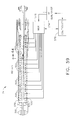
- FIGS. 12-14 and 17 are schematic diagrams of circuits used to power the motor of the instrument according to various embodiments of the present invention.
- FIG. 15 is a block diagram illustrating a charge management circuit according to various embodiments of the present invention.
- FIG. 16 is a block diagram illustrating a charger base according to various embodiments of the present invention.
- FIG. 18 illustrates a typical power curve of a battery
- FIGS. 19-22 illustrate embodiments of an electromagnetic, clutch-type torque-limiting device according to various embodiments of the present invention
- FIGS. 23-25, 27-28, and 59 are views of the lower surface of the anvil of the instrument according to various embodiments of the present invention.
- FIGS. 26, 53, 54, and 68 are cross-sectional front views of the end effector according to various embodiments of the present invention.
- FIGS. 29-32 show an embodiment of the end effector having RF electrodes according to various embodiments of the present invention.
- FIGS. 33-36 show another embodiment of the end effector having RF electrodes according to various embodiments of the present invention.
- FIGS. 37-40 show another embodiment of the end effector having RF electrodes according to various embodiments of the present invention.
- FIGS. 41-44 show another embodiment of the end effector having RF electrodes according to various embodiments of the present invention.
- FIGS. 45-48 show another embodiment of the end effector having RF electrodes according to various embodiments of the present invention.
- FIGS. 49-52 show another embodiment of the end effector having RF electrodes according to various embodiments of the present invention.
- FIGS. 55 and 56 show side views of the end effector according to various embodiments of the present invention.
- FIG. 57 is a diagram of the handle of the instrument according to another embodiment of the present invention.
- FIG. 58 is a cut-away view of the handle of the embodiment of FIG. 57 according to various embodiments of the present invention.
- FIGS. 60-66 illustrate a multi-layer circuit board according to various embodiments of the present invention.
- FIG. 67 is a diagram illustrating an end effector according to various embodiments of the present invention.
- FIGS. 69 and 70 are diagram of an instrument comprising a flexible neck assembly according to various embodiments of the present invention.
- FIGS. 1 and 2 depict a surgical cutting and fastening instrument 10 according to various embodiments of the present invention.
- the illustrated embodiment is an endoscopic instrument and, in general, the embodiments of the instrument 10 described herein are endoscopic surgical cutting and fastening instruments. It should be noted, however, that according to other embodiments of the present invention, the instrument may be a non-endoscopic surgical cutting and fastening instrument, such as a laparoscopic instrument.
- the surgical instrument 10 depicted in FIGS. 1 and 2 comprises a handle 6 , a shaft 8 , and an articulating end effector 12 pivotally connected to the shaft 8 at an articulation pivot 14 .
- An articulation control 16 may be provided adjacent to the handle 6 to effect rotation of the end effector 12 about the articulation pivot 14 .
- the end effector 12 is configured to act as an endocutter for clamping, severing and stapling tissue, although, in other embodiments, different types of end effectors may be used, such as end effectors for other types of surgical devices, such as graspers, cutters, staplers, clip appliers, access devices, drug/gene therapy devices, ultrasound, RF or laser devices, etc. More details regarding RF devices may be found in the '312 Patent.
- the handle 6 of the instrument 10 may include a closure trigger 18 and a firing trigger 20 for actuating the end effector 12 .
- the end effector 12 is shown separated from the handle 6 by a preferably elongate shaft 8 .
- a clinician or operator of the instrument 10 may articulate the end effector 12 relative to the shaft 8 by utilizing the articulation control 16 , as described in more detail in published U.S. Patent Application Publication No. 2007/0158385, entitled SURGICAL INSTRUMENT HAVING AN ARTICULATING END EFFECTOR, now U.S. Pat. No. 7,670,334, which is incorporated herein by reference.
- the end effector 12 includes in this example, among other things, a staple channel 22 and a pivotally translatable clamping member, such as an anvil 24 , which are maintained at a spacing that assures effective stapling and severing of tissue clamped in the end effector 12 .
- the handle 6 includes a pistol grip 26 towards which a closure trigger 18 is pivotally drawn by the clinician to cause clamping or closing of the anvil 24 toward the staple channel 22 of the end effector 12 to thereby clamp tissue positioned between the anvil 24 and channel 22 .
- the firing trigger 20 is farther outboard of the closure trigger 18 . Once the closure trigger 18 is locked in the closure position as further described below, the firing trigger 20 may rotate slightly toward the pistol grip 26 so that it can be reached by the operator using one hand.
- the operator may pivotally draw the firing trigger 20 toward the pistol grip 12 to cause the stapling and severing of clamped tissue in the end effector 12 .
- different types of clamping members besides the anvil 24 could be used, such as, for example, an opposing jaw, etc.
- proximal and distal are used herein with reference to a clinician gripping the handle 6 of an instrument 10 .
- end effector 12 is distal with respect to the more proximal handle 6 .
- spatial terms such as “vertical” and “horizontal” are used herein with respect to the drawings.
- surgical instruments are used in many orientations and positions, and these terms are not intended to be limiting and absolute.
- the closure trigger 18 may be actuated first. Once the clinician is satisfied with the positioning of the end effector 12 , the clinician may draw back the closure trigger 18 to its fully closed, locked position proximate to the pistol grip 26 . The firing trigger 20 may then be actuated. The firing trigger 20 returns to the open position (shown in FIGS. 1 and 2 ) when the clinician removes pressure, as described more fully below. A release button on the handle 6 , when depressed may release the locked closure trigger 18 .
- the release button may be implemented in various forms such as, for example, as a slide release button 160 shown in FIG. 7 or any of the mechanisms described in published U.S. Patent Application Publication No. 2007/0175955, which is incorporated herein by reference.
- FIG. 3 is an exploded view of the end effector 12 according to various embodiments.
- the end effector 12 may include, in addition to the previously mentioned channel 22 and anvil 24 , a cutting instrument 32 , a sled 33 , a staple cartridge 34 that is removably seated in the channel 22 , and a helical screw shaft 36 .
- the cutting instrument 32 may be, for example, a knife.
- the anvil 24 may be pivotably opened and closed at a pivot point 25 connected to the proximate end of the channel 22 .
- the anvil 24 may also include a tab 27 at its proximate end that is inserted into a component of the mechanical closure system (described further below) to open and close the anvil 24 .
- the anvil 24 may pivot about the pivot point 25 into the clamped or closed position. If clamping of the end effector 12 is satisfactory, the operator may actuate the firing trigger 20 , which, as explained in more detail below, causes the knife 32 and sled 33 to travel longitudinally along the channel 22 , thereby cutting tissue clamped within the end effector 12 . The movement of the sled 33 along the channel 22 causes the staples of the staple cartridge 34 to be driven through the severed tissue and against the closed anvil 24 , which turns the staples to fasten the severed tissue. In various embodiments, the sled 33 may be an integral component of the cartridge 34 .
- the sled 33 may be part of the cartridge 34 , such that when the knife 32 retracts following the cutting operation, the sled 33 does not retract.
- FIGS. 4 and 5 are exploded views and FIG. 6 is a side view of the end effector 12 and shaft 8 according to various embodiments.
- the shaft 8 may include a proximate closure tube 40 and a distal closure tube 42 pivotably linked by a pivot links 44 .
- the distal closure tube 42 includes an opening 45 into which the tab 27 on the anvil 24 is inserted in order to open and close the anvil 24 , as further described below.
- Disposed inside the closure tubes 40 , 42 may be a proximate spine tube 46 .
- Disposed inside the proximate spine tube 46 may be a main rotational (or proximate) drive shaft 48 that communicates with a secondary (or distal) drive shaft 50 via a bevel gear assembly 52 .
- the secondary drive shaft 50 is connected to a drive gear 54 that engages a proximate drive gear 56 of the helical screw shaft 36 .
- the vertical bevel gear 52 b may sit and pivot in an opening 57 in the distal end of the proximate spine tube 46 .
- a distal spine tube 58 may be used to enclose the secondary drive shaft 50 and the drive gears 54 , 56 .
- a bearing 38 positioned at a distal end of the staple channel 22 , receives the helical drive screw 36 , allowing the helical drive screw 36 to freely rotate with respect to the channel 22 .
- the helical screw shaft 36 may interface a threaded opening (not shown) of the knife 32 such that rotation of the shaft 36 causes the knife 32 to translate distally or proximately (depending on the direction of the rotation) through the staple channel 22 .
- the bevel gear assembly 52 a - c causes the secondary drive shaft 50 to rotate, which in turn, because of the engagement of the drive gears 54 , 56 , causes the helical screw shaft 36 to rotate, which causes the knife driving member 32 to travel longitudinally along the channel 22 to cut any tissue clamped within the end effector.
- the sled 33 may be made of, for example, plastic, and may have a sloped distal surface. As the sled 33 traverses the channel 22 , the sloped forward surface may push up or drive the staples in the staple cartridge through the clamped tissue and against the anvil 24 . The anvil 24 turns the staples, thereby stapling the severed tissue. When the knife 32 is retracted, the knife 32 and sled 33 may become disengaged, thereby leaving the sled 33 at the distal end of the channel 22 .
- FIGS. 7-10 illustrate an exemplary embodiment of a motor-driven endocutter.
- the illustrated embodiment provides user-feedback regarding the deployment and loading force of the cutting instrument in the end effector.
- the embodiment may use power provided by the user in retracting the firing trigger 20 to power the device (a so-called “power assist” mode).
- the handle 6 includes exterior lower side pieces 59 , 60 and exterior upper side pieces 61 , 62 that fit together to form, in general, the exterior of the handle 6 .
- a battery 64 such as a Li ion battery, may be provided in the pistol grip portion 26 of the handle 6 .
- the battery 64 powers a motor 65 disposed in an upper portion of the pistol grip portion 26 of the handle 6 .
- a number of battery cells connected in series may be used to power the motor 65 .
- the motor 65 may be a DC brushed driving motor having a maximum rotation of approximately 25,000 RPM with no load.
- the motor 64 may drive a 90° bevel gear assembly 66 comprising a first bevel gear 68 and a second bevel gear 70 .
- the bevel gear assembly 66 may drive a planetary gear assembly 72 .
- the planetary gear assembly 72 may include a pinion gear 74 connected to a drive shaft 76 .
- the pinion gear 74 may drive a mating ring gear 78 that drives a helical gear drum 80 via a drive shaft 82 .
- a ring 84 may be threaded on the helical gear drum 80 .
- the handle 6 may also include a run motor sensor 110 in communication with the firing trigger 20 to detect when the firing trigger 20 has been drawn in (or “closed”) toward the pistol grip portion 26 of the handle 6 by the operator to thereby actuate the cutting/stapling operation by the end effector 12 .
- the sensor 110 may be a proportional sensor such as, for example, a rheostat, or variable resistor. When the firing trigger 20 is drawn in, the sensor 110 detects the movement, and sends an electrical signal indicative of the voltage (or power) to be supplied to the motor 65 . When the sensor 110 is a variable resistor or the like, the rotation of the motor 65 may be generally proportional to the amount of movement of the firing trigger 20 .
- the rotation of the motor 65 is relatively low.
- the rotation of the motor 65 is at its maximum. In other words, the harder the user pulls on the firing trigger 20 , the more voltage is applied to the motor 65 , causing greater rates of rotation.
- the handle 6 may include a middle handle piece 104 adjacent to the upper portion of the firing trigger 20 .
- the handle 6 also may comprise a bias spring 112 connected between posts on the middle handle piece 104 and the firing trigger 20 .
- the bias spring 112 may bias the firing trigger 20 to its fully open position. In that way, when the operator releases the firing trigger 20 , the bias spring 112 will pull the firing trigger 20 to its open position, thereby removing actuation of the sensor 110 , thereby stopping rotation of the motor 65 .
- the bias spring 112 any time a user closes the firing trigger 20 , the user will experience resistance to the closing operation, thereby providing the user with feedback as to the amount of rotation exerted by the motor 65 .
- the operator could stop retracting the firing trigger 20 to thereby remove force from the sensor 100 , to thereby stop the motor 65 .
- the user may stop the deployment of the end effector 12 , thereby providing a measure of control of the cutting/fastening operation to the operator.
- the distal end of the helical gear drum 80 includes a distal drive shaft 120 that drives a ring gear 122 , which mates with a pinion gear 124 .
- the pinion gear 124 is connected to the main drive shaft 48 of the main drive shaft assembly. In that way, rotation of the motor 65 causes the main drive shaft assembly to rotate, which causes actuation of the end effector 12 , as described above.
- the ring 84 threaded on the helical gear drum 80 may include a post 86 that is disposed within a slot 88 of a slotted arm 90 .
- the slotted arm 90 has an opening 92 at its opposite end 94 that receives a pivot pin 96 that is connected between the handle exterior side pieces 59 , 60 .
- the pivot pin 96 is also disposed through an opening 100 in the firing trigger 20 and an opening 102 in the middle handle piece 104 .
- the handle 6 may include a reverse motor (or end-of-stroke sensor) 130 and a stop motor (or beginning-of-stroke) sensor 142 .
- the reverse motor sensor 130 may be a limit switch located at the distal end of the helical gear drum 80 such that the ring 84 threaded on the helical gear drum 80 contacts and trips the reverse motor sensor 130 when the ring 84 reaches the distal end of the helical gear drum 80 .
- the reverse motor sensor 130 when activated, sends a signal to the motor 65 to reverse its rotation direction, thereby withdrawing the knife 32 of the end effector 12 following the cutting operation.
- the stop motor sensor 142 may be, for example, a normally-closed limit switch. In various embodiments, it may be located at the proximate end of the helical gear drum 80 so that the ring 84 trips the switch 142 when the ring 84 reaches the proximate end of the helical gear drum 80 .
- the sensor 110 detects the deployment of the firing trigger 20 and sends a signal to the motor 65 to cause forward rotation of the motor 65 at, for example, a rate proportional to how hard the operator pulls back the firing trigger 20 .
- the forward rotation of the motor 65 in turn causes the ring gear 78 at the distal end of the planetary gear assembly 72 to rotate, thereby causing the helical gear drum 80 to rotate, causing the ring 84 threaded on the helical gear drum 80 to travel distally along the helical gear drum 80 .
- the rotation of the helical gear drum 80 also drives the main drive shaft assembly as described above, which in turn causes deployment of the knife 32 in the end effector 12 .
- the knife 32 and sled 33 are caused to traverse the channel 22 longitudinally, thereby cutting tissue clamped in the end effector 12 .
- the stapling operation of the end effector 12 is caused to happen in embodiments where a stapling-type end effector is used.
- the ring 84 on the helical gear drum 80 will have reached the distal end of the helical gear drum 80 , thereby causing the reverse motor sensor 130 to be tripped, which sends a signal to the motor 65 to cause the motor 65 to reverse its rotation. This in turn causes the knife 32 to retract, and also causes the ring 84 on the helical gear drum 80 to move back to the proximate end of the helical gear drum 80 .
- the middle handle piece 104 includes a backside shoulder 106 that engages the slotted arm 90 as best shown in FIGS. 8 and 9 .
- the middle handle piece 104 also has a forward motion stop 107 that engages the firing trigger 20 .
- the movement of the slotted arm 90 is controlled, as explained above, by rotation of the motor 65 .
- the middle handle piece 104 will be free to rotate CCW.
- the firing trigger 20 will engage the forward motion stop 107 of the middle handle piece 104 , causing the middle handle piece 104 to rotate CCW.
- the middle handle piece 104 will only be able to rotate CCW as far as the slotted arm 90 permits. In that way, if the motor 65 should stop rotating for some reason, the slotted arm 90 will stop rotating, and the user will not be able to further draw in the firing trigger 20 because the middle handle piece 104 will not be free to rotate CCW due to the slotted arm 90 .
- the closure system includes a yoke 250 connected to the closure trigger 18 by a pin 251 that is inserted through aligned openings in both the closure trigger 18 and the yoke 250 .
- a pivot pin 252 about which the closure trigger 18 pivots, is inserted through another opening in the closure trigger 18 which is offset from where the pin 251 is inserted through the closure trigger 18 .
- the distal end of the yoke 250 is connected, via a pin 254 , to a first closure bracket 256 .
- the first closure bracket 256 connects to a second closure bracket 258 .
- the closure brackets 256 , 258 define an opening in which the proximate end of the proximate closure tube 40 (see FIG. 4 ) is seated and held such that longitudinal movement of the closure brackets 256 , 258 causes longitudinal motion by the proximate closure tube 40 .
- the instrument 10 also includes a closure rod 260 disposed inside the proximate closure tube 40 .
- the closure rod 260 may include a window 261 into which a post 263 on one of the handle exterior pieces, such as exterior lower side piece 59 in the illustrated embodiment, is disposed to fixedly connect the closure rod 260 to the handle 6 . In that way, the proximate closure tube 40 is capable of moving longitudinally relative to the closure rod 260 .
- the closure rod 260 may also include a distal collar 267 that fits into a cavity 269 in proximate spine tube 46 and is retained therein by a cap 271 (see FIG. 4 ).
- the closure brackets 256 , 258 cause the proximate closure tube 40 to move distally (i.e., away from the handle end of the instrument 10 ), which causes the distal closure tube 42 to move distally, which causes the anvil 24 to rotate about the pivot point 25 into the clamped or closed position.
- the proximate closure tube 40 is caused to slide proximately, which causes the distal closure tube 42 to slide proximately, which, by virtue of the tab 27 being inserted in the window 45 of the distal closure tube 42 , causes the anvil 24 to pivot about the pivot point 25 into the open or unclamped position.
- an operator may clamp tissue between the anvil 24 and channel 22 , and may unclamp the tissue following the cutting/stapling operation by unlocking the closure trigger 20 from the locked position.
- FIG. 11 is a schematic diagram of an electrical circuit of the instrument 10 according to various embodiments of the present invention.
- the sensor 110 When an operator initially pulls in the firing trigger 20 after locking the closure trigger 18 , the sensor 110 is activated, allowing current to flow there through. If the normally-open reverse motor sensor switch 130 is open (meaning the end of the end effector stroke has not been reached), current will flow to a single pole, double throw relay 132 . Since the reverse motor sensor switch 130 is not closed, the inductor 134 of the relay 132 will not be energized, so the relay 132 will be in its non-energized state.
- the circuit also includes a cartridge lockout sensor 136 . If the end effector 12 includes a staple cartridge 34 , the sensor 136 will be in the closed state, allowing current to flow. Otherwise, if the end effector 12 does not include a staple cartridge 34 , the sensor 136 will be open, thereby preventing the battery 64 from powering the motor 65 .
- the sensor 136 When the staple cartridge 34 is present, the sensor 136 is closed, which energizes a single pole, single throw relay 138 .
- the relay 138 When the relay 138 is energized, current flows through the relay 136 , through the variable resistor sensor 110 , and to the motor 65 via a double pole, double throw relay 140 , thereby powering the motor 65 , and allowing it to rotate in the forward direction.
- the reverse motor sensor 130 will be activated, thereby closing the switch 130 and energizing the relay 134 . This causes the relay 134 to assume its energized state (not shown in FIG.
- an on-off type sensor could be used.
- the rate of rotation of the motor 65 would not be proportional to the force applied by the operator. Rather, the motor 65 would generally rotate at a constant rate. But the operator would still experience force feedback because the firing trigger 20 is geared into the gear drive train.
- the motor may be powered by a number of battery cells connected in series. Further, it may be desirable in certain circumstances to power the motor with some fraction of the total number of battery cells.
- the motor 65 may be powered by a power pack 299 comprising six (6) battery cells 310 connected in series.
- the battery cells 310 may be, for example, 3-volt lithium battery cells, such as CR 123A battery cells, although in other embodiments, different types of battery cells could be used (including battery cells with different voltage levels and/or different chemistries). If six 3-volt battery cells 310 were connected in series to power the motor 65 , the total voltage available to power the motor 65 would be 18 volts.
- the battery cells 310 may comprise rechargeable or non-rechargeable battery cells.
- the circuit may include a switch 312 that selectively allows the motor 65 to be powered by either (1) all of the battery cells 310 or (2) a fraction of the battery cells 310 .
- the switch 312 may allow the motor 65 to be powered by all six battery cells or four of the battery cells. That way, the switch 312 could be used to power the motor 65 with either 18 volts (when using all six battery cells 310 ) or 12 volts (such using four of the second battery cells).
- the design choice for the number of battery cells in the fraction that is used to power the motor 65 may be based on the voltage required by the motor 65 when operating at maximum output for the heaviest loads.
- the switch 312 may be, for example, an electromechanical switch, such as a micro switch. In other embodiments, the switch 312 may be implemented with a solid-state switch, such as transistor. A second switch 314 , such as a push button switch, may be used to control whether power is applied to the motor 65 at all. Also, a forward/reverse switch 316 may be used to control whether the motor 65 rotates in the forward direction or the reverse direction. The forward/reverse switch 316 may be implemented with a double pole-double throw switch, such as the relay 140 shown in FIG. 11 .
- the user of the instrument 10 could select the desired power level by using some sort of switch control, such as a position-dependent switch (not shown), such as a toggle switch, a mechanical lever switch, or a cam, which controls the position of the switch 312 . Then the user may activate the second switch 314 to connect the selected battery cells 310 to the motor 65 .
- the circuit shown in FIG. 12 could be used to power the motor of other types of motorized surgical instruments, such as circular cutters and/or laparoscopic instruments. More details regarding circular cutters may be found in published U.S. Patent Application Publication Nos. 2006/0047307, now U.S. Pat. No. 8,317,074, and 2007/0262116, now U.S. Pat. No. 7,500,979, which are incorporated herein by reference.
- a primary power source 340 such as a battery cell, such as a CR2 or CR123A battery cell, may be used to charge a number of secondary accumulator devices 342 .
- the primary power source 340 may comprise one or a number of series-connected battery cells, which are preferably replaceable in the illustrated embodiment.
- the secondary accumulator devices 342 may comprise, for example, rechargeable battery cells and/or supercapacitors (also known as “ultracapacitors” or “electrochemical double layer capacitors” (EDLC)).
- supercapacitors are electrochemical capacitors that have an unusually high energy density when compared to common electrolytic capacitors, typically on the order of thousands of times greater than a high-capacity electrolytic capacitor.
- the primary power source 340 may charge the secondary accumulator devices 342 . Once sufficiently charged, the primary power source 340 may be removed and the secondary accumulator devices 342 may be used to power the motor 65 during a procedure or operation.
- the accumulating devices 342 may take about fifteen to thirty minutes to charge in various circumstances.
- Supercapacitors have the characteristic they can charge and discharge extremely rapidly in comparison to conventional batteries. In addition, whereas batteries are good for only a limited number of charge/discharge cycles, supercapacitors can often be charged/discharged repeatedly, sometimes for tens of millions of cycles.
- the supercapacitors may comprise carbon nanotubes, conductive polymers (e.g., polyacenes), or carbon aerogels.
- a charge management circuit 344 could be employed to determine when the secondary accumulator devices 342 are sufficiently charged.
- the charge management circuit 344 may include an indicator, such as one or more LEDs, an LCD display, etc., that is activated to alert a user of the instrument 10 when the secondary accumulator devices 342 are sufficiently charged.
- the primary power source 340 , the secondary accumulator devices 342 , and the charge management circuit 344 may be part of a power pack in the pistol grip portion 26 of the handle 6 of the instrument 10 , or in another part of the instrument 10 .
- the power pack may be removable from the pistol grip portion 26 , in which case, when the instrument 10 is to be used for surgery, the power pack may be inserted aseptically into the pistol grip portion 26 (or other position in the instrument according to other embodiments) by, for example, a circulating nurse assisting in the surgery. After insertion of the power pack, the nurse could put the replaceable primary power source 340 in the power pack to charge up the secondary accumulator devices 342 a certain time period prior to use of the instrument 10 , such as thirty minutes.
- the charge management circuit 344 may indicate that the power pack is ready for use. At this point, the replaceable primary power source 340 may be removed. During the operation, the user of the instrument 10 may then activate the motor 65 , such as by activating the switch 314 , whereby the secondary accumulator devices 342 power the motor 65 .
- the secondary accumulator devices 342 could be reusable. In alternative embodiments, however, it should be noted that the secondary accumulator devices 342 could be non-rechargeable and/or non-reusable.
- the secondary accumulators 342 may be used with the cell selection switch 312 described above in connection with FIG. 12 .
- the charge management circuit 344 may also include indicators (e.g., LEDs or LCD display) that indicate how much charge remains in the secondary accumulator devices 342 . That way, the surgeon (or other user of the instrument 10 ) can see how much charge remains through the course of the procedure involving the instrument 10 .
- indicators e.g., LEDs or LCD display
- the charge management circuit 344 may comprise a charge meter 345 for measuring the charge across the secondary accumulators 342 .
- the charge management circuit 344 also may comprise a non-volatile memory 346 , such as flash or ROM memory, and one or more processors 348 .
- the processor(s) 348 may be connected to the memory 346 to control the memory.
- the processor(s) 348 may be connected to the charge meter 345 to read the readings of and otherwise control the charge meter 345 .
- the processor(s) 348 may control the LEDs or other output devices of the charge management circuit 344 .
- the processor(s) 348 can store parameters of the instrument 10 in the memory 346 .
- the parameters may include operating parameters of the instrument that are sensed by various sensors that may be installed or employed in the instrument 10 , such as, for example, the number of firings, the levels of forces involved, the distance of the compression gap between the opposing jaws of the end effector 12 , the amount of articulation, etc.
- the parameters stored in the memory 346 may comprise ID values for various components of the instrument 10 that the charge management circuit 344 may read and store.
- the components having such IDs may be replaceable components, such as the staple cartridge 34 .
- the IDs may be for example, RFIDs that the charge management circuit 344 reads via a RFID transponder 350 .
- the RFID transponder 350 may read RFIDs from components of the instrument, such as the staple cartridge 34 , that include RFID tags.
- the ID values may be read, stored in the memory 346 , and compared by the processor 348 to a list of acceptable ID values stored in the memory 346 or another store associated with the charge management circuit, to determine, for example, if the removable/replaceable component associated with the read ID value is authentic and/or proper.
- the charge management circuit 344 may prevent use of the power pack by the instrument 10 , such as by opening a switch (not shown) that would prevent power from the power pack being delivered to the motor 65 .
- various parameters that the processor 348 may evaluate to determine whether the component is authentic and/or proper include: date code; component model/type; manufacturer; regional information; and previous error codes.
- the charge management circuit 344 may also comprise an i/o interface 352 for communicating with another device, such as described below. That way, the parameters stored in the memory 346 may be downloaded to another device.
- the i/o interface 352 may be, for example, a wired or wireless interface.
- the power pack may comprise the secondary accumulators 342 , the charge management circuit 344 , and/or the f/r switch 316 .
- the power pack 299 could be connected to a charger base 362 , which may, among other things, charge the secondary accumulators 342 in the power pack.
- the charger base 362 could be connected to the power pack 299 by connecting aseptically the charger base 362 to the power pack 299 while the power pack is installed in the instrument 10 .
- the charger base 362 could be connected to the power pack 299 by removing the power pack 299 from the instrument 10 and connecting it to the charger base 362 .
- the power pack 299 may be aseptically installed in the instrument 10 .
- the charger base 362 may comprise a power source 364 for charging the secondary accumulators 342 .
- the power source 364 of the charger base 362 may be, for example, a battery (or a number of series-connected batteries), or an AC/DC converter that converters AC power, such as from electrical power mains, to DC, or any other suitable power source for charging the secondary accumulators 342 .
- the charger base 362 may also comprise indicator devices, such as LEDs, a LCD display, etc., to show the charge status of the secondary accumulators 342 .
- the charger base 362 may comprise one or more processors 366 , one or more memory units 368 , and i/o interfaces 370 , 372 .
- the charger base 362 may communicate with the power pack 299 (via the power pack's i/o interface 352 ). That way, for example, data stored in the memory 346 of the power pack 299 may be downloaded to the memory 368 of the charger base 362 .
- the processor 366 can evaluate the ID values for the removable/replaceable components, downloaded from the charge management circuit 344 , to determine the authenticity and suitability of the components.
- the operating parameters downloaded from the charge management circuit 344 may also stored in the memory 368 , and then may then be downloaded to another computer device via the second i/o interface 372 for evaluation and analysis, such as by the hospital system in which the operation involving the instrument 10 is performed, by the office of the surgeon, by the distributor of the instrument, by the manufacturer of the instrument, etc.
- the charger base 362 may also comprise a charge meter 374 for measuring the charge across the secondary accumulators 342 .
- the charge meter 374 may be in communication with the processor(s) 366 , so that the processor(s) 366 can determine in real-time the suitability of the power pack 299 for use to ensure high performance.
- the battery circuit may comprise a power regulator 320 to control the power supplied by the power savers 310 to the motor 65 .
- the power regulator 320 may also be part of the power pack 299 , or it may be a separate component.
- the motor 65 may be a brushed DC motor.
- the speed of brushed DC motors generally is proportional to the applied input voltage.
- the power regulator 320 may provide a highly regulated output voltage to the motor 65 so that the motor 65 will operate at a constant (or substantially constant) speed.
- the power regulator 320 may comprise a switch-mode power converter, such as a buck-boost converter, as shown in the example of FIG. 17 .
- Such a buck-boost converter 320 may comprise a power switch 322 , such as a FET, a rectifier 324 , an inductor 326 , and a capacitor 328 .
- the input voltage source e.g., the power sources 310
- the capacitor 328 supplies energy to the output load (e.g., the motor 65 ).
- the inductor 326 is connected to the output load (e.g., the motor 65 ) and the capacitor 328 , so energy is transferred from the inductor 326 to the capacitor 328 and the load 65 .
- a control circuit 330 may control the power switch 322 .
- the control circuit 330 may employ digital and/or analog control loops.
- the control circuit 330 may receive control information from a master controller (not shown) via a communication link, such as a serial or parallel digital data bus.
- the voltage set point for the output of the power regulator 320 may be set, for example, to one-half of the open circuit voltage, at which point the maximum power available from the source is available.
- different power converter topologies may be employed, including linear or switch-mode power converters.
- Other switch-mode topologies that may be employed include a flyback, forward, buck, boost, and SEPIC.
- the set point voltage for the power regulator 320 could be changed depending on how many of the battery cells are being used to power the motor 65 .
- the power regulator 320 could be used with the secondary accumulator devices 342 shown in FIG. 13 .
- the forward-reverse switch 316 could be incorporated into the power regulator 320 , although it is shown separately in FIG. 17 .
- Batteries can typically be modeled as an ideal voltage source and a source resistance. For an ideal model, when the source and load resistance are matched, maximum power is transferred to the load.
- FIG. 18 shows a typical power curve for a battery. When the battery circuit is open, the voltage across the battery is high (at its open circuit value) and the current drawn from the battery is zero. The power delivered from the battery is zero also. As more current is drawn from the battery, the voltage across the battery decreases. The power delivered by the battery is the product of the current and the voltage. The power reaches its peak around at a voltage level that is less than the open circuit voltage. As shown in FIG. 18 , with most battery chemistries there is a sharp drop in the voltage/power at higher current because of the chemistry or positive temperature coefficient (PTC), or because of a battery protection device.
- PTC positive temperature coefficient
- the control circuit 330 can monitor the output voltage and control the set point of the regulator 320 so that the battery operates on the “left” or power-increasing side of the power curve. If the battery reaches the peak power level, the control circuit 330 can change (e.g., lower) the set point of the regulator so that less total power is being demanded from the battery. The motor 65 would then slow down. In this way, the demand from the power pack would rarely if ever exceed the peak available power so that a power-starving situation during a procedure could be avoided.
- the power drawn from the battery may be optimized in such a way that the chemical reactions within the battery cells would have time to recover, to thereby optimize the current and power available from the battery.
- batteries typically provide more power at the beginning of the pulse that toward the end of the pulse. This is due to several factors, including: (1) the PTC may be changing its resistance during the pulse; (2) the temperature of the battery may be changing; and (3) the electrochemical reaction rate is changing due to electrolyte at the cathode being depleted and the rate of diffusion of the fresh electrolyte limits the reaction rate.
- the control circuit 330 may control the converter 320 so that it draws a lower current from the battery to allow the battery to recover before it is pulsed again.
- the instrument 10 may comprise a clutch-type torque-limiting device.
- the clutch-type torque-limiting device may be located, for example, between the motor 65 and the bevel gear 68 , between the bevel gear 70 and the planetary gear assembly 72 , or on the output shaft of the planetary gear assembly 72 .
- the torque-limiting device may use an electromagnetic or permanent magnetic clutch.
- FIGS. 19 to 22 show a sample electromagnetic clutch 400 that could be used in the instrument 10 according to various embodiments.
- the clutch 400 may comprise a horseshoe-shaped stator 402 having magnetic disks 404 , 406 at each end.
- the first disk 404 may be connected to an axially movable, rotatable pole piece 408 , such as the output pole of the motor 65 .
- the second magnetic disk 406 may be connected to an axially stationary, rotatable pole piece 410 , such as an input pole to a gear box of the instrument 10 .
- the first pole piece 408 is axially pulled away from the second pole piece 410 by a clearance 412 such that the magnetic disks 404 , 406 are not engaged.
- a wire coil (not shown), which may be wrapped around the stator 402 may be used to create the electromagnetic flux needed to actuate the clutch 400 .
- the resulting magnetic flux may cause the two magnetic disks 404 , 406 to attract, causing the first pole piece 408 to move axially toward the second pole piece 410 , thereby causing the two magnetic disks 404 , 406 to become engaged, as shown in FIGS. 21 and 22 , such that the two pole pieces 408 , 410 will rotate together until the torque exceeds the friction torque generated between the faces of magnetic disks 404 and 406 .
- the attractive force between the two disks 404 , 406 and the corresponding torque capacity of the clutch 400 could be controlled by controlling the diameter of the disks 404 , 406 , the coefficient of friction between the contacting faces of magnetic disks 404 and 406 , and by using magnetic materials for the disks 404 , 406 that saturate at a known and controllable flux density. Therefore, even if there was an operating condition where more current was passed through the coil, the magnetic material of the disks 404 , 406 would not generate a greater attractive force and subsequent limiting torque.
- the clutch 400 could be quickly deactivated by removing current from the wire to limit the amount of heat generated within the clutch 400 and within the motor 65 . By disconnecting the motor from the rest of the drive train, via the clutch 400 , most of the stored inertial energy in the drive train would be disconnected, limiting shock if the output were to be blocked suddenly. In addition, by being electrically controlled, some limited slipping could be designed-in to aid in reducing shocks when restarting the drive train under load.
- the clutch 400 would be less sensitive to changes in system voltage.
- the torque limit in such embodiments would be primarily a function of the physical dimensions of the components of the clutch (e.g., the magnetic disks 404 , 406 ) and would not require voltage regulators or other external components for proper operation.
- the torque-limiting device may comprise a permanent magnet (not shown).
- the permanent magnet may be connected, for example, to the first, axially-movable, pole piece 408 , and attract the axially-fixed second pole piece 410 , or vice versa.
- one of the disks 404 , 406 could be made of a permanent magnet and the other one of a magnetic material like iron.
- the stator 402 could be made in the form of a permanent magnet, causing the magnetic disks 404 and 406 to be attracted to each other. Because of the permanent magnet, the two disks 404 , 406 would be engaged always.
- Using a permanent magnet would not provide as accurate as torque control as the electromagnetic clutch configuration described above, but it would have the advantages of: (1) not requiring controls or control logic to control the current through the coil; (2) being more compact that the electromagnetic clutch configuration; and (3) simplifying design of the instrument 10 .
- the end effector 12 may emit RF energy to coagulate tissue clamped in the end effector.
- the RF energy may be transmitted between electrodes in the end effector 12 .
- a RF source (not shown), comprising, for example, an oscillator and an amplifier, among other components, which may supply the RF energy to the electrode, may be located in the instrument itself, such as in the handle 6 for a cordless instrument 10 , or the RF source may be external to the instrument 10 .
- the RF source may be activated as described further below.
- the end effector 12 may comprise multiple sections (or segments) of electrodes.
- the lower surface of the anvil 24 i.e., the surface facing the staple cartridge 34
- the lower surface of the anvil 24 may comprise three co-linear RF segments.
- each segment has the same length (e.g., 20 mm), although in other embodiments there may be more or fewer segments, and the segments may have different lengths.
- the illustrated embodiment there is a pair of distal electrodes 500 1 , a pair of middle electrodes 500 2 , and a pair of proximate electrodes 500 3 on each side of the knife channel 516 .
- the metallic outer portion or channel 22 of the end effector 12 or the metallic anvil 24 may serve as the counter-electrode (or cathode) for each of the three upper active electrodes (or anodes) 500 .
- the upper electrodes 500 may be coupled to the RF source. When energized, RF energy may propagate between the upper electrodes 500 and the counter electrode, coagulating tissue clamped between the electrodes.
- the electrodes 500 may be energized simultaneously or in various orders, such as sequentially.
- the sequence may be automatic (controlled, for example, by a controller (not shown) in communication with the RF source) or by selection by the user.
- the proximate electrodes 500 3 could be energized first; then the middle electrodes 500 2 ; then the distal electrodes 500 1 . That way, the operator (e.g., the operating surgeon) can selectively coagulate areas of the staple line.
- the electrodes in such an embodiment could be controlled by a multiplexer and/or a multiple output generator, as described further below. That way, the tissue under each electrode 500 could be treated individually according to the coagulation needs.
- Each electrode in the pair may be connected to the RF source so that they are energized at the same time. That is, for the distal pair of active electrodes 500 1 , each, being on opposite sides of the knife channel, may be energized by the RF source at the same time. Same for the middle pair of electrodes 500 2 and the proximate pair of electrodes 500 3 , although, in an embodiment where the electrode pairs are energized in sequence, the distal pair is not energized at the same time as the middle and proximate pairs, and so on.
- various electrical parameters such as impedance, delivered power or energy, etc.
- various electrical parameters such as impedance, delivered power or energy, etc.
- the output to particular electrodes 500 could be modified to produce the most desirable tissue effect.
- another advantage is in the case of a metal staple or other electrically conductive object left from a previous instrument firing or surgical procedure that may cause a short of the electrodes. Such a short situation could be detected by the generator and/or multiplexer, and the energy could be modulated in a manner appropriate for the short circuit.
- the smaller active electrodes 500 can concentrate the therapeutic energy at the tissue while the larger, return electrode is used to complete the circuit with minimal impact on the tissue interface.
- the return electrode preferably has greater mass and thereby is able to stay cooler during electrosurgical application.
- the electrodes 500 may be surrounded by an electrically insulating material 504 , which may comprise a ceramic material.
- FIG. 59 shows an embodiment having fifteen pairs of segmented RF electrodes 500 on a circuit board 570 , or other type of suitable substrate, on the lower surface of the anvil 24 (i.e., the surface facing the channel 22 ).
- the various electrode pairs are energized by the RF source (or generator) 574 .
- the multiplexer 576 may distribute the RF energy to the various electrode pairs as desired under the control of a controller 578 .
- the RF source 574 , the multiplexer 576 , and the controller 578 may be located in the handle 6 of the instrument.
- FIG. 64 shows a cross-sectional end view of the anvil 24 according to such an embodiment.
- the circuit board 570 adjacent to the staple pockets 584 , comprises three conducting layers 580 1-3 , having insulating layers 582 1-4 therebetween.
- FIGS. 65 and 66 show how the various layers 580 1-3 may be stacked to connect back to the multiplexer 576 in the handle.
- An advantage of having so many RF electrodes in the end effector 12 is that, in the case of a metal staple line 590 or other electrically conductive object left in the tissue 592 from a previous instrument firing or surgical procedure that may cause a short of the electrodes, such a short situation could be detected by the generator and multiplexer, and the energy could be modulated in a manner appropriate for the short circuit.
- FIG. 27 shows another end effector 12 with RF electrodes.
- the end effector 12 only comprises distal electrodes 500 1 , with the metallic anvil 24 serving as the return electrode.
- the distal electrodes 500 1 do not span the entire length of the anvil 24 , but only a fraction of the length.
- distal electrodes 500 1 are only approximately 20 mm in length along a 60 mm anvil, so that the distal electrodes 500 1 only cover approximately the most distal 1 ⁇ 3 of the anvil length.
- the distal electrodes 500 1 could cover the most distal 1/10 to 1 ⁇ 2 of the anvil length.
- Such embodiments could be used for spot coagulation, as described in U.S. Pat. No. 5,599,350, which is incorporated herein by reference.
- FIG. 28 shows yet another embodiment of the end effector 12 with RF electrodes.
- an active electrode 500 is positioned at the distal tip of the anvil 24 , insulated by the anvil 24 by an electrically non-conductive insulator 504 , which may be made of ceramic material. Such an embodiment may be used for spot coagulation.
- FIGS. 29 to 32 illustrate other embodiments of the end effector 12 that may be useful for spot coagulation.
- the anvil 24 comprises a pair of electrodes 500 1 , 500 2 at the distal end of the anvil 24 and along a lateral side of the anvil 24 .
- FIG. 29 is front-end view of the anvil 24 according to such an embodiment
- FIG. 30 is a side view
- FIG. 31 is an enlarged fragmentary front-end view
- FIG. 32 is a top view.
- the metallic anvil 24 may act as the return electrode.
- the active electrodes 500 1 , 500 2 may be insulated from the anvil 24 by electrically non-conductive insulators 504 , which may comprise ceramic material.
- FIGS. 33 to 36 show an embodiment where the anvil 24 comprises two distal electrodes 500 1 , 500 2 located at the top, center of the anvil 24 .
- the metallic anvil 24 may act as the return electrode, and the active electrodes 500 1 , 500 2 may be insulated from the anvil 24 by electrically non-conductive insulators 504 .
- FIGS. 37 to 40 show an embodiment where one active electrode 500 1 (e.g., the active electrode) is positioned on the anvil 24 , and another active electrode 500 2 is positioned on the lower jaw 22 , and preferably on the cartridge 34 .
- the metallic anvil 24 may serve as the return electrode.
- the anvil electrode 500 1 is insulated from the anvil 24 by an insulator 504 .
- the electrode 500 2 being positioned in the cartridge 34 , which is preferably made from a non-conductive material such as plastic, is insulated from the metallic channel 22 by the cartridge 34 .
- FIGS. 41 to 44 show an embodiment where the anvil 24 has two active electrodes 500 1 , 500 2 at the very most distal end of the anvil 24 that extend completely from the upper surface of the anvil 24 to the lower surface.
- the metallic anvil 24 may act as the return electrode, and the active electrodes 500 1 , 500 2 may be insulated from the anvil 24 by electrically non-conductive insulators 504 .
- FIGS. 45 to 48 show an embodiment where the cartridge 34 has two active electrodes 500 1 , 500 2 at the very most distal end of the staple cartridge 34 .
- the metallic anvil 24 or the metallic channel 22 may act as the return electrode.
- the electrodes 500 1 , 500 2 are connected to insulator inserts 503 , but in other embodiments, the insulator inserts 503 could be omitted and the plastic cartridge 34 may serve as the insulator for the electrodes 500 1 , 500 2 .
- FIGS. 49 to 52 show an embodiment having one active electrode 500 1 at the very most distal end of the anvil 24 and another active electrode 500 2 at the very most distal end of the cartridge 34 .
- the metallic anvil 24 or the metallic channel 22 may act as the return electrode.
- the electrode 500 2 is connected to insulator inserts 503 , 505 , but in other embodiments, the insulator inserts 503 , 505 could be omitted and the plastic cartridge 34 may serve as the insulator for the electrode 500 2 .
- FIG. 57 is a side view and FIG. 58 is a cross-sectional side of the handle 6 according to other embodiments of the present invention.
- the illustrated embodiment only includes one trigger, the closure trigger 18 .
- Activation of the knife, staple drivers, and/or RF electrodes in this embodiment may be achieved through means other than a separate firing trigger.
- actuation of the knife, staple drivers, and/or RF electrodes may be activated by a push-button switch 540 or other type of switch that is in a position that is convenient for the operator.
- the switch 540 is shown at the most proximate portion of the handle 6 .
- the switch may be positioned near the distal end of the handle 6 so that pulling of the nozzle 539 activates the switch to cause actuation of the instrument.
- a switch (not shown) may be placed under or near the nozzle 539 so that movement of the nozzles toggles the switch.
- actuation of the knife, staple drivers, and/or RF electrodes may be activated by voice or other sound commands detected by a microphone 542 .
- the handle 6 may comprise a RF or sonic transceiver 541 , which may receive and/or transmit RF or sonic signals to activate the instrument.
- a foot pedal or switch 544 could be used to active the instrument 10 .
- the foot pedal 544 may be connected to the handle 6 by a cord 545 .
- the handle 6 may comprise a dial control 546 or some other suitable control device for controlling actuation of the segmented RF electrodes (see, for example, FIGS. 23 and 24 ). Using such a control device 546 , the operator may serially activate the various pairs of RF electrodes 500 in the end effector 12 .
- the instrument 10 shown in FIGS. 57 and 58 also includes many feedback systems for the user.
- the instrument 10 may comprise the speaker 543 for audibleizing commands or instructions to the operator.
- the handle 6 may comprise visual indicators 548 , such as LEDs or other light sources that provide visual feedback regarding actuation of the various segmented RF electrodes.
- each of the visual indicators 548 could correspond to one of the segmented RF electrode pairs.
- the corresponding visual indicator 548 may be activated when the segmented RF electrode pair is activated.
- the handle 6 may comprise an alphanumeric display 550 , which may be an LED or LCD display, for example.
- the display 550 may be connected to a circuit board 552 inside the handle 6 .
- the handle 6 may also comprise a vibrator 554 in the pistol grip portion 26 that may provide vibrational feedback to the operator.
- the vibrator 554 could vibrate each time that one of the segmented pairs of the RF electrodes in the end effector 12 is activated.
- FIG. 26 is a cross-sectional view of the end effector 12 according to various embodiments where the electrodes are on the upper jaw (or anvil) 24 .
- the active electrodes 500 are positioned adjacent the knife slot 516 .
- the metal anvil 24 may serve as the return electrode.
- Insulators 504 which may be made of ceramic, insulate the electrodes 500 from the metallic anvil 24 .
- the embodiment of FIG. 68 is similar to that of FIG. 26 , except that electrodes 500 are made smaller, such that a portion of the insulators 504 can extend between the respective electrodes 500 and the edges of the knife channel 516 .
- FIG. 53 is a cross-sectional end view of the end effector 12 according to another embodiment.
- the active electrodes 500 1 , 500 2 are on the anvil 24 on opposite sides of the knife channel.
- the electrodes 500 1 , 500 2 are insulated from the metallic anvil by insulators 504 , which again preferably comprise ceramic material.
- the insulators 504 are made very thin (compare with FIG. 26 ). Making the insulators 504 very thin provides the potential advantage that the anvil 24 may include a relatively large metal section 520 above the electrodes 500 , thereby potentially supporting a slimmer anvil profile for a given anvil stiffness, or a stiffer profile for a given anvil cross-sectional dimension.
- the insulators 504 may be cast in or sputter coated onto the anvil 24 .
- FIG. 54 illustrates another embodiment.
- the active electrodes 500 1 , 500 2 are sputter coated or bonded to the insulators 504 , which may also be sputter coated or bonded to the anvil 24 .
- the electrodes 500 1 , 500 2 may comprise silver, which is a good conductor of electricity and has antimicrobial properties.
- FIG. 55 shows a side view of the end effector according to another embodiment.
- a thin film of electrically insulating material 530 is deposited on the face of the cartridge 34 .
- the insulating film 530 preferably comprises a heat- and arc-resistant material, such as ceramic. This would tend to increase the resistance of the cartridge 34 to arc-tracking and shorting, permitting more firings between changes of the cartridge 34 .
- the cartridge 34 was a poor electrical conductor, it would support quicker heating of tissue and reduce the overall energy requirements.
- the active electrodes (not shown in FIG. 55 ) may be in the anvil 24 , as described in embodiments above.
- FIG. 56 shows an embodiment that is similar to that shown in FIG. 55 , except that in FIG. 56 , a thin layer 532 of slightly electrically conductive material is deposited on top of the insulating film 530 .
- the conductivity of the thin, slightly conductive layer 532 may be lower than the conductive of the tissue clamped in the end effector 12 for treatment. As such, the thin, slightly conductive layer 532 would provide a reduced-conductivity path to provide additional heating of the clamped tissue. This would tend to reduce the time required to heat the tissue and achieve coagulation.
- the instrument 10 may comprise an articulation pivot 14 for articulating the end effector 12 .
- a clinician or operator of the instrument 10 may articulate the end effector 12 relative to the shaft 8 by utilizing the articulation control 16 , as described in more detail in published U.S. Patent Application Publication No. 2007/0158385, entitled SURGICAL INSTRUMENT HAVING AN ARTICULATING END EFFECTOR, now U.S. Pat. No. 7,670,334, which is incorporated herein by reference.
- the end effector 12 may be articulated by a separate instrument, such as gripper, that is inserted into the patient so that its operative portion is near the end effector 12 so that it can articulate the end effector 12 as desired.
- the separate instrument may be inserted through a different opening as the end effector 12 , or through the same opening.
- different operators can operate the separate instruments, or one person can operate both instruments, to articulate the end effector 12 .
- the end effector 12 may be articulated by carefully pushing it against other parts of the patient to achieve the desired articulation.
- the end effector 12 may be connected to the handle by a flexible cable.
- the end effector 12 could be positioned as desired and held in position by use of another instrument, e.g., a separate gripper instrument.
- the end effector 12 could be positioned by a separate instrument and clamped by a second separate instrument.
- the end effector 12 could be made sufficiently small, such as 8 to 9 mm wide by 10 to 11 mm tall, so that a pull-to-close mechanism could be used to clamp the end effector from the handle 6 .
- the pull-to-close mechanism could be adapted from that described in U.S. Pat. No.
- the cable 600 could be disposed in or along a flexible endoscope for use, for example, in upper or lower gastro-intestinal tract procedures.
- the instrument 10 may comprise a flexible neck assembly 732 enabling articulation of the end effector 12 .
- an articulation transmission assembly 731 coupled to the shaft 8 When an articulation transmission assembly 731 coupled to the shaft 8 is rotated, it may cause remote articulation of the flexible neck assembly 732 .
- the flexible neck assembly 732 may comprise first and second flexible neck portions 733 , 734 , which receive first and second flexible band assemblies 735 , 736 .
- one of the first and second flexible transmission band assemblies 735 , 736 is moved forwardly and the other band assembly is moved rearwardly.
- the devices disclosed herein can be designed to be disposed of after a single use, or they can be designed to be used multiple times. In either case, however, the device can be reconditioned for reuse after at least one use. Reconditioning can include any combination of the steps of disassembly of the device, followed by cleaning or replacement of particular pieces, and subsequent reassembly. In particular, the device can be disassembled, and any number of the particular pieces or parts of the device can be selectively replaced or removed in any combination. Upon cleaning and/or replacement of particular parts, the device can be reassembled for subsequent use either at a reconditioning facility, or by a surgical team immediately prior to a surgical procedure.
- reconditioning of a device can utilize a variety of techniques for disassembly, cleaning/replacement, and reassembly. Use of such techniques, and the resulting reconditioned device, are all within the scope of the present application.
- the various embodiments of the invention described herein will be processed before surgery.
- a new or used instrument is obtained and if necessary cleaned.
- the instrument can then be sterilized.
- the instrument is placed in a closed and sealed container, such as a thermoformed plastic shell covered with a sheet of TYVEK (commercially available from E. I. du Pont de Nemours and Company).
- the container and instrument are then placed in a field of radiation that can penetrate the container, such as gamma radiation, x-rays, or high-energy electrons.
- the radiation kills bacteria on the instrument and in the container.
- the sterilized instrument can then be stored in the sterile container.
- the sealed container keeps the instrument sterile until it is opened in the medical facility.
- the device is sterilized. This can be done by any number of ways known to those skilled in the art including beta or gamma radiation, ethylene oxide, steam and other methods.
- the present invention has been discussed in terms of endoscopic procedures and apparatus.
- use herein of terms such as “endoscopic” should not be construed to limit the present invention to a surgical stapling and severing instrument for use only in conjunction with an endoscopic tube (i.e., trocar).
- endoscopic a surgical stapling and severing instrument for use only in conjunction with an endoscopic tube (i.e., trocar).
- endoscopic i.e., trocar
- the present invention may find use in any procedure where access is limited, including but not limited to laparoscopic procedures, as well as open procedures.
- the unique and novel aspects of the various staple cartridge embodiments of the present invention may find utility when used in connection with other forms of stapling apparatuses without departing from the spirit and scope of the present invention.
Abstract
Description
Claims (16)
Priority Applications (1)
| Application Number | Priority Date | Filing Date | Title |
|---|---|---|---|
| US14/862,478 US10238387B2 (en) | 2008-02-14 | 2015-09-23 | Surgical instrument comprising a control system |
Applications Claiming Priority (3)
| Application Number | Priority Date | Filing Date | Title |
|---|---|---|---|
| US3157308A | 2008-02-14 | 2008-02-14 | |
| US14/668,406 US10238385B2 (en) | 2008-02-14 | 2015-03-25 | Surgical instrument system for evaluating tissue impedance |
| US14/862,478 US10238387B2 (en) | 2008-02-14 | 2015-09-23 | Surgical instrument comprising a control system |
Related Parent Applications (1)
| Application Number | Title | Priority Date | Filing Date |
|---|---|---|---|
| US14/668,406 Continuation US10238385B2 (en) | 2008-02-14 | 2015-03-25 | Surgical instrument system for evaluating tissue impedance |
Publications (2)
| Publication Number | Publication Date |
|---|---|
| US20160008023A1 US20160008023A1 (en) | 2016-01-14 |
| US10238387B2 true US10238387B2 (en) | 2019-03-26 |
Family
ID=41000289
Family Applications (9)
| Application Number | Title | Priority Date | Filing Date |
|---|---|---|---|
| US14/668,406 Active 2030-02-26 US10238385B2 (en) | 2008-02-14 | 2015-03-25 | Surgical instrument system for evaluating tissue impedance |
| US14/668,426 Active 2030-04-28 US10470763B2 (en) | 2008-02-14 | 2015-03-25 | Surgical cutting and fastening instrument including a sensing system |
| US14/862,478 Active 2029-07-03 US10238387B2 (en) | 2008-02-14 | 2015-09-23 | Surgical instrument comprising a control system |
| US14/862,482 Active 2029-09-21 US10265067B2 (en) | 2008-02-14 | 2015-09-23 | Surgical instrument including a regulator and a control system |
| US15/692,367 Active 2028-07-12 US10542974B2 (en) | 2008-02-14 | 2017-08-31 | Surgical instrument including a control system |
| US16/020,615 Active 2028-04-28 US10806450B2 (en) | 2008-02-14 | 2018-06-27 | Surgical cutting and fastening instrument having a control system |
| US16/020,610 Active US10206676B2 (en) | 2008-02-14 | 2018-06-27 | Surgical cutting and fastening instrument |
| US16/580,286 Active US11717285B2 (en) | 2008-02-14 | 2019-09-24 | Surgical cutting and fastening instrument having RF electrodes |
| US17/032,031 Active 2028-08-05 US11801047B2 (en) | 2008-02-14 | 2020-09-25 | Surgical stapling system comprising a control circuit configured to selectively monitor tissue impedance and adjust control of a motor |
Family Applications Before (2)
| Application Number | Title | Priority Date | Filing Date |
|---|---|---|---|
| US14/668,406 Active 2030-02-26 US10238385B2 (en) | 2008-02-14 | 2015-03-25 | Surgical instrument system for evaluating tissue impedance |
| US14/668,426 Active 2030-04-28 US10470763B2 (en) | 2008-02-14 | 2015-03-25 | Surgical cutting and fastening instrument including a sensing system |
Family Applications After (6)
| Application Number | Title | Priority Date | Filing Date |
|---|---|---|---|
| US14/862,482 Active 2029-09-21 US10265067B2 (en) | 2008-02-14 | 2015-09-23 | Surgical instrument including a regulator and a control system |
| US15/692,367 Active 2028-07-12 US10542974B2 (en) | 2008-02-14 | 2017-08-31 | Surgical instrument including a control system |
| US16/020,615 Active 2028-04-28 US10806450B2 (en) | 2008-02-14 | 2018-06-27 | Surgical cutting and fastening instrument having a control system |
| US16/020,610 Active US10206676B2 (en) | 2008-02-14 | 2018-06-27 | Surgical cutting and fastening instrument |
| US16/580,286 Active US11717285B2 (en) | 2008-02-14 | 2019-09-24 | Surgical cutting and fastening instrument having RF electrodes |
| US17/032,031 Active 2028-08-05 US11801047B2 (en) | 2008-02-14 | 2020-09-25 | Surgical stapling system comprising a control circuit configured to selectively monitor tissue impedance and adjust control of a motor |
Country Status (6)
| Country | Link |
|---|---|
| US (9) | US10238385B2 (en) |
| JP (1) | JP5410110B2 (en) |
| CN (1) | CN101507628B (en) |
| BR (1) | BRPI0901282A2 (en) |
| HK (1) | HK1135880A1 (en) |
| RU (1) | RU2493788C2 (en) |
Cited By (398)
| Publication number | Priority date | Publication date | Assignee | Title |
|---|---|---|---|---|
| US10413294B2 (en) | 2012-06-28 | 2019-09-17 | Ethicon Llc | Shaft assembly arrangements for surgical instruments |
| US10426471B2 (en) | 2016-12-21 | 2019-10-01 | Ethicon Llc | Surgical instrument with multiple failure response modes |
| US10433840B2 (en) | 2016-04-18 | 2019-10-08 | Ethicon Llc | Surgical instrument comprising a replaceable cartridge jaw |
| US10448950B2 (en) | 2016-12-21 | 2019-10-22 | Ethicon Llc | Surgical staplers with independently actuatable closing and firing systems |
| US10448952B2 (en) | 2006-09-29 | 2019-10-22 | Ethicon Llc | End effector for use with a surgical fastening instrument |
| US10463372B2 (en) | 2010-09-30 | 2019-11-05 | Ethicon Llc | Staple cartridge comprising multiple regions |
| US10470770B2 (en) | 2010-07-30 | 2019-11-12 | Ethicon Llc | Circular surgical fastening devices with tissue acquisition arrangements |
| US10485543B2 (en) | 2016-12-21 | 2019-11-26 | Ethicon Llc | Anvil having a knife slot width |
| US10485547B2 (en) | 2004-07-28 | 2019-11-26 | Ethicon Llc | Surgical staple cartridges |
| US10492783B2 (en) | 2016-04-15 | 2019-12-03 | Ethicon, Llc | Surgical instrument with improved stop/start control during a firing motion |
| US10492785B2 (en) | 2016-12-21 | 2019-12-03 | Ethicon Llc | Shaft assembly comprising a lockout |
| USD869655S1 (en) | 2017-06-28 | 2019-12-10 | Ethicon Llc | Surgical fastener cartridge |
| US10499914B2 (en) | 2016-12-21 | 2019-12-10 | Ethicon Llc | Staple forming pocket arrangements |
| US10524787B2 (en) | 2015-03-06 | 2020-01-07 | Ethicon Llc | Powered surgical instrument with parameter-based firing rate |
| US10524789B2 (en) | 2016-12-21 | 2020-01-07 | Ethicon Llc | Laterally actuatable articulation lock arrangements for locking an end effector of a surgical instrument in an articulated configuration |
| US10524788B2 (en) | 2015-09-30 | 2020-01-07 | Ethicon Llc | Compressible adjunct with attachment regions |
| US10531887B2 (en) | 2015-03-06 | 2020-01-14 | Ethicon Llc | Powered surgical instrument including speed display |
| US10537324B2 (en) | 2016-12-21 | 2020-01-21 | Ethicon Llc | Stepped staple cartridge with asymmetrical staples |
| US10537325B2 (en) | 2016-12-21 | 2020-01-21 | Ethicon Llc | Staple forming pocket arrangement to accommodate different types of staples |
| US10542974B2 (en) | 2008-02-14 | 2020-01-28 | Ethicon Llc | Surgical instrument including a control system |
| US10548600B2 (en) | 2010-09-30 | 2020-02-04 | Ethicon Llc | Multiple thickness implantable layers for surgical stapling devices |
| US10561422B2 (en) | 2014-04-16 | 2020-02-18 | Ethicon Llc | Fastener cartridge comprising deployable tissue engaging members |
| US10568625B2 (en) | 2016-12-21 | 2020-02-25 | Ethicon Llc | Staple cartridges and arrangements of staples and staple cavities therein |
| US10568626B2 (en) | 2016-12-21 | 2020-02-25 | Ethicon Llc | Surgical instruments with jaw opening features for increasing a jaw opening distance |
| US10588632B2 (en) | 2016-12-21 | 2020-03-17 | Ethicon Llc | Surgical end effectors and firing members thereof |
| US10588624B2 (en) | 2013-12-23 | 2020-03-17 | Ethicon Llc | Surgical staples, staple cartridges and surgical end effectors |
| US10588625B2 (en) | 2016-02-09 | 2020-03-17 | Ethicon Llc | Articulatable surgical instruments with off-axis firing beam arrangements |
| US10588633B2 (en) | 2017-06-28 | 2020-03-17 | Ethicon Llc | Surgical instruments with open and closable jaws and axially movable firing member that is initially parked in close proximity to the jaws prior to firing |
| US10588626B2 (en) | 2014-03-26 | 2020-03-17 | Ethicon Llc | Surgical instrument displaying subsequent step of use |
| US10595882B2 (en) | 2017-06-20 | 2020-03-24 | Ethicon Llc | Methods for closed loop control of motor velocity of a surgical stapling and cutting instrument |
| US10603117B2 (en) | 2017-06-28 | 2020-03-31 | Ethicon Llc | Articulation state detection mechanisms |
| USD879808S1 (en) | 2017-06-20 | 2020-03-31 | Ethicon Llc | Display panel with graphical user interface |
| USD879809S1 (en) | 2017-06-20 | 2020-03-31 | Ethicon Llc | Display panel with changeable graphical user interface |
| US10617420B2 (en) | 2011-05-27 | 2020-04-14 | Ethicon Llc | Surgical system comprising drive systems |
| US10617418B2 (en) | 2015-08-17 | 2020-04-14 | Ethicon Llc | Implantable layers for a surgical instrument |
| US10617416B2 (en) | 2013-03-14 | 2020-04-14 | Ethicon Llc | Control systems for surgical instruments |
| US10617413B2 (en) | 2016-04-01 | 2020-04-14 | Ethicon Llc | Closure system arrangements for surgical cutting and stapling devices with separate and distinct firing shafts |
| US10617417B2 (en) | 2014-11-06 | 2020-04-14 | Ethicon Llc | Staple cartridge comprising a releasable adjunct material |
| US10624861B2 (en) | 2010-09-30 | 2020-04-21 | Ethicon Llc | Tissue thickness compensator configured to redistribute compressive forces |
| US10624633B2 (en) | 2017-06-20 | 2020-04-21 | Ethicon Llc | Systems and methods for controlling motor velocity of a surgical stapling and cutting instrument |
| US10631859B2 (en) | 2017-06-27 | 2020-04-28 | Ethicon Llc | Articulation systems for surgical instruments |
| US10639115B2 (en) | 2012-06-28 | 2020-05-05 | Ethicon Llc | Surgical end effectors having angled tissue-contacting surfaces |
| US10639036B2 (en) | 2008-02-14 | 2020-05-05 | Ethicon Llc | Robotically-controlled motorized surgical cutting and fastening instrument |
| US10646220B2 (en) | 2017-06-20 | 2020-05-12 | Ethicon Llc | Systems and methods for controlling displacement member velocity for a surgical instrument |
| US10653435B2 (en) | 2006-01-31 | 2020-05-19 | Ethicon Llc | Motor-driven surgical cutting and fastening instrument with tactile position feedback |
| US10667809B2 (en) | 2016-12-21 | 2020-06-02 | Ethicon Llc | Staple cartridge and staple cartridge channel comprising windows defined therein |
| US10667808B2 (en) | 2012-03-28 | 2020-06-02 | Ethicon Llc | Staple cartridge comprising an absorbable adjunct |
| US10675028B2 (en) | 2006-01-31 | 2020-06-09 | Ethicon Llc | Powered surgical instruments with firing system lockout arrangements |
| US10682134B2 (en) | 2017-12-21 | 2020-06-16 | Ethicon Llc | Continuous use self-propelled stapling instrument |
| US10682142B2 (en) | 2008-02-14 | 2020-06-16 | Ethicon Llc | Surgical stapling apparatus including an articulation system |
| US10682141B2 (en) | 2008-02-14 | 2020-06-16 | Ethicon Llc | Surgical device including a control system |
| US10687810B2 (en) | 2016-12-21 | 2020-06-23 | Ethicon Llc | Stepped staple cartridge with tissue retention and gap setting features |
| US10687806B2 (en) | 2015-03-06 | 2020-06-23 | Ethicon Llc | Adaptive tissue compression techniques to adjust closure rates for multiple tissue types |
| US10687813B2 (en) | 2017-12-15 | 2020-06-23 | Ethicon Llc | Adapters with firing stroke sensing arrangements for use in connection with electromechanical surgical instruments |
| US10695063B2 (en) | 2012-02-13 | 2020-06-30 | Ethicon Llc | Surgical cutting and fastening instrument with apparatus for determining cartridge and firing motion status |
| US10695058B2 (en) | 2014-12-18 | 2020-06-30 | Ethicon Llc | Surgical instrument systems comprising an articulatable end effector and means for adjusting the firing stroke of a firing member |
| US10695062B2 (en) | 2010-10-01 | 2020-06-30 | Ethicon Llc | Surgical instrument including a retractable firing member |
| US10702266B2 (en) | 2013-04-16 | 2020-07-07 | Ethicon Llc | Surgical instrument system |
| US10702267B2 (en) | 2007-03-15 | 2020-07-07 | Ethicon Llc | Surgical stapling instrument having a releasable buttress material |
| USD890784S1 (en) | 2017-06-20 | 2020-07-21 | Ethicon Llc | Display panel with changeable graphical user interface |
| US10716565B2 (en) | 2017-12-19 | 2020-07-21 | Ethicon Llc | Surgical instruments with dual articulation drivers |
| US10729509B2 (en) | 2017-12-19 | 2020-08-04 | Ethicon Llc | Surgical instrument comprising closure and firing locking mechanism |
| US10729501B2 (en) | 2017-09-29 | 2020-08-04 | Ethicon Llc | Systems and methods for language selection of a surgical instrument |
| US10736633B2 (en) | 2015-09-30 | 2020-08-11 | Ethicon Llc | Compressible adjunct with looping members |
| US10736630B2 (en) | 2014-10-13 | 2020-08-11 | Ethicon Llc | Staple cartridge |
| US10736634B2 (en) | 2011-05-27 | 2020-08-11 | Ethicon Llc | Robotically-driven surgical instrument including a drive system |
| US10743875B2 (en) | 2017-12-15 | 2020-08-18 | Ethicon Llc | Surgical end effectors with jaw stiffener arrangements configured to permit monitoring of firing member |
| US10743873B2 (en) | 2014-12-18 | 2020-08-18 | Ethicon Llc | Drive arrangements for articulatable surgical instruments |
| US10743872B2 (en) | 2017-09-29 | 2020-08-18 | Ethicon Llc | System and methods for controlling a display of a surgical instrument |
| US10743851B2 (en) | 2008-02-14 | 2020-08-18 | Ethicon Llc | Interchangeable tools for surgical instruments |
| US10743877B2 (en) | 2010-09-30 | 2020-08-18 | Ethicon Llc | Surgical stapler with floating anvil |
| US10743874B2 (en) | 2017-12-15 | 2020-08-18 | Ethicon Llc | Sealed adapters for use with electromechanical surgical instruments |
| US10743870B2 (en) | 2008-02-14 | 2020-08-18 | Ethicon Llc | Surgical stapling apparatus with interlockable firing system |
| US10751109B2 (en) | 2014-12-22 | 2020-08-25 | Ethicon Llc | High power battery powered RF amplifier topology |
| US10751053B2 (en) | 2014-09-26 | 2020-08-25 | Ethicon Llc | Fastener cartridges for applying expandable fastener lines |
| USD894389S1 (en) | 2016-06-24 | 2020-08-25 | Ethicon Llc | Surgical fastener |
| US10751076B2 (en) | 2009-12-24 | 2020-08-25 | Ethicon Llc | Motor-driven surgical cutting instrument with electric actuator directional control assembly |
| US10758229B2 (en) | 2016-12-21 | 2020-09-01 | Ethicon Llc | Surgical instrument comprising improved jaw control |
| US10758230B2 (en) | 2016-12-21 | 2020-09-01 | Ethicon Llc | Surgical instrument with primary and safety processors |
| US10765427B2 (en) | 2017-06-28 | 2020-09-08 | Ethicon Llc | Method for articulating a surgical instrument |
| US10772625B2 (en) | 2015-03-06 | 2020-09-15 | Ethicon Llc | Signal and power communication system positioned on a rotatable shaft |
| US10772629B2 (en) | 2017-06-27 | 2020-09-15 | Ethicon Llc | Surgical anvil arrangements |
| USD896379S1 (en) | 2016-06-24 | 2020-09-15 | Ethicon Llc | Surgical fastener cartridge |
| USD896380S1 (en) | 2016-06-24 | 2020-09-15 | Ethicon Llc | Surgical fastener cartridge |
| US10779825B2 (en) | 2017-12-15 | 2020-09-22 | Ethicon Llc | Adapters with end effector position sensing and control arrangements for use in connection with electromechanical surgical instruments |
| US10779903B2 (en) | 2017-10-31 | 2020-09-22 | Ethicon Llc | Positive shaft rotation lock activated by jaw closure |
| US10779824B2 (en) | 2017-06-28 | 2020-09-22 | Ethicon Llc | Surgical instrument comprising an articulation system lockable by a closure system |
| US10779876B2 (en) | 2011-10-24 | 2020-09-22 | Ethicon Llc | Battery powered surgical instrument |
| US10780539B2 (en) | 2011-05-27 | 2020-09-22 | Ethicon Llc | Stapling instrument for use with a robotic system |
| US10779820B2 (en) | 2017-06-20 | 2020-09-22 | Ethicon Llc | Systems and methods for controlling motor speed according to user input for a surgical instrument |
| US10779821B2 (en) | 2018-08-20 | 2020-09-22 | Ethicon Llc | Surgical stapler anvils with tissue stop features configured to avoid tissue pinch |
| US10779826B2 (en) | 2017-12-15 | 2020-09-22 | Ethicon Llc | Methods of operating surgical end effectors |
| US10799284B2 (en) | 2017-03-15 | 2020-10-13 | Ethicon Llc | Electrosurgical instrument with textured jaws |
| US10806448B2 (en) | 2014-12-18 | 2020-10-20 | Ethicon Llc | Surgical instrument assembly comprising a flexible articulation system |
| US10806449B2 (en) | 2005-11-09 | 2020-10-20 | Ethicon Llc | End effectors for surgical staplers |
| US10813639B2 (en) | 2017-06-20 | 2020-10-27 | Ethicon Llc | Closed loop feedback control of motor velocity of a surgical stapling and cutting instrument based on system conditions |
| US10828033B2 (en) | 2017-12-15 | 2020-11-10 | Ethicon Llc | Handheld electromechanical surgical instruments with improved motor control arrangements for positioning components of an adapter coupled thereto |
| US10835250B2 (en) | 2008-02-15 | 2020-11-17 | Ethicon Llc | End effector coupling arrangements for a surgical cutting and stapling instrument |
| US10835330B2 (en) | 2017-12-19 | 2020-11-17 | Ethicon Llc | Method for determining the position of a rotatable jaw of a surgical instrument attachment assembly |
| US10842492B2 (en) | 2018-08-20 | 2020-11-24 | Ethicon Llc | Powered articulatable surgical instruments with clutching and locking arrangements for linking an articulation drive system to a firing drive system |
| US10842490B2 (en) | 2017-10-31 | 2020-11-24 | Ethicon Llc | Cartridge body design with force reduction based on firing completion |
| US10856869B2 (en) | 2017-06-27 | 2020-12-08 | Ethicon Llc | Surgical anvil arrangements |
| US10856870B2 (en) | 2018-08-20 | 2020-12-08 | Ethicon Llc | Switching arrangements for motor powered articulatable surgical instruments |
| US10863986B2 (en) | 2015-09-23 | 2020-12-15 | Ethicon Llc | Surgical stapler having downstream current-based motor control |
| US10869665B2 (en) | 2013-08-23 | 2020-12-22 | Ethicon Llc | Surgical instrument system including a control system |
| US10869666B2 (en) | 2017-12-15 | 2020-12-22 | Ethicon Llc | Adapters with control systems for controlling multiple motors of an electromechanical surgical instrument |
| USD906355S1 (en) | 2017-06-28 | 2020-12-29 | Ethicon Llc | Display screen or portion thereof with a graphical user interface for a surgical instrument |
| US10881399B2 (en) | 2017-06-20 | 2021-01-05 | Ethicon Llc | Techniques for adaptive control of motor velocity of a surgical stapling and cutting instrument |
| USD907648S1 (en) | 2017-09-29 | 2021-01-12 | Ethicon Llc | Display screen or portion thereof with animated graphical user interface |
| US10888321B2 (en) | 2017-06-20 | 2021-01-12 | Ethicon Llc | Systems and methods for controlling velocity of a displacement member of a surgical stapling and cutting instrument |
| USD907647S1 (en) | 2017-09-29 | 2021-01-12 | Ethicon Llc | Display screen or portion thereof with animated graphical user interface |
| US10893867B2 (en) | 2013-03-14 | 2021-01-19 | Ethicon Llc | Drive train control arrangements for modular surgical instruments |
| US10893863B2 (en) | 2016-06-24 | 2021-01-19 | Ethicon Llc | Staple cartridge comprising offset longitudinal staple rows |
| US10893853B2 (en) | 2006-01-31 | 2021-01-19 | Ethicon Llc | Stapling assembly including motor drive systems |
| US10898183B2 (en) | 2017-06-29 | 2021-01-26 | Ethicon Llc | Robotic surgical instrument with closed loop feedback techniques for advancement of closure member during firing |
| US10903685B2 (en) | 2017-06-28 | 2021-01-26 | Ethicon Llc | Surgical shaft assemblies with slip ring assemblies forming capacitive channels |
| US10905423B2 (en) | 2014-09-05 | 2021-02-02 | Ethicon Llc | Smart cartridge wake up operation and data retention |
| US10905418B2 (en) | 2014-10-16 | 2021-02-02 | Ethicon Llc | Staple cartridge comprising a tissue thickness compensator |
| US10912559B2 (en) | 2018-08-20 | 2021-02-09 | Ethicon Llc | Reinforced deformable anvil tip for surgical stapler anvil |
| US10918380B2 (en) | 2006-01-31 | 2021-02-16 | Ethicon Llc | Surgical instrument system including a control system |
| US10918386B2 (en) | 2007-01-10 | 2021-02-16 | Ethicon Llc | Interlock and surgical instrument including same |
| USD910847S1 (en) | 2017-12-19 | 2021-02-16 | Ethicon Llc | Surgical instrument assembly |
| US10925599B2 (en) | 2013-12-23 | 2021-02-23 | Ethicon Llc | Modular surgical instruments |
| US10932772B2 (en) | 2017-06-29 | 2021-03-02 | Ethicon Llc | Methods for closed loop velocity control for robotic surgical instrument |
| US10932778B2 (en) | 2008-10-10 | 2021-03-02 | Ethicon Llc | Powered surgical cutting and stapling apparatus with manually retractable firing system |
| US10945728B2 (en) | 2014-12-18 | 2021-03-16 | Ethicon Llc | Locking arrangements for detachable shaft assemblies with articulatable surgical end effectors |
| US10945727B2 (en) | 2016-12-21 | 2021-03-16 | Ethicon Llc | Staple cartridge with deformable driver retention features |
| US10945731B2 (en) | 2010-09-30 | 2021-03-16 | Ethicon Llc | Tissue thickness compensator comprising controlled release and expansion |
| US10959725B2 (en) | 2012-06-15 | 2021-03-30 | Ethicon Llc | Articulatable surgical instrument comprising a firing drive |
| US10959771B2 (en) | 2015-10-16 | 2021-03-30 | Ethicon Llc | Suction and irrigation sealing grasper |
| USD914878S1 (en) | 2018-08-20 | 2021-03-30 | Ethicon Llc | Surgical instrument anvil |
| US10966627B2 (en) | 2015-03-06 | 2021-04-06 | Ethicon Llc | Time dependent evaluation of sensor data to determine stability, creep, and viscoelastic elements of measures |
| US10966724B2 (en) | 2015-08-26 | 2021-04-06 | Ethicon Llc | Surgical staples comprising a guide |
| US10966718B2 (en) | 2017-12-15 | 2021-04-06 | Ethicon Llc | Dynamic clamping assemblies with improved wear characteristics for use in connection with electromechanical surgical instruments |
| US10980535B2 (en) | 2008-09-23 | 2021-04-20 | Ethicon Llc | Motorized surgical instrument with an end effector |
| US10980537B2 (en) | 2017-06-20 | 2021-04-20 | Ethicon Llc | Closed loop feedback control of motor velocity of a surgical stapling and cutting instrument based on measured time over a specified number of shaft rotations |
| US10987102B2 (en) | 2010-09-30 | 2021-04-27 | Ethicon Llc | Tissue thickness compensator comprising a plurality of layers |
| USD917500S1 (en) | 2017-09-29 | 2021-04-27 | Ethicon Llc | Display screen or portion thereof with graphical user interface |
| US10993715B2 (en) | 2016-12-21 | 2021-05-04 | Ethicon Llc | Staple cartridge comprising staples with different clamping breadths |
| US10993716B2 (en) | 2017-06-27 | 2021-05-04 | Ethicon Llc | Surgical anvil arrangements |
| US11000275B2 (en) | 2006-01-31 | 2021-05-11 | Ethicon Llc | Surgical instrument |
| US11006955B2 (en) | 2017-12-15 | 2021-05-18 | Ethicon Llc | End effectors with positive jaw opening features for use with adapters for electromechanical surgical instruments |
| US11007022B2 (en) | 2017-06-29 | 2021-05-18 | Ethicon Llc | Closed loop velocity control techniques based on sensed tissue parameters for robotic surgical instrument |
| US11007004B2 (en) | 2012-06-28 | 2021-05-18 | Ethicon Llc | Powered multi-axial articulable electrosurgical device with external dissection features |
| US11013511B2 (en) | 2007-06-22 | 2021-05-25 | Ethicon Llc | Surgical stapling instrument with an articulatable end effector |
| US11020115B2 (en) | 2014-02-12 | 2021-06-01 | Cilag Gmbh International | Deliverable surgical instrument |
| US11020109B2 (en) | 2013-12-23 | 2021-06-01 | Ethicon Llc | Surgical stapling assembly for use with a powered surgical interface |
| US11020112B2 (en) | 2017-12-19 | 2021-06-01 | Ethicon Llc | Surgical tools configured for interchangeable use with different controller interfaces |
| US11026684B2 (en) | 2016-04-15 | 2021-06-08 | Ethicon Llc | Surgical instrument with multiple program responses during a firing motion |
| US11026678B2 (en) | 2015-09-23 | 2021-06-08 | Cilag Gmbh International | Surgical stapler having motor control based on an electrical parameter related to a motor current |
| US11033267B2 (en) | 2017-12-15 | 2021-06-15 | Ethicon Llc | Systems and methods of controlling a clamping member firing rate of a surgical instrument |
| US11033323B2 (en) | 2017-09-29 | 2021-06-15 | Cilag Gmbh International | Systems and methods for managing fluid and suction in electrosurgical systems |
| US11033325B2 (en) | 2017-02-16 | 2021-06-15 | Cilag Gmbh International | Electrosurgical instrument with telescoping suction port and debris cleaner |
| US11039834B2 (en) | 2018-08-20 | 2021-06-22 | Cilag Gmbh International | Surgical stapler anvils with staple directing protrusions and tissue stability features |
| US11045270B2 (en) | 2017-12-19 | 2021-06-29 | Cilag Gmbh International | Robotic attachment comprising exterior drive actuator |
| US11045192B2 (en) | 2018-08-20 | 2021-06-29 | Cilag Gmbh International | Fabricating techniques for surgical stapler anvils |
| US11051811B2 (en) | 2006-01-31 | 2021-07-06 | Ethicon Llc | End effector for use with a surgical instrument |
| US11051813B2 (en) | 2006-01-31 | 2021-07-06 | Cilag Gmbh International | Powered surgical instruments with firing system lockout arrangements |
| US11051810B2 (en) | 2016-04-15 | 2021-07-06 | Cilag Gmbh International | Modular surgical instrument with configurable operating mode |
| US11051807B2 (en) | 2019-06-28 | 2021-07-06 | Cilag Gmbh International | Packaging assembly including a particulate trap |
| US11058422B2 (en) | 2015-12-30 | 2021-07-13 | Cilag Gmbh International | Mechanisms for compensating for battery pack failure in powered surgical instruments |
| US11071545B2 (en) | 2014-09-05 | 2021-07-27 | Cilag Gmbh International | Smart cartridge wake up operation and data retention |
| US11071554B2 (en) | 2017-06-20 | 2021-07-27 | Cilag Gmbh International | Closed loop feedback control of motor velocity of a surgical stapling and cutting instrument based on magnitude of velocity error measurements |
| US11071543B2 (en) | 2017-12-15 | 2021-07-27 | Cilag Gmbh International | Surgical end effectors with clamping assemblies configured to increase jaw aperture ranges |
| US11076929B2 (en) | 2015-09-25 | 2021-08-03 | Cilag Gmbh International | Implantable adjunct systems for determining adjunct skew |
| US11076853B2 (en) | 2017-12-21 | 2021-08-03 | Cilag Gmbh International | Systems and methods of displaying a knife position during transection for a surgical instrument |
| US11083453B2 (en) | 2014-12-18 | 2021-08-10 | Cilag Gmbh International | Surgical stapling system including a flexible firing actuator and lateral buckling supports |
| US11083458B2 (en) | 2018-08-20 | 2021-08-10 | Cilag Gmbh International | Powered surgical instruments with clutching arrangements to convert linear drive motions to rotary drive motions |
| US11083452B2 (en) | 2010-09-30 | 2021-08-10 | Cilag Gmbh International | Staple cartridge including a tissue thickness compensator |
| US11083457B2 (en) | 2012-06-28 | 2021-08-10 | Cilag Gmbh International | Surgical instrument system including replaceable end effectors |
| US11083454B2 (en) | 2015-12-30 | 2021-08-10 | Cilag Gmbh International | Mechanisms for compensating for drivetrain failure in powered surgical instruments |
| US11090045B2 (en) | 2005-08-31 | 2021-08-17 | Cilag Gmbh International | Staple cartridges for forming staples having differing formed staple heights |
| US11090046B2 (en) | 2017-06-20 | 2021-08-17 | Cilag Gmbh International | Systems and methods for controlling displacement member motion of a surgical stapling and cutting instrument |
| US11090103B2 (en) | 2010-05-21 | 2021-08-17 | Cilag Gmbh International | Medical device |
| US11090075B2 (en) | 2017-10-30 | 2021-08-17 | Cilag Gmbh International | Articulation features for surgical end effector |
| US11103241B2 (en) | 2008-09-23 | 2021-08-31 | Cilag Gmbh International | Motor-driven surgical cutting instrument |
| US11109859B2 (en) | 2015-03-06 | 2021-09-07 | Cilag Gmbh International | Surgical instrument comprising a lockable battery housing |
| US11123071B2 (en) | 2008-09-19 | 2021-09-21 | Cilag Gmbh International | Staple cartridge for us with a surgical instrument |
| US11123065B2 (en) | 2013-12-23 | 2021-09-21 | Cilag Gmbh International | Surgical cutting and stapling instruments with independent jaw control features |
| US11129613B2 (en) | 2015-12-30 | 2021-09-28 | Cilag Gmbh International | Surgical instruments with separable motors and motor control circuits |
| US11133106B2 (en) | 2013-08-23 | 2021-09-28 | Cilag Gmbh International | Surgical instrument assembly comprising a retraction assembly |
| US11129680B2 (en) | 2017-12-21 | 2021-09-28 | Cilag Gmbh International | Surgical instrument comprising a projector |
| US11134942B2 (en) | 2016-12-21 | 2021-10-05 | Cilag Gmbh International | Surgical stapling instruments and staple-forming anvils |
| US11134938B2 (en) | 2007-06-04 | 2021-10-05 | Cilag Gmbh International | Robotically-controlled shaft based rotary drive systems for surgical instruments |
| US11135352B2 (en) | 2004-07-28 | 2021-10-05 | Cilag Gmbh International | End effector including a gradually releasable medical adjunct |
| US11134947B2 (en) | 2005-08-31 | 2021-10-05 | Cilag Gmbh International | Fastener cartridge assembly comprising a camming sled with variable cam arrangements |
| US11134944B2 (en) | 2017-10-30 | 2021-10-05 | Cilag Gmbh International | Surgical stapler knife motion controls |
| US11147551B2 (en) | 2019-03-25 | 2021-10-19 | Cilag Gmbh International | Firing drive arrangements for surgical systems |
| US11147553B2 (en) | 2019-03-25 | 2021-10-19 | Cilag Gmbh International | Firing drive arrangements for surgical systems |
| US11154296B2 (en) | 2010-09-30 | 2021-10-26 | Cilag Gmbh International | Anvil layer attached to a proximal end of an end effector |
| US11154301B2 (en) | 2015-02-27 | 2021-10-26 | Cilag Gmbh International | Modular stapling assembly |
| US11172929B2 (en) | 2019-03-25 | 2021-11-16 | Cilag Gmbh International | Articulation drive arrangements for surgical systems |
| US11191545B2 (en) | 2016-04-15 | 2021-12-07 | Cilag Gmbh International | Staple formation detection mechanisms |
| US11197670B2 (en) | 2017-12-15 | 2021-12-14 | Cilag Gmbh International | Surgical end effectors with pivotal jaws configured to touch at their respective distal ends when fully closed |
| US11197671B2 (en) | 2012-06-28 | 2021-12-14 | Cilag Gmbh International | Stapling assembly comprising a lockout |
| US11202633B2 (en) | 2014-09-26 | 2021-12-21 | Cilag Gmbh International | Surgical stapling buttresses and adjunct materials |
| US11207064B2 (en) | 2011-05-27 | 2021-12-28 | Cilag Gmbh International | Automated end effector component reloading system for use with a robotic system |
| US11207065B2 (en) | 2018-08-20 | 2021-12-28 | Cilag Gmbh International | Method for fabricating surgical stapler anvils |
| US11213295B2 (en) | 2015-09-02 | 2022-01-04 | Cilag Gmbh International | Surgical staple configurations with camming surfaces located between portions supporting surgical staples |
| US11219455B2 (en) | 2019-06-28 | 2022-01-11 | Cilag Gmbh International | Surgical instrument including a lockout key |
| US11219456B2 (en) | 2015-08-26 | 2022-01-11 | Cilag Gmbh International | Surgical staple strips for permitting varying staple properties and enabling easy cartridge loading |
| US11224427B2 (en) | 2006-01-31 | 2022-01-18 | Cilag Gmbh International | Surgical stapling system including a console and retraction assembly |
| US11224426B2 (en) | 2016-02-12 | 2022-01-18 | Cilag Gmbh International | Mechanisms for compensating for drivetrain failure in powered surgical instruments |
| US11224423B2 (en) | 2015-03-06 | 2022-01-18 | Cilag Gmbh International | Smart sensors with local signal processing |
| US11224497B2 (en) | 2019-06-28 | 2022-01-18 | Cilag Gmbh International | Surgical systems with multiple RFID tags |
| US11224428B2 (en) | 2016-12-21 | 2022-01-18 | Cilag Gmbh International | Surgical stapling systems |
| US11229437B2 (en) | 2019-06-28 | 2022-01-25 | Cilag Gmbh International | Method for authenticating the compatibility of a staple cartridge with a surgical instrument |
| US11234698B2 (en) | 2019-12-19 | 2022-02-01 | Cilag Gmbh International | Stapling system comprising a clamp lockout and a firing lockout |
| US11241230B2 (en) | 2012-06-28 | 2022-02-08 | Cilag Gmbh International | Clip applier tool for use with a robotic surgical system |
| US11241229B2 (en) | 2014-10-29 | 2022-02-08 | Cilag Gmbh International | Staple cartridges comprising driver arrangements |
| US11246678B2 (en) | 2019-06-28 | 2022-02-15 | Cilag Gmbh International | Surgical stapling system having a frangible RFID tag |
| US11246592B2 (en) | 2017-06-28 | 2022-02-15 | Cilag Gmbh International | Surgical instrument comprising an articulation system lockable to a frame |
| US11246590B2 (en) | 2005-08-31 | 2022-02-15 | Cilag Gmbh International | Staple cartridge including staple drivers having different unfired heights |
| US11246618B2 (en) | 2013-03-01 | 2022-02-15 | Cilag Gmbh International | Surgical instrument soft stop |
| US11253254B2 (en) | 2019-04-30 | 2022-02-22 | Cilag Gmbh International | Shaft rotation actuator on a surgical instrument |
| US11253256B2 (en) | 2018-08-20 | 2022-02-22 | Cilag Gmbh International | Articulatable motor powered surgical instruments with dedicated articulation motor arrangements |
| US11259805B2 (en) | 2017-06-28 | 2022-03-01 | Cilag Gmbh International | Surgical instrument comprising firing member supports |
| US11259803B2 (en) | 2019-06-28 | 2022-03-01 | Cilag Gmbh International | Surgical stapling system having an information encryption protocol |
| US11259799B2 (en) | 2014-03-26 | 2022-03-01 | Cilag Gmbh International | Interface systems for use with surgical instruments |
| US11266405B2 (en) | 2017-06-27 | 2022-03-08 | Cilag Gmbh International | Surgical anvil manufacturing methods |
| US11266409B2 (en) | 2014-04-16 | 2022-03-08 | Cilag Gmbh International | Fastener cartridge comprising a sled including longitudinally-staggered ramps |
| US11272938B2 (en) | 2006-06-27 | 2022-03-15 | Cilag Gmbh International | Surgical instrument including dedicated firing and retraction assemblies |
| US11278279B2 (en) | 2006-01-31 | 2022-03-22 | Cilag Gmbh International | Surgical instrument assembly |
| US11284898B2 (en) | 2014-09-18 | 2022-03-29 | Cilag Gmbh International | Surgical instrument including a deployable knife |
| US11291449B2 (en) | 2009-12-24 | 2022-04-05 | Cilag Gmbh International | Surgical cutting instrument that analyzes tissue thickness |
| US11291441B2 (en) | 2007-01-10 | 2022-04-05 | Cilag Gmbh International | Surgical instrument with wireless communication between control unit and remote sensor |
| US11291447B2 (en) | 2019-12-19 | 2022-04-05 | Cilag Gmbh International | Stapling instrument comprising independent jaw closing and staple firing systems |
| US11291451B2 (en) | 2019-06-28 | 2022-04-05 | Cilag Gmbh International | Surgical instrument with battery compatibility verification functionality |
| US11291440B2 (en) | 2018-08-20 | 2022-04-05 | Cilag Gmbh International | Method for operating a powered articulatable surgical instrument |
| US11298132B2 (en) | 2019-06-28 | 2022-04-12 | Cilag GmbH Inlernational | Staple cartridge including a honeycomb extension |
| US11298125B2 (en) | 2010-09-30 | 2022-04-12 | Cilag Gmbh International | Tissue stapler having a thickness compensator |
| US11298127B2 (en) | 2019-06-28 | 2022-04-12 | Cilag GmbH Interational | Surgical stapling system having a lockout mechanism for an incompatible cartridge |
| US11304696B2 (en) | 2019-12-19 | 2022-04-19 | Cilag Gmbh International | Surgical instrument comprising a powered articulation system |
| US11304695B2 (en) | 2017-08-03 | 2022-04-19 | Cilag Gmbh International | Surgical system shaft interconnection |
| US11311290B2 (en) | 2017-12-21 | 2022-04-26 | Cilag Gmbh International | Surgical instrument comprising an end effector dampener |
| US11311294B2 (en) | 2014-09-05 | 2022-04-26 | Cilag Gmbh International | Powered medical device including measurement of closure state of jaws |
| US11311292B2 (en) | 2016-04-15 | 2022-04-26 | Cilag Gmbh International | Surgical instrument with detection sensors |
| US11317917B2 (en) | 2016-04-18 | 2022-05-03 | Cilag Gmbh International | Surgical stapling system comprising a lockable firing assembly |
| US11317913B2 (en) | 2016-12-21 | 2022-05-03 | Cilag Gmbh International | Lockout arrangements for surgical end effectors and replaceable tool assemblies |
| US11324503B2 (en) | 2017-06-27 | 2022-05-10 | Cilag Gmbh International | Surgical firing member arrangements |
| US11324501B2 (en) | 2018-08-20 | 2022-05-10 | Cilag Gmbh International | Surgical stapling devices with improved closure members |
| US11344303B2 (en) | 2016-02-12 | 2022-05-31 | Cilag Gmbh International | Mechanisms for compensating for drivetrain failure in powered surgical instruments |
| US11350928B2 (en) | 2016-04-18 | 2022-06-07 | Cilag Gmbh International | Surgical instrument comprising a tissue thickness lockout and speed control system |
| US11350929B2 (en) | 2007-01-10 | 2022-06-07 | Cilag Gmbh International | Surgical instrument with wireless communication between control unit and sensor transponders |
| US11376098B2 (en) | 2019-06-28 | 2022-07-05 | Cilag Gmbh International | Surgical instrument system comprising an RFID system |
| US11382628B2 (en) | 2014-12-10 | 2022-07-12 | Cilag Gmbh International | Articulatable surgical instrument system |
| US11382624B2 (en) | 2015-09-02 | 2022-07-12 | Cilag Gmbh International | Surgical staple cartridge with improved staple driver configurations |
| US11382627B2 (en) | 2014-04-16 | 2022-07-12 | Cilag Gmbh International | Surgical stapling assembly comprising a firing member including a lateral extension |
| US11382638B2 (en) | 2017-06-20 | 2022-07-12 | Cilag Gmbh International | Closed loop feedback control of motor velocity of a surgical stapling and cutting instrument based on measured time over a specified displacement distance |
| US11399829B2 (en) | 2017-09-29 | 2022-08-02 | Cilag Gmbh International | Systems and methods of initiating a power shutdown mode for a surgical instrument |
| US11399837B2 (en) | 2019-06-28 | 2022-08-02 | Cilag Gmbh International | Mechanisms for motor control adjustments of a motorized surgical instrument |
| US11399828B2 (en) | 2005-08-31 | 2022-08-02 | Cilag Gmbh International | Fastener cartridge assembly comprising a fixed anvil and different staple heights |
| US11406380B2 (en) | 2008-09-23 | 2022-08-09 | Cilag Gmbh International | Motorized surgical instrument |
| US11419606B2 (en) | 2016-12-21 | 2022-08-23 | Cilag Gmbh International | Shaft assembly comprising a clutch configured to adapt the output of a rotary firing member to two different systems |
| US11426167B2 (en) | 2019-06-28 | 2022-08-30 | Cilag Gmbh International | Mechanisms for proper anvil attachment surgical stapling head assembly |
| US11426251B2 (en) | 2019-04-30 | 2022-08-30 | Cilag Gmbh International | Articulation directional lights on a surgical instrument |
| US11432816B2 (en) | 2019-04-30 | 2022-09-06 | Cilag Gmbh International | Articulation pin for a surgical instrument |
| US11439470B2 (en) | 2011-05-27 | 2022-09-13 | Cilag Gmbh International | Robotically-controlled surgical instrument with selectively articulatable end effector |
| US11446029B2 (en) | 2019-12-19 | 2022-09-20 | Cilag Gmbh International | Staple cartridge comprising projections extending from a curved deck surface |
| US11452528B2 (en) | 2019-04-30 | 2022-09-27 | Cilag Gmbh International | Articulation actuators for a surgical instrument |
| US11452526B2 (en) | 2020-10-29 | 2022-09-27 | Cilag Gmbh International | Surgical instrument comprising a staged voltage regulation start-up system |
| US11457918B2 (en) | 2014-10-29 | 2022-10-04 | Cilag Gmbh International | Cartridge assemblies for surgical staplers |
| US11464513B2 (en) | 2012-06-28 | 2022-10-11 | Cilag Gmbh International | Surgical instrument system including replaceable end effectors |
| USD966512S1 (en) | 2020-06-02 | 2022-10-11 | Cilag Gmbh International | Staple cartridge |
| US11464601B2 (en) | 2019-06-28 | 2022-10-11 | Cilag Gmbh International | Surgical instrument comprising an RFID system for tracking a movable component |
| US11464512B2 (en) | 2019-12-19 | 2022-10-11 | Cilag Gmbh International | Staple cartridge comprising a curved deck surface |
| USD967421S1 (en) | 2020-06-02 | 2022-10-18 | Cilag Gmbh International | Staple cartridge |
| US11471138B2 (en) | 2010-09-17 | 2022-10-18 | Cilag Gmbh International | Power control arrangements for surgical instruments and batteries |
| US11471157B2 (en) | 2019-04-30 | 2022-10-18 | Cilag Gmbh International | Articulation control mapping for a surgical instrument |
| US11471155B2 (en) | 2017-08-03 | 2022-10-18 | Cilag Gmbh International | Surgical system bailout |
| US11478241B2 (en) | 2019-06-28 | 2022-10-25 | Cilag Gmbh International | Staple cartridge including projections |
| US11484358B2 (en) | 2017-09-29 | 2022-11-01 | Cilag Gmbh International | Flexible electrosurgical instrument |
| US11484311B2 (en) | 2005-08-31 | 2022-11-01 | Cilag Gmbh International | Staple cartridge comprising a staple driver arrangement |
| US11484312B2 (en) | 2005-08-31 | 2022-11-01 | Cilag Gmbh International | Staple cartridge comprising a staple driver arrangement |
| US11490951B2 (en) | 2017-09-29 | 2022-11-08 | Cilag Gmbh International | Saline contact with electrodes |
| US11497492B2 (en) | 2019-06-28 | 2022-11-15 | Cilag Gmbh International | Surgical instrument including an articulation lock |
| US11497546B2 (en) | 2017-03-31 | 2022-11-15 | Cilag Gmbh International | Area ratios of patterned coatings on RF electrodes to reduce sticking |
| US11504116B2 (en) | 2011-04-29 | 2022-11-22 | Cilag Gmbh International | Layer of material for a surgical end effector |
| US11504122B2 (en) | 2019-12-19 | 2022-11-22 | Cilag Gmbh International | Surgical instrument comprising a nested firing member |
| US11517390B2 (en) | 2020-10-29 | 2022-12-06 | Cilag Gmbh International | Surgical instrument comprising a limited travel switch |
| US11517325B2 (en) | 2017-06-20 | 2022-12-06 | Cilag Gmbh International | Closed loop feedback control of motor velocity of a surgical stapling and cutting instrument based on measured displacement distance traveled over a specified time interval |
| US11523821B2 (en) | 2014-09-26 | 2022-12-13 | Cilag Gmbh International | Method for creating a flexible staple line |
| US11523823B2 (en) | 2016-02-09 | 2022-12-13 | Cilag Gmbh International | Surgical instruments with non-symmetrical articulation arrangements |
| US11523822B2 (en) | 2019-06-28 | 2022-12-13 | Cilag Gmbh International | Battery pack including a circuit interrupter |
| US11529138B2 (en) | 2013-03-01 | 2022-12-20 | Cilag Gmbh International | Powered surgical instrument including a rotary drive screw |
| US11529137B2 (en) | 2019-12-19 | 2022-12-20 | Cilag Gmbh International | Staple cartridge comprising driver retention members |
| US11529139B2 (en) | 2019-12-19 | 2022-12-20 | Cilag Gmbh International | Motor driven surgical instrument |
| US11534259B2 (en) | 2020-10-29 | 2022-12-27 | Cilag Gmbh International | Surgical instrument comprising an articulation indicator |
| USD974560S1 (en) | 2020-06-02 | 2023-01-03 | Cilag Gmbh International | Staple cartridge |
| USD975278S1 (en) | 2020-06-02 | 2023-01-10 | Cilag Gmbh International | Staple cartridge |
| US11553971B2 (en) | 2019-06-28 | 2023-01-17 | Cilag Gmbh International | Surgical RFID assemblies for display and communication |
| USD975851S1 (en) | 2020-06-02 | 2023-01-17 | Cilag Gmbh International | Staple cartridge |
| USD975850S1 (en) | 2020-06-02 | 2023-01-17 | Cilag Gmbh International | Staple cartridge |
| US11559304B2 (en) | 2019-12-19 | 2023-01-24 | Cilag Gmbh International | Surgical instrument comprising a rapid closure mechanism |
| USD976401S1 (en) | 2020-06-02 | 2023-01-24 | Cilag Gmbh International | Staple cartridge |
| US11564682B2 (en) | 2007-06-04 | 2023-01-31 | Cilag Gmbh International | Surgical stapler device |
| US11564686B2 (en) | 2017-06-28 | 2023-01-31 | Cilag Gmbh International | Surgical shaft assemblies with flexible interfaces |
| US11571212B2 (en) | 2008-02-14 | 2023-02-07 | Cilag Gmbh International | Surgical stapling system including an impedance sensor |
| US11571231B2 (en) | 2006-09-29 | 2023-02-07 | Cilag Gmbh International | Staple cartridge having a driver for driving multiple staples |
| US11571215B2 (en) | 2010-09-30 | 2023-02-07 | Cilag Gmbh International | Layer of material for a surgical end effector |
| US11576672B2 (en) | 2019-12-19 | 2023-02-14 | Cilag Gmbh International | Surgical instrument comprising a closure system including a closure member and an opening member driven by a drive screw |
| USD980425S1 (en) | 2020-10-29 | 2023-03-07 | Cilag Gmbh International | Surgical instrument assembly |
| US11607219B2 (en) | 2019-12-19 | 2023-03-21 | Cilag Gmbh International | Staple cartridge comprising a detachable tissue cutting knife |
| US11607239B2 (en) | 2016-04-15 | 2023-03-21 | Cilag Gmbh International | Systems and methods for controlling a surgical stapling and cutting instrument |
| US11617577B2 (en) | 2020-10-29 | 2023-04-04 | Cilag Gmbh International | Surgical instrument comprising a sensor configured to sense whether an articulation drive of the surgical instrument is actuatable |
| US11622763B2 (en) | 2013-04-16 | 2023-04-11 | Cilag Gmbh International | Stapling assembly comprising a shiftable drive |
| US11627959B2 (en) | 2019-06-28 | 2023-04-18 | Cilag Gmbh International | Surgical instruments including manual and powered system lockouts |
| US11627960B2 (en) | 2020-12-02 | 2023-04-18 | Cilag Gmbh International | Powered surgical instruments with smart reload with separately attachable exteriorly mounted wiring connections |
| US11633182B2 (en) | 2006-09-29 | 2023-04-25 | Cilag Gmbh International | Surgical stapling assemblies |
| US11638587B2 (en) | 2019-06-28 | 2023-05-02 | Cilag Gmbh International | RFID identification systems for surgical instruments |
| US11638582B2 (en) | 2020-07-28 | 2023-05-02 | Cilag Gmbh International | Surgical instruments with torsion spine drive arrangements |
| US11642125B2 (en) | 2016-04-15 | 2023-05-09 | Cilag Gmbh International | Robotic surgical system including a user interface and a control circuit |
| US11648009B2 (en) | 2019-04-30 | 2023-05-16 | Cilag Gmbh International | Rotatable jaw tip for a surgical instrument |
| US11648005B2 (en) | 2008-09-23 | 2023-05-16 | Cilag Gmbh International | Robotically-controlled motorized surgical instrument with an end effector |
| US11653915B2 (en) | 2020-12-02 | 2023-05-23 | Cilag Gmbh International | Surgical instruments with sled location detection and adjustment features |
| US11653920B2 (en) | 2020-12-02 | 2023-05-23 | Cilag Gmbh International | Powered surgical instruments with communication interfaces through sterile barrier |
| US11653914B2 (en) | 2017-06-20 | 2023-05-23 | Cilag Gmbh International | Systems and methods for controlling motor velocity of a surgical stapling and cutting instrument according to articulation angle of end effector |
| US11660163B2 (en) | 2019-06-28 | 2023-05-30 | Cilag Gmbh International | Surgical system with RFID tags for updating motor assembly parameters |
| US11678877B2 (en) | 2014-12-18 | 2023-06-20 | Cilag Gmbh International | Surgical instrument including a flexible support configured to support a flexible firing member |
| US11678882B2 (en) | 2020-12-02 | 2023-06-20 | Cilag Gmbh International | Surgical instruments with interactive features to remedy incidental sled movements |
| US11684367B2 (en) | 2016-12-21 | 2023-06-27 | Cilag Gmbh International | Stepped assembly having and end-of-life indicator |
| US11684434B2 (en) | 2019-06-28 | 2023-06-27 | Cilag Gmbh International | Surgical RFID assemblies for instrument operational setting control |
| US11690619B2 (en) | 2016-06-24 | 2023-07-04 | Cilag Gmbh International | Staple cartridge comprising staples having different geometries |
| US11696757B2 (en) | 2021-02-26 | 2023-07-11 | Cilag Gmbh International | Monitoring of internal systems to detect and track cartridge motion status |
| US11696761B2 (en) | 2019-03-25 | 2023-07-11 | Cilag Gmbh International | Firing drive arrangements for surgical systems |
| US11701113B2 (en) | 2021-02-26 | 2023-07-18 | Cilag Gmbh International | Stapling instrument comprising a separate power antenna and a data transfer antenna |
| US11701111B2 (en) | 2019-12-19 | 2023-07-18 | Cilag Gmbh International | Method for operating a surgical stapling instrument |
| US11717291B2 (en) | 2021-03-22 | 2023-08-08 | Cilag Gmbh International | Staple cartridge comprising staples configured to apply different tissue compression |
| US11717294B2 (en) | 2014-04-16 | 2023-08-08 | Cilag Gmbh International | End effector arrangements comprising indicators |
| US11717289B2 (en) | 2020-10-29 | 2023-08-08 | Cilag Gmbh International | Surgical instrument comprising an indicator which indicates that an articulation drive is actuatable |
| US11723658B2 (en) | 2021-03-22 | 2023-08-15 | Cilag Gmbh International | Staple cartridge comprising a firing lockout |
| US11723662B2 (en) | 2021-05-28 | 2023-08-15 | Cilag Gmbh International | Stapling instrument comprising an articulation control display |
| US11723657B2 (en) | 2021-02-26 | 2023-08-15 | Cilag Gmbh International | Adjustable communication based on available bandwidth and power capacity |
| US11730473B2 (en) | 2021-02-26 | 2023-08-22 | Cilag Gmbh International | Monitoring of manufacturing life-cycle |
| US11730471B2 (en) | 2016-02-09 | 2023-08-22 | Cilag Gmbh International | Articulatable surgical instruments with single articulation link arrangements |
| US11737749B2 (en) | 2021-03-22 | 2023-08-29 | Cilag Gmbh International | Surgical stapling instrument comprising a retraction system |
| US11737751B2 (en) | 2020-12-02 | 2023-08-29 | Cilag Gmbh International | Devices and methods of managing energy dissipated within sterile barriers of surgical instrument housings |
| US11744581B2 (en) | 2020-12-02 | 2023-09-05 | Cilag Gmbh International | Powered surgical instruments with multi-phase tissue treatment |
| US11744583B2 (en) | 2021-02-26 | 2023-09-05 | Cilag Gmbh International | Distal communication array to tune frequency of RF systems |
| US11749877B2 (en) | 2021-02-26 | 2023-09-05 | Cilag Gmbh International | Stapling instrument comprising a signal antenna |
| US11744603B2 (en) | 2021-03-24 | 2023-09-05 | Cilag Gmbh International | Multi-axis pivot joints for surgical instruments and methods for manufacturing same |
| US11751869B2 (en) | 2021-02-26 | 2023-09-12 | Cilag Gmbh International | Monitoring of multiple sensors over time to detect moving characteristics of tissue |
| US11759202B2 (en) | 2021-03-22 | 2023-09-19 | Cilag Gmbh International | Staple cartridge comprising an implantable layer |
| US11766260B2 (en) | 2016-12-21 | 2023-09-26 | Cilag Gmbh International | Methods of stapling tissue |
| US11766259B2 (en) | 2016-12-21 | 2023-09-26 | Cilag Gmbh International | Method of deforming staples from two different types of staple cartridges with the same surgical stapling instrument |
| US11771419B2 (en) | 2019-06-28 | 2023-10-03 | Cilag Gmbh International | Packaging for a replaceable component of a surgical stapling system |
| US11779330B2 (en) | 2020-10-29 | 2023-10-10 | Cilag Gmbh International | Surgical instrument comprising a jaw alignment system |
| US11786243B2 (en) | 2021-03-24 | 2023-10-17 | Cilag Gmbh International | Firing members having flexible portions for adapting to a load during a surgical firing stroke |
| US11786239B2 (en) | 2021-03-24 | 2023-10-17 | Cilag Gmbh International | Surgical instrument articulation joint arrangements comprising multiple moving linkage features |
| US11793518B2 (en) | 2006-01-31 | 2023-10-24 | Cilag Gmbh International | Powered surgical instruments with firing system lockout arrangements |
| US11793516B2 (en) | 2021-03-24 | 2023-10-24 | Cilag Gmbh International | Surgical staple cartridge comprising longitudinal support beam |
| US11793514B2 (en) | 2021-02-26 | 2023-10-24 | Cilag Gmbh International | Staple cartridge comprising sensor array which may be embedded in cartridge body |
| US11793522B2 (en) | 2015-09-30 | 2023-10-24 | Cilag Gmbh International | Staple cartridge assembly including a compressible adjunct |
| US11806011B2 (en) | 2021-03-22 | 2023-11-07 | Cilag Gmbh International | Stapling instrument comprising tissue compression systems |
| US11812964B2 (en) | 2021-02-26 | 2023-11-14 | Cilag Gmbh International | Staple cartridge comprising a power management circuit |
| US11826042B2 (en) | 2021-03-22 | 2023-11-28 | Cilag Gmbh International | Surgical instrument comprising a firing drive including a selectable leverage mechanism |
| US11826132B2 (en) | 2015-03-06 | 2023-11-28 | Cilag Gmbh International | Time dependent evaluation of sensor data to determine stability, creep, and viscoelastic elements of measures |
| US11826012B2 (en) | 2021-03-22 | 2023-11-28 | Cilag Gmbh International | Stapling instrument comprising a pulsed motor-driven firing rack |
| US11826048B2 (en) | 2017-06-28 | 2023-11-28 | Cilag Gmbh International | Surgical instrument comprising selectively actuatable rotatable couplers |
| US11832816B2 (en) | 2021-03-24 | 2023-12-05 | Cilag Gmbh International | Surgical stapling assembly comprising nonplanar staples and planar staples |
| US11839352B2 (en) | 2007-01-11 | 2023-12-12 | Cilag Gmbh International | Surgical stapling device with an end effector |
| US11839422B2 (en) | 2016-09-23 | 2023-12-12 | Cilag Gmbh International | Electrosurgical instrument with fluid diverter |
| US11844520B2 (en) | 2019-12-19 | 2023-12-19 | Cilag Gmbh International | Staple cartridge comprising driver retention members |
| US11844518B2 (en) | 2020-10-29 | 2023-12-19 | Cilag Gmbh International | Method for operating a surgical instrument |
| US11849945B2 (en) | 2021-03-24 | 2023-12-26 | Cilag Gmbh International | Rotary-driven surgical stapling assembly comprising eccentrically driven firing member |
| US11849952B2 (en) | 2010-09-30 | 2023-12-26 | Cilag Gmbh International | Staple cartridge comprising staples positioned within a compressible portion thereof |
| US11849941B2 (en) | 2007-06-29 | 2023-12-26 | Cilag Gmbh International | Staple cartridge having staple cavities extending at a transverse angle relative to a longitudinal cartridge axis |
| US11849943B2 (en) | 2020-12-02 | 2023-12-26 | Cilag Gmbh International | Surgical instrument with cartridge release mechanisms |
| US11849944B2 (en) | 2021-03-24 | 2023-12-26 | Cilag Gmbh International | Drivers for fastener cartridge assemblies having rotary drive screws |
| US11857183B2 (en) | 2021-03-24 | 2024-01-02 | Cilag Gmbh International | Stapling assembly components having metal substrates and plastic bodies |
| US11877745B2 (en) | 2021-10-18 | 2024-01-23 | Cilag Gmbh International | Surgical stapling assembly having longitudinally-repeating staple leg clusters |
| USD1013170S1 (en) | 2020-10-29 | 2024-01-30 | Cilag Gmbh International | Surgical instrument assembly |
| US11883026B2 (en) | 2014-04-16 | 2024-01-30 | Cilag Gmbh International | Fastener cartridge assemblies and staple retainer cover arrangements |
| US11883020B2 (en) | 2006-01-31 | 2024-01-30 | Cilag Gmbh International | Surgical instrument having a feedback system |
| US11890010B2 (en) | 2020-12-02 | 2024-02-06 | Cllag GmbH International | Dual-sided reinforced reload for surgical instruments |
| US11890012B2 (en) | 2004-07-28 | 2024-02-06 | Cilag Gmbh International | Staple cartridge comprising cartridge body and attached support |
| US11896219B2 (en) | 2021-03-24 | 2024-02-13 | Cilag Gmbh International | Mating features between drivers and underside of a cartridge deck |
| US11896217B2 (en) | 2020-10-29 | 2024-02-13 | Cilag Gmbh International | Surgical instrument comprising an articulation lock |
| US11896218B2 (en) | 2021-03-24 | 2024-02-13 | Cilag Gmbh International | Method of using a powered stapling device |
| US11903582B2 (en) | 2021-03-24 | 2024-02-20 | Cilag Gmbh International | Leveraging surfaces for cartridge installation |
| US11903581B2 (en) | 2019-04-30 | 2024-02-20 | Cilag Gmbh International | Methods for stapling tissue using a surgical instrument |
| US11911032B2 (en) | 2019-12-19 | 2024-02-27 | Cilag Gmbh International | Staple cartridge comprising a seating cam |
| US11918220B2 (en) | 2012-03-28 | 2024-03-05 | Cilag Gmbh International | Tissue thickness compensator comprising tissue ingrowth features |
| US11918212B2 (en) | 2015-03-31 | 2024-03-05 | Cilag Gmbh International | Surgical instrument with selectively disengageable drive systems |
| US11925349B2 (en) | 2021-02-26 | 2024-03-12 | Cilag Gmbh International | Adjustment to transfer parameters to improve available power |
| US11931033B2 (en) | 2019-12-19 | 2024-03-19 | Cilag Gmbh International | Staple cartridge comprising a latch lockout |
| US11931025B2 (en) | 2020-10-29 | 2024-03-19 | Cilag Gmbh International | Surgical instrument comprising a releasable closure drive lock |
| US11937816B2 (en) | 2021-10-28 | 2024-03-26 | Cilag Gmbh International | Electrical lead arrangements for surgical instruments |
| US11944306B2 (en) | 2008-09-19 | 2024-04-02 | Cilag Gmbh International | Surgical stapler including a replaceable staple cartridge |
| US11944296B2 (en) | 2020-12-02 | 2024-04-02 | Cilag Gmbh International | Powered surgical instruments with external connectors |
| US11944338B2 (en) | 2015-03-06 | 2024-04-02 | Cilag Gmbh International | Multiple level thresholds to modify operation of powered surgical instruments |
| US11944336B2 (en) | 2021-03-24 | 2024-04-02 | Cilag Gmbh International | Joint arrangements for multi-planar alignment and support of operational drive shafts in articulatable surgical instruments |
| US11944300B2 (en) | 2017-08-03 | 2024-04-02 | Cilag Gmbh International | Method for operating a surgical system bailout |
| US11950777B2 (en) | 2021-02-26 | 2024-04-09 | Cilag Gmbh International | Staple cartridge comprising an information access control system |
| US11950779B2 (en) | 2021-02-26 | 2024-04-09 | Cilag Gmbh International | Method of powering and communicating with a staple cartridge |
| US11957342B2 (en) | 2021-11-01 | 2024-04-16 | Cilag Gmbh International | Devices, systems, and methods for detecting tissue and foreign objects during a surgical operation |
| US11957337B2 (en) | 2021-10-18 | 2024-04-16 | Cilag Gmbh International | Surgical stapling assembly with offset ramped drive surfaces |
| US11963682B2 (en) | 2015-08-26 | 2024-04-23 | Cilag Gmbh International | Surgical staples comprising hardness variations for improved fastening of tissue |
Families Citing this family (189)
| Publication number | Priority date | Publication date | Assignee | Title |
|---|---|---|---|---|
| US10835307B2 (en) | 2001-06-12 | 2020-11-17 | Ethicon Llc | Modular battery powered handheld surgical instrument containing elongated multi-layered shaft |
| US20070194079A1 (en) | 2005-08-31 | 2007-08-23 | Hueil Joseph C | Surgical stapling device with staple drivers of different height |
| US9861359B2 (en) | 2006-01-31 | 2018-01-09 | Ethicon Llc | Powered surgical instruments with firing system lockout arrangements |
| US20070225562A1 (en) | 2006-03-23 | 2007-09-27 | Ethicon Endo-Surgery, Inc. | Articulating endoscopic accessory channel |
| US11039836B2 (en) | 2007-01-11 | 2021-06-22 | Cilag Gmbh International | Staple cartridge for use with a surgical stapling instrument |
| US8893946B2 (en) | 2007-03-28 | 2014-11-25 | Ethicon Endo-Surgery, Inc. | Laparoscopic tissue thickness and clamp load measuring devices |
| US8408439B2 (en) | 2007-06-22 | 2013-04-02 | Ethicon Endo-Surgery, Inc. | Surgical stapling instrument with an articulatable end effector |
| US8561870B2 (en) | 2008-02-13 | 2013-10-22 | Ethicon Endo-Surgery, Inc. | Surgical stapling instrument |
| US8657174B2 (en) | 2008-02-14 | 2014-02-25 | Ethicon Endo-Surgery, Inc. | Motorized surgical cutting and fastening instrument having handle based power source |
| US11272927B2 (en) | 2008-02-15 | 2022-03-15 | Cilag Gmbh International | Layer arrangements for surgical staple cartridges |
| US8074858B2 (en) * | 2008-07-17 | 2011-12-13 | Tyco Healthcare Group Lp | Surgical retraction mechanism |
| US9089360B2 (en) | 2008-08-06 | 2015-07-28 | Ethicon Endo-Surgery, Inc. | Devices and techniques for cutting and coagulating tissue |
| US8517239B2 (en) | 2009-02-05 | 2013-08-27 | Ethicon Endo-Surgery, Inc. | Surgical stapling instrument comprising a magnetic element driver |
| US8453907B2 (en) | 2009-02-06 | 2013-06-04 | Ethicon Endo-Surgery, Inc. | Motor driven surgical fastener device with cutting member reversing mechanism |
| US8444036B2 (en) | 2009-02-06 | 2013-05-21 | Ethicon Endo-Surgery, Inc. | Motor driven surgical fastener device with mechanisms for adjusting a tissue gap within the end effector |
| US8663220B2 (en) | 2009-07-15 | 2014-03-04 | Ethicon Endo-Surgery, Inc. | Ultrasonic surgical instruments |
| PT2456424E (en) | 2009-07-22 | 2013-09-30 | Gruenenthal Gmbh | Oxidation-stabilized tamper-resistant dosage form |
| US10172669B2 (en) | 2009-10-09 | 2019-01-08 | Ethicon Llc | Surgical instrument comprising an energy trigger lockout |
| US11090104B2 (en) | 2009-10-09 | 2021-08-17 | Cilag Gmbh International | Surgical generator for ultrasonic and electrosurgical devices |
| US8608046B2 (en) | 2010-01-07 | 2013-12-17 | Ethicon Endo-Surgery, Inc. | Test device for a surgical tool |
| US8469981B2 (en) | 2010-02-11 | 2013-06-25 | Ethicon Endo-Surgery, Inc. | Rotatable cutting implement arrangements for ultrasonic surgical instruments |
| US9289212B2 (en) | 2010-09-17 | 2016-03-22 | Ethicon Endo-Surgery, Inc. | Surgical instruments and batteries for surgical instruments |
| US8733613B2 (en) | 2010-09-29 | 2014-05-27 | Ethicon Endo-Surgery, Inc. | Staple cartridge |
| US9314246B2 (en) | 2010-09-30 | 2016-04-19 | Ethicon Endo-Surgery, Llc | Tissue stapler having a thickness compensator incorporating an anti-inflammatory agent |
| US9220501B2 (en) | 2010-09-30 | 2015-12-29 | Ethicon Endo-Surgery, Inc. | Tissue thickness compensators |
| US9204880B2 (en) | 2012-03-28 | 2015-12-08 | Ethicon Endo-Surgery, Inc. | Tissue thickness compensator comprising capsules defining a low pressure environment |
| US20120080498A1 (en) | 2010-09-30 | 2012-04-05 | Ethicon Endo-Surgery, Inc. | Curved end effector for a stapling instrument |
| US9364233B2 (en) | 2010-09-30 | 2016-06-14 | Ethicon Endo-Surgery, Llc | Tissue thickness compensators for circular surgical staplers |
| US9232941B2 (en) | 2010-09-30 | 2016-01-12 | Ethicon Endo-Surgery, Inc. | Tissue thickness compensator comprising a reservoir |
| US10123798B2 (en) | 2010-09-30 | 2018-11-13 | Ethicon Llc | Tissue thickness compensator comprising controlled release and expansion |
| US9307989B2 (en) | 2012-03-28 | 2016-04-12 | Ethicon Endo-Surgery, Llc | Tissue stapler having a thickness compensator incorportating a hydrophobic agent |
| US9332974B2 (en) | 2010-09-30 | 2016-05-10 | Ethicon Endo-Surgery, Llc | Layered tissue thickness compensator |
| CN103140178B (en) | 2010-09-30 | 2015-09-23 | 伊西康内外科公司 | Comprise the closure system keeping matrix and alignment matrix |
| US9381058B2 (en) | 2010-11-05 | 2016-07-05 | Ethicon Endo-Surgery, Llc | Recharge system for medical devices |
| US10660695B2 (en) | 2010-11-05 | 2020-05-26 | Ethicon Llc | Sterile medical instrument charging device |
| US20120116381A1 (en) | 2010-11-05 | 2012-05-10 | Houser Kevin L | Surgical instrument with charging station and wireless communication |
| US20120116265A1 (en) | 2010-11-05 | 2012-05-10 | Houser Kevin L | Surgical instrument with charging devices |
| US9597143B2 (en) | 2010-11-05 | 2017-03-21 | Ethicon Endo-Surgery, Llc | Sterile medical instrument charging device |
| BR112013015782B1 (en) * | 2010-12-21 | 2020-12-15 | Stryker Corporation | MOTORIZED SURGICAL TOOL |
| US9050084B2 (en) | 2011-09-23 | 2015-06-09 | Ethicon Endo-Surgery, Inc. | Staple cartridge including collapsible deck arrangement |
| US9439668B2 (en) | 2012-04-09 | 2016-09-13 | Ethicon Endo-Surgery, Llc | Switch arrangements for ultrasonic surgical instruments |
| CN102657544B (en) * | 2012-05-04 | 2014-06-25 | 北京中法派尔特医疗设备有限公司 | Stitching instrument and jaw assembly thereof |
| US9649111B2 (en) | 2012-06-28 | 2017-05-16 | Ethicon Endo-Surgery, Llc | Replaceable clip cartridge for a clip applier |
| US20140005705A1 (en) | 2012-06-29 | 2014-01-02 | Ethicon Endo-Surgery, Inc. | Surgical instruments with articulating shafts |
| US9351754B2 (en) | 2012-06-29 | 2016-05-31 | Ethicon Endo-Surgery, Llc | Ultrasonic surgical instruments with distally positioned jaw assemblies |
| US9408622B2 (en) | 2012-06-29 | 2016-08-09 | Ethicon Endo-Surgery, Llc | Surgical instruments with articulating shafts |
| US9393037B2 (en) | 2012-06-29 | 2016-07-19 | Ethicon Endo-Surgery, Llc | Surgical instruments with articulating shafts |
| US9386985B2 (en) | 2012-10-15 | 2016-07-12 | Ethicon Endo-Surgery, Llc | Surgical cutting instrument |
| US9095367B2 (en) | 2012-10-22 | 2015-08-04 | Ethicon Endo-Surgery, Inc. | Flexible harmonic waveguides/blades for surgical instruments |
| US20140135804A1 (en) | 2012-11-15 | 2014-05-15 | Ethicon Endo-Surgery, Inc. | Ultrasonic and electrosurgical devices |
| US9386984B2 (en) | 2013-02-08 | 2016-07-12 | Ethicon Endo-Surgery, Llc | Staple cartridge comprising a releasable cover |
| US20140249557A1 (en) | 2013-03-01 | 2014-09-04 | Ethicon Endo-Surgery, Inc. | Thumbwheel switch arrangements for surgical instruments |
| US20140263552A1 (en) | 2013-03-13 | 2014-09-18 | Ethicon Endo-Surgery, Inc. | Staple cartridge tissue thickness sensor system |
| US9572577B2 (en) | 2013-03-27 | 2017-02-21 | Ethicon Endo-Surgery, Llc | Fastener cartridge comprising a tissue thickness compensator including openings therein |
| US9332984B2 (en) | 2013-03-27 | 2016-05-10 | Ethicon Endo-Surgery, Llc | Fastener cartridge assemblies |
| US9795384B2 (en) | 2013-03-27 | 2017-10-24 | Ethicon Llc | Fastener cartridge comprising a tissue thickness compensator and a gap setting element |
| US9574644B2 (en) | 2013-05-30 | 2017-02-21 | Ethicon Endo-Surgery, Llc | Power module for use with a surgical instrument |
| US9681870B2 (en) | 2013-12-23 | 2017-06-20 | Ethicon Llc | Articulatable surgical instruments with separate and distinct closing and firing systems |
| US9642620B2 (en) | 2013-12-23 | 2017-05-09 | Ethicon Endo-Surgery, Llc | Surgical cutting and stapling instruments with articulatable end effectors |
| CN106232029B (en) | 2014-02-24 | 2019-04-12 | 伊西康内外科有限责任公司 | Fastening system including firing member locking piece |
| US9839422B2 (en) | 2014-02-24 | 2017-12-12 | Ethicon Llc | Implantable layers and methods for altering implantable layers for use with surgical fastening instruments |
| US9913642B2 (en) | 2014-03-26 | 2018-03-13 | Ethicon Llc | Surgical instrument comprising a sensor system |
| US9750499B2 (en) | 2014-03-26 | 2017-09-05 | Ethicon Llc | Surgical stapling instrument system |
| US9826977B2 (en) | 2014-03-26 | 2017-11-28 | Ethicon Llc | Sterilization verification circuit |
| US10130382B2 (en) * | 2014-03-27 | 2018-11-20 | Medtronic Xomed, Inc. | Powered surgical handpiece having a surgical tool with an RFID tag |
| US10092310B2 (en) | 2014-03-27 | 2018-10-09 | Ethicon Llc | Electrosurgical devices |
| US9737355B2 (en) | 2014-03-31 | 2017-08-22 | Ethicon Llc | Controlling impedance rise in electrosurgical medical devices |
| US9913680B2 (en) | 2014-04-15 | 2018-03-13 | Ethicon Llc | Software algorithms for electrosurgical instruments |
| US10045781B2 (en) | 2014-06-13 | 2018-08-14 | Ethicon Llc | Closure lockout systems for surgical instruments |
| US9730694B2 (en) * | 2014-07-01 | 2017-08-15 | Covidien Lp | Loading unit including shipping assembly |
| US10285724B2 (en) | 2014-07-31 | 2019-05-14 | Ethicon Llc | Actuation mechanisms and load adjustment assemblies for surgical instruments |
| WO2016042475A2 (en) * | 2014-09-15 | 2016-03-24 | Stepwise Ltd. | Tissue staplers, stapler heads, and methods of surgically fastening and cutting a bodily tissue |
| US10117649B2 (en) | 2014-12-18 | 2018-11-06 | Ethicon Llc | Surgical instrument assembly comprising a lockable articulation system |
| US10188385B2 (en) | 2014-12-18 | 2019-01-29 | Ethicon Llc | Surgical instrument system comprising lockable systems |
| US10245095B2 (en) | 2015-02-06 | 2019-04-02 | Ethicon Llc | Electrosurgical instrument with rotation and articulation mechanisms |
| US10226250B2 (en) | 2015-02-27 | 2019-03-12 | Ethicon Llc | Modular stapling assembly |
| US9931118B2 (en) | 2015-02-27 | 2018-04-03 | Ethicon Endo-Surgery, Llc | Reinforced battery for a surgical instrument |
| US10180463B2 (en) | 2015-02-27 | 2019-01-15 | Ethicon Llc | Surgical apparatus configured to assess whether a performance parameter of the surgical apparatus is within an acceptable performance band |
| US10045776B2 (en) | 2015-03-06 | 2018-08-14 | Ethicon Llc | Control techniques and sub-processor contained within modular shaft with select control processing from handle |
| US9895148B2 (en) | 2015-03-06 | 2018-02-20 | Ethicon Endo-Surgery, Llc | Monitoring speed control and precision incrementing of motor for powered surgical instruments |
| US10617412B2 (en) | 2015-03-06 | 2020-04-14 | Ethicon Llc | System for detecting the mis-insertion of a staple cartridge into a surgical stapler |
| US10314638B2 (en) | 2015-04-07 | 2019-06-11 | Ethicon Llc | Articulating radio frequency (RF) tissue seal with articulating state sensing |
| US10368861B2 (en) | 2015-06-18 | 2019-08-06 | Ethicon Llc | Dual articulation drive system arrangements for articulatable surgical instruments |
| CN107750142B (en) * | 2015-06-18 | 2021-04-16 | 伊西康有限责任公司 | Articulating surgical instrument with composite firing beam structure having center firing support member for articulation support |
| US11051873B2 (en) * | 2015-06-30 | 2021-07-06 | Cilag Gmbh International | Surgical system with user adaptable techniques employing multiple energy modalities based on tissue parameters |
| US10765470B2 (en) | 2015-06-30 | 2020-09-08 | Ethicon Llc | Surgical system with user adaptable techniques employing simultaneous energy modalities based on tissue parameters |
| US10076326B2 (en) | 2015-09-23 | 2018-09-18 | Ethicon Llc | Surgical stapler having current mirror-based motor control |
| US10085751B2 (en) | 2015-09-23 | 2018-10-02 | Ethicon Llc | Surgical stapler having temperature-based motor control |
| US10327769B2 (en) | 2015-09-23 | 2019-06-25 | Ethicon Llc | Surgical stapler having motor control based on a drive system component |
| US10363036B2 (en) | 2015-09-23 | 2019-07-30 | Ethicon Llc | Surgical stapler having force-based motor control |
| US10687884B2 (en) | 2015-09-30 | 2020-06-23 | Ethicon Llc | Circuits for supplying isolated direct current (DC) voltage to surgical instruments |
| US10980539B2 (en) | 2015-09-30 | 2021-04-20 | Ethicon Llc | Implantable adjunct comprising bonded layers |
| US10595930B2 (en) | 2015-10-16 | 2020-03-24 | Ethicon Llc | Electrode wiping surgical device |
| US10548655B2 (en) | 2015-10-16 | 2020-02-04 | Ethicon Llc | Control and electrical connections for electrode endocutter device |
| US10959806B2 (en) | 2015-12-30 | 2021-03-30 | Ethicon Llc | Energized medical device with reusable handle |
| US10575848B2 (en) | 2015-12-31 | 2020-03-03 | Ethicon Llc | Surgical stapler with fixed jaw support pin |
| US10285693B2 (en) | 2015-12-31 | 2019-05-14 | Ethicon Llc | Surgical stapler with locking translatable pin |
| US10610219B2 (en) | 2015-12-31 | 2020-04-07 | Ethicon Llc | Surgical stapler with curved outer surface on anvil |
| US10045780B2 (en) | 2015-12-31 | 2018-08-14 | Ethicon Llc | Method of applying staples in lower anterior bowel resection |
| US10258334B2 (en) * | 2015-12-31 | 2019-04-16 | Ethicon Llc | Surgical stapler with variable height drivers for uniform staple formation |
| US10561474B2 (en) | 2015-12-31 | 2020-02-18 | Ethicon Llc | Surgical stapler with end of stroke indicator |
| US10251664B2 (en) | 2016-01-15 | 2019-04-09 | Ethicon Llc | Modular battery powered handheld surgical instrument with multi-function motor via shifting gear assembly |
| US11229471B2 (en) | 2016-01-15 | 2022-01-25 | Cilag Gmbh International | Modular battery powered handheld surgical instrument with selective application of energy based on tissue characterization |
| US10609629B2 (en) * | 2016-02-01 | 2020-03-31 | Qualcomm Incorporated | Method and apparatus for exploiting radio access technology system information blocks for time transfer based positioning |
| US10258331B2 (en) | 2016-02-12 | 2019-04-16 | Ethicon Llc | Mechanisms for compensating for drivetrain failure in powered surgical instruments |
| US10555769B2 (en) | 2016-02-22 | 2020-02-11 | Ethicon Llc | Flexible circuits for electrosurgical instrument |
| US10485542B2 (en) | 2016-04-01 | 2019-11-26 | Ethicon Llc | Surgical stapling instrument comprising multiple lockouts |
| US10405859B2 (en) | 2016-04-15 | 2019-09-10 | Ethicon Llc | Surgical instrument with adjustable stop/start control during a firing motion |
| US11179150B2 (en) | 2016-04-15 | 2021-11-23 | Cilag Gmbh International | Systems and methods for controlling a surgical stapling and cutting instrument |
| WO2017187583A1 (en) * | 2016-04-27 | 2017-11-02 | オリンパス株式会社 | Living body suture device |
| US10987156B2 (en) | 2016-04-29 | 2021-04-27 | Ethicon Llc | Electrosurgical instrument with electrically conductive gap setting member and electrically insulative tissue engaging members |
| US10856934B2 (en) | 2016-04-29 | 2020-12-08 | Ethicon Llc | Electrosurgical instrument with electrically conductive gap setting and tissue engaging members |
| US10456193B2 (en) | 2016-05-03 | 2019-10-29 | Ethicon Llc | Medical device with a bilateral jaw configuration for nerve stimulation |
| USD822206S1 (en) | 2016-06-24 | 2018-07-03 | Ethicon Llc | Surgical fastener |
| JP6776030B2 (en) | 2016-07-06 | 2020-10-28 | ソニー・オリンパスメディカルソリューションズ株式会社 | Medical equipment |
| US10376305B2 (en) | 2016-08-05 | 2019-08-13 | Ethicon Llc | Methods and systems for advanced harmonic energy |
| USD896378S1 (en) | 2016-12-22 | 2020-09-15 | Integra Lifesciences Corporation | Bipolar forceps |
| US20180250002A1 (en) * | 2017-03-03 | 2018-09-06 | Covidien Lp | Powered surgical devices having tissue sensing function |
| US10881396B2 (en) | 2017-06-20 | 2021-01-05 | Ethicon Llc | Surgical instrument with variable duration trigger arrangement |
| US10327767B2 (en) | 2017-06-20 | 2019-06-25 | Ethicon Llc | Control of motor velocity of a surgical stapling and cutting instrument based on angle of articulation |
| US10368864B2 (en) | 2017-06-20 | 2019-08-06 | Ethicon Llc | Systems and methods for controlling displaying motor velocity for a surgical instrument |
| US10390841B2 (en) | 2017-06-20 | 2019-08-27 | Ethicon Llc | Control of motor velocity of a surgical stapling and cutting instrument based on angle of articulation |
| US10888325B2 (en) | 2017-06-28 | 2021-01-12 | Ethicon Llc | Cartridge arrangements for surgical cutting and fastening instruments with lockout disablement features |
| US11278346B2 (en) | 2017-06-28 | 2022-03-22 | Cilag Gmbh International | Systems and methods of displaying surgical instrument status |
| US11013552B2 (en) * | 2017-06-28 | 2021-05-25 | Cilag Gmbh International | Electrosurgical cartridge for use in thin profile surgical cutting and stapling instrument |
| USD854151S1 (en) | 2017-06-28 | 2019-07-16 | Ethicon Llc | Surgical instrument shaft |
| US11272976B2 (en) | 2017-06-28 | 2022-03-15 | Cilag Gmbh International | Surgical end effector for applying electrosurgical energy to different electrodes on different time periods |
| US10813640B2 (en) | 2017-06-28 | 2020-10-27 | Ethicon Llc | Method of coating slip rings |
| US11058477B2 (en) | 2017-06-28 | 2021-07-13 | Cilag Gmbh International | Surgical cutting and fastening instruments with dual power sources |
| US10265120B2 (en) * | 2017-06-28 | 2019-04-23 | Ethicon Llc | Systems and methods for controlling control circuits for an independent energy delivery over segmented sections |
| USD865175S1 (en) | 2017-06-28 | 2019-10-29 | Ethicon Llc | Staple cartridge for surgical instrument |
| USD851762S1 (en) | 2017-06-28 | 2019-06-18 | Ethicon Llc | Anvil |
| USD893717S1 (en) | 2017-06-28 | 2020-08-18 | Ethicon Llc | Staple cartridge for surgical instrument |
| US11103301B2 (en) * | 2017-06-28 | 2021-08-31 | Cilag Gmbh International | Surgical system coupleable with staple cartridge and radio frequency cartridge, and having a plurality of radio-frequency energy return paths |
| US10888369B2 (en) * | 2017-06-28 | 2021-01-12 | Ethicon Llc | Systems and methods for controlling control circuits for independent energy delivery over segmented sections |
| USD908216S1 (en) | 2017-06-28 | 2021-01-19 | Ethicon Llc | Surgical instrument |
| US11160604B2 (en) | 2017-06-28 | 2021-11-02 | Cilag Gmbh International | Surgical end effector to adjust jaw compression |
| US11129666B2 (en) | 2017-06-28 | 2021-09-28 | Cilag Gmbh International | Shaft module circuitry arrangements |
| US11298128B2 (en) | 2017-06-28 | 2022-04-12 | Cilag Gmbh International | Surgical system couplable with staple cartridge and radio frequency cartridge, and method of using same |
| US10716614B2 (en) | 2017-06-28 | 2020-07-21 | Ethicon Llc | Surgical shaft assemblies with slip ring assemblies with increased contact pressure |
| US10211586B2 (en) | 2017-06-28 | 2019-02-19 | Ethicon Llc | Surgical shaft assemblies with watertight housings |
| US11065048B2 (en) | 2017-06-28 | 2021-07-20 | Cilag Gmbh International | Flexible circuit arrangement for surgical fastening instruments |
| US10398434B2 (en) | 2017-06-29 | 2019-09-03 | Ethicon Llc | Closed loop velocity control of closure member for robotic surgical instrument |
| US10258418B2 (en) | 2017-06-29 | 2019-04-16 | Ethicon Llc | System for controlling articulation forces |
| US11172928B2 (en) * | 2017-08-29 | 2021-11-16 | Cilag Gmbh International | Endocutter control system |
| US10881403B2 (en) | 2017-08-29 | 2021-01-05 | Ethicon Llc | Endocutter control system |
| US10796471B2 (en) | 2017-09-29 | 2020-10-06 | Ethicon Llc | Systems and methods of displaying a knife position for a surgical instrument |
| US10765429B2 (en) | 2017-09-29 | 2020-09-08 | Ethicon Llc | Systems and methods for providing alerts according to the operational state of a surgical instrument |
| US10932804B2 (en) | 2017-10-30 | 2021-03-02 | Ethicon Llc | Surgical instrument with sensor and/or control systems |
| US11129634B2 (en) | 2017-10-30 | 2021-09-28 | Cilag Gmbh International | Surgical instrument with rotary drive selectively actuating multiple end effector functions |
| US11116485B2 (en) | 2017-10-30 | 2021-09-14 | Cilag Gmbh International | Surgical instrument with modular power sources |
| US20200015899A1 (en) | 2018-07-16 | 2020-01-16 | Ethicon Llc | Surgical visualization with proximity tracking features |
| US11853835B2 (en) | 2019-06-28 | 2023-12-26 | Cilag Gmbh International | RFID identification systems for surgical instruments |
| US11361176B2 (en) * | 2019-06-28 | 2022-06-14 | Cilag Gmbh International | Surgical RFID assemblies for compatibility detection |
| CN110420049A (en) * | 2019-08-20 | 2019-11-08 | 北京大学第三医院(北京大学第三临床医学院) | A kind of clamper applied to Odontoidectomy and grip component |
| US11395653B2 (en) * | 2019-11-26 | 2022-07-26 | Covidien Lp | Surgical stapling device with impedance sensor |
| US11832996B2 (en) | 2019-12-30 | 2023-12-05 | Cilag Gmbh International | Analyzing surgical trends by a surgical system |
| US11937866B2 (en) | 2019-12-30 | 2024-03-26 | Cilag Gmbh International | Method for an electrosurgical procedure |
| US11696776B2 (en) | 2019-12-30 | 2023-07-11 | Cilag Gmbh International | Articulatable surgical instrument |
| US11219501B2 (en) | 2019-12-30 | 2022-01-11 | Cilag Gmbh International | Visualization systems using structured light |
| US11660089B2 (en) | 2019-12-30 | 2023-05-30 | Cilag Gmbh International | Surgical instrument comprising a sensing system |
| US11648060B2 (en) | 2019-12-30 | 2023-05-16 | Cilag Gmbh International | Surgical system for overlaying surgical instrument data onto a virtual three dimensional construct of an organ |
| US20210196349A1 (en) | 2019-12-30 | 2021-07-01 | Ethicon Llc | Electrosurgical instrument with flexible wiring assemblies |
| US11786291B2 (en) | 2019-12-30 | 2023-10-17 | Cilag Gmbh International | Deflectable support of RF energy electrode with respect to opposing ultrasonic blade |
| US11896442B2 (en) | 2019-12-30 | 2024-02-13 | Cilag Gmbh International | Surgical systems for proposing and corroborating organ portion removals |
| US11744667B2 (en) | 2019-12-30 | 2023-09-05 | Cilag Gmbh International | Adaptive visualization by a surgical system |
| US20210196361A1 (en) | 2019-12-30 | 2021-07-01 | Ethicon Llc | Electrosurgical instrument with monopolar and bipolar energy capabilities |
| US11779329B2 (en) | 2019-12-30 | 2023-10-10 | Cilag Gmbh International | Surgical instrument comprising a flex circuit including a sensor system |
| US11284963B2 (en) | 2019-12-30 | 2022-03-29 | Cilag Gmbh International | Method of using imaging devices in surgery |
| US11937863B2 (en) | 2019-12-30 | 2024-03-26 | Cilag Gmbh International | Deflectable electrode with variable compression bias along the length of the deflectable electrode |
| US11759283B2 (en) | 2019-12-30 | 2023-09-19 | Cilag Gmbh International | Surgical systems for generating three dimensional constructs of anatomical organs and coupling identified anatomical structures thereto |
| US11812957B2 (en) | 2019-12-30 | 2023-11-14 | Cilag Gmbh International | Surgical instrument comprising a signal interference resolution system |
| US11786294B2 (en) | 2019-12-30 | 2023-10-17 | Cilag Gmbh International | Control program for modular combination energy device |
| US11944366B2 (en) | 2019-12-30 | 2024-04-02 | Cilag Gmbh International | Asymmetric segmented ultrasonic support pad for cooperative engagement with a movable RF electrode |
| US11684412B2 (en) | 2019-12-30 | 2023-06-27 | Cilag Gmbh International | Surgical instrument with rotatable and articulatable surgical end effector |
| US11452525B2 (en) | 2019-12-30 | 2022-09-27 | Cilag Gmbh International | Surgical instrument comprising an adjustment system |
| US11779387B2 (en) | 2019-12-30 | 2023-10-10 | Cilag Gmbh International | Clamp arm jaw to minimize tissue sticking and improve tissue control |
| US11950797B2 (en) | 2019-12-30 | 2024-04-09 | Cilag Gmbh International | Deflectable electrode with higher distal bias relative to proximal bias |
| US11776144B2 (en) | 2019-12-30 | 2023-10-03 | Cilag Gmbh International | System and method for determining, adjusting, and managing resection margin about a subject tissue |
| US11911063B2 (en) | 2019-12-30 | 2024-02-27 | Cilag Gmbh International | Techniques for detecting ultrasonic blade to electrode contact and reducing power to ultrasonic blade |
| US20220133303A1 (en) * | 2020-10-29 | 2022-05-05 | Ethicon Llc | Surgical instrument comprising sealable interface |
| JP1702878S (en) * | 2021-04-09 | 2021-12-20 | ||
| US11931035B2 (en) | 2021-04-30 | 2024-03-19 | Cilag Gmbh International | Articulation system for surgical instrument |
| US11918275B2 (en) | 2021-04-30 | 2024-03-05 | Cilag Gmbh International | Electrosurgical adaptation techniques of energy modality for combination electrosurgical instruments based on shorting or tissue impedance irregularity |
| US11944295B2 (en) * | 2021-04-30 | 2024-04-02 | Cilag Gmbh International | Surgical instrument comprising end effector with longitudinal sealing step |
| US11826043B2 (en) | 2021-04-30 | 2023-11-28 | Cilag Gmbh International | Staple cartridge comprising formation support features |
| US11857184B2 (en) | 2021-04-30 | 2024-01-02 | Cilag Gmbh International | Surgical instrument comprising a rotation-driven and translation-driven tissue cutting knife |
| US20230119119A1 (en) | 2021-10-18 | 2023-04-20 | Cilag Gmbh International | Cable-driven actuation system for robotic surgical tool attachment |
| US20230301657A1 (en) * | 2022-03-25 | 2023-09-28 | Cilag Gmbh International | Thermally formed tissue cushion adjunct for surgical stapler end effector |
Citations (4143)
| Publication number | Priority date | Publication date | Assignee | Title |
|---|---|---|---|---|
| SU297156A1 (en) | SURGICAL APPARATUS FOR LAYING TUBULAR ORGANS WITH METAL CLIPS | |||
| US66052A (en) | 1867-06-25 | smith | ||
| US662587A (en) | 1900-05-18 | 1900-11-27 | Charles Chandler Blake | Insulated support for electric conductors. |
| US670748A (en) | 1900-10-25 | 1901-03-26 | Paul Weddeler | Flexible shafting. |
| US719487A (en) | 1901-09-16 | 1903-02-03 | William E Minor | Dilator. |
| US804229A (en) | 1904-07-27 | 1905-11-14 | Thomas C Hutchinson | Forceps and the like. |
| US951393A (en) | 1909-04-06 | 1910-03-08 | John N Hahn | Staple. |
| FR459743A (en) | 1912-09-14 | 1913-11-12 | Bariquant Et Marre Des Atel | Flexible transmission |
| DE273689C (en) | 1913-08-07 | 1914-05-08 | ||
| US1306107A (en) | 1919-06-10 | Assigotob to amebxcak | ||
| US1314601A (en) | 1919-09-02 | Flexible shaft | ||
| US1677337A (en) | 1924-09-27 | 1928-07-17 | Thomas E Grove | Antrum drill |
| US1794907A (en) | 1929-07-19 | 1931-03-03 | Joseph N Kelly | Worm and gear |
| US1849427A (en) | 1927-10-17 | 1932-03-15 | Westminster Tool And Electric | Handle of tools driven by flexible shafts |
| US1944116A (en) | 1930-05-26 | 1934-01-16 | Edward A Stratman | Lever locking device |
| US1954048A (en) | 1931-01-06 | 1934-04-10 | Jeffrey Mfg Co | Tool holder |
| US2037727A (en) | 1934-12-27 | 1936-04-21 | United Shoe Machinery Corp | Fastening |
| US2132295A (en) | 1937-05-05 | 1938-10-04 | Hawkins Earl | Stapling device |
| US2161632A (en) | 1937-12-20 | 1939-06-06 | Martin L Nattenheimer | Fastening device |
| US2211117A (en) | 1937-09-06 | 1940-08-13 | Rieter Joh Jacob & Cie Ag | Device for drawing rovings in speeders and spinning machines |
| US2214870A (en) | 1938-08-10 | 1940-09-17 | William J West | Siding cutter |
| US2224882A (en) | 1939-08-01 | 1940-12-17 | Herbert G Peck | Umbrella |
| US2318379A (en) | 1941-04-17 | 1943-05-04 | Walter S Davis | Suture package |
| US2329440A (en) | 1941-04-02 | 1943-09-14 | Bocjl Corp | Fastener |
| US2441096A (en) | 1944-09-04 | 1948-05-04 | Singer Mfg Co | Control means for portable electric tools |
| US2448741A (en) | 1945-04-25 | 1948-09-07 | American Cystoscope Makers Inc | Endoscopic surgical instrument |
| US2450527A (en) | 1945-10-27 | 1948-10-05 | P & V Quicklocking Co | Semiautomatic coupling |
| US2527256A (en) | 1947-11-07 | 1950-10-24 | Earle R Jackson | Connector for brushes, brooms, and the like |
| US2526902A (en) | 1947-07-31 | 1950-10-24 | Norman C Rublee | Insulating staple |
| US2578686A (en) | 1945-04-27 | 1951-12-18 | Tubing Appliance Co Inc | Open-sided-socket ratchet wrench |
| FR999646A (en) | 1949-11-16 | 1952-02-04 | Cable clamp device | |
| US2638901A (en) | 1951-07-30 | 1953-05-19 | Everett D Sugarbaker | Surgical clamp |
| US2674149A (en) | 1952-03-01 | 1954-04-06 | Jerry S Benson | Multiple pronged fastener device with spreading means |
| US2711461A (en) | 1953-12-24 | 1955-06-21 | Singer Mfg Co | Portable electric tool handle assemblies |
| FR1112936A (en) | 1954-10-20 | 1956-03-20 | Electric motor and three-speed control enclosed in a sheath | |
| US2742955A (en) | 1951-01-13 | 1956-04-24 | Richard A Dominguez | Collapsible seat structure |
| US2804848A (en) | 1954-09-30 | 1957-09-03 | Chicago Pneumatic Tool Co | Drilling apparatus |
| US2808482A (en) | 1956-04-12 | 1957-10-01 | Miniature Switch Corp | Toggle switch construction |
| US2853074A (en) | 1956-06-15 | 1958-09-23 | Edward A Olson | Stapling instrument for surgical purposes |
| US2887004A (en) | 1954-11-04 | 1959-05-19 | William H Stewart | Staple having flat depressed head with reinforcing ridge |
| US2957353A (en) | 1958-08-26 | 1960-10-25 | Teleflex Inc | Connector |
| US2959974A (en) | 1958-05-28 | 1960-11-15 | Melvin H Emrick | Forward and reverse friction drive tapping attachment |
| US3032769A (en) | 1959-08-18 | 1962-05-08 | John R Palmer | Method of making a bracket |
| US3060972A (en) | 1957-08-22 | 1962-10-30 | Bausch & Lomb | Flexible tube structures |
| US3075062A (en) | 1960-02-02 | 1963-01-22 | J B T Instr Inc | Toggle switch |
| US3078465A (en) | 1959-09-09 | 1963-02-26 | Bobrov Boris Sergueevitch | Instrument for stitching gastric stump |
| US3079606A (en) | 1960-01-04 | 1963-03-05 | Bobrov Boris Sergeevich | Instrument for placing lateral gastrointestinal anastomoses |
| US3080564A (en) | 1959-09-10 | 1963-03-12 | Strekopitov Alexey Alexeevich | Instrument for stitching hollow organs |
| GB939929A (en) | 1959-10-30 | 1963-10-16 | Vasilii Fedotovich Goodov | Instrument for stitching blood vessels, intestines, bronchi and other soft tissues |
| US3166072A (en) | 1962-10-22 | 1965-01-19 | Jr John T Sullivan | Barbed clips |
| US3180236A (en) | 1962-12-20 | 1965-04-27 | Beckett Harcum Co | Fluid motor construction |
| US3196869A (en) | 1962-06-13 | 1965-07-27 | William M Scholl | Buttress pad and method of making the same |
| US3204731A (en) | 1961-05-26 | 1965-09-07 | Gardner Denver Co | Positive engaging jaw clutch or brake |
| US3266494A (en) | 1963-08-26 | 1966-08-16 | Possis Machine Corp | Powered forceps |
| US3269631A (en) | 1964-06-19 | 1966-08-30 | Takaro Timothy | Surgical stapler |
| US3269630A (en) | 1964-04-30 | 1966-08-30 | Fleischer Harry | Stapling instrument |
| US3275211A (en) | 1965-05-10 | 1966-09-27 | United States Surgical Corp | Surgical stapler with replaceable cartridge |
| US3317103A (en) | 1965-05-03 | 1967-05-02 | Cullen | Apparatus for handling hose or similar elongate members |
| US3317105A (en) | 1964-03-25 | 1967-05-02 | Niiex Khirurgicheskoi Apparatu | Instrument for placing lateral intestinal anastomoses |
| US3357296A (en) | 1965-05-14 | 1967-12-12 | Keuneth W Lefever | Staple fastener |
| US3359978A (en) | 1964-10-26 | 1967-12-26 | Jr Raymond M Smith | Guide needle for flexible catheters |
| US3480193A (en) | 1967-09-15 | 1969-11-25 | Robert E Ralston | Power-operable fastener applying device |
| US3490675A (en) | 1966-10-10 | 1970-01-20 | United States Surgical Corp | Instrument for placing lateral gastrointestinal anastomoses |
| US3494533A (en) | 1966-10-10 | 1970-02-10 | United States Surgical Corp | Surgical stapler for stitching body organs |
| US3499591A (en) | 1967-06-23 | 1970-03-10 | United States Surgical Corp | Instrument for placing lateral gastro-intestinal anastomoses |
| US3503396A (en) | 1967-09-21 | 1970-03-31 | American Hospital Supply Corp | Atraumatic surgical clamp |
| US3509629A (en) | 1966-10-01 | 1970-05-05 | Mitsubishi Electric Corp | Portable and adjustable contra-angle dental instrument |
| GB1210522A (en) | 1966-10-10 | 1970-10-28 | United States Surgical Corp | Instrument for placing lateral gastro-intestinal anastomoses |
| GB1217159A (en) | 1967-12-05 | 1970-12-31 | Coventry Gauge & Tool Co Ltd | Torque limiting device |
| US3551987A (en) | 1968-09-12 | 1971-01-05 | Jack E Wilkinson | Stapling clamp for gastrointestinal surgery |
| US3568675A (en) | 1968-08-30 | 1971-03-09 | Clyde B Harvey | Fistula and penetrating wound dressing |
| US3572159A (en) | 1969-06-12 | 1971-03-23 | Teleflex Inc | Motion transmitting remote control assembly |
| US3583393A (en) | 1967-12-26 | 1971-06-08 | Olympus Optical Co | Bendable tube assembly |
| US3589589A (en) | 1967-09-19 | 1971-06-29 | Ernest Mikhailovich Akopov | Surgical instrument for stitching tissues by means of staples |
| US3598943A (en) | 1969-12-01 | 1971-08-10 | Illinois Tool Works | Actuator assembly for toggle switch |
| US3608549A (en) | 1970-01-15 | 1971-09-28 | Merrill Edward Wilson | Method of administering drugs and capsule therefor |
| US3618842A (en) | 1970-03-20 | 1971-11-09 | United States Surgical Corp | Surgical stapling cartridge with cylindrical driving cams |
| DE1775926A1 (en) | 1968-08-28 | 1972-01-27 | Ver Deutsche Metallwerke Ag | Verfaerkungen for plastic Bowden cable guide hoses without wire reinforcement |
| US3638652A (en) | 1970-06-01 | 1972-02-01 | James L Kelley | Surgical instrument for intraluminal anastomosis |
| US3640317A (en) | 1969-03-21 | 1972-02-08 | Jack Panfili | Clip for closing fragile stuffed casings |
| US3643851A (en) | 1969-08-25 | 1972-02-22 | United States Surgical Corp | Skin stapler |
| US3650453A (en) | 1970-08-13 | 1972-03-21 | United States Surgical Corp | Staple cartridge with drive belt |
| JPS4711908Y1 (en) | 1968-01-18 | 1972-05-02 | ||
| US3661666A (en) | 1970-08-06 | 1972-05-09 | Philip Morris Inc | Method for making swab applicators |
| US3662939A (en) | 1970-02-26 | 1972-05-16 | United States Surgical Corp | Surgical stapler for skin and fascia |
| US3688966A (en) | 1969-11-10 | 1972-09-05 | Spotnails | Magazine and feed assembly for a fastener-driving tool |
| US3695646A (en) | 1970-06-18 | 1972-10-03 | Metal Matic Inc | Ball and socket pipe joint with clip spring |
| US3709221A (en) | 1969-11-21 | 1973-01-09 | Pall Corp | Microporous nonadherent surgical dressing |
| US3717294A (en) | 1970-12-14 | 1973-02-20 | Surgical Corp | Cartridge and powering instrument for stapling skin and fascia |
| US3734207A (en) | 1971-12-27 | 1973-05-22 | M Fishbein | Battery powered orthopedic cutting tool |
| US3740994A (en) | 1970-10-13 | 1973-06-26 | Surgical Corp | Three stage medical instrument |
| US3744495A (en) | 1970-01-02 | 1973-07-10 | M Johnson | Method of securing prolapsed vagina in cattle |
| US3746002A (en) | 1971-04-29 | 1973-07-17 | J Haller | Atraumatic surgical clamp |
| US3747603A (en) | 1971-11-03 | 1973-07-24 | B Adler | Cervical dilators |
| US3751902A (en) | 1972-02-22 | 1973-08-14 | Emhart Corp | Apparatus for installing insulation on a staple |
| US3752161A (en) | 1971-08-02 | 1973-08-14 | Minnesota Mining & Mfg | Fluid operated surgical tool |
| GB1339394A (en) | 1972-04-06 | 1973-12-05 | Vnii Khirurgicheskoi Apparatur | Dies for surgical stapling instruments |
| US3799151A (en) | 1970-12-21 | 1974-03-26 | Olympus Optical Co | Controllably bendable tube of an endoscope |
| US3808452A (en) | 1973-06-04 | 1974-04-30 | Gte Automatic Electric Lab Inc | Power supply system having redundant d. c. power supplies |
| US3819100A (en) | 1972-09-29 | 1974-06-25 | United States Surgical Corp | Surgical stapling instrument |
| US3821919A (en) | 1972-11-10 | 1974-07-02 | Illinois Tool Works | Staple |
| US3836171A (en) | 1971-07-07 | 1974-09-17 | Tokai Rika Co Ltd | Safety belt locking device |
| US3837555A (en) | 1970-12-14 | 1974-09-24 | Surgical Corp | Powering instrument for stapling skin and fascia |
| US3841474A (en) | 1971-07-12 | 1974-10-15 | Hilti Ag | Nail holder assembly |
| US3851196A (en) | 1971-09-08 | 1974-11-26 | Xynetics Inc | Plural axis linear motor structure |
| US3863639A (en) | 1974-04-04 | 1975-02-04 | Richard N Kleaveland | Disposable visceral retainer |
| JPS5033988U (en) | 1973-07-21 | 1975-04-11 | ||
| US3883624A (en) | 1971-11-18 | 1975-05-13 | Grandview Ind Limited | Recovery and utilization of scrap in production of foamed thermoplastic polymeric products |
| US3885491A (en) | 1973-12-21 | 1975-05-27 | Illinois Tool Works | Locking staple |
| US3892228A (en) | 1972-10-06 | 1975-07-01 | Olympus Optical Co | Apparatus for adjusting the flexing of the bending section of an endoscope |
| US3894174A (en) | 1974-07-03 | 1975-07-08 | Emhart Corp | Insulated staple and method of making the same |
| US3902247A (en) | 1970-05-15 | 1975-09-02 | Siemens Ag | Device for operating dental hand pieces |
| US3940844A (en) | 1972-02-22 | 1976-03-02 | Pci Group, Inc. | Method of installing an insulating sleeve on a staple |
| US3944163A (en) | 1973-03-24 | 1976-03-16 | Kabushiki Kaisha Tokai Rika Denki Seisakusho | Seat belt retractor |
| US3950686A (en) | 1974-12-11 | 1976-04-13 | Trw Inc. | Series redundant drive system |
| US3952747A (en) | 1974-03-28 | 1976-04-27 | Kimmell Jr Garman O | Filter and filter insertion instrument |
| SU511939A1 (en) | 1973-07-13 | 1976-04-30 | Центральная Научно-Исследовательская Лаборатория При 4-М Главном Управлении | Apparatus for imposing arcuate suture on the greater curvature of the stomach |
| US3955581A (en) | 1974-10-18 | 1976-05-11 | United States Surgical Corporation | Three-stage surgical instrument |
| US3959879A (en) | 1973-02-26 | 1976-06-01 | Rockwell International Corporation | Electrically powered grass trimmer |
| US3972734A (en) | 1957-12-27 | 1976-08-03 | Catalyst Research Corporation | Thermal deferred action battery |
| USRE28932E (en) | 1972-09-29 | 1976-08-17 | United States Surgical Corporation | Surgical stapling instrument |
| US3981051A (en) | 1970-03-16 | 1976-09-21 | Brumlik George C | Bristle-like gripping device |
| US4025216A (en) | 1975-03-19 | 1977-05-24 | Newage Kitchens Limited | Knockdown interlocking connectors |
| US4027746A (en) | 1975-09-05 | 1977-06-07 | Shimano Industrial Company, Limited | Center-pull type caliper brake for a bicycle |
| US4034143A (en) | 1960-02-24 | 1977-07-05 | Catalyst Research Corporation | Thermal deferred action battery with interconnecting, foldable electrodes |
| CA1015829A (en) | 1974-05-23 | 1977-08-16 | Kurt Pokrandt | Current sensing circuitry |
| US4054108A (en) | 1976-08-02 | 1977-10-18 | General Motors Corporation | Internal combustion engine |
| US4060089A (en) | 1975-09-03 | 1977-11-29 | United States Surgical Corporation | Surgical fastening method and device therefor |
| US4066133A (en) | 1974-09-04 | 1978-01-03 | Robert Bosch G.M.B.H. | Power hand tool |
| US4100820A (en) | 1976-09-13 | 1978-07-18 | Joel Evett | Shift lever and integral handbrake apparatus |
| US4106446A (en) | 1974-02-28 | 1978-08-15 | Kabushiki Kaisha Toyota Chuo Kenkyusho | Internal combustion engine with auxiliary combustion chamber |
| US4108211A (en) | 1975-04-28 | 1978-08-22 | Fuji Photo Optical Co., Ltd. | Articulated, four-way bendable tube structure |
| US4111206A (en) | 1975-05-04 | 1978-09-05 | Vishnevsky Alexandr A | Surgical instrument for applying metal staples to organs and tissues and for simultaneous division thereof |
| US4127227A (en) | 1976-10-08 | 1978-11-28 | United States Surgical Corporation | Wide fascia staple cartridge |
| US4129059A (en) | 1974-11-07 | 1978-12-12 | Eck William F Van | Staple-type fastener |
| US4135517A (en) | 1977-07-21 | 1979-01-23 | Minnesota Mining And Manufacturing Company | Femoral prosthesis trial fitting device |
| EP0000756A1 (en) | 1977-08-05 | 1979-02-21 | Charles H. Klieman | Surgical stapler |
| US4154122A (en) | 1977-09-16 | 1979-05-15 | Severin Hubert J | Hand-powered tool |
| SU674747A1 (en) | 1976-11-24 | 1979-07-25 | Всесоюзный научно-исследовательский и испытательный институт медицинской техники | Apparatus for mechanical suturing of tissues |
| US4169990A (en) | 1974-06-24 | 1979-10-02 | General Electric Company | Electronically commutated motor |
| US4180285A (en) | 1978-05-11 | 1979-12-25 | Reneau Bobby J | Articulated ball connector for use with pipeline |
| GB2024012A (en) | 1978-04-10 | 1980-01-09 | Johnson & Johnson | Oxygen-generating surgical dressing |
| US4185701A (en) | 1975-05-19 | 1980-01-29 | Sps Technologies, Inc. | Tightening apparatus |
| US4190042A (en) | 1978-03-16 | 1980-02-26 | Manfred Sinnreich | Surgical retractor for endoscopes |
| US4198982A (en) | 1978-03-31 | 1980-04-22 | Memorial Hospital For Cancer And Allied Diseases | Surgical stapling instrument and method |
| US4198734A (en) | 1972-04-04 | 1980-04-22 | Brumlik George C | Self-gripping devices with flexible self-gripping means and method |
| SU728848A1 (en) | 1977-05-24 | 1980-04-25 | Всесоюзный научно-исследовательский и испытательный институт медицинской техники | Surgical suturing arrangement |
| US4207898A (en) | 1978-03-27 | 1980-06-17 | Senco Products, Inc. | Intralumenal anastomosis surgical stapling instrument |
| US4213562A (en) | 1977-04-29 | 1980-07-22 | Roger Garrett | Programmer |
| US4226242A (en) | 1977-09-13 | 1980-10-07 | United States Surgical Corporation | Repeating hemostatic clip applying instruments and multi-clip cartridges therefor |
| US4239431A (en) | 1974-10-22 | 1980-12-16 | Basfer S.R.L. | Light-weight program controller |
| US4241861A (en) | 1977-12-20 | 1980-12-30 | Fleischer Harry N | Scissor-type surgical stapler |
| US4244372A (en) | 1978-03-31 | 1981-01-13 | Kapitanov Nikolai N | Surgical instrument for suturing organs |
| US4250436A (en) | 1979-09-24 | 1981-02-10 | The Singer Company | Motor braking arrangement and method |
| US4261244A (en) | 1979-05-14 | 1981-04-14 | Senco Products, Inc. | Surgical staple |
| US4272002A (en) | 1979-07-23 | 1981-06-09 | Lawrence M. Smith | Internal surgical stapler |
| US4272662A (en) | 1979-05-21 | 1981-06-09 | C & K Components, Inc. | Toggle switch with shaped wire spring contact |
| US4274304A (en) | 1978-03-29 | 1981-06-23 | Cooper Industries, Inc. | In-line reversing mechanism |
| US4274398A (en) | 1979-05-14 | 1981-06-23 | Scott Jr Frank B | Surgical retractor utilizing elastic tubes frictionally held in spaced notches |
| US4275813A (en) | 1979-06-04 | 1981-06-30 | United States Surgical Corporation | Coherent surgical staple array |
| US4278091A (en) | 1980-02-01 | 1981-07-14 | Howmedica, Inc. | Soft tissue retainer for use with bone implants, especially bone staples |
| EP0033633A2 (en) | 1980-02-01 | 1981-08-12 | Russell Hansford Taggart | Current detector |
| JPS56112235A (en) | 1980-02-07 | 1981-09-04 | Vnii Ispytatel Med Tech | Surgical suturing implement for suturing staple |
| US4289133A (en) | 1980-02-28 | 1981-09-15 | Senco Products, Inc. | Cut-through backup washer for the scalpel of an intraluminal surgical stapling instrument |
| US4289131A (en) | 1979-05-17 | 1981-09-15 | Ergo Instruments, Inc. | Surgical power tool |
| US4290542A (en) | 1978-12-25 | 1981-09-22 | Fedotov Vladimir M | Surgical instrument for staple suturing of organs |
| USD261356S (en) | 1977-09-07 | 1981-10-20 | Ofrex Group Limited | Strip of insulated cable clips |
| US4296881A (en) | 1980-04-03 | 1981-10-27 | Sukoo Lee | Surgical stapler using cartridge |
| US4296654A (en) | 1979-08-20 | 1981-10-27 | Mercer Albert E | Adjustable angled socket wrench extension |
| SU886900A1 (en) | 1979-03-26 | 1981-12-07 | Всесоюзный научно-исследовательский и испытательный институт медицинской техники | Surgical apparatus for applying line sutures |
| US4304236A (en) | 1977-05-26 | 1981-12-08 | United States Surgical Corporation | Stapling instrument having an anvil-carrying part of particular geometric shape |
| US4312363A (en) | 1980-02-26 | 1982-01-26 | Senco Products, Inc. | Surgical tissue thickness measuring instrument |
| US4312685A (en) | 1978-09-14 | 1982-01-26 | Audi Nsu Auto Union Aktiengesellschaft | Surface hardening of cams of motor-vehicle camshafts |
| US4317451A (en) | 1980-02-19 | 1982-03-02 | Ethicon, Inc. | Plastic surgical staple |
| US4319576A (en) | 1980-02-26 | 1982-03-16 | Senco Products, Inc. | Intralumenal anastomosis surgical stapling instrument |
| US4321002A (en) | 1978-03-27 | 1982-03-23 | Minnesota Mining And Manufacturing Company | Medical stapling device |
| US4321746A (en) | 1978-11-01 | 1982-03-30 | White Consolidated Industries, Inc. | Tool changer for vertical boring machine |
| DE3036217A1 (en) | 1980-09-25 | 1982-04-08 | Siemens AG, 1000 Berlin und 8000 München | Infrared beam appts. for medical examinations - incorporates three transmission units, one on each face of console containing accumulator and mounted on stand |
| US4328839A (en) | 1980-09-19 | 1982-05-11 | Drilling Development, Inc. | Flexible drill pipe |
| US4331277A (en) | 1980-05-23 | 1982-05-25 | United States Surgical Corporation | Self-contained gas powered surgical stapler |
| CA1125615A (en) | 1976-10-08 | 1982-06-15 | United States Surgical Corporation | Multi-clip cartridge for repeating hemostatic clip applying instrument |
| US4340331A (en) | 1979-03-26 | 1982-07-20 | Savino Dominick J | Staple and anviless stapling apparatus therefor |
| US4347450A (en) | 1980-12-10 | 1982-08-31 | Colligan Wallace M | Portable power tool |
| WO1982002824A1 (en) | 1981-02-17 | 1982-09-02 | United States Surgical Corp | Indicator for surgical stapler |
| US4349028A (en) | 1980-10-03 | 1982-09-14 | United States Surgical Corporation | Surgical stapling apparatus having self-contained pneumatic system for completing manually initiated motion sequence |
| US4350151A (en) | 1981-03-12 | 1982-09-21 | Lone Star Medical Products, Inc. | Expanding dilator |
| US4353371A (en) | 1980-09-24 | 1982-10-12 | Cosman Eric R | Longitudinally, side-biting, bipolar coagulating, surgical instrument |
| US4357940A (en) | 1979-12-13 | 1982-11-09 | Detroit Neurosurgical Foundation | Tissue pneumatic separator structure |
| DE3212828A1 (en) | 1981-04-07 | 1982-11-18 | Vsesojuznyj naučno-issledovatel'skij i ispytatel'nyj institut medicinskoj techniki, Moskva | SURGICAL CLAMP, METHOD AND PLIERS FOR THEIR REMOVAL |
| US4361057A (en) | 1980-02-28 | 1982-11-30 | John Sigan | Handlebar adjusting device |
| US4366544A (en) | 1979-04-16 | 1982-12-28 | Mitsubishi Denki Kabushiki Kaisha | Judging system for detecting failure of machine |
| US4373147A (en) | 1981-07-23 | 1983-02-08 | General Signal Corporation | Torque compensated electric motor |
| US4376380A (en) | 1980-02-05 | 1983-03-15 | John D. Brush & Co., Inc. | Combination lock |
| SU1009439A1 (en) | 1981-03-24 | 1983-04-07 | Предприятие П/Я Р-6094 | Surgical suturing device for application of anastomosis on digestive tract |
| US4380312A (en) | 1980-07-17 | 1983-04-19 | Minnesota Mining And Manufacturing Company | Stapling tool |
| US4382326A (en) | 1981-01-19 | 1983-05-10 | Minnesota Mining & Manufacturing Company | Staple supporting and staple removing strip |
| US4383634A (en) | 1981-05-26 | 1983-05-17 | United States Surgical Corporation | Surgical stapler apparatus with pivotally mounted actuator assemblies |
| GB2109241A (en) | 1981-09-11 | 1983-06-02 | Fuji Photo Optical Co Ltd | Endoscope together with another medical appliance |
| SU1022703A1 (en) | 1979-12-20 | 1983-06-15 | Всесоюзный научно-исследовательский и испытательный институт медицинской техники | Device for correcting and fixing vertebral column of patients ill with scoliosis surgical apparatus for applying compression sutures |
| US4393728A (en) | 1979-03-16 | 1983-07-19 | Robotgruppen Hb | Flexible arm, particularly a robot arm |
| US4396139A (en) | 1980-02-15 | 1983-08-02 | Technalytics, Inc. | Surgical stapling system, apparatus and staple |
| JPS58501360A (en) | 1981-09-03 | 1983-08-18 | ユナイテツド ステイツ サ−ジカル コ−ポレ−シヨン | Surgical stapler device with curved shaft |
| US4402445A (en) | 1981-10-09 | 1983-09-06 | United States Surgical Corporation | Surgical fastener and means for applying same |
| US4406621A (en) | 1981-05-04 | 1983-09-27 | Young Dental Manufacturing Company, Inc. | Coupling ensemble for dental handpiece |
| DE3210466A1 (en) | 1982-03-22 | 1983-09-29 | Peter Dipl.-Kfm. Dr. 6230 Frankfurt Gschaider | Method and device for carrying out handling processes |
| US4409057A (en) | 1981-01-19 | 1983-10-11 | Minnesota Mining & Manufacturing Company | Staple supporting and removing strip |
| US4408692A (en) | 1982-04-12 | 1983-10-11 | The Kendall Company | Sterile cover for instrument |
| US4415112A (en) | 1981-10-27 | 1983-11-15 | United States Surgical Corporation | Surgical stapling assembly having resiliently mounted anvil |
| US4416276A (en) | 1981-10-26 | 1983-11-22 | Valleylab, Inc. | Adaptive, return electrode monitoring system |
| US4417890A (en) | 1981-08-17 | 1983-11-29 | Baxter Travenol Laboratories, Inc. | Antibacterial closure |
| US4423456A (en) | 1981-11-13 | 1983-12-27 | Medtronic, Inc. | Battery reversal protection |
| US4428376A (en) | 1980-05-02 | 1984-01-31 | Ethicon Inc. | Plastic surgical staple |
| US4429695A (en) | 1980-02-05 | 1984-02-07 | United States Surgical Corporation | Surgical instruments |
| US4430997A (en) | 1980-11-19 | 1984-02-14 | Ethicon, Inc. | Multiple clip applier |
| US4438659A (en) | 1981-07-09 | 1984-03-27 | Tractel S.A. | Release mechanism for a traction apparatus acting on a cable which passes therethrough |
| US4442964A (en) | 1981-12-07 | 1984-04-17 | Senco Products, Inc. | Pressure sensitive and working-gap controlled surgical stapling instrument |
| US4448194A (en) | 1982-02-03 | 1984-05-15 | Ethicon, Inc. | Full stroke compelling mechanism for surgical instrument with drum drive |
| US4451743A (en) | 1980-12-29 | 1984-05-29 | Citizen Watch Company Limited | DC-to-DC Voltage converter |
| US4452376A (en) | 1977-08-05 | 1984-06-05 | Charles H. Klieman | Hemostatic clip applicator |
| US4454887A (en) | 1981-04-15 | 1984-06-19 | Krueger Christian | Medical instruments for introduction into the respiratory tract of a patient |
| GB2090534B (en) | 1980-12-29 | 1984-06-20 | Vnii Ispytatelny I Med Tekh | Device for establishing compression anastomoses |
| US4461305A (en) | 1981-09-04 | 1984-07-24 | Cibley Leonard J | Automated biopsy device |
| US4467805A (en) | 1982-08-25 | 1984-08-28 | Mamoru Fukuda | Skin closure stapling device for surgical procedures |
| US4469481A (en) | 1981-06-23 | 1984-09-04 | Terumo Corporation | Apparatus for infusing medication |
| US4470414A (en) | 1980-11-04 | 1984-09-11 | Agency Of Industrial Science & Technology | Laser surgical knife |
| US4471780A (en) | 1982-02-05 | 1984-09-18 | Ethicon, Inc. | Multiple ligating clip applier instrument |
| US4471781A (en) | 1982-02-03 | 1984-09-18 | Ethicon, Inc. | Surgical instrument with rotatable front housing and latch mechanism |
| US4473077A (en) | 1982-05-28 | 1984-09-25 | United States Surgical Corporation | Surgical stapler apparatus with flexible shaft |
| JPS59174920A (en) | 1983-03-23 | 1984-10-03 | エヌ・ベ−・フイリツプス・フル−イランペンフアブリケン | Magnetic sensor/actuator |
| US4475679A (en) | 1981-08-07 | 1984-10-09 | Fleury Jr George J | Multi-staple cartridge for surgical staplers |
| EP0122046A1 (en) | 1983-03-11 | 1984-10-17 | Ethicon, Inc. | Absorbable fastening device with internal locking means |
| US4478220A (en) | 1982-02-05 | 1984-10-23 | Ethicon, Inc. | Ligating clip cartridge |
| US4480641A (en) | 1982-02-05 | 1984-11-06 | Ethicon, Inc. | Tip configuration for a ligating clip applier |
| US4485817A (en) | 1982-05-28 | 1984-12-04 | United States Surgical Corporation | Surgical stapler apparatus with flexible shaft |
| US4485816A (en) | 1981-06-25 | 1984-12-04 | Alchemia | Shape-memory surgical staple apparatus and method for use in surgical suturing |
| US4486928A (en) | 1981-07-09 | 1984-12-11 | Magnavox Government And Industrial Electronics Company | Apparatus for tool storage and selection |
| US4488523A (en) | 1982-09-24 | 1984-12-18 | United States Surgical Corporation | Flexible, hydraulically actuated device for applying surgical fasteners |
| US4489875A (en) | 1980-10-17 | 1984-12-25 | United States Surgical Corporation | Self-centering surgical staple and stapler for applying the same |
| US4500024A (en) | 1980-11-19 | 1985-02-19 | Ethicon, Inc. | Multiple clip applier |
| US4499895A (en) | 1981-10-15 | 1985-02-19 | Olympus Optical Co., Ltd. | Endoscope system with an electric bending mechanism |
| US4503842A (en) | 1981-11-04 | 1985-03-12 | Olympus Optical Co., Ltd. | Endoscope apparatus with electric deflection mechanism |
| US4505272A (en) | 1982-02-23 | 1985-03-19 | Vsesojozny Naucho-Issledovatelsky i Ispytatelny Institut Meditsinskoi Tekhniki | Surgical suturing instrument for performing anastomoses between structures of the digestive tract |
| US4505414A (en) | 1983-10-12 | 1985-03-19 | Filipi Charles J | Expandable anvil surgical stapler |
| US4505273A (en) | 1982-02-10 | 1985-03-19 | Intermedicat Gmbh | Surgical staple |
| US4506671A (en) | 1983-03-30 | 1985-03-26 | United States Surgical Corporation | Apparatus for applying two-part surgical fasteners |
| EP0137478A2 (en) | 1983-10-13 | 1985-04-17 | BASF Aktiengesellschaft | Process for the preparation on N-methyl cyclic imines |
| US4512038A (en) | 1979-04-27 | 1985-04-23 | University Of Medicine And Dentistry Of New Jersey | Bio-absorbable composite tissue scaffold |
| JPS60100955A (en) | 1983-10-14 | 1985-06-04 | センメツド,インコーポレーテツド | Disposable straight surgical clipper |
| US4520817A (en) | 1980-02-05 | 1985-06-04 | United States Surgical Corporation | Surgical instruments |
| US4522327A (en) | 1983-05-18 | 1985-06-11 | United States Surgical Corporation | Surgical fastener applying apparatus |
| US4526174A (en) | 1981-03-27 | 1985-07-02 | Minnesota Mining And Manufacturing Company | Staple and cartridge for use in a tissue stapling device and a tissue closing method |
| US4527724A (en) | 1983-06-10 | 1985-07-09 | Senmed, Inc. | Disposable linear surgical stapling instrument |
| US4530453A (en) | 1983-10-04 | 1985-07-23 | United States Surgical Corporation | Surgical fastener applying apparatus |
| US4530357A (en) | 1983-04-18 | 1985-07-23 | Pawloski James A | Fluid actuated orthopedic tool |
| US4531522A (en) | 1983-06-20 | 1985-07-30 | Ethicon, Inc. | Two-piece tissue fastener with locking top and method for applying same |
| US4532927A (en) | 1983-06-20 | 1985-08-06 | Ethicon, Inc. | Two-piece tissue fastener with non-reentry bent leg staple and retaining receiver |
| US4540202A (en) | 1981-02-10 | 1985-09-10 | Andre Amphoux | Articulated tubular conduit arm for sucking gaseous fluids |
| EP0156774A2 (en) | 1984-03-30 | 1985-10-02 | Senmed, Inc. | Multiple-Load cartridge assembly for a linear surgical stapling instrument |
| US4548202A (en) | 1983-06-20 | 1985-10-22 | Ethicon, Inc. | Mesh tissue fasteners |
| US4556058A (en) | 1983-08-17 | 1985-12-03 | United States Surgical Corporation | Apparatus for ligation and division with fixed jaws |
| US4560915A (en) | 1984-08-23 | 1985-12-24 | Wen Products, Inc. | Electronic charging circuit for battery operated appliances |
| US4565189A (en) | 1981-10-08 | 1986-01-21 | Bio Mabuchi Co. Ltd. | Beauty treatment device |
| US4565109A (en) | 1983-12-27 | 1986-01-21 | Tsay Chi Chour | Instantaneous direction changing rotation mechanism |
| US4566620A (en) | 1984-10-19 | 1986-01-28 | United States Surgical Corporation | Articulated surgical fastener applying apparatus |
| US4569346A (en) | 1983-03-30 | 1986-02-11 | United States Surgical Corporation | Safety apparatus for surgical occluding and cutting device |
| US4569469A (en) | 1985-02-15 | 1986-02-11 | Minnesota Mining And Manufacturing Company | Bone stapler cartridge |
| US4571213A (en) | 1983-11-17 | 1986-02-18 | Nikko Co., Ltd. | Direction-converting device for a toy car |
| US4573468A (en) | 1977-05-26 | 1986-03-04 | United States Surgical Corporation | Hollow body organ stapling instrument and disposable cartridge employing relief vents |
| US4573622A (en) | 1984-10-19 | 1986-03-04 | United States Surgical Corporation | Surgical fastener applying apparatus with variable fastener arrays |
| US4573469A (en) | 1983-06-20 | 1986-03-04 | Ethicon, Inc. | Two-piece tissue fastener with coinable leg staple and retaining receiver and method and instrument for applying same |
| US4576165A (en) | 1984-01-23 | 1986-03-18 | United States Surgical Corporation | Surgical ligation and cutting device with safety means |
| US4580712A (en) | 1984-10-19 | 1986-04-08 | United States Surgical Corporation | Surgical fastener applying apparatus with progressive application of fastener |
| EP0072754B1 (en) | 1981-08-17 | 1986-04-09 | United States Surgical Corporation | Improved surgical stapler apparatus |
| WO1986002254A1 (en) | 1984-10-19 | 1986-04-24 | United States Surgical Corporation | Surgical fastener applying apparatus |
| US4585153A (en) | 1984-07-16 | 1986-04-29 | Ethicon, Inc. | Surgical instrument for applying two-piece fasteners comprising frictionally held U-shaped staples and receivers (Case III) |
| US4586502A (en) | 1982-02-03 | 1986-05-06 | Ethicon, Inc. | Surgical instrument actuator with non-collinear hydraulic pistons |
| US4586501A (en) | 1982-10-21 | 1986-05-06 | Michel Claracq | Device for partly occluding a vessel in particular the inferior vena cava and inherent component of this device |
| JPS6198249A (en) | 1984-10-19 | 1986-05-16 | センメド・インコーポレイテツド | Staple closing instrument for surgery |
| US4589870A (en) | 1984-02-21 | 1986-05-20 | Indicon, Inc. | Incremental actuator for syringe |
| US4589416A (en) | 1983-10-04 | 1986-05-20 | United States Surgical Corporation | Surgical fastener retainer member assembly |
| US4591085A (en) | 1984-07-16 | 1986-05-27 | Ethicon, Inc. | Surgical instrument for applying fasteners, said instrument having an improved trigger interlocking mechanism (Case VI) |
| US4597753A (en) | 1983-04-21 | 1986-07-01 | Hundon Forge Limited | Implanting method and device |
| US4600037A (en) | 1984-03-19 | 1986-07-15 | Texas Eastern Drilling Systems, Inc. | Flexible drill pipe |
| USRE32214E (en) | 1980-02-12 | 1986-07-22 | Henke-Sass, Wolf Gmbh | Pistol-type syringe |
| EP0189807A2 (en) | 1985-01-23 | 1986-08-06 | SMITH & NEPHEW DYONICS, INC. | Surgical system for powered instruments |
| US4604786A (en) | 1982-11-05 | 1986-08-12 | The Grigoleit Company | Method of making a composite article including a body having a decorative metal plate attached thereto |
| US4605004A (en) | 1984-07-16 | 1986-08-12 | Ethicon, Inc. | Surgical instrument for applying fasteners said instrument including force supporting means (case IV) |
| US4606343A (en) | 1980-08-18 | 1986-08-19 | United States Surgical Corporation | Self-powered surgical fastening instrument |
| US4607638A (en) | 1984-04-20 | 1986-08-26 | Design Standards Corporation | Surgical staples |
| US4608981A (en) | 1984-10-19 | 1986-09-02 | Senmed, Inc. | Surgical stapling instrument with staple height adjusting mechanism |
| US4610250A (en) | 1985-10-08 | 1986-09-09 | United States Surgical Corporation | Two-part surgical fastener for fascia wound approximation |
| USD286180S (en) | 1984-10-16 | 1986-10-14 | United States Surgical Corporation | Surgical fastener |
| US4617914A (en) | 1984-05-04 | 1986-10-21 | Asahi Kogaku Kogyo Kabushiki Kaisha | End curving device for endoscope |
| US4619391A (en) | 1984-04-18 | 1986-10-28 | Acme United Corporation | Surgical stapling instrument |
| US4619262A (en) | 1984-07-10 | 1986-10-28 | Syncare, Inc. | Surgical stapling device |
| USD286442S (en) | 1985-12-31 | 1986-10-28 | United States Surgical Corporation | Surgical fastener |
| SU1271497A1 (en) | 1985-01-07 | 1986-11-23 | Научно-производственное объединение "Мединструмент" | Apparatus for bringing together the wound edges |
| US4628459A (en) | 1983-03-08 | 1986-12-09 | Hitachi Koki Company, Limited | Computerized circuit arrangement for jig saw |
| US4629107A (en) | 1983-08-16 | 1986-12-16 | Vsesojuzny Nauchno-Issledovatelsky I Ispytatelny Institute Meditsinskoi Tekhniki | Ligating instrument |
| USD287278S (en) | 1984-02-21 | 1986-12-16 | Senmed, Inc. | Flexible surgical stapler |
| US4633874A (en) | 1984-10-19 | 1987-01-06 | Senmed, Inc. | Surgical stapling instrument with jaw latching mechanism and disposable staple cartridge |
| US4634419A (en) | 1985-12-13 | 1987-01-06 | Cooper Lasersonics, Inc. | Angulated ultrasonic surgical handpieces and method for their production |
| US4633861A (en) | 1984-10-19 | 1987-01-06 | Senmed, Inc. | Surgical stapling instrument with jaw clamping mechanism |
| US4635638A (en) | 1984-02-07 | 1987-01-13 | Galil Advanced Technologies Ltd. | Power-driven gripping tool particularly useful as a suturing device |
| US4641076A (en) | 1985-01-23 | 1987-02-03 | Hall Surgical-Division Of Zimmer, Inc. | Method and apparatus for sterilizing and charging batteries |
| US4642618A (en) | 1985-07-23 | 1987-02-10 | Ibm Corporation | Tool failure detector |
| US4643173A (en) | 1985-01-29 | 1987-02-17 | Bell John H | Heated traction belt |
| US4643731A (en) | 1985-08-16 | 1987-02-17 | Alza Corporation | Means for providing instant agent from agent dispensing system |
| US4646722A (en) | 1984-12-10 | 1987-03-03 | Opielab, Inc. | Protective endoscope sheath and method of installing same |
| EP0212278A2 (en) | 1985-07-23 | 1987-03-04 | Charles J. Policastro | Apparatus for monitoring storing and transmitting detected physiological information |
| US4654028A (en) | 1985-03-14 | 1987-03-31 | Hisayoshi Suma | Incision opening expansion holder for inosculation |
| US4655222A (en) | 1984-07-30 | 1987-04-07 | Ethicon, Inc. | Coated surgical staple |
| US4662555A (en) | 1986-03-11 | 1987-05-05 | Edward Weck & Company, Inc. | Surgical stapler |
| US4663874A (en) | 1984-02-24 | 1987-05-12 | C. I. Kaseo Co., Ltd. | Magnetically attachable sign |
| US4664305A (en) | 1982-05-04 | 1987-05-12 | Blake Joseph W Iii | Surgical stapler |
| US4665916A (en) | 1985-08-09 | 1987-05-19 | United States Surgical Corporation | Surgical stapler apparatus |
| US4667674A (en) | 1983-10-04 | 1987-05-26 | United States Surgical Corporation | Surgical fastener exhibiting improved hemostasis |
| US4669647A (en) | 1983-08-26 | 1987-06-02 | Technalytics, Inc. | Surgical stapler |
| US4671280A (en) | 1985-05-13 | 1987-06-09 | Ethicon, Inc. | Surgical fastening device and method for manufacture |
| US4671445A (en) | 1984-08-09 | 1987-06-09 | Baxter Travenol Laboratories, Inc. | Flexible surgical stapler assembly |
| US4671278A (en) | 1985-01-14 | 1987-06-09 | Thomas J. Fogarty | Scalp hemostatic clip and dispenser therefor |
| US4672964A (en) | 1986-02-21 | 1987-06-16 | Dee Robert N | Scalpel with universally adjustable blade |
| US4675944A (en) | 1986-03-17 | 1987-06-30 | Wells Daryl F | Pneumatic meat saw |
| US4676245A (en) | 1983-02-09 | 1987-06-30 | Mamoru Fukuda | Interlocking surgical staple assembly |
| US4679460A (en) | 1985-02-02 | 1987-07-14 | Yoshigai Kikai Kinzoku Kabushiki Kaisha | Brake lever device |
| US4679719A (en) | 1985-12-27 | 1987-07-14 | Senco Products, Inc. | Electronic control for a pneumatic fastener driving tool |
| US4684051A (en) | 1985-09-10 | 1987-08-04 | Akopov Ernest M | Surgical instrument |
| US4688555A (en) | 1986-04-25 | 1987-08-25 | Circon Corporation | Endoscope with cable compensating mechanism |
| SU1333319A2 (en) | 1985-12-10 | 1987-08-30 | Петрозаводский государственный университет им.О.В.Куусинена | Suture appliance for hollow organs |
| US4691703A (en) | 1986-04-25 | 1987-09-08 | Board Of Regents, University Of Washington | Thermal cautery system |
| US4693248A (en) | 1983-06-20 | 1987-09-15 | Ethicon, Inc. | Two-piece tissue fastener with deformable retaining receiver |
| US4698579A (en) | 1983-07-13 | 1987-10-06 | Howmedica International, Inc. | Charger for a battery-operated surgical machine |
| US4700703A (en) | 1986-03-27 | 1987-10-20 | Semion Resnick | Cartridge assembly for a surgical stapling instrument |
| JPS62170011U (en) | 1986-04-16 | 1987-10-28 | ||
| US4709120A (en) | 1986-06-06 | 1987-11-24 | Pearson Dean C | Underground utility equipment vault |
| US4708141A (en) | 1985-04-04 | 1987-11-24 | Takasago Medical Industry Co., Ltd. | Soluble suturing device for an intestine |
| EP0129442B1 (en) | 1983-06-20 | 1987-11-25 | Ethicon, Inc. | Method and apparatus for applying a fastener to tissue with a pair of hollow needles |
| FR2598905A1 (en) | 1986-05-22 | 1987-11-27 | Chevalier Jean Michel | Device for interrupting the flow of a fluid in a duct with a flexible wall, in particular a hollow viscus and clamp assembly comprising this device |
| US4715520A (en) | 1985-10-10 | 1987-12-29 | United States Surgical Corporation | Surgical fastener applying apparatus with tissue edge control |
| US4719917A (en) | 1987-02-17 | 1988-01-19 | Minnesota Mining And Manufacturing Company | Surgical staple |
| US4721099A (en) | 1985-10-30 | 1988-01-26 | Kabushiki Kaisha Machida Seisakusho | Operating mechanism for bendable section of endoscope |
| EP0255631A1 (en) | 1986-08-01 | 1988-02-10 | C. & E. FEIN GmbH & Co. | Sterilizable battery |
| US4724840A (en) | 1982-02-03 | 1988-02-16 | Ethicon, Inc. | Surgical fastener applier with rotatable front housing and laterally extending curved needle for guiding a flexible pusher |
| US4727308A (en) | 1986-08-28 | 1988-02-23 | International Business Machines Corporation | FET power converter with reduced switching loss |
| SU1377053A1 (en) | 1985-10-02 | 1988-02-28 | В. Г. Сахаутдинов, Р. А. Талипов, Р. М. Халиков и 3. X. Гарифуллин | Surgical suturing apparatus |
| SU1377052A1 (en) | 1985-04-17 | 1988-02-28 | Всесоюзный онкологический научный центр | Arrangement for connecting hollow organs |
| US4728876A (en) | 1986-02-19 | 1988-03-01 | Minnesota Mining And Manufacturing Company | Orthopedic drive assembly |
| US4728020A (en) | 1985-08-30 | 1988-03-01 | United States Surgical Corporation | Articulated surgical fastener applying apparatus |
| US4729260A (en) | 1985-12-06 | 1988-03-08 | Desoutter Limited | Two speed gearbox |
| US4730726A (en) | 1987-04-21 | 1988-03-15 | United States Surgical Corporation | Sealed sterile package |
| US4741336A (en) | 1984-07-16 | 1988-05-03 | Ethicon, Inc. | Shaped staples and slotted receivers (case VII) |
| US4743214A (en) | 1986-09-03 | 1988-05-10 | Tai Cheng Yang | Steering control for toy electric vehicles |
| US4744363A (en) | 1986-07-07 | 1988-05-17 | Hasson Harrith M | Intra-abdominal organ stabilizer, retractor and tissue manipulator |
| US4747820A (en) | 1986-04-09 | 1988-05-31 | Cooper Lasersonics, Inc. | Irrigation/aspiration manifold and fittings for ultrasonic surgical aspiration system |
| US4750902A (en) | 1985-08-28 | 1988-06-14 | Sonomed Technology, Inc. | Endoscopic ultrasonic aspirators |
| JPS63147449A (en) | 1986-12-12 | 1988-06-20 | オリンパス光学工業株式会社 | Medical treatment jig |
| US4752024A (en) | 1986-10-17 | 1988-06-21 | Green David T | Surgical fastener and surgical stapling apparatus |
| US4754909A (en) | 1984-08-09 | 1988-07-05 | Barker John M | Flexible stapler |
| EP0276104A2 (en) | 1987-01-21 | 1988-07-27 | American Medical Systems, Inc. | Apparatus for removal of objects from body passages |
| US4763669A (en) | 1986-01-09 | 1988-08-16 | Jaeger John C | Surgical instrument with adjustable angle of operation |
| US4773420A (en) | 1987-06-22 | 1988-09-27 | U.S. Surgical Corporation | Purse string applicator |
| DE3709067A1 (en) | 1987-03-19 | 1988-09-29 | Ewald Hensler | Medical, especially surgical, instrument |
| US4777780A (en) | 1987-04-21 | 1988-10-18 | United States Surgical Corporation | Method for forming a sealed sterile package |
| US4781186A (en) | 1984-05-30 | 1988-11-01 | Devices For Vascular Intervention, Inc. | Atherectomy device having a flexible housing |
| JPS63270040A (en) | 1987-04-28 | 1988-11-08 | Haruo Takase | Suturing method and device in surgical operation |
| US4784137A (en) | 1987-11-16 | 1988-11-15 | Kulik Yaroslav P | Surgical suturing instrument |
| US4787387A (en) | 1984-11-08 | 1988-11-29 | American Cyanamid Company | Surgical closure element |
| US4790314A (en) | 1988-03-16 | 1988-12-13 | Kenneth Weaver | Orifice dilator |
| US4790225A (en) | 1982-11-24 | 1988-12-13 | Panduit Corp. | Dispenser of discrete cable ties provided on a continuous ribbon of cable ties |
| SU1443874A1 (en) | 1987-04-23 | 1988-12-15 | Всесоюзный научно-исследовательский и испытательный институт медицинской техники | Surgical apparatus for applying compression anastomoses |
| US4805617A (en) | 1987-11-05 | 1989-02-21 | Ethicon, Inc. | Surgical fastening systems made from polymeric materials |
| US4805823A (en) | 1988-03-18 | 1989-02-21 | Ethicon, Inc. | Pocket configuration for internal organ staplers |
| US4807628A (en) | 1985-04-26 | 1989-02-28 | Edward Weck & Company, Inc. | Method and apparatus for storing, dispensing, and applying surgical staples |
| US4809695A (en) | 1981-10-21 | 1989-03-07 | Owen M. Gwathmey | Suturing assembly and method |
| US4815460A (en) | 1984-09-26 | 1989-03-28 | Michael Porat | Gripper teeth for medical instruments |
| US4817847A (en) | 1986-04-21 | 1989-04-04 | Finanzaktiengesellschaft Globe Control | Instrument and a procedure for performing an anastomosis |
| US4817643A (en) | 1987-07-30 | 1989-04-04 | Olson Mary Lou C | Chinese finger cuff dental floss |
| US4819853A (en) | 1987-12-31 | 1989-04-11 | United States Surgical Corporation | Surgical fastener cartridge |
| US4821939A (en) | 1987-09-02 | 1989-04-18 | United States Surgical Corporation | Staple cartridge and an anvilless surgical stapler |
| US4827911A (en) | 1986-04-02 | 1989-05-09 | Cooper Lasersonics, Inc. | Method and apparatus for ultrasonic surgical fragmentation and removal of tissue |
| US4828944A (en) | 1986-11-14 | 1989-05-09 | Casio Computer Co., Ltd. | Thin battery-containing structure |
| US4828542A (en) | 1986-08-29 | 1989-05-09 | Twin Rivers Engineering | Foam substrate and micropackaged active ingredient particle composite dispensing materials |
| US4830855A (en) | 1987-11-13 | 1989-05-16 | Landec Labs, Inc. | Temperature-controlled active agent dispenser |
| US4833937A (en) | 1985-04-22 | 1989-05-30 | Shimano Industrial Company Limited | Adjusting device for a control cable for a bicycle |
| US4834720A (en) | 1987-12-24 | 1989-05-30 | Becton, Dickinson And Company | Implantable port septum |
| JPH0129503B2 (en) | 1985-04-11 | 1989-06-12 | Calp Kogyo Kk | |
| US4838859A (en) | 1987-05-19 | 1989-06-13 | Steve Strassmann | Steerable catheter |
| US4844068A (en) | 1987-06-05 | 1989-07-04 | Ethicon, Inc. | Bariatric surgical instrument |
| US4848637A (en) | 1987-06-11 | 1989-07-18 | Pruitt J Crayton | Staple device for use on the mesenteries of the abdomen |
| US4856078A (en) | 1988-03-23 | 1989-08-08 | Zenith Electronics Corporation | DC fan speed control |
| US4860644A (en) | 1988-02-29 | 1989-08-29 | Donaldson Company, Inc. | Articulatable fume exhauster trunk |
| US4863423A (en) | 1987-09-15 | 1989-09-05 | H. G. Wallace Ltd. | Catheter and cannula assembly |
| US4862891A (en) | 1988-03-14 | 1989-09-05 | Canyon Medical Products | Device for sequential percutaneous dilation |
| US4868530A (en) | 1987-01-15 | 1989-09-19 | Tocksfors Verkstads Ab | Electronic switch |
| SU1509051A1 (en) | 1987-09-14 | 1989-09-23 | Институт прикладной физики АН СССР | Appliance for suturing organs |
| US4869415A (en) | 1988-09-26 | 1989-09-26 | Ethicon, Inc. | Energy storage means for a surgical stapler |
| US4873977A (en) | 1987-02-11 | 1989-10-17 | Odis L. Avant | Stapling method and apparatus for vesicle-urethral re-anastomosis following retropubic prostatectomy and other tubular anastomosis |
| US4875486A (en) | 1986-09-04 | 1989-10-24 | Advanced Techtronics, Inc. | Instrument and method for non-invasive in vivo testing for body fluid constituents |
| US4880015A (en) | 1988-06-03 | 1989-11-14 | Nierman David M | Biopsy forceps |
| US4890613A (en) | 1986-09-19 | 1990-01-02 | Ethicon, Inc. | Two piece internal organ fastener |
| US4892244A (en) | 1988-11-07 | 1990-01-09 | Ethicon, Inc. | Surgical stapler cartridge lockout device |
| US4894051A (en) | 1984-05-14 | 1990-01-16 | Surgical Systems & Instruments, Inc. | Atherectomy system with a biasing sleeve and method of using the same |
| US4893622A (en) | 1986-10-17 | 1990-01-16 | United States Surgical Corporation | Method of stapling tubular body organs |
| US4896584A (en) | 1986-10-22 | 1990-01-30 | Kurt Stoll | Piston-cylinder assembly |
| US4900303A (en) | 1978-03-10 | 1990-02-13 | Lemelson Jerome H | Dispensing catheter and method |
| US4903697A (en) | 1986-03-27 | 1990-02-27 | Semion Resnick | Cartridge assembly for a surgical stapling instrument |
| US4909789A (en) | 1986-03-28 | 1990-03-20 | Olympus Optical Co., Ltd. | Observation assisting forceps |
| US4915100A (en) | 1988-12-19 | 1990-04-10 | United States Surgical Corporation | Surgical stapler apparatus with tissue shield |
| US4919679A (en) | 1989-01-31 | 1990-04-24 | Osteonics Corp. | Femoral stem surgical instrument system |
| US4921479A (en) | 1987-10-02 | 1990-05-01 | Joseph Grayzel | Catheter sheath with longitudinal seam |
| SU1561964A1 (en) | 1986-04-24 | 1990-05-07 | Благовещенский государственный медицинский институт | Surgical suturing apparatus |
| US4925082A (en) | 1988-07-06 | 1990-05-15 | Kim Kwang Shick | Stapler with indicator windows |
| US4928699A (en) | 1987-05-18 | 1990-05-29 | Olympus Optical Co., Ltd. | Ultrasonic diagnosis device |
| US4930674A (en) | 1989-02-24 | 1990-06-05 | Abiomed, Inc. | Surgical stapler |
| US4930503A (en) | 1987-06-11 | 1990-06-05 | Pruitt J Crayton | Stapling process and device for use on the mesenteries of the abdomen |
| US4931047A (en) | 1987-09-30 | 1990-06-05 | Cavitron, Inc. | Method and apparatus for providing enhanced tissue fragmentation and/or hemostasis |
| US4931737A (en) | 1988-06-14 | 1990-06-05 | U.S. Philips Corporation | Circuit for measuring the capacity of a battery |
| US4933843A (en) | 1986-11-06 | 1990-06-12 | Storz Instrument Company | Control system for ophthalmic surgical instruments |
| US4932960A (en) | 1989-09-01 | 1990-06-12 | United States Surgical Corporation | Absorbable surgical fastener |
| US4938408A (en) | 1988-01-15 | 1990-07-03 | Ethicon, Inc. | Surgical stapler safety and sequencing mechanisms |
| US4941623A (en) | 1987-05-12 | 1990-07-17 | United States Surgical Corporation | Stapling process and device for use on the mesentery of the abdomen |
| USD309350S (en) | 1987-06-01 | 1990-07-17 | Pfizer Hospital Products Group, Inc. | Surgical sternotomy band tightening instrument |
| US4943182A (en) | 1988-03-14 | 1990-07-24 | Ecia - Equipments Et Composants Pour L'industrie Automobile | Rapid fastener of the bayonet type |
| US4944443A (en) | 1988-04-22 | 1990-07-31 | Innovative Surgical Devices, Inc. | Surgical suturing instrument and method |
| US4946067A (en) | 1989-06-07 | 1990-08-07 | Wickes Manufacturing Company | Inflation valve with actuating lever interlock |
| US4948327A (en) | 1988-09-28 | 1990-08-14 | Crupi Jr Theodore P | Towing apparatus for coupling to towed vehicle undercarriage |
| US4949707A (en) | 1984-11-08 | 1990-08-21 | Minnesota Scientific, Inc. | Retractor apparatus |
| US4951860A (en) | 1987-12-28 | 1990-08-28 | Edward Weck & Co. | Method and apparatus for storing, dispensing and applying surgical staples |
| US4955959A (en) | 1989-05-26 | 1990-09-11 | United States Surgical Corporation | Locking mechanism for a surgical fastening apparatus |
| US4957212A (en) | 1985-05-02 | 1990-09-18 | Goetze Ag | Non-circular piston rings |
| US4962877A (en) | 1988-09-02 | 1990-10-16 | Hervas Pedro L | Hydraulic device with flexible body for surgical anastomosts |
| US4964863A (en) | 1987-06-10 | 1990-10-23 | Moskovsky Gorodskoi Nauchno-Issledovatelsky Institut Skoroi Pomoschi Imeni N.V. Sklifosovskogo | Device for establishing esophagoenterostomies |
| US4965709A (en) | 1989-09-25 | 1990-10-23 | General Electric Company | Switching converter with pseudo-resonant DC link |
| JPH02279149A (en) | 1989-03-13 | 1990-11-15 | Samuel Shiber | Removing instrument for atheromatous alterial blocker |
| US4973274A (en) | 1988-01-18 | 1990-11-27 | Sanshin Kogyo Kabushiki Kaisha | Shift assisting device |
| US4973302A (en) | 1988-09-16 | 1990-11-27 | Playtex Family Products Corporation | Compact tampon applicator |
| US4978333A (en) | 1988-12-20 | 1990-12-18 | Valleylab, Inc. | Resonator for surgical handpiece |
| US4978049A (en) | 1989-05-26 | 1990-12-18 | United States Surgical Corporation | Three staple drive member |
| US4979952A (en) | 1987-03-02 | 1990-12-25 | Olympus Optical Co., Ltd. | Ultrasonic vibration treatment apparatus |
| US4984564A (en) | 1989-09-27 | 1991-01-15 | Frank Yuen | Surgical retractor device |
| JPH0312126A (en) | 1989-05-26 | 1991-01-21 | United States Surgical Corp | Apparatus and method for placing staple in abdminal cavity-scope or endoscope operation |
| US4987049A (en) | 1989-07-21 | 1991-01-22 | Konica Corporation | Image-receiving element for heat transfer type dye image |
| US4986808A (en) | 1988-12-20 | 1991-01-22 | Valleylab, Inc. | Magnetostrictive transducer |
| US4988334A (en) | 1986-04-09 | 1991-01-29 | Valleylab, Inc. | Ultrasonic surgical system with aspiration tubulation connector |
| US4995959A (en) | 1988-09-24 | 1991-02-26 | Fresenius, Ag | Measuring apparatus for determination of the activity or of the concentration of ions in solutions |
| US4995877A (en) | 1988-02-19 | 1991-02-26 | Richard Wolf Gmbh | Device with a rotationally-driven surgical instrument |
| US4996975A (en) | 1989-06-01 | 1991-03-05 | Kabushiki Kaisha Toshiba | Electronic endoscope apparatus capable of warning lifetime of electronic scope |
| US5002543A (en) | 1990-04-09 | 1991-03-26 | Bradshaw Anthony J | Steerable intramedullary fracture reduction device |
| US5005754A (en) | 1990-04-04 | 1991-04-09 | Ethicon, Inc. | Bladder and mandrel for use with surgical stapler |
| US5009661A (en) | 1989-04-24 | 1991-04-23 | Michelson Gary K | Protective mechanism for surgical rongeurs |
| US5014899A (en) | 1990-03-30 | 1991-05-14 | United States Surgical Corporation | Surgical stapling apparatus |
| US5014898A (en) | 1988-09-17 | 1991-05-14 | Haubold-Kihlberg Gmbh | Pneumatically operated fastener driving implement |
| US5015227A (en) | 1987-09-30 | 1991-05-14 | Valleylab Inc. | Apparatus for providing enhanced tissue fragmentation and/or hemostasis |
| US5018515A (en) | 1987-12-14 | 1991-05-28 | The Kendall Company | See through absorbent dressing |
| EP0169044B1 (en) | 1984-07-16 | 1991-06-05 | Ethicon, Inc. | "w" shaped staples and slotted receivers |
| US5024671A (en) | 1988-09-19 | 1991-06-18 | Baxter International Inc. | Microporous vascular graft |
| US5024652A (en) | 1988-09-23 | 1991-06-18 | Dumenek Vladimir A | Ophthalmological device |
| US5027834A (en) | 1987-06-11 | 1991-07-02 | United States Surgical Corporation | Stapling process for use on the mesenteries of the abdomen |
| US5030226A (en) | 1988-01-15 | 1991-07-09 | United States Surgical Corporation | Surgical clip applicator |
| US5031814A (en) | 1989-05-26 | 1991-07-16 | United States Surgical Corporation | Locking mechanism for surgical fastening apparatus |
| US5035040A (en) | 1989-05-30 | 1991-07-30 | Duo-Fast Corporation | Hog ring fastener, tool and methods |
| US5038247A (en) | 1989-04-17 | 1991-08-06 | Delco Electronics Corporation | Method and apparatus for inductive load control with current simulation |
| US5038109A (en) | 1988-10-13 | 1991-08-06 | Gyrus Medical Limited | Screening and monitoring instrument |
| JPH0378514U (en) | 1989-11-30 | 1991-08-08 | ||
| US5042707A (en) | 1990-10-16 | 1991-08-27 | Taheri Syde A | Intravascular stapler, and method of operating same |
| JPH0385009U (en) | 1989-12-19 | 1991-08-28 | ||
| US5061269A (en) | 1989-02-07 | 1991-10-29 | Joseph J. Berke | Surgical rongeur power grip structure and method |
| US5062491A (en) | 1987-12-23 | 1991-11-05 | Honda Giken Kogyo Kabushiki Kaisha | Apparatus for controlling nut runner |
| US5062563A (en) | 1989-04-10 | 1991-11-05 | United States Surgical Corporation | Fascia stapler |
| US5065929A (en) | 1991-04-01 | 1991-11-19 | Ethicon, Inc. | Surgical stapler with locking means |
| US5071052A (en) | 1988-09-22 | 1991-12-10 | United States Surgical Corporation | Surgical fastening apparatus with activation lockout |
| US5071430A (en) | 1988-11-11 | 1991-12-10 | United States Surgical Corporation | Surgical instrument |
| US5074454A (en) | 1990-06-04 | 1991-12-24 | Peters Ronald L | Surgical stapler |
| US5077506A (en) | 1989-02-03 | 1991-12-31 | Dyonics, Inc. | Microprocessor controlled arthroscopic surgical system |
| US5079006A (en) | 1987-07-15 | 1992-01-07 | Aprex Corporation | Pharmaceutical compositions containing a magnetically detectable material |
| US5080556A (en) | 1990-09-28 | 1992-01-14 | General Electric Company | Thermal seal for a gas turbine spacer disc |
| US5084057A (en) | 1989-07-18 | 1992-01-28 | United States Surgical Corporation | Apparatus and method for applying surgical clips in laparoscopic or endoscopic procedures |
| US5083695A (en) | 1990-12-18 | 1992-01-28 | Minnesota Mining And Manufacturing Company | Stapler and firing device |
| SU1708312A1 (en) | 1989-05-16 | 1992-01-30 | Всесоюзный научно-исследовательский и испытательный институт медицинской техники | Surgical apparatus for suturing bone tissue |
| US5088979A (en) | 1990-10-11 | 1992-02-18 | Wilson-Cook Medical Inc. | Method for esophageal invagination and devices useful therein |
| US5088997A (en) | 1990-03-15 | 1992-02-18 | Valleylab, Inc. | Gas coagulation device |
| US5089606A (en) | 1989-01-24 | 1992-02-18 | Minnesota Mining And Manufacturing Company | Water-insoluble polysaccharide hydrogel foam for medical applications |
| US5094247A (en) | 1990-08-31 | 1992-03-10 | Cordis Corporation | Biopsy forceps with handle having a flexible coupling |
| US5098004A (en) | 1989-12-19 | 1992-03-24 | Duo-Fast Corporation | Fastener driving tool |
| US5098360A (en) | 1988-12-26 | 1992-03-24 | Tochigifujisangyo Kabushiki Kaisha | Differential gear with limited slip and locking mechanism |
| SU1722476A1 (en) | 1990-04-02 | 1992-03-30 | Свердловский Филиал Научно-Производственного Объединения "Фтизиопульмонология" | Appliance for temporary occlusion of tubular organs |
| US5100042A (en) | 1990-03-05 | 1992-03-31 | United States Surgical Corporation | Surgical fastener apparatus |
| US5100420A (en) | 1989-07-18 | 1992-03-31 | United States Surgical Corporation | Apparatus and method for applying surgical clips in laparoscopic or endoscopic procedures |
| US5104400A (en) | 1989-05-26 | 1992-04-14 | Impra, Inc. | Blood vessel patch |
| US5104025A (en) | 1990-09-28 | 1992-04-14 | Ethicon, Inc. | Intraluminal anastomotic surgical stapler with detached anvil |
| US5104397A (en) | 1989-04-14 | 1992-04-14 | Codman & Shurtleff, Inc. | Multi-position latching mechanism for forceps |
| US5106008A (en) | 1989-05-26 | 1992-04-21 | United States Surgical Corporation | Locking mechanism for a surgical fastening apparatus |
| US5108368A (en) | 1990-01-04 | 1992-04-28 | Pilot Cardiovascular System, Inc. | Steerable medical device |
| US5109722A (en) | 1990-01-12 | 1992-05-05 | The Toro Company | Self-detenting transmission shift key |
| US5111987A (en) | 1989-01-23 | 1992-05-12 | Moeinzadeh Manssour H | Semi-disposable surgical stapler |
| US5116349A (en) | 1990-05-23 | 1992-05-26 | United States Surgical Corporation | Surgical fastener apparatus |
| US5119009A (en) | 1989-04-20 | 1992-06-02 | Motorola, Inc. | Lithium battery deactivator |
| US5122156A (en) | 1990-12-14 | 1992-06-16 | United States Surgical Corporation | Apparatus for securement and attachment of body organs |
| USD327323S (en) | 1989-08-02 | 1992-06-23 | Ethicon,Inc. | Combination skin stapler and rotating head |
| US5124990A (en) | 1990-05-08 | 1992-06-23 | Caterpillar Inc. | Diagnostic hardware for serial datalink |
| US5129570A (en) | 1990-11-30 | 1992-07-14 | Ethicon, Inc. | Surgical stapler |
| JPH04215747A (en) | 1990-02-13 | 1992-08-06 | Ethicon Inc | Head rotation type skin stapler |
| SU1752361A1 (en) | 1990-07-10 | 1992-08-07 | Производственное Объединение "Челябинский Тракторный Завод Им.В.И.Ленина" | Surgical sutural material |
| US5137198A (en) | 1991-05-16 | 1992-08-11 | Ethicon, Inc. | Fast closure device for linear surgical stapling instrument |
| US5139513A (en) | 1989-10-17 | 1992-08-18 | Bieffe Medital S.A. | Apparatus and method for suturing |
| US5141144A (en) | 1990-12-18 | 1992-08-25 | Minnesota Mining And Manufacturing Company | Stapler and firing device |
| US5142932A (en) | 1991-09-04 | 1992-09-01 | The United States Of America As Represented By The Administrator Of The National Aeronautics And Space Administration | Flexible robotic arm |
| US5155941A (en) | 1989-09-18 | 1992-10-20 | Olympus Optical Co., Ltd. | Industrial endoscope system having a rotary treatment member |
| US5156614A (en) | 1990-09-17 | 1992-10-20 | United States Surgical Corporation | Apparatus for applying two-part surgical fasteners |
| US5156315A (en) | 1990-09-17 | 1992-10-20 | United States Surgical Corporation | Arcuate apparatus for applying two-part surgical fasteners |
| US5156609A (en) | 1989-12-26 | 1992-10-20 | Nakao Naomi L | Endoscopic stapling device and method |
| US5158567A (en) | 1987-09-02 | 1992-10-27 | United States Surgical Corporation | One-piece surgical staple |
| USD330699S (en) | 1990-10-19 | 1992-11-03 | W. W. Cross, Inc. | Insulated staple |
| US5163598A (en) | 1990-07-23 | 1992-11-17 | Rudolph Peters | Sternum stapling apparatus |
| WO1992020295A1 (en) | 1991-05-24 | 1992-11-26 | John Koivukangas | Surgical operation device |
| JPH04131860U (en) | 1991-05-24 | 1992-12-04 | 三洋電機株式会社 | battery device |
| US5168605A (en) | 1991-02-15 | 1992-12-08 | Russell Bartlett | Method and apparatus for securing a tarp |
| WO1992021300A1 (en) | 1991-06-06 | 1992-12-10 | Valleylab, Inc. | Electrosurgical and ultrasonic surgical system |
| US5171253A (en) | 1991-03-22 | 1992-12-15 | Klieman Charles H | Velcro-like closure system with absorbable suture materials for absorbable hemostatic clips and surgical strips |
| US5171247A (en) | 1991-04-04 | 1992-12-15 | Ethicon, Inc. | Endoscopic multiple ligating clip applier with rotating shaft |
| US5171249A (en) | 1991-04-04 | 1992-12-15 | Ethicon, Inc. | Endoscopic multiple ligating clip applier |
| US5170925A (en) | 1991-03-18 | 1992-12-15 | Ethicon, Inc. | Laparoscopic stapler with knife means |
| US5173133A (en) | 1991-07-23 | 1992-12-22 | United States Surgical Corporation | Method for annealing stapler anvils |
| US5176688A (en) | 1991-07-17 | 1993-01-05 | Perinchery Narayan | Stone extractor and method |
| US5176677A (en) | 1989-11-17 | 1993-01-05 | Sonokinetics Group | Endoscopic ultrasonic rotary electro-cauterizing aspirator |
| US5187422A (en) | 1991-07-31 | 1993-02-16 | Stryker Corporation | Charger for batteries of different type |
| US5188111A (en) | 1991-01-18 | 1993-02-23 | Catheter Research, Inc. | Device for seeking an area of interest within a body |
| US5188102A (en) | 1990-05-11 | 1993-02-23 | Sumitomo Bakelite Company Limited | Surgical ultrasonic horn |
| US5190544A (en) | 1986-06-23 | 1993-03-02 | Pfizer Hospital Products Group, Inc. | Modular femoral fixation system |
| US5190560A (en) | 1991-06-20 | 1993-03-02 | Woods John B | Instrument for ligation and castration |
| US5192288A (en) | 1992-05-26 | 1993-03-09 | Origin Medsystems, Inc. | Surgical clip applier |
| US5195505A (en) | 1990-12-27 | 1993-03-23 | United States Surgical Corporation | Surgical retractor |
| US5195968A (en) | 1990-02-02 | 1993-03-23 | Ingemar Lundquist | Catheter steering mechanism |
| US5197648A (en) | 1988-11-29 | 1993-03-30 | Gingold Bruce S | Surgical stapling apparatus |
| US5197649A (en) | 1991-10-29 | 1993-03-30 | The Trustees Of Columbia University In The City Of New York | Gastrointestinal endoscoptic stapler |
| US5197966A (en) | 1992-05-22 | 1993-03-30 | Sommerkamp T Greg | Radiodorsal buttress blade plate implant for repairing distal radius fractures |
| US5197970A (en) | 1988-01-15 | 1993-03-30 | United States Surgical Corporation | Surgical clip applicator |
| US5200280A (en) | 1991-09-05 | 1993-04-06 | Black & Decker Inc. | Terminal cover for a battery pack |
| JPH0584252A (en) | 1991-02-19 | 1993-04-06 | Ethicon Inc | Surgical stapler inserted into tissue |
| US5201750A (en) | 1989-09-06 | 1993-04-13 | Vascomed Institut Fur Kathetertechnologie Gmbh | Dilation catheter with motor drive for dilation of blood vessels |
| US5205459A (en) | 1991-08-23 | 1993-04-27 | Ethicon, Inc. | Surgical anastomosis stapling instrument |
| US5207697A (en) | 1991-06-27 | 1993-05-04 | Stryker Corporation | Battery powered surgical handpiece |
| EP0539762A1 (en) | 1991-10-30 | 1993-05-05 | American Cyanamid Company | Linear surgical stapling instrument |
| SU1814161A1 (en) | 1991-03-19 | 1993-05-07 | Penzen Nii Elektronno Mekh Pri | Electric motor |
| US5209747A (en) | 1990-12-13 | 1993-05-11 | Knoepfler Dennis J | Adjustable angle medical forceps |
| US5209756A (en) | 1989-11-03 | 1993-05-11 | Bahaa Botros Seedhom | Ligament fixation staple |
| WO1993008755A1 (en) | 1991-11-08 | 1993-05-13 | Ep Technologies, Inc. | Ablation electrode with insulated temperature sensing elements |
| US5211649A (en) | 1987-02-10 | 1993-05-18 | Vaso Products Australia Pty. Limited | Venous cuff applicator, cartridge and cuff |
| US5211655A (en) | 1992-05-08 | 1993-05-18 | Hasson Harrith M | Multiple use forceps for endoscopy |
| EP0541950A1 (en) | 1991-10-30 | 1993-05-19 | American Cyanamid Company | Malleable, bioabsorbable, plastic staple and method and apparatus for deforming such staple |
| JPH05123325A (en) | 1991-11-01 | 1993-05-21 | Olympus Optical Co Ltd | Treating tool |
| US5217478A (en) | 1987-02-18 | 1993-06-08 | Linvatec Corporation | Arthroscopic surgical instrument drive system |
| US5217457A (en) | 1990-03-15 | 1993-06-08 | Valleylab Inc. | Enhanced electrosurgical apparatus |
| EP0545029A1 (en) | 1991-11-07 | 1993-06-09 | American Cyanamid Company | Surgical stapling instrument |
| US5220269A (en) | 1991-10-04 | 1993-06-15 | Innova Electronics Corporation | Power supply unit |
| US5219111A (en) | 1991-03-11 | 1993-06-15 | Ethicon, Inc. | Pneumatically actuated linear stapling device |
| US5221281A (en) | 1992-06-30 | 1993-06-22 | Valleylab Inc. | Electrosurgical tubular trocar |
| US5221036A (en) | 1991-06-11 | 1993-06-22 | Haruo Takase | Surgical stapler |
| US5222976A (en) | 1989-05-16 | 1993-06-29 | Inbae Yoon | Suture devices particularly useful in endoscopic surgery |
| US5222975A (en) | 1992-07-13 | 1993-06-29 | Lawrence Crainich | Surgical staples |
| US5222963A (en) | 1991-01-17 | 1993-06-29 | Ethicon, Inc. | Pull-through circular anastomosic intraluminal stapler with absorbable fastener means |
| US5223675A (en) | 1992-04-02 | 1993-06-29 | Taft Anthony W | Cable fastener |
| US5222945A (en) | 1992-10-13 | 1993-06-29 | Basnight Robert W | Hypodermic syringe with protective shield |
| EP0548998A1 (en) | 1989-02-22 | 1993-06-30 | United States Surgical Corporation | Skin fastener |
| WO1993013718A1 (en) | 1992-01-21 | 1993-07-22 | Valleylab, Inc. | Electrosurgical control for a trocar |
| WO1993014690A1 (en) | 1992-01-24 | 1993-08-05 | Applied Medical Resources, Inc. | Surgical manipulator |
| US5234447A (en) | 1990-08-28 | 1993-08-10 | Robert L. Kaster | Side-to-end vascular anastomotic staple apparatus |
| US5236440A (en) | 1992-04-14 | 1993-08-17 | American Cyanamid Company | Surgical fastener |
| US5236424A (en) | 1992-06-05 | 1993-08-17 | Cardiac Pathways Corporation | Catheter with retractable cannula for delivering a plurality of chemicals |
| WO1993015648A1 (en) | 1992-02-07 | 1993-08-19 | Wilk Peter J | Endoscope with disposable insertion member |
| WO1993015850A1 (en) | 1992-02-07 | 1993-08-19 | Valleylab, Inc. | Ultrasonic surgical apparatus |
| USD338729S (en) | 1991-03-22 | 1993-08-24 | Ethicon, Inc. | Linear surgical stapler |
| JPH05212039A (en) | 1991-10-18 | 1993-08-24 | United States Surgical Corp | Apparatus and method for applying surgi- cal staple for mounting object on vital tissue |
| US5239981A (en) | 1989-11-16 | 1993-08-31 | Effner Biomet Gmbh | Film covering to protect a surgical instrument and an endoscope to be used with the film covering |
| JPH05226945A (en) | 1991-04-09 | 1993-09-03 | Olympus Optical Co Ltd | Voltage current conversion circuit and differential amplifier circuit having same circuit |
| US5242457A (en) | 1992-05-08 | 1993-09-07 | Ethicon, Inc. | Surgical instrument and staples for applying purse string sutures |
| US5244462A (en) | 1990-03-15 | 1993-09-14 | Valleylab Inc. | Electrosurgical apparatus |
| US5246156A (en) | 1991-09-12 | 1993-09-21 | Ethicon, Inc. | Multiple fire endoscopic stapling mechanism |
| US5246443A (en) | 1990-10-30 | 1993-09-21 | Christian Mai | Clip and osteosynthesis plate with dynamic compression and self-retention |
| WO1993019681A1 (en) | 1992-03-31 | 1993-10-14 | Valleylab, Inc. | Electrosurgical bipolar cutting handpiece |
| US5253793A (en) | 1990-09-17 | 1993-10-19 | United States Surgical Corporation | Apparatus for applying two-part surgical fasteners |
| US5258008A (en) | 1992-07-29 | 1993-11-02 | Wilk Peter J | Surgical stapling device and associated method |
| US5258007A (en) | 1992-05-14 | 1993-11-02 | Robert F. Spetzler | Powered surgical instrument |
| US5258010A (en) | 1991-05-30 | 1993-11-02 | United States Surgical Corporation | Anvilless surgical apparatus for applying surgical fasteners |
| US5258009A (en) | 1992-06-30 | 1993-11-02 | American Cyanamid Company | Malleable, bioabsorbable,plastic staple having a knotted configuration; and method and apparatus for deforming such staple |
| US5258012A (en) | 1992-06-30 | 1993-11-02 | Ethicon, Inc. | Surgical fasteners |
| US5259366A (en) | 1992-11-03 | 1993-11-09 | Boris Reydel | Method of using a catheter-sleeve assembly for an endoscope |
| US5259835A (en) | 1991-08-29 | 1993-11-09 | Tri-Point Medical L.P. | Wound closure means and method using flowable adhesive |
| US5260637A (en) | 1991-09-18 | 1993-11-09 | MAGNETI MARELLI S.p.A. | Electrical system for a motor vehicle, including at least one supercapacitor |
| US5261922A (en) | 1992-02-20 | 1993-11-16 | Hood Larry L | Improved ultrasonic knife |
| US5261877A (en) | 1991-07-22 | 1993-11-16 | Dow Corning Wright | Method of performing a thrombectomy procedure |
| US5263973A (en) | 1991-08-30 | 1993-11-23 | Cook Melvin S | Surgical stapling method |
| US5264218A (en) | 1989-10-25 | 1993-11-23 | C. R. Bard, Inc. | Modifiable, semi-permeable, wound dressing |
| US5263937A (en) | 1993-02-11 | 1993-11-23 | Shipp John I | Trocar with profile to reduce insertion force |
| US5263629A (en) | 1992-06-29 | 1993-11-23 | Ethicon, Inc. | Method and apparatus for achieving hemostasis along a staple line |
| GR930100110A (en) | 1992-03-30 | 1993-11-30 | Ethicon Inc | Surgical staple for insertion into tissue. |
| US5268622A (en) | 1991-06-27 | 1993-12-07 | Stryker Corporation | DC powered surgical handpiece having a motor control circuit |
| US5271543A (en) | 1992-02-07 | 1993-12-21 | Ethicon, Inc. | Surgical anastomosis stapling instrument with flexible support shaft and anvil adjusting mechanism |
| US5275608A (en) | 1991-10-16 | 1994-01-04 | Implemed, Inc. | Generic endoscopic instrument |
| US5279416A (en) | 1992-06-05 | 1994-01-18 | Edward Weck Incorporated | Ligating device cartridge with separable retainer |
| JPH067357A (en) | 1992-01-17 | 1994-01-18 | Ethicon Inc | System for endoscopic surgery provided with detecting means |
| US5282829A (en) | 1991-08-15 | 1994-02-01 | United States Surgical Corporation | Hollow body implants |
| US5282806A (en) | 1992-08-21 | 1994-02-01 | Habley Medical Technology Corporation | Endoscopic surgical instrument having a removable, rotatable, end effector assembly |
| US5285381A (en) | 1992-09-09 | 1994-02-08 | Vanderbilt University | Multiple control-point control system and method of use |
| JPH0630945A (en) | 1992-05-19 | 1994-02-08 | Olympus Optical Co Ltd | Suturing apparatus |
| US5286253A (en) | 1992-10-09 | 1994-02-15 | Linvatec Corporation | Angled rotating surgical instrument |
| US5290271A (en) | 1990-05-14 | 1994-03-01 | Jernberg Gary R | Surgical implant and method for controlled release of chemotherapeutic agents |
| US5290310A (en) | 1991-10-30 | 1994-03-01 | Howmedica, Inc. | Hemostatic implant introducer |
| DE4228909A1 (en) | 1992-08-28 | 1994-03-10 | Ethicon Gmbh | Endoscopic application for abdominal ligature binders - has gripper with main body, in which is longitudinally displaceable actuator. |
| RU2008830C1 (en) | 1990-07-13 | 1994-03-15 | Константин Алексеевич Додонов | Electrosurgical apparatus |
| US5297714A (en) | 1991-04-17 | 1994-03-29 | Ethicon, Inc. | Surgical staple with modified "B" shaped configuration |
| EP0591946A1 (en) | 1992-10-06 | 1994-04-13 | United States Surgical Corporation | Surgical fastening apparatus |
| US5304204A (en) | 1993-02-09 | 1994-04-19 | Ethicon, Inc. | Receiverless surgical fasteners |
| EP0593920A1 (en) | 1992-09-23 | 1994-04-27 | United States Surgical Corporation | Apparatus for applying surgical fasteners |
| EP0594148A1 (en) | 1992-10-21 | 1994-04-27 | United States Surgical Corporation | Bioabsorbable foam pledgets |
| US5309387A (en) | 1988-08-05 | 1994-05-03 | Ryoichi Mori | Tamper resistant module with logical elements arranged on a substrate to protect information stored in the same module |
| US5307976A (en) | 1991-10-18 | 1994-05-03 | Ethicon, Inc. | Linear stapling mechanism with cutting means |
| US5308576A (en) | 1991-10-18 | 1994-05-03 | United States Surgical Corporation | Injection molded anvils |
| US5309927A (en) | 1992-10-22 | 1994-05-10 | Ethicon, Inc. | Circular stapler tissue retention spring method |
| GB2272159A (en) | 1992-11-10 | 1994-05-11 | Andreas G Constantinides | Surgical/diagnostic aid |
| US5312329A (en) | 1993-04-07 | 1994-05-17 | Valleylab Inc. | Piezo ultrasonic and electrosurgical handpiece |
| US5312023A (en) | 1991-10-18 | 1994-05-17 | United States Surgical Corporation | Self contained gas powered surgical apparatus |
| US5314424A (en) | 1992-04-06 | 1994-05-24 | United States Surgical Corporation | Surgical instrument locking mechanism |
| US5313935A (en) | 1992-12-31 | 1994-05-24 | Symbiosis Corporation | Apparatus for counting the number of times a surgical instrument has been used |
| US5313967A (en) | 1992-07-24 | 1994-05-24 | Medtronic, Inc. | Helical guidewire |
| US5314445A (en) | 1991-02-15 | 1994-05-24 | Heidmueller Elke | Surgical instrument |
| US5314466A (en) | 1992-04-13 | 1994-05-24 | Ep Technologies, Inc. | Articulated unidirectional microwave antenna systems for cardiac ablation |
| WO1994011057A1 (en) | 1992-11-16 | 1994-05-26 | Boaz Avitall | Catheter deflection control |
| USD347474S (en) | 1991-10-11 | 1994-05-31 | Ethicon, Inc. | Endoscopic stapler |
| US5318221A (en) | 1989-05-26 | 1994-06-07 | United States Surgical Corporation | Apparatus and method for placing staples in laparoscopic or endoscopic procedures |
| EP0600182A2 (en) | 1992-10-02 | 1994-06-08 | United States Surgical Corporation | Apparatus for applying two-part surgical fasteners in laparoscopic or endoscopic procedures |
| WO1994012108A1 (en) | 1992-11-30 | 1994-06-09 | Valleylab, Inc. | An ultrasonic surgical handpiece and an energy initiator to maintain the vibration and linear dynamics |
| US5320627A (en) | 1991-01-09 | 1994-06-14 | Endomedix Corporation | Method and device for intracorporeal device for intracorporeal morselling of tissue and/or calculi during endoscopic surgical procedures |
| WO1994014129A1 (en) | 1992-12-08 | 1994-06-23 | Hemostatix Corporation | Local in-device memory feature for electrically powered medical equipment |
| US5326013A (en) | 1991-10-18 | 1994-07-05 | United States Surgical Corporation | Self contained gas powered surgical apparatus |
| US5330487A (en) | 1992-12-17 | 1994-07-19 | Tfi Acquistion Corp. | Drive mechanism for surgical instruments |
| USD348930S (en) | 1991-10-11 | 1994-07-19 | Ethicon, Inc. | Endoscopic stapler |
| JPH06197901A (en) | 1992-10-09 | 1994-07-19 | Ethicon Inc | Stapling apparatus for surgery of endoscope with turnable and rotatable staple cartridge |
| US5329923A (en) | 1991-02-15 | 1994-07-19 | Lundquist Ingemar H | Torquable catheter |
| US5330502A (en) | 1992-10-09 | 1994-07-19 | Ethicon, Inc. | Rotational endoscopic mechanism with jointed drive mechanism |
| FR2689749B1 (en) | 1992-04-13 | 1994-07-22 | Toledano Haviv | FLEXIBLE SURGICAL STAPLING INSTRUMENT FOR CIRCULAR ANASTOMOSES. |
| US5332142A (en) | 1991-10-18 | 1994-07-26 | Ethicon, Inc. | Linear stapling mechanism with cutting means |
| US5331971A (en) | 1990-05-10 | 1994-07-26 | Symbiosis Corporation | Endoscopic surgical instruments |
| US5333773A (en) | 1991-08-23 | 1994-08-02 | Ethicon, Inc. | Sealing means for endoscopic surgical anastomosis stapling instrument |
| US5334183A (en) | 1985-08-28 | 1994-08-02 | Valleylab, Inc. | Endoscopic electrosurgical apparatus |
| US5333422A (en) | 1992-12-02 | 1994-08-02 | The United States Of America As Represented By The United States Department Of Energy | Lightweight extendable and retractable pole |
| US5336130A (en) | 1993-03-04 | 1994-08-09 | Metal-Fab, Inc. | Adjustable exhauster arm assembly |
| US5336229A (en) | 1993-02-09 | 1994-08-09 | Laparomed Corporation | Dual ligating and dividing apparatus |
| US5336232A (en) | 1991-03-14 | 1994-08-09 | United States Surgical Corporation | Approximating apparatus for surgical jaw structure and method of using the same |
| US5339799A (en) | 1991-04-23 | 1994-08-23 | Olympus Optical Co., Ltd. | Medical system for reproducing a state of contact of the treatment section in the operation unit |
| US5342385A (en) | 1991-02-05 | 1994-08-30 | Norelli Robert A | Fluid-expandable surgical retractor |
| US5343391A (en) | 1990-04-10 | 1994-08-30 | Mushabac David R | Device for obtaining three dimensional contour data and for operating on a patient and related method |
| JPH06237937A (en) | 1993-02-12 | 1994-08-30 | Olympus Optical Co Ltd | Suturing device for surgery |
| US5341807A (en) | 1992-06-30 | 1994-08-30 | American Cardiac Ablation Co., Inc. | Ablation catheter positioning system |
| US5342381A (en) | 1993-02-11 | 1994-08-30 | Everest Medical Corporation | Combination bipolar scissors and forceps instrument |
| US5341810A (en) | 1991-10-29 | 1994-08-30 | Sulzer Medizinaltechnik Ag | Sterile puncturing device for blood vessels with a non-sterile ultrasound probe, and apparatus for preparing the device |
| US5342396A (en) | 1993-03-02 | 1994-08-30 | Cook Melvin S | Staples |
| US5342395A (en) | 1990-07-06 | 1994-08-30 | American Cyanamid Co. | Absorbable surgical repair devices |
| US5343382A (en) | 1993-04-05 | 1994-08-30 | Delco Electronics Corp. | Adaptive current control |
| US5341724A (en) | 1993-06-28 | 1994-08-30 | Bronislav Vatel | Pneumatic telescoping cylinder and method |
| WO1994018893A1 (en) | 1993-02-22 | 1994-09-01 | Valleylab, Inc. | A laparoscopic dissection tension retractor device and method |
| US5344454A (en) | 1991-07-24 | 1994-09-06 | Baxter International Inc. | Closed porous chambers for implanting tissue in a host |
| US5344059A (en) | 1992-05-19 | 1994-09-06 | United States Surgical Corporation | Surgical apparatus and anvil delivery system therefor |
| US5346504A (en) | 1992-11-19 | 1994-09-13 | Ethicon, Inc. | Intraluminal manipulator with a head having articulating links |
| WO1994020030A1 (en) | 1993-03-02 | 1994-09-15 | Cook Melvin S | Improved staples |
| US5348259A (en) | 1992-02-10 | 1994-09-20 | Massachusetts Institute Of Technology | Flexible, articulable column |
| DE9412228U1 (en) | 1994-07-28 | 1994-09-22 | Loctite Europa Eeig | Peristaltic pump for precise dosing of small amounts of liquid |
| US5350388A (en) | 1989-03-07 | 1994-09-27 | Albert Einstein College Of Medicine Of Yeshiva University | Hemostasis apparatus and method |
| US5350391A (en) | 1992-10-19 | 1994-09-27 | Benedetto Iacovelli | Laparoscopic instruments |
| US5350400A (en) | 1991-10-30 | 1994-09-27 | American Cyanamid Company | Malleable, bioabsorbable, plastic staple; and method and apparatus for deforming such staple |
| US5350355A (en) | 1992-02-14 | 1994-09-27 | Automated Medical Instruments, Inc. | Automated surgical instrument |
| US5352235A (en) | 1992-03-16 | 1994-10-04 | Tibor Koros | Laparoscopic grasper and cutter |
| US5352229A (en) | 1993-05-12 | 1994-10-04 | Marlowe Goble E | Arbor press staple and washer and method for its use |
| US5354250A (en) | 1992-04-15 | 1994-10-11 | Christensen Jane N | Apparatus for training the muscles of the female pelvic diaphragm |
| US5354303A (en) | 1991-01-09 | 1994-10-11 | Endomedix Corporation | Devices for enclosing, manipulating, debulking and removing tissue through minimal incisions |
| US5356006A (en) | 1992-12-16 | 1994-10-18 | Ethicon, Inc. | Sterile package for surgical devices |
| US5356064A (en) | 1991-10-18 | 1994-10-18 | United States Surgical Corporation | Apparatus and method for applying surgical staples to attach an object to body tissue |
| US5358506A (en) | 1991-03-14 | 1994-10-25 | United States Surgical Corporation | Approximating apparatus for surgical jaw structure |
| US5359231A (en) | 1991-06-21 | 1994-10-25 | Lutron Electronics Co., Inc. | Wallbox-mountable switch and dimmer |
| US5358510A (en) | 1993-01-26 | 1994-10-25 | Ethicon, Inc. | Two part surgical fastener |
| WO1994023659A1 (en) | 1993-04-19 | 1994-10-27 | Valleylab, Inc. | Electrosurgical processor and method of use |
| US5360428A (en) | 1992-07-22 | 1994-11-01 | Hutchinson Jr William B | Laparoscopic instrument with electrical cutting wires |
| US5359993A (en) | 1992-12-31 | 1994-11-01 | Symbiosis Corporation | Apparatus for counting the number of times a medical instrument has been used |
| US5360305A (en) | 1993-03-19 | 1994-11-01 | Duo-Fast Corporation | Clinch staples and method of manufacturing and applying clinch staples |
| EP0623311A2 (en) | 1993-05-05 | 1994-11-09 | Ethicon, Inc. | Staple cartridge for a surgical stapler |
| WO1994024947A1 (en) | 1993-04-30 | 1994-11-10 | Minnesota Mining And Manufacturing Company | Surgical instrument having an articulated jaw structure and a detachable knife |
| WO1994024943A1 (en) | 1993-04-30 | 1994-11-10 | United States Surgical Corporation | Laparoscopic surgical stapler |
| US5364001A (en) | 1991-10-18 | 1994-11-15 | United States Surgical Corporation | Self contained gas powered surgical apparatus |
| USD352780S (en) | 1993-04-19 | 1994-11-22 | Valleylab Inc. | Combined suction, irrigation and electrosurgical handle |
| US5366133A (en) | 1991-10-18 | 1994-11-22 | United States Surgical Corporation | Surgical fastening apparatus with shipping interlock |
| US5368015A (en) | 1991-03-18 | 1994-11-29 | Wilk; Peter J. | Automated surgical system and apparatus |
| JPH06327684A (en) | 1993-05-19 | 1994-11-29 | Olympus Optical Co Ltd | Surgical suture instrument |
| US5369565A (en) | 1991-10-04 | 1994-11-29 | Innova Electronics Corp. | Modular power supply system |
| US5368592A (en) | 1992-04-13 | 1994-11-29 | Ep Technologies, Inc. | Articulated systems for cardiac ablation |
| US5372124A (en) | 1991-04-10 | 1994-12-13 | Olympus Optical Co., Ltd. | Treating instrument |
| US5372596A (en) | 1993-07-27 | 1994-12-13 | Valleylab Inc. | Apparatus for leakage control and method for its use |
| US5372602A (en) | 1992-11-30 | 1994-12-13 | Device For Vascular Intervention, Inc. | Method of removing plaque using catheter cutter with torque control |
| US5374277A (en) | 1992-10-09 | 1994-12-20 | Ethicon, Inc. | Surgical instrument |
| US5375588A (en) | 1992-08-17 | 1994-12-27 | Yoon; Inbae | Method and apparatus for use in endoscopic procedures |
| US5376095A (en) | 1993-11-04 | 1994-12-27 | Ethicon Endo-Surgery | Endoscopic multi-fire flat stapler with low profile |
| EP0630614A1 (en) | 1993-06-21 | 1994-12-28 | Ethicon, Inc. | Endoscopic surgical instrument with pivotable and rotatable staple cartridge holding tip portion |
| EP0630612A1 (en) | 1993-05-24 | 1994-12-28 | Ethicon, Inc. | Endoscopic surgical instrument with electromagnetic sensor |
| US5381782A (en) | 1992-01-09 | 1995-01-17 | Spectrum Medsystems Corporation | Bi-directional and multi-directional miniscopes |
| US5381649A (en) | 1993-06-04 | 1995-01-17 | Webb; Stephen A. | Medical staple forming die and punch |
| US5382247A (en) | 1994-01-21 | 1995-01-17 | Valleylab Inc. | Technique for electrosurgical tips and method of manufacture and use |
| EP0634144A1 (en) | 1993-07-15 | 1995-01-18 | Ethicon, Inc. | An Endoscopic instrument having a torsionally stiff drive shaft for applying fasteners to tissue |
| US5383888A (en) | 1992-02-12 | 1995-01-24 | United States Surgical Corporation | Articulating endoscopic surgical apparatus |
| US5383895A (en) | 1993-02-10 | 1995-01-24 | Unisurge, Inc. | Endoscopic surgical grasper and method |
| US5383881A (en) | 1989-07-18 | 1995-01-24 | United States Surgical Corporation | Safety device for use with endoscopic instrumentation |
| WO1995002369A1 (en) | 1993-07-12 | 1995-01-26 | Gyrus Medical Limited | An electrosurgical generator |
| JPH0731623A (en) | 1992-07-02 | 1995-02-03 | Marlow Surgical Technol Inc | Endoscope apparatus system |
| JPH079622U (en) | 1993-07-27 | 1995-02-10 | 和光化成工業株式会社 | Vehicle sun visor holder structure |
| US5389102A (en) | 1990-09-13 | 1995-02-14 | United States Surgical Corporation | Apparatus and method for subcuticular stapling of body tissue |
| US5389104A (en) | 1992-11-18 | 1995-02-14 | Symbiosis Corporation | Arthroscopic surgical instruments |
| US5389098A (en) | 1992-05-19 | 1995-02-14 | Olympus Optical Co., Ltd. | Surgical device for stapling and/or fastening body tissues |
| US5388568A (en) | 1990-07-09 | 1995-02-14 | B.V. Optische Industrie "De Oude Delft" | Manipulator assembly for an endoscope |
| US5391180A (en) | 1991-08-05 | 1995-02-21 | United States Surgical Corporation | Articulating endoscopic surgical apparatus |
| JPH0747070A (en) | 1993-04-29 | 1995-02-21 | Ethicon Inc | Ligation clip appliance |
| EP0639349A2 (en) | 1993-08-19 | 1995-02-22 | United States Surgical Corporation | Surgical apparatus with indicator |
| US5392979A (en) | 1987-05-26 | 1995-02-28 | United States Surgical Corporation | Surgical stapler apparatus |
| US5395030A (en) | 1992-06-04 | 1995-03-07 | Olympus Optical Co., Ltd. | Surgical device for stapling and fastening body tissues |
| US5395312A (en) | 1991-10-18 | 1995-03-07 | Desai; Ashvin | Surgical tool |
| US5395384A (en) | 1992-12-30 | 1995-03-07 | Duthoit; Francois R. | Instrument for the extraction of patho-logical vein sections such as varices |
| WO1995006817A1 (en) | 1993-08-31 | 1995-03-09 | Valleylab, Inc. | Pump head cartridge |
| US5397046A (en) | 1991-10-18 | 1995-03-14 | United States Surgical Corporation | Lockout mechanism for surgical apparatus |
| US5397324A (en) | 1993-03-10 | 1995-03-14 | Carroll; Brendan J. | Surgical stapler instrument and method for vascular hemostasis |
| US5403276A (en) | 1993-02-16 | 1995-04-04 | Danek Medical, Inc. | Apparatus for minimally invasive tissue removal |
| US5403312A (en) * | 1993-07-22 | 1995-04-04 | Ethicon, Inc. | Electrosurgical hemostatic device |
| US5404106A (en) | 1993-05-26 | 1995-04-04 | Fuji Jukogyo Kabushiki Kaisha | Battery capacity estimating system and method |
| EP0646357A1 (en) | 1993-09-30 | 1995-04-05 | Ethicon, Inc. | Surgical instrument having improved manipulating means |
| EP0646356A2 (en) | 1993-09-30 | 1995-04-05 | Ethicon, Inc. | Articulable socket joint assembly for an endoscopic instrument and surgical fastener track therefor |
| US5404870A (en) | 1993-05-28 | 1995-04-11 | Ethicon, Inc. | Method of using a transanal inserter |
| US5405360A (en) | 1992-02-24 | 1995-04-11 | United States Surgical Corporation | Resilient arm mesh deployer |
| US5405073A (en) | 1993-12-06 | 1995-04-11 | Ethicon, Inc. | Flexible support shaft assembly |
| US5405072A (en) | 1991-10-17 | 1995-04-11 | United States Surgical Corporation | Anvil for surgical staplers |
| US5404960A (en) | 1993-01-27 | 1995-04-11 | Mitsubishi Denki Kabushiki Kaisha | Motor-driven power steering apparatus for automobiles |
| WO1995009577A1 (en) | 1993-10-07 | 1995-04-13 | Valleylab, Inc. | Automatic control for electrosurgical generator energy |
| WO1995009576A1 (en) | 1993-10-07 | 1995-04-13 | Valleylab, Inc. | Automatic control for electrosurgical generator |
| US5408409A (en) | 1990-05-11 | 1995-04-18 | International Business Machines Corporation | Image-directed robotic system for precise robotic surgery including redundant consistency checking |
| US5407293A (en) | 1993-04-29 | 1995-04-18 | Crainich; Lawrence | Coupling apparatus for medical instrument |
| US5409498A (en) | 1992-11-05 | 1995-04-25 | Ethicon, Inc. | Rotatable articulating endoscopic fastening instrument |
| US5409703A (en) | 1993-06-24 | 1995-04-25 | Carrington Laboratories, Inc. | Dried hydrogel from hydrophilic-hygroscopic polymer |
| USD357981S (en) | 1993-09-01 | 1995-05-02 | United States Surgical Corporation | Surgical stapler |
| US5411481A (en) | 1992-04-08 | 1995-05-02 | American Cyanamid Co. | Surgical purse string suturing instrument and method |
| US5413267A (en) | 1991-05-14 | 1995-05-09 | United States Surgical Corporation | Surgical stapler with spent cartridge sensing and lockout means |
| US5413107A (en) | 1994-02-16 | 1995-05-09 | Tetrad Corporation | Ultrasonic probe having articulated structure and rotatable transducer head |
| US5413272A (en) | 1991-05-07 | 1995-05-09 | United States Surgical Corporation | Surgical fastening device |
| US5413268A (en) | 1989-05-26 | 1995-05-09 | United States Surgical Corporation | Apparatus and method for placing stables in laparoscopic or endoscopic procedures |
| US5415335A (en) | 1994-04-07 | 1995-05-16 | Ethicon Endo-Surgery | Surgical stapler cartridge containing lockout mechanism |
| JPH07124166A (en) | 1993-11-02 | 1995-05-16 | Olympus Optical Co Ltd | Suture device |
| US5415334A (en) | 1993-05-05 | 1995-05-16 | Ethicon Endo-Surgery | Surgical stapler and staple cartridge |
| US5417203A (en) | 1992-04-23 | 1995-05-23 | United States Surgical Corporation | Articulating endoscopic surgical apparatus |
| US5419766A (en) | 1993-09-28 | 1995-05-30 | Critikon, Inc. | Catheter with stick protection |
| GB2284242A (en) | 1993-11-30 | 1995-05-31 | Wolf Gmbh Richard | Remote movement of manipulator end effector |
| WO1995014436A1 (en) | 1993-11-24 | 1995-06-01 | Valleylab, Inc. | A retrograde high frequency tissue splitter |
| US5422567A (en) | 1993-12-27 | 1995-06-06 | Valleylab Inc. | High frequency power measurement |
| US5427298A (en) | 1993-10-28 | 1995-06-27 | Tegtmeier; C. Allen | Method and apparatus for indicating quantity of fasteners in a fastening device |
| WO1995017855A1 (en) | 1993-12-30 | 1995-07-06 | Valleylab, Inc. | Bipolar ultrasonic surgery |
| US5431322A (en) | 1991-10-18 | 1995-07-11 | United States Surgical Corporation | Self contained gas powered surgical apparatus |
| US5431654A (en) | 1991-09-30 | 1995-07-11 | Stryker Corporation | Bone cement injector |
| WO1995018572A1 (en) | 1994-01-04 | 1995-07-13 | Alpha Surgical Technologies, Inc. | Stapling device |
| US5437681A (en) | 1994-01-13 | 1995-08-01 | Suturtek Inc. | Suturing instrument with thread management |
| WO1995020360A1 (en) | 1994-01-31 | 1995-08-03 | Valleylab, Inc. | Telescoping bipolar electrode for non-invasive medical procedures |
| US5439479A (en) | 1990-12-20 | 1995-08-08 | United States Surigcal Corporation | Surgical clip |
| US5439155A (en) | 1993-10-07 | 1995-08-08 | United States Surgical Corporation | Cartridge for surgical fastener applying apparatus |
| US5441494A (en) | 1993-07-29 | 1995-08-15 | Ethicon, Inc. | Manipulable hand for laparoscopy |
| US5441191A (en) | 1993-12-30 | 1995-08-15 | Linden; Gerald E. | Indicating "staples low" in a paper stapler |
| US5441193A (en) | 1993-09-23 | 1995-08-15 | United States Surgical Corporation | Surgical fastener applying apparatus with resilient film |
| GB2286435A (en) | 1994-02-14 | 1995-08-16 | Borg Warner Automotive | Power transmitting assembly |
| US5444113A (en) | 1988-08-08 | 1995-08-22 | Ecopol, Llc | End use applications of biodegradable polymers |
| US5443197A (en) | 1993-06-16 | 1995-08-22 | United States Surgical Corporation | Locking mechanism for a skin stapler cartridge |
| US5443463A (en) | 1992-05-01 | 1995-08-22 | Vesta Medical, Inc. | Coagulating forceps |
| US5445304A (en) | 1990-12-18 | 1995-08-29 | United States Surgical Corporation | Safety device for a surgical stapler cartridge |
| US5445155A (en) | 1991-03-13 | 1995-08-29 | Scimed Life Systems Incorporated | Intravascular imaging apparatus and methods for use and manufacture |
| US5445604A (en) | 1980-05-22 | 1995-08-29 | Smith & Nephew Associated Companies, Ltd. | Wound dressing with conformable elastomeric wound contact layer |
| US5445644A (en) | 1992-04-16 | 1995-08-29 | Ethicon, Inc. | Pyloroplasty/pylorectomy shield |
| EP0669104A1 (en) | 1994-02-25 | 1995-08-30 | Ethicon Endo-Surgery | Anvil pockets for surgical stapler |
| US5447513A (en) | 1992-05-06 | 1995-09-05 | Ethicon, Inc. | Endoscopic ligation and division instrument |
| WO1995023557A1 (en) | 1994-03-01 | 1995-09-08 | United States Surgical Corporation | Surgical stapler with anvil sensor and lockout |
| US5449365A (en) | 1992-09-02 | 1995-09-12 | United States Surgical Corporation | Surgical clamp apparatus |
| US5449370A (en) | 1993-05-12 | 1995-09-12 | Ethicon, Inc. | Blunt tipped ultrasonic trocar |
| WO1995024865A1 (en) | 1994-03-17 | 1995-09-21 | Valleylab Inc. | Methods of making and using ultrasonic handpiece |
| US5452836A (en) | 1994-02-07 | 1995-09-26 | Ethicon Endo-Surgery, Inc. | Surgical stapling instrument with improved jaw closure and staple firing actuator mechanism |
| US5452837A (en) | 1994-01-21 | 1995-09-26 | Ethicon Endo-Surgery, Inc. | Surgical stapler with tissue gripping ridge |
| WO1995025471A2 (en) | 1994-03-23 | 1995-09-28 | Valleylab Inc. | Monopolar/bipolar electrosurgical handpiece for minimally invasive surgery |
| US5454822A (en) | 1992-12-31 | 1995-10-03 | K. Widmann Ag | Apparatus for clamping and cutting viscera |
| US5454378A (en) | 1993-02-11 | 1995-10-03 | Symbiosis Corporation | Biopsy forceps having a detachable proximal handle and distal jaws |
| US5454827A (en) | 1994-05-24 | 1995-10-03 | Aust; Gilbert M. | Surgical instrument |
| EP0674876A2 (en) | 1994-03-30 | 1995-10-04 | Ethicon Endo-Surgery, Inc. | Surgical stapling instrument |
| WO1995026562A1 (en) | 1994-03-28 | 1995-10-05 | Valleylab Inc. | Tool and switch and method of assembling |
| JPH07255735A (en) | 1994-03-17 | 1995-10-09 | Terumo Corp | Surgical appliance |
| US5456917A (en) | 1993-04-12 | 1995-10-10 | Cambridge Scientific, Inc. | Method for making a bioerodible material for the sustained release of a medicament and the material made from the method |
| EP0676173A1 (en) | 1994-04-07 | 1995-10-11 | United States Surgical Corporation | Graduated anvil for surgical stapling instruments |
| US5458579A (en) | 1991-12-31 | 1995-10-17 | Technalytics, Inc. | Mechanical trocar insertion apparatus |
| US5458279A (en) | 1991-05-14 | 1995-10-17 | Minnesota Mining And Manufacturing Company | Surgical stapler with safety feature |
| JPH07285089A (en) | 1994-04-14 | 1995-10-31 | Mitsubishi Heavy Ind Ltd | Pentadactylic hand arm mechanism |
| US5462215A (en) | 1991-10-18 | 1995-10-31 | United States Surgical Corporation | Locking device for an apparatus for applying surgical fasteners |
| EP0679367A2 (en) | 1994-04-28 | 1995-11-02 | Ethicon Endo-Surgery, Inc. | Identification device for surgical instrument |
| US5464013A (en) | 1984-05-25 | 1995-11-07 | Lemelson; Jerome H. | Medical scanning and treatment system and method |
| US5464300A (en) | 1993-04-29 | 1995-11-07 | Crainich; Lawrence | Medical instrument and coupling apparatus for same |
| WO1995029639A1 (en) | 1994-05-02 | 1995-11-09 | United States Surgical Corporation | Laparoscopic stapler with overload sensor and interlock |
| US5465894A (en) | 1993-12-06 | 1995-11-14 | Ethicon, Inc. | Surgical stapling instrument with articulated stapling head assembly on rotatable and flexible support shaft |
| US5466020A (en) | 1994-12-30 | 1995-11-14 | Valleylab Inc. | Bayonet connector for surgical handpiece |
| US5465895A (en) | 1994-02-03 | 1995-11-14 | Ethicon Endo-Surgery, Inc. | Surgical stapler instrument |
| US5467911A (en) | 1993-04-27 | 1995-11-21 | Olympus Optical Co., Ltd. | Surgical device for stapling and fastening body tissues |
| US5468253A (en) | 1993-01-21 | 1995-11-21 | Ethicon, Inc. | Elastomeric medical device |
| US5470006A (en) | 1990-12-06 | 1995-11-28 | United States Surgical Corporation | Surgical fastening apparatus with locking mechanism |
| US5470008A (en) | 1993-12-20 | 1995-11-28 | United States Surgical Corporation | Apparatus for applying surgical fasteners |
| US5471129A (en) | 1992-04-03 | 1995-11-28 | Ivoclar Ag | Rechargeable light curing apparatus |
| US5470009A (en) | 1990-12-06 | 1995-11-28 | United States Surgical Corporation | Surgical fastening apparatus with locking mechanism |
| US5470010A (en) | 1991-04-04 | 1995-11-28 | Ethicon, Inc. | Multiple fire endoscopic stapling mechanism |
| US5473204A (en) | 1994-06-16 | 1995-12-05 | Temple; Thomas D. | Time delay switch |
| EP0685204A1 (en) | 1994-05-05 | 1995-12-06 | United States Surgical Corporation | Self-contained powered surgical apparatus |
| US5474223A (en) | 1991-10-18 | 1995-12-12 | United States Surgical Corporation | Surgical fastener applying apparatus |
| EP0686374A2 (en) | 1994-06-10 | 1995-12-13 | Ethicon Endo-Surgery, Inc. | Surgical stapling instrument and method |
| US5476479A (en) | 1991-09-26 | 1995-12-19 | United States Surgical Corporation | Handle for endoscopic surgical instruments and jaw structure |
| US5476481A (en) | 1991-11-15 | 1995-12-19 | Robert Ley | Electrotherapy apparatus with superimposed AC fields |
| US5478354A (en) | 1993-07-14 | 1995-12-26 | United States Surgical Corporation | Wound closing apparatus and method |
| US5478003A (en) | 1991-10-18 | 1995-12-26 | United States Surgical Corporation | Surgical apparatus |
| US5480409A (en) | 1994-05-10 | 1996-01-02 | Riza; Erol D. | Laparoscopic surgical instrument |
| US5480089A (en) | 1994-08-19 | 1996-01-02 | United States Surgical Corporation | Surgical stapler apparatus with improved staple pockets |
| US5483952A (en) | 1991-09-26 | 1996-01-16 | United States Surgical Corporation | Handle for surgical instruments |
| US5484451A (en) | 1992-05-08 | 1996-01-16 | Ethicon, Inc. | Endoscopic surgical instrument and staples for applying purse string sutures |
| US5484095A (en) | 1992-03-31 | 1996-01-16 | United States Surgical Corporation | Apparatus for endoscopically applying staples individually to body tissue |
| RU2052979C1 (en) | 1994-03-22 | 1996-01-27 | Товарищество с ограниченной ответственностью "Дипы" ЛТД | Apparatus for application of clamping clips and magazine for suturing staples or clamping clips |
| US5487500A (en) | 1994-02-03 | 1996-01-30 | Ethicon Endo-Surgery, Inc. | Surgical stapler instrument |
| US5487499A (en) | 1993-10-08 | 1996-01-30 | United States Surgical Corporation | Surgical apparatus for applying surgical fasteners including a counter |
| JPH0833641A (en) | 1994-02-10 | 1996-02-06 | Bio Vascular Inc | Buttress member and method to perform removal operation of affected tissue |
| US5489290A (en) | 1993-05-28 | 1996-02-06 | Snowden-Pencer, Inc. | Flush port for endoscopic surgical instruments |
| US5489058A (en) | 1994-05-02 | 1996-02-06 | Minnesota Mining And Manufacturing Company | Surgical stapler with mechanisms for reducing the firing force |
| US5489256A (en) | 1992-09-01 | 1996-02-06 | Adair; Edwin L. | Sterilizable endoscope with separable disposable tube assembly |
| US5490819A (en) | 1991-08-05 | 1996-02-13 | United States Surgical Corporation | Articulating endoscopic surgical apparatus |
| US5492671A (en) | 1994-12-20 | 1996-02-20 | Zimmer, Inc. | Sterilization case and method of sterilization |
| WO1996004858A1 (en) | 1994-08-12 | 1996-02-22 | Valleylab, Inc. | Laser-assisted electrosurgery system |
| US5496317A (en) | 1993-05-04 | 1996-03-05 | Gyrus Medical Limited | Laparoscopic surgical instrument |
| EP0699418A1 (en) | 1994-08-05 | 1996-03-06 | United States Surgical Corporation | Self-contained powered surgical apparatus |
| US5497933A (en) | 1991-10-18 | 1996-03-12 | United States Surgical Corporation | Apparatus and method for applying surgical staples to attach an object to body tissue |
| US5501654A (en) | 1993-07-15 | 1996-03-26 | Ethicon, Inc. | Endoscopic instrument having articulating element |
| EP0702937A1 (en) | 1994-09-23 | 1996-03-27 | United States Surgical Corporation | Endoscopic surgical apparatus with rotation lock |
| US5503635A (en) | 1993-11-12 | 1996-04-02 | United States Surgical Corporation | Apparatus and method for performing compressional anastomoses |
| US5505363A (en) | 1989-05-26 | 1996-04-09 | United States Surgical Corporation | Surgical staples with plated anvils |
| EP0705571A1 (en) | 1994-10-07 | 1996-04-10 | United States Surgical Corporation | Self-contained powered surgical apparatus |
| US5507426A (en) | 1994-08-05 | 1996-04-16 | United States Surgical Corporation | Apparatus for applying surgical fasteners |
| US5509596A (en) | 1991-10-18 | 1996-04-23 | United States Surgical Corporation | Apparatus for applying surgical fasteners |
| US5511564A (en) | 1992-07-29 | 1996-04-30 | Valleylab Inc. | Laparoscopic stretching instrument and associated method |
| US5514157A (en) | 1992-02-12 | 1996-05-07 | United States Surgical Corporation | Articulating endoscopic surgical apparatus |
| US5514129A (en) | 1993-12-03 | 1996-05-07 | Valleylab Inc. | Automatic bipolar control for an electrosurgical generator |
| US5520609A (en) | 1991-05-29 | 1996-05-28 | Origin Medsystems, Inc. | Apparatus and method for peritoneal retraction |
| US5520634A (en) | 1993-04-23 | 1996-05-28 | Ethicon, Inc. | Mechanical morcellator |
| US5520700A (en) | 1992-11-13 | 1996-05-28 | Technion Research & Development Foundation, Ltd. | Stapler device particularly useful in medical suturing |
| EP0528478B1 (en) | 1991-08-09 | 1996-05-29 | Skil Nederland B.V. | Cordless power tool |
| US5522831A (en) | 1994-06-13 | 1996-06-04 | Dennis R. Sleister | Incising trocar and cannula assembly |
| US5522817A (en) | 1989-03-31 | 1996-06-04 | United States Surgical Corporation | Absorbable surgical fastener with bone penetrating elements |
| US5527264A (en) | 1991-05-29 | 1996-06-18 | Origin Medsystem, Inc. | Methods of using endoscopic inflatable retraction devices |
| US5527320A (en) | 1994-02-10 | 1996-06-18 | Pilling Weck Inc. | Surgical clip applying instrument |
| WO1996018344A2 (en) | 1994-12-07 | 1996-06-20 | Mcguckin, James, F., Jr. | Apparatus and method for performing colon/rectal surgery |
| JPH08164141A (en) | 1994-12-13 | 1996-06-25 | Olympus Optical Co Ltd | Treating tool |
| WO1996019152A1 (en) | 1994-12-22 | 1996-06-27 | Valleylab, Inc. | Adaptive monitoring for a return electrode consisting of two parts (rem) |
| WO1996019151A1 (en) | 1994-12-21 | 1996-06-27 | Valleylab, Inc. | Rate control for a smoke/liquid suction accessory |
| US5531856A (en) | 1991-05-29 | 1996-07-02 | Origin Medsystems, Inc. | Endoscopic inflatable retraction devices |
| US5531305A (en) | 1993-11-05 | 1996-07-02 | Borg-Warner Automotive, Inc. | Synchronizer clutch assembly for multiple ratio gearing |
| US5531744A (en) | 1991-11-01 | 1996-07-02 | Medical Scientific, Inc. | Alternative current pathways for bipolar surgical cutting tool |
| US5533661A (en) | 1991-08-23 | 1996-07-09 | Ethicon, Inc. | Sealing means for endoscopic surgical anastomosis stapling instrument |
| US5533581A (en) | 1991-05-18 | 1996-07-09 | Robert Bosch Gmbh | Electric hand tool, in particular drill |
| US5533521A (en) | 1994-07-15 | 1996-07-09 | United States Surgical Corporation | Interchangeable tissue measuring device |
| WO1996020652A1 (en) | 1994-12-30 | 1996-07-11 | Valleylab, Inc. | Partially coated electrodes, manufacture and use |
| USD372086S (en) | 1995-02-03 | 1996-07-23 | Valleylab Inc. | Aspirator attachment for a surgical device |
| WO1996022055A1 (en) | 1995-01-19 | 1996-07-25 | Inbae Yoon | Surgical stapling system and method of applying staples from multiple staple cartridges |
| US5540375A (en) | 1993-04-20 | 1996-07-30 | United States Surgical Corporation | Endoscopic stapler |
| US5540705A (en) | 1995-05-19 | 1996-07-30 | Suturtek, Inc. | Suturing instrument with thread management |
| US5541489A (en) | 1994-12-15 | 1996-07-30 | Intel Corporation | Smart battery power availability feature based on battery-specific characteristics |
| US5543119A (en) | 1993-07-15 | 1996-08-06 | Siemens Aktiengesellschaft | Cassette for treating medical instruments |
| US5542949A (en) | 1987-05-14 | 1996-08-06 | Yoon; Inbae | Multifunctional clip applier instrument |
| US5542594A (en) | 1993-10-06 | 1996-08-06 | United States Surgical Corporation | Surgical stapling apparatus with biocompatible surgical fabric |
| US5543695A (en) | 1993-12-15 | 1996-08-06 | Stryker Corporation | Medical instrument with programmable torque control |
| WO1996023448A1 (en) | 1995-02-03 | 1996-08-08 | Valleylab, Inc. | Electrosurgical aspirator combined with a pencil |
| US5544802A (en) | 1994-07-27 | 1996-08-13 | Crainich; Lawrence | Surgical staple and stapler device therefor |
| WO1996024301A1 (en) | 1995-02-10 | 1996-08-15 | Valleylab, Inc. | Plasma enhanced bipolar electrosurgical system |
| US5549627A (en) | 1994-10-21 | 1996-08-27 | Kieturakis; Maciej J. | Surgical instruments and method for applying progressive intracorporeal traction |
| JPH08215201A (en) | 1994-12-02 | 1996-08-27 | Ethicon Inc | Surgical device equipped with latch mechanism for high visualization |
| US5549637A (en) | 1994-11-10 | 1996-08-27 | Crainich; Lawrence | Articulated medical instrument |
| US5549621A (en) | 1993-05-14 | 1996-08-27 | Byron C. Sutherland | Apparatus and method for performing vertical banded gastroplasty |
| US5549583A (en) | 1995-08-04 | 1996-08-27 | Adam Spence Corporation | Surgical connector |
| US5551622A (en) | 1994-07-13 | 1996-09-03 | Yoon; Inbae | Surgical stapler |
| US5553765A (en) | 1995-04-28 | 1996-09-10 | Ethicon Endo-Surgery, Inc. | Surgical stapler with improved operating lever mounting arrangement |
| JPH08229050A (en) | 1994-12-22 | 1996-09-10 | Ethicon Endo Surgery Inc | Electric surgical device,electric surgical method,electric surgical processing method of tissue and electric surgical impedance feedback controller |
| RU2066128C1 (en) | 1993-06-21 | 1996-09-10 | Иван Александрович Корольков | Surgical suture appliance |
| US5554148A (en) | 1987-11-17 | 1996-09-10 | Brown University Research Foundation | Renewable neural implant device and method |
| US5553624A (en) | 1993-02-11 | 1996-09-10 | Symbiosis Corporation | Endoscopic biopsy forceps jaws and instruments incorporating same |
| US5553675A (en) | 1994-06-10 | 1996-09-10 | Minnesota Mining And Manufacturing Company | Orthopedic surgical device |
| WO1996027337A1 (en) | 1995-03-07 | 1996-09-12 | Valleylab Inc. | Surgical gas plasma ignition apparatus and method |
| US5556020A (en) | 1995-07-21 | 1996-09-17 | Hou; Chang F. | Power staple gun |
| US5556416A (en) | 1993-10-12 | 1996-09-17 | Valleylab, Inc. | Endoscopic instrument |
| DE19509116A1 (en) | 1995-03-16 | 1996-09-19 | Deutsche Forsch Luft Raumfahrt | Flexible structure comprising material block subdivided into sections by notches |
| US5558665A (en) | 1994-06-24 | 1996-09-24 | Archimedes Surgical, Inc. | Surgical instrument and method for intraluminal retraction of an anatomic structure |
| US5558671A (en) * | 1993-07-22 | 1996-09-24 | Yates; David C. | Impedance feedback monitor for electrosurgical instrument |
| US5558533A (en) | 1992-12-18 | 1996-09-24 | Yazaki Corporation | Electrical connector |
| US5560532A (en) | 1993-10-08 | 1996-10-01 | United States Surgical Corporation | Apparatus and method for applying surgical staples to body tissue |
| US5563481A (en) | 1992-04-13 | 1996-10-08 | Smith & Nephew Endoscopy, Inc. | Brushless motor |
| US5561881A (en) | 1994-03-22 | 1996-10-08 | U.S. Philips Corporation | Electric toothbrush |
| US5562702A (en) | 1994-02-18 | 1996-10-08 | Ethicon Endo-Surgery, Inc. | Cable-actuated jaw assembly for surgical instruments |
| US5562690A (en) | 1993-11-12 | 1996-10-08 | United States Surgical Corporation | Apparatus and method for performing compressional anastomoses |
| US5562682A (en) | 1993-10-08 | 1996-10-08 | Richard-Allan Medical Industries, Inc. | Surgical Instrument with adjustable arms |
| WO1996031155A1 (en) | 1995-04-06 | 1996-10-10 | Guthrie Robert B | Methods and apparatus for inhibiting contamination of reusable pulse oximetry sensors |
| US5564615A (en) | 1992-10-09 | 1996-10-15 | Ethicon, Inc. | Surgical instrument |
| EP0737446A1 (en) | 1995-04-12 | 1996-10-16 | Ethicon Endo-Surgery, Inc. | Electrosurgical hemostatic device with recessed and deformable electrodes |
| US5569270A (en) | 1994-12-13 | 1996-10-29 | Weng; Edward E. | Laparoscopic surgical instrument |
| US5569161A (en) | 1992-10-08 | 1996-10-29 | Wendell V. Ebling | Endoscope with sterile sleeve |
| US5569284A (en) | 1994-09-23 | 1996-10-29 | United States Surgical Corporation | Morcellator |
| JPH08289895A (en) | 1995-04-21 | 1996-11-05 | Olympus Optical Co Ltd | Suture device |
| US5571090A (en) | 1994-10-07 | 1996-11-05 | United States Surgical Corporation | Vascular suturing apparatus |
| US5571116A (en) | 1994-10-02 | 1996-11-05 | United States Surgical Corporation | Non-invasive treatment of gastroesophageal reflux disease |
| US5571100A (en) | 1993-11-01 | 1996-11-05 | Gyrus Medical Limited | Electrosurgical apparatus |
| US5571285A (en) | 1991-02-19 | 1996-11-05 | Ethicon, Inc. | Surgical staple for insertion into tissue |
| US5571488A (en) | 1993-07-15 | 1996-11-05 | Siemens Aktiengesellschaft | Apparatus for the hygienic preparation of medical instruments |
| US5574431A (en) | 1995-08-29 | 1996-11-12 | Checkpoint Systems, Inc. | Deactivateable security tag |
| US5573169A (en) | 1992-10-02 | 1996-11-12 | United States Surgical Corporation | Apparatus for applying two-part surgical fasteners in laparoscopic or endoscopic procedures |
| EP0741996A2 (en) | 1995-05-08 | 1996-11-13 | Ethicon Endo-Surgery, Inc. | Surgical tissue treating device with locking mechanism |
| WO1996035464A1 (en) | 1995-05-12 | 1996-11-14 | Perkins Rodney C | Translumenal circumferential injector |
| US5575799A (en) | 1995-03-30 | 1996-11-19 | United States Surgical Corporation | Articulating surgical apparatus |
| US5575805A (en) | 1994-10-07 | 1996-11-19 | Li Medical Technologies, Inc. | Variable tip-pressure surgical grasper |
| US5575789A (en) | 1994-10-27 | 1996-11-19 | Valleylab Inc. | Energizable surgical tool safety device and method |
| US5575054A (en) | 1994-10-06 | 1996-11-19 | Minnesota Mining And Manufacturing Company | Bone stapler cartridge |
| US5578052A (en) | 1992-10-27 | 1996-11-26 | Koros; Tibor | Insulated laparoscopic grasper with removable shaft |
| US5579978A (en) | 1991-10-18 | 1996-12-03 | United States Surgical Corporation | Apparatus for applying surgical fasteners |
| US5582617A (en) | 1993-07-21 | 1996-12-10 | Charles H. Klieman | Surgical instrument for endoscopic and general surgery |
| US5583114A (en) | 1994-07-27 | 1996-12-10 | Minnesota Mining And Manufacturing Company | Adhesive sealant composition |
| WO1996039087A1 (en) | 1995-06-06 | 1996-12-12 | Valleylab Inc. | Exit spark control for an electrosurgical generator |
| WO1996039089A1 (en) | 1995-06-06 | 1996-12-12 | Valleylab Inc. | Control apparatus for electrosurgical generator power output |
| WO1996039086A1 (en) | 1995-06-06 | 1996-12-12 | Valleylab Inc. | Power control for an electrosurgical generator |
| WO1996039088A1 (en) | 1995-06-06 | 1996-12-12 | Valleylab Inc. | Digital waveform generation for electrosurgical generators |
| WO1996039085A1 (en) | 1995-06-06 | 1996-12-12 | Valleylab Inc. | A control system for neurosurgical electrosurgical unit |
| EP0748614A1 (en) | 1995-06-15 | 1996-12-18 | Eis Instruments | Force magnifying apparatus for a cutting forceps |
| JPH08336540A (en) | 1994-12-19 | 1996-12-24 | Ethicon Endo Surgery Inc | Equipment for surgery |
| US5588579A (en) | 1994-08-25 | 1996-12-31 | United States Surgical Corporation | Anvil for circular stapler |
| US5591187A (en) | 1995-07-14 | 1997-01-07 | Dekel; Moshe | Laparoscopic tissue retrieval device and method |
| US5591170A (en) | 1994-10-14 | 1997-01-07 | Genesis Orthopedics | Intramedullary bone cutting saw |
| WO1997000646A1 (en) | 1995-06-23 | 1997-01-09 | Gyrus Medical Limited | An electrosurgical instrument |
| WO1997000647A1 (en) | 1995-06-23 | 1997-01-09 | Gyrus Medical Limited | An electrosurgical instrument |
| WO1997001989A1 (en) | 1995-07-03 | 1997-01-23 | Frater Dirk A | System for mounting bolster material on tissue staplers |
| US5597107A (en) | 1994-02-03 | 1997-01-28 | Ethicon Endo-Surgery, Inc. | Surgical stapler instrument |
| US5599151A (en) | 1993-03-04 | 1997-02-04 | Daum Gmbh | Surgical manipulator |
| US5599350A (en) | 1995-04-03 | 1997-02-04 | Ethicon Endo-Surgery, Inc. | Electrosurgical clamping device with coagulation feedback |
| US5599279A (en) | 1994-03-16 | 1997-02-04 | Gus J. Slotman | Surgical instruments and method useful for endoscopic spinal procedures |
| US5599852A (en) | 1994-10-18 | 1997-02-04 | Ethicon, Inc. | Injectable microdispersions for soft tissue repair and augmentation |
| US5601573A (en) | 1994-03-02 | 1997-02-11 | Ethicon Endo-Surgery, Inc. | Sterile occlusion fasteners and instruments and method for their placement |
| US5602449A (en) | 1992-04-13 | 1997-02-11 | Smith & Nephew Endoscopy, Inc. | Motor controlled surgical system and method having positional control |
| US5601604A (en) | 1993-05-27 | 1997-02-11 | Inamed Development Co. | Universal gastric band |
| WO1997006582A1 (en) | 1995-08-10 | 1997-02-20 | Valleylab Inc. | Method and assembly of member and terminal |
| US5605272A (en) | 1996-03-12 | 1997-02-25 | Ethicon Endo-Surgery, Inc. | Trigger mechanism for surgical instruments |
| US5607433A (en) | 1994-07-15 | 1997-03-04 | Micro Medical Devices | Foldable lens delivery system |
| US5607474A (en) | 1992-02-14 | 1997-03-04 | Board Of Regents, University Of Texas System | Multi-phase bioerodible implant/carrier and method of manufacturing and using same |
| DE19534043A1 (en) | 1995-09-14 | 1997-03-20 | Carisius Christensen Gmbh Dr | Surgical machine with inductively stored electric energy driven electric motor |
| US5614887A (en) | 1995-06-07 | 1997-03-25 | Buchbinder; Dale | Patient monitoring system and method thereof |
| US5613937A (en) | 1993-02-22 | 1997-03-25 | Heartport, Inc. | Method of retracting heart tissue in closed-chest heart surgery using endo-scopic retraction |
| US5613499A (en) | 1990-05-10 | 1997-03-25 | Symbiosis Corporation | Endoscopic biopsy forceps jaws and instruments incorporating same |
| WO1997010763A1 (en) | 1995-09-19 | 1997-03-27 | Valleylab Inc. | Energy delivery system for vessel sealing |
| WO1997010764A1 (en) | 1995-09-19 | 1997-03-27 | Valleylab Inc. | Vascular tissue sealing pressure control and method |
| WO1997011649A1 (en) | 1995-09-27 | 1997-04-03 | Valleylab Inc. | Coated electrosurgical electrode and method of manufacture |
| WO1997011648A2 (en) | 1995-09-26 | 1997-04-03 | Valleylab Inc. | Electrosurgical generator power control circuit and method |
| US5618307A (en) | 1995-04-03 | 1997-04-08 | Heartport, Inc. | Clamp assembly and method of use |
| US5620452A (en) | 1994-12-22 | 1997-04-15 | Yoon; Inbae | Surgical clip with ductile tissue penetrating members |
| US5620326A (en) | 1995-06-09 | 1997-04-15 | Simulab Corporation | Anatomical simulator for videoendoscopic surgical training |
| US5620289A (en) | 1996-02-09 | 1997-04-15 | Curry; Rinda M. | Colored staples |
| US5624398A (en) | 1996-02-08 | 1997-04-29 | Symbiosis Corporation | Endoscopic robotic surgical tools and methods |
| US5624452A (en) | 1995-04-07 | 1997-04-29 | Ethicon Endo-Surgery, Inc. | Hemostatic surgical cutting or stapling instrument |
| WO1997015237A1 (en) | 1995-10-24 | 1997-05-01 | Gyrus Medical Limited | Electrosurgical hand-held battery-operated instrument |
| EP0770355A1 (en) | 1995-10-27 | 1997-05-02 | United States Surgical Corporation | Surgical stapler having interchangeable loading units |
| US5626595A (en) | 1992-02-14 | 1997-05-06 | Automated Medical Instruments, Inc. | Automated surgical instrument |
| US5628446A (en) | 1994-05-05 | 1997-05-13 | United States Surgical Corporation | Self-contained powered surgical apparatus |
| US5628743A (en) | 1994-12-21 | 1997-05-13 | Valleylab Inc. | Dual mode ultrasonic surgical apparatus |
| US5630782A (en) | 1992-09-01 | 1997-05-20 | Adair; Edwin L. | Sterilizable endoscope with separable auxiliary assembly |
| US5630540A (en) | 1995-05-24 | 1997-05-20 | United States Surgical Corporation | Surgical staple and staple drive member |
| US5633374A (en) | 1993-11-26 | 1997-05-27 | The Upjohn Company | Pyrimidine, cyanoguanidines as K-channel blockers |
| US5636780A (en) | 1991-10-18 | 1997-06-10 | United States Surgical Corporation | Self contained gas powered surgical apparatus |
| US5636779A (en) | 1994-12-13 | 1997-06-10 | United States Surgical Corporation | Apparatus for applying surgical fasteners |
| JPH09164144A (en) | 1995-08-28 | 1997-06-24 | United States Surgical Corp | Stapler for surgery |
| US5643294A (en) | 1993-03-01 | 1997-07-01 | United States Surgical Corporation | Surgical apparatus having an increased range of operability |
| US5643291A (en) | 1994-09-29 | 1997-07-01 | United States Surgical Corporation | Surgical clip applicator |
| US5643319A (en) | 1991-05-13 | 1997-07-01 | United States Surgical Corporation | Device for applying a meniscal staple |
| WO1997024073A1 (en) | 1995-12-29 | 1997-07-10 | Gyrus Medical Limited | An electrosurgical instrument and an electrosurgical electrode assembly |
| US5647869A (en) | 1994-06-29 | 1997-07-15 | Gyrus Medical Limited | Electrosurgical apparatus |
| USD381077S (en) | 1994-10-25 | 1997-07-15 | Ethicon Endo-Surgery | Multifunctional surgical stapling instrument |
| WO1997024993A1 (en) | 1996-01-09 | 1997-07-17 | Gyrus Medical Limited | An electrosurgical instrument |
| US5649956A (en) | 1995-06-07 | 1997-07-22 | Sri International | System and method for releasably holding a surgical instrument |
| US5649937A (en) | 1992-06-04 | 1997-07-22 | Olympus Optical Co., Ltd. | Tissue-fixing surgical device, and method of fixing tissues |
| US5651821A (en) | 1994-06-27 | 1997-07-29 | Ricoh Company, Ltd. | Battery disposal and collection apparatus |
| US5651762A (en) | 1993-07-09 | 1997-07-29 | Bridges; Doye R. | Apparatus for holding intestines out of an operative field |
| US5651491A (en) | 1995-10-27 | 1997-07-29 | United States Surgical Corporation | Surgical stapler having interchangeable loading units |
| US5653721A (en) | 1995-10-19 | 1997-08-05 | Ethicon Endo-Surgery, Inc. | Override mechanism for an actuator on a surgical instrument |
| US5653373A (en) | 1990-09-17 | 1997-08-05 | United States Surgical Corporation | Arcuate apparatus for applying two-part surgical fasteners |
| US5653677A (en) | 1994-04-12 | 1997-08-05 | Fuji Photo Optical Co. Ltd | Electronic endoscope apparatus with imaging unit separable therefrom |
| US5657417A (en) | 1995-05-02 | 1997-08-12 | Burndy Corporation | Control for battery powered tool |
| US5657429A (en) | 1992-08-10 | 1997-08-12 | Computer Motion, Inc. | Automated endoscope system optimal positioning |
| US5658307A (en) | 1990-11-07 | 1997-08-19 | Exconde; Primo D. | Method of using a surgical dissector instrument |
| US5658238A (en) | 1992-02-25 | 1997-08-19 | Olympus Optical Co., Ltd. | Endoscope apparatus capable of being switched to a mode in which a curvature operating lever is returned and to a mode in which the curvature operating lever is not returned |
| US5658298A (en) | 1993-11-09 | 1997-08-19 | Inamed Development Company | Laparoscopic tool |
| US5658281A (en) | 1995-12-04 | 1997-08-19 | Valleylab Inc | Bipolar electrosurgical scissors and method of manufacture |
| WO1997030659A1 (en) | 1996-02-23 | 1997-08-28 | Williamson Warren P Iv | Means and method of replacing a heart valve in a minimally invasive manner |
| WO1997030644A1 (en) | 1996-02-23 | 1997-08-28 | Somnus Medical Technologies, Inc. | Apparatus for cosmetically remodeling a body structure |
| US5662662A (en) | 1992-10-09 | 1997-09-02 | Ethicon Endo-Surgery, Inc. | Surgical instrument and method |
| US5662667A (en) | 1995-09-19 | 1997-09-02 | Ethicon Endo-Surgery, Inc. | Surgical clamping mechanism |
| US5665085A (en) | 1991-11-01 | 1997-09-09 | Medical Scientific, Inc. | Electrosurgical cutting tool |
| US5667526A (en) | 1995-09-07 | 1997-09-16 | Levin; John M. | Tissue retaining clamp |
| US5669918A (en) | 1995-03-16 | 1997-09-23 | Deutsche Forschungsanstalt Fur Luft-Und Raumfahrt E.V. | Surgical instrument for preparing an anastomosis in minimally invasive surgery |
| WO1997034533A1 (en) | 1996-03-21 | 1997-09-25 | S.A. Development Of Advanced Medical Products Ltd. | Surgical stapler and method of surgical fastening |
| US5674286A (en) | 1991-02-12 | 1997-10-07 | United States Surgical Corporation | Bioabsorbable medical implants |
| US5673842A (en) | 1996-03-05 | 1997-10-07 | Ethicon Endo-Surgery | Surgical stapler with locking mechanism |
| US5678748A (en) | 1995-05-24 | 1997-10-21 | Vir Engineering | Surgical stapler with improved safety mechanism |
| US5681341A (en) | 1995-03-14 | 1997-10-28 | Origin Medsystems, Inc. | Flexible lifting apparatus |
| US5680981A (en) | 1994-05-05 | 1997-10-28 | United States Surgical Corporation | Self-contained powered surgical apparatus |
| CN1163558A (en) | 1994-10-11 | 1997-10-29 | 查尔斯·H·克利曼 | Endoscopic instrument with detachable end effector |
| WO1997039688A2 (en) | 1996-04-22 | 1997-10-30 | Vnus Medical Technologies, Inc. | Method and apparatus for delivery of an appliance in a vessel |
| US5685474A (en) | 1994-10-04 | 1997-11-11 | United States Surgical Corporation | Tactile indicator for surgical instrument |
| US5686090A (en) | 1993-01-28 | 1997-11-11 | Ethicon, Inc. | Multi-layered implant |
| WO1997041767A2 (en) | 1996-05-03 | 1997-11-13 | Green Philip S | System and method for endoscopic imaging and endosurgery |
| US5688270A (en) | 1993-07-22 | 1997-11-18 | Ethicon Endo-Surgery,Inc. | Electrosurgical hemostatic device with recessed and/or offset electrodes |
| EP0625335B1 (en) | 1993-04-20 | 1997-11-19 | United States Surgical Corporation | Surgical stapler |
| US5695524A (en) | 1994-04-05 | 1997-12-09 | Tracor Aerospace, Inc. | Constant width, adjustable grip, staple apparatus and method |
| US5695504A (en) | 1995-02-24 | 1997-12-09 | Heartport, Inc. | Devices and methods for performing a vascular anastomosis |
| RU2098025C1 (en) | 1993-10-11 | 1997-12-10 | Аркадий Вениаминович Дубровский | Rotary device |
| US5697543A (en) | 1996-03-12 | 1997-12-16 | Ethicon Endo-Surgery, Inc. | Linear stapler with improved firing stroke |
| US5697542A (en) | 1995-10-19 | 1997-12-16 | Ethicon Endo-Surgery, Inc. | Endoscopic surgical stapler with compact profile |
| US5697909A (en) | 1992-01-07 | 1997-12-16 | Arthrocare Corporation | Methods and apparatus for surgical cutting |
| JPH09323068A (en) | 1996-06-07 | 1997-12-16 | Chowa Kogyo Kk | Method for controlling phase difference of eccentric weight for excitation and mechanism for controlling the same phase |
| US5700276A (en) | 1995-06-10 | 1997-12-23 | Olympus Winter & Ibe Gmbh | Surgical forceps |
| US5700270A (en) | 1995-10-20 | 1997-12-23 | United States Surgical Corporation | Surgical clip applier |
| US5702409A (en) | 1995-07-21 | 1997-12-30 | W. L. Gore & Associates, Inc. | Device and method for reinforcing surgical staples |
| US5702408A (en) | 1996-07-17 | 1997-12-30 | Ethicon Endo-Surgery, Inc. | Articulating surgical instrument |
| US5704534A (en) | 1994-12-19 | 1998-01-06 | Ethicon Endo-Surgery, Inc. | Articulation assembly for surgical instruments |
| US5704087A (en) | 1995-09-19 | 1998-01-06 | Strub; Richard | Dental care apparatus and technique |
| US5707392A (en) | 1995-09-29 | 1998-01-13 | Symbiosis Corporation | Hermaphroditic stamped forceps jaw for disposable endoscopic biopsy forceps and method of making the same |
| US5706998A (en) | 1995-07-17 | 1998-01-13 | United States Surgical Corporation | Surgical stapler with alignment pin locking mechanism |
| WO1998001080A1 (en) | 1996-07-10 | 1998-01-15 | Symbiosis Corporation | Endoscopic surgical instruments having detachable proximal and distal portions |
| US5709706A (en) | 1994-06-28 | 1998-01-20 | Aesculap Ag | Surgical instrument |
| US5709680A (en) * | 1993-07-22 | 1998-01-20 | Ethicon Endo-Surgery, Inc. | Electrosurgical hemostatic device |
| US5709335A (en) | 1994-06-17 | 1998-01-20 | Heartport, Inc. | Surgical stapling instrument and method thereof |
| US5712460A (en) | 1994-07-19 | 1998-01-27 | Linvatec Corporation | Multi-function surgical device control system |
| US5711472A (en) | 1991-10-18 | 1998-01-27 | United States Surgical Corporation | Self contained gas powered surgical apparatus |
| US5713896A (en) * | 1991-11-01 | 1998-02-03 | Medical Scientific, Inc. | Impedance feedback electrosurgical system |
| US5713128A (en) | 1996-02-16 | 1998-02-03 | Valleylab Inc | Electrosurgical pad apparatus and method of manufacture |
| US5713505A (en) | 1996-05-13 | 1998-02-03 | Ethicon Endo-Surgery, Inc. | Articulation transmission mechanism for surgical instruments |
| DE19707373C1 (en) | 1997-02-25 | 1998-02-05 | Storz Karl Gmbh & Co | Releasable connection of two tube shaft instruments or instrument parts |
| US5715988A (en) | 1995-08-14 | 1998-02-10 | United States Surgical Corporation | Surgical stapler with lockout mechanism |
| US5715987A (en) | 1994-04-05 | 1998-02-10 | Tracor Incorporated | Constant width, adjustable grip, staple apparatus and method |
| US5718360A (en) | 1992-09-08 | 1998-02-17 | United States Surgical Corporation | Surgical apparatus and detachable anvil rod therefor |
| US5718714A (en) | 1994-10-11 | 1998-02-17 | Circon Corporation | Surgical instrument with removable shaft assembly |
| US5718359A (en) | 1995-08-14 | 1998-02-17 | United States Of America Surgical Corporation | Surgical stapler with lockout mechanism |
| US5718548A (en) | 1992-10-20 | 1998-02-17 | Clipmaster Corporation Pty Ltd | Staple assembly |
| US5724025A (en) | 1993-10-21 | 1998-03-03 | Tavori; Itzchak | Portable vital signs monitor |
| US5725554A (en) | 1993-10-08 | 1998-03-10 | Richard-Allan Medical Industries, Inc. | Surgical staple and stapler |
| US5725536A (en) | 1996-02-20 | 1998-03-10 | Richard-Allen Medical Industries, Inc. | Articulated surgical instrument with improved articulation control mechanism |
| US5728121A (en) | 1996-04-17 | 1998-03-17 | Teleflex Medical, Inc. | Surgical grasper devices |
| US5728113A (en) | 1994-10-07 | 1998-03-17 | United States Surgical Corporation | Endoscopic vascular suturing apparatus |
| US5730758A (en) | 1996-09-12 | 1998-03-24 | Allgeyer; Dean O. | Staple and staple applicator for use in skin fixation of catheters |
| US5732872A (en) | 1994-06-17 | 1998-03-31 | Heartport, Inc. | Surgical stapling instrument |
| USD393067S (en) | 1996-08-27 | 1998-03-31 | Valleylab Inc. | Electrosurgical pencil |
| US5733308A (en) | 1995-04-21 | 1998-03-31 | W. L. Gore & Associates, Inc. | Surgical pledget dispensing system |
| US5732821A (en) | 1995-09-28 | 1998-03-31 | Biomet, Inc. | System for sterilizing medical devices |
| US5735445A (en) | 1995-03-07 | 1998-04-07 | United States Surgical Corporation | Surgical stapler |
| US5735848A (en) | 1993-07-22 | 1998-04-07 | Ethicon, Inc. | Electrosurgical stapling device |
| US5735874A (en) | 1996-06-21 | 1998-04-07 | Ethicon Endo-Surgery, Inc. | Variable position handle locking mechanism |
| US5738648A (en) | 1996-01-23 | 1998-04-14 | Valleylab Inc | Method and apparatus for a valve and irrigator |
| US5741271A (en) | 1991-11-05 | 1998-04-21 | Nakao; Naomi L. | Surgical retrieval assembly and associated method |
| US5743456A (en) | 1993-12-16 | 1998-04-28 | Stryker Corporation | Hand actuable surgical handpiece |
| WO1998017180A1 (en) | 1996-10-21 | 1998-04-30 | Bio-Vascular, Inc. | Apparatus and method for producing a reinforced surgical fastener suture line |
| US5747953A (en) | 1996-03-29 | 1998-05-05 | Stryker Corporation | Cordless, battery operated surical tool |
| US5749968A (en) | 1993-03-01 | 1998-05-12 | Focal, Inc. | Device for priming for improved adherence of gels to substrates |
| US5749889A (en) | 1996-02-13 | 1998-05-12 | Imagyn Medical, Inc. | Method and apparatus for performing biopsy |
| JPH10118090A (en) | 1996-10-18 | 1998-05-12 | Kaijirushi Hamono Kaihatsu Center:Kk | Processing tool for endoscope |
| US5752970A (en) | 1995-02-03 | 1998-05-19 | Yoon; Inbae | Cannula with distal end valve |
| US5752644A (en) | 1995-07-11 | 1998-05-19 | United States Surgical Corporation | Disposable loading unit for surgical stapler |
| US5755717A (en) | 1996-01-16 | 1998-05-26 | Ethicon Endo-Surgery, Inc. | Electrosurgical clamping device with improved coagulation feedback |
| WO1998022154A2 (en) | 1996-11-21 | 1998-05-28 | Tissue Engineering, Inc. | Biopolymer foams for use in tissue repair and reconstruction |
| US5762256A (en) | 1995-08-28 | 1998-06-09 | United States Surgical Corporation | Surgical stapler |
| US5762255A (en) | 1996-02-20 | 1998-06-09 | Richard-Allan Medical Industries, Inc. | Surgical instrument with improvement safety lockout mechanisms |
| US5766188A (en) | 1995-05-08 | 1998-06-16 | Kabushikikaisha Igaki Iryo Sekkei | Medical suturing material |
| US5769791A (en) | 1992-09-14 | 1998-06-23 | Sextant Medical Corporation | Tissue interrogating device and methods |
| US5769748A (en) | 1997-01-16 | 1998-06-23 | Hughes Electronics Corporation | Gimbal employing differential combination of offset drives |
| US5769892A (en) | 1996-10-22 | 1998-06-23 | Mitroflow International Inc. | Surgical stapler sleeve for reinforcing staple lines |
| US5772578A (en) | 1995-09-14 | 1998-06-30 | Richard Wolf Gmbh | Endoscopic instrument |
| US5772379A (en) | 1996-05-24 | 1998-06-30 | Evensen; Kenneth | Self-filling staple fastener |
| WO1998027880A1 (en) | 1996-12-20 | 1998-07-02 | Gyrus Medical Limited | Electrosurgical generator and system for underwater operation |
| US5779130A (en) | 1994-08-05 | 1998-07-14 | United States Surgical Corporation | Self-contained powered surgical apparatus |
| US5778939A (en) | 1996-02-08 | 1998-07-14 | Dual Voltage Co. Ltd. | Flexible plastics vacuum cleaner core |
| WO1998030153A1 (en) | 1997-01-09 | 1998-07-16 | Coalescent Surgical, Inc. | Pinned retainer surgical fasteners, instruments and methods for minimally invasive vascular and endoscopic surgery |
| US5782749A (en) | 1994-05-10 | 1998-07-21 | Riza; Erol D. | Laparoscopic surgical instrument with adjustable grip |
| US5784934A (en) | 1997-01-30 | 1998-07-28 | Shinano Pneumatic Industries, Inc. | Ratchet wrench with pivotable head |
| US5785232A (en) | 1996-04-17 | 1998-07-28 | Vir Engineering | Surgical stapler |
| US5785647A (en) | 1996-07-31 | 1998-07-28 | United States Surgical Corporation | Surgical instruments useful for spinal surgery |
| JPH10200699A (en) | 1997-01-16 | 1998-07-31 | Ricoh Co Ltd | Servo controller in scanner of image formation device |
| US5792135A (en) | 1996-05-20 | 1998-08-11 | Intuitive Surgical, Inc. | Articulated surgical instrument for performing minimally invasive surgery with enhanced dexterity and sensitivity |
| US5792165A (en) | 1993-07-21 | 1998-08-11 | Charles H. Klieman | Endoscopic instrument with detachable end effector |
| US5791231A (en) | 1993-05-17 | 1998-08-11 | Endorobotics Corporation | Surgical robotic system and hydraulic actuator therefor |
| US5792162A (en) | 1994-10-25 | 1998-08-11 | Becton, Dickinson And Company | Guarded surgical scalpel with scalpel blade remover |
| US5796188A (en) | 1995-10-05 | 1998-08-18 | Xomed Surgical Products, Inc. | Battery-powered medical instrument with power booster |
| US5797637A (en) | 1997-02-21 | 1998-08-25 | Ervin; Scott P. | Roll mover and method of using |
| US5797538A (en) | 1994-10-05 | 1998-08-25 | United States Surgical Corporation | Articulating apparatus for applying surgical fasteners to body tissue |
| US5797537A (en) | 1996-02-20 | 1998-08-25 | Richard-Allan Medical Industries, Inc. | Articulated surgical instrument with improved firing mechanism |
| US5797941A (en) | 1995-02-01 | 1998-08-25 | Ethicon Endo-Surgery, Inc. | Surgical instrument with expandable cutting element |
| US5797927A (en) | 1995-09-22 | 1998-08-25 | Yoon; Inbae | Combined tissue clamping and suturing instrument |
| US5797959A (en) | 1995-09-21 | 1998-08-25 | United States Surgical Corporation | Surgical apparatus with articulating jaw structure |
| US5799857A (en) | 1993-10-07 | 1998-09-01 | United States Surgical Corporation | Circular anastomosis device |
| US5800423A (en) | 1993-05-14 | 1998-09-01 | Sri International | Remote center positioner with channel shaped linkage element |
| US5804936A (en) | 1995-10-31 | 1998-09-08 | Smith & Nephew, Inc. | Motor controlled surgical system |
| US5804726A (en) | 1995-10-16 | 1998-09-08 | Mtd Products Inc. | Acoustic signature analysis for a noisy enviroment |
| US5807378A (en) | 1995-06-07 | 1998-09-15 | Sri International | Surgical manipulator for a telerobotic system |
| US5807376A (en) | 1994-06-24 | 1998-09-15 | United States Surgical Corporation | Apparatus and method for performing surgical tasks during laparoscopic procedures |
| US5809441A (en) | 1995-10-19 | 1998-09-15 | Case Corporation | Apparatus and method of neutral start control of a power transmission |
| US5806676A (en) | 1994-03-16 | 1998-09-15 | Chr. Renz Gmbh & Co. | Device for packaging binding elements |
| US5810811A (en) * | 1993-07-22 | 1998-09-22 | Ethicon Endo-Surgery, Inc. | Electrosurgical hemostatic device |
| US5810846A (en) | 1995-08-03 | 1998-09-22 | United States Surgical Corporation | Vascular hole closure |
| US5810855A (en) | 1995-07-21 | 1998-09-22 | Gore Enterprise Holdings, Inc. | Endoscopic device and method for reinforcing surgical staples |
| US5810721A (en) | 1996-03-04 | 1998-09-22 | Heartport, Inc. | Soft tissue retractor and method for providing surgical access |
| US5814055A (en) | 1995-09-19 | 1998-09-29 | Ethicon Endo-Surgery, Inc. | Surgical clamping mechanism |
| US5814057A (en) | 1994-06-03 | 1998-09-29 | Gunze Limited | Supporting element for staple region |
| US5817091A (en) | 1997-05-20 | 1998-10-06 | Medical Scientific, Inc. | Electrosurgical device having a visible indicator |
| US5817119A (en) | 1993-07-21 | 1998-10-06 | Charles H. Klieman | Surgical instrument for endoscopic and general surgery |
| US5817093A (en) * | 1993-07-22 | 1998-10-06 | Ethicon Endo-Surgery, Inc. | Impedance feedback monitor with query electrode for electrosurgical instrument |
| EP0869104A1 (en) | 1997-04-04 | 1998-10-07 | Emhart Glass Machinery Investments Inc. | Pneumatically operated mechanism |
| US5820009A (en) | 1996-02-20 | 1998-10-13 | Richard-Allan Medical Industries, Inc. | Articulated surgical instrument with improved jaw closure mechanism |
| US5823066A (en) | 1996-05-13 | 1998-10-20 | Ethicon Endo-Surgery, Inc. | Articulation transmission mechanism for surgical instruments |
| US5824333A (en) | 1994-10-18 | 1998-10-20 | Ethicon, Inc. | Injectable liquid copolymers for soft tissue repair and augmentation |
| US5827298A (en) | 1995-11-17 | 1998-10-27 | Innovasive Devices, Inc. | Surgical fastening system and method for using the same |
| WO1998047436A1 (en) | 1997-04-24 | 1998-10-29 | Gyrus Medical Limited | An electrosurgical instrument |
| US5830598A (en) | 1996-08-15 | 1998-11-03 | Ericsson Inc. | Battery pack incorporating battery pack contact assembly and method |
| JPH10296660A (en) | 1997-04-25 | 1998-11-10 | Hitachi Koki Co Ltd | Battery type portable tool |
| US5833696A (en) | 1996-10-03 | 1998-11-10 | United States Surgical Corporation | Apparatus for applying surgical clips |
| US5836503A (en) | 1996-04-22 | 1998-11-17 | United States Surgical Corporation | Insertion device for surgical apparatus |
| EP0878169A1 (en) | 1997-05-14 | 1998-11-18 | Ethicon Endo-Surgery, Inc. | Improved electrosurgical hemostatic device including an anvil |
| US5839369A (en) | 1995-10-20 | 1998-11-24 | Eastman Kodak Company | Method of controlled laser imaging of zirconia alloy ceramic lithographic member to provide localized melting in exposed areas |
| US5839639A (en) | 1995-08-17 | 1998-11-24 | Lasersurge, Inc. | Collapsible anvil assembly and applicator instrument |
| EP0879742A1 (en) | 1997-05-20 | 1998-11-25 | TRW Occupant Restraint Systems GmbH & Co. KG | Method of manufacturing a cable portion with a fastening member for a vehicle occupant restraint system and cable portion manufactured by using the method |
| US5843096A (en) | 1995-05-08 | 1998-12-01 | Igaki; Keiji | Medical suturing material |
| US5843021A (en) | 1994-05-09 | 1998-12-01 | Somnus Medical Technologies, Inc. | Cell necrosis apparatus |
| US5843132A (en) | 1996-10-07 | 1998-12-01 | Ilvento; Joseph P. | Self-contained, self-powered temporary intravenous pacing catheter assembly |
| US5843169A (en) | 1997-04-08 | 1998-12-01 | Taheri; Syde A. | Apparatus and method for stapling graft material to a blood vessel wall while preserving the patency of orifices |
| US5843097A (en) | 1996-02-03 | 1998-12-01 | Aesculap Ag | Surgical applicator |
| US5847566A (en) | 1994-09-16 | 1998-12-08 | Seiko Epson Corporation | Battery capacity calculation method |
| US5846254A (en) | 1997-04-08 | 1998-12-08 | Ethicon Endo-Surgery, Inc. | Surgical instrument for forming a knot |
| US5849023A (en) | 1996-12-27 | 1998-12-15 | Mericle; Robert William | Disposable remote flexible drive cutting apparatus |
| US5849011A (en) | 1995-06-19 | 1998-12-15 | Vidamed, Inc. | Medical device with trigger actuation assembly |
| US5849020A (en) | 1997-06-30 | 1998-12-15 | Ethicon Endo-Surgery, Inc. | Inductively coupled electrosurgical instrument |
| US5851179A (en) | 1996-10-10 | 1998-12-22 | Nellcor Puritan Bennett Incorporated | Pulse oximeter sensor with articulating head |
| US5853366A (en) | 1996-07-08 | 1998-12-29 | Kelsey, Inc. | Marker element for interstitial treatment and localizing device and method using same |
| WO1998058589A1 (en) | 1997-06-23 | 1998-12-30 | Medicor Corporation | Yoke for surgical instrument |
| US5855583A (en) | 1996-02-20 | 1999-01-05 | Computer Motion, Inc. | Method and apparatus for performing minimally invasive cardiac procedures |
| FR2765794A1 (en) | 1997-07-11 | 1999-01-15 | Joel Bardeau | DRAINAGE DEVICE, PARTICULARLY FOR COVERING |
| US5860975A (en) | 1994-12-21 | 1999-01-19 | Gyrus Medical Limited | Electrosurgical instrument |
| US5860581A (en) | 1994-03-24 | 1999-01-19 | United States Surgical Corporation | Anvil for circular stapler |
| WO1999003407A1 (en) | 1997-07-18 | 1999-01-28 | Gyrus Medical Limited | An electrosurgical instrument |
| WO1999003409A1 (en) | 1997-07-18 | 1999-01-28 | Gyrus Medical Limited | An electrosurgical instrument |
| WO1999003408A1 (en) | 1997-07-18 | 1999-01-28 | Gyrus Medical Limited | An electrosurgical instrument |
| US5865361A (en) | 1997-09-23 | 1999-02-02 | United States Surgical Corporation | Surgical stapling apparatus |
| US5865638A (en) | 1995-12-21 | 1999-02-02 | Alcoa Fujikura Ltd. | Electrical connector |
| US5868361A (en) | 1993-12-29 | 1999-02-09 | Sigma-Aldrich Co. | Support system having an interchangeable splice |
| US5868790A (en) | 1996-05-06 | 1999-02-09 | Physio-Control Corporation | Keyed self-latching battery pack for a portable defibrillator |
| US5873885A (en) | 1996-08-29 | 1999-02-23 | Storz Instrument Company | Surgical handpiece |
| US5878937A (en) | 1991-10-18 | 1999-03-09 | United States Surgical Corporation | Apparatus for applying surgical fasteners |
| US5878607A (en) | 1995-07-06 | 1999-03-09 | Johnson & Johnson Professional, Inc. | Surgical cast cutter |
| US5878938A (en) | 1997-08-11 | 1999-03-09 | Ethicon Endo-Surgery, Inc. | Surgical stapler with improved locking mechanism |
| US5881777A (en) | 1996-11-29 | 1999-03-16 | Staubli Lyon | Weaving loom with three-position jacquard selection device |
| WO1999012487A1 (en) | 1997-09-09 | 1999-03-18 | Sherwood Services Ag | Apparatus and method for sealing and cutting tissue |
| WO1999012488A1 (en) | 1997-09-10 | 1999-03-18 | Sherwood Services Ag | Bipolar instrument for vessel fusion |
| WO1999012483A1 (en) | 1997-09-11 | 1999-03-18 | Genzyme Corporation | Articulating endoscopic implant rotator surgical apparatus and method for using same |
| EP0650701B1 (en) | 1993-11-01 | 1999-03-24 | Gyrus Medical Limited | Electrosurgical apparatus for laporoscopy and similar interventions |
| WO1999015091A1 (en) | 1997-09-22 | 1999-04-01 | Sherwood Services Ag | Surgical gas plasma ignition apparatus and method |
| US5891094A (en) | 1995-09-07 | 1999-04-06 | Innerdyne, Inc. | System for direct heating of fluid solution in a hollow body organ and methods |
| US5891160A (en) | 1996-02-23 | 1999-04-06 | Cardiovascular Technologies, Llc | Fastener delivery and deployment mechanism and method for placing the fastener in minimally invasive surgery |
| US5893878A (en) | 1997-04-24 | 1999-04-13 | Pierce; Javin | Micro traumatic tissue manipulator apparatus |
| US5893835A (en) | 1997-10-10 | 1999-04-13 | Ethicon Endo-Surgery, Inc. | Ultrasonic clamp coagulator apparatus having dual rotational positioning |
| US5899824A (en) | 1997-02-12 | 1999-05-04 | Accudart Corporation | Snap-fit dart and adapter |
| US5899914A (en) | 1997-06-11 | 1999-05-04 | Endius Incorporated | Surgical instrument |
| US5903117A (en) | 1997-10-28 | 1999-05-11 | Xomed Surgical Products, Inc. | Method and adaptor for connecting a powered surgical instrument to a medical console |
| US5901895A (en) | 1994-10-05 | 1999-05-11 | United States Surgical Corporation | Articulating apparatus for applying surgical fasteners to body tissue |
| US5904693A (en) | 1993-04-27 | 1999-05-18 | American Cyanamid Company | Automatic laparoscopic ligation clip applicator |
| US5904647A (en) | 1996-10-08 | 1999-05-18 | Asahi Kogyo Kabushiki Kaisha | Treatment accessories for an endoscope |
| US5904702A (en) | 1997-08-14 | 1999-05-18 | University Of Massachusetts | Instrument for thoracic surgical procedures |
| WO1999023959A1 (en) | 1997-11-12 | 1999-05-20 | Valleylab, Inc. | Bipolar electrosurgical instrument for sealing vessels |
| WO1999023933A2 (en) | 1997-11-12 | 1999-05-20 | Valleylab, Inc. | Bipolar electrosurgical instrument with replaceable electrodes |
| US5906577A (en) | 1997-04-30 | 1999-05-25 | University Of Massachusetts | Device, surgical access port, and method of retracting an incision into an opening and providing a channel through the incision |
| US5906625A (en) | 1992-06-04 | 1999-05-25 | Olympus Optical Co., Ltd. | Tissue-fixing surgical instrument, tissue-fixing device, and method of fixing tissue |
| US5907211A (en) | 1997-02-28 | 1999-05-25 | Massachusetts Institute Of Technology | High-efficiency, large stroke electromechanical actuator |
| WO1999025261A1 (en) | 1997-11-14 | 1999-05-27 | Sherwood Services Ag | Laparoscopic bipolar electrosurgical instrument |
| US5908402A (en) | 1997-02-03 | 1999-06-01 | Valleylab | Method and apparatus for detecting tube occlusion in argon electrosurgery system |
| US5909062A (en) | 1998-03-10 | 1999-06-01 | Krietzman; Mark Howard | Secondary power supply for use with handheld illumination devices |
| WO1999029244A1 (en) | 1997-12-10 | 1999-06-17 | Valleylab, Inc. | Smart recognition apparatus and method |
| EP0923907A1 (en) | 1997-12-19 | 1999-06-23 | Gyrus Medical Limited | An electrosurgical instrument |
| US5915616A (en) | 1991-10-18 | 1999-06-29 | United States Surgical Corporation | Surgical fastener applying apparatus |
| US5916225A (en) | 1994-09-29 | 1999-06-29 | Surgical Sense, Inc. | Hernia mesh patch |
| US5919198A (en) | 1997-04-17 | 1999-07-06 | Ethicon Endo-Surgery, Inc. | Disposable cartridge with drivers |
| US5921956A (en) | 1997-09-24 | 1999-07-13 | Smith & Nephew, Inc. | Surgical instrument |
| WO1999034744A1 (en) | 1998-01-09 | 1999-07-15 | Ethicon, Inc. | Suture buttress |
| US5924864A (en) | 1997-04-18 | 1999-07-20 | Kaltenbach & Voigt Gmbh | Handpiece for medical purposes, in particular for a medical or dental treatment device, preferably for a cutting treatment of a dental root canal |
| US5931853A (en) | 1995-08-25 | 1999-08-03 | Mcewen; James A. | Physiologic tourniquet with safety circuit |
| US5931847A (en) | 1997-01-09 | 1999-08-03 | Ethicon Endo-Surgery, Inc. | Surgical cutting instrument with improved cutting edge |
| US5937951A (en) | 1997-07-18 | 1999-08-17 | Ethicon Endo-Surgery, Inc. | Skin stapler with rack and pinion staple feed mechanism |
| US5941890A (en) | 1998-06-26 | 1999-08-24 | Ethicon Endo-Surgery, Inc. | Implantable surgical marker |
| US5941442A (en) | 1995-10-27 | 1999-08-24 | United States Surgical | Surgical stapler |
| US5944172A (en) | 1997-10-06 | 1999-08-31 | Allen-Bradley Company, Llc | Biasing assembly for a switching device |
| US5944715A (en) | 1996-06-20 | 1999-08-31 | Gyrus Medical Limited | Electrosurgical instrument |
| US5947984A (en) | 1997-10-10 | 1999-09-07 | Ethicon Endo-Surger, Inc. | Ultrasonic clamp coagulator apparatus having force limiting clamping mechanism |
| US5946978A (en) | 1997-11-13 | 1999-09-07 | Shimano Inc. | Cable adjustment device |
| US5948030A (en) | 1997-07-25 | 1999-09-07 | General Motors Corporation | Steering angle determaination method and apparatus |
| US5948429A (en) | 1994-11-22 | 1999-09-07 | Tissue Engineering, Inc. | Methods for preparing biopolymer foams |
| US5951581A (en) | 1996-12-02 | 1999-09-14 | Angiotrax, Inc. | Cutting apparatus having disposable handpiece |
| US5951574A (en) | 1998-10-23 | 1999-09-14 | Ethicon Endo-Surgery, Inc. | Multiple clip applier having a split feeding mechanism |
| US5951516A (en) | 1997-09-01 | 1999-09-14 | N.J. Phillips Pty. Limited | Applicator |
| US5951552A (en) | 1997-06-30 | 1999-09-14 | Ethicon Endo-Surgery, Inc. | Capacitively coupled cordless electrosurgical instrument |
| WO1999045849A1 (en) | 1998-03-12 | 1999-09-16 | Shelhigh, Inc. | Pericardial strip and stapler assembly for dividing and sealing visceral tissues and method of use thereof |
| WO1999048430A1 (en) | 1998-03-26 | 1999-09-30 | Gyrus Medical Limited | An electrosurgical instrument |
| US5964394A (en) | 1996-03-15 | 1999-10-12 | United States Surgical Corporation | Surgical fastener applying device |
| GB2336214A (en) | 1998-01-16 | 1999-10-13 | David William Taylor | Preventionof multiple use of limited use devices |
| WO1999051158A1 (en) | 1998-04-03 | 1999-10-14 | Gyrus Medical Limited | An electrode assembly for an electrosurgical instrument |
| US5971916A (en) | 1995-12-27 | 1999-10-26 | Koren; Arie | Video camera cover |
| US5973221A (en) | 1994-06-08 | 1999-10-26 | Seton Healthcare Group Plc. | Wound dressing |
| US5977746A (en) | 1998-07-21 | 1999-11-02 | Stryker Corporation | Rechargeable battery pack and method for manufacturing same |
| USD416089S (en) | 1996-04-08 | 1999-11-02 | Richard-Allan Medical Industries, Inc. | Endoscopic linear stapling and dividing surgical instrument |
| US5984949A (en) | 1997-10-06 | 1999-11-16 | Levin; John M. | Tissue hooks and tools for applying same |
| RU2141279C1 (en) | 1998-03-11 | 1999-11-20 | Кондратюк Георгий Константинович | Multipurpose attachment |
| US5988479A (en) | 1994-12-13 | 1999-11-23 | United States Surgical Corporation | Apparatus for applying surgical fasteners |
| US5990379A (en) | 1994-11-15 | 1999-11-23 | Kenton W. Gregory & Sisters Of Providence | Prosthetic devices including elastin or elastin-based materials |
| US5993466A (en) | 1997-06-17 | 1999-11-30 | Yoon; Inbae | Suturing instrument with multiple rotatably mounted spreadable needle holders |
| US5997552A (en) | 1995-10-20 | 1999-12-07 | United States Surgical Corporation | Meniscal fastener applying device |
| US5997528A (en) | 1996-08-29 | 1999-12-07 | Bausch & Lomb Surgical, Inc. | Surgical system providing automatic reconfiguration |
| US6001108A (en) | 1996-02-20 | 1999-12-14 | Computer Motion, Inc. | Method and apparatus for performing minimally invasive cardiac procedures |
| US6003517A (en) | 1998-04-30 | 1999-12-21 | Ethicon Endo-Surgery, Inc. | Method for using an electrosurgical device on lung tissue |
| US6004335A (en) | 1994-08-02 | 1999-12-21 | Ethicon Endo-Surgery, Inc. | Ultrasonic hemostatic and cutting instrument |
| US6007521A (en) | 1997-01-07 | 1999-12-28 | Bidwell; Robert E. | Drainage catheter system |
| US6010054A (en) | 1996-02-20 | 2000-01-04 | Imagyn Medical Technologies | Linear stapling instrument with improved staple cartridge |
| US6010513A (en) | 1997-11-26 | 2000-01-04 | Bionx Implants Oy | Device for installing a tissue fastener |
| US6010520A (en) | 1998-05-01 | 2000-01-04 | Pattison; C. Phillip | Double tapered esophageal dilator |
| DE19851291A1 (en) | 1998-11-06 | 2000-01-05 | Siemens Ag | Data input unit suitable for use in operating theatre |
| JP2000014632A (en) | 1998-07-02 | 2000-01-18 | Olympus Optical Co Ltd | Endoscope system |
| US6015417A (en) | 1996-01-25 | 2000-01-18 | Reynolds, Jr.; Walker | Surgical fastener |
| US6015406A (en) | 1996-01-09 | 2000-01-18 | Gyrus Medical Limited | Electrosurgical instrument |
| US6017354A (en) | 1996-08-15 | 2000-01-25 | Stryker Corporation | Integrated system for powered surgical tools |
| US6017322A (en) | 1995-11-21 | 2000-01-25 | Catheter Imaging Systems, Inc. | Steerable catheter having disposable module and sterilizable handle and method of connecting same |
| US6017356A (en) | 1997-09-19 | 2000-01-25 | Ethicon Endo-Surgery Inc. | Method for using a trocar for penetration and skin incision |
| US6018227A (en) | 1998-06-22 | 2000-01-25 | Stryker Corporation | Battery charger especially useful with sterilizable, rechargeable battery packs |
| RU2144791C1 (en) | 1997-04-14 | 2000-01-27 | Дубровский Аркадий Вениаминович | Gently sloping turning device |
| US6019745A (en) | 1993-05-04 | 2000-02-01 | Zeneca Limited | Syringes and syringe pumps |
| JP2000033071A (en) | 1998-07-17 | 2000-02-02 | Olympus Optical Co Ltd | Endoscope therapeutic device |
| US6022352A (en) | 1997-03-28 | 2000-02-08 | Biomet, Inc. | Bone fixation screw system |
| US6023641A (en) | 1998-04-29 | 2000-02-08 | Medtronic, Inc. | Power consumption reduction in medical devices employing multiple digital signal processors |
| US6024708A (en) | 1990-05-10 | 2000-02-15 | Symbiosis Corporation | Radial jaw biopsy forceps |
| US6024764A (en) | 1997-08-19 | 2000-02-15 | Intermedics, Inc. | Apparatus for imparting physician-determined shapes to implantable tubular devices |
| US6024750A (en) | 1997-08-14 | 2000-02-15 | United States Surgical | Ultrasonic curved blade |
| US6024748A (en) | 1996-07-23 | 2000-02-15 | United States Surgical Corporation | Singleshot anastomosis instrument with detachable loading unit and method |
| US6030384A (en) | 1998-05-01 | 2000-02-29 | Nezhat; Camran | Bipolar surgical instruments having focused electrical fields |
| US6033105A (en) | 1996-11-15 | 2000-03-07 | Barker; Donald | Integrated bone cement mixing and dispensing system |
| US6033378A (en) | 1990-02-02 | 2000-03-07 | Ep Technologies, Inc. | Catheter steering mechanism |
| US6033399A (en) | 1997-04-09 | 2000-03-07 | Valleylab, Inc. | Electrosurgical generator with adaptive power control |
| US6033427A (en) | 1998-01-07 | 2000-03-07 | Lee; Benjamin I. | Method and device for percutaneous sealing of internal puncture sites |
| US6032849A (en) | 1995-08-28 | 2000-03-07 | United States Surgical | Surgical stapler |
| US6036667A (en) | 1996-10-04 | 2000-03-14 | United States Surgical Corporation | Ultrasonic dissection and coagulation system |
| US6037927A (en) | 1994-07-14 | 2000-03-14 | Immersion Corporation | Method and apparatus for providing force feedback to the user of an interactive computer simulation |
| US6037724A (en) | 1997-05-01 | 2000-03-14 | Osteomed Corporation | Electronic controlled surgical power tool |
| US6043626A (en) | 1996-10-29 | 2000-03-28 | Ericsson Inc. | Auxiliary battery holder with multicharger functionality |
| US6042601A (en) | 1998-03-18 | 2000-03-28 | United States Surgical Corporation | Apparatus for vascular hole closure |
| US6049145A (en) | 1997-07-07 | 2000-04-11 | Motorola, Inc. | Tamper proof safety circuit |
| US6047861A (en) | 1998-04-15 | 2000-04-11 | Vir Engineering, Inc. | Two component fluid dispenser |
| US6050990A (en) | 1996-12-05 | 2000-04-18 | Thermolase Corporation | Methods and devices for inhibiting hair growth and related skin treatments |
| US6050472A (en) | 1996-04-26 | 2000-04-18 | Olympus Optical Co., Ltd. | Surgical anastomosis stapler |
| US6050989A (en) | 1998-08-24 | 2000-04-18 | Linvatec Corporation | Angularly adjustable powered surgical handpiece |
| JP2000112002A (en) | 1998-10-01 | 2000-04-21 | Fuji Photo Film Co Ltd | Film unit equipped with lens and built-in data imprinting device |
| US6053922A (en) | 1995-07-18 | 2000-04-25 | Krause; William R. | Flexible shaft |
| US6053899A (en) | 1997-10-02 | 2000-04-25 | Scimed Life Systems, Inc. | Material delivery device and method of using the same |
| US6056735A (en) | 1996-04-04 | 2000-05-02 | Olympus Optical Co., Ltd. | Ultrasound treatment system |
| WO2000024322A1 (en) | 1998-10-23 | 2000-05-04 | Applied Medical Resources Corporation | Surgical grasper with inserts and method of using same |
| WO2000024330A1 (en) | 1998-10-23 | 2000-05-04 | Sherwood Services Ag | Open vessel sealing forceps with disposable electrodes |
| US6059806A (en) | 1996-02-26 | 2000-05-09 | Aesculap A.G. & Co. K.G. | Drill for surgical purposes |
| US6063098A (en) | 1996-12-23 | 2000-05-16 | Houser; Kevin | Articulable ultrasonic surgical apparatus |
| US6063025A (en) | 1993-07-09 | 2000-05-16 | Bioenterics Corporation | Apparatus for holding intestines out of an operative field |
| US6063095A (en) | 1996-02-20 | 2000-05-16 | Computer Motion, Inc. | Method and apparatus for performing minimally invasive surgical procedures |
| US6062360A (en) | 1998-05-13 | 2000-05-16 | Brunswick Corporation | Synchronizer for a gear shift mechanism for a marine propulsion system |
| US6065679A (en) | 1996-09-06 | 2000-05-23 | Ivi Checkmate Inc. | Modular transaction terminal |
| US6066151A (en) | 1997-12-24 | 2000-05-23 | Olympus Optical Co., Ltd. | Ultrasonic surgical apparatus |
| US6065919A (en) | 1999-02-18 | 2000-05-23 | Peck; Philip D. | Self-tapping screw with an improved thread design |
| US6066132A (en) | 1998-06-30 | 2000-05-23 | Ethicon, Inc. | Articulating endometrial ablation device |
| USRE36720E (en) | 1990-12-13 | 2000-05-30 | United States Surgical Corporation | Apparatus and method for applying latchless surgical clips |
| US6071233A (en) | 1997-10-31 | 2000-06-06 | Olympus Optical Co., Ltd. | Endoscope |
| US6074386A (en) | 1995-12-29 | 2000-06-13 | Gyrus Medical Limited | Electrosurgical instrument and an electrosurgical electrode assembly |
| WO2000033755A1 (en) | 1998-12-08 | 2000-06-15 | Intuitive Surgical, Inc. | Surgical robotic tools, data architecture, and use |
| US6077280A (en) | 1995-06-29 | 2000-06-20 | Thomas Jefferson University | Surgical clamp |
| JP2000166932A (en) | 1998-12-11 | 2000-06-20 | Johnson & Johnson Medical Kk | Automatic anastomotic instrument and guide balloon mountable to this anastomotic device |
| US6077290A (en) | 1999-09-10 | 2000-06-20 | Tnco, Incorporated | Endoscopic instrument with removable front end |
| US6077286A (en) | 1996-05-07 | 2000-06-20 | Karl Storz Gmbh & Co. Kg | Instrument with a bendable handle |
| JP2000171730A (en) | 1998-12-08 | 2000-06-23 | Olympus Optical Co Ltd | Battery type portable endoscopic device |
| US6082577A (en) | 1997-07-29 | 2000-07-04 | Thomas & Betts International Inc. | Cable tie dispensing apparatus |
| US6083223A (en) * | 1997-08-28 | 2000-07-04 | Baker; James A. | Methods and apparatus for welding blood vessels |
| US6083242A (en) | 1999-02-17 | 2000-07-04 | Holobeam, Inc. | Surgical staples with deformation zones of non-uniform cross section |
| US6083234A (en) | 1996-07-23 | 2000-07-04 | Surgical Dynamics, Inc. | Anastomosis instrument and method |
| EP0484677B2 (en) | 1990-10-05 | 2000-07-05 | United States Surgical Corporation | Apparatus for placing staples in laparoscopic or endoscopic procedures |
| US6086600A (en) | 1997-11-03 | 2000-07-11 | Symbiosis Corporation | Flexible endoscopic surgical instrument for invagination and fundoplication |
| US6086544A (en) | 1999-03-31 | 2000-07-11 | Ethicon Endo-Surgery, Inc. | Control apparatus for an automated surgical biopsy device |
| US6090106A (en) | 1996-01-09 | 2000-07-18 | Gyrus Medical Limited | Electrosurgical instrument |
| WO2000041638A1 (en) | 1999-01-15 | 2000-07-20 | Gyrus Medical Limited | An electrosurgical system |
| US6099537A (en) | 1996-02-26 | 2000-08-08 | Olympus Optical Co., Ltd. | Medical treatment instrument |
| US6104162A (en) | 1999-09-11 | 2000-08-15 | Sainsbury; Simon R. | Method and apparatus for multi-power source for power tools |
| US6102271A (en) | 1998-11-23 | 2000-08-15 | Ethicon Endo-Surgery, Inc. | Circular stapler for hemorrhoidal surgery |
| US6104304A (en) | 1999-07-06 | 2000-08-15 | Conexant Systems, Inc. | Self-test and status reporting system for microcontroller-controlled devices |
| WO2000048506A1 (en) | 1999-02-15 | 2000-08-24 | Herrmann Ingo F | Deformable fiberscope with a displaceable supplementary device |
| US6109500A (en) | 1996-10-04 | 2000-08-29 | United States Surgical Corporation | Lockout mechanism for a surgical stapler |
| US6110187A (en) | 1995-02-24 | 2000-08-29 | Heartport, Inc. | Device and method for minimizing heart displacements during a beating heart surgical procedure |
| US6113618A (en) | 1999-01-13 | 2000-09-05 | Stryker Corporation | Surgical saw with spring-loaded, low-noise cutting blade |
| US6117148A (en) | 1997-10-17 | 2000-09-12 | Ravo; Biagio | Intraluminal anastomotic device |
| US6117158A (en) | 1999-07-07 | 2000-09-12 | Ethicon Endo-Surgery, Inc. | Ratchet release mechanism for hand held instruments |
| EP1034747A1 (en) | 1999-03-05 | 2000-09-13 | Gyrus Medical Limited | Electrosurgery system and instrument |
| EP1034748A1 (en) | 1999-03-05 | 2000-09-13 | Gyrus Medical Limited | UHF electrosurgery system |
| WO2000053112A2 (en) | 1999-03-05 | 2000-09-14 | Gyrus Medical Limited | Dual frequency electrosurgery system |
| US6120462A (en) | 1999-03-31 | 2000-09-19 | Ethicon Endo-Surgery, Inc. | Control method for an automated surgical biopsy device |
| US6119913A (en) | 1996-06-14 | 2000-09-19 | Boston Scientific Corporation | Endoscopic stapler |
| US6120433A (en) | 1994-09-01 | 2000-09-19 | Olympus Optical Co., Ltd. | Surgical manipulator system |
| WO2000054653A1 (en) | 1999-03-12 | 2000-09-21 | Boston Scientific Limited | Controllable endoscopic sheath |
| US6123241A (en) | 1995-05-23 | 2000-09-26 | Applied Tool Development Corporation | Internal combustion powered tool |
| US6123701A (en) | 1997-10-09 | 2000-09-26 | Perfect Surgical Techniques, Inc. | Methods and systems for organ resection |
| USH1904H (en) | 1997-05-14 | 2000-10-03 | Ethicon Endo-Surgery, Inc. | Electrosurgical hemostatic method and device |
| US6126058A (en) | 1998-06-19 | 2000-10-03 | Scimed Life Systems, Inc. | Method and device for full thickness resectioning of an organ |
| US6126670A (en) | 1998-12-16 | 2000-10-03 | Medtronic, Inc. | Cordless surgical handpiece with disposable battery; and method |
| WO2000057796A1 (en) | 1999-03-31 | 2000-10-05 | Rosenblatt Peter L | Systems and methods for soft tissue reconstruction |
| US6131790A (en) | 1998-09-02 | 2000-10-17 | Piraka; Hadi A. | Surgical stapler and cartridge |
| US6132368A (en) | 1996-12-12 | 2000-10-17 | Intuitive Surgical, Inc. | Multi-component telepresence system and method |
| JP2000287987A (en) | 1999-04-01 | 2000-10-17 | Olympus Optical Co Ltd | Chargeable battery type medical treatment apparatus |
| EP0726632B1 (en) | 1995-02-10 | 2000-10-25 | The Raymond Corporation | Lift truck with internal temperature monitor and system |
| US6139546A (en) | 1997-10-06 | 2000-10-31 | Somnus Medical Technologies, Inc. | Linear power control with digital phase lock |
| WO2000064365A1 (en) | 1999-04-23 | 2000-11-02 | Sdgi Holdings, Inc. | Shape memory alloy staple |
| US6142149A (en) | 1997-10-23 | 2000-11-07 | Steen; Scot Kenneth | Oximetry device, open oxygen delivery system oximetry device and method of controlling oxygen saturation |
| US6142933A (en) | 1998-11-23 | 2000-11-07 | Ethicon Endo-Surgery, Inc. | Anoscope for hemorrhoidal surgery |
| US6147135A (en) | 1998-12-31 | 2000-11-14 | Ethicon, Inc. | Fabrication of biocompatible polymeric composites |
| US6151323A (en) | 1997-01-17 | 2000-11-21 | 3Com Technologies | Method of supporting unknown addresses in an interface for data transmission in an asynchronous transfer mode |
| EP1053720A1 (en) | 1999-05-21 | 2000-11-22 | Gyrus Medical Limited | Electrosurgery system and method |
| EP1053719A1 (en) | 1999-05-21 | 2000-11-22 | Gyrus Medical Limited | Electrosurgery system and instrument |
| JP2000325303A (en) | 1999-05-17 | 2000-11-28 | Olympus Optical Co Ltd | Endoscopic therapeutic device |
| US6152935A (en) | 1996-12-11 | 2000-11-28 | Ethicon, Inc. | Meniscal repair device having integral spring member |
| EP1055400A1 (en) | 1999-05-28 | 2000-11-29 | Gyrus Medical Limited | An electrosurgical instrument |
| EP1055399A1 (en) | 1999-05-28 | 2000-11-29 | Gyrus Medical Limited | An electrosurgical generator and system |
| DE19924311A1 (en) | 1999-05-27 | 2000-11-30 | Walter A Rau | Clip cutting device to cut body tissue and place staple on at least one side of cut line; has clamp head with staples and pressure plate part, with collagen and fibrin fleece underlay covering staples |
| US6157169A (en) | 1997-04-30 | 2000-12-05 | Samsung Electronics Co., Ltd. | Monitoring technique for accurately determining residual capacity of a battery |
| EP1058177A1 (en) | 1999-06-04 | 2000-12-06 | Alps Electric Co., Ltd. | Input device for game machine |
| WO2000072765A1 (en) | 1999-06-02 | 2000-12-07 | Powermed, Inc. | An electromechanical driver device for use with anastomosing, stapling, and resecting instruments |
| WO2000072762A1 (en) | 1999-06-02 | 2000-12-07 | Powermed, Inc. | Electromechanical driver for an anastomosis surgical stapler |
| US6159224A (en) | 1996-11-27 | 2000-12-12 | Yoon; Inbae | Multiple needle suturing instrument and method |
| US6159200A (en) | 1996-11-18 | 2000-12-12 | Smith & Nephew | Systems, methods, and instruments for minimally invasive surgery |
| US6159146A (en) | 1999-03-12 | 2000-12-12 | El Gazayerli; Mohamed Mounir | Method and apparatus for minimally-invasive fundoplication |
| US6162537A (en) | 1996-11-12 | 2000-12-19 | Solutia Inc. | Implantable fibers and medical articles |
| US6165184A (en) | 1996-11-18 | 2000-12-26 | Smith & Nephew, Inc. | Systems methods and instruments for minimally invasive surgery |
| US6165175A (en) | 1999-02-02 | 2000-12-26 | Ethicon Endo-Surgery, Inc. | RF bipolar mesentery takedown device including improved bipolar end effector |
| US6165188A (en) | 1996-12-02 | 2000-12-26 | Angiotrax, Inc. | Apparatus for percutaneously performing myocardial revascularization having controlled cutting depth and methods of use |
| US6167185A (en) | 1998-11-24 | 2000-12-26 | Jds Fitel Inc. | Adjustable optical attenuator |
| WO2000078222A1 (en) | 1999-06-21 | 2000-12-28 | Micromuscle Ab | Micro tools |
| US6168605B1 (en) | 1999-07-08 | 2001-01-02 | Ethicon Endo-Surgery, Inc. | Curved laparoscopic scissor having arcs of curvature |
| US6171305B1 (en) | 1998-05-05 | 2001-01-09 | Cardiac Pacemakers, Inc. | RF ablation apparatus and method having high output impedance drivers |
| US6171330B1 (en) | 1997-12-15 | 2001-01-09 | Sofradim Production | Pneumatic surgical instrument for the distribution and placement of connecting or fastening means |
| US6173074B1 (en) | 1997-09-30 | 2001-01-09 | Lucent Technologies, Inc. | Acoustic signature recognition and identification |
| US6171316B1 (en) | 1997-10-10 | 2001-01-09 | Origin Medsystems, Inc. | Endoscopic surgical instrument for rotational manipulation |
| RU2161450C1 (en) | 1999-07-22 | 2001-01-10 | Каншин Николай Николаевич | Surgical suturing device |
| US6174309B1 (en) | 1999-02-11 | 2001-01-16 | Medical Scientific, Inc. | Seal & cut electrosurgical instrument |
| US6175290B1 (en) | 1999-06-30 | 2001-01-16 | Gt Development Corporation | Contactless stalk mounted control switch |
| US6174318B1 (en) | 1998-04-23 | 2001-01-16 | Scimed Life Systems, Inc. | Basket with one or more moveable legs |
| WO2001003587A1 (en) | 1999-07-12 | 2001-01-18 | Powermed, Inc. | Expanding parallel jaw device for use with an electromechanical driver device |
| WO2001005702A1 (en) | 1999-07-16 | 2001-01-25 | Memc Electronic Materials, Inc. | An acidic ozone solution having a high ozone content, a method for preparing the solution, and a cleaning method using the solution |
| US6181105B1 (en) | 1999-04-26 | 2001-01-30 | Exonix Corporation | Self contained transportable power source maintenance and charge |
| US6182673B1 (en) | 1999-04-12 | 2001-02-06 | Mike Kindermann Marketing/Vertriebs Gmbh | Dump facility for cassette sewage tanks |
| US6185356B1 (en) | 1995-06-27 | 2001-02-06 | Lumitex, Inc. | Protective cover for a lighting device |
| JP2001037763A (en) | 1999-06-30 | 2001-02-13 | Ethicon Inc | Foaming material for staple application device |
| US6186142B1 (en) | 1997-07-25 | 2001-02-13 | Minnesota Innovative Technologies & Instruments Corporation (Miti) | Control of respiratory oxygen delivery |
| DE20016423U1 (en) | 1999-10-28 | 2001-02-15 | Karlsruhe Forschzent | Clamping device that can be used endoscopically |
| WO2001010482A1 (en) | 1999-08-05 | 2001-02-15 | Biocardia, Inc. | A system and method for delivering thermally sensitive and reverse-thermal gelation matrials |
| US6190386B1 (en) | 1999-03-09 | 2001-02-20 | Everest Medical Corporation | Electrosurgical forceps with needle electrodes |
| US6193129B1 (en) | 2000-01-24 | 2001-02-27 | Ethicon Endo-Surgery, Inc. | Cutting blade for a surgical anastomosis stapling instrument |
| US6197042B1 (en) | 2000-01-05 | 2001-03-06 | Medical Technology Group, Inc. | Vascular sheath with puncture site closure apparatus and methods of use |
| EP1080694A1 (en) | 1999-06-11 | 2001-03-07 | Gyrus Medical Limited | An electrosurgical generator. |
| US6200330B1 (en) | 1998-11-23 | 2001-03-13 | Theodore V. Benderev | Systems for securing sutures, grafts and soft tissue to bone and periosteum |
| DE19941859A1 (en) | 1999-09-02 | 2001-03-15 | Siemens Audiologische Technik | Battery powered medical apparatus e.g. hearing aid |
| US6206904B1 (en) | 1998-06-12 | 2001-03-27 | Ashai Kogaku Kogyo Kabushiki Kaisha | Foreign body-recovering instrument for endoscope |
| US6206894B1 (en) | 1997-10-09 | 2001-03-27 | Ethicon Endo-Surgery, Inc. | Electrically powered needle holder to assist in suturing |
| US6209414B1 (en) | 1998-06-12 | 2001-04-03 | Chuohatsujo Kabushiki Kaisha | Cable end structure for pull-cable |
| JP2001087272A (en) | 1999-09-24 | 2001-04-03 | Motoko Iwabuchi | Automatic suturing unit for excising living body tissue |
| US6214028B1 (en) | 1997-05-01 | 2001-04-10 | Inbae Yoon | Surgical instrument with multiple rotatably mounted offset end effectors and method of using the same |
| EP1090592A1 (en) | 1999-10-05 | 2001-04-11 | Ethicon Endo-Surgery | Surgical stapler having two staple forming surfaces |
| US6221007B1 (en) | 1996-05-03 | 2001-04-24 | Philip S. Green | System and method for endoscopic imaging and endosurgery |
| US6220368B1 (en) | 1999-06-29 | 2001-04-24 | Microaire Surgical Instruments, Inc. | Powered surgical instrument having locking systems and a clutch mechanism |
| US6221023B1 (en) * | 1995-12-01 | 2001-04-24 | Kabushiki Kaisha Tokai Rika Denki Seisakusho | Sensor for intra-corporeal medical device and a method of manufacture |
| US6223100B1 (en) | 1992-01-21 | 2001-04-24 | Sri, International | Apparatus and method for performing computer enhanced surgery with articulated instrument |
| US20010000531A1 (en) | 1997-09-19 | 2001-04-26 | Casscells Christopher D. | Electrocauterizing tool for orthopedic shave devices |
| US6223835B1 (en) | 1999-01-29 | 2001-05-01 | Black & Decker Inc. | Battery-powered hand-guided power tool |
| US6224617B1 (en) | 1997-10-17 | 2001-05-01 | Angiotrax, Inc. | Methods and apparatus for defibrillating a heart refractory to electrical stimuli |
| EP1095627A1 (en) | 1999-10-27 | 2001-05-02 | Everest Medical Corporation | Electrosurgical probe for surface treatment |
| US6228098B1 (en) | 1998-07-10 | 2001-05-08 | General Surgical Innovations, Inc. | Apparatus and method for surgical fastening |
| US6228084B1 (en) | 1999-04-06 | 2001-05-08 | Kirwan Surgical Products, Inc. | Electro-surgical forceps having recessed irrigation channel |
| US6228089B1 (en) | 1997-12-19 | 2001-05-08 | Depuy International Limited | Device for positioning and guiding a surgical instrument during orthopaedic interventions |
| US6231565B1 (en) | 1997-06-18 | 2001-05-15 | United States Surgical Corporation | Robotic arm DLUs for performing surgical tasks |
| WO2001035845A1 (en) | 1999-11-18 | 2001-05-25 | Gyrus Medical Limited | Electrosurgical system |
| US6237604B1 (en) | 1999-09-07 | 2001-05-29 | Scimed Life Systems, Inc. | Systems and methods for preventing automatic identification of re-used single use devices |
| US6238384B1 (en) | 1997-01-08 | 2001-05-29 | Ferdinand Peer | Instrument for compensating for hand tremor during the manipulation of fine structures |
| DE10052679A1 (en) | 1999-10-26 | 2001-05-31 | Circon Corp | Endoscope has control section and shaft with frame, and pipe containing slits |
| US6241723B1 (en) | 1997-10-15 | 2001-06-05 | Team Medical Llc | Electrosurgical system |
| US6245084B1 (en) | 1998-10-20 | 2001-06-12 | Promex, Inc. | System for controlling a motor driven surgical cutting instrument |
| US6249076B1 (en) | 1998-04-14 | 2001-06-19 | Massachusetts Institute Of Technology | Conducting polymer actuator |
| US6248116B1 (en) | 1997-12-16 | 2001-06-19 | B. Braun Celsa | Medical treatment of a diseased anatomical duct |
| US6248117B1 (en) | 1999-04-16 | 2001-06-19 | Vital Access Corp | Anastomosis apparatus for use in intraluminally directed vascular anastomosis |
| US6249105B1 (en) | 1998-11-13 | 2001-06-19 | Neal Andrews | System and method for detecting performance components of a battery pack |
| US6251485B1 (en) | 1997-05-23 | 2001-06-26 | The Dow Chemical Company | Fast-setting latex coatings and formulations |
| US6250532B1 (en) | 1991-10-18 | 2001-06-26 | United States Surgical Corporation | Surgical stapling apparatus |
| US6254534B1 (en) | 1999-10-14 | 2001-07-03 | Atropos Limited | Retractor |
| US6254642B1 (en) | 1997-12-09 | 2001-07-03 | Thomas V. Taylor | Perorally insertable gastroesophageal anti-reflux valve prosthesis and tool for implantation thereof |
| US6254619B1 (en) | 1999-12-28 | 2001-07-03 | Antoine Garabet | Microkeratome |
| US6258107B1 (en) | 1998-08-17 | 2001-07-10 | DEUTSCHES ZENTRUM FüR LUFT-UND RAUMFAHRT E.V. | Apparatus for connecting a variety of surgical instruments to an operating control device |
| US6261286B1 (en) | 1995-06-23 | 2001-07-17 | Gyrus Medical Limited | Electrosurgical generator and system |
| US6261679B1 (en) | 1998-05-22 | 2001-07-17 | Kimberly-Clark Worldwide, Inc. | Fibrous absorbent material and methods of making the same |
| US6264617B1 (en) | 1977-09-12 | 2001-07-24 | Symbiosis Corporation | Radial jaw biopsy forceps |
| WO2001054594A1 (en) | 2000-01-24 | 2001-08-02 | Ethicon Endo-Surgery (Europe) Gmbh | Surgical stapling instrument |
| US6270508B1 (en) | 1998-10-26 | 2001-08-07 | Charles H. Klieman | End effector and instrument for endoscopic and general surgery needle control |
| US6270916B1 (en) | 1997-04-10 | 2001-08-07 | Alcatel | Complete discharge device for lithium battery |
| US6273876B1 (en) | 1997-12-05 | 2001-08-14 | Intratherapeutics, Inc. | Catheter segments having circumferential supports with axial projection |
| US6273897B1 (en) | 2000-02-29 | 2001-08-14 | Ethicon, Inc. | Surgical bettress and surgical stapling apparatus |
| WO2001058371A1 (en) | 2000-02-08 | 2001-08-16 | Gyrus Medical Limited | An electrosurgical instrument and an electrosurgery system including such an instrument |
| WO2001062158A2 (en) | 2000-02-22 | 2001-08-30 | Power Medical Interventions Inc. | A fluid delivery device |
| WO2001062161A1 (en) | 2000-02-22 | 2001-08-30 | Power Medical Interventions, Inc. | A tissue stapling attachment for use with an electromechanical driver device |
| WO2001062169A2 (en) | 2000-02-22 | 2001-08-30 | Gyrus Medical Limited | Plasma device for tissue resurfacing |
| WO2001062163A1 (en) | 2000-02-22 | 2001-08-30 | Power Medical Interventions, Inc. | A carriage assembly for controlling a steering wire steering mechanism within a flexible shaft |
| WO2001062162A1 (en) | 2000-02-22 | 2001-08-30 | Power Medical Interventions, Inc. | A fluid delivery mechanism for use with anastomosing, stapling, and resecting instruments |
| WO2001062164A2 (en) | 2000-02-22 | 2001-08-30 | Power Medical Interventions, Inc. | An electromechanical driver and remote surgical instrument attachment having computer assisted control capabilities |
| JP2001514541A (en) | 1997-03-05 | 2001-09-11 | ザ トラスティーズ オブ コロンビア ユニバーシティー イン ザ シティー オブ ニューヨーク | Electrothermal device for sealing and bonding or cutting tissue |
| US6293927B1 (en) | 1997-07-24 | 2001-09-25 | Rex Medical | Stationary central tunnel dialysis catheter with optional separable sheath |
| US20010025183A1 (en) | 2000-02-25 | 2001-09-27 | Ramin Shahidi | Methods and apparatuses for maintaining a trajectory in sterotaxi for tracking a target inside a body |
| US6296640B1 (en) | 1998-02-06 | 2001-10-02 | Ethicon Endo-Surgery, Inc. | RF bipolar end effector for use in electrosurgical instruments |
| DE20112837U1 (en) | 2001-08-02 | 2001-10-04 | Aesculap Ag & Co Kg | Forceps or tweezers shaped surgical instrument |
| JP2001276091A (en) | 2000-03-29 | 2001-10-09 | Toshiba Corp | Medical manipulator |
| US6302743B1 (en) | 2001-02-09 | 2001-10-16 | Pen-Li Chiu | Electric outlet assembly with rotary receptacles |
| US6305891B1 (en) | 2000-05-15 | 2001-10-23 | Mark S. Burlingame | Fastening device and a spacer, and a method of using the same |
| US6306424B1 (en) | 1999-06-30 | 2001-10-23 | Ethicon, Inc. | Foam composite for the repair or regeneration of tissue |
| US6306149B1 (en) | 2000-02-15 | 2001-10-23 | Microline, Inc. | Medical clip device with cyclical pusher mechanism |
| WO2001078605A2 (en) | 2000-04-13 | 2001-10-25 | Boston Scientific Corporation | Magnetic clutch for the drive shaft of a catheter |
| US6309397B1 (en) | 1999-12-02 | 2001-10-30 | Sri International | Accessories for minimally invasive robotic surgery and methods |
| US6309403B1 (en) | 1998-06-01 | 2001-10-30 | Board Of Trustees Operating Michigan State University | Dexterous articulated linkage for surgical applications |
| WO2001080757A2 (en) | 2000-04-27 | 2001-11-01 | Medtronic, Inc. | Vibration sensitive ablation device and method |
| US6312435B1 (en) | 1999-10-08 | 2001-11-06 | Intuitive Surgical, Inc. | Surgical instrument with extended reach for use in minimally invasive surgery |
| US6320123B1 (en) | 1999-10-20 | 2001-11-20 | Steven S. Reimers | System and method for shielding electrical components from electromagnetic waves |
| US6319510B1 (en) | 1999-04-20 | 2001-11-20 | Alayne Yates | Gum pad for delivery of medication to mucosal tissues |
| US6322494B1 (en) | 1998-04-03 | 2001-11-27 | Gyrus Medical Limited | Endoscope |
| US6324339B1 (en) | 1999-11-29 | 2001-11-27 | Eveready Battery Company, Inc. | Battery pack including input and output waveform modification capability |
| WO2001091646A1 (en) | 2000-05-30 | 2001-12-06 | Ethicon Endo-Surgery (Europe) Gmbh | Surgical stapling instrument |
| US6328498B1 (en) | 1997-11-19 | 2001-12-11 | Patrick Mersch | Universal flexible sheath with bellow for articulated joint and equipment for fixing same |
| US6333029B1 (en) | 1999-06-30 | 2001-12-25 | Ethicon, Inc. | Porous tissue scaffoldings for the repair of regeneration of tissue |
| US6334860B1 (en) | 1998-12-18 | 2002-01-01 | Karl Storz Gmbh & Co. Kg | Bipolar medical instrument |
| WO2002000121A1 (en) | 2000-06-28 | 2002-01-03 | Alexander Von Fuchs | Anti-slip protection device for a housing head for medical instruments |
| US6338737B1 (en) | 1997-07-17 | 2002-01-15 | Haviv Toledano | Flexible annular stapler for closed surgery of hollow organs |
| WO2002007608A2 (en) | 2000-07-20 | 2002-01-31 | Tiva Medical, Inc. | Hand-actuated articulating surgical tool |
| WO2002007618A1 (en) | 2000-07-21 | 2002-01-31 | Atropos Limited | A cannula |
| US20020014510A1 (en) | 2000-05-09 | 2002-02-07 | Lutz Richter | Gathering stapler with separate drives and method of operating the gathering stapler |
| US6346077B1 (en) | 1996-02-20 | 2002-02-12 | Cardiothoracic Systems, Inc. | Surgical instrument for stabilizing the beating heart during coronary artery bypass graft surgery |
| US6348061B1 (en) | 2000-02-22 | 2002-02-19 | Powermed, Inc. | Vessel and lumen expander attachment for use with an electromechanical driver device |
| JP2002051974A (en) | 2000-08-14 | 2002-02-19 | Fuji Photo Optical Co Ltd | Endoscope manipulator |
| US20020022836A1 (en) | 1999-03-05 | 2002-02-21 | Gyrus Medical Limited | Electrosurgery system |
| US20020022861A1 (en) | 2000-05-19 | 2002-02-21 | Daniel Jacobs | Multi-point tissue tension distribution device, a combined orbital rim repair and suspension variation, and a method of tissue approximation using the device |
| US20020022810A1 (en) | 1999-12-07 | 2002-02-21 | Alex Urich | Non-linear flow restrictor for a medical aspiration system |
| US6352532B1 (en) | 1999-12-14 | 2002-03-05 | Ethicon Endo-Surgery, Inc. | Active load control of ultrasonic surgical instruments |
| US6352503B1 (en) | 1998-07-17 | 2002-03-05 | Olympus Optical Co., Ltd. | Endoscopic surgery apparatus |
| WO2002017799A1 (en) | 2000-08-30 | 2002-03-07 | Cerebral Vascular Applications Inc. | Medical instrument |
| US20020029032A1 (en) | 2000-09-07 | 2002-03-07 | Eva Arkin | Fluorescent surgical hardware and surgical supplies for improved visualization |
| US6355699B1 (en) | 1999-06-30 | 2002-03-12 | Ethicon, Inc. | Process for manufacturing biomedical foams |
| US6356072B1 (en) | 1999-09-24 | 2002-03-12 | Jacob Chass | Hall effect sensor of displacement of magnetic core |
| WO2002019932A1 (en) | 2000-09-05 | 2002-03-14 | Gyrus Medical Limited | Electrosurgery system |
| WO2002019920A1 (en) | 2000-09-08 | 2002-03-14 | Coleman James E | Surgical staple |
| US6358224B1 (en) | 1999-09-24 | 2002-03-19 | Tyco Healthcare Group Lp | Irrigation system for endoscopic surgery |
| JP2002085415A (en) | 2000-09-19 | 2002-03-26 | Inprest Co Ltd | Surgical stapler |
| USD454951S1 (en) | 2001-02-27 | 2002-03-26 | Visionary Biomedical, Inc. | Steerable catheter |
| US6364888B1 (en) | 1996-09-09 | 2002-04-02 | Intuitive Surgical, Inc. | Alignment of master and slave in a minimally invasive surgical apparatus |
| WO2002026143A1 (en) | 2000-09-27 | 2002-04-04 | Applied Medical Resources | Surgical apparatus with detachable handle assembly |
| US6373152B1 (en) | 1999-12-17 | 2002-04-16 | Synergy Scientech Corp. | Electrical energy storage device |
| US6371114B1 (en) | 1998-07-24 | 2002-04-16 | Minnesota Innovative Technologies & Instruments Corporation | Control device for supplying supplemental respiratory oxygen |
| US6370981B2 (en) | 1999-02-16 | 2002-04-16 | Shimano Inc. | Gear indicator for a bicycle |
| WO2002030297A2 (en) | 2000-10-13 | 2002-04-18 | Tyco Healthcare Group Lp | Surgical fastener applying apparatus |
| US6377011B1 (en) | 2000-01-26 | 2002-04-23 | Massachusetts Institute Of Technology | Force feedback user interface for minimally invasive surgical simulator and teleoperator and other similar apparatus |
| WO2002032322A2 (en) | 2000-10-20 | 2002-04-25 | United States Surgical | Directionally biased staple and anvil assembly for forming the staple |
| RU2181566C2 (en) | 2000-01-10 | 2002-04-27 | Дубровский Аркадий Вениаминович | Controllable pivoting mechanism |
| CN2488482Y (en) | 2001-07-05 | 2002-05-01 | 天津市华志计算机应用有限公司 | Joint locking mechanism for mechanical arm |
| FR2815842A1 (en) | 2000-10-31 | 2002-05-03 | Assist Publ Hopitaux De Paris | Stapling pliers for use in rectal surgery, e.g. for cancer, have transverse plates mounted on their jaws, upper plate acting as staple feed and lower as staple closing plate |
| US6383201B1 (en) | 1999-05-14 | 2002-05-07 | Tennison S. Dong | Surgical prosthesis for repairing a hernia |
| WO2002036028A1 (en) | 2000-10-31 | 2002-05-10 | Gyrus Medical Limited | An electrosurgical system |
| US6387113B1 (en) | 1999-02-02 | 2002-05-14 | Biomet, Inc. | Method and apparatus for repairing a torn meniscus |
| US6387114B2 (en) | 2000-04-28 | 2002-05-14 | Scimed Life Systems, Inc. | Gastrointestinal compression clips |
| US6387092B1 (en) | 1999-09-07 | 2002-05-14 | Scimed Life Systems, Inc. | Systems and methods to identify and disable re-used single use devices based on time elapsed from first therapeutic use |
| US6391038B2 (en) | 1999-07-28 | 2002-05-21 | Cardica, Inc. | Anastomosis system and method for controlling a tissue site |
| US6392854B1 (en) | 2000-07-27 | 2002-05-21 | Motorola, Inc. | Method and system for testing continuity of a motor and associated drive circuitry |
| JP2002143078A (en) | 2000-11-08 | 2002-05-21 | Olympus Optical Co Ltd | Outside tube for endoscope |
| US6398781B1 (en) | 1999-03-05 | 2002-06-04 | Gyrus Medical Limited | Electrosurgery system |
| US6398779B1 (en) | 1998-10-23 | 2002-06-04 | Sherwood Services Ag | Vessel sealing system |
| WO2002043571A2 (en) | 2000-11-28 | 2002-06-06 | Power Medical Interventions, Inc. | Electro-mechanical surgical device |
| US6402766B2 (en) | 1999-07-23 | 2002-06-11 | Ethicon, Inc. | Graft fixation device combination |
| US6406472B1 (en) | 1993-05-14 | 2002-06-18 | Sri International, Inc. | Remote center positioner |
| US6406440B1 (en) | 2000-12-21 | 2002-06-18 | Ethicon Endo-Surgery, Inc. | Specimen retrieval bag |
| US6409724B1 (en) | 1999-05-28 | 2002-06-25 | Gyrus Medical Limited | Electrosurgical instrument |
| US6412639B1 (en) | 2000-04-28 | 2002-07-02 | Closure Medical Corporation | Medical procedure kit having medical adhesive |
| US6413274B1 (en) | 1998-01-27 | 2002-07-02 | United States Surgical Corporation | Stapling apparatus and method for heart valve replacement |
| US6416486B1 (en) | 1999-03-31 | 2002-07-09 | Ethicon Endo-Surgery, Inc. | Ultrasonic surgical device having an embedding surface and a coagulating surface |
| US6419695B1 (en) | 2000-05-22 | 2002-07-16 | Shlomo Gabbay | Cardiac prosthesis for helping improve operation of a heart valve |
| US20020095175A1 (en) | 1998-02-24 | 2002-07-18 | Brock David L. | Flexible instrument |
| US6423079B1 (en) | 2000-03-07 | 2002-07-23 | Blake, Iii Joseph W | Repeating multi-clip applier |
| US20020103494A1 (en) | 2001-01-31 | 2002-08-01 | Pacey John Allen | Percutaneous cannula delvery system for hernia patch |
| WO2002058568A1 (en) | 2001-01-24 | 2002-08-01 | Tyco Healthcare Group Lp | Anastomosis instrument and method for performing same |
| US6429611B1 (en) | 2000-01-28 | 2002-08-06 | Hui Li | Rotary and linear motor |
| US6430298B1 (en) | 1995-01-13 | 2002-08-06 | Lonnie Joe Kettl | Microphone mounting structure for a sound amplifying respirator and/or bubble suit |
| US6428487B1 (en) | 1999-12-17 | 2002-08-06 | Ethicon Endo-Surgery, Inc. | Surgical biopsy system with remote control for selecting an operational mode |
| US6428070B1 (en) | 1999-07-07 | 2002-08-06 | Smc Corporation | Chuck with position detecting function |
| WO2002060328A1 (en) | 2001-01-31 | 2002-08-08 | Rex Medical, Inc. | Apparatus and method for stapling and resectioning gastro-esophageal tissue |
| US6432065B1 (en) | 1999-12-17 | 2002-08-13 | Ethicon Endo-Surgery, Inc. | Method for using a surgical biopsy system with remote control for selecting and operational mode |
| US6436110B2 (en) | 1999-07-23 | 2002-08-20 | Ethicon, Inc. | Method of securing a graft using a graft fixation device |
| US6436122B1 (en) | 1999-03-17 | 2002-08-20 | Karl Storz Gmbh & Co. Kg | Handle for a medical instrument |
| US6436107B1 (en) | 1996-02-20 | 2002-08-20 | Computer Motion, Inc. | Method and apparatus for performing minimally invasive surgical procedures |
| RU2187249C2 (en) | 2000-04-27 | 2002-08-20 | Общество с ограниченной ответственностью "ЭНДОМЕДИУМ+" | Surgical instrument |
| US6439439B1 (en) | 2001-01-12 | 2002-08-27 | Telios Orthopedic Systems, Inc. | Bone cement delivery apparatus and hand-held fluent material dispensing apparatus |
| US6440146B2 (en) | 1996-07-23 | 2002-08-27 | United States Surgical Corporation | Anastomosis instrument and method |
| US6441577B2 (en) | 1998-08-04 | 2002-08-27 | Intuitive Surgical, Inc. | Manipulator positioning linkage for robotic surgery |
| US6439446B1 (en) | 2000-12-01 | 2002-08-27 | Stephen J. Perry | Safety lockout for actuator shaft |
| WO2002065933A2 (en) | 2001-02-15 | 2002-08-29 | Endovia Medical Inc. | Surgical master/slave system |
| US6445530B1 (en) | 1998-09-25 | 2002-09-03 | Seagate Technology Llc | Class AB H-bridge using current sensing MOSFETs |
| WO2002067785A2 (en) | 2001-02-27 | 2002-09-06 | Tyco Healthcare Group Lp | External mixer assembly |
| US6447799B1 (en) | 2000-07-24 | 2002-09-10 | Joseph M. Ullman | Thromboplastic system |
| US6447518B1 (en) | 1995-07-18 | 2002-09-10 | William R. Krause | Flexible shaft components |
| USD462758S1 (en) | 1997-04-14 | 2002-09-10 | Baxter International Inc. | Pistol grip manually operable irrigation surgical instrument |
| US6447523B1 (en) | 1989-08-16 | 2002-09-10 | Medtronic, Inc. | Method of manipulating matter in a mammalian body |
| US6447864B2 (en) | 1998-02-02 | 2002-09-10 | Fort James Corporation | Sheet material having weakness zones and a system for dispensing the material |
| US20020127265A1 (en) | 2000-12-21 | 2002-09-12 | Bowman Steven M. | Use of reinforced foam implants with enhanced integrity for soft tissue repair and regeneration |
| US20020128633A1 (en) | 1998-02-24 | 2002-09-12 | Brock David L. | Surgical instrument |
| US6450989B2 (en) | 1998-04-27 | 2002-09-17 | Artemis Medical, Inc. | Dilating and support apparatus with disease inhibitors and methods for use |
| US6454781B1 (en) | 1999-05-26 | 2002-09-24 | Ethicon Endo-Surgery, Inc. | Feedback control in an ultrasonic surgical instrument for improved tissue effects |
| US20020134811A1 (en) | 2001-01-29 | 2002-09-26 | Senco Products, Inc. | Multi-mode power tool utilizing attachment |
| US20020135474A1 (en) | 2001-03-21 | 2002-09-26 | Sylliassen Douglas G. | Method and device for sensor-based power management of a consumer electronic device |
| US6458077B1 (en) | 1999-07-29 | 2002-10-01 | Richard Wolf Gmbh | Medical instrument, in particular a rectoscope |
| US6458147B1 (en) | 1998-11-06 | 2002-10-01 | Neomend, Inc. | Compositions, systems, and methods for arresting or controlling bleeding or fluid leakage in body tissue |
| US20020143340A1 (en) | 2001-03-28 | 2002-10-03 | Gc Corporation | Fixing pin of dental tissue regeneration membrane |
| US6460627B1 (en) | 1999-11-18 | 2002-10-08 | Hilti Aktiengesellschaft | Drilling and/or chiseling device |
| WO2002080781A2 (en) | 2001-04-03 | 2002-10-17 | Tyco Healthcare Group Lp | Surgical stapling device for performing circular anastomoses |
| JP2002314298A (en) | 2001-04-18 | 2002-10-25 | Matsushita Electric Ind Co Ltd | Device for packaging electronic component |
| US6471659B2 (en) | 1999-12-27 | 2002-10-29 | Neothermia Corporation | Minimally invasive intact recovery of tissue |
| US6471106B1 (en) | 2001-11-15 | 2002-10-29 | Intellectual Property Llc | Apparatus and method for restricting the discharge of fasteners from a tool |
| US20020158593A1 (en) | 2001-04-27 | 2002-10-31 | Henderson Jeffery L. | Circuit for controlling dynamic braking of a motor shaft in a power tool |
| WO2002085218A2 (en) | 2001-04-20 | 2002-10-31 | Power Medical Interventions, Inc. | Bipolar or ultrasonic surgical device |
| WO2002087586A1 (en) | 2001-04-26 | 2002-11-07 | Control Delivery Systems, Inc. | Sustained release drug delivery system containing codrugs |
| US6478210B2 (en) | 2000-10-25 | 2002-11-12 | Scimed Life Systems, Inc. | Method and device for full thickness resectioning of an organ |
| US6482217B1 (en) | 1998-04-10 | 2002-11-19 | Endicor Medical, Inc. | Neuro thrombectomy catheter |
| US6482200B2 (en) | 2001-01-03 | 2002-11-19 | Ronald D. Shippert | Cautery apparatus and method |
| US6485667B1 (en) | 1997-01-17 | 2002-11-26 | Rayonier Products And Financial Services Company | Process for making a soft, strong, absorbent material for use in absorbent articles |
| US6486286B1 (en) | 1998-10-13 | 2002-11-26 | Affymetrix, Inc. | Use of hexahydrolupulones as antibacterial agents |
| US6488196B1 (en) | 1999-06-30 | 2002-12-03 | Axya Medical, Inc. | Surgical stapler and method of applying plastic staples to body tissue |
| US6492785B1 (en) | 2000-06-27 | 2002-12-10 | Deere & Company | Variable current limit control for vehicle electric drive system |
| WO2002098302A1 (en) | 2001-06-07 | 2002-12-12 | Christy Cummins | Surgical staple |
| US20020185514A1 (en) | 2000-12-22 | 2002-12-12 | Shane Adams | Control module for flywheel operated hand tool |
| US20020188170A1 (en) | 2001-04-27 | 2002-12-12 | Santamore William P. | Prevention of myocardial infarction induced ventricular expansion and remodeling |
| US20020188287A1 (en) | 2001-05-21 | 2002-12-12 | Roni Zvuloni | Apparatus and method for cryosurgery within a body cavity |
| US6494896B1 (en) | 1999-11-30 | 2002-12-17 | Closure Medical Corporation | Applicator for laparoscopic or endoscopic surgery |
| US6494885B1 (en) | 2001-01-17 | 2002-12-17 | Avtar S. Dhindsa | Endoscopic stone extraction device with rotatable basket |
| JP2002369820A (en) | 2001-05-07 | 2002-12-24 | Ethicon Endo Surgery Inc | Surgical tissue stapling instrument and staple cartridge, attached to its end effecter |
| US6498480B1 (en) | 2000-11-22 | 2002-12-24 | Wabash Technologies, Inc. | Magnetic non-contacting rotary transducer |
| US6500194B2 (en) | 1991-12-03 | 2002-12-31 | Scimed Life Systems, Inc. | Surgical treatment of stress urinary incontinence |
| US6500176B1 (en) | 2000-10-23 | 2002-12-31 | Csaba Truckai | Electrosurgical systems and techniques for sealing tissue |
| WO2003000138A2 (en) | 1999-06-02 | 2003-01-03 | Power Medical Interventions, Inc. | Electro-mechanical surgical device with data memory unit |
| WO2003001329A2 (en) | 2001-06-20 | 2003-01-03 | Power Medical Interventions, Inc. | A method and system for integrated medical tracking |
| US6503257B2 (en) | 2001-05-07 | 2003-01-07 | Ethicon Endo-Surgery, Inc. | Method for releasing buttress material attached to a surgical fastening device |
| US6503259B2 (en) | 2000-12-27 | 2003-01-07 | Ethicon, Inc. | Expandable anastomotic device |
| US6503139B2 (en) | 1997-03-04 | 2003-01-07 | Coral S.P.A. | All-purpose conduit for conveying harmful fumes or gases away from a work station |
| WO2003001986A2 (en) | 2001-06-29 | 2003-01-09 | Intuitive Surgical, Inc. | Surgical tool having positively positionable tendon-actuated multi-disk wrist joint |
| US20030009193A1 (en) | 2001-05-02 | 2003-01-09 | Santi Corsaro | Surgical instrument |
| US6506197B1 (en) | 2000-11-15 | 2003-01-14 | Ethicon, Inc. | Surgical method for affixing a valve to a heart using a looped suture combination |
| US20030011245A1 (en) | 2000-03-28 | 2003-01-16 | Arnim Fiebig | Electric device |
| US6511468B1 (en) | 1997-10-17 | 2003-01-28 | Micro Therapeutics, Inc. | Device and method for controlling injection of liquid embolic composition |
| US6512360B1 (en) | 1999-03-15 | 2003-01-28 | Amiteq Co., Ltd | Self-induction-type stroke sensor |
| US6510854B2 (en) | 2000-03-16 | 2003-01-28 | Gyrus Medical Limited | Method of treatment of prostatic adenoma |
| US6514252B2 (en) | 1998-05-01 | 2003-02-04 | Perfect Surgical Techniques, Inc. | Bipolar surgical instruments having focused electrical fields |
| US6517535B2 (en) | 1994-06-24 | 2003-02-11 | Gyrus Ent L.L.C. | Apparatus for ablating turbinates |
| US6517566B1 (en) | 1998-05-11 | 2003-02-11 | Surgical Connections, Inc. | Devices and methods for treating e.g. urinary stress incontinence |
| US6520971B1 (en) | 2000-11-27 | 2003-02-18 | Scimed Life Systems, Inc. | Full thickness resection device control handle |
| US6522101B2 (en) | 1999-12-10 | 2003-02-18 | Stryker Corporation | Rechargeable battery with memory that contains charging sequence data |
| US6520972B2 (en) | 2000-02-04 | 2003-02-18 | Stephen F. Peters | Surgical clip applier |
| EP1284120A1 (en) | 2001-08-09 | 2003-02-19 | Ingo F. Prof. Dr. Herrmann | Disposable endoscope sheath |
| WO2003013363A1 (en) | 2001-08-09 | 2003-02-20 | Christy Cummins | Surgical stapling device and method |
| WO2003013372A2 (en) | 2001-08-08 | 2003-02-20 | Stryker Corporation | Surgical tool system with components that perform inductive data transfer |
| US6524180B1 (en) | 2002-02-19 | 2003-02-25 | Maury Simms | Adjustable duct assembly for fume and dust removal |
| WO2003015604A2 (en) | 2001-08-16 | 2003-02-27 | Is, Llc | Apparatus for delivering instrument over endoscope |
| US6527782B2 (en) | 2000-06-07 | 2003-03-04 | Sterotaxis, Inc. | Guide for medical devices |
| US6527785B2 (en) | 1999-08-03 | 2003-03-04 | Onux Medical, Inc. | Surgical suturing instrument and method of use |
| EP1287788A1 (en) | 2001-08-27 | 2003-03-05 | Gyrus Medical Limited | Electrosurgical system |
| WO2003020139A2 (en) | 2001-09-03 | 2003-03-13 | Vleugels Michel Petronella Hub | Surgical instrument |
| WO2003020106A2 (en) | 2001-08-28 | 2003-03-13 | Ethicon, Inc. | Composite staple for completing an anastomosis |
| US6535764B2 (en) | 2001-05-01 | 2003-03-18 | Intrapace, Inc. | Gastric treatment and diagnosis device and method |
| US6533723B1 (en) | 2000-08-25 | 2003-03-18 | Ge Marquette Medical Systems, Inc. | Multiple-link cable management apparatus |
| US6532958B1 (en) | 1997-07-25 | 2003-03-18 | Minnesota Innovative Technologies & Instruments Corporation | Automated control and conservation of supplemental respiratory oxygen |
| US6533784B2 (en) | 2001-02-24 | 2003-03-18 | Csaba Truckai | Electrosurgical working end for transecting and sealing tissue |
| WO2003024339A1 (en) | 2001-09-21 | 2003-03-27 | Gyrus Medical Limited | Surgical system and method for cutting and coagulation |
| US6539816B2 (en) | 1998-08-03 | 2003-04-01 | Kayaba Industry Co., Ltd. | Torque detector |
| US6545384B1 (en) | 1997-02-07 | 2003-04-08 | Sri International | Electroactive polymer devices |
| US6543456B1 (en) | 2002-05-31 | 2003-04-08 | Ethicon Endo-Surgery, Inc. | Method for minimally invasive surgery in the digestive system |
| US20030066858A1 (en) | 2001-10-04 | 2003-04-10 | Isaberg Rapid Ab | Control device for a drive motor in a stapler |
| US6547786B1 (en) | 1999-05-21 | 2003-04-15 | Gyrus Medical | Electrosurgery system and instrument |
| DE20121753U1 (en) | 2001-06-15 | 2003-04-17 | Bema Gmbh & Co Kg Endochirurgi | Handle for a surgical instrument comprises a locking device having a sliding element attached to one handle part and axially moving in a clamping housing attached to the other handle part |
| WO2003030743A2 (en) | 2001-10-05 | 2003-04-17 | Tyco Healthcare Group Lp | Surgical stapling device |
| US6550546B2 (en) | 1999-06-03 | 2003-04-22 | One World Technologies, Inc. | Spindle lock and chipping mechanism for hammer drill |
| US6551333B2 (en) | 2000-10-19 | 2003-04-22 | Ethicon Endo-Surgery, Inc. | Method for attaching hernia mesh |
| US20030078647A1 (en) | 1999-08-05 | 2003-04-24 | Franco Vallana | Angioplasty stent adapted to counter restenosis, respective kit and components |
| US6554861B2 (en) | 1999-01-19 | 2003-04-29 | Gyrus Ent L.L.C. | Otologic prosthesis |
| US6555770B2 (en) | 2000-07-06 | 2003-04-29 | Alps Electric Co., Ltd. | Composite operation switch |
| US6558378B2 (en) | 1998-05-05 | 2003-05-06 | Cardiac Pacemakers, Inc. | RF ablation system and method having automatic temperature control |
| WO2003037193A1 (en) | 2001-10-30 | 2003-05-08 | Eurosurgical Sa | Surgical instrument |
| US20030084983A1 (en) | 2001-01-09 | 2003-05-08 | Krishnakumar Rangachari | Absorbent material incorporating synthetic fibers and process for making the material |
| JP2003135473A (en) | 2001-11-01 | 2003-05-13 | Mizuho Co Ltd | Active forceps for endoscopic surgery |
| US6565560B1 (en) | 1997-07-18 | 2003-05-20 | Gyrus Medical Limited | Electrosurgical instrument |
| US6566619B2 (en) | 2001-04-07 | 2003-05-20 | Itt Manufacturing Enterprises, Inc. | Rocker switch with centering torsion spring |
| JP2003148903A (en) | 2001-02-23 | 2003-05-21 | Koninkl Philips Electronics Nv | Device provided with magnetic position sensor |
| US20030096158A1 (en) | 2001-11-21 | 2003-05-22 | Hitachi Koki Co., Ltd. | Battery pack and cordless power tool using the same as power source |
| US20030094356A1 (en) | 2001-11-20 | 2003-05-22 | Michael Waldron | Switch mechanism for a power tool |
| US6569171B2 (en) | 2001-02-28 | 2003-05-27 | Microline, Inc. | Safety locking mechanism for a medical clip device |
| WO2003047436A2 (en) | 2001-11-30 | 2003-06-12 | Power Medical Interventions, Inc. | Surgical cutting and stapling device |
| US6578751B2 (en) | 2001-09-26 | 2003-06-17 | Scimed Life Systems, Inc. | Method of sequentially firing staples using springs and a rotary or linear shutter |
| US20030114851A1 (en) | 2001-12-13 | 2003-06-19 | Csaba Truckai | Electrosurgical jaws for controlled application of clamping pressure |
| US6582427B1 (en) | 1999-03-05 | 2003-06-24 | Gyrus Medical Limited | Electrosurgery system |
| US6582441B1 (en) | 2000-02-24 | 2003-06-24 | Advanced Bionics Corporation | Surgical insertion tool |
| US6583533B2 (en) | 1997-02-07 | 2003-06-24 | Sri International | Electroactive polymer electrodes |
| US6585664B2 (en) | 2000-08-02 | 2003-07-01 | Ethicon Endo-Surgery, Inc. | Calibration method for an automated surgical biopsy device |
| US6587750B2 (en) | 2001-09-25 | 2003-07-01 | Intuitive Surgical, Inc. | Removable infinite roll master grip handle and touch sensor for robotic surgery |
| US6585144B2 (en) | 1998-06-19 | 2003-07-01 | Acimed Life Systems, Inc. | Integrated surgical staple retainer for a full thickness resectioning device |
| EP1323384A2 (en) | 2001-12-10 | 2003-07-02 | Ethicon Endo-Surgery, Inc. | Surgical instrument having a fastener delivery mechanism |
| US6589164B1 (en) | 2000-02-15 | 2003-07-08 | Transvascular, Inc. | Sterility barriers for insertion of non-sterile apparatus into catheters or other medical devices |
| US6588931B2 (en) | 2000-12-07 | 2003-07-08 | Delphi Technologies, Inc. | Temperature sensor with flexible circuit substrate |
| WO2003055402A1 (en) | 2001-12-27 | 2003-07-10 | Gyrus Group Plc | A surgical instrument |
| US6594552B1 (en) | 1999-04-07 | 2003-07-15 | Intuitive Surgical, Inc. | Grip strength with tactile feedback for robotic surgery |
| JP2003521304A (en) | 2000-01-25 | 2003-07-15 | アエスクラップ アクチェンゲゼルシャフト ウント コンパニー コマンディトゲゼルシャフト | Bipolar gripping device |
| US6592538B1 (en) | 1998-03-20 | 2003-07-15 | New York Society For The Ruptured And Crippled Maintaining The Hospital For Special Surgery | Dynamic orthopedic braces |
| WO2003057048A1 (en) | 2002-01-08 | 2003-07-17 | Power Medical Interventions, Inc. | A surgical device |
| WO2003057058A1 (en) | 2002-01-03 | 2003-07-17 | Starion Instruments Corporation | Combined dissecting, cauterizing, and stapling device |
| US6596432B2 (en) | 1994-05-30 | 2003-07-22 | Canon Kabushiki Kaisha | Rechargeable batteries |
| US6596296B1 (en) | 1999-08-06 | 2003-07-22 | Board Of Regents, The University Of Texas System | Drug releasing biodegradable fiber implant |
| US6596304B1 (en) | 1998-09-18 | 2003-07-22 | Imedex Biomateriaux | Method for preparing two-layer bicomposite collagen material for preventing post-operative adhesions |
| US20030139741A1 (en) | 2000-10-31 | 2003-07-24 | Gyrus Medical Limited | Surgical instrument |
| US6599323B2 (en) | 2000-12-21 | 2003-07-29 | Ethicon, Inc. | Reinforced tissue implants and methods of manufacture and use |
| US6603050B2 (en) | 2000-02-23 | 2003-08-05 | Uxb International, Inc. | Destruction of energetic materials |
| US6601749B2 (en) | 1998-06-19 | 2003-08-05 | Scimed Life Systems, Inc. | Multi fire full thickness resectioning device |
| US6602262B2 (en) | 2000-06-02 | 2003-08-05 | Scimed Life Systems, Inc. | Medical device having linear to rotation control |
| WO2003063694A1 (en) | 2002-01-30 | 2003-08-07 | Power Medical Interventions, Inc. | Surgical imaging device |
| US6605078B2 (en) | 2001-11-26 | 2003-08-12 | Scimed Life Systems, Inc. | Full thickness resection device |
| US6605911B1 (en) | 1998-09-03 | 2003-08-12 | Webasto Dachsysteme Gmbh | Drive device and method for moving a vehicle part |
| US6605669B2 (en) | 2001-04-03 | 2003-08-12 | E. I. Du Pont De Nemours And Company | Radiation-curable coating compounds |
| US20030153968A1 (en) | 2002-02-14 | 2003-08-14 | Geis John S. | Vessel support, delivery system for vessel support and method for preventive treatment of aorta diseases |
| USD478665S1 (en) | 2002-03-22 | 2003-08-19 | Gyrus Ent L.L.C. | Disposable trigger |
| US6611793B1 (en) | 1999-09-07 | 2003-08-26 | Scimed Life Systems, Inc. | Systems and methods to identify and disable re-use single use devices based on detecting environmental changes |
| USD478986S1 (en) | 2002-03-22 | 2003-08-26 | Gyrus Ent L.L.C. | Surgical tool |
| US20030163085A1 (en) | 2002-01-16 | 2003-08-28 | Tanner Howard M. | Catheter hand-piece apparatus and method of using the same |
| US6613069B2 (en) | 1993-02-22 | 2003-09-02 | Heartport, Inc. | Tunneling instrument for port access multivessel coronary artery bypass surgery |
| JP3442423B2 (en) | 1992-06-05 | 2003-09-02 | 積水化学工業株式会社 | Simple corset and simple corset stuck body |
| US6620166B1 (en) | 1998-01-09 | 2003-09-16 | Ethicon, Inc. | Suture buttress system |
| US6620111B2 (en) | 2001-04-20 | 2003-09-16 | Ethicon Endo-Surgery, Inc. | Surgical biopsy device having automatic rotation of the probe for taking multiple samples |
| US6625517B1 (en) | 1999-04-26 | 2003-09-23 | Emil D. Bogdanov | Position feedback system and method for use thereof |
| WO2003077769A1 (en) | 2002-03-15 | 2003-09-25 | Power Medical Interventions, Inc. | Drive shaft for an electro-mechanical surgical device |
| US20030181900A1 (en) | 2002-03-25 | 2003-09-25 | Long Gary L. | Endoscopic ablation system with a plurality of electrodes |
| US6626834B2 (en) | 2001-01-25 | 2003-09-30 | Shane Dunne | Spiral scanner with electronic control |
| WO2003079909A2 (en) | 2002-03-19 | 2003-10-02 | Tyco Healthcare Group, Lp | Surgical fastener applying apparatus |
| WO2003079911A1 (en) | 2002-03-22 | 2003-10-02 | Gyrus Ent L.L.C. | Powered surgical apparatus, method of manufacturing powered surgical apparatus, and method of using powered surgical apparatus |
| US6629630B2 (en) | 1998-06-19 | 2003-10-07 | Scimed Life Systems, Inc. | Non-circular resection device and endoscope |
| US6629974B2 (en) | 2000-02-22 | 2003-10-07 | Gyrus Medical Limited | Tissue treatment method |
| US20030190584A1 (en) | 2001-04-05 | 2003-10-09 | Heasley John Martin | Rubber Dams With Operative Inserts Which Isolate Anatomical Structures by Effectively Resisting External Vector Forces of Displacement |
| WO2003082126A1 (en) | 2002-03-26 | 2003-10-09 | Synovis Life Technologies, Inc. | Circular stapler buttress combination |
| RU32984U1 (en) | 2003-04-30 | 2003-10-10 | Институт экспериментальной ветеринарии Сибири и Дальнего Востока СО РАСХН | CUTIMETER |
| US6636412B2 (en) | 1999-09-17 | 2003-10-21 | Taser International, Inc. | Hand-held stun gun for incapacitating a human target |
| JP2003300416A (en) | 2002-04-10 | 2003-10-21 | Kyowa Sangyo Kk | Vehicle sunvisor |
| US6635838B1 (en) | 2002-06-24 | 2003-10-21 | Brent A. Kornelson | Switch actuating device and method of mounting same |
| WO2003086206A1 (en) | 2002-04-11 | 2003-10-23 | Tyco Healthcare Group, Lp | Surgical stapling apparatus including an anvil and cartridge each having cooperating mating surfaces |
| US6638285B2 (en) | 2001-04-16 | 2003-10-28 | Shlomo Gabbay | Biological tissue strip and system and method to seal tissue |
| US6638297B1 (en) | 2002-05-30 | 2003-10-28 | Ethicon Endo-Surgery, Inc. | Surgical staple |
| US6638108B2 (en) | 2000-11-30 | 2003-10-28 | Sumitomo Wiring Systems, Ltd. | Connector with plural housings accommodated in a casing |
| WO2003088845A2 (en) | 2002-04-16 | 2003-10-30 | Tyco Healthcare Group, Lp | Surgical stapler and method |
| US6641528B2 (en) | 2000-09-08 | 2003-11-04 | Fuji Photo Optical Co., Ltd. | Bending part of endoscope |
| WO2003090630A2 (en) | 2002-04-25 | 2003-11-06 | Tyco Healthcare Group, Lp | Surgical instruments including micro-electromechanical systems (mems) |
| US20030205029A1 (en) | 2000-01-20 | 2003-11-06 | Chapolini Robert J. | Method and apparatus for introducing a non-sterile component into a sterile device |
| US6645201B1 (en) | 1998-02-19 | 2003-11-11 | Curon Medical, Inc. | Systems and methods for treating dysfunctions in the intestines and rectum |
| US6646307B1 (en) | 2002-02-21 | 2003-11-11 | Advanced Micro Devices, Inc. | MOSFET having a double gate |
| US20030212005A1 (en) | 1998-03-24 | 2003-11-13 | Petito George D. | Composition and method for growing, protecting, and healing tissues and cells |
| US6648816B2 (en) | 2000-02-01 | 2003-11-18 | Karl Storz Gmbh & Co. Kg | Device for intracorporal, minimal-invasive treatment of a patient |
| US6648901B2 (en) | 1998-06-10 | 2003-11-18 | Converge Medical, Inc. | Anastomosis systems |
| US20030216732A1 (en) | 2002-05-20 | 2003-11-20 | Csaba Truckai | Medical instrument with thermochromic or piezochromic surface indicators |
| WO2003094746A1 (en) | 2002-05-10 | 2003-11-20 | Tyco Healthcare Group, Lp | Surgical stapling apparatus having a wound closure material applicator assembly |
| WO2003094747A1 (en) | 2002-05-13 | 2003-11-20 | Tyco Healthcare Group, Lp | Surgical stapler and disposable loading unit having different size staples |
| WO2003094745A1 (en) | 2002-05-10 | 2003-11-20 | Tyco Healthcare Group, Lp | Electrosurgical stapling apparatus |
| WO2003094743A1 (en) | 2002-05-10 | 2003-11-20 | Tyco Healthcare Group, Lp | Wound closure material applicator and stapler |
| USRE38335E1 (en) | 1994-05-24 | 2003-11-25 | Endius Incorporated | Surgical instrument |
| US6652595B1 (en) | 1996-03-25 | 2003-11-25 | Davol Inc. | Method of repairing inguinal hernias |
| US6656177B2 (en) | 2000-10-23 | 2003-12-02 | Csaba Truckai | Electrosurgical systems and techniques for sealing tissue |
| US6659940B2 (en) | 2000-04-10 | 2003-12-09 | C2Cure Inc. | Image sensor and an endoscope using the same |
| WO2003101313A1 (en) | 2002-05-31 | 2003-12-11 | Cerebral Vascular Applications, Inc. | Medical instrument |
| US6663623B1 (en) | 2000-03-13 | 2003-12-16 | Olympus Optical Co., Ltd. | Electric surgical operation apparatus |
| US6667825B2 (en) | 2001-01-03 | 2003-12-23 | Santa Fe Science And Technology, Inc. | Stable conjugated polymer electrochromic devices incorporating ionic liquids |
| US6666854B1 (en) | 1999-06-25 | 2003-12-23 | La Precision | Endoscopic surgical instrument |
| US6666875B1 (en) | 1999-03-05 | 2003-12-23 | Olympus Optical Co., Ltd. | Surgical apparatus permitting recharge of battery-driven surgical instrument in noncontact state |
| USD484243S1 (en) | 2002-03-22 | 2003-12-23 | Gyrus Ent L.L.C. | Surgical tool blade holder |
| WO2003105702A2 (en) | 2002-06-14 | 2003-12-24 | Power Medical Interventions, Inc. | Surgical device |
| WO2003105698A2 (en) | 2002-06-17 | 2003-12-24 | Tyco Healthcare Group, Lp | Annular support structures |
| US6671185B2 (en) | 2001-11-28 | 2003-12-30 | Landon Duval | Intelligent fasteners |
| USD484595S1 (en) | 2002-03-22 | 2003-12-30 | Gyrus Ent L.L.C. | Surgical tool blade holder |
| USD484596S1 (en) | 2002-03-22 | 2003-12-30 | Gyrus Ent L.L.C. | Surgical tool blade holder |
| USD484977S1 (en) | 2002-03-22 | 2004-01-06 | Gyrus Ent L.L.C. | Surgical tool blade holder |
| US20040006340A1 (en) | 2002-07-02 | 2004-01-08 | Gyrus Medical, Inc. | Bipolar electrosurgical instrument for cutting, desiccating and sealing tissue |
| US20040006335A1 (en) | 2002-07-08 | 2004-01-08 | Garrison Lawrence L. | Cauterizing surgical saw |
| US6677687B2 (en) | 2001-10-23 | 2004-01-13 | Sun Microsystems, Inc. | System for distributing power in CPCI computer architecture |
| US6676660B2 (en) | 2002-01-23 | 2004-01-13 | Ethicon Endo-Surgery, Inc. | Feedback light apparatus and method for use with an electrosurgical instrument |
| WO2004004578A1 (en) | 2002-07-03 | 2004-01-15 | Christy Cummins | Surgical stapling device |
| US6679410B2 (en) | 2001-07-19 | 2004-01-20 | Hilti Aktiengesellschaft | Setting tool with a setting depth control |
| US6679269B2 (en) | 1995-07-28 | 2004-01-20 | Scimed Life Systems, Inc. | Systems and methods for conducting electrophysiological testing using high-voltage energy pulses to stun tissue |
| WO2004006980A2 (en) | 2002-07-11 | 2004-01-22 | Sightline Technologies Ltd. | Piston-actuated endoscopic steering system |
| US6682528B2 (en) | 1998-10-23 | 2004-01-27 | Sherwood Services Ag | Endoscopic bipolar electrosurgical forceps |
| US6682527B2 (en) | 2001-03-13 | 2004-01-27 | Perfect Surgical Techniques, Inc. | Method and system for heating tissue with a bipolar instrument |
| US6685727B2 (en) | 2001-12-07 | 2004-02-03 | Bio-Seal, Llc | Bioabsorbable sealant |
| US6685698B2 (en) | 2000-07-27 | 2004-02-03 | Intuitive Surgical, Inc. | Roll-pitch-roll surgical tool |
| US20040024457A1 (en) | 2000-12-08 | 2004-02-05 | Boyce Todd M. | Implant for orthopedic applications |
| WO2004011037A2 (en) | 2002-07-31 | 2004-02-05 | Tyco Heathcare Group, Lp | Tool member cover and cover deployment device |
| US6689153B1 (en) | 1999-04-16 | 2004-02-10 | Orthopaedic Biosystems Ltd, Inc. | Methods and apparatus for a coated anchoring device and/or suture |
| US20040030333A1 (en) | 1999-01-15 | 2004-02-12 | Gyrus Medical Ltd. | Electrosurgical system and method |
| US6692692B2 (en) | 2002-04-29 | 2004-02-17 | Eric J. Stetzel | Dental drill sterilization through application of high amperage current |
| US6692507B2 (en) | 2001-08-23 | 2004-02-17 | Scimed Life Systems, Inc. | Impermanent biocompatible fastener |
| US20040034357A1 (en) | 1999-08-03 | 2004-02-19 | University Of Massachusetts, A Massachusetts Corporation | Controlled release implantable devices |
| WO2004014238A2 (en) | 2002-08-07 | 2004-02-19 | Scimed Life Systems, Inc. | Electroactive polymer actuated medical devices |
| US6695774B2 (en) | 2001-01-19 | 2004-02-24 | Endactive, Inc. | Apparatus and method for controlling endoscopic instruments |
| US6697048B2 (en) | 1995-01-18 | 2004-02-24 | Immersion Corporation | Computer interface apparatus including linkage having flex |
| US6696814B2 (en) | 2001-07-09 | 2004-02-24 | Tyco Electronics Corporation | Microprocessor for controlling the speed and frequency of a motor shaft in a power tool |
| US6699177B1 (en) | 1996-02-20 | 2004-03-02 | Computer Motion, Inc. | Method and apparatus for performing minimally invasive surgical procedures |
| US6699214B2 (en) | 2000-01-19 | 2004-03-02 | Scimed Life Systems, Inc. | Shear-sensitive injectable delivery system |
| US6699235B2 (en) | 2001-06-29 | 2004-03-02 | Intuitive Surgical, Inc. | Platform link wrist mechanism |
| US20040044364A1 (en) | 2002-08-29 | 2004-03-04 | Devries Robert | Tissue fasteners and related deployment systems and methods |
| US6704210B1 (en) | 1994-05-20 | 2004-03-09 | Medtronic, Inc. | Bioprothesis film strip for surgical stapler and method of attaching the same |
| RU2225170C2 (en) | 2001-12-25 | 2004-03-10 | Дубровский Аркадий Вениаминович | Instrument having rotation device |
| WO2004019769A1 (en) | 2002-08-27 | 2004-03-11 | Neoguide Systems, Inc. | Tendon-dirven endoscope and methods of insertion |
| US20040049172A1 (en) | 2002-03-18 | 2004-03-11 | Root Thomas V. | Reusable instruments and related systems and methods |
| WO2004019803A1 (en) | 2002-08-28 | 2004-03-11 | Heribert Schmid | Dental treatment system |
| US20040049121A1 (en) | 2002-09-06 | 2004-03-11 | Uri Yaron | Positioning system for neurological procedures in the brain |
| US6705503B1 (en) | 2001-08-20 | 2004-03-16 | Tricord Solutions, Inc. | Electrical motor driven nail gun |
| WO2004021868A2 (en) | 2002-09-06 | 2004-03-18 | C.R. Bard, Inc. | External endoscopic accessory control system |
| US6709445B2 (en) | 2000-02-21 | 2004-03-23 | Richard Wolf Gmbh | Forceps for dissecting free tissue in body cavities |
| US20040059362A1 (en) | 2002-09-20 | 2004-03-25 | Knodel Bryan D. | Method of performing surgery using surgical device with expandable member |
| US6712773B1 (en) | 2000-09-11 | 2004-03-30 | Tyco Healthcare Group Lp | Biopsy system |
| US6716233B1 (en) * | 1999-06-02 | 2004-04-06 | Power Medical Interventions, Inc. | Electromechanical driver and remote surgical instrument attachment having computer assisted control capabilities |
| US6716232B1 (en) | 1993-04-30 | 2004-04-06 | United States Surgical Corporation | Surgical instrument having an articulated jaw structure and a detachable knife |
| US6716223B2 (en) | 2001-11-09 | 2004-04-06 | Micrus Corporation | Reloadable sheath for catheter system for deploying vasoocclusive devices |
| US20040068224A1 (en) | 2002-10-02 | 2004-04-08 | Couvillon Lucien Alfred | Electroactive polymer actuated medication infusion pumps |
| US20040068161A1 (en) | 2002-10-02 | 2004-04-08 | Couvillon Lucien Alfred | Thrombolysis catheter |
| WO2004028585A2 (en) | 2002-09-30 | 2004-04-08 | Sightline Technologies Ltd. | Piston-actuated endoscopic tool |
| US20040068307A1 (en) | 2000-02-08 | 2004-04-08 | Gyrus Medical Limited | Surgical instrument |
| US6720734B2 (en) | 2002-08-08 | 2004-04-13 | Datex-Ohmeda, Inc. | Oximeter with nulled op-amp current feedback |
| EP1407719A2 (en) | 2002-10-08 | 2004-04-14 | Gyrus Medical Limited | A surgical instrument |
| US20040070369A1 (en) | 2002-10-11 | 2004-04-15 | Makita Corporation | Adapters for battery chargers |
| US20040073222A1 (en) | 2000-11-28 | 2004-04-15 | Tomoaki Koseki | Ligament fixing system |
| US6722550B1 (en) | 2003-05-09 | 2004-04-20 | Illinois Tool Works Inc. | Fuel level indicator for combustion tools |
| US6723109B2 (en) | 2001-02-07 | 2004-04-20 | Karl Storz Endoscopy-America, Inc. | Deployable surgical clamp with delivery/retrieval device and actuator |
| US6723091B2 (en) | 2000-02-22 | 2004-04-20 | Gyrus Medical Limited | Tissue resurfacing |
| US6723087B2 (en) | 2001-12-14 | 2004-04-20 | Medtronic, Inc. | Apparatus and method for performing surgery on a patient |
| EP1411626A2 (en) | 2002-10-18 | 2004-04-21 | Black & Decker Inc. | Method and device for braking a motor |
| WO2004032754A2 (en) | 2002-10-04 | 2004-04-22 | Tyco Healthcare Group, Lp | Tool assembly for surgical stapling device |
| DE10314827B3 (en) | 2003-04-01 | 2004-04-22 | Tuebingen Scientific Surgical Products Gmbh | Surgical instrument used in minimal invasive surgery comprises an effector-operating gear train having a push bar displaceably arranged in a tubular shaft and lying in contact with a push bolt interacting with an engaging element |
| WO2004032763A2 (en) | 2002-10-04 | 2004-04-22 | Tyco Healthcare Group, Lp | Surgical stapler with universal articulation and tissue pre-clamp |
| WO2004032760A2 (en) | 2002-10-04 | 2004-04-22 | Tyco Healthcare Group, Lp | Pneumatic powered surgical stapling device |
| US20040078037A1 (en) | 2001-05-10 | 2004-04-22 | Gyrus Medical Limited | Surgical instrument |
| WO2004032762A1 (en) | 2002-10-04 | 2004-04-22 | Tyco Healthcare Group, Lp | Tool assembly for a surgical stapling device |
| WO2004032783A1 (en) | 2002-09-27 | 2004-04-22 | Aesculap Ag & Co. Kg | Set of instruments for performing a surgical operation |
| US6726706B2 (en) | 2001-06-26 | 2004-04-27 | Steven Dominguez | Suture tape and method for use |
| WO2004034875A2 (en) | 2002-10-15 | 2004-04-29 | Dusa Pharmaceuticals, Inc. | Medical device sheath apparatus and method |
| US6729119B2 (en) | 2001-12-28 | 2004-05-04 | The Schnipke Family Limited Liability Company | Robotic loader for surgical stapling cartridge |
| US20040085180A1 (en) | 2002-10-30 | 2004-05-06 | Cyntec Co., Ltd. | Current sensor, its production substrate, and its production process |
| US20040093024A1 (en) | 2000-09-01 | 2004-05-13 | James Lousararian | Advanced wound site management systems and methods |
| US6736825B2 (en) | 1999-12-14 | 2004-05-18 | Integrated Vascular Interventional Technologies, L C (Ivit Lc) | Paired expandable anastomosis devices and related methods |
| US6736854B2 (en) | 2002-05-10 | 2004-05-18 | C. R. Bard, Inc. | Prosthetic repair fabric with erosion resistant edge |
| US20040098040A1 (en) | 2002-07-30 | 2004-05-20 | Olympus Optical Co., Ltd. | Surgical instrument |
| US6740030B2 (en) | 2002-01-04 | 2004-05-25 | Vision Sciences, Inc. | Endoscope assemblies having working channels with reduced bending and stretching resistance |
| JP2004147701A (en) | 2002-10-28 | 2004-05-27 | Top:Kk | Handle structure for surgical instrument |
| US20040102783A1 (en) | 2002-11-27 | 2004-05-27 | Sutterlin Chester E. | Powered Kerrison-like Rongeur system |
| US20040101822A1 (en) | 2002-11-26 | 2004-05-27 | Ulrich Wiesner | Fluorescent silica-based nanoparticles |
| US6744385B2 (en) | 2001-08-07 | 2004-06-01 | Namiki Seimitsu Houseki Kabushiki Kaisha | Magnetic micro-encoder and micro motor |
| US6747300B2 (en) | 2002-03-04 | 2004-06-08 | Ternational Rectifier Corporation | H-bridge drive utilizing a pair of high and low side MOSFETs in a common insulation housing |
| US6747121B2 (en) | 2001-09-05 | 2004-06-08 | Synthes (Usa) | Poly(L-lactide-co-glycolide) copolymers, methods for making and using same, and devices containing same |
| JP2004162035A (en) | 2002-10-02 | 2004-06-10 | Eamex Co | Method for producing conductive polymer, conductive polymer, conductive polymer molding and conductive molymer, laminate and apparatus using them |
| WO2004047626A1 (en) | 2002-11-22 | 2004-06-10 | Jiang, Shoumei | Endoscope assembly with disposable sheath |
| US20040110439A1 (en) | 2001-04-20 | 2004-06-10 | Chaikof Elliot L | Native protein mimetic fibers, fiber networks and fabrics for medical use |
| WO2004047653A2 (en) | 2002-11-26 | 2004-06-10 | Stephan Koscher | Surgical instrument |
| US6749600B1 (en) | 2000-11-15 | 2004-06-15 | Impulse Dynamics N.V. | Braided splittable catheter sheath |
| US20040115022A1 (en) | 1997-07-03 | 2004-06-17 | Albertson Stephen H. | Categorizing fasteners and construction connectors using visual identifiers |
| WO2004050971A2 (en) | 2002-11-29 | 2004-06-17 | Liddicoat John R | Apparatus and method for manipulating tissue |
| US20040122423A1 (en) | 2001-04-06 | 2004-06-24 | Dycus Sean T. | Vessel sealer and divider with non-conductive stop members |
| WO2004052426A2 (en) | 2002-12-05 | 2004-06-24 | Vision-Sciences, Inc. | Endoscopic sheath assemblies having longitudinal expansion inhibiting mechanisms |
| US6756705B2 (en) | 2000-02-10 | 2004-06-29 | Tri-Tech., Inc | Linear stepper motor |
| US6754959B1 (en) | 2003-04-15 | 2004-06-29 | Guiette, Iii William E. | Hand-held, cartridge-actuated cutter |
| US6755843B2 (en) | 2000-09-29 | 2004-06-29 | Olympus Optical Co., Ltd. | Endoscopic suturing device |
| US6755195B1 (en) | 1999-11-11 | 2004-06-29 | Norbert Lemke | Device for controlling an electric appliance used in the sterile area during medical operations |
| US6758846B2 (en) | 2000-02-08 | 2004-07-06 | Gyrus Medical Limited | Electrosurgical instrument and an electrosurgery system including such an instrument |
| WO2004056277A1 (en) | 2002-12-23 | 2004-07-08 | Gyrus Medical Limited | Electrosurgical method and apparatus |
| WO2004056276A1 (en) | 2002-12-20 | 2004-07-08 | Gyrus Ent L.L.C | A surgical instrument |
| US20040133095A1 (en) | 2002-11-14 | 2004-07-08 | Dunki-Jacobs Robert J. | Methods and devices for detecting abnormal tissue cells |
| US6762339B1 (en) | 1999-05-21 | 2004-07-13 | 3M Innovative Properties Company | Hydrophilic polypropylene fibers having antimicrobial activity |
| US6764445B2 (en) | 1998-11-20 | 2004-07-20 | Intuitive Surgical, Inc. | Stabilizer for robotic beating-heart surgery |
| US20040143297A1 (en) | 2003-01-21 | 2004-07-22 | Maynard Ramsey | Advanced automatic external defibrillator powered by alternative and optionally multiple electrical power sources and a new business method for single use AED distribution and refurbishment |
| US6766957B2 (en) | 2001-05-25 | 2004-07-27 | Sony Corporation | Optical device for bar-code reading, method for manufacturing an optical device, and light projection/receiving package |
| US6767352B2 (en) | 1999-08-03 | 2004-07-27 | Onux Medical, Inc. | Surgical suturing instrument and method of use |
| US6767356B2 (en) | 2000-09-01 | 2004-07-27 | Angiolink Corporation | Advanced wound site management systems and methods |
| WO2004062516A1 (en) | 2003-01-09 | 2004-07-29 | Gyrus Medical Limited | An electrosurgical generator |
| US6769590B2 (en) | 2001-04-02 | 2004-08-03 | Susan E. Vresh | Luminal anastomotic device and method |
| US6770027B2 (en) | 2001-10-05 | 2004-08-03 | Scimed Life Systems, Inc. | Robotic endoscope with wireless interface |
| US6770070B1 (en) | 2000-03-17 | 2004-08-03 | Rita Medical Systems, Inc. | Lung treatment apparatus and method |
| US6769594B2 (en) | 2002-05-31 | 2004-08-03 | Tyco Healthcare Group, Lp | End-to-end anastomosis instrument and method for performing same |
| US6770072B1 (en) | 2001-10-22 | 2004-08-03 | Surgrx, Inc. | Electrosurgical jaw structure for controlled energy delivery |
| EP1442694A1 (en) | 2003-01-29 | 2004-08-04 | Karl Storz Endovision, Inc. | Composite flexible endoscope insertion shaft with tubular substructure |
| US20040153100A1 (en) | 1999-01-25 | 2004-08-05 | Ahlberg Russelle E | Multiple clip applier apparatus and method |
| WO2004064600A2 (en) | 2003-01-15 | 2004-08-05 | Usgi Medical, Inc. | Endoluminal tool deployment system |
| US6775575B2 (en) | 2001-02-26 | 2004-08-10 | D. Bommi Bommannan | System and method for reducing post-surgical complications |
| US6773409B2 (en) | 2001-09-19 | 2004-08-10 | Surgrx Llc | Surgical system for applying ultrasonic energy to tissue |
| US6773438B1 (en) | 2000-10-19 | 2004-08-10 | Ethicon Endo-Surgery | Surgical instrument having a rotary lockout mechanism |
| US20040158261A1 (en) | 2002-05-15 | 2004-08-12 | Vu Dinh Q. | Endoscopic device for spill-proof laparoscopic ovarian cystectomy |
| JP2004524076A (en) | 2001-01-11 | 2004-08-12 | ギブン・イメージング・リミテツド | Apparatus and system for in vivo procedures |
| US6777838B2 (en) | 1997-12-16 | 2004-08-17 | Fred N. Miekka | Methods and apparatus for increasing power of permanent magnet motors |
| JP2004229976A (en) | 2003-01-31 | 2004-08-19 | Nippon Zeon Co Ltd | Forceps type electrical operative instrument |
| US6780151B2 (en) | 1999-10-26 | 2004-08-24 | Acmi Corporation | Flexible ureteropyeloscope |
| US6780180B1 (en) | 1995-06-23 | 2004-08-24 | Gyrus Medical Limited | Electrosurgical instrument |
| CN1523725A (en) | 2003-02-18 | 2004-08-25 | ���̲���-������˾ | Over current protective amperage control for battery of electric tool |
| US20040167572A1 (en) | 2003-02-20 | 2004-08-26 | Roth Noah M. | Coated medical devices |
| US20040164123A1 (en) | 2000-10-13 | 2004-08-26 | Racenet David C. | Surgical stapling device |
| US6783524B2 (en) | 2001-04-19 | 2004-08-31 | Intuitive Surgical, Inc. | Robotic surgical tool with ultrasound cauterizing and cutting instrument |
| US6786864B2 (en) | 2001-02-06 | 2004-09-07 | Olympus Corporation | Endoscopic system and method for positioning an indwelling tube |
| US6788018B1 (en) | 1999-08-03 | 2004-09-07 | Intuitive Surgical, Inc. | Ceiling and floor mounted surgical robot set-up arms |
| US6786896B1 (en) | 1997-09-19 | 2004-09-07 | Massachusetts Institute Of Technology | Robotic apparatus |
| US6786382B1 (en) | 2003-07-09 | 2004-09-07 | Ethicon Endo-Surgery, Inc. | Surgical stapling instrument incorporating an articulation joint for a firing bar track |
| EP1453432A2 (en) | 2001-12-04 | 2004-09-08 | Power Medical Interventions, Inc. | System and method for calibrating a surgical instrument |
| US6790173B2 (en) | 2002-06-13 | 2004-09-14 | Usgi Medical, Inc. | Shape lockable apparatus and method for advancing an instrument through unsupported anatomy |
| WO2004078236A2 (en) | 2003-03-04 | 2004-09-16 | Norton Healthcare Limited | Medicament dispensing device with a display indicative of the state of an internal medicament reservoir |
| WO2004078050A2 (en) | 2003-03-05 | 2004-09-16 | Gyrus Medical Limited | Electrosurgical generator and system |
| US20040181219A1 (en) | 2000-02-08 | 2004-09-16 | Gyrus Medical Limited | Electrosurgical instrument and an electrosugery system including such an instrument |
| WO2004078051A2 (en) | 2001-08-27 | 2004-09-16 | Gyrus Medial Limited | Electrosurgical system |
| US6793663B2 (en) | 1999-07-30 | 2004-09-21 | Forschungszentrum Karlsruhe Gmbh | Surgical applicator tip for delivering clips of clamps |
| US6793669B2 (en) | 2001-07-31 | 2004-09-21 | The University Of Tokyo | Active forceps |
| EP1459695A1 (en) | 2003-03-21 | 2004-09-22 | Ethicon Endo-Surgery, Inc. | Medical device with improved wall construction |
| US6796921B1 (en) | 2003-05-30 | 2004-09-28 | One World Technologies Limited | Three speed rotary power tool |
| US20040193189A1 (en) | 2003-03-25 | 2004-09-30 | Kortenbach Juergen A. | Passive surgical clip |
| DE202004012389U1 (en) | 2004-07-30 | 2004-09-30 | Aesculap Ag & Co. Kg | Surgical machine has brushless electric motor with space vector pulse width modulation control using rotor position sensing by reverse EMF during coil disconnection |
| US20040197367A1 (en) | 2003-04-02 | 2004-10-07 | Alireza Rezania | Composite scaffolds seeded with mammalian cells |
| US20040199181A1 (en) | 2003-04-02 | 2004-10-07 | Knodel Bryan D. | Surgical device for anastomosis |
| US6802844B2 (en) | 2001-03-26 | 2004-10-12 | Nuvasive, Inc | Spinal alignment apparatus and methods |
| US6802822B1 (en) | 2000-03-31 | 2004-10-12 | 3M Innovative Properties Company | Dispenser for an adhesive tissue sealant having a flexible link |
| US6802843B2 (en) | 2001-09-13 | 2004-10-12 | Csaba Truckai | Electrosurgical working end with resistive gradient electrodes |
| WO2004086987A1 (en) | 2003-03-26 | 2004-10-14 | Tyco Healthcare Group, Lp | Energy stored in spring with controlled release |
| US20040204735A1 (en) | 2003-04-11 | 2004-10-14 | Shiroff Jason Alan | Subcutaneous dissection tool incorporating pharmacological agent delivery |
| US6806808B1 (en) | 1999-02-26 | 2004-10-19 | Sri International | Wireless event-recording device with identification codes |
| US6805273B2 (en) | 2002-11-04 | 2004-10-19 | Federico Bilotti | Surgical stapling instrument |
| DE10314072A1 (en) | 2003-03-28 | 2004-10-21 | Aesculap Ag & Co. Kg | Surgical instrument e.g. surgical pliers, clamping tool, cutting tool, has rotation lock that has indentation bar engaging indentation return to fix movable handles of surgical instrument in closed position |
| JP2004532084A (en) | 2001-06-07 | 2004-10-21 | カルテンバッハ ウント フォークト ゲーエムベーハー ウント コンパニー カーゲー | Supply and / or maintenance devices and / or systems for medical or dental-medical instruments and / or medical or dental-medical instruments |
| US6810359B2 (en) | 2000-11-07 | 2004-10-26 | Japan Institute Of Plant Maintenance | Maintenance and management method of equipment for production operations and support system therefor |
| US6808525B2 (en) | 2001-08-27 | 2004-10-26 | Gyrus Medical, Inc. | Bipolar electrosurgical hook probe for cutting and coagulating tissue |
| EP1473819A1 (en) | 2002-01-16 | 2004-11-03 | Toyota Jidosha Kabushiki Kaisha | Voltage converter control apparatus, voltage conversion method, storage medium, program, drive system, and vehicle having the drive system |
| US6814741B2 (en) | 1998-01-09 | 2004-11-09 | Ethicon, Inc. | Suture buttress |
| WO2004096015A2 (en) | 2003-04-25 | 2004-11-11 | Applied Medical Resources Corporation | Steerable kink-resistant sheath |
| WO2004096057A2 (en) | 2003-04-29 | 2004-11-11 | Tyco Healthcare Group, Lp | Surgical stapling device with dissecting tip |
| US6818018B1 (en) | 1998-08-14 | 2004-11-16 | Incept Llc | In situ polymerizable hydrogels |
| EP1477119A1 (en) | 2002-02-20 | 2004-11-17 | New X-national Technology K.K. | Drug administration method |
| US6821282B2 (en) | 2000-11-27 | 2004-11-23 | Scimed Life Systems, Inc. | Full thickness resection device control handle |
| US6821284B2 (en) | 2003-01-22 | 2004-11-23 | Novare Surgical Systems, Inc. | Surgical clamp inserts with micro-tractive surfaces |
| EP1479348A1 (en) | 2003-05-20 | 2004-11-24 | Ethicon Endo-Surgery | Surgical stapling instrument having a single lockout mechanism |
| EP1479347A1 (en) | 2003-05-20 | 2004-11-24 | Ethicon Endo-Surgery, Inc. | Surgical stapling instrument having a firing lockout for an unclosed anvil |
| EP1479345A1 (en) | 2003-05-20 | 2004-11-24 | Ethicon Endo-Surgery | Surgical stapling instrument having a spent cartridge lockout |
| US20040236352A1 (en) | 1997-09-22 | 2004-11-25 | Yulun Wang | Method and apparatus for performing minimally invasive cardiac procedures |
| JP2004329624A (en) | 2003-05-08 | 2004-11-25 | Olympus Corp | Surgical treatment instrument |
| WO2004103157A2 (en) | 2003-05-15 | 2004-12-02 | Lsi Solutions, Inc. | System for endoscopic suturing |
| US20040243163A1 (en) | 2003-04-02 | 2004-12-02 | Gyrus Ent L.L.C | Surgical instrument |
| JP2004337617A (en) | 2003-05-16 | 2004-12-02 | Ethicon Endo Surgery Inc | Medical apparatus and guide system for use with endoscope |
| US20040243147A1 (en) | 2001-07-03 | 2004-12-02 | Lipow Kenneth I. | Surgical robot and robotic controller |
| US6828902B2 (en) | 1998-12-14 | 2004-12-07 | Soundcraft, Inc. | Wireless data input to RFID reader |
| US20040247415A1 (en) | 2003-06-04 | 2004-12-09 | Mangone Peter G. | Slotted fastener and fastening method |
| WO2004105621A1 (en) | 2003-05-09 | 2004-12-09 | Tyco Healthcare Group, Lp | Anastomotic staple with fluid dispensing capillary |
| US20040249366A1 (en) | 2001-09-25 | 2004-12-09 | Reiner Kunz | Multifunctional instrument for use in microinvasive surgery |
| JP2004344662A (en) | 2003-05-20 | 2004-12-09 | Ethicon Endo Surgery Inc | Surgical stapler incorporating e-beam firing mechanism |
| WO2004105593A1 (en) | 2003-05-29 | 2004-12-09 | Kiyoteru Shima | External forceps channel device for endoscope |
| US6831629B2 (en) | 2001-01-19 | 2004-12-14 | Nagano Fujitsu Component Limited | Pointing device |
| US20040254566A1 (en) | 2003-01-31 | 2004-12-16 | Gianni Plicchi | Apparatus for the maneuvering of flexible catheters in the human cardiovascular system |
| US20040254455A1 (en) | 2002-05-15 | 2004-12-16 | Iddan Gavriel J. | Magneic switch for use in a system that includes an in-vivo device, and method of use thereof |
| US20040254590A1 (en) | 2003-06-16 | 2004-12-16 | Hoffman Gary H. | Method and instrument for the performance of stapled anastamoses |
| RU42750U1 (en) | 2004-07-26 | 2004-12-20 | Альбертин Сергей Викторович | DEVICE FOR DOSED SUBMISSION OF SUBSTANCES |
| US6834001B2 (en) | 2001-09-26 | 2004-12-21 | Sanyo Electric Co., Ltd. | Multi-stage switched capacitor DC-DC converter |
| US6832998B2 (en) | 2001-12-27 | 2004-12-21 | Gyrus Group Plc | Surgical instrument |
| US20040260315A1 (en) | 2003-06-17 | 2004-12-23 | Dell Jeffrey R. | Expandable tissue support member and method of forming the support member |
| US6835173B2 (en) | 2001-10-05 | 2004-12-28 | Scimed Life Systems, Inc. | Robotic endoscope |
| US6836611B2 (en) | 2002-10-03 | 2004-12-28 | J. W. Speaker Corporation | Light guide and lateral illuminator |
| US6835336B2 (en) | 1997-10-03 | 2004-12-28 | Ethicon, Inc. | Methods for making biopolymer sponge tubes |
| WO2004112618A2 (en) | 2003-06-17 | 2004-12-29 | Tyco Healthcare Group, Lp | Surgical stapling device |
| WO2004112652A2 (en) | 2003-06-20 | 2004-12-29 | Medtronic Vascular, Inc. | Device, system, and method for contracting tissue in a mammalian body |
| US6837883B2 (en) | 1998-11-20 | 2005-01-04 | Intuitive Surgical, Inc. | Arm cart for telerobotic surgical system |
| US6837846B2 (en) | 2000-04-03 | 2005-01-04 | Neo Guide Systems, Inc. | Endoscope having a guide tube |
| US6838493B2 (en) | 1999-03-25 | 2005-01-04 | Metabolix, Inc. | Medical devices and applications of polyhydroxyalkanoate polymers |
| US6841967B2 (en) | 2000-12-27 | 2005-01-11 | Lg Electronics Inc. | Coil winding number variable type motor and coil winding number varying method for varying cooling and heating capacity of reciprocating compressor |
| US20050010213A1 (en) | 2003-07-08 | 2005-01-13 | Depuy Spine, Inc. | Attachment mechanism for surgical instrument |
| US20050010158A1 (en) | 2001-05-24 | 2005-01-13 | Brugger James M. | Drop-in blood treatment cartridge with filter |
| US6843789B2 (en) | 2000-10-31 | 2005-01-18 | Gyrus Medical Limited | Electrosurgical system |
| US6843793B2 (en) | 1998-02-24 | 2005-01-18 | Endovia Medical, Inc. | Surgical instrument |
| JP2005013573A (en) | 2003-06-27 | 2005-01-20 | Olympus Corp | Electronic endoscope system |
| US6847190B2 (en) | 2002-02-26 | 2005-01-25 | Linvatec Corporation | Method and apparatus for charging sterilizable rechargeable batteries |
| US6850817B1 (en) | 1992-01-21 | 2005-02-01 | Sri International | Surgical system |
| JP2005028149A (en) | 2003-07-09 | 2005-02-03 | Ethicon Endo Surgery Inc | Surgical stapling instrument incorporating tapered firing bar for increased flexibility around articulation joint |
| JP2005028148A (en) | 2003-07-09 | 2005-02-03 | Ethicon Endo Surgery Inc | Surgical instrument with laterally moving articulation control part |
| US6852330B2 (en) | 2000-12-21 | 2005-02-08 | Depuy Mitek, Inc. | Reinforced foam implants with enhanced integrity for soft tissue repair and regeneration |
| US6853879B2 (en) | 2001-08-10 | 2005-02-08 | Kabushiki Kaisha Toshiba | Medical manipulator and method of controlling the same |
| US6852122B2 (en) | 2003-01-23 | 2005-02-08 | Cordis Corporation | Coated endovascular AAA device |
| US20050032511A1 (en) | 2003-08-07 | 2005-02-10 | Cardiac Pacemakers, Inc. | Wireless firmware download to an external device |
| US20050033352A1 (en) | 2003-06-27 | 2005-02-10 | Christoph Zepf | Actuating drive for surgical instruments |
| US6859882B2 (en) | 1990-06-01 | 2005-02-22 | Amphus, Inc. | System, method, and architecture for dynamic server power management and dynamic workload management for multi-server environment |
| JP2005505334A (en) | 2001-10-05 | 2005-02-24 | タイコ ヘルスケア グループ エルピー | Surgical stapling apparatus and method |
| US6861142B1 (en) | 2002-06-06 | 2005-03-01 | Hills, Inc. | Controlling the dissolution of dissolvable polymer components in plural component fibers |
| US6861954B2 (en) | 2001-03-30 | 2005-03-01 | Bruce H. Levin | Tracking medical products with integrated circuits |
| USRE38708E1 (en) | 1995-07-11 | 2005-03-01 | United States Surgical Corporation | Disposable loading unit for surgical stapler |
| US6863694B1 (en) | 2000-07-03 | 2005-03-08 | Osteotech, Inc. | Osteogenic implants derived from bone |
| US6863668B2 (en) | 2002-08-16 | 2005-03-08 | Edwards Lifesciences Corporation | Articulation mechanism for medical devices |
| US20050051163A1 (en) | 2000-03-04 | 2005-03-10 | Deem Mark E. | Methods and devices for use in performing pulmonary procedures |
| US20050054946A1 (en) | 2003-09-04 | 2005-03-10 | Jacek Krzyzanowski | Variations of biopsy jaw and clevis and method of manufacture |
| US6867248B1 (en) | 1997-05-12 | 2005-03-15 | Metabolix, Inc. | Polyhydroxyalkanoate compositions having controlled degradation rates |
| USD502994S1 (en) | 2003-05-21 | 2005-03-15 | Blake, Iii Joseph W | Repeating multi-clip applier |
| US20050059997A1 (en) | 2003-09-17 | 2005-03-17 | Bauman Ann M. | Circular stapler buttress |
| US20050057225A1 (en) | 2001-11-09 | 2005-03-17 | Didier Marquet | Method and device for supplying electric energy power to an appliance |
| US20050058890A1 (en) | 2003-09-15 | 2005-03-17 | Kenneth Brazell | Removable battery pack for a portable electric power tool |
| US6869430B2 (en) | 2000-03-31 | 2005-03-22 | Rita Medical Systems, Inc. | Tissue biopsy and treatment apparatus and method |
| US6869435B2 (en) | 2002-01-17 | 2005-03-22 | Blake, Iii John W | Repeating multi-clip applier |
| US6872214B2 (en) | 2000-11-20 | 2005-03-29 | Medigus Ltd. | Stapler for endoscopes |
| JP2005080702A (en) | 2003-09-04 | 2005-03-31 | Johnson & Johnson Kk | Stapling device |
| US20050070929A1 (en) | 2003-09-30 | 2005-03-31 | Dalessandro David A. | Apparatus and method for attaching a surgical buttress to a stapling apparatus |
| WO2005027983A2 (en) | 2003-09-17 | 2005-03-31 | Gore Enterprise Holdings, Inc. | Circular stapler buttress |
| EP1520522A1 (en) | 2003-09-29 | 2005-04-06 | Ethicon Endo-Surgery, Inc. | Surgical stapling instrument having multistroke firing incorporating a traction-biased ratcheting mechanism |
| EP1520523A1 (en) | 2003-09-29 | 2005-04-06 | Ethicon Endo-Surgery, Inc. | Surgical stapling instrument with multistroke firing incorporating an anti-backup mechanism |
| EP1520521A1 (en) | 2003-09-29 | 2005-04-06 | Ethicon Endo-Surgery, Inc. | Surgical stapling instrument incorporating a firing mechanism having a linked rack transmission |
| US20050075561A1 (en) | 2003-10-01 | 2005-04-07 | Lucent Medical Systems, Inc. | Method and apparatus for indicating an encountered obstacle during insertion of a medical device |
| EP1523942A2 (en) | 2003-10-17 | 2005-04-20 | Tyco Healthcare Group Lp | Surgical fastener applying apparatus with controlled beam deflection |
| JP2005103280A (en) | 2003-09-29 | 2005-04-21 | Ethicon Endo Surgery Inc | Surgical stapling instrument having multistroke firing mechanism with opening lockout means |
| US20050085693A1 (en) | 2000-04-03 | 2005-04-21 | Amir Belson | Activated polymer articulated instruments and methods of insertion |
| US6884392B2 (en) | 2002-11-12 | 2005-04-26 | Minntech Corporation | Apparatus and method for steam reprocessing flexible endoscopes |
| US6884428B2 (en) | 2000-12-21 | 2005-04-26 | Depuy Mitek, Inc. | Use of reinforced foam implants with enhanced integrity for soft tissue repair and regeneration |
| US20050090817A1 (en) | 2003-10-22 | 2005-04-28 | Scimed Life Systems, Inc. | Bendable endoscopic bipolar device |
| WO2005037329A2 (en) | 2003-10-17 | 2005-04-28 | Tyco Healthcare Group, Lp | Surgical stapling device with independent tip rotation |
| US6889116B2 (en) | 2000-09-29 | 2005-05-03 | Kabushiki Kaisha Toshiba | Manipulator |
| US6887710B2 (en) | 1998-11-13 | 2005-05-03 | Mesosystems Technology, Inc. | Robust system for screening mail for biological agents |
| US20050096683A1 (en) | 2003-11-01 | 2005-05-05 | Medtronic, Inc. | Using thinner laminations to reduce operating temperature in a high speed hand-held surgical power tool |
| WO2005042041A1 (en) | 2003-10-30 | 2005-05-12 | Mcneil-Ppc, Inc. | Composite materials comprising metal-loaded nanoparticles |
| US6893435B2 (en) | 2000-10-31 | 2005-05-17 | Gyrus Medical Limited | Electrosurgical system |
| US6894140B2 (en) | 2002-10-28 | 2005-05-17 | Tyco Healthecare Gropu Lp | Fast curing compositions |
| WO2005044078A2 (en) | 2003-10-30 | 2005-05-19 | Woojin Lee | Surgical instrument |
| JP2005131173A (en) | 2003-10-31 | 2005-05-26 | Olympus Corp | Externally mounted channel for endoscope |
| JP2005131163A (en) | 2003-10-31 | 2005-05-26 | Olympus Corp | External channel for endoscope |
| JP2005131211A (en) | 2003-10-31 | 2005-05-26 | Olympus Corp | Externally mounted channel for endoscope |
| JP2005131164A (en) | 2003-10-31 | 2005-05-26 | Olympus Corp | External channel for endoscope |
| JP2005131212A (en) | 2003-10-31 | 2005-05-26 | Olympus Corp | External channel for endoscope and endoscope device |
| US6899593B1 (en) | 2003-11-18 | 2005-05-31 | Dieter Moeller | Grinding apparatus for blending defects on turbine blades and associated method of use |
| US6899538B2 (en) | 2000-07-19 | 2005-05-31 | J. Morita Manufacturing Corporation | Identification type instrument assembly, identification type adapter, identification type tube, and medical apparatus using them |
| US20050116673A1 (en) | 2003-04-18 | 2005-06-02 | Rensselaer Polytechnic Institute | Methods and systems for controlling the operation of a tool |
| JP2005137423A (en) | 2003-11-04 | 2005-06-02 | Olympus Corp | External channel for endoscope and branch member for external channel |
| WO2005048809A1 (en) | 2003-10-23 | 2005-06-02 | Sherwood Services Ag | Redundant temperature monitoring in electrosurgical systems for safety mitigation |
| JP2005144183A (en) | 2003-11-18 | 2005-06-09 | Maquet Gmbh & Co Kg | Method for preparing and/or providing devices for use in medical operation or surgery, computer software and computer system |
| JP2005516714A (en) | 2002-02-13 | 2005-06-09 | アプライド メディカル リソーシーズ コーポレイション | Tissue melting / welding apparatus and method |
| US6905498B2 (en) | 2000-04-27 | 2005-06-14 | Atricure Inc. | Transmural ablation device with EKG sensor and pacing electrode |
| US6905497B2 (en) * | 2001-10-22 | 2005-06-14 | Surgrx, Inc. | Jaw structure for electrosurgical instrument |
| US20050131211A1 (en) | 1997-07-25 | 2005-06-16 | Hagan Bayley | Designed protein pores as components for biosensors |
| US20050130682A1 (en) | 2002-05-13 | 2005-06-16 | Ken Takara | Cordless device system |
| US20050131457A1 (en) | 2003-12-15 | 2005-06-16 | Ethicon, Inc. | Variable stiffness shaft |
| US20050131173A1 (en) | 1998-05-18 | 2005-06-16 | Phillips Petroleum Company | Compositions that can produce polymers |
| JP2005152416A (en) | 2003-11-27 | 2005-06-16 | Olympus Corp | Insertion auxiliary implement |
| US6908472B2 (en) | 2000-10-20 | 2005-06-21 | Ethicon Endo-Surgery, Inc. | Apparatus and method for altering generator functions in an ultrasonic surgical system |
| US20050137454A1 (en) | 2002-06-13 | 2005-06-23 | Usgi Medical Corp. | Shape lockable apparatus and method for advancing an instrument through unsupported anatomy |
| WO2005055846A1 (en) | 2003-12-09 | 2005-06-23 | Gyrus Group Plc | A surgical instrument |
| US6911916B1 (en) | 1996-06-24 | 2005-06-28 | The Cleveland Clinic Foundation | Method and apparatus for accessing medical data over a network |
| US6911033B2 (en) | 2001-08-21 | 2005-06-28 | Microline Pentax Inc. | Medical clip applying device |
| US20050143759A1 (en) | 2003-12-30 | 2005-06-30 | Kelly William D. | Curved cutter stapler shaped for male pelvis |
| US20050143769A1 (en) | 2002-08-19 | 2005-06-30 | White Jeffrey S. | Ultrasonic dissector |
| US20050139636A1 (en) | 2003-12-30 | 2005-06-30 | Schwemberger Richard F. | Replaceable cartridge module for a surgical stapling and cutting instrument |
| US6913579B2 (en) | 2001-05-01 | 2005-07-05 | Surgrx, Inc. | Electrosurgical working end and method for obtaining tissue samples for biopsy |
| US6913613B2 (en) | 1999-09-09 | 2005-07-05 | Tuebingen Scientific Surgical Products Ohg | Surgical instrument for minimally invasive surgical interventions |
| US6913608B2 (en) | 2000-10-23 | 2005-07-05 | Viacor, Inc. | Automated annular plication for mitral valve repair |
| CN1634601A (en) | 2003-12-26 | 2005-07-06 | 吉林省中立实业有限公司 | Method for sterilizing medical appliance |
| CN1636525A (en) | 2003-07-09 | 2005-07-13 | 伊西康内外科公司 | Surgical stapling instrument having articulation joint support plates for supporting a firing bar |
| JP2005187954A (en) | 2003-12-24 | 2005-07-14 | Kureha Ltd | Highly stretchable nonwoven fabric having clear embossing pattern formed therein and method for producing the same |
| US20050150928A1 (en) | 2002-05-09 | 2005-07-14 | Toshiyuki Kameyama | Cartridge for stapler and stapler |
| US20050154406A1 (en) | 1999-07-28 | 2005-07-14 | Cardica, Inc. | Method for anastomosing vessels |
| US20050154258A1 (en) | 2000-04-03 | 2005-07-14 | Tartaglia Joseph M. | Endoscope with adjacently positioned guiding apparatus |
| US6921412B1 (en) | 1999-05-18 | 2005-07-26 | Cryolife, Inc. | Self-supporting, shaped, three-dimensional biopolymeric materials and methods |
| US6921397B2 (en) | 2003-05-27 | 2005-07-26 | Cardia, Inc. | Flexible delivery device |
| US20050165419A1 (en) | 2001-02-02 | 2005-07-28 | Sauer Jude S. | System for endoscopic suturing |
| US6923819B2 (en) | 2001-06-14 | 2005-08-02 | Suturtek Incorporated | Apparatus and method for surgical suturing with thread management |
| US6923803B2 (en) | 1999-01-15 | 2005-08-02 | Gyrus Medical Limited | Electrosurgical system and method |
| US6923093B2 (en) | 2002-10-29 | 2005-08-02 | Rizwan Ullah | Tool drive system |
| US20050169974A1 (en) | 2002-05-08 | 2005-08-04 | Radi Medical Systems Ab | Dissolvable medical sealing device |
| US20050171522A1 (en) | 2004-01-30 | 2005-08-04 | Christopherson Mark A. | Transurethral needle ablation system with needle position indicator |
| US6926716B2 (en) | 2001-11-09 | 2005-08-09 | Surgrx Inc. | Electrosurgical instrument |
| CN2716900Y (en) | 2004-08-09 | 2005-08-10 | 陈永 | Novel feeling mouse |
| WO2005072634A2 (en) | 2004-02-02 | 2005-08-11 | Gyrus Medical, Inc. | An electrosurgical instrument |
| US20050177249A1 (en) | 2004-02-09 | 2005-08-11 | Kladakis Stephanie M. | Scaffolds with viable tissue |
| US20050177181A1 (en) | 2002-11-01 | 2005-08-11 | Jonathan Kagan | Devices and methods for treating morbid obesity |
| US6929641B2 (en) | 2001-08-27 | 2005-08-16 | Gyrus Medical Limited | Electrosurgical system |
| US6928902B1 (en) | 2003-03-20 | 2005-08-16 | Luis P. Eyssallenne | Air powered wrench device with pivotable head and method of using |
| US6929644B2 (en) | 2001-10-22 | 2005-08-16 | Surgrx Inc. | Electrosurgical jaw structure for controlled energy delivery |
| US20050182298A1 (en) | 2002-12-06 | 2005-08-18 | Intuitive Surgical Inc. | Cardiac tissue ablation instrument with flexible wrist |
| US6931830B2 (en) | 2002-12-23 | 2005-08-23 | Chase Liao | Method of forming a wire package |
| US6932218B2 (en) | 2002-07-03 | 2005-08-23 | Monica Rich Kosann Photography Llc | Folding photo case |
| US20050186240A1 (en) | 2004-02-23 | 2005-08-25 | Ringeisen Timothy A. | Gel suitable for implantation and delivery system |
| WO2005078892A1 (en) | 2004-02-11 | 2005-08-25 | P A Consulting Services Limited | Power supply systems for electrical devices |
| US20050187545A1 (en) | 2004-02-20 | 2005-08-25 | Hooven Michael D. | Magnetic catheter ablation device and method |
| US6936948B2 (en) | 2003-05-27 | 2005-08-30 | Pratt & Whitney Canada Corp. | Electric machine having an integrally continuous stator winding and stator slot bridges |
| US6936042B2 (en) | 1999-01-22 | 2005-08-30 | Intuitive Surgical | Surgical tools for use in minimally invasive telesurgical applications |
| WO2005079675A2 (en) | 2004-02-17 | 2005-09-01 | Cook Biotech Incorporated | Medical devices and methods for applying bolster material |
| USD509297S1 (en) | 2003-10-17 | 2005-09-06 | Tyco Healthcare Group, Lp | Surgical instrument |
| US6939358B2 (en) | 2001-12-20 | 2005-09-06 | Gore Enterprise Holdings, Inc. | Apparatus and method for applying reinforcement material to a surgical stapler |
| US6942674B2 (en) | 2000-01-05 | 2005-09-13 | Integrated Vascular Systems, Inc. | Apparatus and methods for delivering a closure device |
| USD509589S1 (en) | 2003-10-17 | 2005-09-13 | Tyco Healthcare Group, Lp | Handle for surgical instrument |
| US6942662B2 (en) | 2001-12-27 | 2005-09-13 | Gyrus Group Plc | Surgical Instrument |
| US20050203550A1 (en) | 2004-03-11 | 2005-09-15 | Laufer Michael D. | Surgical fastener |
| US6945981B2 (en) | 2000-10-20 | 2005-09-20 | Ethicon-Endo Surgery, Inc. | Finger operated switch for controlling a surgical handpiece |
| US20050209614A1 (en) | 2004-03-04 | 2005-09-22 | Fenter Felix W | Anastomosis apparatus and methods with computer-aided, automated features |
| WO2005087128A1 (en) | 2004-03-05 | 2005-09-22 | Hansen Medical, Inc. | Robotic catheter system |
| US6951562B2 (en) | 2002-11-13 | 2005-10-04 | Ralph Fritz Zwirnmann | Adjustable length tap and method for drilling and tapping a bore in bone |
| US20050222665A1 (en) | 1999-04-23 | 2005-10-06 | Ernest Aranyi | Endovascular fastener applicator |
| US20050222616A1 (en) | 2001-10-05 | 2005-10-06 | Rethy Csaba L | Surgical fastener applying apparatus |
| US20050222611A1 (en) | 2004-03-31 | 2005-10-06 | Sutter Medizintechnik Gmbh | Bipolar double-hinged instrument |
| US20050222587A1 (en) | 2004-03-30 | 2005-10-06 | Makoto Jinno | Manipulator apparatus |
| US6953461B2 (en) * | 2002-05-16 | 2005-10-11 | Tissuelink Medical, Inc. | Fluid-assisted medical devices, systems and methods |
| US6953138B1 (en) | 2004-02-18 | 2005-10-11 | Frank W. Dworak | Surgical stapler anvil with nested staple forming pockets |
| US20050228224A1 (en) | 2004-04-13 | 2005-10-13 | Olympus Corporation | Endoscope therapeutic device |
| WO2005096954A2 (en) | 2004-03-31 | 2005-10-20 | Kevin Marchitto | Electromagnetic treatment of tissues and cells |
| EP0880338B1 (en) | 1996-02-13 | 2005-10-26 | ConMed Corporation | Surgical access device |
| US20050240178A1 (en) | 2000-12-29 | 2005-10-27 | Intuitive Surgical, Inc. | Bipolar cauterizing instrument |
| US6960107B1 (en) | 2004-04-16 | 2005-11-01 | Brunswick Corporation | Marine transmission with a cone clutch used for direct transfer of torque |
| US6959851B2 (en) | 2003-07-16 | 2005-11-01 | Tyco Healthcare Group Lp | Surgical stapling device with tissue tensioner |
| US6960220B2 (en) | 2003-01-22 | 2005-11-01 | Cardia, Inc. | Hoop design for occlusion device |
| US6962587B2 (en) | 2000-07-25 | 2005-11-08 | Rita Medical Systems, Inc. | Method for detecting and treating tumors using localized impedance measurement |
| CN2738962Y (en) | 2004-11-15 | 2005-11-09 | 胡建坤 | Electric shaver and electric shaver with charger |
| EP1344498B1 (en) | 1996-01-09 | 2005-11-09 | Gyrus Medical Limited | An electrosurgical instrument |
| US20050251063A1 (en) | 2004-05-07 | 2005-11-10 | Raghuveer Basude | Safety device for sampling tissue |
| US20050256452A1 (en) | 2002-11-15 | 2005-11-17 | Demarchi Thomas | Steerable vascular sheath |
| US6966909B2 (en) | 2002-03-15 | 2005-11-22 | Gyrus Medical Limited | Surgical instrument |
| US6966907B2 (en) | 2001-08-27 | 2005-11-22 | Gyrus Medical Limited | Electrosurgical generator and system |
| US20050261676A1 (en) | 2004-05-20 | 2005-11-24 | Gyrus Medical Limited | Surgical instrument |
| WO2005110243A2 (en) | 2004-05-03 | 2005-11-24 | Ams Research Corporation | Surgical implants and related methods |
| US6969385B2 (en) | 2002-05-01 | 2005-11-29 | Manuel Ricardo Moreyra | Wrist with decoupled motion transmission |
| US6968908B2 (en) | 2003-02-05 | 2005-11-29 | Makita Corporation | Power tools |
| WO2005112808A1 (en) | 2004-05-12 | 2005-12-01 | Medtronic, Inc. | Device and method for determining tissue thickness and creating cardiac ablation lesions |
| US20050267455A1 (en) | 2002-05-31 | 2005-12-01 | Eggers Philip E | Electrosurgery with infiltration anesthesia |
| JP2005328882A (en) | 2004-05-18 | 2005-12-02 | Olympus Corp | Treatment instrument for endoscope, and endoscopic system |
| US6972199B2 (en) | 2000-07-25 | 2005-12-06 | Verimetra, Inc. | Method of making a cutting instrument having integrated sensors |
| US6971988B2 (en) | 2003-03-17 | 2005-12-06 | Tyco Healthcare Group, Lp | Endoscopic tissue removal apparatus and method |
| EP1330989B1 (en) | 1996-01-09 | 2005-12-07 | Gyrus Medical Limited | An electrosurgical instrument |
| JP2005335432A (en) | 2004-05-24 | 2005-12-08 | Nissan Motor Co Ltd | Rear wheel steering control device |
| WO2005115253A2 (en) | 2004-05-17 | 2005-12-08 | Rex Medical, L.P. | Vascular hole closure device |
| WO2005115251A1 (en) | 2004-05-25 | 2005-12-08 | Christy Cummins | Surgical stapler |
| US6974435B2 (en) | 2001-03-20 | 2005-12-13 | Therox, Inc | Method for enriching a bodily fluid with a gas |
| US6974462B2 (en) | 2001-12-19 | 2005-12-13 | Boston Scientific Scimed, Inc. | Surgical anchor implantation device |
| WO2005117735A1 (en) | 2004-06-02 | 2005-12-15 | Gyrus Medical Limited | Electrosurgical generator and system |
| JP2005342267A (en) | 2004-06-03 | 2005-12-15 | Olympus Medical Systems Corp | Treatment tool for surgery |
| US20050274034A1 (en) | 2003-06-09 | 2005-12-15 | Mitutoyo Corporation | Measuring instrument |
| US20050283188A1 (en) | 1998-05-29 | 2005-12-22 | By-Pass, Inc. | Vascular closure device |
| US6978922B2 (en) | 2001-11-28 | 2005-12-27 | Ethicon Endo-Surgery (Europe) G.M.B.H. | Surgical stapling instrument |
| WO2005122936A1 (en) | 2004-06-18 | 2005-12-29 | Gyrus Medical Limited | A surgical instrument |
| US6981978B2 (en) | 2002-08-30 | 2006-01-03 | Satiety, Inc. | Methods and devices for maintaining a space occupying device in a relatively fixed location within a stomach |
| US6981941B2 (en) | 1999-06-02 | 2006-01-03 | Power Medical Interventions | Electro-mechanical surgical device |
| US20060008787A1 (en) | 2004-07-02 | 2006-01-12 | Robert Hayman | Voice alert in dentistry |
| US6988650B2 (en) | 2003-12-30 | 2006-01-24 | Ethicon Endo-Surgery, Inc. | Retaining pin lever advancement mechanism for a curved cutter stapler |
| US6989034B2 (en) | 2002-05-31 | 2006-01-24 | Ethicon, Inc. | Attachment of absorbable tissue scaffolds to fixation devices |
| US20060020336A1 (en) | 2001-10-23 | 2006-01-26 | Liddicoat John R | Automated annular plication for mitral valve repair |
| US20060020258A1 (en) | 2004-07-20 | 2006-01-26 | Medtronic, Inc. | Surgical apparatus with a manually actuatable assembly and a method of operating same |
| CA2512960A1 (en) | 2004-07-28 | 2006-01-28 | Ethicon Endo-Surgery, Inc. | Surgical instrument incorporating electroactive polymer actuator blocking lockout mechanism |
| CA2514274A1 (en) | 2004-07-28 | 2006-01-28 | Ethicon Endo-Surgery, Inc. | Surgical instrument incorporating an electrically actuated articulation mechanism |
| US6993200B2 (en) | 2001-11-20 | 2006-01-31 | Sony Corporation | System and method for effectively rendering high dynamic range images |
| US6993413B2 (en) | 2003-03-31 | 2006-01-31 | Kabushiki Kaisha Toshiba | Manipulator and its control apparatus and method |
| US6990731B2 (en) | 2002-07-15 | 2006-01-31 | Haytayan Harry M | Method and apparatus for fastening together structural components |
| EP1621143A2 (en) | 2004-07-28 | 2006-02-01 | Ethicon Endo-Surgery, Inc. | Surgical instrument incorporating an electrically actuated pivoting articulation mechanism |
| EP1621145A2 (en) | 2004-07-28 | 2006-02-01 | Ethicon Endo-Surgery, Inc. | Surgical stapling instrument |
| EP1621139A2 (en) | 2004-07-28 | 2006-02-01 | Ethicon Endo-Surgery, Inc. | Articulating surgical stapling instrument |
| CN1726878A (en) | 2004-07-28 | 2006-02-01 | 伊西康内外科公司 | Electroactive polymer-based actuation mechanism for circular stapler |
| EP1621141A2 (en) | 2004-07-28 | 2006-02-01 | Ethicon Endo-Surgery, Inc. | Surgical stapling instrument |
| US20060025812A1 (en) | 2004-07-28 | 2006-02-02 | Ethicon Endo-Surgery, Inc. | Surgical instrument incorporating an electrically actuated pivoting articulation mechanism |
| US6994708B2 (en) | 2001-04-19 | 2006-02-07 | Intuitive Surgical | Robotic tool with monopolar electro-surgical scissors |
| US6995729B2 (en) | 2004-01-09 | 2006-02-07 | Biosense Webster, Inc. | Transponder with overlapping coil antennas on a common core |
| US6996433B2 (en) | 1999-02-02 | 2006-02-07 | Senorx, Inc. | Imageable biopsy site marker |
| JP2006034978A (en) | 2004-07-28 | 2006-02-09 | Ethicon Endo Surgery Inc | Surgical instrument incorporating electrically actuated articulation movement mechanism |
| JP2006034977A (en) | 2004-07-28 | 2006-02-09 | Ethicon Endo Surgery Inc | Surgical stapling instrument having single lockout mechanism for prevention of misfiring |
| US6997935B2 (en) | 2001-11-20 | 2006-02-14 | Advanced Medical Optics, Inc. | Resonant converter tuning for maintaining substantially constant phaco handpiece power under increased load |
| US6998736B2 (en) | 2002-12-06 | 2006-02-14 | Lg Electronics Inc. | Apparatus and method for controlling driving of linear motor |
| US6998816B2 (en) | 2003-06-30 | 2006-02-14 | Sony Electronics Inc. | System and method for reducing external battery capacity requirement for a wireless card |
| US7001380B2 (en) | 1999-01-15 | 2006-02-21 | Gyrus Medical Limited | Electrosurgical system and method |
| US7000911B2 (en) | 2001-06-22 | 2006-02-21 | Delaware Capital Formation, Inc. | Motor pack for automated machinery |
| US20060041188A1 (en) | 2003-03-25 | 2006-02-23 | Dirusso Carlo A | Flexible endoscope |
| US7007176B2 (en) | 2000-10-10 | 2006-02-28 | Primarion, Inc. | System and method for highly phased power regulation using adaptive compensation control |
| WO2006023486A1 (en) | 2004-08-19 | 2006-03-02 | Tyco Healthcare Group, Lp | Water-swellable copolymers and articles and coating made therefrom |
| WO2006023578A2 (en) | 2004-08-17 | 2006-03-02 | Tyco Healthcare Group, Lp | Stapling support structures |
| US7009039B2 (en) | 2001-07-19 | 2006-03-07 | Prochon Biotech Ltd. | Plasma protein matrices and methods for their preparation |
| US7008433B2 (en) | 2001-02-15 | 2006-03-07 | Depuy Acromed, Inc. | Vertebroplasty injection device |
| US20060052824A1 (en) | 2003-06-16 | 2006-03-09 | Ransick Mark H | Surgical implant |
| US20060052825A1 (en) | 2003-06-16 | 2006-03-09 | Ransick Mark H | Surgical implant alloy |
| WO2006026520A2 (en) | 2004-08-31 | 2006-03-09 | Surgical Solutions Llc | Medical device with articulating shaft |
| US7011657B2 (en) | 2001-10-22 | 2006-03-14 | Surgrx, Inc. | Jaw structure for electrosurgical instrument and method of use |
| WO2006028314A1 (en) | 2004-09-10 | 2006-03-16 | Inha-Industry Partnership Institute | An operating staple and intraluminal stapler for operation having the operating staple |
| WO2006027014A1 (en) | 2004-09-10 | 2006-03-16 | Ethicon Endo-Surgery, Inc. | Surgical stapling instrument |
| US7014640B2 (en) | 2003-03-28 | 2006-03-21 | Depuy Products, Inc. | Bone graft delivery device and method of use |
| US20060064086A1 (en) | 2003-03-13 | 2006-03-23 | Darren Odom | Bipolar forceps with multiple electrode array end effector assembly |
| US7018390B2 (en) | 1999-11-12 | 2006-03-28 | Edwards Lifesciences Corporation | Medical device introducer and obturator |
| JP2006510879A (en) | 2002-12-18 | 2006-03-30 | コーニンクレッカ フィリップス エレクトロニクス エヌ ヴィ | Magnetic position sensor |
| US7021669B1 (en) | 1999-04-03 | 2006-04-04 | Gardena Manufacturing Gmbh | Coupling part for a fluid coupling device |
| US7025775B2 (en) | 2003-05-15 | 2006-04-11 | Applied Medical Resources Corporation | Surgical instrument with removable shaft apparatus and method |
| US7025743B2 (en) | 1998-08-18 | 2006-04-11 | Medtronic Minimed, Inc. | External infusion device with remote programming, bolus estimator and/or vibration alarm capabilities |
| US7025732B2 (en) | 2003-02-25 | 2006-04-11 | Ethicon Endo-Surgery, Inc. | Biopsy device with variable speed cutter advance |
| US20060079879A1 (en) | 2004-10-08 | 2006-04-13 | Faller Craig N | Actuation mechanism for use with an ultrasonic surgical instrument |
| US7029435B2 (en) | 2003-10-16 | 2006-04-18 | Granit Medical Innovation, Llc | Endoscope having multiple working segments |
| US7028570B2 (en) | 2003-01-21 | 2006-04-18 | Honda Motor Co., Ltd. | Transmission |
| US7029439B2 (en) | 2002-07-09 | 2006-04-18 | Welch Allyn, Inc. | Medical diagnostic instrument |
| US7030904B2 (en) | 1997-10-06 | 2006-04-18 | Micro-Medical Devices, Inc. | Reduced area imaging device incorporated within wireless endoscopic devices |
| EP1647231A1 (en) | 2004-10-18 | 2006-04-19 | Tyco Healthcare Group Lp | Support structures and methods of using the same |
| US7033356B2 (en) | 2002-07-02 | 2006-04-25 | Gyrus Medical, Inc. | Bipolar electrosurgical instrument for cutting desiccating and sealing tissue |
| US7035716B2 (en) | 2001-01-29 | 2006-04-25 | The Acrobot Company Limited | Active-constraint robots |
| US7035762B2 (en) | 2002-07-11 | 2006-04-25 | Alcatel Canada Inc. | System and method for tracking utilization data for an electronic device |
| WO2006044581A2 (en) | 2004-10-13 | 2006-04-27 | Medtronic, Inc. | Single-use transurethral needle ablation device |
| US20060087746A1 (en) | 2004-10-22 | 2006-04-27 | Kenneth Lipow | Remote augmented motor-sensory interface for surgery |
| WO2006044490A2 (en) | 2004-10-18 | 2006-04-27 | Tyco Healthcare Group, Lp | Annular adhesive structure |
| WO2006044810A2 (en) | 2004-10-18 | 2006-04-27 | Tyco Healthcare Group, Lp | Surgical fasteners coated with wound treatment materials |
| US20060086032A1 (en) | 2004-10-27 | 2006-04-27 | Joseph Valencic | Weapon and input device to record information |
| US7037344B2 (en) | 2002-11-01 | 2006-05-02 | Valentx, Inc. | Apparatus and methods for treatment of morbid obesity |
| US7037314B2 (en) | 2001-01-09 | 2006-05-02 | Armstrong David N | Multiple band ligator and anoscope system and method for using same |
| US7036680B1 (en) | 2004-04-07 | 2006-05-02 | Avery Dennison Corporation | Device for dispensing plastic fasteners |
| EP1652481A2 (en) | 2004-10-18 | 2006-05-03 | Tyco Healthcare Group Lp | Surgical apparatus and structure for applying sprayable wound treatment material |
| EP1082944B1 (en) | 1995-06-23 | 2006-05-03 | Gyrus Medical Limited | An electrosurgical generator and system |
| US7041102B2 (en) | 2001-10-22 | 2006-05-09 | Surgrx, Inc. | Electrosurgical working end with replaceable cartridges |
| US7041088B2 (en) | 2002-10-11 | 2006-05-09 | Ethicon, Inc. | Medical devices having durable and lubricious polymeric coating |
| US7041868B2 (en) | 2000-12-29 | 2006-05-09 | Kimberly-Clark Worldwide, Inc. | Bioabsorbable wound dressing |
| WO2006049852A2 (en) | 2004-10-18 | 2006-05-11 | Tyco Healthcare Group, Lp | Apparatus for applying wound treatment material using tissue-penetrating needles |
| WO2006050360A1 (en) | 2004-11-02 | 2006-05-11 | Medtronic, Inc. | Techniques for user-activated data retention in an implantable medical device |
| US20060100649A1 (en) | 2002-12-17 | 2006-05-11 | Hart Charles C | Surgical staple-clip and applier |
| US7046082B2 (en) | 2002-12-27 | 2006-05-16 | Rohm Co., Ltd. | Electronic device having sound output module |
| WO2006051252A1 (en) | 2004-11-12 | 2006-05-18 | Gyrus Medical Limited | Electrosurgical generator and system |
| US7048687B1 (en) | 1999-04-14 | 2006-05-23 | Ob Scientific, Inc. | Limited use medical probe |
| US20060111723A1 (en) | 2002-09-26 | 2006-05-25 | Chapolini Robert J | Orthopedic medical device with unitary components |
| US7052499B2 (en) | 1998-02-18 | 2006-05-30 | Walter Lorenz Surgical, Inc. | Method and apparatus for bone fracture fixation |
| US7052454B2 (en) | 2001-10-20 | 2006-05-30 | Applied Medical Resources Corporation | Sealed surgical access device |
| US20060116634A1 (en) | 2002-07-16 | 2006-06-01 | Yehoshua Shachar | System and method for controlling movement of a surgical tool |
| WO2006057702A2 (en) | 2004-11-24 | 2006-06-01 | Novare Surgical Systems, Inc. | Hand-actuated device for remote manipulation of a grasping tool |
| US7056330B2 (en) | 2002-05-31 | 2006-06-06 | Ethicon Endo-Surgery, Inc. | Method for applying tissue fastener |
| WO2006059067A1 (en) | 2004-12-03 | 2006-06-08 | Gyrus Medical Limited | An electrosurgical generator |
| US7059508B2 (en) | 2004-06-30 | 2006-06-13 | Ethicon Endo-Surgery, Inc. | Surgical stapling instrument incorporating an uneven multistroke firing mechanism having a rotary transmission |
| US7064509B1 (en) | 2005-03-14 | 2006-06-20 | Visteon Global Technologies, Inc. | Apparatus for DC motor position detection with capacitive ripple current extraction |
| US7063712B2 (en) | 2001-04-27 | 2006-06-20 | Cardica, Inc. | Anastomosis method |
| US7063671B2 (en) | 2002-06-21 | 2006-06-20 | Boston Scientific Scimed, Inc. | Electronically activated capture device |
| US7067038B2 (en) | 2003-02-06 | 2006-06-27 | The Procter & Gamble Company | Process for making unitary fibrous structure comprising randomly distributed cellulosic fibers and non-randomly distributed synthetic fibers |
| US7066879B2 (en) | 2003-07-15 | 2006-06-27 | The Trustees Of Columbia University In The City Of New York | Insertable device and system for minimal access procedure |
| JP3791856B2 (en) | 1996-04-26 | 2006-06-28 | オリンパス株式会社 | Medical suture device |
| US20060142772A1 (en) | 2004-12-29 | 2006-06-29 | Ralph James D | Surgical fasteners and related implant devices having bioabsorbable components |
| US7070597B2 (en) | 2001-10-18 | 2006-07-04 | Surgrx, Inc. | Electrosurgical working end for controlled energy delivery |
| US7071287B2 (en) | 2002-07-22 | 2006-07-04 | Aspen Aerogels, Inc. | Aerogel metallic compositions |
| EP1676539A1 (en) | 2004-12-29 | 2006-07-05 | DePuy Products, Inc. | System and method for ensuring proper medical instrument use in an operating room |
| US7075770B1 (en) | 1999-09-17 | 2006-07-11 | Taser International, Inc. | Less lethal weapons and methods for halting locomotion |
| WO2006073581A2 (en) | 2004-11-23 | 2006-07-13 | Novare Surgical Systems, Inc. | Articulating mechanisms and link systems with torque transmission in remote manipulation of instruments and tools |
| US20060161050A1 (en) | 2003-10-15 | 2006-07-20 | John Butler | A surgical sealing device |
| JP2006187649A (en) | 2006-04-03 | 2006-07-20 | Olympus Corp | Suturing/ligaturing implement applier |
| US20060161185A1 (en) | 2005-01-14 | 2006-07-20 | Usgi Medical Inc. | Methods and apparatus for transmitting force to an end effector over an elongate member |
| US7081114B2 (en) | 2000-11-29 | 2006-07-25 | St. Jude Medical, Atrial Fibrillation Division, Inc. | Electrophysiology/ablation catheter having lariat configuration of variable radius |
| US20060167471A1 (en) | 2005-01-27 | 2006-07-27 | Vector Surgical | Surgical marker |
| US7083615B2 (en) | 2003-02-24 | 2006-08-01 | Intuitive Surgical Inc | Surgical tool having electrocautery energy supply conductor with inhibited current leakage |
| US7083620B2 (en) | 2002-10-30 | 2006-08-01 | Medtronic, Inc. | Electrosurgical hemostat |
| US7083075B2 (en) | 2003-09-29 | 2006-08-01 | Ethicon Endo-Surgery, Inc. | Multi-stroke mechanism with automatic end of stroke retraction |
| US7083073B2 (en) | 2001-11-29 | 2006-08-01 | Max Co., Ltd. | Electric stapler |
| US7083626B2 (en) | 2002-10-04 | 2006-08-01 | Applied Medical Resources Corporation | Surgical access device with pendent valve |
| US7083619B2 (en) | 2001-10-22 | 2006-08-01 | Surgrx, Inc. | Electrosurgical instrument and method of use |
| US20060173470A1 (en) | 2005-01-31 | 2006-08-03 | Oray B N | Surgical fastener buttress material |
| US7087049B2 (en) | 1998-11-20 | 2006-08-08 | Intuitive Surgical | Repositioning and reorientation of master/slave relationship in minimally invasive telesurgery |
| US7087054B2 (en) | 2002-10-01 | 2006-08-08 | Surgrx, Inc. | Electrosurgical instrument and method of use |
| US20060176031A1 (en) | 2005-02-04 | 2006-08-10 | Ess Technology, Inc. | Dual output switching regulator and method of operation |
| US20060178556A1 (en) | 2001-06-29 | 2006-08-10 | Intuitive Surgical, Inc. | Articulate and swapable endoscope for a surgical robot |
| US7090637B2 (en) | 2003-05-23 | 2006-08-15 | Novare Surgical Systems, Inc. | Articulating mechanism for remote manipulation of a surgical or diagnostic tool |
| US7091412B2 (en) | 2002-03-04 | 2006-08-15 | Nanoset, Llc | Magnetically shielded assembly |
| US7090683B2 (en) | 1998-02-24 | 2006-08-15 | Hansen Medical, Inc. | Flexible instrument |
| US7090673B2 (en) | 2001-04-06 | 2006-08-15 | Sherwood Services Ag | Vessel sealer and divider |
| US20060180633A1 (en) | 2005-02-17 | 2006-08-17 | Tyco Healthcare Group, Lp | Surgical staple |
| WO2006085389A1 (en) | 2005-02-09 | 2006-08-17 | Johnson & Johnson Kabushiki Kaisha | Stapling instrument |
| US7094202B2 (en) | 2003-09-29 | 2006-08-22 | Ethicon Endo-Surgery, Inc. | Method of operating an endoscopic device with one hand |
| US7094247B2 (en) | 2002-07-22 | 2006-08-22 | Niti Medical Technologies Ltd. | Intussusception and anastomosis apparatus |
| US7094916B2 (en) | 2002-04-22 | 2006-08-22 | Wisconsin Alumni Research Foundation | (20S)-1α-hydroxy-2α-methyl and 2β-methyl-19-nor-vitamin D3 and their uses |
| JP2006218297A (en) | 2005-02-07 | 2006-08-24 | Ethicon Endo Surgery Inc | Surgical staple appliance incorporating multiple-stroke shooting mechanism by retreat system of return spring manual rotation type |
| US20060185682A1 (en) | 2004-02-17 | 2006-08-24 | Tyco Healthcare Group Lp | Surgical stapling apparatus with locking mechanism |
| JP2006218228A (en) | 2005-02-14 | 2006-08-24 | Olympus Corp | Battery unit, battery device having the same, medical instrument and endoscope |
| US7098794B2 (en) | 2004-04-30 | 2006-08-29 | Kimberly-Clark Worldwide, Inc. | Deactivating a data tag for user privacy or tamper-evident packaging |
| US7096972B2 (en) | 2002-09-17 | 2006-08-29 | Orozco Jr Efrem | Hammer drill attachment |
| US7097650B2 (en) | 2003-10-14 | 2006-08-29 | Satiety, Inc. | System for tissue approximation and fixation |
| JP2006223872A (en) | 2005-02-18 | 2006-08-31 | Ethicon Endo Surgery Inc | Surgical instrument incorporating fluid transfer controlled articulation mechanism |
| US7101187B1 (en) | 2005-08-11 | 2006-09-05 | Protex International Corp. | Rotatable electrical connector |
| US7100949B2 (en) | 1997-04-15 | 2006-09-05 | Swagelok Company | Ferrule with relief to reduce galling |
| US7101394B2 (en) | 2002-05-02 | 2006-09-05 | Boston Scientific Scimed, Inc. | Energetically-controlled delivery of biologically active material from an implanted medical device |
| EP1400214B1 (en) | 2002-09-18 | 2006-09-06 | Ethicon Endo-Surgery | Endoscopic ablation system with a distally mounted image sensor |
| US20060199999A1 (en) | 2001-06-29 | 2006-09-07 | Intuitive Surgical Inc. | Cardiac tissue ablation instrument with flexible wrist |
| WO2006092563A1 (en) | 2005-03-04 | 2006-09-08 | Gyrus Ent, L.L.C. | Surgical instrument and method |
| WO2006092565A1 (en) | 2005-03-04 | 2006-09-08 | Gyrus Ent, L.L.C. | Surgical instrument and method |
| US7104741B2 (en) | 2002-01-29 | 2006-09-12 | Joh. Friedrich Behrens Ag | Fastening means and process for its manufacture |
| US20060206100A1 (en) | 2005-03-09 | 2006-09-14 | Brasseler Usa Medical Llc | Surgical apparatus and power module for same, and a method of preparing a surgical apparatus |
| US20060201989A1 (en) | 2005-03-11 | 2006-09-14 | Ojeda Herminio F | Surgical anvil and system for deploying the same |
| US7108701B2 (en) | 2001-09-28 | 2006-09-19 | Ethicon, Inc. | Drug releasing anastomosis devices and methods for treating anastomotic sites |
| US7112214B2 (en) | 2002-06-25 | 2006-09-26 | Incisive Surgical, Inc. | Dynamic bioabsorbable fastener for use in wound closure |
| US7111769B2 (en) | 2003-07-09 | 2006-09-26 | Ethicon Endo-Surgery, Inc. | Surgical instrument incorporating an articulation mechanism having rotation about the longitudinal axis |
| US20060217729A1 (en) | 2005-03-09 | 2006-09-28 | Brasseler Usa Medical Llc | Surgical apparatus and tools for same |
| US7116100B1 (en) | 2005-03-21 | 2006-10-03 | Hr Textron, Inc. | Position sensing for moveable mechanical systems and associated methods and apparatus |
| US7118563B2 (en) | 2003-02-25 | 2006-10-10 | Spectragenics, Inc. | Self-contained, diode-laser-based dermatologic treatment apparatus |
| US7118020B2 (en) | 2005-01-05 | 2006-10-10 | Chung-Heng Lee | Stapler |
| US7118528B1 (en) | 2004-03-16 | 2006-10-10 | Gregory Piskun | Hemorrhoids treatment method and associated instrument assembly including anoscope and cofunctioning tissue occlusion device |
| US7122028B2 (en) | 2001-12-19 | 2006-10-17 | Allegiance Corporation | Reconfiguration surgical apparatus |
| US7121446B2 (en) | 2004-12-13 | 2006-10-17 | Niti Medical Technologies Ltd. | Palm-size surgical stapler for single hand operation |
| JP2006281405A (en) | 2005-04-04 | 2006-10-19 | Hitachi Koki Co Ltd | Cordless power tool |
| US7126879B2 (en) | 2003-03-10 | 2006-10-24 | Healthtrac Systems, Inc. | Medication package and method |
| US7125403B2 (en) | 1998-12-08 | 2006-10-24 | Intuitive Surgical | In vivo accessories for minimally invasive robotic surgery |
| US7125409B2 (en) | 2001-10-22 | 2006-10-24 | Surgrx, Inc. | Electrosurgical working end for controlled energy delivery |
| US7126303B2 (en) | 2003-07-08 | 2006-10-24 | Board Of Regents Of The University Of Nebraska | Robot for surgical applications |
| JP2006289064A (en) | 2005-04-06 | 2006-10-26 | Tyco Healthcare Group Lp | Loading unit comprising drive assembly lock mechanism |
| US7128254B2 (en) | 2004-09-07 | 2006-10-31 | Ethicon Endo-Surgery, Inc. | Surgical stapling instrument incorporating a multistroke firing mechanism having a rotary slip-clutch transmission |
| WO2006115958A1 (en) | 2005-04-28 | 2006-11-02 | Warsaw Orthopedic, Inc. | Method and apparatus for surgical instrument identification |
| US20060244460A1 (en) | 2005-04-29 | 2006-11-02 | Weaver Jeffrey S | System and method for battery management |
| US7131445B2 (en) | 2002-12-23 | 2006-11-07 | Gyrus Medical Limited | Electrosurgical method and apparatus |
| GB2425903A (en) | 2005-05-02 | 2006-11-08 | Bosch Gmbh Robert | Electric power tool controller avoids exhaustive discharge of battery |
| US20060252993A1 (en) | 2005-03-23 | 2006-11-09 | Freed David I | Medical devices and systems |
| US20060252990A1 (en) | 2005-05-06 | 2006-11-09 | Melissa Kubach | Systems and methods for endoscope integrity testing |
| US7135027B2 (en) | 2002-10-04 | 2006-11-14 | Baxter International, Inc. | Devices and methods for mixing and extruding medically useful compositions |
| US7134587B2 (en) | 2003-12-30 | 2006-11-14 | Ethicon Endo-Surgery, Inc. | Knife retraction arm for a curved cutter stapler |
| EP1721568A1 (en) | 2004-03-02 | 2006-11-15 | Olympus Corporation | Endoscope |
| US20060258904A1 (en) | 2005-05-13 | 2006-11-16 | David Stefanchik | Feeding tube and track |
| US20060259073A1 (en) | 2004-03-10 | 2006-11-16 | Manabu Miyamoto | Surgical instrument |
| US7137980B2 (en) | 1998-10-23 | 2006-11-21 | Sherwood Services Ag | Method and system for controlling output of RF medical generator |
| US7139016B2 (en) | 2001-02-28 | 2006-11-21 | Eastman Kodak Company | Intra-oral camera system with chair-mounted display |
| EP1723914A1 (en) | 2005-05-17 | 2006-11-22 | Ethicon Endo-Surgery, Inc. | Surgical stapler having a plastic closure plate |
| GB2426391A (en) | 2005-05-17 | 2006-11-22 | Milwaukee Electric Tool Corp | Securing a battery to a battery charger |
| US20060264929A1 (en) | 2001-12-27 | 2006-11-23 | Gyrus Group Plc | Surgical system |
| US20060261763A1 (en) | 2005-05-23 | 2006-11-23 | Masco Corporation | Brushed motor position control based upon back current detection |
| US20060264831A1 (en) | 2005-05-20 | 2006-11-23 | Medtronic, Inc. | Portable therapy delivery device with fluid delivery |
| US7141055B2 (en) | 2002-04-24 | 2006-11-28 | Surgical Connections, Inc. | Resection and anastomosis devices and methods |
| WO2006125940A1 (en) | 2005-05-25 | 2006-11-30 | Gyrus Medical, Inc. | A surgical instrument |
| US20060271042A1 (en) | 2005-05-26 | 2006-11-30 | Gyrus Medical, Inc. | Cutting and coagulating electrosurgical forceps having cam controlled jaw closure |
| US7146191B2 (en) | 2004-01-16 | 2006-12-05 | United States Thermoelectric Consortium | Wireless communications apparatus and method |
| US7143924B2 (en) | 2004-02-17 | 2006-12-05 | Tyco Healthcare Group Lp | Surgical stapling apparatus with locking mechanism |
| EP1728473A1 (en) | 2005-06-02 | 2006-12-06 | Tyco Healthcare Group Lp | Expandable backspan staple |
| US20060273135A1 (en) * | 2005-06-03 | 2006-12-07 | Beetel Robert J | Surgical instruments employing sensors |
| US7147648B2 (en) | 2003-07-08 | 2006-12-12 | Board Of Supervisors Of Louisiana State University And Agricultural And Mechanical College | Device for cutting and holding a cornea during a transplant procedure |
| US7147140B2 (en) | 2003-12-30 | 2006-12-12 | Ethicon Endo - Surgery, Inc. | Cartridge retainer for a curved cutter stapler |
| US7147139B2 (en) | 2003-12-30 | 2006-12-12 | Ethicon Endo-Surgery, Inc | Closure plate lockout for a curved cutter stapler |
| EP1285633B1 (en) | 2001-08-07 | 2006-12-13 | Universitair Medisch Centrum Utrecht | Device for connecting a surgical instrument to a stable basis |
| US20060282064A1 (en) | 2005-05-31 | 2006-12-14 | Olympus Medical Systems Corporation | Surgical operation apparatus |
| WO2006132992A2 (en) | 2005-06-03 | 2006-12-14 | Tyco Healthcare Group Lp | Battery powered surgical instrument |
| US20060284730A1 (en) | 2005-06-20 | 2006-12-21 | Heribert Schmid | Medical device |
| US7155316B2 (en) | 2002-08-13 | 2006-12-26 | Microbotics Corporation | Microsurgical robot system |
| EP1736105A1 (en) | 2005-06-23 | 2006-12-27 | Ethicon Endo-Surgery, Inc. | Surgical instrument with articulating shaft with double pivot closure and single pivot frame ground |
| US7156863B2 (en) | 2000-03-16 | 2007-01-02 | Medigus Ltd. | Fundoplication apparatus and method |
| WO2007002180A2 (en) | 2005-06-28 | 2007-01-04 | Stryker Corporation | Powered surgical tool with control module that contains a sensor for remotely monitoring the tool power generating unit |
| US7160296B2 (en) | 2001-05-10 | 2007-01-09 | Rita Medical Systems, Inc. | Tissue ablation apparatus and method |
| US7161036B2 (en) | 2003-12-22 | 2007-01-09 | Sumitomo Chemical Company, Limited | Process for producing oxime |
| US7161580B2 (en) | 2002-04-25 | 2007-01-09 | Immersion Corporation | Haptic feedback using rotary harmonic moving mass |
| US7160299B2 (en) | 2003-05-01 | 2007-01-09 | Sherwood Services Ag | Method of fusing biomaterials with radiofrequency energy |
| US20070010838A1 (en) | 2003-05-20 | 2007-01-11 | Shelton Frederick E Iv | Surgical stapling instrument having a firing lockout for an unclosed anvil |
| US20070010702A1 (en) | 2003-04-08 | 2007-01-11 | Xingwu Wang | Medical device with low magnetic susceptibility |
| JP2007000634A (en) | 2005-06-23 | 2007-01-11 | Ethicon Endo Surgery Inc | Surgical instrument having fluid actuated opposing jaw |
| US7163563B2 (en) | 2001-07-16 | 2007-01-16 | Depuy Products, Inc. | Unitary surgical device and method |
| EP1484024B1 (en) | 2003-04-01 | 2007-01-17 | Tuebingen Scientific Medical GmbH | Surgical instrument with handgrip and zero setting arrangment |
| US20070016235A1 (en) | 2004-12-03 | 2007-01-18 | Kazue Tanaka | Ultrasonic surgical apparatus and method of driving ultrasonic treatment device |
| US7166133B2 (en) | 2002-06-13 | 2007-01-23 | Kensey Nash Corporation | Devices and methods for treating defects in the tissue of a living being |
| US7170910B2 (en) | 2003-04-29 | 2007-01-30 | National Chiao Tung University | Evanescent-field optical amplifiers and lasers |
| US7168604B2 (en) | 2003-06-20 | 2007-01-30 | Tyco Healthcare Group Lp | Surgical stapling device |
| US7171279B2 (en) | 2000-08-18 | 2007-01-30 | Oliver Crispin Robotics Limited | Articulating arm for positioning a tool at a location |
| US20070026039A1 (en) | 2005-07-29 | 2007-02-01 | Drumheller Paul D | Composite self-cohered web materials |
| US20070027551A1 (en) | 2005-07-29 | 2007-02-01 | Farnsworth Ted R | Composite self-cohered web materials |
| WO2007014355A2 (en) | 2005-07-27 | 2007-02-01 | Power Medical Interventions, Inc. | Shaft, e.g., for an electro-mechanical surgical device |
| US20070027468A1 (en) | 2005-08-01 | 2007-02-01 | Wales Kenneth S | Surgical instrument with an articulating shaft locking mechanism |
| US20070026040A1 (en) | 2005-07-29 | 2007-02-01 | Crawley Jerald M | Composite self-cohered web materials |
| US7172615B2 (en) | 2000-05-19 | 2007-02-06 | Coapt Systems, Inc. | Remotely anchored tissue fixation device |
| US7172593B2 (en) | 2000-10-25 | 2007-02-06 | Sdgi Holdings, Inc. | Non-metallic implant devices and intra-operative methods for assembly and fixation |
| US7172104B2 (en) | 2004-02-17 | 2007-02-06 | Tyco Healthcare Group Lp | Surgical stapling apparatus |
| WO2007016290A2 (en) | 2005-07-27 | 2007-02-08 | Power Medical Interventions, Inc. | Surgical device |
| US7174636B2 (en) | 2002-09-04 | 2007-02-13 | Scimed Life Systems, Inc. | Method of making an embolic filter |
| CN2868212Y (en) | 2005-11-11 | 2007-02-14 | 钟李宽 | Random-replaceable laparoscope surgical forceps |
| WO2007018898A2 (en) | 2005-07-20 | 2007-02-15 | Cambridge Endoscopic Devices, Inc. | Surgical instrument guide device |
| US7179267B2 (en) | 2000-03-06 | 2007-02-20 | Tyco Healthcare Group Lp | Apparatus and method for performing a bypass procedure in a digestive system |
| US7179223B2 (en) | 2002-08-06 | 2007-02-20 | Olympus Optical Co., Ltd. | Endoscope apparatus having an internal channel |
| CN1915180A (en) | 2005-08-15 | 2007-02-21 | Tyco医疗健康集团 | Surgical stapling instruments including a cartridge having multiple staple sizes |
| US20070043387A1 (en) | 1999-05-18 | 2007-02-22 | Cardica, Inc. | Surgical method for treating a vessel wall |
| RU61114U1 (en) | 2005-12-23 | 2007-02-27 | Мирзакарим Санакулович Норбеков | DEVICE FOR THE DEVELOPMENT OF BRAIN ACTIVITY |
| US7183737B2 (en) | 2003-07-17 | 2007-02-27 | Asmo Co., Ltd. | Motor control device and motor control method |
| RU61122U1 (en) | 2006-07-14 | 2007-02-27 | Нина Васильевна Гайгерова | SURGICAL STAPER |
| US7182239B1 (en) | 2004-08-27 | 2007-02-27 | Myers Stephan R | Segmented introducer device for a circular surgical stapler |
| US7182763B2 (en) | 2004-11-23 | 2007-02-27 | Instrasurgical, Llc | Wound closure device |
| US20070049951A1 (en) | 2005-08-25 | 2007-03-01 | Microline Pentax Inc. | Apparatus alignment device |
| US20070049966A1 (en) | 2005-03-22 | 2007-03-01 | Frank Bonadio | Surgical instrument |
| US7187960B2 (en) | 2002-04-22 | 2007-03-06 | Marcio Marc Abreu | Apparatus and method for measuring biologic parameters |
| EP1759812A1 (en) | 2005-08-31 | 2007-03-07 | Ethicon Endo-Surgery, Inc. | Staple cartridges for forming staples having differing formed staple heights |
| US20070055228A1 (en) | 2005-07-22 | 2007-03-08 | Berg Howard K | Ultrasonic scalpel device |
| US20070051375A1 (en) | 2005-09-06 | 2007-03-08 | Milliman Keith L | Instrument introducer |
| US7190147B2 (en) | 2003-10-24 | 2007-03-13 | Eagle-Picher Technologies, Llc | Battery with complete discharge device |
| US7196911B2 (en) | 2003-07-18 | 2007-03-27 | Hitachi Koki Co., Ltd. | DC power source unit with battery charging function |
| US7195627B2 (en) | 2003-01-09 | 2007-03-27 | Gyrus Medical Limited | Electrosurgical generator |
| EP1767163A1 (en) | 2005-09-22 | 2007-03-28 | Sherwood Services AG | Bipolar forceps with multiple electrode array end effector assembly |
| EP1767157A1 (en) | 2005-09-26 | 2007-03-28 | Ethicon Endo-Surgery, Inc. | Surgical stapling instrument having end effector gripping surfaces |
| US20070073341A1 (en) | 2005-07-26 | 2007-03-29 | Kms Medical Llc | Method for operating a surgical stapling and cutting device |
| US20070073389A1 (en) | 2001-11-28 | 2007-03-29 | Aptus Endosystems, Inc. | Endovascular aneurysm devices, systems, and methods |
| WO2007034161A2 (en) | 2005-09-21 | 2007-03-29 | The Dezac Group Limited | Laser hair removal device |
| EP1769756A1 (en) | 2005-09-30 | 2007-04-04 | Ethicon Endo-Surgery, Inc. | Surgical stapling instrument having load sensing control circuitry |
| EP1769758A1 (en) | 2005-09-30 | 2007-04-04 | Ethicon Endo-Surgery, Inc. | Electroactive polymer-based articulation mechanism for surgical circular stapler |
| US20070078484A1 (en) | 2005-10-03 | 2007-04-05 | Joseph Talarico | Gentle touch surgical instrument and method of using same |
| US20070078328A1 (en) | 2005-02-10 | 2007-04-05 | Olympus Corporation | Operation assisting system |
| JP2007083051A (en) | 2005-09-21 | 2007-04-05 | Ethicon Endo Surgery Inc | Surgical stapling instrument having force controlled spacing end effector |
| US7202653B2 (en) | 2004-03-25 | 2007-04-10 | Richtek Technology Corp. | High efficiency power converter |
| US7202576B1 (en) | 2003-10-03 | 2007-04-10 | American Power Conversion Corporation | Uninterruptible power supply systems and enclosures |
| US7204404B2 (en) | 2003-12-30 | 2007-04-17 | Ethicon Endo-Surgery, Inc. | Slotted pins guiding knife in a curved cutter stapler |
| US20070084897A1 (en) | 2003-05-20 | 2007-04-19 | Shelton Frederick E Iv | Articulating surgical stapling instrument incorporating a two-piece e-beam firing mechanism |
| US7207556B2 (en) | 2002-03-25 | 2007-04-24 | Ricoh Company, Ltd. | Sheet finisher having an angularly movable stapler and image forming system including the same |
| USD541418S1 (en) | 2004-10-06 | 2007-04-24 | Sherwood Services Ag | Lung sealing device |
| US7207233B2 (en) | 2001-12-13 | 2007-04-24 | Black & Decker Inc. | Mechanism for use in a power tool and a power tool including such a mechanism |
| US7208005B2 (en) | 2001-08-06 | 2007-04-24 | The Penn State Research Foundation | Multifunctional tool and method for minimally invasive surgery |
| US7207472B2 (en) | 2003-12-30 | 2007-04-24 | Ethicon Endo-Surgery, Inc. | Cartridge with locking knife for a curved cutter stapler |
| US20070090788A1 (en) | 2005-10-21 | 2007-04-26 | Hansford Brey D | System and method for recharging a battery exposed to a harsh environment |
| JP2007105481A (en) | 2005-10-14 | 2007-04-26 | Tyco Healthcare Group Lp | Surgical stapling device |
| US7211979B2 (en) | 2005-04-13 | 2007-05-01 | The Broad Of Trustees Of The Leland Stanford Junior University | Torque-position transformer for task control of position controlled robots |
| US7211092B2 (en) | 2002-11-19 | 2007-05-01 | Pilling Weck Incorporated | Automated-feed surgical clip applier and related methods |
| US7210609B2 (en) | 2004-07-30 | 2007-05-01 | Tools For Surgery, Llc | Stapling apparatus having a curved anvil and driver |
| EP1780825A1 (en) | 2005-10-31 | 2007-05-02 | Black & Decker, Inc. | Battery pack and internal component arrangement within the battery pack for cordless power tool system |
| WO2007051000A2 (en) | 2005-10-27 | 2007-05-03 | Immersion Corporation | System and method for controlling force applied to and manipulation of medical instruments |
| US7214224B2 (en) | 2002-09-18 | 2007-05-08 | Gyrus Medical Limited | Electrosurgical system |
| US7215517B2 (en) | 2002-05-08 | 2007-05-08 | Seiko Epson Corporation | Constant-voltage switching power supply provided with overvoltage output protecting circuit, and electronic apparatus provided with overvoltage protecting circuit |
| CN1960679A (en) | 2004-02-23 | 2007-05-09 | 动力医疗干预公司 | Surgical cutting and stapling device |
| US20070106317A1 (en) | 2005-11-09 | 2007-05-10 | Shelton Frederick E Iv | Hydraulically and electrically actuated articulation joints for surgical instruments |
| US20070102472A1 (en) | 2005-11-04 | 2007-05-10 | Ethicon Endo-Surgery, Inc. | Electrosurgical stapling instrument with disposable severing / stapling unit |
| US20070106113A1 (en) | 2005-11-07 | 2007-05-10 | Biagio Ravo | Combination endoscopic operative delivery system |
| JP2007117725A (en) | 2005-09-29 | 2007-05-17 | Ethicon Endo Surgery Inc | Surgical stapling instrument having preloaded firing assistance mechanism |
| US7220260B2 (en) | 2002-06-27 | 2007-05-22 | Gyrus Medical Limited | Electrosurgical system |
| WO2007059233A2 (en) | 2005-11-15 | 2007-05-24 | Johns Hopkins University | An active cannula for bio-sensing and surgical intervention |
| EP1790293A2 (en) | 2005-11-23 | 2007-05-30 | Ethicon Endo-Surgery, Inc. | Surgical stapler with a bendable end effector |
| EP1790294A1 (en) | 2004-09-15 | 2007-05-30 | Max Co., Ltd. | Stapler for medical application |
| JP2007130479A (en) | 2005-11-10 | 2007-05-31 | Ethicon Endo Surgery Inc | Disposable loading unit and surgical instrument including this unit |
| US7226450B2 (en) | 1998-03-02 | 2007-06-05 | The Board Of Regents Of The University Of Texas Systems | Tissue penetrating device and methods for using same |
| US7225959B2 (en) | 2001-04-30 | 2007-06-05 | Black & Decker, Inc. | Portable, battery-powered air compressor for a pneumatic tool system |
| US7225963B2 (en) | 2004-02-17 | 2007-06-05 | Tyco Healthcare Group Lp | Surgical stapling apparatus with locking mechanism |
| US7229408B2 (en) | 2004-06-30 | 2007-06-12 | Ethicon, Inc. | Low profile surgical retractor |
| US20070135686A1 (en) | 2005-12-14 | 2007-06-14 | Pruitt John C Jr | Tools and methods for epicardial access |
| US20070134251A1 (en) | 2004-08-06 | 2007-06-14 | Genentech, Inc. | Assays and methods using biomarkers |
| US20070135803A1 (en) | 2005-09-14 | 2007-06-14 | Amir Belson | Methods and apparatus for performing transluminal and other procedures |
| DE202007003114U1 (en) | 2006-06-13 | 2007-06-21 | Olympus Winter & Ibe Gmbh | Medical forceps has a removable tool that fits into a retaining sleeve that has a snap action element that prevents rotation |
| US7235089B1 (en) | 1994-12-07 | 2007-06-26 | Boston Scientific Corporation | Surgical apparatus and method |
| US7235072B2 (en) | 2003-02-20 | 2007-06-26 | Sherwood Services Ag | Motion detector for controlling electrosurgical output |
| US7235302B2 (en) | 2001-05-21 | 2007-06-26 | 3M Innovative Properties Company | Fluoropolymer bonding composition and method |
| EP1800610A1 (en) | 2005-12-23 | 2007-06-27 | Ethicon Endo-Surgery, Inc. | Surgical stapling instrument incorporating a mult-stroke firing mechanism with a flexible rack |
| US7238901B2 (en) | 2004-11-12 | 2007-07-03 | Nautilus Hyosung Inc. | Tamper resistant pin entry apparatus |
| US7239657B1 (en) | 1999-11-08 | 2007-07-03 | Tagmaster Ag | Interference protection |
| US20070155010A1 (en) | 2005-07-29 | 2007-07-05 | Farnsworth Ted R | Highly porous self-cohered fibrous tissue engineering scaffold |
| WO2007074430A1 (en) | 2005-12-28 | 2007-07-05 | Given Imaging Ltd. | Device, system and method for activation of an in vivo device |
| US7241288B2 (en) | 2003-04-01 | 2007-07-10 | Marcus Braun | Surgical instrument |
| US7249267B2 (en) | 2002-12-21 | 2007-07-24 | Power-One, Inc. | Method and system for communicating filter compensation coefficients for a digital power control system |
| US7246734B2 (en) | 2005-12-05 | 2007-07-24 | Ethicon Endo-Surgery, Inc. | Rotary hydraulic pump actuated multi-stroke surgical instrument |
| US20070173813A1 (en) | 2006-01-24 | 2007-07-26 | Sherwood Services Ag | System and method for tissue sealing |
| EP1813203A2 (en) | 2006-01-31 | 2007-08-01 | Ethicon Endo-Surgery, Inc. | Motor-driven surgical cutting and fastening instrument with adaptive user feedback |
| EP1813209A1 (en) | 2006-01-31 | 2007-08-01 | Ethicon Endo-Surgery, Inc. | Disposable staple cartridge having an anvil with tissue locator for use with a surgical cutting and fastening instrument and modular and effector system therefor |
| EP1813207A1 (en) | 2006-01-31 | 2007-08-01 | Ethicon Endo-Surgery, Inc. | Electronic lockouts and surgical instrument including same |
| EP1813201A1 (en) | 2006-01-31 | 2007-08-01 | Ethicon Endo-Surgery, Inc. | Surgical instrument having recording capabilities |
| EP1813202A1 (en) | 2006-01-31 | 2007-08-01 | Ethicon Endo-Surgery, Inc. | Gearing selector for a powered surgical cutting and fastening instrument |
| EP1813200A2 (en) | 2006-01-31 | 2007-08-01 | Ethicon Endo-Surgery, Inc. | Surgical instrument having a removable battery |
| EP1813199A1 (en) | 2006-01-31 | 2007-08-01 | Ethicon Endo-Surgery, Inc. | Surgical instrument having a feedback system |
| US20070179477A1 (en) | 2006-01-12 | 2007-08-02 | Karl-Heinz Danger | Surgical coupling device |
| US20070175962A1 (en) * | 2006-01-31 | 2007-08-02 | Shelton Frederick E Iv | Motor-driven surgical cutting and fastening instrument with tactile position feedback |
| US20070175955A1 (en) | 2006-01-31 | 2007-08-02 | Shelton Frederick E Iv | Surgical cutting and fastening instrument with closure trigger locking mechanism |
| US7252641B2 (en) | 2003-02-25 | 2007-08-07 | Ethicon Endo-Surgery, Inc. | Method of operating a biopsy device |
| EP1815950A1 (en) | 2006-02-03 | 2007-08-08 | The European Atomic Energy Community (EURATOM), represented by the European Commission | Robotic surgical system for performing minimally invasive medical procedures |
| US20070185545A1 (en) | 2006-02-06 | 2007-08-09 | Medtronic Emergency Response Systems, Inc. | Post-download patient data protection in a medical device |
| WO2007089603A2 (en) | 2006-01-27 | 2007-08-09 | Suturtek Incorporated | Apparatus and method for tissue closure |
| US7256695B2 (en) | 2002-09-23 | 2007-08-14 | Microstrain, Inc. | Remotely powered and remotely interrogated wireless digital sensor telemetry system |
| US7255696B2 (en) | 2004-11-24 | 2007-08-14 | Gyrus Group Plc | Electrosurgical instrument |
| US7255012B2 (en) | 2004-12-01 | 2007-08-14 | Rosemount Inc. | Process fluid flow device with variable orifice |
| JP2007203047A (en) | 2006-02-02 | 2007-08-16 | Tyco Healthcare Group Lp | Supporting material mechanically adjusted to support suitable formation of surgical element in diseased tissue |
| JP2007203049A (en) | 2006-01-31 | 2007-08-16 | Ethicon Endo Surgery Inc | Motor-driven surgical cutting/fastening instrument with user feedback system |
| US20070190110A1 (en) | 2006-02-10 | 2007-08-16 | Pameijer Cornelis H | Agents and devices for providing blood clotting functions to wounds |
| US7260431B2 (en) | 2004-05-20 | 2007-08-21 | Cardiac Pacemakers, Inc. | Combined remodeling control therapy and anti-remodeling therapy by implantable cardiac device |
| US20070197954A1 (en) | 2003-03-18 | 2007-08-23 | James Keenan | Medical devices with enhanced ultrasonic visibilty |
| US20070194079A1 (en) | 2005-08-31 | 2007-08-23 | Hueil Joseph C | Surgical stapling device with staple drivers of different height |
| US20070198039A1 (en) | 2006-01-27 | 2007-08-23 | Wilson-Cook Medical, Inc. | Intragastric device for treating obesity |
| WO2007098220A2 (en) | 2006-02-20 | 2007-08-30 | Black & Decker Inc. | Dc motor with dual commutator bar set and selectable series and parallel connected coils |
| US20070203510A1 (en) | 2006-02-28 | 2007-08-30 | Bettuchi Michael J | Annular disk for reduction of anastomotic tension and methods of using the same |
| US7265374B2 (en) | 2005-06-10 | 2007-09-04 | Arima Computer Corporation | Light emitting semiconductor device |
| CN200942099Y (en) | 2006-08-17 | 2007-09-05 | 苏州天臣国际医疗科技有限公司 | Insurance mechanism for binding instrument |
| US20070208375A1 (en) | 2006-02-23 | 2007-09-06 | Kouji Nishizawa | Surgical device |
| US7267679B2 (en) | 1999-09-13 | 2007-09-11 | Rex Medical, L.P | Vascular hole closure device |
| US7267677B2 (en) | 1998-10-23 | 2007-09-11 | Sherwood Services Ag | Vessel sealing instrument |
| JP2007526026A (en) | 2003-12-23 | 2007-09-13 | ヘムコン, インコーポレイテッド | Wound dressing and method for controlling life-threatening severe bleeding |
| US7272002B2 (en) | 2005-11-16 | 2007-09-18 | Adc Dsl Systems, Inc. | Auxiliary cooling methods and systems for electrical device housings |
| US7273483B2 (en) | 2000-10-20 | 2007-09-25 | Ethicon Endo-Surgery, Inc. | Apparatus and method for alerting generator functions in an ultrasonic surgical system |
| EP1837041A1 (en) | 2006-03-20 | 2007-09-26 | Tissuemed Limited | Tissue-adhesive materials |
| US20070225562A1 (en) | 2006-03-23 | 2007-09-27 | Ethicon Endo-Surgery, Inc. | Articulating endoscopic accessory channel |
| US7276068B2 (en) | 2002-10-04 | 2007-10-02 | Sherwood Services Ag | Vessel sealing instrument with electrical cutting mechanism |
| US7276044B2 (en) | 2001-05-06 | 2007-10-02 | Stereotaxis, Inc. | System and methods for advancing a catheter |
| JP2007252916A (en) | 2006-03-23 | 2007-10-04 | Ethicon Endo Surgery Inc | Method and device for controlling articulation |
| US20070233163A1 (en) | 1999-07-28 | 2007-10-04 | Cardica, Inc. | Anastomosis System with Cutting Element |
| US7278563B1 (en) | 2006-04-25 | 2007-10-09 | Green David T | Surgical instrument for progressively stapling and incising tissue |
| US7278949B2 (en) | 2003-06-13 | 2007-10-09 | Zf Friedrichshafen Ag | Planetary transmission |
| US7278994B2 (en) | 1997-07-18 | 2007-10-09 | Gyrus Medical Limited | Electrosurgical instrument |
| EP0922435B1 (en) | 1997-03-31 | 2007-10-17 | Kabushikikaisha Igaki Iryo Sekkei | Suture retaining member for use in medical treatment |
| US20070243227A1 (en) | 2006-04-14 | 2007-10-18 | Michael Gertner | Coatings for surgical staplers |
| US20070244471A1 (en) | 2005-10-21 | 2007-10-18 | Don Malackowski | System and method for managing the operation of a battery powered surgical tool and the battery used to power the tool |
| US7286850B2 (en) | 2003-05-20 | 2007-10-23 | Agere Systems Inc. | Wireless communication module system and method for performing a wireless communication |
| US20070246505A1 (en) | 2006-04-24 | 2007-10-25 | Medical Ventures Inc. | Surgical buttress assemblies and methods of uses thereof |
| US7289139B2 (en) | 2002-03-12 | 2007-10-30 | Karl Storz Imaging, Inc. | Endoscope reader |
| US7287682B1 (en) | 2003-01-20 | 2007-10-30 | Hazem Ezzat | Surgical device and method |
| US7295893B2 (en) | 2003-03-31 | 2007-11-13 | Kabushiki Kaisha Toshiba | Manipulator and its control apparatus and method |
| US7295907B2 (en) | 2005-06-14 | 2007-11-13 | Trw Automotive U.S. Llc | Recovery of calibrated center steering position after loss of battery power |
| EP1679096B1 (en) | 2005-01-05 | 2007-11-14 | Misha Tereschouk | Hand applicator of encapsulated liquids |
| WO2007129121A1 (en) | 2006-05-08 | 2007-11-15 | Tayside Health Board | Device and method for improved surgical suturing |
| WO2007131110A2 (en) | 2006-05-03 | 2007-11-15 | Raptor Ridge, Llc | Systems and methods of tissue closure |
| US7297149B2 (en) | 2005-04-14 | 2007-11-20 | Ethicon Endo-Surgery, Inc. | Surgical clip applier methods |
| EP1857057A2 (en) | 2006-05-18 | 2007-11-21 | Tyco Healthcare Group Lp | Surgical stapling instruments including a cartridge having multiple staple sizes |
| US7300373B2 (en) | 2003-03-31 | 2007-11-27 | Kabushiki Kaisha Toshiba | Power transmission mechanism and manipulator |
| US20070275035A1 (en) | 2006-05-24 | 2007-11-29 | Microchips, Inc. | Minimally Invasive Medical Implant Devices for Controlled Drug Delivery |
| WO2007137304A2 (en) | 2006-05-19 | 2007-11-29 | Ethicon Endo-Surgery, Inc. | Electrical surgical instrument |
| US20070276409A1 (en) | 2006-05-25 | 2007-11-29 | Ethicon Endo-Surgery, Inc. | Endoscopic gastric restriction methods and devices |
| US7303106B2 (en) | 2002-10-04 | 2007-12-04 | Tyco Healthcare Group Lp | Surgical stapling device with visual indicator |
| US7303556B2 (en) | 2000-10-04 | 2007-12-04 | Synthes | Device for supplying an electro-pen with electrical energy |
| US7303502B2 (en) | 2003-12-02 | 2007-12-04 | Qinetiq Limited | Gear change mechanism |
| WO2007139734A2 (en) | 2006-05-23 | 2007-12-06 | Cambridge Endoscopic Devices, Inc. | Surgical instrument |
| US20070286892A1 (en) | 2006-06-13 | 2007-12-13 | Uri Herzberg | Compositions and methods for preventing or reducing postoperative ileus and gastric stasis in mammals |
| WO2007142625A2 (en) | 2006-06-02 | 2007-12-13 | Tyco Healthcare Group Lp | Surgical stapler with timer and feedback display |
| EP1402821B1 (en) | 2002-09-30 | 2007-12-19 | DePuy Spine, Inc. | Device for advancing a functional element through tissue |
| CN200991269Y (en) | 2006-12-20 | 2007-12-19 | 张红 | Reload-unit structure of alimentary tract stapler |
| WO2007146987A2 (en) | 2006-06-13 | 2007-12-21 | Intuitive Surgical, Inc. | Minimally invasive surgical system |
| WO2007145825A2 (en) | 2006-06-05 | 2007-12-21 | Cambridge Endoscopic Devices, Inc. | Surgical instrument |
| US7311238B2 (en) | 2005-09-01 | 2007-12-25 | Ringsun (Shenzhen) Industrial Limited | Electric stapler |
| US7313430B2 (en) | 2003-08-28 | 2007-12-25 | Medtronic Navigation, Inc. | Method and apparatus for performing stereotactic surgery |
| WO2007147439A1 (en) | 2006-06-21 | 2007-12-27 | Rudolf Steffen | Device for introducing and positioning surgical instruments and corresponding method |
| US20070296286A1 (en) | 2003-10-28 | 2007-12-27 | Avenell Eric G | Powered Hand Tool |
| US7314473B2 (en) | 2002-09-18 | 2008-01-01 | Kabushiki Kaisha Toshiba | Medical manipulator |
| CN101095621A (en) | 2006-06-27 | 2008-01-02 | 伊西康内外科公司 | Manually driven surgical cutting and fastening instrument |
| US20080003196A1 (en) | 2006-06-30 | 2008-01-03 | Jonn Jerry Y | Absorbable cyanoacrylate compositions |
| CN201001747Y (en) | 2006-12-25 | 2008-01-09 | 苏州天臣国际医疗科技有限公司 | Illuminable round tubular surgical operation binding instrument |
| US20080015598A1 (en) | 2006-07-11 | 2008-01-17 | Megan Prommersberger | Novel skin staples |
| US20080021486A1 (en) | 2006-07-19 | 2008-01-24 | Boston Scientific Scimed, Inc. | Method and apparatus for tissue resection |
| US7322859B2 (en) | 2004-02-26 | 2008-01-29 | Itt Manufacturing Enterprises, Inc. | Electrical connector |
| US7324572B2 (en) | 2004-01-14 | 2008-01-29 | Asia Optical Co., Inc. | Laser driver circuit for burst mode transmission and fabrication method thereof |
| US7322975B2 (en) | 2004-11-24 | 2008-01-29 | Gyrus Group Plc | Electrosurgical instrument |
| US20080029574A1 (en) | 2006-08-02 | 2008-02-07 | Shelton Frederick E | Pneumatically powered surgical cutting and fastening instrument with actuator at distal end |
| US20080029575A1 (en) | 2006-08-02 | 2008-02-07 | Shelton Frederick E | Surgical cutting and fastening instrument with distally mounted pneumatically powered rotary drive member |
| US20080030170A1 (en) | 2006-08-03 | 2008-02-07 | Bruno Dacquay | Safety charging system for surgical hand piece |
| US7330004B2 (en) | 2005-06-06 | 2008-02-12 | Lutron Electronics Co., Inc. | Method and apparatus for quiet variable motor speed control |
| US7328829B2 (en) | 2004-12-13 | 2008-02-12 | Niti Medical Technologies Ltd. | Palm size surgical stapler for single hand operation |
| US7328828B2 (en) | 2005-11-04 | 2008-02-12 | Ethicon Endo-Surgery, Inc, | Lockout mechanisms and surgical instruments including same |
| US7331403B2 (en) | 2004-04-02 | 2008-02-19 | Black & Decker Inc. | Lock-out for activation arm mechanism in a power tool |
| US20080042861A1 (en) | 2006-08-16 | 2008-02-21 | Bruno Dacquay | Safety battery meter system for surgical hand piece |
| WO2008021969A2 (en) | 2006-08-09 | 2008-02-21 | Coherex Medical, Inc. | Methods, systems and devices for reducing the size of an internal tissue opening |
| WO2008020964A2 (en) | 2006-08-16 | 2008-02-21 | Cambridge Endoscopic Devices, Inc. | Surgical instrument |
| US7335199B2 (en) | 2000-02-22 | 2008-02-26 | Rhytec Limited | Tissue resurfacing |
| US7334718B2 (en) | 2000-11-30 | 2008-02-26 | Boston Scientific Scimed, Inc. | Stapling and cutting in resectioning for full thickness resection devices |
| US7336045B2 (en) | 2003-05-26 | 2008-02-26 | Innosource B.V. | Speed regulator for a brushless dc motor |
| US7336184B2 (en) | 2004-09-24 | 2008-02-26 | Intel Corporation | Inertially controlled switch and RFID tag |
| US20080051833A1 (en) | 2006-08-25 | 2008-02-28 | Vincent Gramuglia | Suture passer and method of passing suture material |
| US7337774B2 (en) | 2001-11-02 | 2008-03-04 | Poly Systems Pty Ltd. | Projectile firing device using liquified gas propellant |
| US7338513B2 (en) | 2003-10-30 | 2008-03-04 | Cambridge Endoscopic Devices, Inc. | Surgical instrument |
| US7338505B2 (en) | 2002-01-09 | 2008-03-04 | Neoguide Systems, Inc. | Apparatus and method for endoscopic colectomy |
| CN101137402A (en) | 2004-10-20 | 2008-03-05 | 伊西康公司 | Reinforced absorbable multilayered fabric for use in medical devices and its preparation thereof |
| CN201029899Y (en) | 2007-01-05 | 2008-03-05 | 苏州天臣国际医疗科技有限公司 | Micro-wound surgery side stitching apparatus |
| WO2008027972A1 (en) | 2006-08-29 | 2008-03-06 | Boston Scientific Limited | Self-powered medical device |
| US7341591B2 (en) | 2003-01-30 | 2008-03-11 | Depuy Spine, Inc. | Anterior buttress staple |
| EP1897502A1 (en) | 2006-09-11 | 2008-03-12 | Tyco Healthcare Group Lp | Rotating knob locking mechanism for surgical stapling device |
| US20080065153A1 (en) | 2006-09-08 | 2008-03-13 | Warsaw Orthopedic, Inc. | Surgical staple |
| US7346406B2 (en) | 2002-07-18 | 2008-03-18 | Black & Decker Inc. | System and method for data retrieval in AC power tools via an AC line cord |
| US7344533B2 (en) | 2001-09-28 | 2008-03-18 | Angiodynamics, Inc. | Impedance controlled tissue ablation apparatus and method |
| US7343920B2 (en) | 2002-12-20 | 2008-03-18 | Toby E Bruce | Connective tissue repair system |
| US7344532B2 (en) | 2001-08-27 | 2008-03-18 | Gyrus Medical Limited | Electrosurgical generator and system |
| US7346344B2 (en) | 2003-05-30 | 2008-03-18 | Aol Llc, A Delaware Limited Liability Company | Identity-based wireless device configuration |
| CN101143105A (en) | 2006-09-11 | 2008-03-19 | 苏州天臣国际医疗科技有限公司 | Surgical binding instrument binding mechanism |
| US20080071328A1 (en) | 2006-09-06 | 2008-03-20 | Medtronic, Inc. | Initiating medical system communications |
| US7348763B1 (en) | 2002-12-20 | 2008-03-25 | Linvatec Corporation | Method for utilizing temperature to determine a battery state |
| US7348875B2 (en) | 2004-05-04 | 2008-03-25 | Battelle Memorial Institute | Semi-passive radio frequency identification (RFID) tag with active beacon |
| US7351258B2 (en) | 2001-04-20 | 2008-04-01 | The Research Foundation Of State University Of New York At Stony Brook | Apparatus and method for fixation of vascular grafts |
| US20080078802A1 (en) | 2006-09-29 | 2008-04-03 | Hess Christopher J | Surgical staples and stapling instruments |
| US20080082114A1 (en) | 2006-09-29 | 2008-04-03 | Mckenna Robert H | Adhesive Mechanical Fastener for Lumen Creation Utilizing Tissue Necrosing Means |
| US7354502B2 (en) | 2003-02-06 | 2008-04-08 | The Procter & Gamble Company | Method for making a fibrous structure comprising cellulosic and synthetic fibers |
| EP1908417A2 (en) | 2006-10-06 | 2008-04-09 | Ethicon Endo-Surgery, Inc. | Devices for reduction of post operative ileus |
| US20080083807A1 (en) | 2006-10-06 | 2008-04-10 | Beardsley John W | Surgical instrument including a locking assembly |
| US20080085296A1 (en) | 2006-10-06 | 2008-04-10 | Powell Darrel M | Methods for reduction of post operative ileus. |
| US7357806B2 (en) | 2001-12-06 | 2008-04-15 | Ethicon Endo-Surgery, Inc. | Clip ejector for endoscopic clip applier |
| US20080091072A1 (en) | 2006-10-13 | 2008-04-17 | Terumo Kabushiki Kaisha | Manipulator |
| US7361168B2 (en) | 2004-04-21 | 2008-04-22 | Acclarent, Inc. | Implantable device and methods for delivering drugs and other substances to treat sinusitis and other disorders |
| US7361195B2 (en) | 2001-07-16 | 2008-04-22 | Depuy Products, Inc. | Cartilage repair apparatus and method |
| US7364060B2 (en) | 2003-10-17 | 2008-04-29 | Tyco Healthcare Group Lp | Surgical stapling device with tiltable anvil head |
| US7364061B2 (en) | 2003-09-29 | 2008-04-29 | Ethicon Endo-Surgery, Inc. | Surgical stapling instrument incorporating a multistroke firing position indicator and retraction mechanism |
| US7368124B2 (en) | 2003-03-07 | 2008-05-06 | Depuy Mitek, Inc. | Method of preparation of bioabsorbable porous reinforced tissue implants and implants thereof |
| EP1917929A1 (en) | 2006-11-06 | 2008-05-07 | Terumo Kabushiki Kaisha | Manipulator |
| US20080114250A1 (en) | 2006-11-10 | 2008-05-15 | Penrith Corporation | Transducer array imaging system |
| WO2008057281A2 (en) | 2006-10-26 | 2008-05-15 | Tyco Healthcare Group Lp | Methods of using shape memory alloys for buttress attachment |
| JP2008516669A (en) | 2004-10-15 | 2008-05-22 | タイコ ヘルスケア グループ エルピー | Seal elements for anastomosis |
| US7377918B2 (en) | 2004-04-28 | 2008-05-27 | Gyrus Medical Limited | Electrosurgical method and apparatus |
| US7377928B2 (en) | 2002-04-15 | 2008-05-27 | Cook Biotech Incorporated | Apparatus and method for producing a reinforced surgical staple line |
| WO2008061566A1 (en) | 2006-11-23 | 2008-05-29 | Tte Germany Gmbh | Power failure detection circuit |
| US7380695B2 (en) | 2003-05-20 | 2008-06-03 | Ethicon Endo-Surgery, Inc. | Surgical stapling instrument having a single lockout mechanism for prevention of firing |
| US20080129253A1 (en) | 2006-11-03 | 2008-06-05 | Advanced Desalination Inc. | Battery energy reclamation apparatus and method thereby |
| US7384417B2 (en) | 1990-12-14 | 2008-06-10 | Cucin Robert L | Air-powered tissue-aspiration instrument system employing curved bipolar-type electro-cauterizing dual cannula assembly |
| US7386730B2 (en) | 2001-09-05 | 2008-06-10 | Olympus Corporation | Remote medical supporting system |
| US7384403B2 (en) | 2004-12-17 | 2008-06-10 | Depuy Products, Inc. | Wireless communication system for transmitting information from a medical device |
| US7386365B2 (en) | 2004-05-04 | 2008-06-10 | Intuitive Surgical, Inc. | Tool grip calibration for robotic surgery |
| US20080140159A1 (en) | 2006-12-06 | 2008-06-12 | Transoma Medical, Inc. | Implantable device for monitoring biological signals |
| WO2008070763A1 (en) | 2006-12-06 | 2008-06-12 | Ethicon Endo-Surgery, Inc | Safety fastener for tissue apposition |
| US7388484B2 (en) | 2005-08-16 | 2008-06-17 | Honeywell International Inc. | Conductive tamper switch for security devices |
| US7388217B2 (en) | 2004-03-15 | 2008-06-17 | Ims Nanofabrication Gmbh | Particle-optical projection system |
| US7391173B2 (en) | 2006-06-30 | 2008-06-24 | Intuitive Surgical, Inc | Mechanically decoupled capstan drive |
| US20080154335A1 (en) | 2004-02-12 | 2008-06-26 | Ndi Medical, Llc | Portable assemblies, systems and methods for providing functional or therapeutic neuromuscular stimulation |
| US20080154299A1 (en) | 2006-12-08 | 2008-06-26 | Steve Livneh | Forceps for performing endoscopic surgery |
| US7394190B2 (en) | 2005-06-08 | 2008-07-01 | Nanoforce Technologies Corporation | Luminous lamp having an ultraviolet filtering and explosion proof thin film |
| WO2008080148A2 (en) | 2006-12-21 | 2008-07-03 | Doheny Eye Institute | Disposable vitrectomy handpiece |
| US7397364B2 (en) | 2003-11-11 | 2008-07-08 | Biosense Webster, Inc. | Digital wireless position sensor |
| US7400752B2 (en) | 2002-02-21 | 2008-07-15 | Alcon Manufacturing, Ltd. | Video overlay system for surgical apparatus |
| US7400107B2 (en) | 2004-07-30 | 2008-07-15 | Aesculap Ag & Co. Kg | Surgical machine and method for operating a surgical machine |
| US7401000B2 (en) | 2003-08-28 | 2008-07-15 | Honda Motor Co., Ltd. | Acoustic vibration analyzing apparatus and acoustic vibration analyzing method, program for analyzing acoustic vibration, and recording medium, readable by computer, on which program for analyzing acoustic vibration is stored |
| US7398707B2 (en) | 2000-07-27 | 2008-07-15 | Intuitive Surgical Inc. | Roll-pitch-roll surgical tool |
| US7398908B2 (en) | 2005-08-15 | 2008-07-15 | Tyco Healthcare Group Lp | Surgical stapling instruments including a cartridge having multiple staple sizes |
| EP1943964A1 (en) | 2007-01-11 | 2008-07-16 | Ethicon Endo-Surgery, Inc. | Surgical stapling device having supports for a flexible drive mechanism |
| EP1943959A1 (en) | 2007-01-10 | 2008-07-16 | Ethicon Endo-Surgery, Inc. | Interlock and surgical instrument including same |
| EP1943957A2 (en) | 2007-01-10 | 2008-07-16 | Ethicon Endo-Surgery, Inc. | Surgical instrument with wireless communication between control unit and sensor transponders |
| EP1943976A2 (en) | 2007-01-10 | 2008-07-16 | Ethicon Endo-Surgery, Inc. | Surgical instrument with enhaqnced battery performance |
| EP1943955A2 (en) | 2007-01-10 | 2008-07-16 | Ethicon Endo-Surgery, Inc. | Surgical instrument with wireless communication between control unit and remote sensor |
| US20080169328A1 (en) | 2007-01-11 | 2008-07-17 | Shelton Frederick E | Buttress material for use with a surgical stapler |
| WO2008089404A2 (en) | 2007-01-19 | 2008-07-24 | Synovis Life Technologies, Inc. | Circular stapler anvil introducer |
| US7404449B2 (en) | 2003-05-12 | 2008-07-29 | Bermingham Construction Limited | Pile driving control apparatus and pile driving system |
| US7404509B2 (en) | 2004-07-28 | 2008-07-29 | Ethicon Endo-Surgery, Inc. | Electroactive polymer-based articulation mechanism for linear stapler |
| US20080183193A1 (en) | 2006-10-25 | 2008-07-31 | Terumo Kabushiki Kaisha | Manipulator for medical use |
| US7407074B2 (en) | 2004-07-28 | 2008-08-05 | Ethicon Endo-Surgery, Inc. | Electroactive polymer-based actuation mechanism for multi-fire surgical fastening instrument |
| US7407076B2 (en) | 2000-10-13 | 2008-08-05 | Tyco Healthcare Group Lp | Surgical stapling device |
| US7408310B2 (en) | 2005-04-08 | 2008-08-05 | Lg Electronics Inc. | Apparatus for controlling driving of reciprocating compressor and method thereof |
| RU2007103563A (en) | 2006-01-31 | 2008-08-10 | Этикон Эндо-Серджери, Инк. (Us) | SURGICAL CUTTING AND LOCKING UNIT WITH DRIVE FROM ENGINE AND MECHANICAL CLOSING SYSTEM |
| US7410085B2 (en) | 2005-05-18 | 2008-08-12 | Hilti Aktiengesellschaft | Electrical drive-in tool |
| EP1593337B1 (en) | 2003-02-11 | 2008-08-13 | Olympus Corporation | Overtube |
| US20080190989A1 (en) | 2005-10-03 | 2008-08-14 | Crews Samuel T | Endoscopic plication device and method |
| US7413563B2 (en) | 2003-05-27 | 2008-08-19 | Cardia, Inc. | Flexible medical device |
| WO2008101228A2 (en) | 2007-02-15 | 2008-08-21 | Hansen Medical, Inc. | Robotic medical instrument system |
| US20080200835A1 (en) | 2006-06-30 | 2008-08-21 | Monson Gavin M | Energy Biopsy Device for Tissue Penetration and Hemostasis |
| US20080200755A1 (en) | 2007-02-15 | 2008-08-21 | Bakos Gregory J | Method and device for retrieving suture tags |
| US20080200934A1 (en) | 2007-02-15 | 2008-08-21 | Fox William D | Surgical devices and methods using magnetic force to form an anastomosis |
| US20080196419A1 (en) | 2007-02-16 | 2008-08-21 | Serge Dube | Build-up monitoring system for refrigerated enclosures |
| US20080200911A1 (en) | 2007-02-15 | 2008-08-21 | Long Gary L | Electrical ablation apparatus, system, and method |
| WO2008101080A1 (en) | 2007-02-16 | 2008-08-21 | Ethicon Endo-Surgery, Inc | Flexible endoscope shapelock |
| US20080197167A1 (en) | 2005-06-03 | 2008-08-21 | Tyco Healthcare Group Lp | Surgical stapler with timer and feedback display |
| US20080200933A1 (en) | 2007-02-15 | 2008-08-21 | Bakos Gregory J | Surgical devices and methods for forming an anastomosis between organs by gaining access thereto through a natural orifice in the body |
| US7416101B2 (en) * | 2006-01-31 | 2008-08-26 | Ethicon Endo-Surgery, Inc. | Motor-driven surgical cutting and fastening instrument with loading force feedback |
| US7418078B2 (en) | 2005-05-06 | 2008-08-26 | Siemens Medical Solutions Usa, Inc. | Spot-size effect reduction |
| WO2008103797A2 (en) | 2007-02-21 | 2008-08-28 | Ethicon Endo-Surgery, Inc. | Electrically self-powered surgical instrument with cryptographic identification of interchangeable part |
| US7422136B1 (en) | 2007-03-15 | 2008-09-09 | Tyco Healthcare Group Lp | Powered surgical stapling device |
| US7422138B2 (en) | 2006-02-01 | 2008-09-09 | Ethicon Endo-Surgery, Inc. | Elliptical intraluminal surgical stapler for anastomosis |
| JP2008206967A (en) | 2007-01-10 | 2008-09-11 | Ethicon Endo Surgery Inc | Surgical instrument having element for communication between control unit and end effector |
| WO2008109125A1 (en) | 2007-03-06 | 2008-09-12 | Tyco Healthcare Group Lp | Surgical stapling apparatus |
| WO2008109123A2 (en) | 2007-03-06 | 2008-09-12 | Tyco Healthcare Group Lp | Wound closure material |
| JP2008212638A (en) | 2007-01-10 | 2008-09-18 | Ethicon Endo Surgery Inc | Prevention of cartridge reuse in surgical instrument |
| JP2008220032A (en) | 2007-03-02 | 2008-09-18 | Oriental Motor Co Ltd | Inductance load controller |
| WO2008112912A2 (en) | 2007-03-13 | 2008-09-18 | Smith & Nephew, Inc. | Internal fixation devices |
| US20080234709A1 (en) | 2007-03-22 | 2008-09-25 | Houser Kevin L | Ultrasonic surgical instrument and cartilage and bone shaping blades therefor |
| EP1974678A2 (en) | 2007-03-28 | 2008-10-01 | Ethicon Endo-Surgery, Inc. | Surgical stapling and cutting instrument with side mounted retraction member |
| US20080242939A1 (en) | 2007-04-02 | 2008-10-02 | William Johnston | Retractor system for internal in-situ assembly during laparoscopic surgery |
| WO2008118728A1 (en) | 2007-03-22 | 2008-10-02 | Tyco Healthcare Group Lp | Apparatus for forming variable height surgical fasteners |
| WO2008118928A2 (en) | 2007-03-26 | 2008-10-02 | Tyco Healthcare Group Lp | Endoscopic surgical clip applier |
| US7431188B1 (en) | 2007-03-15 | 2008-10-07 | Tyco Healthcare Group Lp | Surgical stapling apparatus with powered articulation |
| US20080249608A1 (en) | 2007-04-04 | 2008-10-09 | Vipul Dave | Bioabsorbable Polymer, Bioabsorbable Composite Stents |
| USD578644S1 (en) | 2007-06-20 | 2008-10-14 | Abbott Laboratories | Medical device delivery handle |
| US7435249B2 (en) | 1997-11-12 | 2008-10-14 | Covidien Ag | Electrosurgical instruments which reduces collateral damage to adjacent tissue |
| EP1980214A2 (en) | 2007-04-09 | 2008-10-15 | Tyco Healthcare Group, LP | Surgical stapling apparatus with powered retraction |
| EP1980213A2 (en) | 2007-04-13 | 2008-10-15 | Tyco Healthcare Group, LP | Powered surgical instrument |
| US20080255413A1 (en) | 2007-04-13 | 2008-10-16 | Michael Zemlok | Powered surgical instrument |
| WO2008124748A1 (en) | 2007-04-09 | 2008-10-16 | Adrian Edward Park | Frame device |
| US7438209B1 (en) | 2007-03-15 | 2008-10-21 | Ethicon Endo-Surgery, Inc. | Surgical stapling instruments having a releasable staple-forming pocket |
| US7439354B2 (en) | 2003-12-11 | 2008-10-21 | E.I. Du Pont De Nemours And Company | Process for preparing amide acetals |
| US20080262654A1 (en) | 2006-10-25 | 2008-10-23 | Terumo Kabushiki Kaisha | Manipulator system |
| US7443547B2 (en) | 2004-07-03 | 2008-10-28 | Science Forge, Inc. | Portable electronic faxing, scanning, copying, and printing device |
| US7441685B1 (en) | 2007-06-22 | 2008-10-28 | Ethicon Endo-Surgery, Inc. | Surgical stapling instrument with a return mechanism |
| US20080269596A1 (en) | 2004-03-10 | 2008-10-30 | Ian Revie | Orthpaedic Monitoring Systems, Methods, Implants and Instruments |
| WO2008131357A1 (en) | 2007-04-20 | 2008-10-30 | Doheny Eye Institute | Independent surgical center |
| JP2008259860A (en) | 2007-04-13 | 2008-10-30 | Tyco Healthcare Group Lp | Powered surgical operation instrument |
| EP1987780A2 (en) | 2007-05-01 | 2008-11-05 | Tyco Healthcare Group, LP | Powered surgical stapling device platform |
| EP1990014A2 (en) | 2007-05-10 | 2008-11-12 | Tyco Healthcare Group LP | Powered tacker instrument |
| US20080281171A1 (en) | 2007-05-08 | 2008-11-13 | Abbott Diabetes Care, Inc. | Analyte monitoring system and methods |
| EP1992296A1 (en) | 2007-05-17 | 2008-11-19 | Tyco Healthcare Group, LP | Gear driven knife drive mechanism |
| JP2008283459A (en) | 2007-05-10 | 2008-11-20 | Sharp Corp | Data transmission system, data transmission device, management server device, and data transmission method |
| US7455682B2 (en) | 2004-10-18 | 2008-11-25 | Tyco Healthcare Group Lp | Structure containing wound treatment material |
| US20080293910A1 (en) | 2007-05-24 | 2008-11-27 | Tyco Healthcare Group Lp | Adhesive formulatiions |
| US20080294179A1 (en) | 2007-05-12 | 2008-11-27 | Balbierz Daniel J | Devices and methods for stomach partitioning |
| EP1997439A2 (en) | 2007-05-31 | 2008-12-03 | Ethicon Endo-Surgery, Inc. | Pneumatically powered surgical cutting and fastening instrument with electrical feedback |
| US20080297287A1 (en) | 2007-05-30 | 2008-12-04 | Magnetecs, Inc. | Magnetic linear actuator for deployable catheter tools |
| US20080296346A1 (en) | 2007-05-31 | 2008-12-04 | Shelton Iv Frederick E | Pneumatically powered surgical cutting and fastening instrument with electrical control and recording mechanisms |
| EP2000102A2 (en) | 2007-06-04 | 2008-12-10 | Ethicon Endo-Surgery, Inc. | Surgical instrument having a directional switching mechanism |
| EP2000101A2 (en) | 2007-06-04 | 2008-12-10 | Ethicon Endo-Surgery, Inc. | Surgical instrument having a common trigger for actuating an end effector closing system and a staple firing system |
| US7464849B2 (en) | 2006-01-31 | 2008-12-16 | Ethicon Endo-Surgery, Inc. | Electro-mechanical surgical instrument with closure system and anvil alignment components |
| US7464845B2 (en) | 2005-12-22 | 2008-12-16 | Welcome Co., Ltd. | Hand-held staple gun having a safety device |
| US20080308603A1 (en) | 2007-06-18 | 2008-12-18 | Shelton Frederick E | Cable driven surgical stapling and cutting instrument with improved cable attachment arrangements |
| US20080312687A1 (en) | 2007-06-12 | 2008-12-18 | Blier Kenneth M | Surgical fastener |
| US7467849B2 (en) | 2004-01-21 | 2008-12-23 | Silverbrook Research Pty Ltd | Printhead incorporating a static pagewidth printhead |
| US7467740B2 (en) | 2005-09-21 | 2008-12-23 | Ethicon Endo-Surgery, Inc. | Surgical stapling instruments having flexible channel and anvil features for adjustable staple heights |
| EP2005894A2 (en) | 2007-06-18 | 2008-12-24 | Tyco Healthcare Group LP | Surgical staple buttress material retention system |
| US20080315829A1 (en) | 2005-02-11 | 2008-12-25 | Stuart Micheal Ruan Jones | Power Supply Systems for Electrical Devices |
| EP2008595A2 (en) | 2007-06-27 | 2008-12-31 | Tyco Healthcare Group LP | Buttress and surgical stapling apparatus |
| US20090004455A1 (en) | 2007-06-27 | 2009-01-01 | Philippe Gravagna | Reinforced composite implant |
| US7473221B2 (en) | 2000-10-19 | 2009-01-06 | Applied Medical Resources Corporation | Surgical access apparatus and method |
| JP2009000531A (en) | 2007-06-22 | 2009-01-08 | Tyco Healthcare Group Lp | Detachable buttress material retention systems for use with surgical stapling device |
| US7476237B2 (en) | 2003-02-27 | 2009-01-13 | Olympus Corporation | Surgical instrument |
| US20090015195A1 (en) | 2007-07-04 | 2009-01-15 | Hartmut Loth-Krausser | Device with Electric Appliance and Charging Station |
| US7479608B2 (en) | 2006-05-19 | 2009-01-20 | Ethicon Endo-Surgery, Inc. | Force switch |
| US20090020958A1 (en) | 2006-03-31 | 2009-01-22 | Soul David F | Methods and apparatus for operating an internal combustion engine |
| US7481348B2 (en) | 2006-10-06 | 2009-01-27 | Tyco Healthcare Group Lp | Surgical instrument with articulating tool assembly |
| US7481824B2 (en) | 2005-12-30 | 2009-01-27 | Ethicon Endo-Surgery, Inc. | Surgical instrument with bending articulation controlled articulation pivot joint |
| JP2009502351A (en) | 2005-07-27 | 2009-01-29 | パワー メディカル インターヴェンションズ インコーポレーテッド | Surgical equipment |
| US7485133B2 (en) | 2004-07-14 | 2009-02-03 | Warsaw Orthopedic, Inc. | Force diffusion spinal hook |
| US7485142B2 (en) | 2001-12-21 | 2009-02-03 | Simcha Milo | Implantation system for annuloplasty rings |
| US7487899B2 (en) | 2004-07-28 | 2009-02-10 | Ethicon Endo-Surgery, Inc. | Surgical instrument incorporating EAP complete firing system lockout mechanism |
| US7489055B2 (en) | 2005-06-29 | 2009-02-10 | Lg Electronics Inc. | Linear motor and linear compressor using the same |
| US7491232B2 (en) | 1998-09-18 | 2009-02-17 | Aptus Endosystems, Inc. | Catheter-based fastener implantation apparatus and methods with implantation force resolution |
| US7490749B2 (en) | 2007-03-28 | 2009-02-17 | Ethicon Endo-Surgery, Inc. | Surgical stapling and cutting instrument with manually retractable firing member |
| EP2025293A1 (en) | 2007-08-15 | 2009-02-18 | Tyco Healthcare Group LP | Surgical instrument with flexible drive mechanism |
| WO2009022614A1 (en) | 2007-08-14 | 2009-02-19 | Olympus Medical Systems Corp. | Treatment device for living tissue |
| US20090048583A1 (en) | 2004-02-10 | 2009-02-19 | Williams Michael S | Intravascular delivery system for therapeutic agents |
| WO2009023851A1 (en) | 2007-08-15 | 2009-02-19 | Board Of Regents Of The University Of Nebraska | Modular and cooperative medical devices and related systems and methods |
| US7494501B2 (en) | 2003-11-12 | 2009-02-24 | Applied Medical Resources Corporation | Overmolded grasper jaw |
| US7494499B2 (en) | 2002-02-15 | 2009-02-24 | Olympus Corporation | Surgical therapeutic instrument |
| US7494039B2 (en) | 2003-06-17 | 2009-02-24 | Tyco Healthcare Group Lp | Surgical stapling device |
| JP2009507526A (en) | 2005-07-26 | 2009-02-26 | エシコン エンド−サージェリー,インク. | Surgical stapling and cutting device and method of using the device |
| CA2639177A1 (en) | 2007-08-31 | 2009-02-28 | Tyco Healthcare Group Lp | Surgical instrument having a plastic surface |
| EP1749486B1 (en) | 2005-08-05 | 2009-03-04 | Ethicon Endo-Surgery, Inc. | Swing gate for device lockout in a curved cutter stapler |
| US7501198B2 (en) | 2002-02-07 | 2009-03-10 | Linvatec Corporation | Sterile transfer battery container |
| US7500979B2 (en) | 2005-08-31 | 2009-03-10 | Ethicon Endo-Surgery, Inc. | Surgical stapling device with multiple stacked actuator wedge cams for driving staple drivers |
| WO2009033057A2 (en) | 2007-09-06 | 2009-03-12 | Cardica, Inc. | Endocutter with staple feed |
| US20090076506A1 (en) | 2007-09-18 | 2009-03-19 | Surgrx, Inc. | Electrosurgical instrument and method |
| US7507202B2 (en) | 2003-05-28 | 2009-03-24 | Karl Storz Gmbh & Co. Kg | Retractor for performing heart and thorax surgeries |
| EP2039302A2 (en) | 2007-09-18 | 2009-03-25 | Ethicon Endo-Surgery, Inc. | Devices for reduction of post operative ileus |
| EP2039308A2 (en) | 2007-09-24 | 2009-03-25 | Tyco Healthcare Group LP | Materials delivery system for stapling device |
| EP2039316A2 (en) | 2007-09-24 | 2009-03-25 | Tyco Healthcare Group LP | Insertion shroud for surgical instrument |
| US20090081313A1 (en) | 2006-04-28 | 2009-03-26 | Biomagnesium Systems Ltd. | Biodegradable Magnesium Alloys and Uses Thereof |
| WO2009039506A1 (en) | 2007-09-21 | 2009-03-26 | Power Medical Interventions, Inc. | Surgical device |
| US20090078736A1 (en) | 2004-07-26 | 2009-03-26 | Van Lue Stephen J | Surgical stapler with magnetically secured components |
| US7510566B2 (en) | 2000-05-19 | 2009-03-31 | Coapt Systems, Inc. | Multi-point tissue tension distribution device and method, a chin lift variation |
| US7510534B2 (en) | 2001-07-20 | 2009-03-31 | Ethicon Endo-Surgery, Inc. | Method for operating biopsy device |
| US20090088659A1 (en) | 2007-09-27 | 2009-04-02 | Immersion Corporation | Biological Sensing With Haptic Feedback |
| US7513407B1 (en) | 2007-09-20 | 2009-04-07 | Acuman Power Tools Corp. | Counterforce-counteracting device for a nailer |
| US7513408B2 (en) | 2004-07-28 | 2009-04-07 | Ethicon Endo-Surgery, Inc. | Multiple firing stroke surgical instrument incorporating electroactive polymer anti-backup mechanism |
| EP1721576B1 (en) | 2005-05-09 | 2009-04-08 | Robert A. Van Wyk | Apparatus and kit for thermal suture cutting |
| EP2044890A1 (en) | 2007-10-05 | 2009-04-08 | Tyco Healthcare Group LP | Powered surgical stapling device |
| US20090092651A1 (en) | 2007-10-05 | 2009-04-09 | Bhavin Shah | Absorbable adhesives and their formulation for use in medical applications |
| WO2009046394A1 (en) | 2007-10-04 | 2009-04-09 | Ethicon Endo-Surgery, Inc. | Electrically self-powered surgical instrument with manual release |
| US20090099579A1 (en) | 2007-10-16 | 2009-04-16 | Tyco Healthcare Group Lp | Self-adherent implants and methods of preparation |
| US7527632B2 (en) | 2003-03-31 | 2009-05-05 | Cordis Corporation | Modified delivery device for coated medical devices |
| EP2055243A2 (en) | 2007-10-31 | 2009-05-06 | Tyco Healthcare Group LP | Powered surgical instrument |
| US20090119011A1 (en) | 2007-11-07 | 2009-05-07 | Honda Motor Co., Ltd. | Navigation Apparatus |
| US7530984B2 (en) | 2006-06-05 | 2009-05-12 | Medigus Ltd. | Transgastric method for carrying out a partial fundoplication |
| US7530985B2 (en) | 2002-01-30 | 2009-05-12 | Olympus Corporation | Endoscopic suturing system |
| US7534259B2 (en) | 2004-05-05 | 2009-05-19 | Direct Flow Medical, Inc. | Nonstented heart valves with formed in situ support |
| US7533906B2 (en) | 2003-10-14 | 2009-05-19 | Water Pik, Inc. | Rotatable and pivotable connector |
| WO2009067649A2 (en) | 2007-11-21 | 2009-05-28 | Ethicon Endo-Surgery, Inc. | Bipolar forceps having a cutting element |
| WO2009066105A1 (en) | 2007-11-21 | 2009-05-28 | Smith & Nephew Plc | Wound dressing |
| US7540867B2 (en) | 2005-03-29 | 2009-06-02 | Kabushiki Kaisha Toshiba | Manipulator |
| US7542807B2 (en) | 2001-12-04 | 2009-06-02 | Endoscopic Technologies, Inc. | Conduction block verification probe and method of use |
| EP1719461B1 (en) | 2002-06-17 | 2009-06-03 | Tyco Healthcare Group Lp | Annular support structures |
| US20090143855A1 (en) | 2007-11-29 | 2009-06-04 | Boston Scientific Scimed, Inc. | Medical Device Including Drug-Loaded Fibers |
| US7549563B2 (en) | 2003-12-30 | 2009-06-23 | Ethicon Endo-Surgery, Inc. | Rotating curved cutter stapler |
| US7549564B2 (en) | 2007-06-22 | 2009-06-23 | Ethicon Endo-Surgery, Inc. | Surgical stapling instrument with an articulating end effector |
| US7554343B2 (en) | 2005-07-25 | 2009-06-30 | Piezoinnovations | Ultrasonic transducer control method and system |
| US7553173B2 (en) | 2005-12-30 | 2009-06-30 | Click, Inc. | Vehicle connector lockout apparatus and method of using same |
| US7552854B2 (en) | 2006-05-19 | 2009-06-30 | Applied Medical Resources Corporation | Surgical stapler with firing lock mechanism |
| US20090171147A1 (en) | 2007-12-31 | 2009-07-02 | Woojin Lee | Surgical instrument |
| US7556647B2 (en) | 2003-10-08 | 2009-07-07 | Arbor Surgical Technologies, Inc. | Attachment device and methods of using the same |
| EP2077093A2 (en) | 2008-01-03 | 2009-07-08 | Tyco Healthcare Group LP | Surgical stapler |
| US20090177226A1 (en) | 2005-05-05 | 2009-07-09 | Jon Reinprecht | Bioabsorbable Surgical Compositions |
| US7561637B2 (en) | 2003-05-19 | 2009-07-14 | Telefonaktiebolaget L M Ericsson (Publ) | Determination of a channel estimate of a transmission channel |
| US7559937B2 (en) | 2005-08-09 | 2009-07-14 | Towertech Research Group | Surgical fastener apparatus and reinforcing material |
| US20090181290A1 (en) | 2008-01-14 | 2009-07-16 | Travis Baldwin | System and Method for an Automated Battery Arrangement |
| US7563269B2 (en) | 2003-01-06 | 2009-07-21 | Olympus Corporation | Ultrasonic treatment device |
| US7563862B2 (en) | 2001-08-24 | 2009-07-21 | Neuren Pharmaceuticals Limited | Neural regeneration peptides and methods for their use in treatment of brain damage |
| US7562910B2 (en) | 2006-10-10 | 2009-07-21 | Norma Germany Gmbh | Plug-type connection arrangement for a hose and a pipe |
| WO2009091497A2 (en) | 2008-01-16 | 2009-07-23 | John Hyoung Kim | Minimally invasive surgical instrument |
| US7567045B2 (en) | 2003-06-26 | 2009-07-28 | Kongsberg Automotive Ab | Method and arrangement for control of direct current motor |
| US7566300B2 (en) | 2004-04-15 | 2009-07-28 | Wilson-Cook Medical, Inc. | Endoscopic surgical access devices and methods of articulating an external accessory channel |
| US20090188964A1 (en) | 2006-06-01 | 2009-07-30 | Boris Orlov | Membrane augmentation, such as of for treatment of cardiac valves, and fastening devices for membrane augmentation |
| US7568603B2 (en) | 2006-01-31 | 2009-08-04 | Ethicon Endo-Surgery, Inc. | Motor-driven surgical cutting and fastening instrument with articulatable end effector |
| US7568619B2 (en) | 2004-12-15 | 2009-08-04 | Alcon, Inc. | System and method for identifying and controlling ophthalmic surgical devices and components |
| US20090198272A1 (en) | 2008-02-06 | 2009-08-06 | Lawrence Kerver | Method and apparatus for articulating the wrist of a laparoscopic grasping instrument |
| US20090204109A1 (en) | 2003-02-25 | 2009-08-13 | Tria Beauty, Inc. | Eye-Safe Dermatologic Treatment Apparatus and Method |
| US7575144B2 (en) | 2006-01-31 | 2009-08-18 | Ethicon Endo-Surgery, Inc. | Surgical fastener and cutter with single cable actuator |
| CN101507622A (en) | 2008-02-14 | 2009-08-19 | 伊西康内外科公司 | Motorized surgical cutting and fastening instrument having handle based power source |
| EP2090254A1 (en) | 2008-02-14 | 2009-08-19 | Ethicon Endo-Surgery, Inc. | Articulatable loading units for surgical stapling and cutting instruments |
| EP2090256A2 (en) | 2008-02-14 | 2009-08-19 | Ethicon Endo-Surgery, Inc. | Motorized surgical cutting and fastening instrument |
| CN101507628A (en) | 2008-02-14 | 2009-08-19 | 伊西康内外科公司 | Surgical cutting and fastening instrument having RF electrodes |
| EP2090245A1 (en) | 2008-02-15 | 2009-08-19 | Ethicon Endo-Surgery, Inc. | End effector coupling arrangements for a surgical cutting and stapling instrument |
| EP2090231A1 (en) | 2008-02-15 | 2009-08-19 | Ethicon Endo-Surgery, Inc. | Buttress material having an activatable adhesive |
| CN101507625A (en) | 2008-02-14 | 2009-08-19 | 伊西康内外科公司 | Disposable motor-driven loading unit for use with a surgical cutting and stapling apparatus |
| EP2090241A1 (en) | 2008-02-15 | 2009-08-19 | Ethicon Endo-Surgery, Inc. | Feedback and lockout mechanism for surgical instrument |
| US20090206137A1 (en) | 2008-02-15 | 2009-08-20 | Ethicon Endo-Surgery, Inc. | Disposable loading units for a surgical cutting and stapling instrument |
| US7578825B2 (en) | 2004-04-19 | 2009-08-25 | Acumed Llc | Placement of fasteners into bone |
| EP1745748B1 (en) | 2005-07-19 | 2009-08-26 | Ethicon Endo-Surgery, Inc. | Surgical instrument with laterally moved shaft actuator coupled to pivoting articulation joint |
| JP2009189838A (en) | 2008-02-14 | 2009-08-27 | Ethicon Endo Surgery Inc | Motorized cutting and fastening instrument having control circuit for optimizing battery usage |
| JP2009189846A (en) | 2008-02-15 | 2009-08-27 | Ethicon Endo Surgery Inc | Surgical end effector with buttress retention feature |
| JP2009189823A (en) | 2008-02-14 | 2009-08-27 | Ethicon Endo Surgery Inc | Disposable loading unit with firing indicator |
| US7583063B2 (en) | 2003-05-27 | 2009-09-01 | Pratt & Whitney Canada Corp. | Architecture for electric machine |
| EP2095777A2 (en) | 2008-02-28 | 2009-09-02 | Ethicon Endo-Surgery, Inc. | Staple cartridges for forming staples having differing formed staple heights |
| US7586289B2 (en) | 2006-05-23 | 2009-09-08 | Ultralife Corporation | Complete discharge device |
| EP2098170A2 (en) | 2008-02-14 | 2009-09-09 | Ethicon Endo-Surgery, Inc. | Interchangeable tools for surgical instruments |
| JP2009207260A (en) | 2008-02-27 | 2009-09-10 | Denso Corp | Motor controller |
| EP2100562A2 (en) | 2008-02-14 | 2009-09-16 | Ethicon Endo-Surgery, Inc. | Surgical stapling apparatus with control features operable with one hand |
| US20090234273A1 (en) | 2008-03-17 | 2009-09-17 | Alfred Intoccia | Surgical trocar with feedback |
| US7591783B2 (en) | 2003-04-01 | 2009-09-22 | Boston Scientific Scimed, Inc. | Articulation joint for video endoscope |
| US7591818B2 (en) | 2001-12-04 | 2009-09-22 | Endoscopic Technologies, Inc. | Cardiac ablation devices and methods |
| WO2009120944A2 (en) | 2008-03-27 | 2009-10-01 | St. Jude Medical, Atrial Fibrillation Division, Inc. | Robotic catheter manipulator assembly |
| US20090248041A1 (en) | 2008-03-31 | 2009-10-01 | Intuitive Surgical, Inc. | Robotic surgical tools for laser marking and laser cutting |
| US20090247368A1 (en) | 2008-03-31 | 2009-10-01 | Boson Technology Co., Ltd. | Sports health care apparatus with physiological monitoring function |
| US20090247901A1 (en) | 2008-03-25 | 2009-10-01 | Brian Zimmer | Latching side removal spacer |
| US20090242610A1 (en) | 2008-03-26 | 2009-10-01 | Shelton Iv Frederick E | Disposable loading unit and surgical instruments including same |
| US7597699B2 (en) | 2005-07-25 | 2009-10-06 | Rogers William G | Motorized surgical handpiece |
| US7598972B2 (en) | 2005-08-03 | 2009-10-06 | Ricoh Company, Limited | Optical scanning device and image forming apparatus |
| US7597229B2 (en) | 2007-06-22 | 2009-10-06 | Ethicon Endo-Surgery, Inc. | End effector closure system for a surgical stapling instrument |
| US7597693B2 (en) | 2003-06-13 | 2009-10-06 | Covidien Ag | Vessel sealer and divider for use with small trocars and cannulas |
| JP2009226028A (en) | 2008-03-24 | 2009-10-08 | Terumo Corp | Manipulator |
| US20090253959A1 (en) | 2008-04-07 | 2009-10-08 | Olympus Medical Systems Corp. | Medical manipulator system |
| US7600663B2 (en) | 2007-07-05 | 2009-10-13 | Green David T | Apparatus for stapling and incising tissue |
| US20090255974A1 (en) | 2008-04-14 | 2009-10-15 | Tyco Healthcare Group Lp | Single loop surgical fastener apparatus for applying variable compression |
| US7604150B2 (en) | 2007-06-22 | 2009-10-20 | Ethicon Endo-Surgery, Inc. | Surgical stapling instrument with an anti-back up mechanism |
| US7604668B2 (en) | 2005-07-29 | 2009-10-20 | Gore Enterprise Holdings, Inc. | Composite self-cohered web materials |
| EP2110083A2 (en) | 2008-04-14 | 2009-10-21 | Tyco Healthcare Group LP | Variable compression surgical fastener catridge |
| EP2110082A1 (en) | 2008-04-14 | 2009-10-21 | Tyco Healthcare Group LP | Variable compression surgical fastener apparatus |
| US20090262078A1 (en) | 2008-04-21 | 2009-10-22 | David Pizzi | Cellular phone with special sensor functions |
| US7607557B2 (en) | 2005-11-04 | 2009-10-27 | Ethicon Endo-Surgery, Inc. | Surgical stapling instruments structured for pump-assisted delivery of medical agents |
| EP2111803A2 (en) | 2008-04-22 | 2009-10-28 | Tyco Healthcare Group, LP | A cartridge for applying varying amounts of tissue compression |
| US20090270895A1 (en) | 2007-04-06 | 2009-10-29 | Interlace Medical, Inc. | Low advance ratio, high reciprocation rate tissue removal device |
| US7611474B2 (en) | 2004-12-29 | 2009-11-03 | Ethicon Endo-Surgery, Inc. | Core sampling biopsy device with short coupled MRI-compatible driver |
| US7615003B2 (en) | 2005-05-13 | 2009-11-10 | Ethicon Endo-Surgery, Inc. | Track for medical devices |
| EP2116197A2 (en) | 2008-05-09 | 2009-11-11 | Tyco Healthcare Group LP | Variable compression surgical fastener cartridge |
| EP2116195A1 (en) | 2008-05-09 | 2009-11-11 | Tyco Healthcare Group LP | Varying tissue compression using take-up component |
| WO2009137761A2 (en) | 2008-05-09 | 2009-11-12 | Elmer Valin | Laparoscopic gastric and intestinal trocar |
| EP1908426B1 (en) | 2006-10-05 | 2009-11-18 | Tyco Healthcare Group Lp | Method and force-limiting handle mechanism for a surgical instrument |
| WO2009143331A1 (en) | 2008-05-21 | 2009-11-26 | Cook Biotech Incorporated | Devices and methods for applying bolster materials to surgical fastening apparatuses |
| WO2009143092A1 (en) | 2008-05-21 | 2009-11-26 | Ethicon Endo-Surgery, Inc. | Surgical instrument with automatically reconfigurable articulating end effector |
| US20090290016A1 (en) | 2008-05-20 | 2009-11-26 | Hoya Corporation | Endoscope system |
| US7624902B2 (en) | 2007-08-31 | 2009-12-01 | Tyco Healthcare Group Lp | Surgical stapling apparatus |
| EP1875870B1 (en) | 2006-07-07 | 2009-12-02 | Ethicon Endo-Surgery, Inc. | A surgical stapling instrument. |
| US7630841B2 (en) | 2007-03-30 | 2009-12-08 | Texas Instruments Incorporated | Supervising and sequencing commonly driven power supplies with digital information |
| US20090306639A1 (en) | 2008-06-06 | 2009-12-10 | Galil Medical Ltd. | Cryoprobe incorporating electronic module, and system utilizing same |
| WO2009150650A2 (en) | 2008-06-12 | 2009-12-17 | Ramot At Tel Aviv University Ltd. | Drug-eluting medical devices |
| US20090308907A1 (en) | 2008-06-12 | 2009-12-17 | Nalagatla Anil K | Partially reusable surgical stapler |
| JP2009291604A (en) | 2008-06-06 | 2009-12-17 | Tyco Healthcare Group Lp | Knife lockout mechanism for surgical instrument |
| US7635074B2 (en) | 2005-10-04 | 2009-12-22 | Tyco Healthcare Group Lp | Staple drive assembly |
| US7641091B2 (en) | 2005-10-04 | 2010-01-05 | Tyco Healthcare Group Lp | Staple drive assembly |
| US7641095B2 (en) | 2006-12-21 | 2010-01-05 | Tyco Healthcare Group Lp | Staple driver for articulating surgical stapler |
| US7644783B2 (en) | 2005-02-09 | 2010-01-12 | Black & Decker Inc. | Power tool gear-train and torque overload clutch therefor |
| EP1878395B1 (en) | 2006-07-11 | 2010-01-13 | Karl Storz GmbH & Co. KG | Medical instrument |
| US7650185B2 (en) | 2006-04-25 | 2010-01-19 | Cardiac Pacemakers, Inc. | System and method for walking an implantable medical device from a sleep state |
| US7648519B2 (en) | 2006-09-13 | 2010-01-19 | Cambridge Endoscopic Devices, Inc. | Surgical instrument |
| US7648457B2 (en) | 2005-05-13 | 2010-01-19 | Ethicon Endo-Surgery, Inc. | Method of positioning a device on an endoscope |
| US20100016888A1 (en) | 2005-05-05 | 2010-01-21 | Allison Calabrese | Surgical Gasket |
| US20100012703A1 (en) | 2005-05-05 | 2010-01-21 | Allison Calabrese | Surgical Gasket |
| US7651498B2 (en) | 2003-03-09 | 2010-01-26 | Edward G. Shifrin | Sternal closure system, method and apparatus therefor |
| US20100023024A1 (en) | 2008-07-25 | 2010-01-28 | Zeiner Mark S | Reloadable laparoscopic fastener deploying device with disposable cartridge for use in a gastric volume reduction procedure |
| US7656131B2 (en) | 2005-10-31 | 2010-02-02 | Black & Decker Inc. | Methods of charging battery packs for cordless power tool systems |
| US7655288B2 (en) | 2005-07-29 | 2010-02-02 | Gore Enterprise Holdings, Inc. | Composite self-cohered web materials |
| US7655584B2 (en) | 2005-07-29 | 2010-02-02 | Gore Enterprise Holdings, Inc. | Highly porous self-cohered web materials |
| US7654431B2 (en) | 2005-02-18 | 2010-02-02 | Ethicon Endo-Surgery, Inc. | Surgical instrument with guided laterally moving articulation member |
| US7655004B2 (en) | 2007-02-15 | 2010-02-02 | Ethicon Endo-Surgery, Inc. | Electroporation ablation apparatus, system, and method |
| US20100030233A1 (en) | 2008-07-08 | 2010-02-04 | Whitman Michael P | Surgical attachment for use with a robotic surgical system |
| US7658705B2 (en) | 2003-06-09 | 2010-02-09 | Cardioenergetics, Inc. | Actuation mechanisms for a heart actuation device |
| US7658311B2 (en) | 2007-06-22 | 2010-02-09 | Ethicon Endo-Surgery, Inc. | Surgical stapling instrument with a geared return mechanism |
| EP2151204A1 (en) | 2008-08-04 | 2010-02-10 | Tyco Healthcare Group LP | Articulating surgical device |
| US20100036370A1 (en) | 2008-08-07 | 2010-02-11 | Al Mirel | Electrosurgical instrument jaw structure with cutting tip |
| JP2010505524A (en) | 2006-10-05 | 2010-02-25 | タイコ ヘルスケア グループ リミテッド パートナーシップ | Flexible endoscopic suturing device |
| US7670334B2 (en) | 2006-01-10 | 2010-03-02 | Ethicon Endo-Surgery, Inc. | Surgical instrument having an articulating end effector |
| US7674253B2 (en) | 2006-08-18 | 2010-03-09 | Kensey Nash Corporation | Catheter for conducting a procedure within a lumen, duct or organ of a living being |
| US7673780B2 (en) | 2005-11-09 | 2010-03-09 | Ethicon Endo-Surgery, Inc. | Articulation joint with improved moment arm extension for articulating an end effector of a surgical instrument |
| US7674270B2 (en) | 2002-05-02 | 2010-03-09 | Laparocision, Inc | Apparatus for positioning a medical instrument |
| US7673783B2 (en) | 2005-11-04 | 2010-03-09 | Ethicon Endo-Surgery, Inc. | Surgical stapling instruments structured for delivery of medical agents |
| WO2010028332A2 (en) | 2008-09-08 | 2010-03-11 | Mayo Foundation For Medical Education And Research | Devices, kits and methods for surgical fastening |
| CN101669833A (en) | 2008-09-11 | 2010-03-17 | 苏州天臣国际医疗科技有限公司 | Automatic purse-string device |
| US20100069942A1 (en) | 2008-09-18 | 2010-03-18 | Ethicon Endo-Surgery, Inc. | Surgical instrument with apparatus for measuring elapsed time between actions |
| WO2010030434A1 (en) | 2008-09-12 | 2010-03-18 | Boston Scientific Scimed, Inc. | Flexible conduit with locking element |
| US20100065604A1 (en) | 2008-09-15 | 2010-03-18 | Frankenman International Ltd. | Lockout mechanism for a surgical stapler |
| US7682367B2 (en) | 2007-02-28 | 2010-03-23 | Tyco Healthcare Group Lp | Surgical stapling apparatus |
| US7682686B2 (en) | 2002-12-20 | 2010-03-23 | The Procter & Gamble Company | Tufted fibrous web |
| EP2165654A1 (en) | 2008-09-18 | 2010-03-24 | Ethicon Endo-Surgery, Inc. | End Effector for use with a surgical cutting and stapling intrument |
| EP2165663A2 (en) | 2008-09-23 | 2010-03-24 | Ethicon Endo-Surgery, Inc. | Accessing data stored in a memory of a surgical instrument |
| EP2165656A2 (en) | 2008-09-19 | 2010-03-24 | Ethicon Endo-Surgery, Inc. | Lockout arrangement for a surgical stapler |
| EP2165660A2 (en) | 2008-09-23 | 2010-03-24 | Ethicon Endo-Surgery, Inc. | Motorized surgical instrument |
| EP2165664A2 (en) | 2008-09-23 | 2010-03-24 | Ethicon Endo-Surgery, Inc. | Motor-driven surgical cutting instrument |
| US20100076489A1 (en) | 2007-03-06 | 2010-03-25 | Joshua Stopek | Wound closure material |
| US20100076483A1 (en) | 2008-09-24 | 2010-03-25 | Terumo Kabushiki Kaisha | Medical manipulator |
| US7688028B2 (en) | 2004-10-18 | 2010-03-30 | Black & Decker Inc. | Cordless power system |
| US7686201B2 (en) | 2003-09-01 | 2010-03-30 | Tyco Healthcare Group Lp | Circular stapler for hemorrhoid operations |
| US7686826B2 (en) | 2003-10-30 | 2010-03-30 | Cambridge Endoscopic Devices, Inc. | Surgical instrument |
| US7686804B2 (en) | 2005-01-14 | 2010-03-30 | Covidien Ag | Vessel sealer and divider with rotating sealer and cutter |
| US20100081883A1 (en) | 2008-09-30 | 2010-04-01 | Ethicon Endo-Surgery, Inc. | Methods and devices for performing gastroplasties using a multiple port access device |
| JP2010069310A (en) | 2008-09-19 | 2010-04-02 | Ethicon Endo Surgery Inc | Surgical stapling instrument with cutting member arrangement |
| JP2010069307A (en) | 2008-09-19 | 2010-04-02 | Ethicon Endo Surgery Inc | Lockout arrangement for surgical stapler |
| US7691103B2 (en) | 2006-04-29 | 2010-04-06 | Board Of Regents, The University Of Texas System | Devices for use in transluminal and endoluminal surgery |
| US7691106B2 (en) | 2005-09-23 | 2010-04-06 | Synvasive Technology, Inc. | Transverse acting surgical saw blade |
| US7694864B2 (en) | 2004-07-14 | 2010-04-13 | Olympus Corporation | Tissue stapler with positioning mechanism |
| US20100094340A1 (en) | 2008-10-15 | 2010-04-15 | Tyco Healthcare Group Lp | Coating compositions |
| US7699835B2 (en) | 2001-02-15 | 2010-04-20 | Hansen Medical, Inc. | Robotically controlled surgical instruments |
| US7699859B2 (en) | 1999-07-28 | 2010-04-20 | Cardica, Inc. | Method of performing anastomosis |
| US7699860B2 (en) | 2005-04-14 | 2010-04-20 | Ethicon Endo-Surgery, Inc. | Surgical clip |
| US20100100124A1 (en) | 2005-05-05 | 2010-04-22 | Tyco Healthcare Group Lp | Bioabsorbable surgical composition |
| WO2010045425A1 (en) | 2008-10-15 | 2010-04-22 | Ethicon Endo-Surgery, Inc. | Powered articulatable surgical cutting and fastening instrument with flexible drive member |
| US7703653B2 (en) | 2007-09-28 | 2010-04-27 | Tyco Healthcare Group Lp | Articulation mechanism for surgical instrument |
| EP1566150B1 (en) | 2004-02-23 | 2010-04-28 | Biosense Webster, Inc. | Robotically guided catheter |
| JP2010098844A (en) | 2008-10-16 | 2010-04-30 | Toyota Motor Corp | Power supply system of vehicle |
| US7708182B2 (en) | 2007-04-17 | 2010-05-04 | Tyco Healthcare Group Lp | Flexible endoluminal surgical instrument |
| US7708180B2 (en) | 2006-11-09 | 2010-05-04 | Ethicon Endo-Surgery, Inc. | Surgical fastening device with initiator impregnation of a matrix or buttress to improve adhesive application |
| US7708181B2 (en) | 2008-03-18 | 2010-05-04 | Barosense, Inc. | Endoscopic stapling devices and methods |
| WO2010050771A2 (en) | 2008-10-31 | 2010-05-06 | Chang Wook Jeong | Surgical robot system having tool for minimally invasive surgery |
| US7714334B2 (en) | 2007-08-16 | 2010-05-11 | Lin Peter P W | Polarless surface mounting light emitting diode |
| US7712182B2 (en) | 2003-07-25 | 2010-05-11 | Milwaukee Electric Tool Corporation | Air flow-producing device, such as a vacuum cleaner or a blower |
| US7713190B2 (en) | 1998-02-24 | 2010-05-11 | Hansen Medical, Inc. | Flexible instrument |
| EP2184014A2 (en) | 2008-10-23 | 2010-05-12 | Tyco Healthcare Group LP | Surgical retrieval apparatus |
| US20100116519A1 (en) | 2007-04-23 | 2010-05-13 | Marc Gareis | Power screwdriver |
| US20100122339A1 (en) | 2007-04-27 | 2010-05-13 | Roberto Boccacci | Data survey device, integrated with an antitamper system |
| WO2010054404A1 (en) | 2008-11-10 | 2010-05-14 | Barosense, Inc | Multi-fire stapling systems and methods for delivering arrays of staples |
| US7717873B2 (en) | 2002-06-14 | 2010-05-18 | Mcneil-Ppc, Inc. | Applicator device for suppositories and the like |
| US7718556B2 (en) | 2002-12-16 | 2010-05-18 | Gunze Limited | Medical film |
| US7717915B2 (en) | 2005-08-19 | 2010-05-18 | Olympus Medical Systems Corporation | Ultrasonic coagulation and cutting apparatus |
| US7718180B2 (en) | 2003-10-23 | 2010-05-18 | Karp Nelson M | Immunizing compositions comprising nucleic acids encoding the HIV-1 matrix protein myristate binding site |
| WO2010056714A1 (en) | 2008-11-14 | 2010-05-20 | Revascular Therapeutics Inc. | Method and system for reversibly controlled drilling of luminal occlusions |
| US7722607B2 (en) | 2005-09-30 | 2010-05-25 | Covidien Ag | In-line vessel sealer and divider |
| US7722610B2 (en) | 2005-06-02 | 2010-05-25 | Tyco Healthcare Group Lp | Multiple coil staple and staple applier |
| US7721930B2 (en) | 2006-11-10 | 2010-05-25 | Thicon Endo-Surgery, Inc. | Disposable cartridge with adhesive for use with a stapling device |
| US7729742B2 (en) | 2001-12-21 | 2010-06-01 | Biosense, Inc. | Wireless position sensor |
| US7727954B2 (en) | 2006-04-13 | 2010-06-01 | Warsaw Orthopedic, Inc. | Drug depot implant designs |
| US7726171B2 (en) | 2004-09-15 | 2010-06-01 | Ao Technology Ag | Device and process for calibrating geometrical measurements of surgical tools and orienting the same in space |
| US7728553B2 (en) | 2005-10-28 | 2010-06-01 | Black & Decker Inc. | Battery pack for cordless power tools |
| US20100133317A1 (en) | 2006-09-29 | 2010-06-03 | Shelton Iv Frederick E | Motor-Driven Surgical Cutting And Fastening Instrument with Tactile Position Feedback |
| US7731724B2 (en) | 2005-04-14 | 2010-06-08 | Ethicon Endo-Surgery, Inc. | Surgical clip advancement and alignment mechanism |
| CN101721236A (en) | 2008-10-29 | 2010-06-09 | 苏州天臣国际医疗科技有限公司 | Surgical cutting and binding apparatus |
| US20100145146A1 (en) | 2005-12-28 | 2010-06-10 | Envisionier Medical Technologies, Inc. | Endoscopic digital recording system with removable screen and storage device |
| WO2010063795A1 (en) | 2008-12-03 | 2010-06-10 | Angiomed Gmbh & Co. Medizintechnik Kg | Catheter sheath for implant delivery |
| US7736306B2 (en) | 2005-10-14 | 2010-06-15 | Applied Medical Resources Corporation | Hand access laparoscopic device |
| US7738971B2 (en) | 2007-01-10 | 2010-06-15 | Ethicon Endo-Surgery, Inc. | Post-sterilization programming of surgical instruments |
| US7736374B2 (en) | 2004-05-07 | 2010-06-15 | Usgi Medical, Inc. | Tissue manipulation and securement system |
| US7736254B2 (en) | 2006-10-12 | 2010-06-15 | Intuitive Surgical Operations, Inc. | Compact cable tension tender device |
| EP1769754B1 (en) | 2005-09-30 | 2010-06-16 | Ethicon Endo-Surgery, Inc. | Electroactive polymer-based actuation mechanism for linear surgical stapler |
| US20100147921A1 (en) | 2008-12-16 | 2010-06-17 | Lee Olson | Surgical Apparatus Including Surgical Buttress |
| US7740159B2 (en) | 2006-08-02 | 2010-06-22 | Ethicon Endo-Surgery, Inc. | Pneumatically powered surgical cutting and fastening instrument with a variable control of the actuating rate of firing with mechanical power assist |
| US7742036B2 (en) | 2003-12-22 | 2010-06-22 | Immersion Corporation | System and method for controlling haptic devices having multiple operational modes |
| US7747146B2 (en) | 2007-08-08 | 2010-06-29 | Allegro Microsystems, Inc. | Motor controller having a multifunction port |
| US7744624B2 (en) | 2004-10-18 | 2010-06-29 | Tyco Healthcare Group Lp | Extraluminal sealant applicator and method |
| US7748587B2 (en) | 2003-02-07 | 2010-07-06 | Max Kabushiki Kaisha | Staple refill, stapler and cartridge |
| US7748632B2 (en) | 2006-07-25 | 2010-07-06 | Hand Held Products, Inc. | Portable data terminal and battery therefor |
| JP2010148879A (en) | 2008-12-23 | 2010-07-08 | Tyco Healthcare Group Lp | Surgical stapling apparatus |
| US7753245B2 (en) | 2007-06-22 | 2010-07-13 | Ethicon Endo-Surgery, Inc. | Surgical stapling instruments |
| US7753246B2 (en) | 2007-01-31 | 2010-07-13 | Tyco Healthcare Group Lp | Surgical instrument with replaceable loading unit |
| US7753904B2 (en) | 2006-01-31 | 2010-07-13 | Ethicon Endo-Surgery, Inc. | Endoscopic surgical instrument with a handle that can articulate with respect to the shaft |
| US20100179022A1 (en) | 2007-12-06 | 2010-07-15 | Harmonic Ad, Inc. | Switchable rotation drive device |
| US7757924B2 (en) | 2004-02-05 | 2010-07-20 | Satiety, Inc. | Single fold system for tissue approximation and fixation |
| US7758612B2 (en) | 2004-04-27 | 2010-07-20 | Tyco Healthcare Group Lp | Surgery delivery device and mesh anchor |
| US20100180711A1 (en) | 2009-01-19 | 2010-07-22 | Comau, Inc. | Robotic end effector system and method |
| US7762462B2 (en) | 1998-09-11 | 2010-07-27 | Metrologic Instruments, Inc. | Electronic information display system employing a plurality of electronic-ink display labels associated with a plurality of manufactured items for displaying information which changes as the manufactured items move through wholesale/retail distribution channels |
| US7762998B2 (en) | 2003-09-15 | 2010-07-27 | Allergan, Inc. | Implantable device fastening system and methods of use |
| US20100191292A1 (en) | 2004-02-17 | 2010-07-29 | Demeo Joseph | Oriented polymer implantable device and process for making same |
| US20100191262A1 (en) | 2009-01-26 | 2010-07-29 | Harris Jason L | Surgical stapler for applying a large staple through small delivery port and a method of using the stapler to secure a tissue fold |
| US7766821B2 (en) | 2004-06-08 | 2010-08-03 | Henke-Sass, Wolf Gmbh | Bendable portion of an insertion tube of an endoscope and method of producing it |
| US7766894B2 (en) | 2001-02-15 | 2010-08-03 | Hansen Medical, Inc. | Coaxial catheter system |
| US7766207B2 (en) | 2003-12-30 | 2010-08-03 | Ethicon Endo-Surgery, Inc. | Articulating curved cutter stapler |
| US7766209B2 (en) | 2008-02-13 | 2010-08-03 | Ethicon Endo-Surgery, Inc. | Surgical stapling instrument with improved firing trigger arrangement |
| US20100193566A1 (en) | 2009-02-05 | 2010-08-05 | Ethicon Endo-Surgery, Inc. | Surgical stapling instrument |
| US7771396B2 (en) | 2006-03-22 | 2010-08-10 | Ethicon Endo-Surgery, Inc. | Intubation device for enteral feeding |
| US7770776B2 (en) | 2005-01-26 | 2010-08-10 | Suzhou Touchstone International Medical Science Co., Ltd | Rotatable stapling head of a surgical stapler |
| US7770658B2 (en) | 2005-05-12 | 2010-08-10 | Estic Corporation | Control method and control unit for impact type screw fastening device |
| US7772725B2 (en) | 2005-09-22 | 2010-08-10 | Eastman Kodak Company | Apparatus and method for current control in H-Bridge load drivers |
| US7772720B2 (en) | 2007-12-03 | 2010-08-10 | Spx Corporation | Supercapacitor and charger for secondary power |
| EP2214610A1 (en) | 2007-11-21 | 2010-08-11 | Smith&Nephew PLC | Vacuum assisted wound dressing |
| US20100204717A1 (en) | 2009-02-12 | 2010-08-12 | Cardica, Inc. | Surgical Device for Multiple Clip Application |
| WO2010090940A1 (en) | 2009-02-06 | 2010-08-12 | Ethicon Endo-Surgery, Inc. | Driven surgical stapler improvements |
| US7778004B2 (en) | 2005-09-13 | 2010-08-17 | Taser International, Inc. | Systems and methods for modular electronic weaponry |
| US7776037B2 (en) | 2006-07-07 | 2010-08-17 | Covidien Ag | System and method for controlling electrode gap during tissue sealing |
| US7776065B2 (en) | 2007-03-20 | 2010-08-17 | Symmetry Medical New Bedford Inc | End effector mechanism for a surgical instrument |
| US7775972B2 (en) | 1998-02-24 | 2010-08-17 | Hansen Medical, Inc. | Flexible instrument |
| EP2218409A1 (en) | 2009-02-12 | 2010-08-18 | Tyco Healthcare Group LP | Powered surgical instrument with secondary circuit board |
| WO2010093333A1 (en) | 2009-02-11 | 2010-08-19 | Nanyang Technological University | Multi-layered surgical prosthesis |
| US7780685B2 (en) | 2006-11-09 | 2010-08-24 | Ethicon Endo-Surgery, Inc. | Adhesive and mechanical fastener |
| US7780309B2 (en) | 2007-06-05 | 2010-08-24 | Eveready Battery Company, Inc. | Preparedness flashlight |
| US7780663B2 (en) | 2006-09-22 | 2010-08-24 | Ethicon Endo-Surgery, Inc. | End effector coatings for electrosurgical instruments |
| US7787256B2 (en) | 2007-08-10 | 2010-08-31 | Gore Enterprise Holdings, Inc. | Tamper respondent system |
| US7784662B2 (en) | 2005-02-18 | 2010-08-31 | Ethicon Endo-Surgery, Inc. | Surgical instrument with articulating shaft with single pivot closure and double pivot frame ground |
| WO2010098871A2 (en) | 2009-02-26 | 2010-09-02 | Amir Belson | Improved apparatus and methods for hybrid endoscopic and laparoscopic surgery |
| US7789283B2 (en) | 2008-06-06 | 2010-09-07 | Tyco Healthcare Group Lp | Knife/firing rod connection for surgical instrument |
| US7789875B2 (en) | 1998-02-24 | 2010-09-07 | Hansen Medical, Inc. | Surgical instruments |
| US7789883B2 (en) | 2007-02-14 | 2010-09-07 | Olympus Medical Systems Corp. | Curative treatment system, curative treatment device, and treatment method for living tissue using energy |
| CN101828940A (en) | 2010-05-12 | 2010-09-15 | 苏州天臣国际医疗科技有限公司 | Flexural linear closed cutter |
| US7799965B2 (en) | 2006-04-11 | 2010-09-21 | Tyco Healthcare Group Lp | Wound dressings with anti-microbial and zinc-containing agents |
| US7799039B2 (en) | 2005-11-09 | 2010-09-21 | Ethicon Endo-Surgery, Inc. | Surgical instrument having a hydraulically actuated end effector |
| US7798386B2 (en) | 2007-05-30 | 2010-09-21 | Ethicon Endo-Surgery, Inc. | Surgical instrument articulation joint cover |
| EP1647286B1 (en) | 2003-07-17 | 2010-09-29 | Gunze Limited | Stitching reinforcement material for automatic stitching device |
| US20100249497A1 (en) | 2009-03-30 | 2010-09-30 | Peine William J | Surgical instrument |
| US7806871B2 (en) | 2005-05-09 | 2010-10-05 | Boston Scientific Scimed, Inc. | Method and device for tissue removal and for delivery of a therapeutic agent or bulking agent |
| US20100256675A1 (en) | 2009-04-03 | 2010-10-07 | Romans Matthew L | Absorbable surgical staple |
| US7810693B2 (en) | 2007-05-30 | 2010-10-12 | Ethicon Endo-Surgery, Inc. | Surgical stapling and cutting instrument with articulatable end effector |
| KR20100110134A (en) | 2009-04-02 | 2010-10-12 | 한국과학기술원 | A laparoscopic surgical instrument with 4 degree of freedom |
| US7811275B2 (en) | 2003-09-15 | 2010-10-12 | Allergan, Inc. | Methods of implanting an injection port |
| US7810691B2 (en) | 2007-05-16 | 2010-10-12 | The Invention Science Fund I, Llc | Gentle touch surgical stapler |
| US20100258327A1 (en) | 2007-11-27 | 2010-10-14 | Florian Esenwein | Electrically driven hand-held power tool |
| US7815565B2 (en) | 2003-05-16 | 2010-10-19 | Ethicon Endo-Surgery, Inc. | Endcap for use with an endoscope |
| US7815662B2 (en) | 2007-03-08 | 2010-10-19 | Ethicon Endo-Surgery, Inc. | Surgical suture anchors and deployment device |
| US7815092B2 (en) | 2005-07-27 | 2010-10-19 | Power Medical Interventions, Llc | Staple pocket arrangement for surgical stapler |
| EP1702570B1 (en) | 2005-03-15 | 2010-10-20 | Tyco Healthcare Group LP | Anastomosis composite gasket |
| CN101868203A (en) | 2007-11-21 | 2010-10-20 | 史密夫及内修公开有限公司 | Wound dressing |
| US20100267662A1 (en) | 2007-11-08 | 2010-10-21 | Ceapro, Inc. | Avenanthramide-containing compositions |
| US7819297B2 (en) | 2008-02-14 | 2010-10-26 | Ethicon Endo-Surgery, Inc. | Surgical stapling apparatus with reprocessible handle assembly |
| US7819884B2 (en) | 2001-02-15 | 2010-10-26 | Hansen Medical, Inc. | Robotically controlled medical instrument |
| US7819296B2 (en) | 2008-02-14 | 2010-10-26 | Ethicon Endo-Surgery, Inc. | Surgical stapling apparatus with retractable firing systems |
| US7819886B2 (en) | 2004-10-08 | 2010-10-26 | Tyco Healthcare Group Lp | Endoscopic surgical clip applier |
| CN101873834A (en) | 2007-06-29 | 2010-10-27 | 伊西康内外科公司 | Washer for use with a surgical stapling instrument |
| JP2010240429A (en) | 2009-04-06 | 2010-10-28 | Tyco Healthcare Group Lp | Structure for attaching buttress material to anvil and cartridge of surgical stapler |
| US20100274160A1 (en) | 2009-04-22 | 2010-10-28 | Chie Yachi | Switching structure and surgical equipment |
| US7824401B2 (en) | 2004-10-08 | 2010-11-02 | Intuitive Surgical Operations, Inc. | Robotic tool with wristed monopolar electrosurgical end effectors |
| US7824422B2 (en) | 2000-05-12 | 2010-11-02 | Compagnie Européenne d'etude et de Recherche de Dispositifs pour l'Implatation Par Laporoscopie | Adjustable gastroplastry ring comprising a grip tab |
| EP2030578B1 (en) | 2007-08-29 | 2010-11-03 | Tyco Healthcare Group LP | Rotary knife cutting systems |
| EP2245993A2 (en) | 2009-04-01 | 2010-11-03 | Ethicon Endo-Surgery, Inc. | Methods and devices for cutting and fastening tissue |
| EP2245994A1 (en) | 2009-04-27 | 2010-11-03 | Power Medical Interventions, LLC | Device and method for controlling compression of tissue |
| US7831292B2 (en) | 2002-03-06 | 2010-11-09 | Mako Surgical Corp. | Guidance system and method for surgical procedures with improved feedback |
| US7828808B2 (en) | 2004-06-07 | 2010-11-09 | Novare Surgical Systems, Inc. | Link systems and articulation mechanisms for remote manipulation of surgical or diagnostic tools |
| US7828794B2 (en) | 2005-08-25 | 2010-11-09 | Covidien Ag | Handheld electrosurgical apparatus for controlling operating room equipment |
| EP2036505B1 (en) | 2007-09-11 | 2010-11-10 | Tyco Healthcare Group LP | Articulating joint for surgical instruments |
| US7832611B2 (en) | 2007-05-16 | 2010-11-16 | The Invention Science Fund I, Llc | Steerable surgical stapler |
| US7836400B2 (en) | 2006-03-31 | 2010-11-16 | Research In Motion Limited | Snooze support for event reminders |
| US7833234B2 (en) | 2004-10-06 | 2010-11-16 | Sofradim Production | Appliance for storing, distributing and placing surgical fasteners |
| US7835823B2 (en) | 2006-01-05 | 2010-11-16 | Intuitive Surgical Operations, Inc. | Method for tracking and reporting usage events to determine when preventive maintenance is due for a medical robotic system |
| US20100292540A1 (en) | 2009-05-12 | 2010-11-18 | Hess Christopher J | Surgical retractor and method |
| US7837425B2 (en) | 2003-07-16 | 2010-11-23 | Tokyo Electron Limited | Transportation apparatus and drive mechanism |
| US7839109B2 (en) | 2007-04-17 | 2010-11-23 | Lutron Electronics Co., Inc. | Method of controlling a motorized window treatment |
| US7837685B2 (en) | 2005-07-13 | 2010-11-23 | Covidien Ag | Switch mechanisms for safe activation of energy on an electrosurgical instrument |
| US7837080B2 (en) | 2008-09-18 | 2010-11-23 | Ethicon Endo-Surgery, Inc. | Surgical stapling instrument with device for indicating when the instrument has cut through tissue |
| US7838789B2 (en) | 2006-08-30 | 2010-11-23 | Coactive Technologies, Inc. | Rocker switch |
| EP2253280A1 (en) | 2009-05-19 | 2010-11-24 | Tyco Healthcare Group LP | Recognition of interchangeable component of a device |
| US20100298636A1 (en) | 2009-02-19 | 2010-11-25 | Salvatore Castro | Flexible rigidizing instruments |
| WO2010134913A1 (en) | 2009-05-20 | 2010-11-25 | California Institute Of Technology | Endoscope and system and method of operation thereof |
| US7841503B2 (en) | 2006-07-16 | 2010-11-30 | Medigus Ltd. | Endoscopic device comprising linear staplers and a video camera on its distal end |
| US7842025B2 (en) | 2001-12-31 | 2010-11-30 | Biosense Webster, Inc. | Dual-function catheter handle |
| US7843158B2 (en) | 2008-03-31 | 2010-11-30 | Intuitive Surgical Operations, Inc. | Medical robotic system adapted to inhibit motions resulting in excessive end effector forces |
| EP1627605B1 (en) | 2004-07-28 | 2010-12-01 | Ethicon Endo-Surgery, Inc. | Surgical stapling instrument having a medicament dispenser |
| US7848066B2 (en) | 2005-07-12 | 2010-12-07 | Rohm Co., Ltd. | Motor drive device and electronic device using the same |
| US7845536B2 (en) | 2004-10-18 | 2010-12-07 | Tyco Healthcare Group Lp | Annular adhesive structure |
| US7846085B2 (en) | 1999-08-13 | 2010-12-07 | Boston Scientific Scimed, Inc. | Kit for forming implants in wall of gastrointestinal tract |
| US7846149B2 (en) | 2002-04-15 | 2010-12-07 | Tyco Healthcare Group Lp | Instrument introducer |
| EP2258282A2 (en) | 2009-06-02 | 2010-12-08 | Tyco Healthcare Group LP | Surgical instrument and method for perforing a resection |
| EP2130498B1 (en) | 2008-06-04 | 2010-12-08 | Tyco Healthcare Group LP | Surgical stapling instrument with independent sequential firing |
| US20100312261A1 (en) | 2007-11-30 | 2010-12-09 | Sumitomo Bakelite Co., Ltd. | Sheath for gastrostoma, sheathed dilator, sheath for gastrostoma with insertion aid, gastrostomy catheter kit, and method of splitting sheath for gastrostoma |
| US7850623B2 (en) | 2005-10-27 | 2010-12-14 | Boston Scientific Scimed, Inc. | Elongate medical device with continuous reinforcement member |
| US7850982B2 (en) | 2004-12-01 | 2010-12-14 | Tyco Healthcare Group Lp | Biomaterial drug delivery and surface modification compositions |
| US7850642B2 (en) | 2004-03-05 | 2010-12-14 | Hansen Medical, Inc. | Methods using a robotic catheter system |
| CN101912285A (en) | 2009-03-31 | 2010-12-15 | Tyco医疗健康集团 | Surgical stapling apparatus |
| US7854735B2 (en) | 2006-02-16 | 2010-12-21 | Ethicon Endo-Surgery, Inc. | Energy-based medical treatment system and method |
| EP2027811B1 (en) | 2007-08-23 | 2010-12-22 | Tyco Healthcare Group LP | Endoscopic surgical devices |
| EP2263568A2 (en) | 2009-06-19 | 2010-12-22 | Tyco Healthcare Group LP | Flexible surgical stapler with motor in the head |
| US7857185B2 (en) | 2008-02-14 | 2010-12-28 | Ethicon Endo-Surgery, Inc. | Disposable loading unit for surgical stapling apparatus |
| US7857813B2 (en) | 2006-08-29 | 2010-12-28 | Baxano, Inc. | Tissue access guidewire system and method |
| US20100331856A1 (en) | 2008-12-12 | 2010-12-30 | Hansen Medical Inc. | Multiple flexible and steerable elongate instruments for minimally invasive operations |
| US7862502B2 (en) | 2006-10-20 | 2011-01-04 | Ellipse Technologies, Inc. | Method and apparatus for adjusting a gastrointestinal restriction device |
| US7862546B2 (en) | 2003-06-16 | 2011-01-04 | Ethicon Endo-Surgery, Inc. | Subcutaneous self attaching injection port with integral moveable retention members |
| US7862579B2 (en) | 2004-07-28 | 2011-01-04 | Ethicon Endo-Surgery, Inc. | Electroactive polymer-based articulation mechanism for grasper |
| US7861906B2 (en) | 2008-02-14 | 2011-01-04 | Ethicon Endo-Surgery, Inc. | Surgical stapling apparatus with articulatable components |
| CN101933824A (en) | 2009-06-29 | 2011-01-05 | Tyco医疗健康集团 | Self-sealing compositions |
| KR20110003229A (en) | 2009-07-03 | 2011-01-11 | 주식회사 이턴 | Hybrid surgical robot system and control method thereof |
| US7866527B2 (en) | 2008-02-14 | 2011-01-11 | Ethicon Endo-Surgery, Inc. | Surgical stapling apparatus with interlockable firing system |
| EP1994890B1 (en) | 2007-05-25 | 2011-01-12 | Tyco Healthcare Group, LP | Staple buttress retention system |
| US20110006101A1 (en) | 2009-02-06 | 2011-01-13 | EthiconEndo-Surgery, Inc. | Motor driven surgical fastener device with cutting member lockout arrangements |
| US7871418B2 (en) | 2006-10-06 | 2011-01-18 | Ethicon Endo-Surgery, Inc. | Applier for fastener for single lumen access anastomosis |
| US7871440B2 (en) | 2006-12-11 | 2011-01-18 | Depuy Products, Inc. | Unitary surgical device and method |
| US20110011916A1 (en) | 2009-07-16 | 2011-01-20 | New York University | Anastomosis device |
| WO2011008672A2 (en) | 2009-07-15 | 2011-01-20 | Ethicon Endo-Surgery, Inc. | Electrosurgery generator for ultrasonic surgical instruments |
| US7875055B2 (en) | 2003-12-04 | 2011-01-25 | Ethicon, Inc. | Active suture for the delivery of therapeutic fluids |
| CN201719298U (en) | 2010-04-01 | 2011-01-26 | 江苏瑞安贝医疗器械有限公司 | Free handle anti-dropping mechanism for straight line cutting anastomat |
| US20110016960A1 (en) | 2007-03-13 | 2011-01-27 | Franck Debrailly | Device For Detecting Angular Position, Electric Motor, Steering Column And Reduction Gear |
| US20110021871A1 (en) | 2009-07-27 | 2011-01-27 | Gerry Berkelaar | Laparoscopic surgical instrument |
| US20110022032A1 (en) | 2007-10-05 | 2011-01-27 | Tyco Healthcare Group Lp | Battery ejection design for a surgical device |
| US7879063B2 (en) | 2000-01-13 | 2011-02-01 | Boston Scientific Cupertino Corp. | Deployable recoverable vascular filter and methods of use |
| US20110024478A1 (en) | 2009-02-06 | 2011-02-03 | Shelton Iv Frederick E | Driven Surgical Stapler Improvements |
| WO2011013103A1 (en) | 2009-07-31 | 2011-02-03 | Dexterite Surgical | Ergonomic and semi-automatic manipulator, and applications to instruments for minimally invasive surgery |
| US20110024477A1 (en) | 2009-02-06 | 2011-02-03 | Hall Steven G | Driven Surgical Stapler Improvements |
| US20110025311A1 (en) | 2009-07-29 | 2011-02-03 | Logitech Europe S.A. | Magnetic rotary system for input devices |
| US20110034910A1 (en) | 2009-08-10 | 2011-02-10 | Tyco Healthcare Group Lp | System and method for preventing reprocessing of a powered surgical instrument |
| US7886952B2 (en) | 2004-02-17 | 2011-02-15 | Tyco Healthcare Group Lp | Surgical stapling apparatus with locking mechanism |
| US7886951B2 (en) | 2008-11-24 | 2011-02-15 | Tyco Healthcare Group Lp | Pouch used to deliver medication when ruptured |
| US7887535B2 (en) | 1999-10-18 | 2011-02-15 | Covidien Ag | Vessel sealing wave jaw |
| US20110036891A1 (en) | 2009-08-11 | 2011-02-17 | Tyco Healthcare Group Lp | Surgical stapler with visual positional indicator |
| US7891531B1 (en) | 2006-01-31 | 2011-02-22 | Ward Gary L | Sub-miniature surgical staple cartridge |
| EP2286738A2 (en) | 2009-08-17 | 2011-02-23 | Tyco Healthcare Group LP | Safety method of powered surgical instruments |
| US20110046667A1 (en) | 2009-08-17 | 2011-02-24 | Patrick John Culligan | Apparatus for housing a plurality of needles and method of use therefor |
| US7898198B2 (en) | 2005-06-29 | 2011-03-01 | Drs Test & Energy Management, Llc | Torque controller in an electric motor |
| US7896214B2 (en) | 2008-09-23 | 2011-03-01 | Tyco Healthcare Group Lp | Tissue stop for surgical instrument |
| US7896895B2 (en) | 2005-11-23 | 2011-03-01 | Ethicon Endo-Surgery, Inc. | Surgical clip and applier device and method of use |
| US7896897B2 (en) | 2002-11-22 | 2011-03-01 | Tyco Healthcare Group Lp | Sheath introduction apparatus and method |
| US7900806B2 (en) | 2005-12-14 | 2011-03-08 | Suzhou Touchstone International Medical Science Co., Ltd. | Circular stapler with an automatic safety mechanism |
| US7905881B2 (en) | 2006-07-04 | 2011-03-15 | Olympus Medical Systems Corp. | Surgical instrument |
| US7905380B2 (en) | 2007-06-04 | 2011-03-15 | Ethicon Endo-Surgery, Inc. | Surgical instrument having a multiple rate directional switching mechanism |
| US7905889B2 (en) | 2005-05-20 | 2011-03-15 | Neotract, Inc. | Integrated handle assembly for anchor delivery system |
| US7905902B2 (en) | 2003-06-16 | 2011-03-15 | Ethicon Endo-Surgery, Inc. | Surgical implant with preferential corrosion zone |
| US20110066156A1 (en) | 2009-09-14 | 2011-03-17 | Warsaw Orthopedic, Inc. | Surgical Tool |
| US7909220B2 (en) | 2007-10-05 | 2011-03-22 | Tyco Healthcare Group Lp | Surgical stapler having an articulation mechanism |
| US7909191B2 (en) | 2005-06-03 | 2011-03-22 | Greatbatch Ltd. | Connectable instrument trays for creating a modular case |
| US7914543B2 (en) | 2003-10-14 | 2011-03-29 | Satiety, Inc. | Single fold device for tissue fixation |
| US7913891B2 (en) | 2008-02-14 | 2011-03-29 | Ethicon Endo-Surgery, Inc. | Disposable loading unit with user feedback features and surgical instrument for use therewith |
| JP2011509786A (en) | 2008-01-25 | 2011-03-31 | スミス アンド ネフュー ピーエルシー | Multi-layer scaffold |
| US7918867B2 (en) | 2001-12-07 | 2011-04-05 | Abbott Laboratories | Suture trimmer |
| US7918377B2 (en) | 2008-10-16 | 2011-04-05 | Ethicon Endo-Surgery, Inc. | Surgical stapling instrument with apparatus for providing anvil position feedback |
| US7918848B2 (en) | 2005-03-25 | 2011-04-05 | Maquet Cardiovascular, Llc | Tissue welding and cutting apparatus and method |
| US7918376B1 (en) | 2009-03-09 | 2011-04-05 | Cardica, Inc. | Articulated surgical instrument |
| US7918230B2 (en) | 2007-09-21 | 2011-04-05 | Tyco Healthcare Group Lp | Surgical device having a rotatable jaw portion |
| EP2305135A1 (en) | 2009-10-02 | 2011-04-06 | Tyco Healthcare Group LP | Wound closure material |
| US20110082538A1 (en) | 2009-10-01 | 2011-04-07 | Jonathan Dahlgren | Medical device, kit and method for constricting tissue or a bodily orifice, for example, a mitral valve |
| US7923144B2 (en) | 2007-03-31 | 2011-04-12 | Tesla Motors, Inc. | Tunable frangible battery pack system |
| US7922743B2 (en) | 2004-10-18 | 2011-04-12 | Tyco Healthcare Group Lp | Structure for applying sprayable wound treatment material |
| EP2308388A1 (en) | 2009-10-05 | 2011-04-13 | Tyco Healthcare Group LP | Internal backbone structural chassis for a surgical device |
| WO2011044343A2 (en) | 2009-10-09 | 2011-04-14 | Ethicon Endo-Surgery, Inc. | Surgical instrument |
| US20110087276A1 (en) | 2009-10-09 | 2011-04-14 | Ethicon Endo-Surgery, Inc. | Method for forming a staple |
| US20110087278A1 (en) | 2009-10-08 | 2011-04-14 | Tyco Healthcare Group Lp | Surgical Staple And Method Of Use |
| JP2011072797A (en) | 2009-10-01 | 2011-04-14 | Tyco Healthcare Group Lp | Mesh implant |
| JP2011072574A (en) | 2009-09-30 | 2011-04-14 | Terumo Corp | Medical manipulator |
| US7926691B2 (en) | 2008-04-14 | 2011-04-19 | Tyco Healthcare Group, L.P. | Variable compression surgical fastener cartridge |
| US7927328B2 (en) | 2006-01-24 | 2011-04-19 | Covidien Ag | System and method for closed loop monitoring of monopolar electrosurgical apparatus |
| US7930065B2 (en) | 2005-12-30 | 2011-04-19 | Intuitive Surgical Operations, Inc. | Robotic surgery system including position sensors using fiber bragg gratings |
| US7928281B2 (en) | 1992-06-19 | 2011-04-19 | Arizant Technologies Llc | Wound covering |
| US7930040B1 (en) | 2003-05-06 | 2011-04-19 | Greatbatch Ltd. | Rotatable lead introducer |
| US20110088921A1 (en) | 2008-07-25 | 2011-04-21 | Sylvain Forgues | Pneumatic hand tool rotational speed control method and portable apparatus |
| US7931695B2 (en) | 2003-07-15 | 2011-04-26 | Kensey Nash Corporation | Compliant osteosynthesis fixation plate |
| US7931877B2 (en) | 2005-05-19 | 2011-04-26 | Sage Products, Inc. | Needleless hub disinfection device |
| US20110095064A1 (en) | 2009-10-22 | 2011-04-28 | Taylor Walter J | Fuel level monitoring system for combustion-powered tools |
| EP2316345A1 (en) | 2001-06-22 | 2011-05-04 | Tyco Healthcare Group LP | Electro-mechanical surgical device |
| CN102038532A (en) | 2010-12-07 | 2011-05-04 | 苏州天臣国际医疗科技有限公司 | Nail bin assembly |
| CN102038531A (en) | 2009-10-15 | 2011-05-04 | Tyco医疗健康集团 | Staple line reinforcement for anvil and cartridge |
| EP2316366A2 (en) | 2009-10-30 | 2011-05-04 | Tyco Healthcare Group, LP | Roll joint for a surgical instrument |
| US20110101794A1 (en) | 2008-07-21 | 2011-05-05 | Kirk Schroeder | Portable Power Supply Device |
| US7941865B2 (en) | 2005-11-01 | 2011-05-10 | Black & Decker Inc. | Rechargeable battery pack and operating system |
| EP2319443A1 (en) | 2009-11-06 | 2011-05-11 | Tyco Healthcare Group, LP | Battery powered electrosurgery |
| US20110112517A1 (en) | 2009-11-06 | 2011-05-12 | Peine Willliam J | Surgical instrument |
| US7945798B2 (en) | 2007-10-03 | 2011-05-17 | Lenovo (Singapore) Pte. Ltd. | Battery pack for portable computer |
| US7944175B2 (en) | 2006-04-26 | 2011-05-17 | Makita Corporation | Battery charging systems |
| US7945792B2 (en) | 2007-10-17 | 2011-05-17 | Spansion Llc | Tamper reactive memory device to secure data from tamper attacks |
| WO2011060311A2 (en) | 2009-11-13 | 2011-05-19 | Intuitive Surgical Operations, Inc. | End effector with redundant closing mechanisms |
| US20110114697A1 (en) | 2009-11-19 | 2011-05-19 | Ethicon Endo-Surgery, Inc. | Circular stapler introducer with multi-lumen sheath |
| US7946453B2 (en) | 2006-11-09 | 2011-05-24 | Ethicon Endo-Surgery, Inc. | Surgical band fluid media dispenser |
| EP2324776A2 (en) | 2009-11-20 | 2011-05-25 | Tyco Healthcare Group LP | Surgical console and hand-held surgical device |
| US20110125138A1 (en) | 2009-11-20 | 2011-05-26 | Donald Malinouskas | Surgical console and hand-held surgical device |
| US20110129706A1 (en) | 2009-11-30 | 2011-06-02 | Hitachi, Ltd. | Lithium-Ion Secondary Battery |
| US20110127945A1 (en) | 2009-11-30 | 2011-06-02 | Tetsuya Yoneda | Forced discharge mechanism and safety switch device for storage battery |
| US7954687B2 (en) | 2007-11-06 | 2011-06-07 | Tyco Healthcare Group Lp | Coated surgical staples and an illuminated staple cartridge for a surgical stapling instrument |
| US7955253B2 (en) | 2002-12-24 | 2011-06-07 | Usgi Medical, Inc. | Apparatus and methods for achieving endoluminal access |
| US7955322B2 (en) | 2005-12-20 | 2011-06-07 | Intuitive Surgical Operations, Inc. | Wireless communication in a robotic surgical system |
| US7955380B2 (en) | 2006-03-17 | 2011-06-07 | Medtronic Vascular, Inc. | Prosthesis fixation apparatus and methods |
| US7955257B2 (en) | 2006-01-05 | 2011-06-07 | Depuy Spine, Inc. | Non-rigid surgical retractor |
| US7954685B2 (en) | 2007-11-06 | 2011-06-07 | Tyco Healthcare Group Lp | Articulation and firing force mechanisms |
| EP2329773A1 (en) | 2009-12-02 | 2011-06-08 | Tyco Healthcare Group LP | Adapters for use between surgical handle assembly and surgical end effector |
| US7959052B2 (en) | 2006-06-05 | 2011-06-14 | Medigus Ltd. | Endoscopic stapler having camera |
| US7959051B2 (en) | 2008-02-15 | 2011-06-14 | Ethicon Endo-Surgery, Inc. | Closure systems for a surgical cutting and stapling instrument |
| US20110144764A1 (en) | 2009-10-29 | 2011-06-16 | Prosidyan Inc. | Bone graft material |
| US7963964B2 (en) | 2000-02-10 | 2011-06-21 | Santilli Albert N | Surgical clamp assembly with electrodes |
| US7963913B2 (en) | 1996-12-12 | 2011-06-21 | Intuitive Surgical Operations, Inc. | Instrument interface of a robotic surgical system |
| US7966236B2 (en) | 2004-07-07 | 2011-06-21 | Ubs Financial Services Inc. | Method and system for real time margin calculation |
| US7964206B2 (en) | 2003-08-20 | 2011-06-21 | Bioretec Oy | Porous medical device and method for its manufacture |
| US7967791B2 (en) | 2007-07-23 | 2011-06-28 | Ethicon Endo-Surgery, Inc. | Surgical access device |
| US7967179B2 (en) | 2009-03-31 | 2011-06-28 | Tyco Healthcare Group Lp | Center cinch and release of buttress material |
| US7967178B2 (en) | 2006-10-06 | 2011-06-28 | Tyco Healthcare Group Lp | Grasping jaw mechanism |
| CN201879759U (en) | 2010-12-21 | 2011-06-29 | 南京迈迪欣医疗器械有限公司 | Cartridge device of disposable rotary cutting anastomat capable of controlling tissue thickness |
| EP2340771A2 (en) | 2009-12-31 | 2011-07-06 | Tyco Healthcare Group LP | Indicator for surgical stapler |
| US20110163146A1 (en) | 2006-03-23 | 2011-07-07 | Ortiz Mark S | Surgical Stapling And Cuttting Device |
| US7976213B2 (en) | 2005-05-18 | 2011-07-12 | United Technologies Corporation | Arrangement for controlling fluid jets injected into a fluid stream |
| US7979137B2 (en) | 2004-02-11 | 2011-07-12 | Ethicon, Inc. | System and method for nerve stimulation |
| JP4722849B2 (en) | 2003-09-12 | 2011-07-13 | マイルストーン サイアンティフィック インク | Drug injection device that identifies tissue using pressure sensing |
| WO2011084969A1 (en) | 2010-01-07 | 2011-07-14 | Ethicon Endo-Surgery, Inc. | Test device for a surgical tool |
| US20110172495A1 (en) | 2010-03-26 | 2011-07-14 | Armstrong David N | Surgical retractor |
| US7981132B2 (en) | 1993-03-05 | 2011-07-19 | Tyco Healthcare Group Lp | Self-conforming surgical seal |
| US7980443B2 (en) | 2008-02-15 | 2011-07-19 | Ethicon Endo-Surgery, Inc. | End effectors for a surgical cutting and stapling instrument |
| US20110174861A1 (en) | 2007-01-10 | 2011-07-21 | Shelton Iv Frederick E | Surgical Instrument With Wireless Communication Between Control Unit and Remote Sensor |
| US7987405B2 (en) | 2004-01-16 | 2011-07-26 | Zih Corp. | Method and system for calculating and verifying the integrity of data in a data transmission system |
| US7988027B2 (en) | 2009-03-31 | 2011-08-02 | Tyco Healthcare Group Lp | Crimp and release of suture holding buttress material |
| US7988028B2 (en) | 2008-09-23 | 2011-08-02 | Tyco Healthcare Group Lp | Surgical instrument having an asymmetric dynamic clamping member |
| US7988015B2 (en) | 2003-12-12 | 2011-08-02 | Automated Merchandising Systems Inc. | Adjustable storage rack for a vending machine |
| US7994670B2 (en) | 2008-01-31 | 2011-08-09 | Beijing Jingwei Hirain Technologies Co., Ltd. | Systems, devices, and/or methods for rotating a vehicle lamp |
| US7993360B2 (en) | 2006-07-11 | 2011-08-09 | Arthrex, Inc. | Rotary shaver with improved connection between flexible and rigid rotatable tubes |
| EP2353545A1 (en) | 2010-02-02 | 2011-08-10 | Tyco Healthcare Group LP | Surgical meshes |
| US7997468B2 (en) | 2008-05-05 | 2011-08-16 | Tyco Healthcare Group Lp | Surgical instrument with clamp |
| US7997054B2 (en) | 2008-06-25 | 2011-08-16 | Biotronik Vi Patent Ag | Fiber strand and implantable supporting body having a fiber strand |
| US20110199225A1 (en) | 2010-02-15 | 2011-08-18 | Honeywell International Inc. | Use of token switch to indicate unauthorized manipulation of a protected device |
| US8002785B2 (en) | 2004-09-04 | 2011-08-23 | Roche Diagnostics Operations, Inc. | Lancing apparatus for producing a puncture wound |
| US8002784B2 (en) | 2006-05-12 | 2011-08-23 | Terumo Kabushiki Kaisha | Manipulator |
| US8002696B2 (en) | 2004-03-23 | 2011-08-23 | Olympus Corporation | Endoscope system |
| US8007511B2 (en) | 2003-06-06 | 2011-08-30 | Hansen Medical, Inc. | Surgical instrument design |
| US8006365B2 (en) | 2008-01-30 | 2011-08-30 | Easylap Ltd. | Device and method for applying rotary tacks |
| US8007370B2 (en) | 2009-03-10 | 2011-08-30 | Cobra Golf, Inc. | Metal injection molded putter |
| EP2361562A1 (en) | 2010-02-25 | 2011-08-31 | Tyco Healthcare Group LP | Articulating endoscopic surgical clip applier |
| CN201949071U (en) | 2010-12-10 | 2011-08-31 | 苏州天臣国际医疗科技有限公司 | Linear type cutting suturing device |
| JP2011524199A (en) | 2008-06-12 | 2011-09-01 | エシコン・エンド−サージェリィ・インコーポレイテッド | Partially reusable surgical stapler |
| US8011550B2 (en) | 2009-03-31 | 2011-09-06 | Tyco Healthcare Group Lp | Surgical stapling apparatus |
| US8011551B2 (en) | 2008-07-01 | 2011-09-06 | Tyco Healthcare Group Lp | Retraction mechanism with clutch-less drive for use with a surgical apparatus |
| US20110218400A1 (en) | 2010-03-05 | 2011-09-08 | Tyco Healthcare Group Lp | Surgical instrument with integrated wireless camera |
| US20110218550A1 (en) | 2010-03-08 | 2011-09-08 | Tyco Healthcare Group Lp | System and method for determining and adjusting positioning and orientation of a surgical device |
| US8016881B2 (en) | 2002-07-31 | 2011-09-13 | Icon Interventional Systems, Inc. | Sutures and surgical staples for anastamoses, wound closures, and surgical closures |
| US8021375B2 (en) | 2008-04-21 | 2011-09-20 | Conmed Corporation | Surgical clip applicator |
| CN102188270A (en) | 2010-03-16 | 2011-09-21 | Tyco医疗健康集团 | Method and apparatus for determining parameters of linear motion in a surgical instrument |
| US20110230713A1 (en) | 2008-09-09 | 2011-09-22 | Olympus Winter & Ibe Gmbh | Laparoscope with adjustable shaft |
| DE102010013150A1 (en) | 2010-03-27 | 2011-09-29 | Volkswagen Ag | Device for thermal insulation of e.g. lead acid battery utilized in engine component of hybrid car, has battery arranged at distance from inner surfaces of base part, side panel and upper part of housing |
| US20110238044A1 (en) | 2008-12-05 | 2011-09-29 | Surgical Innovations Limited | Surgical instrument, handle for a surgical instrument and surgical instrument system |
| US8028882B2 (en) | 2007-05-01 | 2011-10-04 | Tyco Healthcare Group | Anvil position detector for a surgical stapler |
| US8029510B2 (en) | 2005-04-16 | 2011-10-04 | Aesculap Ag | Surgical machine and method for controlling and/or regulating a surgical machine |
| US8028885B2 (en) | 2006-05-19 | 2011-10-04 | Ethicon Endo-Surgery, Inc. | Electric surgical instrument with optimized power supply and drive |
| US8031069B2 (en) | 2008-01-14 | 2011-10-04 | Oded Yair Cohn | Electronic security seal and system |
| US20110241597A1 (en) | 2010-03-30 | 2011-10-06 | Lin Engineering | H-bridge drive circuit for step motor control |
| US8034363B2 (en) | 2008-12-11 | 2011-10-11 | Advanced Technologies And Regenerative Medicine, Llc. | Sustained release systems of ascorbic acid phosphate |
| US8034337B2 (en) | 2008-05-30 | 2011-10-11 | Xbiotech, Inc. | Interleukin-1α antibodies |
| WO2011127137A1 (en) | 2010-04-06 | 2011-10-13 | Pavel Menn | Articulating steerable clip applier for laparoscopic procedures |
| US8037591B2 (en) | 2009-02-02 | 2011-10-18 | Ethicon Endo-Surgery, Inc. | Surgical scissors |
| US8038686B2 (en) | 2005-04-14 | 2011-10-18 | Ethicon Endo-Surgery, Inc. | Clip applier configured to prevent clip fallout |
| EP2377472A1 (en) | 2010-04-16 | 2011-10-19 | Tyco Healthcare Group LP | Hand-held surgical devices |
| US8044536B2 (en) | 2007-10-10 | 2011-10-25 | Ams Research Corporation | Powering devices having low and high voltage circuits |
| US8044604B2 (en) | 2008-04-08 | 2011-10-25 | Rohm Co., Ltd. | Inverter |
| US8048503B2 (en) | 2005-07-29 | 2011-11-01 | Gore Enterprise Holdings, Inc. | Highly porous self-cohered web materials |
| EP2153781B1 (en) | 2008-08-12 | 2011-11-02 | Tyco Healthcare Group, LP | Surgical tilt anvil assembly |
| US8052636B2 (en) | 2004-03-05 | 2011-11-08 | Hansen Medical, Inc. | Robotic catheter system and methods |
| US20110275901A1 (en) | 2010-05-07 | 2011-11-10 | Ethicon Endo-Surgery, Inc. | Laparoscopic devices with articulating end effectors |
| US20110276083A1 (en) | 2010-05-07 | 2011-11-10 | Ethicon Endo-Surgery, Inc. | Bendable shaft for handle positioning |
| US8057508B2 (en) | 2004-07-28 | 2011-11-15 | Ethicon Endo-Surgery, Inc. | Surgical instrument incorporating an electrically actuated articulation locking mechanism |
| US8060250B2 (en) | 2008-12-15 | 2011-11-15 | GM Global Technology Operations LLC | Joint-space impedance control for tendon-driven manipulators |
| US8058771B2 (en) | 2008-08-06 | 2011-11-15 | Ethicon Endo-Surgery, Inc. | Ultrasonic device for cutting and coagulating with stepped output |
| US8056789B1 (en) | 2009-06-03 | 2011-11-15 | Cardica, Inc. | Staple and feeder belt configurations for surgical stapler |
| US20110278343A1 (en) | 2009-01-29 | 2011-11-17 | Cardica, Inc. | Clamping of Hybrid Surgical Instrument |
| US20110279268A1 (en) | 2009-10-28 | 2011-11-17 | Olympus Medical Systems Corp. | Medical apparatus |
| US8061014B2 (en) | 2007-12-03 | 2011-11-22 | Covidien Ag | Method of assembling a cordless hand-held ultrasonic cautery cutting device |
| US8061576B2 (en) | 2007-08-31 | 2011-11-22 | Tyco Healthcare Group Lp | Surgical instrument |
| US8063619B2 (en) | 2008-10-20 | 2011-11-22 | Dell Products L.P. | System and method for powering an information handling system in multiple power states |
| US8062236B2 (en) | 2006-02-02 | 2011-11-22 | Tyco Healthcare Group, Lp | Method and system to determine an optimal tissue compression time to implant a surgical element |
| EP2387943A2 (en) | 2010-05-17 | 2011-11-23 | Tyco Healthcare Group LP | Optical sensors for intraoperative procedures |
| US8066167B2 (en) | 2009-03-23 | 2011-11-29 | Ethicon Endo-Surgery, Inc. | Circular surgical stapling instrument with anvil locking system |
| US8066720B2 (en) | 2007-03-08 | 2011-11-29 | Cardica, Inc. | Surgical method for stapling tissue |
| US8066158B2 (en) | 2004-09-05 | 2011-11-29 | Gateway Plastics, Inc. | Closure for a container |
| EP2389928A2 (en) | 2010-05-27 | 2011-11-30 | Tyco Healthcare Group LP | Biodegradable polymer encapsulated microsphere particulate film and method of making thereof |
| US20110295295A1 (en) | 2006-01-31 | 2011-12-01 | Ethicon Endo-Surgery, Inc. | Robotically-controlled surgical instrument having recording capabilities |
| USD650074S1 (en) | 2010-10-01 | 2011-12-06 | Ethicon Endo-Surgery, Inc. | Surgical instrument |
| US8070743B2 (en) | 2002-11-01 | 2011-12-06 | Valentx, Inc. | Devices and methods for attaching an endolumenal gastrointestinal implant |
| US8074858B2 (en) | 2008-07-17 | 2011-12-13 | Tyco Healthcare Group Lp | Surgical retraction mechanism |
| US8075476B2 (en) | 2004-07-27 | 2011-12-13 | Intuitive Surgical Operations, Inc. | Cannula system and method of use |
| CN101779977B (en) | 2010-02-25 | 2011-12-14 | 上海创亿医疗器械技术有限公司 | Nail bin for surgical linear cut stapler |
| US8079950B2 (en) | 2005-09-29 | 2011-12-20 | Intuitive Surgical Operations, Inc. | Autofocus and/or autoscaling in telesurgery |
| US8080004B2 (en) | 2005-10-26 | 2011-12-20 | Earl Downey | Laparoscopic surgical instrument |
| EP2397079A1 (en) | 2010-06-18 | 2011-12-21 | Tyco Healthcare Group LP | Staple position sensor system |
| US20110313894A1 (en) | 2010-06-18 | 2011-12-22 | Dye Alan W | System and Method for Surgical Pack Manufacture, Monitoring, and Tracking |
| US8085013B2 (en) | 2008-01-02 | 2011-12-27 | Mstar Semiconductor, Inc. | DC power converter and mode-switching method |
| US8084001B2 (en) | 2005-05-02 | 2011-12-27 | Cornell Research Foundation, Inc. | Photoluminescent silica-based sensors and methods of use |
| US8084969B2 (en) | 2007-10-01 | 2011-12-27 | Allegro Microsystems, Inc. | Hall-effect based linear motor controller |
| EP2399538A2 (en) | 2010-06-23 | 2011-12-28 | Tyco Healthcare Group, LP | Surgical instrument with a separable coaxial joint |
| US20110315413A1 (en) | 2010-06-25 | 2011-12-29 | Mako Surgical Corp. | Kit-Of Parts for Multi-Functional Tool, Drive Unit, and Operating Members |
| US8089509B2 (en) | 2001-11-09 | 2012-01-03 | Karl Storz Imaging, Inc. | Programmable camera control unit with updatable program |
| US20120004636A1 (en) | 2010-07-02 | 2012-01-05 | Denny Lo | Hemostatic fibrous material |
| US8093572B2 (en) | 2007-06-29 | 2012-01-10 | Accuray Incorporated | Integrated variable-aperture collimator and fixed-aperture collimator |
| US8092443B2 (en) | 2009-03-30 | 2012-01-10 | Medtronic, Inc. | Element for implantation with medical device |
| WO2012006306A2 (en) | 2010-07-08 | 2012-01-12 | Ethicon Endo-Surgery, Inc. | Surgical instrument comprising an articulatable end effector |
| US20120016239A1 (en) | 2004-10-06 | 2012-01-19 | Guided Therapy Systems, Llc | Systems for cosmetic treatment |
| WO2012009431A2 (en) | 2010-07-14 | 2012-01-19 | Ethicon Endo-Surgery, Inc. | Surgical instruments with electrodes |
| US8100872B2 (en) | 2002-10-23 | 2012-01-24 | Tyco Healthcare Group Lp | Medical dressing containing antimicrobial agent |
| US8102278B2 (en) | 2002-11-15 | 2012-01-24 | Vega Grieshaber Kg | Wireless communication |
| US8100824B2 (en) | 2003-05-23 | 2012-01-24 | Intuitive Surgical Operations, Inc. | Tool with articulation lock |
| US8108072B2 (en) | 2007-09-30 | 2012-01-31 | Intuitive Surgical Operations, Inc. | Methods and systems for robotic instrument tool tracking with adaptive fusion of kinematics information and image information |
| US8107925B2 (en) | 2006-03-24 | 2012-01-31 | Ntt Docomo, Inc. | Portable base station device |
| US20120029272A1 (en) | 2010-07-30 | 2012-02-02 | Shelton Iv Frederick E | Apparatus and methods for protecting adjacent structures during the insertion of a surgical instrument into a tubular organ |
| WO2012013577A1 (en) | 2010-07-26 | 2012-02-02 | Laboratorios Miret, S.A. | Composition for coating medical devices containing lae and a polycationic amphoteric polymer |
| US8110208B1 (en) | 2009-03-30 | 2012-02-07 | Biolife, L.L.C. | Hemostatic compositions for arresting blood flow from an open wound or surgical site |
| EP2415416A1 (en) | 2010-07-23 | 2012-02-08 | Conmed Corporation | Tissue fusion system and method of performing a functional verification test |
| US20120033360A1 (en) | 2010-08-06 | 2012-02-09 | Hon Hai Precision Industry Co., Ltd. | Electronic device assembly |
| US8113405B2 (en) | 2008-09-03 | 2012-02-14 | Tyco Healthcare Group, Lp | Surgical instrument with indicator |
| WO2012021671A1 (en) | 2010-08-12 | 2012-02-16 | Ethicon Endo-Surgery, Inc. | Surgical stapling instrument with improved firing trigger arrangement |
| US8118206B2 (en) | 2008-03-15 | 2012-02-21 | Surgisense Corporation | Sensing adjunct for surgical staplers |
| US8122128B2 (en) | 2003-11-18 | 2012-02-21 | Burke Ii Robert M | System for regulating access to and distributing content in a network |
| US8120301B2 (en) | 2009-03-09 | 2012-02-21 | Intuitive Surgical Operations, Inc. | Ergonomic surgeon control console in robotic surgical systems |
| US8125168B2 (en) | 2007-11-19 | 2012-02-28 | Honeywell International Inc. | Motor having controllable torque |
| US8123523B2 (en) | 2005-07-26 | 2012-02-28 | Angstrom Manufacturing, Inc. | Prophy angle and adapter |
| US8127976B2 (en) | 2009-05-08 | 2012-03-06 | Tyco Healthcare Group Lp | Stapler cartridge and channel interlock |
| US8128624B2 (en) | 2003-05-01 | 2012-03-06 | Covidien Ag | Electrosurgical instrument that directs energy delivery and protects adjacent tissue |
| US8128662B2 (en) | 2004-10-20 | 2012-03-06 | Vertiflex, Inc. | Minimally invasive tooling for delivery of interspinous spacer |
| US8128643B2 (en) | 2006-10-17 | 2012-03-06 | Tyco Healthcare Group Lp | Apparatus for applying surgical clips |
| US20120059286A1 (en) | 2010-09-07 | 2012-03-08 | Roger Hastings | Self-Powered Ablation Catheter for Renal Denervation |
| US8132706B2 (en) | 2009-06-05 | 2012-03-13 | Tyco Healthcare Group Lp | Surgical stapling apparatus having articulation mechanism |
| US8134306B2 (en) | 2004-09-15 | 2012-03-13 | Research In Motion Limited | Visual notification methods for candy-bar type cellphones |
| US8132703B2 (en) | 2008-09-03 | 2012-03-13 | Tyco Healthcare Group, Lp | Surgical instrument with indicator |
| US20120064483A1 (en) | 2010-09-13 | 2012-03-15 | Kevin Lint | Hard-wired and wireless system with footswitch for operating a dental or medical treatment apparatus |
| US8136713B2 (en) | 2008-03-25 | 2012-03-20 | Tyco Healthcare Group Lp | Surgical stapling instrument having transducer effecting vibrations |
| US8136712B2 (en) | 2009-12-10 | 2012-03-20 | Ethicon Endo-Surgery, Inc. | Surgical stapler with discrete staple height adjustment and tactile feedback |
| US8136711B2 (en) | 2006-09-08 | 2012-03-20 | Tyco Healthcare Group Lp | Dissection tip and introducer for surgical instrument |
| US8137339B2 (en) | 2006-08-08 | 2012-03-20 | Terumo Kabushiki Kaisha | Working mechanism and manipulator |
| US8141763B2 (en) | 2004-03-19 | 2012-03-27 | Tyco Healthcare Group Lp | Anvil assembly with improved cut ring |
| US8142200B2 (en) | 2007-03-26 | 2012-03-27 | Liposonix, Inc. | Slip ring spacer and method for its use |
| US8142515B2 (en) | 2002-11-04 | 2012-03-27 | Sofradim Production | Prosthesis for reinforcement of tissue structures |
| US8142461B2 (en) | 2007-03-22 | 2012-03-27 | Ethicon Endo-Surgery, Inc. | Surgical instruments |
| US8143520B2 (en) | 2009-07-22 | 2012-03-27 | Paul Cutler | Universal wall plate thermometer |
| US8142425B2 (en) | 2007-10-30 | 2012-03-27 | Hemostatix Medical Techs, LLC | Hemostatic surgical blade, system and method of blade manufacture |
| US20120078071A1 (en) | 2010-09-29 | 2012-03-29 | Dexcom, Inc. | Advanced continuous analyte monitoring system |
| JP2012507356A (en) | 2008-10-30 | 2012-03-29 | エシコン・インコーポレイテッド | Implant system and method for the treatment of obstructive sleep apnea |
| US20120078244A1 (en) | 2010-09-24 | 2012-03-29 | Worrell Barry C | Control features for articulating surgical device |
| US20120078139A1 (en) | 2009-10-09 | 2012-03-29 | Ethicon Endo-Surgery, Inc. | Surgical generator for ultrasonic and electrosurgical devices |
| WO2012040438A1 (en) | 2010-09-24 | 2012-03-29 | Ethicon Endo-Surgery, Inc. | Articulation joint features for articulating surgical device |
| US8147485B2 (en) | 2006-01-24 | 2012-04-03 | Covidien Ag | System and method for tissue sealing |
| US8147456B2 (en) | 2007-06-22 | 2012-04-03 | Medical Components, Inc. | Hub for tearaway sheath assembly |
| US8147421B2 (en) | 2003-01-15 | 2012-04-03 | Nuvasive, Inc. | System and methods for determining nerve direction to a surgical instrument |
| US8146790B2 (en) | 2009-07-11 | 2012-04-03 | Tyco Healthcare Group Lp | Surgical instrument with safety mechanism |
| WO2012044844A2 (en) | 2010-09-30 | 2012-04-05 | Ethicon Endo-Surgery, Inc. | Fastener system comprising a retention matrix and an alignment matrix |
| US20120080340A1 (en) | 2010-09-30 | 2012-04-05 | Ethicon Endo-Surgery, Inc. | Staple cartridge comprising a variable thickness compressible portion |
| US20120080498A1 (en) | 2010-09-30 | 2012-04-05 | Ethicon Endo-Surgery, Inc. | Curved end effector for a stapling instrument |
| WO2012044606A2 (en) | 2010-10-01 | 2012-04-05 | Ethicon Endo-Surgery, Inc. | Surgical instrument with jaw member |
| WO2012044597A1 (en) | 2010-10-01 | 2012-04-05 | Ethicon Endo-Surgery, Inc. | Surgical instrument having a power control circuit |
| US8152041B2 (en) | 2009-10-14 | 2012-04-10 | Tyco Healthcare Group Lp | Varying tissue compression aided by elastic members |
| US8154239B2 (en) | 2008-10-01 | 2012-04-10 | Terumo Kabushiki Kaisha | Medical manipulator |
| US20120086276A1 (en) | 2010-10-12 | 2012-04-12 | Sawyers Thomas P | Supplying Power To An Electronic Device Using Multiple Power Sources |
| US8157793B2 (en) | 2006-10-25 | 2012-04-17 | Terumo Kabushiki Kaisha | Manipulator for medical use |
| US20120095458A1 (en) | 2008-07-22 | 2012-04-19 | Cybulski James S | Tissue Modification Devices and Methods of Using The Same |
| US8162138B2 (en) | 2009-11-09 | 2012-04-24 | Containmed, Inc. | Universal surgical fastener sterilization caddy |
| US8162965B2 (en) | 2009-09-09 | 2012-04-24 | Tyco Healthcare Group Lp | Low profile cutting assembly with a return spring |
| US8162668B2 (en) | 2000-10-23 | 2012-04-24 | Simulab Corporation | Medical training simulator including contact-less sensors |
| US8167622B2 (en) | 2009-12-02 | 2012-05-01 | Mig Technology Inc. | Power plug with a freely rotatable delivery point |
| US8170241B2 (en) | 2008-04-17 | 2012-05-01 | Intouch Technologies, Inc. | Mobile tele-presence system with a microphone system |
| US8167898B1 (en) | 2009-05-05 | 2012-05-01 | Cardica, Inc. | Flexible cutter for surgical stapler |
| EP2446834A1 (en) | 2010-11-02 | 2012-05-02 | Tyco Healthcare Group LP | Adapter for powered surgical devices |
| WO2012058213A2 (en) | 2010-10-29 | 2012-05-03 | Carefusion 207, Inc. | Articulating laparoscopic surgical instruments |
| US8172004B2 (en) | 2009-08-05 | 2012-05-08 | Techtronic Power Tools Technology Limited | Automatic transmission for a power tool |
| US8172120B2 (en) | 2007-05-16 | 2012-05-08 | The Invention Science Fund I, Llc | Maneuverable surgical stapler |
| US20120116261A1 (en) | 2010-11-05 | 2012-05-10 | Mumaw Daniel J | Surgical instrument with slip ring assembly to power ultrasonic transducer |
| US20120116266A1 (en) | 2010-11-05 | 2012-05-10 | Houser Kevin L | Surgical instrument with modular end effector and detection feature |
| US20120116265A1 (en) | 2010-11-05 | 2012-05-10 | Houser Kevin L | Surgical instrument with charging devices |
| US8179705B2 (en) | 2008-05-27 | 2012-05-15 | Power-One, Inc. | Apparatus and method of optimizing power system efficiency using a power loss model |
| US8180458B2 (en) | 2007-12-17 | 2012-05-15 | Thermage, Inc. | Method and apparatus for digital signal processing for radio frequency surgery measurements |
| US20120118595A1 (en) | 2007-09-06 | 2012-05-17 | Pellenc (Societe Anonyme) | Multifunctional portable electric apparatuses |
| US20120123203A1 (en) | 2009-06-16 | 2012-05-17 | Frii Sa | Device for treatments of endoscopic resection/removal of tissues |
| US8181840B2 (en) | 2004-03-19 | 2012-05-22 | Tyco Healthcare Group Lp | Tissue tensioner assembly and approximation mechanism for surgical stapling device |
| US8183807B2 (en) | 2009-09-11 | 2012-05-22 | Anpec Electronics Corporation | Method of driving DC motor and related circuit for avoiding reverse current |
| US8182422B2 (en) | 2005-12-13 | 2012-05-22 | Avantis Medical Systems, Inc. | Endoscope having detachable imaging device and method of using |
| EP2455007A2 (en) | 2010-11-19 | 2012-05-23 | Tyco Healthcare Group LP | Surgical device |
| WO2012068156A2 (en) | 2010-11-15 | 2012-05-24 | Intuitive Surgical Operations, Inc. | Decoupling instrument shaft roll and end effector actuation in a surgical instrument |
| US8186558B2 (en) | 2009-11-10 | 2012-05-29 | Tyco Healthcare Group Lp | Locking mechanism for use with loading units |
| US8186556B2 (en) | 2008-05-09 | 2012-05-29 | Tyco Healthcare Group Lp | Variable compression surgical fastener apparatus |
| US20120132286A1 (en) | 2010-11-30 | 2012-05-31 | Kia Motors Corporation | Water-discharging device of high voltage battery pack |
| US8192651B2 (en) | 2005-06-07 | 2012-06-05 | E. I. du Pont de Nemours and Company Dupont (UK) Limited | Aluminum thick film composition(s), electrode(s), semiconductor device(s), and methods of making thereof |
| US8197501B2 (en) | 2008-03-20 | 2012-06-12 | Medtronic Xomed, Inc. | Control for a powered surgical instrument |
| US8197837B2 (en) | 2003-03-07 | 2012-06-12 | Depuy Mitek, Inc. | Method of preparation of bioabsorbable porous reinforced tissue implants and implants thereof |
| EP2462878A1 (en) | 2010-12-07 | 2012-06-13 | Immersion Corporation | Surgical stapler having haptic feedback |
| EP2462880A2 (en) | 2010-12-10 | 2012-06-13 | Tyco Healthcare Group LP | Surgical apparatus including surgical buttress |
| US8202549B2 (en) | 2007-08-14 | 2012-06-19 | The Regents Of The University Of California | Mesocellular oxide foams as hemostatic compositions and methods of use |
| US8205779B2 (en) | 2009-07-23 | 2012-06-26 | Tyco Healthcare Group Lp | Surgical stapler with tactile feedback system |
| US8210721B2 (en) | 2008-11-24 | 2012-07-03 | Everlight Electronics Co., Ltd. | LED lamp manufacturing method |
| US8211125B2 (en) | 2008-08-15 | 2012-07-03 | Ethicon Endo-Surgery, Inc. | Sterile appliance delivery device for endoscopic procedures |
| US20120171539A1 (en) | 2011-01-03 | 2012-07-05 | Marcin Rejman | Handheld machine tool energy supply unit |
| US8215531B2 (en) | 2004-07-28 | 2012-07-10 | Ethicon Endo-Surgery, Inc. | Surgical stapling instrument having a medical substance dispenser |
| US8215532B2 (en) | 2008-09-23 | 2012-07-10 | Tyco Healthcare Group Lp | Tissue stop for surgical instrument |
| US20120175398A1 (en) | 2010-11-22 | 2012-07-12 | Mayo Foundation For Medical Education And Research | Stapling apparatus and methods of assembling or operating the same |
| US8220468B2 (en) | 2008-03-31 | 2012-07-17 | Intuitive Surgical Operations, Inc. | Sterile drape interface for robotic surgical instrument |
| US8221424B2 (en) | 2004-12-20 | 2012-07-17 | Spinascope, Inc. | Surgical instrument for orthopedic surgery |
| US8220688B2 (en) | 2009-12-24 | 2012-07-17 | Ethicon Endo-Surgery, Inc. | Motor-driven surgical cutting instrument with electric actuator directional control assembly |
| CN101912284B (en) | 2010-08-13 | 2012-07-18 | 李东瑞 | Arc-shaped cutting anastomat |
| US8226553B2 (en) | 2009-03-31 | 2012-07-24 | Ethicon Endo-Surgery, Inc. | Access device with insert |
| US8226675B2 (en) | 2007-03-22 | 2012-07-24 | Ethicon Endo-Surgery, Inc. | Surgical instruments |
| US8226635B2 (en) | 2006-10-23 | 2012-07-24 | Boston Scientific Scimed, Inc. | Device for circulating heated fluid |
| US8229549B2 (en) | 2004-07-09 | 2012-07-24 | Tyco Healthcare Group Lp | Surgical imaging device |
| US8225979B2 (en) | 2009-10-30 | 2012-07-24 | Tyco Healthcare Group Lp | Locking shipping wedge |
| US8227946B2 (en) | 2010-06-07 | 2012-07-24 | Samsung Electro-Mechanics Co., Ltd. | Flat type vibration motor |
| US8226715B2 (en) | 2003-06-30 | 2012-07-24 | Depuy Mitek, Inc. | Scaffold for connective tissue repair |
| US8228048B2 (en) | 2009-01-30 | 2012-07-24 | Hewlett-Packard Development Company, L.P. | Method and system of regulating voltages |
| EP2478845A2 (en) | 2011-01-19 | 2012-07-25 | Tyco Healthcare Group LP | Surgical instrument including inductively coupled accessory |
| US8231041B2 (en) | 2008-04-14 | 2012-07-31 | Tyco Healthcare Group Lp | Variable compression surgical fastener cartridge |
| US8231042B2 (en) | 2008-11-06 | 2012-07-31 | Tyco Healthcare Group Lp | Surgical stapler |
| EP2481359A1 (en) | 2011-01-26 | 2012-08-01 | Tyco Healthcare Group LP | Buttress film with hemostatic action for surgical stapling apparatus |
| JP2012517289A (en) | 2009-02-06 | 2012-08-02 | エシコン・エンド−サージェリィ・インコーポレイテッド | Improvement of driven surgical stapler |
| US8235272B2 (en) | 2009-11-20 | 2012-08-07 | Tyco Healthcare Group Lp | Surgical stapling device with captive anvil |
| US8237388B2 (en) | 2007-04-03 | 2012-08-07 | Terumo Kabushiki Kaisha | Manipulator and control method therefor |
| EP2484304A2 (en) | 2011-02-03 | 2012-08-08 | Terumo Kabushiki Kaisha | Medical manipulator system |
| US8241271B2 (en) | 2005-06-30 | 2012-08-14 | Intuitive Surgical Operations, Inc. | Robotic surgical instruments with a fluid flow control system for irrigation, aspiration, and blowing |
| US8241308B2 (en) | 2002-04-24 | 2012-08-14 | Boston Scientific Scimed, Inc. | Tissue fastening devices and processes that promote tissue adhesion |
| EP2486860A2 (en) | 2011-02-11 | 2012-08-15 | Tyco Healthcare Group LP | Surgical stapling apparatus |
| US8246608B2 (en) | 2007-08-31 | 2012-08-21 | Terumo Kabushiki Kaisha | Medical manipulator system |
| US8245594B2 (en) | 2008-12-23 | 2012-08-21 | Intuitive Surgical Operations, Inc. | Roll joint and method for a surgical apparatus |
| WO2012109760A1 (en) | 2011-02-18 | 2012-08-23 | Traumis Surgical Systems Inc. | Tool with integrated navigation and guidance system and related apparatus and methods |
| US20120211542A1 (en) | 2011-02-23 | 2012-08-23 | Tyco Healthcare Group I.P | Controlled tissue compression systems and methods |
| CN202397539U (en) | 2011-12-29 | 2012-08-29 | 瑞奇外科器械(中国)有限公司 | Surgical suturing machine and suturing nail drive thereof |
| US8257356B2 (en) | 2004-10-15 | 2012-09-04 | Baxano, Inc. | Guidewire exchange systems to treat spinal stenosis |
| US8257634B2 (en) | 2009-10-06 | 2012-09-04 | Tyco Healthcare Group Lp | Actuation sled having a curved guide member and method |
| US8257386B2 (en) | 2007-09-11 | 2012-09-04 | Cambridge Endoscopic Devices, Inc. | Surgical instrument |
| US8257251B2 (en) | 2009-04-08 | 2012-09-04 | Ethicon Endo-Surgery, Inc. | Methods and devices for providing access into a body cavity |
| US8258745B2 (en) | 2009-09-10 | 2012-09-04 | Syntheon, Llc | Surgical sterilizer with integrated battery charging device |
| US20120223121A1 (en) | 2001-10-20 | 2012-09-06 | Viola Frank J | Surgical stapler with timer and feedback display |
| US8262655B2 (en) | 2007-11-21 | 2012-09-11 | Ethicon Endo-Surgery, Inc. | Bipolar forceps |
| EP2497431A1 (en) | 2011-03-10 | 2012-09-12 | Tyco Healthcare Group LP | Surgical instrument buttress attachment |
| CN202426586U (en) | 2011-12-22 | 2012-09-12 | 苏州天臣国际医疗科技有限公司 | Nail cabinet for surgical suture cutter |
| US8267300B2 (en) | 2009-12-30 | 2012-09-18 | Ethicon Endo-Surgery, Inc. | Dampening device for endoscopic surgical stapler |
| US8267951B2 (en) | 2008-06-12 | 2012-09-18 | Ncontact Surgical, Inc. | Dissecting cannula and methods of use thereof |
| US20120234895A1 (en) | 2011-03-15 | 2012-09-20 | Ethicon Endo-Surgery, Inc. | Surgical staple cartridges and end effectors with vessel measurement arrangements |
| US20120239068A1 (en) | 2010-12-10 | 2012-09-20 | Morris James R | Surgical instrument |
| US8273404B2 (en) | 2008-05-19 | 2012-09-25 | Cordis Corporation | Extraction of solvents from drug containing polymer reservoirs |
| US8272918B2 (en) | 2009-07-03 | 2012-09-25 | Tsui King Lam | Simulation dog tail swinging installment |
| US20120241493A1 (en) | 2010-09-30 | 2012-09-27 | Ethicon Endo-Surgery, Inc. | Tissue thickness compensator comprising controlled release and expansion |
| WO2012127462A1 (en) | 2011-03-22 | 2012-09-27 | Human Extensions Ltd. | Motorized surgical instruments |
| US8276802B2 (en) | 2009-07-11 | 2012-10-02 | Tyco Healthcare Group Lp | Surgical instrument with double cartridge and anvil assemblies |
| US8277473B2 (en) | 2007-04-03 | 2012-10-02 | Terumo Kabushiki Kaisha | Manipulator system and control apparatus |
| US20120253328A1 (en) | 2011-03-30 | 2012-10-04 | Tyco Healthcare Group Lp | Combined presentation unit for reposable battery operated surgical system |
| WO2012135705A1 (en) | 2011-03-30 | 2012-10-04 | Tyco Healthcare Group Lp | Ultrasonic surgical instruments |
| US20120248169A1 (en) | 2010-09-30 | 2012-10-04 | Ethicon Endo-Surgery, Inc. | Methods for forming tissue thickness compensator arrangements for surgical staplers |
| US20120251861A1 (en) | 2011-03-31 | 2012-10-04 | De Poan Pneumatic Corp. | Shock proof structure of battery pack for receiving battery cell |
| US8285367B2 (en) | 2007-10-05 | 2012-10-09 | The Invention Science Fund I, Llc | Vasculature and lymphatic system imaging and ablation associated with a reservoir |
| US8281446B2 (en) | 2004-07-14 | 2012-10-09 | Colgate-Palmolive Company | Oral care implement |
| US8282654B2 (en) | 2005-05-31 | 2012-10-09 | Karl Storz Gmbh & Co. Kg | Clip and clip applicator for closing blood vessels |
| US8281974B2 (en) | 2009-01-14 | 2012-10-09 | Tyco Healthcare, Group LP | Surgical stapler with suture locator |
| EP1616549B1 (en) | 2003-04-23 | 2012-10-10 | Otsuka Pharmaceutical Factory, Inc. | Drug solution filling plastic ampoule and process for producing the same |
| US8287522B2 (en) | 2006-05-19 | 2012-10-16 | Mako Surgical Corp. | Method and apparatus for controlling a haptic device |
| US8286723B2 (en) | 2010-01-07 | 2012-10-16 | Black & Decker Inc. | Power screwdriver having rotary input control |
| US8286845B2 (en) | 2000-11-27 | 2012-10-16 | Boston Scientific Scimed, Inc. | Full thickness resection device control handle |
| US8287561B2 (en) | 2002-06-28 | 2012-10-16 | Boston Scientific Scimed, Inc. | Balloon-type actuator for surgical applications |
| CN202489990U (en) | 2011-12-30 | 2012-10-17 | 苏州天臣国际医疗科技有限公司 | Linear sewing and cutting device for surgery |
| WO2012143913A2 (en) | 2011-04-21 | 2012-10-26 | Novogate Medical Ltd | Tissue closure device and method of delivery and uses thereof |
| US8298161B2 (en) | 2002-09-12 | 2012-10-30 | Intuitive Surgical Operations, Inc. | Shape-transferring cannula system and method of use |
| US8298233B2 (en) | 2010-08-20 | 2012-10-30 | Tyco Healthcare Group Lp | Surgical instrument configured for use with interchangeable hand grips |
| EP2517638A1 (en) | 2011-04-29 | 2012-10-31 | Tyco Healthcare Group LP | Surgical stapling apparatus |
| EP2517637A1 (en) | 2011-04-27 | 2012-10-31 | Tyco Healthcare Group LP | Circular stapler and staple line reinforcement material |
| US8302323B2 (en) | 2010-06-21 | 2012-11-06 | Confluent Surgical, Inc. | Hemostatic patch |
| US8308725B2 (en) | 2007-03-20 | 2012-11-13 | Minos Medical | Reverse sealing and dissection instrument |
| US8310188B2 (en) | 2006-08-30 | 2012-11-13 | Rohm Co., Ltd. | Motor drive circuit with short startup time |
| US8308659B2 (en) | 2008-05-09 | 2012-11-13 | Greatbatch Ltd. | Bi-directional sheath deflection mechanism |
| US8308040B2 (en) | 2007-06-22 | 2012-11-13 | Ethicon Endo-Surgery, Inc. | Surgical stapling instrument with an articulatable end effector |
| US20120289979A1 (en) | 2007-10-08 | 2012-11-15 | Sherif Eskaros | Apparatus for Supplying Surgical Staple Line Reinforcement |
| US8313509B2 (en) | 2010-01-19 | 2012-11-20 | Covidien Lp | Suture and retainer assembly and SULU |
| US20120292367A1 (en) | 2006-01-31 | 2012-11-22 | Ethicon Endo-Surgery, Inc. | Robotically-controlled end effector |
| US8317071B1 (en) | 2009-03-09 | 2012-11-27 | Cardica, Inc. | Endocutter with auto-feed buttress |
| US8317790B2 (en) | 2007-09-14 | 2012-11-27 | W. L. Gore & Associates, Inc. | Surgical staple line reinforcements |
| US8319002B2 (en) | 2007-12-06 | 2012-11-27 | Nanosys, Inc. | Nanostructure-enhanced platelet binding and hemostatic structures |
| EP2526883A1 (en) | 2010-01-22 | 2012-11-28 | Olympus Medical Systems Corp. | Treatment tool, treatment device, and treatment method |
| EP2526877A1 (en) | 2011-05-27 | 2012-11-28 | Tyco Healthcare Group LP | Method of internally potting or sealing a handheld medical device |
| WO2012160163A1 (en) | 2011-05-25 | 2012-11-29 | Sanofi-Aventis Deutschland Gmbh | Medicament delivery device with cap |
| US8323789B2 (en) | 2006-08-31 | 2012-12-04 | Cambridge Enterprise Limited | Nanomaterial polymer compositions and uses thereof |
| US8322590B2 (en) | 2009-10-28 | 2012-12-04 | Covidien Lp | Surgical stapling instrument |
| US8322901B2 (en) | 2010-01-28 | 2012-12-04 | Michelotti William M | Illuminated vehicle wheel with bearing seal slip ring assembly |
| WO2012166503A1 (en) | 2011-05-27 | 2012-12-06 | Ethicon Endo-Surgery, Inc. | Robotically-controlled disposable motor-drive loading unit |
| US8328062B2 (en) | 2009-07-21 | 2012-12-11 | Covidien Lp | Surgical instrument with curvilinear tissue-contacting surfaces |
| US8328064B2 (en) | 2009-05-06 | 2012-12-11 | Covidien Lp | Pin locking mechanism for a surgical instrument |
| US8328061B2 (en) | 2010-02-02 | 2012-12-11 | Covidien Lp | Surgical instrument for joining tissue |
| US8328802B2 (en) | 2008-03-19 | 2012-12-11 | Covidien Ag | Cordless medical cauterization and cutting device |
| US8333691B2 (en) | 2004-02-05 | 2012-12-18 | Polydiagnost Gmbh | Endoscope comprising a flexible probe |
| US8334468B2 (en) | 2008-11-06 | 2012-12-18 | Covidien Ag | Method of switching a cordless hand-held ultrasonic cautery cutting device |
| US8336754B2 (en) | 2011-02-04 | 2012-12-25 | Covidien Lp | Locking articulation mechanism for surgical stapler |
| CN102835977A (en) | 2011-06-21 | 2012-12-26 | 达华国际股份有限公司 | Minimal invasion medical device |
| US8343150B2 (en) | 2009-07-15 | 2013-01-01 | Covidien Lp | Mechanical cycling of seal pressure coupled with energy for tissue fusion |
| US8342378B2 (en) | 2009-08-17 | 2013-01-01 | Covidien Lp | One handed stapler |
| US8347978B2 (en) | 2004-04-02 | 2013-01-08 | Black & Decker Inc. | Method for controlling a power driver |
| US8349987B2 (en) | 2009-02-19 | 2013-01-08 | Covidien Lp | Adhesive formulations |
| US8348837B2 (en) | 2008-12-09 | 2013-01-08 | Covidien Lp | Anoscope |
| US8348959B2 (en) | 2006-03-23 | 2013-01-08 | Symmetry Medical Manufacturing, Inc. | Angled surgical driver |
| US8348126B2 (en) | 2009-03-31 | 2013-01-08 | Covidien Lp | Crimp and release of suture holding buttress material |
| US8348972B2 (en) | 2007-07-11 | 2013-01-08 | Covidien Lp | Surgical staple with augmented compression area |
| US8348127B2 (en) | 2010-04-07 | 2013-01-08 | Covidien Lp | Surgical fastener applying apparatus |
| US8348124B2 (en) | 2011-02-08 | 2013-01-08 | Covidien Lp | Knife bar with geared overdrive |
| US20130012983A1 (en) | 2011-07-08 | 2013-01-10 | Tyco Healthcare Group Lp | Surgical Instrument with Flexible Shaft |
| WO2013009699A2 (en) | 2011-07-11 | 2013-01-17 | Agile Endosurgery, Inc. | Surgical tool |
| WO2013009252A2 (en) | 2011-07-11 | 2013-01-17 | Medical Vision Research & Development Ab | Status control for electrically powered surgical tool systems |
| US8357161B2 (en) | 2009-10-30 | 2013-01-22 | Covidien Lp | Coaxial drive |
| US8356740B1 (en) | 2009-03-09 | 2013-01-22 | Cardica, Inc. | Controlling compression applied to tissue by surgical tool |
| US20130023910A1 (en) | 2011-07-21 | 2013-01-24 | Solomon Clifford T | Tissue-identifying surgical instrument |
| US8360298B2 (en) | 2008-09-23 | 2013-01-29 | Covidien Lp | Surgical instrument and loading unit for use therewith |
| US8360299B2 (en) | 2009-08-11 | 2013-01-29 | Covidien Lp | Surgical stapling apparatus |
| US8361501B2 (en) | 2004-09-30 | 2013-01-29 | Covalon Technologies, Inc. | Non-adhesive elastic gelatin matrices |
| US8360296B2 (en) | 2010-09-09 | 2013-01-29 | Ethicon Endo-Surgery, Inc. | Surgical stapling head assembly with firing lockout for a surgical stapler |
| US20130030462A1 (en) | 2009-12-22 | 2013-01-31 | Neosurgical Limited | Laparoscopic surgical device |
| US8366559B2 (en) | 2010-06-23 | 2013-02-05 | Lenkbar, Llc | Cannulated flexible drive shaft |
| US8366787B2 (en) | 2000-08-04 | 2013-02-05 | Depuy Products, Inc. | Hybrid biologic-synthetic bioabsorbable scaffolds |
| US8365975B1 (en) | 2009-05-05 | 2013-02-05 | Cardica, Inc. | Cam-controlled knife for surgical instrument |
| US8371393B2 (en) | 2009-05-15 | 2013-02-12 | Max Co., Ltd. | Electric stapler and operation method of electric stapler |
| WO2013023114A1 (en) | 2011-08-10 | 2013-02-14 | Ethicon Endo-Surgery, Inc. | Device for applying adjunct in endoscopic procedure |
| US8376865B2 (en) | 2006-06-20 | 2013-02-19 | Cardiacmd, Inc. | Torque shaft and torque shaft drive |
| US8377044B2 (en) | 2007-03-30 | 2013-02-19 | Ethicon Endo-Surgery, Inc. | Detachable end effectors |
| US8382790B2 (en) | 2008-02-26 | 2013-02-26 | Terumo Kabushiki Kaisha | Manipulator |
| US8389588B2 (en) | 2003-12-04 | 2013-03-05 | Kensey Nash Corporation | Bi-phasic compressed porous reinforcement materials suitable for implant |
| US8388633B2 (en) | 2006-10-31 | 2013-03-05 | Ethicon, Inc. | Implantable repair device |
| US8387848B2 (en) | 2009-08-20 | 2013-03-05 | Covidien Lp | Surgical staple |
| US8393516B2 (en) | 2009-02-26 | 2013-03-12 | Covidien Lp | Surgical stapling apparatus with curved cartridge and anvil assemblies |
| WO2013036409A1 (en) | 2011-09-06 | 2013-03-14 | Ethicon Endo-Surgery, Inc. | Firing member displacement system for a stapling instrument |
| US8398673B2 (en) | 2008-02-15 | 2013-03-19 | Surgical Innovations V.O.F. | Surgical instrument for grasping and cutting tissue |
| US8400851B2 (en) | 2010-07-02 | 2013-03-19 | SK Hynix Inc. | Output enable signal generation circuit of semiconductor memory |
| US8397971B2 (en) | 2009-02-05 | 2013-03-19 | Ethicon Endo-Surgery, Inc. | Sterilizable surgical instrument |
| US8398669B2 (en) | 2002-04-09 | 2013-03-19 | Jae-Hwang Kim | Indwelling fecal diverting device |
| US8397973B1 (en) | 2009-03-09 | 2013-03-19 | Cardica, Inc. | Wide handle for true multi-fire surgical stapler |
| US20130068816A1 (en) | 2011-09-15 | 2013-03-21 | Venkataramanan Mandakolathur Vasudevan | Surgical instrument and buttress material |
| US8403946B2 (en) | 2010-07-28 | 2013-03-26 | Covidien Lp | Articulating clip applier cartridge |
| US8403950B2 (en) | 2007-12-03 | 2013-03-26 | Covidien Ag | Cordless hand-held ultrasonic cautery cutting device |
| US8403832B2 (en) | 2010-02-26 | 2013-03-26 | Covidien Lp | Drive mechanism for articulation of a surgical instrument |
| US8403138B2 (en) | 2008-04-10 | 2013-03-26 | Aesculap Ag | Surgical clip cartridge and housing member for use therein |
| WO2013043721A2 (en) | 2011-09-23 | 2013-03-28 | Ethicon Endo-Surgery, Inc. | Surgical stapler with floating anvil |
| US8409079B2 (en) | 2008-05-14 | 2013-04-02 | Olympus Medical Systems Corp. | Electric bending operation device and medical treatment system including electric bending operation device |
| US8409175B2 (en) | 2005-07-20 | 2013-04-02 | Woojin Lee | Surgical instrument guide device |
| US8409174B2 (en) | 2007-07-25 | 2013-04-02 | Terumo Kabushiki Kaisha | Medical manipulator system |
| US8409222B2 (en) | 2004-10-08 | 2013-04-02 | Covidien Lp | Endoscopic surgical clip applier |
| US8411500B2 (en) | 2010-07-07 | 2013-04-02 | Crocus Technology Sa | Magnetic device with optimized heat confinement |
| US8409223B2 (en) | 2008-08-29 | 2013-04-02 | Covidien Lp | Endoscopic surgical clip applier with clip retention |
| US8413872B2 (en) | 2009-10-28 | 2013-04-09 | Covidien Lp | Surgical fastening apparatus |
| US8414577B2 (en) | 2009-02-05 | 2013-04-09 | Ethicon Endo-Surgery, Inc. | Surgical instruments and components for use in sterile environments |
| US8418073B2 (en) | 2009-03-09 | 2013-04-09 | Intuitive Surgical Operations, Inc. | User interfaces for electrosurgical tools in robotic surgical systems |
| US20130090534A1 (en) | 2011-09-13 | 2013-04-11 | Thomas W. Burns | Intraocular physiological sensor |
| US8418908B1 (en) | 2011-10-26 | 2013-04-16 | Covidien Lp | Staple feeding and forming apparatus |
| US8419717B2 (en) | 2006-06-13 | 2013-04-16 | Intuitive Surgical Operations, Inc. | Control system configured to compensate for non-ideal actuator-to-joint linkage characteristics in a medical robotic system |
| US8423182B2 (en) | 2009-03-09 | 2013-04-16 | Intuitive Surgical Operations, Inc. | Adaptable integrated energy control system for electrosurgical tools in robotic surgical systems |
| US8419754B2 (en) | 2009-01-16 | 2013-04-16 | Suturenetics, Inc. | Surgical suturing latch |
| US20130096568A1 (en) | 2011-10-18 | 2013-04-18 | Warsaw Orthopedic, Inc. | Modular tool apparatus and method |
| US8427430B2 (en) | 2007-08-30 | 2013-04-23 | Samsung Electronics Co., Ltd. | Apparatus for and method of controlling digital image processing apparatus |
| US8425600B2 (en) | 2007-11-14 | 2013-04-23 | G. Patrick Maxwell | Interfaced medical implant assembly |
| EP2090238B1 (en) | 2008-02-14 | 2013-04-24 | Ethicon Endo-Surgery, Inc. | Surgical cutting and fastening instrument having RF electrodes |
| US20130098970A1 (en) | 2011-10-25 | 2013-04-25 | David Racenet | Surgical Apparatus and Method for Endoluminal Surgery |
| US8430898B2 (en) | 2007-07-31 | 2013-04-30 | Ethicon Endo-Surgery, Inc. | Ultrasonic surgical instruments |
| US8430292B2 (en) | 2009-10-28 | 2013-04-30 | Covidien Lp | Surgical fastening apparatus |
| US8430892B2 (en) | 2009-10-06 | 2013-04-30 | Covidien Lp | Surgical clip applier having a wireless clip counter |
| EP2586380A1 (en) | 2011-10-26 | 2013-05-01 | Covidien LP | Buttress release from surgical stapler by knife pushing |
| EP2586383A2 (en) | 2011-10-27 | 2013-05-01 | Covidien LP | System and method of using simulation reload to optimize staple formation |
| WO2013062978A2 (en) | 2011-10-24 | 2013-05-02 | Ethicon Endo-Surgery, Inc. | Medical instrument |
| US20130105552A1 (en) | 2011-10-26 | 2013-05-02 | Intuitive Surgical Operations, Inc. | Cartridge Status and Presence Detection |
| US8435257B2 (en) | 2007-12-03 | 2013-05-07 | Covidien Ag | Cordless hand-held ultrasonic cautery cutting device and method |
| US8439246B1 (en) | 2010-07-20 | 2013-05-14 | Cardica, Inc. | Surgical stapler with cartridge-adjustable clamp gap |
| US20130123816A1 (en) | 2011-11-10 | 2013-05-16 | Gerald Hodgkinson | Hydrophilic medical devices |
| US8444036B2 (en) | 2009-02-06 | 2013-05-21 | Ethicon Endo-Surgery, Inc. | Motor driven surgical fastener device with mechanisms for adjusting a tissue gap within the end effector |
| US8444549B2 (en) | 2009-04-16 | 2013-05-21 | Covidien Lp | Self-steering endoscopic device |
| US20130131476A1 (en) | 2011-11-15 | 2013-05-23 | Oneeros, Inc. | Oximetric plethysmography |
| US20130126202A1 (en) | 2010-07-30 | 2013-05-23 | Hitachi Koki Co., Ltd. | Screw Tightening Tool |
| US20130131651A1 (en) | 2010-09-24 | 2013-05-23 | Ethicon Endo-Surgery, Inc. | Features providing linear actuation through articulation joint in surgical instrument |
| US20130136969A1 (en) | 2011-01-25 | 2013-05-30 | Panasonic Corporation | Battery module and battery assembly used in battery module |
| US8454495B2 (en) | 2003-02-25 | 2013-06-04 | Olympus Corporation | Capsule medical apparatus |
| US8454628B2 (en) | 2002-09-20 | 2013-06-04 | Syntheon, Llc | Surgical fastener aligning instrument particularly for transoral treatment of gastroesophageal reflux disease |
| US8457757B2 (en) | 2007-11-26 | 2013-06-04 | Micro Transponder, Inc. | Implantable transponder systems and methods |
| US8453904B2 (en) | 2007-10-08 | 2013-06-04 | W. L. Gore & Associates, Inc. | Apparatus for supplying surgical staple line reinforcement |
| US8453906B2 (en) | 2010-07-14 | 2013-06-04 | Ethicon Endo-Surgery, Inc. | Surgical instruments with electrodes |
| AU2011218702B2 (en) | 2007-01-12 | 2013-06-06 | Ethicon Endo-Surgery, Inc | Adjustable compression staple and method for stapling with adjustable compression |
| US8459525B2 (en) | 2008-02-14 | 2013-06-11 | Ethicon Endo-Sugery, Inc. | Motorized surgical cutting and fastening instrument having a magnetic drive train torque limiting device |
| US8464922B2 (en) | 2008-05-09 | 2013-06-18 | Covidien Lp | Variable compression surgical fastener cartridge |
| US8464925B2 (en) | 2010-05-11 | 2013-06-18 | Ethicon Endo-Surgery, Inc. | Methods and apparatus for delivering tissue treatment compositions to stapled tissue |
| US8465502B2 (en) | 2008-08-25 | 2013-06-18 | Covidien Lp | Surgical clip applier and method of assembly |
| US8465515B2 (en) | 2007-08-29 | 2013-06-18 | Ethicon Endo-Surgery, Inc. | Tissue retractors |
| US8465475B2 (en) | 2008-08-18 | 2013-06-18 | Intuitive Surgical Operations, Inc. | Instrument with multiple articulation locks |
| US20130158390A1 (en) | 2011-12-20 | 2013-06-20 | General Electric Company | Ultrasonic needle guiding apparatus, method and system |
| US20130153641A1 (en) | 2008-02-15 | 2013-06-20 | Ethicon Endo-Surgery, Inc. | Releasable layer of material and surgical end effector having the same |
| US8469946B2 (en) | 2008-05-09 | 2013-06-25 | Hoya Corporation | Operation unit and treatment tool for endoscope provided with the same |
| EP2606812A1 (en) | 2011-12-23 | 2013-06-26 | Covidien LP | Apparatus for endoscopic procedures |
| EP2606834A2 (en) | 2011-12-20 | 2013-06-26 | Covidien LP | Hand held surgical handle assembly, surgical adapters for use between surgical handle assembly and surgical end effectors, and methods of use |
| US20130162198A1 (en) | 2011-12-27 | 2013-06-27 | Kabushiki Kaisha Toshiba | Information processing apparatus and control method |
| US8475474B2 (en) | 1999-07-28 | 2013-07-02 | Cardica, Inc. | Anastomosis method utilizing tool with fluid-driven actuator |
| US8475453B2 (en) | 2006-10-06 | 2013-07-02 | Covidien Lp | Endoscopic vessel sealer and divider having a flexible articulating shaft |
| US8475454B1 (en) | 2012-03-01 | 2013-07-02 | Hasan M. Sh. Sh. Alshemari | Electrosurgical midline clamping scissors |
| US20130172929A1 (en) | 2006-09-29 | 2013-07-04 | Ethicon Endo-Surgery, Inc. | Method for forming a staple |
| US8479969B2 (en) | 2007-01-10 | 2013-07-09 | Ethicon Endo-Surgery, Inc. | Drive interface for operably coupling a manipulatable surgical tool to a robot |
| AU2012200178B2 (en) | 2005-03-15 | 2013-07-11 | Covidien Lp | Anastomosis composite gasket |
| US8485970B2 (en) | 2008-09-30 | 2013-07-16 | Ethicon Endo-Surgery, Inc. | Surgical access device |
| US8485413B2 (en) | 2009-02-05 | 2013-07-16 | Ethicon Endo-Surgery, Inc. | Surgical stapling instrument comprising an articulation joint |
| EP2614782A2 (en) | 2012-01-13 | 2013-07-17 | Covidien LP | System for performing surgical procedures with a reusable instrument module |
| US8491581B2 (en) | 2008-03-19 | 2013-07-23 | Covidien Ag | Method for powering a surgical instrument |
| US8491603B2 (en) | 2006-06-14 | 2013-07-23 | MacDonald Dettwiller and Associates Inc. | Surgical manipulator |
| EP2617369A1 (en) | 2012-01-20 | 2013-07-24 | Covidien LP | Curved guide member for articulating instruments |
| US8496154B2 (en) | 2009-10-08 | 2013-07-30 | Covidien Lp | Pair of double staple pusher in triple row stapler |
| EP2620117A1 (en) | 2012-01-25 | 2013-07-31 | Covidien LP | Portable surgical instrument |
| US8500721B2 (en) | 2009-03-04 | 2013-08-06 | Terumo Kabushiki Kaisha | Medical manipulator |
| US8500762B2 (en) | 2007-10-17 | 2013-08-06 | Davol, Inc. (a C.R. Bard Company) | Fixating means between a mesh and mesh deployment means especially useful for hernia repair surgeries and methods thereof |
| WO2013116869A1 (en) | 2012-02-02 | 2013-08-08 | Transenterix, Inc. | Mechanized multi-instrument surgical system |
| US8506580B2 (en) | 2007-04-11 | 2013-08-13 | Covidien Lp | Surgical clip applier |
| US8511308B2 (en) | 2007-12-06 | 2013-08-20 | Cpair, Inc. | CPR system with feed back instruction |
| US20130214030A1 (en) | 2010-09-30 | 2013-08-22 | Ethicon Endo-Surgery, Inc. | Actuator for releasing a tissue thickness compensator from a fastener cartridge |
| US20130214025A1 (en) | 2007-10-05 | 2013-08-22 | Covidien Lp | Powered surgical stapling device |
| US8521273B2 (en) | 2008-01-29 | 2013-08-27 | Gilbert H. KLIMAN | Drug delivery devices, kits and methods therefor |
| US8517239B2 (en) | 2009-02-05 | 2013-08-27 | Ethicon Endo-Surgery, Inc. | Surgical stapling instrument comprising a magnetic element driver |
| US8523900B2 (en) | 2009-02-03 | 2013-09-03 | Terumo Kabushiki Kaisha | Medical manipulator |
| US8523881B2 (en) | 2010-07-26 | 2013-09-03 | Valtech Cardio, Ltd. | Multiple anchor delivery tool |
| US8532747B2 (en) | 2008-08-22 | 2013-09-10 | Devicor Medical Products, Inc. | Biopsy marker delivery device |
| US20130238021A1 (en) | 2010-04-29 | 2013-09-12 | Jeffrey M. Gross | High-Density Self-Retaining Sutures, Manufacturing Equipment and Methods |
| US8534528B2 (en) | 2007-06-04 | 2013-09-17 | Ethicon Endo-Surgery, Inc. | Surgical instrument having a multiple rate directional switching mechanism |
| US8535304B2 (en) | 2006-03-31 | 2013-09-17 | Ablacor Medical Corporation | System and method for advancing, orienting, and immobilizing on internal body tissue a catheter or other therapeutic device |
| US8535340B2 (en) | 2009-10-21 | 2013-09-17 | Covidien Lp | Methods for ultrasonic tissue sensing and feedback |
| US8540131B2 (en) | 2011-03-15 | 2013-09-24 | Ethicon Endo-Surgery, Inc. | Surgical staple cartridges with tissue tethers for manipulating divided tissue and methods of using same |
| US8540133B2 (en) | 2008-09-19 | 2013-09-24 | Ethicon Endo-Surgery, Inc. | Staple cartridge |
| US8540735B2 (en) | 2010-12-16 | 2013-09-24 | Apollo Endosurgery, Inc. | Endoscopic suture cinch system |
| US20130253480A1 (en) | 2012-03-22 | 2013-09-26 | Cory G. Kimball | Surgical instrument usage data management |
| US20130248578A1 (en) | 2012-03-05 | 2013-09-26 | Ivan Jesus ARTEAGA GONZALEZ | Surgical device |
| EP2644124A1 (en) | 2012-03-28 | 2013-10-02 | Ethicon Endo-Surgery, Inc. | Tissue thickness compensator comprising capsules defining a low pressure environment |
| US20130256380A1 (en) | 2011-04-29 | 2013-10-03 | Ethicon Endo-Surgery, Inc. | Layer of material for a surgical end effector |
| US20130256373A1 (en) | 2012-03-28 | 2013-10-03 | Ethicon Endo-Surgery, Inc. | Devices and methods for attaching tissue thickness compensating materials to surgical stapling instruments |
| US8551076B2 (en) | 2006-06-13 | 2013-10-08 | Intuitive Surgical Operations, Inc. | Retrograde instrument |
| WO2013151888A1 (en) | 2012-04-04 | 2013-10-10 | Cardica, Inc. | Surgical staple cartridge with bendable tip |
| US8555660B2 (en) | 2007-04-25 | 2013-10-15 | Denso Corporation | Operation unit for vehicle air conditioner and vehicle air-conditioning control apparatus using the same |
| US8560147B2 (en) | 2011-07-26 | 2013-10-15 | Gogoro, Inc. | Apparatus, method and article for physical security of power storage devices in vehicles |
| US8556935B1 (en) | 2011-03-15 | 2013-10-15 | Cardica, Inc. | Method of manufacturing surgical staples |
| EP2649949A1 (en) | 2012-04-09 | 2013-10-16 | Covidien LP | Surgical fastener applying apparatus |
| EP2649948A1 (en) | 2012-04-11 | 2013-10-16 | Covidien LP | Apparatus for endoscopic procedures |
| US8561870B2 (en) | 2008-02-13 | 2013-10-22 | Ethicon Endo-Surgery, Inc. | Surgical stapling instrument |
| US8562598B2 (en) | 2008-03-31 | 2013-10-22 | Applied Medical Resources Corporation | Electrosurgical system |
| US8561871B2 (en) | 2009-12-31 | 2013-10-22 | Covidien Lp | Indicators for surgical staplers |
| US20130277410A1 (en) | 2012-04-18 | 2013-10-24 | Cardica, Inc. | Safety lockout for surgical stapler |
| US8568416B2 (en) | 2004-10-15 | 2013-10-29 | Baxano Surgical, Inc. | Access and tissue modification systems and methods |
| US8568425B2 (en) | 2010-11-01 | 2013-10-29 | Covidien Lp | Wire spool for passing of wire through a rotational coupling |
| US8574263B2 (en) | 2011-07-20 | 2013-11-05 | Covidien Lp | Coaxial coil lock |
| US8575880B2 (en) | 2010-03-17 | 2013-11-05 | Alan Lyndon Grantz | Direct current motor with independently driven and switchable stators |
| US8573465B2 (en) | 2008-02-14 | 2013-11-05 | Ethicon Endo-Surgery, Inc. | Robotically-controlled surgical end effector system with rotary actuated closure systems |
| US8574199B2 (en) | 2006-07-03 | 2013-11-05 | Novo Nordisk A/S | Coupling for injection devices |
| US8573461B2 (en) | 2008-02-14 | 2013-11-05 | Ethicon Endo-Surgery, Inc. | Surgical stapling instruments with cam-driven staple deployment arrangements |
| US8579897B2 (en) | 2007-11-21 | 2013-11-12 | Ethicon Endo-Surgery, Inc. | Bipolar forceps |
| US8579178B2 (en) | 2005-08-15 | 2013-11-12 | Covidien Lp | Surgical stapling instruments including a cartridge having multiple staples sizes |
| WO2013167427A1 (en) | 2012-05-09 | 2013-11-14 | Deutsches Zentrum für Luft- und Raumfahrt e.V. | Minimally invasive instrument for robotic surgery |
| US8584920B2 (en) | 2011-11-04 | 2013-11-19 | Covidien Lp | Surgical stapling apparatus including releasable buttress |
| US8585583B2 (en) | 2007-08-23 | 2013-11-19 | Terumo Kabushiki Kaisha | Working mechanism for medical manipulator |
| US8585721B2 (en) | 2011-10-12 | 2013-11-19 | Covidien Lp | Mesh fixation system |
| US8584919B2 (en) | 2008-02-14 | 2013-11-19 | Ethicon Endo-Sugery, Inc. | Surgical stapling apparatus with load-sensitive firing mechanism |
| US8590764B2 (en) | 2003-12-24 | 2013-11-26 | Boston Scientific Scimed, Inc. | Circumferential full thickness resectioning device |
| US20130317753A1 (en) | 2012-05-24 | 2013-11-28 | Deka Products Limited Partnership | System, Method, and Apparatus for Electronic Patient Care |
| US8599450B2 (en) | 2009-03-12 | 2013-12-03 | Ricoh Company, Ltd. | Image read device and copier |
| US20130324981A1 (en) | 2010-09-17 | 2013-12-05 | Ethicon Endo-Surgery, Inc. | Surgical instrument battery comprising a plurality of cells |
| US8602288B2 (en) | 2008-09-23 | 2013-12-10 | Ethicon Endo-Surgery. Inc. | Robotically-controlled motorized surgical end effector system with rotary actuated closure systems having variable actuation speeds |
| US8603110B2 (en) | 2002-04-25 | 2013-12-10 | Terumo Kabushiki Kaisha | Organism tissue suturing apparatus |
| US8603077B2 (en) | 2010-05-14 | 2013-12-10 | Intuitive Surgical Operations, Inc. | Force transmission for robotic surgical instrument |
| US8603135B2 (en) | 2011-07-20 | 2013-12-10 | Covidien Lp | Articulating surgical apparatus |
| US20130327552A1 (en) | 2012-06-08 | 2013-12-12 | Black & Decker Inc. | Power tool having multiple operating modes |
| US8608045B2 (en) | 2008-10-10 | 2013-12-17 | Ethicon Endo-Sugery, Inc. | Powered surgical cutting and stapling apparatus with manually retractable firing system |
| US8608745B2 (en) | 2007-03-26 | 2013-12-17 | DePuy Synthes Products, LLC | System, apparatus, and method for cutting bone during an orthopaedic surgical procedure |
| US20130334285A1 (en) | 2005-08-31 | 2013-12-19 | Ethicon Endo-Surgery, Inc. | Fastener cartridge assembly comprising a movable cartridge and a staple driver arrangement |
| US20130333910A1 (en) | 2009-07-29 | 2013-12-19 | Hitachi Koki Co., Ltd., | Impact tool |
| US20130334280A1 (en) | 2012-06-14 | 2013-12-19 | Covidien Lp | Sliding Anvil/Retracting Cartridge Reload |
| WO2013188130A1 (en) | 2012-06-15 | 2013-12-19 | Ethicon Endo-Surgery, Inc. | Articulatable surgical instrument comprising a firing drive |
| US8616431B2 (en) | 2007-06-04 | 2013-12-31 | Ethicon Endo-Surgery, Inc. | Shiftable drive interface for robotically-controlled surgical tool |
| US20140005718A1 (en) | 2012-06-28 | 2014-01-02 | Ethicon Endo-Surgery, Inc. | Multi-functional powered surgical device with external dissection features |
| US20140005702A1 (en) | 2012-06-29 | 2014-01-02 | Ethicon Endo-Surgery, Inc. | Ultrasonic surgical instruments with distally positioned transducers |
| US20140001231A1 (en) | 2012-06-28 | 2014-01-02 | Ethicon Endo-Surgery, Inc. | Firing system lockout arrangements for surgical instruments |
| US20140001234A1 (en) | 2012-06-28 | 2014-01-02 | Ethicon Endo-Surgery, Inc. | Coupling arrangements for attaching surgical end effectors to drive systems therefor |
| US20140005640A1 (en) | 2012-06-28 | 2014-01-02 | Ethicon Endo-Surgery, Inc. | Surgical end effector jaw and electrode configurations |
| WO2014004199A1 (en) | 2012-03-28 | 2014-01-03 | Ethicon Endo-Surgery, Inc. | Tissue stapler having a thickness compensator incorporating an anti-inflammatory agent |
| WO2014008289A2 (en) | 2012-07-02 | 2014-01-09 | Barosense, Inc. | Stapler for forming multiple tissue plications |
| US20140012289A1 (en) | 2012-07-09 | 2014-01-09 | Covidien Lp | Apparatus for endoscopic procedures |
| US8628518B2 (en) | 2005-12-30 | 2014-01-14 | Intuitive Surgical Operations, Inc. | Wireless force sensor on a distal portion of a surgical instrument and method |
| US8627993B2 (en) | 2007-02-12 | 2014-01-14 | Ethicon Endo-Surgery, Inc. | Active braking electrical surgical instrument and method for braking such an instrument |
| US8628545B2 (en) | 2008-06-13 | 2014-01-14 | Covidien Lp | Endoscopic stitching devices |
| US20140018832A1 (en) | 2013-09-13 | 2014-01-16 | Ethicon Endo-Surgery, Inc. | Method For Applying A Surgical Clip Having A Compliant Portion |
| US8632462B2 (en) | 2011-03-14 | 2014-01-21 | Ethicon Endo-Surgery, Inc. | Trans-rectum universal ports |
| US8632525B2 (en) | 2010-09-17 | 2014-01-21 | Ethicon Endo-Surgery, Inc. | Power control arrangements for surgical instruments and batteries |
| US8631992B1 (en) | 2009-05-03 | 2014-01-21 | Cardica, Inc. | Feeder belt with padded staples for true multi-fire surgical stapler |
| EP2687164A2 (en) | 2012-07-18 | 2014-01-22 | Covidien LP | Apparatus for endoscopic procedures |
| US8639936B2 (en) | 2008-03-25 | 2014-01-28 | Alcatel Lucent | Methods and entities using IPSec ESP to support security functionality for UDP-based traffic |
| US8640788B2 (en) | 2009-11-13 | 2014-02-04 | Intuitive Surgical Operations, Inc. | Motor interface for parallel drive shafts within an independently rotating member |
| US8646674B2 (en) | 2010-05-11 | 2014-02-11 | Ethicon Endo-Surgery, Inc. | Methods and apparatus for delivering tissue treatment compositions to stapled tissue |
| US8647258B2 (en) | 2008-01-10 | 2014-02-11 | Covidien Lp | Apparatus for endoscopic procedures |
| US8652151B2 (en) | 2001-07-09 | 2014-02-18 | Covidien Lp | Right angle clip applier apparatus and method |
| US20140048580A1 (en) | 2012-08-20 | 2014-02-20 | Covidien Lp | Buttress attachment features for surgical stapling apparatus |
| US8657814B2 (en) | 2005-08-22 | 2014-02-25 | Medtronic Ablation Frontiers Llc | User interface for tissue ablation system |
| US8657808B2 (en) | 2004-08-31 | 2014-02-25 | Medtronic, Inc. | Surgical apparatus including a hand-activated, cable assembly and method of using same |
| US8657177B2 (en) | 2011-10-25 | 2014-02-25 | Covidien Lp | Surgical apparatus and method for endoscopic surgery |
| US8657175B2 (en) | 2009-10-29 | 2014-02-25 | Medigus Ltd. | Medical device comprising alignment systems for bringing two portions into alignment |
| US8663192B2 (en) | 2009-04-27 | 2014-03-04 | Intersect Ent, Inc. | Devices and methods for treating pain associated with tonsillectomies |
| US8664792B2 (en) | 2010-06-21 | 2014-03-04 | Envision Energy (Denmark) Aps | Wind turbine and a shaft for a wind turbine |
| US8663270B2 (en) | 2010-07-23 | 2014-03-04 | Conmed Corporation | Jaw movement mechanism and method for a surgical tool |
| US8662370B2 (en) | 2010-04-08 | 2014-03-04 | Hidehisa Thomas Takei | Introducer system and assembly for surgical staplers |
| US8663245B2 (en) | 2004-06-18 | 2014-03-04 | Medtronic, Inc. | Device for occlusion of a left atrial appendage |
| US8663262B2 (en) | 2007-12-03 | 2014-03-04 | Covidien Ag | Battery assembly for battery-powered surgical instruments |
| US8663106B2 (en) | 2002-08-22 | 2014-03-04 | Bodymedia, Inc. | Non-invasive temperature monitoring device |
| US8672922B2 (en) | 2005-12-20 | 2014-03-18 | Intuitive Surgical Operations, Inc. | Wireless communication in a robotic surgical system |
| US8675820B2 (en) | 2010-08-10 | 2014-03-18 | Varian Medical Systems, Inc. | Electronic conical collimator verification |
| US8673210B2 (en) | 2007-04-05 | 2014-03-18 | Germitec | Method for tracking the use of a medical apparatus |
| US8672206B2 (en) | 2011-10-25 | 2014-03-18 | Covidien Lp | Apparatus for endoscopic procedures |
| US8672935B2 (en) | 1995-04-06 | 2014-03-18 | Olympus Corporation | Ultrasound treatment system |
| US20140081176A1 (en) | 2011-04-11 | 2014-03-20 | Chandra Hassan | Surgical technique(s) and/or device(s) |
| US8679093B2 (en) | 2010-11-23 | 2014-03-25 | Microchips, Inc. | Multi-dose drug delivery device and method |
| US8679156B2 (en) | 2007-01-12 | 2014-03-25 | Ethicon Endo-Surgery, Inc. | Adjustable compression staple and method for stapling with adjustable compression |
| US8679454B2 (en) | 2001-10-05 | 2014-03-25 | Surmodics, Inc. | Particle immobilized coatings and uses thereof |
| US8679098B2 (en) | 2011-09-13 | 2014-03-25 | Covidien Lp | Rotation knobs for surgical instruments |
| US8685020B2 (en) | 2010-05-17 | 2014-04-01 | Ethicon Endo-Surgery, Inc. | Surgical instruments and end effectors therefor |
| US8684962B2 (en) | 2008-03-27 | 2014-04-01 | St. Jude Medical, Atrial Fibrillation Division, Inc. | Robotic catheter device cartridge |
| US20140100558A1 (en) | 2012-10-05 | 2014-04-10 | Gregory P. Schmitz | Micro-articulated surgical instruments using micro gear actuation |
| US8696665B2 (en) | 2010-03-26 | 2014-04-15 | Ethicon Endo-Surgery, Inc. | Surgical cutting and sealing instrument with reduced firing force |
| US8701959B2 (en) | 2008-06-06 | 2014-04-22 | Covidien Lp | Mechanically pivoting cartridge channel for surgical instrument |
| US20140115229A1 (en) | 2012-10-19 | 2014-04-24 | Lsi Corporation | Method and system to reduce system boot loader download time for spi based flash memories |
| US20140114327A1 (en) | 2012-10-22 | 2014-04-24 | Ethicon Endo-Surgery, Inc. | Surgeon feedback sensing and display methods |
| US20140110456A1 (en) | 2012-10-18 | 2014-04-24 | Covidien Lp | Surgical device identification |
| CN203564285U (en) | 2013-09-23 | 2014-04-30 | 瑞奇外科器械(中国)有限公司 | End effector, surgical operating instrument and purse-string clamp |
| CN203564287U (en) | 2013-09-23 | 2014-04-30 | 瑞奇外科器械(中国)有限公司 | End effector, surgical operating instrument and purse-string forceps |
| US8715302B2 (en) | 2011-06-17 | 2014-05-06 | Estech, Inc. (Endoscopic Technologies, Inc.) | Left atrial appendage treatment systems and methods |
| US8714352B2 (en) | 2010-12-10 | 2014-05-06 | Covidien Lp | Cartridge shipping aid |
| US8714429B2 (en) | 2003-04-29 | 2014-05-06 | Covidien Lp | Dissecting tip for surgical stapler |
| US8721666B2 (en) | 2007-09-26 | 2014-05-13 | Ethicon, Inc. | Method of facial reconstructive surgery using a self-anchoring tissue lifting device |
| US20140131418A1 (en) | 2012-11-09 | 2014-05-15 | Covidien Lp | Surgical Stapling Apparatus Including Buttress Attachment |
| US8727961B2 (en) | 2003-05-22 | 2014-05-20 | Kimberly-Clark Worldwide, Inc. | Apparatus for the prevention of urinary incontinence in females |
| US8728099B2 (en) | 2009-05-12 | 2014-05-20 | Ethicon, Inc. | Surgical fasteners, applicator instruments, and methods for deploying surgical fasteners |
| CN203597997U (en) | 2013-10-31 | 2014-05-21 | 山东威瑞外科医用制品有限公司 | Nail bin of anastomat and anastomat |
| US8733614B2 (en) | 2006-10-06 | 2014-05-27 | Covidien Lp | End effector identification by mechanical features |
| US8733613B2 (en) | 2010-09-29 | 2014-05-27 | Ethicon Endo-Surgery, Inc. | Staple cartridge |
| US8734336B2 (en) | 1998-12-01 | 2014-05-27 | Atropos Limited | Wound retractor device |
| US8734359B2 (en) | 2009-08-03 | 2014-05-27 | Fico Mirros, S.A. | Method and system for determining an individual's state of attention |
| US8733470B2 (en) | 2008-07-02 | 2014-05-27 | Robert Bosch Gmbh | Electric machine tool |
| US8739033B2 (en) | 2001-10-23 | 2014-05-27 | Immersion Corporation | Devices using tactile feedback to deliver silent status information |
| US8740987B2 (en) | 2001-06-04 | 2014-06-03 | Warsaw Orthopedic, Inc. | Tissue-derived mesh for orthopedic regeneration |
| US8739417B2 (en) | 2008-06-10 | 2014-06-03 | Makita Corporation | Circular saw |
| CN103829983A (en) | 2014-03-07 | 2014-06-04 | 常州威克医疗器械有限公司 | Anti-skid cartridge with different staple heights |
| US8746533B2 (en) | 2011-01-14 | 2014-06-10 | New Hope Ventures, Lp | Surgical stapling device and method |
| US8747238B2 (en) | 2012-06-28 | 2014-06-10 | Ethicon Endo-Surgery, Inc. | Rotary drive shaft assemblies for surgical instruments with articulatable end effectors |
| US8747441B2 (en) | 2002-12-31 | 2014-06-10 | Depuy Spine, Inc. | Resilient bone plate and screw system allowing bi-directional assembly |
| US20140158747A1 (en) | 2012-12-06 | 2014-06-12 | Ethicon Endo-Surgery, Inc. | Surgical stapler with varying staple widths along different circumferences |
| US8752264B2 (en) | 2012-03-06 | 2014-06-17 | Covidien Lp | Surgical tissue sealer |
| EP2743042A2 (en) | 2011-08-11 | 2014-06-18 | Movasu, Inc. | Apparatus for fixing a joint structure |
| US20140166724A1 (en) | 2014-02-24 | 2014-06-19 | Ethicon Endo-Surgery, Inc. | Staple cartridge including a barbed staple |
| US8758235B2 (en) | 2011-07-13 | 2014-06-24 | Cook Medical Technologies Llc | Foldable surgical retractor |
| US8758366B2 (en) | 2007-07-09 | 2014-06-24 | Neotract, Inc. | Multi-actuating trigger anchor delivery system |
| US8757287B2 (en) | 2005-08-17 | 2014-06-24 | Bsh Bosch Und Siemens Hausgeraete Gmbh | Electric-motor kitchen appliance comprising an electric or electronic control |
| US20140175147A1 (en) | 2009-06-22 | 2014-06-26 | Cardica, Inc. | Surgical stapler with reduced clamp gap for insertion |
| US20140175150A1 (en) | 2013-10-01 | 2014-06-26 | Ethicon Endo-Surgery, Inc. | Providing Near Real Time Feedback To A User of A Surgical Instrument |
| US8763879B2 (en) | 2006-01-31 | 2014-07-01 | Ethicon Endo-Surgery, Inc. | Accessing data stored in a memory of surgical instrument |
| US8770460B2 (en) | 2008-12-23 | 2014-07-08 | George E. Belzer | Shield for surgical stapler and method of use |
| US8771169B2 (en) | 2008-01-10 | 2014-07-08 | Covidien Lp | Imaging system for a surgical device |
| CN103908313A (en) | 2012-12-29 | 2014-07-09 | 苏州天臣国际医疗科技有限公司 | Surgical operating instrument |
| GB2509523A (en) | 2013-01-07 | 2014-07-09 | Anish Kumar Mampetta | Surgical instrument with flexible members and a motor |
| US8777898B2 (en) | 2011-01-31 | 2014-07-15 | Boston Scientific Scimed, Inc. | Medical devices having releasable coupling |
| US20140200561A1 (en) | 2013-01-16 | 2014-07-17 | Covidien Lp | Hand held electromechanical surgical system including battery compartment diagnostic display |
| US8784404B2 (en) | 2009-06-29 | 2014-07-22 | Carefusion 2200, Inc. | Flexible wrist-type element and methods of manufacture and use thereof |
| US8783541B2 (en) | 2003-05-20 | 2014-07-22 | Frederick E. Shelton, IV | Robotically-controlled surgical end effector system |
| US8784415B2 (en) | 2008-05-05 | 2014-07-22 | Stryker Corporation | Powered surgical tool with an isolation circuit connected between the tool power terminals and the memory internal to the tool |
| US8783543B2 (en) | 2010-07-30 | 2014-07-22 | Ethicon Endo-Surgery, Inc. | Tissue acquisition arrangements and methods for surgical stapling devices |
| US20140207125A1 (en) | 2013-01-24 | 2014-07-24 | Covidien Lp | Intelligent adapter assembly for use with an electromechanical surgical system |
| US20140207124A1 (en) | 2013-01-23 | 2014-07-24 | Ethicon Endo-Surgery, Inc. | Surgical instrument with selectable integral or external power source |
| WO2014113438A1 (en) | 2013-01-18 | 2014-07-24 | Ethicon Endo-Surgery, Inc. | Motorized surgical instrument |
| US8790658B2 (en) | 2007-07-26 | 2014-07-29 | Sanofi Pasteur Limited | Antigen-adjuvant compositions and methods |
| US8790684B2 (en) | 2007-10-31 | 2014-07-29 | Cordis Corporation | Vascular closure device |
| US8789740B2 (en) | 2010-07-30 | 2014-07-29 | Ethicon Endo-Surgery, Inc. | Linear cutting and stapling device with selectively disengageable cutting member |
| CN203736251U (en) | 2013-12-30 | 2014-07-30 | 瑞奇外科器械(中国)有限公司 | Support of flexible driving element, end effector and surgical operating instrument |
| EP2759267A2 (en) | 2013-01-23 | 2014-07-30 | Covidien LP | Surgical apparatus including surgical buttress |
| US8795276B2 (en) | 2010-06-09 | 2014-08-05 | Ethicon Endo-Surgery, Inc. | Electrosurgical instrument employing a plurality of electrodes |
| US8795324B2 (en) | 2007-07-30 | 2014-08-05 | Karl Storz Gmbh & Co. Kg | Working mechanism for medical manipulator and cleaning method therefor |
| US8800838B2 (en) | 2005-08-31 | 2014-08-12 | Ethicon Endo-Surgery, Inc. | Robotically-controlled cable-based surgical end effectors |
| US8800841B2 (en) | 2011-03-15 | 2014-08-12 | Ethicon Endo-Surgery, Inc. | Surgical staple cartridges |
| US8800681B2 (en) | 2009-12-11 | 2014-08-12 | Societe De Prospection Et D'inventions Techniques Spit | Fastening tool with an internal combustion engine with a unique opening and closing chamber abutment |
| EP2764826A1 (en) | 2013-02-08 | 2014-08-13 | Ethicon Endo-Surgery, Inc. | Surgical stapling cartridge with layer retention features |
| EP2764827A2 (en) | 2013-02-08 | 2014-08-13 | Ethicon Endo-Surgery, Inc. | Multiple thickness implantable layers for surgical stapling devices |
| US20140224857A1 (en) | 2013-02-08 | 2014-08-14 | Ethicon Endo-Surgery, Inc. | Staple cartridge comprising a compressible portion |
| US20140228867A1 (en) | 2011-09-30 | 2014-08-14 | Covidien Lp | Implantable devices having swellable grip members |
| US8810197B2 (en) | 2009-03-16 | 2014-08-19 | Olympus Winter & Ibe Gmbh | Autoclavable charging device for a rechargeable energy store of a surgical instrument and associated method |
| US8811017B2 (en) | 2008-08-27 | 2014-08-19 | Sony Corporation | Display apparatus |
| US8808294B2 (en) | 2008-09-09 | 2014-08-19 | William Casey Fox | Method and apparatus for a multiple transition temperature implant |
| US8808308B2 (en) | 2008-10-13 | 2014-08-19 | Alcon Research, Ltd. | Automated intraocular lens injector device |
| US8807414B2 (en) | 2006-10-06 | 2014-08-19 | Covidien Lp | System and method for non-contact electronic articulation sensing |
| EP2767243A2 (en) | 2013-02-18 | 2014-08-20 | Covidien LP | Apparatus for endoscopic procedures |
| US20140230595A1 (en) | 2011-11-04 | 2014-08-21 | Titan Medical Inc. | Apparatus and method for controlling an end-effector assembly |
| US8813866B2 (en) | 2010-02-12 | 2014-08-26 | Makita Corporation | Electric tool powered by a plurality of battery packs and adapter therefor |
| US8814025B2 (en) | 2011-09-15 | 2014-08-26 | Ethicon Endo-Surgery, Inc. | Fibrin pad matrix with suspended heat activated beads of adhesive |
| US8822934B2 (en) | 2006-11-03 | 2014-09-02 | Accuray Incorporated | Collimator changer |
| US8820603B2 (en) | 2006-01-31 | 2014-09-02 | Ethicon Endo-Surgery, Inc. | Accessing data stored in a memory of a surgical instrument |
| US8820606B2 (en) | 2012-02-24 | 2014-09-02 | Covidien Lp | Buttress retention system for linear endostaplers |
| US8825164B2 (en) | 2010-06-11 | 2014-09-02 | Enteromedics Inc. | Neural modulation devices and methods |
| EP2772209A1 (en) | 2013-03-01 | 2014-09-03 | Ethicon Endo-Surgery, Inc. | Sensor straightened end effector during removal through trocar |
| US20140249573A1 (en) | 2011-09-20 | 2014-09-04 | A.A. Cash Technology Ltd. | Methods and devices for occluding blood flow to an organ |
| US20140248167A1 (en) | 2013-03-01 | 2014-09-04 | Aisan Kogyo Kabushiki Kaisha | Electric vacuum pump |
| US8834498B2 (en) | 2006-11-10 | 2014-09-16 | Ethicon Endo-Surgery, Inc. | Method and device for effecting anastomosis of hollow organ structures using adhesive and fasteners |
| US8833219B2 (en) | 2009-01-26 | 2014-09-16 | Illinois Tool Works Inc. | Wire saw |
| EP2777520A1 (en) | 2013-03-14 | 2014-09-17 | Ethicon Endo-Surgery, Inc. | Articulatable surgical instrument comprising a firing drive |
| EP2777528A2 (en) | 2013-03-13 | 2014-09-17 | Covidien LP | Apparatus for endoscopic procedures |
| EP2777538A2 (en) | 2013-03-14 | 2014-09-17 | Ethicon Endo-Surgery, Inc. | Control systems for surgical instruments |
| EP2777524A2 (en) | 2013-03-12 | 2014-09-17 | Ethicon Endo-Surgery, Inc. | Powered surgical instruments with firing system lockout arrangements |
| US20140263552A1 (en) | 2013-03-13 | 2014-09-18 | Ethicon Endo-Surgery, Inc. | Staple cartridge tissue thickness sensor system |
| US20140276730A1 (en) | 2013-03-14 | 2014-09-18 | Ethicon Endo-Surgery, Inc. | Surgical instrument with reinforced articulation section |
| US20140263558A1 (en) | 2013-03-15 | 2014-09-18 | Cardica, Inc. | Extended curved tip for surgical apparatus |
| US20140288460A1 (en) | 2011-05-03 | 2014-09-25 | Endosee Corporation | Method and apparatus for hysteroscopy and endometrial biopsy |
| US20140291383A1 (en) | 2006-03-23 | 2014-10-02 | Ethicon Endo-Surgery, Inc. | Robotically-controlled surgical instrument with selectively articulatable end effector |
| US20140291379A1 (en) | 2013-03-27 | 2014-10-02 | Ethicon Endo-Surgery, Inc. | Tissue thickness compensator comprising a cutting member path |
| US8851215B2 (en) | 2009-09-10 | 2014-10-07 | Makita Corporation | Electric wheeled apparatus |
| US8852185B2 (en) | 2011-05-19 | 2014-10-07 | Covidien Lp | Apparatus for performing an electrosurgical procedure |
| US8851354B2 (en) | 2009-12-24 | 2014-10-07 | Ethicon Endo-Surgery, Inc. | Surgical cutting instrument that analyzes tissue thickness |
| US8852199B2 (en) | 2010-08-06 | 2014-10-07 | Abyrx, Inc. | Method and device for handling bone adhesives |
| US20140303660A1 (en) | 2013-04-04 | 2014-10-09 | Elwha Llc | Active tremor control in surgical instruments |
| US8857693B2 (en) | 2011-03-15 | 2014-10-14 | Ethicon Endo-Surgery, Inc. | Surgical instruments with lockable articulating end effector |
| CN102973300B (en) | 2012-12-13 | 2014-10-15 | 常州市新能源吻合器总厂有限公司 | Tissue clamping member of linear cutting anastomat and nail granary of tissue clamping member |
| CN102783741B (en) | 2012-08-16 | 2014-10-15 | 东华大学 | Multistage-spreading heat-dissipation fire-proof heat-insulation composite fabric, preparation method and application |
| US20140309666A1 (en) | 2013-04-16 | 2014-10-16 | Ethicon Endo-Surgery, Inc. | Powered linear surgical stapler |
| US8870912B2 (en) | 2011-05-31 | 2014-10-28 | Intuitive Surgical Operations, Inc. | Surgical instrument with single drive input for two end effector mechanisms |
| US8876858B2 (en) | 2010-04-14 | 2014-11-04 | Tuebingen Scientific Medical Gmbh | Surgical instrument with elastically movable instrument head |
| US8888792B2 (en) | 2008-07-14 | 2014-11-18 | Ethicon Endo-Surgery, Inc. | Tissue apposition clip application devices and methods |
| US8888809B2 (en) | 2010-10-01 | 2014-11-18 | Ethicon Endo-Surgery, Inc. | Surgical instrument with jaw member |
| US8888688B2 (en) | 2000-04-03 | 2014-11-18 | Intuitive Surgical Operations, Inc. | Connector device for a controllable instrument |
| US8888695B2 (en) | 2007-03-30 | 2014-11-18 | Covidien Lp | Laparoscopic port assembly |
| US8893946B2 (en) | 2007-03-28 | 2014-11-25 | Ethicon Endo-Surgery, Inc. | Laparoscopic tissue thickness and clamp load measuring devices |
| US8894654B2 (en) | 2010-03-31 | 2014-11-25 | Smart Medical Devices, Inc. | Depth controllable and measurable medical driver devices and methods of use |
| US8899460B2 (en) | 2007-06-12 | 2014-12-02 | Black & Decker Inc. | Magazine assembly for nailer |
| US8899464B2 (en) | 2011-10-03 | 2014-12-02 | Ethicon Endo-Surgery, Inc. | Attachment of surgical staple buttress to cartridge |
| US8899461B2 (en) | 2010-10-01 | 2014-12-02 | Covidien Lp | Tissue stop for surgical instrument |
| US8911426B2 (en) | 2010-02-08 | 2014-12-16 | On Demand Therapeutics, Inc. | Low-permeability, laser-activated drug delivery device |
| US8911460B2 (en) | 2007-03-22 | 2014-12-16 | Ethicon Endo-Surgery, Inc. | Ultrasonic surgical instruments |
| US8911448B2 (en) | 2011-09-23 | 2014-12-16 | Orthosensor, Inc | Device and method for enabling an orthopedic tool for parameter measurement |
| US20140367446A1 (en) | 2013-06-18 | 2014-12-18 | Covidien Lp | Method of emergency retraction for electro-mechanical surgical devices and systems |
| US20140367445A1 (en) | 2013-06-18 | 2014-12-18 | Covidien Lp | Emergency retraction for electro-mechanical surgical devices and systems |
| US20140378950A1 (en) | 2013-06-19 | 2014-12-25 | Mouldex Co., Ltd. | Rotatable connector for medical use |
| US20140374130A1 (en) | 2012-03-13 | 2014-12-25 | Hitachi Koki Co., Ltd. | Impact Tool |
| US8922163B2 (en) | 2009-04-24 | 2014-12-30 | Murray MacDonald | Automated battery and data delivery system |
| US8920438B2 (en) | 2004-10-08 | 2014-12-30 | Covidien Lp | Apparatus for applying surgical clips |
| US20150002089A1 (en) | 2011-11-22 | 2015-01-01 | Marcin Rejman | Charging device for batteries of hand-held tools |
| US8926598B2 (en) | 2011-03-15 | 2015-01-06 | Ethicon Endo-Surgery, Inc. | Surgical instruments with articulatable and rotatable end effector |
| US8926506B2 (en) | 2009-03-06 | 2015-01-06 | Ethicon Endo-Surgery, Inc. | Methods and devices for providing access into a body cavity |
| US8931679B2 (en) | 2011-10-17 | 2015-01-13 | Covidien Lp | Surgical stapling apparatus |
| US8931576B2 (en) | 2010-05-19 | 2015-01-13 | Hitachi Koki., Ltd. | Power tool for performing soft-start control appropriated for motor load |
| US8936614B2 (en) | 2010-12-30 | 2015-01-20 | Covidien Lp | Combined unilateral/bilateral jaws on a surgical instrument |
| CN104337556A (en) | 2013-08-09 | 2015-02-11 | 瑞奇外科器械(中国)有限公司 | Bending control device and surgical operating instrument |
| US8955732B2 (en) | 2009-08-11 | 2015-02-17 | Covidien Lp | Surgical stapling apparatus |
| US8956342B1 (en) | 2011-09-01 | 2015-02-17 | Microaire Surgical Instruments Llc | Method and device for ergonomically and ambidextrously operable surgical device |
| US8961504B2 (en) | 2010-04-09 | 2015-02-24 | Covidien Lp | Optical hydrology arrays and system and method for monitoring water displacement during treatment of patient tissue |
| US8960521B2 (en) | 2011-07-15 | 2015-02-24 | Covidien Lp | Loose staples removal system |
| US8963714B2 (en) | 2011-06-24 | 2015-02-24 | Abbvie Inc. | Tamper-evident packaging |
| US8960520B2 (en) | 2007-10-05 | 2015-02-24 | Covidien Lp | Method and apparatus for determining parameters of linear motion in a surgical instrument |
| US20150053743A1 (en) | 2013-08-23 | 2015-02-26 | Ethicon Endo-Surgery, Inc. | Error detection arrangements for surgical instrument assemblies |
| US8968340B2 (en) | 2011-02-23 | 2015-03-03 | Covidien Lp | Single actuating jaw flexible endolumenal stitching device |
| US8968337B2 (en) | 2010-07-28 | 2015-03-03 | Covidien Lp | Articulating clip applier |
| US8970507B2 (en) | 2009-10-02 | 2015-03-03 | Blackberry Limited | Method of waking up and a portable electronic device configured to perform the same |
| US8968355B2 (en) | 2008-08-04 | 2015-03-03 | Covidien Lp | Articulating surgical device |
| US8967448B2 (en) | 2011-12-14 | 2015-03-03 | Covidien Lp | Surgical stapling apparatus including buttress attachment via tabs |
| US8968358B2 (en) | 2009-08-05 | 2015-03-03 | Covidien Lp | Blunt tissue dissection surgical instrument jaw designs |
| US8968312B2 (en) | 2011-11-16 | 2015-03-03 | Covidien Lp | Surgical device with powered articulation wrist rotation |
| EP2842500A1 (en) | 2006-05-19 | 2015-03-04 | Ethicon Endo-Surgery, Inc. | Surgical device |
| US20150066000A1 (en) | 2012-03-06 | 2015-03-05 | Briteseed Llc | Surgical Tool With Integrated Sensor |
| EP2845545A1 (en) | 2013-08-30 | 2015-03-11 | Covidien LP | Surgical stapling apparatus |
| WO2015032797A1 (en) | 2013-09-03 | 2015-03-12 | Frank Wenger | Intraluminal stapler |
| US8979843B2 (en) | 2010-07-23 | 2015-03-17 | Ethicon Endo-Surgery, Inc. | Electrosurgical cutting and sealing instrument |
| US8982195B2 (en) | 2006-09-07 | 2015-03-17 | Abbott Medical Optics Inc. | Digital video capture system and method with customizable graphical overlay |
| US8979890B2 (en) | 2010-10-01 | 2015-03-17 | Ethicon Endo-Surgery, Inc. | Surgical instrument with jaw member |
| US8991678B2 (en) | 2011-11-15 | 2015-03-31 | Intuitive Surgical Operations, Inc. | Surgical instrument with stowing knife blade |
| US8992042B2 (en) | 2011-11-14 | 2015-03-31 | Halma Holdings, Inc. | Illumination devices using natural light LEDs |
| US8996165B2 (en) | 2008-10-21 | 2015-03-31 | Intouch Technologies, Inc. | Telepresence robot with a camera boom |
| EP2853220A1 (en) | 2012-05-01 | 2015-04-01 | Covidien LP | Simplified spring load mechanism for delivering shaft force of a surgical instrument |
| US8998061B2 (en) | 2010-10-01 | 2015-04-07 | Covidien Lp | Surgical fastener applying apparatus |
| US8998059B2 (en) | 2011-08-01 | 2015-04-07 | Ethicon Endo-Surgery, Inc. | Adjunct therapy device having driver with cavity for hemostatic agent |
| US9002518B2 (en) | 2003-06-30 | 2015-04-07 | Intuitive Surgical Operations, Inc. | Maximum torque driving of robotic surgical tools in robotic surgical systems |
| US9004339B1 (en) | 2009-05-26 | 2015-04-14 | Cardica, Inc. | Cartridgizable feeder belt for surgical stapler |
| US9005230B2 (en) | 2008-09-23 | 2015-04-14 | Ethicon Endo-Surgery, Inc. | Motorized surgical instrument |
| US9011439B2 (en) | 2006-11-20 | 2015-04-21 | Poly-Med, Inc. | Selectively absorbable/biodegradable, fibrous composite constructs and applications thereof |
| US9010606B2 (en) | 2009-03-31 | 2015-04-21 | Covidien Lp | Surgical stapling apparatus |
| US9011471B2 (en) | 2010-11-05 | 2015-04-21 | Ethicon Endo-Surgery, Inc. | Surgical instrument with pivoting coupling to modular shaft and end effector |
| US9010608B2 (en) | 2011-12-14 | 2015-04-21 | Covidien Lp | Releasable buttress retention on a surgical stapler |
| US20150108199A1 (en) | 2012-03-28 | 2015-04-23 | Ethicon Endo-Surgery, Inc. | Tissue thickness compensator comprising tissue ingrowth features |
| US9017355B2 (en) | 2007-12-03 | 2015-04-28 | Covidien Ag | Battery-powered hand-held ultrasonic surgical cautery cutting device |
| US9017331B2 (en) | 2011-07-27 | 2015-04-28 | William Casey Fox | Bone staple, instrument and method of use and manufacturing |
| US9016541B2 (en) | 2008-05-09 | 2015-04-28 | Covidien Lp | Varying tissue compression with an anvil configuration |
| US9016539B2 (en) | 2011-10-25 | 2015-04-28 | Covidien Lp | Multi-use loading unit |
| US9017369B2 (en) | 2006-08-17 | 2015-04-28 | Karl Storz Gmbh & Co. Kg | Tubular medical instrument |
| US9021684B2 (en) | 2011-04-19 | 2015-05-05 | Tyco Electronics Corporation | Method of fabricating a slip ring component |
| US9023071B2 (en) | 2008-09-12 | 2015-05-05 | Ethicon Endo-Surgery, Inc. | Ultrasonic device for fingertip control |
| US9023014B2 (en) | 2007-09-21 | 2015-05-05 | Covidien Lp | Quick connect assembly for use between surgical handle assembly and surgical accessories |
| US20150122870A1 (en) | 2007-10-05 | 2015-05-07 | Covidien Lp | Powered surgical stapling device |
| US9030169B2 (en) | 2009-03-03 | 2015-05-12 | Robert Bosch Gmbh | Battery system and method for system state of charge determination |
| US9028494B2 (en) | 2012-06-28 | 2015-05-12 | Ethicon Endo-Surgery, Inc. | Interchangeable end effector coupling arrangement |
| US9034505B2 (en) | 2011-02-15 | 2015-05-19 | Zimmer Surgical Sa | Battery housing for powered surgical tool |
| US9039690B2 (en) | 2009-09-15 | 2015-05-26 | Olympus Winter & Ibe Gmbh | Combined ultrasound and HF surgical system |
| US9038881B1 (en) | 2009-05-05 | 2015-05-26 | Cardica, Inc. | Feeder belt actuation mechanism for true multi-fire surgical stapler |
| US9043027B2 (en) | 2011-05-31 | 2015-05-26 | Intuitive Surgical Operations, Inc. | Positive control of robotic surgical instrument end effector |
| US9039694B2 (en) | 2010-10-22 | 2015-05-26 | Just Right Surgical, Llc | RF generator system for surgical vessel sealing |
| US9039720B2 (en) | 2010-11-05 | 2015-05-26 | Ethicon Endo-Surgery, Inc. | Surgical instrument with ratcheting rotatable shaft |
| US20150148830A1 (en) | 2013-11-22 | 2015-05-28 | Ethicon Endo-Surgery, Inc. | Features for coupling surgical instrument shaft assembly with instrument body |
| US9044230B2 (en) | 2012-02-13 | 2015-06-02 | Ethicon Endo-Surgery, Inc. | Surgical cutting and fastening instrument with apparatus for determining cartridge and firing motion status |
| US9044229B2 (en) | 2011-03-15 | 2015-06-02 | Ethicon Endo-Surgery, Inc. | Surgical fastener instruments |
| US20150150620A1 (en) | 2012-11-20 | 2015-06-04 | Olympus Medical Systems Corp. | Tissue resection apparatus |
| US9050100B2 (en) | 2012-12-10 | 2015-06-09 | Ethicon Endo-Surgery, Inc. | Surgical instrument with feedback at end effector |
| US9050123B2 (en) | 2007-04-16 | 2015-06-09 | Smith & Nephew, Inc. | Powered surgical system |
| US9050120B2 (en) | 2007-09-30 | 2015-06-09 | Intuitive Surgical Operations, Inc. | Apparatus and method of user interface with alternate tool mode for robotic surgical tools |
| US9050084B2 (en) | 2011-09-23 | 2015-06-09 | Ethicon Endo-Surgery, Inc. | Staple cartridge including collapsible deck arrangement |
| US9055961B2 (en) | 2011-02-18 | 2015-06-16 | Intuitive Surgical Operations, Inc. | Fusing and cutting surgical instrument and related methods |
| US9055943B2 (en) | 2007-09-21 | 2015-06-16 | Covidien Lp | Hand held surgical handle assembly, surgical adapters for use between surgical handle assembly and surgical end effectors, and methods of use |
| US9055942B2 (en) | 2005-10-03 | 2015-06-16 | Boston Scienctific Scimed, Inc. | Endoscopic plication devices and methods |
| US9061392B2 (en) | 2008-07-25 | 2015-06-23 | Sylvain Forgues | Controlled electro-pneumatic power tools and interactive consumable |
| US9060776B2 (en) | 2009-10-09 | 2015-06-23 | Ethicon Endo-Surgery, Inc. | Surgical generator for ultrasonic and electrosurgical devices |
| US9060794B2 (en) | 2011-10-18 | 2015-06-23 | Mako Surgical Corp. | System and method for robotic surgery |
| US20150173756A1 (en) | 2013-12-23 | 2015-06-25 | Ethicon Endo-Surgery, Inc. | Surgical cutting and stapling methods |
| US20150173744A1 (en) | 2013-12-23 | 2015-06-25 | Ethicon Endo-Surgery, Inc. | Surgical staples and staple cartridges |
| US20150173789A1 (en) | 2013-12-23 | 2015-06-25 | Ethicon Endo-Surgery, Inc. | Surgical instruments with articulatable shaft arrangements |
| US9072535B2 (en) | 2011-05-27 | 2015-07-07 | Ethicon Endo-Surgery, Inc. | Surgical stapling instruments with rotatable staple deployment arrangements |
| US9072523B2 (en) | 2010-11-05 | 2015-07-07 | Ethicon Endo-Surgery, Inc. | Medical device with feature for sterile acceptance of non-sterile reusable component |
| US9072536B2 (en) | 2012-06-28 | 2015-07-07 | Ethicon Endo-Surgery, Inc. | Differential locking arrangements for rotary powered surgical instruments |
| US9078653B2 (en) | 2012-03-26 | 2015-07-14 | Ethicon Endo-Surgery, Inc. | Surgical stapling device with lockout system for preventing actuation in the absence of an installed staple cartridge |
| US20150196296A1 (en) | 2008-02-15 | 2015-07-16 | Ethicon Endo-Surgery, Inc. | Layer arrangements for surgical staple cartridges |
| US9086875B2 (en) | 2009-06-05 | 2015-07-21 | Qualcomm Incorporated | Controlling power consumption of a mobile device based on gesture recognition |
| US9091588B2 (en) | 2010-05-28 | 2015-07-28 | Prognost Systems Gmbh | System and method of mechanical fault detection based on signature detection |
| US9089326B2 (en) | 2011-10-07 | 2015-07-28 | Ethicon Endo-Surgery, Inc. | Dual staple cartridge for surgical stapler |
| US9099863B2 (en) | 2011-09-09 | 2015-08-04 | Covidien Lp | Surgical generator and related method for mitigating overcurrent conditions |
| US9096033B2 (en) | 2007-06-13 | 2015-08-04 | Intuitive Surgical Operations, Inc. | Surgical system instrument sterile adapter |
| US20150222212A1 (en) | 2012-09-28 | 2015-08-06 | Hitachi Koki Co., Ltd. | Electric power tool |
| US9101385B2 (en) | 2012-06-28 | 2015-08-11 | Ethicon Endo-Surgery, Inc. | Electrode connections for rotary driven surgical tools |
| US9101475B2 (en) | 2009-02-12 | 2015-08-11 | Warsaw Orthopedic, Inc. | Segmented delivery system |
| US9107690B2 (en) | 2007-12-03 | 2015-08-18 | Covidien Ag | Battery-powered hand-held ultrasonic surgical cautery cutting device |
| US9110587B2 (en) | 2012-07-13 | 2015-08-18 | Samsung Electronics Co., Ltd. | Method for transmitting and receiving data between memo layer and application and electronic device using the same |
| US20150231409A1 (en) | 2009-10-15 | 2015-08-20 | Covidien Lp | Buttress brachytherapy and integrated staple line markers for margin identification |
| US9113887B2 (en) | 2012-04-10 | 2015-08-25 | Covidien Lp | Electrosurgical generator |
| US9113881B2 (en) | 2012-03-16 | 2015-08-25 | Covidien Lp | Travel clip for surgical staple cartridge |
| US9119657B2 (en) | 2012-06-28 | 2015-09-01 | Ethicon Endo-Surgery, Inc. | Rotary actuatable closure arrangement for surgical end effector |
| US9123286B2 (en) | 2012-03-05 | 2015-09-01 | Samsung Display Co., Ltd. | Power generator having a power selector and organic light emitting display device using the same |
| US9119898B2 (en) | 2008-11-07 | 2015-09-01 | Sofradim Production | Medical implant including a 3D mesh of oxidized cellulose and a collagen sponge |
| US9119957B2 (en) | 2002-06-28 | 2015-09-01 | Cochlear Limited | Cochlear implant system component having multiple electrode assemblies |
| US9124097B2 (en) | 2010-12-29 | 2015-09-01 | International Safety And Development, Inc. | Polarity correcting device |
| US20150245835A1 (en) | 2009-10-15 | 2015-09-03 | Covidien Lp | Buttress brachytherapy and integrated staple line markers for margin identification |
| US9126317B2 (en) | 2002-06-27 | 2015-09-08 | Snap-On Incorporated | Tool apparatus system and method of use |
| US9125662B2 (en) | 2012-06-28 | 2015-09-08 | Ethicon Endo-Surgery, Inc. | Multi-axis articulating and rotating surgical tools |
| US9131957B2 (en) | 2012-09-12 | 2015-09-15 | Gyrus Acmi, Inc. | Automatic tool marking |
| US9131950B2 (en) | 2011-04-15 | 2015-09-15 | Endoplus, Inc. | Laparoscopic instrument |
| US9138226B2 (en) | 2005-03-30 | 2015-09-22 | Covidien Lp | Cartridge assembly for a surgical stapling device |
| US9144455B2 (en) | 2010-06-07 | 2015-09-29 | Just Right Surgical, Llc | Low power tissue sealing device and method |
| EP2923660A2 (en) | 2014-03-26 | 2015-09-30 | Ethicon Endo-Surgery, Inc. | Surgical instrument comprising a rotatable shaft |
| EP2923647A2 (en) | 2014-03-26 | 2015-09-30 | Ethicon Endo-Surgery, Inc. | Surgical instrument comprising interactive systems |
| US9149325B2 (en) | 2013-01-25 | 2015-10-06 | Ethicon Endo-Surgery, Inc. | End effector with compliant clamping jaw |
| US9149324B2 (en) | 2010-07-08 | 2015-10-06 | Ethicon Endo-Surgery, Inc. | Surgical instrument comprising an articulatable end effector |
| US9153994B2 (en) | 2011-10-14 | 2015-10-06 | Welch Allyn, Inc. | Motion sensitive and capacitor powered handheld device |
| US20150282810A1 (en) | 2010-09-30 | 2015-10-08 | Ethicon Endo-Surgery, Inc. | Retainer assembly including a tissue thickness compensator |
| WO2015153642A1 (en) | 2014-03-31 | 2015-10-08 | Intuitive Surgical Operations, Inc. | Surgical instrument with shiftable transmission |
| US9161803B2 (en) | 2010-11-05 | 2015-10-20 | Ethicon Endo-Surgery, Inc. | Motor driven electrosurgical device with mechanical and electrical feedback |
| US9161753B2 (en) | 2012-10-10 | 2015-10-20 | Covidien Lp | Buttress fixation for a circular stapler |
| EP2932913A1 (en) | 2014-04-17 | 2015-10-21 | Covidien LP | End of life transmission system for surgical instruments |
| US20150297228A1 (en) | 2014-04-16 | 2015-10-22 | Ethicon Endo-Surgery, Inc. | Fastener cartridges including extensions having different configurations |
| US20150297236A1 (en) | 2014-04-16 | 2015-10-22 | Ethicon Endo-Surgery, Inc. | Surgical stapling buttresses and adjunct materials |
| US20150297222A1 (en) | 2014-04-16 | 2015-10-22 | Ethicon Endo-Surgery, Inc. | Fastener cartridges including extensions having different configurations |
| US20150303417A1 (en) | 2014-04-17 | 2015-10-22 | Robert Bosch Gmbh | Rechargeable battery device |
| US20150297219A1 (en) | 2010-09-30 | 2015-10-22 | Ethicon Endo-Surgery, Inc. | Staple cartridge comprising staples positioned within a compressible portion thereof |
| US9168039B1 (en) | 2007-09-06 | 2015-10-27 | Cardica, Inc. | Surgical stapler with staples of different sizes |
| US9168054B2 (en) | 2009-10-09 | 2015-10-27 | Ethicon Endo-Surgery, Inc. | Surgical generator for ultrasonic and electrosurgical devices |
| US9168144B2 (en) | 2009-09-14 | 2015-10-27 | Evgeny Rivin | Prosthesis for replacement of cartilage |
| US20150305729A1 (en) | 2014-04-28 | 2015-10-29 | Covidien Lp | Systems and methods for determining an end of life state for surgical devices |
| US9182244B2 (en) | 2011-07-26 | 2015-11-10 | Gogoro Inc. | Apparatus, method and article for authentication, security and control of power storage devices, such as batteries |
| US20150324317A1 (en) | 2014-05-07 | 2015-11-12 | Covidien Lp | Authentication and information system for reusable surgical instruments |
| US9186046B2 (en) | 2007-08-14 | 2015-11-17 | Koninklijke Philips Electronics N.V. | Robotic instrument systems and methods utilizing optical fiber sensor |
| US9186221B2 (en) | 2008-07-16 | 2015-11-17 | Intuitive Surgical Operations Inc. | Backend mechanism for four-cable wrist |
| US9186148B2 (en) | 2012-01-05 | 2015-11-17 | Ethicon Endo-Surgery, Inc. | Tissue stapler anvil feature to prevent premature jaw opening |
| US9186142B2 (en) | 2013-02-28 | 2015-11-17 | Ethicon Endo-Surgery, Inc. | Surgical instrument end effector articulation drive with pinion and opposing racks |
| US20150327864A1 (en) | 2011-12-14 | 2015-11-19 | Covidien Lp | Buttress assembly for use with surgical stapling device |
| US9192430B2 (en) | 2009-05-01 | 2015-11-24 | Covidien Lp | Electrosurgical instrument with time limit circuit |
| US9192434B2 (en) | 2012-07-17 | 2015-11-24 | Covidien Lp | Gap control via overmold teeth and hard stops |
| US9192384B2 (en) | 2012-11-09 | 2015-11-24 | Covidien Lp | Recessed groove for better suture retention |
| US9193045B2 (en) | 2011-10-14 | 2015-11-24 | Robert Bosch Gmbh | Tool attachment |
| US20150336249A1 (en) | 2012-12-22 | 2015-11-26 | Hitachi Koki Co., Ltd. | Impact tool and method of controlling impact tool |
| US9198662B2 (en) | 2012-03-28 | 2015-12-01 | Ethicon Endo-Surgery, Inc. | Tissue thickness compensator having improved visibility |
| US9198683B2 (en) | 2009-09-30 | 2015-12-01 | Aegis Medical Innovations, Inc. | Tissue capture and occlusion systems and methods |
| US9198642B2 (en) | 2011-09-14 | 2015-12-01 | Olaf Storz | Medical handheld device and power unit |
| US9198644B2 (en) | 2011-09-22 | 2015-12-01 | Ethicon Endo-Surgery, Inc. | Anvil cartridge for surgical fastening device |
| US9204830B2 (en) | 2005-04-15 | 2015-12-08 | Surgisense Corporation | Surgical instruments with sensors for detecting tissue properties, and system using such instruments |
| US9204923B2 (en) | 2008-07-16 | 2015-12-08 | Intuitive Surgical Operations, Inc. | Medical instrument electronically energized using drive cables |
| US20150351758A1 (en) | 2014-06-10 | 2015-12-10 | Ethicon Endo-Surgery, Inc. | Adjunct materials and methods of using same in surgical methods for tissue sealing |
| US20150351762A1 (en) | 2014-06-10 | 2015-12-10 | Ethicon Endo-Surgery, Inc. | Devices and methods for sealing staples in tissue |
| US20150352699A1 (en) | 2013-01-24 | 2015-12-10 | Hitachi Koki Co., Ltd. | Power Tool |
| US9216030B2 (en) | 2013-10-10 | 2015-12-22 | Gyrus Acmi, Inc. | Laparoscopic forceps assembly |
| US9216013B2 (en) | 2013-02-18 | 2015-12-22 | Covidien Lp | Apparatus for endoscopic procedures |
| US9216020B2 (en) | 2010-09-30 | 2015-12-22 | Changzhou Kangdi Medical Stapler Co., Ltd. | Endoscopic surgical cutting stapler with a chain articulation |
| US9216062B2 (en) | 2011-02-15 | 2015-12-22 | Intuitive Surgical Operations, Inc. | Seals and sealing methods for a surgical instrument having an articulated end effector actuated by a drive shaft |
| US20150372265A1 (en) | 2013-02-13 | 2015-12-24 | Kabushiki Kaisha Toyota Jidoshokki | Battery module |
| US9220502B2 (en) | 2011-12-28 | 2015-12-29 | Covidien Lp | Staple formation recognition for a surgical device |
| US9220501B2 (en) | 2010-09-30 | 2015-12-29 | Ethicon Endo-Surgery, Inc. | Tissue thickness compensators |
| US9220508B2 (en) | 2013-09-06 | 2015-12-29 | Ethicon Endo-Surgery, Inc. | Surgical clip applier with articulation section |
| US9220570B2 (en) | 2012-06-29 | 2015-12-29 | Children's National Medical Center | Automated surgical and interventional procedures |
| US20150374360A1 (en) | 2014-06-25 | 2015-12-31 | Ethicon Endo-Surgery, Inc. | Articulation drive features for surgical stapler |
| US20150380187A1 (en) | 2014-06-26 | 2015-12-31 | Covidien Lp | Adapter assemblies for interconnecting surgical loading units and handle assemblies |
| US20150374361A1 (en) | 2014-06-25 | 2015-12-31 | Ethicon Endo-Surgery, Inc. | Jaw opening feature for surgical stapler |
| US20150374371A1 (en) | 2014-06-26 | 2015-12-31 | Covidien Lp | Adapter assemblies for interconnecting surgical loading units and handle assemblies |
| US9226767B2 (en) | 2012-06-29 | 2016-01-05 | Ethicon Endo-Surgery, Inc. | Closed feedback control for electrosurgical device |
| US9226750B2 (en) | 2011-02-15 | 2016-01-05 | Intuitive Surgical Operations,Inc. | Methods and systems for detecting clamping or firing failure |
| US9232979B2 (en) | 2012-02-10 | 2016-01-12 | Ethicon Endo-Surgery, Inc. | Robotically controlled surgical instrument |
| US9233610B2 (en) | 2012-12-14 | 2016-01-12 | Hyundai Motor Company | Apparatus and method of compensating for motor velocity of fuel cell vehicle |
| US9237921B2 (en) | 2012-04-09 | 2016-01-19 | Ethicon Endo-Surgery, Inc. | Devices and techniques for cutting and coagulating tissue |
| US9240740B2 (en) | 2013-05-30 | 2016-01-19 | The Boeing Company | Active voltage controller for an electric motor |
| US9237891B2 (en) | 2005-08-31 | 2016-01-19 | Ethicon Endo-Surgery, Inc. | Robotically-controlled surgical stapling devices that produce formed staples having different lengths |
| US9237895B2 (en) | 2007-12-21 | 2016-01-19 | Smith & Nephew, Inc. | Surgical aimer |
| US9237892B2 (en) | 2011-12-14 | 2016-01-19 | Covidien Lp | Buttress attachment to the cartridge surface |
| US9241731B2 (en) | 2012-04-09 | 2016-01-26 | Ethicon Endo-Surgery, Inc. | Rotatable electrical connection for ultrasonic surgical instruments |
| US20160023342A1 (en) | 2014-07-28 | 2016-01-28 | Black & Decker Inc. | Sound damping for power tools |
| US20160030103A1 (en) | 2009-04-17 | 2016-02-04 | Domain Surgical, Inc. | Layered ferromagnetic coated conductor thermal surgical tool |
| US9259274B2 (en) | 2008-09-30 | 2016-02-16 | Intuitive Surgical Operations, Inc. | Passive preload and capstan drive for surgical instruments |
| US9261172B2 (en) | 2004-09-30 | 2016-02-16 | Intuitive Surgical Operations, Inc. | Multi-ply strap drive trains for surgical robotic arms |
| US9265516B2 (en) | 2012-06-29 | 2016-02-23 | Gyrus Acmi, Inc. | Blade retention mechanism for surgical instrument |
| US9265585B2 (en) | 2012-10-23 | 2016-02-23 | Covidien Lp | Surgical instrument with rapid post event detection |
| US9265500B2 (en) | 2009-08-19 | 2016-02-23 | Covidien Lp | Surgical staple |
| US9271718B2 (en) | 2009-08-18 | 2016-03-01 | Karl Storz Gmbh & Co. Kg | Suturing and ligating method |
| US9271753B2 (en) | 2002-08-08 | 2016-03-01 | Atropos Limited | Surgical device |
| US20160066913A1 (en) | 2014-09-05 | 2016-03-10 | Ethicon Endo-Surgery, Inc. | Local display of tissue parameter stabilization |
| US20160069449A1 (en) | 2014-09-08 | 2016-03-10 | Nidec Copal Electronics Corporation | Thin-type gear motor and muscle force assisting device using thin-type gear motor |
| US9283045B2 (en) | 2012-06-29 | 2016-03-15 | Ethicon Endo-Surgery, Llc | Surgical instruments with fluid management system |
| US9282974B2 (en) | 2012-06-28 | 2016-03-15 | Ethicon Endo-Surgery, Llc | Empty clip cartridge lockout |
| US9283028B2 (en) | 2013-03-15 | 2016-03-15 | Covidien Lp | Crest-factor control of phase-shifted inverter |
| US9293757B2 (en) | 2011-05-19 | 2016-03-22 | Electricite De France | Metal-air accumulator with air electrode protection device |
| US9289211B2 (en) | 2013-03-13 | 2016-03-22 | Covidien Lp | Surgical stapling apparatus |
| US9289256B2 (en) | 2012-06-28 | 2016-03-22 | Ethicon Endo-Surgery, Llc | Surgical end effectors having angled tissue-contacting surfaces |
| US9289207B2 (en) | 2012-11-29 | 2016-03-22 | Ethicon Endo-Surgery, Llc | Surgical staple with integral pledget for tip deflection |
| US9295514B2 (en) | 2013-08-30 | 2016-03-29 | Ethicon Endo-Surgery, Llc | Surgical devices with close quarter articulation features |
| US9295466B2 (en) | 2012-11-30 | 2016-03-29 | Covidien Lp | Surgical apparatus including surgical buttress |
| US9295522B2 (en) | 2013-11-08 | 2016-03-29 | Covidien Lp | Medical device adapter with wrist mechanism |
| US20160089198A1 (en) | 2013-05-31 | 2016-03-31 | Covidien Lp | Surgical device with an end-effector assembly and system for monitoring of tissue during a surgical procedure |
| US9301752B2 (en) | 2010-09-30 | 2016-04-05 | Ethicon Endo-Surgery, Llc | Tissue thickness compensator comprising a plurality of capsules |
| US9301691B2 (en) | 2014-02-21 | 2016-04-05 | Covidien Lp | Instrument for optically detecting tissue attributes |
| US20160095585A1 (en) | 2014-10-07 | 2016-04-07 | Covidien Lp | Handheld electromechanical surgical system |
| US9308011B2 (en) | 2009-04-03 | 2016-04-12 | The Board Of Trustees Of The Leland Stanford Junior University | Surgical device and methods |
| US9307989B2 (en) | 2012-03-28 | 2016-04-12 | Ethicon Endo-Surgery, Llc | Tissue stapler having a thickness compensator incorportating a hydrophobic agent |
| EP2823773B1 (en) | 2013-07-08 | 2016-04-13 | Covidien LP | Coupling member configurated for use with surgical devices |
| US9314908B2 (en) | 2009-07-29 | 2016-04-19 | Hitachi Koki Co., Ltd. | Impact tool |
| US9314246B2 (en) | 2010-09-30 | 2016-04-19 | Ethicon Endo-Surgery, Llc | Tissue stapler having a thickness compensator incorporating an anti-inflammatory agent |
| US9314261B2 (en) | 2007-12-03 | 2016-04-19 | Covidien Ag | Battery-powered hand-held ultrasonic surgical cautery cutting device |
| JP2016512057A (en) | 2013-03-01 | 2016-04-25 | エシコン・エンド−サージェリィ・インコーポレイテッドEthicon Endo−Surgery,Inc. | Rotary powered surgical instrument with multiple degrees of freedom |
| US9326788B2 (en) | 2012-06-29 | 2016-05-03 | Ethicon Endo-Surgery, Llc | Lockout mechanism for use with robotic electrosurgical device |
| US20160120544A1 (en) | 2014-10-29 | 2016-05-05 | Ethicon Endo-Surgery, Inc. | Cartridge assemblies for surgical staplers |
| US20160120545A1 (en) | 2014-10-29 | 2016-05-05 | Ethicon Endo-Surgery, Inc. | Staple cartridges comprising driver arrangements |
| US9333082B2 (en) | 2007-07-10 | 2016-05-10 | Warsaw Orthopedic, Inc. | Delivery system attachment |
| US9332984B2 (en) | 2013-03-27 | 2016-05-10 | Ethicon Endo-Surgery, Llc | Fastener cartridge assemblies |
| US9332890B2 (en) | 2010-10-06 | 2016-05-10 | Hoya Corporation | Processor for electronic endoscope and electronic endoscope apparatus |
| US9332974B2 (en) | 2010-09-30 | 2016-05-10 | Ethicon Endo-Surgery, Llc | Layered tissue thickness compensator |
| CN103750872B (en) | 2013-12-31 | 2016-05-11 | 苏州天臣国际医疗科技有限公司 | Straight line stitching instrument cutter sweep |
| US9339226B2 (en) | 2010-01-21 | 2016-05-17 | OrthAlign, Inc. | Systems and methods for joint replacement |
| US9345480B2 (en) | 2013-01-18 | 2016-05-24 | Covidien Lp | Surgical instrument and cartridge members for use therewith |
| US9351728B2 (en) | 2013-06-28 | 2016-05-31 | Covidien Lp | Articulating apparatus for endoscopic procedures |
| US9351731B2 (en) | 2011-12-14 | 2016-05-31 | Covidien Lp | Surgical stapling apparatus including releasable surgical buttress |
| US9351732B2 (en) | 2011-12-14 | 2016-05-31 | Covidien Lp | Buttress attachment to degradable polymer zones |
| EP2510891B1 (en) | 2011-04-15 | 2016-06-01 | Covidien AG | Battery-powered hand-held ultrasonic surgical cautery cutting device |
| US9358015B2 (en) | 2008-08-29 | 2016-06-07 | Covidien Lp | Endoscopic surgical clip applier with wedge plate |
| EP2298220B1 (en) | 2001-02-15 | 2016-06-08 | Hansen Medical, Inc. | Flexible instrument |
| US9364220B2 (en) | 2012-06-19 | 2016-06-14 | Covidien Lp | Apparatus for endoscopic procedures |
| US9364217B2 (en) | 2012-10-16 | 2016-06-14 | Covidien Lp | In-situ loaded stapler |
| US9368991B2 (en) | 2012-10-30 | 2016-06-14 | The Board Of Trustees Of The University Of Alabama | Distributed battery power electronics architecture and control |
| US9364229B2 (en) | 2005-03-15 | 2016-06-14 | Covidien Lp | Circular anastomosis structures |
| US9364233B2 (en) | 2010-09-30 | 2016-06-14 | Ethicon Endo-Surgery, Llc | Tissue thickness compensators for circular surgical staplers |
| US20160166256A1 (en) | 2014-12-10 | 2016-06-16 | Ethicon Endo-Surgery, Inc. | Articulatable surgical instrument system |
| US20160166308A1 (en) | 2009-04-17 | 2016-06-16 | Domain Surgical, Inc. | Thermally adjustable surgical system and method |
| US20160174972A1 (en) | 2014-12-18 | 2016-06-23 | Ethicon Endo-Surgery, Inc. | Surgical instrument with an anvil that is selectively movable about a discrete non-movable axis relative to a staple cartridge |
| US20160174969A1 (en) | 2014-12-18 | 2016-06-23 | Ethicon Endo-Surgery, Inc. | Surgical instrument assembly comprising lockable systems |
| US20160174971A1 (en) | 2014-12-18 | 2016-06-23 | Ethicon Endo-Surgery, Inc. | Surgical instrument assembly comprising a lockable articulation system |
| US9375206B2 (en) | 2011-08-25 | 2016-06-28 | Endocontrol | Surgical instrument with disengageable handle |
| US9375255B2 (en) | 2010-11-05 | 2016-06-28 | Ethicon Endo-Surgery, Llc | Surgical instrument handpiece with resiliently biased coupling to modular shaft and end effector |
| US9381058B2 (en) | 2010-11-05 | 2016-07-05 | Ethicon Endo-Surgery, Llc | Recharge system for medical devices |
| US20160193673A1 (en) | 2013-08-19 | 2016-07-07 | Hitachi Koki Co., Ltd. | Electric power tool |
| US9386985B2 (en) | 2012-10-15 | 2016-07-12 | Ethicon Endo-Surgery, Llc | Surgical cutting instrument |
| US9387003B2 (en) | 2011-04-11 | 2016-07-12 | Karl Storz Gmbh & Co. Kg | Handling device for a micro-invasive surgical instrument |
| US20160199089A1 (en) | 2006-09-29 | 2016-07-14 | Ethicon Endo-Surgery, Llc | Surgical staples having attached drivers and stapling instruments for deploying the same |
| US9393018B2 (en) | 2011-09-22 | 2016-07-19 | Ethicon Endo-Surgery, Inc. | Surgical staple assembly with hemostatic feature |
| US9393017B2 (en) | 2011-02-15 | 2016-07-19 | Intuitive Surgical Operations, Inc. | Methods and systems for detecting staple cartridge misfire or failure |
| US9402627B2 (en) | 2012-12-13 | 2016-08-02 | Covidien Lp | Folded buttress for use with a surgical apparatus |
| US9402604B2 (en) | 2012-07-20 | 2016-08-02 | Covidien Lp | Apparatus for endoscopic procedures |
| US9411370B2 (en) | 2013-03-22 | 2016-08-09 | Schneider Electric Industries Sas | Human-machine dialog system |
| US9408622B2 (en) | 2012-06-29 | 2016-08-09 | Ethicon Endo-Surgery, Llc | Surgical instruments with articulating shafts |
| US9414849B2 (en) | 2010-03-30 | 2016-08-16 | Karl Storz Gmbh & Co. Kg | Medical manipulator system |
| US9421014B2 (en) | 2012-10-18 | 2016-08-23 | Covidien Lp | Loading unit velocity and position feedback |
| US9421030B2 (en) | 2008-11-14 | 2016-08-23 | Cole Isolation Technique, Llc | Follicular dissection device and method |
| US9420967B2 (en) | 2013-03-19 | 2016-08-23 | Surgisense Corporation | Apparatus, systems and methods for determining tissue oxygenation |
| US20160249917A1 (en) | 2015-02-27 | 2016-09-01 | Ethicon Endo-Surgery, Llc | Surgical apparatus configured to track an end-of-life parameter |
| US20160249915A1 (en) | 2015-02-27 | 2016-09-01 | Ethicon Endo-Surgery, Llc | Surgical apparatus configured to assess whether a performance parameter of the surgical apparatus is within an acceptable performance band |
| US20160249927A1 (en) | 2015-02-27 | 2016-09-01 | Ethicon Endo-Surgery, Llc | Modular stapling assembly |
| US20160256156A1 (en) | 2015-03-06 | 2016-09-08 | Ethicon Endo-Surgery, Llc | Time dependent evaluation of sensor data to determine stability, creep, and viscoelastic elements of measures |
| US20160256160A1 (en) | 2015-03-06 | 2016-09-08 | Ethicon Endo-Surgery, Llc | System for detecting the mis-insertion of a staple cartridge into a surgical stapler |
| US20160256159A1 (en) | 2015-03-05 | 2016-09-08 | Covidien Lp | Jaw members and methods of manufacture |
| US20160256154A1 (en) | 2015-03-06 | 2016-09-08 | Ethicon Endo-Surgery, Llc | Adaptive tissue compression techniques to adjust closure rates for multiple tissue types |
| US20160256161A1 (en) | 2015-03-06 | 2016-09-08 | Ethicon Endo-Surgery, Llc | Surgical instrument comprising a lockable battery housing |
| US20160256185A1 (en) | 2015-03-06 | 2016-09-08 | Ethicon Endo-Surgery, Llc | Multiple level thresholds to modify operation of powered surgical instruments |
| US9445808B2 (en) | 2012-12-11 | 2016-09-20 | Ethicon Endo-Surgery, Llc | Electrosurgical end effector with tissue tacking features |
| US20160270780A1 (en) | 2013-03-01 | 2016-09-22 | Ethicon Endo-Surgery, Llc | Surgical instrument soft stop |
| US20160278765A1 (en) | 2015-03-25 | 2016-09-29 | Ethicon Endo-Surgery, Llc | Surgical staple buttress with integral adhesive for releasably attaching to a surgical stapler |
| US20160278775A1 (en) | 2015-03-25 | 2016-09-29 | Ethicon Endo-Surgery, Llc | Malleable bioabsorbable polymer adhesive for releasably attaching a staple buttress to a surgical stapler |
| US9461340B2 (en) | 2011-04-18 | 2016-10-04 | Huawei Device Co., Ltd. | Battery, battery assembly, and user equipment |
| US20160287251A1 (en) | 2015-03-31 | 2016-10-06 | Ethicon Endo-Surgery, Llc | Stapling end effector configured to compensate for an uneven gap between a first jaw and a second jaw |
| US9463040B2 (en) | 2012-08-14 | 2016-10-11 | Movasu, Inc. | Device for fixing joint structure |
| US9468447B2 (en) | 2012-08-14 | 2016-10-18 | Insurgical, LLC | Limited-use tool system and method of reprocessing |
| US9471969B2 (en) | 2014-06-23 | 2016-10-18 | Exxonmobil Upstream Research Company | Methods for differential image quality enhancement for a multiple detector system, systems and use thereof |
| US9470297B2 (en) | 2012-12-19 | 2016-10-18 | Covidien Lp | Lower anterior resection 90 degree instrument |
| US9474540B2 (en) | 2009-10-08 | 2016-10-25 | Ethicon-Endo-Surgery, Inc. | Laparoscopic device with compound angulation |
| US9474506B2 (en) | 2005-02-08 | 2016-10-25 | Volcano Corporation | Apparatus and methods for low-cost intravascular ultrasound imaging and for crossing severe vascular occlusions |
| US9475180B2 (en) | 2010-01-07 | 2016-10-25 | Black & Decker Inc. | Power tool having rotary input control |
| US9474523B2 (en) | 2004-09-20 | 2016-10-25 | Endoevolution, Llc | Apparatus and method for minimally invasive suturing |
| US9480492B2 (en) | 2011-10-25 | 2016-11-01 | Covidien Lp | Apparatus for endoscopic procedures |
| US9483095B2 (en) | 2013-03-04 | 2016-11-01 | Abbott Medical Optics Inc. | Apparatus and method for providing a modular power supply with multiple adjustable output voltages |
| US9486213B2 (en) | 2011-11-14 | 2016-11-08 | Thd Lap Ltd. | Drive mechanism for articulating tacker |
| US9486186B2 (en) | 2011-12-05 | 2016-11-08 | Devicor Medical Products, Inc. | Biopsy device with slide-in probe |
| US9488197B2 (en) | 2013-07-10 | 2016-11-08 | Hyundai Motor Company | Hydraulic circuit for automatic transmission |
| EP2747235B1 (en) | 2012-12-24 | 2016-11-09 | Festool GmbH | Electric device in the form of a manually operated machine tool or a suction device |
| US9492192B2 (en) | 2006-06-30 | 2016-11-15 | Atheromed, Inc. | Atherectomy devices, systems, and methods |
| US9492146B2 (en) | 2011-10-25 | 2016-11-15 | Covidien Lp | Apparatus for endoscopic procedures |
| US9504521B2 (en) | 2005-03-17 | 2016-11-29 | Stryker Corporation | Surgical tool arrangement |
| EP2364651B1 (en) | 2010-03-12 | 2016-11-30 | Covidien LP | Method and apparatus for determining parameters of linear motion in a surgical instrument |
| US20160346034A1 (en) | 2015-05-29 | 2016-12-01 | Covidien Lp | Surgical device with an end effector assembly and system for monitoring of tissue before and after a surgical procedure |
| US20160345976A1 (en) | 2010-09-30 | 2016-12-01 | Ethicon Endo-Surgery, Llc | Tissue thickness compensator comprising a plurality of layers |
| US9510846B2 (en) | 2010-01-26 | 2016-12-06 | Artack Medical (2013) Ltd. | Articulating medical instrument |
| US9521996B2 (en) | 2011-07-13 | 2016-12-20 | Cook Medical Technologies Llc | Surgical retractor device |
| US20160367246A1 (en) | 2015-06-18 | 2016-12-22 | Ethicon Endo-Surgery, Llc | Dual articulation drive system arrangements for articulatable surgical instruments |
| US20160367122A1 (en) | 2014-10-20 | 2016-12-22 | Olympus Corporation | Solid-state image pickup apparatus and electronic endoscope including solid-state image pickup apparatus |
| US9526481B2 (en) | 2011-09-14 | 2016-12-27 | Olaf Storz | Power unit, medical handheld device and arrangement |
| USD775336S1 (en) | 2013-12-23 | 2016-12-27 | Ethicon Endo-Surgery, Llc | Surgical fastener |
| US9526564B2 (en) | 2012-10-08 | 2016-12-27 | Covidien Lp | Electric stapler device |
| US9532783B2 (en) | 2012-12-17 | 2017-01-03 | Ethicon Endo-Surgery, Llc | Circular stapler with selectable motorized and manual control, including a control ring |
| US20170007254A1 (en) | 2013-03-01 | 2017-01-12 | Ethicon Endo-Surgery, Llc | Articulatable surgical instruments with conductive pathways for signal communication |
| US9545258B2 (en) | 2007-05-17 | 2017-01-17 | Boston Scientific Scimed, Inc. | Tissue aperture securing and sealing apparatuses and related methods of use |
| US20170014125A1 (en) | 2007-01-11 | 2017-01-19 | Ethicon Endo-Surgery, Llc | Surgical stapling device having supports for a flexible drive mechanism |
| US9554796B2 (en) | 2012-07-18 | 2017-01-31 | Covidien Lp | Multi-fire surgical stapling apparatus including safety lockout and visual indicator |
| US9561038B2 (en) | 2012-06-28 | 2017-02-07 | Ethicon Endo-Surgery, Llc | Interchangeable clip applier |
| US9561045B2 (en) | 2006-06-13 | 2017-02-07 | Intuitive Surgical Operations, Inc. | Tool with rotation lock |
| US9574644B2 (en) | 2013-05-30 | 2017-02-21 | Ethicon Endo-Surgery, Llc | Power module for use with a surgical instrument |
| US9572577B2 (en) | 2013-03-27 | 2017-02-21 | Ethicon Endo-Surgery, Llc | Fastener cartridge comprising a tissue thickness compensator including openings therein |
| US9572592B2 (en) | 2012-05-31 | 2017-02-21 | Ethicon Endo-Surgery, Llc | Surgical instrument with orientation sensing |
| US20170049447A1 (en) | 2015-08-17 | 2017-02-23 | Ethicon Endo-Surgery, Llc | Implantable layers for a surgical instrument |
| US20170055996A1 (en) | 2015-08-26 | 2017-03-02 | Ethicon Endo-Surgery, Llc | Surgical staples comprising features for improved fastening of tissue |
| US20170055989A1 (en) | 2015-08-31 | 2017-03-02 | Ethicon Endo-Surgery, Llc | Inducing tissue adhesions using surgical adjuncts and medicants |
| US20170055986A1 (en) | 2015-08-31 | 2017-03-02 | Ethicon Endo-Surgery, Llc | Medicant Eluting Adjuncts and Methods of Using Medicant Eluting Adjuncts |
| US9585672B2 (en) | 2011-02-25 | 2017-03-07 | Thd S.P.A. | Device for implanting a prosthesis in a tissue |
| US9585550B2 (en) | 2003-06-26 | 2017-03-07 | University Of Dundee | Rectal expander |
| US9597143B2 (en) | 2010-11-05 | 2017-03-21 | Ethicon Endo-Surgery, Llc | Sterile medical instrument charging device |
| US9597104B2 (en) | 2012-06-01 | 2017-03-21 | Covidien Lp | Handheld surgical handle assembly, surgical adapters for use between surgical handle assembly and surgical end effectors, and methods of use |
| US20170079647A1 (en) | 2015-09-23 | 2017-03-23 | Ethicon Endo-Surgery, Llc | Surgical stapler having downstream current-based motor control |
| US20170079644A1 (en) | 2015-09-23 | 2017-03-23 | Ethicon Endo-Surgery, Llc | Surgical stapler having motor control based on an electrical parameter related to a motor current |
| US20170079643A1 (en) | 2015-09-23 | 2017-03-23 | Ethicon Endo-Surgery, Llc | Surgical stapler having force-based motor control |
| US20170079640A1 (en) | 2015-09-23 | 2017-03-23 | Ethicon Endo Surgery Llc | Surgical stapler having motor control based on a drive system component |
| US20170079642A1 (en) | 2015-09-23 | 2017-03-23 | Ethicon Endo-Surgery, Llc | Surgical stapler having magnetic field-based motor control |
| US20170086823A1 (en) | 2015-09-29 | 2017-03-30 | Ethicon Endo-Surgery, Llc | Surgical stapling instrument with shaft release, powered firing, and powered articulation |
| US20170086845A1 (en) | 2015-09-30 | 2017-03-30 | Ethicon Endo-Surgery, Llc | Compressible adjunct assemblies with attachment layers |
| US20170086841A1 (en) | 2015-09-30 | 2017-03-30 | Ethicon Endo-Surgery, Llc | Compressible adjunct and method for making the same |
| US20170086936A1 (en) | 2015-09-25 | 2017-03-30 | Ethicon Endo-Surgery, Llc | Implantable adjunct systems for determining adjunct skew |
| US20170086838A1 (en) | 2015-09-30 | 2017-03-30 | Ethicon Endo-Surgery, Llc | Implantable adjunct comprising bonded layers |
| US9614258B2 (en) | 2012-12-28 | 2017-04-04 | Semiconductor Energy Laboratory Co., Ltd. | Power storage device and power storage system |
| US9610080B2 (en) | 2009-10-15 | 2017-04-04 | Covidien Lp | Staple line reinforcement for anvil and cartridge |
| US9629814B2 (en) | 2010-09-30 | 2017-04-25 | Ethicon Endo-Surgery, Llc | Tissue thickness compensator configured to redistribute compressive forces |
| US9629652B2 (en) | 2011-10-10 | 2017-04-25 | Ethicon Endo-Surgery, Llc | Surgical instrument with clutching slip ring assembly to power ultrasonic transducer |
| EP2789299B1 (en) | 2013-03-07 | 2017-05-03 | Covidien LP | Powered surgical stapling device |
| US20170119390A1 (en) | 2015-10-29 | 2017-05-04 | Ethicon Endo-Surgery, Llc | Surgical stapler buttress assembly with features to interact with movable end effector components |
| US9642620B2 (en) | 2013-12-23 | 2017-05-09 | Ethicon Endo-Surgery, Llc | Surgical cutting and stapling instruments with articulatable end effectors |
| US20170135697A1 (en) | 2013-03-14 | 2017-05-18 | Covidien Lp | Powered stapling apparatus |
| US9655613B2 (en) | 2013-03-14 | 2017-05-23 | Dextera Surgical Inc. | Beltless staple chain for cartridge and cartridgeless surgical staplers |
| US9655615B2 (en) | 2011-04-19 | 2017-05-23 | Dextera Surgical Inc. | Active wedge and I-beam for surgical stapler |
| US9662131B2 (en) | 2007-10-31 | 2017-05-30 | Karl Storz Gmbh & Co. Kg | Manipulator for medical use |
| US9662116B2 (en) | 2006-05-19 | 2017-05-30 | Ethicon, Llc | Electrically self-powered surgical instrument with cryptographic identification of interchangeable part |
| US9668732B2 (en) | 2013-03-15 | 2017-06-06 | Applied Medical Resources Corporation | Surgical stapler handle assembly having actuation mechanism with longitudinally rotatable shaft |
| US9675405B2 (en) | 2014-04-08 | 2017-06-13 | Ethicon Llc | Methods and devices for controlling motorized surgical devices |
| US9675344B2 (en) | 2011-01-07 | 2017-06-13 | Z-Medical Gmbh & Co. Kg | Surgical instrument |
| US9675375B2 (en) | 2006-03-29 | 2017-06-13 | Ethicon Llc | Ultrasonic surgical system and method |
| US9681884B2 (en) | 2012-05-31 | 2017-06-20 | Ethicon Endo-Surgery, Llc | Surgical instrument with stress sensor |
| US9681870B2 (en) | 2013-12-23 | 2017-06-20 | Ethicon Llc | Articulatable surgical instruments with separate and distinct closing and firing systems |
| US9690362B2 (en) | 2014-03-26 | 2017-06-27 | Ethicon Llc | Surgical instrument control circuit having a safety processor |
| US9689466B2 (en) | 2013-08-23 | 2017-06-27 | Nidec Copal Electronics Corporation | Gear motor including reduction mechanism |
| US9687233B2 (en) | 2013-05-09 | 2017-06-27 | Dextera Surgical Inc. | Surgical stapling and cutting apparatus—deployment mechanisms, systems and methods |
| US9693774B2 (en) | 2014-06-25 | 2017-07-04 | Ethicon Llc | Pivotable articulation joint unlocking feature for surgical stapler |
| US9693772B2 (en) | 2009-10-15 | 2017-07-04 | Covidien Lp | Staple line reinforcement for anvil and cartridge |
| US20170189019A1 (en) | 2015-12-30 | 2017-07-06 | Ethicon Endo-Surgery, Llc | Mechanisms for compensating for drivetrain failure in powered surgical instruments |
| US20170189018A1 (en) | 2015-12-30 | 2017-07-06 | Ethicon Endo-Surgery, Llc | Mechanisms for compensating for battery pack failure in powered surgical instruments |
| US20170189020A1 (en) | 2015-12-30 | 2017-07-06 | Ethicon Endo-Surgery, Llc | Surgical instruments with separable motors and motor control circuits |
| US9700319B2 (en) | 2013-05-15 | 2017-07-11 | Dextera Surgical Inc. | Surgical stapling and cutting apparatus, clamp mechanisms, systems and methods |
| US9700318B2 (en) | 2013-04-09 | 2017-07-11 | Covidien Lp | Apparatus for endoscopic procedures |
| US9700312B2 (en) | 2014-01-28 | 2017-07-11 | Covidien Lp | Surgical apparatus |
| US20170196561A1 (en) | 2015-03-06 | 2017-07-13 | Ethicon Llc | Powered surgical instrument including speed display |
| US20170196562A1 (en) | 2015-03-06 | 2017-07-13 | Ethicon Llc | Powered surgical instrument with parameter-based firing rate |
| US9707684B2 (en) | 2006-10-25 | 2017-07-18 | The European Atomic Energy Community (Euratom), Represented By The European Commission | Force estimation for a minimally invasive robotic surgery system |
| US9706993B2 (en) | 2013-03-08 | 2017-07-18 | Covidien Lp | Staple cartridge with shipping wedge |
| US9707043B2 (en) | 2011-09-02 | 2017-07-18 | Stryker Corporation | Surgical instrument including housing, a cutting accessory that extends from the housing and actuators that establish the position of the cutting accessory relative to the housing |
| US20170202596A1 (en) | 2016-01-15 | 2017-07-20 | Ethicon Endo-Surgery, Llc | Modular battery powered handheld surgical instrument with energy conservation techniques |
| US9713468B2 (en) | 2009-01-26 | 2017-07-25 | Ethicon Endo-Surgery, Inc. | Surgical stapler for applying a large staple through a small delivery port and a method of using the stapler to secure a tissue fold |
| US20170209145A1 (en) | 2014-09-05 | 2017-07-27 | Ethicon Llc | Powered medical device including measurement of closure state of jaws |
| US9724096B2 (en) | 2014-03-29 | 2017-08-08 | Standard Bariatrics, Inc. | End effectors, surgical stapling devices, and methods of using same |
| US9724098B2 (en) | 2012-03-28 | 2017-08-08 | Ethicon Endo-Surgery, Llc | Staple cartridge comprising an implantable layer |
| US9724163B2 (en) | 1996-12-12 | 2017-08-08 | Intuitive Surgical Operations, Inc. | Disposable sterile surgical adaptor |
| US9724092B2 (en) | 2013-12-23 | 2017-08-08 | Ethicon Llc | Modular surgical instruments |
| US20170224331A1 (en) | 2016-02-09 | 2017-08-10 | Ethicon Endo-Surgery, Llc | Surgical instruments with an end effector that is highly articulatable relative to an elongate shaft assembly |
| US20170224334A1 (en) | 2016-02-09 | 2017-08-10 | Ethicon Endo-Surgery, Llc | Articulatable surgical instruments with single articulation link arrangements |
| US9731410B2 (en) | 2010-12-02 | 2017-08-15 | Makita Corporation | Power tool |
| US20170231627A1 (en) | 2016-02-12 | 2017-08-17 | Ethicon Endo-Surgery, Llc | Mechanisms for compensating for drivetrain failure in powered surgical instruments |
| US20170231626A1 (en) | 2016-02-12 | 2017-08-17 | Ethicon Endo-Surgery, Llc | Mechanisms for compensating for drivetrain failure in powered surgical instruments |
| US20170231623A1 (en) | 2016-02-12 | 2017-08-17 | Ethicon Endo-Surgery, Llc | Mechanisms for compensating for drivetrain failure in powered surgical instruments |
| US20170231628A1 (en) | 2016-02-12 | 2017-08-17 | Ethicon Endo-Surgery, Llc | Mechanisms for compensating for drivetrain failure in powered surgical instruments |
| US9737297B2 (en) | 2008-05-05 | 2017-08-22 | Covidien Lp | Surgical instrument with sequential clamping and cutting |
| US9757126B2 (en) | 2014-03-31 | 2017-09-12 | Covidien Lp | Surgical stapling apparatus with firing lockout mechanism |
| US9775611B2 (en) | 2015-01-06 | 2017-10-03 | Covidien Lp | Clam shell surgical stapling loading unit |
| US9775610B2 (en) | 2013-04-09 | 2017-10-03 | Covidien Lp | Apparatus for endoscopic procedures |
| US20170281167A1 (en) | 2016-04-01 | 2017-10-05 | Ethicon Endo-Surgery, Llc | Closure system arrangements for surgical cutting and stapling devices with separate and distinct firing shafts |
| US20170281180A1 (en) | 2016-04-01 | 2017-10-05 | Ethicon Endo-Surgery, Llc | Anvil modification members for surgical staplers |
| US9782214B2 (en) | 2010-11-05 | 2017-10-10 | Ethicon Llc | Surgical instrument with sensor and powered control |
| US9788847B2 (en) | 2010-03-15 | 2017-10-17 | Karl Storz Gmbh & Co. Kg | Medical manipulator |
| US9788851B2 (en) | 2012-04-18 | 2017-10-17 | Ethicon Llc | Surgical instrument with tissue density sensing |
| US20170296184A1 (en) | 2016-04-15 | 2017-10-19 | Ethicon Endo-Surgery, Llc | Modular surgical instrument with configurable operating mode |
| US20170296172A1 (en) | 2016-04-18 | 2017-10-19 | Ethicon Endo-Surgery, Llc | Surgical instrument comprising a lockout |
| US20170296213A1 (en) | 2016-04-15 | 2017-10-19 | Ethicon Endo-Surgery, Llc | Systems and methods for controlling a surgical stapling and cutting instrument |
| US20170296173A1 (en) | 2016-04-18 | 2017-10-19 | Ethicon Endo-Surgery, Llc | Method for operating a surgical instrument |
| US20170296180A1 (en) | 2016-04-15 | 2017-10-19 | Ethicon Endo-Surgery, Llc | Surgical instrument with adjustable stop/start control during a firing motion |
| US20170296189A1 (en) | 2016-04-15 | 2017-10-19 | Ethicon Endo-Surgery, Llc | Staple formation detection mechanisms |
| US20170296179A1 (en) | 2016-04-15 | 2017-10-19 | Ethicon Endo-Surgery, Llc | Surgical instrument with improved stop/start control during a firing motion |
| US20170296169A1 (en) | 2016-04-15 | 2017-10-19 | Ethicon Endo-Surgery, Llc | Systems and methods for controlling a surgical stapling and cutting instrument |
| US20170296178A1 (en) | 2016-04-15 | 2017-10-19 | Ethicon Endo-Surgery, Llc | Surgical instrument with detection sensors |
| US20170296183A1 (en) | 2016-04-15 | 2017-10-19 | Ethicon Endo-Surgery, Llc | Surgical instrument with multiple program responses during a firing motion |
| US20170296177A1 (en) | 2016-04-15 | 2017-10-19 | Ethicon Endo-Surgery, Llc | Surgical instrument with multiple program responses during a firing motion |
| US9795384B2 (en) | 2013-03-27 | 2017-10-24 | Ethicon Llc | Fastener cartridge comprising a tissue thickness compensator and a gap setting element |
| USD800904S1 (en) | 2016-03-09 | 2017-10-24 | Ethicon Endo-Surgery, Llc | Surgical stapling instrument |
| US9795379B2 (en) | 2013-02-28 | 2017-10-24 | Ethicon Llc | Surgical instrument with multi-diameter shaft |
| US9797486B2 (en) | 2013-06-20 | 2017-10-24 | Covidien Lp | Adapter direct drive with manual retraction, lockout and connection mechanisms |
| US9802033B2 (en) | 2014-01-28 | 2017-10-31 | Ethicon Llc | Surgical devices having controlled tissue cutting and sealing |
| US9814462B2 (en) | 2010-09-30 | 2017-11-14 | Ethicon Llc | Assembly for fastening tissue comprising a compressible layer |
| US9820768B2 (en) | 2012-06-29 | 2017-11-21 | Ethicon Llc | Ultrasonic surgical instruments with control mechanisms |
| US9820741B2 (en) | 2011-05-12 | 2017-11-21 | Covidien Lp | Replaceable staple cartridge |
| US9825455B2 (en) | 2010-12-16 | 2017-11-21 | St. Jude Medical, Atrial Fibrillation Division, Inc. | System and method of automatic detection and prevention of motor runaway |
| US9829698B2 (en) | 2015-08-31 | 2017-11-28 | Panasonic Corporation | Endoscope |
| US9833239B2 (en) | 2014-10-15 | 2017-12-05 | Ethicon Llc | Surgical instrument battery pack with power profile emulation |
| US20170348043A1 (en) | 2016-06-02 | 2017-12-07 | Gyrus ACMI, Inc., d.b.a Olympus Surgical Technologies America | Two-stage electrosurgical device for vessel sealing |
| US9839421B2 (en) | 2013-02-28 | 2017-12-12 | Ethicon Llc | Jaw closure feature for end effector of surgical instrument |
| US9839428B2 (en) | 2013-12-23 | 2017-12-12 | Ethicon Llc | Surgical cutting and stapling instruments with independent jaw control features |
| US9839480B2 (en) | 2012-07-09 | 2017-12-12 | Covidien Lp | Surgical adapter assemblies for use between surgical handle assembly and surgical end effectors |
| US20170354415A1 (en) | 2016-06-14 | 2017-12-14 | Covidien Lp | Buttress attachment for surgical stapling instrument |
| US9844376B2 (en) | 2014-11-06 | 2017-12-19 | Ethicon Llc | Staple cartridge comprising a releasable adjunct material |
| US9844374B2 (en) | 2014-12-18 | 2017-12-19 | Ethicon Llc | Surgical instrument systems comprising an articulatable end effector and means for adjusting the firing stroke of a firing member |
| US9844375B2 (en) | 2014-12-18 | 2017-12-19 | Ethicon Llc | Drive arrangements for articulatable surgical instruments |
| US9861359B2 (en) | 2006-01-31 | 2018-01-09 | Ethicon Llc | Powered surgical instruments with firing system lockout arrangements |
| US9861261B2 (en) | 2014-03-14 | 2018-01-09 | Hrayr Karnig Shahinian | Endoscope system and method of operation thereof |
| US9868198B2 (en) | 2012-06-01 | 2018-01-16 | Covidien Lp | Hand held surgical handle assembly, surgical adapters for use between surgical handle assembly and surgical loading units, and methods of use |
| US9872683B2 (en) | 2013-03-14 | 2018-01-23 | Applied Medical Resources Corporation | Surgical stapler with partial pockets |
| US9889230B2 (en) | 2008-10-17 | 2018-02-13 | Covidien Lp | Hemostatic implant |
| US9895148B2 (en) | 2015-03-06 | 2018-02-20 | Ethicon Endo-Surgery, Llc | Monitoring speed control and precision incrementing of motor for powered surgical instruments |
| US9895813B2 (en) | 2008-03-31 | 2018-02-20 | Intuitive Surgical Operations, Inc. | Force and torque sensing in a surgical robot setup arm |
| US20180049883A1 (en) | 2004-05-14 | 2018-02-22 | Nathan C. Moskowitz | Tools for implantation and extraction of articial discs |
| US20180049824A1 (en) | 2016-08-16 | 2018-02-22 | Ethicon Endo-Surgery, Llc | Robotics Tool Exchange |
| US9901342B2 (en) | 2015-03-06 | 2018-02-27 | Ethicon Endo-Surgery, Llc | Signal and power communication system positioned on a rotatable shaft |
| US9901341B2 (en) | 2014-05-16 | 2018-02-27 | Covidien Lp | Surgical instrument |
| US9907456B2 (en) | 2006-02-28 | 2018-03-06 | Olympus Corporation | Rotate-to-advance catheterization system |
| US9913642B2 (en) | 2014-03-26 | 2018-03-13 | Ethicon Llc | Surgical instrument comprising a sensor system |
| US9913694B2 (en) | 2011-05-31 | 2018-03-13 | Intuitive Surgical Operations, Inc. | Grip force control in a robotic surgical instrument |
| US9924944B2 (en) | 2014-10-16 | 2018-03-27 | Ethicon Llc | Staple cartridge comprising an adjunct material |
| US9924945B2 (en) | 2012-09-18 | 2018-03-27 | Shanghai Yisi Medical Technology Co., Ltd | Surgical apparatus actuator |
| US9931116B2 (en) | 2012-02-10 | 2018-04-03 | Covidien Lp | Buttress composition |
| US9936951B2 (en) | 2013-03-12 | 2018-04-10 | Covidien Lp | Interchangeable tip reload |
| US9936949B2 (en) | 2013-09-23 | 2018-04-10 | Ethicon Llc | Surgical stapling instrument with drive assembly having toggle features |
| US9936950B2 (en) | 2013-11-08 | 2018-04-10 | Ethicon Llc | Hybrid adjunct materials for use in surgical stapling |
| US9943312B2 (en) | 2014-09-02 | 2018-04-17 | Ethicon Llc | Methods and devices for locking a surgical device based on loading of a fastener cartridge in the surgical device |
| US20180103952A1 (en) | 2014-02-24 | 2018-04-19 | Ethicon Llc | Implantable layer assemblies |
| US20180110523A1 (en) | 2012-06-28 | 2018-04-26 | Ethicon Llc | Empty clip cartridge lockout |
| US9955965B2 (en) | 2012-07-09 | 2018-05-01 | Covidien Lp | Switch block control assembly of a medical device |
| US9955966B2 (en) | 2013-09-17 | 2018-05-01 | Covidien Lp | Adapter direct drive with manual retraction, lockout, and connection mechanisms for improper use prevention |
| US9962161B2 (en) | 2014-02-12 | 2018-05-08 | Ethicon Llc | Deliverable surgical instrument |
| US20180126504A1 (en) | 2011-05-27 | 2018-05-10 | Ethicon Llc | Automated end effector component reloading system for use with a robotic system |
| US20180125590A1 (en) | 2007-01-10 | 2018-05-10 | Ethicon Llc | Surgical instrument with wireless communication between control unit and remote sensor |
| US9968397B2 (en) | 2006-10-06 | 2018-05-15 | Covidien Lp | Endoscopic vessel sealer and divider having a flexible articulating shaft |
| US20180132850A1 (en) | 2014-03-26 | 2018-05-17 | Ethicon Llc | Surgical instrument comprising a sensor system |
| US9987000B2 (en) | 2014-12-18 | 2018-06-05 | Ethicon Llc | Surgical instrument assembly comprising a flexible articulation system |
| US9993248B2 (en) | 2015-03-06 | 2018-06-12 | Ethicon Endo-Surgery, Llc | Smart sensors with local signal processing |
| US9999408B2 (en) | 2011-09-14 | 2018-06-19 | Ethicon Endo-Surgery, Inc. | Surgical instrument with fluid fillable buttress |
| US20180168632A1 (en) | 2016-12-21 | 2018-06-21 | Ethicon Endo-Surgery, Llc | Staple cartridges and arrangements of staples and staple cavities therein |
| US20180168584A1 (en) | 2016-12-21 | 2018-06-21 | Ethicon Endo-Surgery, Llc | Surgical stapling instruments and staple-forming anvils |
| US20180168600A1 (en) | 2016-12-21 | 2018-06-21 | Ethicon Endo-Surgery, Llc | Surgical instrument comprising improved jaw control |
| US20180168589A1 (en) | 2016-12-21 | 2018-06-21 | Ethicon Endo-Surgery, Llc | Method for attaching a shaft assembly to a surgical instrument and, alternatively, to a surgical robot |
| US20180168620A1 (en) | 2016-12-21 | 2018-06-21 | Ethicon Endo-Surgery, Llc | Staple forming pocket arrangements |
| US20180168613A1 (en) | 2016-12-21 | 2018-06-21 | Ethicon Endo-Surgery, Llc | Surgical instruments with jaws that are pivotable about a fixed axis and include separate and distinct closure and firing systems |
| US20180168582A1 (en) | 2016-12-21 | 2018-06-21 | Ethicon Endo-Surgery, Llc | Laterally actuatable articulation lock arrangements for locking an end effector of a surgical instrument in an articulated configuration |
| US20180168640A1 (en) | 2016-12-21 | 2018-06-21 | Ethicon Endo-Surgery, Llc | Surgical instruments with positive jaw opening features |
| US20180168609A1 (en) | 2016-12-21 | 2018-06-21 | Ethicon Endo-Surgery, Llc | Firing assembly comprising a fuse |
| US20180168642A1 (en) | 2016-12-21 | 2018-06-21 | Ethicon Endo-Surgery, Llc | Surgical stapling instruments and replaceable tool assemblies thereof |
| US20180168592A1 (en) | 2016-12-21 | 2018-06-21 | Ethicon Endo-Surgery, Llc | Shaft assembly comprising a clutch configured to adapt the output of a rotary firing member to two different systems |
| US20180168599A1 (en) | 2016-12-21 | 2018-06-21 | Ethicon Endo-Surgery, Llc | Staple forming pocket arrangement to accommodate different types of staples |
| US20180168607A1 (en) | 2016-12-21 | 2018-06-21 | Ethicon Endo-Surgery, Llc | Firing member pin configurations |
| US20180168625A1 (en) | 2016-12-21 | 2018-06-21 | Ethicon Endo-Surgery, Llc | Surgical stapling instruments with smart staple cartridges |
| US20180168622A1 (en) | 2016-12-21 | 2018-06-21 | Ethicon Endo-Surgery, Llc | Surgical instrument with multiple failure response modes |
| US20180168615A1 (en) | 2016-12-21 | 2018-06-21 | Ethicon Endo-Surgery, Llc | Method of deforming staples from two different types of staple cartridges with the same surgical stapling instrument |
| US10004500B2 (en) | 2014-09-02 | 2018-06-26 | Ethicon Llc | Devices and methods for manually retracting a drive shaft, drive beam, and associated components of a surgical fastening device |
| US20180199940A1 (en) | 2013-12-09 | 2018-07-19 | Covidien Lp | Adapter assembly for interconnecting electromechanical surgical devices and surgical loading units, and surgical systems thereof |
| US10029125B2 (en) | 2015-04-16 | 2018-07-24 | Ethicon Llc | Ultrasonic surgical instrument with articulation joint having integral stiffening members |
| US20180206906A1 (en) | 2012-06-29 | 2018-07-26 | Covidien Lp | Surgical forceps |
| US10034668B2 (en) | 2015-02-19 | 2018-07-31 | Covidien Lp | Circular knife blade for linear staplers |
| US10041822B2 (en) | 2007-10-05 | 2018-08-07 | Covidien Lp | Methods to shorten calibration times for powered devices |
| US10039545B2 (en) | 2015-02-23 | 2018-08-07 | Covidien Lp | Double fire stapling |
| US10039440B2 (en) | 2012-06-11 | 2018-08-07 | Intuitive Surgical Operations, Inc. | Systems and methods for cleaning a minimally invasive instrument |
| US20180221050A1 (en) | 2017-02-06 | 2018-08-09 | Covidien Lp | Connector clip for securing an introducer to a surgical fastener applying apparatus |
| US10045776B2 (en) | 2015-03-06 | 2018-08-14 | Ethicon Llc | Control techniques and sub-processor contained within modular shaft with select control processing from handle |
| US10045781B2 (en) | 2014-06-13 | 2018-08-14 | Ethicon Llc | Closure lockout systems for surgical instruments |
| US10052164B2 (en) | 2015-10-02 | 2018-08-21 | Ethicon Llc | System and method of converting user input into motion of a surgical instrument via a robotic surgical system |
| US10058317B2 (en) | 2012-07-26 | 2018-08-28 | Smith & Nephew, Inc. | Knotless anchor for instability repair |
| US10064620B2 (en) | 2014-06-25 | 2018-09-04 | Ethicon Llc | Method of unlocking articulation joint in surgical stapler |
| US10064639B2 (en) | 2012-09-26 | 2018-09-04 | Karl Storz Se & Co. Kg | Brake release mechanism and medical manipulator provided with same |
| US10064649B2 (en) | 2014-07-07 | 2018-09-04 | Covidien Lp | Pleated seal for surgical hand or instrument access |
| US10076326B2 (en) | 2015-09-23 | 2018-09-18 | Ethicon Llc | Surgical stapler having current mirror-based motor control |
| US10076325B2 (en) | 2014-10-13 | 2018-09-18 | Ethicon Llc | Surgical stapling apparatus comprising a tissue stop |
| US10085748B2 (en) | 2014-12-18 | 2018-10-02 | Ethicon Llc | Locking arrangements for detachable shaft assemblies with articulatable surgical end effectors |
| US10085624B2 (en) | 2013-07-26 | 2018-10-02 | Olympus Corporation | Manipulator and manipulator system |
| US10085751B2 (en) | 2015-09-23 | 2018-10-02 | Ethicon Llc | Surgical stapler having temperature-based motor control |
| US10092292B2 (en) | 2013-02-28 | 2018-10-09 | Ethicon Llc | Staple forming features for surgical stapling instrument |
Family Cites Families (2287)
| Publication number | Priority date | Publication date | Assignee | Title |
|---|---|---|---|---|
| US2120951A (en) | 1938-06-14 | Steering repeater compass | ||
| US98636A (en) * | 1870-01-04 | Improvement in ships rudders | ||
| US903739A (en) | 1908-07-30 | 1908-11-10 | William Lesemann | Gearing. |
| US1082105A (en) | 1912-10-17 | 1913-12-23 | George A Anderson | Releasable driving mechanism. |
| US1075556A (en) | 1913-05-12 | 1913-10-14 | American Carbon & Battery Company | Battery. |
| US1188721A (en) | 1915-05-05 | 1916-06-27 | Frank Bittner | Pipe-wrench. |
| US1466128A (en) | 1921-11-28 | 1923-08-28 | Baker Bros | Drill-press control |
| US1912783A (en) | 1931-04-20 | 1933-06-06 | Meyer Josephine | Sanitary pad holder |
| US2028635A (en) | 1933-09-11 | 1936-01-21 | Wappler Frederick Charles | Forcipated surgical instrument |
| US2256295A (en) | 1937-11-26 | 1941-09-16 | H A Douglas Mfg Co | Electric switch |
| US2224108A (en) | 1939-04-15 | 1940-12-03 | Ingersoll Milling Machine Co | Machine tool |
| US2406389A (en) | 1942-11-30 | 1946-08-27 | Lee Engineering Res Corp | Electric motor |
| US2420552A (en) | 1942-12-05 | 1947-05-13 | Gen Electric | Driving mechanism |
| US2377581A (en) | 1944-03-09 | 1945-06-05 | Matthew J Shaffrey | Divided nut construction |
| US2507872A (en) | 1946-01-18 | 1950-05-16 | Unsinger Ap Corp | Implement or toolholder |
| US2491872A (en) | 1946-06-15 | 1949-12-20 | Int Resistance Co | Liquid cooled resistor |
| US2701489A (en) | 1951-09-12 | 1955-02-08 | Leonard C Osborn | Cam-actuated slidable jaw wrench |
| US2724289A (en) | 1954-04-27 | 1955-11-22 | Janette Electric Mfg Co | Coupling apparatus |
| US2825178A (en) | 1955-10-07 | 1958-03-04 | Havilah S Hawkins | Articulated toy set of building blocks |
| US2856192A (en) | 1956-10-29 | 1958-10-14 | Hi Shear Rivet Tool Company | Collet with spring jaws |
| US3035256A (en) | 1960-02-02 | 1962-05-15 | Thompson Ramo Wooldridge Inc | Remote frequency indicator |
| SU143738A1 (en) | 1960-06-15 | 1960-11-30 | А.А. Стрекопытов | Method of suturing lung tissue by double-sided immersion sutures |
| US3026744A (en) | 1960-07-14 | 1962-03-27 | Cutler Hammer Inc | Motor operated and overriding manual drive for rotatable shaft operated devices |
| US3252643A (en) | 1962-12-24 | 1966-05-24 | Strekopytov Alexey Alexcevich | Instrument for suturing living tissue |
| US3315863A (en) | 1965-07-06 | 1967-04-25 | United States Surgical Corp | Medical instrument |
| US3726755A (en) | 1966-09-29 | 1973-04-10 | Owens Corning Fiberglass Corp | High-strength foam material |
| US3377893A (en) | 1967-03-06 | 1968-04-16 | John A. Shorb | Wrench having pivoted jaws adjustable by a lockable exterior camming sleeve |
| NL6710441A (en) | 1967-07-28 | 1969-01-30 | ||
| US4369013A (en) | 1969-02-13 | 1983-01-18 | Velo-Bind, Inc. | Bookbinding strips |
| US3661339A (en) | 1969-03-27 | 1972-05-09 | Nippon Kogaku Kk | Film rewinding mechanism for cameras |
| US3797494A (en) | 1969-04-01 | 1974-03-19 | Alza Corp | Bandage for the administration of drug by controlled metering through microporous materials |
| US3635394A (en) | 1969-07-30 | 1972-01-18 | Rohe Scientific Corp | Automated clinical laboratory |
| US3604561A (en) | 1969-08-07 | 1971-09-14 | Codman & Shurtleff | Multiple stapler cartridge |
| US3685250A (en) | 1970-07-09 | 1972-08-22 | Woodman Co | Cam interrupted sealing jaws for product stripping |
| BE758685A (en) | 1970-10-14 | 1971-05-10 | Vnii Khirurgicheskoi Apparatur | SURGICAL APPARATUS FOR TISSUE SUTURE WITH STAPLES |
| US3727904A (en) | 1971-03-12 | 1973-04-17 | E Gabbey | Concentricity coil for screw threads |
| US3724237A (en) | 1971-06-07 | 1973-04-03 | Black & Decker Mfg Co | Attachment coupling for power tool |
| US3747692A (en) | 1971-08-30 | 1973-07-24 | Parrott Bell Seltzer Park & Gi | Stonesetter{40 s hand tool |
| US3825007A (en) | 1972-01-07 | 1974-07-23 | R Rand | Pledgets |
| US3887393A (en) | 1972-12-15 | 1975-06-03 | Bell & Howell Co | Battery holder assembly |
| US3822818A (en) | 1973-02-20 | 1974-07-09 | A Strekopytov | Surgical instrument for joining osseous tissues by staples |
| US3826978A (en) | 1973-04-03 | 1974-07-30 | Dynalysis Of Princeton | Waveguide refractometer |
| US3863940A (en) | 1973-04-04 | 1975-02-04 | Philip T Cummings | Wide opening collet |
| US3899829A (en) | 1974-02-07 | 1975-08-19 | Fred Storm Ind Designs Inc | Holder and actuator means for surgical instruments |
| JPS552966Y2 (en) | 1974-02-08 | 1980-01-24 | ||
| US4459519A (en) | 1974-06-24 | 1984-07-10 | General Electric Company | Electronically commutated motor systems and control therefor |
| US3973179A (en) | 1974-08-23 | 1976-08-03 | The Black And Decker Manufacturing Company | Modular cordless tools |
| US3993072A (en) | 1974-08-28 | 1976-11-23 | Alza Corporation | Microporous drug delivery device |
| US3999110A (en) | 1975-02-06 | 1976-12-21 | The Black And Decker Manufacturing Company | Battery pack and latch |
| US4085337A (en) | 1975-10-07 | 1978-04-18 | Moeller Wolfgang W | Electric drill multi-functional apparatus |
| US4047654A (en) | 1976-06-23 | 1977-09-13 | Alfredo Alvarado | Surgical stapler |
| DE2628508A1 (en) | 1976-06-25 | 1977-12-29 | Hilti Ag | SWIVEL NUT WITH TWO U-SHAPED DISCS |
| DE2649052C2 (en) | 1976-10-28 | 1979-01-25 | Roland Offsetmaschinenfabrik Faber & Schleicher Ag, 6050 Offenbach | Device for switching off the bearing play on printing cylinders of printing machines, in particular rotary offset printing machines |
| US4169476A (en) | 1977-08-12 | 1979-10-02 | Wolf Medical Instruments Corporation | Applicator for surgical clip |
| US4106620A (en) | 1977-10-03 | 1978-08-15 | Brimmer Frances M | Surgical blade dispenser |
| JPS6060024B2 (en) | 1977-10-19 | 1985-12-27 | 株式会社日立製作所 | Engine control method |
| US4203444A (en) | 1977-11-07 | 1980-05-20 | Dyonics, Inc. | Surgical instrument suitable for closed surgery such as of the knee |
| US4160857A (en) | 1978-02-16 | 1979-07-10 | Codman & Shurtleff, Inc. | Canister and removable battery pack unit therefor |
| DE2815486C2 (en) | 1978-04-10 | 1986-10-30 | Thermo Murg KG Apparatebau, 7886 Murg | Burner furnace |
| SU942719A1 (en) | 1979-11-23 | 1982-07-15 | Всесоюзный научно-исследовательский и испытательный институт медицинской техники | Surgical suturing apparatus for application of linear sutures |
| SU1042742A1 (en) | 1980-02-08 | 1983-09-23 | Всесоюзный Научно-Исследовательский Институт Клинической И Экспериментальной Хирургии | Surgical suturing apparatus for application of linear suture |
| US4293604A (en) | 1980-07-11 | 1981-10-06 | Minnesota Mining And Manufacturing Company | Flocked three-dimensional network mat |
| US4394613A (en) | 1981-01-19 | 1983-07-19 | California Institute Of Technology | Full-charge indicator for battery chargers |
| US4348603A (en) | 1981-01-29 | 1982-09-07 | Black & Decker Inc. | Printed-circuit board and trigger-switch arrangement for a portable electric tool |
| FR2499782A1 (en) | 1981-02-11 | 1982-08-13 | Faiveley Sa | METHOD FOR ADJUSTING THE POWER SUPPLY OF A DC MOTOR AND DEVICE FOR IMPLEMENTING SAID METHOD |
| US4389963A (en) | 1981-03-26 | 1983-06-28 | Pearson Richard W | Apparatus and method for monitoring periodic dispensation of pills |
| US4421264A (en) | 1981-06-26 | 1983-12-20 | International Business Machines Corporation | Variable thickness set compensation for stapler |
| US4483562A (en) | 1981-10-16 | 1984-11-20 | Arnold Schoolman | Locking flexible shaft device with live distal end attachment |
| JPS5887494U (en) | 1981-12-05 | 1983-06-14 | 株式会社モリタ製作所 | Speed control device for small medical motors |
| US4425915A (en) | 1982-02-26 | 1984-01-17 | Ethicon, Inc. | Surgical clip applier with in-line cartridge and interruptable biased feeder |
| USD278081S (en) | 1982-04-02 | 1985-03-19 | United States Surgical Corporation | Linear anastomosis surgical staple cartridge |
| US4523707A (en) | 1982-05-04 | 1985-06-18 | Blake Joseph W Iii | Surgical stapler |
| JPS5949356U (en) | 1982-09-25 | 1984-04-02 | 新正工業株式会社 | Cassette type battery case |
| US4476864A (en) | 1982-09-29 | 1984-10-16 | Jirayr Tezel | Combined multiple punch and single punch hair transplant cutting device |
| US4481458A (en) | 1983-04-11 | 1984-11-06 | Levitt-Safety Limited | Miners lamp power pack |
| JPS60113007A (en) | 1983-11-24 | 1985-06-19 | Nissan Motor Co Ltd | Control device of intake and exhaust valve in internal- combustion engine |
| US4608980A (en) | 1984-04-13 | 1986-09-02 | Osada Electric Co., Ltd. | Laser hand piece |
| US4628636A (en) | 1984-05-18 | 1986-12-16 | Holmes-Hally Industries, Inc. | Garage door operator mechanism |
| DE3419477C1 (en) | 1984-05-24 | 1985-11-28 | Hörmann KG Antriebs- und Steuerungstechnik, 4834 Harsewinkel | Gearbox for converting a rotary into a translatory movement |
| US4607636A (en) | 1984-07-16 | 1986-08-26 | Ethicon, Inc. | Surgical instrument for applying fasteners having tissue locking means for maintaining the tissue in the instrument while applying the fasteners (case I) |
| DE3426173A1 (en) | 1984-07-16 | 1986-01-23 | Hilti Ag, Schaan | DRIVING DEVICE FOR FASTENING ELEMENTS, LIKE NAILS, CLIPS AND THE LIKE |
| DE3427329A1 (en) | 1984-07-25 | 1986-01-30 | Mannesmann Kienzle GmbH, 7730 Villingen-Schwenningen | METHOD FOR POSITIONING A SWITCH ASSOCIATED WITH A SPEED LIMITER |
| US4589582A (en) | 1984-08-23 | 1986-05-20 | Senmed, Inc. | Cartridge and driver assembly for a surgical stapling instrument |
| IT1180106B (en) | 1984-11-05 | 1987-09-23 | Olivetti & Co Spa | CIRCUIT FOR PILOTING ELECTRIC MOTORS OF TABULATION SELECTION AND INTERLINE OF A ELECTRONIC WRITING MACHINE |
| DE3543096A1 (en) | 1984-12-05 | 1986-06-05 | Olympus Optical Co., Ltd., Tokio/Tokyo | DEVICE FOR THE CRUSHING OF STONES, LIKE KIDNEY AND GALLET STONES OR THE LIKE |
| US4651734A (en) | 1985-02-08 | 1987-03-24 | The United States Of America As Represented By The United States Department Of Energy | Electrosurgical device for both mechanical cutting and coagulation of bleeding |
| JPH0663165B2 (en) | 1985-11-20 | 1994-08-17 | ユニ・チヤ−ム株式会社 | Nonwoven fabric manufacturing method and apparatus |
| IL74405A0 (en) | 1985-02-21 | 1985-05-31 | Moshe Meller | Illuminated dental drill |
| US4617935A (en) | 1985-03-12 | 1986-10-21 | Ndm Corporation | Medical electrode |
| USD297764S (en) | 1985-12-18 | 1988-09-20 | Ethicon, Inc. | Surgical staple cartridge |
| DE3603121A1 (en) | 1986-02-01 | 1987-10-29 | Hoermann Kg Antrieb Steuertec | DEVICE FOR CONVERTING A ROTATORY STRETCHABLE TO A TRANSLATORY MOVEMENT BY MEANS OF TWO STORAGE DRUMS |
| JPS62221897A (en) | 1986-03-24 | 1987-09-29 | Mitsubishi Electric Corp | Motor control apparatus |
| EP0251444A1 (en) | 1986-04-30 | 1988-01-07 | Minnesota Mining And Manufacturing Company | Anvil assembly |
| SU1563684A1 (en) | 1986-05-26 | 1990-05-15 | Томский государственный медицинский институт | Cryosurgical scalpel |
| USD298967S (en) | 1986-06-09 | 1988-12-13 | Ethicon, Inc. | Surgical staple cartridge |
| US4970656A (en) | 1986-11-07 | 1990-11-13 | Alcon Laboratories, Inc. | Analog drive for ultrasonic probe with tunable phase angle |
| US4954960A (en) | 1986-11-07 | 1990-09-04 | Alcon Laboratories | Linear power control for ultrasonic probe with tuned reactance |
| US4832158A (en) | 1987-01-20 | 1989-05-23 | Delaware Capital Formation, Inc. | Elevator system having microprocessor-based door operator |
| GB8704265D0 (en) | 1987-02-24 | 1987-04-01 | Yang T H | Manual electric tools(1) |
| US4950268A (en) | 1987-02-27 | 1990-08-21 | Xintec Corporation | Laser driver and control circuit |
| US5001649A (en) | 1987-04-06 | 1991-03-19 | Alcon Laboratories, Inc. | Linear power control for ultrasonic probe with tuned reactance |
| US5158222A (en) | 1987-05-26 | 1992-10-27 | United States Surgical Corp. | Surgical stapler apparatus |
| US4761326A (en) | 1987-06-09 | 1988-08-02 | Precision Fabrics Group, Inc. | Foam coated CSR/surgical instrument wrap fabric |
| JPS63318824A (en) | 1987-06-22 | 1988-12-27 | Oki Electric Ind Co Ltd | Capacity coupled rotary coupler |
| US5025559A (en) | 1987-09-29 | 1991-06-25 | Food Industry Equipment International, Inc. | Pneumatic control system for meat trimming knife |
| US4834096A (en) | 1987-10-26 | 1989-05-30 | Edward Weck Incorporated | Plastic ligating clips |
| GB2212433B (en) | 1987-11-16 | 1992-07-29 | Canon Kk | A sheet stapler |
| US5060658A (en) | 1988-02-23 | 1991-10-29 | Vance Products Incorporated | Fine-needle aspiration cell sampling apparatus |
| US4827552A (en) | 1988-03-14 | 1989-05-09 | Better Health Concepts, Inc. | Rotary electric toothbrush |
| FR2631396B1 (en) | 1988-05-11 | 1991-01-04 | Marot Jacques | ASSEMBLY DEVICE FOR REMOVABLE OR MODULAR ELEMENTS |
| US4933800A (en) | 1988-06-03 | 1990-06-12 | Yang Tai Her | Motor overload detection with predetermined rotation reversal |
| GB2220919B (en) | 1988-06-10 | 1992-04-08 | Seikosha Kk | Automatic feeder |
| US5193731A (en) | 1988-07-01 | 1993-03-16 | United States Surgical Corporation | Anastomosis surgical stapling instrument |
| JP2625176B2 (en) | 1988-10-14 | 1997-07-02 | 株式会社テック | Rechargeable electric razor |
| US4962681A (en) | 1988-11-09 | 1990-10-16 | Yang Tai Her | Modular manual electric appliance |
| IT1234756B (en) | 1989-03-17 | 1992-05-26 | Orthofix Srl | EXTERNAL FIXER PARTICULARLY SUITABLE TO BE APPLIED ON THE BASINS. |
| US5164652A (en) | 1989-04-21 | 1992-11-17 | Motorola, Inc. | Method and apparatus for determining battery type and modifying operating characteristics |
| US6200320B1 (en) | 1989-04-24 | 2001-03-13 | Gary Karlin Michelson | Surgical rongeur |
| DE69027678T2 (en) | 1989-05-03 | 1997-02-20 | Medical Technologies Inc Enter | INSTRUMENT FOR INTRALUMINAL RELIEF OF STENOSES |
| US5100422A (en) | 1989-05-26 | 1992-03-31 | Impra, Inc. | Blood vessel patch |
| DE4017626A1 (en) | 1989-05-31 | 1990-12-06 | Kyocera Corp | BLUTGEFAESSKOAGULATIONS - / - hemostatic DEVICE |
| AU614401B2 (en) | 1989-07-24 | 1991-08-29 | Ming-Long Her | Diving case massager |
| US4949927A (en) | 1989-10-17 | 1990-08-21 | John Madocks | Articulable column |
| US5188126A (en) | 1989-11-16 | 1993-02-23 | Fabian Carl E | Surgical implement detector utilizing capacitive coupling |
| SU1736449A1 (en) * | 1989-12-04 | 1992-05-30 | Ставропольский государственный медицинский институт | Polypectomy attachment to flexible endoscopes |
| US5893863A (en) | 1989-12-05 | 1999-04-13 | Yoon; Inbae | Surgical instrument with jaws and movable internal hook member for use thereof |
| US5922001A (en) | 1989-12-05 | 1999-07-13 | Yoon; Inbae | Surgical instrument with jaws and a movable internal blade member and method for use thereof |
| JP3021571B2 (en) | 1990-07-31 | 2000-03-15 | オリンパス光学工業株式会社 | Ultrasound surgical handpiece |
| US5431645A (en) | 1990-05-10 | 1995-07-11 | Symbiosis Corporation | Remotely activated endoscopic tools such as endoscopic biopsy forceps |
| US5033552A (en) | 1990-07-24 | 1991-07-23 | Hu Cheng Te | Multi-function electric tool |
| GB9025131D0 (en) | 1990-11-19 | 1991-01-02 | Ofrex Group Holdings Plc | Improvements in or relating to a stapling machine |
| US5425355A (en) | 1991-01-28 | 1995-06-20 | Laserscope | Energy discharging surgical probe and surgical process having distal energy application without concomitant proximal movement |
| US5690675A (en) | 1991-02-13 | 1997-11-25 | Fusion Medical Technologies, Inc. | Methods for sealing of staples and other fasteners in tissue |
| US5156151A (en) * | 1991-02-15 | 1992-10-20 | Cardiac Pathways Corporation | Endocardial mapping and ablation system and catheter probe |
| US5324489A (en) | 1991-03-04 | 1994-06-28 | Johnson & Johnson Medical, Inc. | Medical instrument sterilization container with a contaminant plug |
| JPH0747031B2 (en) | 1991-03-12 | 1995-05-24 | 株式会社江川 | Equipment for preparing restorations for crown restoration |
| US5438997A (en) | 1991-03-13 | 1995-08-08 | Sieben; Wayne | Intravascular imaging apparatus and methods for use and manufacture |
| US5353798A (en) | 1991-03-13 | 1994-10-11 | Scimed Life Systems, Incorporated | Intravascular imaging apparatus and methods for use and manufacture |
| JP2760666B2 (en) | 1991-03-15 | 1998-06-04 | 株式会社東芝 | Method and apparatus for controlling PWM converter |
| US5300087A (en) | 1991-03-22 | 1994-04-05 | Knoepfler Dennis J | Multiple purpose forceps |
| US5338317A (en) | 1991-05-03 | 1994-08-16 | Vance Products Incorporated | Rotational surgical instrument handle |
| US5181514A (en) | 1991-05-21 | 1993-01-26 | Hewlett-Packard Company | Transducer positioning system |
| FR2677167B1 (en) | 1991-05-29 | 1994-07-08 | Dav | ELECTRIC SWITCH, PARTICULARLY FOR THE CONTROL OF AUTOMOTIVE EQUIPMENT AND ACCESSORIES. |
| US5190657A (en) | 1991-07-22 | 1993-03-02 | Lydall, Inc. | Blood filter and method of filtration |
| US6773458B1 (en) | 1991-07-24 | 2004-08-10 | Baxter International Inc. | Angiogenic tissue implant systems and methods |
| JPH059622U (en) | 1991-07-30 | 1993-02-09 | 京セラ株式会社 | Powder trap |
| US5251801A (en) | 1991-08-05 | 1993-10-12 | Edward Weck Incorporated | Surgical stapler |
| US5302148A (en) | 1991-08-16 | 1994-04-12 | Ted Heinz | Rotatable demountable blocks of several shapes on a central elastic anchor |
| JP2817749B2 (en) | 1991-10-07 | 1998-10-30 | 三菱電機株式会社 | Laser processing equipment |
| JPH07502428A (en) | 1991-11-01 | 1995-03-16 | メディカル サイエンティフィク インコーポレイテッド | electrosurgical cutting tool |
| US5383874A (en) | 1991-11-08 | 1995-01-24 | Ep Technologies, Inc. | Systems for identifying catheters and monitoring their use |
| US5236629A (en) | 1991-11-15 | 1993-08-17 | Xerox Corporation | Conductive composite particles and processes for the preparation thereof |
| RU2069981C1 (en) | 1991-11-15 | 1996-12-10 | Ялмар Яковлевич Татти | Surgical suture appliance |
| US5242456A (en) | 1991-11-21 | 1993-09-07 | Kensey Nash Corporation | Apparatus and methods for clamping tissue and reflecting the same |
| US5173053A (en) | 1991-11-26 | 1992-12-22 | Caterpillar Inc. | Electrical connector for an electromechanical device |
| US5631973A (en) | 1994-05-05 | 1997-05-20 | Sri International | Method for telemanipulation with telepresence |
| DE4305667B4 (en) | 1992-02-24 | 2007-11-29 | Syron Engineering & Manufacturing, LLC, Saline | Joint element for a ball joint |
| US5282826A (en) | 1992-03-05 | 1994-02-01 | Quadtello Corporation | Dissector for endoscopic and laparoscopic use |
| US5478308A (en) | 1992-04-02 | 1995-12-26 | New Dimensions In Medicine, Inc. | Wound packing and package therefor |
| US5672945A (en) | 1992-04-13 | 1997-09-30 | Smith & Nephew Endoscopy, Inc. | Motor controlled surgical system and method having self clearing motor control |
| US5620459A (en) | 1992-04-15 | 1997-04-15 | Microsurge, Inc. | Surgical instrument |
| US5318589A (en) | 1992-04-15 | 1994-06-07 | Microsurge, Inc. | Surgical instrument for endoscopic surgery |
| US5603318A (en) | 1992-04-21 | 1997-02-18 | University Of Utah Research Foundation | Apparatus and method for photogrammetric surgical localization |
| US5261135A (en) | 1992-05-01 | 1993-11-16 | Mitchell Brent R | Screw gun router for drywall installation |
| US5405378A (en) | 1992-05-20 | 1995-04-11 | Strecker; Ernst P. | Device with a prosthesis implantable in the body of a patient |
| US5389072A (en) | 1992-06-05 | 1995-02-14 | Mircor Biomedical, Inc. | Mechanism for manipulating a tool and flexible elongate device using the same |
| US5361902A (en) | 1992-06-05 | 1994-11-08 | Leonard Bloom | Surgical blade dispenser and disposal system for use during an operating procedure and method thereof |
| JPH0636757A (en) | 1992-07-21 | 1994-02-10 | Ricoh Co Ltd | Battery packing device |
| US5330486A (en) | 1992-07-29 | 1994-07-19 | Wilk Peter J | Laparoscopic or endoscopic anastomosis technique and associated instruments |
| US5524180A (en) | 1992-08-10 | 1996-06-04 | Computer Motion, Inc. | Automated endoscope system for optimal positioning |
| CA2142338C (en) | 1992-08-14 | 1999-11-30 | John Stuart Bladen | Position location system |
| US5291133A (en) | 1992-08-24 | 1994-03-01 | General Motors Corporation | Multi-bit encoder signal conditioning circuit having common mode disturbance compensation |
| US5308358A (en) | 1992-08-25 | 1994-05-03 | Bond Albert L | Rigid-shaft surgical instruments that can be disassembled for improved cleaning |
| US5308353A (en) | 1992-08-31 | 1994-05-03 | Merrimac Industries, Inc. | Surgical suturing device |
| US5281400A (en) | 1992-09-30 | 1994-01-25 | Carr Metal Products | Plastic autoclave tray and lid combination |
| US5383460A (en) | 1992-10-05 | 1995-01-24 | Cardiovascular Imaging Systems, Inc. | Method and apparatus for ultrasound imaging and atherectomy |
| US5368599A (en) | 1992-10-08 | 1994-11-29 | United States Surgical Corporation | Surgical fastening apparatus with suture array |
| US5454824A (en) | 1992-10-09 | 1995-10-03 | United States Surgical Corporation | Fragmentable ring applier |
| US5769640A (en) | 1992-12-02 | 1998-06-23 | Cybernet Systems Corporation | Method and system for simulating medical procedures including virtual reality and control method and system for use therein |
| US5236269A (en) | 1993-01-14 | 1993-08-17 | Mattel, Inc. | Battery-powered dispenser for hot melt adhesive |
| DE4304571A1 (en) | 1993-02-16 | 1994-08-18 | Mdc Med Diagnostic Computing | Procedures for planning and controlling a surgical procedure |
| DE4308454A1 (en) | 1993-03-17 | 1994-09-22 | Ferdinand Dr Koeckerling | Surgical suture clip, in particular tobacco pouch suture clip |
| US5303606A (en) | 1993-04-15 | 1994-04-19 | Kokinda Mark A | Anti-backlash nut having a free floating insert for applying an axial force to a lead screw |
| JPH06304176A (en) | 1993-04-27 | 1994-11-01 | Olympus Optical Co Ltd | Suturing and ligating device |
| US5509918A (en) | 1993-05-11 | 1996-04-23 | David Romano | Method and apparatus for drilling a curved bore in an object |
| US5354215A (en) | 1993-06-24 | 1994-10-11 | Viracola Joseph R | Circuit interconnect for a power tool |
| DE4323585A1 (en) | 1993-07-14 | 1995-01-19 | Delma Elektro Med App | Bipolar high-frequency surgical instrument |
| US5827323A (en) | 1993-07-21 | 1998-10-27 | Charles H. Klieman | Surgical instrument for endoscopic and general surgery |
| CA2124505C (en) | 1993-07-21 | 2000-01-04 | William A. S. Buxton | User interface having simultaneously movable tools and cursor |
| CH689906A5 (en) | 1993-09-16 | 2000-01-14 | Whitaker Corp | Module-like electrical contact arrangement. |
| DE69426414T2 (en) | 1993-09-24 | 2001-05-03 | Takiron Co | IMPLANT MATERIAL |
| DE4333983A1 (en) | 1993-10-05 | 1995-04-06 | Delma Elektro Med App | High frequency electrosurgical instrument |
| US5607436A (en) | 1993-10-08 | 1997-03-04 | United States Surgical Corporation | Apparatus for applying surgical clips |
| US5487377A (en) | 1993-11-05 | 1996-01-30 | Clinical Innovation Associates, Inc. | Uterine manipulator and manipulator tip assembly |
| US5643293A (en) | 1993-12-29 | 1997-07-01 | Olympus Optical Co., Ltd. | Suturing instrument |
| US5431666A (en) | 1994-02-24 | 1995-07-11 | Lasersurge, Inc. | Surgical suture instrument |
| US5445142A (en) | 1994-03-15 | 1995-08-29 | Ethicon Endo-Surgery, Inc. | Surgical trocars having optical tips defining one or more viewing ports |
| US5626979A (en) | 1994-04-08 | 1997-05-06 | Sony Corporation | Battery device and electronic equipment employing the battery device as power source |
| US5498164A (en) | 1994-05-09 | 1996-03-12 | Ward; Mark C. | Automotive steering column electrical connector |
| US5881943A (en) | 1994-06-17 | 1999-03-16 | Heartport, Inc. | Surgical anastomosis apparatus and method thereof |
| US5582907A (en) | 1994-07-28 | 1996-12-10 | Pall Corporation | Melt-blown fibrous web |
| US5607303A (en) | 1994-08-03 | 1997-03-04 | Nakamura; Shoukou | Accessory apparatus of dentistry drills for putting oral cavity organs out of way |
| RU2104671C1 (en) | 1994-08-03 | 1998-02-20 | Виктор Алексеевич Липатов | Surgical suturing device |
| US5562694A (en) | 1994-10-11 | 1996-10-08 | Lasersurge, Inc. | Morcellator |
| US5752973A (en) | 1994-10-18 | 1998-05-19 | Archimedes Surgical, Inc. | Endoscopic surgical gripping instrument with universal joint jaw coupler |
| JPH08136628A (en) | 1994-11-11 | 1996-05-31 | Fujitsu Ltd | Device for monitoring capacity of battery |
| US5637110A (en) | 1995-01-31 | 1997-06-10 | Stryker Corporation | Electrocautery surgical tool with relatively pivoted tissue engaging jaws |
| US6409722B1 (en) | 1998-07-07 | 2002-06-25 | Medtronic, Inc. | Apparatus and method for creating, maintaining, and controlling a virtual electrode used for the ablation of tissue |
| AU5528296A (en) | 1995-03-31 | 1996-10-16 | Rockwell International Corporation | Yoke connections for universal joints |
| US5773991A (en) | 1995-05-02 | 1998-06-30 | Texas Instruments Incorporated | Motor current sense circuit using H bridge circuits |
| US6575969B1 (en) | 1995-05-04 | 2003-06-10 | Sherwood Services Ag | Cool-tip radiofrequency thermosurgery electrode system for tumor ablation |
| CA2176047C (en) | 1995-05-22 | 2000-04-11 | Mohi Sobhani | Spring loaded rotary connector |
| US5667864A (en) | 1995-06-07 | 1997-09-16 | Landoll; Leo M. | Absorbant laminates and method of making same |
| US5749896A (en) | 1995-07-18 | 1998-05-12 | Cook; Melvin S. | Staple overlap |
| JP3264607B2 (en) | 1995-07-28 | 2002-03-11 | 株式会社モリタ製作所 | Motor control device for dental handpiece |
| RU2110965C1 (en) | 1995-08-03 | 1998-05-20 | Ярослав Петрович Кулик | Apparatus for laparoscopic interventions |
| JP3359472B2 (en) | 1995-08-07 | 2002-12-24 | 京セラ株式会社 | Battery pack |
| US5664404A (en) | 1995-08-31 | 1997-09-09 | Ethicon, Inc. | Automatic zipper package winding and packaging machine |
| US6075441A (en) | 1996-09-05 | 2000-06-13 | Key-Trak, Inc. | Inventoriable-object control and tracking system |
| DE19535179A1 (en) | 1995-09-22 | 1997-03-27 | Wolf Gmbh Richard | Angled pipe and process for its manufacture |
| US5746770A (en) | 1995-11-22 | 1998-05-05 | Zeitels; Jerrold Roy | Endoscopic retriever |
| US5656917A (en) | 1995-12-14 | 1997-08-12 | Motorola, Inc. | Battery identification apparatus and associated method |
| US5638582A (en) | 1995-12-20 | 1997-06-17 | Flexible Steel Lacing Company | Belt fastener with pre-set staples |
| US5683432A (en) | 1996-01-11 | 1997-11-04 | Medtronic, Inc. | Adaptive, performance-optimizing communication system for communicating with an implanted medical device |
| US7166117B2 (en) | 1996-02-07 | 2007-01-23 | Hellenkamp Johann F | Automatic surgical device and control assembly for cutting a cornea |
| US20070244496A1 (en) | 1996-02-07 | 2007-10-18 | Hellenkamp Johann F | Automatic surgical device and control assembly for cutting a cornea |
| CA2197614C (en) | 1996-02-20 | 2002-07-02 | Charles S. Taylor | Surgical instruments and procedures for stabilizing the beating heart during coronary artery bypass graft surgery |
| US6402780B2 (en) | 1996-02-23 | 2002-06-11 | Cardiovascular Technologies, L.L.C. | Means and method of replacing a heart valve in a minimally invasive manner |
| US5868664A (en) | 1996-02-23 | 1999-02-09 | Envision Medical Corporation | Electrically isolated sterilizable endoscopic video camera head |
| US5951575A (en) | 1996-03-01 | 1999-09-14 | Heartport, Inc. | Apparatus and methods for rotationally deploying needles |
| US5772099A (en) | 1996-04-01 | 1998-06-30 | United States Surgical Corporation | Surgical fastening apparatus with alignment pin |
| US5880733A (en) | 1996-04-30 | 1999-03-09 | Microsoft Corporation | Display system and method for displaying windows of an operating system to provide a three-dimensional workspace for a computer system |
| US5797900A (en) | 1996-05-20 | 1998-08-25 | Intuitive Surgical, Inc. | Wrist mechanism for surgical instrument for performing minimally invasive surgery with enhanced dexterity and sensitivity |
| US5736271A (en) | 1996-06-28 | 1998-04-07 | Telxon Corporation | Battery pack for portable electronic device |
| US5812188A (en) | 1996-07-12 | 1998-09-22 | Adair; Edwin L. | Sterile encapsulated endoscopic video monitor |
| US5765565A (en) | 1996-07-12 | 1998-06-16 | Adair; Edwin L. | Sterile encapsulated operating room video monitor and video monitor support device |
| US5957831A (en) | 1996-07-12 | 1999-09-28 | Adair; Edwin L. | Sterile encapsulated endoscopic video monitor |
| US5732712A (en) | 1996-07-12 | 1998-03-31 | Adair; Edwin L. | Sterile encapsulated operating room video monitor and video monitor support device |
| US6054142A (en) | 1996-08-01 | 2000-04-25 | Cyto Therapeutics, Inc. | Biocompatible devices with foam scaffolds |
| JP3752737B2 (en) | 1996-08-12 | 2006-03-08 | トヨタ自動車株式会社 | Angular velocity detector |
| EP0961578B1 (en) | 1996-11-15 | 2005-09-07 | Michael Stuart Gardner | Ear tag applicator |
| US6102926A (en) | 1996-12-02 | 2000-08-15 | Angiotrax, Inc. | Apparatus for percutaneously performing myocardial revascularization having means for sensing tissue parameters and methods of use |
| US5766186A (en) | 1996-12-03 | 1998-06-16 | Simon Fraser University | Suturing device |
| US6019780A (en) | 1996-12-17 | 2000-02-01 | Tnco, Inc. | Dual pin and groove pivot for micro-instrument |
| IL119883A0 (en) | 1996-12-23 | 1997-03-18 | Dev Of Advanced Medical Produc | Connector of rod posts in surgical stapler apparatus |
| US5966126A (en) | 1996-12-23 | 1999-10-12 | Szabo; Andrew J. | Graphic user interface for database system |
| US6626901B1 (en) | 1997-03-05 | 2003-09-30 | The Trustees Of Columbia University In The City Of New York | Electrothermal instrument for sealing and joining or cutting tissue |
| US5908149A (en) | 1997-03-12 | 1999-06-01 | Ethicon Endo-Surgery, Inc. | Skin stapler with multi-directional release mechanism |
| US5893855A (en) | 1997-04-18 | 1999-04-13 | Jacobs; Robert A. | Surgical stapler |
| US5922003A (en) | 1997-05-09 | 1999-07-13 | Xomed Surgical Products, Inc. | Angled rotary tissue cutting instrument and method of fabricating the same |
| US7048716B1 (en) | 1997-05-15 | 2006-05-23 | Stanford University | MR-compatible devices |
| US5851212A (en) | 1997-06-11 | 1998-12-22 | Endius Incorporated | Surgical instrument |
| DE19731021A1 (en) | 1997-07-18 | 1999-01-21 | Meyer Joerg | In vivo degradable metallic implant |
| US6211626B1 (en) | 1997-08-26 | 2001-04-03 | Color Kinetics, Incorporated | Illumination components |
| US6731976B2 (en) | 1997-09-03 | 2004-05-04 | Medtronic, Inc. | Device and method to measure and communicate body parameters |
| US5980569A (en) | 1997-09-19 | 1999-11-09 | United States Surgical Corp. | Prosthetic valve holder and method of use |
| US6261246B1 (en) | 1997-09-29 | 2001-07-17 | Scimed Life Systems, Inc. | Intravascular imaging guidewire |
| US6055062A (en) | 1997-12-19 | 2000-04-25 | Hewlett-Packard Company | Electronic printer having wireless power and communications connections to accessory units |
| US6200311B1 (en) | 1998-01-20 | 2001-03-13 | Eclipse Surgical Technologies, Inc. | Minimally invasive TMR device |
| US6072299A (en) | 1998-01-26 | 2000-06-06 | Medtronic Physio-Control Manufacturing Corp. | Smart battery with maintenance and testing functions |
| US6457625B1 (en) | 1998-02-17 | 2002-10-01 | Bionx Implants, Oy | Device for installing a tissue fastener |
| US20020087048A1 (en) | 1998-02-24 | 2002-07-04 | Brock David L. | Flexible instrument |
| US8414598B2 (en) | 1998-02-24 | 2013-04-09 | Hansen Medical, Inc. | Flexible instrument |
| US6554844B2 (en) | 1998-02-24 | 2003-04-29 | Endovia Medical, Inc. | Surgical instrument |
| US6626938B1 (en) | 2000-11-16 | 2003-09-30 | Cordis Corporation | Stent graft having a pleated graft member |
| US6001112A (en) | 1998-04-10 | 1999-12-14 | Endicor Medical, Inc. | Rotational atherectomy device |
| FR2777443B1 (en) | 1998-04-21 | 2000-06-30 | Tornier Sa | ANCILLARY FOR THE PLACEMENT AND REMOVAL OF AN IMPLANT AND MORE PARTICULARLY A SUTURE ANCHOR |
| US6039126A (en) | 1998-05-15 | 2000-03-21 | Hsieh; An-Fu | Multi-usage electric tool with angle-changeable grip |
| US7022131B1 (en) | 1998-05-29 | 2006-04-04 | By-Pass Inc. | Methods and devices for vascular surgery |
| CA2276313C (en) | 1998-06-29 | 2008-01-29 | Ethicon Endo-Surgery, Inc. | Balanced ultrasonic blade including a plurality of balance asymmetries |
| CA2276316C (en) | 1998-06-29 | 2008-02-12 | Ethicon Endo-Surgery, Inc. | Method of balancing asymmetric ultrasonic surgical blades |
| US6309400B2 (en) | 1998-06-29 | 2001-10-30 | Ethicon Endo-Surgery, Inc. | Curved ultrasonic blade having a trapezoidal cross section |
| EP1104313A2 (en) | 1998-08-14 | 2001-06-06 | Verigen Transplantation Service International (VTSI) AG | Methods, instruments and materials for chondrocyte cell transplantation |
| DE19837258A1 (en) | 1998-08-17 | 2000-03-02 | Deutsch Zentr Luft & Raumfahrt | Device for operating a surgical instrument for anastomosis of hollow organs |
| USH2086H1 (en) | 1998-08-31 | 2003-10-07 | Kimberly-Clark Worldwide | Fine particle liquid filtration media |
| US6726651B1 (en) | 1999-08-04 | 2004-04-27 | Cardeon Corporation | Method and apparatus for differentially perfusing a patient during cardiopulmonary bypass |
| MXPA01002686A (en) | 1998-09-15 | 2002-06-04 | Medtronic Inc | Method and apparatus for temporarily immobilizing a local area of tissue. |
| US6402748B1 (en) | 1998-09-23 | 2002-06-11 | Sherwood Services Ag | Electrosurgical device having a dielectrical seal |
| DE69942436D1 (en) | 1998-10-23 | 2010-07-08 | Boston Scient Ltd | Improved system for intraluminal imaging |
| JP2000210299A (en) | 1999-01-20 | 2000-08-02 | Olympus Optical Co Ltd | Surgical operation instrument |
| JP3034508B1 (en) | 1998-11-12 | 2000-04-17 | 本田技研工業株式会社 | Motor drive |
| DE69918569T2 (en) | 1998-11-23 | 2005-03-24 | Microdexterity Systems Inc., Memphis | SURGICAL MANIPULATOR |
| US6620173B2 (en) | 1998-12-08 | 2003-09-16 | Intuitive Surgical, Inc. | Method for introducing an end effector to a surgical site in minimally invasive surgery |
| WO2000036692A1 (en) | 1998-12-15 | 2000-06-22 | Electric Fuel Limited | Battery pack design for metal-air battery cells |
| US6887244B1 (en) | 1998-12-16 | 2005-05-03 | Medtronic, Inc. | Cordless surgical handpiece with disposable battery; and method |
| DE19860444C2 (en) | 1998-12-28 | 2001-03-29 | Storz Karl Gmbh & Co Kg | Handle for a medical tubular shaft instrument |
| DE19860611C1 (en) | 1998-12-29 | 2000-03-23 | Fraunhofer Ges Forschung | Particulate polymer foam product molding process for impact resisting cushions, models, prototypes, involving shaping and microwave fusing of foam particles in evacuated bag |
| US6806867B1 (en) | 1998-12-31 | 2004-10-19 | A.T.X. International, Inc. | Palm pad system |
| US6273252B1 (en) | 1999-01-20 | 2001-08-14 | Burke H. Mitchell | Protective covering for a hand-held device |
| ES2153313B1 (en) | 1999-01-21 | 2001-11-16 | Biomed S A | APPARATUS FOR THE GUIDED APPLICATION OF A RETRACTABLE CLAMP FOR THE PRECUTE CLOSURE OF ORIFICES, INCISIONS OR LACERATIONS IN VESSELS, DUCTS OR ANATOMICAL STRUCTURES, HUMAN RETRACTABLE AND PROCEDURE FOR APPLICATION. |
| USD429252S (en) | 1999-02-22 | 2000-08-08 | 3Com Corporation | Computer icon for a display screen |
| JP2000271141A (en) | 1999-03-23 | 2000-10-03 | Olympus Optical Co Ltd | Operation device |
| US6186957B1 (en) | 1999-03-30 | 2001-02-13 | Michael W. Milam | Stethoscope cover |
| US6565554B1 (en) | 1999-04-07 | 2003-05-20 | Intuitive Surgical, Inc. | Friction compensation in a minimally invasive surgical apparatus |
| US6424885B1 (en) | 1999-04-07 | 2002-07-23 | Intuitive Surgical, Inc. | Camera referenced control in a minimally invasive surgical apparatus |
| US10327743B2 (en) | 1999-04-09 | 2019-06-25 | Evalve, Inc. | Device and methods for endoscopic annuloplasty |
| ATE484241T1 (en) | 1999-04-09 | 2010-10-15 | Evalve Inc | METHOD AND DEVICE FOR HEART VALVE REPAIR |
| US7563267B2 (en) | 1999-04-09 | 2009-07-21 | Evalve, Inc. | Fixation device and methods for engaging tissue |
| US7160311B2 (en) | 1999-04-16 | 2007-01-09 | Integrated Vascular Interventional Technologies, L.C. (Ivit Lc) | Locking compression plate anastomosis apparatus |
| US6569173B1 (en) | 1999-12-14 | 2003-05-27 | Integrated Vascular Interventional Technologies, L.C. | Compression plate anastomosis apparatus |
| JP2000304153A (en) | 1999-04-19 | 2000-11-02 | Honda Motor Co Ltd | Electromagnet actuator driving device |
| EP1055397B1 (en) | 1999-04-29 | 2001-05-23 | Karl Storz GmbH & Co. KG | Medical instrument for preparing tissue |
| US6063020A (en) | 1999-05-21 | 2000-05-16 | Datex-Ohmeda, Inc. | Heater door safety interlock for infant warming apparatus |
| US6273902B1 (en) | 1999-06-18 | 2001-08-14 | Novare Surgical Systems, Inc. | Surgical clamp having replaceable pad |
| US6494888B1 (en) | 1999-06-22 | 2002-12-17 | Ndo Surgical, Inc. | Tissue reconfiguration |
| US6927315B1 (en) | 1999-07-30 | 2005-08-09 | 3M Innovative Properties Company | Adhesive composite having distinct phases |
| US20020116063A1 (en) | 1999-08-02 | 2002-08-22 | Bruno Giannetti | Kit for chondrocyte cell transplantation |
| US6666860B1 (en) | 1999-08-24 | 2003-12-23 | Olympus Optical Co., Ltd. | Electric treatment system |
| JP2001069758A (en) | 1999-08-26 | 2001-03-16 | Asahi Optical Co Ltd | Power supply unit for endoscope |
| US6338738B1 (en) | 1999-08-31 | 2002-01-15 | Edwards Lifesciences Corp. | Device and method for stabilizing cardiac tissue |
| US6317616B1 (en) | 1999-09-15 | 2001-11-13 | Neil David Glossop | Method and system to facilitate image guided surgery |
| US6458142B1 (en) | 1999-10-05 | 2002-10-01 | Ethicon Endo-Surgery, Inc. | Force limiting mechanism for an ultrasonic surgical instrument |
| US6325811B1 (en) | 1999-10-05 | 2001-12-04 | Ethicon Endo-Surgery, Inc. | Blades with functional balance asymmetries for use with ultrasonic surgical instruments |
| US6206903B1 (en) | 1999-10-08 | 2001-03-27 | Intuitive Surgical, Inc. | Surgical tool with mechanical advantage |
| EP1092487A3 (en) | 1999-10-15 | 2004-08-25 | Gustav Klauke GmbH | Pressing tool with pressure jaws |
| US6716215B1 (en) | 1999-10-29 | 2004-04-06 | Image-Guided Neurologics | Cranial drill with sterile barrier |
| US6482063B1 (en) | 1999-11-18 | 2002-11-19 | Charles Raymond Frigard | Articulating blocks toy |
| US6592572B1 (en) | 1999-11-22 | 2003-07-15 | Olympus Optical Co., Ltd. | Surgical operation apparatus |
| USD535657S1 (en) | 1999-12-20 | 2007-01-23 | Apple Computer, Inc. | User interface for computer display |
| US6364828B1 (en) | 2000-01-06 | 2002-04-02 | Hubert K. Yeung | Elongated flexible inspection neck |
| US6770078B2 (en) | 2000-01-14 | 2004-08-03 | Peter M. Bonutti | Movable knee implant and methods therefor |
| US8221402B2 (en) | 2000-01-19 | 2012-07-17 | Medtronic, Inc. | Method for guiding a medical device |
| US20010034530A1 (en) | 2000-01-27 | 2001-10-25 | Malackowski Donald W. | Surgery system |
| JP2001208655A (en) | 2000-01-28 | 2001-08-03 | Rion Co Ltd | Failure diagnostic method and its apparatus |
| US6463824B1 (en) | 2000-02-29 | 2002-10-15 | S-B Power Tool Company | Right angle attachment for power hand tool |
| US6763307B2 (en) | 2000-03-06 | 2004-07-13 | Bioseek, Inc. | Patient classification |
| USD455758S1 (en) | 2000-03-08 | 2002-04-16 | Ethicon Endo-Surgery, Inc. | Operational mode icon for a display screen of a control unit for a surgical device |
| GB0005897D0 (en) | 2000-03-10 | 2000-05-03 | Black & Decker Inc | Power tool |
| US6525499B2 (en) | 2000-03-15 | 2003-02-25 | Keihin Corporation | System for controlling vehicle power sliding door |
| IL138632A (en) | 2000-09-21 | 2008-06-05 | Minelu Zonnenschein | Multiple view endoscopes |
| US9314339B2 (en) | 2000-03-27 | 2016-04-19 | Formae, Inc. | Implants for replacing cartilage, with negatively-charged hydrogel surfaces and flexible matrix reinforcement |
| US6778846B1 (en) | 2000-03-30 | 2004-08-17 | Medtronic, Inc. | Method of guiding a medical device and system regarding same |
| JP2001275941A (en) | 2000-03-31 | 2001-10-09 | Olympus Optical Co Ltd | Motor-driven bending endoscopic apparatus |
| JP4716594B2 (en) | 2000-04-17 | 2011-07-06 | オリンパス株式会社 | Endoscope |
| USD445745S1 (en) | 2000-04-18 | 2001-07-31 | Honda Giken Kogyo Kabushiki Kaisha | Indicator icon for a vehicle display screen |
| US6415542B1 (en) | 2000-04-19 | 2002-07-09 | International Business Machines Corporation | Location-based firearm discharge prevention |
| US6361542B1 (en) | 2000-05-17 | 2002-03-26 | Prism Enterprises, Inc. | Obstetrical vacuum extractor cup with force measuring capabilities |
| AU2001275112A1 (en) | 2000-06-01 | 2001-12-11 | Allegrix, Inc. | Systems and methods for application service provision |
| US6306423B1 (en) | 2000-06-02 | 2001-10-23 | Allergan Sales, Inc. | Neurotoxin implant |
| US6883199B1 (en) | 2000-06-06 | 2005-04-26 | Koninklijke Philips Electronics, N.V. | Short-life power toothbrush for trial use |
| GB0014059D0 (en) | 2000-06-09 | 2000-08-02 | Chumas Paul D | Method and apparatus |
| GB0014120D0 (en) | 2000-06-10 | 2000-08-02 | Sinton Richard T | Hand instrument |
| DE10033344B4 (en) | 2000-07-08 | 2011-04-07 | Robert Bosch Gmbh | Method and device for evaluating a sensor signal |
| US6660008B1 (en) | 2001-06-07 | 2003-12-09 | Opus Medical, Inc. | Method and apparatus for attaching connective tissues to bone using a suture anchoring device |
| US20100241137A1 (en) | 2000-07-20 | 2010-09-23 | Mark Doyle | Hand-actuated articulating surgical tool |
| JP5162782B2 (en) | 2000-08-07 | 2013-03-13 | 株式会社小松製作所 | Work machine display |
| JP2002054903A (en) | 2000-08-10 | 2002-02-20 | Nippon Densan Corp | Displacement detecting device |
| US6572629B2 (en) | 2000-08-17 | 2003-06-03 | Johns Hopkins University | Gastric reduction endoscopy |
| US6876850B2 (en) | 2000-08-30 | 2005-04-05 | Sony Corporation | Communication apparatus and communication method |
| JP2002074322A (en) | 2000-08-31 | 2002-03-15 | Sony Corp | Information processor, method for processing information and data recording medium |
| US7177533B2 (en) | 2000-09-24 | 2007-02-13 | Medtronic, Inc. | Motor control system for a surgical handpiece |
| JP3822433B2 (en) | 2000-11-16 | 2006-09-20 | オリンパス株式会社 | TREATMENT TOOL, TREATMENT TOOL CONTROL DEVICE AND MEDICAL TREATMENT SYSTEM |
| WO2002043569A2 (en) | 2000-11-28 | 2002-06-06 | Intuitive Surgical, Inc. | Endoscopic beating-heart stabilizer and vessel occlusion fastener |
| US6899915B2 (en) | 2000-11-29 | 2005-05-31 | President And Fellows Of Harvard College | Methods and compositions for culturing a biological tooth |
| US20020138086A1 (en) | 2000-12-06 | 2002-09-26 | Robert Sixto | Surgical clips particularly useful in the endoluminal treatment of gastroesophageal reflux disease (GERD) |
| AU2002251732A1 (en) | 2001-01-04 | 2002-08-28 | Becomm Corporation | Universal media bar for controlling different types of media |
| EP1349492A2 (en) | 2001-01-04 | 2003-10-08 | Medtronic, Inc. | Implantable medical device with sensor |
| US6620161B2 (en) | 2001-01-24 | 2003-09-16 | Ethicon, Inc. | Electrosurgical instrument with an operational sequencing element |
| US20020111624A1 (en) | 2001-01-26 | 2002-08-15 | Witt David A. | Coagulating electrosurgical instrument with tissue dam |
| US9050192B2 (en) | 2001-02-05 | 2015-06-09 | Formae, Inc. | Cartilage repair implant with soft bearing surface and flexible anchoring device |
| DE60115192T2 (en) | 2001-02-26 | 2006-08-10 | Ethicon, Inc. | Biocompatible composite foam |
| US6551356B2 (en) | 2001-03-19 | 2003-04-22 | Ethicon, Inc. | Pocketed hernia repair |
| US7605826B2 (en) | 2001-03-27 | 2009-10-20 | Siemens Corporate Research, Inc. | Augmented reality guided instrument positioning with depth determining graphics |
| US7101372B2 (en) | 2001-04-06 | 2006-09-05 | Sherwood Sevices Ag | Vessel sealer and divider |
| US7101371B2 (en) | 2001-04-06 | 2006-09-05 | Dycus Sean T | Vessel sealer and divider |
| US7367973B2 (en) | 2003-06-30 | 2008-05-06 | Intuitive Surgical, Inc. | Electro-surgical instrument with replaceable end-effectors and inhibited surface conduction |
| DE60227162D1 (en) | 2001-04-20 | 2008-07-31 | Power Med Interventions Inc | ILLUSTRATION DEVICE |
| NZ511444A (en) | 2001-05-01 | 2004-01-30 | Deep Video Imaging Ltd | Information display |
| US6586898B2 (en) | 2001-05-01 | 2003-07-01 | Magnon Engineering, Inc. | Systems and methods of electric motor control |
| US6349868B1 (en) | 2001-05-03 | 2002-02-26 | Chris A. Mattingly | Multipurpose stapler |
| US6588277B2 (en) | 2001-05-21 | 2003-07-08 | Ethicon Endo-Surgery | Method for detecting transverse mode vibrations in an ultrasonic hand piece/blade |
| US20020177848A1 (en) | 2001-05-24 | 2002-11-28 | Csaba Truckai | Electrosurgical working end for sealing tissue |
| US6558400B2 (en) | 2001-05-30 | 2003-05-06 | Satiety, Inc. | Obesity treatment tools and methods |
| US7025774B2 (en) | 2001-06-12 | 2006-04-11 | Pelikan Technologies, Inc. | Tissue penetration device |
| US20030040670A1 (en) | 2001-06-15 | 2003-02-27 | Assaf Govari | Method for measuring temperature and of adjusting for temperature sensitivity with a medical device having a position sensor |
| USD465226S1 (en) | 2001-06-18 | 2002-11-05 | Bellsouth Intellecutal Property Corporation | Display screen with a user interface icon |
| JP3646162B2 (en) | 2001-07-04 | 2005-05-11 | 独立行政法人産業技術総合研究所 | Transplant for cartilage tissue regeneration |
| US7137949B2 (en) | 2001-07-13 | 2006-11-21 | United States Surgical Corporation | Surgical instrument |
| US7056123B2 (en) | 2001-07-16 | 2006-06-06 | Immersion Corporation | Interface apparatus with cable-driven force feedback and grounded actuators |
| US8025896B2 (en) | 2001-07-16 | 2011-09-27 | Depuy Products, Inc. | Porous extracellular matrix scaffold and method |
| US7011668B2 (en) | 2001-07-23 | 2006-03-14 | Dvl Acquistion Sub, Inc. | Surgical suturing instrument and method of use |
| US6755854B2 (en) | 2001-07-31 | 2004-06-29 | Advanced Cardiovascular Systems, Inc. | Control device and mechanism for deploying a self-expanding medical device |
| EP1419386B1 (en) | 2001-08-10 | 2006-07-12 | Roche Diagnostics GmbH | Method for producing microparticles loaded with proteins |
| US20030045835A1 (en) | 2001-08-30 | 2003-03-06 | Vascular Solutions, Inc. | Method and apparatus for coagulation and closure of pseudoaneurysms |
| JP4857504B2 (en) | 2001-09-10 | 2012-01-18 | マックス株式会社 | Electric stapler staple detection mechanism |
| KR100431690B1 (en) | 2001-09-12 | 2004-05-17 | 김중한 | Apparatus for binding wire |
| US6799669B2 (en) | 2001-09-13 | 2004-10-05 | Siemens Vdo Automotive Corporation | Dynamic clutch control |
| US6955864B1 (en) | 2001-09-21 | 2005-10-18 | Defibtech, Llc | Medical device battery pack with active status indication |
| AU2002362751B2 (en) | 2001-10-05 | 2008-07-03 | Covidien Lp | Tilt top anvil for a surgical fastener device |
| US20050267464A1 (en) | 2001-10-18 | 2005-12-01 | Surgrx, Inc. | Electrosurgical instrument and method of use |
| US7354440B2 (en) | 2001-10-22 | 2008-04-08 | Surgrx, Inc. | Electrosurgical instrument and method of use |
| US7311709B2 (en) | 2001-10-22 | 2007-12-25 | Surgrx, Inc. | Electrosurgical instrument and method of use |
| US7061292B2 (en) | 2001-11-09 | 2006-06-13 | The Regents Of The University Of Colorado | Adaptive voltage regulator for powered digital devices |
| US9320503B2 (en) | 2001-11-28 | 2016-04-26 | Medtronic Vascular, Inc. | Devices, system, and methods for guiding an operative tool into an interior body region |
| JP2003170381A (en) | 2001-11-30 | 2003-06-17 | Seiko Epson Corp | Operating device |
| US10098640B2 (en) | 2001-12-04 | 2018-10-16 | Atricure, Inc. | Left atrial appendage devices and methods |
| US20030121586A1 (en) | 2001-12-11 | 2003-07-03 | 3M Innovative Properties Company | Tack-on-pressure films for temporary surface protection and surface modification |
| DE10163106A1 (en) | 2001-12-24 | 2003-07-10 | Univ Hannover | Medical implants, prostheses, prosthesis parts, medical instruments, devices and aids made of a halide-modified magnesium material |
| US6985870B2 (en) | 2002-01-11 | 2006-01-10 | Baxter International Inc. | Medication delivery system |
| US6999821B2 (en) | 2002-01-18 | 2006-02-14 | Pacesetter, Inc. | Body implantable lead including one or more conductive polymer electrodes and methods for fabricating same |
| EP1474031B1 (en) | 2002-01-22 | 2012-01-11 | Surgrx, Inc. | Electrosurgical instrument and method of use |
| US20030149406A1 (en) | 2002-02-07 | 2003-08-07 | Lucie Martineau | Multi-layer dressing as medical drug delivery system |
| US7197965B1 (en) | 2002-02-25 | 2007-04-03 | Anderson Steven P | Hinged socket wrench speed handle |
| US20050120836A1 (en) | 2003-03-04 | 2005-06-09 | Anderson Steven P. | Hinged socket wrench speed handle |
| US8010180B2 (en) | 2002-03-06 | 2011-08-30 | Mako Surgical Corp. | Haptic guidance system and method |
| US7206627B2 (en) | 2002-03-06 | 2007-04-17 | Z-Kat, Inc. | System and method for intra-operative haptic planning of a medical procedure |
| USD473239S1 (en) | 2002-03-08 | 2003-04-15 | Dca Design International Limited | Portion of a display panel with a computer icon image |
| US7660988B2 (en) | 2002-03-18 | 2010-02-09 | Cognomina, Inc. | Electronic notary |
| US9155544B2 (en) | 2002-03-20 | 2015-10-13 | P Tech, Llc | Robotic systems and methods |
| US6991146B2 (en) | 2002-03-25 | 2006-01-31 | Design Circle, Inc. | Stapler having detached base |
| US7547287B2 (en) | 2002-04-19 | 2009-06-16 | Pelikan Technologies, Inc. | Method and apparatus for penetrating tissue |
| JP2005525873A (en) | 2002-05-16 | 2005-09-02 | スコット・ラボラトリーズ・インコーポレイテッド | System and method enabling aseptic operation of a sedation and analgesia system |
| US7968569B2 (en) | 2002-05-17 | 2011-06-28 | Celgene Corporation | Methods for treatment of multiple myeloma using 3-(4-amino-1-oxo-1,3-dihydro-isoindol-2-yl)-piperidine-2,6-dione |
| US7075412B1 (en) | 2002-05-30 | 2006-07-11 | Thingmagic L.L.C. | Methods and apparatus for operating a radio device |
| WO2008033873A2 (en) | 2006-09-12 | 2008-03-20 | Vidacare Corporation | Medical procedures trays and related methods |
| US20030225439A1 (en) | 2002-05-31 | 2003-12-04 | Cook Alonzo D. | Implantable product with improved aqueous interface characteristics and method for making and using same |
| EP1369208B1 (en) | 2002-06-07 | 2008-04-23 | Black & Decker Inc. | A power tool provided with a locking mechanism |
| JP3738843B2 (en) | 2002-06-11 | 2006-01-25 | ソニー株式会社 | Image detection apparatus, image detection method, and image detection program |
| US20030234194A1 (en) | 2002-06-21 | 2003-12-25 | Clark Dan Warren | Protective shield for a patient control unit |
| RU2284160C2 (en) | 2002-06-24 | 2006-09-27 | Аркадий Вениаминович Дубровский | Device for rotating remote control instrument |
| US6726705B2 (en) | 2002-06-25 | 2004-04-27 | Incisive Surgical, Inc. | Mechanical method and apparatus for bilateral tissue fastening |
| GB2390024B (en) | 2002-06-27 | 2005-09-21 | Gyrus Medical Ltd | Electrosurgical system |
| US20040166169A1 (en) | 2002-07-15 | 2004-08-26 | Prasanna Malaviya | Porous extracellular matrix scaffold and method |
| JP4063166B2 (en) | 2002-07-31 | 2008-03-19 | 日産自動車株式会社 | Electric motor control device |
| JP4142369B2 (en) | 2002-08-07 | 2008-09-03 | オリンパス株式会社 | Endoscopic treatment system |
| US20040044295A1 (en) | 2002-08-19 | 2004-03-04 | Orthosoft Inc. | Graphical user interface for computer-assisted surgery |
| US7494460B2 (en) | 2002-08-21 | 2009-02-24 | Medtronic, Inc. | Methods and apparatus providing suction-assisted tissue engagement through a minimally invasive incision |
| EP1558161A1 (en) | 2002-08-21 | 2005-08-03 | Neothermia Corporation | Device and method for minimally invasive and intact recovery of tissue |
| US6784775B2 (en) | 2002-08-29 | 2004-08-31 | Ljm Associates, Inc. | Proximity safety switch suitable for use in a hair dryer for disabling operation |
| DE10240719B4 (en) | 2002-09-04 | 2006-01-19 | Hilti Ag | Electric hand tool with soft start |
| ATE538727T1 (en) | 2002-09-09 | 2012-01-15 | Brian Kelleher | DEVICE FOR ENDOLUMINAL THERAPY |
| US6925849B2 (en) | 2002-09-10 | 2005-08-09 | Acco Brands, Inc. | Stapler anvil |
| US6895176B2 (en) | 2002-09-12 | 2005-05-17 | General Electric Company | Method and apparatus for controlling electronically commutated motor operating characteristics |
| KR100450086B1 (en) | 2002-09-18 | 2004-09-30 | 삼성테크윈 주식회사 | Means for containing batteries |
| US7033378B2 (en) | 2002-09-20 | 2006-04-25 | Id, Llc | Surgical fastener, particularly for the endoluminal treatment of gastroesophageal reflux disease (GERD) |
| US6814154B2 (en) | 2002-09-23 | 2004-11-09 | Wen San Chou | Power tool having automatically selective driving direction |
| US7666186B2 (en) | 2002-09-27 | 2010-02-23 | Surgitech, Llc | Surgical system with a blade |
| JP3912251B2 (en) | 2002-10-02 | 2007-05-09 | 株式会社日立製作所 | manipulator |
| AU2012268848B2 (en) | 2002-10-04 | 2016-01-28 | Covidien Lp | Surgical stapler with universal articulation and tissue pre-clamp |
| US20040092992A1 (en) | 2002-10-23 | 2004-05-13 | Kenneth Adams | Disposable battery powered rotary tissue cutting instruments and methods therefor |
| US20040218451A1 (en) | 2002-11-05 | 2004-11-04 | Said Joe P. | Accessible user interface and navigation system and method |
| US6801009B2 (en) | 2002-11-27 | 2004-10-05 | Siemens Vdo Automotive Inc. | Current limitation process of brush and brushless DC motors during severe voltage changes |
| AU2003286425A1 (en) | 2002-12-05 | 2004-06-23 | Cardio Incorporated | Layered bioresorbable implant |
| JP3686947B2 (en) | 2002-12-09 | 2005-08-24 | 国立大学法人 東京大学 | High-rigid forceps tip structure for active forceps and active forceps including the same |
| US20040122419A1 (en) | 2002-12-18 | 2004-06-24 | Ceramoptec Industries, Inc. | Medical device recognition system with write-back feature |
| US20040119185A1 (en) | 2002-12-23 | 2004-06-24 | Chen Ching Hsi | Method for manufacturing opened-cell plastic foams |
| US6863924B2 (en) | 2002-12-23 | 2005-03-08 | Kimberly-Clark Worldwide, Inc. | Method of making an absorbent composite |
| JP2004208922A (en) | 2002-12-27 | 2004-07-29 | Olympus Corp | Medical apparatus, medical manipulator and control process for medical apparatus |
| US7455687B2 (en) | 2002-12-30 | 2008-11-25 | Advanced Cardiovascular Systems, Inc. | Polymer link hybrid stent |
| US20090318557A1 (en) | 2003-12-22 | 2009-12-24 | Stockel Richard F | Dermatological compositions |
| US7169146B2 (en) | 2003-02-14 | 2007-01-30 | Surgrx, Inc. | Electrosurgical probe and method of use |
| FR2852226B1 (en) | 2003-03-10 | 2005-07-15 | Univ Grenoble 1 | LOCALIZED MEDICAL INSTRUMENT WITH ORIENTABLE SCREEN |
| US7572298B2 (en) | 2003-03-28 | 2009-08-11 | Ethicon, Inc. | Implantable medical devices and methods for making same |
| CN100515381C (en) | 2003-04-23 | 2009-07-22 | 株式会社大塚制药工厂 | Drug solution filling plastic ampoule and production method therefor |
| US9597078B2 (en) | 2003-04-29 | 2017-03-21 | Covidien Lp | Surgical stapling device with dissecting tip |
| RU2261065C2 (en) * | 2003-05-19 | 2005-09-27 | Турушев Андрей Михайлович | Device electro-coagulation of biologic tissues |
| JP2007501088A (en) | 2003-05-28 | 2007-01-25 | コーニンクレッカ フィリップス エレクトロニクス エヌ ヴィ | Apparatus comprising a movable support for inspecting a person |
| US20060241666A1 (en) | 2003-06-11 | 2006-10-26 | Briggs Barry D | Method and apparatus for body fluid sampling and analyte sensing |
| US7156846B2 (en) | 2003-06-13 | 2007-01-02 | Sherwood Services Ag | Vessel sealer and divider for use with small trocars and cannulas |
| AU2012200594B2 (en) | 2003-06-17 | 2014-03-27 | Covidien Lp | Surgical stapling device |
| US7038421B2 (en) | 2003-06-17 | 2006-05-02 | International Business Machines Corporation | Method and system for multiple servo motor control |
| JP4665432B2 (en) | 2003-06-20 | 2011-04-06 | 日立工機株式会社 | Combustion power tool |
| JP2005015241A (en) | 2003-06-23 | 2005-01-20 | Fuji Photo Film Co Ltd | Fertilizer using photographic waste solution and soil conditioner |
| US20060154546A1 (en) | 2003-06-25 | 2006-07-13 | Andover Coated Products, Inc. | Air permeable pressure-sensitive adhesive tapes |
| DE102004063606B4 (en) | 2004-02-20 | 2015-10-22 | Carl Zeiss Meditec Ag | Holding device, in particular for a medical-optical instrument, with a device for active vibration damping |
| US7042184B2 (en) | 2003-07-08 | 2006-05-09 | Board Of Regents Of The University Of Nebraska | Microrobot for surgical applications |
| DE50301234D1 (en) | 2003-07-15 | 2005-10-27 | Univ Dundee | Medical gripping and / or cutting instrument |
| US7354398B2 (en) | 2003-07-18 | 2008-04-08 | Pentax Corporation | Capsule-type device and capsule-type device controlling system |
| US6949196B2 (en) | 2003-07-28 | 2005-09-27 | Fkos, Llc | Methods and systems for improved dosing of a chemical treatment, such as chlorine dioxide, into a fluid stream, such as a wastewater stream |
| US7121773B2 (en) | 2003-08-01 | 2006-10-17 | Nitto Kohki Co., Ltd. | Electric drill apparatus |
| JP4472395B2 (en) | 2003-08-07 | 2010-06-02 | オリンパス株式会社 | Ultrasonic surgery system |
| US7205959B2 (en) | 2003-09-09 | 2007-04-17 | Sony Ericsson Mobile Communications Ab | Multi-layered displays providing different focal lengths with optically shiftable viewing formats and terminals incorporating the same |
| US20090325859A1 (en) | 2003-09-19 | 2009-12-31 | Northwestern University | Citric acid polymers |
| JP4533695B2 (en) | 2003-09-23 | 2010-09-01 | オリンパス株式会社 | Treatment endoscope |
| DE10345136A1 (en) | 2003-09-29 | 2005-04-21 | Bosch Gmbh Robert | Cordless drill/driver, comprising spring supported switch extending across full front of handle |
| JP4296894B2 (en) | 2003-09-30 | 2009-07-15 | 東海ゴム工業株式会社 | Fluid transfer tube bracket |
| US10022123B2 (en) | 2012-07-09 | 2018-07-17 | Covidien Lp | Surgical adapter assemblies for use between surgical handle assembly and surgical end effectors |
| US7840253B2 (en) | 2003-10-17 | 2010-11-23 | Medtronic Navigation, Inc. | Method and apparatus for surgical navigation |
| WO2005039835A1 (en) | 2003-10-24 | 2005-05-06 | The University Of Western Ontario | Force reflective robotic control system and minimally invasive surgical device |
| US8133500B2 (en) | 2003-12-04 | 2012-03-13 | Kensey Nash Bvf Technology, Llc | Compressed high density fibrous polymers suitable for implant |
| US7375493B2 (en) | 2003-12-12 | 2008-05-20 | Microsoft Corporation | Inductive battery charger |
| US7317955B2 (en) | 2003-12-12 | 2008-01-08 | Conmed Corporation | Virtual operating room integration |
| US7378817B2 (en) | 2003-12-12 | 2008-05-27 | Microsoft Corporation | Inductive power adapter |
| US7604118B2 (en) | 2003-12-15 | 2009-10-20 | Panasonic Corporation | Puncture needle cartridge and lancet for blood collection |
| JP4460890B2 (en) | 2003-12-15 | 2010-05-12 | 衛 光石 | Multi-DOF manipulator |
| US7091191B2 (en) | 2003-12-19 | 2006-08-15 | Ethicon, Inc. | Modified hyaluronic acid for use in musculoskeletal tissue repair |
| DE10361942A1 (en) | 2003-12-24 | 2005-07-21 | Restate Patent Ag | Radioopaque marker for medical implants |
| US7618427B2 (en) | 2003-12-29 | 2009-11-17 | Ethicon Endo-Surgery, Inc. | Device and method for intralumenal anastomosis |
| US20050145672A1 (en) | 2003-12-30 | 2005-07-07 | Schwemberger Richard F. | Curved cutter stapler with aligned tissue retention feature |
| US20050191936A1 (en) | 2004-01-07 | 2005-09-01 | Marine Jon C. | Doll |
| US20050197859A1 (en) | 2004-01-16 | 2005-09-08 | Wilson James C. | Portable electronic data storage and retreival system for group data |
| JP2005211455A (en) | 2004-01-30 | 2005-08-11 | Olympus Corp | Surgical excision apparatus |
| JP4845382B2 (en) | 2004-02-06 | 2011-12-28 | キヤノン株式会社 | Image processing apparatus, control method therefor, computer program, and computer-readable storage medium |
| DE102004029611A1 (en) | 2004-02-06 | 2005-08-25 | Restate Patent Ag | Implant for e.g. releasing active substances into a vessel through which body fluids flow, comprises a base consisting of a biodegradable material as the carrier of the active substances |
| KR100855957B1 (en) | 2004-02-09 | 2008-09-02 | 삼성전자주식회사 | Solid state image sensing device compensating brightness of the side display area and driving method thereof |
| US7086267B2 (en) | 2004-02-18 | 2006-08-08 | Frank W. Dworak | Metal-forming die and method for manufacturing same |
| US20050182443A1 (en) | 2004-02-18 | 2005-08-18 | Closure Medical Corporation | Adhesive-containing wound closure device and method |
| US7780662B2 (en) | 2004-03-02 | 2010-08-24 | Covidien Ag | Vessel sealing system using capacitive RF dielectric heating |
| US8252009B2 (en) | 2004-03-09 | 2012-08-28 | Ethicon Endo-Surgery, Inc. | Devices and methods for placement of partitions within a hollow body organ |
| US8449560B2 (en) | 2004-03-09 | 2013-05-28 | Satiety, Inc. | Devices and methods for placement of partitions within a hollow body organ |
| US9028511B2 (en) | 2004-03-09 | 2015-05-12 | Ethicon Endo-Surgery, Inc. | Devices and methods for placement of partitions within a hollow body organ |
| FI20040415A (en) | 2004-03-18 | 2005-09-19 | Stora Enso Oyj | Prepared food packaging and process for its preparation |
| US7093492B2 (en) | 2004-03-19 | 2006-08-22 | Mechworks Systems Inc. | Configurable vibration sensor |
| US7625388B2 (en) | 2004-03-22 | 2009-12-01 | Alcon, Inc. | Method of controlling a surgical system based on a load on the cutting tip of a handpiece |
| DE102004014011A1 (en) | 2004-03-23 | 2005-10-20 | Airtec Pneumatic Gmbh | Multifunctional therapy device for shock wave or massage therapy comprises a module with a housing containing a rear and a front cylinder head and a cylinder tube, a piston, a control unit, a piston rod, and an adaptable treatment head |
| US7151455B2 (en) | 2004-04-30 | 2006-12-19 | Kimberly-Clark Worldwide, Inc. | Activating a data tag by load or orientation or user control |
| US7336183B2 (en) | 2004-04-30 | 2008-02-26 | Kimberly-Clark Worldwide, Inc. | Decommissioning an electronic data tag |
| US7948381B2 (en) | 2004-04-30 | 2011-05-24 | Binforma Group Limited Liability Company | Reversibly deactivating a radio frequency identification data tag |
| US20050267529A1 (en) | 2004-05-13 | 2005-12-01 | Heber Crockett | Devices, systems and methods for tissue repair |
| US7158032B2 (en) | 2004-05-20 | 2007-01-02 | Xerox Corporation | Diagnosis of programmable modules |
| IL162187A (en) | 2004-05-27 | 2010-05-31 | Elazar Sonnenschein | Stapling device |
| US7450991B2 (en) | 2004-05-28 | 2008-11-11 | Advanced Neuromodulation Systems, Inc. | Systems and methods used to reserve a constant battery capacity |
| US7695493B2 (en) | 2004-06-09 | 2010-04-13 | Usgi Medical, Inc. | System for optimizing anchoring force |
| US7446131B1 (en) | 2004-06-10 | 2008-11-04 | The United States Of America As Represented By The Secretary Of Agriculture | Porous polymeric matrices made of natural polymers and synthetic polymers and optionally at least one cation and methods of making |
| US20050283226A1 (en) | 2004-06-18 | 2005-12-22 | Scimed Life Systems, Inc. | Medical devices |
| US7331406B2 (en) | 2004-06-21 | 2008-02-19 | Duraspin Products Llc | Apparatus for controlling a fastener driving tool, with user-adjustable torque limiting control |
| USD530339S1 (en) | 2004-06-23 | 2006-10-17 | Cellco Partnership | Animated icon for a cellularly communicative electronic device |
| JP2008505666A (en) | 2004-06-24 | 2008-02-28 | エル. ギルデンバーグ,フィリップ | Semi-automatic suturing device |
| USD511525S1 (en) | 2004-06-24 | 2005-11-15 | Verizon Wireless | Icon for the display screen of a cellulary communicative electronic device |
| US7367485B2 (en) | 2004-06-30 | 2008-05-06 | Ethicon Endo-Surgery, Inc. | Surgical stapling instrument incorporating a multistroke firing mechanism having a rotary transmission |
| EP1773177A4 (en) | 2004-06-30 | 2009-03-25 | James V Sitzmann | Medical devices for minimally invasive surgeries and other internal procedures |
| US7608073B2 (en) * | 2004-07-09 | 2009-10-27 | Tyco Healthcare Group Lp | Energy based partial circumferential hemorrhoid repair device |
| JP4596844B2 (en) | 2004-07-23 | 2010-12-15 | テルモ株式会社 | Medical article and ordering system for medical article |
| US11890012B2 (en) | 2004-07-28 | 2024-02-06 | Cilag Gmbh International | Staple cartridge comprising cartridge body and attached support |
| DE102004038415A1 (en) | 2004-07-30 | 2006-03-23 | Aesculap Ag & Co. Kg | Surgical machine and method for controlling and / or regulating a surgical machine |
| US7779737B2 (en) | 2004-08-12 | 2010-08-24 | The Chisel Works, LLC. | Multi-axis panel saw |
| US7395116B2 (en) | 2004-08-19 | 2008-07-01 | Medtronic, Inc. | Lead body-to-connector transition zone |
| US7644016B2 (en) | 2004-08-25 | 2010-01-05 | Warsaw Orthopedic, Inc. | Automated pass-through surgical instrument tray reader |
| DE102004041871B4 (en) | 2004-08-27 | 2014-01-30 | W.O.M. World Of Medicine Ag | Method for producing an autoclavable remote control and autoclavable remote control |
| US8157839B2 (en) | 2004-08-31 | 2012-04-17 | Wadsworth Medical Technologies, Inc. | Systems and methods for closing a tissue opening |
| US7162758B2 (en) | 2004-09-14 | 2007-01-16 | Skinner Lyle J | Multipurpose gripping tool |
| US7540872B2 (en) | 2004-09-21 | 2009-06-02 | Covidien Ag | Articulating bipolar electrosurgical instrument |
| US20070055305A1 (en) | 2004-09-23 | 2007-03-08 | Guido Schnyder | Biodegradable and/or bioabsorbable member for vascular sealing |
| CA2583581C (en) | 2004-09-30 | 2012-04-24 | Ethicon Endo-Surgery, Inc. | Surgical stapling instrument |
| US20070187857A1 (en) | 2004-09-30 | 2007-08-16 | Riley Susan L | Methods for making and using composites, polymer scaffolds, and composite scaffolds |
| US10646292B2 (en) | 2004-09-30 | 2020-05-12 | Intuitive Surgical Operations, Inc. | Electro-mechanical strap stack in robotic arms |
| EP1804688B1 (en) | 2004-10-08 | 2012-06-20 | Tyco Healthcare Group LP | An endoscopic surgical clip applier |
| US9763668B2 (en) | 2004-10-08 | 2017-09-19 | Covidien Lp | Endoscopic surgical clip applier |
| US9070068B2 (en) | 2004-10-19 | 2015-06-30 | Michael E. Coveley | Passive tamper-resistant seal and applications therefor |
| DE102004052204A1 (en) | 2004-10-19 | 2006-05-04 | Karl Storz Gmbh & Co. Kg | Deflectible endoscopic instrument |
| WO2006055166A2 (en) | 2004-10-20 | 2006-05-26 | Atricure, Inc. | Surgical clamp |
| US9463012B2 (en) | 2004-10-26 | 2016-10-11 | P Tech, Llc | Apparatus for guiding and positioning an implant |
| US20060097699A1 (en) | 2004-11-05 | 2006-05-11 | Mathews Associates, Inc. | State of charge indicator for battery |
| US20060106369A1 (en) | 2004-11-12 | 2006-05-18 | Desai Jaydev P | Haptic interface for force reflection in manipulation tasks |
| US20060226957A1 (en) | 2004-11-15 | 2006-10-12 | Miller Ronald H | Health care operating system with radio frequency information transfer |
| US7492261B2 (en) | 2004-11-22 | 2009-02-17 | Warsaw Orthopedic, Inc. | Control system for an RFID-based system for assembling and verifying outbound surgical equipment corresponding to a particular surgery |
| US7641671B2 (en) | 2004-11-22 | 2010-01-05 | Design Standards Corporation | Closing assemblies for clamping device |
| US9700334B2 (en) | 2004-11-23 | 2017-07-11 | Intuitive Surgical Operations, Inc. | Articulating mechanisms and link systems with torque transmission in remote manipulation of instruments and tools |
| US20060142656A1 (en) | 2004-12-09 | 2006-06-29 | Don Malackowski | Wireless system for providing instrument and implant data to a surgical navigation unit |
| US7678121B1 (en) | 2004-12-23 | 2010-03-16 | Cardica, Inc. | Surgical stapling tool |
| JP4681961B2 (en) | 2005-01-14 | 2011-05-11 | オリンパスメディカルシステムズ株式会社 | Surgical instrument |
| US7713542B2 (en) | 2005-01-14 | 2010-05-11 | Ada Foundation | Three dimensional cell protector/pore architecture formation for bone and tissue constructs |
| US20060176242A1 (en) | 2005-02-08 | 2006-08-10 | Blue Belt Technologies, Inc. | Augmented reality device and method |
| US7706853B2 (en) | 2005-02-10 | 2010-04-27 | Terumo Cardiovascular Systems Corporation | Near infrared spectroscopy device with reusable portion |
| WO2006086611A2 (en) | 2005-02-11 | 2006-08-17 | Radatec, Inc. | Microstrip patch antenna for high temperature environments |
| US7572285B2 (en) | 2005-02-18 | 2009-08-11 | Smiths Medical Asd, Inc. | System for providing actuated optimal inflation to multiple temperature regulated blankets and method therefor |
| US7878981B2 (en) | 2005-03-01 | 2011-02-01 | Checkpoint Surgical, Llc | Systems and methods for intra-operative stimulation |
| GB2423931B (en) | 2005-03-03 | 2009-08-26 | Michael John Radley Young | Ultrasonic cutting tool |
| EP1858565B1 (en) | 2005-03-04 | 2021-08-11 | C.R. Bard, Inc. | Access port identification systems and methods |
| CN2785249Y (en) | 2005-03-16 | 2006-05-31 | 刘文辉 | H bridge power module bypassing circuit in H bridge series connection voltage type inverter |
| US7431230B2 (en) | 2005-03-16 | 2008-10-07 | Medtronic Ps Medical, Inc. | Apparatus and method for bone morselization for surgical grafting |
| JP4887838B2 (en) | 2005-03-18 | 2012-02-29 | 株式会社ジェイ・エム・エス | Method for producing porous body and porous body using the same |
| CN2796654Y (en) | 2005-03-21 | 2006-07-19 | 强生(上海)医疗器材有限公司 | Linear cutting and suturing instrument |
| US7670337B2 (en) | 2005-03-25 | 2010-03-02 | Boston Scientific Scimed, Inc. | Ablation probe having a plurality of arrays of electrodes |
| JP2006271697A (en) | 2005-03-29 | 2006-10-12 | Fujinon Corp | Electronic endoscope |
| US8945095B2 (en) | 2005-03-30 | 2015-02-03 | Intuitive Surgical Operations, Inc. | Force and torque sensing for surgical instruments |
| US20060241691A1 (en) | 2005-04-12 | 2006-10-26 | Wilk Patent, Llc | Medical treatment method and device utilizing magnetic elements |
| US8523882B2 (en) | 2005-04-14 | 2013-09-03 | Ethicon Endo-Surgery, Inc. | Clip advancer mechanism with alignment features |
| JP4958896B2 (en) | 2005-04-21 | 2012-06-20 | アスマティックス,インコーポレイテッド | Control method and apparatus for energy delivery |
| EP1877111A1 (en) | 2005-04-26 | 2008-01-16 | Rimon Therapeutics Ltd. | Pro-angiogenic polymer scaffolds |
| WO2006116392A2 (en) | 2005-04-27 | 2006-11-02 | The Regents Of The University Of Michigan | Particle-containing complex porous materials |
| CA2606941C (en) | 2005-05-10 | 2015-06-23 | Cardinal Health 303, Inc. | Medication safety system featuring a multiplexed rfid interrogator panel |
| US8287535B2 (en) | 2005-05-11 | 2012-10-16 | Mayo Foundation For Medical Education And Research | Apparatus and methods for internal surgical procedures |
| US8840876B2 (en) | 2005-05-19 | 2014-09-23 | Ethicon, Inc. | Antimicrobial polymer compositions and the use thereof |
| US20060263444A1 (en) | 2005-05-19 | 2006-11-23 | Xintian Ming | Antimicrobial composition |
| US7758594B2 (en) | 2005-05-20 | 2010-07-20 | Neotract, Inc. | Devices, systems and methods for treating benign prostatic hyperplasia and other conditions |
| CA2508161C (en) | 2005-05-24 | 2010-03-30 | Lawrence Wayne Vereschagin | Automatic banding device and method |
| US20060276726A1 (en) | 2005-06-03 | 2006-12-07 | Holsten Henry E | Tissue tension detection system |
| US11291443B2 (en) | 2005-06-03 | 2022-04-05 | Covidien Lp | Surgical stapler with timer and feedback display |
| AU2012203035B2 (en) | 2005-06-03 | 2014-10-23 | Covidien Lp | Surgical stapler with timer and feedback display |
| US7655003B2 (en) | 2005-06-22 | 2010-02-02 | Smith & Nephew, Inc. | Electrosurgical power control |
| CN101321606B (en) | 2005-06-30 | 2013-04-17 | 直观外科手术操作公司 | Indicator for tool state communication in multiarm robotic telesurgery |
| US9597063B2 (en) | 2006-06-28 | 2017-03-21 | Abbott Laboratories | Expandable introducer sheath to preserve guidewire access |
| US20080312686A1 (en) | 2005-07-01 | 2008-12-18 | Abbott Laboratories | Antimicrobial closure element and closure element applier |
| US7709136B2 (en) | 2005-07-01 | 2010-05-04 | Perimeter Technologies Incorporated | Battery pack assembly |
| USD605201S1 (en) | 2005-07-01 | 2009-12-01 | Roche Diagnostics Operations, Inc. | Image for a risk evaluation system for a portion of a computer screen |
| KR100751733B1 (en) | 2005-07-07 | 2007-08-24 | 한국과학기술연구원 | Method of preparing porous polymer scaffold for tissue engineering using gel spinning technique |
| JP4756943B2 (en) | 2005-07-22 | 2011-08-24 | オリンパス株式会社 | Endoscopic suturing device |
| US7871416B2 (en) | 2005-07-22 | 2011-01-18 | Phillips Edward H | Clamp device to plicate the stomach |
| US9554803B2 (en) | 2005-07-26 | 2017-01-31 | Ethicon Endo-Surgery, Llc | Electrically self-powered surgical instrument with manual release |
| WO2007014353A2 (en) | 2005-07-27 | 2007-02-01 | Power Medical Interventions, Inc. | System and method for forming staple pockets of a surgical stapler |
| AU2006276044B2 (en) | 2005-07-29 | 2010-02-11 | W. L. Gore & Associates, Inc. | Highly porous self-cohered web materials having haemostatic properties |
| US20070027459A1 (en) | 2005-07-29 | 2007-02-01 | Christopher Horvath | Method and system for configuring and data populating a surgical device |
| EP1909746B1 (en) | 2005-08-01 | 2019-01-30 | Laboratorios Miret, S.A. | Preservative systems comprising cationic surfactants |
| US9661991B2 (en) | 2005-08-24 | 2017-05-30 | Koninklijke Philips N.V. | System, method and devices for navigated flexible endoscopy |
| US20080177392A1 (en) | 2005-08-30 | 2008-07-24 | Williams Michael S | Closed system artificial intervertebral disc |
| US11246590B2 (en) | 2005-08-31 | 2022-02-15 | Cilag Gmbh International | Staple cartridge including staple drivers having different unfired heights |
| US11484312B2 (en) | 2005-08-31 | 2022-11-01 | Cilag Gmbh International | Staple cartridge comprising a staple driver arrangement |
| CA2520413C (en) | 2005-09-21 | 2016-10-11 | Sherwood Services Ag | Bipolar forceps with multiple electrode array end effector assembly |
| EP1948044A1 (en) | 2005-09-21 | 2008-07-30 | BHC Pharmaceuticals Pty Ltd | Cutting instrument |
| JP4190530B2 (en) | 2005-09-26 | 2008-12-03 | オリンパスメディカルシステムズ株式会社 | Ultrasonic diagnostic equipment |
| JP2007097252A (en) | 2005-09-27 | 2007-04-12 | Nayuta:Kk | Power unit and its bidirectional step-up/step-down converter |
| KR100699467B1 (en) | 2005-09-28 | 2007-03-26 | 삼성전자주식회사 | RF-ID tag, RF-ID privacy protection system and method thereof |
| JP4927371B2 (en) | 2005-09-28 | 2012-05-09 | 興和株式会社 | Intraocular lens |
| DE102005047320A1 (en) | 2005-09-30 | 2007-04-05 | Biotronik Crm Patent Ag | Detector for atrial flicker and flutter |
| ES2381560T3 (en) | 2005-09-30 | 2012-05-29 | Covidien Ag | Insulating sleeve for electrosurgical forceps |
| US8096459B2 (en) | 2005-10-11 | 2012-01-17 | Ethicon Endo-Surgery, Inc. | Surgical stapler with an end effector support |
| EP1948112A4 (en) | 2005-10-11 | 2011-04-13 | Podaima Blake | Smart medical compliance method and system |
| AU2006228045B2 (en) | 2005-10-14 | 2011-11-24 | Covidien Lp | Apparatus for laparoscopic or endoscopic procedures |
| US8266232B2 (en) | 2005-10-15 | 2012-09-11 | International Business Machines Corporation | Hardware processing of commands within virtual client computing environment |
| US20070173870A2 (en) | 2005-10-18 | 2007-07-26 | Jaime Zacharias | Precision Surgical System |
| US7966269B2 (en) | 2005-10-20 | 2011-06-21 | Bauer James D | Intelligent human-machine interface |
| US20070103437A1 (en) | 2005-10-26 | 2007-05-10 | Outland Research, Llc | Haptic metering for minimally invasive medical procedures |
| US8182444B2 (en) | 2005-11-04 | 2012-05-22 | Medrad, Inc. | Delivery of agents such as cells to tissue |
| PL1785703T3 (en) | 2005-11-15 | 2012-07-31 | Mettler Toledo Gmbh | Method for monitoring and/or determining the condition of a force measuring device and force measuring device |
| US20090216113A1 (en) | 2005-11-17 | 2009-08-27 | Eric Meier | Apparatus and Methods for Using an Electromagnetic Transponder in Orthopedic Procedures |
| US20070118115A1 (en) | 2005-11-22 | 2007-05-24 | Sherwood Services Ag | Bipolar electrosurgical sealing instrument having an improved tissue gripping device |
| DE102005058107A1 (en) | 2005-12-05 | 2007-07-26 | Müller, Erich Johann, Dr. med. | Surgical processing tool |
| WO2007066339A1 (en) | 2005-12-07 | 2007-06-14 | Ramot At Tel Aviv University Ltd. | Drug-delivering composite structures |
| US8190238B2 (en) | 2005-12-09 | 2012-05-29 | Hansen Medical, Inc. | Robotic catheter system and methods |
| US8498691B2 (en) | 2005-12-09 | 2013-07-30 | Hansen Medical, Inc. | Robotic catheter system and methods |
| US7936142B2 (en) | 2005-12-26 | 2011-05-03 | Nitto Kohki Co., Ltd. | Portable drilling device |
| TWI288526B (en) | 2005-12-30 | 2007-10-11 | Yen Sun Technology Corp | Speed transmission control circuit of a brushless DC motor |
| USD552623S1 (en) | 2006-01-04 | 2007-10-09 | Microsoft Corporation | User interface for a portion of a display screen |
| JP4597871B2 (en) | 2006-01-05 | 2010-12-15 | 富士フイルム株式会社 | Digital camera |
| US8202535B2 (en) | 2006-01-06 | 2012-06-19 | Acelrx Pharmaceuticals, Inc. | Small-volume oral transmucosal dosage forms |
| KR100752548B1 (en) | 2006-01-10 | 2007-08-29 | (주)이앤아이 | Hybrid motor and controlling apparatus and method controlling thereof |
| WO2007080783A1 (en) | 2006-01-13 | 2007-07-19 | Olympus Medical Systems Corp. | Rotary self-running endoscope system, program, and method of driving rotary self-running endoscope system |
| US20070173872A1 (en) | 2006-01-23 | 2007-07-26 | Ethicon Endo-Surgery, Inc. | Surgical instrument for cutting and coagulating patient tissue |
| US8248232B2 (en) | 2006-01-25 | 2012-08-21 | Greatbatch Ltd. | Hermetically sealed RFID microelectronic chip connected to a biocompatible RFID antenna |
| US7705559B2 (en) | 2006-01-27 | 2010-04-27 | Stryker Corporation | Aseptic battery with a removal cell cluster, the cell cluster configured for charging in a socket that receives a sterilizable battery |
| US11278279B2 (en) | 2006-01-31 | 2022-03-22 | Cilag Gmbh International | Surgical instrument assembly |
| GB2435214B (en) | 2006-01-31 | 2010-01-20 | Michael John Radley Young | Ultrasonic Cutting Tool |
| US11224427B2 (en) | 2006-01-31 | 2022-01-18 | Cilag Gmbh International | Surgical stapling system including a console and retraction assembly |
| US11793518B2 (en) | 2006-01-31 | 2023-10-24 | Cilag Gmbh International | Powered surgical instruments with firing system lockout arrangements |
| US7595642B2 (en) | 2006-02-01 | 2009-09-29 | Qualcomm Incorporated | Battery management system for determining battery charge sufficiency for a task |
| GB0602192D0 (en) | 2006-02-03 | 2006-03-15 | Tissuemed Ltd | Tissue-adhesive materials |
| WO2007092852A2 (en) | 2006-02-06 | 2007-08-16 | Mynosys Cellular Devices, Inc. | Microsurgical cutting instruments |
| DE102006005998B4 (en) | 2006-02-08 | 2008-05-08 | Schnier, Dietmar, Dr. | Nut with at least two parts |
| JP4910423B2 (en) | 2006-02-27 | 2012-04-04 | ソニー株式会社 | Battery pack, electronic device, and battery remaining amount detection method |
| US20070208359A1 (en) | 2006-03-01 | 2007-09-06 | Hoffman Douglas B | Method for stapling tissue |
| US20070207010A1 (en) | 2006-03-03 | 2007-09-06 | Roni Caspi | Split nut with magnetic coupling |
| US8706316B1 (en) | 2006-03-14 | 2014-04-22 | Snap-On Incorporated | Method and system for enhanced scanner user interface |
| US20070270660A1 (en) | 2006-03-29 | 2007-11-22 | Caylor Edward J Iii | System and method for determining a location of an orthopaedic medical device |
| US7635922B2 (en) | 2006-04-03 | 2009-12-22 | C.E. Niehoff & Co. | Power control system and method |
| US8915842B2 (en) | 2008-07-14 | 2014-12-23 | Ethicon Endo-Surgery, Inc. | Methods and devices for maintaining visibility and providing irrigation and/or suction during surgical procedures |
| CA2648283A1 (en) | 2006-04-07 | 2007-10-18 | Societe De Commercialisation Des Produits De La Recherche Appliquee Socp Ra Sciences Et Genie S.E.C. | Integrated cement delivery system for bone augmentation procedures and methods |
| EP2006185B1 (en) | 2006-04-11 | 2016-07-20 | NSK Ltd. | Electric power steering device and method of assembling the same |
| KR100739165B1 (en) | 2006-04-13 | 2007-07-13 | 엘지전자 주식회사 | Driving control apparatus and method for linear compressor |
| US7450010B1 (en) | 2006-04-17 | 2008-11-11 | Tc License Ltd. | RFID mutual authentication verification session |
| US8267849B2 (en) | 2006-04-18 | 2012-09-18 | Wazer David E | Radioactive therapeutic fastening instrument |
| EP2012976B1 (en) | 2006-04-20 | 2015-09-09 | Illinois Tool Works Inc. | Fastener-driving tool having trigger control mechanism for alternatively permitting bump firing and sequential firing modes of operation |
| US8518024B2 (en) | 2006-04-24 | 2013-08-27 | Transenterix, Inc. | System and method for multi-instrument surgical access using a single access port |
| US20070260132A1 (en) | 2006-05-04 | 2007-11-08 | Sterling Bernhard B | Method and apparatus for processing signals reflecting physiological characteristics from multiple sensors |
| US20070262592A1 (en) | 2006-05-08 | 2007-11-15 | Shih-Ming Hwang | Mounting plate for lock and lock therewith |
| JP2007306710A (en) | 2006-05-11 | 2007-11-22 | Mitsubishi Electric Corp | Motor-driven power steering system |
| JP4584186B2 (en) | 2006-05-15 | 2010-11-17 | トヨタ自動車株式会社 | Failure diagnosis method and failure diagnosis apparatus |
| JP2007312515A (en) | 2006-05-18 | 2007-11-29 | Sony Corp | Switching power supply device, electronic apparatus, and method for controlling switching power circuit |
| BRPI0722407B8 (en) | 2006-05-19 | 2021-06-22 | Ethicon Endo Surgery Inc | surgical instrument with optimized power and operating period |
| WO2007140331A2 (en) | 2006-05-25 | 2007-12-06 | Medtronic, Inc. | Methods of using high intensity focused ultrasound to form an ablated tissue area containing a plurality of lesions |
| US7862554B2 (en) | 2007-04-16 | 2011-01-04 | Intuitive Surgical Operations, Inc. | Articulating tool with improved tension member system |
| US20080125634A1 (en) | 2006-06-14 | 2008-05-29 | Cornova, Inc. | Method and apparatus for identifying and treating myocardial infarction |
| US8560047B2 (en) | 2006-06-16 | 2013-10-15 | Board Of Regents Of The University Of Nebraska | Method and apparatus for computer aided surgery |
| US9579088B2 (en) | 2007-02-20 | 2017-02-28 | Board Of Regents Of The University Of Nebraska | Methods, systems, and devices for surgical visualization and device manipulation |
| US8974542B2 (en) | 2006-06-27 | 2015-03-10 | University of Pittsburgh—of the Commonwealth System of Higher Education | Biodegradable elastomeric patch for treating cardiac or cardiovascular conditions |
| US9718190B2 (en) | 2006-06-29 | 2017-08-01 | Intuitive Surgical Operations, Inc. | Tool position and identification indicator displayed in a boundary area of a computer display screen |
| EP1872729B1 (en) | 2006-06-29 | 2009-10-21 | The University of Dundee | Medical instrument for grasping on object, in particular needle holder |
| EP2428554A1 (en) | 2006-07-06 | 2012-03-14 | Nippon Oil Corporation | Heat treating oil composition |
| ATE486527T1 (en) | 2006-07-07 | 2010-11-15 | Ethicon Endo Surgery Inc | SURGICAL STAPLE APPLICATOR AND STAPLE MAGAZINE AND STAPLE FOR SUCH DEVICE |
| FR2903696B1 (en) | 2006-07-12 | 2011-02-11 | Provence Technologies | PROCESS FOR PURIFYING DIAMINOPHENOTHIAZIUM COMPOUNDS |
| DE102007020583B4 (en) | 2006-07-19 | 2012-10-11 | Erbe Elektromedizin Gmbh | Electrode device with an impedance measuring device and method for producing such an electrode device |
| WO2008013863A2 (en) | 2006-07-26 | 2008-01-31 | Cytori Therapeutics, Inc. | Generation of adipose tissue and adipocytes |
| US20080196253A1 (en) | 2006-08-28 | 2008-08-21 | Richard Simon Ezra | Precision knife and blade dispenser for the same |
| US8230235B2 (en) | 2006-09-07 | 2012-07-24 | International Business Machines Corporation | Selective encryption of data stored on removable media in an automated data storage library |
| DE602006008783D1 (en) | 2006-09-08 | 2009-10-08 | Ethicon Endo Surgery Inc | Surgical instrument and motion transmission actuator therefor |
| US20080064920A1 (en) | 2006-09-08 | 2008-03-13 | Ethicon Endo-Surgery, Inc. | Medical drive system for providing motion to at least a portion of a medical apparatus |
| US8403196B2 (en) | 2006-09-08 | 2013-03-26 | Covidien Lp | Dissection tip and introducer for surgical instrument |
| JP5148092B2 (en) | 2006-09-11 | 2013-02-20 | オリンパスメディカルシステムズ株式会社 | Energy surgical device |
| US8944069B2 (en) | 2006-09-12 | 2015-02-03 | Vidacare Corporation | Assemblies for coupling intraosseous (IO) devices to powered drivers |
| DE502006007177D1 (en) | 2006-09-15 | 2010-07-22 | Brainlab Ag | Apparatus and method for measuring geometric properties of medical treatment devices, in particular for the automatic verification, calibration and measurement of instruments for computer-assisted surgery |
| US7887755B2 (en) | 2006-09-20 | 2011-02-15 | Binforma Group Limited Liability Company | Packaging closures integrated with disposable RFID devices |
| US8015506B2 (en) | 2006-09-22 | 2011-09-06 | Microsoft Corporation | Customizing a menu in a discovery interface |
| US20190269402A1 (en) | 2006-09-29 | 2019-09-05 | Ethicon Llc | Surgical staple having a deformable member with a non-circular cross-sectional geometry |
| US20200038018A1 (en) | 2006-09-29 | 2020-02-06 | Ethicon Llc | End effector for use with a surgical fastening instrument |
| US20080081948A1 (en) | 2006-10-03 | 2008-04-03 | Ethicon Endo-Surgery, Inc. | Apparatus for cleaning a distal scope end of a medical viewing scope |
| US20220218350A1 (en) | 2006-10-03 | 2022-07-14 | Cilag Gmbh International | Robotically-driven surgical instrument with e-beam driver |
| DE102006047204B4 (en) | 2006-10-05 | 2015-04-23 | Erbe Elektromedizin Gmbh | Tubular shaft instrument |
| EP2083702B1 (en) | 2006-10-05 | 2019-02-13 | Covidien LP | Axial stitching device |
| US7952464B2 (en) | 2006-10-05 | 2011-05-31 | Intermec Ip Corp. | Configurable RFID tag with protocol and band selection |
| CN101273908A (en) | 2006-10-06 | 2008-10-01 | 伊西康内外科公司 | Devices for reduction of post operative ileus |
| US20080094228A1 (en) | 2006-10-12 | 2008-04-24 | Welch James P | Patient monitor using radio frequency identification tags |
| CN101534744B (en) | 2006-11-03 | 2013-10-23 | 皇家飞利浦电子股份有限公司 | System and method for maintaining performance of battery-operated toothbrushes |
| SE530262C2 (en) | 2006-11-08 | 2008-04-15 | Atlas Copco Tools Ab | Power tool with interchangeable gear unit |
| US7935130B2 (en) | 2006-11-16 | 2011-05-03 | Intuitive Surgical Operations, Inc. | Two-piece end-effectors for robotic surgical tools |
| CN200984209Y (en) | 2006-11-24 | 2007-12-05 | 苏州天臣国际医疗科技有限公司 | Nail anvil molding groove of the chirurgery binding instrument |
| US20080308504A1 (en) | 2006-12-12 | 2008-12-18 | Hallan Matthew J | Element loading mechanism and method |
| US8062306B2 (en) | 2006-12-14 | 2011-11-22 | Ethicon Endo-Surgery, Inc. | Manually articulating devices |
| WO2008078879A1 (en) | 2006-12-22 | 2008-07-03 | Hyun Duk Uhm | Structure of staple magazine having permanent magnet |
| US8292801B2 (en) | 2006-12-22 | 2012-10-23 | Olympus Medical Systems Corp. | Surgical treatment apparatus |
| JP2008154804A (en) | 2006-12-25 | 2008-07-10 | Cyber Firm Inc | Device for discriminating living body condition, and laser blood flowmeter |
| ES1070456Y (en) | 2007-01-02 | 2009-11-25 | La Torre Martinez Ruben De | CLAMP CLAMP WITH SECURITY AND IDENTIFICATION SYSTEM |
| US20220061862A1 (en) | 2007-01-11 | 2022-03-03 | Cilag Gmbh International | Surgical stapling device with a curved end effector |
| AU2008207816B2 (en) | 2007-01-25 | 2012-02-23 | Energizer Brands, Llc | Portable power supply |
| US7950562B2 (en) | 2007-01-31 | 2011-05-31 | Tyco Healthcare Group Lp | Surgical instrument with replaceable loading unit |
| EP2117442A4 (en) | 2007-02-06 | 2012-05-30 | Stryker Corp | Universal surgical function control system |
| US7430675B2 (en) | 2007-02-16 | 2008-09-30 | Apple Inc. | Anticipatory power management for battery-powered electronic device |
| EP1961433A1 (en) | 2007-02-20 | 2008-08-27 | National University of Ireland Galway | Porous substrates for implantation |
| US7681725B2 (en) | 2007-02-23 | 2010-03-23 | The Procter And Gamble Company | Container with ability to transfer a material to container content |
| US9265559B2 (en) | 2007-02-25 | 2016-02-23 | Avent, Inc. | Electrosurgical method |
| EP1983312B1 (en) | 2007-03-05 | 2018-02-28 | LG Electronics Inc. | Automatic Liquid Dispenser And Refrigerator With The Same |
| US7473258B2 (en) | 2007-03-08 | 2009-01-06 | Cardica, Inc. | Surgical stapler |
| US20080216704A1 (en) | 2007-03-09 | 2008-09-11 | Fisher Controls International Llc | Conformal Coating |
| US20150127021A1 (en) | 2007-03-13 | 2015-05-07 | Longevity Surgical, Inc. | Devices for reconfiguring a portion of the gastrointestinal tract |
| US8500777B2 (en) | 2007-03-13 | 2013-08-06 | Longevity Surgical, Inc. | Methods for approximation and fastening of soft tissue |
| EP1969919B1 (en) | 2007-03-14 | 2012-01-18 | Robert Bosch Gmbh | Hedge cutting or trimming apparatus |
| US20110052660A1 (en) | 2007-03-16 | 2011-03-03 | Board Of Regents Of The University Of Texas System | Ceramic scaffolds for bone repair |
| JP4916011B2 (en) | 2007-03-20 | 2012-04-11 | 株式会社日立製作所 | Master / slave manipulator system |
| EP1972352B1 (en) | 2007-03-23 | 2011-08-10 | Stryker Trauma GmbH | Implantation device, method for producing and for applying the same |
| US20080243088A1 (en) | 2007-03-28 | 2008-10-02 | Docusys, Inc. | Radio frequency identification drug delivery device and monitoring system |
| US8496153B2 (en) | 2007-03-29 | 2013-07-30 | Covidien Lp | Anvil-mounted dissecting tip for surgical stapling device |
| USD570868S1 (en) | 2007-04-02 | 2008-06-10 | Tokyo Electron Limited | Computer generated image for a display panel or screen |
| JP4728996B2 (en) | 2007-04-04 | 2011-07-20 | 三菱電機株式会社 | Particle beam therapy apparatus and particle beam irradiation dose calculation method |
| US20080255420A1 (en) | 2007-04-10 | 2008-10-16 | Cambridge Endoscopic Devices, Inc. | Surgical instrument |
| USD582934S1 (en) | 2007-04-13 | 2008-12-16 | Samsung Electronics Co., Ltd. | Transitional video image display for portable phone |
| US20080255663A1 (en) | 2007-04-13 | 2008-10-16 | Akpek Esen K | Artificial Cornea and Method of Making Same |
| US8323271B2 (en) | 2007-04-20 | 2012-12-04 | Doheny Eye Institute | Sterile surgical tray |
| US8486047B2 (en) | 2007-05-03 | 2013-07-16 | Covidien Lp | Packaged medical device |
| CA2891011A1 (en) | 2007-05-07 | 2008-11-13 | Tyco Healthcare Group Lp | Variable size-uniform compression staple assembly |
| JP2007289715A (en) | 2007-05-07 | 2007-11-08 | Olympus Corp | Ultrasonic diagnostic and therapeutic system |
| US20080281332A1 (en) | 2007-05-07 | 2008-11-13 | Warsaw Orthopedic, Inc. | Surgical screwdriver |
| DE102007023585B4 (en) | 2007-05-16 | 2009-08-20 | Esab Cutting Systems Gmbh | Device and method for calibrating swivel units, in particular on cutting machines |
| US7981102B2 (en) | 2007-05-21 | 2011-07-19 | Asante Solutions, Inc. | Removable controller for an infusion pump |
| US8409234B2 (en) | 2007-05-25 | 2013-04-02 | Hansen Medical, Inc. | Rotational apparatus system and method for a robotic instrument system |
| US7946101B1 (en) | 2007-05-30 | 2011-05-24 | Walgreen Co. | Method and system for verification of contents of a multi-cell, multi-product blister pack |
| US7939152B2 (en) | 2007-06-01 | 2011-05-10 | M-Tech Corporation | Heat-shrinkable anti-fomitic device |
| US20080298784A1 (en) | 2007-06-04 | 2008-12-04 | Mark Allen Kastner | Method of Sensing Speed of Electric Motors and Generators |
| KR101349639B1 (en) | 2007-06-04 | 2014-01-09 | 타이코 일렉트로닉스 저팬 지.케이. | A memory card and a SIM card mounting socket having a sensing switch |
| US11672531B2 (en) | 2007-06-04 | 2023-06-13 | Cilag Gmbh International | Rotary drive systems for surgical instruments |
| US8016841B2 (en) | 2007-06-11 | 2011-09-13 | Novus Scientific Pte. Ltd. | Mesh implant with an interlocking knitted structure |
| US8620473B2 (en) | 2007-06-13 | 2013-12-31 | Intuitive Surgical Operations, Inc. | Medical robotic system with coupled control modes |
| JP5331389B2 (en) | 2007-06-15 | 2013-10-30 | 株式会社半導体エネルギー研究所 | Method for manufacturing display device |
| US20090007014A1 (en) | 2007-06-27 | 2009-01-01 | Microsoft Corporation | Center locked lists |
| CA2698728C (en) | 2007-06-29 | 2016-08-02 | Ethicon Endo-Surgery, Inc. | Washer for use with a surgical stapling instrument |
| US10219832B2 (en) | 2007-06-29 | 2019-03-05 | Actuated Medical, Inc. | Device and method for less forceful tissue puncture |
| US11849941B2 (en) | 2007-06-29 | 2023-12-26 | Cilag Gmbh International | Staple cartridge having staple cavities extending at a transverse angle relative to a longitudinal cartridge axis |
| US7823076B2 (en) | 2007-07-13 | 2010-10-26 | Adobe Systems Incorporated | Simplified user interface navigation |
| US9539061B2 (en) | 2007-07-25 | 2017-01-10 | Karl Storz Gmbh & Co. Kg | Medical manipulator and welding method |
| US8808319B2 (en) | 2007-07-27 | 2014-08-19 | Ethicon Endo-Surgery, Inc. | Surgical instruments |
| US9044261B2 (en) | 2007-07-31 | 2015-06-02 | Ethicon Endo-Surgery, Inc. | Temperature controlled ultrasonic surgical instruments |
| JP4365894B2 (en) | 2007-08-07 | 2009-11-18 | パナソニック株式会社 | Method for manufacturing silicon carbide semiconductor element |
| US8165663B2 (en) | 2007-10-03 | 2012-04-24 | The Invention Science Fund I, Llc | Vasculature and lymphatic system imaging and ablation |
| US20090053288A1 (en) | 2007-08-20 | 2009-02-26 | Eskridge Jr E Stan | Hemostatic woven fabric |
| USD580942S1 (en) | 2007-08-30 | 2008-11-18 | Microsoft Corporation | Graphical user interface for a portion of a display screen |
| GB2452720A (en) | 2007-09-11 | 2009-03-18 | Ethicon Inc | Wound dressing with an antimicrobial absorbent layer and an apertured cover sheet |
| US20090132400A1 (en) | 2007-09-28 | 2009-05-21 | Verizon Services Organization Inc. | Data metering |
| US9707003B2 (en) | 2007-10-02 | 2017-07-18 | Covidien Lp | Articulating surgical instrument |
| US8763874B2 (en) | 2007-10-05 | 2014-07-01 | Senco Brands, Inc. | Gas spring fastener driving tool with improved lifter and latch mechanisms |
| US10498269B2 (en) | 2007-10-05 | 2019-12-03 | Covidien Lp | Powered surgical stapling device |
| US10271844B2 (en) | 2009-04-27 | 2019-04-30 | Covidien Lp | Surgical stapling apparatus employing a predictive stapling algorithm |
| WO2009047664A1 (en) | 2007-10-09 | 2009-04-16 | St Wireless Sa | Non-recursive adaptive filter for predicting the mean processing performance of a complex system´s processing core |
| US8992409B2 (en) | 2007-10-11 | 2015-03-31 | Peter Forsell | Method for controlling flow in a bodily organ |
| CN101188900B (en) | 2007-10-17 | 2011-07-20 | 廖云峰 | Medical diagnosis X ray high-frequency and high-voltage generator based on dual-bed and dual-tube |
| EP2052678A1 (en) | 2007-10-24 | 2009-04-29 | F. Hoffmann-Roche AG | Medical system with monitoring of consumables |
| CN101203085B (en) | 2007-10-30 | 2011-08-10 | 杨扬 | X ray high frequency high voltage generator for medical use diagnose |
| JP5011067B2 (en) | 2007-10-31 | 2012-08-29 | 株式会社東芝 | Manipulator system |
| US20090112234A1 (en) | 2007-10-31 | 2009-04-30 | Lawrence Crainich | Reloadable laparoscopic fastener deploying device for use in a gastric volume reduction procedure |
| US20090118762A1 (en) | 2007-10-31 | 2009-05-07 | Lawrence Crainch | Disposable cartridge for use in a gastric volume reduction procedure |
| KR100877721B1 (en) | 2007-11-05 | 2009-01-07 | (주)건양트루넷 | Apparatus for rivetting |
| US20090131819A1 (en) | 2007-11-20 | 2009-05-21 | Ritchie Paul G | User Interface On Biopsy Device |
| US7791009B2 (en) | 2007-11-27 | 2010-09-07 | University Of Washington | Eliminating illumination crosstalk while using multiple imaging devices with plural scanning devices, each coupled to an optical fiber |
| US8377059B2 (en) | 2007-11-28 | 2013-02-19 | Covidien Ag | Cordless medical cauterization and cutting device |
| US9050098B2 (en) | 2007-11-28 | 2015-06-09 | Covidien Ag | Cordless medical cauterization and cutting device |
| JP5283209B2 (en) | 2007-11-29 | 2013-09-04 | マニー株式会社 | Medical staples |
| WO2009073577A2 (en) | 2007-11-29 | 2009-06-11 | Surgiquest, Inc. | Surgical instruments with improved dexterity for use in minimally invasive surgical procedures |
| US8561473B2 (en) | 2007-12-18 | 2013-10-22 | Intuitive Surgical Operations, Inc. | Force sensor temperature compensation |
| US8352004B2 (en) | 2007-12-21 | 2013-01-08 | Covidien Lp | Medical sensor and technique for using the same |
| JP5071103B2 (en) | 2007-12-29 | 2012-11-14 | ブラザー工業株式会社 | Display body and display body structure |
| US9192376B2 (en) | 2008-01-04 | 2015-11-24 | Luis Jose Almodovar | Rotational driver |
| JP5116490B2 (en) | 2008-01-08 | 2013-01-09 | 株式会社マキタ | Motor control device and electric tool using the same |
| US8490851B2 (en) | 2008-01-15 | 2013-07-23 | Covidien Lp | Surgical stapling apparatus |
| US8192350B2 (en) | 2008-01-28 | 2012-06-05 | Ethicon Endo-Surgery, Inc. | Methods and devices for measuring impedance in a gastric restriction system |
| US8814836B2 (en) | 2008-01-29 | 2014-08-26 | Edge Systems Llc | Devices, systems and methods for treating the skin using time-release substances |
| WO2009096861A1 (en) | 2008-01-29 | 2009-08-06 | Milux Holding Sa | Methods and instruments for treating obesity and gastroesophageal reflux disease |
| US20090192534A1 (en) | 2008-01-29 | 2009-07-30 | Ethicon Endo-Surgery, Inc. | Sensor trigger |
| JP4672031B2 (en) | 2008-01-31 | 2011-04-20 | オリンパスメディカルシステムズ株式会社 | Medical instruments |
| US20100249947A1 (en) | 2009-03-27 | 2010-09-30 | Evera Medical, Inc. | Porous implant with effective extensibility and methods of forming an implant |
| US8870867B2 (en) | 2008-02-06 | 2014-10-28 | Aesculap Ag | Articulable electrosurgical instrument with a stabilizable articulation actuator |
| US20090204925A1 (en) | 2008-02-08 | 2009-08-13 | Sony Ericsson Mobile Communications Ab | Active Desktop with Changeable Desktop Panels |
| US8114345B2 (en) | 2008-02-08 | 2012-02-14 | Ethicon Endo-Surgery, Inc. | System and method of sterilizing an implantable medical device |
| US20220387031A1 (en) | 2008-02-14 | 2022-12-08 | Cilag Gmbh International | Robotically-controlled motorized surgical cutting and fastening instrument |
| US8047100B2 (en) | 2008-02-15 | 2011-11-01 | Black & Decker Inc. | Tool assembly having telescoping fastener support |
| US20220175372A1 (en) | 2008-02-15 | 2022-06-09 | Cilag Gmbh International | Releasable layer of material and surgical end effector having the same |
| JP5529047B2 (en) | 2008-02-18 | 2014-06-25 | テキサス スコティッシュ ライト ホスピタル フォー チルドレン | Tool and method for external fixed support adjustment |
| US8733611B2 (en) | 2008-03-12 | 2014-05-27 | Covidien Lp | Ratcheting mechanism for surgical stapling device |
| US8870049B2 (en) | 2008-03-14 | 2014-10-28 | Transenterix, Inc. | Hernia stapler |
| US20090248100A1 (en) | 2008-03-28 | 2009-10-01 | Defibtech, Llc | System and Method for Conditioning a Lithium Battery in an Automatic External Defibrillator |
| US8808164B2 (en) | 2008-03-28 | 2014-08-19 | Intuitive Surgical Operations, Inc. | Controlling a robotic surgical tool with a display monitor |
| JP2009240605A (en) | 2008-03-31 | 2009-10-22 | Gc Corp | Cell engineering support and its manufacturing method |
| EP2265164A4 (en) | 2008-04-01 | 2013-10-02 | Cardiomems Inc | Strain monitoring system and apparatus |
| FR2929544B1 (en) | 2008-04-02 | 2010-09-03 | Facom | AUTONOMOUS PORTABLE ELECTRICAL APPARATUS WITH ELECTRIC POWER SUPPLY BLOCK LOCKING. |
| US8534527B2 (en) | 2008-04-03 | 2013-09-17 | Black & Decker Inc. | Cordless framing nailer |
| US9078671B2 (en) | 2008-04-17 | 2015-07-14 | Warsaw Orthopedic, Inc. | Surgical tool |
| US20090261141A1 (en) | 2008-04-18 | 2009-10-22 | Stratton Lawrence D | Ergonomic stapler and method for setting staples |
| US8357158B2 (en) | 2008-04-22 | 2013-01-22 | Covidien Lp | Jaw closure detection system |
| KR101565441B1 (en) | 2008-04-30 | 2015-11-03 | 각코우호우진 지치 이카다이가쿠 | Surgical system for natural orifice transluminal endoscopic surgery(notes) |
| EP2821094B1 (en) | 2008-05-06 | 2018-07-04 | Corindus Inc. | Catheter system |
| DE102008001664B4 (en) | 2008-05-08 | 2015-07-30 | Deutsches Zentrum für Luft- und Raumfahrt e.V. | Medical robot and method for meeting the performance requirement of a medical robot |
| US8006577B2 (en) | 2008-05-09 | 2011-08-30 | The Schnipke Family, LLC | Method and apparatus for testing for the presence of excess drivers in a surgical cartridge |
| DE102008024438A1 (en) | 2008-05-14 | 2009-11-19 | Aesculap Ag | Surgical drive unit, surgical instrument and surgical drive system |
| US7430849B1 (en) | 2008-05-16 | 2008-10-07 | Practical Inventions, Llc | Conveyor chain pin remover |
| EP2285305A2 (en) | 2008-05-27 | 2011-02-23 | Maquet Cardiovascular LLC | Surgical instrument and method |
| US8771260B2 (en) | 2008-05-30 | 2014-07-08 | Ethicon Endo-Surgery, Inc. | Actuating and articulating surgical device |
| US8403926B2 (en) | 2008-06-05 | 2013-03-26 | Ethicon Endo-Surgery, Inc. | Manually articulating devices |
| US9396669B2 (en) | 2008-06-16 | 2016-07-19 | Microsoft Technology Licensing, Llc | Surgical procedure capture, modelling, and editing interactive playback |
| US11083364B2 (en) | 2008-06-17 | 2021-08-10 | Apollo Endosurgery Us, Inc. | Endoscopic tissue grasping systems and methods |
| US7543730B1 (en) | 2008-06-24 | 2009-06-09 | Tyco Healthcare Group Lp | Segmented drive member for surgical instruments |
| US8414469B2 (en) | 2008-06-27 | 2013-04-09 | Intuitive Surgical Operations, Inc. | Medical robotic system having entry guide controller with instrument tip velocity limiting |
| US9179832B2 (en) | 2008-06-27 | 2015-11-10 | Intuitive Surgical Operations, Inc. | Medical robotic system with image referenced camera control using partitionable orientational and translational modes |
| US8704849B2 (en) | 2008-07-01 | 2014-04-22 | Canon Kabushiki Kaisha | Display control apparatus and display control method |
| US20100005035A1 (en) | 2008-07-02 | 2010-01-07 | Cake Financial Corporation | Systems and Methods for a Cross-Linked Investment Trading Platform |
| US8206482B2 (en) | 2008-07-04 | 2012-06-26 | Emerson Electric Co. | Vacuum appliance filter assemblies and associated vacuum systems |
| TWI560969B (en) | 2008-07-09 | 2016-12-01 | Access Business Group Int Llc | Wireless charging system and remote device and method of the same |
| DE102008040341A1 (en) | 2008-07-11 | 2010-01-14 | Robert Bosch Gmbh | Accumulator with several accumulator cells |
| US8834465B2 (en) | 2008-07-15 | 2014-09-16 | Immersion Corporation | Modular tool with signal feedback |
| US8487487B2 (en) | 2008-07-15 | 2013-07-16 | Ethicon Endo-Surgery, Inc. | Magnetostrictive actuator of a medical ultrasound transducer assembly, and a medical ultrasound handpiece and a medical ultrasound system having such actuator |
| US8771270B2 (en) | 2008-07-16 | 2014-07-08 | Intuitive Surgical Operations, Inc. | Bipolar cautery instrument |
| WO2010011661A1 (en) | 2008-07-21 | 2010-01-28 | Atricure, Inc. | Apparatus and methods for occluding an anatomical structure |
| US8317437B2 (en) | 2008-08-01 | 2012-11-27 | The Boeing Company | Adaptive positive feed drilling system |
| US9089360B2 (en) | 2008-08-06 | 2015-07-28 | Ethicon Endo-Surgery, Inc. | Devices and techniques for cutting and coagulating tissue |
| DE102008038911A1 (en) | 2008-08-13 | 2010-02-18 | Technische Universität Darmstadt | Manipulation device for a surgical instrument |
| US8413661B2 (en) | 2008-08-14 | 2013-04-09 | Ethicon, Inc. | Methods and devices for treatment of obstructive sleep apnea |
| US8454551B2 (en) | 2008-08-22 | 2013-06-04 | Zevex, Inc. | Removable adapter for phacoemulsification handpiece having irrigation and aspiration fluid paths |
| US7954688B2 (en) | 2008-08-22 | 2011-06-07 | Medtronic, Inc. | Endovascular stapling apparatus and methods of use |
| US8834353B2 (en) | 2008-09-02 | 2014-09-16 | Olympus Medical Systems Corp. | Medical manipulator, treatment system, and treatment method |
| US20100057118A1 (en) | 2008-09-03 | 2010-03-04 | Dietz Timothy G | Ultrasonic surgical blade |
| JP5089537B2 (en) | 2008-09-10 | 2012-12-05 | 三菱電機株式会社 | Failure diagnosis device for electric blower and electric device equipped with the same |
| US9107688B2 (en) | 2008-09-12 | 2015-08-18 | Ethicon Endo-Surgery, Inc. | Activation feature for surgical instrument with pencil grip |
| US8290883B2 (en) | 2008-09-18 | 2012-10-16 | Honda Motor Co., Ltd. | Learning system and learning method comprising an event list database |
| US11648005B2 (en) | 2008-09-23 | 2023-05-16 | Cilag Gmbh International | Robotically-controlled motorized surgical instrument with an end effector |
| US9327061B2 (en) | 2008-09-23 | 2016-05-03 | Senorx, Inc. | Porous bioabsorbable implant |
| US8628544B2 (en) | 2008-09-23 | 2014-01-14 | Covidien Lp | Knife bar for surgical instrument |
| US8937408B2 (en) | 2008-09-27 | 2015-01-20 | Witricity Corporation | Wireless energy transfer for medical applications |
| US20120256494A1 (en) | 2008-09-27 | 2012-10-11 | Kesler Morris P | Tunable wireless energy transfer for medical applications |
| US9339342B2 (en) | 2008-09-30 | 2016-05-17 | Intuitive Surgical Operations, Inc. | Instrument interface |
| US8287487B2 (en) | 2008-10-15 | 2012-10-16 | Asante Solutions, Inc. | Infusion pump system and methods |
| US20100100123A1 (en) | 2008-10-17 | 2010-04-22 | Confluent Surgical, Inc. | Hemostatic implant |
| US9211125B2 (en) | 2008-10-23 | 2015-12-15 | Microline Surgical, Inc. | Flexible clip applier |
| MX2011004313A (en) | 2008-10-31 | 2011-06-16 | Dsm Ip Assets Bv | Improved composition for making a dairy product. |
| US20110009694A1 (en) | 2009-07-10 | 2011-01-13 | Schultz Eric E | Hand-held minimally dimensioned diagnostic device having integrated distal end visualization |
| US9782217B2 (en) | 2008-11-13 | 2017-10-10 | Covidien Ag | Radio frequency generator and method for a cordless medical cauterization and cutting device |
| JP5941281B2 (en) | 2008-11-17 | 2016-06-29 | バイトロナス, インコーポレイテッド | System and method for ablating body tissue |
| JP4752900B2 (en) | 2008-11-19 | 2011-08-17 | ソニー株式会社 | Image processing apparatus, image display method, and image display program |
| US8157834B2 (en) | 2008-11-25 | 2012-04-17 | Ethicon Endo-Surgery, Inc. | Rotational coupling device for surgical instrument with flexible actuators |
| CN101756727A (en) | 2008-11-27 | 2010-06-30 | 苏州天臣国际医疗科技有限公司 | Nail barn of linear type cutting closer |
| US8539866B2 (en) | 2008-12-01 | 2013-09-24 | Castrax, L.L.C. | Method and apparatus to remove cast from an individual |
| USD600712S1 (en) | 2008-12-02 | 2009-09-22 | Microsoft Corporation | Icon for a display screen |
| USD607010S1 (en) | 2008-12-12 | 2009-12-29 | Microsoft Corporation | Icon for a portion of a display screen |
| US20100168741A1 (en) | 2008-12-29 | 2010-07-01 | Hideo Sanai | Surgical operation apparatus |
| US8374723B2 (en) | 2008-12-31 | 2013-02-12 | Intuitive Surgical Operations, Inc. | Obtaining force information in a minimally invasive surgical procedure |
| US9477649B1 (en) | 2009-01-05 | 2016-10-25 | Perceptive Pixel, Inc. | Multi-layer telestration on a multi-touch display device |
| US8632539B2 (en) | 2009-01-14 | 2014-01-21 | Covidien Lp | Vessel sealer and divider |
| US20130268062A1 (en) | 2012-04-05 | 2013-10-10 | Zeus Industrial Products, Inc. | Composite prosthetic devices |
| US20120330329A1 (en) | 2011-06-21 | 2012-12-27 | Harris Jason L | Methods of forming a laparoscopic greater curvature plication using a surgical stapler |
| US20100191255A1 (en) | 2009-01-26 | 2010-07-29 | Lawrence Crainich | Method for Applying A Surgical Staple |
| US20100187285A1 (en) | 2009-01-26 | 2010-07-29 | Harris Jason L | Surgical stapler for applying a large staple though a small delivery port and a method of using the stapler to secure a tissue fold |
| PL2405869T3 (en) | 2009-01-29 | 2022-01-03 | Implantica Patent Ltd. | Obesity treatment |
| US20120007442A1 (en) | 2009-02-06 | 2012-01-12 | Mark Rhodes | Rotary data and power transfer system |
| USD622286S1 (en) | 2009-02-11 | 2010-08-24 | Ricoh Company, Ltd. | Portion of liquid crystal panel with icon image |
| US8690776B2 (en) | 2009-02-17 | 2014-04-08 | Inneroptic Technology, Inc. | Systems, methods, apparatuses, and computer-readable media for image guided surgery |
| JP2010193994A (en) | 2009-02-24 | 2010-09-09 | Fujifilm Corp | Clip package, multiple clip system, and mechanism for preventing mismatch of the multiple clip system |
| DE102009012175A1 (en) | 2009-02-27 | 2010-09-02 | Andreas Stihl Ag & Co. Kg | Electrical appliance with a battery pack |
| US20100228250A1 (en) | 2009-03-05 | 2010-09-09 | Intuitive Surgical Operations, Inc. | Cut and seal instrument |
| US8858547B2 (en) | 2009-03-05 | 2014-10-14 | Intuitive Surgical Operations, Inc. | Cut and seal instrument |
| JP4875117B2 (en) | 2009-03-13 | 2012-02-15 | 株式会社東芝 | Image processing device |
| US8597287B2 (en) | 2009-03-17 | 2013-12-03 | Stryker Corporation | Method and system for varying output intensity of energy applied to an electrosurgical probe |
| US8366719B2 (en) | 2009-03-18 | 2013-02-05 | Integrated Spinal Concepts, Inc. | Image-guided minimal-step placement of screw into bone |
| JP5292155B2 (en) | 2009-03-27 | 2013-09-18 | Tdkラムダ株式会社 | Power supply control device, power supply device, and power supply control method |
| JP2012521811A (en) | 2009-03-27 | 2012-09-20 | エンドスフィア サージカル, インコーポレイテッド | Cannula with integrated camera and illumination |
| JP2010239817A (en) | 2009-03-31 | 2010-10-21 | Brother Ind Ltd | Information display device |
| US9486215B2 (en) | 2009-03-31 | 2016-11-08 | Covidien Lp | Surgical stapling apparatus |
| US9277969B2 (en) | 2009-04-01 | 2016-03-08 | Covidien Lp | Microwave ablation system with user-controlled ablation size and method of use |
| WO2010114633A1 (en) | 2009-04-03 | 2010-10-07 | Biomerix Corporation | At least partially resorbable reticulated elastomeric matrix elements and methods of making same |
| FR2943906B1 (en) | 2009-04-03 | 2013-03-22 | Univ Pierre Et Marie Curie Paris 6 | SURGICAL INSTRUMENT. |
| US8419635B2 (en) | 2009-04-08 | 2013-04-16 | Ethicon Endo-Surgery, Inc. | Surgical access device having removable and replaceable components |
| US20100267525A1 (en) | 2009-04-16 | 2010-10-21 | Mark Tanner | Athletic Training Aid and Method |
| EP2424458B1 (en) | 2009-04-29 | 2019-06-05 | Erbe Elektromedizin GmbH | Hf surgery generator and method for operating an hf surgery generator |
| WO2010126129A1 (en) | 2009-04-30 | 2010-11-04 | テルモ株式会社 | Medical manipulator |
| US8324585B2 (en) | 2009-05-11 | 2012-12-04 | General Electric Company | Digital image detector |
| US9023069B2 (en) | 2009-05-18 | 2015-05-05 | Covidien Lp | Attachable clamp for use with surgical instruments |
| US8221433B2 (en) | 2009-05-26 | 2012-07-17 | Zimmer, Inc. | Bone fixation tool |
| EP2434977B1 (en) | 2009-05-29 | 2016-10-19 | Nanyang Technological University | Robotic system for flexible endoscopy |
| DE102009042491A1 (en) | 2009-05-29 | 2010-12-02 | Aesculap Ag | Surgical instrument for use as shaver, has zone arranged in area of distal section, and drive element rotatably supported in shaft, where flexible section of element exhibits length in axial direction, which corresponds to length of zone |
| US8070034B1 (en) | 2009-05-29 | 2011-12-06 | Cardica, Inc. | Surgical stapler with angled staple bays |
| US9383881B2 (en) | 2009-06-03 | 2016-07-05 | Synaptics Incorporated | Input device and method with pressure-sensitive layer |
| US20100310623A1 (en) | 2009-06-05 | 2010-12-09 | Laurencin Cato T | Synergetic functionalized spiral-in-tubular bone scaffolds |
| US8821514B2 (en) | 2009-06-08 | 2014-09-02 | Covidien Lp | Powered tack applier |
| EP2443542A4 (en) | 2009-06-19 | 2014-07-23 | Google Inc | User interface visualizations |
| US8087562B1 (en) | 2009-06-22 | 2012-01-03 | Cardica, Inc. | Anvil for surgical instrument |
| USD604325S1 (en) | 2009-06-26 | 2009-11-17 | Microsoft Corporation | Animated image for a portion of a display screen |
| CN101944753A (en) | 2009-07-03 | 2011-01-12 | 株式会社尼康 | Electronic equipment, supply capability control method and electric current supply method |
| USD606992S1 (en) | 2009-07-21 | 2009-12-29 | Micro-Star Int'l Co., Ltd. | Laptop computer |
| US9592108B2 (en) | 2009-07-29 | 2017-03-14 | Covidien Lp | System and method of laparoscopic use of hemostatic patch |
| DE202009011312U1 (en) | 2009-08-11 | 2010-12-23 | C. & E. Fein Gmbh | Hand tool with an oscillation drive |
| US8459524B2 (en) | 2009-08-14 | 2013-06-11 | Covidien Lp | Tissue fastening system for a medical device |
| US9114245B2 (en) | 2009-08-14 | 2015-08-25 | Ethicon Endo-Surgery, Inc. | Ultrasonic surgical apparatus and methods for use thereof |
| US8974932B2 (en) | 2009-09-14 | 2015-03-10 | Warsaw Orthopedic, Inc. | Battery powered surgical tool with guide wire |
| EP2296350B1 (en) | 2009-09-14 | 2018-11-07 | Alcatel Lucent | Management of application server-related user data |
| DE102009042411A1 (en) | 2009-09-21 | 2011-03-31 | Richard Wolf Gmbh | Medical instrument |
| EP2485079B1 (en) | 2009-09-29 | 2016-12-21 | Olympus Corporation | Endoscope system |
| US8236011B2 (en) | 2009-10-06 | 2012-08-07 | Ethicon Endo-Surgery, Inc. | Method for deploying fasteners for use in a gastric volume reduction procedure |
| US10172669B2 (en) | 2009-10-09 | 2019-01-08 | Ethicon Llc | Surgical instrument comprising an energy trigger lockout |
| US8523042B2 (en) | 2009-10-21 | 2013-09-03 | The General Hospital Corporation | Apparatus and method for preserving a tissue margin |
| ES2388867B1 (en) | 2009-10-27 | 2013-09-18 | Universitat Politècnica De Catalunya | MINIMALLY INVASIVE LAPAROSCOPIC SURGERY CLAMPS. |
| JP4704520B1 (en) | 2009-10-28 | 2011-06-15 | オリンパスメディカルシステムズ株式会社 | High-frequency surgical apparatus and medical device operating method |
| WO2011055244A1 (en) | 2009-11-04 | 2011-05-12 | Koninklijke Philips Electronics N.V. | Disposable tip with sheath |
| US8418907B2 (en) | 2009-11-05 | 2013-04-16 | Covidien Lp | Surgical stapler having cartridge with adjustable cam mechanism |
| US9259275B2 (en) | 2009-11-13 | 2016-02-16 | Intuitive Surgical Operations, Inc. | Wrist articulation by linked tension members |
| EP2489323B1 (en) | 2009-11-13 | 2018-05-16 | Intuitive Surgical Operations, Inc. | Surgical tool with a compact wrist |
| US9226686B2 (en) | 2009-11-23 | 2016-01-05 | Rf Surgical Systems, Inc. | Method and apparatus to account for transponder tagged objects used during medical procedures |
| DE102009060987A1 (en) | 2009-12-07 | 2011-06-09 | Deutsches Zentrum für Luft- und Raumfahrt e.V. | Surgical manipulation instrument |
| CN101716090A (en) | 2009-12-15 | 2010-06-02 | 李东瑞 | Nut cap of tubular anastomat |
| DE102009059196A1 (en) | 2009-12-17 | 2011-06-22 | Aesculap AG, 78532 | Surgical system for connecting body tissue |
| DE102009060495A1 (en) | 2009-12-23 | 2011-06-30 | Karl Storz GmbH & Co. KG, 78532 | Holding device for medical instruments |
| US8261958B1 (en) | 2010-01-06 | 2012-09-11 | Cardica, Inc. | Stapler cartridge with staples frangibly affixed thereto |
| US8469254B2 (en) | 2010-01-22 | 2013-06-25 | Covidien Lp | Surgical instrument having a drive assembly |
| US8381834B2 (en) | 2010-02-04 | 2013-02-26 | Robert Bosch Gmbh | Drive system for interconnecting attachment devices and handheld rotary power tools |
| JP5461221B2 (en) | 2010-02-12 | 2014-04-02 | 株式会社マキタ | Electric tool powered by multiple battery packs |
| US8672209B2 (en) | 2010-02-25 | 2014-03-18 | Design Standards Corporation | Laproscopic stapler |
| GB2491766A (en) | 2010-02-26 | 2012-12-12 | Myskin Inc | Analytic methods of tissue evaluation |
| US9610412B2 (en) | 2010-03-02 | 2017-04-04 | Covidien Lp | Internally pressurized medical devices |
| WO2011109520A1 (en) | 2010-03-03 | 2011-09-09 | Gavin Braithwaite | Gastric volume filling construct |
| DE102010002702A1 (en) | 2010-03-09 | 2011-09-15 | Robert Bosch Gmbh | Electrical appliance, in particular electric hand tool |
| US8864761B2 (en) | 2010-03-10 | 2014-10-21 | Covidien Lp | System and method for determining proximity relative to a critical structure |
| US8623004B2 (en) | 2010-03-10 | 2014-01-07 | Covidien Lp | Method for determining proximity relative to a critical structure |
| US8288984B2 (en) | 2010-03-17 | 2012-10-16 | Tai-Her Yang | DC brushless motor drive circuit with speed variable-voltage |
| DE102010003339B4 (en) | 2010-03-26 | 2012-02-02 | Leica Microsystems (Schweiz) Ag | Sterile control unit with touch screen |
| US8074859B2 (en) | 2010-03-31 | 2011-12-13 | Tyco Healthcare Group Lp | Surgical instrument |
| USD667018S1 (en) | 2010-04-02 | 2012-09-11 | Kewaunee Scientific Corporation | Display screen of a biological safety cabinet with graphical user interface |
| US9722334B2 (en) | 2010-04-07 | 2017-08-01 | Black & Decker Inc. | Power tool with light unit |
| US8834518B2 (en) | 2010-04-12 | 2014-09-16 | Ethicon Endo-Surgery, Inc. | Electrosurgical cutting and sealing instruments with cam-actuated jaws |
| US8597295B2 (en) | 2010-04-12 | 2013-12-03 | Covidien Lp | Surgical instrument with non-contact electrical coupling |
| US8734831B2 (en) | 2010-04-16 | 2014-05-27 | Snu R&Db Foundation | Method for manufacturing a porous ceramic scaffold having an organic/inorganic hybrid coating layer containing a bioactive factor |
| IT1399603B1 (en) | 2010-04-26 | 2013-04-26 | Scuola Superiore Di Studi Universitari E Di Perfez | ROBOTIC SYSTEM FOR MINIMUM INVASIVE SURGERY INTERVENTIONS |
| US9451938B2 (en) | 2010-04-27 | 2016-09-27 | DePuy Synthes Products, Inc. | Insertion instrument for anchor assembly |
| US20110271186A1 (en) | 2010-04-30 | 2011-11-03 | John Colin Owens | Visual audio mixing system and method thereof |
| US8562592B2 (en) | 2010-05-07 | 2013-10-22 | Ethicon Endo-Surgery, Inc. | Compound angle laparoscopic methods and devices |
| US9226760B2 (en) | 2010-05-07 | 2016-01-05 | Ethicon Endo-Surgery, Inc. | Laparoscopic devices with flexible actuation mechanisms |
| US8689901B2 (en) | 2010-05-12 | 2014-04-08 | X'pole Precision Tools Inc. | Electric power tool |
| JP5085684B2 (en) | 2010-05-19 | 2012-11-28 | オリンパスメディカルシステムズ株式会社 | Treatment instrument system and manipulator system |
| DE102010029100A1 (en) | 2010-05-19 | 2011-11-24 | Osram Gesellschaft mit beschränkter Haftung | Circuit arrangement for operating at least one discharge lamp and at least one LED |
| US20110285507A1 (en) | 2010-05-21 | 2011-11-24 | Nelson Erik T | Tamper Detection RFID Tape |
| US20110292258A1 (en) | 2010-05-28 | 2011-12-01 | C2Cure, Inc. | Two sensor imaging systems |
| USD666209S1 (en) | 2010-06-05 | 2012-08-28 | Apple Inc. | Display screen or portion thereof with graphical user interface |
| CN101856250B (en) | 2010-06-07 | 2011-08-31 | 常州威克医疗器械有限公司 | Disposable automatic safety circular anastomat |
| FR2961087B1 (en) | 2010-06-09 | 2013-06-28 | Allflex Europ | TOOL FOR SAMPLING AN ANIMAL TISSUE SAMPLE. |
| WO2011156776A2 (en) | 2010-06-10 | 2011-12-15 | The Regents Of The University Of California | Smart electric vehicle (ev) charging and grid integration apparatus and methods |
| US20120130217A1 (en) | 2010-11-23 | 2012-05-24 | Kauphusman James V | Medical devices having electrodes mounted thereon and methods of manufacturing therefor |
| WO2011162753A1 (en) | 2010-06-23 | 2011-12-29 | Mako Sugical Corp. | Inertially tracked objects |
| USD650789S1 (en) | 2010-06-25 | 2011-12-20 | Microsoft Corporation | Display screen with in-process indicator |
| US20120008880A1 (en) | 2010-07-06 | 2012-01-12 | Landy Toth | Isolation system for a mobile computing device |
| US10737398B2 (en) | 2010-07-08 | 2020-08-11 | Vanderbilt University | Continuum devices and control methods thereof |
| US8834466B2 (en) | 2010-07-08 | 2014-09-16 | Ethicon Endo-Surgery, Inc. | Surgical instrument comprising an articulatable end effector |
| WO2012149480A2 (en) | 2011-04-29 | 2012-11-01 | University Of Southern California | Systems and methods for in vitro and in vivo imaging of cells on a substrate |
| JP2012023847A (en) | 2010-07-14 | 2012-02-02 | Panasonic Electric Works Co Ltd | Rechargeable electrical apparatus |
| US9011437B2 (en) | 2010-07-23 | 2015-04-21 | Ethicon Endo-Surgery, Inc. | Electrosurgical cutting and sealing instrument |
| US8900267B2 (en) | 2010-08-05 | 2014-12-02 | Microline Surgical, Inc. | Articulable surgical instrument |
| CA2807224A1 (en) | 2010-08-06 | 2012-02-09 | Dainippon Sumitomo Pharma Co., Ltd. | Preparation for treatment of spinal cord injury |
| EP2417925B1 (en) | 2010-08-12 | 2016-12-07 | Immersion Corporation | Electrosurgical tool having tactile feedback |
| CA2945596C (en) | 2010-08-25 | 2018-12-04 | Covidien Ag | Battery-powered hand-held ultrasonic surgical cautery cutting device |
| JP2013537056A (en) | 2010-09-09 | 2013-09-30 | クイーン マリー アンド ウエストフィールド カレッジ、ユニバーシティ オブ ロンドン | Stoma trephine and anastomosis forming method and forming apparatus |
| JPWO2012036296A1 (en) | 2010-09-17 | 2014-02-03 | ユニバーサル・バイオ・リサーチ株式会社 | Cartridge and automatic analyzer |
| US9545253B2 (en) | 2010-09-24 | 2017-01-17 | Ethicon Endo-Surgery, Llc | Surgical instrument with contained dual helix actuator assembly |
| US20220338870A1 (en) | 2010-09-30 | 2022-10-27 | Cilag Gmbh International | Tissue thickness compensator comprising a reservoir |
| US20220175370A1 (en) | 2010-09-30 | 2022-06-09 | Cilag Gmbh International | Tissue thickness compensator comprising at least one medicament |
| BR112013007624B1 (en) | 2010-09-30 | 2020-09-08 | Ethicon Endo-Surgery, Inc. | CUTTING AND FIXING SURGICAL INSTRUMENTS WITH SEPARATE SYSTEMS AND DIFFERENT CUTTING AND TISSUE CUTTING SYSTEMS |
| US10945731B2 (en) | 2010-09-30 | 2021-03-16 | Ethicon Llc | Tissue thickness compensator comprising controlled release and expansion |
| CN103356253B (en) | 2010-09-30 | 2015-09-16 | 伊西康内外科公司 | There is the implantable fastener cartridge of uneven arrangement |
| BR112013007666B1 (en) | 2010-09-30 | 2020-12-08 | Ethicon Endo-Surgery, Inc. | fasteners cartridge |
| RU2599335C2 (en) | 2010-09-30 | 2016-10-10 | Этикон Эндо-Серджери, Инк. | Surgical suturing instrument with compact joint control facilities |
| US11298125B2 (en) | 2010-09-30 | 2022-04-12 | Cilag Gmbh International | Tissue stapler having a thickness compensator |
| US11812965B2 (en) | 2010-09-30 | 2023-11-14 | Cilag Gmbh International | Layer of material for a surgical end effector |
| BR112013007659B1 (en) | 2010-09-30 | 2020-09-08 | Ethicon Endo-Surgery, Inc. | SURGICAL INSTRUMENT |
| US11849952B2 (en) | 2010-09-30 | 2023-12-26 | Cilag Gmbh International | Staple cartridge comprising staples positioned within a compressible portion thereof |
| US9750502B2 (en) | 2010-10-01 | 2017-09-05 | Covidien Lp | Surgical stapling device for performing circular anastomosis and surgical staples for use therewith |
| US10092359B2 (en) | 2010-10-11 | 2018-10-09 | Ecole Polytechnique Federale De Lausanne | Mechanical manipulator for surgical instruments |
| US8828046B2 (en) | 2010-10-14 | 2014-09-09 | Ethicon Endo-Surgery, Inc. | Laparoscopic device with distal handle |
| US20110225105A1 (en) | 2010-10-21 | 2011-09-15 | Ford Global Technologies, Llc | Method and system for monitoring an energy storage system for a vehicle for trip planning |
| US8628529B2 (en) | 2010-10-26 | 2014-01-14 | Ethicon Endo-Surgery, Inc. | Surgical instrument with magnetic clamping force |
| US9089338B2 (en) | 2010-11-05 | 2015-07-28 | Ethicon Endo-Surgery, Inc. | Medical device packaging with window for insertion of reusable component |
| US9421062B2 (en) | 2010-11-05 | 2016-08-23 | Ethicon Endo-Surgery, Llc | Surgical instrument shaft with resiliently biased coupling to handpiece |
| US9017851B2 (en) | 2010-11-05 | 2015-04-28 | Ethicon Endo-Surgery, Inc. | Sterile housing for non-sterile medical device component |
| US20120116381A1 (en) | 2010-11-05 | 2012-05-10 | Houser Kevin L | Surgical instrument with charging station and wireless communication |
| US9017849B2 (en) | 2010-11-05 | 2015-04-28 | Ethicon Endo-Surgery, Inc. | Power source management for medical device |
| US9000720B2 (en) | 2010-11-05 | 2015-04-07 | Ethicon Endo-Surgery, Inc. | Medical device packaging with charging interface |
| US9526921B2 (en) | 2010-11-05 | 2016-12-27 | Ethicon Endo-Surgery, Llc | User feedback through end effector of surgical instrument |
| US8308041B2 (en) | 2010-11-10 | 2012-11-13 | Tyco Healthcare Group Lp | Staple formed over the wire wound closure procedure |
| US20120123463A1 (en) | 2010-11-11 | 2012-05-17 | Moises Jacobs | Mechanically-guided transoral bougie |
| US20120132663A1 (en) | 2010-11-30 | 2012-05-31 | Tyco Healthcare Group Lp | Jaw Restraint |
| WO2012072133A1 (en) | 2010-12-01 | 2012-06-07 | Ethicon Endo-Surgery, Inc. | A surgical stapling device and a method for anchoring a liner to a hollow organ |
| JP5530911B2 (en) | 2010-12-02 | 2014-06-25 | Hoya株式会社 | Zoom electronic endoscope |
| US8801710B2 (en) | 2010-12-07 | 2014-08-12 | Immersion Corporation | Electrosurgical sealing tool having haptic feedback |
| DE102010053811A1 (en) | 2010-12-08 | 2012-06-14 | Moog Gmbh | Fault-proof actuation system |
| CN101991453B (en) | 2010-12-10 | 2012-07-18 | 苏州天臣国际医疗科技有限公司 | Linear type cutting seaming device |
| CN101991452B (en) | 2010-12-10 | 2012-07-04 | 苏州天臣国际医疗科技有限公司 | Linear type surgical stapling apparatus |
| FR2968564B1 (en) | 2010-12-13 | 2013-06-21 | Perouse Medical | MEDICAL DEVICE FOR INPUT IN CONTACT WITH TISSUE OF A PATIENT AND ASSOCIATED MANUFACTURING METHOD. |
| CN102068290B (en) | 2010-12-16 | 2013-06-05 | 苏州天臣国际医疗科技有限公司 | Linear cutting stapler |
| BR112013015782B1 (en) | 2010-12-21 | 2020-12-15 | Stryker Corporation | MOTORIZED SURGICAL TOOL |
| CA2818573C (en) | 2010-12-24 | 2018-01-02 | Ao Technology Ag | Surgical instrument capable of measuring local mechanical resistance of a porous body |
| CN102228387B (en) | 2010-12-29 | 2012-11-07 | 北京中法派尔特医疗设备有限公司 | Numerically controlled surgical stapling apparatus |
| JP2012143283A (en) | 2011-01-07 | 2012-08-02 | Tomato Inc:Kk | Optical beauty instrument and handpiece used for it |
| WO2012097381A1 (en) | 2011-01-14 | 2012-07-19 | Biomerix Corporation | At least partially resorbable reticulated elastomeric matrix elements and methods of making same |
| US20120197239A1 (en) | 2011-01-31 | 2012-08-02 | Paul Smith | Endoscopic medical device with articulating joints |
| US8989903B2 (en) | 2011-02-15 | 2015-03-24 | Intuitive Surgical Operations, Inc. | Methods and systems for indicating a clamping prediction |
| EP3954307B1 (en) | 2011-02-15 | 2024-04-10 | Intuitive Surgical Operations, Inc. | Indicator for knife location in a stapling or vessel sealing instrument |
| DE102011011497A1 (en) | 2011-02-17 | 2012-08-23 | Kuka Roboter Gmbh | Surgical instrument |
| WO2012170092A2 (en) | 2011-03-11 | 2012-12-13 | Winnard Stanley D | Handheld drive device |
| US8397972B2 (en) | 2011-03-18 | 2013-03-19 | Covidien Lp | Shipping wedge with lockout |
| US9949754B2 (en) | 2011-03-28 | 2018-04-24 | Avinger, Inc. | Occlusion-crossing devices |
| US8575895B2 (en) | 2011-03-29 | 2013-11-05 | Rally Manufacturing, Inc. | Method and device for voltage detection and charging of electric battery |
| US9375230B2 (en) | 2011-03-30 | 2016-06-28 | Covidien Lp | Ultrasonic surgical instruments |
| US20140330579A1 (en) | 2011-03-31 | 2014-11-06 | Healthspot, Inc. | Medical Kiosk and Method of Use |
| US10146423B1 (en) | 2011-04-07 | 2018-12-04 | Wells Fargo Bank, N.A. | System and method for generating a position based user interface |
| US9370362B2 (en) | 2011-04-07 | 2016-06-21 | Wake Forest University Health Sciences | Surgical staplers with tissue protection and related methods |
| CN103402413B (en) | 2011-04-08 | 2016-05-25 | 奥林巴斯株式会社 | Endoscope |
| US8540646B2 (en) | 2011-04-18 | 2013-09-24 | Jose Arturo Mendez-Coll | Biopsy and sutureless device |
| CN102743201B (en) | 2011-04-20 | 2014-03-12 | 苏州天臣国际医疗科技有限公司 | Linear cutting suturing device |
| US8631990B1 (en) | 2011-04-25 | 2014-01-21 | Cardica, Inc. | Staple trap for surgical stapler |
| JP5839828B2 (en) | 2011-04-25 | 2016-01-06 | キヤノン株式会社 | Image forming apparatus, image forming apparatus control method, and program |
| US10603044B2 (en) | 2011-04-27 | 2020-03-31 | Covidien Lp | Surgical instruments for use with diagnostic scanning devices |
| EP2702663B1 (en) | 2011-04-28 | 2019-06-12 | Zoll Circulation, Inc. | Battery management system for control of lithium power cells |
| CN103797681B (en) | 2011-04-28 | 2018-05-11 | 佐尔循环公司 | The system and method for tracking and achieving battery performance |
| WO2012149474A2 (en) | 2011-04-28 | 2012-11-01 | Zoll Circulation, Inc. | Viral distribution of battery management parameters |
| BR112013027776B1 (en) | 2011-04-29 | 2021-03-09 | Ethicon Endo-Surgery, Inc. | staple cartridge |
| CN102125450B (en) | 2011-04-29 | 2012-07-25 | 常州市康迪医用吻合器有限公司 | Cutter stapler for surgery |
| CN103764046B (en) | 2011-04-29 | 2016-12-28 | 伊西康内外科公司 | Tissue thickness's compensating part for surgical stapling device |
| CN102247182A (en) | 2011-04-29 | 2011-11-23 | 常州市康迪医用吻合器有限公司 | Electric anastomat for surgical department |
| WO2012149393A2 (en) | 2011-04-29 | 2012-11-01 | Selecta Biosciences, Inc. | Tolerogenic synthetic nanocarriers for antigen-specific deletion of t effector cells |
| AU2012250138B2 (en) | 2011-04-29 | 2016-10-20 | Ethicon Endo-Surgery, Inc. | Staple cartridge loading assembly |
| US9901412B2 (en) | 2011-04-29 | 2018-02-27 | Vanderbilt University | Dexterous surgical manipulator and method of use |
| JP5816457B2 (en) | 2011-05-12 | 2015-11-18 | オリンパス株式会社 | Surgical device |
| US20120289811A1 (en) | 2011-05-13 | 2012-11-15 | Tyco Healthcare Group Lp | Mask on monitor hernia locator |
| US8733615B2 (en) | 2011-05-19 | 2014-05-27 | Ethicon Endo-Surgery, Inc. | Circular stapler with frictional reducing member |
| JP5159918B2 (en) | 2011-05-20 | 2013-03-13 | 浩平 窪田 | Medical implantable staples |
| US20120296342A1 (en) | 2011-05-22 | 2012-11-22 | Kathleen Haglund Wendelschafer | Electric hand-held grooming tool |
| US9161807B2 (en) | 2011-05-23 | 2015-10-20 | Covidien Lp | Apparatus for performing an electrosurgical procedure |
| US9358065B2 (en) | 2011-06-23 | 2016-06-07 | Covidien Lp | Shaped electrode bipolar resection apparatus, system and methods of use |
| US9050089B2 (en) | 2011-05-31 | 2015-06-09 | Covidien Lp | Electrosurgical apparatus with tissue site sensing and feedback control |
| CN107951563B (en) | 2011-05-31 | 2021-03-16 | 直观外科手术操作公司 | Controlling a surgical instrument that detects a fault condition |
| US8523787B2 (en) | 2011-06-03 | 2013-09-03 | Biosense Webster (Israel), Ltd. | Detection of tenting |
| CN102217963A (en) | 2011-06-08 | 2011-10-19 | 刘忠臣 | Sandwiched stapler type alimentary tract anastomosis dissecting sealer |
| US9289209B2 (en) | 2011-06-09 | 2016-03-22 | Covidien Lp | Surgical fastener applying apparatus |
| WO2012171423A1 (en) | 2011-06-14 | 2012-12-20 | 常州市康迪医用吻合器有限公司 | Kidney-shaped surgical stapler nail and shaping groove therefor |
| US9381010B2 (en) | 2011-06-27 | 2016-07-05 | Covidien Lp | Surgical instrument with adapter for facilitating multi-direction end effector articulation |
| CN102243850B (en) | 2011-06-27 | 2013-03-06 | 青岛海信电器股份有限公司 | Backlight source driving circuit, driving method thereof as well as liquid crystal television |
| CN103764061B (en) | 2011-06-27 | 2017-03-08 | 内布拉斯加大学评议会 | Tracing system and Computer Aided Surgery method that instrument carries |
| US9498231B2 (en) | 2011-06-27 | 2016-11-22 | Board Of Regents Of The University Of Nebraska | On-board tool tracking system and methods of computer assisted surgery |
| EP2727545B1 (en) | 2011-06-30 | 2018-09-26 | Karl Storz SE & Co. KG | Medical manipulator |
| US8763876B2 (en) | 2011-06-30 | 2014-07-01 | Covidien Lp | Surgical instrument and cartridge for use therewith |
| EP2731516A2 (en) | 2011-07-11 | 2014-05-21 | EON Surgical Ltd. | Laparoscopic graspers |
| US9421682B2 (en) | 2011-07-18 | 2016-08-23 | Black & Decker Inc. | Multi-head power tool with reverse lock-out capability |
| EP2734674B1 (en) | 2011-07-20 | 2023-06-07 | International Paper Company | Substrate for wallboard joint tape and process for making same |
| US9259265B2 (en) | 2011-07-22 | 2016-02-16 | Ethicon Endo-Surgery, Llc | Surgical instruments for tensioning tissue |
| JP5841451B2 (en) | 2011-08-04 | 2016-01-13 | オリンパス株式会社 | Surgical instrument and control method thereof |
| US8931692B2 (en) | 2011-08-05 | 2015-01-13 | Murat Sancak | Multi-communication featured, touch-operated or keyboard cash register with contact and non-contact credit card reader |
| US9724095B2 (en) | 2011-08-08 | 2017-08-08 | Covidien Lp | Surgical fastener applying apparatus |
| US20130041292A1 (en) | 2011-08-09 | 2013-02-14 | Tyco Healthcare Group Lp | Customizable Haptic Assisted Robot Procedure System with Catalog of Specialized Diagnostic Tips |
| WO2013027202A2 (en) | 2011-08-21 | 2013-02-28 | M.S.T. Medical Surgery Technologies Ltd. | Device and method for asissting laparoscopic surgery - rule based approach |
| US9004799B1 (en) | 2011-08-31 | 2015-04-14 | Skylar Tibbits | Transformable linked self-assembly system |
| EP2754400B1 (en) | 2011-09-08 | 2017-03-08 | Olympus Corporation | Multi-dof forceps |
| USD677273S1 (en) | 2011-09-12 | 2013-03-05 | Microsoft Corporation | Display screen with icon |
| US9757856B2 (en) | 2011-09-13 | 2017-09-12 | Medrobotics Corporation | Highly articulated probes with anti-twist link arrangement, methods of formation thereof, and methods of performing medical procedures |
| US9101359B2 (en) | 2011-09-13 | 2015-08-11 | Ethicon Endo-Surgery, Inc. | Surgical staple cartridge with self-dispensing staple buttress |
| US8998060B2 (en) | 2011-09-13 | 2015-04-07 | Ethicon Endo-Surgery, Inc. | Resistive heated surgical staple cartridge with phase change sealant |
| US20130069088A1 (en) | 2011-09-20 | 2013-03-21 | The Regents Of The University Of California | Light emitting diode with conformal surface electrical contacts with glass encapsulation |
| US20130075447A1 (en) | 2011-09-22 | 2013-03-28 | II William B. Weisenburgh | Adjunct therapy device for applying hemostatic agent |
| USD680646S1 (en) | 2011-09-23 | 2013-04-23 | Ethicon Endo-Surgery, Inc. | Circular stapler |
| US8985429B2 (en) | 2011-09-23 | 2015-03-24 | Ethicon Endo-Surgery, Inc. | Surgical stapling device with adjunct material application feature |
| KR101609959B1 (en) | 2011-09-30 | 2016-04-06 | 히타치가세이가부시끼가이샤 | Rfid tag |
| IN2014DN03441A (en) | 2011-09-30 | 2015-06-05 | Life Technologies Corp | |
| US8708212B2 (en) | 2011-10-18 | 2014-04-29 | Covidien Lp | Tilt top anvil with torsion spring |
| WO2013059432A1 (en) | 2011-10-19 | 2013-04-25 | Ethicon Endo-Surgery, Inc. | Clip applier adapted for use with a surgical robot |
| US8968308B2 (en) | 2011-10-20 | 2015-03-03 | Covidien Lp | Multi-circuit seal plates |
| US9161855B2 (en) | 2011-10-24 | 2015-10-20 | Ethicon, Inc. | Tissue supporting device and method |
| US11207089B2 (en) | 2011-10-25 | 2021-12-28 | Covidien Lp | Apparatus for endoscopic procedures |
| US8899462B2 (en) | 2011-10-25 | 2014-12-02 | Covidien Lp | Apparatus for endoscopic procedures |
| WO2013063522A2 (en) | 2011-10-26 | 2013-05-02 | Reid Robert Cyrus | Surgical instrument motor pack latch |
| CN107348981B (en) | 2011-10-26 | 2020-11-10 | 直观外科手术操作公司 | Surgical instrument with integral scalpel blade |
| JP2013099120A (en) | 2011-10-31 | 2013-05-20 | Sanyo Electric Co Ltd | Charger, battery pack attachment unit, and battery pack unit |
| US9393354B2 (en) | 2011-11-01 | 2016-07-19 | J&M Shuler Medical, Inc. | Mechanical wound therapy for sub-atmospheric wound care system |
| JP5855423B2 (en) | 2011-11-01 | 2016-02-09 | オリンパス株式会社 | Surgery support device |
| CN202313537U (en) | 2011-11-07 | 2012-07-11 | 苏州天臣国际医疗科技有限公司 | Staple cartridge component for linear stapling and cutting device |
| CN103083053A (en) | 2011-11-07 | 2013-05-08 | 苏州天臣国际医疗科技有限公司 | Nail head assembly of stitching device and sewing cutting device |
| EP2781195B1 (en) | 2011-11-16 | 2016-10-26 | Olympus Corporation | Medical instrument |
| US9283334B2 (en) | 2011-11-23 | 2016-03-15 | Northgate Technologies Inc. | System for identifying the presence and correctness of a medical device accessory |
| JP5591213B2 (en) | 2011-11-25 | 2014-09-17 | 三菱電機株式会社 | Inverter device and air conditioner equipped with the same |
| WO2013137942A1 (en) | 2012-03-13 | 2013-09-19 | Eca Medical Instruments | Bidirectional ramped disposable torque limiting device |
| WO2013082310A1 (en) | 2011-12-02 | 2013-06-06 | Barosense, Inc. | Positioning device and articulation assembly for remote positioning of a tool |
| US9259268B2 (en) | 2011-12-06 | 2016-02-16 | Covidien Lp | Vessel sealing using microwave energy |
| US9125651B2 (en) | 2011-12-07 | 2015-09-08 | Ethicon Endo-Surgery, Inc. | Reusable linear stapler cartridge device for tissue thickness measurement |
| WO2013087092A1 (en) | 2011-12-13 | 2013-06-20 | Ethicon Endo-Surgery, Inc. | An applier and a method for anchoring a lining to a hollow organ |
| US9113879B2 (en) | 2011-12-15 | 2015-08-25 | Ethicon Endo-Surgery, Inc. | Devices and methods for endoluminal plication |
| US9113868B2 (en) | 2011-12-15 | 2015-08-25 | Ethicon Endo-Surgery, Inc. | Devices and methods for endoluminal plication |
| US9603599B2 (en) | 2011-12-16 | 2017-03-28 | Ethicon Endo-Surgery, Llc | Feature to reengage safety switch of tissue stapler |
| CN202568350U (en) | 2011-12-21 | 2012-12-05 | 常州市康迪医用吻合器有限公司 | Clamping thickness adjustment mechanism for surgical linear cut stapler |
| US8920368B2 (en) | 2011-12-22 | 2014-12-30 | St. Jude Medical, Atrial Fibrillation Division, Inc. | Multi-user touch-based control of a remote catheter guidance system (RCGS) |
| USD701238S1 (en) | 2011-12-23 | 2014-03-18 | Citrix Systems, Inc. | Display screen with animated graphical user interface |
| WO2013101485A1 (en) | 2011-12-29 | 2013-07-04 | Boston Scientific Scimed, Inc. | Device and methods for renal nerve modulation monitoring |
| US9402555B2 (en) | 2011-12-29 | 2016-08-02 | St. Jude Medical, Atrial Fibrillation Division, Inc. | Drive assembly for use in a robotic control and guidance system |
| US20130175315A1 (en) | 2012-01-11 | 2013-07-11 | Covidien Lp | Method and device for performing a surgical anastomosis |
| US9168042B2 (en) | 2012-01-12 | 2015-10-27 | Covidien Lp | Circular stapling instruments |
| USD736792S1 (en) | 2012-01-13 | 2015-08-18 | Htc Corporation | Display screen with graphical user interface |
| US9636091B2 (en) | 2012-01-13 | 2017-05-02 | Covidien Lp | Hand-held electromechanical surgical system |
| CA2861710A1 (en) | 2012-01-18 | 2013-07-25 | Covidien Lp | Surgical fastener applying apparatus |
| US20130211244A1 (en) | 2012-01-25 | 2013-08-15 | Surgix Ltd. | Methods, Devices, Systems, Circuits and Associated Computer Executable Code for Detecting and Predicting the Position, Orientation and Trajectory of Surgical Tools |
| US9098153B2 (en) | 2012-02-01 | 2015-08-04 | Qualcomm Technologies, Inc. | Touch panel excitation using a drive signal having time-varying characteristics |
| US9265510B2 (en) | 2012-02-06 | 2016-02-23 | Zimmer, Inc. | Cone lock quick connect mechanism |
| JP5620932B2 (en) | 2012-02-14 | 2014-11-05 | 富士フイルム株式会社 | Endoscope system, processor device for endoscope system, and method for operating endoscope system |
| USD686244S1 (en) | 2012-02-23 | 2013-07-16 | JVC Kenwood Corporation | Display screen with an animated dial for a wireless communication device |
| USD725674S1 (en) | 2012-02-24 | 2015-03-31 | Samsung Electronics Co., Ltd. | Display screen or portion thereof with transitional graphical user interface |
| KR102224195B1 (en) | 2012-03-13 | 2021-03-08 | 메드트로닉 좀드 인코퍼레이티드 | Surgical System Including Powered Rotary-Type Handpiece |
| HUE044160T2 (en) | 2012-03-22 | 2019-10-28 | Trb Chemedica Int S A | Method for repair of ligament or tendon |
| US8855822B2 (en) | 2012-03-23 | 2014-10-07 | Innovative Surgical Solutions, Llc | Robotic surgical system with mechanomyography feedback |
| WO2013147335A1 (en) | 2012-03-27 | 2013-10-03 | (주)루트로닉 | Electrode for high-frequency surgery, high-frequency surgery device, and method for controlling same |
| CN104334096B (en) | 2012-03-28 | 2017-09-22 | 伊西康内外科公司 | Include the tissue thickness compensation part of multiple capsules |
| JP6320989B2 (en) | 2012-03-28 | 2018-05-09 | エシコン・エンド−サージェリィ・インコーポレイテッドEthicon Endo−Surgery,Inc. | Tissue thickness compensator with controlled release and expansion |
| RU2635007C2 (en) | 2012-03-28 | 2017-11-08 | Этикон Эндо-Серджери, Инк. | Tissue thickness compensator containing structure for elastic load application |
| BR112014024103B1 (en) | 2012-03-28 | 2022-02-08 | Ethicon Endo-Surgery, Inc | STAPLER SET FOR USE WITH A STAPLER |
| MX356930B (en) | 2012-03-28 | 2018-06-19 | Ethicon Endo Surgery Inc | Tissue thickness compensator comprised of a plurality of materials. |
| US9526563B2 (en) | 2012-04-06 | 2016-12-27 | Covidien Lp | Spindle assembly with mechanical fuse for surgical instruments |
| US9547880B2 (en) | 2012-04-09 | 2017-01-17 | Intel Corporation | Parallel processing image data having top-left dependent pixels |
| WO2013155052A1 (en) | 2012-04-09 | 2013-10-17 | Facet Technologies, Llc | Push-to-charge lancing device |
| US9724118B2 (en) | 2012-04-09 | 2017-08-08 | Ethicon Endo-Surgery, Llc | Techniques for cutting and coagulating tissue for ultrasonic surgical instruments |
| US9144456B2 (en) | 2012-04-09 | 2015-09-29 | Intuitive Surgical Operations, Inc. | Surgical instrument control |
| US9439668B2 (en) | 2012-04-09 | 2016-09-13 | Ethicon Endo-Surgery, Llc | Switch arrangements for ultrasonic surgical instruments |
| US9044238B2 (en) | 2012-04-10 | 2015-06-02 | Covidien Lp | Electrosurgical monopolar apparatus with arc energy vascular coagulation control |
| JP5883343B2 (en) | 2012-04-12 | 2016-03-15 | 株式会社スズキプレシオン | Medical manipulator |
| US9662130B2 (en) | 2012-04-19 | 2017-05-30 | Waldemar Link Gmbh & Co. Kg | Surgical forceps which can be taken apart |
| US9539726B2 (en) | 2012-04-20 | 2017-01-10 | Vanderbilt University | Systems and methods for safe compliant insertion and hybrid force/motion telemanipulation of continuum robots |
| US9507399B2 (en) | 2012-04-24 | 2016-11-29 | Analog Devices, Inc. | Accelerometer-controlled master power switch for electronic devices |
| US8818523B2 (en) | 2012-04-25 | 2014-08-26 | Medtronic, Inc. | Recharge of an implantable device in the presence of other conductive objects |
| US20130284792A1 (en) | 2012-04-26 | 2013-10-31 | Covidien Lp | Surgical Stapling Device Including A Camera |
| US9331721B2 (en) | 2012-04-30 | 2016-05-03 | The Trustees Of Columbia University In The City Of New York | Systems, devices, and methods for continuous time signal processing |
| KR101800189B1 (en) | 2012-04-30 | 2017-11-23 | 삼성전자주식회사 | Apparatus and method for controlling power of surgical robot |
| US9204920B2 (en) | 2012-05-02 | 2015-12-08 | Covidien Lp | External reader for device management |
| US9044241B2 (en) | 2012-05-09 | 2015-06-02 | Boston Scientific Scimed, Inc. | Bushing arm deformation mechanism |
| US9180223B2 (en) | 2012-05-10 | 2015-11-10 | The Trustees Of The Stevens Institute Of Technology | Biphasic osteochondral scaffold for reconstruction of articular cartilage |
| US9364228B2 (en) | 2012-05-11 | 2016-06-14 | Ethicon, Llc | Applicator instruments having distal end caps for facilitating the accurate placement of surgical fasteners during open repair procedures |
| US10575716B2 (en) | 2012-05-11 | 2020-03-03 | Ethicon Llc | Applicator instruments with imaging systems for dispensing surgical fasteners during open repair procedures |
| US11871901B2 (en) | 2012-05-20 | 2024-01-16 | Cilag Gmbh International | Method for situational awareness for surgical network or surgical network connected device capable of adjusting function based on a sensed situation or usage |
| BR112014028926A2 (en) | 2012-05-23 | 2017-11-28 | Stryker Corp | Battery and control module, tool unit, and electrical surgical tool. |
| US8973805B2 (en) | 2012-05-25 | 2015-03-10 | Covidien Lp | Surgical fastener applying apparatus including a knife guard |
| AU2013203675B2 (en) | 2012-05-31 | 2014-11-27 | Covidien Lp | Hand held surgical handle assembly, surgical adapters for use between surgical handle assembly and surgical end effectors, and methods of use |
| CA2789488C (en) | 2012-06-07 | 2014-01-28 | Jae E. Dauvin | Flexible transmission device for tool extensions and the like |
| US11589771B2 (en) | 2012-06-21 | 2023-02-28 | Globus Medical Inc. | Method for recording probe movement and determining an extent of matter removed |
| USD692916S1 (en) | 2012-06-22 | 2013-11-05 | Mako Surgical Corp. | Display device or portion thereof with graphical user interface |
| US20140107697A1 (en) | 2012-06-25 | 2014-04-17 | Castle Surgical, Inc. | Clamping Forceps and Associated Methods |
| US9641122B2 (en) | 2012-06-26 | 2017-05-02 | Johnson Controls Technology Company | HVAC actuator with automatic end stop recalibration |
| US11202631B2 (en) | 2012-06-28 | 2021-12-21 | Cilag Gmbh International | Stapling assembly comprising a firing lockout |
| BR112014032776B1 (en) | 2012-06-28 | 2021-09-08 | Ethicon Endo-Surgery, Inc | SURGICAL INSTRUMENT SYSTEM AND SURGICAL KIT FOR USE WITH A SURGICAL INSTRUMENT SYSTEM |
| US10194801B2 (en) | 2012-06-28 | 2019-02-05 | Koninklijke Philips N.V. | Fiber optic sensor guided navigation for vascular visualization and monitoring |
| JP2014011047A (en) | 2012-06-29 | 2014-01-20 | Canon Components Inc | Shielded cable, manufacturing method of the same, and wireless communication module |
| CN103505240B (en) | 2012-06-29 | 2018-05-22 | 通用电气公司 | Supersonic imaging apparatus and the device and method for adjust automatically user interface layout |
| EP2869779B1 (en) | 2012-07-03 | 2019-02-27 | KUKA Deutschland GmbH | Surgical instrument arrangement |
| DE102012211886A1 (en) | 2012-07-06 | 2014-01-09 | Technische Universität Berlin | Medical instrument and method for pivoting such a medical instrument |
| US9973021B2 (en) | 2012-07-06 | 2018-05-15 | Energous Corporation | Receivers for wireless power transmission |
| US9408605B1 (en) | 2012-07-12 | 2016-08-09 | Cardica, Inc. | Single-trigger clamping and firing of surgical stapler |
| CN104619263B (en) | 2012-07-16 | 2018-07-17 | 米瑞碧利斯医疗公司 | The man-machine interface of ultrasonic guidance treatment and equipment |
| US9572576B2 (en) | 2012-07-18 | 2017-02-21 | Covidien Lp | Surgical apparatus including surgical buttress |
| US10194907B2 (en) | 2012-07-18 | 2019-02-05 | Covidien Lp | Multi-fire stapler with electronic counter, lockout, and visual indicator |
| US20140022283A1 (en) | 2012-07-20 | 2014-01-23 | University Health Network | Augmented reality apparatus |
| US9629632B2 (en) | 2012-07-30 | 2017-04-25 | Conextions, Inc. | Soft tissue repair devices, systems, and methods |
| DE102012213322A1 (en) | 2012-07-30 | 2014-01-30 | Siemens Aktiengesellschaft | Medical apparatus e.g. C-arm X-ray machine has control panel with holding device for releasable attachment of sterile cover, such that cover is clamped on and locked against displacement relative to display |
| US9161769B2 (en) | 2012-07-30 | 2015-10-20 | Covidien Lp | Endoscopic instrument |
| US9572552B1 (en) | 2012-08-09 | 2017-02-21 | Integrated Medical Systems International, Inc. | Battery pack for power surgical hand piece with heat dissipating means |
| US9277957B2 (en) | 2012-08-15 | 2016-03-08 | Ethicon Endo-Surgery, Inc. | Electrosurgical devices and methods |
| CN104717936B (en) | 2012-08-15 | 2018-01-26 | 直观外科手术操作公司 | The breakaway-element clutch for the operation mounting platform that user starts |
| AU2013206804B2 (en) | 2012-08-15 | 2017-12-07 | Covidien Lp | Buttress attachment to degradable polymer zones |
| US8690893B2 (en) | 2012-08-16 | 2014-04-08 | Coloplast A/S | Vaginal manipulator head with tissue index and head extender |
| US9154189B2 (en) | 2012-08-17 | 2015-10-06 | Qualcomm Incorporated | Wireless power system with capacitive proximity sensing |
| US9610068B2 (en) | 2012-08-29 | 2017-04-04 | Boston Scientific Scimed, Inc. | Articulation joint with bending member |
| US9353917B2 (en) | 2012-09-14 | 2016-05-31 | Cree, Inc. | High efficiency lighting device including one or more solid state light emitters, and method of lighting |
| US9301811B2 (en) | 2012-09-17 | 2016-04-05 | Intuitive Surgical Operations, Inc. | Methods and systems for assigning input devices to teleoperated surgical instrument functions |
| US9713474B2 (en) | 2012-09-17 | 2017-07-25 | The Cleveland Clinic Foundation | Endoscopic stapler |
| JP2015535702A (en) | 2012-09-19 | 2015-12-17 | ナンヤン テクノロジカル ユニヴァーシティNanyang Technological University | Flexible master-slave robot endoscope system |
| US20140094681A1 (en) | 2012-10-02 | 2014-04-03 | Covidien Lp | System for navigating surgical instruments adjacent tissue of interest |
| US10842357B2 (en) | 2012-10-10 | 2020-11-24 | Moskowitz Family Llc | Endoscopic surgical system |
| US9044281B2 (en) | 2012-10-18 | 2015-06-02 | Ellipse Technologies, Inc. | Intramedullary implants for replacing lost bone |
| US9095367B2 (en) | 2012-10-22 | 2015-08-04 | Ethicon Endo-Surgery, Inc. | Flexible harmonic waveguides/blades for surgical instruments |
| USD686240S1 (en) | 2012-10-25 | 2013-07-16 | Advanced Mediwatch Co., Ltd. | Display screen with graphical user interface for a sports device |
| JP6304661B2 (en) | 2012-10-26 | 2018-04-04 | 勝行 戸津 | Automatic screw tightening control method and apparatus |
| JP5154710B1 (en) | 2012-11-01 | 2013-02-27 | 株式会社テクノプロジェクト | Medical image exchange system, image relay server, medical image transmission system, and medical image reception system |
| EP2914197B1 (en) | 2012-11-02 | 2020-12-09 | Intuitive Surgical Operations, Inc. | Self-antagonistic drive for medical instruments |
| US9610397B2 (en) | 2012-11-20 | 2017-04-04 | Medimop Medical Projects Ltd. | System and method to distribute power to both an inertial device and a voltage sensitive device from a single current limited power source |
| USD748668S1 (en) | 2012-11-23 | 2016-02-02 | Samsung Electronics Co., Ltd. | Display screen or portion thereof with transitional graphical user interface |
| CN103829981A (en) | 2012-11-26 | 2014-06-04 | 天津瑞贝精密机械技术研发有限公司 | Electric endoscope anastomat |
| CN103841802B (en) | 2012-11-27 | 2017-04-05 | 华硕电脑股份有限公司 | Electronic installation |
| US20140148803A1 (en) | 2012-11-28 | 2014-05-29 | Covidien Lp | External actuator for an electrosurgical instrument |
| US9681936B2 (en) | 2012-11-30 | 2017-06-20 | Covidien Lp | Multi-layer porous film material |
| USD729274S1 (en) | 2012-11-30 | 2015-05-12 | Google Inc. | Portion of a display screen with icon |
| US9566062B2 (en) | 2012-12-03 | 2017-02-14 | Ethicon Endo-Surgery, Llc | Surgical instrument with secondary jaw closure feature |
| CA2893561A1 (en) | 2012-12-05 | 2014-06-12 | Kenji Yoshida | Control interface facility management system |
| US8815594B2 (en) | 2012-12-12 | 2014-08-26 | Southwest Research Institute | Hybrid tissue scaffold for tissue engineering |
| US9486209B2 (en) | 2012-12-13 | 2016-11-08 | Ethicon Endo-Surgery, Llc | Transmission for driving circular needle |
| US10029108B2 (en) | 2012-12-17 | 2018-07-24 | Koninklijke Philips N.V. | Adaptive self-testing and stress analysis of medical devices |
| JP6154483B2 (en) | 2012-12-17 | 2017-06-28 | コーニンクレッカ フィリップス エヌ ヴェKoninklijke Philips N.V. | Apparatus and method for preparing extrudable food |
| USD741895S1 (en) | 2012-12-18 | 2015-10-27 | 2236008 Ontario Inc. | Display screen or portion thereof with graphical user interface |
| CN103860221B (en) | 2012-12-18 | 2016-08-17 | 苏州天臣国际医疗科技有限公司 | Linear stapling cutter nail-head component |
| CN103860225B (en) | 2012-12-18 | 2016-03-09 | 苏州天臣国际医疗科技有限公司 | Linear seam cutting device |
| AU2013266989A1 (en) | 2012-12-19 | 2014-07-03 | Covidien Lp | Buttress attachment to the cartridge surface |
| US9099922B2 (en) | 2012-12-21 | 2015-08-04 | Silicon Laboratories Inc. | System and method for adaptive current limit of a switching regulator |
| US9566065B2 (en) | 2012-12-21 | 2017-02-14 | Cardica, Inc. | Apparatus and methods for surgical stapler clamping and deployment |
| US20140181710A1 (en) | 2012-12-26 | 2014-06-26 | Harman International Industries, Incorporated | Proximity location system |
| KR102194979B1 (en) | 2012-12-31 | 2020-12-28 | 인튜어티브 서지컬 오퍼레이션즈 인코포레이티드 | Surgical staple cartridge with enhanced knife clearance |
| USD750129S1 (en) | 2013-01-09 | 2016-02-23 | Samsung Electronics Co., Ltd. | Display screen or portion thereof with graphical user interface |
| US9204881B2 (en) | 2013-01-11 | 2015-12-08 | Covidien Lp | Buttress retainer for EEA anvil |
| US9522003B2 (en) | 2013-01-14 | 2016-12-20 | Intuitive Surgical Operations, Inc. | Clamping instrument |
| US9675354B2 (en) | 2013-01-14 | 2017-06-13 | Intuitive Surgical Operations, Inc. | Torque compensation |
| US9782187B2 (en) | 2013-01-18 | 2017-10-10 | Covidien Lp | Adapter load button lockout |
| US20140209658A1 (en) | 2013-01-25 | 2014-07-31 | Covidien Lp | Foam application to stapling device |
| US9241758B2 (en) | 2013-01-25 | 2016-01-26 | Ethicon Endo-Surgery, Inc. | Surgical instrument with blade compliant along vertical cutting edge plane |
| US9610114B2 (en) | 2013-01-29 | 2017-04-04 | Ethicon Endo-Surgery, Llc | Bipolar electrosurgical hand shears |
| US9028510B2 (en) | 2013-02-01 | 2015-05-12 | Olympus Medical Systems Corp. | Tissue excision method |
| JP6033698B2 (en) | 2013-02-01 | 2016-11-30 | 株式会社マキタ | Electric tool |
| DE102013101158A1 (en) | 2013-02-06 | 2014-08-07 | Karl Storz Gmbh & Co. Kg | Medical device e.g. endoscope, for forming medical system to perform diagnostic or therapeutic surgeries for patient, has signaling device producing viewable, audible or instruction signal to medical elements with coupling mode |
| BR112015018699B1 (en) | 2013-02-08 | 2022-01-11 | Ethicon Endo-Surgery, Inc | END ACTUATOR ASSEMBLY FOR USE WITH A SURGICAL INSTRUMENT |
| MX360430B (en) | 2013-02-08 | 2018-10-31 | Ethicon Endo Surgery Inc | Staple cartridge comprising a releasable cover. |
| USD759063S1 (en) | 2013-02-14 | 2016-06-14 | Healthmate International, LLC | Display screen with graphical user interface for an electrotherapy device |
| US10231728B2 (en) | 2013-02-15 | 2019-03-19 | Surgimatix, Inc. | Medical fastening device |
| US9517065B2 (en) | 2013-02-28 | 2016-12-13 | Ethicon Endo-Surgery, Llc | Integrated tissue positioning and jaw alignment features for surgical stapler |
| US9808248B2 (en) | 2013-02-28 | 2017-11-07 | Ethicon Llc | Installation features for surgical instrument end effector cartridge |
| US9622746B2 (en) | 2013-02-28 | 2017-04-18 | Ethicon Endo-Surgery, Llc | Distal tip features for end effector of surgical instrument |
| US9717497B2 (en) | 2013-02-28 | 2017-08-01 | Ethicon Llc | Lockout feature for movable cutting member of surgical instrument |
| US20140239047A1 (en) | 2013-02-28 | 2014-08-28 | Covidien Lp | Adherence concepts for non-woven absorbable felt buttresses |
| US9867615B2 (en) | 2013-02-28 | 2018-01-16 | Ethicon Llc | Surgical instrument with articulation lock having a detenting binary spring |
| US10561432B2 (en) | 2013-03-05 | 2020-02-18 | Covidien Lp | Pivoting screw for use with a pair of jaw members of a surgical instrument |
| US9839481B2 (en) | 2013-03-07 | 2017-12-12 | Intuitive Surgical Operations, Inc. | Hybrid manual and robotic interventional instruments and methods of use |
| USD711905S1 (en) | 2013-03-12 | 2014-08-26 | Arthrocare Corporation | Display screen for electrosurgical controller with graphical user interface |
| US9814463B2 (en) | 2013-03-13 | 2017-11-14 | Covidien Lp | Surgical stapling apparatus |
| US9402687B2 (en) | 2013-03-13 | 2016-08-02 | Ethicon Endo-Surgery, Llc | Robotic electrosurgical device with disposable shaft |
| US9254170B2 (en) | 2013-03-13 | 2016-02-09 | Ethicon Endo-Surgery, Inc. | Electrosurgical device with disposable shaft having modular subassembly |
| US9107685B2 (en) | 2013-03-13 | 2015-08-18 | Ethicon Endo-Surgery, Inc. | Electrosurgical device with disposable shaft having clamshell coupling |
| EP3135225B1 (en) | 2013-03-13 | 2019-08-14 | Covidien LP | Surgical stapling apparatus |
| US9629628B2 (en) | 2013-03-13 | 2017-04-25 | Covidien Lp | Surgical stapling apparatus |
| US9717498B2 (en) | 2013-03-13 | 2017-08-01 | Covidien Lp | Surgical stapling apparatus |
| US9867620B2 (en) | 2013-03-14 | 2018-01-16 | Covidien Lp | Articulation joint for apparatus for endoscopic procedures |
| US9352071B2 (en) | 2013-03-14 | 2016-05-31 | Ethicon, Inc. | Method of forming an implantable device |
| US10314559B2 (en) | 2013-03-14 | 2019-06-11 | Inneroptic Technology, Inc. | Medical device guidance |
| JP6114583B2 (en) | 2013-03-14 | 2017-04-12 | カール シュトルツ ゲゼルシャフト ミット ベシュレンクテル ハフツング ウント コンパニー コマンディートゲゼルシャフト | Medical manipulator |
| JP6396987B2 (en) | 2013-03-15 | 2018-09-26 | エスアールアイ インターナショナルSRI International | Super elaborate surgical system |
| US10105149B2 (en) | 2013-03-15 | 2018-10-23 | Board Of Regents Of The University Of Nebraska | On-board tool tracking system and methods of computer assisted surgery |
| EP2967000B1 (en) | 2013-03-15 | 2022-03-09 | Somark Innovations, Inc. | Microelectronic animal identification |
| US10303851B2 (en) | 2013-03-15 | 2019-05-28 | Md24 Patent Technology, Llc | Physician-centric health care delivery platform |
| US9615816B2 (en) | 2013-03-15 | 2017-04-11 | Vidacare LLC | Drivers and drive systems |
| US9722236B2 (en) | 2013-03-15 | 2017-08-01 | General Atomics | Apparatus and method for use in storing energy |
| AU2014228789A1 (en) | 2013-03-15 | 2015-10-29 | Board Of Regents Of The University Of Nebraska | On-board tool tracking system and methods of computer assisted surgery |
| US8961191B2 (en) | 2013-03-15 | 2015-02-24 | Garmin Switzerland Gmbh | Electrical connector for pedal spindle |
| US9373878B2 (en) | 2013-03-19 | 2016-06-21 | Texas Instruments Incorporated | Dielectric waveguide with RJ45 connector |
| US9510827B2 (en) | 2013-03-25 | 2016-12-06 | Covidien Lp | Micro surgical instrument and loading unit for use therewith |
| BR112015026109B1 (en) | 2013-04-16 | 2022-02-22 | Ethicon Endo-Surgery, Inc | surgical instrument |
| CN105307577B (en) | 2013-04-16 | 2018-04-06 | 伊西康内外科公司 | Including the closure drive device operated by identical rotatable output device and the surgical instruments of percussion drive device |
| EP2986234A4 (en) | 2013-04-17 | 2017-01-11 | SP Surgical Inc. | Method and apparatus for passing suture |
| ITMI20130666A1 (en) | 2013-04-23 | 2014-10-24 | Valuebiotech S R L | ROBOT STRUCTURE, PARTICULARLY FOR MINI-INVASIVE SURGERY THROUGH SINGLE PARIETAL ENGRAVING OR NATURAL ORIFICE. |
| JP2016516534A (en) | 2013-04-25 | 2016-06-09 | インテュイティブ サージカル オペレーションズ, インコーポレイテッド | Surgical instrument control input visualization field |
| WO2014175894A1 (en) | 2013-04-25 | 2014-10-30 | Cardica, Inc. | Active wedge and i-beam for surgical stapler |
| KR20140129702A (en) | 2013-04-30 | 2014-11-07 | 삼성전자주식회사 | Surgical robot system and method for controlling the same |
| USD741882S1 (en) | 2013-05-01 | 2015-10-27 | Viber Media S.A.R.L. | Display screen or a portion thereof with graphical user interface |
| US20140330298A1 (en) | 2013-05-03 | 2014-11-06 | Ethicon Endo-Surgery, Inc. | Clamp arm features for ultrasonic surgical instrument |
| US9956677B2 (en) | 2013-05-08 | 2018-05-01 | Black & Decker Inc. | Power tool with interchangeable power heads |
| AU2014263130B2 (en) | 2013-05-10 | 2018-07-12 | Juicero, Inc. | Juicing systems and methods |
| US9237900B2 (en) | 2013-05-10 | 2016-01-19 | Ethicon Endo-Surgery, Inc. | Surgical instrument with split jaw |
| US11020016B2 (en) | 2013-05-30 | 2021-06-01 | Auris Health, Inc. | System and method for displaying anatomy and devices on a movable display |
| US9504520B2 (en) | 2013-06-06 | 2016-11-29 | Ethicon Endo-Surgery, Llc | Surgical instrument with modular motor |
| USD742893S1 (en) | 2013-06-09 | 2015-11-10 | Apple Inc. | Display screen or portion thereof with graphical user interface |
| USD740851S1 (en) | 2013-06-10 | 2015-10-13 | Apple Inc. | Display screen or portion thereof with icon |
| USD742894S1 (en) | 2013-06-10 | 2015-11-10 | Apple Inc. | Display screen or portion thereof with graphical user interface |
| US20140373003A1 (en) | 2013-06-13 | 2014-12-18 | L'oreal | Appliance-based firmware upgrade system |
| DE102013106277A1 (en) | 2013-06-17 | 2014-12-18 | Aesculap Ag | Surgical clip applicator |
| CN104224254B (en) | 2013-06-20 | 2016-03-30 | 瑞奇外科器械(中国)有限公司 | Surgical operating instrument and driving device thereof |
| CN203328751U (en) | 2013-06-20 | 2013-12-11 | 瑞奇外科器械(中国)有限公司 | Surgical operating instrument and driving device thereof |
| US9358004B2 (en) | 2013-06-28 | 2016-06-07 | Covidien Lp | Articulating apparatus for endoscopic procedures |
| US10085746B2 (en) | 2013-06-28 | 2018-10-02 | Covidien Lp | Surgical instrument including rotating end effector and rotation-limiting structure |
| US9668730B2 (en) | 2013-06-28 | 2017-06-06 | Covidien Lp | Articulating apparatus for endoscopic procedures with timing system |
| DK3014394T3 (en) | 2013-07-05 | 2022-07-11 | Jacob A Rubin | WHOLE BODY HUMAN COMPUTER INTERFACE |
| US9750503B2 (en) | 2013-07-11 | 2017-09-05 | Covidien Lp | Methods and devices for performing a surgical anastomosis |
| KR102113853B1 (en) | 2013-07-17 | 2020-06-03 | 삼성전자주식회사 | Method and aparatus of detecting coupling region |
| US10285750B2 (en) | 2013-07-29 | 2019-05-14 | Covidien Lp | Systems and methods for operating an electrosurgical generator |
| USD757028S1 (en) | 2013-08-01 | 2016-05-24 | Palantir Technologies Inc. | Display screen or portion thereof with graphical user interface |
| US10828089B2 (en) | 2013-08-02 | 2020-11-10 | Biosense Webster (Israel) Ltd. | Catheter with improved irrigated tip electrode having two-piece construction, and method of manufacturing therefor |
| USD749623S1 (en) | 2013-08-07 | 2016-02-16 | Robert Bosch Gmbh | Display screen with an animated graphical user interface |
| CN103391037B (en) | 2013-08-13 | 2016-01-20 | 山东大学 | Based on the chaos mixing control system that ARM single-chip microcomputer chaotic maps controls |
| US9597074B2 (en) | 2013-08-15 | 2017-03-21 | Ethicon Endo-Surgery, Llc | Endoluminal stapler with rotating wheel cam for multi-staple firing |
| US9561029B2 (en) | 2013-08-15 | 2017-02-07 | Ethicon Endo-Surgery, Llc | Surgical stapler with rolling anvil |
| US9833235B2 (en) | 2013-08-16 | 2017-12-05 | Covidien Lp | Chip assembly for reusable surgical instruments |
| CN105658154B (en) | 2013-08-23 | 2019-04-26 | 伊西康内外科有限责任公司 | Boosting battery for powered surgical instrument constructs |
| JP6416260B2 (en) | 2013-08-23 | 2018-10-31 | エシコン エルエルシー | Firing member retractor for a powered surgical instrument |
| US9539006B2 (en) | 2013-08-27 | 2017-01-10 | Covidien Lp | Hand held electromechanical surgical handle assembly for use with surgical end effectors, and methods of use |
| USD740414S1 (en) | 2013-08-30 | 2015-10-06 | Karl Storz Gmbh & Co. Kg | Operation handle for medical manipulator system |
| US20150067582A1 (en) | 2013-09-05 | 2015-03-05 | Storehouse Media, Inc. | Content navigation structure and transition mechanism |
| WO2015035178A2 (en) | 2013-09-06 | 2015-03-12 | Brigham And Women's Hospital, Inc. | System and method for a tissue resection margin measurement device |
| CN104422849A (en) | 2013-09-09 | 2015-03-18 | 南京南瑞继保电气有限公司 | Short circuit simulation test circuit and test method thereof |
| EP3043733A1 (en) | 2013-09-13 | 2016-07-20 | Boston Scientific Scimed, Inc. | Ablation balloon with vapor deposited cover layer |
| USD751082S1 (en) | 2013-09-13 | 2016-03-08 | Airwatch Llc | Display screen with a graphical user interface for an email application |
| US20140014704A1 (en) | 2013-09-16 | 2014-01-16 | Ethicon Endo-Surgery, Inc. | Medical Device Having An Improved Coating |
| US20140014707A1 (en) | 2013-09-16 | 2014-01-16 | Ethicon Endo-Surgery, Inc. | Surgical Stapling Instrument Having An Improved Coating |
| US20150076211A1 (en) | 2013-09-17 | 2015-03-19 | Covidien Lp | Surgical instrument controls with illuminated feedback |
| US10172636B2 (en) | 2013-09-17 | 2019-01-08 | Ethicon Llc | Articulation features for ultrasonic surgical instrument |
| CN103505264B (en) | 2013-09-18 | 2015-06-24 | 大连理工大学 | Minimally invasive surgical instrument for treating thoracolumbar spine burst fracture through vertebral pedicle tunnel |
| US10271840B2 (en) | 2013-09-18 | 2019-04-30 | Covidien Lp | Apparatus and method for differentiating between tissue and mechanical obstruction in a surgical instrument |
| USD768152S1 (en) | 2013-09-20 | 2016-10-04 | ACCO Brands Corporation | Display screen including a graphical user interface |
| US9642642B2 (en) | 2013-09-20 | 2017-05-09 | Kok Hoo LIM | Guide tip introducer and method to create thereof |
| US20150088547A1 (en) | 2013-09-22 | 2015-03-26 | Ricoh Company, Ltd. | Mobile Information Gateway for Home Healthcare |
| US10478189B2 (en) | 2015-06-26 | 2019-11-19 | Ethicon Llc | Method of applying an annular array of staples to tissue |
| US9907552B2 (en) | 2013-09-23 | 2018-03-06 | Ethicon Llc | Control features for motorized surgical stapling instrument |
| US10709452B2 (en) | 2013-09-23 | 2020-07-14 | Ethicon Llc | Methods and systems for performing circular stapling |
| US20180132849A1 (en) | 2016-11-14 | 2018-05-17 | Ethicon Endo-Surgery, Llc | Staple forming pocket configurations for circular surgical stapler anvil |
| US10695119B2 (en) | 2013-09-24 | 2020-06-30 | Covidien Lp | Power and bi directional data interface assembly and surgical system including the same |
| US20150082624A1 (en) | 2013-09-24 | 2015-03-26 | Covidien Lp | Aseptic bag to encapsulate an energy source of a surgical instrument |
| US20150088127A1 (en) | 2013-09-24 | 2015-03-26 | Covidien Lp | Aseptic bag to encapsulate an energy source of a surgical instrument |
| US9392885B2 (en) | 2013-09-24 | 2016-07-19 | Marketing Impact Limited | Modular manual lift dispenser security systems and methods for assembling, manufacturing and/or utilizing said security systems |
| US20150087952A1 (en) | 2013-09-24 | 2015-03-26 | Alivecor, Inc. | Smartphone and ecg device microbial shield |
| WO2015047573A1 (en) | 2013-09-25 | 2015-04-02 | Covidien Lp | Surgical instrument with magnetic sensor |
| CN105592812B (en) | 2013-09-27 | 2018-04-24 | 奥林巴斯株式会社 | Handle utensil and processing system |
| USD749128S1 (en) | 2013-10-04 | 2016-02-09 | Microsoft Corporation | Display screen with icon |
| CN104580654B (en) | 2013-10-09 | 2019-05-10 | 中兴通讯股份有限公司 | A kind of method of terminal and electronics waterproof |
| US9295565B2 (en) | 2013-10-18 | 2016-03-29 | Spine Wave, Inc. | Method of expanding an intradiscal space and providing an osteoconductive path during expansion |
| US11504346B2 (en) | 2013-11-03 | 2022-11-22 | Arizona Board Of Regents On Behalf Of The University Of Arizona | Redox-activated pro-chelators |
| DE102013018499B3 (en) | 2013-11-04 | 2014-12-24 | Wagner GmbH Fabrik für medizinische Geräte | Ventilation valve arrangement for a vacuum sterilizing container |
| US20150134077A1 (en) | 2013-11-08 | 2015-05-14 | Ethicon Endo-Surgery, Inc. | Sealing materials for use in surgical stapling |
| USD746459S1 (en) | 2013-11-14 | 2015-12-29 | Karl Storz Gmbh & Co. Kg | Laparoscopic vacuum grasper |
| US9907600B2 (en) | 2013-11-15 | 2018-03-06 | Ethicon Llc | Ultrasonic anastomosis instrument with piezoelectric sealing head |
| US9901358B2 (en) | 2013-11-15 | 2018-02-27 | Ethicon Llc | Ultrasonic surgical instrument with integral blade cleaning feature |
| WO2015076780A1 (en) | 2013-11-19 | 2015-05-28 | Perfecseal, Inc | A vented rigid gas sterilization packaging tray |
| CN104682792B (en) | 2013-11-27 | 2020-01-31 | 德昌电机(深圳)有限公司 | Direct current motor control circuit |
| EP2878274A1 (en) | 2013-12-02 | 2015-06-03 | Ethicon Endo-Surgery, Inc. | Electrically self-powered surgical instrument with cryptographic identification of interchangeable part |
| US10264995B2 (en) | 2013-12-04 | 2019-04-23 | Obalon Therapeutics, Inc. | Systems and methods for locating and/or characterizing intragastric devices |
| USD750122S1 (en) | 2013-12-04 | 2016-02-23 | Medtronic, Inc. | Display screen or portion thereof with graphical user interface |
| USD746854S1 (en) | 2013-12-04 | 2016-01-05 | Medtronic, Inc. | Display screen or portion thereof with graphical user interface |
| EP3578119B1 (en) | 2013-12-11 | 2021-03-17 | Covidien LP | Wrist and jaw assemblies for robotic surgical systems |
| US9782193B2 (en) | 2013-12-11 | 2017-10-10 | Medos International Sàrl | Tissue shaving device having a fluid removal path |
| CN105813580B (en) | 2013-12-12 | 2019-10-15 | 柯惠Lp公司 | Gear train for robotic surgical system |
| CA2932285C (en) | 2013-12-17 | 2019-10-08 | Standard Bariatrics, Inc. | Resection line guide for a medical procedure and method of using same |
| USD769930S1 (en) | 2013-12-18 | 2016-10-25 | Aliphcom | Display screen or portion thereof with animated graphical user interface |
| USD744528S1 (en) | 2013-12-18 | 2015-12-01 | Aliphcom | Display screen or portion thereof with animated graphical user interface |
| US9867613B2 (en) | 2013-12-19 | 2018-01-16 | Covidien Lp | Surgical staples and end effectors for deploying the same |
| WO2015096530A1 (en) | 2013-12-27 | 2015-07-02 | 瑞奇外科器械(中国)有限公司 | Flexible drive element, end effector and surgical instrument |
| EP3087928A4 (en) | 2013-12-27 | 2017-11-08 | Olympus Corporation | Treatment tool handle and treatment tool |
| TWI548388B (en) | 2013-12-30 | 2016-09-11 | 國立臺灣大學 | A handheld robot for orthopedic surgery and a control method thereof |
| CN103690212B (en) | 2013-12-31 | 2015-08-12 | 上海创亿医疗器械技术有限公司 | There is the surgical linear anastomat from changing cutter function |
| US20150201918A1 (en) | 2014-01-02 | 2015-07-23 | Osseodyne Surgical Solutions, Llc | Surgical Handpiece |
| CN203693685U (en) | 2014-01-09 | 2014-07-09 | 杨宗德 | High-speed automatic stop vertebral plate drill |
| US9655616B2 (en) | 2014-01-22 | 2017-05-23 | Covidien Lp | Apparatus for endoscopic procedures |
| US9629627B2 (en) | 2014-01-28 | 2017-04-25 | Coviden Lp | Surgical apparatus |
| US9801679B2 (en) | 2014-01-28 | 2017-10-31 | Ethicon Llc | Methods and devices for controlling motorized surgical devices |
| CN203815517U (en) | 2014-01-29 | 2014-09-10 | 上海创亿医疗器械技术有限公司 | Surgical anastomotic nail forming groove with nail bending groove |
| US9936952B2 (en) | 2014-02-03 | 2018-04-10 | Covidien Lp | Introducer assembly for a surgical fastener applying apparatus |
| US9706674B2 (en) | 2014-02-04 | 2017-07-11 | Covidien Lp | Authentication system for reusable surgical instruments |
| EP3102118A4 (en) | 2014-02-06 | 2018-01-10 | Faculty Physicians and Surgeons of Loma Linda University School of Medicine | Methods and devices for performing abdominal surgery |
| US10213266B2 (en) | 2014-02-07 | 2019-02-26 | Covidien Lp | Robotic surgical assemblies and adapter assemblies thereof |
| USD787547S1 (en) | 2014-02-10 | 2017-05-23 | What Watch Ag | Display screen or portion thereof with animated graphical user interface |
| US11090109B2 (en) | 2014-02-11 | 2021-08-17 | Covidien Lp | Temperature-sensing electrically-conductive tissue-contacting plate configured for use in an electrosurgical jaw member, electrosurgical system including same, and methods of controlling vessel sealing using same |
| USD758433S1 (en) | 2014-02-11 | 2016-06-07 | Samsung Electronics Co., Ltd. | Display screen or portion thereof with graphical user interface |
| US9974541B2 (en) | 2014-02-14 | 2018-05-22 | Covidien Lp | End stop detection |
| US10420607B2 (en) | 2014-02-14 | 2019-09-24 | Arthrocare Corporation | Methods and systems related to an electrosurgical controller |
| US9707005B2 (en) | 2014-02-14 | 2017-07-18 | Ethicon Llc | Lockout mechanisms for surgical devices |
| CA2939345C (en) | 2014-02-17 | 2022-05-31 | Children's National Medical Center | Method and system for providing recommendation for optimal execution of surgical procedures |
| JP6218634B2 (en) | 2014-02-20 | 2017-10-25 | オリンパス株式会社 | ENDOSCOPE SYSTEM AND ENDOSCOPE OPERATING METHOD |
| WO2015127231A1 (en) | 2014-02-21 | 2015-08-27 | Intuitive Surgical Operations, Inc. | Mechanical joints, and related systems and methods |
| KR20230056068A (en) | 2014-02-21 | 2023-04-26 | 인튜어티브 서지컬 오퍼레이션즈 인코포레이티드 | Articulatable members having constrained motion, and related devices and methods |
| USD756373S1 (en) | 2014-02-21 | 2016-05-17 | Aliphcom | Display screen or portion thereof with graphical user interface |
| EP3228254B1 (en) | 2014-02-21 | 2020-01-01 | 3DIntegrated ApS | A set comprising a surgical instrument |
| CA2940510C (en) | 2014-02-24 | 2022-07-05 | Ethicon Endo-Surgery, Llc | Implantable layers comprising a pressed region |
| USD755196S1 (en) | 2014-02-24 | 2016-05-03 | Kennedy-Wilson, Inc. | Display screen or portion thereof with graphical user interface |
| US20150238118A1 (en) | 2014-02-27 | 2015-08-27 | Biorasis, Inc. | Detection of the spatial location of an implantable biosensing platform and method thereof |
| US20150256355A1 (en) | 2014-03-07 | 2015-09-10 | Robert J. Pera | Wall-mounted interactive sensing and audio-visual node devices for networked living and work spaces |
| WO2015138708A1 (en) | 2014-03-12 | 2015-09-17 | Proximed, Llc | Surgical guidance systems, devices, and methods |
| WO2015137040A1 (en) | 2014-03-14 | 2015-09-17 | ソニー株式会社 | Robot arm device, robot arm control method and program |
| US10456208B2 (en) | 2014-03-17 | 2019-10-29 | Intuitive Surgical Operations, Inc. | Surgical cannula mounts and related systems and methods |
| EP4331526A2 (en) | 2014-03-17 | 2024-03-06 | Intuitive Surgical Operations, Inc. | Systems and methods for confirming disc engagement |
| WO2015142933A1 (en) | 2014-03-17 | 2015-09-24 | Intuitive Surgical Operations, Inc. | Guided setup for teleoperated medical device |
| US9554854B2 (en) | 2014-03-18 | 2017-01-31 | Ethicon Endo-Surgery, Llc | Detecting short circuits in electrosurgical medical devices |
| CN106170257A (en) | 2014-03-20 | 2016-11-30 | 明步有限公司 | Disposable surgical tissue stiching instrument and use the application of this tissue stitching instrument |
| JP6204858B2 (en) | 2014-03-25 | 2017-09-27 | 富士フイルム株式会社 | Touch panel module and electronic device |
| BR112016021815B1 (en) | 2014-03-26 | 2022-07-19 | Ethicon Endo-Surgery, Llc. | METHOD TO CONTROL A SURGICAL INSTRUMENT |
| US20220218344A1 (en) | 2014-03-26 | 2022-07-14 | Cilag Gmbh International | Surgical instrument comprising a sensor system |
| CN106456167B (en) | 2014-03-26 | 2019-05-14 | 伊西康内外科有限责任公司 | The feedback algorithm of manual-operated emergent system for surgical instruments |
| BR112016021943B1 (en) | 2014-03-26 | 2022-06-14 | Ethicon Endo-Surgery, Llc | SURGICAL INSTRUMENT FOR USE BY AN OPERATOR IN A SURGICAL PROCEDURE |
| BR112016021800B1 (en) | 2014-03-26 | 2022-07-26 | Ethicon Endo-Surgery, Llc | SURGICAL INSTRUMENT SET |
| US10130382B2 (en) | 2014-03-27 | 2018-11-20 | Medtronic Xomed, Inc. | Powered surgical handpiece having a surgical tool with an RFID tag |
| US9526518B2 (en) | 2014-03-28 | 2016-12-27 | Ethicon Endo-Surgery, Llc | Surgical cutting devices and methods that include a self-adjusting cutting blade |
| EP3125808B1 (en) | 2014-03-28 | 2023-01-04 | Intuitive Surgical Operations, Inc. | Quantitative three-dimensional visualization of instruments in a field of view |
| EP3125796B1 (en) | 2014-03-29 | 2024-03-06 | Standard Bariatrics Inc. | Surgical stapling devices |
| US9549750B2 (en) | 2014-03-31 | 2017-01-24 | Ethicon Endo-Surgery, Llc | Surgical devices with articulating end effectors and methods of using surgical devices with articulating end effectors |
| US10420577B2 (en) | 2014-03-31 | 2019-09-24 | Covidien Lp | Apparatus and method for tissue thickness sensing |
| US11116383B2 (en) | 2014-04-02 | 2021-09-14 | Asensus Surgical Europe S.à.R.L. | Articulated structured light based-laparoscope |
| US10285763B2 (en) | 2014-04-02 | 2019-05-14 | Intuitive Surgical Operations, Inc. | Actuation element guide with twisting channels |
| JP6654623B2 (en) | 2014-04-08 | 2020-02-26 | アキュイティバイオ コーポレーション | Delivery system for placing and gluing a surgical mesh or surgical buttress over a resection edge |
| US9918730B2 (en) | 2014-04-08 | 2018-03-20 | Ethicon Llc | Methods and devices for controlling motorized surgical devices |
| US9980769B2 (en) | 2014-04-08 | 2018-05-29 | Ethicon Llc | Methods and devices for controlling motorized surgical devices |
| WO2015154188A1 (en) | 2014-04-09 | 2015-10-15 | The University Of British Columbia | Drill cover and chuck mechanism |
| US10105126B2 (en) | 2014-04-09 | 2018-10-23 | Lsi Solutions, Inc. | Self-articulating joint for a minimally invasive surgical apparatus |
| US10621686B2 (en) | 2014-04-16 | 2020-04-14 | Vios Medical, Inc. | Patient care and health information management system |
| BR112016023807B1 (en) | 2014-04-16 | 2022-07-12 | Ethicon Endo-Surgery, Llc | CARTRIDGE SET OF FASTENERS FOR USE WITH A SURGICAL INSTRUMENT |
| JP6636452B2 (en) | 2014-04-16 | 2020-01-29 | エシコン エルエルシーEthicon LLC | Fastener cartridge including extension having different configurations |
| CN106456158B (en) | 2014-04-16 | 2019-02-05 | 伊西康内外科有限责任公司 | Fastener cartridge including non-uniform fastener |
| USD756377S1 (en) | 2014-04-17 | 2016-05-17 | Google Inc. | Portion of a display panel with an animated computer icon |
| US10164466B2 (en) | 2014-04-17 | 2018-12-25 | Covidien Lp | Non-contact surgical adapter electrical interface |
| US9668733B2 (en) | 2014-04-21 | 2017-06-06 | Covidien Lp | Stapling device with features to prevent inadvertent firing of staples |
| US10080552B2 (en) | 2014-04-21 | 2018-09-25 | Covidien Lp | Adapter assembly with gimbal for interconnecting electromechanical surgical devices and surgical loading units, and surgical systems thereof |
| US9855108B2 (en) | 2014-04-22 | 2018-01-02 | Bio-Medical Engineering (HK) Limited | Robotic devices and systems for performing single incision procedures and natural orifice translumenal endoscopic surgical procedures, and methods of configuring robotic devices and systems |
| WO2015161677A1 (en) | 2014-04-22 | 2015-10-29 | Bio-Medical Engineering (HK) Limited | Single access surgical robotic devices and systems, and methods of configuring single access surgical robotic devices and systems |
| US10258363B2 (en) | 2014-04-22 | 2019-04-16 | Ethicon Llc | Method of operating an articulating ultrasonic surgical instrument |
| US9844378B2 (en) | 2014-04-29 | 2017-12-19 | Covidien Lp | Surgical stapling apparatus and methods of adhering a surgical buttress thereto |
| US10478207B2 (en) | 2014-04-30 | 2019-11-19 | Vanderbilt University | Surgical grasper |
| USD786280S1 (en) | 2014-05-01 | 2017-05-09 | Beijing Qihoo Technology Company Limited | Display screen with a graphical user interface |
| US9872722B2 (en) | 2014-05-05 | 2018-01-23 | Covidien Lp | Wake-up system and method for powered surgical instruments |
| US10175127B2 (en) | 2014-05-05 | 2019-01-08 | Covidien Lp | End-effector force measurement drive circuit |
| US9861366B2 (en) | 2014-05-06 | 2018-01-09 | Covidien Lp | Ejecting assembly for a surgical stapler |
| US9675368B2 (en) | 2014-05-07 | 2017-06-13 | Stmicroelectronics Asia Pacific Pte Ltd. | Touch panel scanning method, circuit and system |
| USD754679S1 (en) | 2014-05-08 | 2016-04-26 | Express Scripts, Inc. | Display screen with a graphical user interface |
| CN103981635B (en) | 2014-05-09 | 2017-01-11 | 浙江省纺织测试研究院 | Preparation method of porous fiber non-woven fabric |
| WO2015174985A1 (en) | 2014-05-15 | 2015-11-19 | Lp Covidien | Surgical fastener applying apparatus |
| US20170143336A1 (en) | 2014-05-15 | 2017-05-25 | Covidien Lp | Surgical fastener applying apparatus |
| US9668734B2 (en) | 2014-05-16 | 2017-06-06 | Covidien Lp | In-situ loaded stapler |
| JP2015217112A (en) | 2014-05-16 | 2015-12-07 | キヤノン株式会社 | Movable type radiographic device and movable type radiation generation device |
| US9713466B2 (en) | 2014-05-16 | 2017-07-25 | Covidien Lp | Adaptor for surgical instrument for converting rotary input to linear output |
| JP1517663S (en) | 2014-05-30 | 2015-02-16 | ||
| US9751176B2 (en) | 2014-05-30 | 2017-09-05 | Black & Decker Inc. | Power tool accessory attachment system |
| USD771112S1 (en) | 2014-06-01 | 2016-11-08 | Apple Inc. | Display screen or portion thereof with graphical user interface |
| WO2015187107A1 (en) | 2014-06-05 | 2015-12-10 | Eae Elektri̇k Asansör Endüstri̇si̇ İnşaat Sanayi̇ Ve Ti̇caret Anoni̇m Şi̇rketi̇ | Rotary connection mechanism carrying cable in the wind turbines |
| CN104027145B (en) | 2014-06-06 | 2016-07-06 | 山东威瑞外科医用制品有限公司 | Anti-misoperation type Endo-GIA |
| US10251725B2 (en) | 2014-06-09 | 2019-04-09 | Covidien Lp | Authentication and information system for reusable surgical instruments |
| US9848871B2 (en) | 2014-06-10 | 2017-12-26 | Ethicon Llc | Woven and fibrous materials for reinforcing a staple line |
| WO2015191887A1 (en) | 2014-06-11 | 2015-12-17 | Applied Medical Resources Corporation | Surgical stapler with circumferential firing |
| US9918714B2 (en) | 2014-06-13 | 2018-03-20 | Cook Medical Technologies Llc | Stapling device and method |
| WO2015192241A1 (en) | 2014-06-18 | 2015-12-23 | The University Of Ottawa | Tension-limiting temporary epicardial pacing wire extraction device |
| US9987099B2 (en) | 2014-06-18 | 2018-06-05 | Covidien Lp | Disposable housings for encasing handle assemblies |
| US9999423B2 (en) | 2014-06-25 | 2018-06-19 | Ethicon Llc | Translatable articulation joint unlocking feature for surgical stapler |
| US10335147B2 (en) | 2014-06-25 | 2019-07-02 | Ethicon Llc | Method of using lockout features for surgical stapler cartridge |
| JP2016007800A (en) | 2014-06-25 | 2016-01-18 | 株式会社リコー | Abnormality detection system, electronic apparatus, abnormality detection method, and program |
| US9987095B2 (en) | 2014-06-26 | 2018-06-05 | Covidien Lp | Adapter assemblies for interconnecting electromechanical handle assemblies and surgical loading units |
| US20150374372A1 (en) | 2014-06-26 | 2015-12-31 | Covidien Lp | Hand held surgical handle assembly, surgical adapters for use between surgical handle assembly and surgical end effectors, and methods of use |
| USD753167S1 (en) | 2014-06-27 | 2016-04-05 | Opower, Inc. | Display screen of a communications terminal with graphical user interface |
| US9629631B2 (en) | 2014-07-01 | 2017-04-25 | Covidien Lp | Composite drive beam for surgical stapling |
| DE102014009893B4 (en) | 2014-07-04 | 2016-04-28 | gomtec GmbH | End effector for an instrument |
| EP3179948B1 (en) | 2014-07-25 | 2022-04-27 | Covidien LP | Augmented surgical reality environment |
| JP6265859B2 (en) | 2014-07-28 | 2018-01-24 | オリンパス株式会社 | Treatment instrument drive |
| US10285724B2 (en) | 2014-07-31 | 2019-05-14 | Ethicon Llc | Actuation mechanisms and load adjustment assemblies for surgical instruments |
| US10542976B2 (en) | 2014-07-31 | 2020-01-28 | Covidien Lp | Powered surgical instrument with pressure sensitive motor speed control |
| US10058395B2 (en) | 2014-08-01 | 2018-08-28 | Intuitive Surgical Operations, Inc. | Active and semi-active damping in a telesurgical system |
| EP3178411B1 (en) | 2014-08-04 | 2023-12-20 | Olympus Corporation | Surgical instrument |
| CA2958570C (en) | 2014-08-20 | 2017-11-28 | Synaptive Medical (Barbados) Inc. | Intra-operative determination of dimensions for fabrication of artificial bone flap |
| US10194976B2 (en) | 2014-08-25 | 2019-02-05 | Ethicon Llc | Lockout disabling mechanism |
| US9877776B2 (en) | 2014-08-25 | 2018-01-30 | Ethicon Llc | Simultaneous I-beam and spring driven cam jaw closure mechanism |
| US20160051316A1 (en) | 2014-08-25 | 2016-02-25 | Ethicon Endo-Surgery, Inc. | Electrosurgical electrode mechanism |
| US10799649B2 (en) | 2014-08-28 | 2020-10-13 | Unl Holdings Llc | Sensor systems for drug delivery devices |
| US9795380B2 (en) | 2014-09-02 | 2017-10-24 | Ethicon Llc | Devices and methods for facilitating closing and clamping of an end effector of a surgical device |
| USD762659S1 (en) | 2014-09-02 | 2016-08-02 | Apple Inc. | Display screen or portion thereof with graphical user interface |
| US9700320B2 (en) | 2014-09-02 | 2017-07-11 | Ethicon Llc | Devices and methods for removably coupling a cartridge to an end effector of a surgical device |
| US9848877B2 (en) | 2014-09-02 | 2017-12-26 | Ethicon Llc | Methods and devices for adjusting a tissue gap of an end effector of a surgical device |
| US9788835B2 (en) | 2014-09-02 | 2017-10-17 | Ethicon Llc | Devices and methods for facilitating ejection of surgical fasteners from cartridges |
| US9877722B2 (en) | 2014-09-02 | 2018-01-30 | Ethicon Llc | Devices and methods for guiding surgical fasteners |
| US9413128B2 (en) | 2014-09-04 | 2016-08-09 | Htc Corporation | Connector module having a rotating element disposed within and rotatable relative to a case |
| BR112017004361B1 (en) | 2014-09-05 | 2023-04-11 | Ethicon Llc | ELECTRONIC SYSTEM FOR A SURGICAL INSTRUMENT |
| CN204092074U (en) | 2014-09-05 | 2015-01-14 | 瑞奇外科器械(中国)有限公司 | The driving device of surgical operating instrument and surgical operating instrument |
| WO2016037529A1 (en) | 2014-09-12 | 2016-03-17 | 瑞奇外科器械(中国)有限公司 | End effector and staple magazine assembly thereof, and surgical operation instrument |
| KR102649260B1 (en) | 2014-09-15 | 2024-03-20 | 어플라이드 메디컬 리소시스 코포레이션 | Surgical stapler with self-adjusting staple height |
| US10820939B2 (en) | 2014-09-15 | 2020-11-03 | Covidien Lp | Vessel-sealing device including force-balance interface and electrosurgical system including same |
| US10105142B2 (en) | 2014-09-18 | 2018-10-23 | Ethicon Llc | Surgical stapler with plurality of cutting elements |
| WO2016048898A2 (en) | 2014-09-22 | 2016-03-31 | Boston Scientific Scimed, Inc. | Hinged needle |
| BR112017005981B1 (en) | 2014-09-26 | 2022-09-06 | Ethicon, Llc | ANCHOR MATERIAL FOR USE WITH A SURGICAL STAPLE CARTRIDGE AND SURGICAL STAPLE CARTRIDGE FOR USE WITH A SURGICAL INSTRUMENT |
| CN204158440U (en) | 2014-09-26 | 2015-02-18 | 重庆康美唯外科器械有限公司 | Linear anastomat suturing nail chamber structure |
| CN204158441U (en) | 2014-09-26 | 2015-02-18 | 重庆康美唯外科器械有限公司 | Pin chamber of straight anastomat structure |
| US11523821B2 (en) | 2014-09-26 | 2022-12-13 | Cilag Gmbh International | Method for creating a flexible staple line |
| US9953193B2 (en) | 2014-09-30 | 2018-04-24 | Tego, Inc. | Operating systems for an RFID tag |
| US10039564B2 (en) | 2014-09-30 | 2018-08-07 | Ethicon Llc | Surgical devices having power-assisted jaw closure and methods for compressing and sensing tissue |
| US9924943B2 (en) | 2014-10-01 | 2018-03-27 | Covidien Lp | Method of manufacturing jaw members for surgical stapling instrument |
| US9901406B2 (en) | 2014-10-02 | 2018-02-27 | Inneroptic Technology, Inc. | Affected region display associated with a medical device |
| USD766261S1 (en) | 2014-10-10 | 2016-09-13 | Salesforce.Com, Inc. | Display screen or portion thereof with animated graphical user interface |
| GB2531994B (en) | 2014-10-15 | 2020-06-24 | Cmr Surgical Ltd | Surgical articulation |
| USD780803S1 (en) | 2014-10-16 | 2017-03-07 | Orange Research, Inc. | Display panel portion with icon |
| USD761309S1 (en) | 2014-10-17 | 2016-07-12 | Samsung Electronics Co., Ltd. | Display screen or portion thereof with animated graphical user interface |
| US10729443B2 (en) | 2014-10-21 | 2020-08-04 | Covidien Lp | Adapter, extension, and connector assemblies for surgical devices |
| US9991069B2 (en) | 2014-10-22 | 2018-06-05 | Covidien Lp | Surgical instruments and switch assemblies thereof |
| US10085750B2 (en) | 2014-10-22 | 2018-10-02 | Covidien Lp | Adapter with fire rod J-hook lockout |
| US11504192B2 (en) | 2014-10-30 | 2022-11-22 | Cilag Gmbh International | Method of hub communication with surgical instrument systems |
| ES2907269T3 (en) | 2014-11-07 | 2022-04-22 | Corium Inc | Medical device container. |
| CN106470631A (en) | 2014-11-11 | 2017-03-01 | 奥林巴斯株式会社 | Treatment apparatus and disposal system |
| USD772905S1 (en) | 2014-11-14 | 2016-11-29 | Volvo Car Corporation | Display screen with graphical user interface |
| EP3220797A1 (en) | 2014-11-17 | 2017-09-27 | Lina Medical ApS | A device for use in hysteroscopy |
| US9651032B2 (en) | 2014-12-09 | 2017-05-16 | General Electric Company | Submersible power generators and method of operating thereof |
| JP6471341B2 (en) | 2014-12-10 | 2019-02-20 | エドワーズ・ライフサイエンシス・アーゲー | Multi-shot fixing device, method for using a multi-shot fixing device, and method for manufacturing a multi-shot fixing device |
| USD777773S1 (en) | 2014-12-11 | 2017-01-31 | Lenovo (Beijing) Co., Ltd. | Display screen or portion thereof with graphical user interface |
| WO2016100682A1 (en) | 2014-12-17 | 2016-06-23 | Maquet Cardiovascular Llc | Surgical device |
| US10542985B2 (en) | 2014-12-17 | 2020-01-28 | Covidien Lp | Surgical stapling device with firing indicator |
| BR112017012996B1 (en) | 2014-12-18 | 2022-11-08 | Ethicon Llc | SURGICAL INSTRUMENT WITH AN ANvil WHICH IS SELECTIVELY MOVABLE ABOUT AN IMMOVABLE GEOMETRIC AXIS DIFFERENT FROM A STAPLE CARTRIDGE |
| US9993284B2 (en) | 2014-12-19 | 2018-06-12 | Ethicon Llc | Electrosurgical instrument with jaw cleaning mode |
| USD785794S1 (en) | 2014-12-23 | 2017-05-02 | Gyrus Acmi, Inc. | Adapter for a surgical device |
| CN104490440B (en) | 2014-12-30 | 2016-09-14 | 苏州天臣国际医疗科技有限公司 | Surgical operating instrument |
| CN104434250B (en) | 2014-12-30 | 2017-01-18 | 苏州天臣国际医疗科技有限公司 | Reload unit and medical stapler using same |
| EP3241505B1 (en) | 2014-12-30 | 2024-02-07 | Touchstone International Medical Science Co., Ltd. | Stapling head assembly and suturing and cutting apparatus for endoscopic surgery |
| WO2016107585A1 (en) | 2014-12-30 | 2016-07-07 | 苏州天臣国际医疗科技有限公司 | Nail head assembly and suturing and cutting apparatus for endoscopic surgery |
| JP6404478B2 (en) | 2014-12-31 | 2018-10-10 | タッチストーン インターナショナル メディカル サイエンス カンパニーリミテッドTouchstone International Medical Science Co., Ltd. | Staple cartridge unit and medical stapler using the staple cartridge unit |
| AU2016200084B2 (en) | 2015-01-16 | 2020-01-16 | Covidien Lp | Powered surgical stapling device |
| US20170106302A1 (en) | 2015-01-16 | 2017-04-20 | Kma Concepts Limited | Toy Figure with Articulating Limbs and Body |
| CN104586463A (en) | 2015-01-19 | 2015-05-06 | 鲁仁义 | Medical disposable electric motor saw |
| EP3247291B1 (en) | 2015-01-20 | 2021-04-14 | Talon Medical, LLC | Tissue engagement devices and systems |
| US11026750B2 (en) | 2015-01-23 | 2021-06-08 | Queen's University At Kingston | Real-time surgical navigation |
| USD798319S1 (en) | 2015-02-02 | 2017-09-26 | Scanmaskin Sverige Ab | Portion of an electronic display panel with changeable computer-generated screens and icons |
| US9396369B1 (en) | 2015-02-03 | 2016-07-19 | Apple Inc. | Electronic tag transmissions corresponding to physical disturbance of tag |
| US10470767B2 (en) | 2015-02-10 | 2019-11-12 | Covidien Lp | Surgical stapling instrument having ultrasonic energy delivery |
| US10111658B2 (en) | 2015-02-12 | 2018-10-30 | Covidien Lp | Display screens for medical devices |
| CN204520822U (en) | 2015-02-15 | 2015-08-05 | 王超航 | A kind of interchangeable cartridge device for surgical stapling device |
| US10111665B2 (en) | 2015-02-19 | 2018-10-30 | Covidien Lp | Electromechanical surgical systems |
| USD791784S1 (en) | 2015-02-20 | 2017-07-11 | Google Inc. | Portion of a display panel with a graphical user interface with icons |
| US10130367B2 (en) | 2015-02-26 | 2018-11-20 | Covidien Lp | Surgical apparatus |
| USD767624S1 (en) | 2015-02-26 | 2016-09-27 | Samsung Electronics Co., Ltd. | Display screen or portion thereof with animated graphical user interface |
| US10085749B2 (en) | 2015-02-26 | 2018-10-02 | Covidien Lp | Surgical apparatus with conductor strain relief |
| WO2016138443A2 (en) | 2015-02-26 | 2016-09-01 | Stryker Corporation | Surgical instrument with articulation region |
| BR112017018222A2 (en) | 2015-02-27 | 2018-04-17 | Ethicon Llc | surgical instrument system comprising an inspection station |
| US11154301B2 (en) | 2015-02-27 | 2021-10-26 | Cilag Gmbh International | Modular stapling assembly |
| USD770515S1 (en) | 2015-02-27 | 2016-11-01 | Samsung Electronics Co., Ltd. | Display screen or portion thereof with graphical user interface |
| US10064642B2 (en) | 2015-03-04 | 2018-09-04 | Covidien Lp | Surgical instrument for dissecting tissue |
| US9855040B2 (en) | 2015-03-04 | 2018-01-02 | Covidien Lp | Surgical stapling loading unit having articulating jaws |
| US20160256221A1 (en) | 2015-03-05 | 2016-09-08 | Donald L. Smith | Anesthesia cover system |
| JP2020121162A (en) | 2015-03-06 | 2020-08-13 | エシコン エルエルシーEthicon LLC | Time dependent evaluation of sensor data to determine stability element, creep element and viscoelastic element of measurement |
| US10190888B2 (en) | 2015-03-11 | 2019-01-29 | Covidien Lp | Surgical stapling instruments with linear position assembly |
| CN204636451U (en) | 2015-03-12 | 2015-09-16 | 葛益飞 | Arteriovenous is cut and stapling apparatus |
| US10159506B2 (en) | 2015-03-16 | 2018-12-25 | Ethicon Llc | Methods and devices for actuating surgical instruments |
| US10092290B2 (en) | 2015-03-17 | 2018-10-09 | Covidien Lp | Surgical instrument, loading unit for use therewith and related methods |
| US9918717B2 (en) | 2015-03-18 | 2018-03-20 | Covidien Lp | Pivot mechanism for surgical device |
| US9883843B2 (en) | 2015-03-19 | 2018-02-06 | Medtronic Navigation, Inc. | Apparatus and method of counterbalancing axes and maintaining a user selected position of a X-Ray scanner gantry |
| US10004552B1 (en) | 2015-03-19 | 2018-06-26 | Expandoheat, L.L.C. | End effector structure for stapling apparatus |
| US10595929B2 (en) | 2015-03-24 | 2020-03-24 | Ethicon Llc | Surgical instruments with firing system overload protection mechanisms |
| US10863984B2 (en) | 2015-03-25 | 2020-12-15 | Ethicon Llc | Low inherent viscosity bioabsorbable polymer adhesive for releasably attaching a staple buttress to a surgical stapler |
| US10349939B2 (en) | 2015-03-25 | 2019-07-16 | Ethicon Llc | Method of applying a buttress to a surgical stapler |
| US10136891B2 (en) | 2015-03-25 | 2018-11-27 | Ethicon Llc | Naturally derived bioabsorbable polymer gel adhesive for releasably attaching a staple buttress to a surgical stapler |
| US10478187B2 (en) | 2015-03-25 | 2019-11-19 | Ethicon Llc | Biologically derived extracellular matrix with infused viscous absorbable copolymer for releasably attaching a staple buttress to a surgical stapler |
| US10172618B2 (en) | 2015-03-25 | 2019-01-08 | Ethicon Llc | Low glass transition temperature bioabsorbable polymer adhesive for releasably attaching a staple buttress to a surgical stapler |
| US10548593B2 (en) | 2015-03-25 | 2020-02-04 | Ethicon Llc | Flowable bioabsorbable polymer adhesive for releasably attaching a staple buttress to a surgical stapler |
| USD832301S1 (en) | 2015-03-30 | 2018-10-30 | Creed Smith | Display screen or portion thereof with animated graphical user interface |
| US20160287279A1 (en) | 2015-04-01 | 2016-10-06 | Auris Surgical Robotics, Inc. | Microsurgical tool for robotic applications |
| CN107405141A (en) | 2015-04-01 | 2017-11-28 | 阿泰克医疗(2013)有限公司 | Radial type medical treatment device |
| CA2981610C (en) | 2015-04-03 | 2020-05-12 | Conmed Corporation | Autoclave tolerant battery powered motorized surgical hand piece tool and motor control method |
| US10016656B2 (en) | 2015-04-07 | 2018-07-10 | Ohio State Innovation Foundation | Automatically adjustable treadmill control system |
| USD768167S1 (en) | 2015-04-08 | 2016-10-04 | Anthony M Jones | Display screen with icon |
| US10226239B2 (en) | 2015-04-10 | 2019-03-12 | Covidien Lp | Adapter assembly with gimbal for interconnecting electromechanical surgical devices and surgical loading units, and surgical systems thereof |
| US10342567B2 (en) | 2015-04-16 | 2019-07-09 | Ethicon Llc | Ultrasonic surgical instrument with opposing thread drive for end effector articulation |
| US10226274B2 (en) | 2015-04-16 | 2019-03-12 | Ethicon Llc | Ultrasonic surgical instrument with articulation joint having plurality of locking positions |
| US10111698B2 (en) | 2015-04-16 | 2018-10-30 | Ethicon Llc | Surgical instrument with rotatable shaft having plurality of locking positions |
| CN107231792B (en) | 2015-04-20 | 2020-10-27 | 美迪涂丽普有限公司 | Surgical linear suturing device |
| JP6109448B2 (en) | 2015-04-21 | 2017-04-05 | オリンパス株式会社 | Energy treatment tool |
| US10426468B2 (en) | 2015-04-22 | 2019-10-01 | Covidien Lp | Handheld electromechanical surgical system |
| US20160314711A1 (en) | 2015-04-27 | 2016-10-27 | KindHeart, Inc. | Telerobotic surgery system for remote surgeon training using robotic surgery station and remote surgeon station with display of actual animal tissue images and associated methods |
| US20160314717A1 (en) | 2015-04-27 | 2016-10-27 | KindHeart, Inc. | Telerobotic surgery system for remote surgeon training using robotic surgery station coupled to remote surgeon trainee and instructor stations and associated methods |
| US10117650B2 (en) | 2015-05-05 | 2018-11-06 | Covidien Lp | Adapter assembly and loading units for surgical stapling devices |
| US10299789B2 (en) | 2015-05-05 | 2019-05-28 | Covidie LP | Adapter assembly for surgical stapling devices |
| US10039532B2 (en) | 2015-05-06 | 2018-08-07 | Covidien Lp | Surgical instrument with articulation assembly |
| US10143474B2 (en) | 2015-05-08 | 2018-12-04 | Just Right Surgical, Llc | Surgical stapler |
| CA3029355A1 (en) | 2015-05-22 | 2016-11-22 | Covidien Lp | Surgical instruments and methods for performing tonsillectomy, adenoidectomy, and other surgical procedures |
| CN107635481B (en) | 2015-05-25 | 2021-01-05 | 柯惠有限合伙公司 | Minor diameter surgical suturing device |
| US10022120B2 (en) | 2015-05-26 | 2018-07-17 | Ethicon Llc | Surgical needle with recessed features |
| US10172615B2 (en) | 2015-05-27 | 2019-01-08 | Covidien Lp | Multi-fire push rod stapling device |
| US10349941B2 (en) | 2015-05-27 | 2019-07-16 | Covidien Lp | Multi-fire lead screw stapling device |
| US10426555B2 (en) | 2015-06-03 | 2019-10-01 | Covidien Lp | Medical instrument with sensor for use in a system and method for electromagnetic navigation |
| USD772269S1 (en) | 2015-06-05 | 2016-11-22 | Apple Inc. | Display screen or portion thereof with graphical user interface |
| USD764498S1 (en) | 2015-06-07 | 2016-08-23 | Apple Inc. | Display screen or portion thereof with graphical user interface |
| US10806530B2 (en) | 2015-06-10 | 2020-10-20 | Intuitive Surgical Operations, Inc. | System and method for patient-side instrument control |
| US10201381B2 (en) | 2015-06-11 | 2019-02-12 | Conmed Corporation | Hand instruments with shaped shafts for use in laparoscopic surgery |
| US9888914B2 (en) | 2015-06-16 | 2018-02-13 | Ethicon Endo-Surgery, Llc | Suturing instrument with motorized needle drive |
| KR101719208B1 (en) | 2015-06-17 | 2017-03-23 | 주식회사 하이딥 | Touch pressure detectable touch input device including display module |
| US10194911B2 (en) | 2015-06-26 | 2019-02-05 | Ethicon Llc | Surgical stapler with ready state indicator |
| US10905415B2 (en) | 2015-06-26 | 2021-02-02 | Ethicon Llc | Surgical stapler with electromechanical lockout |
| US10271841B2 (en) | 2015-06-26 | 2019-04-30 | Ethicon Llc | Bailout assembly for surgical stapler |
| US10226276B2 (en) | 2015-06-26 | 2019-03-12 | Covidien Lp | Tissue-removing catheter including operational control mechanism |
| CN104921730B (en) | 2015-06-30 | 2017-09-12 | 上海理工大学 | Measure the intelligent apparatus of tissue thickness |
| US9839470B2 (en) | 2015-06-30 | 2017-12-12 | Covidien Lp | Electrosurgical generator for minimizing neuromuscular stimulation |
| US11051873B2 (en) | 2015-06-30 | 2021-07-06 | Cilag Gmbh International | Surgical system with user adaptable techniques employing multiple energy modalities based on tissue parameters |
| US10709894B2 (en) | 2015-07-01 | 2020-07-14 | Btl Medical Technologies S.R.O. | Aesthetic method of biological structure treatment by magnetic field |
| USD769315S1 (en) | 2015-07-09 | 2016-10-18 | Monthly Gift Inc. | Display screen or portion thereof with graphical user interface |
| WO2017012624A1 (en) | 2015-07-21 | 2017-01-26 | 3Dintegrated Aps | Cannula assembly kit, trocar assembly kit, sleeve assembly, minimally invasive surgery system and method therefor |
| GB2540757B (en) | 2015-07-22 | 2021-03-31 | Cmr Surgical Ltd | Torque sensors |
| GB201512964D0 (en) | 2015-07-22 | 2015-09-02 | Cambridge Medical Robotics Ltd | Communication paths for robot arms |
| US10201348B2 (en) | 2015-07-28 | 2019-02-12 | Ethicon Llc | Surgical stapler cartridge with compression features at staple driver edges |
| US10194912B2 (en) | 2015-07-28 | 2019-02-05 | Ethicon Llc | Surgical staple cartridge with outer edge compression features |
| US10314580B2 (en) | 2015-07-28 | 2019-06-11 | Ethicon Llc | Surgical staple cartridge with compression feature at knife slot |
| US10064622B2 (en) | 2015-07-29 | 2018-09-04 | Covidien Lp | Surgical stapling loading unit with stroke counter and lockout |
| US10194913B2 (en) | 2015-07-30 | 2019-02-05 | Ethicon Llc | Surgical instrument comprising systems for assuring the proper sequential operation of the surgical instrument |
| US10045782B2 (en) | 2015-07-30 | 2018-08-14 | Covidien Lp | Surgical stapling loading unit with stroke counter and lockout |
| US11154300B2 (en) | 2015-07-30 | 2021-10-26 | Cilag Gmbh International | Surgical instrument comprising separate tissue securing and tissue cutting systems |
| USD768709S1 (en) | 2015-07-31 | 2016-10-11 | Gen-Probe Incorporated | Display screen or portion thereof with animated graphical user interface |
| WO2017024300A2 (en) | 2015-08-06 | 2017-02-09 | Applied Medical Resources Corporation | Surgical stapler having locking articulation joint |
| USD763277S1 (en) | 2015-08-06 | 2016-08-09 | Fore Support Services, Llc | Display screen with an insurance authorization/preauthorization dashboard graphical user interface |
| CN107920819A (en) | 2015-08-07 | 2018-04-17 | 奥林巴斯株式会社 | Disposal plant |
| US10136949B2 (en) | 2015-08-17 | 2018-11-27 | Ethicon Llc | Gathering and analyzing data for robotic surgical systems |
| US10349940B2 (en) | 2015-08-24 | 2019-07-16 | Ethicon Llc | Surgical stapler buttress applicator with state indicator |
| US11039832B2 (en) | 2015-08-24 | 2021-06-22 | Cilag Gmbh International | Surgical stapler buttress applicator with spent staple cartridge lockout |
| US10342542B2 (en) | 2015-08-24 | 2019-07-09 | Ethicon Llc | Surgical stapler buttress applicator with end effector actuated release mechanism |
| US10166023B2 (en) | 2015-08-24 | 2019-01-01 | Ethicon Llc | Method of applying a buttress to a surgical stapler end effector |
| JP6828018B2 (en) | 2015-08-26 | 2021-02-10 | エシコン エルエルシーEthicon LLC | Surgical staple strips that allow you to change the characteristics of staples and facilitate filling into cartridges |
| USD803234S1 (en) | 2015-08-26 | 2017-11-21 | General Electric Company | Display screen or portion thereof with graphical user interface |
| USD770476S1 (en) | 2015-08-27 | 2016-11-01 | Google Inc. | Display screen with animated graphical user interface |
| US10130738B2 (en) | 2015-08-31 | 2018-11-20 | Ethicon Llc | Adjunct material to promote tissue growth |
| US10188389B2 (en) | 2015-08-31 | 2019-01-29 | Ethicon Llc | Adjunct material for delivery to colon tissue |
| US10357252B2 (en) | 2015-09-02 | 2019-07-23 | Ethicon Llc | Surgical staple configurations with camming surfaces located between portions supporting surgical staples |
| MX2022006192A (en) | 2015-09-02 | 2022-06-16 | Ethicon Llc | Surgical staple configurations with camming surfaces located between portions supporting surgical staples. |
| EP3344165B1 (en) | 2015-09-03 | 2020-12-30 | Stryker Corporation | Powered surgical drill with integral depth gauge that includes a probe that slides over the drill bit |
| US20170066054A1 (en) | 2015-09-08 | 2017-03-09 | Caterpillar Inc. | Powdered metal compacting |
| CA2998456A1 (en) | 2015-09-15 | 2017-03-23 | Alfacyte Ltd | Compositions and methods relating to the treatment of diseases |
| US10258419B2 (en) | 2015-09-25 | 2019-04-16 | Ethicon Llc | Methods for hybrid robotic laparoscopic surgery |
| US10314578B2 (en) | 2015-09-29 | 2019-06-11 | Ethicon Llc | Battery drain circuit for surgical instrument |
| US10642633B1 (en) | 2015-09-29 | 2020-05-05 | EMC IP Holding Company LLC | Intelligent backups with dynamic proxy in virtualized environment |
| US11890015B2 (en) | 2015-09-30 | 2024-02-06 | Cilag Gmbh International | Compressible adjunct with crossing spacer fibers |
| WO2017059228A1 (en) | 2015-10-02 | 2017-04-06 | Elucent Medical, Inc. | Signal tag detection components, devices, and systems |
| US10213204B2 (en) | 2015-10-02 | 2019-02-26 | Covidien Lp | Micro surgical instrument and loading unit for use therewith |
| WO2017062516A1 (en) | 2015-10-05 | 2017-04-13 | Flexdex, Inc. | Medical devices having smoothly articulating multi-cluster joints |
| US10404136B2 (en) | 2015-10-14 | 2019-09-03 | Black & Decker Inc. | Power tool with separate motor case compartment |
| US10265073B2 (en) | 2015-10-15 | 2019-04-23 | Ethicon Llc | Surgical stapler with terminal staple orientation crossing center line |
| US10226251B2 (en) | 2015-10-15 | 2019-03-12 | Ethicon Llc | Surgical staple actuating sled with actuation stroke having minimized distance relative to distal staple |
| US20170105727A1 (en) | 2015-10-15 | 2017-04-20 | Ethicon Endo-Surgery, Llc | Surgical stapler with progressively driven asymmetric alternating staple drivers |
| US11141159B2 (en) | 2015-10-15 | 2021-10-12 | Cilag Gmbh International | Surgical stapler end effector with multi-staple driver crossing center line |
| US10499917B2 (en) | 2015-10-15 | 2019-12-10 | Ethicon Llc | Surgical stapler end effector with knife position indicators |
| US10342535B2 (en) | 2015-10-15 | 2019-07-09 | Ethicon Llc | Method of applying staples to liver and other organs |
| USD788140S1 (en) | 2015-10-16 | 2017-05-30 | Nasdaq, Inc. | Display screen or portion thereof with animated graphical user interface |
| US10595930B2 (en) | 2015-10-16 | 2020-03-24 | Ethicon Llc | Electrode wiping surgical device |
| USD788123S1 (en) | 2015-10-20 | 2017-05-30 | 23Andme, Inc. | Display screen or portion thereof with a graphical user interface for conveying genetic information |
| KR20180072744A (en) | 2015-10-20 | 2018-06-29 | 루멘디 엘티디. | Medical devices for performing minimally invasive procedures |
| US10561412B2 (en) | 2015-10-21 | 2020-02-18 | Ethicon Llc | Suturing instrument with integrated cover needle release |
| US10772632B2 (en) | 2015-10-28 | 2020-09-15 | Covidien Lp | Surgical stapling device with triple leg staples |
| USD788792S1 (en) | 2015-10-28 | 2017-06-06 | Technogym S.P.A. | Portion of a display screen with a graphical user interface |
| US10314588B2 (en) | 2015-10-29 | 2019-06-11 | Ethicon Llc | Fluid penetrable buttress assembly for a surgical stapler |
| EP3367919A4 (en) | 2015-10-29 | 2019-07-10 | Sharp Fluidics LLC | Systems and methods for data capture in an operating room |
| US10433839B2 (en) | 2015-10-29 | 2019-10-08 | Ethicon Llc | Surgical stapler buttress assembly with gel adhesive retainer |
| US10441286B2 (en) | 2015-10-29 | 2019-10-15 | Ethicon Llc | Multi-layer surgical stapler buttress assembly |
| US10357248B2 (en) | 2015-10-29 | 2019-07-23 | Ethicon Llc | Extensible buttress assembly for surgical stapler |
| US10251649B2 (en) | 2015-10-29 | 2019-04-09 | Ethicon Llc | Surgical stapler buttress applicator with data communication |
| US10517592B2 (en) | 2015-10-29 | 2019-12-31 | Ethicon Llc | Surgical stapler buttress assembly with adhesion to wet end effector |
| US10765430B2 (en) | 2015-11-06 | 2020-09-08 | Intuitive Surgical Operations, Inc. | Knife with mechanical fuse |
| US10729435B2 (en) | 2015-11-06 | 2020-08-04 | Covidien Lp | Adapter assemblies for interconnecting surgical loading units and handle assemblies |
| DE102015221998B4 (en) | 2015-11-09 | 2019-01-17 | Siemens Healthcare Gmbh | A method of assisting a finder in locating a target structure in a breast, apparatus and computer program |
| CN108135665B (en) | 2015-11-11 | 2021-02-05 | 直观外科手术操作公司 | Reconfigurable end effector architecture |
| US10709495B2 (en) | 2015-11-13 | 2020-07-14 | Ethicon Llc | Dual step bailout for motorized RF device |
| US10973517B2 (en) | 2015-11-13 | 2021-04-13 | Intuitive Surgical Operations, Inc. | Stapler with composite cardan and screw drive |
| US10143514B2 (en) | 2015-11-13 | 2018-12-04 | Ethicon Llc | Electronic bailout for motorized RF device |
| EP3373831B1 (en) | 2015-11-13 | 2024-01-03 | Intuitive Surgical Operations, Inc. | Push-pull stapler with two degree of freedom wrist |
| WO2017083126A1 (en) | 2015-11-13 | 2017-05-18 | Intuitive Surgical Operations, Inc. | Staple pusher with lost motion between ramps |
| US20190076143A1 (en) | 2015-11-13 | 2019-03-14 | Intuitive Surgical Operations, Inc. | Stapler anvil with compliant tip |
| US10307204B2 (en) | 2015-11-13 | 2019-06-04 | Ethicon Llc | Integrated bailout for motorized RF device |
| WO2017083989A1 (en) | 2015-11-16 | 2017-05-26 | Ao Technology Ag | Surgical power drill including a measuring unit suitable for bone screw length determination |
| EP3380028A1 (en) | 2015-11-25 | 2018-10-03 | Smith & Nephew, Inc. | System and methods of controlling temperature related to electrosurgical procedures |
| US10617411B2 (en) | 2015-12-01 | 2020-04-14 | Covidien Lp | Adapter assembly for surgical device |
| US10111660B2 (en) | 2015-12-03 | 2018-10-30 | Covidien Lp | Surgical stapler flexible distal tip |
| CN108289686B (en) | 2015-12-03 | 2021-03-16 | 波士顿科学国际有限公司 | Electric knife hemostatic clamp |
| USD803235S1 (en) | 2015-12-04 | 2017-11-21 | Capital One Services, Llc | Display screen with a graphical user interface |
| CN108366810B (en) | 2015-12-07 | 2021-02-12 | 奥林巴斯株式会社 | Treatment tool and treatment section probe |
| USD789384S1 (en) | 2015-12-09 | 2017-06-13 | Facebook, Inc. | Display screen with animated graphical user interface |
| US10952726B2 (en) | 2015-12-10 | 2021-03-23 | Covidien Lp | Handheld electromechanical surgical instruments |
| GB201521812D0 (en) | 2015-12-10 | 2016-01-27 | Cambridge Medical Robotics Ltd | Driving a surgical instrument articulation |
| USD800766S1 (en) | 2015-12-11 | 2017-10-24 | Samsung Electronics Co., Ltd. | Display screen or portion thereof with graphical user interface |
| US10338259B2 (en) | 2015-12-14 | 2019-07-02 | Covidien Lp | Surgical adapter assemblies and wireless detection of surgical loading units |
| AU2016262637B2 (en) | 2015-12-17 | 2020-12-10 | Covidien Lp | Multi-fire stapler with electronic counter, lockout, and visual indicator |
| USD795919S1 (en) | 2015-12-17 | 2017-08-29 | The Procter & Gamble Company | Display screen with icon |
| US10624616B2 (en) | 2015-12-18 | 2020-04-21 | Covidien Lp | Surgical instruments including sensors |
| USD864388S1 (en) | 2015-12-21 | 2019-10-22 | avateramedical GmBH | Instrument unit |
| US10420554B2 (en) | 2015-12-22 | 2019-09-24 | Covidien Lp | Personalization of powered surgical devices |
| DE102015122802A1 (en) | 2015-12-23 | 2017-06-29 | Karl Storz Gmbh & Co. Kg | Joint arrangement, guide device, manufacture and use of a joint arrangement |
| JP6180692B1 (en) | 2015-12-28 | 2017-08-16 | オリンパス株式会社 | Medical manipulator system |
| US10561474B2 (en) | 2015-12-31 | 2020-02-18 | Ethicon Llc | Surgical stapler with end of stroke indicator |
| US10314579B2 (en) | 2016-01-07 | 2019-06-11 | Covidien Lp | Adapter assemblies for interconnecting surgical loading units and handle assemblies |
| US10966717B2 (en) | 2016-01-07 | 2021-04-06 | Covidien Lp | Surgical fastener apparatus |
| US10786248B2 (en) | 2016-01-11 | 2020-09-29 | Ethicon. Inc. | Intra dermal tissue fixation device |
| WO2017123584A1 (en) | 2016-01-11 | 2017-07-20 | GYRUS ACMI, INC. (d/b/a OLYMPUS SURGICAL TECHNOLOGIES AMERICA) | Forceps with tissue stops |
| GB201600546D0 (en) | 2016-01-12 | 2016-02-24 | Gyrus Medical Ltd | Electrosurgical device |
| US11129670B2 (en) | 2016-01-15 | 2021-09-28 | Cilag Gmbh International | Modular battery powered handheld surgical instrument with selective application of energy based on button displacement, intensity, or local tissue characterization |
| EP3192491B1 (en) | 2016-01-15 | 2020-01-08 | Evonik Operations GmbH | Composition comprising polyglycerol esters and hydroxy-alkyl modified guar |
| US10508720B2 (en) | 2016-01-21 | 2019-12-17 | Covidien Lp | Adapter assembly with planetary gear drive for interconnecting electromechanical surgical devices and surgical loading units, and surgical systems thereof |
| US10973519B2 (en) | 2016-01-29 | 2021-04-13 | Intuitive Surgical Operations, Inc. | System and method for variable velocity surgical instrument |
| US10695123B2 (en) | 2016-01-29 | 2020-06-30 | Covidien Lp | Surgical instrument with sensor |
| USD782530S1 (en) | 2016-02-01 | 2017-03-28 | Microsoft Corporation | Display screen with animated graphical user interface |
| WO2017132932A1 (en) | 2016-02-04 | 2017-08-10 | Covidien Lp | Circular stapler with visual indicator mechanism |
| BR112018016098B1 (en) | 2016-02-09 | 2023-02-23 | Ethicon Llc | SURGICAL INSTRUMENT |
| WO2017138905A1 (en) | 2016-02-09 | 2017-08-17 | Gnatenko Vitaliy I | Scissors |
| US10349937B2 (en) | 2016-02-10 | 2019-07-16 | Covidien Lp | Surgical stapler with articulation locking mechanism |
| US10420559B2 (en) | 2016-02-11 | 2019-09-24 | Covidien Lp | Surgical stapler with small diameter endoscopic portion |
| US10555769B2 (en) | 2016-02-22 | 2020-02-11 | Ethicon Llc | Flexible circuits for electrosurgical instrument |
| US20170242455A1 (en) | 2016-02-24 | 2017-08-24 | Shavena Dickens | Sterile Screen Protector |
| US9824251B2 (en) | 2016-03-04 | 2017-11-21 | Motorola Mobility Llc | Automating device testing using RFID |
| US11045626B2 (en) | 2016-03-06 | 2021-06-29 | Andrew N. Ellingson | Guide wire device and method |
| US10315566B2 (en) | 2016-03-07 | 2019-06-11 | Lg Electronics Inc. | Vehicle control device mounted on vehicle and method for controlling the vehicle |
| US10625062B2 (en) | 2016-03-08 | 2020-04-21 | Acclarent, Inc. | Dilation catheter assembly with rapid change components |
| US20170262110A1 (en) | 2016-03-10 | 2017-09-14 | Synaptics Incorporated | Hybrid force sensor |
| CA3016604A1 (en) | 2016-03-12 | 2017-09-21 | Philipp K. Lang | Devices and methods for surgery |
| US10350016B2 (en) | 2016-03-17 | 2019-07-16 | Intuitive Surgical Operations, Inc. | Stapler with cable-driven advanceable clamping element and dual distal pulleys |
| US10631858B2 (en) | 2016-03-17 | 2020-04-28 | Intuitive Surgical Operations, Inc. | Stapler with cable-driven advanceable clamping element and distal pulley |
| US10278703B2 (en) | 2016-03-21 | 2019-05-07 | Ethicon, Inc. | Temporary fixation tools for use with circular anastomotic staplers |
| USD800742S1 (en) | 2016-03-25 | 2017-10-24 | Illumina, Inc. | Display screen or portion thereof with graphical user interface |
| US20190110779A1 (en) | 2016-03-31 | 2019-04-18 | Snpshot Trustee Limited | Biological sampler, collector and storage container |
| US10413293B2 (en) | 2016-04-01 | 2019-09-17 | Ethicon Llc | Interchangeable surgical tool assembly with a surgical end effector that is selectively rotatable about a shaft axis |
| US10456140B2 (en) | 2016-04-01 | 2019-10-29 | Ethicon Llc | Surgical stapling system comprising an unclamping lockout |
| US11284890B2 (en) | 2016-04-01 | 2022-03-29 | Cilag Gmbh International | Circular stapling system comprising an incisable tissue support |
| CN109219399B (en) | 2016-04-01 | 2022-05-03 | 伊西康有限责任公司 | Surgical stapling instrument |
| CN109219405B (en) | 2016-04-01 | 2022-05-24 | 伊西康有限责任公司 | Surgical stapling system |
| US10743850B2 (en) | 2016-04-04 | 2020-08-18 | Ethicon Llc | Surgical instrument with locking articulation drive wheel |
| US10507034B2 (en) | 2016-04-04 | 2019-12-17 | Ethicon Llc | Surgical instrument with motorized articulation drive in shaft rotation knob |
| US10722233B2 (en) | 2016-04-07 | 2020-07-28 | Intuitive Surgical Operations, Inc. | Stapling cartridge |
| ES2938241T3 (en) | 2016-04-12 | 2023-04-05 | Applied Med Resources | Surgical stapler with a motorized handle |
| WO2017180785A1 (en) | 2016-04-12 | 2017-10-19 | Applied Medical Resources Corporation | Reload shaft assembly for surgical stapler |
| US9833839B2 (en) | 2016-04-14 | 2017-12-05 | Desktop Metal, Inc. | Fabricating an interface layer for removable support |
| EP4104775A1 (en) | 2016-04-18 | 2022-12-21 | Ethicon LLC | Surgical instrument comprising a lockout |
| US11317917B2 (en) | 2016-04-18 | 2022-05-03 | Cilag Gmbh International | Surgical stapling system comprising a lockable firing assembly |
| US10285700B2 (en) | 2016-04-20 | 2019-05-14 | Ethicon Llc | Surgical staple cartridge with hydraulic staple deployment |
| USD786896S1 (en) | 2016-04-29 | 2017-05-16 | Salesforce.Com, Inc. | Display screen or portion thereof with animated graphical user interface |
| US10561419B2 (en) | 2016-05-04 | 2020-02-18 | Covidien Lp | Powered end effector assembly with pivotable channel |
| CA3225148A1 (en) | 2016-05-19 | 2017-11-23 | Mannkind Corporation | Apparatus, system and method for detecting and monitoring inhalations |
| US20170348010A1 (en) | 2016-06-03 | 2017-12-07 | Orion Biotech Inc. | Surgical drill and method of controlling the automatic stop thereof |
| USD790575S1 (en) | 2016-06-12 | 2017-06-27 | Apple Inc. | Display screen or portion thereof with graphical user interface |
| US10251645B2 (en) | 2016-06-14 | 2019-04-09 | Covidien Lp | Surgical fastening with W-shaped surgical fasteners |
| US10349963B2 (en) | 2016-06-14 | 2019-07-16 | Gyrus Acmi, Inc. | Surgical apparatus with jaw force limiter |
| US20170360441A1 (en) | 2016-06-15 | 2017-12-21 | Covidien Lp | Tool assembly for leak resistant tissue dissection |
| KR102044083B1 (en) | 2016-06-16 | 2019-11-12 | 선전 구딕스 테크놀로지 컴퍼니, 리미티드 | Touch detection device and detection method, and touch device |
| USD850617S1 (en) | 2016-06-24 | 2019-06-04 | Ethicon Llc | Surgical fastener cartridge |
| US10702270B2 (en) | 2016-06-24 | 2020-07-07 | Ethicon Llc | Stapling system for use with wire staples and stamped staples |
| USD847989S1 (en) | 2016-06-24 | 2019-05-07 | Ethicon Llc | Surgical fastener cartridge |
| USD822206S1 (en) | 2016-06-24 | 2018-07-03 | Ethicon Llc | Surgical fastener |
| USD826405S1 (en) | 2016-06-24 | 2018-08-21 | Ethicon Llc | Surgical fastener |
| USD819682S1 (en) | 2016-06-29 | 2018-06-05 | Rockwell Collins, Inc. | Ground system display screen portion with transitional graphical user interface |
| CN105919642A (en) | 2016-06-30 | 2016-09-07 | 江苏风和医疗器材有限公司 | Nail cabin for surgical instrument and surgical instrument |
| CN105997173A (en) | 2016-06-30 | 2016-10-12 | 江苏风和医疗器材有限公司 | Nail cartridge for surgical instrument and surgical instrument |
| CN109475266B (en) | 2016-07-11 | 2021-08-10 | 奥林巴斯株式会社 | Endoscope device |
| US10512464B2 (en) | 2016-07-11 | 2019-12-24 | Chul Hi Park | Surgical brace device for stapled tissue |
| WO2018011664A1 (en) | 2016-07-12 | 2018-01-18 | Stepwise Ltd | Asymmetric stapler heads and applications thereof |
| USD813899S1 (en) | 2016-07-20 | 2018-03-27 | Facebook, Inc. | Display screen with animated graphical user interface |
| USD845342S1 (en) | 2016-08-02 | 2019-04-09 | Smule, Inc. | Display screen or portion thereof with graphical user interface |
| USD844667S1 (en) | 2016-08-02 | 2019-04-02 | Smule, Inc. | Display screen or portion thereof with graphical user interface |
| USD844666S1 (en) | 2016-08-02 | 2019-04-02 | Smule, Inc. | Display screen or portion thereof with graphical user interface |
| US10383631B2 (en) | 2016-08-04 | 2019-08-20 | Covidien Lp | Variable speed control of powered surgical device |
| CA2972840A1 (en) | 2016-08-11 | 2018-02-11 | Ronald Aho | Hammer drill adaptors and methods of use |
| US10595951B2 (en) | 2016-08-15 | 2020-03-24 | Covidien Lp | Force sensor for surgical devices |
| US10765428B2 (en) | 2016-08-15 | 2020-09-08 | Covidien Lp | Hermetic force sensors for surgical devices |
| US10849698B2 (en) | 2016-08-16 | 2020-12-01 | Ethicon Llc | Robotics tool bailouts |
| US10993760B2 (en) | 2016-08-16 | 2021-05-04 | Ethicon, Llc | Modular surgical robotic tool |
| US10500000B2 (en) | 2016-08-16 | 2019-12-10 | Ethicon Llc | Surgical tool with manual control of end effector jaws |
| US10736702B2 (en) | 2016-08-16 | 2020-08-11 | Ethicon Llc | Activating and rotating surgical end effectors |
| US10413373B2 (en) | 2016-08-16 | 2019-09-17 | Ethicon, Llc | Robotic visualization and collision avoidance |
| US9943377B2 (en) | 2016-08-16 | 2018-04-17 | Ethicon Endo-Surgery, Llc | Methods, systems, and devices for causing end effector motion with a robotic surgical system |
| US10952759B2 (en) | 2016-08-25 | 2021-03-23 | Ethicon Llc | Tissue loading of a surgical instrument |
| US10682137B2 (en) | 2016-08-29 | 2020-06-16 | Ethicon Llc | Surgical stapler |
| WO2018044997A1 (en) | 2016-09-02 | 2018-03-08 | Saudi Arabian Oil Company | Controlling hydrocarbon production |
| US10345165B2 (en) | 2016-09-08 | 2019-07-09 | Covidien Lp | Force sensor for surgical devices |
| US11234700B2 (en) | 2016-09-09 | 2022-02-01 | Intuitive Surgical Operations, Inc. | Wrist architecture |
| KR102456430B1 (en) | 2016-09-09 | 2022-10-19 | 인튜어티브 서지컬 오퍼레이션즈 인코포레이티드 | Stapler reload detection and identification |
| KR102544993B1 (en) | 2016-09-09 | 2023-06-20 | 인튜어티브 서지컬 오퍼레이션즈 인코포레이티드 | stapler beam structure |
| EP3512435B1 (en) | 2016-09-14 | 2023-11-01 | Intuitive Surgical Operations, Inc. | Joint assemblies with cross-axis flexural pivots |
| CN106344091B (en) | 2016-09-23 | 2018-09-14 | 普瑞斯星(常州)医疗器械有限公司 | The nail bin groupware of disposable intracavitary cutting incisxal edge stapler |
| EP3518748A4 (en) | 2016-09-28 | 2020-06-03 | Project Moray, Inc. | Base station, charging station, and/or server for robotic catheter systems and other uses, and improved articulated devices and systems |
| WO2018064646A2 (en) | 2016-09-30 | 2018-04-05 | Kerr Corporation | Electronic tool recognition system for dental devices |
| US10482292B2 (en) | 2016-10-03 | 2019-11-19 | Gary L. Sharpe | RFID scanning device |
| USD806108S1 (en) | 2016-10-07 | 2017-12-26 | General Electric Company | Display screen portion with graphical user interface for a healthcare command center computing system |
| CN114176690A (en) | 2016-10-11 | 2022-03-15 | 直观外科手术操作公司 | Stapler cartridge with integral knife |
| CN107967874B (en) | 2016-10-19 | 2020-04-28 | 元太科技工业股份有限公司 | Pixel structure |
| US11074994B2 (en) | 2016-10-26 | 2021-07-27 | Medrespond, Inc. | System and method for synthetic interaction with user and devices |
| US10610236B2 (en) | 2016-11-01 | 2020-04-07 | Covidien Lp | Endoscopic reposable surgical clip applier |
| US10631857B2 (en) | 2016-11-04 | 2020-04-28 | Covidien Lp | Loading unit for surgical instruments with low profile pushers |
| US11642126B2 (en) | 2016-11-04 | 2023-05-09 | Covidien Lp | Surgical stapling apparatus with tissue pockets |
| USD819684S1 (en) | 2016-11-04 | 2018-06-05 | Microsoft Corporation | Display screen with graphical user interface |
| US11116594B2 (en) | 2016-11-08 | 2021-09-14 | Covidien Lp | Surgical systems including adapter assemblies for interconnecting electromechanical surgical devices and end effectors |
| WO2018086046A1 (en) | 2016-11-10 | 2018-05-17 | 天津瑞奇外科器械股份有限公司 | Surgical instrument with interlocking function |
| KR20180053811A (en) | 2016-11-14 | 2018-05-24 | 재단법인 오송첨단의료산업진흥재단 | Distance detecting system for real-time detection of tumor location and method for detecting tumor location using the same |
| USD833608S1 (en) | 2016-11-14 | 2018-11-13 | Ethicon Llc | Stapling head feature for surgical stapler |
| US10603041B2 (en) | 2016-11-14 | 2020-03-31 | Ethicon Llc | Circular surgical stapler with angularly asymmetric deck features |
| USD830550S1 (en) | 2016-11-14 | 2018-10-09 | Ethicon Llc | Surgical stapler |
| US11116532B2 (en) | 2016-11-16 | 2021-09-14 | Cilag Gmbh International | Surgical instrument with selectively actuated gap-setting features for end effector |
| USD820307S1 (en) | 2016-11-16 | 2018-06-12 | Airbnb, Inc. | Display screen with graphical user interface for a video pagination indicator |
| US11382649B2 (en) | 2016-11-17 | 2022-07-12 | Covidien Lp | Rotation control systems for surgical instruments |
| USD810099S1 (en) | 2016-11-17 | 2018-02-13 | Nasdaq, Inc. | Display screen or portion thereof with graphical user interface |
| US10337148B2 (en) | 2016-11-23 | 2019-07-02 | Kimberly-Clark Worldwide, Inc. | Hesperaloe tissue having improved cross-machine direction properties |
| US10463371B2 (en) | 2016-11-29 | 2019-11-05 | Covidien Lp | Reload assembly with spent reload indicator |
| US10881446B2 (en) | 2016-12-19 | 2021-01-05 | Ethicon Llc | Visual displays of electrical pathways |
| USD841667S1 (en) | 2016-12-19 | 2019-02-26 | Coren Intellect LLC | Display screen with employee survey graphical user interface |
| US10251716B2 (en) | 2016-12-19 | 2019-04-09 | Ethicon Llc | Robotic surgical system with selective motion control decoupling |
| US10398460B2 (en) | 2016-12-20 | 2019-09-03 | Ethicon Llc | Robotic endocutter drivetrain with bailout and manual opening |
| USD831676S1 (en) | 2016-12-20 | 2018-10-23 | Hancom, Inc. | Display screen or portion thereof with icon |
| USD808989S1 (en) | 2016-12-20 | 2018-01-30 | Abbott Laboratories | Display screen with graphical user interface |
| US10405932B2 (en) | 2016-12-20 | 2019-09-10 | Ethicon Llc | Robotic endocutter drivetrain with bailout and manual opening |
| CN110087565A (en) | 2016-12-21 | 2019-08-02 | 爱惜康有限责任公司 | Surgical stapling system |
| US10537324B2 (en) | 2016-12-21 | 2020-01-21 | Ethicon Llc | Stepped staple cartridge with asymmetrical staples |
| MX2019007295A (en) | 2016-12-21 | 2019-10-15 | Ethicon Llc | Surgical instrument system comprising an end effector lockout and a firing assembly lockout. |
| US10471282B2 (en) | 2016-12-21 | 2019-11-12 | Ethicon Llc | Ultrasonic robotic tool actuation |
| JP7010956B2 (en) | 2016-12-21 | 2022-01-26 | エシコン エルエルシー | How to staple tissue |
| US10945727B2 (en) | 2016-12-21 | 2021-03-16 | Ethicon Llc | Staple cartridge with deformable driver retention features |
| JP7010957B2 (en) | 2016-12-21 | 2022-01-26 | エシコン エルエルシー | Shaft assembly with lockout |
| CN110099619B (en) | 2016-12-21 | 2022-07-15 | 爱惜康有限责任公司 | Lockout device for surgical end effector and replaceable tool assembly |
| JP2020501822A (en) | 2016-12-21 | 2020-01-23 | エシコン エルエルシーEthicon LLC | Surgical stapling system |
| US10993715B2 (en) | 2016-12-21 | 2021-05-04 | Ethicon Llc | Staple cartridge comprising staples with different clamping breadths |
| US10687810B2 (en) | 2016-12-21 | 2020-06-23 | Ethicon Llc | Stepped staple cartridge with tissue retention and gap setting features |
| MX2019007418A (en) | 2016-12-21 | 2019-10-30 | Ethicon Llc | Surgical stapling instruments with smart staple cartridges. |
| JP2018107934A (en) | 2016-12-27 | 2018-07-05 | 日本電産株式会社 | Motor life estimation method, motor control system, blower system, and multicopter system |
| USD820867S1 (en) | 2016-12-30 | 2018-06-19 | Facebook, Inc. | Display screen with animated graphical user interface |
| US10758298B2 (en) | 2017-01-20 | 2020-09-01 | Ethicon Llc | Articulating electrosurgical tools |
| US10575787B2 (en) | 2017-02-13 | 2020-03-03 | Wright State University | Hydration sensor |
| US20180231111A1 (en) | 2017-02-14 | 2018-08-16 | Disney Enterprises, Inc. | Drive system using balls within a conduit for transmission of motive power |
| US11564684B2 (en) | 2017-02-17 | 2023-01-31 | Cilag Gmbh International | Surgical stapling end effector component with tip having varying bend angle |
| US11564687B2 (en) | 2017-02-17 | 2023-01-31 | Cilag Gmbh International | Method of surgical stapling with end effector component having a curved tip |
| US10716564B2 (en) | 2017-02-17 | 2020-07-21 | Ethicon Llc | Stapling adjunct attachment |
| US10828031B2 (en) | 2017-02-17 | 2020-11-10 | Ethicon Llc | Surgical stapler with elastically deformable tip |
| US10729434B2 (en) | 2017-02-17 | 2020-08-04 | Ethicon Llc | Surgical stapler with insertable distal anvil tip |
| US11141150B2 (en) | 2017-02-17 | 2021-10-12 | Cilag Gmbh International | Buttress loader for surgical staplers |
| US10806451B2 (en) | 2017-02-17 | 2020-10-20 | Ethicon Llc | Surgical stapler with cooperating distal tip features on anvil and staple cartridge |
| US10869663B2 (en) | 2017-02-17 | 2020-12-22 | Ethicon Llc | End effector configured to mate with adjunct materials |
| US10758231B2 (en) | 2017-02-17 | 2020-09-01 | Ethicon Llc | Surgical stapler with bent anvil tip, angled staple cartridge tip, and tissue gripping features |
| US20180235618A1 (en) | 2017-02-22 | 2018-08-23 | Covidien Lp | Loading unit for surgical instruments with low profile pushers |
| US10849621B2 (en) | 2017-02-23 | 2020-12-01 | Covidien Lp | Surgical stapler with small diameter endoscopic portion |
| WO2018156928A1 (en) | 2017-02-27 | 2018-08-30 | Applied Logic, Inc. | System and method for managing the use of surgical instruments |
| US20180242970A1 (en) | 2017-02-28 | 2018-08-30 | Covidien Lp | Reusable powered surgical devices having improved durability |
| DE112018001058B4 (en) | 2017-02-28 | 2020-12-03 | Sony Corporation | MEDICAL ARM SYSTEM AND CONTROL DEVICE |
| US10813710B2 (en) | 2017-03-02 | 2020-10-27 | KindHeart, Inc. | Telerobotic surgery system using minimally invasive surgical tool with variable force scaling and feedback and relayed communications between remote surgeon and surgery station |
| USD854032S1 (en) | 2017-03-03 | 2019-07-16 | Deere & Company | Display screen with a graphical user interface |
| US10299790B2 (en) | 2017-03-03 | 2019-05-28 | Covidien Lp | Adapter with centering mechanism for articulation joint |
| US20180250002A1 (en) | 2017-03-03 | 2018-09-06 | Covidien Lp | Powered surgical devices having tissue sensing function |
| US10743899B2 (en) | 2017-03-24 | 2020-08-18 | Ethicon Llc | Surgical instrument with articulating and rotating end effector and flexible coaxial drive |
| US11078945B2 (en) | 2017-03-26 | 2021-08-03 | Verb Surgical Inc. | Coupler to attach robotic arm to surgical table |
| USD837244S1 (en) | 2017-03-27 | 2019-01-01 | Vudu, Inc. | Display screen or portion thereof with interactive graphical user interface |
| USD837245S1 (en) | 2017-03-27 | 2019-01-01 | Vudu, Inc. | Display screen or portion thereof with graphical user interface |
| CN110730628B (en) | 2017-03-30 | 2022-05-13 | 纽维拉医疗公司 | Medical tool positioning device, system and methods of use and manufacture |
| USD819072S1 (en) | 2017-03-30 | 2018-05-29 | Facebook, Inc. | Display panel of a programmed computer system with a graphical user interface |
| JP6557274B2 (en) | 2017-03-31 | 2019-08-07 | ファナック株式会社 | Component mounting position guidance device, component mounting position guidance system, and component mounting position guidance method |
| US10433842B2 (en) | 2017-04-07 | 2019-10-08 | Lexington Medical, Inc. | Surgical handle assembly |
| US10765442B2 (en) | 2017-04-14 | 2020-09-08 | Ethicon Llc | Surgical devices and methods for biasing an end effector to a closed configuration |
| US10524784B2 (en) | 2017-05-05 | 2020-01-07 | Covidien Lp | Surgical staples with expandable backspan |
| US11311295B2 (en) | 2017-05-15 | 2022-04-26 | Covidien Lp | Adaptive powered stapling algorithm with calibration factor |
| US10588231B2 (en) | 2017-05-18 | 2020-03-10 | Covidien Lp | Hermetically sealed printed circuit boards |
| US10667408B2 (en) | 2017-05-18 | 2020-05-26 | Covidien Lp | Fully encapsulated electronics and printed circuit boards |
| US10420551B2 (en) | 2017-05-30 | 2019-09-24 | Covidien Lp | Authentication and information system for reusable surgical instruments |
| JP1603246S (en) | 2017-05-31 | 2018-05-07 | ||
| US10478185B2 (en) | 2017-06-02 | 2019-11-19 | Covidien Lp | Tool assembly with minimal dead space |
| AU2018202705B2 (en) | 2017-06-02 | 2023-11-16 | Covidien Lp | Handheld electromechanical surgical system |
| JP1601498S (en) | 2017-06-05 | 2018-04-09 | ||
| EA039089B1 (en) | 2017-06-09 | 2021-12-02 | Страйкер Корпорейшн | Surgical systems with twist-lock battery connection |
| US11045199B2 (en) | 2017-06-09 | 2021-06-29 | Covidien Lp | Handheld electromechanical surgical system |
| US10932784B2 (en) | 2017-06-09 | 2021-03-02 | Covidien Lp | Handheld electromechanical surgical system |
| US11596400B2 (en) | 2017-06-09 | 2023-03-07 | Covidien Lp | Handheld electromechanical surgical system |
| WO2018229889A1 (en) | 2017-06-14 | 2018-12-20 | オリンパス株式会社 | Manipulator |
| US10425894B2 (en) | 2017-06-16 | 2019-09-24 | Stryker Corporation | System and method for providing power from a battery to a medical device |
| USD836124S1 (en) | 2017-06-19 | 2018-12-18 | Abishkking Ltd. | Display screen or portion thereof with a graphical user interface |
| US10813639B2 (en) | 2017-06-20 | 2020-10-27 | Ethicon Llc | Closed loop feedback control of motor velocity of a surgical stapling and cutting instrument based on system conditions |
| US10307170B2 (en) | 2017-06-20 | 2019-06-04 | Ethicon Llc | Method for closed loop control of motor velocity of a surgical stapling and cutting instrument |
| US11071554B2 (en) | 2017-06-20 | 2021-07-27 | Cilag Gmbh International | Closed loop feedback control of motor velocity of a surgical stapling and cutting instrument based on magnitude of velocity error measurements |
| US10980537B2 (en) | 2017-06-20 | 2021-04-20 | Ethicon Llc | Closed loop feedback control of motor velocity of a surgical stapling and cutting instrument based on measured time over a specified number of shaft rotations |
| US20180360456A1 (en) | 2017-06-20 | 2018-12-20 | Ethicon Llc | Surgical instrument having controllable articulation velocity |
| US11090046B2 (en) | 2017-06-20 | 2021-08-17 | Cilag Gmbh International | Systems and methods for controlling displacement member motion of a surgical stapling and cutting instrument |
| USD879808S1 (en) | 2017-06-20 | 2020-03-31 | Ethicon Llc | Display panel with graphical user interface |
| US10368864B2 (en) | 2017-06-20 | 2019-08-06 | Ethicon Llc | Systems and methods for controlling displaying motor velocity for a surgical instrument |
| US10881399B2 (en) | 2017-06-20 | 2021-01-05 | Ethicon Llc | Techniques for adaptive control of motor velocity of a surgical stapling and cutting instrument |
| USD879809S1 (en) | 2017-06-20 | 2020-03-31 | Ethicon Llc | Display panel with changeable graphical user interface |
| US10888321B2 (en) | 2017-06-20 | 2021-01-12 | Ethicon Llc | Systems and methods for controlling velocity of a displacement member of a surgical stapling and cutting instrument |
| US11517325B2 (en) | 2017-06-20 | 2022-12-06 | Cilag Gmbh International | Closed loop feedback control of motor velocity of a surgical stapling and cutting instrument based on measured displacement distance traveled over a specified time interval |
| US11382638B2 (en) | 2017-06-20 | 2022-07-12 | Cilag Gmbh International | Closed loop feedback control of motor velocity of a surgical stapling and cutting instrument based on measured time over a specified displacement distance |
| US10624633B2 (en) | 2017-06-20 | 2020-04-21 | Ethicon Llc | Systems and methods for controlling motor velocity of a surgical stapling and cutting instrument |
| US10646220B2 (en) | 2017-06-20 | 2020-05-12 | Ethicon Llc | Systems and methods for controlling displacement member velocity for a surgical instrument |
| US10779820B2 (en) | 2017-06-20 | 2020-09-22 | Ethicon Llc | Systems and methods for controlling motor speed according to user input for a surgical instrument |
| US11653914B2 (en) | 2017-06-20 | 2023-05-23 | Cilag Gmbh International | Systems and methods for controlling motor velocity of a surgical stapling and cutting instrument according to articulation angle of end effector |
| USD890784S1 (en) | 2017-06-20 | 2020-07-21 | Ethicon Llc | Display panel with changeable graphical user interface |
| US10390841B2 (en) | 2017-06-20 | 2019-08-27 | Ethicon Llc | Control of motor velocity of a surgical stapling and cutting instrument based on angle of articulation |
| US10327767B2 (en) | 2017-06-20 | 2019-06-25 | Ethicon Llc | Control of motor velocity of a surgical stapling and cutting instrument based on angle of articulation |
| US10881396B2 (en) | 2017-06-20 | 2021-01-05 | Ethicon Llc | Surgical instrument with variable duration trigger arrangement |
| US10677853B2 (en) | 2017-06-22 | 2020-06-09 | Stryker Corporation | System and method for determining an amount of degradation of a medical device battery |
| JP2020525189A (en) | 2017-06-26 | 2020-08-27 | ボルダー サージカル,リミティド ライアビリティ カンパニー | Buckling prevention actuator |
| US10828029B2 (en) | 2017-06-27 | 2020-11-10 | Ethicon Llc | Surgical stapler with independently actuated drivers to provide varying staple heights |
| US10772629B2 (en) | 2017-06-27 | 2020-09-15 | Ethicon Llc | Surgical anvil arrangements |
| US11324503B2 (en) | 2017-06-27 | 2022-05-10 | Cilag Gmbh International | Surgical firing member arrangements |
| USD865174S1 (en) | 2017-06-27 | 2019-10-29 | Ethicon Llc | Shaft assembly for surgical stapler |
| US10993716B2 (en) | 2017-06-27 | 2021-05-04 | Ethicon Llc | Surgical anvil arrangements |
| US11141154B2 (en) | 2017-06-27 | 2021-10-12 | Cilag Gmbh International | Surgical end effectors and anvils |
| USD835785S1 (en) | 2017-06-27 | 2018-12-11 | Ethicon Llc | Handle for surgical stapler |
| US10639018B2 (en) | 2017-06-27 | 2020-05-05 | Ethicon Llc | Battery pack with integrated circuit providing sleep mode to battery pack and associated surgical instrument |
| US10511065B2 (en) | 2017-06-27 | 2019-12-17 | Ethicon Llc | Battery powered surgical instrument with dual power utilization circuits for dual modes |
| US10856869B2 (en) | 2017-06-27 | 2020-12-08 | Ethicon Llc | Surgical anvil arrangements |
| US11266405B2 (en) | 2017-06-27 | 2022-03-08 | Cilag Gmbh International | Surgical anvil manufacturing methods |
| USD893717S1 (en) | 2017-06-28 | 2020-08-18 | Ethicon Llc | Staple cartridge for surgical instrument |
| USD854151S1 (en) | 2017-06-28 | 2019-07-16 | Ethicon Llc | Surgical instrument shaft |
| US10211586B2 (en) | 2017-06-28 | 2019-02-19 | Ethicon Llc | Surgical shaft assemblies with watertight housings |
| USD869655S1 (en) | 2017-06-28 | 2019-12-10 | Ethicon Llc | Surgical fastener cartridge |
| US11564686B2 (en) | 2017-06-28 | 2023-01-31 | Cilag Gmbh International | Surgical shaft assemblies with flexible interfaces |
| US10716614B2 (en) | 2017-06-28 | 2020-07-21 | Ethicon Llc | Surgical shaft assemblies with slip ring assemblies with increased contact pressure |
| US10603117B2 (en) | 2017-06-28 | 2020-03-31 | Ethicon Llc | Articulation state detection mechanisms |
| USD906355S1 (en) | 2017-06-28 | 2020-12-29 | Ethicon Llc | Display screen or portion thereof with a graphical user interface for a surgical instrument |
| CN110799135B (en) | 2017-06-28 | 2023-02-28 | 爱惜康有限责任公司 | Jaw retainer arrangement for retaining pivotable surgical instrument jaw in pivotable retaining engagement with second surgical instrument jaw |
| US10888325B2 (en) | 2017-06-28 | 2021-01-12 | Ethicon Llc | Cartridge arrangements for surgical cutting and fastening instruments with lockout disablement features |
| US11259805B2 (en) | 2017-06-28 | 2022-03-01 | Cilag Gmbh International | Surgical instrument comprising firing member supports |
| US11013552B2 (en) | 2017-06-28 | 2021-05-25 | Cilag Gmbh International | Electrosurgical cartridge for use in thin profile surgical cutting and stapling instrument |
| US10888369B2 (en) | 2017-06-28 | 2021-01-12 | Ethicon Llc | Systems and methods for controlling control circuits for independent energy delivery over segmented sections |
| EP4070740A1 (en) | 2017-06-28 | 2022-10-12 | Cilag GmbH International | Surgical instrument comprising selectively actuatable rotatable couplers |
| US11246592B2 (en) | 2017-06-28 | 2022-02-15 | Cilag Gmbh International | Surgical instrument comprising an articulation system lockable to a frame |
| US11298128B2 (en) | 2017-06-28 | 2022-04-12 | Cilag Gmbh International | Surgical system couplable with staple cartridge and radio frequency cartridge, and method of using same |
| US10903685B2 (en) | 2017-06-28 | 2021-01-26 | Ethicon Llc | Surgical shaft assemblies with slip ring assemblies forming capacitive channels |
| US10265120B2 (en) | 2017-06-28 | 2019-04-23 | Ethicon Llc | Systems and methods for controlling control circuits for an independent energy delivery over segmented sections |
| US10765427B2 (en) | 2017-06-28 | 2020-09-08 | Ethicon Llc | Method for articulating a surgical instrument |
| US11065048B2 (en) | 2017-06-28 | 2021-07-20 | Cilag Gmbh International | Flexible circuit arrangement for surgical fastening instruments |
| US11103301B2 (en) | 2017-06-28 | 2021-08-31 | Cilag Gmbh International | Surgical system coupleable with staple cartridge and radio frequency cartridge, and having a plurality of radio-frequency energy return paths |
| US11058424B2 (en) | 2017-06-28 | 2021-07-13 | Cilag Gmbh International | Surgical instrument comprising an offset articulation joint |
| US10588633B2 (en) | 2017-06-28 | 2020-03-17 | Ethicon Llc | Surgical instruments with open and closable jaws and axially movable firing member that is initially parked in close proximity to the jaws prior to firing |
| US10813640B2 (en) | 2017-06-28 | 2020-10-27 | Ethicon Llc | Method of coating slip rings |
| USD908216S1 (en) | 2017-06-28 | 2021-01-19 | Ethicon Llc | Surgical instrument |
| US11129666B2 (en) | 2017-06-28 | 2021-09-28 | Cilag Gmbh International | Shaft module circuitry arrangements |
| USD865175S1 (en) | 2017-06-28 | 2019-10-29 | Ethicon Llc | Staple cartridge for surgical instrument |
| USD851762S1 (en) | 2017-06-28 | 2019-06-18 | Ethicon Llc | Anvil |
| US10932772B2 (en) | 2017-06-29 | 2021-03-02 | Ethicon Llc | Methods for closed loop velocity control for robotic surgical instrument |
| US10258418B2 (en) | 2017-06-29 | 2019-04-16 | Ethicon Llc | System for controlling articulation forces |
| US10898183B2 (en) | 2017-06-29 | 2021-01-26 | Ethicon Llc | Robotic surgical instrument with closed loop feedback techniques for advancement of closure member during firing |
| US10398434B2 (en) | 2017-06-29 | 2019-09-03 | Ethicon Llc | Closed loop velocity control of closure member for robotic surgical instrument |
| US11007022B2 (en) | 2017-06-29 | 2021-05-18 | Ethicon Llc | Closed loop velocity control techniques based on sensed tissue parameters for robotic surgical instrument |
| US10927585B2 (en) | 2017-07-17 | 2021-02-23 | Magna Closures Inc. | System for electronic control unit wake-up on movement of a controlled member and protection from motor back electromotive force |
| USD865796S1 (en) | 2017-07-19 | 2019-11-05 | Lenovo (Beijing) Co., Ltd. | Smart glasses with graphical user interface |
| US11172580B2 (en) | 2017-07-24 | 2021-11-09 | Rosemount Aerospace Inc. | BGA component masking dam and a method of manufacturing with the BGA component masking dam |
| US20190038283A1 (en) | 2017-08-03 | 2019-02-07 | Ethicon Llc | Surgical system comprising an articulation bailout |
| US11304695B2 (en) | 2017-08-03 | 2022-04-19 | Cilag Gmbh International | Surgical system shaft interconnection |
| US11471155B2 (en) | 2017-08-03 | 2022-10-18 | Cilag Gmbh International | Surgical system bailout |
| US11944300B2 (en) | 2017-08-03 | 2024-04-02 | Cilag Gmbh International | Method for operating a surgical system bailout |
| US10849625B2 (en) | 2017-08-07 | 2020-12-01 | Covidien Lp | Surgical buttress retention systems for surgical stapling apparatus |
| USD858767S1 (en) | 2017-08-10 | 2019-09-03 | Ethicon Llc | Surgical clip applier device |
| US10912562B2 (en) | 2017-08-14 | 2021-02-09 | Standard Bariatrics, Inc. | End effectors, surgical stapling devices, and methods of using same |
| US10163065B1 (en) | 2017-08-16 | 2018-12-25 | Nmetric, Llc | Systems and methods of ensuring and maintaining equipment viability for a task |
| USD855634S1 (en) | 2017-08-17 | 2019-08-06 | Samsung Electronics Co., Ltd. | Display screen or portion thereof with transitional graphical user interface |
| US20190059986A1 (en) | 2017-08-29 | 2019-02-28 | Ethicon Llc | Methods, systems, and devices for controlling electrosurgical tools |
| US10966720B2 (en) | 2017-09-01 | 2021-04-06 | RevMedica, Inc. | Surgical stapler with removable power pack |
| US10695060B2 (en) | 2017-09-01 | 2020-06-30 | RevMedica, Inc. | Loadable power pack for surgical instruments |
| USD831209S1 (en) | 2017-09-14 | 2018-10-16 | Ethicon Llc | Surgical stapler cartridge |
| US11575281B2 (en) | 2017-09-26 | 2023-02-07 | Stryker Corporation | System and method for wirelessly charging a medical device battery |
| USD863343S1 (en) | 2017-09-27 | 2019-10-15 | Bigfoot Biomedical, Inc. | Display screen or portion thereof with graphical user interface associated with insulin delivery |
| US11399829B2 (en) | 2017-09-29 | 2022-08-02 | Cilag Gmbh International | Systems and methods of initiating a power shutdown mode for a surgical instrument |
| US10743872B2 (en) | 2017-09-29 | 2020-08-18 | Ethicon Llc | System and methods for controlling a display of a surgical instrument |
| USD917500S1 (en) | 2017-09-29 | 2021-04-27 | Ethicon Llc | Display screen or portion thereof with graphical user interface |
| USD907647S1 (en) | 2017-09-29 | 2021-01-12 | Ethicon Llc | Display screen or portion thereof with animated graphical user interface |
| US10796471B2 (en) | 2017-09-29 | 2020-10-06 | Ethicon Llc | Systems and methods of displaying a knife position for a surgical instrument |
| US10729501B2 (en) | 2017-09-29 | 2020-08-04 | Ethicon Llc | Systems and methods for language selection of a surgical instrument |
| US10765429B2 (en) | 2017-09-29 | 2020-09-08 | Ethicon Llc | Systems and methods for providing alerts according to the operational state of a surgical instrument |
| USD907648S1 (en) | 2017-09-29 | 2021-01-12 | Ethicon Llc | Display screen or portion thereof with animated graphical user interface |
| NL2019672B1 (en) | 2017-10-05 | 2019-04-15 | N V Nederlandsche Apparatenfabriek Nedap | System of RFID reader units transmitting synchronized modulation using asynchronous carrier waves |
| USD847199S1 (en) | 2017-10-16 | 2019-04-30 | Caterpillar Inc. | Display screen with animated graphical user interface |
| US10624709B2 (en) | 2017-10-26 | 2020-04-21 | Ethicon Llc | Robotic surgical tool with manual release lever |
| US11229436B2 (en) | 2017-10-30 | 2022-01-25 | Cilag Gmbh International | Surgical system comprising a surgical tool and a surgical hub |
| US11801098B2 (en) | 2017-10-30 | 2023-10-31 | Cilag Gmbh International | Method of hub communication with surgical instrument systems |
| US11317919B2 (en) | 2017-10-30 | 2022-05-03 | Cilag Gmbh International | Clip applier comprising a clip crimping system |
| EP3476301A1 (en) | 2017-10-30 | 2019-05-01 | Ethicon LLC | Surgical suturing instrument |
| US10932804B2 (en) | 2017-10-30 | 2021-03-02 | Ethicon Llc | Surgical instrument with sensor and/or control systems |
| US11026712B2 (en) | 2017-10-30 | 2021-06-08 | Cilag Gmbh International | Surgical instruments comprising a shifting mechanism |
| US11564756B2 (en) | 2017-10-30 | 2023-01-31 | Cilag Gmbh International | Method of hub communication with surgical instrument systems |
| US11116485B2 (en) | 2017-10-30 | 2021-09-14 | Cilag Gmbh International | Surgical instrument with modular power sources |
| US11510741B2 (en) | 2017-10-30 | 2022-11-29 | Cilag Gmbh International | Method for producing a surgical instrument comprising a smart electrical system |
| US11129634B2 (en) | 2017-10-30 | 2021-09-28 | Cilag Gmbh International | Surgical instrument with rotary drive selectively actuating multiple end effector functions |
| US11134944B2 (en) | 2017-10-30 | 2021-10-05 | Cilag Gmbh International | Surgical stapler knife motion controls |
| US11911045B2 (en) | 2017-10-30 | 2024-02-27 | Cllag GmbH International | Method for operating a powered articulating multi-clip applier |
| US11291510B2 (en) | 2017-10-30 | 2022-04-05 | Cilag Gmbh International | Method of hub communication with surgical instrument systems |
| US10987104B2 (en) | 2017-10-30 | 2021-04-27 | Covidien Lp | Apparatus for endoscopic procedures |
| EP3476334A1 (en) | 2017-10-30 | 2019-05-01 | Ethicon LLC | Surgical clip applier configured to store clips in a stored state |
| US11090075B2 (en) | 2017-10-30 | 2021-08-17 | Cilag Gmbh International | Articulation features for surgical end effector |
| US11123070B2 (en) | 2017-10-30 | 2021-09-21 | Cilag Gmbh International | Clip applier comprising a rotatable clip magazine |
| US11311342B2 (en) | 2017-10-30 | 2022-04-26 | Cilag Gmbh International | Method for communicating with surgical instrument systems |
| US10779903B2 (en) | 2017-10-31 | 2020-09-22 | Ethicon Llc | Positive shaft rotation lock activated by jaw closure |
| US10842490B2 (en) | 2017-10-31 | 2020-11-24 | Ethicon Llc | Cartridge body design with force reduction based on firing completion |
| USD848473S1 (en) | 2017-11-01 | 2019-05-14 | General Electric Company | Display screen with transitional graphical user interface |
| US11207068B2 (en) | 2017-11-03 | 2021-12-28 | Ethicon, Inc. | Anvil assembly for use with surgical stapling instruments |
| USD839900S1 (en) | 2017-11-06 | 2019-02-05 | Shenzhen Valuelink E-Commerce Co., Ltd. | Display screen with graphical user interface |
| JP1630005S (en) | 2017-11-21 | 2019-04-22 | ||
| AU201812807S (en) | 2017-11-24 | 2018-06-14 | Dyson Technology Ltd | Display screen with graphical user interface |
| US10743875B2 (en) | 2017-12-15 | 2020-08-18 | Ethicon Llc | Surgical end effectors with jaw stiffener arrangements configured to permit monitoring of firing member |
| US11071543B2 (en) | 2017-12-15 | 2021-07-27 | Cilag Gmbh International | Surgical end effectors with clamping assemblies configured to increase jaw aperture ranges |
| US10779825B2 (en) | 2017-12-15 | 2020-09-22 | Ethicon Llc | Adapters with end effector position sensing and control arrangements for use in connection with electromechanical surgical instruments |
| US10687813B2 (en) | 2017-12-15 | 2020-06-23 | Ethicon Llc | Adapters with firing stroke sensing arrangements for use in connection with electromechanical surgical instruments |
| US11006955B2 (en) | 2017-12-15 | 2021-05-18 | Ethicon Llc | End effectors with positive jaw opening features for use with adapters for electromechanical surgical instruments |
| US10966718B2 (en) | 2017-12-15 | 2021-04-06 | Ethicon Llc | Dynamic clamping assemblies with improved wear characteristics for use in connection with electromechanical surgical instruments |
| US20190183502A1 (en) | 2017-12-15 | 2019-06-20 | Ethicon Llc | Systems and methods of controlling a clamping member |
| US10828033B2 (en) | 2017-12-15 | 2020-11-10 | Ethicon Llc | Handheld electromechanical surgical instruments with improved motor control arrangements for positioning components of an adapter coupled thereto |
| US10779826B2 (en) | 2017-12-15 | 2020-09-22 | Ethicon Llc | Methods of operating surgical end effectors |
| US11197670B2 (en) | 2017-12-15 | 2021-12-14 | Cilag Gmbh International | Surgical end effectors with pivotal jaws configured to touch at their respective distal ends when fully closed |
| US11033267B2 (en) | 2017-12-15 | 2021-06-15 | Ethicon Llc | Systems and methods of controlling a clamping member firing rate of a surgical instrument |
| US10869666B2 (en) | 2017-12-15 | 2020-12-22 | Ethicon Llc | Adapters with control systems for controlling multiple motors of an electromechanical surgical instrument |
| US10743874B2 (en) | 2017-12-15 | 2020-08-18 | Ethicon Llc | Sealed adapters for use with electromechanical surgical instruments |
| US10835330B2 (en) | 2017-12-19 | 2020-11-17 | Ethicon Llc | Method for determining the position of a rotatable jaw of a surgical instrument attachment assembly |
| US11045270B2 (en) | 2017-12-19 | 2021-06-29 | Cilag Gmbh International | Robotic attachment comprising exterior drive actuator |
| US11020112B2 (en) | 2017-12-19 | 2021-06-01 | Ethicon Llc | Surgical tools configured for interchangeable use with different controller interfaces |
| US10729509B2 (en) | 2017-12-19 | 2020-08-04 | Ethicon Llc | Surgical instrument comprising closure and firing locking mechanism |
| US10716565B2 (en) | 2017-12-19 | 2020-07-21 | Ethicon Llc | Surgical instruments with dual articulation drivers |
| USD910847S1 (en) | 2017-12-19 | 2021-02-16 | Ethicon Llc | Surgical instrument assembly |
| US11583274B2 (en) | 2017-12-21 | 2023-02-21 | Cilag Gmbh International | Self-guiding stapling instrument |
| US11311290B2 (en) | 2017-12-21 | 2022-04-26 | Cilag Gmbh International | Surgical instrument comprising an end effector dampener |
| US11129680B2 (en) | 2017-12-21 | 2021-09-28 | Cilag Gmbh International | Surgical instrument comprising a projector |
| US11076853B2 (en) | 2017-12-21 | 2021-08-03 | Cilag Gmbh International | Systems and methods of displaying a knife position during transection for a surgical instrument |
| US20190201594A1 (en) | 2017-12-28 | 2019-07-04 | Ethicon Llc | Method of sensing particulate from smoke evacuated from a patient, adjusting the pump speed based on the sensed information, and communicating the functional parameters of the system to the hub |
| US10944728B2 (en) | 2017-12-28 | 2021-03-09 | Ethicon Llc | Interactive surgical systems with encrypted communication capabilities |
| US11069012B2 (en) | 2017-12-28 | 2021-07-20 | Cilag Gmbh International | Interactive surgical systems with condition handling of devices and data capabilities |
| US11202570B2 (en) | 2017-12-28 | 2021-12-21 | Cilag Gmbh International | Communication hub and storage device for storing parameters and status of a surgical device to be shared with cloud based analytics systems |
| US11311306B2 (en) | 2017-12-28 | 2022-04-26 | Cilag Gmbh International | Surgical systems for detecting end effector tissue distribution irregularities |
| BR112020013066A2 (en) | 2017-12-28 | 2020-12-01 | Ethicon Llc | surgical systems to detect irregularities in tissue distribution on the end actuator |
| US10892899B2 (en) | 2017-12-28 | 2021-01-12 | Ethicon Llc | Self describing data packets generated at an issuing instrument |
| US11419630B2 (en) | 2017-12-28 | 2022-08-23 | Cilag Gmbh International | Surgical system distributed processing |
| US11559308B2 (en) | 2017-12-28 | 2023-01-24 | Cilag Gmbh International | Method for smart energy device infrastructure |
| US11013563B2 (en) | 2017-12-28 | 2021-05-25 | Ethicon Llc | Drive arrangements for robot-assisted surgical platforms |
| US11317937B2 (en) | 2018-03-08 | 2022-05-03 | Cilag Gmbh International | Determining the state of an ultrasonic end effector |
| US20190200997A1 (en) | 2017-12-28 | 2019-07-04 | Ethicon Llc | Stapling device with both compulsory and discretionary lockouts based on sensed parameters |
| US11304699B2 (en) | 2017-12-28 | 2022-04-19 | Cilag Gmbh International | Method for adaptive control schemes for surgical network control and interaction |
| US11376002B2 (en) | 2017-12-28 | 2022-07-05 | Cilag Gmbh International | Surgical instrument cartridge sensor assemblies |
| US20190201115A1 (en) | 2017-12-28 | 2019-07-04 | Ethicon Llc | Aggregation and reporting of surgical hub data |
| US10966791B2 (en) | 2017-12-28 | 2021-04-06 | Ethicon Llc | Cloud-based medical analytics for medical facility segmented individualization of instrument function |
| US20190201142A1 (en) | 2017-12-28 | 2019-07-04 | Ethicon Llc | Automatic tool adjustments for robot-assisted surgical platforms |
| US20190201140A1 (en) | 2017-12-28 | 2019-07-04 | Ethicon Llc | Surgical hub situational awareness |
| US11937769B2 (en) | 2017-12-28 | 2024-03-26 | Cilag Gmbh International | Method of hub communication, processing, storage and display |
| US11284936B2 (en) | 2017-12-28 | 2022-03-29 | Cilag Gmbh International | Surgical instrument having a flexible electrode |
| US11076921B2 (en) | 2017-12-28 | 2021-08-03 | Cilag Gmbh International | Adaptive control program updates for surgical hubs |
| US20190201027A1 (en) | 2017-12-28 | 2019-07-04 | Ethicon Llc | Surgical instrument with acoustic-based motor control |
| US11576677B2 (en) | 2017-12-28 | 2023-02-14 | Cilag Gmbh International | Method of hub communication, processing, display, and cloud analytics |
| US11672605B2 (en) | 2017-12-28 | 2023-06-13 | Cilag Gmbh International | Sterile field interactive control displays |
| US20190200987A1 (en) | 2017-12-28 | 2019-07-04 | Ethicon Llc | Variable output cartridge sensor assembly |
| US11786245B2 (en) | 2017-12-28 | 2023-10-17 | Cilag Gmbh International | Surgical systems with prioritized data transmission capabilities |
| US20190200977A1 (en) | 2017-12-28 | 2019-07-04 | Ethicon Llc | Method for usage of the shroud as an aspect of sensing or controlling a powered surgical device, and a control algorithm to adjust its default operation |
| US11857152B2 (en) | 2017-12-28 | 2024-01-02 | Cilag Gmbh International | Surgical hub spatial awareness to determine devices in operating theater |
| CN111527564A (en) | 2017-12-28 | 2020-08-11 | 爱惜康有限责任公司 | Surgical instrument cartridge sensor assembly |
| US11132462B2 (en) | 2017-12-28 | 2021-09-28 | Cilag Gmbh International | Data stripping method to interrogate patient records and create anonymized record |
| US20190205567A1 (en) | 2017-12-28 | 2019-07-04 | Ethicon Llc | Data pairing to interconnect a device measured parameter with an outcome |
| CN208625784U (en) | 2017-12-28 | 2019-03-22 | 重庆西山科技股份有限公司 | The sealing structure of stapler power handle |
| US11432885B2 (en) | 2017-12-28 | 2022-09-06 | Cilag Gmbh International | Sensing arrangements for robot-assisted surgical platforms |
| US11179208B2 (en) | 2017-12-28 | 2021-11-23 | Cilag Gmbh International | Cloud-based medical analytics for security and authentication trends and reactive measures |
| US11109866B2 (en) | 2017-12-28 | 2021-09-07 | Cilag Gmbh International | Method for circular stapler control algorithm adjustment based on situational awareness |
| US20190206564A1 (en) | 2017-12-28 | 2019-07-04 | Ethicon Llc | Method for facility data collection and interpretation |
| US11166772B2 (en) | 2017-12-28 | 2021-11-09 | Cilag Gmbh International | Surgical hub coordination of control and communication of operating room devices |
| US11324557B2 (en) | 2017-12-28 | 2022-05-10 | Cilag Gmbh International | Surgical instrument with a sensing array |
| US10695081B2 (en) | 2017-12-28 | 2020-06-30 | Ethicon Llc | Controlling a surgical instrument according to sensed closure parameters |
| US10987178B2 (en) | 2017-12-28 | 2021-04-27 | Ethicon Llc | Surgical hub control arrangements |
| US11266468B2 (en) | 2017-12-28 | 2022-03-08 | Cilag Gmbh International | Cooperative utilization of data derived from secondary sources by intelligent surgical hubs |
| US11389164B2 (en) | 2017-12-28 | 2022-07-19 | Cilag Gmbh International | Method of using reinforced flexible circuits with multiple sensors to optimize performance of radio frequency devices |
| US20190206561A1 (en) | 2017-12-28 | 2019-07-04 | Ethicon Llc | Data handling and prioritization in a cloud analytics network |
| US11896443B2 (en) | 2017-12-28 | 2024-02-13 | Cilag Gmbh International | Control of a surgical system through a surgical barrier |
| US20190201034A1 (en) | 2017-12-28 | 2019-07-04 | Ethicon Llc | Powered stapling device configured to adjust force, advancement speed, and overall stroke of cutting member based on sensed parameter of firing or clamping |
| US10849697B2 (en) | 2017-12-28 | 2020-12-01 | Ethicon Llc | Cloud interface for coupled surgical devices |
| US11659023B2 (en) | 2017-12-28 | 2023-05-23 | Cilag Gmbh International | Method of hub communication |
| US20190201045A1 (en) | 2017-12-28 | 2019-07-04 | Ethicon Llc | Method for smoke evacuation for surgical hub |
| US10595887B2 (en) | 2017-12-28 | 2020-03-24 | Ethicon Llc | Systems for adjusting end effector parameters based on perioperative information |
| US11559307B2 (en) | 2017-12-28 | 2023-01-24 | Cilag Gmbh International | Method of robotic hub communication, detection, and control |
| US20190206555A1 (en) | 2017-12-28 | 2019-07-04 | Ethicon Llc | Cloud-based medical analytics for customization and recommendations to a user |
| US11678881B2 (en) | 2017-12-28 | 2023-06-20 | Cilag Gmbh International | Spatial awareness of surgical hubs in operating rooms |
| US20190200906A1 (en) | 2017-12-28 | 2019-07-04 | Ethicon Llc | Dual cmos array imaging |
| US10932872B2 (en) | 2017-12-28 | 2021-03-02 | Ethicon Llc | Cloud-based medical analytics for linking of local usage trends with the resource acquisition behaviors of larger data set |
| US11744604B2 (en) | 2017-12-28 | 2023-09-05 | Cilag Gmbh International | Surgical instrument with a hardware-only control circuit |
| US11424027B2 (en) | 2017-12-28 | 2022-08-23 | Cilag Gmbh International | Method for operating surgical instrument systems |
| US20190201112A1 (en) | 2017-12-28 | 2019-07-04 | Ethicon Llc | Computer implemented interactive surgical systems |
| EP3505095B1 (en) | 2017-12-28 | 2022-07-06 | Ethicon LLC | Mechanisms for controlling different electromechanical systems of an electrosurgical instrument |
| US11589888B2 (en) | 2017-12-28 | 2023-02-28 | Cilag Gmbh International | Method for controlling smart energy devices |
| US20190206569A1 (en) | 2017-12-28 | 2019-07-04 | Ethicon Llc | Method of cloud based data analytics for use with the hub |
| US11410259B2 (en) | 2017-12-28 | 2022-08-09 | Cilag Gmbh International | Adaptive control program updates for surgical devices |
| US11903601B2 (en) | 2017-12-28 | 2024-02-20 | Cilag Gmbh International | Surgical instrument comprising a plurality of drive systems |
| US11100631B2 (en) | 2017-12-28 | 2021-08-24 | Cilag Gmbh International | Use of laser light and red-green-blue coloration to determine properties of back scattered light |
| US11864728B2 (en) | 2017-12-28 | 2024-01-09 | Cilag Gmbh International | Characterization of tissue irregularities through the use of mono-chromatic light refractivity |
| EP3735196A4 (en) | 2018-01-04 | 2022-01-12 | Covidien LP | Robotic surgical instrument including high articulation wrist assembly with torque transmission and mechanical manipulation |
| US10614184B2 (en) | 2018-01-08 | 2020-04-07 | Atlazo, Inc. | Semiconductor process and performance sensor |
| USD870742S1 (en) | 2018-01-26 | 2019-12-24 | Facebook, Inc. | Display screen or portion thereof with animated user interface |
| US10667818B2 (en) | 2018-02-06 | 2020-06-02 | Ethicon Llc | Lockout assembly for linear surgical stapler |
| US10687819B2 (en) | 2018-02-06 | 2020-06-23 | Ethicon Llc | Clamping mechanism for linear surgical stapler |
| US10210244B1 (en) | 2018-02-12 | 2019-02-19 | Asapp, Inc. | Updating natural language interfaces by processing usage data |
| US10820910B2 (en) | 2018-02-15 | 2020-11-03 | Ethicon Llc | Surgical clip applier with articulating joint path for surgical clips |
| US20190262153A1 (en) | 2018-02-23 | 2019-08-29 | Boston Scientific Scimed, Inc. | Medical implant attachment mechanism |
| CN111757707A (en) | 2018-02-26 | 2020-10-09 | 直观外科手术操作公司 | Surgical instrument with lockout mechanism |
| WO2019169010A1 (en) | 2018-02-27 | 2019-09-06 | Applied Medical Resources Corporation | Surgical stapler having a powered handle |
| US20190261982A1 (en) | 2018-02-27 | 2019-08-29 | Covidien Lp | Powered stapler having varying staple heights and sizes |
| US11134946B2 (en) | 2018-02-27 | 2021-10-05 | Bolder Surgical, Llc | Staple cartridge and methods for surgical staplers |
| USD861035S1 (en) | 2018-03-01 | 2019-09-24 | Google Llc | Display screen with animated icon |
| US11160601B2 (en) | 2018-03-13 | 2021-11-02 | Cilag Gmbh International | Supplying electrical energy to electrosurgical instruments |
| US10631860B2 (en) | 2018-03-23 | 2020-04-28 | Ethicon Llc | Surgical instrument with electrical contact under membrane |
| US11471156B2 (en) | 2018-03-28 | 2022-10-18 | Cilag Gmbh International | Surgical stapling devices with improved rotary driven closure systems |
| US11090047B2 (en) | 2018-03-28 | 2021-08-17 | Cilag Gmbh International | Surgical instrument comprising an adaptive control system |
| US11219453B2 (en) | 2018-03-28 | 2022-01-11 | Cilag Gmbh International | Surgical stapling devices with cartridge compatible closure and firing lockout arrangements |
| US11197668B2 (en) | 2018-03-28 | 2021-12-14 | Cilag Gmbh International | Surgical stapling assembly comprising a lockout and an exterior access orifice to permit artificial unlocking of the lockout |
| US11096688B2 (en) | 2018-03-28 | 2021-08-24 | Cilag Gmbh International | Rotary driven firing members with different anvil and channel engagement features |
| US11259806B2 (en) | 2018-03-28 | 2022-03-01 | Cilag Gmbh International | Surgical stapling devices with features for blocking advancement of a camming assembly of an incompatible cartridge installed therein |
| US10973520B2 (en) | 2018-03-28 | 2021-04-13 | Ethicon Llc | Surgical staple cartridge with firing member driven camming assembly that has an onboard tissue cutting feature |
| US20190298353A1 (en) | 2018-03-28 | 2019-10-03 | Ethicon Llc | Surgical stapling devices with asymmetric closure features |
| US11278280B2 (en) | 2018-03-28 | 2022-03-22 | Cilag Gmbh International | Surgical instrument comprising a jaw closure lockout |
| US11207067B2 (en) | 2018-03-28 | 2021-12-28 | Cilag Gmbh International | Surgical stapling device with separate rotary driven closure and firing systems and firing member that engages both jaws while firing |
| CN112074240A (en) | 2018-03-28 | 2020-12-11 | 数据显示器公司 | Auricle removing device |
| US10912578B2 (en) | 2018-04-24 | 2021-02-09 | Covidien Lp | Clamping device with parallel jaw closure |
| WO2019208902A1 (en) | 2018-04-27 | 2019-10-31 | 삼성전자 주식회사 | Wireless power transmission device, and electronic device for wirelessly receiving power and operating method therefor |
| US11896230B2 (en) | 2018-05-07 | 2024-02-13 | Covidien Lp | Handheld electromechanical surgical device including load sensor having spherical ball pivots |
| USD856359S1 (en) | 2018-05-30 | 2019-08-13 | Mindtronic Ai Co., Ltd. | Vehicle display screen or portion thereof with an animated graphical user interface |
| WO2019229158A2 (en) | 2018-06-01 | 2019-12-05 | Steerable Instruments nv | Controllable steerable fusing device |
| US20190388091A1 (en) | 2018-06-21 | 2019-12-26 | Covidien Lp | Powered surgical devices including strain gauges incorporated into flex circuits |
| US10973515B2 (en) | 2018-07-16 | 2021-04-13 | Ethicon Llc | Permanent attachment means for curved tip of component of surgical stapling instrument |
| US10912561B2 (en) | 2018-07-16 | 2021-02-09 | Ethicon Llc | Buttress applier cartridge for surgical stapler having end effector with deflectable curved tip |
| US11324544B2 (en) | 2018-07-25 | 2022-05-10 | Gyrus Acmi, Inc. | Medical instrument |
| US11457843B2 (en) | 2018-08-03 | 2022-10-04 | Dexcom, Inc. | Systems and methods for communication with analyte sensor electronics |
| USD904613S1 (en) | 2018-08-13 | 2020-12-08 | Ethicon Llc | Cartridge for linear surgical stapler |
| USD904612S1 (en) | 2018-08-13 | 2020-12-08 | Ethicon Llc | Cartridge for linear surgical stapler |
| US11045192B2 (en) | 2018-08-20 | 2021-06-29 | Cilag Gmbh International | Fabricating techniques for surgical stapler anvils |
| US11324501B2 (en) | 2018-08-20 | 2022-05-10 | Cilag Gmbh International | Surgical stapling devices with improved closure members |
| USD914878S1 (en) | 2018-08-20 | 2021-03-30 | Ethicon Llc | Surgical instrument anvil |
| US10842492B2 (en) | 2018-08-20 | 2020-11-24 | Ethicon Llc | Powered articulatable surgical instruments with clutching and locking arrangements for linking an articulation drive system to a firing drive system |
| US10779821B2 (en) | 2018-08-20 | 2020-09-22 | Ethicon Llc | Surgical stapler anvils with tissue stop features configured to avoid tissue pinch |
| US11253256B2 (en) | 2018-08-20 | 2022-02-22 | Cilag Gmbh International | Articulatable motor powered surgical instruments with dedicated articulation motor arrangements |
| US10912559B2 (en) | 2018-08-20 | 2021-02-09 | Ethicon Llc | Reinforced deformable anvil tip for surgical stapler anvil |
| US11291440B2 (en) | 2018-08-20 | 2022-04-05 | Cilag Gmbh International | Method for operating a powered articulatable surgical instrument |
| US20200054321A1 (en) | 2018-08-20 | 2020-02-20 | Ethicon Llc | Surgical instruments with progressive jaw closure arrangements |
| US10856870B2 (en) | 2018-08-20 | 2020-12-08 | Ethicon Llc | Switching arrangements for motor powered articulatable surgical instruments |
| US11083458B2 (en) | 2018-08-20 | 2021-08-10 | Cilag Gmbh International | Powered surgical instruments with clutching arrangements to convert linear drive motions to rotary drive motions |
| US11207065B2 (en) | 2018-08-20 | 2021-12-28 | Cilag Gmbh International | Method for fabricating surgical stapler anvils |
| US11039834B2 (en) | 2018-08-20 | 2021-06-22 | Cilag Gmbh International | Surgical stapler anvils with staple directing protrusions and tissue stability features |
| JP7394117B2 (en) | 2018-08-20 | 2023-12-07 | ブライトシード・エルエルシー | A stimulation system used to detect or identify tissue or artifacts |
| US11304704B2 (en) | 2018-08-22 | 2022-04-19 | Covidien Lp | Surgical clip applier and ligation clips |
| WO2020060792A1 (en) | 2018-09-17 | 2020-03-26 | Covidien Lp | Highly articulated laparoscopic joint including electrical signal transmission therethrough |
| CN111134849A (en) | 2018-11-02 | 2020-05-12 | 沃博手术股份有限公司 | Surgical robot system |
| US20200138507A1 (en) | 2018-11-02 | 2020-05-07 | Ethicon Llc | Distal closure mechanism for surgical instruments |
| CN111134754A (en) | 2018-11-02 | 2020-05-12 | 逸思(苏州)医疗科技有限公司 | Push rod self-adaptation structure |
| US11406442B2 (en) | 2018-11-05 | 2022-08-09 | Cilag Gmbh International | Articulate wrist with flexible central member |
| WO2020131418A1 (en) | 2018-12-21 | 2020-06-25 | Intuitive Surgical Operations, Inc. | Actuation mechanisms for surgical instruments |
| US11116505B2 (en) | 2018-12-28 | 2021-09-14 | Cilag Gmbh International | Applicator for surgical stapler buttress |
| US11202628B2 (en) | 2018-12-28 | 2021-12-21 | Cilag Gmbh International | Surgical stapler with tissue engagement features around tissue containment pin |
| US11701109B2 (en) | 2018-12-28 | 2023-07-18 | Cilag Gmbh International | Surgical stapler with sloped staple deck for varying tissue compression |
| US11369373B2 (en) | 2019-01-23 | 2022-06-28 | Lexington Medical, Inc. | Surgical stapler |
| US11439391B2 (en) | 2019-01-30 | 2022-09-13 | Cilag Gmbh International | Surgical stapler with toggling distal tip |
| US11317912B2 (en) | 2019-01-30 | 2022-05-03 | Cilag Gmbh International | Surgical stapler with rotatable distal tip |
| US11304697B2 (en) | 2019-01-30 | 2022-04-19 | Cilag Gmbh International | Surgical stapler with deflectable distal tip |
| WO2020171446A1 (en) | 2019-02-19 | 2020-08-27 | 전남대학교산학협력단 | Micro-robot control apparatus |
| US11357503B2 (en) | 2019-02-19 | 2022-06-14 | Cilag Gmbh International | Staple cartridge retainers with frangible retention features and methods of using same |
| US11317915B2 (en) | 2019-02-19 | 2022-05-03 | Cilag Gmbh International | Universal cartridge based key feature that unlocks multiple lockout arrangements in different surgical staplers |
| US11751872B2 (en) | 2019-02-19 | 2023-09-12 | Cilag Gmbh International | Insertable deactivator element for surgical stapler lockouts |
| US11369377B2 (en) | 2019-02-19 | 2022-06-28 | Cilag Gmbh International | Surgical stapling assembly with cartridge based retainer configured to unlock a firing lockout |
| US11291445B2 (en) | 2019-02-19 | 2022-04-05 | Cilag Gmbh International | Surgical staple cartridges with integral authentication keys |
| CN109730735B (en) | 2019-02-21 | 2024-04-12 | 上海逸思医疗科技股份有限公司 | Reset mechanism, anastomat and medical instrument |
| US11376000B2 (en) | 2019-03-13 | 2022-07-05 | Covidien Lp | Surgical stapler anvil with directionally biased staple pockets |
| CN113573650A (en) | 2019-03-15 | 2021-10-29 | 后续医疗股份有限公司 | Wire device with flexible connection for treating vascular defects |
| US11317978B2 (en) | 2019-03-22 | 2022-05-03 | Globus Medical, Inc. | System for neuronavigation registration and robotic trajectory guidance, robotic surgery, and related methods and devices |
| US11147551B2 (en) | 2019-03-25 | 2021-10-19 | Cilag Gmbh International | Firing drive arrangements for surgical systems |
| US11172929B2 (en) | 2019-03-25 | 2021-11-16 | Cilag Gmbh International | Articulation drive arrangements for surgical systems |
| US11147553B2 (en) | 2019-03-25 | 2021-10-19 | Cilag Gmbh International | Firing drive arrangements for surgical systems |
| US11696761B2 (en) | 2019-03-25 | 2023-07-11 | Cilag Gmbh International | Firing drive arrangements for surgical systems |
| US11717293B2 (en) | 2019-03-29 | 2023-08-08 | Applied Medical Resources Corporation | Reload cover for surgical stapling system |
| US11534164B2 (en) | 2019-04-05 | 2022-12-27 | Covidien Lp | Strain gauge stabilization in a surgical device |
| US20220160358A1 (en) | 2019-04-17 | 2022-05-26 | Intuitive Surgical Operations, Inc. | Surgical stapling instrument |
| US11076933B2 (en) | 2019-04-19 | 2021-08-03 | Elt Sight, Inc. | Authentication systems and methods for an excimer laser system |
| US11471157B2 (en) | 2019-04-30 | 2022-10-18 | Cilag Gmbh International | Articulation control mapping for a surgical instrument |
| US11432816B2 (en) | 2019-04-30 | 2022-09-06 | Cilag Gmbh International | Articulation pin for a surgical instrument |
| US20200345357A1 (en) | 2019-04-30 | 2020-11-05 | Ethicon Llc | Intelligent firing associated with a surgical instrument |
| US20200345359A1 (en) | 2019-04-30 | 2020-11-05 | Ethicon Llc | Tissue stop for a surgical instrument |
| US11253254B2 (en) | 2019-04-30 | 2022-02-22 | Cilag Gmbh International | Shaft rotation actuator on a surgical instrument |
| US11452528B2 (en) | 2019-04-30 | 2022-09-27 | Cilag Gmbh International | Articulation actuators for a surgical instrument |
| US11903581B2 (en) | 2019-04-30 | 2024-02-20 | Cilag Gmbh International | Methods for stapling tissue using a surgical instrument |
| US11426251B2 (en) | 2019-04-30 | 2022-08-30 | Cilag Gmbh International | Articulation directional lights on a surgical instrument |
| US20200345356A1 (en) | 2019-04-30 | 2020-11-05 | Ethicon Llc | Intelligent firing associated with a surgical instrument |
| US11648009B2 (en) | 2019-04-30 | 2023-05-16 | Cilag Gmbh International | Rotatable jaw tip for a surgical instrument |
| CN110336545B (en) | 2019-06-14 | 2020-08-04 | 东南大学 | Bidirectional self-adaptive clock circuit supporting wide frequency range |
| USD964564S1 (en) | 2019-06-25 | 2022-09-20 | Cilag Gmbh International | Surgical staple cartridge retainer with a closure system authentication key |
| USD950728S1 (en) | 2019-06-25 | 2022-05-03 | Cilag Gmbh International | Surgical staple cartridge |
| USD952144S1 (en) | 2019-06-25 | 2022-05-17 | Cilag Gmbh International | Surgical staple cartridge retainer with firing system authentication key |
| US11607278B2 (en) | 2019-06-27 | 2023-03-21 | Cilag Gmbh International | Cooperative robotic surgical systems |
| US11376082B2 (en) | 2019-06-27 | 2022-07-05 | Cilag Gmbh International | Robotic surgical system with local sensing of functional parameters based on measurements of multiple physical inputs |
| US11413102B2 (en) | 2019-06-27 | 2022-08-16 | Cilag Gmbh International | Multi-access port for surgical robotic systems |
| US11369443B2 (en) | 2019-06-27 | 2022-06-28 | Cilag Gmbh International | Method of using a surgical modular robotic assembly |
| US11207146B2 (en) | 2019-06-27 | 2021-12-28 | Cilag Gmbh International | Surgical instrument drive systems with cable-tightening system |
| US11219455B2 (en) | 2019-06-28 | 2022-01-11 | Cilag Gmbh International | Surgical instrument including a lockout key |
| US20200405308A1 (en) | 2019-06-28 | 2020-12-31 | Ethicon Llc | Surgical instrument including a firing lockout |
| US11246678B2 (en) | 2019-06-28 | 2022-02-15 | Cilag Gmbh International | Surgical stapling system having a frangible RFID tag |
| US20200405292A1 (en) | 2019-06-28 | 2020-12-31 | Ethicon Llc | Surgical instrument including a battery unit |
| US11224497B2 (en) | 2019-06-28 | 2022-01-18 | Cilag Gmbh International | Surgical systems with multiple RFID tags |
| US11399837B2 (en) | 2019-06-28 | 2022-08-02 | Cilag Gmbh International | Mechanisms for motor control adjustments of a motorized surgical instrument |
| US11464601B2 (en) | 2019-06-28 | 2022-10-11 | Cilag Gmbh International | Surgical instrument comprising an RFID system for tracking a movable component |
| US20200405307A1 (en) | 2019-06-28 | 2020-12-31 | Ethicon Llc | Control circuit comprising a coating |
| US11426167B2 (en) | 2019-06-28 | 2022-08-30 | Cilag Gmbh International | Mechanisms for proper anvil attachment surgical stapling head assembly |
| US11478241B2 (en) | 2019-06-28 | 2022-10-25 | Cilag Gmbh International | Staple cartridge including projections |
| US11627959B2 (en) | 2019-06-28 | 2023-04-18 | Cilag Gmbh International | Surgical instruments including manual and powered system lockouts |
| US11660163B2 (en) | 2019-06-28 | 2023-05-30 | Cilag Gmbh International | Surgical system with RFID tags for updating motor assembly parameters |
| US11361176B2 (en) | 2019-06-28 | 2022-06-14 | Cilag Gmbh International | Surgical RFID assemblies for compatibility detection |
| US11684434B2 (en) | 2019-06-28 | 2023-06-27 | Cilag Gmbh International | Surgical RFID assemblies for instrument operational setting control |
| US11553971B2 (en) | 2019-06-28 | 2023-01-17 | Cilag Gmbh International | Surgical RFID assemblies for display and communication |
| US11376098B2 (en) | 2019-06-28 | 2022-07-05 | Cilag Gmbh International | Surgical instrument system comprising an RFID system |
| US11298127B2 (en) | 2019-06-28 | 2022-04-12 | Cilag GmbH Interational | Surgical stapling system having a lockout mechanism for an incompatible cartridge |
| US11241235B2 (en) | 2019-06-28 | 2022-02-08 | Cilag Gmbh International | Method of using multiple RFID chips with a surgical assembly |
| US11259803B2 (en) | 2019-06-28 | 2022-03-01 | Cilag Gmbh International | Surgical stapling system having an information encryption protocol |
| US11298132B2 (en) | 2019-06-28 | 2022-04-12 | Cilag GmbH Inlernational | Staple cartridge including a honeycomb extension |
| US11638587B2 (en) | 2019-06-28 | 2023-05-02 | Cilag Gmbh International | RFID identification systems for surgical instruments |
| US11497492B2 (en) | 2019-06-28 | 2022-11-15 | Cilag Gmbh International | Surgical instrument including an articulation lock |
| US11771419B2 (en) | 2019-06-28 | 2023-10-03 | Cilag Gmbh International | Packaging for a replaceable component of a surgical stapling system |
| US11291451B2 (en) | 2019-06-28 | 2022-04-05 | Cilag Gmbh International | Surgical instrument with battery compatibility verification functionality |
| US11523822B2 (en) | 2019-06-28 | 2022-12-13 | Cilag Gmbh International | Battery pack including a circuit interrupter |
| US11853835B2 (en) | 2019-06-28 | 2023-12-26 | Cilag Gmbh International | RFID identification systems for surgical instruments |
| US20200405306A1 (en) | 2019-06-28 | 2020-12-31 | Ethicon Llc | Surgical instrument including a firing system bailout |
| US11051807B2 (en) | 2019-06-28 | 2021-07-06 | Cilag Gmbh International | Packaging assembly including a particulate trap |
| US20200405302A1 (en) | 2019-06-28 | 2020-12-31 | Ethicon Llc | Surgical stapling system having an information decryption protocol |
| JP7417704B2 (en) | 2019-07-31 | 2024-01-18 | コヴィディエン リミテッド パートナーシップ | handheld electromechanical surgical instrument |
| US11559149B2 (en) | 2020-08-14 | 2023-01-24 | Nabors Drilling Technologies Usa, Inc. | Method and apparatus for transitioning between rotary drilling and slide drilling while maintaining a bit of a bottom hole assembly on a wellbore bottom |
| EP3791810B1 (en) | 2019-09-16 | 2023-12-20 | Ethicon LLC | Compressible non-fibrous adjuncts |
| US11638584B2 (en) | 2019-09-16 | 2023-05-02 | Cilag Gmbh International | Compressible non-fibrous adjuncts |
| US11395653B2 (en) | 2019-11-26 | 2022-07-26 | Covidien Lp | Surgical stapling device with impedance sensor |
| US11523824B2 (en) | 2019-12-12 | 2022-12-13 | Covidien Lp | Anvil buttress loading for a surgical stapling apparatus |
| US20210177401A1 (en) | 2019-12-13 | 2021-06-17 | Covidien Lp | Surgical Stapler with Universal Tip Reload |
| US11504122B2 (en) | 2019-12-19 | 2022-11-22 | Cilag Gmbh International | Surgical instrument comprising a nested firing member |
| US20210186501A1 (en) | 2019-12-19 | 2021-06-24 | Ethicon Llc | Staple cartridge comprising a deployable knife |
| US11529139B2 (en) | 2019-12-19 | 2022-12-20 | Cilag Gmbh International | Motor driven surgical instrument |
| US11464512B2 (en) | 2019-12-19 | 2022-10-11 | Cilag Gmbh International | Staple cartridge comprising a curved deck surface |
| US11844520B2 (en) | 2019-12-19 | 2023-12-19 | Cilag Gmbh International | Staple cartridge comprising driver retention members |
| US11291447B2 (en) | 2019-12-19 | 2022-04-05 | Cilag Gmbh International | Stapling instrument comprising independent jaw closing and staple firing systems |
| US11529137B2 (en) | 2019-12-19 | 2022-12-20 | Cilag Gmbh International | Staple cartridge comprising driver retention members |
| US11559304B2 (en) | 2019-12-19 | 2023-01-24 | Cilag Gmbh International | Surgical instrument comprising a rapid closure mechanism |
| US11576672B2 (en) | 2019-12-19 | 2023-02-14 | Cilag Gmbh International | Surgical instrument comprising a closure system including a closure member and an opening member driven by a drive screw |
| US11234698B2 (en) | 2019-12-19 | 2022-02-01 | Cilag Gmbh International | Stapling system comprising a clamp lockout and a firing lockout |
| US11304696B2 (en) | 2019-12-19 | 2022-04-19 | Cilag Gmbh International | Surgical instrument comprising a powered articulation system |
| US11931033B2 (en) | 2019-12-19 | 2024-03-19 | Cilag Gmbh International | Staple cartridge comprising a latch lockout |
| US11446029B2 (en) | 2019-12-19 | 2022-09-20 | Cilag Gmbh International | Staple cartridge comprising projections extending from a curved deck surface |
| US11701111B2 (en) | 2019-12-19 | 2023-07-18 | Cilag Gmbh International | Method for operating a surgical stapling instrument |
| US11911032B2 (en) | 2019-12-19 | 2024-02-27 | Cilag Gmbh International | Staple cartridge comprising a seating cam |
| US11607219B2 (en) | 2019-12-19 | 2023-03-21 | Cilag Gmbh International | Staple cartridge comprising a detachable tissue cutting knife |
| US20210212776A1 (en) | 2019-12-20 | 2021-07-15 | Auris Health, Inc. | Functional indicators for robotic medical systems |
| US20210204951A1 (en) | 2020-01-08 | 2021-07-08 | Covidien Lp | Surgical apparatus |
| US20210212671A1 (en) | 2020-01-14 | 2021-07-15 | Covidien Lp | Handheld electromechanical surgical instruments |
| US11707278B2 (en) | 2020-03-06 | 2023-07-25 | Covidien Lp | Surgical stapler tool assembly to minimize bleeding |
| US20230131172A1 (en) | 2020-03-24 | 2023-04-27 | Covidien Lp | Surgical stapling device with replaceable staple cartridge |
| US20210307744A1 (en) | 2020-04-07 | 2021-10-07 | Covidien Lp | Surgical stapling device with adjustable dissecting tip |
| US11219454B2 (en) | 2020-05-29 | 2022-01-11 | Cilag Gmbh International | Pin trap mechanism for surgical linear cutter |
| USD975850S1 (en) | 2020-06-02 | 2023-01-17 | Cilag Gmbh International | Staple cartridge |
| USD975851S1 (en) | 2020-06-02 | 2023-01-17 | Cilag Gmbh International | Staple cartridge |
| USD976401S1 (en) | 2020-06-02 | 2023-01-24 | Cilag Gmbh International | Staple cartridge |
| USD975278S1 (en) | 2020-06-02 | 2023-01-10 | Cilag Gmbh International | Staple cartridge |
| USD974560S1 (en) | 2020-06-02 | 2023-01-03 | Cilag Gmbh International | Staple cartridge |
| USD966512S1 (en) | 2020-06-02 | 2022-10-11 | Cilag Gmbh International | Staple cartridge |
| USD967421S1 (en) | 2020-06-02 | 2022-10-18 | Cilag Gmbh International | Staple cartridge |
| US20220015760A1 (en) | 2020-07-20 | 2022-01-20 | Covidien Lp | Surgical stapling device with tissue gap control and controlled staple formation |
| US20220031320A1 (en) | 2020-07-28 | 2022-02-03 | Cilag Gmbh International | Surgical instruments with flexible firing member actuator constraint arrangements |
| US11564683B2 (en) | 2020-09-16 | 2023-01-31 | Cilag Gmbh International | Apparatus and method to apply buttress to end effector of surgical stapler via driven member |
| US20220104820A1 (en) | 2020-10-02 | 2022-04-07 | Ethicon Llc | Surgical instrument with adaptive motor control |
| US11576674B2 (en) | 2020-10-06 | 2023-02-14 | Covidien Lp | Surgical stapling device with articulation lock assembly |
| US20220133303A1 (en) | 2020-10-29 | 2022-05-05 | Ethicon Llc | Surgical instrument comprising sealable interface |
| US11931025B2 (en) | 2020-10-29 | 2024-03-19 | Cilag Gmbh International | Surgical instrument comprising a releasable closure drive lock |
| US11896217B2 (en) | 2020-10-29 | 2024-02-13 | Cilag Gmbh International | Surgical instrument comprising an articulation lock |
| US11779330B2 (en) | 2020-10-29 | 2023-10-10 | Cilag Gmbh International | Surgical instrument comprising a jaw alignment system |
| US20220133300A1 (en) | 2020-10-29 | 2022-05-05 | Ethicon Llc | Surgical instrument comprising a stowed closure actuator stop |
| US11844518B2 (en) | 2020-10-29 | 2023-12-19 | Cilag Gmbh International | Method for operating a surgical instrument |
| US11534259B2 (en) | 2020-10-29 | 2022-12-27 | Cilag Gmbh International | Surgical instrument comprising an articulation indicator |
| US11452526B2 (en) | 2020-10-29 | 2022-09-27 | Cilag Gmbh International | Surgical instrument comprising a staged voltage regulation start-up system |
| USD980425S1 (en) | 2020-10-29 | 2023-03-07 | Cilag Gmbh International | Surgical instrument assembly |
| US11717289B2 (en) | 2020-10-29 | 2023-08-08 | Cilag Gmbh International | Surgical instrument comprising an indicator which indicates that an articulation drive is actuatable |
| US11617577B2 (en) | 2020-10-29 | 2023-04-04 | Cilag Gmbh International | Surgical instrument comprising a sensor configured to sense whether an articulation drive of the surgical instrument is actuatable |
| US11517390B2 (en) | 2020-10-29 | 2022-12-06 | Cilag Gmbh International | Surgical instrument comprising a limited travel switch |
| US11653920B2 (en) | 2020-12-02 | 2023-05-23 | Cilag Gmbh International | Powered surgical instruments with communication interfaces through sterile barrier |
| US20220167982A1 (en) | 2020-12-02 | 2022-06-02 | Ethicon Llc | Surgical instruments with electrical connectors for power transmission across sterile barrier |
| US11627960B2 (en) | 2020-12-02 | 2023-04-18 | Cilag Gmbh International | Powered surgical instruments with smart reload with separately attachable exteriorly mounted wiring connections |
| US20220167973A1 (en) | 2020-12-02 | 2022-06-02 | Ethicon Llc | Surgical systems with detachable shaft reload detection |
| US11744581B2 (en) | 2020-12-02 | 2023-09-05 | Cilag Gmbh International | Powered surgical instruments with multi-phase tissue treatment |
| US11849943B2 (en) | 2020-12-02 | 2023-12-26 | Cilag Gmbh International | Surgical instrument with cartridge release mechanisms |
| US11737751B2 (en) | 2020-12-02 | 2023-08-29 | Cilag Gmbh International | Devices and methods of managing energy dissipated within sterile barriers of surgical instrument housings |
| US11653915B2 (en) | 2020-12-02 | 2023-05-23 | Cilag Gmbh International | Surgical instruments with sled location detection and adjustment features |
| US11944296B2 (en) | 2020-12-02 | 2024-04-02 | Cilag Gmbh International | Powered surgical instruments with external connectors |
| US20220168038A1 (en) | 2020-12-02 | 2022-06-02 | Cilag Gmbh International | Method for tissue treatment by surgical instrument |
| US11678882B2 (en) | 2020-12-02 | 2023-06-20 | Cilag Gmbh International | Surgical instruments with interactive features to remedy incidental sled movements |
| US11890010B2 (en) | 2020-12-02 | 2024-02-06 | Cllag GmbH International | Dual-sided reinforced reload for surgical instruments |
| US11925349B2 (en) | 2021-02-26 | 2024-03-12 | Cilag Gmbh International | Adjustment to transfer parameters to improve available power |
| US20220273307A1 (en) | 2021-02-26 | 2022-09-01 | Cilag Gmbh International | Method of powering and communicating with a staple cartridge |
| US11812964B2 (en) | 2021-02-26 | 2023-11-14 | Cilag Gmbh International | Staple cartridge comprising a power management circuit |
| US11701113B2 (en) | 2021-02-26 | 2023-07-18 | Cilag Gmbh International | Stapling instrument comprising a separate power antenna and a data transfer antenna |
| US11696757B2 (en) | 2021-02-26 | 2023-07-11 | Cilag Gmbh International | Monitoring of internal systems to detect and track cartridge motion status |
| US11730473B2 (en) | 2021-02-26 | 2023-08-22 | Cilag Gmbh International | Monitoring of manufacturing life-cycle |
| US20220273303A1 (en) | 2021-02-26 | 2022-09-01 | Ethicon Llc | Staple cartridge comrising a sensing array and a temperature control system |
| US11723657B2 (en) | 2021-02-26 | 2023-08-15 | Cilag Gmbh International | Adjustable communication based on available bandwidth and power capacity |
| US11744583B2 (en) | 2021-02-26 | 2023-09-05 | Cilag Gmbh International | Distal communication array to tune frequency of RF systems |
| US11749877B2 (en) | 2021-02-26 | 2023-09-05 | Cilag Gmbh International | Stapling instrument comprising a signal antenna |
| US11793514B2 (en) | 2021-02-26 | 2023-10-24 | Cilag Gmbh International | Staple cartridge comprising sensor array which may be embedded in cartridge body |
| US11751869B2 (en) | 2021-02-26 | 2023-09-12 | Cilag Gmbh International | Monitoring of multiple sensors over time to detect moving characteristics of tissue |
| US11950779B2 (en) | 2021-02-26 | 2024-04-09 | Cilag Gmbh International | Method of powering and communicating with a staple cartridge |
| US20220273294A1 (en) | 2021-02-26 | 2022-09-01 | Cilag Gmbh International | Surgical instrument system comprising a power transfer coil |
| US11950777B2 (en) | 2021-02-26 | 2024-04-09 | Cilag Gmbh International | Staple cartridge comprising an information access control system |
| US11717291B2 (en) | 2021-03-22 | 2023-08-08 | Cilag Gmbh International | Staple cartridge comprising staples configured to apply different tissue compression |
| US11759202B2 (en) | 2021-03-22 | 2023-09-19 | Cilag Gmbh International | Staple cartridge comprising an implantable layer |
| US11737749B2 (en) | 2021-03-22 | 2023-08-29 | Cilag Gmbh International | Surgical stapling instrument comprising a retraction system |
| US11826042B2 (en) | 2021-03-22 | 2023-11-28 | Cilag Gmbh International | Surgical instrument comprising a firing drive including a selectable leverage mechanism |
| US11826012B2 (en) | 2021-03-22 | 2023-11-28 | Cilag Gmbh International | Stapling instrument comprising a pulsed motor-driven firing rack |
| US11723658B2 (en) | 2021-03-22 | 2023-08-15 | Cilag Gmbh International | Staple cartridge comprising a firing lockout |
| US11806011B2 (en) | 2021-03-22 | 2023-11-07 | Cilag Gmbh International | Stapling instrument comprising tissue compression systems |
| US20220296230A1 (en) | 2021-03-22 | 2022-09-22 | Ethicon Llc | Method of shifting a surgical stapling instrument |
| US11793516B2 (en) | 2021-03-24 | 2023-10-24 | Cilag Gmbh International | Surgical staple cartridge comprising longitudinal support beam |
| US11832816B2 (en) | 2021-03-24 | 2023-12-05 | Cilag Gmbh International | Surgical stapling assembly comprising nonplanar staples and planar staples |
| US11786239B2 (en) | 2021-03-24 | 2023-10-17 | Cilag Gmbh International | Surgical instrument articulation joint arrangements comprising multiple moving linkage features |
| US11896218B2 (en) | 2021-03-24 | 2024-02-13 | Cilag Gmbh International | Method of using a powered stapling device |
| US20220304682A1 (en) | 2021-03-24 | 2022-09-29 | Ethicon Llc | Fastener cartridge with non-repeating fastener rows |
| US11849944B2 (en) | 2021-03-24 | 2023-12-26 | Cilag Gmbh International | Drivers for fastener cartridge assemblies having rotary drive screws |
| US11786243B2 (en) | 2021-03-24 | 2023-10-17 | Cilag Gmbh International | Firing members having flexible portions for adapting to a load during a surgical firing stroke |
| US11903582B2 (en) | 2021-03-24 | 2024-02-20 | Cilag Gmbh International | Leveraging surfaces for cartridge installation |
| US20220304687A1 (en) | 2021-03-24 | 2022-09-29 | Ethicon Llc | Rotary-driven surgical stapling assembly comprising a floatable component |
| US11896219B2 (en) | 2021-03-24 | 2024-02-13 | Cilag Gmbh International | Mating features between drivers and underside of a cartridge deck |
| US11849945B2 (en) | 2021-03-24 | 2023-12-26 | Cilag Gmbh International | Rotary-driven surgical stapling assembly comprising eccentrically driven firing member |
| US11857183B2 (en) | 2021-03-24 | 2024-01-02 | Cilag Gmbh International | Stapling assembly components having metal substrates and plastic bodies |
| US11944336B2 (en) | 2021-03-24 | 2024-04-02 | Cilag Gmbh International | Joint arrangements for multi-planar alignment and support of operational drive shafts in articulatable surgical instruments |
| US11744603B2 (en) | 2021-03-24 | 2023-09-05 | Cilag Gmbh International | Multi-axis pivot joints for surgical instruments and methods for manufacturing same |
| US11826047B2 (en) | 2021-05-28 | 2023-11-28 | Cilag Gmbh International | Stapling instrument comprising jaw mounts |
-
2009
- 2009-02-13 BR BRPI0901282-6A patent/BRPI0901282A2/en not_active Application Discontinuation
- 2009-02-13 JP JP2009031890A patent/JP5410110B2/en active Active
- 2009-02-13 RU RU2009105084/14A patent/RU2493788C2/en not_active IP Right Cessation
- 2009-02-16 CN CN2009100078240A patent/CN101507628B/en not_active Expired - Fee Related
-
2010
- 2010-01-13 HK HK10100356.6A patent/HK1135880A1/en not_active IP Right Cessation
-
2015
- 2015-03-25 US US14/668,406 patent/US10238385B2/en active Active
- 2015-03-25 US US14/668,426 patent/US10470763B2/en active Active
- 2015-09-23 US US14/862,478 patent/US10238387B2/en active Active
- 2015-09-23 US US14/862,482 patent/US10265067B2/en active Active
-
2017
- 2017-08-31 US US15/692,367 patent/US10542974B2/en active Active
-
2018
- 2018-06-27 US US16/020,615 patent/US10806450B2/en active Active
- 2018-06-27 US US16/020,610 patent/US10206676B2/en active Active
-
2019
- 2019-09-24 US US16/580,286 patent/US11717285B2/en active Active
-
2020
- 2020-09-25 US US17/032,031 patent/US11801047B2/en active Active
Patent Citations (6621)
| Publication number | Priority date | Publication date | Assignee | Title |
|---|---|---|---|---|
| US1306107A (en) | 1919-06-10 | Assigotob to amebxcak | ||
| SU189517A1 (en) | ||||
| SU328636A1 (en) | А. А. Стрекопытов, Л. К. Богуш, Н. А. Супер Файнштейн, | THE DEVICE FOR SEWING OF RIBS AND KEYS WITH A CONNECTED SEAM | ||
| US66052A (en) | 1867-06-25 | smith | ||
| SU297156A1 (en) | SURGICAL APPARATUS FOR LAYING TUBULAR ORGANS WITH METAL CLIPS | |||
| US1314601A (en) | 1919-09-02 | Flexible shaft | ||
| US662587A (en) | 1900-05-18 | 1900-11-27 | Charles Chandler Blake | Insulated support for electric conductors. |
| US670748A (en) | 1900-10-25 | 1901-03-26 | Paul Weddeler | Flexible shafting. |
| US719487A (en) | 1901-09-16 | 1903-02-03 | William E Minor | Dilator. |
| US804229A (en) | 1904-07-27 | 1905-11-14 | Thomas C Hutchinson | Forceps and the like. |
| US951393A (en) | 1909-04-06 | 1910-03-08 | John N Hahn | Staple. |
| FR459743A (en) | 1912-09-14 | 1913-11-12 | Bariquant Et Marre Des Atel | Flexible transmission |
| DE273689C (en) | 1913-08-07 | 1914-05-08 | ||
| US1677337A (en) | 1924-09-27 | 1928-07-17 | Thomas E Grove | Antrum drill |
| US1849427A (en) | 1927-10-17 | 1932-03-15 | Westminster Tool And Electric | Handle of tools driven by flexible shafts |
| US1794907A (en) | 1929-07-19 | 1931-03-03 | Joseph N Kelly | Worm and gear |
| US1944116A (en) | 1930-05-26 | 1934-01-16 | Edward A Stratman | Lever locking device |
| US1954048A (en) | 1931-01-06 | 1934-04-10 | Jeffrey Mfg Co | Tool holder |
| US2037727A (en) | 1934-12-27 | 1936-04-21 | United Shoe Machinery Corp | Fastening |
| US2132295A (en) | 1937-05-05 | 1938-10-04 | Hawkins Earl | Stapling device |
| US2211117A (en) | 1937-09-06 | 1940-08-13 | Rieter Joh Jacob & Cie Ag | Device for drawing rovings in speeders and spinning machines |
| US2161632A (en) | 1937-12-20 | 1939-06-06 | Martin L Nattenheimer | Fastening device |
| US2214870A (en) | 1938-08-10 | 1940-09-17 | William J West | Siding cutter |
| US2224882A (en) | 1939-08-01 | 1940-12-17 | Herbert G Peck | Umbrella |
| US2329440A (en) | 1941-04-02 | 1943-09-14 | Bocjl Corp | Fastener |
| US2318379A (en) | 1941-04-17 | 1943-05-04 | Walter S Davis | Suture package |
| US2441096A (en) | 1944-09-04 | 1948-05-04 | Singer Mfg Co | Control means for portable electric tools |
| US2448741A (en) | 1945-04-25 | 1948-09-07 | American Cystoscope Makers Inc | Endoscopic surgical instrument |
| US2578686A (en) | 1945-04-27 | 1951-12-18 | Tubing Appliance Co Inc | Open-sided-socket ratchet wrench |
| US2450527A (en) | 1945-10-27 | 1948-10-05 | P & V Quicklocking Co | Semiautomatic coupling |
| US2526902A (en) | 1947-07-31 | 1950-10-24 | Norman C Rublee | Insulating staple |
| US2527256A (en) | 1947-11-07 | 1950-10-24 | Earle R Jackson | Connector for brushes, brooms, and the like |
| FR999646A (en) | 1949-11-16 | 1952-02-04 | Cable clamp device | |
| US2742955A (en) | 1951-01-13 | 1956-04-24 | Richard A Dominguez | Collapsible seat structure |
| US2638901A (en) | 1951-07-30 | 1953-05-19 | Everett D Sugarbaker | Surgical clamp |
| US2674149A (en) | 1952-03-01 | 1954-04-06 | Jerry S Benson | Multiple pronged fastener device with spreading means |
| US2711461A (en) | 1953-12-24 | 1955-06-21 | Singer Mfg Co | Portable electric tool handle assemblies |
| US2804848A (en) | 1954-09-30 | 1957-09-03 | Chicago Pneumatic Tool Co | Drilling apparatus |
| FR1112936A (en) | 1954-10-20 | 1956-03-20 | Electric motor and three-speed control enclosed in a sheath | |
| US2887004A (en) | 1954-11-04 | 1959-05-19 | William H Stewart | Staple having flat depressed head with reinforcing ridge |
| US2808482A (en) | 1956-04-12 | 1957-10-01 | Miniature Switch Corp | Toggle switch construction |
| US2853074A (en) | 1956-06-15 | 1958-09-23 | Edward A Olson | Stapling instrument for surgical purposes |
| US3060972A (en) | 1957-08-22 | 1962-10-30 | Bausch & Lomb | Flexible tube structures |
| US3972734A (en) | 1957-12-27 | 1976-08-03 | Catalyst Research Corporation | Thermal deferred action battery |
| US2959974A (en) | 1958-05-28 | 1960-11-15 | Melvin H Emrick | Forward and reverse friction drive tapping attachment |
| US2957353A (en) | 1958-08-26 | 1960-10-25 | Teleflex Inc | Connector |
| US3032769A (en) | 1959-08-18 | 1962-05-08 | John R Palmer | Method of making a bracket |
| US3078465A (en) | 1959-09-09 | 1963-02-26 | Bobrov Boris Sergueevitch | Instrument for stitching gastric stump |
| US3080564A (en) | 1959-09-10 | 1963-03-12 | Strekopitov Alexey Alexeevich | Instrument for stitching hollow organs |
| GB939929A (en) | 1959-10-30 | 1963-10-16 | Vasilii Fedotovich Goodov | Instrument for stitching blood vessels, intestines, bronchi and other soft tissues |
| US3079606A (en) | 1960-01-04 | 1963-03-05 | Bobrov Boris Sergeevich | Instrument for placing lateral gastrointestinal anastomoses |
| US3075062A (en) | 1960-02-02 | 1963-01-22 | J B T Instr Inc | Toggle switch |
| US4034143A (en) | 1960-02-24 | 1977-07-05 | Catalyst Research Corporation | Thermal deferred action battery with interconnecting, foldable electrodes |
| US3204731A (en) | 1961-05-26 | 1965-09-07 | Gardner Denver Co | Positive engaging jaw clutch or brake |
| US3196869A (en) | 1962-06-13 | 1965-07-27 | William M Scholl | Buttress pad and method of making the same |
| US3166072A (en) | 1962-10-22 | 1965-01-19 | Jr John T Sullivan | Barbed clips |
| US3180236A (en) | 1962-12-20 | 1965-04-27 | Beckett Harcum Co | Fluid motor construction |
| US3266494A (en) | 1963-08-26 | 1966-08-16 | Possis Machine Corp | Powered forceps |
| US3317105A (en) | 1964-03-25 | 1967-05-02 | Niiex Khirurgicheskoi Apparatu | Instrument for placing lateral intestinal anastomoses |
| US3269630A (en) | 1964-04-30 | 1966-08-30 | Fleischer Harry | Stapling instrument |
| US3269631A (en) | 1964-06-19 | 1966-08-30 | Takaro Timothy | Surgical stapler |
| US3359978A (en) | 1964-10-26 | 1967-12-26 | Jr Raymond M Smith | Guide needle for flexible catheters |
| US3317103A (en) | 1965-05-03 | 1967-05-02 | Cullen | Apparatus for handling hose or similar elongate members |
| US3275211A (en) | 1965-05-10 | 1966-09-27 | United States Surgical Corp | Surgical stapler with replaceable cartridge |
| US3357296A (en) | 1965-05-14 | 1967-12-12 | Keuneth W Lefever | Staple fastener |
| US3509629A (en) | 1966-10-01 | 1970-05-05 | Mitsubishi Electric Corp | Portable and adjustable contra-angle dental instrument |
| GB1210522A (en) | 1966-10-10 | 1970-10-28 | United States Surgical Corp | Instrument for placing lateral gastro-intestinal anastomoses |
| US3494533A (en) | 1966-10-10 | 1970-02-10 | United States Surgical Corp | Surgical stapler for stitching body organs |
| US3490675A (en) | 1966-10-10 | 1970-01-20 | United States Surgical Corp | Instrument for placing lateral gastrointestinal anastomoses |
| US3499591A (en) | 1967-06-23 | 1970-03-10 | United States Surgical Corp | Instrument for placing lateral gastro-intestinal anastomoses |
| US3499591B1 (en) | 1967-06-23 | 1988-09-20 | ||
| US3480193A (en) | 1967-09-15 | 1969-11-25 | Robert E Ralston | Power-operable fastener applying device |
| US3589589A (en) | 1967-09-19 | 1971-06-29 | Ernest Mikhailovich Akopov | Surgical instrument for stitching tissues by means of staples |
| US3503396A (en) | 1967-09-21 | 1970-03-31 | American Hospital Supply Corp | Atraumatic surgical clamp |
| GB1217159A (en) | 1967-12-05 | 1970-12-31 | Coventry Gauge & Tool Co Ltd | Torque limiting device |
| US3583393A (en) | 1967-12-26 | 1971-06-08 | Olympus Optical Co | Bendable tube assembly |
| JPS4711908Y1 (en) | 1968-01-18 | 1972-05-02 | ||
| DE1775926A1 (en) | 1968-08-28 | 1972-01-27 | Ver Deutsche Metallwerke Ag | Verfaerkungen for plastic Bowden cable guide hoses without wire reinforcement |
| US3568675A (en) | 1968-08-30 | 1971-03-09 | Clyde B Harvey | Fistula and penetrating wound dressing |
| US3551987A (en) | 1968-09-12 | 1971-01-05 | Jack E Wilkinson | Stapling clamp for gastrointestinal surgery |
| US3640317A (en) | 1969-03-21 | 1972-02-08 | Jack Panfili | Clip for closing fragile stuffed casings |
| US3572159A (en) | 1969-06-12 | 1971-03-23 | Teleflex Inc | Motion transmitting remote control assembly |
| US3643851A (en) | 1969-08-25 | 1972-02-22 | United States Surgical Corp | Skin stapler |
| US3815476A (en) | 1969-08-25 | 1974-06-11 | United States Surgical Corp | Gas powered driving unit for surgical instrument |
| US3688966A (en) | 1969-11-10 | 1972-09-05 | Spotnails | Magazine and feed assembly for a fastener-driving tool |
| US3709221A (en) | 1969-11-21 | 1973-01-09 | Pall Corp | Microporous nonadherent surgical dressing |
| US3598943A (en) | 1969-12-01 | 1971-08-10 | Illinois Tool Works | Actuator assembly for toggle switch |
| US3744495A (en) | 1970-01-02 | 1973-07-10 | M Johnson | Method of securing prolapsed vagina in cattle |
| US3608549A (en) | 1970-01-15 | 1971-09-28 | Merrill Edward Wilson | Method of administering drugs and capsule therefor |
| US3662939A (en) | 1970-02-26 | 1972-05-16 | United States Surgical Corp | Surgical stapler for skin and fascia |
| US3981051A (en) | 1970-03-16 | 1976-09-21 | Brumlik George C | Bristle-like gripping device |
| US3618842A (en) | 1970-03-20 | 1971-11-09 | United States Surgical Corp | Surgical stapling cartridge with cylindrical driving cams |
| US3902247A (en) | 1970-05-15 | 1975-09-02 | Siemens Ag | Device for operating dental hand pieces |
| US3638652A (en) | 1970-06-01 | 1972-02-01 | James L Kelley | Surgical instrument for intraluminal anastomosis |
| US3695646A (en) | 1970-06-18 | 1972-10-03 | Metal Matic Inc | Ball and socket pipe joint with clip spring |
| US3661666A (en) | 1970-08-06 | 1972-05-09 | Philip Morris Inc | Method for making swab applicators |
| US3650453A (en) | 1970-08-13 | 1972-03-21 | United States Surgical Corp | Staple cartridge with drive belt |
| US3740994A (en) | 1970-10-13 | 1973-06-26 | Surgical Corp | Three stage medical instrument |
| US3717294A (en) | 1970-12-14 | 1973-02-20 | Surgical Corp | Cartridge and powering instrument for stapling skin and fascia |
| US3837555A (en) | 1970-12-14 | 1974-09-24 | Surgical Corp | Powering instrument for stapling skin and fascia |
| US3799151A (en) | 1970-12-21 | 1974-03-26 | Olympus Optical Co | Controllably bendable tube of an endoscope |
| US3746002A (en) | 1971-04-29 | 1973-07-17 | J Haller | Atraumatic surgical clamp |
| US3836171A (en) | 1971-07-07 | 1974-09-17 | Tokai Rika Co Ltd | Safety belt locking device |
| US3841474A (en) | 1971-07-12 | 1974-10-15 | Hilti Ag | Nail holder assembly |
| US3752161A (en) | 1971-08-02 | 1973-08-14 | Minnesota Mining & Mfg | Fluid operated surgical tool |
| US3851196A (en) | 1971-09-08 | 1974-11-26 | Xynetics Inc | Plural axis linear motor structure |
| US3747603A (en) | 1971-11-03 | 1973-07-24 | B Adler | Cervical dilators |
| US3883624A (en) | 1971-11-18 | 1975-05-13 | Grandview Ind Limited | Recovery and utilization of scrap in production of foamed thermoplastic polymeric products |
| US3734207A (en) | 1971-12-27 | 1973-05-22 | M Fishbein | Battery powered orthopedic cutting tool |
| US3751902A (en) | 1972-02-22 | 1973-08-14 | Emhart Corp | Apparatus for installing insulation on a staple |
| US3940844A (en) | 1972-02-22 | 1976-03-02 | Pci Group, Inc. | Method of installing an insulating sleeve on a staple |
| US4198734A (en) | 1972-04-04 | 1980-04-22 | Brumlik George C | Self-gripping devices with flexible self-gripping means and method |
| GB1339394A (en) | 1972-04-06 | 1973-12-05 | Vnii Khirurgicheskoi Apparatur | Dies for surgical stapling instruments |
| US3819100A (en) | 1972-09-29 | 1974-06-25 | United States Surgical Corp | Surgical stapling instrument |
| USRE28932E (en) | 1972-09-29 | 1976-08-17 | United States Surgical Corporation | Surgical stapling instrument |
| US3892228A (en) | 1972-10-06 | 1975-07-01 | Olympus Optical Co | Apparatus for adjusting the flexing of the bending section of an endoscope |
| US3821919A (en) | 1972-11-10 | 1974-07-02 | Illinois Tool Works | Staple |
| US3959879A (en) | 1973-02-26 | 1976-06-01 | Rockwell International Corporation | Electrically powered grass trimmer |
| US3944163A (en) | 1973-03-24 | 1976-03-16 | Kabushiki Kaisha Tokai Rika Denki Seisakusho | Seat belt retractor |
| US3808452A (en) | 1973-06-04 | 1974-04-30 | Gte Automatic Electric Lab Inc | Power supply system having redundant d. c. power supplies |
| SU511939A1 (en) | 1973-07-13 | 1976-04-30 | Центральная Научно-Исследовательская Лаборатория При 4-М Главном Управлении | Apparatus for imposing arcuate suture on the greater curvature of the stomach |
| JPS5033988U (en) | 1973-07-21 | 1975-04-11 | ||
| US3885491A (en) | 1973-12-21 | 1975-05-27 | Illinois Tool Works | Locking staple |
| US4106446A (en) | 1974-02-28 | 1978-08-15 | Kabushiki Kaisha Toyota Chuo Kenkyusho | Internal combustion engine with auxiliary combustion chamber |
| US3952747A (en) | 1974-03-28 | 1976-04-27 | Kimmell Jr Garman O | Filter and filter insertion instrument |
| US3863639A (en) | 1974-04-04 | 1975-02-04 | Richard N Kleaveland | Disposable visceral retainer |
| CA1015829A (en) | 1974-05-23 | 1977-08-16 | Kurt Pokrandt | Current sensing circuitry |
| US4169990A (en) | 1974-06-24 | 1979-10-02 | General Electric Company | Electronically commutated motor |
| US3894174A (en) | 1974-07-03 | 1975-07-08 | Emhart Corp | Insulated staple and method of making the same |
| US4066133A (en) | 1974-09-04 | 1978-01-03 | Robert Bosch G.M.B.H. | Power hand tool |
| US3955581A (en) | 1974-10-18 | 1976-05-11 | United States Surgical Corporation | Three-stage surgical instrument |
| US4239431A (en) | 1974-10-22 | 1980-12-16 | Basfer S.R.L. | Light-weight program controller |
| US4129059A (en) | 1974-11-07 | 1978-12-12 | Eck William F Van | Staple-type fastener |
| US3950686A (en) | 1974-12-11 | 1976-04-13 | Trw Inc. | Series redundant drive system |
| US4025216A (en) | 1975-03-19 | 1977-05-24 | Newage Kitchens Limited | Knockdown interlocking connectors |
| US4108211A (en) | 1975-04-28 | 1978-08-22 | Fuji Photo Optical Co., Ltd. | Articulated, four-way bendable tube structure |
| US4111206A (en) | 1975-05-04 | 1978-09-05 | Vishnevsky Alexandr A | Surgical instrument for applying metal staples to organs and tissues and for simultaneous division thereof |
| US4185701A (en) | 1975-05-19 | 1980-01-29 | Sps Technologies, Inc. | Tightening apparatus |
| US4060089A (en) | 1975-09-03 | 1977-11-29 | United States Surgical Corporation | Surgical fastening method and device therefor |
| US4027746A (en) | 1975-09-05 | 1977-06-07 | Shimano Industrial Company, Limited | Center-pull type caliper brake for a bicycle |
| US4054108A (en) | 1976-08-02 | 1977-10-18 | General Motors Corporation | Internal combustion engine |
| US4100820A (en) | 1976-09-13 | 1978-07-18 | Joel Evett | Shift lever and integral handbrake apparatus |
| US4127227A (en) | 1976-10-08 | 1978-11-28 | United States Surgical Corporation | Wide fascia staple cartridge |
| CA1125615A (en) | 1976-10-08 | 1982-06-15 | United States Surgical Corporation | Multi-clip cartridge for repeating hemostatic clip applying instrument |
| SU674747A1 (en) | 1976-11-24 | 1979-07-25 | Всесоюзный научно-исследовательский и испытательный институт медицинской техники | Apparatus for mechanical suturing of tissues |
| US4213562A (en) | 1977-04-29 | 1980-07-22 | Roger Garrett | Programmer |
| SU728848A1 (en) | 1977-05-24 | 1980-04-25 | Всесоюзный научно-исследовательский и испытательный институт медицинской техники | Surgical suturing arrangement |
| US4304236A (en) | 1977-05-26 | 1981-12-08 | United States Surgical Corporation | Stapling instrument having an anvil-carrying part of particular geometric shape |
| US4573468A (en) | 1977-05-26 | 1986-03-04 | United States Surgical Corporation | Hollow body organ stapling instrument and disposable cartridge employing relief vents |
| US4135517A (en) | 1977-07-21 | 1979-01-23 | Minnesota Mining And Manufacturing Company | Femoral prosthesis trial fitting device |
| US4452376A (en) | 1977-08-05 | 1984-06-05 | Charles H. Klieman | Hemostatic clip applicator |
| EP0000756A1 (en) | 1977-08-05 | 1979-02-21 | Charles H. Klieman | Surgical stapler |
| USD261356S (en) | 1977-09-07 | 1981-10-20 | Ofrex Group Limited | Strip of insulated cable clips |
| US6264617B1 (en) | 1977-09-12 | 2001-07-24 | Symbiosis Corporation | Radial jaw biopsy forceps |
| US4226242A (en) | 1977-09-13 | 1980-10-07 | United States Surgical Corporation | Repeating hemostatic clip applying instruments and multi-clip cartridges therefor |
| US4154122A (en) | 1977-09-16 | 1979-05-15 | Severin Hubert J | Hand-powered tool |
| US4241861A (en) | 1977-12-20 | 1980-12-30 | Fleischer Harry N | Scissor-type surgical stapler |
| US4900303A (en) | 1978-03-10 | 1990-02-13 | Lemelson Jerome H | Dispensing catheter and method |
| US4190042A (en) | 1978-03-16 | 1980-02-26 | Manfred Sinnreich | Surgical retractor for endoscopes |
| US4207898A (en) | 1978-03-27 | 1980-06-17 | Senco Products, Inc. | Intralumenal anastomosis surgical stapling instrument |
| US4321002A (en) | 1978-03-27 | 1982-03-23 | Minnesota Mining And Manufacturing Company | Medical stapling device |
| US4274304A (en) | 1978-03-29 | 1981-06-23 | Cooper Industries, Inc. | In-line reversing mechanism |
| US4244372A (en) | 1978-03-31 | 1981-01-13 | Kapitanov Nikolai N | Surgical instrument for suturing organs |
| US4198982A (en) | 1978-03-31 | 1980-04-22 | Memorial Hospital For Cancer And Allied Diseases | Surgical stapling instrument and method |
| GB2024012A (en) | 1978-04-10 | 1980-01-09 | Johnson & Johnson | Oxygen-generating surgical dressing |
| US4180285A (en) | 1978-05-11 | 1979-12-25 | Reneau Bobby J | Articulated ball connector for use with pipeline |
| US4312685A (en) | 1978-09-14 | 1982-01-26 | Audi Nsu Auto Union Aktiengesellschaft | Surface hardening of cams of motor-vehicle camshafts |
| US4321746A (en) | 1978-11-01 | 1982-03-30 | White Consolidated Industries, Inc. | Tool changer for vertical boring machine |
| US4290542A (en) | 1978-12-25 | 1981-09-22 | Fedotov Vladimir M | Surgical instrument for staple suturing of organs |
| US4393728A (en) | 1979-03-16 | 1983-07-19 | Robotgruppen Hb | Flexible arm, particularly a robot arm |
| US4305539A (en) | 1979-03-26 | 1981-12-15 | Korolkov Ivan A | Surgical suturing instrument for application of a staple suture |
| SU886900A1 (en) | 1979-03-26 | 1981-12-07 | Всесоюзный научно-исследовательский и испытательный институт медицинской техники | Surgical apparatus for applying line sutures |
| US4340331A (en) | 1979-03-26 | 1982-07-20 | Savino Dominick J | Staple and anviless stapling apparatus therefor |
| FR2452275B1 (en) | 1979-03-26 | 1983-04-29 | Ispytatelny Inst Med | |
| US4366544A (en) | 1979-04-16 | 1982-12-28 | Mitsubishi Denki Kabushiki Kaisha | Judging system for detecting failure of machine |
| US4512038A (en) | 1979-04-27 | 1985-04-23 | University Of Medicine And Dentistry Of New Jersey | Bio-absorbable composite tissue scaffold |
| US4261244A (en) | 1979-05-14 | 1981-04-14 | Senco Products, Inc. | Surgical staple |
| US4274398A (en) | 1979-05-14 | 1981-06-23 | Scott Jr Frank B | Surgical retractor utilizing elastic tubes frictionally held in spaced notches |
| US4289131A (en) | 1979-05-17 | 1981-09-15 | Ergo Instruments, Inc. | Surgical power tool |
| US4272662A (en) | 1979-05-21 | 1981-06-09 | C & K Components, Inc. | Toggle switch with shaped wire spring contact |
| US4275813A (en) | 1979-06-04 | 1981-06-30 | United States Surgical Corporation | Coherent surgical staple array |
| US4272002A (en) | 1979-07-23 | 1981-06-09 | Lawrence M. Smith | Internal surgical stapler |
| US4296654A (en) | 1979-08-20 | 1981-10-27 | Mercer Albert E | Adjustable angled socket wrench extension |
| US4250436A (en) | 1979-09-24 | 1981-02-10 | The Singer Company | Motor braking arrangement and method |
| US4357940A (en) | 1979-12-13 | 1982-11-09 | Detroit Neurosurgical Foundation | Tissue pneumatic separator structure |
| US4397311A (en) | 1979-12-20 | 1983-08-09 | Vesesojuzny Nauchnoissledovatelsky I Ispytatelny Institut | Surgical instrument for staple suturing of hollow organs |
| SU1022703A1 (en) | 1979-12-20 | 1983-06-15 | Всесоюзный научно-исследовательский и испытательный институт медицинской техники | Device for correcting and fixing vertebral column of patients ill with scoliosis surgical apparatus for applying compression sutures |
| EP0033633A2 (en) | 1980-02-01 | 1981-08-12 | Russell Hansford Taggart | Current detector |
| US4278091A (en) | 1980-02-01 | 1981-07-14 | Howmedica, Inc. | Soft tissue retainer for use with bone implants, especially bone staples |
| US4493983A (en) | 1980-02-01 | 1985-01-15 | Taggart Russell H | Current detector in combination with an electrical apparatus |
| US4520817A (en) | 1980-02-05 | 1985-06-04 | United States Surgical Corporation | Surgical instruments |
| EP0033548B1 (en) | 1980-02-05 | 1986-05-14 | United States Surgical Corporation | Surgical stapling instrument |
| US4376380A (en) | 1980-02-05 | 1983-03-15 | John D. Brush & Co., Inc. | Combination lock |
| US4429695A (en) | 1980-02-05 | 1984-02-07 | United States Surgical Corporation | Surgical instruments |
| JPS56112235A (en) | 1980-02-07 | 1981-09-04 | Vnii Ispytatel Med Tech | Surgical suturing implement for suturing staple |
| USRE32214E (en) | 1980-02-12 | 1986-07-22 | Henke-Sass, Wolf Gmbh | Pistol-type syringe |
| US4396139A (en) | 1980-02-15 | 1983-08-02 | Technalytics, Inc. | Surgical stapling system, apparatus and staple |
| US4317451A (en) | 1980-02-19 | 1982-03-02 | Ethicon, Inc. | Plastic surgical staple |
| US4319576B1 (en) | 1980-02-26 | 1986-02-25 | ||
| US4319576A (en) | 1980-02-26 | 1982-03-16 | Senco Products, Inc. | Intralumenal anastomosis surgical stapling instrument |
| US4312363A (en) | 1980-02-26 | 1982-01-26 | Senco Products, Inc. | Surgical tissue thickness measuring instrument |
| US4361057A (en) | 1980-02-28 | 1982-11-30 | John Sigan | Handlebar adjusting device |
| US4289133A (en) | 1980-02-28 | 1981-09-15 | Senco Products, Inc. | Cut-through backup washer for the scalpel of an intraluminal surgical stapling instrument |
| US4296881A (en) | 1980-04-03 | 1981-10-27 | Sukoo Lee | Surgical stapler using cartridge |
| US4428376A (en) | 1980-05-02 | 1984-01-31 | Ethicon Inc. | Plastic surgical staple |
| US5445604A (en) | 1980-05-22 | 1995-08-29 | Smith & Nephew Associated Companies, Ltd. | Wound dressing with conformable elastomeric wound contact layer |
| US4331277A (en) | 1980-05-23 | 1982-05-25 | United States Surgical Corporation | Self-contained gas powered surgical stapler |
| US4380312A (en) | 1980-07-17 | 1983-04-19 | Minnesota Mining And Manufacturing Company | Stapling tool |
| US4606343A (en) | 1980-08-18 | 1986-08-19 | United States Surgical Corporation | Self-powered surgical fastening instrument |
| US4328839A (en) | 1980-09-19 | 1982-05-11 | Drilling Development, Inc. | Flexible drill pipe |
| US4353371A (en) | 1980-09-24 | 1982-10-12 | Cosman Eric R | Longitudinally, side-biting, bipolar coagulating, surgical instrument |
| DE3036217A1 (en) | 1980-09-25 | 1982-04-08 | Siemens AG, 1000 Berlin und 8000 München | Infrared beam appts. for medical examinations - incorporates three transmission units, one on each face of console containing accumulator and mounted on stand |
| US4349028A (en) | 1980-10-03 | 1982-09-14 | United States Surgical Corporation | Surgical stapling apparatus having self-contained pneumatic system for completing manually initiated motion sequence |
| US4489875A (en) | 1980-10-17 | 1984-12-25 | United States Surgical Corporation | Self-centering surgical staple and stapler for applying the same |
| US4470414A (en) | 1980-11-04 | 1984-09-11 | Agency Of Industrial Science & Technology | Laser surgical knife |
| US4430997A (en) | 1980-11-19 | 1984-02-14 | Ethicon, Inc. | Multiple clip applier |
| US4500024A (en) | 1980-11-19 | 1985-02-19 | Ethicon, Inc. | Multiple clip applier |
| US4347450A (en) | 1980-12-10 | 1982-08-31 | Colligan Wallace M | Portable power tool |
| US4451743A (en) | 1980-12-29 | 1984-05-29 | Citizen Watch Company Limited | DC-to-DC Voltage converter |
| GB2090534B (en) | 1980-12-29 | 1984-06-20 | Vnii Ispytatelny I Med Tekh | Device for establishing compression anastomoses |
| US4409057A (en) | 1981-01-19 | 1983-10-11 | Minnesota Mining & Manufacturing Company | Staple supporting and removing strip |
| US4382326A (en) | 1981-01-19 | 1983-05-10 | Minnesota Mining & Manufacturing Company | Staple supporting and staple removing strip |
| US4540202A (en) | 1981-02-10 | 1985-09-10 | Andre Amphoux | Articulated tubular conduit arm for sucking gaseous fluids |
| JPS58500053A (en) | 1981-02-17 | 1983-01-13 | ユナイテツド ステイツ サ−ジカル コ−ポレ−シヨン | surgical stapler indicator |
| US4379457A (en) | 1981-02-17 | 1983-04-12 | United States Surgical Corporation | Indicator for surgical stapler |
| WO1982002824A1 (en) | 1981-02-17 | 1982-09-02 | United States Surgical Corp | Indicator for surgical stapler |
| US4350151A (en) | 1981-03-12 | 1982-09-21 | Lone Star Medical Products, Inc. | Expanding dilator |
| SU1009439A1 (en) | 1981-03-24 | 1983-04-07 | Предприятие П/Я Р-6094 | Surgical suturing device for application of anastomosis on digestive tract |
| US4526174A (en) | 1981-03-27 | 1985-07-02 | Minnesota Mining And Manufacturing Company | Staple and cartridge for use in a tissue stapling device and a tissue closing method |
| US4434796A (en) | 1981-04-07 | 1984-03-06 | Vsesojuzny Nauchno-Issledovatelsky I Ispytatelny Institut Meditsinskoi Tekhniki | Surgical staple, a method of and forceps for its removal |
| DE3212828A1 (en) | 1981-04-07 | 1982-11-18 | Vsesojuznyj naučno-issledovatel'skij i ispytatel'nyj institut medicinskoj techniki, Moskva | SURGICAL CLAMP, METHOD AND PLIERS FOR THEIR REMOVAL |
| US4454887A (en) | 1981-04-15 | 1984-06-19 | Krueger Christian | Medical instruments for introduction into the respiratory tract of a patient |
| US4406621A (en) | 1981-05-04 | 1983-09-27 | Young Dental Manufacturing Company, Inc. | Coupling ensemble for dental handpiece |
| US4383634A (en) | 1981-05-26 | 1983-05-17 | United States Surgical Corporation | Surgical stapler apparatus with pivotally mounted actuator assemblies |
| US4469481A (en) | 1981-06-23 | 1984-09-04 | Terumo Corporation | Apparatus for infusing medication |
| US4485816A (en) | 1981-06-25 | 1984-12-04 | Alchemia | Shape-memory surgical staple apparatus and method for use in surgical suturing |
| EP0070230B1 (en) | 1981-07-09 | 1985-04-10 | Tractel S.A. | Declutching mechanism for a hauling apparatus through which runs a cable |
| US4438659A (en) | 1981-07-09 | 1984-03-27 | Tractel S.A. | Release mechanism for a traction apparatus acting on a cable which passes therethrough |
| US4486928A (en) | 1981-07-09 | 1984-12-11 | Magnavox Government And Industrial Electronics Company | Apparatus for tool storage and selection |
| US4373147A (en) | 1981-07-23 | 1983-02-08 | General Signal Corporation | Torque compensated electric motor |
| US4475679A (en) | 1981-08-07 | 1984-10-09 | Fleury Jr George J | Multi-staple cartridge for surgical staplers |
| US4632290A (en) | 1981-08-17 | 1986-12-30 | United States Surgical Corporation | Surgical stapler apparatus |
| US4417890A (en) | 1981-08-17 | 1983-11-29 | Baxter Travenol Laboratories, Inc. | Antibacterial closure |
| EP0072754B1 (en) | 1981-08-17 | 1986-04-09 | United States Surgical Corporation | Improved surgical stapler apparatus |
| JPS58501360A (en) | 1981-09-03 | 1983-08-18 | ユナイテツド ステイツ サ−ジカル コ−ポレ−シヨン | Surgical stapler device with curved shaft |
| US4646745A (en) | 1981-09-03 | 1987-03-03 | United States Surgical Corporation | Surgical stapler apparatus with curved shaft |
| US4576167A (en) | 1981-09-03 | 1986-03-18 | United States Surgical Corporation | Surgical stapler apparatus with curved shaft |
| US4461305A (en) | 1981-09-04 | 1984-07-24 | Cibley Leonard J | Automated biopsy device |
| GB2109241A (en) | 1981-09-11 | 1983-06-02 | Fuji Photo Optical Co Ltd | Endoscope together with another medical appliance |
| US4565189A (en) | 1981-10-08 | 1986-01-21 | Bio Mabuchi Co. Ltd. | Beauty treatment device |
| US4402445A (en) | 1981-10-09 | 1983-09-06 | United States Surgical Corporation | Surgical fastener and means for applying same |
| EP0077262B1 (en) | 1981-10-09 | 1986-08-13 | United States Surgical Corporation | Surgical fastener and means for applying same |
| US4499895A (en) | 1981-10-15 | 1985-02-19 | Olympus Optical Co., Ltd. | Endoscope system with an electric bending mechanism |
| US4809695A (en) | 1981-10-21 | 1989-03-07 | Owen M. Gwathmey | Suturing assembly and method |
| US4416276A (en) | 1981-10-26 | 1983-11-22 | Valleylab, Inc. | Adaptive, return electrode monitoring system |
| US4415112A (en) | 1981-10-27 | 1983-11-15 | United States Surgical Corporation | Surgical stapling assembly having resiliently mounted anvil |
| US4503842A (en) | 1981-11-04 | 1985-03-12 | Olympus Optical Co., Ltd. | Endoscope apparatus with electric deflection mechanism |
| US4423456A (en) | 1981-11-13 | 1983-12-27 | Medtronic, Inc. | Battery reversal protection |
| US4442964A (en) | 1981-12-07 | 1984-04-17 | Senco Products, Inc. | Pressure sensitive and working-gap controlled surgical stapling instrument |
| US4471781A (en) | 1982-02-03 | 1984-09-18 | Ethicon, Inc. | Surgical instrument with rotatable front housing and latch mechanism |
| US4586502A (en) | 1982-02-03 | 1986-05-06 | Ethicon, Inc. | Surgical instrument actuator with non-collinear hydraulic pistons |
| US4448194A (en) | 1982-02-03 | 1984-05-15 | Ethicon, Inc. | Full stroke compelling mechanism for surgical instrument with drum drive |
| US4724840A (en) | 1982-02-03 | 1988-02-16 | Ethicon, Inc. | Surgical fastener applier with rotatable front housing and laterally extending curved needle for guiding a flexible pusher |
| US4478220A (en) | 1982-02-05 | 1984-10-23 | Ethicon, Inc. | Ligating clip cartridge |
| US4471780A (en) | 1982-02-05 | 1984-09-18 | Ethicon, Inc. | Multiple ligating clip applier instrument |
| US4480641A (en) | 1982-02-05 | 1984-11-06 | Ethicon, Inc. | Tip configuration for a ligating clip applier |
| US4505273A (en) | 1982-02-10 | 1985-03-19 | Intermedicat Gmbh | Surgical staple |
| US4505272A (en) | 1982-02-23 | 1985-03-19 | Vsesojozny Naucho-Issledovatelsky i Ispytatelny Institut Meditsinskoi Tekhniki | Surgical suturing instrument for performing anastomoses between structures of the digestive tract |
| DE3210466A1 (en) | 1982-03-22 | 1983-09-29 | Peter Dipl.-Kfm. Dr. 6230 Frankfurt Gschaider | Method and device for carrying out handling processes |
| US4408692A (en) | 1982-04-12 | 1983-10-11 | The Kendall Company | Sterile cover for instrument |
| US4664305A (en) | 1982-05-04 | 1987-05-12 | Blake Joseph W Iii | Surgical stapler |
| US4485817A (en) | 1982-05-28 | 1984-12-04 | United States Surgical Corporation | Surgical stapler apparatus with flexible shaft |
| US4473077A (en) | 1982-05-28 | 1984-09-25 | United States Surgical Corporation | Surgical stapler apparatus with flexible shaft |
| US4467805A (en) | 1982-08-25 | 1984-08-28 | Mamoru Fukuda | Skin closure stapling device for surgical procedures |
| US4488523A (en) | 1982-09-24 | 1984-12-18 | United States Surgical Corporation | Flexible, hydraulically actuated device for applying surgical fasteners |
| US4586501A (en) | 1982-10-21 | 1986-05-06 | Michel Claracq | Device for partly occluding a vessel in particular the inferior vena cava and inherent component of this device |
| US4604786A (en) | 1982-11-05 | 1986-08-12 | The Grigoleit Company | Method of making a composite article including a body having a decorative metal plate attached thereto |
| US4790225A (en) | 1982-11-24 | 1988-12-13 | Panduit Corp. | Dispenser of discrete cable ties provided on a continuous ribbon of cable ties |
| US4676245A (en) | 1983-02-09 | 1987-06-30 | Mamoru Fukuda | Interlocking surgical staple assembly |
| US4628459A (en) | 1983-03-08 | 1986-12-09 | Hitachi Koki Company, Limited | Computerized circuit arrangement for jig saw |
| EP0122046A1 (en) | 1983-03-11 | 1984-10-17 | Ethicon, Inc. | Absorbable fastening device with internal locking means |
| JPS59174920A (en) | 1983-03-23 | 1984-10-03 | エヌ・ベ−・フイリツプス・フル−イランペンフアブリケン | Magnetic sensor/actuator |
| US4652820A (en) | 1983-03-23 | 1987-03-24 | North American Philips Corporation | Combined position sensor and magnetic motor or bearing |
| US4569346A (en) | 1983-03-30 | 1986-02-11 | United States Surgical Corporation | Safety apparatus for surgical occluding and cutting device |
| US4506671A (en) | 1983-03-30 | 1985-03-26 | United States Surgical Corporation | Apparatus for applying two-part surgical fasteners |
| US4530357A (en) | 1983-04-18 | 1985-07-23 | Pawloski James A | Fluid actuated orthopedic tool |
| US4597753A (en) | 1983-04-21 | 1986-07-01 | Hundon Forge Limited | Implanting method and device |
| US4522327A (en) | 1983-05-18 | 1985-06-11 | United States Surgical Corporation | Surgical fastener applying apparatus |
| US4527724A (en) | 1983-06-10 | 1985-07-09 | Senmed, Inc. | Disposable linear surgical stapling instrument |
| EP0129442B1 (en) | 1983-06-20 | 1987-11-25 | Ethicon, Inc. | Method and apparatus for applying a fastener to tissue with a pair of hollow needles |
| US4548202A (en) | 1983-06-20 | 1985-10-22 | Ethicon, Inc. | Mesh tissue fasteners |
| US4532927A (en) | 1983-06-20 | 1985-08-06 | Ethicon, Inc. | Two-piece tissue fastener with non-reentry bent leg staple and retaining receiver |
| US4573469A (en) | 1983-06-20 | 1986-03-04 | Ethicon, Inc. | Two-piece tissue fastener with coinable leg staple and retaining receiver and method and instrument for applying same |
| US4531522A (en) | 1983-06-20 | 1985-07-30 | Ethicon, Inc. | Two-piece tissue fastener with locking top and method for applying same |
| US4693248A (en) | 1983-06-20 | 1987-09-15 | Ethicon, Inc. | Two-piece tissue fastener with deformable retaining receiver |
| US4698579A (en) | 1983-07-13 | 1987-10-06 | Howmedica International, Inc. | Charger for a battery-operated surgical machine |
| US4629107A (en) | 1983-08-16 | 1986-12-16 | Vsesojuzny Nauchno-Issledovatelsky I Ispytatelny Institute Meditsinskoi Tekhniki | Ligating instrument |
| US4556058A (en) | 1983-08-17 | 1985-12-03 | United States Surgical Corporation | Apparatus for ligation and division with fixed jaws |
| US4669647A (en) | 1983-08-26 | 1987-06-02 | Technalytics, Inc. | Surgical stapler |
| US4667674A (en) | 1983-10-04 | 1987-05-26 | United States Surgical Corporation | Surgical fastener exhibiting improved hemostasis |
| US4589416A (en) | 1983-10-04 | 1986-05-20 | United States Surgical Corporation | Surgical fastener retainer member assembly |
| US4530453A (en) | 1983-10-04 | 1985-07-23 | United States Surgical Corporation | Surgical fastener applying apparatus |
| US4505414A (en) | 1983-10-12 | 1985-03-19 | Filipi Charles J | Expandable anvil surgical stapler |
| EP0137478A2 (en) | 1983-10-13 | 1985-04-17 | BASF Aktiengesellschaft | Process for the preparation on N-methyl cyclic imines |
| US4610383A (en) | 1983-10-14 | 1986-09-09 | Senmed, Inc. | Disposable linear surgical stapler |
| JPS60100955A (en) | 1983-10-14 | 1985-06-04 | センメツド,インコーポレーテツド | Disposable straight surgical clipper |
| US4571213A (en) | 1983-11-17 | 1986-02-18 | Nikko Co., Ltd. | Direction-converting device for a toy car |
| US4565109A (en) | 1983-12-27 | 1986-01-21 | Tsay Chi Chour | Instantaneous direction changing rotation mechanism |
| US4576165A (en) | 1984-01-23 | 1986-03-18 | United States Surgical Corporation | Surgical ligation and cutting device with safety means |
| US4635638A (en) | 1984-02-07 | 1987-01-13 | Galil Advanced Technologies Ltd. | Power-driven gripping tool particularly useful as a suturing device |
| US4589870A (en) | 1984-02-21 | 1986-05-20 | Indicon, Inc. | Incremental actuator for syringe |
| USD287278S (en) | 1984-02-21 | 1986-12-16 | Senmed, Inc. | Flexible surgical stapler |
| US4663874A (en) | 1984-02-24 | 1987-05-12 | C. I. Kaseo Co., Ltd. | Magnetically attachable sign |
| US4600037A (en) | 1984-03-19 | 1986-07-15 | Texas Eastern Drilling Systems, Inc. | Flexible drill pipe |
| EP0156774A2 (en) | 1984-03-30 | 1985-10-02 | Senmed, Inc. | Multiple-Load cartridge assembly for a linear surgical stapling instrument |
| US4612933A (en) | 1984-03-30 | 1986-09-23 | Senmed, Inc. | Multiple-load cartridge assembly for a linear surgical stapling instrument |
| JPS60212152A (en) | 1984-03-30 | 1985-10-24 | セムド・インク | Surgical stapler and mount cartridge assembly |
| US4619391A (en) | 1984-04-18 | 1986-10-28 | Acme United Corporation | Surgical stapling instrument |
| US4607638A (en) | 1984-04-20 | 1986-08-26 | Design Standards Corporation | Surgical staples |
| US4617914A (en) | 1984-05-04 | 1986-10-21 | Asahi Kogaku Kogyo Kabushiki Kaisha | End curving device for endoscope |
| US5002553A (en) | 1984-05-14 | 1991-03-26 | Surgical Systems & Instruments, Inc. | Atherectomy system with a clutch |
| US4894051A (en) | 1984-05-14 | 1990-01-16 | Surgical Systems & Instruments, Inc. | Atherectomy system with a biasing sleeve and method of using the same |
| US5464013A (en) | 1984-05-25 | 1995-11-07 | Lemelson; Jerome H. | Medical scanning and treatment system and method |
| US4781186A (en) | 1984-05-30 | 1988-11-01 | Devices For Vascular Intervention, Inc. | Atherectomy device having a flexible housing |
| US4619262A (en) | 1984-07-10 | 1986-10-28 | Syncare, Inc. | Surgical stapling device |
| US4591085A (en) | 1984-07-16 | 1986-05-27 | Ethicon, Inc. | Surgical instrument for applying fasteners, said instrument having an improved trigger interlocking mechanism (Case VI) |
| US4605004A (en) | 1984-07-16 | 1986-08-12 | Ethicon, Inc. | Surgical instrument for applying fasteners said instrument including force supporting means (case IV) |
| US4741336A (en) | 1984-07-16 | 1988-05-03 | Ethicon, Inc. | Shaped staples and slotted receivers (case VII) |
| US4585153A (en) | 1984-07-16 | 1986-04-29 | Ethicon, Inc. | Surgical instrument for applying two-piece fasteners comprising frictionally held U-shaped staples and receivers (Case III) |
| EP0169044B1 (en) | 1984-07-16 | 1991-06-05 | Ethicon, Inc. | "w" shaped staples and slotted receivers |
| US4655222A (en) | 1984-07-30 | 1987-04-07 | Ethicon, Inc. | Coated surgical staple |
| US4671445A (en) | 1984-08-09 | 1987-06-09 | Baxter Travenol Laboratories, Inc. | Flexible surgical stapler assembly |
| US4754909A (en) | 1984-08-09 | 1988-07-05 | Barker John M | Flexible stapler |
| US4560915A (en) | 1984-08-23 | 1985-12-24 | Wen Products, Inc. | Electronic charging circuit for battery operated appliances |
| US4815460A (en) | 1984-09-26 | 1989-03-28 | Michael Porat | Gripper teeth for medical instruments |
| USD286180S (en) | 1984-10-16 | 1986-10-14 | United States Surgical Corporation | Surgical fastener |
| US4605001A (en) | 1984-10-19 | 1986-08-12 | Senmed, Inc. | Surgical stapling instrument with dual staple height mechanism |
| US4580712A (en) | 1984-10-19 | 1986-04-08 | United States Surgical Corporation | Surgical fastener applying apparatus with progressive application of fastener |
| JPH0626812U (en) | 1984-10-19 | 1994-04-12 | センメド・インコーポレイテッド | Surgical stapling device |
| US4633874A (en) | 1984-10-19 | 1987-01-06 | Senmed, Inc. | Surgical stapling instrument with jaw latching mechanism and disposable staple cartridge |
| WO1986002254A1 (en) | 1984-10-19 | 1986-04-24 | United States Surgical Corporation | Surgical fastener applying apparatus |
| US4608981A (en) | 1984-10-19 | 1986-09-02 | Senmed, Inc. | Surgical stapling instrument with staple height adjusting mechanism |
| US4633861A (en) | 1984-10-19 | 1987-01-06 | Senmed, Inc. | Surgical stapling instrument with jaw clamping mechanism |
| JPS61502036A (en) | 1984-10-19 | 1986-09-18 | ユナイテツド ステイツ サ−ジカル コ−ポレ−シヨン | Surgical fastener fastening device |
| EP0178941B1 (en) | 1984-10-19 | 1991-01-02 | Ethicon, Inc. | Surgical stapling instrument with staple height adjusting mechanism |
| US4767044A (en) | 1984-10-19 | 1988-08-30 | United States Surgical Corporation | Surgical fastener applying apparatus |
| JPS6198249A (en) | 1984-10-19 | 1986-05-16 | センメド・インコーポレイテツド | Staple closing instrument for surgery |
| US4573622A (en) | 1984-10-19 | 1986-03-04 | United States Surgical Corporation | Surgical fastener applying apparatus with variable fastener arrays |
| US4566620A (en) | 1984-10-19 | 1986-01-28 | United States Surgical Corporation | Articulated surgical fastener applying apparatus |
| EP0178940B1 (en) | 1984-10-19 | 1991-01-02 | Ethicon, Inc. | Surgical stapling instrument |
| US4949707A (en) | 1984-11-08 | 1990-08-21 | Minnesota Scientific, Inc. | Retractor apparatus |
| US4787387A (en) | 1984-11-08 | 1988-11-29 | American Cyanamid Company | Surgical closure element |
| US4646722A (en) | 1984-12-10 | 1987-03-03 | Opielab, Inc. | Protective endoscope sheath and method of installing same |
| SU1271497A1 (en) | 1985-01-07 | 1986-11-23 | Научно-производственное объединение "Мединструмент" | Apparatus for bringing together the wound edges |
| US4671278A (en) | 1985-01-14 | 1987-06-09 | Thomas J. Fogarty | Scalp hemostatic clip and dispenser therefor |
| EP0189807A2 (en) | 1985-01-23 | 1986-08-06 | SMITH & NEPHEW DYONICS, INC. | Surgical system for powered instruments |
| US4641076A (en) | 1985-01-23 | 1987-02-03 | Hall Surgical-Division Of Zimmer, Inc. | Method and apparatus for sterilizing and charging batteries |
| US4705038A (en) | 1985-01-23 | 1987-11-10 | Dyonics, Inc. | Surgical system for powered instruments |
| US4643173A (en) | 1985-01-29 | 1987-02-17 | Bell John H | Heated traction belt |
| US4679460A (en) | 1985-02-02 | 1987-07-14 | Yoshigai Kikai Kinzoku Kabushiki Kaisha | Brake lever device |
| CN86100996A (en) | 1985-02-15 | 1986-09-10 | 明尼苏达州矿山制造公司 | The material storage tube of improved skeleton fastener |
| US4569469A (en) | 1985-02-15 | 1986-02-11 | Minnesota Mining And Manufacturing Company | Bone stapler cartridge |
| US4654028A (en) | 1985-03-14 | 1987-03-31 | Hisayoshi Suma | Incision opening expansion holder for inosculation |
| US4708141A (en) | 1985-04-04 | 1987-11-24 | Takasago Medical Industry Co., Ltd. | Soluble suturing device for an intestine |
| JPH0129503B2 (en) | 1985-04-11 | 1989-06-12 | Calp Kogyo Kk | |
| SU1377052A1 (en) | 1985-04-17 | 1988-02-28 | Всесоюзный онкологический научный центр | Arrangement for connecting hollow organs |
| US4833937A (en) | 1985-04-22 | 1989-05-30 | Shimano Industrial Company Limited | Adjusting device for a control cable for a bicycle |
| US4807628A (en) | 1985-04-26 | 1989-02-28 | Edward Weck & Company, Inc. | Method and apparatus for storing, dispensing, and applying surgical staples |
| US4957212A (en) | 1985-05-02 | 1990-09-18 | Goetze Ag | Non-circular piston rings |
| US4671280A (en) | 1985-05-13 | 1987-06-09 | Ethicon, Inc. | Surgical fastening device and method for manufacture |
| EP0212278A2 (en) | 1985-07-23 | 1987-03-04 | Charles J. Policastro | Apparatus for monitoring storing and transmitting detected physiological information |
| US5012411A (en) | 1985-07-23 | 1991-04-30 | Charles J. Policastro | Apparatus for monitoring, storing and transmitting detected physiological information |
| US4642618A (en) | 1985-07-23 | 1987-02-10 | Ibm Corporation | Tool failure detector |
| US4665916A (en) | 1985-08-09 | 1987-05-19 | United States Surgical Corporation | Surgical stapler apparatus |
| US4643731A (en) | 1985-08-16 | 1987-02-17 | Alza Corporation | Means for providing instant agent from agent dispensing system |
| EP0233940B1 (en) | 1985-08-28 | 1993-11-18 | Valleylab, Inc. | Endoscopic ultrasonic aspirator with modified working tip and vibration apparatus thereof |
| US4750902A (en) | 1985-08-28 | 1988-06-14 | Sonomed Technology, Inc. | Endoscopic ultrasonic aspirators |
| US5334183A (en) | 1985-08-28 | 1994-08-02 | Valleylab, Inc. | Endoscopic electrosurgical apparatus |
| US4869414A (en) | 1985-08-30 | 1989-09-26 | United States Surgical Corporation | Articulated surgical fastener applying apparatus |
| US4728020A (en) | 1985-08-30 | 1988-03-01 | United States Surgical Corporation | Articulated surgical fastener applying apparatus |
| US4684051A (en) | 1985-09-10 | 1987-08-04 | Akopov Ernest M | Surgical instrument |
| SU1377053A1 (en) | 1985-10-02 | 1988-02-28 | В. Г. Сахаутдинов, Р. А. Талипов, Р. М. Халиков и 3. X. Гарифуллин | Surgical suturing apparatus |
| US4610250A (en) | 1985-10-08 | 1986-09-09 | United States Surgical Corporation | Two-part surgical fastener for fascia wound approximation |
| US4715520A (en) | 1985-10-10 | 1987-12-29 | United States Surgical Corporation | Surgical fastener applying apparatus with tissue edge control |
| US4721099A (en) | 1985-10-30 | 1988-01-26 | Kabushiki Kaisha Machida Seisakusho | Operating mechanism for bendable section of endoscope |
| US4729260A (en) | 1985-12-06 | 1988-03-08 | Desoutter Limited | Two speed gearbox |
| SU1333319A2 (en) | 1985-12-10 | 1987-08-30 | Петрозаводский государственный университет им.О.В.Куусинена | Suture appliance for hollow organs |
| EP0248844B1 (en) | 1985-12-13 | 1993-01-07 | Valleylab, Inc. | Angulated ultrasonic surgical handpieces |
| US4634419A (en) | 1985-12-13 | 1987-01-06 | Cooper Lasersonics, Inc. | Angulated ultrasonic surgical handpieces and method for their production |
| US4679719A (en) | 1985-12-27 | 1987-07-14 | Senco Products, Inc. | Electronic control for a pneumatic fastener driving tool |
| USD286442S (en) | 1985-12-31 | 1986-10-28 | United States Surgical Corporation | Surgical fastener |
| US4763669A (en) | 1986-01-09 | 1988-08-16 | Jaeger John C | Surgical instrument with adjustable angle of operation |
| US4728876A (en) | 1986-02-19 | 1988-03-01 | Minnesota Mining And Manufacturing Company | Orthopedic drive assembly |
| US4672964A (en) | 1986-02-21 | 1987-06-16 | Dee Robert N | Scalpel with universally adjustable blade |
| US4662555A (en) | 1986-03-11 | 1987-05-05 | Edward Weck & Company, Inc. | Surgical stapler |
| US4675944A (en) | 1986-03-17 | 1987-06-30 | Wells Daryl F | Pneumatic meat saw |
| US4700703A (en) | 1986-03-27 | 1987-10-20 | Semion Resnick | Cartridge assembly for a surgical stapling instrument |
| US4903697A (en) | 1986-03-27 | 1990-02-27 | Semion Resnick | Cartridge assembly for a surgical stapling instrument |
| US4909789A (en) | 1986-03-28 | 1990-03-20 | Olympus Optical Co., Ltd. | Observation assisting forceps |
| EP0261230B1 (en) | 1986-04-02 | 1993-11-10 | Valleylab, Inc. | Method and apparatus for ultrasonic surgical fragmentation |
| US4827911A (en) | 1986-04-02 | 1989-05-09 | Cooper Lasersonics, Inc. | Method and apparatus for ultrasonic surgical fragmentation and removal of tissue |
| EP0277959B1 (en) | 1986-04-09 | 1993-10-06 | Valleylab, Inc. | Irrigation/aspiration manifold and fittings for ultrasonic surgical aspiration system |
| US4747820A (en) | 1986-04-09 | 1988-05-31 | Cooper Lasersonics, Inc. | Irrigation/aspiration manifold and fittings for ultrasonic surgical aspiration system |
| US4988334A (en) | 1986-04-09 | 1991-01-29 | Valleylab, Inc. | Ultrasonic surgical system with aspiration tubulation connector |
| JPS62170011U (en) | 1986-04-16 | 1987-10-28 | ||
| US4817847A (en) | 1986-04-21 | 1989-04-04 | Finanzaktiengesellschaft Globe Control | Instrument and a procedure for performing an anastomosis |
| SU1561964A1 (en) | 1986-04-24 | 1990-05-07 | Благовещенский государственный медицинский институт | Surgical suturing apparatus |
| US4688555A (en) | 1986-04-25 | 1987-08-25 | Circon Corporation | Endoscope with cable compensating mechanism |
| US4691703A (en) | 1986-04-25 | 1987-09-08 | Board Of Regents, University Of Washington | Thermal cautery system |
| FR2598905A1 (en) | 1986-05-22 | 1987-11-27 | Chevalier Jean Michel | Device for interrupting the flow of a fluid in a duct with a flexible wall, in particular a hollow viscus and clamp assembly comprising this device |
| US4709120A (en) | 1986-06-06 | 1987-11-24 | Pearson Dean C | Underground utility equipment vault |
| US5190544A (en) | 1986-06-23 | 1993-03-02 | Pfizer Hospital Products Group, Inc. | Modular femoral fixation system |
| US4744363A (en) | 1986-07-07 | 1988-05-17 | Hasson Harrith M | Intra-abdominal organ stabilizer, retractor and tissue manipulator |
| EP0255631A1 (en) | 1986-08-01 | 1988-02-10 | C. & E. FEIN GmbH & Co. | Sterilizable battery |
| JPS6359764A (en) | 1986-08-28 | 1988-03-15 | インタ−ナショナル ビジネス マシ−ンズ コ−ポレ−ション | Dc-dc converter and method of dc-dc conversion |
| US4727308A (en) | 1986-08-28 | 1988-02-23 | International Business Machines Corporation | FET power converter with reduced switching loss |
| US4828542A (en) | 1986-08-29 | 1989-05-09 | Twin Rivers Engineering | Foam substrate and micropackaged active ingredient particle composite dispensing materials |
| US4743214A (en) | 1986-09-03 | 1988-05-10 | Tai Cheng Yang | Steering control for toy electric vehicles |
| US4875486A (en) | 1986-09-04 | 1989-10-24 | Advanced Techtronics, Inc. | Instrument and method for non-invasive in vivo testing for body fluid constituents |
| US4890613A (en) | 1986-09-19 | 1990-01-02 | Ethicon, Inc. | Two piece internal organ fastener |
| US4893622A (en) | 1986-10-17 | 1990-01-16 | United States Surgical Corporation | Method of stapling tubular body organs |
| US4752024A (en) | 1986-10-17 | 1988-06-21 | Green David T | Surgical fastener and surgical stapling apparatus |
| US4896584A (en) | 1986-10-22 | 1990-01-30 | Kurt Stoll | Piston-cylinder assembly |
| US4933843A (en) | 1986-11-06 | 1990-06-12 | Storz Instrument Company | Control system for ophthalmic surgical instruments |
| US4828944A (en) | 1986-11-14 | 1989-05-09 | Casio Computer Co., Ltd. | Thin battery-containing structure |
| JPS63147449A (en) | 1986-12-12 | 1988-06-20 | オリンパス光学工業株式会社 | Medical treatment jig |
| US4896678A (en) | 1986-12-12 | 1990-01-30 | Olympus Optical Co., Ltd. | Endoscopic treating tool |
| US4868530A (en) | 1987-01-15 | 1989-09-19 | Tocksfors Verkstads Ab | Electronic switch |
| EP0276104A2 (en) | 1987-01-21 | 1988-07-27 | American Medical Systems, Inc. | Apparatus for removal of objects from body passages |
| US4865030A (en) | 1987-01-21 | 1989-09-12 | American Medical Systems, Inc. | Apparatus for removal of objects from body passages |
| US5211649A (en) | 1987-02-10 | 1993-05-18 | Vaso Products Australia Pty. Limited | Venous cuff applicator, cartridge and cuff |
| US4873977A (en) | 1987-02-11 | 1989-10-17 | Odis L. Avant | Stapling method and apparatus for vesicle-urethral re-anastomosis following retropubic prostatectomy and other tubular anastomosis |
| JPS63203149A (en) | 1987-02-17 | 1988-08-23 | ミネソタ マイニング アンド マニユフアクチユアリング カンパニー | Surgical staple and surgical stapling method of mammals tissue |
| US4719917A (en) | 1987-02-17 | 1988-01-19 | Minnesota Mining And Manufacturing Company | Surgical staple |
| US5217478A (en) | 1987-02-18 | 1993-06-08 | Linvatec Corporation | Arthroscopic surgical instrument drive system |
| US4979952A (en) | 1987-03-02 | 1990-12-25 | Olympus Optical Co., Ltd. | Ultrasonic vibration treatment apparatus |
| DE3709067A1 (en) | 1987-03-19 | 1988-09-29 | Ewald Hensler | Medical, especially surgical, instrument |
| US4730726A (en) | 1987-04-21 | 1988-03-15 | United States Surgical Corporation | Sealed sterile package |
| US4777780A (en) | 1987-04-21 | 1988-10-18 | United States Surgical Corporation | Method for forming a sealed sterile package |
| SU1443874A1 (en) | 1987-04-23 | 1988-12-15 | Всесоюзный научно-исследовательский и испытательный институт медицинской техники | Surgical apparatus for applying compression anastomoses |
| JPS63270040A (en) | 1987-04-28 | 1988-11-08 | Haruo Takase | Suturing method and device in surgical operation |
| US4941623A (en) | 1987-05-12 | 1990-07-17 | United States Surgical Corporation | Stapling process and device for use on the mesentery of the abdomen |
| US5542949A (en) | 1987-05-14 | 1996-08-06 | Yoon; Inbae | Multifunctional clip applier instrument |
| US4928699A (en) | 1987-05-18 | 1990-05-29 | Olympus Optical Co., Ltd. | Ultrasonic diagnosis device |
| US4838859A (en) | 1987-05-19 | 1989-06-13 | Steve Strassmann | Steerable catheter |
| US5392979A (en) | 1987-05-26 | 1995-02-28 | United States Surgical Corporation | Surgical stapler apparatus |
| USD309350S (en) | 1987-06-01 | 1990-07-17 | Pfizer Hospital Products Group, Inc. | Surgical sternotomy band tightening instrument |
| US4844068A (en) | 1987-06-05 | 1989-07-04 | Ethicon, Inc. | Bariatric surgical instrument |
| US4964863A (en) | 1987-06-10 | 1990-10-23 | Moskovsky Gorodskoi Nauchno-Issledovatelsky Institut Skoroi Pomoschi Imeni N.V. Sklifosovskogo | Device for establishing esophagoenterostomies |
| US4848637A (en) | 1987-06-11 | 1989-07-18 | Pruitt J Crayton | Staple device for use on the mesenteries of the abdomen |
| US4930503A (en) | 1987-06-11 | 1990-06-05 | Pruitt J Crayton | Stapling process and device for use on the mesenteries of the abdomen |
| US5027834A (en) | 1987-06-11 | 1991-07-02 | United States Surgical Corporation | Stapling process for use on the mesenteries of the abdomen |
| US4773420A (en) | 1987-06-22 | 1988-09-27 | U.S. Surgical Corporation | Purse string applicator |
| US5079006A (en) | 1987-07-15 | 1992-01-07 | Aprex Corporation | Pharmaceutical compositions containing a magnetically detectable material |
| US4817643A (en) | 1987-07-30 | 1989-04-04 | Olson Mary Lou C | Chinese finger cuff dental floss |
| US5158567A (en) | 1987-09-02 | 1992-10-27 | United States Surgical Corporation | One-piece surgical staple |
| US4821939A (en) | 1987-09-02 | 1989-04-18 | United States Surgical Corporation | Staple cartridge and an anvilless surgical stapler |
| SU1509051A1 (en) | 1987-09-14 | 1989-09-23 | Институт прикладной физики АН СССР | Appliance for suturing organs |
| US4863423A (en) | 1987-09-15 | 1989-09-05 | H. G. Wallace Ltd. | Catheter and cannula assembly |
| US4931047A (en) | 1987-09-30 | 1990-06-05 | Cavitron, Inc. | Method and apparatus for providing enhanced tissue fragmentation and/or hemostasis |
| US5015227A (en) | 1987-09-30 | 1991-05-14 | Valleylab Inc. | Apparatus for providing enhanced tissue fragmentation and/or hemostasis |
| EP0310431B1 (en) | 1987-09-30 | 1994-11-02 | Valleylab, Inc. | Apparatus for providing enhanced tissue fragmentation and/or hemostasis |
| US4921479A (en) | 1987-10-02 | 1990-05-01 | Joseph Grayzel | Catheter sheath with longitudinal seam |
| US4805617A (en) | 1987-11-05 | 1989-02-21 | Ethicon, Inc. | Surgical fastening systems made from polymeric materials |
| US4830855A (en) | 1987-11-13 | 1989-05-16 | Landec Labs, Inc. | Temperature-controlled active agent dispenser |
| US4784137A (en) | 1987-11-16 | 1988-11-15 | Kulik Yaroslav P | Surgical suturing instrument |
| US5554148A (en) | 1987-11-17 | 1996-09-10 | Brown University Research Foundation | Renewable neural implant device and method |
| US5018515A (en) | 1987-12-14 | 1991-05-28 | The Kendall Company | See through absorbent dressing |
| US5062491A (en) | 1987-12-23 | 1991-11-05 | Honda Giken Kogyo Kabushiki Kaisha | Apparatus for controlling nut runner |
| US4834720A (en) | 1987-12-24 | 1989-05-30 | Becton, Dickinson And Company | Implantable port septum |
| US4951860A (en) | 1987-12-28 | 1990-08-28 | Edward Weck & Co. | Method and apparatus for storing, dispensing and applying surgical staples |
| US4819853A (en) | 1987-12-31 | 1989-04-11 | United States Surgical Corporation | Surgical fastener cartridge |
| US5197970A (en) | 1988-01-15 | 1993-03-30 | United States Surgical Corporation | Surgical clip applicator |
| US5030226A (en) | 1988-01-15 | 1991-07-09 | United States Surgical Corporation | Surgical clip applicator |
| US5018657A (en) | 1988-01-15 | 1991-05-28 | Ethicon, Inc. | Pneumatically actuated surgical stapler head |
| US4938408A (en) | 1988-01-15 | 1990-07-03 | Ethicon, Inc. | Surgical stapler safety and sequencing mechanisms |
| US4951861A (en) | 1988-01-15 | 1990-08-28 | Ethicon, Inc. | Surgical stapler pressure regulator |
| EP0324636B1 (en) | 1988-01-15 | 1994-03-23 | Ethicon, Inc. | Pneumatically actuated surgical stapler head |
| US5514149A (en) | 1988-01-15 | 1996-05-07 | United States Surgical Corporation | Surgical clip applicator |
| US4964559A (en) | 1988-01-15 | 1990-10-23 | Ethicon, Inc. | Pneumatic surgical stapler connectors |
| US4973274A (en) | 1988-01-18 | 1990-11-27 | Sanshin Kogyo Kabushiki Kaisha | Shift assisting device |
| US4995877A (en) | 1988-02-19 | 1991-02-26 | Richard Wolf Gmbh | Device with a rotationally-driven surgical instrument |
| US4860644A (en) | 1988-02-29 | 1989-08-29 | Donaldson Company, Inc. | Articulatable fume exhauster trunk |
| US4862891A (en) | 1988-03-14 | 1989-09-05 | Canyon Medical Products | Device for sequential percutaneous dilation |
| US4943182A (en) | 1988-03-14 | 1990-07-24 | Ecia - Equipments Et Composants Pour L'industrie Automobile | Rapid fastener of the bayonet type |
| US4790314A (en) | 1988-03-16 | 1988-12-13 | Kenneth Weaver | Orifice dilator |
| US4805823A (en) | 1988-03-18 | 1989-02-21 | Ethicon, Inc. | Pocket configuration for internal organ staplers |
| US4856078A (en) | 1988-03-23 | 1989-08-08 | Zenith Electronics Corporation | DC fan speed control |
| US4944443A (en) | 1988-04-22 | 1990-07-31 | Innovative Surgical Devices, Inc. | Surgical suturing instrument and method |
| US4880015A (en) | 1988-06-03 | 1989-11-14 | Nierman David M | Biopsy forceps |
| US4931737A (en) | 1988-06-14 | 1990-06-05 | U.S. Philips Corporation | Circuit for measuring the capacity of a battery |
| US4925082A (en) | 1988-07-06 | 1990-05-15 | Kim Kwang Shick | Stapler with indicator windows |
| US5309387A (en) | 1988-08-05 | 1994-05-03 | Ryoichi Mori | Tamper resistant module with logical elements arranged on a substrate to protect information stored in the same module |
| US5444113A (en) | 1988-08-08 | 1995-08-22 | Ecopol, Llc | End use applications of biodegradable polymers |
| US4962877A (en) | 1988-09-02 | 1990-10-16 | Hervas Pedro L | Hydraulic device with flexible body for surgical anastomosts |
| US4973302A (en) | 1988-09-16 | 1990-11-27 | Playtex Family Products Corporation | Compact tampon applicator |
| US5014898A (en) | 1988-09-17 | 1991-05-14 | Haubold-Kihlberg Gmbh | Pneumatically operated fastener driving implement |
| US5024671A (en) | 1988-09-19 | 1991-06-18 | Baxter International Inc. | Microporous vascular graft |
| US5071052A (en) | 1988-09-22 | 1991-12-10 | United States Surgical Corporation | Surgical fastening apparatus with activation lockout |
| US5024652A (en) | 1988-09-23 | 1991-06-18 | Dumenek Vladimir A | Ophthalmological device |
| US4995959A (en) | 1988-09-24 | 1991-02-26 | Fresenius, Ag | Measuring apparatus for determination of the activity or of the concentration of ions in solutions |
| US4869415A (en) | 1988-09-26 | 1989-09-26 | Ethicon, Inc. | Energy storage means for a surgical stapler |
| US4948327A (en) | 1988-09-28 | 1990-08-14 | Crupi Jr Theodore P | Towing apparatus for coupling to towed vehicle undercarriage |
| US5038109A (en) | 1988-10-13 | 1991-08-06 | Gyrus Medical Limited | Screening and monitoring instrument |
| EP0364216B1 (en) | 1988-10-13 | 1996-01-17 | Gyrus Medical Limited | Screening and monitoring instrument |
| US4892244A (en) | 1988-11-07 | 1990-01-09 | Ethicon, Inc. | Surgical stapler cartridge lockout device |
| US4892244B1 (en) | 1988-11-07 | 1991-08-27 | Ethicon Inc | |
| USRE34519E (en) | 1988-11-07 | 1994-01-25 | Ethicon, Inc. | Surgical stapler cartridge lockout device |
| US5071430A (en) | 1988-11-11 | 1991-12-10 | United States Surgical Corporation | Surgical instrument |
| US5197648A (en) | 1988-11-29 | 1993-03-30 | Gingold Bruce S | Surgical stapling apparatus |
| US4915100A (en) | 1988-12-19 | 1990-04-10 | United States Surgical Corporation | Surgical stapler apparatus with tissue shield |
| EP0375302B1 (en) | 1988-12-20 | 1994-11-02 | Valleylab, Inc. | Magnetostrictive transducer |
| EP0376562B1 (en) | 1988-12-20 | 1994-11-02 | Valleylab, Inc. | Improved resonator for surgical handpiece |
| US4978333A (en) | 1988-12-20 | 1990-12-18 | Valleylab, Inc. | Resonator for surgical handpiece |
| US4986808A (en) | 1988-12-20 | 1991-01-22 | Valleylab, Inc. | Magnetostrictive transducer |
| US5098360A (en) | 1988-12-26 | 1992-03-24 | Tochigifujisangyo Kabushiki Kaisha | Differential gear with limited slip and locking mechanism |
| EP0379721B1 (en) | 1988-12-26 | 1993-09-29 | Tochigifujisangyo Kabushiki Kaisha | Differential gear |
| US5111987A (en) | 1989-01-23 | 1992-05-12 | Moeinzadeh Manssour H | Semi-disposable surgical stapler |
| US5089606A (en) | 1989-01-24 | 1992-02-18 | Minnesota Mining And Manufacturing Company | Water-insoluble polysaccharide hydrogel foam for medical applications |
| US4919679A (en) | 1989-01-31 | 1990-04-24 | Osteonics Corp. | Femoral stem surgical instrument system |
| US5077506A (en) | 1989-02-03 | 1991-12-31 | Dyonics, Inc. | Microprocessor controlled arthroscopic surgical system |
| US5061269A (en) | 1989-02-07 | 1991-10-29 | Joseph J. Berke | Surgical rongeur power grip structure and method |
| EP0548998A1 (en) | 1989-02-22 | 1993-06-30 | United States Surgical Corporation | Skin fastener |
| US4930674A (en) | 1989-02-24 | 1990-06-05 | Abiomed, Inc. | Surgical stapler |
| US5350388A (en) | 1989-03-07 | 1994-09-27 | Albert Einstein College Of Medicine Of Yeshiva University | Hemostasis apparatus and method |
| EP0387980B1 (en) | 1989-03-13 | 1995-10-11 | Samuel Shiber | Atherectomy system with a clutch |
| JPH02279149A (en) | 1989-03-13 | 1990-11-15 | Samuel Shiber | Removing instrument for atheromatous alterial blocker |
| US5522817A (en) | 1989-03-31 | 1996-06-04 | United States Surgical Corporation | Absorbable surgical fastener with bone penetrating elements |
| US5062563A (en) | 1989-04-10 | 1991-11-05 | United States Surgical Corporation | Fascia stapler |
| US5104397A (en) | 1989-04-14 | 1992-04-14 | Codman & Shurtleff, Inc. | Multi-position latching mechanism for forceps |
| EP0392547B1 (en) | 1989-04-14 | 1995-12-27 | JOHNSON & JOHNSON PROFESSIONAL, INC. | Multi-position latching mechanism for forceps |
| US5038247A (en) | 1989-04-17 | 1991-08-06 | Delco Electronics Corporation | Method and apparatus for inductive load control with current simulation |
| US5119009A (en) | 1989-04-20 | 1992-06-02 | Motorola, Inc. | Lithium battery deactivator |
| US5009661A (en) | 1989-04-24 | 1991-04-23 | Michelson Gary K | Protective mechanism for surgical rongeurs |
| SU1708312A1 (en) | 1989-05-16 | 1992-01-30 | Всесоюзный научно-исследовательский и испытательный институт медицинской техники | Surgical apparatus for suturing bone tissue |
| US5222976A (en) | 1989-05-16 | 1993-06-29 | Inbae Yoon | Suture devices particularly useful in endoscopic surgery |
| US5106008A (en) | 1989-05-26 | 1992-04-21 | United States Surgical Corporation | Locking mechanism for a surgical fastening apparatus |
| US4955959A (en) | 1989-05-26 | 1990-09-11 | United States Surgical Corporation | Locking mechanism for a surgical fastening apparatus |
| US5476206A (en) | 1989-05-26 | 1995-12-19 | United States Surgical Corporation | Apparatus and method for placing staples in laparoscopic or endoscopic procedures |
| US4978049A (en) | 1989-05-26 | 1990-12-18 | United States Surgical Corporation | Three staple drive member |
| US5425745A (en) | 1989-05-26 | 1995-06-20 | United States Surgical Corporation | Apparatus and method for placing staples in laparoscopic or endoscopic procedures |
| JPH0312126A (en) | 1989-05-26 | 1991-01-21 | United States Surgical Corp | Apparatus and method for placing staple in abdminal cavity-scope or endoscope operation |
| US6155473A (en) | 1989-05-26 | 2000-12-05 | United States Surgical Corporation | Locking mechanism for a surgical fastening apparatus |
| JPH0318354A (en) | 1989-05-26 | 1991-01-25 | United States Surgical Corp | Staple driving member |
| US5040715A (en) | 1989-05-26 | 1991-08-20 | United States Surgical Corporation | Apparatus and method for placing staples in laparoscopic or endoscopic procedures |
| US5104400A (en) | 1989-05-26 | 1992-04-14 | Impra, Inc. | Blood vessel patch |
| US5554169A (en) | 1989-05-26 | 1996-09-10 | United States Surgical Corporation | Method for placing staples in laparoscopic or endoscopic procedures |
| US5031814A (en) | 1989-05-26 | 1991-07-16 | United States Surgical Corporation | Locking mechanism for surgical fastening apparatus |
| US5505363A (en) | 1989-05-26 | 1996-04-09 | United States Surgical Corporation | Surgical staples with plated anvils |
| US5318221A (en) | 1989-05-26 | 1994-06-07 | United States Surgical Corporation | Apparatus and method for placing staples in laparoscopic or endoscopic procedures |
| US5413268A (en) | 1989-05-26 | 1995-05-09 | United States Surgical Corporation | Apparatus and method for placing stables in laparoscopic or endoscopic procedures |
| US5040715B1 (en) | 1989-05-26 | 1994-04-05 | United States Surgical Corp | Apparatus and method for placing staples in laparoscopic or endoscopic procedures |
| US5035040A (en) | 1989-05-30 | 1991-07-30 | Duo-Fast Corporation | Hog ring fastener, tool and methods |
| US4996975A (en) | 1989-06-01 | 1991-03-05 | Kabushiki Kaisha Toshiba | Electronic endoscope apparatus capable of warning lifetime of electronic scope |
| US4946067A (en) | 1989-06-07 | 1990-08-07 | Wickes Manufacturing Company | Inflation valve with actuating lever interlock |
| US5423835A (en) | 1989-07-18 | 1995-06-13 | United States Surgical Corp | Apparatus and method for applying surgical clips in laparosopic or endoscopic procedures |
| US5100420A (en) | 1989-07-18 | 1992-03-31 | United States Surgical Corporation | Apparatus and method for applying surgical clips in laparoscopic or endoscopic procedures |
| US5383881A (en) | 1989-07-18 | 1995-01-24 | United States Surgical Corporation | Safety device for use with endoscopic instrumentation |
| US5084057A (en) | 1989-07-18 | 1992-01-28 | United States Surgical Corporation | Apparatus and method for applying surgical clips in laparoscopic or endoscopic procedures |
| US4987049A (en) | 1989-07-21 | 1991-01-22 | Konica Corporation | Image-receiving element for heat transfer type dye image |
| USD327323S (en) | 1989-08-02 | 1992-06-23 | Ethicon,Inc. | Combination skin stapler and rotating head |
| US6447523B1 (en) | 1989-08-16 | 2002-09-10 | Medtronic, Inc. | Method of manipulating matter in a mammalian body |
| US4932960A (en) | 1989-09-01 | 1990-06-12 | United States Surgical Corporation | Absorbable surgical fastener |
| US5201750A (en) | 1989-09-06 | 1993-04-13 | Vascomed Institut Fur Kathetertechnologie Gmbh | Dilation catheter with motor drive for dilation of blood vessels |
| US5155941A (en) | 1989-09-18 | 1992-10-20 | Olympus Optical Co., Ltd. | Industrial endoscope system having a rotary treatment member |
| US4965709A (en) | 1989-09-25 | 1990-10-23 | General Electric Company | Switching converter with pseudo-resonant DC link |
| US4984564A (en) | 1989-09-27 | 1991-01-15 | Frank Yuen | Surgical retractor device |
| US5139513A (en) | 1989-10-17 | 1992-08-18 | Bieffe Medital S.A. | Apparatus and method for suturing |
| EP0427949B1 (en) | 1989-10-17 | 1994-06-15 | Bieffe Medital S.A. | Apparatus for performing anastomosis |
| US5264218A (en) | 1989-10-25 | 1993-11-23 | C. R. Bard, Inc. | Modifiable, semi-permeable, wound dressing |
| US5209756A (en) | 1989-11-03 | 1993-05-11 | Bahaa Botros Seedhom | Ligament fixation staple |
| US5239981A (en) | 1989-11-16 | 1993-08-31 | Effner Biomet Gmbh | Film covering to protect a surgical instrument and an endoscope to be used with the film covering |
| US5176677A (en) | 1989-11-17 | 1993-01-05 | Sonokinetics Group | Endoscopic ultrasonic rotary electro-cauterizing aspirator |
| JPH0378514U (en) | 1989-11-30 | 1991-08-08 | ||
| US5098004A (en) | 1989-12-19 | 1992-03-24 | Duo-Fast Corporation | Fastener driving tool |
| JPH0385009U (en) | 1989-12-19 | 1991-08-28 | ||
| US5156609A (en) | 1989-12-26 | 1992-10-20 | Nakao Naomi L | Endoscopic stapling device and method |
| US5108368A (en) | 1990-01-04 | 1992-04-28 | Pilot Cardiovascular System, Inc. | Steerable medical device |
| US5109722A (en) | 1990-01-12 | 1992-05-05 | The Toro Company | Self-detenting transmission shift key |
| US5195968A (en) | 1990-02-02 | 1993-03-23 | Ingemar Lundquist | Catheter steering mechanism |
| US6033378A (en) | 1990-02-02 | 2000-03-07 | Ep Technologies, Inc. | Catheter steering mechanism |
| JPH04215747A (en) | 1990-02-13 | 1992-08-06 | Ethicon Inc | Head rotation type skin stapler |
| US5344060A (en) | 1990-03-05 | 1994-09-06 | United States Surgical Corporation | Surgical fastener apparatus |
| US5100042A (en) | 1990-03-05 | 1992-03-31 | United States Surgical Corporation | Surgical fastener apparatus |
| US5088997A (en) | 1990-03-15 | 1992-02-18 | Valleylab, Inc. | Gas coagulation device |
| US5244462A (en) | 1990-03-15 | 1993-09-14 | Valleylab Inc. | Electrosurgical apparatus |
| US5217457A (en) | 1990-03-15 | 1993-06-08 | Valleylab Inc. | Enhanced electrosurgical apparatus |
| EP0447121B1 (en) | 1990-03-15 | 1997-07-09 | Valleylab, Inc. | Gas coagulation device |
| US5014899A (en) | 1990-03-30 | 1991-05-14 | United States Surgical Corporation | Surgical stapling apparatus |
| SU1722476A1 (en) | 1990-04-02 | 1992-03-30 | Свердловский Филиал Научно-Производственного Объединения "Фтизиопульмонология" | Appliance for temporary occlusion of tubular organs |
| EP0523174B1 (en) | 1990-04-03 | 1994-06-01 | Valleylab, Inc. | Apparatus for providing enhanced tissue fragmentation and/or hemostasis |
| WO1991015157A1 (en) | 1990-04-03 | 1991-10-17 | Valleylab, Inc. | Apparatus for providing enhanced tissue fragmentation and/or hemostasis |
| US5005754A (en) | 1990-04-04 | 1991-04-09 | Ethicon, Inc. | Bladder and mandrel for use with surgical stapler |
| US5002543A (en) | 1990-04-09 | 1991-03-26 | Bradshaw Anthony J | Steerable intramedullary fracture reduction device |
| US5343391A (en) | 1990-04-10 | 1994-08-30 | Mushabac David R | Device for obtaining three dimensional contour data and for operating on a patient and related method |
| US5124990A (en) | 1990-05-08 | 1992-06-23 | Caterpillar Inc. | Diagnostic hardware for serial datalink |
| US5613499A (en) | 1990-05-10 | 1997-03-25 | Symbiosis Corporation | Endoscopic biopsy forceps jaws and instruments incorporating same |
| US6024708A (en) | 1990-05-10 | 2000-02-15 | Symbiosis Corporation | Radial jaw biopsy forceps |
| US5331971A (en) | 1990-05-10 | 1994-07-26 | Symbiosis Corporation | Endoscopic surgical instruments |
| US5188102A (en) | 1990-05-11 | 1993-02-23 | Sumitomo Bakelite Company Limited | Surgical ultrasonic horn |
| US5408409A (en) | 1990-05-11 | 1995-04-18 | International Business Machines Corporation | Image-directed robotic system for precise robotic surgery including redundant consistency checking |
| US5290271A (en) | 1990-05-14 | 1994-03-01 | Jernberg Gary R | Surgical implant and method for controlled release of chemotherapeutic agents |
| US5116349A (en) | 1990-05-23 | 1992-05-26 | United States Surgical Corporation | Surgical fastener apparatus |
| US6859882B2 (en) | 1990-06-01 | 2005-02-22 | Amphus, Inc. | System, method, and architecture for dynamic server power management and dynamic workload management for multi-server environment |
| US5074454A (en) | 1990-06-04 | 1991-12-24 | Peters Ronald L | Surgical stapler |
| US5342395A (en) | 1990-07-06 | 1994-08-30 | American Cyanamid Co. | Absorbable surgical repair devices |
| US5388568A (en) | 1990-07-09 | 1995-02-14 | B.V. Optische Industrie "De Oude Delft" | Manipulator assembly for an endoscope |
| SU1752361A1 (en) | 1990-07-10 | 1992-08-07 | Производственное Объединение "Челябинский Тракторный Завод Им.В.И.Ленина" | Surgical sutural material |
| RU2008830C1 (en) | 1990-07-13 | 1994-03-15 | Константин Алексеевич Додонов | Electrosurgical apparatus |
| US5163598A (en) | 1990-07-23 | 1992-11-17 | Rudolph Peters | Sternum stapling apparatus |
| US5234447A (en) | 1990-08-28 | 1993-08-10 | Robert L. Kaster | Side-to-end vascular anastomotic staple apparatus |
| US5094247A (en) | 1990-08-31 | 1992-03-10 | Cordis Corporation | Biopsy forceps with handle having a flexible coupling |
| US5389102A (en) | 1990-09-13 | 1995-02-14 | United States Surgical Corporation | Apparatus and method for subcuticular stapling of body tissue |
| US5352238A (en) | 1990-09-17 | 1994-10-04 | United States Surgical Corporation | Apparatus for applying two-part surgical fasteners |
| US5379933A (en) | 1990-09-17 | 1995-01-10 | United States Surgical Corporation | Arcuate apparatus for applying two-part surgical fasteners |
| US5156614A (en) | 1990-09-17 | 1992-10-20 | United States Surgical Corporation | Apparatus for applying two-part surgical fasteners |
| US5156315A (en) | 1990-09-17 | 1992-10-20 | United States Surgical Corporation | Arcuate apparatus for applying two-part surgical fasteners |
| US5653373A (en) | 1990-09-17 | 1997-08-05 | United States Surgical Corporation | Arcuate apparatus for applying two-part surgical fasteners |
| US5253793A (en) | 1990-09-17 | 1993-10-19 | United States Surgical Corporation | Apparatus for applying two-part surgical fasteners |
| US5080556A (en) | 1990-09-28 | 1992-01-14 | General Electric Company | Thermal seal for a gas turbine spacer disc |
| US5104025A (en) | 1990-09-28 | 1992-04-14 | Ethicon, Inc. | Intraluminal anastomotic surgical stapler with detached anvil |
| EP0484677B2 (en) | 1990-10-05 | 2000-07-05 | United States Surgical Corporation | Apparatus for placing staples in laparoscopic or endoscopic procedures |
| US5088979A (en) | 1990-10-11 | 1992-02-18 | Wilson-Cook Medical Inc. | Method for esophageal invagination and devices useful therein |
| US5042707A (en) | 1990-10-16 | 1991-08-27 | Taheri Syde A | Intravascular stapler, and method of operating same |
| USD330699S (en) | 1990-10-19 | 1992-11-03 | W. W. Cross, Inc. | Insulated staple |
| US5246443A (en) | 1990-10-30 | 1993-09-21 | Christian Mai | Clip and osteosynthesis plate with dynamic compression and self-retention |
| US5658307A (en) | 1990-11-07 | 1997-08-19 | Exconde; Primo D. | Method of using a surgical dissector instrument |
| US6131789A (en) | 1990-11-30 | 2000-10-17 | Ethicon, Inc. | Surgical stapler |
| EP0488768B1 (en) | 1990-11-30 | 1996-04-17 | Ethicon, Inc. | Surgical stapler |
| US5129570A (en) | 1990-11-30 | 1992-07-14 | Ethicon, Inc. | Surgical stapler |
| US5275323A (en) | 1990-11-30 | 1994-01-04 | Ethicon, Inc. | Surgical stapler |
| US5470009A (en) | 1990-12-06 | 1995-11-28 | United States Surgical Corporation | Surgical fastening apparatus with locking mechanism |
| US5470006A (en) | 1990-12-06 | 1995-11-28 | United States Surgical Corporation | Surgical fastening apparatus with locking mechanism |
| US5209747A (en) | 1990-12-13 | 1993-05-11 | Knoepfler Dennis J | Adjustable angle medical forceps |
| USRE36720E (en) | 1990-12-13 | 2000-05-30 | United States Surgical Corporation | Apparatus and method for applying latchless surgical clips |
| US7384417B2 (en) | 1990-12-14 | 2008-06-10 | Cucin Robert L | Air-powered tissue-aspiration instrument system employing curved bipolar-type electro-cauterizing dual cannula assembly |
| US5122156A (en) | 1990-12-14 | 1992-06-16 | United States Surgical Corporation | Apparatus for securement and attachment of body organs |
| US5083695A (en) | 1990-12-18 | 1992-01-28 | Minnesota Mining And Manufacturing Company | Stapler and firing device |
| US5680983A (en) | 1990-12-18 | 1997-10-28 | United States Surgical Corporation | Safety device for a surgical stapler cartridge |
| US5141144A (en) | 1990-12-18 | 1992-08-25 | Minnesota Mining And Manufacturing Company | Stapler and firing device |
| US5445304A (en) | 1990-12-18 | 1995-08-29 | United States Surgical Corporation | Safety device for a surgical stapler cartridge |
| US5439479A (en) | 1990-12-20 | 1995-08-08 | United States Surigcal Corporation | Surgical clip |
| US5195505A (en) | 1990-12-27 | 1993-03-23 | United States Surgical Corporation | Surgical retractor |
| US5354303A (en) | 1991-01-09 | 1994-10-11 | Endomedix Corporation | Devices for enclosing, manipulating, debulking and removing tissue through minimal incisions |
| US5320627A (en) | 1991-01-09 | 1994-06-14 | Endomedix Corporation | Method and device for intracorporeal device for intracorporeal morselling of tissue and/or calculi during endoscopic surgical procedures |
| US5222963A (en) | 1991-01-17 | 1993-06-29 | Ethicon, Inc. | Pull-through circular anastomosic intraluminal stapler with absorbable fastener means |
| US5188111A (en) | 1991-01-18 | 1993-02-23 | Catheter Research, Inc. | Device for seeking an area of interest within a body |
| US5342385A (en) | 1991-02-05 | 1994-08-30 | Norelli Robert A | Fluid-expandable surgical retractor |
| US5674286A (en) | 1991-02-12 | 1997-10-07 | United States Surgical Corporation | Bioabsorbable medical implants |
| US5329923A (en) | 1991-02-15 | 1994-07-19 | Lundquist Ingemar H | Torquable catheter |
| US5314445A (en) | 1991-02-15 | 1994-05-24 | Heidmueller Elke | Surgical instrument |
| US5168605A (en) | 1991-02-15 | 1992-12-08 | Russell Bartlett | Method and apparatus for securing a tarp |
| JPH0584252A (en) | 1991-02-19 | 1993-04-06 | Ethicon Inc | Surgical stapler inserted into tissue |
| EP0505036B1 (en) | 1991-02-19 | 1995-05-03 | Ethicon, Inc. | Surgical staple cartridge |
| US5571285A (en) | 1991-02-19 | 1996-11-05 | Ethicon, Inc. | Surgical staple for insertion into tissue |
| US5219111A (en) | 1991-03-11 | 1993-06-15 | Ethicon, Inc. | Pneumatically actuated linear stapling device |
| US5445155A (en) | 1991-03-13 | 1995-08-29 | Scimed Life Systems Incorporated | Intravascular imaging apparatus and methods for use and manufacture |
| EP0503662B1 (en) | 1991-03-14 | 1997-06-04 | United States Surgical Corporation | Approximating apparatus for surgical jaw structure |
| US5336232A (en) | 1991-03-14 | 1994-08-09 | United States Surgical Corporation | Approximating apparatus for surgical jaw structure and method of using the same |
| US5358506A (en) | 1991-03-14 | 1994-10-25 | United States Surgical Corporation | Approximating apparatus for surgical jaw structure |
| JPH06125913A (en) | 1991-03-18 | 1994-05-10 | Ethicon Inc | Peritoneoscope stapler with knife means |
| US5170925A (en) | 1991-03-18 | 1992-12-15 | Ethicon, Inc. | Laparoscopic stapler with knife means |
| US5368015A (en) | 1991-03-18 | 1994-11-29 | Wilk; Peter J. | Automated surgical system and apparatus |
| SU1814161A1 (en) | 1991-03-19 | 1993-05-07 | Penzen Nii Elektronno Mekh Pri | Electric motor |
| US5171253A (en) | 1991-03-22 | 1992-12-15 | Klieman Charles H | Velcro-like closure system with absorbable suture materials for absorbable hemostatic clips and surgical strips |
| USD338729S (en) | 1991-03-22 | 1993-08-24 | Ethicon, Inc. | Linear surgical stapler |
| US5065929A (en) | 1991-04-01 | 1991-11-19 | Ethicon, Inc. | Surgical stapler with locking means |
| US5470010A (en) | 1991-04-04 | 1995-11-28 | Ethicon, Inc. | Multiple fire endoscopic stapling mechanism |
| US5171247A (en) | 1991-04-04 | 1992-12-15 | Ethicon, Inc. | Endoscopic multiple ligating clip applier with rotating shaft |
| US5171249A (en) | 1991-04-04 | 1992-12-15 | Ethicon, Inc. | Endoscopic multiple ligating clip applier |
| JPH05226945A (en) | 1991-04-09 | 1993-09-03 | Olympus Optical Co Ltd | Voltage current conversion circuit and differential amplifier circuit having same circuit |
| US5372124A (en) | 1991-04-10 | 1994-12-13 | Olympus Optical Co., Ltd. | Treating instrument |
| US5297714A (en) | 1991-04-17 | 1994-03-29 | Ethicon, Inc. | Surgical staple with modified "B" shaped configuration |
| US5339799A (en) | 1991-04-23 | 1994-08-23 | Olympus Optical Co., Ltd. | Medical system for reproducing a state of contact of the treatment section in the operation unit |
| EP0511470B1 (en) | 1991-04-26 | 1995-10-25 | United States Surgical Corporation | Arcuate apparatus for applying two-part surgical fasteners |
| EP0653189A2 (en) | 1991-04-26 | 1995-05-17 | United States Surgical Corporation | Arcuate apparatus for applying two-part surgical fasteners |
| JPH06121798A (en) | 1991-04-26 | 1994-05-06 | United States Surgical Corp | Arched apparatus for attaching two part surgery pin |
| US5413272A (en) | 1991-05-07 | 1995-05-09 | United States Surgical Corporation | Surgical fastening device |
| US5643319A (en) | 1991-05-13 | 1997-07-01 | United States Surgical Corporation | Device for applying a meniscal staple |
| US5413267A (en) | 1991-05-14 | 1995-05-09 | United States Surgical Corporation | Surgical stapler with spent cartridge sensing and lockout means |
| US5458279A (en) | 1991-05-14 | 1995-10-17 | Minnesota Mining And Manufacturing Company | Surgical stapler with safety feature |
| US5137198A (en) | 1991-05-16 | 1992-08-11 | Ethicon, Inc. | Fast closure device for linear surgical stapling instrument |
| US5533581A (en) | 1991-05-18 | 1996-07-09 | Robert Bosch Gmbh | Electric hand tool, in particular drill |
| JPH04131860U (en) | 1991-05-24 | 1992-12-04 | 三洋電機株式会社 | battery device |
| US5413573A (en) | 1991-05-24 | 1995-05-09 | Onesys Oy | Device for surgical procedures |
| WO1992020295A1 (en) | 1991-05-24 | 1992-11-26 | John Koivukangas | Surgical operation device |
| US5531856A (en) | 1991-05-29 | 1996-07-02 | Origin Medsystems, Inc. | Endoscopic inflatable retraction devices |
| US5520609A (en) | 1991-05-29 | 1996-05-28 | Origin Medsystems, Inc. | Apparatus and method for peritoneal retraction |
| US5738629A (en) | 1991-05-29 | 1998-04-14 | Origin Medsystems, Inc. | Self-retracting endoscope |
| US5527264A (en) | 1991-05-29 | 1996-06-18 | Origin Medsystem, Inc. | Methods of using endoscopic inflatable retraction devices |
| US5258010A (en) | 1991-05-30 | 1993-11-02 | United States Surgical Corporation | Anvilless surgical apparatus for applying surgical fasteners |
| WO1992021300A1 (en) | 1991-06-06 | 1992-12-10 | Valleylab, Inc. | Electrosurgical and ultrasonic surgical system |
| US5190517A (en) | 1991-06-06 | 1993-03-02 | Valleylab Inc. | Electrosurgical and ultrasonic surgical system |
| EP0678007B1 (en) | 1991-06-06 | 1998-09-23 | Valleylab, Inc. | Electrosurgical and ultrasonic surgical system |
| US5221036A (en) | 1991-06-11 | 1993-06-22 | Haruo Takase | Surgical stapler |
| US5190560A (en) | 1991-06-20 | 1993-03-02 | Woods John B | Instrument for ligation and castration |
| US5359231A (en) | 1991-06-21 | 1994-10-25 | Lutron Electronics Co., Inc. | Wallbox-mountable switch and dimmer |
| US5207697A (en) | 1991-06-27 | 1993-05-04 | Stryker Corporation | Battery powered surgical handpiece |
| US5268622A (en) | 1991-06-27 | 1993-12-07 | Stryker Corporation | DC powered surgical handpiece having a motor control circuit |
| US5176688A (en) | 1991-07-17 | 1993-01-05 | Perinchery Narayan | Stone extractor and method |
| US5261877A (en) | 1991-07-22 | 1993-11-16 | Dow Corning Wright | Method of performing a thrombectomy procedure |
| US5173133A (en) | 1991-07-23 | 1992-12-22 | United States Surgical Corporation | Method for annealing stapler anvils |
| US5344454A (en) | 1991-07-24 | 1994-09-06 | Baxter International Inc. | Closed porous chambers for implanting tissue in a host |
| US5187422A (en) | 1991-07-31 | 1993-02-16 | Stryker Corporation | Charger for batteries of different type |
| US5391180A (en) | 1991-08-05 | 1995-02-21 | United States Surgical Corporation | Articulating endoscopic surgical apparatus |
| US5490819A (en) | 1991-08-05 | 1996-02-13 | United States Surgical Corporation | Articulating endoscopic surgical apparatus |
| EP0528478B1 (en) | 1991-08-09 | 1996-05-29 | Skil Nederland B.V. | Cordless power tool |
| US5282829A (en) | 1991-08-15 | 1994-02-01 | United States Surgical Corporation | Hollow body implants |
| US5292053A (en) | 1991-08-23 | 1994-03-08 | Ethicon, Inc. | Surgical anastomosis stapling instrument |
| US5271544A (en) | 1991-08-23 | 1993-12-21 | Ethicon, Inc. | Surgical anastomosis stapling instrument |
| US5285945A (en) | 1991-08-23 | 1994-02-15 | Ethicon, Inc. | Surgical anastomosis stapling instrument |
| US5205459A (en) | 1991-08-23 | 1993-04-27 | Ethicon, Inc. | Surgical anastomosis stapling instrument |
| US5533661A (en) | 1991-08-23 | 1996-07-09 | Ethicon, Inc. | Sealing means for endoscopic surgical anastomosis stapling instrument |
| US5333773A (en) | 1991-08-23 | 1994-08-02 | Ethicon, Inc. | Sealing means for endoscopic surgical anastomosis stapling instrument |
| US5275322A (en) | 1991-08-23 | 1994-01-04 | Ethicon, Inc. | Surgical anastomosis stapling instrument |
| US5259835A (en) | 1991-08-29 | 1993-11-09 | Tri-Point Medical L.P. | Wound closure means and method using flowable adhesive |
| US5263973A (en) | 1991-08-30 | 1993-11-23 | Cook Melvin S | Surgical stapling method |
| US5142932A (en) | 1991-09-04 | 1992-09-01 | The United States Of America As Represented By The Administrator Of The National Aeronautics And Space Administration | Flexible robotic arm |
| US5200280A (en) | 1991-09-05 | 1993-04-06 | Black & Decker Inc. | Terminal cover for a battery pack |
| US5246156A (en) | 1991-09-12 | 1993-09-21 | Ethicon, Inc. | Multiple fire endoscopic stapling mechanism |
| US5333772A (en) | 1991-09-12 | 1994-08-02 | Ethicon, Inc. | Multiple fire endoscopic stapling mechanism |
| US5260637A (en) | 1991-09-18 | 1993-11-09 | MAGNETI MARELLI S.p.A. | Electrical system for a motor vehicle, including at least one supercapacitor |
| US5476479A (en) | 1991-09-26 | 1995-12-19 | United States Surgical Corporation | Handle for endoscopic surgical instruments and jaw structure |
| US5483952A (en) | 1991-09-26 | 1996-01-16 | United States Surgical Corporation | Handle for surgical instruments |
| US5431654A (en) | 1991-09-30 | 1995-07-11 | Stryker Corporation | Bone cement injector |
| US5220269A (en) | 1991-10-04 | 1993-06-15 | Innova Electronics Corporation | Power supply unit |
| US5369565A (en) | 1991-10-04 | 1994-11-29 | Innova Electronics Corp. | Modular power supply system |
| USD348930S (en) | 1991-10-11 | 1994-07-19 | Ethicon, Inc. | Endoscopic stapler |
| USD347474S (en) | 1991-10-11 | 1994-05-31 | Ethicon, Inc. | Endoscopic stapler |
| US5275608A (en) | 1991-10-16 | 1994-01-04 | Implemed, Inc. | Generic endoscopic instrument |
| US5405072A (en) | 1991-10-17 | 1995-04-11 | United States Surgical Corporation | Anvil for surgical staplers |
| US5915616A (en) | 1991-10-18 | 1999-06-29 | United States Surgical Corporation | Surgical fastener applying apparatus |
| US20020117534A1 (en) | 1991-10-18 | 2002-08-29 | Green David T. | Apparatus and method for applying surgical staples to attach an object to body tissue |
| US5636780A (en) | 1991-10-18 | 1997-06-10 | United States Surgical Corporation | Self contained gas powered surgical apparatus |
| US5356064A (en) | 1991-10-18 | 1994-10-18 | United States Surgical Corporation | Apparatus and method for applying surgical staples to attach an object to body tissue |
| US5482197A (en) | 1991-10-18 | 1996-01-09 | United States Surgical Corporation | Articulating surgical cartridge assembly |
| US5647526A (en) | 1991-10-18 | 1997-07-15 | United States Surgical Corporation | Self contained gas powered surgical apparatus |
| US5456401A (en) | 1991-10-18 | 1995-10-10 | United States Surgical Corporation | Surgical apparatus having articulation mechanism |
| US5431322A (en) | 1991-10-18 | 1995-07-11 | United States Surgical Corporation | Self contained gas powered surgical apparatus |
| US5878937A (en) | 1991-10-18 | 1999-03-09 | United States Surgical Corporation | Apparatus for applying surgical fasteners |
| US5307976A (en) | 1991-10-18 | 1994-05-03 | Ethicon, Inc. | Linear stapling mechanism with cutting means |
| US5462215A (en) | 1991-10-18 | 1995-10-31 | United States Surgical Corporation | Locking device for an apparatus for applying surgical fasteners |
| US6644532B2 (en) | 1991-10-18 | 2003-11-11 | United States Surtical Corporation | Surgical stapling apparatus |
| US6877647B2 (en) | 1991-10-18 | 2005-04-12 | United States Surgical Corporation | Surgical stapling apparatus |
| US6619529B2 (en) | 1991-10-18 | 2003-09-16 | United States Surgical Corporation | Surgical stapling apparatus |
| US7296724B2 (en) | 1991-10-18 | 2007-11-20 | United States Surgical Corporation | Surgical stapling apparatus |
| US7624903B2 (en) | 1991-10-18 | 2009-12-01 | Green David T | Apparatus for applying surgical fastners to body tissue |
| EP0541987B1 (en) | 1991-10-18 | 1996-07-17 | United States Surgical Corporation | Apparatus for applying surgical staples to attach an object to body tissue |
| US5332142A (en) | 1991-10-18 | 1994-07-26 | Ethicon, Inc. | Linear stapling mechanism with cutting means |
| US5289963A (en) | 1991-10-18 | 1994-03-01 | United States Surgical Corporation | Apparatus and method for applying surgical staples to attach an object to body tissue |
| EP0537572B1 (en) | 1991-10-18 | 1999-06-23 | United States Surgical Corporation | A locking device for an apparatus for applying surgical fasteners |
| US5308576A (en) | 1991-10-18 | 1994-05-03 | United States Surgical Corporation | Injection molded anvils |
| US5645209A (en) | 1991-10-18 | 1997-07-08 | United States Surgical Corporation | Self contained gas powered surgical apparatus |
| US5478003A (en) | 1991-10-18 | 1995-12-26 | United States Surgical Corporation | Surgical apparatus |
| US5584425A (en) | 1991-10-18 | 1996-12-17 | United States Surgical Corporation | Lockout mechanism for surgical apparatus |
| US5497933A (en) | 1991-10-18 | 1996-03-12 | United States Surgical Corporation | Apparatus and method for applying surgical staples to attach an object to body tissue |
| US5579978A (en) | 1991-10-18 | 1996-12-03 | United States Surgical Corporation | Apparatus for applying surgical fasteners |
| US5397046A (en) | 1991-10-18 | 1995-03-14 | United States Surgical Corporation | Lockout mechanism for surgical apparatus |
| US5395312A (en) | 1991-10-18 | 1995-03-07 | Desai; Ashvin | Surgical tool |
| EP0552423B1 (en) | 1991-10-18 | 1998-01-07 | United States Surgical Corporation | Self contained gas powered surgical apparatus |
| US5706997A (en) | 1991-10-18 | 1998-01-13 | United States Surgical Corporation | Apparatus for applying surgical fasteners |
| US5326013A (en) | 1991-10-18 | 1994-07-05 | United States Surgical Corporation | Self contained gas powered surgical apparatus |
| US5711472A (en) | 1991-10-18 | 1998-01-27 | United States Surgical Corporation | Self contained gas powered surgical apparatus |
| US5312023A (en) | 1991-10-18 | 1994-05-17 | United States Surgical Corporation | Self contained gas powered surgical apparatus |
| US5817109A (en) | 1991-10-18 | 1998-10-06 | United States Surgical Corporation | Apparatus and method for applying surgical staples to attach an object to body tissue |
| US6250532B1 (en) | 1991-10-18 | 2001-06-26 | United States Surgical Corporation | Surgical stapling apparatus |
| US5474223A (en) | 1991-10-18 | 1995-12-12 | United States Surgical Corporation | Surgical fastener applying apparatus |
| US5364001A (en) | 1991-10-18 | 1994-11-15 | United States Surgical Corporation | Self contained gas powered surgical apparatus |
| US5364002A (en) | 1991-10-18 | 1994-11-15 | United States Surgical Corporation | Apparatus and method for applying surgical staples to attach an object to body tissue |
| US5366479A (en) | 1991-10-18 | 1994-11-22 | United States Surgical Corporation | Surgical staple for attaching an object to body tissue |
| US5366134A (en) | 1991-10-18 | 1994-11-22 | United States Surgical Corporation | Surgical fastening apparatus |
| JPH05212039A (en) | 1991-10-18 | 1993-08-24 | United States Surgical Corp | Apparatus and method for applying surgi- cal staple for mounting object on vital tissue |
| US5366133A (en) | 1991-10-18 | 1994-11-22 | United States Surgical Corporation | Surgical fastening apparatus with shipping interlock |
| US5509596A (en) | 1991-10-18 | 1996-04-23 | United States Surgical Corporation | Apparatus for applying surgical fasteners |
| US5472132A (en) | 1991-10-18 | 1995-12-05 | United States Surgical Corporation | Lockout mechanism for surgical apparatus |
| US5197649A (en) | 1991-10-29 | 1993-03-30 | The Trustees Of Columbia University In The City Of New York | Gastrointestinal endoscoptic stapler |
| US5341810A (en) | 1991-10-29 | 1994-08-30 | Sulzer Medizinaltechnik Ag | Sterile puncturing device for blood vessels with a non-sterile ultrasound probe, and apparatus for preparing the device |
| US5411508A (en) | 1991-10-29 | 1995-05-02 | The Trustees Of Columbia University In The City Of New York | Gastrointestinal approximating and tissue attaching device |
| US5350400A (en) | 1991-10-30 | 1994-09-27 | American Cyanamid Company | Malleable, bioabsorbable, plastic staple; and method and apparatus for deforming such staple |
| EP0539762A1 (en) | 1991-10-30 | 1993-05-05 | American Cyanamid Company | Linear surgical stapling instrument |
| US5290310A (en) | 1991-10-30 | 1994-03-01 | Howmedica, Inc. | Hemostatic implant introducer |
| EP0541950A1 (en) | 1991-10-30 | 1993-05-19 | American Cyanamid Company | Malleable, bioabsorbable, plastic staple and method and apparatus for deforming such staple |
| US5240163A (en) | 1991-10-30 | 1993-08-31 | American Cyanamid Company | Linear surgical stapling instrument |
| US6436097B1 (en) | 1991-11-01 | 2002-08-20 | Medical Scientific, Inc. | Electrosurgical cutting tool |
| US5531744A (en) | 1991-11-01 | 1996-07-02 | Medical Scientific, Inc. | Alternative current pathways for bipolar surgical cutting tool |
| US5665085A (en) | 1991-11-01 | 1997-09-09 | Medical Scientific, Inc. | Electrosurgical cutting tool |
| US5713896A (en) * | 1991-11-01 | 1998-02-03 | Medical Scientific, Inc. | Impedance feedback electrosurgical system |
| JPH05123325A (en) | 1991-11-01 | 1993-05-21 | Olympus Optical Co Ltd | Treating tool |
| US5741271A (en) | 1991-11-05 | 1998-04-21 | Nakao; Naomi L. | Surgical retrieval assembly and associated method |
| US5395034A (en) | 1991-11-07 | 1995-03-07 | American Cyanamid Co. | Linear surgical stapling instrument |
| EP0545029A1 (en) | 1991-11-07 | 1993-06-09 | American Cyanamid Company | Surgical stapling instrument |
| US5465896A (en) | 1991-11-07 | 1995-11-14 | United States Surgical Corporation | Linear surgical stapling instrument |
| US5897552A (en) | 1991-11-08 | 1999-04-27 | Ep Technologies, Inc. | Electrode and associated systems using thermally insulated temperature sensing elements |
| WO1993008755A1 (en) | 1991-11-08 | 1993-05-13 | Ep Technologies, Inc. | Ablation electrode with insulated temperature sensing elements |
| US5476481A (en) | 1991-11-15 | 1995-12-19 | Robert Ley | Electrotherapy apparatus with superimposed AC fields |
| US6500194B2 (en) | 1991-12-03 | 2002-12-31 | Scimed Life Systems, Inc. | Surgical treatment of stress urinary incontinence |
| US5458579A (en) | 1991-12-31 | 1995-10-17 | Technalytics, Inc. | Mechanical trocar insertion apparatus |
| US5697909A (en) | 1992-01-07 | 1997-12-16 | Arthrocare Corporation | Methods and apparatus for surgical cutting |
| US5381782A (en) | 1992-01-09 | 1995-01-17 | Spectrum Medsystems Corporation | Bi-directional and multi-directional miniscopes |
| US5383880A (en) * | 1992-01-17 | 1995-01-24 | Ethicon, Inc. | Endoscopic surgical system with sensing means |
| US5433721A (en) | 1992-01-17 | 1995-07-18 | Ethicon, Inc. | Endoscopic instrument having a torsionally stiff drive shaft for applying fasteners to tissue |
| DE69328576T2 (en) | 1992-01-17 | 2001-01-04 | Ethicon Inc | Endoscopic surgical system with sensor means |
| US5667517A (en) | 1992-01-17 | 1997-09-16 | Ethicon, Inc. | Endoscopic surgical system with sensing means |
| EP0552050B1 (en) | 1992-01-17 | 2000-05-10 | Ethicon, Inc. | Endoscopic surgical system with sensing means |
| JPH067357A (en) | 1992-01-17 | 1994-01-18 | Ethicon Inc | System for endoscopic surgery provided with detecting means |
| US5518164A (en) | 1992-01-17 | 1996-05-21 | Ethicon, Inc. | Endoscopic surgical system with sensing means |
| US5518163A (en) | 1992-01-17 | 1996-05-21 | Ethicon, Inc. | Endoscopic surgical system with sensing means |
| US6963792B1 (en) | 1992-01-21 | 2005-11-08 | Sri International | Surgical method |
| US6850817B1 (en) | 1992-01-21 | 2005-02-01 | Sri International | Surgical system |
| WO1993013718A1 (en) | 1992-01-21 | 1993-07-22 | Valleylab, Inc. | Electrosurgical control for a trocar |
| US5423809A (en) | 1992-01-21 | 1995-06-13 | Valleylab Inc. | Electrosurgical control for a trocar |
| US6223100B1 (en) | 1992-01-21 | 2001-04-24 | Sri, International | Apparatus and method for performing computer enhanced surgery with articulated instrument |
| US5284128A (en) | 1992-01-24 | 1994-02-08 | Applied Medical Resources Corporation | Surgical manipulator |
| WO1993014690A1 (en) | 1992-01-24 | 1993-08-05 | Applied Medical Resources, Inc. | Surgical manipulator |
| WO1993015648A1 (en) | 1992-02-07 | 1993-08-19 | Wilk Peter J | Endoscope with disposable insertion member |
| EP0711611A2 (en) | 1992-02-07 | 1996-05-15 | Valleylab, Inc. | Control system for use in ultrasonic surgical apparatus |
| EP0625077B1 (en) | 1992-02-07 | 1997-07-09 | Valleylab, Inc. | Ultrasonic surgical apparatus |
| US5312024A (en) | 1992-02-07 | 1994-05-17 | Ethicon, Inc. | Surgical anastomosis stapling instrument with flexible support shaft and anvil adjusting mechanism |
| US5439156A (en) | 1992-02-07 | 1995-08-08 | Ethicon, Inc. | Surgical anastomosis stapling instrument with flexible support shaft and anvil adjusting mechanism |
| US5609285A (en) | 1992-02-07 | 1997-03-11 | Ethicon, Inc. | Surgical anastomosis stapling instrument with flexible support shaft and anvil adjusting mechanism |
| US6083191A (en) | 1992-02-07 | 2000-07-04 | Sherwood Services Ag | Ultrasonic surgical apparatus |
| US5271543A (en) | 1992-02-07 | 1993-12-21 | Ethicon, Inc. | Surgical anastomosis stapling instrument with flexible support shaft and anvil adjusting mechanism |
| WO1993015850A1 (en) | 1992-02-07 | 1993-08-19 | Valleylab, Inc. | Ultrasonic surgical apparatus |
| US5632433A (en) | 1992-02-07 | 1997-05-27 | Ethicon, Inc. | Surgical anastomosis stapling instrument with flexible support shaft and anvil adjusting mechanism |
| US5348259A (en) | 1992-02-10 | 1994-09-20 | Massachusetts Institute Of Technology | Flexible, articulable column |
| US5607450A (en) | 1992-02-12 | 1997-03-04 | United States Surgical Corporation | Articulating endoscopic surgical apparatus |
| US5514157A (en) | 1992-02-12 | 1996-05-07 | United States Surgical Corporation | Articulating endoscopic surgical apparatus |
| US5782859A (en) | 1992-02-12 | 1998-07-21 | United States Surgical Corporation | Articulating endoscopic surgical apparatus |
| US5383888A (en) | 1992-02-12 | 1995-01-24 | United States Surgical Corporation | Articulating endoscopic surgical apparatus |
| US5766205A (en) | 1992-02-12 | 1998-06-16 | United States Surgical Corporation | Articulating endoscopic surgical apparatus |
| US7087071B2 (en) | 1992-02-12 | 2006-08-08 | United States Surgical Corporation | Articulating endoscopic surgical apparatus |
| US5350355A (en) | 1992-02-14 | 1994-09-27 | Automated Medical Instruments, Inc. | Automated surgical instrument |
| US5607474A (en) | 1992-02-14 | 1997-03-04 | Board Of Regents, University Of Texas System | Multi-phase bioerodible implant/carrier and method of manufacturing and using same |
| US5626595A (en) | 1992-02-14 | 1997-05-06 | Automated Medical Instruments, Inc. | Automated surgical instrument |
| US5342380A (en) | 1992-02-20 | 1994-08-30 | Hood Larry L | Ultrasonic knife |
| US5261922A (en) | 1992-02-20 | 1993-11-16 | Hood Larry L | Improved ultrasonic knife |
| US5405360A (en) | 1992-02-24 | 1995-04-11 | United States Surgical Corporation | Resilient arm mesh deployer |
| US5658238A (en) | 1992-02-25 | 1997-08-19 | Olympus Optical Co., Ltd. | Endoscope apparatus capable of being switched to a mode in which a curvature operating lever is returned and to a mode in which the curvature operating lever is not returned |
| JP2002204801A (en) | 1992-02-27 | 2002-07-23 | United States Surgical Corp | Apparatus and method for subcuticular stapling of body tissue |
| US5352235A (en) | 1992-03-16 | 1994-10-04 | Tibor Koros | Laparoscopic grasper and cutter |
| GR930100110A (en) | 1992-03-30 | 1993-11-30 | Ethicon Inc | Surgical staple for insertion into tissue. |
| US5281216A (en) | 1992-03-31 | 1994-01-25 | Valleylab, Inc. | Electrosurgical bipolar treating apparatus |
| WO1993019681A1 (en) | 1992-03-31 | 1993-10-14 | Valleylab, Inc. | Electrosurgical bipolar cutting handpiece |
| EP0633749B1 (en) | 1992-03-31 | 1997-08-20 | Valleylab, Inc. | Electrosurgical bipolar cutting handpiece |
| US5484095A (en) | 1992-03-31 | 1996-01-16 | United States Surgical Corporation | Apparatus for endoscopically applying staples individually to body tissue |
| US5223675A (en) | 1992-04-02 | 1993-06-29 | Taft Anthony W | Cable fastener |
| US5471129A (en) | 1992-04-03 | 1995-11-28 | Ivoclar Ag | Rechargeable light curing apparatus |
| US5314424A (en) | 1992-04-06 | 1994-05-24 | United States Surgical Corporation | Surgical instrument locking mechanism |
| US5411481A (en) | 1992-04-08 | 1995-05-02 | American Cyanamid Co. | Surgical purse string suturing instrument and method |
| US5314466A (en) | 1992-04-13 | 1994-05-24 | Ep Technologies, Inc. | Articulated unidirectional microwave antenna systems for cardiac ablation |
| US5602449A (en) | 1992-04-13 | 1997-02-11 | Smith & Nephew Endoscopy, Inc. | Motor controlled surgical system and method having positional control |
| US5563481A (en) | 1992-04-13 | 1996-10-08 | Smith & Nephew Endoscopy, Inc. | Brushless motor |
| US5368592A (en) | 1992-04-13 | 1994-11-29 | Ep Technologies, Inc. | Articulated systems for cardiac ablation |
| FR2689749B1 (en) | 1992-04-13 | 1994-07-22 | Toledano Haviv | FLEXIBLE SURGICAL STAPLING INSTRUMENT FOR CIRCULAR ANASTOMOSES. |
| US5236440A (en) | 1992-04-14 | 1993-08-17 | American Cyanamid Company | Surgical fastener |
| US5354250A (en) | 1992-04-15 | 1994-10-11 | Christensen Jane N | Apparatus for training the muscles of the female pelvic diaphragm |
| US5445644A (en) | 1992-04-16 | 1995-08-29 | Ethicon, Inc. | Pyloroplasty/pylorectomy shield |
| US5417203A (en) | 1992-04-23 | 1995-05-23 | United States Surgical Corporation | Articulating endoscopic surgical apparatus |
| US5443463A (en) | 1992-05-01 | 1995-08-22 | Vesta Medical, Inc. | Coagulating forceps |
| US5447513A (en) | 1992-05-06 | 1995-09-05 | Ethicon, Inc. | Endoscopic ligation and division instrument |
| US5484451A (en) | 1992-05-08 | 1996-01-16 | Ethicon, Inc. | Endoscopic surgical instrument and staples for applying purse string sutures |
| US5242457A (en) | 1992-05-08 | 1993-09-07 | Ethicon, Inc. | Surgical instrument and staples for applying purse string sutures |
| US5573543A (en) | 1992-05-08 | 1996-11-12 | Ethicon, Inc. | Endoscopic surgical instrument and staples for applying purse string sutures |
| US5211655A (en) | 1992-05-08 | 1993-05-18 | Hasson Harrith M | Multiple use forceps for endoscopy |
| US5258007A (en) | 1992-05-14 | 1993-11-02 | Robert F. Spetzler | Powered surgical instrument |
| US5344059A (en) | 1992-05-19 | 1994-09-06 | United States Surgical Corporation | Surgical apparatus and anvil delivery system therefor |
| US6053390A (en) | 1992-05-19 | 2000-04-25 | United States Surgical | Anvil for surgical stapler |
| US5389098A (en) | 1992-05-19 | 1995-02-14 | Olympus Optical Co., Ltd. | Surgical device for stapling and/or fastening body tissues |
| US5582611A (en) | 1992-05-19 | 1996-12-10 | Olympus Optical Co., Ltd. | Surgical device for stapling and/or fastening body tissues |
| JPH0630945A (en) | 1992-05-19 | 1994-02-08 | Olympus Optical Co Ltd | Suturing apparatus |
| US5197966A (en) | 1992-05-22 | 1993-03-30 | Sommerkamp T Greg | Radiodorsal buttress blade plate implant for repairing distal radius fractures |
| US5192288A (en) | 1992-05-26 | 1993-03-09 | Origin Medsystems, Inc. | Surgical clip applier |
| US5649937A (en) | 1992-06-04 | 1997-07-22 | Olympus Optical Co., Ltd. | Tissue-fixing surgical device, and method of fixing tissues |
| US5906625A (en) | 1992-06-04 | 1999-05-25 | Olympus Optical Co., Ltd. | Tissue-fixing surgical instrument, tissue-fixing device, and method of fixing tissue |
| US5395030A (en) | 1992-06-04 | 1995-03-07 | Olympus Optical Co., Ltd. | Surgical device for stapling and fastening body tissues |
| US5658300A (en) | 1992-06-04 | 1997-08-19 | Olympus Optical Co., Ltd. | Tissue fixing surgical instrument, tissue-fixing device, and method of fixing tissues |
| JP3442423B2 (en) | 1992-06-05 | 2003-09-02 | 積水化学工業株式会社 | Simple corset and simple corset stuck body |
| US5236424A (en) | 1992-06-05 | 1993-08-17 | Cardiac Pathways Corporation | Catheter with retractable cannula for delivering a plurality of chemicals |
| US5279416A (en) | 1992-06-05 | 1994-01-18 | Edward Weck Incorporated | Ligating device cartridge with separable retainer |
| US7928281B2 (en) | 1992-06-19 | 2011-04-19 | Arizant Technologies Llc | Wound covering |
| US5263629A (en) | 1992-06-29 | 1993-11-23 | Ethicon, Inc. | Method and apparatus for achieving hemostasis along a staple line |
| JPH0654857A (en) | 1992-06-29 | 1994-03-01 | Ethicon Inc | Method and apparatus for hemostasis along row of staple |
| US5258012A (en) | 1992-06-30 | 1993-11-02 | Ethicon, Inc. | Surgical fasteners |
| EP0578425B1 (en) | 1992-06-30 | 1997-09-10 | Ethicon, Inc. | Surgical fasteners |
| US5258009A (en) | 1992-06-30 | 1993-11-02 | American Cyanamid Company | Malleable, bioabsorbable,plastic staple having a knotted configuration; and method and apparatus for deforming such staple |
| JPH0663054A (en) | 1992-06-30 | 1994-03-08 | Ethicon Inc | Surgical cerclage apparatus |
| WO1994000060A1 (en) | 1992-06-30 | 1994-01-06 | Valleylab, Inc. | An electrosurgical tubular trocar |
| US5221281A (en) | 1992-06-30 | 1993-06-22 | Valleylab Inc. | Electrosurgical tubular trocar |
| EP0649290B1 (en) | 1992-06-30 | 1998-03-25 | Valleylab, Inc. | An electrosurgical tubular trocar |
| US5341807A (en) | 1992-06-30 | 1994-08-30 | American Cardiac Ablation Co., Inc. | Ablation catheter positioning system |
| US5618303A (en) | 1992-07-02 | 1997-04-08 | Marlow Surgical Technologies, Inc. | Endoscopic instrument system and method |
| JPH0731623A (en) | 1992-07-02 | 1995-02-03 | Marlow Surgical Technol Inc | Endoscope apparatus system |
| US5222975A (en) | 1992-07-13 | 1993-06-29 | Lawrence Crainich | Surgical staples |
| US5485947A (en) | 1992-07-20 | 1996-01-23 | Ethicon, Inc. | Linear stapling mechanism with cutting means |
| US5360428A (en) | 1992-07-22 | 1994-11-01 | Hutchinson Jr William B | Laparoscopic instrument with electrical cutting wires |
| US5313967A (en) | 1992-07-24 | 1994-05-24 | Medtronic, Inc. | Helical guidewire |
| US5258008A (en) | 1992-07-29 | 1993-11-02 | Wilk Peter J | Surgical stapling device and associated method |
| US5511564A (en) | 1992-07-29 | 1996-04-30 | Valleylab Inc. | Laparoscopic stretching instrument and associated method |
| US5657429A (en) | 1992-08-10 | 1997-08-12 | Computer Motion, Inc. | Automated endoscope system optimal positioning |
| US5878193A (en) | 1992-08-10 | 1999-03-02 | Computer Motion, Inc. | Automated endoscope system for optimal positioning |
| US5375588A (en) | 1992-08-17 | 1994-12-27 | Yoon; Inbae | Method and apparatus for use in endoscopic procedures |
| US5282806A (en) | 1992-08-21 | 1994-02-01 | Habley Medical Technology Corporation | Endoscopic surgical instrument having a removable, rotatable, end effector assembly |
| DE4228909A1 (en) | 1992-08-28 | 1994-03-10 | Ethicon Gmbh | Endoscopic application for abdominal ligature binders - has gripper with main body, in which is longitudinally displaceable actuator. |
| US5383882A (en) | 1992-08-28 | 1995-01-24 | Ethicon, Inc. | Ligature and ligature applying endoscopic instrument |
| US5630782A (en) | 1992-09-01 | 1997-05-20 | Adair; Edwin L. | Sterilizable endoscope with separable auxiliary assembly |
| US5489256A (en) | 1992-09-01 | 1996-02-06 | Adair; Edwin L. | Sterilizable endoscope with separable disposable tube assembly |
| US5449365A (en) | 1992-09-02 | 1995-09-12 | United States Surgical Corporation | Surgical clamp apparatus |
| US5718360A (en) | 1992-09-08 | 1998-02-17 | United States Surgical Corporation | Surgical apparatus and detachable anvil rod therefor |
| US5285381A (en) | 1992-09-09 | 1994-02-08 | Vanderbilt University | Multiple control-point control system and method of use |
| US5769791A (en) | 1992-09-14 | 1998-06-23 | Sextant Medical Corporation | Tissue interrogating device and methods |
| US5485952A (en) | 1992-09-23 | 1996-01-23 | United States Surgical Corporation | Apparatus for applying surgical fasteners |
| EP0603472B1 (en) | 1992-09-23 | 1998-11-25 | United States Surgical Corporation | Self contained gas powered surgical apparatus |
| JP4001860B2 (en) | 1992-09-23 | 2007-10-31 | ユナイテッド ステイツ サージカル コーポレイション | Surgical device with built-in gas power source |
| EP0593920A1 (en) | 1992-09-23 | 1994-04-27 | United States Surgical Corporation | Apparatus for applying surgical fasteners |
| US5465819A (en) | 1992-09-29 | 1995-11-14 | Borg-Warner Automotive, Inc. | Power transmitting assembly |
| EP0600182A2 (en) | 1992-10-02 | 1994-06-08 | United States Surgical Corporation | Apparatus for applying two-part surgical fasteners in laparoscopic or endoscopic procedures |
| US5423471A (en) | 1992-10-02 | 1995-06-13 | United States Surgical Corporation | Apparatus for applying two-part surgical fasteners in laparoscopic or endoscopic procedures |
| US5573169A (en) | 1992-10-02 | 1996-11-12 | United States Surgical Corporation | Apparatus for applying two-part surgical fasteners in laparoscopic or endoscopic procedures |
| EP0591946A1 (en) | 1992-10-06 | 1994-04-13 | United States Surgical Corporation | Surgical fastening apparatus |
| US5569161A (en) | 1992-10-08 | 1996-10-29 | Wendell V. Ebling | Endoscope with sterile sleeve |
| US5564615A (en) | 1992-10-09 | 1996-10-15 | Ethicon, Inc. | Surgical instrument |
| US5374277A (en) | 1992-10-09 | 1994-12-20 | Ethicon, Inc. | Surgical instrument |
| US5588581A (en) | 1992-10-09 | 1996-12-31 | Ethicon Endo-Surgery, Inc. | Surgical instrument |
| JPH06197901A (en) | 1992-10-09 | 1994-07-19 | Ethicon Inc | Stapling apparatus for surgery of endoscope with turnable and rotatable staple cartridge |
| US5330502A (en) | 1992-10-09 | 1994-07-19 | Ethicon, Inc. | Rotational endoscopic mechanism with jointed drive mechanism |
| US5601224A (en) | 1992-10-09 | 1997-02-11 | Ethicon, Inc. | Surgical instrument |
| US5829662A (en) | 1992-10-09 | 1998-11-03 | Ethicon, Inc. | Endoscopic surgical stapling instrument with pivotable and rotatable staple cartridge |
| US5797536A (en) | 1992-10-09 | 1998-08-25 | Ethicon, Inc. | Endoscopic surgical instrument with pivotable and rotatable staple cartridge |
| US5577654A (en) | 1992-10-09 | 1996-11-26 | Ethicon Endo-Surgery, Inc. | Surgical instrument |
| US5381943A (en) | 1992-10-09 | 1995-01-17 | Ethicon, Inc. | Endoscopic surgical stapling instrument with pivotable and rotatable staple cartridge |
| US5286253A (en) | 1992-10-09 | 1994-02-15 | Linvatec Corporation | Angled rotating surgical instrument |
| US5662662A (en) | 1992-10-09 | 1997-09-02 | Ethicon Endo-Surgery, Inc. | Surgical instrument and method |
| EP0592244B1 (en) | 1992-10-09 | 1998-01-14 | Ethicon, Inc. | Endoscopic surgical stapling instrument with pivotable and rotatable staple cartridge |
| US5588580A (en) | 1992-10-09 | 1996-12-31 | Ethicon Endo-Surgery, Inc. | Surgical instrument |
| US5626587A (en) | 1992-10-09 | 1997-05-06 | Ethicon Endo-Surgery, Inc. | Method for operating a surgical instrument |
| US5634584A (en) | 1992-10-09 | 1997-06-03 | Ethicon Endo-Surgery, Inc. | Surgical instrument |
| US5431323A (en) | 1992-10-09 | 1995-07-11 | Ethicon, Inc. | Endoscopic surgical instrument with pivotable and rotatable staple cartridge |
| US5607095A (en) | 1992-10-09 | 1997-03-04 | Ethicon, Inc. | Endoscopic surgical instrument with pivotable and rotatable staple cartridge |
| US5222945A (en) | 1992-10-13 | 1993-06-29 | Basnight Robert W | Hypodermic syringe with protective shield |
| US5350391A (en) | 1992-10-19 | 1994-09-27 | Benedetto Iacovelli | Laparoscopic instruments |
| US5718548A (en) | 1992-10-20 | 1998-02-17 | Clipmaster Corporation Pty Ltd | Staple assembly |
| EP0594148A1 (en) | 1992-10-21 | 1994-04-27 | United States Surgical Corporation | Bioabsorbable foam pledgets |
| US5309927A (en) | 1992-10-22 | 1994-05-10 | Ethicon, Inc. | Circular stapler tissue retention spring method |
| US5578052A (en) | 1992-10-27 | 1996-11-26 | Koros; Tibor | Insulated laparoscopic grasper with removable shaft |
| US5259366A (en) | 1992-11-03 | 1993-11-09 | Boris Reydel | Method of using a catheter-sleeve assembly for an endoscope |
| US5409498A (en) | 1992-11-05 | 1995-04-25 | Ethicon, Inc. | Rotatable articulating endoscopic fastening instrument |
| GB2272159A (en) | 1992-11-10 | 1994-05-11 | Andreas G Constantinides | Surgical/diagnostic aid |
| US5520700A (en) | 1992-11-13 | 1996-05-28 | Technion Research & Development Foundation, Ltd. | Stapler device particularly useful in medical suturing |
| WO1994011057A1 (en) | 1992-11-16 | 1994-05-26 | Boaz Avitall | Catheter deflection control |
| US5441483A (en) | 1992-11-16 | 1995-08-15 | Avitall; Boaz | Catheter deflection control |
| US5389104A (en) | 1992-11-18 | 1995-02-14 | Symbiosis Corporation | Arthroscopic surgical instruments |
| EP0598618B1 (en) | 1992-11-19 | 1998-09-02 | Ethicon, Inc. | Intraluminal manipulator |
| US5346504A (en) | 1992-11-19 | 1994-09-13 | Ethicon, Inc. | Intraluminal manipulator with a head having articulating links |
| EP0768840B1 (en) | 1992-11-30 | 2001-12-12 | Sherwood Services AG | Circuitry for an ultrasonic surgical instrument with an energy initiator to maintain the vibration and linear dynamics |
| US5372602A (en) | 1992-11-30 | 1994-12-13 | Device For Vascular Intervention, Inc. | Method of removing plaque using catheter cutter with torque control |
| WO1994012108A1 (en) | 1992-11-30 | 1994-06-09 | Valleylab, Inc. | An ultrasonic surgical handpiece and an energy initiator to maintain the vibration and linear dynamics |
| US5421829A (en) | 1992-11-30 | 1995-06-06 | Valleylab Inc. | Ultrasonic surgical handpiece and an energy initiator |
| US5333422A (en) | 1992-12-02 | 1994-08-02 | The United States Of America As Represented By The United States Department Of Energy | Lightweight extendable and retractable pole |
| WO1994014129A1 (en) | 1992-12-08 | 1994-06-23 | Hemostatix Corporation | Local in-device memory feature for electrically powered medical equipment |
| US5400267A (en) | 1992-12-08 | 1995-03-21 | Hemostatix Corporation | Local in-device memory feature for electrically powered medical equipment |
| US5356006A (en) | 1992-12-16 | 1994-10-18 | Ethicon, Inc. | Sterile package for surgical devices |
| US5330487A (en) | 1992-12-17 | 1994-07-19 | Tfi Acquistion Corp. | Drive mechanism for surgical instruments |
| US5558533A (en) | 1992-12-18 | 1996-09-24 | Yazaki Corporation | Electrical connector |
| US5807393A (en) | 1992-12-22 | 1998-09-15 | Ethicon Endo-Surgery, Inc. | Surgical tissue treating device with locking mechanism |
| EP0605351B1 (en) | 1992-12-30 | 1998-11-04 | François Régis Duthoit | Instrument for the removal of a length of vein |
| US5395384A (en) | 1992-12-30 | 1995-03-07 | Duthoit; Francois R. | Instrument for the extraction of patho-logical vein sections such as varices |
| US5359993A (en) | 1992-12-31 | 1994-11-01 | Symbiosis Corporation | Apparatus for counting the number of times a medical instrument has been used |
| US5313935A (en) | 1992-12-31 | 1994-05-24 | Symbiosis Corporation | Apparatus for counting the number of times a surgical instrument has been used |
| US5454822A (en) | 1992-12-31 | 1995-10-03 | K. Widmann Ag | Apparatus for clamping and cutting viscera |
| US5713920A (en) | 1993-01-21 | 1998-02-03 | Ethicon, Inc. | Elastomeric medical device |
| US5468253A (en) | 1993-01-21 | 1995-11-21 | Ethicon, Inc. | Elastomeric medical device |
| US5358510A (en) | 1993-01-26 | 1994-10-25 | Ethicon, Inc. | Two part surgical fastener |
| US5404960A (en) | 1993-01-27 | 1995-04-11 | Mitsubishi Denki Kabushiki Kaisha | Motor-driven power steering apparatus for automobiles |
| US5686090A (en) | 1993-01-28 | 1997-11-11 | Ethicon, Inc. | Multi-layered implant |
| US5304204A (en) | 1993-02-09 | 1994-04-19 | Ethicon, Inc. | Receiverless surgical fasteners |
| US5336229A (en) | 1993-02-09 | 1994-08-09 | Laparomed Corporation | Dual ligating and dividing apparatus |
| WO1994017737A1 (en) | 1993-02-09 | 1994-08-18 | Laparomed Corporation | Dual ligating and dividing apparatus |
| US5383895A (en) | 1993-02-10 | 1995-01-24 | Unisurge, Inc. | Endoscopic surgical grasper and method |
| US5553624A (en) | 1993-02-11 | 1996-09-10 | Symbiosis Corporation | Endoscopic biopsy forceps jaws and instruments incorporating same |
| US5263937A (en) | 1993-02-11 | 1993-11-23 | Shipp John I | Trocar with profile to reduce insertion force |
| US5342381A (en) | 1993-02-11 | 1994-08-30 | Everest Medical Corporation | Combination bipolar scissors and forceps instrument |
| US5454378A (en) | 1993-02-11 | 1995-10-03 | Symbiosis Corporation | Biopsy forceps having a detachable proximal handle and distal jaws |
| JPH06237937A (en) | 1993-02-12 | 1994-08-30 | Olympus Optical Co Ltd | Suturing device for surgery |
| US5403276A (en) | 1993-02-16 | 1995-04-04 | Danek Medical, Inc. | Apparatus for minimally invasive tissue removal |
| US5474057A (en) | 1993-02-22 | 1995-12-12 | Valleylab Inc. | Laparoscopic dissection tension retractor device and method |
| US6613069B2 (en) | 1993-02-22 | 2003-09-02 | Heartport, Inc. | Tunneling instrument for port access multivessel coronary artery bypass surgery |
| US5613937A (en) | 1993-02-22 | 1997-03-25 | Heartport, Inc. | Method of retracting heart tissue in closed-chest heart surgery using endo-scopic retraction |
| WO1994018893A1 (en) | 1993-02-22 | 1994-09-01 | Valleylab, Inc. | A laparoscopic dissection tension retractor device and method |
| US5683349A (en) | 1993-02-22 | 1997-11-04 | Valleylab Inc | Laparoscopic dissection tension retractor device and method |
| US5643294A (en) | 1993-03-01 | 1997-07-01 | United States Surgical Corporation | Surgical apparatus having an increased range of operability |
| US5749968A (en) | 1993-03-01 | 1998-05-12 | Focal, Inc. | Device for priming for improved adherence of gels to substrates |
| US5342396A (en) | 1993-03-02 | 1994-08-30 | Cook Melvin S | Staples |
| US5667527A (en) | 1993-03-02 | 1997-09-16 | Holobeam, Inc. | Staples |
| JPH08507708A (en) | 1993-03-02 | 1996-08-20 | ホロビーム インコーポレイティド | Improved staple |
| WO1994020030A1 (en) | 1993-03-02 | 1994-09-15 | Cook Melvin S | Improved staples |
| US5336130A (en) | 1993-03-04 | 1994-08-09 | Metal-Fab, Inc. | Adjustable exhauster arm assembly |
| US5599151A (en) | 1993-03-04 | 1997-02-04 | Daum Gmbh | Surgical manipulator |
| US5813813A (en) | 1993-03-04 | 1998-09-29 | Daum Gmbh | Surgical manipulator |
| US7981132B2 (en) | 1993-03-05 | 2011-07-19 | Tyco Healthcare Group Lp | Self-conforming surgical seal |
| US5397324A (en) | 1993-03-10 | 1995-03-14 | Carroll; Brendan J. | Surgical stapler instrument and method for vascular hemostasis |
| US5360305A (en) | 1993-03-19 | 1994-11-01 | Duo-Fast Corporation | Clinch staples and method of manufacturing and applying clinch staples |
| EP0621006B1 (en) | 1993-03-22 | 1997-10-22 | United States Surgical Corporation | Surgical apparatus with jaws, comprising approximation lockout means |
| US5343382A (en) | 1993-04-05 | 1994-08-30 | Delco Electronics Corp. | Adaptive current control |
| US5312329A (en) | 1993-04-07 | 1994-05-17 | Valleylab Inc. | Piezo ultrasonic and electrosurgical handpiece |
| WO1994022378A1 (en) | 1993-04-07 | 1994-10-13 | Valleylab, Inc. | A piezo ultrasonic and electrosurgical handpiece |
| US5456917A (en) | 1993-04-12 | 1995-10-10 | Cambridge Scientific, Inc. | Method for making a bioerodible material for the sustained release of a medicament and the material made from the method |
| WO1994023659A1 (en) | 1993-04-19 | 1994-10-27 | Valleylab, Inc. | Electrosurgical processor and method of use |
| US5370645A (en) | 1993-04-19 | 1994-12-06 | Valleylab Inc. | Electrosurgical processor and method of use |
| USD352780S (en) | 1993-04-19 | 1994-11-22 | Valleylab Inc. | Combined suction, irrigation and electrosurgical handle |
| EP0695144B1 (en) | 1993-04-19 | 1998-12-09 | Valleylab, Inc. | Electrosurgical processor and method of use |
| EP0621009B1 (en) | 1993-04-20 | 1997-07-30 | Ethicon, Inc. | Surgical instrument |
| EP0625335B1 (en) | 1993-04-20 | 1997-11-19 | United States Surgical Corporation | Surgical stapler |
| US5540375A (en) | 1993-04-20 | 1996-07-30 | United States Surgical Corporation | Endoscopic stapler |
| US5690269A (en) | 1993-04-20 | 1997-11-25 | United States Surgical Corporation | Endoscopic stapler |
| US5520634A (en) | 1993-04-23 | 1996-05-28 | Ethicon, Inc. | Mechanical morcellator |
| US5467911A (en) | 1993-04-27 | 1995-11-21 | Olympus Optical Co., Ltd. | Surgical device for stapling and fastening body tissues |
| US5904693A (en) | 1993-04-27 | 1999-05-18 | American Cyanamid Company | Automatic laparoscopic ligation clip applicator |
| US5464300A (en) | 1993-04-29 | 1995-11-07 | Crainich; Lawrence | Medical instrument and coupling apparatus for same |
| US5431668A (en) | 1993-04-29 | 1995-07-11 | Ethicon, Inc. | Ligating clip applier |
| US5407293A (en) | 1993-04-29 | 1995-04-18 | Crainich; Lawrence | Coupling apparatus for medical instrument |
| JPH0747070A (en) | 1993-04-29 | 1995-02-21 | Ethicon Inc | Ligation clip appliance |
| US7658312B2 (en) | 1993-04-30 | 2010-02-09 | Vidal Claude A | Surgical instrument having an articulated jaw structure and a detachable knife |
| US6716232B1 (en) | 1993-04-30 | 2004-04-06 | United States Surgical Corporation | Surgical instrument having an articulated jaw structure and a detachable knife |
| US5749893A (en) | 1993-04-30 | 1998-05-12 | United States Surgical Corporation | Surgical instrument having an articulated jaw structure and a detachable knife |
| WO1994024947A1 (en) | 1993-04-30 | 1994-11-10 | Minnesota Mining And Manufacturing Company | Surgical instrument having an articulated jaw structure and a detachable knife |
| US8066168B2 (en) | 1993-04-30 | 2011-11-29 | Tyco Healthcare Group Lp | Surgical instrument having an articulated jaw structure and a detachable knife |
| US5728110A (en) | 1993-04-30 | 1998-03-17 | United States Surgical Corporation | Procedure for use of laparoscopic surgical instruments |
| WO1994024943A1 (en) | 1993-04-30 | 1994-11-10 | United States Surgical Corporation | Laparoscopic surgical stapler |
| US5447265A (en) | 1993-04-30 | 1995-09-05 | Minnesota Mining And Manufacturing Company | Laparoscopic surgical instrument with a mechanism for preventing its entry into the abdominal cavity once it is depleted and removed from the abdominal cavity |
| EP0887046B1 (en) | 1993-05-04 | 2003-07-09 | Gyrus Medical Limited | Laparoscopic surgical instrument |
| US5496317A (en) | 1993-05-04 | 1996-03-05 | Gyrus Medical Limited | Laparoscopic surgical instrument |
| US6019745A (en) | 1993-05-04 | 2000-02-01 | Zeneca Limited | Syringes and syringe pumps |
| EP0623316B1 (en) | 1993-05-04 | 1999-03-31 | Gyrus Medical Limited | Laparoscopic surgical instrument |
| US5871135A (en) | 1993-05-05 | 1999-02-16 | Ethicon Endo-Surgery | Surgical stapler and staple cartridge |
| EP0623311A2 (en) | 1993-05-05 | 1994-11-09 | Ethicon, Inc. | Staple cartridge for a surgical stapler |
| US5630541A (en) | 1993-05-05 | 1997-05-20 | Ethicon Endo-Surgery, Inc. | Surgical stapler and staple cartridge |
| US5415334A (en) | 1993-05-05 | 1995-05-16 | Ethicon Endo-Surgery | Surgical stapler and staple cartridge |
| US5417361A (en) | 1993-05-05 | 1995-05-23 | Ethicon Endo-Surgery, Inc. | Staple cartridge for a surgical stapler |
| EP0623312B1 (en) | 1993-05-05 | 1997-09-24 | Ethicon, Inc. | Surgical stapler and staple cartridge |
| US5364003A (en) | 1993-05-05 | 1994-11-15 | Ethicon Endo-Surgery | Staple cartridge for a surgical stapler |
| US5449370A (en) | 1993-05-12 | 1995-09-12 | Ethicon, Inc. | Blunt tipped ultrasonic trocar |
| US5352229A (en) | 1993-05-12 | 1994-10-04 | Marlowe Goble E | Arbor press staple and washer and method for its use |
| US6406472B1 (en) | 1993-05-14 | 2002-06-18 | Sri International, Inc. | Remote center positioner |
| US5549621A (en) | 1993-05-14 | 1996-08-27 | Byron C. Sutherland | Apparatus and method for performing vertical banded gastroplasty |
| US6106511A (en) | 1993-05-14 | 2000-08-22 | Sri International | Methods and devices for positioning a surgical instrument at a surgical site |
| US5800423A (en) | 1993-05-14 | 1998-09-01 | Sri International | Remote center positioner with channel shaped linkage element |
| US5817084A (en) | 1993-05-14 | 1998-10-06 | Sri International | Remote center positioning device with flexible drive |
| US5791231A (en) | 1993-05-17 | 1998-08-11 | Endorobotics Corporation | Surgical robotic system and hydraulic actuator therefor |
| JPH06327684A (en) | 1993-05-19 | 1994-11-29 | Olympus Optical Co Ltd | Surgical suture instrument |
| EP0630612A1 (en) | 1993-05-24 | 1994-12-28 | Ethicon, Inc. | Endoscopic surgical instrument with electromagnetic sensor |
| JPH0751273A (en) | 1993-05-24 | 1995-02-28 | Ethicon Inc | Endoscope operation instrument with electromagnetic sensor |
| US5395033A (en) | 1993-05-24 | 1995-03-07 | Ethicon, Inc. | Endoscopic surgical instrument with electromagnetic sensor |
| US5404106A (en) | 1993-05-26 | 1995-04-04 | Fuji Jukogyo Kabushiki Kaisha | Battery capacity estimating system and method |
| US5601604A (en) | 1993-05-27 | 1997-02-11 | Inamed Development Co. | Universal gastric band |
| US5404870A (en) | 1993-05-28 | 1995-04-11 | Ethicon, Inc. | Method of using a transanal inserter |
| US5489290A (en) | 1993-05-28 | 1996-02-06 | Snowden-Pencer, Inc. | Flush port for endoscopic surgical instruments |
| US5381649A (en) | 1993-06-04 | 1995-01-17 | Webb; Stephen A. | Medical staple forming die and punch |
| US5443197A (en) | 1993-06-16 | 1995-08-22 | United States Surgical Corporation | Locking mechanism for a skin stapler cartridge |
| EP0630614A1 (en) | 1993-06-21 | 1994-12-28 | Ethicon, Inc. | Endoscopic surgical instrument with pivotable and rotatable staple cartridge holding tip portion |
| RU2066128C1 (en) | 1993-06-21 | 1996-09-10 | Иван Александрович Корольков | Surgical suture appliance |
| US5409703A (en) | 1993-06-24 | 1995-04-25 | Carrington Laboratories, Inc. | Dried hydrogel from hydrophilic-hygroscopic polymer |
| US5341724A (en) | 1993-06-28 | 1994-08-30 | Bronislav Vatel | Pneumatic telescoping cylinder and method |
| US5651762A (en) | 1993-07-09 | 1997-07-29 | Bridges; Doye R. | Apparatus for holding intestines out of an operative field |
| US6063025A (en) | 1993-07-09 | 2000-05-16 | Bioenterics Corporation | Apparatus for holding intestines out of an operative field |
| EP0708618B1 (en) | 1993-07-12 | 1997-03-19 | Gyrus Medical Limited | An electrosurgical generator |
| US5438302A (en) | 1993-07-12 | 1995-08-01 | Gyrus Medical Limited | Electrosurgical radiofrequency generator having regulated voltage across switching device |
| WO1995002369A1 (en) | 1993-07-12 | 1995-01-26 | Gyrus Medical Limited | An electrosurgical generator |
| US5478354A (en) | 1993-07-14 | 1995-12-26 | United States Surgical Corporation | Wound closing apparatus and method |
| EP0634144A1 (en) | 1993-07-15 | 1995-01-18 | Ethicon, Inc. | An Endoscopic instrument having a torsionally stiff drive shaft for applying fasteners to tissue |
| US5543119A (en) | 1993-07-15 | 1996-08-06 | Siemens Aktiengesellschaft | Cassette for treating medical instruments |
| US5571488A (en) | 1993-07-15 | 1996-11-05 | Siemens Aktiengesellschaft | Apparatus for the hygienic preparation of medical instruments |
| US5501654A (en) | 1993-07-15 | 1996-03-26 | Ethicon, Inc. | Endoscopic instrument having articulating element |
| US5792165A (en) | 1993-07-21 | 1998-08-11 | Charles H. Klieman | Endoscopic instrument with detachable end effector |
| US5582617A (en) | 1993-07-21 | 1996-12-10 | Charles H. Klieman | Surgical instrument for endoscopic and general surgery |
| US5817119A (en) | 1993-07-21 | 1998-10-06 | Charles H. Klieman | Surgical instrument for endoscopic and general surgery |
| JPH07171163A (en) | 1993-07-22 | 1995-07-11 | Ethicon Inc | Electric hemostasis device for surgery |
| US5876401A (en) | 1993-07-22 | 1999-03-02 | Ethicon Endo Surgery, Inc. | Electrosurgical hemostatic device with adaptive electrodes |
| US5688270A (en) | 1993-07-22 | 1997-11-18 | Ethicon Endo-Surgery,Inc. | Electrosurgical hemostatic device with recessed and/or offset electrodes |
| US5693051A (en) * | 1993-07-22 | 1997-12-02 | Ethicon Endo-Surgery, Inc. | Electrosurgical hemostatic device with adaptive electrodes |
| US5735848A (en) | 1993-07-22 | 1998-04-07 | Ethicon, Inc. | Electrosurgical stapling device |
| US5817093A (en) * | 1993-07-22 | 1998-10-06 | Ethicon Endo-Surgery, Inc. | Impedance feedback monitor with query electrode for electrosurgical instrument |
| US5833690A (en) | 1993-07-22 | 1998-11-10 | Ethicon, Inc. | Electrosurgical device and method |
| US6024741A (en) | 1993-07-22 | 2000-02-15 | Ethicon Endo-Surgery, Inc. | Surgical tissue treating device with locking mechanism |
| US5558671A (en) * | 1993-07-22 | 1996-09-24 | Yates; David C. | Impedance feedback monitor for electrosurgical instrument |
| EP0640317B1 (en) | 1993-07-22 | 1999-09-15 | Ethicon, Inc. | Electrosurgical hemostatic device |
| US5709680A (en) * | 1993-07-22 | 1998-01-20 | Ethicon Endo-Surgery, Inc. | Electrosurgical hemostatic device |
| US5810811A (en) * | 1993-07-22 | 1998-09-22 | Ethicon Endo-Surgery, Inc. | Electrosurgical hemostatic device |
| US5403312A (en) * | 1993-07-22 | 1995-04-04 | Ethicon, Inc. | Electrosurgical hemostatic device |
| EP0710090B1 (en) | 1993-07-27 | 1997-08-13 | Valleylab, Inc. | Apparatus for esu leakage current control and relevant method |
| JPH079622U (en) | 1993-07-27 | 1995-02-10 | 和光化成工業株式会社 | Vehicle sun visor holder structure |
| US5372596A (en) | 1993-07-27 | 1994-12-13 | Valleylab Inc. | Apparatus for leakage control and method for its use |
| WO1995003743A1 (en) | 1993-07-27 | 1995-02-09 | Valleylab, Inc. | Apparatus for esu leakage current control and relevant method |
| US5441494A (en) | 1993-07-29 | 1995-08-15 | Ethicon, Inc. | Manipulable hand for laparoscopy |
| JPH09501081A (en) | 1993-08-03 | 1997-02-04 | シンバイオシス・コーポレーション | Arthroscopic surgical instrument |
| US5464144A (en) | 1993-08-19 | 1995-11-07 | United States Surgical Corporation | Surgical apparatus with indicator |
| US5503320A (en) | 1993-08-19 | 1996-04-02 | United States Surgical Corporation | Surgical apparatus with indicator |
| EP0639349A2 (en) | 1993-08-19 | 1995-02-22 | United States Surgical Corporation | Surgical apparatus with indicator |
| US7237708B1 (en) | 1993-08-19 | 2007-07-03 | United States Surgical Corp. | Surgical apparatus with indicator |
| US5447417A (en) | 1993-08-31 | 1995-09-05 | Valleylab Inc. | Self-adjusting pump head and safety manifold cartridge for a peristaltic pump |
| WO1995006817A1 (en) | 1993-08-31 | 1995-03-09 | Valleylab, Inc. | Pump head cartridge |
| USD357981S (en) | 1993-09-01 | 1995-05-02 | United States Surgical Corporation | Surgical stapler |
| US5441193A (en) | 1993-09-23 | 1995-08-15 | United States Surgical Corporation | Surgical fastener applying apparatus with resilient film |
| US5419766A (en) | 1993-09-28 | 1995-05-30 | Critikon, Inc. | Catheter with stick protection |
| EP0646357A1 (en) | 1993-09-30 | 1995-04-05 | Ethicon, Inc. | Surgical instrument having improved manipulating means |
| JPH07163574A (en) | 1993-09-30 | 1995-06-27 | Ethicon Inc | Foldable socket joint assenbly for endoscopic operation instrument and track of fastener for operation |
| US5405344A (en) | 1993-09-30 | 1995-04-11 | Ethicon, Inc. | Articulable socket joint assembly for an endoscopic instrument for surgical fastner track therefor |
| JPH07163573A (en) | 1993-09-30 | 1995-06-27 | Ethicon Inc | Apparatus for surgery |
| EP0646356A2 (en) | 1993-09-30 | 1995-04-05 | Ethicon, Inc. | Articulable socket joint assembly for an endoscopic instrument and surgical fastener track therefor |
| EP0872213B1 (en) | 1993-10-01 | 2002-05-08 | United States Surgical Corporation | Apparatus with anvil for applying surgical fasteners |
| EP1238634A2 (en) | 1993-10-01 | 2002-09-11 | United States Surgical Corporation | Self contained gas powered surgical apparatus |
| US6045560A (en) | 1993-10-06 | 2000-04-04 | United States Surgical Corporation | Surgical stapling apparatus with biocompatible surgical fabric |
| US5908427A (en) | 1993-10-06 | 1999-06-01 | United States Surgical Corporation | Surgical stapling apparatus and method |
| US5964774A (en) | 1993-10-06 | 1999-10-12 | United States Surgical Corporation | Surgical stapling apparatus and method with surgical fabric |
| US5542594A (en) | 1993-10-06 | 1996-08-06 | United States Surgical Corporation | Surgical stapling apparatus with biocompatible surgical fabric |
| EP0722296B1 (en) | 1993-10-07 | 1998-12-02 | Valleylab, Inc. | Automatic control for electrosurgical generator |
| US5615820A (en) | 1993-10-07 | 1997-04-01 | United States Surgical Corporation | Cartridge surgical fastener applying apparatus |
| JPH09501577A (en) | 1993-10-07 | 1997-02-18 | ヴァリーラブ・インコーポレーテッド | Automatic control of electrosurgical generator |
| WO1995009576A1 (en) | 1993-10-07 | 1995-04-13 | Valleylab, Inc. | Automatic control for electrosurgical generator |
| WO1995009577A1 (en) | 1993-10-07 | 1995-04-13 | Valleylab, Inc. | Automatic control for electrosurgical generator energy |
| US6210403B1 (en) | 1993-10-07 | 2001-04-03 | Sherwood Services Ag | Automatic control for energy from an electrosurgical generator |
| US5439155A (en) | 1993-10-07 | 1995-08-08 | United States Surgical Corporation | Cartridge for surgical fastener applying apparatus |
| US5496312A (en) | 1993-10-07 | 1996-03-05 | Valleylab Inc. | Impedance and temperature generator control |
| US5799857A (en) | 1993-10-07 | 1998-09-01 | United States Surgical Corporation | Circular anastomosis device |
| EP1733686B1 (en) | 1993-10-08 | 2009-04-01 | United States Surgical Corporation | Surgical apparatus for applying surgical fasteners |
| US5725554A (en) | 1993-10-08 | 1998-03-10 | Richard-Allan Medical Industries, Inc. | Surgical staple and stapler |
| US5918791A (en) | 1993-10-08 | 1999-07-06 | United States Surgical Corporation | Surgical apparatus for applying surgical fasteners |
| EP1854416B1 (en) | 1993-10-08 | 2010-06-02 | Tyco Healthcare Group LP | Surgical apparatus for applying surgical fasteners |
| EP0648476B1 (en) | 1993-10-08 | 1998-01-14 | United States Surgical Corporation | Self contained gas powered surgical apparatus |
| US5709334A (en) | 1993-10-08 | 1998-01-20 | United States Surgical Corporation | Surgical apparatus for applying surgical fasteners |
| US5560532A (en) | 1993-10-08 | 1996-10-01 | United States Surgical Corporation | Apparatus and method for applying surgical staples to body tissue |
| EP1300117B1 (en) | 1993-10-08 | 2007-08-29 | United States Surgical Corporation | Surgical apparatus for applying surgical fasteners |
| US5487499A (en) | 1993-10-08 | 1996-01-30 | United States Surgical Corporation | Surgical apparatus for applying surgical fasteners including a counter |
| EP0656188B1 (en) | 1993-10-08 | 2003-01-02 | United States Surgical Corporation | Surgical apparatus for applying surgical fasteners |
| US5562682A (en) | 1993-10-08 | 1996-10-08 | Richard-Allan Medical Industries, Inc. | Surgical Instrument with adjustable arms |
| RU2098025C1 (en) | 1993-10-11 | 1997-12-10 | Аркадий Вениаминович Дубровский | Rotary device |
| US5556416A (en) | 1993-10-12 | 1996-09-17 | Valleylab, Inc. | Endoscopic instrument |
| US5724025A (en) | 1993-10-21 | 1998-03-03 | Tavori; Itzchak | Portable vital signs monitor |
| US5427298A (en) | 1993-10-28 | 1995-06-27 | Tegtmeier; C. Allen | Method and apparatus for indicating quantity of fasteners in a fastening device |
| US5571100B1 (en) | 1993-11-01 | 1998-01-06 | Gyrus Medical Ltd | Electrosurgical apparatus |
| EP0650701B1 (en) | 1993-11-01 | 1999-03-24 | Gyrus Medical Limited | Electrosurgical apparatus for laporoscopy and similar interventions |
| US5571100A (en) | 1993-11-01 | 1996-11-05 | Gyrus Medical Limited | Electrosurgical apparatus |
| JPH07124166A (en) | 1993-11-02 | 1995-05-16 | Olympus Optical Co Ltd | Suture device |
| US5376095A (en) | 1993-11-04 | 1994-12-27 | Ethicon Endo-Surgery | Endoscopic multi-fire flat stapler with low profile |
| US5531305A (en) | 1993-11-05 | 1996-07-02 | Borg-Warner Automotive, Inc. | Synchronizer clutch assembly for multiple ratio gearing |
| US5658298A (en) | 1993-11-09 | 1997-08-19 | Inamed Development Company | Laparoscopic tool |
| US5697943A (en) | 1993-11-12 | 1997-12-16 | United States Surgical Corporation | Apparatus and method for performing compressional anastomoses |
| US5562690A (en) | 1993-11-12 | 1996-10-08 | United States Surgical Corporation | Apparatus and method for performing compressional anastomoses |
| US5503635A (en) | 1993-11-12 | 1996-04-02 | United States Surgical Corporation | Apparatus and method for performing compressional anastomoses |
| WO1995014436A1 (en) | 1993-11-24 | 1995-06-01 | Valleylab, Inc. | A retrograde high frequency tissue splitter |
| US5797906A (en) | 1993-11-24 | 1998-08-25 | Valleylab Inc | Retrograde tissue splitter and method |
| US5449355A (en) | 1993-11-24 | 1995-09-12 | Valleylab Inc. | Retrograde tissue splitter and method |
| US5633374A (en) | 1993-11-26 | 1997-05-27 | The Upjohn Company | Pyrimidine, cyanoguanidines as K-channel blockers |
| US5520678A (en) | 1993-11-30 | 1996-05-28 | Richard Wolf Gmbh | Manipulator arm with proximal and distal control balls |
| GB2284242A (en) | 1993-11-30 | 1995-05-31 | Wolf Gmbh Richard | Remote movement of manipulator end effector |
| US5514129A (en) | 1993-12-03 | 1996-05-07 | Valleylab Inc. | Automatic bipolar control for an electrosurgical generator |
| US5465894A (en) | 1993-12-06 | 1995-11-14 | Ethicon, Inc. | Surgical stapling instrument with articulated stapling head assembly on rotatable and flexible support shaft |
| US5405073A (en) | 1993-12-06 | 1995-04-11 | Ethicon, Inc. | Flexible support shaft assembly |
| US5607094A (en) | 1993-12-06 | 1997-03-04 | Ethicon, Inc. | Surgical stapling instrument with articulated stapling head assembly on rotatable and flexible support shaft |
| US5732871A (en) | 1993-12-06 | 1998-03-31 | Ethicon, Inc. | Surgical stapling instrument with articulated stapling head assembly on rotatable and flexible support shaft |
| US5603443A (en) | 1993-12-06 | 1997-02-18 | Ethicon, Inc. | Surgical stapling instrument with articulated stapling head assembly on rotatable and flexible support shaft |
| US5543695A (en) | 1993-12-15 | 1996-08-06 | Stryker Corporation | Medical instrument with programmable torque control |
| US5743456A (en) | 1993-12-16 | 1998-04-28 | Stryker Corporation | Hand actuable surgical handpiece |
| US5470008A (en) | 1993-12-20 | 1995-11-28 | United States Surgical Corporation | Apparatus for applying surgical fasteners |
| WO1995018383A1 (en) | 1993-12-27 | 1995-07-06 | Valleylab, Inc. | High frequency power measurement |
| US5422567A (en) | 1993-12-27 | 1995-06-06 | Valleylab Inc. | High frequency power measurement |
| US5868361A (en) | 1993-12-29 | 1999-02-09 | Sigma-Aldrich Co. | Support system having an interchangeable splice |
| US5441191A (en) | 1993-12-30 | 1995-08-15 | Linden; Gerald E. | Indicating "staples low" in a paper stapler |
| WO1995017855A1 (en) | 1993-12-30 | 1995-07-06 | Valleylab, Inc. | Bipolar ultrasonic surgery |
| WO1995018572A1 (en) | 1994-01-04 | 1995-07-13 | Alpha Surgical Technologies, Inc. | Stapling device |
| US5782397A (en) | 1994-01-04 | 1998-07-21 | Alpha Surgical Technologies, Inc. | Stapling device |
| US5437681A (en) | 1994-01-13 | 1995-08-01 | Suturtek Inc. | Suturing instrument with thread management |
| US5382247A (en) | 1994-01-21 | 1995-01-17 | Valleylab Inc. | Technique for electrosurgical tips and method of manufacture and use |
| US5452837A (en) | 1994-01-21 | 1995-09-26 | Ethicon Endo-Surgery, Inc. | Surgical stapler with tissue gripping ridge |
| WO1995019739A1 (en) | 1994-01-21 | 1995-07-27 | Valleylab, Inc. | Electrosurgical tips |
| WO1995020360A1 (en) | 1994-01-31 | 1995-08-03 | Valleylab, Inc. | Telescoping bipolar electrode for non-invasive medical procedures |
| US5597107A (en) | 1994-02-03 | 1997-01-28 | Ethicon Endo-Surgery, Inc. | Surgical stapler instrument |
| US5487500A (en) | 1994-02-03 | 1996-01-30 | Ethicon Endo-Surgery, Inc. | Surgical stapler instrument |
| US5465895A (en) | 1994-02-03 | 1995-11-14 | Ethicon Endo-Surgery, Inc. | Surgical stapler instrument |
| US5562241A (en) | 1994-02-03 | 1996-10-08 | Ethicon Endo-Surgery, Inc. | Surgical stapler instrument |
| US5662258A (en) | 1994-02-03 | 1997-09-02 | Ethicon Endo-Surgery, Inc. | Surgical stapler instrument |
| US5452836A (en) | 1994-02-07 | 1995-09-26 | Ethicon Endo-Surgery, Inc. | Surgical stapling instrument with improved jaw closure and staple firing actuator mechanism |
| EP0667119B1 (en) | 1994-02-10 | 1996-07-17 | Bio-Vascular, Inc. | Soft tissue stapling buttress |
| US5549628A (en) | 1994-02-10 | 1996-08-27 | Bio-Vascular, Inc. | Soft tissue stapling buttress |
| US5527320A (en) | 1994-02-10 | 1996-06-18 | Pilling Weck Inc. | Surgical clip applying instrument |
| US5575803A (en) | 1994-02-10 | 1996-11-19 | Bio-Vascular, Inc. | Soft tissue stapling buttress |
| US5503638A (en) | 1994-02-10 | 1996-04-02 | Bio-Vascular, Inc. | Soft tissue stapling buttress |
| JPH0833641A (en) | 1994-02-10 | 1996-02-06 | Bio Vascular Inc | Buttress member and method to perform removal operation of affected tissue |
| GB2286435A (en) | 1994-02-14 | 1995-08-16 | Borg Warner Automotive | Power transmitting assembly |
| US5413107A (en) | 1994-02-16 | 1995-05-09 | Tetrad Corporation | Ultrasonic probe having articulated structure and rotatable transducer head |
| US5562701A (en) | 1994-02-18 | 1996-10-08 | Ethicon Endo-Surgery, Inc. | Cable-actuated jaw assembly for surgical instruments |
| US5562702A (en) | 1994-02-18 | 1996-10-08 | Ethicon Endo-Surgery, Inc. | Cable-actuated jaw assembly for surgical instruments |
| EP0669104A1 (en) | 1994-02-25 | 1995-08-30 | Ethicon Endo-Surgery | Anvil pockets for surgical stapler |
| JPH0833642A (en) | 1994-02-25 | 1996-02-06 | Ethicon Endo Surgery Inc | Improved anvil receiving port for surgical stapler |
| WO1995023557A1 (en) | 1994-03-01 | 1995-09-08 | United States Surgical Corporation | Surgical stapler with anvil sensor and lockout |
| US5894979A (en) | 1994-03-01 | 1999-04-20 | United States Surgical Corporation | Surgical stapler with anvil sensor and lockout |
| US5893506A (en) | 1994-03-01 | 1999-04-13 | United States Surgical Corporation | Surgical stapler with anvil sensor and lockout |
| US5601573A (en) | 1994-03-02 | 1997-02-11 | Ethicon Endo-Surgery, Inc. | Sterile occlusion fasteners and instruments and method for their placement |
| US5806676A (en) | 1994-03-16 | 1998-09-15 | Chr. Renz Gmbh & Co. | Device for packaging binding elements |
| US5599279A (en) | 1994-03-16 | 1997-02-04 | Gus J. Slotman | Surgical instruments and method useful for endoscopic spinal procedures |
| JPH07255735A (en) | 1994-03-17 | 1995-10-09 | Terumo Corp | Surgical appliance |
| US5484398A (en) | 1994-03-17 | 1996-01-16 | Valleylab Inc. | Methods of making and using ultrasonic handpiece |
| WO1995024865A1 (en) | 1994-03-17 | 1995-09-21 | Valleylab Inc. | Methods of making and using ultrasonic handpiece |
| US5561881A (en) | 1994-03-22 | 1996-10-08 | U.S. Philips Corporation | Electric toothbrush |
| RU2052979C1 (en) | 1994-03-22 | 1996-01-27 | Товарищество с ограниченной ответственностью "Дипы" ЛТД | Apparatus for application of clamping clips and magazine for suturing staples or clamping clips |
| WO1995025471A2 (en) | 1994-03-23 | 1995-09-28 | Valleylab Inc. | Monopolar/bipolar electrosurgical handpiece for minimally invasive surgery |
| US5472442A (en) | 1994-03-23 | 1995-12-05 | Valleylab Inc. | Moveable switchable electrosurgical handpiece |
| US5860581A (en) | 1994-03-24 | 1999-01-19 | United States Surgical Corporation | Anvil for circular stapler |
| US5541376A (en) | 1994-03-28 | 1996-07-30 | Valleylab Inc | Switch and connector |
| WO1995026562A1 (en) | 1994-03-28 | 1995-10-05 | Valleylab Inc. | Tool and switch and method of assembling |
| EP0674876A2 (en) | 1994-03-30 | 1995-10-04 | Ethicon Endo-Surgery, Inc. | Surgical stapling instrument |
| US5605273A (en) | 1994-03-30 | 1997-02-25 | Ethicon Endo-Surgery | Surgical instrument having staple head adapted for rib insertion |
| US5580067A (en) | 1994-03-30 | 1996-12-03 | Ethicon Endo Surgery | Handle actuator for surgical instrument having flexible cable |
| US5547117A (en) | 1994-03-30 | 1996-08-20 | Ethicon Endo-Surgery | Handle actuator for surgical instrument having clamp lock and emergency release |
| US5794834A (en) | 1994-03-30 | 1998-08-18 | Ethicon Endo-Surgery | Surgical stapling instrument with remotely articulated stapling head assembly on rotatable support shaft |
| US5855311A (en) | 1994-03-30 | 1999-01-05 | Ethicon Endo-Surgery | Reloadable surgical instrument |
| US5715987A (en) | 1994-04-05 | 1998-02-10 | Tracor Incorporated | Constant width, adjustable grip, staple apparatus and method |
| US5695524A (en) | 1994-04-05 | 1997-12-09 | Tracor Aerospace, Inc. | Constant width, adjustable grip, staple apparatus and method |
| US5560530A (en) | 1994-04-07 | 1996-10-01 | United States Surgical Corporation | Graduated anvil for surgical stapling instruments |
| EP0676173A1 (en) | 1994-04-07 | 1995-10-11 | United States Surgical Corporation | Graduated anvil for surgical stapling instruments |
| US5415335A (en) | 1994-04-07 | 1995-05-16 | Ethicon Endo-Surgery | Surgical stapler cartridge containing lockout mechanism |
| US5653677A (en) | 1994-04-12 | 1997-08-05 | Fuji Photo Optical Co. Ltd | Electronic endoscope apparatus with imaging unit separable therefrom |
| JPH07285089A (en) | 1994-04-14 | 1995-10-31 | Mitsubishi Heavy Ind Ltd | Pentadactylic hand arm mechanism |
| US5535937A (en) | 1994-04-28 | 1996-07-16 | Ethicon Endo-Surgery, Inc. | Identification device for surgical instrument |
| US5562239A (en) | 1994-04-28 | 1996-10-08 | Ethicon Endo-Surgery, Inc. | Identification device for surgical instrument |
| EP0679367A2 (en) | 1994-04-28 | 1995-11-02 | Ethicon Endo-Surgery, Inc. | Identification device for surgical instrument |
| US5529235A (en) | 1994-04-28 | 1996-06-25 | Ethicon Endo-Surgery, Inc. | Identification device for surgical instrument |
| US5693042A (en) | 1994-04-28 | 1997-12-02 | Ethicon Endo-Surgery, Inc. | Identification device for surgical instrument |
| JPH07299074A (en) | 1994-04-28 | 1995-11-14 | Ethicon Endo Surgery Inc | Identification device for surgical equipment |
| US5535934A (en) * | 1994-04-28 | 1996-07-16 | Ethicon Endo-Surgery, Inc. | Identification device for surgical instrument |
| EP1382303B1 (en) | 1994-05-02 | 2006-06-21 | United States Surgical Corporation | Surgical stapler with offset staple rows |
| US5489058A (en) | 1994-05-02 | 1996-02-06 | Minnesota Mining And Manufacturing Company | Surgical stapler with mechanisms for reducing the firing force |
| EP1702567A2 (en) | 1994-05-02 | 2006-09-20 | United States Surgical Corporation | Surgical stapler with mechanisms for reducing the firing force |
| WO1995029639A1 (en) | 1994-05-02 | 1995-11-09 | United States Surgical Corporation | Laparoscopic stapler with overload sensor and interlock |
| US5816471A (en) | 1994-05-02 | 1998-10-06 | United States Surgical Corporation | Surgical stapler with mechanisms for reducing the firing force |
| US5535935A (en) | 1994-05-02 | 1996-07-16 | United States Surgical Corporation | Surgical stapler with mechanisms for reducing the firing force |
| US5586711A (en) | 1994-05-02 | 1996-12-24 | United States Surgical Corporation | Surgical stapler with mechanisms for reducing the firing force |
| US5630539A (en) | 1994-05-02 | 1997-05-20 | United States Surgical Corporation | Laparoscopic stapler with overload sensor and interlock |
| US5470007A (en) | 1994-05-02 | 1995-11-28 | Minnesota Mining And Manufacturing Company | Laparoscopic stapler with overload sensor and interlock |
| EP0685204A1 (en) | 1994-05-05 | 1995-12-06 | United States Surgical Corporation | Self-contained powered surgical apparatus |
| US5680981A (en) | 1994-05-05 | 1997-10-28 | United States Surgical Corporation | Self-contained powered surgical apparatus |
| US5628446A (en) | 1994-05-05 | 1997-05-13 | United States Surgical Corporation | Self-contained powered surgical apparatus |
| US5474566A (en) | 1994-05-05 | 1995-12-12 | United States Surgical Corporation | Self-contained powered surgical apparatus |
| US5843021A (en) | 1994-05-09 | 1998-12-01 | Somnus Medical Technologies, Inc. | Cell necrosis apparatus |
| US5480409A (en) | 1994-05-10 | 1996-01-02 | Riza; Erol D. | Laparoscopic surgical instrument |
| US5782749A (en) | 1994-05-10 | 1998-07-21 | Riza; Erol D. | Laparoscopic surgical instrument with adjustable grip |
| US5843122A (en) | 1994-05-10 | 1998-12-01 | Riza; Erol D. | Surgical tool with pair of pivotable jaws |
| US5928256A (en) | 1994-05-10 | 1999-07-27 | Riza; Erol D. | Motor controlled surgical instrument |
| US6704210B1 (en) | 1994-05-20 | 2004-03-09 | Medtronic, Inc. | Bioprothesis film strip for surgical stapler and method of attaching the same |
| USRE38335E1 (en) | 1994-05-24 | 2003-11-25 | Endius Incorporated | Surgical instrument |
| US5618294A (en) | 1994-05-24 | 1997-04-08 | Aust & Taylor Medical Corporation | Surgical instrument |
| US5454827A (en) | 1994-05-24 | 1995-10-03 | Aust; Gilbert M. | Surgical instrument |
| US6596432B2 (en) | 1994-05-30 | 2003-07-22 | Canon Kabushiki Kaisha | Rechargeable batteries |
| US6063097A (en) | 1994-06-03 | 2000-05-16 | Gunze Limited | Supporting element for staple region |
| US5814057A (en) | 1994-06-03 | 1998-09-29 | Gunze Limited | Supporting element for staple region |
| US5973221A (en) | 1994-06-08 | 1999-10-26 | Seton Healthcare Group Plc. | Wound dressing |
| US5553675A (en) | 1994-06-10 | 1996-09-10 | Minnesota Mining And Manufacturing Company | Orthopedic surgical device |
| EP0686374A2 (en) | 1994-06-10 | 1995-12-13 | Ethicon Endo-Surgery, Inc. | Surgical stapling instrument and method |
| US5522831A (en) | 1994-06-13 | 1996-06-04 | Dennis R. Sleister | Incising trocar and cannula assembly |
| US5473204A (en) | 1994-06-16 | 1995-12-05 | Temple; Thomas D. | Time delay switch |
| US5709335A (en) | 1994-06-17 | 1998-01-20 | Heartport, Inc. | Surgical stapling instrument and method thereof |
| US6588643B2 (en) | 1994-06-17 | 2003-07-08 | Hearport, Inc. | Surgical stapling instrument and method thereof |
| US5732872A (en) | 1994-06-17 | 1998-03-31 | Heartport, Inc. | Surgical stapling instrument |
| US5787897A (en) | 1994-06-24 | 1998-08-04 | Archimedes Surgical, Inc. | Surgical method for intraluminally plicating a fundus of a patient |
| US6517535B2 (en) | 1994-06-24 | 2003-02-11 | Gyrus Ent L.L.C. | Apparatus for ablating turbinates |
| US5807376A (en) | 1994-06-24 | 1998-09-15 | United States Surgical Corporation | Apparatus and method for performing surgical tasks during laparoscopic procedures |
| US5558665A (en) | 1994-06-24 | 1996-09-24 | Archimedes Surgical, Inc. | Surgical instrument and method for intraluminal retraction of an anatomic structure |
| US5651821A (en) | 1994-06-27 | 1997-07-29 | Ricoh Company, Ltd. | Battery disposal and collection apparatus |
| US5709706A (en) | 1994-06-28 | 1998-01-20 | Aesculap Ag | Surgical instrument |
| EP1693015A2 (en) | 1994-06-29 | 2006-08-23 | Gyrus Medical Limited | Electrosurgical apparatus |
| EP1034746B1 (en) | 1994-06-29 | 2006-03-22 | Gyrus Medical Limited | Electrosurgical apparatus |
| EP0694290B1 (en) | 1994-06-29 | 2000-11-15 | Gyrus Medical Limited | Electrosurgical apparatus |
| US5647869A (en) | 1994-06-29 | 1997-07-15 | Gyrus Medical Limited | Electrosurgical apparatus |
| US5833695A (en) | 1994-07-13 | 1998-11-10 | Yoon; Inbae | Surgical stapling system and method of applying staples from multiple staple cartridges |
| US5551622A (en) | 1994-07-13 | 1996-09-03 | Yoon; Inbae | Surgical stapler |
| US5655698A (en) | 1994-07-13 | 1997-08-12 | Yoon; Inbae | Surgical stapler with curved jaws |
| US5662260A (en) | 1994-07-13 | 1997-09-02 | Yoon; Inbae | Surgical staple cartridge |
| US6037927A (en) | 1994-07-14 | 2000-03-14 | Immersion Corporation | Method and apparatus for providing force feedback to the user of an interactive computer simulation |
| US5607433A (en) | 1994-07-15 | 1997-03-04 | Micro Medical Devices | Foldable lens delivery system |
| US5533521A (en) | 1994-07-15 | 1996-07-09 | United States Surgical Corporation | Interchangeable tissue measuring device |
| US5712460A (en) | 1994-07-19 | 1998-01-27 | Linvatec Corporation | Multi-function surgical device control system |
| US5544802A (en) | 1994-07-27 | 1996-08-13 | Crainich; Lawrence | Surgical staple and stapler device therefor |
| US5583114A (en) | 1994-07-27 | 1996-12-10 | Minnesota Mining And Manufacturing Company | Adhesive sealant composition |
| DE9412228U1 (en) | 1994-07-28 | 1994-09-22 | Loctite Europa Eeig | Peristaltic pump for precise dosing of small amounts of liquid |
| US5693020A (en) | 1994-07-28 | 1997-12-02 | Loctite Europa E.E.I.G. (E.W.I.V.) | Hose pump for the exact dosing of small quantities of liquids |
| US6004335A (en) | 1994-08-02 | 1999-12-21 | Ethicon Endo-Surgery, Inc. | Ultrasonic hemostatic and cutting instrument |
| US5954259A (en) | 1994-08-05 | 1999-09-21 | United States Surgical Corporation | Self-contained powered surgical apparatus for applying surgical fasteners |
| US5779130A (en) | 1994-08-05 | 1998-07-14 | United States Surgical Corporation | Self-contained powered surgical apparatus |
| US5507426A (en) | 1994-08-05 | 1996-04-16 | United States Surgical Corporation | Apparatus for applying surgical fasteners |
| JPH08173437A (en) | 1994-08-05 | 1996-07-09 | United States Surgical Corp | Surgical fastener-attaching device |
| EP0699418A1 (en) | 1994-08-05 | 1996-03-06 | United States Surgical Corporation | Self-contained powered surgical apparatus |
| US5653374A (en) | 1994-08-05 | 1997-08-05 | United States Surgical Corporation | Self-contained powered surgical apparatus |
| US5657921A (en) | 1994-08-05 | 1997-08-19 | United States Surgical Corporation | Apparatus for applying surgical fasteners |
| US5509916A (en) | 1994-08-12 | 1996-04-23 | Valleylab Inc. | Laser-assisted electrosurgery system |
| WO1996004858A1 (en) | 1994-08-12 | 1996-02-22 | Valleylab, Inc. | Laser-assisted electrosurgery system |
| US5480089A (en) | 1994-08-19 | 1996-01-02 | United States Surgical Corporation | Surgical stapler apparatus with improved staple pockets |
| JP3056672B2 (en) | 1994-08-25 | 2000-06-26 | ユナイテッド ステイツ サージカル コーポレイション | Anvil for annular stapler |
| US5588579A (en) | 1994-08-25 | 1996-12-31 | United States Surgical Corporation | Anvil for circular stapler |
| US5639008A (en) | 1994-08-25 | 1997-06-17 | The United States Surgical Corporation | Anvil for circular stapler |
| US5758814A (en) | 1994-08-25 | 1998-06-02 | United States Surgical Corporation | Anvil for circular stapler |
| US6120433A (en) | 1994-09-01 | 2000-09-19 | Olympus Optical Co., Ltd. | Surgical manipulator system |
| US5847566A (en) | 1994-09-16 | 1998-12-08 | Seiko Epson Corporation | Battery capacity calculation method |
| EP0702937A1 (en) | 1994-09-23 | 1996-03-27 | United States Surgical Corporation | Endoscopic surgical apparatus with rotation lock |
| US5569284A (en) | 1994-09-23 | 1996-10-29 | United States Surgical Corporation | Morcellator |
| US5609601A (en) | 1994-09-23 | 1997-03-11 | United States Surgical Corporation | Endoscopic surgical apparatus with rotation lock |
| US5836960A (en) | 1994-09-23 | 1998-11-17 | United States Surgical Corporation | Endoscopic surgical apparatus with rotation lock |
| US5695502A (en) | 1994-09-29 | 1997-12-09 | United States Surgical Corporation | Surgical clip applicator |
| US5916225A (en) | 1994-09-29 | 1999-06-29 | Surgical Sense, Inc. | Hernia mesh patch |
| US5643291A (en) | 1994-09-29 | 1997-07-01 | United States Surgical Corporation | Surgical clip applicator |
| US5897562A (en) | 1994-10-02 | 1999-04-27 | United States Surgical Corporation | Non-invasive apparatus for treatment of gastroesophageal reflux disease |
| US5571116A (en) | 1994-10-02 | 1996-11-05 | United States Surgical Corporation | Non-invasive treatment of gastroesophageal reflux disease |
| US5685474A (en) | 1994-10-04 | 1997-11-11 | United States Surgical Corporation | Tactile indicator for surgical instrument |
| US5901895A (en) | 1994-10-05 | 1999-05-11 | United States Surgical Corporation | Articulating apparatus for applying surgical fasteners to body tissue |
| US5797538A (en) | 1994-10-05 | 1998-08-25 | United States Surgical Corporation | Articulating apparatus for applying surgical fasteners to body tissue |
| US5575054A (en) | 1994-10-06 | 1996-11-19 | Minnesota Mining And Manufacturing Company | Bone stapler cartridge |
| JPH08182684A (en) | 1994-10-07 | 1996-07-16 | United States Surgical Corp | Surgical device with self driving power to attach surgical fastener |
| EP0705571A1 (en) | 1994-10-07 | 1996-04-10 | United States Surgical Corporation | Self-contained powered surgical apparatus |
| EP1426012A1 (en) | 1994-10-07 | 2004-06-09 | United States Surgical Corporation | Self-contained powered surgical apparatus |
| EP0705570B1 (en) | 1994-10-07 | 2004-04-28 | United States Surgical Corporation | Self-contained powered surgical apparatus |
| US5728113A (en) | 1994-10-07 | 1998-03-17 | United States Surgical Corporation | Endoscopic vascular suturing apparatus |
| US5575805A (en) | 1994-10-07 | 1996-11-19 | Li Medical Technologies, Inc. | Variable tip-pressure surgical grasper |
| EP1839596A1 (en) | 1994-10-07 | 2007-10-03 | United States Surgical Corporation | Self-contained powered surgical apparatus |
| US5571090A (en) | 1994-10-07 | 1996-11-05 | United States Surgical Corporation | Vascular suturing apparatus |
| US5718714A (en) | 1994-10-11 | 1998-02-17 | Circon Corporation | Surgical instrument with removable shaft assembly |
| CN1163558A (en) | 1994-10-11 | 1997-10-29 | 查尔斯·H·克利曼 | Endoscopic instrument with detachable end effector |
| US5591170A (en) | 1994-10-14 | 1997-01-07 | Genesis Orthopedics | Intramedullary bone cutting saw |
| US5599852A (en) | 1994-10-18 | 1997-02-04 | Ethicon, Inc. | Injectable microdispersions for soft tissue repair and augmentation |
| US5824333A (en) | 1994-10-18 | 1998-10-20 | Ethicon, Inc. | Injectable liquid copolymers for soft tissue repair and augmentation |
| US5549627A (en) | 1994-10-21 | 1996-08-27 | Kieturakis; Maciej J. | Surgical instruments and method for applying progressive intracorporeal traction |
| USD381077S (en) | 1994-10-25 | 1997-07-15 | Ethicon Endo-Surgery | Multifunctional surgical stapling instrument |
| US5792162A (en) | 1994-10-25 | 1998-08-11 | Becton, Dickinson And Company | Guarded surgical scalpel with scalpel blade remover |
| US5575789A (en) | 1994-10-27 | 1996-11-19 | Valleylab Inc. | Energizable surgical tool safety device and method |
| US5549637A (en) | 1994-11-10 | 1996-08-27 | Crainich; Lawrence | Articulated medical instrument |
| US5990379A (en) | 1994-11-15 | 1999-11-23 | Kenton W. Gregory & Sisters Of Providence | Prosthetic devices including elastin or elastin-based materials |
| US5948429A (en) | 1994-11-22 | 1999-09-07 | Tissue Engineering, Inc. | Methods for preparing biopolymer foams |
| US5891558A (en) | 1994-11-22 | 1999-04-06 | Tissue Engineering, Inc. | Biopolymer foams for use in tissue repair and reconstruction |
| US6206897B1 (en) | 1994-12-02 | 2001-03-27 | Ethicon, Inc. | Enhanced visualization of the latching mechanism of latching surgical devices |
| JPH08215201A (en) | 1994-12-02 | 1996-08-27 | Ethicon Inc | Surgical device equipped with latch mechanism for high visualization |
| US7235089B1 (en) | 1994-12-07 | 2007-06-26 | Boston Scientific Corporation | Surgical apparatus and method |
| WO1996018344A2 (en) | 1994-12-07 | 1996-06-20 | Mcguckin, James, F., Jr. | Apparatus and method for performing colon/rectal surgery |
| US6264086B1 (en) | 1994-12-07 | 2001-07-24 | Mcguckin, Jr. James F. | Surgical apparatus and method |
| US5868760A (en) | 1994-12-07 | 1999-02-09 | Mcguckin, Jr.; James F. | Method and apparatus for endolumenally resectioning tissue |
| US5988479A (en) | 1994-12-13 | 1999-11-23 | United States Surgical Corporation | Apparatus for applying surgical fasteners |
| US5569270A (en) | 1994-12-13 | 1996-10-29 | Weng; Edward E. | Laparoscopic surgical instrument |
| US5636779A (en) | 1994-12-13 | 1997-06-10 | United States Surgical Corporation | Apparatus for applying surgical fasteners |
| JPH08164141A (en) | 1994-12-13 | 1996-06-25 | Olympus Optical Co Ltd | Treating tool |
| US5541489A (en) | 1994-12-15 | 1996-07-30 | Intel Corporation | Smart battery power availability feature based on battery-specific characteristics |
| EP0717959B1 (en) | 1994-12-19 | 2002-02-27 | Ethicon Endo-Surgery, Inc. | Surgical instrument |
| JPH08336540A (en) | 1994-12-19 | 1996-12-24 | Ethicon Endo Surgery Inc | Equipment for surgery |
| US5680982A (en) | 1994-12-19 | 1997-10-28 | Ethicon Endo-Surgery, Inc. | Surgical instrument |
| US5632432A (en) | 1994-12-19 | 1997-05-27 | Ethicon Endo-Surgery, Inc. | Surgical instrument |
| US5673841A (en) | 1994-12-19 | 1997-10-07 | Ethicon Endo-Surgery, Inc. | Surgical instrument |
| US5692668A (en) | 1994-12-19 | 1997-12-02 | Ethicon Endo-Surgery, Inc. | Surgical instrument |
| US5826776A (en) | 1994-12-19 | 1998-10-27 | Ethicon Endo-Surgery, Inc. | Surgical instrument |
| US5673840A (en) | 1994-12-19 | 1997-10-07 | Ethicon Endo-Surgery, Inc. | Surgical instrument |
| US5669544A (en) | 1994-12-19 | 1997-09-23 | Ethicon Endo-Surgery, Inc. | Surgical instrument |
| US5704534A (en) | 1994-12-19 | 1998-01-06 | Ethicon Endo-Surgery, Inc. | Articulation assembly for surgical instruments |
| US5492671A (en) | 1994-12-20 | 1996-02-20 | Zimmer, Inc. | Sterilization case and method of sterilization |
| WO1996019151A1 (en) | 1994-12-21 | 1996-06-27 | Valleylab, Inc. | Rate control for a smoke/liquid suction accessory |
| US5613966A (en) | 1994-12-21 | 1997-03-25 | Valleylab Inc | System and method for accessory rate control |
| WO1997037598A1 (en) | 1994-12-21 | 1997-10-16 | Valleylab, Inc. | Dual mode ultrasonic surgical apparatus |
| EP0891154B1 (en) | 1994-12-21 | 2003-09-10 | Sherwood Services AG | Dual mode ultrasonic surgical apparatus |
| US5628743A (en) | 1994-12-21 | 1997-05-13 | Valleylab Inc. | Dual mode ultrasonic surgical apparatus |
| EP0717966B1 (en) | 1994-12-21 | 2003-04-09 | Gyrus Medical Limited | Electrosurgical bipolar scissors |
| US5860975A (en) | 1994-12-21 | 1999-01-19 | Gyrus Medical Limited | Electrosurgical instrument |
| EP0717967B1 (en) | 1994-12-22 | 2003-05-14 | Ethicon Endo-Surgery, Inc. | Impedance feedback monitor for electrosurgical instrument |
| US5620452A (en) | 1994-12-22 | 1997-04-15 | Yoon; Inbae | Surgical clip with ductile tissue penetrating members |
| JPH10512465A (en) | 1994-12-22 | 1998-12-02 | ユーン,インバエ | Surgical clip with malleable tissue penetrating member |
| US5695494A (en) | 1994-12-22 | 1997-12-09 | Valleylab Inc | Rem output stage topology |
| EP0717960B1 (en) | 1994-12-22 | 2003-02-26 | Ethicon Endo-Surgery, Inc. | Electrosurgical hemostatic device |
| JPH08229050A (en) | 1994-12-22 | 1996-09-10 | Ethicon Endo Surgery Inc | Electric surgical device,electric surgical method,electric surgical processing method of tissue and electric surgical impedance feedback controller |
| EP1157666B1 (en) | 1994-12-22 | 2005-09-07 | Ethicon Endo-Surgery, Inc. | Impedance feedback monitor for electrosurgical instrument |
| WO1996019152A1 (en) | 1994-12-22 | 1996-06-27 | Valleylab, Inc. | Adaptive monitoring for a return electrode consisting of two parts (rem) |
| US5713895A (en) | 1994-12-30 | 1998-02-03 | Valleylab Inc | Partially coated electrodes |
| WO1996021119A1 (en) | 1994-12-30 | 1996-07-11 | Valleylab, Inc. | Bayonet connector for surgical handpiece |
| WO1996020652A1 (en) | 1994-12-30 | 1996-07-11 | Valleylab, Inc. | Partially coated electrodes, manufacture and use |
| US5466020A (en) | 1994-12-30 | 1995-11-14 | Valleylab Inc. | Bayonet connector for surgical handpiece |
| US6430298B1 (en) | 1995-01-13 | 2002-08-06 | Lonnie Joe Kettl | Microphone mounting structure for a sound amplifying respirator and/or bubble suit |
| US6697048B2 (en) | 1995-01-18 | 2004-02-24 | Immersion Corporation | Computer interface apparatus including linkage having flex |
| JPH10512469A (en) | 1995-01-19 | 1998-12-02 | ユーン,インバエ | Surgical stapling system and method for applying staples from multiple staple cartridges |
| WO1996022055A1 (en) | 1995-01-19 | 1996-07-25 | Inbae Yoon | Surgical stapling system and method of applying staples from multiple staple cartridges |
| US5797941A (en) | 1995-02-01 | 1998-08-25 | Ethicon Endo-Surgery, Inc. | Surgical instrument with expandable cutting element |
| USD372086S (en) | 1995-02-03 | 1996-07-23 | Valleylab Inc. | Aspirator attachment for a surgical device |
| US5752970A (en) | 1995-02-03 | 1998-05-19 | Yoon; Inbae | Cannula with distal end valve |
| WO1996023448A1 (en) | 1995-02-03 | 1996-08-08 | Valleylab, Inc. | Electrosurgical aspirator combined with a pencil |
| EP0806914B1 (en) | 1995-02-03 | 2001-09-19 | Sherwood Services AG | Electrosurgical aspirator combined with a pencil |
| EP0726632B1 (en) | 1995-02-10 | 2000-10-25 | The Raymond Corporation | Lift truck with internal temperature monitor and system |
| US5669907A (en) | 1995-02-10 | 1997-09-23 | Valleylab Inc. | Plasma enhanced bipolar electrosurgical system |
| WO1996024301A1 (en) | 1995-02-10 | 1996-08-15 | Valleylab, Inc. | Plasma enhanced bipolar electrosurgical system |
| US5695504A (en) | 1995-02-24 | 1997-12-09 | Heartport, Inc. | Devices and methods for performing a vascular anastomosis |
| US6110187A (en) | 1995-02-24 | 2000-08-29 | Heartport, Inc. | Device and method for minimizing heart displacements during a beating heart surgical procedure |
| US6213999B1 (en) | 1995-03-07 | 2001-04-10 | Sherwood Services Ag | Surgical gas plasma ignition apparatus and method |
| WO1996027337A1 (en) | 1995-03-07 | 1996-09-12 | Valleylab Inc. | Surgical gas plasma ignition apparatus and method |
| US5735445A (en) | 1995-03-07 | 1998-04-07 | United States Surgical Corporation | Surgical stapler |
| US5669904A (en) | 1995-03-07 | 1997-09-23 | Valleylab Inc. | Surgical gas plasma ignition apparatus and method |
| EP0814712B1 (en) | 1995-03-07 | 2004-02-18 | Sherwood Services AG | Surgical gas plasma ignition apparatus |
| US5681341A (en) | 1995-03-14 | 1997-10-28 | Origin Medsystems, Inc. | Flexible lifting apparatus |
| US5669918A (en) | 1995-03-16 | 1997-09-23 | Deutsche Forschungsanstalt Fur Luft-Und Raumfahrt E.V. | Surgical instrument for preparing an anastomosis in minimally invasive surgery |
| US6012494A (en) | 1995-03-16 | 2000-01-11 | Deutsche Forschungsanstalt Fur Luft- Und Raumfahrt E.V. | Flexible structure |
| DE19509116A1 (en) | 1995-03-16 | 1996-09-19 | Deutsche Forsch Luft Raumfahrt | Flexible structure comprising material block subdivided into sections by notches |
| US5575799A (en) | 1995-03-30 | 1996-11-19 | United States Surgical Corporation | Articulating surgical apparatus |
| US5618307A (en) | 1995-04-03 | 1997-04-08 | Heartport, Inc. | Clamp assembly and method of use |
| US5599350A (en) | 1995-04-03 | 1997-02-04 | Ethicon Endo-Surgery, Inc. | Electrosurgical clamping device with coagulation feedback |
| WO1996031155A1 (en) | 1995-04-06 | 1996-10-10 | Guthrie Robert B | Methods and apparatus for inhibiting contamination of reusable pulse oximetry sensors |
| US8672935B2 (en) | 1995-04-06 | 2014-03-18 | Olympus Corporation | Ultrasound treatment system |
| US5619992A (en) | 1995-04-06 | 1997-04-15 | Guthrie; Robert B. | Methods and apparatus for inhibiting contamination of reusable pulse oximetry sensors |
| US5624452A (en) | 1995-04-07 | 1997-04-29 | Ethicon Endo-Surgery, Inc. | Hemostatic surgical cutting or stapling instrument |
| US5716366A (en) | 1995-04-07 | 1998-02-10 | Ethicon Endo-Surgery, Inc. | Hemostatic surgical cutting or stapling instrument |
| EP0737446A1 (en) | 1995-04-12 | 1996-10-16 | Ethicon Endo-Surgery, Inc. | Electrosurgical hemostatic device with recessed and deformable electrodes |
| JPH08289895A (en) | 1995-04-21 | 1996-11-05 | Olympus Optical Co Ltd | Suture device |
| US5733308A (en) | 1995-04-21 | 1998-03-31 | W. L. Gore & Associates, Inc. | Surgical pledget dispensing system |
| US5553765A (en) | 1995-04-28 | 1996-09-10 | Ethicon Endo-Surgery, Inc. | Surgical stapler with improved operating lever mounting arrangement |
| US5657417A (en) | 1995-05-02 | 1997-08-12 | Burndy Corporation | Control for battery powered tool |
| US5766188A (en) | 1995-05-08 | 1998-06-16 | Kabushikikaisha Igaki Iryo Sekkei | Medical suturing material |
| US5843096A (en) | 1995-05-08 | 1998-12-01 | Igaki; Keiji | Medical suturing material |
| JPH08336544A (en) | 1995-05-08 | 1996-12-24 | Ethicon Endo Surgery Inc | Tissue medical treatment device for surgery with lock mechanism and treating method |
| EP0741996A2 (en) | 1995-05-08 | 1996-11-13 | Ethicon Endo-Surgery, Inc. | Surgical tissue treating device with locking mechanism |
| WO1996035464A1 (en) | 1995-05-12 | 1996-11-14 | Perkins Rodney C | Translumenal circumferential injector |
| US5540705A (en) | 1995-05-19 | 1996-07-30 | Suturtek, Inc. | Suturing instrument with thread management |
| US6123241A (en) | 1995-05-23 | 2000-09-26 | Applied Tool Development Corporation | Internal combustion powered tool |
| US5738474A (en) | 1995-05-24 | 1998-04-14 | Blewett; Jeffrey J. | Surgical staple and staple drive member |
| US5630540A (en) | 1995-05-24 | 1997-05-20 | United States Surgical Corporation | Surgical staple and staple drive member |
| US5678748A (en) | 1995-05-24 | 1997-10-21 | Vir Engineering | Surgical stapler with improved safety mechanism |
| EP0833592B1 (en) | 1995-06-06 | 2000-05-03 | Sherwood Services AG | Exit spark control for an electrosurgical generator |
| WO1996039088A1 (en) | 1995-06-06 | 1996-12-12 | Valleylab Inc. | Digital waveform generation for electrosurgical generators |
| EP0830094B1 (en) | 1995-06-06 | 2000-09-13 | Sherwood Services AG | Control apparatus for electrosurgical generator power output |
| WO1996039085A1 (en) | 1995-06-06 | 1996-12-12 | Valleylab Inc. | A control system for neurosurgical electrosurgical unit |
| US5628745A (en) | 1995-06-06 | 1997-05-13 | Bek; Robin B. | Exit spark control for an electrosurgical generator |
| WO1996039089A1 (en) | 1995-06-06 | 1996-12-12 | Valleylab Inc. | Control apparatus for electrosurgical generator power output |
| US5599344A (en) | 1995-06-06 | 1997-02-04 | Valleylab Inc. | Control apparatus for electrosurgical generator power output |
| US5720744A (en) | 1995-06-06 | 1998-02-24 | Valleylab Inc | Control system for neurosurgery |
| WO1996039087A1 (en) | 1995-06-06 | 1996-12-12 | Valleylab Inc. | Exit spark control for an electrosurgical generator |
| WO1996039086A1 (en) | 1995-06-06 | 1996-12-12 | Valleylab Inc. | Power control for an electrosurgical generator |
| US6080181A (en) | 1995-06-07 | 2000-06-27 | Sri International | System and method for releasably holding a surgical instrument |
| US5807378A (en) | 1995-06-07 | 1998-09-15 | Sri International | Surgical manipulator for a telerobotic system |
| US5649956A (en) | 1995-06-07 | 1997-07-22 | Sri International | System and method for releasably holding a surgical instrument |
| US5614887A (en) | 1995-06-07 | 1997-03-25 | Buchbinder; Dale | Patient monitoring system and method thereof |
| US5620326A (en) | 1995-06-09 | 1997-04-15 | Simulab Corporation | Anatomical simulator for videoendoscopic surgical training |
| US5951301A (en) | 1995-06-09 | 1999-09-14 | Simulab Corporation | Anatomical simulator for videoendoscopic surgical training |
| US5700276A (en) | 1995-06-10 | 1997-12-23 | Olympus Winter & Ibe Gmbh | Surgical forceps |
| EP0748614A1 (en) | 1995-06-15 | 1996-12-18 | Eis Instruments | Force magnifying apparatus for a cutting forceps |
| US5715604A (en) | 1995-06-15 | 1998-02-10 | Eis Instruments | Force-developing device for cutting forceps |
| US5849011A (en) | 1995-06-19 | 1998-12-15 | Vidamed, Inc. | Medical device with trigger actuation assembly |
| US6056746A (en) | 1995-06-23 | 2000-05-02 | Gyrus Medical Limited | Electrosurgical instrument |
| EP1050278A1 (en) | 1995-06-23 | 2000-11-08 | Gyrus Medical Limited | An electrosurgical instrument |
| US20020029036A1 (en) | 1995-06-23 | 2002-03-07 | Gyrus Medical Limited | Electrosurgical generator and system |
| US6027501A (en) | 1995-06-23 | 2000-02-22 | Gyrus Medical Limited | Electrosurgical instrument |
| EP1082944B1 (en) | 1995-06-23 | 2006-05-03 | Gyrus Medical Limited | An electrosurgical generator and system |
| WO1997000646A1 (en) | 1995-06-23 | 1997-01-09 | Gyrus Medical Limited | An electrosurgical instrument |
| US6416509B1 (en) | 1995-06-23 | 2002-07-09 | Gyrus Medical Limited | Electrosurgical generator and system |
| EP0754437B2 (en) | 1995-06-23 | 2004-12-22 | Gyrus Medical Limited | An electrosurgical generator and system |
| US6293942B1 (en) | 1995-06-23 | 2001-09-25 | Gyrus Medical Limited | Electrosurgical generator method |
| WO1997000647A1 (en) | 1995-06-23 | 1997-01-09 | Gyrus Medical Limited | An electrosurgical instrument |
| US6174308B1 (en) | 1995-06-23 | 2001-01-16 | Gyrus Medical Limited | Electrosurgical instrument |
| US6004319A (en) | 1995-06-23 | 1999-12-21 | Gyrus Medical Limited | Electrosurgical instrument |
| EP1025807B1 (en) | 1995-06-23 | 2004-12-08 | Gyrus Medical Limited | An electrosurgical instrument |
| EP0771176B2 (en) | 1995-06-23 | 2006-01-04 | Gyrus Medical Limited | An electrosurgical instrument |
| US6306134B1 (en) | 1995-06-23 | 2001-10-23 | Gyrus Medical Limited | Electrosurgical generator and system |
| US6780180B1 (en) | 1995-06-23 | 2004-08-24 | Gyrus Medical Limited | Electrosurgical instrument |
| US6261286B1 (en) | 1995-06-23 | 2001-07-17 | Gyrus Medical Limited | Electrosurgical generator and system |
| US6364877B1 (en) | 1995-06-23 | 2002-04-02 | Gyrus Medical Limited | Electrosurgical generator and system |
| EP0833593B2 (en) | 1995-06-23 | 2004-07-28 | Gyrus Medical Limited | An electrosurgical instrument |
| US6185356B1 (en) | 1995-06-27 | 2001-02-06 | Lumitex, Inc. | Protective cover for a lighting device |
| US6077280A (en) | 1995-06-29 | 2000-06-20 | Thomas Jefferson University | Surgical clamp |
| US5902312A (en) | 1995-07-03 | 1999-05-11 | Frater; Dirk A. | System for mounting bolster material on tissue staplers |
| WO1997001989A1 (en) | 1995-07-03 | 1997-01-23 | Frater Dirk A | System for mounting bolster material on tissue staplers |
| US5878607A (en) | 1995-07-06 | 1999-03-09 | Johnson & Johnson Professional, Inc. | Surgical cast cutter |
| US5911353A (en) | 1995-07-11 | 1999-06-15 | United States Surgical Corporation | Disposable loading unit for surgical stapler |
| USRE38708E1 (en) | 1995-07-11 | 2005-03-01 | United States Surgical Corporation | Disposable loading unit for surgical stapler |
| US5752644A (en) | 1995-07-11 | 1998-05-19 | United States Surgical Corporation | Disposable loading unit for surgical stapler |
| US5591187A (en) | 1995-07-14 | 1997-01-07 | Dekel; Moshe | Laparoscopic tissue retrieval device and method |
| US5706998A (en) | 1995-07-17 | 1998-01-13 | United States Surgical Corporation | Surgical stapler with alignment pin locking mechanism |
| US6447518B1 (en) | 1995-07-18 | 2002-09-10 | William R. Krause | Flexible shaft components |
| US6053922A (en) | 1995-07-18 | 2000-04-25 | Krause; William R. | Flexible shaft |
| US5702409A (en) | 1995-07-21 | 1997-12-30 | W. L. Gore & Associates, Inc. | Device and method for reinforcing surgical staples |
| US5556020A (en) | 1995-07-21 | 1996-09-17 | Hou; Chang F. | Power staple gun |
| US5810855A (en) | 1995-07-21 | 1998-09-22 | Gore Enterprise Holdings, Inc. | Endoscopic device and method for reinforcing surgical staples |
| US6679269B2 (en) | 1995-07-28 | 2004-01-20 | Scimed Life Systems, Inc. | Systems and methods for conducting electrophysiological testing using high-voltage energy pulses to stun tissue |
| US5810846A (en) | 1995-08-03 | 1998-09-22 | United States Surgical Corporation | Vascular hole closure |
| US5549583A (en) | 1995-08-04 | 1996-08-27 | Adam Spence Corporation | Surgical connector |
| WO1997006582A1 (en) | 1995-08-10 | 1997-02-20 | Valleylab Inc. | Method and assembly of member and terminal |
| US5611709A (en) | 1995-08-10 | 1997-03-18 | Valleylab Inc | Method and assembly of member and terminal |
| EP0843906B1 (en) | 1995-08-10 | 2000-03-29 | Valleylab, Inc. | Assembly of electrode and terminal |
| US5715988A (en) | 1995-08-14 | 1998-02-10 | United States Surgical Corporation | Surgical stapler with lockout mechanism |
| US5718359A (en) | 1995-08-14 | 1998-02-17 | United States Of America Surgical Corporation | Surgical stapler with lockout mechanism |
| US5839639A (en) | 1995-08-17 | 1998-11-24 | Lasersurge, Inc. | Collapsible anvil assembly and applicator instrument |
| US5931853A (en) | 1995-08-25 | 1999-08-03 | Mcewen; James A. | Physiologic tourniquet with safety circuit |
| US8887979B2 (en) | 1995-08-28 | 2014-11-18 | Covidien Lp | Surgical stapler |
| JPH09164144A (en) | 1995-08-28 | 1997-06-24 | United States Surgical Corp | Stapler for surgery |
| US7891532B2 (en) | 1995-08-28 | 2011-02-22 | Tyco Healthcare Group Lp | Surgical stapler |
| US8453912B2 (en) | 1995-08-28 | 2013-06-04 | Covidien Lp | Surgical stapler |
| US7770774B2 (en) | 1995-08-28 | 2010-08-10 | Tyco Healthcare Group Lp | Surgical stapler |
| US7913893B2 (en) | 1995-08-28 | 2011-03-29 | Tyco Healthcare Group Lp | Surgical stapler |
| US8056788B2 (en) | 1995-08-28 | 2011-11-15 | Tyco Healthcare Group Lp | Surgical stapler |
| US7225964B2 (en) | 1995-08-28 | 2007-06-05 | Tyco Healthcare Group Lp | Surgical stapler |
| US7308998B2 (en) | 1995-08-28 | 2007-12-18 | United States Surgical Corporation | Surgical stapler |
| US7258262B2 (en) | 1995-08-28 | 2007-08-21 | Tyco Healthcare Group Lp | Surgical stapler |
| USRE40514E1 (en) | 1995-08-28 | 2008-09-23 | United States Surgical Corporation | Surgical stapler |
| US7044353B2 (en) | 1995-08-28 | 2006-05-16 | United States Surgical Corporation | Surgical stapler |
| US5762256A (en) | 1995-08-28 | 1998-06-09 | United States Surgical Corporation | Surgical stapler |
| US8272553B2 (en) | 1995-08-28 | 2012-09-25 | Tyco Healthcare Group Lp | Surgical stapler |
| US7128253B2 (en) | 1995-08-28 | 2006-10-31 | United States Surgical Corporation | Surgical stapler |
| US8162197B2 (en) | 1995-08-28 | 2012-04-24 | Tyco Healthcare Group Lp | Surgical stapler |
| US7472814B2 (en) | 1995-08-28 | 2009-01-06 | United States Surgical Corporation | Surgical stapler |
| US6986451B1 (en) | 1995-08-28 | 2006-01-17 | United States Surgical Corporation | Surgical stapler |
| US7278562B2 (en) | 1995-08-28 | 2007-10-09 | United States Surgical Corporation | Surgical stapler |
| US6032849A (en) | 1995-08-28 | 2000-03-07 | United States Surgical | Surgical stapler |
| US8011553B2 (en) | 1995-08-28 | 2011-09-06 | Mastri Dominick L | Surgical stapler |
| US5782396A (en) | 1995-08-28 | 1998-07-21 | United States Surgical Corporation | Surgical stapler |
| EP0760230B1 (en) | 1995-08-28 | 1999-02-24 | United States Surgical Corporation | Surgical stapler |
| US5574431A (en) | 1995-08-29 | 1996-11-12 | Checkpoint Systems, Inc. | Deactivateable security tag |
| US5891094A (en) | 1995-09-07 | 1999-04-06 | Innerdyne, Inc. | System for direct heating of fluid solution in a hollow body organ and methods |
| US5667526A (en) | 1995-09-07 | 1997-09-16 | Levin; John M. | Tissue retaining clamp |
| US5772578A (en) | 1995-09-14 | 1998-06-30 | Richard Wolf Gmbh | Endoscopic instrument |
| DE19534043A1 (en) | 1995-09-14 | 1997-03-20 | Carisius Christensen Gmbh Dr | Surgical machine with inductively stored electric energy driven electric motor |
| WO1997010764A1 (en) | 1995-09-19 | 1997-03-27 | Valleylab Inc. | Vascular tissue sealing pressure control and method |
| US6039733A (en) | 1995-09-19 | 2000-03-21 | Valleylab, Inc. | Method of vascular tissue sealing pressure control |
| US5704087A (en) | 1995-09-19 | 1998-01-06 | Strub; Richard | Dental care apparatus and technique |
| US5776130A (en) | 1995-09-19 | 1998-07-07 | Valleylab, Inc. | Vascular tissue sealing pressure control |
| WO1997010763A1 (en) | 1995-09-19 | 1997-03-27 | Valleylab Inc. | Energy delivery system for vessel sealing |
| US5662667A (en) | 1995-09-19 | 1997-09-02 | Ethicon Endo-Surgery, Inc. | Surgical clamping mechanism |
| US5827271A (en) | 1995-09-19 | 1998-10-27 | Valleylab | Energy delivery system for vessel sealing |
| US5814055A (en) | 1995-09-19 | 1998-09-29 | Ethicon Endo-Surgery, Inc. | Surgical clamping mechanism |
| EP1557129A1 (en) | 1995-09-19 | 2005-07-27 | Sherwood Services AG | Vascular tissue sealing pressure control |
| EP0862386B1 (en) | 1995-09-19 | 2002-06-05 | Sherwood Services AG | Energy delivery system for vessel sealing |
| US5797959A (en) | 1995-09-21 | 1998-08-25 | United States Surgical Corporation | Surgical apparatus with articulating jaw structure |
| US5797927A (en) | 1995-09-22 | 1998-08-25 | Yoon; Inbae | Combined tissue clamping and suturing instrument |
| US5772659A (en) | 1995-09-26 | 1998-06-30 | Valleylab Inc. | Electrosurgical generator power control circuit and method |
| WO1997011648A2 (en) | 1995-09-26 | 1997-04-03 | Valleylab Inc. | Electrosurgical generator power control circuit and method |
| US5702387A (en) | 1995-09-27 | 1997-12-30 | Valleylab Inc | Coated electrosurgical electrode |
| EP0852480B1 (en) | 1995-09-27 | 2003-08-27 | Sherwood Services AG | Coated electrosurgical electrode and method of manufacture |
| WO1997011649A1 (en) | 1995-09-27 | 1997-04-03 | Valleylab Inc. | Coated electrosurgical electrode and method of manufacture |
| US5732821A (en) | 1995-09-28 | 1998-03-31 | Biomet, Inc. | System for sterilizing medical devices |
| US5707392A (en) | 1995-09-29 | 1998-01-13 | Symbiosis Corporation | Hermaphroditic stamped forceps jaw for disposable endoscopic biopsy forceps and method of making the same |
| US5796188A (en) | 1995-10-05 | 1998-08-18 | Xomed Surgical Products, Inc. | Battery-powered medical instrument with power booster |
| US5804726A (en) | 1995-10-16 | 1998-09-08 | Mtd Products Inc. | Acoustic signature analysis for a noisy enviroment |
| US5653721A (en) | 1995-10-19 | 1997-08-05 | Ethicon Endo-Surgery, Inc. | Override mechanism for an actuator on a surgical instrument |
| US5809441A (en) | 1995-10-19 | 1998-09-15 | Case Corporation | Apparatus and method of neutral start control of a power transmission |
| US5769303A (en) | 1995-10-19 | 1998-06-23 | Ethicon Endo-Surgery, Inc. | Endoscopic surgical stapler with compact profile |
| US5779132A (en) | 1995-10-19 | 1998-07-14 | Ethicon Endo-Surgery, Inc. | Endoscopic surgical stapler with compact profile |
| US5779131A (en) | 1995-10-19 | 1998-07-14 | Ethicon Endo-Surgery, Inc. | Endoscopic surgical stapler with compact profile |
| US5697542A (en) | 1995-10-19 | 1997-12-16 | Ethicon Endo-Surgery, Inc. | Endoscopic surgical stapler with compact profile |
| US5700270A (en) | 1995-10-20 | 1997-12-23 | United States Surgical Corporation | Surgical clip applier |
| US5839369A (en) | 1995-10-20 | 1998-11-24 | Eastman Kodak Company | Method of controlled laser imaging of zirconia alloy ceramic lithographic member to provide localized melting in exposed areas |
| US5938667A (en) | 1995-10-20 | 1999-08-17 | United States Surgical Corporation | Surgical clip applier |
| US5997552A (en) | 1995-10-20 | 1999-12-07 | United States Surgical Corporation | Meniscal fastener applying device |
| EP0858295B1 (en) | 1995-10-24 | 2002-12-18 | Gyrus Medical Limited | Electrosurgical instrument |
| WO1997015237A1 (en) | 1995-10-24 | 1997-05-01 | Gyrus Medical Limited | Electrosurgical hand-held battery-operated instrument |
| US6039734A (en) | 1995-10-24 | 2000-03-21 | Gyrus Medical Limited | Electrosurgical hand-held battery-operated instrument |
| US6202914B1 (en) | 1995-10-27 | 2001-03-20 | United States Surgical Corporation | Surgical stapler |
| US6817509B2 (en) | 1995-10-27 | 2004-11-16 | United States Surgical Corporation | Surgical stapler |
| US5651491A (en) | 1995-10-27 | 1997-07-29 | United States Surgical Corporation | Surgical stapler having interchangeable loading units |
| US5941442A (en) | 1995-10-27 | 1999-08-24 | United States Surgical | Surgical stapler |
| EP0770355A1 (en) | 1995-10-27 | 1997-05-02 | United States Surgical Corporation | Surgical stapler having interchangeable loading units |
| US6681978B2 (en) | 1995-10-27 | 2004-01-27 | United States Surgical Corporation | Surgical stapler |
| US5804936A (en) | 1995-10-31 | 1998-09-08 | Smith & Nephew, Inc. | Motor controlled surgical system |
| US5827298A (en) | 1995-11-17 | 1998-10-27 | Innovasive Devices, Inc. | Surgical fastening system and method for using the same |
| US6017322A (en) | 1995-11-21 | 2000-01-25 | Catheter Imaging Systems, Inc. | Steerable catheter having disposable module and sterilizable handle and method of connecting same |
| US6221023B1 (en) * | 1995-12-01 | 2001-04-24 | Kabushiki Kaisha Tokai Rika Denki Seisakusho | Sensor for intra-corporeal medical device and a method of manufacture |
| US5658281A (en) | 1995-12-04 | 1997-08-19 | Valleylab Inc | Bipolar electrosurgical scissors and method of manufacture |
| US5865638A (en) | 1995-12-21 | 1999-02-02 | Alcoa Fujikura Ltd. | Electrical connector |
| US5971916A (en) | 1995-12-27 | 1999-10-26 | Koren; Arie | Video camera cover |
| EP0869742B1 (en) | 1995-12-29 | 2003-05-21 | Gyrus Medical Limited | An electrosurgical instrument and an electrosurgical electrode assembly |
| US6074386A (en) | 1995-12-29 | 2000-06-13 | Gyrus Medical Limited | Electrosurgical instrument and an electrosurgical electrode assembly |
| WO1997024073A1 (en) | 1995-12-29 | 1997-07-10 | Gyrus Medical Limited | An electrosurgical instrument and an electrosurgical electrode assembly |
| EP0873089B1 (en) | 1996-01-09 | 2003-10-22 | Gyrus Medical Limited | Electrosurgical instrument |
| EP1330989B1 (en) | 1996-01-09 | 2005-12-07 | Gyrus Medical Limited | An electrosurgical instrument |
| US6090106A (en) | 1996-01-09 | 2000-07-18 | Gyrus Medical Limited | Electrosurgical instrument |
| WO1997024993A1 (en) | 1996-01-09 | 1997-07-17 | Gyrus Medical Limited | An electrosurgical instrument |
| US6015406A (en) | 1996-01-09 | 2000-01-18 | Gyrus Medical Limited | Electrosurgical instrument |
| US6013076A (en) | 1996-01-09 | 2000-01-11 | Gyrus Medical Limited | Electrosurgical instrument |
| EP1344498B1 (en) | 1996-01-09 | 2005-11-09 | Gyrus Medical Limited | An electrosurgical instrument |
| EP0959784B1 (en) | 1996-01-09 | 2004-04-21 | Gyrus Medical Limited | An electrosurgical instrument |
| US6234178B1 (en) | 1996-01-09 | 2001-05-22 | Gyrus Medical Limited | Electrosurgical instrument |
| US5755717A (en) | 1996-01-16 | 1998-05-26 | Ethicon Endo-Surgery, Inc. | Electrosurgical clamping device with improved coagulation feedback |
| US5738648A (en) | 1996-01-23 | 1998-04-14 | Valleylab Inc | Method and apparatus for a valve and irrigator |
| US6015417A (en) | 1996-01-25 | 2000-01-18 | Reynolds, Jr.; Walker | Surgical fastener |
| US5843097A (en) | 1996-02-03 | 1998-12-01 | Aesculap Ag | Surgical applicator |
| US5624398A (en) | 1996-02-08 | 1997-04-29 | Symbiosis Corporation | Endoscopic robotic surgical tools and methods |
| US5778939A (en) | 1996-02-08 | 1998-07-14 | Dual Voltage Co. Ltd. | Flexible plastics vacuum cleaner core |
| US5620289A (en) | 1996-02-09 | 1997-04-15 | Curry; Rinda M. | Colored staples |
| EP0880338B1 (en) | 1996-02-13 | 2005-10-26 | ConMed Corporation | Surgical access device |
| US5749889A (en) | 1996-02-13 | 1998-05-12 | Imagyn Medical, Inc. | Method and apparatus for performing biopsy |
| US5713128A (en) | 1996-02-16 | 1998-02-03 | Valleylab Inc | Electrosurgical pad apparatus and method of manufacture |
| US6063095A (en) | 1996-02-20 | 2000-05-16 | Computer Motion, Inc. | Method and apparatus for performing minimally invasive surgical procedures |
| US6346077B1 (en) | 1996-02-20 | 2002-02-12 | Cardiothoracic Systems, Inc. | Surgical instrument for stabilizing the beating heart during coronary artery bypass graft surgery |
| US5797537A (en) | 1996-02-20 | 1998-08-25 | Richard-Allan Medical Industries, Inc. | Articulated surgical instrument with improved firing mechanism |
| US5725536A (en) | 1996-02-20 | 1998-03-10 | Richard-Allen Medical Industries, Inc. | Articulated surgical instrument with improved articulation control mechanism |
| US20030083648A1 (en) | 1996-02-20 | 2003-05-01 | Yulun Wang | Method and apparatus for performing minimally invasive surgical procedures |
| US7118582B1 (en) | 1996-02-20 | 2006-10-10 | Computer Motion, Inc. | Method and apparatus for performing minimally invasive cardiac procedures |
| US6010054A (en) | 1996-02-20 | 2000-01-04 | Imagyn Medical Technologies | Linear stapling instrument with improved staple cartridge |
| US6001108A (en) | 1996-02-20 | 1999-12-14 | Computer Motion, Inc. | Method and apparatus for performing minimally invasive cardiac procedures |
| US6436107B1 (en) | 1996-02-20 | 2002-08-20 | Computer Motion, Inc. | Method and apparatus for performing minimally invasive surgical procedures |
| US7083571B2 (en) | 1996-02-20 | 2006-08-01 | Intuitive Surgical | Medical robotic arm that is attached to an operating table |
| US6699177B1 (en) | 1996-02-20 | 2004-03-02 | Computer Motion, Inc. | Method and apparatus for performing minimally invasive surgical procedures |
| US5762255A (en) | 1996-02-20 | 1998-06-09 | Richard-Allan Medical Industries, Inc. | Surgical instrument with improvement safety lockout mechanisms |
| US7025064B2 (en) | 1996-02-20 | 2006-04-11 | Intuitive Surgical Inc | Method and apparatus for performing minimally invasive cardiac procedures |
| US5855583A (en) | 1996-02-20 | 1999-01-05 | Computer Motion, Inc. | Method and apparatus for performing minimally invasive cardiac procedures |
| US5820009A (en) | 1996-02-20 | 1998-10-13 | Richard-Allan Medical Industries, Inc. | Articulated surgical instrument with improved jaw closure mechanism |
| WO1997030659A1 (en) | 1996-02-23 | 1997-08-28 | Williamson Warren P Iv | Means and method of replacing a heart valve in a minimally invasive manner |
| US5800379A (en) | 1996-02-23 | 1998-09-01 | Sommus Medical Technologies, Inc. | Method for ablating interior sections of the tongue |
| WO1997030644A1 (en) | 1996-02-23 | 1997-08-28 | Somnus Medical Technologies, Inc. | Apparatus for cosmetically remodeling a body structure |
| US6042607A (en) | 1996-02-23 | 2000-03-28 | Cardiovascular Technologies Llc | Means and method of replacing a heart valve in a minimally invasive manner |
| US5891160A (en) | 1996-02-23 | 1999-04-06 | Cardiovascular Technologies, Llc | Fastener delivery and deployment mechanism and method for placing the fastener in minimally invasive surgery |
| US6059806A (en) | 1996-02-26 | 2000-05-09 | Aesculap A.G. & Co. K.G. | Drill for surgical purposes |
| US6099537A (en) | 1996-02-26 | 2000-08-08 | Olympus Optical Co., Ltd. | Medical treatment instrument |
| US5810721A (en) | 1996-03-04 | 1998-09-22 | Heartport, Inc. | Soft tissue retractor and method for providing surgical access |
| US5673842A (en) | 1996-03-05 | 1997-10-07 | Ethicon Endo-Surgery | Surgical stapler with locking mechanism |
| US5605272A (en) | 1996-03-12 | 1997-02-25 | Ethicon Endo-Surgery, Inc. | Trigger mechanism for surgical instruments |
| US5697543A (en) | 1996-03-12 | 1997-12-16 | Ethicon Endo-Surgery, Inc. | Linear stapler with improved firing stroke |
| US5964394A (en) | 1996-03-15 | 1999-10-12 | United States Surgical Corporation | Surgical fastener applying device |
| WO1997034533A1 (en) | 1996-03-21 | 1997-09-25 | S.A. Development Of Advanced Medical Products Ltd. | Surgical stapler and method of surgical fastening |
| US6652595B1 (en) | 1996-03-25 | 2003-11-25 | Davol Inc. | Method of repairing inguinal hernias |
| US5747953A (en) | 1996-03-29 | 1998-05-05 | Stryker Corporation | Cordless, battery operated surical tool |
| US6056735A (en) | 1996-04-04 | 2000-05-02 | Olympus Optical Co., Ltd. | Ultrasound treatment system |
| USD416089S (en) | 1996-04-08 | 1999-11-02 | Richard-Allan Medical Industries, Inc. | Endoscopic linear stapling and dividing surgical instrument |
| US5785232A (en) | 1996-04-17 | 1998-07-28 | Vir Engineering | Surgical stapler |
| US5728121A (en) | 1996-04-17 | 1998-03-17 | Teleflex Medical, Inc. | Surgical grasper devices |
| US5836503A (en) | 1996-04-22 | 1998-11-17 | United States Surgical Corporation | Insertion device for surgical apparatus |
| US6149660A (en) | 1996-04-22 | 2000-11-21 | Vnus Medical Technologies, Inc. | Method and apparatus for delivery of an appliance in a vessel |
| WO1997039688A2 (en) | 1996-04-22 | 1997-10-30 | Vnus Medical Technologies, Inc. | Method and apparatus for delivery of an appliance in a vessel |
| JP3791856B2 (en) | 1996-04-26 | 2006-06-28 | オリンパス株式会社 | Medical suture device |
| US6050472A (en) | 1996-04-26 | 2000-04-18 | Olympus Optical Co., Ltd. | Surgical anastomosis stapler |
| US5928137A (en) | 1996-05-03 | 1999-07-27 | Green; Philip S. | System and method for endoscopic imaging and endosurgery |
| WO1997041767A2 (en) | 1996-05-03 | 1997-11-13 | Green Philip S | System and method for endoscopic imaging and endosurgery |
| US6221007B1 (en) | 1996-05-03 | 2001-04-24 | Philip S. Green | System and method for endoscopic imaging and endosurgery |
| CN1545154A (en) | 1996-05-06 | 2004-11-10 | ���Ȱ¿��ƹ�˾ | Keyed self-latching battery pack for a portable defibrillator |
| US5868790A (en) | 1996-05-06 | 1999-02-09 | Physio-Control Corporation | Keyed self-latching battery pack for a portable defibrillator |
| US6077286A (en) | 1996-05-07 | 2000-06-20 | Karl Storz Gmbh & Co. Kg | Instrument with a bendable handle |
| US5823066A (en) | 1996-05-13 | 1998-10-20 | Ethicon Endo-Surgery, Inc. | Articulation transmission mechanism for surgical instruments |
| US5713505A (en) | 1996-05-13 | 1998-02-03 | Ethicon Endo-Surgery, Inc. | Articulation transmission mechanism for surgical instruments |
| US5976122A (en) | 1996-05-20 | 1999-11-02 | Integrated Surgical Systems, Inc. | Articulated surgical instrument for performing minimally invasive surgery with enhanced dexterity and sensitivity |
| US5792135A (en) | 1996-05-20 | 1998-08-11 | Intuitive Surgical, Inc. | Articulated surgical instrument for performing minimally invasive surgery with enhanced dexterity and sensitivity |
| US5772379A (en) | 1996-05-24 | 1998-06-30 | Evensen; Kenneth | Self-filling staple fastener |
| JPH09323068A (en) | 1996-06-07 | 1997-12-16 | Chowa Kogyo Kk | Method for controlling phase difference of eccentric weight for excitation and mechanism for controlling the same phase |
| US6302311B1 (en) | 1996-06-14 | 2001-10-16 | Boston Scientific Corporation | Endoscopic stapler |
| US6119913A (en) | 1996-06-14 | 2000-09-19 | Boston Scientific Corporation | Endoscopic stapler |
| EP0959786B1 (en) | 1996-06-20 | 2004-09-22 | Gyrus Medical Limited | Electrosurgical instrument for underwater treatments |
| US5944715A (en) | 1996-06-20 | 1999-08-31 | Gyrus Medical Limited | Electrosurgical instrument |
| EP0813843B1 (en) | 1996-06-21 | 2003-10-01 | Ethicon Endo-Surgery, Inc. | Variable position handle locking mechanism |
| US5735874A (en) | 1996-06-21 | 1998-04-07 | Ethicon Endo-Surgery, Inc. | Variable position handle locking mechanism |
| US6911916B1 (en) | 1996-06-24 | 2005-06-28 | The Cleveland Clinic Foundation | Method and apparatus for accessing medical data over a network |
| US5853366A (en) | 1996-07-08 | 1998-12-29 | Kelsey, Inc. | Marker element for interstitial treatment and localizing device and method using same |
| US5782748A (en) | 1996-07-10 | 1998-07-21 | Symbiosis Corporation | Endoscopic surgical instruments having detachable proximal and distal portions |
| WO1998001080A1 (en) | 1996-07-10 | 1998-01-15 | Symbiosis Corporation | Endoscopic surgical instruments having detachable proximal and distal portions |
| US5702408A (en) | 1996-07-17 | 1997-12-30 | Ethicon Endo-Surgery, Inc. | Articulating surgical instrument |
| US6024748A (en) | 1996-07-23 | 2000-02-15 | United States Surgical Corporation | Singleshot anastomosis instrument with detachable loading unit and method |
| US6083234A (en) | 1996-07-23 | 2000-07-04 | Surgical Dynamics, Inc. | Anastomosis instrument and method |
| US6440146B2 (en) | 1996-07-23 | 2002-08-27 | United States Surgical Corporation | Anastomosis instrument and method |
| US6726697B2 (en) | 1996-07-23 | 2004-04-27 | United States Surgical Corporation | Anastomosis instrument and method |
| US7322994B2 (en) | 1996-07-23 | 2008-01-29 | United States Surgical Corporation | Anastomosis instrument and method |
| US5785647A (en) | 1996-07-31 | 1998-07-28 | United States Surgical Corporation | Surgical instruments useful for spinal surgery |
| RU2189091C2 (en) | 1996-08-15 | 2002-09-10 | Эрикссон Инк. | Battery unit incorporating contact system |
| US5830598A (en) | 1996-08-15 | 1998-11-03 | Ericsson Inc. | Battery pack incorporating battery pack contact assembly and method |
| US6752816B2 (en) | 1996-08-15 | 2004-06-22 | Stryker Corporation | Powered surgical handpiece with removable control switch |
| US6017354A (en) | 1996-08-15 | 2000-01-25 | Stryker Corporation | Integrated system for powered surgical tools |
| USD393067S (en) | 1996-08-27 | 1998-03-31 | Valleylab Inc. | Electrosurgical pencil |
| US5873885A (en) | 1996-08-29 | 1999-02-23 | Storz Instrument Company | Surgical handpiece |
| US5997528A (en) | 1996-08-29 | 1999-12-07 | Bausch & Lomb Surgical, Inc. | Surgical system providing automatic reconfiguration |
| US6065679A (en) | 1996-09-06 | 2000-05-23 | Ivi Checkmate Inc. | Modular transaction terminal |
| US6364888B1 (en) | 1996-09-09 | 2002-04-02 | Intuitive Surgical, Inc. | Alignment of master and slave in a minimally invasive surgical apparatus |
| USRE37814E1 (en) | 1996-09-12 | 2002-08-06 | Dean Allgeyer, M.D., Inc. | Staple and staple applicator for use in skin fixation of catheters |
| US5730758A (en) | 1996-09-12 | 1998-03-24 | Allgeyer; Dean O. | Staple and staple applicator for use in skin fixation of catheters |
| EP0829235B1 (en) | 1996-09-12 | 2003-06-04 | Ethicon Endo-Surgery, Inc. | Surgical clamping mechanism |
| JPH10113352A (en) | 1996-09-30 | 1998-05-06 | Ethicon Endo Surgery Inc | Joint motion assembly for surgical instrument |
| EP0832605B1 (en) | 1996-09-30 | 2000-06-14 | Ethicon Endo-Surgery, Inc. | Articulation assembly for surgical instruments |
| US5833696A (en) | 1996-10-03 | 1998-11-10 | United States Surgical Corporation | Apparatus for applying surgical clips |
| US6063050A (en) | 1996-10-04 | 2000-05-16 | United States Surgical Corp. | Ultrasonic dissection and coagulation system |
| US6036667A (en) | 1996-10-04 | 2000-03-14 | United States Surgical Corporation | Ultrasonic dissection and coagulation system |
| US6109500A (en) | 1996-10-04 | 2000-08-29 | United States Surgical Corporation | Lockout mechanism for a surgical stapler |
| US5843132A (en) | 1996-10-07 | 1998-12-01 | Ilvento; Joseph P. | Self-contained, self-powered temporary intravenous pacing catheter assembly |
| US5904647A (en) | 1996-10-08 | 1999-05-18 | Asahi Kogyo Kabushiki Kaisha | Treatment accessories for an endoscope |
| US5851179A (en) | 1996-10-10 | 1998-12-22 | Nellcor Puritan Bennett Incorporated | Pulse oximeter sensor with articulating head |
| JPH10118090A (en) | 1996-10-18 | 1998-05-12 | Kaijirushi Hamono Kaihatsu Center:Kk | Processing tool for endoscope |
| JP3934161B2 (en) | 1996-10-21 | 2007-06-20 | シノビス ライフ テクノロジーズ,インコーポレイティド | Apparatus and method for generating an enhanced surgical fastener suture |
| WO1998017180A1 (en) | 1996-10-21 | 1998-04-30 | Bio-Vascular, Inc. | Apparatus and method for producing a reinforced surgical fastener suture line |
| US5752965A (en) | 1996-10-21 | 1998-05-19 | Bio-Vascular, Inc. | Apparatus and method for producing a reinforced surgical fastener suture line |
| US5769892A (en) | 1996-10-22 | 1998-06-23 | Mitroflow International Inc. | Surgical stapler sleeve for reinforcing staple lines |
| US6043626A (en) | 1996-10-29 | 2000-03-28 | Ericsson Inc. | Auxiliary battery holder with multicharger functionality |
| US6162537A (en) | 1996-11-12 | 2000-12-19 | Solutia Inc. | Implantable fibers and medical articles |
| US6033105A (en) | 1996-11-15 | 2000-03-07 | Barker; Donald | Integrated bone cement mixing and dispensing system |
| US6159200A (en) | 1996-11-18 | 2000-12-12 | Smith & Nephew | Systems, methods, and instruments for minimally invasive surgery |
| US6165184A (en) | 1996-11-18 | 2000-12-26 | Smith & Nephew, Inc. | Systems methods and instruments for minimally invasive surgery |
| WO1998022154A2 (en) | 1996-11-21 | 1998-05-28 | Tissue Engineering, Inc. | Biopolymer foams for use in tissue repair and reconstruction |
| US6159224A (en) | 1996-11-27 | 2000-12-12 | Yoon; Inbae | Multiple needle suturing instrument and method |
| US5881777A (en) | 1996-11-29 | 1999-03-16 | Staubli Lyon | Weaving loom with three-position jacquard selection device |
| US6165188A (en) | 1996-12-02 | 2000-12-26 | Angiotrax, Inc. | Apparatus for percutaneously performing myocardial revascularization having controlled cutting depth and methods of use |
| US5951581A (en) | 1996-12-02 | 1999-09-14 | Angiotrax, Inc. | Cutting apparatus having disposable handpiece |
| US6050990A (en) | 1996-12-05 | 2000-04-18 | Thermolase Corporation | Methods and devices for inhibiting hair growth and related skin treatments |
| US6152935A (en) | 1996-12-11 | 2000-11-28 | Ethicon, Inc. | Meniscal repair device having integral spring member |
| US20020091374A1 (en) | 1996-12-12 | 2002-07-11 | Intuitive Surgical, Inc. | Multi-component telepresence system and method |
| US9724163B2 (en) | 1996-12-12 | 2017-08-08 | Intuitive Surgical Operations, Inc. | Disposable sterile surgical adaptor |
| JP2010214166A (en) | 1996-12-12 | 2010-09-30 | Intuitive Surgical Inc | Multi-component telepresence system and method |
| US6866671B2 (en) | 1996-12-12 | 2005-03-15 | Intuitive Surgical, Inc. | Surgical robotic tools, data architecture, and use |
| US6132368A (en) | 1996-12-12 | 2000-10-17 | Intuitive Surgical, Inc. | Multi-component telepresence system and method |
| US7963913B2 (en) | 1996-12-12 | 2011-06-21 | Intuitive Surgical Operations, Inc. | Instrument interface of a robotic surgical system |
| US6093186A (en) | 1996-12-20 | 2000-07-25 | Gyrus Medical Limited | Electrosurgical generator and system |
| WO1998027880A1 (en) | 1996-12-20 | 1998-07-02 | Gyrus Medical Limited | Electrosurgical generator and system for underwater operation |
| EP0949886B1 (en) | 1996-12-20 | 2002-09-11 | Gyrus Medical Limited | Electrosurgical generator and system for underwater operation |
| US6063098A (en) | 1996-12-23 | 2000-05-16 | Houser; Kevin | Articulable ultrasonic surgical apparatus |
| US5849023A (en) | 1996-12-27 | 1998-12-15 | Mericle; Robert William | Disposable remote flexible drive cutting apparatus |
| US6007521A (en) | 1997-01-07 | 1999-12-28 | Bidwell; Robert E. | Drainage catheter system |
| US6238384B1 (en) | 1997-01-08 | 2001-05-29 | Ferdinand Peer | Instrument for compensating for hand tremor during the manipulation of fine structures |
| US6074401A (en) | 1997-01-09 | 2000-06-13 | Coalescent Surgical, Inc. | Pinned retainer surgical fasteners, instruments and methods for minimally invasive vascular and endoscopic surgery |
| US5931847A (en) | 1997-01-09 | 1999-08-03 | Ethicon Endo-Surgery, Inc. | Surgical cutting instrument with improved cutting edge |
| WO1998030153A1 (en) | 1997-01-09 | 1998-07-16 | Coalescent Surgical, Inc. | Pinned retainer surgical fasteners, instruments and methods for minimally invasive vascular and endoscopic surgery |
| JPH10200699A (en) | 1997-01-16 | 1998-07-31 | Ricoh Co Ltd | Servo controller in scanner of image formation device |
| US5769748A (en) | 1997-01-16 | 1998-06-23 | Hughes Electronics Corporation | Gimbal employing differential combination of offset drives |
| US6485667B1 (en) | 1997-01-17 | 2002-11-26 | Rayonier Products And Financial Services Company | Process for making a soft, strong, absorbent material for use in absorbent articles |
| US6151323A (en) | 1997-01-17 | 2000-11-21 | 3Com Technologies | Method of supporting unknown addresses in an interface for data transmission in an asynchronous transfer mode |
| US5784934A (en) | 1997-01-30 | 1998-07-28 | Shinano Pneumatic Industries, Inc. | Ratchet wrench with pivotable head |
| EP0856326B1 (en) | 1997-02-03 | 2003-11-05 | Sherwood Services AG | Apparatus for detecting tube occlusion in a laparoscopic insufflation device |
| US5908402A (en) | 1997-02-03 | 1999-06-01 | Valleylab | Method and apparatus for detecting tube occlusion in argon electrosurgery system |
| US6583533B2 (en) | 1997-02-07 | 2003-06-24 | Sri International | Electroactive polymer electrodes |
| US6545384B1 (en) | 1997-02-07 | 2003-04-08 | Sri International | Electroactive polymer devices |
| US5899824A (en) | 1997-02-12 | 1999-05-04 | Accudart Corporation | Snap-fit dart and adapter |
| US5797637A (en) | 1997-02-21 | 1998-08-25 | Ervin; Scott P. | Roll mover and method of using |
| DE19707373C1 (en) | 1997-02-25 | 1998-02-05 | Storz Karl Gmbh & Co | Releasable connection of two tube shaft instruments or instrument parts |
| US6126359A (en) | 1997-02-25 | 2000-10-03 | Karl Storz Gmbh & Co. Kg | Bayonet coupling for detachable joining of two tubular shaft instruments or instrument parts |
| US5907211A (en) | 1997-02-28 | 1999-05-25 | Massachusetts Institute Of Technology | High-efficiency, large stroke electromechanical actuator |
| US6503139B2 (en) | 1997-03-04 | 2003-01-07 | Coral S.P.A. | All-purpose conduit for conveying harmful fumes or gases away from a work station |
| EP1011494B1 (en) | 1997-03-05 | 2007-01-03 | The Trustees Of Columbia University In The City Of New York | Electrothermal device for sealing and joining or cutting tissue |
| JP2001514541A (en) | 1997-03-05 | 2001-09-11 | ザ トラスティーズ オブ コロンビア ユニバーシティー イン ザ シティー オブ ニューヨーク | Electrothermal device for sealing and bonding or cutting tissue |
| US6022352A (en) | 1997-03-28 | 2000-02-08 | Biomet, Inc. | Bone fixation screw system |
| EP0922435B1 (en) | 1997-03-31 | 2007-10-17 | Kabushikikaisha Igaki Iryo Sekkei | Suture retaining member for use in medical treatment |
| US6050172A (en) | 1997-04-04 | 2000-04-18 | Emhart Glass S.A. | Pneumatically operated mechanism |
| EP0869104A1 (en) | 1997-04-04 | 1998-10-07 | Emhart Glass Machinery Investments Inc. | Pneumatically operated mechanism |
| US5846254A (en) | 1997-04-08 | 1998-12-08 | Ethicon Endo-Surgery, Inc. | Surgical instrument for forming a knot |
| US5843169A (en) | 1997-04-08 | 1998-12-01 | Taheri; Syde A. | Apparatus and method for stapling graft material to a blood vessel wall while preserving the patency of orifices |
| US6033399A (en) | 1997-04-09 | 2000-03-07 | Valleylab, Inc. | Electrosurgical generator with adaptive power control |
| EP0870473B1 (en) | 1997-04-09 | 2005-09-14 | Sherwood Services AG | Electrosurgical generator with adaptive power control |
| US6228080B1 (en) | 1997-04-09 | 2001-05-08 | Sherwood Services Ag | Electrosurgical generator with adaptive power control |
| US6270916B1 (en) | 1997-04-10 | 2001-08-07 | Alcatel | Complete discharge device for lithium battery |
| USD462758S1 (en) | 1997-04-14 | 2002-09-10 | Baxter International Inc. | Pistol grip manually operable irrigation surgical instrument |
| RU2144791C1 (en) | 1997-04-14 | 2000-01-27 | Дубровский Аркадий Вениаминович | Gently sloping turning device |
| US7100949B2 (en) | 1997-04-15 | 2006-09-05 | Swagelok Company | Ferrule with relief to reduce galling |
| US5919198A (en) | 1997-04-17 | 1999-07-06 | Ethicon Endo-Surgery, Inc. | Disposable cartridge with drivers |
| US5924864A (en) | 1997-04-18 | 1999-07-20 | Kaltenbach & Voigt Gmbh | Handpiece for medical purposes, in particular for a medical or dental treatment device, preferably for a cutting treatment of a dental root canal |
| WO1998047436A1 (en) | 1997-04-24 | 1998-10-29 | Gyrus Medical Limited | An electrosurgical instrument |
| US5893878A (en) | 1997-04-24 | 1999-04-13 | Pierce; Javin | Micro traumatic tissue manipulator apparatus |
| US6325799B1 (en) | 1997-04-24 | 2001-12-04 | Gyrus Medical Limited | Electrosurgical instrument |
| JPH10296660A (en) | 1997-04-25 | 1998-11-10 | Hitachi Koki Co Ltd | Battery type portable tool |
| US5906577A (en) | 1997-04-30 | 1999-05-25 | University Of Massachusetts | Device, surgical access port, and method of retracting an incision into an opening and providing a channel through the incision |
| US6157169A (en) | 1997-04-30 | 2000-12-05 | Samsung Electronics Co., Ltd. | Monitoring technique for accurately determining residual capacity of a battery |
| US6037724A (en) | 1997-05-01 | 2000-03-14 | Osteomed Corporation | Electronic controlled surgical power tool |
| US6214028B1 (en) | 1997-05-01 | 2001-04-10 | Inbae Yoon | Surgical instrument with multiple rotatably mounted offset end effectors and method of using the same |
| US6867248B1 (en) | 1997-05-12 | 2005-03-15 | Metabolix, Inc. | Polyhydroxyalkanoate compositions having controlled degradation rates |
| USH2037H1 (en) | 1997-05-14 | 2002-07-02 | David C. Yates | Electrosurgical hemostatic device including an anvil |
| USH1904H (en) | 1997-05-14 | 2000-10-03 | Ethicon Endo-Surgery, Inc. | Electrosurgical hemostatic method and device |
| EP0878169A1 (en) | 1997-05-14 | 1998-11-18 | Ethicon Endo-Surgery, Inc. | Improved electrosurgical hemostatic device including an anvil |
| US5817091A (en) | 1997-05-20 | 1998-10-06 | Medical Scientific, Inc. | Electrosurgical device having a visible indicator |
| EP0879742A1 (en) | 1997-05-20 | 1998-11-25 | TRW Occupant Restraint Systems GmbH & Co. KG | Method of manufacturing a cable portion with a fastening member for a vehicle occupant restraint system and cable portion manufactured by using the method |
| US6251485B1 (en) | 1997-05-23 | 2001-06-26 | The Dow Chemical Company | Fast-setting latex coatings and formulations |
| US5899914A (en) | 1997-06-11 | 1999-05-04 | Endius Incorporated | Surgical instrument |
| US5993466A (en) | 1997-06-17 | 1999-11-30 | Yoon; Inbae | Suturing instrument with multiple rotatably mounted spreadable needle holders |
| US6231565B1 (en) | 1997-06-18 | 2001-05-15 | United States Surgical Corporation | Robotic arm DLUs for performing surgical tasks |
| US6827712B2 (en) | 1997-06-18 | 2004-12-07 | United States Surgical Corporation | Robotic arm DLUs for performing surgical tasks |
| US5947996A (en) | 1997-06-23 | 1999-09-07 | Medicor Corporation | Yoke for surgical instrument |
| WO1998058589A1 (en) | 1997-06-23 | 1998-12-30 | Medicor Corporation | Yoke for surgical instrument |
| US5951552A (en) | 1997-06-30 | 1999-09-14 | Ethicon Endo-Surgery, Inc. | Capacitively coupled cordless electrosurgical instrument |
| US5849020A (en) | 1997-06-30 | 1998-12-15 | Ethicon Endo-Surgery, Inc. | Inductively coupled electrosurgical instrument |
| EP0888749B1 (en) | 1997-06-30 | 2004-09-22 | Ethicon Endo-Surgery, Inc. | Capacitively coupled cordless electrosurgical instrument |
| US20040115022A1 (en) | 1997-07-03 | 2004-06-17 | Albertson Stephen H. | Categorizing fasteners and construction connectors using visual identifiers |
| US6049145A (en) | 1997-07-07 | 2000-04-11 | Motorola, Inc. | Tamper proof safety circuit |
| WO1999002090A1 (en) | 1997-07-09 | 1999-01-21 | Gore Enterprise Holdings, Inc. | Device and method for reinforcing endoscopic staple line |
| JP2003524431A (en) | 1997-07-09 | 2003-08-19 | ゴア エンタープライズ ホールディングス,インコーポレイティド | Apparatus and method for reinforcing staple lines in endoscopic surgery |
| FR2765794A1 (en) | 1997-07-11 | 1999-01-15 | Joel Bardeau | DRAINAGE DEVICE, PARTICULARLY FOR COVERING |
| US6338737B1 (en) | 1997-07-17 | 2002-01-15 | Haviv Toledano | Flexible annular stapler for closed surgery of hollow organs |
| US6565560B1 (en) | 1997-07-18 | 2003-05-20 | Gyrus Medical Limited | Electrosurgical instrument |
| WO1999003408A1 (en) | 1997-07-18 | 1999-01-28 | Gyrus Medical Limited | An electrosurgical instrument |
| EP0996378B1 (en) | 1997-07-18 | 2004-06-30 | Gyrus Medical Limited | An electrosurgical instrument |
| US5937951A (en) | 1997-07-18 | 1999-08-17 | Ethicon Endo-Surgery, Inc. | Skin stapler with rack and pinion staple feed mechanism |
| US6491690B1 (en) | 1997-07-18 | 2002-12-10 | Gyrus Medical Limited | Electrosurgical instrument |
| WO1999003409A1 (en) | 1997-07-18 | 1999-01-28 | Gyrus Medical Limited | An electrosurgical instrument |
| WO1999003407A1 (en) | 1997-07-18 | 1999-01-28 | Gyrus Medical Limited | An electrosurgical instrument |
| US7278994B2 (en) | 1997-07-18 | 2007-10-09 | Gyrus Medical Limited | Electrosurgical instrument |
| US6293927B1 (en) | 1997-07-24 | 2001-09-25 | Rex Medical | Stationary central tunnel dialysis catheter with optional separable sheath |
| US5948030A (en) | 1997-07-25 | 1999-09-07 | General Motors Corporation | Steering angle determaination method and apparatus |
| US6186142B1 (en) | 1997-07-25 | 2001-02-13 | Minnesota Innovative Technologies & Instruments Corporation (Miti) | Control of respiratory oxygen delivery |
| US6561187B2 (en) | 1997-07-25 | 2003-05-13 | Minnesota Innovative Technologies & Instruments Corporation | Control of supplemental respiratory oxygen |
| US7331343B2 (en) | 1997-07-25 | 2008-02-19 | Minnesota Innovative Technologies & Instruments Corporation (Miti) | Control of supplemental respiratory oxygen |
| US20050131211A1 (en) | 1997-07-25 | 2005-06-16 | Hagan Bayley | Designed protein pores as components for biosensors |
| US6532958B1 (en) | 1997-07-25 | 2003-03-18 | Minnesota Innovative Technologies & Instruments Corporation | Automated control and conservation of supplemental respiratory oxygen |
| US6082577A (en) | 1997-07-29 | 2000-07-04 | Thomas & Betts International Inc. | Cable tie dispensing apparatus |
| EP1001710B1 (en) | 1997-08-05 | 2005-01-12 | Gyrus Ent, L.L.C. | Cell necrosis apparatus using electromagnetic energy |
| US5878938A (en) | 1997-08-11 | 1999-03-09 | Ethicon Endo-Surgery, Inc. | Surgical stapler with improved locking mechanism |
| US5904702A (en) | 1997-08-14 | 1999-05-18 | University Of Massachusetts | Instrument for thoracic surgical procedures |
| US6024750A (en) | 1997-08-14 | 2000-02-15 | United States Surgical | Ultrasonic curved blade |
| US6468286B2 (en) | 1997-08-14 | 2002-10-22 | The United States Surgical Corporation | Ultrasonic curved blade |
| US6280407B1 (en) | 1997-08-14 | 2001-08-28 | United States Surgical Corporation | Ultrasonic dissection and coagulation system |
| US6682544B2 (en) | 1997-08-14 | 2004-01-27 | United States Surgical Corporation | Ultrasonic curved blade |
| US6024764A (en) | 1997-08-19 | 2000-02-15 | Intermedics, Inc. | Apparatus for imparting physician-determined shapes to implantable tubular devices |
| US6083223A (en) * | 1997-08-28 | 2000-07-04 | Baker; James A. | Methods and apparatus for welding blood vessels |
| US5951516A (en) | 1997-09-01 | 1999-09-14 | N.J. Phillips Pty. Limited | Applicator |
| WO1999012487A1 (en) | 1997-09-09 | 1999-03-18 | Sherwood Services Ag | Apparatus and method for sealing and cutting tissue |
| US6932810B2 (en) | 1997-09-09 | 2005-08-23 | Sherwood Services Ag | Apparatus and method for sealing and cutting tissue |
| US6334861B1 (en) | 1997-09-10 | 2002-01-01 | Sherwood Services Ag | Biopolar instrument for vessel sealing |
| WO1999012488A1 (en) | 1997-09-10 | 1999-03-18 | Sherwood Services Ag | Bipolar instrument for vessel fusion |
| WO1999012483A1 (en) | 1997-09-11 | 1999-03-18 | Genzyme Corporation | Articulating endoscopic implant rotator surgical apparatus and method for using same |
| US6162208A (en) | 1997-09-11 | 2000-12-19 | Genzyme Corporation | Articulating endoscopic implant rotator surgical apparatus and method for using same |
| US20010000531A1 (en) | 1997-09-19 | 2001-04-26 | Casscells Christopher D. | Electrocauterizing tool for orthopedic shave devices |
| US6786896B1 (en) | 1997-09-19 | 2004-09-07 | Massachusetts Institute Of Technology | Robotic apparatus |
| US20090012534A1 (en) | 1997-09-19 | 2009-01-08 | Massachusetts Institute Of Technology | Robotic apparatus |
| US6017356A (en) | 1997-09-19 | 2000-01-25 | Ethicon Endo-Surgery Inc. | Method for using a trocar for penetration and skin incision |
| US20040236352A1 (en) | 1997-09-22 | 2004-11-25 | Yulun Wang | Method and apparatus for performing minimally invasive cardiac procedures |
| WO1999015091A1 (en) | 1997-09-22 | 1999-04-01 | Sherwood Services Ag | Surgical gas plasma ignition apparatus and method |
| US20060049229A1 (en) | 1997-09-23 | 2006-03-09 | Milliman Keith L | Surgical stapling apparatus |
| US8087563B2 (en) | 1997-09-23 | 2012-01-03 | Tyco Healthcare Group Lp | Surgical stapling apparatus |
| US8210416B2 (en) | 1997-09-23 | 2012-07-03 | Tyco Healthcare Group Lp | Surgical stapling apparatus |
| US7303107B2 (en) | 1997-09-23 | 2007-12-04 | United States Surgical Corporation | Surgical stapling apparatus |
| US6669073B2 (en) | 1997-09-23 | 2003-12-30 | United States Surgical Corporation | Surgical stapling apparatus |
| EP1762190B8 (en) | 1997-09-23 | 2009-12-23 | Tyco Healthcare Group LP | Surgical stapling apparatus |
| JP2001517473A (en) | 1997-09-23 | 2001-10-09 | ユナイテッド ステイツ サージカル コーポレイション | Surgical stapling device |
| WO1999015086A1 (en) | 1997-09-23 | 1999-04-01 | United States Surgical Corporation | Surgical stapling apparatus |
| US6241139B1 (en) | 1997-09-23 | 2001-06-05 | Keith L. Milliman | Surgical stapling apparatus |
| US8342377B2 (en) | 1997-09-23 | 2013-01-01 | Covidien Lp | Surgical stapling apparatus |
| US8292152B2 (en) | 1997-09-23 | 2012-10-23 | Tyco Healthcare Group Lp | Surgical stapling apparatus |
| US6330965B1 (en) | 1997-09-23 | 2001-12-18 | United States Surgical Corporation | Surgical stapling apparatus |
| US9566067B2 (en) | 1997-09-23 | 2017-02-14 | Covidien Lp | Surgical stapling apparatus including sensing mechanism |
| US20040108357A1 (en) | 1997-09-23 | 2004-06-10 | Milliman Keith L. | Surgical stapling apparatus |
| US8636766B2 (en) | 1997-09-23 | 2014-01-28 | Covidien Lp | Surgical stapling apparatus including sensing mechanism |
| US5865361A (en) | 1997-09-23 | 1999-02-02 | United States Surgical Corporation | Surgical stapling apparatus |
| US8256656B2 (en) | 1997-09-23 | 2012-09-04 | Tyco Healthcare Group Lp | Surgical stapling apparatus |
| US9027817B2 (en) | 1997-09-23 | 2015-05-12 | Covidien Lp | Surgical stapling apparatus including sensing mechanism |
| US7565993B2 (en) | 1997-09-23 | 2009-07-28 | Milliman Keith L | Surgical stapling apparatus |
| US8070033B2 (en) | 1997-09-23 | 2011-12-06 | Tyco Healthcare Group Lp | Surgical stapling apparatus |
| US6079606A (en) | 1997-09-23 | 2000-06-27 | United States Surgical Corporation | Surgical stapling apparatus |
| US6953139B2 (en) | 1997-09-23 | 2005-10-11 | United States Surgical Corporation | Surgical stapling apparatus |
| US8939343B2 (en) | 1997-09-23 | 2015-01-27 | Covidien Lp | Surgical stapling apparatus including a drive beam |
| US8083118B2 (en) | 1997-09-23 | 2011-12-27 | Tyco Healthcare Group Lp | Surgical stapling apparatus |
| US5921956A (en) | 1997-09-24 | 1999-07-13 | Smith & Nephew, Inc. | Surgical instrument |
| US6173074B1 (en) | 1997-09-30 | 2001-01-09 | Lucent Technologies, Inc. | Acoustic signature recognition and identification |
| US6053899A (en) | 1997-10-02 | 2000-04-25 | Scimed Life Systems, Inc. | Material delivery device and method of using the same |
| US6835336B2 (en) | 1997-10-03 | 2004-12-28 | Ethicon, Inc. | Methods for making biopolymer sponge tubes |
| EP0906764B1 (en) | 1997-10-03 | 2005-12-14 | Ethicon, Inc. | Biopolymer sponge tubes |
| US5984949A (en) | 1997-10-06 | 1999-11-16 | Levin; John M. | Tissue hooks and tools for applying same |
| US5944172A (en) | 1997-10-06 | 1999-08-31 | Allen-Bradley Company, Llc | Biasing assembly for a switching device |
| US7030904B2 (en) | 1997-10-06 | 2006-04-18 | Micro-Medical Devices, Inc. | Reduced area imaging device incorporated within wireless endoscopic devices |
| US6139546A (en) | 1997-10-06 | 2000-10-31 | Somnus Medical Technologies, Inc. | Linear power control with digital phase lock |
| US6123701A (en) | 1997-10-09 | 2000-09-26 | Perfect Surgical Techniques, Inc. | Methods and systems for organ resection |
| US6206894B1 (en) | 1997-10-09 | 2001-03-27 | Ethicon Endo-Surgery, Inc. | Electrically powered needle holder to assist in suturing |
| US5893835A (en) | 1997-10-10 | 1999-04-13 | Ethicon Endo-Surgery, Inc. | Ultrasonic clamp coagulator apparatus having dual rotational positioning |
| EP0908152B1 (en) | 1997-10-10 | 2002-01-02 | Ethicon Endo-Surgery, Inc. | Ultrasonic clamp coagulator apparatus having force-limiting clamping mechanism |
| US6171316B1 (en) | 1997-10-10 | 2001-01-09 | Origin Medsystems, Inc. | Endoscopic surgical instrument for rotational manipulation |
| US5947984A (en) | 1997-10-10 | 1999-09-07 | Ethicon Endo-Surger, Inc. | Ultrasonic clamp coagulator apparatus having force limiting clamping mechanism |
| US6663641B1 (en) | 1997-10-10 | 2003-12-16 | Origin Medsystems, Inc. | Endoscopic surgical instrument for rotational manipulation |
| US6241723B1 (en) | 1997-10-15 | 2001-06-05 | Team Medical Llc | Electrosurgical system |
| US6224617B1 (en) | 1997-10-17 | 2001-05-01 | Angiotrax, Inc. | Methods and apparatus for defibrillating a heart refractory to electrical stimuli |
| US6511468B1 (en) | 1997-10-17 | 2003-01-28 | Micro Therapeutics, Inc. | Device and method for controlling injection of liquid embolic composition |
| US6117148A (en) | 1997-10-17 | 2000-09-12 | Ravo; Biagio | Intraluminal anastomotic device |
| US6142149A (en) | 1997-10-23 | 2000-11-07 | Steen; Scot Kenneth | Oximetry device, open oxygen delivery system oximetry device and method of controlling oxygen saturation |
| US5903117A (en) | 1997-10-28 | 1999-05-11 | Xomed Surgical Products, Inc. | Method and adaptor for connecting a powered surgical instrument to a medical console |
| US6071233A (en) | 1997-10-31 | 2000-06-06 | Olympus Optical Co., Ltd. | Endoscope |
| US6086600A (en) | 1997-11-03 | 2000-07-11 | Symbiosis Corporation | Flexible endoscopic surgical instrument for invagination and fundoplication |
| EP1032318B1 (en) | 1997-11-12 | 2006-08-30 | Sherwood Services AG | Bipolar electrosurgical instrument with replaceable electrodes |
| US6050996A (en) | 1997-11-12 | 2000-04-18 | Sherwood Services Ag | Bipolar electrosurgical instrument with replaceable electrodes |
| WO1999023933A2 (en) | 1997-11-12 | 1999-05-20 | Valleylab, Inc. | Bipolar electrosurgical instrument with replaceable electrodes |
| WO1999023959A1 (en) | 1997-11-12 | 1999-05-20 | Valleylab, Inc. | Bipolar electrosurgical instrument for sealing vessels |
| US6187003B1 (en) | 1997-11-12 | 2001-02-13 | Sherwood Services Ag | Bipolar electrosurgical instrument for sealing vessels |
| US7435249B2 (en) | 1997-11-12 | 2008-10-14 | Covidien Ag | Electrosurgical instruments which reduces collateral damage to adjacent tissue |
| US5946978A (en) | 1997-11-13 | 1999-09-07 | Shimano Inc. | Cable adjustment device |
| WO1999025261A1 (en) | 1997-11-14 | 1999-05-27 | Sherwood Services Ag | Laparoscopic bipolar electrosurgical instrument |
| US6228083B1 (en) | 1997-11-14 | 2001-05-08 | Sherwood Services Ag | Laparoscopic bipolar electrosurgical instrument |
| US6328498B1 (en) | 1997-11-19 | 2001-12-11 | Patrick Mersch | Universal flexible sheath with bellow for articulated joint and equipment for fixing same |
| US6010513A (en) | 1997-11-26 | 2000-01-04 | Bionx Implants Oy | Device for installing a tissue fastener |
| US6273876B1 (en) | 1997-12-05 | 2001-08-14 | Intratherapeutics, Inc. | Catheter segments having circumferential supports with axial projection |
| US6558429B2 (en) | 1997-12-09 | 2003-05-06 | Reflux Corporation | Perorally insertable gastroesophageal anti-reflux valve prosthesis and tool for implantation thereof |
| US6254642B1 (en) | 1997-12-09 | 2001-07-03 | Thomas V. Taylor | Perorally insertable gastroesophageal anti-reflux valve prosthesis and tool for implantation thereof |
| WO1999029244A1 (en) | 1997-12-10 | 1999-06-17 | Valleylab, Inc. | Smart recognition apparatus and method |
| US6068627A (en) | 1997-12-10 | 2000-05-30 | Valleylab, Inc. | Smart recognition apparatus and method |
| US6171330B1 (en) | 1997-12-15 | 2001-01-09 | Sofradim Production | Pneumatic surgical instrument for the distribution and placement of connecting or fastening means |
| US6777838B2 (en) | 1997-12-16 | 2004-08-17 | Fred N. Miekka | Methods and apparatus for increasing power of permanent magnet motors |
| US6248116B1 (en) | 1997-12-16 | 2001-06-19 | B. Braun Celsa | Medical treatment of a diseased anatomical duct |
| EP0923907A1 (en) | 1997-12-19 | 1999-06-23 | Gyrus Medical Limited | An electrosurgical instrument |
| US6228089B1 (en) | 1997-12-19 | 2001-05-08 | Depuy International Limited | Device for positioning and guiding a surgical instrument during orthopaedic interventions |
| US6066151A (en) | 1997-12-24 | 2000-05-23 | Olympus Optical Co., Ltd. | Ultrasonic surgical apparatus |
| US6033427A (en) | 1998-01-07 | 2000-03-07 | Lee; Benjamin I. | Method and device for percutaneous sealing of internal puncture sites |
| US6814741B2 (en) | 1998-01-09 | 2004-11-09 | Ethicon, Inc. | Suture buttress |
| US6620166B1 (en) | 1998-01-09 | 2003-09-16 | Ethicon, Inc. | Suture buttress system |
| EP1045672B1 (en) | 1998-01-09 | 2006-08-02 | Ethicon, Inc. | Suture buttress |
| US6156056A (en) | 1998-01-09 | 2000-12-05 | Ethicon, Inc. | Suture buttress |
| WO1999034744A1 (en) | 1998-01-09 | 1999-07-15 | Ethicon, Inc. | Suture buttress |
| GB2336214A (en) | 1998-01-16 | 1999-10-13 | David William Taylor | Preventionof multiple use of limited use devices |
| US6413274B1 (en) | 1998-01-27 | 2002-07-02 | United States Surgical Corporation | Stapling apparatus and method for heart valve replacement |
| US6447864B2 (en) | 1998-02-02 | 2002-09-10 | Fort James Corporation | Sheet material having weakness zones and a system for dispensing the material |
| US6296640B1 (en) | 1998-02-06 | 2001-10-02 | Ethicon Endo-Surgery, Inc. | RF bipolar end effector for use in electrosurgical instruments |
| US6485490B2 (en) | 1998-02-06 | 2002-11-26 | Ethicon Endo-Surgery, Inc. | RF bipolar end effector for use in electrosurgical instruments |
| US6468275B1 (en) | 1998-02-06 | 2002-10-22 | Ethicon Endo-Surgery, Inc. | RF bipolar mesentery takedown device including improved bipolar end effector |
| US7052499B2 (en) | 1998-02-18 | 2006-05-30 | Walter Lorenz Surgical, Inc. | Method and apparatus for bone fracture fixation |
| US6645201B1 (en) | 1998-02-19 | 2003-11-11 | Curon Medical, Inc. | Systems and methods for treating dysfunctions in the intestines and rectum |
| US7775972B2 (en) | 1998-02-24 | 2010-08-17 | Hansen Medical, Inc. | Flexible instrument |
| US7789875B2 (en) | 1998-02-24 | 2010-09-07 | Hansen Medical, Inc. | Surgical instruments |
| US7090683B2 (en) | 1998-02-24 | 2006-08-15 | Hansen Medical, Inc. | Flexible instrument |
| US20020128633A1 (en) | 1998-02-24 | 2002-09-12 | Brock David L. | Surgical instrument |
| US6843793B2 (en) | 1998-02-24 | 2005-01-18 | Endovia Medical, Inc. | Surgical instrument |
| US7371210B2 (en) | 1998-02-24 | 2008-05-13 | Hansen Medical, Inc. | Flexible instrument |
| US7713190B2 (en) | 1998-02-24 | 2010-05-11 | Hansen Medical, Inc. | Flexible instrument |
| US20020095175A1 (en) | 1998-02-24 | 2002-07-18 | Brock David L. | Flexible instrument |
| US7918861B2 (en) | 1998-02-24 | 2011-04-05 | Hansen Medical, Inc. | Flexible instrument |
| US7226450B2 (en) | 1998-03-02 | 2007-06-05 | The Board Of Regents Of The University Of Texas Systems | Tissue penetrating device and methods for using same |
| US5909062A (en) | 1998-03-10 | 1999-06-01 | Krietzman; Mark Howard | Secondary power supply for use with handheld illumination devices |
| RU2141279C1 (en) | 1998-03-11 | 1999-11-20 | Кондратюк Георгий Константинович | Multipurpose attachment |
| US6099551A (en) | 1998-03-12 | 2000-08-08 | Shelhigh, Inc. | Pericardial strip and stapler assembly for dividing and sealing visceral tissues and method of use thereof |
| WO1999045849A1 (en) | 1998-03-12 | 1999-09-16 | Shelhigh, Inc. | Pericardial strip and stapler assembly for dividing and sealing visceral tissues and method of use thereof |
| US6042601A (en) | 1998-03-18 | 2000-03-28 | United States Surgical Corporation | Apparatus for vascular hole closure |
| US6592538B1 (en) | 1998-03-20 | 2003-07-15 | New York Society For The Ruptured And Crippled Maintaining The Hospital For Special Surgery | Dynamic orthopedic braces |
| US20030212005A1 (en) | 1998-03-24 | 2003-11-13 | Petito George D. | Composition and method for growing, protecting, and healing tissues and cells |
| WO1999048430A1 (en) | 1998-03-26 | 1999-09-30 | Gyrus Medical Limited | An electrosurgical instrument |
| WO1999051158A1 (en) | 1998-04-03 | 1999-10-14 | Gyrus Medical Limited | An electrode assembly for an electrosurgical instrument |
| US6277114B1 (en) | 1998-04-03 | 2001-08-21 | Gyrus Medical Limited | Electrode assembly for an electrosurical instrument |
| US6322494B1 (en) | 1998-04-03 | 2001-11-27 | Gyrus Medical Limited | Endoscope |
| EP1065981B1 (en) | 1998-04-03 | 2006-05-17 | Gyrus Medical Limited | An electrode assembly for an electrosurgical instrument |
| EP1067876B1 (en) | 1998-04-03 | 2005-08-17 | Gyrus Medical Limited | Endoscope |
| US6482217B1 (en) | 1998-04-10 | 2002-11-19 | Endicor Medical, Inc. | Neuro thrombectomy catheter |
| US6249076B1 (en) | 1998-04-14 | 2001-06-19 | Massachusetts Institute Of Technology | Conducting polymer actuator |
| US6047861A (en) | 1998-04-15 | 2000-04-11 | Vir Engineering, Inc. | Two component fluid dispenser |
| US6174318B1 (en) | 1998-04-23 | 2001-01-16 | Scimed Life Systems, Inc. | Basket with one or more moveable legs |
| US6450989B2 (en) | 1998-04-27 | 2002-09-17 | Artemis Medical, Inc. | Dilating and support apparatus with disease inhibitors and methods for use |
| US6023641A (en) | 1998-04-29 | 2000-02-08 | Medtronic, Inc. | Power consumption reduction in medical devices employing multiple digital signal processors |
| US6003517A (en) | 1998-04-30 | 1999-12-21 | Ethicon Endo-Surgery, Inc. | Method for using an electrosurgical device on lung tissue |
| US6030384A (en) | 1998-05-01 | 2000-02-29 | Nezhat; Camran | Bipolar surgical instruments having focused electrical fields |
| US6010520A (en) | 1998-05-01 | 2000-01-04 | Pattison; C. Phillip | Double tapered esophageal dilator |
| US6162220A (en) | 1998-05-01 | 2000-12-19 | Perfect Surgical Techniques, Inc. | Bipolar surgical instruments having focused electrical fields |
| US6514252B2 (en) | 1998-05-01 | 2003-02-04 | Perfect Surgical Techniques, Inc. | Bipolar surgical instruments having focused electrical fields |
| US6171305B1 (en) | 1998-05-05 | 2001-01-09 | Cardiac Pacemakers, Inc. | RF ablation apparatus and method having high output impedance drivers |
| US6558378B2 (en) | 1998-05-05 | 2003-05-06 | Cardiac Pacemakers, Inc. | RF ablation system and method having automatic temperature control |
| US6517566B1 (en) | 1998-05-11 | 2003-02-11 | Surgical Connections, Inc. | Devices and methods for treating e.g. urinary stress incontinence |
| US6062360A (en) | 1998-05-13 | 2000-05-16 | Brunswick Corporation | Synchronizer for a gear shift mechanism for a marine propulsion system |
| US20050131173A1 (en) | 1998-05-18 | 2005-06-16 | Phillips Petroleum Company | Compositions that can produce polymers |
| US6261679B1 (en) | 1998-05-22 | 2001-07-17 | Kimberly-Clark Worldwide, Inc. | Fibrous absorbent material and methods of making the same |
| US20050283188A1 (en) | 1998-05-29 | 2005-12-22 | By-Pass, Inc. | Vascular closure device |
| US6309403B1 (en) | 1998-06-01 | 2001-10-30 | Board Of Trustees Operating Michigan State University | Dexterous articulated linkage for surgical applications |
| US6648901B2 (en) | 1998-06-10 | 2003-11-18 | Converge Medical, Inc. | Anastomosis systems |
| US6206904B1 (en) | 1998-06-12 | 2001-03-27 | Ashai Kogaku Kogyo Kabushiki Kaisha | Foreign body-recovering instrument for endoscope |
| US6209414B1 (en) | 1998-06-12 | 2001-04-03 | Chuohatsujo Kabushiki Kaisha | Cable end structure for pull-cable |
| US6179195B1 (en) | 1998-06-19 | 2001-01-30 | Scimed Life Systems, Inc. | Method and device for full thickness resectioning of an organ |
| US6840423B2 (en) | 1998-06-19 | 2005-01-11 | Scimed Life Systems, Inc. | Integrated surgical staple retainer for a full thickness resectioning device |
| US6874669B2 (en) | 1998-06-19 | 2005-04-05 | Boston Scientific Scimed, Inc. | Integrated surgical staple retainer for a full thickness resectioning device |
| US8043207B2 (en) | 1998-06-19 | 2011-10-25 | Boston Scientific Scimed, Inc. | Non-circular resection device and endoscope |
| US7059331B2 (en) | 1998-06-19 | 2006-06-13 | Boston Scientific Scimed, Inc. | Method and device for full thickness resectioning of an organ |
| US6629630B2 (en) | 1998-06-19 | 2003-10-07 | Scimed Life Systems, Inc. | Non-circular resection device and endoscope |
| US7546939B2 (en) | 1998-06-19 | 2009-06-16 | Boston Scientific Scimed, Inc. | Method and device for full thickness resectioning of an organ |
| US6241140B1 (en) | 1998-06-19 | 2001-06-05 | Scimed Life Systems, Inc. | Method and device for full-thickness resectioning of an organ |
| US6126058A (en) | 1998-06-19 | 2000-10-03 | Scimed Life Systems, Inc. | Method and device for full thickness resectioning of an organ |
| US6343731B1 (en) | 1998-06-19 | 2002-02-05 | Scimed Life Systems, Inc. | Method and device for full thickness resectioning of an organ |
| US6820791B2 (en) | 1998-06-19 | 2004-11-23 | Scimed Life Systems, Inc. | Non-circular resection device and endoscope |
| US6866178B2 (en) | 1998-06-19 | 2005-03-15 | Boston Scientific Scimed, Inc. | Integrated surgical staple retainer for a full thickness resectioning device |
| US8006889B2 (en) | 1998-06-19 | 2011-08-30 | Boston Scientific Scimed, Inc. | Method and device for full thickness resectioning of an organ |
| US6585144B2 (en) | 1998-06-19 | 2003-07-01 | Acimed Life Systems, Inc. | Integrated surgical staple retainer for a full thickness resectioning device |
| US6601749B2 (en) | 1998-06-19 | 2003-08-05 | Scimed Life Systems, Inc. | Multi fire full thickness resectioning device |
| US7896215B2 (en) | 1998-06-19 | 2011-03-01 | Boston Scientific Scimed, Inc. | Device for full thickness resectioning of an organ |
| US6695198B2 (en) | 1998-06-19 | 2004-02-24 | Scimed Life Systems, Inc. | Integrated surgical staple retainer for a full thickness resectioning device |
| US6827246B2 (en) | 1998-06-19 | 2004-12-07 | Scimed Life Systems, Inc. | Multi fire full thickness resectioning device |
| US6018227A (en) | 1998-06-22 | 2000-01-25 | Stryker Corporation | Battery charger especially useful with sterilizable, rechargeable battery packs |
| US6331761B1 (en) | 1998-06-22 | 2001-12-18 | Stryker Corporation | Battery charger capable of evaluating battery charge state based on the charging history of the battery |
| US5941890A (en) | 1998-06-26 | 1999-08-24 | Ethicon Endo-Surgery, Inc. | Implantable surgical marker |
| US6066132A (en) | 1998-06-30 | 2000-05-23 | Ethicon, Inc. | Articulating endometrial ablation device |
| JP2000014632A (en) | 1998-07-02 | 2000-01-18 | Olympus Optical Co Ltd | Endoscope system |
| US6228098B1 (en) | 1998-07-10 | 2001-05-08 | General Surgical Innovations, Inc. | Apparatus and method for surgical fastening |
| US6450391B1 (en) | 1998-07-10 | 2002-09-17 | United States Surgical Corporation | Apparatus and method for surgical fastening |
| US6352503B1 (en) | 1998-07-17 | 2002-03-05 | Olympus Optical Co., Ltd. | Endoscopic surgery apparatus |
| JP2000033071A (en) | 1998-07-17 | 2000-02-02 | Olympus Optical Co Ltd | Endoscope therapeutic device |
| US5977746A (en) | 1998-07-21 | 1999-11-02 | Stryker Corporation | Rechargeable battery pack and method for manufacturing same |
| US6371114B1 (en) | 1998-07-24 | 2002-04-16 | Minnesota Innovative Technologies & Instruments Corporation | Control device for supplying supplemental respiratory oxygen |
| US6539816B2 (en) | 1998-08-03 | 2003-04-01 | Kayaba Industry Co., Ltd. | Torque detector |
| US6441577B2 (en) | 1998-08-04 | 2002-08-27 | Intuitive Surgical, Inc. | Manipulator positioning linkage for robotic surgery |
| US6818018B1 (en) | 1998-08-14 | 2004-11-16 | Incept Llc | In situ polymerizable hydrogels |
| US6258107B1 (en) | 1998-08-17 | 2001-07-10 | DEUTSCHES ZENTRUM FüR LUFT-UND RAUMFAHRT E.V. | Apparatus for connecting a variety of surgical instruments to an operating control device |
| US7025743B2 (en) | 1998-08-18 | 2006-04-11 | Medtronic Minimed, Inc. | External infusion device with remote programming, bolus estimator and/or vibration alarm capabilities |
| US6050989A (en) | 1998-08-24 | 2000-04-18 | Linvatec Corporation | Angularly adjustable powered surgical handpiece |
| US6131790A (en) | 1998-09-02 | 2000-10-17 | Piraka; Hadi A. | Surgical stapler and cartridge |
| US6605911B1 (en) | 1998-09-03 | 2003-08-12 | Webasto Dachsysteme Gmbh | Drive device and method for moving a vehicle part |
| US7762462B2 (en) | 1998-09-11 | 2010-07-27 | Metrologic Instruments, Inc. | Electronic information display system employing a plurality of electronic-ink display labels associated with a plurality of manufactured items for displaying information which changes as the manufactured items move through wholesale/retail distribution channels |
| US7491232B2 (en) | 1998-09-18 | 2009-02-17 | Aptus Endosystems, Inc. | Catheter-based fastener implantation apparatus and methods with implantation force resolution |
| US6596304B1 (en) | 1998-09-18 | 2003-07-22 | Imedex Biomateriaux | Method for preparing two-layer bicomposite collagen material for preventing post-operative adhesions |
| US6445530B1 (en) | 1998-09-25 | 2002-09-03 | Seagate Technology Llc | Class AB H-bridge using current sensing MOSFETs |
| JP2000112002A (en) | 1998-10-01 | 2000-04-21 | Fuji Photo Film Co Ltd | Film unit equipped with lens and built-in data imprinting device |
| US6486286B1 (en) | 1998-10-13 | 2002-11-26 | Affymetrix, Inc. | Use of hexahydrolupulones as antibacterial agents |
| US6358263B2 (en) | 1998-10-20 | 2002-03-19 | Promex, Inc. | System for controlling a motor driven surgical cutting instrument |
| US6245084B1 (en) | 1998-10-20 | 2001-06-12 | Promex, Inc. | System for controlling a motor driven surgical cutting instrument |
| US6398779B1 (en) | 1998-10-23 | 2002-06-04 | Sherwood Services Ag | Vessel sealing system |
| US7887536B2 (en) | 1998-10-23 | 2011-02-15 | Covidien Ag | Vessel sealing instrument |
| WO2000024322A1 (en) | 1998-10-23 | 2000-05-04 | Applied Medical Resources Corporation | Surgical grasper with inserts and method of using same |
| WO2000024330A1 (en) | 1998-10-23 | 2000-05-04 | Sherwood Services Ag | Open vessel sealing forceps with disposable electrodes |
| US7137980B2 (en) | 1998-10-23 | 2006-11-21 | Sherwood Services Ag | Method and system for controlling output of RF medical generator |
| US5951574A (en) | 1998-10-23 | 1999-09-14 | Ethicon Endo-Surgery, Inc. | Multiple clip applier having a split feeding mechanism |
| JP2002528161A (en) | 1998-10-23 | 2002-09-03 | アプライド メディカル リソーシーズ コーポレイション | Surgical gripping device using insert and method of using the same |
| US7267677B2 (en) | 1998-10-23 | 2007-09-11 | Sherwood Services Ag | Vessel sealing instrument |
| US6682528B2 (en) | 1998-10-23 | 2004-01-27 | Sherwood Services Ag | Endoscopic bipolar electrosurgical forceps |
| US6270508B1 (en) | 1998-10-26 | 2001-08-07 | Charles H. Klieman | End effector and instrument for endoscopic and general surgery needle control |
| DE19851291A1 (en) | 1998-11-06 | 2000-01-05 | Siemens Ag | Data input unit suitable for use in operating theatre |
| US6458147B1 (en) | 1998-11-06 | 2002-10-01 | Neomend, Inc. | Compositions, systems, and methods for arresting or controlling bleeding or fluid leakage in body tissue |
| US6887710B2 (en) | 1998-11-13 | 2005-05-03 | Mesosystems Technology, Inc. | Robust system for screening mail for biological agents |
| US6249105B1 (en) | 1998-11-13 | 2001-06-19 | Neal Andrews | System and method for detecting performance components of a battery pack |
| US7087049B2 (en) | 1998-11-20 | 2006-08-08 | Intuitive Surgical | Repositioning and reorientation of master/slave relationship in minimally invasive telesurgery |
| US6837883B2 (en) | 1998-11-20 | 2005-01-04 | Intuitive Surgical, Inc. | Arm cart for telerobotic surgical system |
| US7806891B2 (en) | 1998-11-20 | 2010-10-05 | Intuitive Surgical Operations, Inc. | Repositioning and reorientation of master/slave relationship in minimally invasive telesurgery |
| US6764445B2 (en) | 1998-11-20 | 2004-07-20 | Intuitive Surgical, Inc. | Stabilizer for robotic beating-heart surgery |
| US7326213B2 (en) | 1998-11-23 | 2008-02-05 | Benderev Theodore V | Systems for securing sutures, grafts and soft tissue to bone and periosteum |
| US6102271A (en) | 1998-11-23 | 2000-08-15 | Ethicon Endo-Surgery, Inc. | Circular stapler for hemorrhoidal surgery |
| US6142933A (en) | 1998-11-23 | 2000-11-07 | Ethicon Endo-Surgery, Inc. | Anoscope for hemorrhoidal surgery |
| US6200330B1 (en) | 1998-11-23 | 2001-03-13 | Theodore V. Benderev | Systems for securing sutures, grafts and soft tissue to bone and periosteum |
| US6167185A (en) | 1998-11-24 | 2000-12-26 | Jds Fitel Inc. | Adjustable optical attenuator |
| US8734336B2 (en) | 1998-12-01 | 2014-05-27 | Atropos Limited | Wound retractor device |
| US6331181B1 (en) | 1998-12-08 | 2001-12-18 | Intuitive Surgical, Inc. | Surgical robotic tools, data architecture, and use |
| US7048745B2 (en) | 1998-12-08 | 2006-05-23 | Intuitive Surgical | Surgical robotic tools, data architecture, and use |
| US7125403B2 (en) | 1998-12-08 | 2006-10-24 | Intuitive Surgical | In vivo accessories for minimally invasive robotic surgery |
| US7524320B2 (en) | 1998-12-08 | 2009-04-28 | Intuitive Surgical, Inc. | Mechanical actuator interface system for robotic surgical tools |
| US6491701B2 (en) | 1998-12-08 | 2002-12-10 | Intuitive Surgical, Inc. | Mechanical actuator interface system for robotic surgical tools |
| JP2000171730A (en) | 1998-12-08 | 2000-06-23 | Olympus Optical Co Ltd | Battery type portable endoscopic device |
| WO2000033755A1 (en) | 1998-12-08 | 2000-06-15 | Intuitive Surgical, Inc. | Surgical robotic tools, data architecture, and use |
| JP2000166932A (en) | 1998-12-11 | 2000-06-20 | Johnson & Johnson Medical Kk | Automatic anastomotic instrument and guide balloon mountable to this anastomotic device |
| US6828902B2 (en) | 1998-12-14 | 2004-12-07 | Soundcraft, Inc. | Wireless data input to RFID reader |
| US6126670A (en) | 1998-12-16 | 2000-10-03 | Medtronic, Inc. | Cordless surgical handpiece with disposable battery; and method |
| US6334860B1 (en) | 1998-12-18 | 2002-01-01 | Karl Storz Gmbh & Co. Kg | Bipolar medical instrument |
| US6147135A (en) | 1998-12-31 | 2000-11-14 | Ethicon, Inc. | Fabrication of biocompatible polymeric composites |
| US6113618A (en) | 1999-01-13 | 2000-09-05 | Stryker Corporation | Surgical saw with spring-loaded, low-noise cutting blade |
| US6336926B1 (en) | 1999-01-15 | 2002-01-08 | Gyrus Medical Limited | Electrosurgical system |
| US20040030333A1 (en) | 1999-01-15 | 2004-02-12 | Gyrus Medical Ltd. | Electrosurgical system and method |
| US7001380B2 (en) | 1999-01-15 | 2006-02-21 | Gyrus Medical Limited | Electrosurgical system and method |
| US6923803B2 (en) | 1999-01-15 | 2005-08-02 | Gyrus Medical Limited | Electrosurgical system and method |
| WO2000041638A1 (en) | 1999-01-15 | 2000-07-20 | Gyrus Medical Limited | An electrosurgical system |
| US6554861B2 (en) | 1999-01-19 | 2003-04-29 | Gyrus Ent L.L.C. | Otologic prosthesis |
| US6936042B2 (en) | 1999-01-22 | 2005-08-30 | Intuitive Surgical | Surgical tools for use in minimally invasive telesurgical applications |
| US20040153100A1 (en) | 1999-01-25 | 2004-08-05 | Ahlberg Russelle E | Multiple clip applier apparatus and method |
| US8529588B2 (en) | 1999-01-25 | 2013-09-10 | Applied Medical Resources Corporation | Multiple clip applier apparatus and method |
| US6223835B1 (en) | 1999-01-29 | 2001-05-01 | Black & Decker Inc. | Battery-powered hand-guided power tool |
| US6996433B2 (en) | 1999-02-02 | 2006-02-07 | Senorx, Inc. | Imageable biopsy site marker |
| US6165175A (en) | 1999-02-02 | 2000-12-26 | Ethicon Endo-Surgery, Inc. | RF bipolar mesentery takedown device including improved bipolar end effector |
| US6387113B1 (en) | 1999-02-02 | 2002-05-14 | Biomet, Inc. | Method and apparatus for repairing a torn meniscus |
| US6174309B1 (en) | 1999-02-11 | 2001-01-16 | Medical Scientific, Inc. | Seal & cut electrosurgical instrument |
| US6878106B1 (en) | 1999-02-15 | 2005-04-12 | Ingo F. Herrmann | Deformable fiberscope with a displaceable supplementary device |
| WO2000048506A1 (en) | 1999-02-15 | 2000-08-24 | Herrmann Ingo F | Deformable fiberscope with a displaceable supplementary device |
| US6370981B2 (en) | 1999-02-16 | 2002-04-16 | Shimano Inc. | Gear indicator for a bicycle |
| US6083242A (en) | 1999-02-17 | 2000-07-04 | Holobeam, Inc. | Surgical staples with deformation zones of non-uniform cross section |
| US6065919A (en) | 1999-02-18 | 2000-05-23 | Peck; Philip D. | Self-tapping screw with an improved thread design |
| US6806808B1 (en) | 1999-02-26 | 2004-10-19 | Sri International | Wireless event-recording device with identification codes |
| US20030153908A1 (en) | 1999-03-05 | 2003-08-14 | Gyrus Medical Ltd. | Electrosurgery system |
| EP1158917B1 (en) | 1999-03-05 | 2005-11-09 | Gyrus Medical Limited | Dual frequency electrosurgery system |
| US6582427B1 (en) | 1999-03-05 | 2003-06-24 | Gyrus Medical Limited | Electrosurgery system |
| EP1034747A1 (en) | 1999-03-05 | 2000-09-13 | Gyrus Medical Limited | Electrosurgery system and instrument |
| WO2000053112A2 (en) | 1999-03-05 | 2000-09-14 | Gyrus Medical Limited | Dual frequency electrosurgery system |
| EP1034748A1 (en) | 1999-03-05 | 2000-09-13 | Gyrus Medical Limited | UHF electrosurgery system |
| US6666875B1 (en) | 1999-03-05 | 2003-12-23 | Olympus Optical Co., Ltd. | Surgical apparatus permitting recharge of battery-driven surgical instrument in noncontact state |
| US20040116952A1 (en) | 1999-03-05 | 2004-06-17 | Olympus Optical Co., Ltd. | Surgical apparatus permitting recharge of battery-driven surgical instrument in noncontact state |
| US6398781B1 (en) | 1999-03-05 | 2002-06-04 | Gyrus Medical Limited | Electrosurgery system |
| US20020022836A1 (en) | 1999-03-05 | 2002-02-21 | Gyrus Medical Limited | Electrosurgery system |
| US6190386B1 (en) | 1999-03-09 | 2001-02-20 | Everest Medical Corporation | Electrosurgical forceps with needle electrodes |
| WO2000054653A1 (en) | 1999-03-12 | 2000-09-21 | Boston Scientific Limited | Controllable endoscopic sheath |
| US6179776B1 (en) | 1999-03-12 | 2001-01-30 | Scimed Life Systems, Inc. | Controllable endoscopic sheath apparatus and related method of use |
| US6159146A (en) | 1999-03-12 | 2000-12-12 | El Gazayerli; Mohamed Mounir | Method and apparatus for minimally-invasive fundoplication |
| US6761685B2 (en) | 1999-03-12 | 2004-07-13 | Scimed Life Systems, Inc. | Controllable endoscopic sheath apparatus and related method of use |
| US7070559B2 (en) | 1999-03-12 | 2006-07-04 | Scimed Life Systems, Inc. | Controllable endoscopic sheath apparatus and related method of use |
| US6512360B1 (en) | 1999-03-15 | 2003-01-28 | Amiteq Co., Ltd | Self-induction-type stroke sensor |
| US6436122B1 (en) | 1999-03-17 | 2002-08-20 | Karl Storz Gmbh & Co. Kg | Handle for a medical instrument |
| US6838493B2 (en) | 1999-03-25 | 2005-01-04 | Metabolix, Inc. | Medical devices and applications of polyhydroxyalkanoate polymers |
| US6120462A (en) | 1999-03-31 | 2000-09-19 | Ethicon Endo-Surgery, Inc. | Control method for an automated surgical biopsy device |
| US6086544A (en) | 1999-03-31 | 2000-07-11 | Ethicon Endo-Surgery, Inc. | Control apparatus for an automated surgical biopsy device |
| WO2000057796A1 (en) | 1999-03-31 | 2000-10-05 | Rosenblatt Peter L | Systems and methods for soft tissue reconstruction |
| US6416486B1 (en) | 1999-03-31 | 2002-07-09 | Ethicon Endo-Surgery, Inc. | Ultrasonic surgical device having an embedding surface and a coagulating surface |
| JP2000287987A (en) | 1999-04-01 | 2000-10-17 | Olympus Optical Co Ltd | Chargeable battery type medical treatment apparatus |
| US7021669B1 (en) | 1999-04-03 | 2006-04-04 | Gardena Manufacturing Gmbh | Coupling part for a fluid coupling device |
| US6228084B1 (en) | 1999-04-06 | 2001-05-08 | Kirwan Surgical Products, Inc. | Electro-surgical forceps having recessed irrigation channel |
| US6594552B1 (en) | 1999-04-07 | 2003-07-15 | Intuitive Surgical, Inc. | Grip strength with tactile feedback for robotic surgery |
| US6182673B1 (en) | 1999-04-12 | 2001-02-06 | Mike Kindermann Marketing/Vertriebs Gmbh | Dump facility for cassette sewage tanks |
| US7048687B1 (en) | 1999-04-14 | 2006-05-23 | Ob Scientific, Inc. | Limited use medical probe |
| US6248117B1 (en) | 1999-04-16 | 2001-06-19 | Vital Access Corp | Anastomosis apparatus for use in intraluminally directed vascular anastomosis |
| US6689153B1 (en) | 1999-04-16 | 2004-02-10 | Orthopaedic Biosystems Ltd, Inc. | Methods and apparatus for a coated anchoring device and/or suture |
| JP2002542186A (en) | 1999-04-20 | 2002-12-10 | ヤティス・アレイン | Gum pad for drug treatment on mucosal tissue |
| US6319510B1 (en) | 1999-04-20 | 2001-11-20 | Alayne Yates | Gum pad for delivery of medication to mucosal tissues |
| US6325805B1 (en) | 1999-04-23 | 2001-12-04 | Sdgi Holdings, Inc. | Shape memory alloy staple |
| WO2000064365A1 (en) | 1999-04-23 | 2000-11-02 | Sdgi Holdings, Inc. | Shape memory alloy staple |
| US20050222665A1 (en) | 1999-04-23 | 2005-10-06 | Ernest Aranyi | Endovascular fastener applicator |
| US6181105B1 (en) | 1999-04-26 | 2001-01-30 | Exonix Corporation | Self contained transportable power source maintenance and charge |
| US6625517B1 (en) | 1999-04-26 | 2003-09-23 | Emil D. Bogdanov | Position feedback system and method for use thereof |
| US6383201B1 (en) | 1999-05-14 | 2002-05-07 | Tennison S. Dong | Surgical prosthesis for repairing a hernia |
| JP2000325303A (en) | 1999-05-17 | 2000-11-28 | Olympus Optical Co Ltd | Endoscopic therapeutic device |
| US20070043387A1 (en) | 1999-05-18 | 2007-02-22 | Cardica, Inc. | Surgical method for treating a vessel wall |
| US6921412B1 (en) | 1999-05-18 | 2005-07-26 | Cryolife, Inc. | Self-supporting, shaped, three-dimensional biopolymeric materials and methods |
| USRE39358E1 (en) | 1999-05-21 | 2006-10-17 | Gyrus Medical Limited | Electrosurgery system and method |
| US6228081B1 (en) | 1999-05-21 | 2001-05-08 | Gyrus Medical Limited | Electrosurgery system and method |
| EP1053719A1 (en) | 1999-05-21 | 2000-11-22 | Gyrus Medical Limited | Electrosurgery system and instrument |
| US6547786B1 (en) | 1999-05-21 | 2003-04-15 | Gyrus Medical | Electrosurgery system and instrument |
| US6762339B1 (en) | 1999-05-21 | 2004-07-13 | 3M Innovative Properties Company | Hydrophilic polypropylene fibers having antimicrobial activity |
| EP1053720A1 (en) | 1999-05-21 | 2000-11-22 | Gyrus Medical Limited | Electrosurgery system and method |
| US7108695B2 (en) | 1999-05-26 | 2006-09-19 | Ethicon Endo-Surgery, Inc. | Feedback control in an ultrasonic surgical instrument for improved tissue effects |
| US6454781B1 (en) | 1999-05-26 | 2002-09-24 | Ethicon Endo-Surgery, Inc. | Feedback control in an ultrasonic surgical instrument for improved tissue effects |
| DE19924311A1 (en) | 1999-05-27 | 2000-11-30 | Walter A Rau | Clip cutting device to cut body tissue and place staple on at least one side of cut line; has clamp head with staples and pressure plate part, with collagen and fibrin fleece underlay covering staples |
| EP1055399A1 (en) | 1999-05-28 | 2000-11-29 | Gyrus Medical Limited | An electrosurgical generator and system |
| US6409724B1 (en) | 1999-05-28 | 2002-06-25 | Gyrus Medical Limited | Electrosurgical instrument |
| EP1055400A1 (en) | 1999-05-28 | 2000-11-29 | Gyrus Medical Limited | An electrosurgical instrument |
| US6846309B2 (en) | 1999-06-02 | 2005-01-25 | Power Medical Interventions, Inc. | Electro-mechanical surgical device |
| US7032798B2 (en) | 1999-06-02 | 2006-04-25 | Power Medical Interventions, Inc. | Electro-mechanical surgical device |
| WO2003000138A2 (en) | 1999-06-02 | 2003-01-03 | Power Medical Interventions, Inc. | Electro-mechanical surgical device with data memory unit |
| US7951071B2 (en) | 1999-06-02 | 2011-05-31 | Tyco Healthcare Group Lp | Moisture-detecting shaft for use with an electro-mechanical surgical device |
| US7077856B2 (en) | 1999-06-02 | 2006-07-18 | Power Medical Interventions, Inc. | Electromechanical driver and remote surgical instrument attachment having computer assisted control capabilities |
| US6846307B2 (en) | 1999-06-02 | 2005-01-25 | Power Medical Interventions, Inc. | Electro-mechanical surgical device |
| WO2000072762A1 (en) | 1999-06-02 | 2000-12-07 | Powermed, Inc. | Electromechanical driver for an anastomosis surgical stapler |
| US6716233B1 (en) * | 1999-06-02 | 2004-04-06 | Power Medical Interventions, Inc. | Electromechanical driver and remote surgical instrument attachment having computer assisted control capabilities |
| US6846308B2 (en) | 1999-06-02 | 2005-01-25 | Power Medical Interventions, Inc. | Electro-mechanical surgical device |
| JP2003500153A (en) | 1999-06-02 | 2003-01-07 | パワー メディカル インターベンションズ,インコーポレイテッド | Electromechanical drive mechanism device for use with anastomosis, staple, and resection instruments |
| US6315184B1 (en) | 1999-06-02 | 2001-11-13 | Powermed, Inc. | Stapling device for use with an electromechanical driver device for use with anastomosing, stapling, and resecting instruments |
| US6981941B2 (en) | 1999-06-02 | 2006-01-03 | Power Medical Interventions | Electro-mechanical surgical device |
| US8357144B2 (en) | 1999-06-02 | 2013-01-22 | Covidien, LP | Electro-mechanical surgical device |
| US6517565B1 (en) | 1999-06-02 | 2003-02-11 | Power Medical Interventions, Inc. | Carriage assembly for controlling a steering wire steering mechanism within a flexible shaft |
| US6443973B1 (en) | 1999-06-02 | 2002-09-03 | Power Medical Interventions, Inc. | Electromechanical driver device for use with anastomosing, stapling, and resecting instruments |
| US6843403B2 (en) | 1999-06-02 | 2005-01-18 | Power Medical Interventions, Inc. | Surgical clamping, cutting and stapling device |
| US8960519B2 (en) | 1999-06-02 | 2015-02-24 | Covidien Lp | Shaft, e.g., for an electro-mechanical surgical device |
| US6849071B2 (en) | 1999-06-02 | 2005-02-01 | Power Medical Interventions, Inc. | Electro-mechanical surgical device |
| US9241716B2 (en) | 1999-06-02 | 2016-01-26 | Covidien Lp | Electromechanical drive and remote surgical instrument attachment having computer assisted control capabilities |
| WO2000072765A1 (en) | 1999-06-02 | 2000-12-07 | Powermed, Inc. | An electromechanical driver device for use with anastomosing, stapling, and resecting instruments |
| US8016858B2 (en) | 1999-06-02 | 2011-09-13 | Tyco Healthcare Group Ip | Electromechanical driver and remote surgical instrument attachment having computer assisted control capabilities |
| US6793652B1 (en) | 1999-06-02 | 2004-09-21 | Power Medical Interventions, Inc. | Electro-mechanical surgical device |
| US6550546B2 (en) | 1999-06-03 | 2003-04-22 | One World Technologies, Inc. | Spindle lock and chipping mechanism for hammer drill |
| US6589118B1 (en) | 1999-06-04 | 2003-07-08 | Alps Electric Co., Ltd. | Analog input device to input multi directional signals |
| EP1058177A1 (en) | 1999-06-04 | 2000-12-06 | Alps Electric Co., Ltd. | Input device for game machine |
| EP1080694A1 (en) | 1999-06-11 | 2001-03-07 | Gyrus Medical Limited | An electrosurgical generator. |
| US7331969B1 (en) | 1999-06-21 | 2008-02-19 | Micromuscle Ab | Micro tools |
| WO2000078222A1 (en) | 1999-06-21 | 2000-12-28 | Micromuscle Ab | Micro tools |
| US6666854B1 (en) | 1999-06-25 | 2003-12-23 | La Precision | Endoscopic surgical instrument |
| US6220368B1 (en) | 1999-06-29 | 2001-04-24 | Microaire Surgical Instruments, Inc. | Powered surgical instrument having locking systems and a clutch mechanism |
| US6355699B1 (en) | 1999-06-30 | 2002-03-12 | Ethicon, Inc. | Process for manufacturing biomedical foams |
| US6333029B1 (en) | 1999-06-30 | 2001-12-25 | Ethicon, Inc. | Porous tissue scaffoldings for the repair of regeneration of tissue |
| US6306424B1 (en) | 1999-06-30 | 2001-10-23 | Ethicon, Inc. | Foam composite for the repair or regeneration of tissue |
| US6488196B1 (en) | 1999-06-30 | 2002-12-03 | Axya Medical, Inc. | Surgical stapler and method of applying plastic staples to body tissue |
| US6325810B1 (en) | 1999-06-30 | 2001-12-04 | Ethicon, Inc. | Foam buttress for stapling apparatus |
| EP1064883B1 (en) | 1999-06-30 | 2005-08-17 | Ethicon, Inc. | Foam buttress for stapling apparatus |
| US6722552B2 (en) | 1999-06-30 | 2004-04-20 | Axya Medical, Inc. | Surgical stapler and method of applying plastic staples to body tissue |
| US6175290B1 (en) | 1999-06-30 | 2001-01-16 | Gt Development Corporation | Contactless stalk mounted control switch |
| JP2001037763A (en) | 1999-06-30 | 2001-02-13 | Ethicon Inc | Foaming material for staple application device |
| US6104304A (en) | 1999-07-06 | 2000-08-15 | Conexant Systems, Inc. | Self-test and status reporting system for microcontroller-controlled devices |
| JP2001046384A (en) | 1999-07-07 | 2001-02-20 | Ethicon Endo Surgery Inc | Appliance for surgery |
| US6428070B1 (en) | 1999-07-07 | 2002-08-06 | Smc Corporation | Chuck with position detecting function |
| US6117158A (en) | 1999-07-07 | 2000-09-12 | Ethicon Endo-Surgery, Inc. | Ratchet release mechanism for hand held instruments |
| US6168605B1 (en) | 1999-07-08 | 2001-01-02 | Ethicon Endo-Surgery, Inc. | Curved laparoscopic scissor having arcs of curvature |
| JP2003504104A (en) | 1999-07-12 | 2003-02-04 | パワー メディカル インターベンションズ,インコーポレイティド | Parallel extension jaw device for use with electro-mechanical drives |
| US6505768B2 (en) | 1999-07-12 | 2003-01-14 | Power Medical Interventions, Inc. | Expanding parallel jaw device for use with an electromechanical driver device |
| US6698643B2 (en) | 1999-07-12 | 2004-03-02 | Power Medical Interventions, Inc. | Expanding parallel jaw device for use with an electromechanical driver device |
| US6264087B1 (en) | 1999-07-12 | 2001-07-24 | Powermed, Inc. | Expanding parallel jaw device for use with an electromechanical driver device |
| US7114642B2 (en) | 1999-07-12 | 2006-10-03 | Power Medical Interventions, Inc. | Expanding parallel jaw device for use with an electromechanical driver device |
| WO2001003587A1 (en) | 1999-07-12 | 2001-01-18 | Powermed, Inc. | Expanding parallel jaw device for use with an electromechanical driver device |
| US7699844B2 (en) | 1999-07-14 | 2010-04-20 | Mederi Therapeutics, Inc. | Method for treating fecal incontinence |
| WO2001005702A1 (en) | 1999-07-16 | 2001-01-25 | Memc Electronic Materials, Inc. | An acidic ozone solution having a high ozone content, a method for preparing the solution, and a cleaning method using the solution |
| RU2161450C1 (en) | 1999-07-22 | 2001-01-10 | Каншин Николай Николаевич | Surgical suturing device |
| US6436110B2 (en) | 1999-07-23 | 2002-08-20 | Ethicon, Inc. | Method of securing a graft using a graft fixation device |
| US6402766B2 (en) | 1999-07-23 | 2002-06-11 | Ethicon, Inc. | Graft fixation device combination |
| US20070233163A1 (en) | 1999-07-28 | 2007-10-04 | Cardica, Inc. | Anastomosis System with Cutting Element |
| US20110101069A1 (en) | 1999-07-28 | 2011-05-05 | Cardica, Inc. | Surgical Stapler with Direct Sled to Staple Contact |
| US7217285B2 (en) | 1999-07-28 | 2007-05-15 | Cardica, Inc. | Apparatus for performing anastomosis |
| US20050154406A1 (en) | 1999-07-28 | 2005-07-14 | Cardica, Inc. | Method for anastomosing vessels |
| US8475474B2 (en) | 1999-07-28 | 2013-07-02 | Cardica, Inc. | Anastomosis method utilizing tool with fluid-driven actuator |
| US7699859B2 (en) | 1999-07-28 | 2010-04-20 | Cardica, Inc. | Method of performing anastomosis |
| US6391038B2 (en) | 1999-07-28 | 2002-05-21 | Cardica, Inc. | Anastomosis system and method for controlling a tissue site |
| US6398797B2 (en) | 1999-07-28 | 2002-06-04 | Cardica, Inc. | Tissue bonding system and method for controlling a tissue site during anastomosis |
| US6458077B1 (en) | 1999-07-29 | 2002-10-01 | Richard Wolf Gmbh | Medical instrument, in particular a rectoscope |
| US6793663B2 (en) | 1999-07-30 | 2004-09-21 | Forschungszentrum Karlsruhe Gmbh | Surgical applicator tip for delivering clips of clamps |
| US6767352B2 (en) | 1999-08-03 | 2004-07-27 | Onux Medical, Inc. | Surgical suturing instrument and method of use |
| US6527785B2 (en) | 1999-08-03 | 2003-03-04 | Onux Medical, Inc. | Surgical suturing instrument and method of use |
| US6788018B1 (en) | 1999-08-03 | 2004-09-07 | Intuitive Surgical, Inc. | Ceiling and floor mounted surgical robot set-up arms |
| US20040034357A1 (en) | 1999-08-03 | 2004-02-19 | University Of Massachusetts, A Massachusetts Corporation | Controlled release implantable devices |
| US20030078647A1 (en) | 1999-08-05 | 2003-04-24 | Franco Vallana | Angioplasty stent adapted to counter restenosis, respective kit and components |
| WO2001010482A1 (en) | 1999-08-05 | 2001-02-15 | Biocardia, Inc. | A system and method for delivering thermally sensitive and reverse-thermal gelation matrials |
| US6488659B1 (en) | 1999-08-05 | 2002-12-03 | Biocardia, Inc. | System and method for delivering thermally sensitive and reverse-thermal gelation materials |
| US6596296B1 (en) | 1999-08-06 | 2003-07-22 | Board Of Regents, The University Of Texas System | Drug releasing biodegradable fiber implant |
| US7846085B2 (en) | 1999-08-13 | 2010-12-07 | Boston Scientific Scimed, Inc. | Kit for forming implants in wall of gastrointestinal tract |
| DE19941859A1 (en) | 1999-09-02 | 2001-03-15 | Siemens Audiologische Technik | Battery powered medical apparatus e.g. hearing aid |
| US6516073B1 (en) | 1999-09-02 | 2003-02-04 | Siemens Audiologische Technik Gmbh | Self-powered medical device |
| US6237604B1 (en) | 1999-09-07 | 2001-05-29 | Scimed Life Systems, Inc. | Systems and methods for preventing automatic identification of re-used single use devices |
| US6611793B1 (en) | 1999-09-07 | 2003-08-26 | Scimed Life Systems, Inc. | Systems and methods to identify and disable re-use single use devices based on detecting environmental changes |
| US6387092B1 (en) | 1999-09-07 | 2002-05-14 | Scimed Life Systems, Inc. | Systems and methods to identify and disable re-used single use devices based on time elapsed from first therapeutic use |
| US6913613B2 (en) | 1999-09-09 | 2005-07-05 | Tuebingen Scientific Surgical Products Ohg | Surgical instrument for minimally invasive surgical interventions |
| US6077290A (en) | 1999-09-10 | 2000-06-20 | Tnco, Incorporated | Endoscopic instrument with removable front end |
| US6104162A (en) | 1999-09-11 | 2000-08-15 | Sainsbury; Simon R. | Method and apparatus for multi-power source for power tools |
| US7267679B2 (en) | 1999-09-13 | 2007-09-11 | Rex Medical, L.P | Vascular hole closure device |
| US7662161B2 (en) | 1999-09-13 | 2010-02-16 | Rex Medical, L.P | Vascular hole closure device |
| US6636412B2 (en) | 1999-09-17 | 2003-10-21 | Taser International, Inc. | Hand-held stun gun for incapacitating a human target |
| US7075770B1 (en) | 1999-09-17 | 2006-07-11 | Taser International, Inc. | Less lethal weapons and methods for halting locomotion |
| US6356072B1 (en) | 1999-09-24 | 2002-03-12 | Jacob Chass | Hall effect sensor of displacement of magnetic core |
| EP1086713B1 (en) | 1999-09-24 | 2004-05-19 | Tyco Healthcare Group Lp | Irrigation system for endoscopic surgery |
| US6358224B1 (en) | 1999-09-24 | 2002-03-19 | Tyco Healthcare Group Lp | Irrigation system for endoscopic surgery |
| JP2001087272A (en) | 1999-09-24 | 2001-04-03 | Motoko Iwabuchi | Automatic suturing unit for excising living body tissue |
| EP1090592A1 (en) | 1999-10-05 | 2001-04-11 | Ethicon Endo-Surgery | Surgical stapler having two staple forming surfaces |
| US6312435B1 (en) | 1999-10-08 | 2001-11-06 | Intuitive Surgical, Inc. | Surgical instrument with extended reach for use in minimally invasive surgery |
| US6582364B2 (en) | 1999-10-14 | 2003-06-24 | Atropos Limited | Retractor and method for use |
| US6254534B1 (en) | 1999-10-14 | 2001-07-03 | Atropos Limited | Retractor |
| US7887535B2 (en) | 1999-10-18 | 2011-02-15 | Covidien Ag | Vessel sealing wave jaw |
| US6320123B1 (en) | 1999-10-20 | 2001-11-20 | Steven S. Reimers | System and method for shielding electrical components from electromagnetic waves |
| DE10052679A1 (en) | 1999-10-26 | 2001-05-31 | Circon Corp | Endoscope has control section and shaft with frame, and pipe containing slits |
| US6780151B2 (en) | 1999-10-26 | 2004-08-24 | Acmi Corporation | Flexible ureteropyeloscope |
| US6749560B1 (en) | 1999-10-26 | 2004-06-15 | Circon Corporation | Endoscope shaft with slotted tube |
| EP1095627A1 (en) | 1999-10-27 | 2001-05-02 | Everest Medical Corporation | Electrosurgical probe for surface treatment |
| DE20016423U1 (en) | 1999-10-28 | 2001-02-15 | Karlsruhe Forschzent | Clamping device that can be used endoscopically |
| US7239657B1 (en) | 1999-11-08 | 2007-07-03 | Tagmaster Ag | Interference protection |
| US6755195B1 (en) | 1999-11-11 | 2004-06-29 | Norbert Lemke | Device for controlling an electric appliance used in the sterile area during medical operations |
| US7018390B2 (en) | 1999-11-12 | 2006-03-28 | Edwards Lifesciences Corporation | Medical device introducer and obturator |
| US6460627B1 (en) | 1999-11-18 | 2002-10-08 | Hilti Aktiengesellschaft | Drilling and/or chiseling device |
| US6558379B1 (en) | 1999-11-18 | 2003-05-06 | Gyrus Medical Limited | Electrosurgical system |
| WO2001035845A1 (en) | 1999-11-18 | 2001-05-25 | Gyrus Medical Limited | Electrosurgical system |
| US6324339B1 (en) | 1999-11-29 | 2001-11-27 | Eveready Battery Company, Inc. | Battery pack including input and output waveform modification capability |
| US6494896B1 (en) | 1999-11-30 | 2002-12-17 | Closure Medical Corporation | Applicator for laparoscopic or endoscopic surgery |
| US20020042620A1 (en) | 1999-12-02 | 2002-04-11 | Intuitive Surgical, Inc. | In vivo accessories for minimally invasive robotic surgery |
| US6309397B1 (en) | 1999-12-02 | 2001-10-30 | Sri International | Accessories for minimally invasive robotic surgery and methods |
| US20020022810A1 (en) | 1999-12-07 | 2002-02-21 | Alex Urich | Non-linear flow restrictor for a medical aspiration system |
| US6522101B2 (en) | 1999-12-10 | 2003-02-18 | Stryker Corporation | Rechargeable battery with memory that contains charging sequence data |
| US6736825B2 (en) | 1999-12-14 | 2004-05-18 | Integrated Vascular Interventional Technologies, L C (Ivit Lc) | Paired expandable anastomosis devices and related methods |
| US6352532B1 (en) | 1999-12-14 | 2002-03-05 | Ethicon Endo-Surgery, Inc. | Active load control of ultrasonic surgical instruments |
| US6373152B1 (en) | 1999-12-17 | 2002-04-16 | Synergy Scientech Corp. | Electrical energy storage device |
| US6752768B2 (en) | 1999-12-17 | 2004-06-22 | Ethicon Endo-Surgery | Surgical biopsy system with remote control for selecting an operational mode |
| US6432065B1 (en) | 1999-12-17 | 2002-08-13 | Ethicon Endo-Surgery, Inc. | Method for using a surgical biopsy system with remote control for selecting and operational mode |
| US6428487B1 (en) | 1999-12-17 | 2002-08-06 | Ethicon Endo-Surgery, Inc. | Surgical biopsy system with remote control for selecting an operational mode |
| US6471659B2 (en) | 1999-12-27 | 2002-10-29 | Neothermia Corporation | Minimally invasive intact recovery of tissue |
| US6254619B1 (en) | 1999-12-28 | 2001-07-03 | Antoine Garabet | Microkeratome |
| US6197042B1 (en) | 2000-01-05 | 2001-03-06 | Medical Technology Group, Inc. | Vascular sheath with puncture site closure apparatus and methods of use |
| US6942674B2 (en) | 2000-01-05 | 2005-09-13 | Integrated Vascular Systems, Inc. | Apparatus and methods for delivering a closure device |
| RU2181566C2 (en) | 2000-01-10 | 2002-04-27 | Дубровский Аркадий Вениаминович | Controllable pivoting mechanism |
| US7879063B2 (en) | 2000-01-13 | 2011-02-01 | Boston Scientific Cupertino Corp. | Deployable recoverable vascular filter and methods of use |
| US6699214B2 (en) | 2000-01-19 | 2004-03-02 | Scimed Life Systems, Inc. | Shear-sensitive injectable delivery system |
| US20030205029A1 (en) | 2000-01-20 | 2003-11-06 | Chapolini Robert J. | Method and apparatus for introducing a non-sterile component into a sterile device |
| WO2001054594A1 (en) | 2000-01-24 | 2001-08-02 | Ethicon Endo-Surgery (Europe) Gmbh | Surgical stapling instrument |
| JP2003521301A (en) | 2000-01-24 | 2003-07-15 | エシコン・エンド−サージェリィ・(ヨーロッパ)・ゲーエムベーハー | Surgical stapling instrument |
| US6193129B1 (en) | 2000-01-24 | 2001-02-27 | Ethicon Endo-Surgery, Inc. | Cutting blade for a surgical anastomosis stapling instrument |
| JP2003521304A (en) | 2000-01-25 | 2003-07-15 | アエスクラップ アクチェンゲゼルシャフト ウント コンパニー コマンディトゲゼルシャフト | Bipolar gripping device |
| US6743230B2 (en) | 2000-01-25 | 2004-06-01 | Aesculap Ag & Co. Kg | Bipolar grasping instrument |
| US6377011B1 (en) | 2000-01-26 | 2002-04-23 | Massachusetts Institute Of Technology | Force feedback user interface for minimally invasive surgical simulator and teleoperator and other similar apparatus |
| US6429611B1 (en) | 2000-01-28 | 2002-08-06 | Hui Li | Rotary and linear motor |
| US6648816B2 (en) | 2000-02-01 | 2003-11-18 | Karl Storz Gmbh & Co. Kg | Device for intracorporal, minimal-invasive treatment of a patient |
| US6520972B2 (en) | 2000-02-04 | 2003-02-18 | Stephen F. Peters | Surgical clip applier |
| CN1424891A (en) | 2000-02-04 | 2003-06-18 | 伊梅根加利福尼亚医疗技术公司 | Surgical clip applier |
| US20040181219A1 (en) | 2000-02-08 | 2004-09-16 | Gyrus Medical Limited | Electrosurgical instrument and an electrosugery system including such an instrument |
| US6758846B2 (en) | 2000-02-08 | 2004-07-06 | Gyrus Medical Limited | Electrosurgical instrument and an electrosurgery system including such an instrument |
| WO2001058371A1 (en) | 2000-02-08 | 2001-08-16 | Gyrus Medical Limited | An electrosurgical instrument and an electrosurgery system including such an instrument |
| US20060111711A1 (en) | 2000-02-08 | 2006-05-25 | Gyrus Medical Limited | Surgical instrument |
| US20040068307A1 (en) | 2000-02-08 | 2004-04-08 | Gyrus Medical Limited | Surgical instrument |
| EP1253866B1 (en) | 2000-02-08 | 2006-07-19 | Gyrus Medical Limited | An electrosurgical instrument and an electrosurgery system including such an instrument |
| US6756705B2 (en) | 2000-02-10 | 2004-06-29 | Tri-Tech., Inc | Linear stepper motor |
| US7963964B2 (en) | 2000-02-10 | 2011-06-21 | Santilli Albert N | Surgical clamp assembly with electrodes |
| US6306149B1 (en) | 2000-02-15 | 2001-10-23 | Microline, Inc. | Medical clip device with cyclical pusher mechanism |
| US6589164B1 (en) | 2000-02-15 | 2003-07-08 | Transvascular, Inc. | Sterility barriers for insertion of non-sterile apparatus into catheters or other medical devices |
| US6709445B2 (en) | 2000-02-21 | 2004-03-23 | Richard Wolf Gmbh | Forceps for dissecting free tissue in body cavities |
| US6488197B1 (en) | 2000-02-22 | 2002-12-03 | Power Medical Interventions, Inc. | Fluid delivery device for use with anastomosing resecting and stapling instruments |
| WO2001062164A2 (en) | 2000-02-22 | 2001-08-30 | Power Medical Interventions, Inc. | An electromechanical driver and remote surgical instrument attachment having computer assisted control capabilities |
| WO2001062169A2 (en) | 2000-02-22 | 2001-08-30 | Gyrus Medical Limited | Plasma device for tissue resurfacing |
| WO2001062163A1 (en) | 2000-02-22 | 2001-08-30 | Power Medical Interventions, Inc. | A carriage assembly for controlling a steering wire steering mechanism within a flexible shaft |
| US6348061B1 (en) | 2000-02-22 | 2002-02-19 | Powermed, Inc. | Vessel and lumen expander attachment for use with an electromechanical driver device |
| US6681979B2 (en) | 2000-02-22 | 2004-01-27 | Power Medical Interventions, Inc. | Fluid delivery device for use with anastomosing stapling, and resecting instruments |
| JP2003523251A (en) | 2000-02-22 | 2003-08-05 | パワー メディカル インターベンションズ,インコーポレイテッド | Fluid delivery device for anastomosis, staple anastomosis and resection instrument |
| WO2001062162A1 (en) | 2000-02-22 | 2001-08-30 | Power Medical Interventions, Inc. | A fluid delivery mechanism for use with anastomosing, stapling, and resecting instruments |
| WO2001062158A2 (en) | 2000-02-22 | 2001-08-30 | Power Medical Interventions Inc. | A fluid delivery device |
| US6723091B2 (en) | 2000-02-22 | 2004-04-20 | Gyrus Medical Limited | Tissue resurfacing |
| US6491201B1 (en) | 2000-02-22 | 2002-12-10 | Power Medical Interventions, Inc. | Fluid delivery mechanism for use with anastomosing, stapling, and resecting instruments |
| JP2003523254A (en) | 2000-02-22 | 2003-08-05 | パワー メディカル インターベンションズ,インコーポレイテッド | Carriage assembly for controlling a steering wire steering mechanism in a flexible shaft |
| US6533157B1 (en) | 2000-02-22 | 2003-03-18 | Power Medical Interventions, Inc. | Tissue stapling attachment for use with an electromechanical driver device |
| WO2001062161A1 (en) | 2000-02-22 | 2001-08-30 | Power Medical Interventions, Inc. | A tissue stapling attachment for use with an electromechanical driver device |
| US6695199B2 (en) | 2000-02-22 | 2004-02-24 | Power Medical Interventions, Inc. | Fluid delivery mechanism for use with anastomosing, stapling, and resecting instruments |
| US7335199B2 (en) | 2000-02-22 | 2008-02-26 | Rhytec Limited | Tissue resurfacing |
| US6629974B2 (en) | 2000-02-22 | 2003-10-07 | Gyrus Medical Limited | Tissue treatment method |
| US6603050B2 (en) | 2000-02-23 | 2003-08-05 | Uxb International, Inc. | Destruction of energetic materials |
| US6582441B1 (en) | 2000-02-24 | 2003-06-24 | Advanced Bionics Corporation | Surgical insertion tool |
| US20010025183A1 (en) | 2000-02-25 | 2001-09-27 | Ramin Shahidi | Methods and apparatuses for maintaining a trajectory in sterotaxi for tracking a target inside a body |
| US6273897B1 (en) | 2000-02-29 | 2001-08-14 | Ethicon, Inc. | Surgical bettress and surgical stapling apparatus |
| JP2001286477A (en) | 2000-02-29 | 2001-10-16 | Ethicon Inc | Surgical buttress and surgical stapling apparatus |
| EP1129665B1 (en) | 2000-02-29 | 2006-11-15 | Ethicon, Inc. | Buttress for surgical stapling apparatus |
| US20050051163A1 (en) | 2000-03-04 | 2005-03-10 | Deem Mark E. | Methods and devices for use in performing pulmonary procedures |
| US7179267B2 (en) | 2000-03-06 | 2007-02-20 | Tyco Healthcare Group Lp | Apparatus and method for performing a bypass procedure in a digestive system |
| US6423079B1 (en) | 2000-03-07 | 2002-07-23 | Blake, Iii Joseph W | Repeating multi-clip applier |
| US6663623B1 (en) | 2000-03-13 | 2003-12-16 | Olympus Optical Co., Ltd. | Electric surgical operation apparatus |
| US6510854B2 (en) | 2000-03-16 | 2003-01-28 | Gyrus Medical Limited | Method of treatment of prostatic adenoma |
| US7156863B2 (en) | 2000-03-16 | 2007-01-02 | Medigus Ltd. | Fundoplication apparatus and method |
| US7819799B2 (en) | 2000-03-16 | 2010-10-26 | Immersion Medical, Inc. | System and method for controlling force applied to and manipulation of medical instruments |
| US6770070B1 (en) | 2000-03-17 | 2004-08-03 | Rita Medical Systems, Inc. | Lung treatment apparatus and method |
| US20030011245A1 (en) | 2000-03-28 | 2003-01-16 | Arnim Fiebig | Electric device |
| JP2001276091A (en) | 2000-03-29 | 2001-10-09 | Toshiba Corp | Medical manipulator |
| US6869430B2 (en) | 2000-03-31 | 2005-03-22 | Rita Medical Systems, Inc. | Tissue biopsy and treatment apparatus and method |
| US6802822B1 (en) | 2000-03-31 | 2004-10-12 | 3M Innovative Properties Company | Dispenser for an adhesive tissue sealant having a flexible link |
| US6858005B2 (en) | 2000-04-03 | 2005-02-22 | Neo Guide Systems, Inc. | Tendon-driven endoscope and methods of insertion |
| US20050154258A1 (en) | 2000-04-03 | 2005-07-14 | Tartaglia Joseph M. | Endoscope with adjacently positioned guiding apparatus |
| US20050085693A1 (en) | 2000-04-03 | 2005-04-21 | Amir Belson | Activated polymer articulated instruments and methods of insertion |
| US6984203B2 (en) | 2000-04-03 | 2006-01-10 | Neoguide Systems, Inc. | Endoscope with adjacently positioned guiding apparatus |
| US8888688B2 (en) | 2000-04-03 | 2014-11-18 | Intuitive Surgical Operations, Inc. | Connector device for a controllable instrument |
| US20060015009A1 (en) | 2000-04-03 | 2006-01-19 | Ross Jaffe | Endoscope having a guide tube |
| US6837846B2 (en) | 2000-04-03 | 2005-01-04 | Neo Guide Systems, Inc. | Endoscope having a guide tube |
| US20050124855A1 (en) | 2000-04-03 | 2005-06-09 | Ross Jaffe | Endoscope having a guide tube |
| US6659940B2 (en) | 2000-04-10 | 2003-12-09 | C2Cure Inc. | Image sensor and an endoscope using the same |
| US6517528B1 (en) | 2000-04-13 | 2003-02-11 | Scimed Life Systems, Inc. | Magnetic catheter drive shaft clutch |
| WO2001078605A2 (en) | 2000-04-13 | 2001-10-25 | Boston Scientific Corporation | Magnetic clutch for the drive shaft of a catheter |
| RU2187249C2 (en) | 2000-04-27 | 2002-08-20 | Общество с ограниченной ответственностью "ЭНДОМЕДИУМ+" | Surgical instrument |
| US6905498B2 (en) | 2000-04-27 | 2005-06-14 | Atricure Inc. | Transmural ablation device with EKG sensor and pacing electrode |
| US8162933B2 (en) | 2000-04-27 | 2012-04-24 | Medtronic, Inc. | Vibration sensitive ablation device and method |
| WO2001080757A2 (en) | 2000-04-27 | 2001-11-01 | Medtronic, Inc. | Vibration sensitive ablation device and method |
| US6412639B1 (en) | 2000-04-28 | 2002-07-02 | Closure Medical Corporation | Medical procedure kit having medical adhesive |
| US6387114B2 (en) | 2000-04-28 | 2002-05-14 | Scimed Life Systems, Inc. | Gastrointestinal compression clips |
| US20020014510A1 (en) | 2000-05-09 | 2002-02-07 | Lutz Richter | Gathering stapler with separate drives and method of operating the gathering stapler |
| US7824422B2 (en) | 2000-05-12 | 2010-11-02 | Compagnie Européenne d'etude et de Recherche de Dispositifs pour l'Implatation Par Laporoscopie | Adjustable gastroplastry ring comprising a grip tab |
| US6305891B1 (en) | 2000-05-15 | 2001-10-23 | Mark S. Burlingame | Fastening device and a spacer, and a method of using the same |
| US7510566B2 (en) | 2000-05-19 | 2009-03-31 | Coapt Systems, Inc. | Multi-point tissue tension distribution device and method, a chin lift variation |
| US7172615B2 (en) | 2000-05-19 | 2007-02-06 | Coapt Systems, Inc. | Remotely anchored tissue fixation device |
| US20020022861A1 (en) | 2000-05-19 | 2002-02-21 | Daniel Jacobs | Multi-point tissue tension distribution device, a combined orbital rim repair and suspension variation, and a method of tissue approximation using the device |
| US6485503B2 (en) | 2000-05-19 | 2002-11-26 | Coapt Systems, Inc. | Multi-point tissue tension distribution device, a brow and face lift variation, and a method of tissue approximation using the device |
| US6419695B1 (en) | 2000-05-22 | 2002-07-16 | Shlomo Gabbay | Cardiac prosthesis for helping improve operation of a heart valve |
| USRE40237E1 (en) | 2000-05-30 | 2008-04-15 | Ethicon Endo-Surgery, Inc. | Surgical stapling instrument |
| WO2001091646A1 (en) | 2000-05-30 | 2001-12-06 | Ethicon Endo-Surgery (Europe) Gmbh | Surgical stapling instrument |
| US6602262B2 (en) | 2000-06-02 | 2003-08-05 | Scimed Life Systems, Inc. | Medical device having linear to rotation control |
| US6527782B2 (en) | 2000-06-07 | 2003-03-04 | Sterotaxis, Inc. | Guide for medical devices |
| US6492785B1 (en) | 2000-06-27 | 2002-12-10 | Deere & Company | Variable current limit control for vehicle electric drive system |
| US20080172087A1 (en) | 2000-06-28 | 2008-07-17 | Alexander Von Fuchs | Anti-slip protection device for a housing head of medical instruments |
| WO2002000121A1 (en) | 2000-06-28 | 2002-01-03 | Alexander Von Fuchs | Anti-slip protection device for a housing head for medical instruments |
| US6863694B1 (en) | 2000-07-03 | 2005-03-08 | Osteotech, Inc. | Osteogenic implants derived from bone |
| US6555770B2 (en) | 2000-07-06 | 2003-04-29 | Alps Electric Co., Ltd. | Composite operation switch |
| US6899538B2 (en) | 2000-07-19 | 2005-05-31 | J. Morita Manufacturing Corporation | Identification type instrument assembly, identification type adapter, identification type tube, and medical apparatus using them |
| US6607475B2 (en) | 2000-07-20 | 2003-08-19 | Tiva Medical, Inc. | Hand-actuated articulating surgical tool |
| WO2002007608A2 (en) | 2000-07-20 | 2002-01-31 | Tiva Medical, Inc. | Hand-actuated articulating surgical tool |
| US20030236505A1 (en) | 2000-07-21 | 2003-12-25 | Frank Bonadio | Cannula |
| WO2002007618A1 (en) | 2000-07-21 | 2002-01-31 | Atropos Limited | A cannula |
| US6447799B1 (en) | 2000-07-24 | 2002-09-10 | Joseph M. Ullman | Thromboplastic system |
| US6972199B2 (en) | 2000-07-25 | 2005-12-06 | Verimetra, Inc. | Method of making a cutting instrument having integrated sensors |
| US6962587B2 (en) | 2000-07-25 | 2005-11-08 | Rita Medical Systems, Inc. | Method for detecting and treating tumors using localized impedance measurement |
| US6392854B1 (en) | 2000-07-27 | 2002-05-21 | Motorola, Inc. | Method and system for testing continuity of a motor and associated drive circuitry |
| US6685698B2 (en) | 2000-07-27 | 2004-02-03 | Intuitive Surgical, Inc. | Roll-pitch-roll surgical tool |
| US7398707B2 (en) | 2000-07-27 | 2008-07-15 | Intuitive Surgical Inc. | Roll-pitch-roll surgical tool |
| US6585664B2 (en) | 2000-08-02 | 2003-07-01 | Ethicon Endo-Surgery, Inc. | Calibration method for an automated surgical biopsy device |
| US8366787B2 (en) | 2000-08-04 | 2013-02-05 | Depuy Products, Inc. | Hybrid biologic-synthetic bioabsorbable scaffolds |
| JP2002051974A (en) | 2000-08-14 | 2002-02-19 | Fuji Photo Optical Co Ltd | Endoscope manipulator |
| US7171279B2 (en) | 2000-08-18 | 2007-01-30 | Oliver Crispin Robotics Limited | Articulating arm for positioning a tool at a location |
| US6533723B1 (en) | 2000-08-25 | 2003-03-18 | Ge Marquette Medical Systems, Inc. | Multiple-link cable management apparatus |
| WO2002017799A1 (en) | 2000-08-30 | 2002-03-07 | Cerebral Vascular Applications Inc. | Medical instrument |
| US6830174B2 (en) | 2000-08-30 | 2004-12-14 | Cerebral Vascular Applications, Inc. | Medical instrument |
| US7503474B2 (en) | 2000-08-30 | 2009-03-17 | Cerebral Vascular Applications, Inc. | Medical instrument |
| US6767356B2 (en) | 2000-09-01 | 2004-07-27 | Angiolink Corporation | Advanced wound site management systems and methods |
| US20040093024A1 (en) | 2000-09-01 | 2004-05-13 | James Lousararian | Advanced wound site management systems and methods |
| WO2002019932A1 (en) | 2000-09-05 | 2002-03-14 | Gyrus Medical Limited | Electrosurgery system |
| US20020029032A1 (en) | 2000-09-07 | 2002-03-07 | Eva Arkin | Fluorescent surgical hardware and surgical supplies for improved visualization |
| WO2002019920A1 (en) | 2000-09-08 | 2002-03-14 | Coleman James E | Surgical staple |
| US6616686B2 (en) | 2000-09-08 | 2003-09-09 | James Coleman | Surgical staples and methods for stapling |
| US6641528B2 (en) | 2000-09-08 | 2003-11-04 | Fuji Photo Optical Co., Ltd. | Bending part of endoscope |
| US7189207B2 (en) | 2000-09-11 | 2007-03-13 | Tyco Healthcare Group Lp | Biopsy system having a single use loading unit operable with a trocar driver, a knife driver and firing module |
| US6712773B1 (en) | 2000-09-11 | 2004-03-30 | Tyco Healthcare Group Lp | Biopsy system |
| JP2002085415A (en) | 2000-09-19 | 2002-03-26 | Inprest Co Ltd | Surgical stapler |
| WO2002026143A1 (en) | 2000-09-27 | 2002-04-04 | Applied Medical Resources | Surgical apparatus with detachable handle assembly |
| US6755843B2 (en) | 2000-09-29 | 2004-06-29 | Olympus Optical Co., Ltd. | Endoscopic suturing device |
| US6889116B2 (en) | 2000-09-29 | 2005-05-03 | Kabushiki Kaisha Toshiba | Manipulator |
| US7303556B2 (en) | 2000-10-04 | 2007-12-04 | Synthes | Device for supplying an electro-pen with electrical energy |
| US7007176B2 (en) | 2000-10-10 | 2006-02-28 | Primarion, Inc. | System and method for highly phased power regulation using adaptive compensation control |
| US20040007608A1 (en) | 2000-10-13 | 2004-01-15 | Ehrenfels Karl H. | Surgical fastener applying apparatus |
| JP4549018B2 (en) | 2000-10-13 | 2010-09-22 | タイコ ヘルスケア グループ リミテッド パートナーシップ | Surgical fastener applicator |
| US9427231B2 (en) | 2000-10-13 | 2016-08-30 | Covidien Lp | Surgical stapling device |
| WO2002030297A2 (en) | 2000-10-13 | 2002-04-18 | Tyco Healthcare Group Lp | Surgical fastener applying apparatus |
| US8074861B2 (en) | 2000-10-13 | 2011-12-13 | Tyco Healthcare Group Lp | Surgical fastener applying apparatus |
| US7055730B2 (en) | 2000-10-13 | 2006-06-06 | Tyco Healthcare Group Lp | Surgical fastener applying apparatus |
| US7293685B2 (en) | 2000-10-13 | 2007-11-13 | Tyco Healthcare Group Lp | Surgical fastener applying apparatus |
| US8777083B2 (en) | 2000-10-13 | 2014-07-15 | Covidien Lp | Surgical stapling device |
| US8371494B2 (en) | 2000-10-13 | 2013-02-12 | Covidien Lp | Surgical stapling device |
| US20040164123A1 (en) | 2000-10-13 | 2004-08-26 | Racenet David C. | Surgical stapling device |
| US7568604B2 (en) | 2000-10-13 | 2009-08-04 | Tyco Healthcare Group Lp | Surgical fastener applying apparatus |
| US7419081B2 (en) | 2000-10-13 | 2008-09-02 | Tyco Healthcare Group Lp | Surgical fastener applying apparatus |
| US20050263563A1 (en) | 2000-10-13 | 2005-12-01 | Racenet David C | Surgical stapling device |
| US7275674B2 (en) | 2000-10-13 | 2007-10-02 | Tyco Healthcare Group Lp | Surgical stapling device |
| US7721933B2 (en) | 2000-10-13 | 2010-05-25 | Tyco Healthcare Group Lp | Surgical fastener applying apparatus |
| US6817508B1 (en) | 2000-10-13 | 2004-11-16 | Tyco Healthcare Group, Lp | Surgical stapling device |
| US8505801B2 (en) | 2000-10-13 | 2013-08-13 | Covidien Lp | Surgical fastener applying apparatus |
| JP2004531280A (en) | 2000-10-13 | 2004-10-14 | タイコ ヘルスケア グループ リミテッド パートナーシップ | Surgical fastener application device |
| US7407076B2 (en) | 2000-10-13 | 2008-08-05 | Tyco Healthcare Group Lp | Surgical stapling device |
| US7140527B2 (en) | 2000-10-13 | 2006-11-28 | Tyco Healthcare Group Lp | Surgical fastener applying apparatus |
| US8033439B2 (en) | 2000-10-13 | 2011-10-11 | Tyco Healthcare Group Lp | Surgical stapling device |
| US6773438B1 (en) | 2000-10-19 | 2004-08-10 | Ethicon Endo-Surgery | Surgical instrument having a rotary lockout mechanism |
| US7473221B2 (en) | 2000-10-19 | 2009-01-06 | Applied Medical Resources Corporation | Surgical access apparatus and method |
| US7485124B2 (en) | 2000-10-19 | 2009-02-03 | Ethicon Endo-Surgery, Inc. | Surgical instrument having a fastener delivery mechanism |
| US6551333B2 (en) | 2000-10-19 | 2003-04-22 | Ethicon Endo-Surgery, Inc. | Method for attaching hernia mesh |
| US7611038B2 (en) | 2000-10-20 | 2009-11-03 | Tyco Healthcare Group Lp | Directionally biased staple and anvil assembly for forming the staple |
| US6945981B2 (en) | 2000-10-20 | 2005-09-20 | Ethicon-Endo Surgery, Inc. | Finger operated switch for controlling a surgical handpiece |
| US7824426B2 (en) | 2000-10-20 | 2010-11-02 | Tyco Healthcare Group, Lp | Directionally biased staples and cartridge having directionally biased staples |
| US7398907B2 (en) | 2000-10-20 | 2008-07-15 | Tyco Healthcare Group Lp | Directionally biased staple and anvil assembly for forming the staple |
| US8905287B2 (en) | 2000-10-20 | 2014-12-09 | Covidien Lp | Directionally biased staple and anvil assembly |
| WO2002032322A2 (en) | 2000-10-20 | 2002-04-25 | United States Surgical | Directionally biased staple and anvil assembly for forming the staple |
| EP1201196B1 (en) | 2000-10-20 | 2006-03-15 | Ethicon Endo-Surgery, Inc. | Apparatus for altering generator functions in an ultrasonic surgical system |
| US20040267310A1 (en) | 2000-10-20 | 2004-12-30 | Racenet David C | Directionally biased staple and anvil assembly for forming the staple |
| US6908472B2 (en) | 2000-10-20 | 2005-06-21 | Ethicon Endo-Surgery, Inc. | Apparatus and method for altering generator functions in an ultrasonic surgical system |
| US7273483B2 (en) | 2000-10-20 | 2007-09-25 | Ethicon Endo-Surgery, Inc. | Apparatus and method for alerting generator functions in an ultrasonic surgical system |
| US8684249B2 (en) | 2000-10-20 | 2014-04-01 | Covidien Lp | Directionally biased staple and anvil assembly |
| US7883465B2 (en) | 2000-10-20 | 2011-02-08 | Ethicon Endo-Surgery, Inc. | Finger operated switch for controlling a surgical handpiece |
| US6500176B1 (en) | 2000-10-23 | 2002-12-31 | Csaba Truckai | Electrosurgical systems and techniques for sealing tissue |
| US6656177B2 (en) | 2000-10-23 | 2003-12-02 | Csaba Truckai | Electrosurgical systems and techniques for sealing tissue |
| US8162668B2 (en) | 2000-10-23 | 2012-04-24 | Simulab Corporation | Medical training simulator including contact-less sensors |
| US6913608B2 (en) | 2000-10-23 | 2005-07-05 | Viacor, Inc. | Automated annular plication for mitral valve repair |
| US6478210B2 (en) | 2000-10-25 | 2002-11-12 | Scimed Life Systems, Inc. | Method and device for full thickness resectioning of an organ |
| US7172593B2 (en) | 2000-10-25 | 2007-02-06 | Sdgi Holdings, Inc. | Non-metallic implant devices and intra-operative methods for assembly and fixation |
| US6793661B2 (en) | 2000-10-30 | 2004-09-21 | Vision Sciences, Inc. | Endoscopic sheath assemblies having longitudinal expansion inhibiting mechanisms |
| WO2002036028A1 (en) | 2000-10-31 | 2002-05-10 | Gyrus Medical Limited | An electrosurgical system |
| FR2815842A1 (en) | 2000-10-31 | 2002-05-03 | Assist Publ Hopitaux De Paris | Stapling pliers for use in rectal surgery, e.g. for cancer, have transverse plates mounted on their jaws, upper plate acting as staple feed and lower as staple closing plate |
| US20030139741A1 (en) | 2000-10-31 | 2003-07-24 | Gyrus Medical Limited | Surgical instrument |
| US6893435B2 (en) | 2000-10-31 | 2005-05-17 | Gyrus Medical Limited | Electrosurgical system |
| US6843789B2 (en) | 2000-10-31 | 2005-01-18 | Gyrus Medical Limited | Electrosurgical system |
| EP1330201B1 (en) | 2000-10-31 | 2008-06-04 | Gyrus Medical Limited | An electrosurgical system |
| US6810359B2 (en) | 2000-11-07 | 2004-10-26 | Japan Institute Of Plant Maintenance | Maintenance and management method of equipment for production operations and support system therefor |
| JP2002143078A (en) | 2000-11-08 | 2002-05-21 | Olympus Optical Co Ltd | Outside tube for endoscope |
| US6749600B1 (en) | 2000-11-15 | 2004-06-15 | Impulse Dynamics N.V. | Braided splittable catheter sheath |
| US6506197B1 (en) | 2000-11-15 | 2003-01-14 | Ethicon, Inc. | Surgical method for affixing a valve to a heart using a looped suture combination |
| US6872214B2 (en) | 2000-11-20 | 2005-03-29 | Medigus Ltd. | Stapler for endoscopes |
| US8128645B2 (en) | 2000-11-20 | 2012-03-06 | Medigus Ltd. | Stapler for endoscopes |
| US6498480B1 (en) | 2000-11-22 | 2002-12-24 | Wabash Technologies, Inc. | Magnetic non-contacting rotary transducer |
| US6821282B2 (en) | 2000-11-27 | 2004-11-23 | Scimed Life Systems, Inc. | Full thickness resection device control handle |
| US8286845B2 (en) | 2000-11-27 | 2012-10-16 | Boston Scientific Scimed, Inc. | Full thickness resection device control handle |
| US6520971B1 (en) | 2000-11-27 | 2003-02-18 | Scimed Life Systems, Inc. | Full thickness resection device control handle |
| US20040073222A1 (en) | 2000-11-28 | 2004-04-15 | Tomoaki Koseki | Ligament fixing system |
| WO2002043571A2 (en) | 2000-11-28 | 2002-06-06 | Power Medical Interventions, Inc. | Electro-mechanical surgical device |
| US7081114B2 (en) | 2000-11-29 | 2006-07-25 | St. Jude Medical, Atrial Fibrillation Division, Inc. | Electrophysiology/ablation catheter having lariat configuration of variable radius |
| US6638108B2 (en) | 2000-11-30 | 2003-10-28 | Sumitomo Wiring Systems, Ltd. | Connector with plural housings accommodated in a casing |
| US7334718B2 (en) | 2000-11-30 | 2008-02-26 | Boston Scientific Scimed, Inc. | Stapling and cutting in resectioning for full thickness resection devices |
| US6439446B1 (en) | 2000-12-01 | 2002-08-27 | Stephen J. Perry | Safety lockout for actuator shaft |
| US6588931B2 (en) | 2000-12-07 | 2003-07-08 | Delphi Technologies, Inc. | Temperature sensor with flexible circuit substrate |
| US20040024457A1 (en) | 2000-12-08 | 2004-02-05 | Boyce Todd M. | Implant for orthopedic applications |
| US8758438B2 (en) | 2000-12-08 | 2014-06-24 | Warsaw Orthopedic, Inc. | Implant for orthopedic applications |
| US6406440B1 (en) | 2000-12-21 | 2002-06-18 | Ethicon Endo-Surgery, Inc. | Specimen retrieval bag |
| US20020127265A1 (en) | 2000-12-21 | 2002-09-12 | Bowman Steven M. | Use of reinforced foam implants with enhanced integrity for soft tissue repair and regeneration |
| US6884428B2 (en) | 2000-12-21 | 2005-04-26 | Depuy Mitek, Inc. | Use of reinforced foam implants with enhanced integrity for soft tissue repair and regeneration |
| US6852330B2 (en) | 2000-12-21 | 2005-02-08 | Depuy Mitek, Inc. | Reinforced foam implants with enhanced integrity for soft tissue repair and regeneration |
| US6599323B2 (en) | 2000-12-21 | 2003-07-29 | Ethicon, Inc. | Reinforced tissue implants and methods of manufacture and use |
| US20020185514A1 (en) | 2000-12-22 | 2002-12-12 | Shane Adams | Control module for flywheel operated hand tool |
| US6503259B2 (en) | 2000-12-27 | 2003-01-07 | Ethicon, Inc. | Expandable anastomotic device |
| US6841967B2 (en) | 2000-12-27 | 2005-01-11 | Lg Electronics Inc. | Coil winding number variable type motor and coil winding number varying method for varying cooling and heating capacity of reciprocating compressor |
| US7041868B2 (en) | 2000-12-29 | 2006-05-09 | Kimberly-Clark Worldwide, Inc. | Bioabsorbable wound dressing |
| US20050240178A1 (en) | 2000-12-29 | 2005-10-27 | Intuitive Surgical, Inc. | Bipolar cauterizing instrument |
| US6667825B2 (en) | 2001-01-03 | 2003-12-23 | Santa Fe Science And Technology, Inc. | Stable conjugated polymer electrochromic devices incorporating ionic liquids |
| US6482200B2 (en) | 2001-01-03 | 2002-11-19 | Ronald D. Shippert | Cautery apparatus and method |
| US20030084983A1 (en) | 2001-01-09 | 2003-05-08 | Krishnakumar Rangachari | Absorbent material incorporating synthetic fibers and process for making the material |
| US7037314B2 (en) | 2001-01-09 | 2006-05-02 | Armstrong David N | Multiple band ligator and anoscope system and method for using same |
| US20050080342A1 (en) | 2001-01-11 | 2005-04-14 | Gilreath Mark G. | Device and system for in-vivo procedures |
| JP2004524076A (en) | 2001-01-11 | 2004-08-12 | ギブン・イメージング・リミテツド | Apparatus and system for in vivo procedures |
| US6439439B1 (en) | 2001-01-12 | 2002-08-27 | Telios Orthopedic Systems, Inc. | Bone cement delivery apparatus and hand-held fluent material dispensing apparatus |
| US6494885B1 (en) | 2001-01-17 | 2002-12-17 | Avtar S. Dhindsa | Endoscopic stone extraction device with rotatable basket |
| US6831629B2 (en) | 2001-01-19 | 2004-12-14 | Nagano Fujitsu Component Limited | Pointing device |
| US6695774B2 (en) | 2001-01-19 | 2004-02-24 | Endactive, Inc. | Apparatus and method for controlling endoscopic instruments |
| US7438718B2 (en) | 2001-01-24 | 2008-10-21 | Tyco Healthcare Group Lp | Anastomosis instrument and method for performing same |
| WO2002058568A1 (en) | 2001-01-24 | 2002-08-01 | Tyco Healthcare Group Lp | Anastomosis instrument and method for performing same |
| JP2005137919A (en) | 2001-01-24 | 2005-06-02 | Tyco Healthcare Group Lp | Anastomosis instrument and method for executing anastomosis |
| US6626834B2 (en) | 2001-01-25 | 2003-09-30 | Shane Dunne | Spiral scanner with electronic control |
| US7035716B2 (en) | 2001-01-29 | 2006-04-25 | The Acrobot Company Limited | Active-constraint robots |
| US20020134811A1 (en) | 2001-01-29 | 2002-09-26 | Senco Products, Inc. | Multi-mode power tool utilizing attachment |
| WO2002060328A1 (en) | 2001-01-31 | 2002-08-08 | Rex Medical, Inc. | Apparatus and method for stapling and resectioning gastro-esophageal tissue |
| US7090684B2 (en) | 2001-01-31 | 2006-08-15 | Rex Medical, Lp | Apparatus and method for resectioning gastro-esophageal tissue |
| JP2005505309A (en) | 2001-01-31 | 2005-02-24 | レックス メディカル インコーポレイテッド | Apparatus and method for stapling and ablating gastroesophageal tissue |
| US9439650B2 (en) | 2001-01-31 | 2016-09-13 | Rex Medical, L.P. | Apparatus and method for resectioning gastro-esophageal tissue |
| US8424741B2 (en) | 2001-01-31 | 2013-04-23 | Rex Medical, L.P. | Apparatus and method for resectioning gastro-esophageal tissue |
| US9271727B2 (en) | 2001-01-31 | 2016-03-01 | Rex Medical, L.P. | Apparatus and method for resectioning gastro-esophageal tissue |
| US6835199B2 (en) | 2001-01-31 | 2004-12-28 | Rex Medical, L.P. | Apparatus and method for resectioning gastro-esophageal tissue |
| US20020103494A1 (en) | 2001-01-31 | 2002-08-01 | Pacey John Allen | Percutaneous cannula delvery system for hernia patch |
| US20050165419A1 (en) | 2001-02-02 | 2005-07-28 | Sauer Jude S. | System for endoscopic suturing |
| US8313496B2 (en) | 2001-02-02 | 2012-11-20 | Lsi Solutions, Inc. | System for endoscopic suturing |
| US6997931B2 (en) | 2001-02-02 | 2006-02-14 | Lsi Solutions, Inc. | System for endoscopic suturing |
| US6786864B2 (en) | 2001-02-06 | 2004-09-07 | Olympus Corporation | Endoscopic system and method for positioning an indwelling tube |
| US6723109B2 (en) | 2001-02-07 | 2004-04-20 | Karl Storz Endoscopy-America, Inc. | Deployable surgical clamp with delivery/retrieval device and actuator |
| EP1230899B1 (en) | 2001-02-07 | 2006-05-03 | Karl Storz Endoscopy-America, Inc. | Deployable surgical clamp with delivery/retrieval device and actuator |
| US6302743B1 (en) | 2001-02-09 | 2001-10-16 | Pen-Li Chiu | Electric outlet assembly with rotary receptacles |
| US7699835B2 (en) | 2001-02-15 | 2010-04-20 | Hansen Medical, Inc. | Robotically controlled surgical instruments |
| US7819884B2 (en) | 2001-02-15 | 2010-10-26 | Hansen Medical, Inc. | Robotically controlled medical instrument |
| US7766894B2 (en) | 2001-02-15 | 2010-08-03 | Hansen Medical, Inc. | Coaxial catheter system |
| WO2002065933A2 (en) | 2001-02-15 | 2002-08-29 | Endovia Medical Inc. | Surgical master/slave system |
| US7008433B2 (en) | 2001-02-15 | 2006-03-07 | Depuy Acromed, Inc. | Vertebroplasty injection device |
| EP2298220B1 (en) | 2001-02-15 | 2016-06-08 | Hansen Medical, Inc. | Flexible instrument |
| US6670806B2 (en) | 2001-02-23 | 2003-12-30 | Koninklijke Philips Electronics N.V. | Magnetic position sensor for measuring linear displacement |
| JP2003148903A (en) | 2001-02-23 | 2003-05-21 | Koninkl Philips Electronics Nv | Device provided with magnetic position sensor |
| US6533784B2 (en) | 2001-02-24 | 2003-03-18 | Csaba Truckai | Electrosurgical working end for transecting and sealing tissue |
| US6775575B2 (en) | 2001-02-26 | 2004-08-10 | D. Bommi Bommannan | System and method for reducing post-surgical complications |
| USD454951S1 (en) | 2001-02-27 | 2002-03-26 | Visionary Biomedical, Inc. | Steerable catheter |
| US7018357B2 (en) | 2001-02-27 | 2006-03-28 | Tyco Healthcare Group Lp | External mixer assembly |
| WO2002067785A2 (en) | 2001-02-27 | 2002-09-06 | Tyco Healthcare Group Lp | External mixer assembly |
| US6569171B2 (en) | 2001-02-28 | 2003-05-27 | Microline, Inc. | Safety locking mechanism for a medical clip device |
| US7139016B2 (en) | 2001-02-28 | 2006-11-21 | Eastman Kodak Company | Intra-oral camera system with chair-mounted display |
| US6682527B2 (en) | 2001-03-13 | 2004-01-27 | Perfect Surgical Techniques, Inc. | Method and system for heating tissue with a bipolar instrument |
| US6974435B2 (en) | 2001-03-20 | 2005-12-13 | Therox, Inc | Method for enriching a bodily fluid with a gas |
| US20020135474A1 (en) | 2001-03-21 | 2002-09-26 | Sylliassen Douglas G. | Method and device for sensor-based power management of a consumer electronic device |
| US6802844B2 (en) | 2001-03-26 | 2004-10-12 | Nuvasive, Inc | Spinal alignment apparatus and methods |
| JP2004535217A (en) | 2001-03-26 | 2004-11-25 | フェリー、ブレット、エイ. | Spinal cord alignment device and method |
| US20020143340A1 (en) | 2001-03-28 | 2002-10-03 | Gc Corporation | Fixing pin of dental tissue regeneration membrane |
| US20040222268A1 (en) | 2001-03-29 | 2004-11-11 | Federico Bilotti | Surgical stapling instrument |
| US6861954B2 (en) | 2001-03-30 | 2005-03-01 | Bruce H. Levin | Tracking medical products with integrated circuits |
| US7097644B2 (en) | 2001-03-30 | 2006-08-29 | Ethicon Endo-Surgery, Inc. | Medical device with improved wall construction |
| US6769590B2 (en) | 2001-04-02 | 2004-08-03 | Susan E. Vresh | Luminal anastomotic device and method |
| US7080769B2 (en) | 2001-04-02 | 2006-07-25 | Vresh Susan E | Luminal anastomotic device |
| US8464924B2 (en) | 2001-04-03 | 2013-06-18 | Covidien Lp | Surgical stapling device for performing circular anastomoses |
| US6945444B2 (en) | 2001-04-03 | 2005-09-20 | Tyco Healthcare Group, Lp | Surgical stapling device for performing circular anastomoses |
| US6605669B2 (en) | 2001-04-03 | 2003-08-12 | E. I. Du Pont De Nemours And Company | Radiation-curable coating compounds |
| US7234624B2 (en) | 2001-04-03 | 2007-06-26 | Tyco Healthcare Group Lp | Surgical stapling device for performing circular anastomoses |
| WO2002080781A2 (en) | 2001-04-03 | 2002-10-17 | Tyco Healthcare Group Lp | Surgical stapling device for performing circular anastomoses |
| US9307994B2 (en) | 2001-04-03 | 2016-04-12 | Covidien Lp | Surgical stapling device for performing circular anastomoses |
| US20030190584A1 (en) | 2001-04-05 | 2003-10-09 | Heasley John Martin | Rubber Dams With Operative Inserts Which Isolate Anatomical Structures by Effectively Resisting External Vector Forces of Displacement |
| US7473253B2 (en) | 2001-04-06 | 2009-01-06 | Covidien Ag | Vessel sealer and divider with non-conductive stop members |
| US8241284B2 (en) | 2001-04-06 | 2012-08-14 | Covidien Ag | Vessel sealer and divider with non-conductive stop members |
| JP2004532676A (en) | 2001-04-06 | 2004-10-28 | シャーウッド・サービシーズ・アクチェンゲゼルシャフト | Vascular sealer and divider with non-conductive stop member |
| US20040122423A1 (en) | 2001-04-06 | 2004-06-24 | Dycus Sean T. | Vessel sealer and divider with non-conductive stop members |
| US7090673B2 (en) | 2001-04-06 | 2006-08-15 | Sherwood Services Ag | Vessel sealer and divider |
| US6566619B2 (en) | 2001-04-07 | 2003-05-20 | Itt Manufacturing Enterprises, Inc. | Rocker switch with centering torsion spring |
| US6638285B2 (en) | 2001-04-16 | 2003-10-28 | Shlomo Gabbay | Biological tissue strip and system and method to seal tissue |
| JP2002314298A (en) | 2001-04-18 | 2002-10-25 | Matsushita Electric Ind Co Ltd | Device for packaging electronic component |
| US6783524B2 (en) | 2001-04-19 | 2004-08-31 | Intuitive Surgical, Inc. | Robotic surgical tool with ultrasound cauterizing and cutting instrument |
| US9358031B2 (en) | 2001-04-19 | 2016-06-07 | Intuitive Surgical Operations, Inc. | Wristed robotic tool with replaceable end-effector cartridges |
| US6994708B2 (en) | 2001-04-19 | 2006-02-07 | Intuitive Surgical | Robotic tool with monopolar electro-surgical scissors |
| US7306597B2 (en) | 2001-04-19 | 2007-12-11 | Intuitive Surgical,Inc | Robotic tool with monopolar electro-surgical scissors |
| WO2002085218A2 (en) | 2001-04-20 | 2002-10-31 | Power Medical Interventions, Inc. | Bipolar or ultrasonic surgical device |
| US20040110439A1 (en) | 2001-04-20 | 2004-06-10 | Chaikof Elliot L | Native protein mimetic fibers, fiber networks and fabrics for medical use |
| US8292888B2 (en) | 2001-04-20 | 2012-10-23 | Tyco Healthcare Group Lp | Bipolar or ultrasonic surgical device |
| US6620111B2 (en) | 2001-04-20 | 2003-09-16 | Ethicon Endo-Surgery, Inc. | Surgical biopsy device having automatic rotation of the probe for taking multiple samples |
| US7351258B2 (en) | 2001-04-20 | 2008-04-01 | The Research Foundation Of State University Of New York At Stony Brook | Apparatus and method for fixation of vascular grafts |
| US20120016467A1 (en) | 2001-04-26 | 2012-01-19 | Psivida Inc. | Polymer-based, sustained release drug delivery system |
| WO2002087586A1 (en) | 2001-04-26 | 2002-11-07 | Control Delivery Systems, Inc. | Sustained release drug delivery system containing codrugs |
| US7063712B2 (en) | 2001-04-27 | 2006-06-20 | Cardica, Inc. | Anastomosis method |
| US20020158593A1 (en) | 2001-04-27 | 2002-10-31 | Henderson Jeffery L. | Circuit for controlling dynamic braking of a motor shaft in a power tool |
| US20020188170A1 (en) | 2001-04-27 | 2002-12-12 | Santamore William P. | Prevention of myocardial infarction induced ventricular expansion and remodeling |
| US7225959B2 (en) | 2001-04-30 | 2007-06-05 | Black & Decker, Inc. | Portable, battery-powered air compressor for a pneumatic tool system |
| US6913579B2 (en) | 2001-05-01 | 2005-07-05 | Surgrx, Inc. | Electrosurgical working end and method for obtaining tissue samples for biopsy |
| US6535764B2 (en) | 2001-05-01 | 2003-03-18 | Intrapace, Inc. | Gastric treatment and diagnosis device and method |
| US20030009193A1 (en) | 2001-05-02 | 2003-01-09 | Santi Corsaro | Surgical instrument |
| EP1254636B1 (en) | 2001-05-02 | 2004-10-13 | Ethicon Endo-Surgery (Europe) GmbH | Surgical instrument for stapling and/or cutting with a wavy tissue interface |
| US7276044B2 (en) | 2001-05-06 | 2007-10-02 | Stereotaxis, Inc. | System and methods for advancing a catheter |
| EP1256317B1 (en) | 2001-05-07 | 2006-12-27 | Ethicon Endo-Surgery, Inc. | Device for attachment of buttress material to a surgical fastening device |
| EP1256318B1 (en) | 2001-05-07 | 2005-02-23 | Ethicon Endo-Surgery, Inc. | Adhesive for attaching buttress material to a surgical fastening device |
| EP1759640B1 (en) | 2001-05-07 | 2008-12-17 | Ethicon Endo-Surgery, Inc. | Device for attachment of buttress material to a surgical fastening device |
| US6503257B2 (en) | 2001-05-07 | 2003-01-07 | Ethicon Endo-Surgery, Inc. | Method for releasing buttress material attached to a surgical fastening device |
| US6592597B2 (en) | 2001-05-07 | 2003-07-15 | Ethicon Endo-Surgery, Inc. | Adhesive for attaching buttress material to a surgical fastening device |
| US6656193B2 (en) | 2001-05-07 | 2003-12-02 | Ethicon Endo-Surgery, Inc. | Device for attachment of buttress material to a surgical fastening device |
| JP2003000603A (en) | 2001-05-07 | 2003-01-07 | Ethicon Endo Surgery Inc | Assembly for fixing buttless material with surgical tissue stapling instrument and surgical stapling instrument |
| JP2002369820A (en) | 2001-05-07 | 2002-12-24 | Ethicon Endo Surgery Inc | Surgical tissue stapling instrument and staple cartridge, attached to its end effecter |
| US6827725B2 (en) | 2001-05-10 | 2004-12-07 | Gyrus Medical Limited | Surgical instrument |
| US7160296B2 (en) | 2001-05-10 | 2007-01-09 | Rita Medical Systems, Inc. | Tissue ablation apparatus and method |
| US20040078037A1 (en) | 2001-05-10 | 2004-04-22 | Gyrus Medical Limited | Surgical instrument |
| US20020188287A1 (en) | 2001-05-21 | 2002-12-12 | Roni Zvuloni | Apparatus and method for cryosurgery within a body cavity |
| US7235302B2 (en) | 2001-05-21 | 2007-06-26 | 3M Innovative Properties Company | Fluoropolymer bonding composition and method |
| US20050010158A1 (en) | 2001-05-24 | 2005-01-13 | Brugger James M. | Drop-in blood treatment cartridge with filter |
| US6766957B2 (en) | 2001-05-25 | 2004-07-27 | Sony Corporation | Optical device for bar-code reading, method for manufacturing an optical device, and light projection/receiving package |
| US8740987B2 (en) | 2001-06-04 | 2014-06-03 | Warsaw Orthopedic, Inc. | Tissue-derived mesh for orthopedic regeneration |
| US7108709B2 (en) | 2001-06-07 | 2006-09-19 | Christy Cummins | Surgical staple |
| US20040028502A1 (en) | 2001-06-07 | 2004-02-12 | Christy Cummins | Surgical staple |
| WO2002098302A1 (en) | 2001-06-07 | 2002-12-12 | Christy Cummins | Surgical staple |
| US8728119B2 (en) | 2001-06-07 | 2014-05-20 | Abbott Vascular Inc. | Surgical staple |
| US7258546B2 (en) | 2001-06-07 | 2007-08-21 | Kaltenbach & Voigt Gmbh & Co. Kg | Medical or dental instrument and/or supply unit and/or care unit and/or system for the medical or dental instrument |
| JP2004532084A (en) | 2001-06-07 | 2004-10-21 | カルテンバッハ ウント フォークト ゲーエムベーハー ウント コンパニー カーゲー | Supply and / or maintenance devices and / or systems for medical or dental-medical instruments and / or medical or dental-medical instruments |
| US7887563B2 (en) | 2001-06-07 | 2011-02-15 | Abbott Vascular Inc. | Surgical staple |
| US6923819B2 (en) | 2001-06-14 | 2005-08-02 | Suturtek Incorporated | Apparatus and method for surgical suturing with thread management |
| DE20121753U1 (en) | 2001-06-15 | 2003-04-17 | Bema Gmbh & Co Kg Endochirurgi | Handle for a surgical instrument comprises a locking device having a sliding element attached to one handle part and axially moving in a clamping housing attached to the other handle part |
| US20090099876A1 (en) | 2001-06-20 | 2009-04-16 | Whitman Michael P | Method and system for integrated medical tracking |
| JP2005521109A (en) | 2001-06-20 | 2005-07-14 | パワー メディカル インターベンションズ,インコーポレイテッド | Method and system for integrated medical tracking |
| WO2003001329A2 (en) | 2001-06-20 | 2003-01-03 | Power Medical Interventions, Inc. | A method and system for integrated medical tracking |
| US7000911B2 (en) | 2001-06-22 | 2006-02-21 | Delaware Capital Formation, Inc. | Motor pack for automated machinery |
| EP2316345A1 (en) | 2001-06-22 | 2011-05-04 | Tyco Healthcare Group LP | Electro-mechanical surgical device |
| US6726706B2 (en) | 2001-06-26 | 2004-04-27 | Steven Dominguez | Suture tape and method for use |
| WO2003001986A2 (en) | 2001-06-29 | 2003-01-09 | Intuitive Surgical, Inc. | Surgical tool having positively positionable tendon-actuated multi-disk wrist joint |
| US6699235B2 (en) | 2001-06-29 | 2004-03-02 | Intuitive Surgical, Inc. | Platform link wrist mechanism |
| US7691098B2 (en) | 2001-06-29 | 2010-04-06 | Intuitive Surgical, Inc. | Platform link wrist mechanism |
| US20060199999A1 (en) | 2001-06-29 | 2006-09-07 | Intuitive Surgical Inc. | Cardiac tissue ablation instrument with flexible wrist |
| US20060178556A1 (en) | 2001-06-29 | 2006-08-10 | Intuitive Surgical, Inc. | Articulate and swapable endoscope for a surgical robot |
| US6817974B2 (en) | 2001-06-29 | 2004-11-16 | Intuitive Surgical, Inc. | Surgical tool having positively positionable tendon-actuated multi-disk wrist joint |
| US20040243147A1 (en) | 2001-07-03 | 2004-12-02 | Lipow Kenneth I. | Surgical robot and robotic controller |
| CN2488482Y (en) | 2001-07-05 | 2002-05-01 | 天津市华志计算机应用有限公司 | Joint locking mechanism for mechanical arm |
| US8652151B2 (en) | 2001-07-09 | 2014-02-18 | Covidien Lp | Right angle clip applier apparatus and method |
| US6696814B2 (en) | 2001-07-09 | 2004-02-24 | Tyco Electronics Corporation | Microprocessor for controlling the speed and frequency of a motor shaft in a power tool |
| US7163563B2 (en) | 2001-07-16 | 2007-01-16 | Depuy Products, Inc. | Unitary surgical device and method |
| US7361195B2 (en) | 2001-07-16 | 2008-04-22 | Depuy Products, Inc. | Cartilage repair apparatus and method |
| US7009039B2 (en) | 2001-07-19 | 2006-03-07 | Prochon Biotech Ltd. | Plasma protein matrices and methods for their preparation |
| US6679410B2 (en) | 2001-07-19 | 2004-01-20 | Hilti Aktiengesellschaft | Setting tool with a setting depth control |
| US7510534B2 (en) | 2001-07-20 | 2009-03-31 | Ethicon Endo-Surgery, Inc. | Method for operating biopsy device |
| US6793669B2 (en) | 2001-07-31 | 2004-09-21 | The University Of Tokyo | Active forceps |
| DE20112837U1 (en) | 2001-08-02 | 2001-10-04 | Aesculap Ag & Co Kg | Forceps or tweezers shaped surgical instrument |
| US7208005B2 (en) | 2001-08-06 | 2007-04-24 | The Penn State Research Foundation | Multifunctional tool and method for minimally invasive surgery |
| EP1285633B1 (en) | 2001-08-07 | 2006-12-13 | Universitair Medisch Centrum Utrecht | Device for connecting a surgical instrument to a stable basis |
| US6744385B2 (en) | 2001-08-07 | 2004-06-01 | Namiki Seimitsu Houseki Kabushiki Kaisha | Magnetic micro-encoder and micro motor |
| US8035487B2 (en) | 2001-08-08 | 2011-10-11 | Stryker Corporation | Method for assembling, identifying and controlling a powered surgical tool assembly assembled from multiple components |
| US9707026B2 (en) | 2001-08-08 | 2017-07-18 | Stryker Corporation | Surgical tool system including a navigation unit that receives information about implant the system is to implant and that responds to the received information |
| US20030093103A1 (en) | 2001-08-08 | 2003-05-15 | Don Malackowski | Surgical tool system with components that perform inductive data transfer |
| WO2003013372A2 (en) | 2001-08-08 | 2003-02-20 | Stryker Corporation | Surgical tool system with components that perform inductive data transfer |
| WO2003013363A1 (en) | 2001-08-09 | 2003-02-20 | Christy Cummins | Surgical stapling device and method |
| US7008435B2 (en) | 2001-08-09 | 2006-03-07 | Christy Cummins | Surgical stapling device and method |
| EP1284120A1 (en) | 2001-08-09 | 2003-02-19 | Ingo F. Prof. Dr. Herrmann | Disposable endoscope sheath |
| US6853879B2 (en) | 2001-08-10 | 2005-02-08 | Kabushiki Kaisha Toshiba | Medical manipulator and method of controlling the same |
| WO2003015604A2 (en) | 2001-08-16 | 2003-02-27 | Is, Llc | Apparatus for delivering instrument over endoscope |
| US6569085B2 (en) | 2001-08-16 | 2003-05-27 | Syntheon, Llc | Methods and apparatus for delivering a medical instrument over an endoscope while the endoscope is in a body lumen |
| US20030195387A1 (en) | 2001-08-16 | 2003-10-16 | Syntheon, Llc | Methods and appartus for delivering a medical instrument over an endoscope while the endoscope is in a body lumen |
| US6705503B1 (en) | 2001-08-20 | 2004-03-16 | Tricord Solutions, Inc. | Electrical motor driven nail gun |
| US6911033B2 (en) | 2001-08-21 | 2005-06-28 | Microline Pentax Inc. | Medical clip applying device |
| US6692507B2 (en) | 2001-08-23 | 2004-02-17 | Scimed Life Systems, Inc. | Impermanent biocompatible fastener |
| US7442201B2 (en) | 2001-08-23 | 2008-10-28 | Boston Scientific Scimed, Inc. | Impermanent biocompatible fastener |
| US7563862B2 (en) | 2001-08-24 | 2009-07-21 | Neuren Pharmaceuticals Limited | Neural regeneration peptides and methods for their use in treatment of brain damage |
| US20060047275A1 (en) | 2001-08-27 | 2006-03-02 | Gyrus Medical Limited | Electrical generator and system |
| US6929641B2 (en) | 2001-08-27 | 2005-08-16 | Gyrus Medical Limited | Electrosurgical system |
| US6808525B2 (en) | 2001-08-27 | 2004-10-26 | Gyrus Medical, Inc. | Bipolar electrosurgical hook probe for cutting and coagulating tissue |
| US7282048B2 (en) | 2001-08-27 | 2007-10-16 | Gyrus Medical Limited | Electrosurgical generator and system |
| US7153300B2 (en) | 2001-08-27 | 2006-12-26 | Gyrus Medical Limited | Electrosurgical system |
| US6966907B2 (en) | 2001-08-27 | 2005-11-22 | Gyrus Medical Limited | Electrosurgical generator and system |
| EP1287788A1 (en) | 2001-08-27 | 2003-03-05 | Gyrus Medical Limited | Electrosurgical system |
| US6984231B2 (en) | 2001-08-27 | 2006-01-10 | Gyrus Medical Limited | Electrosurgical system |
| WO2004078051A2 (en) | 2001-08-27 | 2004-09-16 | Gyrus Medial Limited | Electrosurgical system |
| US7344532B2 (en) | 2001-08-27 | 2008-03-18 | Gyrus Medical Limited | Electrosurgical generator and system |
| CA2458946A1 (en) | 2001-08-28 | 2003-03-13 | Ethicon, Inc. | Composite staple for completing an anastomosis |
| US20070213750A1 (en) | 2001-08-28 | 2007-09-13 | Ethicon, Inc. | Composite Staple for Completing an Anastomosis |
| WO2003020106A2 (en) | 2001-08-28 | 2003-03-13 | Ethicon, Inc. | Composite staple for completing an anastomosis |
| US6629988B2 (en) | 2001-08-28 | 2003-10-07 | Ethicon, Inc. | Composite staple for completing an anastomosis |
| US7220272B2 (en) | 2001-08-28 | 2007-05-22 | Ethicon, Inc. | Composite staple and method for using same |
| JP2005505322A (en) | 2001-08-28 | 2005-02-24 | エシコン・インコーポレイテッド | Compound staples for perfect anastomosis |
| US6755338B2 (en) | 2001-08-29 | 2004-06-29 | Cerebral Vascular Applications, Inc. | Medical instrument |
| US8043328B2 (en) | 2001-08-29 | 2011-10-25 | Richard A. Hillstead, Inc. | Medical instrument |
| US7300450B2 (en) | 2001-09-03 | 2007-11-27 | Vleugels Holding B.V. | Surgical instrument |
| US20050021078A1 (en) | 2001-09-03 | 2005-01-27 | Vleugels Michel Petronella Hubertus | Surgical instrument |
| WO2003020139A2 (en) | 2001-09-03 | 2003-03-13 | Vleugels Michel Petronella Hub | Surgical instrument |
| US7386730B2 (en) | 2001-09-05 | 2008-06-10 | Olympus Corporation | Remote medical supporting system |
| US6747121B2 (en) | 2001-09-05 | 2004-06-08 | Synthes (Usa) | Poly(L-lactide-co-glycolide) copolymers, methods for making and using same, and devices containing same |
| US6802843B2 (en) | 2001-09-13 | 2004-10-12 | Csaba Truckai | Electrosurgical working end with resistive gradient electrodes |
| US6773409B2 (en) | 2001-09-19 | 2004-08-10 | Surgrx Llc | Surgical system for applying ultrasonic energy to tissue |
| WO2003024339A1 (en) | 2001-09-21 | 2003-03-27 | Gyrus Medical Limited | Surgical system and method for cutting and coagulation |
| US7052494B2 (en) | 2001-09-21 | 2006-05-30 | Gyrus Medical Limited | Surgical system and method |
| US6587750B2 (en) | 2001-09-25 | 2003-07-01 | Intuitive Surgical, Inc. | Removable infinite roll master grip handle and touch sensor for robotic surgery |
| US7252660B2 (en) | 2001-09-25 | 2007-08-07 | Reiner Kunz | Multifunctional instrument for use in microinvasive surgery |
| US20040249366A1 (en) | 2001-09-25 | 2004-12-09 | Reiner Kunz | Multifunctional instrument for use in microinvasive surgery |
| US6578751B2 (en) | 2001-09-26 | 2003-06-17 | Scimed Life Systems, Inc. | Method of sequentially firing staples using springs and a rotary or linear shutter |
| US6834001B2 (en) | 2001-09-26 | 2004-12-21 | Sanyo Electric Co., Ltd. | Multi-stage switched capacitor DC-DC converter |
| US20080287944A1 (en) | 2001-09-28 | 2008-11-20 | Angiodynamics, Inc. | Tissue ablation apparatus and method |
| US7108701B2 (en) | 2001-09-28 | 2006-09-19 | Ethicon, Inc. | Drug releasing anastomosis devices and methods for treating anastomotic sites |
| US7344533B2 (en) | 2001-09-28 | 2008-03-18 | Angiodynamics, Inc. | Impedance controlled tissue ablation apparatus and method |
| US20030066858A1 (en) | 2001-10-04 | 2003-04-10 | Isaberg Rapid Ab | Control device for a drive motor in a stapler |
| JP2005505334A (en) | 2001-10-05 | 2005-02-24 | タイコ ヘルスケア グループ エルピー | Surgical stapling apparatus and method |
| WO2003030743A2 (en) | 2001-10-05 | 2003-04-17 | Tyco Healthcare Group Lp | Surgical stapling device |
| US20040232201A1 (en) | 2001-10-05 | 2004-11-25 | Thomas Wenchell | Surgical stapling device |
| US7334717B2 (en) | 2001-10-05 | 2008-02-26 | Tyco Healthcare Group Lp | Surgical fastener applying apparatus |
| US6835173B2 (en) | 2001-10-05 | 2004-12-28 | Scimed Life Systems, Inc. | Robotic endoscope |
| US7631793B2 (en) | 2001-10-05 | 2009-12-15 | Tyco Healthcare Group Lp | Surgical fastener applying apparatus |
| US7631794B2 (en) | 2001-10-05 | 2009-12-15 | Tyco Healthcare Group Lp | Surgical fastener applying apparatus |
| US7032799B2 (en) | 2001-10-05 | 2006-04-25 | Tyco Healthcare Group Lp | Surgical stapling apparatus and method |
| US7188758B2 (en) | 2001-10-05 | 2007-03-13 | Tyco Healthcare Group Lp | Surgical stapling apparatus and method |
| US6770027B2 (en) | 2001-10-05 | 2004-08-03 | Scimed Life Systems, Inc. | Robotic endoscope with wireless interface |
| US8281973B2 (en) | 2001-10-05 | 2012-10-09 | Tyco Healthcare Group Lp | Surgical stapling device |
| US8679454B2 (en) | 2001-10-05 | 2014-03-25 | Surmodics, Inc. | Particle immobilized coatings and uses thereof |
| US20050222616A1 (en) | 2001-10-05 | 2005-10-06 | Rethy Csaba L | Surgical fastener applying apparatus |
| US8113408B2 (en) | 2001-10-05 | 2012-02-14 | Tyco Healthcare Group Lp | Surgical stapling device |
| US8033440B2 (en) | 2001-10-05 | 2011-10-11 | Tyco Healthcare Group Lp | Surgical stapling device |
| US7070597B2 (en) | 2001-10-18 | 2006-07-04 | Surgrx, Inc. | Electrosurgical working end for controlled energy delivery |
| US20120223121A1 (en) | 2001-10-20 | 2012-09-06 | Viola Frank J | Surgical stapler with timer and feedback display |
| US7052454B2 (en) | 2001-10-20 | 2006-05-30 | Applied Medical Resources Corporation | Sealed surgical access device |
| US7041102B2 (en) | 2001-10-22 | 2006-05-09 | Surgrx, Inc. | Electrosurgical working end with replaceable cartridges |
| US6929644B2 (en) | 2001-10-22 | 2005-08-16 | Surgrx Inc. | Electrosurgical jaw structure for controlled energy delivery |
| US6905497B2 (en) * | 2001-10-22 | 2005-06-14 | Surgrx, Inc. | Jaw structure for electrosurgical instrument |
| US7083619B2 (en) | 2001-10-22 | 2006-08-01 | Surgrx, Inc. | Electrosurgical instrument and method of use |
| US7125409B2 (en) | 2001-10-22 | 2006-10-24 | Surgrx, Inc. | Electrosurgical working end for controlled energy delivery |
| US6770072B1 (en) | 2001-10-22 | 2004-08-03 | Surgrx, Inc. | Electrosurgical jaw structure for controlled energy delivery |
| US7011657B2 (en) | 2001-10-22 | 2006-03-14 | Surgrx, Inc. | Jaw structure for electrosurgical instrument and method of use |
| US8739033B2 (en) | 2001-10-23 | 2014-05-27 | Immersion Corporation | Devices using tactile feedback to deliver silent status information |
| US6677687B2 (en) | 2001-10-23 | 2004-01-13 | Sun Microsystems, Inc. | System for distributing power in CPCI computer architecture |
| US20060020336A1 (en) | 2001-10-23 | 2006-01-26 | Liddicoat John R | Automated annular plication for mitral valve repair |
| US7404822B2 (en) | 2001-10-30 | 2008-07-29 | Orthotec, Llc | Surgical instrument |
| WO2003037193A1 (en) | 2001-10-30 | 2003-05-08 | Eurosurgical Sa | Surgical instrument |
| JP2003135473A (en) | 2001-11-01 | 2003-05-13 | Mizuho Co Ltd | Active forceps for endoscopic surgery |
| US7337774B2 (en) | 2001-11-02 | 2008-03-04 | Poly Systems Pty Ltd. | Projectile firing device using liquified gas propellant |
| US20050057225A1 (en) | 2001-11-09 | 2005-03-17 | Didier Marquet | Method and device for supplying electric energy power to an appliance |
| US6716223B2 (en) | 2001-11-09 | 2004-04-06 | Micrus Corporation | Reloadable sheath for catheter system for deploying vasoocclusive devices |
| US8089509B2 (en) | 2001-11-09 | 2012-01-03 | Karl Storz Imaging, Inc. | Programmable camera control unit with updatable program |
| US6926716B2 (en) | 2001-11-09 | 2005-08-09 | Surgrx Inc. | Electrosurgical instrument |
| US6471106B1 (en) | 2001-11-15 | 2002-10-29 | Intellectual Property Llc | Apparatus and method for restricting the discharge of fasteners from a tool |
| US6993200B2 (en) | 2001-11-20 | 2006-01-31 | Sony Corporation | System and method for effectively rendering high dynamic range images |
| US20030094356A1 (en) | 2001-11-20 | 2003-05-22 | Michael Waldron | Switch mechanism for a power tool |
| US6997935B2 (en) | 2001-11-20 | 2006-02-14 | Advanced Medical Optics, Inc. | Resonant converter tuning for maintaining substantially constant phaco handpiece power under increased load |
| US20030096158A1 (en) | 2001-11-21 | 2003-05-22 | Hitachi Koki Co., Ltd. | Battery pack and cordless power tool using the same as power source |
| JP2003164066A (en) | 2001-11-21 | 2003-06-06 | Hitachi Koki Co Ltd | Battery pack |
| US6605078B2 (en) | 2001-11-26 | 2003-08-12 | Scimed Life Systems, Inc. | Full thickness resection device |
| US6671185B2 (en) | 2001-11-28 | 2003-12-30 | Landon Duval | Intelligent fasteners |
| US20070073389A1 (en) | 2001-11-28 | 2007-03-29 | Aptus Endosystems, Inc. | Endovascular aneurysm devices, systems, and methods |
| EP1316290B1 (en) | 2001-11-28 | 2012-02-22 | Ethicon Endo-Surgery (Europe) GmbH | Surgical stapling instrument |
| US6978922B2 (en) | 2001-11-28 | 2005-12-27 | Ethicon Endo-Surgery (Europe) G.M.B.H. | Surgical stapling instrument |
| US7083073B2 (en) | 2001-11-29 | 2006-08-01 | Max Co., Ltd. | Electric stapler |
| US7695485B2 (en) | 2001-11-30 | 2010-04-13 | Power Medical Interventions, Llc | Surgical device |
| US8512359B2 (en) | 2001-11-30 | 2013-08-20 | Covidien Lp | Surgical device |
| JP2005511131A (en) | 2001-11-30 | 2005-04-28 | パワー メディカル インターベンションズ,インコーポレイテッド | Surgical equipment |
| WO2003047436A2 (en) | 2001-11-30 | 2003-06-12 | Power Medical Interventions, Inc. | Surgical cutting and stapling device |
| US7591818B2 (en) | 2001-12-04 | 2009-09-22 | Endoscopic Technologies, Inc. | Cardiac ablation devices and methods |
| US7542807B2 (en) | 2001-12-04 | 2009-06-02 | Endoscopic Technologies, Inc. | Conduction block verification probe and method of use |
| JP2005511137A (en) | 2001-12-04 | 2005-04-28 | パワー メディカル インターベンションズ,インコーポレイテッド | System and method for calibrating a surgical instrument |
| US7803151B2 (en) | 2001-12-04 | 2010-09-28 | Power Medical Interventions, Llc | System and method for calibrating a surgical instrument |
| US9743927B2 (en) | 2001-12-04 | 2017-08-29 | Covidien Lp | System and method for calibrating a surgical instrument |
| EP1453432A2 (en) | 2001-12-04 | 2004-09-08 | Power Medical Interventions, Inc. | System and method for calibrating a surgical instrument |
| US7357806B2 (en) | 2001-12-06 | 2008-04-15 | Ethicon Endo-Surgery, Inc. | Clip ejector for endoscopic clip applier |
| US6685727B2 (en) | 2001-12-07 | 2004-02-03 | Bio-Seal, Llc | Bioabsorbable sealant |
| US7918867B2 (en) | 2001-12-07 | 2011-04-05 | Abbott Laboratories | Suture trimmer |
| EP1323384A2 (en) | 2001-12-10 | 2003-07-02 | Ethicon Endo-Surgery, Inc. | Surgical instrument having a fastener delivery mechanism |
| US20030114851A1 (en) | 2001-12-13 | 2003-06-19 | Csaba Truckai | Electrosurgical jaws for controlled application of clamping pressure |
| US7207233B2 (en) | 2001-12-13 | 2007-04-24 | Black & Decker Inc. | Mechanism for use in a power tool and a power tool including such a mechanism |
| US6723087B2 (en) | 2001-12-14 | 2004-04-20 | Medtronic, Inc. | Apparatus and method for performing surgery on a patient |
| US6974462B2 (en) | 2001-12-19 | 2005-12-13 | Boston Scientific Scimed, Inc. | Surgical anchor implantation device |
| US7122028B2 (en) | 2001-12-19 | 2006-10-17 | Allegiance Corporation | Reconfiguration surgical apparatus |
| US6939358B2 (en) | 2001-12-20 | 2005-09-06 | Gore Enterprise Holdings, Inc. | Apparatus and method for applying reinforcement material to a surgical stapler |
| US7485142B2 (en) | 2001-12-21 | 2009-02-03 | Simcha Milo | Implantation system for annuloplasty rings |
| US7729742B2 (en) | 2001-12-21 | 2010-06-01 | Biosense, Inc. | Wireless position sensor |
| RU2225170C2 (en) | 2001-12-25 | 2004-03-10 | Дубровский Аркадий Вениаминович | Instrument having rotation device |
| WO2003055402A1 (en) | 2001-12-27 | 2003-07-10 | Gyrus Group Plc | A surgical instrument |
| US6942662B2 (en) | 2001-12-27 | 2005-09-13 | Gyrus Group Plc | Surgical Instrument |
| US20060264929A1 (en) | 2001-12-27 | 2006-11-23 | Gyrus Group Plc | Surgical system |
| US6832998B2 (en) | 2001-12-27 | 2004-12-21 | Gyrus Group Plc | Surgical instrument |
| US7211084B2 (en) | 2001-12-27 | 2007-05-01 | Gyrus Group Plc | Surgical system |
| US6990796B2 (en) | 2001-12-28 | 2006-01-31 | The Schnipke Family Limited Liability Company | Robotic loader for surgical stapling cartridge |
| US6729119B2 (en) | 2001-12-28 | 2004-05-04 | The Schnipke Family Limited Liability Company | Robotic loader for surgical stapling cartridge |
| US7842025B2 (en) | 2001-12-31 | 2010-11-30 | Biosense Webster, Inc. | Dual-function catheter handle |
| US6821273B2 (en) | 2002-01-03 | 2004-11-23 | Starion Instruments Corporation | Combined dissecting, cauterizing, and stapling device |
| WO2003057058A1 (en) | 2002-01-03 | 2003-07-17 | Starion Instruments Corporation | Combined dissecting, cauterizing, and stapling device |
| US7396356B2 (en) | 2002-01-03 | 2008-07-08 | Starion Instruments Corporation | Combined dissecting, cauterizing, and stapling device |
| US6602252B2 (en) | 2002-01-03 | 2003-08-05 | Starion Instruments Corporation | Combined dissecting, cauterizing, and stapling device |
| US6740030B2 (en) | 2002-01-04 | 2004-05-25 | Vision Sciences, Inc. | Endoscope assemblies having working channels with reduced bending and stretching resistance |
| US7056284B2 (en) | 2002-01-04 | 2006-06-06 | Vision Sciences, Inc. | Endoscope assemblies having working channels with reduced bending and stretching resistance |
| US20060079735A1 (en) | 2002-01-04 | 2006-04-13 | Stephen Martone | Endoscope assemblies having working channels with reduced bending and stretching resistance |
| WO2003057048A1 (en) | 2002-01-08 | 2003-07-17 | Power Medical Interventions, Inc. | A surgical device |
| US8016855B2 (en) | 2002-01-08 | 2011-09-13 | Tyco Healthcare Group Lp | Surgical device |
| US7338505B2 (en) | 2002-01-09 | 2008-03-04 | Neoguide Systems, Inc. | Apparatus and method for endoscopic colectomy |
| US20030163085A1 (en) | 2002-01-16 | 2003-08-28 | Tanner Howard M. | Catheter hand-piece apparatus and method of using the same |
| EP1473819A1 (en) | 2002-01-16 | 2004-11-03 | Toyota Jidosha Kabushiki Kaisha | Voltage converter control apparatus, voltage conversion method, storage medium, program, drive system, and vehicle having the drive system |
| JP3906843B2 (en) | 2002-01-16 | 2007-04-18 | トヨタ自動車株式会社 | Voltage conversion device control device, voltage conversion method, storage medium, program, drive system, and vehicle equipped with drive system |
| US7199537B2 (en) | 2002-01-16 | 2007-04-03 | Toyota Jidosha Kabushiki Kaisha | Voltage converter control apparatus, and method |
| US6869435B2 (en) | 2002-01-17 | 2005-03-22 | Blake, Iii John W | Repeating multi-clip applier |
| EP1330991B1 (en) | 2002-01-23 | 2007-09-05 | Ethicon Endo-Surgery, Inc. | Electrosurgical instrument with light monitor on effector |
| US6676660B2 (en) | 2002-01-23 | 2004-01-13 | Ethicon Endo-Surgery, Inc. | Feedback light apparatus and method for use with an electrosurgical instrument |
| US7104741B2 (en) | 2002-01-29 | 2006-09-12 | Joh. Friedrich Behrens Ag | Fastening means and process for its manufacture |
| WO2003063694A1 (en) | 2002-01-30 | 2003-08-07 | Power Medical Interventions, Inc. | Surgical imaging device |
| US7530985B2 (en) | 2002-01-30 | 2009-05-12 | Olympus Corporation | Endoscopic suturing system |
| US7751870B2 (en) | 2002-01-30 | 2010-07-06 | Power Medical Interventions, Llc | Surgical imaging device |
| US7501198B2 (en) | 2002-02-07 | 2009-03-10 | Linvatec Corporation | Sterile transfer battery container |
| US7625370B2 (en) | 2002-02-13 | 2009-12-01 | Applied Medical Resources Corporation | Tissue fusion/welder apparatus and method |
| JP2005516714A (en) | 2002-02-13 | 2005-06-09 | アプライド メディカル リソーシーズ コーポレイション | Tissue melting / welding apparatus and method |
| US20030153968A1 (en) | 2002-02-14 | 2003-08-14 | Geis John S. | Vessel support, delivery system for vessel support and method for preventive treatment of aorta diseases |
| US7494499B2 (en) | 2002-02-15 | 2009-02-24 | Olympus Corporation | Surgical therapeutic instrument |
| US6524180B1 (en) | 2002-02-19 | 2003-02-25 | Maury Simms | Adjustable duct assembly for fume and dust removal |
| US7427607B2 (en) | 2002-02-20 | 2008-09-23 | Next21 K.K. | Drug administration method |
| EP1477119A1 (en) | 2002-02-20 | 2004-11-17 | New X-national Technology K.K. | Drug administration method |
| US6646307B1 (en) | 2002-02-21 | 2003-11-11 | Advanced Micro Devices, Inc. | MOSFET having a double gate |
| US7400752B2 (en) | 2002-02-21 | 2008-07-15 | Alcon Manufacturing, Ltd. | Video overlay system for surgical apparatus |
| US6847190B2 (en) | 2002-02-26 | 2005-01-25 | Linvatec Corporation | Method and apparatus for charging sterilizable rechargeable batteries |
| US6747300B2 (en) | 2002-03-04 | 2004-06-08 | Ternational Rectifier Corporation | H-bridge drive utilizing a pair of high and low side MOSFETs in a common insulation housing |
| US7091412B2 (en) | 2002-03-04 | 2006-08-15 | Nanoset, Llc | Magnetically shielded assembly |
| US7831292B2 (en) | 2002-03-06 | 2010-11-09 | Mako Surgical Corp. | Guidance system and method for surgical procedures with improved feedback |
| US7289139B2 (en) | 2002-03-12 | 2007-10-30 | Karl Storz Imaging, Inc. | Endoscope reader |
| EP1347638B1 (en) | 2002-03-12 | 2012-05-02 | Karl Storz Imaging Inc. | Automatic adjustment of endoscopic video camera systems |
| US6966909B2 (en) | 2002-03-15 | 2005-11-22 | Gyrus Medical Limited | Surgical instrument |
| WO2003077769A1 (en) | 2002-03-15 | 2003-09-25 | Power Medical Interventions, Inc. | Drive shaft for an electro-mechanical surgical device |
| US20040049172A1 (en) | 2002-03-18 | 2004-03-11 | Root Thomas V. | Reusable instruments and related systems and methods |
| WO2003079909A2 (en) | 2002-03-19 | 2003-10-02 | Tyco Healthcare Group, Lp | Surgical fastener applying apparatus |
| US7473263B2 (en) | 2002-03-22 | 2009-01-06 | Gyrus Ent L.L.C. | Powered surgical apparatus, method of manufacturing powered surgical apparatus, and method of using powered surgical apparatus |
| US7462187B2 (en) | 2002-03-22 | 2008-12-09 | Gyrus Ent L.L.C. | Powered surgical apparatus, method of manufacturing powered surgical apparatus, and method of using powered surgical apparatus |
| US20050131436A1 (en) | 2002-03-22 | 2005-06-16 | Gyrus Ent L.L.C. | Powered surgical apparatus, method of manufacturing powered surgical apparatus, and method of using powered surgical apparatus |
| US7247161B2 (en) | 2002-03-22 | 2007-07-24 | Gyrus Ent L.L.C. | Powered surgical apparatus, method of manufacturing powered surgical apparatus, and method of using powered surgical apparatus |
| USD478986S1 (en) | 2002-03-22 | 2003-08-26 | Gyrus Ent L.L.C. | Surgical tool |
| EP1487359B1 (en) | 2002-03-22 | 2007-10-10 | Gyrus Ent, L.L.C. | Powered surgical apparatus |
| US8454640B2 (en) | 2002-03-22 | 2013-06-04 | Gyrus Ent L.L.C. | Powered surgical apparatus, method of manufacturing powered surgical apparatus, and method of using powered surgical apparatus |
| USD484243S1 (en) | 2002-03-22 | 2003-12-23 | Gyrus Ent L.L.C. | Surgical tool blade holder |
| USD484596S1 (en) | 2002-03-22 | 2003-12-30 | Gyrus Ent L.L.C. | Surgical tool blade holder |
| USD484595S1 (en) | 2002-03-22 | 2003-12-30 | Gyrus Ent L.L.C. | Surgical tool blade holder |
| US7799044B2 (en) | 2002-03-22 | 2010-09-21 | Gyrus Ent L.L.C. | Powered surgical apparatus, method of manufacturing powered surgical apparatus, and method of using powered surgical apparatus |
| USD478665S1 (en) | 2002-03-22 | 2003-08-19 | Gyrus Ent L.L.C. | Disposable trigger |
| WO2003079911A1 (en) | 2002-03-22 | 2003-10-02 | Gyrus Ent L.L.C. | Powered surgical apparatus, method of manufacturing powered surgical apparatus, and method of using powered surgical apparatus |
| USD484977S1 (en) | 2002-03-22 | 2004-01-06 | Gyrus Ent L.L.C. | Surgical tool blade holder |
| US20030181900A1 (en) | 2002-03-25 | 2003-09-25 | Long Gary L. | Endoscopic ablation system with a plurality of electrodes |
| US7207556B2 (en) | 2002-03-25 | 2007-04-24 | Ricoh Company, Ltd. | Sheet finisher having an angularly movable stapler and image forming system including the same |
| US7137981B2 (en) | 2002-03-25 | 2006-11-21 | Ethicon Endo-Surgery, Inc. | Endoscopic ablation system with a distally mounted image sensor |
| US20050228446A1 (en) | 2002-03-26 | 2005-10-13 | Mooradian Daniel L | Circular stapler buttress combination |
| US7776060B2 (en) | 2002-03-26 | 2010-08-17 | Synovis Life Technologies, Inc. | Circular stapler buttress combination |
| WO2003082126A1 (en) | 2002-03-26 | 2003-10-09 | Synovis Life Technologies, Inc. | Circular stapler buttress combination |
| US7128748B2 (en) | 2002-03-26 | 2006-10-31 | Synovis Life Technologies, Inc. | Circular stapler buttress combination |
| US8398669B2 (en) | 2002-04-09 | 2013-03-19 | Jae-Hwang Kim | Indwelling fecal diverting device |
| JP2003300416A (en) | 2002-04-10 | 2003-10-21 | Kyowa Sangyo Kk | Vehicle sunvisor |
| US8800840B2 (en) | 2002-04-11 | 2014-08-12 | Covidien Lp | Surgical stapling apparatus including an anvil and cartridge each having cooperating mating surfaces |
| WO2003086206A1 (en) | 2002-04-11 | 2003-10-23 | Tyco Healthcare Group, Lp | Surgical stapling apparatus including an anvil and cartridge each having cooperating mating surfaces |
| US7070083B2 (en) | 2002-04-11 | 2006-07-04 | Tyco Healthcare Group Lp | Surgical stapling apparatus including an anvil and cartridge each having cooperating mating surfaces |
| US8393513B2 (en) | 2002-04-11 | 2013-03-12 | Covidien Lp | Surgical stapling apparatus including an anvil and cartridge each having cooperating mating surfaces |
| US7789889B2 (en) | 2002-04-15 | 2010-09-07 | Cook Biotech Incorporated | Apparatus and method for producing a reinforced surgical staple line |
| US7846149B2 (en) | 2002-04-15 | 2010-12-07 | Tyco Healthcare Group Lp | Instrument introducer |
| US7377928B2 (en) | 2002-04-15 | 2008-05-27 | Cook Biotech Incorporated | Apparatus and method for producing a reinforced surgical staple line |
| JP2006506106A (en) | 2002-04-16 | 2006-02-23 | タイコ ヘルスケア グループ エルピー | Surgical stapler and surgical method |
| US7517356B2 (en) | 2002-04-16 | 2009-04-14 | Tyco Healthcare Group Lp | Surgical stapler and method |
| EP1494595B1 (en) | 2002-04-16 | 2011-03-02 | Tyco Healthcare Group LP | Surgical stapler |
| JP2012040398A (en) | 2002-04-16 | 2012-03-01 | Tyco Healthcare Group Lp | Surgical stapler and surgical method |
| WO2003088845A2 (en) | 2002-04-16 | 2003-10-30 | Tyco Healthcare Group, Lp | Surgical stapler and method |
| US20050184121A1 (en) | 2002-04-16 | 2005-08-25 | Russell Heinrich | Surgical stapler and method |
| US7187960B2 (en) | 2002-04-22 | 2007-03-06 | Marcio Marc Abreu | Apparatus and method for measuring biologic parameters |
| US7094916B2 (en) | 2002-04-22 | 2006-08-22 | Wisconsin Alumni Research Foundation | (20S)-1α-hydroxy-2α-methyl and 2β-methyl-19-nor-vitamin D3 and their uses |
| US7141055B2 (en) | 2002-04-24 | 2006-11-28 | Surgical Connections, Inc. | Resection and anastomosis devices and methods |
| US8241308B2 (en) | 2002-04-24 | 2012-08-14 | Boston Scientific Scimed, Inc. | Tissue fastening devices and processes that promote tissue adhesion |
| US20050131390A1 (en) * | 2002-04-25 | 2005-06-16 | Russell Heinrich | Surgical instruments including mems devices |
| US8808311B2 (en) | 2002-04-25 | 2014-08-19 | Covidien Lp | Surgical instruments including MEMS devices |
| US9561031B2 (en) | 2002-04-25 | 2017-02-07 | Covidien Lp | Surgical instrument including MEMS devices |
| US7161580B2 (en) | 2002-04-25 | 2007-01-09 | Immersion Corporation | Haptic feedback using rotary harmonic moving mass |
| WO2003090630A2 (en) | 2002-04-25 | 2003-11-06 | Tyco Healthcare Group, Lp | Surgical instruments including micro-electromechanical systems (mems) |
| US9295468B2 (en) | 2002-04-25 | 2016-03-29 | Covidien Lp | Surgical instruments including MEMS devices |
| EP1496805A2 (en) | 2002-04-25 | 2005-01-19 | Tyco Healthcare Group Lp | Surgical instruments including micro-electromechanical systems (mems) |
| US9962159B2 (en) | 2002-04-25 | 2018-05-08 | Covidien Lp | Surgical instruments including MEMS devices |
| US20170128149A1 (en) | 2002-04-25 | 2017-05-11 | Covidien Lp | Surgical instruments including mems devices |
| US8603110B2 (en) | 2002-04-25 | 2013-12-10 | Terumo Kabushiki Kaisha | Organism tissue suturing apparatus |
| JP2005523105A (en) | 2002-04-25 | 2005-08-04 | タイコ ヘルスケア グループ エルピー | Surgical instruments including microelectromechanical systems (MEMS) |
| US20160030042A1 (en) | 2002-04-25 | 2016-02-04 | Covidien Lp | Surgical instruments including mems devices |
| US6692692B2 (en) | 2002-04-29 | 2004-02-17 | Eric J. Stetzel | Dental drill sterilization through application of high amperage current |
| US6969385B2 (en) | 2002-05-01 | 2005-11-29 | Manuel Ricardo Moreyra | Wrist with decoupled motion transmission |
| US7674270B2 (en) | 2002-05-02 | 2010-03-09 | Laparocision, Inc | Apparatus for positioning a medical instrument |
| US7101394B2 (en) | 2002-05-02 | 2006-09-05 | Boston Scientific Scimed, Inc. | Energetically-controlled delivery of biologically active material from an implanted medical device |
| US7215517B2 (en) | 2002-05-08 | 2007-05-08 | Seiko Epson Corporation | Constant-voltage switching power supply provided with overvoltage output protecting circuit, and electronic apparatus provided with overvoltage protecting circuit |
| US20050169974A1 (en) | 2002-05-08 | 2005-08-04 | Radi Medical Systems Ab | Dissolvable medical sealing device |
| US7044350B2 (en) | 2002-05-09 | 2006-05-16 | Toshiyuki Kameyama | Cartridge for stapler and stapler |
| US20050150928A1 (en) | 2002-05-09 | 2005-07-14 | Toshiyuki Kameyama | Cartridge for stapler and stapler |
| JP4461008B2 (en) | 2002-05-10 | 2010-05-12 | タイコ ヘルスケア グループ エルピー | Electrosurgical stapling device |
| US20050159778A1 (en) | 2002-05-10 | 2005-07-21 | Russell Heinrich | Electrosurgical stapling apparatus |
| WO2003094743A1 (en) | 2002-05-10 | 2003-11-20 | Tyco Healthcare Group, Lp | Wound closure material applicator and stapler |
| US6736854B2 (en) | 2002-05-10 | 2004-05-18 | C. R. Bard, Inc. | Prosthetic repair fabric with erosion resistant edge |
| US7238195B2 (en) | 2002-05-10 | 2007-07-03 | Tyco Healthcare Group Lp | Wound closure material applicator and stapler |
| WO2003094745A1 (en) | 2002-05-10 | 2003-11-20 | Tyco Healthcare Group, Lp | Electrosurgical stapling apparatus |
| WO2003094746A1 (en) | 2002-05-10 | 2003-11-20 | Tyco Healthcare Group, Lp | Surgical stapling apparatus having a wound closure material applicator assembly |
| US7744628B2 (en) | 2002-05-10 | 2010-06-29 | Tyco Healthcare Group Lp | Surgical stapling apparatus having a wound closure material applicator assembly |
| US7207471B2 (en) | 2002-05-10 | 2007-04-24 | Tyco Healthcare Group Lp | Electrosurgical stapling apparatus |
| JP2005524474A (en) | 2002-05-10 | 2005-08-18 | タイコ ヘルスケア グループ エルピー | Wound closure material applicator and stapler |
| US20050145671A1 (en) | 2002-05-10 | 2005-07-07 | Viola Frank J. | Surgical stapling apparatus having a wound closure material applicator assembly |
| US20050230453A1 (en) | 2002-05-10 | 2005-10-20 | Viola Frank J | Wound closure material applicator and stapler |
| US7431730B2 (en) | 2002-05-10 | 2008-10-07 | Tyco Healthcare Group Lp | Surgical stapling apparatus having a wound closure material applicator assembly |
| US20050130682A1 (en) | 2002-05-13 | 2005-06-16 | Ken Takara | Cordless device system |
| WO2003094747A1 (en) | 2002-05-13 | 2003-11-20 | Tyco Healthcare Group, Lp | Surgical stapler and disposable loading unit having different size staples |
| US20040158261A1 (en) | 2002-05-15 | 2004-08-12 | Vu Dinh Q. | Endoscopic device for spill-proof laparoscopic ovarian cystectomy |
| US20040254455A1 (en) | 2002-05-15 | 2004-12-16 | Iddan Gavriel J. | Magneic switch for use in a system that includes an in-vivo device, and method of use thereof |
| US6953461B2 (en) * | 2002-05-16 | 2005-10-11 | Tissuelink Medical, Inc. | Fluid-assisted medical devices, systems and methods |
| US20030216732A1 (en) | 2002-05-20 | 2003-11-20 | Csaba Truckai | Medical instrument with thermochromic or piezochromic surface indicators |
| US7967839B2 (en) | 2002-05-20 | 2011-06-28 | Rocky Mountain Biosystems, Inc. | Electromagnetic treatment of tissues and cells |
| US6638297B1 (en) | 2002-05-30 | 2003-10-28 | Ethicon Endo-Surgery, Inc. | Surgical staple |
| US20050267455A1 (en) | 2002-05-31 | 2005-12-01 | Eggers Philip E | Electrosurgery with infiltration anesthesia |
| US6769594B2 (en) | 2002-05-31 | 2004-08-03 | Tyco Healthcare Group, Lp | End-to-end anastomosis instrument and method for performing same |
| US7056330B2 (en) | 2002-05-31 | 2006-06-06 | Ethicon Endo-Surgery, Inc. | Method for applying tissue fastener |
| US7004174B2 (en) | 2002-05-31 | 2006-02-28 | Neothermia Corporation | Electrosurgery with infiltration anesthesia |
| US6543456B1 (en) | 2002-05-31 | 2003-04-08 | Ethicon Endo-Surgery, Inc. | Method for minimally invasive surgery in the digestive system |
| US6989034B2 (en) | 2002-05-31 | 2006-01-24 | Ethicon, Inc. | Attachment of absorbable tissue scaffolds to fixation devices |
| WO2003101313A1 (en) | 2002-05-31 | 2003-12-11 | Cerebral Vascular Applications, Inc. | Medical instrument |
| US6861142B1 (en) | 2002-06-06 | 2005-03-01 | Hills, Inc. | Controlling the dissolution of dissolvable polymer components in plural component fibers |
| US20050137455A1 (en) | 2002-06-13 | 2005-06-23 | Usgi Medical Corp. | Shape lockable apparatus and method for advancing an instrument through unsupported anatomy |
| US6960163B2 (en) | 2002-06-13 | 2005-11-01 | Usgi Medical Inc. | Shape lockable apparatus and method for advancing an instrument through unsupported anatomy |
| US20050137454A1 (en) | 2002-06-13 | 2005-06-23 | Usgi Medical Corp. | Shape lockable apparatus and method for advancing an instrument through unsupported anatomy |
| US7166133B2 (en) | 2002-06-13 | 2007-01-23 | Kensey Nash Corporation | Devices and methods for treating defects in the tissue of a living being |
| US6790173B2 (en) | 2002-06-13 | 2004-09-14 | Usgi Medical, Inc. | Shape lockable apparatus and method for advancing an instrument through unsupported anatomy |
| WO2003105702A2 (en) | 2002-06-14 | 2003-12-24 | Power Medical Interventions, Inc. | Surgical device |
| US7371403B2 (en) | 2002-06-14 | 2008-05-13 | Providence Health System-Oregon | Wound dressing and method for controlling severe, life-threatening bleeding |
| US7743960B2 (en) | 2002-06-14 | 2010-06-29 | Power Medical Interventions, Llc | Surgical device |
| JP2005529677A (en) | 2002-06-14 | 2005-10-06 | パワー メディカル インターベンションズ,インコーポレイテッド | Surgical device |
| US7717873B2 (en) | 2002-06-14 | 2010-05-18 | Mcneil-Ppc, Inc. | Applicator device for suppositories and the like |
| US8540733B2 (en) | 2002-06-14 | 2013-09-24 | Covidien Lp | Surgical method and device having a first jaw and a second jaw in opposed correspondence for clamping, cutting, and stapling tissue |
| US8192460B2 (en) | 2002-06-17 | 2012-06-05 | Tyco Healthcare Group Lp | Annular support structures |
| US20050245965A1 (en) | 2002-06-17 | 2005-11-03 | Orban Iii Joseph P | Annular support structures |
| WO2003105698A2 (en) | 2002-06-17 | 2003-12-24 | Tyco Healthcare Group, Lp | Annular support structures |
| JP2005529675A (en) | 2002-06-17 | 2005-10-06 | タイコ ヘルスケア グループ エルピー | Annular support structure |
| EP1719461B1 (en) | 2002-06-17 | 2009-06-03 | Tyco Healthcare Group Lp | Annular support structures |
| US7951166B2 (en) | 2002-06-17 | 2011-05-31 | Tyco Healthcare Group Lp | Annular support structures |
| US7744627B2 (en) | 2002-06-17 | 2010-06-29 | Tyco Healthcare Group Lp | Annular support structures |
| US8257391B2 (en) | 2002-06-17 | 2012-09-04 | Tyco Healthcare Group Lp | Annular support structures |
| US7063671B2 (en) | 2002-06-21 | 2006-06-20 | Boston Scientific Scimed, Inc. | Electronically activated capture device |
| US6635838B1 (en) | 2002-06-24 | 2003-10-21 | Brent A. Kornelson | Switch actuating device and method of mounting same |
| US7112214B2 (en) | 2002-06-25 | 2006-09-26 | Incisive Surgical, Inc. | Dynamic bioabsorbable fastener for use in wound closure |
| US9126317B2 (en) | 2002-06-27 | 2015-09-08 | Snap-On Incorporated | Tool apparatus system and method of use |
| US7699856B2 (en) | 2002-06-27 | 2010-04-20 | Van Wyk Robert A | Method, apparatus, and kit for thermal suture cutting |
| US7220260B2 (en) | 2002-06-27 | 2007-05-22 | Gyrus Medical Limited | Electrosurgical system |
| US8287561B2 (en) | 2002-06-28 | 2012-10-16 | Boston Scientific Scimed, Inc. | Balloon-type actuator for surgical applications |
| US9119957B2 (en) | 2002-06-28 | 2015-09-01 | Cochlear Limited | Cochlear implant system component having multiple electrode assemblies |
| US20040006340A1 (en) | 2002-07-02 | 2004-01-08 | Gyrus Medical, Inc. | Bipolar electrosurgical instrument for cutting, desiccating and sealing tissue |
| US7033356B2 (en) | 2002-07-02 | 2006-04-25 | Gyrus Medical, Inc. | Bipolar electrosurgical instrument for cutting desiccating and sealing tissue |
| US6932218B2 (en) | 2002-07-03 | 2005-08-23 | Monica Rich Kosann Photography Llc | Folding photo case |
| WO2004004578A1 (en) | 2002-07-03 | 2004-01-15 | Christy Cummins | Surgical stapling device |
| US7111768B2 (en) | 2002-07-03 | 2006-09-26 | Christy Cummins | Surgical stapling device |
| US20040006335A1 (en) | 2002-07-08 | 2004-01-08 | Garrison Lawrence L. | Cauterizing surgical saw |
| US7029439B2 (en) | 2002-07-09 | 2006-04-18 | Welch Allyn, Inc. | Medical diagnostic instrument |
| US20060089535A1 (en) | 2002-07-11 | 2006-04-27 | Dan Raz | Piston-actuated endoscopic steering system |
| US7035762B2 (en) | 2002-07-11 | 2006-04-25 | Alcatel Canada Inc. | System and method for tracking utilization data for an electronic device |
| WO2004006980A2 (en) | 2002-07-11 | 2004-01-22 | Sightline Technologies Ltd. | Piston-actuated endoscopic steering system |
| US6990731B2 (en) | 2002-07-15 | 2006-01-31 | Haytayan Harry M | Method and apparatus for fastening together structural components |
| US20060116634A1 (en) | 2002-07-16 | 2006-06-01 | Yehoshua Shachar | System and method for controlling movement of a surgical tool |
| US7346406B2 (en) | 2002-07-18 | 2008-03-18 | Black & Decker Inc. | System and method for data retrieval in AC power tools via an AC line cord |
| US7094247B2 (en) | 2002-07-22 | 2006-08-22 | Niti Medical Technologies Ltd. | Intussusception and anastomosis apparatus |
| US7071287B2 (en) | 2002-07-22 | 2006-07-04 | Aspen Aerogels, Inc. | Aerogel metallic compositions |
| US20040098040A1 (en) | 2002-07-30 | 2004-05-20 | Olympus Optical Co., Ltd. | Surgical instrument |
| US8579937B2 (en) | 2002-07-31 | 2013-11-12 | Covidien Lp | Tool member cover and cover deployment device |
| WO2004011037A2 (en) | 2002-07-31 | 2004-02-05 | Tyco Heathcare Group, Lp | Tool member cover and cover deployment device |
| US8016881B2 (en) | 2002-07-31 | 2011-09-13 | Icon Interventional Systems, Inc. | Sutures and surgical staples for anastamoses, wound closures, and surgical closures |
| US7179223B2 (en) | 2002-08-06 | 2007-02-20 | Olympus Optical Co., Ltd. | Endoscope apparatus having an internal channel |
| WO2004014238A2 (en) | 2002-08-07 | 2004-02-19 | Scimed Life Systems, Inc. | Electroactive polymer actuated medical devices |
| US6969395B2 (en) | 2002-08-07 | 2005-11-29 | Boston Scientific Scimed, Inc. | Electroactive polymer actuated medical devices |
| US9271753B2 (en) | 2002-08-08 | 2016-03-01 | Atropos Limited | Surgical device |
| US6720734B2 (en) | 2002-08-08 | 2004-04-13 | Datex-Ohmeda, Inc. | Oximeter with nulled op-amp current feedback |
| US7155316B2 (en) | 2002-08-13 | 2006-12-26 | Microbotics Corporation | Microsurgical robot system |
| US6863668B2 (en) | 2002-08-16 | 2005-03-08 | Edwards Lifesciences Corporation | Articulation mechanism for medical devices |
| US20050143769A1 (en) | 2002-08-19 | 2005-06-30 | White Jeffrey S. | Ultrasonic dissector |
| US8663106B2 (en) | 2002-08-22 | 2014-03-04 | Bodymedia, Inc. | Non-invasive temperature monitoring device |
| WO2004019769A1 (en) | 2002-08-27 | 2004-03-11 | Neoguide Systems, Inc. | Tendon-dirven endoscope and methods of insertion |
| WO2004019803A1 (en) | 2002-08-28 | 2004-03-11 | Heribert Schmid | Dental treatment system |
| US20040044364A1 (en) | 2002-08-29 | 2004-03-04 | Devries Robert | Tissue fasteners and related deployment systems and methods |
| US6981978B2 (en) | 2002-08-30 | 2006-01-03 | Satiety, Inc. | Methods and devices for maintaining a space occupying device in a relatively fixed location within a stomach |
| US7174636B2 (en) | 2002-09-04 | 2007-02-13 | Scimed Life Systems, Inc. | Method of making an embolic filter |
| WO2004021868A2 (en) | 2002-09-06 | 2004-03-18 | C.R. Bard, Inc. | External endoscopic accessory control system |
| US7717846B2 (en) | 2002-09-06 | 2010-05-18 | C.R. Bard, Inc. | External endoscopic accessory control system |
| US20040049121A1 (en) | 2002-09-06 | 2004-03-11 | Uri Yaron | Positioning system for neurological procedures in the brain |
| US8298161B2 (en) | 2002-09-12 | 2012-10-30 | Intuitive Surgical Operations, Inc. | Shape-transferring cannula system and method of use |
| US7096972B2 (en) | 2002-09-17 | 2006-08-29 | Orozco Jr Efrem | Hammer drill attachment |
| US7214224B2 (en) | 2002-09-18 | 2007-05-08 | Gyrus Medical Limited | Electrosurgical system |
| US7314473B2 (en) | 2002-09-18 | 2008-01-01 | Kabushiki Kaisha Toshiba | Medical manipulator |
| EP1402837A1 (en) | 2002-09-18 | 2004-03-31 | Ethicon Endo-Surgery, Inc. | Endoscopic ablation system with a plurality of electrodes |
| EP1400214B1 (en) | 2002-09-18 | 2006-09-06 | Ethicon Endo-Surgery | Endoscopic ablation system with a distally mounted image sensor |
| EP1400206B1 (en) | 2002-09-20 | 2006-11-02 | Ethicon Endo-Surgery, Inc. | Surgical device with expandable member |
| US8454628B2 (en) | 2002-09-20 | 2013-06-04 | Syntheon, Llc | Surgical fastener aligning instrument particularly for transoral treatment of gastroesophageal reflux disease |
| US20040059362A1 (en) | 2002-09-20 | 2004-03-25 | Knodel Bryan D. | Method of performing surgery using surgical device with expandable member |
| US7001408B2 (en) | 2002-09-20 | 2006-02-21 | Ethicon Endo-Surgery,Inc. | Surgical device with expandable member |
| US7256695B2 (en) | 2002-09-23 | 2007-08-14 | Microstrain, Inc. | Remotely powered and remotely interrogated wireless digital sensor telemetry system |
| US20060111723A1 (en) | 2002-09-26 | 2006-05-25 | Chapolini Robert J | Orthopedic medical device with unitary components |
| WO2004032783A1 (en) | 2002-09-27 | 2004-04-22 | Aesculap Ag & Co. Kg | Set of instruments for performing a surgical operation |
| WO2004028585A2 (en) | 2002-09-30 | 2004-04-08 | Sightline Technologies Ltd. | Piston-actuated endoscopic tool |
| US7326203B2 (en) | 2002-09-30 | 2008-02-05 | Depuy Acromed, Inc. | Device for advancing a functional element through tissue |
| EP1402821B1 (en) | 2002-09-30 | 2007-12-19 | DePuy Spine, Inc. | Device for advancing a functional element through tissue |
| US20060235368A1 (en) | 2002-09-30 | 2006-10-19 | Sightline Technologies Ltd. | Piston-actuated endoscopic tool |
| US7087054B2 (en) | 2002-10-01 | 2006-08-08 | Surgrx, Inc. | Electrosurgical instrument and method of use |
| US20040068224A1 (en) | 2002-10-02 | 2004-04-08 | Couvillon Lucien Alfred | Electroactive polymer actuated medication infusion pumps |
| JP2004162035A (en) | 2002-10-02 | 2004-06-10 | Eamex Co | Method for producing conductive polymer, conductive polymer, conductive polymer molding and conductive molymer, laminate and apparatus using them |
| US20040068161A1 (en) | 2002-10-02 | 2004-04-08 | Couvillon Lucien Alfred | Thrombolysis catheter |
| WO2004030554A1 (en) | 2002-10-02 | 2004-04-15 | Scimed Life Systems, Inc. | Thrombolysis catheter |
| CA2477181A1 (en) | 2002-10-02 | 2004-04-15 | Boston Scientific Limited | Electroactive polymer actuated medication infusion pumps |
| US6836611B2 (en) | 2002-10-03 | 2004-12-28 | J. W. Speaker Corporation | Light guide and lateral illuminator |
| US7481347B2 (en) | 2002-10-04 | 2009-01-27 | Tyco Healthcare Group Lp | Pneumatic powered surgical stapling device |
| US7726537B2 (en) | 2002-10-04 | 2010-06-01 | Tyco Healthcare Group Lp | Surgical stapler with universal articulation and tissue pre-clamp |
| US9433411B2 (en) | 2002-10-04 | 2016-09-06 | Covidien Lp | Tool assembly for a surgical stapling device |
| US7083626B2 (en) | 2002-10-04 | 2006-08-01 | Applied Medical Resources Corporation | Surgical access device with pendent valve |
| US8292151B2 (en) | 2002-10-04 | 2012-10-23 | Tyco Healthcare Group Lp | Tool assembly for surgical stapling device |
| WO2004032754A2 (en) | 2002-10-04 | 2004-04-22 | Tyco Healthcare Group, Lp | Tool assembly for surgical stapling device |
| US7546940B2 (en) | 2002-10-04 | 2009-06-16 | Tyco Healthcare Group Lp | Pivoting anvil assembly for surgical stapling device |
| US7303106B2 (en) | 2002-10-04 | 2007-12-04 | Tyco Healthcare Group Lp | Surgical stapling device with visual indicator |
| US8616427B2 (en) | 2002-10-04 | 2013-12-31 | Covidien Lp | Tool assembly for surgical stapling device |
| US7857184B2 (en) | 2002-10-04 | 2010-12-28 | Tyco Healthcare Group Lp | Tool assembly for surgical stapling device |
| US7276068B2 (en) | 2002-10-04 | 2007-10-02 | Sherwood Services Ag | Vessel sealing instrument with electrical cutting mechanism |
| EP1671593B1 (en) | 2002-10-04 | 2008-02-27 | Tyco Healthcare Group Lp | Tool assembly for surgical stapling device |
| US7135027B2 (en) | 2002-10-04 | 2006-11-14 | Baxter International, Inc. | Devices and methods for mixing and extruding medically useful compositions |
| US8408442B2 (en) | 2002-10-04 | 2013-04-02 | Covidien Lp | Tool assembly for a surgical stapling device |
| US7588177B2 (en) | 2002-10-04 | 2009-09-15 | Tyco Healthcare Group Lp | Tool assembly for surgical stapling device |
| US8727200B2 (en) | 2002-10-04 | 2014-05-20 | Covidien Lp | Pneumatic powered surgical stapling device |
| US8091753B2 (en) | 2002-10-04 | 2012-01-10 | Tyco Healthcare Group Lp | Surgical stapling device |
| WO2004032762A1 (en) | 2002-10-04 | 2004-04-22 | Tyco Healthcare Group, Lp | Tool assembly for a surgical stapling device |
| EP1702568B1 (en) | 2002-10-04 | 2008-07-23 | Tyco Healthcare Group LP | Surgical stapler with universal articulation and tissue pre-clamp |
| WO2004032760A2 (en) | 2002-10-04 | 2004-04-22 | Tyco Healthcare Group, Lp | Pneumatic powered surgical stapling device |
| US7617961B2 (en) | 2002-10-04 | 2009-11-17 | Tyco Healthcare Group Lp | Tool assembly for surgical stapling device |
| WO2004032763A2 (en) | 2002-10-04 | 2004-04-22 | Tyco Healthcare Group, Lp | Surgical stapler with universal articulation and tissue pre-clamp |
| EP1407719A2 (en) | 2002-10-08 | 2004-04-14 | Gyrus Medical Limited | A surgical instrument |
| US20040070369A1 (en) | 2002-10-11 | 2004-04-15 | Makita Corporation | Adapters for battery chargers |
| US7041088B2 (en) | 2002-10-11 | 2006-05-09 | Ethicon, Inc. | Medical devices having durable and lubricious polymeric coating |
| US6958035B2 (en) | 2002-10-15 | 2005-10-25 | Dusa Pharmaceuticals, Inc | Medical device sheath apparatus and method of making and using same |
| WO2004034875A2 (en) | 2002-10-15 | 2004-04-29 | Dusa Pharmaceuticals, Inc. | Medical device sheath apparatus and method |
| US7023159B2 (en) | 2002-10-18 | 2006-04-04 | Black & Decker Inc. | Method and device for braking a motor |
| EP1411626A2 (en) | 2002-10-18 | 2004-04-21 | Black & Decker Inc. | Method and device for braking a motor |
| US8100872B2 (en) | 2002-10-23 | 2012-01-24 | Tyco Healthcare Group Lp | Medical dressing containing antimicrobial agent |
| US6894140B2 (en) | 2002-10-28 | 2005-05-17 | Tyco Healthecare Gropu Lp | Fast curing compositions |
| JP2004147701A (en) | 2002-10-28 | 2004-05-27 | Top:Kk | Handle structure for surgical instrument |
| US6923093B2 (en) | 2002-10-29 | 2005-08-02 | Rizwan Ullah | Tool drive system |
| US7963963B2 (en) | 2002-10-30 | 2011-06-21 | Medtronic, Inc. | Electrosurgical hemostat |
| US7083620B2 (en) | 2002-10-30 | 2006-08-01 | Medtronic, Inc. | Electrosurgical hemostat |
| US20040085180A1 (en) | 2002-10-30 | 2004-05-06 | Cyntec Co., Ltd. | Current sensor, its production substrate, and its production process |
| US20050177181A1 (en) | 2002-11-01 | 2005-08-11 | Jonathan Kagan | Devices and methods for treating morbid obesity |
| US7037344B2 (en) | 2002-11-01 | 2006-05-02 | Valentx, Inc. | Apparatus and methods for treatment of morbid obesity |
| US8070743B2 (en) | 2002-11-01 | 2011-12-06 | Valentx, Inc. | Devices and methods for attaching an endolumenal gastrointestinal implant |
| US20090149871A9 (en) | 2002-11-01 | 2009-06-11 | Jonathan Kagan | Devices and methods for treating morbid obesity |
| US6805273B2 (en) | 2002-11-04 | 2004-10-19 | Federico Bilotti | Surgical stapling instrument |
| US8142515B2 (en) | 2002-11-04 | 2012-03-27 | Sofradim Production | Prosthesis for reinforcement of tissue structures |
| US6884392B2 (en) | 2002-11-12 | 2005-04-26 | Minntech Corporation | Apparatus and method for steam reprocessing flexible endoscopes |
| US6951562B2 (en) | 2002-11-13 | 2005-10-04 | Ralph Fritz Zwirnmann | Adjustable length tap and method for drilling and tapping a bore in bone |
| US20040133095A1 (en) | 2002-11-14 | 2004-07-08 | Dunki-Jacobs Robert J. | Methods and devices for detecting abnormal tissue cells |
| US20050256452A1 (en) | 2002-11-15 | 2005-11-17 | Demarchi Thomas | Steerable vascular sheath |
| US8102278B2 (en) | 2002-11-15 | 2012-01-24 | Vega Grieshaber Kg | Wireless communication |
| US7211092B2 (en) | 2002-11-19 | 2007-05-01 | Pilling Weck Incorporated | Automated-feed surgical clip applier and related methods |
| WO2004047626A1 (en) | 2002-11-22 | 2004-06-10 | Jiang, Shoumei | Endoscope assembly with disposable sheath |
| US7896897B2 (en) | 2002-11-22 | 2011-03-01 | Tyco Healthcare Group Lp | Sheath introduction apparatus and method |
| WO2004047653A2 (en) | 2002-11-26 | 2004-06-10 | Stephan Koscher | Surgical instrument |
| US8298677B2 (en) | 2002-11-26 | 2012-10-30 | Cornell Research Foundation, Inc. | Fluorescent silica-based nanoparticles |
| US20040101822A1 (en) | 2002-11-26 | 2004-05-27 | Ulrich Wiesner | Fluorescent silica-based nanoparticles |
| US20040102783A1 (en) | 2002-11-27 | 2004-05-27 | Sutterlin Chester E. | Powered Kerrison-like Rongeur system |
| WO2004049956A2 (en) | 2002-11-27 | 2004-06-17 | The Anspach Effort | Powered kerrison-like rongeur system |
| US7892245B2 (en) | 2002-11-29 | 2011-02-22 | Liddicoat John R | Apparatus and method for manipulating tissue |
| WO2004050971A2 (en) | 2002-11-29 | 2004-06-17 | Liddicoat John R | Apparatus and method for manipulating tissue |
| WO2004052426A2 (en) | 2002-12-05 | 2004-06-24 | Vision-Sciences, Inc. | Endoscopic sheath assemblies having longitudinal expansion inhibiting mechanisms |
| US20050182298A1 (en) | 2002-12-06 | 2005-08-18 | Intuitive Surgical Inc. | Cardiac tissue ablation instrument with flexible wrist |
| US6998736B2 (en) | 2002-12-06 | 2006-02-14 | Lg Electronics Inc. | Apparatus and method for controlling driving of linear motor |
| US7718556B2 (en) | 2002-12-16 | 2010-05-18 | Gunze Limited | Medical film |
| US20060100649A1 (en) | 2002-12-17 | 2006-05-11 | Hart Charles C | Surgical staple-clip and applier |
| JP2006510879A (en) | 2002-12-18 | 2006-03-30 | コーニンクレッカ フィリップス エレクトロニクス エヌ ヴィ | Magnetic position sensor |
| US7119534B2 (en) | 2002-12-18 | 2006-10-10 | Koninklijke Philips Electronics N.V. | Magnetic position sensor |
| US7343920B2 (en) | 2002-12-20 | 2008-03-18 | Toby E Bruce | Connective tissue repair system |
| US7348763B1 (en) | 2002-12-20 | 2008-03-25 | Linvatec Corporation | Method for utilizing temperature to determine a battery state |
| US7682686B2 (en) | 2002-12-20 | 2010-03-23 | The Procter & Gamble Company | Tufted fibrous web |
| WO2004056276A1 (en) | 2002-12-20 | 2004-07-08 | Gyrus Ent L.L.C | A surgical instrument |
| US20040147909A1 (en) | 2002-12-20 | 2004-07-29 | Gyrus Ent L.L.C. | Surgical instrument |
| US7249267B2 (en) | 2002-12-21 | 2007-07-24 | Power-One, Inc. | Method and system for communicating filter compensation coefficients for a digital power control system |
| WO2004056277A1 (en) | 2002-12-23 | 2004-07-08 | Gyrus Medical Limited | Electrosurgical method and apparatus |
| US7131445B2 (en) | 2002-12-23 | 2006-11-07 | Gyrus Medical Limited | Electrosurgical method and apparatus |
| US6931830B2 (en) | 2002-12-23 | 2005-08-23 | Chase Liao | Method of forming a wire package |
| US7955253B2 (en) | 2002-12-24 | 2011-06-07 | Usgi Medical, Inc. | Apparatus and methods for achieving endoluminal access |
| US7046082B2 (en) | 2002-12-27 | 2006-05-16 | Rohm Co., Ltd. | Electronic device having sound output module |
| US8747441B2 (en) | 2002-12-31 | 2014-06-10 | Depuy Spine, Inc. | Resilient bone plate and screw system allowing bi-directional assembly |
| US7563269B2 (en) | 2003-01-06 | 2009-07-21 | Olympus Corporation | Ultrasonic treatment device |
| EP1581128B1 (en) | 2003-01-09 | 2007-05-30 | Gyrus Medical Limited | An electrosurgical generator |
| US7195627B2 (en) | 2003-01-09 | 2007-03-27 | Gyrus Medical Limited | Electrosurgical generator |
| WO2004062516A1 (en) | 2003-01-09 | 2004-07-29 | Gyrus Medical Limited | An electrosurgical generator |
| US7211081B2 (en) | 2003-01-09 | 2007-05-01 | Gyrus Medical Limited | Electrosurgical generator |
| WO2004064600A2 (en) | 2003-01-15 | 2004-08-05 | Usgi Medical, Inc. | Endoluminal tool deployment system |
| US7918845B2 (en) | 2003-01-15 | 2011-04-05 | Usgi Medical, Inc. | Endoluminal tool deployment system |
| US8147421B2 (en) | 2003-01-15 | 2012-04-03 | Nuvasive, Inc. | System and methods for determining nerve direction to a surgical instrument |
| US7287682B1 (en) | 2003-01-20 | 2007-10-30 | Hazem Ezzat | Surgical device and method |
| US7028570B2 (en) | 2003-01-21 | 2006-04-18 | Honda Motor Co., Ltd. | Transmission |
| US20040143297A1 (en) | 2003-01-21 | 2004-07-22 | Maynard Ramsey | Advanced automatic external defibrillator powered by alternative and optionally multiple electrical power sources and a new business method for single use AED distribution and refurbishment |
| US6821284B2 (en) | 2003-01-22 | 2004-11-23 | Novare Surgical Systems, Inc. | Surgical clamp inserts with micro-tractive surfaces |
| US6960220B2 (en) | 2003-01-22 | 2005-11-01 | Cardia, Inc. | Hoop design for occlusion device |
| US6852122B2 (en) | 2003-01-23 | 2005-02-08 | Cordis Corporation | Coated endovascular AAA device |
| US20040225186A1 (en) | 2003-01-29 | 2004-11-11 | Horne Guy E. | Composite flexible endoscope insertion shaft with tubular substructure |
| EP1442694A1 (en) | 2003-01-29 | 2004-08-04 | Karl Storz Endovision, Inc. | Composite flexible endoscope insertion shaft with tubular substructure |
| US7341591B2 (en) | 2003-01-30 | 2008-03-11 | Depuy Spine, Inc. | Anterior buttress staple |
| US20040254566A1 (en) | 2003-01-31 | 2004-12-16 | Gianni Plicchi | Apparatus for the maneuvering of flexible catheters in the human cardiovascular system |
| JP2004229976A (en) | 2003-01-31 | 2004-08-19 | Nippon Zeon Co Ltd | Forceps type electrical operative instrument |
| US6968908B2 (en) | 2003-02-05 | 2005-11-29 | Makita Corporation | Power tools |
| US7354502B2 (en) | 2003-02-06 | 2008-04-08 | The Procter & Gamble Company | Method for making a fibrous structure comprising cellulosic and synthetic fibers |
| US7067038B2 (en) | 2003-02-06 | 2006-06-27 | The Procter & Gamble Company | Process for making unitary fibrous structure comprising randomly distributed cellulosic fibers and non-randomly distributed synthetic fibers |
| US7748587B2 (en) | 2003-02-07 | 2010-07-06 | Max Kabushiki Kaisha | Staple refill, stapler and cartridge |
| EP1593337B1 (en) | 2003-02-11 | 2008-08-13 | Olympus Corporation | Overtube |
| US7645230B2 (en) | 2003-02-11 | 2010-01-12 | Olympus Corporation | Over-tube, method of manufacturing over-tube, method of disposing over-tube, and method of treatment in abdominal cavity |
| US8784304B2 (en) | 2003-02-11 | 2014-07-22 | Olympus Corporation | Over-tube, method of manufacturing over-tube, method of disposing over-tube, and method of treatment in abdominal cavity |
| US7133601B2 (en) | 2003-02-18 | 2006-11-07 | Black & Decker Inc. | Amperage control for protection of battery over current in power tools |
| CN1523725A (en) | 2003-02-18 | 2004-08-25 | ���̲���-������˾ | Over current protective amperage control for battery of electric tool |
| US7955327B2 (en) | 2003-02-20 | 2011-06-07 | Covidien Ag | Motion detector for controlling electrosurgical output |
| US20040167572A1 (en) | 2003-02-20 | 2004-08-26 | Roth Noah M. | Coated medical devices |
| US7235072B2 (en) | 2003-02-20 | 2007-06-26 | Sherwood Services Ag | Motion detector for controlling electrosurgical output |
| US7083615B2 (en) | 2003-02-24 | 2006-08-01 | Intuitive Surgical Inc | Surgical tool having electrocautery energy supply conductor with inhibited current leakage |
| US7118563B2 (en) | 2003-02-25 | 2006-10-10 | Spectragenics, Inc. | Self-contained, diode-laser-based dermatologic treatment apparatus |
| US7252641B2 (en) | 2003-02-25 | 2007-08-07 | Ethicon Endo-Surgery, Inc. | Method of operating a biopsy device |
| US7025732B2 (en) | 2003-02-25 | 2006-04-11 | Ethicon Endo-Surgery, Inc. | Biopsy device with variable speed cutter advance |
| US8454495B2 (en) | 2003-02-25 | 2013-06-04 | Olympus Corporation | Capsule medical apparatus |
| US20090204109A1 (en) | 2003-02-25 | 2009-08-13 | Tria Beauty, Inc. | Eye-Safe Dermatologic Treatment Apparatus and Method |
| US7476237B2 (en) | 2003-02-27 | 2009-01-13 | Olympus Corporation | Surgical instrument |
| WO2004078236A2 (en) | 2003-03-04 | 2004-09-16 | Norton Healthcare Limited | Medicament dispensing device with a display indicative of the state of an internal medicament reservoir |
| US7331340B2 (en) | 2003-03-04 | 2008-02-19 | Ivax Corporation | Medicament dispensing device with a display indicative of the state of an internal medicament reservoir |
| JP2007524435A (en) | 2003-03-04 | 2007-08-30 | ノートン ヘルスケアー リミテッド | Medicine dispensing device having a display indicating the state of the internal medicine reservoir |
| EP1632191A2 (en) | 2003-03-05 | 2006-03-08 | Gyrus Medical Limited | Electrosurgical generator and system |
| EP1599146B1 (en) | 2003-03-05 | 2007-10-03 | Gyrus Medical Limited | Electrosurgical generator and system |
| WO2004078050A2 (en) | 2003-03-05 | 2004-09-16 | Gyrus Medical Limited | Electrosurgical generator and system |
| US7368124B2 (en) | 2003-03-07 | 2008-05-06 | Depuy Mitek, Inc. | Method of preparation of bioabsorbable porous reinforced tissue implants and implants thereof |
| US8197837B2 (en) | 2003-03-07 | 2012-06-12 | Depuy Mitek, Inc. | Method of preparation of bioabsorbable porous reinforced tissue implants and implants thereof |
| US7651498B2 (en) | 2003-03-09 | 2010-01-26 | Edward G. Shifrin | Sternal closure system, method and apparatus therefor |
| US7126879B2 (en) | 2003-03-10 | 2006-10-24 | Healthtrac Systems, Inc. | Medication package and method |
| US20060064086A1 (en) | 2003-03-13 | 2006-03-23 | Darren Odom | Bipolar forceps with multiple electrode array end effector assembly |
| US6971988B2 (en) | 2003-03-17 | 2005-12-06 | Tyco Healthcare Group, Lp | Endoscopic tissue removal apparatus and method |
| US20070197954A1 (en) | 2003-03-18 | 2007-08-23 | James Keenan | Medical devices with enhanced ultrasonic visibilty |
| US6928902B1 (en) | 2003-03-20 | 2005-08-16 | Luis P. Eyssallenne | Air powered wrench device with pivotable head and method of using |
| EP1459695A1 (en) | 2003-03-21 | 2004-09-22 | Ethicon Endo-Surgery, Inc. | Medical device with improved wall construction |
| US20040193189A1 (en) | 2003-03-25 | 2004-09-30 | Kortenbach Juergen A. | Passive surgical clip |
| US20060041188A1 (en) | 2003-03-25 | 2006-02-23 | Dirusso Carlo A | Flexible endoscope |
| WO2004086987A1 (en) | 2003-03-26 | 2004-10-14 | Tyco Healthcare Group, Lp | Energy stored in spring with controlled release |
| US7559449B2 (en) | 2003-03-26 | 2009-07-14 | Tyco Healthcare Group Lp | Energy stored in spring with controlled release |
| DE10314072A1 (en) | 2003-03-28 | 2004-10-21 | Aesculap Ag & Co. Kg | Surgical instrument e.g. surgical pliers, clamping tool, cutting tool, has rotation lock that has indentation bar engaging indentation return to fix movable handles of surgical instrument in closed position |
| US7014640B2 (en) | 2003-03-28 | 2006-03-21 | Depuy Products, Inc. | Bone graft delivery device and method of use |
| US7295893B2 (en) | 2003-03-31 | 2007-11-13 | Kabushiki Kaisha Toshiba | Manipulator and its control apparatus and method |
| US7300373B2 (en) | 2003-03-31 | 2007-11-27 | Kabushiki Kaisha Toshiba | Power transmission mechanism and manipulator |
| US6993413B2 (en) | 2003-03-31 | 2006-01-31 | Kabushiki Kaisha Toshiba | Manipulator and its control apparatus and method |
| US7527632B2 (en) | 2003-03-31 | 2009-05-05 | Cordis Corporation | Modified delivery device for coated medical devices |
| US7674255B2 (en) | 2003-04-01 | 2010-03-09 | Tuebingen Scientific Surgical Products, GmbH | Surgical instrument |
| US7241288B2 (en) | 2003-04-01 | 2007-07-10 | Marcus Braun | Surgical instrument |
| US7241289B2 (en) | 2003-04-01 | 2007-07-10 | Marcus Braun | Surgical instrument |
| US7591783B2 (en) | 2003-04-01 | 2009-09-22 | Boston Scientific Scimed, Inc. | Articulation joint for video endoscope |
| US7549998B2 (en) | 2003-04-01 | 2009-06-23 | Tuebingen Scientific Surgical Product Gmbh | Surgical instrument comprising an instrument handle and zero point adjustment |
| DE10314827B3 (en) | 2003-04-01 | 2004-04-22 | Tuebingen Scientific Surgical Products Gmbh | Surgical instrument used in minimal invasive surgery comprises an effector-operating gear train having a push bar displaceably arranged in a tubular shaft and lying in contact with a push bolt interacting with an engaging element |
| EP1484024B1 (en) | 2003-04-01 | 2007-01-17 | Tuebingen Scientific Medical GmbH | Surgical instrument with handgrip and zero setting arrangment |
| US20040243163A1 (en) | 2003-04-02 | 2004-12-02 | Gyrus Ent L.L.C | Surgical instrument |
| US20040197367A1 (en) | 2003-04-02 | 2004-10-07 | Alireza Rezania | Composite scaffolds seeded with mammalian cells |
| US20040199181A1 (en) | 2003-04-02 | 2004-10-07 | Knodel Bryan D. | Surgical device for anastomosis |
| US20070010702A1 (en) | 2003-04-08 | 2007-01-11 | Xingwu Wang | Medical device with low magnetic susceptibility |
| US20040204735A1 (en) | 2003-04-11 | 2004-10-14 | Shiroff Jason Alan | Subcutaneous dissection tool incorporating pharmacological agent delivery |
| US6754959B1 (en) | 2003-04-15 | 2004-06-29 | Guiette, Iii William E. | Hand-held, cartridge-actuated cutter |
| US20050116673A1 (en) | 2003-04-18 | 2005-06-02 | Rensselaer Polytechnic Institute | Methods and systems for controlling the operation of a tool |
| EP1616549B1 (en) | 2003-04-23 | 2012-10-10 | Otsuka Pharmaceutical Factory, Inc. | Drug solution filling plastic ampoule and process for producing the same |
| US8377029B2 (en) | 2003-04-23 | 2013-02-19 | Otsuka Pharmaceutical Factory, Inc. | Drug solution filling plastic ampoule and process for producing the same |
| WO2004096015A2 (en) | 2003-04-25 | 2004-11-11 | Applied Medical Resources Corporation | Steerable kink-resistant sheath |
| US8714429B2 (en) | 2003-04-29 | 2014-05-06 | Covidien Lp | Dissecting tip for surgical stapler |
| US20180221046A1 (en) | 2003-04-29 | 2018-08-09 | Covidien Lp | Dissecting tip for surgical stapler |
| US7170910B2 (en) | 2003-04-29 | 2007-01-30 | National Chiao Tung University | Evanescent-field optical amplifiers and lasers |
| US9713470B2 (en) | 2003-04-29 | 2017-07-25 | Covidien Lp | Surgical stapling device with dissecting tip |
| US8066166B2 (en) | 2003-04-29 | 2011-11-29 | Tyco Healthcare Group Lp | Surgical stapling device with dissecting tip |
| EP1617768A2 (en) | 2003-04-29 | 2006-01-25 | Tyco Healthcare Group Lp | Surgical stapling device with dissecting tip |
| US20050216055A1 (en) | 2003-04-29 | 2005-09-29 | Tyco Healthcare Group Lp | Surgical stapling device with dissecting tip |
| WO2004096057A2 (en) | 2003-04-29 | 2004-11-11 | Tyco Healthcare Group, Lp | Surgical stapling device with dissecting tip |
| US20040243151A1 (en) | 2003-04-29 | 2004-12-02 | Demmy Todd L. | Surgical stapling device with dissecting tip |
| US8348123B2 (en) | 2003-04-29 | 2013-01-08 | Covidien Lp | Surgical stapling device with dissecting tip |
| RU32984U1 (en) | 2003-04-30 | 2003-10-10 | Институт экспериментальной ветеринарии Сибири и Дальнего Востока СО РАСХН | CUTIMETER |
| US7160299B2 (en) | 2003-05-01 | 2007-01-09 | Sherwood Services Ag | Method of fusing biomaterials with radiofrequency energy |
| US8128624B2 (en) | 2003-05-01 | 2012-03-06 | Covidien Ag | Electrosurgical instrument that directs energy delivery and protects adjacent tissue |
| US7930040B1 (en) | 2003-05-06 | 2011-04-19 | Greatbatch Ltd. | Rotatable lead introducer |
| US8632563B2 (en) | 2003-05-08 | 2014-01-21 | Olympus Corporation | Surgical instrument |
| JP2004329624A (en) | 2003-05-08 | 2004-11-25 | Olympus Corp | Surgical treatment instrument |
| US8636191B2 (en) | 2003-05-09 | 2014-01-28 | Covidien Lp | Anastomotic staple with capillary which expels a bonding agent upon deformation |
| US6722550B1 (en) | 2003-05-09 | 2004-04-20 | Illinois Tool Works Inc. | Fuel level indicator for combustion tools |
| WO2004105621A1 (en) | 2003-05-09 | 2004-12-09 | Tyco Healthcare Group, Lp | Anastomotic staple with fluid dispensing capillary |
| US7404449B2 (en) | 2003-05-12 | 2008-07-29 | Bermingham Construction Limited | Pile driving control apparatus and pile driving system |
| WO2004103157A2 (en) | 2003-05-15 | 2004-12-02 | Lsi Solutions, Inc. | System for endoscopic suturing |
| US7025775B2 (en) | 2003-05-15 | 2006-04-11 | Applied Medical Resources Corporation | Surgical instrument with removable shaft apparatus and method |
| US7431694B2 (en) | 2003-05-16 | 2008-10-07 | Ethicon Endo-Surgery, Inc. | Method of guiding medical devices |
| US7815565B2 (en) | 2003-05-16 | 2010-10-19 | Ethicon Endo-Surgery, Inc. | Endcap for use with an endoscope |
| JP2004337617A (en) | 2003-05-16 | 2004-12-02 | Ethicon Endo Surgery Inc | Medical apparatus and guide system for use with endoscope |
| US7561637B2 (en) | 2003-05-19 | 2009-07-14 | Telefonaktiebolaget L M Ericsson (Publ) | Determination of a channel estimate of a transmission channel |
| US9060770B2 (en) | 2003-05-20 | 2015-06-23 | Ethicon Endo-Surgery, Inc. | Robotically-driven surgical instrument with E-beam driver |
| EP1479346B1 (en) | 2003-05-20 | 2007-01-10 | Ethicon Endo-Surgery | Surgical stapling instrument incorporating keyed firing mechanism |
| EP1479348A1 (en) | 2003-05-20 | 2004-11-24 | Ethicon Endo-Surgery | Surgical stapling instrument having a single lockout mechanism |
| US7140528B2 (en) | 2003-05-20 | 2006-11-28 | Ethicon Endo-Surgery, Inc. | Surgical stapling instrument having an electroactive polymer actuated single lockout mechanism for prevention of firing |
| US7044352B2 (en) | 2003-05-20 | 2006-05-16 | Ethicon Endo-Surgery, Inc. | Surgical stapling instrument having a single lockout mechanism for prevention of firing |
| US7380696B2 (en) | 2003-05-20 | 2008-06-03 | Ethicon Endo-Surgery, Inc. | Articulating surgical stapling instrument incorporating a two-piece E-beam firing mechanism |
| US7000818B2 (en) | 2003-05-20 | 2006-02-21 | Ethicon, Endo-Surger, Inc. | Surgical stapling instrument having separate distinct closing and firing systems |
| US6978921B2 (en) | 2003-05-20 | 2005-12-27 | Ethicon Endo-Surgery, Inc. | Surgical stapling instrument incorporating an E-beam firing mechanism |
| US20110147433A1 (en) | 2003-05-20 | 2011-06-23 | Ethicon Endo-Surgery, Inc. | Articulating surgical stapling instrument incorporating a two-piece e-beam firing mechanism |
| EP1479347A1 (en) | 2003-05-20 | 2004-11-24 | Ethicon Endo-Surgery, Inc. | Surgical stapling instrument having a firing lockout for an unclosed anvil |
| US8783541B2 (en) | 2003-05-20 | 2014-07-22 | Frederick E. Shelton, IV | Robotically-controlled surgical end effector system |
| US20070084897A1 (en) | 2003-05-20 | 2007-04-19 | Shelton Frederick E Iv | Articulating surgical stapling instrument incorporating a two-piece e-beam firing mechanism |
| US7286850B2 (en) | 2003-05-20 | 2007-10-23 | Agere Systems Inc. | Wireless communication module system and method for performing a wireless communication |
| JP2004344662A (en) | 2003-05-20 | 2004-12-09 | Ethicon Endo Surgery Inc | Surgical stapler incorporating e-beam firing mechanism |
| US7641093B2 (en) | 2003-05-20 | 2010-01-05 | Ethicon Endo-Surgery, Inc. | Surgical stapling instrument having an electroactive polymer actuated single lockout mechanism for prevention of firing |
| US20060180634A1 (en) | 2003-05-20 | 2006-08-17 | Shelton Frederick E Iv | Surgical stapling instrument incorporating an e-beam firing mechanism |
| JP2004344663A (en) | 2003-05-20 | 2004-12-09 | Ethicon Endo Surgery Inc | Surgical stapler having separate closing and firing systems |
| US7143923B2 (en) | 2003-05-20 | 2006-12-05 | Ethicon Endo-Surgery, Inc. | Surgical stapling instrument having a firing lockout for an unclosed anvil |
| EP1479345A1 (en) | 2003-05-20 | 2004-11-24 | Ethicon Endo-Surgery | Surgical stapling instrument having a spent cartridge lockout |
| US6988649B2 (en) | 2003-05-20 | 2006-01-24 | Ethicon Endo-Surgery, Inc. | Surgical stapling instrument having a spent cartridge lockout |
| US7380695B2 (en) | 2003-05-20 | 2008-06-03 | Ethicon Endo-Surgery, Inc. | Surgical stapling instrument having a single lockout mechanism for prevention of firing |
| US20070010838A1 (en) | 2003-05-20 | 2007-01-11 | Shelton Frederick E Iv | Surgical stapling instrument having a firing lockout for an unclosed anvil |
| USD502994S1 (en) | 2003-05-21 | 2005-03-15 | Blake, Iii Joseph W | Repeating multi-clip applier |
| US8727961B2 (en) | 2003-05-22 | 2014-05-20 | Kimberly-Clark Worldwide, Inc. | Apparatus for the prevention of urinary incontinence in females |
| US8100824B2 (en) | 2003-05-23 | 2012-01-24 | Intuitive Surgical Operations, Inc. | Tool with articulation lock |
| US7090637B2 (en) | 2003-05-23 | 2006-08-15 | Novare Surgical Systems, Inc. | Articulating mechanism for remote manipulation of a surgical or diagnostic tool |
| US9737365B2 (en) | 2003-05-23 | 2017-08-22 | Intuitive Surgical Operations, Inc. | Tool with articulation lock |
| US7682307B2 (en) | 2003-05-23 | 2010-03-23 | Novare Surgical Systems, Inc. | Articulating mechanism for remote manipulation of a surgical or diagnostic tool |
| US7410483B2 (en) | 2003-05-23 | 2008-08-12 | Novare Surgical Systems, Inc. | Hand-actuated device for remote manipulation of a grasping tool |
| US7336045B2 (en) | 2003-05-26 | 2008-02-26 | Innosource B.V. | Speed regulator for a brushless dc motor |
| US7413563B2 (en) | 2003-05-27 | 2008-08-19 | Cardia, Inc. | Flexible medical device |
| US7583063B2 (en) | 2003-05-27 | 2009-09-01 | Pratt & Whitney Canada Corp. | Architecture for electric machine |
| US6936948B2 (en) | 2003-05-27 | 2005-08-30 | Pratt & Whitney Canada Corp. | Electric machine having an integrally continuous stator winding and stator slot bridges |
| US6921397B2 (en) | 2003-05-27 | 2005-07-26 | Cardia, Inc. | Flexible delivery device |
| US7507202B2 (en) | 2003-05-28 | 2009-03-24 | Karl Storz Gmbh & Co. Kg | Retractor for performing heart and thorax surgeries |
| US20070173687A1 (en) | 2003-05-29 | 2007-07-26 | Kiyoteru Shima | External forceps channel device for endoscope |
| WO2004105593A1 (en) | 2003-05-29 | 2004-12-09 | Kiyoteru Shima | External forceps channel device for endoscope |
| US7346344B2 (en) | 2003-05-30 | 2008-03-18 | Aol Llc, A Delaware Limited Liability Company | Identity-based wireless device configuration |
| US6796921B1 (en) | 2003-05-30 | 2004-09-28 | One World Technologies Limited | Three speed rotary power tool |
| US20040247415A1 (en) | 2003-06-04 | 2004-12-09 | Mangone Peter G. | Slotted fastener and fastening method |
| US8007511B2 (en) | 2003-06-06 | 2011-08-30 | Hansen Medical, Inc. | Surgical instrument design |
| US7658705B2 (en) | 2003-06-09 | 2010-02-09 | Cardioenergetics, Inc. | Actuation mechanisms for a heart actuation device |
| US20050274034A1 (en) | 2003-06-09 | 2005-12-15 | Mitutoyo Corporation | Measuring instrument |
| US7043852B2 (en) | 2003-06-09 | 2006-05-16 | Mitutoyo Corporation | Measuring instrument |
| US7278949B2 (en) | 2003-06-13 | 2007-10-09 | Zf Friedrichshafen Ag | Planetary transmission |
| US7597693B2 (en) | 2003-06-13 | 2009-10-06 | Covidien Ag | Vessel sealer and divider for use with small trocars and cannulas |
| US20040254590A1 (en) | 2003-06-16 | 2004-12-16 | Hoffman Gary H. | Method and instrument for the performance of stapled anastamoses |
| US20060052825A1 (en) | 2003-06-16 | 2006-03-09 | Ransick Mark H | Surgical implant alloy |
| US7905902B2 (en) | 2003-06-16 | 2011-03-15 | Ethicon Endo-Surgery, Inc. | Surgical implant with preferential corrosion zone |
| US7862546B2 (en) | 2003-06-16 | 2011-01-04 | Ethicon Endo-Surgery, Inc. | Subcutaneous self attaching injection port with integral moveable retention members |
| US20060052824A1 (en) | 2003-06-16 | 2006-03-09 | Ransick Mark H | Surgical implant |
| US7597230B2 (en) | 2003-06-17 | 2009-10-06 | Tyco Healthcare Group Lp | Surgical stapling device |
| US7424965B2 (en) | 2003-06-17 | 2008-09-16 | Tyco Healthcare Group Lp | Surgical stapling device |
| US8118207B2 (en) | 2003-06-17 | 2012-02-21 | Tyco Healthcare Group Lp | Surgical stapling device |
| US7494039B2 (en) | 2003-06-17 | 2009-02-24 | Tyco Healthcare Group Lp | Surgical stapling device |
| WO2004112618A2 (en) | 2003-06-17 | 2004-12-29 | Tyco Healthcare Group, Lp | Surgical stapling device |
| US20040260315A1 (en) | 2003-06-17 | 2004-12-23 | Dell Jeffrey R. | Expandable tissue support member and method of forming the support member |
| US7159750B2 (en) | 2003-06-17 | 2007-01-09 | Tyco Healtcare Group Lp | Surgical stapling device |
| WO2004112652A2 (en) | 2003-06-20 | 2004-12-29 | Medtronic Vascular, Inc. | Device, system, and method for contracting tissue in a mammalian body |
| US20070093869A1 (en) | 2003-06-20 | 2007-04-26 | Medtronic Vascular, Inc. | Device, system, and method for contracting tissue in a mammalian body |
| US7168604B2 (en) | 2003-06-20 | 2007-01-30 | Tyco Healthcare Group Lp | Surgical stapling device |
| US9585550B2 (en) | 2003-06-26 | 2017-03-07 | University Of Dundee | Rectal expander |
| US7567045B2 (en) | 2003-06-26 | 2009-07-28 | Kongsberg Automotive Ab | Method and arrangement for control of direct current motor |
| US20050033352A1 (en) | 2003-06-27 | 2005-02-10 | Christoph Zepf | Actuating drive for surgical instruments |
| JP2005013573A (en) | 2003-06-27 | 2005-01-20 | Olympus Corp | Electronic endoscope system |
| US6998816B2 (en) | 2003-06-30 | 2006-02-14 | Sony Electronics Inc. | System and method for reducing external battery capacity requirement for a wireless card |
| US9002518B2 (en) | 2003-06-30 | 2015-04-07 | Intuitive Surgical Operations, Inc. | Maximum torque driving of robotic surgical tools in robotic surgical systems |
| US8226715B2 (en) | 2003-06-30 | 2012-07-24 | Depuy Mitek, Inc. | Scaffold for connective tissue repair |
| US7126303B2 (en) | 2003-07-08 | 2006-10-24 | Board Of Regents Of The University Of Nebraska | Robot for surgical applications |
| US20050010213A1 (en) | 2003-07-08 | 2005-01-13 | Depuy Spine, Inc. | Attachment mechanism for surgical instrument |
| US7147648B2 (en) | 2003-07-08 | 2006-12-12 | Board Of Supervisors Of Louisiana State University And Agricultural And Mechanical College | Device for cutting and holding a cornea during a transplant procedure |
| US7111769B2 (en) | 2003-07-09 | 2006-09-26 | Ethicon Endo-Surgery, Inc. | Surgical instrument incorporating an articulation mechanism having rotation about the longitudinal axis |
| EP1522264A1 (en) | 2003-07-09 | 2005-04-13 | Ethicon Endo-Surgery, Inc. | Surgical stapling instrument incorporating a tapered firing bar for increased flexibility around the articulation joint |
| JP2005028149A (en) | 2003-07-09 | 2005-02-03 | Ethicon Endo Surgery Inc | Surgical stapling instrument incorporating tapered firing bar for increased flexibility around articulation joint |
| CN1636526A (en) | 2003-07-09 | 2005-07-13 | 伊西康内外科公司 | Surgical stapling instrument incorporating a tapered firing bar for increased flexibility around the articulation joint |
| US6786382B1 (en) | 2003-07-09 | 2004-09-07 | Ethicon Endo-Surgery, Inc. | Surgical stapling instrument incorporating an articulation joint for a firing bar track |
| JP2005028147A (en) | 2003-07-09 | 2005-02-03 | Ethicon Endo Surgery Inc | Surgical stapling instrument incorporating articulation joint for firing bar track |
| US6981628B2 (en) | 2003-07-09 | 2006-01-03 | Ethicon Endo-Surgery, Inc. | Surgical instrument with a lateral-moving articulation control |
| US7213736B2 (en) | 2003-07-09 | 2007-05-08 | Ethicon Endo-Surgery, Inc. | Surgical stapling instrument incorporating an electroactive polymer actuated firing bar track through an articulation joint |
| US6964363B2 (en) | 2003-07-09 | 2005-11-15 | Ethicon Endo-Surgery, Inc. | Surgical stapling instrument having articulation joint support plates for supporting a firing bar |
| US7055731B2 (en) | 2003-07-09 | 2006-06-06 | Ethicon Endo-Surgery Inc. | Surgical stapling instrument incorporating a tapered firing bar for increased flexibility around the articulation joint |
| JP2005028148A (en) | 2003-07-09 | 2005-02-03 | Ethicon Endo Surgery Inc | Surgical instrument with laterally moving articulation control part |
| CN1636525A (en) | 2003-07-09 | 2005-07-13 | 伊西康内外科公司 | Surgical stapling instrument having articulation joint support plates for supporting a firing bar |
| US7931695B2 (en) | 2003-07-15 | 2011-04-26 | Kensey Nash Corporation | Compliant osteosynthesis fixation plate |
| US7066879B2 (en) | 2003-07-15 | 2006-06-27 | The Trustees Of Columbia University In The City Of New York | Insertable device and system for minimal access procedure |
| US6959851B2 (en) | 2003-07-16 | 2005-11-01 | Tyco Healthcare Group Lp | Surgical stapling device with tissue tensioner |
| US7837425B2 (en) | 2003-07-16 | 2010-11-23 | Tokyo Electron Limited | Transportation apparatus and drive mechanism |
| EP1647286B1 (en) | 2003-07-17 | 2010-09-29 | Gunze Limited | Stitching reinforcement material for automatic stitching device |
| US7183737B2 (en) | 2003-07-17 | 2007-02-27 | Asmo Co., Ltd. | Motor control device and motor control method |
| US8177797B2 (en) | 2003-07-17 | 2012-05-15 | Gunze Limited | Suture reinforement material for automatic suturing device |
| US7196911B2 (en) | 2003-07-18 | 2007-03-27 | Hitachi Koki Co., Ltd. | DC power source unit with battery charging function |
| US7712182B2 (en) | 2003-07-25 | 2010-05-11 | Milwaukee Electric Tool Corporation | Air flow-producing device, such as a vacuum cleaner or a blower |
| US20050032511A1 (en) | 2003-08-07 | 2005-02-10 | Cardiac Pacemakers, Inc. | Wireless firmware download to an external device |
| US7964206B2 (en) | 2003-08-20 | 2011-06-21 | Bioretec Oy | Porous medical device and method for its manufacture |
| US7401000B2 (en) | 2003-08-28 | 2008-07-15 | Honda Motor Co., Ltd. | Acoustic vibration analyzing apparatus and acoustic vibration analyzing method, program for analyzing acoustic vibration, and recording medium, readable by computer, on which program for analyzing acoustic vibration is stored |
| US7313430B2 (en) | 2003-08-28 | 2007-12-25 | Medtronic Navigation, Inc. | Method and apparatus for performing stereotactic surgery |
| US7686201B2 (en) | 2003-09-01 | 2010-03-30 | Tyco Healthcare Group Lp | Circular stapler for hemorrhoid operations |
| US20050054946A1 (en) | 2003-09-04 | 2005-03-10 | Jacek Krzyzanowski | Variations of biopsy jaw and clevis and method of manufacture |
| JP2005080702A (en) | 2003-09-04 | 2005-03-31 | Johnson & Johnson Kk | Stapling device |
| JP4722849B2 (en) | 2003-09-12 | 2011-07-13 | マイルストーン サイアンティフィック インク | Drug injection device that identifies tissue using pressure sensing |
| US20050058890A1 (en) | 2003-09-15 | 2005-03-17 | Kenneth Brazell | Removable battery pack for a portable electric power tool |
| US7762998B2 (en) | 2003-09-15 | 2010-07-27 | Allergan, Inc. | Implantable device fastening system and methods of use |
| US8007479B2 (en) | 2003-09-15 | 2011-08-30 | Allergan, Inc. | Implantable injection port |
| US7901381B2 (en) | 2003-09-15 | 2011-03-08 | Allergan, Inc. | Implantable device fastening system and methods of use |
| US7972315B2 (en) | 2003-09-15 | 2011-07-05 | Allergan, Inc. | Implantable injection port and protective cap |
| US8079989B2 (en) | 2003-09-15 | 2011-12-20 | Allergan, Inc. | Methods of operating an implantable injection port system |
| US7892200B2 (en) | 2003-09-15 | 2011-02-22 | Allergan, Inc. | Implantable device fastening system and methods of use |
| US7811275B2 (en) | 2003-09-15 | 2010-10-12 | Allergan, Inc. | Methods of implanting an injection port |
| US7947011B2 (en) | 2003-09-15 | 2011-05-24 | Allergan, Inc. | Implantable device fastening system and methods of use |
| US8007465B2 (en) | 2003-09-15 | 2011-08-30 | Allergan, Inc. | Implantable device fastening system and methods of use |
| US8556918B2 (en) | 2003-09-17 | 2013-10-15 | W. L. Gore & Associates, Inc. | Circular stapler buttress |
| US20050059997A1 (en) | 2003-09-17 | 2005-03-17 | Bauman Ann M. | Circular stapler buttress |
| US8123767B2 (en) | 2003-09-17 | 2012-02-28 | Gore Enterprise Holdings, Inc. | Circular stapler buttress |
| US8123766B2 (en) | 2003-09-17 | 2012-02-28 | Gore Enterprise Holdings, Inc. | Circular stapler buttress |
| US8679137B2 (en) | 2003-09-17 | 2014-03-25 | W. L. Gore & Associates, Inc. | Circular stapler buttress |
| WO2005027983A2 (en) | 2003-09-17 | 2005-03-31 | Gore Enterprise Holdings, Inc. | Circular stapler buttress |
| US7547312B2 (en) | 2003-09-17 | 2009-06-16 | Gore Enterprise Holdings, Inc. | Circular stapler buttress |
| US7434715B2 (en) | 2003-09-29 | 2008-10-14 | Ethicon Endo-Surgery, Inc. | Surgical stapling instrument having multistroke firing with opening lockout |
| JP2005103280A (en) | 2003-09-29 | 2005-04-21 | Ethicon Endo Surgery Inc | Surgical stapling instrument having multistroke firing mechanism with opening lockout means |
| US7303108B2 (en) | 2003-09-29 | 2007-12-04 | Ethicon Endo-Surgery, Inc. | Surgical stapling instrument incorporating a multi-stroke firing mechanism with a flexible rack |
| JP2005103281A (en) | 2003-09-29 | 2005-04-21 | Ethicon Endo Surgery Inc | Surgical stapling instrument incorporating firing mechanism having fixed linked rack transmission means |
| US6959852B2 (en) | 2003-09-29 | 2005-11-01 | Ethicon Endo-Surgery, Inc. | Surgical stapling instrument with multistroke firing incorporating an anti-backup mechanism |
| EP1520522A1 (en) | 2003-09-29 | 2005-04-06 | Ethicon Endo-Surgery, Inc. | Surgical stapling instrument having multistroke firing incorporating a traction-biased ratcheting mechanism |
| US7000819B2 (en) | 2003-09-29 | 2006-02-21 | Ethicon Endo-Surgery, Inc. | Surgical stapling instrument having multistroke firing incorporating a traction-biased ratcheting mechanism |
| US7364061B2 (en) | 2003-09-29 | 2008-04-29 | Ethicon Endo-Surgery, Inc. | Surgical stapling instrument incorporating a multistroke firing position indicator and retraction mechanism |
| EP1520521A1 (en) | 2003-09-29 | 2005-04-06 | Ethicon Endo-Surgery, Inc. | Surgical stapling instrument incorporating a firing mechanism having a linked rack transmission |
| EP1520523A1 (en) | 2003-09-29 | 2005-04-06 | Ethicon Endo-Surgery, Inc. | Surgical stapling instrument with multistroke firing incorporating an anti-backup mechanism |
| US7083075B2 (en) | 2003-09-29 | 2006-08-01 | Ethicon Endo-Surgery, Inc. | Multi-stroke mechanism with automatic end of stroke retraction |
| US7094202B2 (en) | 2003-09-29 | 2006-08-22 | Ethicon Endo-Surgery, Inc. | Method of operating an endoscopic device with one hand |
| US6905057B2 (en) | 2003-09-29 | 2005-06-14 | Ethicon Endo-Surgery, Inc. | Surgical stapling instrument incorporating a firing mechanism having a linked rack transmission |
| EP1520525A1 (en) | 2003-09-30 | 2005-04-06 | Ethicon, Inc. | Apparatus and method for attaching a surgical buttress to a stapling apparatus |
| JP2005103293A (en) | 2003-09-30 | 2005-04-21 | Ethicon Inc | Apparatus and method for attaching surgical buttress to stapling apparatus |
| US20080128469A1 (en) | 2003-09-30 | 2008-06-05 | Dalessandro David A | Apparatus and method for attaching a surgical buttress to a stapling apparatus |
| US20050070929A1 (en) | 2003-09-30 | 2005-03-31 | Dalessandro David A. | Apparatus and method for attaching a surgical buttress to a stapling apparatus |
| US20050075561A1 (en) | 2003-10-01 | 2005-04-07 | Lucent Medical Systems, Inc. | Method and apparatus for indicating an encountered obstacle during insertion of a medical device |
| US7202576B1 (en) | 2003-10-03 | 2007-04-10 | American Power Conversion Corporation | Uninterruptible power supply systems and enclosures |
| US7556647B2 (en) | 2003-10-08 | 2009-07-07 | Arbor Surgical Technologies, Inc. | Attachment device and methods of using the same |
| US7097650B2 (en) | 2003-10-14 | 2006-08-29 | Satiety, Inc. | System for tissue approximation and fixation |
| US7914543B2 (en) | 2003-10-14 | 2011-03-29 | Satiety, Inc. | Single fold device for tissue fixation |
| US7533906B2 (en) | 2003-10-14 | 2009-05-19 | Water Pik, Inc. | Rotatable and pivotable connector |
| US20060161050A1 (en) | 2003-10-15 | 2006-07-20 | John Butler | A surgical sealing device |
| US7029435B2 (en) | 2003-10-16 | 2006-04-18 | Granit Medical Innovation, Llc | Endoscope having multiple working segments |
| WO2005037329A2 (en) | 2003-10-17 | 2005-04-28 | Tyco Healthcare Group, Lp | Surgical stapling device with independent tip rotation |
| US7296722B2 (en) | 2003-10-17 | 2007-11-20 | Tyco Healthcare Group Lp | Surgical fastener applying apparatus with controlled beam deflection |
| USD509297S1 (en) | 2003-10-17 | 2005-09-06 | Tyco Healthcare Group, Lp | Surgical instrument |
| USD509589S1 (en) | 2003-10-17 | 2005-09-13 | Tyco Healthcare Group, Lp | Handle for surgical instrument |
| US7364060B2 (en) | 2003-10-17 | 2008-04-29 | Tyco Healthcare Group Lp | Surgical stapling device with tiltable anvil head |
| US8123103B2 (en) | 2003-10-17 | 2012-02-28 | Tyco Healthcare Group Lp | Adaptor for anvil delivery |
| US8770459B2 (en) | 2003-10-17 | 2014-07-08 | Covidien Lp | Surgical stapling device with independent tip rotation |
| US7556186B2 (en) | 2003-10-17 | 2009-07-07 | Tyco Healthcare Group Lp | Surgical stapling device having trigger lock and associated lockout mechanism |
| JP2010246948A (en) | 2003-10-17 | 2010-11-04 | Tyco Healthcare Group Lp | Surgical stapling device |
| EP1523942A2 (en) | 2003-10-17 | 2005-04-20 | Tyco Healthcare Group Lp | Surgical fastener applying apparatus with controlled beam deflection |
| US8424739B2 (en) | 2003-10-17 | 2013-04-23 | Covidien Lp | Surgical stapling device with independent tip rotation |
| US20050090817A1 (en) | 2003-10-22 | 2005-04-28 | Scimed Life Systems, Inc. | Bendable endoscopic bipolar device |
| US7718180B2 (en) | 2003-10-23 | 2010-05-18 | Karp Nelson M | Immunizing compositions comprising nucleic acids encoding the HIV-1 matrix protein myristate binding site |
| US8808161B2 (en) | 2003-10-23 | 2014-08-19 | Covidien Ag | Redundant temperature monitoring in electrosurgical systems for safety mitigation |
| WO2005048809A1 (en) | 2003-10-23 | 2005-06-02 | Sherwood Services Ag | Redundant temperature monitoring in electrosurgical systems for safety mitigation |
| US7190147B2 (en) | 2003-10-24 | 2007-03-13 | Eagle-Picher Technologies, Llc | Battery with complete discharge device |
| US20070296286A1 (en) | 2003-10-28 | 2007-12-27 | Avenell Eric G | Powered Hand Tool |
| US7147650B2 (en) | 2003-10-30 | 2006-12-12 | Woojin Lee | Surgical instrument |
| WO2005044078A2 (en) | 2003-10-30 | 2005-05-19 | Woojin Lee | Surgical instrument |
| US7686826B2 (en) | 2003-10-30 | 2010-03-30 | Cambridge Endoscopic Devices, Inc. | Surgical instrument |
| WO2005042041A1 (en) | 2003-10-30 | 2005-05-12 | Mcneil-Ppc, Inc. | Composite materials comprising metal-loaded nanoparticles |
| US7988779B2 (en) | 2003-10-30 | 2011-08-02 | Mcneil-Ppc, Inc. | Absorbent articles comprising nanoparticles |
| US7338513B2 (en) | 2003-10-30 | 2008-03-04 | Cambridge Endoscopic Devices, Inc. | Surgical instrument |
| AU2010214687A1 (en) | 2003-10-30 | 2010-09-16 | Cambridge Endoscopic Devices, Inc. | Surgical instrument |
| JP2005131163A (en) | 2003-10-31 | 2005-05-26 | Olympus Corp | External channel for endoscope |
| JP2005131211A (en) | 2003-10-31 | 2005-05-26 | Olympus Corp | Externally mounted channel for endoscope |
| JP2005131212A (en) | 2003-10-31 | 2005-05-26 | Olympus Corp | External channel for endoscope and endoscope device |
| JP2005131173A (en) | 2003-10-31 | 2005-05-26 | Olympus Corp | Externally mounted channel for endoscope |
| JP2005131164A (en) | 2003-10-31 | 2005-05-26 | Olympus Corp | External channel for endoscope |
| US20050096683A1 (en) | 2003-11-01 | 2005-05-05 | Medtronic, Inc. | Using thinner laminations to reduce operating temperature in a high speed hand-held surgical power tool |
| JP2005137423A (en) | 2003-11-04 | 2005-06-02 | Olympus Corp | External channel for endoscope and branch member for external channel |
| US7397364B2 (en) | 2003-11-11 | 2008-07-08 | Biosense Webster, Inc. | Digital wireless position sensor |
| US7494501B2 (en) | 2003-11-12 | 2009-02-24 | Applied Medical Resources Corporation | Overmolded grasper jaw |
| US20050125897A1 (en) | 2003-11-18 | 2005-06-16 | Maquet Gmbh & Co. Kg | Method for the preparation of apparatuses to be used for the performance of medical or surgical operations |
| US6899593B1 (en) | 2003-11-18 | 2005-05-31 | Dieter Moeller | Grinding apparatus for blending defects on turbine blades and associated method of use |
| US8122128B2 (en) | 2003-11-18 | 2012-02-21 | Burke Ii Robert M | System for regulating access to and distributing content in a network |
| JP2005144183A (en) | 2003-11-18 | 2005-06-09 | Maquet Gmbh & Co Kg | Method for preparing and/or providing devices for use in medical operation or surgery, computer software and computer system |
| JP2005152416A (en) | 2003-11-27 | 2005-06-16 | Olympus Corp | Insertion auxiliary implement |
| EP1535565B1 (en) | 2003-11-27 | 2010-10-06 | Olympus Corporation | Insertion auxiliary implement for an endoscope |
| US8550984B2 (en) | 2003-11-27 | 2013-10-08 | Olympus Corporation | Insertion auxiliary implement |
| US7303502B2 (en) | 2003-12-02 | 2007-12-04 | Qinetiq Limited | Gear change mechanism |
| US8389588B2 (en) | 2003-12-04 | 2013-03-05 | Kensey Nash Corporation | Bi-phasic compressed porous reinforcement materials suitable for implant |
| US7875055B2 (en) | 2003-12-04 | 2011-01-25 | Ethicon, Inc. | Active suture for the delivery of therapeutic fluids |
| US7147637B2 (en) | 2003-12-09 | 2006-12-12 | Gyrus Group Plc | Surgical instrument |
| WO2005055846A1 (en) | 2003-12-09 | 2005-06-23 | Gyrus Group Plc | A surgical instrument |
| US7439354B2 (en) | 2003-12-11 | 2008-10-21 | E.I. Du Pont De Nemours And Company | Process for preparing amide acetals |
| US7988015B2 (en) | 2003-12-12 | 2011-08-02 | Automated Merchandising Systems Inc. | Adjustable storage rack for a vending machine |
| US20050131457A1 (en) | 2003-12-15 | 2005-06-16 | Ethicon, Inc. | Variable stiffness shaft |
| US7161036B2 (en) | 2003-12-22 | 2007-01-09 | Sumitomo Chemical Company, Limited | Process for producing oxime |
| US7742036B2 (en) | 2003-12-22 | 2010-06-22 | Immersion Corporation | System and method for controlling haptic devices having multiple operational modes |
| JP2007526026A (en) | 2003-12-23 | 2007-09-13 | ヘムコン, インコーポレイテッド | Wound dressing and method for controlling life-threatening severe bleeding |
| JP2005187954A (en) | 2003-12-24 | 2005-07-14 | Kureha Ltd | Highly stretchable nonwoven fabric having clear embossing pattern formed therein and method for producing the same |
| US8590764B2 (en) | 2003-12-24 | 2013-11-26 | Boston Scientific Scimed, Inc. | Circumferential full thickness resectioning device |
| CN1634601A (en) | 2003-12-26 | 2005-07-06 | 吉林省中立实业有限公司 | Method for sterilizing medical appliance |
| US20050143759A1 (en) | 2003-12-30 | 2005-06-30 | Kelly William D. | Curved cutter stapler shaped for male pelvis |
| EP1550409B1 (en) | 2003-12-30 | 2009-06-03 | Ethicon Endo-Surgery, Inc. | Replaceable cartridge module for a surgical stapling and cutting instrument |
| US20050139636A1 (en) | 2003-12-30 | 2005-06-30 | Schwemberger Richard F. | Replaceable cartridge module for a surgical stapling and cutting instrument |
| US6988650B2 (en) | 2003-12-30 | 2006-01-24 | Ethicon Endo-Surgery, Inc. | Retaining pin lever advancement mechanism for a curved cutter stapler |
| EP1550413B1 (en) | 2003-12-30 | 2009-06-03 | Ethicon Endo-Surgery, Inc. | Closure plate lockout for a curved cutter stapler |
| EP1550410B1 (en) | 2003-12-30 | 2008-02-27 | Ethicon Endo-Surgery, Inc. | Surgical cutter stapler with slotted pins guiding knife |
| EP1550408A1 (en) | 2003-12-30 | 2005-07-06 | Ethicon Endo-Surgery, Inc. | Curved cutter stapler shaped for surgical operations for the male pelvis |
| US7204404B2 (en) | 2003-12-30 | 2007-04-17 | Ethicon Endo-Surgery, Inc. | Slotted pins guiding knife in a curved cutter stapler |
| US7134587B2 (en) | 2003-12-30 | 2006-11-14 | Ethicon Endo-Surgery, Inc. | Knife retraction arm for a curved cutter stapler |
| US7549563B2 (en) | 2003-12-30 | 2009-06-23 | Ethicon Endo-Surgery, Inc. | Rotating curved cutter stapler |
| US7207472B2 (en) | 2003-12-30 | 2007-04-24 | Ethicon Endo-Surgery, Inc. | Cartridge with locking knife for a curved cutter stapler |
| US7147139B2 (en) | 2003-12-30 | 2006-12-12 | Ethicon Endo-Surgery, Inc | Closure plate lockout for a curved cutter stapler |
| US7147140B2 (en) | 2003-12-30 | 2006-12-12 | Ethicon Endo - Surgery, Inc. | Cartridge retainer for a curved cutter stapler |
| US7766207B2 (en) | 2003-12-30 | 2010-08-03 | Ethicon Endo-Surgery, Inc. | Articulating curved cutter stapler |
| EP1550412B2 (en) | 2003-12-30 | 2012-10-31 | Ethicon Endo-Surgery, Inc. | Knife retraction arm for a curved cutter stapler |
| US6995729B2 (en) | 2004-01-09 | 2006-02-07 | Biosense Webster, Inc. | Transponder with overlapping coil antennas on a common core |
| EP1552795B1 (en) | 2004-01-09 | 2008-12-17 | Biosense Webster, Inc. | Transponder with overlapping coil antennas on a common core |
| US7324572B2 (en) | 2004-01-14 | 2008-01-29 | Asia Optical Co., Inc. | Laser driver circuit for burst mode transmission and fabrication method thereof |
| US7987405B2 (en) | 2004-01-16 | 2011-07-26 | Zih Corp. | Method and system for calculating and verifying the integrity of data in a data transmission system |
| US7146191B2 (en) | 2004-01-16 | 2006-12-05 | United States Thermoelectric Consortium | Wireless communications apparatus and method |
| US7467849B2 (en) | 2004-01-21 | 2008-12-23 | Silverbrook Research Pty Ltd | Printhead incorporating a static pagewidth printhead |
| US20050171522A1 (en) | 2004-01-30 | 2005-08-04 | Christopherson Mark A. | Transurethral needle ablation system with needle position indicator |
| WO2005072634A2 (en) | 2004-02-02 | 2005-08-11 | Gyrus Medical, Inc. | An electrosurgical instrument |
| US7204835B2 (en) | 2004-02-02 | 2007-04-17 | Gyrus Medical, Inc. | Surgical instrument |
| US7757924B2 (en) | 2004-02-05 | 2010-07-20 | Satiety, Inc. | Single fold system for tissue approximation and fixation |
| US8333691B2 (en) | 2004-02-05 | 2012-12-18 | Polydiagnost Gmbh | Endoscope comprising a flexible probe |
| US20050177249A1 (en) | 2004-02-09 | 2005-08-11 | Kladakis Stephanie M. | Scaffolds with viable tissue |
| US20090048583A1 (en) | 2004-02-10 | 2009-02-19 | Williams Michael S | Intravascular delivery system for therapeutic agents |
| US7979137B2 (en) | 2004-02-11 | 2011-07-12 | Ethicon, Inc. | System and method for nerve stimulation |
| WO2005078892A1 (en) | 2004-02-11 | 2005-08-25 | P A Consulting Services Limited | Power supply systems for electrical devices |
| US20070279011A1 (en) | 2004-02-11 | 2007-12-06 | Pa Consulting Services Limited | Power Supply Systems For Electrical Devices |
| US20080154335A1 (en) | 2004-02-12 | 2008-06-26 | Ndi Medical, Llc | Portable assemblies, systems and methods for providing functional or therapeutic neuromuscular stimulation |
| US8920443B2 (en) | 2004-02-17 | 2014-12-30 | Cook Biotech Incorporated | Medical devices and methods useful for applying bolster material |
| US9186140B2 (en) | 2004-02-17 | 2015-11-17 | Cook Biotech Incorporated | Medical devices and methods useful for applying bolster material |
| EP1563793B1 (en) | 2004-02-17 | 2007-06-13 | Tyco Healthcare Group Lp | Surgical stapling apparatus |
| US7225963B2 (en) | 2004-02-17 | 2007-06-05 | Tyco Healthcare Group Lp | Surgical stapling apparatus with locking mechanism |
| US20100191292A1 (en) | 2004-02-17 | 2010-07-29 | Demeo Joseph | Oriented polymer implantable device and process for making same |
| US7967180B2 (en) | 2004-02-17 | 2011-06-28 | Tyco Healthcare Group Lp | Surgical stapling apparatus with locking mechanism |
| US7886952B2 (en) | 2004-02-17 | 2011-02-15 | Tyco Healthcare Group Lp | Surgical stapling apparatus with locking mechanism |
| US20060185682A1 (en) | 2004-02-17 | 2006-08-24 | Tyco Healthcare Group Lp | Surgical stapling apparatus with locking mechanism |
| EP1563792B1 (en) | 2004-02-17 | 2007-04-18 | Tyco Healthcare Group Lp | Surgical stapling apparatus with locking mechanism |
| US7143924B2 (en) | 2004-02-17 | 2006-12-05 | Tyco Healthcare Group Lp | Surgical stapling apparatus with locking mechanism |
| US7694865B2 (en) | 2004-02-17 | 2010-04-13 | Tyco Healthcare Group Lp | Surgical stapling apparatus with locking mechanism |
| WO2005079675A2 (en) | 2004-02-17 | 2005-09-01 | Cook Biotech Incorporated | Medical devices and methods for applying bolster material |
| US8157148B2 (en) | 2004-02-17 | 2012-04-17 | Tyco Healthcare Group Lp | Surgical stapling apparatus with locking mechanism |
| US7097089B2 (en) | 2004-02-17 | 2006-08-29 | Tyco Healthcare Group Lp | Surgical stapling apparatus with locking mechanism |
| US8920444B2 (en) | 2004-02-17 | 2014-12-30 | Cook Biotech Incorporated | Medical devices and methods useful for applying bolster material |
| US7172104B2 (en) | 2004-02-17 | 2007-02-06 | Tyco Healthcare Group Lp | Surgical stapling apparatus |
| US6953138B1 (en) | 2004-02-18 | 2005-10-11 | Frank W. Dworak | Surgical stapler anvil with nested staple forming pockets |
| US20050187545A1 (en) | 2004-02-20 | 2005-08-25 | Hooven Michael D. | Magnetic catheter ablation device and method |
| US20050186240A1 (en) | 2004-02-23 | 2005-08-25 | Ringeisen Timothy A. | Gel suitable for implantation and delivery system |
| US8214019B2 (en) | 2004-02-23 | 2012-07-03 | Biosense Webster, Inc. | Robotically guided catheter |
| EP1566150B1 (en) | 2004-02-23 | 2010-04-28 | Biosense Webster, Inc. | Robotically guided catheter |
| US8025199B2 (en) | 2004-02-23 | 2011-09-27 | Tyco Healthcare Group Lp | Surgical cutting and stapling device |
| CN1960679A (en) | 2004-02-23 | 2007-05-09 | 动力医疗干预公司 | Surgical cutting and stapling device |
| US7322859B2 (en) | 2004-02-26 | 2008-01-29 | Itt Manufacturing Enterprises, Inc. | Electrical connector |
| EP1721568A1 (en) | 2004-03-02 | 2006-11-15 | Olympus Corporation | Endoscope |
| US20060287576A1 (en) | 2004-03-02 | 2006-12-21 | Olympus Corporation | Endoscope |
| US20050209614A1 (en) | 2004-03-04 | 2005-09-22 | Fenter Felix W | Anastomosis apparatus and methods with computer-aided, automated features |
| WO2005087128A1 (en) | 2004-03-05 | 2005-09-22 | Hansen Medical, Inc. | Robotic catheter system |
| US7972298B2 (en) | 2004-03-05 | 2011-07-05 | Hansen Medical, Inc. | Robotic catheter system |
| US8052636B2 (en) | 2004-03-05 | 2011-11-08 | Hansen Medical, Inc. | Robotic catheter system and methods |
| US7850642B2 (en) | 2004-03-05 | 2010-12-14 | Hansen Medical, Inc. | Methods using a robotic catheter system |
| US20080269596A1 (en) | 2004-03-10 | 2008-10-30 | Ian Revie | Orthpaedic Monitoring Systems, Methods, Implants and Instruments |
| US20060259073A1 (en) | 2004-03-10 | 2006-11-16 | Manabu Miyamoto | Surgical instrument |
| US20050203550A1 (en) | 2004-03-11 | 2005-09-15 | Laufer Michael D. | Surgical fastener |
| US20060100643A1 (en) | 2004-03-11 | 2006-05-11 | Laufer Michael D | Surgical fastening system |
| US7066944B2 (en) | 2004-03-11 | 2006-06-27 | Laufer Michael D | Surgical fastening system |
| US7388217B2 (en) | 2004-03-15 | 2008-06-17 | Ims Nanofabrication Gmbh | Particle-optical projection system |
| US7118528B1 (en) | 2004-03-16 | 2006-10-10 | Gregory Piskun | Hemorrhoids treatment method and associated instrument assembly including anoscope and cofunctioning tissue occlusion device |
| US8141763B2 (en) | 2004-03-19 | 2012-03-27 | Tyco Healthcare Group Lp | Anvil assembly with improved cut ring |
| US8181840B2 (en) | 2004-03-19 | 2012-05-22 | Tyco Healthcare Group Lp | Tissue tensioner assembly and approximation mechanism for surgical stapling device |
| US8002696B2 (en) | 2004-03-23 | 2011-08-23 | Olympus Corporation | Endoscope system |
| US7202653B2 (en) | 2004-03-25 | 2007-04-10 | Richtek Technology Corp. | High efficiency power converter |
| US20050222587A1 (en) | 2004-03-30 | 2005-10-06 | Makoto Jinno | Manipulator apparatus |
| WO2005096954A2 (en) | 2004-03-31 | 2005-10-20 | Kevin Marchitto | Electromagnetic treatment of tissues and cells |
| US20050222611A1 (en) | 2004-03-31 | 2005-10-06 | Sutter Medizintechnik Gmbh | Bipolar double-hinged instrument |
| US8347978B2 (en) | 2004-04-02 | 2013-01-08 | Black & Decker Inc. | Method for controlling a power driver |
| US7331403B2 (en) | 2004-04-02 | 2008-02-19 | Black & Decker Inc. | Lock-out for activation arm mechanism in a power tool |
| US7036680B1 (en) | 2004-04-07 | 2006-05-02 | Avery Dennison Corporation | Device for dispensing plastic fasteners |
| JP2005296412A (en) | 2004-04-13 | 2005-10-27 | Olympus Corp | Endoscopic treatment apparatus |
| US20050228224A1 (en) | 2004-04-13 | 2005-10-13 | Olympus Corporation | Endoscope therapeutic device |
| US7566300B2 (en) | 2004-04-15 | 2009-07-28 | Wilson-Cook Medical, Inc. | Endoscopic surgical access devices and methods of articulating an external accessory channel |
| US6960107B1 (en) | 2004-04-16 | 2005-11-01 | Brunswick Corporation | Marine transmission with a cone clutch used for direct transfer of torque |
| US7578825B2 (en) | 2004-04-19 | 2009-08-25 | Acumed Llc | Placement of fasteners into bone |
| US7361168B2 (en) | 2004-04-21 | 2008-04-22 | Acclarent, Inc. | Implantable device and methods for delivering drugs and other substances to treat sinusitis and other disorders |
| US7758612B2 (en) | 2004-04-27 | 2010-07-20 | Tyco Healthcare Group Lp | Surgery delivery device and mesh anchor |
| US7377918B2 (en) | 2004-04-28 | 2008-05-27 | Gyrus Medical Limited | Electrosurgical method and apparatus |
| US7098794B2 (en) | 2004-04-30 | 2006-08-29 | Kimberly-Clark Worldwide, Inc. | Deactivating a data tag for user privacy or tamper-evident packaging |
| WO2005110243A2 (en) | 2004-05-03 | 2005-11-24 | Ams Research Corporation | Surgical implants and related methods |
| US7722527B2 (en) | 2004-05-03 | 2010-05-25 | Ams Research Corporation | Surgical implants and related methods |
| US7348875B2 (en) | 2004-05-04 | 2008-03-25 | Battelle Memorial Institute | Semi-passive radio frequency identification (RFID) tag with active beacon |
| US7386365B2 (en) | 2004-05-04 | 2008-06-10 | Intuitive Surgical, Inc. | Tool grip calibration for robotic surgery |
| US7534259B2 (en) | 2004-05-05 | 2009-05-19 | Direct Flow Medical, Inc. | Nonstented heart valves with formed in situ support |
| US20050251063A1 (en) | 2004-05-07 | 2005-11-10 | Raghuveer Basude | Safety device for sampling tissue |
| US7736374B2 (en) | 2004-05-07 | 2010-06-15 | Usgi Medical, Inc. | Tissue manipulation and securement system |
| US8333764B2 (en) | 2004-05-12 | 2012-12-18 | Medtronic, Inc. | Device and method for determining tissue thickness and creating cardiac ablation lesions |
| WO2005112808A1 (en) | 2004-05-12 | 2005-12-01 | Medtronic, Inc. | Device and method for determining tissue thickness and creating cardiac ablation lesions |
| US20180049883A1 (en) | 2004-05-14 | 2018-02-22 | Nathan C. Moskowitz | Tools for implantation and extraction of articial discs |
| WO2005115253A2 (en) | 2004-05-17 | 2005-12-08 | Rex Medical, L.P. | Vascular hole closure device |
| JP2005328882A (en) | 2004-05-18 | 2005-12-02 | Olympus Corp | Treatment instrument for endoscope, and endoscopic system |
| US7896877B2 (en) | 2004-05-20 | 2011-03-01 | Gyrus Medical Limited | Surgical instrument |
| US20050261676A1 (en) | 2004-05-20 | 2005-11-24 | Gyrus Medical Limited | Surgical instrument |
| US7260431B2 (en) | 2004-05-20 | 2007-08-21 | Cardiac Pacemakers, Inc. | Combined remodeling control therapy and anti-remodeling therapy by implantable cardiac device |
| WO2005112806A2 (en) | 2004-05-20 | 2005-12-01 | Gyrus Medical Limited | A surgical instrument |
| JP2005335432A (en) | 2004-05-24 | 2005-12-08 | Nissan Motor Co Ltd | Rear wheel steering control device |
| US8590760B2 (en) | 2004-05-25 | 2013-11-26 | Abbott Vascular Inc. | Surgical stapler |
| WO2005115251A1 (en) | 2004-05-25 | 2005-12-08 | Christy Cummins | Surgical stapler |
| WO2005117735A1 (en) | 2004-06-02 | 2005-12-15 | Gyrus Medical Limited | Electrosurgical generator and system |
| JP2005342267A (en) | 2004-06-03 | 2005-12-15 | Olympus Medical Systems Corp | Treatment tool for surgery |
| US8419747B2 (en) | 2004-06-07 | 2013-04-16 | Intuitive Surgical Operations, Inc. | Link systems and articulation mechanisms for remote manipulation of surgical or diagnostic tools |
| US7828808B2 (en) | 2004-06-07 | 2010-11-09 | Novare Surgical Systems, Inc. | Link systems and articulation mechanisms for remote manipulation of surgical or diagnostic tools |
| US7766821B2 (en) | 2004-06-08 | 2010-08-03 | Henke-Sass, Wolf Gmbh | Bendable portion of an insertion tube of an endoscope and method of producing it |
| EP1607050B1 (en) | 2004-06-14 | 2009-12-02 | Ethicon Endo-Surgery, Inc. | Clip ejector for endoscopic clip applier |
| US7150748B2 (en) | 2004-06-18 | 2006-12-19 | Gyrus Medical Limited | Bipolar coagulating instrument |
| WO2005122936A1 (en) | 2004-06-18 | 2005-12-29 | Gyrus Medical Limited | A surgical instrument |
| US8663245B2 (en) | 2004-06-18 | 2014-03-04 | Medtronic, Inc. | Device for occlusion of a left atrial appendage |
| US7229408B2 (en) | 2004-06-30 | 2007-06-12 | Ethicon, Inc. | Low profile surgical retractor |
| EP1611856B1 (en) | 2004-06-30 | 2008-04-16 | Ethicon Endo-Surgery, Inc. | Surgical stapling instrument incorporating an uneven rotary transmission |
| US7059508B2 (en) | 2004-06-30 | 2006-06-13 | Ethicon Endo-Surgery, Inc. | Surgical stapling instrument incorporating an uneven multistroke firing mechanism having a rotary transmission |
| US20060008787A1 (en) | 2004-07-02 | 2006-01-12 | Robert Hayman | Voice alert in dentistry |
| US7443547B2 (en) | 2004-07-03 | 2008-10-28 | Science Forge, Inc. | Portable electronic faxing, scanning, copying, and printing device |
| US7966236B2 (en) | 2004-07-07 | 2011-06-21 | Ubs Financial Services Inc. | Method and system for real time margin calculation |
| US8229549B2 (en) | 2004-07-09 | 2012-07-24 | Tyco Healthcare Group Lp | Surgical imaging device |
| US7694864B2 (en) | 2004-07-14 | 2010-04-13 | Olympus Corporation | Tissue stapler with positioning mechanism |
| US7485133B2 (en) | 2004-07-14 | 2009-02-03 | Warsaw Orthopedic, Inc. | Force diffusion spinal hook |
| US8281446B2 (en) | 2004-07-14 | 2012-10-09 | Colgate-Palmolive Company | Oral care implement |
| US20060020258A1 (en) | 2004-07-20 | 2006-01-26 | Medtronic, Inc. | Surgical apparatus with a manually actuatable assembly and a method of operating same |
| RU42750U1 (en) | 2004-07-26 | 2004-12-20 | Альбертин Сергей Викторович | DEVICE FOR DOSED SUBMISSION OF SUBSTANCES |
| US20090078736A1 (en) | 2004-07-26 | 2009-03-26 | Van Lue Stephen J | Surgical stapler with magnetically secured components |
| US8075476B2 (en) | 2004-07-27 | 2011-12-13 | Intuitive Surgical Operations, Inc. | Cannula system and method of use |
| CN1726874A (en) | 2004-07-28 | 2006-02-01 | 伊西康内外科公司 | Electroactive polymer-based articulation mechanism for grasper |
| JP2006034980A (en) | 2004-07-28 | 2006-02-09 | Ethicon Endo Surgery Inc | Surgical instrument having electroactive polymer block lockout mechanism |
| US7513408B2 (en) | 2004-07-28 | 2009-04-07 | Ethicon Endo-Surgery, Inc. | Multiple firing stroke surgical instrument incorporating electroactive polymer anti-backup mechanism |
| US7506790B2 (en) | 2004-07-28 | 2009-03-24 | Ethicon Endo-Surgery, Inc. | Surgical instrument incorporating an electrically actuated articulation mechanism |
| US9282966B2 (en) | 2004-07-28 | 2016-03-15 | Ethicon Endo-Surgery, Inc. | Surgical stapling instrument |
| US7862579B2 (en) | 2004-07-28 | 2011-01-04 | Ethicon Endo-Surgery, Inc. | Electroactive polymer-based articulation mechanism for grasper |
| US7857183B2 (en) | 2004-07-28 | 2010-12-28 | Ethicon Endo-Surgery, Inc. | Surgical instrument incorporating an electrically actuated articulation mechanism |
| US8317074B2 (en) | 2004-07-28 | 2012-11-27 | Ethicon Endo-Surgery, Inc. | Electroactive polymer-based articulation mechanism for circular stapler |
| US8057508B2 (en) | 2004-07-28 | 2011-11-15 | Ethicon Endo-Surgery, Inc. | Surgical instrument incorporating an electrically actuated articulation locking mechanism |
| EP1627605B1 (en) | 2004-07-28 | 2010-12-01 | Ethicon Endo-Surgery, Inc. | Surgical stapling instrument having a medicament dispenser |
| US8215531B2 (en) | 2004-07-28 | 2012-07-10 | Ethicon Endo-Surgery, Inc. | Surgical stapling instrument having a medical substance dispenser |
| US8517244B2 (en) | 2004-07-28 | 2013-08-27 | Ethicon Endo-Surgery, Inc. | Surgical stapling instrument having a medical substance dispenser |
| CA2512960A1 (en) | 2004-07-28 | 2006-01-28 | Ethicon Endo-Surgery, Inc. | Surgical instrument incorporating electroactive polymer actuator blocking lockout mechanism |
| CA2514274A1 (en) | 2004-07-28 | 2006-01-28 | Ethicon Endo-Surgery, Inc. | Surgical instrument incorporating an electrically actuated articulation mechanism |
| US7487899B2 (en) | 2004-07-28 | 2009-02-10 | Ethicon Endo-Surgery, Inc. | Surgical instrument incorporating EAP complete firing system lockout mechanism |
| US9510830B2 (en) | 2004-07-28 | 2016-12-06 | Ethicon Endo-Surgery, Llc | Staple cartridge |
| US7914551B2 (en) | 2004-07-28 | 2011-03-29 | Ethicon Endo-Surgery, Inc. | Electroactive polymer-based articulation mechanism for multi-fire surgical fastening instrument |
| US20160374675A1 (en) | 2004-07-28 | 2016-12-29 | Ethicon Endo-Surgery, Llc | Articulating surgical stapling instrument incorporating a two-piece e-beam firing mechanism |
| US20170007249A1 (en) | 2004-07-28 | 2017-01-12 | Ethicon Endo-Surgery, Llc | Articulating surgical stapling instrument incorporating a two-piece e-beam firing mechanism |
| US20170007242A1 (en) | 2004-07-28 | 2017-01-12 | Ethicon Endo-Surgery, Llc | Articulating surgical stapling instrument incorporating a two-piece e-beam firing mechanism |
| EP1621143A2 (en) | 2004-07-28 | 2006-02-01 | Ethicon Endo-Surgery, Inc. | Surgical instrument incorporating an electrically actuated pivoting articulation mechanism |
| EP1621145A2 (en) | 2004-07-28 | 2006-02-01 | Ethicon Endo-Surgery, Inc. | Surgical stapling instrument |
| US20170007243A1 (en) | 2004-07-28 | 2017-01-12 | Ethicon Endo-Surgery, Llc | Articulating surgical stapling instrument incorporating a two-piece e-beam firing mechanism |
| EP1621138A2 (en) | 2004-07-28 | 2006-02-01 | Ethicon Endo-Surgery, Inc. | Surgical instrument incorporating EAP blocking lockout mechanism |
| US20170007241A1 (en) | 2004-07-28 | 2017-01-12 | Ethicon Endo-Surgery, Llc | Articulating surgical stapling instrument incorporating a two-piece e-beam firing mechanism |
| US20170007236A1 (en) | 2004-07-28 | 2017-01-12 | Ethicon Endo-Surgery, Llc | Articulating surgical stapling instrument incorporating a two-piece e-beam firing mechanism |
| US7143925B2 (en) | 2004-07-28 | 2006-12-05 | Ethicon Endo-Surgery, Inc. | Surgical instrument incorporating EAP blocking lockout mechanism |
| EP1621139A2 (en) | 2004-07-28 | 2006-02-01 | Ethicon Endo-Surgery, Inc. | Articulating surgical stapling instrument |
| US7147138B2 (en) | 2004-07-28 | 2006-12-12 | Ethicon Endo-Surgery, Inc. | Surgical stapling instrument having an electroactive polymer actuated buttress deployment mechanism |
| CN1726878A (en) | 2004-07-28 | 2006-02-01 | 伊西康内外科公司 | Electroactive polymer-based actuation mechanism for circular stapler |
| US9585663B2 (en) | 2004-07-28 | 2017-03-07 | Ethicon Endo-Surgery, Llc | Surgical stapling instrument configured to apply a compressive pressure to tissue |
| EP1621141A2 (en) | 2004-07-28 | 2006-02-01 | Ethicon Endo-Surgery, Inc. | Surgical stapling instrument |
| JP2006043451A (en) | 2004-07-28 | 2006-02-16 | Ethicon Endo Surgery Inc | Surgical stapling instrument having electric field active polymer actuated buttress deployment mechanism |
| US8905977B2 (en) | 2004-07-28 | 2014-12-09 | Ethicon Endo-Surgery, Inc. | Surgical stapling instrument having an electroactive polymer actuated medical substance dispenser |
| US9603991B2 (en) | 2004-07-28 | 2017-03-28 | Ethicon Endo-Surgery, Llc | Surgical stapling instrument having a medical substance dispenser |
| EP1621151A2 (en) | 2004-07-28 | 2006-02-01 | Ethicon Endo-Surgery, Inc. | Surgical instrument incorporating an electrically actuated articulation mechanism |
| US9737303B2 (en) | 2004-07-28 | 2017-08-22 | Ethicon Llc | Articulating surgical stapling instrument incorporating a two-piece E-beam firing mechanism |
| US9737302B2 (en) | 2004-07-28 | 2017-08-22 | Ethicon Llc | Surgical stapling instrument having a restraining member |
| US20060025812A1 (en) | 2004-07-28 | 2006-02-02 | Ethicon Endo-Surgery, Inc. | Surgical instrument incorporating an electrically actuated pivoting articulation mechanism |
| JP2006034975A (en) | 2004-07-28 | 2006-02-09 | Ethicon Endo Surgery Inc | Articulating surgical stapling instrument incorporating two-piece e-beam firing mechanism |
| US20170319777A1 (en) | 2004-07-28 | 2017-11-09 | Ethicon Llc | Surgical stapling instrument having a medical substance dispenser |
| US9844379B2 (en) | 2004-07-28 | 2017-12-19 | Ethicon Llc | Surgical stapling instrument having a clearanced opening |
| US7410086B2 (en) | 2004-07-28 | 2008-08-12 | Ethicon Endo-Surgery, Inc. | Electroactive polymer-based actuation mechanism for circular stapler |
| JP2006034977A (en) | 2004-07-28 | 2006-02-09 | Ethicon Endo Surgery Inc | Surgical stapling instrument having single lockout mechanism for prevention of misfiring |
| US20140151433A1 (en) | 2004-07-28 | 2014-06-05 | Ethicon Endo-Surgery, Inc. | Surgical stapling instrument |
| US20180085123A1 (en) | 2004-07-28 | 2018-03-29 | Ethicon Llc | Articulating surgical stapling instrument incorporating a two-piece e-beam firing mechanism |
| JP2006034978A (en) | 2004-07-28 | 2006-02-09 | Ethicon Endo Surgery Inc | Surgical instrument incorporating electrically actuated articulation movement mechanism |
| US20180028184A1 (en) | 2004-07-28 | 2018-02-01 | Ethicon Llc | Articulating surgical stapling instrument incorporating a two-piece e-beam firing mechanism |
| US7407077B2 (en) | 2004-07-28 | 2008-08-05 | Ethicon Endo-Surgery, Inc. | Electroactive polymer-based actuation mechanism for linear surgical stapler |
| US7879070B2 (en) | 2004-07-28 | 2011-02-01 | Ethicon Endo-Surgery, Inc. | Electroactive polymer-based actuation mechanism for grasper |
| US20180028185A1 (en) | 2004-07-28 | 2018-02-01 | Ethicon Llc | Articulating surgical stapling instrument incorporating a two-piece e-beam firing mechanism |
| US7407074B2 (en) | 2004-07-28 | 2008-08-05 | Ethicon Endo-Surgery, Inc. | Electroactive polymer-based actuation mechanism for multi-fire surgical fastening instrument |
| US7404509B2 (en) | 2004-07-28 | 2008-07-29 | Ethicon Endo-Surgery, Inc. | Electroactive polymer-based articulation mechanism for linear stapler |
| US20180070946A1 (en) | 2004-07-28 | 2018-03-15 | Ethicon Llc | Articulating surgical stapling instrument incorporating a two-piece e-beam firing mechanism |
| US7400107B2 (en) | 2004-07-30 | 2008-07-15 | Aesculap Ag & Co. Kg | Surgical machine and method for operating a surgical machine |
| DE202004012389U1 (en) | 2004-07-30 | 2004-09-30 | Aesculap Ag & Co. Kg | Surgical machine has brushless electric motor with space vector pulse width modulation control using rotor position sensing by reverse EMF during coil disconnection |
| US7210609B2 (en) | 2004-07-30 | 2007-05-01 | Tools For Surgery, Llc | Stapling apparatus having a curved anvil and driver |
| US20070134251A1 (en) | 2004-08-06 | 2007-06-14 | Genentech, Inc. | Assays and methods using biomarkers |
| JP5140421B2 (en) | 2004-08-06 | 2013-02-06 | ジェネンテック, インコーポレイテッド | Assays and methods using biomarkers |
| CN2716900Y (en) | 2004-08-09 | 2005-08-10 | 陈永 | Novel feeling mouse |
| WO2006023578A2 (en) | 2004-08-17 | 2006-03-02 | Tyco Healthcare Group, Lp | Stapling support structures |
| JP2008510515A (en) | 2004-08-17 | 2008-04-10 | タイコ ヘルスケア グループ エルピー | Stapling support structure |
| EP1791473A2 (en) | 2004-08-17 | 2007-06-06 | Tyco Healthcare Group Lp | Stapling support structures |
| US20080140115A1 (en) | 2004-08-17 | 2008-06-12 | Stopek Joshua B | Stapling Support Structures |
| WO2006023486A1 (en) | 2004-08-19 | 2006-03-02 | Tyco Healthcare Group, Lp | Water-swellable copolymers and articles and coating made therefrom |
| US7935773B2 (en) | 2004-08-19 | 2011-05-03 | Tyco Healthcare Group Lp | Water-swellable copolymers and articles and coatings made therefrom |
| US7182239B1 (en) | 2004-08-27 | 2007-02-27 | Myers Stephan R | Segmented introducer device for a circular surgical stapler |
| US8657808B2 (en) | 2004-08-31 | 2014-02-25 | Medtronic, Inc. | Surgical apparatus including a hand-activated, cable assembly and method of using same |
| US7553275B2 (en) | 2004-08-31 | 2009-06-30 | Surgical Solutions Llc | Medical device with articulating shaft |
| WO2006026520A2 (en) | 2004-08-31 | 2006-03-09 | Surgical Solutions Llc | Medical device with articulating shaft |
| US8002785B2 (en) | 2004-09-04 | 2011-08-23 | Roche Diagnostics Operations, Inc. | Lancing apparatus for producing a puncture wound |
| US8066158B2 (en) | 2004-09-05 | 2011-11-29 | Gateway Plastics, Inc. | Closure for a container |
| US7128254B2 (en) | 2004-09-07 | 2006-10-31 | Ethicon Endo-Surgery, Inc. | Surgical stapling instrument incorporating a multistroke firing mechanism having a rotary slip-clutch transmission |
| CN1868411A (en) | 2004-09-07 | 2006-11-29 | 伊西康内外科公司 | Surgical stapling instrument incorporating a multistroke firing mechanism having a rotary slip-clutch transmission |
| US7909039B2 (en) | 2004-09-10 | 2011-03-22 | Inha-Industry Partnership Institute | Operating staple and intraluminal stapler for operation having the operating staple |
| WO2006027014A1 (en) | 2004-09-10 | 2006-03-16 | Ethicon Endo-Surgery, Inc. | Surgical stapling instrument |
| US7810690B2 (en) | 2004-09-10 | 2010-10-12 | Ethicon Endo-Surgery, Inc. | Surgical stapling instrument |
| WO2006028314A1 (en) | 2004-09-10 | 2006-03-16 | Inha-Industry Partnership Institute | An operating staple and intraluminal stapler for operation having the operating staple |
| EP1790294A1 (en) | 2004-09-15 | 2007-05-30 | Max Co., Ltd. | Stapler for medical application |
| US20080135600A1 (en) | 2004-09-15 | 2008-06-12 | Max Co., Ltd. | Medical Stapler |
| US7726171B2 (en) | 2004-09-15 | 2010-06-01 | Ao Technology Ag | Device and process for calibrating geometrical measurements of surgical tools and orienting the same in space |
| US8134306B2 (en) | 2004-09-15 | 2012-03-13 | Research In Motion Limited | Visual notification methods for candy-bar type cellphones |
| US9474523B2 (en) | 2004-09-20 | 2016-10-25 | Endoevolution, Llc | Apparatus and method for minimally invasive suturing |
| US20090221993A1 (en) | 2004-09-21 | 2009-09-03 | The Dezac Group Limited | Laser hair removal device |
| US7336184B2 (en) | 2004-09-24 | 2008-02-26 | Intel Corporation | Inertially controlled switch and RFID tag |
| US8361501B2 (en) | 2004-09-30 | 2013-01-29 | Covalon Technologies, Inc. | Non-adhesive elastic gelatin matrices |
| US9261172B2 (en) | 2004-09-30 | 2016-02-16 | Intuitive Surgical Operations, Inc. | Multi-ply strap drive trains for surgical robotic arms |
| US20120016239A1 (en) | 2004-10-06 | 2012-01-19 | Guided Therapy Systems, Llc | Systems for cosmetic treatment |
| US7833234B2 (en) | 2004-10-06 | 2010-11-16 | Sofradim Production | Appliance for storing, distributing and placing surgical fasteners |
| USD541418S1 (en) | 2004-10-06 | 2007-04-24 | Sherwood Services Ag | Lung sealing device |
| US8409222B2 (en) | 2004-10-08 | 2013-04-02 | Covidien Lp | Endoscopic surgical clip applier |
| US7824401B2 (en) | 2004-10-08 | 2010-11-02 | Intuitive Surgical Operations, Inc. | Robotic tool with wristed monopolar electrosurgical end effectors |
| US20060079879A1 (en) | 2004-10-08 | 2006-04-13 | Faller Craig N | Actuation mechanism for use with an ultrasonic surgical instrument |
| US8920438B2 (en) | 2004-10-08 | 2014-12-30 | Covidien Lp | Apparatus for applying surgical clips |
| US7819886B2 (en) | 2004-10-08 | 2010-10-26 | Tyco Healthcare Group Lp | Endoscopic surgical clip applier |
| US8267946B2 (en) | 2004-10-08 | 2012-09-18 | Tyco Healthcare Group Lp | Endoscopic surgical clip applier |
| WO2006044581A2 (en) | 2004-10-13 | 2006-04-27 | Medtronic, Inc. | Single-use transurethral needle ablation device |
| US8372094B2 (en) | 2004-10-15 | 2013-02-12 | Covidien Lp | Seal element for anastomosis |
| US8568416B2 (en) | 2004-10-15 | 2013-10-29 | Baxano Surgical, Inc. | Access and tissue modification systems and methods |
| JP2008516669A (en) | 2004-10-15 | 2008-05-22 | タイコ ヘルスケア グループ エルピー | Seal elements for anastomosis |
| US8257356B2 (en) | 2004-10-15 | 2012-09-04 | Baxano, Inc. | Guidewire exchange systems to treat spinal stenosis |
| US7938307B2 (en) | 2004-10-18 | 2011-05-10 | Tyco Healthcare Group Lp | Support structures and methods of using the same |
| US7823592B2 (en) | 2004-10-18 | 2010-11-02 | Tyco Healthcare Group Lp | Annular adhesive structure |
| US8016849B2 (en) | 2004-10-18 | 2011-09-13 | Tyco Healthcare Group Lp | Apparatus for applying wound treatment material using tissue-penetrating needles |
| US8490853B2 (en) | 2004-10-18 | 2013-07-23 | Covidien Lp | Surgical apparatus and structure for applying sprayable wound treatment material |
| JP4783373B2 (en) | 2004-10-18 | 2011-09-28 | タイコ ヘルスケア グループ エルピー | Device for applying a wound healing substance using a tissue penetrating needle |
| US7717313B2 (en) | 2004-10-18 | 2010-05-18 | Tyco Healthcare Group Lp | Surgical apparatus and structure for applying sprayable wound treatment material |
| US8225799B2 (en) | 2004-10-18 | 2012-07-24 | Tyco Healthcare Group Lp | Support structures and methods of using the same |
| US7845536B2 (en) | 2004-10-18 | 2010-12-07 | Tyco Healthcare Group Lp | Annular adhesive structure |
| US7922743B2 (en) | 2004-10-18 | 2011-04-12 | Tyco Healthcare Group Lp | Structure for applying sprayable wound treatment material |
| WO2006049852A2 (en) | 2004-10-18 | 2006-05-11 | Tyco Healthcare Group, Lp | Apparatus for applying wound treatment material using tissue-penetrating needles |
| US8684250B2 (en) | 2004-10-18 | 2014-04-01 | Covidien Lp | Annular adhesive structure |
| US7744624B2 (en) | 2004-10-18 | 2010-06-29 | Tyco Healthcare Group Lp | Extraluminal sealant applicator and method |
| US7688028B2 (en) | 2004-10-18 | 2010-03-30 | Black & Decker Inc. | Cordless power system |
| US8097017B2 (en) | 2004-10-18 | 2012-01-17 | Tyco Healthcare Group Lp | Surgical fasteners coated with wound treatment materials |
| US7699204B2 (en) | 2004-10-18 | 2010-04-20 | Tyco Healthcare Group Lp | Structure containing wound treatment material |
| WO2006044810A2 (en) | 2004-10-18 | 2006-04-27 | Tyco Healthcare Group, Lp | Surgical fasteners coated with wound treatment materials |
| EP1652481A2 (en) | 2004-10-18 | 2006-05-03 | Tyco Healthcare Group Lp | Surgical apparatus and structure for applying sprayable wound treatment material |
| JP2011251156A (en) | 2004-10-18 | 2011-12-15 | Tyco Healthcare Group Lp | Circular adhesive structure |
| US20160310143A1 (en) | 2004-10-18 | 2016-10-27 | Covidien Lp | Support Structures and Methods of Using the Same |
| EP1647231A1 (en) | 2004-10-18 | 2006-04-19 | Tyco Healthcare Group Lp | Support structures and methods of using the same |
| WO2006044490A2 (en) | 2004-10-18 | 2006-04-27 | Tyco Healthcare Group, Lp | Annular adhesive structure |
| US7455682B2 (en) | 2004-10-18 | 2008-11-25 | Tyco Healthcare Group Lp | Structure containing wound treatment material |
| US8128662B2 (en) | 2004-10-20 | 2012-03-06 | Vertiflex, Inc. | Minimally invasive tooling for delivery of interspinous spacer |
| CN101137402A (en) | 2004-10-20 | 2008-03-05 | 伊西康公司 | Reinforced absorbable multilayered fabric for use in medical devices and its preparation thereof |
| US7749204B2 (en) | 2004-10-20 | 2010-07-06 | Ethicon, Inc. | Reinforced absorbable multilayered fabric for use in tissue repair and regeneration |
| US20060087746A1 (en) | 2004-10-22 | 2006-04-27 | Kenneth Lipow | Remote augmented motor-sensory interface for surgery |
| US20060086032A1 (en) | 2004-10-27 | 2006-04-27 | Joseph Valencic | Weapon and input device to record information |
| US8108033B2 (en) | 2004-11-02 | 2012-01-31 | Medtronic, Inc. | Techniques for data retention upon detection of an event in an implantable medical device |
| WO2006050360A1 (en) | 2004-11-02 | 2006-05-11 | Medtronic, Inc. | Techniques for user-activated data retention in an implantable medical device |
| WO2006051252A1 (en) | 2004-11-12 | 2006-05-18 | Gyrus Medical Limited | Electrosurgical generator and system |
| US7238901B2 (en) | 2004-11-12 | 2007-07-03 | Nautilus Hyosung Inc. | Tamper resistant pin entry apparatus |
| CN2738962Y (en) | 2004-11-15 | 2005-11-09 | 胡建坤 | Electric shaver and electric shaver with charger |
| US7182763B2 (en) | 2004-11-23 | 2007-02-27 | Instrasurgical, Llc | Wound closure device |
| WO2006073581A2 (en) | 2004-11-23 | 2006-07-13 | Novare Surgical Systems, Inc. | Articulating mechanisms and link systems with torque transmission in remote manipulation of instruments and tools |
| WO2006057702A2 (en) | 2004-11-24 | 2006-06-01 | Novare Surgical Systems, Inc. | Hand-actuated device for remote manipulation of a grasping tool |
| US7322975B2 (en) | 2004-11-24 | 2008-01-29 | Gyrus Group Plc | Electrosurgical instrument |
| US7255696B2 (en) | 2004-11-24 | 2007-08-14 | Gyrus Group Plc | Electrosurgical instrument |
| US7850982B2 (en) | 2004-12-01 | 2010-12-14 | Tyco Healthcare Group Lp | Biomaterial drug delivery and surface modification compositions |
| US7255012B2 (en) | 2004-12-01 | 2007-08-14 | Rosemount Inc. | Process fluid flow device with variable orifice |
| US20070016235A1 (en) | 2004-12-03 | 2007-01-18 | Kazue Tanaka | Ultrasonic surgical apparatus and method of driving ultrasonic treatment device |
| WO2006059067A1 (en) | 2004-12-03 | 2006-06-08 | Gyrus Medical Limited | An electrosurgical generator |
| US7121446B2 (en) | 2004-12-13 | 2006-10-17 | Niti Medical Technologies Ltd. | Palm-size surgical stapler for single hand operation |
| US7328829B2 (en) | 2004-12-13 | 2008-02-12 | Niti Medical Technologies Ltd. | Palm size surgical stapler for single hand operation |
| US7568619B2 (en) | 2004-12-15 | 2009-08-04 | Alcon, Inc. | System and method for identifying and controlling ophthalmic surgical devices and components |
| US7384403B2 (en) | 2004-12-17 | 2008-06-10 | Depuy Products, Inc. | Wireless communication system for transmitting information from a medical device |
| US8221424B2 (en) | 2004-12-20 | 2012-07-17 | Spinascope, Inc. | Surgical instrument for orthopedic surgery |
| US7611474B2 (en) | 2004-12-29 | 2009-11-03 | Ethicon Endo-Surgery, Inc. | Core sampling biopsy device with short coupled MRI-compatible driver |
| EP1676539A1 (en) | 2004-12-29 | 2006-07-05 | DePuy Products, Inc. | System and method for ensuring proper medical instrument use in an operating room |
| US7896869B2 (en) | 2004-12-29 | 2011-03-01 | Depuy Products, Inc. | System and method for ensuring proper medical instrument use in an operating room |
| US20060142772A1 (en) | 2004-12-29 | 2006-06-29 | Ralph James D | Surgical fasteners and related implant devices having bioabsorbable components |
| EP1679096B1 (en) | 2005-01-05 | 2007-11-14 | Misha Tereschouk | Hand applicator of encapsulated liquids |
| US7118020B2 (en) | 2005-01-05 | 2006-10-10 | Chung-Heng Lee | Stapler |
| US7419321B2 (en) | 2005-01-05 | 2008-09-02 | Misha Tereschouk | Hand applicator of encapsulated liquids |
| US7686804B2 (en) | 2005-01-14 | 2010-03-30 | Covidien Ag | Vessel sealer and divider with rotating sealer and cutter |
| US20060161185A1 (en) | 2005-01-14 | 2006-07-20 | Usgi Medical Inc. | Methods and apparatus for transmitting force to an end effector over an elongate member |
| EP1847225B1 (en) | 2005-01-26 | 2011-12-21 | Suzhou Touchstone International Medical Science Co., Ltd. | Surgical stapler having a stapling head with a rotatable cutter |
| US7770776B2 (en) | 2005-01-26 | 2010-08-10 | Suzhou Touchstone International Medical Science Co., Ltd | Rotatable stapling head of a surgical stapler |
| US20060167471A1 (en) | 2005-01-27 | 2006-07-27 | Vector Surgical | Surgical marker |
| WO2006083748A1 (en) | 2005-01-31 | 2006-08-10 | Synovis Life Technologies, Inc. | Surgical fastener buttress materials |
| JP2008528203A (en) | 2005-01-31 | 2008-07-31 | シノビス ライフ テクノロジーズ,インコーポレイティド | Buttress material for surgical fasteners |
| CN101111196A (en) | 2005-01-31 | 2008-01-23 | 辛诺维斯生命科技公司 | Surgical fastener buttress material |
| US20060173470A1 (en) | 2005-01-31 | 2006-08-03 | Oray B N | Surgical fastener buttress material |
| US20120197272A1 (en) | 2005-01-31 | 2012-08-02 | Synovis Life Technologies, Inc. | Surgical fastener buttress material |
| US20060176031A1 (en) | 2005-02-04 | 2006-08-10 | Ess Technology, Inc. | Dual output switching regulator and method of operation |
| EP1690502B1 (en) | 2005-02-07 | 2011-03-30 | Ethicon Endo-Surgery, Inc. | Surgical stapling instrument incorporating a multi-stroke firing mechanism and a rotary manual retraction system |
| US7143926B2 (en) | 2005-02-07 | 2006-12-05 | Ethicon Endo-Surgery, Inc. | Surgical stapling instrument incorporating a multi-stroke firing mechanism with return spring rotary manual retraction system |
| JP2006218297A (en) | 2005-02-07 | 2006-08-24 | Ethicon Endo Surgery Inc | Surgical staple appliance incorporating multiple-stroke shooting mechanism by retreat system of return spring manual rotation type |
| US9474506B2 (en) | 2005-02-08 | 2016-10-25 | Volcano Corporation | Apparatus and methods for low-cost intravascular ultrasound imaging and for crossing severe vascular occlusions |
| WO2006085389A1 (en) | 2005-02-09 | 2006-08-17 | Johnson & Johnson Kabushiki Kaisha | Stapling instrument |
| US7644783B2 (en) | 2005-02-09 | 2010-01-12 | Black & Decker Inc. | Power tool gear-train and torque overload clutch therefor |
| US20070078328A1 (en) | 2005-02-10 | 2007-04-05 | Olympus Corporation | Operation assisting system |
| US20080315829A1 (en) | 2005-02-11 | 2008-12-25 | Stuart Micheal Ruan Jones | Power Supply Systems for Electrical Devices |
| GB2423199B (en) | 2005-02-11 | 2009-05-13 | Pa Consulting Services | Power supply systems for electrical devices |
| JP2006218228A (en) | 2005-02-14 | 2006-08-24 | Olympus Corp | Battery unit, battery device having the same, medical instrument and endoscope |
| US20060180633A1 (en) | 2005-02-17 | 2006-08-17 | Tyco Healthcare Group, Lp | Surgical staple |
| US7455208B2 (en) | 2005-02-18 | 2008-11-25 | Ethicon Endo-Surgery, Inc. | Surgical instrument with articulating shaft with rigid firing bar supports |
| EP1693008B1 (en) | 2005-02-18 | 2008-12-24 | Ethicon Endo-Surgery, Inc. | Surgical stapling instrument incorporating a fluid transfer controlled articulation mechanism |
| US7784662B2 (en) | 2005-02-18 | 2010-08-31 | Ethicon Endo-Surgery, Inc. | Surgical instrument with articulating shaft with single pivot closure and double pivot frame ground |
| US7654431B2 (en) | 2005-02-18 | 2010-02-02 | Ethicon Endo-Surgery, Inc. | Surgical instrument with guided laterally moving articulation member |
| US7559450B2 (en) | 2005-02-18 | 2009-07-14 | Ethicon Endo-Surgery, Inc. | Surgical instrument incorporating a fluid transfer controlled articulation mechanism |
| US7559452B2 (en) | 2005-02-18 | 2009-07-14 | Ethicon Endo-Surgery, Inc. | Surgical instrument having fluid actuated opposing jaws |
| US7780054B2 (en) | 2005-02-18 | 2010-08-24 | Ethicon Endo-Surgery, Inc. | Surgical instrument with laterally moved shaft actuator coupled to pivoting articulation joint |
| JP2006223872A (en) | 2005-02-18 | 2006-08-31 | Ethicon Endo Surgery Inc | Surgical instrument incorporating fluid transfer controlled articulation mechanism |
| WO2006092563A1 (en) | 2005-03-04 | 2006-09-08 | Gyrus Ent, L.L.C. | Surgical instrument and method |
| US7699846B2 (en) | 2005-03-04 | 2010-04-20 | Gyrus Ent L.L.C. | Surgical instrument and method |
| US7854736B2 (en) | 2005-03-04 | 2010-12-21 | Gyrus Ent, L.L.C. | Surgical instrument and method |
| US7674263B2 (en) | 2005-03-04 | 2010-03-09 | Gyrus Ent, L.L.C. | Surgical instrument and method |
| WO2006092565A1 (en) | 2005-03-04 | 2006-09-08 | Gyrus Ent, L.L.C. | Surgical instrument and method |
| US20060217729A1 (en) | 2005-03-09 | 2006-09-28 | Brasseler Usa Medical Llc | Surgical apparatus and tools for same |
| US20060206100A1 (en) | 2005-03-09 | 2006-09-14 | Brasseler Usa Medical Llc | Surgical apparatus and power module for same, and a method of preparing a surgical apparatus |
| US20060201989A1 (en) | 2005-03-11 | 2006-09-14 | Ojeda Herminio F | Surgical anvil and system for deploying the same |
| US7064509B1 (en) | 2005-03-14 | 2006-06-20 | Visteon Global Technologies, Inc. | Apparatus for DC motor position detection with capacitive ripple current extraction |
| US9364229B2 (en) | 2005-03-15 | 2016-06-14 | Covidien Lp | Circular anastomosis structures |
| US8167895B2 (en) | 2005-03-15 | 2012-05-01 | Tyco Healthcare Group Lp | Anastomosis composite gasket |
| EP1702570B1 (en) | 2005-03-15 | 2010-10-20 | Tyco Healthcare Group LP | Anastomosis composite gasket |
| US7942890B2 (en) | 2005-03-15 | 2011-05-17 | Tyco Healthcare Group Lp | Anastomosis composite gasket |
| AU2012200178B2 (en) | 2005-03-15 | 2013-07-11 | Covidien Lp | Anastomosis composite gasket |
| US9504521B2 (en) | 2005-03-17 | 2016-11-29 | Stryker Corporation | Surgical tool arrangement |
| US7784663B2 (en) | 2005-03-17 | 2010-08-31 | Ethicon Endo-Surgery, Inc. | Surgical stapling instrument having load sensing control circuitry |
| US7116100B1 (en) | 2005-03-21 | 2006-10-03 | Hr Textron, Inc. | Position sensing for moveable mechanical systems and associated methods and apparatus |
| US20070049966A1 (en) | 2005-03-22 | 2007-03-01 | Frank Bonadio | Surgical instrument |
| US20060252993A1 (en) | 2005-03-23 | 2006-11-09 | Freed David I | Medical devices and systems |
| US7918848B2 (en) | 2005-03-25 | 2011-04-05 | Maquet Cardiovascular, Llc | Tissue welding and cutting apparatus and method |
| US7540867B2 (en) | 2005-03-29 | 2009-06-02 | Kabushiki Kaisha Toshiba | Manipulator |
| US9138226B2 (en) | 2005-03-30 | 2015-09-22 | Covidien Lp | Cartridge assembly for a surgical stapling device |
| JP2006281405A (en) | 2005-04-04 | 2006-10-19 | Hitachi Koki Co Ltd | Cordless power tool |
| US7780055B2 (en) | 2005-04-06 | 2010-08-24 | Tyco Healthcare Group Lp | Loading unit having drive assembly locking mechanism |
| EP1709911B1 (en) | 2005-04-06 | 2009-07-29 | Tyco Healthcare Group Lp | Loading unit having drive assembly locking mechanism |
| JP2006289064A (en) | 2005-04-06 | 2006-10-26 | Tyco Healthcare Group Lp | Loading unit comprising drive assembly lock mechanism |
| US7408310B2 (en) | 2005-04-08 | 2008-08-05 | Lg Electronics Inc. | Apparatus for controlling driving of reciprocating compressor and method thereof |
| US7211979B2 (en) | 2005-04-13 | 2007-05-01 | The Broad Of Trustees Of The Leland Stanford Junior University | Torque-position transformer for task control of position controlled robots |
| US7297149B2 (en) | 2005-04-14 | 2007-11-20 | Ethicon Endo-Surgery, Inc. | Surgical clip applier methods |
| US8038686B2 (en) | 2005-04-14 | 2011-10-18 | Ethicon Endo-Surgery, Inc. | Clip applier configured to prevent clip fallout |
| US8075571B2 (en) | 2005-04-14 | 2011-12-13 | Ethicon Endo-Surgery, Inc. | Surgical clip applier methods |
| US7731724B2 (en) | 2005-04-14 | 2010-06-08 | Ethicon Endo-Surgery, Inc. | Surgical clip advancement and alignment mechanism |
| US7699860B2 (en) | 2005-04-14 | 2010-04-20 | Ethicon Endo-Surgery, Inc. | Surgical clip |
| US7842028B2 (en) | 2005-04-14 | 2010-11-30 | Cambridge Endoscopic Devices, Inc. | Surgical instrument guide device |
| US20160073909A1 (en) | 2005-04-15 | 2016-03-17 | Surgisense Corporation | Surgical instruments with sensors for detecting tissue properties, and system using such instruments |
| US9204830B2 (en) | 2005-04-15 | 2015-12-08 | Surgisense Corporation | Surgical instruments with sensors for detecting tissue properties, and system using such instruments |
| US8029510B2 (en) | 2005-04-16 | 2011-10-04 | Aesculap Ag | Surgical machine and method for controlling and/or regulating a surgical machine |
| WO2006115958A1 (en) | 2005-04-28 | 2006-11-02 | Warsaw Orthopedic, Inc. | Method and apparatus for surgical instrument identification |
| US7837694B2 (en) | 2005-04-28 | 2010-11-23 | Warsaw Orthopedic, Inc. | Method and apparatus for surgical instrument identification |
| US20060244460A1 (en) | 2005-04-29 | 2006-11-02 | Weaver Jeffrey S | System and method for battery management |
| US7336048B2 (en) | 2005-05-02 | 2008-02-26 | Robert Bosch Gmbh | Method for operating a power tool |
| US8084001B2 (en) | 2005-05-02 | 2011-12-27 | Cornell Research Foundation, Inc. | Photoluminescent silica-based sensors and methods of use |
| GB2425903A (en) | 2005-05-02 | 2006-11-08 | Bosch Gmbh Robert | Electric power tool controller avoids exhaustive discharge of battery |
| US20100012703A1 (en) | 2005-05-05 | 2010-01-21 | Allison Calabrese | Surgical Gasket |
| US20090177226A1 (en) | 2005-05-05 | 2009-07-09 | Jon Reinprecht | Bioabsorbable Surgical Compositions |
| US20100016888A1 (en) | 2005-05-05 | 2010-01-21 | Allison Calabrese | Surgical Gasket |
| US20100100124A1 (en) | 2005-05-05 | 2010-04-22 | Tyco Healthcare Group Lp | Bioabsorbable surgical composition |
| US7418078B2 (en) | 2005-05-06 | 2008-08-26 | Siemens Medical Solutions Usa, Inc. | Spot-size effect reduction |
| US20060252990A1 (en) | 2005-05-06 | 2006-11-09 | Melissa Kubach | Systems and methods for endoscope integrity testing |
| EP1721576B1 (en) | 2005-05-09 | 2009-04-08 | Robert A. Van Wyk | Apparatus and kit for thermal suture cutting |
| US7806871B2 (en) | 2005-05-09 | 2010-10-05 | Boston Scientific Scimed, Inc. | Method and device for tissue removal and for delivery of a therapeutic agent or bulking agent |
| US7770658B2 (en) | 2005-05-12 | 2010-08-10 | Estic Corporation | Control method and control unit for impact type screw fastening device |
| US7615003B2 (en) | 2005-05-13 | 2009-11-10 | Ethicon Endo-Surgery, Inc. | Track for medical devices |
| US7648457B2 (en) | 2005-05-13 | 2010-01-19 | Ethicon Endo-Surgery, Inc. | Method of positioning a device on an endoscope |
| US20060258904A1 (en) | 2005-05-13 | 2006-11-16 | David Stefanchik | Feeding tube and track |
| US7814816B2 (en) | 2005-05-17 | 2010-10-19 | Milwaukee Electric Tool Corporation | Power tool, battery, charger and method of operating the same |
| GB2426391A (en) | 2005-05-17 | 2006-11-22 | Milwaukee Electric Tool Corp | Securing a battery to a battery charger |
| JP2006346445A (en) | 2005-05-17 | 2006-12-28 | Ethicon Endo Surgery Inc | Surgical stapler having aluminum head |
| EP1723914A1 (en) | 2005-05-17 | 2006-11-22 | Ethicon Endo-Surgery, Inc. | Surgical stapler having a plastic closure plate |
| US7976213B2 (en) | 2005-05-18 | 2011-07-12 | United Technologies Corporation | Arrangement for controlling fluid jets injected into a fluid stream |
| US7410085B2 (en) | 2005-05-18 | 2008-08-12 | Hilti Aktiengesellschaft | Electrical drive-in tool |
| US7931877B2 (en) | 2005-05-19 | 2011-04-26 | Sage Products, Inc. | Needleless hub disinfection device |
| US7905889B2 (en) | 2005-05-20 | 2011-03-15 | Neotract, Inc. | Integrated handle assembly for anchor delivery system |
| US20060264831A1 (en) | 2005-05-20 | 2006-11-23 | Medtronic, Inc. | Portable therapy delivery device with fluid delivery |
| US20060261763A1 (en) | 2005-05-23 | 2006-11-23 | Masco Corporation | Brushed motor position control based upon back current detection |
| WO2006125940A1 (en) | 2005-05-25 | 2006-11-30 | Gyrus Medical, Inc. | A surgical instrument |
| US20060271102A1 (en) | 2005-05-25 | 2006-11-30 | Gyrus Medical, Inc. | Surgical instrument construction |
| US20060271042A1 (en) | 2005-05-26 | 2006-11-30 | Gyrus Medical, Inc. | Cutting and coagulating electrosurgical forceps having cam controlled jaw closure |
| US8282654B2 (en) | 2005-05-31 | 2012-10-09 | Karl Storz Gmbh & Co. Kg | Clip and clip applicator for closing blood vessels |
| US20060282064A1 (en) | 2005-05-31 | 2006-12-14 | Olympus Medical Systems Corporation | Surgical operation apparatus |
| EP1728473A1 (en) | 2005-06-02 | 2006-12-06 | Tyco Healthcare Group Lp | Expandable backspan staple |
| US7722610B2 (en) | 2005-06-02 | 2010-05-25 | Tyco Healthcare Group Lp | Multiple coil staple and staple applier |
| US20060291981A1 (en) | 2005-06-02 | 2006-12-28 | Viola Frank J | Expandable backspan staple |
| JP2006334412A (en) | 2005-06-02 | 2006-12-14 | Tyco Healthcare Group Lp | Staple capable of expandable backspan |
| JP2009506799A (en) | 2005-06-03 | 2009-02-19 | タイコ ヘルスケア グループ リミテッド パートナーシップ | Power-driven surgical instrument |
| US8800839B2 (en) | 2005-06-03 | 2014-08-12 | Covidien Lp | Surgical instruments employing sensors |
| US7870989B2 (en) | 2005-06-03 | 2011-01-18 | Tyco Healthcare Group Lp | Surgical stapler with timer and feedback display |
| US7464847B2 (en) | 2005-06-03 | 2008-12-16 | Tyco Healthcare Group Lp | Surgical stapler with timer and feedback display |
| US9585659B2 (en) | 2005-06-03 | 2017-03-07 | Covidien Lp | Battery powered surgical instrument |
| US8967444B2 (en) | 2005-06-03 | 2015-03-03 | Covidien Lp | Surgical instruments employing sensors |
| US8348125B2 (en) | 2005-06-03 | 2013-01-08 | Covidien Lp | Battery powered surgical instrument |
| US7845534B2 (en) | 2005-06-03 | 2010-12-07 | Tyco Healthcare Group Lp | Surgical stapler with timer and feedback display |
| US7717312B2 (en) * | 2005-06-03 | 2010-05-18 | Tyco Healthcare Group Lp | Surgical instruments employing sensors |
| US20080197167A1 (en) | 2005-06-03 | 2008-08-21 | Tyco Healthcare Group Lp | Surgical stapler with timer and feedback display |
| EP1728475B1 (en) | 2005-06-03 | 2011-08-10 | Tyco Healthcare Group LP | Surgical instruments employing sensors |
| US7461767B2 (en) | 2005-06-03 | 2008-12-09 | Tyco Healthcare Group Lp | Battery powered surgical instrument |
| US8002795B2 (en) | 2005-06-03 | 2011-08-23 | Tyco Healthcare Group, L.P. | Surgical instruments employing sensors |
| US8505799B2 (en) | 2005-06-03 | 2013-08-13 | Covidien Lp | Battery powered surgical instrument |
| US7909221B2 (en) | 2005-06-03 | 2011-03-22 | Tyco Healthcare Group Lp | Battery powered surgical instrument |
| JP2006334417A (en) | 2005-06-03 | 2006-12-14 | Tyco Healthcare Group Lp | Instrument for surgical operation using sensor |
| WO2006132992A2 (en) | 2005-06-03 | 2006-12-14 | Tyco Healthcare Group Lp | Battery powered surgical instrument |
| US20060273135A1 (en) * | 2005-06-03 | 2006-12-07 | Beetel Robert J | Surgical instruments employing sensors |
| US8181839B2 (en) | 2005-06-03 | 2012-05-22 | Tyco Healthcare Group Lp | Surgical instruments employing sensors |
| US7909191B2 (en) | 2005-06-03 | 2011-03-22 | Greatbatch Ltd. | Connectable instrument trays for creating a modular case |
| US7330004B2 (en) | 2005-06-06 | 2008-02-12 | Lutron Electronics Co., Inc. | Method and apparatus for quiet variable motor speed control |
| US8192651B2 (en) | 2005-06-07 | 2012-06-05 | E. I. du Pont de Nemours and Company Dupont (UK) Limited | Aluminum thick film composition(s), electrode(s), semiconductor device(s), and methods of making thereof |
| US7394190B2 (en) | 2005-06-08 | 2008-07-01 | Nanoforce Technologies Corporation | Luminous lamp having an ultraviolet filtering and explosion proof thin film |
| US7265374B2 (en) | 2005-06-10 | 2007-09-04 | Arima Computer Corporation | Light emitting semiconductor device |
| US7295907B2 (en) | 2005-06-14 | 2007-11-13 | Trw Automotive U.S. Llc | Recovery of calibrated center steering position after loss of battery power |
| US20060284730A1 (en) | 2005-06-20 | 2006-12-21 | Heribert Schmid | Medical device |
| US20060289602A1 (en) | 2005-06-23 | 2006-12-28 | Ethicon Endo-Surgery, Inc. | Surgical instrument with articulating shaft with double pivot closure and single pivot frame ground |
| EP1736105A1 (en) | 2005-06-23 | 2006-12-27 | Ethicon Endo-Surgery, Inc. | Surgical instrument with articulating shaft with double pivot closure and single pivot frame ground |
| EP1736104B1 (en) | 2005-06-23 | 2009-03-11 | Ethicon Endo-Surgery, Inc. | Surgical instrument having fluid actuated opposing jaws |
| JP2007000634A (en) | 2005-06-23 | 2007-01-11 | Ethicon Endo Surgery Inc | Surgical instrument having fluid actuated opposing jaw |
| US7638958B2 (en) | 2005-06-28 | 2009-12-29 | Stryker Corporation | Powered surgical tool with control module that contains a sensor for remotely monitoring the tool power generating unit |
| US8657482B2 (en) | 2005-06-28 | 2014-02-25 | Stryker Corporation | Method of mixing bone cement with a power tool including monitoring the mixing of the cement based on data regarding characteristics of components forming the cement and the current drawn by the power tool |
| WO2007002180A2 (en) | 2005-06-28 | 2007-01-04 | Stryker Corporation | Powered surgical tool with control module that contains a sensor for remotely monitoring the tool power generating unit |
| US9559624B2 (en) | 2005-06-28 | 2017-01-31 | Stryker Corporation | Control module for a motorized surgical tool, the module including a trigger sensor, a motor rotor sensor and a control circuit that are sealed from the ambient environment |
| US7489055B2 (en) | 2005-06-29 | 2009-02-10 | Lg Electronics Inc. | Linear motor and linear compressor using the same |
| US7898198B2 (en) | 2005-06-29 | 2011-03-01 | Drs Test & Energy Management, Llc | Torque controller in an electric motor |
| US8241271B2 (en) | 2005-06-30 | 2012-08-14 | Intuitive Surgical Operations, Inc. | Robotic surgical instruments with a fluid flow control system for irrigation, aspiration, and blowing |
| US7848066B2 (en) | 2005-07-12 | 2010-12-07 | Rohm Co., Ltd. | Motor drive device and electronic device using the same |
| US7837685B2 (en) | 2005-07-13 | 2010-11-23 | Covidien Ag | Switch mechanisms for safe activation of energy on an electrosurgical instrument |
| EP1745748B1 (en) | 2005-07-19 | 2009-08-26 | Ethicon Endo-Surgery, Inc. | Surgical instrument with laterally moved shaft actuator coupled to pivoting articulation joint |
| US8409175B2 (en) | 2005-07-20 | 2013-04-02 | Woojin Lee | Surgical instrument guide device |
| WO2007018898A2 (en) | 2005-07-20 | 2007-02-15 | Cambridge Endoscopic Devices, Inc. | Surgical instrument guide device |
| US20070055228A1 (en) | 2005-07-22 | 2007-03-08 | Berg Howard K | Ultrasonic scalpel device |
| US7554343B2 (en) | 2005-07-25 | 2009-06-30 | Piezoinnovations | Ultrasonic transducer control method and system |
| US7597699B2 (en) | 2005-07-25 | 2009-10-06 | Rogers William G | Motorized surgical handpiece |
| JP2009507526A (en) | 2005-07-26 | 2009-02-26 | エシコン エンド−サージェリー,インク. | Surgical stapling and cutting device and method of using the device |
| US8920435B2 (en) | 2005-07-26 | 2014-12-30 | Ethicon Endo-Surgery, Inc. | Method for operating a surgial stapling and cutting device |
| US8579176B2 (en) | 2005-07-26 | 2013-11-12 | Ethicon Endo-Surgery, Inc. | Surgical stapling and cutting device and method for using the device |
| US8123523B2 (en) | 2005-07-26 | 2012-02-28 | Angstrom Manufacturing, Inc. | Prophy angle and adapter |
| US7404508B2 (en) | 2005-07-26 | 2008-07-29 | Ethicon Endo-Surgery, Inc. | Surgical stapling and cutting device |
| US7959050B2 (en) | 2005-07-26 | 2011-06-14 | Ethicon Endo-Surgery, Inc | Electrically self-powered surgical instrument with manual release |
| US8672951B2 (en) | 2005-07-26 | 2014-03-18 | Ethicon Endo-Surgery, Inc. | Electrically self-powered surgical instrument with manual release |
| US20070073341A1 (en) | 2005-07-26 | 2007-03-29 | Kms Medical Llc | Method for operating a surgical stapling and cutting device |
| US8034077B2 (en) | 2005-07-26 | 2011-10-11 | Ethicon Endo-Surgery, Inc. | Method for surgical stapling and cutting device with dual actuating control knob |
| US7419080B2 (en) | 2005-07-26 | 2008-09-02 | Ethicon Endo-Surgery, Inc. | Surgical stapling and cutting device with dual actuating control knob |
| US8245898B2 (en) | 2005-07-26 | 2012-08-21 | Ethicon Endo-Surgery, Inc. | Surgical stapling and cutting device |
| JP2009502352A (en) | 2005-07-27 | 2009-01-29 | パワー メディカル インターヴェンションズ インコーポレーテッド | Surgical device |
| US7770773B2 (en) | 2005-07-27 | 2010-08-10 | Power Medical Interventions, Llc | Surgical device |
| JP2009502351A (en) | 2005-07-27 | 2009-01-29 | パワー メディカル インターヴェンションズ インコーポレーテッド | Surgical equipment |
| US7815092B2 (en) | 2005-07-27 | 2010-10-19 | Power Medical Interventions, Llc | Staple pocket arrangement for surgical stapler |
| WO2007016290A2 (en) | 2005-07-27 | 2007-02-08 | Power Medical Interventions, Inc. | Surgical device |
| WO2007014355A2 (en) | 2005-07-27 | 2007-02-01 | Power Medical Interventions, Inc. | Shaft, e.g., for an electro-mechanical surgical device |
| US8636193B2 (en) | 2005-07-27 | 2014-01-28 | Covidien Lp | Staple pocket arrangement for surgical stapler |
| US8241322B2 (en) | 2005-07-27 | 2012-08-14 | Tyco Healthcare Group Lp | Surgical device |
| US7655584B2 (en) | 2005-07-29 | 2010-02-02 | Gore Enterprise Holdings, Inc. | Highly porous self-cohered web materials |
| US20070027551A1 (en) | 2005-07-29 | 2007-02-01 | Farnsworth Ted R | Composite self-cohered web materials |
| US7604668B2 (en) | 2005-07-29 | 2009-10-20 | Gore Enterprise Holdings, Inc. | Composite self-cohered web materials |
| US8048503B2 (en) | 2005-07-29 | 2011-11-01 | Gore Enterprise Holdings, Inc. | Highly porous self-cohered web materials |
| US7659219B2 (en) | 2005-07-29 | 2010-02-09 | Gore Enterprise Holdings, Inc. | Highly porous self-cohered web materials having haemostatic properties |
| US7655288B2 (en) | 2005-07-29 | 2010-02-02 | Gore Enterprise Holdings, Inc. | Composite self-cohered web materials |
| US20070026039A1 (en) | 2005-07-29 | 2007-02-01 | Drumheller Paul D | Composite self-cohered web materials |
| US20070155010A1 (en) | 2005-07-29 | 2007-07-05 | Farnsworth Ted R | Highly porous self-cohered fibrous tissue engineering scaffold |
| US20070026040A1 (en) | 2005-07-29 | 2007-02-01 | Crawley Jerald M | Composite self-cohered web materials |
| US8597745B2 (en) | 2005-07-29 | 2013-12-03 | W. L. Gore & Associates, Inc. | Composite self-cohered web materials |
| EP1749485A1 (en) | 2005-08-01 | 2007-02-07 | Ethicon Endo-Surgery, Inc. | Surgical instrument with an articulating shaft locking mechanism |
| US20070027468A1 (en) | 2005-08-01 | 2007-02-01 | Wales Kenneth S | Surgical instrument with an articulating shaft locking mechanism |
| US7598972B2 (en) | 2005-08-03 | 2009-10-06 | Ricoh Company, Limited | Optical scanning device and image forming apparatus |
| US7641092B2 (en) | 2005-08-05 | 2010-01-05 | Ethicon Endo - Surgery, Inc. | Swing gate for device lockout in a curved cutter stapler |
| EP1749486B1 (en) | 2005-08-05 | 2009-03-04 | Ethicon Endo-Surgery, Inc. | Swing gate for device lockout in a curved cutter stapler |
| US7559937B2 (en) | 2005-08-09 | 2009-07-14 | Towertech Research Group | Surgical fastener apparatus and reinforcing material |
| US7101187B1 (en) | 2005-08-11 | 2006-09-05 | Protex International Corp. | Rotatable electrical connector |
| US7472816B2 (en) | 2005-08-15 | 2009-01-06 | Tyco Healthcare Group Lp | Surgical stapling instruments including a cartridge having multiple staple sizes |
| CN1915180A (en) | 2005-08-15 | 2007-02-21 | Tyco医疗健康集团 | Surgical stapling instruments including a cartridge having multiple staple sizes |
| US8579178B2 (en) | 2005-08-15 | 2013-11-12 | Covidien Lp | Surgical stapling instruments including a cartridge having multiple staples sizes |
| US7828189B2 (en) | 2005-08-15 | 2010-11-09 | Tyco Healthcare Group Lp | Surgical stapling instruments including a cartridge having multiple staple sizes |
| US7401721B2 (en) | 2005-08-15 | 2008-07-22 | Tyco Healthcare Group Lp | Surgical stapling instruments including a cartridge having multiple staple sizes |
| US7455676B2 (en) | 2005-08-15 | 2008-11-25 | Tyco Healthcare Group Lp | Surgical stapling instruments including a cartridge having multiple staple sizes |
| JP2007050253A (en) | 2005-08-15 | 2007-03-01 | Tyco Healthcare Group Lp | Surgical stapling instrument including cartridge having multiple staple sizes |
| US7726538B2 (en) | 2005-08-15 | 2010-06-01 | Tyco Healthcare Group Lp | Surgical stapling instruments including a cartridge having multiple staple sizes |
| US7726539B2 (en) | 2005-08-15 | 2010-06-01 | Tyco Healthcare Group Lp | Surgical stapling instruments including a cartridge having multiple staple sizes |
| US7398908B2 (en) | 2005-08-15 | 2008-07-15 | Tyco Healthcare Group Lp | Surgical stapling instruments including a cartridge having multiple staple sizes |
| US7407075B2 (en) | 2005-08-15 | 2008-08-05 | Tyco Healthcare Group Lp | Staple cartridge having multiple staple sizes for a surgical stapling instrument |
| US7837079B2 (en) | 2005-08-15 | 2010-11-23 | Tyco Healthcare Group Lp | Surgical stapling instruments including a cartridge having multiple staple sizes |
| US7588174B2 (en) | 2005-08-15 | 2009-09-15 | Tyco Healthcare Group Lp | Surgical stapling instruments including a cartridge having multiple staples sizes |
| US7837081B2 (en) | 2005-08-15 | 2010-11-23 | Tyco Healthcare Group Lp | Surgical stapling instruments including a cartridge having multiple staple sizes |
| EP1754445A2 (en) | 2005-08-15 | 2007-02-21 | Tyco Healthcare Group Lp | Surgical stapling instruments including a cartridge having multiple staple sizes |
| US8070035B2 (en) | 2005-08-15 | 2011-12-06 | Tyco Healthcare Group Lp | Surgical stapling instruments including a cartridge having multiple staple sizes |
| US8157152B2 (en) | 2005-08-15 | 2012-04-17 | Tyco Healthcare Group Lp | Surgical stapling instruments including a cartridge having multiple staples sizes |
| US7481349B2 (en) | 2005-08-15 | 2009-01-27 | Tyco Healthcare Group Lp | Surgical stapling instruments including a cartridge having multiple staple sizes |
| US7388484B2 (en) | 2005-08-16 | 2008-06-17 | Honeywell International Inc. | Conductive tamper switch for security devices |
| US8757287B2 (en) | 2005-08-17 | 2014-06-24 | Bsh Bosch Und Siemens Hausgeraete Gmbh | Electric-motor kitchen appliance comprising an electric or electronic control |
| US7717915B2 (en) | 2005-08-19 | 2010-05-18 | Olympus Medical Systems Corporation | Ultrasonic coagulation and cutting apparatus |
| US8657814B2 (en) | 2005-08-22 | 2014-02-25 | Medtronic Ablation Frontiers Llc | User interface for tissue ablation system |
| US20070049951A1 (en) | 2005-08-25 | 2007-03-01 | Microline Pentax Inc. | Apparatus alignment device |
| US7828794B2 (en) | 2005-08-25 | 2010-11-09 | Covidien Ag | Handheld electrosurgical apparatus for controlling operating room equipment |
| US20070191868A1 (en) | 2005-08-25 | 2007-08-16 | Microline Pentax Inc. | Indicating system for clip applying device |
| US7419495B2 (en) | 2005-08-25 | 2008-09-02 | Microline Pentax Inc. | Trigger lockout device for clip applying instrument |
| US9795382B2 (en) | 2005-08-31 | 2017-10-24 | Ethicon Llc | Fastener cartridge assembly comprising a cam and driver arrangement |
| US20160242776A1 (en) | 2005-08-31 | 2016-08-25 | Ethicon Endo-Surgery, Llc | Staple cartridge comprising a staple driver arrangement |
| US9844373B2 (en) | 2005-08-31 | 2017-12-19 | Ethicon Llc | Fastener cartridge assembly comprising a driver row arrangement |
| US20160192933A1 (en) | 2005-08-31 | 2016-07-07 | Ethicon Endo-Surgery, Llc | Staple cartridges for forming staples having differing formed staple heights |
| US7934630B2 (en) | 2005-08-31 | 2011-05-03 | Ethicon Endo-Surgery, Inc. | Staple cartridges for forming staples having differing formed staple heights |
| US20160000438A1 (en) | 2005-08-31 | 2016-01-07 | Ethicon Endo-Surgery, Inc. | Fastener cartridge assembly comprising a fixed anvil and different staple heights |
| US20130334283A1 (en) | 2005-08-31 | 2013-12-19 | Ethicon Enco-Surgery, Inc. | Fastener cartridge assembly comprising a fixed anvil |
| US20130334285A1 (en) | 2005-08-31 | 2013-12-19 | Ethicon Endo-Surgery, Inc. | Fastener cartridge assembly comprising a movable cartridge and a staple driver arrangement |
| US20150374379A1 (en) | 2005-08-31 | 2015-12-31 | Ethicon Endo-Surgery, Inc. | Fastener cartridge assembly comprising a cam and driver arrangement |
| US20130334284A1 (en) | 2005-08-31 | 2013-12-19 | Ethicon Endo-Surgery, Inc. | Fastener cartridge assembly comprising a fixed anvil and different staple heights |
| US7669746B2 (en) | 2005-08-31 | 2010-03-02 | Ethicon Endo-Surgery, Inc. | Staple cartridges for forming staples having differing formed staple heights |
| US20070194079A1 (en) | 2005-08-31 | 2007-08-23 | Hueil Joseph C | Surgical stapling device with staple drivers of different height |
| US20070194082A1 (en) | 2005-08-31 | 2007-08-23 | Morgan Jerome R | Surgical stapling device with anvil having staple forming pockets of varying depths |
| US9326768B2 (en) | 2005-08-31 | 2016-05-03 | Ethicon Endo-Surgery, Llc | Staple cartridges for forming staples having differing formed staple heights |
| US9839427B2 (en) | 2005-08-31 | 2017-12-12 | Ethicon Llc | Fastener cartridge assembly comprising a fixed anvil and a staple driver arrangement |
| US9592052B2 (en) | 2005-08-31 | 2017-03-14 | Ethicon Endo-Surgery, Llc | Stapling assembly for forming different formed staple heights |
| US8317070B2 (en) | 2005-08-31 | 2012-11-27 | Ethicon Endo-Surgery, Inc. | Surgical stapling devices that produce formed staples having different lengths |
| US20150374368A1 (en) | 2005-08-31 | 2015-12-31 | Ethicon Endo-Surgery, Inc. | Fastener cartridge assembly comprising a fixed anvil |
| US20160235406A1 (en) | 2005-08-31 | 2016-08-18 | Ethicon Endo-Surgery, Llc | Staple cartridge comprising a staple driver arrangement |
| US8464923B2 (en) | 2005-08-31 | 2013-06-18 | Ethicon Endo-Surgery, Inc. | Surgical stapling devices for forming staples with different formed heights |
| US20170311949A1 (en) | 2005-08-31 | 2017-11-02 | Ethicon Llc | Robotically-controlled surgical stapling devices that produce formed staples having different lengths |
| US7673781B2 (en) | 2005-08-31 | 2010-03-09 | Ethicon Endo-Surgery, Inc. | Surgical stapling device with staple driver that supports multiple wire diameter staples |
| US8636187B2 (en) | 2005-08-31 | 2014-01-28 | Ethicon Endo-Surgery, Inc. | Surgical stapling systems that produce formed staples having different lengths |
| US20160235405A1 (en) | 2005-08-31 | 2016-08-18 | Ethicon Endo-Surgery, Llc | Staple cartridge comprising a staple driver arrangement |
| US8567656B2 (en) | 2005-08-31 | 2013-10-29 | Ethicon Endo-Surgery, Inc. | Staple cartridges for forming staples having differing formed staple heights |
| US20160235404A1 (en) | 2005-08-31 | 2016-08-18 | Ethicon Endo-Surgery, Llc | Fastener cartridge assembly comprising a cam and driver arrangement |
| US20160242775A1 (en) | 2005-08-31 | 2016-08-25 | Ethicon Endo-Surgery, Llc | Staple cartridge comprising a staple driver arrangement |
| US10070863B2 (en) | 2005-08-31 | 2018-09-11 | Ethicon Llc | Fastener cartridge assembly comprising a fixed anvil |
| US9237891B2 (en) | 2005-08-31 | 2016-01-19 | Ethicon Endo-Surgery, Inc. | Robotically-controlled surgical stapling devices that produce formed staples having different lengths |
| US20160242777A1 (en) | 2005-08-31 | 2016-08-25 | Ethicon Endo-Surgery, Llc | Staple cartridge comprising a staple driver arrangement |
| EP1759812A1 (en) | 2005-08-31 | 2007-03-07 | Ethicon Endo-Surgery, Inc. | Staple cartridges for forming staples having differing formed staple heights |
| US9848873B2 (en) | 2005-08-31 | 2017-12-26 | Ethicon Llc | Fastener cartridge assembly comprising a driver and staple cavity arrangement |
| US9561032B2 (en) | 2005-08-31 | 2017-02-07 | Ethicon Endo-Surgery, Llc | Staple cartridge comprising a staple driver arrangement |
| JP2007061628A (en) | 2005-08-31 | 2007-03-15 | Ethicon Endo Surgery Inc | Staple cartridges for forming several staples different in height of formed staple |
| US7500979B2 (en) | 2005-08-31 | 2009-03-10 | Ethicon Endo-Surgery, Inc. | Surgical stapling device with multiple stacked actuator wedge cams for driving staple drivers |
| US8800838B2 (en) | 2005-08-31 | 2014-08-12 | Ethicon Endo-Surgery, Inc. | Robotically-controlled cable-based surgical end effectors |
| EP2277667A1 (en) | 2005-08-31 | 2011-01-26 | Ethicon Endo-Surgery, Inc. | Staple cartridges for forming staples having differing formed staple heights |
| US9307988B2 (en) | 2005-08-31 | 2016-04-12 | Ethicon Endo-Surgery, Llc | Staple cartridges for forming staples having differing formed staple heights |
| US7311238B2 (en) | 2005-09-01 | 2007-12-25 | Ringsun (Shenzhen) Industrial Limited | Electric stapler |
| US20070051375A1 (en) | 2005-09-06 | 2007-03-08 | Milliman Keith L | Instrument introducer |
| EP1759645B1 (en) | 2005-09-06 | 2008-11-05 | Tyco Healthcare Group Lp | Instrument introducer |
| US7778004B2 (en) | 2005-09-13 | 2010-08-17 | Taser International, Inc. | Systems and methods for modular electronic weaponry |
| US20070135803A1 (en) | 2005-09-14 | 2007-06-14 | Amir Belson | Methods and apparatus for performing transluminal and other procedures |
| US7467740B2 (en) | 2005-09-21 | 2008-12-23 | Ethicon Endo-Surgery, Inc. | Surgical stapling instruments having flexible channel and anvil features for adjustable staple heights |
| CN101028205B (en) | 2005-09-21 | 2011-01-19 | 伊西康内外科公司 | Surgical stapling instrument having force controlled spacing end effector |
| US7472815B2 (en) | 2005-09-21 | 2009-01-06 | Ethicon Endo-Surgery, Inc. | Surgical stapling instruments with collapsible features for controlling staple height |
| JP2007083051A (en) | 2005-09-21 | 2007-04-05 | Ethicon Endo Surgery Inc | Surgical stapling instrument having force controlled spacing end effector |
| US7407078B2 (en) | 2005-09-21 | 2008-08-05 | Ehthicon Endo-Surgery, Inc. | Surgical stapling instrument having force controlled spacing end effector |
| WO2007034161A2 (en) | 2005-09-21 | 2007-03-29 | The Dezac Group Limited | Laser hair removal device |
| EP1767163A1 (en) | 2005-09-22 | 2007-03-28 | Sherwood Services AG | Bipolar forceps with multiple electrode array end effector assembly |
| US7772725B2 (en) | 2005-09-22 | 2010-08-10 | Eastman Kodak Company | Apparatus and method for current control in H-Bridge load drivers |
| US7691106B2 (en) | 2005-09-23 | 2010-04-06 | Synvasive Technology, Inc. | Transverse acting surgical saw blade |
| US7451904B2 (en) | 2005-09-26 | 2008-11-18 | Ethicon Endo-Surgery, Inc. | Surgical stapling instrument having end effector gripping surfaces |
| EP1767157A1 (en) | 2005-09-26 | 2007-03-28 | Ethicon Endo-Surgery, Inc. | Surgical stapling instrument having end effector gripping surfaces |
| EP1769755B1 (en) | 2005-09-29 | 2011-04-27 | Ethicon Endo-Surgery, Inc. | Surgical stapling instrument having preloaded firing assistance mechanism |
| US8079950B2 (en) | 2005-09-29 | 2011-12-20 | Intuitive Surgical Operations, Inc. | Autofocus and/or autoscaling in telesurgery |
| US7357287B2 (en) | 2005-09-29 | 2008-04-15 | Ethicon Endo-Surgery, Inc. | Surgical stapling instrument having preloaded firing assistance mechanism |
| JP2007117725A (en) | 2005-09-29 | 2007-05-17 | Ethicon Endo Surgery Inc | Surgical stapling instrument having preloaded firing assistance mechanism |
| JP2007098130A (en) | 2005-09-30 | 2007-04-19 | Ethicon Endo Surgery Inc | Surgical stapling instrument having load sensing control circuit |
| EP1769754B1 (en) | 2005-09-30 | 2010-06-16 | Ethicon Endo-Surgery, Inc. | Electroactive polymer-based actuation mechanism for linear surgical stapler |
| EP1769756A1 (en) | 2005-09-30 | 2007-04-04 | Ethicon Endo-Surgery, Inc. | Surgical stapling instrument having load sensing control circuitry |
| EP1769758A1 (en) | 2005-09-30 | 2007-04-04 | Ethicon Endo-Surgery, Inc. | Electroactive polymer-based articulation mechanism for surgical circular stapler |
| US7722607B2 (en) | 2005-09-30 | 2010-05-25 | Covidien Ag | In-line vessel sealer and divider |
| US20080190989A1 (en) | 2005-10-03 | 2008-08-14 | Crews Samuel T | Endoscopic plication device and method |
| US9055942B2 (en) | 2005-10-03 | 2015-06-16 | Boston Scienctific Scimed, Inc. | Endoscopic plication devices and methods |
| US20070078484A1 (en) | 2005-10-03 | 2007-04-05 | Joseph Talarico | Gentle touch surgical instrument and method of using same |
| US7997469B2 (en) | 2005-10-04 | 2011-08-16 | Tyco Healthcare Group Lp | Staple drive assembly |
| US8127975B2 (en) | 2005-10-04 | 2012-03-06 | Tyco Healthcare Group Lp | Staple drive assembly |
| US8336753B2 (en) | 2005-10-04 | 2012-12-25 | Covidien Lp | Staple drive assembly |
| US9364219B2 (en) | 2005-10-04 | 2016-06-14 | Covidien Lp | Staple drive assembly |
| US7635074B2 (en) | 2005-10-04 | 2009-12-22 | Tyco Healthcare Group Lp | Staple drive assembly |
| US7866528B2 (en) | 2005-10-04 | 2011-01-11 | Tyco Healthcare Group Lp | Staple drive assembly |
| US7641091B2 (en) | 2005-10-04 | 2010-01-05 | Tyco Healthcare Group Lp | Staple drive assembly |
| EP1772105B1 (en) | 2005-10-04 | 2014-05-14 | Covidien LP | Staple drive assembly |
| US7883461B2 (en) | 2005-10-14 | 2011-02-08 | Applied Medical Resources | Wound retractor with gel cap |
| US7736306B2 (en) | 2005-10-14 | 2010-06-15 | Applied Medical Resources Corporation | Hand access laparoscopic device |
| US8033438B2 (en) | 2005-10-14 | 2011-10-11 | Tyco Healthcare Group Lp | Surgical stapling device |
| JP2007105481A (en) | 2005-10-14 | 2007-04-26 | Tyco Healthcare Group Lp | Surgical stapling device |
| EP1774914B1 (en) | 2005-10-14 | 2015-12-09 | Covidien LP | Surgical stapling device |
| US20070244471A1 (en) | 2005-10-21 | 2007-10-18 | Don Malackowski | System and method for managing the operation of a battery powered surgical tool and the battery used to power the tool |
| US20070090788A1 (en) | 2005-10-21 | 2007-04-26 | Hansford Brey D | System and method for recharging a battery exposed to a harsh environment |
| US8080004B2 (en) | 2005-10-26 | 2011-12-20 | Earl Downey | Laparoscopic surgical instrument |
| US7850623B2 (en) | 2005-10-27 | 2010-12-14 | Boston Scientific Scimed, Inc. | Elongate medical device with continuous reinforcement member |
| WO2007051000A2 (en) | 2005-10-27 | 2007-05-03 | Immersion Corporation | System and method for controlling force applied to and manipulation of medical instruments |
| US7728553B2 (en) | 2005-10-28 | 2010-06-01 | Black & Decker Inc. | Battery pack for cordless power tools |
| US7656131B2 (en) | 2005-10-31 | 2010-02-02 | Black & Decker Inc. | Methods of charging battery packs for cordless power tool systems |
| US8092932B2 (en) | 2005-10-31 | 2012-01-10 | Black & Decker Inc. | Battery pack and internal component arrangement within the battery pack for cordless power tool system |
| EP1780825A1 (en) | 2005-10-31 | 2007-05-02 | Black & Decker, Inc. | Battery pack and internal component arrangement within the battery pack for cordless power tool system |
| US7941865B2 (en) | 2005-11-01 | 2011-05-10 | Black & Decker Inc. | Rechargeable battery pack and operating system |
| EP1782743B1 (en) | 2005-11-04 | 2009-03-18 | Ethicon Endo-Surgery, Inc. | Electrosurgical stapling instrument with disposable severing/stapling unit |
| US7673783B2 (en) | 2005-11-04 | 2010-03-09 | Ethicon Endo-Surgery, Inc. | Surgical stapling instruments structured for delivery of medical agents |
| US7607557B2 (en) | 2005-11-04 | 2009-10-27 | Ethicon Endo-Surgery, Inc. | Surgical stapling instruments structured for pump-assisted delivery of medical agents |
| US20070102472A1 (en) | 2005-11-04 | 2007-05-10 | Ethicon Endo-Surgery, Inc. | Electrosurgical stapling instrument with disposable severing / stapling unit |
| US7328828B2 (en) | 2005-11-04 | 2008-02-12 | Ethicon Endo-Surgery, Inc, | Lockout mechanisms and surgical instruments including same |
| US20070106113A1 (en) | 2005-11-07 | 2007-05-10 | Biagio Ravo | Combination endoscopic operative delivery system |
| US7799039B2 (en) | 2005-11-09 | 2010-09-21 | Ethicon Endo-Surgery, Inc. | Surgical instrument having a hydraulically actuated end effector |
| JP2007130471A (en) | 2005-11-09 | 2007-05-31 | Ethicon Endo Surgery Inc | Hydraulically and electrically actuated articulation joint for surgical instrument |
| US10028742B2 (en) | 2005-11-09 | 2018-07-24 | Ethicon Llc | Staple cartridge comprising staples with different unformed heights |
| US20070106317A1 (en) | 2005-11-09 | 2007-05-10 | Shelton Frederick E Iv | Hydraulically and electrically actuated articulation joints for surgical instruments |
| US9968356B2 (en) | 2005-11-09 | 2018-05-15 | Ethicon Llc | Surgical instrument drive systems |
| EP1785098B1 (en) | 2005-11-09 | 2010-10-13 | Ethicon Endo-Surgery, Inc. | Surgical instrument having a hydraulically actuated end effector |
| US20150209031A1 (en) | 2005-11-09 | 2015-07-30 | Ethicon Endo-Surgery, Inc. | End effectors for surgical staplers |
| EP1785097A2 (en) | 2005-11-09 | 2007-05-16 | Ethicon Endo-Surgery, Inc. | Hydraulically and electrically actuated articulation joints for surgical instruments |
| US9895147B2 (en) | 2005-11-09 | 2018-02-20 | Ethicon Llc | End effectors for surgical staplers |
| US8858571B2 (en) | 2005-11-09 | 2014-10-14 | Ethicon Endo-Surgery, Inc. | Hydraulically and electrically actuated articulation joints for surgical instruments |
| US7673780B2 (en) | 2005-11-09 | 2010-03-09 | Ethicon Endo-Surgery, Inc. | Articulation joint with improved moment arm extension for articulating an end effector of a surgical instrument |
| US7354447B2 (en) | 2005-11-10 | 2008-04-08 | Ethicon Endo-Surgery, Inc. | Disposable loading unit and surgical instruments including same |
| EP1785102B1 (en) | 2005-11-10 | 2012-01-11 | Ethicon Endo-Surgery, Inc. | Disposable loading unit and surgical instruments including same |
| JP2007130479A (en) | 2005-11-10 | 2007-05-31 | Ethicon Endo Surgery Inc | Disposable loading unit and surgical instrument including this unit |
| US20070170225A1 (en) | 2005-11-10 | 2007-07-26 | Ethicon Endo-Surgery, Inc. | Disposable loading unit and surgical instruments including same |
| CN2868212Y (en) | 2005-11-11 | 2007-02-14 | 钟李宽 | Random-replaceable laparoscope surgical forceps |
| WO2007059233A2 (en) | 2005-11-15 | 2007-05-24 | Johns Hopkins University | An active cannula for bio-sensing and surgical intervention |
| US8152756B2 (en) | 2005-11-15 | 2012-04-10 | The Johns Hopkins University | Active cannula for bio-sensing and surgical intervention |
| US7272002B2 (en) | 2005-11-16 | 2007-09-18 | Adc Dsl Systems, Inc. | Auxiliary cooling methods and systems for electrical device housings |
| EP1790293A2 (en) | 2005-11-23 | 2007-05-30 | Ethicon Endo-Surgery, Inc. | Surgical stapler with a bendable end effector |
| US7651017B2 (en) | 2005-11-23 | 2010-01-26 | Ethicon Endo-Surgery, Inc. | Surgical stapler with a bendable end effector |
| US7896895B2 (en) | 2005-11-23 | 2011-03-01 | Ethicon Endo-Surgery, Inc. | Surgical clip and applier device and method of use |
| US7246734B2 (en) | 2005-12-05 | 2007-07-24 | Ethicon Endo-Surgery, Inc. | Rotary hydraulic pump actuated multi-stroke surgical instrument |
| US8182422B2 (en) | 2005-12-13 | 2012-05-22 | Avantis Medical Systems, Inc. | Endoscope having detachable imaging device and method of using |
| US7900806B2 (en) | 2005-12-14 | 2011-03-08 | Suzhou Touchstone International Medical Science Co., Ltd. | Circular stapler with an automatic safety mechanism |
| US20070135686A1 (en) | 2005-12-14 | 2007-06-14 | Pruitt John C Jr | Tools and methods for epicardial access |
| EP1962711B1 (en) | 2005-12-20 | 2012-02-29 | Intuitive Surgical Operations, Inc. | Instrument interface of a robotic surgical system |
| US7955322B2 (en) | 2005-12-20 | 2011-06-07 | Intuitive Surgical Operations, Inc. | Wireless communication in a robotic surgical system |
| US8672922B2 (en) | 2005-12-20 | 2014-03-18 | Intuitive Surgical Operations, Inc. | Wireless communication in a robotic surgical system |
| US7464845B2 (en) | 2005-12-22 | 2008-12-16 | Welcome Co., Ltd. | Hand-held staple gun having a safety device |
| EP1800610A1 (en) | 2005-12-23 | 2007-06-27 | Ethicon Endo-Surgery, Inc. | Surgical stapling instrument incorporating a mult-stroke firing mechanism with a flexible rack |
| RU61114U1 (en) | 2005-12-23 | 2007-02-27 | Мирзакарим Санакулович Норбеков | DEVICE FOR THE DEVELOPMENT OF BRAIN ACTIVITY |
| WO2007074430A1 (en) | 2005-12-28 | 2007-07-05 | Given Imaging Ltd. | Device, system and method for activation of an in vivo device |
| US20100145146A1 (en) | 2005-12-28 | 2010-06-10 | Envisionier Medical Technologies, Inc. | Endoscopic digital recording system with removable screen and storage device |
| US8628518B2 (en) | 2005-12-30 | 2014-01-14 | Intuitive Surgical Operations, Inc. | Wireless force sensor on a distal portion of a surgical instrument and method |
| US7930065B2 (en) | 2005-12-30 | 2011-04-19 | Intuitive Surgical Operations, Inc. | Robotic surgery system including position sensors using fiber bragg gratings |
| US7553173B2 (en) | 2005-12-30 | 2009-06-30 | Click, Inc. | Vehicle connector lockout apparatus and method of using same |
| US7481824B2 (en) | 2005-12-30 | 2009-01-27 | Ethicon Endo-Surgery, Inc. | Surgical instrument with bending articulation controlled articulation pivot joint |
| US7835823B2 (en) | 2006-01-05 | 2010-11-16 | Intuitive Surgical Operations, Inc. | Method for tracking and reporting usage events to determine when preventive maintenance is due for a medical robotic system |
| US7955257B2 (en) | 2006-01-05 | 2011-06-07 | Depuy Spine, Inc. | Non-rigid surgical retractor |
| US7670334B2 (en) | 2006-01-10 | 2010-03-02 | Ethicon Endo-Surgery, Inc. | Surgical instrument having an articulating end effector |
| EP1806103B1 (en) | 2006-01-10 | 2013-05-15 | Ethicon Endo-Surgery, Inc. | Surgical instrument having an articulating end effector |
| US20070179477A1 (en) | 2006-01-12 | 2007-08-02 | Karl-Heinz Danger | Surgical coupling device |
| US20070173813A1 (en) | 2006-01-24 | 2007-07-26 | Sherwood Services Ag | System and method for tissue sealing |
| US8147485B2 (en) | 2006-01-24 | 2012-04-03 | Covidien Ag | System and method for tissue sealing |
| US7927328B2 (en) | 2006-01-24 | 2011-04-19 | Covidien Ag | System and method for closed loop monitoring of monopolar electrosurgical apparatus |
| US20090292283A1 (en) | 2006-01-24 | 2009-11-26 | Tyco Healthcare Group Lp | System and method for tissue sealing |
| US20070198039A1 (en) | 2006-01-27 | 2007-08-23 | Wilson-Cook Medical, Inc. | Intragastric device for treating obesity |
| WO2007089603A2 (en) | 2006-01-27 | 2007-08-09 | Suturtek Incorporated | Apparatus and method for tissue closure |
| US8469973B2 (en) | 2006-01-27 | 2013-06-25 | Endoevolution, Llc | Apparatus and method for sternotomy closure |
| US8161977B2 (en) | 2006-01-31 | 2012-04-24 | Ethicon Endo-Surgery, Inc. | Accessing data stored in a memory of a surgical instrument |
| EP1813205B1 (en) | 2006-01-31 | 2011-06-08 | Ethicon Endo-Surgery, Inc. | Motor-driven surgical cutting and fastening instrument with loading force feedback |
| US20070175951A1 (en) | 2006-01-31 | 2007-08-02 | Shelton Frederick E Iv | Gearing selector for a powered surgical cutting and fastening instrument |
| US20130020375A1 (en) | 2006-01-31 | 2013-01-24 | Ethicon Endo-Surgery, Inc. | Surgical instrument |
| US9370358B2 (en) | 2006-01-31 | 2016-06-21 | Ethicon Endo-Surgery, Llc | Motor-driven surgical cutting and fastening instrument with tactile position feedback |
| US20110295295A1 (en) | 2006-01-31 | 2011-12-01 | Ethicon Endo-Surgery, Inc. | Robotically-controlled surgical instrument having recording capabilities |
| US20160183939A1 (en) | 2006-01-31 | 2016-06-30 | Ethicon Endo-Surgery, Inc. | Accessing data stored in a memory of a surgical instrument |
| US20130023861A1 (en) | 2006-01-31 | 2013-01-24 | Ethicon Endo-Surgery, Inc. | Surgical instrument |
| US20160192916A1 (en) | 2006-01-31 | 2016-07-07 | Ethicon Endo-Surgery, Llc | Endoscopic surgical instrument with a handle that can articulate with respect to the shaft |
| US7575144B2 (en) | 2006-01-31 | 2009-08-18 | Ethicon Endo-Surgery, Inc. | Surgical fastener and cutter with single cable actuator |
| US20110290856A1 (en) | 2006-01-31 | 2011-12-01 | Ethicon Endo-Surgery, Inc. | Robotically-controlled surgical instrument with force-feedback capabilities |
| US9861359B2 (en) | 2006-01-31 | 2018-01-09 | Ethicon Llc | Powered surgical instruments with firing system lockout arrangements |
| US20130020376A1 (en) | 2006-01-31 | 2013-01-24 | Ethicon Endo-Surgery, Inc. | Surgical instrument |
| US20140303645A1 (en) | 2006-01-31 | 2014-10-09 | Ethicon Endo-Surgery, Inc. | Robotically-controlled end effector |
| US7568603B2 (en) | 2006-01-31 | 2009-08-04 | Ethicon Endo-Surgery, Inc. | Motor-driven surgical cutting and fastening instrument with articulatable end effector |
| EP1813206B1 (en) | 2006-01-31 | 2010-04-28 | Ethicon Endo-Surgery, Inc. | Motor-driven surgical cutting and fastening instrument with tactile position feedback |
| EP1813208B1 (en) | 2006-01-31 | 2009-11-11 | Ethicon Endo-Surgery, Inc. | Motor-driven surgical cutting and fastening instrument with mechanical closure system |
| US7416101B2 (en) * | 2006-01-31 | 2008-08-26 | Ethicon Endo-Surgery, Inc. | Motor-driven surgical cutting and fastening instrument with loading force feedback |
| RU2007103563A (en) | 2006-01-31 | 2008-08-10 | Этикон Эндо-Серджери, Инк. (Us) | SURGICAL CUTTING AND LOCKING UNIT WITH DRIVE FROM ENGINE AND MECHANICAL CLOSING SYSTEM |
| US20160192918A1 (en) | 2006-01-31 | 2016-07-07 | Ethicon Endo-Surgery, Llc | Endoscopic surgical instrument with a handle that can articulate with respect to the shaft |
| EP1813202A1 (en) | 2006-01-31 | 2007-08-01 | Ethicon Endo-Surgery, Inc. | Gearing selector for a powered surgical cutting and fastening instrument |
| US8292155B2 (en) | 2006-01-31 | 2012-10-23 | Ethicon Endo-Surgery, Inc. | Motor-driven surgical cutting and fastening instrument with tactile position feedback |
| US20160256229A1 (en) | 2006-01-31 | 2016-09-08 | Ethicon Endo-Surgery, Llc | Robotically-controlled end effector |
| US9439649B2 (en) | 2006-01-31 | 2016-09-13 | Ethicon Endo-Surgery, Llc | Surgical instrument having force feedback capabilities |
| US20180055526A1 (en) | 2006-01-31 | 2018-03-01 | Ethicon Llc | Motor-driven surgical cutting and fastening instrument with tactile position feedback |
| US20130026208A1 (en) | 2006-01-31 | 2013-01-31 | Ethicon Endo-Surgery, Inc. | Surgical instrument for acting on tissue |
| US20130026210A1 (en) | 2006-01-31 | 2013-01-31 | Ethicon Endo-Surgery, Inc. | Surgical instrument |
| US20160192917A1 (en) | 2006-01-31 | 2016-07-07 | Ethicon Endo-Surgery, Llc | Endoscopic surgical instrument with a handle that can articulate with respect to the shaft |
| US20170196558A1 (en) | 2006-01-31 | 2017-07-13 | Ethicon Llc | Robotically-controlled end effector |
| CN101011286A (en) | 2006-01-31 | 2007-08-08 | 伊西康内外科公司 | Motor-driven surgical cutting and fastening instrument with tactile position feedback |
| JP2007229448A (en) | 2006-01-31 | 2007-09-13 | Ethicon Endo Surgery Inc | Surgical instrument having recording function |
| US8844789B2 (en) | 2006-01-31 | 2014-09-30 | Ethicon Endo-Surgery, Inc. | Automated end effector component reloading system for use with a robotic system |
| US20140284371A1 (en) | 2006-01-31 | 2014-09-25 | Ethicon Endo-Surgery, Inc. | Robotically-controlled end effector |
| US20160199059A1 (en) | 2006-01-31 | 2016-07-14 | Ethicon Endo-Surgery, Llc | Surgical instrument having a feedback system |
| US7721934B2 (en) | 2006-01-31 | 2010-05-25 | Ethicon Endo-Surgery, Inc. | Articulatable drive shaft arrangements for surgical cutting and fastening instruments |
| US20170014129A1 (en) | 2006-01-31 | 2017-01-19 | Ethicon Endo-Surgery, Llc | Surgical instrument having force feedback capabilities |
| US20180256184A1 (en) | 2006-01-31 | 2018-09-13 | Ethicon Llc | Motor-driven surgical cutting and fastening instrument with tactile position feedback |
| US20180256185A1 (en) | 2006-01-31 | 2018-09-13 | Ethicon Llc | Motor-driven surgical cutting and fastening instrument with tactile position feedback |
| US20160199956A1 (en) | 2006-01-31 | 2016-07-14 | Ethicon Endo-Surgery, Llc | Automated end effector component reloading system for use with a robotic system |
| US10058963B2 (en) | 2006-01-31 | 2018-08-28 | Ethicon Llc | Automated end effector component reloading system for use with a robotic system |
| US10052099B2 (en) | 2006-01-31 | 2018-08-21 | Ethicon Llc | Surgical instrument system comprising a firing system including a rotatable shaft and first and second actuation ramps |
| US10052100B2 (en) | 2006-01-31 | 2018-08-21 | Ethicon Llc | Surgical instrument system configured to detect resistive forces experienced by a tissue cutting implement |
| US20160262746A1 (en) | 2006-01-31 | 2016-09-15 | Ethicon Endo-Surgery, Llc | Surgical instrument |
| US8157153B2 (en) | 2006-01-31 | 2012-04-17 | Ethicon Endo-Surgery, Inc. | Surgical instrument with force-feedback capabilities |
| JP2007222615A (en) | 2006-01-31 | 2007-09-06 | Ethicon Endo Surgery Inc | Surgical instrument having removable battery |
| US8167185B2 (en) | 2006-01-31 | 2012-05-01 | Ethicon Endo-Surgery, Inc. | Surgical instrument having recording capabilities |
| US10010322B2 (en) | 2006-01-31 | 2018-07-03 | Ethicon Llc | Surgical instrument |
| US8172124B2 (en) | 2006-01-31 | 2012-05-08 | Ethicon Endo-Surgery, Inc. | Surgical instrument having recording capabilities |
| US10004498B2 (en) | 2006-01-31 | 2018-06-26 | Ethicon Llc | Surgical instrument comprising a plurality of articulation joints |
| US7891531B1 (en) | 2006-01-31 | 2011-02-22 | Ward Gary L | Sub-miniature surgical staple cartridge |
| EP1813211B1 (en) | 2006-01-31 | 2010-03-10 | Ethicon Endo-Surgery, Inc. | Surgical fastener and cutter with cable actuator |
| US8186555B2 (en) | 2006-01-31 | 2012-05-29 | Ethicon Endo-Surgery, Inc. | Motor-driven surgical cutting and fastening instrument with mechanical closure system |
| US7770775B2 (en) | 2006-01-31 | 2010-08-10 | Ethicon Endo-Surgery, Inc. | Motor-driven surgical cutting and fastening instrument with adaptive user feedback |
| US9326769B2 (en) | 2006-01-31 | 2016-05-03 | Ethicon Endo-Surgery, Llc | Surgical instrument |
| US20160220268A1 (en) | 2006-01-31 | 2016-08-04 | Ethicon Endo-Surgery, Llc | Motor-driven surgical cutting and fastening instrument with tactile position feedback |
| US7464849B2 (en) | 2006-01-31 | 2008-12-16 | Ethicon Endo-Surgery, Inc. | Electro-mechanical surgical instrument with closure system and anvil alignment components |
| US8708213B2 (en) | 2006-01-31 | 2014-04-29 | Ethicon Endo-Surgery, Inc. | Surgical instrument having a feedback system |
| US20170238928A1 (en) | 2006-01-31 | 2017-08-24 | Ethicon Llc | Robotically-controlled end effector |
| EP1813199A1 (en) | 2006-01-31 | 2007-08-01 | Ethicon Endo-Surgery, Inc. | Surgical instrument having a feedback system |
| US7464846B2 (en) * | 2006-01-31 | 2008-12-16 | Ethicon Endo-Surgery, Inc. | Surgical instrument having a removable battery |
| US20160220249A1 (en) | 2006-01-31 | 2016-08-04 | Ethicon Endo-Surgery, Llc | Motor-driven surgical cutting and fastening instrument with tactile position feedback |
| US20130181033A1 (en) | 2006-01-31 | 2013-07-18 | Ethicon Endo-Surgery, Inc. | Surgical instrument |
| US20160220266A1 (en) | 2006-01-31 | 2016-08-04 | Ethicon Endo-Surgery, Llc | Motor-driven surgical cutting and fastening instrument with tactile position feedback |
| US20130181034A1 (en) | 2006-01-31 | 2013-07-18 | Ethicon Endo-Surgery, Inc. | Surgical instrument |
| US20150196295A1 (en) | 2006-01-31 | 2015-07-16 | Ethicon Endo-Surgery, Inc. | Gearing selector for a powered surgical cutting and fastening instrument |
| US20170007247A1 (en) | 2006-01-31 | 2017-01-12 | Ethicon Endo-Surgery, Llc | Surgical instrument with firing lockout |
| US20170007250A1 (en) | 2006-01-31 | 2017-01-12 | Ethicon Endo-Surgery, Llc | Accessing data stored in a memory of a surgical instrument |
| EP1813201A1 (en) | 2006-01-31 | 2007-08-01 | Ethicon Endo-Surgery, Inc. | Surgical instrument having recording capabilities |
| US20160262745A1 (en) | 2006-01-31 | 2016-09-15 | Ethicon Endo-Surgery, Llc | Robotically-controlled end effector |
| US20170319201A1 (en) | 2006-01-31 | 2017-11-09 | Ethicon Llc | Robotically-controlled end effector |
| US9743928B2 (en) | 2006-01-31 | 2017-08-29 | Ethicon Endo-Surgery, Inc. | Surgical instrument having a feedback system |
| US8210415B2 (en) | 2006-01-31 | 2012-07-03 | Ward Gary L | Sub-miniature surgical staple cartridge |
| EP1813200A2 (en) | 2006-01-31 | 2007-08-01 | Ethicon Endo-Surgery, Inc. | Surgical instrument having a removable battery |
| EP1813204B1 (en) | 2006-01-31 | 2012-07-18 | Ethicon Endo-Surgery, Inc. | Surgical cutting and fastening instrument with closure trigger locking mechanism |
| US7644848B2 (en) | 2006-01-31 | 2010-01-12 | Ethicon Endo-Surgery, Inc. | Electronic lockouts and surgical instrument including same |
| CA2576347C (en) | 2006-01-31 | 2015-08-11 | Ethicon Endo-Surgery, Inc. | Surgical instrument having a feedback system |
| US9451958B2 (en) | 2006-01-31 | 2016-09-27 | Ethicon Endo-Surgery, Llc | Surgical instrument with firing actuator lockout |
| JP2007203057A (en) | 2006-01-31 | 2007-08-16 | Ethicon Endo Surgery Inc | Electronic lockouts and surgical instrument including same |
| US7845537B2 (en) | 2006-01-31 | 2010-12-07 | Ethicon Endo-Surgery, Inc. | Surgical instrument having recording capabilities |
| US20150060520A1 (en) | 2006-01-31 | 2015-03-05 | Ethicon Endo-Surgery, Inc. | Surgical stapling apparatus comprising a usage lockout |
| US8820605B2 (en) | 2006-01-31 | 2014-09-02 | Ethicon Endo-Surgery, Inc. | Robotically-controlled surgical instruments |
| US8820603B2 (en) | 2006-01-31 | 2014-09-02 | Ethicon Endo-Surgery, Inc. | Accessing data stored in a memory of a surgical instrument |
| JP2007203055A (en) | 2006-01-31 | 2007-08-16 | Ethicon Endo Surgery Inc | Motor-driven surgical cutting/fastening instrument with adaptive user feedback |
| US20150060518A1 (en) | 2006-01-31 | 2015-03-05 | Ethicon Endo-Surgery, Inc. | Surgical instrument having recording capabilities |
| JP2007203051A (en) | 2006-01-31 | 2007-08-16 | Ethicon Endo Surgery Inc | Motor-driven surgical cutting/fastening instrument with tactile position feedback system |
| US9517068B2 (en) | 2006-01-31 | 2016-12-13 | Ethicon Endo-Surgery, Llc | Surgical instrument with automatically-returned firing member |
| US20150060519A1 (en) | 2006-01-31 | 2015-03-05 | Ethicon Endo-Surgery, Inc. | End effector for use with a surgical stapling apparatus comprising a lockout |
| CN101023879B (en) | 2006-01-31 | 2013-03-20 | 伊西康内外科公司 | Surgical instrument having recording capabilities |
| US8746529B2 (en) | 2006-01-31 | 2014-06-10 | Ethicon Endo-Surgery, Inc. | Accessing data stored in a memory of a surgical instrument |
| US20130087597A1 (en) | 2006-01-31 | 2013-04-11 | Ethicon Endo-Surgery, Inc. | Surgical instrument |
| US8752747B2 (en) | 2006-01-31 | 2014-06-17 | Ethicon Endo-Surgery, Inc. | Surgical instrument having recording capabilities |
| US20170333035A1 (en) | 2006-01-31 | 2017-11-23 | Ethicon Llc | Robotically-controlled end effector |
| US9326770B2 (en) | 2006-01-31 | 2016-05-03 | Ethicon Endo-Surgery, Llc | Surgical instrument |
| US20070175962A1 (en) * | 2006-01-31 | 2007-08-02 | Shelton Frederick E Iv | Motor-driven surgical cutting and fastening instrument with tactile position feedback |
| US20120292367A1 (en) | 2006-01-31 | 2012-11-22 | Ethicon Endo-Surgery, Inc. | Robotically-controlled end effector |
| US20170333034A1 (en) | 2006-01-31 | 2017-11-23 | Ethicon Llc | Robotically-controlled end effector |
| EP1813203A2 (en) | 2006-01-31 | 2007-08-01 | Ethicon Endo-Surgery, Inc. | Motor-driven surgical cutting and fastening instrument with adaptive user feedback |
| US8763879B2 (en) | 2006-01-31 | 2014-07-01 | Ethicon Endo-Surgery, Inc. | Accessing data stored in a memory of surgical instrument |
| JP2007203049A (en) | 2006-01-31 | 2007-08-16 | Ethicon Endo Surgery Inc | Motor-driven surgical cutting/fastening instrument with user feedback system |
| US7753904B2 (en) | 2006-01-31 | 2010-07-13 | Ethicon Endo-Surgery, Inc. | Endoscopic surgical instrument with a handle that can articulate with respect to the shaft |
| US9289225B2 (en) | 2006-01-31 | 2016-03-22 | Ethicon Endo-Surgery, Llc | Endoscopic surgical instrument with a handle that can articulate with respect to the shaft |
| US20130116669A1 (en) | 2006-01-31 | 2013-05-09 | Ethicon Endo-Surgery, Inc. | A surgical method using feedback capabilities. |
| EP1813209A1 (en) | 2006-01-31 | 2007-08-01 | Ethicon Endo-Surgery, Inc. | Disposable staple cartridge having an anvil with tissue locator for use with a surgical cutting and fastening instrument and modular and effector system therefor |
| US20170311944A1 (en) | 2006-01-31 | 2017-11-02 | Ethicon Llc | Robotically-controlled end effector |
| US20180055524A1 (en) | 2006-01-31 | 2018-03-01 | Ethicon Llc | Motor-driven surgical cutting and fastening instrument with tactile position feedback |
| US20070175950A1 (en) | 2006-01-31 | 2007-08-02 | Shelton Frederick E Iv | Disposable staple cartridge having an anvil with tissue locator for use with a surgical cutting and fastening instrument and modular end effector system therefor |
| US20070175955A1 (en) | 2006-01-31 | 2007-08-02 | Shelton Frederick E Iv | Surgical cutting and fastening instrument with closure trigger locking mechanism |
| US9320520B2 (en) | 2006-01-31 | 2016-04-26 | Ethicon Endo-Surgery, Inc. | Surgical instrument system |
| EP2292153A1 (en) | 2006-01-31 | 2011-03-09 | Ethicon Endo-Surgery, Inc. | Surgical instrument having recording capabilities |
| US7766210B2 (en) | 2006-01-31 | 2010-08-03 | Ethicon Endo-Surgery, Inc. | Motor-driven surgical cutting and fastening instrument with user feedback system |
| EP1813207A1 (en) | 2006-01-31 | 2007-08-01 | Ethicon Endo-Surgery, Inc. | Electronic lockouts and surgical instrument including same |
| US9113874B2 (en) | 2006-01-31 | 2015-08-25 | Ethicon Endo-Surgery, Inc. | Surgical instrument system |
| US20160249922A1 (en) | 2006-01-31 | 2016-09-01 | Ethicon Endo-Surgery, Llc | Automated end effector component reloading system for use with a robotic system |
| US20180055525A1 (en) | 2006-01-31 | 2018-03-01 | Ethicon Llc | Motor-driven surgical cutting and fastening instrument with tactile position feedback |
| US7422138B2 (en) | 2006-02-01 | 2008-09-09 | Ethicon Endo-Surgery, Inc. | Elliptical intraluminal surgical stapler for anastomosis |
| EP1834594B1 (en) | 2006-02-02 | 2009-06-24 | Tyco Healthcare Group Lp | System to determine an optimal tissue compression time to implant a surgical element |
| JP2007203047A (en) | 2006-02-02 | 2007-08-16 | Tyco Healthcare Group Lp | Supporting material mechanically adjusted to support suitable formation of surgical element in diseased tissue |
| US8062236B2 (en) | 2006-02-02 | 2011-11-22 | Tyco Healthcare Group, Lp | Method and system to determine an optimal tissue compression time to implant a surgical element |
| US9629626B2 (en) | 2006-02-02 | 2017-04-25 | Covidien Lp | Mechanically tuned buttress material to assist with proper formation of surgical element in diseased tissue |
| US20150150554A1 (en) | 2006-02-02 | 2015-06-04 | Covidien Lp | Method and System to Determine an Optimal Tissue Compression Time to Implant a Surgical Element |
| EP1815804B1 (en) | 2006-02-02 | 2009-12-30 | Tyco Healthcare Group Lp | Mechanically tuned buttress material to assist with proper formation of surgical element in diseased tissue |
| EP1815950A1 (en) | 2006-02-03 | 2007-08-08 | The European Atomic Energy Community (EURATOM), represented by the European Commission | Robotic surgical system for performing minimally invasive medical procedures |
| US8506555B2 (en) | 2006-02-03 | 2013-08-13 | The European Atomic Energy Community (Euratom) | Robotic surgical system for performing minimally invasive medical procedures |
| US20070185545A1 (en) | 2006-02-06 | 2007-08-09 | Medtronic Emergency Response Systems, Inc. | Post-download patient data protection in a medical device |
| US20070190110A1 (en) | 2006-02-10 | 2007-08-16 | Pameijer Cornelis H | Agents and devices for providing blood clotting functions to wounds |
| US7854735B2 (en) | 2006-02-16 | 2010-12-21 | Ethicon Endo-Surgery, Inc. | Energy-based medical treatment system and method |
| WO2007098220A2 (en) | 2006-02-20 | 2007-08-30 | Black & Decker Inc. | Dc motor with dual commutator bar set and selectable series and parallel connected coils |
| US7893586B2 (en) | 2006-02-20 | 2011-02-22 | Black & Decker Inc. | DC motor with dual commutator bar set and selectable series and parallel connected coils |
| US20070208375A1 (en) | 2006-02-23 | 2007-09-06 | Kouji Nishizawa | Surgical device |
| US9907456B2 (en) | 2006-02-28 | 2018-03-06 | Olympus Corporation | Rotate-to-advance catheterization system |
| EP1825821B1 (en) | 2006-02-28 | 2010-09-22 | Tyco Healthcare Group LP | Annular disk for reduction of anastomotic tension |
| US20070203510A1 (en) | 2006-02-28 | 2007-08-30 | Bettuchi Michael J | Annular disk for reduction of anastomotic tension and methods of using the same |
| US7955380B2 (en) | 2006-03-17 | 2011-06-07 | Medtronic Vascular, Inc. | Prosthesis fixation apparatus and methods |
| EP1837041A1 (en) | 2006-03-20 | 2007-09-26 | Tissuemed Limited | Tissue-adhesive materials |
| US7771396B2 (en) | 2006-03-22 | 2010-08-10 | Ethicon Endo-Surgery, Inc. | Intubation device for enteral feeding |
| US9492167B2 (en) | 2006-03-23 | 2016-11-15 | Ethicon Endo-Surgery, Llc | Articulatable surgical device with rotary driven cutting member |
| US10070861B2 (en) | 2006-03-23 | 2018-09-11 | Ethicon Llc | Articulatable surgical device |
| US20160192996A1 (en) | 2006-03-23 | 2016-07-07 | Ethicon Endo-Surgery, Llc | Robotically-controlled surgical instrument with selectively articulatable end effector |
| US20180132952A1 (en) | 2006-03-23 | 2018-05-17 | Ethicon Llc | Robotically-controlled surgical instrument with selectively articulatable end effector |
| US20070225562A1 (en) | 2006-03-23 | 2007-09-27 | Ethicon Endo-Surgery, Inc. | Articulating endoscopic accessory channel |
| US9402626B2 (en) | 2006-03-23 | 2016-08-02 | Ethicon Endo-Surgery, Llc | Rotary actuatable surgical fastener and cutter |
| US20110163146A1 (en) | 2006-03-23 | 2011-07-07 | Ortiz Mark S | Surgical Stapling And Cuttting Device |
| JP2007252916A (en) | 2006-03-23 | 2007-10-04 | Ethicon Endo Surgery Inc | Method and device for controlling articulation |
| US10064688B2 (en) | 2006-03-23 | 2018-09-04 | Ethicon Llc | Surgical system with selectively articulatable end effector |
| US8721630B2 (en) | 2006-03-23 | 2014-05-13 | Ethicon Endo-Surgery, Inc. | Methods and devices for controlling articulation |
| US8348959B2 (en) | 2006-03-23 | 2013-01-08 | Symmetry Medical Manufacturing, Inc. | Angled surgical driver |
| US9149274B2 (en) | 2006-03-23 | 2015-10-06 | Ethicon Endo-Surgery, Inc. | Articulating endoscopic accessory channel |
| EP1836986B1 (en) | 2006-03-23 | 2011-11-16 | Ethicon Endo-Surgery, Inc. | Devices for controlling articulation of surgical instruments |
| US20140291383A1 (en) | 2006-03-23 | 2014-10-02 | Ethicon Endo-Surgery, Inc. | Robotically-controlled surgical instrument with selectively articulatable end effector |
| US9301759B2 (en) | 2006-03-23 | 2016-04-05 | Ethicon Endo-Surgery, Llc | Robotically-controlled surgical instrument with selectively articulatable end effector |
| US8236010B2 (en) | 2006-03-23 | 2012-08-07 | Ethicon Endo-Surgery, Inc. | Surgical fastener and cutter with mimicking end effector |
| US8911471B2 (en) | 2006-03-23 | 2014-12-16 | Ethicon Endo-Surgery, Inc. | Articulatable surgical device |
| US8992422B2 (en) | 2006-03-23 | 2015-03-31 | Ethicon Endo-Surgery, Inc. | Robotically-controlled endoscopic accessory channel |
| US8107925B2 (en) | 2006-03-24 | 2012-01-31 | Ntt Docomo, Inc. | Portable base station device |
| US9675375B2 (en) | 2006-03-29 | 2017-06-13 | Ethicon Llc | Ultrasonic surgical system and method |
| US7836400B2 (en) | 2006-03-31 | 2010-11-16 | Research In Motion Limited | Snooze support for event reminders |
| US8535304B2 (en) | 2006-03-31 | 2013-09-17 | Ablacor Medical Corporation | System and method for advancing, orienting, and immobilizing on internal body tissue a catheter or other therapeutic device |
| US20090020958A1 (en) | 2006-03-31 | 2009-01-22 | Soul David F | Methods and apparatus for operating an internal combustion engine |
| JP2006187649A (en) | 2006-04-03 | 2006-07-20 | Olympus Corp | Suturing/ligaturing implement applier |
| US7799965B2 (en) | 2006-04-11 | 2010-09-21 | Tyco Healthcare Group Lp | Wound dressings with anti-microbial and zinc-containing agents |
| US7727954B2 (en) | 2006-04-13 | 2010-06-01 | Warsaw Orthopedic, Inc. | Drug depot implant designs |
| US20070243227A1 (en) | 2006-04-14 | 2007-10-18 | Michael Gertner | Coatings for surgical staplers |
| WO2007121579A1 (en) | 2006-04-24 | 2007-11-01 | Medical Ventures Corp. | Surgical buttress assembly |
| US20070246505A1 (en) | 2006-04-24 | 2007-10-25 | Medical Ventures Inc. | Surgical buttress assemblies and methods of uses thereof |
| US7650185B2 (en) | 2006-04-25 | 2010-01-19 | Cardiac Pacemakers, Inc. | System and method for walking an implantable medical device from a sleep state |
| US7278563B1 (en) | 2006-04-25 | 2007-10-09 | Green David T | Surgical instrument for progressively stapling and incising tissue |
| US7944175B2 (en) | 2006-04-26 | 2011-05-17 | Makita Corporation | Battery charging systems |
| US20090081313A1 (en) | 2006-04-28 | 2009-03-26 | Biomagnesium Systems Ltd. | Biodegradable Magnesium Alloys and Uses Thereof |
| US7691103B2 (en) | 2006-04-29 | 2010-04-06 | Board Of Regents, The University Of Texas System | Devices for use in transluminal and endoluminal surgery |
| JP2009536082A (en) | 2006-05-03 | 2009-10-08 | ラプトール リッジ, エルエルシー | Tissue closure system and method |
| WO2007131110A2 (en) | 2006-05-03 | 2007-11-15 | Raptor Ridge, Llc | Systems and methods of tissue closure |
| US7992757B2 (en) | 2006-05-03 | 2011-08-09 | Raptor Ridge Llc | Systems and methods of tissue closure |
| WO2007129121A1 (en) | 2006-05-08 | 2007-11-15 | Tayside Health Board | Device and method for improved surgical suturing |
| US8002784B2 (en) | 2006-05-12 | 2011-08-23 | Terumo Kabushiki Kaisha | Manipulator |
| JP2007307373A (en) | 2006-05-18 | 2007-11-29 | Tyco Healthcare Group Lp | Surgical stapling instrument including cartridge having multiple staple sizes |
| CN101073509B (en) | 2006-05-18 | 2010-12-22 | Tyco医疗健康集团 | Surgical stapler with multiple suture nail dimension nail-bins |
| EP1857057A2 (en) | 2006-05-18 | 2007-11-21 | Tyco Healthcare Group Lp | Surgical stapling instruments including a cartridge having multiple staple sizes |
| WO2007137304A2 (en) | 2006-05-19 | 2007-11-29 | Ethicon Endo-Surgery, Inc. | Electrical surgical instrument |
| US8286846B2 (en) | 2006-05-19 | 2012-10-16 | Ethicon Endo-Surgery, Inc. | Method for operating an electrical surgical instrument with optimal tissue compression |
| US8573459B2 (en) | 2006-05-19 | 2013-11-05 | Ethicon Endo-Surgery, Inc | Optimal tissue compression electrical surgical instrument |
| US9681873B2 (en) | 2006-05-19 | 2017-06-20 | Ethicon Llc | Electrical surgical stapling instrument with tissue compressive force control |
| US8287522B2 (en) | 2006-05-19 | 2012-10-16 | Mako Surgical Corp. | Method and apparatus for controlling a haptic device |
| US8028885B2 (en) | 2006-05-19 | 2011-10-04 | Ethicon Endo-Surgery, Inc. | Electric surgical instrument with optimized power supply and drive |
| US8038046B2 (en) | 2006-05-19 | 2011-10-18 | Ethicon Endo-Surgery, Inc. | Electrical surgical instrument with optimized power supply and drive |
| US8627995B2 (en) | 2006-05-19 | 2014-01-14 | Ethicon Endo-Sugery, Inc. | Electrically self-powered surgical instrument with cryptographic identification of interchangeable part |
| US8573462B2 (en) | 2006-05-19 | 2013-11-05 | Ethicon Endo-Surgery, Inc. | Electrical surgical instrument with optimized power supply and drive |
| US7552854B2 (en) | 2006-05-19 | 2009-06-30 | Applied Medical Resources Corporation | Surgical stapler with firing lock mechanism |
| US8292157B2 (en) | 2006-05-19 | 2012-10-23 | Ethicon Endo-Surgery, Inc. | Electrical surgical instrument with optimized power supply and drive |
| US8269121B2 (en) | 2006-05-19 | 2012-09-18 | Ethicon Endo-Surgery, Inc. | Force switch |
| EP2486868A2 (en) | 2006-05-19 | 2012-08-15 | Ethicon Endo-Surgery, Inc. | Method of creating a mechanical force switch for a medical device |
| US7714239B2 (en) | 2006-05-19 | 2010-05-11 | Ethicon Endo-Surgery, Inc | Force switch |
| EP2486862A2 (en) | 2006-05-19 | 2012-08-15 | Ethicon Endo-Surgery, Inc. | Electrical surgical instrument |
| US7731073B2 (en) | 2006-05-19 | 2010-06-08 | Applied Medical Resources Corporation | Surgical stapler with firing lock mechanism |
| US9439651B2 (en) | 2006-05-19 | 2016-09-13 | Ethicon Endo-Surgery, Llc | Methods for cryptographic identification of interchangeable parts for surgical instruments |
| US7479608B2 (en) | 2006-05-19 | 2009-01-20 | Ethicon Endo-Surgery, Inc. | Force switch |
| JP2009539420A (en) | 2006-05-19 | 2009-11-19 | エシコン エンド−サージェリー,インク. | Electric surgical instrument |
| EP2842500A1 (en) | 2006-05-19 | 2015-03-04 | Ethicon Endo-Surgery, Inc. | Surgical device |
| US9662116B2 (en) | 2006-05-19 | 2017-05-30 | Ethicon, Llc | Electrically self-powered surgical instrument with cryptographic identification of interchangeable part |
| US8105350B2 (en) | 2006-05-23 | 2012-01-31 | Cambridge Endoscopic Devices, Inc. | Surgical instrument |
| US7586289B2 (en) | 2006-05-23 | 2009-09-08 | Ultralife Corporation | Complete discharge device |
| WO2007139734A2 (en) | 2006-05-23 | 2007-12-06 | Cambridge Endoscopic Devices, Inc. | Surgical instrument |
| US20070275035A1 (en) | 2006-05-24 | 2007-11-29 | Microchips, Inc. | Minimally Invasive Medical Implant Devices for Controlled Drug Delivery |
| US20070276409A1 (en) | 2006-05-25 | 2007-11-29 | Ethicon Endo-Surgery, Inc. | Endoscopic gastric restriction methods and devices |
| JP2007325922A (en) | 2006-05-25 | 2007-12-20 | Ethicon Endo Surgery Inc | Method and device for endoscopic gastric restriction |
| US20090188964A1 (en) | 2006-06-01 | 2009-07-30 | Boris Orlov | Membrane augmentation, such as of for treatment of cardiac valves, and fastening devices for membrane augmentation |
| JP2009538684A (en) | 2006-06-02 | 2009-11-12 | タイコ ヘルスケア グループ リミテッド パートナーシップ | Surgical stapler with timer and feedback display |
| WO2007142625A2 (en) | 2006-06-02 | 2007-12-13 | Tyco Healthcare Group Lp | Surgical stapler with timer and feedback display |
| US7959052B2 (en) | 2006-06-05 | 2011-06-14 | Medigus Ltd. | Endoscopic stapler having camera |
| WO2007145825A2 (en) | 2006-06-05 | 2007-12-21 | Cambridge Endoscopic Devices, Inc. | Surgical instrument |
| US7530984B2 (en) | 2006-06-05 | 2009-05-12 | Medigus Ltd. | Transgastric method for carrying out a partial fundoplication |
| US7615067B2 (en) | 2006-06-05 | 2009-11-10 | Cambridge Endoscopic Devices, Inc. | Surgical instrument |
| US9561045B2 (en) | 2006-06-13 | 2017-02-07 | Intuitive Surgical Operations, Inc. | Tool with rotation lock |
| US7725214B2 (en) | 2006-06-13 | 2010-05-25 | Intuitive Surgical Operations, Inc. | Minimally invasive surgical system |
| DE202007003114U1 (en) | 2006-06-13 | 2007-06-21 | Olympus Winter & Ibe Gmbh | Medical forceps has a removable tool that fits into a retaining sleeve that has a snap action element that prevents rotation |
| WO2007146987A2 (en) | 2006-06-13 | 2007-12-21 | Intuitive Surgical, Inc. | Minimally invasive surgical system |
| US8419717B2 (en) | 2006-06-13 | 2013-04-16 | Intuitive Surgical Operations, Inc. | Control system configured to compensate for non-ideal actuator-to-joint linkage characteristics in a medical robotic system |
| US20080064921A1 (en) | 2006-06-13 | 2008-03-13 | Intuitive Surgical, Inc. | Guide tube control of minimally invasive surgical instruments |
| US8551076B2 (en) | 2006-06-13 | 2013-10-08 | Intuitive Surgical Operations, Inc. | Retrograde instrument |
| US20070286892A1 (en) | 2006-06-13 | 2007-12-13 | Uri Herzberg | Compositions and methods for preventing or reducing postoperative ileus and gastric stasis in mammals |
| US8491603B2 (en) | 2006-06-14 | 2013-07-23 | MacDonald Dettwiller and Associates Inc. | Surgical manipulator |
| US8376865B2 (en) | 2006-06-20 | 2013-02-19 | Cardiacmd, Inc. | Torque shaft and torque shaft drive |
| US20090204108A1 (en) | 2006-06-21 | 2009-08-13 | Rudolf Steffen | Device for introducing and positioning surgical instruments and corresponding method |
| WO2007147439A1 (en) | 2006-06-21 | 2007-12-27 | Rudolf Steffen | Device for introducing and positioning surgical instruments and corresponding method |
| CN101095621A (en) | 2006-06-27 | 2008-01-02 | 伊西康内外科公司 | Manually driven surgical cutting and fastening instrument |
| US20160199061A1 (en) | 2006-06-27 | 2016-07-14 | Ethicon Endo-Surgery, Llc | Manually driven surgical cutting and fastening instrument |
| US20160183945A1 (en) | 2006-06-27 | 2016-06-30 | Ethicon Endo-Surgery, Llc | Manually driven surgical cutting and fastening instrument |
| US8322455B2 (en) | 2006-06-27 | 2012-12-04 | Ethicon Endo-Surgery, Inc. | Manually driven surgical cutting and fastening instrument |
| US9320521B2 (en) | 2006-06-27 | 2016-04-26 | Ethicon Endo-Surgery, Llc | Surgical instrument |
| EP1872727A1 (en) | 2006-06-27 | 2008-01-02 | Ethicon Endo-Surgery, Inc. | Manually driven surgical cutting and fastening instrument |
| US20080003196A1 (en) | 2006-06-30 | 2008-01-03 | Jonn Jerry Y | Absorbable cyanoacrylate compositions |
| US9492192B2 (en) | 2006-06-30 | 2016-11-15 | Atheromed, Inc. | Atherectomy devices, systems, and methods |
| US7391173B2 (en) | 2006-06-30 | 2008-06-24 | Intuitive Surgical, Inc | Mechanically decoupled capstan drive |
| US20080200835A1 (en) | 2006-06-30 | 2008-08-21 | Monson Gavin M | Energy Biopsy Device for Tissue Penetration and Hemostasis |
| US8574199B2 (en) | 2006-07-03 | 2013-11-05 | Novo Nordisk A/S | Coupling for injection devices |
| US7905881B2 (en) | 2006-07-04 | 2011-03-15 | Olympus Medical Systems Corp. | Surgical instrument |
| US8413870B2 (en) | 2006-07-07 | 2013-04-09 | Ethicon Endo-Surgery, Inc. | Surgical stapling instrument |
| EP1875870B1 (en) | 2006-07-07 | 2009-12-02 | Ethicon Endo-Surgery, Inc. | A surgical stapling instrument. |
| US7776037B2 (en) | 2006-07-07 | 2010-08-17 | Covidien Ag | System and method for controlling electrode gap during tissue sealing |
| US7993360B2 (en) | 2006-07-11 | 2011-08-09 | Arthrex, Inc. | Rotary shaver with improved connection between flexible and rigid rotatable tubes |
| US20080015598A1 (en) | 2006-07-11 | 2008-01-17 | Megan Prommersberger | Novel skin staples |
| US7976563B2 (en) | 2006-07-11 | 2011-07-12 | Karl Storz Gmbh & Co. Kg | Medical instrument |
| EP1878395B1 (en) | 2006-07-11 | 2010-01-13 | Karl Storz GmbH & Co. KG | Medical instrument |
| RU61122U1 (en) | 2006-07-14 | 2007-02-27 | Нина Васильевна Гайгерова | SURGICAL STAPER |
| US7841503B2 (en) | 2006-07-16 | 2010-11-30 | Medigus Ltd. | Endoscopic device comprising linear staplers and a video camera on its distal end |
| US20080021486A1 (en) | 2006-07-19 | 2008-01-24 | Boston Scientific Scimed, Inc. | Method and apparatus for tissue resection |
| US7748632B2 (en) | 2006-07-25 | 2010-07-06 | Hand Held Products, Inc. | Portable data terminal and battery therefor |
| US20080029575A1 (en) | 2006-08-02 | 2008-02-07 | Shelton Frederick E | Surgical cutting and fastening instrument with distally mounted pneumatically powered rotary drive member |
| US20080029574A1 (en) | 2006-08-02 | 2008-02-07 | Shelton Frederick E | Pneumatically powered surgical cutting and fastening instrument with actuator at distal end |
| US7740159B2 (en) | 2006-08-02 | 2010-06-22 | Ethicon Endo-Surgery, Inc. | Pneumatically powered surgical cutting and fastening instrument with a variable control of the actuating rate of firing with mechanical power assist |
| US20080029570A1 (en) | 2006-08-02 | 2008-02-07 | Shelton Frederick E | Pneumatically powered surgical cutting and fastening instrument with improved volume storage |
| US20080029573A1 (en) | 2006-08-02 | 2008-02-07 | Shelton Frederick E | Pneumatically powered surgical cutting and fastening instrument with replaceable power sources |
| US7431189B2 (en) | 2006-08-02 | 2008-10-07 | Ethicon Endo-Surgery, Inc. | Pneumatically powered surgical cutting and fastening instrument with mechanical linkage coupling end effector and trigger motion |
| EP1884206B1 (en) | 2006-08-02 | 2013-03-13 | Ethicon Endo-Surgery, Inc. | Surgical cutting and fastening instrument with distally mounted pneumatically powered rotary drive member |
| US8631987B2 (en) | 2006-08-02 | 2014-01-21 | Ethicon Endo-Surgery, Inc. | Pneumatically powered surgical cutting and fastening instrument with a variable control of the actuating rate of firing with mechanical power assist |
| US7441684B2 (en) | 2006-08-02 | 2008-10-28 | Ethicon Endo-Surgery, Inc. | Pneumatically powered surgical cutting and fastening instrument with audible and visual feedback features |
| US7448525B2 (en) | 2006-08-02 | 2008-11-11 | Ethicon Endo-Surgery, Inc. | Pneumatically powered surgical cutting and fastening instrument with manually operated retraction apparatus |
| EP1884201B1 (en) | 2006-08-02 | 2011-03-02 | Ethicon Endo-Surgery, Inc. | Pneumatically powered surgical cutting and fastening instrument with audible and visual feedback features |
| US20080030170A1 (en) | 2006-08-03 | 2008-02-07 | Bruno Dacquay | Safety charging system for surgical hand piece |
| US8137339B2 (en) | 2006-08-08 | 2012-03-20 | Terumo Kabushiki Kaisha | Working mechanism and manipulator |
| WO2008021969A2 (en) | 2006-08-09 | 2008-02-21 | Coherex Medical, Inc. | Methods, systems and devices for reducing the size of an internal tissue opening |
| US20080042861A1 (en) | 2006-08-16 | 2008-02-21 | Bruno Dacquay | Safety battery meter system for surgical hand piece |
| WO2008021687A1 (en) | 2006-08-16 | 2008-02-21 | Alcon Research, Ltd. | Safety battery meter system for surgical hand piece |
| WO2008020964A2 (en) | 2006-08-16 | 2008-02-21 | Cambridge Endoscopic Devices, Inc. | Surgical instrument |
| US7708758B2 (en) | 2006-08-16 | 2010-05-04 | Cambridge Endoscopic Devices, Inc. | Surgical instrument |
| CN200942099Y (en) | 2006-08-17 | 2007-09-05 | 苏州天臣国际医疗科技有限公司 | Insurance mechanism for binding instrument |
| US9017369B2 (en) | 2006-08-17 | 2015-04-28 | Karl Storz Gmbh & Co. Kg | Tubular medical instrument |
| US7674253B2 (en) | 2006-08-18 | 2010-03-09 | Kensey Nash Corporation | Catheter for conducting a procedure within a lumen, duct or organ of a living being |
| US20080051833A1 (en) | 2006-08-25 | 2008-02-28 | Vincent Gramuglia | Suture passer and method of passing suture material |
| US7857813B2 (en) | 2006-08-29 | 2010-12-28 | Baxano, Inc. | Tissue access guidewire system and method |
| WO2008027972A1 (en) | 2006-08-29 | 2008-03-06 | Boston Scientific Limited | Self-powered medical device |
| US20080125749A1 (en) | 2006-08-29 | 2008-05-29 | Boston Scientific Scimed, Inc. | Self-powered medical devices |
| US7838789B2 (en) | 2006-08-30 | 2010-11-23 | Coactive Technologies, Inc. | Rocker switch |
| US8310188B2 (en) | 2006-08-30 | 2012-11-13 | Rohm Co., Ltd. | Motor drive circuit with short startup time |
| US8323789B2 (en) | 2006-08-31 | 2012-12-04 | Cambridge Enterprise Limited | Nanomaterial polymer compositions and uses thereof |
| US20080071328A1 (en) | 2006-09-06 | 2008-03-20 | Medtronic, Inc. | Initiating medical system communications |
| US8982195B2 (en) | 2006-09-07 | 2015-03-17 | Abbott Medical Optics Inc. | Digital video capture system and method with customizable graphical overlay |
| US8136711B2 (en) | 2006-09-08 | 2012-03-20 | Tyco Healthcare Group Lp | Dissection tip and introducer for surgical instrument |
| US20080065153A1 (en) | 2006-09-08 | 2008-03-13 | Warsaw Orthopedic, Inc. | Surgical staple |
| JP2008068073A (en) | 2006-09-11 | 2008-03-27 | Tyco Healthcare Group Lp | Rotating knob locking mechanism for surgical stapling device |
| CN101143105A (en) | 2006-09-11 | 2008-03-19 | 苏州天臣国际医疗科技有限公司 | Surgical binding instrument binding mechanism |
| EP1897502A1 (en) | 2006-09-11 | 2008-03-12 | Tyco Healthcare Group Lp | Rotating knob locking mechanism for surgical stapling device |
| US8424737B2 (en) | 2006-09-11 | 2013-04-23 | Covidien Lp | Rotating knob locking mechanism for surgical stapling device |
| US8794496B2 (en) | 2006-09-11 | 2014-08-05 | Covidien Lp | Rotating knob locking mechanism for surgical stapling device |
| US7648519B2 (en) | 2006-09-13 | 2010-01-19 | Cambridge Endoscopic Devices, Inc. | Surgical instrument |
| US7780663B2 (en) | 2006-09-22 | 2010-08-24 | Ethicon Endo-Surgery, Inc. | End effector coatings for electrosurgical instruments |
| US8973804B2 (en) | 2006-09-29 | 2015-03-10 | Ethicon Endo-Surgery, Inc. | Cartridge assembly having a buttressing member |
| US20080078802A1 (en) | 2006-09-29 | 2008-04-03 | Hess Christopher J | Surgical staples and stapling instruments |
| US9179911B2 (en) | 2006-09-29 | 2015-11-10 | Ethicon Endo-Surgery, Inc. | End effector for use with a surgical fastening instrument |
| US7506791B2 (en) | 2006-09-29 | 2009-03-24 | Ethicon Endo-Surgery, Inc. | Surgical stapling instrument with mechanical mechanism for limiting maximum tissue compression |
| US8485412B2 (en) | 2006-09-29 | 2013-07-16 | Ethicon Endo-Surgery, Inc. | Surgical staples having attached drivers and stapling instruments for deploying the same |
| US9706991B2 (en) | 2006-09-29 | 2017-07-18 | Ethicon Endo-Surgery, Inc. | Staple cartridge comprising staples including a lateral base |
| US20170007248A1 (en) | 2006-09-29 | 2017-01-12 | Ethicon Endo-Surgery, Llc | End effector for use with a surgical fastening instrument |
| US9408604B2 (en) | 2006-09-29 | 2016-08-09 | Ethicon Endo-Surgery, Llc | Surgical instrument comprising a firing system including a compliant portion |
| US20080082125A1 (en) | 2006-09-29 | 2008-04-03 | Murray Michael A | Surgical staple having a deformable member with a non-circular cross-sectional geometry |
| US20080082114A1 (en) | 2006-09-29 | 2008-04-03 | Mckenna Robert H | Adhesive Mechanical Fastener for Lumen Creation Utilizing Tissue Necrosing Means |
| US8720766B2 (en) | 2006-09-29 | 2014-05-13 | Ethicon Endo-Surgery, Inc. | Surgical stapling instruments and staples |
| WO2008039237A1 (en) | 2006-09-29 | 2008-04-03 | Ethicon Endo-Surgery, Inc. | Surgical cutting and stapling device with closure apparatus for limiting maximum tissue compression force |
| JP2010504813A (en) | 2006-09-29 | 2010-02-18 | エシコン・エンド−サージェリィ・インコーポレイテッド | Surgical staples with compressible or pushable members for securing tissue within the surgical staples and stapling instruments for stapling them |
| US20080082126A1 (en) | 2006-09-29 | 2008-04-03 | Murray Michael A | Surgical staple having a deformable member with a non-circular cross-sectional geometry |
| WO2008039249A1 (en) | 2006-09-29 | 2008-04-03 | Ethicon Endo-Surgery, Inc. | Surgical stapling instrument with mechanical mechanism for limiting maximum tissue compression |
| CN101534724A (en) | 2006-09-29 | 2009-09-16 | 伊西康内外科公司 | Surgical staples and stapling instruments |
| US8899465B2 (en) | 2006-09-29 | 2014-12-02 | Ethicon Endo-Surgery, Inc. | Staple cartridge comprising drivers for deploying a plurality of staples |
| CN101534723B (en) | 2006-09-29 | 2012-01-25 | 伊西康内外科公司 | Surgical staples |
| CN101534722B (en) | 2006-09-29 | 2011-06-29 | 伊西康内外科公司 | Surgical staples having dissolvable, bioabsorbable or biofragmentable portions and stapling instruments for deploying the same |
| CN101541251B (en) | 2006-09-29 | 2012-11-07 | 伊西康内外科公司 | Surgical staples having compressible or crushable members for securing tissue therein and stapling instruments for deploying the same |
| US7794475B2 (en) | 2006-09-29 | 2010-09-14 | Ethicon Endo-Surgery, Inc. | Surgical staples having compressible or crushable members for securing tissue therein and stapling instruments for deploying the same |
| US20130172929A1 (en) | 2006-09-29 | 2013-07-04 | Ethicon Endo-Surgery, Inc. | Method for forming a staple |
| US8220690B2 (en) | 2006-09-29 | 2012-07-17 | Ethicon Endo-Surgery, Inc. | Connected surgical staples and stapling instruments for deploying the same |
| US20110060363A1 (en) | 2006-09-29 | 2011-03-10 | Ethicon Endo-Surgery, Inc. | Surgical staples having compressible or crushable members for securing tissue therein and stapling instruments for deploying the same |
| US20160354085A1 (en) | 2006-09-29 | 2016-12-08 | Ethicon Endo-Surgery, Llc | End effector for use with a surgical fastening instrument |
| US20160089137A1 (en) | 2006-09-29 | 2016-03-31 | Ethicon Endo-Surgery, Llc | Method for forming a staple |
| US8499993B2 (en) | 2006-09-29 | 2013-08-06 | Ethicon Endo-Surgery, Inc. | Surgical staple cartridge |
| US20100133317A1 (en) | 2006-09-29 | 2010-06-03 | Shelton Iv Frederick E | Motor-Driven Surgical Cutting And Fastening Instrument with Tactile Position Feedback |
| US7665647B2 (en) | 2006-09-29 | 2010-02-23 | Ethicon Endo-Surgery, Inc. | Surgical cutting and stapling device with closure apparatus for limiting maximum tissue compression force |
| US20120234897A1 (en) | 2006-09-29 | 2012-09-20 | Ethicon Endo-Surgery, Inc. | Surgical cutting and stapling instrument with self adjusting anvil |
| US20130233906A1 (en) | 2006-09-29 | 2013-09-12 | Ethicon Endo-Surgery, Inc. | Surgical staples having attached drivers and stapling instruments deploying the same |
| US20150090763A1 (en) | 2006-09-29 | 2015-04-02 | Ethicon Endo-Surgery, Inc. | Surgical staple having a deformable member with a non-circular cross-sectional geometry |
| US8808325B2 (en) | 2006-09-29 | 2014-08-19 | Ethicon Endo-Surgery, Inc. | Surgical stapling instrument with staples having crown features for increasing formed staple footprint |
| JP2010504846A (en) | 2006-09-29 | 2010-02-18 | エシコン・エンド−サージェリィ・インコーポレイテッド | Surgical stapling instruments and staples |
| US8360297B2 (en) | 2006-09-29 | 2013-01-29 | Ethicon Endo-Surgery, Inc. | Surgical cutting and stapling instrument with self adjusting anvil |
| JP2010504809A (en) | 2006-09-29 | 2010-02-18 | エシコン・エンド−サージェリィ・インコーポレイテッド | Surgical stapling instrument with a mechanical indicator to indicate the level of tissue compression |
| US20160199089A1 (en) | 2006-09-29 | 2016-07-14 | Ethicon Endo-Surgery, Llc | Surgical staples having attached drivers and stapling instruments for deploying the same |
| JP2010504808A (en) | 2006-09-29 | 2010-02-18 | エシコン・エンド−サージェリィ・インコーポレイテッド | Surgical stapling instrument with mechanical mechanism to limit maximum tissue compression |
| US7966799B2 (en) | 2006-09-29 | 2011-06-28 | Ethicon Endo-Surgery, Inc. | Method of manufacturing staples |
| US8348131B2 (en) | 2006-09-29 | 2013-01-08 | Ethicon Endo-Surgery, Inc. | Surgical stapling instrument with mechanical indicator to show levels of tissue compression |
| US8763875B2 (en) | 2006-09-29 | 2014-07-01 | Ethicon Endo-Surgery, Inc. | End effector for use with a surgical fastening instrument |
| US9603595B2 (en) | 2006-09-29 | 2017-03-28 | Ethicon Endo-Surgery, Llc | Surgical instrument comprising an adjustable system configured to accommodate different jaw heights |
| US20120298722A1 (en) | 2006-09-29 | 2012-11-29 | Ethicon Endo-Surgery, Inc. | Surgical staples having attached drivers and stapling instruments for deploying the same |
| US8365976B2 (en) | 2006-09-29 | 2013-02-05 | Ethicon Endo-Surgery, Inc. | Surgical staples having dissolvable, bioabsorbable or biofragmentable portions and stapling instruments for deploying the same |
| WO2008039270A1 (en) | 2006-09-29 | 2008-04-03 | Ethicon Endo-Surgery, Inc. | Surgical staples having compressible or crushable members for securing tissue therein and stapling instruments for deploying the same |
| US20160015391A1 (en) | 2006-10-03 | 2016-01-21 | Ethicon Endo-Surgery, Inc. | Robotically-driven surgical instrument with e-beam driver |
| US20150289873A1 (en) | 2006-10-03 | 2015-10-15 | Ethicon Endo-Surgery, Inc. | Surgical stapling instrument with lockout features to prevent advancement of a firing assembly unless an unfired surgical staple cartridge is operably mounted in an end effector portion of the instrument |
| US20140299648A1 (en) | 2006-10-03 | 2014-10-09 | Ethicon Endo-Surgery, Inc. | Robotically-controlled surgical end effector system |
| JP2010505524A (en) | 2006-10-05 | 2010-02-25 | タイコ ヘルスケア グループ リミテッド パートナーシップ | Flexible endoscopic suturing device |
| EP1908426B1 (en) | 2006-10-05 | 2009-11-18 | Tyco Healthcare Group Lp | Method and force-limiting handle mechanism for a surgical instrument |
| JP5162595B2 (en) | 2006-10-05 | 2013-03-13 | タイコ ヘルスケア グループ リミテッド パートナーシップ | Flexible endoscopic suturing device |
| US8506581B2 (en) | 2006-10-05 | 2013-08-13 | Covidien Lp | Flexible endoscopic stitching devices |
| US8708210B2 (en) | 2006-10-05 | 2014-04-29 | Covidien Lp | Method and force-limiting handle mechanism for a surgical instrument |
| US8246637B2 (en) | 2006-10-05 | 2012-08-21 | Tyco Healthcare Group Lp | Flexible endoscopic stitching devices |
| US8584921B2 (en) | 2006-10-06 | 2013-11-19 | Covidien Lp | Surgical instrument with articulating tool assembly |
| US7845535B2 (en) | 2006-10-06 | 2010-12-07 | Tyco Healthcare Group Lp | Surgical instrument having a plastic surface |
| US7967178B2 (en) | 2006-10-06 | 2011-06-28 | Tyco Healthcare Group Lp | Grasping jaw mechanism |
| US8191752B2 (en) | 2006-10-06 | 2012-06-05 | Tyco Healthcare Group Lp | Surgical instrument having a plastic surface |
| EP1908417A2 (en) | 2006-10-06 | 2008-04-09 | Ethicon Endo-Surgery, Inc. | Devices for reduction of post operative ileus |
| US8245900B2 (en) | 2006-10-06 | 2012-08-21 | Tyco Healthcare Group Lp | Surgical instrument having a plastic surface |
| US8608043B2 (en) | 2006-10-06 | 2013-12-17 | Covidien Lp | Surgical instrument having a multi-layered drive beam |
| US20080083807A1 (en) | 2006-10-06 | 2008-04-10 | Beardsley John W | Surgical instrument including a locking assembly |
| EP1908414B1 (en) | 2006-10-06 | 2011-11-09 | Tyco Healthcare Group, LP | Surgical instrument having a plastic surface |
| US20080085296A1 (en) | 2006-10-06 | 2008-04-10 | Powell Darrel M | Methods for reduction of post operative ileus. |
| US8733614B2 (en) | 2006-10-06 | 2014-05-27 | Covidien Lp | End effector identification by mechanical features |
| US20080086078A1 (en) | 2006-10-06 | 2008-04-10 | Powell Darrel M | Devices for reduction of post operative ileus |
| WO2008045383A2 (en) | 2006-10-06 | 2008-04-17 | Tyco Healthcare Group Lp | Surgical instrument having a multi-layered drive beam |
| EP1908412B1 (en) | 2006-10-06 | 2012-09-12 | Tyco Healthcare Group, LP | Surgical instrument with articulating tool assembly |
| US7871418B2 (en) | 2006-10-06 | 2011-01-18 | Ethicon Endo-Surgery, Inc. | Applier for fastener for single lumen access anastomosis |
| US8770458B2 (en) | 2006-10-06 | 2014-07-08 | Covidien Lp | Surgical instrument having a plastic surface |
| US9968397B2 (en) | 2006-10-06 | 2018-05-15 | Covidien Lp | Endoscopic vessel sealer and divider having a flexible articulating shaft |
| US8807414B2 (en) | 2006-10-06 | 2014-08-19 | Covidien Lp | System and method for non-contact electronic articulation sensing |
| US9204924B2 (en) | 2006-10-06 | 2015-12-08 | Covidien Lp | Endoscopic vessel sealer and divider having a flexible articulating shaft |
| US7866525B2 (en) | 2006-10-06 | 2011-01-11 | Tyco Healthcare Group Lp | Surgical instrument having a plastic surface |
| US8475453B2 (en) | 2006-10-06 | 2013-07-02 | Covidien Lp | Endoscopic vessel sealer and divider having a flexible articulating shaft |
| US7481348B2 (en) | 2006-10-06 | 2009-01-27 | Tyco Healthcare Group Lp | Surgical instrument with articulating tool assembly |
| US7637410B2 (en) | 2006-10-06 | 2009-12-29 | Tyco Healthcare Group Lp | Surgical instrument including a locking assembly |
| US7562910B2 (en) | 2006-10-10 | 2009-07-21 | Norma Germany Gmbh | Plug-type connection arrangement for a hose and a pipe |
| US7736254B2 (en) | 2006-10-12 | 2010-06-15 | Intuitive Surgical Operations, Inc. | Compact cable tension tender device |
| EP1911408B1 (en) | 2006-10-13 | 2010-06-09 | Terumo Kabushiki Kaisha | Manipulator |
| US20080091072A1 (en) | 2006-10-13 | 2008-04-17 | Terumo Kabushiki Kaisha | Manipulator |
| US8128643B2 (en) | 2006-10-17 | 2012-03-06 | Tyco Healthcare Group Lp | Apparatus for applying surgical clips |
| US7862502B2 (en) | 2006-10-20 | 2011-01-04 | Ellipse Technologies, Inc. | Method and apparatus for adjusting a gastrointestinal restriction device |
| US8226635B2 (en) | 2006-10-23 | 2012-07-24 | Boston Scientific Scimed, Inc. | Device for circulating heated fluid |
| US20080183193A1 (en) | 2006-10-25 | 2008-07-31 | Terumo Kabushiki Kaisha | Manipulator for medical use |
| US9855662B2 (en) | 2006-10-25 | 2018-01-02 | The European Atomic Energy Community (Euratom), Represented By The European Commission | Force estimation for a minimally invasive robotic surgery system |
| EP1915957B1 (en) | 2006-10-25 | 2016-08-10 | Karl Storz GmbH & Co. KG | Manipulator for medical use |
| US20080262654A1 (en) | 2006-10-25 | 2008-10-23 | Terumo Kabushiki Kaisha | Manipulator system |
| US8157793B2 (en) | 2006-10-25 | 2012-04-17 | Terumo Kabushiki Kaisha | Manipulator for medical use |
| US9707684B2 (en) | 2006-10-25 | 2017-07-18 | The European Atomic Energy Community (Euratom), Represented By The European Commission | Force estimation for a minimally invasive robotic surgery system |
| WO2008057281A2 (en) | 2006-10-26 | 2008-05-15 | Tyco Healthcare Group Lp | Methods of using shape memory alloys for buttress attachment |
| US8245901B2 (en) | 2006-10-26 | 2012-08-21 | Tyco Healthcare Group Lp | Methods of using shape memory alloys for buttress attachment |
| US8028883B2 (en) | 2006-10-26 | 2011-10-04 | Tyco Healthcare Group Lp | Methods of using shape memory alloys for buttress attachment |
| US8388633B2 (en) | 2006-10-31 | 2013-03-05 | Ethicon, Inc. | Implantable repair device |
| US8822934B2 (en) | 2006-11-03 | 2014-09-02 | Accuray Incorporated | Collimator changer |
| US20080129253A1 (en) | 2006-11-03 | 2008-06-05 | Advanced Desalination Inc. | Battery energy reclamation apparatus and method thereby |
| US20080108443A1 (en) | 2006-11-06 | 2008-05-08 | Terumo Kabushiki Kaisha | Manipulator |
| EP1917929A1 (en) | 2006-11-06 | 2008-05-07 | Terumo Kabushiki Kaisha | Manipulator |
| US7946453B2 (en) | 2006-11-09 | 2011-05-24 | Ethicon Endo-Surgery, Inc. | Surgical band fluid media dispenser |
| US7780685B2 (en) | 2006-11-09 | 2010-08-24 | Ethicon Endo-Surgery, Inc. | Adhesive and mechanical fastener |
| US7708180B2 (en) | 2006-11-09 | 2010-05-04 | Ethicon Endo-Surgery, Inc. | Surgical fastening device with initiator impregnation of a matrix or buttress to improve adhesive application |
| US7721930B2 (en) | 2006-11-10 | 2010-05-25 | Thicon Endo-Surgery, Inc. | Disposable cartridge with adhesive for use with a stapling device |
| US20080114250A1 (en) | 2006-11-10 | 2008-05-15 | Penrith Corporation | Transducer array imaging system |
| US8834498B2 (en) | 2006-11-10 | 2014-09-16 | Ethicon Endo-Surgery, Inc. | Method and device for effecting anastomosis of hollow organ structures using adhesive and fasteners |
| US9011439B2 (en) | 2006-11-20 | 2015-04-21 | Poly-Med, Inc. | Selectively absorbable/biodegradable, fibrous composite constructs and applications thereof |
| WO2008061566A1 (en) | 2006-11-23 | 2008-05-29 | Tte Germany Gmbh | Power failure detection circuit |
| US20080140159A1 (en) | 2006-12-06 | 2008-06-12 | Transoma Medical, Inc. | Implantable device for monitoring biological signals |
| WO2008070763A1 (en) | 2006-12-06 | 2008-06-12 | Ethicon Endo-Surgery, Inc | Safety fastener for tissue apposition |
| US8114100B2 (en) | 2006-12-06 | 2012-02-14 | Ethicon Endo-Surgery, Inc. | Safety fastener for tissue apposition |
| US20080154299A1 (en) | 2006-12-08 | 2008-06-26 | Steve Livneh | Forceps for performing endoscopic surgery |
| US7871440B2 (en) | 2006-12-11 | 2011-01-18 | Depuy Products, Inc. | Unitary surgical device and method |
| CN200991269Y (en) | 2006-12-20 | 2007-12-19 | 张红 | Reload-unit structure of alimentary tract stapler |
| EP1935351B1 (en) | 2006-12-21 | 2012-09-26 | Tyco Healthcare Group, LP | Staple drive for articulating surgical stapler |
| WO2008080148A2 (en) | 2006-12-21 | 2008-07-03 | Doheny Eye Institute | Disposable vitrectomy handpiece |
| US7641095B2 (en) | 2006-12-21 | 2010-01-05 | Tyco Healthcare Group Lp | Staple driver for articulating surgical stapler |
| US9750639B2 (en) | 2006-12-21 | 2017-09-05 | Doheny Eye Institute | Disposable vitrectomy handpiece |
| CN201001747Y (en) | 2006-12-25 | 2008-01-09 | 苏州天臣国际医疗科技有限公司 | Illuminable round tubular surgical operation binding instrument |
| CN201029899Y (en) | 2007-01-05 | 2008-03-05 | 苏州天臣国际医疗科技有限公司 | Micro-wound surgery side stitching apparatus |
| US20140171966A1 (en) | 2007-01-10 | 2014-06-19 | Ethicon Endo-Surgery, Inc. | Surgical instrument with wireless communication between a control unit of a robotic system and remote sensor |
| US8632535B2 (en) | 2007-01-10 | 2014-01-21 | Ethicon Endo-Surgery, Inc. | Interlock and surgical instrument including same |
| US20180110574A1 (en) | 2007-01-10 | 2018-04-26 | Ethicon Llc | Interlock and surgical instrument including same |
| US8746530B2 (en) | 2007-01-10 | 2014-06-10 | Ethicon Endo-Surgery, Inc. | Surgical instrument with wireless communication between control unit and remote sensor |
| US8459520B2 (en) | 2007-01-10 | 2013-06-11 | Ethicon Endo-Surgery, Inc. | Surgical instrument with wireless communication between control unit and remote sensor |
| US7738971B2 (en) | 2007-01-10 | 2010-06-15 | Ethicon Endo-Surgery, Inc. | Post-sterilization programming of surgical instruments |
| US9757123B2 (en) | 2007-01-10 | 2017-09-12 | Ethicon Llc | Powered surgical instrument having a transmission system |
| US20170312042A1 (en) | 2007-01-10 | 2017-11-02 | Ethicon Llc | Surgical instrument with wireless communication between a control unit of a robotic system and remote sensor |
| US20180070939A1 (en) | 2007-01-10 | 2018-03-15 | Ethicon Llc | Powered surgical instrument having a transmission system |
| US20170312040A1 (en) | 2007-01-10 | 2017-11-02 | Ethicon Llc | Surgical instrument with wireless communication between a control unit of a robotic system and remote sensor |
| US20150090762A1 (en) | 2007-01-10 | 2015-04-02 | Ethicon Endo-Surgery, Inc. | Surgical instrument with wireless communication between control unit and remote sensor |
| US20180125590A1 (en) | 2007-01-10 | 2018-05-10 | Ethicon Llc | Surgical instrument with wireless communication between control unit and remote sensor |
| US8479969B2 (en) | 2007-01-10 | 2013-07-09 | Ethicon Endo-Surgery, Inc. | Drive interface for operably coupling a manipulatable surgical tool to a robot |
| US7954682B2 (en) | 2007-01-10 | 2011-06-07 | Ethicon Endo-Surgery, Inc. | Surgical instrument with elements to communicate between control unit and end effector |
| US7900805B2 (en) | 2007-01-10 | 2011-03-08 | Ethicon Endo-Surgery, Inc. | Surgical instrument with enhanced battery performance |
| US20150008248A1 (en) | 2007-01-10 | 2015-01-08 | Ethicon Endo-Surgery, Inc. | Surgical instrument with wireless communication between control unit and sensor transponders |
| JP2008212637A (en) | 2007-01-10 | 2008-09-18 | Ethicon Endo Surgery Inc | Surgical instrument with wireless communication between control unit and remote sensor |
| US20170312041A1 (en) | 2007-01-10 | 2017-11-02 | Ethicon Llc | Surgical instrument with wireless communication between a control unit of a robotic system and remote sensor |
| EP1943959A1 (en) | 2007-01-10 | 2008-07-16 | Ethicon Endo-Surgery, Inc. | Interlock and surgical instrument including same |
| EP1943957A2 (en) | 2007-01-10 | 2008-07-16 | Ethicon Endo-Surgery, Inc. | Surgical instrument with wireless communication between control unit and sensor transponders |
| EP1943976A2 (en) | 2007-01-10 | 2008-07-16 | Ethicon Endo-Surgery, Inc. | Surgical instrument with enhaqnced battery performance |
| EP1943955A2 (en) | 2007-01-10 | 2008-07-16 | Ethicon Endo-Surgery, Inc. | Surgical instrument with wireless communication between control unit and remote sensor |
| US20180000545A1 (en) | 2007-01-10 | 2018-01-04 | Ethicon Llc | Surgical instrument with wireless communication between a control unit of a robotic system and remote sensor |
| JP2008212638A (en) | 2007-01-10 | 2008-09-18 | Ethicon Endo Surgery Inc | Prevention of cartridge reuse in surgical instrument |
| US20150083781A1 (en) | 2007-01-10 | 2015-03-26 | Ethicon Endo-Surgery, Inc. | Surgical instrument with wireless communication between control unit and remote sensor |
| US20110174861A1 (en) | 2007-01-10 | 2011-07-21 | Shelton Iv Frederick E | Surgical Instrument With Wireless Communication Between Control Unit and Remote Sensor |
| EP1943956B1 (en) | 2007-01-10 | 2012-05-02 | Ethicon Endo-Surgery, Inc. | Prevention of cartridge reuse in a surgical instrument |
| US8517243B2 (en) | 2007-01-10 | 2013-08-27 | Ethicon Endo-Surgery, Inc. | Surgical instrument with wireless communication between control unit and remote sensor |
| US20140291378A1 (en) | 2007-01-10 | 2014-10-02 | Ethicon Endo-Surgery, Inc. | Interlock and surgical instrument including same |
| US8684253B2 (en) | 2007-01-10 | 2014-04-01 | Ethicon Endo-Surgery, Inc. | Surgical instrument with wireless communication between a control unit of a robotic system and remote sensor |
| US7721931B2 (en) | 2007-01-10 | 2010-05-25 | Ethicon Endo-Surgery, Inc. | Prevention of cartridge reuse in a surgical instrument |
| US20160235494A1 (en) | 2007-01-10 | 2016-08-18 | Ethicon Endo-Surgery, Llc | Surgical instrument with wireless communication between a control unit of a robotic system and remote sensor |
| US20150090760A1 (en) | 2007-01-10 | 2015-04-02 | Ethicon Endo-Surgery, Inc. | Surgical instrument with wireless communication between control unit and remote sensor |
| US20160000431A1 (en) | 2007-01-10 | 2016-01-07 | Ethicon Endo-Surgery, Inc. | Surgical instrument with wireless communication between control unit and remote sensor |
| US20180110575A1 (en) | 2007-01-10 | 2018-04-26 | Ethicon Llc | Interlock and surgical instrument including same |
| JP2008206967A (en) | 2007-01-10 | 2008-09-11 | Ethicon Endo Surgery Inc | Surgical instrument having element for communication between control unit and end effector |
| CN101361666B (en) | 2007-01-10 | 2011-08-24 | 伊西康内外科公司 | Surgical instrument with wireless communication between control unit and sensor transponders |
| US20180008357A1 (en) | 2007-01-10 | 2018-01-11 | Ethicon Llc | Surgical instrument with wireless communication between a control unit of a robotic system and remote sensor |
| US7721936B2 (en) | 2007-01-10 | 2010-05-25 | Ethicon Endo-Surgery, Inc. | Interlock and surgical instrument including same |
| US20180008356A1 (en) | 2007-01-10 | 2018-01-11 | Ethicon Llc | Surgical instrument with wireless communication between a control unit of a robotic system and remote sensor |
| CN101224119B (en) | 2007-01-10 | 2011-09-21 | 伊西康内外科公司 | Surgical instrument with wireless communication between control unit and remote sensor |
| US20100222901A1 (en) | 2007-01-10 | 2010-09-02 | Swayze Jeffrey S | Post-Sterilization Programming of Surgical Instruments |
| US20160000437A1 (en) | 2007-01-10 | 2016-01-07 | Ethicon Endo-Surgery, Inc. | Surgical instrument with wireless communication between control unit and remote sensor |
| US8652120B2 (en) | 2007-01-10 | 2014-02-18 | Ethicon Endo-Surgery, Inc. | Surgical instrument with wireless communication between control unit and sensor transponders |
| US20150374378A1 (en) | 2007-01-10 | 2015-12-31 | Ethicon Endo-Surgery, Inc. | Surgical instrument with wireless communication between control unit and remote sensor |
| JP2008237881A (en) | 2007-01-10 | 2008-10-09 | Ethicon Endo Surgery Inc | Surgical instrument for radio communication between control unit and sensor transponder |
| US20150090761A1 (en) | 2007-01-10 | 2015-04-02 | Ethicon Endo-Surgery, Inc. | Surgical instrument with wireless communication between control unit and remote sensor |
| US8840603B2 (en) | 2007-01-10 | 2014-09-23 | Ethicon Endo-Surgery, Inc. | Surgical instrument with wireless communication between control unit and sensor transponders |
| US20160235409A1 (en) | 2007-01-11 | 2016-08-18 | Ethicon Endo-Surgery, Llc | Surgical stapling device having supports for a flexible drive mechanism |
| US20160242783A1 (en) | 2007-01-11 | 2016-08-25 | Ethicon Endo-Surgery, Llc | Surgical stapling device with a curved end effector |
| EP1943964A1 (en) | 2007-01-11 | 2008-07-16 | Ethicon Endo-Surgery, Inc. | Surgical stapling device having supports for a flexible drive mechanism |
| US9775613B2 (en) | 2007-01-11 | 2017-10-03 | Ethicon Llc | Surgical stapling device with a curved end effector |
| US9655624B2 (en) | 2007-01-11 | 2017-05-23 | Ethicon Llc | Surgical stapling device with a curved end effector |
| EP1943962A2 (en) | 2007-01-11 | 2008-07-16 | Ethicon Endo-Surgery, Inc. | Improved curved end effector for a surgical stapling device |
| US8827133B2 (en) | 2007-01-11 | 2014-09-09 | Ethicon Endo-Surgery, Inc. | Surgical stapling device having supports for a flexible drive mechanism |
| US8540128B2 (en) | 2007-01-11 | 2013-09-24 | Ethicon Endo-Surgery, Inc. | Surgical stapling device with a curved end effector |
| US9700321B2 (en) | 2007-01-11 | 2017-07-11 | Ethicon Llc | Surgical stapling device having supports for a flexible drive mechanism |
| US20170014125A1 (en) | 2007-01-11 | 2017-01-19 | Ethicon Endo-Surgery, Llc | Surgical stapling device having supports for a flexible drive mechanism |
| CN101224124A (en) | 2007-01-11 | 2008-07-23 | 伊西康内外科公司 | Surgical stapling device having supports for a flexible drive mechanism |
| US9730692B2 (en) | 2007-01-11 | 2017-08-15 | Ethicon Llc | Surgical stapling device with a curved staple cartridge |
| CN101224122A (en) | 2007-01-11 | 2008-07-23 | 伊西康内外科公司 | Apparatus for closing a curved anvil of a surgical stapling device |
| US8701958B2 (en) | 2007-01-11 | 2014-04-22 | Ethicon Endo-Surgery, Inc. | Curved end effector for a surgical stapling device |
| US9750501B2 (en) | 2007-01-11 | 2017-09-05 | Ethicon Endo-Surgery, Llc | Surgical stapling devices having laterally movable anvils |
| US20080169332A1 (en) | 2007-01-11 | 2008-07-17 | Shelton Frederick E | Surgical stapling device with a curved cutting member |
| US9675355B2 (en) | 2007-01-11 | 2017-06-13 | Ethicon Llc | Surgical stapling device with a curved end effector |
| US7434717B2 (en) | 2007-01-11 | 2008-10-14 | Ethicon Endo-Surgery, Inc. | Apparatus for closing a curved anvil of a surgical stapling device |
| US9603598B2 (en) | 2007-01-11 | 2017-03-28 | Ethicon Endo-Surgery, Llc | Surgical stapling device with a curved end effector |
| US20080169328A1 (en) | 2007-01-11 | 2008-07-17 | Shelton Frederick E | Buttress material for use with a surgical stapler |
| JP2008212640A (en) | 2007-01-11 | 2008-09-18 | Ethicon Endo Surgery Inc | Surgical stapling device with curved cutting member |
| EP1943960B1 (en) | 2007-01-11 | 2015-04-01 | Ethicon Endo-Surgery, Inc. | Surgical stapling device with a curved cutting member |
| US20080169333A1 (en) | 2007-01-11 | 2008-07-17 | Shelton Frederick E | Surgical stapler end effector with tapered distal end |
| US9724091B2 (en) | 2007-01-11 | 2017-08-08 | Ethicon Llc | Surgical stapling device |
| US20130341374A1 (en) | 2007-01-11 | 2013-12-26 | Ethicon Endo-Surgery, Inc. | Surgical stapling device with a curved cutting member |
| US9999431B2 (en) | 2007-01-11 | 2018-06-19 | Ethicon Endo-Surgery, Llc | Surgical stapling device having supports for a flexible drive mechanism |
| US8679154B2 (en) | 2007-01-12 | 2014-03-25 | Ethicon Endo-Surgery, Inc. | Adjustable compression staple and method for stapling with adjustable compression |
| US8679156B2 (en) | 2007-01-12 | 2014-03-25 | Ethicon Endo-Surgery, Inc. | Adjustable compression staple and method for stapling with adjustable compression |
| AU2011218702B2 (en) | 2007-01-12 | 2013-06-06 | Ethicon Endo-Surgery, Inc | Adjustable compression staple and method for stapling with adjustable compression |
| WO2008089404A2 (en) | 2007-01-19 | 2008-07-24 | Synovis Life Technologies, Inc. | Circular stapler anvil introducer |
| US8777082B2 (en) | 2007-01-31 | 2014-07-15 | Covidien Lp | Surgical instrument with replaceable loading unit |
| US7753246B2 (en) | 2007-01-31 | 2010-07-13 | Tyco Healthcare Group Lp | Surgical instrument with replaceable loading unit |
| US8627993B2 (en) | 2007-02-12 | 2014-01-14 | Ethicon Endo-Surgery, Inc. | Active braking electrical surgical instrument and method for braking such an instrument |
| US7789883B2 (en) | 2007-02-14 | 2010-09-07 | Olympus Medical Systems Corp. | Curative treatment system, curative treatment device, and treatment method for living tissue using energy |
| US20080249536A1 (en) | 2007-02-15 | 2008-10-09 | Hansen Medical, Inc. | Interface assembly for controlling orientation of robotically controlled medical instrument |
| US7655004B2 (en) | 2007-02-15 | 2010-02-02 | Ethicon Endo-Surgery, Inc. | Electroporation ablation apparatus, system, and method |
| US20080200911A1 (en) | 2007-02-15 | 2008-08-21 | Long Gary L | Electrical ablation apparatus, system, and method |
| WO2008101228A2 (en) | 2007-02-15 | 2008-08-21 | Hansen Medical, Inc. | Robotic medical instrument system |
| US20080200933A1 (en) | 2007-02-15 | 2008-08-21 | Bakos Gregory J | Surgical devices and methods for forming an anastomosis between organs by gaining access thereto through a natural orifice in the body |
| US20080200934A1 (en) | 2007-02-15 | 2008-08-21 | Fox William D | Surgical devices and methods using magnetic force to form an anastomosis |
| US20080200755A1 (en) | 2007-02-15 | 2008-08-21 | Bakos Gregory J | Method and device for retrieving suture tags |
| WO2008101080A1 (en) | 2007-02-16 | 2008-08-21 | Ethicon Endo-Surgery, Inc | Flexible endoscope shapelock |
| US20080196419A1 (en) | 2007-02-16 | 2008-08-21 | Serge Dube | Build-up monitoring system for refrigerated enclosures |
| US20080200762A1 (en) | 2007-02-16 | 2008-08-21 | Stokes Michael J | Flexible endoscope shapelock |
| WO2008103797A2 (en) | 2007-02-21 | 2008-08-28 | Ethicon Endo-Surgery, Inc. | Electrically self-powered surgical instrument with cryptographic identification of interchangeable part |
| US9757130B2 (en) | 2007-02-28 | 2017-09-12 | Ethicon Llc | Stapling assembly for forming different formed staple heights |
| US7682367B2 (en) | 2007-02-28 | 2010-03-23 | Tyco Healthcare Group Lp | Surgical stapling apparatus |
| CN101254126A (en) | 2007-02-28 | 2008-09-03 | 伊西康内外科公司 | Surgical stapling device with staple driver that supports multiple wire diameter staples |
| JP2008220032A (en) | 2007-03-02 | 2008-09-18 | Oriental Motor Co Ltd | Inductance load controller |
| US8371493B2 (en) | 2007-03-06 | 2013-02-12 | Covidien Lp | Surgical stapling apparatus |
| WO2008109123A2 (en) | 2007-03-06 | 2008-09-12 | Tyco Healthcare Group Lp | Wound closure material |
| WO2008109125A1 (en) | 2007-03-06 | 2008-09-12 | Tyco Healthcare Group Lp | Surgical stapling apparatus |
| US8231043B2 (en) | 2007-03-06 | 2012-07-31 | Tyco Healthcare Group Lp | Surgical stapling apparatus |
| US9888924B2 (en) | 2007-03-06 | 2018-02-13 | Covidien Lp | Wound closure material |
| US9192380B2 (en) | 2007-03-06 | 2015-11-24 | Covidien Lp | Surgical stapling apparatus |
| US8413871B2 (en) | 2007-03-06 | 2013-04-09 | Covidien Lp | Surgical stapling apparatus |
| US8529819B2 (en) | 2007-03-06 | 2013-09-10 | Covidien Lp | Wound closure material |
| US8371492B2 (en) | 2007-03-06 | 2013-02-12 | Covidien Lp | Surgical stapling apparatus |
| EP2131750B1 (en) | 2007-03-06 | 2016-05-04 | Covidien LP | Wound closure material |
| US8011555B2 (en) | 2007-03-06 | 2011-09-06 | Tyco Healthcare Group Lp | Surgical stapling apparatus |
| CN101626731A (en) | 2007-03-06 | 2010-01-13 | Tyco医疗健康集团 | Operation stitching device |
| JP2010520025A (en) | 2007-03-06 | 2010-06-10 | タイコ ヘルスケア グループ リミテッド パートナーシップ | Surgical stapling device |
| US20100076489A1 (en) | 2007-03-06 | 2010-03-25 | Joshua Stopek | Wound closure material |
| US8066720B2 (en) | 2007-03-08 | 2011-11-29 | Cardica, Inc. | Surgical method for stapling tissue |
| US7815662B2 (en) | 2007-03-08 | 2010-10-19 | Ethicon Endo-Surgery, Inc. | Surgical suture anchors and deployment device |
| US20100318085A1 (en) | 2007-03-13 | 2010-12-16 | Smith & Nephew, Inc. | Internal fixation devices |
| US20110016960A1 (en) | 2007-03-13 | 2011-01-27 | Franck Debrailly | Device For Detecting Angular Position, Electric Motor, Steering Column And Reduction Gear |
| WO2008112912A2 (en) | 2007-03-13 | 2008-09-18 | Smith & Nephew, Inc. | Internal fixation devices |
| US9289206B2 (en) | 2007-03-15 | 2016-03-22 | Ethicon Endo-Surgery, Llc | Lateral securement members for surgical staple cartridges |
| US8727197B2 (en) | 2007-03-15 | 2014-05-20 | Ethicon Endo-Surgery, Inc. | Staple cartridge cavity configuration with cooperative surgical staple |
| US7673782B2 (en) | 2007-03-15 | 2010-03-09 | Ethicon Endo-Surgery, Inc. | Surgical stapling instrument having a releasable buttress material |
| US20180280020A1 (en) | 2007-03-15 | 2018-10-04 | Ethicon Llc | Surgical stapling instrument having a releasable buttress material |
| US20140175152A1 (en) | 2007-03-15 | 2014-06-26 | Ethicon Endo-Surgery, Inc. | Surgical stapling systems and staple cartridges for deploying surgical staples with tissue compression features |
| US7422136B1 (en) | 2007-03-15 | 2008-09-09 | Tyco Healthcare Group Lp | Powered surgical stapling device |
| US8590762B2 (en) | 2007-03-15 | 2013-11-26 | Ethicon Endo-Surgery, Inc. | Staple cartridge cavity configurations |
| US8672208B2 (en) | 2007-03-15 | 2014-03-18 | Ethicon Endo-Surgery, Inc. | Surgical stapling instrument having a releasable buttress material |
| US7431188B1 (en) | 2007-03-15 | 2008-10-07 | Tyco Healthcare Group Lp | Surgical stapling apparatus with powered articulation |
| US7669747B2 (en) | 2007-03-15 | 2010-03-02 | Ethicon Endo-Surgery, Inc. | Washer for use with a surgical stapling instrument |
| US8925788B2 (en) | 2007-03-15 | 2015-01-06 | Ethicon Endo-Surgery, Inc. | End effectors for surgical stapling instruments |
| WO2009005969A2 (en) | 2007-03-15 | 2009-01-08 | Ethicon Endo-Surgery, Inc | Washer for use with a surgical stapling instrument |
| US20090005809A1 (en) | 2007-03-15 | 2009-01-01 | Hess Christopher J | Surgical staple having a slidable crown |
| JP2008220956A (en) | 2007-03-15 | 2008-09-25 | Tyco Healthcare Group Lp | Powered surgical stapling device |
| US7604151B2 (en) | 2007-03-15 | 2009-10-20 | Ethicon Endo-Surgery, Inc. | Surgical stapling systems and staple cartridges for deploying surgical staples with tissue compression features |
| EP1970014A1 (en) | 2007-03-15 | 2008-09-17 | Tyco Healthcare Group, LP | Powered surgical stapling device |
| US8991676B2 (en) | 2007-03-15 | 2015-03-31 | Ethicon Endo-Surgery, Inc. | Surgical staple having a slidable crown |
| US7735703B2 (en) | 2007-03-15 | 2010-06-15 | Ethicon Endo-Surgery, Inc. | Re-loadable surgical stapling instrument |
| US20090001130A1 (en) | 2007-03-15 | 2009-01-01 | Hess Christopher J | Surgical procedure using a cutting and stapling instrument having releasable staple-forming pockets |
| US8240537B2 (en) | 2007-03-15 | 2012-08-14 | Tyco Healthcare Group Lp | Surgical stapling apparatus with powered articulation |
| US8668130B2 (en) | 2007-03-15 | 2014-03-11 | Ethicon Endo-Surgery, Inc. | Surgical stapling systems and staple cartridges for deploying surgical staples with tissue compression features |
| US9872682B2 (en) | 2007-03-15 | 2018-01-23 | Ethicon Llc | Surgical stapling instrument having a releasable buttress material |
| US8020742B2 (en) | 2007-03-15 | 2011-09-20 | Tyco Healthcare Group Lp | Powered surgical stapling device |
| US20110192882A1 (en) | 2007-03-15 | 2011-08-11 | Ethicon Endo-Surgery, Inc. | Surgical staple having an expandable portion |
| US7637409B2 (en) | 2007-03-15 | 2009-12-29 | Tyco Healthcare Group Lp | Powered surgical stapling device |
| US20090001121A1 (en) | 2007-03-15 | 2009-01-01 | Hess Christopher J | Surgical staple having an expandable portion |
| US8186560B2 (en) | 2007-03-15 | 2012-05-29 | Ethicon Endo-Surgery, Inc. | Surgical stapling systems and staple cartridges for deploying surgical staples with tissue compression features |
| US7438209B1 (en) | 2007-03-15 | 2008-10-21 | Ethicon Endo-Surgery, Inc. | Surgical stapling instruments having a releasable staple-forming pocket |
| US8308725B2 (en) | 2007-03-20 | 2012-11-13 | Minos Medical | Reverse sealing and dissection instrument |
| US7776065B2 (en) | 2007-03-20 | 2010-08-17 | Symmetry Medical New Bedford Inc | End effector mechanism for a surgical instrument |
| WO2008118728A1 (en) | 2007-03-22 | 2008-10-02 | Tyco Healthcare Group Lp | Apparatus for forming variable height surgical fasteners |
| US8142461B2 (en) | 2007-03-22 | 2012-03-27 | Ethicon Endo-Surgery, Inc. | Surgical instruments |
| US8403198B2 (en) | 2007-03-22 | 2013-03-26 | Covidien Lp | Apparatus for forming variable height surgical fasteners |
| US8205780B2 (en) | 2007-03-22 | 2012-06-26 | Tyco Healthcare Group Lp | Apparatus for forming variable height surgical fasteners |
| US20080234709A1 (en) | 2007-03-22 | 2008-09-25 | Houser Kevin L | Ultrasonic surgical instrument and cartilage and bone shaping blades therefor |
| US8911460B2 (en) | 2007-03-22 | 2014-12-16 | Ethicon Endo-Surgery, Inc. | Ultrasonic surgical instruments |
| US8226675B2 (en) | 2007-03-22 | 2012-07-24 | Ethicon Endo-Surgery, Inc. | Surgical instruments |
| US9597073B2 (en) | 2007-03-22 | 2017-03-21 | Covidien Lp | Apparatus for forming variable height surgical fasteners |
| US8382773B2 (en) | 2007-03-26 | 2013-02-26 | Covidien Lp | Endoscopic surgical clip applier |
| WO2008118928A2 (en) | 2007-03-26 | 2008-10-02 | Tyco Healthcare Group Lp | Endoscopic surgical clip applier |
| US8142200B2 (en) | 2007-03-26 | 2012-03-27 | Liposonix, Inc. | Slip ring spacer and method for its use |
| US8608745B2 (en) | 2007-03-26 | 2013-12-17 | DePuy Synthes Products, LLC | System, apparatus, and method for cutting bone during an orthopaedic surgical procedure |
| US20150076207A1 (en) | 2007-03-28 | 2015-03-19 | Ethicon Endo-Surgery, Inc. | Laparoscopic tissue thickness and clamp load measuring devices |
| US7490749B2 (en) | 2007-03-28 | 2009-02-17 | Ethicon Endo-Surgery, Inc. | Surgical stapling and cutting instrument with manually retractable firing member |
| EP1974678A2 (en) | 2007-03-28 | 2008-10-01 | Ethicon Endo-Surgery, Inc. | Surgical stapling and cutting instrument with side mounted retraction member |
| US8893946B2 (en) | 2007-03-28 | 2014-11-25 | Ethicon Endo-Surgery, Inc. | Laparoscopic tissue thickness and clamp load measuring devices |
| US8056787B2 (en) | 2007-03-28 | 2011-11-15 | Ethicon Endo-Surgery, Inc. | Surgical stapling and cutting instrument with travel-indicating retraction member |
| US8377044B2 (en) | 2007-03-30 | 2013-02-19 | Ethicon Endo-Surgery, Inc. | Detachable end effectors |
| US7630841B2 (en) | 2007-03-30 | 2009-12-08 | Texas Instruments Incorporated | Supervising and sequencing commonly driven power supplies with digital information |
| US8888695B2 (en) | 2007-03-30 | 2014-11-18 | Covidien Lp | Laparoscopic port assembly |
| US7923144B2 (en) | 2007-03-31 | 2011-04-12 | Tesla Motors, Inc. | Tunable frangible battery pack system |
| US20080242939A1 (en) | 2007-04-02 | 2008-10-02 | William Johnston | Retractor system for internal in-situ assembly during laparoscopic surgery |
| US8237388B2 (en) | 2007-04-03 | 2012-08-07 | Terumo Kabushiki Kaisha | Manipulator and control method therefor |
| US8277473B2 (en) | 2007-04-03 | 2012-10-02 | Terumo Kabushiki Kaisha | Manipulator system and control apparatus |
| US20080249608A1 (en) | 2007-04-04 | 2008-10-09 | Vipul Dave | Bioabsorbable Polymer, Bioabsorbable Composite Stents |
| US8673210B2 (en) | 2007-04-05 | 2014-03-18 | Germitec | Method for tracking the use of a medical apparatus |
| US20090270895A1 (en) | 2007-04-06 | 2009-10-29 | Interlace Medical, Inc. | Low advance ratio, high reciprocation rate tissue removal device |
| US9427223B2 (en) | 2007-04-09 | 2016-08-30 | Creative Surgical, Llc | Frame device |
| EP1980214A2 (en) | 2007-04-09 | 2008-10-15 | Tyco Healthcare Group, LP | Surgical stapling apparatus with powered retraction |
| US8006885B2 (en) | 2007-04-09 | 2011-08-30 | Tyco Healthcare Group Lp | Surgical stapling apparatus with powered retraction |
| WO2008124748A1 (en) | 2007-04-09 | 2008-10-16 | Adrian Edward Park | Frame device |
| US8506580B2 (en) | 2007-04-11 | 2013-08-13 | Covidien Lp | Surgical clip applier |
| US7950560B2 (en) | 2007-04-13 | 2011-05-31 | Tyco Healthcare Group Lp | Powered surgical instrument |
| US20080255413A1 (en) | 2007-04-13 | 2008-10-16 | Michael Zemlok | Powered surgical instrument |
| JP2008264535A (en) | 2007-04-13 | 2008-11-06 | Tyco Healthcare Group Lp | Powered surgical instrument |
| US8506557B2 (en) | 2007-04-13 | 2013-08-13 | Covidien Lp | Powered surgical instrument |
| EP1980213A2 (en) | 2007-04-13 | 2008-10-15 | Tyco Healthcare Group, LP | Powered surgical instrument |
| US8800837B2 (en) | 2007-04-13 | 2014-08-12 | Covidien Lp | Powered surgical instrument |
| JP2008259860A (en) | 2007-04-13 | 2008-10-30 | Tyco Healthcare Group Lp | Powered surgical operation instrument |
| US8267924B2 (en) | 2007-04-13 | 2012-09-18 | Tyco Healthcare Group Lp | Powered surgical instrument |
| US8685004B2 (en) | 2007-04-13 | 2014-04-01 | Covidien Lp | Powered surgical instrument |
| US7887530B2 (en) | 2007-04-13 | 2011-02-15 | Tyco Healthcare Group Lp | Powered surgical instrument |
| US9050123B2 (en) | 2007-04-16 | 2015-06-09 | Smith & Nephew, Inc. | Powered surgical system |
| US7839109B2 (en) | 2007-04-17 | 2010-11-23 | Lutron Electronics Co., Inc. | Method of controlling a motorized window treatment |
| US7708182B2 (en) | 2007-04-17 | 2010-05-04 | Tyco Healthcare Group Lp | Flexible endoluminal surgical instrument |
| EP1982657B1 (en) | 2007-04-17 | 2013-07-03 | Covidien LP | Flexible endoluminal surgical instrument |
| WO2008131357A1 (en) | 2007-04-20 | 2008-10-30 | Doheny Eye Institute | Independent surgical center |
| US8177776B2 (en) | 2007-04-20 | 2012-05-15 | Doheny Eye Institute | Independent surgical center |
| US20100116519A1 (en) | 2007-04-23 | 2010-05-13 | Marc Gareis | Power screwdriver |
| US8555660B2 (en) | 2007-04-25 | 2013-10-15 | Denso Corporation | Operation unit for vehicle air conditioner and vehicle air-conditioning control apparatus using the same |
| US20100122339A1 (en) | 2007-04-27 | 2010-05-13 | Roberto Boccacci | Data survey device, integrated with an antitamper system |
| US8028882B2 (en) | 2007-05-01 | 2011-10-04 | Tyco Healthcare Group | Anvil position detector for a surgical stapler |
| US8459521B2 (en) | 2007-05-01 | 2013-06-11 | Covidien Lp | Powered surgical stapling device platform |
| EP1987780A2 (en) | 2007-05-01 | 2008-11-05 | Tyco Healthcare Group, LP | Powered surgical stapling device platform |
| US7823760B2 (en) * | 2007-05-01 | 2010-11-02 | Tyco Healthcare Group Lp | Powered surgical stapling device platform |
| US20080281171A1 (en) | 2007-05-08 | 2008-11-13 | Abbott Diabetes Care, Inc. | Analyte monitoring system and methods |
| US8328823B2 (en) | 2007-05-10 | 2012-12-11 | Covidien Lp | Powered tacker instrument |
| EP1990014A2 (en) | 2007-05-10 | 2008-11-12 | Tyco Healthcare Group LP | Powered tacker instrument |
| US8140417B2 (en) | 2007-05-10 | 2012-03-20 | Sharp Kabushiki Kaisha | Data transmission system and data transmitting method |
| JP2008283459A (en) | 2007-05-10 | 2008-11-20 | Sharp Corp | Data transmission system, data transmission device, management server device, and data transmission method |
| US7931660B2 (en) | 2007-05-10 | 2011-04-26 | Tyco Healthcare Group Lp | Powered tacker instrument |
| US20080294179A1 (en) | 2007-05-12 | 2008-11-27 | Balbierz Daniel J | Devices and methods for stomach partitioning |
| US7810691B2 (en) | 2007-05-16 | 2010-10-12 | The Invention Science Fund I, Llc | Gentle touch surgical stapler |
| US7832611B2 (en) | 2007-05-16 | 2010-11-16 | The Invention Science Fund I, Llc | Steerable surgical stapler |
| US8172120B2 (en) | 2007-05-16 | 2012-05-08 | The Invention Science Fund I, Llc | Maneuverable surgical stapler |
| US8910846B2 (en) | 2007-05-17 | 2014-12-16 | Covidien Lp | Gear driven knife drive mechanism |
| EP1992296A1 (en) | 2007-05-17 | 2008-11-19 | Tyco Healthcare Group, LP | Gear driven knife drive mechanism |
| US9545258B2 (en) | 2007-05-17 | 2017-01-17 | Boston Scientific Scimed, Inc. | Tissue aperture securing and sealing apparatuses and related methods of use |
| US20080293910A1 (en) | 2007-05-24 | 2008-11-27 | Tyco Healthcare Group Lp | Adhesive formulatiions |
| US8210414B2 (en) | 2007-05-25 | 2012-07-03 | Tyco Healthcare Group Lp | Staple buttress retention system |
| US8016177B2 (en) | 2007-05-25 | 2011-09-13 | Tyco Healthcare Group Lp | Staple buttress retention system |
| CN101310680B (en) | 2007-05-25 | 2012-04-11 | Tyco医疗健康集团 | Staple buttress retention system |
| US8256654B2 (en) | 2007-05-25 | 2012-09-04 | Tyco Healthcare Group Lp | Staple buttress retention system |
| EP1994890B1 (en) | 2007-05-25 | 2011-01-12 | Tyco Healthcare Group, LP | Staple buttress retention system |
| US8038045B2 (en) | 2007-05-25 | 2011-10-18 | Tyco Healthcare Group Lp | Staple buttress retention system |
| US7810693B2 (en) | 2007-05-30 | 2010-10-12 | Ethicon Endo-Surgery, Inc. | Surgical stapling and cutting instrument with articulatable end effector |
| US7798386B2 (en) | 2007-05-30 | 2010-09-21 | Ethicon Endo-Surgery, Inc. | Surgical instrument articulation joint cover |
| US20080297287A1 (en) | 2007-05-30 | 2008-12-04 | Magnetecs, Inc. | Magnetic linear actuator for deployable catheter tools |
| US20080296346A1 (en) | 2007-05-31 | 2008-12-04 | Shelton Iv Frederick E | Pneumatically powered surgical cutting and fastening instrument with electrical control and recording mechanisms |
| EP1997439A2 (en) | 2007-05-31 | 2008-12-03 | Ethicon Endo-Surgery, Inc. | Pneumatically powered surgical cutting and fastening instrument with electrical feedback |
| EP1997438B1 (en) | 2007-05-31 | 2013-11-27 | Ethicon Endo-Surgery, Inc. | Pneumatically powered surgical cutting and fastening instrument with electrical control and recording mechanisms |
| US8157145B2 (en) | 2007-05-31 | 2012-04-17 | Ethicon Endo-Surgery, Inc. | Pneumatically powered surgical cutting and fastening instrument with electrical feedback |
| US20180280021A1 (en) | 2007-06-04 | 2018-10-04 | Ethicon Llc | Robotically-controlled shaft based rotary drive systems for surgical instruments |
| US8616431B2 (en) | 2007-06-04 | 2013-12-31 | Ethicon Endo-Surgery, Inc. | Shiftable drive interface for robotically-controlled surgical tool |
| US9750498B2 (en) | 2007-06-04 | 2017-09-05 | Ethicon Endo Surgery, Llc | Drive systems for surgical instruments |
| US9186143B2 (en) | 2007-06-04 | 2015-11-17 | Ethicon Endo-Surgery, Inc. | Robotically-controlled shaft based rotary drive systems for surgical instruments |
| US20180280023A1 (en) | 2007-06-04 | 2018-10-04 | Ethicon Llc | Robotically-controlled shaft based rotary drive systems for surgical instruments |
| CN101317782B (en) | 2007-06-04 | 2012-10-03 | 伊西康内外科公司 | Surgical instrument having a directional switching mechanism |
| US7819299B2 (en) | 2007-06-04 | 2010-10-26 | Ethicon Endo-Surgery, Inc. | Surgical instrument having a common trigger for actuating an end effector closing system and a staple firing system |
| JP2009022742A (en) | 2007-06-04 | 2009-02-05 | Ethicon Endo Surgery Inc | Surgical instrument having common trigger for actuating end effector closing system and staple firing system |
| US9795381B2 (en) | 2007-06-04 | 2017-10-24 | Ethicon Endo-Surgery, Llc | Robotically-controlled shaft based rotary drive systems for surgical instruments |
| US20160220248A1 (en) | 2007-06-04 | 2016-08-04 | Ethicon Endo-Surgery, Llc | Robotically-controlled shaft based rotary drive systems for surgical instruments |
| US8534528B2 (en) | 2007-06-04 | 2013-09-17 | Ethicon Endo-Surgery, Inc. | Surgical instrument having a multiple rate directional switching mechanism |
| US8196796B2 (en) | 2007-06-04 | 2012-06-12 | Ethicon Endo-Surgery, Inc. | Shaft based rotary drive system for surgical instruments |
| US8424740B2 (en) | 2007-06-04 | 2013-04-23 | Ethicon Endo-Surgery, Inc. | Surgical instrument having a directional switching mechanism |
| US7905380B2 (en) | 2007-06-04 | 2011-03-15 | Ethicon Endo-Surgery, Inc. | Surgical instrument having a multiple rate directional switching mechanism |
| US8931682B2 (en) | 2007-06-04 | 2015-01-13 | Ethicon Endo-Surgery, Inc. | Robotically-controlled shaft based rotary drive systems for surgical instruments |
| US20160249911A1 (en) | 2007-06-04 | 2016-09-01 | Ethicon Endo-Surgery, Llc | Robotically-controlled shaft based rotary drive systems for surgical instruments |
| US20180280022A1 (en) | 2007-06-04 | 2018-10-04 | Ethicon Llc | Robotically-controlled shaft based rotary drive systems for surgical instruments |
| EP2000101A2 (en) | 2007-06-04 | 2008-12-10 | Ethicon Endo-Surgery, Inc. | Surgical instrument having a common trigger for actuating an end effector closing system and a staple firing system |
| US9987003B2 (en) | 2007-06-04 | 2018-06-05 | Ethicon Llc | Robotic actuator assembly |
| US9585658B2 (en) | 2007-06-04 | 2017-03-07 | Ethicon Endo-Surgery, Llc | Stapling systems |
| US7832408B2 (en) | 2007-06-04 | 2010-11-16 | Ethicon Endo-Surgery, Inc. | Surgical instrument having a directional switching mechanism |
| EP2000102A2 (en) | 2007-06-04 | 2008-12-10 | Ethicon Endo-Surgery, Inc. | Surgical instrument having a directional switching mechanism |
| US7780309B2 (en) | 2007-06-05 | 2010-08-24 | Eveready Battery Company, Inc. | Preparedness flashlight |
| US20080312687A1 (en) | 2007-06-12 | 2008-12-18 | Blier Kenneth M | Surgical fastener |
| US8899460B2 (en) | 2007-06-12 | 2014-12-02 | Black & Decker Inc. | Magazine assembly for nailer |
| US9096033B2 (en) | 2007-06-13 | 2015-08-04 | Intuitive Surgical Operations, Inc. | Surgical system instrument sterile adapter |
| EP2005897A2 (en) | 2007-06-18 | 2008-12-24 | Ethicon Endo-Surgery, Inc. | Cable driven surgical stapling and cutting instrument with improved cable attachment arrangements |
| US8308042B2 (en) | 2007-06-18 | 2012-11-13 | Tyco Healthcare Group Lp | Structure for attachment of buttress material to anvils and cartridges of surgical stapler |
| EP2005896B1 (en) | 2007-06-18 | 2010-10-06 | Ethicon Endo-Surgery, Inc. | Surgical stapling and cutting instrument with improved closure system |
| US7510107B2 (en) | 2007-06-18 | 2009-03-31 | Ethicon Endo-Surgery, Inc. | Cable driven surgical stapling and cutting instrument with apparatus for preventing inadvertent cable disengagement |
| US20080308603A1 (en) | 2007-06-18 | 2008-12-18 | Shelton Frederick E | Cable driven surgical stapling and cutting instrument with improved cable attachment arrangements |
| EP2005900B1 (en) | 2007-06-18 | 2011-01-19 | Ethicon Endo-Surgery, Inc. | Surgical stapling and cutting instrument with improved anvil opening features |
| EP2005894A2 (en) | 2007-06-18 | 2008-12-24 | Tyco Healthcare Group LP | Surgical staple buttress material retention system |
| US7731072B2 (en) | 2007-06-18 | 2010-06-08 | Ethicon Endo-Surgery, Inc. | Surgical stapling and cutting instrument with improved anvil opening features |
| US8308046B2 (en) | 2007-06-18 | 2012-11-13 | Tyco Healthcare Group Lp | Interlocking buttress material retention system |
| CN101327137B (en) | 2007-06-18 | 2013-06-05 | 伊西康内外科公司 | Surgical stapling and cutting instrument with improved closure system |
| US7588175B2 (en) | 2007-06-18 | 2009-09-15 | Ethicon Endo-Surgery, Inc. | Surgical stapling and cutting instrument with improved firing system |
| EP2005901A1 (en) | 2007-06-18 | 2008-12-24 | Ethicon Endo-Surgery, Inc. | Surgical stapling and cutting instruments |
| US20080308602A1 (en) | 2007-06-18 | 2008-12-18 | Timm Richard W | Surgical stapling and cutting instruments |
| US10022125B2 (en) | 2007-06-18 | 2018-07-17 | Covidien Lp | Interlocking buttress material retention system |
| US7588176B2 (en) | 2007-06-18 | 2009-09-15 | Ethicon Endo-Surgery, Inc. | Surgical cutting instrument with improved closure system |
| JP2008307393A (en) | 2007-06-18 | 2008-12-25 | Tyco Healthcare Group Lp | Interlocking buttress material retention system |
| US8083119B2 (en) | 2007-06-18 | 2011-12-27 | Tyco Healthcare Group Lp | Interlocking buttress material retention system |
| US7950561B2 (en) | 2007-06-18 | 2011-05-31 | Tyco Healthcare Group Lp | Structure for attachment of buttress material to anvils and cartridges of surgical staplers |
| US7909224B2 (en) | 2007-06-18 | 2011-03-22 | Tyco Healthcare Group Lp | Interlocking buttress material retention system |
| US7665646B2 (en) | 2007-06-18 | 2010-02-23 | Tyco Healthcare Group Lp | Interlocking buttress material retention system |
| USD578644S1 (en) | 2007-06-20 | 2008-10-14 | Abbott Laboratories | Medical device delivery handle |
| US8512402B2 (en) | 2007-06-22 | 2013-08-20 | Covidien Lp | Detachable buttress material retention systems for use with a surgical stapling device |
| US9113873B2 (en) | 2007-06-22 | 2015-08-25 | Covidien Lp | Detachable buttress material retention systems for use with a surgical stapling device |
| US7658311B2 (en) | 2007-06-22 | 2010-02-09 | Ethicon Endo-Surgery, Inc. | Surgical stapling instrument with a geared return mechanism |
| US9138225B2 (en) | 2007-06-22 | 2015-09-22 | Ethicon Endo-Surgery, Inc. | Surgical stapling instrument with an articulatable end effector |
| US9662110B2 (en) | 2007-06-22 | 2017-05-30 | Ethicon Endo-Surgery, Llc | Surgical stapling instrument with an articulatable end effector |
| US20170224339A1 (en) | 2007-06-22 | 2017-08-10 | Ethicon Llc | Surgical stapling instrument with an articulatable end effector |
| US7604150B2 (en) | 2007-06-22 | 2009-10-20 | Ethicon Endo-Surgery, Inc. | Surgical stapling instrument with an anti-back up mechanism |
| US7549564B2 (en) | 2007-06-22 | 2009-06-23 | Ethicon Endo-Surgery, Inc. | Surgical stapling instrument with an articulating end effector |
| US7845533B2 (en) | 2007-06-22 | 2010-12-07 | Tyco Healthcare Group Lp | Detachable buttress material retention systems for use with a surgical stapling device |
| US8333313B2 (en) | 2007-06-22 | 2012-12-18 | Ethicon Endo-Surgery, Inc. | Surgical stapling instrument with a firing member return mechanism |
| JP2009000531A (en) | 2007-06-22 | 2009-01-08 | Tyco Healthcare Group Lp | Detachable buttress material retention systems for use with surgical stapling device |
| US8308040B2 (en) | 2007-06-22 | 2012-11-13 | Ethicon Endo-Surgery, Inc. | Surgical stapling instrument with an articulatable end effector |
| EP2005895B1 (en) | 2007-06-22 | 2012-08-08 | Tyco Healthcare Group LP | Detachable buttress material retention systems for use with a surgical stapling device |
| CN101336835B (en) | 2007-06-22 | 2011-09-21 | Tyco医疗健康集团 | Detachable buttress material retention systems for use with a surgical stapling device |
| US8408439B2 (en) | 2007-06-22 | 2013-04-02 | Ethicon Endo-Surgery, Inc. | Surgical stapling instrument with an articulatable end effector |
| US7441685B1 (en) | 2007-06-22 | 2008-10-28 | Ethicon Endo-Surgery, Inc. | Surgical stapling instrument with a return mechanism |
| US7597229B2 (en) | 2007-06-22 | 2009-10-06 | Ethicon Endo-Surgery, Inc. | End effector closure system for a surgical stapling instrument |
| US8147456B2 (en) | 2007-06-22 | 2012-04-03 | Medical Components, Inc. | Hub for tearaway sheath assembly |
| US7954684B2 (en) | 2007-06-22 | 2011-06-07 | Ehticon Endo-Surgery, Inc. | Surgical stapling instrument with a firing member return mechanism |
| US8298189B2 (en) | 2007-06-22 | 2012-10-30 | Medical Components, Inc. | Hemostasis valve |
| US8322589B2 (en) | 2007-06-22 | 2012-12-04 | Ethicon Endo-Surgery, Inc. | Surgical stapling instruments |
| US7753245B2 (en) | 2007-06-22 | 2010-07-13 | Ethicon Endo-Surgery, Inc. | Surgical stapling instruments |
| US8353437B2 (en) | 2007-06-22 | 2013-01-15 | Ethicon Endo-Surgery, Inc. | Surgical stapling instrument with a geared return mechanism |
| US9005243B2 (en) | 2007-06-27 | 2015-04-14 | Covidien Lp | Buttress and surgical stapling apparatus |
| CN101332110B (en) | 2007-06-27 | 2013-07-31 | 柯惠Lp公司 | Buttress and surgical stapling apparatus |
| US8062330B2 (en) | 2007-06-27 | 2011-11-22 | Tyco Healthcare Group Lp | Buttress and surgical stapling apparatus |
| JP2009006137A (en) | 2007-06-27 | 2009-01-15 | Tyco Healthcare Group Lp | Buttress and surgical stapling apparatus |
| EP2008595A2 (en) | 2007-06-27 | 2008-12-31 | Tyco Healthcare Group LP | Buttress and surgical stapling apparatus |
| US8496683B2 (en) | 2007-06-27 | 2013-07-30 | Covidien Lp | Buttress and surgical stapling apparatus |
| US9636850B2 (en) | 2007-06-27 | 2017-05-02 | Covidien Lp | Buttress and surgical stapling apparatus |
| US20090004455A1 (en) | 2007-06-27 | 2009-01-01 | Philippe Gravagna | Reinforced composite implant |
| US8093572B2 (en) | 2007-06-29 | 2012-01-10 | Accuray Incorporated | Integrated variable-aperture collimator and fixed-aperture collimator |
| CN101873834A (en) | 2007-06-29 | 2010-10-27 | 伊西康内外科公司 | Washer for use with a surgical stapling instrument |
| US20090015195A1 (en) | 2007-07-04 | 2009-01-15 | Hartmut Loth-Krausser | Device with Electric Appliance and Charging Station |
| US7600663B2 (en) | 2007-07-05 | 2009-10-13 | Green David T | Apparatus for stapling and incising tissue |
| US8758366B2 (en) | 2007-07-09 | 2014-06-24 | Neotract, Inc. | Multi-actuating trigger anchor delivery system |
| US9333082B2 (en) | 2007-07-10 | 2016-05-10 | Warsaw Orthopedic, Inc. | Delivery system attachment |
| US8348972B2 (en) | 2007-07-11 | 2013-01-08 | Covidien Lp | Surgical staple with augmented compression area |
| US7967791B2 (en) | 2007-07-23 | 2011-06-28 | Ethicon Endo-Surgery, Inc. | Surgical access device |
| US8409174B2 (en) | 2007-07-25 | 2013-04-02 | Terumo Kabushiki Kaisha | Medical manipulator system |
| US8790658B2 (en) | 2007-07-26 | 2014-07-29 | Sanofi Pasteur Limited | Antigen-adjuvant compositions and methods |
| US8795324B2 (en) | 2007-07-30 | 2014-08-05 | Karl Storz Gmbh & Co. Kg | Working mechanism for medical manipulator and cleaning method therefor |
| US8430898B2 (en) | 2007-07-31 | 2013-04-30 | Ethicon Endo-Surgery, Inc. | Ultrasonic surgical instruments |
| US7747146B2 (en) | 2007-08-08 | 2010-06-29 | Allegro Microsystems, Inc. | Motor controller having a multifunction port |
| US7787256B2 (en) | 2007-08-10 | 2010-08-31 | Gore Enterprise Holdings, Inc. | Tamper respondent system |
| US8202549B2 (en) | 2007-08-14 | 2012-06-19 | The Regents Of The University Of California | Mesocellular oxide foams as hemostatic compositions and methods of use |
| WO2009022614A1 (en) | 2007-08-14 | 2009-02-19 | Olympus Medical Systems Corp. | Treatment device for living tissue |
| US20090048589A1 (en) | 2007-08-14 | 2009-02-19 | Tomoyuki Takashino | Treatment device and treatment method for living tissue |
| US9186046B2 (en) | 2007-08-14 | 2015-11-17 | Koninklijke Philips Electronics N.V. | Robotic instrument systems and methods utilizing optical fiber sensor |
| WO2009023851A1 (en) | 2007-08-15 | 2009-02-19 | Board Of Regents Of The University Of Nebraska | Modular and cooperative medical devices and related systems and methods |
| US7556185B2 (en) | 2007-08-15 | 2009-07-07 | Tyco Healthcare Group Lp | Surgical instrument with flexible drive mechanism |
| US8974440B2 (en) | 2007-08-15 | 2015-03-10 | Board Of Regents Of The University Of Nebraska | Modular and cooperative medical devices and related systems and methods |
| EP2025293A1 (en) | 2007-08-15 | 2009-02-18 | Tyco Healthcare Group LP | Surgical instrument with flexible drive mechanism |
| US7714334B2 (en) | 2007-08-16 | 2010-05-11 | Lin Peter P W | Polarless surface mounting light emitting diode |
| US8585583B2 (en) | 2007-08-23 | 2013-11-19 | Terumo Kabushiki Kaisha | Working mechanism for medical manipulator |
| EP2027811B1 (en) | 2007-08-23 | 2010-12-22 | Tyco Healthcare Group LP | Endoscopic surgical devices |
| US9005238B2 (en) | 2007-08-23 | 2015-04-14 | Covidien Lp | Endoscopic surgical devices |
| EP2030578B1 (en) | 2007-08-29 | 2010-11-03 | Tyco Healthcare Group LP | Rotary knife cutting systems |
| US7967181B2 (en) | 2007-08-29 | 2011-06-28 | Tyco Healthcare Group Lp | Rotary knife cutting systems |
| US8215533B2 (en) | 2007-08-29 | 2012-07-10 | Tyco Healthcare Group Lp | Rotary knife cutting systems |
| US8465515B2 (en) | 2007-08-29 | 2013-06-18 | Ethicon Endo-Surgery, Inc. | Tissue retractors |
| US8427430B2 (en) | 2007-08-30 | 2013-04-23 | Samsung Electronics Co., Ltd. | Apparatus for and method of controlling digital image processing apparatus |
| EP2030579B1 (en) | 2007-08-31 | 2012-10-03 | Tyco Healthcare Group LP | Surgical instrument having a plastic surface |
| US8246608B2 (en) | 2007-08-31 | 2012-08-21 | Terumo Kabushiki Kaisha | Medical manipulator system |
| JP5333899B2 (en) | 2007-08-31 | 2013-11-06 | コヴィディエン リミテッド パートナーシップ | Surgical instrument having a plastic surface |
| US7624902B2 (en) | 2007-08-31 | 2009-12-01 | Tyco Healthcare Group Lp | Surgical stapling apparatus |
| JP2013128791A (en) | 2007-08-31 | 2013-07-04 | Tyco Healthcare Group Lp | Surgical instrument having plastic surface |
| US8061576B2 (en) | 2007-08-31 | 2011-11-22 | Tyco Healthcare Group Lp | Surgical instrument |
| CA2639177A1 (en) | 2007-08-31 | 2009-02-28 | Tyco Healthcare Group Lp | Surgical instrument having a plastic surface |
| AU2008207624A1 (en) | 2007-08-31 | 2009-03-19 | Covidien Lp | Surgical instrument having a plastic surface |
| ES2396594T3 (en) | 2007-08-31 | 2013-02-22 | Covidien Lp | Surgical instrument that has a plastic surface |
| EP2457519A1 (en) | 2007-08-31 | 2012-05-30 | Tyco Healthcare Group, LP | Surgical instrument having a plastic surface |
| US7963432B2 (en) | 2007-09-06 | 2011-06-21 | Cardica, Inc. | Driverless surgical stapler |
| WO2009033057A2 (en) | 2007-09-06 | 2009-03-12 | Cardica, Inc. | Endocutter with staple feed |
| US9168039B1 (en) | 2007-09-06 | 2015-10-27 | Cardica, Inc. | Surgical stapler with staples of different sizes |
| US7988026B2 (en) | 2007-09-06 | 2011-08-02 | Cardica, Inc. | Endocutter with staple feed |
| US20120118595A1 (en) | 2007-09-06 | 2012-05-17 | Pellenc (Societe Anonyme) | Multifunctional portable electric apparatuses |
| EP2036505B1 (en) | 2007-09-11 | 2010-11-10 | Tyco Healthcare Group LP | Articulating joint for surgical instruments |
| US8556151B2 (en) | 2007-09-11 | 2013-10-15 | Covidien Lp | Articulating joint for surgical instruments |
| US8257386B2 (en) | 2007-09-11 | 2012-09-04 | Cambridge Endoscopic Devices, Inc. | Surgical instrument |
| US8317790B2 (en) | 2007-09-14 | 2012-11-27 | W. L. Gore & Associates, Inc. | Surgical staple line reinforcements |
| EP2039302A2 (en) | 2007-09-18 | 2009-03-25 | Ethicon Endo-Surgery, Inc. | Devices for reduction of post operative ileus |
| US20090076506A1 (en) | 2007-09-18 | 2009-03-19 | Surgrx, Inc. | Electrosurgical instrument and method |
| US7513407B1 (en) | 2007-09-20 | 2009-04-07 | Acuman Power Tools Corp. | Counterforce-counteracting device for a nailer |
| US7963433B2 (en) | 2007-09-21 | 2011-06-21 | Tyco Healthcare Group Lp | Surgical device having multiple drivers |
| US9204877B2 (en) | 2007-09-21 | 2015-12-08 | Covidien Lp | Surgical device having a rotatable jaw portion |
| US8342379B2 (en) | 2007-09-21 | 2013-01-01 | Covidien Lp | Surgical device having multiple drivers |
| US9023014B2 (en) | 2007-09-21 | 2015-05-05 | Covidien Lp | Quick connect assembly for use between surgical handle assembly and surgical accessories |
| US9055943B2 (en) | 2007-09-21 | 2015-06-16 | Covidien Lp | Hand held surgical handle assembly, surgical adapters for use between surgical handle assembly and surgical end effectors, and methods of use |
| US8752748B2 (en) | 2007-09-21 | 2014-06-17 | Covidien Lp | Surgical device having a rotatable jaw portion |
| US8272554B2 (en) | 2007-09-21 | 2012-09-25 | Tyco Healthcare Group Lp | Surgical device having multiple drivers |
| US9017371B2 (en) | 2007-09-21 | 2015-04-28 | Covidien Lp | Surgical device having multiple drivers |
| JP2010540041A (en) | 2007-09-21 | 2010-12-24 | パワー メディカル インターベンションズ, エルエルシー | Surgical equipment |
| CN101801284A (en) | 2007-09-21 | 2010-08-11 | 机能医疗干预公司 | Operating theater instruments |
| US8968276B2 (en) | 2007-09-21 | 2015-03-03 | Covidien Lp | Hand held surgical handle assembly, surgical adapters for use between surgical handle assembly and surgical end effectors, and methods of use |
| CN102793571B (en) | 2007-09-21 | 2014-12-17 | 柯惠Lp公司 | Surgical device |
| US7918230B2 (en) | 2007-09-21 | 2011-04-05 | Tyco Healthcare Group Lp | Surgical device having a rotatable jaw portion |
| WO2009039506A1 (en) | 2007-09-21 | 2009-03-26 | Power Medical Interventions, Inc. | Surgical device |
| JP2009072599A (en) | 2007-09-24 | 2009-04-09 | Tyco Healthcare Group Lp | Insertion shroud for surgical instrument |
| US9597080B2 (en) | 2007-09-24 | 2017-03-21 | Covidien Lp | Insertion shroud for surgical instrument |
| JP2009072595A (en) | 2007-09-24 | 2009-04-09 | Tyco Healthcare Group Lp | Material delivery system for stapling device |
| US8678263B2 (en) | 2007-09-24 | 2014-03-25 | Covidien Lp | Materials delivery system for stapling device |
| EP2039308A2 (en) | 2007-09-24 | 2009-03-25 | Tyco Healthcare Group LP | Materials delivery system for stapling device |
| EP2039316A2 (en) | 2007-09-24 | 2009-03-25 | Tyco Healthcare Group LP | Insertion shroud for surgical instrument |
| US8721666B2 (en) | 2007-09-26 | 2014-05-13 | Ethicon, Inc. | Method of facial reconstructive surgery using a self-anchoring tissue lifting device |
| US20090088659A1 (en) | 2007-09-27 | 2009-04-02 | Immersion Corporation | Biological Sensing With Haptic Feedback |
| US7703653B2 (en) | 2007-09-28 | 2010-04-27 | Tyco Healthcare Group Lp | Articulation mechanism for surgical instrument |
| EP2042107B1 (en) | 2007-09-28 | 2011-06-01 | Tyco Healthcare Group LP | Articulation mechanism for surgical instrument |
| US9050120B2 (en) | 2007-09-30 | 2015-06-09 | Intuitive Surgical Operations, Inc. | Apparatus and method of user interface with alternate tool mode for robotic surgical tools |
| US8108072B2 (en) | 2007-09-30 | 2012-01-31 | Intuitive Surgical Operations, Inc. | Methods and systems for robotic instrument tool tracking with adaptive fusion of kinematics information and image information |
| US8084969B2 (en) | 2007-10-01 | 2011-12-27 | Allegro Microsystems, Inc. | Hall-effect based linear motor controller |
| US7945798B2 (en) | 2007-10-03 | 2011-05-17 | Lenovo (Singapore) Pte. Ltd. | Battery pack for portable computer |
| WO2009046394A1 (en) | 2007-10-04 | 2009-04-09 | Ethicon Endo-Surgery, Inc. | Electrically self-powered surgical instrument with manual release |
| JP2010540192A (en) | 2007-10-04 | 2010-12-24 | エシコン エンド−サージェリー,インク. | Electric self-driven surgical instrument with manual release |
| US8960520B2 (en) | 2007-10-05 | 2015-02-24 | Covidien Lp | Method and apparatus for determining parameters of linear motion in a surgical instrument |
| US20090090763A1 (en) | 2007-10-05 | 2009-04-09 | Tyco Healthcare Group Lp | Powered surgical stapling device |
| US8292147B2 (en) | 2007-10-05 | 2012-10-23 | Tyco Healthcare Group Lp | Surgical stapler having an articulation mechanism |
| CN101401736B (en) | 2007-10-05 | 2013-06-26 | 柯惠Lp公司 | Powered surgical stapling device |
| US10041822B2 (en) | 2007-10-05 | 2018-08-07 | Covidien Lp | Methods to shorten calibration times for powered devices |
| US20110022032A1 (en) | 2007-10-05 | 2011-01-27 | Tyco Healthcare Group Lp | Battery ejection design for a surgical device |
| US9913644B2 (en) | 2007-10-05 | 2018-03-13 | Covidien Lp | Method and apparatus for determining parameters of linear motion in a surgical instrument |
| US7909220B2 (en) | 2007-10-05 | 2011-03-22 | Tyco Healthcare Group Lp | Surgical stapler having an articulation mechanism |
| US20150122870A1 (en) | 2007-10-05 | 2015-05-07 | Covidien Lp | Powered surgical stapling device |
| US8967443B2 (en) | 2007-10-05 | 2015-03-03 | Covidien Lp | Method and apparatus for determining parameters of linear motion in a surgical instrument |
| US20090092651A1 (en) | 2007-10-05 | 2009-04-09 | Bhavin Shah | Absorbable adhesives and their formulation for use in medical applications |
| US9113880B2 (en) | 2007-10-05 | 2015-08-25 | Covidien Lp | Internal backbone structural chassis for a surgical device |
| US20130214025A1 (en) | 2007-10-05 | 2013-08-22 | Covidien Lp | Powered surgical stapling device |
| JP2009090113A (en) | 2007-10-05 | 2009-04-30 | Tyco Healthcare Group Lp | Powered surgical stapling device |
| US8285367B2 (en) | 2007-10-05 | 2012-10-09 | The Invention Science Fund I, Llc | Vasculature and lymphatic system imaging and ablation associated with a reservoir |
| EP2044890A1 (en) | 2007-10-05 | 2009-04-08 | Tyco Healthcare Group LP | Powered surgical stapling device |
| US20120289979A1 (en) | 2007-10-08 | 2012-11-15 | Sherif Eskaros | Apparatus for Supplying Surgical Staple Line Reinforcement |
| US8453904B2 (en) | 2007-10-08 | 2013-06-04 | W. L. Gore & Associates, Inc. | Apparatus for supplying surgical staple line reinforcement |
| US8044536B2 (en) | 2007-10-10 | 2011-10-25 | Ams Research Corporation | Powering devices having low and high voltage circuits |
| US20090099579A1 (en) | 2007-10-16 | 2009-04-16 | Tyco Healthcare Group Lp | Self-adherent implants and methods of preparation |
| US7945792B2 (en) | 2007-10-17 | 2011-05-17 | Spansion Llc | Tamper reactive memory device to secure data from tamper attacks |
| US8500762B2 (en) | 2007-10-17 | 2013-08-06 | Davol, Inc. (a C.R. Bard Company) | Fixating means between a mesh and mesh deployment means especially useful for hernia repair surgeries and methods thereof |
| US8142425B2 (en) | 2007-10-30 | 2012-03-27 | Hemostatix Medical Techs, LLC | Hemostatic surgical blade, system and method of blade manufacture |
| US9113876B2 (en) | 2007-10-31 | 2015-08-25 | Covidien Lp | Powered surgical instrument |
| JP2009106752A (en) | 2007-10-31 | 2009-05-21 | Tyco Healthcare Group Lp | Powered surgical instrument |
| EP2055243A2 (en) | 2007-10-31 | 2009-05-06 | Tyco Healthcare Group LP | Powered surgical instrument |
| US8790684B2 (en) | 2007-10-31 | 2014-07-29 | Cordis Corporation | Vascular closure device |
| US8201721B2 (en) | 2007-10-31 | 2012-06-19 | Tyco Healthcare Group Lp | Powered surgical instrument |
| US9662131B2 (en) | 2007-10-31 | 2017-05-30 | Karl Storz Gmbh & Co. Kg | Manipulator for medical use |
| US7922063B2 (en) * | 2007-10-31 | 2011-04-12 | Tyco Healthcare Group, Lp | Powered surgical instrument |
| US8925783B2 (en) | 2007-10-31 | 2015-01-06 | Covidien Lp | Powered surgical instrument |
| US7954687B2 (en) | 2007-11-06 | 2011-06-07 | Tyco Healthcare Group Lp | Coated surgical staples and an illuminated staple cartridge for a surgical stapling instrument |
| US7954685B2 (en) | 2007-11-06 | 2011-06-07 | Tyco Healthcare Group Lp | Articulation and firing force mechanisms |
| US20090119011A1 (en) | 2007-11-07 | 2009-05-07 | Honda Motor Co., Ltd. | Navigation Apparatus |
| US20100267662A1 (en) | 2007-11-08 | 2010-10-21 | Ceapro, Inc. | Avenanthramide-containing compositions |
| US8425600B2 (en) | 2007-11-14 | 2013-04-23 | G. Patrick Maxwell | Interfaced medical implant assembly |
| US8125168B2 (en) | 2007-11-19 | 2012-02-28 | Honeywell International Inc. | Motor having controllable torque |
| WO2009067649A2 (en) | 2007-11-21 | 2009-05-28 | Ethicon Endo-Surgery, Inc. | Bipolar forceps having a cutting element |
| US8262655B2 (en) | 2007-11-21 | 2012-09-11 | Ethicon Endo-Surgery, Inc. | Bipolar forceps |
| JP2011504391A (en) | 2007-11-21 | 2011-02-10 | スミス アンド ネフュー ピーエルシー | Wound dressing |
| US8808274B2 (en) | 2007-11-21 | 2014-08-19 | Smith & Nephew Plc | Wound dressing |
| US8579897B2 (en) | 2007-11-21 | 2013-11-12 | Ethicon Endo-Surgery, Inc. | Bipolar forceps |
| CN101868203A (en) | 2007-11-21 | 2010-10-20 | 史密夫及内修公开有限公司 | Wound dressing |
| US8715256B2 (en) | 2007-11-21 | 2014-05-06 | Smith & Nephew Plc | Vacuum assisted wound dressing |
| WO2009066105A1 (en) | 2007-11-21 | 2009-05-28 | Smith & Nephew Plc | Wound dressing |
| EP2214610A1 (en) | 2007-11-21 | 2010-08-11 | Smith&Nephew PLC | Vacuum assisted wound dressing |
| US8764732B2 (en) | 2007-11-21 | 2014-07-01 | Smith & Nephew Plc | Wound dressing |
| US8457757B2 (en) | 2007-11-26 | 2013-06-04 | Micro Transponder, Inc. | Implantable transponder systems and methods |
| US20100258327A1 (en) | 2007-11-27 | 2010-10-14 | Florian Esenwein | Electrically driven hand-held power tool |
| US20090143855A1 (en) | 2007-11-29 | 2009-06-04 | Boston Scientific Scimed, Inc. | Medical Device Including Drug-Loaded Fibers |
| US20100312261A1 (en) | 2007-11-30 | 2010-12-09 | Sumitomo Bakelite Co., Ltd. | Sheath for gastrostoma, sheathed dilator, sheath for gastrostoma with insertion aid, gastrostomy catheter kit, and method of splitting sheath for gastrostoma |
| US8403950B2 (en) | 2007-12-03 | 2013-03-26 | Covidien Ag | Cordless hand-held ultrasonic cautery cutting device |
| US8061014B2 (en) | 2007-12-03 | 2011-11-22 | Covidien Ag | Method of assembling a cordless hand-held ultrasonic cautery cutting device |
| US8435257B2 (en) | 2007-12-03 | 2013-05-07 | Covidien Ag | Cordless hand-held ultrasonic cautery cutting device and method |
| US9017355B2 (en) | 2007-12-03 | 2015-04-28 | Covidien Ag | Battery-powered hand-held ultrasonic surgical cautery cutting device |
| US9107690B2 (en) | 2007-12-03 | 2015-08-18 | Covidien Ag | Battery-powered hand-held ultrasonic surgical cautery cutting device |
| US8236020B2 (en) | 2007-12-03 | 2012-08-07 | Covidien Ag | Cordless hand-held ultrasonic cautery cutting device |
| US8333779B2 (en) | 2007-12-03 | 2012-12-18 | Covidien Ag | Method of maintaining constant movement of a cutting blade of an ultrasonic waveguide |
| US9314261B2 (en) | 2007-12-03 | 2016-04-19 | Covidien Ag | Battery-powered hand-held ultrasonic surgical cautery cutting device |
| US9861382B2 (en) | 2007-12-03 | 2018-01-09 | Covidien Ag | Cordless hand-held ultrasonic cautery cutting device |
| US8197502B2 (en) | 2007-12-03 | 2012-06-12 | Covidien Ag | Method of maintaining constant movement of a cutting blade on an ultrasonic waveguide |
| US7772720B2 (en) | 2007-12-03 | 2010-08-10 | Spx Corporation | Supercapacitor and charger for secondary power |
| US8663262B2 (en) | 2007-12-03 | 2014-03-04 | Covidien Ag | Battery assembly for battery-powered surgical instruments |
| US20100179022A1 (en) | 2007-12-06 | 2010-07-15 | Harmonic Ad, Inc. | Switchable rotation drive device |
| US8319002B2 (en) | 2007-12-06 | 2012-11-27 | Nanosys, Inc. | Nanostructure-enhanced platelet binding and hemostatic structures |
| US8511308B2 (en) | 2007-12-06 | 2013-08-20 | Cpair, Inc. | CPR system with feed back instruction |
| US8180458B2 (en) | 2007-12-17 | 2012-05-15 | Thermage, Inc. | Method and apparatus for digital signal processing for radio frequency surgery measurements |
| US9237895B2 (en) | 2007-12-21 | 2016-01-19 | Smith & Nephew, Inc. | Surgical aimer |
| US20090171147A1 (en) | 2007-12-31 | 2009-07-02 | Woojin Lee | Surgical instrument |
| US8085013B2 (en) | 2008-01-02 | 2011-12-27 | Mstar Semiconductor, Inc. | DC power converter and mode-switching method |
| US8727199B2 (en) | 2008-01-03 | 2014-05-20 | Covidien Lp | Surgical stapler |
| EP2077093A2 (en) | 2008-01-03 | 2009-07-08 | Tyco Healthcare Group LP | Surgical stapler |
| US8771169B2 (en) | 2008-01-10 | 2014-07-08 | Covidien Lp | Imaging system for a surgical device |
| US8647258B2 (en) | 2008-01-10 | 2014-02-11 | Covidien Lp | Apparatus for endoscopic procedures |
| US20090181290A1 (en) | 2008-01-14 | 2009-07-16 | Travis Baldwin | System and Method for an Automated Battery Arrangement |
| US8031069B2 (en) | 2008-01-14 | 2011-10-04 | Oded Yair Cohn | Electronic security seal and system |
| WO2009091497A2 (en) | 2008-01-16 | 2009-07-23 | John Hyoung Kim | Minimally invasive surgical instrument |
| JP2011509786A (en) | 2008-01-25 | 2011-03-31 | スミス アンド ネフュー ピーエルシー | Multi-layer scaffold |
| US20170182211A1 (en) | 2008-01-25 | 2017-06-29 | Smith & Nephew Plc | Multilayer scaffold |
| US8521273B2 (en) | 2008-01-29 | 2013-08-27 | Gilbert H. KLIMAN | Drug delivery devices, kits and methods therefor |
| US8006365B2 (en) | 2008-01-30 | 2011-08-30 | Easylap Ltd. | Device and method for applying rotary tacks |
| US7994670B2 (en) | 2008-01-31 | 2011-08-09 | Beijing Jingwei Hirain Technologies Co., Ltd. | Systems, devices, and/or methods for rotating a vehicle lamp |
| US20090198272A1 (en) | 2008-02-06 | 2009-08-06 | Lawrence Kerver | Method and apparatus for articulating the wrist of a laparoscopic grasping instrument |
| US20140014705A1 (en) | 2008-02-13 | 2014-01-16 | Ethicon Endo-Surgery, Inc. | Surgical stapling instrument |
| EP2090234B1 (en) | 2008-02-13 | 2013-09-11 | Ethicon Endo-Surgery, Inc. | Surgical stapling instrument with improved firing trigger arrangement |
| US8453908B2 (en) | 2008-02-13 | 2013-06-04 | Ethicon Endo-Surgery, Inc. | Surgical stapling instrument with improved firing trigger arrangement |
| US8540129B2 (en) | 2008-02-13 | 2013-09-24 | Ethicon Endo-Surgery, Inc. | Surgical stapling instrument with improved firing trigger arrangement |
| US7766209B2 (en) | 2008-02-13 | 2010-08-03 | Ethicon Endo-Surgery, Inc. | Surgical stapling instrument with improved firing trigger arrangement |
| US8561870B2 (en) | 2008-02-13 | 2013-10-22 | Ethicon Endo-Surgery, Inc. | Surgical stapling instrument |
| US9687231B2 (en) | 2008-02-13 | 2017-06-27 | Ethicon Llc | Surgical stapling instrument |
| US20180078248A1 (en) | 2008-02-14 | 2018-03-22 | Ethicon Llc | Interchangeable tools for surgical instruments |
| US8973803B2 (en) | 2008-02-14 | 2015-03-10 | Ethicon Endo-Surgery, Inc. | Surgical stapling apparatus with control features operable with one hand |
| US20140107640A1 (en) | 2008-02-14 | 2014-04-17 | Ethicon Endo-Surgery, Inc. | Motorized surgical cutting and fastening instrument |
| EP2090239B1 (en) | 2008-02-14 | 2011-07-06 | Ethicon Endo-Surgery, Inc. | Disposable loading unit with firing indicator |
| US9901346B2 (en) | 2008-02-14 | 2018-02-27 | Ethicon Llc | Stapling assembly |
| EP2090243B1 (en) | 2008-02-14 | 2011-06-15 | Ethicon Endo-Surgery, Inc. | Motorized surgical cutting and fastening instrument having handle based power source |
| US9901345B2 (en) | 2008-02-14 | 2018-02-27 | Ethicon Llc | Stapling assembly |
| US9901344B2 (en) | 2008-02-14 | 2018-02-27 | Ethicon Llc | Stapling assembly |
| US20110125176A1 (en) | 2008-02-14 | 2011-05-26 | Ethicon Endo-Surgery, Inc. | Motorized surgical cutting and fastening instrument |
| US9204878B2 (en) | 2008-02-14 | 2015-12-08 | Ethicon Endo-Surgery, Inc. | Surgical stapling apparatus with interlockable firing system |
| US20180008271A1 (en) | 2008-02-14 | 2018-01-11 | Ethicon Llc | Detachable motor powered surgical instrument |
| US9095339B2 (en) | 2008-02-14 | 2015-08-04 | Ethicon Endo-Surgery, Inc. | Detachable motor powered surgical instrument |
| US9522029B2 (en) | 2008-02-14 | 2016-12-20 | Ethicon Endo-Surgery, Llc | Motorized surgical cutting and fastening instrument having handle based power source |
| US8752749B2 (en) | 2008-02-14 | 2014-06-17 | Ethicon Endo-Surgery, Inc. | Robotically-controlled disposable motor-driven loading unit |
| US20180064437A1 (en) | 2008-02-14 | 2018-03-08 | Ethicon Llc | Surgical cutting and fastening instrument having rf electrodes |
| US8758391B2 (en) | 2008-02-14 | 2014-06-24 | Ethicon Endo-Surgery, Inc. | Interchangeable tools for surgical instruments |
| US9498219B2 (en) | 2008-02-14 | 2016-11-22 | Ethicon Endo-Surgery, Llc | Detachable motor powered surgical instrument |
| EP2090240B1 (en) | 2008-02-14 | 2011-04-13 | Ethicon Endo-Surgery, Inc. | Disposable motor-driven loading unit for use with a surgical cutting and stapling apparatus |
| US8657174B2 (en) | 2008-02-14 | 2014-02-25 | Ethicon Endo-Surgery, Inc. | Motorized surgical cutting and fastening instrument having handle based power source |
| EP2090238B1 (en) | 2008-02-14 | 2013-04-24 | Ethicon Endo-Surgery, Inc. | Surgical cutting and fastening instrument having RF electrodes |
| US9211121B2 (en) | 2008-02-14 | 2015-12-15 | Ethicon Endo-Surgery, Inc. | Surgical stapling apparatus |
| US8657178B2 (en) | 2008-02-14 | 2014-02-25 | Ethicon Endo-Surgery, Inc. | Surgical stapling apparatus |
| US7913891B2 (en) | 2008-02-14 | 2011-03-29 | Ethicon Endo-Surgery, Inc. | Disposable loading unit with user feedback features and surgical instrument for use therewith |
| US8636736B2 (en) | 2008-02-14 | 2014-01-28 | Ethicon Endo-Surgery, Inc. | Motorized surgical cutting and fastening instrument |
| US7866527B2 (en) | 2008-02-14 | 2011-01-11 | Ethicon Endo-Surgery, Inc. | Surgical stapling apparatus with interlockable firing system |
| US7861906B2 (en) | 2008-02-14 | 2011-01-04 | Ethicon Endo-Surgery, Inc. | Surgical stapling apparatus with articulatable components |
| US7857185B2 (en) | 2008-02-14 | 2010-12-28 | Ethicon Endo-Surgery, Inc. | Disposable loading unit for surgical stapling apparatus |
| US20170007251A1 (en) | 2008-02-14 | 2017-01-12 | Ethicon Endo-Surgery, Llc | Robotically-controlled motorized surgical cutting and fastening instrument |
| US20140243865A1 (en) | 2008-02-14 | 2014-08-28 | Ethicon Endo-Surgery, Inc. | Interchangeable tools for surgical instruments |
| US8622274B2 (en) | 2008-02-14 | 2014-01-07 | Ethicon Endo-Surgery, Inc. | Motorized cutting and fastening instrument having control circuit for optimizing battery usage |
| US20180008269A1 (en) | 2008-02-14 | 2018-01-11 | Ethicon Llc | Detachable motor powered surgical instrument |
| US20180008270A1 (en) | 2008-02-14 | 2018-01-11 | Ethicon Llc | Detachable motor powered surgical instrument |
| US9084601B2 (en) | 2008-02-14 | 2015-07-21 | Ethicon Endo-Surgery, Inc. | Detachable motor powered surgical instrument |
| US20150196348A1 (en) | 2008-02-14 | 2015-07-16 | Ethicon Endo-Surgery, Inc. | Surgical cutting and fastening instrument having rf electrodes |
| US7819296B2 (en) | 2008-02-14 | 2010-10-26 | Ethicon Endo-Surgery, Inc. | Surgical stapling apparatus with retractable firing systems |
| US7819298B2 (en) | 2008-02-14 | 2010-10-26 | Ethicon Endo-Surgery, Inc. | Surgical stapling apparatus with control features operable with one hand |
| US20150196347A1 (en) | 2008-02-14 | 2015-07-16 | Ethicon Endo-Surgery, Inc. | Surgical cutting and fastening instrument having rf electrodes |
| US7819297B2 (en) | 2008-02-14 | 2010-10-26 | Ethicon Endo-Surgery, Inc. | Surgical stapling apparatus with reprocessible handle assembly |
| US9867618B2 (en) | 2008-02-14 | 2018-01-16 | Ethicon Llc | Surgical stapling apparatus including firing force regulation |
| US7810692B2 (en) | 2008-02-14 | 2010-10-12 | Ethicon Endo-Surgery, Inc. | Disposable loading unit with firing indicator |
| CN101507622A (en) | 2008-02-14 | 2009-08-19 | 伊西康内外科公司 | Motorized surgical cutting and fastening instrument having handle based power source |
| EP2090254A1 (en) | 2008-02-14 | 2009-08-19 | Ethicon Endo-Surgery, Inc. | Articulatable loading units for surgical stapling and cutting instruments |
| US8584919B2 (en) | 2008-02-14 | 2013-11-19 | Ethicon Endo-Sugery, Inc. | Surgical stapling apparatus with load-sensitive firing mechanism |
| EP2090256A2 (en) | 2008-02-14 | 2009-08-19 | Ethicon Endo-Surgery, Inc. | Motorized surgical cutting and fastening instrument |
| CN101507628A (en) | 2008-02-14 | 2009-08-19 | 伊西康内外科公司 | Surgical cutting and fastening instrument having RF electrodes |
| US8875971B2 (en) | 2008-02-14 | 2014-11-04 | Ethicon Endo-Surgery, Inc. | Surgical stapling apparatus with interlockable firing system |
| US8113410B2 (en) | 2008-02-14 | 2012-02-14 | Ethicon Endo-Surgery, Inc. | Surgical stapling apparatus with control features |
| CN101507624B (en) | 2008-02-14 | 2013-03-13 | 伊西康内外科公司 | Disposable loading unit with firing indicator |
| EP2090255B1 (en) | 2008-02-14 | 2015-04-15 | Ethicon Endo-Surgery, Inc. | Disposable loading unit with user feedback features |
| US8573461B2 (en) | 2008-02-14 | 2013-11-05 | Ethicon Endo-Surgery, Inc. | Surgical stapling instruments with cam-driven staple deployment arrangements |
| US20140330161A1 (en) | 2008-02-14 | 2014-11-06 | Ethicon Endo-Surgery, Inc. | Interchangeable tools for surgical instruments |
| US8573465B2 (en) | 2008-02-14 | 2013-11-05 | Ethicon Endo-Surgery, Inc. | Robotically-controlled surgical end effector system with rotary actuated closure systems |
| US20180116665A1 (en) | 2008-02-14 | 2018-05-03 | Ethicon Llc | Surgical stapling apparatus with control features operable with one hand |
| US9962158B2 (en) | 2008-02-14 | 2018-05-08 | Ethicon Llc | Surgical stapling apparatuses with lockable end effector positioning systems |
| US9877723B2 (en) | 2008-02-14 | 2018-01-30 | Ethicon Llc | Surgical stapling assembly comprising a selector arrangement |
| US8459525B2 (en) | 2008-02-14 | 2013-06-11 | Ethicon Endo-Sugery, Inc. | Motorized surgical cutting and fastening instrument having a magnetic drive train torque limiting device |
| CN101507625A (en) | 2008-02-14 | 2009-08-19 | 伊西康内外科公司 | Disposable motor-driven loading unit for use with a surgical cutting and stapling apparatus |
| US8998058B2 (en) | 2008-02-14 | 2015-04-07 | Ethicon Endo-Surgery, Inc. | Detachable motor powered surgical instrument |
| US7793812B2 (en) | 2008-02-14 | 2010-09-14 | Ethicon Endo-Surgery, Inc. | Disposable motor-driven loading unit for use with a surgical cutting and stapling apparatus |
| US9072515B2 (en) | 2008-02-14 | 2015-07-07 | Ethicon Endo-Surgery, Inc. | Surgical stapling apparatus |
| US20090206133A1 (en) | 2008-02-14 | 2009-08-20 | Ethicon Endo-Surgery, Inc. | Articulatable loading units for surgical stapling and cutting instruments |
| US20160007992A1 (en) | 2008-02-14 | 2016-01-14 | Ethicon Endo-Surgery, Inc. | Surgical cutting and fastening instrument having rf electrodes |
| US9872684B2 (en) | 2008-02-14 | 2018-01-23 | Ethicon Llc | Surgical stapling apparatus including firing force regulation |
| US20170209146A1 (en) | 2008-02-14 | 2017-07-27 | Ethicon Llc | Robotically-controlled motorized surgical cutting and fastening instrument |
| US8540130B2 (en) | 2008-02-14 | 2013-09-24 | Ethicon Endo-Surgery, Inc. | Disposable motor-driven loading unit for use with a surgical cutting and stapling apparatus |
| JP2009189838A (en) | 2008-02-14 | 2009-08-27 | Ethicon Endo Surgery Inc | Motorized cutting and fastening instrument having control circuit for optimizing battery usage |
| JP2009189836A (en) | 2008-02-14 | 2009-08-27 | Ethicon Endo Surgery Inc | Motorized surgical cutting and fastening instrument |
| JP2009189823A (en) | 2008-02-14 | 2009-08-27 | Ethicon Endo Surgery Inc | Disposable loading unit with firing indicator |
| US8991677B2 (en) | 2008-02-14 | 2015-03-31 | Ethicon Endo-Surgery, Inc. | Detachable motor powered surgical instrument |
| JP2009189837A (en) | 2008-02-14 | 2009-08-27 | Ethicon Endo Surgery Inc | Motorized surgical cutting and fastening instrument having handle based power source |
| JP2009189821A (en) | 2008-02-14 | 2009-08-27 | Ethicon Endo Surgery Inc | Disposable motor-driven loading unit for use with surgical cutting and stapling instrument |
| US10004505B2 (en) | 2008-02-14 | 2018-06-26 | Ethicon Llc | Detachable motor powered surgical instrument |
| US9999426B2 (en) | 2008-02-14 | 2018-06-19 | Ethicon Llc | Detachable motor powered surgical instrument |
| US9179912B2 (en) | 2008-02-14 | 2015-11-10 | Ethicon Endo-Surgery, Inc. | Robotically-controlled motorized surgical cutting and fastening instrument |
| EP2098170A2 (en) | 2008-02-14 | 2009-09-09 | Ethicon Endo-Surgery, Inc. | Interchangeable tools for surgical instruments |
| US9980729B2 (en) | 2008-02-14 | 2018-05-29 | Ethicon Endo-Surgery, Llc | Detachable motor powered surgical instrument |
| US20160058443A1 (en) | 2008-02-14 | 2016-03-03 | Ethicon Endo-Surgery, Inc. | Robotically-controlled motorized surgical cutting and fastening instrument |
| US20170238929A1 (en) | 2008-02-14 | 2017-08-24 | Ethicon Llc | Robotically-controlled motorized surgical cutting and fastening instrument |
| US20180132851A1 (en) | 2008-02-14 | 2018-05-17 | Ethicon Llc | Surgical stapling apparatus with control features operable with one hand |
| EP2100562A2 (en) | 2008-02-14 | 2009-09-16 | Ethicon Endo-Surgery, Inc. | Surgical stapling apparatus with control features operable with one hand |
| US8196795B2 (en) | 2008-02-14 | 2012-06-12 | Ethicon Endo-Surgery, Inc. | Disposable motor-driven loading unit for use with a surgical cutting and stapling apparatus |
| US20090206142A1 (en) | 2008-02-15 | 2009-08-20 | Ethicon Endo-Surgery, Inc. | Buttress material for a surgical stapling instrument |
| US20150201932A1 (en) | 2008-02-15 | 2015-07-23 | Ethicon Endo-Surgery, Inc. | Layer arrangements for surgical staple cartridges |
| US8398673B2 (en) | 2008-02-15 | 2013-03-19 | Surgical Innovations V.O.F. | Surgical instrument for grasping and cutting tissue |
| EP2090237A1 (en) | 2008-02-15 | 2009-08-19 | Ethicon Endo-Surgery, Inc. | Buttress material for a surgical instrument |
| US7980443B2 (en) | 2008-02-15 | 2011-07-19 | Ethicon Endo-Surgery, Inc. | End effectors for a surgical cutting and stapling instrument |
| US20160000442A1 (en) | 2008-02-15 | 2016-01-07 | Ethicon Endo-Surgery, Inc. | Surgical end effector having buttress retention features |
| US7959051B2 (en) | 2008-02-15 | 2011-06-14 | Ethicon Endo-Surgery, Inc. | Closure systems for a surgical cutting and stapling instrument |
| EP2090241A1 (en) | 2008-02-15 | 2009-08-19 | Ethicon Endo-Surgery, Inc. | Feedback and lockout mechanism for surgical instrument |
| CN101507623A (en) | 2008-02-15 | 2009-08-19 | 伊西康内外科公司 | End effector coupling arrangements for a surgical cutting and stapling instrument |
| US20090206137A1 (en) | 2008-02-15 | 2009-08-20 | Ethicon Endo-Surgery, Inc. | Disposable loading units for a surgical cutting and stapling instrument |
| EP2090252B1 (en) | 2008-02-15 | 2012-10-03 | Ethicon Endo-Surgery, Inc. | Packaging for attaching buttress material to a surgical stapling instrument |
| US20180042611A1 (en) | 2008-02-15 | 2018-02-15 | Ethicon Llc | Layer arrangements for surgical staple cartridges |
| CN101507639B (en) | 2008-02-15 | 2012-11-14 | 伊西康内外科公司 | Buttress material for a surgical stapling instrument |
| US20090206126A1 (en) | 2008-02-15 | 2009-08-20 | Ethicon Endo-Surgery, Inc. | Buttress material with alignment and retention features for use with surgical end effectors |
| CN101507620A (en) | 2008-02-15 | 2009-08-19 | 伊西康内外科公司 | Buttress material with alignment and retention features for use with surgical end effectors |
| EP2090244B1 (en) | 2008-02-15 | 2013-10-09 | Ethicon Endo-Surgery, Inc. | Surgical end effector having buttress retention features |
| US20150076208A1 (en) | 2008-02-15 | 2015-03-19 | Ethicon Endo-Surgery, Inc. | Surgical end effector having buttress retention features |
| EP2090231A1 (en) | 2008-02-15 | 2009-08-19 | Ethicon Endo-Surgery, Inc. | Buttress material having an activatable adhesive |
| US9913647B2 (en) | 2008-02-15 | 2018-03-13 | Ethicon Llc | Disposable loading unit for use with a surgical instrument |
| US20150076212A1 (en) | 2008-02-15 | 2015-03-19 | Ethicon Endo-Surgery, Inc. | Surgical end effector having buttress retention features |
| US20150201937A1 (en) | 2008-02-15 | 2015-07-23 | Ethicon Endo-Surgery, Inc. | Layer arrangements for surgical staple cartridges |
| US20150060521A1 (en) | 2008-02-15 | 2015-03-05 | Ethicon Endo-Surgery, Inc. | End effector coupling arrangements for a surgical cutting and stapling instrument |
| EP2090253B1 (en) | 2008-02-15 | 2012-03-28 | Ethicon Endo-Surgery, Inc. | Disposable loading units for a surgical cutting and stapling instrument |
| US20090206131A1 (en) | 2008-02-15 | 2009-08-20 | Ethicon Endo-Surgery, Inc. | End effector coupling arrangements for a surgical cutting and stapling instrument |
| US20090206125A1 (en) | 2008-02-15 | 2009-08-20 | Ethicon Endo-Surgery, Inc. | Packaging for attaching buttress material to a surgical stapling instrument |
| JP2009189846A (en) | 2008-02-15 | 2009-08-27 | Ethicon Endo Surgery Inc | Surgical end effector with buttress retention feature |
| EP2090245A1 (en) | 2008-02-15 | 2009-08-19 | Ethicon Endo-Surgery, Inc. | End effector coupling arrangements for a surgical cutting and stapling instrument |
| US9839429B2 (en) | 2008-02-15 | 2017-12-12 | Ethicon Endo-Surgery, Llc | Stapling system comprising a lockout |
| US20150196296A1 (en) | 2008-02-15 | 2015-07-16 | Ethicon Endo-Surgery, Inc. | Layer arrangements for surgical staple cartridges |
| US20090206139A1 (en) | 2008-02-15 | 2009-08-20 | Ethicon Endo-Surgery, Inc. | Buttress material for a surgical instrument |
| US20090206141A1 (en) | 2008-02-15 | 2009-08-20 | Ethicon Endo-Surgery, Inc. | Buttress material having an activatable adhesive |
| US9585657B2 (en) | 2008-02-15 | 2017-03-07 | Ethicon Endo-Surgery, Llc | Actuator for releasing a layer of material from a surgical end effector |
| US20150201938A1 (en) | 2008-02-15 | 2015-07-23 | Ethicon Endo-Surgery, Inc. | Layer arrangements for surgical staple cartridges |
| US20150201941A1 (en) | 2008-02-15 | 2015-07-23 | Ethicon Endo-Surgery, Inc. | Layer arrangements for surgical staple cartridges |
| US20150201940A1 (en) | 2008-02-15 | 2015-07-23 | Ethicon Endo-Surgery, Inc. | Layer arrangements for surgical staple cartridges |
| US20150201939A1 (en) | 2008-02-15 | 2015-07-23 | Ethicon Endo-Surgery, Inc. | Layer arrangements for surgical staple cartridges |
| US8371491B2 (en) | 2008-02-15 | 2013-02-12 | Ethicon Endo-Surgery, Inc. | Surgical end effector having buttress retention features |
| US20150201936A1 (en) | 2008-02-15 | 2015-07-23 | Ethicon Endo-Surgery, Inc. | Layer arrangements for surgical staple cartridges |
| CN101507633B (en) | 2008-02-15 | 2013-02-20 | 伊西康内外科公司 | Closure systems for a surgical cutting and stapling instrument |
| US8875972B2 (en) | 2008-02-15 | 2014-11-04 | Ethicon Endo-Surgery, Inc. | End effector coupling arrangements for a surgical cutting and stapling instrument |
| EP2090248B1 (en) | 2008-02-15 | 2012-08-29 | Ethicon Endo-Surgery, Inc. | Buttress material with alignment and retention features for use with surgical end effectors |
| US20130153641A1 (en) | 2008-02-15 | 2013-06-20 | Ethicon Endo-Surgery, Inc. | Releasable layer of material and surgical end effector having the same |
| US10058327B2 (en) | 2008-02-15 | 2018-08-28 | Ethicon Llc | End effector coupling arrangements for a surgical cutting and stapling instrument |
| JP2009189847A (en) | 2008-02-15 | 2009-08-27 | Ethicon Endo Surgery Inc | Package for attaching buttress material to surgical stapling instrument |
| US9770245B2 (en) | 2008-02-15 | 2017-09-26 | Ethicon Llc | Layer arrangements for surgical staple cartridges |
| EP2090235B1 (en) | 2008-02-15 | 2016-04-06 | Ethicon Endo-Surgery, Inc. | End effectors for a surgical cutting and stapling instrument |
| US20130153636A1 (en) | 2008-02-15 | 2013-06-20 | Ethicon Endo-Surgery, Inc. | Implantable arrangements for surgical staple cartridges |
| US20150196299A1 (en) | 2008-02-15 | 2015-07-16 | Ethicon Endo-Surgery, Inc. | Layer arrangements for surgical staple cartridges |
| US8608044B2 (en) | 2008-02-15 | 2013-12-17 | Ethicon Endo-Surgery, Inc. | Feedback and lockout mechanism for surgical instrument |
| US8382790B2 (en) | 2008-02-26 | 2013-02-26 | Terumo Kabushiki Kaisha | Manipulator |
| JP2009207260A (en) | 2008-02-27 | 2009-09-10 | Denso Corp | Motor controller |
| JP2009201998A (en) | 2008-02-28 | 2009-09-10 | Ethicon Endo Surgery Inc | Staple cartridge for forming staple having differing formed staple height |
| EP2095777A2 (en) | 2008-02-28 | 2009-09-02 | Ethicon Endo-Surgery, Inc. | Staple cartridges for forming staples having differing formed staple heights |
| US8118206B2 (en) | 2008-03-15 | 2012-02-21 | Surgisense Corporation | Sensing adjunct for surgical staplers |
| US20090234273A1 (en) | 2008-03-17 | 2009-09-17 | Alfred Intoccia | Surgical trocar with feedback |
| US7708181B2 (en) | 2008-03-18 | 2010-05-04 | Barosense, Inc. | Endoscopic stapling devices and methods |
| US8491581B2 (en) | 2008-03-19 | 2013-07-23 | Covidien Ag | Method for powering a surgical instrument |
| US8328802B2 (en) | 2008-03-19 | 2012-12-11 | Covidien Ag | Cordless medical cauterization and cutting device |
| US8197501B2 (en) | 2008-03-20 | 2012-06-12 | Medtronic Xomed, Inc. | Control for a powered surgical instrument |
| JP2009226028A (en) | 2008-03-24 | 2009-10-08 | Terumo Corp | Manipulator |
| US8136713B2 (en) | 2008-03-25 | 2012-03-20 | Tyco Healthcare Group Lp | Surgical stapling instrument having transducer effecting vibrations |
| US8639936B2 (en) | 2008-03-25 | 2014-01-28 | Alcatel Lucent | Methods and entities using IPSec ESP to support security functionality for UDP-based traffic |
| US20090247901A1 (en) | 2008-03-25 | 2009-10-01 | Brian Zimmer | Latching side removal spacer |
| US20090242610A1 (en) | 2008-03-26 | 2009-10-01 | Shelton Iv Frederick E | Disposable loading unit and surgical instruments including same |
| US8317744B2 (en) | 2008-03-27 | 2012-11-27 | St. Jude Medical, Atrial Fibrillation Division, Inc. | Robotic catheter manipulator assembly |
| WO2009120944A2 (en) | 2008-03-27 | 2009-10-01 | St. Jude Medical, Atrial Fibrillation Division, Inc. | Robotic catheter manipulator assembly |
| US8684962B2 (en) | 2008-03-27 | 2014-04-01 | St. Jude Medical, Atrial Fibrillation Division, Inc. | Robotic catheter device cartridge |
| US20090248041A1 (en) | 2008-03-31 | 2009-10-01 | Intuitive Surgical, Inc. | Robotic surgical tools for laser marking and laser cutting |
| US20090247368A1 (en) | 2008-03-31 | 2009-10-01 | Boson Technology Co., Ltd. | Sports health care apparatus with physiological monitoring function |
| US9895813B2 (en) | 2008-03-31 | 2018-02-20 | Intuitive Surgical Operations, Inc. | Force and torque sensing in a surgical robot setup arm |
| US7843158B2 (en) | 2008-03-31 | 2010-11-30 | Intuitive Surgical Operations, Inc. | Medical robotic system adapted to inhibit motions resulting in excessive end effector forces |
| US8562598B2 (en) | 2008-03-31 | 2013-10-22 | Applied Medical Resources Corporation | Electrosurgical system |
| US8220468B2 (en) | 2008-03-31 | 2012-07-17 | Intuitive Surgical Operations, Inc. | Sterile drape interface for robotic surgical instrument |
| US20090253959A1 (en) | 2008-04-07 | 2009-10-08 | Olympus Medical Systems Corp. | Medical manipulator system |
| US8044604B2 (en) | 2008-04-08 | 2011-10-25 | Rohm Co., Ltd. | Inverter |
| US8403138B2 (en) | 2008-04-10 | 2013-03-26 | Aesculap Ag | Surgical clip cartridge and housing member for use therein |
| US8100310B2 (en) | 2008-04-14 | 2012-01-24 | Tyco Healthcare Group Lp | Variable compression surgical fastener apparatus |
| EP2110083A2 (en) | 2008-04-14 | 2009-10-21 | Tyco Healthcare Group LP | Variable compression surgical fastener catridge |
| US8231040B2 (en) | 2008-04-14 | 2012-07-31 | Tyco Healthcare Group Lp | Variable compression surgical fastener cartridge |
| US7926691B2 (en) | 2008-04-14 | 2011-04-19 | Tyco Healthcare Group, L.P. | Variable compression surgical fastener cartridge |
| EP2110084A2 (en) | 2008-04-14 | 2009-10-21 | Tyco Healthcare Group, LP | Single loop surgical fastener apparatus for applying variable compression |
| EP2110082A1 (en) | 2008-04-14 | 2009-10-21 | Tyco Healthcare Group LP | Variable compression surgical fastener apparatus |
| US8231041B2 (en) | 2008-04-14 | 2012-07-31 | Tyco Healthcare Group Lp | Variable compression surgical fastener cartridge |
| US20090255974A1 (en) | 2008-04-14 | 2009-10-15 | Tyco Healthcare Group Lp | Single loop surgical fastener apparatus for applying variable compression |
| US8170241B2 (en) | 2008-04-17 | 2012-05-01 | Intouch Technologies, Inc. | Mobile tele-presence system with a microphone system |
| US20090262078A1 (en) | 2008-04-21 | 2009-10-22 | David Pizzi | Cellular phone with special sensor functions |
| US8021375B2 (en) | 2008-04-21 | 2011-09-20 | Conmed Corporation | Surgical clip applicator |
| US8256655B2 (en) | 2008-04-22 | 2012-09-04 | Tyco Healthcare Group Lp | Cartridge for applying varying amounts of tissue compression |
| US8496156B2 (en) | 2008-04-22 | 2013-07-30 | Covidien Lp | Cartridge for applying varying amounts of tissue compression |
| US8028884B2 (en) | 2008-04-22 | 2011-10-04 | Tyco Healthcare Group Lp | Cartridge for applying varying amounts of tissue compression |
| EP2111803A2 (en) | 2008-04-22 | 2009-10-28 | Tyco Healthcare Group, LP | A cartridge for applying varying amounts of tissue compression |
| JP2009261944A (en) | 2008-04-22 | 2009-11-12 | Tyco Healthcare Group Lp | Cartridge for applying varying amount of tissue compression |
| US7997468B2 (en) | 2008-05-05 | 2011-08-16 | Tyco Healthcare Group Lp | Surgical instrument with clamp |
| US8784415B2 (en) | 2008-05-05 | 2014-07-22 | Stryker Corporation | Powered surgical tool with an isolation circuit connected between the tool power terminals and the memory internal to the tool |
| US9737297B2 (en) | 2008-05-05 | 2017-08-22 | Covidien Lp | Surgical instrument with sequential clamping and cutting |
| EP2116197A2 (en) | 2008-05-09 | 2009-11-11 | Tyco Healthcare Group LP | Variable compression surgical fastener cartridge |
| US8186556B2 (en) | 2008-05-09 | 2012-05-29 | Tyco Healthcare Group Lp | Variable compression surgical fastener apparatus |
| JP2009268908A (en) | 2008-05-09 | 2009-11-19 | Tyco Healthcare Group Lp | Variable tissue compression using take-up component |
| US9016541B2 (en) | 2008-05-09 | 2015-04-28 | Covidien Lp | Varying tissue compression with an anvil configuration |
| US8464922B2 (en) | 2008-05-09 | 2013-06-18 | Covidien Lp | Variable compression surgical fastener cartridge |
| US8091756B2 (en) | 2008-05-09 | 2012-01-10 | Tyco Healthcare Group Lp | Varying tissue compression using take-up component |
| US8795308B2 (en) | 2008-05-09 | 2014-08-05 | Elmer Valin | Laparoscopic gastric and intestinal trocar |
| EP2116195A1 (en) | 2008-05-09 | 2009-11-11 | Tyco Healthcare Group LP | Varying tissue compression using take-up component |
| WO2009137761A2 (en) | 2008-05-09 | 2009-11-12 | Elmer Valin | Laparoscopic gastric and intestinal trocar |
| US8967446B2 (en) | 2008-05-09 | 2015-03-03 | Covidien Lp | Variable compression surgical fastener cartridge |
| EP2116192B1 (en) | 2008-05-09 | 2017-03-22 | Covidien LP | Variable compression surgical fastener apparatus |
| US8308659B2 (en) | 2008-05-09 | 2012-11-13 | Greatbatch Ltd. | Bi-directional sheath deflection mechanism |
| US8469946B2 (en) | 2008-05-09 | 2013-06-25 | Hoya Corporation | Operation unit and treatment tool for endoscope provided with the same |
| US8409079B2 (en) | 2008-05-14 | 2013-04-02 | Olympus Medical Systems Corp. | Electric bending operation device and medical treatment system including electric bending operation device |
| US8273404B2 (en) | 2008-05-19 | 2012-09-25 | Cordis Corporation | Extraction of solvents from drug containing polymer reservoirs |
| US20090290016A1 (en) | 2008-05-20 | 2009-11-26 | Hoya Corporation | Endoscope system |
| WO2009143092A1 (en) | 2008-05-21 | 2009-11-26 | Ethicon Endo-Surgery, Inc. | Surgical instrument with automatically reconfigurable articulating end effector |
| US8956390B2 (en) | 2008-05-21 | 2015-02-17 | Cook Biotech Incorporated | Devices and methods for applying bolster materials to surgical fastening apparatuses |
| WO2009143331A1 (en) | 2008-05-21 | 2009-11-26 | Cook Biotech Incorporated | Devices and methods for applying bolster materials to surgical fastening apparatuses |
| JP2011520564A (en) | 2008-05-21 | 2011-07-21 | エシコン・エンド−サージェリィ・インコーポレイテッド | Surgical instrument having an automatically reconfigurable articulating end effector |
| US7922061B2 (en) | 2008-05-21 | 2011-04-12 | Ethicon Endo-Surgery, Inc. | Surgical instrument with automatically reconfigurable articulating end effector |
| EP2296559B1 (en) | 2008-05-21 | 2016-08-03 | Ethicon Endo-Surgery, Inc. | Surgical instrument with automatically reconfigurable articulating end effector |
| US8179705B2 (en) | 2008-05-27 | 2012-05-15 | Power-One, Inc. | Apparatus and method of optimizing power system efficiency using a power loss model |
| US8034337B2 (en) | 2008-05-30 | 2011-10-11 | Xbiotech, Inc. | Interleukin-1α antibodies |
| US8172122B2 (en) | 2008-06-04 | 2012-05-08 | Tyco Healthcare Group Lp | Surgical stapling instrument with independent sequential firing |
| EP2130498B1 (en) | 2008-06-04 | 2010-12-08 | Tyco Healthcare Group LP | Surgical stapling instrument with independent sequential firing |
| US8016176B2 (en) | 2008-06-04 | 2011-09-13 | Tyco Healthcare Group, Lp | Surgical stapling instrument with independent sequential firing |
| JP2009291604A (en) | 2008-06-06 | 2009-12-17 | Tyco Healthcare Group Lp | Knife lockout mechanism for surgical instrument |
| US8701959B2 (en) | 2008-06-06 | 2014-04-22 | Covidien Lp | Mechanically pivoting cartridge channel for surgical instrument |
| US7789283B2 (en) | 2008-06-06 | 2010-09-07 | Tyco Healthcare Group Lp | Knife/firing rod connection for surgical instrument |
| US7942303B2 (en) | 2008-06-06 | 2011-05-17 | Tyco Healthcare Group Lp | Knife lockout mechanisms for surgical instrument |
| US20090306639A1 (en) | 2008-06-06 | 2009-12-10 | Galil Medical Ltd. | Cryoprobe incorporating electronic module, and system utilizing same |
| US8739417B2 (en) | 2008-06-10 | 2014-06-03 | Makita Corporation | Circular saw |
| US8267951B2 (en) | 2008-06-12 | 2012-09-18 | Ncontact Surgical, Inc. | Dissecting cannula and methods of use thereof |
| US20090308907A1 (en) | 2008-06-12 | 2009-12-17 | Nalagatla Anil K | Partially reusable surgical stapler |
| JP2011524199A (en) | 2008-06-12 | 2011-09-01 | エシコン・エンド−サージェリィ・インコーポレイテッド | Partially reusable surgical stapler |
| WO2009150650A2 (en) | 2008-06-12 | 2009-12-17 | Ramot At Tel Aviv University Ltd. | Drug-eluting medical devices |
| US8007513B2 (en) | 2008-06-12 | 2011-08-30 | Ethicon Endo-Surgery, Inc. | Partially reusable surgical stapler |
| US20160082161A1 (en) | 2008-06-12 | 2016-03-24 | Ramot At Tel-Aviv University Ltd. | Drug-eluting medical devices |
| WO2009152307A1 (en) | 2008-06-12 | 2009-12-17 | Ethicon Endo-Surgery, Inc. | A partially reusable surgical stapler |
| US8628545B2 (en) | 2008-06-13 | 2014-01-14 | Covidien Lp | Endoscopic stitching devices |
| US7997054B2 (en) | 2008-06-25 | 2011-08-16 | Biotronik Vi Patent Ag | Fiber strand and implantable supporting body having a fiber strand |
| US8011551B2 (en) | 2008-07-01 | 2011-09-06 | Tyco Healthcare Group Lp | Retraction mechanism with clutch-less drive for use with a surgical apparatus |
| US8733470B2 (en) | 2008-07-02 | 2014-05-27 | Robert Bosch Gmbh | Electric machine tool |
| US20100030233A1 (en) | 2008-07-08 | 2010-02-04 | Whitman Michael P | Surgical attachment for use with a robotic surgical system |
| US8888792B2 (en) | 2008-07-14 | 2014-11-18 | Ethicon Endo-Surgery, Inc. | Tissue apposition clip application devices and methods |
| US9204923B2 (en) | 2008-07-16 | 2015-12-08 | Intuitive Surgical Operations, Inc. | Medical instrument electronically energized using drive cables |
| US9186221B2 (en) | 2008-07-16 | 2015-11-17 | Intuitive Surgical Operations Inc. | Backend mechanism for four-cable wrist |
| US8820607B2 (en) | 2008-07-17 | 2014-09-02 | Covidien Lp | Surgical retraction mechanism |
| US8074858B2 (en) | 2008-07-17 | 2011-12-13 | Tyco Healthcare Group Lp | Surgical retraction mechanism |
| US20110101794A1 (en) | 2008-07-21 | 2011-05-05 | Kirk Schroeder | Portable Power Supply Device |
| US20120095458A1 (en) | 2008-07-22 | 2012-04-19 | Cybulski James S | Tissue Modification Devices and Methods of Using The Same |
| US20110088921A1 (en) | 2008-07-25 | 2011-04-21 | Sylvain Forgues | Pneumatic hand tool rotational speed control method and portable apparatus |
| US9061392B2 (en) | 2008-07-25 | 2015-06-23 | Sylvain Forgues | Controlled electro-pneumatic power tools and interactive consumable |
| US20100023024A1 (en) | 2008-07-25 | 2010-01-28 | Zeiner Mark S | Reloadable laparoscopic fastener deploying device with disposable cartridge for use in a gastric volume reduction procedure |
| US8968355B2 (en) | 2008-08-04 | 2015-03-03 | Covidien Lp | Articulating surgical device |
| EP2151204A1 (en) | 2008-08-04 | 2010-02-10 | Tyco Healthcare Group LP | Articulating surgical device |
| US8801752B2 (en) | 2008-08-04 | 2014-08-12 | Covidien Lp | Articulating surgical device |
| US8058771B2 (en) | 2008-08-06 | 2011-11-15 | Ethicon Endo-Surgery, Inc. | Ultrasonic device for cutting and coagulating with stepped output |
| US20100036370A1 (en) | 2008-08-07 | 2010-02-11 | Al Mirel | Electrosurgical instrument jaw structure with cutting tip |
| EP2153781B1 (en) | 2008-08-12 | 2011-11-02 | Tyco Healthcare Group, LP | Surgical tilt anvil assembly |
| US8109426B2 (en) | 2008-08-12 | 2012-02-07 | Tyco Healthcare Group Lp | Surgical tilt anvil assembly |
| US8328063B2 (en) | 2008-08-12 | 2012-12-11 | Covidien Lp | Surgical tilt anvil assembly |
| US8211125B2 (en) | 2008-08-15 | 2012-07-03 | Ethicon Endo-Surgery, Inc. | Sterile appliance delivery device for endoscopic procedures |
| US8465475B2 (en) | 2008-08-18 | 2013-06-18 | Intuitive Surgical Operations, Inc. | Instrument with multiple articulation locks |
| US8532747B2 (en) | 2008-08-22 | 2013-09-10 | Devicor Medical Products, Inc. | Biopsy marker delivery device |
| US8465502B2 (en) | 2008-08-25 | 2013-06-18 | Covidien Lp | Surgical clip applier and method of assembly |
| US8811017B2 (en) | 2008-08-27 | 2014-08-19 | Sony Corporation | Display apparatus |
| US9358015B2 (en) | 2008-08-29 | 2016-06-07 | Covidien Lp | Endoscopic surgical clip applier with wedge plate |
| US8409223B2 (en) | 2008-08-29 | 2013-04-02 | Covidien Lp | Endoscopic surgical clip applier with clip retention |
| US8113405B2 (en) | 2008-09-03 | 2012-02-14 | Tyco Healthcare Group, Lp | Surgical instrument with indicator |
| US8132703B2 (en) | 2008-09-03 | 2012-03-13 | Tyco Healthcare Group, Lp | Surgical instrument with indicator |
| US20120125792A1 (en) | 2008-09-08 | 2012-05-24 | Mayo Foundation For Medical Education And Research | Devices, kits and methods for surgical fastening |
| WO2010028332A2 (en) | 2008-09-08 | 2010-03-11 | Mayo Foundation For Medical Education And Research | Devices, kits and methods for surgical fastening |
| US8808294B2 (en) | 2008-09-09 | 2014-08-19 | William Casey Fox | Method and apparatus for a multiple transition temperature implant |
| US20110230713A1 (en) | 2008-09-09 | 2011-09-22 | Olympus Winter & Ibe Gmbh | Laparoscope with adjustable shaft |
| CN101669833A (en) | 2008-09-11 | 2010-03-17 | 苏州天臣国际医疗科技有限公司 | Automatic purse-string device |
| US8047236B2 (en) | 2008-09-12 | 2011-11-01 | Boston Scientific Scimed, Inc. | Flexible conduit with locking element |
| WO2010030434A1 (en) | 2008-09-12 | 2010-03-18 | Boston Scientific Scimed, Inc. | Flexible conduit with locking element |
| US9023071B2 (en) | 2008-09-12 | 2015-05-05 | Ethicon Endo-Surgery, Inc. | Ultrasonic device for fingertip control |
| US20100065604A1 (en) | 2008-09-15 | 2010-03-18 | Frankenman International Ltd. | Lockout mechanism for a surgical stapler |
| US20100069942A1 (en) | 2008-09-18 | 2010-03-18 | Ethicon Endo-Surgery, Inc. | Surgical instrument with apparatus for measuring elapsed time between actions |
| EP2165654A1 (en) | 2008-09-18 | 2010-03-24 | Ethicon Endo-Surgery, Inc. | End Effector for use with a surgical cutting and stapling intrument |
| US7837080B2 (en) | 2008-09-18 | 2010-11-23 | Ethicon Endo-Surgery, Inc. | Surgical stapling instrument with device for indicating when the instrument has cut through tissue |
| US8083120B2 (en) | 2008-09-18 | 2011-12-27 | Ethicon Endo-Surgery, Inc. | End effector for use with a surgical cutting and stapling instrument |
| JP2010069310A (en) | 2008-09-19 | 2010-04-02 | Ethicon Endo Surgery Inc | Surgical stapling instrument with cutting member arrangement |
| US8540133B2 (en) | 2008-09-19 | 2013-09-24 | Ethicon Endo-Surgery, Inc. | Staple cartridge |
| US9326771B2 (en) | 2008-09-19 | 2016-05-03 | Ethicon Endo-Surgery, Llc | Staple cartridge |
| US8205781B2 (en) | 2008-09-19 | 2012-06-26 | Ethicon Endo-Surgery, Inc. | Surgical stapler with apparatus for adjusting staple height |
| US7857186B2 (en) | 2008-09-19 | 2010-12-28 | Ethicon Endo-Surgery, Inc. | Surgical stapler having an intermediate closing position |
| US7954686B2 (en) | 2008-09-19 | 2011-06-07 | Ethicon Endo-Surgery, Inc. | Surgical stapler with apparatus for adjusting staple height |
| CN101675898A (en) | 2008-09-19 | 2010-03-24 | 伊西康内外科公司 | Surgical stapling instrument with cutting member arrangement |
| US9289210B2 (en) | 2008-09-19 | 2016-03-22 | Ethicon Endo-Surgery, Llc | Surgical stapler with apparatus for adjusting staple height |
| US7905381B2 (en) | 2008-09-19 | 2011-03-15 | Ethicon Endo-Surgery, Inc. | Surgical stapling instrument with cutting member arrangement |
| US20160174985A1 (en) | 2008-09-19 | 2016-06-23 | Ethicon Endo-Surgery, Llc | Surgical stapler with apparatus for adjusting staple height |
| EP2165656A2 (en) | 2008-09-19 | 2010-03-24 | Ethicon Endo-Surgery, Inc. | Lockout arrangement for a surgical stapler |
| US7832612B2 (en) | 2008-09-19 | 2010-11-16 | Ethicon Endo-Surgery, Inc. | Lockout arrangement for a surgical stapler |
| JP2010069307A (en) | 2008-09-19 | 2010-04-02 | Ethicon Endo Surgery Inc | Lockout arrangement for surgical stapler |
| EP2165660A2 (en) | 2008-09-23 | 2010-03-24 | Ethicon Endo-Surgery, Inc. | Motorized surgical instrument |
| US20170007341A1 (en) | 2008-09-23 | 2017-01-12 | Ethicon Endo-Surgery, Llc | Robotically-controlled motorized surgical instrument with an end effector |
| US8215532B2 (en) | 2008-09-23 | 2012-07-10 | Tyco Healthcare Group Lp | Tissue stop for surgical instrument |
| US20170007340A1 (en) | 2008-09-23 | 2017-01-12 | Ethicon Endo-Surgery, Llc | Robotically-controlled motorized surgical instrument with an end effector |
| US9028519B2 (en) | 2008-09-23 | 2015-05-12 | Ethicon Endo-Surgery, Inc. | Motorized surgical instrument |
| US20180085116A1 (en) | 2008-09-23 | 2018-03-29 | Ethicon Llc | Motorized surgical instrument |
| EP2165664A2 (en) | 2008-09-23 | 2010-03-24 | Ethicon Endo-Surgery, Inc. | Motor-driven surgical cutting instrument |
| CN101683280A (en) | 2008-09-23 | 2010-03-31 | 伊西康内外科公司 | Accessing data stored in a memory of a surgical instrument |
| CN101683281B (en) | 2008-09-23 | 2014-01-29 | 伊西康内外科公司 | Motorized surgical instrument |
| EP2165663A2 (en) | 2008-09-23 | 2010-03-24 | Ethicon Endo-Surgery, Inc. | Accessing data stored in a memory of a surgical instrument |
| US20170007237A1 (en) | 2008-09-23 | 2017-01-12 | Ethicon Endo-Surgery, Llc | Motorized surgical instrument |
| US9655614B2 (en) | 2008-09-23 | 2017-05-23 | Ethicon Endo-Surgery, Llc | Robotically-controlled motorized surgical instrument with an end effector |
| JP2010075695A (en) | 2008-09-23 | 2010-04-08 | Ethicon Endo Surgery Inc | Accessing data stored in memory of surgical instrument |
| US8210411B2 (en) | 2008-09-23 | 2012-07-03 | Ethicon Endo-Surgery, Inc. | Motor-driven surgical cutting instrument |
| US20170086830A1 (en) | 2008-09-23 | 2017-03-30 | Ethicon Endo-Surgery, Llc | Motor-driven surgical cutting instrument |
| US20170007338A1 (en) | 2008-09-23 | 2017-01-12 | Ethicon Endo-Surgery, Llc | Robotically-controlled motorized surgical instrument with an end effector |
| US20170007238A1 (en) | 2008-09-23 | 2017-01-12 | Ethicon Endo-Surgery, Llc | Motorized surgical instrument |
| JP2010088876A (en) | 2008-09-23 | 2010-04-22 | Ethicon Endo Surgery Inc | Motorized surgical instrument |
| JP2010075694A (en) | 2008-09-23 | 2010-04-08 | Ethicon Endo Surgery Inc | Motor-driven surgical cutting instrument |
| US9295465B2 (en) | 2008-09-23 | 2016-03-29 | Covidien Lp | Tissue stop for surgical instrument |
| US9549732B2 (en) | 2008-09-23 | 2017-01-24 | Ethicon Endo-Surgery, Llc | Motor-driven surgical cutting instrument |
| US10045778B2 (en) | 2008-09-23 | 2018-08-14 | Ethicon Llc | Robotically-controlled motorized surgical instrument with an end effector |
| US7896214B2 (en) | 2008-09-23 | 2011-03-01 | Tyco Healthcare Group Lp | Tissue stop for surgical instrument |
| US9005230B2 (en) | 2008-09-23 | 2015-04-14 | Ethicon Endo-Surgery, Inc. | Motorized surgical instrument |
| US20160000453A1 (en) | 2008-09-23 | 2016-01-07 | Ethicon Endo-Surgery, Inc. | Motor-driven surgical cutting instrument |
| US20180125481A1 (en) | 2008-09-23 | 2018-05-10 | Ethicon Llc | Motor-driven surgical cutting instrument |
| US20150374369A1 (en) | 2008-09-23 | 2015-12-31 | Ethicon Endo-Surgery, Inc. | Motor-driven surgical cutting instrument |
| US8602287B2 (en) | 2008-09-23 | 2013-12-10 | Ethicon Endo-Surgery, Inc. | Motor driven surgical cutting instrument |
| US8360298B2 (en) | 2008-09-23 | 2013-01-29 | Covidien Lp | Surgical instrument and loading unit for use therewith |
| US9050083B2 (en) | 2008-09-23 | 2015-06-09 | Ethicon Endo-Surgery, Inc. | Motorized surgical instrument |
| US7988028B2 (en) | 2008-09-23 | 2011-08-02 | Tyco Healthcare Group Lp | Surgical instrument having an asymmetric dynamic clamping member |
| US8602288B2 (en) | 2008-09-23 | 2013-12-10 | Ethicon Endo-Surgery. Inc. | Robotically-controlled motorized surgical end effector system with rotary actuated closure systems having variable actuation speeds |
| US9386983B2 (en) | 2008-09-23 | 2016-07-12 | Ethicon Endo-Surgery, Llc | Robotically-controlled motorized surgical instrument |
| US20160000452A1 (en) | 2008-09-23 | 2016-01-07 | Ethicon Endo-Surgery, Inc. | Motor-driven surgical cutting instrument |
| US20150182220A1 (en) | 2008-09-23 | 2015-07-02 | Ethicon Endo-Surgery, Inc. | Motorized surgical instrument |
| US20130175317A1 (en) | 2008-09-23 | 2013-07-11 | Ethicon Endo-Surgery, Inc. | Motor-driven surgical cutting instrument |
| US20100076483A1 (en) | 2008-09-24 | 2010-03-25 | Terumo Kabushiki Kaisha | Medical manipulator |
| US8485970B2 (en) | 2008-09-30 | 2013-07-16 | Ethicon Endo-Surgery, Inc. | Surgical access device |
| US9131835B2 (en) | 2008-09-30 | 2015-09-15 | Ethicon Endo-Surgery, Inc. | Surgical access device |
| US20100081883A1 (en) | 2008-09-30 | 2010-04-01 | Ethicon Endo-Surgery, Inc. | Methods and devices for performing gastroplasties using a multiple port access device |
| US9259274B2 (en) | 2008-09-30 | 2016-02-16 | Intuitive Surgical Operations, Inc. | Passive preload and capstan drive for surgical instruments |
| US8154239B2 (en) | 2008-10-01 | 2012-04-10 | Terumo Kabushiki Kaisha | Medical manipulator |
| US9370364B2 (en) | 2008-10-10 | 2016-06-21 | Ethicon Endo-Surgery, Llc | Powered surgical cutting and stapling apparatus with manually retractable firing system |
| US8608045B2 (en) | 2008-10-10 | 2013-12-17 | Ethicon Endo-Sugery, Inc. | Powered surgical cutting and stapling apparatus with manually retractable firing system |
| US20160174984A1 (en) | 2008-10-10 | 2016-06-23 | Ethicon Endo-Surgery, Llc | Powered surgical cutting and stapling apparatus with manually retractable firing system |
| US8808308B2 (en) | 2008-10-13 | 2014-08-19 | Alcon Research, Ltd. | Automated intraocular lens injector device |
| WO2010045425A1 (en) | 2008-10-15 | 2010-04-22 | Ethicon Endo-Surgery, Inc. | Powered articulatable surgical cutting and fastening instrument with flexible drive member |
| US8020743B2 (en) | 2008-10-15 | 2011-09-20 | Ethicon Endo-Surgery, Inc. | Powered articulatable surgical cutting and fastening instrument with flexible drive member |
| JP2010094514A (en) | 2008-10-15 | 2010-04-30 | Tyco Healthcare Group Lp | Coating composition |
| US20100094340A1 (en) | 2008-10-15 | 2010-04-15 | Tyco Healthcare Group Lp | Coating compositions |
| US7918377B2 (en) | 2008-10-16 | 2011-04-05 | Ethicon Endo-Surgery, Inc. | Surgical stapling instrument with apparatus for providing anvil position feedback |
| JP2010098844A (en) | 2008-10-16 | 2010-04-30 | Toyota Motor Corp | Power supply system of vehicle |
| US9889230B2 (en) | 2008-10-17 | 2018-02-13 | Covidien Lp | Hemostatic implant |
| US8063619B2 (en) | 2008-10-20 | 2011-11-22 | Dell Products L.P. | System and method for powering an information handling system in multiple power states |
| US8996165B2 (en) | 2008-10-21 | 2015-03-31 | Intouch Technologies, Inc. | Telepresence robot with a camera boom |
| US9370341B2 (en) | 2008-10-23 | 2016-06-21 | Covidien Lp | Surgical retrieval apparatus |
| EP2184014A2 (en) | 2008-10-23 | 2010-05-12 | Tyco Healthcare Group LP | Surgical retrieval apparatus |
| CN101721236A (en) | 2008-10-29 | 2010-06-09 | 苏州天臣国际医疗科技有限公司 | Surgical cutting and binding apparatus |
| JP2012507356A (en) | 2008-10-30 | 2012-03-29 | エシコン・インコーポレイテッド | Implant system and method for the treatment of obstructive sleep apnea |
| US8561617B2 (en) | 2008-10-30 | 2013-10-22 | Ethicon, Inc. | Implant systems and methods for treating obstructive sleep apnea |
| US9089352B2 (en) | 2008-10-31 | 2015-07-28 | Chang Wook Jeong | Surgical robot system having tool for minimally invasive surgery |
| WO2010050771A2 (en) | 2008-10-31 | 2010-05-06 | Chang Wook Jeong | Surgical robot system having tool for minimally invasive surgery |
| US8334468B2 (en) | 2008-11-06 | 2012-12-18 | Covidien Ag | Method of switching a cordless hand-held ultrasonic cautery cutting device |
| US8231042B2 (en) | 2008-11-06 | 2012-07-31 | Tyco Healthcare Group Lp | Surgical stapler |
| US8487199B2 (en) | 2008-11-06 | 2013-07-16 | Covidien Ag | Method of switching a surgical device |
| US8502091B2 (en) | 2008-11-06 | 2013-08-06 | Covidien Ag | Two-Stage Switch for Surgical Device |
| US9119898B2 (en) | 2008-11-07 | 2015-09-01 | Sofradim Production | Medical implant including a 3D mesh of oxidized cellulose and a collagen sponge |
| US7934631B2 (en) | 2008-11-10 | 2011-05-03 | Barosense, Inc. | Multi-fire stapling systems and methods for delivering arrays of staples |
| WO2010054404A1 (en) | 2008-11-10 | 2010-05-14 | Barosense, Inc | Multi-fire stapling systems and methods for delivering arrays of staples |
| US9421030B2 (en) | 2008-11-14 | 2016-08-23 | Cole Isolation Technique, Llc | Follicular dissection device and method |
| US8657821B2 (en) | 2008-11-14 | 2014-02-25 | Revascular Therapeutics Inc. | Method and system for reversibly controlled drilling of luminal occlusions |
| WO2010056714A1 (en) | 2008-11-14 | 2010-05-20 | Revascular Therapeutics Inc. | Method and system for reversibly controlled drilling of luminal occlusions |
| US8210721B2 (en) | 2008-11-24 | 2012-07-03 | Everlight Electronics Co., Ltd. | LED lamp manufacturing method |
| US8096458B2 (en) | 2008-11-24 | 2012-01-17 | Tyco Healthcare Group Lp | Pouch used to deliver medication when ruptured |
| US7886951B2 (en) | 2008-11-24 | 2011-02-15 | Tyco Healthcare Group Lp | Pouch used to deliver medication when ruptured |
| US8201720B2 (en) | 2008-11-24 | 2012-06-19 | Tyco Healthcare Group Lp | Pouch used to deliver medication when ruptured |
| EP2189121B1 (en) | 2008-11-24 | 2012-07-11 | Tyco Healthcare Group LP | Pouch used to deliver medication when ruptured |
| US9060894B2 (en) | 2008-12-03 | 2015-06-23 | C. R. Bard, Inc. | Catheter sheath for implant delivery |
| WO2010063795A1 (en) | 2008-12-03 | 2010-06-10 | Angiomed Gmbh & Co. Medizintechnik Kg | Catheter sheath for implant delivery |
| US20110238044A1 (en) | 2008-12-05 | 2011-09-29 | Surgical Innovations Limited | Surgical instrument, handle for a surgical instrument and surgical instrument system |
| US8348837B2 (en) | 2008-12-09 | 2013-01-08 | Covidien Lp | Anoscope |
| US8034363B2 (en) | 2008-12-11 | 2011-10-11 | Advanced Technologies And Regenerative Medicine, Llc. | Sustained release systems of ascorbic acid phosphate |
| US20100331856A1 (en) | 2008-12-12 | 2010-12-30 | Hansen Medical Inc. | Multiple flexible and steerable elongate instruments for minimally invasive operations |
| US8060250B2 (en) | 2008-12-15 | 2011-11-15 | GM Global Technology Operations LLC | Joint-space impedance control for tendon-driven manipulators |
| JP2010142636A (en) | 2008-12-16 | 2010-07-01 | Tyco Healthcare Group Lp | Surgical instrument including surgical buttress |
| US20100147922A1 (en) | 2008-12-16 | 2010-06-17 | Tyco Healthcare Group Lp | Surgical Apparatus Including Surgical Buttress |
| US8668129B2 (en) | 2008-12-16 | 2014-03-11 | Covidien Lp | Surgical apparatus including surgical buttress |
| US20100147921A1 (en) | 2008-12-16 | 2010-06-17 | Lee Olson | Surgical Apparatus Including Surgical Buttress |
| EP2198787A1 (en) | 2008-12-16 | 2010-06-23 | Tyco Healthcare Group LP | Surgical apparatus including surgical buttress |
| JP2010148879A (en) | 2008-12-23 | 2010-07-08 | Tyco Healthcare Group Lp | Surgical stapling apparatus |
| US8770460B2 (en) | 2008-12-23 | 2014-07-08 | George E. Belzer | Shield for surgical stapler and method of use |
| US8245594B2 (en) | 2008-12-23 | 2012-08-21 | Intuitive Surgical Operations, Inc. | Roll joint and method for a surgical apparatus |
| US8281974B2 (en) | 2009-01-14 | 2012-10-09 | Tyco Healthcare, Group LP | Surgical stapler with suture locator |
| US8419754B2 (en) | 2009-01-16 | 2013-04-16 | Suturenetics, Inc. | Surgical suturing latch |
| US20100180711A1 (en) | 2009-01-19 | 2010-07-22 | Comau, Inc. | Robotic end effector system and method |
| US8833219B2 (en) | 2009-01-26 | 2014-09-16 | Illinois Tool Works Inc. | Wire saw |
| US20100191262A1 (en) | 2009-01-26 | 2010-07-29 | Harris Jason L | Surgical stapler for applying a large staple through small delivery port and a method of using the stapler to secure a tissue fold |
| US9713468B2 (en) | 2009-01-26 | 2017-07-25 | Ethicon Endo-Surgery, Inc. | Surgical stapler for applying a large staple through a small delivery port and a method of using the stapler to secure a tissue fold |
| US20110278343A1 (en) | 2009-01-29 | 2011-11-17 | Cardica, Inc. | Clamping of Hybrid Surgical Instrument |
| US8228048B2 (en) | 2009-01-30 | 2012-07-24 | Hewlett-Packard Development Company, L.P. | Method and system of regulating voltages |
| US8037591B2 (en) | 2009-02-02 | 2011-10-18 | Ethicon Endo-Surgery, Inc. | Surgical scissors |
| US8523900B2 (en) | 2009-02-03 | 2013-09-03 | Terumo Kabushiki Kaisha | Medical manipulator |
| US20100193566A1 (en) | 2009-02-05 | 2010-08-05 | Ethicon Endo-Surgery, Inc. | Surgical stapling instrument |
| US8517239B2 (en) | 2009-02-05 | 2013-08-27 | Ethicon Endo-Surgery, Inc. | Surgical stapling instrument comprising a magnetic element driver |
| US8485413B2 (en) | 2009-02-05 | 2013-07-16 | Ethicon Endo-Surgery, Inc. | Surgical stapling instrument comprising an articulation joint |
| US8397971B2 (en) | 2009-02-05 | 2013-03-19 | Ethicon Endo-Surgery, Inc. | Sterilizable surgical instrument |
| US8414577B2 (en) | 2009-02-05 | 2013-04-09 | Ethicon Endo-Surgery, Inc. | Surgical instruments and components for use in sterile environments |
| US20150083782A1 (en) | 2009-02-05 | 2015-03-26 | Ethicon Endo-Surgery, Inc. | Surgical stapling instrument comprising a magnetic element driver |
| US20160206314A1 (en) | 2009-02-05 | 2016-07-21 | Ethicon Endo-Surgery, Llc | Articulatable surgical instrument comprising a firing drive |
| US20130270322A1 (en) | 2009-02-05 | 2013-10-17 | Ethicon Endo-Surgery, Inc. | Articulatable surgical instrument comprising a firing drive |
| US20170007239A1 (en) | 2009-02-06 | 2017-01-12 | Ethicon Endo-Surgery, Llc | Motor driven surgical fastener device with switching system configured to prevent firing initiation until activated |
| US20110024477A1 (en) | 2009-02-06 | 2011-02-03 | Hall Steven G | Driven Surgical Stapler Improvements |
| US20110006101A1 (en) | 2009-02-06 | 2011-01-13 | EthiconEndo-Surgery, Inc. | Motor driven surgical fastener device with cutting member lockout arrangements |
| US8444036B2 (en) | 2009-02-06 | 2013-05-21 | Ethicon Endo-Surgery, Inc. | Motor driven surgical fastener device with mechanisms for adjusting a tissue gap within the end effector |
| US8245899B2 (en) | 2009-02-06 | 2012-08-21 | Ethicon Endo-Surgery, Inc. | Driven surgical stapler improvements |
| US8453907B2 (en) | 2009-02-06 | 2013-06-04 | Ethicon Endo-Surgery, Inc. | Motor driven surgical fastener device with cutting member reversing mechanism |
| WO2010090940A1 (en) | 2009-02-06 | 2010-08-12 | Ethicon Endo-Surgery, Inc. | Driven surgical stapler improvements |
| US9486214B2 (en) | 2009-02-06 | 2016-11-08 | Ethicon Endo-Surgery, Llc | Motor driven surgical fastener device with switching system configured to prevent firing initiation until activated |
| JP2012517289A (en) | 2009-02-06 | 2012-08-02 | エシコン・エンド−サージェリィ・インコーポレイテッド | Improvement of driven surgical stapler |
| US20110024478A1 (en) | 2009-02-06 | 2011-02-03 | Shelton Iv Frederick E | Driven Surgical Stapler Improvements |
| US9393015B2 (en) | 2009-02-06 | 2016-07-19 | Ethicon Endo-Surgery, Llc | Motor driven surgical fastener device with cutting member reversing mechanism |
| WO2010093333A1 (en) | 2009-02-11 | 2010-08-19 | Nanyang Technological University | Multi-layered surgical prosthesis |
| US9486302B2 (en) | 2009-02-11 | 2016-11-08 | Nanyang Technological University | Multi-layered surgical prosthesis |
| EP2218409A1 (en) | 2009-02-12 | 2010-08-18 | Tyco Healthcare Group LP | Powered surgical instrument with secondary circuit board |
| US20100204717A1 (en) | 2009-02-12 | 2010-08-12 | Cardica, Inc. | Surgical Device for Multiple Clip Application |
| US9101475B2 (en) | 2009-02-12 | 2015-08-11 | Warsaw Orthopedic, Inc. | Segmented delivery system |
| US8708211B2 (en) | 2009-02-12 | 2014-04-29 | Covidien Lp | Powered surgical instrument with secondary circuit board |
| US9364226B2 (en) | 2009-02-12 | 2016-06-14 | Covidien Lp | Powered surgical instrument |
| US20100298636A1 (en) | 2009-02-19 | 2010-11-25 | Salvatore Castro | Flexible rigidizing instruments |
| US8349987B2 (en) | 2009-02-19 | 2013-01-08 | Covidien Lp | Adhesive formulations |
| US8393516B2 (en) | 2009-02-26 | 2013-03-12 | Covidien Lp | Surgical stapling apparatus with curved cartridge and anvil assemblies |
| WO2010098871A2 (en) | 2009-02-26 | 2010-09-02 | Amir Belson | Improved apparatus and methods for hybrid endoscopic and laparoscopic surgery |
| US8858538B2 (en) | 2009-02-27 | 2014-10-14 | Modular Sugical, Inc. | Apparatus and methods for hybrid endoscopic and laparoscopic surgery |
| US9030169B2 (en) | 2009-03-03 | 2015-05-12 | Robert Bosch Gmbh | Battery system and method for system state of charge determination |
| US8500721B2 (en) | 2009-03-04 | 2013-08-06 | Terumo Kabushiki Kaisha | Medical manipulator |
| US8926506B2 (en) | 2009-03-06 | 2015-01-06 | Ethicon Endo-Surgery, Inc. | Methods and devices for providing access into a body cavity |
| US7918376B1 (en) | 2009-03-09 | 2011-04-05 | Cardica, Inc. | Articulated surgical instrument |
| US8356740B1 (en) | 2009-03-09 | 2013-01-22 | Cardica, Inc. | Controlling compression applied to tissue by surgical tool |
| US8317071B1 (en) | 2009-03-09 | 2012-11-27 | Cardica, Inc. | Endocutter with auto-feed buttress |
| US8397973B1 (en) | 2009-03-09 | 2013-03-19 | Cardica, Inc. | Wide handle for true multi-fire surgical stapler |
| US8423182B2 (en) | 2009-03-09 | 2013-04-16 | Intuitive Surgical Operations, Inc. | Adaptable integrated energy control system for electrosurgical tools in robotic surgical systems |
| US8418073B2 (en) | 2009-03-09 | 2013-04-09 | Intuitive Surgical Operations, Inc. | User interfaces for electrosurgical tools in robotic surgical systems |
| US8120301B2 (en) | 2009-03-09 | 2012-02-21 | Intuitive Surgical Operations, Inc. | Ergonomic surgeon control console in robotic surgical systems |
| US8007370B2 (en) | 2009-03-10 | 2011-08-30 | Cobra Golf, Inc. | Metal injection molded putter |
| US8599450B2 (en) | 2009-03-12 | 2013-12-03 | Ricoh Company, Ltd. | Image read device and copier |
| US8810197B2 (en) | 2009-03-16 | 2014-08-19 | Olympus Winter & Ibe Gmbh | Autoclavable charging device for a rechargeable energy store of a surgical instrument and associated method |
| US8066167B2 (en) | 2009-03-23 | 2011-11-29 | Ethicon Endo-Surgery, Inc. | Circular surgical stapling instrument with anvil locking system |
| US20100249497A1 (en) | 2009-03-30 | 2010-09-30 | Peine William J | Surgical instrument |
| US8092443B2 (en) | 2009-03-30 | 2012-01-10 | Medtronic, Inc. | Element for implantation with medical device |
| US8110208B1 (en) | 2009-03-30 | 2012-02-07 | Biolife, L.L.C. | Hemostatic compositions for arresting blood flow from an open wound or surgical site |
| US8348126B2 (en) | 2009-03-31 | 2013-01-08 | Covidien Lp | Crimp and release of suture holding buttress material |
| US8226553B2 (en) | 2009-03-31 | 2012-07-24 | Ethicon Endo-Surgery, Inc. | Access device with insert |
| US8939344B2 (en) | 2009-03-31 | 2015-01-27 | Covidien Lp | Surgical stapling apparatus |
| US9010606B2 (en) | 2009-03-31 | 2015-04-21 | Covidien Lp | Surgical stapling apparatus |
| CN101912285A (en) | 2009-03-31 | 2010-12-15 | Tyco医疗健康集团 | Surgical stapling apparatus |
| JP2010240411A (en) | 2009-03-31 | 2010-10-28 | Tyco Healthcare Group Lp | Wound closure material |
| US8016178B2 (en) | 2009-03-31 | 2011-09-13 | Tyco Healthcare Group Lp | Surgical stapling apparatus |
| US8011550B2 (en) | 2009-03-31 | 2011-09-06 | Tyco Healthcare Group Lp | Surgical stapling apparatus |
| CN101934098A (en) | 2009-03-31 | 2011-01-05 | Tyco医疗健康集团 | Wound closure material |
| EP2430986A2 (en) | 2009-03-31 | 2012-03-21 | Tyco Healthcare Group LP | Surgical stapling apparatus |
| US7988027B2 (en) | 2009-03-31 | 2011-08-02 | Tyco Healthcare Group Lp | Crimp and release of suture holding buttress material |
| US7967179B2 (en) | 2009-03-31 | 2011-06-28 | Tyco Healthcare Group Lp | Center cinch and release of buttress material |
| US8945163B2 (en) | 2009-04-01 | 2015-02-03 | Ethicon Endo-Surgery, Inc. | Methods and devices for cutting and fastening tissue |
| EP2245993A2 (en) | 2009-04-01 | 2010-11-03 | Ethicon Endo-Surgery, Inc. | Methods and devices for cutting and fastening tissue |
| KR20100110134A (en) | 2009-04-02 | 2010-10-12 | 한국과학기술원 | A laparoscopic surgical instrument with 4 degree of freedom |
| US9308011B2 (en) | 2009-04-03 | 2016-04-12 | The Board Of Trustees Of The Leland Stanford Junior University | Surgical device and methods |
| US20100256675A1 (en) | 2009-04-03 | 2010-10-07 | Romans Matthew L | Absorbable surgical staple |
| JP2010240429A (en) | 2009-04-06 | 2010-10-28 | Tyco Healthcare Group Lp | Structure for attaching buttress material to anvil and cartridge of surgical stapler |
| US8257251B2 (en) | 2009-04-08 | 2012-09-04 | Ethicon Endo-Surgery, Inc. | Methods and devices for providing access into a body cavity |
| US8444549B2 (en) | 2009-04-16 | 2013-05-21 | Covidien Lp | Self-steering endoscopic device |
| US20160166308A1 (en) | 2009-04-17 | 2016-06-16 | Domain Surgical, Inc. | Thermally adjustable surgical system and method |
| US20160192977A1 (en) | 2009-04-17 | 2016-07-07 | Domain Surgical, Inc. | Thermal surgical tool |
| US20160030103A1 (en) | 2009-04-17 | 2016-02-04 | Domain Surgical, Inc. | Layered ferromagnetic coated conductor thermal surgical tool |
| US20100274160A1 (en) | 2009-04-22 | 2010-10-28 | Chie Yachi | Switching structure and surgical equipment |
| US8922163B2 (en) | 2009-04-24 | 2014-12-30 | Murray MacDonald | Automated battery and data delivery system |
| US9016540B2 (en) | 2009-04-27 | 2015-04-28 | Covidien Lp | Device and method for controlling compression of tissue |
| EP2245994A1 (en) | 2009-04-27 | 2010-11-03 | Power Medical Interventions, LLC | Device and method for controlling compression of tissue |
| US8663192B2 (en) | 2009-04-27 | 2014-03-04 | Intersect Ent, Inc. | Devices and methods for treating pain associated with tonsillectomies |
| US8012170B2 (en) | 2009-04-27 | 2011-09-06 | Tyco Healthcare Group Lp | Device and method for controlling compression of tissue |
| US8499992B2 (en) | 2009-04-27 | 2013-08-06 | Covidien Lp | Device and method for controlling compression of tissue |
| US9192430B2 (en) | 2009-05-01 | 2015-11-24 | Covidien Lp | Electrosurgical instrument with time limit circuit |
| US8631992B1 (en) | 2009-05-03 | 2014-01-21 | Cardica, Inc. | Feeder belt with padded staples for true multi-fire surgical stapler |
| US9038881B1 (en) | 2009-05-05 | 2015-05-26 | Cardica, Inc. | Feeder belt actuation mechanism for true multi-fire surgical stapler |
| US8167898B1 (en) | 2009-05-05 | 2012-05-01 | Cardica, Inc. | Flexible cutter for surgical stapler |
| US8365975B1 (en) | 2009-05-05 | 2013-02-05 | Cardica, Inc. | Cam-controlled knife for surgical instrument |
| US8328064B2 (en) | 2009-05-06 | 2012-12-11 | Covidien Lp | Pin locking mechanism for a surgical instrument |
| EP2248475B1 (en) | 2009-05-08 | 2012-07-11 | Tyco Healthcare Group LP | Stapler cartridge and channel interlock |
| US8127976B2 (en) | 2009-05-08 | 2012-03-06 | Tyco Healthcare Group Lp | Stapler cartridge and channel interlock |
| US20100292540A1 (en) | 2009-05-12 | 2010-11-18 | Hess Christopher J | Surgical retractor and method |
| US8728099B2 (en) | 2009-05-12 | 2014-05-20 | Ethicon, Inc. | Surgical fasteners, applicator instruments, and methods for deploying surgical fasteners |
| US8371393B2 (en) | 2009-05-15 | 2013-02-12 | Max Co., Ltd. | Electric stapler and operation method of electric stapler |
| EP2253280A1 (en) | 2009-05-19 | 2010-11-24 | Tyco Healthcare Group LP | Recognition of interchangeable component of a device |
| US8308043B2 (en) | 2009-05-19 | 2012-11-13 | Covidien Lp | Recognition of interchangeable component of a device |
| WO2010134913A1 (en) | 2009-05-20 | 2010-11-25 | California Institute Of Technology | Endoscope and system and method of operation thereof |
| US9004339B1 (en) | 2009-05-26 | 2015-04-14 | Cardica, Inc. | Cartridgizable feeder belt for surgical stapler |
| EP2258282A2 (en) | 2009-06-02 | 2010-12-08 | Tyco Healthcare Group LP | Surgical instrument and method for perforing a resection |
| JP2010279690A (en) | 2009-06-02 | 2010-12-16 | Tyco Healthcare Group Lp | Surgical instrument and method for performing resection |
| US8418909B2 (en) | 2009-06-02 | 2013-04-16 | Covidien Lp | Surgical instrument and method for performing a resection |
| US8056789B1 (en) | 2009-06-03 | 2011-11-15 | Cardica, Inc. | Staple and feeder belt configurations for surgical stapler |
| US8365973B1 (en) | 2009-06-03 | 2013-02-05 | Cardica, Inc. | D-shaped surgical staples |
| US9086875B2 (en) | 2009-06-05 | 2015-07-21 | Qualcomm Incorporated | Controlling power consumption of a mobile device based on gesture recognition |
| US8132706B2 (en) | 2009-06-05 | 2012-03-13 | Tyco Healthcare Group Lp | Surgical stapling apparatus having articulation mechanism |
| US20120123203A1 (en) | 2009-06-16 | 2012-05-17 | Frii Sa | Device for treatments of endoscopic resection/removal of tissues |
| EP2263568A2 (en) | 2009-06-19 | 2010-12-22 | Tyco Healthcare Group LP | Flexible surgical stapler with motor in the head |
| US8827134B2 (en) | 2009-06-19 | 2014-09-09 | Covidien Lp | Flexible surgical stapler with motor in the head |
| US20140175147A1 (en) | 2009-06-22 | 2014-06-26 | Cardica, Inc. | Surgical stapler with reduced clamp gap for insertion |
| JP2011005260A (en) | 2009-06-29 | 2011-01-13 | Tyco Healthcare Group Lp | Self-sealing composition |
| US9463260B2 (en) | 2009-06-29 | 2016-10-11 | Covidien Lp | Self-sealing compositions |
| CN101933824A (en) | 2009-06-29 | 2011-01-05 | Tyco医疗健康集团 | Self-sealing compositions |
| US8784404B2 (en) | 2009-06-29 | 2014-07-22 | Carefusion 2200, Inc. | Flexible wrist-type element and methods of manufacture and use thereof |
| CN102469995B (en) | 2009-07-03 | 2015-03-11 | 伊顿株式会社 | Handle piece for hybrid surgical robot system |
| KR20110003229A (en) | 2009-07-03 | 2011-01-11 | 주식회사 이턴 | Hybrid surgical robot system and control method thereof |
| US8272918B2 (en) | 2009-07-03 | 2012-09-25 | Tsui King Lam | Simulation dog tail swinging installment |
| US8684248B2 (en) | 2009-07-11 | 2014-04-01 | Covidien Lp | Surgical instrument with safety mechanism |
| US8931680B2 (en) | 2009-07-11 | 2015-01-13 | Covidien Lp | Surgical instrument with safety mechanism |
| US8146790B2 (en) | 2009-07-11 | 2012-04-03 | Tyco Healthcare Group Lp | Surgical instrument with safety mechanism |
| US8276802B2 (en) | 2009-07-11 | 2012-10-02 | Tyco Healthcare Group Lp | Surgical instrument with double cartridge and anvil assemblies |
| US8631993B2 (en) | 2009-07-11 | 2014-01-21 | Covidien Lp | Surgical instrument with double cartridge and anvil assemblies |
| US8833630B2 (en) | 2009-07-11 | 2014-09-16 | Covidien Lp | Surgical instrument with safety mechanism |
| WO2011008672A2 (en) | 2009-07-15 | 2011-01-20 | Ethicon Endo-Surgery, Inc. | Electrosurgery generator for ultrasonic surgical instruments |
| US8343150B2 (en) | 2009-07-15 | 2013-01-01 | Covidien Lp | Mechanical cycling of seal pressure coupled with energy for tissue fusion |
| US20110011916A1 (en) | 2009-07-16 | 2011-01-20 | New York University | Anastomosis device |
| US8328062B2 (en) | 2009-07-21 | 2012-12-11 | Covidien Lp | Surgical instrument with curvilinear tissue-contacting surfaces |
| US8143520B2 (en) | 2009-07-22 | 2012-03-27 | Paul Cutler | Universal wall plate thermometer |
| US8205779B2 (en) | 2009-07-23 | 2012-06-26 | Tyco Healthcare Group Lp | Surgical stapler with tactile feedback system |
| US20110021871A1 (en) | 2009-07-27 | 2011-01-27 | Gerry Berkelaar | Laparoscopic surgical instrument |
| US20110025311A1 (en) | 2009-07-29 | 2011-02-03 | Logitech Europe S.A. | Magnetic rotary system for input devices |
| US20130333910A1 (en) | 2009-07-29 | 2013-12-19 | Hitachi Koki Co., Ltd., | Impact tool |
| US9314908B2 (en) | 2009-07-29 | 2016-04-19 | Hitachi Koki Co., Ltd. | Impact tool |
| US8920433B2 (en) | 2009-07-31 | 2014-12-30 | Dexterite Surgical | Ergonomic and semi-automatic manipulator, and applications to instruments for minimally invasive surgery |
| WO2011013103A1 (en) | 2009-07-31 | 2011-02-03 | Dexterite Surgical | Ergonomic and semi-automatic manipulator, and applications to instruments for minimally invasive surgery |
| US8734359B2 (en) | 2009-08-03 | 2014-05-27 | Fico Mirros, S.A. | Method and system for determining an individual's state of attention |
| US8172004B2 (en) | 2009-08-05 | 2012-05-08 | Techtronic Power Tools Technology Limited | Automatic transmission for a power tool |
| US8968358B2 (en) | 2009-08-05 | 2015-03-03 | Covidien Lp | Blunt tissue dissection surgical instrument jaw designs |
| US20110034910A1 (en) | 2009-08-10 | 2011-02-10 | Tyco Healthcare Group Lp | System and method for preventing reprocessing of a powered surgical instrument |
| EP2283780A2 (en) | 2009-08-10 | 2011-02-16 | Tyco Healthcare Group LP | System for preventing reprocessing of a powered surgical instrument |
| US20110036891A1 (en) | 2009-08-11 | 2011-02-17 | Tyco Healthcare Group Lp | Surgical stapler with visual positional indicator |
| US8955732B2 (en) | 2009-08-11 | 2015-02-17 | Covidien Lp | Surgical stapling apparatus |
| US9782170B2 (en) | 2009-08-11 | 2017-10-10 | Covidien Lp | Surgical stapling apparatus |
| US8360299B2 (en) | 2009-08-11 | 2013-01-29 | Covidien Lp | Surgical stapling apparatus |
| US8733612B2 (en) | 2009-08-17 | 2014-05-27 | Covidien Lp | Safety method for powered surgical instruments |
| US8342378B2 (en) | 2009-08-17 | 2013-01-01 | Covidien Lp | One handed stapler |
| EP2286738A2 (en) | 2009-08-17 | 2011-02-23 | Tyco Healthcare Group LP | Safety method of powered surgical instruments |
| US20110046667A1 (en) | 2009-08-17 | 2011-02-24 | Patrick John Culligan | Apparatus for housing a plurality of needles and method of use therefor |
| US9271718B2 (en) | 2009-08-18 | 2016-03-01 | Karl Storz Gmbh & Co. Kg | Suturing and ligating method |
| US9265500B2 (en) | 2009-08-19 | 2016-02-23 | Covidien Lp | Surgical staple |
| US8387848B2 (en) | 2009-08-20 | 2013-03-05 | Covidien Lp | Surgical staple |
| EP2286735B1 (en) | 2009-08-20 | 2013-03-13 | Covidien LP | Surgical staple |
| US8162965B2 (en) | 2009-09-09 | 2012-04-24 | Tyco Healthcare Group Lp | Low profile cutting assembly with a return spring |
| US8851215B2 (en) | 2009-09-10 | 2014-10-07 | Makita Corporation | Electric wheeled apparatus |
| US8258745B2 (en) | 2009-09-10 | 2012-09-04 | Syntheon, Llc | Surgical sterilizer with integrated battery charging device |
| US8183807B2 (en) | 2009-09-11 | 2012-05-22 | Anpec Electronics Corporation | Method of driving DC motor and related circuit for avoiding reverse current |
| US20110066156A1 (en) | 2009-09-14 | 2011-03-17 | Warsaw Orthopedic, Inc. | Surgical Tool |
| US9168144B2 (en) | 2009-09-14 | 2015-10-27 | Evgeny Rivin | Prosthesis for replacement of cartilage |
| US9039690B2 (en) | 2009-09-15 | 2015-05-26 | Olympus Winter & Ibe Gmbh | Combined ultrasound and HF surgical system |
| US9198683B2 (en) | 2009-09-30 | 2015-12-01 | Aegis Medical Innovations, Inc. | Tissue capture and occlusion systems and methods |
| JP2011072574A (en) | 2009-09-30 | 2011-04-14 | Terumo Corp | Medical manipulator |
| US8470355B2 (en) | 2009-10-01 | 2013-06-25 | Covidien Lp | Mesh implant |
| US20110082538A1 (en) | 2009-10-01 | 2011-04-07 | Jonathan Dahlgren | Medical device, kit and method for constricting tissue or a bodily orifice, for example, a mitral valve |
| EP2314254A2 (en) | 2009-10-01 | 2011-04-27 | Tyco Healthcare Group LP | Mesh implant |
| JP2011072797A (en) | 2009-10-01 | 2011-04-14 | Tyco Healthcare Group Lp | Mesh implant |
| EP2305135A1 (en) | 2009-10-02 | 2011-04-06 | Tyco Healthcare Group LP | Wound closure material |
| US8970507B2 (en) | 2009-10-02 | 2015-03-03 | Blackberry Limited | Method of waking up and a portable electronic device configured to perform the same |
| JP2011078763A (en) | 2009-10-02 | 2011-04-21 | Tyco Healthcare Group Lp | Wound closure material |
| EP2308388A1 (en) | 2009-10-05 | 2011-04-13 | Tyco Healthcare Group LP | Internal backbone structural chassis for a surgical device |
| US8257634B2 (en) | 2009-10-06 | 2012-09-04 | Tyco Healthcare Group Lp | Actuation sled having a curved guide member and method |
| US8430892B2 (en) | 2009-10-06 | 2013-04-30 | Covidien Lp | Surgical clip applier having a wireless clip counter |
| US9474540B2 (en) | 2009-10-08 | 2016-10-25 | Ethicon-Endo-Surgery, Inc. | Laparoscopic device with compound angulation |
| US9498213B2 (en) | 2009-10-08 | 2016-11-22 | Covidien Lp | Pair of double staple pusher in triple row stapler |
| US8496154B2 (en) | 2009-10-08 | 2013-07-30 | Covidien Lp | Pair of double staple pusher in triple row stapler |
| US20110087278A1 (en) | 2009-10-08 | 2011-04-14 | Tyco Healthcare Group Lp | Surgical Staple And Method Of Use |
| US8141762B2 (en) | 2009-10-09 | 2012-03-27 | Ethicon Endo-Surgery, Inc. | Surgical stapler comprising a staple pocket |
| US9168054B2 (en) | 2009-10-09 | 2015-10-27 | Ethicon Endo-Surgery, Inc. | Surgical generator for ultrasonic and electrosurgical devices |
| US20110087276A1 (en) | 2009-10-09 | 2011-04-14 | Ethicon Endo-Surgery, Inc. | Method for forming a staple |
| US8348129B2 (en) | 2009-10-09 | 2013-01-08 | Ethicon Endo-Surgery, Inc. | Surgical stapler having a closure mechanism |
| US9060776B2 (en) | 2009-10-09 | 2015-06-23 | Ethicon Endo-Surgery, Inc. | Surgical generator for ultrasonic and electrosurgical devices |
| US20120078139A1 (en) | 2009-10-09 | 2012-03-29 | Ethicon Endo-Surgery, Inc. | Surgical generator for ultrasonic and electrosurgical devices |
| WO2011044343A2 (en) | 2009-10-09 | 2011-04-14 | Ethicon Endo-Surgery, Inc. | Surgical instrument |
| US8152041B2 (en) | 2009-10-14 | 2012-04-10 | Tyco Healthcare Group Lp | Varying tissue compression aided by elastic members |
| US9610080B2 (en) | 2009-10-15 | 2017-04-04 | Covidien Lp | Staple line reinforcement for anvil and cartridge |
| CN102038531A (en) | 2009-10-15 | 2011-05-04 | Tyco医疗健康集团 | Staple line reinforcement for anvil and cartridge |
| EP2311386B1 (en) | 2009-10-15 | 2017-06-14 | Covidien LP | Staple line reinforcement for anvil and cartridge |
| US20150245835A1 (en) | 2009-10-15 | 2015-09-03 | Covidien Lp | Buttress brachytherapy and integrated staple line markers for margin identification |
| US8561873B2 (en) | 2009-10-15 | 2013-10-22 | Covidien Lp | Staple line reinforcement for anvil and cartridge |
| US8157151B2 (en) | 2009-10-15 | 2012-04-17 | Tyco Healthcare Group Lp | Staple line reinforcement for anvil and cartridge |
| US9693772B2 (en) | 2009-10-15 | 2017-07-04 | Covidien Lp | Staple line reinforcement for anvil and cartridge |
| US20150231409A1 (en) | 2009-10-15 | 2015-08-20 | Covidien Lp | Buttress brachytherapy and integrated staple line markers for margin identification |
| US8535340B2 (en) | 2009-10-21 | 2013-09-17 | Covidien Lp | Methods for ultrasonic tissue sensing and feedback |
| US20110095064A1 (en) | 2009-10-22 | 2011-04-28 | Taylor Walter J | Fuel level monitoring system for combustion-powered tools |
| US20110279268A1 (en) | 2009-10-28 | 2011-11-17 | Olympus Medical Systems Corp. | Medical apparatus |
| US8322590B2 (en) | 2009-10-28 | 2012-12-04 | Covidien Lp | Surgical stapling instrument |
| US8413872B2 (en) | 2009-10-28 | 2013-04-09 | Covidien Lp | Surgical fastening apparatus |
| US8430292B2 (en) | 2009-10-28 | 2013-04-30 | Covidien Lp | Surgical fastening apparatus |
| US8657175B2 (en) | 2009-10-29 | 2014-02-25 | Medigus Ltd. | Medical device comprising alignment systems for bringing two portions into alignment |
| US20110144764A1 (en) | 2009-10-29 | 2011-06-16 | Prosidyan Inc. | Bone graft material |
| US8398633B2 (en) | 2009-10-30 | 2013-03-19 | Covidien Lp | Jaw roll joint |
| US8357161B2 (en) | 2009-10-30 | 2013-01-22 | Covidien Lp | Coaxial drive |
| US8225979B2 (en) | 2009-10-30 | 2012-07-24 | Tyco Healthcare Group Lp | Locking shipping wedge |
| EP2316366A2 (en) | 2009-10-30 | 2011-05-04 | Tyco Healthcare Group, LP | Roll joint for a surgical instrument |
| US8418906B2 (en) | 2009-10-30 | 2013-04-16 | Covidien Lp | Locking shipping wedge |
| WO2011056458A1 (en) | 2009-11-06 | 2011-05-12 | Cambridge Endoscopic Devices, Inc. | Surgical instrument |
| US20110112517A1 (en) | 2009-11-06 | 2011-05-12 | Peine Willliam J | Surgical instrument |
| EP2319443A1 (en) | 2009-11-06 | 2011-05-11 | Tyco Healthcare Group, LP | Battery powered electrosurgery |
| US20110112530A1 (en) | 2009-11-06 | 2011-05-12 | Keller Craig A | Battery Powered Electrosurgery |
| US8162138B2 (en) | 2009-11-09 | 2012-04-24 | Containmed, Inc. | Universal surgical fastener sterilization caddy |
| US8186558B2 (en) | 2009-11-10 | 2012-05-29 | Tyco Healthcare Group Lp | Locking mechanism for use with loading units |
| US8640788B2 (en) | 2009-11-13 | 2014-02-04 | Intuitive Surgical Operations, Inc. | Motor interface for parallel drive shafts within an independently rotating member |
| WO2011060311A2 (en) | 2009-11-13 | 2011-05-19 | Intuitive Surgical Operations, Inc. | End effector with redundant closing mechanisms |
| US8876857B2 (en) | 2009-11-13 | 2014-11-04 | Intuitive Surgical Operations, Inc. | End effector with redundant closing mechanisms |
| US20110114697A1 (en) | 2009-11-19 | 2011-05-19 | Ethicon Endo-Surgery, Inc. | Circular stapler introducer with multi-lumen sheath |
| US8622275B2 (en) | 2009-11-19 | 2014-01-07 | Ethicon Endo-Surgery, Inc. | Circular stapler introducer with rigid distal end portion |
| US8899466B2 (en) | 2009-11-19 | 2014-12-02 | Ethicon Endo-Surgery, Inc. | Devices and methods for introducing a surgical circular stapling instrument into a patient |
| US8353439B2 (en) | 2009-11-19 | 2013-01-15 | Ethicon Endo-Surgery, Inc. | Circular stapler introducer with radially-openable distal end portion |
| US8353438B2 (en) | 2009-11-19 | 2013-01-15 | Ethicon Endo-Surgery, Inc. | Circular stapler introducer with rigid cap assembly configured for easy removal |
| US20110121049A1 (en) | 2009-11-20 | 2011-05-26 | Power Medical Interventions, Llc. | Surgical console and hand-held surgical device |
| US8235272B2 (en) | 2009-11-20 | 2012-08-07 | Tyco Healthcare Group Lp | Surgical stapling device with captive anvil |
| EP2324776A2 (en) | 2009-11-20 | 2011-05-25 | Tyco Healthcare Group LP | Surgical console and hand-held surgical device |
| US20110125138A1 (en) | 2009-11-20 | 2011-05-26 | Donald Malinouskas | Surgical console and hand-held surgical device |
| US8444037B2 (en) | 2009-11-20 | 2013-05-21 | Covidien Lp | Surgical stapling device with captive anvil |
| US20110129706A1 (en) | 2009-11-30 | 2011-06-02 | Hitachi, Ltd. | Lithium-Ion Secondary Battery |
| US20110127945A1 (en) | 2009-11-30 | 2011-06-02 | Tetsuya Yoneda | Forced discharge mechanism and safety switch device for storage battery |
| US8167622B2 (en) | 2009-12-02 | 2012-05-01 | Mig Technology Inc. | Power plug with a freely rotatable delivery point |
| EP2329773A1 (en) | 2009-12-02 | 2011-06-08 | Tyco Healthcare Group LP | Adapters for use between surgical handle assembly and surgical end effector |
| JP2011115594A (en) | 2009-12-02 | 2011-06-16 | Tyco Healthcare Group Lp | Adapter for use between surgical handle assembly and surgical end effector |
| CN102113902B (en) | 2009-12-02 | 2015-04-01 | 柯惠Lp公司 | Adapter for use between surgical handle assembly and surgical end effector |
| US8806973B2 (en) | 2009-12-02 | 2014-08-19 | Covidien Lp | Adapters for use between surgical handle assembly and surgical end effector |
| US8136712B2 (en) | 2009-12-10 | 2012-03-20 | Ethicon Endo-Surgery, Inc. | Surgical stapler with discrete staple height adjustment and tactile feedback |
| US8800681B2 (en) | 2009-12-11 | 2014-08-12 | Societe De Prospection Et D'inventions Techniques Spit | Fastening tool with an internal combustion engine with a unique opening and closing chamber abutment |
| US20130030462A1 (en) | 2009-12-22 | 2013-01-31 | Neosurgical Limited | Laparoscopic surgical device |
| US9307987B2 (en) | 2009-12-24 | 2016-04-12 | Ethicon Endo-Surgery, Llc | Surgical cutting instrument that analyzes tissue thickness |
| US8851354B2 (en) | 2009-12-24 | 2014-10-07 | Ethicon Endo-Surgery, Inc. | Surgical cutting instrument that analyzes tissue thickness |
| US20160183944A1 (en) | 2009-12-24 | 2016-06-30 | Ethicon Endo-Surgery, Llc | Surgical cutting instrument that analyzes tissue thickness |
| US9675372B2 (en) | 2009-12-24 | 2017-06-13 | Ethicon Llc | Motor-driven surgical cutting instrument with electric actuator directional control assembly |
| US20170333070A1 (en) | 2009-12-24 | 2017-11-23 | Ethicon Llc | Motor-driven surgical cutting instrument with electric actuator directional control assembly |
| US8453914B2 (en) | 2009-12-24 | 2013-06-04 | Ethicon Endo-Surgery, Inc. | Motor-driven surgical cutting instrument with electric actuator directional control assembly |
| US8220688B2 (en) | 2009-12-24 | 2012-07-17 | Ethicon Endo-Surgery, Inc. | Motor-driven surgical cutting instrument with electric actuator directional control assembly |
| US8267300B2 (en) | 2009-12-30 | 2012-09-18 | Ethicon Endo-Surgery, Inc. | Dampening device for endoscopic surgical stapler |
| EP2340771A2 (en) | 2009-12-31 | 2011-07-06 | Tyco Healthcare Group LP | Indicator for surgical stapler |
| US8561871B2 (en) | 2009-12-31 | 2013-10-22 | Covidien Lp | Indicators for surgical staplers |
| US8714430B2 (en) | 2009-12-31 | 2014-05-06 | Covidien Lp | Indicator for surgical stapler |
| US9475180B2 (en) | 2010-01-07 | 2016-10-25 | Black & Decker Inc. | Power tool having rotary input control |
| WO2011084969A1 (en) | 2010-01-07 | 2011-07-14 | Ethicon Endo-Surgery, Inc. | Test device for a surgical tool |
| US8608046B2 (en) | 2010-01-07 | 2013-12-17 | Ethicon Endo-Surgery, Inc. | Test device for a surgical tool |
| US8286723B2 (en) | 2010-01-07 | 2012-10-16 | Black & Decker Inc. | Power screwdriver having rotary input control |
| US9585660B2 (en) | 2010-01-07 | 2017-03-07 | Ethicon Endo-Surgery, Llc | Method for testing a surgical tool |
| US8313509B2 (en) | 2010-01-19 | 2012-11-20 | Covidien Lp | Suture and retainer assembly and SULU |
| US9339226B2 (en) | 2010-01-21 | 2016-05-17 | OrthAlign, Inc. | Systems and methods for joint replacement |
| EP2526883A1 (en) | 2010-01-22 | 2012-11-28 | Olympus Medical Systems Corp. | Treatment tool, treatment device, and treatment method |
| US20130006227A1 (en) | 2010-01-22 | 2013-01-03 | Tomoyuki Takashino | Medical treatment apparatus and control method of medical treatment apparatus |
| US9510846B2 (en) | 2010-01-26 | 2016-12-06 | Artack Medical (2013) Ltd. | Articulating medical instrument |
| US8322901B2 (en) | 2010-01-28 | 2012-12-04 | Michelotti William M | Illuminated vehicle wheel with bearing seal slip ring assembly |
| JP2013517891A (en) | 2010-01-29 | 2013-05-20 | エシコン・エンド−サージェリィ・インコーポレイテッド | Surgical stapling instrument with medical substance dispenser |
| US9510925B2 (en) | 2010-02-02 | 2016-12-06 | Covidien Lp | Surgical meshes |
| EP2353545A1 (en) | 2010-02-02 | 2011-08-10 | Tyco Healthcare Group LP | Surgical meshes |
| US8328061B2 (en) | 2010-02-02 | 2012-12-11 | Covidien Lp | Surgical instrument for joining tissue |
| US8911426B2 (en) | 2010-02-08 | 2014-12-16 | On Demand Therapeutics, Inc. | Low-permeability, laser-activated drug delivery device |
| US8813866B2 (en) | 2010-02-12 | 2014-08-26 | Makita Corporation | Electric tool powered by a plurality of battery packs and adapter therefor |
| US20110199225A1 (en) | 2010-02-15 | 2011-08-18 | Honeywell International Inc. | Use of token switch to indicate unauthorized manipulation of a protected device |
| CN101779977B (en) | 2010-02-25 | 2011-12-14 | 上海创亿医疗器械技术有限公司 | Nail bin for surgical linear cut stapler |
| US8403945B2 (en) | 2010-02-25 | 2013-03-26 | Covidien Lp | Articulating endoscopic surgical clip applier |
| EP2361562A1 (en) | 2010-02-25 | 2011-08-31 | Tyco Healthcare Group LP | Articulating endoscopic surgical clip applier |
| CN102166129B (en) | 2010-02-25 | 2015-03-25 | 柯惠Lp公司 | Articulating endoscopic surgical clip applier |
| US8403832B2 (en) | 2010-02-26 | 2013-03-26 | Covidien Lp | Drive mechanism for articulation of a surgical instrument |
| US20110218400A1 (en) | 2010-03-05 | 2011-09-08 | Tyco Healthcare Group Lp | Surgical instrument with integrated wireless camera |
| US20110218550A1 (en) | 2010-03-08 | 2011-09-08 | Tyco Healthcare Group Lp | System and method for determining and adjusting positioning and orientation of a surgical device |
| EP2364651B1 (en) | 2010-03-12 | 2016-11-30 | Covidien LP | Method and apparatus for determining parameters of linear motion in a surgical instrument |
| US9788847B2 (en) | 2010-03-15 | 2017-10-17 | Karl Storz Gmbh & Co. Kg | Medical manipulator |
| CN102188270A (en) | 2010-03-16 | 2011-09-21 | Tyco医疗健康集团 | Method and apparatus for determining parameters of linear motion in a surgical instrument |
| US8575880B2 (en) | 2010-03-17 | 2013-11-05 | Alan Lyndon Grantz | Direct current motor with independently driven and switchable stators |
| US8696665B2 (en) | 2010-03-26 | 2014-04-15 | Ethicon Endo-Surgery, Inc. | Surgical cutting and sealing instrument with reduced firing force |
| US20110172495A1 (en) | 2010-03-26 | 2011-07-14 | Armstrong David N | Surgical retractor |
| DE102010013150A1 (en) | 2010-03-27 | 2011-09-29 | Volkswagen Ag | Device for thermal insulation of e.g. lead acid battery utilized in engine component of hybrid car, has battery arranged at distance from inner surfaces of base part, side panel and upper part of housing |
| US20110241597A1 (en) | 2010-03-30 | 2011-10-06 | Lin Engineering | H-bridge drive circuit for step motor control |
| US9414849B2 (en) | 2010-03-30 | 2016-08-16 | Karl Storz Gmbh & Co. Kg | Medical manipulator system |
| US8894654B2 (en) | 2010-03-31 | 2014-11-25 | Smart Medical Devices, Inc. | Depth controllable and measurable medical driver devices and methods of use |
| CN201719298U (en) | 2010-04-01 | 2011-01-26 | 江苏瑞安贝医疗器械有限公司 | Free handle anti-dropping mechanism for straight line cutting anastomat |
| US9918715B2 (en) | 2010-04-06 | 2018-03-20 | Conmed Corporation | Articulating steerable clip applier for laparoscopic procedures |
| WO2011127137A1 (en) | 2010-04-06 | 2011-10-13 | Pavel Menn | Articulating steerable clip applier for laparoscopic procedures |
| US8348127B2 (en) | 2010-04-07 | 2013-01-08 | Covidien Lp | Surgical fastener applying apparatus |
| US8662370B2 (en) | 2010-04-08 | 2014-03-04 | Hidehisa Thomas Takei | Introducer system and assembly for surgical staplers |
| US8961504B2 (en) | 2010-04-09 | 2015-02-24 | Covidien Lp | Optical hydrology arrays and system and method for monitoring water displacement during treatment of patient tissue |
| CN102247177B (en) | 2010-04-13 | 2016-02-10 | 柯惠Lp公司 | Surgical console and hand held surgical device |
| US8876858B2 (en) | 2010-04-14 | 2014-11-04 | Tuebingen Scientific Medical Gmbh | Surgical instrument with elastically movable instrument head |
| US8517241B2 (en) | 2010-04-16 | 2013-08-27 | Covidien Lp | Hand-held surgical devices |
| EP2377472A1 (en) | 2010-04-16 | 2011-10-19 | Tyco Healthcare Group LP | Hand-held surgical devices |
| US9706981B2 (en) | 2010-04-16 | 2017-07-18 | Covidien Lp | Hand-held surgical devices |
| US20130238021A1 (en) | 2010-04-29 | 2013-09-12 | Jeffrey M. Gross | High-Density Self-Retaining Sutures, Manufacturing Equipment and Methods |
| US20110275901A1 (en) | 2010-05-07 | 2011-11-10 | Ethicon Endo-Surgery, Inc. | Laparoscopic devices with articulating end effectors |
| US20110276083A1 (en) | 2010-05-07 | 2011-11-10 | Ethicon Endo-Surgery, Inc. | Bendable shaft for handle positioning |
| US8646674B2 (en) | 2010-05-11 | 2014-02-11 | Ethicon Endo-Surgery, Inc. | Methods and apparatus for delivering tissue treatment compositions to stapled tissue |
| US8464925B2 (en) | 2010-05-11 | 2013-06-18 | Ethicon Endo-Surgery, Inc. | Methods and apparatus for delivering tissue treatment compositions to stapled tissue |
| JP2013526342A (en) | 2010-05-11 | 2013-06-24 | エシコン・エンド−サージェリィ・インコーポレイテッド | Method and apparatus for delivering a tissue treatment composition to stapled tissue |
| CN101828940A (en) | 2010-05-12 | 2010-09-15 | 苏州天臣国际医疗科技有限公司 | Flexural linear closed cutter |
| US8603077B2 (en) | 2010-05-14 | 2013-12-10 | Intuitive Surgical Operations, Inc. | Force transmission for robotic surgical instrument |
| EP2387943A2 (en) | 2010-05-17 | 2011-11-23 | Tyco Healthcare Group LP | Optical sensors for intraoperative procedures |
| US8958860B2 (en) | 2010-05-17 | 2015-02-17 | Covidien Lp | Optical sensors for intraoperative procedures |
| US8685020B2 (en) | 2010-05-17 | 2014-04-01 | Ethicon Endo-Surgery, Inc. | Surgical instruments and end effectors therefor |
| US8931576B2 (en) | 2010-05-19 | 2015-01-13 | Hitachi Koki., Ltd. | Power tool for performing soft-start control appropriated for motor load |
| EP2389928A2 (en) | 2010-05-27 | 2011-11-30 | Tyco Healthcare Group LP | Biodegradable polymer encapsulated microsphere particulate film and method of making thereof |
| US20110293690A1 (en) | 2010-05-27 | 2011-12-01 | Tyco Healthcare Group Lp | Biodegradable Polymer Encapsulated Microsphere Particulate Film and Method of Making Thereof |
| US9091588B2 (en) | 2010-05-28 | 2015-07-28 | Prognost Systems Gmbh | System and method of mechanical fault detection based on signature detection |
| US9144455B2 (en) | 2010-06-07 | 2015-09-29 | Just Right Surgical, Llc | Low power tissue sealing device and method |
| US8227946B2 (en) | 2010-06-07 | 2012-07-24 | Samsung Electro-Mechanics Co., Ltd. | Flat type vibration motor |
| US8795276B2 (en) | 2010-06-09 | 2014-08-05 | Ethicon Endo-Surgery, Inc. | Electrosurgical instrument employing a plurality of electrodes |
| US8825164B2 (en) | 2010-06-11 | 2014-09-02 | Enteromedics Inc. | Neural modulation devices and methods |
| EP2397079A1 (en) | 2010-06-18 | 2011-12-21 | Tyco Healthcare Group LP | Staple position sensor system |
| US20110313894A1 (en) | 2010-06-18 | 2011-12-22 | Dye Alan W | System and Method for Surgical Pack Manufacture, Monitoring, and Tracking |
| US8596515B2 (en) | 2010-06-18 | 2013-12-03 | Covidien Lp | Staple position sensor system |
| US8302323B2 (en) | 2010-06-21 | 2012-11-06 | Confluent Surgical, Inc. | Hemostatic patch |
| US8664792B2 (en) | 2010-06-21 | 2014-03-04 | Envision Energy (Denmark) Aps | Wind turbine and a shaft for a wind turbine |
| US8366559B2 (en) | 2010-06-23 | 2013-02-05 | Lenkbar, Llc | Cannulated flexible drive shaft |
| US9028495B2 (en) | 2010-06-23 | 2015-05-12 | Covidien Lp | Surgical instrument with a separable coaxial joint |
| EP2399538A2 (en) | 2010-06-23 | 2011-12-28 | Tyco Healthcare Group, LP | Surgical instrument with a separable coaxial joint |
| US20110315413A1 (en) | 2010-06-25 | 2011-12-29 | Mako Surgical Corp. | Kit-Of Parts for Multi-Functional Tool, Drive Unit, and Operating Members |
| US8400851B2 (en) | 2010-07-02 | 2013-03-19 | SK Hynix Inc. | Output enable signal generation circuit of semiconductor memory |
| US20120004636A1 (en) | 2010-07-02 | 2012-01-05 | Denny Lo | Hemostatic fibrous material |
| US8411500B2 (en) | 2010-07-07 | 2013-04-02 | Crocus Technology Sa | Magnetic device with optimized heat confinement |
| WO2012006306A2 (en) | 2010-07-08 | 2012-01-12 | Ethicon Endo-Surgery, Inc. | Surgical instrument comprising an articulatable end effector |
| US9149324B2 (en) | 2010-07-08 | 2015-10-06 | Ethicon Endo-Surgery, Inc. | Surgical instrument comprising an articulatable end effector |
| US8453906B2 (en) | 2010-07-14 | 2013-06-04 | Ethicon Endo-Surgery, Inc. | Surgical instruments with electrodes |
| US8613383B2 (en) | 2010-07-14 | 2013-12-24 | Ethicon Endo-Surgery, Inc. | Surgical instruments with electrodes |
| WO2012009431A2 (en) | 2010-07-14 | 2012-01-19 | Ethicon Endo-Surgery, Inc. | Surgical instruments with electrodes |
| US20120016413A1 (en) | 2010-07-14 | 2012-01-19 | Ethicon Endo-Surgery, Inc. | Surgical fastening devices comprising rivets |
| US8439246B1 (en) | 2010-07-20 | 2013-05-14 | Cardica, Inc. | Surgical stapler with cartridge-adjustable clamp gap |
| US8979843B2 (en) | 2010-07-23 | 2015-03-17 | Ethicon Endo-Surgery, Inc. | Electrosurgical cutting and sealing instrument |
| US8663270B2 (en) | 2010-07-23 | 2014-03-04 | Conmed Corporation | Jaw movement mechanism and method for a surgical tool |
| US8840609B2 (en) | 2010-07-23 | 2014-09-23 | Conmed Corporation | Tissue fusion system and method of performing a functional verification test |
| EP2415416A1 (en) | 2010-07-23 | 2012-02-08 | Conmed Corporation | Tissue fusion system and method of performing a functional verification test |
| WO2012013577A1 (en) | 2010-07-26 | 2012-02-02 | Laboratorios Miret, S.A. | Composition for coating medical devices containing lae and a polycationic amphoteric polymer |
| US8523881B2 (en) | 2010-07-26 | 2013-09-03 | Valtech Cardio, Ltd. | Multiple anchor delivery tool |
| US8403946B2 (en) | 2010-07-28 | 2013-03-26 | Covidien Lp | Articulating clip applier cartridge |
| US8968337B2 (en) | 2010-07-28 | 2015-03-03 | Covidien Lp | Articulating clip applier |
| US9597075B2 (en) | 2010-07-30 | 2017-03-21 | Ethicon Endo-Surgery, Inc. | Tissue acquisition arrangements and methods for surgical stapling devices |
| US8783543B2 (en) | 2010-07-30 | 2014-07-22 | Ethicon Endo-Surgery, Inc. | Tissue acquisition arrangements and methods for surgical stapling devices |
| US8789740B2 (en) | 2010-07-30 | 2014-07-29 | Ethicon Endo-Surgery, Inc. | Linear cutting and stapling device with selectively disengageable cutting member |
| US8672207B2 (en) | 2010-07-30 | 2014-03-18 | Ethicon Endo-Surgery, Inc. | Transwall visualization arrangements and methods for surgical circular staplers |
| US20120029272A1 (en) | 2010-07-30 | 2012-02-02 | Shelton Iv Frederick E | Apparatus and methods for protecting adjacent structures during the insertion of a surgical instrument into a tubular organ |
| US20130126202A1 (en) | 2010-07-30 | 2013-05-23 | Hitachi Koki Co., Ltd. | Screw Tightening Tool |
| US8801735B2 (en) | 2010-07-30 | 2014-08-12 | Ethicon Endo-Surgery, Inc. | Surgical circular stapler with tissue retention arrangements |
| US8801734B2 (en) | 2010-07-30 | 2014-08-12 | Ethicon Endo-Surgery, Inc. | Circular stapling instruments with secondary cutting arrangements and methods of using same |
| US8852199B2 (en) | 2010-08-06 | 2014-10-07 | Abyrx, Inc. | Method and device for handling bone adhesives |
| US20120033360A1 (en) | 2010-08-06 | 2012-02-09 | Hon Hai Precision Industry Co., Ltd. | Electronic device assembly |
| US8675820B2 (en) | 2010-08-10 | 2014-03-18 | Varian Medical Systems, Inc. | Electronic conical collimator verification |
| WO2012021671A1 (en) | 2010-08-12 | 2012-02-16 | Ethicon Endo-Surgery, Inc. | Surgical stapling instrument with improved firing trigger arrangement |
| CN101912284B (en) | 2010-08-13 | 2012-07-18 | 李东瑞 | Arc-shaped cutting anastomat |
| US8298233B2 (en) | 2010-08-20 | 2012-10-30 | Tyco Healthcare Group Lp | Surgical instrument configured for use with interchangeable hand grips |
| US20120059286A1 (en) | 2010-09-07 | 2012-03-08 | Roger Hastings | Self-Powered Ablation Catheter for Renal Denervation |
| US8360296B2 (en) | 2010-09-09 | 2013-01-29 | Ethicon Endo-Surgery, Inc. | Surgical stapling head assembly with firing lockout for a surgical stapler |
| US9232945B2 (en) | 2010-09-09 | 2016-01-12 | Ethicon Endo-Surgery, Inc. | Surgical stapling head assembly with firing lockout for a surgical stapler |
| US8794497B2 (en) | 2010-09-09 | 2014-08-05 | Ethicon Endo-Surgery, Inc. | Surgical stapling head assembly with firing lockout for a surgical stapler |
| US20160113653A1 (en) | 2010-09-09 | 2016-04-28 | Ethicon Endo-Surgery, Llc | Surgical stapling head assembly with firing lockout for a surgical stapler |
| US20120064483A1 (en) | 2010-09-13 | 2012-03-15 | Kevin Lint | Hard-wired and wireless system with footswitch for operating a dental or medical treatment apparatus |
| US20130324981A1 (en) | 2010-09-17 | 2013-12-05 | Ethicon Endo-Surgery, Inc. | Surgical instrument battery comprising a plurality of cells |
| US8632525B2 (en) | 2010-09-17 | 2014-01-21 | Ethicon Endo-Surgery, Inc. | Power control arrangements for surgical instruments and batteries |
| US20130324982A1 (en) | 2010-09-17 | 2013-12-05 | Ethicon Endo-Surgery, Inc. | Orientable battery for a surgical instrument |
| US9289212B2 (en) | 2010-09-17 | 2016-03-22 | Ethicon Endo-Surgery, Inc. | Surgical instruments and batteries for surgical instruments |
| US20150080868A1 (en) | 2010-09-17 | 2015-03-19 | Ethicon Endo-Surgery, Inc. | Power control arrangements for surgical instruments and batteries |
| US10039529B2 (en) | 2010-09-17 | 2018-08-07 | Ethicon Llc | Power control arrangements for surgical instruments and batteries |
| US20120074200A1 (en) | 2010-09-24 | 2012-03-29 | Ethicon Endo-Surgery, Inc. | Surgical instrument with selectively articulatable end effector |
| US20130131651A1 (en) | 2010-09-24 | 2013-05-23 | Ethicon Endo-Surgery, Inc. | Features providing linear actuation through articulation joint in surgical instrument |
| US9220559B2 (en) | 2010-09-24 | 2015-12-29 | Ethicon Endo-Surgery, Inc. | Articulation joint features for articulating surgical device |
| WO2012040438A1 (en) | 2010-09-24 | 2012-03-29 | Ethicon Endo-Surgery, Inc. | Articulation joint features for articulating surgical device |
| US20120078244A1 (en) | 2010-09-24 | 2012-03-29 | Worrell Barry C | Control features for articulating surgical device |
| US8789741B2 (en) | 2010-09-24 | 2014-07-29 | Ethicon Endo-Surgery, Inc. | Surgical instrument with trigger assembly for generating multiple actuation motions |
| US20150265276A1 (en) | 2010-09-29 | 2015-09-24 | Ethicon Endo-Surgery, Inc. | Staple cartridge |
| US9131940B2 (en) | 2010-09-29 | 2015-09-15 | Ethicon Endo-Surgery, Inc. | Staple cartridge |
| US20120078071A1 (en) | 2010-09-29 | 2012-03-29 | Dexcom, Inc. | Advanced continuous analyte monitoring system |
| US8733613B2 (en) | 2010-09-29 | 2014-05-27 | Ethicon Endo-Surgery, Inc. | Staple cartridge |
| US8740038B2 (en) | 2010-09-30 | 2014-06-03 | Ethicon Endo-Surgery, Inc. | Staple cartridge comprising a releasable portion |
| US9833238B2 (en) | 2010-09-30 | 2017-12-05 | Ethicon Endo-Surgery, Llc | Retainer assembly including a tissue thickness compensator |
| US9113865B2 (en) | 2010-09-30 | 2015-08-25 | Ethicon Endo-Surgery, Inc. | Staple cartridge comprising a layer |
| US9113862B2 (en) | 2010-09-30 | 2015-08-25 | Ethicon Endo-Surgery, Inc. | Surgical stapling instrument with a variable staple forming system |
| US20180271520A1 (en) | 2010-09-30 | 2018-09-27 | Ethicon Llc | Tissue thickness compensator comprising at least one medicament |
| US9113864B2 (en) | 2010-09-30 | 2015-08-25 | Ethicon Endo-Surgery, Inc. | Surgical cutting and fastening instruments with separate and distinct fastener deployment and tissue cutting systems |
| WO2012044844A2 (en) | 2010-09-30 | 2012-04-05 | Ethicon Endo-Surgery, Inc. | Fastener system comprising a retention matrix and an alignment matrix |
| US9345477B2 (en) | 2010-09-30 | 2016-05-24 | Ethicon Endo-Surgery, Llc | Tissue stapler having a thickness compensator comprising incorporating a hemostatic agent |
| US9358005B2 (en) | 2010-09-30 | 2016-06-07 | Ethicon Endo-Surgery, Llc | End effector layer including holding features |
| US9364233B2 (en) | 2010-09-30 | 2016-06-14 | Ethicon Endo-Surgery, Llc | Tissue thickness compensators for circular surgical staplers |
| US8893949B2 (en) | 2010-09-30 | 2014-11-25 | Ethicon Endo-Surgery, Inc. | Surgical stapler with floating anvil |
| US8864009B2 (en) | 2010-09-30 | 2014-10-21 | Ethicon Endo-Surgery, Inc. | Tissue thickness compensator for a surgical stapler comprising an adjustable anvil |
| WO2012044820A1 (en) | 2010-09-30 | 2012-04-05 | Ethicon Endo-Surgery, Inc. | Collapsible fastener cartridge |
| WO2012044854A1 (en) | 2010-09-30 | 2012-04-05 | Ethicon Endo-Surgery, Inc. | Fastener system comprising a retention matrix and a cover |
| US8864007B2 (en) | 2010-09-30 | 2014-10-21 | Ethicon Endo-Surgery, Inc. | Implantable fastener cartridge having a non-uniform arrangement |
| US8899463B2 (en) | 2010-09-30 | 2014-12-02 | Ethicon Endo-Surgery, Inc. | Surgical staple cartridges supporting non-linearly arranged staples and surgical stapling instruments with common staple-forming pockets |
| US20160174974A1 (en) | 2010-09-30 | 2016-06-23 | Ethicon Endo-Surgery, Llc | Adhesive film laminate |
| US20120080478A1 (en) | 2010-09-30 | 2012-04-05 | Ethicon Endo-Surgery, Inc. | Surgical staple cartridges with detachable support structures and surgical stapling instruments with systems for preventing actuation motions when a cartridge is not present |
| US8857694B2 (en) | 2010-09-30 | 2014-10-14 | Ethicon Endo-Surgery, Inc. | Staple cartridge loading assembly |
| US9320518B2 (en) | 2010-09-30 | 2016-04-26 | Ethicon Endo-Surgery, Llc | Tissue stapler having a thickness compensator incorporating an oxygen generating agent |
| US20180250001A1 (en) | 2010-09-30 | 2018-09-06 | Ethicon Llc | Anvil layer attached to a proximal end of an end effector |
| US10064624B2 (en) | 2010-09-30 | 2018-09-04 | Ethicon Llc | End effector with implantable layer |
| US9386988B2 (en) | 2010-09-30 | 2016-07-12 | Ethicon End-Surgery, LLC | Retainer assembly including a tissue thickness compensator |
| US20120080340A1 (en) | 2010-09-30 | 2012-04-05 | Ethicon Endo-Surgery, Inc. | Staple cartridge comprising a variable thickness compressible portion |
| US8840003B2 (en) | 2010-09-30 | 2014-09-23 | Ethicon Endo-Surgery, Inc. | Surgical stapling instrument with compact articulation control arrangement |
| US20160199063A1 (en) | 2010-09-30 | 2016-07-14 | Ethicon Endo-Surgery, Llc | Tissue thickness compensator comprising a reservoir |
| US20120080336A1 (en) | 2010-09-30 | 2012-04-05 | Ethicon Endo-Surgery, Inc. | Staple cartridge comprising staples positioned within a compressible portion thereof |
| US20120080498A1 (en) | 2010-09-30 | 2012-04-05 | Ethicon Endo-Surgery, Inc. | Curved end effector for a stapling instrument |
| WO2012044554A1 (en) | 2010-09-30 | 2012-04-05 | Ethicon Endo-Surgery, Inc. | Surgical staple cartridges supporting non-linearly arranged staples and surgical stapling instruments with common staple-forming pockets |
| US9314246B2 (en) | 2010-09-30 | 2016-04-19 | Ethicon Endo-Surgery, Llc | Tissue stapler having a thickness compensator incorporating an anti-inflammatory agent |
| US20120080344A1 (en) | 2010-09-30 | 2012-04-05 | Ethicon Endo-Surgery, Inc. | Implantable fastener cartridge comprising a support retainer |
| US20160199064A1 (en) | 2010-09-30 | 2016-07-14 | Ethicon Endo-Surgery, Llc | Multiple thickness implantable layers for surgical stapling devices |
| WO2012044551A1 (en) | 2010-09-30 | 2012-04-05 | Ethicon Endo-Surgery, Inc. | Implantable fastener cartridge comprising a support retainer |
| WO2012044853A1 (en) | 2010-09-30 | 2012-04-05 | Ethicon Endo-Surgery, Inc. | Fastening instrument for deploying a fastener system comprising a retention matrix |
| US8814024B2 (en) | 2010-09-30 | 2014-08-26 | Ethicon Endo-Surgery, Inc. | Fastener system comprising a plurality of connected retention matrix elements |
| US9307965B2 (en) | 2010-09-30 | 2016-04-12 | Ethicon Endo-Surgery, Llc | Tissue stapler having a thickness compensator incorporating an anti-microbial agent |
| US10028743B2 (en) | 2010-09-30 | 2018-07-24 | Ethicon Llc | Staple cartridge assembly comprising an implantable layer |
| US8925782B2 (en) | 2010-09-30 | 2015-01-06 | Ethicon Endo-Surgery, Inc. | Implantable fastener cartridge comprising multiple layers |
| US9433419B2 (en) | 2010-09-30 | 2016-09-06 | Ethicon Endo-Surgery, Inc. | Tissue thickness compensator comprising a plurality of layers |
| US9301753B2 (en) | 2010-09-30 | 2016-04-05 | Ethicon Endo-Surgery, Llc | Expandable tissue thickness compensator |
| US9301755B2 (en) | 2010-09-30 | 2016-04-05 | Ethicon Endo-Surgery, Llc | Compressible staple cartridge assembly |
| US9301752B2 (en) | 2010-09-30 | 2016-04-05 | Ethicon Endo-Surgery, Llc | Tissue thickness compensator comprising a plurality of capsules |
| US20160287249A1 (en) | 2010-09-30 | 2016-10-06 | Ethicon Endo-Surgery, Llc | Tissue thickness compensators for circular surgical staplers |
| US8783542B2 (en) | 2010-09-30 | 2014-07-22 | Ethicon Endo-Surgery, Inc. | Fasteners supported by a fastener cartridge support |
| US20150282810A1 (en) | 2010-09-30 | 2015-10-08 | Ethicon Endo-Surgery, Inc. | Retainer assembly including a tissue thickness compensator |
| US8777004B2 (en) | 2010-09-30 | 2014-07-15 | Ethicon Endo-Surgery, Inc. | Compressible staple cartridge comprising alignment members |
| US9480476B2 (en) | 2010-09-30 | 2016-11-01 | Ethicon Endo-Surgery, Llc | Tissue thickness compensator comprising resilient members |
| US8763877B2 (en) | 2010-09-30 | 2014-07-01 | Ethicon Endo-Surgery, Inc. | Surgical instruments with reconfigurable shaft segments |
| US9295464B2 (en) | 2010-09-30 | 2016-03-29 | Ethicon Endo-Surgery, Inc. | Surgical stapler anvil comprising a plurality of forming pockets |
| US8757465B2 (en) | 2010-09-30 | 2014-06-24 | Ethicon Endo-Surgery, Inc. | Fastener system comprising a retention matrix and an alignment matrix |
| US20160345976A1 (en) | 2010-09-30 | 2016-12-01 | Ethicon Endo-Surgery, Llc | Tissue thickness compensator comprising a plurality of layers |
| US8752699B2 (en) | 2010-09-30 | 2014-06-17 | Ethicon Endo-Surgery, Inc. | Implantable fastener cartridge comprising bioabsorbable layers |
| US8746535B2 (en) | 2010-09-30 | 2014-06-10 | Ethicon Endo-Surgery, Inc. | Tissue thickness compensator comprising detachable portions |
| US8740037B2 (en) | 2010-09-30 | 2014-06-03 | Ethicon Endo-Surgery, Inc. | Compressible fastener cartridge |
| US8740034B2 (en) | 2010-09-30 | 2014-06-03 | Ethicon Endo-Surgery, Inc. | Surgical stapling instrument with interchangeable staple cartridge arrangements |
| CN103648408A (en) | 2010-09-30 | 2014-03-19 | 伊西康内外科公司 | Tissue thickness compensator for a surgical stapler comprising an adjustable anvil |
| US8657176B2 (en) | 2010-09-30 | 2014-02-25 | Ethicon Endo-Surgery, Inc. | Tissue thickness compensator for a surgical stapler |
| US20160074040A1 (en) | 2010-09-30 | 2016-03-17 | Ethicon Endo-Surgery, Inc. | Methods for forming tissue thickness compensator arrangements for surgical staplers |
| US9282962B2 (en) | 2010-09-30 | 2016-03-15 | Ethicon Endo-Surgery, Llc | Adhesive film laminate |
| US9566061B2 (en) | 2010-09-30 | 2017-02-14 | Ethicon Endo-Surgery, Llc | Fastener cartridge comprising a releasably attached tissue thickness compensator |
| US20180116658A1 (en) | 2010-09-30 | 2018-05-03 | Ethicon Llc | Actuator for releasing a tissue thickness compensator from a fastener cartridge |
| US9572574B2 (en) | 2010-09-30 | 2017-02-21 | Ethicon Endo-Surgery, Llc | Tissue thickness compensators comprising therapeutic agents |
| US9592053B2 (en) | 2010-09-30 | 2017-03-14 | Ethicon Endo-Surgery, Llc | Staple cartridge comprising multiple regions |
| US20150297219A1 (en) | 2010-09-30 | 2015-10-22 | Ethicon Endo-Surgery, Inc. | Staple cartridge comprising staples positioned within a compressible portion thereof |
| US20180110520A1 (en) | 2010-09-30 | 2018-04-26 | Ethicon Llc | Staple cartridge comprising a releasable portion |
| US20180110521A1 (en) | 2010-09-30 | 2018-04-26 | Ethicon Llc | Staple cartridge comprising a releasable portion |
| US20180103953A1 (en) | 2010-09-30 | 2018-04-19 | Ethicon Llc | Surgical stapler with floating anvil |
| US20180103955A1 (en) | 2010-09-30 | 2018-04-19 | Ethicon Llc | Staple cartridge comprising a releasable portion |
| US9168038B2 (en) | 2010-09-30 | 2015-10-27 | Ethicon Endo-Surgery, Inc. | Staple cartridge comprising a tissue thickness compensator |
| US9592050B2 (en) | 2010-09-30 | 2017-03-14 | Ethicon Endo-Surgery, Llc | End effector comprising a distal tissue abutment member |
| US20150313594A1 (en) | 2010-09-30 | 2015-11-05 | Ethicon Endo-Surgery, Inc. | Retainer assembly including a tissue thickness compensator |
| US9277919B2 (en) | 2010-09-30 | 2016-03-08 | Ethicon Endo-Surgery, Llc | Tissue thickness compensator comprising fibers to produce a resilient load |
| US9924947B2 (en) | 2010-09-30 | 2018-03-27 | Ethicon Llc | Staple cartridge comprising a compressible portion |
| US9615826B2 (en) | 2010-09-30 | 2017-04-11 | Ethicon Endo-Surgery, Llc | Multiple thickness implantable layers for surgical stapling devices |
| US9629814B2 (en) | 2010-09-30 | 2017-04-25 | Ethicon Endo-Surgery, Llc | Tissue thickness compensator configured to redistribute compressive forces |
| US9272406B2 (en) | 2010-09-30 | 2016-03-01 | Ethicon Endo-Surgery, Llc | Fastener cartridge comprising a cutting member for releasing a tissue thickness compensator |
| US8978956B2 (en) | 2010-09-30 | 2015-03-17 | Ethicon Endo-Surgery, Inc. | Jaw closure arrangements for surgical instruments |
| US20120241493A1 (en) | 2010-09-30 | 2012-09-27 | Ethicon Endo-Surgery, Inc. | Tissue thickness compensator comprising controlled release and expansion |
| US8978954B2 (en) | 2010-09-30 | 2015-03-17 | Ethicon Endo-Surgery, Inc. | Staple cartridge comprising an adjustable distal portion |
| US9700317B2 (en) | 2010-09-30 | 2017-07-11 | Ethicon Endo-Surgery, Llc | Fastener cartridge comprising a releasable tissue thickness compensator |
| US20130256379A1 (en) | 2010-09-30 | 2013-10-03 | Ethicon Endo-Surgery, Inc. | Surgical stapling cartridge with layer retention features |
| US8529600B2 (en) | 2010-09-30 | 2013-09-10 | Ethicon Endo-Surgery, Inc. | Fastener system comprising a retention matrix |
| US20130214030A1 (en) | 2010-09-30 | 2013-08-22 | Ethicon Endo-Surgery, Inc. | Actuator for releasing a tissue thickness compensator from a fastener cartridge |
| US20120248169A1 (en) | 2010-09-30 | 2012-10-04 | Ethicon Endo-Surgery, Inc. | Methods for forming tissue thickness compensator arrangements for surgical staplers |
| US9044228B2 (en) | 2010-09-30 | 2015-06-02 | Ethicon Endo-Surgery, Inc. | Fastener system comprising a plurality of fastener cartridges |
| US8474677B2 (en) | 2010-09-30 | 2013-07-02 | Ethicon Endo-Surgery, Inc. | Fastener system comprising a retention matrix and a cover |
| US9232941B2 (en) | 2010-09-30 | 2016-01-12 | Ethicon Endo-Surgery, Inc. | Tissue thickness compensator comprising a reservoir |
| US20180055510A1 (en) | 2010-09-30 | 2018-03-01 | Ethicon Llc | Retainer assembly including a tissue thickness compensator |
| US20170265856A1 (en) | 2010-09-30 | 2017-09-21 | Ethicon Llc | Staple cartridge comprising a variable thickness compressible portion |
| US20160000430A1 (en) | 2010-09-30 | 2016-01-07 | Ethicon Endo-Surgery, Inc. | Tissue stapler having a thickness compensator incorporating an anti-microbial agent |
| US20150335328A1 (en) | 2010-09-30 | 2015-11-26 | Ethicon Endo-Surgery, Inc. | Tissue thickness compensator comprising portions having different properties |
| EP2517651A2 (en) | 2010-09-30 | 2012-10-31 | Ethicon Endo-Surgery, Inc. | Tissue thickness compensator for a surgical stapler |
| US9788834B2 (en) | 2010-09-30 | 2017-10-17 | Ethicon Llc | Layer comprising deployable attachment members |
| EP2517649A2 (en) | 2010-09-30 | 2012-10-31 | Ethicon Endo-Surgery, Inc. | Staple cartridge comprising compressible distortion resistant components |
| EP2517642A2 (en) | 2010-09-30 | 2012-10-31 | Ethicon Endo-Surgery, Inc. | Staple cartridge comprising staples positioned within a compressible portion thereof |
| EP2517645A2 (en) | 2010-09-30 | 2012-10-31 | Ethicon Endo-Surgery, Inc. | Tissue thickness compensator for a surgical stapler comprising an adjustable anvil |
| US20150342607A1 (en) | 2010-09-30 | 2015-12-03 | Ethicon Endo-Surgery, Inc. | Tissue thickness compensator for a surgical stapler comprising an adjustable anvil |
| WO2012148667A2 (en) | 2010-09-30 | 2012-11-01 | Ethicon Endo-Surgery, Inc. | Tissue thickness compensator comprising detachable portions |
| US9044227B2 (en) | 2010-09-30 | 2015-06-02 | Ethicon Endo-Surgery, Inc. | Collapsible fastener cartridge |
| US9883861B2 (en) | 2010-09-30 | 2018-02-06 | Ethicon Llc | Retainer assembly including a tissue thickness compensator |
| WO2012148703A2 (en) | 2010-09-30 | 2012-11-01 | Ethicon Endo-Surgery, Inc. | Staple cartridge comprising compressible distortion resistant components |
| US9795383B2 (en) | 2010-09-30 | 2017-10-24 | Ethicon Llc | Tissue thickness compensator comprising resilient members |
| US9801634B2 (en) | 2010-09-30 | 2017-10-31 | Ethicon Llc | Tissue thickness compensator for a surgical stapler |
| WO2012148668A2 (en) | 2010-09-30 | 2012-11-01 | Ethicon Endo-Surgery, Inc. | Tissue thickness compensator for a surgical stapler comprising an adjustable anvil |
| US20170311950A1 (en) | 2010-09-30 | 2017-11-02 | Ethicon Llc | Staple cartridge comprising a releasable portion |
| US9808247B2 (en) | 2010-09-30 | 2017-11-07 | Ethicon Llc | Stapling system comprising implantable layers |
| US9016542B2 (en) | 2010-09-30 | 2015-04-28 | Ethicon Endo-Surgery, Inc. | Staple cartridge comprising compressible distortion resistant components |
| US20150374376A1 (en) | 2010-09-30 | 2015-12-31 | Ethicon Endo-Surgery, Inc. | Staple cartridge comprising staples positioned within a compressible portion thereof |
| US20150374375A1 (en) | 2010-09-30 | 2015-12-31 | Ethicon Endo-Surgery, Inc. | Staple cartridge comprising staples positioned within a compressible portion thereof |
| US9814462B2 (en) | 2010-09-30 | 2017-11-14 | Ethicon Llc | Assembly for fastening tissue comprising a compressible layer |
| US20150374374A1 (en) | 2010-09-30 | 2015-12-31 | Ethicon Endo-Surgery, Inc. | Staple cartridge comprising staples positioned within a compressible portion thereof |
| US9861361B2 (en) | 2010-09-30 | 2018-01-09 | Ethicon Llc | Releasable tissue thickness compensator and fastener cartridge having the same |
| US9826978B2 (en) | 2010-09-30 | 2017-11-28 | Ethicon Llc | End effectors with same side closure and firing motions |
| US20170367991A1 (en) | 2010-09-30 | 2017-12-28 | Ethicon Llc | Tissue thickness compensator configured to redistribute compressive forces |
| US9216020B2 (en) | 2010-09-30 | 2015-12-22 | Changzhou Kangdi Medical Stapler Co., Ltd. | Endoscopic surgical cutting stapler with a chain articulation |
| US9833242B2 (en) | 2010-09-30 | 2017-12-05 | Ethicon Endo-Surgery, Llc | Tissue thickness compensators |
| US9848875B2 (en) | 2010-09-30 | 2017-12-26 | Ethicon Llc | Anvil layer attached to a proximal end of an end effector |
| US20170360442A1 (en) | 2010-09-30 | 2017-12-21 | Ethicon Llc | Multiple thickness implantable layers for surgical stapling devices |
| US9220501B2 (en) | 2010-09-30 | 2015-12-29 | Ethicon Endo-Surgery, Inc. | Tissue thickness compensators |
| US9033203B2 (en) | 2010-09-30 | 2015-05-19 | Ethicon Endo-Surgery, Inc. | Fastening instrument for deploying a fastener system comprising a retention matrix |
| US9844372B2 (en) | 2010-09-30 | 2017-12-19 | Ethicon Llc | Retainer assembly including a tissue thickness compensator |
| US9220500B2 (en) | 2010-09-30 | 2015-12-29 | Ethicon Endo-Surgery, Inc. | Tissue thickness compensator comprising structure to produce a resilient load |
| US8393514B2 (en) | 2010-09-30 | 2013-03-12 | Ethicon Endo-Surgery, Inc. | Selectively orientable implantable fastener cartridge |
| US9839420B2 (en) | 2010-09-30 | 2017-12-12 | Ethicon Llc | Tissue thickness compensator comprising at least one medicament |
| US9332974B2 (en) | 2010-09-30 | 2016-05-10 | Ethicon Endo-Surgery, Llc | Layered tissue thickness compensator |
| US20150374377A1 (en) | 2010-09-30 | 2015-12-31 | Ethicon Endo-Surgery, Inc. | Staple cartridge comprising staples positioned within a compressible portion thereof |
| US9833236B2 (en) | 2010-09-30 | 2017-12-05 | Ethicon Llc | Tissue thickness compensator for surgical staplers |
| US8979890B2 (en) | 2010-10-01 | 2015-03-17 | Ethicon Endo-Surgery, Inc. | Surgical instrument with jaw member |
| USD650074S1 (en) | 2010-10-01 | 2011-12-06 | Ethicon Endo-Surgery, Inc. | Surgical instrument |
| US20180000483A1 (en) | 2010-10-01 | 2018-01-04 | Ethicon Llc | Surgical instrument having a power control circuit |
| US8695866B2 (en) | 2010-10-01 | 2014-04-15 | Ethicon Endo-Surgery, Inc. | Surgical instrument having a power control circuit |
| US8888809B2 (en) | 2010-10-01 | 2014-11-18 | Ethicon Endo-Surgery, Inc. | Surgical instrument with jaw member |
| WO2012044606A2 (en) | 2010-10-01 | 2012-04-05 | Ethicon Endo-Surgery, Inc. | Surgical instrument with jaw member |
| WO2012044597A1 (en) | 2010-10-01 | 2012-04-05 | Ethicon Endo-Surgery, Inc. | Surgical instrument having a power control circuit |
| US8899461B2 (en) | 2010-10-01 | 2014-12-02 | Covidien Lp | Tissue stop for surgical instrument |
| US9687236B2 (en) | 2010-10-01 | 2017-06-27 | Ethicon Endo-Surgery, Inc. | Surgical instrument having a power control circuit |
| US8998061B2 (en) | 2010-10-01 | 2015-04-07 | Covidien Lp | Surgical fastener applying apparatus |
| US9332890B2 (en) | 2010-10-06 | 2016-05-10 | Hoya Corporation | Processor for electronic endoscope and electronic endoscope apparatus |
| US20120086276A1 (en) | 2010-10-12 | 2012-04-12 | Sawyers Thomas P | Supplying Power To An Electronic Device Using Multiple Power Sources |
| US9039694B2 (en) | 2010-10-22 | 2015-05-26 | Just Right Surgical, Llc | RF generator system for surgical vessel sealing |
| WO2012058213A2 (en) | 2010-10-29 | 2012-05-03 | Carefusion 207, Inc. | Articulating laparoscopic surgical instruments |
| US20120109186A1 (en) | 2010-10-29 | 2012-05-03 | Parrott David A | Articulating laparoscopic surgical instruments |
| EP2446835B1 (en) | 2010-11-01 | 2015-01-07 | Covidien LP | Wire spool for passing of wire through a rotational coupling |
| US8568425B2 (en) | 2010-11-01 | 2013-10-29 | Covidien Lp | Wire spool for passing of wire through a rotational coupling |
| EP2446834A1 (en) | 2010-11-02 | 2012-05-02 | Tyco Healthcare Group LP | Adapter for powered surgical devices |
| US9282963B2 (en) | 2010-11-02 | 2016-03-15 | Covidien Lp | Adapter for powered surgical devices |
| US8292150B2 (en) | 2010-11-02 | 2012-10-23 | Tyco Healthcare Group Lp | Adapter for powered surgical devices |
| US20120116265A1 (en) | 2010-11-05 | 2012-05-10 | Houser Kevin L | Surgical instrument with charging devices |
| US9161803B2 (en) | 2010-11-05 | 2015-10-20 | Ethicon Endo-Surgery, Inc. | Motor driven electrosurgical device with mechanical and electrical feedback |
| US9375255B2 (en) | 2010-11-05 | 2016-06-28 | Ethicon Endo-Surgery, Llc | Surgical instrument handpiece with resiliently biased coupling to modular shaft and end effector |
| US20120116261A1 (en) | 2010-11-05 | 2012-05-10 | Mumaw Daniel J | Surgical instrument with slip ring assembly to power ultrasonic transducer |
| US9381058B2 (en) | 2010-11-05 | 2016-07-05 | Ethicon Endo-Surgery, Llc | Recharge system for medical devices |
| US9072523B2 (en) | 2010-11-05 | 2015-07-07 | Ethicon Endo-Surgery, Inc. | Medical device with feature for sterile acceptance of non-sterile reusable component |
| US9510895B2 (en) | 2010-11-05 | 2016-12-06 | Ethicon Endo-Surgery, Llc | Surgical instrument with modular shaft and end effector |
| US9364279B2 (en) | 2010-11-05 | 2016-06-14 | Ethicon Endo-Surgery, Llc | User feedback through handpiece of surgical instrument |
| US9308009B2 (en) | 2010-11-05 | 2016-04-12 | Ethicon Endo-Surgery, Llc | Surgical instrument with modular shaft and transducer |
| US9095346B2 (en) | 2010-11-05 | 2015-08-04 | Ethicon Endo-Surgery, Inc. | Medical device usage data processing |
| US9011471B2 (en) | 2010-11-05 | 2015-04-21 | Ethicon Endo-Surgery, Inc. | Surgical instrument with pivoting coupling to modular shaft and end effector |
| US9597143B2 (en) | 2010-11-05 | 2017-03-21 | Ethicon Endo-Surgery, Llc | Sterile medical instrument charging device |
| US9039720B2 (en) | 2010-11-05 | 2015-05-26 | Ethicon Endo-Surgery, Inc. | Surgical instrument with ratcheting rotatable shaft |
| US20120116266A1 (en) | 2010-11-05 | 2012-05-10 | Houser Kevin L | Surgical instrument with modular end effector and detection feature |
| US9782214B2 (en) | 2010-11-05 | 2017-10-10 | Ethicon Llc | Surgical instrument with sensor and powered control |
| WO2012068156A2 (en) | 2010-11-15 | 2012-05-24 | Intuitive Surgical Operations, Inc. | Decoupling instrument shaft roll and end effector actuation in a surgical instrument |
| US9095362B2 (en) | 2010-11-15 | 2015-08-04 | Intutitive Surgical Operations, Inc. | Method for passively decoupling torque applied by a remote actuator into an independently rotating member |
| US8992565B2 (en) | 2010-11-15 | 2015-03-31 | Intuitive Surgical Operations, Inc. | Decoupling instrument shaft roll and end effector actuation in a surgical instrument |
| EP2455007A2 (en) | 2010-11-19 | 2012-05-23 | Tyco Healthcare Group LP | Surgical device |
| US8480703B2 (en) | 2010-11-19 | 2013-07-09 | Covidien Lp | Surgical device |
| US20120175398A1 (en) | 2010-11-22 | 2012-07-12 | Mayo Foundation For Medical Education And Research | Stapling apparatus and methods of assembling or operating the same |
| US8679093B2 (en) | 2010-11-23 | 2014-03-25 | Microchips, Inc. | Multi-dose drug delivery device and method |
| US20120132286A1 (en) | 2010-11-30 | 2012-05-31 | Kia Motors Corporation | Water-discharging device of high voltage battery pack |
| US9731410B2 (en) | 2010-12-02 | 2017-08-15 | Makita Corporation | Power tool |
| CN102038532A (en) | 2010-12-07 | 2011-05-04 | 苏州天臣国际医疗科技有限公司 | Nail bin assembly |
| US8523043B2 (en) | 2010-12-07 | 2013-09-03 | Immersion Corporation | Surgical stapler having haptic feedback |
| EP2462878A1 (en) | 2010-12-07 | 2012-06-13 | Immersion Corporation | Surgical stapler having haptic feedback |
| US20120239068A1 (en) | 2010-12-10 | 2012-09-20 | Morris James R | Surgical instrument |
| US8348130B2 (en) | 2010-12-10 | 2013-01-08 | Covidien Lp | Surgical apparatus including surgical buttress |
| US9186137B2 (en) | 2010-12-10 | 2015-11-17 | Covidien Lp | Cartridge shipping aid |
| US8714352B2 (en) | 2010-12-10 | 2014-05-06 | Covidien Lp | Cartridge shipping aid |
| CN201949071U (en) | 2010-12-10 | 2011-08-31 | 苏州天臣国际医疗科技有限公司 | Linear type cutting suturing device |
| EP2462880A2 (en) | 2010-12-10 | 2012-06-13 | Tyco Healthcare Group LP | Surgical apparatus including surgical buttress |
| US8540735B2 (en) | 2010-12-16 | 2013-09-24 | Apollo Endosurgery, Inc. | Endoscopic suture cinch system |
| US9825455B2 (en) | 2010-12-16 | 2017-11-21 | St. Jude Medical, Atrial Fibrillation Division, Inc. | System and method of automatic detection and prevention of motor runaway |
| CN201879759U (en) | 2010-12-21 | 2011-06-29 | 南京迈迪欣医疗器械有限公司 | Cartridge device of disposable rotary cutting anastomat capable of controlling tissue thickness |
| US9124097B2 (en) | 2010-12-29 | 2015-09-01 | International Safety And Development, Inc. | Polarity correcting device |
| US8936614B2 (en) | 2010-12-30 | 2015-01-20 | Covidien Lp | Combined unilateral/bilateral jaws on a surgical instrument |
| US20120171539A1 (en) | 2011-01-03 | 2012-07-05 | Marcin Rejman | Handheld machine tool energy supply unit |
| US9675344B2 (en) | 2011-01-07 | 2017-06-13 | Z-Medical Gmbh & Co. Kg | Surgical instrument |
| US8746533B2 (en) | 2011-01-14 | 2014-06-10 | New Hope Ventures, Lp | Surgical stapling device and method |
| EP2478845A2 (en) | 2011-01-19 | 2012-07-25 | Tyco Healthcare Group LP | Surgical instrument including inductively coupled accessory |
| US8603089B2 (en) | 2011-01-19 | 2013-12-10 | Covidien Lp | Surgical instrument including inductively coupled accessory |
| US20130136969A1 (en) | 2011-01-25 | 2013-05-30 | Panasonic Corporation | Battery module and battery assembly used in battery module |
| EP2481359A1 (en) | 2011-01-26 | 2012-08-01 | Tyco Healthcare Group LP | Buttress film with hemostatic action for surgical stapling apparatus |
| US9084602B2 (en) | 2011-01-26 | 2015-07-21 | Covidien Lp | Buttress film with hemostatic action for surgical stapling apparatus |
| US8777898B2 (en) | 2011-01-31 | 2014-07-15 | Boston Scientific Scimed, Inc. | Medical devices having releasable coupling |
| US8276801B2 (en) | 2011-02-01 | 2012-10-02 | Tyco Healthcare Group Lp | Surgical stapling apparatus |
| US9730717B2 (en) | 2011-02-03 | 2017-08-15 | Karl Storz Gmbh & Co. Kg | Medical manipulator system |
| EP2484304A2 (en) | 2011-02-03 | 2012-08-08 | Terumo Kabushiki Kaisha | Medical manipulator system |
| US8336754B2 (en) | 2011-02-04 | 2012-12-25 | Covidien Lp | Locking articulation mechanism for surgical stapler |
| US8348124B2 (en) | 2011-02-08 | 2013-01-08 | Covidien Lp | Knife bar with geared overdrive |
| EP2486860A2 (en) | 2011-02-11 | 2012-08-15 | Tyco Healthcare Group LP | Surgical stapling apparatus |
| US9687253B2 (en) | 2011-02-15 | 2017-06-27 | Zimmer Surgical Sa | Battery housing for powered surgical tool |
| US9034505B2 (en) | 2011-02-15 | 2015-05-19 | Zimmer Surgical Sa | Battery housing for powered surgical tool |
| US9216062B2 (en) | 2011-02-15 | 2015-12-22 | Intuitive Surgical Operations, Inc. | Seals and sealing methods for a surgical instrument having an articulated end effector actuated by a drive shaft |
| US9226750B2 (en) | 2011-02-15 | 2016-01-05 | Intuitive Surgical Operations,Inc. | Methods and systems for detecting clamping or firing failure |
| US9393017B2 (en) | 2011-02-15 | 2016-07-19 | Intuitive Surgical Operations, Inc. | Methods and systems for detecting staple cartridge misfire or failure |
| WO2012109760A1 (en) | 2011-02-18 | 2012-08-23 | Traumis Surgical Systems Inc. | Tool with integrated navigation and guidance system and related apparatus and methods |
| US9055961B2 (en) | 2011-02-18 | 2015-06-16 | Intuitive Surgical Operations, Inc. | Fusing and cutting surgical instrument and related methods |
| US9554812B2 (en) | 2011-02-18 | 2017-01-31 | DePuy Synthes Products, Inc. | Tool with integrated navigation and guidance system and related apparatus and methods |
| US8968340B2 (en) | 2011-02-23 | 2015-03-03 | Covidien Lp | Single actuating jaw flexible endolumenal stitching device |
| US20120211542A1 (en) | 2011-02-23 | 2012-08-23 | Tyco Healthcare Group I.P | Controlled tissue compression systems and methods |
| US9585672B2 (en) | 2011-02-25 | 2017-03-07 | Thd S.P.A. | Device for implanting a prosthesis in a tissue |
| US20120283707A1 (en) | 2011-03-01 | 2012-11-08 | Giordano James R | Surgical instrument with wireless communication between control unit and remote sensor |
| US9055944B2 (en) | 2011-03-10 | 2015-06-16 | Covidien Lp | Surgical instrument buttress attachment |
| EP2497431A1 (en) | 2011-03-10 | 2012-09-12 | Tyco Healthcare Group LP | Surgical instrument buttress attachment |
| US8479968B2 (en) | 2011-03-10 | 2013-07-09 | Covidien Lp | Surgical instrument buttress attachment |
| US8858590B2 (en) | 2011-03-14 | 2014-10-14 | Ethicon Endo-Surgery, Inc. | Tissue manipulation devices |
| US9974529B2 (en) | 2011-03-14 | 2018-05-22 | Ethicon Llc | Surgical instrument |
| US8978955B2 (en) | 2011-03-14 | 2015-03-17 | Ethicon Endo-Surgery, Inc. | Anvil assemblies with collapsible frames for circular staplers |
| US9211122B2 (en) | 2011-03-14 | 2015-12-15 | Ethicon Endo-Surgery, Inc. | Surgical access devices with anvil introduction and specimen retrieval structures |
| US9033204B2 (en) | 2011-03-14 | 2015-05-19 | Ethicon Endo-Surgery, Inc. | Circular stapling devices with tissue-puncturing anvil features |
| US8632462B2 (en) | 2011-03-14 | 2014-01-21 | Ethicon Endo-Surgery, Inc. | Trans-rectum universal ports |
| US9113883B2 (en) | 2011-03-14 | 2015-08-25 | Ethicon Endo-Surgery, Inc. | Collapsible anvil plate assemblies for circular surgical stapling devices |
| US9125654B2 (en) | 2011-03-14 | 2015-09-08 | Ethicon Endo-Surgery, Inc. | Multiple part anvil assemblies for circular surgical stapling devices |
| US9113884B2 (en) | 2011-03-14 | 2015-08-25 | Ethicon Endo-Surgery, Inc. | Modular surgical tool systems |
| US9089330B2 (en) | 2011-03-14 | 2015-07-28 | Ethicon Endo-Surgery, Inc. | Surgical bowel retractor devices |
| US8734478B2 (en) | 2011-03-14 | 2014-05-27 | Ethicon Endo-Surgery, Inc. | Rectal manipulation devices |
| US9918704B2 (en) | 2011-03-14 | 2018-03-20 | Ethicon Llc | Surgical instrument |
| US8827903B2 (en) | 2011-03-14 | 2014-09-09 | Ethicon Endo-Surgery, Inc. | Modular tool heads for use with circular surgical instruments |
| US20150297210A1 (en) | 2011-03-14 | 2015-10-22 | Ethicon Endo-Surgery, Inc. | Surgical bowel retractor devices |
| US9980713B2 (en) | 2011-03-14 | 2018-05-29 | Ethicon Llc | Anvil assemblies with collapsible frames for circular staplers |
| US10045769B2 (en) | 2011-03-14 | 2018-08-14 | Ethicon Llc | Circular surgical staplers with foldable anvil assemblies |
| US8556935B1 (en) | 2011-03-15 | 2013-10-15 | Cardica, Inc. | Method of manufacturing surgical staples |
| US20120234895A1 (en) | 2011-03-15 | 2012-09-20 | Ethicon Endo-Surgery, Inc. | Surgical staple cartridges and end effectors with vessel measurement arrangements |
| US8540131B2 (en) | 2011-03-15 | 2013-09-24 | Ethicon Endo-Surgery, Inc. | Surgical staple cartridges with tissue tethers for manipulating divided tissue and methods of using same |
| US8800841B2 (en) | 2011-03-15 | 2014-08-12 | Ethicon Endo-Surgery, Inc. | Surgical staple cartridges |
| US8926598B2 (en) | 2011-03-15 | 2015-01-06 | Ethicon Endo-Surgery, Inc. | Surgical instruments with articulatable and rotatable end effector |
| US8857693B2 (en) | 2011-03-15 | 2014-10-14 | Ethicon Endo-Surgery, Inc. | Surgical instruments with lockable articulating end effector |
| US9044229B2 (en) | 2011-03-15 | 2015-06-02 | Ethicon Endo-Surgery, Inc. | Surgical fastener instruments |
| US9649096B2 (en) | 2011-03-22 | 2017-05-16 | Human Extensions Ltd. | Motorized surgical instruments |
| WO2012127462A1 (en) | 2011-03-22 | 2012-09-27 | Human Extensions Ltd. | Motorized surgical instruments |
| US20120253328A1 (en) | 2011-03-30 | 2012-10-04 | Tyco Healthcare Group Lp | Combined presentation unit for reposable battery operated surgical system |
| US20140012299A1 (en) | 2011-03-30 | 2014-01-09 | Covidien Lp | Ultrasonic surgical instruments |
| WO2012135705A1 (en) | 2011-03-30 | 2012-10-04 | Tyco Healthcare Group Lp | Ultrasonic surgical instruments |
| US20120251861A1 (en) | 2011-03-31 | 2012-10-04 | De Poan Pneumatic Corp. | Shock proof structure of battery pack for receiving battery cell |
| US9387003B2 (en) | 2011-04-11 | 2016-07-12 | Karl Storz Gmbh & Co. Kg | Handling device for a micro-invasive surgical instrument |
| US20140081176A1 (en) | 2011-04-11 | 2014-03-20 | Chandra Hassan | Surgical technique(s) and/or device(s) |
| US9131950B2 (en) | 2011-04-15 | 2015-09-15 | Endoplus, Inc. | Laparoscopic instrument |
| EP2510891B1 (en) | 2011-04-15 | 2016-06-01 | Covidien AG | Battery-powered hand-held ultrasonic surgical cautery cutting device |
| US9461340B2 (en) | 2011-04-18 | 2016-10-04 | Huawei Device Co., Ltd. | Battery, battery assembly, and user equipment |
| US9021684B2 (en) | 2011-04-19 | 2015-05-05 | Tyco Electronics Corporation | Method of fabricating a slip ring component |
| US9655615B2 (en) | 2011-04-19 | 2017-05-23 | Dextera Surgical Inc. | Active wedge and I-beam for surgical stapler |
| WO2012143913A2 (en) | 2011-04-21 | 2012-10-26 | Novogate Medical Ltd | Tissue closure device and method of delivery and uses thereof |
| US20140039549A1 (en) | 2011-04-21 | 2014-02-06 | Novogate Medical Ltd | Tissue closure device and method of deliver and uses thereof |
| EP2517637A1 (en) | 2011-04-27 | 2012-10-31 | Tyco Healthcare Group LP | Circular stapler and staple line reinforcement material |
| US8789737B2 (en) | 2011-04-27 | 2014-07-29 | Covidien Lp | Circular stapler and staple line reinforcement material |
| US9351730B2 (en) | 2011-04-29 | 2016-05-31 | Ethicon Endo-Surgery, Llc | Tissue thickness compensator comprising channels |
| US9211120B2 (en) | 2011-04-29 | 2015-12-15 | Ethicon Endo-Surgery, Inc. | Tissue thickness compensator comprising a plurality of medicaments |
| EP2517638A1 (en) | 2011-04-29 | 2012-10-31 | Tyco Healthcare Group LP | Surgical stapling apparatus |
| US20160192929A1 (en) | 2011-04-29 | 2016-07-07 | Ethicon Endo-Surgery, Llc | Tissue thickness compensator comprising channels |
| US20180132845A1 (en) | 2011-04-29 | 2018-05-17 | Ethicon Llc | Layer of material for a surgical end effector |
| US20130256380A1 (en) | 2011-04-29 | 2013-10-03 | Ethicon Endo-Surgery, Inc. | Layer of material for a surgical end effector |
| US9241714B2 (en) | 2011-04-29 | 2016-01-26 | Ethicon Endo-Surgery, Inc. | Tissue thickness compensator and method for making the same |
| US20140288460A1 (en) | 2011-05-03 | 2014-09-25 | Endosee Corporation | Method and apparatus for hysteroscopy and endometrial biopsy |
| US9820741B2 (en) | 2011-05-12 | 2017-11-21 | Covidien Lp | Replaceable staple cartridge |
| US8852185B2 (en) | 2011-05-19 | 2014-10-07 | Covidien Lp | Apparatus for performing an electrosurgical procedure |
| US9293757B2 (en) | 2011-05-19 | 2016-03-22 | Electricite De France | Metal-air accumulator with air electrode protection device |
| US9295784B2 (en) | 2011-05-25 | 2016-03-29 | Sanofi-Aventis Deutschland Gmbh | Medicament delivery device with cap |
| WO2012160163A1 (en) | 2011-05-25 | 2012-11-29 | Sanofi-Aventis Deutschland Gmbh | Medicament delivery device with cap |
| US9072535B2 (en) | 2011-05-27 | 2015-07-07 | Ethicon Endo-Surgery, Inc. | Surgical stapling instruments with rotatable staple deployment arrangements |
| EP2713902A1 (en) | 2011-05-27 | 2014-04-09 | Ethicon Endo-Surgery, Inc. | Robotically-controlled disposable motor-drive loading unit |
| US9913648B2 (en) | 2011-05-27 | 2018-03-13 | Ethicon Endo-Surgery, Llc | Surgical system |
| US20160235408A1 (en) | 2011-05-27 | 2016-08-18 | Ethicon Endo-Surgery, Llc | Robotically-driven surgical instrument with e-beam driver |
| US20150265357A1 (en) | 2011-05-27 | 2015-09-24 | Ethicon Endo-Surgery, Inc. | Automated reloading devices for replacing used end effectors on robotic surgical systems |
| US20180133856A1 (en) | 2011-05-27 | 2018-05-17 | Ethicon Llc | Automated end effector component reloading system for use with a robotic system |
| US20180126504A1 (en) | 2011-05-27 | 2018-05-10 | Ethicon Llc | Automated end effector component reloading system for use with a robotic system |
| US10071452B2 (en) | 2011-05-27 | 2018-09-11 | Ethicon Llc | Automated end effector component reloading system for use with a robotic system |
| US20170258469A1 (en) | 2011-05-27 | 2017-09-14 | Ethicon Llc | Robotically-driven surgical instrument with e-beam driver |
| US20170245952A1 (en) | 2011-05-27 | 2017-08-31 | Ethicon Llc | Surgical system comprising drive systems |
| US9271799B2 (en) | 2011-05-27 | 2016-03-01 | Ethicon Endo-Surgery, Llc | Robotic surgical system with removable motor housing |
| US20160235403A1 (en) | 2011-05-27 | 2016-08-18 | Ethicon Endo-Surgery, Llc | Robotically-driven surgical instrument with e-beam driver |
| US9775614B2 (en) | 2011-05-27 | 2017-10-03 | Ethicon Endo-Surgery, Llc | Surgical stapling instruments with rotatable staple deployment arrangements |
| US20170245953A1 (en) | 2011-05-27 | 2017-08-31 | Ethicon Llc | Surgical stapling instruments with rotatable staple deployment arrangements |
| EP2526877A1 (en) | 2011-05-27 | 2012-11-28 | Tyco Healthcare Group LP | Method of internally potting or sealing a handheld medical device |
| US20160242781A1 (en) | 2011-05-27 | 2016-08-25 | Ethicon Endo-Surgery, Llc | Robotically-driven surgical instrument with e-beam driver |
| US20160242782A1 (en) | 2011-05-27 | 2016-08-25 | Ethicon Endo-Surgery, Llc | Robotically-driven surgical instrument with e-beam driver |
| US20180110522A1 (en) | 2011-05-27 | 2018-04-26 | Ethicon Llc | Surgical stapling instruments with rotatable staple deployment arrangements |
| WO2012166503A1 (en) | 2011-05-27 | 2012-12-06 | Ethicon Endo-Surgery, Inc. | Robotically-controlled disposable motor-drive loading unit |
| US20160051257A1 (en) | 2011-05-27 | 2016-02-25 | Ethicon Endo-Surgery, Inc. | Surgical stapling instruments with rotatable staple deployment arrangements |
| US20120303002A1 (en) | 2011-05-27 | 2012-11-29 | Matthew Chowaniec | Method Of Internally Potting Or Sealing A Handheld Medical Device |
| US10004506B2 (en) | 2011-05-27 | 2018-06-26 | Ethicon Llc | Surgical system |
| US9043027B2 (en) | 2011-05-31 | 2015-05-26 | Intuitive Surgical Operations, Inc. | Positive control of robotic surgical instrument end effector |
| US8870912B2 (en) | 2011-05-31 | 2014-10-28 | Intuitive Surgical Operations, Inc. | Surgical instrument with single drive input for two end effector mechanisms |
| US9913694B2 (en) | 2011-05-31 | 2018-03-13 | Intuitive Surgical Operations, Inc. | Grip force control in a robotic surgical instrument |
| US8715302B2 (en) | 2011-06-17 | 2014-05-06 | Estech, Inc. (Endoscopic Technologies, Inc.) | Left atrial appendage treatment systems and methods |
| CN102835977A (en) | 2011-06-21 | 2012-12-26 | 达华国际股份有限公司 | Minimal invasion medical device |
| US8963714B2 (en) | 2011-06-24 | 2015-02-24 | Abbvie Inc. | Tamper-evident packaging |
| US20130012983A1 (en) | 2011-07-08 | 2013-01-10 | Tyco Healthcare Group Lp | Surgical Instrument with Flexible Shaft |
| WO2013009252A2 (en) | 2011-07-11 | 2013-01-17 | Medical Vision Research & Development Ab | Status control for electrically powered surgical tool systems |
| US20140188159A1 (en) | 2011-07-11 | 2014-07-03 | Agile Endosurgery, Inc. | Surgical tool |
| US20130018400A1 (en) | 2011-07-11 | 2013-01-17 | Sven Milton | Status control for electrically powered surgical tool systems |
| WO2013009699A2 (en) | 2011-07-11 | 2013-01-17 | Agile Endosurgery, Inc. | Surgical tool |
| US9521996B2 (en) | 2011-07-13 | 2016-12-20 | Cook Medical Technologies Llc | Surgical retractor device |
| US8758235B2 (en) | 2011-07-13 | 2014-06-24 | Cook Medical Technologies Llc | Foldable surgical retractor |
| US8960521B2 (en) | 2011-07-15 | 2015-02-24 | Covidien Lp | Loose staples removal system |
| US8574263B2 (en) | 2011-07-20 | 2013-11-05 | Covidien Lp | Coaxial coil lock |
| US8603135B2 (en) | 2011-07-20 | 2013-12-10 | Covidien Lp | Articulating surgical apparatus |
| US20130023910A1 (en) | 2011-07-21 | 2013-01-24 | Solomon Clifford T | Tissue-identifying surgical instrument |
| US9182244B2 (en) | 2011-07-26 | 2015-11-10 | Gogoro Inc. | Apparatus, method and article for authentication, security and control of power storage devices, such as batteries |
| US8560147B2 (en) | 2011-07-26 | 2013-10-15 | Gogoro, Inc. | Apparatus, method and article for physical security of power storage devices in vehicles |
| US9017331B2 (en) | 2011-07-27 | 2015-04-28 | William Casey Fox | Bone staple, instrument and method of use and manufacturing |
| US8998059B2 (en) | 2011-08-01 | 2015-04-07 | Ethicon Endo-Surgery, Inc. | Adjunct therapy device having driver with cavity for hemostatic agent |
| US9492170B2 (en) | 2011-08-10 | 2016-11-15 | Ethicon Endo-Surgery, Inc. | Device for applying adjunct in endoscopic procedure |
| WO2013023114A1 (en) | 2011-08-10 | 2013-02-14 | Ethicon Endo-Surgery, Inc. | Device for applying adjunct in endoscopic procedure |
| EP2743042A2 (en) | 2011-08-11 | 2014-06-18 | Movasu, Inc. | Apparatus for fixing a joint structure |
| US9375206B2 (en) | 2011-08-25 | 2016-06-28 | Endocontrol | Surgical instrument with disengageable handle |
| US8956342B1 (en) | 2011-09-01 | 2015-02-17 | Microaire Surgical Instruments Llc | Method and device for ergonomically and ambidextrously operable surgical device |
| US9707043B2 (en) | 2011-09-02 | 2017-07-18 | Stryker Corporation | Surgical instrument including housing, a cutting accessory that extends from the housing and actuators that establish the position of the cutting accessory relative to the housing |
| WO2013036409A1 (en) | 2011-09-06 | 2013-03-14 | Ethicon Endo-Surgery, Inc. | Firing member displacement system for a stapling instrument |
| US9107663B2 (en) | 2011-09-06 | 2015-08-18 | Ethicon Endo-Surgery, Inc. | Stapling instrument comprising resettable staple drivers |
| US8789739B2 (en) | 2011-09-06 | 2014-07-29 | Ethicon Endo-Surgery, Inc. | Continuous stapling instrument |
| US8833632B2 (en) | 2011-09-06 | 2014-09-16 | Ethicon Endo-Surgery, Inc. | Firing member displacement system for a stapling instrument |
| US9198661B2 (en) | 2011-09-06 | 2015-12-01 | Ethicon Endo-Surgery, Inc. | Stapling instrument comprising a plurality of staple cartridges stored therein |
| US9099863B2 (en) | 2011-09-09 | 2015-08-04 | Covidien Lp | Surgical generator and related method for mitigating overcurrent conditions |
| US20130090534A1 (en) | 2011-09-13 | 2013-04-11 | Thomas W. Burns | Intraocular physiological sensor |
| US8679098B2 (en) | 2011-09-13 | 2014-03-25 | Covidien Lp | Rotation knobs for surgical instruments |
| US9526481B2 (en) | 2011-09-14 | 2016-12-27 | Olaf Storz | Power unit, medical handheld device and arrangement |
| US9198642B2 (en) | 2011-09-14 | 2015-12-01 | Olaf Storz | Medical handheld device and power unit |
| US9999408B2 (en) | 2011-09-14 | 2018-06-19 | Ethicon Endo-Surgery, Inc. | Surgical instrument with fluid fillable buttress |
| US8814025B2 (en) | 2011-09-15 | 2014-08-26 | Ethicon Endo-Surgery, Inc. | Fibrin pad matrix with suspended heat activated beads of adhesive |
| US20130068816A1 (en) | 2011-09-15 | 2013-03-21 | Venkataramanan Mandakolathur Vasudevan | Surgical instrument and buttress material |
| US20140249573A1 (en) | 2011-09-20 | 2014-09-04 | A.A. Cash Technology Ltd. | Methods and devices for occluding blood flow to an organ |
| US9393018B2 (en) | 2011-09-22 | 2016-07-19 | Ethicon Endo-Surgery, Inc. | Surgical staple assembly with hemostatic feature |
| US9198644B2 (en) | 2011-09-22 | 2015-12-01 | Ethicon Endo-Surgery, Inc. | Anvil cartridge for surgical fastening device |
| US9050084B2 (en) | 2011-09-23 | 2015-06-09 | Ethicon Endo-Surgery, Inc. | Staple cartridge including collapsible deck arrangement |
| WO2013043717A1 (en) | 2011-09-23 | 2013-03-28 | Ethicon Endo-Surgery, Inc. | Staple cartridge including collapsible deck |
| WO2013043707A2 (en) | 2011-09-23 | 2013-03-28 | Ethicon Endo-Surgery, Inc. | Surgical stapler with stationary staple drivers |
| US9055941B2 (en) | 2011-09-23 | 2015-06-16 | Ethicon Endo-Surgery, Inc. | Staple cartridge including collapsible deck |
| US9216019B2 (en) | 2011-09-23 | 2015-12-22 | Ethicon Endo-Surgery, Inc. | Surgical stapler with stationary staple drivers |
| US9687237B2 (en) | 2011-09-23 | 2017-06-27 | Ethicon Endo-Surgery, Llc | Staple cartridge including collapsible deck arrangement |
| US9592054B2 (en) | 2011-09-23 | 2017-03-14 | Ethicon Endo-Surgery, Llc | Surgical stapler with stationary staple drivers |
| US8911448B2 (en) | 2011-09-23 | 2014-12-16 | Orthosensor, Inc | Device and method for enabling an orthopedic tool for parameter measurement |
| WO2013043721A2 (en) | 2011-09-23 | 2013-03-28 | Ethicon Endo-Surgery, Inc. | Surgical stapler with floating anvil |
| US20140228867A1 (en) | 2011-09-30 | 2014-08-14 | Covidien Lp | Implantable devices having swellable grip members |
| US8899464B2 (en) | 2011-10-03 | 2014-12-02 | Ethicon Endo-Surgery, Inc. | Attachment of surgical staple buttress to cartridge |
| US9089326B2 (en) | 2011-10-07 | 2015-07-28 | Ethicon Endo-Surgery, Inc. | Dual staple cartridge for surgical stapler |
| US9629652B2 (en) | 2011-10-10 | 2017-04-25 | Ethicon Endo-Surgery, Llc | Surgical instrument with clutching slip ring assembly to power ultrasonic transducer |
| US8585721B2 (en) | 2011-10-12 | 2013-11-19 | Covidien Lp | Mesh fixation system |
| US9153994B2 (en) | 2011-10-14 | 2015-10-06 | Welch Allyn, Inc. | Motion sensitive and capacitor powered handheld device |
| US9193045B2 (en) | 2011-10-14 | 2015-11-24 | Robert Bosch Gmbh | Tool attachment |
| US8931679B2 (en) | 2011-10-17 | 2015-01-13 | Covidien Lp | Surgical stapling apparatus |
| US9060794B2 (en) | 2011-10-18 | 2015-06-23 | Mako Surgical Corp. | System and method for robotic surgery |
| US20130096568A1 (en) | 2011-10-18 | 2013-04-18 | Warsaw Orthopedic, Inc. | Modular tool apparatus and method |
| US9421060B2 (en) | 2011-10-24 | 2016-08-23 | Ethicon Endo-Surgery, Llc | Litz wire battery powered device |
| US9414880B2 (en) | 2011-10-24 | 2016-08-16 | Ethicon Endo-Surgery, Llc | User interface in a battery powered device |
| WO2013062978A2 (en) | 2011-10-24 | 2013-05-02 | Ethicon Endo-Surgery, Inc. | Medical instrument |
| US9016545B2 (en) | 2011-10-25 | 2015-04-28 | Covidien Lp | Apparatus for endoscopic procedures |
| US8672206B2 (en) | 2011-10-25 | 2014-03-18 | Covidien Lp | Apparatus for endoscopic procedures |
| US9526499B2 (en) | 2011-10-25 | 2016-12-27 | Covidien Lp | Multi-use loading unit |
| US9480492B2 (en) | 2011-10-25 | 2016-11-01 | Covidien Lp | Apparatus for endoscopic procedures |
| US9016539B2 (en) | 2011-10-25 | 2015-04-28 | Covidien Lp | Multi-use loading unit |
| US8657177B2 (en) | 2011-10-25 | 2014-02-25 | Covidien Lp | Surgical apparatus and method for endoscopic surgery |
| US9492146B2 (en) | 2011-10-25 | 2016-11-15 | Covidien Lp | Apparatus for endoscopic procedures |
| US20130098970A1 (en) | 2011-10-25 | 2013-04-25 | David Racenet | Surgical Apparatus and Method for Endoluminal Surgery |
| EP2586380A1 (en) | 2011-10-26 | 2013-05-01 | Covidien LP | Buttress release from surgical stapler by knife pushing |
| US9675351B2 (en) | 2011-10-26 | 2017-06-13 | Covidien Lp | Buttress release from surgical stapler by knife pushing |
| US20130105552A1 (en) | 2011-10-26 | 2013-05-02 | Intuitive Surgical Operations, Inc. | Cartridge Status and Presence Detection |
| EP2586379B1 (en) | 2011-10-26 | 2016-08-10 | Covidien LP | Staple feeding and forming apparatus |
| US8418908B1 (en) | 2011-10-26 | 2013-04-16 | Covidien Lp | Staple feeding and forming apparatus |
| EP2586383A2 (en) | 2011-10-27 | 2013-05-01 | Covidien LP | System and method of using simulation reload to optimize staple formation |
| US9364231B2 (en) | 2011-10-27 | 2016-06-14 | Covidien Lp | System and method of using simulation reload to optimize staple formation |
| US8584920B2 (en) | 2011-11-04 | 2013-11-19 | Covidien Lp | Surgical stapling apparatus including releasable buttress |
| US8870050B2 (en) | 2011-11-04 | 2014-10-28 | Covidien Lp | Surgical stapling apparatus including releasable buttress |
| US20140230595A1 (en) | 2011-11-04 | 2014-08-21 | Titan Medical Inc. | Apparatus and method for controlling an end-effector assembly |
| US20130123816A1 (en) | 2011-11-10 | 2013-05-16 | Gerald Hodgkinson | Hydrophilic medical devices |
| US9486213B2 (en) | 2011-11-14 | 2016-11-08 | Thd Lap Ltd. | Drive mechanism for articulating tacker |
| US8992042B2 (en) | 2011-11-14 | 2015-03-31 | Halma Holdings, Inc. | Illumination devices using natural light LEDs |
| US20130131476A1 (en) | 2011-11-15 | 2013-05-23 | Oneeros, Inc. | Oximetric plethysmography |
| US8991678B2 (en) | 2011-11-15 | 2015-03-31 | Intuitive Surgical Operations, Inc. | Surgical instrument with stowing knife blade |
| US8968312B2 (en) | 2011-11-16 | 2015-03-03 | Covidien Lp | Surgical device with powered articulation wrist rotation |
| US20150002089A1 (en) | 2011-11-22 | 2015-01-01 | Marcin Rejman | Charging device for batteries of hand-held tools |
| US9486186B2 (en) | 2011-12-05 | 2016-11-08 | Devicor Medical Products, Inc. | Biopsy device with slide-in probe |
| US20150327864A1 (en) | 2011-12-14 | 2015-11-19 | Covidien Lp | Buttress assembly for use with surgical stapling device |
| US9351731B2 (en) | 2011-12-14 | 2016-05-31 | Covidien Lp | Surgical stapling apparatus including releasable surgical buttress |
| US9351732B2 (en) | 2011-12-14 | 2016-05-31 | Covidien Lp | Buttress attachment to degradable polymer zones |
| US9237892B2 (en) | 2011-12-14 | 2016-01-19 | Covidien Lp | Buttress attachment to the cartridge surface |
| US8967448B2 (en) | 2011-12-14 | 2015-03-03 | Covidien Lp | Surgical stapling apparatus including buttress attachment via tabs |
| US9010608B2 (en) | 2011-12-14 | 2015-04-21 | Covidien Lp | Releasable buttress retention on a surgical stapler |
| US9277922B2 (en) | 2011-12-14 | 2016-03-08 | Covidien Lp | Surgical stapling apparatus including buttress attachment via tabs |
| EP2606834A2 (en) | 2011-12-20 | 2013-06-26 | Covidien LP | Hand held surgical handle assembly, surgical adapters for use between surgical handle assembly and surgical end effectors, and methods of use |
| US20130158390A1 (en) | 2011-12-20 | 2013-06-20 | General Electric Company | Ultrasonic needle guiding apparatus, method and system |
| CN202426586U (en) | 2011-12-22 | 2012-09-12 | 苏州天臣国际医疗科技有限公司 | Nail cabinet for surgical suture cutter |
| EP2606812A1 (en) | 2011-12-23 | 2013-06-26 | Covidien LP | Apparatus for endoscopic procedures |
| US20130162198A1 (en) | 2011-12-27 | 2013-06-27 | Kabushiki Kaisha Toshiba | Information processing apparatus and control method |
| US9220502B2 (en) | 2011-12-28 | 2015-12-29 | Covidien Lp | Staple formation recognition for a surgical device |
| CN202397539U (en) | 2011-12-29 | 2012-08-29 | 瑞奇外科器械(中国)有限公司 | Surgical suturing machine and suturing nail drive thereof |
| CN202489990U (en) | 2011-12-30 | 2012-10-17 | 苏州天臣国际医疗科技有限公司 | Linear sewing and cutting device for surgery |
| US9186148B2 (en) | 2012-01-05 | 2015-11-17 | Ethicon Endo-Surgery, Inc. | Tissue stapler anvil feature to prevent premature jaw opening |
| US8894647B2 (en) | 2012-01-13 | 2014-11-25 | Covidien Lp | System and method for performing surgical procedures with a reusable instrument module |
| EP2614782A2 (en) | 2012-01-13 | 2013-07-17 | Covidien LP | System for performing surgical procedures with a reusable instrument module |
| US8864010B2 (en) | 2012-01-20 | 2014-10-21 | Covidien Lp | Curved guide member for articulating instruments |
| EP2617369A1 (en) | 2012-01-20 | 2013-07-24 | Covidien LP | Curved guide member for articulating instruments |
| US9326812B2 (en) | 2012-01-25 | 2016-05-03 | Covidien Lp | Portable surgical instrument |
| EP2620117A1 (en) | 2012-01-25 | 2013-07-31 | Covidien LP | Portable surgical instrument |
| WO2013116869A1 (en) | 2012-02-02 | 2013-08-08 | Transenterix, Inc. | Mechanized multi-instrument surgical system |
| US9333040B2 (en) | 2012-02-02 | 2016-05-10 | Transenterix Surgical, Inc. | Mechanized multi-instrument surgical system |
| US9931116B2 (en) | 2012-02-10 | 2018-04-03 | Covidien Lp | Buttress composition |
| US9232979B2 (en) | 2012-02-10 | 2016-01-12 | Ethicon Endo-Surgery, Inc. | Robotically controlled surgical instrument |
| US9730697B2 (en) | 2012-02-13 | 2017-08-15 | Ethicon Endo-Surgery, Llc | Surgical cutting and fastening instrument with apparatus for determining cartridge and firing motion status |
| US9044230B2 (en) | 2012-02-13 | 2015-06-02 | Ethicon Endo-Surgery, Inc. | Surgical cutting and fastening instrument with apparatus for determining cartridge and firing motion status |
| US20170319209A1 (en) | 2012-02-13 | 2017-11-09 | Ethicon Llc | Surgical cutting and fastening instrument with apparatus for determining cartridge and firing motion status |
| US8820606B2 (en) | 2012-02-24 | 2014-09-02 | Covidien Lp | Buttress retention system for linear endostaplers |
| US8475454B1 (en) | 2012-03-01 | 2013-07-02 | Hasan M. Sh. Sh. Alshemari | Electrosurgical midline clamping scissors |
| EP2633830A1 (en) | 2012-03-01 | 2013-09-04 | Hasan M. Sh. Sh. Alshemari | Electrosurgical midline clamping scissors |
| US9123286B2 (en) | 2012-03-05 | 2015-09-01 | Samsung Display Co., Ltd. | Power generator having a power selector and organic light emitting display device using the same |
| US20130248578A1 (en) | 2012-03-05 | 2013-09-26 | Ivan Jesus ARTEAGA GONZALEZ | Surgical device |
| US8752264B2 (en) | 2012-03-06 | 2014-06-17 | Covidien Lp | Surgical tissue sealer |
| US20150066000A1 (en) | 2012-03-06 | 2015-03-05 | Briteseed Llc | Surgical Tool With Integrated Sensor |
| US20140374130A1 (en) | 2012-03-13 | 2014-12-25 | Hitachi Koki Co., Ltd. | Impact Tool |
| US9113881B2 (en) | 2012-03-16 | 2015-08-25 | Covidien Lp | Travel clip for surgical staple cartridge |
| US20130253480A1 (en) | 2012-03-22 | 2013-09-26 | Cory G. Kimball | Surgical instrument usage data management |
| US20150289874A1 (en) | 2012-03-26 | 2015-10-15 | Ethicon Endo-Surgery, Inc. | Surgical stapling device with lockout system for preventing actuation in the absence of an installed staple cartridge |
| US9078653B2 (en) | 2012-03-26 | 2015-07-14 | Ethicon Endo-Surgery, Inc. | Surgical stapling device with lockout system for preventing actuation in the absence of an installed staple cartridge |
| US20150108199A1 (en) | 2012-03-28 | 2015-04-23 | Ethicon Endo-Surgery, Inc. | Tissue thickness compensator comprising tissue ingrowth features |
| WO2014004199A1 (en) | 2012-03-28 | 2014-01-03 | Ethicon Endo-Surgery, Inc. | Tissue stapler having a thickness compensator incorporating an anti-inflammatory agent |
| US9414838B2 (en) | 2012-03-28 | 2016-08-16 | Ethicon Endo-Surgery, Llc | Tissue thickness compensator comprised of a plurality of materials |
| US9307989B2 (en) | 2012-03-28 | 2016-04-12 | Ethicon Endo-Surgery, Llc | Tissue stapler having a thickness compensator incorportating a hydrophobic agent |
| US20180110516A1 (en) | 2012-03-28 | 2018-04-26 | Ethicon Llc | Tissue thickness compensator comprising capsules defining a low pressure environment |
| US9974538B2 (en) | 2012-03-28 | 2018-05-22 | Ethicon Llc | Staple cartridge comprising a compressible layer |
| US9314247B2 (en) | 2012-03-28 | 2016-04-19 | Ethicon Endo-Surgery, Llc | Tissue stapler having a thickness compensator incorporating a hydrophilic agent |
| US9320523B2 (en) | 2012-03-28 | 2016-04-26 | Ethicon Endo-Surgery, Llc | Tissue thickness compensator comprising tissue ingrowth features |
| US9918716B2 (en) | 2012-03-28 | 2018-03-20 | Ethicon Llc | Staple cartridge comprising implantable layers |
| US9198662B2 (en) | 2012-03-28 | 2015-12-01 | Ethicon Endo-Surgery, Inc. | Tissue thickness compensator having improved visibility |
| US9724098B2 (en) | 2012-03-28 | 2017-08-08 | Ethicon Endo-Surgery, Llc | Staple cartridge comprising an implantable layer |
| EP2644124A1 (en) | 2012-03-28 | 2013-10-02 | Ethicon Endo-Surgery, Inc. | Tissue thickness compensator comprising capsules defining a low pressure environment |
| EP2644209A2 (en) | 2012-03-28 | 2013-10-02 | Ethicon Endo-Surgery, Inc. | Methods for forming tissue thickness compensator arrangements for surgical staplers |
| WO2013148762A2 (en) | 2012-03-28 | 2013-10-03 | Ethicon Endo-Surgery, Inc. | Expandable tissue thickness compensator |
| US9517063B2 (en) | 2012-03-28 | 2016-12-13 | Ethicon Endo-Surgery, Llc | Movable member for use with a tissue thickness compensator |
| US9204880B2 (en) | 2012-03-28 | 2015-12-08 | Ethicon Endo-Surgery, Inc. | Tissue thickness compensator comprising capsules defining a low pressure environment |
| US20130256373A1 (en) | 2012-03-28 | 2013-10-03 | Ethicon Endo-Surgery, Inc. | Devices and methods for attaching tissue thickness compensating materials to surgical stapling instruments |
| WO2013151888A1 (en) | 2012-04-04 | 2013-10-10 | Cardica, Inc. | Surgical staple cartridge with bendable tip |
| US9241731B2 (en) | 2012-04-09 | 2016-01-26 | Ethicon Endo-Surgery, Inc. | Rotatable electrical connection for ultrasonic surgical instruments |
| EP2649949A1 (en) | 2012-04-09 | 2013-10-16 | Covidien LP | Surgical fastener applying apparatus |
| US9237921B2 (en) | 2012-04-09 | 2016-01-19 | Ethicon Endo-Surgery, Inc. | Devices and techniques for cutting and coagulating tissue |
| US9113887B2 (en) | 2012-04-10 | 2015-08-25 | Covidien Lp | Electrosurgical generator |
| EP2649948A1 (en) | 2012-04-11 | 2013-10-16 | Covidien LP | Apparatus for endoscopic procedures |
| US20130277410A1 (en) | 2012-04-18 | 2013-10-24 | Cardica, Inc. | Safety lockout for surgical stapler |
| US9788851B2 (en) | 2012-04-18 | 2017-10-17 | Ethicon Llc | Surgical instrument with tissue density sensing |
| EP2853220A1 (en) | 2012-05-01 | 2015-04-01 | Covidien LP | Simplified spring load mechanism for delivering shaft force of a surgical instrument |
| WO2013167427A1 (en) | 2012-05-09 | 2013-11-14 | Deutsches Zentrum für Luft- und Raumfahrt e.V. | Minimally invasive instrument for robotic surgery |
| US10085806B2 (en) | 2012-05-09 | 2018-10-02 | DEUTSCHES ZENTRUM FüR LUFT-UND RAUMFAHRT E.V. | Minimally invasive instrument for robotic surgery |
| US20130317753A1 (en) | 2012-05-24 | 2013-11-28 | Deka Products Limited Partnership | System, Method, and Apparatus for Electronic Patient Care |
| US9572592B2 (en) | 2012-05-31 | 2017-02-21 | Ethicon Endo-Surgery, Llc | Surgical instrument with orientation sensing |
| US9681884B2 (en) | 2012-05-31 | 2017-06-20 | Ethicon Endo-Surgery, Llc | Surgical instrument with stress sensor |
| US9597104B2 (en) | 2012-06-01 | 2017-03-21 | Covidien Lp | Handheld surgical handle assembly, surgical adapters for use between surgical handle assembly and surgical end effectors, and methods of use |
| US9868198B2 (en) | 2012-06-01 | 2018-01-16 | Covidien Lp | Hand held surgical handle assembly, surgical adapters for use between surgical handle assembly and surgical loading units, and methods of use |
| US20130327552A1 (en) | 2012-06-08 | 2013-12-12 | Black & Decker Inc. | Power tool having multiple operating modes |
| US10039440B2 (en) | 2012-06-11 | 2018-08-07 | Intuitive Surgical Operations, Inc. | Systems and methods for cleaning a minimally invasive instrument |
| US20130334280A1 (en) | 2012-06-14 | 2013-12-19 | Covidien Lp | Sliding Anvil/Retracting Cartridge Reload |
| US9101358B2 (en) | 2012-06-15 | 2015-08-11 | Ethicon Endo-Surgery, Inc. | Articulatable surgical instrument comprising a firing drive |
| WO2013188130A1 (en) | 2012-06-15 | 2013-12-19 | Ethicon Endo-Surgery, Inc. | Articulatable surgical instrument comprising a firing drive |
| US10064621B2 (en) | 2012-06-15 | 2018-09-04 | Ethicon Llc | Articulatable surgical instrument comprising a firing drive |
| US9364220B2 (en) | 2012-06-19 | 2016-06-14 | Covidien Lp | Apparatus for endoscopic procedures |
| US20170215881A1 (en) | 2012-06-28 | 2017-08-03 | Ethicon Llc | Firing system lockout arrangements for surgical instruments |
| US20180116662A1 (en) | 2012-06-28 | 2018-05-03 | Ethicon Llc | Firing system lockout arrangements for surgical instruments |
| US20170135695A1 (en) | 2012-06-28 | 2017-05-18 | Ethicon Endo-Surgery, Llc | Hand held rotary powered surgical instruments with end effectors that are articulatable about multiple axes |
| US20140001234A1 (en) | 2012-06-28 | 2014-01-02 | Ethicon Endo-Surgery, Inc. | Coupling arrangements for attaching surgical end effectors to drive systems therefor |
| US9101385B2 (en) | 2012-06-28 | 2015-08-11 | Ethicon Endo-Surgery, Inc. | Electrode connections for rotary driven surgical tools |
| US20160331375A1 (en) | 2012-06-28 | 2016-11-17 | Ethicon Endo-Surgery, Llc | Surgical stapling device with rotary driven firing member |
| US9289256B2 (en) | 2012-06-28 | 2016-03-22 | Ethicon Endo-Surgery, Llc | Surgical end effectors having angled tissue-contacting surfaces |
| US9649111B2 (en) | 2012-06-28 | 2017-05-16 | Ethicon Endo-Surgery, Llc | Replaceable clip cartridge for a clip applier |
| US20140005640A1 (en) | 2012-06-28 | 2014-01-02 | Ethicon Endo-Surgery, Inc. | Surgical end effector jaw and electrode configurations |
| US20140005678A1 (en) | 2012-06-28 | 2014-01-02 | Ethicon Endo-Surgery, Inc. | Rotary drive arrangements for surgical instruments |
| US20170086831A1 (en) | 2012-06-28 | 2017-03-30 | Ethicon Endo-Surgery, Llc | Firing system lockout arrangements for surgical instruments |
| US9072536B2 (en) | 2012-06-28 | 2015-07-07 | Ethicon Endo-Surgery, Inc. | Differential locking arrangements for rotary powered surgical instruments |
| WO2014004294A2 (en) | 2012-06-28 | 2014-01-03 | Ethicon Endo-Surgery, Inc. | Robotically powered surgical device with manually-actuatable reversing system |
| US20140001231A1 (en) | 2012-06-28 | 2014-01-02 | Ethicon Endo-Surgery, Inc. | Firing system lockout arrangements for surgical instruments |
| US9119657B2 (en) | 2012-06-28 | 2015-09-01 | Ethicon Endo-Surgery, Inc. | Rotary actuatable closure arrangement for surgical end effector |
| US9226751B2 (en) | 2012-06-28 | 2016-01-05 | Ethicon Endo-Surgery, Inc. | Surgical instrument system including replaceable end effectors |
| US20160183943A1 (en) | 2012-06-28 | 2016-06-30 | Ethicon Endo-Surgery, Llc | Empty clip cartridge lockout |
| US9364230B2 (en) | 2012-06-28 | 2016-06-14 | Ethicon Endo-Surgery, Llc | Surgical stapling instruments with rotary joint assemblies |
| US20180070942A1 (en) | 2012-06-28 | 2018-03-15 | Ethicon Llc | Firing system lockout arrangements for surgical instruments |
| US20170319207A1 (en) | 2012-06-28 | 2017-11-09 | Ethicon Llc | Surgical instrument system including replaceable end effectors |
| US9125662B2 (en) | 2012-06-28 | 2015-09-08 | Ethicon Endo-Surgery, Inc. | Multi-axis articulating and rotating surgical tools |
| US20140005718A1 (en) | 2012-06-28 | 2014-01-02 | Ethicon Endo-Surgery, Inc. | Multi-functional powered surgical device with external dissection features |
| US8747238B2 (en) | 2012-06-28 | 2014-06-10 | Ethicon Endo-Surgery, Inc. | Rotary drive shaft assemblies for surgical instruments with articulatable end effectors |
| US9204879B2 (en) | 2012-06-28 | 2015-12-08 | Ethicon Endo-Surgery, Inc. | Flexible drive member |
| US20170196637A1 (en) | 2012-06-28 | 2017-07-13 | Ethicon Llc | Multi-functional powered surgical device with external dissection features |
| US20160106431A1 (en) | 2012-06-28 | 2016-04-21 | Ethicon Endo-Surgery, Llc | Surgical instrument system including replaceable end effectors |
| US9561038B2 (en) | 2012-06-28 | 2017-02-07 | Ethicon Endo-Surgery, Llc | Interchangeable clip applier |
| US20180140368A1 (en) | 2012-06-28 | 2018-05-24 | Ethicon Llc | Surgical end effectors having angled tissue-contacting surfaces |
| US20160206310A1 (en) | 2012-06-28 | 2016-07-21 | Ethicon Endo-Surgery, Llc | Robotically powered surgical device with manually actuatable reversing system |
| US9408606B2 (en) | 2012-06-28 | 2016-08-09 | Ethicon Endo-Surgery, Llc | Robotically powered surgical device with manually-actuatable reversing system |
| US20180110523A1 (en) | 2012-06-28 | 2018-04-26 | Ethicon Llc | Empty clip cartridge lockout |
| US20160000513A1 (en) | 2012-06-28 | 2016-01-07 | Ethicon Endo-Surgery, Inc. | Rotary drive arrangements for surgical instruments |
| US9907620B2 (en) | 2012-06-28 | 2018-03-06 | Ethicon Endo-Surgery, Llc | Surgical end effectors having angled tissue-contacting surfaces |
| US9028494B2 (en) | 2012-06-28 | 2015-05-12 | Ethicon Endo-Surgery, Inc. | Interchangeable end effector coupling arrangement |
| US9282974B2 (en) | 2012-06-28 | 2016-03-15 | Ethicon Endo-Surgery, Llc | Empty clip cartridge lockout |
| US20170000485A1 (en) | 2012-06-28 | 2017-01-05 | Ethicon Endo-Surgery, Llc | Firing system lockout arrangements for surgical instruments |
| US20170290585A1 (en) | 2012-06-28 | 2017-10-12 | Ethicon Llc | Firing system lockout arrangements for surgical instruments |
| US9265516B2 (en) | 2012-06-29 | 2016-02-23 | Gyrus Acmi, Inc. | Blade retention mechanism for surgical instrument |
| US9326788B2 (en) | 2012-06-29 | 2016-05-03 | Ethicon Endo-Surgery, Llc | Lockout mechanism for use with robotic electrosurgical device |
| US9283045B2 (en) | 2012-06-29 | 2016-03-15 | Ethicon Endo-Surgery, Llc | Surgical instruments with fluid management system |
| US20180206906A1 (en) | 2012-06-29 | 2018-07-26 | Covidien Lp | Surgical forceps |
| US9226767B2 (en) | 2012-06-29 | 2016-01-05 | Ethicon Endo-Surgery, Inc. | Closed feedback control for electrosurgical device |
| US20140005702A1 (en) | 2012-06-29 | 2014-01-02 | Ethicon Endo-Surgery, Inc. | Ultrasonic surgical instruments with distally positioned transducers |
| US9408622B2 (en) | 2012-06-29 | 2016-08-09 | Ethicon Endo-Surgery, Llc | Surgical instruments with articulating shafts |
| US9820768B2 (en) | 2012-06-29 | 2017-11-21 | Ethicon Llc | Ultrasonic surgical instruments with control mechanisms |
| US9220570B2 (en) | 2012-06-29 | 2015-12-29 | Children's National Medical Center | Automated surgical and interventional procedures |
| WO2014008289A2 (en) | 2012-07-02 | 2014-01-09 | Barosense, Inc. | Stapler for forming multiple tissue plications |
| US9907553B2 (en) | 2012-07-02 | 2018-03-06 | Boston Scientific Scimed, Inc. | Stapler for forming multiple tissue plications |
| US9839480B2 (en) | 2012-07-09 | 2017-12-12 | Covidien Lp | Surgical adapter assemblies for use between surgical handle assembly and surgical end effectors |
| US20140012289A1 (en) | 2012-07-09 | 2014-01-09 | Covidien Lp | Apparatus for endoscopic procedures |
| US9955965B2 (en) | 2012-07-09 | 2018-05-01 | Covidien Lp | Switch block control assembly of a medical device |
| EP2684529A2 (en) | 2012-07-09 | 2014-01-15 | Covidien LP | Apparatus for endoscopic procedures |
| US9110587B2 (en) | 2012-07-13 | 2015-08-18 | Samsung Electronics Co., Ltd. | Method for transmitting and receiving data between memo layer and application and electronic device using the same |
| US9192434B2 (en) | 2012-07-17 | 2015-11-24 | Covidien Lp | Gap control via overmold teeth and hard stops |
| EP2687164A2 (en) | 2012-07-18 | 2014-01-22 | Covidien LP | Apparatus for endoscopic procedures |
| US9554796B2 (en) | 2012-07-18 | 2017-01-31 | Covidien Lp | Multi-fire surgical stapling apparatus including safety lockout and visual indicator |
| US9402604B2 (en) | 2012-07-20 | 2016-08-02 | Covidien Lp | Apparatus for endoscopic procedures |
| US10058317B2 (en) | 2012-07-26 | 2018-08-28 | Smith & Nephew, Inc. | Knotless anchor for instability repair |
| US9468447B2 (en) | 2012-08-14 | 2016-10-18 | Insurgical, LLC | Limited-use tool system and method of reprocessing |
| US9463040B2 (en) | 2012-08-14 | 2016-10-11 | Movasu, Inc. | Device for fixing joint structure |
| CN102783741B (en) | 2012-08-16 | 2014-10-15 | 东华大学 | Multistage-spreading heat-dissipation fire-proof heat-insulation composite fabric, preparation method and application |
| US20140048580A1 (en) | 2012-08-20 | 2014-02-20 | Covidien Lp | Buttress attachment features for surgical stapling apparatus |
| US20180214147A1 (en) | 2012-08-20 | 2018-08-02 | Covidien Lp | Buttress attachment features for surgical stapling apparatus |
| EP2700367A1 (en) | 2012-08-20 | 2014-02-26 | Covidien LP | Buttress attachment features for surgical stapling apparatus |
| US9131957B2 (en) | 2012-09-12 | 2015-09-15 | Gyrus Acmi, Inc. | Automatic tool marking |
| US9924945B2 (en) | 2012-09-18 | 2018-03-27 | Shanghai Yisi Medical Technology Co., Ltd | Surgical apparatus actuator |
| US10064639B2 (en) | 2012-09-26 | 2018-09-04 | Karl Storz Se & Co. Kg | Brake release mechanism and medical manipulator provided with same |
| US20150222212A1 (en) | 2012-09-28 | 2015-08-06 | Hitachi Koki Co., Ltd. | Electric power tool |
| US20140100558A1 (en) | 2012-10-05 | 2014-04-10 | Gregory P. Schmitz | Micro-articulated surgical instruments using micro gear actuation |
| US9526564B2 (en) | 2012-10-08 | 2016-12-27 | Covidien Lp | Electric stapler device |
| US9161753B2 (en) | 2012-10-10 | 2015-10-20 | Covidien Lp | Buttress fixation for a circular stapler |
| US9386985B2 (en) | 2012-10-15 | 2016-07-12 | Ethicon Endo-Surgery, Llc | Surgical cutting instrument |
| US9364217B2 (en) | 2012-10-16 | 2016-06-14 | Covidien Lp | In-situ loaded stapler |
| US9421014B2 (en) | 2012-10-18 | 2016-08-23 | Covidien Lp | Loading unit velocity and position feedback |
| US20140110456A1 (en) | 2012-10-18 | 2014-04-24 | Covidien Lp | Surgical device identification |
| US20140115229A1 (en) | 2012-10-19 | 2014-04-24 | Lsi Corporation | Method and system to reduce system boot loader download time for spi based flash memories |
| US20140114327A1 (en) | 2012-10-22 | 2014-04-24 | Ethicon Endo-Surgery, Inc. | Surgeon feedback sensing and display methods |
| US9265585B2 (en) | 2012-10-23 | 2016-02-23 | Covidien Lp | Surgical instrument with rapid post event detection |
| US9368991B2 (en) | 2012-10-30 | 2016-06-14 | The Board Of Trustees Of The University Of Alabama | Distributed battery power electronics architecture and control |
| US20140131418A1 (en) | 2012-11-09 | 2014-05-15 | Covidien Lp | Surgical Stapling Apparatus Including Buttress Attachment |
| US9192384B2 (en) | 2012-11-09 | 2015-11-24 | Covidien Lp | Recessed groove for better suture retention |
| US20150150620A1 (en) | 2012-11-20 | 2015-06-04 | Olympus Medical Systems Corp. | Tissue resection apparatus |
| US9289207B2 (en) | 2012-11-29 | 2016-03-22 | Ethicon Endo-Surgery, Llc | Surgical staple with integral pledget for tip deflection |
| US9295466B2 (en) | 2012-11-30 | 2016-03-29 | Covidien Lp | Surgical apparatus including surgical buttress |
| US20140158747A1 (en) | 2012-12-06 | 2014-06-12 | Ethicon Endo-Surgery, Inc. | Surgical stapler with varying staple widths along different circumferences |
| US9050100B2 (en) | 2012-12-10 | 2015-06-09 | Ethicon Endo-Surgery, Inc. | Surgical instrument with feedback at end effector |
| US9445808B2 (en) | 2012-12-11 | 2016-09-20 | Ethicon Endo-Surgery, Llc | Electrosurgical end effector with tissue tacking features |
| US9402627B2 (en) | 2012-12-13 | 2016-08-02 | Covidien Lp | Folded buttress for use with a surgical apparatus |
| CN102973300B (en) | 2012-12-13 | 2014-10-15 | 常州市新能源吻合器总厂有限公司 | Tissue clamping member of linear cutting anastomat and nail granary of tissue clamping member |
| US9233610B2 (en) | 2012-12-14 | 2016-01-12 | Hyundai Motor Company | Apparatus and method of compensating for motor velocity of fuel cell vehicle |
| US9532783B2 (en) | 2012-12-17 | 2017-01-03 | Ethicon Endo-Surgery, Llc | Circular stapler with selectable motorized and manual control, including a control ring |
| US10024407B2 (en) | 2012-12-19 | 2018-07-17 | Covidien Lp | Lower anterior resection 90 degree instrument |
| US9470297B2 (en) | 2012-12-19 | 2016-10-18 | Covidien Lp | Lower anterior resection 90 degree instrument |
| EP2745782B1 (en) | 2012-12-19 | 2017-10-25 | Covidien LP | Surgical instrument with articulating drive shaft |
| US20150336249A1 (en) | 2012-12-22 | 2015-11-26 | Hitachi Koki Co., Ltd. | Impact tool and method of controlling impact tool |
| EP2747235B1 (en) | 2012-12-24 | 2016-11-09 | Festool GmbH | Electric device in the form of a manually operated machine tool or a suction device |
| US9614258B2 (en) | 2012-12-28 | 2017-04-04 | Semiconductor Energy Laboratory Co., Ltd. | Power storage device and power storage system |
| CN103908313A (en) | 2012-12-29 | 2014-07-09 | 苏州天臣国际医疗科技有限公司 | Surgical operating instrument |
| GB2509523A (en) | 2013-01-07 | 2014-07-09 | Anish Kumar Mampetta | Surgical instrument with flexible members and a motor |
| US20140200561A1 (en) | 2013-01-16 | 2014-07-17 | Covidien Lp | Hand held electromechanical surgical system including battery compartment diagnostic display |
| US20170150983A1 (en) | 2013-01-16 | 2017-06-01 | Covidien Lp | Hand held electromechanical surgical system including battery compartment diagnostic display |
| US9345480B2 (en) | 2013-01-18 | 2016-05-24 | Covidien Lp | Surgical instrument and cartridge members for use therewith |
| WO2014113438A1 (en) | 2013-01-18 | 2014-07-24 | Ethicon Endo-Surgery, Inc. | Motorized surgical instrument |
| US9433420B2 (en) | 2013-01-23 | 2016-09-06 | Covidien Lp | Surgical apparatus including surgical buttress |
| US20140207124A1 (en) | 2013-01-23 | 2014-07-24 | Ethicon Endo-Surgery, Inc. | Surgical instrument with selectable integral or external power source |
| EP2759267A2 (en) | 2013-01-23 | 2014-07-30 | Covidien LP | Surgical apparatus including surgical buttress |
| US20150352699A1 (en) | 2013-01-24 | 2015-12-10 | Hitachi Koki Co., Ltd. | Power Tool |
| US20140207125A1 (en) | 2013-01-24 | 2014-07-24 | Covidien Lp | Intelligent adapter assembly for use with an electromechanical surgical system |
| US9149325B2 (en) | 2013-01-25 | 2015-10-06 | Ethicon Endo-Surgery, Inc. | End effector with compliant clamping jaw |
| US9386984B2 (en) | 2013-02-08 | 2016-07-12 | Ethicon Endo-Surgery, Llc | Staple cartridge comprising a releasable cover |
| EP2764826A1 (en) | 2013-02-08 | 2014-08-13 | Ethicon Endo-Surgery, Inc. | Surgical stapling cartridge with layer retention features |
| EP2764827A2 (en) | 2013-02-08 | 2014-08-13 | Ethicon Endo-Surgery, Inc. | Multiple thickness implantable layers for surgical stapling devices |
| US20140224857A1 (en) | 2013-02-08 | 2014-08-14 | Ethicon Endo-Surgery, Inc. | Staple cartridge comprising a compressible portion |
| US20150372265A1 (en) | 2013-02-13 | 2015-12-24 | Kabushiki Kaisha Toyota Jidoshokki | Battery module |
| US9216013B2 (en) | 2013-02-18 | 2015-12-22 | Covidien Lp | Apparatus for endoscopic procedures |
| EP2767243A2 (en) | 2013-02-18 | 2014-08-20 | Covidien LP | Apparatus for endoscopic procedures |
| US9421003B2 (en) | 2013-02-18 | 2016-08-23 | Covidien Lp | Apparatus for endoscopic procedures |
| US9839421B2 (en) | 2013-02-28 | 2017-12-12 | Ethicon Llc | Jaw closure feature for end effector of surgical instrument |
| US9795379B2 (en) | 2013-02-28 | 2017-10-24 | Ethicon Llc | Surgical instrument with multi-diameter shaft |
| US9186142B2 (en) | 2013-02-28 | 2015-11-17 | Ethicon Endo-Surgery, Inc. | Surgical instrument end effector articulation drive with pinion and opposing racks |
| US10092292B2 (en) | 2013-02-28 | 2018-10-09 | Ethicon Llc | Staple forming features for surgical stapling instrument |
| US20170007254A1 (en) | 2013-03-01 | 2017-01-12 | Ethicon Endo-Surgery, Llc | Articulatable surgical instruments with conductive pathways for signal communication |
| US20140248167A1 (en) | 2013-03-01 | 2014-09-04 | Aisan Kogyo Kabushiki Kaisha | Electric vacuum pump |
| US9468438B2 (en) | 2013-03-01 | 2016-10-18 | Eticon Endo-Surgery, LLC | Sensor straightened end effector during removal through trocar |
| US9398911B2 (en) | 2013-03-01 | 2016-07-26 | Ethicon Endo-Surgery, Llc | Rotary powered surgical instruments with multiple degrees of freedom |
| US9782169B2 (en) | 2013-03-01 | 2017-10-10 | Ethicon Llc | Rotary powered articulation joints for surgical instruments |
| US9554794B2 (en) | 2013-03-01 | 2017-01-31 | Ethicon Endo-Surgery, Llc | Multiple processor motor control for modular surgical instruments |
| US20160270780A1 (en) | 2013-03-01 | 2016-09-22 | Ethicon Endo-Surgery, Llc | Surgical instrument soft stop |
| US20170007347A1 (en) | 2013-03-01 | 2017-01-12 | Ethicon Endo-Surgery, Llc | Articulatable surgical instruments with conductive pathways for signal communication |
| US20170007255A1 (en) | 2013-03-01 | 2017-01-12 | Ethicon Endo-Surgery, Llc | Articulatable surgical instruments with conductive pathways for signal communication |
| EP2772206A2 (en) | 2013-03-01 | 2014-09-03 | Ethicon Endo-Surgery, Inc. | Surgical instrument soft stop |
| JP2016512057A (en) | 2013-03-01 | 2016-04-25 | エシコン・エンド−サージェリィ・インコーポレイテッドEthicon Endo−Surgery,Inc. | Rotary powered surgical instrument with multiple degrees of freedom |
| EP2772209A1 (en) | 2013-03-01 | 2014-09-03 | Ethicon Endo-Surgery, Inc. | Sensor straightened end effector during removal through trocar |
| US9326767B2 (en) | 2013-03-01 | 2016-05-03 | Ethicon Endo-Surgery, Llc | Joystick switch assemblies for surgical instruments |
| US9307986B2 (en) | 2013-03-01 | 2016-04-12 | Ethicon Endo-Surgery, Llc | Surgical instrument soft stop |
| US9700309B2 (en) | 2013-03-01 | 2017-07-11 | Ethicon Llc | Articulatable surgical instruments with conductive pathways for signal communication |
| US20140249557A1 (en) | 2013-03-01 | 2014-09-04 | Ethicon Endo-Surgery, Inc. | Thumbwheel switch arrangements for surgical instruments |
| US9358003B2 (en) | 2013-03-01 | 2016-06-07 | Ethicon Endo-Surgery, Llc | Electromechanical surgical device with signal relay arrangement |
| WO2014134034A2 (en) | 2013-03-01 | 2014-09-04 | Ethicon Endo-Surgery, Inc. | Surgical instrument soft stop |
| US20140246475A1 (en) | 2013-03-01 | 2014-09-04 | Ethicon Endo-Surgery, Inc. | Control methods for surgical instruments with removable implement portions |
| US9483095B2 (en) | 2013-03-04 | 2016-11-01 | Abbott Medical Optics Inc. | Apparatus and method for providing a modular power supply with multiple adjustable output voltages |
| EP2789299B1 (en) | 2013-03-07 | 2017-05-03 | Covidien LP | Powered surgical stapling device |
| US9706993B2 (en) | 2013-03-08 | 2017-07-18 | Covidien Lp | Staple cartridge with shipping wedge |
| US9936951B2 (en) | 2013-03-12 | 2018-04-10 | Covidien Lp | Interchangeable tip reload |
| EP2777524A2 (en) | 2013-03-12 | 2014-09-17 | Ethicon Endo-Surgery, Inc. | Powered surgical instruments with firing system lockout arrangements |
| US9289211B2 (en) | 2013-03-13 | 2016-03-22 | Covidien Lp | Surgical stapling apparatus |
| US9668729B2 (en) | 2013-03-13 | 2017-06-06 | Covidien Lp | Surgical stapling apparatus |
| US9345481B2 (en) | 2013-03-13 | 2016-05-24 | Ethicon Endo-Surgery, Llc | Staple cartridge tissue thickness sensor system |
| US20140263552A1 (en) | 2013-03-13 | 2014-09-18 | Ethicon Endo-Surgery, Inc. | Staple cartridge tissue thickness sensor system |
| EP2777528A2 (en) | 2013-03-13 | 2014-09-17 | Covidien LP | Apparatus for endoscopic procedures |
| EP2777533B1 (en) | 2013-03-13 | 2016-10-12 | Covidien LP | Surgical stapling apparatus |
| US9492189B2 (en) | 2013-03-13 | 2016-11-15 | Covidien Lp | Apparatus for endoscopic procedures |
| US9629623B2 (en) | 2013-03-14 | 2017-04-25 | Ethicon Endo-Surgery, Llc | Drive system lockout arrangements for modular surgical instruments |
| US20140276730A1 (en) | 2013-03-14 | 2014-09-18 | Ethicon Endo-Surgery, Inc. | Surgical instrument with reinforced articulation section |
| EP2777520A1 (en) | 2013-03-14 | 2014-09-17 | Ethicon Endo-Surgery, Inc. | Articulatable surgical instrument comprising a firing drive |
| US9888919B2 (en) | 2013-03-14 | 2018-02-13 | Ethicon Llc | Method and system for operating a surgical instrument |
| US20170367700A1 (en) | 2013-03-14 | 2017-12-28 | Ethicon Llc | Control systems for surgical instruments |
| US9629629B2 (en) | 2013-03-14 | 2017-04-25 | Ethicon Endo-Surgey, LLC | Control systems for surgical instruments |
| EP2777538A2 (en) | 2013-03-14 | 2014-09-17 | Ethicon Endo-Surgery, Inc. | Control systems for surgical instruments |
| US20140263541A1 (en) | 2013-03-14 | 2014-09-18 | Ethicon Endo-Surgery, Inc. | Articulatable surgical instrument comprising an articulation lock |
| US20140263554A1 (en) | 2013-03-14 | 2014-09-18 | Ethicon Endo-Surgery, Inc. | Multi-function motor for a surgical instrument |
| US9351726B2 (en) | 2013-03-14 | 2016-05-31 | Ethicon Endo-Surgery, Llc | Articulation control system for articulatable surgical instruments |
| EP2777537A1 (en) | 2013-03-14 | 2014-09-17 | Ethicon Endo-Surgery, Inc. | Articulatable surgical instrument comprising an articulation lock |
| EP2786714A2 (en) | 2013-03-14 | 2014-10-08 | Ethicon Endo-Surgery, Inc. | System for operating a surgical instrument |
| WO2014158882A2 (en) | 2013-03-14 | 2014-10-02 | Ethicon Endo-Surgery, Inc. | Sensor arrangements for absolute positioning system for surgical instruments |
| US9351727B2 (en) | 2013-03-14 | 2016-05-31 | Ethicon Endo-Surgery, Llc | Drive train control arrangements for modular surgical instruments |
| US9687230B2 (en) | 2013-03-14 | 2017-06-27 | Ethicon Llc | Articulatable surgical instrument comprising a firing drive |
| US20160192936A1 (en) | 2013-03-14 | 2016-07-07 | Ethicon Endo-Surgery, Llc | Drive train control arrangements for modular surgical instruments |
| US9655613B2 (en) | 2013-03-14 | 2017-05-23 | Dextera Surgical Inc. | Beltless staple chain for cartridge and cartridgeless surgical staplers |
| US9332987B2 (en) | 2013-03-14 | 2016-05-10 | Ethicon Endo-Surgery, Llc | Control arrangements for a drive member of a surgical instrument |
| US9883860B2 (en) | 2013-03-14 | 2018-02-06 | Ethicon Llc | Interchangeable shaft assemblies for use with a surgical instrument |
| US9808244B2 (en) | 2013-03-14 | 2017-11-07 | Ethicon Llc | Sensor arrangements for absolute positioning system for surgical instruments |
| US20170135697A1 (en) | 2013-03-14 | 2017-05-18 | Covidien Lp | Powered stapling apparatus |
| US9872683B2 (en) | 2013-03-14 | 2018-01-23 | Applied Medical Resources Corporation | Surgical stapler with partial pockets |
| US20140263558A1 (en) | 2013-03-15 | 2014-09-18 | Cardica, Inc. | Extended curved tip for surgical apparatus |
| US9668732B2 (en) | 2013-03-15 | 2017-06-06 | Applied Medical Resources Corporation | Surgical stapler handle assembly having actuation mechanism with longitudinally rotatable shaft |
| US9283028B2 (en) | 2013-03-15 | 2016-03-15 | Covidien Lp | Crest-factor control of phase-shifted inverter |
| US9420967B2 (en) | 2013-03-19 | 2016-08-23 | Surgisense Corporation | Apparatus, systems and methods for determining tissue oxygenation |
| US9411370B2 (en) | 2013-03-22 | 2016-08-09 | Schneider Electric Industries Sas | Human-machine dialog system |
| US20140291379A1 (en) | 2013-03-27 | 2014-10-02 | Ethicon Endo-Surgery, Inc. | Tissue thickness compensator comprising a cutting member path |
| US20180140299A1 (en) | 2013-03-27 | 2018-05-24 | Ethicon Llc | Fastener cartridge comprising a tissue thickness compensator and a gap setting element |
| US9572577B2 (en) | 2013-03-27 | 2017-02-21 | Ethicon Endo-Surgery, Llc | Fastener cartridge comprising a tissue thickness compensator including openings therein |
| US9332984B2 (en) | 2013-03-27 | 2016-05-10 | Ethicon Endo-Surgery, Llc | Fastener cartridge assemblies |
| US9795384B2 (en) | 2013-03-27 | 2017-10-24 | Ethicon Llc | Fastener cartridge comprising a tissue thickness compensator and a gap setting element |
| US20140303660A1 (en) | 2013-04-04 | 2014-10-09 | Elwha Llc | Active tremor control in surgical instruments |
| US9700318B2 (en) | 2013-04-09 | 2017-07-11 | Covidien Lp | Apparatus for endoscopic procedures |
| US9775610B2 (en) | 2013-04-09 | 2017-10-03 | Covidien Lp | Apparatus for endoscopic procedures |
| EP2803324A2 (en) | 2013-04-16 | 2014-11-19 | Ethicon Endo-Surgery, Inc. | Modular motor driven surgical instruments with alignment features for aligning rotary drive shafts with surgical end effector shafts |
| US9649110B2 (en) | 2013-04-16 | 2017-05-16 | Ethicon Llc | Surgical instrument comprising a closing drive and a firing drive operated from the same rotatable output |
| WO2014172213A2 (en) | 2013-04-16 | 2014-10-23 | Ethicon Endo-Surgery, Inc. | Modular motor driven surgical instruments with alignment features for aligning rotary drive shafts with surgical end effector shafts |
| US9826976B2 (en) | 2013-04-16 | 2017-11-28 | Ethicon Llc | Motor driven surgical instruments with lockable dual drive shafts |
| US20140309666A1 (en) | 2013-04-16 | 2014-10-16 | Ethicon Endo-Surgery, Inc. | Powered linear surgical stapler |
| US9867612B2 (en) | 2013-04-16 | 2018-01-16 | Ethicon Llc | Powered surgical stapler |
| EP2792313A2 (en) | 2013-04-16 | 2014-10-22 | Ethicon Endo-Surgery, Inc. | Powered linear surgical stapler |
| US9801626B2 (en) | 2013-04-16 | 2017-10-31 | Ethicon Llc | Modular motor driven surgical instruments with alignment features for aligning rotary drive shafts with surgical end effector shafts |
| US9844368B2 (en) | 2013-04-16 | 2017-12-19 | Ethicon Llc | Surgical system comprising first and second drive systems |
| US9814460B2 (en) | 2013-04-16 | 2017-11-14 | Ethicon Llc | Modular motor driven surgical instruments with status indication arrangements |
| US20140305990A1 (en) | 2013-04-16 | 2014-10-16 | Ethicon Endo-Surgery, Inc. | Drive system decoupling arrangement for a surgical instrument |
| US20140305991A1 (en) | 2013-04-16 | 2014-10-16 | Ethicon Endo-Surgery, Inc. | Transmission arrangement for a surgical instrument |
| US9687233B2 (en) | 2013-05-09 | 2017-06-27 | Dextera Surgical Inc. | Surgical stapling and cutting apparatus—deployment mechanisms, systems and methods |
| US9700319B2 (en) | 2013-05-15 | 2017-07-11 | Dextera Surgical Inc. | Surgical stapling and cutting apparatus, clamp mechanisms, systems and methods |
| US9240740B2 (en) | 2013-05-30 | 2016-01-19 | The Boeing Company | Active voltage controller for an electric motor |
| US9574644B2 (en) | 2013-05-30 | 2017-02-21 | Ethicon Endo-Surgery, Llc | Power module for use with a surgical instrument |
| US20160089198A1 (en) | 2013-05-31 | 2016-03-31 | Covidien Lp | Surgical device with an end-effector assembly and system for monitoring of tissue during a surgical procedure |
| US20140367446A1 (en) | 2013-06-18 | 2014-12-18 | Covidien Lp | Method of emergency retraction for electro-mechanical surgical devices and systems |
| US20140367445A1 (en) | 2013-06-18 | 2014-12-18 | Covidien Lp | Emergency retraction for electro-mechanical surgical devices and systems |
| EP2815704A1 (en) | 2013-06-18 | 2014-12-24 | Covidien LP | Emergency retraction for electro-mechanical surgical devices and systems |
| US20140378950A1 (en) | 2013-06-19 | 2014-12-25 | Mouldex Co., Ltd. | Rotatable connector for medical use |
| US9797486B2 (en) | 2013-06-20 | 2017-10-24 | Covidien Lp | Adapter direct drive with manual retraction, lockout and connection mechanisms |
| US9351728B2 (en) | 2013-06-28 | 2016-05-31 | Covidien Lp | Articulating apparatus for endoscopic procedures |
| US9757129B2 (en) | 2013-07-08 | 2017-09-12 | Covidien Lp | Coupling member configured for use with surgical devices |
| EP2823773B1 (en) | 2013-07-08 | 2016-04-13 | Covidien LP | Coupling member configurated for use with surgical devices |
| US9488197B2 (en) | 2013-07-10 | 2016-11-08 | Hyundai Motor Company | Hydraulic circuit for automatic transmission |
| US10085624B2 (en) | 2013-07-26 | 2018-10-02 | Olympus Corporation | Manipulator and manipulator system |
| CN104337556A (en) | 2013-08-09 | 2015-02-11 | 瑞奇外科器械(中国)有限公司 | Bending control device and surgical operating instrument |
| US20160193673A1 (en) | 2013-08-19 | 2016-07-07 | Hitachi Koki Co., Ltd. | Electric power tool |
| US20150076209A1 (en) | 2013-08-23 | 2015-03-19 | Ethicon Endo-Surgery, Inc. | Torque optimization for surgical instruments |
| EP2839787B1 (en) | 2013-08-23 | 2017-06-14 | Ethicon LLC | Error detection arrangements for surgical instrument assemblies |
| US20170249431A1 (en) | 2013-08-23 | 2017-08-31 | Ethicon Llc | Firing trigger lockout arrangements for surgical instruments |
| US20180146960A1 (en) | 2013-08-23 | 2018-05-31 | Ethicon Llc | Torque optimization for surgical instruments |
| US20180206843A1 (en) | 2013-08-23 | 2018-07-26 | Ethicon Llc | Secondary battery arrangements for powered surgical instruments |
| US20180064442A1 (en) | 2013-08-23 | 2018-03-08 | Ethicon Llc | Tamper proof circuit for surgical instrument battery pack |
| US20180125489A1 (en) | 2013-08-23 | 2018-05-10 | Ethicon Llc | End effector detection systems for surgical instruments |
| US20170196649A1 (en) | 2013-08-23 | 2017-07-13 | Ethicon Llc | Error detection and diagnostics for surgical instrument assemblies |
| US9445813B2 (en) | 2013-08-23 | 2016-09-20 | Ethicon Endo-Surgery, Llc | Closure indicator systems for surgical instruments |
| US20180064440A1 (en) | 2013-08-23 | 2018-03-08 | Ethicon Llc | Tamper proof circuit for surgical instrument battery pack |
| US9283054B2 (en) | 2013-08-23 | 2016-03-15 | Ethicon Endo-Surgery, Llc | Interactive displays |
| US9924942B2 (en) | 2013-08-23 | 2018-03-27 | Ethicon Llc | Motor-powered articulatable surgical instruments |
| US20180064443A1 (en) | 2013-08-23 | 2018-03-08 | Ethicon Llc | Tamper proof circuit for surgical instrument battery pack |
| US20180064441A1 (en) | 2013-08-23 | 2018-03-08 | Ethicon Llc | Tamper proof circuit for surgical instrument battery pack |
| US20170007245A1 (en) | 2013-08-23 | 2017-01-12 | Ethicon Endo-Surgery, Llc | Tamper proof circuit for surgical instrument battery pack |
| US20180055513A1 (en) | 2013-08-23 | 2018-03-01 | Ethicon Llc | Tamper proof circuit for surgical instrument battery pack |
| US20170196560A1 (en) | 2013-08-23 | 2017-07-13 | Ethicon Llc | End effector detection and firing rate modulation systems for surgical instruments |
| US20170007246A1 (en) | 2013-08-23 | 2017-01-12 | Ethicon Endo-Surgery, Llc | Tamper proof circuit for surgical instrument battery pack |
| US20150053743A1 (en) | 2013-08-23 | 2015-02-26 | Ethicon Endo-Surgery, Inc. | Error detection arrangements for surgical instrument assemblies |
| US9987006B2 (en) | 2013-08-23 | 2018-06-05 | Ethicon Llc | Shroud retention arrangement for sterilizable surgical instruments |
| US9808249B2 (en) | 2013-08-23 | 2017-11-07 | Ethicon Llc | Attachment portions for surgical instrument assemblies |
| US9775609B2 (en) | 2013-08-23 | 2017-10-03 | Ethicon Llc | Tamper proof circuit for surgical instrument battery pack |
| US20180153542A1 (en) | 2013-08-23 | 2018-06-07 | Ethicon Llc | Torque optimization for surgical instruments |
| US20150053737A1 (en) | 2013-08-23 | 2015-02-26 | Ethicon Endo-Surgery, Inc. | End effector detection systems for surgical instruments |
| US20150053746A1 (en) | 2013-08-23 | 2015-02-26 | Ethicon Endo-Surgery, Inc. | Torque optimization for surgical instruments |
| US20150053748A1 (en) | 2013-08-23 | 2015-02-26 | Ethicon Endo-Surgery, Inc. | Secondary battery arrangements for powered surgical instruments |
| US9510828B2 (en) | 2013-08-23 | 2016-12-06 | Ethicon Endo-Surgery, Llc | Conductor arrangements for electrically powered surgical instruments with rotatable end effectors |
| US20180125488A1 (en) | 2013-08-23 | 2018-05-10 | Ethicon Llc | Shroud retention arrangement for sterilizable surgical instruments |
| US9700310B2 (en) | 2013-08-23 | 2017-07-11 | Ethicon Llc | Firing member retraction devices for powered surgical instruments |
| US20170007244A1 (en) | 2013-08-23 | 2017-01-12 | Ethicon Endo-Surgery, Llc | Tamper proof circuit for surgical instrument battery pack |
| US9689466B2 (en) | 2013-08-23 | 2017-06-27 | Nidec Copal Electronics Corporation | Gear motor including reduction mechanism |
| US20150076210A1 (en) | 2013-08-23 | 2015-03-19 | Ethicon Endo-Surgery, Inc. | Torque optimization for surgical instruments |
| US20150053742A1 (en) | 2013-08-23 | 2015-02-26 | Ethicon Endo-Surgery, Inc. | Firing trigger lockout arrangements for surgical instruments |
| US9662108B2 (en) | 2013-08-30 | 2017-05-30 | Covidien Lp | Surgical stapling apparatus |
| EP2845545A1 (en) | 2013-08-30 | 2015-03-11 | Covidien LP | Surgical stapling apparatus |
| US9295514B2 (en) | 2013-08-30 | 2016-03-29 | Ethicon Endo-Surgery, Llc | Surgical devices with close quarter articulation features |
| WO2015032797A1 (en) | 2013-09-03 | 2015-03-12 | Frank Wenger | Intraluminal stapler |
| US9220508B2 (en) | 2013-09-06 | 2015-12-29 | Ethicon Endo-Surgery, Inc. | Surgical clip applier with articulation section |
| US20140018832A1 (en) | 2013-09-13 | 2014-01-16 | Ethicon Endo-Surgery, Inc. | Method For Applying A Surgical Clip Having A Compliant Portion |
| US9955966B2 (en) | 2013-09-17 | 2018-05-01 | Covidien Lp | Adapter direct drive with manual retraction, lockout, and connection mechanisms for improper use prevention |
| US9936949B2 (en) | 2013-09-23 | 2018-04-10 | Ethicon Llc | Surgical stapling instrument with drive assembly having toggle features |
| CN203564285U (en) | 2013-09-23 | 2014-04-30 | 瑞奇外科器械(中国)有限公司 | End effector, surgical operating instrument and purse-string clamp |
| CN203564287U (en) | 2013-09-23 | 2014-04-30 | 瑞奇外科器械(中国)有限公司 | End effector, surgical operating instrument and purse-string forceps |
| US20140175150A1 (en) | 2013-10-01 | 2014-06-26 | Ethicon Endo-Surgery, Inc. | Providing Near Real Time Feedback To A User of A Surgical Instrument |
| US9216030B2 (en) | 2013-10-10 | 2015-12-22 | Gyrus Acmi, Inc. | Laparoscopic forceps assembly |
| CN203597997U (en) | 2013-10-31 | 2014-05-21 | 山东威瑞外科医用制品有限公司 | Nail bin of anastomat and anastomat |
| US9295522B2 (en) | 2013-11-08 | 2016-03-29 | Covidien Lp | Medical device adapter with wrist mechanism |
| US9936950B2 (en) | 2013-11-08 | 2018-04-10 | Ethicon Llc | Hybrid adjunct materials for use in surgical stapling |
| US20150148830A1 (en) | 2013-11-22 | 2015-05-28 | Ethicon Endo-Surgery, Inc. | Features for coupling surgical instrument shaft assembly with instrument body |
| US20180199940A1 (en) | 2013-12-09 | 2018-07-19 | Covidien Lp | Adapter assembly for interconnecting electromechanical surgical devices and surgical loading units, and surgical systems thereof |
| US9839428B2 (en) | 2013-12-23 | 2017-12-12 | Ethicon Llc | Surgical cutting and stapling instruments with independent jaw control features |
| US20150173789A1 (en) | 2013-12-23 | 2015-06-25 | Ethicon Endo-Surgery, Inc. | Surgical instruments with articulatable shaft arrangements |
| US20150173749A1 (en) | 2013-12-23 | 2015-06-25 | Ethicon Endo-Surgery, Inc. | Surgical staples and staple cartridges |
| US9687232B2 (en) | 2013-12-23 | 2017-06-27 | Ethicon Llc | Surgical staples |
| US9549735B2 (en) | 2013-12-23 | 2017-01-24 | Ethicon Endo-Surgery, Llc | Fastener cartridge comprising a firing member including fastener transfer surfaces |
| USD775336S1 (en) | 2013-12-23 | 2016-12-27 | Ethicon Endo-Surgery, Llc | Surgical fastener |
| US9642620B2 (en) | 2013-12-23 | 2017-05-09 | Ethicon Endo-Surgery, Llc | Surgical cutting and stapling instruments with articulatable end effectors |
| US9681870B2 (en) | 2013-12-23 | 2017-06-20 | Ethicon Llc | Articulatable surgical instruments with separate and distinct closing and firing systems |
| US9763662B2 (en) | 2013-12-23 | 2017-09-19 | Ethicon Llc | Fastener cartridge comprising a firing member configured to directly engage and eject fasteners from the fastener cartridge |
| US9724092B2 (en) | 2013-12-23 | 2017-08-08 | Ethicon Llc | Modular surgical instruments |
| US9968354B2 (en) | 2013-12-23 | 2018-05-15 | Ethicon Llc | Surgical staples and methods for making the same |
| US20150173756A1 (en) | 2013-12-23 | 2015-06-25 | Ethicon Endo-Surgery, Inc. | Surgical cutting and stapling methods |
| US9585662B2 (en) | 2013-12-23 | 2017-03-07 | Ethicon Endo-Surgery, Llc | Fastener cartridge comprising an extendable firing member |
| US20150173744A1 (en) | 2013-12-23 | 2015-06-25 | Ethicon Endo-Surgery, Inc. | Surgical staples and staple cartridges |
| CN203736251U (en) | 2013-12-30 | 2014-07-30 | 瑞奇外科器械(中国)有限公司 | Support of flexible driving element, end effector and surgical operating instrument |
| CN103750872B (en) | 2013-12-31 | 2016-05-11 | 苏州天臣国际医疗科技有限公司 | Straight line stitching instrument cutter sweep |
| US9700312B2 (en) | 2014-01-28 | 2017-07-11 | Covidien Lp | Surgical apparatus |
| US9802033B2 (en) | 2014-01-28 | 2017-10-31 | Ethicon Llc | Surgical devices having controlled tissue cutting and sealing |
| US9962161B2 (en) | 2014-02-12 | 2018-05-08 | Ethicon Llc | Deliverable surgical instrument |
| US20180161034A1 (en) | 2014-02-12 | 2018-06-14 | Ethicon Llc | Deliverable surgical instrument |
| US9301691B2 (en) | 2014-02-21 | 2016-04-05 | Covidien Lp | Instrument for optically detecting tissue attributes |
| US9757124B2 (en) | 2014-02-24 | 2017-09-12 | Ethicon Llc | Implantable layer assemblies |
| US9884456B2 (en) | 2014-02-24 | 2018-02-06 | Ethicon Llc | Implantable layers and methods for altering one or more properties of implantable layers for use with fastening instruments |
| US9839423B2 (en) | 2014-02-24 | 2017-12-12 | Ethicon Llc | Implantable layers and methods for modifying the shape of the implantable layers for use with a surgical fastening instrument |
| US9775608B2 (en) | 2014-02-24 | 2017-10-03 | Ethicon Llc | Fastening system comprising a firing member lockout |
| US20140166726A1 (en) | 2014-02-24 | 2014-06-19 | Ethicon Endo-Surgery, Inc. | Staple cartridge including a barbed staple |
| US9693777B2 (en) | 2014-02-24 | 2017-07-04 | Ethicon Llc | Implantable layers comprising a pressed region |
| US9839422B2 (en) | 2014-02-24 | 2017-12-12 | Ethicon Llc | Implantable layers and methods for altering implantable layers for use with surgical fastening instruments |
| US20180103952A1 (en) | 2014-02-24 | 2018-04-19 | Ethicon Llc | Implantable layer assemblies |
| US20140166725A1 (en) | 2014-02-24 | 2014-06-19 | Ethicon Endo-Surgery, Inc. | Staple cartridge including a barbed staple. |
| US20140166724A1 (en) | 2014-02-24 | 2014-06-19 | Ethicon Endo-Surgery, Inc. | Staple cartridge including a barbed staple |
| CN103829983A (en) | 2014-03-07 | 2014-06-04 | 常州威克医疗器械有限公司 | Anti-skid cartridge with different staple heights |
| US9861261B2 (en) | 2014-03-14 | 2018-01-09 | Hrayr Karnig Shahinian | Endoscope system and method of operation thereof |
| EP2923647A2 (en) | 2014-03-26 | 2015-09-30 | Ethicon Endo-Surgery, Inc. | Surgical instrument comprising interactive systems |
| US10013049B2 (en) | 2014-03-26 | 2018-07-03 | Ethicon Llc | Power management through sleep options of segmented circuit and wake up control |
| US20170209226A1 (en) | 2014-03-26 | 2017-07-27 | Ethicon Llc | Surgical instrument displaying subsequent step of use |
| US20180095487A1 (en) | 2014-03-26 | 2018-04-05 | Ethicon Llc | Systems and methods for controlling a segmented circuit |
| US9826977B2 (en) | 2014-03-26 | 2017-11-28 | Ethicon Llc | Sterilization verification circuit |
| US9743929B2 (en) | 2014-03-26 | 2017-08-29 | Ethicon Llc | Modular powered surgical instrument with detachable shaft assemblies |
| US9820738B2 (en) | 2014-03-26 | 2017-11-21 | Ethicon Llc | Surgical instrument comprising interactive systems |
| US9750499B2 (en) | 2014-03-26 | 2017-09-05 | Ethicon Llc | Surgical stapling instrument system |
| US20150272582A1 (en) | 2014-03-26 | 2015-10-01 | Ethicon Endo-Surgery, Inc. | Power management control systems for surgical instruments |
| EP2923653A2 (en) | 2014-03-26 | 2015-09-30 | Ethicon Endo-Surgery, Inc. | Surgical stapling instrument system |
| WO2015148141A1 (en) | 2014-03-26 | 2015-10-01 | Ethicon Endo-Surgery, Inc. | Surgical instrument comprising a rotatable shaft |
| US9733663B2 (en) | 2014-03-26 | 2017-08-15 | Ethicon Llc | Power management through segmented circuit and variable voltage protection |
| US10028761B2 (en) | 2014-03-26 | 2018-07-24 | Ethicon Llc | Feedback algorithms for manual bailout systems for surgical instruments |
| US20150272580A1 (en) | 2014-03-26 | 2015-10-01 | Ethicon Endo-Surgery, Inc. | Verification of number of battery exchanges/procedure count |
| WO2015148136A1 (en) | 2014-03-26 | 2015-10-01 | Ethicon Endo-Surgery, Inc. | Modular surgical instrument system |
| US20150280384A1 (en) | 2014-03-26 | 2015-10-01 | Ethicon Endo-Surgery, Inc. | Surgical instrument comprising a rotatable shaft |
| US10004497B2 (en) | 2014-03-26 | 2018-06-26 | Ethicon Llc | Interface systems for use with surgical instruments |
| US9913642B2 (en) | 2014-03-26 | 2018-03-13 | Ethicon Llc | Surgical instrument comprising a sensor system |
| US9804618B2 (en) | 2014-03-26 | 2017-10-31 | Ethicon Llc | Systems and methods for controlling a segmented circuit |
| US20150272571A1 (en) | 2014-03-26 | 2015-10-01 | Ethicon Endo-Surgery, Inc. | Surgical instrument utilizing sensor adaptation |
| EP2923660A2 (en) | 2014-03-26 | 2015-09-30 | Ethicon Endo-Surgery, Inc. | Surgical instrument comprising a rotatable shaft |
| US9690362B2 (en) | 2014-03-26 | 2017-06-27 | Ethicon Llc | Surgical instrument control circuit having a safety processor |
| US20150272557A1 (en) | 2014-03-26 | 2015-10-01 | Ethicon Endo-Surgery, Inc. | Modular surgical instrument system |
| US20180074535A1 (en) | 2014-03-26 | 2018-03-15 | Ethicon Llc | Systems and methods for controlling a segmented circuit |
| US20180132850A1 (en) | 2014-03-26 | 2018-05-17 | Ethicon Llc | Surgical instrument comprising a sensor system |
| US9730695B2 (en) | 2014-03-26 | 2017-08-15 | Ethicon Endo-Surgery, Llc | Power management through segmented circuit |
| US9724096B2 (en) | 2014-03-29 | 2017-08-08 | Standard Bariatrics, Inc. | End effectors, surgical stapling devices, and methods of using same |
| US20170172672A1 (en) | 2014-03-31 | 2017-06-22 | Intuitive Surgical Operations, Inc. | Surgical Instrument with Shiftable Transmission |
| WO2015153642A1 (en) | 2014-03-31 | 2015-10-08 | Intuitive Surgical Operations, Inc. | Surgical instrument with shiftable transmission |
| US9757126B2 (en) | 2014-03-31 | 2017-09-12 | Covidien Lp | Surgical stapling apparatus with firing lockout mechanism |
| US9675405B2 (en) | 2014-04-08 | 2017-06-13 | Ethicon Llc | Methods and devices for controlling motorized surgical devices |
| US10010324B2 (en) | 2014-04-16 | 2018-07-03 | Ethicon Llc | Fastener cartridge compromising fastener cavities including fastener control features |
| US20150297233A1 (en) | 2014-04-16 | 2015-10-22 | Ethicon Endo-Surgery, Inc. | Fastener cartridge assemblies and staple retainer cover arrangements |
| EP2944270A1 (en) | 2014-04-16 | 2015-11-18 | Ethicon Endo-Surgery, Inc. | Fastener cartridge including a layer attached thereto |
| US20150297232A1 (en) | 2014-04-16 | 2015-10-22 | Ethicon Endo-Surgery, Inc. | Fastener cartridge comprising non-uniform fasteners |
| US9833241B2 (en) | 2014-04-16 | 2017-12-05 | Ethicon Llc | Surgical fastener cartridges with driver stabilizing arrangements |
| US20150297235A1 (en) | 2014-04-16 | 2015-10-22 | Ethicon Endo-Surgery, Inc. | Fastener cartridge including a layer attached thereto |
| US20150297223A1 (en) | 2014-04-16 | 2015-10-22 | Ethicon Endo-Surgery, Inc. | Fastener cartridges including extensions having different configurations |
| US20150297234A1 (en) | 2014-04-16 | 2015-10-22 | Ethicon Endo-Surgery, Inc. | End effector comprising an anvil including projections extending therefrom |
| US20150297225A1 (en) | 2014-04-16 | 2015-10-22 | Ethicon Endo-Surgery, Inc. | Fastener cartridges including extensions having different configurations |
| US9877721B2 (en) | 2014-04-16 | 2018-01-30 | Ethicon Llc | Fastener cartridge comprising tissue control features |
| US20150297222A1 (en) | 2014-04-16 | 2015-10-22 | Ethicon Endo-Surgery, Inc. | Fastener cartridges including extensions having different configurations |
| US20150297228A1 (en) | 2014-04-16 | 2015-10-22 | Ethicon Endo-Surgery, Inc. | Fastener cartridges including extensions having different configurations |
| US20150297236A1 (en) | 2014-04-16 | 2015-10-22 | Ethicon Endo-Surgery, Inc. | Surgical stapling buttresses and adjunct materials |
| US20150297229A1 (en) | 2014-04-16 | 2015-10-22 | Ethicon Endo-Surgery, Inc. | Fastener cartridge comprising deployable tissue engaging members |
| US9844369B2 (en) | 2014-04-16 | 2017-12-19 | Ethicon Llc | Surgical end effectors with firing element monitoring arrangements |
| EP2932913A1 (en) | 2014-04-17 | 2015-10-21 | Covidien LP | End of life transmission system for surgical instruments |
| US20150297200A1 (en) | 2014-04-17 | 2015-10-22 | Covidien Lp | End of life transmission system for surgical instruments |
| US20150303417A1 (en) | 2014-04-17 | 2015-10-22 | Robert Bosch Gmbh | Rechargeable battery device |
| US20150305729A1 (en) | 2014-04-28 | 2015-10-29 | Covidien Lp | Systems and methods for determining an end of life state for surgical devices |
| US20150324317A1 (en) | 2014-05-07 | 2015-11-12 | Covidien Lp | Authentication and information system for reusable surgical instruments |
| US9901341B2 (en) | 2014-05-16 | 2018-02-27 | Covidien Lp | Surgical instrument |
| US20150351762A1 (en) | 2014-06-10 | 2015-12-10 | Ethicon Endo-Surgery, Inc. | Devices and methods for sealing staples in tissue |
| US9936954B2 (en) | 2014-06-10 | 2018-04-10 | Ethicon Llc | Devices and methods for sealing staples in tissue |
| US20150351758A1 (en) | 2014-06-10 | 2015-12-10 | Ethicon Endo-Surgery, Inc. | Adjunct materials and methods of using same in surgical methods for tissue sealing |
| US9913646B2 (en) | 2014-06-10 | 2018-03-13 | Ethicon Llc | Devices for sealing staples in tissue |
| US9924946B2 (en) | 2014-06-10 | 2018-03-27 | Ethicon Llc | Devices and methods for sealing staples in tissue |
| US10045781B2 (en) | 2014-06-13 | 2018-08-14 | Ethicon Llc | Closure lockout systems for surgical instruments |
| US9471969B2 (en) | 2014-06-23 | 2016-10-18 | Exxonmobil Upstream Research Company | Methods for differential image quality enhancement for a multiple detector system, systems and use thereof |
| US9693774B2 (en) | 2014-06-25 | 2017-07-04 | Ethicon Llc | Pivotable articulation joint unlocking feature for surgical stapler |
| US20150374363A1 (en) | 2014-06-25 | 2015-12-31 | Ethicon Endo-Surgery, Inc. | Lockout engagement features for surgical stapler |
| US10064620B2 (en) | 2014-06-25 | 2018-09-04 | Ethicon Llc | Method of unlocking articulation joint in surgical stapler |
| US20150374361A1 (en) | 2014-06-25 | 2015-12-31 | Ethicon Endo-Surgery, Inc. | Jaw opening feature for surgical stapler |
| US20150374360A1 (en) | 2014-06-25 | 2015-12-31 | Ethicon Endo-Surgery, Inc. | Articulation drive features for surgical stapler |
| US20150374371A1 (en) | 2014-06-26 | 2015-12-31 | Covidien Lp | Adapter assemblies for interconnecting surgical loading units and handle assemblies |
| US20150380187A1 (en) | 2014-06-26 | 2015-12-31 | Covidien Lp | Adapter assemblies for interconnecting surgical loading units and handle assemblies |
| US20180228490A1 (en) | 2014-06-26 | 2018-08-16 | Covidien Lp | Adapter assemblies for interconnecting surgical loading units and handle assemblies |
| US10064649B2 (en) | 2014-07-07 | 2018-09-04 | Covidien Lp | Pleated seal for surgical hand or instrument access |
| US20160023342A1 (en) | 2014-07-28 | 2016-01-28 | Black & Decker Inc. | Sound damping for power tools |
| US9943312B2 (en) | 2014-09-02 | 2018-04-17 | Ethicon Llc | Methods and devices for locking a surgical device based on loading of a fastener cartridge in the surgical device |
| US10004500B2 (en) | 2014-09-02 | 2018-06-26 | Ethicon Llc | Devices and methods for manually retracting a drive shaft, drive beam, and associated components of a surgical fastening device |
| US20160066911A1 (en) | 2014-09-05 | 2016-03-10 | Ethicon Endo-Surgery, Inc. | Smart cartridge wake up operation and data retention |
| US9737301B2 (en) | 2014-09-05 | 2017-08-22 | Ethicon Llc | Monitoring device degradation based on component evaluation |
| US20160066913A1 (en) | 2014-09-05 | 2016-03-10 | Ethicon Endo-Surgery, Inc. | Local display of tissue parameter stabilization |
| US9724094B2 (en) | 2014-09-05 | 2017-08-08 | Ethicon Llc | Adjunct with integrated sensors to quantify tissue compression |
| US10016199B2 (en) | 2014-09-05 | 2018-07-10 | Ethicon Llc | Polarity of hall magnet to identify cartridge type |
| US9788836B2 (en) | 2014-09-05 | 2017-10-17 | Ethicon Llc | Multiple motor control for powered medical device |
| US20160066912A1 (en) | 2014-09-05 | 2016-03-10 | Ethicon Endo-Surgery, Inc. | Circuitry and sensors for powered medical device |
| US20170209145A1 (en) | 2014-09-05 | 2017-07-27 | Ethicon Llc | Powered medical device including measurement of closure state of jaws |
| US9757128B2 (en) | 2014-09-05 | 2017-09-12 | Ethicon Llc | Multiple sensors with one sensor affecting a second sensor's output or interpretation |
| US20160069449A1 (en) | 2014-09-08 | 2016-03-10 | Nidec Copal Electronics Corporation | Thin-type gear motor and muscle force assisting device using thin-type gear motor |
| US20160089147A1 (en) | 2014-09-26 | 2016-03-31 | Ethicon Endo-Surgery, Inc. | Surgical staple and driver arrangements for staple cartridges |
| US9801628B2 (en) | 2014-09-26 | 2017-10-31 | Ethicon Llc | Surgical staple and driver arrangements for staple cartridges |
| US20160089142A1 (en) | 2014-09-26 | 2016-03-31 | Ethicon Endo-Surgery, Inc. | Method for creating a flexible staple line |
| US20160089146A1 (en) | 2014-09-26 | 2016-03-31 | Ethicon Endo-Surgery, Inc. | Circular fastener cartridges for applying radially expandable fastener lines |
| US20160089149A1 (en) | 2014-09-26 | 2016-03-31 | Ethicon Endo-Surgery, Inc. | Circular fastener cartridges for applying radially expandable fastener lines |
| US20170119397A1 (en) | 2014-09-26 | 2017-05-04 | Ethicon Endo-Surgery, Llc | Circular fastener cartridges for applying radially expandable fastener lines |
| US9801627B2 (en) | 2014-09-26 | 2017-10-31 | Ethicon Llc | Fastener cartridge for creating a flexible staple line |
| US9943310B2 (en) | 2014-09-26 | 2018-04-17 | Ethicon Llc | Surgical stapling buttresses and adjunct materials |
| US20160095585A1 (en) | 2014-10-07 | 2016-04-07 | Covidien Lp | Handheld electromechanical surgical system |
| US10076325B2 (en) | 2014-10-13 | 2018-09-18 | Ethicon Llc | Surgical stapling apparatus comprising a tissue stop |
| US9974539B2 (en) | 2014-10-15 | 2018-05-22 | Ethicon Llc | Surgical instrument battery pack with voltage polling |
| US9833239B2 (en) | 2014-10-15 | 2017-12-05 | Ethicon Llc | Surgical instrument battery pack with power profile emulation |
| US9924944B2 (en) | 2014-10-16 | 2018-03-27 | Ethicon Llc | Staple cartridge comprising an adjunct material |
| US10052104B2 (en) | 2014-10-16 | 2018-08-21 | Ethicon Llc | Staple cartridge comprising a tissue thickness compensator |
| US20160367122A1 (en) | 2014-10-20 | 2016-12-22 | Olympus Corporation | Solid-state image pickup apparatus and electronic endoscope including solid-state image pickup apparatus |
| US20160120544A1 (en) | 2014-10-29 | 2016-05-05 | Ethicon Endo-Surgery, Inc. | Cartridge assemblies for surgical staplers |
| US20160120545A1 (en) | 2014-10-29 | 2016-05-05 | Ethicon Endo-Surgery, Inc. | Staple cartridges comprising driver arrangements |
| US9844376B2 (en) | 2014-11-06 | 2017-12-19 | Ethicon Llc | Staple cartridge comprising a releasable adjunct material |
| US20160166256A1 (en) | 2014-12-10 | 2016-06-16 | Ethicon Endo-Surgery, Inc. | Articulatable surgical instrument system |
| US9844374B2 (en) | 2014-12-18 | 2017-12-19 | Ethicon Llc | Surgical instrument systems comprising an articulatable end effector and means for adjusting the firing stroke of a firing member |
| US20180110518A1 (en) | 2014-12-18 | 2018-04-26 | Ethicon Llc | Drive arrangements for articulatable surgical instruments |
| US9844375B2 (en) | 2014-12-18 | 2017-12-19 | Ethicon Llc | Drive arrangements for articulatable surgical instruments |
| US20160174969A1 (en) | 2014-12-18 | 2016-06-23 | Ethicon Endo-Surgery, Inc. | Surgical instrument assembly comprising lockable systems |
| US20180110519A1 (en) | 2014-12-18 | 2018-04-26 | Ethicon Llc | Surgical instrument systems comprising an articulatable end effector and means for adjusting the firing stroke of a firing member |
| US20160174972A1 (en) | 2014-12-18 | 2016-06-23 | Ethicon Endo-Surgery, Inc. | Surgical instrument with an anvil that is selectively movable about a discrete non-movable axis relative to a staple cartridge |
| US20160174971A1 (en) | 2014-12-18 | 2016-06-23 | Ethicon Endo-Surgery, Inc. | Surgical instrument assembly comprising a lockable articulation system |
| US9968355B2 (en) | 2014-12-18 | 2018-05-15 | Ethicon Llc | Surgical instruments with articulatable end effectors and improved firing beam support arrangements |
| US9987000B2 (en) | 2014-12-18 | 2018-06-05 | Ethicon Llc | Surgical instrument assembly comprising a flexible articulation system |
| US10004501B2 (en) | 2014-12-18 | 2018-06-26 | Ethicon Llc | Surgical instruments with improved closure arrangements |
| US10085748B2 (en) | 2014-12-18 | 2018-10-02 | Ethicon Llc | Locking arrangements for detachable shaft assemblies with articulatable surgical end effectors |
| US9943309B2 (en) | 2014-12-18 | 2018-04-17 | Ethicon Llc | Surgical instruments with articulatable end effectors and movable firing beam support arrangements |
| US9775611B2 (en) | 2015-01-06 | 2017-10-03 | Covidien Lp | Clam shell surgical stapling loading unit |
| US10034668B2 (en) | 2015-02-19 | 2018-07-31 | Covidien Lp | Circular knife blade for linear staplers |
| US10039545B2 (en) | 2015-02-23 | 2018-08-07 | Covidien Lp | Double fire stapling |
| US20160249917A1 (en) | 2015-02-27 | 2016-09-01 | Ethicon Endo-Surgery, Llc | Surgical apparatus configured to track an end-of-life parameter |
| US20160249918A1 (en) | 2015-02-27 | 2016-09-01 | Ethicon Endo-Surgery, Llc | Charging system that enables emergency resolutions for charging a battery |
| US20160249927A1 (en) | 2015-02-27 | 2016-09-01 | Ethicon Endo-Surgery, Llc | Modular stapling assembly |
| US20160249910A1 (en) | 2015-02-27 | 2016-09-01 | Ethicon Endo-Surgery, Llc | Surgical charging system that charges and/or conditions one or more batteries |
| US9931118B2 (en) | 2015-02-27 | 2018-04-03 | Ethicon Endo-Surgery, Llc | Reinforced battery for a surgical instrument |
| US9993258B2 (en) | 2015-02-27 | 2018-06-12 | Ethicon Llc | Adaptable surgical instrument handle |
| US20160249915A1 (en) | 2015-02-27 | 2016-09-01 | Ethicon Endo-Surgery, Llc | Surgical apparatus configured to assess whether a performance parameter of the surgical apparatus is within an acceptable performance band |
| US20160249916A1 (en) | 2015-02-27 | 2016-09-01 | Ethicon Endo-Surgery, Llc | System for monitoring whether a surgical instrument needs to be serviced |
| US20160249909A1 (en) | 2015-02-27 | 2016-09-01 | Ethicon Endo-Surgery, Llc | Power adapter for a surgical instrument |
| US10045779B2 (en) | 2015-02-27 | 2018-08-14 | Ethicon Llc | Surgical instrument system comprising an inspection station |
| US20160256159A1 (en) | 2015-03-05 | 2016-09-08 | Covidien Lp | Jaw members and methods of manufacture |
| US9808246B2 (en) | 2015-03-06 | 2017-11-07 | Ethicon Endo-Surgery, Llc | Method of operating a powered surgical instrument |
| US20160256185A1 (en) | 2015-03-06 | 2016-09-08 | Ethicon Endo-Surgery, Llc | Multiple level thresholds to modify operation of powered surgical instruments |
| US9993248B2 (en) | 2015-03-06 | 2018-06-12 | Ethicon Endo-Surgery, Llc | Smart sensors with local signal processing |
| US20160256161A1 (en) | 2015-03-06 | 2016-09-08 | Ethicon Endo-Surgery, Llc | Surgical instrument comprising a lockable battery housing |
| US20160256154A1 (en) | 2015-03-06 | 2016-09-08 | Ethicon Endo-Surgery, Llc | Adaptive tissue compression techniques to adjust closure rates for multiple tissue types |
| US20160256071A1 (en) | 2015-03-06 | 2016-09-08 | Ethicon Endo-Surgery, Llc | Overlaid multi sensor radio frequency (rf) electrode system to measure tissue compression |
| US20160256160A1 (en) | 2015-03-06 | 2016-09-08 | Ethicon Endo-Surgery, Llc | System for detecting the mis-insertion of a staple cartridge into a surgical stapler |
| US20170196561A1 (en) | 2015-03-06 | 2017-07-13 | Ethicon Llc | Powered surgical instrument including speed display |
| US20180085117A1 (en) | 2015-03-06 | 2018-03-29 | Ethicon Llc | Powered surgical instrument |
| US10045776B2 (en) | 2015-03-06 | 2018-08-14 | Ethicon Llc | Control techniques and sub-processor contained within modular shaft with select control processing from handle |
| US20170196562A1 (en) | 2015-03-06 | 2017-07-13 | Ethicon Llc | Powered surgical instrument with parameter-based firing rate |
| US20160256156A1 (en) | 2015-03-06 | 2016-09-08 | Ethicon Endo-Surgery, Llc | Time dependent evaluation of sensor data to determine stability, creep, and viscoelastic elements of measures |
| US10052044B2 (en) | 2015-03-06 | 2018-08-21 | Ethicon Llc | Time dependent evaluation of sensor data to determine stability, creep, and viscoelastic elements of measures |
| US9901342B2 (en) | 2015-03-06 | 2018-02-27 | Ethicon Endo-Surgery, Llc | Signal and power communication system positioned on a rotatable shaft |
| US9924961B2 (en) | 2015-03-06 | 2018-03-27 | Ethicon Endo-Surgery, Llc | Interactive feedback system for powered surgical instruments |
| US9895148B2 (en) | 2015-03-06 | 2018-02-20 | Ethicon Endo-Surgery, Llc | Monitoring speed control and precision incrementing of motor for powered surgical instruments |
| US20160278775A1 (en) | 2015-03-25 | 2016-09-29 | Ethicon Endo-Surgery, Llc | Malleable bioabsorbable polymer adhesive for releasably attaching a staple buttress to a surgical stapler |
| US20160278765A1 (en) | 2015-03-25 | 2016-09-29 | Ethicon Endo-Surgery, Llc | Surgical staple buttress with integral adhesive for releasably attaching to a surgical stapler |
| US20160287253A1 (en) | 2015-03-31 | 2016-10-06 | Ethicon Endo-Surgery, Llc. | Surgical instrument with selectively disengageable threaded drive systems |
| US20160287250A1 (en) | 2015-03-31 | 2016-10-06 | Ethicon Endo-Surgery, Llc | Surgical instrument with progressive rotary drive systems |
| US20160287251A1 (en) | 2015-03-31 | 2016-10-06 | Ethicon Endo-Surgery, Llc | Stapling end effector configured to compensate for an uneven gap between a first jaw and a second jaw |
| US10029125B2 (en) | 2015-04-16 | 2018-07-24 | Ethicon Llc | Ultrasonic surgical instrument with articulation joint having integral stiffening members |
| US20160346034A1 (en) | 2015-05-29 | 2016-12-01 | Covidien Lp | Surgical device with an end effector assembly and system for monitoring of tissue before and after a surgical procedure |
| US10052102B2 (en) | 2015-06-18 | 2018-08-21 | Ethicon Llc | Surgical end effectors with dual cam actuated jaw closing features |
| US20160367246A1 (en) | 2015-06-18 | 2016-12-22 | Ethicon Endo-Surgery, Llc | Dual articulation drive system arrangements for articulatable surgical instruments |
| US20160367256A1 (en) | 2015-06-18 | 2016-12-22 | Ethicon Endo-Surgery, Llc | Surgical end effectors with positive jaw opening arrangements |
| US20160367247A1 (en) | 2015-06-18 | 2016-12-22 | Ethicon Endo-Surgery, Llc | Surgical stapling instruments with lockout arrangements for preventing firing system actuation when a cartridge is spent or missing |
| US20160367254A1 (en) | 2015-06-18 | 2016-12-22 | Ethicon Endo-Surgery, Llc | Articulatable surgical instruments with composite firing beam structures with center firing support member for articulation support |
| US20160367245A1 (en) | 2015-06-18 | 2016-12-22 | Ethicon Endo-Surgery, Llc | Push/pull articulation drive systems for articulatable surgical instruments |
| US20160367255A1 (en) | 2015-06-18 | 2016-12-22 | Ethicon Endo-Surgery, Llc | Movable firing beam support arrangements for articulatable surgical instruments |
| US20170049448A1 (en) | 2015-08-17 | 2017-02-23 | Ethicon Endo-Surgery, Llc | Implantable layers for a surgical instrument |
| US20170049444A1 (en) | 2015-08-17 | 2017-02-23 | Ethicon Endo-Surgery, Llc | Implantable layers for a surgical instrument |
| US20170049447A1 (en) | 2015-08-17 | 2017-02-23 | Ethicon Endo-Surgery, Llc | Implantable layers for a surgical instrument |
| US20170056006A1 (en) | 2015-08-26 | 2017-03-02 | Ethicon Endo-Surgery, Llc | Staple cartridge assembly comprising staple alignment features on a firing member |
| US20170055997A1 (en) | 2015-08-26 | 2017-03-02 | Ethicon Endo-Surgery, Llc | Staple cartridge assembly without a bottom cover |
| US20170055996A1 (en) | 2015-08-26 | 2017-03-02 | Ethicon Endo-Surgery, Llc | Surgical staples comprising features for improved fastening of tissue |
| US20170056002A1 (en) | 2015-08-26 | 2017-03-02 | Ethicon Endo-Surgery, Llc | Staple cartridge assembly comprising various tissue compression gaps and staple forming gaps |
| US20170055998A1 (en) | 2015-08-26 | 2017-03-02 | Ethicon Endo-Surgery, Llc | Surgical staple strips for permitting varying staple properties and enabling easy cartridge loading |
| US20170056007A1 (en) | 2015-08-26 | 2017-03-02 | Ethicon Endo-Surgery, Llc | Staples comprising a cover |
| US20170055999A1 (en) | 2015-08-26 | 2017-03-02 | Ethicon Endo-Surgey, LLC | Staple cartridge assembly comprising staple cavities for providing better staple guidance |
| US20170056005A1 (en) | 2015-08-26 | 2017-03-02 | Ethicon Endo-Surgery, Llc | Surgical staples for minimizing staple roll |
| US10028744B2 (en) | 2015-08-26 | 2018-07-24 | Ethicon Llc | Staple cartridge assembly including staple guides |
| US20170056001A1 (en) | 2015-08-26 | 2017-03-02 | Ethicon Endo-Surgery, Llc | Staple cartridge assembly including features for controlling the rotation of staples when being ejected therefrom |
| US20170056004A1 (en) | 2015-08-26 | 2017-03-02 | Ethicon Endo-Surgery, Llc | Staples configured to support an implantable adjunct |
| US20170056000A1 (en) | 2015-08-26 | 2017-03-02 | Ethicon Endo-Surgery, Llc | Surgical stapling configurations for curved and circular stapling instruments |
| US20170055989A1 (en) | 2015-08-31 | 2017-03-02 | Ethicon Endo-Surgery, Llc | Inducing tissue adhesions using surgical adjuncts and medicants |
| US9829698B2 (en) | 2015-08-31 | 2017-11-28 | Panasonic Corporation | Endoscope |
| US20170055986A1 (en) | 2015-08-31 | 2017-03-02 | Ethicon Endo-Surgery, Llc | Medicant Eluting Adjuncts and Methods of Using Medicant Eluting Adjuncts |
| US10085751B2 (en) | 2015-09-23 | 2018-10-02 | Ethicon Llc | Surgical stapler having temperature-based motor control |
| US10076326B2 (en) | 2015-09-23 | 2018-09-18 | Ethicon Llc | Surgical stapler having current mirror-based motor control |
| US20170079640A1 (en) | 2015-09-23 | 2017-03-23 | Ethicon Endo Surgery Llc | Surgical stapler having motor control based on a drive system component |
| US20170079643A1 (en) | 2015-09-23 | 2017-03-23 | Ethicon Endo-Surgery, Llc | Surgical stapler having force-based motor control |
| US20170079642A1 (en) | 2015-09-23 | 2017-03-23 | Ethicon Endo-Surgery, Llc | Surgical stapler having magnetic field-based motor control |
| US20170079644A1 (en) | 2015-09-23 | 2017-03-23 | Ethicon Endo-Surgery, Llc | Surgical stapler having motor control based on an electrical parameter related to a motor current |
| US20170079647A1 (en) | 2015-09-23 | 2017-03-23 | Ethicon Endo-Surgery, Llc | Surgical stapler having downstream current-based motor control |
| US20170086936A1 (en) | 2015-09-25 | 2017-03-30 | Ethicon Endo-Surgery, Llc | Implantable adjunct systems for determining adjunct skew |
| US20170086823A1 (en) | 2015-09-29 | 2017-03-30 | Ethicon Endo-Surgery, Llc | Surgical stapling instrument with shaft release, powered firing, and powered articulation |
| US20170086839A1 (en) | 2015-09-30 | 2017-03-30 | Ethicon Endo-Surgery, Llc | Woven constructs with interlocked standing fibers |
| US20170086836A1 (en) | 2015-09-30 | 2017-03-30 | Ethicon Endo-Surgery, Llc | Implantable layer comprising a constricted configuration |
| US20170086827A1 (en) | 2015-09-30 | 2017-03-30 | Ethicon Endo-Surgery, Llc | Compressible adjunct with looping members |
| US20170086835A1 (en) | 2015-09-30 | 2017-03-30 | Ethicon Endo-Surgery, Llc | Implantable layer comprising plastically deformed fibers |
| US20170086832A1 (en) | 2015-09-30 | 2017-03-30 | Ethicon Endo-Surgery, Llc | Tubular absorbable constructs |
| US20170086840A1 (en) | 2015-09-30 | 2017-03-30 | Ethicon Endo-Surgery, Llc | Compressible adjuncts with bonding nodes |
| US20170086843A1 (en) | 2015-09-30 | 2017-03-30 | Ethicon Endo-Surgery, Llc | Compressible adjunct with attachment regions |
| US20170086829A1 (en) | 2015-09-30 | 2017-03-30 | Ethicon Endo-Surgery, Llc | Compressible adjunct with intermediate supporting structures |
| US20170086837A1 (en) | 2015-09-30 | 2017-03-30 | Ethicon Endo-Surgey, LLC | Compressible adjunct with crossing spacer fibers |
| US20170086841A1 (en) | 2015-09-30 | 2017-03-30 | Ethicon Endo-Surgery, Llc | Compressible adjunct and method for making the same |
| US20170086845A1 (en) | 2015-09-30 | 2017-03-30 | Ethicon Endo-Surgery, Llc | Compressible adjunct assemblies with attachment layers |
| US20170086842A1 (en) | 2015-09-30 | 2017-03-30 | Ethicon Endo-Surgery, Llc | Method for applying an implantable layer to a fastener cartridge |
| US20170086844A1 (en) | 2015-09-30 | 2017-03-30 | Ethicon Endo-Surgery, Llc | Progressively releasable implantable adjunct for use with a surgical stapling instrument |
| US20170086838A1 (en) | 2015-09-30 | 2017-03-30 | Ethicon Endo-Surgery, Llc | Implantable adjunct comprising bonded layers |
| US10052164B2 (en) | 2015-10-02 | 2018-08-21 | Ethicon Llc | System and method of converting user input into motion of a surgical instrument via a robotic surgical system |
| US20170119390A1 (en) | 2015-10-29 | 2017-05-04 | Ethicon Endo-Surgery, Llc | Surgical stapler buttress assembly with features to interact with movable end effector components |
| US20170189019A1 (en) | 2015-12-30 | 2017-07-06 | Ethicon Endo-Surgery, Llc | Mechanisms for compensating for drivetrain failure in powered surgical instruments |
| US20170189018A1 (en) | 2015-12-30 | 2017-07-06 | Ethicon Endo-Surgery, Llc | Mechanisms for compensating for battery pack failure in powered surgical instruments |
| US20170189020A1 (en) | 2015-12-30 | 2017-07-06 | Ethicon Endo-Surgery, Llc | Surgical instruments with separable motors and motor control circuits |
| US20170202596A1 (en) | 2016-01-15 | 2017-07-20 | Ethicon Endo-Surgery, Llc | Modular battery powered handheld surgical instrument with energy conservation techniques |
| US20170224331A1 (en) | 2016-02-09 | 2017-08-10 | Ethicon Endo-Surgery, Llc | Surgical instruments with an end effector that is highly articulatable relative to an elongate shaft assembly |
| US20170224342A1 (en) | 2016-02-09 | 2017-08-10 | Ethicon Endo-Surgery, Llc | Surgical instruments with multiple link articulation arrangements |
| US20170224332A1 (en) | 2016-02-09 | 2017-08-10 | Ethicon Endo-Surgery, Llc | Surgical instruments with non-symmetrical articulation arrangements |
| US20170224336A1 (en) | 2016-02-09 | 2017-08-10 | Ethicon Endo-Surgery, Llc | Surgical instruments with tensioning arrangements for cable driven articulation systems |
| US20170224343A1 (en) | 2016-02-09 | 2017-08-10 | Ethicon Endo-Surgery, Llc | Surgical instruments with closure stroke reduction arrangements |
| US20170224330A1 (en) | 2016-02-09 | 2017-08-10 | Ethicon Endo-Surgery, Llc | Surgical instrument articulation mechanism with slotted secondary constraint |
| US20170224333A1 (en) | 2016-02-09 | 2017-08-10 | Ethicon Endo-Surgery, Llc | Surgical instrument with articulating and axially translatable end effector |
| US20170224335A1 (en) | 2016-02-09 | 2017-08-10 | Ethicon Endo-Surgery, Llc | Articulatable surgical instruments with off-axis firing beam arrangements |
| US20170224334A1 (en) | 2016-02-09 | 2017-08-10 | Ethicon Endo-Surgery, Llc | Articulatable surgical instruments with single articulation link arrangements |
| US20170231626A1 (en) | 2016-02-12 | 2017-08-17 | Ethicon Endo-Surgery, Llc | Mechanisms for compensating for drivetrain failure in powered surgical instruments |
| US20170231623A1 (en) | 2016-02-12 | 2017-08-17 | Ethicon Endo-Surgery, Llc | Mechanisms for compensating for drivetrain failure in powered surgical instruments |
| US20170231628A1 (en) | 2016-02-12 | 2017-08-17 | Ethicon Endo-Surgery, Llc | Mechanisms for compensating for drivetrain failure in powered surgical instruments |
| US20170231627A1 (en) | 2016-02-12 | 2017-08-17 | Ethicon Endo-Surgery, Llc | Mechanisms for compensating for drivetrain failure in powered surgical instruments |
| USD800904S1 (en) | 2016-03-09 | 2017-10-24 | Ethicon Endo-Surgery, Llc | Surgical stapling instrument |
| US20170281180A1 (en) | 2016-04-01 | 2017-10-05 | Ethicon Endo-Surgery, Llc | Anvil modification members for surgical staplers |
| US20170281167A1 (en) | 2016-04-01 | 2017-10-05 | Ethicon Endo-Surgery, Llc | Closure system arrangements for surgical cutting and stapling devices with separate and distinct firing shafts |
| US20170296177A1 (en) | 2016-04-15 | 2017-10-19 | Ethicon Endo-Surgery, Llc | Surgical instrument with multiple program responses during a firing motion |
| US20170296184A1 (en) | 2016-04-15 | 2017-10-19 | Ethicon Endo-Surgery, Llc | Modular surgical instrument with configurable operating mode |
| US20170296179A1 (en) | 2016-04-15 | 2017-10-19 | Ethicon Endo-Surgery, Llc | Surgical instrument with improved stop/start control during a firing motion |
| US20170296169A1 (en) | 2016-04-15 | 2017-10-19 | Ethicon Endo-Surgery, Llc | Systems and methods for controlling a surgical stapling and cutting instrument |
| US20170296178A1 (en) | 2016-04-15 | 2017-10-19 | Ethicon Endo-Surgery, Llc | Surgical instrument with detection sensors |
| US20170296213A1 (en) | 2016-04-15 | 2017-10-19 | Ethicon Endo-Surgery, Llc | Systems and methods for controlling a surgical stapling and cutting instrument |
| US20170296183A1 (en) | 2016-04-15 | 2017-10-19 | Ethicon Endo-Surgery, Llc | Surgical instrument with multiple program responses during a firing motion |
| US20170296185A1 (en) | 2016-04-15 | 2017-10-19 | Ethicon Llc | Systems and methods for controlling a surgical stapling and cutting instrument |
| US20170296189A1 (en) | 2016-04-15 | 2017-10-19 | Ethicon Endo-Surgery, Llc | Staple formation detection mechanisms |
| US20170296180A1 (en) | 2016-04-15 | 2017-10-19 | Ethicon Endo-Surgery, Llc | Surgical instrument with adjustable stop/start control during a firing motion |
| US20170296190A1 (en) | 2016-04-18 | 2017-10-19 | Ethicon Endo-Surgery, Llc | Surgical instrument system comprising a magnetic lockout |
| US20170296170A1 (en) | 2016-04-18 | 2017-10-19 | Ethicon Endo-Surgery, Llc | Cartridge lockout arrangements for rotary powered surgical cutting and stapling instruments |
| US20170296172A1 (en) | 2016-04-18 | 2017-10-19 | Ethicon Endo-Surgery, Llc | Surgical instrument comprising a lockout |
| US20170296171A1 (en) | 2016-04-18 | 2017-10-19 | Ethicon Endo-Surgery, Llc | Surgical instrument comprising a primary firing lockout and a secondary firing lockout |
| US20170296191A1 (en) | 2016-04-18 | 2017-10-19 | Ethicon Endo-Surgery, Llc | Surgical instrument comprising a replaceable cartridge jaw |
| US20170296173A1 (en) | 2016-04-18 | 2017-10-19 | Ethicon Endo-Surgery, Llc | Method for operating a surgical instrument |
| US20170348043A1 (en) | 2016-06-02 | 2017-12-07 | Gyrus ACMI, Inc., d.b.a Olympus Surgical Technologies America | Two-stage electrosurgical device for vessel sealing |
| US20170354415A1 (en) | 2016-06-14 | 2017-12-14 | Covidien Lp | Buttress attachment for surgical stapling instrument |
| US20180049824A1 (en) | 2016-08-16 | 2018-02-22 | Ethicon Endo-Surgery, Llc | Robotics Tool Exchange |
| US20180168628A1 (en) | 2016-12-21 | 2018-06-21 | Ethicon Endo-Surgery, Llc | Articulatable surgical end effector with asymmetric shaft arrangement |
| US20180168627A1 (en) | 2016-12-21 | 2018-06-21 | Ethicon Endo-Surgery, Llc | No-cartridge and spent cartridge lockout arrangements for surgical staplers |
| US20180168639A1 (en) | 2016-12-21 | 2018-06-21 | Ethicon Endo-Surgery, Llc | Surgical end effectors with expandable tissue stop arrangements |
| US20180168645A1 (en) | 2016-12-21 | 2018-06-21 | Ethicon Endo-Surgery, Llc | Surgical end effectors and firing members thereof |
| US20180168624A1 (en) | 2016-12-21 | 2018-06-21 | Ethicon Endo-Surgery, Llc | Surgical instrument with primary and safety processors |
| US20180168626A1 (en) | 2016-12-21 | 2018-06-21 | Ethicon Endo-Surgery, Llc | Closure members with cam surface arrangements for surgical instruments with separate and distinct closure and firing systems |
| US20180168629A1 (en) | 2016-12-21 | 2018-06-21 | Ethicon Endo-Surgery, Llc | Staple cartridges and arrangements of staples and staple cavities therein |
| US20180168615A1 (en) | 2016-12-21 | 2018-06-21 | Ethicon Endo-Surgery, Llc | Method of deforming staples from two different types of staple cartridges with the same surgical stapling instrument |
| US20180168601A1 (en) | 2016-12-21 | 2018-06-21 | Ethicon Endo-Surgery, Llc | Staple forming pocket arrangements comprising primary sidewalls and pocket sidewalls |
| US20180168602A1 (en) | 2016-12-21 | 2018-06-21 | Ethicon Endo-Surgery, Llc | Staple cartridge and staple cartridge channel comprising windows defined therein |
| US20180168606A1 (en) | 2016-12-21 | 2018-06-21 | Ethicon Endo-Surgery, Llc | Firing assembly comprising a lockout |
| US20180168631A1 (en) | 2016-12-21 | 2018-06-21 | Ethicon Endo-Surgery, Llc | Surgical stapling instruments and staple-forming anvils |
| US20180168630A1 (en) | 2016-12-21 | 2018-06-21 | Ethicon Endo-Surgery, Llc | Surgical tool assemblies with clutching arrangements for shifting between closure systems with closure stroke reduction features and articulation and firing systems |
| US20180168595A1 (en) | 2016-12-21 | 2018-06-21 | Ethicon Endo-Surgery, Llc | Shaft assembly comprising a lockout |
| US20180168622A1 (en) | 2016-12-21 | 2018-06-21 | Ethicon Endo-Surgery, Llc | Surgical instrument with multiple failure response modes |
| US20180168598A1 (en) | 2016-12-21 | 2018-06-21 | Ethicon Endo-Surgery, Llc | Staple forming pocket arrangements comprising zoned forming surface grooves |
| US20180168649A1 (en) | 2016-12-21 | 2018-06-21 | Ethicon Endo-Surgery, Llc | Articulatable surgical stapling instruments |
| US20180168625A1 (en) | 2016-12-21 | 2018-06-21 | Ethicon Endo-Surgery, Llc | Surgical stapling instruments with smart staple cartridges |
| US20180168619A1 (en) | 2016-12-21 | 2018-06-21 | Ethicon Endo-Surgery, Llc | Surgical stapling systems |
| US20180168576A1 (en) | 2016-12-21 | 2018-06-21 | Ethicon Endo-Surgery, Llc | Jaw actuated lock arrangements for preventing advancement of a firing member in a surgical end effector unless an unfired cartridge is installed in the end effector |
| US20180168608A1 (en) | 2016-12-21 | 2018-06-21 | Ethicon Endo-Surgery, Llc | Surgical instrument system comprising an end effector lockout and a firing assembly lockout |
| US20180168575A1 (en) | 2016-12-21 | 2018-06-21 | Ethicon Endo-Surgery, Llc | Surgical stapling systems |
| US20180168611A1 (en) | 2016-12-21 | 2018-06-21 | Ethicon Endo-Surgery, Llc | Anvil having a knife slot width |
| US20180168610A1 (en) | 2016-12-21 | 2018-06-21 | Ethicon Endo-Surgery, Llc | Firing assembly comprising a multiple failed-state fuse |
| US20180168597A1 (en) | 2016-12-21 | 2018-06-21 | Ethicon Endo-Surgery, Llc | Method for resetting a fuse of a surgical instrument shaft |
| US20180168578A1 (en) | 2016-12-21 | 2018-06-21 | Ethicon Endo-Surgery, Llc | Protective cover arrangements for a joint interface between a movable jaw and actuator shaft of a surgical instrument |
| US20180168579A1 (en) | 2016-12-21 | 2018-06-21 | Ethicon Endo-Surgery, Llc | Surgical end effector with two separate cooperating opening features for opening and closing end effector jaws |
| US20180168607A1 (en) | 2016-12-21 | 2018-06-21 | Ethicon Endo-Surgery, Llc | Firing member pin configurations |
| US20180168593A1 (en) | 2016-12-21 | 2018-06-21 | Ethicon Endo-Surgery, Llc | Surgical system comprising a firing member rotatable into an articulation state to articulate an end effector of the surgical system |
| US20180168577A1 (en) | 2016-12-21 | 2018-06-21 | Ethicon Endo-Surgery, Llc | Axially movable closure system arrangements for applying closure motions to jaws of surgical instruments |
| US20180168635A1 (en) | 2016-12-21 | 2018-06-21 | Ethicon Endo-Surgery, Llc | Surgical tool assemblies with closure stroke reduction features |
| US20180168651A1 (en) | 2016-12-21 | 2018-06-21 | Ethicon Endo-Surgery, Llc | Surgical end effectors and adaptable firing members therefor |
| US20180168583A1 (en) | 2016-12-21 | 2018-06-21 | Ethicon Endo-Surgery, Llc | Articulatable surgical instruments with articulation stroke amplification features |
| US20180168636A1 (en) | 2016-12-21 | 2018-06-21 | Ethicon Endo-Surgery, Llc | Surgical instruments with jaw opening features for increasing a jaw opening distance |
| US20180168634A1 (en) | 2016-12-21 | 2018-06-21 | Ethicon Endo-Surgery, Llc | Staple cartridges and arrangements of staples and staple cavities therein |
| US20180168644A1 (en) | 2016-12-21 | 2018-06-21 | Ethicon Endo-Surgery, Llc | Lockout arrangements for surgical end effectors and replaceable tool assemblies |
| US20180168594A1 (en) | 2016-12-21 | 2018-06-21 | Ethicon Endo-Surgery, Llc | Bilaterally asymmetric staple forming pocket pairs |
| US20180168641A1 (en) | 2016-12-21 | 2018-06-21 | Ethicon Endo-Surgery, Llc | Surgical instruments with lockout arrangements for preventing firing system actuation unless an unspent staple cartridge is present |
| US20180168614A1 (en) | 2016-12-21 | 2018-06-21 | Ethicon Endo-Surgery, Llc | Anvil arrangements for surgical staplers |
| US20180168637A1 (en) | 2016-12-21 | 2018-06-21 | Ethicon Endo-Surgery, Llc | Methods of stapling tissue |
| US20180168633A1 (en) | 2016-12-21 | 2018-06-21 | Ethicon Endo-Surgery, Llc | Surgical stapling instruments and staple-forming anvils |
| US20180168599A1 (en) | 2016-12-21 | 2018-06-21 | Ethicon Endo-Surgery, Llc | Staple forming pocket arrangement to accommodate different types of staples |
| US20180168581A1 (en) | 2016-12-21 | 2018-06-21 | Ethicon Endo-Surgery, Llc | Articulation lock arrangements for locking an end effector in an articulated position in response to actuation of a jaw closure system |
| US20180168612A1 (en) | 2016-12-21 | 2018-06-21 | Ethicon Endo-Surgery, Llc | Surgical staplers with independently actuatable closing and firing systems |
| US20180168592A1 (en) | 2016-12-21 | 2018-06-21 | Ethicon Endo-Surgery, Llc | Shaft assembly comprising a clutch configured to adapt the output of a rotary firing member to two different systems |
| US20180168646A1 (en) | 2016-12-21 | 2018-06-21 | Ethicon Endo-Surgery, Llc | Lockout arrangements for surgical end effectors |
| US20180168638A1 (en) | 2016-12-21 | 2018-06-21 | Ethicon Endo-Surgery, Llc | Firing members with non-parallel jaw engagement features for surgical end effectors |
| US20180168621A1 (en) | 2016-12-21 | 2018-06-21 | Ethicon Endo-Surgery, Llc | Surgical staple cartridge with movable camming member configured to disengage firing member lockout features |
| US20180168604A1 (en) | 2016-12-21 | 2018-06-21 | Ethicon Endo-Surgery, Llc | Closure member arrangements for surgical instruments |
| US20180168580A1 (en) | 2016-12-21 | 2018-06-21 | Ethicon Endo-Surgery, Llc | Articulatable surgical instrument with independent pivotable linkage distal of an articulation lock |
| US20180168590A1 (en) | 2016-12-21 | 2018-06-21 | Ethicon Endo-Surgery, Llc | Shaft assembly comprising a manually-operable retraction system for use with a motorized surgical instrument system |
| US20180168642A1 (en) | 2016-12-21 | 2018-06-21 | Ethicon Endo-Surgery, Llc | Surgical stapling instruments and replaceable tool assemblies thereof |
| US20180168591A1 (en) | 2016-12-21 | 2018-06-21 | Ethicon Endo-Surgery, Llc | Shaft assembly comprising separately actuatable and retractable systems |
| US20180168618A1 (en) | 2016-12-21 | 2018-06-21 | Ethicon Endo-Surgery, Llc | Surgical stapling systems |
| US20180168605A1 (en) | 2016-12-21 | 2018-06-21 | Ethicon Endo-Surgery, Llc | Staple firing member comprising a missing cartridge and/or spent cartridge lockout |
| US20180168609A1 (en) | 2016-12-21 | 2018-06-21 | Ethicon Endo-Surgery, Llc | Firing assembly comprising a fuse |
| US20180168623A1 (en) | 2016-12-21 | 2018-06-21 | Ethicon Endo-Surgery, Llc | Surgical stapling systems |
| US20180168596A1 (en) | 2016-12-21 | 2018-06-21 | Ethicon Endo-Surgery, Llc | Shaft assembly comprising first and second articulation lockouts |
| US20180168603A1 (en) | 2016-12-21 | 2018-06-21 | Ethicon Endo-Surgery, Llc | Surgical instrument comprising a cutting member |
| US20180168640A1 (en) | 2016-12-21 | 2018-06-21 | Ethicon Endo-Surgery, Llc | Surgical instruments with positive jaw opening features |
| US20180168582A1 (en) | 2016-12-21 | 2018-06-21 | Ethicon Endo-Surgery, Llc | Laterally actuatable articulation lock arrangements for locking an end effector of a surgical instrument in an articulated configuration |
| US20180168613A1 (en) | 2016-12-21 | 2018-06-21 | Ethicon Endo-Surgery, Llc | Surgical instruments with jaws that are pivotable about a fixed axis and include separate and distinct closure and firing systems |
| US20180168620A1 (en) | 2016-12-21 | 2018-06-21 | Ethicon Endo-Surgery, Llc | Staple forming pocket arrangements |
| US20180168589A1 (en) | 2016-12-21 | 2018-06-21 | Ethicon Endo-Surgery, Llc | Method for attaching a shaft assembly to a surgical instrument and, alternatively, to a surgical robot |
| US20180168600A1 (en) | 2016-12-21 | 2018-06-21 | Ethicon Endo-Surgery, Llc | Surgical instrument comprising improved jaw control |
| US20180168584A1 (en) | 2016-12-21 | 2018-06-21 | Ethicon Endo-Surgery, Llc | Surgical stapling instruments and staple-forming anvils |
| US20180168632A1 (en) | 2016-12-21 | 2018-06-21 | Ethicon Endo-Surgery, Llc | Staple cartridges and arrangements of staples and staple cavities therein |
| US20180221050A1 (en) | 2017-02-06 | 2018-08-09 | Covidien Lp | Connector clip for securing an introducer to a surgical fastener applying apparatus |
Non-Patent Citations (61)
| Title |
|---|
| "Biomedical Coatings," Fort Wayne Metals, Research Products Corporation, obtained online at www.fwmetals.com on Jun. 21,2010 (1 page). |
| "Indian Standard: Automotive Vehicles-Brakes and Braking Systems (IS 11852-1:2001)", Mar. 1, 2001. |
| "Indian Standard: Automotive Vehicles—Brakes and Braking Systems (IS 11852-1:2001)", Mar. 1, 2001. |
| Allegro MicroSystems, LLC, Automotive Full Bridge MOSFET Driver, A3941-DS, Rev. 5, 21 pages, http://www.allegromicro.com/˜/media/Files/Datasheets/A3941-Datasheet.ashx?la=en. |
| Anonymous, Analog Devices Wiki, Chapter 11: The Current Mirror, Aug. 20, 2017, 22 pages. https://wiki.analog.com/university/courses/electronics/text/chapter-11?rev=1503222341. |
| Anonymous: "Sense & Control Application Note Current Sensing Using Linear Hall Sensors," Feb. 3, 2009, pp. 1-18. Retrieved from the Internet: URL: http://www.infineon.com/dgdl/Current_Sensing_Rev.1.1.pdf?fileId=db3a304332d040720132d9395 03e5f17 [retrieved on Oct. 18, 2016]. |
| ASTM procedure D2240-00, "Standard Test Method for Rubber Property-Durometer Hardness," (Published Aug. 2000). |
| ASTM procedure D2240-05, "Standard Test Method for Rubber Property-Durometer Hardness," (Published Apr. 2010). |
| B.R. Coolman, DVM, MS et al., "Comparison of Skin Staples with Sutures for Anastomosis of the Small Intestine in Dogs," Abstract; http://www.blackwell-synergy.com/doi/abs/10.1053/jvet.2000.7539?cookieSet=1&journalCode=vsu which redirects to http://www3.interscience.wiley.com/journa1/119040681/abstract?CRETRY=1&SRETRY=0; [online] accessed: Sep. 22, 2008 (2 pages). |
| Brar et al., "Investigation of the mechanical and degradation properties of Mg-Sr and Mg-Zn-Sr alloys for use as potential biodegradable implant materials," J. Mech. Behavior of Biomed. Mater. 7 (2012) pp. 87-95. |
| Breedveld et al., "A New, Easily Miniaturized Sterrable Endoscope," IEEE Engineering in Medicine and Biology Magazine (Nov./Dec. 2005). |
| Byrne et al., "Molecular Imprinting within Hydrogels," Advanced Drug Delivery Reviews, 54 (2002) pp. 149-161. |
| C.C. Thompson et al., "Peroral Endoscopic Reduction of Dilated Gastrojejunal Anastomosis After Roux-en-Y Gastric Bypass: A Possible New Option for Patients with Weight Regain," Surg Endosc (2006) vol. 20., pp. 1744-1748. |
| Chen et al., "Elastomeric Biomaterials for Tissue Engineering," Progress in Polymer Science 38 (2013), pp. 584-671. |
| Covidien "iDrive™ Ultra Powered Stapling System, A Guide for Surgeons," (6 pages). |
| Covidien "iDrive™ Ultra Powered Stapling System, Cleaning and Sterilization Guide," (2 pages). |
| Covidien Brochure "iDrive™ Ultra Powered Stapling System," (6 pages). |
| Covidien Brochure, "Endo GIA™ Black Reload with Tri-Staple™ Technology," (2012), 2 pages. |
| Covidien Brochure, "Endo GIA™ Curved Tip Reload with Tri-Staple™ Technology," (2012), 2 pages. |
| Covidien Brochure, "Endo GIA™ Reloads with Tri-Staple™ Technology and Endo GIA™ Ultra Universal Staplers," (2010), 2 pages. |
| Covidien Brochure, "Endo GIA™ Reloads with Tri-Staple™ Technology," (2010), 1 page. |
| Covidien Brochure, "Endo GIA™ Reloads with Tri-Staple™ Technology," (2010), 2 pages. |
| Covidien Brochure, "Endo GIA™ Ultra Universal Stapler," (2010), 2 pages. |
| Covidien iDrive™ Ultra in Service Reference Card, "iDrive™ Ultra Powered Stapling Device," (4 pages). |
| Covidien iDrive™ Ultra Powered Stapling System ibrochure, "The Power of iDrive™ Ultra Powered Stapling System and Tri-Staple™ Technology," (23 pages). |
| Cuper et al., "The Use of Near-Infrared Light for Safe and Effective Visualization of Subsurface Blood Vessels to Facilitate Blood Withdrawal in Children," Medical Engineering & Physics, vol. 35, No. 4, pp. 433-440 (2013). |
| D. Tuite, Ed., "Get the Lowdown on Ultracapacitors," Nov. 15, 2007; [online] URL: http://electronicdesign.com/Articles/Print.cfm?ArticleID-17465, accessed Jan. 15, 2008 (5 pages). |
| Data Sheet of LM4F230H5QR, 2007. |
| Datasheet for Panasonic TK Relays Ultra Low Profile 2 A Polarized Relay, Copyright Matsushita Electric Works, Ltd. (Known of at least as early as Aug. 17, 2010), 5 pages. |
| Disclosed Anonymously, "Motor-Driven Surgical Stapler Improvements," Research Disclosure Database No. 526041, Published: Feb. 2008. |
| Ebara, "Carbohydrate-Derived Hydrogels and Microgels," Engineered Carbohydrate-Based Materials for Biomedical Applications: Polymers, Surfaes, Dendrimers, Nanoparticles, and Hydrogels, Edited by Ravin Narain, 2011, pp. 337-345. |
| Fast, Versatile Blackfin Processors Handle Advanced RFID Reader Applications; Analog Dialogue: vol. 40-Sep. 2006; http://www.analog.com/library/analogDialogue/archives/40-09/rfid.pdf; Wayback Machine to Feb. 15, 2012. |
| Fast, Versatile Blackfin Processors Handle Advanced RFID Reader Applications; Analog Dialogue: vol. 40—Sep. 2006; http://www.analog.com/library/analogDialogue/archives/40-09/rfid.pdf; Wayback Machine to Feb. 15, 2012. |
| Hoffman, "Hydrogels for Biomedical Applications," Advanced Drug Delivery Reviews, 43 (2002) pp. 3-12. |
| Hoffman, "Hydrogels for Biomedical Applications," Advanced Drug Delivery Reviews, 54 (2002) pp. 3-12. |
| http://ninpgan.net/publications/51-100/89.pdf; 2004, Ning Pan, on Uniqueness of Fibrous Materials, Design & Nature II. Eds: Colins, M. and Brebbia, C. WIT Press, Boston, 493-504. |
| Jeong et al., "Thermosensitive Sol-Gel Reversible Hydrogels," Advanced Drug Delivery Reviews, 54 (2002) pp. 37-51. |
| Lyon et al. "The Relationship Between Current Load and Temperature for Quasi-Steady State and Transient Conditions," SPIE-International Society for Optical Engineering. Proceedings, vol. 4020, (pp. 62-70), Mar. 30, 2000. |
| Lyon et al. "The Relationship Between Current Load and Temperature for Quasi-Steady State and Transient Conditions," SPIE—International Society for Optical Engineering. Proceedings, vol. 4020, (pp. 62-70), Mar. 30, 2000. |
| Matsuda, "Thermodynamics of Formation of Porous Polymeric Membrane from Solutions," Polymer Journal, vol. 23, No. 5, pp. 435-444 (1991). |
| Miyata et al., "Biomolecule-Sensitive Hydrogels," Advanced Drug Delivery Reviews, 54 (2002) pp. 79-98. |
| Mouser Electronics, "LM317 3-Terminal Adjustable Regulator with Overcurrent/Overtemperature Self Protection", Sep. 30, 2016 (Sep. 30, 2016), XP0555246104, Retrieved from the Internet: URL: http://www.mouser.com/ds/2/405/lm317m-440423.pdf, pp. 1-9. |
| Mouser Electronics, "LM317M 3-Terminal Adjustable Regulator with Overcurrent/Overtemperature Self Protection", Mar. 31, 2014 (Mar. 31, 2014), XP0555246104, Retrieved from the Internet: URL: http://www.mouser.com/ds/2/405/1m317m-440423.pdf, pp. 1-8. |
| Patrick J. Sweeney: "RFID for Dummies", Mar. 11, 2010, pp. 365-365, XP055150775, ISBN: 978-1-11-805447-5, Retrieved from the Internet: URL: books.google.de/books?isbn=1118054474 [retrieved on Nov. 4, 2014]-book not attached. |
| Patrick J. Sweeney: "RFID for Dummies", Mar. 11, 2010, pp. 365-365, XP055150775, ISBN: 978-1-11-805447-5, Retrieved from the Internet: URL: books.google.de/books?isbn=1118054474 [retrieved on Nov. 4, 2014]—book not attached. |
| Pellicer et al. "On the biodegradability, mechanical behavior, and cytocompatibility of amorphous Mg72Zn23Ca5 and crystalline Mg70Zn23Ca5Pd2 alloys as temporary implant materials," J Biomed Mater Res Part A ,2013:101A:502-517. |
| Peppas, "Physiologically Responsive Hydrogels," Journal of Bioactive and Compatible Polymers, vol. 6 (Jul. 1991) pp. 241-246. |
| Peppas, Editor "Hydrogels in Medicine and Pharmacy," vol. I, Fundamentals, CRC Press, 1986. |
| Pitt et al., "Attachment of Hyaluronan to Metallic Surfaces," J. Biomed. Mater. Res. 68A: pp. 95-106, 2004. |
| Qiu et al., "Environment-Sensitive Hydrogels for Drug Delivery," Advanced Drug Delivery Reviews, 53 (2001) pp. 321-339. |
| Schellhammer et al., "Poly-Lactic-Acid for Coating of Endovascular Stents: Preliminary Results in Canine Experimental Av-Fistulae," Mat.-wiss. u. Werkstofftech., 32, pp. 193-199 (2001). |
| Seils et al., Covidien Summary: Clinical Study "UCONN Biodynamics: Final Report on Results," (2 pages). |
| Serial Communication Protocol; Michael Lemmon Feb. 1, 2009; http://www3.nd.edu/˜lemmon/courses/ee224/web-manual/web-manual/lab12/node2.html; Wayback Machine to Apr. 29, 2012. |
| Solorio et al., "Gelatin Microspheres Crosslinked with Genipin for Local Delivery of Growth Factors," J. Tissue Eng. Regen. Med. (2010), 4(7): pp. 514-523. |
| Texas Instruments: "Current Recirculation and Decay Modes," Application Report SLVA321-Mar. 2009; Retrieved from the Internet: URL:http://www.ti.com/lit/an/sIva321/slva321 [retrieved on Apr. 25, 2017], 7 pages. |
| Texas Instruments: "Current Recirculation and Decay Modes," Application Report SLVA321—Mar. 2009; Retrieved from the Internet: URL:http://www.ti.com/lit/an/sIva321/slva321 [retrieved on Apr. 25, 2017], 7 pages. |
| The Sodem Aseptic Battery Transfer Kit, Sodem Systems, 2000, 3 pages. |
| Van Meer et al., "A Disposable Plastic Compact Wrist for Smart Minimally Invasive Surgical Tools," LAAS/CNRS (Aug. 2005). |
| Yan et al, Comparison of the effects of Mg-6Zn and Ti-3AI-2.5V alloys on TGF-β/TNF-α/VEGF/b-FGF in the healing of the intestinal track in vivo, Biomed. Mater. 9 (2014), 11 pages. |
| Yan et al., "Comparison of the effects of Mg-6Zn and titanium on intestinal tract in vivo," J Mater Sci: Mater Med (2013), 11 pages. |
| Young, "Microcellular foams via phase separation," Journal of Vacuum Science & Technology A 4(3), (May/Jun. 1986). |
Cited By (737)
| Publication number | Priority date | Publication date | Assignee | Title |
|---|---|---|---|---|
| US10568629B2 (en) | 2004-07-28 | 2020-02-25 | Ethicon Llc | Articulating surgical stapling instrument |
| US11896225B2 (en) | 2004-07-28 | 2024-02-13 | Cilag Gmbh International | Staple cartridge comprising a pan |
| US11882987B2 (en) | 2004-07-28 | 2024-01-30 | Cilag Gmbh International | Articulating surgical stapling instrument incorporating a two-piece E-beam firing mechanism |
| US11684365B2 (en) | 2004-07-28 | 2023-06-27 | Cilag Gmbh International | Replaceable staple cartridges for surgical instruments |
| US11812960B2 (en) | 2004-07-28 | 2023-11-14 | Cilag Gmbh International | Method of segmenting the operation of a surgical stapling instrument |
| US10687817B2 (en) | 2004-07-28 | 2020-06-23 | Ethicon Llc | Stapling device comprising a firing member lockout |
| US11083456B2 (en) | 2004-07-28 | 2021-08-10 | Cilag Gmbh International | Articulating surgical instrument incorporating a two-piece firing mechanism |
| US11963679B2 (en) | 2004-07-28 | 2024-04-23 | Cilag Gmbh International | Articulating surgical stapling instrument incorporating a two-piece E-beam firing mechanism |
| US10485547B2 (en) | 2004-07-28 | 2019-11-26 | Ethicon Llc | Surgical staple cartridges |
| US10799240B2 (en) | 2004-07-28 | 2020-10-13 | Ethicon Llc | Surgical instrument comprising a staple firing lockout |
| US11116502B2 (en) | 2004-07-28 | 2021-09-14 | Cilag Gmbh International | Surgical stapling instrument incorporating a two-piece firing mechanism |
| US11135352B2 (en) | 2004-07-28 | 2021-10-05 | Cilag Gmbh International | End effector including a gradually releasable medical adjunct |
| US11890012B2 (en) | 2004-07-28 | 2024-02-06 | Cilag Gmbh International | Staple cartridge comprising cartridge body and attached support |
| US10716563B2 (en) | 2004-07-28 | 2020-07-21 | Ethicon Llc | Stapling system comprising an instrument assembly including a lockout |
| US11771425B2 (en) | 2005-08-31 | 2023-10-03 | Cilag Gmbh International | Stapling assembly for forming staples to different formed heights |
| US11179153B2 (en) | 2005-08-31 | 2021-11-23 | Cilag Gmbh International | Staple cartridges for forming staples having differing formed staple heights |
| US11272928B2 (en) | 2005-08-31 | 2022-03-15 | Cilag GmbH Intemational | Staple cartridges for forming staples having differing formed staple heights |
| US11246590B2 (en) | 2005-08-31 | 2022-02-15 | Cilag Gmbh International | Staple cartridge including staple drivers having different unfired heights |
| US11839375B2 (en) | 2005-08-31 | 2023-12-12 | Cilag Gmbh International | Fastener cartridge assembly comprising an anvil and different staple heights |
| US11399828B2 (en) | 2005-08-31 | 2022-08-02 | Cilag Gmbh International | Fastener cartridge assembly comprising a fixed anvil and different staple heights |
| US11576673B2 (en) | 2005-08-31 | 2023-02-14 | Cilag Gmbh International | Stapling assembly for forming staples to different heights |
| US11134947B2 (en) | 2005-08-31 | 2021-10-05 | Cilag Gmbh International | Fastener cartridge assembly comprising a camming sled with variable cam arrangements |
| US11793512B2 (en) | 2005-08-31 | 2023-10-24 | Cilag Gmbh International | Staple cartridges for forming staples having differing formed staple heights |
| US11730474B2 (en) | 2005-08-31 | 2023-08-22 | Cilag Gmbh International | Fastener cartridge assembly comprising a movable cartridge and a staple driver arrangement |
| US11172927B2 (en) | 2005-08-31 | 2021-11-16 | Cilag Gmbh International | Staple cartridges for forming staples having differing formed staple heights |
| US11484312B2 (en) | 2005-08-31 | 2022-11-01 | Cilag Gmbh International | Staple cartridge comprising a staple driver arrangement |
| US11090045B2 (en) | 2005-08-31 | 2021-08-17 | Cilag Gmbh International | Staple cartridges for forming staples having differing formed staple heights |
| US11484311B2 (en) | 2005-08-31 | 2022-11-01 | Cilag Gmbh International | Staple cartridge comprising a staple driver arrangement |
| US11793511B2 (en) | 2005-11-09 | 2023-10-24 | Cilag Gmbh International | Surgical instruments |
| US10806449B2 (en) | 2005-11-09 | 2020-10-20 | Ethicon Llc | End effectors for surgical staplers |
| US10993713B2 (en) | 2005-11-09 | 2021-05-04 | Ethicon Llc | Surgical instruments |
| US11944299B2 (en) | 2006-01-31 | 2024-04-02 | Cilag Gmbh International | Surgical instrument having force feedback capabilities |
| US11350916B2 (en) | 2006-01-31 | 2022-06-07 | Cilag Gmbh International | Endoscopic surgical instrument with a handle that can articulate with respect to the shaft |
| US10806479B2 (en) | 2006-01-31 | 2020-10-20 | Ethicon Llc | Motor-driven surgical cutting and fastening instrument with tactile position feedback |
| US11278279B2 (en) | 2006-01-31 | 2022-03-22 | Cilag Gmbh International | Surgical instrument assembly |
| US10893853B2 (en) | 2006-01-31 | 2021-01-19 | Ethicon Llc | Stapling assembly including motor drive systems |
| US10918380B2 (en) | 2006-01-31 | 2021-02-16 | Ethicon Llc | Surgical instrument system including a control system |
| US11166717B2 (en) | 2006-01-31 | 2021-11-09 | Cilag Gmbh International | Surgical instrument with firing lockout |
| US10952728B2 (en) | 2006-01-31 | 2021-03-23 | Ethicon Llc | Powered surgical instruments with firing system lockout arrangements |
| US10959722B2 (en) | 2006-01-31 | 2021-03-30 | Ethicon Llc | Surgical instrument for deploying fasteners by way of rotational motion |
| US11883020B2 (en) | 2006-01-31 | 2024-01-30 | Cilag Gmbh International | Surgical instrument having a feedback system |
| US11793518B2 (en) | 2006-01-31 | 2023-10-24 | Cilag Gmbh International | Powered surgical instruments with firing system lockout arrangements |
| US11103269B2 (en) | 2006-01-31 | 2021-08-31 | Cilag Gmbh International | Motor-driven surgical cutting and fastening instrument with tactile position feedback |
| US11890008B2 (en) | 2006-01-31 | 2024-02-06 | Cilag Gmbh International | Surgical instrument with firing lockout |
| US11801051B2 (en) | 2006-01-31 | 2023-10-31 | Cilag Gmbh International | Accessing data stored in a memory of a surgical instrument |
| US11612393B2 (en) | 2006-01-31 | 2023-03-28 | Cilag Gmbh International | Robotically-controlled end effector |
| US10709468B2 (en) | 2006-01-31 | 2020-07-14 | Ethicon Llc | Motor-driven surgical cutting and fastening instrument |
| US11051813B2 (en) | 2006-01-31 | 2021-07-06 | Cilag Gmbh International | Powered surgical instruments with firing system lockout arrangements |
| US11051811B2 (en) | 2006-01-31 | 2021-07-06 | Ethicon Llc | End effector for use with a surgical instrument |
| US11364046B2 (en) | 2006-01-31 | 2022-06-21 | Cilag Gmbh International | Motor-driven surgical cutting and fastening instrument with tactile position feedback |
| US11648024B2 (en) | 2006-01-31 | 2023-05-16 | Cilag Gmbh International | Motor-driven surgical cutting and fastening instrument with position feedback |
| US11224427B2 (en) | 2006-01-31 | 2022-01-18 | Cilag Gmbh International | Surgical stapling system including a console and retraction assembly |
| US11648008B2 (en) | 2006-01-31 | 2023-05-16 | Cilag Gmbh International | Surgical instrument having force feedback capabilities |
| US11020113B2 (en) | 2006-01-31 | 2021-06-01 | Cilag Gmbh International | Surgical instrument having force feedback capabilities |
| US11224454B2 (en) | 2006-01-31 | 2022-01-18 | Cilag Gmbh International | Motor-driven surgical cutting and fastening instrument with tactile position feedback |
| US11660110B2 (en) | 2006-01-31 | 2023-05-30 | Cilag Gmbh International | Motor-driven surgical cutting and fastening instrument with tactile position feedback |
| US10675028B2 (en) | 2006-01-31 | 2020-06-09 | Ethicon Llc | Powered surgical instruments with firing system lockout arrangements |
| US11890029B2 (en) | 2006-01-31 | 2024-02-06 | Cilag Gmbh International | Motor-driven surgical cutting and fastening instrument |
| US11246616B2 (en) | 2006-01-31 | 2022-02-15 | Cilag Gmbh International | Motor-driven surgical cutting and fastening instrument with tactile position feedback |
| US10653435B2 (en) | 2006-01-31 | 2020-05-19 | Ethicon Llc | Motor-driven surgical cutting and fastening instrument with tactile position feedback |
| US11000275B2 (en) | 2006-01-31 | 2021-05-11 | Ethicon Llc | Surgical instrument |
| US11272938B2 (en) | 2006-06-27 | 2022-03-15 | Cilag Gmbh International | Surgical instrument including dedicated firing and retraction assemblies |
| US11633182B2 (en) | 2006-09-29 | 2023-04-25 | Cilag Gmbh International | Surgical stapling assemblies |
| US10448952B2 (en) | 2006-09-29 | 2019-10-22 | Ethicon Llc | End effector for use with a surgical fastening instrument |
| US11571231B2 (en) | 2006-09-29 | 2023-02-07 | Cilag Gmbh International | Staple cartridge having a driver for driving multiple staples |
| US10595862B2 (en) | 2006-09-29 | 2020-03-24 | Ethicon Llc | Staple cartridge including a compressible member |
| US11622785B2 (en) | 2006-09-29 | 2023-04-11 | Cilag Gmbh International | Surgical staples having attached drivers and stapling instruments for deploying the same |
| US11678876B2 (en) | 2006-09-29 | 2023-06-20 | Cilag Gmbh International | Powered surgical instrument |
| US11877748B2 (en) | 2006-10-03 | 2024-01-23 | Cilag Gmbh International | Robotically-driven surgical instrument with E-beam driver |
| US11382626B2 (en) | 2006-10-03 | 2022-07-12 | Cilag Gmbh International | Surgical system including a knife bar supported for rotational and axial travel |
| US11350929B2 (en) | 2007-01-10 | 2022-06-07 | Cilag Gmbh International | Surgical instrument with wireless communication between control unit and sensor transponders |
| US11937814B2 (en) | 2007-01-10 | 2024-03-26 | Cilag Gmbh International | Surgical instrument for use with a robotic system |
| US10918386B2 (en) | 2007-01-10 | 2021-02-16 | Ethicon Llc | Interlock and surgical instrument including same |
| US11134943B2 (en) | 2007-01-10 | 2021-10-05 | Cilag Gmbh International | Powered surgical instrument including a control unit and sensor |
| US10952727B2 (en) | 2007-01-10 | 2021-03-23 | Ethicon Llc | Surgical instrument for assessing the state of a staple cartridge |
| US11291441B2 (en) | 2007-01-10 | 2022-04-05 | Cilag Gmbh International | Surgical instrument with wireless communication between control unit and remote sensor |
| US11849947B2 (en) | 2007-01-10 | 2023-12-26 | Cilag Gmbh International | Surgical system including a control circuit and a passively-powered transponder |
| US10945729B2 (en) | 2007-01-10 | 2021-03-16 | Ethicon Llc | Interlock and surgical instrument including same |
| US11918211B2 (en) | 2007-01-10 | 2024-03-05 | Cilag Gmbh International | Surgical stapling instrument for use with a robotic system |
| US11812961B2 (en) | 2007-01-10 | 2023-11-14 | Cilag Gmbh International | Surgical instrument including a motor control system |
| US11000277B2 (en) | 2007-01-10 | 2021-05-11 | Ethicon Llc | Surgical instrument with wireless communication between control unit and remote sensor |
| US11844521B2 (en) | 2007-01-10 | 2023-12-19 | Cilag Gmbh International | Surgical instrument for use with a robotic system |
| US11931032B2 (en) | 2007-01-10 | 2024-03-19 | Cilag Gmbh International | Surgical instrument with wireless communication between a control unit of a robotic system and remote sensor |
| US11666332B2 (en) | 2007-01-10 | 2023-06-06 | Cilag Gmbh International | Surgical instrument comprising a control circuit configured to adjust the operation of a motor |
| US11771426B2 (en) | 2007-01-10 | 2023-10-03 | Cilag Gmbh International | Surgical instrument with wireless communication |
| US11166720B2 (en) | 2007-01-10 | 2021-11-09 | Cilag Gmbh International | Surgical instrument including a control module for assessing an end effector |
| US11839352B2 (en) | 2007-01-11 | 2023-12-12 | Cilag Gmbh International | Surgical stapling device with an end effector |
| US11337693B2 (en) | 2007-03-15 | 2022-05-24 | Cilag Gmbh International | Surgical stapling instrument having a releasable buttress material |
| US10702267B2 (en) | 2007-03-15 | 2020-07-07 | Ethicon Llc | Surgical stapling instrument having a releasable buttress material |
| US11147549B2 (en) | 2007-06-04 | 2021-10-19 | Cilag Gmbh International | Stapling instrument including a firing system and a closure system |
| US11564682B2 (en) | 2007-06-04 | 2023-01-31 | Cilag Gmbh International | Surgical stapler device |
| US11559302B2 (en) | 2007-06-04 | 2023-01-24 | Cilag Gmbh International | Surgical instrument including a firing member movable at different speeds |
| US11857181B2 (en) | 2007-06-04 | 2024-01-02 | Cilag Gmbh International | Robotically-controlled shaft based rotary drive systems for surgical instruments |
| US11154298B2 (en) | 2007-06-04 | 2021-10-26 | Cilag Gmbh International | Stapling system for use with a robotic surgical system |
| US11134938B2 (en) | 2007-06-04 | 2021-10-05 | Cilag Gmbh International | Robotically-controlled shaft based rotary drive systems for surgical instruments |
| US11648006B2 (en) | 2007-06-04 | 2023-05-16 | Cilag Gmbh International | Robotically-controlled shaft based rotary drive systems for surgical instruments |
| US11911028B2 (en) | 2007-06-04 | 2024-02-27 | Cilag Gmbh International | Surgical instruments for use with a robotic surgical system |
| US11672531B2 (en) | 2007-06-04 | 2023-06-13 | Cilag Gmbh International | Rotary drive systems for surgical instruments |
| US11013511B2 (en) | 2007-06-22 | 2021-05-25 | Ethicon Llc | Surgical stapling instrument with an articulatable end effector |
| US11849941B2 (en) | 2007-06-29 | 2023-12-26 | Cilag Gmbh International | Staple cartridge having staple cavities extending at a transverse angle relative to a longitudinal cartridge axis |
| US11925346B2 (en) | 2007-06-29 | 2024-03-12 | Cilag Gmbh International | Surgical staple cartridge including tissue supporting surfaces |
| US10743870B2 (en) | 2008-02-14 | 2020-08-18 | Ethicon Llc | Surgical stapling apparatus with interlockable firing system |
| US10722232B2 (en) | 2008-02-14 | 2020-07-28 | Ethicon Llc | Surgical instrument for use with different cartridges |
| US10925605B2 (en) | 2008-02-14 | 2021-02-23 | Ethicon Llc | Surgical stapling system |
| US10716568B2 (en) | 2008-02-14 | 2020-07-21 | Ethicon Llc | Surgical stapling apparatus with control features operable with one hand |
| US11612395B2 (en) | 2008-02-14 | 2023-03-28 | Cilag Gmbh International | Surgical system including a control system having an RFID tag reader |
| US10888330B2 (en) | 2008-02-14 | 2021-01-12 | Ethicon Llc | Surgical system |
| US10682141B2 (en) | 2008-02-14 | 2020-06-16 | Ethicon Llc | Surgical device including a control system |
| US11571212B2 (en) | 2008-02-14 | 2023-02-07 | Cilag Gmbh International | Surgical stapling system including an impedance sensor |
| US10743851B2 (en) | 2008-02-14 | 2020-08-18 | Ethicon Llc | Interchangeable tools for surgical instruments |
| US10874396B2 (en) | 2008-02-14 | 2020-12-29 | Ethicon Llc | Stapling instrument for use with a surgical robot |
| US10765432B2 (en) | 2008-02-14 | 2020-09-08 | Ethicon Llc | Surgical device including a control system |
| US11446034B2 (en) | 2008-02-14 | 2022-09-20 | Cilag Gmbh International | Surgical stapling assembly comprising first and second actuation systems configured to perform different functions |
| US11464514B2 (en) | 2008-02-14 | 2022-10-11 | Cilag Gmbh International | Motorized surgical stapling system including a sensing array |
| US10888329B2 (en) | 2008-02-14 | 2021-01-12 | Ethicon Llc | Detachable motor powered surgical instrument |
| US11638583B2 (en) | 2008-02-14 | 2023-05-02 | Cilag Gmbh International | Motorized surgical system having a plurality of power sources |
| US10905427B2 (en) | 2008-02-14 | 2021-02-02 | Ethicon Llc | Surgical System |
| US10905426B2 (en) | 2008-02-14 | 2021-02-02 | Ethicon Llc | Detachable motor powered surgical instrument |
| US10898195B2 (en) | 2008-02-14 | 2021-01-26 | Ethicon Llc | Detachable motor powered surgical instrument |
| US10806450B2 (en) * | 2008-02-14 | 2020-10-20 | Ethicon Llc | Surgical cutting and fastening instrument having a control system |
| US10682142B2 (en) | 2008-02-14 | 2020-06-16 | Ethicon Llc | Surgical stapling apparatus including an articulation system |
| US11484307B2 (en) | 2008-02-14 | 2022-11-01 | Cilag Gmbh International | Loading unit coupleable to a surgical stapling system |
| US10639036B2 (en) | 2008-02-14 | 2020-05-05 | Ethicon Llc | Robotically-controlled motorized surgical cutting and fastening instrument |
| US11717285B2 (en) | 2008-02-14 | 2023-08-08 | Cilag Gmbh International | Surgical cutting and fastening instrument having RF electrodes |
| US10542974B2 (en) | 2008-02-14 | 2020-01-28 | Ethicon Llc | Surgical instrument including a control system |
| US11801047B2 (en) | 2008-02-14 | 2023-10-31 | Cilag Gmbh International | Surgical stapling system comprising a control circuit configured to selectively monitor tissue impedance and adjust control of a motor |
| US10898194B2 (en) | 2008-02-14 | 2021-01-26 | Ethicon Llc | Detachable motor powered surgical instrument |
| US11154297B2 (en) | 2008-02-15 | 2021-10-26 | Cilag Gmbh International | Layer arrangements for surgical staple cartridges |
| US10835250B2 (en) | 2008-02-15 | 2020-11-17 | Ethicon Llc | End effector coupling arrangements for a surgical cutting and stapling instrument |
| US11944306B2 (en) | 2008-09-19 | 2024-04-02 | Cilag Gmbh International | Surgical stapler including a replaceable staple cartridge |
| US11123071B2 (en) | 2008-09-19 | 2021-09-21 | Cilag Gmbh International | Staple cartridge for us with a surgical instrument |
| US11871923B2 (en) | 2008-09-23 | 2024-01-16 | Cilag Gmbh International | Motorized surgical instrument |
| US11812954B2 (en) | 2008-09-23 | 2023-11-14 | Cilag Gmbh International | Robotically-controlled motorized surgical instrument with an end effector |
| US11406380B2 (en) | 2008-09-23 | 2022-08-09 | Cilag Gmbh International | Motorized surgical instrument |
| US11103241B2 (en) | 2008-09-23 | 2021-08-31 | Cilag Gmbh International | Motor-driven surgical cutting instrument |
| US11517304B2 (en) | 2008-09-23 | 2022-12-06 | Cilag Gmbh International | Motor-driven surgical cutting instrument |
| US11648005B2 (en) | 2008-09-23 | 2023-05-16 | Cilag Gmbh International | Robotically-controlled motorized surgical instrument with an end effector |
| US10980535B2 (en) | 2008-09-23 | 2021-04-20 | Ethicon Llc | Motorized surgical instrument with an end effector |
| US11617576B2 (en) | 2008-09-23 | 2023-04-04 | Cilag Gmbh International | Motor-driven surgical cutting instrument |
| US11684361B2 (en) | 2008-09-23 | 2023-06-27 | Cilag Gmbh International | Motor-driven surgical cutting instrument |
| US11045189B2 (en) | 2008-09-23 | 2021-06-29 | Cilag Gmbh International | Robotically-controlled motorized surgical instrument with an end effector |
| US10932778B2 (en) | 2008-10-10 | 2021-03-02 | Ethicon Llc | Powered surgical cutting and stapling apparatus with manually retractable firing system |
| US11793521B2 (en) | 2008-10-10 | 2023-10-24 | Cilag Gmbh International | Powered surgical cutting and stapling apparatus with manually retractable firing system |
| US11583279B2 (en) | 2008-10-10 | 2023-02-21 | Cilag Gmbh International | Powered surgical cutting and stapling apparatus with manually retractable firing system |
| US11730477B2 (en) | 2008-10-10 | 2023-08-22 | Cilag Gmbh International | Powered surgical system with manually retractable firing system |
| US10751076B2 (en) | 2009-12-24 | 2020-08-25 | Ethicon Llc | Motor-driven surgical cutting instrument with electric actuator directional control assembly |
| US11291449B2 (en) | 2009-12-24 | 2022-04-05 | Cilag Gmbh International | Surgical cutting instrument that analyzes tissue thickness |
| US11090103B2 (en) | 2010-05-21 | 2021-08-17 | Cilag Gmbh International | Medical device |
| US10470770B2 (en) | 2010-07-30 | 2019-11-12 | Ethicon Llc | Circular surgical fastening devices with tissue acquisition arrangements |
| US11478247B2 (en) | 2010-07-30 | 2022-10-25 | Cilag Gmbh International | Tissue acquisition arrangements and methods for surgical stapling devices |
| US11471138B2 (en) | 2010-09-17 | 2022-10-18 | Cilag Gmbh International | Power control arrangements for surgical instruments and batteries |
| US11925354B2 (en) | 2010-09-30 | 2024-03-12 | Cilag Gmbh International | Staple cartridge comprising staples positioned within a compressible portion thereof |
| US10898193B2 (en) | 2010-09-30 | 2021-01-26 | Ethicon Llc | End effector for use with a surgical instrument |
| US11602340B2 (en) | 2010-09-30 | 2023-03-14 | Cilag Gmbh International | Adhesive film laminate |
| US11083452B2 (en) | 2010-09-30 | 2021-08-10 | Cilag Gmbh International | Staple cartridge including a tissue thickness compensator |
| US11583277B2 (en) | 2010-09-30 | 2023-02-21 | Cilag Gmbh International | Layer of material for a surgical end effector |
| US10888328B2 (en) | 2010-09-30 | 2021-01-12 | Ethicon Llc | Surgical end effector |
| US11737754B2 (en) | 2010-09-30 | 2023-08-29 | Cilag Gmbh International | Surgical stapler with floating anvil |
| US11571215B2 (en) | 2010-09-30 | 2023-02-07 | Cilag Gmbh International | Layer of material for a surgical end effector |
| US11154296B2 (en) | 2010-09-30 | 2021-10-26 | Cilag Gmbh International | Anvil layer attached to a proximal end of an end effector |
| US11857187B2 (en) | 2010-09-30 | 2024-01-02 | Cilag Gmbh International | Tissue thickness compensator comprising controlled release and expansion |
| US10835251B2 (en) | 2010-09-30 | 2020-11-17 | Ethicon Llc | Surgical instrument assembly including an end effector configurable in different positions |
| US11944292B2 (en) | 2010-09-30 | 2024-04-02 | Cilag Gmbh International | Anvil layer attached to a proximal end of an end effector |
| US11850310B2 (en) | 2010-09-30 | 2023-12-26 | Cilag Gmbh International | Staple cartridge including an adjunct |
| US10624861B2 (en) | 2010-09-30 | 2020-04-21 | Ethicon Llc | Tissue thickness compensator configured to redistribute compressive forces |
| US11911027B2 (en) | 2010-09-30 | 2024-02-27 | Cilag Gmbh International | Adhesive film laminate |
| US10548600B2 (en) | 2010-09-30 | 2020-02-04 | Ethicon Llc | Multiple thickness implantable layers for surgical stapling devices |
| US11559496B2 (en) | 2010-09-30 | 2023-01-24 | Cilag Gmbh International | Tissue thickness compensator configured to redistribute compressive forces |
| US10869669B2 (en) | 2010-09-30 | 2020-12-22 | Ethicon Llc | Surgical instrument assembly |
| US11540824B2 (en) | 2010-09-30 | 2023-01-03 | Cilag Gmbh International | Tissue thickness compensator |
| US11672536B2 (en) | 2010-09-30 | 2023-06-13 | Cilag Gmbh International | Layer of material for a surgical end effector |
| US11883025B2 (en) | 2010-09-30 | 2024-01-30 | Cilag Gmbh International | Tissue thickness compensator comprising a plurality of layers |
| US11395651B2 (en) | 2010-09-30 | 2022-07-26 | Cilag Gmbh International | Adhesive film laminate |
| US11406377B2 (en) | 2010-09-30 | 2022-08-09 | Cilag Gmbh International | Adhesive film laminate |
| US10987102B2 (en) | 2010-09-30 | 2021-04-27 | Ethicon Llc | Tissue thickness compensator comprising a plurality of layers |
| US11298125B2 (en) | 2010-09-30 | 2022-04-12 | Cilag Gmbh International | Tissue stapler having a thickness compensator |
| US11849952B2 (en) | 2010-09-30 | 2023-12-26 | Cilag Gmbh International | Staple cartridge comprising staples positioned within a compressible portion thereof |
| US11812965B2 (en) | 2010-09-30 | 2023-11-14 | Cilag Gmbh International | Layer of material for a surgical end effector |
| US11957795B2 (en) | 2010-09-30 | 2024-04-16 | Cilag Gmbh International | Tissue thickness compensator configured to redistribute compressive forces |
| US11684360B2 (en) | 2010-09-30 | 2023-06-27 | Cilag Gmbh International | Staple cartridge comprising a variable thickness compressible portion |
| US10743877B2 (en) | 2010-09-30 | 2020-08-18 | Ethicon Llc | Surgical stapler with floating anvil |
| US10945731B2 (en) | 2010-09-30 | 2021-03-16 | Ethicon Llc | Tissue thickness compensator comprising controlled release and expansion |
| US10463372B2 (en) | 2010-09-30 | 2019-11-05 | Ethicon Llc | Staple cartridge comprising multiple regions |
| US10695062B2 (en) | 2010-10-01 | 2020-06-30 | Ethicon Llc | Surgical instrument including a retractable firing member |
| US11529142B2 (en) | 2010-10-01 | 2022-12-20 | Cilag Gmbh International | Surgical instrument having a power control circuit |
| US11504116B2 (en) | 2011-04-29 | 2022-11-22 | Cilag Gmbh International | Layer of material for a surgical end effector |
| US11612394B2 (en) | 2011-05-27 | 2023-03-28 | Cilag Gmbh International | Automated end effector component reloading system for use with a robotic system |
| US11129616B2 (en) | 2011-05-27 | 2021-09-28 | Cilag Gmbh International | Surgical stapling system |
| US11266410B2 (en) | 2011-05-27 | 2022-03-08 | Cilag Gmbh International | Surgical device for use with a robotic system |
| US10813641B2 (en) | 2011-05-27 | 2020-10-27 | Ethicon Llc | Robotically-driven surgical instrument |
| US10736634B2 (en) | 2011-05-27 | 2020-08-11 | Ethicon Llc | Robotically-driven surgical instrument including a drive system |
| US10617420B2 (en) | 2011-05-27 | 2020-04-14 | Ethicon Llc | Surgical system comprising drive systems |
| US11918208B2 (en) | 2011-05-27 | 2024-03-05 | Cilag Gmbh International | Robotically-controlled shaft based rotary drive systems for surgical instruments |
| US11439470B2 (en) | 2011-05-27 | 2022-09-13 | Cilag Gmbh International | Robotically-controlled surgical instrument with selectively articulatable end effector |
| US10980534B2 (en) | 2011-05-27 | 2021-04-20 | Ethicon Llc | Robotically-controlled motorized surgical instrument with an end effector |
| US11207064B2 (en) | 2011-05-27 | 2021-12-28 | Cilag Gmbh International | Automated end effector component reloading system for use with a robotic system |
| US10780539B2 (en) | 2011-05-27 | 2020-09-22 | Ethicon Llc | Stapling instrument for use with a robotic system |
| US11583278B2 (en) | 2011-05-27 | 2023-02-21 | Cilag Gmbh International | Surgical stapling system having multi-direction articulation |
| US10779876B2 (en) | 2011-10-24 | 2020-09-22 | Ethicon Llc | Battery powered surgical instrument |
| US10695063B2 (en) | 2012-02-13 | 2020-06-30 | Ethicon Llc | Surgical cutting and fastening instrument with apparatus for determining cartridge and firing motion status |
| US10667808B2 (en) | 2012-03-28 | 2020-06-02 | Ethicon Llc | Staple cartridge comprising an absorbable adjunct |
| US11793509B2 (en) | 2012-03-28 | 2023-10-24 | Cilag Gmbh International | Staple cartridge including an implantable layer |
| US11406378B2 (en) | 2012-03-28 | 2022-08-09 | Cilag Gmbh International | Staple cartridge comprising a compressible tissue thickness compensator |
| US11918220B2 (en) | 2012-03-28 | 2024-03-05 | Cilag Gmbh International | Tissue thickness compensator comprising tissue ingrowth features |
| US10959725B2 (en) | 2012-06-15 | 2021-03-30 | Ethicon Llc | Articulatable surgical instrument comprising a firing drive |
| US11707273B2 (en) | 2012-06-15 | 2023-07-25 | Cilag Gmbh International | Articulatable surgical instrument comprising a firing drive |
| US11154299B2 (en) | 2012-06-28 | 2021-10-26 | Cilag Gmbh International | Stapling assembly comprising a firing lockout |
| US11007004B2 (en) | 2012-06-28 | 2021-05-18 | Ethicon Llc | Powered multi-axial articulable electrosurgical device with external dissection features |
| US11197671B2 (en) | 2012-06-28 | 2021-12-14 | Cilag Gmbh International | Stapling assembly comprising a lockout |
| US11141155B2 (en) | 2012-06-28 | 2021-10-12 | Cilag Gmbh International | Drive system for surgical tool |
| US11278284B2 (en) | 2012-06-28 | 2022-03-22 | Cilag Gmbh International | Rotary drive arrangements for surgical instruments |
| US11141156B2 (en) | 2012-06-28 | 2021-10-12 | Cilag Gmbh International | Surgical stapling assembly comprising flexible output shaft |
| US11779420B2 (en) | 2012-06-28 | 2023-10-10 | Cilag Gmbh International | Robotic surgical attachments having manually-actuated retraction assemblies |
| US11464513B2 (en) | 2012-06-28 | 2022-10-11 | Cilag Gmbh International | Surgical instrument system including replaceable end effectors |
| US11534162B2 (en) | 2012-06-28 | 2022-12-27 | Cilag GmbH Inlernational | Robotically powered surgical device with manually-actuatable reversing system |
| US11857189B2 (en) | 2012-06-28 | 2024-01-02 | Cilag Gmbh International | Surgical instrument including first and second articulation joints |
| US11241230B2 (en) | 2012-06-28 | 2022-02-08 | Cilag Gmbh International | Clip applier tool for use with a robotic surgical system |
| US11083457B2 (en) | 2012-06-28 | 2021-08-10 | Cilag Gmbh International | Surgical instrument system including replaceable end effectors |
| US11109860B2 (en) | 2012-06-28 | 2021-09-07 | Cilag Gmbh International | Surgical end effectors for use with hand-held and robotically-controlled rotary powered surgical systems |
| US11540829B2 (en) | 2012-06-28 | 2023-01-03 | Cilag Gmbh International | Surgical instrument system including replaceable end effectors |
| US11806013B2 (en) | 2012-06-28 | 2023-11-07 | Cilag Gmbh International | Firing system arrangements for surgical instruments |
| US11039837B2 (en) | 2012-06-28 | 2021-06-22 | Cilag Gmbh International | Firing system lockout arrangements for surgical instruments |
| US10413294B2 (en) | 2012-06-28 | 2019-09-17 | Ethicon Llc | Shaft assembly arrangements for surgical instruments |
| US11510671B2 (en) | 2012-06-28 | 2022-11-29 | Cilag Gmbh International | Firing system lockout arrangements for surgical instruments |
| US10639115B2 (en) | 2012-06-28 | 2020-05-05 | Ethicon Llc | Surgical end effectors having angled tissue-contacting surfaces |
| US11602346B2 (en) | 2012-06-28 | 2023-03-14 | Cilag Gmbh International | Robotically powered surgical device with manually-actuatable reversing system |
| US11918213B2 (en) | 2012-06-28 | 2024-03-05 | Cilag Gmbh International | Surgical stapler including couplers for attaching a shaft to an end effector |
| US11202631B2 (en) | 2012-06-28 | 2021-12-21 | Cilag Gmbh International | Stapling assembly comprising a firing lockout |
| US10932775B2 (en) | 2012-06-28 | 2021-03-02 | Ethicon Llc | Firing system lockout arrangements for surgical instruments |
| US11373755B2 (en) | 2012-08-23 | 2022-06-28 | Cilag Gmbh International | Surgical device drive system including a ratchet mechanism |
| US11246618B2 (en) | 2013-03-01 | 2022-02-15 | Cilag Gmbh International | Surgical instrument soft stop |
| US11957345B2 (en) | 2013-03-01 | 2024-04-16 | Cilag Gmbh International | Articulatable surgical instruments with conductive pathways for signal communication |
| US11529138B2 (en) | 2013-03-01 | 2022-12-20 | Cilag Gmbh International | Powered surgical instrument including a rotary drive screw |
| US11266406B2 (en) | 2013-03-14 | 2022-03-08 | Cilag Gmbh International | Control systems for surgical instruments |
| US10617416B2 (en) | 2013-03-14 | 2020-04-14 | Ethicon Llc | Control systems for surgical instruments |
| US10893867B2 (en) | 2013-03-14 | 2021-01-19 | Ethicon Llc | Drive train control arrangements for modular surgical instruments |
| US11690615B2 (en) | 2013-04-16 | 2023-07-04 | Cilag Gmbh International | Surgical system including an electric motor and a surgical instrument |
| US11638581B2 (en) | 2013-04-16 | 2023-05-02 | Cilag Gmbh International | Powered surgical stapler |
| US11633183B2 (en) | 2013-04-16 | 2023-04-25 | Cilag International GmbH | Stapling assembly comprising a retraction drive |
| US10888318B2 (en) | 2013-04-16 | 2021-01-12 | Ethicon Llc | Powered surgical stapler |
| US11395652B2 (en) | 2013-04-16 | 2022-07-26 | Cilag Gmbh International | Powered surgical stapler |
| US11564679B2 (en) | 2013-04-16 | 2023-01-31 | Cilag Gmbh International | Powered surgical stapler |
| US11406381B2 (en) | 2013-04-16 | 2022-08-09 | Cilag Gmbh International | Powered surgical stapler |
| US10702266B2 (en) | 2013-04-16 | 2020-07-07 | Ethicon Llc | Surgical instrument system |
| US11622763B2 (en) | 2013-04-16 | 2023-04-11 | Cilag Gmbh International | Stapling assembly comprising a shiftable drive |
| US11133106B2 (en) | 2013-08-23 | 2021-09-28 | Cilag Gmbh International | Surgical instrument assembly comprising a retraction assembly |
| US11376001B2 (en) | 2013-08-23 | 2022-07-05 | Cilag Gmbh International | Surgical stapling device with rotary multi-turn retraction mechanism |
| US11134940B2 (en) | 2013-08-23 | 2021-10-05 | Cilag Gmbh International | Surgical instrument including a variable speed firing member |
| US10898190B2 (en) | 2013-08-23 | 2021-01-26 | Ethicon Llc | Secondary battery arrangements for powered surgical instruments |
| US11504119B2 (en) | 2013-08-23 | 2022-11-22 | Cilag Gmbh International | Surgical instrument including an electronic firing lockout |
| US11000274B2 (en) | 2013-08-23 | 2021-05-11 | Ethicon Llc | Powered surgical instrument |
| US11389160B2 (en) | 2013-08-23 | 2022-07-19 | Cilag Gmbh International | Surgical system comprising a display |
| US11109858B2 (en) | 2013-08-23 | 2021-09-07 | Cilag Gmbh International | Surgical instrument including a display which displays the position of a firing element |
| US11918209B2 (en) | 2013-08-23 | 2024-03-05 | Cilag Gmbh International | Torque optimization for surgical instruments |
| US10869665B2 (en) | 2013-08-23 | 2020-12-22 | Ethicon Llc | Surgical instrument system including a control system |
| US11026680B2 (en) | 2013-08-23 | 2021-06-08 | Cilag Gmbh International | Surgical instrument configured to operate in different states |
| US11701110B2 (en) | 2013-08-23 | 2023-07-18 | Cilag Gmbh International | Surgical instrument including a drive assembly movable in a non-motorized mode of operation |
| US10925599B2 (en) | 2013-12-23 | 2021-02-23 | Ethicon Llc | Modular surgical instruments |
| US11364028B2 (en) | 2013-12-23 | 2022-06-21 | Cilag Gmbh International | Modular surgical system |
| US11123065B2 (en) | 2013-12-23 | 2021-09-21 | Cilag Gmbh International | Surgical cutting and stapling instruments with independent jaw control features |
| US11020109B2 (en) | 2013-12-23 | 2021-06-01 | Ethicon Llc | Surgical stapling assembly for use with a powered surgical interface |
| US11896223B2 (en) | 2013-12-23 | 2024-02-13 | Cilag Gmbh International | Surgical cutting and stapling instruments with independent jaw control features |
| US11950776B2 (en) | 2013-12-23 | 2024-04-09 | Cilag Gmbh International | Modular surgical instruments |
| US11583273B2 (en) | 2013-12-23 | 2023-02-21 | Cilag Gmbh International | Surgical stapling system including a firing beam extending through an articulation region |
| US10588624B2 (en) | 2013-12-23 | 2020-03-17 | Ethicon Llc | Surgical staples, staple cartridges and surgical end effectors |
| US11246587B2 (en) | 2013-12-23 | 2022-02-15 | Cilag Gmbh International | Surgical cutting and stapling instruments |
| US11759201B2 (en) | 2013-12-23 | 2023-09-19 | Cilag Gmbh International | Surgical stapling system comprising an end effector including an anvil with an anvil cap |
| US11026677B2 (en) | 2013-12-23 | 2021-06-08 | Cilag Gmbh International | Surgical stapling assembly |
| US11779327B2 (en) | 2013-12-23 | 2023-10-10 | Cilag Gmbh International | Surgical stapling system including a push bar |
| US11020115B2 (en) | 2014-02-12 | 2021-06-01 | Cilag Gmbh International | Deliverable surgical instrument |
| US11259799B2 (en) | 2014-03-26 | 2022-03-01 | Cilag Gmbh International | Interface systems for use with surgical instruments |
| US10588626B2 (en) | 2014-03-26 | 2020-03-17 | Ethicon Llc | Surgical instrument displaying subsequent step of use |
| US10898185B2 (en) | 2014-03-26 | 2021-01-26 | Ethicon Llc | Surgical instrument power management through sleep and wake up control |
| US10863981B2 (en) | 2014-03-26 | 2020-12-15 | Ethicon Llc | Interface systems for use with surgical instruments |
| US11596406B2 (en) | 2014-04-16 | 2023-03-07 | Cilag Gmbh International | Fastener cartridges including extensions having different configurations |
| US11944307B2 (en) | 2014-04-16 | 2024-04-02 | Cilag Gmbh International | Surgical stapling system including jaw windows |
| US11298134B2 (en) | 2014-04-16 | 2022-04-12 | Cilag Gmbh International | Fastener cartridge comprising non-uniform fasteners |
| US10561422B2 (en) | 2014-04-16 | 2020-02-18 | Ethicon Llc | Fastener cartridge comprising deployable tissue engaging members |
| US11382625B2 (en) | 2014-04-16 | 2022-07-12 | Cilag Gmbh International | Fastener cartridge comprising non-uniform fasteners |
| US11382627B2 (en) | 2014-04-16 | 2022-07-12 | Cilag Gmbh International | Surgical stapling assembly comprising a firing member including a lateral extension |
| US11963678B2 (en) | 2014-04-16 | 2024-04-23 | Cilag Gmbh International | Fastener cartridges including extensions having different configurations |
| US11717294B2 (en) | 2014-04-16 | 2023-08-08 | Cilag Gmbh International | End effector arrangements comprising indicators |
| US11883026B2 (en) | 2014-04-16 | 2024-01-30 | Cilag Gmbh International | Fastener cartridge assemblies and staple retainer cover arrangements |
| US11925353B2 (en) | 2014-04-16 | 2024-03-12 | Cilag Gmbh International | Surgical stapling instrument comprising internal passage between stapling cartridge and elongate channel |
| US11918222B2 (en) | 2014-04-16 | 2024-03-05 | Cilag Gmbh International | Stapling assembly having firing member viewing windows |
| US11266409B2 (en) | 2014-04-16 | 2022-03-08 | Cilag Gmbh International | Fastener cartridge comprising a sled including longitudinally-staggered ramps |
| US11406386B2 (en) | 2014-09-05 | 2022-08-09 | Cilag Gmbh International | End effector including magnetic and impedance sensors |
| US11311294B2 (en) | 2014-09-05 | 2022-04-26 | Cilag Gmbh International | Powered medical device including measurement of closure state of jaws |
| US10905423B2 (en) | 2014-09-05 | 2021-02-02 | Ethicon Llc | Smart cartridge wake up operation and data retention |
| US11071545B2 (en) | 2014-09-05 | 2021-07-27 | Cilag Gmbh International | Smart cartridge wake up operation and data retention |
| US11076854B2 (en) | 2014-09-05 | 2021-08-03 | Cilag Gmbh International | Smart cartridge wake up operation and data retention |
| US11717297B2 (en) | 2014-09-05 | 2023-08-08 | Cilag Gmbh International | Smart cartridge wake up operation and data retention |
| US11389162B2 (en) | 2014-09-05 | 2022-07-19 | Cilag Gmbh International | Smart cartridge wake up operation and data retention |
| US11653918B2 (en) | 2014-09-05 | 2023-05-23 | Cilag Gmbh International | Local display of tissue parameter stabilization |
| US11284898B2 (en) | 2014-09-18 | 2022-03-29 | Cilag Gmbh International | Surgical instrument including a deployable knife |
| US11523821B2 (en) | 2014-09-26 | 2022-12-13 | Cilag Gmbh International | Method for creating a flexible staple line |
| US10751053B2 (en) | 2014-09-26 | 2020-08-25 | Ethicon Llc | Fastener cartridges for applying expandable fastener lines |
| US11202633B2 (en) | 2014-09-26 | 2021-12-21 | Cilag Gmbh International | Surgical stapling buttresses and adjunct materials |
| US10736630B2 (en) | 2014-10-13 | 2020-08-11 | Ethicon Llc | Staple cartridge |
| US11931031B2 (en) | 2014-10-16 | 2024-03-19 | Cilag Gmbh International | Staple cartridge comprising a deck including an upper surface and a lower surface |
| US11701114B2 (en) | 2014-10-16 | 2023-07-18 | Cilag Gmbh International | Staple cartridge |
| US11918210B2 (en) | 2014-10-16 | 2024-03-05 | Cilag Gmbh International | Staple cartridge comprising a cartridge body including a plurality of wells |
| US11185325B2 (en) | 2014-10-16 | 2021-11-30 | Cilag Gmbh International | End effector including different tissue gaps |
| US10905418B2 (en) | 2014-10-16 | 2021-02-02 | Ethicon Llc | Staple cartridge comprising a tissue thickness compensator |
| US11457918B2 (en) | 2014-10-29 | 2022-10-04 | Cilag Gmbh International | Cartridge assemblies for surgical staplers |
| US11864760B2 (en) | 2014-10-29 | 2024-01-09 | Cilag Gmbh International | Staple cartridges comprising driver arrangements |
| US11931038B2 (en) | 2014-10-29 | 2024-03-19 | Cilag Gmbh International | Cartridge assemblies for surgical staplers |
| US11241229B2 (en) | 2014-10-29 | 2022-02-08 | Cilag Gmbh International | Staple cartridges comprising driver arrangements |
| US10617417B2 (en) | 2014-11-06 | 2020-04-14 | Ethicon Llc | Staple cartridge comprising a releasable adjunct material |
| US11337698B2 (en) | 2014-11-06 | 2022-05-24 | Cilag Gmbh International | Staple cartridge comprising a releasable adjunct material |
| US11382628B2 (en) | 2014-12-10 | 2022-07-12 | Cilag Gmbh International | Articulatable surgical instrument system |
| US11678877B2 (en) | 2014-12-18 | 2023-06-20 | Cilag Gmbh International | Surgical instrument including a flexible support configured to support a flexible firing member |
| US10945728B2 (en) | 2014-12-18 | 2021-03-16 | Ethicon Llc | Locking arrangements for detachable shaft assemblies with articulatable surgical end effectors |
| US11399831B2 (en) | 2014-12-18 | 2022-08-02 | Cilag Gmbh International | Drive arrangements for articulatable surgical instruments |
| US11517311B2 (en) | 2014-12-18 | 2022-12-06 | Cilag Gmbh International | Surgical instrument systems comprising an articulatable end effector and means for adjusting the firing stroke of a firing member |
| US10743873B2 (en) | 2014-12-18 | 2020-08-18 | Ethicon Llc | Drive arrangements for articulatable surgical instruments |
| US11571207B2 (en) | 2014-12-18 | 2023-02-07 | Cilag Gmbh International | Surgical system including lateral supports for a flexible drive member |
| US11547403B2 (en) | 2014-12-18 | 2023-01-10 | Cilag Gmbh International | Surgical instrument having a laminate firing actuator and lateral buckling supports |
| US11812958B2 (en) | 2014-12-18 | 2023-11-14 | Cilag Gmbh International | Locking arrangements for detachable shaft assemblies with articulatable surgical end effectors |
| US11083453B2 (en) | 2014-12-18 | 2021-08-10 | Cilag Gmbh International | Surgical stapling system including a flexible firing actuator and lateral buckling supports |
| US11553911B2 (en) | 2014-12-18 | 2023-01-17 | Cilag Gmbh International | Surgical instrument assembly comprising a flexible articulation system |
| US10806448B2 (en) | 2014-12-18 | 2020-10-20 | Ethicon Llc | Surgical instrument assembly comprising a flexible articulation system |
| US10695058B2 (en) | 2014-12-18 | 2020-06-30 | Ethicon Llc | Surgical instrument systems comprising an articulatable end effector and means for adjusting the firing stroke of a firing member |
| US11547404B2 (en) | 2014-12-18 | 2023-01-10 | Cilag Gmbh International | Surgical instrument assembly comprising a flexible articulation system |
| US10751109B2 (en) | 2014-12-22 | 2020-08-25 | Ethicon Llc | High power battery powered RF amplifier topology |
| US11154301B2 (en) | 2015-02-27 | 2021-10-26 | Cilag Gmbh International | Modular stapling assembly |
| US11744588B2 (en) | 2015-02-27 | 2023-09-05 | Cilag Gmbh International | Surgical stapling instrument including a removably attachable battery pack |
| US11324506B2 (en) | 2015-02-27 | 2022-05-10 | Cilag Gmbh International | Modular stapling assembly |
| US11826132B2 (en) | 2015-03-06 | 2023-11-28 | Cilag Gmbh International | Time dependent evaluation of sensor data to determine stability, creep, and viscoelastic elements of measures |
| US10966627B2 (en) | 2015-03-06 | 2021-04-06 | Ethicon Llc | Time dependent evaluation of sensor data to determine stability, creep, and viscoelastic elements of measures |
| US10524787B2 (en) | 2015-03-06 | 2020-01-07 | Ethicon Llc | Powered surgical instrument with parameter-based firing rate |
| US10772625B2 (en) | 2015-03-06 | 2020-09-15 | Ethicon Llc | Signal and power communication system positioned on a rotatable shaft |
| US11224423B2 (en) | 2015-03-06 | 2022-01-18 | Cilag Gmbh International | Smart sensors with local signal processing |
| US11944338B2 (en) | 2015-03-06 | 2024-04-02 | Cilag Gmbh International | Multiple level thresholds to modify operation of powered surgical instruments |
| US11426160B2 (en) | 2015-03-06 | 2022-08-30 | Cilag Gmbh International | Smart sensors with local signal processing |
| US11350843B2 (en) | 2015-03-06 | 2022-06-07 | Cilag Gmbh International | Time dependent evaluation of sensor data to determine stability, creep, and viscoelastic elements of measures |
| US11109859B2 (en) | 2015-03-06 | 2021-09-07 | Cilag Gmbh International | Surgical instrument comprising a lockable battery housing |
| US10531887B2 (en) | 2015-03-06 | 2020-01-14 | Ethicon Llc | Powered surgical instrument including speed display |
| US10687806B2 (en) | 2015-03-06 | 2020-06-23 | Ethicon Llc | Adaptive tissue compression techniques to adjust closure rates for multiple tissue types |
| US11918212B2 (en) | 2015-03-31 | 2024-03-05 | Cilag Gmbh International | Surgical instrument with selectively disengageable drive systems |
| US10617418B2 (en) | 2015-08-17 | 2020-04-14 | Ethicon Llc | Implantable layers for a surgical instrument |
| US11219456B2 (en) | 2015-08-26 | 2022-01-11 | Cilag Gmbh International | Surgical staple strips for permitting varying staple properties and enabling easy cartridge loading |
| US11510675B2 (en) | 2015-08-26 | 2022-11-29 | Cilag Gmbh International | Surgical end effector assembly including a connector strip interconnecting a plurality of staples |
| US11051817B2 (en) | 2015-08-26 | 2021-07-06 | Cilag Gmbh International | Method for forming a staple against an anvil of a surgical stapling instrument |
| US11963682B2 (en) | 2015-08-26 | 2024-04-23 | Cilag Gmbh International | Surgical staples comprising hardness variations for improved fastening of tissue |
| US10966724B2 (en) | 2015-08-26 | 2021-04-06 | Ethicon Llc | Surgical staples comprising a guide |
| US11589868B2 (en) | 2015-09-02 | 2023-02-28 | Cilag Gmbh International | Surgical staple configurations with camming surfaces located between portions supporting surgical staples |
| US11213295B2 (en) | 2015-09-02 | 2022-01-04 | Cilag Gmbh International | Surgical staple configurations with camming surfaces located between portions supporting surgical staples |
| US11382624B2 (en) | 2015-09-02 | 2022-07-12 | Cilag Gmbh International | Surgical staple cartridge with improved staple driver configurations |
| US11344299B2 (en) | 2015-09-23 | 2022-05-31 | Cilag Gmbh International | Surgical stapler having downstream current-based motor control |
| US11490889B2 (en) | 2015-09-23 | 2022-11-08 | Cilag Gmbh International | Surgical stapler having motor control based on an electrical parameter related to a motor current |
| US10863986B2 (en) | 2015-09-23 | 2020-12-15 | Ethicon Llc | Surgical stapler having downstream current-based motor control |
| US11849946B2 (en) | 2015-09-23 | 2023-12-26 | Cilag Gmbh International | Surgical stapler having downstream current-based motor control |
| US11026678B2 (en) | 2015-09-23 | 2021-06-08 | Cilag Gmbh International | Surgical stapler having motor control based on an electrical parameter related to a motor current |
| US11076929B2 (en) | 2015-09-25 | 2021-08-03 | Cilag Gmbh International | Implantable adjunct systems for determining adjunct skew |
| US10524788B2 (en) | 2015-09-30 | 2020-01-07 | Ethicon Llc | Compressible adjunct with attachment regions |
| US10603039B2 (en) | 2015-09-30 | 2020-03-31 | Ethicon Llc | Progressively releasable implantable adjunct for use with a surgical stapling instrument |
| US11553916B2 (en) | 2015-09-30 | 2023-01-17 | Cilag Gmbh International | Compressible adjunct with crossing spacer fibers |
| US10736633B2 (en) | 2015-09-30 | 2020-08-11 | Ethicon Llc | Compressible adjunct with looping members |
| US11903586B2 (en) | 2015-09-30 | 2024-02-20 | Cilag Gmbh International | Compressible adjunct with crossing spacer fibers |
| US11890015B2 (en) | 2015-09-30 | 2024-02-06 | Cilag Gmbh International | Compressible adjunct with crossing spacer fibers |
| US11793522B2 (en) | 2015-09-30 | 2023-10-24 | Cilag Gmbh International | Staple cartridge assembly including a compressible adjunct |
| US11712244B2 (en) | 2015-09-30 | 2023-08-01 | Cilag Gmbh International | Implantable layer with spacer fibers |
| US10932779B2 (en) | 2015-09-30 | 2021-03-02 | Ethicon Llc | Compressible adjunct with crossing spacer fibers |
| US11944308B2 (en) | 2015-09-30 | 2024-04-02 | Cilag Gmbh International | Compressible adjunct with crossing spacer fibers |
| US10959771B2 (en) | 2015-10-16 | 2021-03-30 | Ethicon Llc | Suction and irrigation sealing grasper |
| US11083454B2 (en) | 2015-12-30 | 2021-08-10 | Cilag Gmbh International | Mechanisms for compensating for drivetrain failure in powered surgical instruments |
| US11058422B2 (en) | 2015-12-30 | 2021-07-13 | Cilag Gmbh International | Mechanisms for compensating for battery pack failure in powered surgical instruments |
| US11129613B2 (en) | 2015-12-30 | 2021-09-28 | Cilag Gmbh International | Surgical instruments with separable motors and motor control circuits |
| US11484309B2 (en) | 2015-12-30 | 2022-11-01 | Cilag Gmbh International | Surgical stapling system comprising a controller configured to cause a motor to reset a firing sequence |
| US11759208B2 (en) | 2015-12-30 | 2023-09-19 | Cilag Gmbh International | Mechanisms for compensating for battery pack failure in powered surgical instruments |
| US10588625B2 (en) | 2016-02-09 | 2020-03-17 | Ethicon Llc | Articulatable surgical instruments with off-axis firing beam arrangements |
| US11523823B2 (en) | 2016-02-09 | 2022-12-13 | Cilag Gmbh International | Surgical instruments with non-symmetrical articulation arrangements |
| US11730471B2 (en) | 2016-02-09 | 2023-08-22 | Cilag Gmbh International | Articulatable surgical instruments with single articulation link arrangements |
| US11224426B2 (en) | 2016-02-12 | 2022-01-18 | Cilag Gmbh International | Mechanisms for compensating for drivetrain failure in powered surgical instruments |
| US11826045B2 (en) | 2016-02-12 | 2023-11-28 | Cilag Gmbh International | Mechanisms for compensating for drivetrain failure in powered surgical instruments |
| US11779336B2 (en) | 2016-02-12 | 2023-10-10 | Cilag Gmbh International | Mechanisms for compensating for drivetrain failure in powered surgical instruments |
| US11344303B2 (en) | 2016-02-12 | 2022-05-31 | Cilag Gmbh International | Mechanisms for compensating for drivetrain failure in powered surgical instruments |
| US10617413B2 (en) | 2016-04-01 | 2020-04-14 | Ethicon Llc | Closure system arrangements for surgical cutting and stapling devices with separate and distinct firing shafts |
| US11771454B2 (en) | 2016-04-15 | 2023-10-03 | Cilag Gmbh International | Stapling assembly including a controller for monitoring a clamping laod |
| US11642125B2 (en) | 2016-04-15 | 2023-05-09 | Cilag Gmbh International | Robotic surgical system including a user interface and a control circuit |
| US11284891B2 (en) | 2016-04-15 | 2022-03-29 | Cilag Gmbh International | Surgical instrument with multiple program responses during a firing motion |
| US11051810B2 (en) | 2016-04-15 | 2021-07-06 | Cilag Gmbh International | Modular surgical instrument with configurable operating mode |
| US11350932B2 (en) | 2016-04-15 | 2022-06-07 | Cilag Gmbh International | Surgical instrument with improved stop/start control during a firing motion |
| US11517306B2 (en) | 2016-04-15 | 2022-12-06 | Cilag Gmbh International | Surgical instrument with detection sensors |
| US10492783B2 (en) | 2016-04-15 | 2019-12-03 | Ethicon, Llc | Surgical instrument with improved stop/start control during a firing motion |
| US11026684B2 (en) | 2016-04-15 | 2021-06-08 | Ethicon Llc | Surgical instrument with multiple program responses during a firing motion |
| US11317910B2 (en) | 2016-04-15 | 2022-05-03 | Cilag Gmbh International | Surgical instrument with detection sensors |
| US11607239B2 (en) | 2016-04-15 | 2023-03-21 | Cilag Gmbh International | Systems and methods for controlling a surgical stapling and cutting instrument |
| US11931028B2 (en) | 2016-04-15 | 2024-03-19 | Cilag Gmbh International | Surgical instrument with multiple program responses during a firing motion |
| US11191545B2 (en) | 2016-04-15 | 2021-12-07 | Cilag Gmbh International | Staple formation detection mechanisms |
| US11311292B2 (en) | 2016-04-15 | 2022-04-26 | Cilag Gmbh International | Surgical instrument with detection sensors |
| US11147554B2 (en) | 2016-04-18 | 2021-10-19 | Cilag Gmbh International | Surgical instrument system comprising a magnetic lockout |
| US11350928B2 (en) | 2016-04-18 | 2022-06-07 | Cilag Gmbh International | Surgical instrument comprising a tissue thickness lockout and speed control system |
| US11811253B2 (en) | 2016-04-18 | 2023-11-07 | Cilag Gmbh International | Surgical robotic system with fault state detection configurations based on motor current draw |
| US11317917B2 (en) | 2016-04-18 | 2022-05-03 | Cilag Gmbh International | Surgical stapling system comprising a lockable firing assembly |
| US10433840B2 (en) | 2016-04-18 | 2019-10-08 | Ethicon Llc | Surgical instrument comprising a replaceable cartridge jaw |
| US11559303B2 (en) | 2016-04-18 | 2023-01-24 | Cilag Gmbh International | Cartridge lockout arrangements for rotary powered surgical cutting and stapling instruments |
| USD896380S1 (en) | 2016-06-24 | 2020-09-15 | Ethicon Llc | Surgical fastener cartridge |
| US10893863B2 (en) | 2016-06-24 | 2021-01-19 | Ethicon Llc | Staple cartridge comprising offset longitudinal staple rows |
| US11690619B2 (en) | 2016-06-24 | 2023-07-04 | Cilag Gmbh International | Staple cartridge comprising staples having different geometries |
| US11786246B2 (en) | 2016-06-24 | 2023-10-17 | Cilag Gmbh International | Stapling system for use with wire staples and stamped staples |
| USD948043S1 (en) | 2016-06-24 | 2022-04-05 | Cilag Gmbh International | Surgical fastener |
| USD896379S1 (en) | 2016-06-24 | 2020-09-15 | Ethicon Llc | Surgical fastener cartridge |
| USD894389S1 (en) | 2016-06-24 | 2020-08-25 | Ethicon Llc | Surgical fastener |
| US11839422B2 (en) | 2016-09-23 | 2023-12-12 | Cilag Gmbh International | Electrosurgical instrument with fluid diverter |
| US10918385B2 (en) | 2016-12-21 | 2021-02-16 | Ethicon Llc | Surgical system comprising a firing member rotatable into an articulation state to articulate an end effector of the surgical system |
| US10617414B2 (en) | 2016-12-21 | 2020-04-14 | Ethicon Llc | Closure member arrangements for surgical instruments |
| US10426471B2 (en) | 2016-12-21 | 2019-10-01 | Ethicon Llc | Surgical instrument with multiple failure response modes |
| US10448950B2 (en) | 2016-12-21 | 2019-10-22 | Ethicon Llc | Surgical staplers with independently actuatable closing and firing systems |
| US10993715B2 (en) | 2016-12-21 | 2021-05-04 | Ethicon Llc | Staple cartridge comprising staples with different clamping breadths |
| US10485543B2 (en) | 2016-12-21 | 2019-11-26 | Ethicon Llc | Anvil having a knife slot width |
| US11957344B2 (en) | 2016-12-21 | 2024-04-16 | Cilag Gmbh International | Surgical stapler having rows of obliquely oriented staples |
| US11369376B2 (en) | 2016-12-21 | 2022-06-28 | Cilag Gmbh International | Surgical stapling systems |
| US10492785B2 (en) | 2016-12-21 | 2019-12-03 | Ethicon Llc | Shaft assembly comprising a lockout |
| US11350934B2 (en) | 2016-12-21 | 2022-06-07 | Cilag Gmbh International | Staple forming pocket arrangement to accommodate different types of staples |
| US11350935B2 (en) | 2016-12-21 | 2022-06-07 | Cilag Gmbh International | Surgical tool assemblies with closure stroke reduction features |
| US11419606B2 (en) | 2016-12-21 | 2022-08-23 | Cilag Gmbh International | Shaft assembly comprising a clutch configured to adapt the output of a rotary firing member to two different systems |
| US11653917B2 (en) | 2016-12-21 | 2023-05-23 | Cilag Gmbh International | Surgical stapling systems |
| US10499914B2 (en) | 2016-12-21 | 2019-12-10 | Ethicon Llc | Staple forming pocket arrangements |
| US10524789B2 (en) | 2016-12-21 | 2020-01-07 | Ethicon Llc | Laterally actuatable articulation lock arrangements for locking an end effector of a surgical instrument in an articulated configuration |
| US10537324B2 (en) | 2016-12-21 | 2020-01-21 | Ethicon Llc | Stepped staple cartridge with asymmetrical staples |
| US10537325B2 (en) | 2016-12-21 | 2020-01-21 | Ethicon Llc | Staple forming pocket arrangement to accommodate different types of staples |
| US10542982B2 (en) | 2016-12-21 | 2020-01-28 | Ethicon Llc | Shaft assembly comprising first and second articulation lockouts |
| US10568625B2 (en) | 2016-12-21 | 2020-02-25 | Ethicon Llc | Staple cartridges and arrangements of staples and staple cavities therein |
| US10568626B2 (en) | 2016-12-21 | 2020-02-25 | Ethicon Llc | Surgical instruments with jaw opening features for increasing a jaw opening distance |
| US10568624B2 (en) | 2016-12-21 | 2020-02-25 | Ethicon Llc | Surgical instruments with jaws that are pivotable about a fixed axis and include separate and distinct closure and firing systems |
| US11684367B2 (en) | 2016-12-21 | 2023-06-27 | Cilag Gmbh International | Stepped assembly having and end-of-life indicator |
| US11317913B2 (en) | 2016-12-21 | 2022-05-03 | Cilag Gmbh International | Lockout arrangements for surgical end effectors and replaceable tool assemblies |
| US10582928B2 (en) | 2016-12-21 | 2020-03-10 | Ethicon Llc | Articulation lock arrangements for locking an end effector in an articulated position in response to actuation of a jaw closure system |
| US10588632B2 (en) | 2016-12-21 | 2020-03-17 | Ethicon Llc | Surgical end effectors and firing members thereof |
| US10980536B2 (en) | 2016-12-21 | 2021-04-20 | Ethicon Llc | No-cartridge and spent cartridge lockout arrangements for surgical staplers |
| US11931034B2 (en) | 2016-12-21 | 2024-03-19 | Cilag Gmbh International | Surgical stapling instruments with smart staple cartridges |
| US10588630B2 (en) | 2016-12-21 | 2020-03-17 | Ethicon Llc | Surgical tool assemblies with closure stroke reduction features |
| US10588631B2 (en) | 2016-12-21 | 2020-03-17 | Ethicon Llc | Surgical instruments with positive jaw opening features |
| US10959727B2 (en) | 2016-12-21 | 2021-03-30 | Ethicon Llc | Articulatable surgical end effector with asymmetric shaft arrangement |
| US10945727B2 (en) | 2016-12-21 | 2021-03-16 | Ethicon Llc | Staple cartridge with deformable driver retention features |
| US11191540B2 (en) | 2016-12-21 | 2021-12-07 | Cilag Gmbh International | Protective cover arrangements for a joint interface between a movable jaw and actuator shaft of a surgical instrument |
| US11701115B2 (en) | 2016-12-21 | 2023-07-18 | Cilag Gmbh International | Methods of stapling tissue |
| US11918215B2 (en) | 2016-12-21 | 2024-03-05 | Cilag Gmbh International | Staple cartridge with array of staple pockets |
| US10905422B2 (en) | 2016-12-21 | 2021-02-02 | Ethicon Llc | Surgical instrument for use with a robotic surgical system |
| US11000276B2 (en) | 2016-12-21 | 2021-05-11 | Ethicon Llc | Stepped staple cartridge with asymmetrical staples |
| US10603036B2 (en) | 2016-12-21 | 2020-03-31 | Ethicon Llc | Articulatable surgical instrument with independent pivotable linkage distal of an articulation lock |
| US10898186B2 (en) | 2016-12-21 | 2021-01-26 | Ethicon Llc | Staple forming pocket arrangements comprising primary sidewalls and pocket sidewalls |
| US10610224B2 (en) | 2016-12-21 | 2020-04-07 | Ethicon Llc | Lockout arrangements for surgical end effectors and replaceable tool assemblies |
| US10779823B2 (en) | 2016-12-21 | 2020-09-22 | Ethicon Llc | Firing member pin angle |
| US10624635B2 (en) | 2016-12-21 | 2020-04-21 | Ethicon Llc | Firing members with non-parallel jaw engagement features for surgical end effectors |
| US10893864B2 (en) | 2016-12-21 | 2021-01-19 | Ethicon | Staple cartridges and arrangements of staples and staple cavities therein |
| US10888322B2 (en) | 2016-12-21 | 2021-01-12 | Ethicon Llc | Surgical instrument comprising a cutting member |
| US10639034B2 (en) | 2016-12-21 | 2020-05-05 | Ethicon Llc | Surgical instruments with lockout arrangements for preventing firing system actuation unless an unspent staple cartridge is present |
| US11497499B2 (en) | 2016-12-21 | 2022-11-15 | Cilag Gmbh International | Articulatable surgical stapling instruments |
| US11179155B2 (en) | 2016-12-21 | 2021-11-23 | Cilag Gmbh International | Anvil arrangements for surgical staplers |
| US10881401B2 (en) | 2016-12-21 | 2021-01-05 | Ethicon Llc | Staple firing member comprising a missing cartridge and/or spent cartridge lockout |
| US11766260B2 (en) | 2016-12-21 | 2023-09-26 | Cilag Gmbh International | Methods of stapling tissue |
| US10639035B2 (en) | 2016-12-21 | 2020-05-05 | Ethicon Llc | Surgical stapling instruments and replaceable tool assemblies thereof |
| US11090048B2 (en) | 2016-12-21 | 2021-08-17 | Cilag Gmbh International | Method for resetting a fuse of a surgical instrument shaft |
| US11766259B2 (en) | 2016-12-21 | 2023-09-26 | Cilag Gmbh International | Method of deforming staples from two different types of staple cartridges with the same surgical stapling instrument |
| US10667810B2 (en) | 2016-12-21 | 2020-06-02 | Ethicon Llc | Closure members with cam surface arrangements for surgical instruments with separate and distinct closure and firing systems |
| US10667811B2 (en) | 2016-12-21 | 2020-06-02 | Ethicon Llc | Surgical stapling instruments and staple-forming anvils |
| US11096689B2 (en) | 2016-12-21 | 2021-08-24 | Cilag Gmbh International | Shaft assembly comprising a lockout |
| US10667809B2 (en) | 2016-12-21 | 2020-06-02 | Ethicon Llc | Staple cartridge and staple cartridge channel comprising windows defined therein |
| US11134942B2 (en) | 2016-12-21 | 2021-10-05 | Cilag Gmbh International | Surgical stapling instruments and staple-forming anvils |
| US10675026B2 (en) | 2016-12-21 | 2020-06-09 | Ethicon Llc | Methods of stapling tissue |
| US10675025B2 (en) | 2016-12-21 | 2020-06-09 | Ethicon Llc | Shaft assembly comprising separately actuatable and retractable systems |
| US10682138B2 (en) | 2016-12-21 | 2020-06-16 | Ethicon Llc | Bilaterally asymmetric staple forming pocket pairs |
| US10856868B2 (en) | 2016-12-21 | 2020-12-08 | Ethicon Llc | Firing member pin configurations |
| US10687810B2 (en) | 2016-12-21 | 2020-06-23 | Ethicon Llc | Stepped staple cartridge with tissue retention and gap setting features |
| US10687809B2 (en) | 2016-12-21 | 2020-06-23 | Ethicon Llc | Surgical staple cartridge with movable camming member configured to disengage firing member lockout features |
| US10835247B2 (en) | 2016-12-21 | 2020-11-17 | Ethicon Llc | Lockout arrangements for surgical end effectors |
| US10835245B2 (en) | 2016-12-21 | 2020-11-17 | Ethicon Llc | Method for attaching a shaft assembly to a surgical instrument and, alternatively, to a surgical robot |
| US10695055B2 (en) | 2016-12-21 | 2020-06-30 | Ethicon Llc | Firing assembly comprising a lockout |
| US11224428B2 (en) | 2016-12-21 | 2022-01-18 | Cilag Gmbh International | Surgical stapling systems |
| US11571210B2 (en) | 2016-12-21 | 2023-02-07 | Cilag Gmbh International | Firing assembly comprising a multiple failed-state fuse |
| US11849948B2 (en) | 2016-12-21 | 2023-12-26 | Cilag Gmbh International | Method for resetting a fuse of a surgical instrument shaft |
| US10736629B2 (en) | 2016-12-21 | 2020-08-11 | Ethicon Llc | Surgical tool assemblies with clutching arrangements for shifting between closure systems with closure stroke reduction features and articulation and firing systems |
| US10813638B2 (en) | 2016-12-21 | 2020-10-27 | Ethicon Llc | Surgical end effectors with expandable tissue stop arrangements |
| US10758229B2 (en) | 2016-12-21 | 2020-09-01 | Ethicon Llc | Surgical instrument comprising improved jaw control |
| US10758230B2 (en) | 2016-12-21 | 2020-09-01 | Ethicon Llc | Surgical instrument with primary and safety processors |
| US11160551B2 (en) | 2016-12-21 | 2021-11-02 | Cilag Gmbh International | Articulatable surgical stapling instruments |
| US11160553B2 (en) | 2016-12-21 | 2021-11-02 | Cilag Gmbh International | Surgical stapling systems |
| US11191543B2 (en) | 2016-12-21 | 2021-12-07 | Cilag Gmbh International | Assembly comprising a lock |
| US11564688B2 (en) | 2016-12-21 | 2023-01-31 | Cilag Gmbh International | Robotic surgical tool having a retraction mechanism |
| US11033325B2 (en) | 2017-02-16 | 2021-06-15 | Cilag Gmbh International | Electrosurgical instrument with telescoping suction port and debris cleaner |
| US10799284B2 (en) | 2017-03-15 | 2020-10-13 | Ethicon Llc | Electrosurgical instrument with textured jaws |
| US11497546B2 (en) | 2017-03-31 | 2022-11-15 | Cilag Gmbh International | Area ratios of patterned coatings on RF electrodes to reduce sticking |
| USD879809S1 (en) | 2017-06-20 | 2020-03-31 | Ethicon Llc | Display panel with changeable graphical user interface |
| US11793513B2 (en) | 2017-06-20 | 2023-10-24 | Cilag Gmbh International | Systems and methods for controlling motor speed according to user input for a surgical instrument |
| US11653914B2 (en) | 2017-06-20 | 2023-05-23 | Cilag Gmbh International | Systems and methods for controlling motor velocity of a surgical stapling and cutting instrument according to articulation angle of end effector |
| US11672532B2 (en) | 2017-06-20 | 2023-06-13 | Cilag Gmbh International | Techniques for adaptive control of motor velocity of a surgical stapling and cutting instrument |
| US10779820B2 (en) | 2017-06-20 | 2020-09-22 | Ethicon Llc | Systems and methods for controlling motor speed according to user input for a surgical instrument |
| US11090046B2 (en) | 2017-06-20 | 2021-08-17 | Cilag Gmbh International | Systems and methods for controlling displacement member motion of a surgical stapling and cutting instrument |
| US10813639B2 (en) | 2017-06-20 | 2020-10-27 | Ethicon Llc | Closed loop feedback control of motor velocity of a surgical stapling and cutting instrument based on system conditions |
| US11382638B2 (en) | 2017-06-20 | 2022-07-12 | Cilag Gmbh International | Closed loop feedback control of motor velocity of a surgical stapling and cutting instrument based on measured time over a specified displacement distance |
| US10980537B2 (en) | 2017-06-20 | 2021-04-20 | Ethicon Llc | Closed loop feedback control of motor velocity of a surgical stapling and cutting instrument based on measured time over a specified number of shaft rotations |
| US10646220B2 (en) | 2017-06-20 | 2020-05-12 | Ethicon Llc | Systems and methods for controlling displacement member velocity for a surgical instrument |
| US11213302B2 (en) | 2017-06-20 | 2022-01-04 | Cilag Gmbh International | Method for closed loop control of motor velocity of a surgical stapling and cutting instrument |
| USD890784S1 (en) | 2017-06-20 | 2020-07-21 | Ethicon Llc | Display panel with changeable graphical user interface |
| US11871939B2 (en) | 2017-06-20 | 2024-01-16 | Cilag Gmbh International | Method for closed loop control of motor velocity of a surgical stapling and cutting instrument |
| US10888321B2 (en) | 2017-06-20 | 2021-01-12 | Ethicon Llc | Systems and methods for controlling velocity of a displacement member of a surgical stapling and cutting instrument |
| US10595882B2 (en) | 2017-06-20 | 2020-03-24 | Ethicon Llc | Methods for closed loop control of motor velocity of a surgical stapling and cutting instrument |
| US10881399B2 (en) | 2017-06-20 | 2021-01-05 | Ethicon Llc | Techniques for adaptive control of motor velocity of a surgical stapling and cutting instrument |
| USD879808S1 (en) | 2017-06-20 | 2020-03-31 | Ethicon Llc | Display panel with graphical user interface |
| US11517325B2 (en) | 2017-06-20 | 2022-12-06 | Cilag Gmbh International | Closed loop feedback control of motor velocity of a surgical stapling and cutting instrument based on measured displacement distance traveled over a specified time interval |
| US10624633B2 (en) | 2017-06-20 | 2020-04-21 | Ethicon Llc | Systems and methods for controlling motor velocity of a surgical stapling and cutting instrument |
| US11071554B2 (en) | 2017-06-20 | 2021-07-27 | Cilag Gmbh International | Closed loop feedback control of motor velocity of a surgical stapling and cutting instrument based on magnitude of velocity error measurements |
| US10856869B2 (en) | 2017-06-27 | 2020-12-08 | Ethicon Llc | Surgical anvil arrangements |
| US11090049B2 (en) | 2017-06-27 | 2021-08-17 | Cilag Gmbh International | Staple forming pocket arrangements |
| US11766258B2 (en) | 2017-06-27 | 2023-09-26 | Cilag Gmbh International | Surgical anvil arrangements |
| US11141154B2 (en) | 2017-06-27 | 2021-10-12 | Cilag Gmbh International | Surgical end effectors and anvils |
| US11324503B2 (en) | 2017-06-27 | 2022-05-10 | Cilag Gmbh International | Surgical firing member arrangements |
| US10993716B2 (en) | 2017-06-27 | 2021-05-04 | Ethicon Llc | Surgical anvil arrangements |
| US11266405B2 (en) | 2017-06-27 | 2022-03-08 | Cilag Gmbh International | Surgical anvil manufacturing methods |
| US10772629B2 (en) | 2017-06-27 | 2020-09-15 | Ethicon Llc | Surgical anvil arrangements |
| US10631859B2 (en) | 2017-06-27 | 2020-04-28 | Ethicon Llc | Articulation systems for surgical instruments |
| US11083455B2 (en) | 2017-06-28 | 2021-08-10 | Cilag Gmbh International | Surgical instrument comprising an articulation system ratio |
| US10639037B2 (en) | 2017-06-28 | 2020-05-05 | Ethicon Llc | Surgical instrument with axially movable closure member |
| US11259805B2 (en) | 2017-06-28 | 2022-03-01 | Cilag Gmbh International | Surgical instrument comprising firing member supports |
| USD906355S1 (en) | 2017-06-28 | 2020-12-29 | Ethicon Llc | Display screen or portion thereof with a graphical user interface for a surgical instrument |
| US11058424B2 (en) | 2017-06-28 | 2021-07-13 | Cilag Gmbh International | Surgical instrument comprising an offset articulation joint |
| US11246592B2 (en) | 2017-06-28 | 2022-02-15 | Cilag Gmbh International | Surgical instrument comprising an articulation system lockable to a frame |
| US11484310B2 (en) | 2017-06-28 | 2022-11-01 | Cilag Gmbh International | Surgical instrument comprising a shaft including a closure tube profile |
| US11389161B2 (en) | 2017-06-28 | 2022-07-19 | Cilag Gmbh International | Surgical instrument comprising selectively actuatable rotatable couplers |
| US10903685B2 (en) | 2017-06-28 | 2021-01-26 | Ethicon Llc | Surgical shaft assemblies with slip ring assemblies forming capacitive channels |
| US11478242B2 (en) | 2017-06-28 | 2022-10-25 | Cilag Gmbh International | Jaw retainer arrangement for retaining a pivotable surgical instrument jaw in pivotable retaining engagement with a second surgical instrument jaw |
| US11529140B2 (en) | 2017-06-28 | 2022-12-20 | Cilag Gmbh International | Surgical instrument lockout arrangement |
| US10603117B2 (en) | 2017-06-28 | 2020-03-31 | Ethicon Llc | Articulation state detection mechanisms |
| US11696759B2 (en) | 2017-06-28 | 2023-07-11 | Cilag Gmbh International | Surgical stapling instruments comprising shortened staple cartridge noses |
| US10695057B2 (en) | 2017-06-28 | 2020-06-30 | Ethicon Llc | Surgical instrument lockout arrangement |
| US11642128B2 (en) | 2017-06-28 | 2023-05-09 | Cilag Gmbh International | Method for articulating a surgical instrument |
| US10588633B2 (en) | 2017-06-28 | 2020-03-17 | Ethicon Llc | Surgical instruments with open and closable jaws and axially movable firing member that is initially parked in close proximity to the jaws prior to firing |
| USD1018577S1 (en) | 2017-06-28 | 2024-03-19 | Cilag Gmbh International | Display screen or portion thereof with a graphical user interface for a surgical instrument |
| US10758232B2 (en) | 2017-06-28 | 2020-09-01 | Ethicon Llc | Surgical instrument with positive jaw opening features |
| US11678880B2 (en) | 2017-06-28 | 2023-06-20 | Cilag Gmbh International | Surgical instrument comprising a shaft including a housing arrangement |
| US11020114B2 (en) | 2017-06-28 | 2021-06-01 | Cilag Gmbh International | Surgical instruments with articulatable end effector with axially shortened articulation joint configurations |
| US11826048B2 (en) | 2017-06-28 | 2023-11-28 | Cilag Gmbh International | Surgical instrument comprising selectively actuatable rotatable couplers |
| USD869655S1 (en) | 2017-06-28 | 2019-12-10 | Ethicon Llc | Surgical fastener cartridge |
| US10765427B2 (en) | 2017-06-28 | 2020-09-08 | Ethicon Llc | Method for articulating a surgical instrument |
| US11564686B2 (en) | 2017-06-28 | 2023-01-31 | Cilag Gmbh International | Surgical shaft assemblies with flexible interfaces |
| US10779824B2 (en) | 2017-06-28 | 2020-09-22 | Ethicon Llc | Surgical instrument comprising an articulation system lockable by a closure system |
| US10786253B2 (en) | 2017-06-28 | 2020-09-29 | Ethicon Llc | Surgical end effectors with improved jaw aperture arrangements |
| US11000279B2 (en) | 2017-06-28 | 2021-05-11 | Ethicon Llc | Surgical instrument comprising an articulation system ratio |
| US10898183B2 (en) | 2017-06-29 | 2021-01-26 | Ethicon Llc | Robotic surgical instrument with closed loop feedback techniques for advancement of closure member during firing |
| US11007022B2 (en) | 2017-06-29 | 2021-05-18 | Ethicon Llc | Closed loop velocity control techniques based on sensed tissue parameters for robotic surgical instrument |
| US11890005B2 (en) | 2017-06-29 | 2024-02-06 | Cilag Gmbh International | Methods for closed loop velocity control for robotic surgical instrument |
| US10932772B2 (en) | 2017-06-29 | 2021-03-02 | Ethicon Llc | Methods for closed loop velocity control for robotic surgical instrument |
| US11944300B2 (en) | 2017-08-03 | 2024-04-02 | Cilag Gmbh International | Method for operating a surgical system bailout |
| US11304695B2 (en) | 2017-08-03 | 2022-04-19 | Cilag Gmbh International | Surgical system shaft interconnection |
| US11471155B2 (en) | 2017-08-03 | 2022-10-18 | Cilag Gmbh International | Surgical system bailout |
| USD907648S1 (en) | 2017-09-29 | 2021-01-12 | Ethicon Llc | Display screen or portion thereof with animated graphical user interface |
| USD917500S1 (en) | 2017-09-29 | 2021-04-27 | Ethicon Llc | Display screen or portion thereof with graphical user interface |
| US11484358B2 (en) | 2017-09-29 | 2022-11-01 | Cilag Gmbh International | Flexible electrosurgical instrument |
| US10743872B2 (en) | 2017-09-29 | 2020-08-18 | Ethicon Llc | System and methods for controlling a display of a surgical instrument |
| US10729501B2 (en) | 2017-09-29 | 2020-08-04 | Ethicon Llc | Systems and methods for language selection of a surgical instrument |
| USD907647S1 (en) | 2017-09-29 | 2021-01-12 | Ethicon Llc | Display screen or portion thereof with animated graphical user interface |
| US11033323B2 (en) | 2017-09-29 | 2021-06-15 | Cilag Gmbh International | Systems and methods for managing fluid and suction in electrosurgical systems |
| US11399829B2 (en) | 2017-09-29 | 2022-08-02 | Cilag Gmbh International | Systems and methods of initiating a power shutdown mode for a surgical instrument |
| US11490951B2 (en) | 2017-09-29 | 2022-11-08 | Cilag Gmbh International | Saline contact with electrodes |
| US11134944B2 (en) | 2017-10-30 | 2021-10-05 | Cilag Gmbh International | Surgical stapler knife motion controls |
| US11090075B2 (en) | 2017-10-30 | 2021-08-17 | Cilag Gmbh International | Articulation features for surgical end effector |
| US10779903B2 (en) | 2017-10-31 | 2020-09-22 | Ethicon Llc | Positive shaft rotation lock activated by jaw closure |
| US11478244B2 (en) | 2017-10-31 | 2022-10-25 | Cilag Gmbh International | Cartridge body design with force reduction based on firing completion |
| US11963680B2 (en) | 2017-10-31 | 2024-04-23 | Cilag Gmbh International | Cartridge body design with force reduction based on firing completion |
| US10842490B2 (en) | 2017-10-31 | 2020-11-24 | Ethicon Llc | Cartridge body design with force reduction based on firing completion |
| US10828033B2 (en) | 2017-12-15 | 2020-11-10 | Ethicon Llc | Handheld electromechanical surgical instruments with improved motor control arrangements for positioning components of an adapter coupled thereto |
| US11071543B2 (en) | 2017-12-15 | 2021-07-27 | Cilag Gmbh International | Surgical end effectors with clamping assemblies configured to increase jaw aperture ranges |
| US11033267B2 (en) | 2017-12-15 | 2021-06-15 | Ethicon Llc | Systems and methods of controlling a clamping member firing rate of a surgical instrument |
| US10966718B2 (en) | 2017-12-15 | 2021-04-06 | Ethicon Llc | Dynamic clamping assemblies with improved wear characteristics for use in connection with electromechanical surgical instruments |
| US10687813B2 (en) | 2017-12-15 | 2020-06-23 | Ethicon Llc | Adapters with firing stroke sensing arrangements for use in connection with electromechanical surgical instruments |
| US10743875B2 (en) | 2017-12-15 | 2020-08-18 | Ethicon Llc | Surgical end effectors with jaw stiffener arrangements configured to permit monitoring of firing member |
| US10869666B2 (en) | 2017-12-15 | 2020-12-22 | Ethicon Llc | Adapters with control systems for controlling multiple motors of an electromechanical surgical instrument |
| US10779825B2 (en) | 2017-12-15 | 2020-09-22 | Ethicon Llc | Adapters with end effector position sensing and control arrangements for use in connection with electromechanical surgical instruments |
| US10743874B2 (en) | 2017-12-15 | 2020-08-18 | Ethicon Llc | Sealed adapters for use with electromechanical surgical instruments |
| US11197670B2 (en) | 2017-12-15 | 2021-12-14 | Cilag Gmbh International | Surgical end effectors with pivotal jaws configured to touch at their respective distal ends when fully closed |
| US11896222B2 (en) | 2017-12-15 | 2024-02-13 | Cilag Gmbh International | Methods of operating surgical end effectors |
| US10779826B2 (en) | 2017-12-15 | 2020-09-22 | Ethicon Llc | Methods of operating surgical end effectors |
| US11006955B2 (en) | 2017-12-15 | 2021-05-18 | Ethicon Llc | End effectors with positive jaw opening features for use with adapters for electromechanical surgical instruments |
| US10835330B2 (en) | 2017-12-19 | 2020-11-17 | Ethicon Llc | Method for determining the position of a rotatable jaw of a surgical instrument attachment assembly |
| US11284953B2 (en) | 2017-12-19 | 2022-03-29 | Cilag Gmbh International | Method for determining the position of a rotatable jaw of a surgical instrument attachment assembly |
| US10729509B2 (en) | 2017-12-19 | 2020-08-04 | Ethicon Llc | Surgical instrument comprising closure and firing locking mechanism |
| US10716565B2 (en) | 2017-12-19 | 2020-07-21 | Ethicon Llc | Surgical instruments with dual articulation drivers |
| US11020112B2 (en) | 2017-12-19 | 2021-06-01 | Ethicon Llc | Surgical tools configured for interchangeable use with different controller interfaces |
| US11045270B2 (en) | 2017-12-19 | 2021-06-29 | Cilag Gmbh International | Robotic attachment comprising exterior drive actuator |
| USD910847S1 (en) | 2017-12-19 | 2021-02-16 | Ethicon Llc | Surgical instrument assembly |
| US10682134B2 (en) | 2017-12-21 | 2020-06-16 | Ethicon Llc | Continuous use self-propelled stapling instrument |
| US11576668B2 (en) | 2017-12-21 | 2023-02-14 | Cilag Gmbh International | Staple instrument comprising a firing path display |
| US11364027B2 (en) | 2017-12-21 | 2022-06-21 | Cilag Gmbh International | Surgical instrument comprising speed control |
| US11179152B2 (en) | 2017-12-21 | 2021-11-23 | Cilag Gmbh International | Surgical instrument comprising a tissue grasping system |
| US11883019B2 (en) | 2017-12-21 | 2024-01-30 | Cilag Gmbh International | Stapling instrument comprising a staple feeding system |
| US10743868B2 (en) | 2017-12-21 | 2020-08-18 | Ethicon Llc | Surgical instrument comprising a pivotable distal head |
| US11179151B2 (en) | 2017-12-21 | 2021-11-23 | Cilag Gmbh International | Surgical instrument comprising a display |
| US11369368B2 (en) | 2017-12-21 | 2022-06-28 | Cilag Gmbh International | Surgical instrument comprising synchronized drive systems |
| US11337691B2 (en) | 2017-12-21 | 2022-05-24 | Cilag Gmbh International | Surgical instrument configured to determine firing path |
| US11751867B2 (en) | 2017-12-21 | 2023-09-12 | Cilag Gmbh International | Surgical instrument comprising sequenced systems |
| US11849939B2 (en) | 2017-12-21 | 2023-12-26 | Cilag Gmbh International | Continuous use self-propelled stapling instrument |
| US11076853B2 (en) | 2017-12-21 | 2021-08-03 | Cilag Gmbh International | Systems and methods of displaying a knife position during transection for a surgical instrument |
| US11583274B2 (en) | 2017-12-21 | 2023-02-21 | Cilag Gmbh International | Self-guiding stapling instrument |
| US11311290B2 (en) | 2017-12-21 | 2022-04-26 | Cilag Gmbh International | Surgical instrument comprising an end effector dampener |
| US11129680B2 (en) | 2017-12-21 | 2021-09-28 | Cilag Gmbh International | Surgical instrument comprising a projector |
| US10912559B2 (en) | 2018-08-20 | 2021-02-09 | Ethicon Llc | Reinforced deformable anvil tip for surgical stapler anvil |
| US11324501B2 (en) | 2018-08-20 | 2022-05-10 | Cilag Gmbh International | Surgical stapling devices with improved closure members |
| US11291440B2 (en) | 2018-08-20 | 2022-04-05 | Cilag Gmbh International | Method for operating a powered articulatable surgical instrument |
| US10856870B2 (en) | 2018-08-20 | 2020-12-08 | Ethicon Llc | Switching arrangements for motor powered articulatable surgical instruments |
| USD914878S1 (en) | 2018-08-20 | 2021-03-30 | Ethicon Llc | Surgical instrument anvil |
| US11083458B2 (en) | 2018-08-20 | 2021-08-10 | Cilag Gmbh International | Powered surgical instruments with clutching arrangements to convert linear drive motions to rotary drive motions |
| US11957339B2 (en) | 2018-08-20 | 2024-04-16 | Cilag Gmbh International | Method for fabricating surgical stapler anvils |
| US11207065B2 (en) | 2018-08-20 | 2021-12-28 | Cilag Gmbh International | Method for fabricating surgical stapler anvils |
| US11039834B2 (en) | 2018-08-20 | 2021-06-22 | Cilag Gmbh International | Surgical stapler anvils with staple directing protrusions and tissue stability features |
| US11045192B2 (en) | 2018-08-20 | 2021-06-29 | Cilag Gmbh International | Fabricating techniques for surgical stapler anvils |
| US10842492B2 (en) | 2018-08-20 | 2020-11-24 | Ethicon Llc | Powered articulatable surgical instruments with clutching and locking arrangements for linking an articulation drive system to a firing drive system |
| US11253256B2 (en) | 2018-08-20 | 2022-02-22 | Cilag Gmbh International | Articulatable motor powered surgical instruments with dedicated articulation motor arrangements |
| US10779821B2 (en) | 2018-08-20 | 2020-09-22 | Ethicon Llc | Surgical stapler anvils with tissue stop features configured to avoid tissue pinch |
| US11696761B2 (en) | 2019-03-25 | 2023-07-11 | Cilag Gmbh International | Firing drive arrangements for surgical systems |
| US11147551B2 (en) | 2019-03-25 | 2021-10-19 | Cilag Gmbh International | Firing drive arrangements for surgical systems |
| US11147553B2 (en) | 2019-03-25 | 2021-10-19 | Cilag Gmbh International | Firing drive arrangements for surgical systems |
| US11172929B2 (en) | 2019-03-25 | 2021-11-16 | Cilag Gmbh International | Articulation drive arrangements for surgical systems |
| US11471157B2 (en) | 2019-04-30 | 2022-10-18 | Cilag Gmbh International | Articulation control mapping for a surgical instrument |
| US11648009B2 (en) | 2019-04-30 | 2023-05-16 | Cilag Gmbh International | Rotatable jaw tip for a surgical instrument |
| US11903581B2 (en) | 2019-04-30 | 2024-02-20 | Cilag Gmbh International | Methods for stapling tissue using a surgical instrument |
| US11426251B2 (en) | 2019-04-30 | 2022-08-30 | Cilag Gmbh International | Articulation directional lights on a surgical instrument |
| US11452528B2 (en) | 2019-04-30 | 2022-09-27 | Cilag Gmbh International | Articulation actuators for a surgical instrument |
| US11253254B2 (en) | 2019-04-30 | 2022-02-22 | Cilag Gmbh International | Shaft rotation actuator on a surgical instrument |
| US11432816B2 (en) | 2019-04-30 | 2022-09-06 | Cilag Gmbh International | Articulation pin for a surgical instrument |
| US11350938B2 (en) | 2019-06-28 | 2022-06-07 | Cilag Gmbh International | Surgical instrument comprising an aligned rfid sensor |
| US11291451B2 (en) | 2019-06-28 | 2022-04-05 | Cilag Gmbh International | Surgical instrument with battery compatibility verification functionality |
| US11478241B2 (en) | 2019-06-28 | 2022-10-25 | Cilag Gmbh International | Staple cartridge including projections |
| US11660163B2 (en) | 2019-06-28 | 2023-05-30 | Cilag Gmbh International | Surgical system with RFID tags for updating motor assembly parameters |
| US11246678B2 (en) | 2019-06-28 | 2022-02-15 | Cilag Gmbh International | Surgical stapling system having a frangible RFID tag |
| US11241235B2 (en) | 2019-06-28 | 2022-02-08 | Cilag Gmbh International | Method of using multiple RFID chips with a surgical assembly |
| US11259803B2 (en) | 2019-06-28 | 2022-03-01 | Cilag Gmbh International | Surgical stapling system having an information encryption protocol |
| US11497492B2 (en) | 2019-06-28 | 2022-11-15 | Cilag Gmbh International | Surgical instrument including an articulation lock |
| US11464601B2 (en) | 2019-06-28 | 2022-10-11 | Cilag Gmbh International | Surgical instrument comprising an RFID system for tracking a movable component |
| US11426167B2 (en) | 2019-06-28 | 2022-08-30 | Cilag Gmbh International | Mechanisms for proper anvil attachment surgical stapling head assembly |
| US11523822B2 (en) | 2019-06-28 | 2022-12-13 | Cilag Gmbh International | Battery pack including a circuit interrupter |
| US11553919B2 (en) | 2019-06-28 | 2023-01-17 | Cilag Gmbh International | Method for authenticating the compatibility of a staple cartridge with a surgical instrument |
| US11744593B2 (en) | 2019-06-28 | 2023-09-05 | Cilag Gmbh International | Method for authenticating the compatibility of a staple cartridge with a surgical instrument |
| US11627959B2 (en) | 2019-06-28 | 2023-04-18 | Cilag Gmbh International | Surgical instruments including manual and powered system lockouts |
| US11553971B2 (en) | 2019-06-28 | 2023-01-17 | Cilag Gmbh International | Surgical RFID assemblies for display and communication |
| US11229437B2 (en) | 2019-06-28 | 2022-01-25 | Cilag Gmbh International | Method for authenticating the compatibility of a staple cartridge with a surgical instrument |
| US11638587B2 (en) | 2019-06-28 | 2023-05-02 | Cilag Gmbh International | RFID identification systems for surgical instruments |
| US11224497B2 (en) | 2019-06-28 | 2022-01-18 | Cilag Gmbh International | Surgical systems with multiple RFID tags |
| US11298127B2 (en) | 2019-06-28 | 2022-04-12 | Cilag GmbH Interational | Surgical stapling system having a lockout mechanism for an incompatible cartridge |
| US11298132B2 (en) | 2019-06-28 | 2022-04-12 | Cilag GmbH Inlernational | Staple cartridge including a honeycomb extension |
| US11771419B2 (en) | 2019-06-28 | 2023-10-03 | Cilag Gmbh International | Packaging for a replaceable component of a surgical stapling system |
| US11684434B2 (en) | 2019-06-28 | 2023-06-27 | Cilag Gmbh International | Surgical RFID assemblies for instrument operational setting control |
| US11684369B2 (en) | 2019-06-28 | 2023-06-27 | Cilag Gmbh International | Method of using multiple RFID chips with a surgical assembly |
| US11051807B2 (en) | 2019-06-28 | 2021-07-06 | Cilag Gmbh International | Packaging assembly including a particulate trap |
| US11376098B2 (en) | 2019-06-28 | 2022-07-05 | Cilag Gmbh International | Surgical instrument system comprising an RFID system |
| US11399837B2 (en) | 2019-06-28 | 2022-08-02 | Cilag Gmbh International | Mechanisms for motor control adjustments of a motorized surgical instrument |
| US11219455B2 (en) | 2019-06-28 | 2022-01-11 | Cilag Gmbh International | Surgical instrument including a lockout key |
| US11504122B2 (en) | 2019-12-19 | 2022-11-22 | Cilag Gmbh International | Surgical instrument comprising a nested firing member |
| US11304696B2 (en) | 2019-12-19 | 2022-04-19 | Cilag Gmbh International | Surgical instrument comprising a powered articulation system |
| US11559304B2 (en) | 2019-12-19 | 2023-01-24 | Cilag Gmbh International | Surgical instrument comprising a rapid closure mechanism |
| US11911032B2 (en) | 2019-12-19 | 2024-02-27 | Cilag Gmbh International | Staple cartridge comprising a seating cam |
| US11291447B2 (en) | 2019-12-19 | 2022-04-05 | Cilag Gmbh International | Stapling instrument comprising independent jaw closing and staple firing systems |
| US11607219B2 (en) | 2019-12-19 | 2023-03-21 | Cilag Gmbh International | Staple cartridge comprising a detachable tissue cutting knife |
| US11701111B2 (en) | 2019-12-19 | 2023-07-18 | Cilag Gmbh International | Method for operating a surgical stapling instrument |
| US11844520B2 (en) | 2019-12-19 | 2023-12-19 | Cilag Gmbh International | Staple cartridge comprising driver retention members |
| US11446029B2 (en) | 2019-12-19 | 2022-09-20 | Cilag Gmbh International | Staple cartridge comprising projections extending from a curved deck surface |
| US11576672B2 (en) | 2019-12-19 | 2023-02-14 | Cilag Gmbh International | Surgical instrument comprising a closure system including a closure member and an opening member driven by a drive screw |
| US11234698B2 (en) | 2019-12-19 | 2022-02-01 | Cilag Gmbh International | Stapling system comprising a clamp lockout and a firing lockout |
| US11931033B2 (en) | 2019-12-19 | 2024-03-19 | Cilag Gmbh International | Staple cartridge comprising a latch lockout |
| US11529139B2 (en) | 2019-12-19 | 2022-12-20 | Cilag Gmbh International | Motor driven surgical instrument |
| US11464512B2 (en) | 2019-12-19 | 2022-10-11 | Cilag Gmbh International | Staple cartridge comprising a curved deck surface |
| US11529137B2 (en) | 2019-12-19 | 2022-12-20 | Cilag Gmbh International | Staple cartridge comprising driver retention members |
| USD975278S1 (en) | 2020-06-02 | 2023-01-10 | Cilag Gmbh International | Staple cartridge |
| USD976401S1 (en) | 2020-06-02 | 2023-01-24 | Cilag Gmbh International | Staple cartridge |
| USD967421S1 (en) | 2020-06-02 | 2022-10-18 | Cilag Gmbh International | Staple cartridge |
| USD974560S1 (en) | 2020-06-02 | 2023-01-03 | Cilag Gmbh International | Staple cartridge |
| USD975850S1 (en) | 2020-06-02 | 2023-01-17 | Cilag Gmbh International | Staple cartridge |
| USD975851S1 (en) | 2020-06-02 | 2023-01-17 | Cilag Gmbh International | Staple cartridge |
| USD966512S1 (en) | 2020-06-02 | 2022-10-11 | Cilag Gmbh International | Staple cartridge |
| US11864756B2 (en) | 2020-07-28 | 2024-01-09 | Cilag Gmbh International | Surgical instruments with flexible ball chain drive arrangements |
| US11826013B2 (en) | 2020-07-28 | 2023-11-28 | Cilag Gmbh International | Surgical instruments with firing member closure features |
| US11857182B2 (en) | 2020-07-28 | 2024-01-02 | Cilag Gmbh International | Surgical instruments with combination function articulation joint arrangements |
| US11883024B2 (en) | 2020-07-28 | 2024-01-30 | Cilag Gmbh International | Method of operating a surgical instrument |
| US11638582B2 (en) | 2020-07-28 | 2023-05-02 | Cilag Gmbh International | Surgical instruments with torsion spine drive arrangements |
| US11660090B2 (en) | 2020-07-28 | 2023-05-30 | Cllag GmbH International | Surgical instruments with segmented flexible drive arrangements |
| US11737748B2 (en) | 2020-07-28 | 2023-08-29 | Cilag Gmbh International | Surgical instruments with double spherical articulation joints with pivotable links |
| US11871925B2 (en) | 2020-07-28 | 2024-01-16 | Cilag Gmbh International | Surgical instruments with dual spherical articulation joint arrangements |
| US11779330B2 (en) | 2020-10-29 | 2023-10-10 | Cilag Gmbh International | Surgical instrument comprising a jaw alignment system |
| US11844518B2 (en) | 2020-10-29 | 2023-12-19 | Cilag Gmbh International | Method for operating a surgical instrument |
| USD1013170S1 (en) | 2020-10-29 | 2024-01-30 | Cilag Gmbh International | Surgical instrument assembly |
| US11896217B2 (en) | 2020-10-29 | 2024-02-13 | Cilag Gmbh International | Surgical instrument comprising an articulation lock |
| US11717289B2 (en) | 2020-10-29 | 2023-08-08 | Cilag Gmbh International | Surgical instrument comprising an indicator which indicates that an articulation drive is actuatable |
| US11534259B2 (en) | 2020-10-29 | 2022-12-27 | Cilag Gmbh International | Surgical instrument comprising an articulation indicator |
| US11931025B2 (en) | 2020-10-29 | 2024-03-19 | Cilag Gmbh International | Surgical instrument comprising a releasable closure drive lock |
| USD980425S1 (en) | 2020-10-29 | 2023-03-07 | Cilag Gmbh International | Surgical instrument assembly |
| US11517390B2 (en) | 2020-10-29 | 2022-12-06 | Cilag Gmbh International | Surgical instrument comprising a limited travel switch |
| US11452526B2 (en) | 2020-10-29 | 2022-09-27 | Cilag Gmbh International | Surgical instrument comprising a staged voltage regulation start-up system |
| US11617577B2 (en) | 2020-10-29 | 2023-04-04 | Cilag Gmbh International | Surgical instrument comprising a sensor configured to sense whether an articulation drive of the surgical instrument is actuatable |
| US11944296B2 (en) | 2020-12-02 | 2024-04-02 | Cilag Gmbh International | Powered surgical instruments with external connectors |
| US11849943B2 (en) | 2020-12-02 | 2023-12-26 | Cilag Gmbh International | Surgical instrument with cartridge release mechanisms |
| US11890010B2 (en) | 2020-12-02 | 2024-02-06 | Cllag GmbH International | Dual-sided reinforced reload for surgical instruments |
| US11627960B2 (en) | 2020-12-02 | 2023-04-18 | Cilag Gmbh International | Powered surgical instruments with smart reload with separately attachable exteriorly mounted wiring connections |
| US11678882B2 (en) | 2020-12-02 | 2023-06-20 | Cilag Gmbh International | Surgical instruments with interactive features to remedy incidental sled movements |
| US11744581B2 (en) | 2020-12-02 | 2023-09-05 | Cilag Gmbh International | Powered surgical instruments with multi-phase tissue treatment |
| US11653915B2 (en) | 2020-12-02 | 2023-05-23 | Cilag Gmbh International | Surgical instruments with sled location detection and adjustment features |
| US11653920B2 (en) | 2020-12-02 | 2023-05-23 | Cilag Gmbh International | Powered surgical instruments with communication interfaces through sterile barrier |
| US11737751B2 (en) | 2020-12-02 | 2023-08-29 | Cilag Gmbh International | Devices and methods of managing energy dissipated within sterile barriers of surgical instrument housings |
| US11950777B2 (en) | 2021-02-26 | 2024-04-09 | Cilag Gmbh International | Staple cartridge comprising an information access control system |
| US11812964B2 (en) | 2021-02-26 | 2023-11-14 | Cilag Gmbh International | Staple cartridge comprising a power management circuit |
| US11793514B2 (en) | 2021-02-26 | 2023-10-24 | Cilag Gmbh International | Staple cartridge comprising sensor array which may be embedded in cartridge body |
| US11749877B2 (en) | 2021-02-26 | 2023-09-05 | Cilag Gmbh International | Stapling instrument comprising a signal antenna |
| US11723657B2 (en) | 2021-02-26 | 2023-08-15 | Cilag Gmbh International | Adjustable communication based on available bandwidth and power capacity |
| US11925349B2 (en) | 2021-02-26 | 2024-03-12 | Cilag Gmbh International | Adjustment to transfer parameters to improve available power |
| US11730473B2 (en) | 2021-02-26 | 2023-08-22 | Cilag Gmbh International | Monitoring of manufacturing life-cycle |
| US11751869B2 (en) | 2021-02-26 | 2023-09-12 | Cilag Gmbh International | Monitoring of multiple sensors over time to detect moving characteristics of tissue |
| US11696757B2 (en) | 2021-02-26 | 2023-07-11 | Cilag Gmbh International | Monitoring of internal systems to detect and track cartridge motion status |
| US11701113B2 (en) | 2021-02-26 | 2023-07-18 | Cilag Gmbh International | Stapling instrument comprising a separate power antenna and a data transfer antenna |
| US11744583B2 (en) | 2021-02-26 | 2023-09-05 | Cilag Gmbh International | Distal communication array to tune frequency of RF systems |
| US11950779B2 (en) | 2021-02-26 | 2024-04-09 | Cilag Gmbh International | Method of powering and communicating with a staple cartridge |
| US11717291B2 (en) | 2021-03-22 | 2023-08-08 | Cilag Gmbh International | Staple cartridge comprising staples configured to apply different tissue compression |
| US11759202B2 (en) | 2021-03-22 | 2023-09-19 | Cilag Gmbh International | Staple cartridge comprising an implantable layer |
| US11737749B2 (en) | 2021-03-22 | 2023-08-29 | Cilag Gmbh International | Surgical stapling instrument comprising a retraction system |
| US11806011B2 (en) | 2021-03-22 | 2023-11-07 | Cilag Gmbh International | Stapling instrument comprising tissue compression systems |
| US11723658B2 (en) | 2021-03-22 | 2023-08-15 | Cilag Gmbh International | Staple cartridge comprising a firing lockout |
| US11826012B2 (en) | 2021-03-22 | 2023-11-28 | Cilag Gmbh International | Stapling instrument comprising a pulsed motor-driven firing rack |
| US11826042B2 (en) | 2021-03-22 | 2023-11-28 | Cilag Gmbh International | Surgical instrument comprising a firing drive including a selectable leverage mechanism |
| US11832816B2 (en) | 2021-03-24 | 2023-12-05 | Cilag Gmbh International | Surgical stapling assembly comprising nonplanar staples and planar staples |
| US11786239B2 (en) | 2021-03-24 | 2023-10-17 | Cilag Gmbh International | Surgical instrument articulation joint arrangements comprising multiple moving linkage features |
| US11944336B2 (en) | 2021-03-24 | 2024-04-02 | Cilag Gmbh International | Joint arrangements for multi-planar alignment and support of operational drive shafts in articulatable surgical instruments |
| US11857183B2 (en) | 2021-03-24 | 2024-01-02 | Cilag Gmbh International | Stapling assembly components having metal substrates and plastic bodies |
| US11849945B2 (en) | 2021-03-24 | 2023-12-26 | Cilag Gmbh International | Rotary-driven surgical stapling assembly comprising eccentrically driven firing member |
| US11849944B2 (en) | 2021-03-24 | 2023-12-26 | Cilag Gmbh International | Drivers for fastener cartridge assemblies having rotary drive screws |
| US11744603B2 (en) | 2021-03-24 | 2023-09-05 | Cilag Gmbh International | Multi-axis pivot joints for surgical instruments and methods for manufacturing same |
| US11896218B2 (en) | 2021-03-24 | 2024-02-13 | Cilag Gmbh International | Method of using a powered stapling device |
| US11896219B2 (en) | 2021-03-24 | 2024-02-13 | Cilag Gmbh International | Mating features between drivers and underside of a cartridge deck |
| US11786243B2 (en) | 2021-03-24 | 2023-10-17 | Cilag Gmbh International | Firing members having flexible portions for adapting to a load during a surgical firing stroke |
| US11903582B2 (en) | 2021-03-24 | 2024-02-20 | Cilag Gmbh International | Leveraging surfaces for cartridge installation |
| US11793516B2 (en) | 2021-03-24 | 2023-10-24 | Cilag Gmbh International | Surgical staple cartridge comprising longitudinal support beam |
| US11918217B2 (en) | 2021-05-28 | 2024-03-05 | Cilag Gmbh International | Stapling instrument comprising a staple cartridge insertion stop |
| US11826047B2 (en) | 2021-05-28 | 2023-11-28 | Cilag Gmbh International | Stapling instrument comprising jaw mounts |
| US11723662B2 (en) | 2021-05-28 | 2023-08-15 | Cilag Gmbh International | Stapling instrument comprising an articulation control display |
| US11877745B2 (en) | 2021-10-18 | 2024-01-23 | Cilag Gmbh International | Surgical stapling assembly having longitudinally-repeating staple leg clusters |
| US11957337B2 (en) | 2021-10-18 | 2024-04-16 | Cilag Gmbh International | Surgical stapling assembly with offset ramped drive surfaces |
| US11937816B2 (en) | 2021-10-28 | 2024-03-26 | Cilag Gmbh International | Electrical lead arrangements for surgical instruments |
| US11957342B2 (en) | 2021-11-01 | 2024-04-16 | Cilag Gmbh International | Devices, systems, and methods for detecting tissue and foreign objects during a surgical operation |
Also Published As
| Publication number | Publication date |
|---|---|
| US11801047B2 (en) | 2023-10-31 |
| JP2009213878A (en) | 2009-09-24 |
| US11717285B2 (en) | 2023-08-08 |
| US10806450B2 (en) | 2020-10-20 |
| US10206676B2 (en) | 2019-02-19 |
| US10470763B2 (en) | 2019-11-12 |
| US20160007992A1 (en) | 2016-01-14 |
| BRPI0901282A2 (en) | 2009-11-17 |
| US10542974B2 (en) | 2020-01-28 |
| CN101507628A (en) | 2009-08-19 |
| US20160008023A1 (en) | 2016-01-14 |
| US20200100783A1 (en) | 2020-04-02 |
| US20190029675A1 (en) | 2019-01-31 |
| US20150196347A1 (en) | 2015-07-16 |
| US20180303478A1 (en) | 2018-10-25 |
| HK1135880A1 (en) | 2010-06-18 |
| RU2493788C2 (en) | 2013-09-27 |
| US20180064437A1 (en) | 2018-03-08 |
| JP5410110B2 (en) | 2014-02-05 |
| US10238385B2 (en) | 2019-03-26 |
| US20210121175A1 (en) | 2021-04-29 |
| US20150196348A1 (en) | 2015-07-16 |
| US10265067B2 (en) | 2019-04-23 |
| RU2009105084A (en) | 2010-08-20 |
| CN101507628B (en) | 2013-09-11 |
Similar Documents
| Publication | Publication Date | Title |
|---|---|---|
| US11638583B2 (en) | Motorized surgical system having a plurality of power sources | |
| US11801047B2 (en) | Surgical stapling system comprising a control circuit configured to selectively monitor tissue impedance and adjust control of a motor | |
| US8459525B2 (en) | Motorized surgical cutting and fastening instrument having a magnetic drive train torque limiting device | |
| US8622274B2 (en) | Motorized cutting and fastening instrument having control circuit for optimizing battery usage | |
| US8657174B2 (en) | Motorized surgical cutting and fastening instrument having handle based power source |
Legal Events
| Date | Code | Title | Description |
|---|---|---|---|
| AS | Assignment |
Owner name: ETHICON ENDO-SURGERY, INC., OHIO Free format text: ASSIGNMENT OF ASSIGNORS INTEREST;ASSIGNORS:YATES, DAVID C.;HUITEMA, THOMAS W.;SHELTON, FREDERICK E., IV;SIGNING DATES FROM 20151008 TO 20151110;REEL/FRAME:037523/0119 |
|
| AS | Assignment |
Owner name: ETHICON ENDO-SURGERY, LLC, PUERTO RICO Free format text: ASSIGNMENT OF ASSIGNORS INTEREST;ASSIGNOR:ETHICON ENDO-SURGERY, INC.;REEL/FRAME:038569/0273 Effective date: 20151209 |
|
| AS | Assignment |
Owner name: ETHICON ENDO-SURGERY, LLC, PUERTO RICO Free format text: CORRECTIVE ASSIGNMENT TO CORRECT THE APPLICATION NUMBER 14/932497 PREVIOUSLY RECORDED ON REEL 038569 FRAME 0273. ASSIGNOR(S) HEREBY CONFIRMS THE ASSIGNMENT;ASSIGNOR:ETHICON ENDO-SURGERY, INC.;REEL/FRAME:044250/0200 Effective date: 20151209 |
|
| AS | Assignment |
Owner name: ETHICON LLC, PUERTO RICO Free format text: CHANGE OF NAME;ASSIGNOR:ETHICON ENDO-SURGERY, LLC;REEL/FRAME:045603/0712 Effective date: 20161230 |
|
| STCF | Information on status: patent grant |
Free format text: PATENTED CASE |
|
| AS | Assignment |
Owner name: CILAG GMBH INTERNATIONAL, SWITZERLAND Free format text: ASSIGNMENT OF ASSIGNORS INTEREST;ASSIGNOR:ETHICON LLC;REEL/FRAME:056601/0339 Effective date: 20210405 |
|
| MAFP | Maintenance fee payment |
Free format text: PAYMENT OF MAINTENANCE FEE, 4TH YEAR, LARGE ENTITY (ORIGINAL EVENT CODE: M1551); ENTITY STATUS OF PATENT OWNER: LARGE ENTITY Year of fee payment: 4 |