US11832996B2 - Analyzing surgical trends by a surgical system - Google Patents
Analyzing surgical trends by a surgical system Download PDFInfo
- Publication number
- US11832996B2 US11832996B2 US16/729,772 US201916729772A US11832996B2 US 11832996 B2 US11832996 B2 US 11832996B2 US 201916729772 A US201916729772 A US 201916729772A US 11832996 B2 US11832996 B2 US 11832996B2
- Authority
- US
- United States
- Prior art keywords
- surgical
- action
- tissue
- data
- procedure
- Prior art date
- Legal status (The legal status is an assumption and is not a legal conclusion. Google has not performed a legal analysis and makes no representation as to the accuracy of the status listed.)
- Active, expires
Links
Images


Classifications
-
- A—HUMAN NECESSITIES
- A61—MEDICAL OR VETERINARY SCIENCE; HYGIENE
- A61B—DIAGNOSIS; SURGERY; IDENTIFICATION
- A61B90/00—Instruments, implements or accessories specially adapted for surgery or diagnosis and not covered by any of the groups A61B1/00 - A61B50/00, e.g. for luxation treatment or for protecting wound edges
- A61B90/36—Image-producing devices or illumination devices not otherwise provided for
- A61B90/361—Image-producing devices, e.g. surgical cameras
-
- A—HUMAN NECESSITIES
- A61—MEDICAL OR VETERINARY SCIENCE; HYGIENE
- A61B—DIAGNOSIS; SURGERY; IDENTIFICATION
- A61B1/00—Instruments for performing medical examinations of the interior of cavities or tubes of the body by visual or photographical inspection, e.g. endoscopes; Illuminating arrangements therefor
- A61B1/00002—Operational features of endoscopes
- A61B1/00004—Operational features of endoscopes characterised by electronic signal processing
- A61B1/00009—Operational features of endoscopes characterised by electronic signal processing of image signals during a use of endoscope
- A61B1/000094—Operational features of endoscopes characterised by electronic signal processing of image signals during a use of endoscope extracting biological structures
-
- A—HUMAN NECESSITIES
- A61—MEDICAL OR VETERINARY SCIENCE; HYGIENE
- A61B—DIAGNOSIS; SURGERY; IDENTIFICATION
- A61B1/00—Instruments for performing medical examinations of the interior of cavities or tubes of the body by visual or photographical inspection, e.g. endoscopes; Illuminating arrangements therefor
- A61B1/06—Instruments for performing medical examinations of the interior of cavities or tubes of the body by visual or photographical inspection, e.g. endoscopes; Illuminating arrangements therefor with illuminating arrangements
- A61B1/0638—Instruments for performing medical examinations of the interior of cavities or tubes of the body by visual or photographical inspection, e.g. endoscopes; Illuminating arrangements therefor with illuminating arrangements providing two or more wavelengths
-
- A—HUMAN NECESSITIES
- A61—MEDICAL OR VETERINARY SCIENCE; HYGIENE
- A61B—DIAGNOSIS; SURGERY; IDENTIFICATION
- A61B34/00—Computer-aided surgery; Manipulators or robots specially adapted for use in surgery
- A61B34/10—Computer-aided planning, simulation or modelling of surgical operations
-
- A—HUMAN NECESSITIES
- A61—MEDICAL OR VETERINARY SCIENCE; HYGIENE
- A61B—DIAGNOSIS; SURGERY; IDENTIFICATION
- A61B5/00—Measuring for diagnostic purposes; Identification of persons
- A61B5/0033—Features or image-related aspects of imaging apparatus, e.g. for MRI, optical tomography or impedance tomography apparatus; Arrangements of imaging apparatus in a room
- A61B5/0036—Features or image-related aspects of imaging apparatus, e.g. for MRI, optical tomography or impedance tomography apparatus; Arrangements of imaging apparatus in a room including treatment, e.g., using an implantable medical device, ablating, ventilating
-
- A—HUMAN NECESSITIES
- A61—MEDICAL OR VETERINARY SCIENCE; HYGIENE
- A61B—DIAGNOSIS; SURGERY; IDENTIFICATION
- A61B5/00—Measuring for diagnostic purposes; Identification of persons
- A61B5/0059—Measuring for diagnostic purposes; Identification of persons using light, e.g. diagnosis by transillumination, diascopy, fluorescence
- A61B5/0075—Measuring for diagnostic purposes; Identification of persons using light, e.g. diagnosis by transillumination, diascopy, fluorescence by spectroscopy, i.e. measuring spectra, e.g. Raman spectroscopy, infrared absorption spectroscopy
-
- A—HUMAN NECESSITIES
- A61—MEDICAL OR VETERINARY SCIENCE; HYGIENE
- A61B—DIAGNOSIS; SURGERY; IDENTIFICATION
- A61B5/00—Measuring for diagnostic purposes; Identification of persons
- A61B5/0059—Measuring for diagnostic purposes; Identification of persons using light, e.g. diagnosis by transillumination, diascopy, fluorescence
- A61B5/0077—Devices for viewing the surface of the body, e.g. camera, magnifying lens
-
- A—HUMAN NECESSITIES
- A61—MEDICAL OR VETERINARY SCIENCE; HYGIENE
- A61B—DIAGNOSIS; SURGERY; IDENTIFICATION
- A61B5/00—Measuring for diagnostic purposes; Identification of persons
- A61B5/0059—Measuring for diagnostic purposes; Identification of persons using light, e.g. diagnosis by transillumination, diascopy, fluorescence
- A61B5/0082—Measuring for diagnostic purposes; Identification of persons using light, e.g. diagnosis by transillumination, diascopy, fluorescence adapted for particular medical purposes
- A61B5/0084—Measuring for diagnostic purposes; Identification of persons using light, e.g. diagnosis by transillumination, diascopy, fluorescence adapted for particular medical purposes for introduction into the body, e.g. by catheters
- A61B5/0086—Measuring for diagnostic purposes; Identification of persons using light, e.g. diagnosis by transillumination, diascopy, fluorescence adapted for particular medical purposes for introduction into the body, e.g. by catheters using infrared radiation
-
- A—HUMAN NECESSITIES
- A61—MEDICAL OR VETERINARY SCIENCE; HYGIENE
- A61B—DIAGNOSIS; SURGERY; IDENTIFICATION
- A61B5/00—Measuring for diagnostic purposes; Identification of persons
- A61B5/48—Other medical applications
- A61B5/4887—Locating particular structures in or on the body
- A61B5/4893—Nerves
-
- A—HUMAN NECESSITIES
- A61—MEDICAL OR VETERINARY SCIENCE; HYGIENE
- A61B—DIAGNOSIS; SURGERY; IDENTIFICATION
- A61B5/00—Measuring for diagnostic purposes; Identification of persons
- A61B5/74—Details of notification to user or communication with user or patient; User input means
- A61B5/742—Details of notification to user or communication with user or patient; User input means using visual displays
- A61B5/7425—Displaying combinations of multiple images regardless of image source, e.g. displaying a reference anatomical image with a live image
-
- A—HUMAN NECESSITIES
- A61—MEDICAL OR VETERINARY SCIENCE; HYGIENE
- A61B—DIAGNOSIS; SURGERY; IDENTIFICATION
- A61B5/00—Measuring for diagnostic purposes; Identification of persons
- A61B5/74—Details of notification to user or communication with user or patient; User input means
- A61B5/746—Alarms related to a physiological condition, e.g. details of setting alarm thresholds or avoiding false alarms
-
- G—PHYSICS
- G01—MEASURING; TESTING
- G01B—MEASURING LENGTH, THICKNESS OR SIMILAR LINEAR DIMENSIONS; MEASURING ANGLES; MEASURING AREAS; MEASURING IRREGULARITIES OF SURFACES OR CONTOURS
- G01B11/00—Measuring arrangements characterised by the use of optical techniques
- G01B11/22—Measuring arrangements characterised by the use of optical techniques for measuring depth
-
- G—PHYSICS
- G01—MEASURING; TESTING
- G01B—MEASURING LENGTH, THICKNESS OR SIMILAR LINEAR DIMENSIONS; MEASURING ANGLES; MEASURING AREAS; MEASURING IRREGULARITIES OF SURFACES OR CONTOURS
- G01B11/00—Measuring arrangements characterised by the use of optical techniques
- G01B11/24—Measuring arrangements characterised by the use of optical techniques for measuring contours or curvatures
- G01B11/25—Measuring arrangements characterised by the use of optical techniques for measuring contours or curvatures by projecting a pattern, e.g. one or more lines, moiré fringes on the object
-
- G—PHYSICS
- G01—MEASURING; TESTING
- G01J—MEASUREMENT OF INTENSITY, VELOCITY, SPECTRAL CONTENT, POLARISATION, PHASE OR PULSE CHARACTERISTICS OF INFRARED, VISIBLE OR ULTRAVIOLET LIGHT; COLORIMETRY; RADIATION PYROMETRY
- G01J3/00—Spectrometry; Spectrophotometry; Monochromators; Measuring colours
- G01J3/02—Details
- G01J3/0278—Control or determination of height or angle information for sensors or receivers
-
- G—PHYSICS
- G01—MEASURING; TESTING
- G01J—MEASUREMENT OF INTENSITY, VELOCITY, SPECTRAL CONTENT, POLARISATION, PHASE OR PULSE CHARACTERISTICS OF INFRARED, VISIBLE OR ULTRAVIOLET LIGHT; COLORIMETRY; RADIATION PYROMETRY
- G01J3/00—Spectrometry; Spectrophotometry; Monochromators; Measuring colours
- G01J3/28—Investigating the spectrum
- G01J3/2823—Imaging spectrometer
-
- G—PHYSICS
- G01—MEASURING; TESTING
- G01S—RADIO DIRECTION-FINDING; RADIO NAVIGATION; DETERMINING DISTANCE OR VELOCITY BY USE OF RADIO WAVES; LOCATING OR PRESENCE-DETECTING BY USE OF THE REFLECTION OR RERADIATION OF RADIO WAVES; ANALOGOUS ARRANGEMENTS USING OTHER WAVES
- G01S17/00—Systems using the reflection or reradiation of electromagnetic waves other than radio waves, e.g. lidar systems
- G01S17/88—Lidar systems specially adapted for specific applications
- G01S17/89—Lidar systems specially adapted for specific applications for mapping or imaging
-
- G—PHYSICS
- G06—COMPUTING OR CALCULATING; COUNTING
- G06T—IMAGE DATA PROCESSING OR GENERATION, IN GENERAL
- G06T7/00—Image analysis
- G06T7/0002—Inspection of images, e.g. flaw detection
- G06T7/0012—Biomedical image inspection
-
- G—PHYSICS
- G06—COMPUTING OR CALCULATING; COUNTING
- G06T—IMAGE DATA PROCESSING OR GENERATION, IN GENERAL
- G06T7/00—Image analysis
- G06T7/50—Depth or shape recovery
- G06T7/521—Depth or shape recovery from laser ranging, e.g. using interferometry; from the projection of structured light
-
- G—PHYSICS
- G16—INFORMATION AND COMMUNICATION TECHNOLOGY [ICT] SPECIALLY ADAPTED FOR SPECIFIC APPLICATION FIELDS
- G16H—HEALTHCARE INFORMATICS, i.e. INFORMATION AND COMMUNICATION TECHNOLOGY [ICT] SPECIALLY ADAPTED FOR THE HANDLING OR PROCESSING OF MEDICAL OR HEALTHCARE DATA
- G16H20/00—ICT specially adapted for therapies or health-improving plans, e.g. for handling prescriptions, for steering therapy or for monitoring patient compliance
- G16H20/40—ICT specially adapted for therapies or health-improving plans, e.g. for handling prescriptions, for steering therapy or for monitoring patient compliance relating to mechanical, radiation or invasive therapies, e.g. surgery, laser therapy, dialysis or acupuncture
-
- G—PHYSICS
- G16—INFORMATION AND COMMUNICATION TECHNOLOGY [ICT] SPECIALLY ADAPTED FOR SPECIFIC APPLICATION FIELDS
- G16H—HEALTHCARE INFORMATICS, i.e. INFORMATION AND COMMUNICATION TECHNOLOGY [ICT] SPECIALLY ADAPTED FOR THE HANDLING OR PROCESSING OF MEDICAL OR HEALTHCARE DATA
- G16H30/00—ICT specially adapted for the handling or processing of medical images
- G16H30/40—ICT specially adapted for the handling or processing of medical images for processing medical images, e.g. editing
-
- A—HUMAN NECESSITIES
- A61—MEDICAL OR VETERINARY SCIENCE; HYGIENE
- A61B—DIAGNOSIS; SURGERY; IDENTIFICATION
- A61B1/00—Instruments for performing medical examinations of the interior of cavities or tubes of the body by visual or photographical inspection, e.g. endoscopes; Illuminating arrangements therefor
- A61B1/00002—Operational features of endoscopes
- A61B1/00043—Operational features of endoscopes provided with output arrangements
- A61B1/00045—Display arrangement
-
- A—HUMAN NECESSITIES
- A61—MEDICAL OR VETERINARY SCIENCE; HYGIENE
- A61B—DIAGNOSIS; SURGERY; IDENTIFICATION
- A61B1/00—Instruments for performing medical examinations of the interior of cavities or tubes of the body by visual or photographical inspection, e.g. endoscopes; Illuminating arrangements therefor
- A61B1/00002—Operational features of endoscopes
- A61B1/00043—Operational features of endoscopes provided with output arrangements
- A61B1/00055—Operational features of endoscopes provided with output arrangements for alerting the user
-
- A—HUMAN NECESSITIES
- A61—MEDICAL OR VETERINARY SCIENCE; HYGIENE
- A61B—DIAGNOSIS; SURGERY; IDENTIFICATION
- A61B34/00—Computer-aided surgery; Manipulators or robots specially adapted for use in surgery
- A61B34/20—Surgical navigation systems; Devices for tracking or guiding surgical instruments, e.g. for frameless stereotaxis
- A61B2034/2046—Tracking techniques
- A61B2034/2051—Electromagnetic tracking systems
-
- A—HUMAN NECESSITIES
- A61—MEDICAL OR VETERINARY SCIENCE; HYGIENE
- A61B—DIAGNOSIS; SURGERY; IDENTIFICATION
- A61B34/00—Computer-aided surgery; Manipulators or robots specially adapted for use in surgery
- A61B34/20—Surgical navigation systems; Devices for tracking or guiding surgical instruments, e.g. for frameless stereotaxis
- A61B2034/2046—Tracking techniques
- A61B2034/2065—Tracking using image or pattern recognition
-
- A—HUMAN NECESSITIES
- A61—MEDICAL OR VETERINARY SCIENCE; HYGIENE
- A61B—DIAGNOSIS; SURGERY; IDENTIFICATION
- A61B34/00—Computer-aided surgery; Manipulators or robots specially adapted for use in surgery
- A61B34/25—User interfaces for surgical systems
- A61B2034/252—User interfaces for surgical systems indicating steps of a surgical procedure
-
- A—HUMAN NECESSITIES
- A61—MEDICAL OR VETERINARY SCIENCE; HYGIENE
- A61B—DIAGNOSIS; SURGERY; IDENTIFICATION
- A61B34/00—Computer-aided surgery; Manipulators or robots specially adapted for use in surgery
- A61B34/30—Surgical robots
- A61B2034/302—Surgical robots specifically adapted for manipulations within body cavities, e.g. within abdominal or thoracic cavities
-
- A—HUMAN NECESSITIES
- A61—MEDICAL OR VETERINARY SCIENCE; HYGIENE
- A61B—DIAGNOSIS; SURGERY; IDENTIFICATION
- A61B90/00—Instruments, implements or accessories specially adapted for surgery or diagnosis and not covered by any of the groups A61B1/00 - A61B50/00, e.g. for luxation treatment or for protecting wound edges
- A61B90/08—Accessories or related features not otherwise provided for
- A61B2090/0801—Prevention of accidental cutting or pricking
- A61B2090/08021—Prevention of accidental cutting or pricking of the patient or his organs
-
- A—HUMAN NECESSITIES
- A61—MEDICAL OR VETERINARY SCIENCE; HYGIENE
- A61B—DIAGNOSIS; SURGERY; IDENTIFICATION
- A61B90/00—Instruments, implements or accessories specially adapted for surgery or diagnosis and not covered by any of the groups A61B1/00 - A61B50/00, e.g. for luxation treatment or for protecting wound edges
- A61B90/08—Accessories or related features not otherwise provided for
- A61B2090/0807—Indication means
-
- A—HUMAN NECESSITIES
- A61—MEDICAL OR VETERINARY SCIENCE; HYGIENE
- A61B—DIAGNOSIS; SURGERY; IDENTIFICATION
- A61B90/00—Instruments, implements or accessories specially adapted for surgery or diagnosis and not covered by any of the groups A61B1/00 - A61B50/00, e.g. for luxation treatment or for protecting wound edges
- A61B90/36—Image-producing devices or illumination devices not otherwise provided for
- A61B2090/364—Correlation of different images or relation of image positions in respect to the body
-
- A—HUMAN NECESSITIES
- A61—MEDICAL OR VETERINARY SCIENCE; HYGIENE
- A61B—DIAGNOSIS; SURGERY; IDENTIFICATION
- A61B90/00—Instruments, implements or accessories specially adapted for surgery or diagnosis and not covered by any of the groups A61B1/00 - A61B50/00, e.g. for luxation treatment or for protecting wound edges
- A61B90/36—Image-producing devices or illumination devices not otherwise provided for
- A61B90/37—Surgical systems with images on a monitor during operation
- A61B2090/371—Surgical systems with images on a monitor during operation with simultaneous use of two cameras
-
- A—HUMAN NECESSITIES
- A61—MEDICAL OR VETERINARY SCIENCE; HYGIENE
- A61B—DIAGNOSIS; SURGERY; IDENTIFICATION
- A61B90/00—Instruments, implements or accessories specially adapted for surgery or diagnosis and not covered by any of the groups A61B1/00 - A61B50/00, e.g. for luxation treatment or for protecting wound edges
- A61B90/36—Image-producing devices or illumination devices not otherwise provided for
- A61B90/37—Surgical systems with images on a monitor during operation
- A61B2090/373—Surgical systems with images on a monitor during operation using light, e.g. by using optical scanners
-
- A—HUMAN NECESSITIES
- A61—MEDICAL OR VETERINARY SCIENCE; HYGIENE
- A61B—DIAGNOSIS; SURGERY; IDENTIFICATION
- A61B90/00—Instruments, implements or accessories specially adapted for surgery or diagnosis and not covered by any of the groups A61B1/00 - A61B50/00, e.g. for luxation treatment or for protecting wound edges
- A61B90/36—Image-producing devices or illumination devices not otherwise provided for
- A61B90/37—Surgical systems with images on a monitor during operation
- A61B2090/374—NMR or MRI
-
- A—HUMAN NECESSITIES
- A61—MEDICAL OR VETERINARY SCIENCE; HYGIENE
- A61B—DIAGNOSIS; SURGERY; IDENTIFICATION
- A61B90/00—Instruments, implements or accessories specially adapted for surgery or diagnosis and not covered by any of the groups A61B1/00 - A61B50/00, e.g. for luxation treatment or for protecting wound edges
- A61B90/36—Image-producing devices or illumination devices not otherwise provided for
- A61B90/37—Surgical systems with images on a monitor during operation
- A61B2090/376—Surgical systems with images on a monitor during operation using X-rays, e.g. fluoroscopy
- A61B2090/3762—Surgical systems with images on a monitor during operation using X-rays, e.g. fluoroscopy using computed tomography systems [CT]
-
- A—HUMAN NECESSITIES
- A61—MEDICAL OR VETERINARY SCIENCE; HYGIENE
- A61B—DIAGNOSIS; SURGERY; IDENTIFICATION
- A61B2562/00—Details of sensors; Constructional details of sensor housings or probes; Accessories for sensors
- A61B2562/02—Details of sensors specially adapted for in-vivo measurements
- A61B2562/0271—Thermal or temperature sensors
-
- A—HUMAN NECESSITIES
- A61—MEDICAL OR VETERINARY SCIENCE; HYGIENE
- A61B—DIAGNOSIS; SURGERY; IDENTIFICATION
- A61B34/00—Computer-aided surgery; Manipulators or robots specially adapted for use in surgery
- A61B34/30—Surgical robots
-
- A—HUMAN NECESSITIES
- A61—MEDICAL OR VETERINARY SCIENCE; HYGIENE
- A61B—DIAGNOSIS; SURGERY; IDENTIFICATION
- A61B5/00—Measuring for diagnostic purposes; Identification of persons
- A61B5/0093—Detecting, measuring or recording by applying one single type of energy and measuring its conversion into another type of energy
- A61B5/0095—Detecting, measuring or recording by applying one single type of energy and measuring its conversion into another type of energy by applying light and detecting acoustic waves, i.e. photoacoustic measurements
-
- A—HUMAN NECESSITIES
- A61—MEDICAL OR VETERINARY SCIENCE; HYGIENE
- A61B—DIAGNOSIS; SURGERY; IDENTIFICATION
- A61B90/00—Instruments, implements or accessories specially adapted for surgery or diagnosis and not covered by any of the groups A61B1/00 - A61B50/00, e.g. for luxation treatment or for protecting wound edges
- A61B90/30—Devices for illuminating a surgical field, the devices having an interrelation with other surgical devices or with a surgical procedure
-
- G—PHYSICS
- G01—MEASURING; TESTING
- G01B—MEASURING LENGTH, THICKNESS OR SIMILAR LINEAR DIMENSIONS; MEASURING ANGLES; MEASURING AREAS; MEASURING IRREGULARITIES OF SURFACES OR CONTOURS
- G01B11/00—Measuring arrangements characterised by the use of optical techniques
- G01B11/02—Measuring arrangements characterised by the use of optical techniques for measuring length, width or thickness
- G01B11/06—Measuring arrangements characterised by the use of optical techniques for measuring length, width or thickness for measuring thickness ; e.g. of sheet material
- G01B11/0608—Height gauges
-
- G—PHYSICS
- G06—COMPUTING OR CALCULATING; COUNTING
- G06T—IMAGE DATA PROCESSING OR GENERATION, IN GENERAL
- G06T2207/00—Indexing scheme for image analysis or image enhancement
- G06T2207/10—Image acquisition modality
- G06T2207/10068—Endoscopic image
-
- G—PHYSICS
- G06—COMPUTING OR CALCULATING; COUNTING
- G06T—IMAGE DATA PROCESSING OR GENERATION, IN GENERAL
- G06T2207/00—Indexing scheme for image analysis or image enhancement
- G06T2207/20—Special algorithmic details
- G06T2207/20081—Training; Learning
Definitions
- Surgical systems often incorporate an imaging system, which can allow the clinician(s) to view the surgical site and/or one or more portions thereof on one or more displays such as a monitor, for example.
- the display(s) can be local and/or remote to a surgical theater.
- An imaging system can include a scope with a camera that views the surgical site and transmits the view to a display that is viewable by a clinician.
- Scopes include, but are not limited to, arthroscopes, angioscopes, bronchoscopes, choledochoscopes, colonoscopes, cytoscopes, duodenoscopes, enteroscopes, esophagogastro-duodenoscopes (gastroscopes), endoscopes, laryngoscopes, nasopharyngo-neproscopes, sigmoidoscopes, thoracoscopes, ureteroscopes, and exoscopes.
- Imaging systems can be limited by the information that they are able to recognize and/or convey to the clinician(s). For example, certain concealed structures, physical contours, and/or dimensions within a three-dimensional space may be unrecognizable intraoperatively by certain imaging systems. Additionally, certain imaging systems may be incapable of communicating and/or conveying certain information to the clinician(s) intraoperatively.
- a surgical control system communicably connectable to a back-end computer system.
- the surgical control system includes an imaging system and a control circuit coupled to the imaging system.
- the imaging system includes an emitter configured to emit electromagnetic radiation (EMR) and an image sensor configured to receive the EMR reflected from a surgical site. At least a portion of the EMR is emitted as structured EMR.
- the control circuit is configured to generate an image of the surgical site via the reflected EMR received by the image sensor, determine a surgical action being performed based on the image, receive a baseline surgical action associated with the surgical action from the back-end computer system, and provide a user recommendation according to a comparison between the surgical action and the baseline surgical action.
- a computer system communicably connectable to a plurality of surgical hubs is disclosed.
- the plurality of surgical hubs each communicably connectable to an imaging system.
- the computer system includes a control circuit configured to receive, from the plurality of surgical hubs, a plurality of images of a plurality of surgical sites as captured by each imaging system during a plurality of surgical procedures, determine a plurality of surgical outcomes, each of the plurality of surgical outcomes associated with one of the plurality of surgical procedures and based upon one of the plurality of images, determine a baseline surgical action according to the plurality of images and the plurality of surgical outcomes, and transmit the baseline surgical action to the plurality of surgical hubs.
- a method of controlling a surgical system communicably connectable to a back-end computer system includes an imaging system.
- the imaging system includes an emitter configured to emit electromagnetic radiation (EMR). At least a portion of the EMR is emitted as structured EMR and an image sensor configured to receive the EMR reflected from a surgical site.
- the method includes generating an image of the surgical site via the reflected EMR received by the image sensor, determining a surgical action being performed based on the image, receiving a baseline surgical action associated with the surgical action from the back-end computer system, and providing a user recommendation according to a comparison between the surgical action and the baseline surgical action.
- FIG. 1 is a schematic of a surgical visualization system including an imaging device and a surgical device, the surgical visualization system configured to identify a critical structure below a tissue surface, according to at least one aspect of the present disclosure.
- FIG. 2 is a schematic of a control system for a surgical visualization system, according to at least one aspect of the present disclosure.
- FIG. 2 A illustrates a control circuit configured to control aspects of a surgical visualization system, according to at least one aspect of the present disclosure.
- FIG. 2 B illustrates a combinational logic circuit configured to control aspects of a surgical visualization system, according to at least one aspect of the present disclosure.
- FIG. 2 C illustrates a sequential logic circuit configured to control aspects of a surgical visualization system, according to at least one aspect of the present disclosure.
- FIG. 3 is a schematic depicting triangularization between the surgical device, the imaging device, and the critical structure of FIG. 1 to determine a depth d A of the critical structure below the tissue surface, according to at least one aspect of the present disclosure.
- FIG. 4 is a schematic of a surgical visualization system configured to identify a critical structure below a tissue surface, wherein the surgical visualization system includes a pulsed light source for determining a depth d A of the critical structure below the tissue surface, according to at least one aspect of the present disclosure.
- FIG. 5 is a schematic of a surgical visualization system including an imaging device and a surgical device, the surgical visualization system configured to identify a critical structure below a tissue surface, according to at least one aspect of the present disclosure.
- FIG. 6 is a schematic of a surgical visualization system including a three-dimensional camera, wherein the surgical visualization system is configured to identify a critical structure that is embedded within tissue, according to at least one aspect of the present disclosure.
- FIGS. 7 A and 7 B are views of the critical structure taken by the three-dimensional camera of FIG. 6 , in which FIG. 7 A is a view from a left-side lens of the three-dimensional camera and FIG. 7 B is a view from a right-side lens of the three-dimensional camera, according to at least one aspect of the present disclosure.
- FIG. 8 is a schematic of the surgical visualization system of FIG. 6 , in which a camera-to-critical structure distance d w from the three-dimensional camera to the critical structure can be determined, according to at least one aspect of the present disclosure.
- FIG. 9 is a schematic of a surgical visualization system utilizing two cameras to determine the position of an embedded critical structure, according to at least one aspect of the present disclosure.
- FIG. 10 A is a schematic of a surgical visualization system utilizing a camera that is moved axially between a plurality of known positions to determine a position of an embedded critical structure, according to at least one aspect of the present disclosure.
- FIG. 10 B is a schematic of the surgical visualization system of FIG. 10 A , in which the camera is moved axially and rotationally between a plurality of known positions to determine a position of the embedded critical structure, according to at least one aspect of the present disclosure.
- FIG. 11 is a schematic of a control system for a surgical visualization system, according to at least one aspect of the present disclosure.
- FIG. 12 is a schematic of a structured light source for a surgical visualization system, according to at least one aspect of the present disclosure.
- FIG. 13 A is a graph of absorption coefficient verse wavelength for various biological materials, according to at least one aspect of the present disclosure.
- FIG. 13 B is a schematic of the visualization of anatomical structures via a spectral surgical visualization system, according to at least one aspect of the present disclosure.
- FIGS. 13 C- 13 E depict illustrative hyperspectral identifying signatures to differentiate anatomy from obscurants, wherein FIG. 13 C is a graphical representation of a ureter signature versus obscurants, FIG. 13 D is a graphical representation of an artery signature versus obscurants, and FIG. 13 E is a graphical representation of a nerve signature versus obscurants, according to at least one aspect of the present disclosure.
- FIG. 14 is a schematic of a near infrared (NIR) time-of-flight measurement system configured to sense distance to a critical anatomical structure, the time-of-flight measurement system including a transmitter (emitter) and a receiver (sensor) positioned on a common device, according to at least one aspect of the present disclosure.
- NIR near infrared
- FIG. 15 is a schematic of an emitted wave, a received wave, and a delay between the emitted wave and the received wave of the NIR time-of-flight measurement system of FIG. 17 A , according to at least one aspect of the present disclosure.
- FIG. 16 illustrates a NIR time-of-flight measurement system configured to sense a distance to different structures, the time-of-flight measurement system including a transmitter (emitter) and a receiver (sensor) on separate devices, according to at least one aspect of the present disclosure.
- FIG. 17 is a block diagram of a computer-implemented interactive surgical system, according to at least one aspect of the present disclosure.
- FIG. 18 is a surgical system being used to perform a surgical procedure in an operating room, according to at least one aspect of the present disclosure.
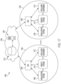
- FIG. 19 illustrates a computer-implemented interactive surgical system, according to at least one aspect of the present disclosure.
- FIG. 20 illustrates a diagram of a situationally aware surgical system, according to at least one aspect of the present disclosure.
- FIG. 21 illustrates a timeline depicting situational awareness of a hub, according to at least one aspect of the present disclosure.
- FIG. 22 is a diagram of a surgical system, in accordance with at least one aspect of the present disclosure.
- FIG. 23 is a logic flow diagram of a process for providing dynamic surgical recommendations to users, in accordance with at least one aspect of the present disclosure.
- FIG. 24 is a surgical visualization displaying a recommended surgical instrument position, in accordance with at least one aspect of the present disclosure.
- the present disclosure is directed to a surgical visualization platform that leverages “digital surgery” to obtain additional information about a patient's anatomy and/or a surgical procedure.
- the surgical visualization platform is further configured to convey data and/or information to one or more clinicians in a helpful manner.
- various aspects of the present disclosure provide improved visualization of the patient's anatomy and/or the surgical procedure.
- Digital surgery can embrace robotic systems, advanced imaging, advanced instrumentation, artificial intelligence, machine learning, data analytics for performance tracking and benchmarking, connectivity both inside and outside of the operating room (OR), and more.
- various surgical visualization platforms described herein can be used in combination with a robotic surgical system, surgical visualization platforms are not limited to use with a robotic surgical system.
- advanced surgical visualization can occur without robotics and/or with limited and/or optional robotic assistance.
- digital surgery can occur without robotics and/or with limited and/or optional robotic assistance.
- a surgical system that incorporates a surgical visualization platform may enable smart dissection in order to identify and avoid critical structures.
- Critical structures include anatomical structures such as a ureter, an artery such as a superior mesenteric artery, a vein such as a portal vein, a nerve such as a phrenic nerve, and/or a tumor, among other anatomical structures.
- a critical structure can be a foreign structure in the anatomical field, such as a surgical device, surgical fastener, clip, tack, bougie, band, and/or plate, for example.
- Critical structures can be determined on a patient-by-patient and/or a procedure-by-procedure basis. Example critical structures are further described herein. Smart dissection technology may provide improved intraoperative guidance for dissection and/or can enable smarter decisions with critical anatomy detection and avoidance technology, for example.
- a surgical system incorporating a surgical visualization platform may also enable smart anastomosis technologies that provide more consistent anastomoses at optimal location(s) with improved workflow.
- Cancer localization technologies may also be improved with the various surgical visualization platforms and procedures described herein. For example, cancer localization technologies can identify and track a cancer location, orientation, and its margins. In certain instances, the cancer localizations technologies may compensate for movement of a tool, a patient, and/or the patient's anatomy during a surgical procedure in order to provide guidance back to the point of interest for the clinician.
- tissue characterization technologies may characterize tissue type and health without the need for physical haptics, especially when dissecting and/or placing stapling devices within the tissue. Certain tissue characterization technologies described herein may be utilized without ionizing radiation and/or contrast agents.
- a surgical visualization platform may preoperatively locate, map, and ideally diagnose the lymph system and/or lymph nodes involved in cancerous diagnosis and staging, for example.
- the information available to the clinician via the “naked eye” and/or an imaging system may provide an incomplete view of the surgical site.
- certain structures such as structures embedded or buried within an organ, can be at least partially concealed or hidden from view.
- certain dimensions and/or relative distances can be difficult to ascertain with existing sensor systems and/or difficult for the “naked eye” to perceive.
- certain structures can move preoperatively (e.g. before a surgical procedure but after a preoperative scan) and/or intraoperatively. In such instances, the clinician can be unable to accurately determine the location of a critical structure intraoperatively.
- a clinician's decision-making process can be inhibited. For example, a clinician may avoid certain areas in order to avoid inadvertent dissection of a critical structure; however, the avoided area may be unnecessarily large and/or at least partially misplaced. Due to uncertainty and/or overly/excessive exercises in caution, the clinician may not access certain desired regions. For example, excess caution may cause a clinician to leave a portion of a tumor and/or other undesirable tissue in an effort to avoid a critical structure even if the critical structure is not in the particular area and/or would not be negatively impacted by the clinician working in that particular area. In certain instances, surgical results can be improved with increased knowledge and/or certainty, which can allow a surgeon to be more accurate and, in certain instances, less conservative/more aggressive with respect to particular anatomical areas.
- the present disclosure provides a surgical visualization system for intraoperative identification and avoidance of critical structures.
- the present disclosure provides a surgical visualization system that enables enhanced intraoperative decision making and improved surgical outcomes.
- the disclosed surgical visualization system provides advanced visualization capabilities beyond what a clinician sees with the “naked eye” and/or beyond what an imaging system can recognize and/or convey to the clinician.
- the various surgical visualization systems can augment and enhance what a clinician is able to know prior to tissue treatment (e.g. dissection) and, thus, may improve outcomes in various instances.
- a visualization system can include a first light emitter configured to emit a plurality of spectral waves, a second light emitter configured to emit a light pattern, and one or more receivers, or sensors, configured to detect visible light, molecular responses to the spectral waves (spectral imaging), and/or the light pattern.
- any reference to “light,” unless specifically in reference to visible light can include electromagnetic radiation (EMR) or photons in the visible and/or non-visible portions of the EMR wavelength spectrum.
- EMR electromagnetic radiation
- the surgical visualization system can also include an imaging system and a control circuit in signal communication with the receiver(s) and the imaging system. Based on output from the receiver(s), the control circuit can determine a geometric surface map, i.e.
- the control circuit can determine one more distances to an at least partially concealed structure.
- the imaging system can convey the geometric surface map and the one or more distances to a clinician.
- an augmented view of the surgical site provided to the clinician can provide a representation of the concealed structure within the relevant context of the surgical site.
- the imaging system can virtually augment the concealed structure on the geometric surface map of the concealing and/or obstructing tissue similar to a line drawn on the ground to indicate a utility line below the surface.
- the imaging system can convey the proximity of one or more surgical tools to the visible and obstructing tissue and/or to the at least partially concealed structure and/or the depth of the concealed structure below the visible surface of the obstructing tissue.
- the visualization system can determine a distance with respect to the augmented line on the surface of the visible tissue and convey the distance to the imaging system.
- a surgical visualization system for intraoperative identification and avoidance of critical structures.
- a surgical visualization system can provide valuable information to a clinician during a surgical procedure.
- the clinician can confidently maintain momentum throughout the surgical procedure knowing that the surgical visualization system is tracking a critical structure such as a ureter, specific nerves, and/or critical blood vessels, for example, which may be approached during dissection, for example.
- the surgical visualization system can provide an indication to the clinician in sufficient time for the clinician to pause and/or slow down the surgical procedure and evaluate the proximity to the critical structure to prevent inadvertent damage thereto.
- the surgical visualization system can provide an ideal, optimized, and/or customizable amount of information to the clinician to allow the clinician to move confidently and/or quickly through tissue while avoiding inadvertent damage to healthy tissue and/or critical structure(s) and, thus, to minimize the risk of harm resulting from the surgical procedure.
- FIG. 1 is a schematic of a surgical visualization system 100 according to at least one aspect of the present disclosure.
- the surgical visualization system 100 can create a visual representation of a critical structure 101 within an anatomical field.
- the surgical visualization system 100 can be used for clinical analysis and/or medical intervention, for example.
- the surgical visualization system 100 can be used intraoperatively to provide real-time, or near real-time, information to the clinician regarding proximity data, dimensions, and/or distances during a surgical procedure.
- the surgical visualization system 100 is configured for intraoperative identification of critical structure(s) and/or to facilitate the avoidance of the critical structure(s) 101 by a surgical device.
- a clinician can avoid maneuvering a surgical device around the critical structure 101 and/or a region in a predefined proximity of the critical structure 101 during a surgical procedure.
- the clinician can avoid dissection of and/or near a vein, artery, nerve, and/or vessel, for example, identified as the critical structure 101 , for example.
- the critical structure 101 can be determined on a patient-by-patient and/or a procedure-by-procedure basis.
- the surgical visualization system 100 incorporates tissue identification and geometric surface mapping in combination with a distance sensor system 104 . In combination, these features of the surgical visualization system 100 can determine a position of a critical structure 101 within the anatomical field and/or the proximity of a surgical device 102 to the surface 105 of the visible tissue and/or to the critical structure 101 .
- the surgical visualization system 100 includes an imaging system that includes an imaging device 120 , such as a camera, for example, configured to provide real-time views of the surgical site.
- the imaging device 120 is a spectral camera (e.g.
- the surgical visualization system 100 includes a plurality of subsystems—an imaging subsystem, a surface mapping subsystem, a tissue identification subsystem, and/or a distance determining subsystem. These subsystems can cooperate to intra-operatively provide advanced data synthesis and integrated information to the clinician(s).
- the imaging device can include a camera or imaging sensor that is configured to detect visible light, spectral light waves (visible or invisible), and a structured light pattern (visible or invisible), for example.
- the imaging system can include an imaging device such as an endoscope, for example. Additionally or alternatively, the imaging system can include an imaging device such as an arthroscope, angioscope, bronchoscope, choledochoscope, colonoscope, cytoscope, duodenoscope, enteroscope, esophagogastro-duodenoscope (gastroscope), laryngoscope, nasopharyngo-neproscope, sigmoidoscope, thoracoscope, ureteroscope, or exoscope, for example. In other instances, such as in open surgery applications, the imaging system may not include a scope.
- the tissue identification subsystem can be achieved with a spectral imaging system.
- the spectral imaging system can rely on hyperspectral imaging, multispectral imaging, or selective spectral imaging, for example.
- Hyperspectral imaging of tissue is further described in U.S. Pat. No. 9,274,047, titled SYSTEM AND METHOD FOR GROSS ANATOMIC PATHOLOGY USING HYPERSPECTRAL IMAGING, issued Mar. 1, 2016, which is incorporated by reference herein in its entirety.
- the surface mapping subsystem can be achieved with a light pattern system, as further described herein.
- a light pattern or structured light
- Known surface mapping techniques can be utilized in the surgical visualization systems described herein.
- Structured light is the process of projecting a known pattern (often a grid or horizontal bars) on to a surface.
- U.S. Patent Application Publication No. 2017/0055819, titled SET COMPRISING A SURGICAL INSTRUMENT, published Mar. 2, 2017, and U.S. Patent Application Publication No. 2017/0251900, titled DEPICTION SYSTEM, published Sep. 7, 2017, disclose a surgical system comprising a light source and a projector for projecting a light pattern.
- U.S. Patent Application Publication No. 2017/0055819, titled SET COMPRISING A SURGICAL INSTRUMENT, published Mar. 2, 2017, and U.S. Patent Application Publication No. 2017/0251900, titled DEPICTION SYSTEM, published Sep. 7, 2017, are incorporated by reference herein in their respective entireties.
- the distance determining system can be incorporated into the surface mapping system.
- structured light can be utilized to generate a three-dimensional virtual model of the visible surface and determine various distances with respect to the visible surface.
- the distance determining system can rely on time-of-flight measurements to determine one or more distances to the identified tissue (or other structures) at the surgical site.
- FIG. 2 is a schematic diagram of a control system 133 , which can be utilized with the surgical visualization system 100 .
- the control system 133 includes a control circuit 132 in signal communication with a memory 134 .
- the memory 134 stores instructions executable by the control circuit 132 to determine and/or recognize critical structures (e.g. the critical structure 101 in FIG. 1 ), determine and/or compute one or more distances and/or three-dimensional digital representations, and to communicate certain information to one or more clinicians.
- the memory 134 stores surface mapping logic 136 , imaging logic 138 , tissue identification logic 140 , or distance determining logic 141 or any combinations of the logic 136 , 138 , 140 , and 141 .
- the control system 133 also includes an imaging system 142 having one or more cameras 144 (like the imaging device 120 in FIG. 1 ), one or more displays 146 , or one or more controls 148 or any combinations of these elements.
- the camera 144 can include one or more image sensors 135 to receive signals from various light sources emitting light at various visible and invisible spectra (e.g. visible light, spectral imagers, three-dimensional lens, among others).
- the display 146 can include one or more screens or monitors for depicting real, virtual, and/or virtually-augmented images and/or information to one or more clinicians.
- the heart of the camera 144 is the image sensor 135 .
- image sensors 135 are solid-state electronic devices containing up to millions of discrete photodetector sites called pixels.
- the image sensor 135 technology falls into one of two categories: Charge-Coupled Device (CCD) and Complementary Metal Oxide Semiconductor (CMOS) imagers and more recently, short-wave infrared (SWIR) is an emerging technology in imaging.
- CCD Charge-Coupled Device
- CMOS Complementary Metal Oxide Semiconductor
- SWIR short-wave infrared
- Another type of image sensor 135 employs a hybrid CCD/CMOS architecture (sold under the name “sCMOS”) and consists of CMOS readout integrated circuits (ROICs) that are bump bonded to a CCD imaging substrate.
- sCMOS hybrid CCD/CMOS architecture
- ROICs CMOS readout integrated circuits
- CCD and CMOS image sensors 135 are sensitive to wavelengths from approximately 350-1050 nm, although the range is usually given from 400-1000 nm.
- CMOS sensors are, in general, more sensitive to IR wavelengths than CCD sensors.
- Solid state image sensors 135 are based on the photoelectric effect and, as a result, cannot distinguish between colors. Accordingly, there are two types of color CCD cameras: single chip and three-chip.
- Single chip color CCD cameras offer a common, low-cost imaging solution and use a mosaic (e.g. Bayer) optical filter to separate incoming light into a series of colors and employ an interpolation algorithm to resolve full color images. Each color is, then, directed to a different set of pixels.
- a mosaic e.g. Bayer
- Three-chip color CCD cameras provide higher resolution by employing a prism to direct each section of the incident spectrum to a different chip. More accurate color reproduction is possible, as each point in space of the object has separate RGB intensity values, rather than using an algorithm to determine the color. Three-chip cameras offer extremely high resolutions.
- the control system 133 also includes a spectral light source 150 and a structured light source 152 .
- a single source can be pulsed to emit wavelengths of light in the spectral light source 150 range and wavelengths of light in the structured light source 152 range.
- a single light source can be pulsed to provide light in the invisible spectrum (e.g. infrared spectral light) and wavelengths of light on the visible spectrum.
- the spectral light source 150 can be a hyperspectral light source, a multispectral light source, and/or a selective spectral light source, for example.
- the tissue identification logic 140 can identify critical structure(s) via data from the spectral light source 150 received by the image sensor 135 portion of the camera 144 .
- the surface mapping logic 136 can determine the surface contours of the visible tissue based on reflected structured light. With time-of-flight measurements, the distance determining logic 141 can determine one or more distance(s) to the visible tissue and/or the critical structure 101 . One or more outputs from the surface mapping logic 136 , the tissue identification logic 140 , and the distance determining logic 141 , can be provided to the imaging logic 138 , and combined, blended, and/or overlaid to be conveyed to a clinician via the display 146 of the imaging system 142 .
- FIGS. 2 A- 2 C describe various aspects of the control circuit 132 for controlling various aspects of the surgical visualization system 100 .
- the control circuit 400 can be configured to implement various processes described herein.
- the control circuit 400 may comprise a microcontroller comprising one or more processors 402 (e.g., microprocessor, microcontroller) coupled to at least one memory circuit 404 .
- the memory circuit 404 stores machine-executable instructions that, when executed by the processor 402 , cause the processor 402 to execute machine instructions to implement various processes described herein.
- the processor 402 may be any one of a number of single-core or multicore processors known in the art.
- the memory circuit 404 may comprise volatile and non-volatile storage media.
- the processor 402 may include an instruction processing unit 406 and an arithmetic unit 408 .
- the instruction processing unit may be configured to receive instructions from the memory circuit 404 of this disclosure.
- FIG. 2 B illustrates a combinational logic circuit 410 configured to control aspects of the surgical visualization system 100 , according to at least one aspect of this disclosure.
- the combinational logic circuit 410 can be configured to implement various processes described herein.
- the combinational logic circuit 410 may comprise a finite state machine comprising a combinational logic 412 configured to receive data associated with the surgical instrument or tool at an input 414 , process the data by the combinational logic 412 , and provide an output 416 .
- FIG. 2 C illustrates a sequential logic circuit 420 configured to control aspects of the surgical visualization system 100 , according to at least one aspect of this disclosure.
- the sequential logic circuit 420 or the combinational logic 422 can be configured to implement various processes described herein.
- the sequential logic circuit 420 may comprise a finite state machine.
- the sequential logic circuit 420 may comprise a combinational logic 422 , at least one memory circuit 424 , and a clock 429 , for example.
- the at least one memory circuit 424 can store a current state of the finite state machine.
- the sequential logic circuit 420 may be synchronous or asynchronous.
- the combinational logic 422 is configured to receive data associated with a surgical device or system from an input 426 , process the data by the combinational logic 422 , and provide an output 428 .
- the circuit may comprise a combination of a processor (e.g., processor 402 in FIG. 2 A ) and a finite state machine to implement various processes herein.
- the finite state machine may comprise a combination of a combinational logic circuit (e.g., combinational logic circuit 410 , FIG. 2 B ) and the sequential logic circuit 420 .
- the critical structure 101 can be an anatomical structure of interest.
- the critical structure 101 can be a ureter, an artery such as a superior mesenteric artery, a vein such as a portal vein, a nerve such as a phrenic nerve, and/or a tumor, among other anatomical structures.
- the critical structure 101 can be a foreign structure in the anatomical field, such as a surgical device, surgical fastener, clip, tack, bougie, band, and/or plate, for example.
- Example critical structures are further described herein and in the aforementioned U.S. patent applications, including U.S. patent application Ser. No. 16/128,192, titled VISUALIZATION OF SURGICAL DEVICES, filed Sep. 11, 2018, for example, which are incorporated by reference herein in their respective entireties.
- the critical structure 101 may be embedded in tissue 103 . Stated differently, the critical structure 101 may be positioned below the surface 105 of the tissue 103 . In such instances, the tissue 103 conceals the critical structure 101 from the clinician's view. The critical structure 101 is also obscured from the view of the imaging device 120 by the tissue 103 .
- the tissue 103 can be fat, connective tissue, adhesions, and/or organs, for example. In other instances, the critical structure 101 can be partially obscured from view.
- FIG. 1 also depicts the surgical device 102 .
- the surgical device 102 includes an end effector having opposing jaws extending from the distal end of the shaft of the surgical device 102 .
- the surgical device 102 can be any suitable surgical device such as, for example, a dissector, a stapler, a grasper, a clip applier, and/or an energy device including mono-polar probes, bi-polar probes, ablation probes, and/or an ultrasonic end effector.
- the surgical device 102 can include another imaging or diagnostic modality, such as an ultrasound device, for example.
- the surgical visualization system 100 can be configured to achieve identification of one or more critical structures 101 and the proximity of the surgical device 102 to the critical structure(s) 101 .
- the imaging device 120 of the surgical visualization system 100 is configured to detect light at various wavelengths, such as, for example, visible light, spectral light waves (visible or invisible), and a structured light pattern (visible or invisible).
- the imaging device 120 may include a plurality of lenses, sensors, and/or receivers for detecting the different signals.
- the imaging device 120 can be a hyperspectral, multispectral, or selective spectral camera, as further described herein.
- the imaging device 120 can also include a waveform sensor 122 (such as a spectral image sensor, detector, and/or three-dimensional camera lens).
- the imaging device 120 can include a right-side lens and a left-side lens used together to record two two-dimensional images at the same time and, thus, generate a three-dimensional image of the surgical site, render a three-dimensional image of the surgical site, and/or determine one or more distances at the surgical site.
- the imaging device 120 can be configured to receive images indicative of the topography of the visible tissue and the identification and position of hidden critical structures, as further described herein.
- the field of view of the imaging device 120 can overlap with a pattern of light (structured light) on the surface 105 of the tissue, as shown in FIG. 1 .
- the surgical visualization system 100 may be incorporated into a robotic system 110 .
- the robotic system 110 may include a first robotic arm 112 and a second robotic arm 114 .
- the robotic arms 112 , 114 include rigid structural members 116 and joints 118 , which can include servomotor controls.
- the first robotic arm 112 is configured to maneuver the surgical device 102
- the second robotic arm 114 is configured to maneuver the imaging device 120 .
- a robotic control unit can be configured to issue control motions to the robotic arms 112 , 114 , which can affect the surgical device 102 and the imaging device 120 , for example.
- the surgical visualization system 100 also includes an emitter 106 , which is configured to emit a pattern of light, such as stripes, grid lines, and/or dots, to enable the determination of the topography or landscape of the surface 105 .
- projected light arrays 130 can be used for three-dimensional scanning and registration on the surface 105 .
- the projected light arrays 130 can be emitted from the emitter 106 located on the surgical device 102 and/or one of the robotic arms 112 , 114 and/or the imaging device 120 , for example.
- the projected light array 130 is employed to determine the shape defined by the surface 105 of the tissue 103 and/or the motion of the surface 105 intraoperatively.
- the imaging device 120 is configured to detect the projected light arrays 130 reflected from the surface 105 to determine the topography of the surface 105 and various distances with respect to the surface 105 .
- the imaging device 120 also may include an optical waveform emitter 123 that is configured to emit electromagnetic radiation 124 (NIR photons) that can penetrate the surface 105 of the tissue 103 and reach the critical structure 101 .
- the imaging device 120 and the optical waveform emitter 123 thereon can be positionable by the robotic arm 114 .
- a corresponding waveform sensor 122 (an image sensor, spectrometer, or vibrational sensor, for example) on the imaging device 120 is configured to detect the effect of the electromagnetic radiation received by the waveform sensor 122 .
- the wavelengths of the electromagnetic radiation 124 emitted by the optical waveform emitter 123 can be configured to enable the identification of the type of anatomical and/or physical structure, such as the critical structure 101 .
- the identification of the critical structure 101 can be accomplished through spectral analysis, photo-acoustics, and/or ultrasound, for example.
- the wavelengths of the electromagnetic radiation 124 may be variable.
- the waveform sensor 122 and optical waveform emitter 123 may be inclusive of a multispectral imaging system and/or a selective spectral imaging system, for example. In other instances, the waveform sensor 122 and optical waveform emitter 123 may be inclusive of a photoacoustic imaging system, for example. In other instances, the optical waveform emitter 123 can be positioned on a separate surgical device from the imaging device 120 .
- the surgical visualization system 100 also may include the distance sensor system 104 configured to determine one or more distances at the surgical site.
- the time-of-flight distance sensor system 104 may be a time-of-flight distance sensor system that includes an emitter, such as the emitter 106 , and a receiver 108 , which can be positioned on the surgical device 102 .
- the time-of-flight emitter can be separate from the structured light emitter.
- the emitter 106 portion of the time-of-flight distance sensor system 104 may include a very tiny laser source and the receiver 108 portion of the time-of-flight distance sensor system 104 may include a matching sensor.
- the time-of-flight distance sensor system 104 can detect the “time of flight,” or how long the laser light emitted by the emitter 106 has taken to bounce back to the sensor portion of the receiver 108 .
- Use of a very narrow light source in the emitter 106 enables the distance sensor system 104 to determining the distance to the surface 105 of the tissue 103 directly in front of the distance sensor system 104 .
- d e is the emitter-to-tissue distance from the emitter 106 to the surface 105 of the tissue 103
- d t is the device-to-tissue distance from the distal end of the surgical device 102 to the surface 105 of the tissue.
- the distance sensor system 104 can be employed to determine the emitter-to-tissue distance d e .
- the device-to-tissue distance d t is obtainable from the known position of the emitter 106 on the shaft of the surgical device 102 relative to the distal end of the surgical device 102 . In other words, when the distance between the emitter 106 and the distal end of the surgical device 102 is known, the device-to-tissue distance d t can be determined from the emitter-to-tissue distance d e .
- the shaft of the surgical device 102 can include one or more articulation joints, and can be articulatable with respect to the emitter 106 and the jaws.
- the articulation configuration can include a multi-joint vertebrae-like structure, for example.
- a three-dimensional camera can be utilized to triangulate one or more distances to the surface 105 .
- the receiver 108 for the time-of-flight distance sensor system 104 can be mounted on a separate surgical device instead of the surgical device 102 .
- the receiver 108 can be mounted on a cannula or trocar through which the surgical device 102 extends to reach the surgical site.
- the receiver 108 for the time-of-flight distance sensor system 104 can be mounted on a separate robotically-controlled arm (e.g. the robotic arm 114 ), on a movable arm that is operated by another robot, and/or to an operating room (OR) table or fixture.
- the imaging device 120 includes the time-of-flight receiver 108 to determine the distance from the emitter 106 to the surface 105 of the tissue 103 using a line between the emitter 106 on the surgical device 102 and the imaging device 120 .
- the distance d e can be triangulated based on known positions of the emitter 106 (on the surgical device 102 ) and the receiver 108 (on the imaging device 120 ) of the time-of-flight distance sensor system 104 .
- the three-dimensional position of the receiver 108 can be known and/or registered to the robot coordinate plane intraoperatively.
- the position of the emitter 106 of the time-of-flight distance sensor system 104 can be controlled by the first robotic arm 112 and the position of the receiver 108 of the time-of-flight distance sensor system 104 can be controlled by the second robotic arm 114 .
- the surgical visualization system 100 can be utilized apart from a robotic system. In such instances, the distance sensor system 104 can be independent of the robotic system.
- one or more of the robotic arms 112 , 114 may be separate from a main robotic system used in the surgical procedure. At least one of the robotic arms 112 , 114 can be positioned and registered to a particular coordinate system without a servomotor control. For example, a closed-loop control system and/or a plurality of sensors for the robotic arms 110 can control and/or register the position of the robotic arm(s) 112 , 114 relative to the particular coordinate system. Similarly, the position of the surgical device 102 and the imaging device 120 can be registered relative to a particular coordinate system.
- d w is the camera-to-critical structure distance from the optical waveform emitter 123 located on the imaging device 120 to the surface of the critical structure 101
- d A is the depth of the critical structure 101 below the surface 105 of the tissue 103 (i.e., the distance between the portion of the surface 105 closest to the surgical device 102 and the critical structure 101 ).
- the time-of-flight of the optical waveforms emitted from the optical waveform emitter 123 located on the imaging device 120 can be configured to determine the camera-to-critical structure distance d w .
- the use of spectral imaging in combination with time-of-flight sensors is further described herein.
- FIG. 1 is the camera-to-critical structure distance from the optical waveform emitter 123 located on the imaging device 120 to the surface of the critical structure 101
- d A is the depth of the critical structure 101 below the surface 105 of the tissue 103 (i.e., the distance between the portion of the surface 105 closest to the surgical device 102 and the critical structure 101
- the depth d A of the critical structure 101 relative to the surface 105 of the tissue 103 can be determined by triangulating from the distance d w and known positions of the emitter 106 on the surgical device 102 and the optical waveform emitter 123 on the imaging device 120 (and, thus, the known distance d x therebetween) to determine the distance d y , which is the sum of the distances d e and d A .
- time-of-flight from the optical waveform emitter 123 can be configured to determine the distance from the optical waveform emitter 123 to the surface 105 of the tissue 103 .
- a first waveform (or range of waveforms) can be utilized to determine the camera-to-critical structure distance d w and a second waveform (or range of waveforms) can be utilized to determine the distance to the surface 105 of the tissue 103 .
- the different waveforms can be utilized to determine the depth of the critical structure 101 below the surface 105 of the tissue 103 .
- the distance d A can be determined from an ultrasound, a registered magnetic resonance imaging (MRI) or computerized tomography (CT) scan.
- the distance d A can be determined with spectral imaging because the detection signal received by the imaging device can vary based on the type of material. For example, fat can decrease the detection signal in a first way, or a first amount, and collagen can decrease the detection signal in a different, second way, or a second amount.
- a surgical device 162 includes the optical waveform emitter 123 and the waveform sensor 122 that is configured to detect the reflected waveforms.
- the optical waveform emitter 123 can be configured to emit waveforms for determining the distances d t and d w from a common device, such as the surgical device 162 , as further described herein.
- various information regarding visible tissue, embedded critical structures, and surgical devices can be determined by utilizing a combination approach that incorporates one or more time-of-flight distance sensors, spectral imaging, and/or structured light arrays in combination with an image sensor configured to detect the spectral wavelengths and the structured light arrays.
- the image sensor can be configured to receive visible light and, thus, provide images of the surgical site to an imaging system.
- Logic or algorithms are employed to discern the information received from the time-of-flight sensors, spectral wavelengths, structured light, and visible light and render three-dimensional images of the surface tissue and underlying anatomical structures.
- the imaging device 120 can include multiple image sensors.
- the camera-to-critical structure distance d w can also be detected in one or more alternative ways.
- a fluoroscopy visualization technology such as fluorescent indosciedine green (ICG), for example, can be utilized to illuminate a critical structure 201 , as shown in FIGS. 6 - 8 .
- a camera 220 can include two optical waveforms sensors 222 , 224 , which take simultaneous left-side and right-side images of the critical structure 201 ( FIGS. 7 A and 7 B ). In such instances, the camera 220 can depict a glow of the critical structure 201 below the surface 205 of the tissue 203 , and the distance d w can be determined by the known distance between the sensors 222 and 224 .
- distances can be determined more accurately by utilizing more than one camera or by moving a camera between multiple locations.
- one camera can be controlled by a first robotic arm and a second camera by another robotic arm.
- one camera can be a follower camera on a follower arm, for example.
- the follower arm, and camera thereon, can be programmed to track the other camera and to maintain a particular distance and/or lens angle, for example.
- the surgical visualization system 100 may employ two separate waveform receivers (i.e. cameras/image sensors) to determine d w .
- two separate waveform receivers i.e. cameras/image sensors
- the actual location can be triangulated from two separate cameras 320 a , 320 b at known locations.
- a surgical visualization system may employ a dithering or moving camera 440 to determine the distance d w .
- the camera 440 is robotically-controlled such that the three-dimensional coordinates of the camera 440 at the different positions are known.
- the camera 440 can pivot at a cannula or patient interface.
- a critical structure 401 or the contents thereof e.g. a vessel or the contents of the vessel
- the actual location can be triangulated from the camera 440 moved rapidly between two or more known locations.
- the camera 440 is moved axially along an axis A.
- the camera 440 translates a distance d 1 closer to the critical structure 401 along the axis A to the location indicated as a location 440 ′, such as by moving in and out on a robotic arm.
- the distance to the critical structure 401 can be calculated.
- a 4.28 mm axial translation (the distance d 1 ) can correspond to an angle ⁇ 1 of 6.28 degrees and an angle ⁇ 2 of 8.19 degrees.
- the camera 440 can rotate or sweep along an arc between different positions. Referring now to FIG.
- the camera 440 is moved axially along the axis A and is rotated an angle ⁇ 3 about the axis A.
- a pivot point 442 for rotation of the camera 440 is positioned at the cannula/patient interface.
- the camera 440 is translated and rotated to a location 440 ′′.
- the distance to the critical structure 401 can be calculated.
- a distance d 2 can be 9.01 mm, for example, and the angle ⁇ 3 can be 0.9 degrees, for example.
- FIG. 5 depicts a surgical visualization system 500 , which is similar to the surgical visualization system 100 in many respects.
- the surgical visualization system 500 can be a further exemplification of the surgical visualization system 100 .
- the surgical visualization system 500 includes a surgical device 502 and an imaging device 520 .
- the imaging device 520 includes a spectral light emitter 523 , which is configured to emit spectral light in a plurality of wavelengths to obtain a spectral image of hidden structures, for example.
- the imaging device 520 can also include a three-dimensional camera and associated electronic processing circuits in various instances.
- the surgical visualization system 500 is shown being utilized intraoperatively to identify and facilitate avoidance of certain critical structures, such as a ureter 501 a and vessels 501 b in an organ 503 (the uterus in this example), that are not visible on the surface.
- the surgical visualization system 500 is configured to determine an emitter-to-tissue distance d e from an emitter 506 on the surgical device 502 to a surface 505 of the uterus 503 via structured light.
- the surgical visualization system 500 is configured to extrapolate a device-to-tissue distance d t from the surgical device 502 to the surface 505 of the uterus 503 based on the emitter-to-tissue distance d e .
- the surgical visualization system 500 is also configured to determine a tissue-to-ureter distance d A from the ureter 501 a to the surface 505 and a camera-to ureter distance d w from the imaging device 520 to the ureter 501 a . As described herein with respect to FIG.
- the surgical visualization system 500 can determine the distance d w with spectral imaging and time-of-flight sensors, for example. In various instances, the surgical visualization system 500 can determine (e.g. triangulate) the tissue-to-ureter distance d A (or depth) based on other distances and/or the surface mapping logic described herein.
- the control system 600 is a conversion system that integrates spectral signature tissue identification and structured light tissue positioning to identify critical structures, especially when those structures are obscured by other tissue, such as fat, connective tissue, blood, and/or other organs, for example. Such technology could also be useful for detecting tissue variability, such as differentiating tumors and/or non-healthy tissue from healthy tissue within an organ.
- the control system 600 is configured for implementing a hyperspectral imaging and visualization system in which a molecular response is utilized to detect and identify anatomy in a surgical field of view.
- the control system 600 includes a conversion logic circuit 648 to convert tissue data to surgeon usable information.
- the variable reflectance based on wavelengths with respect to obscuring material can be utilized to identify the critical structure in the anatomy.
- the control system 600 combines the identified spectral signature and the structural light data in an image.
- the control system 600 can be employed to create of three-dimensional data set for surgical use in a system with augmentation image overlays. Techniques can be employed both intraoperatively and preoperatively using additional visual information.
- the control system 600 is configured to provide warnings to a clinician when in the proximity of one or more critical structures.
- Various algorithms can be employed to guide robotic automation and semi-automated approaches based on the surgical procedure and proximity to the critical structure(s).
- a projected array of lights is employed to determine tissue shape and motion intraoperatively.
- flash Lidar may be utilized for surface mapping of the tissue.
- the control system 600 is configured to detect the critical structure(s) and provide an image overlay of the critical structure and measure the distance to the surface of the visible tissue and the distance to the embedded/buried critical structure(s). In other instances, the control system 600 can measure the distance to the surface of the visible tissue or detect the critical structure(s) and provide an image overlay of the critical structure.
- the control system 600 includes a spectral control circuit 602 .
- the spectral control circuit 602 can be a field programmable gate array (FPGA) or another suitable circuit configuration as described herein in connection with FIGS. 2 A- 2 C , for example.
- the spectral control circuit 602 includes a processor 604 to receive video input signals from a video input processor 606 .
- the processor 604 can be configured for hyperspectral processing and can utilize C/C++ code, for example.
- the video input processor 606 receives video-in of control (metadata) data such as shutter time, wave length, and sensor analytics, for example.
- metadata video-in of control
- the processor 604 is configured to process the video input signal from the video input processor 606 and provide a video output signal to a video output processor 608 , which includes a hyperspectral video-out of interface control (metadata) data, for example.
- the video output processor 608 provides the video output signal to an image overlay controller 610 .
- the video input processor 606 is coupled to a camera 612 at the patient side via a patient isolation circuit 614 .
- the camera 612 includes a solid state image sensor 634 .
- the patient isolation circuit can include a plurality of transformers so that the patient is isolated from other circuits in the system.
- the camera 612 receives intraoperative images through optics 632 and the image sensor 634 .
- the image sensor 634 can include a CMOS image sensor, for example, or may include any of the image sensor technologies discussed herein in connection with FIG. 2 , for example.
- the camera 612 outputs images in 14 bit/pixel signals. It will be appreciated that higher or lower pixel resolutions may be employed without departing from the scope of the present disclosure.
- the isolated camera output signal 613 is provided to a color RGB fusion circuit 616 , which employs a hardware register 618 and a Nios2 co-processor 620 to process the camera output signal 613 .
- a color RGB fusion output signal is provided to the video input processor 606 and a laser pulsing control circuit 622 .
- the laser pulsing control circuit 622 controls a laser light engine 624 .
- the laser light engine 624 outputs light in a plurality of wavelengths ( ⁇ 1 , ⁇ 2 , ⁇ 3 . . . ⁇ n ) including near infrared (NIR).
- the laser light engine 624 can operate in a plurality of modes. In one aspect, the laser light engine 624 can operate in two modes, for example. In a first mode, e.g. a normal operating mode, the laser light engine 624 outputs an illuminating signal. In a second mode, e.g. an identification mode, the laser light engine 624 outputs RGBG and NIR light. In various instances, the laser light engine 624 can operate in a polarizing mode.
- Light output 626 from the laser light engine 624 illuminates targeted anatomy in an intraoperative surgical site 627 .
- the laser pulsing control circuit 622 also controls a laser pulse controller 628 for a laser pattern projector 630 that projects a laser light pattern 631 , such as a grid or pattern of lines and/or dots, at a predetermined wavelength ( ⁇ 2 ) on the operative tissue or organ at the surgical site 627 .
- the camera 612 receives the patterned light as well as the reflected light output through the camera optics 632 .
- the image sensor 634 converts the received light into a digital signal.
- the color RGB fusion circuit 616 also outputs signals to the image overlay controller 610 and a video input module 636 for reading the laser light pattern 631 projected onto the targeted anatomy at the surgical site 627 by the laser pattern projector 630 .
- a processing module 638 processes the laser light pattern 631 and outputs a first video output signal 640 representative of the distance to the visible tissue at the surgical site 627 .
- the data is provided to the image overlay controller 610 .
- the processing module 638 also outputs a second video signal 642 representative of a three-dimensional rendered shape of the tissue or organ of the targeted anatomy at the surgical site.
- the first and second video output signals 640 , 642 include data representative of the position of the critical structure on a three-dimensional surface model, which is provided to an integration module 643 .
- the integration module 643 can determine the distance d A ( FIG. 1 ) to a buried critical structure (e.g. via triangularization algorithms 644 ), and the distance d A can be provided to the image overlay controller 610 via a video out processor 646 .
- the foregoing conversion logic can encompass the conversion logic circuit 648 intermediate video monitors 652 and the camera 624 /laser pattern projector 630 positioned at the surgical site 627 .
- Preoperative data 650 from a CT or MRI scan can be employed to register or align certain three-dimensional deformable tissue in various instances.
- Such preoperative data 650 can be provided to the integration module 643 and ultimately to the image overlay controller 610 so that such information can be overlaid with the views from the camera 612 and provided to the video monitors 652 .
- Registration of preoperative data is further described herein and in the aforementioned U.S. patent applications, including U.S. patent application Ser. No. 16/128,195, titled INTEGRATION OF IMAGING DATA, filed Sep. 11, 2018, for example, which are incorporated by reference herein in their respective entireties.
- the video monitors 652 can output the integrated/augmented views from the image overlay controller 610 .
- a clinician can select and/or toggle between different views on one or more monitors.
- the clinician can toggle between (A) a view in which a three-dimensional rendering of the visible tissue is depicted and (B) an augmented view in which one or more hidden critical structures are depicted over the three-dimensional rendering of the visible tissue.
- the clinician can toggle on distance measurements to one or more hidden critical structures and/or the surface of visible tissue, for example.
- control system 600 and/or various control circuits thereof can be incorporated into various surgical visualization systems disclosed herein.
- FIG. 12 illustrates a structured (or patterned) light system 700 , according to at least one aspect of the present disclosure.
- structured light in the form of stripes or lines can be projected from a light source and/or projector 706 onto the surface 705 of targeted anatomy to identify the shape and contours of the surface 705 .
- a camera 720 which can be similar in various respects to the imaging device 120 ( FIG. 1 ), for example, can be configured to detect the projected pattern of light on the surface 705 . The way that the projected pattern deforms upon striking the surface 705 allows vision systems to calculate the depth and surface information of the targeted anatomy.
- invisible (or imperceptible) structured light can be utilized, in which the structured light is used without interfering with other computer vision tasks for which the projected pattern may be confusing.
- infrared light or extremely fast frame rates of visible light that alternate between two exact opposite patterns can be utilized to prevent interference.
- Structured light is further described at en.wikipedia.org/wiki/Structured_light.
- the various surgical visualization systems described herein can be utilized to visualize various different types of tissues and/or anatomical structures, including tissues and/or anatomical structures that may be obscured from being visualized by EMR in the visible portion of the spectrum.
- the surgical visualization systems can utilize a spectral imaging system to visualize different types of tissues based upon their varying combinations of constituent materials.
- a spectral imaging system can be configured to detect the presence of various constituent materials within a tissue being visualized based on the absorption coefficient of the tissue across various EMR wavelengths.
- the spectral imaging system can be further configured to characterize the tissue type of the tissue being visualized based upon the particular combination of constituent materials. To illustrate, FIG.
- 13 A is a graph 2300 depicting how the absorption coefficient of various biological materials varies across the EMR wavelength spectrum.
- the vertical axis 2303 represents absorption coefficient of the biological material (e.g., in cm ⁇ 1 ) and the horizontal axis 2304 represents EMR wavelength (e.g., in ⁇ m).
- the graph 2300 further illustrates a first line 2310 representing the absorption coefficient of water at various EMR wavelengths, a second line 2312 representing the absorption coefficient of protein at various EMR wavelengths, a third line 2314 representing the absorption coefficient of melanin at various EMR wavelengths, a fourth line 2316 representing the absorption coefficient of deoxygenated hemoglobin at various EMR wavelengths, a fifth line 2318 representing the absorption coefficient of oxygenated hemoglobin at various EMR wavelengths, and a sixth line 2319 representing the absorption coefficient of collagen at various EMR wavelengths.
- Different tissue types have different combinations of constituent materials and, therefore, the tissue type(s) being visualized by a surgical visualization system can be identified and differentiated between according to the particular combination of detected constituent materials.
- a spectral imaging system can be configured to emit EMR at a number of different wavelengths, determine the constituent materials of the tissue based on the detected absorption EMR absorption response at the different wavelengths, and then characterize the tissue type based on the particular detected combination of constituent materials.
- FIG. 13 B An illustration of the utilization of spectral imaging techniques to visualize different tissue types and/or anatomical structures is shown in FIG. 13 B .
- a spectral emitter 2320 e.g., spectral light source 150
- the EMR emitted by the spectral emitter 2320 and reflected from the tissues and/or structures at the surgical site 2325 can be received by an image sensor 135 ( FIG. 2 ) to visualize the tissues and/or structures, which can be either visible (e.g., be located at the surface of the surgical site 2325 ) or obscured (e.g., underlay other tissue and/or structures at the surgical site 2325 ).
- an imaging system 142 can visualize a tumor 2332 , an artery 2334 , and various abnormalities 2338 (i.e., tissues not confirming to known or expected spectral signatures) based upon the spectral signatures characterized by the differing absorptive characteristics (e.g., absorption coefficient) of the constituent materials for each of the different tissue/structure types.
- the visualized tissues and structures can be displayed on a display screen associated with or coupled to the imaging system 142 , such as an imaging system display 146 ( FIG. 2 ), a primary display 2119 ( FIG. 18 ), a non-sterile display 2109 ( FIG. 18 ), a hub display 2215 ( FIG. 19 ), a device/instrument display 2237 ( FIG. 19 ), and so on.
- the imaging system 142 can be configured to tailor or update the displayed surgical site visualization according to the identified tissue and/or structure types.
- the imaging system 142 can display a margin 2330 a associated with the tumor 2332 being visualized on a display screen (e.g., display 146 ).
- the margin 2330 a can indicate the area or amount of tissue that should be excised to ensure complete removal of the tumor 2332 .
- the control system 133 FIG. 2
- the imaging system 142 has identified multiple abnormalities 2338 within the FOV.
- the control system 133 can adjust the displayed margin 2330 a to a first updated margin 2330 b having sufficient dimensions to encompass the abnormalities 2338 .
- the imaging system 142 has also identified an artery 2334 partially overlapping with the initially displayed margin 2330 a (as indicated by the highlighted region 2336 of the artery 2334 ). Accordingly, the control system 133 can adjust the displayed margin 2330 a to a second updated margin 2330 c having sufficient dimensions to encompass the relevant portion of the artery 2334 .
- Tissues and/or structures can also be imaged or characterized according to their reflective characteristics, in addition to or in lieu of their absorptive characteristics described above with respect to FIGS. 13 A and 13 B , across the EMR wavelength spectrum.
- FIGS. 13 C- 13 E illustrate various graphs of reflectance of different types of tissues or structures across different EMR wavelengths.
- FIG. 13 C is a graphical representation 1050 of an illustrative ureter signature versus obscurants.
- FIG. 13 D is a graphical representation 1052 of an illustrative artery signature versus obscurants.
- FIG. 13 E is a graphical representation 1054 of an illustrative nerve signature versus obscurants.
- 13 C- 13 E represent reflectance as a function of wavelength (nm) for the particular structures (ureter, artery, and nerve) relative to the corresponding reflectances of fat, lung tissue, and blood at the corresponding wavelengths.
- nm wavelength
- These graphs are simply for illustrative purposes and it should be understood that other tissues and/or structures could have corresponding detectable reflectance signatures that would allow the tissues and/or structures to be identified and visualized.
- select wavelengths for spectral imaging can be identified and utilized based on the anticipated critical structures and/or obscurants at a surgical site (i.e., “selective spectral” imaging). By utilizing selective spectral imaging, the amount of time required to obtain the spectral image can be minimized such that the information can be obtained in real-time, or near real-time, and utilized intraoperatively.
- the wavelengths can be selected by a clinician or by a control circuit based on input by the clinician. In certain instances, the wavelengths can be selected based on machine learning and/or big data accessible to the control circuit via a cloud, for example.
- spectral imaging to tissue can be utilized intraoperatively to measure the distance between a waveform emitter and a critical structure that is obscured by tissue.
- a time-of-flight sensor system 1104 utilizing waveforms 1124 , 1125 is shown.
- the time-of-flight sensor system 1104 can be incorporated into the surgical visualization system 100 ( FIG. 1 ) in certain instances.
- the time-of-flight sensor system 1104 includes a waveform emitter 1106 and a waveform receiver 1108 on the same surgical device 1102 .
- the emitted wave 1124 extends to the critical structure 1101 from the emitter 1106 and the received wave 1125 is reflected back to by the receiver 1108 from the critical structure 1101 .
- the surgical device 1102 is positioned through a trocar 1110 that extends into a cavity 1107 in a patient.
- the waveforms 1124 , 1125 are configured to penetrate obscuring tissue 1103 .
- the wavelengths of the waveforms 1124 , 1125 can be in the NIR or SWIR spectrum of wavelengths.
- a spectral signal e.g. hyperspectral, multispectral, or selective spectral
- a photoacoustic signal can be emitted from the emitter 1106 and can penetrate the tissue 1103 in which the critical structure 1101 is concealed.
- the emitted waveform 1124 can be reflected by the critical structure 1101 .
- the received waveform 1125 can be delayed due to the distance d between the distal end of the surgical device 1102 and the critical structure 1101 .
- the waveforms 1124 , 1125 can be selected to target the critical structure 1101 within the tissue 1103 based on the spectral signature of the critical structure 1101 , as further described herein.
- the emitter 1106 is configured to provide a binary signal on and off, as shown in FIG. 15 , for example, which can be measured by the receiver 1108 .
- the time-of-flight sensor system 1104 is configured to determine the distance d ( FIG. 14 ).
- a time-of-flight timing diagram 1130 for the emitter 1106 and the receiver 1108 of FIG. 14 is shown in FIG. 15 .
- the delay is a function of the distance d and the distance d is given by:
- the time-of-flight of the waveforms 1124 , 1125 corresponds to the distance din FIG. 14 .
- additional emitters/receivers and/or pulsing signals from the emitter 1106 can be configured to emit a non-penetrating signal.
- the non-penetrating tissue can be configured to determine the distance from the emitter to the surface 1105 of the obscuring tissue 1103 .
- d A the depth of the critical structure 1101 ;
- d w the distance from the emitter 1106 to the critical structure 1101 (din FIG. 14 );
- d t the distance from the emitter 1106 (on the distal end of the surgical device 1102 ) to the surface 1105 of the obscuring tissue 1103 .
- a time-of-flight sensor system 1204 utilizing waves 1224 a , 1224 b , 1224 c , 1225 a , 1225 b , 1225 c is shown.
- the time-of-flight sensor system 1204 can be incorporated into the surgical visualization system 100 ( FIG. 1 ) in certain instances.
- the time-of-flight sensor system 1204 includes a waveform emitter 1206 and a waveform receiver 1208 .
- the waveform emitter 1206 is positioned on a first surgical device 1202 a
- the waveform receiver 1208 is positioned on a second surgical device 1202 b .
- the surgical devices 1202 a , 1202 b are positioned through their respective trocars 1210 a , 1210 b , respectively, which extend into a cavity 1207 in a patient.
- the emitted waves 1224 a , 1224 b , 1224 c extend toward a surgical site from the emitter 1206 and the received waves 1225 a , 1225 b , 1225 c are reflected back to the receiver 1208 from various structures and/or surfaces at the surgical site.
- the different emitted waves 1224 a , 1224 b , 1224 c are configured to target different types of material at the surgical site.
- the wave 1224 a targets the obscuring tissue 1203
- the wave 1224 b targets a first critical structure 1201 a (e.g. a vessel)
- the wave 1224 c targets a second critical structure 1201 b (e.g. a cancerous tumor).
- the wavelengths of the waves 1224 a , 1224 b , 1224 c can be in the visible light, NIR, or SWIR spectrum of wavelengths.
- visible light can be reflected off a surface 1205 of the tissue 1203 and NIR and/or SWIR waveforms can be configured to penetrate the surface 1205 of the tissue 1203 .
- a spectral signal e.g. hyperspectral, multispectral, or selective spectral
- a photoacoustic signal can be emitted from the emitter 1206 .
- the waves 1224 b , 1224 c can be selected to target the critical structures 1201 a , 1201 b within the tissue 1203 based on the spectral signature of the critical structure 1201 a , 1201 b , as further described herein.
- Photoacoustic imaging is further described in various U.S. patent applications, which are incorporated by reference herein in the present disclosure.
- the emitted waves 1224 a , 1224 b , 1224 c can be reflected off the targeted material (i.e. the surface 1205 , the first critical structure 1201 a , and the second structure 1201 b , respectively).
- the received waveforms 1225 a , 1225 b , 1225 c can be delayed due to the distances d 1a , d 2a , d 3a , d 1b , d 2b , d 2c indicated in FIG. 16 .
- the various distances d 1a , d 2a , d 3a , d 1b , d 2b , d 2c can be calculated from the known position of the emitter 1206 and the receiver 1208 .
- the positions can be known when the surgical devices 1202 a , 1202 b are robotically-controlled.
- the distance to the obscured critical structures 1201 a , 1201 b can be triangulated using penetrating wavelengths. Because the speed of light is constant for any wavelength of visible or invisible light, the time-of-flight sensor system 1204 can determine the various distances.
- the receiver 1208 can be rotated such that the center of mass of the target structure in the resulting images remains constant, i.e., in a plane perpendicular to the axis of a select target structures 1203 , 1201 a , or 1201 b .
- Such an orientation can quickly communicate one or more relevant distances and/or perspectives with respect to the critical structure.
- the surgical site is displayed from a viewpoint in which the critical structure 1201 a is perpendicular to the viewing plane (i.e. the vessel is oriented in/out of the page).
- such an orientation can be default setting; however, the view can be rotated or otherwise adjusted by a clinician.
- the clinician can toggle between different surfaces and/or target structures that define the viewpoint of the surgical site provided by the imaging system.
- the receiver 1208 can be mounted on a trocar or cannula, such as the trocar 1210 b , for example, through which the surgical device 1202 b is positioned. In other instances, the receiver 1208 can be mounted on a separate robotic arm for which the three-dimensional position is known. In various instances, the receiver 1208 can be mounted on a movable arm that is separate from the robot that controls the surgical device 1202 a or can be mounted to an operating room (OR) table that is intraoperatively registerable to the robot coordinate plane. In such instances, the position of the emitter 1206 and the receiver 1208 can be registerable to the same coordinate plane such that the distances can be triangulated from outputs from the time-of-flight sensor system 1204 .
- TOF-NIRS time-of-flight sensor systems and near-infrared spectroscopy
- time-of-flight spectral waveforms are configured to determine the depth of the critical structure and/or the proximity of a surgical device to the critical structure.
- the various surgical visualization systems disclosed herein include surface mapping logic that is configured to create three-dimensional rendering of the surface of the visible tissue. In such instances, even when the visible tissue obstructs a critical structure, the clinician can be aware of the proximity (or lack thereof) of a surgical device to the critical structure. In one instances, the topography of the surgical site is provided on a monitor by the surface mapping logic. If the critical structure is close to the surface of the tissue, spectral imaging can convey the position of the critical structure to the clinician. For example, spectral imaging may detect structures within 5 or 10 mm of the surface.
- spectral imaging may detect structures 10 or 20 mm below the surface of the tissue. Based on the known limits of the spectral imaging system, the system is configured to convey that a critical structure is out-of-range if it is simply not detected by the spectral imaging system. Therefore, the clinician can continue to move the surgical device and/or manipulate the tissue. When the critical structure moves into range of the spectral imaging system, the system can identify the structure and, thus, communicate that the structure is within range. In such instances, an alert can be provided when a structure is initially identified and/or moved further within a predefined proximity zone. In such instances, even non-identification of a critical structure by a spectral imaging system with known bounds/ranges can provide proximity information (i.e. the lack of proximity) to the clinician.
- proximity information i.e. the lack of proximity
- Various surgical visualization systems disclosed herein can be configured to identify intraoperatively the presence of and/or proximity to critical structure(s) and to alert a clinician prior to damaging the critical structure(s) by inadvertent dissection and/or transection.
- the surgical visualization systems are configured to identify one or more of the following critical structures: ureters, bowel, rectum, nerves (including the phrenic nerve, recurrent laryngeal nerve [RLN], promontory facial nerve, vagus nerve, and branches thereof), vessels (including the pulmonary and lobar arteries and veins, inferior mesenteric artery [IMA] and branches thereof, superior rectal artery, sigmoidal arteries, and left colic artery), superior mesenteric artery (SMA) and branches thereof (including middle colic artery, right colic artery, ilecolic artery), hepatic artery and branches thereof, portal vein and branches thereof, splenic artery/vein and branches thereof, external and internal (hypogastric) ilea
- various aspects of the present disclosure provide intraoperative critical structure identification (e.g., identification of ureters, nerves, and/or vessels) and instrument proximity monitoring.
- various surgical visualization systems disclosed herein can include spectral imaging and surgical instrument tracking, which enable the visualization of critical structures below the surface of the tissue, such as 1.0-1.5 cm below the surface of the tissue, for example.
- the surgical visualization system can identify structures less than 1.0 cm or more the 1.5 cm below the surface of the tissue. For example, even a surgical visualization system that can identify structures only within 0.2 mm of the surface, for example, can be valuable if the structure cannot otherwise be seen due to the depth.
- the surgical visualization system can augment the clinician's view with a virtual depiction of the critical structure as a visible white-light image overlay on the surface of visible tissue, for example.
- the surgical visualization system can provide real-time, three-dimensional spatial tracking of the distal tip of surgical instruments and can provide a proximity alert when the distal tip of a surgical instrument moves within a certain range of the critical structure, such as within 1.0 cm of the critical structure, for example.
- Various surgical visualization systems disclosed herein can identify when dissection is too close to a critical structure. Dissection may be “too close” to a critical structure based on the temperature (i.e. too hot within a proximity of the critical structure that may risk damaging/heating/melting the critical structure) and/or based on tension (i.e. too much tension within a proximity of the critical structure that may risk damaging/tearing/pulling the critical structure).
- a surgical visualization system can facilitate dissection around vessels when skeletonizing the vessels prior to ligation, for example.
- a thermal imaging camera can be utilized to read the heat at the surgical site and provide a warning to the clinician that is based on the detected heat and the distance from a tool to the structure.
- an alert can be provided to the clinician at a first distance (such as 10 mm, for example), and if the temperature of the tool is less than or equal to the predefined threshold, the alert can be provided to the clinician at a second distance (such as 5 mm, for example).
- the predefined thresholds and/or warning distances can be default settings and/or programmable by the clinician.
- a proximity alert can be linked to thermal measurements made by the tool itself, such as a thermocouple that measures the heat in a distal jaw of a monopolar or bipolar dissector or vessel sealer, for example.
- Various surgical visualization systems disclosed herein can provide adequate sensitivity with respect to a critical structure and specificity to enable a clinician to proceed with confidence in a quick but safe dissection based on the standard of care and/or device safety data.
- the system can function intraoperatively and in real-time during a surgical procedure with minimal ionizing radiation risk to a patient or a clinician and, in various instances, no risk of ionizing radiation risk to the patient or the clinician.
- the patient and clinician(s) may be exposed to ionizing radiation via an X-ray beam, for example, that is utilized to view the anatomical structures in real-time.
- Various surgical visualization systems disclosed herein can be configured to detect and identify one or more desired types of critical structures in a forward path of a surgical device, such as when the path of the surgical device is robotically controlled, for example. Additionally or alternatively, the surgical visualization system can be configured to detect and identify one or more types of critical structures in a surrounding area of the surgical device and/or in multiple planes/dimensions, for example.
- various surgical visualization systems disclosed herein can be easy to operate and/or interpret.
- various surgical visualization systems can incorporate an “override” feature that allows the clinician to override a default setting and/or operation. For example, a clinician can selectively turn off alerts from the surgical visualization system and/or get closer to a critical structure than suggested by the surgical visualization system such as when the risk to the critical structure is less than risk of avoiding the area (e.g. when removing cancer around a critical structure the risk of leaving the cancerous tissue can be greater than the risk of damage to the critical structure).
- Various surgical visualization systems disclosed herein can be incorporated into a surgical system and/or used during a surgical procedure with limited impact to the workflow. In other words, implementation of the surgical visualization system may not change the way the surgical procedure is implemented. Moreover, the surgical visualization system can be economical in comparison to the costs of an inadvertent transection. Data indicates the reduction in inadvertent damage to a critical structure can drive incremental reimbursement.
- Various surgical visualization systems disclosed herein can operate in real-time, or near real-time, and far enough in advance to enable a clinician to anticipate critical structure(s). For example, a surgical visualization system can provide enough time to “slow down, evaluate, and avoid” in order to maximize efficiency of the surgical procedure.
- Various surgical visualization systems disclosed herein may not require a contrast agent, or dye, that is injected into tissue.
- spectral imaging is configured to visualize hidden structures intraoperatively without the use of a contrast agent or dye.
- the contrast agent can be easier to inject into the proper layer(s) of tissue than other visualization systems.
- the time between injection of the contrast agent and visualization of the critical structure can be less than two hours, for example.
- Various surgical visualization systems disclosed herein can be linked with clinical data and/or device data.
- data can provide boundaries for how close energy-enabled surgical devices (or other potentially damaging devices) should be from tissue that the surgeon does not want to damage.
- Any data modules that interface with the surgical visualization systems disclosed herein can be provided integrally or separately from a robot to enable use with stand-alone surgical devices in open or laparoscopic procedures, for example.
- the surgical visualization systems can be compatible with robotic surgical systems in various instances. For example, the visualization images/information can be displayed in a robotic console.
- clinicians may not know the location of a critical structure with respect to a surgical tool. For example, when a critical structure is embedded in tissue, the clinician may be unable to ascertain the location of the critical structure. In certain instances, a clinician may want to keep a surgical device outside a range of positions surrounding the critical structure and/or away from the visible tissue covering the hidden critical structure. When the location of a concealed critical structure is unknown, the clinician may risk moving too close to the critical structure, which can result in inadvertent trauma and/or dissection of the critical structure and/or too much energy, heat, and/or tension in proximity of the critical structure. Alternatively, the clinician may stay too far away from a suspected location of the critical structure and risk affecting tissue at a less desirable location in an effort to avoid the critical structure.
- a surgical visualization system presents surgical device tracking with respect to one or more critical structures.
- the surgical visualization system can track the proximity of a surgical device with respect to a critical structure. Such tracking can occur intraoperatively, in real-time, and/or in near real-time.
- the tracking data can be provided to the clinicians via a display screen (e.g. a monitor) of an imaging system.
- a surgical visualization system includes a surgical device comprising an emitter configured to emit a structured light pattern onto a visible surface, an imaging system comprising a camera configured to detect an embedded structure and the structured light pattern on the visible surface, and a control circuit in signal communication with the camera and the imaging system, wherein the control circuit is configured to determine a distance from the surgical device to the embedded structure and provide a signal to the imaging system indicative of the distance.
- the distance can be determined by computing a distance from the camera to the critical structure that is illuminated with fluoroscopy technology and based on a three-dimensional view of the illuminated structure provided by images from multiple lenses (e.g. a left-side lens and a right-side lens) of the camera.
- the distance from the surgical device to the critical structure can be triangulated based on the known positions of the surgical device and the camera, for example.
- Alternative means for determining the distance to an embedded critical structure are further described herein.
- NIR time-of-flight distance sensors can be employed.
- the surgical visualization system can determine a distance to visible tissue overlying/covering an embedded critical structure.
- the surgical visualization system can identify a hidden critical structure and augment a view of the hidden critical structure by depicting a schematic of the hidden critical structure on the visible structure, such as a line on the surface of the visible tissue.
- the surgical visualization system can further determine the distance to the augmented line on the visible tissue.
- the clinician can make more informed decisions regarding the placement of the surgical device relative to the concealed critical structure. For example, the clinician can view the distance between the surgical device and the critical structure in real-time/intraoperatively and, in certain instances, an alert and/or warning can be provided by the imaging system when the surgical device is moved within a predefined proximity and/or zone of the critical structure. In certain instances, the alert and/or warning can be provided when the trajectory of the surgical device indicates a likely collision with a “no-fly” zone in the proximity of the critical structure (e.g.
- the surgical visualization system can be utilized to detect tissue variability, such as the variability of tissue within an organ to differentiate tumors/cancerous tissue/unhealthy tissue from healthy tissue. Such a surgical visualization system can maximize the removal of the unhealthy tissue while minimizing the removal of the healthy tissue.
- a computer-implemented interactive surgical system 2100 includes one or more surgical systems 2102 and a cloud-based system (e.g., the cloud 2104 that may include a remote server 2113 coupled to a storage device 2105 ).
- Each surgical system 2102 includes at least one surgical hub 2106 in communication with the cloud 2104 that may include a remote server 2113 .
- the surgical system 2102 includes a visualization system 2108 , a robotic system 2110 , and a handheld intelligent surgical instrument 2112 , which are configured to communicate with one another and/or the hub 2106 .
- a surgical system 2102 may include an M number of hubs 2106 , an N number of visualization systems 2108 , an O number of robotic systems 2110 , and a P number of handheld intelligent surgical instruments 2112 , where M, N, O, and P are integers greater than or equal to one.
- FIG. 18 depicts an example of a surgical system 2102 being used to perform a surgical procedure on a patient who is lying down on an operating table 2114 in a surgical operating room 2116 .
- a robotic system 2110 is used in the surgical procedure as a part of the surgical system 2102 .
- the robotic system 2110 includes a surgeon's console 2118 , a patient side cart 2120 (surgical robot), and a surgical robotic hub 2122 .
- the patient side cart 2120 can manipulate at least one removably coupled surgical tool 2117 through a minimally invasive incision in the body of the patient while the surgeon views the surgical site through the surgeon's console 2118 .
- An image of the surgical site can be obtained by a medical imaging device 2124 , which can be manipulated by the patient side cart 2120 to orient the imaging device 2124 .
- the robotic hub 2122 can be used to process the images of the surgical site for subsequent display to the surgeon through the surgeon's console 2118 .
- robotic systems can be readily adapted for use with the surgical system 2102 .
- Various examples of robotic systems and surgical tools that are suitable for use with the present disclosure are described in various U.S. patent applications, which are incorporated by reference herein in the present disclosure.
- the imaging device 2124 includes at least one image sensor and one or more optical components.
- Suitable image sensors include, but are not limited to, Charge-Coupled Device (CCD) sensors and Complementary Metal-Oxide Semiconductor (CMOS) sensors.
- CCD Charge-Coupled Device
- CMOS Complementary Metal-Oxide Semiconductor
- the optical components of the imaging device 2124 may include one or more illumination sources and/or one or more lenses.
- the one or more illumination sources may be directed to illuminate portions of the surgical field.
- the one or more image sensors may receive light reflected or refracted from the surgical field, including light reflected or refracted from tissue and/or surgical instruments.
- the one or more illumination sources may be configured to radiate electromagnetic energy in the visible spectrum as well as the invisible spectrum.
- the visible spectrum sometimes referred to as the optical spectrum or luminous spectrum, is that portion of the electromagnetic spectrum that is visible to (i.e., can be detected by) the human eye and may be referred to as visible light or simply light.
- a typical human eye will respond to wavelengths in air that are from about 380 nm to about 750 nm.
- the invisible spectrum is that portion of the electromagnetic spectrum that lies below and above the visible spectrum (i.e., wavelengths below about 380 nm and above about 750 nm).
- the invisible spectrum is not detectable by the human eye.
- Wavelengths greater than about 750 nm are longer than the red visible spectrum, and they become invisible infrared (IR), microwave, and radio electromagnetic radiation.
- Wavelengths less than about 380 nm are shorter than the violet spectrum, and they become invisible ultraviolet, x-ray, and gamma ray electromagnetic radiation.
- the imaging device 2124 is configured for use in a minimally invasive procedure.
- imaging devices suitable for use with the present disclosure include, but not limited to, an arthroscope, angioscope, bronchoscope, choledochoscope, colonoscope, cytoscope, duodenoscope, enteroscope, esophagogastro-duodenoscope (gastroscope), endoscope, laryngoscope, nasopharyngo-neproscope, sigmoidoscope, thoracoscope, and ureteroscope.
- the imaging device employs multi-spectrum monitoring to discriminate topography and underlying structures.
- a multi-spectral image is one that captures image data within specific wavelength ranges across the electromagnetic spectrum. The wavelengths may be separated by filters or by the use of instruments that are sensitive to particular wavelengths, including light from frequencies beyond the visible light range, e.g., IR and ultraviolet. Spectral imaging can allow extraction of additional information the human eye fails to capture with its receptors for red, green, and blue. The use of multi-spectral imaging is described in various U.S. patent applications that are incorporated by reference herein in the present disclosure. Multi-spectrum monitoring can be a useful tool in relocating a surgical field after a surgical task is completed to perform one or more of the previously described tests on the treated tissue.
- the sterile field may be considered a specified area, such as within a tray or on a sterile towel, that is considered free of microorganisms, or the sterile field may be considered an area, immediately around a patient, who has been prepared for a surgical procedure.
- the sterile field may include the scrubbed team members, who are properly attired, and all furniture and fixtures in the area.
- the visualization system 2108 includes one or more imaging sensors, one or more image-processing units, one or more storage arrays, and one or more displays that are strategically arranged with respect to the sterile field, as illustrated in FIG. 18 .
- the visualization system 2108 includes an interface for HL7, PACS, and EMR. Various components of the visualization system 2108 are described in various U.S. patent applications that are incorporated by reference herein in the present disclosure.
- a primary display 2119 is positioned in the sterile field to be visible to an operator at the operating table 2114 .
- a visualization tower 21121 is positioned outside the sterile field.
- the visualization tower 21121 includes a first non-sterile display 2107 and a second non-sterile display 2109 , which face away from each other.
- the visualization system 2108 guided by the hub 2106 , is configured to utilize the displays 2107 , 2109 , and 2119 to coordinate information flow to operators inside and outside the sterile field.
- the hub 2106 may cause the visualization system 2108 to display a snapshot of a surgical site, as recorded by an imaging device 2124 , on a non-sterile display 2107 or 2109 , while maintaining a live feed of the surgical site on the primary display 2119 .
- the snapshot on the non-sterile display 2107 or 2109 can permit a non-sterile operator to perform a diagnostic step relevant to the surgical procedure, for example.
- the hub 2106 is also configured to route a diagnostic input or feedback entered by a non-sterile operator at the visualization tower 21121 to the primary display 2119 within the sterile field, where it can be viewed by a sterile operator at the operating table.
- the input can be in the form of a modification to the snapshot displayed on the non-sterile display 2107 or 2109 , which can be routed to the primary display 2119 by the hub 2106 .
- a surgical instrument 2112 is being used in the surgical procedure as part of the surgical system 2102 .
- the hub 2106 is also configured to coordinate information flow to a display of the surgical instrument 2112 , as is described in various U.S. patent applications that are incorporated by reference herein in the present disclosure.
- a diagnostic input or feedback entered by a non-sterile operator at the visualization tower 21121 can be routed by the hub 2106 to the surgical instrument display 2115 within the sterile field, where it can be viewed by the operator of the surgical instrument 2112 .
- Example surgical instruments that are suitable for use with the surgical system 2102 are described in various U.S. patent applications that are incorporated by reference herein in the present disclosure.
- FIG. 19 illustrates a computer-implemented interactive surgical system 2200 .
- the computer-implemented interactive surgical system 2200 is similar in many respects to the computer-implemented interactive surgical system 2100 .
- the surgical system 2200 includes at least one surgical hub 2236 in communication with a cloud 2204 that may include a remote server 2213 .
- the computer-implemented interactive surgical system 2200 comprises a surgical hub 2236 connected to multiple operating theater devices such as, for example, intelligent surgical instruments, robots, and other computerized devices located in the operating theater.
- the surgical hub 2236 comprises a communications interface for communicably coupling the surgical hub 2236 to the cloud 2204 and/or remote server 2213 . As illustrated in the example of FIG.
- the surgical hub 2236 is coupled to an imaging module 2238 that is coupled to an endoscope 2239 , a generator module 2240 that is coupled to an energy device 2421 , a smoke evacuator module 2226 , a suction/irrigation module 2228 , a communication module 2230 , a processor module 2232 , a storage array 2234 , a smart device/instrument 2235 optionally coupled to a display 2237 , and a non-contact sensor module 2242 .
- the operating theater devices are coupled to cloud computing resources and data storage via the surgical hub 2236 .
- a robot hub 2222 also may be connected to the surgical hub 2236 and to the cloud computing resources.
- the devices/instruments 2235 , visualization systems 2209 , among others, may be coupled to the surgical hub 2236 via wired or wireless communication standards or protocols, as described herein.
- the surgical hub 2236 may be coupled to a hub display 2215 (e.g., monitor, screen) to display and overlay images received from the imaging module, device/instrument display, and/or other visualization systems 208 .
- the hub display also may display data received from devices connected to the modular control tower in conjunction with images and overlaid images.
- the various visualization systems or aspects of visualization systems described herein can be utilized as part of a situational awareness system that can be embodied or executed by a surgical hub 2106 , 2236 ( FIGS. 17 - 19 ).
- a surgical hub 2106 , 2236 FIGS. 17 - 19
- characterizing, identifying, and/or visualizing surgical instruments or other surgical devices (including their positions, orientations, and actions), tissues, structures, users, and other things located within the surgical field or the operating theater can provide contextual data that can be utilized by a situational awareness system to infer the type of surgical procedure or a step thereof being performed, the type of tissue(s) and/or structure(s) being manipulated by the surgeon, and so on.
- This contextual data can then be utilized by the situational awareness system to provide alerts to users, suggest subsequent steps or actions for the users to undertake, prepare surgical devices in anticipation for their use (e.g., activate an electrosurgical generator in anticipation of an electrosurgical instrument being utilized in a subsequent step of the surgical procedure), control surgical instruments intelligently (e.g., customize surgical instrument operational parameters based on each patient's particular health profile), and so on.
- an “intelligent” device including control algorithms that respond to sensed data can be an improvement over a “dumb” device that operates without accounting for sensed data
- some sensed data can be incomplete or inconclusive when considered in isolation, i.e., without the context of the type of surgical procedure being performed or the type of tissue that is being operated on.
- the control algorithm may control modular device incorrectly or suboptimally given the particular context-free sensed data.
- Modular devices can include any surgical devices that is controllable by a situational awareness system, such as visualization system devices (e.g., a camera or display screen), surgical instruments (e.g., an ultrasonic surgical instrument, an electrosurgical instrument, or a surgical stapler), and other surgical devices (e.g., a smoke evacuator).
- visualization system devices e.g., a camera or display screen
- surgical instruments e.g., an ultrasonic surgical instrument, an electrosurgical instrument, or a surgical stapler
- other surgical devices e.g., a smoke evacuator
- the optimal manner for a control algorithm to control a surgical instrument in response to a particular sensed parameter can vary according to the particular tissue type being operated on. This is due to the fact that different tissue types have different properties (e.g., resistance to tearing) and thus respond differently to actions taken by surgical instruments. Therefore, it may be desirable for a surgical instrument to take different actions even when the same measurement for a particular parameter is sensed.
- the optimal manner in which to control a surgical stapling and cutting instrument in response to the instrument sensing an unexpectedly high force to close its end effector will vary depending upon whether the tissue type is susceptible or resistant to tearing.
- the instrument's control algorithm would optimally ramp down the motor in response to an unexpectedly high force to close to avoid tearing the tissue.
- the instrument's control algorithm would optimally ramp up the motor in response to an unexpectedly high force to close to ensure that the end effector is clamped properly on the tissue. Without knowing whether lung or stomach tissue has been clamped, the control algorithm may make a suboptimal decision.
- FIG. 20 illustrates a diagram of a situationally aware surgical system 2400 , in accordance with at least one aspect of the present disclosure.
- the data sources 2426 include, for example, the modular devices 2402 (which can include sensors configured to detect parameters associated with the patient and/or the modular device itself), databases 2422 (e.g., an EMR database containing patient records), and patient monitoring devices 2424 (e.g., a blood pressure (BP) monitor and an electrocardiography (EKG) monitor).
- the modular devices 2402 which can include sensors configured to detect parameters associated with the patient and/or the modular device itself
- databases 2422 e.g., an EMR database containing patient records
- patient monitoring devices 2424 e.g., a blood pressure (BP) monitor and an electrocardiography (EKG) monitor.
- BP blood pressure
- EKG electrocardiography
- a surgical hub 2404 which may be similar to the hub 106 in many respects, can be configured to derive the contextual information pertaining to the surgical procedure from the data based upon, for example, the particular combination(s) of received data or the particular order in which the data is received from the data sources 2426 .
- the contextual information inferred from the received data can include, for example, the type of surgical procedure being performed, the particular step of the surgical procedure that the surgeon is performing, the type of tissue being operated on, or the body cavity that is the subject of the procedure.
- the surgical hub 2404 can incorporate a situational awareness system, which is the hardware and/or programming associated with the surgical hub 2404 that derives contextual information pertaining to the surgical procedure from the received data.
- the situational awareness system of the surgical hub 2404 can be configured to derive the contextual information from the data received from the data sources 2426 in a variety of different ways.
- the situational awareness system includes a pattern recognition system, or machine learning system (e.g., an artificial neural network), that has been trained on training data to correlate various inputs (e.g., data from databases 2422 , patient monitoring devices 2424 , and/or modular devices 2402 ) to corresponding contextual information regarding a surgical procedure.
- a machine learning system can be trained to accurately derive contextual information regarding a surgical procedure from the provided inputs.
- the situational awareness system can include a lookup table storing pre-characterized contextual information regarding a surgical procedure in association with one or more inputs (or ranges of inputs) corresponding to the contextual information. In response to a query with one or more inputs, the lookup table can return the corresponding contextual information for the situational awareness system for controlling the modular devices 2402 .
- the contextual information received by the situational awareness system of the surgical hub 2404 is associated with a particular control adjustment or set of control adjustments for one or more modular devices 2402 .
- the situational awareness system includes a further machine learning system, lookup table, or other such system, which generates or retrieves one or more control adjustments for one or more modular devices 2402 when provided the contextual information as input.
- a surgical hub 2404 incorporating a situational awareness system provides a number of benefits for the surgical system 2400 .
- One benefit includes improving the interpretation of sensed and collected data, which would in turn improve the processing accuracy and/or the usage of the data during the course of a surgical procedure.
- a situationally aware surgical hub 2404 could determine what type of tissue was being operated on; therefore, when an unexpectedly high force to close the surgical instrument's end effector is detected, the situationally aware surgical hub 2404 could correctly ramp up or ramp down the motor of the surgical instrument for the type of tissue.
- the type of tissue being operated can affect the adjustments that are made to the compression rate and load thresholds of a surgical stapling and cutting instrument for a particular tissue gap measurement.
- a situationally aware surgical hub 2404 could infer whether a surgical procedure being performed is a thoracic or an abdominal procedure, allowing the surgical hub 2404 to determine whether the tissue clamped by an end effector of the surgical stapling and cutting instrument is lung (for a thoracic procedure) or stomach (for an abdominal procedure) tissue. The surgical hub 2404 could then adjust the compression rate and load thresholds of the surgical stapling and cutting instrument appropriately for the type of tissue.
- the type of body cavity being operated in during an insufflation procedure can affect the function of a smoke evacuator.
- a situationally aware surgical hub 2404 could determine whether the surgical site is under pressure (by determining that the surgical procedure is utilizing insufflation) and determine the procedure type. As a procedure type is generally performed in a specific body cavity, the surgical hub 2404 could then control the motor rate of the smoke evacuator appropriately for the body cavity being operated in. Thus, a situationally aware surgical hub 2404 could provide a consistent amount of smoke evacuation for both thoracic and abdominal procedures.
- the type of procedure being performed can affect the optimal energy level for an ultrasonic surgical instrument or radio frequency (RF) electrosurgical instrument to operate at.
- Arthroscopic procedures for example, require higher energy levels because the end effector of the ultrasonic surgical instrument or RF electrosurgical instrument is immersed in fluid.
- a situationally aware surgical hub 2404 could determine whether the surgical procedure is an arthroscopic procedure. The surgical hub 2404 could then adjust the RF power level or the ultrasonic amplitude of the generator (i.e., “energy level”) to compensate for the fluid filled environment.
- the type of tissue being operated on can affect the optimal energy level for an ultrasonic surgical instrument or RF electrosurgical instrument to operate at.
- a situationally aware surgical hub 2404 could determine what type of surgical procedure is being performed and then customize the energy level for the ultrasonic surgical instrument or RF electrosurgical instrument, respectively, according to the expected tissue profile for the surgical procedure. Furthermore, a situationally aware surgical hub 2404 can be configured to adjust the energy level for the ultrasonic surgical instrument or RF electrosurgical instrument throughout the course of a surgical procedure, rather than just on a procedure-by-procedure basis. A situationally aware surgical hub 2404 could determine what step of the surgical procedure is being performed or will subsequently be performed and then update the control algorithms for the generator and/or ultrasonic surgical instrument or RF electrosurgical instrument to set the energy level at a value appropriate for the expected tissue type according to the surgical procedure step.
- data can be drawn from additional data sources 2426 to improve the conclusions that the surgical hub 2404 draws from one data source 2426 .
- a situationally aware surgical hub 2404 could augment data that it receives from the modular devices 2402 with contextual information that it has built up regarding the surgical procedure from other data sources 2426 .
- a situationally aware surgical hub 2404 can be configured to determine whether hemostasis has occurred (i.e., whether bleeding at a surgical site has stopped) according to video or image data received from a medical imaging device. However, in some cases the video or image data can be inconclusive.
- the surgical hub 2404 can be further configured to compare a physiologic measurement (e.g., blood pressure sensed by a BP monitor communicably connected to the surgical hub 2404 ) with the visual or image data of hemostasis (e.g., from a medical imaging device 124 ( FIG. 2 ) communicably coupled to the surgical hub 2404 ) to make a determination on the integrity of the staple line or tissue weld.
- a physiologic measurement e.g., blood pressure sensed by a BP monitor communicably connected to the surgical hub 2404
- the visual or image data of hemostasis e.g., from a medical imaging device 124 ( FIG. 2 ) communicably coupled to the surgical hub 2404
- the situational awareness system of the surgical hub 2404 can consider the physiological measurement data to provide additional context in analyzing the visualization data.
- the additional context can be useful when the visualization data may be inconclusive or incomplete on its own.
- Another benefit includes proactively and automatically controlling the paired modular devices 2402 according to the particular step of the surgical procedure that is being performed to reduce the number of times that medical personnel are required to interact with or control the surgical system 2400 during the course of a surgical procedure.
- a situationally aware surgical hub 2404 could proactively activate the generator to which an RF electrosurgical instrument is connected if it determines that a subsequent step of the procedure requires the use of the instrument. Proactively activating the energy source allows the instrument to be ready for use a soon as the preceding step of the procedure is completed.
- a situationally aware surgical hub 2404 could determine whether the current or subsequent step of the surgical procedure requires a different view or degree of magnification on the display according to the feature(s) at the surgical site that the surgeon is expected to need to view. The surgical hub 2404 could then proactively change the displayed view (supplied by, e.g., a medical imaging device for the visualization system 108 ) accordingly so that the display automatically adjusts throughout the surgical procedure.
- a situationally aware surgical hub 2404 could determine which step of the surgical procedure is being performed or will subsequently be performed and whether particular data or comparisons between data will be required for that step of the surgical procedure.
- the surgical hub 2404 can be configured to automatically call up data screens based upon the step of the surgical procedure being performed, without waiting for the surgeon to ask for the particular information.
- a situationally aware surgical hub 2404 could determine whether the operating theater is setup properly or optimally for the surgical procedure to be performed.
- the surgical hub 2404 can be configured to determine the type of surgical procedure being performed, retrieve the corresponding checklists, product location, or setup needs (e.g., from a memory), and then compare the current operating theater layout to the standard layout for the type of surgical procedure that the surgical hub 2404 determines is being performed.
- the surgical hub 2404 can be configured to compare the list of items for the procedure scanned by a suitable scanner for example and/or a list of devices paired with the surgical hub 2404 to a recommended or anticipated manifest of items and/or devices for the given surgical procedure. If there are any discontinuities between the lists, the surgical hub 2404 can be configured to provide an alert indicating that a particular modular device 2402 , patient monitoring device 2424 , and/or other surgical item is missing. In one exemplification, the surgical hub 2404 can be configured to determine the relative distance or position of the modular devices 2402 and patient monitoring devices 2424 via proximity sensors, for example. The surgical hub 2404 can compare the relative positions of the devices to a recommended or anticipated layout for the particular surgical procedure. If there are any discontinuities between the layouts, the surgical hub 2404 can be configured to provide an alert indicating that the current layout for the surgical procedure deviates from the recommended layout.
- a situationally aware surgical hub 2404 could determine whether the surgeon (or other medical personnel) was making an error or otherwise deviating from the expected course of action during the course of a surgical procedure.
- the surgical hub 2404 can be configured to determine the type of surgical procedure being performed, retrieve the corresponding list of steps or order of equipment usage (e.g., from a memory), and then compare the steps being performed or the equipment being used during the course of the surgical procedure to the expected steps or equipment for the type of surgical procedure that the surgical hub 2404 determined is being performed.
- the surgical hub 2404 can be configured to provide an alert indicating that an unexpected action is being performed or an unexpected device is being utilized at the particular step in the surgical procedure.
- the situational awareness system for the surgical hub 2404 improves surgical procedure outcomes by adjusting the surgical instruments (and other modular devices 2402 ) for the particular context of each surgical procedure (such as adjusting to different tissue types) and validating actions during a surgical procedure.
- the situational awareness system also improves surgeons' efficiency in performing surgical procedures by automatically suggesting next steps, providing data, and adjusting displays and other modular devices 2402 in the surgical theater according to the specific context of the procedure.
- a timeline 2500 depicting situational awareness of a hub such as the surgical hub 106 or 206 ( FIGS. 1 - 11 ), for example.
- the timeline 2500 is an illustrative surgical procedure and the contextual information that the surgical hub 106 , 206 can derive from the data received from the data sources at each step in the surgical procedure.
- the timeline 2500 depicts the typical steps that would be taken by the nurses, surgeons, and other medical personnel during the course of a lung segmentectomy procedure, beginning with setting up the operating theater and ending with transferring the patient to a post-operative recovery room.
- the situationally aware surgical hub 106 , 206 receives data from the data sources throughout the course of the surgical procedure, including data generated each time medical personnel utilize a modular device that is paired with the surgical hub 106 , 206 .
- the surgical hub 106 , 206 can receive this data from the paired modular devices and other data sources and continually derive inferences (i.e., contextual information) about the ongoing procedure as new data is received, such as which step of the procedure is being performed at any given time.
- the situational awareness system of the surgical hub 106 , 206 is able to, for example, record data pertaining to the procedure for generating reports, verify the steps being taken by the medical personnel, provide data or prompts (e.g., via a display screen) that may be pertinent for the particular procedural step, adjust modular devices based on the context (e.g., activate monitors, adjust the field of view (FOV) of the medical imaging device, or change the energy level of an ultrasonic surgical instrument or RF electrosurgical instrument), and take any other such action described above.
- record data pertaining to the procedure for generating reports verify the steps being taken by the medical personnel, provide data or prompts (e.g., via a display screen) that may be pertinent for the particular procedural step, adjust modular devices based on the context (e.g., activate monitors, adjust the field of view (FOV) of the medical imaging device, or change the energy level of an ultrasonic surgical instrument or RF electrosurgical instrument), and take any other such action described above.
- FOV field of view
- the hospital staff members retrieve the patient's EMR from the hospital's EMR database. Based on select patient data in the EMR, the surgical hub 106 , 206 determines that the procedure to be performed is a thoracic procedure.
- Second step 2504 the staff members scan the incoming medical supplies for the procedure.
- the surgical hub 106 , 206 cross-references the scanned supplies with a list of supplies that are utilized in various types of procedures and confirms that the mix of supplies corresponds to a thoracic procedure. Further, the surgical hub 106 , 206 is also able to determine that the procedure is not a wedge procedure (because the incoming supplies either lack certain supplies that are necessary for a thoracic wedge procedure or do not otherwise correspond to a thoracic wedge procedure).
- Third step 2506 the medical personnel scan the patient band via a scanner that is communicably connected to the surgical hub 106 , 206 .
- the surgical hub 106 , 206 can then confirm the patient's identity based on the scanned data.
- the medical staff turns on the auxiliary equipment.
- the auxiliary equipment being utilized can vary according to the type of surgical procedure and the techniques to be used by the surgeon, but in this illustrative case they include a smoke evacuator, insufflator, and medical imaging device.
- the auxiliary equipment that are modular devices can automatically pair with the surgical hub 106 , 206 that is located within a particular vicinity of the modular devices as part of their initialization process.
- the surgical hub 106 , 206 can then derive contextual information about the surgical procedure by detecting the types of modular devices that pair with it during this pre-operative or initialization phase.
- the surgical hub 106 , 206 determines that the surgical procedure is a VATS procedure based on this particular combination of paired modular devices. Based on the combination of the data from the patient's EMR, the list of medical supplies to be used in the procedure, and the type of modular devices that connect to the hub, the surgical hub 106 , 206 can generally infer the specific procedure that the surgical team will be performing. Once the surgical hub 106 , 206 knows what specific procedure is being performed, the surgical hub 106 , 206 can then retrieve the steps of that procedure from a memory or from the cloud and then cross-reference the data it subsequently receives from the connected data sources (e.g., modular devices and patient monitoring devices) to infer what step of the surgical procedure the surgical team is performing.
- the connected data sources e.g., modular devices and patient monitoring devices
- the staff members attach the EKG electrodes and other patient monitoring devices to the patient.
- the EKG electrodes and other patient monitoring devices are able to pair with the surgical hub 106 , 206 .
- the surgical hub 106 , 206 begins receiving data from the patient monitoring devices, the surgical hub 106 , 206 thus confirms that the patient is in the operating theater.
- the surgical hub 106 , 206 can infer that the patient is under anesthesia based on data from the modular devices and/or patient monitoring devices, including EKG data, blood pressure data, ventilator data, or combinations thereof, for example.
- the pre-operative portion of the lung segmentectomy procedure is completed and the operative portion begins.
- the patient's lung that is being operated on is collapsed (while ventilation is switched to the contralateral lung).
- the surgical hub 106 , 206 can infer from the ventilator data that the patient's lung has been collapsed, for example.
- the surgical hub 106 , 206 can infer that the operative portion of the procedure has commenced as it can compare the detection of the patient's lung collapsing to the expected steps of the procedure (which can be accessed or retrieved previously) and thereby determine that collapsing the lung is the first operative step in this particular procedure.
- the medical imaging device e.g., a scope
- receives the medical imaging device data i.e., video or image data
- the surgical hub 106 , 206 can determine that the laparoscopic portion of the surgical procedure has commenced. Further, the surgical hub 106 , 206 can determine that the particular procedure being performed is a segmentectomy, as opposed to a lobectomy (note that a wedge procedure has already been discounted by the surgical hub 106 , 206 based on data received at the second step 2504 of the procedure).
- the data from the medical imaging device 124 FIG.
- the medical imaging device 2 can be utilized to determine contextual information regarding the type of procedure being performed in a number of different ways, including by determining the angle at which the medical imaging device is oriented with respect to the visualization of the patient's anatomy, monitoring the number or medical imaging devices being utilized (i.e., that are activated and paired with the surgical hub 106 , 206 ), and monitoring the types of visualization devices utilized.
- one technique for performing a VATS lobectomy places the camera in the lower anterior corner of the patient's chest cavity above the diaphragm
- one technique for performing a VATS segmentectomy places the camera in an anterior intercostal position relative to the segmental fissure.
- the situational awareness system can be trained to recognize the positioning of the medical imaging device according to the visualization of the patient's anatomy.
- one technique for performing a VATS lobectomy utilizes a single medical imaging device, whereas another technique for performing a VATS segmentectomy utilizes multiple cameras.
- one technique for performing a VATS segmentectomy utilizes an infrared light source (which can be communicably coupled to the surgical hub as part of the visualization system) to visualize the segmental fissure, which is not utilized in a VATS lobectomy.
- the surgical hub 106 , 206 can thereby determine the specific type of surgical procedure being performed and/or the technique being used for a particular type of surgical procedure.
- the surgical team begins the dissection step of the procedure.
- the surgical hub 106 , 206 can infer that the surgeon is in the process of dissecting to mobilize the patient's lung because it receives data from the RF or ultrasonic generator indicating that an energy instrument is being fired.
- the surgical hub 106 , 206 can cross-reference the received data with the retrieved steps of the surgical procedure to determine that an energy instrument being fired at this point in the process (i.e., after the completion of the previously discussed steps of the procedure) corresponds to the dissection step.
- the energy instrument can be an energy tool mounted to a robotic arm of a robotic surgical system.
- Tenth step 2520 the surgical team proceeds to the ligation step of the procedure.
- the surgical hub 106 , 206 can infer that the surgeon is ligating arteries and veins because it receives data from the surgical stapling and cutting instrument indicating that the instrument is being fired. Similarly to the prior step, the surgical hub 106 , 206 can derive this inference by cross-referencing the receipt of data from the surgical stapling and cutting instrument with the retrieved steps in the process.
- the surgical instrument can be a surgical tool mounted to a robotic arm of a robotic surgical system.
- the segmentectomy portion of the procedure is performed.
- the surgical hub 106 , 206 can infer that the surgeon is transecting the parenchyma based on data from the surgical stapling and cutting instrument, including data from its cartridge.
- the cartridge data can correspond to the size or type of staple being fired by the instrument, for example.
- the cartridge data can thus indicate the type of tissue being stapled and/or transected.
- the type of staple being fired is utilized for parenchyma (or other similar tissue types), which allows the surgical hub 106 , 206 to infer that the segmentectomy portion of the procedure is being performed.
- the node dissection step is then performed.
- the surgical hub 106 , 206 can infer that the surgical team is dissecting the node and performing a leak test based on data received from the generator indicating that an RF or ultrasonic instrument is being fired.
- an RF or ultrasonic instrument being utilized after parenchyma was transected corresponds to the node dissection step, which allows the surgical hub 106 , 206 to make this inference.
- surgeons regularly switch back and forth between surgical stapling/cutting instruments and surgical energy (i.e., RF or ultrasonic) instruments depending upon the particular step in the procedure because different instruments are better adapted for particular tasks.
- the particular sequence in which the stapling/cutting instruments and surgical energy instruments are used can indicate what step of the procedure the surgeon is performing.
- robotic tools can be utilized for one or more steps in a surgical procedure and/or handheld surgical instruments can be utilized for one or more steps in the surgical procedure.
- the surgeon(s) can alternate between robotic tools and handheld surgical instruments and/or can use the devices concurrently, for example.
- the patient's anesthesia is reversed.
- the surgical hub 106 , 206 can infer that the patient is emerging from the anesthesia based on the ventilator data (i.e., the patient's breathing rate begins increasing), for example.
- the fourteenth step 2528 is that the medical personnel remove the various patient monitoring devices from the patient.
- the surgical hub 2106 , 2236 can thus infer that the patient is being transferred to a recovery room when the hub loses EKG, BP, and other data from the patient monitoring devices.
- the surgical hub 2106 , 2236 can determine or infer when each step of a given surgical procedure is taking place according to data received from the various data sources that are communicably coupled to the surgical hub 2106 , 2236 .
- the surgical outcome associated with any given decision point in a surgical procedure can be direct and easy to identify.
- the amount of bleeding that occurs after making an incision is direct and easy to identify because one can generally visualize the blood, and it is highly time correlated with the act of making the incision.
- the surgical outcome associated a surgical procedure decision point can be highly attenuated from the decision itself. For example, there can be a large time delay (e.g., years) in the readmission of patients who underwent surgical procedures performed by a given surgeon, and it is unlikely that it could be determined which particular action taken by the surgeon led to the readmission.
- surgical systems can be configured to track perioperative surgical data, such as via surgical hubs 2106 , 2236 as described above under the heading SURGICAL HUB SYSTEM, for analysis by computer systems (e.g., the cloud 2204 and/or remove servers 2213 ). Further, surgical systems can be configured to determine contextual information associated with surgical procedures, as described above under the heading SITUATIONAL AWARENESS.
- the ability to track perioperative surgical data, determine contextual information associated with the surgical procedures, and analyze all of this data across a network of surgical systems spread across a region or even the world can be leveraged to identify and track trends associated with the various decision points associated with a surgical procedure (e.g., what types of surgical devices to use in the procedure, where to make an incision, or how much tissue to remove) and then determine which actions are most highly correlated to surgical outcomes (e.g., the amount of bleeding at an incision, whether any intraoperative corrective actions were necessary, reoperation rates, postoperative bleeding rates, or readmission rates) that are positive in order to suggest particular actions at the various decisions points associated with a surgical procedure.
- a surgical procedure e.g., what types of surgical devices to use in the procedure, where to make an incision, or how much tissue to remove
- surgical outcomes e.g., the amount of bleeding at an incision, whether any intraoperative corrective actions were necessary, reoperation rates, postoperative bleeding rates, or readmission rates
- a surgical system can be configured to monitor the actions taken by users in performing a surgical procedure and then provide recommendations or alerts when the actions deviate from the baseline actions.
- the baseline actions can be determined by monitoring or recording the performance of surgical procedures, determining the surgical outcomes associated with the various surgical procedures, determining which particular surgical actions are most associated with positive surgical outcomes, and then establishing baselines for the various surgical actions in each surgical procedure type according to which actions are associated with positive surgical outcomes.
- FIG. 22 is a diagram of a surgical system 7000 that could be configured to implement the aforementioned techniques.
- the surgical system 7000 includes a control system 7002 that is coupled to an imaging system 7004 and a back-end computer system 7010 via a data network (e.g., a LAN, a WAN, or the Internet).
- the control system 7002 can include the control system 133 described in connection with FIG. 2 , a surgical hub 2106 , 2236 as described in connection with FIGS. 17 - 19 , and other such systems.
- the control system 7002 can include the imaging system 142 ( FIG. 2 ) or any other such imaging or visualization systems described in connection with FIGS. 1 - 19 , including imaging systems that are configured to utilize structure electromagnetic radiation (EMR) techniques and/or multispectral imaging techniques to characterize objects.
- EMR structure electromagnetic radiation
- the back-end computer system 7010 can include a cloud computing architecture or another computer system configured to store and execute various machine learning models or other algorithms.
- the surgical system 7000 can monitor decision points within the procedure (e.g., device selection, stapler cartridge selection, or order of operating steps) and log these decisions.
- the surgical system 7000 can utilize the imaging system 7004 to monitor intraoperative decision points by visualizing objects that enter the field of view (FOV) of the imaging system 7004 and then performing (e.g., by the control system 7002 ) object recognition or other computer vision techniques to identify the surgical devices being utilized in the surgical procedure, the particular organ or tissue being operated on, and so on.
- FOV field of view
- the identified actions taken by the surgeon at the various decision points can then be utilized to inform algorithms that balance patient factors, surgeon factors, device utilization, and clinical outcome data to, for example, train machine learning models (e.g., an artificial neural network) using supervised or unsupervised machine learning techniques.
- train machine learning models e.g., an artificial neural network
- the machine learning models can offer suggestions to users when a statistically significant outcome could be influenced by a decision point during the surgical procedure.
- these machine learning models or other algorithms could be utilized to postoperatively review actions taken by the surgical staff during a surgical procedure and flag actions for review by the surgical staff. The surgical staff could then be provided the opportunity to confirm or disagree with each flagged assessment to better inform and train both the surgical staff and the algorithm.
- control system 7002 can be configured to collect perioperative data and then provide (e.g., intraoperatively or postoperatively) the data to a back-end computer system 7010 (e.g., a cloud computing system) via the data network 7008 .
- the back-end computer system 7010 can then be configured to execute and train the machine learning models or other algorithms based on the data provided by the control system 7002 or network of control systems 7002 to which it is connected.
- the trained machine learning models can be executed by the back-end computer system 7010 and provide recommendations or analysis to the control system 7002 in real time, during the performance of a surgical procedure, based on intraoperative data provided by the control system 7002 .
- the trained machine learning models can be provided to and executed by the control systems 7002 themselves.
- the surgical system 7000 can be configured to analyze the various actions being taken during the surgical procedure, such as the type of surgical instrument selected to perform a given surgical procedure step or the position or orientation of the surgical instrument relative to the patient's tissues, via an imaging system 7004 that includes a structured light system (e.g., a structured light source 152 ) to identify objects within the FOV of the imaging system 7004 and thereby enable adaptive responses and comparisons between current actions with previous actions in similar surgical procedure types.
- the surgical system 7000 can be configured to compile perioperative data from multiple data sources to provide trends and references for structured light tracking of objects during a surgical procedure.
- the visualized surgical procedure data can be compared with clinical outcomes resulting during the performance of the procedure or after the procedure to determine trends in the techniques utilized for particular surgical procedure steps, the types of surgical instruments utilized, and other decision points with the clinical outcomes to provide future baselines. These baselines could thus define the best practices for performing a given surgical procedure.
- control system 7002 can be configured to execute various control algorithms, as described in connection with FIG. 2 , including surface mapping logic 136 , imaging logic 138 , tissue identification logic 140 , distance determining logic 141 , targeting logic, and/or trajectory projecting logic.
- the control algorithms can be configured to control surgical instruments or other components of the surgical system 7000 , display information to users, and/or control a robotic system 2110 ( FIG. 17 ).
- the machine learning models or algorithms being trained on the perioperative surgical action data and the surgical outcome data can further be utilized to refine the various control algorithms executed by the control system 7002 .
- targeting or trajectory projecting logic could be refined based on the visualization of tissue volumes and surfaces (e.g., as determined by a structured light system of the imaging system 7004 ) in combination with locally measured surgical instrument parameters.
- This intraoperative data can then be utilized in conjunction with the surgical outcome data, which could include data associated with interactions between the tissue and the surgical instrument, to improve control algorithms of the devices.
- control system 7002 can be configured to record the positions of the surgical devices utilized in a surgical procedure relative to the patient in a local or global coordinate system.
- a local coordinate system could be defined relative to, for example, the surgical devices themselves, particular tissues or organs, or virtual points of view, as described in U.S. patent application Ser. No. 16/729,803, titled ADAPTIVE VISUALIZATION BY A SURGICAL SYSTEM, filed Dec. 30, 2019, which is hereby incorporated by reference herein in its entirety.
- a global coordinate system could be defined relative to, for example, the patient or the operating theater.
- control system 7002 can be configured to record the functions performed by the surgical devices, such as whether a surgical instrument was fired, the power level of the surgical instrument, or tissue characteristics or other parameters sensed by the surgical instrument. Accordingly, the surgical devices' positions and functions can be utilized to inform/train the machine learning models or other algorithms, which can then correlate the relative positions and functions of the surgical devices to positive surgical outcomes to help surgeons improve technique or provide more precise information to study and improve surgical device functions.
- an algorithm could be developed to change the function of the articulation buttons of a surgical instrument based on data that changing the function of the articulation buttons results in better surgical outcomes, possibly due to the articulation buttons being unintuitive when the surgical instrument is in a particular position and/or performing a particular function.
- control system 7002 can be configured to continuously monitor the movements of the surgeon in search of wasted steps, unnecessary tissue contact/manipulation, or actions/steps that were unexpected based on situational awareness.
- the control system 7002 could flag such identified events for postoperative review by the surgeon and provide the surgeon with the opportunity to confirm or disagree with each flagged assessment to better inform/train both the surgeon and the algorithm.
- FIG. 23 is a logic flow diagram of a process 7100 for providing dynamic surgical recommendations to users.
- the process 7100 can be embodied as, for example, instructions stored in a memory 134 coupled to a control circuit 132 that, when executed by the control circuit 132 , cause the control circuit 132 to perform the enumerated steps of the process 7100 .
- control circuit 132 can collectively refer to one or multiple control circuits associated with or distributed between the control system 7002 and the back-end computer system 7010 .
- control circuit 132 could include a control circuit of the control system 7002 and/or a control circuit of the back-end computer system 7010 .
- process 7100 is described as being executed by the control system 7002 and the back-end computer system 7010 ; however, it should be understood that the process 7100 can be executed by other combinations of hardware, software, and/or firmware and that any particular step of the process 7100 can be executed by either the control system 7002 or the back-end computer system 7010 .
- control system 7002 and/or the back-end computer system 7010 executing the process 7100 can receive 7102 images (e.g., captured via the imaging system 7004 ) of a surgical procedure being performed and perioperative data.
- the images can be associated with perioperative data, such as positions of surgical devices in local or global coordinate systems, sensor measurements, object recognition data, and so on.
- the images can be generated at least in part based on a structured light system and can thus include three-dimensional (3D) volumetric data or surface mapping data.
- the control system 7002 can initially generate the images via the imaging system 7004 and then provide the image data to the back-end computer system 7010 for processing thereby.
- the back-end computer system 7010 can be communicatively connected to a number of different control systems 7002 , which can in turn be located in or associated with a number of different facilities or hospital networks. Thus, the back-end computer system 7010 can receive the surgical image data across a number of different control systems 7002 to train the machine learning models or other algorithms.
- control system 7002 and/or the back-end computer system 7010 can determine 7104 surgical outcomes associated with the surgical procedures for which the perioperative data was received.
- the control system 7002 could determine a surgical outcome by, for example, visualizing the surgical outcome (e.g., bleeding along an incision line) via the imaging system 7004 .
- the back-end computer system 7010 could determine a surgical outcome by, for example, storing a database of surgical outcomes associated with a given surgical procedure.
- the database could be updated as additional information related to the patient is received by the back-end computer system 7010 , or the back-end computer system 7010 could allow users to update the database as surgical outcomes are identified. For example, users (e.g., medical facility personnel) could update the database when a patient returns for a reoperation procedure or reports undue amounts of pain or other negative outcomes associated with the surgical procedure.
- control system 7002 and/or the back-end computer system 7010 can determine 7106 a baseline surgical action corresponding to the images and the outcome data.
- the back-end computer system 7010 can be programmed to execute and train a machine learning model to correlate the received images and other perioperative data with the determined outcomes to establish the surgical action at each defined decision point in the surgical procedure that is most correlated (or correlated at least above a threshold) to desired or positive surgical outcomes.
- Such surgical actions can thus be defined as the baseline or recommended surgical actions to be performed at each decision point associated with each surgical procedure type.
- the machine learning model can then be utilized to provide preoperative, intraoperative, or postoperative recommendations to users according to the defined baseline.
- control system 7002 can generate 7108 an image of the surgical site during a surgical procedure via, for example, the imaging system 7004 .
- the image can be generated 7108 using structured EMR, multispectral imaging, or any other imaging techniques described above.
- the image can be associated with a variety of perioperative data, including, for example, surface mapping or 3D geometry determined via structured EMR, subsurface or tissue characteristic data determined via multispectral imaging techniques, object recognition data, positional data relative to global and/or local coordinates systems, and/or contextual data determined via a situational awareness system.
- control system 7002 and/or back-end computer system 7010 can determine 7110 a surgical action that is being performed at a given decision point in the surgical procedure.
- the control system 7002 and/or back-end computer system 7010 can make this determination via a situational awareness system.
- the control system 7002 could determine that the surgeon is dissecting to mobilize a lung, ligating vessels, or transecting parenchyma based upon generator data and surgical instrument data (including the relative activations of the surgical devices), as described above in connection with FIG. 21 .
- the decision points for the surgical actions would include what devices are being utilized for the particular step of the surgical procedure (e.g., ultrasonic instrument or electrosurgical instrument, size and type of staple cartridge, or brand of surgical instrument), where or what the surgeon is transecting or ligating, and so on.
- the control system 7002 and/or back-end computer system 7010 could determine what preoperative mix of surgical devices are planned for the surgical procedure by visualizing the prep table in the operating theater. In this example, the decision point for the surgical action would thus be the selected surgical devices for the procedure.
- control system 7002 and/or back-end computer system 7010 can compare 7112 the current surgical action to the baseline surgical action for the given decision point of the surgical procedure that was determined using the techniques described above. Accordingly, the control system 7002 and/or back-end computer system 7010 can provide 7114 a recommendation based on the comparison between the surgical action and the baseline.
- the recommendation can be provided preoperatively (e.g., recommending a different mix of surgical devices to perform the procedure), intraoperatively (e.g., recommending a different position for the end effector of the surgical instrument), or postoperatively (e.g., recommending different surgical actions at flagged points in the procedure via a report to be reviewed by the surgeon).
- the recommendation can only be provided if the surgical action deviates from the baseline by at least a threshold amount.
- the recommendation can take the form of an audible alert, textual or graphical feedback, haptic feedback, and so on.
- a display 7006 coupled to the control system 7002 can display a video feed 7200 of the surgical site 7014 as provided by the imaging system 7004 .
- the video feed 7200 can show the position of the surgical instrument 7210 and visualizations of other tissues and/or structures, which in this specific example include a tumor 7016 and various vessels 7018 .
- control system 7002 and/or back-end computer system 7010 has determined that the position of the surgical instrument 7210 has deviated from the baseline position for the given step of the surgical procedure. Accordingly, the control system 7002 has caused the display 7006 to provide 7114 a recommendation in the form of a graphical overlay 7212 that shows the recommended or baseline position for the surgical instrument 7210 for the given surgical procedure step.
- surgical systems could also be configured to predict and project an effect of an action that could be taken during a surgical procedure for users.
- 3D surface and volume visualizations of tissues and/or structures could be combined with a computational analysis and modeling data set derived from a data source to record the effects of various surgical devices on the tissues and/or structures.
- a surgical system 7000 could, via an imaging system 7004 , visualize the surgical site 7014 (including any tissues and/or structures located there) and then record the effects on the various tissues and/or structures in response to various treatments, such as firing a surgical stapler or firing an electrosurgical instrument. The effects on the tissues and/or structures could then be recorded and modeled for any given type(s), size(s), and configuration(s) of the tissues and/or structures.
- a computational analysis could then be executed (e.g., by the control system 7002 ) to predict an aspect of the treatment projection from the surgical device being utilized in the surgical procedure.
- a treatment projection could include the application of thermal or electrical energy to a tissue and the extent to which the application of energy would penetrate into the 3D scanned volume of the tissue. This treatment projection could be provided to the user as a graphical overlay on the video feed 7200 shown on the display 7006 , for example.
- the projection from the model could be determined separately from and compared against predictions developed by other models or surgical devices.
- the imaging system 7004 could include a secondary sensing array (e.g., an IR CMOS array) configured to sense tissues characteristics and project the application of energy to the tissue to compare the projections with projections forecast from other models or surgical devices (e.g., an electrosurgical generator).
- the forecast from the other data source could be adjusted based on the comparative accuracy of the projection modeled by the control system 7002 relative to the forecast from the other data source, as determined according to historical surgical procedure data.
- a power level of an electrosurgical instrument or ultrasonic surgical instrument and the visualization of the tissue-to-instrument jaw interaction could be utilized to provide the algorithm (which could be based on finite element analysis, for example) and the boundary conditions of the forecast (e.g., by the generator).
- the control system 7002 could take a variety of different actions.
- the control system 7002 could provide a user alert (e.g., emit a different tone than normal) prior to the user opening the jaws to inspect the tissue, notify the user after completion of the surgical step (e.g., emit a different tone at the end of the energy delivery by the surgical instrument), soft lockout the jaws of the surgical instrument (e.g., until overridden by the user), or adjust the generator control algorithm to adjust the delivery of energy to the tissue (e.g., extend the delivery of energy to ensure a safe outcome at the cost of additional time).
- a user alert e.g., emit a different tone than normal
- the control system 7002 could provide a user alert (e.g., emit a different tone than normal) prior to the user opening the jaws to inspect the tissue, notify the user after completion of the surgical step (e.g., emit a different tone at the end of the energy delivery by the surgical instrument), soft lockout the jaws of the surgical instrument (e.g.
- Various surgical visualization systems disclosed herein may be employed in one or more of the following clinical applications.
- the following clinical applications are non-exhaustive and merely illustrative applications for one or more of the various surgical visualization systems disclosed herein.
- a surgical visualization system can be employed in a number of different types of procedures for different medical specialties, such as urology, gynecology, oncology, colorectal, thoracic, bariatric/gastric, and hepato-pancreato-biliary (HPB), for example.
- urological procedures such as a prostatectomy, for example, the ureter may be detected in fat or connective tissue and/or nerves may be detected in fat, for example.
- the ureter may be detected in fat and/or in connective tissue, for example.
- a vessel may be detected in the lung or in connective tissue and/or a nerve may be detected in connective tissue (e.g., an esophagostomy).
- a vessel may be detected in fat.
- a vessel may be detected in fat (extrahepatic), in connective tissue (extrahepatic), and the bile duct may be detected in parenchyma (liver or pancreas) tissue.
- a clinician may want to remove an endometrial myoma. From a preoperative magnetic resonance imaging (MRI) scan, the clinician may know that the endometrial myoma is located on the surface of the bowel. Therefore, the clinician may want to know, intraoperatively, what tissue constitute a portion of the bowel and what tissue constitutes a portion of the rectum.
- a surgical visualization system can indicate the different types of tissue (bowel versus rectum) and convey that information to a clinician via an imaging system.
- the imaging system can determine and communicate the proximity of a surgical device to the select tissue. In such instances, the surgical visualization system can provide increased procedural efficiency without critical complications.
- a clinician may stay away from certain anatomic regions to avoid getting too close to critical structures and, thus, the clinician may not remove all of the endometriosis, for example.
- a surgical visualization system can enable the gynecologist to mitigate the risk of getting too close to the critical structure such that the gynecologist can get close enough with the surgical device to remove all the endometriosis, which can improve the patient outcomes (democratizing surgery).
- Such a system can enable the surgeon to “keep moving” during the surgical procedure instead of repeatedly stopping and restarting in order to identify areas to avoid, especially during the application of therapeutic energy such as ultrasonic or electrosurgical energy, for example.
- therapeutic energy such as ultrasonic or electrosurgical energy
- a clinician may risk dissection of a vessel at a location that is too proximal and, thus, which can affect blood supply to a lobe other than the target lobe.
- anatomic differences from patient to patient may lead to dissection of a vessel (e.g. a branch) that affects a different lobe based on the particular patient.
- a surgical visualization system can enable the identification of the correct vessel at the desired location, which enables the clinician to dissect with appropriate anatomic certainty. For example, the system can confirm that the correct vessel is in the correct place and then the clinician can safely divide the vessel.
- a clinician may make multiple dissections before dissecting at the best location due to uncertainty about the anatomy of the vessel.
- a surgical visualization system can minimize the number of dissections by indicating the correct vessel and the best location for dissection.
- Ureters and cardinal ligaments are dense and provide unique challenges during dissection. In such instances, it can be especially desirable to minimize the number of dissections.
- a clinician e.g. a surgical oncologist
- a surgical visualization system can determine and/or convey such information to the clinician intraoperatively to enhance intraoperative decision making and improve surgical outcomes.
- the surgical visualization system can be compatible with minimally invasive surgery (MIS), open surgery, and/or robotic approaches using either an endoscope or exoscope, for example.
- MIS minimally invasive surgery
- a clinician may want to turn off one or more alerts regarding the proximity of a surgical tool to one or more critical structure to avoid being overly conservative during a surgical procedure.
- the clinician may want to receive certain types of alerts, such as haptic feedback (e.g. vibrations/buzzing) to indicate proximity and/or or “no fly zones” to stay sufficiently far away from one or more critical structures.
- haptic feedback e.g. vibrations/buzzing
- a surgical visualization system can provide flexibility based on the experience of the clinician and/or desired aggressiveness of the procedure, for example. In such instances, the system provides a balance between “knowing too much” and “knowing enough” to anticipate and avoid critical structures.
- the surgical visualization system can assist in planning the next step(s) during a surgical procedure.
- Example 1 A surgical control system communicably connectable to a back-end computer system, the surgical control system comprising an imaging system and a control circuit coupled to the imaging system.
- the imaging system comprises an emitter configured to emit electromagnetic radiation (EMR) and an image sensor configured to receive the EMR reflected from a surgical site. At least a portion of the EMR is emitted as structured EMR.
- the control circuit is configured to generate an image of the surgical site via the reflected EMR received by the image sensor, determine a surgical action being performed based on the image, receive a baseline surgical action associated with the surgical action from the back-end computer system, and provide a user recommendation according to a comparison between the surgical action and the baseline surgical action.
- Example 2 The surgical control system of Example 1, wherein the surgical control system is communicably coupled to a display screen and the user recommendation comprises a graphical representation of the baseline surgical action relative to the surgical action displayed on the display screen.
- Example 3 The surgical control system of Examples 1 or 2, wherein the control circuit is configured to provide the user recommendation according to whether the comparison between the surgical action and the baseline surgical action differs by at least a threshold.
- Example 4 The surgical control system of any one of Examples 1-3, wherein the control circuit is further configured to receive perioperative data and determine a surgical action being performed based on the image and the received perioperative data.
- Example 5 The surgical control system of Example 4, wherein the perioperative data comprises at least one of surgical generator data or surgical instrument sensor data.
- Example 6 The surgical control system of any one of Examples 1-5, wherein a surgical hub communicably connected to one or more surgical devices comprises the surgical control system.
- Example 7 The surgical control system of any one of Examples 1-5, wherein the surgical control system is communicably connectable to a surgical hub and the control circuit is configured to determine the surgical action being performed based on the image according to an analysis algorithm and receive an update to the analysis algorithm from the surgical hub.
- Example 8 A computer system communicably connectable to a plurality of surgical hubs, the plurality of surgical hubs each communicably connectable to an imaging system, the computer system comprising a control circuit configured to receive, from the plurality of surgical hubs, a plurality of images of a plurality of surgical sites as captured by each imaging system during a plurality of surgical procedures, determine a plurality of surgical outcomes, each of the plurality of surgical outcomes associated with one of the plurality of surgical procedures and based upon one of the plurality of images, determine a baseline surgical action according to the plurality of images and the plurality of surgical outcomes, and transmit the baseline surgical action to the plurality of surgical hubs.
- a control circuit configured to receive, from the plurality of surgical hubs, a plurality of images of a plurality of surgical sites as captured by each imaging system during a plurality of surgical procedures, determine a plurality of surgical outcomes, each of the plurality of surgical outcomes associated with one of the plurality of surgical procedures and based upon one of the plurality of images, determine a
- Example 9 The computer system of Example 8, wherein the control circuit is configured to train a machine learning model to correlate a surgical action with a positive surgical outcome based on the plurality of images and the plurality of surgical outcomes to determine the baseline surgical action for each surgical action.
- Example 10 The computer system of Examples 8 or 9, wherein the control circuit is configured to receive, from the plurality of surgical hubs, perioperative data associated with the plurality of surgical procedures and determine the plurality of surgical outcomes based on the plurality of images and the perioperative data.
- Example 11 The computer system of any one of Examples 8-10, wherein the control circuit is configured to receive the plurality of surgical outcomes as input by a user.
- Example 12 A method of controlling a surgical system communicably connectable to a back-end computer system, the control system comprising an imaging system, the imaging system comprising an emitter configured to emit electromagnetic radiation (EMR), wherein at least a portion of the EMR is emitted as structured EMR and an image sensor configured to receive the EMR reflected from a surgical site, the method comprising generating an image of the surgical site via the reflected EMR received by the image sensor, determining a surgical action being performed based on the image, receiving a baseline surgical action associated with the surgical action from the back-end computer system, and providing a user recommendation according to a comparison between the surgical action and the baseline surgical action.
- EMR electromagnetic radiation
- Example 13 The method of Example 12, wherein the surgical system comprises a display screen and the user recommendation comprises a graphical representation of the baseline surgical action relative to the surgical action displayed on the display screen.
- Example 14 The method of Example 12 or 13, wherein the user recommendation is provided according to whether the comparison between the surgical action and the baseline surgical action differs by at least a threshold.
- Example 15 The method of any one of Examples 12-14, further comprising receiving perioperative data and determining a surgical action being performed based on the image and the received perioperative data.
- Example 16 The method of Example 15, wherein the perioperative data comprises at least one of surgical generator data or surgical instrument sensor data.
- Example 17 The method of any one of Examples 12-16, wherein the surgical system comprises a surgical hub and the method further comprises determining the surgical action being performed based on the image according to an analysis algorithm and receiving an update to the analysis algorithm from the surgical hub.
- a machine-readable medium may include any mechanism for storing or transmitting information in a form readable by a machine (e.g., a computer), but is not limited to, floppy diskettes, optical disks, compact disc, read-only memory (CD-ROMs), and magneto-optical disks, read-only memory (ROMs), random access memory (RAM), erasable programmable read-only memory (EPROM), electrically erasable programmable read-only memory (EEPROM), magnetic or optical cards, flash memory, or a tangible, machine-readable storage used in the transmission of information over the Internet via electrical, optical, acoustical or other forms of propagated signals (e.g., carrier waves, infrared signals, digital signals, etc.). Accordingly, the non-
- control circuit may refer to, for example, hardwired circuitry, programmable circuitry (e.g., a computer processor including one or more individual instruction processing cores, processing unit, processor, microcontroller, microcontroller unit, controller, digital signal processor (DSP), programmable logic device (PLD), programmable logic array (PLA), or field programmable gate array (FPGA)), state machine circuitry, firmware that stores instructions executed by programmable circuitry, and any combination thereof.
- programmable circuitry e.g., a computer processor including one or more individual instruction processing cores, processing unit, processor, microcontroller, microcontroller unit, controller, digital signal processor (DSP), programmable logic device (PLD), programmable logic array (PLA), or field programmable gate array (FPGA)
- state machine circuitry firmware that stores instructions executed by programmable circuitry, and any combination thereof.
- the control circuit may, collectively or individually, be embodied as circuitry that forms part of a larger system, for example, an integrated circuit (IC), an application-specific integrated circuit (ASIC), a system on-chip (SoC), desktop computers, laptop computers, tablet computers, servers, smart phones, etc.
- IC integrated circuit
- ASIC application-specific integrated circuit
- SoC system on-chip
- control circuit includes, but is not limited to, electrical circuitry having at least one discrete electrical circuit, electrical circuitry having at least one integrated circuit, electrical circuitry having at least one application specific integrated circuit, electrical circuitry forming a general purpose computing device configured by a computer program (e.g., a general purpose computer configured by a computer program which at least partially carries out processes and/or devices described herein, or a microprocessor configured by a computer program which at least partially carries out processes and/or devices described herein), electrical circuitry forming a memory device (e.g., forms of random access memory), and/or electrical circuitry forming a communications device (e.g., a modem, communications switch, or optical-electrical equipment).
- a computer program e.g., a general purpose computer configured by a computer program which at least partially carries out processes and/or devices described herein, or a microprocessor configured by a computer program which at least partially carries out processes and/or devices described herein
- electrical circuitry forming a memory device
- logic may refer to an app, software, firmware and/or circuitry configured to perform any of the aforementioned operations.
- Software may be embodied as a software package, code, instructions, instruction sets and/or data recorded on non-transitory computer readable storage medium.
- Firmware may be embodied as code, instructions or instruction sets and/or data that are hard-coded (e.g., nonvolatile) in memory devices.
- the terms “component,” “system,” “module” and the like can refer to a computer-related entity, either hardware, a combination of hardware and software, software, or software in execution.
- an “algorithm” refers to a self-consistent sequence of steps leading to a desired result, where a “step” refers to a manipulation of physical quantities and/or logic states which may, though need not necessarily, take the form of electrical or magnetic signals capable of being stored, transferred, combined, compared, and otherwise manipulated. It is common usage to refer to these signals as bits, values, elements, symbols, characters, terms, numbers, or the like. These and similar terms may be associated with the appropriate physical quantities and are merely convenient labels applied to these quantities and/or states.
- a network may include a packet switched network.
- the communication devices may be capable of communicating with each other using a selected packet switched network communications protocol.
- One example communications protocol may include an Ethernet communications protocol which may be capable permitting communication using a Transmission Control Protocol/Internet Protocol (TCP/IP).
- TCP/IP Transmission Control Protocol/Internet Protocol
- the Ethernet protocol may comply or be compatible with the Ethernet standard published by the Institute of Electrical and Electronics Engineers (IEEE) titled “IEEE 802.3 Standard”, published in December, 2008 and/or later versions of this standard.
- the communication devices may be capable of communicating with each other using an X.25 communications protocol.
- the X.25 communications protocol may comply or be compatible with a standard promulgated by the International Telecommunication Union-Telecommunication Standardization Sector (ITU-T).
- the communication devices may be capable of communicating with each other using a frame relay communications protocol.
- the frame relay communications protocol may comply or be compatible with a standard promulgated by Consultative Committee for International Circuit and Telephone (CCITT) and/or the American National Standards Institute (ANSI).
- the transceivers may be capable of communicating with each other using an Asynchronous Transfer Mode (ATM) communications protocol.
- ATM Asynchronous Transfer Mode
- the ATM communications protocol may comply or be compatible with an ATM standard published by the ATM Forum titled “ATM-MPLS Network Interworking 2.0” published August 2001, and/or later versions of this standard.
- ATM-MPLS Network Interworking 2.0 published August 2001
- One or more components may be referred to herein as “configured to,” “configurable to,” “operable/operative to,” “adapted/adaptable,” “able to,” “conformable/conformed to,” etc.
- “configured to” can generally encompass active-state components and/or inactive-state components and/or standby-state components, unless context requires otherwise.
- proximal and distal are used herein with reference to a clinician manipulating the handle portion of the surgical instrument.
- proximal refers to the portion closest to the clinician and the term “distal” refers to the portion located away from the clinician.
- distal refers to the portion located away from the clinician.
- spatial terms such as “vertical”, “horizontal”, “up”, and “down” may be used herein with respect to the drawings.
- surgical instruments are used in many orientations and positions, and these terms are not intended to be limiting and/or absolute.
- any reference to “one aspect,” “an aspect,” “an exemplification,” “one exemplification,” and the like means that a particular feature, structure, or characteristic described in connection with the aspect is included in at least one aspect.
- appearances of the phrases “in one aspect,” “in an aspect,” “in an exemplification,” and “in one exemplification” in various places throughout the specification are not necessarily all referring to the same aspect.
- the particular features, structures or characteristics may be combined in any suitable manner in one or more aspects.
Landscapes
- Health & Medical Sciences (AREA)
- Life Sciences & Earth Sciences (AREA)
- Engineering & Computer Science (AREA)
- Physics & Mathematics (AREA)
- Surgery (AREA)
- Medical Informatics (AREA)
- General Health & Medical Sciences (AREA)
- Public Health (AREA)
- Heart & Thoracic Surgery (AREA)
- Biomedical Technology (AREA)
- Veterinary Medicine (AREA)
- Molecular Biology (AREA)
- Animal Behavior & Ethology (AREA)
- Pathology (AREA)
- Nuclear Medicine, Radiotherapy & Molecular Imaging (AREA)
- Biophysics (AREA)
- Radiology & Medical Imaging (AREA)
- General Physics & Mathematics (AREA)
- Spectroscopy & Molecular Physics (AREA)
- Optics & Photonics (AREA)
- Computer Vision & Pattern Recognition (AREA)
- Oral & Maxillofacial Surgery (AREA)
- Signal Processing (AREA)
- Primary Health Care (AREA)
- Theoretical Computer Science (AREA)
- Epidemiology (AREA)
- Robotics (AREA)
- Computer Networks & Wireless Communication (AREA)
- Quality & Reliability (AREA)
- Neurology (AREA)
- Electromagnetism (AREA)
- Remote Sensing (AREA)
- Physiology (AREA)
- Urology & Nephrology (AREA)
- Radar, Positioning & Navigation (AREA)
- Endoscopes (AREA)
- Prostheses (AREA)
Abstract
Description
d A =d w −d t.
where:
d A =d w −d t.
where:
Claims (17)
Priority Applications (8)
| Application Number | Priority Date | Filing Date | Title |
|---|---|---|---|
| US16/729,772 US11832996B2 (en) | 2019-12-30 | 2019-12-30 | Analyzing surgical trends by a surgical system |
| JP2022540415A JP2023508541A (en) | 2019-12-30 | 2020-10-28 | Analyzing Surgical Trends and Providing User Recommendations by a Surgical System |
| BR112022012624A BR112022012624A2 (en) | 2019-12-30 | 2020-10-28 | ANALYSIS OF SURGICAL TRENDS BY A SURGICAL SYSTEM AND PROVISION OF RECOMMENDATIONS TO USERS |
| CN202080091472.6A CN115279298A (en) | 2019-12-30 | 2020-10-28 | Analyze surgical trends and provide user recommendations through surgical systems |
| PCT/IB2020/060084 WO2021136993A1 (en) | 2019-12-30 | 2020-10-28 | Analyzing surgical trends by a surgical system and providing user recommandations |
| EP20217675.6A EP3845194B1 (en) | 2019-12-30 | 2020-12-29 | Analyzing surgical trends by a surgical system and providing user recommandations |
| US17/348,120 US12115029B2 (en) | 2019-12-30 | 2021-06-15 | Analyzing surgical trends by a surgical system |
| US18/897,488 US20250090265A1 (en) | 2019-12-30 | 2024-09-26 | Analyzing surgical trends by a surgical system |
Applications Claiming Priority (1)
| Application Number | Priority Date | Filing Date | Title |
|---|---|---|---|
| US16/729,772 US11832996B2 (en) | 2019-12-30 | 2019-12-30 | Analyzing surgical trends by a surgical system |
Related Child Applications (1)
| Application Number | Title | Priority Date | Filing Date |
|---|---|---|---|
| US17/348,120 Continuation US12115029B2 (en) | 2019-12-30 | 2021-06-15 | Analyzing surgical trends by a surgical system |
Publications (2)
| Publication Number | Publication Date |
|---|---|
| US20210196386A1 US20210196386A1 (en) | 2021-07-01 |
| US11832996B2 true US11832996B2 (en) | 2023-12-05 |
Family
ID=73172770
Family Applications (2)
| Application Number | Title | Priority Date | Filing Date |
|---|---|---|---|
| US16/729,772 Active 2041-11-28 US11832996B2 (en) | 2019-12-30 | 2019-12-30 | Analyzing surgical trends by a surgical system |
| US17/348,120 Active 2041-03-06 US12115029B2 (en) | 2019-12-30 | 2021-06-15 | Analyzing surgical trends by a surgical system |
Family Applications After (1)
| Application Number | Title | Priority Date | Filing Date |
|---|---|---|---|
| US17/348,120 Active 2041-03-06 US12115029B2 (en) | 2019-12-30 | 2021-06-15 | Analyzing surgical trends by a surgical system |
Country Status (6)
| Country | Link |
|---|---|
| US (2) | US11832996B2 (en) |
| EP (1) | EP3845194B1 (en) |
| JP (1) | JP2023508541A (en) |
| CN (1) | CN115279298A (en) |
| BR (1) | BR112022012624A2 (en) |
| WO (1) | WO2021136993A1 (en) |
Cited By (1)
| Publication number | Priority date | Publication date | Assignee | Title |
|---|---|---|---|---|
| US12115029B2 (en) | 2019-12-30 | 2024-10-15 | Cilag Gmbh International | Analyzing surgical trends by a surgical system |
Families Citing this family (27)
| Publication number | Priority date | Publication date | Assignee | Title |
|---|---|---|---|---|
| US20200015904A1 (en) | 2018-07-16 | 2020-01-16 | Ethicon Llc | Surgical visualization controls |
| CN112584738B (en) * | 2018-08-30 | 2024-04-23 | 奥林巴斯株式会社 | Recording device, image observation device, observation system, control method for observation system, and storage medium |
| US12257013B2 (en) | 2019-03-15 | 2025-03-25 | Cilag Gmbh International | Robotic surgical systems with mechanisms for scaling camera magnification according to proximity of surgical tool to tissue |
| US11648081B2 (en) * | 2019-04-02 | 2023-05-16 | Intuitive Surgical Operations, Inc. | System and method for image detection during instrument grasping and stapling |
| US12207881B2 (en) | 2019-12-30 | 2025-01-28 | Cilag Gmbh International | Surgical systems correlating visualization data and powered surgical instrument data |
| US11219501B2 (en) | 2019-12-30 | 2022-01-11 | Cilag Gmbh International | Visualization systems using structured light |
| US11648060B2 (en) | 2019-12-30 | 2023-05-16 | Cilag Gmbh International | Surgical system for overlaying surgical instrument data onto a virtual three dimensional construct of an organ |
| US11896442B2 (en) | 2019-12-30 | 2024-02-13 | Cilag Gmbh International | Surgical systems for proposing and corroborating organ portion removals |
| US11744667B2 (en) | 2019-12-30 | 2023-09-05 | Cilag Gmbh International | Adaptive visualization by a surgical system |
| US11776144B2 (en) | 2019-12-30 | 2023-10-03 | Cilag Gmbh International | System and method for determining, adjusting, and managing resection margin about a subject tissue |
| US12053223B2 (en) | 2019-12-30 | 2024-08-06 | Cilag Gmbh International | Adaptive surgical system control according to surgical smoke particulate characteristics |
| US11284963B2 (en) | 2019-12-30 | 2022-03-29 | Cilag Gmbh International | Method of using imaging devices in surgery |
| US11759283B2 (en) | 2019-12-30 | 2023-09-19 | Cilag Gmbh International | Surgical systems for generating three dimensional constructs of anatomical organs and coupling identified anatomical structures thereto |
| US12002571B2 (en) | 2019-12-30 | 2024-06-04 | Cilag Gmbh International | Dynamic surgical visualization systems |
| US12075984B2 (en) * | 2021-07-14 | 2024-09-03 | Cilag Gmbh International | Stereoscopic endoscope with critical structure depth estimation |
| US12137872B2 (en) | 2021-09-29 | 2024-11-12 | Cilag Gmbh International | Surgical devices, systems, and methods using multi-source imaging |
| US12290319B2 (en) | 2021-09-29 | 2025-05-06 | Cilag Gmbh International | Methods for controlling cooperative surgical instruments |
| US12295667B2 (en) | 2021-09-29 | 2025-05-13 | Cilag Gmbh International | Surgical devices, systems, and methods using multi-source imaging |
| US11937798B2 (en) | 2021-09-29 | 2024-03-26 | Cilag Gmbh International | Surgical systems with port devices for instrument control |
| US12364545B2 (en) | 2021-09-29 | 2025-07-22 | Cilag Gmbh International | Surgical devices, systems, and methods using fiducial identification and tracking |
| US12376910B2 (en) * | 2021-09-29 | 2025-08-05 | Cilag Gmbh International | Methods for controlling cooperative surgical instruments |
| US12239387B2 (en) | 2021-09-29 | 2025-03-04 | Cilag Gmbh International | Surgical methods using fiducial identification and tracking |
| US12137986B2 (en) | 2021-09-29 | 2024-11-12 | Cilag Gmbh International | Methods for controlling cooperative surgical instruments |
| EP4537356A1 (en) * | 2022-06-06 | 2025-04-16 | Medtronic Vascular Inc. | Percutaneous coronary intervention planning |
| US20240221895A1 (en) * | 2022-12-30 | 2024-07-04 | Cilag Gmbh International | Surgical data specialty harmonization for training machine learning models |
| CN115778546B (en) * | 2023-02-07 | 2023-05-09 | 武汉楚精灵医疗科技有限公司 | Intelligent auxiliary method and device for endoscopic submucosal dissection and related equipment |
| CN117017494B (en) * | 2023-08-29 | 2024-06-11 | 哈尔滨海鸿基业科技发展有限公司 | Imaging navigation system for lymphatic venous anastomosis |
Citations (452)
| Publication number | Priority date | Publication date | Assignee | Title |
|---|---|---|---|---|
| US3901602A (en) | 1974-05-13 | 1975-08-26 | Us Commerce | Light scattering method and apparatus for the chemical characterization of particulate matter |
| US4753641A (en) | 1987-09-10 | 1988-06-28 | Vaslow Dale F | Emergency medical needle |
| US4785180A (en) | 1986-04-04 | 1988-11-15 | Deutsche Forschungs-Und Versuchsanstalt Fur Luft-Und Raumfahrt E.V. | Optoelectronic system housed in a plastic sphere |
| US4986262A (en) | 1987-03-31 | 1991-01-22 | Kabushiki Kaisha Toshiba | Measuring endoscope |
| US5434667A (en) | 1988-09-15 | 1995-07-18 | Eastman Kodak Company | Characterization of particles by modulated dynamic light scattering |
| US5460182A (en) | 1992-09-14 | 1995-10-24 | Sextant Medical Corporation | Tissue penetrating apparatus and methods |
| US5609562A (en) | 1993-11-16 | 1997-03-11 | Worldwide Optical Trocar Licensing Corporation | Visually directed trocar and method |
| US20010012327A1 (en) | 2000-02-09 | 2001-08-09 | Siemens Aktiengesellschaft | Method for automatically aligning a medical instrument in the body of a patient using a computed tomography apparatus |
| US6350233B1 (en) | 1998-07-30 | 2002-02-26 | David Z. Lubowski | Sigmoidoscope |
| US20030069591A1 (en) | 2001-02-27 | 2003-04-10 | Carson Christopher Patrick | Computer assisted knee arthroplasty instrumentation, systems, and processes |
| US6614453B1 (en) | 2000-05-05 | 2003-09-02 | Koninklijke Philips Electronics, N.V. | Method and apparatus for medical image display for surgical tool planning and navigation in clinical environments |
| US6632183B2 (en) | 2001-02-12 | 2003-10-14 | Thermal Technologies, Inc. | Perfusion sensitive biopsy extractor |
| US20040082842A1 (en) | 2002-10-28 | 2004-04-29 | Lumba Vijay K. | System for monitoring fetal status |
| US20040106916A1 (en) | 2002-03-06 | 2004-06-03 | Z-Kat, Inc. | Guidance system and method for surgical procedures with improved feedback |
| US20040147926A1 (en) | 2001-04-06 | 2004-07-29 | Iversen Bjorn Franc | Computer assisted insertion of an artificial hip joint |
| US20040176751A1 (en) | 2002-08-14 | 2004-09-09 | Endovia Medical, Inc. | Robotic medical instrument system |
| US6804012B2 (en) | 2001-11-30 | 2004-10-12 | 3D Connection Gmbh | Arrangement for the detection for relative movements or relative position of two objects |
| US20040230199A1 (en) | 2002-10-04 | 2004-11-18 | Jansen Herbert Andre | Computer-assisted hip replacement surgery |
| US6869430B2 (en) | 2000-03-31 | 2005-03-22 | Rita Medical Systems, Inc. | Tissue biopsy and treatment apparatus and method |
| US20050113846A1 (en) | 2001-02-27 | 2005-05-26 | Carson Christopher P. | Surgical navigation systems and processes for unicompartmental knee arthroplasty |
| US20050124975A1 (en) | 2000-09-12 | 2005-06-09 | Law Peter K. | Myogenic cell transfer catheter and method |
| US20050167621A1 (en) | 2000-12-19 | 2005-08-04 | Haishan Zeng | Imaging methods for fluorescence and reflectance imaging and spectroscopy and for contemporaneous measurements of electromagnetic radiation with multiple measuring devices |
| US20050177181A1 (en) | 2002-11-01 | 2005-08-11 | Jonathan Kagan | Devices and methods for treating morbid obesity |
| US6951535B2 (en) | 2002-01-16 | 2005-10-04 | Intuitive Surgical, Inc. | Tele-medicine system that transmits an entire state of a subsystem |
| US20050279354A1 (en) | 2004-06-21 | 2005-12-22 | Harvey Deutsch | Structures and Methods for the Joint Delivery of Fluids and Light |
| US20060013454A1 (en) | 2003-04-18 | 2006-01-19 | Medispectra, Inc. | Systems for identifying, displaying, marking, and treating suspect regions of tissue |
| US20060079841A1 (en) | 2004-10-07 | 2006-04-13 | University Technologies International Inc. | Rapid insufflation drug compartment |
| US20060206007A1 (en) | 2005-03-14 | 2006-09-14 | Bala John L | Disposable illuminator endoscope |
| US20060224045A1 (en) | 2005-03-31 | 2006-10-05 | Depuy Spine, Inc. | Integrated access device and light source for surgical procedures |
| US20060227324A1 (en) | 2004-09-17 | 2006-10-12 | Jmar Research, Inc. | Systems and methods for detecting scattered light from a particle using illumination incident at an angle |
| JP2006280591A (en) | 2005-03-31 | 2006-10-19 | Olympus Medical Systems Corp | Surgery support device |
| US7137980B2 (en) | 1998-10-23 | 2006-11-21 | Sherwood Services Ag | Method and system for controlling output of RF medical generator |
| US20060282096A1 (en) | 2005-06-13 | 2006-12-14 | Papa Christopher A | Quick load mechanism for a surgical suturing apparatus |
| US20060293557A1 (en) | 2005-03-11 | 2006-12-28 | Bracco Imaging, S.P.A. | Methods and apparati for surgical navigation and visualization with microscope ("Micro Dex-Ray") |
| US20070014784A1 (en) | 2005-06-23 | 2007-01-18 | Medtronic Vascular, Inc. | Methods and Systems for Treating Injured Cardiac Tissue |
| US20070019781A1 (en) | 2005-07-25 | 2007-01-25 | Gabriel Haras | Computer-tomographic system for carrying out a monitored intervention |
| US20070040906A1 (en) | 2005-08-18 | 2007-02-22 | Pentax Corporation | Electronic endoscope, endoscope light unit, endoscope processor, and electronic endoscope system |
| US20070066970A1 (en) | 2005-09-16 | 2007-03-22 | Leonard Ineson | Integrated electrosurgical cart and surgical smoke evacuator unit |
| US20070093748A1 (en) | 2005-06-23 | 2007-04-26 | Medtronic Vascular, Inc. | Methods and systems for treating injured cardiac tissue |
| US20070100210A1 (en) | 2005-11-02 | 2007-05-03 | Depuy Spine, Inc. | Illuminated surgical access system including a surgical access device and coupled light emitter |
| US20070156021A1 (en) | 2005-09-14 | 2007-07-05 | Bradford Morse | Remote imaging apparatus having an adaptive lens |
| US20070172472A1 (en) | 2005-06-23 | 2007-07-26 | Asha Nayak | Methods and Systems for Treating Injured Cardiac Tissue |
| US20070175955A1 (en) | 2006-01-31 | 2007-08-02 | Shelton Frederick E Iv | Surgical cutting and fastening instrument with closure trigger locking mechanism |
| US20070239149A1 (en) | 2005-03-21 | 2007-10-11 | Lieponis Jonas V | Multi-purpose surgical instrument with integral optical system |
| US20070265495A1 (en) | 2005-12-15 | 2007-11-15 | Medivision, Inc. | Method and apparatus for field of view tracking |
| US7314048B2 (en) | 2002-04-17 | 2008-01-01 | Orthosoft Inc. | CAS drill guide and drill tracking system |
| US20080001919A1 (en) | 2004-03-17 | 2008-01-03 | 3D Connexion Gmbh | User Interface Device |
| US20080004633A1 (en) | 2006-05-19 | 2008-01-03 | Mako Surgical Corp. | System and method for verifying calibration of a surgical device |
| US20080015664A1 (en) | 2004-10-06 | 2008-01-17 | Podhajsky Ronald J | Systems and methods for thermally profiling radiofrequency electrodes |
| WO2008033133A2 (en) | 2005-09-13 | 2008-03-20 | The Trustees Of Columbia University In The City Of New York | Insertable device and system for minimal access procedure |
| US20080077158A1 (en) | 2006-06-16 | 2008-03-27 | Hani Haider | Method and Apparatus for Computer Aided Surgery |
| US20080144906A1 (en) | 2006-10-09 | 2008-06-19 | General Electric Company | System and method for video capture for fluoroscopy and navigation |
| JP4106991B2 (en) | 2002-07-15 | 2008-06-25 | ブラザー工業株式会社 | Sewing machine control device, sewing machine control method, and sewing machine control program |
| US20080151233A1 (en) | 2004-12-30 | 2008-06-26 | Danmarks Tekniske Universitet | Method And Apparatus For Classification Of Surfaces |
| US20080194930A1 (en) | 2007-02-09 | 2008-08-14 | Harris Melvyn L | Infrared-visible needle |
| US20080205588A1 (en) | 2005-02-11 | 2008-08-28 | Siyong Kim | System Including Computed Tomography Device For Image Guided Treatment |
| US20080228104A1 (en) | 2004-03-11 | 2008-09-18 | Uber Arthur E | Energy Assisted Medical Devices, Systems and Methods |
| US20080234866A1 (en) | 2007-03-20 | 2008-09-25 | Kosuke Kishi | Master-slave manipulator system |
| US20080269596A1 (en) | 2004-03-10 | 2008-10-30 | Ian Revie | Orthpaedic Monitoring Systems, Methods, Implants and Instruments |
| US20080297360A1 (en) | 2004-11-12 | 2008-12-04 | Vfs Technologies Limited | Particle Detector, System and Method |
| US20080319491A1 (en) | 2007-06-19 | 2008-12-25 | Ryan Schoenefeld | Patient-matched surgical component and methods of use |
| US20090000627A1 (en) | 2002-03-06 | 2009-01-01 | Mako Surgical Corp. | Haptic guidance system and method |
| US7477931B2 (en) | 2004-12-06 | 2009-01-13 | Cambridge Research & Instruments, Inc. | Systems and methods for in-vivo and optical imaging and measurement |
| US7516675B2 (en) | 2007-07-03 | 2009-04-14 | Kulite Semiconductor Products, Inc. | Joystick sensor apparatus |
| US20090234223A1 (en) | 2005-03-31 | 2009-09-17 | Fumiyuki Onoda | Surgery Assisting Apparatus and Treatment Assisting Apparatus |
| US20090326336A1 (en) | 2008-06-25 | 2009-12-31 | Heinz Ulrich Lemke | Process for comprehensive surgical assist system by means of a therapy imaging and model management system (TIMMS) |
| US20100030231A1 (en) | 2005-06-02 | 2010-02-04 | Ian Revie | Surgical system and method |
| US20100036374A1 (en) | 2008-08-11 | 2010-02-11 | Tyco Healthcare Group Lp | Electrosurgical System Having a Sensor for Monitoring Smoke or Aerosols |
| US20100081875A1 (en) | 2003-07-15 | 2010-04-01 | EndoRobotics Inc. | Surgical Device For Minimal Access Surgery |
| US20100087755A1 (en) | 2007-04-02 | 2010-04-08 | Boezaart Andre P | Medical/surgical tool for both identifying subcutaneous target tissue by means of emitting an interrogation signal and positioning a catheter at the target |
| US7726171B2 (en) | 2004-09-15 | 2010-06-01 | Ao Technology Ag | Device and process for calibrating geometrical measurements of surgical tools and orienting the same in space |
| US20100137882A1 (en) | 2002-03-06 | 2010-06-03 | Z-Kat, Inc. | System and method for interactive haptic positioning of a medical device |
| US20100152539A1 (en) | 2008-12-17 | 2010-06-17 | Ethicon Endo-Surgery, Inc. | Positionable imaging medical devices |
| US7740623B2 (en) | 2001-01-13 | 2010-06-22 | Medtronic, Inc. | Devices and methods for interstitial injection of biologic agents into tissue |
| US7766210B2 (en) | 2006-01-31 | 2010-08-03 | Ethicon Endo-Surgery, Inc. | Motor-driven surgical cutting and fastening instrument with user feedback system |
| US20100194574A1 (en) | 2009-01-30 | 2010-08-05 | David James Monk | Particle detection system and method of detecting particles |
| US7770775B2 (en) | 2006-01-31 | 2010-08-10 | Ethicon Endo-Surgery, Inc. | Motor-driven surgical cutting and fastening instrument with adaptive user feedback |
| US20100217278A1 (en) | 2009-02-20 | 2010-08-26 | Ashok Burton Tripathi | Real-time surgical reference indicium apparatus and methods for intraocular lens implantation |
| US7798385B2 (en) | 2007-05-16 | 2010-09-21 | The Invention Science Fund I, Llc | Surgical stapling instrument with chemical sealant |
| US7810691B2 (en) | 2007-05-16 | 2010-10-12 | The Invention Science Fund I, Llc | Gentle touch surgical stapler |
| US20100280493A1 (en) | 2005-06-23 | 2010-11-04 | Asha Nayak | Methods and Systems for Treating Injured Cardiac Tissue |
| US20110014181A1 (en) | 2009-07-20 | 2011-01-20 | Medtronic Vascular, Inc. | Microneedle Delivery Device and Methods of Using Same |
| US20110046476A1 (en) | 2007-08-24 | 2011-02-24 | Universite Joseph Fourier- Grenoble 1 | System and method for analysing a surgical operation by endoscopy |
| US7901353B2 (en) | 2005-04-04 | 2011-03-08 | Invuity, Inc. | Illuminated cannula |
| US7905840B2 (en) | 2003-10-17 | 2011-03-15 | Nuvasive, Inc. | Surgical access system and related methods |
| US20110071531A1 (en) | 2001-02-27 | 2011-03-24 | Carson Christopher P | Systems using imaging data to facilitate surgical procedures |
| US20110082369A1 (en) | 2009-10-07 | 2011-04-07 | Intuitive Surgical, Inc. | Methods and apparatus for displaying enhanced imaging data on a clinical image |
| US7975894B2 (en) | 2007-05-16 | 2011-07-12 | The Invention Science Fund I, Llc | Sensing surgical fastener |
| US20110201881A1 (en) | 2010-02-16 | 2011-08-18 | Frederick Emch | Laser guided endoscopic surgical tool |
| US8041089B2 (en) | 2006-11-24 | 2011-10-18 | Brainlab Ag | Method and device for registering an anatomical structure using markers |
| US20110257611A1 (en) | 2010-04-16 | 2011-10-20 | Kci Licensing, Inc. | Systems, apparatuses, and methods for sizing a subcutaneous, reduced-pressure treatment device |
| US20110257661A1 (en) | 2009-01-20 | 2011-10-20 | Seung Wook Choi | Surgical robot for liposuction |
| US8063883B2 (en) | 2006-04-05 | 2011-11-22 | 3DConnection Holding SA | Optoelectronic device for determining relative movements or relative positions of two objects |
| US8073528B2 (en) | 2007-09-30 | 2011-12-06 | Intuitive Surgical Operations, Inc. | Tool tracking systems, methods and computer products for image guided surgery |
| US20110306985A1 (en) | 2010-06-09 | 2011-12-15 | National University Corporation Tokyo University | Surgical Assistance System |
| US8079950B2 (en) | 2005-09-29 | 2011-12-20 | Intuitive Surgical Operations, Inc. | Autofocus and/or autoscaling in telesurgery |
| US20120004894A1 (en) | 2007-09-21 | 2012-01-05 | Edwin Brian Butler | Systems, Methods and Apparatuses for Generating and using Representations of Individual or Aggregate Human Medical Data |
| US20120046668A1 (en) | 2010-08-23 | 2012-02-23 | Bernard Gantes | Robotic surgery system |
| US8142450B2 (en) | 2007-03-13 | 2012-03-27 | Longevity Surgical, Inc. | Methods for reducing gastric volume |
| US8161977B2 (en) | 2006-01-31 | 2012-04-24 | Ethicon Endo-Surgery, Inc. | Accessing data stored in a memory of a surgical instrument |
| US20120143341A1 (en) | 2006-12-12 | 2012-06-07 | Arthrodisc, L.L.C. | Devices and methods for visual differentiation of intervertebral spaces |
| KR20120068597A (en) | 2010-12-17 | 2012-06-27 | 주식회사 이턴 | Surgical robot system and adaptive control method thereof |
| US20120165837A1 (en) | 2010-06-25 | 2012-06-28 | Suturenetics, Inc. | Endoscopic Suturing Device, System and Method |
| US8224484B2 (en) | 2007-09-30 | 2012-07-17 | Intuitive Surgical Operations, Inc. | Methods of user interface with alternate tool mode for robotic surgical tools |
| US8231639B2 (en) | 2001-11-28 | 2012-07-31 | Aptus Endosystems, Inc. | Systems and methods for attaching a prosthesis within a body lumen or hollow organ |
| US20120265022A1 (en) | 2011-04-18 | 2012-10-18 | Tyco Healthcare Group Lp | Trocar with integrated light and/or scope optical fibers |
| US20120300051A1 (en) | 2011-05-27 | 2012-11-29 | Daigo Kenji | Imaging apparatus, and display method using the same |
| US20130035583A1 (en) | 2011-08-02 | 2013-02-07 | Samsung Electronics Co., Ltd. | Method and apparatus for processing medical image, and robotic surgery system using image guidance |
| US20130053679A1 (en) | 2011-08-31 | 2013-02-28 | Analogic Corporation | Multi-modality image acquisition |
| US20130090554A1 (en) | 2010-06-24 | 2013-04-11 | Uc-Care Ltd. | Focused prostate cancer treatment system and method |
| US20130100250A1 (en) | 2011-10-07 | 2013-04-25 | Massachusetts Institute Of Technology | Methods and apparatus for imaging of occluded objects from scattered light |
| WO2013093391A1 (en) | 2011-12-20 | 2013-06-27 | Smiths Medical International Limited | Imaging and illumination apparatus |
| US20130172902A1 (en) | 2011-12-29 | 2013-07-04 | Mako Surgical Corp. | Neural Monitor-Based Dynamic Haptics |
| US20130211244A1 (en) | 2012-01-25 | 2013-08-15 | Surgix Ltd. | Methods, Devices, Systems, Circuits and Associated Computer Executable Code for Detecting and Predicting the Position, Orientation and Trajectory of Surgical Tools |
| US8523043B2 (en) | 2010-12-07 | 2013-09-03 | Immersion Corporation | Surgical stapler having haptic feedback |
| US20130274673A1 (en) | 2011-08-24 | 2013-10-17 | Ablative Solutions, Inc. | Intravascular ablation catheter with enhanced fluoroscopic visibility |
| US20130274596A1 (en) | 2012-04-16 | 2013-10-17 | Children's National Medical Center | Dual-mode stereo imaging system for tracking and control in surgical and interventional procedures |
| US20130274674A1 (en) | 2011-08-24 | 2013-10-17 | Ablative Solutions, Inc. | Intravascular ablation catheter with precision depth of penetration calibration |
| WO2013163391A1 (en) | 2012-04-25 | 2013-10-31 | The Trustees Of Columbia University In The City Of New York | Surgical structured light system |
| US20130296712A1 (en) | 2012-05-03 | 2013-11-07 | Covidien Lp | Integrated non-contact dimensional metrology tool |
| US20140005685A1 (en) | 2011-03-17 | 2014-01-02 | Brainlab Ag | Method for preparing the reconstruction of a damaged bone structure |
| US8632468B2 (en) | 2009-02-25 | 2014-01-21 | Koninklijke Philips N.V. | Method, system and devices for transjugular intrahepatic portosystemic shunt (TIPS) procedures |
| US20140024945A1 (en) | 2012-07-23 | 2014-01-23 | ClariTrac Inc. | Ultrasound device for needle procedures |
| US20140035762A1 (en) | 2013-10-01 | 2014-02-06 | Ethicon Endo-Surgery, Inc. | Providing Near Real Time Feedback To A User Of A Surgical Instrument |
| US8652148B2 (en) | 2010-02-25 | 2014-02-18 | Zimmer, Inc. | Tracked cartilage repair system |
| EP2700365A1 (en) | 2012-08-23 | 2014-02-26 | Nederlandse Organisatie voor toegepast -natuurwetenschappelijk onderzoek TNO | Suturing toolkit |
| US8706211B2 (en) | 2007-08-17 | 2014-04-22 | The Invention Science Fund I, Llc | Systems, devices, and methods including catheters having self-cleaning surfaces |
| US20140114180A1 (en) | 2011-06-27 | 2014-04-24 | Koninklijke Philips N.V. | Live 3d angiogram using registration of a surgical tool curve to an x-ray image |
| US20140148679A1 (en) | 2012-11-29 | 2014-05-29 | University Of Washington Through Its Center For Commercialization | Methods and Systems for Determining Tumor Boundary Characteristics |
| US20140163664A1 (en) | 2006-11-21 | 2014-06-12 | David S. Goldsmith | Integrated system for the ballistic and nonballistic infixion and retrieval of implants with or without drug targeting |
| US20140163359A1 (en) | 2011-08-21 | 2014-06-12 | Mordehai Sholev | Device and method for assisting laparoscopic surgery - rule based approach |
| US8755576B2 (en) | 2011-09-09 | 2014-06-17 | Calgary Scientific Inc. | Determining contours of a vessel using an active contouring model |
| US20140171793A1 (en) | 2011-08-31 | 2014-06-19 | Feng Lin | Methods for detecting and tracking needle |
| US20140179997A1 (en) | 2012-12-20 | 2014-06-26 | avateramedical GmBH | System with Decoupled Multiple Cameras for Use in Minimal-Invasive Surgery |
| US20140175150A1 (en) | 2013-10-01 | 2014-06-26 | Ethicon Endo-Surgery, Inc. | Providing Near Real Time Feedback To A User of A Surgical Instrument |
| US8763879B2 (en) | 2006-01-31 | 2014-07-01 | Ethicon Endo-Surgery, Inc. | Accessing data stored in a memory of surgical instrument |
| EP2754383A2 (en) | 2013-01-10 | 2014-07-16 | M.S.T. Medical Surgery Technologies Ltd. | Device and method for assisting laparoscopic surgery - rule based approach |
| US8820603B2 (en) | 2006-01-31 | 2014-09-02 | Ethicon Endo-Surgery, Inc. | Accessing data stored in a memory of a surgical instrument |
| US20140267549A1 (en) | 2012-11-26 | 2014-09-18 | Intouch Health | Enhanced video interaction for a user interface of a telepresence network |
| US8840616B2 (en) | 2009-05-29 | 2014-09-23 | Smith & Nephew, Inc. | Methods and apparatus for performing knee arthroplasty |
| US20140320684A1 (en) | 2007-04-03 | 2014-10-30 | David Chatenever | Universal Control Unit and Display With Non-Contact Adjustment Functionality |
| US20140336461A1 (en) | 2012-04-25 | 2014-11-13 | The Trustees Of Columbia University In The City Of New York | Surgical structured light system |
| US20140378843A1 (en) | 2012-01-20 | 2014-12-25 | The Trustees Of Dartmouth College | Method And Apparatus For Quantitative Hyperspectral Fluorescence And Reflectance Imaging For Surgical Guidance |
| US20150009473A1 (en) | 2012-03-17 | 2015-01-08 | Visunex Medical Systems Co. Ltd. | Eye imaging apparatus with a wide field of view and related methods |
| US8932208B2 (en) | 2005-05-26 | 2015-01-13 | Maquet Cardiovascular Llc | Apparatus and methods for performing minimally-invasive surgical procedures |
| US8934003B2 (en) | 2010-01-08 | 2015-01-13 | Koninklijkle Philips N.V. | Uncalibrated visual servoing using real-time velocity optimization |
| US20150018999A1 (en) | 2013-07-09 | 2015-01-15 | Hyundai Motor Company | Joint guarantee system for vehicle assembly and control method of the same |
| US20150025548A1 (en) | 2012-03-08 | 2015-01-22 | Neutar, Llc | Patient and Procedure Customized Fixation and Targeting Devices for Stereotactic Frames |
| US20150032140A1 (en) | 2012-05-04 | 2015-01-29 | Roger Khouri | Surgical tools and methods for their use |
| US20150051460A1 (en) | 2012-04-04 | 2015-02-19 | Noopur Saxena | System and method for locating blood vessels and analysing blood |
| US20150066107A1 (en) | 2013-09-04 | 2015-03-05 | Northwestern University | System and method for animal-human neural interface |
| US8989528B2 (en) | 2006-02-22 | 2015-03-24 | Hansen Medical, Inc. | Optical fiber grating sensors and methods of manufacture |
| US8992558B2 (en) | 2008-12-18 | 2015-03-31 | Osteomed, Llc | Lateral access system for the lumbar spine |
| US9005118B2 (en) | 2005-11-02 | 2015-04-14 | DePuy Synthes Products, LLC | Illuminated surgical access system including a surgical access device and coupled light emitter |
| US20150133909A1 (en) | 2006-07-14 | 2015-05-14 | Neuwave Medical, Inc. | Energy delivery systems and uses thereof |
| US20150145966A1 (en) | 2013-11-27 | 2015-05-28 | Children's National Medical Center | 3d corrected imaging |
| US9044230B2 (en) | 2012-02-13 | 2015-06-02 | Ethicon Endo-Surgery, Inc. | Surgical cutting and fastening instrument with apparatus for determining cartridge and firing motion status |
| US9064173B2 (en) | 2012-03-07 | 2015-06-23 | Blue River Technology, Inc. | Method and apparatus for automated plant necrosis |
| US9072535B2 (en) | 2011-05-27 | 2015-07-07 | Ethicon Endo-Surgery, Inc. | Surgical stapling instruments with rotatable staple deployment arrangements |
| US9072501B2 (en) | 2013-03-15 | 2015-07-07 | Regents Of The University Of Minnesota | Micro-orifice surgical access system |
| US20150202005A1 (en) | 2014-01-20 | 2015-07-23 | Omniguide, Inc. | System and Method To Control Surgical Energy Devices |
| US20150209035A1 (en) | 2007-10-05 | 2015-07-30 | Covidien Lp | Methods to shorten calibration times for powered devices |
| US20150223903A1 (en) | 2014-01-31 | 2015-08-13 | The Johns Hopkins University | Method and system for transcranial photoacoustic imaging for guiding skull base surgeries |
| US20150243056A1 (en) | 2014-02-24 | 2015-08-27 | Samsung Electronics Co., Ltd. | Diagnostic imaging method and apparatus, and recording medium thereof |
| US20150238276A1 (en) | 2012-09-30 | 2015-08-27 | M.S.T. Medical Surgery Technologies Ltd. | Device and method for assisting laparoscopic surgery - directing and maneuvering articulating tool |
| US20150238071A1 (en) | 2012-10-18 | 2015-08-27 | The Arizona Board Of Regents On Behalf Of The University Of Arizona | Multi-Resolution Foveated Endoscope/Laparoscope |
| US9119670B2 (en) | 2010-04-28 | 2015-09-01 | Ryerson University | System and methods for intraoperative guidance feedback |
| US20150245878A1 (en) | 2014-02-28 | 2015-09-03 | Branislav Jaramaz | System and methods for positioning bone cut guide |
| WO2015135058A1 (en) | 2014-03-14 | 2015-09-17 | Synaptive Medical (Barbados) Inc. | Methods and systems for intraoperatively confirming location of tissue structures |
| US9141868B2 (en) | 2012-06-26 | 2015-09-22 | Xerox Corporation | Contemporaneously reconstructing images captured of a scene illuminated with unstructured and structured illumination sources |
| US20150272557A1 (en) | 2014-03-26 | 2015-10-01 | Ethicon Endo-Surgery, Inc. | Modular surgical instrument system |
| US9161817B2 (en) | 2008-03-27 | 2015-10-20 | St. Jude Medical, Atrial Fibrillation Division, Inc. | Robotic catheter system |
| US9161820B2 (en) | 2004-10-28 | 2015-10-20 | Nico Corporation | Surgical access assembly and method of using same |
| US20150297177A1 (en) | 2014-04-17 | 2015-10-22 | The Johns Hopkins University | Robot assisted ultrasound system |
| US20150305650A1 (en) | 2014-04-23 | 2015-10-29 | Mark Hunter | Apparatuses and methods for endobronchial navigation to and confirmation of the location of a target tissue and percutaneous interception of the target tissue |
| US9179822B2 (en) | 2010-03-17 | 2015-11-10 | Fujifilm Corporation | Endoscopic observation supporting system, method, device and program |
| US9179890B2 (en) | 2011-07-14 | 2015-11-10 | Siemens Aktiengesellschaft | Model-based positioning for intracardiac echocardiography volume stitching |
| US20150366628A1 (en) | 2014-06-18 | 2015-12-24 | Covidien Lp | Augmented surgical reality environment system |
| US20160000516A1 (en) | 2014-06-09 | 2016-01-07 | The Johns Hopkins University | Virtual rigid body optical tracking system and method |
| US20160007827A1 (en) | 2011-08-21 | 2016-01-14 | M.S.T. Medical Surgery Technologies Ltd | Device and method for asissting laparoscopic surgery - rule based approach |
| US20160014328A1 (en) | 2013-03-27 | 2016-01-14 | Olympus Corporation | Image processing device, endoscope apparatus, information storage device, and image processing method |
| US9241693B2 (en) | 2010-07-20 | 2016-01-26 | The Johns Hopkins University | Interferometric force sensor for surgical instruments |
| US20160022146A1 (en) | 2013-03-15 | 2016-01-28 | Synaptive Medical (Barbados) Inc. | Insert Imaging Device for Surgical Procedures |
| US9254103B2 (en) | 2011-08-15 | 2016-02-09 | The Trustees Of Dartmouth College | Operative microscope having diffuse optical imaging system with tomographic image reconstruction and superposition in field of view |
| US20160038004A1 (en) | 2013-05-23 | 2016-02-11 | Olympus Corporation | Endoscope apparatus and method for operating endoscope apparatus |
| US9259290B2 (en) | 2009-06-08 | 2016-02-16 | MRI Interventions, Inc. | MRI-guided surgical systems with proximity alerts |
| US9265587B2 (en) | 2010-05-03 | 2016-02-23 | General Electric Company | Method for determining an insertion trajectory of a tool in a deformable tissular matrix and robotic system executing the method |
| US9274047B2 (en) | 2013-05-24 | 2016-03-01 | Massachusetts Institute Of Technology | Methods and apparatus for imaging of occluded objects |
| US20160070436A1 (en) | 2013-03-15 | 2016-03-10 | Monroe M. Thomas | Planning, navigation and simulation systems and methods for minimally invasive therapy |
| US9282878B2 (en) | 2008-08-13 | 2016-03-15 | Invuity, Inc. | Cyclo olefin polymer and copolymer medical devices |
| US20160086380A1 (en) | 2014-09-22 | 2016-03-24 | Invuity, Inc | Hyperspectral imager |
| US9295773B2 (en) | 2010-11-09 | 2016-03-29 | Frank Prosl | Hemodialysis access system |
| US9326770B2 (en) | 2006-01-31 | 2016-05-03 | Ethicon Endo-Surgery, Llc | Surgical instrument |
| US20160135909A1 (en) | 2013-07-26 | 2016-05-19 | Olympus Corporation | Medical system and method for controlling the same |
| US9345389B2 (en) | 2010-11-12 | 2016-05-24 | Emory University | Additional systems and methods for providing real-time anatomical guidance in a diagnostic or therapeutic procedure |
| US20160183841A1 (en) | 2013-08-15 | 2016-06-30 | Intuitive Surgical Operations Inc. | Graphical User Interface For Catheter Positioning And Insertion |
| US20160206204A1 (en) | 2013-08-28 | 2016-07-21 | Konica Minolta, Inc. | Organ Imaging Device |
| US9402726B2 (en) | 2011-08-15 | 2016-08-02 | Conformis, Inc. | Revision systems, tools and methods for revising joint arthroplasty implants |
| US20160228090A1 (en) | 2015-02-09 | 2016-08-11 | The Johns Hopkins University | Photoacoustic tracking and registration in interventional ultrasound |
| US20160235304A1 (en) | 2015-02-13 | 2016-08-18 | HELMHOLTZ ZENTRUM MUENCHEN DEUTSCHES FORSCHUNGSZENTRUM etc. | Device and method for multispectral optoacoustic imaging |
| US20160256101A1 (en) | 2013-10-14 | 2016-09-08 | Avraham Aharoni | Device and System Device and System for Imaging Veins |
| US20160270861A1 (en) | 2013-10-31 | 2016-09-22 | Health Research, Inc. | System and methods for a situation and awareness-based intelligent surgical system |
| US9480534B2 (en) | 2012-08-03 | 2016-11-01 | Stryker Corporation | Navigation system and method for removing a volume of tissue from a patient |
| US20160331467A1 (en) | 2006-02-06 | 2016-11-17 | Conformis, Inc. | Revision Systems, Tools and Methods for Revising Joint Arthroplasty Implants |
| US20160338795A1 (en) | 2015-05-19 | 2016-11-24 | Invuity, Inc. | Multispectral light source |
| US20160346034A1 (en) | 2015-05-29 | 2016-12-01 | Covidien Lp | Surgical device with an end effector assembly and system for monitoring of tissue before and after a surgical procedure |
| US20170007350A1 (en) | 2014-02-04 | 2017-01-12 | Koninklijke Philips N.V. | Visualization of depth and position of blood vessels and robot guided visualization of blood vessel cross section |
| US9547940B1 (en) * | 2014-09-12 | 2017-01-17 | University Of South Florida | Systems and methods for providing augmented reality in minimally invasive surgery |
| US20170020460A1 (en) | 2014-04-08 | 2017-01-26 | Polyvalor, Limited Partnership | System and method for assessing a cancer status of biological tissue |
| US9561082B2 (en) | 2013-12-30 | 2017-02-07 | National Taiwan University | Handheld robot for orthopedic surgery and control method thereof |
| US9561019B2 (en) | 2012-03-07 | 2017-02-07 | Ziteo, Inc. | Methods and systems for tracking and guiding sensors and instruments |
| US20170059408A1 (en) | 2014-02-21 | 2017-03-02 | Universität Stuttgart | Method and Device for Generating Multispectral or Hyperspectral Light, for Hyperspectral Imaging and/or for Distance Measurement and/or 2D or 3D Profile Measurement of an Object by Means of Spectrometry |
| US20170055819A1 (en) | 2014-02-21 | 2017-03-02 | 3Dintegrated Aps | Set comprising a surgical instrument |
| WO2017042171A1 (en) | 2015-09-10 | 2017-03-16 | Koninklijke Philips N.V. | Apparatus for imaging in a medical treatment |
| US20170071688A1 (en) | 2014-09-04 | 2017-03-16 | Memic Innovative Surgery Ltd. | Device and system including mechanical arms |
| US20170071475A1 (en) | 2014-06-30 | 2017-03-16 | Fujifilm Corporation | Photoacoustic image generation apparatus, signal processing device, and photoacoustic image generation method |
| US9597054B2 (en) | 2012-01-18 | 2017-03-21 | Koninklijke Philips N.V. | Ultrasonic guidance of a needle path during biopsy |
| DE102015115903A1 (en) | 2015-09-21 | 2017-03-23 | Karl Storz Gmbh & Co. Kg | Micro-invasive medical instrument |
| US20170079530A1 (en) | 2014-10-29 | 2017-03-23 | Spectral Md, Inc. | Reflective mode multi-spectral time-resolved optical imaging methods and apparatuses for tissue classification |
| US20170099479A1 (en) | 2014-05-20 | 2017-04-06 | University Of Washington Through Its Center For Commercialization | Systems and methods for mediated-reality surgical visualization |
| US9649109B2 (en) | 2013-03-14 | 2017-05-16 | C.R. Bard, Inc. | Surgical instrument with an actuation lockout |
| US20170165008A1 (en) | 2015-12-14 | 2017-06-15 | Nuvasive, Inc. | 3D Visualization During Surgery with Reduced Radiation Exposure |
| US20170172662A1 (en) | 2014-03-28 | 2017-06-22 | Intuitive Surgical Operations, Inc. | Quantitative three-dimensional visualization of instruments in a field of view |
| US20170172382A1 (en) | 2014-04-02 | 2017-06-22 | M.S.T. Medical Surgery Technologies Ltd | An articulated structured light based-laparoscope |
| US20170180704A1 (en) | 2014-03-28 | 2017-06-22 | Intuitive Surgical Operations, Inc. | Quantitative three-dimensional imaging of surgical scenes from multiport perspectives |
| US20170181808A1 (en) | 2014-03-28 | 2017-06-29 | Intuitive Surgical Operations, Inc. | Surgical system with haptic feedback based upon quantitative three-dimensional imaging |
| US20170181809A1 (en) | 2014-03-28 | 2017-06-29 | Intuitive Surgical Operations, Inc. | Alignment of q3d models with 3d images |
| US20170189006A1 (en) | 2015-10-13 | 2017-07-06 | Entourage Medical Technologies, Inc. | Surgical closure configurations |
| US20170197028A1 (en) | 2016-01-12 | 2017-07-13 | David S. Goldsmith | Nonjacketing side-entry connectors and prosthetic disorder response systems |
| US20170202624A1 (en) | 2014-06-08 | 2017-07-20 | M.S.T. Medical Surgery Technologies Ltd | Device and method for assisting laparoscopic surgery utilizing a touch screen |
| US9720076B2 (en) | 2014-08-29 | 2017-08-01 | Omnivision Technologies, Inc. | Calibration circuitry and method for a time of flight imaging system |
| US9730690B2 (en) | 2010-09-20 | 2017-08-15 | Entourage Medical Technologies, Inc. | Method for providing surgical access |
| US20170238962A1 (en) | 2015-07-21 | 2017-08-24 | 3Dintegrated Aps | Cannula assembly kit |
| US20170251900A1 (en) | 2015-10-09 | 2017-09-07 | 3Dintegrated Aps | Depiction system |
| US20170258526A1 (en) | 2016-03-12 | 2017-09-14 | Philipp K. Lang | Devices and methods for surgery |
| US20170265943A1 (en) | 2016-03-16 | 2017-09-21 | Gal Sela | Trajectory alignment system and methods |
| US20170265947A1 (en) | 2016-03-16 | 2017-09-21 | Kelly Noel Dyer | Trajectory guidance alignment system and methods |
| US9775497B2 (en) | 2012-03-30 | 2017-10-03 | Olympus Corporation | Endoscope apparatus for outputting signals corresponding to first and second narrowband wavelength bands |
| US9788851B2 (en) | 2012-04-18 | 2017-10-17 | Ethicon Llc | Surgical instrument with tissue density sensing |
| US20170296213A1 (en) | 2016-04-15 | 2017-10-19 | Ethicon Endo-Surgery, Llc | Systems and methods for controlling a surgical stapling and cutting instrument |
| US20170304007A1 (en) | 2013-03-15 | 2017-10-26 | Synaptive Medical (Barbados) Inc. | Context aware surgical systems |
| US9801685B2 (en) | 2011-12-23 | 2017-10-31 | Orthosoft Inc. | Connection method for MEMS navigation unit for computer-assisted surgery |
| US20170312032A1 (en) | 2016-04-27 | 2017-11-02 | Arthrology Consulting, Llc | Method for augmenting a surgical field with virtual guidance content |
| US20170319057A1 (en) | 2014-12-17 | 2017-11-09 | Carestream Health, Inc. | Intra-oral 3-d fluorescence imaging |
| US20170366773A1 (en) | 2016-06-21 | 2017-12-21 | Siemens Aktiengesellschaft | Projection in endoscopic medical imaging |
| US20170367580A1 (en) | 2014-10-29 | 2017-12-28 | Spectral Md, Inc. | Reflective mode multi-spectral time-resolved optical imaging methods and apparatuses for tissue classification |
| US9855317B2 (en) | 2015-04-27 | 2018-01-02 | Reflex Medical, Inc. | Systems and methods for sympathetic cardiopulmonary neuromodulation |
| US9857167B2 (en) | 2015-06-23 | 2018-01-02 | Hand Held Products, Inc. | Dual-projector three-dimensional scanner |
| US20180014851A1 (en) | 2015-07-21 | 2018-01-18 | 3Dintegrated Aps | Minimally invasive surgery system |
| US20180014777A1 (en) | 2015-06-15 | 2018-01-18 | Haim Amir | Systems and methods for adaptive skin treatment |
| US9883857B2 (en) | 2013-10-29 | 2018-02-06 | Entourage Medical Technologies, Inc. | System for providing surgical access |
| US9911187B2 (en) | 2015-08-19 | 2018-03-06 | Brainlab Ag | Determining a straight line trajectory for a medical procedure |
| US20180064498A1 (en) | 2015-03-10 | 2018-03-08 | Covidien Lp | Measuring health of a connector member of a robotic surgical system |
| US9918640B2 (en) | 2010-02-12 | 2018-03-20 | Helmholtz Zentrum München Deutsches Forschungszentrum Für Gesundheit Und Umwelt Gmbh | Method and device for multi-spectral photonic imaging |
| US20180082480A1 (en) | 2016-09-16 | 2018-03-22 | John R. White | Augmented reality surgical technique guidance |
| US9987019B2 (en) | 2015-09-17 | 2018-06-05 | Olympus Corporation | Endoscopic treatment tool |
| US20180168741A1 (en) | 2016-12-19 | 2018-06-21 | Ethicon Endo-Surgery, Inc. | Surgical system with augmented reality display |
| US10010326B2 (en) | 2015-09-17 | 2018-07-03 | Olympus Corporation | Endoscopic treatment tool |
| US10022199B2 (en) | 2013-01-29 | 2018-07-17 | Brainlab Ag | Registration correction based on shift detection in image data |
| US20180214016A1 (en) | 2015-09-04 | 2018-08-02 | Medos International Sarl | Surgical visualization systems and related methods |
| US10042150B2 (en) | 2013-05-15 | 2018-08-07 | The Administrators Of The Tulane Educational Fund | Microscopy of a tissue sample using structured illumination |
| US10045763B2 (en) | 2015-09-17 | 2018-08-14 | Olympus Corporation | Endoscopic treatment tool set |
| US20180228550A1 (en) * | 2015-07-29 | 2018-08-16 | Kyle Richard Dupont | Handheld scanner for rapid registration in a medical navigation system |
| US20180228559A1 (en) | 2017-01-31 | 2018-08-16 | Cambridge Medical Robotics Limited | Surgical instrument engagement detection |
| US20180228555A1 (en) | 2017-02-15 | 2018-08-16 | Synaptive Medical Inc. | Digitally enhanced surgical instruments |
| US20180235715A1 (en) | 2017-02-22 | 2018-08-23 | Orthosoft Inc. | Bone and tool tracking in robotized computer-assisted surgery |
| EP3367387A1 (en) | 2017-02-28 | 2018-08-29 | Digital Surgery Ltd | Methods and system for providing real-time surgical guidance |
| US20180247128A1 (en) | 2017-02-28 | 2018-08-30 | Digital Surgery Limited | Surgical tracking and procedural map analysis tool |
| US20180247153A1 (en) | 2017-02-28 | 2018-08-30 | Verily Life Sciences Llc | System and method for multiclass classification of images using a programmable light source |
| US20180242967A1 (en) | 2017-02-26 | 2018-08-30 | Endoevolution, Llc | Apparatus and method for minimally invasive suturing |
| US10068173B2 (en) | 2014-05-22 | 2018-09-04 | Invuity, Inc. | Medical device featuring cladded waveguide |
| US10070929B2 (en) | 2013-06-11 | 2018-09-11 | Atsushi Tanji | Surgical operation support system, surgical operation support apparatus, surgical operation support method, surgical operation support program, and information processing apparatus |
| US20180270474A1 (en) * | 2015-02-06 | 2018-09-20 | The University Of Akron | Optical imaging system and methods thereof |
| US20180271603A1 (en) | 2015-08-30 | 2018-09-27 | M.S.T. Medical Surgery Technologies Ltd | Intelligent surgical tool control system for laparoscopic surgeries |
| US20180271615A1 (en) | 2017-03-21 | 2018-09-27 | Amit Mahadik | Methods and systems to automate surgical interventions |
| WO2018171851A1 (en) | 2017-03-20 | 2018-09-27 | 3Dintegrated Aps | A 3d reconstruction system |
| US10085611B2 (en) | 2013-07-11 | 2018-10-02 | Olympus Corporation | Light source apparatus for driving light sources based on generated light adjustment information |
| US10105470B2 (en) | 2012-10-24 | 2018-10-23 | Stryker Corporation | Mobile instrument assembly for use as part of a medical/surgical waste collection system, the assembly including a vacuum source to which a mobile waste collection cart can be releasably attached |
| WO2018200767A1 (en) | 2017-04-27 | 2018-11-01 | Arthrology Consulting, Llc | Method for augmenting a surgical with virtual guidance content |
| US10123706B2 (en) | 2016-07-27 | 2018-11-13 | Align Technology, Inc. | Intraoral scanner with dental diagnostics capabilities |
| US20180333210A1 (en) | 2015-11-20 | 2018-11-22 | Stichting Het Nederlands Kanker Instituut-Antoni van Leeuwenhoek Ziekenhuis | Method and system of providing visual information about a location of a tumour under a body surface of a human or animal body, computer program, and computer program product |
| US10136959B2 (en) | 2016-12-28 | 2018-11-27 | Auris Health, Inc. | Endolumenal object sizing |
| US20180338806A1 (en) | 2017-05-24 | 2018-11-29 | KindHeart, Inc. | Surgical simulation system using force sensing and optical tracking and robotic surgery system |
| US20180343381A1 (en) | 2016-02-09 | 2018-11-29 | Fujifilm Corporation | Distance image acquisition apparatus and application thereof |
| US10143470B2 (en) | 2016-01-06 | 2018-12-04 | Olympus Corporation | Tissue-fastening tool indwelling device |
| US20180344140A1 (en) | 2017-05-30 | 2018-12-06 | Endochoice, Inc. | Illuminator window for a multiple viewing element endoscope |
| CN109011149A (en) | 2018-09-04 | 2018-12-18 | 清华大学 | Fixation device, processing method and the implantable medical devices of implantable medical devices |
| US20180368883A1 (en) | 2017-05-17 | 2018-12-27 | The Governors Of The University Of Alberta | Hand-held device and computer-implemented system and method for assisted steering of a percutaneously inserted needle |
| US10170205B2 (en) | 2013-07-24 | 2019-01-01 | Karl Storz Endoscopy-America, Inc. | Multi-dimensional surgical safety countermeasure system |
| US20190000478A1 (en) | 2017-06-28 | 2019-01-03 | Ethicon Llc | Surgical system couplable with staple cartridge and radio frequency cartridge, and method of using same |
| US20190008579A1 (en) | 2017-07-10 | 2019-01-10 | Covidien Lp | Energy-based surgical devices facilitating breakdown of tissue specimens for removal |
| US20190022418A1 (en) | 2017-07-18 | 2019-01-24 | Sensus Healthcare, Inc. | Real-Time X-Ray Dosimetry in Intraoperative Radiation Therapy |
| US10194981B2 (en) | 2015-07-29 | 2019-02-05 | Medlumics S.L. | Radiofrequency ablation catheter with optical tissue evaluation |
| US10194990B2 (en) | 2016-04-27 | 2019-02-05 | Arthrology Consulting, Llc | Method for augmenting a surgical field with virtual guidance content |
| US20190046276A1 (en) | 2016-02-26 | 2019-02-14 | Trophy | Guided surgery apparatus and method |
| US20190053872A1 (en) | 2016-03-02 | 2019-02-21 | Covidien Lp | Systems and methods for removing occluding objects in surgical images and/or video |
| US20190053691A1 (en) | 2015-10-09 | 2019-02-21 | 3Dintegrated Aps | A laparoscopic tool system for minimally invasive surgery |
| US20190059736A1 (en) | 2015-11-05 | 2019-02-28 | Deutsches Krebsforschungszentrum Stiftung des öffentlichen Rechts | System for Fluorescence Aided Surgery |
| US10219738B2 (en) | 2013-03-15 | 2019-03-05 | Convergent Dental, Inc. | System and method for imaging in laser dental treatment |
| US20190069824A1 (en) | 2015-10-13 | 2019-03-07 | Hypermed Imaging, Inc. | Compact light sensors for surgical applications and shock detection |
| US20190076186A1 (en) | 2012-10-29 | 2019-03-14 | Ablative Solutions, Inc. | Peri-vascular tissue ablation catheters |
| US10238356B2 (en) | 2014-05-19 | 2019-03-26 | Toshiba Medical Systems Corporation | X-ray computed tomography apparatus and medical image display apparatus |
| US20190099226A1 (en) | 2017-10-04 | 2019-04-04 | Novartis Ag | Surgical suite integration and optimization |
| US20190104919A1 (en) | 2012-05-20 | 2019-04-11 | Ethicon Llc | Method for situational awareness for surgical network or surgical network connected device capable of adjusting function based on a sensed situation or usage |
| US20190110924A1 (en) | 2017-10-18 | 2019-04-18 | Jesus Moreno | Opthalmic microsurgical instrument |
| US20190117319A1 (en) | 2017-10-20 | 2019-04-25 | Massachusetts Institute Of Technology | Medical probes and methods of use |
| US20190125455A1 (en) | 2017-10-30 | 2019-05-02 | Ethicon Llc | Method of hub communication with surgical instrument systems |
| US20190125361A1 (en) | 2017-10-30 | 2019-05-02 | Ethicon Llc | Method for operating a powered articulating multi-clip applier |
| US20190125457A1 (en) | 2017-10-30 | 2019-05-02 | Ethicon Llc | Method for communicating with surgical instrument systems |
| US20190125456A1 (en) | 2017-10-30 | 2019-05-02 | Ethicon Llc | Method of hub communication with surgical instrument systems |
| US20190125459A1 (en) | 2014-10-30 | 2019-05-02 | Ethicon Llc | Method of hub communication with surgical instrument systems |
| US20190125454A1 (en) | 2017-10-30 | 2019-05-02 | Ethicon Llc | Method of hub communication with surgical instrument systems |
| US20190142524A1 (en) | 2016-04-28 | 2019-05-16 | Intellijoint Surgical Inc. | Systems, methods and devices to scan 3d surfaces for intra-operative localization |
| US10314463B2 (en) | 2014-10-24 | 2019-06-11 | Auris Health, Inc. | Automated endoscope calibration |
| US20190175272A1 (en) | 2016-08-10 | 2019-06-13 | Australian Institute of Robotic Orthopaedics Pty Ltd | Robot-assisted laser surgical system |
| US20190180865A1 (en) | 2016-06-16 | 2019-06-13 | Sony Corporation | Information processing apparatus, information processing method, program, and medical observation system |
| US20190192150A1 (en) | 2017-12-21 | 2019-06-27 | Ethicon Llc | Surgical instrument configured to determine firing path |
| US20190206564A1 (en) | 2017-12-28 | 2019-07-04 | Ethicon Llc | Method for facility data collection and interpretation |
| US20190201142A1 (en) | 2017-12-28 | 2019-07-04 | Ethicon Llc | Automatic tool adjustments for robot-assisted surgical platforms |
| US20190208641A1 (en) | 2017-12-28 | 2019-07-04 | Ethicon Llc | Method of using reinforced flexible circuits with multiple sensors to optimize performance of radio frequency devices |
| US20190201075A1 (en) | 2017-12-28 | 2019-07-04 | Ethicon Llc | Mechanisms for controlling different electromechanical systems of an electrosurgical instrument |
| US20190205567A1 (en) | 2017-12-28 | 2019-07-04 | Ethicon Llc | Data pairing to interconnect a device measured parameter with an outcome |
| WO2019130085A1 (en) | 2017-12-28 | 2019-07-04 | Ethicon Llc | Safety systems for smart powered surgical stapling |
| US20190201120A1 (en) | 2017-12-28 | 2019-07-04 | Ethicon Llc | Sensing arrangements for robot-assisted surgical platforms |
| US20190201594A1 (en) | 2017-12-28 | 2019-07-04 | Ethicon Llc | Method of sensing particulate from smoke evacuated from a patient, adjusting the pump speed based on the sensed information, and communicating the functional parameters of the system to the hub |
| US20190200906A1 (en) | 2017-12-28 | 2019-07-04 | Ethicon Llc | Dual cmos array imaging |
| US20190201047A1 (en) | 2017-12-28 | 2019-07-04 | Ethicon Llc | Method for smart energy device infrastructure |
| US20190201102A1 (en) | 2017-12-28 | 2019-07-04 | Ethicon Llc | Surgical network recommendations from real time analysis of procedure variables against a baseline highlighting differences from the optimal solution |
| US20190201045A1 (en) | 2017-12-28 | 2019-07-04 | Ethicon Llc | Method for smoke evacuation for surgical hub |
| US20190206562A1 (en) | 2017-12-28 | 2019-07-04 | Ethicon Llc | Method of hub communication, processing, display, and cloud analytics |
| US20190200905A1 (en) | 2017-12-28 | 2019-07-04 | Ethicon Llc | Characterization of tissue irregularities through the use of mono-chromatic light refractivity |
| US20190201136A1 (en) | 2017-12-28 | 2019-07-04 | Ethicon Llc | Method of hub communication |
| US20190201137A1 (en) | 2017-12-28 | 2019-07-04 | Ethicon Llc | Method of robotic hub communication, detection, and control |
| US20190204201A1 (en) | 2017-12-28 | 2019-07-04 | Ethicon Llc | Adjustments based on airborne particle properties |
| US20190200981A1 (en) | 2017-12-28 | 2019-07-04 | Ethicon Llc | Method of compressing tissue within a stapling device and simultaneously displaying the location of the tissue within the jaws |
| US20190201046A1 (en) | 2017-12-28 | 2019-07-04 | Ethicon Llc | Method for controlling smart energy devices |
| US20190206563A1 (en) | 2017-12-28 | 2019-07-04 | Ethicon Llc | Method for adaptive control schemes for surgical network control and interaction |
| US20190201116A1 (en) | 2017-12-28 | 2019-07-04 | Ethicon Llc | Cooperative utilization of data derived from secondary sources by intelligent surgical hubs |
| US20190206569A1 (en) | 2017-12-28 | 2019-07-04 | Ethicon Llc | Method of cloud based data analytics for use with the hub |
| US10357253B2 (en) | 2015-09-17 | 2019-07-23 | Olympus Corporation | Endoscopic treatment tool |
| US20190223961A1 (en) | 2018-01-19 | 2019-07-25 | Verily Life Sciences Llc | Step-based system for providing surgical intraoperative cues |
| US20190247050A1 (en) | 2006-11-21 | 2019-08-15 | David S. Goldsmith | Integrated system for the infixion and retrieval of implants |
| US10390835B2 (en) | 2015-12-10 | 2019-08-27 | Covidien Lp | Surgical fastener apparatus with linear position sensor |
| US20190269476A1 (en) | 2012-08-03 | 2019-09-05 | Stryker Corporation | Surgical robotic system and method for commanding instrument position based on iterative boundary evaluation |
| US20190279524A1 (en) | 2018-03-06 | 2019-09-12 | Digital Surgery Limited | Techniques for virtualized tool interaction |
| US20190293554A1 (en) | 2016-03-28 | 2019-09-26 | Sony Corporation | Imaging apparatus and imaging method |
| US10433911B2 (en) | 2013-09-18 | 2019-10-08 | iMIRGE Medical INC. | Optical targeting and visualization of trajectories |
| US20190307524A1 (en) | 2016-12-07 | 2019-10-10 | Koninklijke Philips N.V. | Image guided motion scaling for robot control |
| US20190311542A1 (en) | 2018-04-10 | 2019-10-10 | Robert E. Douglas | Smart operating room equipped with smart surgical devices |
| US20190320117A1 (en) | 2016-12-27 | 2019-10-17 | Zhejiang Dahua Technology Co., Ltd. | Methods and systems of multi-camera |
| US20190321118A1 (en) | 2018-04-24 | 2019-10-24 | Titan Medical Inc. | System and apparatus for positioning an instrument in a body cavity for performing a surgical procedure |
| US20190320878A1 (en) | 2017-01-09 | 2019-10-24 | Intuitive Surgical Operations, Inc. | Systems and methods for registering elongate devices to three dimensional images in image-guided procedures |
| US10467752B2 (en) | 2013-06-11 | 2019-11-05 | Atsushi Tanji | Bone cutting support system, information processing apparatus, image processing method, and image processing program |
| US10470687B2 (en) | 2012-12-07 | 2019-11-12 | University Of Houston | Surgical procedure management systems and methods |
| US10470763B2 (en) | 2008-02-14 | 2019-11-12 | Ethicon Llc | Surgical cutting and fastening instrument including a sensing system |
| US20190374140A1 (en) | 2018-06-08 | 2019-12-12 | East Carolina University | Determining Peripheral Oxygen Saturation (SpO2) and Hemoglobin Concentration Using Multi-Spectral Laser Imaging (MSLI) Methods and Systems |
| US10506991B2 (en) | 2017-08-31 | 2019-12-17 | Biosense Webster (Israel) Ltd. | Displaying position and optical axis of an endoscope in an anatomical image |
| US10510149B2 (en) | 2015-07-17 | 2019-12-17 | ams Sensors Singapore Pte. Ltd | Generating a distance map based on captured images of a scene |
| US10512518B2 (en) | 2005-04-04 | 2019-12-24 | Invuity, Inc. | Illuminated telescoping cannula |
| US20190388157A1 (en) | 2018-06-21 | 2019-12-26 | Acclarent, Inc. | Surgical navigation system with pattern recognition for fail-safe tissue removal |
| US10531074B2 (en) | 2015-10-16 | 2020-01-07 | CapsoVision, Inc. | Endoscope employing structured light providing physiological feature size measurement |
| US20200008879A1 (en) | 2016-12-19 | 2020-01-09 | Koninklijke Philips N.V. | Ultrasound guidance of actuatable medical tool |
| US20200015925A1 (en) | 2018-07-16 | 2020-01-16 | Ethicon Llc | Combination emitter and camera assembly |
| US20200018844A1 (en) | 2016-11-10 | 2020-01-16 | Imagesat Israel Ltd. | Multi satellite detection and tracking of moving objects |
| US10546423B2 (en) | 2015-02-03 | 2020-01-28 | Globus Medical, Inc. | Surgeon head-mounted display apparatuses |
| US20200030036A1 (en) | 2018-07-25 | 2020-01-30 | Think Surgical Inc. | Intraoperative adjustment of a pre-operatively planned implant cavity to improve implant fit |
| US10548679B2 (en) | 2014-08-22 | 2020-02-04 | Intuitive Surgical Operations Inc. | Systems and methods for adaptive input mapping |
| US20200037858A1 (en) | 2018-07-01 | 2020-02-06 | Luiz Lanat Pedreira de Cerqueira Filho | Fairing for free scar instrument and method |
| US10561465B2 (en) | 2013-10-09 | 2020-02-18 | Nuvasive, Inc. | Surgical spinal correction |
| US20200060725A1 (en) | 2017-05-16 | 2020-02-27 | Olympus Corporation | Tissue-fastening tool indwelling system and method for indwelling tissue-fastening tool |
| US10576246B2 (en) | 2011-08-24 | 2020-03-03 | Ablative Solutions, Inc. | Intravascular fluid catheter with minimal internal fluid volume |
| US10587659B2 (en) | 2011-10-28 | 2020-03-10 | Magic Leap, Inc. | System and method for augmented and virtual reality |
| US10588699B2 (en) | 2013-03-15 | 2020-03-17 | Synaptive Medical (Barbados) Inc. | Intelligent positioning system and methods therefore |
| US10607738B2 (en) | 2015-05-15 | 2020-03-31 | University Health Network | System and method for minimally invasive thermal ablation treatment planning |
| US20200121245A1 (en) | 2017-04-04 | 2020-04-23 | Aranz Healthcare Limited | Anatomical surface assessment methods, devices and systems |
| US10643371B2 (en) | 2014-08-11 | 2020-05-05 | Covidien Lp | Treatment procedure planning system and method |
| WO2020116991A1 (en) | 2018-12-06 | 2020-06-11 | 한국 한의학 연구원 | Ultrasonic imaging device having acupuncture guide function |
| US20200188032A1 (en) * | 2018-12-13 | 2020-06-18 | Covidien Lp | Thoracic imaging, distance measuring, and notification system and method |
| US10695166B2 (en) | 2015-08-14 | 2020-06-30 | Timothy R. Willis | Intraocular lenses (IOLs) and related assemblies and intraocular attachment methods |
| US10702186B2 (en) | 2016-12-06 | 2020-07-07 | Siemens Healthcare Gmbh | Method and apparatus for identifying an organ structure of an examined object in magnetic resonance image data |
| US10704093B2 (en) | 2017-07-05 | 2020-07-07 | The Regents Of The Universtiy Of California | Assay for pre-operative prediction of organ function recovery |
| US20200222146A1 (en) * | 2019-01-10 | 2020-07-16 | Covidien Lp | Endoscopic imaging with augmented parallax |
| US20200246073A1 (en) | 2019-02-04 | 2020-08-06 | Covidien Lp | Systems and methods facilitating pre-operative prediction of post-operative tissue function |
| US20200273577A1 (en) | 2019-02-21 | 2020-08-27 | Theator inc. | System for updating a predicted outcome |
| US20200281662A1 (en) | 2017-11-21 | 2020-09-10 | Shenzhen Mindray Bio-Medical Electronics Co., Ltd. | Ultrasound system and method for planning ablation |
| US20200289205A1 (en) | 2019-03-15 | 2020-09-17 | Ethicon Llc | Robotic surgical systems with mechanisms for scaling camera magnification according to proximity of surgical tool to tissue |
| US20200289223A1 (en) | 2019-03-15 | 2020-09-17 | Ethicon Llc | Segmented control inputs for surgical robotic systems |
| US20200289222A1 (en) | 2019-03-15 | 2020-09-17 | Ethicon Llc | Selectable variable response of shaft motion of surgical robotic systems |
| US20200289217A1 (en) | 2019-03-15 | 2020-09-17 | Ethicon Llc | Jaw coordination of robotic surgical controls |
| US20200289229A1 (en) | 2019-03-15 | 2020-09-17 | Ethicon Llc | Robotic surgical controls having feedback capabilities |
| US20200289216A1 (en) | 2019-03-15 | 2020-09-17 | Ethicon Llc | Motion capture controls for robotic surgery |
| US20200289230A1 (en) | 2019-03-15 | 2020-09-17 | Ethicon Llc | Robotic surgical controls with force feedback |
| US20200289219A1 (en) | 2019-03-15 | 2020-09-17 | Ethicon Llc | Input controls for robotic surgery |
| US20200289221A1 (en) | 2019-03-15 | 2020-09-17 | Ethicon Llc | Robotic surgical systems with selectively lockable end effectors |
| US20200289228A1 (en) | 2019-03-15 | 2020-09-17 | Ethicon Llc | Dual mode controls for robotic surgery |
| US20200315721A1 (en) | 2016-06-09 | 2020-10-08 | Intuitive Surgical Operations, Inc. | Computer-assisted tele-operated surgery systems and methods |
| US10806518B2 (en) | 2016-04-27 | 2020-10-20 | Arthrology Consulting, Llc | Methods for augmenting a surgical field with virtual guidance and tracking and adapting to deviation from a surgical plan |
| US20200330166A1 (en) | 2018-01-10 | 2020-10-22 | Covidien Lp | Guidance for placement of surgical ports |
| US10813700B2 (en) | 2016-04-27 | 2020-10-27 | Arthrology Consulting, Llc | Methods for augmenting a surgical field with virtual guidance and tracking and adapting to deviation from a surgical plan |
| US20200345451A1 (en) | 2017-09-05 | 2020-11-05 | Covidien Lp | Camera control for surgical robotic systems |
| US20200367972A1 (en) | 2018-02-12 | 2020-11-26 | Shenzhen Mindray Bio-Medical Electronics Co., Ltd. | Display method and system for ultrasound-guided intervention |
| US10861197B2 (en) | 2016-10-17 | 2020-12-08 | Canon Kabushiki Kaisha | Radiographing apparatus, radiographing system, radiographing method, and storage medium |
| US10866783B2 (en) | 2011-08-21 | 2020-12-15 | Transenterix Europe S.A.R.L. | Vocally activated surgical control system |
| US20200397266A1 (en) | 2017-03-10 | 2020-12-24 | Transenterix Surgical, Inc. | Apparatus and method for enhanced tissue visualization |
| US20200405395A1 (en) | 2017-07-03 | 2020-12-31 | Spine Align, Llc | Intraoperative alignment assessment system and method |
| US10881458B2 (en) | 2012-10-29 | 2021-01-05 | Ablative Solutions, Inc. | Peri-vascular tissue ablation catheters |
| US10898064B2 (en) | 2012-03-07 | 2021-01-26 | Transenterix Europe S.A.R.L. | Endoscopic control and maneuvering system in at least two degrees of freedom |
| US20210045838A1 (en) | 2018-05-10 | 2021-02-18 | Memorial Sloan Kettering Cancer Center | Systems for augmented reality surgical and clinical visualization |
| US10925465B2 (en) | 2019-04-08 | 2021-02-23 | Activ Surgical, Inc. | Systems and methods for medical imaging |
| US20210068908A1 (en) | 2017-11-13 | 2021-03-11 | Koninklijke Philips N.V. | Robotic tool control |
| US10945796B2 (en) | 2014-02-12 | 2021-03-16 | Koninklijke Philips N.V. | Robotic control of surgical instrument visibility |
| US10945787B2 (en) | 2012-10-29 | 2021-03-16 | Ablative Solutions, Inc. | Peri-vascular tissue ablation catheters |
| US10973519B2 (en) | 2016-01-29 | 2021-04-13 | Intuitive Surgical Operations, Inc. | System and method for variable velocity surgical instrument |
| US10980420B2 (en) | 2016-01-26 | 2021-04-20 | Stryker European Operations Limited | Configurable platform |
| US10986999B2 (en) | 2017-04-27 | 2021-04-27 | Curadel, LLC | Range-finding in optical imaging |
| US10987176B2 (en) | 2018-06-19 | 2021-04-27 | Tornier, Inc. | Virtual guidance for orthopedic surgical procedures |
| US11006100B1 (en) | 2018-04-10 | 2021-05-11 | Robert Edwin Douglas | Smart glasses system |
| US20210137634A1 (en) | 2017-09-11 | 2021-05-13 | Philipp K. Lang | Augmented Reality Display for Vascular and Other Interventions, Compensation for Cardiac and Respiratory Motion |
| US11013563B2 (en) | 2017-12-28 | 2021-05-25 | Ethicon Llc | Drive arrangements for robot-assisted surgical platforms |
| US20210153943A1 (en) | 2013-03-15 | 2021-05-27 | Synaptive Medical Inc. | Intermodal synchronization of surgical data |
| US11020016B2 (en) | 2013-05-30 | 2021-06-01 | Auris Health, Inc. | System and method for displaying anatomy and devices on a movable display |
| US20210196382A1 (en) | 2019-12-30 | 2021-07-01 | Ethicon Llc | Surgical system for overlaying surgical instrument data onto a virtual three dimensional construct of an organ |
| US20210196109A1 (en) | 2019-12-30 | 2021-07-01 | Ethicon Llc | Adaptive visualization by a surgical system |
| US20210196108A1 (en) | 2019-12-30 | 2021-07-01 | Ethicon Llc | Adaptive surgical system control according to surgical smoke cloud characteristics |
| US20210196384A1 (en) | 2019-12-30 | 2021-07-01 | Ethicon Llc | Dynamic surgical visualization systems |
| US20210196381A1 (en) | 2019-12-30 | 2021-07-01 | Ethicon Llc | Surgical systems for proposing and corroborating organ portion removals |
| US20210196385A1 (en) | 2019-12-30 | 2021-07-01 | Ethicon Llc | Surgical systems for generating three dimensional constructs of anatomical organs and coupling identified anatomical structures thereto |
| US20210196425A1 (en) | 2019-12-30 | 2021-07-01 | Ethicon Llc | Method of using imaging devices in surgery |
| US20210196423A1 (en) | 2019-12-30 | 2021-07-01 | Ethicon Llc | System and method for determining, adjusting, and managing resection margin about a subject tissue |
| US20210196098A1 (en) | 2019-12-30 | 2021-07-01 | Ethicon Llc | Surgical system control based on multiple sensed parameters |
| US20210199557A1 (en) | 2019-12-30 | 2021-07-01 | Ethicon Llc | Adaptive surgical system control according to surgical smoke particulate characteristics |
| US20210196383A1 (en) | 2019-12-30 | 2021-07-01 | Ethicon Llc | Surgical systems correlating visualization data and powered surgical instrument data |
| US11058501B2 (en) | 2015-06-09 | 2021-07-13 | Intuitive Surgical Operations, Inc. | Configuring surgical system with surgical procedures atlas |
| US20210212794A1 (en) | 2019-12-30 | 2021-07-15 | Ethicon Llc | Visualization systems using structured light |
| US11100631B2 (en) | 2017-12-28 | 2021-08-24 | Cilag Gmbh International | Use of laser light and red-green-blue coloration to determine properties of back scattered light |
| US20210259789A1 (en) | 2018-10-12 | 2021-08-26 | Sony Corporation | Surgical support system, data processing apparatus and method |
| US20210259660A1 (en) | 2018-06-29 | 2021-08-26 | Koninklijke Philips N.V. | Biopsy prediction and guidance with ultrasound imaging and associated devices, systems, and methods |
| US11109866B2 (en) | 2017-12-28 | 2021-09-07 | Cilag Gmbh International | Method for circular stapler control algorithm adjustment based on situational awareness |
| US20210307835A1 (en) | 2019-12-30 | 2021-10-07 | Cilag Gmbh International | Analyzing surgical trends by a surgical system |
| US20210315645A1 (en) | 2018-10-03 | 2021-10-14 | Cmr Surgical Limited | Feature identification |
| US20220000559A1 (en) | 2020-07-05 | 2022-01-06 | Asensus Surgical Us, Inc. | Providing surgical assistance via automatic tracking and visual feedback during surgery |
| US20220000565A1 (en) | 2018-11-15 | 2022-01-06 | Comofi Medtech Private Limited | System for renal puncturing assistance |
| US20220047259A1 (en) | 2020-08-13 | 2022-02-17 | Covidien Lp | Endoluminal robotic systems and methods for suturing |
| US11257589B2 (en) | 2017-12-28 | 2022-02-22 | Cilag Gmbh International | Real-time analysis of comprehensive cost of all instrumentation used in surgery utilizing data fluidity to track instruments through stocking and in-house processes |
| US11269173B2 (en) | 2019-08-19 | 2022-03-08 | Covidien Lp | Systems and methods for displaying medical video images and/or medical 3D models |
| US11276175B2 (en) | 2017-05-18 | 2022-03-15 | Brainlab Ag | Determining a clinical target volume |
| US20220079675A1 (en) | 2018-11-16 | 2022-03-17 | Philipp K. Lang | Augmented Reality Guidance for Surgical Procedures with Adjustment of Scale, Convergence and Focal Plane or Focal Point of Virtual Data |
| US11315438B1 (en) | 2016-06-24 | 2022-04-26 | Verily Life Sciences Llc | Surgical training systems and methods |
| US20220133412A1 (en) | 2018-11-22 | 2022-05-05 | Vuze Medical Ltd. | Apparatus and methods for use with image-guided skeletal procedures |
| US11410259B2 (en) | 2017-12-28 | 2022-08-09 | Cilag Gmbh International | Adaptive control program updates for surgical devices |
| US11424027B2 (en) | 2017-12-28 | 2022-08-23 | Cilag Gmbh International | Method for operating surgical instrument systems |
| US11583349B2 (en) | 2017-06-28 | 2023-02-21 | Intuitive Surgical Operations, Inc. | Systems and methods for projecting an endoscopic image to a three-dimensional volume |
Family Cites Families (3)
| Publication number | Priority date | Publication date | Assignee | Title |
|---|---|---|---|---|
| AU2001259435A1 (en) * | 2000-05-03 | 2001-11-12 | Stephen T Flock | Optical imaging of subsurface anatomical structures and biomolecules |
| US9007438B2 (en) * | 2012-05-21 | 2015-04-14 | Xerox Corporation | 3D imaging using structured light for accurate vehicle occupancy detection |
| US20160128553A1 (en) * | 2014-11-07 | 2016-05-12 | Zheng Jason Geng | Intra- Abdominal Lightfield 3D Endoscope and Method of Making the Same |
-
2019
- 2019-12-30 US US16/729,772 patent/US11832996B2/en active Active
-
2020
- 2020-10-28 BR BR112022012624A patent/BR112022012624A2/en unknown
- 2020-10-28 WO PCT/IB2020/060084 patent/WO2021136993A1/en active Application Filing
- 2020-10-28 JP JP2022540415A patent/JP2023508541A/en active Pending
- 2020-10-28 CN CN202080091472.6A patent/CN115279298A/en active Pending
- 2020-12-29 EP EP20217675.6A patent/EP3845194B1/en active Active
-
2021
- 2021-06-15 US US17/348,120 patent/US12115029B2/en active Active
Patent Citations (501)
| Publication number | Priority date | Publication date | Assignee | Title |
|---|---|---|---|---|
| US3901602A (en) | 1974-05-13 | 1975-08-26 | Us Commerce | Light scattering method and apparatus for the chemical characterization of particulate matter |
| US4785180A (en) | 1986-04-04 | 1988-11-15 | Deutsche Forschungs-Und Versuchsanstalt Fur Luft-Und Raumfahrt E.V. | Optoelectronic system housed in a plastic sphere |
| US4986262A (en) | 1987-03-31 | 1991-01-22 | Kabushiki Kaisha Toshiba | Measuring endoscope |
| US4753641A (en) | 1987-09-10 | 1988-06-28 | Vaslow Dale F | Emergency medical needle |
| US5434667A (en) | 1988-09-15 | 1995-07-18 | Eastman Kodak Company | Characterization of particles by modulated dynamic light scattering |
| US5460182A (en) | 1992-09-14 | 1995-10-24 | Sextant Medical Corporation | Tissue penetrating apparatus and methods |
| US5609562A (en) | 1993-11-16 | 1997-03-11 | Worldwide Optical Trocar Licensing Corporation | Visually directed trocar and method |
| US6350233B1 (en) | 1998-07-30 | 2002-02-26 | David Z. Lubowski | Sigmoidoscope |
| US7137980B2 (en) | 1998-10-23 | 2006-11-21 | Sherwood Services Ag | Method and system for controlling output of RF medical generator |
| US20010012327A1 (en) | 2000-02-09 | 2001-08-09 | Siemens Aktiengesellschaft | Method for automatically aligning a medical instrument in the body of a patient using a computed tomography apparatus |
| US6386758B2 (en) | 2000-02-09 | 2002-05-14 | Siemens Aktiengesellschaft | Method for automatically aligning a medical instrument in the body of a patient using a computed tomography apparatus |
| US6869430B2 (en) | 2000-03-31 | 2005-03-22 | Rita Medical Systems, Inc. | Tissue biopsy and treatment apparatus and method |
| US6614453B1 (en) | 2000-05-05 | 2003-09-02 | Koninklijke Philips Electronics, N.V. | Method and apparatus for medical image display for surgical tool planning and navigation in clinical environments |
| US20050124975A1 (en) | 2000-09-12 | 2005-06-09 | Law Peter K. | Myogenic cell transfer catheter and method |
| US20050167621A1 (en) | 2000-12-19 | 2005-08-04 | Haishan Zeng | Imaging methods for fluorescence and reflectance imaging and spectroscopy and for contemporaneous measurements of electromagnetic radiation with multiple measuring devices |
| US7740623B2 (en) | 2001-01-13 | 2010-06-22 | Medtronic, Inc. | Devices and methods for interstitial injection of biologic agents into tissue |
| US6632183B2 (en) | 2001-02-12 | 2003-10-14 | Thermal Technologies, Inc. | Perfusion sensitive biopsy extractor |
| US20070123912A1 (en) | 2001-02-27 | 2007-05-31 | Carson Christopher P | Surgical navigation systems and processes for unicompartmental knee arthroplasty |
| US20110071531A1 (en) | 2001-02-27 | 2011-03-24 | Carson Christopher P | Systems using imaging data to facilitate surgical procedures |
| US20050113846A1 (en) | 2001-02-27 | 2005-05-26 | Carson Christopher P. | Surgical navigation systems and processes for unicompartmental knee arthroplasty |
| US20030069591A1 (en) | 2001-02-27 | 2003-04-10 | Carson Christopher Patrick | Computer assisted knee arthroplasty instrumentation, systems, and processes |
| US20040147926A1 (en) | 2001-04-06 | 2004-07-29 | Iversen Bjorn Franc | Computer assisted insertion of an artificial hip joint |
| US8231639B2 (en) | 2001-11-28 | 2012-07-31 | Aptus Endosystems, Inc. | Systems and methods for attaching a prosthesis within a body lumen or hollow organ |
| US6804012B2 (en) | 2001-11-30 | 2004-10-12 | 3D Connection Gmbh | Arrangement for the detection for relative movements or relative position of two objects |
| US6951535B2 (en) | 2002-01-16 | 2005-10-04 | Intuitive Surgical, Inc. | Tele-medicine system that transmits an entire state of a subsystem |
| US20040106916A1 (en) | 2002-03-06 | 2004-06-03 | Z-Kat, Inc. | Guidance system and method for surgical procedures with improved feedback |
| US20090000627A1 (en) | 2002-03-06 | 2009-01-01 | Mako Surgical Corp. | Haptic guidance system and method |
| US20190159848A1 (en) | 2002-03-06 | 2019-05-30 | Mako Surgical Corp. | Surgical guidance system and method |
| US20100137882A1 (en) | 2002-03-06 | 2010-06-03 | Z-Kat, Inc. | System and method for interactive haptic positioning of a medical device |
| US7314048B2 (en) | 2002-04-17 | 2008-01-01 | Orthosoft Inc. | CAS drill guide and drill tracking system |
| JP4106991B2 (en) | 2002-07-15 | 2008-06-25 | ブラザー工業株式会社 | Sewing machine control device, sewing machine control method, and sewing machine control program |
| US20040176751A1 (en) | 2002-08-14 | 2004-09-09 | Endovia Medical, Inc. | Robotic medical instrument system |
| US20040230199A1 (en) | 2002-10-04 | 2004-11-18 | Jansen Herbert Andre | Computer-assisted hip replacement surgery |
| US20040082842A1 (en) | 2002-10-28 | 2004-04-29 | Lumba Vijay K. | System for monitoring fetal status |
| US20050177181A1 (en) | 2002-11-01 | 2005-08-11 | Jonathan Kagan | Devices and methods for treating morbid obesity |
| US20060013454A1 (en) | 2003-04-18 | 2006-01-19 | Medispectra, Inc. | Systems for identifying, displaying, marking, and treating suspect regions of tissue |
| US20100081875A1 (en) | 2003-07-15 | 2010-04-01 | EndoRobotics Inc. | Surgical Device For Minimal Access Surgery |
| US7905840B2 (en) | 2003-10-17 | 2011-03-15 | Nuvasive, Inc. | Surgical access system and related methods |
| US20080269596A1 (en) | 2004-03-10 | 2008-10-30 | Ian Revie | Orthpaedic Monitoring Systems, Methods, Implants and Instruments |
| US20080228104A1 (en) | 2004-03-11 | 2008-09-18 | Uber Arthur E | Energy Assisted Medical Devices, Systems and Methods |
| US20080001919A1 (en) | 2004-03-17 | 2008-01-03 | 3D Connexion Gmbh | User Interface Device |
| US20050279354A1 (en) | 2004-06-21 | 2005-12-22 | Harvey Deutsch | Structures and Methods for the Joint Delivery of Fluids and Light |
| US7726171B2 (en) | 2004-09-15 | 2010-06-01 | Ao Technology Ag | Device and process for calibrating geometrical measurements of surgical tools and orienting the same in space |
| US20060227324A1 (en) | 2004-09-17 | 2006-10-12 | Jmar Research, Inc. | Systems and methods for detecting scattered light from a particle using illumination incident at an angle |
| US20080015664A1 (en) | 2004-10-06 | 2008-01-17 | Podhajsky Ronald J | Systems and methods for thermally profiling radiofrequency electrodes |
| US20060079841A1 (en) | 2004-10-07 | 2006-04-13 | University Technologies International Inc. | Rapid insufflation drug compartment |
| US9161820B2 (en) | 2004-10-28 | 2015-10-20 | Nico Corporation | Surgical access assembly and method of using same |
| US20190099070A1 (en) | 2004-10-28 | 2019-04-04 | Nico Corporation | Surgical access assembly and method of using same |
| US20080297360A1 (en) | 2004-11-12 | 2008-12-04 | Vfs Technologies Limited | Particle Detector, System and Method |
| US7477931B2 (en) | 2004-12-06 | 2009-01-13 | Cambridge Research & Instruments, Inc. | Systems and methods for in-vivo and optical imaging and measurement |
| US20080151233A1 (en) | 2004-12-30 | 2008-06-26 | Danmarks Tekniske Universitet | Method And Apparatus For Classification Of Surfaces |
| US20080205588A1 (en) | 2005-02-11 | 2008-08-28 | Siyong Kim | System Including Computed Tomography Device For Image Guided Treatment |
| US20060293557A1 (en) | 2005-03-11 | 2006-12-28 | Bracco Imaging, S.P.A. | Methods and apparati for surgical navigation and visualization with microscope ("Micro Dex-Ray") |
| US20060206007A1 (en) | 2005-03-14 | 2006-09-14 | Bala John L | Disposable illuminator endoscope |
| US20070239149A1 (en) | 2005-03-21 | 2007-10-11 | Lieponis Jonas V | Multi-purpose surgical instrument with integral optical system |
| US20060224045A1 (en) | 2005-03-31 | 2006-10-05 | Depuy Spine, Inc. | Integrated access device and light source for surgical procedures |
| JP2006280591A (en) | 2005-03-31 | 2006-10-19 | Olympus Medical Systems Corp | Surgery support device |
| US20090234223A1 (en) | 2005-03-31 | 2009-09-17 | Fumiyuki Onoda | Surgery Assisting Apparatus and Treatment Assisting Apparatus |
| US7901353B2 (en) | 2005-04-04 | 2011-03-08 | Invuity, Inc. | Illuminated cannula |
| US10512518B2 (en) | 2005-04-04 | 2019-12-24 | Invuity, Inc. | Illuminated telescoping cannula |
| US8932208B2 (en) | 2005-05-26 | 2015-01-13 | Maquet Cardiovascular Llc | Apparatus and methods for performing minimally-invasive surgical procedures |
| US20100030231A1 (en) | 2005-06-02 | 2010-02-04 | Ian Revie | Surgical system and method |
| US20060282096A1 (en) | 2005-06-13 | 2006-12-14 | Papa Christopher A | Quick load mechanism for a surgical suturing apparatus |
| US20070172472A1 (en) | 2005-06-23 | 2007-07-26 | Asha Nayak | Methods and Systems for Treating Injured Cardiac Tissue |
| US20100280493A1 (en) | 2005-06-23 | 2010-11-04 | Asha Nayak | Methods and Systems for Treating Injured Cardiac Tissue |
| US20070014784A1 (en) | 2005-06-23 | 2007-01-18 | Medtronic Vascular, Inc. | Methods and Systems for Treating Injured Cardiac Tissue |
| US20070093748A1 (en) | 2005-06-23 | 2007-04-26 | Medtronic Vascular, Inc. | Methods and systems for treating injured cardiac tissue |
| US20070019781A1 (en) | 2005-07-25 | 2007-01-25 | Gabriel Haras | Computer-tomographic system for carrying out a monitored intervention |
| US20070040906A1 (en) | 2005-08-18 | 2007-02-22 | Pentax Corporation | Electronic endoscope, endoscope light unit, endoscope processor, and electronic endoscope system |
| WO2008033133A2 (en) | 2005-09-13 | 2008-03-20 | The Trustees Of Columbia University In The City Of New York | Insertable device and system for minimal access procedure |
| US20070156021A1 (en) | 2005-09-14 | 2007-07-05 | Bradford Morse | Remote imaging apparatus having an adaptive lens |
| US20070066970A1 (en) | 2005-09-16 | 2007-03-22 | Leonard Ineson | Integrated electrosurgical cart and surgical smoke evacuator unit |
| US8079950B2 (en) | 2005-09-29 | 2011-12-20 | Intuitive Surgical Operations, Inc. | Autofocus and/or autoscaling in telesurgery |
| US9005118B2 (en) | 2005-11-02 | 2015-04-14 | DePuy Synthes Products, LLC | Illuminated surgical access system including a surgical access device and coupled light emitter |
| US20070100210A1 (en) | 2005-11-02 | 2007-05-03 | Depuy Spine, Inc. | Illuminated surgical access system including a surgical access device and coupled light emitter |
| US20070265495A1 (en) | 2005-12-15 | 2007-11-15 | Medivision, Inc. | Method and apparatus for field of view tracking |
| US7770775B2 (en) | 2006-01-31 | 2010-08-10 | Ethicon Endo-Surgery, Inc. | Motor-driven surgical cutting and fastening instrument with adaptive user feedback |
| US8820603B2 (en) | 2006-01-31 | 2014-09-02 | Ethicon Endo-Surgery, Inc. | Accessing data stored in a memory of a surgical instrument |
| US7766210B2 (en) | 2006-01-31 | 2010-08-03 | Ethicon Endo-Surgery, Inc. | Motor-driven surgical cutting and fastening instrument with user feedback system |
| US20070175955A1 (en) | 2006-01-31 | 2007-08-02 | Shelton Frederick E Iv | Surgical cutting and fastening instrument with closure trigger locking mechanism |
| US8161977B2 (en) | 2006-01-31 | 2012-04-24 | Ethicon Endo-Surgery, Inc. | Accessing data stored in a memory of a surgical instrument |
| US8763879B2 (en) | 2006-01-31 | 2014-07-01 | Ethicon Endo-Surgery, Inc. | Accessing data stored in a memory of surgical instrument |
| US9326770B2 (en) | 2006-01-31 | 2016-05-03 | Ethicon Endo-Surgery, Llc | Surgical instrument |
| US20160331467A1 (en) | 2006-02-06 | 2016-11-17 | Conformis, Inc. | Revision Systems, Tools and Methods for Revising Joint Arthroplasty Implants |
| US8989528B2 (en) | 2006-02-22 | 2015-03-24 | Hansen Medical, Inc. | Optical fiber grating sensors and methods of manufacture |
| US8063883B2 (en) | 2006-04-05 | 2011-11-22 | 3DConnection Holding SA | Optoelectronic device for determining relative movements or relative positions of two objects |
| US20080004633A1 (en) | 2006-05-19 | 2008-01-03 | Mako Surgical Corp. | System and method for verifying calibration of a surgical device |
| US20170020613A1 (en) | 2006-05-19 | 2017-01-26 | Mako Surgical Corp. | Method and apparatus for controlling a haptic device |
| US20080077158A1 (en) | 2006-06-16 | 2008-03-27 | Hani Haider | Method and Apparatus for Computer Aided Surgery |
| US20140039520A1 (en) | 2006-06-16 | 2014-02-06 | Hani Haider | Method and apparatus for computer aided surgery |
| US20150133909A1 (en) | 2006-07-14 | 2015-05-14 | Neuwave Medical, Inc. | Energy delivery systems and uses thereof |
| US20080144906A1 (en) | 2006-10-09 | 2008-06-19 | General Electric Company | System and method for video capture for fluoroscopy and navigation |
| US20140163664A1 (en) | 2006-11-21 | 2014-06-12 | David S. Goldsmith | Integrated system for the ballistic and nonballistic infixion and retrieval of implants with or without drug targeting |
| US20190247050A1 (en) | 2006-11-21 | 2019-08-15 | David S. Goldsmith | Integrated system for the infixion and retrieval of implants |
| US8041089B2 (en) | 2006-11-24 | 2011-10-18 | Brainlab Ag | Method and device for registering an anatomical structure using markers |
| US20120143341A1 (en) | 2006-12-12 | 2012-06-07 | Arthrodisc, L.L.C. | Devices and methods for visual differentiation of intervertebral spaces |
| US20080194930A1 (en) | 2007-02-09 | 2008-08-14 | Harris Melvyn L | Infrared-visible needle |
| US8142450B2 (en) | 2007-03-13 | 2012-03-27 | Longevity Surgical, Inc. | Methods for reducing gastric volume |
| US20080234866A1 (en) | 2007-03-20 | 2008-09-25 | Kosuke Kishi | Master-slave manipulator system |
| US20100087755A1 (en) | 2007-04-02 | 2010-04-08 | Boezaart Andre P | Medical/surgical tool for both identifying subcutaneous target tissue by means of emitting an interrogation signal and positioning a catheter at the target |
| US20140320684A1 (en) | 2007-04-03 | 2014-10-30 | David Chatenever | Universal Control Unit and Display With Non-Contact Adjustment Functionality |
| US7810691B2 (en) | 2007-05-16 | 2010-10-12 | The Invention Science Fund I, Llc | Gentle touch surgical stapler |
| US7798385B2 (en) | 2007-05-16 | 2010-09-21 | The Invention Science Fund I, Llc | Surgical stapling instrument with chemical sealant |
| US7975894B2 (en) | 2007-05-16 | 2011-07-12 | The Invention Science Fund I, Llc | Sensing surgical fastener |
| US20080319491A1 (en) | 2007-06-19 | 2008-12-25 | Ryan Schoenefeld | Patient-matched surgical component and methods of use |
| US7516675B2 (en) | 2007-07-03 | 2009-04-14 | Kulite Semiconductor Products, Inc. | Joystick sensor apparatus |
| US8706211B2 (en) | 2007-08-17 | 2014-04-22 | The Invention Science Fund I, Llc | Systems, devices, and methods including catheters having self-cleaning surfaces |
| US20110046476A1 (en) | 2007-08-24 | 2011-02-24 | Universite Joseph Fourier- Grenoble 1 | System and method for analysing a surgical operation by endoscopy |
| US20120004894A1 (en) | 2007-09-21 | 2012-01-05 | Edwin Brian Butler | Systems, Methods and Apparatuses for Generating and using Representations of Individual or Aggregate Human Medical Data |
| US8224484B2 (en) | 2007-09-30 | 2012-07-17 | Intuitive Surgical Operations, Inc. | Methods of user interface with alternate tool mode for robotic surgical tools |
| US8073528B2 (en) | 2007-09-30 | 2011-12-06 | Intuitive Surgical Operations, Inc. | Tool tracking systems, methods and computer products for image guided surgery |
| US20150209035A1 (en) | 2007-10-05 | 2015-07-30 | Covidien Lp | Methods to shorten calibration times for powered devices |
| US10470763B2 (en) | 2008-02-14 | 2019-11-12 | Ethicon Llc | Surgical cutting and fastening instrument including a sensing system |
| US9161817B2 (en) | 2008-03-27 | 2015-10-20 | St. Jude Medical, Atrial Fibrillation Division, Inc. | Robotic catheter system |
| US20090326336A1 (en) | 2008-06-25 | 2009-12-31 | Heinz Ulrich Lemke | Process for comprehensive surgical assist system by means of a therapy imaging and model management system (TIMMS) |
| US20100036374A1 (en) | 2008-08-11 | 2010-02-11 | Tyco Healthcare Group Lp | Electrosurgical System Having a Sensor for Monitoring Smoke or Aerosols |
| US9282878B2 (en) | 2008-08-13 | 2016-03-15 | Invuity, Inc. | Cyclo olefin polymer and copolymer medical devices |
| US20100152539A1 (en) | 2008-12-17 | 2010-06-17 | Ethicon Endo-Surgery, Inc. | Positionable imaging medical devices |
| US8992558B2 (en) | 2008-12-18 | 2015-03-31 | Osteomed, Llc | Lateral access system for the lumbar spine |
| US10687797B2 (en) | 2008-12-18 | 2020-06-23 | Howmedica Osteonics Corp. | Lateral access system for the lumbar spine |
| US20110257661A1 (en) | 2009-01-20 | 2011-10-20 | Seung Wook Choi | Surgical robot for liposuction |
| US20100194574A1 (en) | 2009-01-30 | 2010-08-05 | David James Monk | Particle detection system and method of detecting particles |
| US20100217278A1 (en) | 2009-02-20 | 2010-08-26 | Ashok Burton Tripathi | Real-time surgical reference indicium apparatus and methods for intraocular lens implantation |
| US8632468B2 (en) | 2009-02-25 | 2014-01-21 | Koninklijke Philips N.V. | Method, system and devices for transjugular intrahepatic portosystemic shunt (TIPS) procedures |
| US8840616B2 (en) | 2009-05-29 | 2014-09-23 | Smith & Nephew, Inc. | Methods and apparatus for performing knee arthroplasty |
| US9259290B2 (en) | 2009-06-08 | 2016-02-16 | MRI Interventions, Inc. | MRI-guided surgical systems with proximity alerts |
| US20110014181A1 (en) | 2009-07-20 | 2011-01-20 | Medtronic Vascular, Inc. | Microneedle Delivery Device and Methods of Using Same |
| US20110082369A1 (en) | 2009-10-07 | 2011-04-07 | Intuitive Surgical, Inc. | Methods and apparatus for displaying enhanced imaging data on a clinical image |
| US8934003B2 (en) | 2010-01-08 | 2015-01-13 | Koninklijkle Philips N.V. | Uncalibrated visual servoing using real-time velocity optimization |
| US9918640B2 (en) | 2010-02-12 | 2018-03-20 | Helmholtz Zentrum München Deutsches Forschungszentrum Für Gesundheit Und Umwelt Gmbh | Method and device for multi-spectral photonic imaging |
| US20110201881A1 (en) | 2010-02-16 | 2011-08-18 | Frederick Emch | Laser guided endoscopic surgical tool |
| US8652148B2 (en) | 2010-02-25 | 2014-02-18 | Zimmer, Inc. | Tracked cartilage repair system |
| US9179822B2 (en) | 2010-03-17 | 2015-11-10 | Fujifilm Corporation | Endoscopic observation supporting system, method, device and program |
| US20110257611A1 (en) | 2010-04-16 | 2011-10-20 | Kci Licensing, Inc. | Systems, apparatuses, and methods for sizing a subcutaneous, reduced-pressure treatment device |
| US9119670B2 (en) | 2010-04-28 | 2015-09-01 | Ryerson University | System and methods for intraoperative guidance feedback |
| US9901409B2 (en) | 2010-04-28 | 2018-02-27 | Ryerson University | System and methods for intraoperative guidance feedback |
| US9265587B2 (en) | 2010-05-03 | 2016-02-23 | General Electric Company | Method for determining an insertion trajectory of a tool in a deformable tissular matrix and robotic system executing the method |
| US20110306985A1 (en) | 2010-06-09 | 2011-12-15 | National University Corporation Tokyo University | Surgical Assistance System |
| US20130090554A1 (en) | 2010-06-24 | 2013-04-11 | Uc-Care Ltd. | Focused prostate cancer treatment system and method |
| US20120165837A1 (en) | 2010-06-25 | 2012-06-28 | Suturenetics, Inc. | Endoscopic Suturing Device, System and Method |
| US9241693B2 (en) | 2010-07-20 | 2016-01-26 | The Johns Hopkins University | Interferometric force sensor for surgical instruments |
| US20120046668A1 (en) | 2010-08-23 | 2012-02-23 | Bernard Gantes | Robotic surgery system |
| US9730690B2 (en) | 2010-09-20 | 2017-08-15 | Entourage Medical Technologies, Inc. | Method for providing surgical access |
| US9295773B2 (en) | 2010-11-09 | 2016-03-29 | Frank Prosl | Hemodialysis access system |
| US9345389B2 (en) | 2010-11-12 | 2016-05-24 | Emory University | Additional systems and methods for providing real-time anatomical guidance in a diagnostic or therapeutic procedure |
| US8523043B2 (en) | 2010-12-07 | 2013-09-03 | Immersion Corporation | Surgical stapler having haptic feedback |
| KR20120068597A (en) | 2010-12-17 | 2012-06-27 | 주식회사 이턴 | Surgical robot system and adaptive control method thereof |
| US20140005685A1 (en) | 2011-03-17 | 2014-01-02 | Brainlab Ag | Method for preparing the reconstruction of a damaged bone structure |
| US20120265022A1 (en) | 2011-04-18 | 2012-10-18 | Tyco Healthcare Group Lp | Trocar with integrated light and/or scope optical fibers |
| US20120300051A1 (en) | 2011-05-27 | 2012-11-29 | Daigo Kenji | Imaging apparatus, and display method using the same |
| US9072535B2 (en) | 2011-05-27 | 2015-07-07 | Ethicon Endo-Surgery, Inc. | Surgical stapling instruments with rotatable staple deployment arrangements |
| US20140114180A1 (en) | 2011-06-27 | 2014-04-24 | Koninklijke Philips N.V. | Live 3d angiogram using registration of a surgical tool curve to an x-ray image |
| US9179890B2 (en) | 2011-07-14 | 2015-11-10 | Siemens Aktiengesellschaft | Model-based positioning for intracardiac echocardiography volume stitching |
| US20130035583A1 (en) | 2011-08-02 | 2013-02-07 | Samsung Electronics Co., Ltd. | Method and apparatus for processing medical image, and robotic surgery system using image guidance |
| US9254103B2 (en) | 2011-08-15 | 2016-02-09 | The Trustees Of Dartmouth College | Operative microscope having diffuse optical imaging system with tomographic image reconstruction and superposition in field of view |
| US9402726B2 (en) | 2011-08-15 | 2016-08-02 | Conformis, Inc. | Revision systems, tools and methods for revising joint arthroplasty implants |
| US10866783B2 (en) | 2011-08-21 | 2020-12-15 | Transenterix Europe S.A.R.L. | Vocally activated surgical control system |
| US20160007827A1 (en) | 2011-08-21 | 2016-01-14 | M.S.T. Medical Surgery Technologies Ltd | Device and method for asissting laparoscopic surgery - rule based approach |
| US20140163359A1 (en) | 2011-08-21 | 2014-06-12 | Mordehai Sholev | Device and method for assisting laparoscopic surgery - rule based approach |
| US10576246B2 (en) | 2011-08-24 | 2020-03-03 | Ablative Solutions, Inc. | Intravascular fluid catheter with minimal internal fluid volume |
| US20130274673A1 (en) | 2011-08-24 | 2013-10-17 | Ablative Solutions, Inc. | Intravascular ablation catheter with enhanced fluoroscopic visibility |
| US20130274674A1 (en) | 2011-08-24 | 2013-10-17 | Ablative Solutions, Inc. | Intravascular ablation catheter with precision depth of penetration calibration |
| US20140171793A1 (en) | 2011-08-31 | 2014-06-19 | Feng Lin | Methods for detecting and tracking needle |
| US20130053679A1 (en) | 2011-08-31 | 2013-02-28 | Analogic Corporation | Multi-modality image acquisition |
| US8755576B2 (en) | 2011-09-09 | 2014-06-17 | Calgary Scientific Inc. | Determining contours of a vessel using an active contouring model |
| US20130100250A1 (en) | 2011-10-07 | 2013-04-25 | Massachusetts Institute Of Technology | Methods and apparatus for imaging of occluded objects from scattered light |
| US10587659B2 (en) | 2011-10-28 | 2020-03-10 | Magic Leap, Inc. | System and method for augmented and virtual reality |
| WO2013093391A1 (en) | 2011-12-20 | 2013-06-27 | Smiths Medical International Limited | Imaging and illumination apparatus |
| US9801685B2 (en) | 2011-12-23 | 2017-10-31 | Orthosoft Inc. | Connection method for MEMS navigation unit for computer-assisted surgery |
| US20130172902A1 (en) | 2011-12-29 | 2013-07-04 | Mako Surgical Corp. | Neural Monitor-Based Dynamic Haptics |
| US9597054B2 (en) | 2012-01-18 | 2017-03-21 | Koninklijke Philips N.V. | Ultrasonic guidance of a needle path during biopsy |
| US20140378843A1 (en) | 2012-01-20 | 2014-12-25 | The Trustees Of Dartmouth College | Method And Apparatus For Quantitative Hyperspectral Fluorescence And Reflectance Imaging For Surgical Guidance |
| US20130211244A1 (en) | 2012-01-25 | 2013-08-15 | Surgix Ltd. | Methods, Devices, Systems, Circuits and Associated Computer Executable Code for Detecting and Predicting the Position, Orientation and Trajectory of Surgical Tools |
| US9044230B2 (en) | 2012-02-13 | 2015-06-02 | Ethicon Endo-Surgery, Inc. | Surgical cutting and fastening instrument with apparatus for determining cartridge and firing motion status |
| US9561019B2 (en) | 2012-03-07 | 2017-02-07 | Ziteo, Inc. | Methods and systems for tracking and guiding sensors and instruments |
| US10898064B2 (en) | 2012-03-07 | 2021-01-26 | Transenterix Europe S.A.R.L. | Endoscopic control and maneuvering system in at least two degrees of freedom |
| US9064173B2 (en) | 2012-03-07 | 2015-06-23 | Blue River Technology, Inc. | Method and apparatus for automated plant necrosis |
| US20150025548A1 (en) | 2012-03-08 | 2015-01-22 | Neutar, Llc | Patient and Procedure Customized Fixation and Targeting Devices for Stereotactic Frames |
| US20150009473A1 (en) | 2012-03-17 | 2015-01-08 | Visunex Medical Systems Co. Ltd. | Eye imaging apparatus with a wide field of view and related methods |
| US9775497B2 (en) | 2012-03-30 | 2017-10-03 | Olympus Corporation | Endoscope apparatus for outputting signals corresponding to first and second narrowband wavelength bands |
| US20150051460A1 (en) | 2012-04-04 | 2015-02-19 | Noopur Saxena | System and method for locating blood vessels and analysing blood |
| US20130274596A1 (en) | 2012-04-16 | 2013-10-17 | Children's National Medical Center | Dual-mode stereo imaging system for tracking and control in surgical and interventional procedures |
| US9788851B2 (en) | 2012-04-18 | 2017-10-17 | Ethicon Llc | Surgical instrument with tissue density sensing |
| WO2013163391A1 (en) | 2012-04-25 | 2013-10-31 | The Trustees Of Columbia University In The City Of New York | Surgical structured light system |
| US20140336461A1 (en) | 2012-04-25 | 2014-11-13 | The Trustees Of Columbia University In The City Of New York | Surgical structured light system |
| US20130296712A1 (en) | 2012-05-03 | 2013-11-07 | Covidien Lp | Integrated non-contact dimensional metrology tool |
| US20150032140A1 (en) | 2012-05-04 | 2015-01-29 | Roger Khouri | Surgical tools and methods for their use |
| US20190104919A1 (en) | 2012-05-20 | 2019-04-11 | Ethicon Llc | Method for situational awareness for surgical network or surgical network connected device capable of adjusting function based on a sensed situation or usage |
| US9141868B2 (en) | 2012-06-26 | 2015-09-22 | Xerox Corporation | Contemporaneously reconstructing images captured of a scene illuminated with unstructured and structured illumination sources |
| US20140024945A1 (en) | 2012-07-23 | 2014-01-23 | ClariTrac Inc. | Ultrasound device for needle procedures |
| US9480534B2 (en) | 2012-08-03 | 2016-11-01 | Stryker Corporation | Navigation system and method for removing a volume of tissue from a patient |
| US20190269476A1 (en) | 2012-08-03 | 2019-09-05 | Stryker Corporation | Surgical robotic system and method for commanding instrument position based on iterative boundary evaluation |
| EP2700365A1 (en) | 2012-08-23 | 2014-02-26 | Nederlandse Organisatie voor toegepast -natuurwetenschappelijk onderzoek TNO | Suturing toolkit |
| US20150238276A1 (en) | 2012-09-30 | 2015-08-27 | M.S.T. Medical Surgery Technologies Ltd. | Device and method for assisting laparoscopic surgery - directing and maneuvering articulating tool |
| US20150238071A1 (en) | 2012-10-18 | 2015-08-27 | The Arizona Board Of Regents On Behalf Of The University Of Arizona | Multi-Resolution Foveated Endoscope/Laparoscope |
| US10105470B2 (en) | 2012-10-24 | 2018-10-23 | Stryker Corporation | Mobile instrument assembly for use as part of a medical/surgical waste collection system, the assembly including a vacuum source to which a mobile waste collection cart can be releasably attached |
| US20190076186A1 (en) | 2012-10-29 | 2019-03-14 | Ablative Solutions, Inc. | Peri-vascular tissue ablation catheters |
| US10945787B2 (en) | 2012-10-29 | 2021-03-16 | Ablative Solutions, Inc. | Peri-vascular tissue ablation catheters |
| US10881458B2 (en) | 2012-10-29 | 2021-01-05 | Ablative Solutions, Inc. | Peri-vascular tissue ablation catheters |
| US20140267549A1 (en) | 2012-11-26 | 2014-09-18 | Intouch Health | Enhanced video interaction for a user interface of a telepresence network |
| US20140148679A1 (en) | 2012-11-29 | 2014-05-29 | University Of Washington Through Its Center For Commercialization | Methods and Systems for Determining Tumor Boundary Characteristics |
| US10470687B2 (en) | 2012-12-07 | 2019-11-12 | University Of Houston | Surgical procedure management systems and methods |
| US20140179997A1 (en) | 2012-12-20 | 2014-06-26 | avateramedical GmBH | System with Decoupled Multiple Cameras for Use in Minimal-Invasive Surgery |
| EP2754383A2 (en) | 2013-01-10 | 2014-07-16 | M.S.T. Medical Surgery Technologies Ltd. | Device and method for assisting laparoscopic surgery - rule based approach |
| US10022199B2 (en) | 2013-01-29 | 2018-07-17 | Brainlab Ag | Registration correction based on shift detection in image data |
| US9649109B2 (en) | 2013-03-14 | 2017-05-16 | C.R. Bard, Inc. | Surgical instrument with an actuation lockout |
| US20210153943A1 (en) | 2013-03-15 | 2021-05-27 | Synaptive Medical Inc. | Intermodal synchronization of surgical data |
| US20160022146A1 (en) | 2013-03-15 | 2016-01-28 | Synaptive Medical (Barbados) Inc. | Insert Imaging Device for Surgical Procedures |
| US9072501B2 (en) | 2013-03-15 | 2015-07-07 | Regents Of The University Of Minnesota | Micro-orifice surgical access system |
| US10219738B2 (en) | 2013-03-15 | 2019-03-05 | Convergent Dental, Inc. | System and method for imaging in laser dental treatment |
| US20170304007A1 (en) | 2013-03-15 | 2017-10-26 | Synaptive Medical (Barbados) Inc. | Context aware surgical systems |
| US20160070436A1 (en) | 2013-03-15 | 2016-03-10 | Monroe M. Thomas | Planning, navigation and simulation systems and methods for minimally invasive therapy |
| US10588699B2 (en) | 2013-03-15 | 2020-03-17 | Synaptive Medical (Barbados) Inc. | Intelligent positioning system and methods therefore |
| US10255723B2 (en) | 2013-03-15 | 2019-04-09 | Synaptive Medical (Barbados) Inc. | Planning, navigation and simulation systems and methods for minimally invasive therapy |
| US20160014328A1 (en) | 2013-03-27 | 2016-01-14 | Olympus Corporation | Image processing device, endoscope apparatus, information storage device, and image processing method |
| US10042150B2 (en) | 2013-05-15 | 2018-08-07 | The Administrators Of The Tulane Educational Fund | Microscopy of a tissue sample using structured illumination |
| US10768402B2 (en) | 2013-05-15 | 2020-09-08 | The Administrators Of The Tulane Educational Fund | Microscopy of a tissue sample using structured illumination |
| US20160038004A1 (en) | 2013-05-23 | 2016-02-11 | Olympus Corporation | Endoscope apparatus and method for operating endoscope apparatus |
| US9274047B2 (en) | 2013-05-24 | 2016-03-01 | Massachusetts Institute Of Technology | Methods and apparatus for imaging of occluded objects |
| US11020016B2 (en) | 2013-05-30 | 2021-06-01 | Auris Health, Inc. | System and method for displaying anatomy and devices on a movable display |
| US10467752B2 (en) | 2013-06-11 | 2019-11-05 | Atsushi Tanji | Bone cutting support system, information processing apparatus, image processing method, and image processing program |
| US10070929B2 (en) | 2013-06-11 | 2018-09-11 | Atsushi Tanji | Surgical operation support system, surgical operation support apparatus, surgical operation support method, surgical operation support program, and information processing apparatus |
| US20150018999A1 (en) | 2013-07-09 | 2015-01-15 | Hyundai Motor Company | Joint guarantee system for vehicle assembly and control method of the same |
| US10085611B2 (en) | 2013-07-11 | 2018-10-02 | Olympus Corporation | Light source apparatus for driving light sources based on generated light adjustment information |
| US10170205B2 (en) | 2013-07-24 | 2019-01-01 | Karl Storz Endoscopy-America, Inc. | Multi-dimensional surgical safety countermeasure system |
| US20160135909A1 (en) | 2013-07-26 | 2016-05-19 | Olympus Corporation | Medical system and method for controlling the same |
| US20160183841A1 (en) | 2013-08-15 | 2016-06-30 | Intuitive Surgical Operations Inc. | Graphical User Interface For Catheter Positioning And Insertion |
| US20160206204A1 (en) | 2013-08-28 | 2016-07-21 | Konica Minolta, Inc. | Organ Imaging Device |
| US20150066107A1 (en) | 2013-09-04 | 2015-03-05 | Northwestern University | System and method for animal-human neural interface |
| US10433911B2 (en) | 2013-09-18 | 2019-10-08 | iMIRGE Medical INC. | Optical targeting and visualization of trajectories |
| US20140175150A1 (en) | 2013-10-01 | 2014-06-26 | Ethicon Endo-Surgery, Inc. | Providing Near Real Time Feedback To A User of A Surgical Instrument |
| US20140035762A1 (en) | 2013-10-01 | 2014-02-06 | Ethicon Endo-Surgery, Inc. | Providing Near Real Time Feedback To A User Of A Surgical Instrument |
| US10561465B2 (en) | 2013-10-09 | 2020-02-18 | Nuvasive, Inc. | Surgical spinal correction |
| US20160256101A1 (en) | 2013-10-14 | 2016-09-08 | Avraham Aharoni | Device and System Device and System for Imaging Veins |
| US9883857B2 (en) | 2013-10-29 | 2018-02-06 | Entourage Medical Technologies, Inc. | System for providing surgical access |
| US20160270861A1 (en) | 2013-10-31 | 2016-09-22 | Health Research, Inc. | System and methods for a situation and awareness-based intelligent surgical system |
| US20150145966A1 (en) | 2013-11-27 | 2015-05-28 | Children's National Medical Center | 3d corrected imaging |
| US9561082B2 (en) | 2013-12-30 | 2017-02-07 | National Taiwan University | Handheld robot for orthopedic surgery and control method thereof |
| US20150202005A1 (en) | 2014-01-20 | 2015-07-23 | Omniguide, Inc. | System and Method To Control Surgical Energy Devices |
| US20150223903A1 (en) | 2014-01-31 | 2015-08-13 | The Johns Hopkins University | Method and system for transcranial photoacoustic imaging for guiding skull base surgeries |
| US20170007350A1 (en) | 2014-02-04 | 2017-01-12 | Koninklijke Philips N.V. | Visualization of depth and position of blood vessels and robot guided visualization of blood vessel cross section |
| US10945796B2 (en) | 2014-02-12 | 2021-03-16 | Koninklijke Philips N.V. | Robotic control of surgical instrument visibility |
| US20170059408A1 (en) | 2014-02-21 | 2017-03-02 | Universität Stuttgart | Method and Device for Generating Multispectral or Hyperspectral Light, for Hyperspectral Imaging and/or for Distance Measurement and/or 2D or 3D Profile Measurement of an Object by Means of Spectrometry |
| US20170055819A1 (en) | 2014-02-21 | 2017-03-02 | 3Dintegrated Aps | Set comprising a surgical instrument |
| US20150243056A1 (en) | 2014-02-24 | 2015-08-27 | Samsung Electronics Co., Ltd. | Diagnostic imaging method and apparatus, and recording medium thereof |
| US20150245878A1 (en) | 2014-02-28 | 2015-09-03 | Branislav Jaramaz | System and methods for positioning bone cut guide |
| WO2015135058A1 (en) | 2014-03-14 | 2015-09-17 | Synaptive Medical (Barbados) Inc. | Methods and systems for intraoperatively confirming location of tissue structures |
| US20150272557A1 (en) | 2014-03-26 | 2015-10-01 | Ethicon Endo-Surgery, Inc. | Modular surgical instrument system |
| US20170181808A1 (en) | 2014-03-28 | 2017-06-29 | Intuitive Surgical Operations, Inc. | Surgical system with haptic feedback based upon quantitative three-dimensional imaging |
| US20170180704A1 (en) | 2014-03-28 | 2017-06-22 | Intuitive Surgical Operations, Inc. | Quantitative three-dimensional imaging of surgical scenes from multiport perspectives |
| US20170172662A1 (en) | 2014-03-28 | 2017-06-22 | Intuitive Surgical Operations, Inc. | Quantitative three-dimensional visualization of instruments in a field of view |
| US20170181809A1 (en) | 2014-03-28 | 2017-06-29 | Intuitive Surgical Operations, Inc. | Alignment of q3d models with 3d images |
| US20170172382A1 (en) | 2014-04-02 | 2017-06-22 | M.S.T. Medical Surgery Technologies Ltd | An articulated structured light based-laparoscope |
| US20170020460A1 (en) | 2014-04-08 | 2017-01-26 | Polyvalor, Limited Partnership | System and method for assessing a cancer status of biological tissue |
| US20150297177A1 (en) | 2014-04-17 | 2015-10-22 | The Johns Hopkins University | Robot assisted ultrasound system |
| US20150305650A1 (en) | 2014-04-23 | 2015-10-29 | Mark Hunter | Apparatuses and methods for endobronchial navigation to and confirmation of the location of a target tissue and percutaneous interception of the target tissue |
| US10238356B2 (en) | 2014-05-19 | 2019-03-26 | Toshiba Medical Systems Corporation | X-ray computed tomography apparatus and medical image display apparatus |
| US20170099479A1 (en) | 2014-05-20 | 2017-04-06 | University Of Washington Through Its Center For Commercialization | Systems and methods for mediated-reality surgical visualization |
| US10068173B2 (en) | 2014-05-22 | 2018-09-04 | Invuity, Inc. | Medical device featuring cladded waveguide |
| US20170202624A1 (en) | 2014-06-08 | 2017-07-20 | M.S.T. Medical Surgery Technologies Ltd | Device and method for assisting laparoscopic surgery utilizing a touch screen |
| US20160000516A1 (en) | 2014-06-09 | 2016-01-07 | The Johns Hopkins University | Virtual rigid body optical tracking system and method |
| US20150366628A1 (en) | 2014-06-18 | 2015-12-24 | Covidien Lp | Augmented surgical reality environment system |
| US20170071475A1 (en) | 2014-06-30 | 2017-03-16 | Fujifilm Corporation | Photoacoustic image generation apparatus, signal processing device, and photoacoustic image generation method |
| US10643371B2 (en) | 2014-08-11 | 2020-05-05 | Covidien Lp | Treatment procedure planning system and method |
| US10548679B2 (en) | 2014-08-22 | 2020-02-04 | Intuitive Surgical Operations Inc. | Systems and methods for adaptive input mapping |
| US9720076B2 (en) | 2014-08-29 | 2017-08-01 | Omnivision Technologies, Inc. | Calibration circuitry and method for a time of flight imaging system |
| US20170071688A1 (en) | 2014-09-04 | 2017-03-16 | Memic Innovative Surgery Ltd. | Device and system including mechanical arms |
| US9547940B1 (en) * | 2014-09-12 | 2017-01-17 | University Of South Florida | Systems and methods for providing augmented reality in minimally invasive surgery |
| US20160086380A1 (en) | 2014-09-22 | 2016-03-24 | Invuity, Inc | Hyperspectral imager |
| US10314463B2 (en) | 2014-10-24 | 2019-06-11 | Auris Health, Inc. | Automated endoscope calibration |
| US20170079530A1 (en) | 2014-10-29 | 2017-03-23 | Spectral Md, Inc. | Reflective mode multi-spectral time-resolved optical imaging methods and apparatuses for tissue classification |
| US20170367580A1 (en) | 2014-10-29 | 2017-12-28 | Spectral Md, Inc. | Reflective mode multi-spectral time-resolved optical imaging methods and apparatuses for tissue classification |
| US20190125459A1 (en) | 2014-10-30 | 2019-05-02 | Ethicon Llc | Method of hub communication with surgical instrument systems |
| US20170319057A1 (en) | 2014-12-17 | 2017-11-09 | Carestream Health, Inc. | Intra-oral 3-d fluorescence imaging |
| US10546423B2 (en) | 2015-02-03 | 2020-01-28 | Globus Medical, Inc. | Surgeon head-mounted display apparatuses |
| US10666928B2 (en) | 2015-02-06 | 2020-05-26 | The University Of Akron | Optical imaging system and methods thereof |
| US20180270474A1 (en) * | 2015-02-06 | 2018-09-20 | The University Of Akron | Optical imaging system and methods thereof |
| US20160228090A1 (en) | 2015-02-09 | 2016-08-11 | The Johns Hopkins University | Photoacoustic tracking and registration in interventional ultrasound |
| US20160235304A1 (en) | 2015-02-13 | 2016-08-18 | HELMHOLTZ ZENTRUM MUENCHEN DEUTSCHES FORSCHUNGSZENTRUM etc. | Device and method for multispectral optoacoustic imaging |
| US20180064498A1 (en) | 2015-03-10 | 2018-03-08 | Covidien Lp | Measuring health of a connector member of a robotic surgical system |
| US9855317B2 (en) | 2015-04-27 | 2018-01-02 | Reflex Medical, Inc. | Systems and methods for sympathetic cardiopulmonary neuromodulation |
| US10607738B2 (en) | 2015-05-15 | 2020-03-31 | University Health Network | System and method for minimally invasive thermal ablation treatment planning |
| US20160338795A1 (en) | 2015-05-19 | 2016-11-24 | Invuity, Inc. | Multispectral light source |
| US20160346034A1 (en) | 2015-05-29 | 2016-12-01 | Covidien Lp | Surgical device with an end effector assembly and system for monitoring of tissue before and after a surgical procedure |
| US11058501B2 (en) | 2015-06-09 | 2021-07-13 | Intuitive Surgical Operations, Inc. | Configuring surgical system with surgical procedures atlas |
| US20180014777A1 (en) | 2015-06-15 | 2018-01-18 | Haim Amir | Systems and methods for adaptive skin treatment |
| US9857167B2 (en) | 2015-06-23 | 2018-01-02 | Hand Held Products, Inc. | Dual-projector three-dimensional scanner |
| US10510149B2 (en) | 2015-07-17 | 2019-12-17 | ams Sensors Singapore Pte. Ltd | Generating a distance map based on captured images of a scene |
| US20180014851A1 (en) | 2015-07-21 | 2018-01-18 | 3Dintegrated Aps | Minimally invasive surgery system |
| US20170238962A1 (en) | 2015-07-21 | 2017-08-24 | 3Dintegrated Aps | Cannula assembly kit |
| US20180228550A1 (en) * | 2015-07-29 | 2018-08-16 | Kyle Richard Dupont | Handheld scanner for rapid registration in a medical navigation system |
| US10194981B2 (en) | 2015-07-29 | 2019-02-05 | Medlumics S.L. | Radiofrequency ablation catheter with optical tissue evaluation |
| US10695166B2 (en) | 2015-08-14 | 2020-06-30 | Timothy R. Willis | Intraocular lenses (IOLs) and related assemblies and intraocular attachment methods |
| US9911187B2 (en) | 2015-08-19 | 2018-03-06 | Brainlab Ag | Determining a straight line trajectory for a medical procedure |
| US20180271603A1 (en) | 2015-08-30 | 2018-09-27 | M.S.T. Medical Surgery Technologies Ltd | Intelligent surgical tool control system for laparoscopic surgeries |
| US20180214016A1 (en) | 2015-09-04 | 2018-08-02 | Medos International Sarl | Surgical visualization systems and related methods |
| WO2017042171A1 (en) | 2015-09-10 | 2017-03-16 | Koninklijke Philips N.V. | Apparatus for imaging in a medical treatment |
| US10010326B2 (en) | 2015-09-17 | 2018-07-03 | Olympus Corporation | Endoscopic treatment tool |
| US9987019B2 (en) | 2015-09-17 | 2018-06-05 | Olympus Corporation | Endoscopic treatment tool |
| US10045763B2 (en) | 2015-09-17 | 2018-08-14 | Olympus Corporation | Endoscopic treatment tool set |
| US10357253B2 (en) | 2015-09-17 | 2019-07-23 | Olympus Corporation | Endoscopic treatment tool |
| DE102015115903A1 (en) | 2015-09-21 | 2017-03-23 | Karl Storz Gmbh & Co. Kg | Micro-invasive medical instrument |
| US20170251900A1 (en) | 2015-10-09 | 2017-09-07 | 3Dintegrated Aps | Depiction system |
| US20190053691A1 (en) | 2015-10-09 | 2019-02-21 | 3Dintegrated Aps | A laparoscopic tool system for minimally invasive surgery |
| US20170189006A1 (en) | 2015-10-13 | 2017-07-06 | Entourage Medical Technologies, Inc. | Surgical closure configurations |
| US20190069824A1 (en) | 2015-10-13 | 2019-03-07 | Hypermed Imaging, Inc. | Compact light sensors for surgical applications and shock detection |
| US10531074B2 (en) | 2015-10-16 | 2020-01-07 | CapsoVision, Inc. | Endoscope employing structured light providing physiological feature size measurement |
| US20190059736A1 (en) | 2015-11-05 | 2019-02-28 | Deutsches Krebsforschungszentrum Stiftung des öffentlichen Rechts | System for Fluorescence Aided Surgery |
| US20180333210A1 (en) | 2015-11-20 | 2018-11-22 | Stichting Het Nederlands Kanker Instituut-Antoni van Leeuwenhoek Ziekenhuis | Method and system of providing visual information about a location of a tumour under a body surface of a human or animal body, computer program, and computer program product |
| US10390835B2 (en) | 2015-12-10 | 2019-08-27 | Covidien Lp | Surgical fastener apparatus with linear position sensor |
| US20170165008A1 (en) | 2015-12-14 | 2017-06-15 | Nuvasive, Inc. | 3D Visualization During Surgery with Reduced Radiation Exposure |
| US10143470B2 (en) | 2016-01-06 | 2018-12-04 | Olympus Corporation | Tissue-fastening tool indwelling device |
| US20170197028A1 (en) | 2016-01-12 | 2017-07-13 | David S. Goldsmith | Nonjacketing side-entry connectors and prosthetic disorder response systems |
| US10980420B2 (en) | 2016-01-26 | 2021-04-20 | Stryker European Operations Limited | Configurable platform |
| US10973519B2 (en) | 2016-01-29 | 2021-04-13 | Intuitive Surgical Operations, Inc. | System and method for variable velocity surgical instrument |
| US20180343381A1 (en) | 2016-02-09 | 2018-11-29 | Fujifilm Corporation | Distance image acquisition apparatus and application thereof |
| US20190046276A1 (en) | 2016-02-26 | 2019-02-14 | Trophy | Guided surgery apparatus and method |
| US20190053872A1 (en) | 2016-03-02 | 2019-02-21 | Covidien Lp | Systems and methods for removing occluding objects in surgical images and/or video |
| US20170258526A1 (en) | 2016-03-12 | 2017-09-14 | Philipp K. Lang | Devices and methods for surgery |
| US20170265947A1 (en) | 2016-03-16 | 2017-09-21 | Kelly Noel Dyer | Trajectory guidance alignment system and methods |
| US20170265943A1 (en) | 2016-03-16 | 2017-09-21 | Gal Sela | Trajectory alignment system and methods |
| US20190293554A1 (en) | 2016-03-28 | 2019-09-26 | Sony Corporation | Imaging apparatus and imaging method |
| US20170296213A1 (en) | 2016-04-15 | 2017-10-19 | Ethicon Endo-Surgery, Llc | Systems and methods for controlling a surgical stapling and cutting instrument |
| US20170312032A1 (en) | 2016-04-27 | 2017-11-02 | Arthrology Consulting, Llc | Method for augmenting a surgical field with virtual guidance content |
| US10813700B2 (en) | 2016-04-27 | 2020-10-27 | Arthrology Consulting, Llc | Methods for augmenting a surgical field with virtual guidance and tracking and adapting to deviation from a surgical plan |
| US10806518B2 (en) | 2016-04-27 | 2020-10-20 | Arthrology Consulting, Llc | Methods for augmenting a surgical field with virtual guidance and tracking and adapting to deviation from a surgical plan |
| US20200038112A1 (en) | 2016-04-27 | 2020-02-06 | Arthrology Consulting, Llc | Method for augmenting a surgical field with virtual guidance content |
| US10194990B2 (en) | 2016-04-27 | 2019-02-05 | Arthrology Consulting, Llc | Method for augmenting a surgical field with virtual guidance content |
| US20190142524A1 (en) | 2016-04-28 | 2019-05-16 | Intellijoint Surgical Inc. | Systems, methods and devices to scan 3d surfaces for intra-operative localization |
| US20200315721A1 (en) | 2016-06-09 | 2020-10-08 | Intuitive Surgical Operations, Inc. | Computer-assisted tele-operated surgery systems and methods |
| US20190180865A1 (en) | 2016-06-16 | 2019-06-13 | Sony Corporation | Information processing apparatus, information processing method, program, and medical observation system |
| US20170366773A1 (en) | 2016-06-21 | 2017-12-21 | Siemens Aktiengesellschaft | Projection in endoscopic medical imaging |
| US11315438B1 (en) | 2016-06-24 | 2022-04-26 | Verily Life Sciences Llc | Surgical training systems and methods |
| US10123706B2 (en) | 2016-07-27 | 2018-11-13 | Align Technology, Inc. | Intraoral scanner with dental diagnostics capabilities |
| US20190175272A1 (en) | 2016-08-10 | 2019-06-13 | Australian Institute of Robotic Orthopaedics Pty Ltd | Robot-assisted laser surgical system |
| US20180082480A1 (en) | 2016-09-16 | 2018-03-22 | John R. White | Augmented reality surgical technique guidance |
| US10861197B2 (en) | 2016-10-17 | 2020-12-08 | Canon Kabushiki Kaisha | Radiographing apparatus, radiographing system, radiographing method, and storage medium |
| US20200018844A1 (en) | 2016-11-10 | 2020-01-16 | Imagesat Israel Ltd. | Multi satellite detection and tracking of moving objects |
| US10702186B2 (en) | 2016-12-06 | 2020-07-07 | Siemens Healthcare Gmbh | Method and apparatus for identifying an organ structure of an examined object in magnetic resonance image data |
| US20190307524A1 (en) | 2016-12-07 | 2019-10-10 | Koninklijke Philips N.V. | Image guided motion scaling for robot control |
| US20180168741A1 (en) | 2016-12-19 | 2018-06-21 | Ethicon Endo-Surgery, Inc. | Surgical system with augmented reality display |
| US20200008879A1 (en) | 2016-12-19 | 2020-01-09 | Koninklijke Philips N.V. | Ultrasound guidance of actuatable medical tool |
| US20190320117A1 (en) | 2016-12-27 | 2019-10-17 | Zhejiang Dahua Technology Co., Ltd. | Methods and systems of multi-camera |
| US10136959B2 (en) | 2016-12-28 | 2018-11-27 | Auris Health, Inc. | Endolumenal object sizing |
| US20190320878A1 (en) | 2017-01-09 | 2019-10-24 | Intuitive Surgical Operations, Inc. | Systems and methods for registering elongate devices to three dimensional images in image-guided procedures |
| US20180228559A1 (en) | 2017-01-31 | 2018-08-16 | Cambridge Medical Robotics Limited | Surgical instrument engagement detection |
| US20180228555A1 (en) | 2017-02-15 | 2018-08-16 | Synaptive Medical Inc. | Digitally enhanced surgical instruments |
| US20180235715A1 (en) | 2017-02-22 | 2018-08-23 | Orthosoft Inc. | Bone and tool tracking in robotized computer-assisted surgery |
| US20180242967A1 (en) | 2017-02-26 | 2018-08-30 | Endoevolution, Llc | Apparatus and method for minimally invasive suturing |
| EP3367387A1 (en) | 2017-02-28 | 2018-08-29 | Digital Surgery Ltd | Methods and system for providing real-time surgical guidance |
| US20180247128A1 (en) | 2017-02-28 | 2018-08-30 | Digital Surgery Limited | Surgical tracking and procedural map analysis tool |
| US20180247153A1 (en) | 2017-02-28 | 2018-08-30 | Verily Life Sciences Llc | System and method for multiclass classification of images using a programmable light source |
| US20200397266A1 (en) | 2017-03-10 | 2020-12-24 | Transenterix Surgical, Inc. | Apparatus and method for enhanced tissue visualization |
| WO2018171851A1 (en) | 2017-03-20 | 2018-09-27 | 3Dintegrated Aps | A 3d reconstruction system |
| US20180271615A1 (en) | 2017-03-21 | 2018-09-27 | Amit Mahadik | Methods and systems to automate surgical interventions |
| US20200121245A1 (en) | 2017-04-04 | 2020-04-23 | Aranz Healthcare Limited | Anatomical surface assessment methods, devices and systems |
| US10986999B2 (en) | 2017-04-27 | 2021-04-27 | Curadel, LLC | Range-finding in optical imaging |
| WO2018200767A1 (en) | 2017-04-27 | 2018-11-01 | Arthrology Consulting, Llc | Method for augmenting a surgical with virtual guidance content |
| US20200060725A1 (en) | 2017-05-16 | 2020-02-27 | Olympus Corporation | Tissue-fastening tool indwelling system and method for indwelling tissue-fastening tool |
| US20180368883A1 (en) | 2017-05-17 | 2018-12-27 | The Governors Of The University Of Alberta | Hand-held device and computer-implemented system and method for assisted steering of a percutaneously inserted needle |
| US11276175B2 (en) | 2017-05-18 | 2022-03-15 | Brainlab Ag | Determining a clinical target volume |
| US20180338806A1 (en) | 2017-05-24 | 2018-11-29 | KindHeart, Inc. | Surgical simulation system using force sensing and optical tracking and robotic surgery system |
| US20180344140A1 (en) | 2017-05-30 | 2018-12-06 | Endochoice, Inc. | Illuminator window for a multiple viewing element endoscope |
| US11583349B2 (en) | 2017-06-28 | 2023-02-21 | Intuitive Surgical Operations, Inc. | Systems and methods for projecting an endoscopic image to a three-dimensional volume |
| US20190000478A1 (en) | 2017-06-28 | 2019-01-03 | Ethicon Llc | Surgical system couplable with staple cartridge and radio frequency cartridge, and method of using same |
| US20200405395A1 (en) | 2017-07-03 | 2020-12-31 | Spine Align, Llc | Intraoperative alignment assessment system and method |
| US10704093B2 (en) | 2017-07-05 | 2020-07-07 | The Regents Of The Universtiy Of California | Assay for pre-operative prediction of organ function recovery |
| US20200291476A1 (en) | 2017-07-05 | 2020-09-17 | The Regents Of The University Of California | Assay for pre-operative prediction of organ function recovery |
| US20190008579A1 (en) | 2017-07-10 | 2019-01-10 | Covidien Lp | Energy-based surgical devices facilitating breakdown of tissue specimens for removal |
| US20190022418A1 (en) | 2017-07-18 | 2019-01-24 | Sensus Healthcare, Inc. | Real-Time X-Ray Dosimetry in Intraoperative Radiation Therapy |
| US10506991B2 (en) | 2017-08-31 | 2019-12-17 | Biosense Webster (Israel) Ltd. | Displaying position and optical axis of an endoscope in an anatomical image |
| US20200345451A1 (en) | 2017-09-05 | 2020-11-05 | Covidien Lp | Camera control for surgical robotic systems |
| US20210137634A1 (en) | 2017-09-11 | 2021-05-13 | Philipp K. Lang | Augmented Reality Display for Vascular and Other Interventions, Compensation for Cardiac and Respiratory Motion |
| US20190099226A1 (en) | 2017-10-04 | 2019-04-04 | Novartis Ag | Surgical suite integration and optimization |
| US20190110924A1 (en) | 2017-10-18 | 2019-04-18 | Jesus Moreno | Opthalmic microsurgical instrument |
| US20190117319A1 (en) | 2017-10-20 | 2019-04-25 | Massachusetts Institute Of Technology | Medical probes and methods of use |
| US20190125454A1 (en) | 2017-10-30 | 2019-05-02 | Ethicon Llc | Method of hub communication with surgical instrument systems |
| US20190125361A1 (en) | 2017-10-30 | 2019-05-02 | Ethicon Llc | Method for operating a powered articulating multi-clip applier |
| US20190125456A1 (en) | 2017-10-30 | 2019-05-02 | Ethicon Llc | Method of hub communication with surgical instrument systems |
| US20190125457A1 (en) | 2017-10-30 | 2019-05-02 | Ethicon Llc | Method for communicating with surgical instrument systems |
| US20190125455A1 (en) | 2017-10-30 | 2019-05-02 | Ethicon Llc | Method of hub communication with surgical instrument systems |
| US20210068908A1 (en) | 2017-11-13 | 2021-03-11 | Koninklijke Philips N.V. | Robotic tool control |
| US20200281662A1 (en) | 2017-11-21 | 2020-09-10 | Shenzhen Mindray Bio-Medical Electronics Co., Ltd. | Ultrasound system and method for planning ablation |
| US10743868B2 (en) | 2017-12-21 | 2020-08-18 | Ethicon Llc | Surgical instrument comprising a pivotable distal head |
| US20190192150A1 (en) | 2017-12-21 | 2019-06-27 | Ethicon Llc | Surgical instrument configured to determine firing path |
| US20190192145A1 (en) | 2017-12-21 | 2019-06-27 | Ethicon Llc | Continuous use self-propelled stapling instrument |
| US20190192151A1 (en) | 2017-12-21 | 2019-06-27 | Ethicon Llc | Surgical instrument having a display comprising image layers |
| US20190201047A1 (en) | 2017-12-28 | 2019-07-04 | Ethicon Llc | Method for smart energy device infrastructure |
| US20190206562A1 (en) | 2017-12-28 | 2019-07-04 | Ethicon Llc | Method of hub communication, processing, display, and cloud analytics |
| US11100631B2 (en) | 2017-12-28 | 2021-08-24 | Cilag Gmbh International | Use of laser light and red-green-blue coloration to determine properties of back scattered light |
| US11109866B2 (en) | 2017-12-28 | 2021-09-07 | Cilag Gmbh International | Method for circular stapler control algorithm adjustment based on situational awareness |
| US11257589B2 (en) | 2017-12-28 | 2022-02-22 | Cilag Gmbh International | Real-time analysis of comprehensive cost of all instrumentation used in surgery utilizing data fluidity to track instruments through stocking and in-house processes |
| US20190201142A1 (en) | 2017-12-28 | 2019-07-04 | Ethicon Llc | Automatic tool adjustments for robot-assisted surgical platforms |
| US20190201075A1 (en) | 2017-12-28 | 2019-07-04 | Ethicon Llc | Mechanisms for controlling different electromechanical systems of an electrosurgical instrument |
| US20190205567A1 (en) | 2017-12-28 | 2019-07-04 | Ethicon Llc | Data pairing to interconnect a device measured parameter with an outcome |
| US11013563B2 (en) | 2017-12-28 | 2021-05-25 | Ethicon Llc | Drive arrangements for robot-assisted surgical platforms |
| WO2019130085A1 (en) | 2017-12-28 | 2019-07-04 | Ethicon Llc | Safety systems for smart powered surgical stapling |
| US20190201120A1 (en) | 2017-12-28 | 2019-07-04 | Ethicon Llc | Sensing arrangements for robot-assisted surgical platforms |
| US20190201594A1 (en) | 2017-12-28 | 2019-07-04 | Ethicon Llc | Method of sensing particulate from smoke evacuated from a patient, adjusting the pump speed based on the sensed information, and communicating the functional parameters of the system to the hub |
| US20190200906A1 (en) | 2017-12-28 | 2019-07-04 | Ethicon Llc | Dual cmos array imaging |
| US20190201102A1 (en) | 2017-12-28 | 2019-07-04 | Ethicon Llc | Surgical network recommendations from real time analysis of procedure variables against a baseline highlighting differences from the optimal solution |
| US20190201045A1 (en) | 2017-12-28 | 2019-07-04 | Ethicon Llc | Method for smoke evacuation for surgical hub |
| US11424027B2 (en) | 2017-12-28 | 2022-08-23 | Cilag Gmbh International | Method for operating surgical instrument systems |
| US20190200905A1 (en) | 2017-12-28 | 2019-07-04 | Ethicon Llc | Characterization of tissue irregularities through the use of mono-chromatic light refractivity |
| US20190201136A1 (en) | 2017-12-28 | 2019-07-04 | Ethicon Llc | Method of hub communication |
| US20190201137A1 (en) | 2017-12-28 | 2019-07-04 | Ethicon Llc | Method of robotic hub communication, detection, and control |
| US20190204201A1 (en) | 2017-12-28 | 2019-07-04 | Ethicon Llc | Adjustments based on airborne particle properties |
| US20190200981A1 (en) | 2017-12-28 | 2019-07-04 | Ethicon Llc | Method of compressing tissue within a stapling device and simultaneously displaying the location of the tissue within the jaws |
| US20190201046A1 (en) | 2017-12-28 | 2019-07-04 | Ethicon Llc | Method for controlling smart energy devices |
| US20190206563A1 (en) | 2017-12-28 | 2019-07-04 | Ethicon Llc | Method for adaptive control schemes for surgical network control and interaction |
| US20190201116A1 (en) | 2017-12-28 | 2019-07-04 | Ethicon Llc | Cooperative utilization of data derived from secondary sources by intelligent surgical hubs |
| US11410259B2 (en) | 2017-12-28 | 2022-08-09 | Cilag Gmbh International | Adaptive control program updates for surgical devices |
| US20190206569A1 (en) | 2017-12-28 | 2019-07-04 | Ethicon Llc | Method of cloud based data analytics for use with the hub |
| US20190208641A1 (en) | 2017-12-28 | 2019-07-04 | Ethicon Llc | Method of using reinforced flexible circuits with multiple sensors to optimize performance of radio frequency devices |
| US20190206564A1 (en) | 2017-12-28 | 2019-07-04 | Ethicon Llc | Method for facility data collection and interpretation |
| US20200330166A1 (en) | 2018-01-10 | 2020-10-22 | Covidien Lp | Guidance for placement of surgical ports |
| US20190223961A1 (en) | 2018-01-19 | 2019-07-25 | Verily Life Sciences Llc | Step-based system for providing surgical intraoperative cues |
| US20200367972A1 (en) | 2018-02-12 | 2020-11-26 | Shenzhen Mindray Bio-Medical Electronics Co., Ltd. | Display method and system for ultrasound-guided intervention |
| US20190279524A1 (en) | 2018-03-06 | 2019-09-12 | Digital Surgery Limited | Techniques for virtualized tool interaction |
| US11006100B1 (en) | 2018-04-10 | 2021-05-11 | Robert Edwin Douglas | Smart glasses system |
| US20190311542A1 (en) | 2018-04-10 | 2019-10-10 | Robert E. Douglas | Smart operating room equipped with smart surgical devices |
| US20190321118A1 (en) | 2018-04-24 | 2019-10-24 | Titan Medical Inc. | System and apparatus for positioning an instrument in a body cavity for performing a surgical procedure |
| US20210045838A1 (en) | 2018-05-10 | 2021-02-18 | Memorial Sloan Kettering Cancer Center | Systems for augmented reality surgical and clinical visualization |
| US20190374140A1 (en) | 2018-06-08 | 2019-12-12 | East Carolina University | Determining Peripheral Oxygen Saturation (SpO2) and Hemoglobin Concentration Using Multi-Spectral Laser Imaging (MSLI) Methods and Systems |
| US10987176B2 (en) | 2018-06-19 | 2021-04-27 | Tornier, Inc. | Virtual guidance for orthopedic surgical procedures |
| US20190388157A1 (en) | 2018-06-21 | 2019-12-26 | Acclarent, Inc. | Surgical navigation system with pattern recognition for fail-safe tissue removal |
| US20210259660A1 (en) | 2018-06-29 | 2021-08-26 | Koninklijke Philips N.V. | Biopsy prediction and guidance with ultrasound imaging and associated devices, systems, and methods |
| US20200037858A1 (en) | 2018-07-01 | 2020-02-06 | Luiz Lanat Pedreira de Cerqueira Filho | Fairing for free scar instrument and method |
| US20200015914A1 (en) | 2018-07-16 | 2020-01-16 | Ethicon Llc | Robotic systems with separate photoacoustic receivers |
| US20220323066A1 (en) | 2018-07-16 | 2022-10-13 | Cilag Gmbh International | Surgical visualization and monitoring |
| US20230074951A1 (en) | 2018-07-16 | 2023-03-09 | Cilag Gmbh International | Safety logic for surgical suturing systems |
| US10792034B2 (en) | 2018-07-16 | 2020-10-06 | Ethicon Llc | Visualization of surgical devices |
| US20200015903A1 (en) | 2018-07-16 | 2020-01-16 | Ethicon Llc | Surgical visualization of multiple targets |
| US20200015901A1 (en) | 2018-07-16 | 2020-01-16 | Ethicon Llc | Safety logic for surgical suturing systems |
| US20200015925A1 (en) | 2018-07-16 | 2020-01-16 | Ethicon Llc | Combination emitter and camera assembly |
| US20200015898A1 (en) | 2018-07-16 | 2020-01-16 | Ethicon Llc | Surgical visualization feedback system |
| US20200015906A1 (en) | 2018-07-16 | 2020-01-16 | Ethicon Llc | Surgical visualization and monitoring |
| US20200015902A1 (en) | 2018-07-16 | 2020-01-16 | Ethicon Llc | Force sensor through structured light deflection |
| US10925598B2 (en) | 2018-07-16 | 2021-02-23 | Ethicon Llc | Robotically-assisted surgical suturing systems |
| US20230046220A1 (en) | 2018-07-16 | 2023-02-16 | Cilag Gmbh International | Robotic systems with separate photoacoustic receivers |
| US20200015897A1 (en) | 2018-07-16 | 2020-01-16 | Ethicon Llc | Operative communication of light |
| US20200015907A1 (en) | 2018-07-16 | 2020-01-16 | Ethicon Llc | Integration of imaging data |
| US20200015900A1 (en) | 2018-07-16 | 2020-01-16 | Ethicon Llc | Controlling an emitter assembly pulse sequence |
| US20200015924A1 (en) | 2018-07-16 | 2020-01-16 | Ethicon Llc | Robotic light projection tools |
| US20200015899A1 (en) | 2018-07-16 | 2020-01-16 | Ethicon Llc | Surgical visualization with proximity tracking features |
| US20200015668A1 (en) | 2018-07-16 | 2020-01-16 | Ethicon Llc | Singular emr source emitter assembly |
| US20220273288A1 (en) | 2018-07-16 | 2022-09-01 | Cilag Gmbh International | Operative communication of light |
| US20200015904A1 (en) | 2018-07-16 | 2020-01-16 | Ethicon Llc | Surgical visualization controls |
| US11000270B2 (en) | 2018-07-16 | 2021-05-11 | Ethicon Llc | Surgical visualization platform |
| US20200030036A1 (en) | 2018-07-25 | 2020-01-30 | Think Surgical Inc. | Intraoperative adjustment of a pre-operatively planned implant cavity to improve implant fit |
| CN109011149A (en) | 2018-09-04 | 2018-12-18 | 清华大学 | Fixation device, processing method and the implantable medical devices of implantable medical devices |
| US20210315645A1 (en) | 2018-10-03 | 2021-10-14 | Cmr Surgical Limited | Feature identification |
| US20210259789A1 (en) | 2018-10-12 | 2021-08-26 | Sony Corporation | Surgical support system, data processing apparatus and method |
| US20220000565A1 (en) | 2018-11-15 | 2022-01-06 | Comofi Medtech Private Limited | System for renal puncturing assistance |
| US20220079675A1 (en) | 2018-11-16 | 2022-03-17 | Philipp K. Lang | Augmented Reality Guidance for Surgical Procedures with Adjustment of Scale, Convergence and Focal Plane or Focal Point of Virtual Data |
| US20220133412A1 (en) | 2018-11-22 | 2022-05-05 | Vuze Medical Ltd. | Apparatus and methods for use with image-guided skeletal procedures |
| WO2020116991A1 (en) | 2018-12-06 | 2020-06-11 | 한국 한의학 연구원 | Ultrasonic imaging device having acupuncture guide function |
| US20200188032A1 (en) * | 2018-12-13 | 2020-06-18 | Covidien Lp | Thoracic imaging, distance measuring, and notification system and method |
| US20200222146A1 (en) * | 2019-01-10 | 2020-07-16 | Covidien Lp | Endoscopic imaging with augmented parallax |
| US20200246073A1 (en) | 2019-02-04 | 2020-08-06 | Covidien Lp | Systems and methods facilitating pre-operative prediction of post-operative tissue function |
| US20200273577A1 (en) | 2019-02-21 | 2020-08-27 | Theator inc. | System for updating a predicted outcome |
| US20200289222A1 (en) | 2019-03-15 | 2020-09-17 | Ethicon Llc | Selectable variable response of shaft motion of surgical robotic systems |
| US11213361B2 (en) | 2019-03-15 | 2022-01-04 | Cilag Gmbh International | Robotic surgical systems with mechanisms for scaling surgical tool motion according to tissue proximity |
| US20200289205A1 (en) | 2019-03-15 | 2020-09-17 | Ethicon Llc | Robotic surgical systems with mechanisms for scaling camera magnification according to proximity of surgical tool to tissue |
| US20200289223A1 (en) | 2019-03-15 | 2020-09-17 | Ethicon Llc | Segmented control inputs for surgical robotic systems |
| US20200289217A1 (en) | 2019-03-15 | 2020-09-17 | Ethicon Llc | Jaw coordination of robotic surgical controls |
| US20200289229A1 (en) | 2019-03-15 | 2020-09-17 | Ethicon Llc | Robotic surgical controls having feedback capabilities |
| US20200289216A1 (en) | 2019-03-15 | 2020-09-17 | Ethicon Llc | Motion capture controls for robotic surgery |
| US20200289230A1 (en) | 2019-03-15 | 2020-09-17 | Ethicon Llc | Robotic surgical controls with force feedback |
| US20200289219A1 (en) | 2019-03-15 | 2020-09-17 | Ethicon Llc | Input controls for robotic surgery |
| US20200289221A1 (en) | 2019-03-15 | 2020-09-17 | Ethicon Llc | Robotic surgical systems with selectively lockable end effectors |
| US20200289228A1 (en) | 2019-03-15 | 2020-09-17 | Ethicon Llc | Dual mode controls for robotic surgery |
| US10925465B2 (en) | 2019-04-08 | 2021-02-23 | Activ Surgical, Inc. | Systems and methods for medical imaging |
| US11269173B2 (en) | 2019-08-19 | 2022-03-08 | Covidien Lp | Systems and methods for displaying medical video images and/or medical 3D models |
| US20210196381A1 (en) | 2019-12-30 | 2021-07-01 | Ethicon Llc | Surgical systems for proposing and corroborating organ portion removals |
| US20210196385A1 (en) | 2019-12-30 | 2021-07-01 | Ethicon Llc | Surgical systems for generating three dimensional constructs of anatomical organs and coupling identified anatomical structures thereto |
| US20210307835A1 (en) | 2019-12-30 | 2021-10-07 | Cilag Gmbh International | Analyzing surgical trends by a surgical system |
| US20210307865A1 (en) | 2019-12-30 | 2021-10-07 | Cilag Gmbh International | Method of using imaging devices in surgery |
| US20210307870A1 (en) | 2019-12-30 | 2021-10-07 | Cilag Gmbh International | Method of using imaging devices in surgery |
| US20210307866A1 (en) | 2019-12-30 | 2021-10-07 | Cilag Gmbh International | Method of using imaging devices in surgery |
| US20210307867A1 (en) | 2019-12-30 | 2021-10-07 | Cilag Gmbh International | Method of using imaging devices in surgery |
| US20210307868A1 (en) | 2019-12-30 | 2021-10-07 | Cilag Gmbh International | Method of using imaging devices in surgery |
| US20210196384A1 (en) | 2019-12-30 | 2021-07-01 | Ethicon Llc | Dynamic surgical visualization systems |
| US20210282861A1 (en) | 2019-12-30 | 2021-09-16 | Cilag Gmbh International | Surgical systems for proposing and corroborating organ portion removals |
| US20210196383A1 (en) | 2019-12-30 | 2021-07-01 | Ethicon Llc | Surgical systems correlating visualization data and powered surgical instrument data |
| US20210196108A1 (en) | 2019-12-30 | 2021-07-01 | Ethicon Llc | Adaptive surgical system control according to surgical smoke cloud characteristics |
| US11219501B2 (en) | 2019-12-30 | 2022-01-11 | Cilag Gmbh International | Visualization systems using structured light |
| US20210205019A1 (en) | 2019-12-30 | 2021-07-08 | Ethicon Llc | Surgical systems for generating three dimensional constructs of anatomical organs and coupling identified anatomical structures thereto |
| US20210196109A1 (en) | 2019-12-30 | 2021-07-01 | Ethicon Llc | Adaptive visualization by a surgical system |
| US20210275252A1 (en) | 2019-12-30 | 2021-09-09 | Ethicon Llc | Surgical systems for generating three dimensional constructs of anatomical organs and coupling identified anatomical structures thereto |
| US20210196382A1 (en) | 2019-12-30 | 2021-07-01 | Ethicon Llc | Surgical system for overlaying surgical instrument data onto a virtual three dimensional construct of an organ |
| US20210275251A1 (en) | 2019-12-30 | 2021-09-09 | Ethicon Llc | Surgical systems for generating three dimensional constructs of anatomical organs and coupling identified anatomical structures thereto |
| US20210199557A1 (en) | 2019-12-30 | 2021-07-01 | Ethicon Llc | Adaptive surgical system control according to surgical smoke particulate characteristics |
| US20210307869A1 (en) | 2019-12-30 | 2021-10-07 | Cilag Gmbh International | Method of using imaging devices in surgery |
| US20210196425A1 (en) | 2019-12-30 | 2021-07-01 | Ethicon Llc | Method of using imaging devices in surgery |
| US20210196423A1 (en) | 2019-12-30 | 2021-07-01 | Ethicon Llc | System and method for determining, adjusting, and managing resection margin about a subject tissue |
| US20210212792A1 (en) | 2019-12-30 | 2021-07-15 | Ethicon Llc | System and method for determining, adjusting, and managing resection margin about a subject tissue |
| US20210212794A1 (en) | 2019-12-30 | 2021-07-15 | Ethicon Llc | Visualization systems using structured light |
| US20210196098A1 (en) | 2019-12-30 | 2021-07-01 | Ethicon Llc | Surgical system control based on multiple sensed parameters |
| US20220000559A1 (en) | 2020-07-05 | 2022-01-06 | Asensus Surgical Us, Inc. | Providing surgical assistance via automatic tracking and visual feedback during surgery |
| US20220047259A1 (en) | 2020-08-13 | 2022-02-17 | Covidien Lp | Endoluminal robotic systems and methods for suturing |
Non-Patent Citations (14)
| Title |
|---|
| "ATM-MPLS Networking Version 2.0, af-aic-0178.001" ATM Standard, The ATM Forum Technical Committee, published Aug. 2003. |
| Brainlab Ag: "iPLAN CRANIAL—Software user guide", Jan. 1, 2014, Retrieved from the internet: URL: https://userguides.brainlab.com/wp-content/uploads/2019/12/iPlan-Cranial-3.0-Software-User-Guide-English-60914-63EN-Rev.1.4.pdf, pp. 1-268 (Jan. 1, 2014). |
| Brecht, Hans-Peter et al., "Whole-body three-dimensional optoacoustic tomography system for small animals," Journal of Biomedical Optics, vol. 14, No. 6, 064007-1-064007-7 (2009). |
| Elhajj, et al., "Sleeve Gastrectomy Surgical Assistive Instrument for Accurate Remnant Stomach Volume," ASME, J. Med. Devices, vol. 4, pp. 1-10, Jun. 2010. |
| Fuchs et al., "Three-dimensional visualization and virtual simulation of resections in pediatric solid tumors," Journal of Pediatric Surgery (2005) 40, 364-370. |
| Ge, Jiawei et al., "Landmark-Guided Deformable Image Registration for Supervised Autonomous Robotic Tumor Resection," Advances in Intelligent Data Analysis XIX, LNCS, Springer International Publishing, pp. 320-328, Oct. 10, 2019. |
| IEEE Std 802.3-2012 (Revision of IEEE Std 802.3-2008, published Dec. 28, 2012. |
| Kurata et al. "Time-of-flight Near-infrared Spectroscopy for Nondestructive Measurement of Internal Quality in Grapefruit," J. Amer. Soc. Hort. Sci. 138(3): 225-228, 2013. |
| Lacy, Antonio, "Main Steps to Perform a Sleeve Gastrectomy," retrieved from https://aischannel.com/society/main-steps-to-perform-a-sleeve-gastrectomy/ on Feb. 14, 2020. pp. 1-7, Jun. 11, 2015. |
| Open Technique for Low Anterior Resection, retrieved from https://abdominalkey.com/open-technique-for-low-anterior-resection/ on Feb. 4, 2020. 6 pages. |
| Sukumar et al., "Robotic Partial Nephrectomy Using Robotic Bulldog Clamps," JSLS: Journal of the Society of Laparoendoscopic Surgeons, 15(4), pp. 520-526, 2011. |
| Thyroid Fine Needle Aspiration (FNA) Biopsy, retrieved from www.fairview.org/patient-education/90246 on Feb. 4, 2020. 3 pages. |
| Ueda et al., "Quantitative computed tomography for the prediction of pulmonary function after lung cancer surgery: a simple method using simulation software," European Journal of Cardio-thoracic Surgery, 35 (2009) 414-418. |
| X12C4 Robotic Drop-In, retrieved from https://bkultrasound.com/transducers/x12c4-robotic-drop-in on Feb. 13, 2020. 2 pages. |
Cited By (1)
| Publication number | Priority date | Publication date | Assignee | Title |
|---|---|---|---|---|
| US12115029B2 (en) | 2019-12-30 | 2024-10-15 | Cilag Gmbh International | Analyzing surgical trends by a surgical system |
Also Published As
| Publication number | Publication date |
|---|---|
| EP3845194A1 (en) | 2021-07-07 |
| EP3845194B1 (en) | 2024-02-21 |
| JP2023508541A (en) | 2023-03-02 |
| US12115029B2 (en) | 2024-10-15 |
| CN115279298A (en) | 2022-11-01 |
| EP3845194C0 (en) | 2024-02-21 |
| WO2021136993A1 (en) | 2021-07-08 |
| BR112022012624A2 (en) | 2022-09-06 |
| US20210307835A1 (en) | 2021-10-07 |
| US20210196386A1 (en) | 2021-07-01 |
Similar Documents
| Publication | Publication Date | Title |
|---|---|---|
| US12115029B2 (en) | Analyzing surgical trends by a surgical system | |
| US11908146B2 (en) | System and method for determining, adjusting, and managing resection margin about a subject tissue | |
| US11589731B2 (en) | Visualization systems using structured light | |
| US12053223B2 (en) | Adaptive surgical system control according to surgical smoke particulate characteristics | |
| US11744667B2 (en) | Adaptive visualization by a surgical system | |
| US11759284B2 (en) | Surgical systems for generating three dimensional constructs of anatomical organs and coupling identified anatomical structures thereto | |
| US12002571B2 (en) | Dynamic surgical visualization systems | |
| US11850104B2 (en) | Surgical imaging system | |
| US12207881B2 (en) | Surgical systems correlating visualization data and powered surgical instrument data | |
| US11648060B2 (en) | Surgical system for overlaying surgical instrument data onto a virtual three dimensional construct of an organ | |
| US20210196108A1 (en) | Adaptive surgical system control according to surgical smoke cloud characteristics | |
| US20210196098A1 (en) | Surgical system control based on multiple sensed parameters | |
| US20250090265A1 (en) | Analyzing surgical trends by a surgical system | |
| EP4066771A1 (en) | Visualization systems using structured light | |
| EP4105939A1 (en) | Analyzing surgical trends by a surgical system | |
| EP4066772A1 (en) | System and method for determining, adjusting, and managing resection margin about a subject tissue |
Legal Events
| Date | Code | Title | Description |
|---|---|---|---|
| FEPP | Fee payment procedure |
Free format text: ENTITY STATUS SET TO UNDISCOUNTED (ORIGINAL EVENT CODE: BIG.); ENTITY STATUS OF PATENT OWNER: LARGE ENTITY |
|
| STPP | Information on status: patent application and granting procedure in general |
Free format text: APPLICATION DISPATCHED FROM PREEXAM, NOT YET DOCKETED |
|
| AS | Assignment |
Owner name: ETHICON LLC, PUERTO RICO Free format text: ASSIGNMENT OF ASSIGNORS INTEREST;ASSIGNORS:SHELTON, FREDERICK E., IV;HARRIS, JASON L.;SIGNING DATES FROM 20200113 TO 20200123;REEL/FRAME:052537/0134 |
|
| AS | Assignment |
Owner name: CILAG GMBH INTERNATIONAL, SWITZERLAND Free format text: ASSIGNMENT OF ASSIGNORS INTEREST;ASSIGNOR:ETHICON LLC;REEL/FRAME:056983/0569 Effective date: 20210405 |
|
| STPP | Information on status: patent application and granting procedure in general |
Free format text: DOCKETED NEW CASE - READY FOR EXAMINATION |
|
| STPP | Information on status: patent application and granting procedure in general |
Free format text: NON FINAL ACTION MAILED |
|
| STPP | Information on status: patent application and granting procedure in general |
Free format text: RESPONSE TO NON-FINAL OFFICE ACTION ENTERED AND FORWARDED TO EXAMINER |
|
| STPP | Information on status: patent application and granting procedure in general |
Free format text: FINAL REJECTION MAILED |
|
| STPP | Information on status: patent application and granting procedure in general |
Free format text: DOCKETED NEW CASE - READY FOR EXAMINATION |
|
| STPP | Information on status: patent application and granting procedure in general |
Free format text: NOTICE OF ALLOWANCE MAILED -- APPLICATION RECEIVED IN OFFICE OF PUBLICATIONS |
|
| STPP | Information on status: patent application and granting procedure in general |
Free format text: NOTICE OF ALLOWANCE MAILED -- APPLICATION RECEIVED IN OFFICE OF PUBLICATIONS |
|
| STPP | Information on status: patent application and granting procedure in general |
Free format text: PUBLICATIONS -- ISSUE FEE PAYMENT VERIFIED |
|
| STPP | Information on status: patent application and granting procedure in general |
Free format text: PUBLICATIONS -- ISSUE FEE PAYMENT VERIFIED |
|
| STCF | Information on status: patent grant |
Free format text: PATENTED CASE |