DE102007020583B4 - Electrode device with an impedance measuring device and method for producing such an electrode device - Google Patents
Electrode device with an impedance measuring device and method for producing such an electrode device Download PDFInfo
- Publication number
- DE102007020583B4 DE102007020583B4 DE102007020583A DE102007020583A DE102007020583B4 DE 102007020583 B4 DE102007020583 B4 DE 102007020583B4 DE 102007020583 A DE102007020583 A DE 102007020583A DE 102007020583 A DE102007020583 A DE 102007020583A DE 102007020583 B4 DE102007020583 B4 DE 102007020583B4
- Authority
- DE
- Germany
- Prior art keywords
- measuring
- electrode
- current
- main electrode
- impedance
- Prior art date
- Legal status (The legal status is an assumption and is not a legal conclusion. Google has not performed a legal analysis and makes no representation as to the accuracy of the status listed.)
- Expired - Fee Related
Links
Images


Classifications
-
- A—HUMAN NECESSITIES
- A61—MEDICAL OR VETERINARY SCIENCE; HYGIENE
- A61B—DIAGNOSIS; SURGERY; IDENTIFICATION
- A61B18/00—Surgical instruments, devices or methods for transferring non-mechanical forms of energy to or from the body
- A61B18/04—Surgical instruments, devices or methods for transferring non-mechanical forms of energy to or from the body by heating
- A61B18/12—Surgical instruments, devices or methods for transferring non-mechanical forms of energy to or from the body by heating by passing a current through the tissue to be heated, e.g. high-frequency current
- A61B18/14—Probes or electrodes therefor
- A61B18/16—Indifferent or passive electrodes for grounding
-
- A—HUMAN NECESSITIES
- A61—MEDICAL OR VETERINARY SCIENCE; HYGIENE
- A61B—DIAGNOSIS; SURGERY; IDENTIFICATION
- A61B18/00—Surgical instruments, devices or methods for transferring non-mechanical forms of energy to or from the body
- A61B18/04—Surgical instruments, devices or methods for transferring non-mechanical forms of energy to or from the body by heating
- A61B18/12—Surgical instruments, devices or methods for transferring non-mechanical forms of energy to or from the body by heating by passing a current through the tissue to be heated, e.g. high-frequency current
- A61B18/1206—Generators therefor
- A61B18/1233—Generators therefor with circuits for assuring patient safety
-
- A—HUMAN NECESSITIES
- A61—MEDICAL OR VETERINARY SCIENCE; HYGIENE
- A61B—DIAGNOSIS; SURGERY; IDENTIFICATION
- A61B18/00—Surgical instruments, devices or methods for transferring non-mechanical forms of energy to or from the body
- A61B2018/00636—Sensing and controlling the application of energy
- A61B2018/00773—Sensed parameters
- A61B2018/00875—Resistance or impedance
Abstract
Elektrodeneinrichtung mit einer Neutralelektrode für eine monopolare elektrochirurgische Behandlung, umfassend – mindestens eine Hauptelektrode (10), – mindestens einen von der Hauptelektrode (10) durch einen Spalt getrennten, elektrisch leitenden Ring zur verbesserten Stromaufteilung, – eine Impedanz-Messeinrichtung (20) zum Messen einer Impedanz zwischen der Hauptelektrode (10) und dem Körper (6) und zum Erzeugen eines Impedanzsignals, – eine, mit der Impedanz-Messeinrichtung (20) verbundene Auswerteinrichtung (30) zur Erzeugung eines Auswertsignals betreffend die Impedanz und/oder eine zumindest mögliche Erwärmung des Körpers (6) und/oder des Hautabschnittes (5), wobei eine Vielzahl zur Hauptelektrode (10) beabstandet angeordnete Messelektroden (14–17) vorgesehen sind und die Impedanz-Messeinrichtung (20) mindestens einen mit der Hauptelektrode (10) und den Messelektroden (14–17) verbundenen Messstromgenerator (32) zur Erzeugung eines hochfrequenten Messstroms (IM) umfasst, der zwischen den Messelektroden (14–17) und der Hauptelektrode (10) fließt, wobei eine Vielzahl von jeweils elektrisch leitende Ringe bildenden Messelektroden (14–17) und eine Vielzahl von Impedanz-Messeinrichtungen...Electrode device with a neutral electrode for a monopolar electrosurgical treatment, comprising - at least one main electrode (10), - at least one electrically conductive ring separated from the main electrode (10) by a gap for improved current distribution, - an impedance measuring device (20) for measuring an impedance between the main electrode (10) and the body (6) and for generating an impedance signal, - an evaluation device (30) connected to the impedance measuring device (20) for generating an evaluation signal relating to the impedance and / or an at least possible heating of the body (6) and / or of the skin section (5), a plurality of measuring electrodes (14-17) spaced apart from the main electrode (10) being provided and the impedance measuring device (20) having at least one with the main electrode (10) and the Measuring electrodes (14-17) connected measuring current generator (32) for generating a high-frequency measuring current (IM) which flows between the measuring electrodes (14-17) and the main electrode (10), a multiplicity of measuring electrodes (14-17) each forming electrically conductive rings and a multiplicity of impedance measuring devices ...
Description
Die Erfindung betrifft eine Elektrodeneinrichtung, insbesondere eine Neutralelektrode zum Einleiten eines hochfrequenten Behandlungsstroms nach dem Oberbegriff des Patentanspruches 1.The invention relates to an electrode device, in particular a neutral electrode for introducing a high-frequency treatment current according to the preamble of
Bei elektrochirurgischen Eingriffen werden unter anderem so genannte monopolare Instrumente verwendet, bei welchen der in das Gewebe eingeleitete Behandlungsstrom durch den Körper in eine so genannte Neutralelektrode fließt. Eine derartige Anordnung ist im Prinzip in den
Aus der
Zur Feststellung eines korrekten Elektrodensitzes sind nun viele Vorschläge gemacht worden. So z. B. wird in der
Aus der
Aus der
Die
In allen Fällen ist der bisherige Elektrodenaufbau bzw. ist das bisherige Verfahren nur bedingt geeignet, mit vertretbarem Aufwand ein korrektes Einleiten eines hochfrequenten Behandlungsstromes über eine Neutralelektrode sicherzustellen.In all cases, the previous electrode structure or the previous method is only partially suitable to ensure a reasonable introduction of a high-frequency treatment current via a neutral electrode with reasonable effort.
Der Erfindung liegt die Aufgabe zu Grunde, eine Elektrodeneinrichtung und ein Verfahren zur Überwachung der Anlage und des HF-Stromflusses und seiner räumlichen Verteilung der eingangs genannten Art dahin gehend aufzuzeigen, dass eine erhöhte Sicherheit bei verbesserten Stromeinleitungseigenschaften sichergestellt wird.The invention is based on the object of demonstrating an electrode device and a method for monitoring the system and the HF current flow and its spatial distribution of the type mentioned initially in such a way that increased safety is ensured with improved current injection properties.
Diese Aufgabe wird vorrichtungsmäßig durch eine Elektrodeneinrichtung nach Anspruch 1 und verfahrensmäßig durch ein Verfahren nach Anspruch 9 gelöst.This object is achieved in terms of apparatus by an electrode device according to
Insbesondere wird die Aufgabe durch eine Elektrodeneinrichtung, insbesondere Neutralelektrode zum Einleiten eines hochfrequenten Behandlungsstroms über einen Hautabschnitt in einen menschlichen oder tierischen Körper, insbesondere bei einer monopolaren elektrochirurgischen Behandlung gelöst, die mindestens eine Hauptelektrode zum Einleiten des Behandlungsstromes in den Körper, eine Impedanz-Messeinrichtung zum Messen einer Impedanz zwischen der Hauptelektrode und dem Körper bzw. einer Hilfselektrode, eine mit der Impedanz-Messeinrichtung verbundene Auswerteinrichtung zur Erzeugung eines Auswertsignals betreffend die Impedanz und/oder eine zumindest mögliche Erwärmung des Körpers und/oder des Hautabschnittes aufweist, wobei mindestens eine zur Hauptelektrode beabstandet angeordnete Messelektrode vorgesehen ist und die Impedanz-Messeinrichtung mindestens einen mit der Hauptelektrode und der Messelektrode verbundenen Messstromgenerator zur Erzeugung eines hochfrequenten Messstroms umfasst, der zwischen der Messelektrode und der Hauptelektrode fließt. In particular, the object is achieved by an electrode device, in particular a neutral electrode for introducing a high-frequency treatment current through a skin section into a human or animal body, in particular in a monopolar electrosurgical treatment, the at least one main electrode for introducing the treatment current into the body, an impedance measuring device for Measuring an impedance between the main electrode and the body or an auxiliary electrode, having an evaluation device connected to the impedance measuring device for generating an evaluation signal relating to the impedance and / or at least possible heating of the body and / or the skin portion, wherein at least one of the main electrode spaced measuring electrode is provided and the impedance measuring device at least one connected to the main electrode and the measuring electrode measuring current generator for generating a high-frequency measuring current includes, which flows between the measuring electrode and the main electrode.
Ein wesentlicher Punkt der Erfindung liegt somit darin, dass einerseits eine gesonderte Messelektrode vorgesehen ist und andererseits ein gesonderter, vom eigentlichen Behandlungsstrom unabhängiger Messstrom verwendet wird, um die Impedanz zwischen der Messelektrode und der Hauptelektrode zu messen. Es fließt also zwischen Generator und Messelektrode praktisch nur der Messstrom. Steigt die Impedanz an, so ist dies ein Zeichen dafür, dass ein Teil der Elektrodenfläche den Kontakt zum darunter liegenden Hautabschnitt zumindest teilweise verloren hat. Da mit einem solchen Kontaktverlust auch gleichzeitig eine erhöhte Stromdichte betreffend den Behandlungsstrom einhergeht, wird durch diese Messung auch gleichzeitig festgestellt, ob eine Erwärmung der unter der Elektrode liegenden Haut- bzw. Gewebeteile zu erwarten ist.An essential point of the invention is thus that on the one hand a separate measuring electrode is provided and on the other hand a separate, independent of the actual treatment current measuring current is used to measure the impedance between the measuring electrode and the main electrode. Thus, between the generator and the measuring electrode, practically only the measuring current flows. If the impedance increases, this is a sign that part of the electrode surface has at least partially lost contact with the underlying skin segment. Since such a loss of contact also simultaneously involves an increased current density with regard to the treatment current, this measurement also simultaneously determines whether heating of the skin or tissue parts lying beneath the electrode is to be expected.
Vorzugsweise weist der Messstrom eine vom Behandlungsstrom derart verschiedene Frequenz oder Phasenlage auf, dass der Messstrom vom Behandlungsstrom durch Filtereinrichtungen trennbar ist. Der Messstrom ist hierbei auch ein hochfrequenter Strom, wie dies die Vorschriften betreffend elektrochirurgische Geräte fordern. Da sowohl der Messstrom als auch der Behandlungsstrom durch die entsprechenden Schaltungsteile definiert sind, können sehr schmalbandige Filter (z. B. mittels einer PLL-Schaltung) aufgebaut werden, so dass sehr genaue Messungen zu erwarten sind.The measuring current preferably has a frequency or phase position that differs from the treatment current such that the measuring current can be separated from the treatment current by filter devices. The measuring current is in this case also a high-frequency current, as required by the regulations concerning electrosurgical devices. Since both the measuring current and the treatment current are defined by the corresponding circuit parts, it is possible to set up very narrow-band filters (for example by means of a PLL circuit), so that very precise measurements can be expected.
Vorzugsweise ist die Frequenz des Messstromes niedriger als die Frequenz des Behandlungsstromes. Damit kommt der Messstrom nicht in den Frequenzbereich von Oberwellen, die z. B. durch die Entstehung von Lichtbögen bei der Elektrochirurgie erzeugt werden.Preferably, the frequency of the measuring current is lower than the frequency of the treatment current. Thus, the measuring current does not come in the frequency range of harmonics, z. B. generated by the formation of arcs in electrosurgery.
Die Impedanz-Messeinrichtung weist vorzugsweise eine Spannungsmesseinrichtung zur Messung eines Spannungsabfalls zwischen der Hauptelektrode und der Messelektrode beim Durchleiten des Messstroms auf. Es muss also der Generator zur Erzeugung des Messstromes lediglich als Wechselstromquelle mit konstanter Amplitude ausgebildet werden, was schaltungstechnisch sehr einfach zu realisieren ist.The impedance measuring device preferably has a voltage measuring device for measuring a voltage drop between the main electrode and the measuring electrode when passing the measuring current. So it must be designed to generate the measuring current only as an AC source with constant amplitude, which is very easy to implement circuitry.
Weiterhin weist die Impedanz-Messeinrichtung vorzugsweise eine Spannungsmesseinrichtung zur Messung eines Spannungsabfalls zwischen der Hauptelektrode und der Messelektrode beim Fließen eines Behandlungsstromes auf. Dadurch können in einfacher Weise Messwerte generiert werden, die eine Aussagekraft in Bezug auf die zu erwartende Erwärmung des Gewebes bzw. des Hautabschnittes haben.Furthermore, the impedance measuring device preferably has a voltage measuring device for measuring a voltage drop between the main electrode and the measuring electrode during the flow of a treatment current. As a result, measured values can be generated in a simple manner, which have a significance in relation to the expected heating of the tissue or of the skin segment.
Die Messelektrode (bzw. die mehreren Messelektroden) wird vorzugsweise als elektrisch leitender Ring ausgebildet, übernimmt also gleichzeitig die oben bereits beschriebene und aus dem Stand der Technik nach der
Bei einer bevorzugten Ausführungsform ist eine Vielzahl von insbesondere jeweils elektrisch leitenden Ringen bildenden Messelektroden und eine Vielzahl von Impedanz-Messeinrichtungen vorgesehen. Die Auswerteinrichtung ist derart ausgebildet, dass ein Verlauf der Spannungsabfälle des Behandlungsstroms von der Hauptelektrode zu den Messelektroden feststellbar ist. Mit einer derartigen Anordnung ist es möglich, eine Inhomogenität des Gewebes hinsichtlich seines spezifischen Widerstands unter der Elektrodeneinrichtung festzustellen. Darüber hinaus ist ein Ablösen der Elektrodeneinrichtung mit einer derartigen Anordnung besonders leicht feststellbar.In a preferred embodiment, a plurality of measuring electrodes, in particular each electrically conductive rings, and a multiplicity of impedance measuring devices are provided. The evaluation device is designed such that a profile of the voltage drops of the treatment current from the main electrode to the measuring electrodes can be detected. With such an arrangement, it is possible to detect inhomogeneity of the tissue with respect to its resistivity under the electrode device. In addition, a detachment of the electrode device with such an arrangement is particularly easy to detect.
Die Auswerteinrichtung ist vorzugsweise derart ausgebildet, dass ein Warnsignal dann abgegeben wird, wenn ein durch den Behandlungsstrom bewirkter Spannungsabfall zur Messelektrode eine vorbestimmte Schwelle, abhängig von RUEB, überschreitet. Dadurch wird die Sicherheit der Elektrodeneinrichtung weiter erhöht.The evaluation device is preferably designed such that a warning signal is emitted when a voltage drop caused by the treatment current to the measuring electrode exceeds a predetermined threshold, depending on R UEB . As a result, the safety of the electrode device is further increased.
Das hier beanspruchte Verfahren zum Einleiten eines hochfrequenten Behandlungsstroms ist entsprechend aufgebaut. The method claimed here for introducing a high-frequency treatment current is structured accordingly.
Nachfolgend werden bevorzugte Ausführungsformen der Erfindung anhand von Abbildungen näher erläutert. Hierbei zeigenHereinafter, preferred embodiments of the invention will be explained in more detail with reference to drawings. Show here
In der nachfolgenden Beschreibung werden für gleiche und gleich wirkende Teile dieselben Bezugsziffern verwendet.In the following description, the same reference numerals are used for the same and like parts.
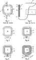
Bei der in
Die Ausführungsform nach
Die Ausführungsform nach
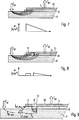
Ein wesentlicher Teilaspekt der hier vorliegenden Problematik wird nachfolgend anhand der
Wenn man von einer „einfachen” Anordnung ausgeht, die also nur eine einzige Hauptelektrode
Die in
Bei der in
Es ist eine Impedanz-Messeinrichtung
Parallel zum Messstromgenerator
Weiterhin enthält die Impedanz-Messeinrichtung
Die Auswerteinrichtung
Im Betrieb wird nun nach dem Aufkleben der Elektrodeneinrichtung auf einen Hautabschnitt
Wenn weiterhin über die zweite Spannungsmesseinrichtung
Mit der soeben dargestellten Ausführungsform der Erfindung kann – wie dies in
Bei der in
Folgende Parameter können durch die Auswertschaltung bestimmt werden:
- IM
- Messstrom zur Messung des Übergangswiderstandes RUEB
- UM,Ring
- Spannungsabfall durch IM zwischen elektrisch leitendem Ring und Innenfläche, wird zur Berechnung des Übergangswiderstandes in Zusammenhang mit IM herangezogen
- UHF,Ring
- HF-Spannung (350 kHz) zwischen Hauptelektrode und elektrisch leitendem Ring. Zusammen mit dem Übergangswiderstand ein Mail für den Strom, der „über” den elektrisch leitenden Ring fließt
- IHF
- Gesamtstrom, der über die Neutralelektrode zum Generator fließt

- RUEB
- Übergangswiderstand zur Bestimmung der Anlagequalität und der Berechnung über den Ring verteilten Stroms
- IHF,Ring
- HF-Strom, der auf den elektrisch leitenden Ring fließt und verteilt wird
- PHF,mnen
- Leistung, die am Rand der Hauptelektrode in Wärme umgesetzt wird
- PHF,Ring
- Leistung, die am elektrisch leitenden Ring in Wärme umgesetzt wird
- RV
- Virtueller Widerstand des Gewebes unter der Neutralelektrode, über den der Teil des HF-Stroms fließt, der nicht über den Ring verteilt wird. Dient als Hilfsgröße zur Leistungsberechnung
- I M
- Measuring current for measuring the contact resistance R UEB
- U M, ring
- Voltage drop through I M between electrically conductive ring and inner surface, is used to calculate the contact resistance in connection with I M
- U HF, ring
- HF voltage (350 kHz) between the main electrode and the electrically conductive ring. Together with the contact resistance a mail for the current that flows "over" the electrically conductive ring
- I HF
- Total current flowing through the neutral electrode to the generator
- R UEB
- Transition resistance for determining the quality of the equipment and the calculation of the distribution over the ring
- I HF, ring
- HF current that flows to the electrically conductive ring and is distributed
- P HF, can
- Power that is converted into heat at the edge of the main electrode
- P HF, ring
- Power that is converted to heat at the electrically conductive ring
- R V
- Virtual resistance of the tissue below the neutral electrode, over which flows the portion of the RF current that is not distributed across the ring. Serves as an auxiliary variable for the performance calculation
Aus den beiden berechneten Leistungen PHF,innen und PHF,Ring sind Abschätzungen der Temperaturerhöhung an den Rändern der Neutralelektrode möglich, da diese Leistungen in einem geometrisch näherungsweise bekannten Gebiet umgesetzt werden. Hierzu ist eine allgemeine Annahme der thermischen Leitfähigkeit des darunter liegenden Gewebes möglich, da zum einen das betroffene Gebiet von den Ausmaßen her sehr eingeschränkt ist und zum anderen unter der Elektrode keine direkten Luftströmungen oder sonstige externe Einflüsse auftreten können.Estimates of the temperature increase at the edges of the neutral electrode are possible from the two calculated powers P HF, inner and P HF, ring , since these powers are converted in a geometrically approximately known region. For this purpose, a general assumption of the thermal conductivity of the underlying tissue is possible because on the one hand the affected area is very limited in terms of dimensions and on the other under the electrode no direct air currents or other external influences can occur.
Aus Obigem geht hervor, dass folgende Vorteile von besonderer Bedeutung sind:
Durch die Erfindung wird eine bessere Erkennung einer Ablösung der Elektrodeneinrichtung am Rand ermöglicht. An jeder Kante der „Neutralelektrode” wird eine Ablösung von der Haut mit derselben Genauigkeit erkannt. Da in dem Randbereich auch die größte Stromdichte auftritt, ist hier eine exakte Überwachung nötig. Demgegenüber ist bei den bisherigen Elektrodenformen die Erkennung dieser wichtigen Parameter senkrecht zur Gelbrücke ungenauer als parallel dazu. Insbesondere ist dieser Nachteil bei den handelsüblichen, zweigeteilten Neutralelektroden (siehe z. B.
By the invention, a better recognition of a detachment of the electrode device is made possible at the edge. At each edge of the "neutral electrode" detachment from the skin is recognized with the same accuracy. Since the highest current density occurs in the edge area, an exact monitoring is necessary here. In contrast, in the previous electrode forms, the recognition of these important parameters perpendicular to the gel bridge is more inaccurate than parallel to it. In particular, this disadvantage is the commercially available, two-part neutral electrodes (see, for.
Durch Messung der HF-Spannung zwischen dem elektrisch leitenden Ring und der Hauptelektrode kann durch den bekannten Übergangswiderstand der Strom ermittelt werden, der vom elektrisch leitenden Ring verteilt wird. Somit kann eine Aussage über das Verhältnis des Gesamtstroms zum Strom über den elektrisch leitenden Ring getroffen und dadurch bestimmt werden, wie effektiv die Verteilungswirkung des elektrisch leitenden Ringes ist.By measuring the HF voltage between the electrically conductive ring and the main electrode can be determined by the known contact resistance of the current, which is distributed by the electrically conductive ring. Thus, a statement can be made about the ratio of the total current to the current across the electrically conductive ring and thereby determine how effective the distribution effect of the electrically conductive ring is.
Durch messtechnische Ermittlungen der Stromverteilung zwischen dem unter dem Ring liegenden Gewebe und dem elektrisch leitenden Ring können auch Rückschlüsse auf die Widerstandsverhältnisse der tieferen, stromführenden Gewebeschichten gezogen werden.By metrological investigations of the current distribution between the underlying tissue under the ring and the electrically conductive ring and conclusions on the resistance ratios of the deeper, current-carrying tissue layers can be drawn.
Wenn sich unter der den Behandlungsstrom IHF ableitenden Fläche der Neutralelektrode ein seht gut leitfähiges Gewebe mit einem geringen Flächenanteil befindet, z. B. ein großes Blutgefäß nahe unter der Hautoberfläche (womöglich umgeben von Fettgewebe), fließt darüber ein großer Teil des Stroms, was aufgrund der kleinen Fläche zu hohen Stromdichten und damit Verbrennungen an diesen Stellen führen kann. Solche Fälle sind aus der Vergangenheit bekannt. Dieses Problem kann bei der beschriebenen Anordnung bzw. dem beschriebenen Verfahren dadurch erkannt werden, dass nur noch ein sehr geringer Anteil des Behandlungsstroms IHF über den elektrisch leitenden Ring fließt. Folglich muss der restliche Behandlungsstrom auf einem Weg mit geringerer Leitfähigkeit direkt unter die Hauptelektrode gelangen können.If under the treatment current I HF dissipating surface of the neutral electrode is a good looking conductive fabric with a small area ratio, z. As a large blood vessel near the skin surface (possibly surrounded by fatty tissue), flows over a large part of the current, which can lead to high current densities and thus burns at these points due to the small area. Such cases are known from the past. This problem can be recognized in the described arrangement or the method described in that only a very small proportion of the treatment current I HF flows through the electrically conductive ring. Consequently, the remainder of the treatment stream must be able to pass directly under the main electrode on a path of lower conductivity.
Mit den bekannten Strom- und Widerstandsverhältnissen kann die zugehörige Verlustleistung berechnet werden. Somit können Aussagen über eine mögliche Temperaturerhöhung in den Randbereichen der Elektrode getroffen werden, wo die Temperaturerhöhung auch am größten ist. Das exakte thermische Verhalten des Gewebes ist zwar von Fall zu Fall verschieden, da es sich aber um ein geometrisch sehr eingegrenztes Gebiet unter der Elektrode handelt, kann mit hoher Wahrscheinlichkeit eine unzulässige Temperaturerhöhung mit guter Genauigkeit abgeschätzt werden.With the known current and resistance conditions, the associated power loss can be calculated. Thus, statements about a possible temperature increase in the edge regions of the electrode can be made, where the temperature increase is also greatest. Although the exact thermal behavior of the tissue differs from case to case, but since it is a very limited area under the electrode, it is highly probable that an inadmissible increase in temperature can be estimated with good accuracy.
Die Orientierung der erfindungsgemäßen Elektrode zum Operationsfeld ist nahezu bedeutungslos (von der Anschlussfahne abgesehen). Prinzip bedingt ist das Auftreten eines unsymmetrischen Behandlungsstroms IHF nicht mehr möglich, da es nur eine einzige den Behandlungsstrom leitende Fläche (die Hauptelektrode
BezugszeichenlisteLIST OF REFERENCE NUMBERS
- 11
- HF-GeneratorRF generator
- 22
- Elektrochirurgisches InstrumentElectrosurgical instrument
- 33
- Neutralelektrodeneutral electrode
- 55
- Hautabschnittskin section
- GG
- Gewebe/KörperTissue / body
- 77
- Gefäßvessel
- 88th
- LeitgelConductive Gel
- 99
- Trägerfoliesupport film
- 1010
- Hauptelektrodemain electrode
- 1111
- elektrisch leitender Ringelectrically conductive ring
- 1212
- Spaltgap
- 1313
- Anschlussfahneterminal lug
- 1414
- Messelektrodemeasuring electrode
- 1515
- Messelektrodemeasuring electrode
- 1616
- Messelektrodemeasuring electrode
- 1717
- Messelektrodemeasuring electrode
- 2020
- Impedanz-MesseinrichtungImpedance measuring device
- 3030
- Auswerteinrichtungevaluation
- 3131
- Anzeige/Signal-ErzeugungseinrichtungDisplay / Signal generator
- 3232
- MessstromgeneratorMeasuring current generator
- 33, 33'33, 33 '
- Filter (IHF)Filter (I HF )
- 3434
- Filter (IM)Filter (I M )
- 3535
- Spannungsmesseinrichtung (UM)Voltage measuring device (U M )
- 36, 36'36, 36 '
- Spannungsmesseinrichtung (U)Voltage measuring device (U)
Claims (11)
Priority Applications (6)
| Application Number | Priority Date | Filing Date | Title |
|---|---|---|---|
| DE102007020583A DE102007020583B4 (en) | 2006-07-19 | 2007-05-02 | Electrode device with an impedance measuring device and method for producing such an electrode device |
| CN2007800269355A CN101489499B (en) | 2006-07-19 | 2007-07-12 | Electrode device |
| JP2009519835A JP5127829B2 (en) | 2006-07-19 | 2007-07-12 | Electrode device |
| EP07786043A EP2043539B1 (en) | 2006-07-19 | 2007-07-12 | Electrode device |
| PCT/EP2007/006215 WO2008009385A1 (en) | 2006-07-19 | 2007-07-12 | Electrode device |
| US12/374,265 US8449536B2 (en) | 2006-07-19 | 2007-07-12 | Electrode device |
Applications Claiming Priority (3)
| Application Number | Priority Date | Filing Date | Title |
|---|---|---|---|
| DE102006033510 | 2006-07-19 | ||
| DE102006033510.4 | 2006-07-19 | ||
| DE102007020583A DE102007020583B4 (en) | 2006-07-19 | 2007-05-02 | Electrode device with an impedance measuring device and method for producing such an electrode device |
Publications (2)
| Publication Number | Publication Date |
|---|---|
| DE102007020583A1 DE102007020583A1 (en) | 2008-01-31 |
| DE102007020583B4 true DE102007020583B4 (en) | 2012-10-11 |
Family
ID=38510465
Family Applications (1)
| Application Number | Title | Priority Date | Filing Date |
|---|---|---|---|
| DE102007020583A Expired - Fee Related DE102007020583B4 (en) | 2006-07-19 | 2007-05-02 | Electrode device with an impedance measuring device and method for producing such an electrode device |
Country Status (6)
| Country | Link |
|---|---|
| US (1) | US8449536B2 (en) |
| EP (1) | EP2043539B1 (en) |
| JP (1) | JP5127829B2 (en) |
| CN (1) | CN101489499B (en) |
| DE (1) | DE102007020583B4 (en) |
| WO (1) | WO2008009385A1 (en) |
Families Citing this family (436)
| Publication number | Priority date | Publication date | Assignee | Title |
|---|---|---|---|---|
| US20070084897A1 (en) | 2003-05-20 | 2007-04-19 | Shelton Frederick E Iv | Articulating surgical stapling instrument incorporating a two-piece e-beam firing mechanism |
| US9060770B2 (en) | 2003-05-20 | 2015-06-23 | Ethicon Endo-Surgery, Inc. | Robotically-driven surgical instrument with E-beam driver |
| US11896225B2 (en) | 2004-07-28 | 2024-02-13 | Cilag Gmbh International | Staple cartridge comprising a pan |
| US8215531B2 (en) | 2004-07-28 | 2012-07-10 | Ethicon Endo-Surgery, Inc. | Surgical stapling instrument having a medical substance dispenser |
| US8730031B2 (en) | 2005-04-28 | 2014-05-20 | Proteus Digital Health, Inc. | Communication system using an implantable device |
| US9198608B2 (en) | 2005-04-28 | 2015-12-01 | Proteus Digital Health, Inc. | Communication system incorporated in a container |
| US8912908B2 (en) | 2005-04-28 | 2014-12-16 | Proteus Digital Health, Inc. | Communication system with remote activation |
| US8836513B2 (en) | 2006-04-28 | 2014-09-16 | Proteus Digital Health, Inc. | Communication system incorporated in an ingestible product |
| EP2671507A3 (en) | 2005-04-28 | 2014-02-19 | Proteus Digital Health, Inc. | Pharma-informatics system |
| US8802183B2 (en) | 2005-04-28 | 2014-08-12 | Proteus Digital Health, Inc. | Communication system with enhanced partial power source and method of manufacturing same |
| US11246590B2 (en) | 2005-08-31 | 2022-02-15 | Cilag Gmbh International | Staple cartridge including staple drivers having different unfired heights |
| US10159482B2 (en) | 2005-08-31 | 2018-12-25 | Ethicon Llc | Fastener cartridge assembly comprising a fixed anvil and different staple heights |
| US9237891B2 (en) | 2005-08-31 | 2016-01-19 | Ethicon Endo-Surgery, Inc. | Robotically-controlled surgical stapling devices that produce formed staples having different lengths |
| US7934630B2 (en) | 2005-08-31 | 2011-05-03 | Ethicon Endo-Surgery, Inc. | Staple cartridges for forming staples having differing formed staple heights |
| US11484312B2 (en) | 2005-08-31 | 2022-11-01 | Cilag Gmbh International | Staple cartridge comprising a staple driver arrangement |
| US7669746B2 (en) | 2005-08-31 | 2010-03-02 | Ethicon Endo-Surgery, Inc. | Staple cartridges for forming staples having differing formed staple heights |
| EP1920418A4 (en) | 2005-09-01 | 2010-12-29 | Proteus Biomedical Inc | Implantable zero-wire communications system |
| US20070106317A1 (en) | 2005-11-09 | 2007-05-10 | Shelton Frederick E Iv | Hydraulically and electrically actuated articulation joints for surgical instruments |
| US20110024477A1 (en) | 2009-02-06 | 2011-02-03 | Hall Steven G | Driven Surgical Stapler Improvements |
| US7845537B2 (en) | 2006-01-31 | 2010-12-07 | Ethicon Endo-Surgery, Inc. | Surgical instrument having recording capabilities |
| US11278279B2 (en) | 2006-01-31 | 2022-03-22 | Cilag Gmbh International | Surgical instrument assembly |
| US7753904B2 (en) | 2006-01-31 | 2010-07-13 | Ethicon Endo-Surgery, Inc. | Endoscopic surgical instrument with a handle that can articulate with respect to the shaft |
| US11793518B2 (en) | 2006-01-31 | 2023-10-24 | Cilag Gmbh International | Powered surgical instruments with firing system lockout arrangements |
| US8186555B2 (en) | 2006-01-31 | 2012-05-29 | Ethicon Endo-Surgery, Inc. | Motor-driven surgical cutting and fastening instrument with mechanical closure system |
| US11224427B2 (en) | 2006-01-31 | 2022-01-18 | Cilag Gmbh International | Surgical stapling system including a console and retraction assembly |
| US8820603B2 (en) | 2006-01-31 | 2014-09-02 | Ethicon Endo-Surgery, Inc. | Accessing data stored in a memory of a surgical instrument |
| US20110290856A1 (en) | 2006-01-31 | 2011-12-01 | Ethicon Endo-Surgery, Inc. | Robotically-controlled surgical instrument with force-feedback capabilities |
| US8708213B2 (en) | 2006-01-31 | 2014-04-29 | Ethicon Endo-Surgery, Inc. | Surgical instrument having a feedback system |
| US20120292367A1 (en) | 2006-01-31 | 2012-11-22 | Ethicon Endo-Surgery, Inc. | Robotically-controlled end effector |
| US8992422B2 (en) | 2006-03-23 | 2015-03-31 | Ethicon Endo-Surgery, Inc. | Robotically-controlled endoscopic accessory channel |
| JP2009544338A (en) | 2006-05-02 | 2009-12-17 | プロテウス バイオメディカル インコーポレイテッド | Treatment regimen customized to the patient |
| US8322455B2 (en) | 2006-06-27 | 2012-12-04 | Ethicon Endo-Surgery, Inc. | Manually driven surgical cutting and fastening instrument |
| US10568652B2 (en) | 2006-09-29 | 2020-02-25 | Ethicon Llc | Surgical staples having attached drivers of different heights and stapling instruments for deploying the same |
| US8708210B2 (en) | 2006-10-05 | 2014-04-29 | Covidien Lp | Method and force-limiting handle mechanism for a surgical instrument |
| ATE535057T1 (en) | 2006-10-17 | 2011-12-15 | Proteus Biomedical Inc | LOW VOLTAGE OSCILLATOR FOR MEDICAL FACILITIES |
| SG175681A1 (en) | 2006-10-25 | 2011-11-28 | Proteus Biomedical Inc | Controlled activation ingestible identifier |
| EP2069004A4 (en) | 2006-11-20 | 2014-07-09 | Proteus Digital Health Inc | Active signal processing personal health signal receivers |
| US8684253B2 (en) | 2007-01-10 | 2014-04-01 | Ethicon Endo-Surgery, Inc. | Surgical instrument with wireless communication between a control unit of a robotic system and remote sensor |
| US8652120B2 (en) | 2007-01-10 | 2014-02-18 | Ethicon Endo-Surgery, Inc. | Surgical instrument with wireless communication between control unit and sensor transponders |
| US11291441B2 (en) | 2007-01-10 | 2022-04-05 | Cilag Gmbh International | Surgical instrument with wireless communication between control unit and remote sensor |
| US11039836B2 (en) | 2007-01-11 | 2021-06-22 | Cilag Gmbh International | Staple cartridge for use with a surgical stapling instrument |
| US8701958B2 (en) | 2007-01-11 | 2014-04-22 | Ethicon Endo-Surgery, Inc. | Curved end effector for a surgical stapling device |
| AU2008210291B2 (en) | 2007-02-01 | 2013-10-03 | Otsuka Pharmaceutical Co., Ltd. | Ingestible event marker systems |
| MY154556A (en) | 2007-02-14 | 2015-06-30 | Proteus Digital Health Inc | In-body power source having high surface area electrode |
| EP2063771A1 (en) | 2007-03-09 | 2009-06-03 | Proteus Biomedical, Inc. | In-body device having a deployable antenna |
| US8932221B2 (en) | 2007-03-09 | 2015-01-13 | Proteus Digital Health, Inc. | In-body device having a multi-directional transmitter |
| US20090001130A1 (en) | 2007-03-15 | 2009-01-01 | Hess Christopher J | Surgical procedure using a cutting and stapling instrument having releasable staple-forming pockets |
| US8080007B2 (en) * | 2007-05-07 | 2011-12-20 | Tyco Healthcare Group Lp | Capacitive electrosurgical return pad with contact quality monitoring |
| US8231614B2 (en) | 2007-05-11 | 2012-07-31 | Tyco Healthcare Group Lp | Temperature monitoring return electrode |
| US8540632B2 (en) | 2007-05-24 | 2013-09-24 | Proteus Digital Health, Inc. | Low profile antenna for in body device |
| US11857181B2 (en) | 2007-06-04 | 2024-01-02 | Cilag Gmbh International | Robotically-controlled shaft based rotary drive systems for surgical instruments |
| US8931682B2 (en) | 2007-06-04 | 2015-01-13 | Ethicon Endo-Surgery, Inc. | Robotically-controlled shaft based rotary drive systems for surgical instruments |
| US7753245B2 (en) | 2007-06-22 | 2010-07-13 | Ethicon Endo-Surgery, Inc. | Surgical stapling instruments |
| US11849941B2 (en) | 2007-06-29 | 2023-12-26 | Cilag Gmbh International | Staple cartridge having staple cavities extending at a transverse angle relative to a longitudinal cartridge axis |
| US8801703B2 (en) | 2007-08-01 | 2014-08-12 | Covidien Lp | System and method for return electrode monitoring |
| EP2192946B1 (en) | 2007-09-25 | 2022-09-14 | Otsuka Pharmaceutical Co., Ltd. | In-body device with virtual dipole signal amplification |
| US8187263B2 (en) | 2008-02-04 | 2012-05-29 | Tyco Healthcare Group Lp | System and method for return electrode monitoring |
| US8523853B2 (en) | 2008-02-05 | 2013-09-03 | Covidien Lp | Hybrid contact quality monitoring return electrode |
| US8758391B2 (en) | 2008-02-14 | 2014-06-24 | Ethicon Endo-Surgery, Inc. | Interchangeable tools for surgical instruments |
| US8636736B2 (en) | 2008-02-14 | 2014-01-28 | Ethicon Endo-Surgery, Inc. | Motorized surgical cutting and fastening instrument |
| US7819298B2 (en) | 2008-02-14 | 2010-10-26 | Ethicon Endo-Surgery, Inc. | Surgical stapling apparatus with control features operable with one hand |
| US9179912B2 (en) | 2008-02-14 | 2015-11-10 | Ethicon Endo-Surgery, Inc. | Robotically-controlled motorized surgical cutting and fastening instrument |
| BRPI0901282A2 (en) | 2008-02-14 | 2009-11-17 | Ethicon Endo Surgery Inc | surgical cutting and fixation instrument with rf electrodes |
| US7866527B2 (en) | 2008-02-14 | 2011-01-11 | Ethicon Endo-Surgery, Inc. | Surgical stapling apparatus with interlockable firing system |
| US8573465B2 (en) | 2008-02-14 | 2013-11-05 | Ethicon Endo-Surgery, Inc. | Robotically-controlled surgical end effector system with rotary actuated closure systems |
| US8486059B2 (en) | 2008-02-15 | 2013-07-16 | Covidien Lp | Multi-layer return electrode |
| US9615826B2 (en) | 2010-09-30 | 2017-04-11 | Ethicon Endo-Surgery, Llc | Multiple thickness implantable layers for surgical stapling devices |
| ES2636844T3 (en) | 2008-03-05 | 2017-10-09 | Proteus Biomedical, Inc. | Ingestible multimode communication systems and markers, and methods to use them |
| US9987072B2 (en) | 2008-03-17 | 2018-06-05 | Covidien Lp | System and method for detecting a fault in a capacitive return electrode for use in electrosurgery |
| CA2730275C (en) | 2008-07-08 | 2019-05-21 | Proteus Biomedical, Inc. | Ingestible event marker data framework |
| US8540633B2 (en) | 2008-08-13 | 2013-09-24 | Proteus Digital Health, Inc. | Identifier circuits for generating unique identifiable indicators and techniques for producing same |
| US11648005B2 (en) | 2008-09-23 | 2023-05-16 | Cilag Gmbh International | Robotically-controlled motorized surgical instrument with an end effector |
| US9386983B2 (en) | 2008-09-23 | 2016-07-12 | Ethicon Endo-Surgery, Llc | Robotically-controlled motorized surgical instrument |
| US9005230B2 (en) | 2008-09-23 | 2015-04-14 | Ethicon Endo-Surgery, Inc. | Motorized surgical instrument |
| US8210411B2 (en) | 2008-09-23 | 2012-07-03 | Ethicon Endo-Surgery, Inc. | Motor-driven surgical cutting instrument |
| US8608045B2 (en) | 2008-10-10 | 2013-12-17 | Ethicon Endo-Sugery, Inc. | Powered surgical cutting and stapling apparatus with manually retractable firing system |
| AU2009313879B2 (en) | 2008-11-13 | 2011-10-20 | Proteus Digital Health, Inc. | Ingestible therapy activator system and method |
| US8055334B2 (en) | 2008-12-11 | 2011-11-08 | Proteus Biomedical, Inc. | Evaluation of gastrointestinal function using portable electroviscerography systems and methods of using the same |
| US9659423B2 (en) | 2008-12-15 | 2017-05-23 | Proteus Digital Health, Inc. | Personal authentication apparatus system and method |
| TWI503101B (en) | 2008-12-15 | 2015-10-11 | Proteus Digital Health Inc | Body-associated receiver and method |
| US9439566B2 (en) | 2008-12-15 | 2016-09-13 | Proteus Digital Health, Inc. | Re-wearable wireless device |
| CA2750158A1 (en) | 2009-01-06 | 2010-07-15 | Proteus Biomedical, Inc. | Ingestion-related biofeedback and personalized medical therapy method and system |
| KR20110104079A (en) | 2009-01-06 | 2011-09-21 | 프로테우스 바이오메디컬, 인코포레이티드 | Pharmaceutical dosages delivery system |
| US8517239B2 (en) | 2009-02-05 | 2013-08-27 | Ethicon Endo-Surgery, Inc. | Surgical stapling instrument comprising a magnetic element driver |
| EP2393430A1 (en) | 2009-02-06 | 2011-12-14 | Ethicon Endo-Surgery, Inc. | Driven surgical stapler improvements |
| GB2480965B (en) | 2009-03-25 | 2014-10-08 | Proteus Digital Health Inc | Probablistic pharmacokinetic and pharmacodynamic modeling |
| SG10201810784SA (en) | 2009-04-28 | 2018-12-28 | Proteus Digital Health Inc | Highly Reliable Ingestible Event Markers And Methods For Using The Same |
| EP2432458A4 (en) | 2009-05-12 | 2014-02-12 | Proteus Digital Health Inc | Ingestible event markers comprising an ingestible component |
| EP2467707A4 (en) | 2009-08-21 | 2014-12-17 | Proteus Digital Health Inc | Apparatus and method for measuring biochemical parameters |
| US8388614B2 (en) | 2009-09-29 | 2013-03-05 | Covidien Lp | Return electrode temperature prediction |
| TWI517050B (en) | 2009-11-04 | 2016-01-11 | 普羅托斯數位健康公司 | System for supply chain management |
| UA109424C2 (en) | 2009-12-02 | 2015-08-25 | PHARMACEUTICAL PRODUCT, PHARMACEUTICAL TABLE WITH ELECTRONIC MARKER AND METHOD OF MANUFACTURING PHARMACEUTICAL TABLETS | |
| US8851354B2 (en) | 2009-12-24 | 2014-10-07 | Ethicon Endo-Surgery, Inc. | Surgical cutting instrument that analyzes tissue thickness |
| US8220688B2 (en) | 2009-12-24 | 2012-07-17 | Ethicon Endo-Surgery, Inc. | Motor-driven surgical cutting instrument with electric actuator directional control assembly |
| US20110190755A1 (en) * | 2010-01-29 | 2011-08-04 | Medtronic Ablation Frontiers Llc | Patient return electrode detection for ablation system |
| MX2012008922A (en) | 2010-02-01 | 2012-10-05 | Proteus Digital Health Inc | Data gathering system. |
| CN102905672B (en) | 2010-04-07 | 2016-08-17 | 普罗秋斯数字健康公司 | Miniature ingestible device |
| TWI557672B (en) | 2010-05-19 | 2016-11-11 | 波提亞斯數位康健公司 | Computer system and computer-implemented method to track medication from manufacturer to a patient, apparatus and method for confirming delivery of medication to a patient, patient interface device |
| US8783543B2 (en) | 2010-07-30 | 2014-07-22 | Ethicon Endo-Surgery, Inc. | Tissue acquisition arrangements and methods for surgical stapling devices |
| US11925354B2 (en) | 2010-09-30 | 2024-03-12 | Cilag Gmbh International | Staple cartridge comprising staples positioned within a compressible portion thereof |
| US11298125B2 (en) | 2010-09-30 | 2022-04-12 | Cilag Gmbh International | Tissue stapler having a thickness compensator |
| US20120080336A1 (en) | 2010-09-30 | 2012-04-05 | Ethicon Endo-Surgery, Inc. | Staple cartridge comprising staples positioned within a compressible portion thereof |
| US9629814B2 (en) | 2010-09-30 | 2017-04-25 | Ethicon Endo-Surgery, Llc | Tissue thickness compensator configured to redistribute compressive forces |
| US10945731B2 (en) | 2010-09-30 | 2021-03-16 | Ethicon Llc | Tissue thickness compensator comprising controlled release and expansion |
| US10405854B2 (en) | 2010-09-30 | 2019-09-10 | Ethicon Llc | Surgical stapling cartridge with layer retention features |
| US9211120B2 (en) | 2011-04-29 | 2015-12-15 | Ethicon Endo-Surgery, Inc. | Tissue thickness compensator comprising a plurality of medicaments |
| US11812965B2 (en) | 2010-09-30 | 2023-11-14 | Cilag Gmbh International | Layer of material for a surgical end effector |
| US9386988B2 (en) | 2010-09-30 | 2016-07-12 | Ethicon End-Surgery, LLC | Retainer assembly including a tissue thickness compensator |
| US8695866B2 (en) | 2010-10-01 | 2014-04-15 | Ethicon Endo-Surgery, Inc. | Surgical instrument having a power control circuit |
| EP2642983A4 (en) | 2010-11-22 | 2014-03-12 | Proteus Digital Health Inc | Ingestible device with pharmaceutical product |
| WO2012073232A1 (en) * | 2010-12-03 | 2012-06-07 | Syneron Medical Ltd. | A method and apparatus for improving electrode-skin contact |
| US9439599B2 (en) | 2011-03-11 | 2016-09-13 | Proteus Digital Health, Inc. | Wearable personal body associated device with various physical configurations |
| CA2834649C (en) | 2011-04-29 | 2021-02-16 | Ethicon Endo-Surgery, Inc. | Staple cartridge comprising staples positioned within a compressible portion thereof |
| US11207064B2 (en) | 2011-05-27 | 2021-12-28 | Cilag Gmbh International | Automated end effector component reloading system for use with a robotic system |
| US9072535B2 (en) | 2011-05-27 | 2015-07-07 | Ethicon Endo-Surgery, Inc. | Surgical stapling instruments with rotatable staple deployment arrangements |
| WO2015112603A1 (en) | 2014-01-21 | 2015-07-30 | Proteus Digital Health, Inc. | Masticable ingestible product and communication system therefor |
| US9756874B2 (en) | 2011-07-11 | 2017-09-12 | Proteus Digital Health, Inc. | Masticable ingestible product and communication system therefor |
| CA2842952C (en) | 2011-07-21 | 2019-01-08 | Proteus Digital Health, Inc. | Mobile communication device, system, and method |
| US9235683B2 (en) | 2011-11-09 | 2016-01-12 | Proteus Digital Health, Inc. | Apparatus, system, and method for managing adherence to a regimen |
| US9044230B2 (en) | 2012-02-13 | 2015-06-02 | Ethicon Endo-Surgery, Inc. | Surgical cutting and fastening instrument with apparatus for determining cartridge and firing motion status |
| CN104321024B (en) | 2012-03-28 | 2017-05-24 | 伊西康内外科公司 | Tissue thickness compensator comprising a plurality of layers |
| MX350846B (en) | 2012-03-28 | 2017-09-22 | Ethicon Endo Surgery Inc | Tissue thickness compensator comprising capsules defining a low pressure environment. |
| RU2644272C2 (en) | 2012-03-28 | 2018-02-08 | Этикон Эндо-Серджери, Инк. | Limitation node with tissue thickness compensator |
| US9101358B2 (en) | 2012-06-15 | 2015-08-11 | Ethicon Endo-Surgery, Inc. | Articulatable surgical instrument comprising a firing drive |
| US9226751B2 (en) | 2012-06-28 | 2016-01-05 | Ethicon Endo-Surgery, Inc. | Surgical instrument system including replaceable end effectors |
| US11278284B2 (en) | 2012-06-28 | 2022-03-22 | Cilag Gmbh International | Rotary drive arrangements for surgical instruments |
| BR112014032776B1 (en) | 2012-06-28 | 2021-09-08 | Ethicon Endo-Surgery, Inc | SURGICAL INSTRUMENT SYSTEM AND SURGICAL KIT FOR USE WITH A SURGICAL INSTRUMENT SYSTEM |
| US20140001231A1 (en) | 2012-06-28 | 2014-01-02 | Ethicon Endo-Surgery, Inc. | Firing system lockout arrangements for surgical instruments |
| US9289256B2 (en) | 2012-06-28 | 2016-03-22 | Ethicon Endo-Surgery, Llc | Surgical end effectors having angled tissue-contacting surfaces |
| US9649111B2 (en) | 2012-06-28 | 2017-05-16 | Ethicon Endo-Surgery, Llc | Replaceable clip cartridge for a clip applier |
| RU2636861C2 (en) | 2012-06-28 | 2017-11-28 | Этикон Эндо-Серджери, Инк. | Blocking of empty cassette with clips |
| KR20150038038A (en) | 2012-07-23 | 2015-04-08 | 프로테우스 디지털 헬스, 인코포레이티드 | Techniques for manufacturing ingestible event markers comprising an ingestible component |
| MX340182B (en) | 2012-10-18 | 2016-06-28 | Proteus Digital Health Inc | Apparatus, system, and method to adaptively optimize power dissipation and broadcast power in a power source for a communication device. |
| JP2016508529A (en) | 2013-01-29 | 2016-03-22 | プロテウス デジタル ヘルス, インコーポレイテッド | Highly expandable polymer film and composition containing the same |
| RU2669463C2 (en) | 2013-03-01 | 2018-10-11 | Этикон Эндо-Серджери, Инк. | Surgical instrument with soft stop |
| BR112015021098B1 (en) | 2013-03-01 | 2022-02-15 | Ethicon Endo-Surgery, Inc | COVERAGE FOR A JOINT JOINT AND SURGICAL INSTRUMENT |
| US9629629B2 (en) | 2013-03-14 | 2017-04-25 | Ethicon Endo-Surgey, LLC | Control systems for surgical instruments |
| US9332987B2 (en) | 2013-03-14 | 2016-05-10 | Ethicon Endo-Surgery, Llc | Control arrangements for a drive member of a surgical instrument |
| WO2014144738A1 (en) | 2013-03-15 | 2014-09-18 | Proteus Digital Health, Inc. | Metal detector apparatus, system, and method |
| WO2014151929A1 (en) | 2013-03-15 | 2014-09-25 | Proteus Digital Health, Inc. | Personal authentication apparatus system and method |
| BR112015026109B1 (en) | 2013-04-16 | 2022-02-22 | Ethicon Endo-Surgery, Inc | surgical instrument |
| US9826976B2 (en) | 2013-04-16 | 2017-11-28 | Ethicon Llc | Motor driven surgical instruments with lockable dual drive shafts |
| EP3968263A1 (en) | 2013-06-04 | 2022-03-16 | Otsuka Pharmaceutical Co., Ltd. | System, apparatus and methods for data collection and assessing outcomes |
| US9924942B2 (en) | 2013-08-23 | 2018-03-27 | Ethicon Llc | Motor-powered articulatable surgical instruments |
| MX369362B (en) | 2013-08-23 | 2019-11-06 | Ethicon Endo Surgery Llc | Firing member retraction devices for powered surgical instruments. |
| US9796576B2 (en) | 2013-08-30 | 2017-10-24 | Proteus Digital Health, Inc. | Container with electronically controlled interlock |
| JP6043023B1 (en) | 2013-09-20 | 2016-12-14 | プロテウス デジタル ヘルス, インコーポレイテッド | Method, device and system for receiving and decoding signals in the presence of noise using slicing and warping |
| JP2016537924A (en) | 2013-09-24 | 2016-12-01 | プロテウス デジタル ヘルス, インコーポレイテッド | Method and apparatus for use with electromagnetic signals received at frequencies that are not accurately known in advance |
| US10084880B2 (en) | 2013-11-04 | 2018-09-25 | Proteus Digital Health, Inc. | Social media networking based on physiologic information |
| US9962161B2 (en) | 2014-02-12 | 2018-05-08 | Ethicon Llc | Deliverable surgical instrument |
| BR112016021943B1 (en) | 2014-03-26 | 2022-06-14 | Ethicon Endo-Surgery, Llc | SURGICAL INSTRUMENT FOR USE BY AN OPERATOR IN A SURGICAL PROCEDURE |
| US10004497B2 (en) | 2014-03-26 | 2018-06-26 | Ethicon Llc | Interface systems for use with surgical instruments |
| US9804618B2 (en) | 2014-03-26 | 2017-10-31 | Ethicon Llc | Systems and methods for controlling a segmented circuit |
| CN106456159B (en) | 2014-04-16 | 2019-03-08 | 伊西康内外科有限责任公司 | Fastener cartridge assembly and nail retainer lid arragement construction |
| JP6636452B2 (en) | 2014-04-16 | 2020-01-29 | エシコン エルエルシーEthicon LLC | Fastener cartridge including extension having different configurations |
| CN106456158B (en) | 2014-04-16 | 2019-02-05 | 伊西康内外科有限责任公司 | Fastener cartridge including non-uniform fastener |
| US20150297225A1 (en) | 2014-04-16 | 2015-10-22 | Ethicon Endo-Surgery, Inc. | Fastener cartridges including extensions having different configurations |
| US10561422B2 (en) | 2014-04-16 | 2020-02-18 | Ethicon Llc | Fastener cartridge comprising deployable tissue engaging members |
| US11311294B2 (en) | 2014-09-05 | 2022-04-26 | Cilag Gmbh International | Powered medical device including measurement of closure state of jaws |
| US10016199B2 (en) | 2014-09-05 | 2018-07-10 | Ethicon Llc | Polarity of hall magnet to identify cartridge type |
| BR112017004361B1 (en) | 2014-09-05 | 2023-04-11 | Ethicon Llc | ELECTRONIC SYSTEM FOR A SURGICAL INSTRUMENT |
| US10105142B2 (en) | 2014-09-18 | 2018-10-23 | Ethicon Llc | Surgical stapler with plurality of cutting elements |
| JP6648119B2 (en) | 2014-09-26 | 2020-02-14 | エシコン エルエルシーEthicon LLC | Surgical stapling buttress and accessory materials |
| US11523821B2 (en) | 2014-09-26 | 2022-12-13 | Cilag Gmbh International | Method for creating a flexible staple line |
| US10076325B2 (en) | 2014-10-13 | 2018-09-18 | Ethicon Llc | Surgical stapling apparatus comprising a tissue stop |
| US9924944B2 (en) | 2014-10-16 | 2018-03-27 | Ethicon Llc | Staple cartridge comprising an adjunct material |
| US11141153B2 (en) | 2014-10-29 | 2021-10-12 | Cilag Gmbh International | Staple cartridges comprising driver arrangements |
| US10517594B2 (en) | 2014-10-29 | 2019-12-31 | Ethicon Llc | Cartridge assemblies for surgical staplers |
| US9844376B2 (en) | 2014-11-06 | 2017-12-19 | Ethicon Llc | Staple cartridge comprising a releasable adjunct material |
| US10736636B2 (en) | 2014-12-10 | 2020-08-11 | Ethicon Llc | Articulatable surgical instrument system |
| US9968355B2 (en) | 2014-12-18 | 2018-05-15 | Ethicon Llc | Surgical instruments with articulatable end effectors and improved firing beam support arrangements |
| US10085748B2 (en) | 2014-12-18 | 2018-10-02 | Ethicon Llc | Locking arrangements for detachable shaft assemblies with articulatable surgical end effectors |
| US9987000B2 (en) | 2014-12-18 | 2018-06-05 | Ethicon Llc | Surgical instrument assembly comprising a flexible articulation system |
| US9844374B2 (en) | 2014-12-18 | 2017-12-19 | Ethicon Llc | Surgical instrument systems comprising an articulatable end effector and means for adjusting the firing stroke of a firing member |
| MX2017008108A (en) | 2014-12-18 | 2018-03-06 | Ethicon Llc | Surgical instrument with an anvil that is selectively movable about a discrete non-movable axis relative to a staple cartridge. |
| US9844375B2 (en) | 2014-12-18 | 2017-12-19 | Ethicon Llc | Drive arrangements for articulatable surgical instruments |
| US11154301B2 (en) | 2015-02-27 | 2021-10-26 | Cilag Gmbh International | Modular stapling assembly |
| US10441279B2 (en) | 2015-03-06 | 2019-10-15 | Ethicon Llc | Multiple level thresholds to modify operation of powered surgical instruments |
| US10617412B2 (en) | 2015-03-06 | 2020-04-14 | Ethicon Llc | System for detecting the mis-insertion of a staple cartridge into a surgical stapler |
| US9901342B2 (en) | 2015-03-06 | 2018-02-27 | Ethicon Endo-Surgery, Llc | Signal and power communication system positioned on a rotatable shaft |
| US10052044B2 (en) | 2015-03-06 | 2018-08-21 | Ethicon Llc | Time dependent evaluation of sensor data to determine stability, creep, and viscoelastic elements of measures |
| US9993248B2 (en) | 2015-03-06 | 2018-06-12 | Ethicon Endo-Surgery, Llc | Smart sensors with local signal processing |
| US10687806B2 (en) | 2015-03-06 | 2020-06-23 | Ethicon Llc | Adaptive tissue compression techniques to adjust closure rates for multiple tissue types |
| US10245033B2 (en) | 2015-03-06 | 2019-04-02 | Ethicon Llc | Surgical instrument comprising a lockable battery housing |
| JP2020121162A (en) | 2015-03-06 | 2020-08-13 | エシコン エルエルシーEthicon LLC | Time dependent evaluation of sensor data to determine stability element, creep element and viscoelastic element of measurement |
| US10213201B2 (en) | 2015-03-31 | 2019-02-26 | Ethicon Llc | Stapling end effector configured to compensate for an uneven gap between a first jaw and a second jaw |
| US11051543B2 (en) | 2015-07-21 | 2021-07-06 | Otsuka Pharmaceutical Co. Ltd. | Alginate on adhesive bilayer laminate film |
| US10835249B2 (en) | 2015-08-17 | 2020-11-17 | Ethicon Llc | Implantable layers for a surgical instrument |
| US10105139B2 (en) | 2015-09-23 | 2018-10-23 | Ethicon Llc | Surgical stapler having downstream current-based motor control |
| US10238386B2 (en) | 2015-09-23 | 2019-03-26 | Ethicon Llc | Surgical stapler having motor control based on an electrical parameter related to a motor current |
| US10299878B2 (en) | 2015-09-25 | 2019-05-28 | Ethicon Llc | Implantable adjunct systems for determining adjunct skew |
| US10980539B2 (en) | 2015-09-30 | 2021-04-20 | Ethicon Llc | Implantable adjunct comprising bonded layers |
| US11690623B2 (en) | 2015-09-30 | 2023-07-04 | Cilag Gmbh International | Method for applying an implantable layer to a fastener cartridge |
| US11890015B2 (en) | 2015-09-30 | 2024-02-06 | Cilag Gmbh International | Compressible adjunct with crossing spacer fibers |
| US10271849B2 (en) | 2015-09-30 | 2019-04-30 | Ethicon Llc | Woven constructs with interlocked standing fibers |
| KR20170042177A (en) * | 2015-10-08 | 2017-04-18 | (주)와이브레인 | Electronic stimulator |
| US10368865B2 (en) | 2015-12-30 | 2019-08-06 | Ethicon Llc | Mechanisms for compensating for drivetrain failure in powered surgical instruments |
| US10292704B2 (en) | 2015-12-30 | 2019-05-21 | Ethicon Llc | Mechanisms for compensating for battery pack failure in powered surgical instruments |
| US10265068B2 (en) | 2015-12-30 | 2019-04-23 | Ethicon Llc | Surgical instruments with separable motors and motor control circuits |
| US11213293B2 (en) | 2016-02-09 | 2022-01-04 | Cilag Gmbh International | Articulatable surgical instruments with single articulation link arrangements |
| CN108882932B (en) | 2016-02-09 | 2021-07-23 | 伊西康有限责任公司 | Surgical instrument with asymmetric articulation configuration |
| US10448948B2 (en) | 2016-02-12 | 2019-10-22 | Ethicon Llc | Mechanisms for compensating for drivetrain failure in powered surgical instruments |
| US11224426B2 (en) | 2016-02-12 | 2022-01-18 | Cilag Gmbh International | Mechanisms for compensating for drivetrain failure in powered surgical instruments |
| US10617413B2 (en) | 2016-04-01 | 2020-04-14 | Ethicon Llc | Closure system arrangements for surgical cutting and stapling devices with separate and distinct firing shafts |
| US10357247B2 (en) | 2016-04-15 | 2019-07-23 | Ethicon Llc | Surgical instrument with multiple program responses during a firing motion |
| US10426467B2 (en) | 2016-04-15 | 2019-10-01 | Ethicon Llc | Surgical instrument with detection sensors |
| US11607239B2 (en) | 2016-04-15 | 2023-03-21 | Cilag Gmbh International | Systems and methods for controlling a surgical stapling and cutting instrument |
| US10456137B2 (en) | 2016-04-15 | 2019-10-29 | Ethicon Llc | Staple formation detection mechanisms |
| US10335145B2 (en) | 2016-04-15 | 2019-07-02 | Ethicon Llc | Modular surgical instrument with configurable operating mode |
| US10828028B2 (en) | 2016-04-15 | 2020-11-10 | Ethicon Llc | Surgical instrument with multiple program responses during a firing motion |
| US11179150B2 (en) | 2016-04-15 | 2021-11-23 | Cilag Gmbh International | Systems and methods for controlling a surgical stapling and cutting instrument |
| US10492783B2 (en) | 2016-04-15 | 2019-12-03 | Ethicon, Llc | Surgical instrument with improved stop/start control during a firing motion |
| US11317917B2 (en) | 2016-04-18 | 2022-05-03 | Cilag Gmbh International | Surgical stapling system comprising a lockable firing assembly |
| US10363037B2 (en) | 2016-04-18 | 2019-07-30 | Ethicon Llc | Surgical instrument system comprising a magnetic lockout |
| US20170296173A1 (en) | 2016-04-18 | 2017-10-19 | Ethicon Endo-Surgery, Llc | Method for operating a surgical instrument |
| CN105879225A (en) * | 2016-06-08 | 2016-08-24 | 广州加佳康医疗科技有限公司 | Intelligent and portable electrotherapeutical apparatus |
| CN109843149B (en) | 2016-07-22 | 2020-07-07 | 普罗秋斯数字健康公司 | Electromagnetic sensing and detection of ingestible event markers |
| EP3531901A4 (en) | 2016-10-26 | 2021-01-27 | Proteus Digital Health, Inc. | Methods for manufacturing capsules with ingestible event markers |
| JP6983893B2 (en) | 2016-12-21 | 2021-12-17 | エシコン エルエルシーEthicon LLC | Lockout configuration for surgical end effectors and replaceable tool assemblies |
| US10485543B2 (en) | 2016-12-21 | 2019-11-26 | Ethicon Llc | Anvil having a knife slot width |
| US20180168623A1 (en) | 2016-12-21 | 2018-06-21 | Ethicon Endo-Surgery, Llc | Surgical stapling systems |
| US11419606B2 (en) | 2016-12-21 | 2022-08-23 | Cilag Gmbh International | Shaft assembly comprising a clutch configured to adapt the output of a rotary firing member to two different systems |
| US10758230B2 (en) | 2016-12-21 | 2020-09-01 | Ethicon Llc | Surgical instrument with primary and safety processors |
| US20180168633A1 (en) | 2016-12-21 | 2018-06-21 | Ethicon Endo-Surgery, Llc | Surgical stapling instruments and staple-forming anvils |
| US10667810B2 (en) | 2016-12-21 | 2020-06-02 | Ethicon Llc | Closure members with cam surface arrangements for surgical instruments with separate and distinct closure and firing systems |
| US11134942B2 (en) | 2016-12-21 | 2021-10-05 | Cilag Gmbh International | Surgical stapling instruments and staple-forming anvils |
| US10610224B2 (en) | 2016-12-21 | 2020-04-07 | Ethicon Llc | Lockout arrangements for surgical end effectors and replaceable tool assemblies |
| US20180168615A1 (en) | 2016-12-21 | 2018-06-21 | Ethicon Endo-Surgery, Llc | Method of deforming staples from two different types of staple cartridges with the same surgical stapling instrument |
| US10888322B2 (en) | 2016-12-21 | 2021-01-12 | Ethicon Llc | Surgical instrument comprising a cutting member |
| US10695055B2 (en) | 2016-12-21 | 2020-06-30 | Ethicon Llc | Firing assembly comprising a lockout |
| US10568626B2 (en) | 2016-12-21 | 2020-02-25 | Ethicon Llc | Surgical instruments with jaw opening features for increasing a jaw opening distance |
| MX2019007311A (en) | 2016-12-21 | 2019-11-18 | Ethicon Llc | Surgical stapling systems. |
| US10675026B2 (en) | 2016-12-21 | 2020-06-09 | Ethicon Llc | Methods of stapling tissue |
| US10682138B2 (en) | 2016-12-21 | 2020-06-16 | Ethicon Llc | Bilaterally asymmetric staple forming pocket pairs |
| US10675025B2 (en) | 2016-12-21 | 2020-06-09 | Ethicon Llc | Shaft assembly comprising separately actuatable and retractable systems |
| JP7010956B2 (en) | 2016-12-21 | 2022-01-26 | エシコン エルエルシー | How to staple tissue |
| EP3592270A1 (en) * | 2017-03-08 | 2020-01-15 | Affera, Inc. | Devices, systems and methods for balancing ablation energy |
| US10779820B2 (en) | 2017-06-20 | 2020-09-22 | Ethicon Llc | Systems and methods for controlling motor speed according to user input for a surgical instrument |
| US10646220B2 (en) | 2017-06-20 | 2020-05-12 | Ethicon Llc | Systems and methods for controlling displacement member velocity for a surgical instrument |
| US10813639B2 (en) | 2017-06-20 | 2020-10-27 | Ethicon Llc | Closed loop feedback control of motor velocity of a surgical stapling and cutting instrument based on system conditions |
| US10624633B2 (en) | 2017-06-20 | 2020-04-21 | Ethicon Llc | Systems and methods for controlling motor velocity of a surgical stapling and cutting instrument |
| US10881399B2 (en) | 2017-06-20 | 2021-01-05 | Ethicon Llc | Techniques for adaptive control of motor velocity of a surgical stapling and cutting instrument |
| US11382638B2 (en) | 2017-06-20 | 2022-07-12 | Cilag Gmbh International | Closed loop feedback control of motor velocity of a surgical stapling and cutting instrument based on measured time over a specified displacement distance |
| US11517325B2 (en) | 2017-06-20 | 2022-12-06 | Cilag Gmbh International | Closed loop feedback control of motor velocity of a surgical stapling and cutting instrument based on measured displacement distance traveled over a specified time interval |
| US11090046B2 (en) | 2017-06-20 | 2021-08-17 | Cilag Gmbh International | Systems and methods for controlling displacement member motion of a surgical stapling and cutting instrument |
| USD879808S1 (en) | 2017-06-20 | 2020-03-31 | Ethicon Llc | Display panel with graphical user interface |
| US10980537B2 (en) | 2017-06-20 | 2021-04-20 | Ethicon Llc | Closed loop feedback control of motor velocity of a surgical stapling and cutting instrument based on measured time over a specified number of shaft rotations |
| US11071554B2 (en) | 2017-06-20 | 2021-07-27 | Cilag Gmbh International | Closed loop feedback control of motor velocity of a surgical stapling and cutting instrument based on magnitude of velocity error measurements |
| USD879809S1 (en) | 2017-06-20 | 2020-03-31 | Ethicon Llc | Display panel with changeable graphical user interface |
| US11653914B2 (en) | 2017-06-20 | 2023-05-23 | Cilag Gmbh International | Systems and methods for controlling motor velocity of a surgical stapling and cutting instrument according to articulation angle of end effector |
| US10881396B2 (en) | 2017-06-20 | 2021-01-05 | Ethicon Llc | Surgical instrument with variable duration trigger arrangement |
| US10307170B2 (en) | 2017-06-20 | 2019-06-04 | Ethicon Llc | Method for closed loop control of motor velocity of a surgical stapling and cutting instrument |
| US10888321B2 (en) | 2017-06-20 | 2021-01-12 | Ethicon Llc | Systems and methods for controlling velocity of a displacement member of a surgical stapling and cutting instrument |
| USD890784S1 (en) | 2017-06-20 | 2020-07-21 | Ethicon Llc | Display panel with changeable graphical user interface |
| US11266405B2 (en) | 2017-06-27 | 2022-03-08 | Cilag Gmbh International | Surgical anvil manufacturing methods |
| US10856869B2 (en) | 2017-06-27 | 2020-12-08 | Ethicon Llc | Surgical anvil arrangements |
| US10993716B2 (en) | 2017-06-27 | 2021-05-04 | Ethicon Llc | Surgical anvil arrangements |
| US10772629B2 (en) | 2017-06-27 | 2020-09-15 | Ethicon Llc | Surgical anvil arrangements |
| US11141154B2 (en) | 2017-06-27 | 2021-10-12 | Cilag Gmbh International | Surgical end effectors and anvils |
| US11324503B2 (en) | 2017-06-27 | 2022-05-10 | Cilag Gmbh International | Surgical firing member arrangements |
| US10786253B2 (en) | 2017-06-28 | 2020-09-29 | Ethicon Llc | Surgical end effectors with improved jaw aperture arrangements |
| US11246592B2 (en) | 2017-06-28 | 2022-02-15 | Cilag Gmbh International | Surgical instrument comprising an articulation system lockable to a frame |
| US10903685B2 (en) | 2017-06-28 | 2021-01-26 | Ethicon Llc | Surgical shaft assemblies with slip ring assemblies forming capacitive channels |
| US11259805B2 (en) | 2017-06-28 | 2022-03-01 | Cilag Gmbh International | Surgical instrument comprising firing member supports |
| EP3420947B1 (en) | 2017-06-28 | 2022-05-25 | Cilag GmbH International | Surgical instrument comprising selectively actuatable rotatable couplers |
| US10765427B2 (en) | 2017-06-28 | 2020-09-08 | Ethicon Llc | Method for articulating a surgical instrument |
| US10716614B2 (en) | 2017-06-28 | 2020-07-21 | Ethicon Llc | Surgical shaft assemblies with slip ring assemblies with increased contact pressure |
| US11389161B2 (en) | 2017-06-28 | 2022-07-19 | Cilag Gmbh International | Surgical instrument comprising selectively actuatable rotatable couplers |
| US11564686B2 (en) | 2017-06-28 | 2023-01-31 | Cilag Gmbh International | Surgical shaft assemblies with flexible interfaces |
| USD906355S1 (en) | 2017-06-28 | 2020-12-29 | Ethicon Llc | Display screen or portion thereof with a graphical user interface for a surgical instrument |
| US10898183B2 (en) | 2017-06-29 | 2021-01-26 | Ethicon Llc | Robotic surgical instrument with closed loop feedback techniques for advancement of closure member during firing |
| US10932772B2 (en) | 2017-06-29 | 2021-03-02 | Ethicon Llc | Methods for closed loop velocity control for robotic surgical instrument |
| US11007022B2 (en) | 2017-06-29 | 2021-05-18 | Ethicon Llc | Closed loop velocity control techniques based on sensed tissue parameters for robotic surgical instrument |
| US11304695B2 (en) | 2017-08-03 | 2022-04-19 | Cilag Gmbh International | Surgical system shaft interconnection |
| US11944300B2 (en) | 2017-08-03 | 2024-04-02 | Cilag Gmbh International | Method for operating a surgical system bailout |
| US11471155B2 (en) | 2017-08-03 | 2022-10-18 | Cilag Gmbh International | Surgical system bailout |
| US20190083162A1 (en) | 2017-09-19 | 2019-03-21 | Biosense Webster (Israel) Ltd. | Electrode disconnect detection |
| USD907647S1 (en) | 2017-09-29 | 2021-01-12 | Ethicon Llc | Display screen or portion thereof with animated graphical user interface |
| USD917500S1 (en) | 2017-09-29 | 2021-04-27 | Ethicon Llc | Display screen or portion thereof with graphical user interface |
| US10765429B2 (en) | 2017-09-29 | 2020-09-08 | Ethicon Llc | Systems and methods for providing alerts according to the operational state of a surgical instrument |
| US10743872B2 (en) | 2017-09-29 | 2020-08-18 | Ethicon Llc | System and methods for controlling a display of a surgical instrument |
| US10729501B2 (en) | 2017-09-29 | 2020-08-04 | Ethicon Llc | Systems and methods for language selection of a surgical instrument |
| US11399829B2 (en) | 2017-09-29 | 2022-08-02 | Cilag Gmbh International | Systems and methods of initiating a power shutdown mode for a surgical instrument |
| USD907648S1 (en) | 2017-09-29 | 2021-01-12 | Ethicon Llc | Display screen or portion thereof with animated graphical user interface |
| WO2019071269A2 (en) | 2017-10-06 | 2019-04-11 | Powell Charles Lee | System and method to treat obstructive sleep apnea |
| US11134944B2 (en) | 2017-10-30 | 2021-10-05 | Cilag Gmbh International | Surgical stapler knife motion controls |
| US11090075B2 (en) | 2017-10-30 | 2021-08-17 | Cilag Gmbh International | Articulation features for surgical end effector |
| US10842490B2 (en) | 2017-10-31 | 2020-11-24 | Ethicon Llc | Cartridge body design with force reduction based on firing completion |
| US10779903B2 (en) | 2017-10-31 | 2020-09-22 | Ethicon Llc | Positive shaft rotation lock activated by jaw closure |
| US11197670B2 (en) | 2017-12-15 | 2021-12-14 | Cilag Gmbh International | Surgical end effectors with pivotal jaws configured to touch at their respective distal ends when fully closed |
| US10743874B2 (en) | 2017-12-15 | 2020-08-18 | Ethicon Llc | Sealed adapters for use with electromechanical surgical instruments |
| US10779825B2 (en) | 2017-12-15 | 2020-09-22 | Ethicon Llc | Adapters with end effector position sensing and control arrangements for use in connection with electromechanical surgical instruments |
| US11006955B2 (en) | 2017-12-15 | 2021-05-18 | Ethicon Llc | End effectors with positive jaw opening features for use with adapters for electromechanical surgical instruments |
| US10828033B2 (en) | 2017-12-15 | 2020-11-10 | Ethicon Llc | Handheld electromechanical surgical instruments with improved motor control arrangements for positioning components of an adapter coupled thereto |
| US10869666B2 (en) | 2017-12-15 | 2020-12-22 | Ethicon Llc | Adapters with control systems for controlling multiple motors of an electromechanical surgical instrument |
| US10966718B2 (en) | 2017-12-15 | 2021-04-06 | Ethicon Llc | Dynamic clamping assemblies with improved wear characteristics for use in connection with electromechanical surgical instruments |
| US11033267B2 (en) | 2017-12-15 | 2021-06-15 | Ethicon Llc | Systems and methods of controlling a clamping member firing rate of a surgical instrument |
| US10743875B2 (en) | 2017-12-15 | 2020-08-18 | Ethicon Llc | Surgical end effectors with jaw stiffener arrangements configured to permit monitoring of firing member |
| US10779826B2 (en) | 2017-12-15 | 2020-09-22 | Ethicon Llc | Methods of operating surgical end effectors |
| US10687813B2 (en) | 2017-12-15 | 2020-06-23 | Ethicon Llc | Adapters with firing stroke sensing arrangements for use in connection with electromechanical surgical instruments |
| US11071543B2 (en) | 2017-12-15 | 2021-07-27 | Cilag Gmbh International | Surgical end effectors with clamping assemblies configured to increase jaw aperture ranges |
| US11045270B2 (en) | 2017-12-19 | 2021-06-29 | Cilag Gmbh International | Robotic attachment comprising exterior drive actuator |
| USD910847S1 (en) | 2017-12-19 | 2021-02-16 | Ethicon Llc | Surgical instrument assembly |
| US10716565B2 (en) | 2017-12-19 | 2020-07-21 | Ethicon Llc | Surgical instruments with dual articulation drivers |
| US10835330B2 (en) | 2017-12-19 | 2020-11-17 | Ethicon Llc | Method for determining the position of a rotatable jaw of a surgical instrument attachment assembly |
| US10729509B2 (en) | 2017-12-19 | 2020-08-04 | Ethicon Llc | Surgical instrument comprising closure and firing locking mechanism |
| US11020112B2 (en) | 2017-12-19 | 2021-06-01 | Ethicon Llc | Surgical tools configured for interchangeable use with different controller interfaces |
| US11147547B2 (en) | 2017-12-21 | 2021-10-19 | Cilag Gmbh International | Surgical stapler comprising storable cartridges having different staple sizes |
| US11129680B2 (en) | 2017-12-21 | 2021-09-28 | Cilag Gmbh International | Surgical instrument comprising a projector |
| US11311290B2 (en) | 2017-12-21 | 2022-04-26 | Cilag Gmbh International | Surgical instrument comprising an end effector dampener |
| US11076853B2 (en) | 2017-12-21 | 2021-08-03 | Cilag Gmbh International | Systems and methods of displaying a knife position during transection for a surgical instrument |
| US10912559B2 (en) | 2018-08-20 | 2021-02-09 | Ethicon Llc | Reinforced deformable anvil tip for surgical stapler anvil |
| US11207065B2 (en) | 2018-08-20 | 2021-12-28 | Cilag Gmbh International | Method for fabricating surgical stapler anvils |
| US11083458B2 (en) | 2018-08-20 | 2021-08-10 | Cilag Gmbh International | Powered surgical instruments with clutching arrangements to convert linear drive motions to rotary drive motions |
| US11324501B2 (en) | 2018-08-20 | 2022-05-10 | Cilag Gmbh International | Surgical stapling devices with improved closure members |
| USD914878S1 (en) | 2018-08-20 | 2021-03-30 | Ethicon Llc | Surgical instrument anvil |
| US11291440B2 (en) | 2018-08-20 | 2022-04-05 | Cilag Gmbh International | Method for operating a powered articulatable surgical instrument |
| US10779821B2 (en) | 2018-08-20 | 2020-09-22 | Ethicon Llc | Surgical stapler anvils with tissue stop features configured to avoid tissue pinch |
| US10842492B2 (en) | 2018-08-20 | 2020-11-24 | Ethicon Llc | Powered articulatable surgical instruments with clutching and locking arrangements for linking an articulation drive system to a firing drive system |
| US11045192B2 (en) | 2018-08-20 | 2021-06-29 | Cilag Gmbh International | Fabricating techniques for surgical stapler anvils |
| US11253256B2 (en) | 2018-08-20 | 2022-02-22 | Cilag Gmbh International | Articulatable motor powered surgical instruments with dedicated articulation motor arrangements |
| US11039834B2 (en) | 2018-08-20 | 2021-06-22 | Cilag Gmbh International | Surgical stapler anvils with staple directing protrusions and tissue stability features |
| US10856870B2 (en) | 2018-08-20 | 2020-12-08 | Ethicon Llc | Switching arrangements for motor powered articulatable surgical instruments |
| US11488361B1 (en) * | 2019-02-15 | 2022-11-01 | Meta Platforms Technologies, Llc | Systems and methods for calibrating wearables based on impedance levels of users' skin surfaces |
| JP7342105B2 (en) * | 2019-03-14 | 2023-09-11 | テルモ株式会社 | Electrical stimulation application device and determination method |
| US11147553B2 (en) | 2019-03-25 | 2021-10-19 | Cilag Gmbh International | Firing drive arrangements for surgical systems |
| US11147551B2 (en) | 2019-03-25 | 2021-10-19 | Cilag Gmbh International | Firing drive arrangements for surgical systems |
| US11172929B2 (en) | 2019-03-25 | 2021-11-16 | Cilag Gmbh International | Articulation drive arrangements for surgical systems |
| US11696761B2 (en) | 2019-03-25 | 2023-07-11 | Cilag Gmbh International | Firing drive arrangements for surgical systems |
| US11426251B2 (en) | 2019-04-30 | 2022-08-30 | Cilag Gmbh International | Articulation directional lights on a surgical instrument |
| US11432816B2 (en) | 2019-04-30 | 2022-09-06 | Cilag Gmbh International | Articulation pin for a surgical instrument |
| US11452528B2 (en) | 2019-04-30 | 2022-09-27 | Cilag Gmbh International | Articulation actuators for a surgical instrument |
| US11471157B2 (en) | 2019-04-30 | 2022-10-18 | Cilag Gmbh International | Articulation control mapping for a surgical instrument |
| US11903581B2 (en) | 2019-04-30 | 2024-02-20 | Cilag Gmbh International | Methods for stapling tissue using a surgical instrument |
| US11648009B2 (en) | 2019-04-30 | 2023-05-16 | Cilag Gmbh International | Rotatable jaw tip for a surgical instrument |
| US11253254B2 (en) | 2019-04-30 | 2022-02-22 | Cilag Gmbh International | Shaft rotation actuator on a surgical instrument |
| US11478241B2 (en) | 2019-06-28 | 2022-10-25 | Cilag Gmbh International | Staple cartridge including projections |
| US11229437B2 (en) | 2019-06-28 | 2022-01-25 | Cilag Gmbh International | Method for authenticating the compatibility of a staple cartridge with a surgical instrument |
| US11298132B2 (en) | 2019-06-28 | 2022-04-12 | Cilag GmbH Inlernational | Staple cartridge including a honeycomb extension |
| US11259803B2 (en) | 2019-06-28 | 2022-03-01 | Cilag Gmbh International | Surgical stapling system having an information encryption protocol |
| US11224497B2 (en) | 2019-06-28 | 2022-01-18 | Cilag Gmbh International | Surgical systems with multiple RFID tags |
| US11771419B2 (en) | 2019-06-28 | 2023-10-03 | Cilag Gmbh International | Packaging for a replaceable component of a surgical stapling system |
| US11684434B2 (en) | 2019-06-28 | 2023-06-27 | Cilag Gmbh International | Surgical RFID assemblies for instrument operational setting control |
| US11219455B2 (en) | 2019-06-28 | 2022-01-11 | Cilag Gmbh International | Surgical instrument including a lockout key |
| US11051807B2 (en) | 2019-06-28 | 2021-07-06 | Cilag Gmbh International | Packaging assembly including a particulate trap |
| US11523822B2 (en) | 2019-06-28 | 2022-12-13 | Cilag Gmbh International | Battery pack including a circuit interrupter |
| US11553971B2 (en) | 2019-06-28 | 2023-01-17 | Cilag Gmbh International | Surgical RFID assemblies for display and communication |
| US11638587B2 (en) | 2019-06-28 | 2023-05-02 | Cilag Gmbh International | RFID identification systems for surgical instruments |
| US11660163B2 (en) | 2019-06-28 | 2023-05-30 | Cilag Gmbh International | Surgical system with RFID tags for updating motor assembly parameters |
| US11246678B2 (en) | 2019-06-28 | 2022-02-15 | Cilag Gmbh International | Surgical stapling system having a frangible RFID tag |
| US11291451B2 (en) | 2019-06-28 | 2022-04-05 | Cilag Gmbh International | Surgical instrument with battery compatibility verification functionality |
| US11497492B2 (en) | 2019-06-28 | 2022-11-15 | Cilag Gmbh International | Surgical instrument including an articulation lock |
| US11426167B2 (en) | 2019-06-28 | 2022-08-30 | Cilag Gmbh International | Mechanisms for proper anvil attachment surgical stapling head assembly |
| US11464601B2 (en) | 2019-06-28 | 2022-10-11 | Cilag Gmbh International | Surgical instrument comprising an RFID system for tracking a movable component |
| US11399837B2 (en) | 2019-06-28 | 2022-08-02 | Cilag Gmbh International | Mechanisms for motor control adjustments of a motorized surgical instrument |
| US11627959B2 (en) | 2019-06-28 | 2023-04-18 | Cilag Gmbh International | Surgical instruments including manual and powered system lockouts |
| US11376098B2 (en) | 2019-06-28 | 2022-07-05 | Cilag Gmbh International | Surgical instrument system comprising an RFID system |
| US11298127B2 (en) | 2019-06-28 | 2022-04-12 | Cilag GmbH Interational | Surgical stapling system having a lockout mechanism for an incompatible cartridge |
| US11364076B2 (en) | 2019-12-12 | 2022-06-21 | Covidien Lp | Monopolar return pad |
| US11291447B2 (en) | 2019-12-19 | 2022-04-05 | Cilag Gmbh International | Stapling instrument comprising independent jaw closing and staple firing systems |
| US11559304B2 (en) | 2019-12-19 | 2023-01-24 | Cilag Gmbh International | Surgical instrument comprising a rapid closure mechanism |
| US11844520B2 (en) | 2019-12-19 | 2023-12-19 | Cilag Gmbh International | Staple cartridge comprising driver retention members |
| US11931033B2 (en) | 2019-12-19 | 2024-03-19 | Cilag Gmbh International | Staple cartridge comprising a latch lockout |
| US11464512B2 (en) | 2019-12-19 | 2022-10-11 | Cilag Gmbh International | Staple cartridge comprising a curved deck surface |
| US11304696B2 (en) | 2019-12-19 | 2022-04-19 | Cilag Gmbh International | Surgical instrument comprising a powered articulation system |
| US11911032B2 (en) | 2019-12-19 | 2024-02-27 | Cilag Gmbh International | Staple cartridge comprising a seating cam |
| US11234698B2 (en) | 2019-12-19 | 2022-02-01 | Cilag Gmbh International | Stapling system comprising a clamp lockout and a firing lockout |
| US11529139B2 (en) | 2019-12-19 | 2022-12-20 | Cilag Gmbh International | Motor driven surgical instrument |
| US11576672B2 (en) | 2019-12-19 | 2023-02-14 | Cilag Gmbh International | Surgical instrument comprising a closure system including a closure member and an opening member driven by a drive screw |
| US11701111B2 (en) | 2019-12-19 | 2023-07-18 | Cilag Gmbh International | Method for operating a surgical stapling instrument |
| US11446029B2 (en) | 2019-12-19 | 2022-09-20 | Cilag Gmbh International | Staple cartridge comprising projections extending from a curved deck surface |
| US11504122B2 (en) | 2019-12-19 | 2022-11-22 | Cilag Gmbh International | Surgical instrument comprising a nested firing member |
| US11529137B2 (en) | 2019-12-19 | 2022-12-20 | Cilag Gmbh International | Staple cartridge comprising driver retention members |
| US11607219B2 (en) | 2019-12-19 | 2023-03-21 | Cilag Gmbh International | Staple cartridge comprising a detachable tissue cutting knife |
| USD976401S1 (en) | 2020-06-02 | 2023-01-24 | Cilag Gmbh International | Staple cartridge |
| USD974560S1 (en) | 2020-06-02 | 2023-01-03 | Cilag Gmbh International | Staple cartridge |
| USD975278S1 (en) | 2020-06-02 | 2023-01-10 | Cilag Gmbh International | Staple cartridge |
| USD975851S1 (en) | 2020-06-02 | 2023-01-17 | Cilag Gmbh International | Staple cartridge |
| USD967421S1 (en) | 2020-06-02 | 2022-10-18 | Cilag Gmbh International | Staple cartridge |
| USD975850S1 (en) | 2020-06-02 | 2023-01-17 | Cilag Gmbh International | Staple cartridge |
| USD966512S1 (en) | 2020-06-02 | 2022-10-11 | Cilag Gmbh International | Staple cartridge |
| US20220031320A1 (en) | 2020-07-28 | 2022-02-03 | Cilag Gmbh International | Surgical instruments with flexible firing member actuator constraint arrangements |
| US11534259B2 (en) | 2020-10-29 | 2022-12-27 | Cilag Gmbh International | Surgical instrument comprising an articulation indicator |
| USD980425S1 (en) | 2020-10-29 | 2023-03-07 | Cilag Gmbh International | Surgical instrument assembly |
| US11931025B2 (en) | 2020-10-29 | 2024-03-19 | Cilag Gmbh International | Surgical instrument comprising a releasable closure drive lock |
| US11617577B2 (en) | 2020-10-29 | 2023-04-04 | Cilag Gmbh International | Surgical instrument comprising a sensor configured to sense whether an articulation drive of the surgical instrument is actuatable |
| US11517390B2 (en) | 2020-10-29 | 2022-12-06 | Cilag Gmbh International | Surgical instrument comprising a limited travel switch |
| US11452526B2 (en) | 2020-10-29 | 2022-09-27 | Cilag Gmbh International | Surgical instrument comprising a staged voltage regulation start-up system |
| US11779330B2 (en) | 2020-10-29 | 2023-10-10 | Cilag Gmbh International | Surgical instrument comprising a jaw alignment system |
| US11717289B2 (en) | 2020-10-29 | 2023-08-08 | Cilag Gmbh International | Surgical instrument comprising an indicator which indicates that an articulation drive is actuatable |
| USD1013170S1 (en) | 2020-10-29 | 2024-01-30 | Cilag Gmbh International | Surgical instrument assembly |
| US11896217B2 (en) | 2020-10-29 | 2024-02-13 | Cilag Gmbh International | Surgical instrument comprising an articulation lock |
| US11844518B2 (en) | 2020-10-29 | 2023-12-19 | Cilag Gmbh International | Method for operating a surgical instrument |
| US11627960B2 (en) | 2020-12-02 | 2023-04-18 | Cilag Gmbh International | Powered surgical instruments with smart reload with separately attachable exteriorly mounted wiring connections |
| US11890010B2 (en) | 2020-12-02 | 2024-02-06 | Cllag GmbH International | Dual-sided reinforced reload for surgical instruments |
| US11944296B2 (en) | 2020-12-02 | 2024-04-02 | Cilag Gmbh International | Powered surgical instruments with external connectors |
| US11653915B2 (en) | 2020-12-02 | 2023-05-23 | Cilag Gmbh International | Surgical instruments with sled location detection and adjustment features |
| US11653920B2 (en) | 2020-12-02 | 2023-05-23 | Cilag Gmbh International | Powered surgical instruments with communication interfaces through sterile barrier |
| US11849943B2 (en) | 2020-12-02 | 2023-12-26 | Cilag Gmbh International | Surgical instrument with cartridge release mechanisms |
| US11737751B2 (en) | 2020-12-02 | 2023-08-29 | Cilag Gmbh International | Devices and methods of managing energy dissipated within sterile barriers of surgical instrument housings |
| US11744581B2 (en) | 2020-12-02 | 2023-09-05 | Cilag Gmbh International | Powered surgical instruments with multi-phase tissue treatment |
| US11678882B2 (en) | 2020-12-02 | 2023-06-20 | Cilag Gmbh International | Surgical instruments with interactive features to remedy incidental sled movements |
| US11812964B2 (en) | 2021-02-26 | 2023-11-14 | Cilag Gmbh International | Staple cartridge comprising a power management circuit |
| US11793514B2 (en) | 2021-02-26 | 2023-10-24 | Cilag Gmbh International | Staple cartridge comprising sensor array which may be embedded in cartridge body |
| US11723657B2 (en) | 2021-02-26 | 2023-08-15 | Cilag Gmbh International | Adjustable communication based on available bandwidth and power capacity |
| US11751869B2 (en) | 2021-02-26 | 2023-09-12 | Cilag Gmbh International | Monitoring of multiple sensors over time to detect moving characteristics of tissue |
| US11925349B2 (en) | 2021-02-26 | 2024-03-12 | Cilag Gmbh International | Adjustment to transfer parameters to improve available power |
| US11701113B2 (en) | 2021-02-26 | 2023-07-18 | Cilag Gmbh International | Stapling instrument comprising a separate power antenna and a data transfer antenna |
| US11696757B2 (en) | 2021-02-26 | 2023-07-11 | Cilag Gmbh International | Monitoring of internal systems to detect and track cartridge motion status |
| US11950779B2 (en) | 2021-02-26 | 2024-04-09 | Cilag Gmbh International | Method of powering and communicating with a staple cartridge |
| US11730473B2 (en) | 2021-02-26 | 2023-08-22 | Cilag Gmbh International | Monitoring of manufacturing life-cycle |
| US11744583B2 (en) | 2021-02-26 | 2023-09-05 | Cilag Gmbh International | Distal communication array to tune frequency of RF systems |
| US11950777B2 (en) | 2021-02-26 | 2024-04-09 | Cilag Gmbh International | Staple cartridge comprising an information access control system |
| US11749877B2 (en) | 2021-02-26 | 2023-09-05 | Cilag Gmbh International | Stapling instrument comprising a signal antenna |
| US11759202B2 (en) | 2021-03-22 | 2023-09-19 | Cilag Gmbh International | Staple cartridge comprising an implantable layer |
| US11826012B2 (en) | 2021-03-22 | 2023-11-28 | Cilag Gmbh International | Stapling instrument comprising a pulsed motor-driven firing rack |
| US11737749B2 (en) | 2021-03-22 | 2023-08-29 | Cilag Gmbh International | Surgical stapling instrument comprising a retraction system |
| US11826042B2 (en) | 2021-03-22 | 2023-11-28 | Cilag Gmbh International | Surgical instrument comprising a firing drive including a selectable leverage mechanism |
| US11717291B2 (en) | 2021-03-22 | 2023-08-08 | Cilag Gmbh International | Staple cartridge comprising staples configured to apply different tissue compression |
| US11806011B2 (en) | 2021-03-22 | 2023-11-07 | Cilag Gmbh International | Stapling instrument comprising tissue compression systems |
| US11723658B2 (en) | 2021-03-22 | 2023-08-15 | Cilag Gmbh International | Staple cartridge comprising a firing lockout |
| US11944336B2 (en) | 2021-03-24 | 2024-04-02 | Cilag Gmbh International | Joint arrangements for multi-planar alignment and support of operational drive shafts in articulatable surgical instruments |
| US11896218B2 (en) | 2021-03-24 | 2024-02-13 | Cilag Gmbh International | Method of using a powered stapling device |
| US11786239B2 (en) | 2021-03-24 | 2023-10-17 | Cilag Gmbh International | Surgical instrument articulation joint arrangements comprising multiple moving linkage features |
| US11903582B2 (en) | 2021-03-24 | 2024-02-20 | Cilag Gmbh International | Leveraging surfaces for cartridge installation |
| US11849945B2 (en) | 2021-03-24 | 2023-12-26 | Cilag Gmbh International | Rotary-driven surgical stapling assembly comprising eccentrically driven firing member |
| US11849944B2 (en) | 2021-03-24 | 2023-12-26 | Cilag Gmbh International | Drivers for fastener cartridge assemblies having rotary drive screws |
| US11896219B2 (en) | 2021-03-24 | 2024-02-13 | Cilag Gmbh International | Mating features between drivers and underside of a cartridge deck |
| US11793516B2 (en) | 2021-03-24 | 2023-10-24 | Cilag Gmbh International | Surgical staple cartridge comprising longitudinal support beam |
| US11786243B2 (en) | 2021-03-24 | 2023-10-17 | Cilag Gmbh International | Firing members having flexible portions for adapting to a load during a surgical firing stroke |
| US11857183B2 (en) | 2021-03-24 | 2024-01-02 | Cilag Gmbh International | Stapling assembly components having metal substrates and plastic bodies |
| US11744603B2 (en) | 2021-03-24 | 2023-09-05 | Cilag Gmbh International | Multi-axis pivot joints for surgical instruments and methods for manufacturing same |
| US11832816B2 (en) | 2021-03-24 | 2023-12-05 | Cilag Gmbh International | Surgical stapling assembly comprising nonplanar staples and planar staples |
| US11918217B2 (en) | 2021-05-28 | 2024-03-05 | Cilag Gmbh International | Stapling instrument comprising a staple cartridge insertion stop |
| US11877745B2 (en) | 2021-10-18 | 2024-01-23 | Cilag Gmbh International | Surgical stapling assembly having longitudinally-repeating staple leg clusters |
| US11937816B2 (en) | 2021-10-28 | 2024-03-26 | Cilag Gmbh International | Electrical lead arrangements for surgical instruments |
Citations (3)
| Publication number | Priority date | Publication date | Assignee | Title |
|---|---|---|---|---|
| DE3239640A1 (en) * | 1981-10-26 | 1983-05-19 | Valleylab, Inc., Boulder, Col. | Monitoring arrangement for a return electrode |
| DE3206947A1 (en) * | 1982-02-26 | 1983-09-15 | Erbe Elektromedizin GmbH, 7400 Tübingen | Neutral electrode for radio-frequency surgery |
| EP1173095B1 (en) * | 1999-04-29 | 2004-06-23 | Leonhard Lang KG | Medical electrode |
Family Cites Families (10)
| Publication number | Priority date | Publication date | Assignee | Title |
|---|---|---|---|---|
| JPS509399U (en) | 1973-05-23 | 1975-01-30 | ||
| JPS5523525Y2 (en) * | 1975-01-22 | 1980-06-05 | ||
| US4416276A (en) * | 1981-10-26 | 1983-11-22 | Valleylab, Inc. | Adaptive, return electrode monitoring system |
| CA1219642A (en) * | 1984-04-18 | 1987-03-24 | Monique Frize | Multi-element electrosurgical indifferent electrode with temperature balancing resistors |
| EP0262888A3 (en) * | 1986-09-27 | 1989-10-18 | Ronald Davidson Clark | Surgical diathermy apparatus |
| DE58908600D1 (en) | 1989-04-01 | 1994-12-08 | Erbe Elektromedizin | Device for monitoring the application of neutral electrodes in high-frequency surgery. |
| JP2874947B2 (en) * | 1990-03-29 | 1999-03-24 | ソニーケミカル株式会社 | Counter electrode for electric scalpel |
| US6258085B1 (en) | 1999-05-11 | 2001-07-10 | Sherwood Services Ag | Electrosurgical return electrode monitor |
| US7270662B2 (en) * | 2004-01-21 | 2007-09-18 | Naheed Visram | Surgical perforation device with electrocardiogram (ECG) monitoring ability and method of using ECG to position a surgical perforation device |
| US7771419B2 (en) * | 2004-10-05 | 2010-08-10 | Granite Advisory Services, Inc. | Biomedical dispersive electrode |
-
2007
- 2007-05-02 DE DE102007020583A patent/DE102007020583B4/en not_active Expired - Fee Related
- 2007-07-12 JP JP2009519835A patent/JP5127829B2/en not_active Expired - Fee Related
- 2007-07-12 CN CN2007800269355A patent/CN101489499B/en not_active Expired - Fee Related
- 2007-07-12 EP EP07786043A patent/EP2043539B1/en not_active Expired - Fee Related
- 2007-07-12 WO PCT/EP2007/006215 patent/WO2008009385A1/en active Application Filing
- 2007-07-12 US US12/374,265 patent/US8449536B2/en not_active Expired - Fee Related
Patent Citations (3)
| Publication number | Priority date | Publication date | Assignee | Title |
|---|---|---|---|---|
| DE3239640A1 (en) * | 1981-10-26 | 1983-05-19 | Valleylab, Inc., Boulder, Col. | Monitoring arrangement for a return electrode |
| DE3206947A1 (en) * | 1982-02-26 | 1983-09-15 | Erbe Elektromedizin GmbH, 7400 Tübingen | Neutral electrode for radio-frequency surgery |
| EP1173095B1 (en) * | 1999-04-29 | 2004-06-23 | Leonhard Lang KG | Medical electrode |
Also Published As
| Publication number | Publication date |
|---|---|
| DE102007020583A1 (en) | 2008-01-31 |
| CN101489499A (en) | 2009-07-22 |
| EP2043539A1 (en) | 2009-04-08 |
| EP2043539B1 (en) | 2012-09-26 |
| JP2009543624A (en) | 2009-12-10 |
| JP5127829B2 (en) | 2013-01-23 |
| CN101489499B (en) | 2011-09-28 |
| US8449536B2 (en) | 2013-05-28 |
| WO2008009385A1 (en) | 2008-01-24 |
| US20090281539A1 (en) | 2009-11-12 |
Similar Documents
| Publication | Publication Date | Title |
|---|---|---|
| DE102007020583B4 (en) | Electrode device with an impedance measuring device and method for producing such an electrode device | |
| DE102007056974B4 (en) | An RF surgical inspection device and method for identifying a patient-applied RF neutral electrode | |
| DE3206947A1 (en) | Neutral electrode for radio-frequency surgery | |
| EP2367493B1 (en) | Electrosurgical device having a temperature measurement device for determining a temperature and/or a temperature change at a neutral electrode | |
| DE102007051097A1 (en) | HF surgical device and method for an HF surgical device | |
| DE10224154A1 (en) | Application device for electrosurgical device for body tissue removal via of HF current has electrode subset selected from active electrode set in dependence on measured impedance of body tissue | |
| DE4231236A1 (en) | Dual-surface impedance-monitoring electrode for high-frequency surgery - comprises interdigitated inner and outer sections of esp. neutral electrode mutually isolated by nonconductive meander region | |
| EP4164531B1 (en) | Monitoring unit and high-frequency surgery system comprising such a monitoring unit | |
| DE602005005145T2 (en) | Medical electrode assembly with possibility to monitor the treatment | |
| EP2337516B1 (en) | Electrosurgical hf generator | |
| EP2208476B1 (en) | Flat electrode | |
| DE102016220157A1 (en) | High-frequency generator | |
| DE112013001594B4 (en) | Apparatus and method for measuring and controlling thermal effects in high frequency surgery | |
| DE4237761C2 (en) | High-frequency surgery facility | |
| DE102008054351B4 (en) | Electrosurgical HF generator | |
| DE2535341C2 (en) | System for cutting and / or coagulating human tissue in surgery | |
| WO2014075932A1 (en) | Electrosurgical instrument for coagulating or ablating body tissue | |
| EP4265211A1 (en) | Electrical surgery system and method for determining an electrode type of a neutral electrode | |
| EP4245237A1 (en) | Electrosurgical system and method for testing the electrical connection between a neutral electrode and a patient | |
| DE4135185A1 (en) | HF generator for surgical cutting and coagulation instrument | |
| EP3964152A1 (en) | Tissue treatment device and method for detecting electrode head / tissue contact | |
| WO2010130419A1 (en) | Application electrode with a coagulating section and a cutting section for use in an electrosurgical appliance |
Legal Events
| Date | Code | Title | Description |
|---|---|---|---|
| OP8 | Request for examination as to paragraph 44 patent law | ||
| R018 | Grant decision by examination section/examining division | ||
| R020 | Patent grant now final |
Effective date: 20130112 |
|
| R119 | Application deemed withdrawn, or ip right lapsed, due to non-payment of renewal fee |