JP5292155B2 - Power supply control device, power supply device, and power supply control method - Google Patents
Power supply control device, power supply device, and power supply control method Download PDFInfo
- Publication number
- JP5292155B2 JP5292155B2 JP2009079798A JP2009079798A JP5292155B2 JP 5292155 B2 JP5292155 B2 JP 5292155B2 JP 2009079798 A JP2009079798 A JP 2009079798A JP 2009079798 A JP2009079798 A JP 2009079798A JP 5292155 B2 JP5292155 B2 JP 5292155B2
- Authority
- JP
- Japan
- Prior art keywords
- voltage
- constant current
- terminals
- pair
- power supply
- Prior art date
- Legal status (The legal status is an assumption and is not a legal conclusion. Google has not performed a legal analysis and makes no representation as to the accuracy of the status listed.)
- Expired - Fee Related
Links
Images


Classifications
-
- H—ELECTRICITY
- H02—GENERATION; CONVERSION OR DISTRIBUTION OF ELECTRIC POWER
- H02H—EMERGENCY PROTECTIVE CIRCUIT ARRANGEMENTS
- H02H3/00—Emergency protective circuit arrangements for automatic disconnection directly responsive to an undesired change from normal electric working condition with or without subsequent reconnection ; integrated protection
- H02H3/02—Details
- H02H3/06—Details with automatic reconnection
- H02H3/066—Reconnection being a consequence of eliminating the fault which caused disconnection
-
- H—ELECTRICITY
- H02—GENERATION; CONVERSION OR DISTRIBUTION OF ELECTRIC POWER
- H02J—CIRCUIT ARRANGEMENTS OR SYSTEMS FOR SUPPLYING OR DISTRIBUTING ELECTRIC POWER; SYSTEMS FOR STORING ELECTRIC ENERGY
- H02J7/00—Circuit arrangements for charging or depolarising batteries or for supplying loads from batteries
- H02J7/0029—Circuit arrangements for charging or depolarising batteries or for supplying loads from batteries with safety or protection devices or circuits
- H02J7/0031—Circuit arrangements for charging or depolarising batteries or for supplying loads from batteries with safety or protection devices or circuits using battery or load disconnect circuits
-
- G—PHYSICS
- G05—CONTROLLING; REGULATING
- G05F—SYSTEMS FOR REGULATING ELECTRIC OR MAGNETIC VARIABLES
- G05F1/00—Automatic systems in which deviations of an electric quantity from one or more predetermined values are detected at the output of the system and fed back to a device within the system to restore the detected quantity to its predetermined value or values, i.e. retroactive systems
- G05F1/10—Regulating voltage or current
- G05F1/46—Regulating voltage or current wherein the variable actually regulated by the final control device is dc
- G05F1/56—Regulating voltage or current wherein the variable actually regulated by the final control device is dc using semiconductor devices in series with the load as final control devices
- G05F1/565—Regulating voltage or current wherein the variable actually regulated by the final control device is dc using semiconductor devices in series with the load as final control devices sensing a condition of the system or its load in addition to means responsive to deviations in the output of the system, e.g. current, voltage, power factor
- G05F1/569—Regulating voltage or current wherein the variable actually regulated by the final control device is dc using semiconductor devices in series with the load as final control devices sensing a condition of the system or its load in addition to means responsive to deviations in the output of the system, e.g. current, voltage, power factor for protection
- G05F1/573—Regulating voltage or current wherein the variable actually regulated by the final control device is dc using semiconductor devices in series with the load as final control devices sensing a condition of the system or its load in addition to means responsive to deviations in the output of the system, e.g. current, voltage, power factor for protection with overcurrent detector
-
- H—ELECTRICITY
- H02—GENERATION; CONVERSION OR DISTRIBUTION OF ELECTRIC POWER
- H02H—EMERGENCY PROTECTIVE CIRCUIT ARRANGEMENTS
- H02H3/00—Emergency protective circuit arrangements for automatic disconnection directly responsive to an undesired change from normal electric working condition with or without subsequent reconnection ; integrated protection
- H02H3/12—Emergency protective circuit arrangements for automatic disconnection directly responsive to an undesired change from normal electric working condition with or without subsequent reconnection ; integrated protection responsive to underload or no-load
Description
本発明は、電源供給制御装置、電源装置および電源供給制御方法に関する。 The present invention, the power supply control apparatus, relates to the power supply and the power supply control how.
電源装置の過負荷保護について、たとえば特許文献1に提案がなされている。特許文献1では、電源装置の過負荷時に電源供給を停止する過負荷保護回路が開示されている。なお、電源装置が過負荷状態となる一般的な原因として負荷の短絡が考えられる。
Regarding overload protection of a power supply device, for example,
また、特許文献1の過負荷保護回路では、過負荷が解消されたか否かを検出するためにタイマを用い、定期的に電源供給を再開することにより電源装置の過負荷状態を確認している。このときに、電源装置の過負荷状態が解消していれば、電源供給を再開する。
Moreover, in the overload protection circuit of
本発明は、このような背景の下に行われたものであって、電源装置の過負荷状態が解消されると直ちに電源供給を再開することができる電源供給制御装置、電源装置および電源供給制御方法を提供することを目的とする。 The present invention has been carried out under such a background, and is a power supply control device, a power supply device, and a power supply control capable of restarting the power supply immediately when the overload state of the power supply device is resolved an object of the present invention is to provide an mETHODS.
特許文献1の過負荷保護回路では、タイマを用い定期的に電源供給を再開することにより電源装置の過負荷状態を確認している。よって、タイマにより設定されている周期の時刻が来ないと電源装置の過負荷状態の確認はできない。すなわち、タイマにより設定されている周期の時刻の合間において電源装置の過負荷状態が解消していたとしても特許文献1の過負荷保護回路では、それを検出できない。
In the overload protection circuit of
これにより、特許文献1の過負荷保護回路では、既に電源装置の過負荷状態が解消しているにも関わらずタイマの周期の時刻が来ていないために、電源供給の再開が遅れるという状況が発生する。このような状況は、できる限り速やかな電源供給の再開を望むユーザにとってユーザの要求を満足しないものである。
As a result, in the overload protection circuit disclosed in
本発明は、このような背景の下に行われたものであって、電源装置の過負荷状態が解消されると直ちに電源供給を再開することができる電源供給制御装置、電源供給制御方法、プログラムおよび電源装置を提供することを目的とする。 The present invention has been performed under such a background, and a power supply control device, a power supply control method, and a program capable of resuming power supply immediately when the overload state of the power supply device is resolved And it aims at providing a power supply device.
本発明の第一の観点は、電源供給装置としての観点である。すなわち、本発明の電源供給制御装置は、負荷が接続される一対の端子への電力の供給を制御する電力供給制御装置において、一対の端子の電圧と所定の関係にある電圧を測定する電圧測定部と、この電圧測定部の測定した電圧から、一対の端子間における短絡の存在を検出し、短絡の存在が検出されたときには、一対の端子への電力の供給を停止させる短絡検出部と、定電流を一対の端子間に供給する定電流供給部と、を備え、定電流供給部は、一対の端子へ供給される電力に対して逆バイアスとなり、定電流に対して順バイアスとなるダイオードを介して、定電流を一対の端子間に供給し、電圧測定部は、定電流供給部とダイオードとの接続点の電圧を測定し、短絡検出部は、定電流供給部が一対の端子間に定電流を供給している状態で、電圧測定部の測定した電圧が所定の閾値以上または所定の閾値を超えたときに、負荷の短絡が解消されたことを検出するものである。 The first aspect of the present invention is a viewpoint as a power supply apparatus. That is, the power supply control device of the present invention is a power supply control device that controls the supply of power to a pair of terminals to which a load is connected, and a voltage measurement that measures a voltage having a predetermined relationship with the voltage of the pair of terminals. A short-circuit detecting unit that detects the presence of a short circuit between the pair of terminals from the voltage measured by the voltage measuring unit and stops the supply of power to the pair of terminals when the presence of the short circuit is detected; A constant current supply unit that supplies a constant current between a pair of terminals, and the constant current supply unit is reverse-biased with respect to the power supplied to the pair of terminals and is forward-biased with respect to the constant current The voltage measurement unit measures the voltage at the connection point between the constant current supply unit and the diode, and the short circuit detection unit has a constant current supply unit between the pair of terminals. With a constant current supplied to When the measured voltage of the voltage measuring unit exceeds a predetermined threshold value or more or a predetermined threshold value, and detects that a short-circuit of the load is eliminated.
本発明の第二の観点は、電源装置としての観点である。すなわち、本発明の電源装置は、負荷が接続される一対の端子と、一対の端子に電力を供給するバッテリと、バッテリから負荷に供給される電力を接続または切断するスイッチと、スイッチを選択的に制御し、一対の端子間に短絡の存在が検出されたときにはスイッチを切断し、短絡が解消されたときにはスイッチを接続する電力供給制御装置と、を備え、電力供給制御装置は、一対の端子の電圧と所定の関係にある電圧を測定する電圧測定部と、この電圧測定部の測定した電圧から、一対の端子間における短絡の存在を検出し、短絡の存在が検出されたときには、スイッチに、一対の端子への電力の供給を切断させる短絡検出部と、定電流を一対の端子間に供給する定電流供給部と、を有し、定電流供給部は、一対の端子へ供給される電力に対して逆バイアスとなり、定電流に対して順バイアスとなるダイオードを介して、定電流を一対の端子間に供給し、電圧測定部は、定電流供給部とダイオードとの接続点の電圧を測定し、短絡検出部は、定電流供給部が一対の端子間に前記定電流を供給している状態で、電圧測定部の測定した電圧が所定の閾値以上または所定の閾値を超えたときに、負荷の短絡が解消されたことを検出するものである。 The second aspect of the present invention is a viewpoint as a power supply device. That is, the power supply device of the present invention selectively selects a pair of terminals to which a load is connected, a battery that supplies power to the pair of terminals, a switch that connects or disconnects power supplied from the battery to the load, and a switch. And a power supply control device that disconnects the switch when the presence of a short circuit is detected between the pair of terminals and connects the switch when the short circuit is resolved, and the power supply control device includes the pair of terminals. A voltage measuring unit that measures a voltage having a predetermined relationship with the voltage of the voltage, and detects the presence of a short circuit between the pair of terminals from the voltage measured by the voltage measuring unit, and when a short circuit is detected, A short-circuit detection unit that cuts off the supply of power to the pair of terminals, and a constant current supply unit that supplies a constant current between the pair of terminals. The constant current supply unit is supplied to the pair of terminals. Electric power In contrast, a constant current is supplied between a pair of terminals via a diode that is reverse-biased and forward-biased with respect to the constant current, and the voltage measurement unit measures the voltage at the connection point between the constant-current supply unit and the diode. The short circuit detection unit is in a state where the constant current supply unit supplies the constant current between a pair of terminals, and when the voltage measured by the voltage measurement unit exceeds a predetermined threshold or exceeds a predetermined threshold, It detects that the short circuit of the load has been eliminated.
本発明の第三の観点は、電源供給制御方法としての観点である。すなわち、本発明の電源供給制御方法は、負荷が接続される一対の端子の電圧と所定の関係にある電圧を測定し、測定した電圧から、一対の端子間における短絡の存在を検出し、短絡の存在が検出されたときには、一対の端子への電力の供給を停止させる電力供給制御方法において、一対の端子間には、定電流供給部から、一対の端子へ供給される電力に対して逆バイアスとなり定電流に対して順バイアスとなるダイオードを介して、定電流が供給され、一対の端子の電圧と所定の関係にある電圧は、定電流供給部とダイオードとの接続点で測定され、定電流を一対の端子間に供給し、一対の端子間に定電流を供給している状態で、測定した電圧が所定の閾値以上または所定の閾値を超えたときに、負荷の短絡が解消されたことを検出するものである。 The third aspect of the present invention is a viewpoint as a power supply control method. That is, the power supply control method of the present invention, the voltage and voltage in a predetermined relationship of a pair of pin to which a load is connected to the measurement, from the measured voltage, and detecting the presence of a short circuit between the pair of terminals, when the presence of the short circuit is detected, the power supply control method of Ru stopping the supply of power to the pair of terminals, between a pair of terminals, from the constant current supply unit, with respect to power supplied to a pair of terminals A constant current is supplied via a diode that is reverse-biased and forward-biased with respect to the constant current, and a voltage that has a predetermined relationship with the voltage at a pair of terminals is measured at the connection point between the constant-current supply unit and the diode. When a constant voltage is supplied between a pair of terminals and a constant current is supplied between the pair of terminals, when a measured voltage exceeds a predetermined threshold value or exceeds a predetermined threshold value, a load short-circuit occurs. Detect that it has been resolved It is.
本発明によれば、電源装置の過負荷状態が解消されると直ちに電源供給を再開することができる。 According to the present invention, power supply can be resumed as soon as the overload state of the power supply device is resolved.
(本発明の第一の実施の形態に係る電源装置1の要部構成について)
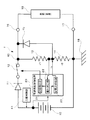
本発明の第一の実施の形態に係る電源装置1の要部構成について図1を参照して説明する。図1は、電源装置1の要部構成図である。電源装置1は、図1に示すように、バッテリ10、ダイオード11、スイッチ12、抵抗13、抵抗14、ダイオード15、端子16、端子17、接地18、電源供給制御装置20を備える。また、電源供給制御装置20は、短絡検出部21、電圧測定部22、定電流供給部23を備える。また、電源装置1には、負荷19が端子16、17を介して接続されている。また、バッテリ10を充電するための充電制御部41を備えるが、以下の説明には直接関係が無いので説明を省略する。なお、以下に説明において、抵抗値、電圧値、電流値については、それぞれ単位Ω(オーム)、V(ボルト)、A(アンペア)の記載および図示を省略することとする。
(About the principal part structure of the
A configuration of a main part of the
バッテリ10は直流電源であり、たとえばリチウムバッテリである。ダイオード11は、バッテリ10に対して電流が逆流することを阻止する部材である。スイッチ12は、バッテリ10による負荷19への電源供給をON(開始)/OFF(停止)する部材である。抵抗13および抵抗14は、スイッチ12がON状態のときに、バッテリ10から負荷19に供給される電流の一部が分岐点40により分岐されて流れることによって電圧を発生させる部材である。ダイオード15は、端子16側から電源供給制御装置20側への電流が逆流することを阻止する部材である。
The
なお、ダイオード15は、抵抗13の抵抗値r1が大きい値に設定されているので、定電流供給部23が動作して定電流を出力側に供給する場合に定電流isを、端子16側に流す役割を果たしている。
In addition, since the resistance value r1 of the
端子16および端子17は、負荷19が接続される部材である。接地18は、電源装置1に接地電位をもたらす部材である。負荷19は、通常は、バッテリ10により駆動される機器などである。ここで、負荷19によって端子16と端子17との間が短絡される場合とは、たとえば、ユーザが誤って負荷19が接続されている端子16、17にドライバーの先端などの金属を接触させるような場合が考えられる。あるいは、負荷19と端子16、17とを接続するための導線同士をユーザが誤って接触させてしまったような場合などが考えられる。
The
電源供給制御装置20は、負荷19の短絡検出または短絡解消検出した場合のスイッチ12の制御を行う部材である。電源供給制御装置20の短絡検出部21は、負荷19の短絡の有無を検出する部材である。電源供給制御装置20の電圧測定部22は、抵抗13、抵抗14によって発生する電圧を測定する部材である。定電流供給部23は、定電流を抵抗13と抵抗14との接続部に供給する部材である。これにより、定電流供給部23によりダイオード15の順バイアス方向に定電流が供給される。
The power
(電源供給制御装置20の動作原理について)
次に、電源供給制御装置20の動作原理について図1〜図8を参照して説明する。まず、電源供給制御装置20が短絡を検出する動作原理について図2〜図4を参照して説明する。抵抗13の抵抗値をr1とし、抵抗14の抵抗値をr2とする。以下では、r1+r2=Rとして説明する。このときに、抵抗13の抵抗値r1と抵抗14の抵抗値r2との和Rは、負荷19の内部抵抗値rLと比較してきわめて大きくなるように設定することが好ましい(rL<<R)。すなわち、バッテリ10から負荷19に電源が供給される際、分岐点40によって抵抗13および抵抗14の方向に分岐される電流は、負荷19を駆動するためには使われないため、負荷19の方向に流れる電流と比較してきわめて小さいことが好ましい。一方で、電圧測定部22が測定可能な電圧値は、電圧測定部22の設計上、所定の値に決められている。よって、抵抗14の抵抗値r2は、電圧測定部22が測定可能な電圧値となるように設定されている。
(About the operating principle of the power supply control device 20)
Next, the operation principle of the power
このように、2つの抵抗13および抵抗14による分圧回路を用いることにより、電圧測定部22が測定可能な電圧値を抵抗14の抵抗値を調整することによって実現しつつ抵抗13の抵抗値を調整することによって抵抗13と抵抗14の抵抗値の和Rを所望する大きな抵抗値とすることができる。
As described above, by using the voltage dividing circuit including the two
また、電圧測定部22を直流電圧計の記号によって表記する。さらに、図2、図3、図5、図6、図7では、動作原理の説明に直接関係の無いダイオード11の図示は省略する。
Moreover, the
状況1:負荷19が正常である場合(図2)
バッテリ10は、スイッチ12、端子16、端子17を介して負荷19に電源を供給している。この場合には、図2に示すように、分岐点40によって負荷19に流れる電流i1(一点鎖線)の一部が分岐され、抵抗13、14側に電流値i2の電流(二点鎖線)が流れる。この電流値i2の電流によって抵抗13と抵抗14との接続点にはi2×r2=v1の電圧値が発生する。よって、電圧測定部22は、電圧値v1を短絡検出部21に出力する。このときには、負荷19の内部抵抗値rLは、抵抗13、14による抵抗値Rと比較してきわめて小さい抵抗値(rL<<R)となるため、電流値i2は電流値i1と比較してきわめて小さい電流値(i2<<i1)となる。
Situation 1: When
The
状況2:負荷19に短絡が発生した場合(図3)
負荷19で短絡が発生すると、図3に示すように、負荷19が有する抵抗値r0Lは、ほぼ“0”になる(r0L≒0)。よって、負荷19に流れる電流値i3は、図2に示す電流値i1よりも増加する(i3>i1)。一方、抵抗13、14の分圧回路の間の電圧はほぼなくなるので、電圧測定部22は、電圧値“0”を短絡検出部21に出力する。
Situation 2: When a short circuit occurs in the load 19 (FIG. 3)
When a short circuit occurs in the
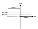
ここで、短絡検出部21は、図4に示すように、電圧測定部22の測定する電圧値v1が閾値Th♯1以下の“0”となったことを検出することにより、負荷19に短絡が発生したことを検出することができる。このようにして、短絡検出部21は、電圧測定部22により測定される電圧値によって負荷19の短絡の有無を検出することができる。これにより、短絡検出部21は、スイッチ12をOFF状態とすべく制御を実施する。この短絡検出の原理とスイッチ12をOFF状態にする動作は従来の短絡検出方法と同じである。なお、図示は省略するがスイッチ12には、電源供給制御装置20からの指示によってスイッチ12をON/OFFするためのスイッチ駆動機構を有する。なお、閾値Th♯2について後述する。この閾値Th♯2は請求項でいう所定の閾値に相当する。
Here, as shown in FIG. 4, the short-
状況3:スイッチ12が短絡によりOFF状態となった場合(図5)
短絡検出部21が負荷19で発生した短絡を検出すると、図3に示すように、スイッチ12をOFF状態となるように制御する。これにより、図5に示すように、電源装置1は、負荷19に対する電源供給を停止する。このときに、電圧測定部22は、電圧値“0”を短絡検出部21に出力する。
Situation 3: When
When the short
状況4:負荷19の短絡解消を検出する場合(図6)
負荷19で短絡が発生し、図5に示すように、スイッチ12がOFF状態になると、これを受けて、定電流供給部23は、図6に示すように、抵抗13と抵抗14との接続点に電流値isの定電流の供給を開始する。これにより、定電流供給部23は、ダイオード15の順バイアス方向に定電流を供給する。この電流値isは、たとえば10μAなどのきわめて小さい電流値である。この電流値isの定電流は、抵抗13の抵抗値r1をダイオード15の内部抵抗値よりも十分大きく設定しているので、ダイオード15、端子16、負荷19、端子17を介して接地18に流れる。この電流値isの定電流によって、ダイオード15には、is×(ダイオード15の内部抵抗)=v2の電圧値が発生する。なお、抵抗13の抵抗値r1はダイオード15の内部抵抗値より数千倍以上大きいことが好ましい。よって、電圧測定部22は、電圧値v2を短絡検出部21に出力する。また、電圧値v2は、ダイオード15の順方向電圧降下(Vf)に相当する。
Situation 4: When short-circuit elimination of the
When a short circuit occurs in the
状況5:負荷19の短絡が解消された場合(図7)
負荷19で発生した短絡が解消すると、図7に示すように、負荷19は、正常時の抵抗値rLに戻る。あるいは負荷19が接続状態となる。抵抗値r0L≒0であったので、rL>>r0Lとなる。これによって、抵抗14には、電流値i4の電流が流れる。これにより、抵抗14には、i4×r2=v3の電圧値が発生する。この抵抗14に流れる電流値i4の電流は出力側がオープン状態であれば電流値isの定電流と等しい。よって、電圧測定部22は、電圧値v3を短絡検出部21に出力する。なお、図7において負荷19を流れる電流値i5は、(=is−i4)になる。
Situation 5: When the short circuit of the
When the short circuit generated in the
ここで、短絡検出部21には、図8に示すように、閾値Th♯2が設定されている。この閾値Th♯2は、負荷19が短絡状態であるときには、v2≦Th♯2となり、負荷19の短絡が解消したときには、v3>Th♯2となるように設定されている。また、図4で説明した閾値Th♯1と比べると高い値である。すなわち、図4で説明した閾値Th♯1は、電圧値“0”よりも高ければよいのに対し、図8の閾値Th♯2は、電圧値v2(=Vf)よりも高くなければならないからである。
Here, as shown in FIG. 8, a threshold
このようにして、短絡検出部21は、電圧測定部22により計測される電圧値によって負荷19の短絡の解消を検出することができる。負荷19の短絡の解消を検出した短絡検出部21は、スイッチ12をON状態にすべく制御を実施する。これにより、電源装置1は、再び図2に示す状態に復帰する。また、このときに、定電流供給部23による電流値isの定電流の供給を停止する。
In this way, the short
このようにして、電源供給制御装置20は、負荷19の短絡発生および短絡解消を検出し、スイッチ12のON/OFF制御を行うことができる。
In this way, the power
以上の電源供給制御装置20の動作手順を図9のフローチャートに示す。
START:電源供給制御装置20は、電源装置1が稼働を開始すると、ステップS1の処理へ移行する。なお、電源装置1が稼働を開始するとは、不図示の電源装置1の起動スイッチがON状態となる。あるいは、バッテリ10が電源装置1に装着されるなどの状態をいう。
The operation procedure of the power
START: When the
ステップS1:短絡検出部21は、電圧測定部22の測定する電圧値が閾値Th♯1以下になったか否かを判断する。短絡検出部21は、電圧測定部22から出力される電圧値が短絡が発生したことを判断する閾値Th♯1よりも高いv1であれば(ステップS1でNo)、ステップS1の処理を繰り返す。一方、短絡検出部21は、電圧測定部22から出力される電圧値が閾値Th♯1以下である“0”であれば(ステップS1でYes)、ステップS2の処理へ移行する。
Step S1: The short-
ステップS2:短絡検出部21は、負荷19が短絡状態と判断してスイッチ12をOFF状態に制御し、ステップS3の処理へ移行する。
Step S2: The short-
ステップS3:短絡検出部21は、定電流供給部23に指示を行い、定電流の供給を開始し、ステップS4の処理へ移行する。
Step S3: The short
ステップS4:短絡検出部21は、電圧測定部22から出力される電圧値が閾値Th♯2以上か否かを判断する。短絡検出部21は、電圧測定部22から出力される電圧値が閾値Th♯2未満であれば(ステップS4でNo)、ステップS4の処理を繰り返す。一方、短絡検出部21は、電圧測定部22から出力される電圧値が閾値Th♯2以上であれば(ステップS4でYes)、ステップS5の処理へ移行する。
Step S4: The short
ステップS5:短絡検出部21は、負荷19の短絡状態が解消したと判断してスイッチ12をON状態に制御すると共に定電流供給部23に指示を行い、定電流の供給を停止してステップS1の処理へ戻る。
Step S5: The short-
次に、電源供給制御装置20の動作をタイムチャートとして図10に示す。図10では、電圧測定部22による測定電圧値、短絡検出部21によるスイッチ制御および定電流供給部23による定電流供給について併記する。さらに、参考として、端子16、17における端子電圧についても併記する。
Next, the operation of the power
T1:短絡無し
電圧測定部22は、電圧値v1を出力する。このとき短絡検出部21は、短絡を検出していないため、スイッチ12をON状態としている。また、短絡検出部21は、定電流供給部23に対して定電流供給を指示していない。また、このときの端子16、17の電圧値はvTとする。
T1: No short circuit The
T2:短絡発生
電圧測定部22は、電圧値“0”を出力する。短絡検出部21は、閾値Th♯1よりも低い電圧値“0”が電圧測定部22から出力されたので短絡を検出する。ここで、短絡状態と判断された場合、バッテリ(電源)10を保護する必要があるので、スイッチ12をOFF状態に移行する時間は速い方が好ましく、スイッチ12をOFF状態に移行する時間は、たとえば500μsec(マイクロセコンド)以下が好ましい。このとき短絡検出部21は、バッテリ10にとって影響の無い瞬間的な短絡については無視したいので多少の監視時間を設けてある。この監視時間は、たとえば250μsecである。また、このときの端子16、17の電圧値は“0”になる。したがって、スイッチ12をOFF状態に移行する時間は、たとえば250μsec〜500μsec以下が好ましい。
T2: Short circuit occurrence The
T3:スイッチOFF制御実施、定電流供給開始
短絡検出部21は、監視時間(たとえば250μsec)が経過すると、スイッチ12をOFF状態に制御する。また、短絡検出部21は、スイッチ12をOFF状態に制御すると共に、定電流供給部23に定電流供給の指示を出す。定電流供給部23は、短絡検出部21からの指示を受けて定電流の供給を開始する。また、このときの端子16、17の電圧値は“0”のままである。
T3: Implementation of switch OFF control, start of constant current supply The short-
T4:短絡継続
負荷19の短絡が継続している状態では、定電流供給部23がダイオード15の順バイアス方向に供給する定電流によってダイオード15にはダイオード15の順方向電圧降下Vfに相当する電圧値v2が発生し続ける。電圧測定部22は、この電圧値v2を短絡検出部21に出力する。短絡検出部21は、電圧測定部22からの電圧値v2と閾値Th♯2とを比較し、電圧値v2が閾値Th♯2未満であるので短絡が解消していないと判断する。また、このときの端子16、17の電圧値は“0”のままである。
T4: Continued short circuit In a state where the short circuit of the
T5:短絡解消検出
負荷19の短絡が解消すると、定電流供給部23が供給する定電流は抵抗14側に流れるようになる。これにより、電圧測定部22は、閾値Th♯2以上の電圧値v3を短絡検出部21に出力する。短絡検出部21は、電圧値v3と閾値Th♯2とを比較し、電圧値v3(V)がTh♯2以上であるので負荷19の短絡解消を検出する。このとき短絡検出部21は、瞬間的な短絡解消については無視したいので多少の監視時間を設けてある。この監視時間は、たとえば250μsec(マイクロセコンド)である。また、このときの端子16、17の電圧値vtは、(i5×rL)となる。
T5: Short circuit elimination detection When the short circuit of the
T6:スイッチON制御実施、定電流供給停止
短絡検出部21は、監視時間(たとえば250μsec)が経過すると、スイッチ12をON状態に制御すると共に定電流供給部23に対して定電流供給の停止を指示する。定電流供給部23は、短絡検出部21からの定電流供給の停止指示を受け取ると定電流の供給を停止する。
T6: Switch ON control implementation, constant current supply stop When the monitoring time (for example, 250 μsec) elapses, the short-
これにより、電源装置1は、負荷19の短絡が解消されると直ちに負荷19への電源供給を再開することができる。これは、できる限り速やかな電源供給の再開を望むユーザにとってユーザの要求を満足するものである。また、特許文献1の過負荷保護回路のように、短絡解消をスイッチ12を定期的にON状態に戻して判断すると、短絡状態が解消していなければ、短時間ではあるがバッテリ10から大きな電流が流れることになる。これはバッテリ10の容量を急速に低下させる原因となる。電源装置1では、ごく微小な定電流(たとえば10μA)によって短絡解消の検出を行うため、短絡解消検出のためにバッテリ10の容量を低下させるといったことも回避できる。
Thereby, the
(本発明の第二の実施の形態に係る電源装置1Aの要部構成について)
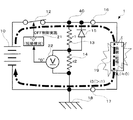
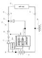
本発明の第二の実施の形態に係る電源装置1Aの要部構成について図11を参照して説明する。図11は、電源装置1Aの要部構成図である。電源装置1Aは、電源装置1とは一部が異なる。以下では、第一の実施の形態と同一または同種の部材は同一または同一系の符号を用いて説明し、その説明を省略または簡略化し、かつ異なる部材について主として説明する。
(About the principal part structure of the power supply device 1A which concerns on 2nd embodiment of this invention)
The configuration of the main part of the power supply device 1A according to the second embodiment of the present invention will be described with reference to FIG. FIG. 11 is a main part configuration diagram of the power supply device 1A. The power supply device 1A is partially different from the
電源装置1Aは、電源装置1が備える抵抗13、抵抗14を備えない。また、電源装置1Aは、電源供給制御装置20Aを備える。電源供給制御装置20Aは、短絡検出部21A、電圧測定部22A、定電流供給部23Aを備える。
The power supply device 1A does not include the
短絡検出部21Aの処理および動作については第一の実施の形態における短絡検出部21と同じである。
The processing and operation of the short-
定電流供給部23Aは、電源装置1Aが稼働中であれば常時、電流値isの定電流をダイオード15の順バイアス方向に対して供給し続ける。これにより、電圧測定部22Aは、ダイオード15および負荷19の内部抵抗と定電流供給部23Aがダイオード15の順バイアス方向に対して供給する電流値isの定電流とによって生じる電圧値を測定する。
The constant
(電源供給制御装置20Aの動作原理について)
次に、電源供給制御装置20Aの動作原理について図12を参照して説明する。負荷19が正常(短絡無し)である場合(図12のT1)、電圧測定部22Aは、ダイオード15および負荷19の内部抵抗と定電流供給部23Aがダイオード15の順バイアス方向に対して供給する電流値isの定電流とによって生じる電圧値v1Aを測定している。
(About the operating principle of the power supply control device 20A)
Next, the operating principle of the power supply control device 20A will be described with reference to FIG. When the
電圧測定部22Aの測定結果は、短絡検出部21Aに出力される。短絡検出部21Aは、電圧測定部22Aの測定結果が電圧値v1Aである場合、負荷19は正常(短絡無し)と判定する。
The measurement result of the
ここで、負荷19に短絡が発生すると(図12のT2)、ダイオード15の分岐41側は接地18と同電位となる。これにより、電圧測定部22Aが測定する電圧値は、ダイオード15の内部抵抗と定電流供給部23Aがダイオード15の順バイアス方向に対して供給する定電流とによって生じるダイオード15の順方向電圧降下Vfに相当する電圧値v2となる。
Here, when a short circuit occurs in the load 19 (T2 in FIG. 12), the
短絡検出部21Aは、電圧測定部22Aの測定結果が電圧値v2となったことを受け、負荷19における短絡発生を検出し、スイッチ12をOFF状態に制御する(図12のT3)。短絡検出部21Aは、電圧測定部22Aの測定結果が電圧値v2である内は短絡継続としてスイッチ12をOFF状態のまま待機する(図12のT4)。
In response to the measurement result of the
ここで、負荷19の短絡が解消すると、電圧測定部22Aは、再びダイオード15および負荷19の内部抵抗と定電流供給部23Aがダイオード15の順バイアス方向に対して供給する電流値isの定電流とによって生じる電圧値v1Aを測定するようになる。短絡検出部21Aは、電圧測定部22Aの測定結果が電圧値v1Aに復帰したことを受けて短絡解消を検出する(図12のT5)。
Here, when the short circuit of the
短絡検出部21Aは、短絡解消を検出するとスイッチ12をON状態に制御する(図12のT6)。
When the short
電源供給制御装置20Aの動作手順を示すフローチャートは、図9に示した電源供給制御装置20の動作手順を示すフローチャートの内、ステップS3の「定電流供給開始」を削除したものと同じになる。すなわち、電源供給制御装置20Aでは、電源装置1Aの稼働中には常時、定電流供給部23Aからダイオード15の順バイアス方向に対して定電流を供給し続けている。このため、図9のステップS3の処理は不要である。なお、図4に示すv1は、第二の実施の形態ではv1Aに置き替えられる。また、図8に示すv3は、第二の実施の形態ではv1Aに置き替えられる。
The flowchart showing the operation procedure of the power supply control device 20A is the same as the flowchart showing the operation procedure of the power
(ICおよびプログラムを用いる実施の形態)
電源供給制御装置20は、短絡検出部21、電圧測定部22、定電流供給部23の3つの機能ブロックからなる構成として説明したが、これらの機能を併せ持つ1つの電子回路を構成し、この電子回路をIC(Integrated Circuit)として実現することができる。
(Embodiment using IC and program)
The power
あるいは、電源供給制御装置20の短絡検出部21、電圧測定部22、定電流供給部23は、所定のプログラムにより動作する汎用の情報処理装置(CPU(Central Processing Unit)、DSP(Digital Signal
Processor)、マイクロプロセッサ(マイクロコンピュータ)など)によって構成されてもよい。例えば、汎用の情報処理装置は、メモリ、CPU、入出力ポートなどを有する。汎用の情報処理装置のCPUは、メモリなどから所定のプログラムとして制御プログラムを読み込んで実行する。これにより、汎用の情報処理装置には、電源供給制御装置20の短絡検出部21、電圧測定部22、定電流供給部23の機能が実現される。
Alternatively, the short-
Processor), a microprocessor (microcomputer), or the like. For example, a general-purpose information processing apparatus has a memory, a CPU, an input / output port, and the like. The CPU of the general-purpose information processing apparatus reads and executes a control program as a predetermined program from a memory or the like. Thereby, the functions of the short-
なお、汎用の情報処理装置が実行する制御プログラムは、電源供給制御装置20の出荷前に、汎用の情報処理装置のメモリなどに記憶されたものであっても、電源供給制御装置20の出荷後に、汎用の情報処理装置のメモリなどに記憶されたものであってもよい。また、制御プログラムの一部が、電源供給制御装置20の出荷後に、汎用の情報処理装置のメモリなどに記憶されたものであってもよい。電源供給制御装置20の出荷後に、汎用の情報処理装置のメモリなどに記憶される制御プログラムは、例えば、CD−ROMなどのコンピュータ読取可能な記録媒体に記憶されているものをインストールしたものであっても、インターネットなどの伝送媒体を介してダウンロードしたものをインストールしたものであってもよい。
Even if the control program executed by the general-purpose information processing apparatus is stored in the memory or the like of the general-purpose information processing apparatus before the power
また、制御プログラムは、汎用の情報処理装置によって直接実行可能なものだけでなく、ハードディスクなどにインストールすることによって実行可能となるものも含む。また、圧縮されたり、暗号化されたりしたものも含む。 The control program includes not only a program that can be directly executed by a general-purpose information processing apparatus, but also a program that can be executed by being installed on a hard disk or the like. Also included are those that are compressed or encrypted.
また、電源供給制御装置20を、上述したように、ICあるいは汎用の情報処理装置(CPU、DSP、マイクロプロセッサ(マイクロコンピュータ)など)によって構成して小型化することにより、バッテリ10を内蔵するバッテリパック内部に組み込むことができる。
Further, as described above, the power
これにより、電源装置1をバッテリパックなどに内蔵可能な小型な構成としながら電源装置1の過負荷状態が検出されると電源供給を停止し、電源装置1の過負荷状態が解消されると直ちに電源供給を再開することができる電源装置1を実現することができる。
As a result, the power supply is stopped when the overload state of the
(その他の実施の形態)
本発明の実施の形態は、その要旨を逸脱しない限り、様々に変更が可能である。たとえば、図9のフローチャートにおいて、ステップS1の電圧値が閾値Th♯1以下であるか否かを判断する処理を、電圧値が閾値Th♯1未満であるか否かを判断する処理に変更してもよい。ステップS4の電圧値が閾値Th♯2以上であるか否かを判断する処理を、電圧値が閾値Th♯2を超えたか否かを判断する処理に変更してもよい。
(Other embodiments)
The embodiment of the present invention can be variously modified without departing from the gist thereof. For example, in the flowchart of FIG. 9, the process of determining whether or not the voltage value in step S1 is less than or equal to threshold
また、第一の実施の形態における定電流供給部23が供給する定電流については、きわめて微小な電流値であるため、電源装置1が稼働中には常時流すようにしてもバッテリ10の寿命に対する影響は少ない。よって、定電流供給部23が供給する定電流については、第二の実施の形態と同様に、第一の実施の形態においても電源装置1の稼働中には常時流すようにしてもよい。この場合、図9のフローチャートにおけるステップS3の処理「定電流供給開始」は削除される。
In addition, the constant current supplied by the constant
この場合には、図3に示した負荷19の短絡発生時において、電圧測定部22の出力は“0”にはならない。すなわち、負荷19に短絡が発生した場合には、定電流供給部23からの定電流がダイオード15の順バイアス方向に供給されるので、電圧測定部22に表れる電圧はv2(=Vt)である。なお、この場合でも電流値isは微小であるため、閾値Th♯2>閾値Th♯1の関係には変わりはない。
In this case, when the short circuit of the
1、1A…電源装置、10…バッテリ(電源)、13、14…抵抗(出力側と並列に接続される回路)、15…ダイオード(出力側と並列に接続される回路)、16、17…端子、19…負荷、20、20A…電源供給制御装置、21、21A…短絡検出部、22、22A…電圧測定部、23、23A…定電流供給部
DESCRIPTION OF
Claims (3)
前記一対の端子の電圧と所定の関係にある電圧を測定する電圧測定部と、
この電圧測定部の測定した電圧から、前記一対の端子間における短絡の存在を検出し、短絡の存在が検出されたときには、前記一対の端子への電力の供給を停止させる短絡検出部と、
定電流を前記一対の端子間に供給する定電流供給部と、
を備え、
前記定電流供給部は、前記一対の端子へ供給される電力に対して逆バイアスとなり、前記定電流に対して順バイアスとなるダイオードを介して、前記定電流を前記一対の端子間に供給し、
前記電圧測定部は、前記定電流供給部と前記ダイオードとの接続点の電圧を測定し、
前記短絡検出部は、前記定電流供給部が前記一対の端子間に前記定電流を供給している状態で、前記電圧測定部の測定した電圧が所定の閾値以上または所定の閾値を超えたときに、前記負荷の短絡が解消されたことを検出する
ことを特徴とする電力供給制御装置。 In a power supply control device that controls supply of power to a pair of terminals to which a load is connected,
A voltage measuring unit for measuring a voltage in a predetermined relationship with the voltage of the pair of terminals;
From the voltage measured by this voltage measurement unit, the presence of a short circuit between the pair of terminals is detected, and when the presence of a short circuit is detected, a short circuit detection unit that stops the supply of power to the pair of terminals;
A constant current supply unit for supplying a constant current between the pair of terminals;
With
The constant current supply unit supplies the constant current between the pair of terminals via a diode that is reverse-biased with respect to the power supplied to the pair of terminals and is forward-biased with respect to the constant current. ,
The voltage measurement unit measures a voltage at a connection point between the constant current supply unit and the diode,
When the voltage measured by the voltage measurement unit exceeds a predetermined threshold or exceeds a predetermined threshold in a state where the constant current supply unit supplies the constant current between the pair of terminals, And detecting that the short circuit of the load has been eliminated.
前記一対の端子に電力を供給するバッテリと、
前記バッテリから前記負荷に供給される電力を接続または切断するスイッチと、
前記スイッチを選択的に制御し、前記一対の端子間に短絡の存在が検出されたときには前記スイッチを切断し、前記短絡が解消されたときには前記スイッチを接続する電力供給制御装置と、
を備え、
前記電力供給制御装置は、
前記一対の端子の電圧と所定の関係にある電圧を測定する電圧測定部と、
この電圧測定部の測定した電圧から、前記一対の端子間における短絡の存在を検出し、短絡の存在が検出されたときには、前記スイッチに、前記一対の端子への電力の供給を切断させる短絡検出部と、
定電流を前記一対の端子間に供給する定電流供給部と、
を有し、
前記定電流供給部は、前記一対の端子へ供給される電力に対して逆バイアスとなり、前記定電流に対して順バイアスとなるダイオードを介して、前記定電流を前記一対の端子間に供給し、
前記電圧測定部は、前記定電流供給部と前記ダイオードとの接続点の電圧を測定し、
前記短絡検出部は、前記定電流供給部が前記一対の端子間に前記定電流を供給している状態で、前記電圧測定部の測定した電圧が所定の閾値以上または所定の閾値を超えたときに、前記負荷の短絡が解消されたことを検出する
ことを特徴とする電源装置。 A pair of terminals to which a load is connected;
A battery for supplying power to the pair of terminals;
A switch for connecting or disconnecting power supplied from the battery to the load;
A power supply control device that selectively controls the switch, disconnects the switch when the presence of a short circuit is detected between the pair of terminals, and connects the switch when the short circuit is resolved;
With
The power supply control device includes:
A voltage measuring unit for measuring a voltage in a predetermined relationship with the voltage of the pair of terminals;
From the voltage measured by the voltage measuring unit, the presence of a short circuit between the pair of terminals is detected, and when the presence of a short circuit is detected, the switch causes the switch to cut off the supply of power to the pair of terminals. And
A constant current supply unit for supplying a constant current between the pair of terminals;
Have
The constant current supply unit supplies the constant current between the pair of terminals via a diode that is reverse-biased with respect to the power supplied to the pair of terminals and is forward-biased with respect to the constant current. ,
The voltage measurement unit measures a voltage at a connection point between the constant current supply unit and the diode,
When the voltage measured by the voltage measurement unit exceeds a predetermined threshold or exceeds a predetermined threshold in a state where the constant current supply unit supplies the constant current between the pair of terminals, Further, it is detected that the short circuit of the load has been eliminated.
測定した電圧から、前記一対の端子間における短絡の存在を検出し、
短絡の存在が検出されたときには、前記一対の端子への電力の供給を停止させる
電力供給制御方法において、
前記一対の端子間には、定電流供給部から、前記一対の端子へ供給される電力に対して逆バイアスとなり前記定電流に対して順バイアスとなるダイオードを介して、定電流が供給され、
前記一対の端子の電圧と所定の関係にある電圧は、前記定電流供給部と前記ダイオードとの接続点で測定され、
前記一対の端子間に前記定電流を供給している状態で、前記測定した電圧が所定の閾値以上または所定の閾値を超えたときに、前記負荷の短絡が解消されたことを検出する
ことを特徴とする電力供給制御方法。 Load measures the voltage and the voltage on the predetermined relationship of the pair of pin to be connected,
From the measured voltage, detect the presence of a short circuit between the pair of terminals,
When the presence of the short circuit is detected, Ru stops the supply of power to the pair of terminals
In the power supply control method,
A constant current is supplied between the pair of terminals via a diode that is reverse-biased with respect to the power supplied to the pair of terminals from the constant-current supply unit and is forward-biased with respect to the constant current.
The voltage in a predetermined relationship with the voltage of the pair of terminals is measured at a connection point between the constant current supply unit and the diode,
Detecting that the short circuit of the load has been eliminated when the measured voltage exceeds a predetermined threshold or exceeds a predetermined threshold in a state where the constant current is supplied between the pair of terminals. A power supply control method characterized.
Priority Applications (2)
| Application Number | Priority Date | Filing Date | Title |
|---|---|---|---|
| JP2009079798A JP5292155B2 (en) | 2009-03-27 | 2009-03-27 | Power supply control device, power supply device, and power supply control method |
| US12/659,951 US8369056B2 (en) | 2009-03-27 | 2010-03-25 | Power supply control device, method for controlling power supply, program and power supply device |
Applications Claiming Priority (1)
| Application Number | Priority Date | Filing Date | Title |
|---|---|---|---|
| JP2009079798A JP5292155B2 (en) | 2009-03-27 | 2009-03-27 | Power supply control device, power supply device, and power supply control method |
Publications (3)
| Publication Number | Publication Date |
|---|---|
| JP2010233389A JP2010233389A (en) | 2010-10-14 |
| JP2010233389A5 JP2010233389A5 (en) | 2012-05-10 |
| JP5292155B2 true JP5292155B2 (en) | 2013-09-18 |
Family
ID=42934188
Family Applications (1)
| Application Number | Title | Priority Date | Filing Date |
|---|---|---|---|
| JP2009079798A Expired - Fee Related JP5292155B2 (en) | 2009-03-27 | 2009-03-27 | Power supply control device, power supply device, and power supply control method |
Country Status (2)
| Country | Link |
|---|---|
| US (1) | US8369056B2 (en) |
| JP (1) | JP5292155B2 (en) |
Cited By (1)
| Publication number | Priority date | Publication date | Assignee | Title |
|---|---|---|---|---|
| US11381095B2 (en) * | 2018-02-01 | 2022-07-05 | Gs Yuasa International Ltd. | Management device, energy storage apparatus, and management method for energy storage device |
Families Citing this family (384)
| Publication number | Priority date | Publication date | Assignee | Title |
|---|---|---|---|---|
| US20070084897A1 (en) | 2003-05-20 | 2007-04-19 | Shelton Frederick E Iv | Articulating surgical stapling instrument incorporating a two-piece e-beam firing mechanism |
| US9060770B2 (en) | 2003-05-20 | 2015-06-23 | Ethicon Endo-Surgery, Inc. | Robotically-driven surgical instrument with E-beam driver |
| US11890012B2 (en) | 2004-07-28 | 2024-02-06 | Cilag Gmbh International | Staple cartridge comprising cartridge body and attached support |
| US8215531B2 (en) | 2004-07-28 | 2012-07-10 | Ethicon Endo-Surgery, Inc. | Surgical stapling instrument having a medical substance dispenser |
| US11246590B2 (en) | 2005-08-31 | 2022-02-15 | Cilag Gmbh International | Staple cartridge including staple drivers having different unfired heights |
| US7669746B2 (en) | 2005-08-31 | 2010-03-02 | Ethicon Endo-Surgery, Inc. | Staple cartridges for forming staples having differing formed staple heights |
| US10159482B2 (en) | 2005-08-31 | 2018-12-25 | Ethicon Llc | Fastener cartridge assembly comprising a fixed anvil and different staple heights |
| US9237891B2 (en) | 2005-08-31 | 2016-01-19 | Ethicon Endo-Surgery, Inc. | Robotically-controlled surgical stapling devices that produce formed staples having different lengths |
| US7934630B2 (en) | 2005-08-31 | 2011-05-03 | Ethicon Endo-Surgery, Inc. | Staple cartridges for forming staples having differing formed staple heights |
| US11484312B2 (en) | 2005-08-31 | 2022-11-01 | Cilag Gmbh International | Staple cartridge comprising a staple driver arrangement |
| US20070106317A1 (en) | 2005-11-09 | 2007-05-10 | Shelton Frederick E Iv | Hydraulically and electrically actuated articulation joints for surgical instruments |
| US7753904B2 (en) | 2006-01-31 | 2010-07-13 | Ethicon Endo-Surgery, Inc. | Endoscopic surgical instrument with a handle that can articulate with respect to the shaft |
| US20110290856A1 (en) | 2006-01-31 | 2011-12-01 | Ethicon Endo-Surgery, Inc. | Robotically-controlled surgical instrument with force-feedback capabilities |
| US20110024477A1 (en) | 2009-02-06 | 2011-02-03 | Hall Steven G | Driven Surgical Stapler Improvements |
| US8708213B2 (en) | 2006-01-31 | 2014-04-29 | Ethicon Endo-Surgery, Inc. | Surgical instrument having a feedback system |
| US8186555B2 (en) | 2006-01-31 | 2012-05-29 | Ethicon Endo-Surgery, Inc. | Motor-driven surgical cutting and fastening instrument with mechanical closure system |
| US11224427B2 (en) | 2006-01-31 | 2022-01-18 | Cilag Gmbh International | Surgical stapling system including a console and retraction assembly |
| US8820603B2 (en) | 2006-01-31 | 2014-09-02 | Ethicon Endo-Surgery, Inc. | Accessing data stored in a memory of a surgical instrument |
| US11793518B2 (en) | 2006-01-31 | 2023-10-24 | Cilag Gmbh International | Powered surgical instruments with firing system lockout arrangements |
| US20120292367A1 (en) | 2006-01-31 | 2012-11-22 | Ethicon Endo-Surgery, Inc. | Robotically-controlled end effector |
| US11278279B2 (en) | 2006-01-31 | 2022-03-22 | Cilag Gmbh International | Surgical instrument assembly |
| US7845537B2 (en) | 2006-01-31 | 2010-12-07 | Ethicon Endo-Surgery, Inc. | Surgical instrument having recording capabilities |
| US8992422B2 (en) | 2006-03-23 | 2015-03-31 | Ethicon Endo-Surgery, Inc. | Robotically-controlled endoscopic accessory channel |
| US8322455B2 (en) | 2006-06-27 | 2012-12-04 | Ethicon Endo-Surgery, Inc. | Manually driven surgical cutting and fastening instrument |
| US10568652B2 (en) | 2006-09-29 | 2020-02-25 | Ethicon Llc | Surgical staples having attached drivers of different heights and stapling instruments for deploying the same |
| US8652120B2 (en) | 2007-01-10 | 2014-02-18 | Ethicon Endo-Surgery, Inc. | Surgical instrument with wireless communication between control unit and sensor transponders |
| US8684253B2 (en) | 2007-01-10 | 2014-04-01 | Ethicon Endo-Surgery, Inc. | Surgical instrument with wireless communication between a control unit of a robotic system and remote sensor |
| US11291441B2 (en) | 2007-01-10 | 2022-04-05 | Cilag Gmbh International | Surgical instrument with wireless communication between control unit and remote sensor |
| US20080169332A1 (en) | 2007-01-11 | 2008-07-17 | Shelton Frederick E | Surgical stapling device with a curved cutting member |
| US11039836B2 (en) | 2007-01-11 | 2021-06-22 | Cilag Gmbh International | Staple cartridge for use with a surgical stapling instrument |
| US20090001121A1 (en) | 2007-03-15 | 2009-01-01 | Hess Christopher J | Surgical staple having an expandable portion |
| US8931682B2 (en) | 2007-06-04 | 2015-01-13 | Ethicon Endo-Surgery, Inc. | Robotically-controlled shaft based rotary drive systems for surgical instruments |
| US11672531B2 (en) | 2007-06-04 | 2023-06-13 | Cilag Gmbh International | Rotary drive systems for surgical instruments |
| US7753245B2 (en) | 2007-06-22 | 2010-07-13 | Ethicon Endo-Surgery, Inc. | Surgical stapling instruments |
| US11849941B2 (en) | 2007-06-29 | 2023-12-26 | Cilag Gmbh International | Staple cartridge having staple cavities extending at a transverse angle relative to a longitudinal cartridge axis |
| US8573465B2 (en) | 2008-02-14 | 2013-11-05 | Ethicon Endo-Surgery, Inc. | Robotically-controlled surgical end effector system with rotary actuated closure systems |
| US9179912B2 (en) | 2008-02-14 | 2015-11-10 | Ethicon Endo-Surgery, Inc. | Robotically-controlled motorized surgical cutting and fastening instrument |
| US8636736B2 (en) | 2008-02-14 | 2014-01-28 | Ethicon Endo-Surgery, Inc. | Motorized surgical cutting and fastening instrument |
| US7819298B2 (en) | 2008-02-14 | 2010-10-26 | Ethicon Endo-Surgery, Inc. | Surgical stapling apparatus with control features operable with one hand |
| US7866527B2 (en) | 2008-02-14 | 2011-01-11 | Ethicon Endo-Surgery, Inc. | Surgical stapling apparatus with interlockable firing system |
| BRPI0901282A2 (en) | 2008-02-14 | 2009-11-17 | Ethicon Endo Surgery Inc | surgical cutting and fixation instrument with rf electrodes |
| US8758391B2 (en) | 2008-02-14 | 2014-06-24 | Ethicon Endo-Surgery, Inc. | Interchangeable tools for surgical instruments |
| US10390823B2 (en) | 2008-02-15 | 2019-08-27 | Ethicon Llc | End effector comprising an adjunct |
| US11648005B2 (en) | 2008-09-23 | 2023-05-16 | Cilag Gmbh International | Robotically-controlled motorized surgical instrument with an end effector |
| US9386983B2 (en) | 2008-09-23 | 2016-07-12 | Ethicon Endo-Surgery, Llc | Robotically-controlled motorized surgical instrument |
| US9005230B2 (en) | 2008-09-23 | 2015-04-14 | Ethicon Endo-Surgery, Inc. | Motorized surgical instrument |
| US8210411B2 (en) | 2008-09-23 | 2012-07-03 | Ethicon Endo-Surgery, Inc. | Motor-driven surgical cutting instrument |
| US8608045B2 (en) | 2008-10-10 | 2013-12-17 | Ethicon Endo-Sugery, Inc. | Powered surgical cutting and stapling apparatus with manually retractable firing system |
| US8517239B2 (en) | 2009-02-05 | 2013-08-27 | Ethicon Endo-Surgery, Inc. | Surgical stapling instrument comprising a magnetic element driver |
| BRPI1008667A2 (en) | 2009-02-06 | 2016-03-08 | Ethicom Endo Surgery Inc | improvement of the operated surgical stapler |
| US8220688B2 (en) | 2009-12-24 | 2012-07-17 | Ethicon Endo-Surgery, Inc. | Motor-driven surgical cutting instrument with electric actuator directional control assembly |
| US8851354B2 (en) | 2009-12-24 | 2014-10-07 | Ethicon Endo-Surgery, Inc. | Surgical cutting instrument that analyzes tissue thickness |
| US8783543B2 (en) | 2010-07-30 | 2014-07-22 | Ethicon Endo-Surgery, Inc. | Tissue acquisition arrangements and methods for surgical stapling devices |
| US10945731B2 (en) | 2010-09-30 | 2021-03-16 | Ethicon Llc | Tissue thickness compensator comprising controlled release and expansion |
| US11849952B2 (en) | 2010-09-30 | 2023-12-26 | Cilag Gmbh International | Staple cartridge comprising staples positioned within a compressible portion thereof |
| US9386988B2 (en) | 2010-09-30 | 2016-07-12 | Ethicon End-Surgery, LLC | Retainer assembly including a tissue thickness compensator |
| US11812965B2 (en) | 2010-09-30 | 2023-11-14 | Cilag Gmbh International | Layer of material for a surgical end effector |
| US9861361B2 (en) | 2010-09-30 | 2018-01-09 | Ethicon Llc | Releasable tissue thickness compensator and fastener cartridge having the same |
| US9629814B2 (en) | 2010-09-30 | 2017-04-25 | Ethicon Endo-Surgery, Llc | Tissue thickness compensator configured to redistribute compressive forces |
| US8864009B2 (en) | 2010-09-30 | 2014-10-21 | Ethicon Endo-Surgery, Inc. | Tissue thickness compensator for a surgical stapler comprising an adjustable anvil |
| US9839420B2 (en) | 2010-09-30 | 2017-12-12 | Ethicon Llc | Tissue thickness compensator comprising at least one medicament |
| US11298125B2 (en) | 2010-09-30 | 2022-04-12 | Cilag Gmbh International | Tissue stapler having a thickness compensator |
| US8695866B2 (en) | 2010-10-01 | 2014-04-15 | Ethicon Endo-Surgery, Inc. | Surgical instrument having a power control circuit |
| CN102162823B (en) * | 2011-01-12 | 2013-02-27 | 中兴通讯股份有限公司 | Method and device for detecting state of overcurrent protector of battery |
| JP6026509B2 (en) | 2011-04-29 | 2016-11-16 | エシコン・エンド−サージェリィ・インコーポレイテッドEthicon Endo−Surgery,Inc. | Staple cartridge including staples disposed within a compressible portion of the staple cartridge itself |
| US11207064B2 (en) | 2011-05-27 | 2021-12-28 | Cilag Gmbh International | Automated end effector component reloading system for use with a robotic system |
| US9072535B2 (en) | 2011-05-27 | 2015-07-07 | Ethicon Endo-Surgery, Inc. | Surgical stapling instruments with rotatable staple deployment arrangements |
| US9044230B2 (en) | 2012-02-13 | 2015-06-02 | Ethicon Endo-Surgery, Inc. | Surgical cutting and fastening instrument with apparatus for determining cartridge and firing motion status |
| JP5735445B2 (en) * | 2012-03-13 | 2015-06-17 | 旭化成エレクトロニクス株式会社 | Power connection circuit |
| JP6305979B2 (en) | 2012-03-28 | 2018-04-04 | エシコン・エンド−サージェリィ・インコーポレイテッドEthicon Endo−Surgery,Inc. | Tissue thickness compensator with multiple layers |
| BR112014024098B1 (en) | 2012-03-28 | 2021-05-25 | Ethicon Endo-Surgery, Inc. | staple cartridge |
| MX353040B (en) | 2012-03-28 | 2017-12-18 | Ethicon Endo Surgery Inc | Retainer assembly including a tissue thickness compensator. |
| FR2991779B1 (en) * | 2012-06-12 | 2014-07-11 | Commissariat Energie Atomique | BATTERY OF ACCUMULATORS PROTECTED AGAINST SHORT CIRCUITS EXTERNAL |
| US9101358B2 (en) | 2012-06-15 | 2015-08-11 | Ethicon Endo-Surgery, Inc. | Articulatable surgical instrument comprising a firing drive |
| US20140001231A1 (en) | 2012-06-28 | 2014-01-02 | Ethicon Endo-Surgery, Inc. | Firing system lockout arrangements for surgical instruments |
| US9289256B2 (en) | 2012-06-28 | 2016-03-22 | Ethicon Endo-Surgery, Llc | Surgical end effectors having angled tissue-contacting surfaces |
| BR112014032776B1 (en) | 2012-06-28 | 2021-09-08 | Ethicon Endo-Surgery, Inc | SURGICAL INSTRUMENT SYSTEM AND SURGICAL KIT FOR USE WITH A SURGICAL INSTRUMENT SYSTEM |
| EP2866686A1 (en) | 2012-06-28 | 2015-05-06 | Ethicon Endo-Surgery, Inc. | Empty clip cartridge lockout |
| US11202631B2 (en) | 2012-06-28 | 2021-12-21 | Cilag Gmbh International | Stapling assembly comprising a firing lockout |
| US9649111B2 (en) | 2012-06-28 | 2017-05-16 | Ethicon Endo-Surgery, Llc | Replaceable clip cartridge for a clip applier |
| US20140001234A1 (en) | 2012-06-28 | 2014-01-02 | Ethicon Endo-Surgery, Inc. | Coupling arrangements for attaching surgical end effectors to drive systems therefor |
| US9204879B2 (en) | 2012-06-28 | 2015-12-08 | Ethicon Endo-Surgery, Inc. | Flexible drive member |
| US9337648B2 (en) * | 2012-08-13 | 2016-05-10 | Thales Defense & Security, Inc. | Device, method, and system for integrated battery power control |
| JP6345707B2 (en) | 2013-03-01 | 2018-06-20 | エシコン・エンド−サージェリィ・インコーポレイテッドEthicon Endo−Surgery,Inc. | Surgical instrument with soft stop |
| BR112015021098B1 (en) | 2013-03-01 | 2022-02-15 | Ethicon Endo-Surgery, Inc | COVERAGE FOR A JOINT JOINT AND SURGICAL INSTRUMENT |
| US9808244B2 (en) | 2013-03-14 | 2017-11-07 | Ethicon Llc | Sensor arrangements for absolute positioning system for surgical instruments |
| US9629629B2 (en) | 2013-03-14 | 2017-04-25 | Ethicon Endo-Surgey, LLC | Control systems for surgical instruments |
| BR112015026109B1 (en) | 2013-04-16 | 2022-02-22 | Ethicon Endo-Surgery, Inc | surgical instrument |
| US9867612B2 (en) | 2013-04-16 | 2018-01-16 | Ethicon Llc | Powered surgical stapler |
| JP6416260B2 (en) | 2013-08-23 | 2018-10-31 | エシコン エルエルシー | Firing member retractor for a powered surgical instrument |
| US9775609B2 (en) | 2013-08-23 | 2017-10-03 | Ethicon Llc | Tamper proof circuit for surgical instrument battery pack |
| JP6322957B2 (en) * | 2013-10-30 | 2018-05-16 | 株式会社オートネットワーク技術研究所 | Overcurrent protection circuit |
| US9962161B2 (en) | 2014-02-12 | 2018-05-08 | Ethicon Llc | Deliverable surgical instrument |
| US9826977B2 (en) | 2014-03-26 | 2017-11-28 | Ethicon Llc | Sterilization verification circuit |
| US9820738B2 (en) | 2014-03-26 | 2017-11-21 | Ethicon Llc | Surgical instrument comprising interactive systems |
| BR112016021943B1 (en) | 2014-03-26 | 2022-06-14 | Ethicon Endo-Surgery, Llc | SURGICAL INSTRUMENT FOR USE BY AN OPERATOR IN A SURGICAL PROCEDURE |
| CN106456158B (en) | 2014-04-16 | 2019-02-05 | 伊西康内外科有限责任公司 | Fastener cartridge including non-uniform fastener |
| US9801628B2 (en) | 2014-09-26 | 2017-10-31 | Ethicon Llc | Surgical staple and driver arrangements for staple cartridges |
| US10299792B2 (en) | 2014-04-16 | 2019-05-28 | Ethicon Llc | Fastener cartridge comprising non-uniform fasteners |
| JP6636452B2 (en) | 2014-04-16 | 2020-01-29 | エシコン エルエルシーEthicon LLC | Fastener cartridge including extension having different configurations |
| US20150297223A1 (en) | 2014-04-16 | 2015-10-22 | Ethicon Endo-Surgery, Inc. | Fastener cartridges including extensions having different configurations |
| BR112016023807B1 (en) | 2014-04-16 | 2022-07-12 | Ethicon Endo-Surgery, Llc | CARTRIDGE SET OF FASTENERS FOR USE WITH A SURGICAL INSTRUMENT |
| US9852097B2 (en) | 2014-04-29 | 2017-12-26 | Microchip Technology Incorporated | Flexconnect disconnect detection |
| BR112017004361B1 (en) | 2014-09-05 | 2023-04-11 | Ethicon Llc | ELECTRONIC SYSTEM FOR A SURGICAL INSTRUMENT |
| US11311294B2 (en) | 2014-09-05 | 2022-04-26 | Cilag Gmbh International | Powered medical device including measurement of closure state of jaws |
| US10016199B2 (en) * | 2014-09-05 | 2018-07-10 | Ethicon Llc | Polarity of hall magnet to identify cartridge type |
| US10105142B2 (en) | 2014-09-18 | 2018-10-23 | Ethicon Llc | Surgical stapler with plurality of cutting elements |
| BR112017005981B1 (en) | 2014-09-26 | 2022-09-06 | Ethicon, Llc | ANCHOR MATERIAL FOR USE WITH A SURGICAL STAPLE CARTRIDGE AND SURGICAL STAPLE CARTRIDGE FOR USE WITH A SURGICAL INSTRUMENT |
| US11523821B2 (en) | 2014-09-26 | 2022-12-13 | Cilag Gmbh International | Method for creating a flexible staple line |
| US10076325B2 (en) | 2014-10-13 | 2018-09-18 | Ethicon Llc | Surgical stapling apparatus comprising a tissue stop |
| US9924944B2 (en) | 2014-10-16 | 2018-03-27 | Ethicon Llc | Staple cartridge comprising an adjunct material |
| US10517594B2 (en) | 2014-10-29 | 2019-12-31 | Ethicon Llc | Cartridge assemblies for surgical staplers |
| US11141153B2 (en) | 2014-10-29 | 2021-10-12 | Cilag Gmbh International | Staple cartridges comprising driver arrangements |
| US9844376B2 (en) | 2014-11-06 | 2017-12-19 | Ethicon Llc | Staple cartridge comprising a releasable adjunct material |
| US10736636B2 (en) | 2014-12-10 | 2020-08-11 | Ethicon Llc | Articulatable surgical instrument system |
| BR112017012996B1 (en) | 2014-12-18 | 2022-11-08 | Ethicon Llc | SURGICAL INSTRUMENT WITH AN ANvil WHICH IS SELECTIVELY MOVABLE ABOUT AN IMMOVABLE GEOMETRIC AXIS DIFFERENT FROM A STAPLE CARTRIDGE |
| US9943309B2 (en) | 2014-12-18 | 2018-04-17 | Ethicon Llc | Surgical instruments with articulatable end effectors and movable firing beam support arrangements |
| US9844375B2 (en) | 2014-12-18 | 2017-12-19 | Ethicon Llc | Drive arrangements for articulatable surgical instruments |
| US9987000B2 (en) | 2014-12-18 | 2018-06-05 | Ethicon Llc | Surgical instrument assembly comprising a flexible articulation system |
| US9844374B2 (en) | 2014-12-18 | 2017-12-19 | Ethicon Llc | Surgical instrument systems comprising an articulatable end effector and means for adjusting the firing stroke of a firing member |
| US10085748B2 (en) | 2014-12-18 | 2018-10-02 | Ethicon Llc | Locking arrangements for detachable shaft assemblies with articulatable surgical end effectors |
| US11154301B2 (en) | 2015-02-27 | 2021-10-26 | Cilag Gmbh International | Modular stapling assembly |
| US10617412B2 (en) | 2015-03-06 | 2020-04-14 | Ethicon Llc | System for detecting the mis-insertion of a staple cartridge into a surgical stapler |
| US9924961B2 (en) | 2015-03-06 | 2018-03-27 | Ethicon Endo-Surgery, Llc | Interactive feedback system for powered surgical instruments |
| US10245033B2 (en) | 2015-03-06 | 2019-04-02 | Ethicon Llc | Surgical instrument comprising a lockable battery housing |
| US10441279B2 (en) | 2015-03-06 | 2019-10-15 | Ethicon Llc | Multiple level thresholds to modify operation of powered surgical instruments |
| US9901342B2 (en) | 2015-03-06 | 2018-02-27 | Ethicon Endo-Surgery, Llc | Signal and power communication system positioned on a rotatable shaft |
| JP2020121162A (en) | 2015-03-06 | 2020-08-13 | エシコン エルエルシーEthicon LLC | Time dependent evaluation of sensor data to determine stability element, creep element and viscoelastic element of measurement |
| US9993248B2 (en) | 2015-03-06 | 2018-06-12 | Ethicon Endo-Surgery, Llc | Smart sensors with local signal processing |
| US10052044B2 (en) | 2015-03-06 | 2018-08-21 | Ethicon Llc | Time dependent evaluation of sensor data to determine stability, creep, and viscoelastic elements of measures |
| US10687806B2 (en) | 2015-03-06 | 2020-06-23 | Ethicon Llc | Adaptive tissue compression techniques to adjust closure rates for multiple tissue types |
| US10213201B2 (en) | 2015-03-31 | 2019-02-26 | Ethicon Llc | Stapling end effector configured to compensate for an uneven gap between a first jaw and a second jaw |
| JP6144727B2 (en) * | 2015-07-02 | 2017-06-07 | 京セラ株式会社 | Charging apparatus, charging program, and charging method |
| US11058425B2 (en) | 2015-08-17 | 2021-07-13 | Ethicon Llc | Implantable layers for a surgical instrument |
| US10238386B2 (en) | 2015-09-23 | 2019-03-26 | Ethicon Llc | Surgical stapler having motor control based on an electrical parameter related to a motor current |
| US10105139B2 (en) | 2015-09-23 | 2018-10-23 | Ethicon Llc | Surgical stapler having downstream current-based motor control |
| US10299878B2 (en) | 2015-09-25 | 2019-05-28 | Ethicon Llc | Implantable adjunct systems for determining adjunct skew |
| US10736633B2 (en) | 2015-09-30 | 2020-08-11 | Ethicon Llc | Compressible adjunct with looping members |
| US10478188B2 (en) | 2015-09-30 | 2019-11-19 | Ethicon Llc | Implantable layer comprising a constricted configuration |
| US10980539B2 (en) | 2015-09-30 | 2021-04-20 | Ethicon Llc | Implantable adjunct comprising bonded layers |
| US11890015B2 (en) | 2015-09-30 | 2024-02-06 | Cilag Gmbh International | Compressible adjunct with crossing spacer fibers |
| US10368865B2 (en) | 2015-12-30 | 2019-08-06 | Ethicon Llc | Mechanisms for compensating for drivetrain failure in powered surgical instruments |
| US10265068B2 (en) | 2015-12-30 | 2019-04-23 | Ethicon Llc | Surgical instruments with separable motors and motor control circuits |
| US10292704B2 (en) | 2015-12-30 | 2019-05-21 | Ethicon Llc | Mechanisms for compensating for battery pack failure in powered surgical instruments |
| US10283982B2 (en) * | 2016-01-27 | 2019-05-07 | Gm Global Technology Operations Llc. | Voltage disconnect architecture |
| US11213293B2 (en) | 2016-02-09 | 2022-01-04 | Cilag Gmbh International | Articulatable surgical instruments with single articulation link arrangements |
| US10245029B2 (en) | 2016-02-09 | 2019-04-02 | Ethicon Llc | Surgical instrument with articulating and axially translatable end effector |
| BR112018016098B1 (en) | 2016-02-09 | 2023-02-23 | Ethicon Llc | SURGICAL INSTRUMENT |
| US10448948B2 (en) | 2016-02-12 | 2019-10-22 | Ethicon Llc | Mechanisms for compensating for drivetrain failure in powered surgical instruments |
| US11224426B2 (en) | 2016-02-12 | 2022-01-18 | Cilag Gmbh International | Mechanisms for compensating for drivetrain failure in powered surgical instruments |
| US10617413B2 (en) | 2016-04-01 | 2020-04-14 | Ethicon Llc | Closure system arrangements for surgical cutting and stapling devices with separate and distinct firing shafts |
| US11607239B2 (en) | 2016-04-15 | 2023-03-21 | Cilag Gmbh International | Systems and methods for controlling a surgical stapling and cutting instrument |
| US10357247B2 (en) | 2016-04-15 | 2019-07-23 | Ethicon Llc | Surgical instrument with multiple program responses during a firing motion |
| US10456137B2 (en) | 2016-04-15 | 2019-10-29 | Ethicon Llc | Staple formation detection mechanisms |
| US10492783B2 (en) | 2016-04-15 | 2019-12-03 | Ethicon, Llc | Surgical instrument with improved stop/start control during a firing motion |
| US10426467B2 (en) | 2016-04-15 | 2019-10-01 | Ethicon Llc | Surgical instrument with detection sensors |
| US10335145B2 (en) | 2016-04-15 | 2019-07-02 | Ethicon Llc | Modular surgical instrument with configurable operating mode |
| US10828028B2 (en) | 2016-04-15 | 2020-11-10 | Ethicon Llc | Surgical instrument with multiple program responses during a firing motion |
| US11179150B2 (en) | 2016-04-15 | 2021-11-23 | Cilag Gmbh International | Systems and methods for controlling a surgical stapling and cutting instrument |
| US10426469B2 (en) | 2016-04-18 | 2019-10-01 | Ethicon Llc | Surgical instrument comprising a primary firing lockout and a secondary firing lockout |
| US11317917B2 (en) | 2016-04-18 | 2022-05-03 | Cilag Gmbh International | Surgical stapling system comprising a lockable firing assembly |
| US20170296173A1 (en) | 2016-04-18 | 2017-10-19 | Ethicon Endo-Surgery, Llc | Method for operating a surgical instrument |
| CN107528307B (en) * | 2016-06-22 | 2021-09-10 | 赛尔富电子有限公司 | Protection circuit for short circuit of LED power supply load |
| US20180168619A1 (en) | 2016-12-21 | 2018-06-21 | Ethicon Endo-Surgery, Llc | Surgical stapling systems |
| US10898186B2 (en) | 2016-12-21 | 2021-01-26 | Ethicon Llc | Staple forming pocket arrangements comprising primary sidewalls and pocket sidewalls |
| US10758230B2 (en) | 2016-12-21 | 2020-09-01 | Ethicon Llc | Surgical instrument with primary and safety processors |
| US11160551B2 (en) | 2016-12-21 | 2021-11-02 | Cilag Gmbh International | Articulatable surgical stapling instruments |
| US11419606B2 (en) | 2016-12-21 | 2022-08-23 | Cilag Gmbh International | Shaft assembly comprising a clutch configured to adapt the output of a rotary firing member to two different systems |
| JP7010956B2 (en) | 2016-12-21 | 2022-01-26 | エシコン エルエルシー | How to staple tissue |
| CN110099619B (en) | 2016-12-21 | 2022-07-15 | 爱惜康有限责任公司 | Lockout device for surgical end effector and replaceable tool assembly |
| US10856868B2 (en) | 2016-12-21 | 2020-12-08 | Ethicon Llc | Firing member pin configurations |
| CN110087565A (en) | 2016-12-21 | 2019-08-02 | 爱惜康有限责任公司 | Surgical stapling system |
| US10675026B2 (en) | 2016-12-21 | 2020-06-09 | Ethicon Llc | Methods of stapling tissue |
| US10568626B2 (en) | 2016-12-21 | 2020-02-25 | Ethicon Llc | Surgical instruments with jaw opening features for increasing a jaw opening distance |
| US10835245B2 (en) | 2016-12-21 | 2020-11-17 | Ethicon Llc | Method for attaching a shaft assembly to a surgical instrument and, alternatively, to a surgical robot |
| US10667809B2 (en) | 2016-12-21 | 2020-06-02 | Ethicon Llc | Staple cartridge and staple cartridge channel comprising windows defined therein |
| US20180168615A1 (en) | 2016-12-21 | 2018-06-21 | Ethicon Endo-Surgery, Llc | Method of deforming staples from two different types of staple cartridges with the same surgical stapling instrument |
| US11134942B2 (en) | 2016-12-21 | 2021-10-05 | Cilag Gmbh International | Surgical stapling instruments and staple-forming anvils |
| US10568624B2 (en) | 2016-12-21 | 2020-02-25 | Ethicon Llc | Surgical instruments with jaws that are pivotable about a fixed axis and include separate and distinct closure and firing systems |
| US10758229B2 (en) | 2016-12-21 | 2020-09-01 | Ethicon Llc | Surgical instrument comprising improved jaw control |
| US10893864B2 (en) | 2016-12-21 | 2021-01-19 | Ethicon | Staple cartridges and arrangements of staples and staple cavities therein |
| US9906117B1 (en) * | 2017-03-24 | 2018-02-27 | Versatile Power, Inc. | Systems, methods, and devices for remote sense without wires |
| US10307170B2 (en) | 2017-06-20 | 2019-06-04 | Ethicon Llc | Method for closed loop control of motor velocity of a surgical stapling and cutting instrument |
| US11090046B2 (en) | 2017-06-20 | 2021-08-17 | Cilag Gmbh International | Systems and methods for controlling displacement member motion of a surgical stapling and cutting instrument |
| US10813639B2 (en) | 2017-06-20 | 2020-10-27 | Ethicon Llc | Closed loop feedback control of motor velocity of a surgical stapling and cutting instrument based on system conditions |
| US10624633B2 (en) | 2017-06-20 | 2020-04-21 | Ethicon Llc | Systems and methods for controlling motor velocity of a surgical stapling and cutting instrument |
| US11382638B2 (en) | 2017-06-20 | 2022-07-12 | Cilag Gmbh International | Closed loop feedback control of motor velocity of a surgical stapling and cutting instrument based on measured time over a specified displacement distance |
| US10881399B2 (en) | 2017-06-20 | 2021-01-05 | Ethicon Llc | Techniques for adaptive control of motor velocity of a surgical stapling and cutting instrument |
| US10888321B2 (en) | 2017-06-20 | 2021-01-12 | Ethicon Llc | Systems and methods for controlling velocity of a displacement member of a surgical stapling and cutting instrument |
| US11517325B2 (en) | 2017-06-20 | 2022-12-06 | Cilag Gmbh International | Closed loop feedback control of motor velocity of a surgical stapling and cutting instrument based on measured displacement distance traveled over a specified time interval |
| US10881396B2 (en) | 2017-06-20 | 2021-01-05 | Ethicon Llc | Surgical instrument with variable duration trigger arrangement |
| US11071554B2 (en) | 2017-06-20 | 2021-07-27 | Cilag Gmbh International | Closed loop feedback control of motor velocity of a surgical stapling and cutting instrument based on magnitude of velocity error measurements |
| US10779820B2 (en) | 2017-06-20 | 2020-09-22 | Ethicon Llc | Systems and methods for controlling motor speed according to user input for a surgical instrument |
| USD890784S1 (en) | 2017-06-20 | 2020-07-21 | Ethicon Llc | Display panel with changeable graphical user interface |
| US11653914B2 (en) | 2017-06-20 | 2023-05-23 | Cilag Gmbh International | Systems and methods for controlling motor velocity of a surgical stapling and cutting instrument according to articulation angle of end effector |
| US10646220B2 (en) | 2017-06-20 | 2020-05-12 | Ethicon Llc | Systems and methods for controlling displacement member velocity for a surgical instrument |
| US10980537B2 (en) | 2017-06-20 | 2021-04-20 | Ethicon Llc | Closed loop feedback control of motor velocity of a surgical stapling and cutting instrument based on measured time over a specified number of shaft rotations |
| USD879808S1 (en) | 2017-06-20 | 2020-03-31 | Ethicon Llc | Display panel with graphical user interface |
| USD879809S1 (en) | 2017-06-20 | 2020-03-31 | Ethicon Llc | Display panel with changeable graphical user interface |
| US11324503B2 (en) | 2017-06-27 | 2022-05-10 | Cilag Gmbh International | Surgical firing member arrangements |
| US11141154B2 (en) | 2017-06-27 | 2021-10-12 | Cilag Gmbh International | Surgical end effectors and anvils |
| US11266405B2 (en) | 2017-06-27 | 2022-03-08 | Cilag Gmbh International | Surgical anvil manufacturing methods |
| US10856869B2 (en) | 2017-06-27 | 2020-12-08 | Ethicon Llc | Surgical anvil arrangements |
| US10772629B2 (en) | 2017-06-27 | 2020-09-15 | Ethicon Llc | Surgical anvil arrangements |
| US10993716B2 (en) | 2017-06-27 | 2021-05-04 | Ethicon Llc | Surgical anvil arrangements |
| US10716614B2 (en) | 2017-06-28 | 2020-07-21 | Ethicon Llc | Surgical shaft assemblies with slip ring assemblies with increased contact pressure |
| US10765427B2 (en) | 2017-06-28 | 2020-09-08 | Ethicon Llc | Method for articulating a surgical instrument |
| US10903685B2 (en) | 2017-06-28 | 2021-01-26 | Ethicon Llc | Surgical shaft assemblies with slip ring assemblies forming capacitive channels |
| US11564686B2 (en) | 2017-06-28 | 2023-01-31 | Cilag Gmbh International | Surgical shaft assemblies with flexible interfaces |
| USD906355S1 (en) | 2017-06-28 | 2020-12-29 | Ethicon Llc | Display screen or portion thereof with a graphical user interface for a surgical instrument |
| EP4070740A1 (en) | 2017-06-28 | 2022-10-12 | Cilag GmbH International | Surgical instrument comprising selectively actuatable rotatable couplers |
| US11259805B2 (en) | 2017-06-28 | 2022-03-01 | Cilag Gmbh International | Surgical instrument comprising firing member supports |
| US11058424B2 (en) | 2017-06-28 | 2021-07-13 | Cilag Gmbh International | Surgical instrument comprising an offset articulation joint |
| US11246592B2 (en) | 2017-06-28 | 2022-02-15 | Cilag Gmbh International | Surgical instrument comprising an articulation system lockable to a frame |
| US10588633B2 (en) | 2017-06-28 | 2020-03-17 | Ethicon Llc | Surgical instruments with open and closable jaws and axially movable firing member that is initially parked in close proximity to the jaws prior to firing |
| US10932772B2 (en) | 2017-06-29 | 2021-03-02 | Ethicon Llc | Methods for closed loop velocity control for robotic surgical instrument |
| US11007022B2 (en) | 2017-06-29 | 2021-05-18 | Ethicon Llc | Closed loop velocity control techniques based on sensed tissue parameters for robotic surgical instrument |
| US10898183B2 (en) | 2017-06-29 | 2021-01-26 | Ethicon Llc | Robotic surgical instrument with closed loop feedback techniques for advancement of closure member during firing |
| US11944300B2 (en) | 2017-08-03 | 2024-04-02 | Cilag Gmbh International | Method for operating a surgical system bailout |
| US11304695B2 (en) | 2017-08-03 | 2022-04-19 | Cilag Gmbh International | Surgical system shaft interconnection |
| US11471155B2 (en) | 2017-08-03 | 2022-10-18 | Cilag Gmbh International | Surgical system bailout |
| USD907647S1 (en) | 2017-09-29 | 2021-01-12 | Ethicon Llc | Display screen or portion thereof with animated graphical user interface |
| US10743872B2 (en) | 2017-09-29 | 2020-08-18 | Ethicon Llc | System and methods for controlling a display of a surgical instrument |
| US10729501B2 (en) | 2017-09-29 | 2020-08-04 | Ethicon Llc | Systems and methods for language selection of a surgical instrument |
| US10765429B2 (en) | 2017-09-29 | 2020-09-08 | Ethicon Llc | Systems and methods for providing alerts according to the operational state of a surgical instrument |
| US11399829B2 (en) | 2017-09-29 | 2022-08-02 | Cilag Gmbh International | Systems and methods of initiating a power shutdown mode for a surgical instrument |
| USD917500S1 (en) | 2017-09-29 | 2021-04-27 | Ethicon Llc | Display screen or portion thereof with graphical user interface |
| USD907648S1 (en) | 2017-09-29 | 2021-01-12 | Ethicon Llc | Display screen or portion thereof with animated graphical user interface |
| US10515592B2 (en) * | 2017-10-23 | 2019-12-24 | Samsung Electronics Co., Ltd. | Display device and a method of driving a gate driver |
| US11134944B2 (en) | 2017-10-30 | 2021-10-05 | Cilag Gmbh International | Surgical stapler knife motion controls |
| US11090075B2 (en) | 2017-10-30 | 2021-08-17 | Cilag Gmbh International | Articulation features for surgical end effector |
| US10779903B2 (en) | 2017-10-31 | 2020-09-22 | Ethicon Llc | Positive shaft rotation lock activated by jaw closure |
| US10842490B2 (en) | 2017-10-31 | 2020-11-24 | Ethicon Llc | Cartridge body design with force reduction based on firing completion |
| US10743875B2 (en) | 2017-12-15 | 2020-08-18 | Ethicon Llc | Surgical end effectors with jaw stiffener arrangements configured to permit monitoring of firing member |
| US11197670B2 (en) | 2017-12-15 | 2021-12-14 | Cilag Gmbh International | Surgical end effectors with pivotal jaws configured to touch at their respective distal ends when fully closed |
| US10687813B2 (en) | 2017-12-15 | 2020-06-23 | Ethicon Llc | Adapters with firing stroke sensing arrangements for use in connection with electromechanical surgical instruments |
| US10828033B2 (en) | 2017-12-15 | 2020-11-10 | Ethicon Llc | Handheld electromechanical surgical instruments with improved motor control arrangements for positioning components of an adapter coupled thereto |
| US11033267B2 (en) | 2017-12-15 | 2021-06-15 | Ethicon Llc | Systems and methods of controlling a clamping member firing rate of a surgical instrument |
| US10966718B2 (en) | 2017-12-15 | 2021-04-06 | Ethicon Llc | Dynamic clamping assemblies with improved wear characteristics for use in connection with electromechanical surgical instruments |
| US10779825B2 (en) | 2017-12-15 | 2020-09-22 | Ethicon Llc | Adapters with end effector position sensing and control arrangements for use in connection with electromechanical surgical instruments |
| US11006955B2 (en) | 2017-12-15 | 2021-05-18 | Ethicon Llc | End effectors with positive jaw opening features for use with adapters for electromechanical surgical instruments |
| US10743874B2 (en) | 2017-12-15 | 2020-08-18 | Ethicon Llc | Sealed adapters for use with electromechanical surgical instruments |
| US10779826B2 (en) | 2017-12-15 | 2020-09-22 | Ethicon Llc | Methods of operating surgical end effectors |
| US10869666B2 (en) | 2017-12-15 | 2020-12-22 | Ethicon Llc | Adapters with control systems for controlling multiple motors of an electromechanical surgical instrument |
| US11071543B2 (en) | 2017-12-15 | 2021-07-27 | Cilag Gmbh International | Surgical end effectors with clamping assemblies configured to increase jaw aperture ranges |
| USD910847S1 (en) | 2017-12-19 | 2021-02-16 | Ethicon Llc | Surgical instrument assembly |
| US10835330B2 (en) | 2017-12-19 | 2020-11-17 | Ethicon Llc | Method for determining the position of a rotatable jaw of a surgical instrument attachment assembly |
| US11020112B2 (en) | 2017-12-19 | 2021-06-01 | Ethicon Llc | Surgical tools configured for interchangeable use with different controller interfaces |
| US10716565B2 (en) | 2017-12-19 | 2020-07-21 | Ethicon Llc | Surgical instruments with dual articulation drivers |
| US10729509B2 (en) | 2017-12-19 | 2020-08-04 | Ethicon Llc | Surgical instrument comprising closure and firing locking mechanism |
| US11045270B2 (en) | 2017-12-19 | 2021-06-29 | Cilag Gmbh International | Robotic attachment comprising exterior drive actuator |
| US11583274B2 (en) | 2017-12-21 | 2023-02-21 | Cilag Gmbh International | Self-guiding stapling instrument |
| US11311290B2 (en) | 2017-12-21 | 2022-04-26 | Cilag Gmbh International | Surgical instrument comprising an end effector dampener |
| US11076853B2 (en) | 2017-12-21 | 2021-08-03 | Cilag Gmbh International | Systems and methods of displaying a knife position during transection for a surgical instrument |
| US11129680B2 (en) | 2017-12-21 | 2021-09-28 | Cilag Gmbh International | Surgical instrument comprising a projector |
| CN109962450B (en) * | 2017-12-22 | 2022-04-15 | 武汉杰开科技有限公司 | Short-circuit protection device |
| KR102586102B1 (en) * | 2018-02-05 | 2023-10-05 | 삼성에스디아이 주식회사 | Battery protection circuit and battery pack including same |
| KR20190100601A (en) * | 2018-02-21 | 2019-08-29 | 삼성전자주식회사 | An electronic apparatus and a method for controlling voltage output to an external electronic device according to voltage sensed at a signal terminal connected to the external electronic device |
| US11045192B2 (en) | 2018-08-20 | 2021-06-29 | Cilag Gmbh International | Fabricating techniques for surgical stapler anvils |
| US11039834B2 (en) | 2018-08-20 | 2021-06-22 | Cilag Gmbh International | Surgical stapler anvils with staple directing protrusions and tissue stability features |
| US11083458B2 (en) | 2018-08-20 | 2021-08-10 | Cilag Gmbh International | Powered surgical instruments with clutching arrangements to convert linear drive motions to rotary drive motions |
| USD914878S1 (en) | 2018-08-20 | 2021-03-30 | Ethicon Llc | Surgical instrument anvil |
| US11324501B2 (en) | 2018-08-20 | 2022-05-10 | Cilag Gmbh International | Surgical stapling devices with improved closure members |
| US10842492B2 (en) | 2018-08-20 | 2020-11-24 | Ethicon Llc | Powered articulatable surgical instruments with clutching and locking arrangements for linking an articulation drive system to a firing drive system |
| US10912559B2 (en) | 2018-08-20 | 2021-02-09 | Ethicon Llc | Reinforced deformable anvil tip for surgical stapler anvil |
| US10856870B2 (en) | 2018-08-20 | 2020-12-08 | Ethicon Llc | Switching arrangements for motor powered articulatable surgical instruments |
| US11207065B2 (en) | 2018-08-20 | 2021-12-28 | Cilag Gmbh International | Method for fabricating surgical stapler anvils |
| US11253256B2 (en) | 2018-08-20 | 2022-02-22 | Cilag Gmbh International | Articulatable motor powered surgical instruments with dedicated articulation motor arrangements |
| US11291440B2 (en) | 2018-08-20 | 2022-04-05 | Cilag Gmbh International | Method for operating a powered articulatable surgical instrument |
| US10779821B2 (en) | 2018-08-20 | 2020-09-22 | Ethicon Llc | Surgical stapler anvils with tissue stop features configured to avoid tissue pinch |
| US11016140B1 (en) * | 2018-10-31 | 2021-05-25 | Wisk Aero Llc | Battery diode fault monitoring |
| US11147553B2 (en) | 2019-03-25 | 2021-10-19 | Cilag Gmbh International | Firing drive arrangements for surgical systems |
| US11172929B2 (en) | 2019-03-25 | 2021-11-16 | Cilag Gmbh International | Articulation drive arrangements for surgical systems |
| US11696761B2 (en) | 2019-03-25 | 2023-07-11 | Cilag Gmbh International | Firing drive arrangements for surgical systems |
| US11147551B2 (en) | 2019-03-25 | 2021-10-19 | Cilag Gmbh International | Firing drive arrangements for surgical systems |
| US11471157B2 (en) | 2019-04-30 | 2022-10-18 | Cilag Gmbh International | Articulation control mapping for a surgical instrument |
| US11903581B2 (en) | 2019-04-30 | 2024-02-20 | Cilag Gmbh International | Methods for stapling tissue using a surgical instrument |
| US11452528B2 (en) | 2019-04-30 | 2022-09-27 | Cilag Gmbh International | Articulation actuators for a surgical instrument |
| US11426251B2 (en) | 2019-04-30 | 2022-08-30 | Cilag Gmbh International | Articulation directional lights on a surgical instrument |
| US11253254B2 (en) | 2019-04-30 | 2022-02-22 | Cilag Gmbh International | Shaft rotation actuator on a surgical instrument |
| US11432816B2 (en) | 2019-04-30 | 2022-09-06 | Cilag Gmbh International | Articulation pin for a surgical instrument |
| US11648009B2 (en) | 2019-04-30 | 2023-05-16 | Cilag Gmbh International | Rotatable jaw tip for a surgical instrument |
| US11259803B2 (en) | 2019-06-28 | 2022-03-01 | Cilag Gmbh International | Surgical stapling system having an information encryption protocol |
| US11627959B2 (en) | 2019-06-28 | 2023-04-18 | Cilag Gmbh International | Surgical instruments including manual and powered system lockouts |
| US11464601B2 (en) | 2019-06-28 | 2022-10-11 | Cilag Gmbh International | Surgical instrument comprising an RFID system for tracking a movable component |
| US11660163B2 (en) | 2019-06-28 | 2023-05-30 | Cilag Gmbh International | Surgical system with RFID tags for updating motor assembly parameters |
| US11051807B2 (en) | 2019-06-28 | 2021-07-06 | Cilag Gmbh International | Packaging assembly including a particulate trap |
| US11298132B2 (en) | 2019-06-28 | 2022-04-12 | Cilag GmbH Inlernational | Staple cartridge including a honeycomb extension |
| US11246678B2 (en) | 2019-06-28 | 2022-02-15 | Cilag Gmbh International | Surgical stapling system having a frangible RFID tag |
| US11478241B2 (en) | 2019-06-28 | 2022-10-25 | Cilag Gmbh International | Staple cartridge including projections |
| US11771419B2 (en) | 2019-06-28 | 2023-10-03 | Cilag Gmbh International | Packaging for a replaceable component of a surgical stapling system |
| US11219455B2 (en) | 2019-06-28 | 2022-01-11 | Cilag Gmbh International | Surgical instrument including a lockout key |
| US11298127B2 (en) | 2019-06-28 | 2022-04-12 | Cilag GmbH Interational | Surgical stapling system having a lockout mechanism for an incompatible cartridge |
| US11638587B2 (en) | 2019-06-28 | 2023-05-02 | Cilag Gmbh International | RFID identification systems for surgical instruments |
| US11426167B2 (en) | 2019-06-28 | 2022-08-30 | Cilag Gmbh International | Mechanisms for proper anvil attachment surgical stapling head assembly |
| US11553971B2 (en) | 2019-06-28 | 2023-01-17 | Cilag Gmbh International | Surgical RFID assemblies for display and communication |
| US11684434B2 (en) | 2019-06-28 | 2023-06-27 | Cilag Gmbh International | Surgical RFID assemblies for instrument operational setting control |
| US11291451B2 (en) | 2019-06-28 | 2022-04-05 | Cilag Gmbh International | Surgical instrument with battery compatibility verification functionality |
| US11224497B2 (en) | 2019-06-28 | 2022-01-18 | Cilag Gmbh International | Surgical systems with multiple RFID tags |
| US11399837B2 (en) | 2019-06-28 | 2022-08-02 | Cilag Gmbh International | Mechanisms for motor control adjustments of a motorized surgical instrument |
| US11497492B2 (en) | 2019-06-28 | 2022-11-15 | Cilag Gmbh International | Surgical instrument including an articulation lock |
| US11376098B2 (en) | 2019-06-28 | 2022-07-05 | Cilag Gmbh International | Surgical instrument system comprising an RFID system |
| US11241235B2 (en) | 2019-06-28 | 2022-02-08 | Cilag Gmbh International | Method of using multiple RFID chips with a surgical assembly |
| US11523822B2 (en) | 2019-06-28 | 2022-12-13 | Cilag Gmbh International | Battery pack including a circuit interrupter |
| US11940856B2 (en) | 2019-08-15 | 2024-03-26 | Tridonic Gmbh & Co Kg | Output load identification method and the apparatus incorporating the same |
| CA3153000A1 (en) * | 2019-08-28 | 2021-03-04 | SparkCharge, Inc. | Battery module |
| US11529137B2 (en) | 2019-12-19 | 2022-12-20 | Cilag Gmbh International | Staple cartridge comprising driver retention members |
| US11529139B2 (en) | 2019-12-19 | 2022-12-20 | Cilag Gmbh International | Motor driven surgical instrument |
| US11291447B2 (en) | 2019-12-19 | 2022-04-05 | Cilag Gmbh International | Stapling instrument comprising independent jaw closing and staple firing systems |
| US11701111B2 (en) | 2019-12-19 | 2023-07-18 | Cilag Gmbh International | Method for operating a surgical stapling instrument |
| US11559304B2 (en) | 2019-12-19 | 2023-01-24 | Cilag Gmbh International | Surgical instrument comprising a rapid closure mechanism |
| US11234698B2 (en) | 2019-12-19 | 2022-02-01 | Cilag Gmbh International | Stapling system comprising a clamp lockout and a firing lockout |
| US11844520B2 (en) | 2019-12-19 | 2023-12-19 | Cilag Gmbh International | Staple cartridge comprising driver retention members |
| US11464512B2 (en) | 2019-12-19 | 2022-10-11 | Cilag Gmbh International | Staple cartridge comprising a curved deck surface |
| US11446029B2 (en) | 2019-12-19 | 2022-09-20 | Cilag Gmbh International | Staple cartridge comprising projections extending from a curved deck surface |
| US11607219B2 (en) | 2019-12-19 | 2023-03-21 | Cilag Gmbh International | Staple cartridge comprising a detachable tissue cutting knife |
| US11931033B2 (en) | 2019-12-19 | 2024-03-19 | Cilag Gmbh International | Staple cartridge comprising a latch lockout |
| US11304696B2 (en) | 2019-12-19 | 2022-04-19 | Cilag Gmbh International | Surgical instrument comprising a powered articulation system |
| US11504122B2 (en) | 2019-12-19 | 2022-11-22 | Cilag Gmbh International | Surgical instrument comprising a nested firing member |
| US11911032B2 (en) | 2019-12-19 | 2024-02-27 | Cilag Gmbh International | Staple cartridge comprising a seating cam |
| US11576672B2 (en) | 2019-12-19 | 2023-02-14 | Cilag Gmbh International | Surgical instrument comprising a closure system including a closure member and an opening member driven by a drive screw |
| USD966512S1 (en) | 2020-06-02 | 2022-10-11 | Cilag Gmbh International | Staple cartridge |
| USD975850S1 (en) | 2020-06-02 | 2023-01-17 | Cilag Gmbh International | Staple cartridge |
| USD976401S1 (en) | 2020-06-02 | 2023-01-24 | Cilag Gmbh International | Staple cartridge |
| USD975851S1 (en) | 2020-06-02 | 2023-01-17 | Cilag Gmbh International | Staple cartridge |
| USD975278S1 (en) | 2020-06-02 | 2023-01-10 | Cilag Gmbh International | Staple cartridge |
| USD967421S1 (en) | 2020-06-02 | 2022-10-18 | Cilag Gmbh International | Staple cartridge |
| USD974560S1 (en) | 2020-06-02 | 2023-01-03 | Cilag Gmbh International | Staple cartridge |
| US20220031320A1 (en) | 2020-07-28 | 2022-02-03 | Cilag Gmbh International | Surgical instruments with flexible firing member actuator constraint arrangements |
| US11779330B2 (en) | 2020-10-29 | 2023-10-10 | Cilag Gmbh International | Surgical instrument comprising a jaw alignment system |
| USD980425S1 (en) | 2020-10-29 | 2023-03-07 | Cilag Gmbh International | Surgical instrument assembly |
| US11896217B2 (en) | 2020-10-29 | 2024-02-13 | Cilag Gmbh International | Surgical instrument comprising an articulation lock |
| US11931025B2 (en) | 2020-10-29 | 2024-03-19 | Cilag Gmbh International | Surgical instrument comprising a releasable closure drive lock |
| US11452526B2 (en) | 2020-10-29 | 2022-09-27 | Cilag Gmbh International | Surgical instrument comprising a staged voltage regulation start-up system |
| US11517390B2 (en) | 2020-10-29 | 2022-12-06 | Cilag Gmbh International | Surgical instrument comprising a limited travel switch |
| US11617577B2 (en) | 2020-10-29 | 2023-04-04 | Cilag Gmbh International | Surgical instrument comprising a sensor configured to sense whether an articulation drive of the surgical instrument is actuatable |
| US11534259B2 (en) | 2020-10-29 | 2022-12-27 | Cilag Gmbh International | Surgical instrument comprising an articulation indicator |
| USD1013170S1 (en) | 2020-10-29 | 2024-01-30 | Cilag Gmbh International | Surgical instrument assembly |
| US11844518B2 (en) | 2020-10-29 | 2023-12-19 | Cilag Gmbh International | Method for operating a surgical instrument |
| US11717289B2 (en) | 2020-10-29 | 2023-08-08 | Cilag Gmbh International | Surgical instrument comprising an indicator which indicates that an articulation drive is actuatable |
| US11627960B2 (en) | 2020-12-02 | 2023-04-18 | Cilag Gmbh International | Powered surgical instruments with smart reload with separately attachable exteriorly mounted wiring connections |
| US11653920B2 (en) | 2020-12-02 | 2023-05-23 | Cilag Gmbh International | Powered surgical instruments with communication interfaces through sterile barrier |
| US11744581B2 (en) | 2020-12-02 | 2023-09-05 | Cilag Gmbh International | Powered surgical instruments with multi-phase tissue treatment |
| US11944296B2 (en) | 2020-12-02 | 2024-04-02 | Cilag Gmbh International | Powered surgical instruments with external connectors |
| US11890010B2 (en) | 2020-12-02 | 2024-02-06 | Cllag GmbH International | Dual-sided reinforced reload for surgical instruments |
| US11849943B2 (en) | 2020-12-02 | 2023-12-26 | Cilag Gmbh International | Surgical instrument with cartridge release mechanisms |
| US11737751B2 (en) | 2020-12-02 | 2023-08-29 | Cilag Gmbh International | Devices and methods of managing energy dissipated within sterile barriers of surgical instrument housings |
| US11678882B2 (en) | 2020-12-02 | 2023-06-20 | Cilag Gmbh International | Surgical instruments with interactive features to remedy incidental sled movements |
| US11653915B2 (en) | 2020-12-02 | 2023-05-23 | Cilag Gmbh International | Surgical instruments with sled location detection and adjustment features |
| US11751869B2 (en) | 2021-02-26 | 2023-09-12 | Cilag Gmbh International | Monitoring of multiple sensors over time to detect moving characteristics of tissue |
| US11925349B2 (en) | 2021-02-26 | 2024-03-12 | Cilag Gmbh International | Adjustment to transfer parameters to improve available power |
| US11812964B2 (en) | 2021-02-26 | 2023-11-14 | Cilag Gmbh International | Staple cartridge comprising a power management circuit |
| US11696757B2 (en) | 2021-02-26 | 2023-07-11 | Cilag Gmbh International | Monitoring of internal systems to detect and track cartridge motion status |
| US11730473B2 (en) | 2021-02-26 | 2023-08-22 | Cilag Gmbh International | Monitoring of manufacturing life-cycle |
| US11744583B2 (en) | 2021-02-26 | 2023-09-05 | Cilag Gmbh International | Distal communication array to tune frequency of RF systems |
| US11950779B2 (en) | 2021-02-26 | 2024-04-09 | Cilag Gmbh International | Method of powering and communicating with a staple cartridge |
| US11701113B2 (en) | 2021-02-26 | 2023-07-18 | Cilag Gmbh International | Stapling instrument comprising a separate power antenna and a data transfer antenna |
| US11793514B2 (en) | 2021-02-26 | 2023-10-24 | Cilag Gmbh International | Staple cartridge comprising sensor array which may be embedded in cartridge body |
| US11723657B2 (en) | 2021-02-26 | 2023-08-15 | Cilag Gmbh International | Adjustable communication based on available bandwidth and power capacity |
| US11950777B2 (en) | 2021-02-26 | 2024-04-09 | Cilag Gmbh International | Staple cartridge comprising an information access control system |
| US11749877B2 (en) | 2021-02-26 | 2023-09-05 | Cilag Gmbh International | Stapling instrument comprising a signal antenna |
| US11737749B2 (en) | 2021-03-22 | 2023-08-29 | Cilag Gmbh International | Surgical stapling instrument comprising a retraction system |
| US11826012B2 (en) | 2021-03-22 | 2023-11-28 | Cilag Gmbh International | Stapling instrument comprising a pulsed motor-driven firing rack |
| US11759202B2 (en) | 2021-03-22 | 2023-09-19 | Cilag Gmbh International | Staple cartridge comprising an implantable layer |
| US11723658B2 (en) | 2021-03-22 | 2023-08-15 | Cilag Gmbh International | Staple cartridge comprising a firing lockout |
| US11717291B2 (en) | 2021-03-22 | 2023-08-08 | Cilag Gmbh International | Staple cartridge comprising staples configured to apply different tissue compression |
| US11806011B2 (en) | 2021-03-22 | 2023-11-07 | Cilag Gmbh International | Stapling instrument comprising tissue compression systems |
| US11826042B2 (en) | 2021-03-22 | 2023-11-28 | Cilag Gmbh International | Surgical instrument comprising a firing drive including a selectable leverage mechanism |
| US11832816B2 (en) | 2021-03-24 | 2023-12-05 | Cilag Gmbh International | Surgical stapling assembly comprising nonplanar staples and planar staples |
| US11903582B2 (en) | 2021-03-24 | 2024-02-20 | Cilag Gmbh International | Leveraging surfaces for cartridge installation |
| US11849944B2 (en) | 2021-03-24 | 2023-12-26 | Cilag Gmbh International | Drivers for fastener cartridge assemblies having rotary drive screws |
| US11896218B2 (en) | 2021-03-24 | 2024-02-13 | Cilag Gmbh International | Method of using a powered stapling device |
| US11786243B2 (en) | 2021-03-24 | 2023-10-17 | Cilag Gmbh International | Firing members having flexible portions for adapting to a load during a surgical firing stroke |
| US11896219B2 (en) | 2021-03-24 | 2024-02-13 | Cilag Gmbh International | Mating features between drivers and underside of a cartridge deck |
| US11744603B2 (en) | 2021-03-24 | 2023-09-05 | Cilag Gmbh International | Multi-axis pivot joints for surgical instruments and methods for manufacturing same |
| US11786239B2 (en) | 2021-03-24 | 2023-10-17 | Cilag Gmbh International | Surgical instrument articulation joint arrangements comprising multiple moving linkage features |
| US11944336B2 (en) | 2021-03-24 | 2024-04-02 | Cilag Gmbh International | Joint arrangements for multi-planar alignment and support of operational drive shafts in articulatable surgical instruments |
| US11849945B2 (en) | 2021-03-24 | 2023-12-26 | Cilag Gmbh International | Rotary-driven surgical stapling assembly comprising eccentrically driven firing member |
| US11793516B2 (en) | 2021-03-24 | 2023-10-24 | Cilag Gmbh International | Surgical staple cartridge comprising longitudinal support beam |
| US11857183B2 (en) | 2021-03-24 | 2024-01-02 | Cilag Gmbh International | Stapling assembly components having metal substrates and plastic bodies |
| US11826047B2 (en) | 2021-05-28 | 2023-11-28 | Cilag Gmbh International | Stapling instrument comprising jaw mounts |
| US11957337B2 (en) | 2021-10-18 | 2024-04-16 | Cilag Gmbh International | Surgical stapling assembly with offset ramped drive surfaces |
| US11877745B2 (en) | 2021-10-18 | 2024-01-23 | Cilag Gmbh International | Surgical stapling assembly having longitudinally-repeating staple leg clusters |
| US11937816B2 (en) | 2021-10-28 | 2024-03-26 | Cilag Gmbh International | Electrical lead arrangements for surgical instruments |
Family Cites Families (7)
| Publication number | Priority date | Publication date | Assignee | Title |
|---|---|---|---|---|
| JPS5996604A (en) | 1982-11-24 | 1984-06-04 | 株式会社フジクラ | Dislocation composite insulated wire and method of producingsame |
| JPS5996604U (en) * | 1982-12-20 | 1984-06-30 | ソニー株式会社 | Protection circuit for power supply stabilization circuit |
| JPH078532A (en) | 1992-03-17 | 1995-01-13 | Daitoubou Shinsou Kk | Portable sauna |
| JPH06233446A (en) * | 1993-02-04 | 1994-08-19 | Rohm Co Ltd | Power supply circuit and video camera-tape recorder with power supply |
| JP3963597B2 (en) * | 1998-10-06 | 2007-08-22 | 新日本無線株式会社 | Short circuit protection circuit |
| US7042280B1 (en) * | 2003-12-15 | 2006-05-09 | National Semiconductor Corporation | Over-current protection circuit |
| TW200935698A (en) * | 2008-02-01 | 2009-08-16 | Holtek Semiconductor Inc | Power IC with over-current protection andits circuit and method |
-
2009
- 2009-03-27 JP JP2009079798A patent/JP5292155B2/en not_active Expired - Fee Related
-
2010
- 2010-03-25 US US12/659,951 patent/US8369056B2/en not_active Expired - Fee Related
Cited By (1)
| Publication number | Priority date | Publication date | Assignee | Title |
|---|---|---|---|---|
| US11381095B2 (en) * | 2018-02-01 | 2022-07-05 | Gs Yuasa International Ltd. | Management device, energy storage apparatus, and management method for energy storage device |
Also Published As
| Publication number | Publication date |
|---|---|
| US20100259856A1 (en) | 2010-10-14 |
| JP2010233389A (en) | 2010-10-14 |
| US8369056B2 (en) | 2013-02-05 |
Similar Documents
| Publication | Publication Date | Title |
|---|---|---|
| JP5292155B2 (en) | Power supply control device, power supply device, and power supply control method | |
| JP5313616B2 (en) | Battery pack for electric tools and electric tools | |
| JP4415131B2 (en) | Battery protection device and battery protection circuit | |
| JP2007236066A (en) | Semiconductor integrated circuit for charge control, charging equipment using the semiconductor integrated circuit for charge control, and secondary battery connection detecting method | |
| JP2007236065A (en) | Semiconductor integrated circuit for charge control, charging equipment using the semiconductor integrated circuit for charge control, and secondary battery connection detecting method | |
| JP2010273440A (en) | Charging circuit of series connection battery group | |
| JP2011109768A (en) | Battery pack | |
| JP2009241665A (en) | Lamp driving device and program | |
| JP5443013B2 (en) | Battery protection circuit and battery device | |
| JP2009239989A (en) | Charger | |
| JP2009023421A (en) | Electric power supply control device and electric power supply control method | |
| JP2001245438A (en) | Battery charger | |
| JP4913458B2 (en) | measuring device | |
| AU2019202248B2 (en) | Power management integrated circuit | |
| JP6985999B2 (en) | Charge protection circuit, charging device, electronic device and charge protection method | |
| JP5663156B2 (en) | Secondary battery charge control circuit | |
| TWI756409B (en) | Battery module | |
| JPH09331638A (en) | Electronic equipment, and device and method for charging | |
| CN108574318B (en) | Charge-discharge control circuit and battery device | |
| JPH09233727A (en) | Battery charger | |
| EP3716011A1 (en) | Power management integrated circuit | |
| JP3776896B2 (en) | Power circuit | |
| WO2018168392A1 (en) | Power feed control device, power feed control method and computer program | |
| JP2007037225A (en) | Charging circuit and charge control method | |
| JPH08149684A (en) | Overcurrent interrupter for feeder line |
Legal Events
| Date | Code | Title | Description |
|---|---|---|---|
| A521 | Written amendment |
Free format text: JAPANESE INTERMEDIATE CODE: A523 Effective date: 20120316 |
|
| A621 | Written request for application examination |
Free format text: JAPANESE INTERMEDIATE CODE: A621 Effective date: 20120316 |
|
| A977 | Report on retrieval |
Free format text: JAPANESE INTERMEDIATE CODE: A971007 Effective date: 20120918 |
|
| A131 | Notification of reasons for refusal |
Free format text: JAPANESE INTERMEDIATE CODE: A131 Effective date: 20120925 |
|
| A521 | Written amendment |
Free format text: JAPANESE INTERMEDIATE CODE: A523 Effective date: 20121113 |
|
| A01 | Written decision to grant a patent or to grant a registration (utility model) |
Free format text: JAPANESE INTERMEDIATE CODE: A01 Effective date: 20130521 |
|
| A61 | First payment of annual fees (during grant procedure) |
Free format text: JAPANESE INTERMEDIATE CODE: A61 Effective date: 20130610 |
|
| LAPS | Cancellation because of no payment of annual fees |