US6311366B1 - Battery power combination vacuum cleaner - Google Patents
Battery power combination vacuum cleaner Download PDFInfo
- Publication number
- US6311366B1 US6311366B1 US09/441,492 US44149299A US6311366B1 US 6311366 B1 US6311366 B1 US 6311366B1 US 44149299 A US44149299 A US 44149299A US 6311366 B1 US6311366 B1 US 6311366B1
- Authority
- US
- United States
- Prior art keywords
- fan
- vacuum cleaner
- opening
- discs
- housing
- Prior art date
- Legal status (The legal status is an assumption and is not a legal conclusion. Google has not performed a legal analysis and makes no representation as to the accuracy of the status listed.)
- Expired - Lifetime
Links
- 238000004140 cleaning Methods 0.000 claims abstract description 23
- 239000012530 fluid Substances 0.000 claims description 4
- 239000004020 conductor Substances 0.000 claims 1
- 230000007246 mechanism Effects 0.000 description 5
- 230000000717 retained effect Effects 0.000 description 3
- 239000003638 chemical reducing agent Substances 0.000 description 2
- 239000000428 dust Substances 0.000 description 2
- 239000004744 fabric Substances 0.000 description 2
- 239000002253 acid Substances 0.000 description 1
- 150000007513 acids Chemical class 0.000 description 1
- 230000000694 effects Effects 0.000 description 1
- 230000004048 modification Effects 0.000 description 1
- 238000012986 modification Methods 0.000 description 1
- 230000035515 penetration Effects 0.000 description 1
- 230000009467 reduction Effects 0.000 description 1
- 238000007790 scraping Methods 0.000 description 1
- 239000007787 solid Substances 0.000 description 1
- 239000003381 stabilizer Substances 0.000 description 1
Images


Classifications
-
- A—HUMAN NECESSITIES
- A47—FURNITURE; DOMESTIC ARTICLES OR APPLIANCES; COFFEE MILLS; SPICE MILLS; SUCTION CLEANERS IN GENERAL
- A47L—DOMESTIC WASHING OR CLEANING; SUCTION CLEANERS IN GENERAL
- A47L5/00—Structural features of suction cleaners
- A47L5/12—Structural features of suction cleaners with power-driven air-pumps or air-compressors, e.g. driven by motor vehicle engine vacuum
- A47L5/22—Structural features of suction cleaners with power-driven air-pumps or air-compressors, e.g. driven by motor vehicle engine vacuum with rotary fans
- A47L5/225—Convertible suction cleaners, i.e. convertible between different types thereof, e.g. from upright suction cleaners to sledge-type suction cleaners
-
- A—HUMAN NECESSITIES
- A47—FURNITURE; DOMESTIC ARTICLES OR APPLIANCES; COFFEE MILLS; SPICE MILLS; SUCTION CLEANERS IN GENERAL
- A47L—DOMESTIC WASHING OR CLEANING; SUCTION CLEANERS IN GENERAL
- A47L5/00—Structural features of suction cleaners
- A47L5/12—Structural features of suction cleaners with power-driven air-pumps or air-compressors, e.g. driven by motor vehicle engine vacuum
- A47L5/22—Structural features of suction cleaners with power-driven air-pumps or air-compressors, e.g. driven by motor vehicle engine vacuum with rotary fans
- A47L5/28—Suction cleaners with handles and nozzles fixed on the casings, e.g. wheeled suction cleaners with steering handle
- A47L5/30—Suction cleaners with handles and nozzles fixed on the casings, e.g. wheeled suction cleaners with steering handle with driven dust-loosening tools, e.g. rotating brushes
-
- A—HUMAN NECESSITIES
- A47—FURNITURE; DOMESTIC ARTICLES OR APPLIANCES; COFFEE MILLS; SPICE MILLS; SUCTION CLEANERS IN GENERAL
- A47L—DOMESTIC WASHING OR CLEANING; SUCTION CLEANERS IN GENERAL
- A47L5/00—Structural features of suction cleaners
- A47L5/12—Structural features of suction cleaners with power-driven air-pumps or air-compressors, e.g. driven by motor vehicle engine vacuum
- A47L5/22—Structural features of suction cleaners with power-driven air-pumps or air-compressors, e.g. driven by motor vehicle engine vacuum with rotary fans
- A47L5/28—Suction cleaners with handles and nozzles fixed on the casings, e.g. wheeled suction cleaners with steering handle
- A47L5/34—Suction cleaners with handles and nozzles fixed on the casings, e.g. wheeled suction cleaners with steering handle with height adjustment of nozzles or dust-loosening tools
-
- A—HUMAN NECESSITIES
- A47—FURNITURE; DOMESTIC ARTICLES OR APPLIANCES; COFFEE MILLS; SPICE MILLS; SUCTION CLEANERS IN GENERAL
- A47L—DOMESTIC WASHING OR CLEANING; SUCTION CLEANERS IN GENERAL
- A47L5/00—Structural features of suction cleaners
- A47L5/12—Structural features of suction cleaners with power-driven air-pumps or air-compressors, e.g. driven by motor vehicle engine vacuum
- A47L5/22—Structural features of suction cleaners with power-driven air-pumps or air-compressors, e.g. driven by motor vehicle engine vacuum with rotary fans
- A47L5/36—Suction cleaners with hose between nozzle and casing; Suction cleaners for fixing on staircases; Suction cleaners for carrying on the back
-
- A—HUMAN NECESSITIES
- A47—FURNITURE; DOMESTIC ARTICLES OR APPLIANCES; COFFEE MILLS; SPICE MILLS; SUCTION CLEANERS IN GENERAL
- A47L—DOMESTIC WASHING OR CLEANING; SUCTION CLEANERS IN GENERAL
- A47L9/00—Details or accessories of suction cleaners, e.g. mechanical means for controlling the suction or for effecting pulsating action; Storing devices specially adapted to suction cleaners or parts thereof; Carrying-vehicles specially adapted for suction cleaners
- A47L9/10—Filters; Dust separators; Dust removal; Automatic exchange of filters
- A47L9/14—Bags or the like; Rigid filtering receptacles; Attachment of, or closures for, bags or receptacles
- A47L9/1409—Rigid filtering receptacles
-
- A—HUMAN NECESSITIES
- A47—FURNITURE; DOMESTIC ARTICLES OR APPLIANCES; COFFEE MILLS; SPICE MILLS; SUCTION CLEANERS IN GENERAL
- A47L—DOMESTIC WASHING OR CLEANING; SUCTION CLEANERS IN GENERAL
- A47L9/00—Details or accessories of suction cleaners, e.g. mechanical means for controlling the suction or for effecting pulsating action; Storing devices specially adapted to suction cleaners or parts thereof; Carrying-vehicles specially adapted for suction cleaners
- A47L9/20—Means for cleaning filters
-
- A—HUMAN NECESSITIES
- A47—FURNITURE; DOMESTIC ARTICLES OR APPLIANCES; COFFEE MILLS; SPICE MILLS; SUCTION CLEANERS IN GENERAL
- A47L—DOMESTIC WASHING OR CLEANING; SUCTION CLEANERS IN GENERAL
- A47L9/00—Details or accessories of suction cleaners, e.g. mechanical means for controlling the suction or for effecting pulsating action; Storing devices specially adapted to suction cleaners or parts thereof; Carrying-vehicles specially adapted for suction cleaners
- A47L9/22—Mountings for motor fan assemblies
-
- A—HUMAN NECESSITIES
- A47—FURNITURE; DOMESTIC ARTICLES OR APPLIANCES; COFFEE MILLS; SPICE MILLS; SUCTION CLEANERS IN GENERAL
- A47L—DOMESTIC WASHING OR CLEANING; SUCTION CLEANERS IN GENERAL
- A47L9/00—Details or accessories of suction cleaners, e.g. mechanical means for controlling the suction or for effecting pulsating action; Storing devices specially adapted to suction cleaners or parts thereof; Carrying-vehicles specially adapted for suction cleaners
- A47L9/28—Installation of the electric equipment, e.g. adaptation or attachment to the suction cleaner; Controlling suction cleaners by electric means
- A47L9/2836—Installation of the electric equipment, e.g. adaptation or attachment to the suction cleaner; Controlling suction cleaners by electric means characterised by the parts which are controlled
- A47L9/2842—Suction motors or blowers
-
- A—HUMAN NECESSITIES
- A47—FURNITURE; DOMESTIC ARTICLES OR APPLIANCES; COFFEE MILLS; SPICE MILLS; SUCTION CLEANERS IN GENERAL
- A47L—DOMESTIC WASHING OR CLEANING; SUCTION CLEANERS IN GENERAL
- A47L9/00—Details or accessories of suction cleaners, e.g. mechanical means for controlling the suction or for effecting pulsating action; Storing devices specially adapted to suction cleaners or parts thereof; Carrying-vehicles specially adapted for suction cleaners
- A47L9/28—Installation of the electric equipment, e.g. adaptation or attachment to the suction cleaner; Controlling suction cleaners by electric means
- A47L9/2857—User input or output elements for control, e.g. buttons, switches or displays
-
- A—HUMAN NECESSITIES
- A47—FURNITURE; DOMESTIC ARTICLES OR APPLIANCES; COFFEE MILLS; SPICE MILLS; SUCTION CLEANERS IN GENERAL
- A47L—DOMESTIC WASHING OR CLEANING; SUCTION CLEANERS IN GENERAL
- A47L9/00—Details or accessories of suction cleaners, e.g. mechanical means for controlling the suction or for effecting pulsating action; Storing devices specially adapted to suction cleaners or parts thereof; Carrying-vehicles specially adapted for suction cleaners
- A47L9/28—Installation of the electric equipment, e.g. adaptation or attachment to the suction cleaner; Controlling suction cleaners by electric means
- A47L9/2868—Arrangements for power supply of vacuum cleaners or the accessories thereof
- A47L9/2884—Details of arrangements of batteries or their installation
-
- A—HUMAN NECESSITIES
- A47—FURNITURE; DOMESTIC ARTICLES OR APPLIANCES; COFFEE MILLS; SPICE MILLS; SUCTION CLEANERS IN GENERAL
- A47L—DOMESTIC WASHING OR CLEANING; SUCTION CLEANERS IN GENERAL
- A47L9/00—Details or accessories of suction cleaners, e.g. mechanical means for controlling the suction or for effecting pulsating action; Storing devices specially adapted to suction cleaners or parts thereof; Carrying-vehicles specially adapted for suction cleaners
- A47L9/32—Handles
- A47L9/325—Handles for wheeled suction cleaners with steering handle
-
- Y—GENERAL TAGGING OF NEW TECHNOLOGICAL DEVELOPMENTS; GENERAL TAGGING OF CROSS-SECTIONAL TECHNOLOGIES SPANNING OVER SEVERAL SECTIONS OF THE IPC; TECHNICAL SUBJECTS COVERED BY FORMER USPC CROSS-REFERENCE ART COLLECTIONS [XRACs] AND DIGESTS
- Y10—TECHNICAL SUBJECTS COVERED BY FORMER USPC
- Y10S—TECHNICAL SUBJECTS COVERED BY FORMER USPC CROSS-REFERENCE ART COLLECTIONS [XRACs] AND DIGESTS
- Y10S15/00—Brushing, scrubbing, and general cleaning
- Y10S15/01—Rechargeable batter
Definitions
- This invention relates to vacuum cleaners and, more particularly, to battery powered vacuum cleaners which may be converted from an upright cleaner to a canister cleaner and, further, to a canister cleaner which may be carried by a shoulder strap for on the floor or off the floor cleaning operations.
- Battery powered upright cleaners are typically designed to perform specific cleaning functions such as bare floor cleaning and small area cleaning on carpets and rugs. These vacuum cleaners are useful as an accessory to a full size carpet cleaner for small jobs. It is desirable, however, to have a cleaner which is versatile enough to perform the functions of a full size vacuum but possess the advantages of a portable stick vac and a portable canister vac which may be carried by a shoulder strap.
- the vacuum cleaner includes an upper body containing a battery, a suction motor, a multi-position extension handle, and a removable dust cup.
- the upper body is pivotally connected to a floor engaging nozzle assembly ahead of a brush roll air intake orifice.
- Toward the rear of the nozzle assembly are two rearwardly extending projections which are spaced apart and to which rear wheels are mounted.
- the mounting projections are spaced apart to allow the upper body assembly to pivot 90 degrees from the vertical storage position to a ground-hugging overall height that aids in gaining cleaning access under low objects such as beds, chairs, couches, etc.
- the motor and fan unit in the upper body is mounted so that the axis of fan rotation is angularly related to the longitudinal axis of the upper body, and so that the fan presents an elliptical envelope of rotation when viewed in the direction of the longitudinal axis of the upper body.
- This arrangement permits the height of the upper body housing to be reduced for the previously described cleaning operations.
- the upper body provides a containment chamber.
- the containment chamber is provided with a substantially planar filter which extends from a distal end to a proximal end of the containment chamber to separate the chamber into an airflow chamber and a dirt chamber.
- the direction of flow of dirt-laden air is substantially parallel to the filter so that dirt is not built up on the filter but tends to be swept away by the incoming air stream.
- the containment chamber is easily removed and emptied without removing the filter during each disposal operation.
- the filter may be cleaned by removing it from the containment chamber.
- the fan comprises an impeller having a pair of circular faces one of which has a circular central opening therethrough.
- a plurality of spaced curved vanes are provided between the plates extending outwardly from the central opening to an outer periphery of each plate.
- a windguard supports the motor and fan unit.
- the windguard comprises spaced mounting plates, the first one of which supports the motor and a second one of which has an air cone conduit.
- the fan is located between the plates and a plurality of exhaust vanes connect the plates just outward of the path of travel of the fan to extend a short distance from the end of the plates.
- the vanes extending from the plates are received in lateral slots in the housing to aid in supporting the entire assembly.
- An air guard cylinder extends axially from the central opening of the fan and is received in the circular opening of the air cone conduit in closely spaced relationship.
- the other end of the air guard cylinder forms a laterally elongated opening which communicates with an elongated aperture in an end wall of the containment chamber. Air is thus drawn in from the containment chamber into the eye of the fan and then radially outwardly through the vanes between the plates to the outside environment.
- the motor housing is connected to a lower accessory receiving assembly by a longitudinal spine.
- the containment chamber is removably mounted on the spine between the motor housing and the accessory receiving assembly.
- a tubular opening is defined by the accessory receiving assembly and is in fluid communication with an intake opening in the containment chamber.
- the floor and rug cleaning housing wall nozzle is attached to the accessory receiving assembly by an outlet tube which is pivotally connected to the floor and rug cleaning nozzle. The tube may be removed from the accessory receiving assembly and a hose may be connected to the assembly to convert the unit into a canister cleaner.
- a handle is telescoped into the spine of the vacuum cleaner and may be adjusted to project at different extensions from the cleaner to accommodate persons of different height.
- the handle may be entirely removed from the unit, a carrying strap may be attached to the cleaner and the cleaner may be carried about as a portable on or off the floor cleaning unit.
- a compartment for the battery providing accessibility from the exterior of the housing.
- a disconnect connection is provided on the housing to electrically engage the battery and to provide terminals for leads which run along the spine of the vacuum to the motor housing and to a switch provided at the upper portion of the housing. Leads may also extend to the accessory mounting assembly to be associated with quick disconnect connectors on the rug nozzle to a brush roll motor so that a powered brush roll accessory may be provided.
- FIG. 1 is a perspective view of a vacuum cleaner according to this invention
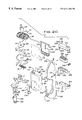
- FIGS. 2A, 2 B, and 2 C together comprise an exploded view of the vacuum cleaner
- FIG. 3 is a sectional view, the plane of the section being indicated by the line 3 — 3 in FIG. 1;
- FIG. 4 is a cross sectional view, the plane of the section being indicated by the line 4 — 4 in FIG. 3;
- FIG. 5 is a fragmentary sectional view, the plane of the section being indicated by the line 5 — 5 in FIG. 4;
- FIG. 6 is a cross sectional view, the plane of the section being indicated by the line 6 — 6 in FIG. 3;
- FIG. 7 is a cross sectional view, the plane of the section being indicated by the line 7 — 7 in FIG. 6;
- FIG. 8 is a perspective view of the dirt containment chamber illustrating the filter removed therefrom;
- FIG. 9 is a perspective view of the filter
- FIG. 10 is a sectional view of the rug nozzle according to one aspect of this invention.
- FIG. 11 is a sectional view of the rug nozzle according to another aspect of this invention.
- FIG. 12 is a bottom view of the rug nozzle illustrated in FIG. 11;
- FIG. 13 is a bottom view of the rug nozzle illustrated in FIG. 12.
- FIG. 14 is a perspective view of a rug nozzle according to another aspect of this invention.
- the vacuum cleaner 10 includes an elongated casing or upper body member 12 which is pivotally connected at its distal end to a floor and rug cleaning housing 14 and has a handle 16 projecting from its distal end.
- the elongated casing 12 includes a motor housing 18 at one end and an accessory receiving assembly 20 at its other end.
- the motor housing 18 and the assembly 20 are joined by a spine 22 .
- the assembly 24 includes a motor 26 and a fan 28 .
- the motor 26 is mounted on a fan cover plate 30 within a central socket 32 .
- the fan 28 is mounted for rotation on the other side of the plate 30 and as may be seen in FIG. 4 comprises a plurality of curved vanes 32 extending between first and second mounting disks 34 and 36 .
- the disk 36 has a central air intake opening 38 defined by a cylindrical air guard 40 .
- a plurality of laterally extending air guide vanes 42 are provided along the lateral edges of the plate 30 and each vane 42 has an extending tab 44 (FIG. 5 ).
- a reducer 48 having a base plate 50 (FIG. 6) is assembled on the motor fan assembly by a plurality of recesses 52 provided in the plate 50 .
- the plate 50 and the plate 30 are spaced apart a distance so that both plates are spaced closely adjacent the fan 28 .
- the fins 46 project beyond the edges of the plates 50 and 30 and are received in a slot 54 in the housing 18 .
- the slot 54 and spaced parallel ribs 56 and 58 serve to retain the motor fan assembly and the housing 18 .
- a gasket 60 is provided between the plate 50 and the rib 58 to seal the motor fan unit.
- the ribs 56 and 58 and the slots 54 mount the motor fan assembly at an angle with respect to a longitudinal axis of the upper body 12 .
- This angular mounting arrangement reduces the profile of the outer fan unit as viewed along the axis so that the width of the housing 12 measured normal to the axis may be reduced. As will become apparent reduction of this width enables the user to clean under low clearance items of furniture such as beds or the like.
- the angular rim 38 projects into an opening 70 in the plate 50 and is closely spaced thereto.
- the opening 70 communicates with a reducer tube 72 which projects from the plate 50 as a cylinder and then flows laterally outwardly to form an elongated opening 74 .
- the opening 74 is covered by a grate 76 and is sealed to an end wall 78 .
- the end wall 78 and an opposite wall 80 define a cavity which receives a dust cup 82 .
- the cup 82 is generally rectangular but has a front face 84 molded to conform to the configuration of the body 12 . As may be seen in FIGS. 3 and 8, one end of the cup 82 has an open mouth defined by an edge 88 which is sealed against the end wall 78 .
- the front face 84 extends around a recess 90 in the housing 18 and is sealed by a gasket 92 .
- the cup 82 is in fluid communication with the intake of the fan 28 .
- the other end of the cup is closed but has an opening 94 which communicates with an intake tube 96 .
- the intake tube 96 is provided with a flapper valve 98 at its upper end to minimize the gravitational discharge of debris.
- a substantially flat filter element 100 is removably mounted in the dirt cup 82 .
- the filter 100 is preferably made from plastic and has a framework which comprises longitudinal sides 102 and 104 and a central frame member 106 .
- a rectangular frame 108 is provided at one end of the filter.
- a filter fabric 110 extends between the sides 102 and 104 and extends across the frame 108 .
- the filter 100 is mounted in the dirt cup by sliding the filter edges 102 and 104 between parallel ribs 112 and 114 which are provided on opposite sides of the dirt cup 82 .
- one side 116 of the tube 96 is flattened to closely face the filter fabric 110 .
- the flattened portion flows at its lower end to a full cylinder to provide a circular opening at the inlet 94 .
- the cylindrical portion of the tube 96 is accommodated by a complimentary cylindrical impression 118 at one end of the filter.
- the filter 100 separates the interior of the dirt cup 82 into a dirty air chamber 120 and a clean air chamber 122 . Since the face of the filter screen 110 is substantially in the direction of dirty air flow the screen tends not to be deeply embedded with dirt and the dirt tends to collect in the cup rather than on the filter screen. Thus the cup may be emptied without removing and cleaning the screen after each use. However, when the screen is completely coated with dirt the filter is easily removed from the dirt cup and thoroughly cleaned. To aid in this operation, it may be noted in FIG. 8 that one edge 124 of the dirt cup 82 is provided with a series of comb-like projections 126 which may be used as an aid in scraping the surface of the filter screen 110 .
- the dirt cup 82 is retained in an operating position by an upper loop 130 which is placed over a hook 132 on the housing 18 .
- a lower spring hinge 134 snaps over and is retained by a detent 136 .
- a handle grip 140 is provided at the front face of the dirt cup 82 .
- the inlet tube 96 and its opening 94 are seated on a gasket 150 which is provided on a T-joint and accessory holder 152 and the accessory mounting assembly 20 .
- the holder 152 has a cylindrical socket 154 which receives a T-joint 156 .
- the T-joint 156 is provided with a spring biased locking button 158 which projects through an aperture 160 in the socket 156 .
- the button locks the T-joint in the socket and permits removal of the T-joint 156 .
- the T-joint 156 has a hollow interior and is received between a cylindrical surface 162 in a lower nozzle member 164 and a complimentary cylindrical surface 166 in an upper nozzle member 168 (FIG. 2 A). With the upper and lower nozzle members 168 and 164 assembled, the T-joint 156 is permitted to swivel between vertical and horizontal positions.
- a suction inlet opening 170 is provided in a portion of the cylindrical side wall of the T-joint 156 .
- the inlet opening 170 is in communication with an air inlet passage 172 formed by a wall 174 in the lower nozzle assembly 164 and a wall 176 in the upper nozzle assembly 168 .
- the inlet opening 170 is otherwise sealed by a lower gasket nozzle 178 provided on the cylindrical surface 162 .
- the passage 172 in turn communicates with an elongated chamber 178 in the lower nozzle member 164 which, in turn, is open to the floor or carpet being vacuumed.
- a powered brush roll 180 having a multiplicity of bristles 182 is mounted for rotation in the chamber 178 and is covered by an inner shroud 184 .
- the brush roll 180 is driven by a drive motor 186 through a driving belt 188 and a drive wheel 190 which is connected to one end of the brush roll 180 .
- the drive motor 186 is mounted in the lower nozzle on motor mounting cradles 192 .
- a pair of small front wheels 200 are provided ahead of brush roll air intake 202 and are spaced inwardly from front corners 204 .
- the front corners 204 define recessed channels 206 in air communication with the brush roll air intake 202 to enhance edge and corner cleaning effectiveness.
- two rearwardly extending projections 208 and 210 rotatable mount a pair of relatively large rear wheels 212 and 214 .
- the extensions 208 and 210 provide a space therebetween which allows the upper body assembly to pivot 90 degrees from a vertical storage position to a “ground-hugging” overall height that acids in gaining cleaning access under low objects, such as beds, chairs, couches, etc.
- a two position height adjustment mechanism 216 comprises a carriage formed by a pair of parallel links 218 and 220 , which are fixed at one end to an axle 222 .
- a roller 224 is rotatably mounted between the links 218 and 220 .
- the axle 222 is provided with centrally located flattened portions 226 and 228 and is mounted for rotation between channel plates 230 and 232 .
- a leaf spring 234 is mounted on a post 236 and retains the axle 222 and, therefore, the roller 224 in the position illustrated in solid outline in FIGS. 11 and 12. In that illustrated position the roller 224 tends to minimize penetration of the section inlet opening into plush or deep pile carpeting.
- the roller may be pivoted about 180 degrees to the position illustrated in phantom outline in FIG. 12 to permit the intake opening of the nozzle to be spaced a short distance from the floor.
- the flattened portion 226 of the axle 228 engages the spring 234 .
- projecting finger grips 240 may be provided on the links 218 and 220 .
- a flexible scraper blade 242 is mounted just rear of the intake 202 of the nozzle to scrape any debris into a position to be picked up by the intake nozzle.
- the mechanism includes an axle 250 which is mounted for pivotable movement between a pair of bearing plates 252 and 254 .
- a retaining plate 256 covers and retains the axle 250 between the plates 252 and 254 .
- a pair of links 258 and 260 are fixed to the axle 250 and rotatably mount a roller 262 .
- Stabilizer ribs 264 which project from the cover, prevent movement of the roller 262 and the axle 250 in their axial directions.
- Pressure pads 266 and 268 are located on opposite sides of the axle 250 and frictionally engage cam projections 270 at the ends of the axle 250 when the roller 262 is in its operative illustrated position and its phantom outline position, respectively.
- FIG. 14 there is illustrated a mechanism for providing a permanent elevation of the nozzle opening with respect to plush or deep pile carpeting.
- That mechanism includes an axle 270 which is transversely supported by end posts 272 and 274 .
- a plurality of rotatable rollers 276 are mounted on the axle 270 which are provided with mutually interlocking ends 278 which join the rollers 276 as a rotational unit.
- the interlocking end configuration of the rollers 276 prevents hair and string buildup on the axle 270 during use.
- the rollers 276 provide spaces therebetween which ensure adequate vacuum suction to the nozzle intake 202 .
- the brush roll motor 186 and the suction motor 26 are powered by a battery pack 280 .
- the battery pack 280 includes a plurality of rechargeable batteries 282 which are electrically connected in series by a plurality of busbars 284 . Additional busbars 286 and 288 provide contact points 290 and 292 in openings 294 and 296 in an upper battery case 298 .
- the upper battery case 298 cooperates with a lower battery case 300 to provide the battery pack 280 .
- a circuit board 302 is provided within the upper and lower battery cases to provide components which are required for recharging the battery.
- the recharging pin connector (not shown) may be inserted into an opening 304 formed by the upper and lower battery cases to recharge the batteries 282 when the battery pack 280 is removed from the vacuum cleaner or when the battery pack 280 is mounted in an operating position in the vacuum cleaner.
- a battery compartment 306 is provided in the vacuum cleaner and has an inner configuration which conforms to the shape of the battery pack 280 . It may be noted that the battery pack 280 is asymmetrical in that one corner 308 is provided with a slight radius. This prohibits the battery pack from being mounted in an inverted position within the compartment 306 .
- the battery pack 280 is retained in the compartment 306 by a flexible detent 310 which engages a complimentary detent (not shown) within the compartment 306 .
- the contacts 294 and 296 are in electrical contact with contacts 312 and 314 which in turn supply d current from the battery pack 282 a pair of contacts 316 and 318 which are located in alignment with pin openings 320 in the housing adjacently opening 94 in the housing.
- socket pins 322 mounted on the T-joint 156 electrically engage the contacts 312 and 314 .
- a wiring harness 324 electrically connects the pins 322 to the brush roll motor 186 .
- a wiring harness 326 connects the contacts 312 and 314 to a multi-position switch 328 and connects the switch to a pair of pins 322 .
- the switch 328 controls the supply of power to the motor 26 .
- a first position of the switch 328 is an off position which prevents supply of power to the motor 186 and the motor 26 .
- the switch has a second position which supplies power to both motors 186 and 26 and has a third position which supplies power only to the motor 26 .
- the last mentioned position of the switch is utilized when bare floors are vacuumed without rotation of the brush roll.
- the handle 16 includes a shaft 340 which is slidably received in the spine 22 .
- a spring biased latch 342 engages an upper notch 344 to retain the handle in a retracted position, and engages a lower notch 346 to retain the handle in an extended position.
- the handle may also be removed from the spine 22 , if the vacuum cleaner is used as a portable canister cleaner.
- the T-joint 156 is removed from the holder 152 and a connector end 348 of an accessory hose 350 (FIG. 2C) is inserted into the holder 152 .
- the connector end 348 is provided with electrical connector contact pins which are received in the pin openings 320 to provide power for a brush roll motor (not shown) in a cleaning accessory (also not shown) at the distal end of the hose 350 .
- the upper body member 12 may be provided with a carrying strap 352 which is attached to the member 12 by links 354 and 356 as is indicated in FIG. 2 C.
Landscapes
- Engineering & Computer Science (AREA)
- Mechanical Engineering (AREA)
- Nozzles For Electric Vacuum Cleaners (AREA)
- Electric Vacuum Cleaner (AREA)
Abstract
Description
Claims (26)
Priority Applications (1)
| Application Number | Priority Date | Filing Date | Title |
|---|---|---|---|
| US09/441,492 US6311366B1 (en) | 1998-11-18 | 1999-11-17 | Battery power combination vacuum cleaner |
Applications Claiming Priority (2)
| Application Number | Priority Date | Filing Date | Title |
|---|---|---|---|
| US10891298P | 1998-11-18 | 1998-11-18 | |
| US09/441,492 US6311366B1 (en) | 1998-11-18 | 1999-11-17 | Battery power combination vacuum cleaner |
Publications (1)
| Publication Number | Publication Date |
|---|---|
| US6311366B1 true US6311366B1 (en) | 2001-11-06 |
Family
ID=22324775
Family Applications (1)
| Application Number | Title | Priority Date | Filing Date |
|---|---|---|---|
| US09/441,492 Expired - Lifetime US6311366B1 (en) | 1998-11-18 | 1999-11-17 | Battery power combination vacuum cleaner |
Country Status (4)
| Country | Link |
|---|---|
| US (1) | US6311366B1 (en) |
| CA (1) | CA2289808A1 (en) |
| GB (2) | GB9927129D0 (en) |
| MX (1) | MXPA99010565A (en) |
Cited By (98)
| Publication number | Priority date | Publication date | Assignee | Title |
|---|---|---|---|---|
| US20020194695A1 (en) * | 2001-01-12 | 2002-12-26 | Royal Appliance Mfg. Co. | Vacuum cleaner with noise suppression features |
| US20040088819A1 (en) * | 2002-11-07 | 2004-05-13 | Hafling Danielle M. | Dirt cup assembly with attachable and detachable external filter holder |
| FR2847791A1 (en) * | 2002-11-29 | 2004-06-04 | Claude Brenot | Compact device for cleaning floors, uses tapered chamber with fan above to collect dust and waste by suction and uses taper of chamber to slow air as it moves upward before transfer to collection chamber |
| US20040163201A1 (en) * | 2000-09-01 | 2004-08-26 | Royal Appliance Mfg. Co. | Bagless canister vacuum cleaner |
| US20040178284A1 (en) * | 2003-03-10 | 2004-09-16 | Fahy Cathal L. | Cleaning device with universal motion quick disconnect head |
| US20040216263A1 (en) * | 2000-05-05 | 2004-11-04 | Bissell Homecare, Inc. | Vacuum cleaner with detachable cyclonic vacuum module |
| WO2005023077A1 (en) * | 2003-09-03 | 2005-03-17 | Morphy Richards Limited | Apparatus for floor treatment |
| US20050060835A1 (en) * | 2003-09-20 | 2005-03-24 | Yasushi Kondo | Bagless vacuum cleaner and dust container assembly |
| US20050071946A1 (en) * | 2002-11-07 | 2005-04-07 | Hafling Danielle M. | Removable dirt cup assembly with external filter |
| US20050102790A1 (en) * | 2002-07-25 | 2005-05-19 | Toshiba Tec Kabushiki Kaisha | Vacuum cleaner |
| WO2005084511A1 (en) * | 2004-03-02 | 2005-09-15 | Bissell Homecare, Inc. | Vacuum cleaner with detachable cyclonic vacuum module |
| US20050210627A1 (en) * | 2004-03-19 | 2005-09-29 | Greg Luebbering | Circular vacuum handle |
| US20060156509A1 (en) * | 2005-01-18 | 2006-07-20 | Luebbering Gregory W | Vacuum cleaner with collapsible handle |
| US7159271B2 (en) | 2003-09-29 | 2007-01-09 | Electrolux Home Care Products Ltd. | Wet extractor cleaning device fluid tank arrangement |
| US20070006417A1 (en) * | 2005-07-07 | 2007-01-11 | Ross Richardson | Vacuum Cleaner Providing Filter-Absence Detection |
| US20070022562A1 (en) * | 2005-07-28 | 2007-02-01 | Leonard Hampton | Multi-position cleaning device handgrip |
| WO2007032796A2 (en) | 2005-06-10 | 2007-03-22 | Electrolux Home Care Products North America | Sodium bicarbonate vacuum bag inserts |
| US20070067946A1 (en) * | 2005-09-27 | 2007-03-29 | Samsung Gwangju Electronics Co., Ltd. | Suction brush of vacuum cleaner |
| US20070101536A1 (en) * | 2003-03-27 | 2007-05-10 | Nielsen Innovation | Twin-motor independent vacuum cleaner |
| US20070163073A1 (en) * | 2006-01-19 | 2007-07-19 | Arnold Sepke | Vacuum cleaner dustcup and conduit construction |
| US20070163075A1 (en) * | 2006-01-17 | 2007-07-19 | Butler Dennis C | Stair cleaning vacuum cleaner |
| USD549905S1 (en) | 2006-08-18 | 2007-08-28 | Electrolux Homecare Products, Ltd. | Handle for a vacuum cleaner |
| US7293326B2 (en) | 2004-07-29 | 2007-11-13 | Electrolux Home Care Products, Inc. | Vacuum cleaner alignment bracket |
| US20070266519A1 (en) * | 2006-05-16 | 2007-11-22 | Royal Appliance Mfg. Co. | Battery powered cleaning attachment |
| US7305735B2 (en) | 2002-10-11 | 2007-12-11 | Panasonic Corporation Of North America | Vacuum cleaner equipped with dirt cup and separate filter drawer |
| US20080040883A1 (en) * | 2006-04-10 | 2008-02-21 | Jonas Beskow | Air Flow Losses in a Vacuum Cleaners |
| US20080062618A1 (en) * | 2005-02-11 | 2008-03-13 | Alfred Kaercher Gmbh & Co. Kg | Cleaning apparatus |
| US20080209666A1 (en) * | 2006-12-12 | 2008-09-04 | G.B.D. Corp. | Convertible surface cleaning apparatus |
| CN100435709C (en) * | 2003-06-03 | 2008-11-26 | 松下电器产业株式会社 | Electric dust collector |
| US20090056060A1 (en) * | 2007-08-28 | 2009-03-05 | Samsung Gwangju Electronics., Ltd. | Stick type vacuum cleaner |
| US20090276974A1 (en) * | 2008-03-14 | 2009-11-12 | David Khalil | Cordless Hand-Held Rechargeable Vacuum Cleaner and Charger Unit Therefore |
| US20100088843A1 (en) * | 2008-03-14 | 2010-04-15 | Brett Reed | Battery powered cordless cleaning system |
| US7712182B2 (en) | 2003-07-25 | 2010-05-11 | Milwaukee Electric Tool Corporation | Air flow-producing device, such as a vacuum cleaner or a blower |
| US7882593B2 (en) | 2007-01-19 | 2011-02-08 | Ab Electrolux | Dirt separator system for a vacuum cleaner |
| US7958597B2 (en) | 2006-03-24 | 2011-06-14 | Ab Electrolux | Handheld vacuum cleaner |
| US8001653B1 (en) | 2009-06-04 | 2011-08-23 | Longley Everton W | Vacuum apparatus |
| US20110219573A1 (en) * | 2010-03-12 | 2011-09-15 | G.B.D. Corp. | Surface cleaning apparatus with enhanced operability |
| USD652377S1 (en) | 2008-10-16 | 2012-01-17 | Techtronic Floor Care Technology Limited | Battery charger combination |
| US8151411B2 (en) | 2006-04-10 | 2012-04-10 | Ab Electrolux | Vacuum cleaner |
| US8225456B2 (en) | 2003-02-10 | 2012-07-24 | Ab Electrolux | Hand held vacuum cleaner |
| US20120222252A1 (en) * | 2011-03-04 | 2012-09-06 | G.B.D. Corp. | Surface cleaning apparatus |
| US8402601B2 (en) | 2007-01-23 | 2013-03-26 | AB Electronlux | Vacuum cleaner nozzle |
| US8424154B2 (en) | 2006-04-10 | 2013-04-23 | Ab Electrolux | Vacuum cleaner with filter cleaning means |
| US20140196247A1 (en) * | 2013-01-11 | 2014-07-17 | Bissell Homecare, Inc. | Vacuum cleaner |
| US8943647B1 (en) | 2013-08-09 | 2015-02-03 | Techtronic Floor Care Technology Limited | Vacuum cleaner including a removable handle assembly |
| US9003600B2 (en) | 2012-04-18 | 2015-04-14 | Shop Vac Corporation | Vacuum cleaner with noise reduction recesses |
| DE102014116588A1 (en) * | 2014-11-13 | 2016-05-19 | Vorwerk & Co. Interholding Gmbh | Suction nozzle for a vacuum cleaner to maintain a floor |
| US20160367093A1 (en) * | 2015-06-17 | 2016-12-22 | Bissell Homecare, Inc. | Vacuum cleaner |
| US9811089B2 (en) | 2013-12-19 | 2017-11-07 | Aktiebolaget Electrolux | Robotic cleaning device with perimeter recording function |
| US9939529B2 (en) | 2012-08-27 | 2018-04-10 | Aktiebolaget Electrolux | Robot positioning system |
| US9946263B2 (en) | 2013-12-19 | 2018-04-17 | Aktiebolaget Electrolux | Prioritizing cleaning areas |
| US9962052B2 (en) | 2011-03-04 | 2018-05-08 | Omachron Intellectual Property Inc. | Surface cleaning apparatus |
| US10045675B2 (en) | 2013-12-19 | 2018-08-14 | Aktiebolaget Electrolux | Robotic vacuum cleaner with side brush moving in spiral pattern |
| US10149589B2 (en) | 2013-12-19 | 2018-12-11 | Aktiebolaget Electrolux | Sensing climb of obstacle of a robotic cleaning device |
| US10154765B2 (en) | 2014-01-17 | 2018-12-18 | Techtronic Floor Care Technology Limited | Vacuum cleaner including a removable canister assembly |
| USD836863S1 (en) | 2017-06-12 | 2018-12-25 | Emerson Electric Co. | Upright vacuum cleaner |
| US10209080B2 (en) | 2013-12-19 | 2019-02-19 | Aktiebolaget Electrolux | Robotic cleaning device |
| US10219665B2 (en) | 2013-04-15 | 2019-03-05 | Aktiebolaget Electrolux | Robotic vacuum cleaner with protruding sidebrush |
| US10231591B2 (en) | 2013-12-20 | 2019-03-19 | Aktiebolaget Electrolux | Dust container |
| US10433697B2 (en) | 2013-12-19 | 2019-10-08 | Aktiebolaget Electrolux | Adaptive speed control of rotating side brush |
| US10448794B2 (en) | 2013-04-15 | 2019-10-22 | Aktiebolaget Electrolux | Robotic vacuum cleaner |
| US10448797B2 (en) | 2016-10-19 | 2019-10-22 | Tti (Macao Commercial Offshore) Limited | Vacuum cleaner |
| US10499778B2 (en) | 2014-09-08 | 2019-12-10 | Aktiebolaget Electrolux | Robotic vacuum cleaner |
| US10518416B2 (en) | 2014-07-10 | 2019-12-31 | Aktiebolaget Electrolux | Method for detecting a measurement error in a robotic cleaning device |
| US10534367B2 (en) | 2014-12-16 | 2020-01-14 | Aktiebolaget Electrolux | Experience-based roadmap for a robotic cleaning device |
| US10617271B2 (en) | 2013-12-19 | 2020-04-14 | Aktiebolaget Electrolux | Robotic cleaning device and method for landmark recognition |
| US10678251B2 (en) | 2014-12-16 | 2020-06-09 | Aktiebolaget Electrolux | Cleaning method for a robotic cleaning device |
| US10729297B2 (en) | 2014-09-08 | 2020-08-04 | Aktiebolaget Electrolux | Robotic vacuum cleaner |
| US10758101B2 (en) | 2017-06-12 | 2020-09-01 | Emerson Electric Co. | Upright vacuum cleaner with battery support plate |
| US10877484B2 (en) | 2014-12-10 | 2020-12-29 | Aktiebolaget Electrolux | Using laser sensor for floor type detection |
| US10874274B2 (en) | 2015-09-03 | 2020-12-29 | Aktiebolaget Electrolux | System of robotic cleaning devices |
| US10874271B2 (en) | 2014-12-12 | 2020-12-29 | Aktiebolaget Electrolux | Side brush and robotic cleaner |
| CN112915693A (en) * | 2021-02-02 | 2021-06-08 | 李玉军 | Industrial dust filtration equipment |
| US11099554B2 (en) | 2015-04-17 | 2021-08-24 | Aktiebolaget Electrolux | Robotic cleaning device and a method of controlling the robotic cleaning device |
| US11122953B2 (en) | 2016-05-11 | 2021-09-21 | Aktiebolaget Electrolux | Robotic cleaning device |
| US11169533B2 (en) | 2016-03-15 | 2021-11-09 | Aktiebolaget Electrolux | Robotic cleaning device and a method at the robotic cleaning device of performing cliff detection |
| US11291345B2 (en) | 2018-08-27 | 2022-04-05 | Techtronic Floor Care Technology Limited | Floor cleaner |
| US11363923B2 (en) | 2018-08-27 | 2022-06-21 | Techtronic Floor Care Technology Limited | Floor cleaner |
| US11445872B2 (en) | 2014-12-17 | 2022-09-20 | Omachron Intellectual Property Inc. | Surface cleaning apparatus |
| US11445871B2 (en) | 2014-12-17 | 2022-09-20 | Omachron Intellectual Property Inc. | Surface cleaning apparatus |
| US11452409B2 (en) | 2014-12-17 | 2022-09-27 | Omachron Intellectual Property Inc. | Surface cleaning apparatus |
| US11474533B2 (en) | 2017-06-02 | 2022-10-18 | Aktiebolaget Electrolux | Method of detecting a difference in level of a surface in front of a robotic cleaning device |
| US20220330777A1 (en) * | 2021-04-15 | 2022-10-20 | Shenzhen Tianwan Chuangxin Co., Ltd | Vertical household floor scrubber |
| US11484175B2 (en) | 2018-08-27 | 2022-11-01 | Techtronic Floor Care Technology Limited | Floor cleaner |
| US11534041B2 (en) | 2014-12-17 | 2022-12-27 | Omachron Intellectual Property Inc. | Surface cleaning apparatus |
| US11627856B2 (en) | 2018-08-27 | 2023-04-18 | Techtronic Floor Care Technology Limited | Floor cleaner |
| US20230160227A1 (en) * | 2021-11-23 | 2023-05-25 | Kokido Development Limited | Autonomous impeller vacuum cleaner for cleaning swimming pools |
| US11723498B2 (en) | 2018-07-02 | 2023-08-15 | Sharkninja Operating Llc | Vacuum pod configured to couple to one or more accessories |
| US11745190B2 (en) | 2019-01-23 | 2023-09-05 | Omachron Intellectual Property Inc. | Surface cleaning apparatus |
| US11779178B2 (en) | 2021-08-05 | 2023-10-10 | Omachron Intellectual Property Inc. | Household appliance having an improved cyclone and a cyclone for same |
| US11864719B2 (en) | 2018-09-07 | 2024-01-09 | Sharkninja Operating Llc | Battery and suction motor assembly for a surface treatment apparatus and a surface treatment apparatus having the same |
| US11889960B2 (en) | 2018-08-27 | 2024-02-06 | Techtronic Floor Care Technology Limited | Floor cleaner |
| US11921517B2 (en) | 2017-09-26 | 2024-03-05 | Aktiebolaget Electrolux | Controlling movement of a robotic cleaning device |
| US12053140B2 (en) | 2018-09-19 | 2024-08-06 | Sharkninja Operating Llc | Cleaning head for a surface treatment apparatus having one or more stabilizers and surface treatment apparatus having the same |
| CN118557096A (en) * | 2024-08-02 | 2024-08-30 | 山东沐点智能科技有限公司 | A campus cleaning and disinfection robot |
| US12075966B2 (en) | 2021-08-05 | 2024-09-03 | Omachron Intellectual Property Inc. | Household appliance having an improved cyclone and a cyclone for same |
| US12171393B2 (en) | 2011-03-04 | 2024-12-24 | Omachron Intellectual Property Inc. | Surface cleaning apparatus |
| US12207782B2 (en) | 2019-07-19 | 2025-01-28 | Techtronic Floor Care Technology Limited | Floor cleaner |
Families Citing this family (4)
| Publication number | Priority date | Publication date | Assignee | Title |
|---|---|---|---|---|
| GB2377163B (en) * | 2001-07-05 | 2004-12-15 | Hoover Ltd | Vacuum cleaner |
| GB2377880A (en) * | 2001-07-25 | 2003-01-29 | Black & Decker Inc | Multi-operational battery powered vacuum cleaner |
| US20160095485A1 (en) * | 2014-10-03 | 2016-04-07 | Techtronic Industries Co. Ltd. | Vacuum cleaner including a removable dirt collection assembly |
| DE102016103513A1 (en) * | 2016-02-29 | 2017-08-31 | Miele & Cie. Kg | Vacuum cleaner with obliquely arranged fan |
Citations (31)
| Publication number | Priority date | Publication date | Assignee | Title |
|---|---|---|---|---|
| US1918519A (en) | 1930-07-16 | 1933-07-18 | Clements Mfg Co | Vacuum cleaner |
| US1983566A (en) | 1932-02-11 | 1934-12-11 | Citizens Trust Company Of Tole | Air-method cleaner |
| US2340944A (en) * | 1941-09-02 | 1944-02-08 | Harry C Easter | Insect eliminator |
| GB985891A (en) | 1961-09-05 | 1965-03-10 | Schoettle Kg Electrostar | Domestic appliance for vacuum cleaning, polishing or carpet-beating |
| GB1262121A (en) | 1968-03-18 | 1972-02-02 | Sanyo Electric Co | Vacuum cleaner |
| US4521936A (en) | 1983-09-30 | 1985-06-11 | Electrolux Corporation | Self-cleaning joint |
| US4570286A (en) | 1982-09-30 | 1986-02-18 | David Ross | Portable vacuum cleaning device |
| US4573236A (en) | 1983-07-08 | 1986-03-04 | Prototypes, Ltd. | Vacuum cleaning appliances |
| US4638526A (en) | 1984-03-19 | 1987-01-27 | Matsushita Electric Industrial Co., Ltd. | Nozzle assembly for vacuum cleaner |
| US4660246A (en) | 1986-04-14 | 1987-04-28 | The Singer Company | Versatile vacuum cleaning appliance |
| US4662026A (en) | 1986-05-15 | 1987-05-05 | The Singer Company | Convertible vacuum cleaner handle |
| US4670973A (en) | 1985-01-25 | 1987-06-09 | Alsthom-Atlantique S.A. | Method of making an insulating stay |
| US4766638A (en) | 1987-03-04 | 1988-08-30 | Bissell Inc. | Four-way vacuum cleaner |
| US4835409A (en) | 1988-02-26 | 1989-05-30 | Black & Decker Inc. | Corded/cordless dual-mode power-operated device |
| US4841594A (en) | 1986-11-07 | 1989-06-27 | Black & Decker, Inc. | Cordless vacuum cleaner with power brush |
| USD307657S (en) * | 1987-07-09 | 1990-05-01 | Benny Li | Vacuum cleaner |
| US4928346A (en) | 1986-11-07 | 1990-05-29 | Black & Decker Inc. | Hand-held vacuum cleaner with power brush |
| US4968174A (en) | 1988-07-13 | 1990-11-06 | Black & Decker, Inc. | Latch for telescoping handle of vacuum cleaner |
| US5014388A (en) * | 1989-05-15 | 1991-05-14 | White Consolidated Industries, Inc. | Battery powered vacuum cleaner |
| US5020186A (en) * | 1990-01-24 | 1991-06-04 | Black & Decker Inc. | Vacuum cleaners |
| US5042109A (en) * | 1990-01-12 | 1991-08-27 | Royal Appliance Mfg. Co. | Height adjustment mechanism |
| US5086536A (en) | 1990-05-11 | 1992-02-11 | The Scott Fetzer Company | Convertible vacuum cleaner |
| US5283939A (en) | 1990-01-12 | 1994-02-08 | Royal Appliance Mfg. Co. | Method of assembling a vacuum cleaner |
| US5296769A (en) | 1992-01-24 | 1994-03-22 | Electrolux Corporation | Air guide assembly for an electric motor and methods of making |
| US5309600A (en) | 1993-02-12 | 1994-05-10 | Bissell Inc. | Vacuum cleaner with a detachable vacuum module |
| US5347679A (en) | 1993-01-07 | 1994-09-20 | Royal Appliance Mfg. Co. | Stick type vacuum cleaner |
| US5446943A (en) | 1993-01-07 | 1995-09-05 | Royal Appliance Mfg. Co. | Compact air path construction for vacuum cleaner |
| US5524321A (en) | 1994-02-14 | 1996-06-11 | Bissell Inc. | Vacuum Cleaner with a detachable vacuum module |
| US5564160A (en) | 1995-01-13 | 1996-10-15 | White Consolidated Industries, Inc. | Vacuum cleaner having forwardly curved handle |
| US5765258A (en) * | 1996-01-11 | 1998-06-16 | Black & Decker Inc. | Vacuum cleaner with all components in floor traveling head |
| US5966774A (en) * | 1996-11-30 | 1999-10-19 | Black & Decker, Inc. | Hand-held vacuum cleaner |
-
1999
- 1999-11-16 CA CA002289808A patent/CA2289808A1/en not_active Abandoned
- 1999-11-16 GB GBGB9927129.8A patent/GB9927129D0/en not_active Ceased
- 1999-11-17 MX MXPA99010565A patent/MXPA99010565A/en not_active IP Right Cessation
- 1999-11-17 US US09/441,492 patent/US6311366B1/en not_active Expired - Lifetime
- 1999-11-18 GB GB9927337A patent/GB2343837A/en not_active Withdrawn
Patent Citations (32)
| Publication number | Priority date | Publication date | Assignee | Title |
|---|---|---|---|---|
| US1918519A (en) | 1930-07-16 | 1933-07-18 | Clements Mfg Co | Vacuum cleaner |
| US1983566A (en) | 1932-02-11 | 1934-12-11 | Citizens Trust Company Of Tole | Air-method cleaner |
| US2340944A (en) * | 1941-09-02 | 1944-02-08 | Harry C Easter | Insect eliminator |
| GB985891A (en) | 1961-09-05 | 1965-03-10 | Schoettle Kg Electrostar | Domestic appliance for vacuum cleaning, polishing or carpet-beating |
| GB1262121A (en) | 1968-03-18 | 1972-02-02 | Sanyo Electric Co | Vacuum cleaner |
| US4570286A (en) | 1982-09-30 | 1986-02-18 | David Ross | Portable vacuum cleaning device |
| US4573236A (en) | 1983-07-08 | 1986-03-04 | Prototypes, Ltd. | Vacuum cleaning appliances |
| US4521936A (en) | 1983-09-30 | 1985-06-11 | Electrolux Corporation | Self-cleaning joint |
| US4638526A (en) | 1984-03-19 | 1987-01-27 | Matsushita Electric Industrial Co., Ltd. | Nozzle assembly for vacuum cleaner |
| US4670973A (en) | 1985-01-25 | 1987-06-09 | Alsthom-Atlantique S.A. | Method of making an insulating stay |
| US4660246A (en) | 1986-04-14 | 1987-04-28 | The Singer Company | Versatile vacuum cleaning appliance |
| US4662026A (en) | 1986-05-15 | 1987-05-05 | The Singer Company | Convertible vacuum cleaner handle |
| US4928346A (en) | 1986-11-07 | 1990-05-29 | Black & Decker Inc. | Hand-held vacuum cleaner with power brush |
| US4841594A (en) | 1986-11-07 | 1989-06-27 | Black & Decker, Inc. | Cordless vacuum cleaner with power brush |
| US4766638A (en) | 1987-03-04 | 1988-08-30 | Bissell Inc. | Four-way vacuum cleaner |
| USD307657S (en) * | 1987-07-09 | 1990-05-01 | Benny Li | Vacuum cleaner |
| US4835409A (en) | 1988-02-26 | 1989-05-30 | Black & Decker Inc. | Corded/cordless dual-mode power-operated device |
| US4968174A (en) | 1988-07-13 | 1990-11-06 | Black & Decker, Inc. | Latch for telescoping handle of vacuum cleaner |
| US5014388A (en) * | 1989-05-15 | 1991-05-14 | White Consolidated Industries, Inc. | Battery powered vacuum cleaner |
| US5283939A (en) | 1990-01-12 | 1994-02-08 | Royal Appliance Mfg. Co. | Method of assembling a vacuum cleaner |
| US5042109A (en) * | 1990-01-12 | 1991-08-27 | Royal Appliance Mfg. Co. | Height adjustment mechanism |
| US5020186A (en) * | 1990-01-24 | 1991-06-04 | Black & Decker Inc. | Vacuum cleaners |
| US5086536A (en) | 1990-05-11 | 1992-02-11 | The Scott Fetzer Company | Convertible vacuum cleaner |
| US5296769A (en) | 1992-01-24 | 1994-03-22 | Electrolux Corporation | Air guide assembly for an electric motor and methods of making |
| US5347679A (en) | 1993-01-07 | 1994-09-20 | Royal Appliance Mfg. Co. | Stick type vacuum cleaner |
| US5446943A (en) | 1993-01-07 | 1995-09-05 | Royal Appliance Mfg. Co. | Compact air path construction for vacuum cleaner |
| US5606770A (en) * | 1993-01-07 | 1997-03-04 | Royal Appliance Mfg. Co. | Compact air path construction for vacuum cleaner |
| US5309600A (en) | 1993-02-12 | 1994-05-10 | Bissell Inc. | Vacuum cleaner with a detachable vacuum module |
| US5524321A (en) | 1994-02-14 | 1996-06-11 | Bissell Inc. | Vacuum Cleaner with a detachable vacuum module |
| US5564160A (en) | 1995-01-13 | 1996-10-15 | White Consolidated Industries, Inc. | Vacuum cleaner having forwardly curved handle |
| US5765258A (en) * | 1996-01-11 | 1998-06-16 | Black & Decker Inc. | Vacuum cleaner with all components in floor traveling head |
| US5966774A (en) * | 1996-11-30 | 1999-10-19 | Black & Decker, Inc. | Hand-held vacuum cleaner |
Cited By (149)
| Publication number | Priority date | Publication date | Assignee | Title |
|---|---|---|---|---|
| US7188388B2 (en) | 2000-05-05 | 2007-03-13 | Bissell Homecare, Inc. | Vacuum cleaner with detachable cyclonic vacuum module |
| US20040216263A1 (en) * | 2000-05-05 | 2004-11-04 | Bissell Homecare, Inc. | Vacuum cleaner with detachable cyclonic vacuum module |
| US20040163201A1 (en) * | 2000-09-01 | 2004-08-26 | Royal Appliance Mfg. Co. | Bagless canister vacuum cleaner |
| US7052523B2 (en) * | 2000-09-01 | 2006-05-30 | Royal Appliance Mfg. Co. | Bagless canister vacuum cleaner |
| US7627929B2 (en) | 2001-01-12 | 2009-12-08 | Royal Appliance Mfg. Co. | Vacuum cleaner with noise suppression features |
| US7900317B2 (en) | 2001-01-12 | 2011-03-08 | Royal Appliance Mfg. Co. | Vacuum cleaner with noise suppression features |
| US8739358B2 (en) | 2001-01-12 | 2014-06-03 | Techtronic Floor Care Technology Limited | Vacuum cleaner with noise suppression features |
| US20110214247A1 (en) * | 2001-01-12 | 2011-09-08 | Stephens Paul D | Vacuum cleaner with noise suppression features |
| US7114216B2 (en) | 2001-01-12 | 2006-10-03 | Royal Appliance Mfg. Co. | Vacuum cleaner with noise suppression features |
| US20100064471A1 (en) * | 2001-01-12 | 2010-03-18 | Stephens Paul D | Vacuum cleaner with noise suppression features |
| US20020194695A1 (en) * | 2001-01-12 | 2002-12-26 | Royal Appliance Mfg. Co. | Vacuum cleaner with noise suppression features |
| US20040139573A1 (en) * | 2001-01-12 | 2004-07-22 | Stephens Paul D. | Vacuum cleaner with noise suppression features |
| US6532621B2 (en) * | 2001-01-12 | 2003-03-18 | Royal Appliance Mfg. Co. | Vacuum cleaner with noise suppression features |
| US20070056136A1 (en) * | 2001-01-12 | 2007-03-15 | Royal Appliance Mfg. Co, | Vacuum cleaner with noise suppression features |
| US6948211B2 (en) | 2001-01-12 | 2005-09-27 | Royal Appliance Mfg. Co. | Vacuum cleaner with noise suppression features |
| US7337492B2 (en) * | 2002-07-25 | 2008-03-04 | Toshiba Tec Kabushiki Kaisha | Vacuum cleaner having a noise blocking member facing an intake vent of a motor fan |
| US20050102790A1 (en) * | 2002-07-25 | 2005-05-19 | Toshiba Tec Kabushiki Kaisha | Vacuum cleaner |
| US7305735B2 (en) | 2002-10-11 | 2007-12-11 | Panasonic Corporation Of North America | Vacuum cleaner equipped with dirt cup and separate filter drawer |
| US20050071946A1 (en) * | 2002-11-07 | 2005-04-07 | Hafling Danielle M. | Removable dirt cup assembly with external filter |
| US20040088819A1 (en) * | 2002-11-07 | 2004-05-13 | Hafling Danielle M. | Dirt cup assembly with attachable and detachable external filter holder |
| US7181804B2 (en) | 2002-11-07 | 2007-02-27 | Panasonic Corporation Of North America | Removable dirt cup assembly with external filter |
| US7185394B2 (en) | 2002-11-07 | 2007-03-06 | Panasonic Corporation Of North America | Dirt cup assembly with attachable and detachable external filter holder |
| FR2847791A1 (en) * | 2002-11-29 | 2004-06-04 | Claude Brenot | Compact device for cleaning floors, uses tapered chamber with fan above to collect dust and waste by suction and uses taper of chamber to slow air as it moves upward before transfer to collection chamber |
| US8607406B2 (en) | 2003-02-10 | 2013-12-17 | Ab Electrolux | Hand held vacuum cleaner |
| US8225456B2 (en) | 2003-02-10 | 2012-07-24 | Ab Electrolux | Hand held vacuum cleaner |
| US6889917B2 (en) * | 2003-03-10 | 2005-05-10 | S.C. Johnson & Son, Inc. | Cleaning device with universal motion quick disconnect head |
| US20040178284A1 (en) * | 2003-03-10 | 2004-09-16 | Fahy Cathal L. | Cleaning device with universal motion quick disconnect head |
| US20070101536A1 (en) * | 2003-03-27 | 2007-05-10 | Nielsen Innovation | Twin-motor independent vacuum cleaner |
| CN100435709C (en) * | 2003-06-03 | 2008-11-26 | 松下电器产业株式会社 | Electric dust collector |
| US7712182B2 (en) | 2003-07-25 | 2010-05-11 | Milwaukee Electric Tool Corporation | Air flow-producing device, such as a vacuum cleaner or a blower |
| WO2005023077A1 (en) * | 2003-09-03 | 2005-03-17 | Morphy Richards Limited | Apparatus for floor treatment |
| US20050060835A1 (en) * | 2003-09-20 | 2005-03-24 | Yasushi Kondo | Bagless vacuum cleaner and dust container assembly |
| US8448293B2 (en) | 2003-09-29 | 2013-05-28 | Electrolux Home Care Products, Inc. | Wet extractor floor brush |
| US7159271B2 (en) | 2003-09-29 | 2007-01-09 | Electrolux Home Care Products Ltd. | Wet extractor cleaning device fluid tank arrangement |
| GB2425249A (en) * | 2004-03-02 | 2006-10-25 | Bissell Homecare Inc | Vacuum cleaner with detachable cyclonic vacuum module |
| US7377007B2 (en) | 2004-03-02 | 2008-05-27 | Bissell Homecare, Inc. | Vacuum cleaner with detachable vacuum module |
| AU2005218490B2 (en) * | 2004-03-02 | 2010-04-01 | Bissell Inc. | Vacuum cleaner with detachable cyclonic vacuum module |
| GB2425249B (en) * | 2004-03-02 | 2007-08-08 | Bissell Homecare Inc | Vacuum cleaner with detachable cyclonic vacuum module |
| US20070226946A1 (en) * | 2004-03-02 | 2007-10-04 | Bissell Homecare, Inc. | Vacuum Cleaner with Detachable Cyclonic Vacuum Module |
| WO2005084511A1 (en) * | 2004-03-02 | 2005-09-15 | Bissell Homecare, Inc. | Vacuum cleaner with detachable cyclonic vacuum module |
| US20050210627A1 (en) * | 2004-03-19 | 2005-09-29 | Greg Luebbering | Circular vacuum handle |
| US7293326B2 (en) | 2004-07-29 | 2007-11-13 | Electrolux Home Care Products, Inc. | Vacuum cleaner alignment bracket |
| US8650707B2 (en) | 2004-07-29 | 2014-02-18 | Electrolux Home Care Products, Inc. | Vacuum cleaner sound reducing device |
| US8020251B2 (en) | 2005-01-18 | 2011-09-20 | Electrolux Home Care Products, Inc. | Vacuum cleaner with collapsible handle |
| US20060156509A1 (en) * | 2005-01-18 | 2006-07-20 | Luebbering Gregory W | Vacuum cleaner with collapsible handle |
| US20080062618A1 (en) * | 2005-02-11 | 2008-03-13 | Alfred Kaercher Gmbh & Co. Kg | Cleaning apparatus |
| US7450367B2 (en) * | 2005-02-11 | 2008-11-11 | Alfred Kaercher Gmbh & Co. Kg | Cleaning apparatus |
| WO2007032796A2 (en) | 2005-06-10 | 2007-03-22 | Electrolux Home Care Products North America | Sodium bicarbonate vacuum bag inserts |
| US20070006417A1 (en) * | 2005-07-07 | 2007-01-11 | Ross Richardson | Vacuum Cleaner Providing Filter-Absence Detection |
| US8667639B2 (en) * | 2005-07-07 | 2014-03-11 | Hoover Limited | Vacuum cleaner providing filter-absence detection |
| US20070022562A1 (en) * | 2005-07-28 | 2007-02-01 | Leonard Hampton | Multi-position cleaning device handgrip |
| US20070067946A1 (en) * | 2005-09-27 | 2007-03-29 | Samsung Gwangju Electronics Co., Ltd. | Suction brush of vacuum cleaner |
| US20070163075A1 (en) * | 2006-01-17 | 2007-07-19 | Butler Dennis C | Stair cleaning vacuum cleaner |
| US20070163073A1 (en) * | 2006-01-19 | 2007-07-19 | Arnold Sepke | Vacuum cleaner dustcup and conduit construction |
| US7958597B2 (en) | 2006-03-24 | 2011-06-14 | Ab Electrolux | Handheld vacuum cleaner |
| US8424154B2 (en) | 2006-04-10 | 2013-04-23 | Ab Electrolux | Vacuum cleaner with filter cleaning means |
| US20080040883A1 (en) * | 2006-04-10 | 2008-02-21 | Jonas Beskow | Air Flow Losses in a Vacuum Cleaners |
| US8151411B2 (en) | 2006-04-10 | 2012-04-10 | Ab Electrolux | Vacuum cleaner |
| US20070266519A1 (en) * | 2006-05-16 | 2007-11-22 | Royal Appliance Mfg. Co. | Battery powered cleaning attachment |
| US7578025B2 (en) * | 2006-05-16 | 2009-08-25 | Royal Appliance Mfg. Co. | Battery powered cleaning attachment |
| USD549905S1 (en) | 2006-08-18 | 2007-08-28 | Electrolux Homecare Products, Ltd. | Handle for a vacuum cleaner |
| US8127398B2 (en) * | 2006-12-12 | 2012-03-06 | G.B.D. Corp. | Convertible surface cleaning apparatus |
| US20080209666A1 (en) * | 2006-12-12 | 2008-09-04 | G.B.D. Corp. | Convertible surface cleaning apparatus |
| US7882593B2 (en) | 2007-01-19 | 2011-02-08 | Ab Electrolux | Dirt separator system for a vacuum cleaner |
| US8402601B2 (en) | 2007-01-23 | 2013-03-26 | AB Electronlux | Vacuum cleaner nozzle |
| US20090056060A1 (en) * | 2007-08-28 | 2009-03-05 | Samsung Gwangju Electronics., Ltd. | Stick type vacuum cleaner |
| US8671509B2 (en) * | 2008-03-14 | 2014-03-18 | Techtronic Floor Care Technology Limited | Battery powered cordless cleaning system |
| US9504364B2 (en) | 2008-03-14 | 2016-11-29 | Techtronic Floor Care Technology Limited | Battery powered cordless cleaning system |
| US10568481B2 (en) | 2008-03-14 | 2020-02-25 | Techtronic Floor Care Technology Limited | Battery powered cordless cleaning system |
| US8607405B2 (en) | 2008-03-14 | 2013-12-17 | Techtronic Floor Care Technology Limited | Battery powered cordless cleaning system |
| US20120317743A1 (en) * | 2008-03-14 | 2012-12-20 | Brett Reed | Battery powered cordless cleaning system |
| US20100088843A1 (en) * | 2008-03-14 | 2010-04-15 | Brett Reed | Battery powered cordless cleaning system |
| US20090276974A1 (en) * | 2008-03-14 | 2009-11-12 | David Khalil | Cordless Hand-Held Rechargeable Vacuum Cleaner and Charger Unit Therefore |
| US8756753B2 (en) | 2008-03-14 | 2014-06-24 | Techtronic Floor Care Technology Limited | Battery powered cordless cleaning system |
| USD652377S1 (en) | 2008-10-16 | 2012-01-17 | Techtronic Floor Care Technology Limited | Battery charger combination |
| US8001653B1 (en) | 2009-06-04 | 2011-08-23 | Longley Everton W | Vacuum apparatus |
| US11839342B2 (en) | 2010-03-12 | 2023-12-12 | Omachron Intellectual Property Inc. | Surface cleaning apparatus with enhanced operability |
| US8875340B2 (en) * | 2010-03-12 | 2014-11-04 | G.B.D. Corp. | Surface cleaning apparatus with enhanced operability |
| US20110219573A1 (en) * | 2010-03-12 | 2011-09-15 | G.B.D. Corp. | Surface cleaning apparatus with enhanced operability |
| US9668631B2 (en) | 2010-03-12 | 2017-06-06 | Omachron Intellectual Property Inc. | Surface cleaning apparatus with enhanced operability |
| US11771275B2 (en) | 2010-03-12 | 2023-10-03 | Omachron Intellectual Property Inc. | Surface cleaning apparatus with enhanced operability |
| US20120222252A1 (en) * | 2011-03-04 | 2012-09-06 | G.B.D. Corp. | Surface cleaning apparatus |
| US12171393B2 (en) | 2011-03-04 | 2024-12-24 | Omachron Intellectual Property Inc. | Surface cleaning apparatus |
| US9962052B2 (en) | 2011-03-04 | 2018-05-08 | Omachron Intellectual Property Inc. | Surface cleaning apparatus |
| US10827890B2 (en) | 2011-03-04 | 2020-11-10 | Omachron Intellectual Property Inc. | Surface cleaning apparatus |
| US9003600B2 (en) | 2012-04-18 | 2015-04-14 | Shop Vac Corporation | Vacuum cleaner with noise reduction recesses |
| US9939529B2 (en) | 2012-08-27 | 2018-04-10 | Aktiebolaget Electrolux | Robot positioning system |
| US20140196247A1 (en) * | 2013-01-11 | 2014-07-17 | Bissell Homecare, Inc. | Vacuum cleaner |
| US9668628B2 (en) * | 2013-01-11 | 2017-06-06 | Bissell Homecare, Inc. | Vacuum cleaner |
| US12156627B2 (en) | 2013-01-11 | 2024-12-03 | Bissell Inc. | Vacuum cleaner |
| US10610072B2 (en) | 2013-01-11 | 2020-04-07 | Bissell Homecare, Inc. | Vacuum cleaner |
| US10219665B2 (en) | 2013-04-15 | 2019-03-05 | Aktiebolaget Electrolux | Robotic vacuum cleaner with protruding sidebrush |
| US10448794B2 (en) | 2013-04-15 | 2019-10-22 | Aktiebolaget Electrolux | Robotic vacuum cleaner |
| US8943647B1 (en) | 2013-08-09 | 2015-02-03 | Techtronic Floor Care Technology Limited | Vacuum cleaner including a removable handle assembly |
| US10617271B2 (en) | 2013-12-19 | 2020-04-14 | Aktiebolaget Electrolux | Robotic cleaning device and method for landmark recognition |
| US10209080B2 (en) | 2013-12-19 | 2019-02-19 | Aktiebolaget Electrolux | Robotic cleaning device |
| US9946263B2 (en) | 2013-12-19 | 2018-04-17 | Aktiebolaget Electrolux | Prioritizing cleaning areas |
| US10045675B2 (en) | 2013-12-19 | 2018-08-14 | Aktiebolaget Electrolux | Robotic vacuum cleaner with side brush moving in spiral pattern |
| US10149589B2 (en) | 2013-12-19 | 2018-12-11 | Aktiebolaget Electrolux | Sensing climb of obstacle of a robotic cleaning device |
| US10433697B2 (en) | 2013-12-19 | 2019-10-08 | Aktiebolaget Electrolux | Adaptive speed control of rotating side brush |
| US9811089B2 (en) | 2013-12-19 | 2017-11-07 | Aktiebolaget Electrolux | Robotic cleaning device with perimeter recording function |
| US10231591B2 (en) | 2013-12-20 | 2019-03-19 | Aktiebolaget Electrolux | Dust container |
| US10154765B2 (en) | 2014-01-17 | 2018-12-18 | Techtronic Floor Care Technology Limited | Vacuum cleaner including a removable canister assembly |
| US10518416B2 (en) | 2014-07-10 | 2019-12-31 | Aktiebolaget Electrolux | Method for detecting a measurement error in a robotic cleaning device |
| US10499778B2 (en) | 2014-09-08 | 2019-12-10 | Aktiebolaget Electrolux | Robotic vacuum cleaner |
| US10729297B2 (en) | 2014-09-08 | 2020-08-04 | Aktiebolaget Electrolux | Robotic vacuum cleaner |
| TWI612931B (en) * | 2014-11-13 | 2018-02-01 | Vorwerk Co Interholding | Nozzle for vacuum cleaners for nursing floors |
| DE102014116588A1 (en) * | 2014-11-13 | 2016-05-19 | Vorwerk & Co. Interholding Gmbh | Suction nozzle for a vacuum cleaner to maintain a floor |
| DE102014116588B4 (en) * | 2014-11-13 | 2019-02-28 | Vorwerk & Co. Interholding Gmbh | Suction nozzle for a vacuum cleaner to maintain a floor |
| US10877484B2 (en) | 2014-12-10 | 2020-12-29 | Aktiebolaget Electrolux | Using laser sensor for floor type detection |
| US10874271B2 (en) | 2014-12-12 | 2020-12-29 | Aktiebolaget Electrolux | Side brush and robotic cleaner |
| US10534367B2 (en) | 2014-12-16 | 2020-01-14 | Aktiebolaget Electrolux | Experience-based roadmap for a robotic cleaning device |
| US10678251B2 (en) | 2014-12-16 | 2020-06-09 | Aktiebolaget Electrolux | Cleaning method for a robotic cleaning device |
| US11445872B2 (en) | 2014-12-17 | 2022-09-20 | Omachron Intellectual Property Inc. | Surface cleaning apparatus |
| US11445871B2 (en) | 2014-12-17 | 2022-09-20 | Omachron Intellectual Property Inc. | Surface cleaning apparatus |
| US11534041B2 (en) | 2014-12-17 | 2022-12-27 | Omachron Intellectual Property Inc. | Surface cleaning apparatus |
| US11889969B2 (en) | 2014-12-17 | 2024-02-06 | Omachron Intellectual Property Inc. | Surface cleaning apparatus |
| US11452409B2 (en) | 2014-12-17 | 2022-09-27 | Omachron Intellectual Property Inc. | Surface cleaning apparatus |
| US11099554B2 (en) | 2015-04-17 | 2021-08-24 | Aktiebolaget Electrolux | Robotic cleaning device and a method of controlling the robotic cleaning device |
| US20160367093A1 (en) * | 2015-06-17 | 2016-12-22 | Bissell Homecare, Inc. | Vacuum cleaner |
| US9986881B2 (en) * | 2015-06-17 | 2018-06-05 | Bissell Homecare, Inc. | Vacuum cleaner |
| US11712142B2 (en) | 2015-09-03 | 2023-08-01 | Aktiebolaget Electrolux | System of robotic cleaning devices |
| US10874274B2 (en) | 2015-09-03 | 2020-12-29 | Aktiebolaget Electrolux | System of robotic cleaning devices |
| US11169533B2 (en) | 2016-03-15 | 2021-11-09 | Aktiebolaget Electrolux | Robotic cleaning device and a method at the robotic cleaning device of performing cliff detection |
| US11122953B2 (en) | 2016-05-11 | 2021-09-21 | Aktiebolaget Electrolux | Robotic cleaning device |
| US10448797B2 (en) | 2016-10-19 | 2019-10-22 | Tti (Macao Commercial Offshore) Limited | Vacuum cleaner |
| US11474533B2 (en) | 2017-06-02 | 2022-10-18 | Aktiebolaget Electrolux | Method of detecting a difference in level of a surface in front of a robotic cleaning device |
| US10758101B2 (en) | 2017-06-12 | 2020-09-01 | Emerson Electric Co. | Upright vacuum cleaner with battery support plate |
| USD836863S1 (en) | 2017-06-12 | 2018-12-25 | Emerson Electric Co. | Upright vacuum cleaner |
| US11921517B2 (en) | 2017-09-26 | 2024-03-05 | Aktiebolaget Electrolux | Controlling movement of a robotic cleaning device |
| US11723498B2 (en) | 2018-07-02 | 2023-08-15 | Sharkninja Operating Llc | Vacuum pod configured to couple to one or more accessories |
| US11363923B2 (en) | 2018-08-27 | 2022-06-21 | Techtronic Floor Care Technology Limited | Floor cleaner |
| US11291345B2 (en) | 2018-08-27 | 2022-04-05 | Techtronic Floor Care Technology Limited | Floor cleaner |
| US11751734B2 (en) | 2018-08-27 | 2023-09-12 | Techtronic Floor Care Technology Limited | Floor cleaner |
| US11627856B2 (en) | 2018-08-27 | 2023-04-18 | Techtronic Floor Care Technology Limited | Floor cleaner |
| US11484175B2 (en) | 2018-08-27 | 2022-11-01 | Techtronic Floor Care Technology Limited | Floor cleaner |
| US11889960B2 (en) | 2018-08-27 | 2024-02-06 | Techtronic Floor Care Technology Limited | Floor cleaner |
| US11406240B1 (en) | 2018-08-27 | 2022-08-09 | Techtronic Floor Care Technology Limited | Floor cleaner |
| US11864719B2 (en) | 2018-09-07 | 2024-01-09 | Sharkninja Operating Llc | Battery and suction motor assembly for a surface treatment apparatus and a surface treatment apparatus having the same |
| US12053140B2 (en) | 2018-09-19 | 2024-08-06 | Sharkninja Operating Llc | Cleaning head for a surface treatment apparatus having one or more stabilizers and surface treatment apparatus having the same |
| US11745190B2 (en) | 2019-01-23 | 2023-09-05 | Omachron Intellectual Property Inc. | Surface cleaning apparatus |
| US12207782B2 (en) | 2019-07-19 | 2025-01-28 | Techtronic Floor Care Technology Limited | Floor cleaner |
| CN112915693A (en) * | 2021-02-02 | 2021-06-08 | 李玉军 | Industrial dust filtration equipment |
| US20220330777A1 (en) * | 2021-04-15 | 2022-10-20 | Shenzhen Tianwan Chuangxin Co., Ltd | Vertical household floor scrubber |
| US11779178B2 (en) | 2021-08-05 | 2023-10-10 | Omachron Intellectual Property Inc. | Household appliance having an improved cyclone and a cyclone for same |
| US12075966B2 (en) | 2021-08-05 | 2024-09-03 | Omachron Intellectual Property Inc. | Household appliance having an improved cyclone and a cyclone for same |
| US20230160227A1 (en) * | 2021-11-23 | 2023-05-25 | Kokido Development Limited | Autonomous impeller vacuum cleaner for cleaning swimming pools |
| US12534929B2 (en) * | 2021-11-23 | 2026-01-27 | Kokido Development Limited | Autonomous impeller vacuum cleaner for cleaning swimming pools |
| CN118557096A (en) * | 2024-08-02 | 2024-08-30 | 山东沐点智能科技有限公司 | A campus cleaning and disinfection robot |
Also Published As
| Publication number | Publication date |
|---|---|
| GB2343837A (en) | 2000-05-24 |
| GB9927337D0 (en) | 2000-01-12 |
| CA2289808A1 (en) | 2000-05-18 |
| GB9927129D0 (en) | 2000-01-12 |
| MXPA99010565A (en) | 2005-03-22 |
Similar Documents
| Publication | Publication Date | Title |
|---|---|---|
| US6311366B1 (en) | Battery power combination vacuum cleaner | |
| CA2367174C (en) | Hand-held vacuum cleaner with a detachable head | |
| KR101143659B1 (en) | Convertible vacuum cleaner | |
| US5309600A (en) | Vacuum cleaner with a detachable vacuum module | |
| US5524321A (en) | Vacuum Cleaner with a detachable vacuum module | |
| US5671499A (en) | Vacuum cleaner with all components in floor traveling head | |
| US8347454B2 (en) | Swivel electrical connector for a suction head of a surface treating appliance | |
| US20090000054A1 (en) | Vacuum Cleaner Cleanout System | |
| GB2458221A (en) | Handheld vacuum cleaner | |
| JPH10192204A (en) | Brush head assembly of vacuum cleaner | |
| KR20090089105A (en) | Cleaning device | |
| US6421874B1 (en) | Pivotal edge cleaning brushes for vacuum cleaner | |
| JP4468440B2 (en) | Vacuum cleaner and its suction port | |
| CA2463270C (en) | Agitator cavity fitting for floor care cleaning apparatus | |
| CA2526665C (en) | Hand-held vacuum cleaner with a detachable head | |
| US20070028413A1 (en) | Upright vacuum cleaner with removable air path cover for canister assembly | |
| EP0606169A2 (en) | Vacuum cleaner | |
| JP3844111B2 (en) | Vacuum cleaner and its suction port | |
| GB2468797A (en) | Handheld vacuum cleaner | |
| JP4564368B2 (en) | Vacuum cleaner and its suction port | |
| JPH04322625A (en) | vacuum cleaner floor nozzle | |
| JP3668029B2 (en) | Air circulation type vacuum cleaner | |
| JP4028784B2 (en) | Suction port and vacuum cleaner | |
| GB2461196A (en) | Vacuum cleaner with power cord winding arrangement | |
| JPH11206646A (en) | Vacuum cleaner and its suction body |
Legal Events
| Date | Code | Title | Description |
|---|---|---|---|
| AS | Assignment |
Owner name: WHITE CONSOLITATED INDUSTRIES, INC., OHIO Free format text: ASSIGNMENT OF ASSIGNORS INTEREST;ASSIGNORS:SEPKE, ARNOLD L.;BOBROSKY, VINCENT;REEL/FRAME:010403/0798 Effective date: 19991115 |
|
| FEPP | Fee payment procedure |
Free format text: PAYOR NUMBER ASSIGNED (ORIGINAL EVENT CODE: ASPN); ENTITY STATUS OF PATENT OWNER: LARGE ENTITY |
|
| STCF | Information on status: patent grant |
Free format text: PATENTED CASE |
|
| AS | Assignment |
Owner name: WHITE CONSOLIDATED LIMITED, OHIO Free format text: ASSIGNMENT OF ASSIGNORS INTEREST;ASSIGNOR:WHITE CONSOLIDATED INDUSTRIES, INC.;REEL/FRAME:015000/0974 Effective date: 20010102 |
|
| AS | Assignment |
Owner name: ELECTROLUX HOME CARE PRODUCTS LTD., OHIO Free format text: ASSIGNMENT OF ASSIGNORS INTEREST;ASSIGNOR:WHITE CONSOLIDATED LTD.;REEL/FRAME:016145/0937 Effective date: 20040323 |
|
| FPAY | Fee payment |
Year of fee payment: 4 |
|
| AS | Assignment |
Owner name: WHITE CONSOLIDATED LIMITED, OHIO Free format text: CORRECTIVE ASSIGNMENT TO CORRECT THE ASSIGNMENT EXECUTION DATE PREVIOUSLY RECORDED ON REEL 015000 FRAME 0974;ASSIGNOR:WHITE CONSOLIDATED INDUSTRIES, INC.;REEL/FRAME:017073/0743 Effective date: 20020102 |
|
| FPAY | Fee payment |
Year of fee payment: 8 |
|
| FEPP | Fee payment procedure |
Free format text: PAYOR NUMBER ASSIGNED (ORIGINAL EVENT CODE: ASPN); ENTITY STATUS OF PATENT OWNER: LARGE ENTITY Free format text: PAYER NUMBER DE-ASSIGNED (ORIGINAL EVENT CODE: RMPN); ENTITY STATUS OF PATENT OWNER: LARGE ENTITY |
|
| FPAY | Fee payment |
Year of fee payment: 12 |
|
| AS | Assignment |
Owner name: ELECTROLUX HOME CARE PRODUCTS, INC., OHIO Free format text: MERGER AND CHANGE OF NAME;ASSIGNORS:ELECTROLUX HOME CARE PRODUCTS LTD;ELECTROLUX HOME CARE PRODUCTS, INC.;REEL/FRAME:040311/0450 Effective date: 20070629 |
|
| AS | Assignment |
Owner name: MIDEA AMERICA, CORP., NEW JERSEY Free format text: ASSIGNMENT OF ASSIGNORS INTEREST;ASSIGNORS:ELECTROLUX HOME CARE PRODUCTS, INC.;ELECTROLUX HOME PRODUCTS, INC.;REEL/FRAME:042105/0120 Effective date: 20161227 |