JP3668029B2 - Air circulation type vacuum cleaner - Google Patents
Air circulation type vacuum cleaner Download PDFInfo
- Publication number
- JP3668029B2 JP3668029B2 JP00053599A JP53599A JP3668029B2 JP 3668029 B2 JP3668029 B2 JP 3668029B2 JP 00053599 A JP00053599 A JP 00053599A JP 53599 A JP53599 A JP 53599A JP 3668029 B2 JP3668029 B2 JP 3668029B2
- Authority
- JP
- Japan
- Prior art keywords
- suction
- air
- pipe
- vacuum cleaner
- suction port
- Prior art date
- Legal status (The legal status is an assumption and is not a legal conclusion. Google has not performed a legal analysis and makes no representation as to the accuracy of the status listed.)
- Expired - Fee Related
Links
Images


Landscapes
- Nozzles For Electric Vacuum Cleaners (AREA)
Description
【0001】
【発明の属する技術分野】
本発明は、掃除機本体内の電動送風機の動作により吸込み口体の吸気口から空気を吸込み、この吸込んだ空気をフィルタに通して塵埃を捕捉し、フィルタを通過して電動送風機から排出される空気を吸気口に戻して、この戻された空気を回収し、循環させながら掃除をする空気循環式の電気掃除機に関する。
【0002】
【従来の技術】
従来、空気循環式電気掃除機は種々提案されているが、それらの吸込み経路は、いずれも掃除機本体の吸込み用の接続口体に、被掃除面の塵埃を吸込む吸気口を吸込み口体主部の底面に有した吸込み口体側の連通管を差込み接続した単一の吸込み経路だけであって、この吸込み経路のみを用いて掃除機本体内の電動送風機の動作に伴って形成される空気循環に伴う吸塵を行なっている。
【0003】
【発明が解決しようとする課題】
しかし、吸込み口体は床面の掃除に適するように比較的大形に形成されているので、その吸込み口体主部を、テーブルや壁等の比較的高い掃除場所、或いは障子の桟や扉のガラス回り等の吸込み口体主部より狭い掃除場所に対向させて、その掃除場所を掃除するには不適当で使い勝手がよくない。このような事情は、掃除機本体の接続口体に差込み接続される連通管の吸込み管部と、吸気口を有した吸込み口体主部とが可撓性の吸塵ホースを介して接続されている構成にあっても、同様であり、しかも、吸込み口体が掃除機本体の下端部に直接接続されているアップライト型の空気循環式電気掃除機においては、なお更である。
【0004】
したがって、本発明が解決しようとする課題は、床面以外の被掃除場所についても容易に掃除ができるとともに、そのための構造による風損が少ない空気循環式電気掃除機を得ることにある。
【0005】
【課題を解決するための手段】
本発明は、掃除機本体に内蔵された電動送風機の動作により吸込み口体の吸気口から吸込んだ空気を、前記電動送風機の上流側集塵室内のフィルタに通して塵埃を捕捉し、前記フィルタを通過して前記電動送風機から排出された空気を前記吸気口に戻して、この戻された空気を回収し循環させながら掃除をする電気掃除機を前提とする。
【0006】
そして、前記課題を解決するために、請求項1の発明は、一対の本体ケースを連結して前記掃除機本体を形成し、これら本体ケースの内面に設けたリブで、前記フィルタが出し入れ可能に収容される前記集塵室と、前記電動送風機が設置される排気室と、前記電動送風機から排出されて前記吸込み口体に向かう空気を導く還流風路とを仕切り、前記フィルタを間に置いて前記還流風路と反対側に開口された前記集塵室の開口を開閉するケース蓋を設け、前記還流風路に対する気密を保持してこの還流風路を横切るガイドパイプを前記一対の本体ケース間に挟んで設け、前記吸気口から前記集塵室に至る第1吸込み経路とは異なる第2吸込み経路を形成する蛇腹管からなる可撓性の吸込みホースを、前記ガイドパイプ内に挿入して前記フィルタの上流側に連通して設け、この吸込みホース又は前記吸込み口体の少なくとも一方を通して吸塵可能としたことを特徴とするものである。
【0007】
この請求項1の発明に係る空気循環式電気掃除機は、電動送風機から排出された空気を掃除機本体と吸込み口体とにわたって循環させるに伴い、吸込み口体の吸気口から床面等の被掃除面上の塵埃を吸引して空気循環式の掃除ができる。この吸込み口体での吸込みを基本とする使用形態では、吸込みホースは空気の吸込みがない非使用状態に保持されているので、主に床面の掃除に適する。掃除中に、フィルタの上流側に連通された吸込みホースを使用する場合には、吸込み口体を経由する第1の吸込み経路に加えて第2の吸込み経路をなす吸込みホースを通して外気を吸込むことができ、その際に吸込みホース自身の可撓性によって、このホースの先端開口を、吸込み口体では掃除が不適当な掃除場所に対向させて吸塵できる。
【0008】
そして、前記いずれの使用形態においても、電動送風機から排出された空気は掃除機本体の還流風路を通って吸込み口体側に導かれる。ところで、掃除機本体に取付けられた前記吸込みホースは蛇腹管製であるため、このホースが還流風路を横切るとともにこの風路に露出して設けられる場合には、還流風路を流れる空気が吸込みホースの特に蛇腹構造によって乱され易い。そのため、還流風路を通る空気が吸込み口体側に流れ込みづらくなって、電動送風機に対するバックプレッシャが高まるので、掃除機本体と吸込み口体とにわたる空気の循環性能が低下する。しかし、請求項1の発明においては、還流風路を横切って設けたガイドパイプ内に蛇腹製の吸込みホースを挿入して、このホースが還流風路を流れる空気に直接接しないようにしたから、吸込みホースにより還流風路を流れる空気が乱されることがないとともに、ガイドパイプは蛇腹管ではないのでこのパイプによって還流風路を流れる空気が乱されることは少ない。
【0009】
請求項1の発明を実施するにあたり、この発明に従属する請求項2の発明のように、前記吸込み口体側の連通管の吸込み管部が挿入される接続口体を前記集塵室の上流側に位置して前記一対の本体ケース間に挟んで設け、前記還流風路を横切る前記ガイドパイプを、前記還流風路を通る空気が方向を変えて前記吸込み管部に流れ込む部分にこの部分を通る空気の流動方向に沿うように斜状をなして設けるとよい。このようにすることは、ガイドパイプが還流風路を流れる空気に沿うような順方向に配置されるので、このパイプによる還流風路での風路抵抗がより少なくなり、前記バックプレッシャをより小さくできるとともに、斜状ガイドパイプに沿って設けられる吸込みホースを、その非使用時に掃除機本体の外面に沿わせ易い点で優れている。
【0010】
請求項2の発明を実施するにあたり、この発明に従属する請求項3の発明のように、吸込み空気流を前記集塵室に導く前記吸込み管部が挿入された前記接続口体の筒部に分岐管を設け、この分岐管に連通する通孔を前記吸込み管部の周面に開口するとともに前記分岐管に前記吸込みホースを接続して、前記吸込み管部と前記吸込みホースとを連通させ、かつ、前記分岐管に前記ガイドパイプの端部を接続するとよい。このようにすることは、吸込み口体を経由する第1の吸込み経路と吸込みホースを経由する第2の吸込み経路の双方について、同一の接続口体を共用できるので、前記両経路について個別に接続口体を設ける必要がないとともに、この接続口体をガイドパイプの取付けにも使用できるので、吸込みホースを及びガイドパイプを掃除機本体に取付けるための構造が簡単である点で優れている。
【0011】
【発明の実施の形態】
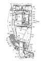
以下、図1〜図13を参照して本発明の第1の実施の形態を説明する。図1及び図3に示されるように第1の実施の形態に係るアップライト型の空気循環式電気掃除機11は、掃除機本体12と、吸込み口体13と、ハンドル14とを備えている。
【0012】
掃除機本体12は、図2等に示される左右一対の合成樹脂製本体ケース21をねじ止め等により連結して形成されている。この本体ケース21の上端部一側(使用時に裏側となる側)には枢着部15を介してハンドル14が連結されている。操作スイッチ14aを有するハンドル14は、使用時には図1に示されるように掃除機本体12の上方に連続して延びる使用位置に配置され、非使用時には枢着部15を中心に下方に回動して折り畳まれて掃除機本体12の前記裏側に沿う非使用位置に配置される。このハンドル14の長さは掃除機本体12とこれに後述のように連結される吸込み口体13との合計長さに略等しく、前記非使用位置のハンドル14は、その下端が床面に接した際に掃除機本体12の自立姿勢が損なわれないように支え得るようになっている。
【0013】
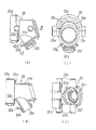
本体ケース21の下端部にはその下端面に露出する接続口体22が取付けられている。この接続口体22は、一対の本体ケース21間に挟まれるとともに、図6に示した位置決め突起22eを本体ケース21の図示しない突起受け部に嵌合させることによって、軸方向及び周方向に移動しないように設置される。図3に示されるように接続口体22には吸込み口体13が着脱可能に挿入して取付けられる。図4〜図7に示されるように接続口体22は、大径部22aと小径部22bとを連ねて段付き円筒状をなす主管部と、小径部22bの周面から一体に分岐された分岐管22dとからなり、かつ、小径部22bと大径部22aとの境をなす壁面には複数の通気孔22cが周方向に間隔的に設けられている。
【0014】
図3に示されるように両本体ケース21の内面にはこれらの連結に伴って先端が互いに当接される所要の仕切りリブが一体に設けられており、これらリブによって、本体ケース21内は、下部の集塵室23と、中間部の排気室24と、上部のリール収容部25と、集塵室23及び排気室24にわたる還流室26とに仕切られている。排気室24の前側(吸込み空気の流れを基準に上流側)に位置された集塵室23は、掃除機本体12の使用時に表側となる面において開口され、この開口は本体ケース21の下部に着脱可能に取付けられるケース蓋27により気密的に閉じられている。還流室26は後述の電動送風機35から排出された空気を吸込み口体13側に導く還流風路を形成している。
【0015】
図3及び図4に示されるように集塵室23の斜状底壁部はフィルタ取付け部28として形成され、このフィルタ取付け部28の近傍には手動により図示しないばねの力に抗して図3中矢印E方向に枢軸29を中心にして回動操作されるフィルタ押さえ30が取付けられている。フィルタ取付け部28と接続口体22の小径部22bとの間には、これらの間を気密に仕切る環状のゴムシール20が介装されており、このシール20は次に説明する口枠の吸込み開口を開閉する弁板部20aを一体に有している。弁板部20aは吸込み負圧によって引き動かされて前記吸込み開口を開くとともに、前記負圧の消失に伴い自身の弾性力で吸込み開口を閉じる位置に戻される。
【0016】
集塵室23に出し入れ可能に収容されるフィルタとしての紙パック製の集塵袋31は、その平板状でかつ中央部に吸込み開口を有した口枠31aを、フィルタ押さえ30によりフィルタ取付け部28に取付けて、集塵室23に収容されている。集塵室23の上部には多数の細長い通気孔を有したフィルタ支え32が収容され、このフィルタ支え32は掃除動作に伴い膨張した集塵袋31を支持する。
【0017】
排気室24には電動送風機35がその吸込み口を集塵室23側に向けて設置されている。36、37は電動送風機35の前後両端部に嵌合された防振用のモータ支持ゴムである。排気室24と集塵室23との境界部に位置される仕切りリブ38には前記吸込み口に対向する開口38aが開けられており、それによって集塵室23内の集塵袋31を通過した空気が電動送風機35に吸込まれる。なお、図3中45は電動送風機35の吸込み側に連通して配置されて集塵室23内の真空圧が所定の値より下がった時に開いて掃除機本体12外の空気(外気)を集塵室23内に導入するためのリーク弁である。
【0018】
電動送風機35は、電動送風部35aとこの送風部35aに取付けられたモータカバー39とを備えている。図3に示されるように電動送風部35aは、ディフューザ及び遠心ファンをファンカバーの内部に収めた送風部35bの下流側に、固定子及び回転子等の前記送風部以外の部品からなる整流子モータ部35cが突出した構成となっている。ファンカバーの外周面には前記モータ支持ゴム36が嵌合されている。この電動送風機35の運転時には、その吸込み口から遠心ファンに吸込まれた集塵室23側の空気は、このファンの周囲から吐出された後、ファンカバーの内面で案内されながらディフューザ内にその外周部の入口から流入し、そして、このディフューザにより静圧化されながら主として整流子モータ部35cの周囲等に向けて流出される。
【0019】
合成樹脂によりカップ状に成形されたモータカバー39は、送風部35bのディフューザよりも下流側部分を覆い隠している。このカバー39の開口縁部は、ファンカバーの外周部に、両カバー間を気密的にシールする前記モータ支持ゴム36を挟んで嵌合されている。モータカバー39の周壁には、モータカバー39内と排気室24とを連通する図示しない複数の排気小孔が開けられているとともに、排気室24に臨んで本体ケース21には図示しない排気口(前記排気小孔よりも排気面積が遥かに大きい。)が設けられていて、これらの排出経路により循環風量に対して所定量の空気を掃除機本体12外に排出して必要な吸気性能を得ることができるようになっている。
【0020】
モータカバー39の底壁中央部にはその外面から突出して前記モータ支持ゴム37が取付けられている。このモータカバー39を備えた電動送風機35は、その軸方向両端部にモータ支持ゴム36、37を夫々嵌め付けた状態で、排気室24及びリール収容部25の境界をなす仕切りリブ21bと前記仕切りリブ38との間に挿入して設置される。図3に示されるようにリール収容部25には電動送風機35に給電するためのコードリール40が収容されている。
【0021】
図3、図5、図6に示されるようにモータカバー39の周部には前記図示しない排気小孔に比較して遥かに開口面積が大きい空気出口41が一体に突設され、この出口41にはゴムパッキン42が嵌合されている。空気出口41は前記還流室26を仕切る仕切りリブ43に設けた孔44に気密的に接続されている。そのため、空気出口41を介してモータカバー39内と還流室26とは連通されている。
【0022】
電動送風機35に吸込まれる空気の流れを基準として前記集塵袋31よりも上流側に配置された接続口体22の分岐管22dは、還流室26内に突出されている。図4及び図7に示されるように分岐管22dの先端部外周面には、螺旋状凸部22f及びこの小径部22b側に連なって張り出した環状の鍔22gが一体に設けられている。そして、図3〜図5に示されるように分岐管22dには、吸込みホース33の基端部が前記螺旋状凸部22fに螺合して連結されているとともに、この連結部の外周に螺合してドーナツ状のゴムパッキング34が被着されている。ゴムパッキング34は、前記連結部の気密を実現するものであり、その一面は前記鍔22gに接着されている。
【0023】
前記のように取付けられた吸込みホース33は、蛇腹管からなり、自在に変形できる可撓性を有しているとともに軸方向に伸縮自在であり、このホース33の流路断面積は後述の内側管部62の流路断面積よりも小さい。吸込みホース33は掃除機本体12の下部のホース導出部12aを通って掃除機本体12の外部に引出されている。ホース導出部12aは一対の本体ケース21に一体に形成された導出壁部12a1(図2及び図6参照)を合わせることによって設けられている。
【0024】
このホース導出部12aの内部、言い換えれば、還流室26の一部には、硬質合成樹脂等により形成されたガイドパイプ46が取付けられている。ガイドパイプ46は円筒形状であってその外周面は凹凸がないように滑らかに形成されている。このガイドパイプ46の一端部は、ゴムパッキング34の外周面に嵌合し接着止めすることによって、分岐管22dに連結されている。ガイドパイプ46の他端部は、ホース導出部12aの先端開口部の内周面との間に環状のゴムパッキング47を挟み込んで、ホース導出部12aの先端開口に支持されている。還流風路をなす還流室26を横切るように設けられた吸込みホース33及びガイドパイプ46の存在に拘らず、両パッキング34、47は、いずれも還流室26と掃除機本体12の外部との気密を図って、還流室26から掃除機本体12の外部への還流空気の吹出し及び掃除機本体12外から還流室26へ外気の吸込みを妨げている。
【0025】
ガイドパイプ46は前記取付け構造により、還流室26(つまり還流風路)を通る空気が流れ方向を変えて後述の連通管51の内側管部62に流れ込む部分に、この部分を通る空気の流動方向に沿うように斜状をなすとともに還流室26を横切って設けられている。しかも、本実施形態においてガイドパイプ46の先端部は、図1〜図3に示されるように掃除機本体12の上部側に向けてこの本体12の外面に露出されている。そのため、ガイドパイプ46に根元部が挿入して収容された吸込みホース33は、掃除機本体12を斜めにして使用する電気掃除機11の通常の使用姿勢において、床面と対向する掃除機本体12の面に沿って上方に向けて引出されている。吸込みホース33の先端部には図2に示されるように硬質合成樹脂製の円筒状の握り管33aが連結されている。
【0026】
吸込みホース33は、その使用時において握り管33aの開口を通して直接塵埃を吸込むことができるとともに、図2(B)に示されるように握り管33aに着脱自在に接続される隙間掃除用ノズル(なお、つる口とも称される。)48、又は図示しない丸ブラシ等の補助吸込み口体を接続して、この補助吸込み口体48を介して塵埃を吸込むことができる。そして、図2に示されるように掃除機本体12の外面には、例えばハンドル14の付け根部の近傍に位置してホース支え49が突設されている。このホース支え49は、握り管33aの内側又は外側に嵌合する短い閉鎖筒部49aを有し、この筒部49aに握り管33aを着脱可能に嵌合させることによって、吸込みホース33の先端部を閉じてこのホース33を支持するものである。
【0027】
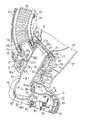
次に、図4、図8〜図13を参照して前記吸込み口体13について説明する。吸込み口体13は、掃除機本体12側に連通される接続部としての合成樹脂製の連通管51と、合成樹脂製の吸込み口体主部52と、回転清掃体53と、還流吹出し口54と、戻り風路A及び吸込み風路Bとを備えている。
【0028】
前記接続口体22に着脱可能に嵌入して取付けられることにより掃除機本体12側に連通される連通管51は、図4、図12、図13に示されるように接続口体22の大径部22a内に挿脱可能に差込み接続された大径な外側管部61と、この内側に複数のリブを介して一体かつ同心的に設けられるとともに接続口体22の筒部としての小径部22b内に挿脱可能に差込み接続された小径な内側管部62と、互いに背向するように逆向きとなって両管部61、62の軸方向に対して略直角状に突設された左右一対の枢軸管部63とを有している。一対の枢軸管部63は、円筒形状をなしているとともに、その開放された先端縁には周方向に連続するフランジ63aが一体に突設されている。
【0029】
外側管部61の一端は開放されており、他端は一対の連通口64を介して枢軸管部63に個別に連通されている。枢軸管部63の先端は開放されており、奥端は内側管部62で閉じられている。外側管部61の外周面には合成ゴム製Oリング等の環状シール材65が取付けられている。図4に示されるように外側管部61は、その外周面から一体に張り出したフランジ部61aが、前記接続口体22の大径部22aの先端に当るまでこの大径部22aの内側に嵌入される。この嵌合による接続状態で、大径部22aと外側管部61との間の気密はシール材65により確保されるとともに、内外両管部61、62間の流路部分は通気孔22cを介して前記還流室26に連通される。なお、接続口体22側には図4に示されるようにばね16で付勢されたベルクランク状のロック摘み17が回動可能に設けられ、この摘み17の爪17aを外側管部61の外周面に設けた凹み61bに引っ掛けることにより、接続口体22に対する吸込み口体13の外れ止めがなされるとともに、この外れ止めはロック摘み17を適宜押圧して回動させることにより外すことができる。
【0030】
外側管部61よりも長い円筒形状の内側管部62の軸方向両端はいずれも開放されている。接続口体22への連通管51の前記取付けに伴い小径部22b内に嵌入された内側管部62は、主たる吸込み管部として使用されるものであって、その内部を通して塵埃を含んだ空気を前記集塵袋31内に導くようになっている。この内側管部62の周壁には、図4及び図12等に示されるように通孔62cが設けられている。この通孔62cは前記分岐管22dに直接連通されるものであって、この通孔62cを通して吸込みホース33を通る空気を集塵室23側に吸込めるようになっている。
【0031】
接続口体22外に突出された内側管部62の先端部の開口は、枢軸管部63間に設けられる入口62aをなしており、その上下縁には入口上部壁66及び入口下部壁67とが夫々外向きに突出されている。この入口62aと一対の枢軸管部63との境界をなす左右一対の入口端部側壁62bは、これらの対向面間距離が内側管部62に対する空気の吸込み方向上流側(図12点鎖線の矢印で示す。)程広がるように斜状に形成されている。この構成は風損を少なくして円滑に空気を入口62aに吸込むことができる点で優れている。
【0032】
図8〜図11に示されるように吸込み口体主部52は、主部上ケース71と、主部下ケース72と、これらの間に挟着される主部中ケース73とをねじ止めにより連結して形成されている。
【0033】
主部中ケース73より後側において主部上下両ケース71、72の内面には、半円状の凹みを有した一対の軸受部74(主部下ケース72側のもののみ図9、図10に示す。)が夫々一体に突設されていて、これら互いに合わされる上下の軸受部74により前記各枢軸管部63が夫々上下から挟まれて回動可能に連結されている。この連結構造により吸込み口体主部52の後部に連通管51が上下方向に起倒するように回動可能に枢着され、この回動により吸込み口体主部52は被掃除面に対して適正な姿勢を得られるようになっている。連通管51と吸込み口体主部52の相対的回動は、前記入口下部壁67と、主部下ケース72にその軸受部74間にわたって設けた上向きのストッパ部75とにより規制されるとともに、この回動の際フランジ部63aと軸受部74との互いの合い面は摺接される。図12中Pは連通管51と吸込み口体主部52との回動中心を示している。
【0034】
吸込み口体主部52内は、吹出し室81と、この吹出し室81の下側の回収室82とに区画されていて、主部中ケース73は両室81、82間の隔壁をなしている。吹出し室81は、主部上ケース71の内面に突設されたリブ83(図3参照)と、主部下ケース72の内面に突設されたリブ84(図9、図10参照)と合い面を互いに凹凸嵌合させるとともに、前記リブ83に連なって主部上ケース71の内面に突設されたリブ85(図8参照)と、主部中ケース73の上面に突設されたリブ86(図9参照)との合い面を互いに凹凸嵌合させることにより、仕切られている。なお、図8〜図10中に示す他のリブ87〜90は吹出し室81の一側及び前側を囲んでおり、これらは前記リブ83〜86と同様に各ケース71〜73に設けられている。この囲みの前部は後述の吸気口91と略同形状であって、吸気口91の真上に形成されている。
【0035】
回収室82は、主部下ケース72と主部中ケース73とで区画されており、これら両ケース72、73の合い面は互いに凹凸嵌合されている。主部下ケース72の底壁72aには、図10〜図12に示されるように回収室82に臨んで吸気口91が形成されている。この吸気口91は吸込み口体13の幅方向(図8〜図11において左右方向)に延びる長方形の開口で形成されている。図11に示されるように主部下ケース72の底壁72aには、吸気口91の後縁に沿って固定ブラシ92が取付けられている。このブラシ92は吸気口91を通って被掃除面に吹付けられた空気が吸込み口体13の後方に向けて吹き抜けることを防止する防風手段としても使用される。
【0036】
図12に示されるように主部中ケース73の幅方向中央部における後端部は、上向きに折り曲げられて主部上ケース71の内面に凹凸嵌合されているとともに、この折り曲げ部分には円弧状部73aが形成されている。この円弧状部73aは前記連通管51の入口62aの前側に対向し配置されている。主部下ケース72には円弧状部73aの幅方向両端から下側に連続する円弧面を有したガイド93が設けられている。これら相連続する円弧状部73aとガイド93とは、円弧状をなすシャッタ94の移動を案内する。吸込み口体主部52に対する連通管51の起倒動作に連動して往復移動される断面円弧状のシャッタ94は、連通管51と吸込み口体主部52とにわたって設けられていて、その後縁部94aの内側には連通管51の入口上部壁66が引っ掛っている。
【0037】
そのため、シャッタ94は、図12に示されるように吸込み口体主部52に対して連通管51が斜めとなる使用姿勢にある場合に、入口上部壁66に引張られて図12に示す開き位置に配置され、非使用時等において吸込み口体52に対して連通管51が直角状となる姿勢にある場合に、図4に示されるように前記後縁部94aに内側管部62が当ってこの管部62に押されて閉じ位置に配置される。シャッタ94が開き位置にある時は吸込み風路Bにおける前記入口62aの直前位置での風路断面積が最大となり、シャッタ94が閉じ位置にある時は前記直前位置での風路断面積が最小(シャッタ94が前記底壁72に当って風路断面積が零となる状態を含む。)となるように設定されている。したがって、シャッタ94は吸込み口体13を通る風量を増減する風量調節手段として用いられている。
【0038】
このように連通管51がある角度以上に起き上がった際に連動するシャッタ94を設けて、それにより前記風路断面積を制限することは、図3、図4に示されるように掃除機本体12が自立姿勢に置かれた時に電動送風機35が動作していても、吸込み口体13を通って循環する風量が減るので、自動的に回転清掃体53の回転を減速ないしは停止させることができる点で優れている。
【0039】
前記回収室82の前部は吸気口91の真上に位置されてこの口91に連通されている。回収室82の後部はその幅方向中央部に集束されるように狭められて後方へ少し延びており、この延出後部は連通管51の内側管部62の入口62aに対向し連通している。そして、回収室82と内側管部62の内側流路とは互いに連通する吸込み風路Bを形成している。この風路Bを通って、吸気口91に向けて回収室82に吹出された空気とともに、この吸気口91に被掃除面側から吸込まれる空気が、掃除機本体12側に吸込まれるようになっている。
【0040】
図10〜図12に示されるように前記回転清掃体53は、回転軸101に清掃部材として1以上のブレード102を取付けるとともに、回転軸101の両端部に支え軸サポート103、104を夫々嵌着し、これらサポート103、104から夫々突設された支え軸105を軸受106で夫々支持して形成されている。したがって、回転清掃体53は、その両端の軸受106以外の部分が一体に回転されるようになっている。回転清掃体53は、その軸受106を主部下ケース72の幅方向両端部に設けられた図示しない軸受保持部に回り止めして取付けることにより、吸気口91と平行な姿勢でこれに臨んで回収室82に配置されている。回転清掃体53が回転される時、そのブレード102の先端部は吸気口91を通過して被掃除面に接するようになっている。
【0041】
前記吹出し室81の後部には図8及び図9に示されるように連通管51の枢軸管部63が配置されていて、これらの管部63を介して吹出し室81と連通管51の内外両管部61、62間の流路とが連通されている。吹出し室81の前部は既述のように主部中ケース73に臨んでおり、この部分には主部中ケース73を貫通して前記還流吹出し口54が吸込み口体主部52の幅方向に沿って形成されている。吸気口91との間に回転清掃体53を置いて設けられた還流吹出し口54は、吹出し室81内の空気をブレード102に吹付けるものであり、吸込み口体13を前方へ押し動かす際に連れ回りする回転清掃体53の回転方向F(図12参照)を順方向と定義した時、この順方向の回転が得られるように回転清掃体53の回転軸101よりも前側に位置して主部中ケース73に開口されている。
【0042】
還流吹出し口54は吸込み口体主部52の幅方向に連続して延びるスリットにより形成されている。したがって、還流吹出し口54は回転清掃体53の軸線と平行に設けられている。そして、この還流吹出し口54は吸込み口体主部52の幅方向に連通管51を中心として同じ様に振り分けて設けられている。なお、還流吹出し口54は非連続な複数の孔等によって形成することもできる。
【0043】
前記構成において、連通管51の内外両管部61、62間の流路、枢軸管部63の内側流路、吸込み口体主部52の吹出し室81は、この記載順に互いに連通する戻り風路Aを形成しており、前記電動送風機35から吐出された空気は戻り風路Aによって還流吹出し口54に導かれて、この吹出し口54を通って吸気口91に戻されるようになっている。
【0044】
なお、図中111は吸込み口体主部52の前部外面に沿って取付けられたバンパー、112は主部下ケース72に取付けられた前車輪、113、114は同じく後車輪である。
【0045】
次に、前記構成の吸込み口体13を備えた空気循環式電気掃除機11の動作を説明する。この電気掃除機11を用いて主に床面の掃除をする基本的な使用時には、図1に示されるように掃除機本体12の接続口体22に吸込み口体13の連通管51を差込み接続した状態で、コードリール40から巻き戻された電源コードを介して電動送風機35に給電し、この送風機35を運転するとともに吸込み口体13を床面等の被掃除面に接触させながら、ハンドル14を介して電気掃除機11全体を移動させることにより使用される。この基本的な使用形態では、吸込みホース33はその先端部をホース支え49に支持されて非使用状態に保持されている。
【0046】
前記使用時には、吸込み口体13の吸込み風路Bに導かれて集塵袋31に流入した吸込み空気(図1及び図12中点線矢印で流れ方向を示す)中に含まれる塵埃が集塵袋31に捕捉され、この集塵袋31を通った空気は、更にフィルタ支え32を通過して電動送風機35に吸込まれてから、そのモータカバー39の空気出口41を通って還流室26に排出されるとともに、その一部は図示しない排気小孔から排気室24を経由して図示しない排気口を通って掃除機本体12外に排出される。
【0047】
還流室26に流入した排気は、接続口体22の通気孔22cから吸込み口体13の戻り風路Aに導かれて、その還流吹出し口54から吸込み風路Bの回収室82側に例えば吸気口91に向けて吹出される。こうした空気の流れを図1及び図12中実線矢印で示す。そのため、吹出し空気は、還流吹出し口54の真下に回転自在に配置された回転清掃体53のブレード102に吹付けられて、この清掃体53を図12中時計回りに回転させるとともに、その直後に吸気口91に対向している被掃除面に吹付けられてから、この被掃除面の塵埃を浮き上げながら吸気口91を通って回収室82に吸込まれ吸込み風路Bに回収される。そして、この回収に伴い掃除機本体12の集塵室23に吸込まれる。
【0048】
このように電動送風機35から排出された空気を吸込み口体13で回収し循環させることに伴い、その勢いで吸込み口体13の底壁72aと被掃除面との間の外部の空気を塵埃と一緒に吸気口91に吸込むとともに、前記循環する空気を利用して回転清掃体53を回転させて被掃除面の塵埃のかき出しを行ないながら、空気循環式の掃除をすることができる。
【0049】
このような基本的な使用形態は主に床面の掃除に適することは勿論であるが、この使用形態においては既述のように吸込みホース33の先端部がホース支え49に嵌合され閉じられた非使用状態に保持されているから、このホース支え49がフィルタとしての集塵袋31の上流側に連通していると言えども、吸込みホース33を通って外気が吸込まれることが防止される。したがって、前記基本的な使用形態においては、第1吸込み経路、つまり、吸込み口体13の吸込み口体主部52の回収室82から連通管51の内側管部62を経て集塵室23の集塵袋31に至る経路を通って、掃除機本体12側に回収される風量が減ることがないから、吸気口91での塵埃の吸込み性能が低下することがない。
【0050】
又、集塵室23の上流側に連通された吸込みホース33は伸縮可能でかつ可撓性を有していて、その先端部をなす握り管33aは、掃除機本体12の外面に突出されたホース支え49から任意に取外すことができ、その取外しにより、吸込み口体13を経由する第1の吸込み経路の他に第2の吸込み経路を形成できる。この第2吸込み経路は、吸込みホース33から、接続口体22の分岐管22d、及び連通管51の内側管部62の通孔62c、及び内側管部62を経て集塵室23内の集塵袋31に至る経路で形成される。
【0051】
前記のようにホース支え49から吸込みホース33の先端部を外して、このホース33を使用状態とすることにより、第1吸込み経路をなす吸込み口体13内の吸込み流路を閉じることなく、吸込みホース33を通して外気を吸込むことができる。そして、この吸込みホース33の使用時には、このホース33自身の可撓性及び伸縮性を利用して、その先端の握り管33aの開口を直接、または握り管33aに適宜差込み接続した補助吸込み口体48の先端開口を、テーブルや壁等の比較的高い掃除場所、或いは障子の桟や扉のガラス回り等の所望とする掃除場所に対向させて、その場所からの吸塵ができる。そのため、握り管33aよりも形状的に遥かに大きく主として床掃除用に適する構成の吸込み口体13では掃除が不適当な場所を、吸込みホース33を用いて必要により手軽に掃除することができる。したがって、前記構成の電気掃除機11は、掃除場所に応じて吸込み口体13と吸込みホース33とを使い分けることができるから、使い勝手がよいものである。
【0052】
前記いずれの使用形態においても、電動送風機35から排出された空気は掃除機本体12の還流風路をなした還流室26を通って接続口体22に差込み接続された吸込み口体13の内側管部62側に導かれる。ところで、掃除機本体12に取付けられた吸込みホース33は蛇腹管製であるため、このホース33が還流室26を横切ってこの室26内に露出して設けられる場合には、還流室26を流れる空気が吸込みホース33の特に蛇腹構造によって乱され易く風損が多い。そのため、還流室26を通る空気が吸込み口体13の内側管部62側に流れ込みづらくなって、電動送風機35に対するバックプレッシャが高まるので、掃除機本体12と吸込み口体13とにわたる空気の循環性能が低下する。
【0053】
しかし、この電気掃除機は前記のように還流室26を横切ってガイドパイプ46を設け、このパイプ46内に蛇腹製の吸込みホース33の基端部を挿入して、ガイドパイプ46で周囲から覆われた吸込みホース33が還流室26を流れる空気に直接接しないように構成してある。そのため、吸込みホース33の蛇腹構造により還流室26を流れる空気が乱されることがないとともに、ガイドパイプ46は蛇腹管ではないので、このパイプ46によって還流室26を流れる空気が乱されることは少ない。したがって、還流室26を横切るように配置される吸込みホース33を備えたにも拘らず、接続口体22の内側管部62に空気を導く還流室26内での風損を少なくできて、電動送風機35に対するバックプレッシャが高まることを抑制できる。
【0054】
しかも、還流室26を横切るガイドパイプ46は、還流室26を通る空気が流動方向を変えて前記吸込み管部62に流れ込む部分に、この部分を通る空気の流動方向に沿うように斜状に設けて、ガイドパイプ46を還流室26を流れる空気に沿うように順方向に配置してある。そのため、このパイプ46による還流室26での風路抵抗をより少なくできて、前記バックプレッシャをより小さくできる。
【0055】
以上のように電動送風機35に対するバックプレッシャが小さいことにより、掃除機本体12と吸込み口体13とにわたる空気の循環が容易となるので、吸気口91での吸塵力を向上できるとともに、回転清掃体53の回転もし易くなって被掃除面の塵埃のかき出し力も向上できる。
【0056】
その上、既述のようにガイドパイプ46が斜状に設けられることにより、そこに通して設けられた吸込みホース33を、その非使用時には図1〜図3などに示されるように掃除機本体12の外面に沿わせ易く、その収まりが良いものである。
【0057】
又、既述のような吸込みホース33を用いての掃除は、掃除機本体12がいかなる姿勢でも可能であるが、通常は、掃除機本体12を支えることが拘束されない自立姿勢、つまり、図3及び図4に示されるように掃除機本体12が起立して置かれた姿勢で行われる。このように掃除機本体12が起立した姿勢では、吸込み口体主部52に対して連通管51が直角状に配置されるに伴い、前記シャッタ94の後縁部94aに連通管51の内側管部62が当ってこの管部62に押されてシャッタ94が閉じ位置に配置されている。この閉じ位置にあるシャッタ94は、前記空気の循環を停止することなく、吸込み風路Bにおける前記入口62aの直前位置での風路断面積を、通常の使用時における前記風路断面積の10%〜95%に絞るように位置される。
【0058】
このように連通管51の起倒により連動するシャッタ94により、掃除機本体12と吸込み口体13とにわたる空気の循環風量を少なく制限できるから、この状態で使用される吸込みホース33に対する吸気負圧の影響が増えて吸込みホース33を通る風量が多く確保されるので、吸込みホース33での吸塵力を強くできる。しかも、掃除機本体12が自立姿勢に置かれた時に既述のように第1吸込み経路の風路断面積を制限することは、循環風量を減らせるので、自動的に回転清掃体53の回転を減速ないしは停止させることができ、したがって、回転清掃体53のかき出し作用に伴う床面の同一個所への悪影響を少なくできる。
【0059】
なお、吸込みホース33を使用しないで掃除機本体12を自立状態から被掃除面に対して斜めとなる通常の使用姿勢にした場合には、その際の吸込み口体主部52に対する連通管51の相対的回動に伴ってシャッタ94が、第1吸込み経路の吸込み風路断面積の一部の遮断状態を解除して、掃除機本体12と吸込み口体13とにわたる空気の循環風量を多く確保するので、第1吸込み経路を通して実現される通常の空気循環式の掃除を行なうことができる。
【0060】
又、前記構成では、集塵室23の上流側に吸込み口体13側の連通管51が挿入される接続口体22を備えていて、集塵室23に吸込み空気を導く内側管部62が挿入された接続口体22の筒部、つまり小径部22bに吸込みホース33が接続される分岐管22dを設け、この分岐管22dに連通する通孔62cを内側管部62の周面に開口して、接続口体22に挿入された連通管51の吸込み空気流を導く吸込み管部としての内側管部62に吸込みホース33を連通させている。この構成により、吸込み口体13側の他に吸込みホース33側からも吸塵する構造において、同一の接続口体22を共用できるので、第1の吸込み経路と第2の吸込み経路の双方について個別に接続口体を設ける必要がなく、同一の接続口体を共用できる。しかも、分岐管22dにガイドパイプ46の一端部を接続して、接続口体22をガイドパイプ46の取付けにも利用したので、吸込みホース33を及びガイドパイプ46を掃除機本体12に取付けるための構造を簡単にできる。
【0061】
なお、本発明は前記実施の形態には制約されるものではなく、キャニスタ型やハンディ型の空気循環式電気掃除機にも適用できるとともに、本発明において回転清掃体は省略してもよい。
【0062】
又、本発明において、吸込みホース33は集塵室23内のフィルタの上流側に連通して設けてあればよく、そのために、例えば、集塵袋を用いないで集塵室の後部等に平面状フィルタを配設した構成にあっては、このフィルタの上流側において集塵室と掃除機本体外とにわたる接続口体を前記接続口体22とは別に設けて、そこに吸込みホースを接続してもよい。
【0063】
【発明の効果】
本発明は、以上説明したような形態で実施され、以下に記載されるような効果を奏する。
【0064】
請求項1〜3に記載の発明に係る空気循環式電気掃除機によれば、主として床面の掃除を担う吸込み口体の他に、この吸込み口体では掃除が不適当な場所の掃除に適する吸込みホースを備えるから、床面以外の被掃除場所についても容易に掃除ができ、使い勝手を向上できるととともに、掃除機本体の還流風路を横切って設けたガイドパイプ内に蛇腹製の吸込みホースを挿入したから、このホースが還流風路を流れる空気を乱だすことがなくなって前記還流風路を通る空気の風損を少なくできるものであり、それに伴い電動送風機のバックプレッシャを低減して掃除機本体と吸込み口体とにわたる空気の循環性能を良好にできる。
【図面の簡単な説明】
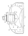
【図1】本発明の第1の実施の形態に係るアップライト型の空気循環式電気掃除機全体の構成を一部切欠して概略的に示す斜視図。
【図2】(A)は第1の実施の形態に係る電気掃除機の掃除機本体を示す斜視図。
(B)は第1の実施の形態に係る電気掃除機の掃除機本体を補助吸込み口体とともに示す斜視図。
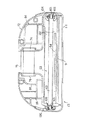
【図3】第1の実施の形態に係る電気掃除機の掃除機本体及び吸込み口体とを示す断面図。
【図4】図3に示された電気掃除機の吸込み口体回りの構成を拡大して示す断面図。
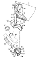
【図5】第1の実施の形態に係る電気掃除機の掃除機本体の集塵室回りの構成を一部切欠いて示す斜視図。
【図6】図5に示された部分の分解斜視図。
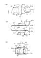
【図7】(A)は第1の実施の形態に係る電気掃除機の掃除機本体が備える接続口体の構成を示す側面図。
(B)は前記接続口体の構成を示す断面図。
(C)は前記接続口体を図7(A)中矢印X方向から見て示す矢視図。
(D)は前記接続口体を図7(A)中矢印W方向から見て示す矢視図。
【図8】図4に示された吸込み口体の構成を示す平面図。
【図9】図4に示された吸込み口体の構成をその主部上ケースを取除くとともに一部を断面して示す平面図。
【図10】図4に示された吸込み口体の構成をその主部上ケース、主部中ケース、及び連通管を取除いて示す平面図。
【図11】図4に示された吸込み口体の構成を示す底面図。
【図12】図8中Z−Z線に沿う断面図。
【図13】(A)は図4に示された吸込み口体が備える連通管を示す側面図。
(B)は図13(A)中Y−Y線に沿う断面図。
(C)は図4に示された吸込み口体が備える連通管を一部断面して示す正面図。
【符号の説明】
11…電気掃除機、
12…掃除機本体、
12a…ホース導出部、
13…吸込み口体、
21…本体ケース、
22…接続口体、
22a…接続口体の大径部、
22b…接続口体の小径部(筒部)、
22c…通気孔、
22d…分岐管、
23…集塵室、
26…還流室(還流風路)、
27…ケース蓋、
31…集塵袋(フィルタ)、
33…吸込みホース、
33a…吸込みホースの握り管、
34…ゴムパッキング、
35…電動送風機、
46…ガイドパイプ、
47…ゴムパッキング、
49…ホース支え、
49a…閉鎖筒部、
51…連通管、
52…吸込み口体主部、
54…還流吹出し口、
61…外側管部、
62…内側管部(吸込み管部)、
62a…内側管部の入口、
62c…内側管部の通孔、
63…枢軸管部、
66…入口上部壁、
71…主部上ケース、
72…主部下ケース、
73…主部中ケース、
82…回収室、
83…吹出し室、
91…吸気口、
A…戻り風路、
B…吸込み風路。 [0001]
BACKGROUND OF THE INVENTION
The present invention sucks air from the suction port of the suction port body by the operation of the electric blower in the main body of the vacuum cleaner, passes the sucked air through a filter to capture dust, passes through the filter, and is discharged from the electric blower. The present invention relates to an air circulation type electric vacuum cleaner that returns air to an intake port, collects the returned air, and performs cleaning while circulating the air.
[0002]
[Prior art]
Conventionally, various air-circulating vacuum cleaners have been proposed, but the suction path of each of these suction paths is mainly connected to the suction inlet of the cleaner body, and the suction inlet for sucking dust on the surface to be cleaned. The air circulation formed by the operation of the electric blower in the main body of the vacuum cleaner using only the suction path by inserting and connecting the communication pipe on the side of the suction port on the bottom surface of the unit. Dust absorption associated with.
[0003]
[Problems to be solved by the invention]
However, since the suction port body is formed in a relatively large size so as to be suitable for cleaning the floor surface, the main portion of the suction port body is set to a relatively high cleaning place such as a table or a wall, or a shoji frame or door. It is unsuitable and unusable for cleaning the cleaning place facing the cleaning place narrower than the main part of the suction port such as around the glass. Such a situation is that the suction pipe portion of the communication pipe inserted and connected to the connection port body of the vacuum cleaner main body and the suction port body main portion having the suction port are connected via a flexible dust suction hose. This is the same even in the case of the upright type air circulation type vacuum cleaner in which the suction port is directly connected to the lower end of the vacuum cleaner body.
[0004]
Therefore, the problem to be solved by the present invention is to obtain an air circulation type vacuum cleaner that can easily clean a place to be cleaned other than the floor surface and has less windage loss due to its structure.
[0005]
[Means for Solving the Problems]
The present invention captures dust by passing the air sucked from the suction port of the suction port body through the operation of the electric blower built in the vacuum cleaner body through the filter in the dust collection chamber upstream of the electric blower. It is premised on a vacuum cleaner that cleans the air that passes through and is discharged from the electric blower back to the intake port, and collects and circulates the returned air.
[0006]
And in order to solve the said subject, invention of Claim 1 is the following.A pair of main body cases are connected to form the vacuum cleaner main body, and the dust collection chamber in which the filter can be inserted and removed by ribs provided on the inner surfaces of the main body cases, and the exhaust in which the electric blower is installed. And an opening of the dust collecting chamber that is opened to the opposite side of the return air passage with the filter interposed therebetween, partitioning the chamber and a return air passage for guiding the air discharged from the electric blower and directed to the suction port body A case lid is provided that opens and closes the return air passage, and a guide pipe that crosses the return air passage is sandwiched between the pair of main body cases. The first pipe extends from the intake port to the dust collection chamber. A flexible suction hose made of a bellows tube forming a second suction path different from the suction path is inserted into the guide pipe and communicated with the upstream side of the filter;Dust can be sucked through at least one of the suction hose or the suction port body.
[0007]
In the air circulation type vacuum cleaner according to the first aspect of the present invention, as the air discharged from the electric blower is circulated between the cleaner body and the suction port body, the suction port body from the suction port to the floor surface or the like is covered. Air circulation type cleaning is possible by sucking dust on the cleaning surface. In the usage mode based on the suction through the suction port body, the suction hose is kept in a non-use state where there is no air suction, and is therefore mainly suitable for cleaning the floor surface. When a suction hose communicated with the upstream side of the filter is used during cleaning, outside air may be sucked through the suction hose that forms the second suction path in addition to the first suction path that passes through the suction port body. At this time, the suction hose itself can be made flexible by the flexibility of the suction hose itself so as to face the cleaning place where the suction mouth body is inappropriate for cleaning.
[0008]
And in any said usage form, the air discharged | emitted from the electric blower is guide | induced to the suction inlet body side through the recirculation | reflux air path of a cleaner body. By the way, since the suction hose attached to the vacuum cleaner body is made of a bellows tube, when this hose crosses the reflux air passage and is exposed to this air passage, the air flowing through the reflux air passage is sucked. The hose is particularly disturbed by the bellows structure. For this reason, the air passing through the reflux air passage hardly flows into the suction port body, and the back pressure with respect to the electric blower increases, so that the air circulation performance between the cleaner body and the suction port body is deteriorated. However, in the invention of claim 1, a bellows suction hose is inserted into the guide pipe provided across the reflux air passage so that the hose does not directly contact the air flowing through the reflux air passage. The air flowing through the return air passage is not disturbed by the suction hose, and the guide pipe is not a bellows tube, so that the air flowing through the return air passage is rarely disturbed by this pipe.
[0009]
In carrying out the invention of claim 1, like the invention of claim 2 subordinate to this invention,A connection port body into which the suction pipe portion of the communication pipe on the suction port body side is inserted is located on the upstream side of the dust collection chamber and is sandwiched between the pair of body cases,When the guide pipe that crosses the return air passage is provided in a slanted shape so that the air passing through the return air passage changes its direction and flows into the suction pipe portion so as to follow the flow direction of the air passing through this portion. Good. By doing so, the guide pipe is arranged in the forward direction along the air flowing through the return air passage, so that the air passage resistance in the return air passage due to this pipe becomes smaller and the back pressure is made smaller. In addition, the suction hose provided along the oblique guide pipe is excellent in that it can be easily along the outer surface of the cleaner body when not in use.
[0010]
In carrying out the invention of claim 2, as in the invention of claim 3 subordinate to this invention, the tube portion of the connection port body into which the suction pipe portion for guiding the suction air flow to the dust collecting chamber is inserted is provided. A branch pipe is provided, a through hole communicating with the branch pipe is opened in the peripheral surface of the suction pipe portion, and the suction hose is connected to the branch pipe, and the suction pipe portion and the suction hose are communicated with each other. And it is good to connect the end of the guide pipe to the branch pipe. By doing so, the same connection port body can be shared for both the first suction path that passes through the suction port body and the second suction path that passes through the suction hose. It is not necessary to provide a mouth body, and this connection mouth body can be used for mounting the guide pipe, which is excellent in that the structure for mounting the suction hose and the guide pipe to the cleaner body is simple.
[0011]
DETAILED DESCRIPTION OF THE INVENTION
Hereinafter, a first embodiment of the present invention will be described with reference to FIGS. As shown in FIGS. 1 and 3, the upright type air circulation vacuum cleaner 11 according to the first embodiment includes a
[0012]
The vacuum cleaner
[0013]
A
[0014]
As shown in FIG. 3, the inner surfaces of the two
[0015]
As shown in FIGS. 3 and 4, the slanted bottom wall portion of the
[0016]
A
[0017]
An
[0018]
The
[0019]
The
[0020]
The motor support rubber 37 is attached to the center of the bottom wall of the
[0021]
As shown in FIGS. 3, 5, and 6, an
[0022]
A
[0023]
The
[0024]
A
[0025]
Due to the mounting structure, the
[0026]
The
[0027]
Next, the
[0028]
As shown in FIGS. 4, 12, and 13, the
[0029]
One end of the
[0030]
Both ends in the axial direction of the cylindrical
[0031]
The opening at the front end of the
[0032]
As shown in FIG. 8 to FIG. 11, the suction port body
[0033]
A pair of bearing
[0034]
The suction port body
[0035]
The
[0036]
As shown in FIG. 12, the rear end portion in the center portion in the width direction of the main
[0037]
Therefore, as shown in FIG. 12, the
[0038]
As shown in FIGS. 3 and 4, it is possible to provide the
[0039]
The front portion of the
[0040]
As shown in FIGS. 10 to 12, the
[0041]
As shown in FIGS. 8 and 9, a
[0042]
The
[0043]
In the above configuration, the flow path between the inner and
[0044]
In the figure, 111 is a bumper attached along the front outer surface of the suction port
[0045]
Next, the operation of the air circulation type vacuum cleaner 11 provided with the
[0046]
At the time of use, dust contained in the suction air (indicated by the dotted arrow in FIGS. 1 and 12 indicates the flow direction) guided to the suction air passage B of the
[0047]
The exhaust gas flowing into the
[0048]
As the air discharged from the
[0049]
Of course, such a basic use form is suitable mainly for cleaning the floor surface. However, in this use form, the tip of the
[0050]
Further, the
[0051]
As described above, the tip of the
[0052]
In any of the above usage forms, the air discharged from the
[0053]
However, this vacuum cleaner is provided with the
[0054]
Moreover, the
[0055]
Since the back pressure with respect to the
[0056]
In addition, as described above, the
[0057]
Further, the cleaning using the
[0058]
In this way, the
[0059]
In addition, when the vacuum cleaner
[0060]
Further, in the above configuration, the
[0061]
The present invention is not limited to the above embodiment, and can be applied to a canister type or handy type air circulation type electric vacuum cleaner, and the rotary cleaning body may be omitted in the present invention.
[0062]
In the present invention, the
[0063]
【The invention's effect】
The present invention is implemented in the form as described above, and has the following effects.
[0064]
According to the air circulation type vacuum cleaner according to the first to third aspects of the present invention, in addition to the suction port body mainly responsible for cleaning the floor surface, this suction port body is suitable for cleaning an unsuitable place for cleaning. Because it has a suction hose, it can be easily cleaned in areas to be cleaned other than the floor, improving usability, and a bellows suction hose in the guide pipe provided across the reflux air passage of the vacuum cleaner body Since this hose is inserted, the hose does not disturb the air flowing through the return air passage, and the air loss through the return air passage can be reduced. Accordingly, the back pressure of the electric blower is reduced and the vacuum cleaner Air circulation performance across the main body and the suction port can be improved.
[Brief description of the drawings]
FIG. 1 is a perspective view schematically showing a part of the entire structure of an upright air circulation vacuum cleaner according to a first embodiment of the present invention.
FIG. 2A is a perspective view showing a cleaner body of the electric vacuum cleaner according to the first embodiment.
(B) is a perspective view which shows the vacuum cleaner main body of the vacuum cleaner which concerns on 1st Embodiment with an auxiliary suction inlet.
FIG. 3 is a cross-sectional view showing a vacuum cleaner body and a suction port body of the electric vacuum cleaner according to the first embodiment.
4 is an enlarged cross-sectional view showing a configuration around a suction port body of the electric vacuum cleaner shown in FIG. 3;
FIG. 5 is a perspective view showing a part of the configuration around the dust collection chamber of the vacuum cleaner main body of the electric vacuum cleaner according to the first embodiment.
6 is an exploded perspective view of the portion shown in FIG.
FIG. 7A is a side view showing a configuration of a connection port body provided in the vacuum cleaner main body of the electric vacuum cleaner according to the first embodiment.
(B) is sectional drawing which shows the structure of the said connection port body.
(C) is an arrow view which shows the said connection port body seeing from the arrow X direction in FIG. 7 (A).
(D) is an arrow view which shows the said connection port body seeing from the arrow W direction in FIG. 7 (A).
FIG. 8 is a plan view showing the configuration of the suction port body shown in FIG. 4;
FIG. 9 is a plan view showing the structure of the suction port shown in FIG. 4 with the main case upper case removed and partly in section.
10 is a plan view showing the configuration of the suction port body shown in FIG. 4 with its main part upper case, main part middle case, and communication pipe removed. FIG.
11 is a bottom view showing the structure of the suction port shown in FIG. 4;
12 is a cross-sectional view taken along the line ZZ in FIG.
13A is a side view showing a communication pipe provided in the suction port shown in FIG. 4; FIG.
(B) is sectional drawing which follows the YY line in FIG. 13 (A).
FIG. 5C is a front view showing a partial cross section of the communication pipe included in the suction port shown in FIG.
[Explanation of symbols]
11 ... vacuum cleaner,
12 ... vacuum cleaner body,
12a ... hose outlet part,
13 ... Suction mouth,
21 ... body case,
22: Connection port,
22a: Large diameter portion of the connection port,
22b ... a small diameter part (cylinder part) of the connection port body,
22c ... vent hole,
22d ... branch pipe,
23 ... dust collection chamber,
26 ... Reflux chamber (reflux air passage),
27 ... Case lid,
31 ... Dust collection bag (filter),
33 ... Suction hose,
33a ... gripping pipe of suction hose,
34 ... Rubber packing,
35 ... Electric blower,
46 ... Guide pipe,
47 ... Rubber packing,
49 ... Hose support,
49a ... closed cylinder,
51 ... Communication pipe,
52 ... Main part of the suction port,
54 ... Reflux outlet,
61 ... Outer tube part,
62 ... Inner tube (suction tube),
62a ... the inlet of the inner pipe,
62c ... the through hole of the inner tube part,
63 ... Axis tube part,
66 ... upper entrance wall,
71 ... upper case of main part,
72. Main lower case,
73 ... Middle case of main part,
82 ... Recovery room,
83 ... Blowout room,
91 ... Inlet,
A ... Return air path,
B ... Suction air passage.
Claims (3)
一対の本体ケースを連結して前記掃除機本体を形成し、
これら本体ケースの内面に設けたリブで、前記フィルタが出し入れ可能に収容される前記集塵室と、前記電動送風機が設置される排気室と、前記電動送風機から排出されて前記吸込み口体に向かう空気を導く還流風路とを仕切り、
前記フィルタを間に置いて前記還流風路と反対側に開口された前記集塵室の開口を開閉するケース蓋を設け、
前記還流風路に対する気密を保持してこの還流風路を横切るガイドパイプを前記一対の本体ケース間に挟んで設け、
前記吸気口から前記集塵室に至る第1吸込み経路とは異なる第2吸込み経路を形成する蛇腹管からなる可撓性の吸込みホースを、前記ガイドパイプ内に挿入して前記フィルタの上流側に連通して設け、
この吸込みホース又は前記吸込み口体の少なくとも一方を通して吸塵可能としたことを特徴とする空気循環式電気掃除機。The air sucked from the suction port of the suction port body by the operation of the electric blower built in the vacuum cleaner body is passed through the filter in the dust collection chamber on the upstream side of the electric blower, and the dust is captured and passed through the filter. In the vacuum cleaner that cleans the air exhausted from the electric blower by returning it to the intake port and collecting and circulating the returned air.
A pair of body cases are connected to form the vacuum cleaner body,
Ribs provided on the inner surfaces of the main body case, the dust collection chamber in which the filter is accommodated so as to be able to be put in and out, an exhaust chamber in which the electric blower is installed, and a discharge from the electric blower toward the suction port body. Partition the return air duct that leads the air,
Provided with a case lid that opens and closes the opening of the dust collection chamber opened on the opposite side of the reflux air passage with the filter in between,
Maintaining airtightness with respect to the return air passage, a guide pipe that crosses the return air passage is provided between the pair of body cases,
A flexible suction hose made of a bellows tube that forms a second suction path that is different from the first suction path from the suction port to the dust collecting chamber is inserted into the guide pipe and is placed upstream of the filter. Communicated,
An air circulation type electric vacuum cleaner capable of sucking dust through at least one of the suction hose or the suction port body.
Priority Applications (1)
| Application Number | Priority Date | Filing Date | Title |
|---|---|---|---|
| JP00053599A JP3668029B2 (en) | 1999-01-05 | 1999-01-05 | Air circulation type vacuum cleaner |
Applications Claiming Priority (1)
| Application Number | Priority Date | Filing Date | Title |
|---|---|---|---|
| JP00053599A JP3668029B2 (en) | 1999-01-05 | 1999-01-05 | Air circulation type vacuum cleaner |
Publications (2)
| Publication Number | Publication Date |
|---|---|
| JP2000197591A JP2000197591A (en) | 2000-07-18 |
| JP3668029B2 true JP3668029B2 (en) | 2005-07-06 |
Family
ID=11476463
Family Applications (1)
| Application Number | Title | Priority Date | Filing Date |
|---|---|---|---|
| JP00053599A Expired - Fee Related JP3668029B2 (en) | 1999-01-05 | 1999-01-05 | Air circulation type vacuum cleaner |
Country Status (1)
| Country | Link |
|---|---|
| JP (1) | JP3668029B2 (en) |
Families Citing this family (1)
| Publication number | Priority date | Publication date | Assignee | Title |
|---|---|---|---|---|
| JP5653113B2 (en) * | 2010-07-27 | 2015-01-14 | 株式会社東芝 | Suction port for vacuum cleaner and electric vacuum cleaner provided with the same |
-
1999
- 1999-01-05 JP JP00053599A patent/JP3668029B2/en not_active Expired - Fee Related
Also Published As
| Publication number | Publication date |
|---|---|
| JP2000197591A (en) | 2000-07-18 |
Similar Documents
| Publication | Publication Date | Title |
|---|---|---|
| KR101821908B1 (en) | Electric vacuum cleaner | |
| US7735187B2 (en) | Bag cage having bag caddy | |
| KR100849778B1 (en) | Vacuum cleaner and its suction port | |
| JP3668029B2 (en) | Air circulation type vacuum cleaner | |
| JP3482145B2 (en) | Air circulation type vacuum cleaner | |
| JP3162031B2 (en) | Suction port body and vacuum cleaner | |
| JP3525065B2 (en) | Suction port body and vacuum cleaner | |
| JP3525067B2 (en) | Suction port body and vacuum cleaner | |
| JP3482144B2 (en) | Air circulation type vacuum cleaner | |
| JP3163291B2 (en) | Suction port body and vacuum cleaner | |
| JP2000107097A (en) | Suction port body and vacuum cleaner | |
| JP3819641B2 (en) | Suction port and vacuum cleaner | |
| JP3525066B2 (en) | Suction port body and vacuum cleaner | |
| JP2000189352A (en) | Air circulation type vacuum cleaner | |
| JP2000189351A (en) | Electric vacuum cleaner | |
| JP3470100B2 (en) | Suction port body and vacuum cleaner | |
| JP3482137B2 (en) | Suction port body and vacuum cleaner | |
| JP3542275B2 (en) | Air circulation type vacuum cleaner and suction device | |
| JPH11221175A (en) | Vacuum cleaner suction tool | |
| JP2001353109A (en) | Vacuum cleaner and its suction body | |
| JP2001186999A (en) | Circulation type vacuum cleaner | |
| JP3163276B2 (en) | Electric vacuum cleaner | |
| JP2006204781A (en) | Vacuum cleaner and its suction port | |
| JP2001008861A (en) | Circulation type vacuum cleaner | |
| JP3542287B2 (en) | Suction port body and vacuum cleaner |
Legal Events
| Date | Code | Title | Description |
|---|---|---|---|
| A977 | Report on retrieval |
Free format text: JAPANESE INTERMEDIATE CODE: A971007 Effective date: 20040816 |
|
| A131 | Notification of reasons for refusal |
Free format text: JAPANESE INTERMEDIATE CODE: A131 Effective date: 20041102 |
|
| A521 | Written amendment |
Free format text: JAPANESE INTERMEDIATE CODE: A523 Effective date: 20041224 |
|
| TRDD | Decision of grant or rejection written | ||
| A01 | Written decision to grant a patent or to grant a registration (utility model) |
Free format text: JAPANESE INTERMEDIATE CODE: A01 Effective date: 20050405 |
|
| A61 | First payment of annual fees (during grant procedure) |
Free format text: JAPANESE INTERMEDIATE CODE: A61 Effective date: 20050407 |
|
| R150 | Certificate of patent or registration of utility model |
Free format text: JAPANESE INTERMEDIATE CODE: R150 |
|
| FPAY | Renewal fee payment (event date is renewal date of database) |
Free format text: PAYMENT UNTIL: 20080415 Year of fee payment: 3 |
|
| S111 | Request for change of ownership or part of ownership |
Free format text: JAPANESE INTERMEDIATE CODE: R313113 |
|
| FPAY | Renewal fee payment (event date is renewal date of database) |
Free format text: PAYMENT UNTIL: 20080415 Year of fee payment: 3 |
|
| R350 | Written notification of registration of transfer |
Free format text: JAPANESE INTERMEDIATE CODE: R350 |
|
| FPAY | Renewal fee payment (event date is renewal date of database) |
Free format text: PAYMENT UNTIL: 20080415 Year of fee payment: 3 |
|
| FPAY | Renewal fee payment (event date is renewal date of database) |
Free format text: PAYMENT UNTIL: 20090415 Year of fee payment: 4 |
|
| FPAY | Renewal fee payment (event date is renewal date of database) |
Free format text: PAYMENT UNTIL: 20090415 Year of fee payment: 4 |
|
| S533 | Written request for registration of change of name |
Free format text: JAPANESE INTERMEDIATE CODE: R313533 |
|
| R350 | Written notification of registration of transfer |
Free format text: JAPANESE INTERMEDIATE CODE: R350 |
|
| R350 | Written notification of registration of transfer |
Free format text: JAPANESE INTERMEDIATE CODE: R350 |
|
| FPAY | Renewal fee payment (event date is renewal date of database) |
Free format text: PAYMENT UNTIL: 20090415 Year of fee payment: 4 |
|
| FPAY | Renewal fee payment (event date is renewal date of database) |
Free format text: PAYMENT UNTIL: 20100415 Year of fee payment: 5 |
|
| LAPS | Cancellation because of no payment of annual fees |