EP2196596A1 - Paneel sowie Befestigungssystem für Paneele - Google Patents
Paneel sowie Befestigungssystem für Paneele Download PDFInfo
- Publication number
- EP2196596A1 EP2196596A1 EP10158660A EP10158660A EP2196596A1 EP 2196596 A1 EP2196596 A1 EP 2196596A1 EP 10158660 A EP10158660 A EP 10158660A EP 10158660 A EP10158660 A EP 10158660A EP 2196596 A1 EP2196596 A1 EP 2196596A1
- Authority
- EP
- European Patent Office
- Prior art keywords
- hook
- panel
- locking
- panels
- recess
- Prior art date
- Legal status (The legal status is an assumption and is not a legal conclusion. Google has not performed a legal analysis and makes no representation as to the accuracy of the status listed.)
- Granted
Links
- 230000000903 blocking effect Effects 0.000 claims description 67
- 210000000078 claw Anatomy 0.000 claims description 28
- 239000000758 substrate Substances 0.000 claims description 12
- 238000010276 construction Methods 0.000 description 8
- 238000005304 joining Methods 0.000 description 6
- 239000000463 material Substances 0.000 description 6
- 238000003780 insertion Methods 0.000 description 3
- 230000037431 insertion Effects 0.000 description 3
- 238000000034 method Methods 0.000 description 3
- 239000011162 core material Substances 0.000 description 2
- 238000009408 flooring Methods 0.000 description 2
- 238000009434 installation Methods 0.000 description 2
- 238000003801 milling Methods 0.000 description 2
- 239000002023 wood Substances 0.000 description 2
- 239000011093 chipboard Substances 0.000 description 1
- 230000001419 dependent effect Effects 0.000 description 1
- 238000009826 distribution Methods 0.000 description 1
- 210000003746 feather Anatomy 0.000 description 1
- 238000004519 manufacturing process Methods 0.000 description 1
- 230000007246 mechanism Effects 0.000 description 1
- 239000010421 standard material Substances 0.000 description 1
Images


Classifications
-
- E—FIXED CONSTRUCTIONS
- E04—BUILDING
- E04F—FINISHING WORK ON BUILDINGS, e.g. STAIRS, FLOORS
- E04F15/00—Flooring
- E04F15/02—Flooring or floor layers composed of a number of similar elements
- E04F15/02038—Flooring or floor layers composed of a number of similar elements characterised by tongue and groove connections between neighbouring flooring elements
-
- E—FIXED CONSTRUCTIONS
- E04—BUILDING
- E04F—FINISHING WORK ON BUILDINGS, e.g. STAIRS, FLOORS
- E04F15/00—Flooring
- E04F15/02—Flooring or floor layers composed of a number of similar elements
-
- F—MECHANICAL ENGINEERING; LIGHTING; HEATING; WEAPONS; BLASTING
- F16—ENGINEERING ELEMENTS AND UNITS; GENERAL MEASURES FOR PRODUCING AND MAINTAINING EFFECTIVE FUNCTIONING OF MACHINES OR INSTALLATIONS; THERMAL INSULATION IN GENERAL
- F16B—DEVICES FOR FASTENING OR SECURING CONSTRUCTIONAL ELEMENTS OR MACHINE PARTS TOGETHER, e.g. NAILS, BOLTS, CIRCLIPS, CLAMPS, CLIPS OR WEDGES; JOINTS OR JOINTING
- F16B5/00—Joining sheets or plates, e.g. panels, to one another or to strips or bars parallel to them
- F16B5/0004—Joining sheets, plates or panels in abutting relationship
- F16B5/0008—Joining sheets, plates or panels in abutting relationship by moving the sheets, plates or panels substantially in their own plane, perpendicular to the abutting edge
- F16B5/0012—Joining sheets, plates or panels in abutting relationship by moving the sheets, plates or panels substantially in their own plane, perpendicular to the abutting edge a tongue on the edge of one sheet, plate or panel co-operating with a groove in the edge of another sheet, plate or panel
-
- F—MECHANICAL ENGINEERING; LIGHTING; HEATING; WEAPONS; BLASTING
- F16—ENGINEERING ELEMENTS AND UNITS; GENERAL MEASURES FOR PRODUCING AND MAINTAINING EFFECTIVE FUNCTIONING OF MACHINES OR INSTALLATIONS; THERMAL INSULATION IN GENERAL
- F16B—DEVICES FOR FASTENING OR SECURING CONSTRUCTIONAL ELEMENTS OR MACHINE PARTS TOGETHER, e.g. NAILS, BOLTS, CIRCLIPS, CLAMPS, CLIPS OR WEDGES; JOINTS OR JOINTING
- F16B5/00—Joining sheets or plates, e.g. panels, to one another or to strips or bars parallel to them
- F16B5/0004—Joining sheets, plates or panels in abutting relationship
- F16B5/0032—Joining sheets, plates or panels in abutting relationship by moving the sheets, plates, or panels or the interlocking key parallel to the abutting edge
- F16B5/0044—Joining sheets, plates or panels in abutting relationship by moving the sheets, plates, or panels or the interlocking key parallel to the abutting edge and using interlocking keys of circular, square, rectangular or like shape
-
- F—MECHANICAL ENGINEERING; LIGHTING; HEATING; WEAPONS; BLASTING
- F16—ENGINEERING ELEMENTS AND UNITS; GENERAL MEASURES FOR PRODUCING AND MAINTAINING EFFECTIVE FUNCTIONING OF MACHINES OR INSTALLATIONS; THERMAL INSULATION IN GENERAL
- F16B—DEVICES FOR FASTENING OR SECURING CONSTRUCTIONAL ELEMENTS OR MACHINE PARTS TOGETHER, e.g. NAILS, BOLTS, CIRCLIPS, CLAMPS, CLIPS OR WEDGES; JOINTS OR JOINTING
- F16B5/00—Joining sheets or plates, e.g. panels, to one another or to strips or bars parallel to them
- F16B5/0004—Joining sheets, plates or panels in abutting relationship
- F16B5/0056—Joining sheets, plates or panels in abutting relationship by moving the sheets, plates or panels or the interlocking key perpendicular to the main plane
- F16B5/0064—Joining sheets, plates or panels in abutting relationship by moving the sheets, plates or panels or the interlocking key perpendicular to the main plane and using C-shaped clamps
-
- F—MECHANICAL ENGINEERING; LIGHTING; HEATING; WEAPONS; BLASTING
- F16—ENGINEERING ELEMENTS AND UNITS; GENERAL MEASURES FOR PRODUCING AND MAINTAINING EFFECTIVE FUNCTIONING OF MACHINES OR INSTALLATIONS; THERMAL INSULATION IN GENERAL
- F16B—DEVICES FOR FASTENING OR SECURING CONSTRUCTIONAL ELEMENTS OR MACHINE PARTS TOGETHER, e.g. NAILS, BOLTS, CIRCLIPS, CLAMPS, CLIPS OR WEDGES; JOINTS OR JOINTING
- F16B5/00—Joining sheets or plates, e.g. panels, to one another or to strips or bars parallel to them
- F16B5/0004—Joining sheets, plates or panels in abutting relationship
- F16B5/008—Joining sheets, plates or panels in abutting relationship by a rotating or sliding and rotating movement
-
- E—FIXED CONSTRUCTIONS
- E04—BUILDING
- E04F—FINISHING WORK ON BUILDINGS, e.g. STAIRS, FLOORS
- E04F15/00—Flooring
- E04F15/02—Flooring or floor layers composed of a number of similar elements
- E04F15/04—Flooring or floor layers composed of a number of similar elements only of wood or with a top layer of wood, e.g. with wooden or metal connecting members
-
- E—FIXED CONSTRUCTIONS
- E04—BUILDING
- E04F—FINISHING WORK ON BUILDINGS, e.g. STAIRS, FLOORS
- E04F2201/00—Joining sheets or plates or panels
- E04F2201/01—Joining sheets, plates or panels with edges in abutting relationship
- E04F2201/0138—Joining sheets, plates or panels with edges in abutting relationship by moving the sheets, plates or panels perpendicular to the main plane
-
- E—FIXED CONSTRUCTIONS
- E04—BUILDING
- E04F—FINISHING WORK ON BUILDINGS, e.g. STAIRS, FLOORS
- E04F2201/00—Joining sheets or plates or panels
- E04F2201/01—Joining sheets, plates or panels with edges in abutting relationship
- E04F2201/0153—Joining sheets, plates or panels with edges in abutting relationship by rotating the sheets, plates or panels around an axis which is parallel to the abutting edges, possibly combined with a sliding movement
-
- E—FIXED CONSTRUCTIONS
- E04—BUILDING
- E04F—FINISHING WORK ON BUILDINGS, e.g. STAIRS, FLOORS
- E04F2201/00—Joining sheets or plates or panels
- E04F2201/02—Non-undercut connections, e.g. tongue and groove connections
- E04F2201/023—Non-undercut connections, e.g. tongue and groove connections with a continuous tongue or groove
-
- E—FIXED CONSTRUCTIONS
- E04—BUILDING
- E04F—FINISHING WORK ON BUILDINGS, e.g. STAIRS, FLOORS
- E04F2201/00—Joining sheets or plates or panels
- E04F2201/02—Non-undercut connections, e.g. tongue and groove connections
- E04F2201/026—Non-undercut connections, e.g. tongue and groove connections with rabbets, e.g. being stepped
-
- E—FIXED CONSTRUCTIONS
- E04—BUILDING
- E04F—FINISHING WORK ON BUILDINGS, e.g. STAIRS, FLOORS
- E04F2201/00—Joining sheets or plates or panels
- E04F2201/03—Undercut connections, e.g. using undercut tongues or grooves
-
- E—FIXED CONSTRUCTIONS
- E04—BUILDING
- E04F—FINISHING WORK ON BUILDINGS, e.g. STAIRS, FLOORS
- E04F2201/00—Joining sheets or plates or panels
- E04F2201/04—Other details of tongues or grooves
- E04F2201/042—Other details of tongues or grooves with grooves positioned on the rear-side of the panel
-
- E—FIXED CONSTRUCTIONS
- E04—BUILDING
- E04F—FINISHING WORK ON BUILDINGS, e.g. STAIRS, FLOORS
- E04F2201/00—Joining sheets or plates or panels
- E04F2201/05—Separate connectors or inserts, e.g. pegs, pins, keys or strips
-
- E—FIXED CONSTRUCTIONS
- E04—BUILDING
- E04F—FINISHING WORK ON BUILDINGS, e.g. STAIRS, FLOORS
- E04F2201/00—Joining sheets or plates or panels
- E04F2201/05—Separate connectors or inserts, e.g. pegs, pins, keys or strips
- E04F2201/0517—U- or C-shaped brackets and clamps
-
- E—FIXED CONSTRUCTIONS
- E04—BUILDING
- E04F—FINISHING WORK ON BUILDINGS, e.g. STAIRS, FLOORS
- E04F2201/00—Joining sheets or plates or panels
- E04F2201/05—Separate connectors or inserts, e.g. pegs, pins, keys or strips
- E04F2201/0523—Separate tongues; Interlocking keys, e.g. joining mouldings of circular, square or rectangular shape
-
- Y—GENERAL TAGGING OF NEW TECHNOLOGICAL DEVELOPMENTS; GENERAL TAGGING OF CROSS-SECTIONAL TECHNOLOGIES SPANNING OVER SEVERAL SECTIONS OF THE IPC; TECHNICAL SUBJECTS COVERED BY FORMER USPC CROSS-REFERENCE ART COLLECTIONS [XRACs] AND DIGESTS
- Y10—TECHNICAL SUBJECTS COVERED BY FORMER USPC
- Y10T—TECHNICAL SUBJECTS COVERED BY FORMER US CLASSIFICATION
- Y10T428/00—Stock material or miscellaneous articles
- Y10T428/16—Two dimensionally sectional layer
- Y10T428/163—Next to unitary web or sheet of equal or greater extent
- Y10T428/164—Continuous two dimensionally sectional layer
- Y10T428/167—Cellulosic sections [e.g., parquet floor, etc.]
Definitions
- the invention relates to a fastening system for quadrangular tabular panels arranged on the narrow sides of the panels holding profiles of which oppositely arranged holding profiles match each other so that similar panels are connected to each other, especially for floor panels, with oppositely arranged first holding profiles, which are designed so that on a front row panel in the second row, a new panel is lockable, in which the new panel is first added in an inclined position relative to the lying panel to the lying panel and subsequently pivoted down into the plane of the lying panel, and with oppositely disposed second Holding profiles that have corresponding hook elements, with one of the hook elements of the new panel and a hook element of an already in the second row lying panel by the pivoting down of the new panel a Hakenverbindund produced is.
- a generic fastening system is from the DE 199 29 896 A1 known. It is characteristic of such a fastening system that the first and second holding profiles used have very different geometries and thus also the joining methods of the various holding profiles are very different. In particular, the second retaining profiles formed as hook elements, which are joined together to form a hook connection, harbor a technical problem. Although the known hook connection secures floor panels well against evenly sliding apart at right angles to the narrow sides of the connected panels. However, it does not provide satisfactory resistance to disengagement of the hook elements in a direction perpendicular to the laying plane of the panels.
- Such a fastening system for so-called laminate flooring which has a core of wood-based material, such as MDF, HDF or chipboard material, is preferably used.
- the mechanical holding profiles are usually milled to the narrow sides of wood-based panels.
- Laminate flooring is mainly laid floating.
- a padding-sound insulating intermediate layer is usually arranged between the laying substrate and the laminate panels.
- a footfall sound insulating layer is fixedly mounted on the underside facing the laying surface of laminate panels.
- the hook connection of the known fastening system when in the region of a hook connection only that panel is subjected to a large load, the hook element is at the bottom, namely facing the laying surface.
- the hooked with this overhead hook element of the adjacent panel is not loaded therefore is pressed by the load only the panel with the underlying hook element in the mostly soft impact sound insulating liner.
- the overhead hook element of the unloaded panel separates from the underlying hook element of the adjacent panel.
- the hook connection is out of order and the function usually can not be restored.
- undercuts are integrated into the hook connection, by which a release of the hook connection is to be prevented perpendicular to the laying plane of the panels.
- these undercuts have proven to be insufficient, this type of fasteners sufficient To give strength.
- the invention has for its object to provide a fastening system that is equipped with a hook connection, which does not dissolve even if a load on the panel with the underlying hook element and the overhead hook element of the adjacent panel is without load.
- each hook connection is associated with an additional blocking element, which prevents the hooked connection in a direction perpendicular to the plane of the laid panels in the hooked state of two panels.
- the blocking element may be a very simple component, for which there are many constructive embodiments. It may be a blocking element preassembled on one of the hook elements, a loose blocking element attached after hooking of the hook elements, or a blocking element integrated in the core material of the panel.
- each of the hook elements of the opposite narrow sides of a panel has a locking groove which extends in the longitudinal direction of the narrow side.
- the locking grooves of two panels adjoin one another in the connected state of the hook elements and form a common locking recess.
- the locking grooves can be very easily mitfräsen.
- appropriate contours must be provided on the milling tools.
- the locking recess has a round or rectangular cross-section, this has the advantage that particularly inexpensive standard material is used as locking elements can.
- Corresponding rod material can, for example, be prefabricated ready made or separated by the meter in locking elements of appropriate length.
- a nail is used as a blocking element, or the blocking element is designed in the manner of a nail. The head of a nail simplifies both during installation the insertion of the locking element in the hook connection and the removal of the locking element when the hook connection must be loosened again for disassembly of the panels.
- the locking element in the hooked state of two panels is simply inserted into the locking recess and the cross section protrudes at least partially into the cross section of the locking groove of the one panel and partially in the cross section of the locking groove of the other panel.
- the cross-sectional distribution between the locking grooves is almost arbitrary. It can for example be made dependent on whether one of the hook elements in which the locking groove is formed is more stable than the other.
- the insertion of the locking element in the locking recess can be done by insertion or impact. It is possible to design the tolerances of the blocking element and the locking recess so that the blocking element can be inserted easily or tightly into the locking recess.
- the locking grooves are provided on such surfaces of a hook member, which are aligned in the installed state of the panels approximately perpendicular to the plane in which the panels are laid.
- the handling can be improved if the undercut of the bottom recess of a first panel in the assembled state of two panels is oriented oppositely to the undercut of the bottom recess of a second panel.
- the blocking element is expediently designed as a U-shaped bracket, which engages behind the undercut of the bottom recess of the first panel and the undercut of the bottom recess of the second panel in the mounted state.
- the blocking element is arranged in a locking groove of one of the hook elements of a first panel and has a resilient latching tab.
- a locking groove of the associated hook element of the opposite narrow side of a second panel forms an undercut detent recess, in which the locking tab of the hook element of the first panel is automatically latched during assembly.
- This construction may simply be provided with a blocking element having a locking tab projecting far in the relaxed state from the narrow side, which comes into contact with the hook element of the adjacent panel during the pivoting down of a new panel in the plane of the laid panels and is automatically folded back as far in that the latching tab on the narrow side no longer protrudes beyond the outer end of the hook element.
- the locking tab automatically springs into the latching recess of the hook element of the adjacent panel and locks the hook connection in vertical direction, namely perpendicular to the plane of the laid panels.
- Such a self-locking element can be pre-assembled in one of the hook elements or loosely attached, so that it can install the publisher even during the installation of the panels on the designated hook element.
- the automatic locking element and the locking recess are suitably designed so that the locking element can be easily pulled out at any time with a simple tool, such as a pointed pliers in the longitudinal direction of the narrow sides of the hook connection when the panels must be removed.
- a simple tool such as a pointed pliers in the longitudinal direction of the narrow sides of the hook connection when the panels must be removed.
- a free space is provided on both sides of the locking tab, so that a pair of pliers can be attached.
- the principal advantage of locking by means of a latching locking element against a blocking element to be inserted is that no space is required in front of the narrow side of a row of panels in order to attach the blocking element to a locking recess and insert it into it.
- a push-in locking element can no longer be inserted into a locking recess near a wall, whereas the latchable locking element can be easily attached laterally to one of the hook elements and locked by pivoting down a new panel.
- a fourth alternative of the fastening system provides that the blocking element is designed as a claw piece, which is arranged in the mounted state between engaging behind hook surfaces of the hook elements.
- the claw piece has claw elements which engage in the surface of the hook surfaces and prevent vertical movement apart of the hook elements.
- the claw piece is locked in a recess provided for this purpose of the hook member and nestled in the mounted state of the hook connection, starting at the recess to above the hook surface on the hook member.
- the recess for the claw piece may simply be arranged on the part of the hook element which engages behind the corresponding hook element, the opening of the recess being arranged on a surface of the hook element which faces the laying surface, and the claw piece in the assembled state of the hook connection in such a way bent over that it protrudes between the engaging behind hook surfaces.
- the handling of the claw piece is simplified in that it is L-shaped, and that a first leg of the L-shaped Krall Suites is insertable in the recess of the hook member and a second provided with the claw members leg points in the direction of the hook surface of the same hook member. In this case, the latter leg is automatically bent during assembly into the space of the engaging behind hook surfaces.
- locking recess which is formed by locking grooves of two hook elements
- different locking elements can be used, which have different geometries and give the required strength by different mechanisms of locking the hook connection.
- the locking grooves and locking elements are particularly matched.
- either a rod-shaped blocking element in its longitudinal direction in the locking recess can be inserted or alternatively a blocking element in the same SperrausEnglishung receivable having a resilient latching tab, in which case one of the locking grooves forms a holding receptacle for the locking tab provided with the locking element and the associated locking groove forms an undercut detent recess into which the resilient locking tab is automatically latched during assembly of the hook connection.
- a panel with a fastening system according to the invention has two different types of holding profiles interacting with one another. Those holding profiles, over which the individual laying rows of a floor are locked together, have holding profiles, which are locked according to the principle: slanting attaching a new panel and then pivoting down the same.
- the type of holding profile required for this purpose makes it possible to mechanically lock a new panel by means of a hinge-like pivoting movement on a laid row of panels. The individual rows of panels are thereby secured against level pulling in a direction perpendicular to the locked retaining profiles.
- hook elements At the other two narrow sides of a panel holding profiles are mounted in the form of hook elements, wherein a first hook element protrudes from the narrow side and facing the laying surface in the installed state and the second hook member protrudes from the narrow side and the decorative top of the panel faces. Both hook elements of a hook connection are secured by an additional locking element against a movement apart perpendicular to the plane of the laid panels.
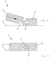
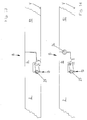
- FIG. 1 The drawing is a kind of holding profiles of the fastening system 1 according to the invention shown in perspective. At the respective opposite narrow side of panels 2 and 3 corresponding holding profiles are provided so that the adjacent panels 2 and 3 can be connected together.
- this type of holding profiles is a modified tongue and groove joint, in which the spring 4 engages behind an undercut in the lower groove wall of the groove 5, so that both panels 2 and 3 in the installed state against a pulling apart in the plane of, laid panels 2 and 3 and are secured perpendicular to the direction of the locked narrow sides.
- FIG. 2 shows the oblique attachment of a new panel 2.
- the spring 4 of the new panel 2 is always brought in the direction of arrow P1 with the groove 5 of the laid panel 3 into engagement and the new panel 2 then swung down on the laying surface V until the in FIG. 3 shown situation is reached.
- a curved portion 4 a of the cross section of the spring 4 engages behind a curved in cross-section recess 5 a in the lower groove wall 5 b of the groove 5, that a flat sliding apart of the panels 2 and 3 is prevented perpendicular to the locked narrow sides.
- FIG. 4 shows hook connection 8 device disengaged.
- This example on uneven ground, with air between the panels and the laying substrate V and then when a soft impact sound insulating liner 9 between the panels and laying substrate V is arranged.
- FIG. 4 illustrates the symbolically shown weight 11, as a panel, the hook element facing the laying surface, under the load of a weight 11 in a soft impact sound insulating liner 9 sinks. This results in a height offset 12 on the surface of the panels 2 and 10.
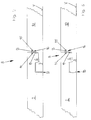
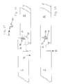
- the Figures 5-10 represent different embodiments of hook connections 8, which are all locked with an additional locking element 13.
- the blocking element 13 prevents the hook connection 8 from moving apart in a direction perpendicular to the plane of the laid panels 2 and 10
- FIG. 4 prevents the additional blocking element 13 a height offset of the hooked panels 2 and 10.
- the blocking element 13 has in the embodiments of Figures 5-10 a rectangular cross section.
- locking grooves 14 and 15 are provided which are in the hooked state of the hook elements 6 and 7 are exactly opposite so that a common Sperraus Principleung 16 results, in which the blocking element 13 is inserted in a direction perpendicular to the plane of the drawing shown.
- the embodiment according to FIG. 5 shows a free space 17 between the free end of the hook member 7, which faces the laying substrate V, and the narrow side of the associated panel second
- FIGS. 7 and 8 show examples of a hook connection 8, in which an additional blocking element 22 is provided on the narrow side on the freely projecting surface 20 of a hook element 7, which faces the laying substrate V.
- the locking groove 15 is accordingly arranged on a rearward surface 21 of the hook element 6 on the narrow side of the panel 2.
- FIG. 7 shows an example in which the hook elements 6 and 7 have a free space 17 in the region of the locking element 22.
- no free space 17 between the hook elements 6 and 7 is provided in the area of the blocking element 22.
- an undercut connection 18 increases the strength of the hook connection 8 against sliding apart in a direction perpendicular to the plane of the laid panels 2 and 10.
- FIGS. 9 and 10 are shown constructions in which each hook connection 8 is equipped with two locking elements 13 and 22.
- the positions of the locking elements 13 and 22 are off FIG. 5 and FIG. 7 combined.
- FIG. 10 are the positions of the locking elements 13 and 22 according to FIGS. 6 and 8th combined.
- FIG. 9 is another example of a hook connection 8, in which the laying element V facing the hook element 7 at its free end has a gap 17 to the narrow side of the hook member 6 of the adjacent panel 2, whereas FIG. 10 in the same place an undercut connection 18 provides.
- Locking elements are provided with a round cross-section.
- a locking groove having a semicircular cross-section is integrally formed on the outer free end of the hook element 6, which faces the upper side of the panel 2.
- a locking groove 24 is accordingly attached to a recessed surface 19 of the hook element 7, so that the two locking grooves 23 and 24 together result in a locking recess 25 with a circular cross-section, in which a blocking element 26 is arranged.
- FIG. 12 In FIG. 11 is provided between the laying substrate V facing hook element 7 of a panel 10 and a recessed surface 21 of the hook member 6 on the narrow side of the adjacent panel 2, a free gap 17, whereas according to FIG. 12 an undercut connection 18 is integrated in the same place.
- FIG. 13 is an example of that Locking element 27 may be provided at a location in which a free space 17 between the outer free end of the lower hook member 7 and the opposite surface 21 of the corresponding hook member 6 is provided.
- An embodiment without clearance 17, with flat abutting flat surfaces and an embodiment with an undercut connection 18 according to the lower hook element 7 of FIG. 12 can also be equipped with a locking recess and a blocking element 27.
- FIG. 14 a particularly strong hook connection 8 is shown in which two locking elements 26 and 27 are used with a circular cross section.
- the locations of the blocking elements 26 and 27 are taken together from the embodiments according to FIG. 11 and FIG. 13 ,
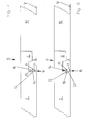
- FIGS. 15 and 16 the laid state of panels 2 and 10 is shown with a finished hook connection 8.
- blocking grooves 30, 31, 32 and 33 are provided in areas which are approximately parallel to the plane of the laid panels.
- the locking grooves 30 and 32 of a hook member 6 and the locking grooves 31 and 33 of the corresponding hook member 7 are arranged so that they are exactly opposite each other and together form a Sperraus foundedung in which a locking element 34 and 35 is arranged.
- the blocking elements 34 and 35 are designed such that they laterally engage in the groove walls of the blocking grooves 30, 31, 32 and 33 fix.
- protruding claw elements 34a and 35a are provided for this purpose on the surface of the locking elements.
- These can also be designed in the manner of barbs, wherein the barbs in the one locking groove 30 and the barbs in the opposite locking groove 31 of the same locking recess are arranged in opposite directions. The same applies to the barbs in the locking grooves 32 and 33.
- FIGS. 17-20 Another embodiment of a hook connection 8 is in the FIGS. 17-20 shown.
- FIG. 17 shows a loose locking element 36 with a resilient latching tab 37, which is widely spread in the illustrated relaxed state.
- FIG. 18 shows the gradual joining of the hook connection 8 in the direction of the arrow P2.
- the blocking element 36 according to FIG. 17 in a groove 38 in the freely protruding surface 38 a of the upper hook element 6 is inserted.
- the resilient latching tab 37 is folded back by the joining movement itself.
- the locking tab 37 of the locking element 36 automatically springs into a locking recess 39 of the corresponding hook element 7.
- the locking tab 37 is spread far less than in her after Fig. 17 shown relaxed position so that it permanently exerts a spring pressure against the locking recess 39 and the hook connection 8 securely locked.
- the blocking element 36 can be used by a laying craftsman as a loose element in the designated groove 38 of the upper hook member 6 or pre-assembled on the hook side of the hook element 6.
- the blocking element 36 may extend over the entire length of the narrow side of a panel or only over part of the length of the narrow side. In the exemplary embodiment, it extends from one end of the narrow side over half its length.
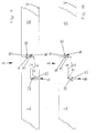
- FIG. 19 is shown that on both sides of the locking tab 37 free spaces are available. These can serve, for example, for the purpose of disassembling the panels 2 and 10, the blocking element 36 by means of a pair of needle nose pliers from the hook connection. 8 pull it out and unlock it.
- FIGS. 18 and 19 again show a construction in which the laying substrate V facing hook element 7 at its outer end has a free space 17 to the corresponding hook element 6.
- FIG. 20 A further embodiment of the hook connection with a blocking element, which has an automatic latching tab, is in FIG. 20 shown.
- the only difference to the embodiment after FIGS. 18 and 19 is that the laying substrate V facing hook element 7 of the panel 10 at its free outer end has no clearance 17 to the corresponding hook element 6 of the connected panel 2.
- an undercut connection 18 is again provided, which, like the blocking element 36, prevents the hook connection 8 from moving apart in a direction perpendicular to the plane of the laid-down panels 2 and 10.
- a blocking element in the form of a claw piece 40 which is arranged in the assembled state between engaging behind hook surfaces 41 and 42 of the hook elements 6 and 7.
- the claw piece 40 has claw elements 40 a, which engage in the surface of the hook surfaces 41 and 42 and prevent vertical movement apart of the hook elements 6 and 7.
- a free gap 43 is formed between the engaging behind hook surfaces 41 and 42.
- the claw piece 40 is shown in the assembled state of the hook connection 8.
- the claw piece 40 is fastened in a recess 44 provided for this purpose of the hook element 6 and, beginning at the recess 44, snuggles against the hook element 41 on the hook element 6.
- the recess 44 for the claw piece 40 is at the part of the Hook element 6 is arranged, which engages behind the corresponding hook element 7, wherein the opening of the recess 44 is arranged on a surface 45 of the hook element 6 facing the laying surface.
- the claw piece 40 is bent over in such a way that it projects into the intermediate space 43, which is formed by the hooking surfaces 41 and 42 engaging behind each other.
- the claw piece 40 is L-shaped prior to assembly.
- a first leg of the L-shaped Krall Cultures inserted in the recess 44 of the hook member 6.
- the second leg is provided with the claw elements and has approximately perpendicular to the narrow side of the panel 10 before mounting away. The latter leg is automatically bent into the space 43 of the engaging behind hook surfaces 41 and 42 during assembly.
- each panel 2 and 10 on its underside facing the laying substrate V undercut Bodenausappel traditions 47 and 48, one of which is arranged in the region of each hook member 6 and 7 on the underside of the panel 2 and 10 respectively.
- a bracket 46 engages in a respective bottom recesses 47 and 48 of two adjacent panels 2 and 10.
- each floor recess 47 and 48 has an undercut.
- the bracket 46 is U-shaped. It is understood that the clip 46 also locks a flat lateral sliding apart at right angles to the hook elements 6 and 7 of the narrow side of the panels 2 and 10 and thus supports the function of the hook connection 8.
- Fig. 23 shows a blocking element 50 with a special cross-section, which in practice by the in Fig. 26 Locking element 51 shown can be replaced.
- the latter blocking element 51 has a simple round cross section.
- Fig. 23 an empty locking groove 52 in which the locking element 51 is captively receivable.
- the captive safety ensures during handling of a panel 2 and during the hooking of the hook connection 8 according to arrow direction P3, that the blocking element 50 does not fall out of the locking groove 52. So that an exchange of the locking elements 50 and 51 is possible, the locking grooves 52 and 53 provided in the hook elements 6 and 7 are adapted in a special way to the geometry of the different locking elements 50 and 51.
- the blocking element 50 is a development of the in Fig. 17 It has a locking tab 54 which in Fig. 23 is shown in a widely spread relaxed state. On a back 55, the blocking element 50 has a round shape, which is in accordance with Fig. 24 fitting into the locking groove 52 of the hook member 6 inserts.
- the blocking element 50 is provided with holding elements 56 and 57, by means of which it can be secured captively in the blocking groove 52 of the hook element 6.
- the holding elements 56 and 57 also serve to prevent slippage or twisting of the locking element 50 in the locking groove 52 or in the locking recess 58 formed by the locking grooves 52 and 53.
- the holding elements 56 and 57 are formed in the present embodiment as a blunt cam. At the empty locking groove 52 of the Fig.
- the locking groove 52 has at the edges of its semicircular cross section material recesses 56a and 57a, which serve to receive the holding elements 56 and 57.
- the dimension A indicated on the locking groove 52 is made somewhat smaller than the dimension B indicated on the blocking element 50. This causes the captive clamping of the blocking element 50 in the locking groove 52.
- the retaining elements of the blocking element 50 formed as barbs or claw elements (not shown) which are fixable in a part of the groove wall of the locking groove 52, and hold the locking element 50 captive on the hook member 6.
- the material recesses in the locking groove 52 are not required in this embodiment.
- Fig. 24 shows the joining process of a hook connection 8.
- a panel 2 is namely pivoted down according to arrow P3 on the laying surface V, whereby the hook elements 6 and 7 of the panels 2 and 10 hooked together.
- the locking member 50 is securely held in the locking groove 52 while the hook members are connected in the manner described.
- the locking tab 54 automatically springs into the locking groove 53, which serves as a detent recess and locks the hook connection.
Abstract
Description
- Die Erfindung betrifft ein Befestigungssystem für viereckige tafelförmige Paneele mit an den Schmalseiten der Paneele angeordneten Halteprofilen, von denen gegenüberliegend angeordnete Halteprofile derart zueinander passen, dass gleichartige Paneele miteinander verbindbar sind, insbesondere für Fußbodenpaneele, mit gegenüberliegend angeordneten ersten Halteprofilen, die so ausgebildet sind, dass an einem in erster Reihe liegenden Paneel in zweiter Reihe ein neues Paneel verriegelbar ist, in dem das neue Paneel zunächst in Schrägstellung relativ zu dem liegenden Paneel an das liegende Paneel angefügt und nachfolgend in die Ebene des liegenden Paneels herabgeschwenkt wird, sowie mit gegenüberliegend angeordneten zweiten Halteprofilen, die korrespondierende Hakenelemente aufweisen, wobei mit einem der Hakenelemente des neuen Paneels und einem Hakenelement eines bereits in zweiter Reihe liegenden Paneels durch das Herabschwenken des neuen Paneels eine Hakenverbindund herstellbar ist.
- Ein gattungsgemäßes Befestigungssystem ist aus der
DE 199 29 896 A1 bekannt. Charakteristisch ist für ein solches Befestigungssystem, dass die verwendeten ersten und zweiten Halteprofile stark unterschiedliche Geometrien aufweisen und sich dadurch auch die Fügeweisen der verschiedenartigen Halteprofile sehr unterscheiden. Insbesondere die als Hakenelemente ausgebildeten zweiten Halteprofile, die zu einer Hakenverbindung zusammengefügt werden, bergen ein technisches Problem. Zwar sichert die bekannte Hakenverbindung Fußbodenpaneele gut gegen ebenes Auseinanderschieben rechtwinklig zu den Schmalseiten der verbundenen Paneele. Allerdings bietet sie keine befriedigende Festigkeit gegen ein Lösen der Hakenelemente in einer Richtung senkrecht zu der Verlegeebene der Paneele. - Bevorzugt angewendet wird ein derartiges Befestigungssystem für sogenannten Laminatfußboden, der einen Kern aus Holzwerkstoff, wie MDF, HDF oder Spanplattenmaterial aufweist. Die mechanischen Halteprofile sind zumeist an die Schmalseiten von Holzwerkstoffplatten angefräst.
- Laminatfußboden wird überwiegend schwimmend verlegt. Zur Minderung von Trittschall wird üblicherweise eine trittschalldämmende Zwischenlage zwischen dem Verlegeuntergrund und den Laminatpaneelen angeordnet. Auch bekannt ist es, dass eine trittschalldämmende Schicht an der dem Verlegeuntergrund zugewandten Unterseite von Laminatpaneelen fest angebracht ist.
- Besonders problematisch ist die Hakenverbindung des bekannten Befestigungssystem dann, wenn im Bereich einer Hakenverbindung nur dasjenige Paneel mit einer großen Last beaufschlagt ist, dessen Hakenelement unten liegt, nämlich dem Verlegeuntergrund zugewandt ist. Das mit diesem verhakte obenliegende Hakenelement des benachbarten Paneels ist nicht belastet daher wird durch die Last nur das Paneel mit dem untenliegenden Hakenelement in die zumeist weiche trittschalldämmende Zwischenlage gedrückt. Dabei löst sich das obenliegende Hakenelement des unbelasteten Paneels aus dem untenliegenden Hakenelement des benachbarten Paneels. Die Hakenverbindung ist außer Funktion und die Funktion meist nicht wieder herstellbar.
- Nach dem Stand der Technik sind Hinterschneidungen in die Hakenverbindung integriert, durch die ein Lösen der Hakenverbindung senkrecht zur Verlegeebene der Paneele verhindert werden soll. Diese Hinterschneidungen haben sich jedoch als unzureichend erwiesen, dieser Art von Befestigungselementen eine ausreichende Festigkeit zu verleihen.
- Der Erfindung liegt die Aufgabe zugrunde, ein Befestigungssystem anzugeben, das mit einer Hakenverbindung ausgestattet, die sich auch dann nicht löst, wenn auf dem Paneel mit dem untenliegenden Hakenelement eine Last aufsteht und das obenliegenden Hakenelement des benachbarten Paneels ohne Last ist.
- Erfindungsgemäß wird die Aufgabe dadurch gelöst, dass jeder Hakenverbindung ein zusätzliches Sperrelement zugeordnet ist, das im verhakten Zustand zweier Paneele ein Lösen der Hakenverbindung in einer Richtung senkrecht zu der Ebene der verlegten Paneele unterbindet.
- Bei dem Sperrelement kann es sich um ein sehr einfaches Bauteil handeln, für das es vielfältige konstruktive Ausgestaltungen gibt. Es kann sich um ein Sperrelement handeln, das an einem der Hakenelemente vormontiert ist, um ein loses Sperrelement, das nach dem Verhaken der Hakenelemente angebracht wird, oder um ein in das Kernmaterial des Paneels integriertes Sperrelement.
- In einer besonders einfachen Ausführung weist jedes der Hakenelemente der gegenüberliegenden Schmalseiten eines Paneels eine Sperrnut auf, die sich in Längsrichtung der Schmalseite erstreckt. Die Sperrnuten zweier Paneele grenzen dabei im verbundenen Zustand der Hakenelemente aneinander und bilden eine gemeinsame Sperrausnehmung. Bei der Profilierung der Hakenelemente mit Fräswerkzeugen lassen sich die Sperrnuten sehr einfach mitfräsen. Hierzu müssen entsprechende Konturen an den Fräswerkzeugen vorgesehen sein.
- Wenn die Sperrausnehmung einen runden oder rechteckigen Querschnitt aufweist, hat dies den Vorteil, dass als Sperrelemente besonders kostengünstiges Standardmaterial verwendet werden kann. Es kommen beliebige Werkstoffe für Sperrelemente mit rundem oder rechteckigem Querschnitt in Frage. Entsprechendes Stangenmaterial kann beispielsweise fertig konfektioniert bezogen oder als Meterware in Sperrelemente entsprechender Länge aufgetrennt werden. Für Sperrnuten, die gemeinsam eine Sperrausnehmung mit rundem Querschnitt bilden, ist es besonders günstig, wenn als Sperrelement ein Nagel verwendet wird, oder das Sperrelement nach Art eines Nagels ausgebildet ist. Der Kopf eines Nagels vereinfacht sowohl während der Verlegung das Einfügen des Sperrelements in die Hakenverbindung als auch das Entfernen des Sperrelements, wenn die Hakenverbindung zwecks Demontage der Paneele nochmals gelöst werden muss.
- Es ist sehr nützlich, wenn das Sperrelement im verhakten Zustand zweier Paneele einfach in die Sperrausnehmung einfügbar ist und der Querschnitt zumindest teilweise in den Querschnitt der Sperrnut des einen Paneels und teilweise in den Querschnitt der Sperrnut des anderen Paneels ragt. Die Querschnittsaufteilung zwischen den Sperrnuten ist nahezu beliebig. Sie kann beispielsweise davon abhängig gemacht werden, ob eines der Hakenelemente, in dem sich die Sperrnut befindet, stabiler ausgebildet ist als das andere. Das Einfügen des Sperrelements in die Sperrausnehmung kann durch Einschieben oder Einschlagen erfolgen. Es ist möglich, die Toleranzen des Sperrelements und der Sperrausnehmung so auszulegen, dass das Sperrelement sich leicht oder straff in die Sperrausnehmung einfügen lässt.
- Bevorzugt dann, wenn es sich um ein einfaches Sperrelement mit rundem oder mehreckigem Querschnitt handelt, ist es vorteilhaft, wenn die Sperrnuten an solchen Flächen eines Hakenelements vorgesehen sind, die im verlegten Zustand der Paneele etwa senkrecht zu der Ebene ausgerichtet sind, in der die Paneele verlegt sind.
- Eine alternative Konstruktion eines Befestigungssystems mit Hakenelementen sieht vor, dass jedes Paneel im verlegten Zustand auf seiner einem Verlegeuntergrund zugewandten Unterseite hinterschnittene Bodenausnehmungen aufweist, von denen zumindest je eine im Bereich jedes Hakenelements an der Unterseite des Paneels angeordnet ist.
- Die Handhabung lässt sich verbessern, wenn die Hinterschneidung der Bodenausnehmung eines ersten Paneels im zusammengefügten Zustand zweier Paneele entgegengesetzt ausgerichtet ist zu der Hinterschneidung der Bodenausnehmung eines zweiten Paneels. Für die Konstruktion des Befestigungssystems mit Bodenausnehmungen im Bereich der Hakenelemente ist das Sperrelement zweckmäßig als U-förmige Klammer ausgebildet, welche die Hinterschneidung der Bodenausnehmung des ersten Paneels sowie die Hinterschneidung der Bodenausnehmung des zweiten Paneels im montierten Zustand hintergreift.
- Bei einer dritten Alternative eines Befestigungssystems ist das Sperrelement in einer Sperrnut eines der Hakenelemente eines ersten Paneels angeordnet und weist eine federnde Rastlasche auf. Dabei bildet eine Sperrnut des zugeordneten Hakenelements der gegenüberliegenden Schmalseite eines zweiten Paneels eine hinterschnittene Rastvertiefung, in der die Rastlasche des Hakenelements des ersten Paneels während der Montage selbsttätig einrastbar ist.
- Diese Konstruktion kann einfacherweise mit einem Sperrelement versehen sein, das eine im entspannten Zustand von der Schmalseite weit hervorstehende Rastlasche aufweist, die während des Herabschwenkens eines neuen Paneels in die Ebene der verlegten Paneele mit dem Hakenelement des benachbarten Paneels in Berührung kommt und automatisch soweit zurückgeklappt wird, dass die Rastlasche an der Schmalseite nicht mehr über das äußere Ende des Hakenelements hinausragt. Wenn die Hakenverbindung nahezu ihre Verriegelungsposition erreicht hat, federt die Rastlasche selbsttätig in die Rastvertiefung des Hakenelements des benachbarten Paneels hervor und verriegelt die Hakenverbindung in vertikaler Richtung, nämlich senkrecht zur Ebene der verlegten Paneele.
- Ein derartig selbsttätiges Rastelement kann in einem der Hakenelemente vormontiert sein oder lose beiliegen, damit es der Verleger selbst während der Verlegung der Paneele an dem dafür vorgesehenen Hakenelement anbringen kann.
- Das selbsttätige Sperrelement sowie die Rastvertiefung sind zweckmäßigerweise so ausgebildet, dass das Sperrelement jederzeit mit einem einfachen Werkzeug, beispielsweise einer spitzen Zange leicht in Längsrichtung der Schmalseiten aus der Hakenverbindung herausgezogen werden kann, wenn die Paneele demontiert werden müssen. Dazu ist zu beiden Seiten der Rastlasche ein freier Zwischenraum vorgesehen, damit eine Zange angesetzt werden kann.
- Der prinzipielle Vorteil der Verriegelung mittels eines einrastenden Sperrelements gegenüber einem einzuschiebenden Sperrelement ist, dass vor der Schmalseite einer Paneelreihe kein Raum benötigt wird, um das Sperrelement an eine Sperrausnehmung anzusetzen und in diese einzuschieben. Ein einzuschiebendes Sperrelement lässt sich nahe einer Wand nicht mehr in eine Sperrausnehmung einfügen, wohingegen das einrastbare Sperrelement problemlos seitlich an eines der Hakenelemente angefügt und durch Herabschwenken eines neuen Paneels verriegelt werden kann.
- Eine vierte Alternative des Befestigungssystems sieht vor, dass das Sperrelement als Krallstück ausgebildet ist, das im montierten Zustand zwischen sich hintergreifenden Hakenflächen der Hakenelemente angeordnet ist. Das Krallstück weist Krallelemente auf, die in die Oberfläche der Hakenflächen greifen und eine vertikale Auseinanderbewegung der Hakenelemente verhindern.
- Vorzugsweise ist zwischen den sich hintergreifenden Hakenflächen ein Zwischenraum für das Krallstück vorgesehen, damit zu starke Zwängungen zwischen den Hakenelementen vermieden werden.
- Weiterhin ist es nützlich, wenn das Krallstück in einer dafür vorgesehenen Ausnehmung des Hakenelements arretiert ist und im montierten Zustand der Hakenverbindung beginnend an der Ausnehmung bis über die Hakenfläche an dem Hakenelement angeschmiegt ist.
- Einfacherweise kann die Ausnehmung für das Krallstück an dem Teil des Hakenelements angeordnet sein, der das korrespondierende Hakenelement hintergreift, wobei die Öffnung der Ausnehmung an einer Fläche des Hakenelements angeordnet ist, die zum Verlegeuntergrund gewandt ist, und wobei das Krallstück im montierten Zustand der Hakenverbindung derart umgebogen ist, dass es zwischen die sich hintergreifenden Hakenflächen ragt.
- Die Handhabung des Krallstücks vereinfacht sich dadurch, dass es L-förmig ausgebildet ist, und dass ein erster Schenkel des L-förmigen Krallstücks in der Ausnehmung des Hakenelements einsetzbar ist und ein zweiter mit den Krallelementen versehener Schenkel in Richtung der Hakenfläche desselben Hakenelements weist. Dabei wird letzterer Schenkel während der Montage automatisch in den Zwischenraum der sich hintergreifenden Hakenflächen hineingebogen.
- Mit einer weiteren nützlichen Verbesserung ist bezweckt, dass in ein und derselben Sperrausnehmung, die durch Sperrnuten zweier Hakenelemente gebildet ist, unterschiedliche Sperrelemente verwendet werden können, die unterschiedliche Geometrien aufweisen und durch unterschiedliche Mechanismen der Verriegelung der Hakenverbindung die erforderliche Festigkeit verleihen. Zu diesem Zweck sind die Sperrnuten und Sperrelemente besonders aufeinander abgestimmt. Dabei ist entweder ein stabförmiges Sperrelement in seiner Längsrichtung in die Sperrausnehmung einschiebbar oder alternativ ein Sperrelement in derselben Sperrausnehmung aufnehmbar, das eine federnde Rastlasche aufweist, wobei dann eine der Sperrnuten eine Halteaufnahme für das mit der Rastlasche versehene Sperrelement bildet und die zugeordnete Sperrnut eine hinterschnittene Rastvertiefung bildet, in die die federnde Rastlasche während der Montage der Hakenverbindung selbsttätig einrastbar ist.
- Ein Paneel mit einem erfindungsgemäßen Befestigungssystem weist zwei unterschiedliche Arten miteinander zusammenwirkender Halteprofile auf. Diejenigen Halteprofile, über die die einzelnen Verlegereihen eines Fußbodens miteinander verriegelt sind, weisen Halteprofile auf, die nach dem Prinzip: Schräge's Ansetzen eines neuen Paneels und anschließendes Herabschwenken desselben verriegelt werden. Die hierfür benötigte Art Halteprofil ermöglicht es, ein neues Paneel durch eine scharnierartige Schwenkbewegung an einer verlegten Paneelreihe mechanisch zu verriegeln. Die einzelnen Paneelreihen sind dadurch gegen ebenes Auseinanderziehen in einer Richtung senkrecht zu den verriegelten Halteprofilen gesichert.
- An den übrigen beiden Schmalseiten eines Paneels sind Halteprofile in Form von Hakenelementen angebracht, wobei ein erstes Hakenelement von der Schmalseite hervorsteht und im verlegten Zustand dem Verlegeuntergrund zugewandt ist und das zweite Hakenelement von der Schmalseite hervorsteht und der dekorativen Oberseite des Paneels zugewandt ist. Beide Hakenelemente einer Hakenverbindung sind durch ein zusätzliches Sperrelement gegen ein Auseinanderbewegen senkrecht zur Ebene der verlegten Paneele gesichert.
- Nachstehend ist die Erfindung in einer Zeichnung beispielhaft dargestellt und anhand der Figuren detailliert beschrieben.
-
- Fig. 1
- eine perspektivische Darstellung eines Halteprofils, das durch schräges Ansetzen eines neuen Paneels und anschließendes Herabsenken in die Verlegeebene mechanisch zu verriegeln ist,
- Fig. 2
- das schräge Ansetzen der Halteprofile gemäß
Figur 1 , - Fig. 3
- die Halteprofile gemäß
Figur 1 im verriegelten Zustand, - Fig. 4
- Halteprofile in Form von Hakenelementen gemäß dem Stand der Technik,
- Fig. 5-10
- Ausführungsformen einer Hakenverbindung mit einem oder mehreren zusätzlichen Sperrelementen mit rechteckigem Querschnitt,
- Fig. 11-14
- eine Konstruktion einer Hakenverbindung mit einem oder mehreren zusätzlichen Sperrelementen, die einen runden Querschnitt aufweisen,
- Fig. 15/16
- Ausführungsformen einer Hakenverbindung mit Sperrelementen, die im verlegten Zustand der Paneele in solche Flächen der Hakenelemente eingelassen sind, die etwa horizontal liegen,
- Fig. 17-20
- eine Ausführungsform einer Hakenverbindung mit einem Sperrelement mit einer federnden Rastlasche, die während der Montage der Hakenverbindung selbsttätig in eine zugeordnete Rastvertiefung eingreift
- Fig. 21
- eine Hakenverbindung mit einem als Krallstück ausgebildeten Sperrelement,
- Fig. 22
- eine Hakenverbindung mit einem als Klammer ausgebildeten Sperrelement an der Unterseite der Paneele,
- Fig. 23
- ein weiteres Sperrelement mit einer federnden Rastlasche sowie eine Sperrnut, die zur Aufnahme des Sperrelements angepasst ist,
- Fig. 24
- eine Hakenverbindung mit dem Sperrelement gemäß
Fig. 23 , während des Fügevorgangs, - Fig. 25
- eine Hakenverbindung mit dem Sperrelement gemäß
Fig. 23 im eingerasteten Zustand, - Fig. 26
- eine Hakenverbindung mit denselben Sperrnuten und derselben Sperrausnehmung, wie gemäß
Fig. 25 , wobei das Rastlaschen-Sperrelement ersetzt ist durch ein Sperrelement mit rundem Querschnitt. - Nach
Figur 1 der Zeichnung ist eine Art der Halteprofile des erfindungsgemäßen Befestigungssystems 1 perspektivisch dargestellt. An der jeweils gegenüberliegenden Schmalseite von Paneelen 2 und 3 sind korrespondierende Halteprofile vorgesehen, so dass sich die benachbarten Paneele 2 und 3 miteinander verbinden lassen. Bei dieser Art der Halteprofile handelt es sich um eine modifizierte Nut- und Federverbindung, bei der die Feder 4 eine Hinterschneidung in der unteren Nutwand der Nut 5 hintergreift, so dass beide Paneele 2 und 3 im verlegten Zustand gegen ein Auseinanderziehen in der Ebene der,verlegten Paneele 2 und 3 und senkrecht zur Richtung der verriegelten Schmalseiten gesichert sind. -
Figur 2 zeigt das schräge Ansetzen eines neuen Paneels 2. Dabei wird stets die Feder 4 des neuen Paneels 2 in Pfeilrichtung P1 mit der Nut 5 des verlegten Paneels 3 in Eingriff gebracht und das neue Paneel 2 anschließend auf den Verlegeuntergrund V herabgeschwenkt, bis die inFigur 3 dargestellte Lage erreicht ist. Es ist leicht verständlich, dass ein gekrümmter Bereich 4a des Querschnitts der Feder 4 eine im Querschnitt gekrümmte Vertiefung 5a in der unteren Nutwand 5b der Nut 5 derart hintergreift, dass ein ebenes Auseinanderschieben der Paneele 2 und 3 senkrecht zu den verriegelten Schmalseiten verhindert ist. - An den übrigen Schmalseiten eines Paneels 2 bzw. 3, das mit dem erfindungsgemäßen Befestigungssystem 1 ausgestattet ist, sind korrespondierende Halteprofile mit Hakenelementen 6 und 7 vorgesehen. Diese haben den Vorteil, dass sie sich sozusagen gleichzeitig mit der Verriegelung der gemäß
Figuren 1-3 beschriebenen Halteprofile, Feder 4 und Nut 5, nach dem schrägen Ansetzen durch ein Herabschwenken des neuen Paneels 2 auf den Verlegeuntergrund V miteinander verhaken. Eine irgendwie geartete seitliche Fügebewegung ist zur Herstellung der sich ergebenden Hakenverbindung 8 nicht erforderlich. - Die gemäß
Figur 4 dargestellte Hakenverbindung 8 gerät außer Eingriff. Dies beispielsweise auf unebenen Untergründen, mit Luft zwischen den Paneelen und dem Verlegeuntergrund V sowie dann, wenn eine weiche trittschalldämmende Zwischenlage 9 zwischen den Paneelen und Verlegeuntergrund V angeordnet ist. InFigur 4 verdeutlicht das symbolisch dargestellte Gewicht 11, wie ein Paneel, dessen Hakenelement dem Verlegeuntergrund zugewandt ist, unter der Last eines Gewichts 11 in eine weiche trittschalldämmende Zwischenlage 9 einsinkt. Hierbei kommt es zu einem Höhenversatz 12 an der Oberfläche der Paneele 2 und 10. - Die
Figuren 5-10 stellen unterschiedliche Ausführungsformen von Hakenverbindungen 8 dar, die alle mit einem zusätzlichen Sperrelement 13 verriegelt sind. Das Sperrelement 13 verhindert ein Auseinanderbewegen der Hakenverbindung 8 in einer Richtung senkrecht zur Ebene der verlegten Paneele 2 und 10. Auch bei einer Belastung gemäßFigur 4 verhindert das zusätzliche Sperrelement 13 einen Höhenversatz der verhakten Paneele 2 und 10. Das Sperrelement 13 weist in den Ausführungsformen derFiguren 5-10 einen rechteckigen Querschnitt auf. Zur Aufnahme des Sperrelements 13 sind Sperrnuten 14 und 15 vorgesehen, die sich im verhakten Zustand der Hakenelemente 6 und 7 exakt so gegenüberliegen, dass sich eine gemeinsame Sperrausnehmung 16 ergibt, in die das Sperrelement 13 in einer Richtung senkrecht zur der dargestellten Zeichnungsebene eingefügt wird. Die Ausführungsform gemäßFigur 5 zeigt einen freien Zwischenraum 17 zwischen dem freien Ende des Hakenelements 7, das dem Verlegeuntergrund V zugewandt ist, und der Schmalseite des zugeordneten Paneels 2. - In
Figur 6 hingegen ist an der gleichen Stelle kein Spiel vorgesehen. Stattdessen ist auch hier eine hinterschnittene Verbindung 18 vorgesehen, die ebenfalls in einer Richtung senkrecht zur der Ebene der verlegten Paneele 2 und 10 verriegelt. An dem Paneel 2, dessen Hakenelement 6 der Oberfläche zugewandt ist, weist das Hakenelement 6 an einer frei hervorstehenden Fläche der Schmalseite die Sperrnut 14 auf, wohingegen die Sperrnut 15 des gegenüberliegenden Hakenelements 7 der Hakenverbindung 8 an einer zurückstehenden Fläche 19 des Hakenelements 7 vorgesehen ist. Das gleiche gilt für die Ausführungsform gemäßFigur 6 . - Die
Figuren 7 und 8 zeigen Beispiele einer Hakenverbindung 8, bei denen das ein zusätzliches Sperrelement 22 auf der Schmalseite an der frei hervorstehenden Fläche 20 eines Hakenelements 7 vorgesehen ist, das dem Verlegeuntergrund V zugewandt ist. An dem korrespondierenden Hakenelement 6 ist die Sperrnut 15 demgemäß an einer zurückstehenden Fläche 21 des Hakenelements 6 an der Schmalseite des Paneels 2 angeordnet.Figur 7 zeigt ein Beispiel, bei dem die Hakenelemente 6 und 7 im Bereich des Sperrelements 22 einen freien Zwischenraum 17 aufweisen. GemäßFigur 8 hingegen ist im Bereich des Sperrelements 22 kein freier Zwischenraum 17 zwischen den Hakenelementen 6 und 7 vorgesehen. Stattdessen erhöht eine hinterschnittene Verbindung 18 die Festigkeit der Hakenverbindung 8 gegen ein Auseinanderschieben in einer Richtung senkrecht zu der Ebene der verlegten Paneele 2und 10. - Gemäß
Figuren 9 und 10 sind Konstruktionen dargestellt, in denen jede Hakenverbindung 8 mit zwei Sperrelementen 13 und 22 ausgestattet ist. GemäßFigur 9 sind die Positionen der Sperrelemente 13 und 22 ausFigur 5 undFigur 7 zusammengenommen. InFigur 10 sind die Positionen der Sperrelemente 13 und 22 gemäßFiguren 6 und8 zusammengenommen.Figur 9 ist ein weiteres Beispiel für eine Hakenverbindung 8, bei der das dem Verlegeuntergrund V zugewandte Hakenelement 7 an seinem freien Ende einen Zwischenraum 17 zu der Schmalseite des Hakenelements 6 des benachbarten Paneels 2 aufweist, wohingegenFigur 10 an der gleichen Stelle eine hinterschnittene Verbindung 18 vorsieht. - Gemäß
Figuren 11-14 sind Sperrelemente mit rundem Querschnitt vorgesehen. GemäßFigur 11 ist eine Sperrnut mit halbkreisförmigem Querschnitt an dem äußeren freien Ende des Hakenelements 6 angeformt, das der Oberseite des Paneels 2 zugewandt ist. An dem korrespondierenden Hakenelement 7 ist eine Sperrnut 24 demgemäß an einer zurückstehenden Fläche 19 des Hakenelements 7 angebracht, so dass die beiden Sperrnuten 23 und 24 gemeinsam eine Sperrausnehmung 25 mit kreisförmigem Querschnitt ergeben, in der ein Sperrelement 26 angeordnet ist. Das Gleiche gilt für die Ausführungsform gemäßFigur 12 . InFigur 11 ist zwischen dem dem Verlegeuntergrund V zugewandten Hakenelement 7 des einen Paneels 10 und einer zurückstehenden Fläche 21 des Hakenelements 6 an der Schmalseite des benachbarten Paneels 2 ein freier Zwischenraum 17 vorgesehen, wohingegen gemäßFigur 12 an der gleichen Stelle eine hinterschnittene Verbindung 18 integriert ist. - Im Unterschied zu
Fig. 12 ist gemäßFigur 13 der Ort für ein kreisrundes Sperrelement 27 an das freie Ende eines Hakenelements 7 eines Paneels 10 verlagert. Eine Sperrnut 28 des korrespondierenden Hakenelements 6 ist dementsprechend an einer an der Schmalseite zurückstehenden Fläche 21 des benachbarten Paneels 2 vorgesehen.Figur 13 ist ein Beispiel dafür, dass das Sperrelement 27 an einem Ort vorgesehen sein kann, bei dem ein freier Zwischenraum 17 zwischen dem äußeren freien Ende des unteren Hakenelements 7 und der gegenüberliegenden Fläche 21 des korrespondierenden Hakenelements 6 vorgesehen ist. Eine Ausführungsform ohne Freiraum 17, mit flach aneinander liegenden ebenen Flächen sowie eine Ausführungsform mit einer hinterschnittenen Verbindung 18 gemäß dem unteren Hakenelement 7 derFigur 12 kann ebenfalls mit einer Sperrausnehmung und einem Sperrelement 27 ausgestattet werden. - Gemäß
Figur 14 ist eine besonders feste Hakenverbindung 8 dargestellt, bei der zwei Sperrelemente 26 und 27 mit kreisförmigem Querschnitt zum Einsatz kommen. Die Orte der Sperrelemente 26 und 27 sind zusammengenommen aus den Ausführungsformen gemäßFigur 11 undFigur 13 . - In
Figur 15 und 16 ist der verlegte Zustand von Paneelen 2 und 10 mit einer fertigen Hakenverbindung 8 dargestellt. Dabei sind Sperrnuten 30, 31, 32 und 33 in Flächen vorgesehen sind, die etwa parallel zur Ebene der verlegten Paneele liegen. Wiederum sind die Sperrnuten 30 und 32 des einen Hakenelements 6 sowie die Sperrnuten 31 und 33 des korrespondierenden Hakenelements 7 so angeordnet, dass sie sich exakt gegenüberliegen und gemeinsam je eine Sperrausnehmung bilden, in der ein Sperrelement 34 bzw. 35 angeordnet ist. Sowohl gemäßFigur 15 als auch gemäßFigur 16 ist es möglich, auf eines der Sperrelemente 34 bzw. 35 und die entsprechende Sperrausnehmung zu verzichten, um die Geometrie zu vereinfachen. Da die Sperrelemente 34 und 35 ein Auseinanderbewegen der Hakenverbindungen 8 in einer Richtung senkrecht zu der Ebene der Paneele 2 und 10 verhindern müssen, sind die Sperrelemente 34 und 35 so ausgelegt, dass sie sich seitlich in die Nutwände der Sperrnuten30, 31, 32 und 33 festsetzen. In den dargestellten Ausführungsbeispielen sind zu diesem Zweck an der Oberfläche der Sperrelemente hervorstehende Krallelemente 34a und 35a vorgesehen. Diese können auch nach Art von Widerhaken ausgebildet sein, wobei die Widerhaken in der einen Sperrnut 30 und die Widerhaken in der gegenüberliegenden Sperrnut 31 derselben Sperrausnehmung entgegengerichtet angeordnet sind. Das gleiche gilt für die Widerhaken in den Sperrnuten 32 und 33. - Eine weitere Ausführungsform einer Hakenverbindung 8 ist in den
Figuren 17 - 20 dargestellt.Figur 17 zeigt ein loses Sperrelement 36 mit einer federnden Rastlasche 37, die im dargestellten entspannten Zustand weit abgespreizt ist.Figur 18 zeigt das allmähliche Ineinanderfügen der Hakenverbindung 8 gemäß Pfeilrichtung P2. Dabei ist das Sperrelement 36 gemäßFigur 17 in einer Nut 38 in der frei hervorstehenden Fläche 38a des oberen Hakenelements 6 eingesetzt. Die federnde Rastlasche 37 ist durch die Fügebewegung selbst zurückgeklappt. Sobald die Hakenverbindung 8 die inFigur 19 dargestellte Verriegelungslage nahezu erreicht, federt die Rastlasche 37 des Sperrelements 36 selbsttätig in eine Rastvertiefung 39 des korrespondierenden Hakenelements 7. In der gezeigten Stellung ist die Rastlasche 37 weniger weit abgespreizt als in ihrer nachFig. 17 gezeigten entspannten Lage, so dass sie permanent einen Federdruck gegen die Rastvertiefung 39 ausübt und die Hakenverbindung 8 sicher arretiert. - Das Sperrelement 36 kann durch einen Verlegehandwerker als loses Element in der dafür vorgesehenen Nut 38 des oberen Hakenelements 6 eingesetzt werden oder herstellerseitig an dem Hakenelement 6 vormontiert sein. Das Sperrelement 36 kann sich über die gesamte Länge der Schmalseite eines Paneels erstrecken oder nur über einen Teil der Länge der Schmalseite. In dem Ausführungsbeispiel erstreckt es sich von einem Ende der Schmalseite über deren halbe Länge.
- In
Figur 19 ist dargestellt, dass zu beiden Seiten der Rastlasche 37 Freiräume vorhanden sind. Diese können beispielsweise dazu dienen, zwecks Demontage der Paneele 2 und 10 das Sperrelement 36 mit Hilfe einer Spitzzange aus der Hakenverbindung 8 herauszuziehen und diese dadurch zu entriegeln. - Die
Figuren 18 und 19 zeigen wiederum eine Konstruktion, bei der das dem Verlegeuntergrund V zugewandte Hakenelement 7 an seinem äußeren Ende einen freien Zwischenraum 17 zu dem korrespondierenden Hakenelement 6 aufweist. - Eine weitere Ausführungsform der Hakenverbindung mit einem Sperrelement, 36 das eine selbsttätige Rastlasche 37 aufweist, ist in
Figur 20 dargestellt. Der einzige Unterschied zu der Ausführungsform nachFig. 18 und Fig. 19 besteht darin, dass das dem Verlegeuntergrund V zugewandte Hakenelement 7 des Paneels 10 an seinem freien äußeren Ende keinen Freiraum 17 zu dem korrespondierenden Hakenelement 6 des verbundenen Paneels 2 aufweist. Stattdessen ist wiederum eine hinterschnittene Verbindung 18 vorgesehen, die ebenso wie das Sperrelement 36 ein Auseinanderbewegen der Hakenverbindung 8 in einer Richtung senkrecht zu der Ebene der verlegten Paneele 2 und 10 verhindert. - Eine andere Konstruktion eines Befestigungssystems 1 sieht gemäß
Fig. 21 ein Sperrelement in Form eines Krallstücks 40 vor, das im montierten Zustand zwischen sich hintergreifenden Hakenflächen 41 und 42 der Hakenelemente 6 und 7 angeordnet ist. Das Krallstück 40 weist Krallelemente 40 a auf, die in die Oberfläche der Hakenflächen 41 und 42 greifen und eine vertikale Auseinanderbewegung der Hakenelemente 6 und 7 verhindern. Um Platz für das Krallstück 40 zu schaffen und Zwängungen zwischen den Hakenelementen 6 und 7 zu vermeiden, ist zwischen den sich hintergreifenden Hakenflächen 41 und 42 ein freier Zwischenraum 43 gebildet. In der Darstellung derFig. 21 ist das Krallstück 40 im montierten Zustand der Hakenverbindung 8 gezeigt. Das Krallstück 40 ist in einer dafür vorgesehenen Ausnehmung 44 des Hakenelements 6 befestigt und schmiegt sich beginnend an der Ausnehmung 44 bis über die Hakenfläche 41 an dem Hakenelement 6 an. Die Ausnehmung 44 für das Krallstück 40 ist an dem Teil des Hakenelements 6 angeordnet, der das korrespondierende Hakenelement 7 hintergreift, wobei die Öffnung der Ausnehmung 44 an einer zum Verlegeuntergrund gewandten Fläche 45 des Hakenelements 6 angeordnet ist. Das Krallstück 40 ist dabei derart umgebogen, dass es in den Zwischenraum 43 hineinragt, den die sich hintergreifenden Hakenflächen 41 und 42 bilden. - Das Krallstück 40 ist vor der Montage L-förmig ausgebildet. Ein erster Schenkel des L-förmigen Krallstücks steckt in der Ausnehmung 44 des Hakenelements 6. Der zweite Schenkel ist mit den Krallelementen versehen und weist vor der Montage etwa senkrecht von der Schmalseite des Paneels 10 weg. Letzterer Schenkel wird während der Montage automatisch in den Zwischenraum 43 der sich hintergreifenden Hakenflächen 41 und 42 hineingebogen.
- Die in
Fig. 22 gezeigte letzte Konstruktion des erfiridungsgemäßen Befestigungssystems macht von einem Sperrelement in Form einer Klammer 46 Gebrauch. Zu diesem Zweck weist jedes Paneel 2 und 10 auf seiner dem Verlegeuntergrund V zugewandten Unterseite hinterschnittene Bodenausnehmungen 47 und 48 auf, von denen je eine im Bereich jedes Hakenelements 6 bzw. 7 an der Unterseite des Paneels 2 bzw. 10 angeordnet ist. In je einer Bodenausnehmungen 47 und 48 zweier benachbarter Paneele 2 und 10 greift eine Klammer 46 ein. Damit die Klammer 46 ein Auseinanderbewegen der Hakenverbindung 8 in einer Richtung senkrecht zu der Ebene der verlegten Paneele 2 und 20 verhindert, weist jede Bodenausnehmung 47 und 48 eine Hinterschneidung auf. NachFig. 22 ist die Hinterschneidung der Bodenausnehmung 47 eines ersten Paneels 2 im zusammengefügten Zustand zweier Paneele entgegengesetzt ausgerichtet zu der Hinterschneidung der Bodenausnehmung 48 eines zweiten Paneels 10. Die Klammer 46 ist U-förmig ausgebildet. Es ist selbstverständlich, dass die Klammer 46 auch ein ebenes seitliches Auseinanderschieben rechtwinklig zu den Hakenelementen 6 und 7 der Schmalseite der Paneele 2 und 10 verriegelt und somit die Funktion der Hakenverbindung 8 unterstützt. -
Fig. 23 zeigt ein Sperrelement 50 mit besonderem Querschnitt, das in der Praxis durch das inFig. 26 gezeigte Sperrelement 51 ersetzt werden kann. Letzteres Sperrelement 51 weist einen einfachen runden Querschnitt auf. Außerdem zeigtFig. 23 eine leere Sperrnut 52, in der das Sperrelement 51 verliersicher aufnehmbar ist. Die Verliersicherheit gewährleistet während der Handhabung eines Paneels 2 und während der Verhakung der Hakenverbindung 8 gemäß Pfeilrichtung P3, dass das Sperrelement 50 nicht aus der Sperrnut 52 herausfällt. Damit ein Austausch der Sperrelemente 50 und 51 möglich ist, sind die in den Hakenelementen 6 und 7 vorgesehenen Sperrnuten 52 und 53 in besonderer Weise an die Geometrie der unterschiedlichen Sperrelemente 50 und 51 angepaßt. - Das Sperrelement 50 ist eine Weiterbildung des in
Fig. 17 dargestellten Sperrelements 36. Es weist eine Rastlasche 54 auf, die inFig. 23 in einem weit abgespreizten entspannten Zustand dargestellt ist. An einem Rücken 55 weist das Sperrelement 50 eine runde Form auf, die sich gemäßFig. 24 passend in die Sperrnut 52 des Hakenelements 6 einfügt. Das Sperrelement 50 ist mit Halteelementen 56 und 57 versehen, über die es in der Sperrnut 52 des Hakenelements 6 verliersicher festlegbar ist. Die Halteelemente 56 und 57 dienen außerdem dazu ein Verrutschen bzw. eine Verdrehung des Sperrelements 50 in der Sperrnut 52 bzw. in der durch die Sperrnuten 52 und 53 gebildeten Sperrausnehmung 58 zu verhindern. Die Halteelemente 56 und 57 sind in der vorliegenden Ausführungsform als stumpfe Nocken ausgebildet. An der leeren Sperrnut 52 derFig. 23 ist zu sehen, dass diese an den Rändern ihres halbkreisförmigen Querschnitts Materialausnehmungen 56a und 57a aufweist, die zur Aufnahme der Halteelemente 56 und 57 dienen. Das an der Sperrnut 52 angegebene Maß A ist etwas geringer ausgeführt als das an dem Sperrelement 50 angegebene Maß B. Dies bewirkt die verliersichere Klemmung des Sperrelements 50 in der Sperrnut 52. In einer anderen Ausführungsform sind die Halteelemente des Sperrelements 50 als Widerhaken oder Krallelemente ausgebildet (nicht dargestellt), die in einem Teil der Nutwand der Sperrnut 52 festsetzbar sind, und das Sperrelement 50 verliersicher an dem Hakenelement 6 festhalten. Die Materialausnehmungen in der Sperrnut 52 sind bei dieser Ausführung nicht erforderlich. -
Fig. 24 zeigt den Fügevorgang einer Hakenverbindung 8. Ein Paneel 2 wird nämlich gemäß Pfeilrichtung P3 auf den Verlegeuntergrund V herabgeschwenkt, wodurch die Hakenelemente 6 und 7 der Paneele 2 und 10 sich miteinander verhaken. Es ist leicht erkennbar, dass das Sperrelement 50 sicher in der Sperrnut 52 gehalten ist, während die Hakenelemente auf die beschriebene Weise verbunden werden. Sobald das freie Ende der Rastlasche 54 eine obere Kante 53a der Sperrnut 53 passiert hat, federt die Rastlasche 54 selbsttätig in die Sperrnut 53, welche ihr als Rastvertiefung dient und verriegelt die Hakenverbindung. -
- 1
- Befestigungssystem
- 2
- Paneel
- 3
- Paneel
- 4
- Feder
- 4a
- gekrümmter Bereich
- 5
- Nut
- 5a
- gekrümmte Vertiefung
- 5b
- untere Nutwand
- 6
- Hakenelement
- 7
- Hakenelement
- 8
- Hakenverbindung
- 9
- Trittschall dämmende Zwischenlage
- 10
- Paneel
- 11
- Gewicht
- 12
- Höhenversatz
- 13
- Sperrelement
- 14
- Sperrnut
- 15
- Sperrnut
- 16
- Sperrausnehmung
- 17
- Zwischenraum
- 18
- hinterschnittene Verbindung
- 19
- zurückstehende Fläche
- 20
- hervorstehende Fläche
- 21
- zurückstehende Fläche
- 22
- Sperrelement
- 23
- Sperrnut
- 24
- Sperrnut
- 25
- Sperrausnehmung
- 26
- Sperrelement
- 27
- Sperrelement
- 28
- Sperrelement
- 30
- Sperrnut
- 31
- Sperrnut
- 32
- Sperrnut
- 33
- Sperrnut
- 34
- Sperrelement
- 34a
- Krallelement
- 35
- Sperrelement
- 35a
- Krallelement
- 36
- Sperrelement
- 37
- Rastlasche
- 38
- Nut
- 38a
- hervorstehende Fläche
- 39
- Rastvertiefung
- 40
- Krallstück
- 40a
- Krallelement
- 41
- Hakenfläche
- 42
- Hakenfläche
- 43
- Zwischenraum
- 44
- Ausnehmung
- 45
- Fläche
- 46
- Klammer
- 47
- Bodenausnehmung
- 48
- Bodenausnehmung
- 50
- Sperrelement
- 51
- Sperrelement
- 52
- Sperrnut
- 53
- Sperrnut
- 54
- Rastlasche
- 55
- Rücken
- 56
- Halteelement
- 57
- Halteelement
- 58
- Sperrausnehmung
- A
- Maß
- B
- Maß
- P1
- Pfeilrichtung
- P2
- Pfeilrichtung
- P3
- Pfeilrichtung
- V
- Verlegeuntergrund
Claims (15)
- Befestigungssystem (1) für viereckige tafelförmige Paneele (2, 3, 10) mit an den Schmalseiten der Paneele (2, 3, 10) angeordneten Halteprofilen, von denen gegenüberliegend angeordnete Halteprofile derart zueinander passen, dass gleichartige Paneele (2, 3, 10) miteinander verbindbar sind, insbesondere für Fußbodenpaneele, mit gegenüberliegend angeordneten ersten Halteprofilen, die so ausgebildet sind, dass an einem in erster Reihe liegenden Paneel (2, 3, 10) in zweiter Reihe ein neues Paneel (2) verriegelbar ist, indem das neue Paneel (2) zunächst in Schrägstellung relativ zu dem liegenden Paneel (3) an das liegende Paneel (3) angefügt und nachfolgend in die Ebene des liegenden Paneels (3) herabgeschwenkt wird, sowie mit gegenüberliegend angeordneten zweiten Halteprofilen, die korrespondierende Hakenelemente (6, 7) aufweisen, wobei mit einem der Hakenelemente (6, 7) des neuen Paneels (2) und einem Hakenelement (6, 7) eines bereits in zweiter Reihe liegenden Paneels (3) durch das Herabschwenken des neuen Paneels (2) eine Hakenverbindung (8) herstellbar ist, dadurch gekennzeichnet, dass jeder Hakenverbindung (8) ein zusätzliches Sperrelement (13, 22, 26, 27, 34, 35, 36, 40, 46) zugeordnet ist, das im verhakten Zustand zweier Paneele (2, 3, 10) ein Lösen der Hakenverbindung (8) in einer Richtung senkrecht zu der Ebene der verlegten Paneele (2, 3, 10) unterbindet.
- Befestigungssystem nach Anspruch 1, dadurch gekennzeichnet, dass jedes der Hakenelemente (6, 7) der gegenüberliegenden Schmalseiten eines Paneels (2, 3, 10) eine Sperrnut (14, 15, 23, 24, 28, 30, 31, 32, 33) aufweist, die sich in Längsrichtung der Schmalseite erstreckt, dass die Sperrnuten (14, 15, 23, 24, 28, 30, 31, 32, 33) zweier Paneele (2, 3, 10) im verbundenen Zustand der Hakenelemente (6, 7) aneinander grenzen und eine gemeinsame Sperrausnehmung (16, 25) bilden.
- Befestigungssystem nach Anspruch 2, dadurch gekennzeichnet, dass die Sperrausnehmung (16, 25) einen runden oder rechteckigen Querschnitt aufweist.
- Befestigungssystem nach Anspruch 2 oder 3, dadurch gekennzeichnet, dass das Sperrelement (13, 22, 26, 27, 34, 35, 36, 40, 46) im verhakten Zustand zweier Paneele (2, 3, 10) in die Sperrausnehmung (16, 25) einfügbar ist und der Querschnitt des Sperrelements (13, 22, 26, 27, 34, 35, 36, 40, 46) zumindest teilweise in den Querschnitt der Sperrnut (14, 15, 23, 24, 28, 30, 31, 32, 33) des einen Paneels und teilweise in den Querschnitt der Sperrnut (14, 15, 23, 24, 28, 30, 31, 32, 33) des anderen Paneels (2, 3, 10) ragt.
- Befestigungssystem nach einem der Ansprüche 2 bis 4, dadurch gekennzeichnet, dass die Sperrnuten (14, 15, 23, 24, 28, 30, 31, 32, 33) an solchen Flächen eines Hakenelements (6, 7) vorgesehen sind, die im verlegten Zustand der Paneele (2, 3, 10) etwa senkrecht zu der Ebene ausgerichtet sind, in der die Paneele (2, 3, 10) verlegt sind.
- Befestigungssystem nach Anspruch 1, dadurch gekennzeichnet, dass jedes Paneel (2, 3, 10) im verlegten Zustand der Paneele (2, 3, 10) auf seiner einem Verlegeuntergrund (V) zugewandten Unterseite hinterschnittene Bodenausnehmungen (47, 48) aufweist, von denen zumindest je eine im Bereich jedes Hakenelements (6, 7) an der Unterseite des Paneels (2, 3, 10) angeordnet ist.
- Befestigungssystem nach Anspruch 6, dadurch gekennzeichnet, dass die Hinterschneidung der Bodenausnehmung (47) eines ersten Paneels (2) im zusammengefügten Zustand zweier Paneele entgegengesetzt ausgerichtet ist zu der Hinterschneidung der Bodenausnehmung (48) eines zweiten Paneels (10).
- Befestigungssystem nach Anspruch 1, dadurch gekennzeichnet, dass das Sperrelement als etwa U-förmige Klammer (46) ausgebildet ist, welche die Hinterschneidung der Bodenausnehmung (47, 48) des ersten Paneels (2) sowie die Hinterschneidung der Bodenausnehmung (48) des zweiten Paneels (10) im montierten Zustand hintergreift.
- Befestigungssystem nach Anspruch 1, dadurch gekennzeichnet, dass das Sperrelement (36) in einer Sperrnut eines der Hakenelemente (6) eines ersten Paneels (2) angeordnet ist und eine federnde Rastlasche (37) aufweist, wobei eine Sperrnut des zugeordneten Hakenelements (7) der gegenüberliegenden Schmalseite eines zweiten Paneels (10) eine hinterschnittene Rastvertiefung (39) bildet, in die die Rastlasche (37) des Hakenelements (6) des ersten Paneels (2) während der Montage selbsttätig einrastbar ist.
- Befestigungssystem nach Anspruch 1, dadurch gekennzeichnet, dass das Sperrelement als Krallstück (40) ausgebildet ist und im montierten Zustand zwischen sich hintergreifenden Hakenflächen (41, 42) der Hakenelemente (6, 7) angeordnet ist.
- Befestigungssystem nach Anspruch 11, dadurch gekennzeichnet, dass zwischen den sich hintergreifenden Hakenflächen (41, 42) ein Zwischenraum (43) für das Krallstück (40) vorgesehen ist.
- Befestigungssystem nach Anspruch 11 oder 12, dadurch gekennzeichnet, dass das Krallstück (40) in einer dafür vorgesehenen Ausnehmung (44) des Hakenelements (6) angebracht ist und im montierten Zustand der Hakenverbindung (8) beginnend an der Ausnehmung (44) bis über die Hakenfläche (41) an dem Hakenelement (6) angeschmiegt ist.
- Befestigungssystem nach einem der Ansprüche 11 bis 13, dadurch gekennzeichnet, dass die Ausnehmung (44) für das Krallstück (40) an dem Teil des Hakenelements (6) angeordnet ist, der das korrespondierende Hakenelement (7) hintergreift, wobei die Öffnung der Ausnehmung (44) an einer Fläche (45) des Hakenelements (6) angeordnet ist, die zum Verlegeuntergrund (V) gewandt ist, wobei das Krallstück (40) im montierten Zustand der Hakenverbindung (8) derart umgebogen ist, dass es in den Zwischenraum (43) der sich hintergreifenden Hakenflächen (41, 42) ragt.
- Befestigungssystem nach Anspruch 13, dadurch gekennzeichnet, dass dass Krallstück (40) L-förmig ausgebildet ist, und dass ein erster Schenkel des L-förmigen Krallstücks (40) in der Ausnehmung (44) des Hakenelements (6) einsetzbar ist und ein zweiter Schenkel in Richtung der Hakenfläche desselben Hakenelements weist, wobei der zweite Schenkel während der Montage automatisch in den Zwischenraum (43) der sich hintergreifenden Hakenflächen hineingezogen wird.
- Befestigungssystem nach Anspruch 2 oder 9, dadurch gekennzeichnet, dass die Sperrnuten (52, 53) der Hakenverbindung (8), welche die gemeinsame Sperrausnehmung bilden, derart ausgebildet sind, dass entweder ein stabförmiges Sperrelement (51) in seiner Längsrichtung in die Sperrausnehmung einschiebbar ist oder alternativ ein Sperrelement (50) in derselben Sperrausnehmung aufnehmbar ist, das eine federnde Rastlasche (54) aufweist, wobei dann eine der Sperrnuten (52, 53) eine Halteaufnahme für das mit der Rastlasche (54) versehene Sperrelement (50) bildet und die zugeordnete Sperrnut (53) eine hinterschnittene Rastvertiefung bildet, in die die federnde Rastlasche (54) während der Montage der Hakenverbindung (8) selbsttätig einrastbar ist.
Applications Claiming Priority (3)
| Application Number | Priority Date | Filing Date | Title |
|---|---|---|---|
| DE10138285A DE10138285A1 (de) | 2001-08-10 | 2001-08-10 | Paneel sowie Befestigungssystem für Paneele |
| EP02754315A EP1415056B1 (de) | 2001-08-10 | 2002-07-04 | Paneel sowie Befestigungssystem für Paneele |
| EP06000431A EP1669512B9 (de) | 2001-08-10 | 2002-07-04 | Sperrelement zur Verwendung in einer Hakenverbindung von viereckigen tafelförmigen Paneelen |
Related Parent Applications (2)
| Application Number | Title | Priority Date | Filing Date |
|---|---|---|---|
| EP02754315.6 Division | 2002-07-04 | ||
| EP06000431.4 Division | 2006-01-10 |
Publications (2)
| Publication Number | Publication Date |
|---|---|
| EP2196596A1 true EP2196596A1 (de) | 2010-06-16 |
| EP2196596B1 EP2196596B1 (de) | 2013-03-13 |
Family
ID=7694376
Family Applications (6)
| Application Number | Title | Priority Date | Filing Date |
|---|---|---|---|
| EP08100112.5A Expired - Lifetime EP1953309B1 (de) | 2001-08-10 | 2002-07-04 | Befestigungssystem für Paneele sowie Paneel mit dem Befestigungssystem |
| EP06000431A Expired - Lifetime EP1669512B9 (de) | 2001-08-10 | 2002-07-04 | Sperrelement zur Verwendung in einer Hakenverbindung von viereckigen tafelförmigen Paneelen |
| EP10157450.7A Expired - Lifetime EP2194210B1 (de) | 2001-08-10 | 2002-07-04 | Paneel sowie Befestigungssystem für Paneele |
| EP02754315A Expired - Lifetime EP1415056B1 (de) | 2001-08-10 | 2002-07-04 | Paneel sowie Befestigungssystem für Paneele |
| EP10178642.4A Expired - Lifetime EP2345775B1 (de) | 2001-08-10 | 2002-07-04 | Paneel sowie Befestigungssystem für Paneele |
| EP10158660A Expired - Lifetime EP2196596B1 (de) | 2001-08-10 | 2002-07-04 | Befestigungssystem für Paneele |
Family Applications Before (5)
| Application Number | Title | Priority Date | Filing Date |
|---|---|---|---|
| EP08100112.5A Expired - Lifetime EP1953309B1 (de) | 2001-08-10 | 2002-07-04 | Befestigungssystem für Paneele sowie Paneel mit dem Befestigungssystem |
| EP06000431A Expired - Lifetime EP1669512B9 (de) | 2001-08-10 | 2002-07-04 | Sperrelement zur Verwendung in einer Hakenverbindung von viereckigen tafelförmigen Paneelen |
| EP10157450.7A Expired - Lifetime EP2194210B1 (de) | 2001-08-10 | 2002-07-04 | Paneel sowie Befestigungssystem für Paneele |
| EP02754315A Expired - Lifetime EP1415056B1 (de) | 2001-08-10 | 2002-07-04 | Paneel sowie Befestigungssystem für Paneele |
| EP10178642.4A Expired - Lifetime EP2345775B1 (de) | 2001-08-10 | 2002-07-04 | Paneel sowie Befestigungssystem für Paneele |
Country Status (11)
| Country | Link |
|---|---|
| US (5) | US7451578B2 (de) |
| EP (6) | EP1953309B1 (de) |
| AT (2) | ATE315698T1 (de) |
| CA (1) | CA2456513C (de) |
| DE (7) | DE20122778U1 (de) |
| DK (3) | DK2196596T3 (de) |
| ES (5) | ES2254713T3 (de) |
| PL (3) | PL201803B1 (de) |
| PT (3) | PT2196596E (de) |
| RU (1) | RU2265703C1 (de) |
| WO (1) | WO2003016654A1 (de) |
Families Citing this family (256)
| Publication number | Priority date | Publication date | Assignee | Title |
|---|---|---|---|---|
| US7086205B2 (en) | 1993-05-10 | 2006-08-08 | Valinge Aluminium Ab | System for joining building panels |
| US7131242B2 (en) | 1995-03-07 | 2006-11-07 | Pergo (Europe) Ab | Flooring panel or wall panel and use thereof |
| SE9500810D0 (sv) | 1995-03-07 | 1995-03-07 | Perstorp Flooring Ab | Golvplatta |
| US7992358B2 (en) | 1998-02-04 | 2011-08-09 | Pergo AG | Guiding means at a joint |
| SE514645C2 (sv) | 1998-10-06 | 2001-03-26 | Perstorp Flooring Ab | Golvbeläggningsmaterial innefattande skivformiga golvelement avsedda att sammanfogas av separata sammanfogningsprofiler |
| SE518184C2 (sv) | 2000-03-31 | 2002-09-03 | Perstorp Flooring Ab | Golvbeläggningsmaterial innefattande skivformiga golvelement vilka sammanfogas med hjälp av sammankopplingsorgan |
| US8028486B2 (en) | 2001-07-27 | 2011-10-04 | Valinge Innovation Ab | Floor panel with sealing means |
| DE20122778U1 (de) | 2001-08-10 | 2007-10-25 | Akzenta Paneele + Profile Gmbh | Paneel sowie Befestigungssystem für Paneele |
| US8250825B2 (en) | 2001-09-20 | 2012-08-28 | Välinge Innovation AB | Flooring and method for laying and manufacturing the same |
| SE525661C2 (sv) | 2002-03-20 | 2005-03-29 | Vaelinge Innovation Ab | System för bildande av dekorativa fogpartier och golvskivor därför |
| EP2281978B1 (de) * | 2002-04-03 | 2016-10-12 | Välinge Innovation AB | Verfahren zur Befestigung eines Streifens an einer Bodenplatte |
| DE50311595D1 (de) | 2002-04-05 | 2009-07-30 | Tilo Gmbh | Fussbodendielen |
| US8850769B2 (en) | 2002-04-15 | 2014-10-07 | Valinge Innovation Ab | Floorboards for floating floors |
| US7739849B2 (en) | 2002-04-22 | 2010-06-22 | Valinge Innovation Ab | Floorboards, flooring systems and methods for manufacturing and installation thereof |
| AT413228B (de) * | 2002-08-19 | 2005-12-15 | Kaindl M | Verkleidungsplatte |
| ATE395481T1 (de) * | 2002-11-15 | 2008-05-15 | Flooring Technologies Ltd | Einrichtung bestehend aus zwei miteinander verbindbaren bauplatten und einem einsatz zum verriegeln dieser bauplatten |
| AT501440A1 (de) * | 2003-03-07 | 2006-09-15 | Kaindl Flooring Gmbh | Verkleidungsplatte |
| SE0300642D0 (sv) | 2003-03-11 | 2003-03-11 | Pergo Europ Ab | Process for sealing a joint |
| SE526688C2 (sv) | 2003-11-20 | 2005-10-25 | Pergo Europ Ab | Förfarande för hopfogning av paneler där en låsstav förs in i ett låsspår eller en låskavitet |
| US7886497B2 (en) | 2003-12-02 | 2011-02-15 | Valinge Innovation Ab | Floorboard, system and method for forming a flooring, and a flooring formed thereof |
| DE202004000084U1 (de) * | 2004-01-06 | 2004-04-29 | M. Kaindl | Einschwenkprofil |
| EP1555357A1 (de) * | 2004-01-13 | 2005-07-20 | Berry Finance Nv | Bodenplatte |
| US20050166516A1 (en) | 2004-01-13 | 2005-08-04 | Valinge Aluminium Ab | Floor covering and locking systems |
| AT500407B8 (de) * | 2004-03-23 | 2007-02-15 | Kaindl Flooring Gmbh | Verbindungsplatte |
| DE102004029233A1 (de) * | 2004-06-17 | 2006-06-08 | Kronospan Technical Co. Ltd., Engomi | Multipositionierbare Wandpaneele |
| SE527570C2 (sv) | 2004-10-05 | 2006-04-11 | Vaelinge Innovation Ab | Anordning och metod för ytbehandling av skivformat ämne samt golvskiva |
| US7454875B2 (en) | 2004-10-22 | 2008-11-25 | Valinge Aluminium Ab | Mechanical locking system for floor panels |
| US7841144B2 (en) | 2005-03-30 | 2010-11-30 | Valinge Innovation Ab | Mechanical locking system for panels and method of installing same |
| DK1936068T3 (da) * | 2004-10-22 | 2012-03-19 | Vaelinge Innovation Ab | Fremgangsmåde til tilvejebringelse af gulvpaneler med et mekanisk låsesystem |
| US8215078B2 (en) | 2005-02-15 | 2012-07-10 | Välinge Innovation Belgium BVBA | Building panel with compressed edges and method of making same |
| US20130139478A1 (en) | 2005-03-31 | 2013-06-06 | Flooring Industries Limited, Sarl | Methods for packaging floor panels, as well as packed set of floor panels |
| BE1016938A6 (nl) | 2005-03-31 | 2007-10-02 | Flooring Ind Ltd | Werkwijzen voor het vervaardigen en verpakken van vloerpanelen, inrichtingen hierbij aangewend, alsmede vloerpaneel en verpakte set van vloerpanelen. |
| US8061104B2 (en) | 2005-05-20 | 2011-11-22 | Valinge Innovation Ab | Mechanical locking system for floor panels |
| US20060260253A1 (en) * | 2005-05-23 | 2006-11-23 | Quality Craft Ltd. | Laminate flooring panel bevel and method of manufacturing same |
| US20060260252A1 (en) * | 2005-05-23 | 2006-11-23 | Quality Craft Ltd. | Connection for laminate flooring |
| US20070022689A1 (en) * | 2005-07-07 | 2007-02-01 | The Parallax Group International, Llc | Plastic flooring with improved seal |
| SE529076C2 (sv) * | 2005-07-11 | 2007-04-24 | Pergo Europ Ab | En fog till paneler |
| DE102005037811A1 (de) * | 2005-08-08 | 2007-02-15 | Johannes Schulte | Fußbodenbelag |
| DE102005059540A1 (de) * | 2005-08-19 | 2007-06-14 | Bauer, Jörg R. | Lösbar aneinander zu befestigende, flächige Bauteile, sowie Bauteil |
| DE202005014132U1 (de) * | 2005-09-07 | 2007-01-25 | Tilo Gmbh | Paneel aus Holz |
| US20070068110A1 (en) * | 2005-09-28 | 2007-03-29 | Bing-Hong Liu | Floor panel with coupling means and methods of making the same |
| US20070130872A1 (en) * | 2005-12-08 | 2007-06-14 | Goodwin Milton W | Wide width lock and fold laminate |
| US8021014B2 (en) * | 2006-01-10 | 2011-09-20 | Valinge Innovation Ab | Floor light |
| SE530653C2 (sv) | 2006-01-12 | 2008-07-29 | Vaelinge Innovation Ab | Fuktsäker golvskiva samt golv med ett elastiskt ytskikt omfattande ett dekorativt spår |
| DE102006011887A1 (de) | 2006-01-13 | 2007-07-19 | Akzenta Paneele + Profile Gmbh | Sperrelement, Paneel mit separatem Sperrelement, Verfahren zur Installation eines Paneelbelags aus Paneelen mit Sperrelementen sowie Verfahren und Vorrichtung zur Vormontage eines Sperrelements an einem Paneel |
| SE529506C2 (sv) * | 2006-02-03 | 2007-08-28 | Pergo Europ Ab | Ett fogskydd för paneler |
| DE102006006124A1 (de) * | 2006-02-10 | 2007-08-23 | Flooring Technologies Ltd. | Einrichtung zum Verriegeln zweier Bauplatten |
| EP2749710B1 (de) * | 2006-04-14 | 2018-05-23 | Yekalon Industry Inc. | Bodenplatte und Fußbodensystem |
| KR100762943B1 (ko) * | 2006-05-19 | 2007-10-02 | 주식회사 한솔홈데코 | 결합구를 이용한 조립식 바닥재 및 이의 조립 방법 |
| WO2007136193A1 (en) * | 2006-05-19 | 2007-11-29 | Hansol Home Deco Co., Ltd. | Sectional flooring with coupling member, and assembling method thereof |
| BE1017157A3 (nl) | 2006-06-02 | 2008-03-04 | Flooring Ind Ltd | Vloerbekleding, vloerelement en werkwijze voor het vervaardigen van vloerelementen. |
| SE533410C2 (sv) | 2006-07-11 | 2010-09-14 | Vaelinge Innovation Ab | Golvpaneler med mekaniska låssystem med en flexibel och förskjutbar tunga samt tunga därför |
| US7861482B2 (en) | 2006-07-14 | 2011-01-04 | Valinge Innovation Ab | Locking system comprising a combination lock for panels |
| DE102006037614B3 (de) | 2006-08-10 | 2007-12-20 | Guido Schulte | Fußbodenbelag und Verlegeverfahren |
| US11725394B2 (en) | 2006-11-15 | 2023-08-15 | Välinge Innovation AB | Mechanical locking of floor panels with vertical folding |
| US8689512B2 (en) | 2006-11-15 | 2014-04-08 | Valinge Innovation Ab | Mechanical locking of floor panels with vertical folding |
| SE532607C2 (sv) * | 2006-11-15 | 2010-03-02 | Vaelinge Innovation Ab | Mekanisk låsning av golvpaneler med vertikal vikning |
| EP3540146B1 (de) | 2006-11-15 | 2021-08-25 | Välinge Innovation AB | Mechanische arretierung von bodenplatten mit vertikaler faltung |
| DE102006057491A1 (de) * | 2006-12-06 | 2008-06-12 | Akzenta Paneele + Profile Gmbh | Paneel sowie Bodenbelag |
| SE531111C2 (sv) * | 2006-12-08 | 2008-12-23 | Vaelinge Innovation Ab | Mekanisk låsning av golvpaneler |
| DE102007002590A1 (de) * | 2007-01-12 | 2008-07-31 | Akzenta Paneele + Profile Gmbh | Paneel sowie Bodenbelag |
| DE102007020271A1 (de) | 2007-02-01 | 2008-08-07 | August Hipper | Verbindung für Fußbodenelemente |
| US7984600B2 (en) * | 2007-02-02 | 2011-07-26 | Mohawk Carpet Corporation | Groutless tile system and method for making the same |
| DE102007063720B4 (de) * | 2007-02-21 | 2021-02-11 | Hamberger Industriewerke Gmbh | Verbindung für plattenförmige Bauelemente und Fußbodenpaneel mit einer solchen Verbindung |
| DE102007015907B4 (de) | 2007-04-02 | 2011-08-25 | Flooring Technologies Ltd. | System zur Verbindung und Verriegelung zweier Bauplatten, insbesondere Fußbodenpaneele, und Bauplatte, insbesondere Fußbodenpaneel |
| DE102007030750B4 (de) * | 2007-04-02 | 2015-01-08 | Hamberger Industriewerke Gmbh | Verbindung |
| DE102007026342B4 (de) | 2007-06-06 | 2013-11-28 | Laminatepark Gmbh & Co. Kg | Set aus tafelförmigen Paneelen mit bewegbarem Verriegelungselement |
| DE102007063837B3 (de) | 2007-06-06 | 2020-01-23 | Laminatepark Gmbh & Co. Kg | Set aus tafelförmigen Paneelen mit bewegbarem Verriegelungselement |
| US20080301945A1 (en) * | 2007-06-08 | 2008-12-11 | Kelly Gibson | Method of forming rectangular panels for use in a panelling system |
| DE102007049792A1 (de) | 2007-08-10 | 2009-02-19 | Hamberger Industriewerke Gmbh | Verbindung |
| DE202008005295U1 (de) | 2007-08-10 | 2008-10-23 | Hamberger Industriewerke Gmbh | Verbindung |
| DE102007042250B4 (de) | 2007-09-06 | 2010-04-22 | Flooring Technologies Ltd. | Einrichtung zur Verbindung und Verriegelung zweier Bauplatten, insbesondere Fussbodenpaneele |
| DE102007043308B4 (de) | 2007-09-11 | 2009-12-03 | Flooring Technologies Ltd. | Einrichtung zur Verbindung und Verriegelung zweier Bauplatten, insbesondere Fussbodenpaneele |
| EP2235286B1 (de) * | 2007-11-07 | 2019-01-02 | Välinge Innovation AB | Mechanische verriegelung von fussbodenplatten mit vertikaler schnappfaltung und installationsverfahren zur verbindung solcher platten |
| US8353140B2 (en) | 2007-11-07 | 2013-01-15 | Valinge Innovation Ab | Mechanical locking of floor panels with vertical snap folding |
| BE1018600A5 (nl) | 2007-11-23 | 2011-04-05 | Flooring Ind Ltd Sarl | Vloerpaneel. |
| US7805903B2 (en) * | 2007-12-13 | 2010-10-05 | Liu David C | Locking mechanism for flooring boards |
| DE102008003550B4 (de) * | 2008-01-09 | 2009-10-22 | Flooring Technologies Ltd. | Einrichtung und Verfahren zum Verriegeln zweier Bodenpaneele |
| RU2485265C2 (ru) * | 2008-01-31 | 2013-06-20 | Велинге Инновейшн Белджиум Бвба | Механический фиксатор панелей пола, способы установки и разборки панелей, способ и оборудование для создания запирающего устройства, способ соединения смещаемого шипа с панелью и заготовка шипа |
| US8505257B2 (en) | 2008-01-31 | 2013-08-13 | Valinge Innovation Ab | Mechanical locking of floor panels |
| DE102008021970B4 (de) | 2008-05-02 | 2016-03-24 | Laminatepark Gmbh & Co. Kg | Paneel mit vereinfachtem Rastelement |
| US8112967B2 (en) | 2008-05-15 | 2012-02-14 | Valinge Innovation Ab | Mechanical locking of floor panels |
| DE202008011589U1 (de) * | 2008-09-01 | 2008-11-27 | Akzenta Paneele + Profile Gmbh | Fußbodenpaneel aus Kunststoff mit mechanischen Verriegelungskanten |
| DE102008047098B3 (de) * | 2008-09-12 | 2010-04-08 | Guido Schulte | Fußbodenbelag |
| DE102008047099B4 (de) * | 2008-09-12 | 2010-05-12 | Guido Schulte | Fußbodenbelag |
| WO2010042182A1 (en) * | 2008-10-08 | 2010-04-15 | Armstrong World Industries, Inc. | Flooring panel with first and second decorative surfaces |
| BE1018389A3 (nl) | 2008-12-17 | 2010-10-05 | Unilin Bvba | Samengesteld element, meerlagige plaat en paneelvormig element voor het vormen van zulk samengesteld element. |
| US8316612B2 (en) * | 2008-12-18 | 2012-11-27 | Radva Corporation | Pre-insulated structural building panels |
| BE1018627A5 (nl) * | 2009-01-16 | 2011-05-03 | Flooring Ind Ltd Sarl | Vloerpaneel. |
| AU2009338857B2 (en) | 2009-01-30 | 2016-03-10 | Valinge Innovation Ab | Mechanical lockings of floor panels and a tongue blank |
| CH700513A2 (de) | 2009-03-10 | 2010-09-15 | Innovaris Ag | Paneele. |
| USD656245S1 (en) * | 2009-04-16 | 2012-03-20 | Rene St-Cyr (1996) Inc. | Floor plank |
| BE1018753A3 (nl) | 2009-05-11 | 2011-08-02 | Flooring Ind Ltd Sarl | Laminaatpaneel en werkwijzen voor het vervaardigen van laminaatpanelen. |
| NL2003019C2 (nl) | 2009-06-12 | 2010-12-15 | 4Sight Innovation Bv | Vloerpaneel en vloerbedekking bestaande uit meerdere van dergelijke vloerpanelen. |
| WO2011014112A1 (en) * | 2009-07-31 | 2011-02-03 | Välinge Innovation AB | Methods and arrangements relating to edge machining of building panels |
| US11717901B2 (en) | 2009-07-31 | 2023-08-08 | Valinge Innovation Ab | Methods and arrangements relating to edge machining of building panels |
| BR112012001979B1 (pt) | 2009-07-31 | 2020-12-22 | Välinge Innovation AB | método para produção de sistemas de travamento mecânico em um painel de piso |
| US20110030300A1 (en) * | 2009-08-10 | 2011-02-10 | Liu David C | Floor And Tile With Padding |
| US11725395B2 (en) | 2009-09-04 | 2023-08-15 | Välinge Innovation AB | Resilient floor |
| US8365499B2 (en) | 2009-09-04 | 2013-02-05 | Valinge Innovation Ab | Resilient floor |
| US8646242B2 (en) * | 2009-09-18 | 2014-02-11 | Snap Lock Industries, Inc. | Modular floor tile with connector system |
| DE102009048050B3 (de) * | 2009-10-02 | 2011-01-20 | Guido Schulte | Belag aus mechanischen miteinander verbindbaren Elementen |
| WO2011085306A1 (en) | 2010-01-11 | 2011-07-14 | Mannington Mills, Inc. | Floor covering with interlocking design |
| EP2524093B1 (de) | 2010-01-12 | 2020-02-05 | Välinge Innovation AB | Mechanisches verschlusssystem für bodenplatten |
| EP3524754B1 (de) | 2010-01-14 | 2020-10-28 | Unilin, BV | Bodenplattenanordnung |
| DE102010004717A1 (de) | 2010-01-15 | 2011-07-21 | Pergo (Europe) Ab | Set aus Paneelen umfassend Halteprofile mit einem separaten Clip sowie Verfahren zum Einbringen des Clips |
| US20130255174A1 (en) * | 2010-01-29 | 2013-10-03 | Royal Mouldings, Limited | Siding joinery |
| BR112012018285B1 (pt) | 2010-02-04 | 2020-02-18 | Välinge Innovation AB | Conjunto de painéis de piso |
| US8234830B2 (en) | 2010-02-04 | 2012-08-07 | Välinge Innovations AB | Mechanical locking system for floor panels |
| RU2525556C2 (ru) | 2010-04-15 | 2014-08-20 | Спанолюкс Н.В.-Див. Бальтерио | Блок напольных панелей |
| BE1019331A5 (nl) | 2010-05-10 | 2012-06-05 | Flooring Ind Ltd Sarl | Vloerpaneel en werkwijzen voor het vervaardigen van vloerpanelen. |
| BR112012026551A2 (pt) * | 2010-05-10 | 2016-07-12 | Pergo Europ Ab | conjunto de painéis |
| DE102010021436A1 (de) | 2010-05-25 | 2011-12-01 | Hamberger Industriewerke Gmbh | Verbindung für zwei Paneele |
| PL2575542T3 (pl) | 2010-06-03 | 2021-09-06 | Unilin, Bv | Element złożony i połączenie narożne zastosowane w nim |
| PL2588685T3 (pl) * | 2010-06-30 | 2021-01-25 | Kreafin Group Sa | Panel z ulepszonymi środkami sprzęgającymi |
| WO2012052055A1 (en) | 2010-10-20 | 2012-04-26 | Kronoplus Technical Ag | Surface covering comprising laminate panels and an extraneous locking element |
| DE202010015754U1 (de) | 2010-11-23 | 2011-01-20 | Akzenta Paneele + Profile Gmbh | Fußbodenpaneel mit weichelastischer Nutzschicht |
| DE102010063976B4 (de) * | 2010-12-22 | 2013-01-17 | Akzenta Paneele + Profile Gmbh | Paneel |
| US8191328B1 (en) * | 2011-02-04 | 2012-06-05 | Liu David C | Hardwood flooring with sliding locking mechanism |
| BR112013023790B1 (pt) * | 2011-03-18 | 2021-06-29 | Inotec International Pty Ltd | Sistemas de juntas verticais e sistema de cobertura de superficie |
| US8806832B2 (en) | 2011-03-18 | 2014-08-19 | Inotec Global Limited | Vertical joint system and associated surface covering system |
| SE535477C2 (sv) * | 2011-03-25 | 2012-08-21 | Lindberg Foervaltning Ab P | Väggskiva med kantlist och metod för framställning därav |
| WO2012139601A1 (en) | 2011-04-15 | 2012-10-18 | i-TeConsult n.v | Surface covering kit comprising panels and an extraneous locking element |
| EP2520737B1 (de) * | 2011-05-03 | 2017-03-22 | Barlinek S.A. | Baupaneel mit einer Einrichtung zur Verbindung mit wenigstens einem weiteren Baupaneel auf einem Untergrund |
| UA109938C2 (uk) | 2011-05-06 | 2015-10-26 | Механічна фіксуюча система для будівельних панелей | |
| US8925264B2 (en) * | 2011-05-09 | 2015-01-06 | Parallax Group International, Llc | Floor tiles with hybrid interlocking system |
| BE1020044A5 (nl) | 2011-06-29 | 2013-04-02 | Unilin Bvba | Lade, ladeconstructie en werkwijze voor het vervaardigen van een lade. |
| UA114715C2 (uk) | 2011-07-05 | 2017-07-25 | Сералок Інновейшн Аб | Механічна фіксація панелей настилу підлоги до язичка з нанесеним шаром клею |
| US9725912B2 (en) | 2011-07-11 | 2017-08-08 | Ceraloc Innovation Ab | Mechanical locking system for floor panels |
| US8650826B2 (en) | 2011-07-19 | 2014-02-18 | Valinge Flooring Technology Ab | Mechanical locking system for floor panels |
| US20130025964A1 (en) * | 2011-07-27 | 2013-01-31 | Armstrong World Industries, Inc. | Sound reducing tongue and groove member sound reducing fabrication process and sound reducing blend |
| DE102012105793A1 (de) | 2011-07-29 | 2013-01-31 | Hamberger Industriewerke Gmbh | Verbindung für elastische oder plattenförmige Bauelemente und Fußbodenbelag |
| DE102012102339A1 (de) | 2011-07-29 | 2013-01-31 | Hamberger Industriewerke Gmbh | Verbindung für elastische oder plattenförmige Bauelemente, Profilschieber und Fußbodenbelag |
| US8769905B2 (en) | 2011-08-15 | 2014-07-08 | Valinge Flooring Technology Ab | Mechanical locking system for floor panels |
| US8763340B2 (en) | 2011-08-15 | 2014-07-01 | Valinge Flooring Technology Ab | Mechanical locking system for floor panels |
| US8857126B2 (en) | 2011-08-15 | 2014-10-14 | Valinge Flooring Technology Ab | Mechanical locking system for floor panels |
| PL3299539T3 (pl) * | 2011-08-15 | 2020-03-31 | Ceraloc Innovation Ab | Panele budowlane zapewnione z mechanicznym układem blokującym |
| HUE047989T2 (hu) | 2011-08-29 | 2020-05-28 | Ceraloc Innovation Ab | Mechanikus összekapcsoló rendszer padlólapokhoz |
| US9695600B2 (en) | 2011-10-03 | 2017-07-04 | Unilin Bvba | Panel and method for manufacturing panels |
| US8800212B2 (en) | 2011-11-23 | 2014-08-12 | Parallax Group International, Llc | Wall mounting devices |
| DE102011119889A1 (de) | 2011-11-28 | 2013-05-29 | Falquon Gmbh | System bestehend aus zwei miteinander verbundenen und verriegelten Bauplatten mit einem Verriegelungselement |
| DE202011108752U1 (de) | 2011-12-06 | 2012-01-24 | Akzenta Paneele + Profile Gmbh | Verriegelungssystem für Paneelen und Paneel mit Verriegelungssystem |
| DE102012013742A1 (de) | 2011-12-19 | 2013-06-20 | Fritz Egger Gmbh & Co. Og | Paneel eines Fußbodenbelags mit Fremdelement |
| DE102011122086A1 (de) | 2011-12-22 | 2013-06-27 | Falquon Gmbh | System bestehend aus zwei miteinander verbundenen und verriegelten Bauplatten mit einem Verriegelungselement |
| WO2013102804A2 (en) | 2012-01-05 | 2013-07-11 | Flooring Industries Limited, Sarl | Panel |
| BE1020433A3 (nl) | 2012-01-05 | 2013-10-01 | Flooring Ind Ltd Sarl | Paneel. |
| BE1022209B1 (nl) * | 2012-01-12 | 2016-03-01 | I.V.C. N.V. | Vloerpaneel |
| WO2013118030A2 (en) | 2012-02-07 | 2013-08-15 | Flooring Industries Limited, Sarl | Floor panel for forming a floor covering, floor covering formed from such floor panels and method for manufacturing such floor panels. |
| ES2670505T3 (es) | 2012-02-16 | 2018-05-30 | Syngenta Participations Ag | Proteínas pesticidas modificadas |
| US20150203864A1 (en) | 2012-03-13 | 2015-07-23 | University Of Guelph | Myb55 promoter and use thereof |
| RU2615754C2 (ru) * | 2012-03-29 | 2017-04-11 | Прокопенко Дмитрий Олегович | Способ обработки соединительных торцов отделочной панели |
| US9216541B2 (en) | 2012-04-04 | 2015-12-22 | Valinge Innovation Ab | Method for producing a mechanical locking system for building panels |
| US8596013B2 (en) | 2012-04-04 | 2013-12-03 | Valinge Innovation Ab | Building panel with a mechanical locking system |
| US9816270B2 (en) | 2012-06-19 | 2017-11-14 | Valinge Innovation Ab | Mechanical locking system for floorboards |
| US9140010B2 (en) | 2012-07-02 | 2015-09-22 | Valinge Flooring Technology Ab | Panel forming |
| EP3613920B1 (de) | 2012-11-22 | 2024-01-31 | Ceraloc Innovation AB | Mechanisches arretierungssystem für bodenplatten |
| DE102013101756A1 (de) | 2012-11-30 | 2014-06-05 | Hamberger Industriewerke Gmbh | Verbindung und Verriegelungselement |
| EP2946047B1 (de) * | 2013-01-11 | 2019-03-13 | Flooring Industries Limited, SARL | Bodenplatte zur bildung eines fussbodenbelages |
| US9194134B2 (en) | 2013-03-08 | 2015-11-24 | Valinge Innovation Ab | Building panels provided with a mechanical locking system |
| PL2978909T3 (pl) | 2013-03-25 | 2018-08-31 | Vaelinge Innovation Ab | Deski podłogowe z mechanicznym systemem blokującym |
| BE1021833B1 (nl) | 2013-05-30 | 2016-01-21 | Flooring Industries Limited Sarl | Paneel |
| LT3014034T (lt) | 2013-06-27 | 2019-11-11 | Vaelinge Innovation Ab | Statybinė plokštė su mechaninio fiksavimo sistema |
| EA031216B1 (ru) | 2013-07-09 | 2018-12-28 | Сералок Инновейшн Аб | Комплект керамических или каменных плиток |
| DE102013108539A1 (de) | 2013-08-07 | 2015-02-12 | Hamberger Industriewerke Gmbh | Verbindung und Verriegelungselement |
| DE102013108538A1 (de) | 2013-08-07 | 2015-02-12 | Hamberger Industriewerke Gmbh | Verbindung und Verriegelungselement |
| US9726210B2 (en) | 2013-09-16 | 2017-08-08 | Valinge Innovation Ab | Assembled product and a method of assembling the product |
| SI3470690T1 (sl) | 2013-09-16 | 2022-02-28 | Vaelinge Innovation Ab | Sestavljen izdelek |
| EP3060728B1 (de) | 2013-10-25 | 2019-04-10 | Ceraloc Innovation AB | Mechanisches verschlusssystem für bodenplatten |
| WO2015104680A1 (en) | 2014-01-09 | 2015-07-16 | Flooring Industries Limited, Sarl | Floor panel for forming a floor covering |
| US9714672B2 (en) | 2014-01-10 | 2017-07-25 | Valinge Innovation Ab | Panels comprising a mechanical locking device and an assembled product comprising the panels |
| UA119454C2 (uk) | 2014-01-10 | 2019-06-25 | Велінге Інновейшн Аб | Меблева панель |
| WO2015130160A1 (en) * | 2014-02-26 | 2015-09-03 | Innovations 4 Flooring Holding N.V. | Panel interconnectable with similar panels for forming a covering |
| LT3219870T (lt) * | 2014-02-26 | 2020-08-10 | I4F Licensing Nv | Plokštė, sujungiama su analogiškomis plokštėmis dangai suformuoti |
| USD928988S1 (en) | 2014-02-26 | 2021-08-24 | I4F Licensing Nv | Panel interconnectable with similar panels for forming a covering |
| EP2915934A1 (de) | 2014-03-06 | 2015-09-09 | Flooring Industries Ltd., SARL. | Set aus Paneelen mit Verriegelungselement |
| KR102398462B1 (ko) | 2014-03-24 | 2022-05-13 | 플로어링 인더스트리즈 리미티드 에스에이알엘 | 상호 로킹 가능한 패널의 세트 |
| US9260870B2 (en) | 2014-03-24 | 2016-02-16 | Ivc N.V. | Set of mutually lockable panels |
| RS56466B1 (sr) * | 2014-04-26 | 2018-01-31 | René Bangratz | Konstrukcija nadstrešnice sa sklopom za držanje |
| MX2016014501A (es) | 2014-05-09 | 2017-01-23 | Vaelinge Innovation Ab | Sistema de bloqueo mecanico para paneles de construccion. |
| US10246883B2 (en) | 2014-05-14 | 2019-04-02 | Valinge Innovation Ab | Building panel with a mechanical locking system |
| US9458634B2 (en) | 2014-05-14 | 2016-10-04 | Valinge Innovation Ab | Building panel with a mechanical locking system |
| US20160009475A1 (en) * | 2014-07-09 | 2016-01-14 | General Electric Company | Water heater appliance |
| DE102015106035A1 (de) | 2014-07-31 | 2016-02-04 | Hamberger Industriewerke Gmbh | Verbindung für plattenförmige Bauelemente und Feder |
| FR3024990B1 (fr) | 2014-08-25 | 2018-11-16 | Gerflor | Panneau de sol pour la realisation d'un revetement. |
| HRP20230136T1 (hr) * | 2014-08-29 | 2023-03-31 | Välinge Innovation AB | Sustav vertikalnog spoja za površinsku ploču |
| US10138636B2 (en) | 2014-11-27 | 2018-11-27 | Valinge Innovation Ab | Mechanical locking system for floor panels |
| RS56653B1 (sr) | 2014-12-08 | 2018-03-30 | Innovations4Flooring Holding N V | Panel sa zakačnim zabravnim sistemom |
| UA124050C2 (uk) | 2014-12-12 | 2021-07-14 | Сінгента Партісіпейшнс Аг | Химерний ген, який кодує білок, токсичний для кукурудзяного метелика, та спосіб його застосування |
| PL3594514T3 (pl) | 2014-12-19 | 2023-03-20 | Välinge Innovation AB | Panele zawierające mechaniczne urządzenie blokujące |
| PL3237704T3 (pl) | 2014-12-22 | 2020-05-18 | Ceraloc Innovation Ab | Mechaniczny układ blokujący dla paneli podłogowych |
| US10072428B2 (en) | 2015-01-15 | 2018-09-11 | Flooring Industries Limited, Sarl | Floor panel for forming a floor covering |
| BE1022985B1 (nl) | 2015-01-16 | 2016-10-27 | Flooring Industries Limited Sarl | Vloerpaneel voor het vormen van een vloerbekleding |
| WO2016113677A1 (en) * | 2015-01-16 | 2016-07-21 | Flooring Industries Limited, Sarl | Floor panel for forming a floor covering |
| CN107208426B (zh) | 2015-01-16 | 2019-07-26 | 塞拉洛克创新股份有限公司 | 用于地板镶板的机械锁定系统 |
| RU2653207C2 (ru) * | 2015-01-22 | 2018-05-07 | Барлинек С.А. | Строительные панели с внутренними компенсационными зазорами |
| DE202015101572U1 (de) * | 2015-03-27 | 2015-04-21 | Guido Schulte | Belag von im Verbund verlegten rechteckigen oder quadratischen Paneelen |
| US10670064B2 (en) | 2015-04-21 | 2020-06-02 | Valinge Innovation Ab | Panel with a slider |
| UA123581C2 (uk) | 2015-04-30 | 2021-04-28 | Велінге Інновейшн Аб | Панель з кріпильним пристроєм |
| DK3473783T3 (da) | 2015-05-12 | 2020-08-17 | Aladdin Mfg Corp | Fremgangsmåde til fremstilling af gulvplader |
| CN108026956B (zh) | 2015-09-22 | 2020-07-17 | 瓦林格创新股份有限公司 | 包括机械锁定装置的镶板和包括所述镶板的组合产品 |
| BE1023545B1 (nl) * | 2015-10-23 | 2017-04-28 | Flooring Industries Limited, Sarl | Set van vloerpanelen voor het vormen van een vloerbekleding |
| WO2017095314A1 (en) | 2015-12-03 | 2017-06-08 | Välinge Innovation AB | Panels comprising a mechanical locking device and an assembled product comprising the panels |
| EA035583B1 (ru) | 2015-12-17 | 2020-07-10 | Велинге Инновейшн Аб | Способ изготовления механической замковой системы для панелей |
| EP3192934A1 (de) | 2016-01-14 | 2017-07-19 | Akzenta Paneele + Profile GmbH | Paneelelement |
| BE1023818B1 (nl) | 2016-01-15 | 2017-08-01 | Flooring Industries Limited Sarl | Vloerpaneel voor het vormen van een vloerbekleding |
| DE102016114226A1 (de) | 2016-01-22 | 2017-07-27 | Hamberger Industriewerke Gmbh | Verbindung für elastische oder feste Bauelemente |
| DE102016114221A1 (de) | 2016-01-22 | 2017-07-27 | Hamberger Industriewerke Gmbh | Verbindung für Bauelemente |
| DK3407765T3 (da) | 2016-01-26 | 2021-04-26 | Vaelinge Innovation Ab | Paneler omfattende en mekanisk fastlåsningsindretning til opnåelse af et møbelprodukt |
| EP3411599B1 (de) | 2016-02-04 | 2021-03-31 | Välinge Innovation AB | Set aus platten für eine montiertes produkt |
| JP6869991B2 (ja) | 2016-02-09 | 2021-05-12 | ベーリンゲ、イノベイション、アクチボラグVaelinge Innovation Ab | 複合要素用の一組のパネル形状要素 |
| EP3414462B1 (de) | 2016-02-09 | 2020-10-07 | Välinge Innovation AB | Element und verfahren zur bereitstellung einer demontagenut |
| JP6921834B2 (ja) | 2016-02-15 | 2021-08-18 | ベーリンゲ、イノベイション、アクチボラグVaelinge Innovation Ab | 家具製品用のパネルの形成方法 |
| US11331824B2 (en) | 2016-06-29 | 2022-05-17 | Valinge Innovation Ab | Method and device for inserting a tongue |
| BR112018076069B1 (pt) | 2016-06-29 | 2023-01-17 | Vãlinge Innovation Ab | Método e dispositivo para inserir uma lingueta |
| US10828798B2 (en) | 2016-06-29 | 2020-11-10 | Valinge Innovation Ab | Method and device for inserting a tongue |
| US11045933B2 (en) | 2016-06-30 | 2021-06-29 | Valinge Innovation Ab | Device for inserting a tongue |
| EP3519650A4 (de) | 2016-09-30 | 2020-07-08 | Välinge Innovation AB | Durch vertikale verschiebung montierte und miteinander in der vertikalen und horizontalen richtung verriegelte plattenreihe |
| US10889996B2 (en) | 2016-10-11 | 2021-01-12 | Core Innovations Limited | Engineered flooring product and method of manufacturing thereof |
| CN109863317A (zh) | 2016-10-27 | 2019-06-07 | 瓦林格创新股份有限公司 | 具有机械锁定装置的镶板组件 |
| MY195040A (en) | 2016-12-22 | 2023-01-04 | Valinge Innovation Ab | Device for Inserting a Tongue into an Insertion Groove in a Panel |
| US10400458B1 (en) * | 2017-02-10 | 2019-09-03 | David W Moeller | Interlocking flooring system using locking strips |
| NL2018781B1 (en) | 2017-04-26 | 2018-11-05 | Innovations4Flooring Holding N V | Panel and covering |
| MY196739A (en) | 2017-05-15 | 2023-05-03 | Valinge Innovation Ab | Elements and a locking device for an assembled product |
| WO2018211054A1 (de) * | 2017-05-18 | 2018-11-22 | Falquon Gmbh | Einrichtung zum verriegeln zweier bodenpaneele |
| EP3728869B1 (de) | 2017-12-22 | 2023-01-25 | Välinge Innovation AB | Plattensatz, verfahren zur montage davon und verriegelungsvorrichtung für ein möbelprodukt |
| WO2019125291A1 (en) | 2017-12-22 | 2019-06-27 | Välinge Innovation AB | A set of panels, a method for assembly of the same and a locking device for a furniture product |
| NL2020255B1 (en) | 2018-01-09 | 2019-07-15 | Innovations4Flooring Holding N V | Panel, in particular a floor panel or wall panel |
| EP3737802B1 (de) | 2018-01-09 | 2023-05-10 | Välinge Innovation AB | Paneelsatz |
| NL2020254B1 (en) * | 2018-01-09 | 2019-07-15 | Innovations4Flooring Holding N V | Tile, in particular carpet tile, and covering of such tiles |
| BE1026099B1 (nl) | 2018-03-16 | 2019-10-14 | Kreafin Group Sa | Paneel waarvan de koppelmiddelen geschikt zijn om de langse zijden en/of kopse zijden onderling met elkaar te verbinden |
| WO2019141954A1 (fr) | 2018-01-22 | 2019-07-25 | Inovame | Procede de fabrication d'un panneau de revetement en matiere plastique et panneau ainsi realise |
| BR112020019162A2 (pt) | 2018-03-23 | 2021-01-05 | Välinge Innovation AB | Painéis que compreendem um dispositivo de travamento mecânico e um produto montado que compreende os painéis |
| US10799965B2 (en) * | 2018-04-09 | 2020-10-13 | Robert Bosch Tool Corporation | Extendable rails for table saw |
| CA3096995A1 (en) | 2018-04-18 | 2019-10-24 | Valinge Innovation Ab | Set of panels with a mechanical locking device |
| CN112262266B (zh) | 2018-04-18 | 2022-06-17 | 瓦林格创新股份有限公司 | 具有机械锁定装置的镶板组 |
| MX2020011009A (es) | 2018-04-18 | 2020-11-11 | Vaelinge Innovation Ab | Lengueta simetrica y cruz en t. |
| CN112119226B (zh) | 2018-04-18 | 2022-05-27 | 瓦林格创新股份有限公司 | 具有机械锁定装置的镶板组 |
| US11614114B2 (en) | 2018-04-19 | 2023-03-28 | Valinge Innovation Ab | Panels for an assembled product |
| EP3807475B1 (de) | 2018-06-13 | 2023-11-15 | Ceraloc Innovation AB | Bodensystem mit einem verbindungssystem und einer zugehörigen verbindungsvorrichtung |
| JP2021535330A (ja) | 2018-08-30 | 2021-12-16 | ベーリンゲ、イノベイション、アクチボラグVaelinge Innovation Ab | 機械的係止装置を有するパネルのセット |
| US11060302B2 (en) | 2019-01-10 | 2021-07-13 | Valinge Innovation Ab | Unlocking system for panels |
| CN113840699B (zh) | 2019-03-05 | 2023-10-24 | 塞拉洛克创新股份有限公司 | 用于在板块元件中形成沟槽的方法以及相关镶板 |
| CA3134101A1 (en) | 2019-03-25 | 2020-10-01 | Ceraloc Innovation Ab | A mineral-based panel comprising grooves and a method for forming grooves |
| DE202019101807U1 (de) | 2019-03-29 | 2019-05-06 | Akzenta Paneele + Profile Gmbh | Paneel |
| EP3718437A1 (de) | 2019-04-05 | 2020-10-07 | Välinge Innovation AB | Verfahren zur montage eines möbelstücks |
| EP3798385A1 (de) | 2019-09-24 | 2021-03-31 | Välinge Innovation AB | Gebäudeplatte |
| EP4081395A4 (de) | 2019-12-27 | 2024-01-10 | Ceraloc Innovation Ab | Auf thermoplastik basierende bauplatte mit einer ausgleichsschicht |
| BE1026833B1 (nl) | 2020-04-21 | 2021-07-02 | Flooring Ind Ltd Sarl | Paneel |
| EP3971364A1 (de) | 2020-09-17 | 2022-03-23 | Surface Technologies GmbH & Co. KG | Paneel |
| EP3971366A1 (de) | 2020-09-17 | 2022-03-23 | Surface Technologies GmbH & Co. KG | Paneel |
| EP3971365A1 (de) | 2020-09-17 | 2022-03-23 | Surface Technologies GmbH & Co. KG | Paneel |
| CN113187123B (zh) * | 2021-04-07 | 2022-07-26 | 中建八局第二建设有限公司 | 一种快速安装的aac板墙及其施工方法 |
| EP4326564A1 (de) | 2021-04-21 | 2024-02-28 | Flooring Industries Limited, SARL | Dekorpaneel und verfahren zur herstellung eines dekorpaneels |
| EP4079527A1 (de) | 2021-04-21 | 2022-10-26 | Flooring Industries Limited, SARL | Dekoratives paneel und verfahren zur herstellung eines dekorativen paneels |
| EP4129711A1 (de) | 2021-08-05 | 2023-02-08 | Flooring Industries Limited, SARL | Verfahren zur herstellung eines produkts mit einer dekorativen oberflächenschicht |
| WO2023154887A1 (en) | 2022-02-11 | 2023-08-17 | Northeast Agricultural University | Methods and compositions for increasing protein and/or oil content and modifying oil profile in a plant |
Citations (10)
| Publication number | Priority date | Publication date | Assignee | Title |
|---|---|---|---|---|
| WO1984002155A1 (en) * | 1982-12-03 | 1984-06-07 | Jan Carlsson | Device for joining together building boards, such as floor boards |
| US5274979A (en) * | 1992-12-22 | 1994-01-04 | Tsai Jui Hsing | Insulating plate unit |
| WO1996027719A1 (en) * | 1995-03-07 | 1996-09-12 | Perstorp Flooring Ab | Flooring panel or wall panel |
| WO1998040583A1 (de) * | 1997-03-08 | 1998-09-17 | Akzenta Paneele + Profile Gmbh | Oberflächenauflage aus tafelförmigen paneelen |
| WO1999066151A1 (en) * | 1998-06-03 | 1999-12-23 | Välinge Aluminium AB | Locking system and flooring board |
| WO2000047841A1 (en) * | 1999-02-10 | 2000-08-17 | Perstorp Flooring Ab | Flooring material, comprising board shaped floor elements which are intended to be joined vertically |
| DE19929896A1 (de) | 1999-06-30 | 2001-01-04 | Akzenta Paneele & Profile Gmbh | Befestigungssystem für Paneele |
| WO2001002669A1 (de) | 1999-06-30 | 2001-01-11 | Akzenta Paneele + Profile Gmbh | Paneel sowie befestigungssystem für paneele |
| WO2001051732A1 (de) | 2000-01-13 | 2001-07-19 | Hülsta-Werke Hüls Gmbh & Co. Kg | Paneelelement |
| WO2001075247A1 (en) | 2000-03-31 | 2001-10-11 | Perstorp Flooring Ab | A flooring material comprising sheet-shaped floor elements which are joined by means of joining members |
Family Cites Families (107)
| Publication number | Priority date | Publication date | Assignee | Title |
|---|---|---|---|---|
| BE418853A (de) | ||||
| DE7402354U (de) | 1974-05-30 | Vaw Leichtmetall Gmbh | Sicherungsvorrichtung von Paneelen | |
| US338653A (en) | 1886-03-23 | Thied to sam gibbs | ||
| US623562A (en) * | 1899-04-25 | Parquetry | ||
| BE417526A (de) | ||||
| US753791A (en) * | 1903-08-25 | 1904-03-01 | Elisha J Fulghum | Method of making floor-boards. |
| US890436A (en) | 1907-10-11 | 1908-06-09 | Christian Momberg | Matched flooring. |
| US1723306A (en) * | 1927-08-02 | 1929-08-06 | Harry E Sipe | Resilient attaching strip |
| US1776188A (en) | 1928-07-12 | 1930-09-16 | Langbaum Maurice | Furniture pad |
| US1854396A (en) | 1931-03-18 | 1932-04-19 | Structural Gypsum Corp | Gypsum lumber |
| BE398364A (de) | 1932-09-13 | |||
| US2138085A (en) | 1935-03-11 | 1938-11-29 | Wood Mosaic Co Inc | Portable composite floor |
| CH200949A (de) | 1937-12-03 | 1938-11-15 | Ferdinand Baechi | Verfahren zur Herstellung von Böden und nach diesem Verfahren hergestellter Boden. |
| US2381469A (en) | 1943-08-21 | 1945-08-07 | Carroll V Sweet | Building panel |
| US2430200A (en) | 1944-11-18 | 1947-11-04 | Nina Mae Wilson | Lock joint |
| US2644553A (en) * | 1947-06-05 | 1953-07-07 | Walton W Cushman | Panel fastening means |
| US2740167A (en) | 1952-09-05 | 1956-04-03 | John C Rowley | Interlocking parquet block |
| US3040388A (en) | 1959-09-04 | 1962-06-26 | George T Conn | Knockdown portable dance floor |
| US3172508A (en) | 1962-01-19 | 1965-03-09 | Fenestra Inc | Interlocking structural unit |
| US3192574A (en) | 1962-10-22 | 1965-07-06 | Admiral Chair Company | Temporary floor construction |
| US3175476A (en) | 1963-04-29 | 1965-03-30 | Fenestra Inc | Locking bar for auxiliary landing mat |
| US3200553A (en) | 1963-09-06 | 1965-08-17 | Forrest Ind Inc | Composition board flooring strip |
| US3310919A (en) | 1964-10-02 | 1967-03-28 | Sico Inc | Portable floor |
| US3347048A (en) | 1965-09-27 | 1967-10-17 | Coastal Res Corp | Revetment block |
| US3526420A (en) | 1968-05-22 | 1970-09-01 | Itt | Self-locking seam |
| US3579941A (en) | 1968-11-19 | 1971-05-25 | Howard C Tibbals | Wood parquet block flooring unit |
| SE319199B (de) | 1968-12-20 | 1970-01-12 | P Kihlstedt | |
| SE515324C2 (sv) * | 2000-06-22 | 2001-07-16 | Tarkett Sommer Ab | Golvbräda med kopplingsorgan |
| US3657852A (en) | 1969-09-15 | 1972-04-25 | Walter J Worthington | Floor tiles |
| CH526974A (de) * | 1970-02-20 | 1972-08-31 | Bruun & Soerensen | Fussboden zum Auflegen auf eine Eisbahn |
| DK122829B (da) * | 1970-05-01 | 1972-04-17 | P Bruun | Samling af mindst to bygningsdele samt fremgangsmåde til fremstilling af denne samling. |
| US3673751A (en) | 1970-07-21 | 1972-07-04 | Champion Inc | Building and swimming pool construction |
| BE765817A (nl) | 1971-04-16 | 1971-09-16 | Fyens Constantinus F | Verbetering aan bekledingspanelen. |
| DE2159042C3 (de) | 1971-11-29 | 1974-04-18 | Heinrich 6700 Ludwigshafen Hebgen | Dämmplatte, insbesondere aus Kunststoffhartschaum |
| CH562377A5 (en) | 1971-11-29 | 1975-05-30 | Hebgen Heinrich | Form-locked building panel joint connection - with shaped end of one fitting into lipped rounded edge channel of next |
| IT988463B (it) | 1972-06-23 | 1975-04-10 | Celtic Ind Ltd & Co Kg | Gruppo di elementi di costruzione per cassette di progettazione per costruzione di modelli di edifici ed altro |
| US3988187A (en) | 1973-02-06 | 1976-10-26 | Atlantic Richfield Company | Method of laying floor tile |
| DE2502992A1 (de) | 1975-01-25 | 1976-07-29 | Geb Jahn Helga Tritschler | Bodenplatte |
| US4416097A (en) | 1976-02-20 | 1983-11-22 | Weir Richard L | Universal beam construction system |
| US4169688A (en) * | 1976-03-15 | 1979-10-02 | Sato Toshio | Artificial skating-rink floor |
| DE2616077A1 (de) | 1976-04-13 | 1977-10-27 | Hans Josef Hewener | Verbindungssteg mit flansch fuer parkettfussboeden |
| US4094090A (en) | 1977-02-11 | 1978-06-13 | Walmer Harry E | Doll house |
| SE415915B (sv) * | 1979-02-16 | 1980-11-10 | Moelnlycke Ab | Kopplingsanordning |
| DE7928703U1 (de) | 1979-10-09 | 1981-07-02 | Terbrack Kunststoff GmbH & Co KG, 4426 Vreden | Platte fuer eine aus diesen platten zusammensetzbare spielflaeche |
| US4426820A (en) | 1979-04-24 | 1984-01-24 | Heinz Terbrack | Panel for a composite surface and a method of assembling same |
| DE2917025A1 (de) | 1979-04-26 | 1980-11-27 | Reynolds Aluminium France S A | Zu einer loesbaren paneelenverbindung geeignete und im breitenverband vereinigbare paneele mit profilleisten im bereich gegenueberliegender flaechen |
| EP0024360A1 (de) | 1979-08-16 | 1981-03-04 | Rütgerswerke Aktiengesellschaft | Verkleidungselement für Fassadenflächen |
| US4316351A (en) * | 1980-05-27 | 1982-02-23 | Ting Raymond M L | Thermally insulated building construction panel and a wall formed from such panels |
| DE3041781A1 (de) | 1980-11-05 | 1982-06-24 | Terbrack Kunststoff GmbH & Co KG, 4426 Vreden | Verbindungsmittel fuer platten |
| US4449346A (en) * | 1980-11-12 | 1984-05-22 | Tremblay J Gerard | Panel assembly |
| DE3117605A1 (de) | 1981-05-05 | 1982-11-25 | Gruber & Weber, 7562 Gernsbach | Fussbodenverlegeteil |
| EP0085196A1 (de) | 1982-01-29 | 1983-08-10 | JANSSEN & FRITSEN B.V. | Zusammensetzbare Matte |
| DK149498C (da) | 1983-04-07 | 1986-12-01 | Inter Ikea As | Beklaedning af braedder til f.eks. gulve eller paneler |
| DE3343601A1 (de) | 1983-12-02 | 1985-06-13 | Bütec Gesellschaft für bühnentechnische Einrichtungen mbH, 4010 Hilden | Verbindungsanordnung fuer rechteckige platten |
| EP0161233B1 (de) | 1984-03-26 | 1987-10-21 | Gilbert O. Rousseau | Dekoratives Paneel |
| AU566257B2 (en) | 1985-01-10 | 1987-10-15 | Hockney Pty Ltd | Table top for lorry |
| IT208464Z2 (it) | 1985-05-10 | 1988-05-28 | Giben Impianti Spa | Pressore per macchine sezionatrici di pacchi di pannelli di legno e od altro materiale dotato di due organi di pressatura ad azionamento indipendente |
| US4819932A (en) | 1986-02-28 | 1989-04-11 | Trotter Jr Phil | Aerobic exercise floor system |
| US4741136A (en) | 1986-10-08 | 1988-05-03 | Thompson Gerald M | Edge fastener for caulkless jointed panels |
| US4807416A (en) | 1988-03-23 | 1989-02-28 | Council Of Forest Industries Of British Columbia Plywood Technical Centre | Tongue and groove profile |
| US5086599A (en) | 1990-02-15 | 1992-02-11 | Structural Panels, Inc. | Building panel and method |
| DE9004451U1 (de) | 1990-04-19 | 1990-06-28 | Villeroy & Boch Ag, 6642 Mettlach, De | |
| CA2036029C (en) | 1991-02-08 | 1994-06-21 | Alexander V. Parasin | Tongue and groove profile |
| US5348778A (en) | 1991-04-12 | 1994-09-20 | Bayer Aktiengesellschaft | Sandwich elements in the form of slabs, shells and the like |
| DE4122099C1 (de) | 1991-04-12 | 1992-10-01 | Bayer Ag, 5090 Leverkusen, De | |
| CH684544A5 (de) | 1992-03-25 | 1994-10-14 | Swifloor Sa | Platte für Beläge, insbesondere für hochbeanspruchbare Bodenbeläge, und mit dieser Platte hergestellter Plattenbelag. |
| DE4215273C2 (de) | 1992-05-09 | 1996-01-25 | Dietmar Groeger | Belag zur Verkleidung von Boden-, Wand- und/oder Deckenflächen, insbesondere in der Art eines Riemenfußbodens |
| US5295341A (en) | 1992-07-10 | 1994-03-22 | Nikken Seattle, Inc. | Snap-together flooring system |
| US5363616A (en) | 1992-08-13 | 1994-11-15 | Diston Industries, Inc. | Adjustable corner mullion for joining building panels |
| US5283102A (en) | 1992-10-28 | 1994-02-01 | Premier Wood Floors | Laminated wood flooring product and wood floor |
| US7086205B2 (en) * | 1993-05-10 | 2006-08-08 | Valinge Aluminium Ab | System for joining building panels |
| SE9301595L (sv) | 1993-05-10 | 1994-10-17 | Tony Pervan | Fog för tunna flytande hårda golv |
| JPH0748879A (ja) * | 1993-08-05 | 1995-02-21 | Takeshige Shimonohara | 部材の接合方法及び接合構造 |
| IT1267884B1 (it) | 1994-11-29 | 1997-02-18 | Alberto Giordani | Pannello modulare isolante termoacustico ammortizzante a montaggio rapido e metodo di fabbricazione dello stesso. |
| SE503917C2 (sv) | 1995-01-30 | 1996-09-30 | Golvabia Ab | Anordning för sammanfogning medelst not och spånt av angränsande stycken av golvbeläggningsmaterial samt ett golvbeläggningsmaterial sammansatt av ett antal mindre stycken |
| DE19503948A1 (de) | 1995-02-07 | 1996-08-08 | Bub Frank Martin | Bauelement zur Verkleidung von Flächen mit Oberflächenelementen |
| SE9500810D0 (sv) | 1995-03-07 | 1995-03-07 | Perstorp Flooring Ab | Golvplatta |
| US6421970B1 (en) * | 1995-03-07 | 2002-07-23 | Perstorp Flooring Ab | Flooring panel or wall panel and use thereof |
| US5618602A (en) | 1995-03-22 | 1997-04-08 | Wilsonart Int Inc | Articles with tongue and groove joint and method of making such a joint |
| GB9516752D0 (en) | 1995-08-16 | 1995-10-18 | Lawborough Consultants | Improvements in or relating to seabed enclosures |
| US5630304A (en) | 1995-12-28 | 1997-05-20 | Austin; John | Adjustable interlock floor tile |
| BE1010487A6 (nl) | 1996-06-11 | 1998-10-06 | Unilin Beheer Bv | Vloerbekleding bestaande uit harde vloerpanelen en werkwijze voor het vervaardigen van dergelijke vloerpanelen. |
| SE509059C2 (sv) | 1996-12-05 | 1998-11-30 | Valinge Aluminium Ab | Metod och utrustning för framställning av en byggnadsskiva, såsom en golvskiva |
| US5797237A (en) | 1997-02-28 | 1998-08-25 | Standard Plywoods, Incorporated | Flooring system |
| US5921047A (en) * | 1997-03-24 | 1999-07-13 | Walker; Marshall P. | Building structure having prefabricated interfitting structural parts |
| ES2225911T3 (es) * | 1997-04-22 | 2005-03-16 | Mondo S.P.A. | Pisos dispuesto en capas, en particular para instalaciones atleticas. |
| US6324809B1 (en) | 1997-11-25 | 2001-12-04 | Premark Rwp Holdings, Inc. | Article with interlocking edges and covering product prepared therefrom |
| US6215485B1 (en) * | 1998-04-03 | 2001-04-10 | Avid Technology, Inc. | Storing effects descriptions from a nonlinear editor using field chart and/or pixel coordinate data for use by a compositor |
| SE514645C2 (sv) * | 1998-10-06 | 2001-03-26 | Perstorp Flooring Ab | Golvbeläggningsmaterial innefattande skivformiga golvelement avsedda att sammanfogas av separata sammanfogningsprofiler |
| SE513189C2 (sv) * | 1998-10-06 | 2000-07-24 | Perstorp Flooring Ab | Vertikalmonterbart golvbeläggningsmaterial innefattande skivformiga golvelement vilka sammanfogas med hjälp av separata sammanfogningsprofiler |
| WO2000022250A1 (en) * | 1998-10-09 | 2000-04-20 | American Structural Composites, Inc. | Composite structural building panels and connection systems |
| DE19851200C1 (de) | 1998-11-06 | 2000-03-30 | Kronotex Gmbh Holz Und Kunstha | Fußbodenpaneele |
| FR2785633B1 (fr) | 1998-11-09 | 2001-02-09 | Valerie Roy | Panneau de recouvrement pour parquet, lambris ou analogue |
| US6098365A (en) | 1998-11-19 | 2000-08-08 | Apa - The Engineered Wood Association | Radius tongue and groove profile |
| US6397548B1 (en) | 1998-11-19 | 2002-06-04 | Apa-The Engineered Wood Association | Radius tongue and groove profile |
| US6122879A (en) | 1999-04-07 | 2000-09-26 | Worldwide Refrigeration Industries, Inc. | Snap together insulated panels |
| DE29911462U1 (de) * | 1999-07-02 | 1999-11-18 | Akzenta Paneele & Profile Gmbh | Befestigungssystem für Paneele |
| WO2001024410A1 (en) * | 1999-09-29 | 2001-04-05 | Samsung Electronics Co., Ltd | System and method for compensating timing error using pilot symbol in ofdm/cdma communication system |
| SE522860C2 (sv) * | 2000-03-10 | 2004-03-09 | Pergo Europ Ab | Vertikalt förenade golvelement innefattande en kombination av olika golvelement |
| BE1013569A3 (nl) * | 2000-06-20 | 2002-04-02 | Unilin Beheer Bv | Vloerbekleding. |
| US6513862B2 (en) | 2000-11-17 | 2003-02-04 | Fukuvi Usa, Inc. | Door panel and door assembly |
| US6546691B2 (en) * | 2000-12-13 | 2003-04-15 | Kronospan Technical Company Ltd. | Method of laying panels |
| US6769218B2 (en) | 2001-01-12 | 2004-08-03 | Valinge Aluminium Ab | Floorboard and locking system therefor |
| DE20122778U1 (de) | 2001-08-10 | 2007-10-25 | Akzenta Paneele + Profile Gmbh | Paneel sowie Befestigungssystem für Paneele |
| US7886497B2 (en) | 2003-12-02 | 2011-02-15 | Valinge Innovation Ab | Floorboard, system and method for forming a flooring, and a flooring formed thereof |
| SE529076C2 (sv) * | 2005-07-11 | 2007-04-24 | Pergo Europ Ab | En fog till paneler |
| DE102006006124A1 (de) * | 2006-02-10 | 2007-08-23 | Flooring Technologies Ltd. | Einrichtung zum Verriegeln zweier Bauplatten |
-
2001
- 2001-08-10 DE DE20122778U patent/DE20122778U1/de not_active Expired - Lifetime
- 2001-08-10 DE DE10138285A patent/DE10138285A1/de not_active Ceased
- 2001-08-10 DE DE20122553U patent/DE20122553U1/de not_active Expired - Lifetime
-
2002
- 2002-07-04 AT AT02754315T patent/ATE315698T1/de active
- 2002-07-04 ES ES02754315T patent/ES2254713T3/es not_active Expired - Lifetime
- 2002-07-04 EP EP08100112.5A patent/EP1953309B1/de not_active Expired - Lifetime
- 2002-07-04 RU RU2004107124/03A patent/RU2265703C1/ru active
- 2002-07-04 EP EP06000431A patent/EP1669512B9/de not_active Expired - Lifetime
- 2002-07-04 EP EP10157450.7A patent/EP2194210B1/de not_active Expired - Lifetime
- 2002-07-04 PL PL367767A patent/PL201803B1/pl unknown
- 2002-07-04 DK DK10158660.0T patent/DK2196596T3/da active
- 2002-07-04 CA CA002456513A patent/CA2456513C/en not_active Expired - Lifetime
- 2002-07-04 PL PL410328A patent/PL235591B1/pl unknown
- 2002-07-04 EP EP02754315A patent/EP1415056B1/de not_active Expired - Lifetime
- 2002-07-04 PT PT101586600T patent/PT2196596E/pt unknown
- 2002-07-04 DE DE20222005U patent/DE20222005U1/de not_active Expired - Lifetime
- 2002-07-04 AT AT06000431T patent/ATE506507T1/de active
- 2002-07-04 DE DE50215024T patent/DE50215024D1/de not_active Expired - Lifetime
- 2002-07-04 DE DE20222006U patent/DE20222006U1/de not_active Expired - Lifetime
- 2002-07-04 DE DE50205596T patent/DE50205596D1/de not_active Expired - Lifetime
- 2002-07-04 ES ES06000431T patent/ES2364848T3/es not_active Expired - Lifetime
- 2002-07-04 DK DK02754315T patent/DK1415056T3/da active
- 2002-07-04 PT PT101574507T patent/PT2194210E/pt unknown
- 2002-07-04 DK DK10157450.7T patent/DK2194210T3/da active
- 2002-07-04 US US10/486,457 patent/US7451578B2/en active Active
- 2002-07-04 ES ES08100112.5T patent/ES2683146T3/es not_active Expired - Lifetime
- 2002-07-04 EP EP10178642.4A patent/EP2345775B1/de not_active Expired - Lifetime
- 2002-07-04 PL PL383455A patent/PL220197B1/pl unknown
- 2002-07-04 EP EP10158660A patent/EP2196596B1/de not_active Expired - Lifetime
- 2002-07-04 ES ES10157450.7T patent/ES2500919T3/es not_active Expired - Lifetime
- 2002-07-04 PT PT08100112T patent/PT1953309T/pt unknown
- 2002-07-04 ES ES10158660T patent/ES2413581T3/es not_active Expired - Lifetime
- 2002-07-04 WO PCT/DE2002/002444 patent/WO2003016654A1/de not_active Application Discontinuation
-
2007
- 2007-07-19 US US11/780,322 patent/US8024904B2/en not_active Expired - Fee Related
-
2010
- 2010-12-28 US US12/980,124 patent/US8132384B2/en not_active Expired - Fee Related
-
2011
- 2011-09-23 US US13/242,244 patent/US8631621B2/en not_active Expired - Lifetime
-
2013
- 2013-12-16 US US14/107,341 patent/US8966853B2/en not_active Expired - Fee Related
Patent Citations (10)
| Publication number | Priority date | Publication date | Assignee | Title |
|---|---|---|---|---|
| WO1984002155A1 (en) * | 1982-12-03 | 1984-06-07 | Jan Carlsson | Device for joining together building boards, such as floor boards |
| US5274979A (en) * | 1992-12-22 | 1994-01-04 | Tsai Jui Hsing | Insulating plate unit |
| WO1996027719A1 (en) * | 1995-03-07 | 1996-09-12 | Perstorp Flooring Ab | Flooring panel or wall panel |
| WO1998040583A1 (de) * | 1997-03-08 | 1998-09-17 | Akzenta Paneele + Profile Gmbh | Oberflächenauflage aus tafelförmigen paneelen |
| WO1999066151A1 (en) * | 1998-06-03 | 1999-12-23 | Välinge Aluminium AB | Locking system and flooring board |
| WO2000047841A1 (en) * | 1999-02-10 | 2000-08-17 | Perstorp Flooring Ab | Flooring material, comprising board shaped floor elements which are intended to be joined vertically |
| DE19929896A1 (de) | 1999-06-30 | 2001-01-04 | Akzenta Paneele & Profile Gmbh | Befestigungssystem für Paneele |
| WO2001002669A1 (de) | 1999-06-30 | 2001-01-11 | Akzenta Paneele + Profile Gmbh | Paneel sowie befestigungssystem für paneele |
| WO2001051732A1 (de) | 2000-01-13 | 2001-07-19 | Hülsta-Werke Hüls Gmbh & Co. Kg | Paneelelement |
| WO2001075247A1 (en) | 2000-03-31 | 2001-10-11 | Perstorp Flooring Ab | A flooring material comprising sheet-shaped floor elements which are joined by means of joining members |
Also Published As
Similar Documents
| Publication | Publication Date | Title |
|---|---|---|
| EP2194210B1 (de) | Paneel sowie Befestigungssystem für Paneele | |
| EP2078801B1 (de) | Einrichtung zum Verriegeln zweier Bauplatten | |
| EP2213812B1 (de) | Paneel, insbesondere Bodenpaneel | |
| EP1200690B1 (de) | Verfahren zur verlegung und verriegelung von paneelen | |
| EP1766154B1 (de) | Multipositionierbare wand- oder deckenpaneele | |
| EP2089596A1 (de) | Paneel sowie bodenbelag | |
| DE102007035648A1 (de) | Tafelförmiges Paneel mit separatem Rastelement | |
| DE202015009717U1 (de) | Bodenplatte zur Herstellung eines Belags | |
| DE10230818B3 (de) | Fussbodenpaneel und Verfahren zum Verlegen eines Fussbodenpaneels | |
| EP1900889B1 (de) | Fussbodenpaneel | |
| DE102012102339A1 (de) | Verbindung für elastische oder plattenförmige Bauelemente, Profilschieber und Fußbodenbelag | |
| EP3263792B1 (de) | Klammersystem für paneele | |
| DE10224540A1 (de) | Fussbodenpaneel und Verfahren zum Verlegen eines solchen Paneels | |
| DE102015106035A1 (de) | Verbindung für plattenförmige Bauelemente und Feder | |
| EP1580341B1 (de) | Verbindugselement für eine Profilkonstruktion und Profilkonstruktion | |
| DE10253236B4 (de) | Fussbodenpaneel und Verfahren zum Verlegen eines Fussbodenpaneels | |
| DE20222022U1 (de) | Befestigungssystem für Paneele | |
| DE10154767A1 (de) | Fussbodenpaneel | |
| DE19744340A1 (de) | Modulares Verkleidungssystem | |
| DE102017110880B4 (de) | Einrichtung zum Verriegeln zweier Bodenpaneele | |
| DE19710239C2 (de) | Deckenelement zum Renovieren abgehängter Montagedecken | |
| DE202010013189U1 (de) | Vorrichtung zum Befestigen einer Profilierleiste | |
| DE10230819A1 (de) | Fussbodenpaneel und Verfahren zum Verlegen eines Fussbodenpaneels |
Legal Events
| Date | Code | Title | Description |
|---|---|---|---|
| PUAI | Public reference made under article 153(3) epc to a published international application that has entered the european phase |
Free format text: ORIGINAL CODE: 0009012 |
|
| AC | Divisional application: reference to earlier application |
Ref document number: 1415056 Country of ref document: EP Kind code of ref document: P Ref document number: 1669512 Country of ref document: EP Kind code of ref document: P |
|
| AK | Designated contracting states |
Kind code of ref document: A1 Designated state(s): AT BE BG CH CY CZ DE DK EE ES FI FR GB GR IE IT LI LU MC NL PT SE SK TR |
|
| AX | Request for extension of the european patent |
Extension state: AL LT LV MK RO SI |
|
| 17P | Request for examination filed |
Effective date: 20100624 |
|
| 17Q | First examination report despatched |
Effective date: 20100722 |
|
| GRAP | Despatch of communication of intention to grant a patent |
Free format text: ORIGINAL CODE: EPIDOSNIGR1 |
|
| GRAS | Grant fee paid |
Free format text: ORIGINAL CODE: EPIDOSNIGR3 |
|
| GRAA | (expected) grant |
Free format text: ORIGINAL CODE: 0009210 |
|
| AC | Divisional application: reference to earlier application |
Ref document number: 1415056 Country of ref document: EP Kind code of ref document: P Ref document number: 1669512 Country of ref document: EP Kind code of ref document: P |
|
| AK | Designated contracting states |
Kind code of ref document: B1 Designated state(s): AT BE BG CH CY CZ DE DK EE ES FI FR GB GR IE IT LI LU MC NL PT SE SK TR |
|
| REG | Reference to a national code |
Ref country code: GB Ref legal event code: FG4D Free format text: NOT ENGLISH |
|
| REG | Reference to a national code |
Ref country code: AT Ref legal event code: REF Ref document number: 600917 Country of ref document: AT Kind code of ref document: T Effective date: 20130315 Ref country code: CH Ref legal event code: EP |
|
| REG | Reference to a national code |
Ref country code: IE Ref legal event code: FG4D Free format text: LANGUAGE OF EP DOCUMENT: GERMAN |
|
| REG | Reference to a national code |
Ref country code: DE Ref legal event code: R096 Ref document number: 50215726 Country of ref document: DE Effective date: 20130502 |
|
| REG | Reference to a national code |
Ref country code: CH Ref legal event code: NV Representative=s name: KATZAROV S.A., CH |
|
| REG | Reference to a national code |
Ref country code: PT Ref legal event code: SC4A Free format text: AVAILABILITY OF NATIONAL TRANSLATION Effective date: 20130524 |
|
| REG | Reference to a national code |
Ref country code: DK Ref legal event code: T3 |
|
| REG | Reference to a national code |
Ref country code: SE Ref legal event code: TRGR |
|
| REG | Reference to a national code |
Ref country code: ES Ref legal event code: FG2A Ref document number: 2413581 Country of ref document: ES Kind code of ref document: T3 Effective date: 20130717 |
|
| REG | Reference to a national code |
Ref country code: NL Ref legal event code: T3 |
|
| REG | Reference to a national code |
Ref country code: EE Ref legal event code: FG4A Ref document number: E008093 Country of ref document: EE Effective date: 20130612 |
|
| REG | Reference to a national code |
Ref country code: GR Ref legal event code: EP Ref document number: 20130401075 Country of ref document: GR Effective date: 20130614 |
|
| REG | Reference to a national code |
Ref country code: SK Ref legal event code: T3 Ref document number: E 14326 Country of ref document: SK |
|
| PLBE | No opposition filed within time limit |
Free format text: ORIGINAL CODE: 0009261 |
|
| STAA | Information on the status of an ep patent application or granted ep patent |
Free format text: STATUS: NO OPPOSITION FILED WITHIN TIME LIMIT |
|
| 26N | No opposition filed |
Effective date: 20131216 |
|
| PG25 | Lapsed in a contracting state [announced via postgrant information from national office to epo] |
Ref country code: MC Free format text: LAPSE BECAUSE OF FAILURE TO SUBMIT A TRANSLATION OF THE DESCRIPTION OR TO PAY THE FEE WITHIN THE PRESCRIBED TIME-LIMIT Effective date: 20130313 |
|
| REG | Reference to a national code |
Ref country code: DE Ref legal event code: R097 Ref document number: 50215726 Country of ref document: DE Effective date: 20131216 |
|
| PG25 | Lapsed in a contracting state [announced via postgrant information from national office to epo] |
Ref country code: CY Free format text: LAPSE BECAUSE OF FAILURE TO SUBMIT A TRANSLATION OF THE DESCRIPTION OR TO PAY THE FEE WITHIN THE PRESCRIBED TIME-LIMIT Effective date: 20130313 |
|
| REG | Reference to a national code |
Ref country code: FR Ref legal event code: PLFP Year of fee payment: 14 |
|
| REG | Reference to a national code |
Ref country code: FR Ref legal event code: PLFP Year of fee payment: 15 |
|
| REG | Reference to a national code |
Ref country code: FR Ref legal event code: PLFP Year of fee payment: 16 |
|
| REG | Reference to a national code |
Ref country code: CH Ref legal event code: PCAR Free format text: NEW ADDRESS: AVENUE DES MORGINES 12, 1213 PETIT-LANCY (CH) |
|
| REG | Reference to a national code |
Ref country code: FR Ref legal event code: PLFP Year of fee payment: 17 |
|
| PGFP | Annual fee paid to national office [announced via postgrant information from national office to epo] |
Ref country code: SK Payment date: 20210622 Year of fee payment: 20 Ref country code: CZ Payment date: 20210623 Year of fee payment: 20 |
|
| PGFP | Annual fee paid to national office [announced via postgrant information from national office to epo] |
Ref country code: TR Payment date: 20210629 Year of fee payment: 20 |
|
| PGFP | Annual fee paid to national office [announced via postgrant information from national office to epo] |
Ref country code: NL Payment date: 20210721 Year of fee payment: 20 |
|
| PGFP | Annual fee paid to national office [announced via postgrant information from national office to epo] |
Ref country code: FR Payment date: 20210721 Year of fee payment: 20 Ref country code: FI Payment date: 20210720 Year of fee payment: 20 Ref country code: BG Payment date: 20210719 Year of fee payment: 20 Ref country code: AT Payment date: 20210720 Year of fee payment: 20 Ref country code: EE Payment date: 20210720 Year of fee payment: 20 Ref country code: IE Payment date: 20210726 Year of fee payment: 20 Ref country code: IT Payment date: 20210730 Year of fee payment: 20 Ref country code: LU Payment date: 20210720 Year of fee payment: 20 |
|
| PGFP | Annual fee paid to national office [announced via postgrant information from national office to epo] |
Ref country code: DK Payment date: 20210721 Year of fee payment: 20 Ref country code: ES Payment date: 20210819 Year of fee payment: 20 Ref country code: GB Payment date: 20210722 Year of fee payment: 20 Ref country code: CH Payment date: 20210723 Year of fee payment: 20 Ref country code: BE Payment date: 20210721 Year of fee payment: 20 Ref country code: SE Payment date: 20210721 Year of fee payment: 20 Ref country code: GR Payment date: 20210720 Year of fee payment: 20 Ref country code: DE Payment date: 20210929 Year of fee payment: 20 |
|
| PGFP | Annual fee paid to national office [announced via postgrant information from national office to epo] |
Ref country code: PT Payment date: 20210701 Year of fee payment: 20 |
|
| REG | Reference to a national code |
Ref country code: DE Ref legal event code: R071 Ref document number: 50215726 Country of ref document: DE |
|
| REG | Reference to a national code |
Ref country code: NL Ref legal event code: MK Effective date: 20220703 |
|
| REG | Reference to a national code |
Ref country code: DK Ref legal event code: EUP Expiry date: 20220704 |
|
| REG | Reference to a national code |
Ref country code: CH Ref legal event code: PL |
|
| REG | Reference to a national code |
Ref country code: SK Ref legal event code: MK4A Ref document number: E 14326 Country of ref document: SK Expiry date: 20220704 Ref country code: GB Ref legal event code: PE20 Expiry date: 20220703 |
|
| PG25 | Lapsed in a contracting state [announced via postgrant information from national office to epo] |
Ref country code: CZ Free format text: LAPSE BECAUSE OF EXPIRATION OF PROTECTION Effective date: 20220704 |
|
| REG | Reference to a national code |
Ref country code: BE Ref legal event code: MK Effective date: 20220704 |
|
| REG | Reference to a national code |
Ref country code: FI Ref legal event code: MAE Ref country code: ES Ref legal event code: FD2A Effective date: 20220805 |
|
| REG | Reference to a national code |
Ref country code: AT Ref legal event code: MK07 Ref document number: 600917 Country of ref document: AT Kind code of ref document: T Effective date: 20220704 |
|
| REG | Reference to a national code |
Ref country code: SE Ref legal event code: EUG |
|
| REG | Reference to a national code |
Ref country code: IE Ref legal event code: MK9A |
|
| PG25 | Lapsed in a contracting state [announced via postgrant information from national office to epo] |
Ref country code: SK Free format text: LAPSE BECAUSE OF EXPIRATION OF PROTECTION Effective date: 20220704 Ref country code: PT Free format text: LAPSE BECAUSE OF EXPIRATION OF PROTECTION Effective date: 20220713 Ref country code: IE Free format text: LAPSE BECAUSE OF EXPIRATION OF PROTECTION Effective date: 20220704 Ref country code: GB Free format text: LAPSE BECAUSE OF EXPIRATION OF PROTECTION Effective date: 20220703 Ref country code: ES Free format text: LAPSE BECAUSE OF EXPIRATION OF PROTECTION Effective date: 20220705 |