EP2251934A1 - Wireless ic device and wireless communication system - Google Patents
Wireless ic device and wireless communication system Download PDFInfo
- Publication number
- EP2251934A1 EP2251934A1 EP09718502A EP09718502A EP2251934A1 EP 2251934 A1 EP2251934 A1 EP 2251934A1 EP 09718502 A EP09718502 A EP 09718502A EP 09718502 A EP09718502 A EP 09718502A EP 2251934 A1 EP2251934 A1 EP 2251934A1
- Authority
- EP
- European Patent Office
- Prior art keywords
- radiation plate
- radio frequency
- radio
- annular electrode
- magnetic
- Prior art date
- Legal status (The legal status is an assumption and is not a legal conclusion. Google has not performed a legal analysis and makes no representation as to the accuracy of the status listed.)
- Granted
Links
- 238000004891 communication Methods 0.000 title claims abstract description 47
- 230000005855 radiation Effects 0.000 claims abstract description 298
- 230000005684 electric field Effects 0.000 claims abstract description 66
- 230000008878 coupling Effects 0.000 claims abstract description 34
- 238000010168 coupling process Methods 0.000 claims abstract description 34
- 238000005859 coupling reaction Methods 0.000 claims abstract description 34
- 239000000919 ceramic Substances 0.000 claims description 4
- 239000011347 resin Substances 0.000 claims description 3
- 229920005989 resin Polymers 0.000 claims description 3
- 230000006870 function Effects 0.000 description 11
- 239000004020 conductor Substances 0.000 description 8
- 238000004519 manufacturing process Methods 0.000 description 7
- 230000004907 flux Effects 0.000 description 6
- 238000000034 method Methods 0.000 description 6
- 230000005540 biological transmission Effects 0.000 description 5
- 238000013461 design Methods 0.000 description 5
- 230000000694 effects Effects 0.000 description 5
- 229910052751 metal Inorganic materials 0.000 description 5
- 239000002184 metal Substances 0.000 description 5
- 230000008569 process Effects 0.000 description 5
- 239000003550 marker Substances 0.000 description 4
- 238000012360 testing method Methods 0.000 description 4
- 239000000853 adhesive Substances 0.000 description 3
- 230000001070 adhesive effect Effects 0.000 description 3
- 230000008859 change Effects 0.000 description 3
- 229920002799 BoPET Polymers 0.000 description 2
- 229910052782 aluminium Inorganic materials 0.000 description 2
- 230000007423 decrease Effects 0.000 description 2
- 230000005611 electricity Effects 0.000 description 2
- 239000000463 material Substances 0.000 description 2
- 238000000059 patterning Methods 0.000 description 2
- 230000008054 signal transmission Effects 0.000 description 2
- 230000003068 static effect Effects 0.000 description 2
- RYGMFSIKBFXOCR-UHFFFAOYSA-N Copper Chemical compound [Cu] RYGMFSIKBFXOCR-UHFFFAOYSA-N 0.000 description 1
- XAGFODPZIPBFFR-UHFFFAOYSA-N aluminium Chemical compound [Al] XAGFODPZIPBFFR-UHFFFAOYSA-N 0.000 description 1
- 230000015556 catabolic process Effects 0.000 description 1
- 229910052802 copper Inorganic materials 0.000 description 1
- 239000010949 copper Substances 0.000 description 1
- 239000011889 copper foil Substances 0.000 description 1
- 238000006731 degradation reaction Methods 0.000 description 1
- 238000001514 detection method Methods 0.000 description 1
- 238000010586 diagram Methods 0.000 description 1
- 239000003989 dielectric material Substances 0.000 description 1
- 238000010304 firing Methods 0.000 description 1
- 239000011888 foil Substances 0.000 description 1
- 230000006698 induction Effects 0.000 description 1
- 230000004048 modification Effects 0.000 description 1
- 238000012986 modification Methods 0.000 description 1
- 230000003071 parasitic effect Effects 0.000 description 1
- 238000007747 plating Methods 0.000 description 1
- 238000003825 pressing Methods 0.000 description 1
- 238000012545 processing Methods 0.000 description 1
- 230000004044 response Effects 0.000 description 1
- 230000009291 secondary effect Effects 0.000 description 1
- 238000005549 size reduction Methods 0.000 description 1
- 239000000758 substrate Substances 0.000 description 1
Images


Classifications
-
- G—PHYSICS
- G06—COMPUTING; CALCULATING OR COUNTING
- G06K—GRAPHICAL DATA READING; PRESENTATION OF DATA; RECORD CARRIERS; HANDLING RECORD CARRIERS
- G06K19/00—Record carriers for use with machines and with at least a part designed to carry digital markings
- G06K19/06—Record carriers for use with machines and with at least a part designed to carry digital markings characterised by the kind of the digital marking, e.g. shape, nature, code
- G06K19/067—Record carriers with conductive marks, printed circuits or semiconductor circuit elements, e.g. credit or identity cards also with resonating or responding marks without active components
- G06K19/07—Record carriers with conductive marks, printed circuits or semiconductor circuit elements, e.g. credit or identity cards also with resonating or responding marks without active components with integrated circuit chips
- G06K19/077—Constructional details, e.g. mounting of circuits in the carrier
- G06K19/07749—Constructional details, e.g. mounting of circuits in the carrier the record carrier being capable of non-contact communication, e.g. constructional details of the antenna of a non-contact smart card
- G06K19/07766—Constructional details, e.g. mounting of circuits in the carrier the record carrier being capable of non-contact communication, e.g. constructional details of the antenna of a non-contact smart card comprising at least a second communication arrangement in addition to a first non-contact communication arrangement
- G06K19/07767—Constructional details, e.g. mounting of circuits in the carrier the record carrier being capable of non-contact communication, e.g. constructional details of the antenna of a non-contact smart card comprising at least a second communication arrangement in addition to a first non-contact communication arrangement the first and second communication means being two different antennas types, e.g. dipole and coil type, or two antennas of the same kind but operating at different frequencies
-
- G—PHYSICS
- G06—COMPUTING; CALCULATING OR COUNTING
- G06K—GRAPHICAL DATA READING; PRESENTATION OF DATA; RECORD CARRIERS; HANDLING RECORD CARRIERS
- G06K19/00—Record carriers for use with machines and with at least a part designed to carry digital markings
- G06K19/06—Record carriers for use with machines and with at least a part designed to carry digital markings characterised by the kind of the digital marking, e.g. shape, nature, code
- G06K19/067—Record carriers with conductive marks, printed circuits or semiconductor circuit elements, e.g. credit or identity cards also with resonating or responding marks without active components
- G06K19/07—Record carriers with conductive marks, printed circuits or semiconductor circuit elements, e.g. credit or identity cards also with resonating or responding marks without active components with integrated circuit chips
- G06K19/077—Constructional details, e.g. mounting of circuits in the carrier
- G06K19/07749—Constructional details, e.g. mounting of circuits in the carrier the record carrier being capable of non-contact communication, e.g. constructional details of the antenna of a non-contact smart card
- G06K19/07773—Antenna details
- G06K19/07777—Antenna details the antenna being of the inductive type
-
- G—PHYSICS
- G06—COMPUTING; CALCULATING OR COUNTING
- G06K—GRAPHICAL DATA READING; PRESENTATION OF DATA; RECORD CARRIERS; HANDLING RECORD CARRIERS
- G06K19/00—Record carriers for use with machines and with at least a part designed to carry digital markings
- G06K19/06—Record carriers for use with machines and with at least a part designed to carry digital markings characterised by the kind of the digital marking, e.g. shape, nature, code
- G06K19/067—Record carriers with conductive marks, printed circuits or semiconductor circuit elements, e.g. credit or identity cards also with resonating or responding marks without active components
- G06K19/07—Record carriers with conductive marks, printed circuits or semiconductor circuit elements, e.g. credit or identity cards also with resonating or responding marks without active components with integrated circuit chips
- G06K19/077—Constructional details, e.g. mounting of circuits in the carrier
- G06K19/07749—Constructional details, e.g. mounting of circuits in the carrier the record carrier being capable of non-contact communication, e.g. constructional details of the antenna of a non-contact smart card
- G06K19/07773—Antenna details
- G06K19/07786—Antenna details the antenna being of the HF type, such as a dipole
-
- H—ELECTRICITY
- H01—ELECTRIC ELEMENTS
- H01Q—ANTENNAS, i.e. RADIO AERIALS
- H01Q1/00—Details of, or arrangements associated with, antennas
- H01Q1/12—Supports; Mounting means
- H01Q1/22—Supports; Mounting means by structural association with other equipment or articles
- H01Q1/2208—Supports; Mounting means by structural association with other equipment or articles associated with components used in interrogation type services, i.e. in systems for information exchange between an interrogator/reader and a tag/transponder, e.g. in Radio Frequency Identification [RFID] systems
- H01Q1/2216—Supports; Mounting means by structural association with other equipment or articles associated with components used in interrogation type services, i.e. in systems for information exchange between an interrogator/reader and a tag/transponder, e.g. in Radio Frequency Identification [RFID] systems used in interrogator/reader equipment
-
- H—ELECTRICITY
- H01—ELECTRIC ELEMENTS
- H01Q—ANTENNAS, i.e. RADIO AERIALS
- H01Q1/00—Details of, or arrangements associated with, antennas
- H01Q1/12—Supports; Mounting means
- H01Q1/22—Supports; Mounting means by structural association with other equipment or articles
- H01Q1/2208—Supports; Mounting means by structural association with other equipment or articles associated with components used in interrogation type services, i.e. in systems for information exchange between an interrogator/reader and a tag/transponder, e.g. in Radio Frequency Identification [RFID] systems
- H01Q1/2225—Supports; Mounting means by structural association with other equipment or articles associated with components used in interrogation type services, i.e. in systems for information exchange between an interrogator/reader and a tag/transponder, e.g. in Radio Frequency Identification [RFID] systems used in active tags, i.e. provided with its own power source or in passive tags, i.e. deriving power from RF signal
-
- H—ELECTRICITY
- H01—ELECTRIC ELEMENTS
- H01Q—ANTENNAS, i.e. RADIO AERIALS
- H01Q1/00—Details of, or arrangements associated with, antennas
- H01Q1/36—Structural form of radiating elements, e.g. cone, spiral, umbrella; Particular materials used therewith
- H01Q1/38—Structural form of radiating elements, e.g. cone, spiral, umbrella; Particular materials used therewith formed by a conductive layer on an insulating support
-
- H—ELECTRICITY
- H01—ELECTRIC ELEMENTS
- H01Q—ANTENNAS, i.e. RADIO AERIALS
- H01Q23/00—Antennas with active circuits or circuit elements integrated within them or attached to them
-
- H—ELECTRICITY
- H01—ELECTRIC ELEMENTS
- H01Q—ANTENNAS, i.e. RADIO AERIALS
- H01Q9/00—Electrically-short antennas having dimensions not more than twice the operating wavelength and consisting of conductive active radiating elements
- H01Q9/04—Resonant antennas
- H01Q9/16—Resonant antennas with feed intermediate between the extremities of the antenna, e.g. centre-fed dipole
- H01Q9/20—Two collinear substantially straight active elements; Substantially straight single active elements
- H01Q9/24—Shunt feed arrangements to single active elements, e.g. for delta matching
-
- H—ELECTRICITY
- H01—ELECTRIC ELEMENTS
- H01L—SEMICONDUCTOR DEVICES NOT COVERED BY CLASS H10
- H01L2224/00—Indexing scheme for arrangements for connecting or disconnecting semiconductor or solid-state bodies and methods related thereto as covered by H01L24/00
- H01L2224/01—Means for bonding being attached to, or being formed on, the surface to be connected, e.g. chip-to-package, die-attach, "first-level" interconnects; Manufacturing methods related thereto
- H01L2224/10—Bump connectors; Manufacturing methods related thereto
- H01L2224/15—Structure, shape, material or disposition of the bump connectors after the connecting process
- H01L2224/16—Structure, shape, material or disposition of the bump connectors after the connecting process of an individual bump connector
- H01L2224/161—Disposition
- H01L2224/16151—Disposition the bump connector connecting between a semiconductor or solid-state body and an item not being a semiconductor or solid-state body, e.g. chip-to-substrate, chip-to-passive
- H01L2224/16221—Disposition the bump connector connecting between a semiconductor or solid-state body and an item not being a semiconductor or solid-state body, e.g. chip-to-substrate, chip-to-passive the body and the item being stacked
- H01L2224/16225—Disposition the bump connector connecting between a semiconductor or solid-state body and an item not being a semiconductor or solid-state body, e.g. chip-to-substrate, chip-to-passive the body and the item being stacked the item being non-metallic, e.g. insulating substrate with or without metallisation
-
- H—ELECTRICITY
- H01—ELECTRIC ELEMENTS
- H01L—SEMICONDUCTOR DEVICES NOT COVERED BY CLASS H10
- H01L2924/00—Indexing scheme for arrangements or methods for connecting or disconnecting semiconductor or solid-state bodies as covered by H01L24/00
- H01L2924/0001—Technical content checked by a classifier
- H01L2924/00011—Not relevant to the scope of the group, the symbol of which is combined with the symbol of this group
-
- H—ELECTRICITY
- H01—ELECTRIC ELEMENTS
- H01L—SEMICONDUCTOR DEVICES NOT COVERED BY CLASS H10
- H01L2924/00—Indexing scheme for arrangements or methods for connecting or disconnecting semiconductor or solid-state bodies as covered by H01L24/00
- H01L2924/0001—Technical content checked by a classifier
- H01L2924/00014—Technical content checked by a classifier the subject-matter covered by the group, the symbol of which is combined with the symbol of this group, being disclosed without further technical details
Definitions
- the present invention relates to radio frequency IC devices, and particularly to a radio frequency IC device used in a radio frequency identification (RFID) system and a radio communication system including the radio frequency IC device.
- RFID radio frequency identification
- An RFID system allows noncontact communication between a reader/writer that generates an induction field and an IC chip (also referred to as an IC tag or a radio IC chip) that stores predetermined information and is attached to an article or a container, and thereby allows transmission of information therebetween.
- the IC chip is capable of communicating with the reader/writer when connected to an antenna, that is, to a radiation plate.
- a tag antenna disclosed in Patent Document 1 has been conventionally known as one for mounting an IC chip thereon.
- This tag antenna has portions of large line width at both ends of a dipole antenna. Mounting an LSI chip on a feeder unit at the center of the dipole antenna allows the tag antenna to function as an RFID system. An inductance unit is disposed around the feeder unit and provides impedance matching between the LSI chip and the dipole antenna.
- the inductance unit performs impedance matching between the LSI chip and the dipole antenna. This may cause problems in that a frequency range in which impedance matching can be achieved is narrow, an LSI chip having a different impedance cannot be supported, variations in manufacture of inductance units may cause variations in frequency of signals that can be transmitted and received, and thus the tag antenna does not operate as an RFID system.
- the size of the dipole antenna is reduced by forming, at both ends of the dipole antenna, regions wider than the line width of a dipole portion of the dipole antenna.
- the size reduction of the antenna causes degradation in signal radiation characteristics, and narrows the frequency range in which a desired radiation gain can be achieved.
- the present inventors have focused attention on the point that it is necessary for an IC chip of this type to appropriately perform both long-distance communication and short-distance communication. This is because although information is usually exchanged through long-distance communication, specific information may preferably be exchanged only through short-distance communication. For example, in the stage of manufacturing IC chips, when a plurality of IC chips arranged in close proximity are assigned IDs or subjected to characteristic testing, it is necessary that only a specific IC chip be distinguished from adjacent IC chips and allowed to communicate with a reader/writer within a short distance only.
- Patent Document 2 discloses a method for testing an RFID tag.
- the RFID tag includes an antenna that performs communication at UHF-band frequencies and a matching circuit that adjusts impedance of the antenna.
- an antenna coil of a reader/writer is placed toward the matching circuit of the RFID tag, so that a magnetic flux from the antenna coil causes a control circuit of the RFID tag to operate and thus the RFID tag can be tested.
- the size of the matching circuit is substantially determined by the impedance of an IC. Since it is difficult to increase an area where the magnetic flux crosses, a distance along which the control circuit of the RFID tag can be operated is small.
- Patent Document 3 discloses an interposer that firmly electrically connects a substrate having an IC chip mounted thereon to a conductive connecting part of another electrical circuit.
- Patent Document 1 Japanese Unexamined Patent Application Publication No. 2006-295879
- Patent Document 2 Japanese Unexamined Patent Application Publication No. 2007-79687
- Patent Document 3 Japanese Unexamined Patent Application Publication No. 2003-168760
- a first object of the present invention is to provide a radio frequency IC device capable of achieving impedance matching between a radio IC and a radiation plate in a wide frequency band, and achieving desired radiation characteristics over a wide range of frequencies.
- a second object of the present invention is to provide s radio frequency IC device capable of achieving the first object in a simple manufacturing process.
- a third object of the present invention is to provide a radio frequency IC device and a radio communication system that allow both long-distance and short-distance communication and, in particular, allow short-distance communication using a small amount of energy.
- a radio frequency IC device includes a radio IC; an annular electrode coupled to the radio IC and having at least a pair of end portions; and a dipole radiation plate coupled to the annular electrode.
- a radio frequency IC device includes a radio IC; an interposer coupled to the radio IC and having a line electrode formed on at least one principal surface of a base and/or inside the base; an annular electrode having at least a pair of end portions; and a dipole radiation plate coupled to the annular electrode.
- the line electrode is coupled to at least one of the annular electrode and the radiation plate.
- a radio frequency IC device includes a radio IC; a feed circuit coupled to the radio IC, and constituted by a resonant circuit including an inductance element and having a predetermined resonant frequency; an annular electrode having at least a pair of end portions and electromagnetically coupled to the feed circuit at the pair of end portions; and a dipole radiation plate coupled to the annular electrode.
- a radio frequency IC device includes a radio IC; a magnetic-field radiation plate coupled to the radio IC and having at least a pair of end portions; and an electric-field radiation plate coupled to the magnetic-field radiation plate.
- a radio frequency IC device includes a radio IC; an interposer coupled to the radio IC and having a line electrode formed on at least one principal surface of a base and/or inside the base; a magnetic-field radiation plate having at least a pair of end portions; and an electric-field radiation plate coupled to the magnetic-field radiation plate.
- the line electrode is coupled to at least one of the magnetic-field radiation plate and the electric-field radiation plate.
- a radio frequency IC device includes a radio IC; a feed circuit coupled to the radio IC, and constituted by a resonant circuit including an inductance element and having a predetermined resonant frequency; a magnetic-field radiation plate having at least a pair of end portions and electromagnetically coupled to the feed circuit at the pair of end portions; and an electric-field radiation plate coupled to the magnetic-field radiation plate.
- a radio communication system includes a radio frequency IC device according to any one of the first to sixth aspects described above, and a reader/writer configured to communicate with the radio frequency IC device.
- the reader/writer includes a magnetic-field radiation plate constituted by an annular electrode.
- a frequency of a signal used in communicating with a reader/writer is substantially determined by the feed circuit constituted by the resonant circuit having a predetermined resonant frequency.
- the feed circuit board having the feed circuit may be removed to allow the radiation plate to function as a resonant circuit.
- an interposer may be disposed between the radio IC and the annular electrode.
- the magnetic-field radiation plate allows short-distance communication, while the electric-field radiation plate allows long-distance communication.
- the magnetic-field radiation plate can be relatively freely designed regardless of impedance matching, and it is possible to secure a large area where a magnetic flux crosses. As a result, it becomes possible to perform short-distance communication with a reader/writer using a small amount of energy.
- the annular electrode since the annular electrode is provided, it is possible to achieve desired radiation characteristics over a wide range of frequencies. Moreover, since the magnetic-field radiation plate allows short-distance communication and the electric-field radiation plate allows long-distance communication, it is possible to appropriately perform both short-distance and long-distance communication by using the magnetic-field radiation plate and the electric-field radiation plate. Since the magnetic-field radiation plate can have a large area where a magnetic flux crosses regardless of impedance matching, it is possible to perform short-distance communication with a reader/writer using a small amount of energy.
- the resonant circuit included in the feed circuit it is possible to widen a frequency band where impedance matching between the radio IC and the radiation plate can be achieved. Additionally, when an interposer is disposed between the radio IC and the annular electrode, the interposer on which a very small radio IC is mounted can be mounted on the annular electrode in a simple process.
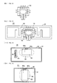
- Fig. 1 illustrates a radio frequency IC device 2A according to a first embodiment of the present invention.
- the radio frequency IC device 2A includes an electromagnetic coupling module 1, a radiation plate 15, and an annular electrode 25.
- the electromagnetic coupling module 1 includes a radio IC chip 5 that processes transmission/reception signals of predetermined frequencies, and a feed circuit board 10 on which the radio IC chip 5 is mounted.
- the radiation plate 15 and the annular electrode 25 are formed on a base 20, such as a PET film.
- Fig. 1(A) illustrates the radio frequency IC device in a state where the electromagnetic coupling module 1 is mounted.
- Fig. 1(B) illustrates the radiation plate 15 and the annular electrode 25 in a state where the electromagnetic coupling module 1 is not mounted.
- Fig. 1(C) illustrates a modification of a connecting part 27 between the radiation plate 15 and the annular electrode 25.
- the radiation plate 15 has a so-called dipole shape, and is disposed to extend on both sides of the electromagnetic coupling module 1.
- the annular electrode 25 has a pair of wide end portions 26a and 26b on which the electromagnetic coupling module 1 is mounted. A part of the annular electrode 25 is electrically connected to the radiation plate 15 through the connecting part 27.
- the radiation plate 15 and the annular electrode 25 may be formed by attaching a conductive metal sheet, such as a sheet of aluminum foil or copper foil, to the base 20 and patterning the conductive metal sheet.
- the radiation plate 15 and the annular electrode 25 may be formed by producing a film by plating or applying conductive paste, such as Al, Cu, or Ag paste, to the base 20 and patterning the film.
- the feed circuit board 10 includes a feed circuit 11 (which will be described in detail below with reference to Fig. 5 ) having a resonant and matching circuit including inductance elements L1 and L2.
- the inductance elements L1 and L2 have different inductance values and are magnetically coupled to each other (as indicated by mutual inductance M) in opposite phases.
- the radio IC chip 5 includes a clock circuit, a logic circuit, a memory circuit, etc., and stores necessary information. While not shown, a pair of input/output terminal electrodes and a pair of mounting terminal electrodes are disposed on the back side of the radio IC chip 5. As illustrated in Fig. 3 , the input/output terminal electrodes are electrically connected through metal bumps etc. to feeder terminal electrodes 42a and 42b on the feed circuit board 10, while the mounting terminal electrodes are electrically connected through metal bumps etc. to mounting electrodes 43a and 43b on the feed circuit board 10.
- the inductance elements L1 and L2 included in the feed circuit 11 are magnetically coupled to each other in opposite phases, resonate at a frequency processed by the radio IC chip 5, and are electromagnetically coupled to the respective end portions 26a and 26b of the annular electrode 25.
- the feed circuit 11 matches the impedance (typically 50 ⁇ ) of the radio IC chip 5 to the impedance (spatial impedance, 377 ⁇ ) of the radiation plate 15.
- the feed circuit 11 transmits, through the annular electrode 25 to the radiation plate 15, a transmission signal originating from the radio IC chip 5 and having a predetermined frequency. Also, the feed circuit 11 selects, from signals received by the radiation plate 15 and transmitted through the annular electrode 25, a reception signal having a predetermined frequency and supplies the selected reception signal to the radio IC chip 5. Thus, in the radio frequency IC device 2A, the radio IC chip 5 is operated by a signal received by the radiation plate 15, and a response signal from the radio IC chip 5 radiates outward from the radiation plate 15.
- the annular electrode 25 has a predetermined electrical length from the end portion 26a to the end portion 26b, and has a predetermined resonant frequency corresponding to the electrical length.
- the radiation plate 15 also has a predetermined resonant frequency corresponding to its electrical length.
- the annular electrode 25 and the radiation plate 15 are designed such that f1 is lower than f2, where f1 is a resonant frequency of the annular electrode 25 and f2 is a resonant frequency of the radiation plate 15. That is, the annular electrode 25 and the radiation plate 15 are designed such that the electrical length of the annular electrode 25 alone is greater than or equal to that of the radiation plate 15 alone.
- the annular electrode 25 is electrically connected to the radiation plate 15 through the connecting part 27.
- a point at which a current passing through the annular electrode 25 and a current passing through the radiation plate 15 reach their maximum values coincides with a point of connection between the annular electrode 25 and the radiation plate 15.
- a signal from the electromagnetic coupling module 1 propagates through the annular electrode 25 and is directly transmitted to the radiation plate 15.
- a signal from the annular electrode 25 is partially radiated as a magnetic field to the outside of the radio frequency IC device 2A, while a signal from the radiation plate 15 is radiated outward as an electric field.
- the annular electrode 25 and the radiation plate 15 are designed such that the resonant frequency f1 of the annular electrode 25 is lower than the resonant frequency f2 of the radiation plate 15, it is possible to widen the frequency range of radiation characteristics of the radio frequency IC device.
- Fig. 4 is a graph showing frequency characteristics of a radiation gain of the radio frequency IC device 2A according to the first embodiment.
- a radiation gain as high as 1.5 dB or above can be achieved over a frequency band as wide as 100 MHz between the resonant frequency of the annular electrode 25 and the resonant frequency of the radiation plate 15 in a state where the annular electrode 25 and the radiation plate 15 are coupled to each other.
- marker 1 and marker 2 indicate a maximum usable frequency and a lowest usable frequency, respectively, of RFID in a UHF band.
- f0 is set to be between a frequency f1' of marker 1 and a frequency f2' of marker 2, where f0 is a frequency of a signal transmitted and received by the radio frequency IC device 2A
- f0 is a frequency of a signal transmitted and received by the radio frequency IC device 2A
- a good radiation gain can be achieved at a predetermined signal frequency f0.
- the radio frequency IC device 2A can operate without any problem at frequencies between the two frequencies f1' and f2'.
- a radio frequency IC device with improved reliability can be provided.
- the annular electrode 25 and the radiation plate 15 are connected to each other through the connecting part 27.
- the resonant frequency f2 of the radiation plate 15 is lower than the corresponding design value of the radiation plate 15 alone. Therefore, it is preferable to design the resonant frequency f1 of the annular electrode 25 alone to be lower than the resonant frequency f2 of the radiation plate 15.
- the radio frequency IC device 2A can achieve good radiation characteristics in a frequency band between the frequencies f1' and f2'. It is also preferable that the resonant frequency f1 of the annular electrode 25 alone be designed to be higher than the resonant frequency of the resonant circuit included in the feed circuit 11.
- the resonant frequency f1 of the annular electrode 25 is reduced. Therefore, when the resonant frequency f1 of the annular electrode 25 alone is designed to be higher than the resonant frequency f0 of the resonant circuit, the resonant frequency f0 can be set to be in a frequency band between the frequencies f1' and f2' during operation of the radio frequency IC device 2A, that is, in a state where the annular electrode 25 and the radiation plate 15 are coupled to each other. Thus, it is possible to perform stable communication while maintaining a high radiation gain. It is preferable that the resonant frequency f2 of the radiation plate 15 be less than half a signal wavelength ⁇ .
- the radio frequency IC device 2A As described above, in the radio frequency IC device 2A, a resonant frequency of a signal is set in the feed circuit 11 provided in the feed circuit board 10. Therefore, the radio frequency IC device 2A operates normally even when attached to various articles. At the same time, variations in radiation characteristics can be reduced, and there is no need to change the design of the radiation plate 15 etc. for each article.
- the frequency of a transmission signal radiated from the radiation plate 15 and the frequency of a reception signal supplied to the radio IC chip 5 are substantially equivalent to the resonant frequency of the feed circuit 11 in the feed circuit board 10. The frequencies of transmission and reception signals are determined in the feed circuit board 10.
- a width W and a spacing L (see Fig. 1(B) ) at the connecting part 27 affect the degree of this coupling. Specifically, as the width W and the spacing L increase, the degree of this coupling decreases.
- the connecting part 27 may be divided at two locations.
- the degree of coupling described above increases as a width W' increases, while decreases as a spacing L' increases.
- the feed circuit board 10 is formed by stacking, pressing, and firing dielectric or magnetic ceramic sheets 41a to 41h.
- the feeder terminal electrodes 42a and 42b, the mounting electrodes 43a and 43b, and via-hole conductors 44a, 44b, 45a, and 45b are formed on the uppermost sheet 41a.
- Line electrodes 46a and 46b constituting the inductance elements L1 and L2 are formed on each of the sheets 41b to 41h on the second to eighth layers, respectively.
- Via-hole conductors 47a, 47b, 48a, and 48b are also formed on the sheets 41b to 41h as necessary.
- the line electrodes 46a are spirally connected through the via-hole conductors 47a to form the inductance element L1
- the line electrodes 46b are spirally connected through the via-hole conductors 47b to form the inductance element L2.
- a capacitance is formed between lines of the line electrodes 46a and 46b.
- An end portion 46a-1 of the line electrode 46a on the sheet 41b is connected through the via-hole conductor 45a to the feeder terminal electrode 42a, while an end portion 46a-2 of the line electrode 46a on the sheet 41h is connected through the via-hole conductors 48a and 45b to the feeder terminal electrode 42b.
- An end portion 46b-1 of the line electrode 46b on the sheet 41b is connected through the via-hole conductor 44b to the feeder terminal electrode 42b, while an end portion 46b-2 of the line electrode 46b on the sheet 41h is connected through the via-hole conductors 48b and 44a to the feeder terminal electrode 42a.
- the inductance elements L1 and L2 are formed at different positions on the left and right.
- the magnetic fields generated in the inductance elements L1 and L2 are opposite in direction.
- the annular electrode 25 is rectangular in the first embodiment, but may be elliptical or another shape. This applies to the other embodiments described below.
- Fig. 6 illustrates a radio frequency IC device 2B according to a second embodiment of the present invention.
- the radio frequency IC device 2B is identical to the radio frequency IC device 2A of the first embodiment in that it includes the electromagnetic coupling module 1 having the radio IC chip 5 and the feed circuit board 10, the annular electrode 25, and the radiation plate 15.
- a difference from the radio frequency IC device 2A is that the radiation plate 15 of the radio frequency IC device 2B has end portions 16a and 16b bent and extending along their corresponding sides of the annular electrode 25.
- the radio frequency IC device 2B of the second embodiment is compact in size. Moreover, by directing the end portions 16a and 16b of the radiation plate 15 in a predetermined direction, directivity in the predetermined direction can be improved. Additionally, since bent portions including the end portions 16a and 16b are arranged in close proximity to the annular electrode 25, electromagnetic coupling that occurs as a secondary effect can further enhance the coupling between the annular electrode 25 and the radiation plate 15. It is thus possible to improve a radiation gain of the radio frequency IC device and further widen the frequency range of radiation characteristics of the radio frequency IC device.
- Fig. 7 illustrates a radio frequency IC device 2C according to a third embodiment of the present invention.
- the radiation plate 15 has wide portions 17a and 17b at its ends.
- the other configurations are the same as those of the first and second embodiments, and operational effects of the third embodiment are also the same as those of the first and second embodiments.
- Fig. 8 illustrates a radio frequency IC device 2D according to a fourth embodiment of the present invention.
- the wide portions 17a and 17b of the radiation plate 15 have empty spaces 18a and 18b, respectively.
- the other configurations are the same as those of the first and third embodiments, and operational effects of the fourth embodiment are also the same as those of the first and third embodiments.
- providing the empty spaces 18a and 18b in the wide portions 17a and 17b makes it possible to lower the resonant frequency of the radiation plate 15 and reduce the overall length of the radiation plate 15. It is thus possible to reduce the size of the radio frequency IC device while improving its radiation characteristics.
- Fig. 9 illustrates a radio frequency IC device 2E according to a fifth embodiment of the present invention.
- the end portions 26a and 26b of the annular electrode 25 are bent toward the inside of the annular electrode 25.
- the other configurations are the same as those of the first and third embodiments, and operational effects of the fifth embodiment are also the same as those of the first and third embodiments.
- bent portions including the end portions 26a and 26b and their adjacent line portions of the annular electrode 25 form a capacitance.
- the resonant frequency of the annular electrode 25 can be designed on the basis of this capacitance and the length of the annular electrode 25. It is possible to reduce the overall length of the annular electrode 25, and thus to reduce the size of the radio frequency IC device. Also, the degree of freedom in designing the annular electrode 25 can be increased.
- Fig. 10 illustrates a radio frequency IC device 2F according to a sixth embodiment of the present invention.
- the annular electrode 25 and the radiation plate 15 are electrically isolated from each other and not connected through the connecting part 27. That is, a part of the annular electrode 25 is adjacent to and in parallel with the radiation plate 15. The adjacent portions of the annular electrode 25 and the radiation plate 15 are electromagnetically coupled to each other to form a coupling part 28, through which a signal is transmitted and received.
- a signal from the electromagnetic coupling module 1 propagates through the annular electrode 25 and causes a magnetic field to be generated around the annular electrode 25.
- the magnetic field generated around the annular electrode 25 is coupled to the radiation plate 15 in the coupling part 28, so that a signal is transmitted and received therebetween.
- the degree of coupling between the annular electrode 25 and the radiation plate 15 can be changed by varying the distance between the annular electrode 25 and the radiation plate 15 in the coupling part 28 and the length of the coupling part 28. Additionally, since the radiation plate 15 and the annular electrode 25 are electrically isolated from each other, static electricity entering from the radiation plate 15 can be blocked by the coupling part 28. It is thus possible to prevent the radio IC chip 5 from being broken by static electricity.
- Fig. 11 illustrates a radio frequency IC device 2G according to a seventh embodiment of the present invention.
- the radio frequency IC device 2G includes the electromagnetic coupling module 1 described in the first embodiment, and a magnetic-field radiation plate 50 and an electric-field radiation plate 60 that are formed on the base 20.
- the magnetic-field radiation plate 50 is constituted by an annular electrode having a pair of end portions 51a and 51b.
- the end portions 51a and 51b are electromagnetically coupled to the feed circuit 11 (see Fig. 2 ) in the feed circuit board 10.
- the electric-field radiation plate 60 has a dipole shape, and has a base portion 61a, bent portions 61b, and wide end portions 62a and 62b.
- the electric-field radiation plate 60 is electrically connected through connecting parts 57 to the magnetic-field radiation plate 50.
- the magnetic-field radiation plate 50 is formed in part of the electric-field radiation plate 60.
- the radiation plates 50 and 60 may be electrically isolated from each other, but arranged in close proximity and electromagnetically coupled to each other (see the sixth embodiment illustrated in Fig. 10 ).
- the electric-field radiation plate 60 is used in long-distance communication with a reader/writer.
- the magnetic-field radiation plate 50 allows short-distance communication with a reader/writer.
- a reader/writer includes a magnetic-field radiation plate 70 (see Fig. 12 ) constituted by an annular electrode.
- the magnetic-field radiation plate 70 is substantially the same in size as the magnetic-field radiation plate 50 of the radio frequency IC device 2G. From the magnetic-field radiation plate 70, magnetic fields indicated by arrows in Fig. 12 are generated in near fields. From the magnetic-field radiation plate 50, similar magnetic fields are generated in near fields. As illustrated in Fig. 13 , by placing the radiation plate 70 over the radiation plate 50, the radiation plates 50 and 70 are magnetically coupled in close proximity to each other and thus, short-distance communication therebetween is performed.
- the magnetic-field radiation plate 50 can be relatively freely designed regardless of impedance matching, and it is possible to secure a large area where a magnetic flux crosses. As a result, it becomes possible to perform short-distance communication with a reader/writer using a small amount of energy.
- the radio frequency IC device 2G is capable of performing both long-distance and short-distance communication with the reader/writer, and thus can be used in a wider range of applications.
- the magnetic-field radiation plate 50 and the electric-field radiation plate 60 radiate a magnetic field and an electric field, respectively, and there is little interference therebetween, it is possible to independently design the magnetic-field radiation plate 50 and the electric-field radiation plate 60.
- the magnetic-field radiation plate 50 and the magnetic-field radiation plate 70 of a reader/writer make it possible to perform short-distance communication between the reader/writer and only a specific radio frequency IC device 2G distinguished from the other radio frequency IC devices 2G.
- Fig. 14 illustrates a radio frequency IC device 2H according to an eighth embodiment of the present invention.
- a ground electrode 81 on a printed circuit board 80 serves as an electric-field radiation plate.
- the ground electrode 81 has an empty space 82, and the electromagnetic coupling module 1 is coupled to end portions 83a and 83b of the ground electrode 81.
- an area i.e., a region 84 indicated by an alternate long and short dashed line
- An electrode 86 formed in another empty space 85 of the ground electrode 81 is a wiring pattern, which is connected via a through hole to an internal element (not shown).
- Fig. 15 illustrates a radio frequency IC device 2I according to a ninth embodiment of the present invention.
- en electrode 91 disposed over a substantially entire surface of a base 90 serves as an electric-field radiation plate.
- the electrode 91 has an empty space 92, and the electromagnetic coupling module 1 is coupled to end portions 93a and 93b of the electrode 91.
- an area i.e., a region 94 indicated by an alternate long and short dashed line
- an area around the empty space 92 functions as a magnetic-field radiation plate.
- Fig. 16 and Fig. 17 illustrate a radio frequency IC device 2J according to a tenth embodiment of the present invention.
- the radio IC chip 5 is mounted on the pair of end portions 26a and 26b of the annular electrode 25, with conductive adhesives 6 interposed therebetween.
- the annular electrode 25 is coupled to the dipole radiation plate 15.
- the radio frequency IC device 2J of the tenth embodiment is realized by removing the feed circuit board 10 from the radio frequency IC device 2C of the third embodiment.
- the annular electrode 25 functions as an impedance matching circuit (resonant circuit). Although no feed circuit is provided, the radio frequency IC device 2J is capable of transmitting and receiving a radio signal without any problem.
- the pair of end portions 26a and 26b of the annular electrode 25 is disposed at a position farthest from the connecting part 27, through which the annular electrode 25 is connected to the radiation plate 15.
- the end portions 26a and 26b may be disposed in close proximity to the radiation plate 15.
- Fig. 18 and Fig. 19 illustrate a radio frequency IC device 2K according to an eleventh embodiment of the present invention.
- the radio IC chip 5 is mounted on the pair of end portions 26a and 26b of the annular electrode 25, with an interposer 7 disposed therebetween.
- the annular electrode 25 is coupled to the dipole radiation plate 15.
- the interposer 7 is made by forming line electrodes 9a and 9b on a surface of a base 8, such as a PET film.
- the interposer 7 is bonded to the end portions 26a and 26b of the annular electrode 25 such that the line electrodes 9a and 9b are disposed opposite the end portions 26a and 26b, respectively, and coupled thereto.
- the line electrodes 9a and 9b are capacitively coupled to the end portions 26a and 26b.
- the radio IC chip 5 is mounted on the line electrodes 9a and 9b, with the conductive adhesives 6 interposed therebetween.
- the interposer 7 serves to connect the radio IC chip 5 to the annular electrode 25, but does not serve as a feed circuit.
- the eleventh embodiment is the same as the tenth embodiment in which the feed circuit board 10 is not provided.
- automatically mounting the radio IC chip 5 on the interposer 7 is relatively easy, because the radio IC chip 5 and the interposer 7 are not significantly different in size.
- the degree of accuracy needed to bond the interposer 7 having the radio IC chip 5 mounted thereon to the base 20, the interposer 7 being relatively large in size, is not very high. Therefore, the radio frequency IC device 2K of the eleventh embodiment can be more easily manufactured than the radio frequency IC device 2J of the tenth embodiment.
- the interposer 7 is disposed such that it is coupled to the end portions 26a and 26b of the annular electrode 25.
- the interposer 7 may be disposed in areas where the annular electrode 25 and the wide end portions 17a and 17b at the ends of the radiation plate 15 are located in close proximity.
- the line electrodes 9a and 9b of the interposer 7 may be coupled to the end portions 26a and 26b of the annular electrode 25 not only capacitively, but also magnetically and moreover, the line electrodes 9a and 9b may be made electrically connected to the end portions 26a and 26b through conductive adhesives.
- each radio frequency IC device has been described as one including an electric-field radiation plate and a magnetic-field radiation plate.
- the dipole radiation plate 15 functions as an electric-field radiation plate
- the annular electrode 25 functions as a magnetic-field radiation plate.
- the radiation plate 15 and the annular electrode 25 may be arranged such that an electric field generated by the electric-field radiation plate and a magnetic field generated by the magnetic-field radiation plate are orthogonal to each other.
- an annular electrode serves as a magnetic-field radiation plate, so that a magnetic field generated around the annular electrode is used for communication.
- an electric field is generated radially in the directions of upper and lower surfaces and upper and lower sides of the electrode plane.
- the magnetic field and the electric field are made orthogonal to each other and are not coupled to each other.
- the electric-field radiation plate and the magnetic-field radiation plate can be arranged in close proximity to each other, and a radio frequency IC device having good radiation characteristics can be provided.
- a magnetic field generated around the magnetic-field radiation plate is coupled to an edge of the electric-field radiation plate and thus, the electric-field radiation plate and the magnetic-field radiation plate are magnetically coupled to each other.
- the electric-field radiation plate is magnetically coupled but functions as an electric-field radiation plate, because signals radiated therefrom are mostly electric fields.
- Fig. 20 illustrates a radiation plate of a reader/writer that is combined with the radio frequency IC devices 2G, 2H, and 2I of the seventh, eighth, and ninth embodiments (or may also be combined with the radio frequency IC devices of the first to sixth, tenth, and eleventh embodiments) to form a radio communication system.
- the radiation plate includes the magnetic-field radiation plate 70 illustrated in Fig. 12 and dipole electric-field radiation plates 75. End portions 76 of the electric-field radiation plates 75 are connected to port 1 of the reader/writer, while end portions 71 of the magnetic-field radiation plate 70 are connected to port 2 of the reader/writer.
- the reader/writer By transmitting and receiving a signal while switching between ports 1 and 2, the reader/writer is capable of determining whether a radio frequency IC device operates at a magnetic-field radiation plate or an electric-field radiation plate. Therefore, in this radio communication system, it is possible to detect whether the radio frequency IC device is close to or far from the reader/writer, and exchange appropriate information in accordance with the detection.
- Fig. 21 illustrates an embodiment of a radio communication system according to the present invention.
- a reader/writer 100 including a magnetic-field radiation plate and an electric-field radiation plate e.g., the radiation plates 70 and 75 illustrated in Fig. 16
- a security card 115 carried by each person in the room.
- the reader/writer 100 Through communication between the electric-field radiation plate of the reader/writer 100 and that of the radio frequency IC device, information is exchanged between the reader/writer 100 and the radio frequency IC device embedded in the security card 115 of each person in the room.
- the security card 115 By bringing the security card 115 close to the reader/writer 100, communication between their magnetic-field radiation plates is made, so that the door 110 is controlled to be automatically opened. That is, the reader/writer 100 is capable not only of allowing the door 110 to be opened or closed in accordance with the intention of a person carrying the security card 115, but also of obtaining information about each person in the room.
- the feed circuit may be formed on the feed circuit board, and the radio IC and the feed circuit board may constitute an electromagnetic coupling module.
- a resonant frequency of the annular electrode alone be higher than a resonant frequency of the resonant circuit and lower than a resonant frequency of the radiation plate alone. It is further preferable that a frequency of a signal transmitted and received by the radiation plate in a state where the annular electrode and the radiation plate are coupled to each other be higher than a resonant frequency of the annular electrode and lower than a resonant frequency of the radiation plate.
- the resonant frequency of the annular electrode is set to be lower than that of the radiation plate, it is possible to widen the frequency range of signal radiation characteristics.
- the radio frequency IC device can be used in RFID systems from all over the world, the RFID systems being different in usable signal frequency.
- the annular electrode and the radiation plate may be arranged such that a magnetic field generated around the annular electrode is orthogonal to an electric field generated around the dipole radiation plate.
- the annular electrode may be electrically connected to the radiation plate. This can enhance the coupling between the annular electrode and the radiation plate, improve signal transmission efficiency between the annular electrode and the radiation plate, and thus can make it possible to achieve excellent radiation characteristics. When part of the annular electrode is arranged in close proximity to the radiation plate, it is possible to achieve further excellent radiation characteristics.
- the annular electrode and the radiation plate may be formed on the same base. This makes it possible to manufacture the annular electrode and the radiation plate in the same process.
- the radiation plate may have wide portions at both ends thereof, the wide portions being wider than a line width of a center portion in a longitudinal direction of the radiation plate. Each of the wide portions may have an empty space.
- the pair of end portions of the annular electrode may be arranged toward the inside of the annular electrode.
- capacitance occurs between adjacent parts of the annular electrode, and the resonant frequency of the annular electrode can be designed on the basis of the capacitance components and inductance components of the annular electrode. Therefore, it is possible to reduce the length of the annular electrode and the size of the radio frequency IC device.
- a frequency of a signal transmitted and received by the radiation plate is substantially determined by a resonant frequency of the resonant circuit.
- the feed circuit board may be a ceramic or resin multilayer board.
- the feed circuit can be made less likely to be affected by factors outside the circuit board and thus, variations in radiation characteristics can be reduced.
- the radiation plate functions as an electric-field radiation plate
- the annular electrode functions as a magnetic-field radiation plate.
- a control circuit included in a radio IC can be operated.
- impedance matching is performed in a resonant circuit, and the magnetic-field radiation plate can be relatively freely designed regardless of the impedance matching. Therefore, it is possible to secure a large area where a magnetic flux crosses. As a result, it becomes possible to perform short-distance communication with the reader/writer using a small amount of energy.
- the radio frequency IC device is capable of performing both long-distance and short-distance communication with the reader/writer, and thus can be used in a wider range of applications.
- the annular electrode 25 of the first to sixth, tenth, and eleventh embodiments also functions as the magnetic-field radiation plate 50 described in the seventh embodiment. Therefore, the description of the magnetic-field radiation plate 50 is also applicable to the annular electrode 25.
- radio frequency IC device and the radio communication system according to the present invention are not limited to the embodiments described above, and may be variously modified within the scope of the invention.
- the materials of the radiation plate and base discussed in the above embodiments are shown for illustrative purposes only. Any materials having necessary properties may be used.
- the radio IC chip may be connected to the plane electrode by processing other than by forming metal bumps therebetween.
- the radio IC may be formed as an element within the feed circuit board.
- the radio IC may be formed as an element within the feed circuit board.
- each annular electrode may be connected or coupled to its corresponding radiation plate at a different position.
- the present invention is useful when applied to a radio frequency IC device and a radio communication system.
- the present invention is excellent in that it makes it possible to widen a frequency band where impedance matching between a radio IC and a radiation plate can be achieved, and to provide desired radiation characteristics over a wide range of frequencies.
Landscapes
- Engineering & Computer Science (AREA)
- Computer Hardware Design (AREA)
- Microelectronics & Electronic Packaging (AREA)
- Physics & Mathematics (AREA)
- General Physics & Mathematics (AREA)
- Theoretical Computer Science (AREA)
- Computer Networks & Wireless Communication (AREA)
- Details Of Aerials (AREA)
Abstract
Description
- The present invention relates to radio frequency IC devices, and particularly to a radio frequency IC device used in a radio frequency identification (RFID) system and a radio communication system including the radio frequency IC device.
- Conventionally, RFID systems have been developed as article management systems. An RFID system allows noncontact communication between a reader/writer that generates an induction field and an IC chip (also referred to as an IC tag or a radio IC chip) that stores predetermined information and is attached to an article or a container, and thereby allows transmission of information therebetween. The IC chip is capable of communicating with the reader/writer when connected to an antenna, that is, to a radiation plate. A tag antenna disclosed in
Patent Document 1 has been conventionally known as one for mounting an IC chip thereon. - This tag antenna has portions of large line width at both ends of a dipole antenna. Mounting an LSI chip on a feeder unit at the center of the dipole antenna allows the tag antenna to function as an RFID system. An inductance unit is disposed around the feeder unit and provides impedance matching between the LSI chip and the dipole antenna.
- In the tag antenna described above, only the inductance unit performs impedance matching between the LSI chip and the dipole antenna. This may cause problems in that a frequency range in which impedance matching can be achieved is narrow, an LSI chip having a different impedance cannot be supported, variations in manufacture of inductance units may cause variations in frequency of signals that can be transmitted and received, and thus the tag antenna does not operate as an RFID system.
- In the tag antenna disclosed in
Patent Document 1, the size of the dipole antenna is reduced by forming, at both ends of the dipole antenna, regions wider than the line width of a dipole portion of the dipole antenna. However, the size reduction of the antenna causes degradation in signal radiation characteristics, and narrows the frequency range in which a desired radiation gain can be achieved. - The present inventors have focused attention on the point that it is necessary for an IC chip of this type to appropriately perform both long-distance communication and short-distance communication. This is because although information is usually exchanged through long-distance communication, specific information may preferably be exchanged only through short-distance communication. For example, in the stage of manufacturing IC chips, when a plurality of IC chips arranged in close proximity are assigned IDs or subjected to characteristic testing, it is necessary that only a specific IC chip be distinguished from adjacent IC chips and allowed to communicate with a reader/writer within a short distance only.
-
Patent Document 2 discloses a method for testing an RFID tag. The RFID tag includes an antenna that performs communication at UHF-band frequencies and a matching circuit that adjusts impedance of the antenna. For testing the RFID tag, an antenna coil of a reader/writer is placed toward the matching circuit of the RFID tag, so that a magnetic flux from the antenna coil causes a control circuit of the RFID tag to operate and thus the RFID tag can be tested. - However, in this RFID tag, the size of the matching circuit is substantially determined by the impedance of an IC. Since it is difficult to increase an area where the magnetic flux crosses, a distance along which the control circuit of the RFID tag can be operated is small.
-
Patent Document 3 discloses an interposer that firmly electrically connects a substrate having an IC chip mounted thereon to a conductive connecting part of another electrical circuit.
Patent Document 1: Japanese Unexamined Patent Application Publication No.2006-295879
Patent Document 2: Japanese Unexamined Patent Application Publication No.2007-79687
Patent Document 3: Japanese Unexamined Patent Application Publication No.2003-168760 - A first object of the present invention is to provide a radio frequency IC device capable of achieving impedance matching between a radio IC and a radiation plate in a wide frequency band, and achieving desired radiation characteristics over a wide range of frequencies.
- A second object of the present invention is to provide s radio frequency IC device capable of achieving the first object in a simple manufacturing process.
- A third object of the present invention is to provide a radio frequency IC device and a radio communication system that allow both long-distance and short-distance communication and, in particular, allow short-distance communication using a small amount of energy.
- A radio frequency IC device according to a first aspect of the present invention includes a radio IC; an annular electrode coupled to the radio IC and having at least a pair of end portions; and a dipole radiation plate coupled to the annular electrode.
- A radio frequency IC device according to a second aspect of the present invention includes a radio IC; an interposer coupled to the radio IC and having a line electrode formed on at least one principal surface of a base and/or inside the base; an annular electrode having at least a pair of end portions; and a dipole radiation plate coupled to the annular electrode. The line electrode is coupled to at least one of the annular electrode and the radiation plate.
- A radio frequency IC device according to a third aspect of the present invention includes a radio IC; a feed circuit coupled to the radio IC, and constituted by a resonant circuit including an inductance element and having a predetermined resonant frequency; an annular electrode having at least a pair of end portions and electromagnetically coupled to the feed circuit at the pair of end portions; and a dipole radiation plate coupled to the annular electrode.
- A radio frequency IC device according to a fourth aspect of the present invention includes a radio IC; a magnetic-field radiation plate coupled to the radio IC and having at least a pair of end portions; and an electric-field radiation plate coupled to the magnetic-field radiation plate.
- A radio frequency IC device according to a fifth aspect of the present invention includes a radio IC; an interposer coupled to the radio IC and having a line electrode formed on at least one principal surface of a base and/or inside the base; a magnetic-field radiation plate having at least a pair of end portions; and an electric-field radiation plate coupled to the magnetic-field radiation plate. The line electrode is coupled to at least one of the magnetic-field radiation plate and the electric-field radiation plate.
- A radio frequency IC device according to a sixth aspect of the present invention includes a radio IC; a feed circuit coupled to the radio IC, and constituted by a resonant circuit including an inductance element and having a predetermined resonant frequency; a magnetic-field radiation plate having at least a pair of end portions and electromagnetically coupled to the feed circuit at the pair of end portions; and an electric-field radiation plate coupled to the magnetic-field radiation plate.
- A radio communication system according to a seventh aspect of the present invention includes a radio frequency IC device according to any one of the first to sixth aspects described above, and a reader/writer configured to communicate with the radio frequency IC device. The reader/writer includes a magnetic-field radiation plate constituted by an annular electrode.
- In the radio frequency IC device of the third aspect, a frequency of a signal used in communicating with a reader/writer is substantially determined by the feed circuit constituted by the resonant circuit having a predetermined resonant frequency. By designing the feed circuit in accordance with the impedances of the radio IC and radiation plate to be used, it is possible to support various impedances. Additionally, by arranging the annular electrode such that it is coupled to the feed circuit and the dipole radiation plate, it is possible to reduce loss of a signal transmitted from the annular electrode to the radiation plate, and thus to improve signal radiation characteristics.
- Like the radio frequency IC device of the first aspect described above, the feed circuit board having the feed circuit may be removed to allow the radiation plate to function as a resonant circuit. Like the radio frequency IC device of the second aspect described above, an interposer may be disposed between the radio IC and the annular electrode.
- In the radio frequency IC device of the fourth, fifth, and sixth aspects described above, the magnetic-field radiation plate allows short-distance communication, while the electric-field radiation plate allows long-distance communication. When impedance matching is performed in the resonant circuit, the magnetic-field radiation plate can be relatively freely designed regardless of impedance matching, and it is possible to secure a large area where a magnetic flux crosses. As a result, it becomes possible to perform short-distance communication with a reader/writer using a small amount of energy.
- According to the present invention, since the annular electrode is provided, it is possible to achieve desired radiation characteristics over a wide range of frequencies. Moreover, since the magnetic-field radiation plate allows short-distance communication and the electric-field radiation plate allows long-distance communication, it is possible to appropriately perform both short-distance and long-distance communication by using the magnetic-field radiation plate and the electric-field radiation plate. Since the magnetic-field radiation plate can have a large area where a magnetic flux crosses regardless of impedance matching, it is possible to perform short-distance communication with a reader/writer using a small amount of energy.
- By using the resonant circuit included in the feed circuit, it is possible to widen a frequency band where impedance matching between the radio IC and the radiation plate can be achieved. Additionally, when an interposer is disposed between the radio IC and the annular electrode, the interposer on which a very small radio IC is mounted can be mounted on the annular electrode in a simple process.
-
- [
Fig. 1] Fig. 1(A) to Fig. 1(C) are plan views illustrating a radio frequency IC device according to a first embodiment. - [
Fig. 2] Fig. 2 is an equivalent circuit diagram illustrating a feed circuit of the radio frequency IC device according to the first embodiment. - [
Fig. 3] Fig. 3 is a perspective view illustrating a state in which a radio IC chip is mounted on a feed circuit board included in the radio frequency IC device according to the first embodiment. - [
Fig. 4] Fig. 4 is a graph showing frequency characteristics of a radiation gain of the radio frequency IC device according to the first embodiment. - [
Fig. 5] Fig. 5 is a plan view illustrating a laminated structure of the feed circuit board included in the radio frequency IC device according to the first embodiment. - [
Fig. 6] Fig. 6 is a plan view illustrating a radio frequency IC device according to a second embodiment. - [
Fig. 7] Fig. 7 is a plan view illustrating a radio frequency IC device according to a third embodiment. - [
Fig. 8] Fig. 8 is a plan view illustrating a radio frequency IC device according to a fourth embodiment. - [
Fig. 9] Fig. 9 is a plan view illustrating a radio frequency IC device according to a fifth embodiment. - [
Fig. 10] Fig. 10 is a plan view illustrating a radio frequency IC device according to a sixth embodiment. - [
Fig. 11] Fig. 11 is a plan view illustrating a radio frequency IC device according to a seventh embodiment. - [
Fig. 12] Fig. 12 is a plan view illustrating a first example of a radiation plate of a reader/writer. - [
Fig. 13] Fig. 13 is a plan view illustrating a state in which the radiation plate of the reader/writer is placed over the radio frequency IC device according to the seventh embodiment. - [
Fig. 14] Fig. 14 is a plan view illustrating a radio frequency IC device according to an eighth embodiment. - [
Fig. 15] Fig. 15 is a plan view illustrating a radio frequency IC device according to a ninth embodiment. - [
Fig. 16] Fig. 16 is a plan view illustrating a radio frequency IC device according to a tenth embodiment. - [
Fig. 17] Fig. 17 is a cross-sectional view illustrating a main part of the radio frequency IC device according to the tenth embodiment. - [
Fig. 18] Fig. 18 is a plan view illustrating a radio frequency IC device according to an eleventh embodiment. - [
Fig. 19] Fig. 19 is a cross-sectional view illustrating a main part of the radio frequency IC device according to the eleventh embodiment. - [
Fig. 20] Fig. 20 is a plan view illustrating a second example of a radiation plate of a reader/writer. - [
Fig. 21] Fig. 21 illustrates an embodiment of a radio communication system according to the present invention. -
- 1:
- electromagnetic coupling module
- 2A to 2K:
- radio frequency IC device
- 5:
- radio IC chip
- 7:
- interposer
- 8:
- base
- 9a, 9b:
- line electrode
- 10:
- feed circuit board
- 11:
- feed circuit
- 15:
- radiation plate
- 16a, 16b:
- end portion
- 17a, 17b:
- wide portion
- 18a, 18b:
- empty space
- 20:
- base
- 25:
- annular electrode
- 26a, 26b:
- end portion
- 27:
- connecting part
- 28:
- coupling part
- 50:
- magnetic-field radiation plate
- 60:
- electric-field radiation plate
- 70:
- magnetic-field radiation plate of reader/writer
- 75:
- electric-field radiation plates of reader/writer
- 100:
- reader/writer
- 115:
- security card
- L1, L2:
- inductance element
- Hereinafter, embodiments of a radio frequency IC device and a radio communication system according to the present invention will be described with reference to the attached drawings. In the drawings, like components and parts are given the same reference numerals, and redundant description will be omitted.
-
Fig. 1 illustrates a radio frequency IC device 2A according to a first embodiment of the present invention. The radio frequency IC device 2A includes anelectromagnetic coupling module 1, aradiation plate 15, and anannular electrode 25. Theelectromagnetic coupling module 1 includes aradio IC chip 5 that processes transmission/reception signals of predetermined frequencies, and afeed circuit board 10 on which theradio IC chip 5 is mounted. Theradiation plate 15 and theannular electrode 25 are formed on abase 20, such as a PET film. -
Fig. 1(A) illustrates the radio frequency IC device in a state where theelectromagnetic coupling module 1 is mounted.Fig. 1(B) illustrates theradiation plate 15 and theannular electrode 25 in a state where theelectromagnetic coupling module 1 is not mounted.Fig. 1(C) illustrates a modification of a connectingpart 27 between theradiation plate 15 and theannular electrode 25. - The
radiation plate 15 has a so-called dipole shape, and is disposed to extend on both sides of theelectromagnetic coupling module 1. Theannular electrode 25 has a pair ofwide end portions 26a and 26b on which theelectromagnetic coupling module 1 is mounted. A part of theannular electrode 25 is electrically connected to theradiation plate 15 through the connectingpart 27. Theradiation plate 15 and theannular electrode 25 may be formed by attaching a conductive metal sheet, such as a sheet of aluminum foil or copper foil, to thebase 20 and patterning the conductive metal sheet. Alternatively, theradiation plate 15 and theannular electrode 25 may be formed by producing a film by plating or applying conductive paste, such as Al, Cu, or Ag paste, to thebase 20 and patterning the film. - As illustrated as an equivalent circuit in
Fig. 2 , thefeed circuit board 10 includes a feed circuit 11 (which will be described in detail below with reference toFig. 5 ) having a resonant and matching circuit including inductance elements L1 and L2. The inductance elements L1 and L2 have different inductance values and are magnetically coupled to each other (as indicated by mutual inductance M) in opposite phases. - The
radio IC chip 5 includes a clock circuit, a logic circuit, a memory circuit, etc., and stores necessary information. While not shown, a pair of input/output terminal electrodes and a pair of mounting terminal electrodes are disposed on the back side of theradio IC chip 5. As illustrated inFig. 3 , the input/output terminal electrodes are electrically connected through metal bumps etc. tofeeder terminal electrodes feed circuit board 10, while the mounting terminal electrodes are electrically connected through metal bumps etc. to mountingelectrodes 43a and 43b on thefeed circuit board 10. - The inductance elements L1 and L2 included in the
feed circuit 11 are magnetically coupled to each other in opposite phases, resonate at a frequency processed by theradio IC chip 5, and are electromagnetically coupled to therespective end portions 26a and 26b of theannular electrode 25. Thefeed circuit 11 matches the impedance (typically 50 Ω) of theradio IC chip 5 to the impedance (spatial impedance, 377 Ω) of theradiation plate 15. - The
feed circuit 11 transmits, through theannular electrode 25 to theradiation plate 15, a transmission signal originating from theradio IC chip 5 and having a predetermined frequency. Also, thefeed circuit 11 selects, from signals received by theradiation plate 15 and transmitted through theannular electrode 25, a reception signal having a predetermined frequency and supplies the selected reception signal to theradio IC chip 5. Thus, in the radio frequency IC device 2A, theradio IC chip 5 is operated by a signal received by theradiation plate 15, and a response signal from theradio IC chip 5 radiates outward from theradiation plate 15. - The
annular electrode 25 has a predetermined electrical length from the end portion 26a to theend portion 26b, and has a predetermined resonant frequency corresponding to the electrical length. Theradiation plate 15 also has a predetermined resonant frequency corresponding to its electrical length. Theannular electrode 25 and theradiation plate 15 are designed such that f1 is lower than f2, where f1 is a resonant frequency of theannular electrode 25 and f2 is a resonant frequency of theradiation plate 15. That is, theannular electrode 25 and theradiation plate 15 are designed such that the electrical length of theannular electrode 25 alone is greater than or equal to that of theradiation plate 15 alone. Theannular electrode 25 is electrically connected to theradiation plate 15 through the connectingpart 27. Preferably, a point at which a current passing through theannular electrode 25 and a current passing through theradiation plate 15 reach their maximum values coincides with a point of connection between theannular electrode 25 and theradiation plate 15. Thus, a signal from theelectromagnetic coupling module 1 propagates through theannular electrode 25 and is directly transmitted to theradiation plate 15. When a point at which both of the above-described currents reach their maximum values coincides with a point of connection between theannular electrode 25 and theradiation plate 15, it is possible to enhance coupling therebetween, and thus to improve signal transmission efficiency. - A signal from the
annular electrode 25 is partially radiated as a magnetic field to the outside of the radio frequency IC device 2A, while a signal from theradiation plate 15 is radiated outward as an electric field. When theannular electrode 25 and theradiation plate 15 are designed such that the resonant frequency f1 of theannular electrode 25 is lower than the resonant frequency f2 of theradiation plate 15, it is possible to widen the frequency range of radiation characteristics of the radio frequency IC device. -
Fig. 4 is a graph showing frequency characteristics of a radiation gain of the radio frequency IC device 2A according to the first embodiment. As is apparent fromFig. 4 , a radiation gain as high as 1.5 dB or above can be achieved over a frequency band as wide as 100 MHz between the resonant frequency of theannular electrode 25 and the resonant frequency of theradiation plate 15 in a state where theannular electrode 25 and theradiation plate 15 are coupled to each other. Referring toFig. 4 ,marker 1 andmarker 2 indicate a maximum usable frequency and a lowest usable frequency, respectively, of RFID in a UHF band. - When f0 is set to be between a frequency f1' of
marker 1 and a frequency f2' ofmarker 2, where f0 is a frequency of a signal transmitted and received by the radio frequency IC device 2A, a good radiation gain can be achieved at a predetermined signal frequency f0. Even when the frequencies f1' and f2' may slightly change due to variations in manufacturing theannular electrode 25 andradiation plate 15, the radio frequency IC device 2A can operate without any problem at frequencies between the two frequencies f1' and f2'. Thus, a radio frequency IC device with improved reliability can be provided. - The
annular electrode 25 and theradiation plate 15 are connected to each other through the connectingpart 27.
When theannular electrode 25 and theradiation plate 15 are coupled to each other, the resonant frequency f2 of theradiation plate 15 is lower than the corresponding design value of theradiation plate 15 alone. Therefore, it is preferable to design the resonant frequency f1 of theannular electrode 25 alone to be lower than the resonant frequency f2 of theradiation plate 15. Thus, the radio frequency IC device 2A can achieve good radiation characteristics in a frequency band between the frequencies f1' and f2'. It is also preferable that the resonant frequency f1 of theannular electrode 25 alone be designed to be higher than the resonant frequency of the resonant circuit included in thefeed circuit 11. As described above, when theannular electrode 25 is coupled to theradiation plate 15, the resonant frequency f1 of theannular electrode 25 is reduced. Therefore, when the resonant frequency f1 of theannular electrode 25 alone is designed to be higher than the resonant frequency f0 of the resonant circuit, the resonant frequency f0 can be set to be in a frequency band between the frequencies f1' and f2' during operation of the radio frequency IC device 2A, that is, in a state where theannular electrode 25 and theradiation plate 15 are coupled to each other. Thus, it is possible to perform stable communication while maintaining a high radiation gain. It is preferable that the resonant frequency f2 of theradiation plate 15 be less than half a signal wavelength λ. - As described above, in the radio frequency IC device 2A, a resonant frequency of a signal is set in the
feed circuit 11 provided in thefeed circuit board 10. Therefore, the radio frequency IC device 2A operates normally even when attached to various articles. At the same time, variations in radiation characteristics can be reduced, and there is no need to change the design of theradiation plate 15 etc. for each article. The frequency of a transmission signal radiated from theradiation plate 15 and the frequency of a reception signal supplied to theradio IC chip 5 are substantially equivalent to the resonant frequency of thefeed circuit 11 in thefeed circuit board 10. The frequencies of transmission and reception signals are determined in thefeed circuit board 10. Therefore, regardless of the shapes, sizes, and arrangement of theradiation plate 15 and theannular electrode 25, that is, even when the radio frequency IC device 2A is, for example, rolled or sandwiched between dielectrics, there is no change in frequency characteristics and stable frequency characteristics can be achieved. - Next, a description will be given about the degree of coupling at the connecting
part 27 between theannular electrode 25 and theradiation plate 15. A width W and a spacing L (seeFig. 1(B) ) at the connectingpart 27 affect the degree of this coupling. Specifically, as the width W and the spacing L increase, the degree of this coupling decreases. - As illustrated in
Fig. 1(C) , the connectingpart 27 may be divided at two locations. In this case, the degree of coupling described above increases as a width W' increases, while decreases as a spacing L' increases. - Next, a configuration of the
feed circuit board 10 will be described with reference toFig. 5 . Thefeed circuit board 10 is formed by stacking, pressing, and firing dielectric or magneticceramic sheets 41a to 41h. Thefeeder terminal electrodes electrodes 43a and 43b, and via-hole conductors uppermost sheet 41a.Line electrodes sheets 41b to 41h on the second to eighth layers, respectively. Via-hole conductors sheets 41b to 41h as necessary. - By stacking the
sheets 41a to 41h, theline electrodes 46a are spirally connected through the via-hole conductors 47a to form the inductance element L1, while theline electrodes 46b are spirally connected through the via-hole conductors 47b to form the inductance element L2. A capacitance is formed between lines of theline electrodes - An
end portion 46a-1 of theline electrode 46a on thesheet 41b is connected through the via-hole conductor 45a to thefeeder terminal electrode 42a, while anend portion 46a-2 of theline electrode 46a on thesheet 41h is connected through the via-hole conductors 48a and 45b to thefeeder terminal electrode 42b. Anend portion 46b-1 of theline electrode 46b on thesheet 41b is connected through the via-hole conductor 44b to thefeeder terminal electrode 42b, while anend portion 46b-2 of theline electrode 46b on thesheet 41h is connected through the via-hole conductors feeder terminal electrode 42a. - In the
feed circuit 11 described above, since the inductance elements L1 and L2 are wound in opposite directions, magnetic fields generated in the inductance elements L1 and L2 are cancelled out. Since the magnetic fields are cancelled out, it is necessary to increase the lengths of theline electrodes - In a perspective plan view of the
feed circuit board 10, the inductance elements L1 and L2 are formed at different positions on the left and right. The magnetic fields generated in the inductance elements L1 and L2 are opposite in direction. Thus, when thefeed circuit 11 is coupled to theend portions 26a and 26b of theannular electrode 25, currents of opposite directions are excited in theend portions 26a and 26b, so that theannular electrode 25 can transmit and receive a signal to and from theradiation plate 15. - The
annular electrode 25 is rectangular in the first embodiment, but may be elliptical or another shape. This applies to the other embodiments described below. -
Fig. 6 illustrates a radio frequency IC device 2B according to a second embodiment of the present invention. The radio frequency IC device 2B is identical to the radio frequency IC device 2A of the first embodiment in that it includes theelectromagnetic coupling module 1 having theradio IC chip 5 and thefeed circuit board 10, theannular electrode 25, and theradiation plate 15. A difference from the radio frequency IC device 2A is that theradiation plate 15 of the radio frequency IC device 2B hasend portions 16a and 16b bent and extending along their corresponding sides of theannular electrode 25. - Since the
radiation plate 15 has theend portions 16a and 16b bent toward theannular electrode 25, the radio frequency IC device 2B of the second embodiment is compact in size. Moreover, by directing theend portions 16a and 16b of theradiation plate 15 in a predetermined direction, directivity in the predetermined direction can be improved. Additionally, since bent portions including theend portions 16a and 16b are arranged in close proximity to theannular electrode 25, electromagnetic coupling that occurs as a secondary effect can further enhance the coupling between theannular electrode 25 and theradiation plate 15. It is thus possible to improve a radiation gain of the radio frequency IC device and further widen the frequency range of radiation characteristics of the radio frequency IC device. -
Fig. 7 illustrates a radio frequency IC device 2C according to a third embodiment of the present invention.
In the radio frequency IC device 2C, theradiation plate 15 haswide portions 17a and 17b at its ends. The other configurations are the same as those of the first and second embodiments, and operational effects of the third embodiment are also the same as those of the first and second embodiments. -
Fig. 8 illustrates a radio frequency IC device 2D according to a fourth embodiment of the present invention. In the radio frequency IC device 2D, thewide portions 17a and 17b of theradiation plate 15 have empty spaces 18a and 18b, respectively. The other configurations are the same as those of the first and third embodiments, and operational effects of the fourth embodiment are also the same as those of the first and third embodiments. In the fourth embodiment, in particular, providing the empty spaces 18a and 18b in thewide portions 17a and 17b makes it possible to lower the resonant frequency of theradiation plate 15 and reduce the overall length of theradiation plate 15. It is thus possible to reduce the size of the radio frequency IC device while improving its radiation characteristics. -
Fig. 9 illustrates a radio frequency IC device 2E according to a fifth embodiment of the present invention.
In the radio frequency IC device 2E, theend portions 26a and 26b of theannular electrode 25 are bent toward the inside of theannular electrode 25. The other configurations are the same as those of the first and third embodiments, and operational effects of the fifth embodiment are also the same as those of the first and third embodiments. In the fifth embodiment, in particular, since theend portions 26a and 26b are arranged toward the inside of theannular electrode 25, bent portions including theend portions 26a and 26b and their adjacent line portions of theannular electrode 25 form a capacitance. The resonant frequency of theannular electrode 25 can be designed on the basis of this capacitance and the length of theannular electrode 25. It is possible to reduce the overall length of theannular electrode 25, and thus to reduce the size of the radio frequency IC device. Also, the degree of freedom in designing theannular electrode 25 can be increased. -
Fig. 10 illustrates a radiofrequency IC device 2F according to a sixth embodiment of the present invention.
In the radiofrequency IC device 2F, theannular electrode 25 and theradiation plate 15 are electrically isolated from each other and not connected through the connectingpart 27. That is, a part of theannular electrode 25 is adjacent to and in parallel with theradiation plate 15. The adjacent portions of theannular electrode 25 and theradiation plate 15 are electromagnetically coupled to each other to form acoupling part 28, through which a signal is transmitted and received. - A signal from the
electromagnetic coupling module 1 propagates through theannular electrode 25 and causes a magnetic field to be generated around theannular electrode 25. The magnetic field generated around theannular electrode 25 is coupled to theradiation plate 15 in thecoupling part 28, so that a signal is transmitted and received therebetween. The degree of coupling between theannular electrode 25 and theradiation plate 15 can be changed by varying the distance between theannular electrode 25 and theradiation plate 15 in thecoupling part 28 and the length of thecoupling part 28. Additionally, since theradiation plate 15 and theannular electrode 25 are electrically isolated from each other, static electricity entering from theradiation plate 15 can be blocked by thecoupling part 28. It is thus possible to prevent theradio IC chip 5 from being broken by static electricity. - The other configurations of the sixth embodiment are the same as those of the first and third embodiments, and operational effects of the sixth embodiment are basically the same as those of the first and third embodiments described above.
-
Fig. 11 illustrates a radiofrequency IC device 2G according to a seventh embodiment of the present invention. The radiofrequency IC device 2G includes theelectromagnetic coupling module 1 described in the first embodiment, and a magnetic-field radiation plate 50 and an electric-field radiation plate 60 that are formed on thebase 20. - The magnetic-
field radiation plate 50 is constituted by an annular electrode having a pair ofend portions 51a and 51b. Theend portions 51a and 51b are electromagnetically coupled to the feed circuit 11 (seeFig. 2 ) in thefeed circuit board 10. The electric-field radiation plate 60 has a dipole shape, and has abase portion 61a,bent portions 61b, andwide end portions field radiation plate 60 is electrically connected through connectingparts 57 to the magnetic-field radiation plate 50. In other words, the magnetic-field radiation plate 50 is formed in part of the electric-field radiation plate 60. Alternatively, theradiation plates Fig. 10 ). - Like the
radiation plate 15 described above, the electric-field radiation plate 60 is used in long-distance communication with a reader/writer. The magnetic-field radiation plate 50 allows short-distance communication with a reader/writer. For short-distance communication, a reader/writer includes a magnetic-field radiation plate 70 (seeFig. 12 ) constituted by an annular electrode. In planar view, the magnetic-field radiation plate 70 is substantially the same in size as the magnetic-field radiation plate 50 of the radiofrequency IC device 2G. From the magnetic-field radiation plate 70, magnetic fields indicated by arrows inFig. 12 are generated in near fields. From the magnetic-field radiation plate 50, similar magnetic fields are generated in near fields. As illustrated inFig. 13 , by placing theradiation plate 70 over theradiation plate 50, theradiation plates - Impedance matching between the
radio IC chip 5 and theradiation plates feed circuit 11. The magnetic-field radiation plate 50 can be relatively freely designed regardless of impedance matching, and it is possible to secure a large area where a magnetic flux crosses. As a result, it becomes possible to perform short-distance communication with a reader/writer using a small amount of energy. With the magnetic-field radiation plate 50 and the electric-field radiation plate 60, the radiofrequency IC device 2G is capable of performing both long-distance and short-distance communication with the reader/writer, and thus can be used in a wider range of applications. Moreover, since the magnetic-field radiation plate 50 and the electric-field radiation plate 60 radiate a magnetic field and an electric field, respectively, and there is little interference therebetween, it is possible to independently design the magnetic-field radiation plate 50 and the electric-field radiation plate 60. - In particular, in the stage of manufacturing the radio
frequency IC device 2G, when a plurality of the radiofrequency IC devices 2G arranged in close proximity are assigned IDs and subjected to characteristic testing, the magnetic-field radiation plate 50 and the magnetic-field radiation plate 70 of a reader/writer make it possible to perform short-distance communication between the reader/writer and only a specific radiofrequency IC device 2G distinguished from the other radiofrequency IC devices 2G. -
Fig. 14 illustrates a radiofrequency IC device 2H according to an eighth embodiment of the present invention. In the radiofrequency IC device 2H, aground electrode 81 on a printedcircuit board 80 serves as an electric-field radiation plate. Theground electrode 81 has anempty space 82, and theelectromagnetic coupling module 1 is coupled to endportions 83a and 83b of theground electrode 81. Thus, an area (i.e., aregion 84 indicated by an alternate long and short dashed line) around theempty space 82 functions as a magnetic-field radiation plate. Anelectrode 86 formed in anotherempty space 85 of theground electrode 81 is a wiring pattern, which is connected via a through hole to an internal element (not shown). - Operational effects of the eighth embodiment are the same as those of the seventh embodiment. In particular, in the eighth embodiment where the
ground electrode 81 serves as a radiation plate, it is not necessary to form an additional radiation plate. When a unique ID is written to the radiofrequency IC device 2H in the process of manufacturing an apparatus (e.g., mobile phone) including the printedcircuit board 80, the ID can be used in process management and history management. -
Fig. 15 illustrates a radio frequency IC device 2I according to a ninth embodiment of the present invention.
In the radio frequency IC device 2I, enelectrode 91 disposed over a substantially entire surface of abase 90 serves as an electric-field radiation plate. Theelectrode 91 has anempty space 92, and theelectromagnetic coupling module 1 is coupled to endportions electrode 91. Thus, an area (i.e., aregion 94 indicated by an alternate long and short dashed line) around theempty space 92 functions as a magnetic-field radiation plate. -
Fig. 16 and Fig. 17 illustrate a radiofrequency IC device 2J according to a tenth embodiment of the present invention. In the radiofrequency IC device 2J, theradio IC chip 5 is mounted on the pair ofend portions 26a and 26b of theannular electrode 25, withconductive adhesives 6 interposed therebetween. Theannular electrode 25 is coupled to thedipole radiation plate 15. In other words, the radiofrequency IC device 2J of the tenth embodiment is realized by removing thefeed circuit board 10 from the radio frequency IC device 2C of the third embodiment. In the radiofrequency IC device 2J, theannular electrode 25 functions as an impedance matching circuit (resonant circuit). Although no feed circuit is provided, the radiofrequency IC device 2J is capable of transmitting and receiving a radio signal without any problem. - In the present embodiment, the pair of
end portions 26a and 26b of theannular electrode 25 is disposed at a position farthest from the connectingpart 27, through which theannular electrode 25 is connected to theradiation plate 15. Alternatively, theend portions 26a and 26b may be disposed in close proximity to theradiation plate 15. -
Fig. 18 and Fig. 19 illustrate a radiofrequency IC device 2K according to an eleventh embodiment of the present invention. In the radiofrequency IC device 2K, theradio IC chip 5 is mounted on the pair ofend portions 26a and 26b of theannular electrode 25, with aninterposer 7 disposed therebetween. Theannular electrode 25 is coupled to thedipole radiation plate 15. Theinterposer 7 is made by formingline electrodes 9a and 9b on a surface of abase 8, such as a PET film. Theinterposer 7 is bonded to theend portions 26a and 26b of theannular electrode 25 such that theline electrodes 9a and 9b are disposed opposite theend portions 26a and 26b, respectively, and coupled thereto.
Theline electrodes 9a and 9b are capacitively coupled to theend portions 26a and 26b. Theradio IC chip 5 is mounted on theline electrodes 9a and 9b, with theconductive adhesives 6 interposed therebetween. - The
interposer 7 serves to connect theradio IC chip 5 to theannular electrode 25, but does not serve as a feed circuit. In this respect, the eleventh embodiment is the same as the tenth embodiment in which thefeed circuit board 10 is not provided. In the tenth embodiment, it is difficult to directly and automatically mount theradio IC chip 5, which is a very small component, on thebase 20. However, automatically mounting theradio IC chip 5 on theinterposer 7 is relatively easy, because theradio IC chip 5 and theinterposer 7 are not significantly different in size. The degree of accuracy needed to bond theinterposer 7 having theradio IC chip 5 mounted thereon to thebase 20, theinterposer 7 being relatively large in size, is not very high. Therefore, the radiofrequency IC device 2K of the eleventh embodiment can be more easily manufactured than the radiofrequency IC device 2J of the tenth embodiment. - In the present embodiment, the
interposer 7 is disposed such that it is coupled to theend portions 26a and 26b of theannular electrode 25. Alternatively, theinterposer 7 may be disposed in areas where theannular electrode 25 and thewide end portions 17a and 17b at the ends of theradiation plate 15 are located in close proximity. By coupling theinterposer 7 simultaneously to both theannular electrode 25 and theradiation plate 15, it is possible to provide a radio frequency IC device with improved radiation characteristics. Theline electrodes 9a and 9b of theinterposer 7 may be coupled to theend portions 26a and 26b of theannular electrode 25 not only capacitively, but also magnetically and moreover, theline electrodes 9a and 9b may be made electrically connected to theend portions 26a and 26b through conductive adhesives. - In the seventh, eighth, and ninth embodiments, each radio frequency IC device has been described as one including an electric-field radiation plate and a magnetic-field radiation plate. In the first to sixth, tenth, and eleventh embodiments described above, the
dipole radiation plate 15 functions as an electric-field radiation plate and theannular electrode 25 functions as a magnetic-field radiation plate. In the latter case, theradiation plate 15 and theannular electrode 25 may be arranged such that an electric field generated by the electric-field radiation plate and a magnetic field generated by the magnetic-field radiation plate are orthogonal to each other. - Conventionally, it has not been possible to arrange an electric-field radiation plate and a magnetic-field radiation plate in close proximity to each other. This is because central axes of the two radiation plates may deviate, or an electric field and a magnetic field cannot be made orthogonal to each other and may interfere with each other. However, in the embodiments described above, an annular electrode serves as a magnetic-field radiation plate, so that a magnetic field generated around the annular electrode is used for communication. In magnetic field radiation, an electric field is generated radially in the directions of upper and lower surfaces and upper and lower sides of the electrode plane. In the embodiments described above, since an electric field is radiated in a direction tangent to a magnetic field generated in the annular electrode, the magnetic field and the electric field are made orthogonal to each other and are not coupled to each other. Thus, the electric-field radiation plate and the magnetic-field radiation plate can be arranged in close proximity to each other, and a radio frequency IC device having good radiation characteristics can be provided.
- In areas where the magnetic-field radiation plate and the electric-field radiation plate are adjacent to each other, a magnetic field generated around the magnetic-field radiation plate is coupled to an edge of the electric-field radiation plate and thus, the electric-field radiation plate and the magnetic-field radiation plate are magnetically coupled to each other. The electric-field radiation plate is magnetically coupled but functions as an electric-field radiation plate, because signals radiated therefrom are mostly electric fields.
-
Fig. 20 illustrates a radiation plate of a reader/writer that is combined with the radiofrequency IC devices field radiation plate 70 illustrated inFig. 12 and dipole electric-field radiation plates 75.End portions 76 of the electric-field radiation plates 75 are connected toport 1 of the reader/writer, whileend portions 71 of the magnetic-field radiation plate 70 are connected toport 2 of the reader/writer. - By transmitting and receiving a signal while switching between
ports -
Fig. 21 illustrates an embodiment of a radio communication system according to the present invention. In the radio communication system ofFig. 21 , a reader/writer 100 including a magnetic-field radiation plate and an electric-field radiation plate (e.g., theradiation plates Fig. 16 ) is installed near adoor 110, and one of the radio frequency IC devices described above is formed on asecurity card 115 carried by each person in the room. - Through communication between the electric-field radiation plate of the reader/
writer 100 and that of the radio frequency IC device, information is exchanged between the reader/writer 100 and the radio frequency IC device embedded in thesecurity card 115 of each person in the room. By bringing thesecurity card 115 close to the reader/writer 100, communication between their magnetic-field radiation plates is made, so that thedoor 110 is controlled to be automatically opened. That is, the reader/writer 100 is capable not only of allowing thedoor 110 to be opened or closed in accordance with the intention of a person carrying thesecurity card 115, but also of obtaining information about each person in the room. - In the radio frequency IC device, the feed circuit may be formed on the feed circuit board, and the radio IC and the feed circuit board may constitute an electromagnetic coupling module.
- It is preferable that a resonant frequency of the annular electrode alone be higher than a resonant frequency of the resonant circuit and lower than a resonant frequency of the radiation plate alone. It is further preferable that a frequency of a signal transmitted and received by the radiation plate in a state where the annular electrode and the radiation plate are coupled to each other be higher than a resonant frequency of the annular electrode and lower than a resonant frequency of the radiation plate. When the resonant frequency of the annular electrode is set to be lower than that of the radiation plate, it is possible to widen the frequency range of signal radiation characteristics. When the annular electrode and the radiation plate are simply designed such that the frequency of a signal to be transmitted and received is between the resonance frequencies of the annular electrode and the radiation plate, the radio frequency IC device can be used in RFID systems from all over the world, the RFID systems being different in usable signal frequency.
- The annular electrode and the radiation plate may be arranged such that a magnetic field generated around the annular electrode is orthogonal to an electric field generated around the dipole radiation plate.
- The annular electrode may be electrically connected to the radiation plate. This can enhance the coupling between the annular electrode and the radiation plate, improve signal transmission efficiency between the annular electrode and the radiation plate, and thus can make it possible to achieve excellent radiation characteristics. When part of the annular electrode is arranged in close proximity to the radiation plate, it is possible to achieve further excellent radiation characteristics.
- The annular electrode and the radiation plate may be formed on the same base. This makes it possible to manufacture the annular electrode and the radiation plate in the same process.
- The radiation plate may have wide portions at both ends thereof, the wide portions being wider than a line width of a center portion in a longitudinal direction of the radiation plate. Each of the wide portions may have an empty space. By providing the wide portions at both ends of the radiation plate, it is possible to reduce the length of the radiation plate and the size of the radio frequency IC device.
- The pair of end portions of the annular electrode may be arranged toward the inside of the annular electrode. Thus, since parts of the annular electrode are arranged in close proximity, capacitance occurs between adjacent parts of the annular electrode, and the resonant frequency of the annular electrode can be designed on the basis of the capacitance components and inductance components of the annular electrode. Therefore, it is possible to reduce the length of the annular electrode and the size of the radio frequency IC device.
- A frequency of a signal transmitted and received by the radiation plate is substantially determined by a resonant frequency of the resonant circuit. Thus, it is possible to freely design the shapes and sizes of the annular electrode and radiation plate.
- The feed circuit board may be a ceramic or resin multilayer board. In particular, when inductance elements constituting the feed circuit are embedded in the circuit board, the feed circuit can be made less likely to be affected by factors outside the circuit board and thus, variations in radiation characteristics can be reduced.
- The radiation plate functions as an electric-field radiation plate, while the annular electrode functions as a magnetic-field radiation plate. By providing a magnetic-field radiation plate constituted by an annular electrode in a reader/writer and bringing the magnetic-field radiation plate close to a magnetic-field radiation plate (annular electrode) of a radio frequency IC device, a control circuit included in a radio IC can be operated. In the radio frequency IC device, impedance matching is performed in a resonant circuit, and the magnetic-field radiation plate can be relatively freely designed regardless of the impedance matching. Therefore, it is possible to secure a large area where a magnetic flux crosses. As a result, it becomes possible to perform short-distance communication with the reader/writer using a small amount of energy. With the magnetic-field radiation plate and the electric-field radiation plate, the radio frequency IC device is capable of performing both long-distance and short-distance communication with the reader/writer, and thus can be used in a wider range of applications.
- The
annular electrode 25 of the first to sixth, tenth, and eleventh embodiments also functions as the magnetic-field radiation plate 50 described in the seventh embodiment. Therefore, the description of the magnetic-field radiation plate 50 is also applicable to theannular electrode 25. - The radio frequency IC device and the radio communication system according to the present invention are not limited to the embodiments described above, and may be variously modified within the scope of the invention.
- For example, the materials of the radiation plate and base discussed in the above embodiments are shown for illustrative purposes only. Any materials having necessary properties may be used. Also, the radio IC chip may be connected to the plane electrode by processing other than by forming metal bumps therebetween.
- Additionally, the radio IC may be formed as an element within the feed circuit board. By forming a radio IC unit within the feed circuit board, it is possible to eliminate parasitic components at the connecting part between the radio IC unit and the feed circuit, and thus to improve characteristics of the radio frequency IC device. It is also possible to reduce the profile of the radio frequency IC device.
- Although the annular electrode and the radiation plate are symmetrical in each of the embodiments described above, each annular electrode may be connected or coupled to its corresponding radiation plate at a different position.
- As described above, the present invention is useful when applied to a radio frequency IC device and a radio communication system. In particular, the present invention is excellent in that it makes it possible to widen a frequency band where impedance matching between a radio IC and a radiation plate can be achieved, and to provide desired radiation characteristics over a wide range of frequencies.
Claims (32)
- A radio frequency IC device comprising:a radio IC;an annular electrode coupled to the radio IC and having at least a pair of end portions; anda dipole radiation plate coupled to the annular electrode.
- A radio frequency IC device comprising:a radio IC;an interposer coupled to the radio IC and having a line electrode formed on at least one principal surface of a base and/or inside the base;an annular electrode having at least a pair of end portions; anda dipole radiation plate coupled to the annular electrode,wherein the line electrode is coupled to at least one of the annular electrode and the radiation plate.
- A radio frequency IC device comprising:a radio IC;a feed circuit coupled to the radio IC, and constituted by a resonant circuit including an inductance element and having a predetermined resonant frequency;an annular electrode having at least a pair of end portions and electromagnetically coupled to the feed circuit at the pair of end portions; anda dipole radiation plate coupled to the annular electrode.
- The radio frequency IC device according to Claim 3,
wherein the feed circuit is formed on the feed circuit board; and
the radio IC and the feed circuit board constitute an electromagnetic coupling module. - The radio frequency IC device according to any one of Claims 1 to 4, wherein a resonant frequency of the annular electrode alone is higher than a resonant frequency of the resonant circuit and lower than a resonant frequency of the radiation plate alone.
- The radio frequency IC device according to any one of Claims 1 to 5, wherein a frequency of a signal transmitted and received by the radiation plate in a state where the annular electrode and the radiation plate are coupled to each other is higher than a resonant frequency of the annular electrode and lower than a resonant frequency of the radiation plate.
- The radio frequency IC device according to Claims 1 to 6, wherein the annular electrode and the radiation plate are arranged such that a magnetic field generated around the annular electrode is orthogonal to an electric field generated around the radiation plate.
- The radio frequency IC device according to any one of Claims 1 to 7, wherein the annular electrode is electrically connected to the radiation plate.
- The radio frequency IC device according to any one of Claims 1 to 7, wherein part of the annular electrode is arranged in close proximity to the radiation plate.
- The radio frequency IC device according to any one of Claims 1 to 9, wherein the annular electrode and the radiation plate are formed on the same base.
- The radio frequency IC device according to any one of Claims 1 to 10, wherein the radiation plate has wide portions at both ends thereof, the wide portions being wider than a line width of a center portion in a longitudinal direction of the radiation plate.
- The radio frequency IC device according to Claim 11, wherein each of the wide portions has an empty space.
- The radio frequency IC device according to any one of Claims 1 to 12, wherein the pair of end portions of the annular electrode is arranged toward the inside of the annular electrode.
- The radio frequency IC device according to any one of Claims 1 to 13, wherein a frequency of a signal transmitted and received by the radiation plate is substantially determined by a resonant frequency of the resonant circuit.
- The radio frequency IC device according to any one of Claims 4 to 14, wherein the feed circuit board is a ceramic or resin multilayer board.
- A radio frequency IC device comprising:a radio IC;a magnetic-field radiation plate coupled to the radio IC and having at least a pair of end portions; andan electric-field radiation plate coupled to the magnetic-field radiation plate.
- A radio frequency IC device comprising:a radio IC;an interposer coupled to the radio IC and having a line electrode formed on at least one principal surface of a base and/or inside the base;a magnetic-field radiation plate having at least a pair of end portions; andan electric-field radiation plate coupled to the magnetic-field radiation plate,wherein the line electrode is coupled to at least one of the magnetic-field radiation plate and the electric-field radiation plate.
- A radio frequency IC device comprising:a radio IC;a feed circuit coupled to the radio IC, and constituted by a resonant circuit including an inductance element and having a predetermined resonant frequency;a magnetic-field radiation plate having at least a pair of end portions and electromagnetically coupled to the feed circuit at the pair of end portions; andan electric-field radiation plate coupled to the magnetic-field radiation plate.
- The radio frequency IC device according to Claim 18, wherein the feed circuit is formed on the feed circuit board; and
the radio IC and the feed circuit board constitute an electromagnetic coupling module. - The radio frequency IC device according to any one of Claims 16 to 19, wherein the magnetic-field radiation plate is constituted by an annular electrode, and the electric-field radiation plate is constituted by a dipole radiation plate.
- The radio frequency IC device according to any one of Claims 16 to 20, wherein a resonant frequency of the magnetic-field radiation plate alone is higher than a resonant frequency of the resonant circuit and lower than a resonant frequency of the electric-field radiation plate alone.
- The radio frequency IC device according to any one of Claims 16 to 21, wherein a frequency of a signal transmitted and received by the electric-field radiation plate in a state where the magnetic-field radiation plate and the electric-field radiation plate are coupled to each other is higher than a resonant frequency of the magnetic-field radiation plate and lower than a resonant frequency of the electric-field radiation plate.
- The radio frequency IC device according to Claims 16 to 22, wherein the magnetic-field radiation plate and the electric-field radiation plate are arranged such that a magnetic field generated around the magnetic-field radiation plate is orthogonal to an electric field generated around the electric-field radiation plate.
- The radio frequency IC device according to any one of Claims 16 to 23, wherein the magnetic-field radiation plate is electrically connected to the electric-field radiation plate.
- The radio frequency IC device according to any one of Claims 16 to 24, wherein part of the magnetic-field radiation plate is arranged in close proximity to the electric-field radiation plate.
- The radio frequency IC device according to any one of Claims 16 to 25, wherein the magnetic-field radiation plate and the electric-field radiation plate are formed on the same base.
- The radio frequency IC device according to any one of Claims 16 to 26, wherein the electric-field radiation plate has wide portions at both ends thereof, the wide portions being wider than a line width of a center portion in a longitudinal direction of the electric-field radiation plate.
- The radio frequency IC device according to Claim 27,
wherein each of the wide portions has an empty space. - The radio frequency IC device according to any one of Claims 16 to 28, wherein the pair of end portions of the magnetic-field radiation plate is arranged toward the inside of the magnetic-field radiation plate.
- The radio frequency IC device according to any one of Claims 16 to 29, wherein a frequency of a signal transmitted and received by the electric-field radiation plate is substantially determined by a resonant frequency of the resonant circuit.
- The radio frequency IC device according to any one of Claims 19 to 30, wherein the feed circuit board is a ceramic or resin multilayer board.
- A radio communication system comprising a radio frequency IC device according to any one of Claims 1 to 31, and a reader/writer configured to communicate with the radio frequency IC device,
wherein the reader/writer includes a magnetic-field radiation plate constituted by an annular electrode.
Applications Claiming Priority (4)
| Application Number | Priority Date | Filing Date | Title |
|---|---|---|---|
| JP2008052145 | 2008-03-03 | ||
| JP2008225468 | 2008-09-03 | ||
| JP2008231358 | 2008-09-09 | ||
| PCT/JP2009/053690 WO2009110381A1 (en) | 2008-03-03 | 2009-02-27 | Wireless ic device and wireless communication system |
Publications (3)
| Publication Number | Publication Date |
|---|---|
| EP2251934A1 true EP2251934A1 (en) | 2010-11-17 |
| EP2251934A4 EP2251934A4 (en) | 2012-09-12 |
| EP2251934B1 EP2251934B1 (en) | 2018-05-02 |
Family
ID=41055941
Family Applications (1)
| Application Number | Title | Priority Date | Filing Date |
|---|---|---|---|
| EP09718502.9A Active EP2251934B1 (en) | 2008-03-03 | 2009-02-27 | Wireless ic device and wireless communication system |
Country Status (4)
| Country | Link |
|---|---|
| US (1) | US8797148B2 (en) |
| EP (1) | EP2251934B1 (en) |
| JP (1) | JP5267463B2 (en) |
| WO (1) | WO2009110381A1 (en) |
Cited By (71)
| Publication number | Priority date | Publication date | Assignee | Title |
|---|---|---|---|---|
| US20100328038A1 (en) * | 2009-06-29 | 2010-12-30 | Toshiba Tec Kabushiki Kaisha | Wireless tag reading apparatus and method for arranging reader antenna of wireless tag reading apparatus |
| US8177138B2 (en) | 2008-10-29 | 2012-05-15 | Murata Manufacturing Co., Ltd. | Radio IC device |
| US8228765B2 (en) | 2006-06-30 | 2012-07-24 | Murata Manufacturing Co., Ltd. | Optical disc |
| US8299929B2 (en) | 2006-09-26 | 2012-10-30 | Murata Manufacturing Co., Ltd. | Inductively coupled module and item with inductively coupled module |
| US8336786B2 (en) | 2010-03-12 | 2012-12-25 | Murata Manufacturing Co., Ltd. | Wireless communication device and metal article |
| US8342416B2 (en) | 2009-01-09 | 2013-01-01 | Murata Manufacturing Co., Ltd. | Wireless IC device, wireless IC module and method of manufacturing wireless IC module |
| US8381997B2 (en) | 2009-06-03 | 2013-02-26 | Murata Manufacturing Co., Ltd. | Radio frequency IC device and method of manufacturing the same |
| US8400365B2 (en) | 2009-11-20 | 2013-03-19 | Murata Manufacturing Co., Ltd. | Antenna device and mobile communication terminal |
| US8413907B2 (en) | 2007-07-17 | 2013-04-09 | Murata Manufacturing Co., Ltd. | Wireless IC device and electronic apparatus |
| US8418928B2 (en) | 2009-04-14 | 2013-04-16 | Murata Manufacturing Co., Ltd. | Wireless IC device component and wireless IC device |
| US8424762B2 (en) | 2007-04-14 | 2013-04-23 | Murata Manufacturing Co., Ltd. | Wireless IC device and component for wireless IC device |
| US8424769B2 (en) | 2010-07-08 | 2013-04-23 | Murata Manufacturing Co., Ltd. | Antenna and RFID device |
| CN103094683A (en) * | 2013-01-29 | 2013-05-08 | 郑州联睿电子科技有限公司 | Super-wide band antenna with notching characteristic |
| US8531346B2 (en) | 2007-04-26 | 2013-09-10 | Murata Manufacturing Co., Ltd. | Wireless IC device |
| US8546927B2 (en) | 2010-09-03 | 2013-10-01 | Murata Manufacturing Co., Ltd. | RFIC chip mounting structure |
| US8552870B2 (en) | 2007-07-09 | 2013-10-08 | Murata Manufacturing Co., Ltd. | Wireless IC device |
| US8583043B2 (en) | 2009-01-16 | 2013-11-12 | Murata Manufacturing Co., Ltd. | High-frequency device and wireless IC device |
| US8590797B2 (en) | 2008-05-21 | 2013-11-26 | Murata Manufacturing Co., Ltd. | Wireless IC device |
| US8596545B2 (en) | 2008-05-28 | 2013-12-03 | Murata Manufacturing Co., Ltd. | Component of wireless IC device and wireless IC device |
| US8602310B2 (en) | 2010-03-03 | 2013-12-10 | Murata Manufacturing Co., Ltd. | Radio communication device and radio communication terminal |
| US8610636B2 (en) | 2007-12-20 | 2013-12-17 | Murata Manufacturing Co., Ltd. | Radio frequency IC device |
| US8613395B2 (en) | 2011-02-28 | 2013-12-24 | Murata Manufacturing Co., Ltd. | Wireless communication device |
| US8676117B2 (en) | 2006-01-19 | 2014-03-18 | Murata Manufacturing Co., Ltd. | Wireless IC device and component for wireless IC device |
| US8680971B2 (en) | 2009-09-28 | 2014-03-25 | Murata Manufacturing Co., Ltd. | Wireless IC device and method of detecting environmental state using the device |
| US8692718B2 (en) | 2008-11-17 | 2014-04-08 | Murata Manufacturing Co., Ltd. | Antenna and wireless IC device |
| US8718727B2 (en) | 2009-12-24 | 2014-05-06 | Murata Manufacturing Co., Ltd. | Antenna having structure for multi-angled reception and mobile terminal including the antenna |
| US8720789B2 (en) | 2012-01-30 | 2014-05-13 | Murata Manufacturing Co., Ltd. | Wireless IC device |
| US8740093B2 (en) | 2011-04-13 | 2014-06-03 | Murata Manufacturing Co., Ltd. | Radio IC device and radio communication terminal |
| US8757500B2 (en) | 2007-05-11 | 2014-06-24 | Murata Manufacturing Co., Ltd. | Wireless IC device |
| US8770489B2 (en) | 2011-07-15 | 2014-07-08 | Murata Manufacturing Co., Ltd. | Radio communication device |
| US8797225B2 (en) | 2011-03-08 | 2014-08-05 | Murata Manufacturing Co., Ltd. | Antenna device and communication terminal apparatus |
| US8797148B2 (en) | 2008-03-03 | 2014-08-05 | Murata Manufacturing Co., Ltd. | Radio frequency IC device and radio communication system |
| US8810456B2 (en) | 2009-06-19 | 2014-08-19 | Murata Manufacturing Co., Ltd. | Wireless IC device and coupling method for power feeding circuit and radiation plate |
| US8814056B2 (en) | 2011-07-19 | 2014-08-26 | Murata Manufacturing Co., Ltd. | Antenna device, RFID tag, and communication terminal apparatus |
| US8847831B2 (en) | 2009-07-03 | 2014-09-30 | Murata Manufacturing Co., Ltd. | Antenna and antenna module |
| US8853549B2 (en) | 2009-09-30 | 2014-10-07 | Murata Manufacturing Co., Ltd. | Circuit substrate and method of manufacturing same |
| US8870077B2 (en) | 2008-08-19 | 2014-10-28 | Murata Manufacturing Co., Ltd. | Wireless IC device and method for manufacturing same |
| US8878739B2 (en) | 2011-07-14 | 2014-11-04 | Murata Manufacturing Co., Ltd. | Wireless communication device |
| US8905296B2 (en) | 2011-12-01 | 2014-12-09 | Murata Manufacturing Co., Ltd. | Wireless integrated circuit device and method of manufacturing the same |
| US8905316B2 (en) | 2010-05-14 | 2014-12-09 | Murata Manufacturing Co., Ltd. | Wireless IC device |
| US8915448B2 (en) | 2007-12-26 | 2014-12-23 | Murata Manufacturing Co., Ltd. | Antenna device and radio frequency IC device |
| US8937576B2 (en) | 2011-04-05 | 2015-01-20 | Murata Manufacturing Co., Ltd. | Wireless communication device |
| US8944335B2 (en) | 2010-09-30 | 2015-02-03 | Murata Manufacturing Co., Ltd. | Wireless IC device |
| US8976075B2 (en) | 2009-04-21 | 2015-03-10 | Murata Manufacturing Co., Ltd. | Antenna device and method of setting resonant frequency of antenna device |
| US8981906B2 (en) | 2010-08-10 | 2015-03-17 | Murata Manufacturing Co., Ltd. | Printed wiring board and wireless communication system |
| US8991713B2 (en) | 2011-01-14 | 2015-03-31 | Murata Manufacturing Co., Ltd. | RFID chip package and RFID tag |
| US9024725B2 (en) | 2009-11-04 | 2015-05-05 | Murata Manufacturing Co., Ltd. | Communication terminal and information processing system |
| US9024837B2 (en) | 2010-03-31 | 2015-05-05 | Murata Manufacturing Co., Ltd. | Antenna and wireless communication device |
| US9104950B2 (en) | 2009-01-30 | 2015-08-11 | Murata Manufacturing Co., Ltd. | Antenna and wireless IC device |
| US9117157B2 (en) | 2009-10-02 | 2015-08-25 | Murata Manufacturing Co., Ltd. | Wireless IC device and electromagnetic coupling module |
| US9123996B2 (en) | 2010-05-14 | 2015-09-01 | Murata Manufacturing Co., Ltd. | Wireless IC device |
| US9166291B2 (en) | 2010-10-12 | 2015-10-20 | Murata Manufacturing Co., Ltd. | Antenna device and communication terminal apparatus |
| US9165239B2 (en) | 2006-04-26 | 2015-10-20 | Murata Manufacturing Co., Ltd. | Electromagnetic-coupling-module-attached article |
| US9178279B2 (en) | 2009-11-04 | 2015-11-03 | Murata Manufacturing Co., Ltd. | Wireless IC tag, reader-writer, and information processing system |
| US9231305B2 (en) | 2008-10-24 | 2016-01-05 | Murata Manufacturing Co., Ltd. | Wireless IC device |
| US9236651B2 (en) | 2010-10-21 | 2016-01-12 | Murata Manufacturing Co., Ltd. | Communication terminal device |
| US9281873B2 (en) | 2008-05-26 | 2016-03-08 | Murata Manufacturing Co., Ltd. | Wireless IC device system and method of determining authenticity of wireless IC device |
| US9378452B2 (en) | 2011-05-16 | 2016-06-28 | Murata Manufacturing Co., Ltd. | Radio IC device |
| US9444143B2 (en) | 2009-10-16 | 2016-09-13 | Murata Manufacturing Co., Ltd. | Antenna and wireless IC device |
| US9460320B2 (en) | 2009-10-27 | 2016-10-04 | Murata Manufacturing Co., Ltd. | Transceiver and radio frequency identification tag reader |
| US9461363B2 (en) | 2009-11-04 | 2016-10-04 | Murata Manufacturing Co., Ltd. | Communication terminal and information processing system |
| US9460376B2 (en) | 2007-07-18 | 2016-10-04 | Murata Manufacturing Co., Ltd. | Radio IC device |
| CN106030618A (en) * | 2014-11-07 | 2016-10-12 | 株式会社村田制作所 | Wireless communication device, method for manufacturing same, and method for producing seal fitted with RFIC element |
| US9543642B2 (en) | 2011-09-09 | 2017-01-10 | Murata Manufacturing Co., Ltd. | Antenna device and wireless device |
| US9558384B2 (en) | 2010-07-28 | 2017-01-31 | Murata Manufacturing Co., Ltd. | Antenna apparatus and communication terminal instrument |
| US9692128B2 (en) | 2012-02-24 | 2017-06-27 | Murata Manufacturing Co., Ltd. | Antenna device and wireless communication device |
| US9727765B2 (en) | 2010-03-24 | 2017-08-08 | Murata Manufacturing Co., Ltd. | RFID system including a reader/writer and RFID tag |
| US9761923B2 (en) | 2011-01-05 | 2017-09-12 | Murata Manufacturing Co., Ltd. | Wireless communication device |
| US10013650B2 (en) | 2010-03-03 | 2018-07-03 | Murata Manufacturing Co., Ltd. | Wireless communication module and wireless communication device |
| WO2019025683A1 (en) * | 2017-08-01 | 2019-02-07 | Primo1D | Patch antenna for coupling a transmitting/receiving terminal to an rfid device |
| US10235544B2 (en) | 2012-04-13 | 2019-03-19 | Murata Manufacturing Co., Ltd. | Inspection method and inspection device for RFID tag |
Families Citing this family (36)
| Publication number | Priority date | Publication date | Assignee | Title |
|---|---|---|---|---|
| WO2011087123A1 (en) | 2010-01-18 | 2011-07-21 | 株式会社フジクラ | Antenna device and antenna system |
| JP5485807B2 (en) * | 2010-06-16 | 2014-05-07 | 日精株式会社 | Substrate antenna |
| US10381720B2 (en) * | 2010-12-08 | 2019-08-13 | Nxp B.V. | Radio frequency identification (RFID) integrated circuit (IC) and matching network/antenna embedded in surface mount devices (SMD) |
| JP5605251B2 (en) * | 2011-02-04 | 2014-10-15 | 株式会社村田製作所 | Wireless IC device |
| CN102957454B (en) * | 2011-08-26 | 2014-12-17 | 国民技术股份有限公司 | Method and system for utilizing magnetic bidirectional communication |
| JP5951361B2 (en) * | 2012-05-31 | 2016-07-13 | 株式会社東芝 | Wireless communication device |
| JP5910883B2 (en) * | 2012-09-11 | 2016-04-27 | 株式会社 ワイテックス | Composite antenna for wireless tag |
| JP5621951B1 (en) * | 2012-12-19 | 2014-11-12 | 株式会社村田製作所 | Mounting structure of chip parts and module parts |
| JP6467137B2 (en) * | 2014-03-24 | 2019-02-06 | サトーホールディングス株式会社 | Loop antenna pattern, antenna pattern using the same, and RFID inlay using the antenna pattern |
| US9197986B1 (en) * | 2014-06-12 | 2015-11-24 | Nxp, B.V. | Electromagnetic induction radio |
| US10009069B2 (en) | 2014-05-05 | 2018-06-26 | Nxp B.V. | Wireless power delivery and data link |
| US10015604B2 (en) | 2014-05-05 | 2018-07-03 | Nxp B.V. | Electromagnetic induction field communication |
| US9812788B2 (en) | 2014-11-24 | 2017-11-07 | Nxp B.V. | Electromagnetic field induction for inter-body and transverse body communication |
| US9819395B2 (en) | 2014-05-05 | 2017-11-14 | Nxp B.V. | Apparatus and method for wireless body communication |
| US10014578B2 (en) | 2014-05-05 | 2018-07-03 | Nxp B.V. | Body antenna system |
| US9819075B2 (en) | 2014-05-05 | 2017-11-14 | Nxp B.V. | Body communication antenna |
| JP6007356B2 (en) | 2014-09-01 | 2016-10-12 | 株式会社イーガルド | Non-contact information communication terminal device, card type device, portable telephone and wearable device |
| KR20160046187A (en) * | 2014-10-20 | 2016-04-28 | 삼성전자주식회사 | Antenna Structure and Electronic Device with the same |
| US9819097B2 (en) | 2015-08-26 | 2017-11-14 | Nxp B.V. | Antenna system |
| US10320086B2 (en) | 2016-05-04 | 2019-06-11 | Nxp B.V. | Near-field electromagnetic induction (NFEMI) antenna |
| JP6057488B1 (en) * | 2016-05-17 | 2017-01-11 | 株式会社eNFC | Transmission apparatus and transmission system |
| USD814447S1 (en) * | 2016-10-06 | 2018-04-03 | Avery Dennison Retail Information Services, Llc | Antenna |
| US11308379B2 (en) | 2016-12-29 | 2022-04-19 | Avery Dennison Retail Information Services Llc | RFID tags with shielding structure for incorporation into microwavable food packaging |
| IT201800003127A1 (en) * | 2018-02-28 | 2019-08-28 | St Microelectronics Srl | RADIOFREQUENCY LABEL DEVICE, GROUP CORRESPONDING AND PROCEDURE |
| JP2021522573A (en) | 2018-04-20 | 2021-08-30 | アベリー・デニソン・リテイル・インフォメーション・サービシズ・リミテッド・ライアビリティ・カンパニーAvery Dennison Retail Information Services, Llc | Shielded RFID tag for incorporation into microwave oven-compatible food packaging |
| WO2019204698A1 (en) * | 2018-04-20 | 2019-10-24 | Avery Dennison Retail Information Services, Llc | Rfid straps with a top and bottom conductor |
| CN112639825B (en) | 2018-06-27 | 2024-03-19 | 艾利丹尼森零售信息服务公司 | RFID tag resistant to operation in high frequency band of microwave oven |
| CN110175667A (en) * | 2019-06-03 | 2019-08-27 | 北京宏诚创新科技有限公司 | A kind of RF tag for liquid biochemical material management |
| JP1654575S (en) * | 2019-06-18 | 2020-03-09 | ||
| JP1654573S (en) * | 2019-06-18 | 2020-03-09 | ||
| JP1654574S (en) * | 2019-06-18 | 2020-03-09 | ||
| JP1654578S (en) * | 2019-06-19 | 2020-03-09 | ||
| US11677151B2 (en) * | 2020-09-11 | 2023-06-13 | Nxp B.V. | Near-field communications device |
| JP1700412S (en) * | 2021-02-01 | 2021-11-22 | ||
| JP1700413S (en) * | 2021-02-01 | 2021-11-22 | ||
| JP1700516S (en) * | 2021-06-22 | 2021-11-22 |
Citations (6)
| Publication number | Priority date | Publication date | Assignee | Title |
|---|---|---|---|---|
| JPH02249303A (en) * | 1989-03-23 | 1990-10-05 | Matsushita Electric Ind Co Ltd | Strip line resonator |
| US5572226A (en) * | 1992-05-15 | 1996-11-05 | Micron Technology, Inc. | Spherical antenna pattern(s) from antenna(s) arranged in a two-dimensional plane for use in RFID tags and labels |
| US20060158380A1 (en) * | 2004-12-08 | 2006-07-20 | Hae-Won Son | Antenna using inductively coupled feeding method, RFID tag using the same and antenna impedence matching method thereof |
| US20070052613A1 (en) * | 2005-09-06 | 2007-03-08 | Sebastian Gallschuetz | Radio frequency identification transponder antenna |
| WO2007054900A2 (en) * | 2005-11-10 | 2007-05-18 | Nxp B.V. | Broadband antenna for a transponder of a radio frequency identification system |
| WO2007096789A1 (en) * | 2006-02-24 | 2007-08-30 | Nxp B.V. | Transmitter, receiver, antenna arrangement for use with a transmitter or for use with a receiver, and rfid transponder |
Family Cites Families (495)
| Publication number | Priority date | Publication date | Assignee | Title |
|---|---|---|---|---|
| US3364564A (en) | 1965-06-28 | 1968-01-23 | Gregory Ind Inc | Method of producing welding studs dischargeable in end-to-end relationship |
| JPS6193701A (en) | 1984-10-13 | 1986-05-12 | Toyota Motor Corp | Antenna system for automobile |
| US5253969A (en) * | 1989-03-10 | 1993-10-19 | Sms Schloemann-Siemag Aktiengesellschaft | Feeding system for strip material, particularly in treatment plants for metal strips |
| JP2763664B2 (en) * | 1990-07-25 | 1998-06-11 | 日本碍子株式会社 | Wiring board for distributed constant circuit |
| NL9100176A (en) | 1991-02-01 | 1992-03-02 | Nedap Nv | Antenna configuration for contactless identification label - forms part of tuned circuit of ID or credit card interrogated via inductive coupling |
| NL9100347A (en) | 1991-02-26 | 1992-03-02 | Nedap Nv | Integrated transformer circuit for ID or credit card - is interrogated via contactless inductive coupling using capacitor to form tuned circuit |
| JPH04321190A (en) | 1991-04-22 | 1992-11-11 | Mitsubishi Electric Corp | Antenna circuit and its production for non-contact type portable storage |
| DE69215283T2 (en) * | 1991-07-08 | 1997-03-20 | Nippon Telegraph & Telephone | Extendable antenna system |
| US5491483A (en) * | 1994-01-05 | 1996-02-13 | Texas Instruments Incorporated | Single loop transponder system and method |
| US6096431A (en) | 1994-07-25 | 2000-08-01 | Toppan Printing Co., Ltd. | Biodegradable cards |
| JP3141692B2 (en) * | 1994-08-11 | 2001-03-05 | 松下電器産業株式会社 | Millimeter wave detector |
| US5528222A (en) * | 1994-09-09 | 1996-06-18 | International Business Machines Corporation | Radio frequency circuit and memory in thin flexible package |
| US5955723A (en) * | 1995-05-03 | 1999-09-21 | Siemens Aktiengesellschaft | Contactless chip card |
| US5629241A (en) * | 1995-07-07 | 1997-05-13 | Hughes Aircraft Company | Microwave/millimeter wave circuit structure with discrete flip-chip mounted elements, and method of fabricating the same |
| JP3150575B2 (en) | 1995-07-18 | 2001-03-26 | 沖電気工業株式会社 | Tag device and manufacturing method thereof |
| GB2305075A (en) | 1995-09-05 | 1997-03-26 | Ibm | Radio Frequency Tag for Electronic Apparatus |
| DE19534229A1 (en) * | 1995-09-15 | 1997-03-20 | Licentia Gmbh | Transponder arrangement |
| US6104611A (en) * | 1995-10-05 | 2000-08-15 | Nortel Networks Corporation | Packaging system for thermally controlling the temperature of electronic equipment |
| AUPO055296A0 (en) * | 1996-06-19 | 1996-07-11 | Integrated Silicon Design Pty Ltd | Enhanced range transponder system |
| US6104311A (en) | 1996-08-26 | 2000-08-15 | Addison Technologies | Information storage and identification tag |
| CN1155913C (en) | 1996-10-09 | 2004-06-30 | Pav卡有限公司 | Method and connection arrangement for producing chip card |
| JP3279205B2 (en) | 1996-12-10 | 2002-04-30 | 株式会社村田製作所 | Surface mount antenna and communication equipment |
| JPH10193849A (en) | 1996-12-27 | 1998-07-28 | Rohm Co Ltd | Circuit chip-mounted card and circuit chip module |
| DE19703029A1 (en) | 1997-01-28 | 1998-07-30 | Amatech Gmbh & Co Kg | Transmission module for a transponder device and transponder device and method for operating a transponder device |
| CA2283503C (en) * | 1997-03-10 | 2002-08-06 | Precision Dynamics Corporation | Reactively coupled elements in circuits on flexible substrates |
| US5955949A (en) * | 1997-08-18 | 1999-09-21 | X-Cyte, Inc. | Layered structure for a transponder tag |
| WO1999026195A1 (en) | 1997-11-14 | 1999-05-27 | Toppan Printing Co., Ltd. | Composite ic module and composite ic card |
| JP2001084463A (en) | 1999-09-14 | 2001-03-30 | Miyake:Kk | Resonance circuit |
| JPH11261325A (en) | 1998-03-10 | 1999-09-24 | Shiro Sugimura | Coil element and its manufacture |
| US6362784B1 (en) | 1998-03-31 | 2002-03-26 | Matsuda Electric Industrial Co., Ltd. | Antenna unit and digital television receiver |
| JP4260917B2 (en) * | 1998-03-31 | 2009-04-30 | 株式会社東芝 | Loop antenna |
| US5936150A (en) * | 1998-04-13 | 1999-08-10 | Rockwell Science Center, Llc | Thin film resonant chemical sensor with resonant acoustic isolator |
| KR20010013741A (en) | 1998-04-14 | 2001-02-26 | 리버티 카톤 컴퍼니 텍사스 | Container for compressors and other goods |
| US6107920A (en) * | 1998-06-09 | 2000-08-22 | Motorola, Inc. | Radio frequency identification tag having an article integrated antenna |
| US6018299A (en) | 1998-06-09 | 2000-01-25 | Motorola, Inc. | Radio frequency identification tag having a printed antenna and method |
| JP2000021639A (en) | 1998-07-02 | 2000-01-21 | Sharp Corp | Inductor, resonance circuit using the same, matching circuit, antenna circuit, and oscillation circuit |
| JP2000022421A (en) | 1998-07-03 | 2000-01-21 | Murata Mfg Co Ltd | Chip antenna and radio device mounted with it |
| AUPP473898A0 (en) | 1998-07-20 | 1998-08-13 | Integrated Silicon Design Pty Ltd | Metal screened electronic labelling system |
| JP2000311226A (en) | 1998-07-28 | 2000-11-07 | Toshiba Corp | Radio ic card and its production and read and write system of the same |
| EP0977145A3 (en) | 1998-07-28 | 2002-11-06 | Kabushiki Kaisha Toshiba | Radio IC card |
| JP3956172B2 (en) | 1998-07-31 | 2007-08-08 | 吉川アールエフシステム株式会社 | Data carrier and antenna for data carrier |
| JP2000059260A (en) | 1998-08-04 | 2000-02-25 | Sony Corp | Storage device |
| CN100492388C (en) | 1998-08-14 | 2009-05-27 | 3M创新有限公司 | Radio frequency identification system applications |
| DE69909301T2 (en) | 1998-08-14 | 2004-04-22 | 3M Innovative Properties Co., St. Paul | USE FOR A HIGH FREQUENCY IDENTIFICATION SYSTEM |
| JP2000077928A (en) * | 1998-09-03 | 2000-03-14 | Lintec Corp | Loop antenna and data carrier |
| JP4411670B2 (en) | 1998-09-08 | 2010-02-10 | 凸版印刷株式会社 | Non-contact IC card manufacturing method |
| JP4508301B2 (en) | 1998-09-16 | 2010-07-21 | 大日本印刷株式会社 | Non-contact IC card |
| JP3632466B2 (en) | 1998-10-23 | 2005-03-23 | 凸版印刷株式会社 | Inspection device and inspection method for non-contact IC card |
| JP2000137785A (en) | 1998-10-30 | 2000-05-16 | Sony Corp | Manufacture of noncontact type ic card and noncontact type ic card |
| JP3924962B2 (en) | 1998-10-30 | 2007-06-06 | 株式会社デンソー | ID tag for dishes |
| JP2000137779A (en) | 1998-10-30 | 2000-05-16 | Hitachi Maxell Ltd | Non-contact information medium and production thereof |
| US6837438B1 (en) * | 1998-10-30 | 2005-01-04 | Hitachi Maxell, Ltd. | Non-contact information medium and communication system utilizing the same |
| US6366260B1 (en) * | 1998-11-02 | 2002-04-02 | Intermec Ip Corp. | RFID tag employing hollowed monopole antenna |
| JP2000148948A (en) | 1998-11-05 | 2000-05-30 | Sony Corp | Non-contact ic label and its manufacture |
| JP2000172812A (en) | 1998-12-08 | 2000-06-23 | Hitachi Maxell Ltd | Noncontact information medium |
| FR2787640B1 (en) * | 1998-12-22 | 2003-02-14 | Gemplus Card Int | ARRANGEMENT OF AN ANTENNA IN A METALLIC ENVIRONMENT |
| JP3088404B2 (en) | 1999-01-14 | 2000-09-18 | 埼玉日本電気株式会社 | Mobile radio terminal and built-in antenna |
| JP2000222540A (en) | 1999-02-03 | 2000-08-11 | Hitachi Maxell Ltd | Non-contact type semiconductor tag |
| JP2000228602A (en) * | 1999-02-08 | 2000-08-15 | Alps Electric Co Ltd | Resonance line |
| JP2000243797A (en) | 1999-02-18 | 2000-09-08 | Sanken Electric Co Ltd | Semiconductor wafer, and cutting method thereof, and semiconductor wafer assembly and cutting method thereof |
| JP3967487B2 (en) | 1999-02-23 | 2007-08-29 | 株式会社東芝 | IC card |
| JP2000251049A (en) | 1999-03-03 | 2000-09-14 | Konica Corp | Card and production thereof |
| JP4106673B2 (en) | 1999-03-05 | 2008-06-25 | 株式会社エフ・イー・シー | Antenna device using coil unit, printed circuit board |
| JP4349597B2 (en) | 1999-03-26 | 2009-10-21 | 大日本印刷株式会社 | IC chip manufacturing method and memory medium manufacturing method incorporating the same |
| JP3751178B2 (en) | 1999-03-30 | 2006-03-01 | 日本碍子株式会社 | Transceiver |
| US6542050B1 (en) | 1999-03-30 | 2003-04-01 | Ngk Insulators, Ltd. | Transmitter-receiver |
| JP2000286634A (en) | 1999-03-30 | 2000-10-13 | Ngk Insulators Ltd | Antenna system and its manufacture |
| JP3067764B1 (en) | 1999-03-31 | 2000-07-24 | 株式会社豊田自動織機製作所 | Mobile communication coupler, mobile body, and mobile communication method |
| JP2000321984A (en) | 1999-05-12 | 2000-11-24 | Hitachi Ltd | Label with rf-id tag |
| JP3557130B2 (en) | 1999-07-14 | 2004-08-25 | 新光電気工業株式会社 | Method for manufacturing semiconductor device |
| JP2001043340A (en) | 1999-07-29 | 2001-02-16 | Toppan Printing Co Ltd | Composite ic card |
| US6259369B1 (en) | 1999-09-30 | 2001-07-10 | Moore North America, Inc. | Low cost long distance RFID reading |
| JP2001101369A (en) | 1999-10-01 | 2001-04-13 | Matsushita Electric Ind Co Ltd | Rf tag |
| JP3451373B2 (en) * | 1999-11-24 | 2003-09-29 | オムロン株式会社 | Manufacturing method of data carrier capable of reading electromagnetic wave |
| JP4186149B2 (en) | 1999-12-06 | 2008-11-26 | 株式会社エフ・イー・シー | Auxiliary antenna for IC card |
| JP2001188890A (en) | 2000-01-05 | 2001-07-10 | Omron Corp | Non-contact tag |
| JP2001209767A (en) | 2000-01-27 | 2001-08-03 | Hitachi Maxell Ltd | Object to be accessed provided with non-contact ic module |
| US7334734B2 (en) * | 2000-01-27 | 2008-02-26 | Hitachi Maxwell, Ltd. | Non-contact IC module |
| JP2001240046A (en) | 2000-02-25 | 2001-09-04 | Toppan Forms Co Ltd | Container and manufacturing method thereof |
| JP4514880B2 (en) | 2000-02-28 | 2010-07-28 | 大日本印刷株式会社 | Book delivery, returns and inventory management system |
| JP2001257292A (en) | 2000-03-10 | 2001-09-21 | Hitachi Maxell Ltd | Semiconductor device |
| JP2001256457A (en) | 2000-03-13 | 2001-09-21 | Toshiba Corp | Semiconductor device, its manufacture and ic card communication system |
| US6796508B2 (en) | 2000-03-28 | 2004-09-28 | Lucatron Ag | Rfid-label with an element for regulating the resonance frequency |
| JP4624536B2 (en) | 2000-04-04 | 2011-02-02 | 大日本印刷株式会社 | Non-contact data carrier device |
| JP4624537B2 (en) | 2000-04-04 | 2011-02-02 | 大日本印刷株式会社 | Non-contact data carrier device, storage |
| JP2001291181A (en) | 2000-04-07 | 2001-10-19 | Ricoh Elemex Corp | Sensor and sensor system |
| JP2001319380A (en) | 2000-05-11 | 2001-11-16 | Mitsubishi Materials Corp | Optical disk with rfid |
| JP2001331976A (en) | 2000-05-17 | 2001-11-30 | Casio Comput Co Ltd | Optical recording type recording medium |
| JP4223174B2 (en) | 2000-05-19 | 2009-02-12 | Dxアンテナ株式会社 | Film antenna |
| JP2001339226A (en) | 2000-05-26 | 2001-12-07 | Nec Saitama Ltd | Antenna system |
| JP2001344574A (en) | 2000-05-30 | 2001-12-14 | Mitsubishi Materials Corp | Antenna device for interrogator |
| JP2001352176A (en) | 2000-06-05 | 2001-12-21 | Fuji Xerox Co Ltd | Multilayer printed wiring board and manufacturing method of multilayer printed wiring board |
| EP1290618A2 (en) | 2000-06-06 | 2003-03-12 | Battelle Memorial Institute | Remote communication system |
| JP2001358527A (en) | 2000-06-12 | 2001-12-26 | Matsushita Electric Ind Co Ltd | Antenna device |
| EP1172760B1 (en) * | 2000-06-23 | 2004-12-01 | Toyo Aluminium Kabushiki Kaisha | Antenna coil for IC card and manufacturing method thereof |
| JP2002157564A (en) | 2000-11-21 | 2002-05-31 | Toyo Aluminium Kk | Antenna coil for ic card and its manufacturing method |
| US6894624B2 (en) * | 2000-07-04 | 2005-05-17 | Credipass Co., Ltd. | Passive transponder identification and credit-card type transponder |
| JP4138211B2 (en) | 2000-07-06 | 2008-08-27 | 株式会社村田製作所 | Electronic component and manufacturing method thereof, collective electronic component, mounting structure of electronic component, and electronic apparatus |
| JP2002024776A (en) | 2000-07-07 | 2002-01-25 | Nippon Signal Co Ltd:The | Ic card reader/writer |
| CN1251131C (en) * | 2000-07-19 | 2006-04-12 | 株式会社哈尼克斯 | RFID tag housing structure, RFID tag installation structure and RFID tag communication method |
| RU2163739C1 (en) | 2000-07-20 | 2001-02-27 | Криштопов Александр Владимирович | Antenna |
| JP2002042076A (en) | 2000-07-21 | 2002-02-08 | Dainippon Printing Co Ltd | Non-contact data carrier and booklet therewith |
| JP2002042083A (en) | 2000-07-27 | 2002-02-08 | Hitachi Maxell Ltd | Non-contact communication type information carrier |
| JP3075400U (en) | 2000-08-03 | 2001-02-16 | 昌栄印刷株式会社 | Non-contact IC card |
| US6466007B1 (en) | 2000-08-14 | 2002-10-15 | Teradyne, Inc. | Test system for smart card and indentification devices and the like |
| JP2002063557A (en) | 2000-08-21 | 2002-02-28 | Mitsubishi Materials Corp | Tag for rfid |
| JP2002076750A (en) * | 2000-08-24 | 2002-03-15 | Murata Mfg Co Ltd | Antenna device and radio equipment equipped with it |
| JP2002143826A (en) | 2000-08-30 | 2002-05-21 | Denso Corp | System for recycling waste and system for detecting unlawful dumping |
| JP3481575B2 (en) | 2000-09-28 | 2003-12-22 | 寛児 川上 | antenna |
| JP4615695B2 (en) | 2000-10-19 | 2011-01-19 | 三星エスディーエス株式会社 | IC module for IC card and IC card using it |
| US6634564B2 (en) | 2000-10-24 | 2003-10-21 | Dai Nippon Printing Co., Ltd. | Contact/noncontact type data carrier module |
| JP4628611B2 (en) * | 2000-10-27 | 2011-02-09 | 三菱マテリアル株式会社 | antenna |
| JP4432254B2 (en) | 2000-11-20 | 2010-03-17 | 株式会社村田製作所 | Surface mount antenna structure and communication device including the same |
| JP2002185358A (en) | 2000-11-24 | 2002-06-28 | Supersensor Pty Ltd | Method for fitting rf transponder to container |
| JP4641096B2 (en) | 2000-12-07 | 2011-03-02 | 大日本印刷株式会社 | Non-contact data carrier device and wiring member for booster antenna |
| JP2002183676A (en) | 2000-12-08 | 2002-06-28 | Hitachi Ltd | Information reader |
| JP2002175920A (en) | 2000-12-08 | 2002-06-21 | Murata Mfg Co Ltd | High-frequency filter element |
| JP2002183690A (en) | 2000-12-11 | 2002-06-28 | Hitachi Maxell Ltd | Noncontact ic tag device |
| AU2002226093A1 (en) | 2000-12-15 | 2002-06-24 | Electrox Corp. | Process for the manufacture of novel, inexpensive radio frequency identificationdevices |
| JP3788325B2 (en) | 2000-12-19 | 2006-06-21 | 株式会社村田製作所 | Multilayer coil component and manufacturing method thereof |
| JP3621655B2 (en) | 2001-04-23 | 2005-02-16 | 株式会社ハネックス中央研究所 | RFID tag structure and manufacturing method thereof |
| TW531976B (en) * | 2001-01-11 | 2003-05-11 | Hanex Co Ltd | Communication apparatus and installing structure, manufacturing method and communication method |
| KR20020061103A (en) * | 2001-01-12 | 2002-07-22 | 후루까와덴끼고오교 가부시끼가이샤 | Antenna device and terminal with the antenna device |
| JP2002280821A (en) | 2001-01-12 | 2002-09-27 | Furukawa Electric Co Ltd:The | Antenna system and terminal equipment |
| JP2002222398A (en) | 2001-01-25 | 2002-08-09 | Jstm Kk | Non-contact data carrier |
| JP2002232221A (en) | 2001-01-30 | 2002-08-16 | Alps Electric Co Ltd | Transmission and reception unit |
| WO2002061675A1 (en) | 2001-01-31 | 2002-08-08 | Hitachi, Ltd. | Non-contact identification medium |
| JP4662400B2 (en) | 2001-02-05 | 2011-03-30 | 大日本印刷株式会社 | Articles with coil-on-chip semiconductor modules |
| JP2002246828A (en) | 2001-02-15 | 2002-08-30 | Mitsubishi Materials Corp | Antenna for transponder |
| JP4396046B2 (en) | 2001-02-16 | 2010-01-13 | 株式会社デンソー | Reader / writer for ID tag |
| DE60239262D1 (en) * | 2001-03-02 | 2011-04-07 | Nxp Bv | MODULE AND ELECTRONIC DEVICE |
| JP4712986B2 (en) | 2001-03-06 | 2011-06-29 | 大日本印刷株式会社 | Liquid container with RFID tag |
| JP2002290130A (en) | 2001-03-28 | 2002-10-04 | Aiwa Co Ltd | Radio communication unit |
| JP3570386B2 (en) | 2001-03-30 | 2004-09-29 | 松下電器産業株式会社 | Portable information terminal with built-in wireless function |
| JP2002298109A (en) | 2001-03-30 | 2002-10-11 | Toppan Forms Co Ltd | Contactless ic medium and manufacturing method thereof |
| JP3772778B2 (en) | 2001-03-30 | 2006-05-10 | 三菱マテリアル株式会社 | Antenna coil, identification tag using the same, reader / writer device, reader device and writer device |
| JP2002308437A (en) | 2001-04-16 | 2002-10-23 | Dainippon Printing Co Ltd | Inspection system using rfid tag |
| JP2002319812A (en) | 2001-04-20 | 2002-10-31 | Oji Paper Co Ltd | Data carrier adhesion method |
| JP4700831B2 (en) | 2001-04-23 | 2011-06-15 | 株式会社ハネックス | RFID tag communication distance expansion method |
| JP4265114B2 (en) | 2001-04-26 | 2009-05-20 | 三菱マテリアル株式会社 | Antenna coil for tags |
| JP2002325013A (en) | 2001-04-26 | 2002-11-08 | Mitsubishi Materials Corp | Antenna coil |
| JP2005236339A (en) | 2001-07-19 | 2005-09-02 | Oji Paper Co Ltd | Ic chip mounted body |
| FI112550B (en) | 2001-05-31 | 2003-12-15 | Rafsec Oy | Smart label and smart label path |
| JP2002366917A (en) | 2001-06-07 | 2002-12-20 | Hitachi Ltd | Ic card incorporating antenna |
| JP2002362613A (en) | 2001-06-07 | 2002-12-18 | Toppan Printing Co Ltd | Laminated packaging material having non-contact ic, packaging container using laminated packaging material and method for detecting opened seal of packaging container |
| JP4710174B2 (en) | 2001-06-13 | 2011-06-29 | 株式会社村田製作所 | Balanced LC filter |
| JP2002373029A (en) | 2001-06-18 | 2002-12-26 | Hitachi Ltd | Method for preventing illegal copy of software by using ic tag |
| JP4882167B2 (en) | 2001-06-18 | 2012-02-22 | 大日本印刷株式会社 | Card-integrated form with non-contact IC chip |
| JP4759854B2 (en) | 2001-06-19 | 2011-08-31 | 株式会社寺岡精工 | Mounting method of IC tag to metal object and IC tag built-in marker |
| JP2003087008A (en) * | 2001-07-02 | 2003-03-20 | Ngk Insulators Ltd | Laminated type dielectric filter |
| JP4058919B2 (en) | 2001-07-03 | 2008-03-12 | 日立化成工業株式会社 | Non-contact IC label, non-contact IC card, non-contact IC label or IC module for non-contact IC card |
| JP2003026177A (en) | 2001-07-12 | 2003-01-29 | Toppan Printing Co Ltd | Packaging member with non-contact type ic chip |
| JP2003030612A (en) | 2001-07-19 | 2003-01-31 | Oji Paper Co Ltd | Ic chip mounting body |
| JP4670195B2 (en) | 2001-07-23 | 2011-04-13 | 凸版印刷株式会社 | Mobile phone case with non-contact IC card |
| US7274285B2 (en) | 2001-07-24 | 2007-09-25 | Hewlett-Packard Development Company, L.P. | System and method for improved object identification |
| ATE377908T1 (en) | 2001-07-26 | 2007-11-15 | Irdeto Access Bv | TIME VALIDATION SYSTEM |
| JP3629448B2 (en) | 2001-07-27 | 2005-03-16 | Tdk株式会社 | ANTENNA DEVICE AND ELECTRONIC DEVICE HAVING THE SAME |
| JP2003069335A (en) | 2001-08-28 | 2003-03-07 | Hitachi Kokusai Electric Inc | Auxiliary antenna |
| JP2003067711A (en) | 2001-08-29 | 2003-03-07 | Toppan Forms Co Ltd | Article provided with ic chip mounting body or antenna part |
| JP2003078333A (en) * | 2001-08-30 | 2003-03-14 | Murata Mfg Co Ltd | Radio communication apparatus |
| JP2003078336A (en) | 2001-08-30 | 2003-03-14 | Tokai Univ | Laminated spiral antenna |
| JP4514374B2 (en) | 2001-09-05 | 2010-07-28 | トッパン・フォームズ株式会社 | RF-ID inspection system |
| JP4747467B2 (en) | 2001-09-07 | 2011-08-17 | 大日本印刷株式会社 | Non-contact IC tag |
| JP2003085520A (en) | 2001-09-11 | 2003-03-20 | Oji Paper Co Ltd | Manufacturing method for ic card |
| JP2003099184A (en) | 2001-09-25 | 2003-04-04 | Sharp Corp | Information system and information processor and input pen to be used for the same system |
| JP4698096B2 (en) | 2001-09-25 | 2011-06-08 | トッパン・フォームズ株式会社 | RF-ID inspection system |
| JP4845306B2 (en) | 2001-09-25 | 2011-12-28 | トッパン・フォームズ株式会社 | RF-ID inspection system |
| JP2003110344A (en) | 2001-09-26 | 2003-04-11 | Hitachi Metals Ltd | Surface-mounting type antenna and antenna device mounting the same |
| US7088304B2 (en) | 2001-09-28 | 2006-08-08 | Mitsubishi Materials Corporation | Antenna coil, and RFID-use tag using it, transponder-use antenna |
| JP4196554B2 (en) | 2001-09-28 | 2008-12-17 | 三菱マテリアル株式会社 | Tag antenna coil and RFID tag using the same |
| JP2003132330A (en) | 2001-10-25 | 2003-05-09 | Sato Corp | Rfid label printer |
| JP2003134007A (en) | 2001-10-30 | 2003-05-09 | Auto Network Gijutsu Kenkyusho:Kk | System and method for exchanging signal between on- vehicle equipment |
| JP3984458B2 (en) | 2001-11-20 | 2007-10-03 | 大日本印刷株式会社 | Manufacturing method of package with IC tag |
| JP3908514B2 (en) | 2001-11-20 | 2007-04-25 | 大日本印刷株式会社 | Package with IC tag and method of manufacturing package with IC tag |
| US6812707B2 (en) | 2001-11-27 | 2004-11-02 | Mitsubishi Materials Corporation | Detection element for objects and detection device using the same |
| JP3894540B2 (en) | 2001-11-30 | 2007-03-22 | トッパン・フォームズ株式会社 | Interposer with conductive connection |
| JP2003188338A (en) | 2001-12-13 | 2003-07-04 | Sony Corp | Circuit board and its manufacturing method |
| JP3700777B2 (en) | 2001-12-17 | 2005-09-28 | 三菱マテリアル株式会社 | Electrode structure of RFID tag and method for adjusting resonance frequency using the electrode |
| JP2003188620A (en) | 2001-12-19 | 2003-07-04 | Murata Mfg Co Ltd | Antenna integral with module |
| JP4028224B2 (en) | 2001-12-20 | 2007-12-26 | 大日本印刷株式会社 | Paper IC card substrate having non-contact communication function |
| JP3895175B2 (en) | 2001-12-28 | 2007-03-22 | Ntn株式会社 | Dielectric resin integrated antenna |
| JP2003209421A (en) | 2002-01-17 | 2003-07-25 | Dainippon Printing Co Ltd | Rfid tag having transparent antenna and production method therefor |
| JP3896965B2 (en) | 2002-01-17 | 2007-03-22 | 三菱マテリアル株式会社 | Reader / writer antenna and reader / writer equipped with the antenna |
| JP3915092B2 (en) | 2002-01-21 | 2007-05-16 | 株式会社エフ・イー・シー | Booster antenna for IC card |
| JP2003216919A (en) | 2002-01-23 | 2003-07-31 | Toppan Forms Co Ltd | Rf-id media |
| JP2003233780A (en) | 2002-02-06 | 2003-08-22 | Mitsubishi Electric Corp | Data communication device |
| JP3998992B2 (en) | 2002-02-14 | 2007-10-31 | 大日本印刷株式会社 | Method for forming antenna pattern on IC chip mounted on web and package with IC tag |
| JP2003243918A (en) | 2002-02-18 | 2003-08-29 | Dainippon Printing Co Ltd | Antenna for non-contact ic tag, and non-contact ic tag |
| JP2003249813A (en) | 2002-02-25 | 2003-09-05 | Tecdia Kk | Tag for rfid with loop antenna |
| US7119693B1 (en) | 2002-03-13 | 2006-10-10 | Celis Semiconductor Corp. | Integrated circuit with enhanced coupling |
| JP2003288560A (en) | 2002-03-27 | 2003-10-10 | Toppan Forms Co Ltd | Interposer and inlet sheet with antistatic function |
| US7129834B2 (en) * | 2002-03-28 | 2006-10-31 | Kabushiki Kaisha Toshiba | String wireless sensor and its manufacturing method |
| JP2003309418A (en) | 2002-04-17 | 2003-10-31 | Alps Electric Co Ltd | Dipole antenna |
| JP2003308363A (en) | 2002-04-18 | 2003-10-31 | Oki Electric Ind Co Ltd | Product and related information management method |
| JP2003317060A (en) | 2002-04-22 | 2003-11-07 | Dainippon Printing Co Ltd | Ic card |
| US7135974B2 (en) | 2002-04-22 | 2006-11-14 | Symbol Technologies, Inc. | Power source system for RF location/identification tags |
| JP2003317052A (en) | 2002-04-24 | 2003-11-07 | Smart Card:Kk | Ic tag system |
| JP3879098B2 (en) | 2002-05-10 | 2007-02-07 | 株式会社エフ・イー・シー | Booster antenna for IC card |
| JP3979178B2 (en) | 2002-05-14 | 2007-09-19 | 凸版印刷株式会社 | Non-contact IC medium module and non-contact IC medium |
| US6753814B2 (en) | 2002-06-27 | 2004-06-22 | Harris Corporation | Dipole arrangements using dielectric substrates of meta-materials |
| US6842707B2 (en) * | 2002-06-27 | 2005-01-11 | Spx Corporation | Apparatus and method for testing and charging a power source with ethernet |
| JP3863464B2 (en) | 2002-07-05 | 2006-12-27 | 株式会社ヨコオ | Filter built-in antenna |
| JP3803085B2 (en) | 2002-08-08 | 2006-08-02 | 株式会社日立製作所 | Wireless IC tag |
| JP4100993B2 (en) | 2002-08-09 | 2008-06-11 | キヤノン株式会社 | Electronics |
| JP4107381B2 (en) | 2002-08-23 | 2008-06-25 | 横浜ゴム株式会社 | Pneumatic tire |
| JP2004096566A (en) | 2002-09-02 | 2004-03-25 | Toenec Corp | Inductive communication equipment |
| JP3925364B2 (en) | 2002-09-03 | 2007-06-06 | 株式会社豊田中央研究所 | Antenna and diversity receiver |
| JP3645239B2 (en) | 2002-09-06 | 2005-05-11 | シャープ株式会社 | Dipole antenna, tag and moving object identification system using the same |
| WO2004027681A2 (en) * | 2002-09-20 | 2004-04-01 | Fairchild Semiconductor Corporation | Rfid tag wide bandwidth logarithmic spiral antenna method and system |
| JP3975918B2 (en) * | 2002-09-27 | 2007-09-12 | ソニー株式会社 | Antenna device |
| JP2004121412A (en) | 2002-09-30 | 2004-04-22 | Toppan Printing Co Ltd | Surgical gauze, and its management device |
| JP2004126750A (en) | 2002-09-30 | 2004-04-22 | Toppan Forms Co Ltd | Information write/read device, antenna and rf-id medium |
| JP3958667B2 (en) | 2002-10-16 | 2007-08-15 | 株式会社日立国際電気 | Loop antenna for reader / writer, and article management shelf and book management system provided with the loop antenna |
| WO2004036813A2 (en) | 2002-10-17 | 2004-04-29 | Ambient Corporation | Repeaters sharing a common medium for communications |
| JP4158483B2 (en) | 2002-10-22 | 2008-10-01 | ソニー株式会社 | IC module |
| JP3659956B2 (en) | 2002-11-11 | 2005-06-15 | 松下電器産業株式会社 | Pressure measuring device and pressure measuring system |
| JP3789424B2 (en) | 2002-11-20 | 2006-06-21 | 埼玉日本電気株式会社 | Mobile device |
| JP2004213582A (en) | 2003-01-09 | 2004-07-29 | Mitsubishi Materials Corp | Rfid tag, reader/writer and rfid system with tag |
| JP2004234595A (en) | 2003-02-03 | 2004-08-19 | Matsushita Electric Ind Co Ltd | Information recording medium reader |
| DE602004026549D1 (en) | 2003-02-03 | 2010-05-27 | Panasonic Corp | ANTENNA DEVICE AND THEREOF USING WIRELESS COMMUNICATION DEVICE |
| EP1445821A1 (en) | 2003-02-06 | 2004-08-11 | Matsushita Electric Industrial Co., Ltd. | Portable radio communication apparatus provided with a boom portion |
| US7225992B2 (en) | 2003-02-13 | 2007-06-05 | Avery Dennison Corporation | RFID device tester and method |
| JP2004253858A (en) | 2003-02-18 | 2004-09-09 | Minerva:Kk | Booster antenna device for ic tag |
| JP4010263B2 (en) | 2003-03-14 | 2007-11-21 | 富士電機ホールディングス株式会社 | Antenna and data reader |
| JP2004280390A (en) | 2003-03-14 | 2004-10-07 | Toppan Forms Co Ltd | Rf-id media and method for manufacturing the same |
| JP4034676B2 (en) | 2003-03-20 | 2008-01-16 | 日立マクセル株式会社 | Non-contact communication type information carrier |
| JP2004297249A (en) | 2003-03-26 | 2004-10-21 | Matsushita Electric Ind Co Ltd | Coupler between different phase lines, mounting method therefor, and coupling method between different phase lines |
| JP4097139B2 (en) | 2003-03-26 | 2008-06-11 | Necトーキン株式会社 | Wireless tag |
| JP2004297681A (en) | 2003-03-28 | 2004-10-21 | Toppan Forms Co Ltd | Non-contact information recording medium |
| JP2004304370A (en) | 2003-03-28 | 2004-10-28 | Sony Corp | Antenna coil and communication equipment |
| JP4208631B2 (en) | 2003-04-17 | 2009-01-14 | 日本ミクロン株式会社 | Manufacturing method of semiconductor device |
| JP2004326380A (en) | 2003-04-24 | 2004-11-18 | Dainippon Printing Co Ltd | Rfid tag |
| JP2004334268A (en) | 2003-04-30 | 2004-11-25 | Dainippon Printing Co Ltd | Paper slip ic tag, book/magazine with it, and book with it |
| JP2004336250A (en) | 2003-05-02 | 2004-11-25 | Taiyo Yuden Co Ltd | Antenna matching circuit, and mobile communication apparatus and dielectric antenna having the same |
| JP4080944B2 (en) | 2003-05-12 | 2008-04-23 | 株式会社ハネックス | Data carrier installation structure |
| JP2004343000A (en) | 2003-05-19 | 2004-12-02 | Fujikura Ltd | Semiconductor module, non-contact integrated circuit tag having the semiconductor module, and method of manufacturing semiconductor module |
| US7336243B2 (en) * | 2003-05-29 | 2008-02-26 | Sky Cross, Inc. | Radio frequency identification tag |
| JP2004362190A (en) | 2003-06-04 | 2004-12-24 | Hitachi Ltd | Semiconductor device |
| JP4828088B2 (en) | 2003-06-05 | 2011-11-30 | 凸版印刷株式会社 | IC tag |
| JP2005005866A (en) * | 2003-06-10 | 2005-01-06 | Alps Electric Co Ltd | Antenna-integrated module |
| JP3596774B1 (en) | 2003-06-12 | 2004-12-02 | 松下電器産業株式会社 | Portable radio |
| JP2005033461A (en) | 2003-07-11 | 2005-02-03 | Mitsubishi Materials Corp | Rfid system and structure of antenna therein |
| JP2005050581A (en) | 2003-07-30 | 2005-02-24 | Seiko Epson Corp | Power supply cord, power supply code inspection device, and power supply code inspection method |
| JP2005064799A (en) | 2003-08-11 | 2005-03-10 | Toppan Printing Co Ltd | Rfid antenna for portable information terminal unit |
| JP3982476B2 (en) | 2003-10-01 | 2007-09-26 | ソニー株式会社 | Communications system |
| JP4417930B2 (en) * | 2003-10-08 | 2010-02-17 | 東芝テック株式会社 | Wireless tag reader and reading method |
| JP4062233B2 (en) | 2003-10-20 | 2008-03-19 | トヨタ自動車株式会社 | Loop antenna device |
| JP4680489B2 (en) | 2003-10-21 | 2011-05-11 | 三菱電機株式会社 | Information record reading system |
| JP2005134942A (en) | 2003-10-28 | 2005-05-26 | Mitsubishi Materials Corp | Rfid reader/writer and structure of antenna |
| JP3570430B1 (en) * | 2003-10-29 | 2004-09-29 | オムロン株式会社 | Loop coil antenna |
| JP4402426B2 (en) | 2003-10-30 | 2010-01-20 | 大日本印刷株式会社 | Temperature change detection system |
| JP4343655B2 (en) | 2003-11-12 | 2009-10-14 | 株式会社日立製作所 | antenna |
| JP4451125B2 (en) | 2003-11-28 | 2010-04-14 | シャープ株式会社 | Small antenna |
| JP4177241B2 (en) | 2003-12-04 | 2008-11-05 | 株式会社日立情報制御ソリューションズ | Wireless IC tag antenna, wireless IC tag, and container with wireless IC tag |
| JP2005165839A (en) | 2003-12-04 | 2005-06-23 | Nippon Signal Co Ltd:The | Reader/writer, ic tag, article control device, and optical disk device |
| JP4916658B2 (en) | 2003-12-19 | 2012-04-18 | 株式会社半導体エネルギー研究所 | Semiconductor device |
| US7494066B2 (en) | 2003-12-19 | 2009-02-24 | Semiconductor Energy Laboratory Co., Ltd. | Semiconductor device |
| US6999028B2 (en) * | 2003-12-23 | 2006-02-14 | 3M Innovative Properties Company | Ultra high frequency radio frequency identification tag |
| JP4326936B2 (en) | 2003-12-24 | 2009-09-09 | シャープ株式会社 | Wireless tag |
| ATE503287T1 (en) * | 2003-12-25 | 2011-04-15 | Mitsubishi Materials Corp | ANTENNA DEVICE AND COMMUNICATION DEVICE |
| JP2005210676A (en) * | 2003-12-25 | 2005-08-04 | Hitachi Ltd | Wireless ic tag, and method and apparatus for manufacturing the same |
| JP4089680B2 (en) | 2003-12-25 | 2008-05-28 | 三菱マテリアル株式会社 | Antenna device |
| EP1548674A1 (en) | 2003-12-25 | 2005-06-29 | Hitachi, Ltd. | Radio IC tag, method and apparatus for manufacturing the same |
| JP4218519B2 (en) | 2003-12-26 | 2009-02-04 | 戸田工業株式会社 | Magnetic field antenna, wireless system and communication system using the same |
| JP2005190417A (en) | 2003-12-26 | 2005-07-14 | Taketani Shoji:Kk | Fixed object management system and individual identifier for use therein |
| JP3791923B2 (en) | 2004-01-13 | 2006-06-28 | 株式会社東芝 | Wireless communication terminal |
| JP4174801B2 (en) | 2004-01-15 | 2008-11-05 | 株式会社エフ・イー・シー | Identification tag reader / writer antenna |
| FR2865329B1 (en) | 2004-01-19 | 2006-04-21 | Pygmalyon | PASSIVE RECEIVER-RECEIVER DEVICE POWERED BY AN ELECTROMAGNETIC WAVE |
| JP2005210223A (en) | 2004-01-20 | 2005-08-04 | Tdk Corp | Antenna device |
| EP1706857A4 (en) * | 2004-01-22 | 2011-03-09 | Mikoh Corp | A modular radio frequency identification tagging method |
| JP4271591B2 (en) | 2004-01-30 | 2009-06-03 | 双信電機株式会社 | Antenna device |
| KR101270180B1 (en) | 2004-01-30 | 2013-05-31 | 가부시키가이샤 한도오따이 에네루기 켄큐쇼 | An inspection apparatus, inspenction method, and method for manufacturing a semiconductor device |
| JP2005229474A (en) | 2004-02-16 | 2005-08-25 | Olympus Corp | Information terminal device |
| JP4393228B2 (en) | 2004-02-27 | 2010-01-06 | シャープ株式会社 | Small antenna and wireless tag provided with the same |
| JP2005252853A (en) | 2004-03-05 | 2005-09-15 | Fec Inc | Antenna for rf-id |
| JP2005277579A (en) | 2004-03-23 | 2005-10-06 | Kyocera Corp | High frequency module and communication apparatus employing the same |
| JP4374346B2 (en) | 2004-03-24 | 2009-12-02 | 株式会社内田洋行 | IC tag affixing sheet for optical recording media |
| JP2005275870A (en) | 2004-03-25 | 2005-10-06 | Matsushita Electric Ind Co Ltd | Insertion type radio communication medium device and electronic equipment |
| JP2005284352A (en) | 2004-03-26 | 2005-10-13 | Toshiba Corp | Portable electronic equipment |
| JP2005284455A (en) | 2004-03-29 | 2005-10-13 | Fujita Denki Seisakusho:Kk | Rfid system |
| JP4067510B2 (en) | 2004-03-31 | 2008-03-26 | シャープ株式会社 | Television receiver |
| JP2005293537A (en) | 2004-04-05 | 2005-10-20 | Fuji Xynetics Kk | Cardboard with ic tag |
| US8139759B2 (en) | 2004-04-16 | 2012-03-20 | Panasonic Corporation | Line state detecting apparatus and transmitting apparatus and receiving apparatus of balanced transmission system |
| JP2005311205A (en) | 2004-04-23 | 2005-11-04 | Nec Corp | Semiconductor device |
| JP2005306696A (en) | 2004-04-26 | 2005-11-04 | Matsushita Electric Ind Co Ltd | Magnetic ferrite, and common mode noise filter and chip transformer using the same |
| JP2005340759A (en) | 2004-04-27 | 2005-12-08 | Sony Corp | Magnetic core member for antenna module, antenna module, and personal digital assistant equipped with this |
| JP2005322119A (en) | 2004-05-11 | 2005-11-17 | Ic Brains Co Ltd | Device for preventing illegal taking of article equipped with ic tag |
| JP2005321305A (en) | 2004-05-10 | 2005-11-17 | Murata Mfg Co Ltd | Electronic component measurement jig |
| JP3867085B2 (en) | 2004-05-13 | 2007-01-10 | 東芝テック株式会社 | Wireless communication device, RF tag reader / writer, and printer |
| JP4191088B2 (en) | 2004-05-14 | 2008-12-03 | 株式会社デンソー | Electronic equipment |
| JP2005333244A (en) | 2004-05-18 | 2005-12-02 | Mitsubishi Electric Corp | Mobile telephone set |
| US7317396B2 (en) | 2004-05-26 | 2008-01-08 | Funai Electric Co., Ltd. | Optical disc having RFID tag, optical disc apparatus, and system for preventing unauthorized copying |
| JP4551122B2 (en) | 2004-05-26 | 2010-09-22 | 株式会社岩田レーベル | RFID label affixing device |
| JP4360276B2 (en) | 2004-06-02 | 2009-11-11 | 船井電機株式会社 | Optical disc having wireless IC tag and optical disc reproducing apparatus |
| JP2005345802A (en) | 2004-06-03 | 2005-12-15 | Casio Comput Co Ltd | Imaging device, replacement unit used for the imaging device, and replacement unit use control method and program |
| JP4348282B2 (en) * | 2004-06-11 | 2009-10-21 | 株式会社日立製作所 | Wireless IC tag and method of manufacturing wireless IC tag |
| JP2005352858A (en) | 2004-06-11 | 2005-12-22 | Hitachi Maxell Ltd | Communication type recording medium |
| JP4530140B2 (en) | 2004-06-28 | 2010-08-25 | Tdk株式会社 | Soft magnetic material and antenna device using the same |
| JP4359198B2 (en) | 2004-06-30 | 2009-11-04 | 株式会社日立製作所 | IC tag mounting substrate manufacturing method |
| JP4328682B2 (en) | 2004-07-13 | 2009-09-09 | 富士通株式会社 | Radio tag antenna structure for optical recording medium and optical recording medium housing case with radio tag antenna |
| JP4413698B2 (en) * | 2004-07-15 | 2010-02-10 | 日本電業工作株式会社 | Ring antenna with parasitic element |
| JP2006033312A (en) | 2004-07-15 | 2006-02-02 | Matsushita Electric Ind Co Ltd | Antenna and antenna fitting method |
| JP2004362602A (en) | 2004-07-26 | 2004-12-24 | Hitachi Ltd | Rfid tag |
| JP2006039947A (en) | 2004-07-27 | 2006-02-09 | Daido Steel Co Ltd | Composite magnetic sheet |
| JP2006050200A (en) | 2004-08-04 | 2006-02-16 | Matsushita Electric Ind Co Ltd | Reader/writer |
| JP4653440B2 (en) | 2004-08-13 | 2011-03-16 | 富士通株式会社 | RFID tag and manufacturing method thereof |
| JP4186895B2 (en) | 2004-09-01 | 2008-11-26 | 株式会社デンソーウェーブ | Coil antenna for non-contact communication device and manufacturing method thereof |
| JP2005129019A (en) | 2004-09-03 | 2005-05-19 | Sony Chem Corp | Ic card |
| US20060055531A1 (en) * | 2004-09-14 | 2006-03-16 | Honeywell International, Inc. | Combined RF tag and SAW sensor |
| JP4600742B2 (en) | 2004-09-30 | 2010-12-15 | ブラザー工業株式会社 | Print head and tag label producing apparatus |
| JP2006107296A (en) | 2004-10-08 | 2006-04-20 | Dainippon Printing Co Ltd | Non-contact ic tag and antenna for non-contact ic tag |
| GB2419779A (en) * | 2004-10-29 | 2006-05-03 | Hewlett Packard Development Co | Document having conductive tracks for coupling to a memory tag and a reader |
| JP2008519347A (en) | 2004-11-05 | 2008-06-05 | キネテイツク・リミテツド | Detunable radio frequency tag |
| US7615479B1 (en) * | 2004-11-08 | 2009-11-10 | Alien Technology Corporation | Assembly comprising functional block deposited therein |
| US7551141B1 (en) * | 2004-11-08 | 2009-06-23 | Alien Technology Corporation | RFID strap capacitively coupled and method of making same |
| WO2006049068A1 (en) | 2004-11-08 | 2006-05-11 | Matsushita Electric Industrial Co., Ltd. | Antenna assembly and wireless communication system employing same |
| JP4088797B2 (en) | 2004-11-18 | 2008-05-21 | 日本電気株式会社 | RFID tag |
| JP2006148518A (en) | 2004-11-19 | 2006-06-08 | Matsushita Electric Works Ltd | Adjuster and adjusting method of non-contact ic card |
| US7342490B2 (en) * | 2004-11-23 | 2008-03-11 | Alien Technology Corporation | Radio frequency identification static discharge protection |
| JP2006151402A (en) | 2004-11-25 | 2006-06-15 | Rengo Co Ltd | Corrugated box with radio tag |
| JP4281683B2 (en) | 2004-12-16 | 2009-06-17 | 株式会社デンソー | IC tag mounting structure |
| US8716834B2 (en) | 2004-12-24 | 2014-05-06 | Semiconductor Energy Laboratory Co., Ltd. | Semiconductor device including antenna |
| JP4942998B2 (en) | 2004-12-24 | 2012-05-30 | 株式会社半導体エネルギー研究所 | Semiconductor device and manufacturing method of semiconductor device |
| JP4541246B2 (en) | 2004-12-24 | 2010-09-08 | トッパン・フォームズ株式会社 | Non-contact IC module |
| JP4737505B2 (en) | 2005-01-14 | 2011-08-03 | 日立化成工業株式会社 | IC tag inlet and manufacturing method of IC tag inlet |
| US7714794B2 (en) | 2005-01-19 | 2010-05-11 | Behzad Tavassoli Hozouri | RFID antenna |
| JP4711692B2 (en) | 2005-02-01 | 2011-06-29 | 富士通株式会社 | Meander line antenna |
| JP2006237674A (en) | 2005-02-22 | 2006-09-07 | Suncall Corp | Patch antenna and rfid inlet |
| JP2006232292A (en) | 2005-02-22 | 2006-09-07 | Nippon Sheet Glass Co Ltd | Container with electronic tag, and rfid system |
| JP2006238282A (en) | 2005-02-28 | 2006-09-07 | Matsushita Electric Ind Co Ltd | Antenna unit, transmitter/receiver, wireless tag reading apparatus, and wireless tag read system |
| JP4639857B2 (en) | 2005-03-07 | 2011-02-23 | 富士ゼロックス株式会社 | A storage box for storing articles to which RFID tags are attached, an arrangement method thereof, a communication method, a communication confirmation method, and a packaging structure. |
| CA2967430C (en) | 2005-03-10 | 2018-05-08 | Gen-Probe Incorporated | Systems and methods to perform assays for detecting or quantifying analytes within samples |
| JP4330575B2 (en) | 2005-03-17 | 2009-09-16 | 富士通株式会社 | Tag antenna |
| JP4437965B2 (en) | 2005-03-22 | 2010-03-24 | Necトーキン株式会社 | Wireless tag |
| JP4087859B2 (en) * | 2005-03-25 | 2008-05-21 | 東芝テック株式会社 | Wireless tag |
| JP2006270681A (en) | 2005-03-25 | 2006-10-05 | Sony Corp | Portable equipment |
| JP2006287659A (en) | 2005-03-31 | 2006-10-19 | Tdk Corp | Antenna device |
| KR100973243B1 (en) | 2005-04-01 | 2010-07-30 | 후지쯔 가부시끼가이샤 | Rfid tag applicable to metal and rfid tag section of the same |
| JP4750450B2 (en) | 2005-04-05 | 2011-08-17 | 富士通株式会社 | RFID tag |
| JP2006302219A (en) | 2005-04-25 | 2006-11-02 | Fujita Denki Seisakusho:Kk | Rfid tag communication range setting device |
| US8115681B2 (en) * | 2005-04-26 | 2012-02-14 | Emw Co., Ltd. | Ultra-wideband antenna having a band notch characteristic |
| JP4771115B2 (en) | 2005-04-27 | 2011-09-14 | 日立化成工業株式会社 | IC tag |
| JP4452865B2 (en) | 2005-04-28 | 2010-04-21 | 智三 太田 | Wireless IC tag device and RFID system |
| JP4529786B2 (en) * | 2005-04-28 | 2010-08-25 | 株式会社日立製作所 | Signal processing circuit and non-contact IC card and tag using the same |
| US8111143B2 (en) * | 2005-04-29 | 2012-02-07 | Hewlett-Packard Development Company, L.P. | Assembly for monitoring an environment |
| JP4740645B2 (en) | 2005-05-17 | 2011-08-03 | 富士通株式会社 | Manufacturing method of semiconductor device |
| JP2007013120A (en) | 2005-05-30 | 2007-01-18 | Semiconductor Energy Lab Co Ltd | Semiconductor device |
| US7688272B2 (en) | 2005-05-30 | 2010-03-30 | Semiconductor Energy Laboratory Co., Ltd. | Semiconductor device |
| JP4255931B2 (en) | 2005-06-01 | 2009-04-22 | 日本電信電話株式会社 | Non-contact IC medium and control device |
| JP2007007888A (en) | 2005-06-28 | 2007-01-18 | Oji Paper Co Ltd | Non-contact ic chip mount body mounting corrugated cardboard and its manufacturing method |
| JP4286813B2 (en) | 2005-07-08 | 2009-07-01 | 富士通株式会社 | Antenna and RFID tag equipped with the same |
| JP2007028002A (en) | 2005-07-13 | 2007-02-01 | Matsushita Electric Ind Co Ltd | Antenna of reader/writer, and communication system |
| KR100998779B1 (en) | 2005-07-29 | 2010-12-06 | 후지쯔 가부시끼가이샤 | Rf tag and rf tag manufacturing method |
| JP2007040702A (en) | 2005-07-29 | 2007-02-15 | Oki Electric Ind Co Ltd | Semiconductor ic, wireless ic tag and sensor |
| WO2007013167A1 (en) * | 2005-07-29 | 2007-02-01 | Fujitsu Limited | Rf tag and rf tag manufacturing method |
| JP4720348B2 (en) | 2005-08-04 | 2011-07-13 | パナソニック株式会社 | Antenna for RF-ID reader / writer device, RF-ID reader / writer device using the antenna, and RF-ID system |
| WO2007017944A1 (en) * | 2005-08-10 | 2007-02-15 | Hitachi, Ltd. | Antenna |
| JP4737716B2 (en) | 2005-08-11 | 2011-08-03 | ブラザー工業株式会社 | RFID tag IC circuit holder, tag tape roll, RFID tag cartridge |
| JP4801951B2 (en) | 2005-08-18 | 2011-10-26 | 富士通フロンテック株式会社 | RFID tag |
| JP2007068073A (en) | 2005-09-02 | 2007-03-15 | Sony Corp | Information processing device |
| JP4725261B2 (en) | 2005-09-12 | 2011-07-13 | オムロン株式会社 | RFID tag inspection method |
| JP4384102B2 (en) * | 2005-09-13 | 2009-12-16 | 株式会社東芝 | Portable radio device and antenna device |
| JP2007096655A (en) | 2005-09-28 | 2007-04-12 | Oji Paper Co Ltd | Antenna for rfid tag and rfid tag |
| JP4075919B2 (en) | 2005-09-29 | 2008-04-16 | オムロン株式会社 | Antenna unit and non-contact IC tag |
| JP4826195B2 (en) | 2005-09-30 | 2011-11-30 | 大日本印刷株式会社 | RFID tag |
| JP2007116347A (en) | 2005-10-19 | 2007-05-10 | Mitsubishi Materials Corp | Tag antenna and mobile radio equipment |
| JP4774273B2 (en) | 2005-10-31 | 2011-09-14 | 株式会社サトー | RFID label and RFID label attaching method |
| JP2007159083A (en) | 2005-11-09 | 2007-06-21 | Alps Electric Co Ltd | Antenna matching circuit |
| JP4803184B2 (en) | 2005-11-22 | 2011-10-26 | 株式会社村田製作所 | Coil antenna and portable electronic device |
| JP4899446B2 (en) | 2005-11-24 | 2012-03-21 | Tdk株式会社 | Composite electronic component and manufacturing method thereof |
| JP2007150642A (en) | 2005-11-28 | 2007-06-14 | Hitachi Ulsi Systems Co Ltd | Interrogator for wireless tag, antenna for wireless tag, wireless tag system, and wireless tag selector |
| JP2007150868A (en) | 2005-11-29 | 2007-06-14 | Renesas Technology Corp | Electronic equipment and method of manufacturing the same |
| US7573388B2 (en) | 2005-12-08 | 2009-08-11 | The Kennedy Group, Inc. | RFID device with augmented grain |
| JP4560480B2 (en) | 2005-12-13 | 2010-10-13 | Necトーキン株式会社 | Wireless tag |
| JP4815211B2 (en) | 2005-12-22 | 2011-11-16 | 株式会社サトー | RFID label and RFID label attaching method |
| JP4848764B2 (en) | 2005-12-26 | 2011-12-28 | 大日本印刷株式会社 | Non-contact data carrier device |
| JP4123306B2 (en) * | 2006-01-19 | 2008-07-23 | 株式会社村田製作所 | Wireless IC device |
| JP4696923B2 (en) | 2006-01-19 | 2011-06-08 | 横河電機株式会社 | Antenna, wireless tag device using the antenna, and wireless tag communication device |
| US7519328B2 (en) * | 2006-01-19 | 2009-04-14 | Murata Manufacturing Co., Ltd. | Wireless IC device and component for wireless IC device |
| EP3367500B1 (en) | 2006-01-19 | 2021-08-11 | Murata Manufacturing Co., Ltd. | Wireless ic device |
| JP4416822B2 (en) | 2006-01-27 | 2010-02-17 | 東京特殊電線株式会社 | Tag device, transceiver device and tag system |
| KR101061648B1 (en) | 2006-02-19 | 2011-09-01 | 니폰샤신인사츠가부시키가이샤 | Feeding structure of the housing with antenna |
| KR101313926B1 (en) | 2006-02-22 | 2013-10-01 | 도요세이칸 그룹 홀딩스 가부시키가이샤 | Base material for rfid tag adapted to metallic material |
| JP4524674B2 (en) | 2006-02-23 | 2010-08-18 | ブラザー工業株式会社 | Interrogator for RFID tag communication system |
| JP4026080B2 (en) | 2006-02-24 | 2007-12-26 | オムロン株式会社 | Antenna and RFID tag |
| JP4755921B2 (en) | 2006-02-24 | 2011-08-24 | 富士通株式会社 | RFID tag |
| JP5055478B2 (en) | 2006-02-28 | 2012-10-24 | 凸版印刷株式会社 | IC tag |
| WO2007099602A1 (en) | 2006-02-28 | 2007-09-07 | Matsushita Electric Industrial Co., Ltd. | Portable radio apparatus |
| JP3121577U (en) | 2006-03-02 | 2006-05-18 | 株式会社スマート | Eccentric magnetic coil system |
| EP1993170A4 (en) | 2006-03-06 | 2011-11-16 | Mitsubishi Electric Corp | Rfid tag, method for manufacturing rfid tag and method for arranging rfid tag |
| JP2007241789A (en) | 2006-03-10 | 2007-09-20 | Ic Brains Co Ltd | Radio tag reader/writer, communication device and communication system |
| JP3933191B1 (en) | 2006-03-13 | 2007-06-20 | 株式会社村田製作所 | Portable electronic devices |
| JP2007249620A (en) | 2006-03-16 | 2007-09-27 | Nec Tokin Corp | Wireless tag |
| JP2007287128A (en) | 2006-03-22 | 2007-11-01 | Orient Sokki Computer Kk | Non-contact ic medium |
| JP4735368B2 (en) | 2006-03-28 | 2011-07-27 | 富士通株式会社 | Planar antenna |
| JP4854362B2 (en) | 2006-03-30 | 2012-01-18 | 富士通株式会社 | RFID tag and manufacturing method thereof |
| JP4927625B2 (en) | 2006-03-31 | 2012-05-09 | ニッタ株式会社 | Magnetic shield sheet, non-contact IC card communication improving method, and non-contact IC card container |
| JP2007279782A (en) | 2006-04-03 | 2007-10-25 | Dainippon Printing Co Ltd | Non-contact ic tag having ic chip breakdown prevention structure, connecting element of the non-contact ic tag, and manufacturing method of the non-contact ic tag connecting element |
| WO2007122870A1 (en) * | 2006-04-10 | 2007-11-01 | Murata Manufacturing Co., Ltd. | Wireless ic device |
| JP4572983B2 (en) * | 2006-04-14 | 2010-11-04 | 株式会社村田製作所 | Wireless IC device |
| CN102780084B (en) | 2006-04-14 | 2016-03-02 | 株式会社村田制作所 | Antenna |
| JP4853095B2 (en) | 2006-04-24 | 2012-01-11 | 大日本印刷株式会社 | Non-contact data carrier, wiring board for non-contact data carrier |
| JP2007295395A (en) | 2006-04-26 | 2007-11-08 | Fujitsu Ltd | Antenna for tag, and tag using the same |
| US9064198B2 (en) * | 2006-04-26 | 2015-06-23 | Murata Manufacturing Co., Ltd. | Electromagnetic-coupling-module-attached article |
| ATE526648T1 (en) | 2006-04-26 | 2011-10-15 | Murata Manufacturing Co | ITEM WITH ELECTROMAGNETICALLY COUPLED MODULES |
| JP4803253B2 (en) | 2006-04-26 | 2011-10-26 | 株式会社村田製作所 | Article with power supply circuit board |
| US20080068132A1 (en) * | 2006-05-16 | 2008-03-20 | Georges Kayanakis | Contactless radiofrequency device featuring several antennas and related antenna selection circuit |
| US7589675B2 (en) | 2006-05-19 | 2009-09-15 | Industrial Technology Research Institute | Broadband antenna |
| JP2007324865A (en) * | 2006-05-31 | 2007-12-13 | Sony Chemical & Information Device Corp | Antenna circuit, and transponder |
| CN101460964B (en) | 2006-06-01 | 2011-09-21 | 株式会社村田制作所 | Wireless IC device and wireless IC device composite component |
| CN101467209B (en) | 2006-06-30 | 2012-03-21 | 株式会社村田制作所 | Optical disc |
| WO2008007606A1 (en) * | 2006-07-11 | 2008-01-17 | Murata Manufacturing Co., Ltd. | Antenna and radio ic device |
| JP2008033716A (en) | 2006-07-31 | 2008-02-14 | Sankyo Kk | Coin type rfid tag |
| KR100797172B1 (en) | 2006-08-08 | 2008-01-23 | 삼성전자주식회사 | Loop-antenna having a matching circuit on it |
| JP4836899B2 (en) | 2006-09-05 | 2011-12-14 | パナソニック株式会社 | Magnetic striped array sheet, RFID magnetic sheet, electromagnetic shielding sheet, and manufacturing method thereof |
| US7981528B2 (en) * | 2006-09-05 | 2011-07-19 | Panasonic Corporation | Magnetic sheet with stripe-arranged magnetic grains, RFID magnetic sheet, magnetic shielding sheet and method of manufacturing the same |
| US8120462B2 (en) | 2006-09-25 | 2012-02-21 | Sensomatic Electronics, LLC | Method and system for standing wave detection for radio frequency identification marker readers |
| JP2008083867A (en) | 2006-09-26 | 2008-04-10 | Matsushita Electric Works Ltd | Memory card socket |
| JP2008092131A (en) | 2006-09-29 | 2008-04-17 | Tdk Corp | Antenna element and mobile information terminal |
| JP2008098993A (en) | 2006-10-12 | 2008-04-24 | Dx Antenna Co Ltd | Antenna |
| JP4913529B2 (en) | 2006-10-13 | 2012-04-11 | トッパン・フォームズ株式会社 | RFID media |
| JP2008107947A (en) | 2006-10-24 | 2008-05-08 | Toppan Printing Co Ltd | Rfid tag |
| JP2008118359A (en) | 2006-11-02 | 2008-05-22 | Nec Corp | Walkie-talkie |
| US7605761B2 (en) * | 2006-11-30 | 2009-10-20 | Semiconductor Energy Laboratory Co., Ltd. | Antenna and semiconductor device having the same |
| DE102006057369A1 (en) | 2006-12-04 | 2008-06-05 | Airbus Deutschland Gmbh | Radio frequency identification tag for e.g. identifying metal container, has radio frequency identification scanning antenna with conductor loop that is aligned diagonally or perpendicularly to attachment surface |
| US8026818B2 (en) * | 2006-12-20 | 2011-09-27 | Checkpoint Systems, Inc. | EAS and UHF combination tag |
| WO2008081699A1 (en) | 2006-12-28 | 2008-07-10 | Philtech Inc. | Base sheet |
| JP2008167190A (en) | 2006-12-28 | 2008-07-17 | Philtech Inc | Base body sheet |
| JP2008182438A (en) | 2007-01-24 | 2008-08-07 | Nec Tokin Corp | Radio tag |
| JP2008207875A (en) | 2007-01-30 | 2008-09-11 | Sony Corp | Optical disk case, optical disk tray, card member and manufacturing method |
| US7886315B2 (en) * | 2007-01-30 | 2011-02-08 | Sony Corporation | Optical disc case, optical disc tray, card member, and manufacturing method |
| JP2008197714A (en) | 2007-02-08 | 2008-08-28 | Dainippon Printing Co Ltd | Non-contact data carrier device, and auxiliary antenna for non-contact data carrier |
| JP4872713B2 (en) | 2007-02-27 | 2012-02-08 | 大日本印刷株式会社 | Non-contact data carrier device |
| JP5061657B2 (en) | 2007-03-05 | 2012-10-31 | 大日本印刷株式会社 | Non-contact data carrier device |
| JP2008226099A (en) | 2007-03-15 | 2008-09-25 | Dainippon Printing Co Ltd | Noncontact data carrier device |
| JP4865614B2 (en) | 2007-03-27 | 2012-02-01 | マグネックス・コーポレーション | RFID chip and antenna with improved range |
| JP4867753B2 (en) | 2007-03-30 | 2012-02-01 | Tdk株式会社 | ANTENNA DEVICE AND RADIO COMMUNICATION DEVICE USING THE SAME |
| ATE555453T1 (en) | 2007-04-06 | 2012-05-15 | Murata Manufacturing Co | RADIO IC DEVICE |
| GB2461443B (en) | 2007-04-13 | 2012-06-06 | Murata Manufacturing Co | Magnetic field coupling antenna module arrangements including a magnetic core embedded in an insulating layer and their manufacturing methods. |
| WO2009005080A1 (en) | 2007-07-04 | 2009-01-08 | Murata Manufacturing Co., Ltd. | Radio ic device and component for radio ic device |
| US7762472B2 (en) | 2007-07-04 | 2010-07-27 | Murata Manufacturing Co., Ltd | Wireless IC device |
| JP4525859B2 (en) * | 2007-05-10 | 2010-08-18 | 株式会社村田製作所 | Wireless IC device |
| EP2148449B1 (en) | 2007-05-11 | 2012-12-12 | Murata Manufacturing Co., Ltd. | Wireless ic device |
| US9053402B2 (en) * | 2007-05-14 | 2015-06-09 | Tateyama Kagaku Industry Co., Ltd. | Wireless IC tag and method for manufacturing wireless IC tag |
| JP4770792B2 (en) | 2007-05-18 | 2011-09-14 | パナソニック電工株式会社 | Antenna device |
| JP4867787B2 (en) | 2007-05-22 | 2012-02-01 | Tdk株式会社 | Antenna device |
| JP4885093B2 (en) | 2007-06-11 | 2012-02-29 | 株式会社タムラ製作所 | Booster antenna coil |
| JP2009017284A (en) | 2007-07-05 | 2009-01-22 | Panasonic Corp | Antenna device |
| EP2166617B1 (en) * | 2007-07-09 | 2015-09-30 | Murata Manufacturing Co. Ltd. | Wireless ic device |
| KR101037035B1 (en) * | 2007-07-17 | 2011-05-25 | 가부시키가이샤 무라타 세이사쿠쇼 | Wireless ic device and electronic apparatus |
| JP4867830B2 (en) | 2007-07-18 | 2012-02-01 | 株式会社村田製作所 | Wireless IC device |
| CN101578736B (en) | 2007-07-18 | 2013-02-27 | 株式会社村田制作所 | Wireless ic device |
| US7830311B2 (en) | 2007-07-18 | 2010-11-09 | Murata Manufacturing Co., Ltd. | Wireless IC device and electronic device |
| EP2680193B1 (en) | 2007-07-18 | 2015-11-18 | Murata Manufacturing Co., Ltd. | Apparatus comprising an RFID device |
| US20090021352A1 (en) * | 2007-07-18 | 2009-01-22 | Murata Manufacturing Co., Ltd. | Radio frequency ic device and electronic apparatus |
| JP2009037413A (en) | 2007-08-01 | 2009-02-19 | Murata Mfg Co Ltd | Radio ic device |
| JP4702336B2 (en) | 2007-08-10 | 2011-06-15 | 株式会社デンソーウェーブ | Portable RFID tag reader |
| JP4885092B2 (en) | 2007-09-06 | 2012-02-29 | 株式会社タムラ製作所 | Booster antenna coil |
| US8717244B2 (en) * | 2007-10-11 | 2014-05-06 | 3M Innovative Properties Company | RFID tag with a modified dipole antenna |
| TW200919327A (en) | 2007-10-29 | 2009-05-01 | China Steel Corp | Three-dimensional wireless identification label adhered onto metal |
| JP2009110144A (en) | 2007-10-29 | 2009-05-21 | Oji Paper Co Ltd | Coin-shaped rfid tag |
| JP5155642B2 (en) | 2007-11-28 | 2013-03-06 | ルネサスエレクトロニクス株式会社 | ID tag |
| JP2009135166A (en) | 2007-11-29 | 2009-06-18 | Nikon Corp | Exposure method and exposure device, exposure unit, and device manufacturing method |
| WO2009081719A1 (en) | 2007-12-20 | 2009-07-02 | Murata Manufacturing Co., Ltd. | Radio ic device |
| JP2009181246A (en) | 2008-01-29 | 2009-08-13 | Toppan Forms Co Ltd | Rfid inspection system |
| JP2009182630A (en) | 2008-01-30 | 2009-08-13 | Dainippon Printing Co Ltd | Booster antenna board, booster antenna board sheet and non-contact type data carrier device |
| EP2251933A4 (en) * | 2008-03-03 | 2012-09-12 | Murata Manufacturing Co | Composite antenna |
| EP2251934B1 (en) | 2008-03-03 | 2018-05-02 | Murata Manufacturing Co. Ltd. | Wireless ic device and wireless communication system |
| JP4404166B2 (en) | 2008-03-26 | 2010-01-27 | 株式会社村田製作所 | Wireless IC device |
| JP4535209B2 (en) | 2008-04-14 | 2010-09-01 | 株式会社村田製作所 | Wireless IC device, electronic apparatus, and method for adjusting resonance frequency of wireless IC device |
| JP2009260758A (en) | 2008-04-18 | 2009-11-05 | Murata Mfg Co Ltd | Radio ic device |
| US20090284369A1 (en) | 2008-05-13 | 2009-11-19 | Qualcomm Incorporated | Transmit power control for a wireless charging system |
| JP4927781B2 (en) | 2008-05-15 | 2012-05-09 | 株式会社東海理化電機製作所 | Portable machine |
| WO2009142114A1 (en) | 2008-05-21 | 2009-11-26 | 株式会社村田製作所 | Wireless ic device |
| JP5078022B2 (en) | 2008-05-22 | 2012-11-21 | Necトーキン株式会社 | Wireless tag and method of using wireless tag |
| JP4557186B2 (en) | 2008-06-25 | 2010-10-06 | 株式会社村田製作所 | Wireless IC device and manufacturing method thereof |
| JP2010015342A (en) | 2008-07-03 | 2010-01-21 | Dainippon Printing Co Ltd | Antenna sheet, inlet, and ic tag |
| JP2010050844A (en) | 2008-08-22 | 2010-03-04 | Sony Corp | Loop antenna and communication device |
| JP5319313B2 (en) | 2008-08-29 | 2013-10-16 | 峰光電子株式会社 | Loop antenna |
| JP4618459B2 (en) | 2008-09-05 | 2011-01-26 | オムロン株式会社 | RFID tag, RFID tag set and RFID system |
| JP3148168U (en) | 2008-10-21 | 2009-02-05 | 株式会社村田製作所 | Wireless IC device |
| WO2010050361A1 (en) | 2008-10-29 | 2010-05-06 | 株式会社村田製作所 | Wireless ic device |
| CN102273012B (en) | 2009-01-09 | 2013-11-20 | 株式会社村田制作所 | Wireless IC device, wireless IC module and wireless IC module manufacturing method |
| JP5287289B2 (en) | 2009-01-26 | 2013-09-11 | 株式会社村田製作所 | Antenna device |
| JP5316638B2 (en) | 2009-03-13 | 2013-10-16 | 株式会社村田製作所 | Antenna device |
| WO2010119854A1 (en) | 2009-04-14 | 2010-10-21 | 株式会社村田製作所 | Component for wireless ic device and wireless ic device |
| JP4883136B2 (en) | 2009-05-15 | 2012-02-22 | 株式会社村田製作所 | Coil antenna |
| JP2011015395A (en) | 2009-06-03 | 2011-01-20 | Nippon Information System:Kk | Cloth with rfid tag, and system for managing cloth with rfid tag |
| JP2011010202A (en) * | 2009-06-29 | 2011-01-13 | Toshiba Tec Corp | Wireless tag reading apparatus, and method for arrangement of reader antenna thereof |
| JP5304580B2 (en) | 2009-10-02 | 2013-10-02 | 株式会社村田製作所 | Wireless IC device |
| JP2010051012A (en) | 2009-11-06 | 2010-03-04 | Tdk Corp | Antenna, and radio ic memory |
| KR101705742B1 (en) | 2009-11-20 | 2017-02-10 | 히타치 긴조쿠 가부시키가이샤 | Antenna |
| JP5521686B2 (en) | 2010-03-25 | 2014-06-18 | 株式会社村田製作所 | Antenna apparatus and wireless communication device |
| JP5558960B2 (en) | 2010-07-30 | 2014-07-23 | トッパン・フォームズ株式会社 | RF-ID media inspection device |
| JP4894960B2 (en) | 2011-03-15 | 2012-03-14 | 株式会社村田製作所 | Electronics |
-
2009
- 2009-02-27 EP EP09718502.9A patent/EP2251934B1/en active Active
- 2009-02-27 JP JP2009536499A patent/JP5267463B2/en active Active
- 2009-02-27 WO PCT/JP2009/053690 patent/WO2009110381A1/en active Application Filing
-
2010
- 2010-08-19 US US12/859,340 patent/US8797148B2/en active Active
Patent Citations (6)
| Publication number | Priority date | Publication date | Assignee | Title |
|---|---|---|---|---|
| JPH02249303A (en) * | 1989-03-23 | 1990-10-05 | Matsushita Electric Ind Co Ltd | Strip line resonator |
| US5572226A (en) * | 1992-05-15 | 1996-11-05 | Micron Technology, Inc. | Spherical antenna pattern(s) from antenna(s) arranged in a two-dimensional plane for use in RFID tags and labels |
| US20060158380A1 (en) * | 2004-12-08 | 2006-07-20 | Hae-Won Son | Antenna using inductively coupled feeding method, RFID tag using the same and antenna impedence matching method thereof |
| US20070052613A1 (en) * | 2005-09-06 | 2007-03-08 | Sebastian Gallschuetz | Radio frequency identification transponder antenna |
| WO2007054900A2 (en) * | 2005-11-10 | 2007-05-18 | Nxp B.V. | Broadband antenna for a transponder of a radio frequency identification system |
| WO2007096789A1 (en) * | 2006-02-24 | 2007-08-30 | Nxp B.V. | Transmitter, receiver, antenna arrangement for use with a transmitter or for use with a receiver, and rfid transponder |
Non-Patent Citations (1)
| Title |
|---|
| See also references of WO2009110381A1 * |
Cited By (90)
| Publication number | Priority date | Publication date | Assignee | Title |
|---|---|---|---|---|
| US8725071B2 (en) | 2006-01-19 | 2014-05-13 | Murata Manufacturing Co., Ltd. | Wireless IC device and component for wireless IC device |
| US8676117B2 (en) | 2006-01-19 | 2014-03-18 | Murata Manufacturing Co., Ltd. | Wireless IC device and component for wireless IC device |
| US9165239B2 (en) | 2006-04-26 | 2015-10-20 | Murata Manufacturing Co., Ltd. | Electromagnetic-coupling-module-attached article |
| US8228765B2 (en) | 2006-06-30 | 2012-07-24 | Murata Manufacturing Co., Ltd. | Optical disc |
| US8299929B2 (en) | 2006-09-26 | 2012-10-30 | Murata Manufacturing Co., Ltd. | Inductively coupled module and item with inductively coupled module |
| US8424762B2 (en) | 2007-04-14 | 2013-04-23 | Murata Manufacturing Co., Ltd. | Wireless IC device and component for wireless IC device |
| US8531346B2 (en) | 2007-04-26 | 2013-09-10 | Murata Manufacturing Co., Ltd. | Wireless IC device |
| US8757500B2 (en) | 2007-05-11 | 2014-06-24 | Murata Manufacturing Co., Ltd. | Wireless IC device |
| US8662403B2 (en) | 2007-07-04 | 2014-03-04 | Murata Manufacturing Co., Ltd. | Wireless IC device and component for wireless IC device |
| US8552870B2 (en) | 2007-07-09 | 2013-10-08 | Murata Manufacturing Co., Ltd. | Wireless IC device |
| US8413907B2 (en) | 2007-07-17 | 2013-04-09 | Murata Manufacturing Co., Ltd. | Wireless IC device and electronic apparatus |
| US9460376B2 (en) | 2007-07-18 | 2016-10-04 | Murata Manufacturing Co., Ltd. | Radio IC device |
| US9830552B2 (en) | 2007-07-18 | 2017-11-28 | Murata Manufacturing Co., Ltd. | Radio IC device |
| US8610636B2 (en) | 2007-12-20 | 2013-12-17 | Murata Manufacturing Co., Ltd. | Radio frequency IC device |
| US8915448B2 (en) | 2007-12-26 | 2014-12-23 | Murata Manufacturing Co., Ltd. | Antenna device and radio frequency IC device |
| US8797148B2 (en) | 2008-03-03 | 2014-08-05 | Murata Manufacturing Co., Ltd. | Radio frequency IC device and radio communication system |
| US9022295B2 (en) | 2008-05-21 | 2015-05-05 | Murata Manufacturing Co., Ltd. | Wireless IC device |
| US8590797B2 (en) | 2008-05-21 | 2013-11-26 | Murata Manufacturing Co., Ltd. | Wireless IC device |
| US8973841B2 (en) | 2008-05-21 | 2015-03-10 | Murata Manufacturing Co., Ltd. | Wireless IC device |
| US9281873B2 (en) | 2008-05-26 | 2016-03-08 | Murata Manufacturing Co., Ltd. | Wireless IC device system and method of determining authenticity of wireless IC device |
| US8596545B2 (en) | 2008-05-28 | 2013-12-03 | Murata Manufacturing Co., Ltd. | Component of wireless IC device and wireless IC device |
| US8870077B2 (en) | 2008-08-19 | 2014-10-28 | Murata Manufacturing Co., Ltd. | Wireless IC device and method for manufacturing same |
| US9231305B2 (en) | 2008-10-24 | 2016-01-05 | Murata Manufacturing Co., Ltd. | Wireless IC device |
| US8177138B2 (en) | 2008-10-29 | 2012-05-15 | Murata Manufacturing Co., Ltd. | Radio IC device |
| US8917211B2 (en) | 2008-11-17 | 2014-12-23 | Murata Manufacturing Co., Ltd. | Antenna and wireless IC device |
| US8692718B2 (en) | 2008-11-17 | 2014-04-08 | Murata Manufacturing Co., Ltd. | Antenna and wireless IC device |
| US8544759B2 (en) | 2009-01-09 | 2013-10-01 | Murata Manufacturing., Ltd. | Wireless IC device, wireless IC module and method of manufacturing wireless IC module |
| US8342416B2 (en) | 2009-01-09 | 2013-01-01 | Murata Manufacturing Co., Ltd. | Wireless IC device, wireless IC module and method of manufacturing wireless IC module |
| US8583043B2 (en) | 2009-01-16 | 2013-11-12 | Murata Manufacturing Co., Ltd. | High-frequency device and wireless IC device |
| US9104950B2 (en) | 2009-01-30 | 2015-08-11 | Murata Manufacturing Co., Ltd. | Antenna and wireless IC device |
| US8876010B2 (en) | 2009-04-14 | 2014-11-04 | Murata Manufacturing Co., Ltd | Wireless IC device component and wireless IC device |
| US8418928B2 (en) | 2009-04-14 | 2013-04-16 | Murata Manufacturing Co., Ltd. | Wireless IC device component and wireless IC device |
| US8690070B2 (en) | 2009-04-14 | 2014-04-08 | Murata Manufacturing Co., Ltd. | Wireless IC device component and wireless IC device |
| US9203157B2 (en) | 2009-04-21 | 2015-12-01 | Murata Manufacturing Co., Ltd. | Antenna device and method of setting resonant frequency of antenna device |
| US9564678B2 (en) | 2009-04-21 | 2017-02-07 | Murata Manufacturing Co., Ltd. | Antenna device and method of setting resonant frequency of antenna device |
| US8976075B2 (en) | 2009-04-21 | 2015-03-10 | Murata Manufacturing Co., Ltd. | Antenna device and method of setting resonant frequency of antenna device |
| US8381997B2 (en) | 2009-06-03 | 2013-02-26 | Murata Manufacturing Co., Ltd. | Radio frequency IC device and method of manufacturing the same |
| US8810456B2 (en) | 2009-06-19 | 2014-08-19 | Murata Manufacturing Co., Ltd. | Wireless IC device and coupling method for power feeding circuit and radiation plate |
| US20100328038A1 (en) * | 2009-06-29 | 2010-12-30 | Toshiba Tec Kabushiki Kaisha | Wireless tag reading apparatus and method for arranging reader antenna of wireless tag reading apparatus |
| US8847831B2 (en) | 2009-07-03 | 2014-09-30 | Murata Manufacturing Co., Ltd. | Antenna and antenna module |
| US8680971B2 (en) | 2009-09-28 | 2014-03-25 | Murata Manufacturing Co., Ltd. | Wireless IC device and method of detecting environmental state using the device |
| US8853549B2 (en) | 2009-09-30 | 2014-10-07 | Murata Manufacturing Co., Ltd. | Circuit substrate and method of manufacturing same |
| US9117157B2 (en) | 2009-10-02 | 2015-08-25 | Murata Manufacturing Co., Ltd. | Wireless IC device and electromagnetic coupling module |
| US9444143B2 (en) | 2009-10-16 | 2016-09-13 | Murata Manufacturing Co., Ltd. | Antenna and wireless IC device |
| US9460320B2 (en) | 2009-10-27 | 2016-10-04 | Murata Manufacturing Co., Ltd. | Transceiver and radio frequency identification tag reader |
| US9178279B2 (en) | 2009-11-04 | 2015-11-03 | Murata Manufacturing Co., Ltd. | Wireless IC tag, reader-writer, and information processing system |
| US9024725B2 (en) | 2009-11-04 | 2015-05-05 | Murata Manufacturing Co., Ltd. | Communication terminal and information processing system |
| US9461363B2 (en) | 2009-11-04 | 2016-10-04 | Murata Manufacturing Co., Ltd. | Communication terminal and information processing system |
| US8704716B2 (en) | 2009-11-20 | 2014-04-22 | Murata Manufacturing Co., Ltd. | Antenna device and mobile communication terminal |
| US8400365B2 (en) | 2009-11-20 | 2013-03-19 | Murata Manufacturing Co., Ltd. | Antenna device and mobile communication terminal |
| US8718727B2 (en) | 2009-12-24 | 2014-05-06 | Murata Manufacturing Co., Ltd. | Antenna having structure for multi-angled reception and mobile terminal including the antenna |
| US10013650B2 (en) | 2010-03-03 | 2018-07-03 | Murata Manufacturing Co., Ltd. | Wireless communication module and wireless communication device |
| US8602310B2 (en) | 2010-03-03 | 2013-12-10 | Murata Manufacturing Co., Ltd. | Radio communication device and radio communication terminal |
| US8336786B2 (en) | 2010-03-12 | 2012-12-25 | Murata Manufacturing Co., Ltd. | Wireless communication device and metal article |
| US8528829B2 (en) | 2010-03-12 | 2013-09-10 | Murata Manufacturing Co., Ltd. | Wireless communication device and metal article |
| US9727765B2 (en) | 2010-03-24 | 2017-08-08 | Murata Manufacturing Co., Ltd. | RFID system including a reader/writer and RFID tag |
| US9024837B2 (en) | 2010-03-31 | 2015-05-05 | Murata Manufacturing Co., Ltd. | Antenna and wireless communication device |
| US9123996B2 (en) | 2010-05-14 | 2015-09-01 | Murata Manufacturing Co., Ltd. | Wireless IC device |
| US8905316B2 (en) | 2010-05-14 | 2014-12-09 | Murata Manufacturing Co., Ltd. | Wireless IC device |
| US8424769B2 (en) | 2010-07-08 | 2013-04-23 | Murata Manufacturing Co., Ltd. | Antenna and RFID device |
| US9558384B2 (en) | 2010-07-28 | 2017-01-31 | Murata Manufacturing Co., Ltd. | Antenna apparatus and communication terminal instrument |
| US8981906B2 (en) | 2010-08-10 | 2015-03-17 | Murata Manufacturing Co., Ltd. | Printed wiring board and wireless communication system |
| US8546927B2 (en) | 2010-09-03 | 2013-10-01 | Murata Manufacturing Co., Ltd. | RFIC chip mounting structure |
| US8944335B2 (en) | 2010-09-30 | 2015-02-03 | Murata Manufacturing Co., Ltd. | Wireless IC device |
| US9166291B2 (en) | 2010-10-12 | 2015-10-20 | Murata Manufacturing Co., Ltd. | Antenna device and communication terminal apparatus |
| US9236651B2 (en) | 2010-10-21 | 2016-01-12 | Murata Manufacturing Co., Ltd. | Communication terminal device |
| US9761923B2 (en) | 2011-01-05 | 2017-09-12 | Murata Manufacturing Co., Ltd. | Wireless communication device |
| US8991713B2 (en) | 2011-01-14 | 2015-03-31 | Murata Manufacturing Co., Ltd. | RFID chip package and RFID tag |
| US8757502B2 (en) | 2011-02-28 | 2014-06-24 | Murata Manufacturing Co., Ltd. | Wireless communication device |
| US8960561B2 (en) | 2011-02-28 | 2015-02-24 | Murata Manufacturing Co., Ltd. | Wireless communication device |
| US8613395B2 (en) | 2011-02-28 | 2013-12-24 | Murata Manufacturing Co., Ltd. | Wireless communication device |
| US8797225B2 (en) | 2011-03-08 | 2014-08-05 | Murata Manufacturing Co., Ltd. | Antenna device and communication terminal apparatus |
| US8937576B2 (en) | 2011-04-05 | 2015-01-20 | Murata Manufacturing Co., Ltd. | Wireless communication device |
| US8740093B2 (en) | 2011-04-13 | 2014-06-03 | Murata Manufacturing Co., Ltd. | Radio IC device and radio communication terminal |
| US9378452B2 (en) | 2011-05-16 | 2016-06-28 | Murata Manufacturing Co., Ltd. | Radio IC device |
| US8878739B2 (en) | 2011-07-14 | 2014-11-04 | Murata Manufacturing Co., Ltd. | Wireless communication device |
| US8770489B2 (en) | 2011-07-15 | 2014-07-08 | Murata Manufacturing Co., Ltd. | Radio communication device |
| US8814056B2 (en) | 2011-07-19 | 2014-08-26 | Murata Manufacturing Co., Ltd. | Antenna device, RFID tag, and communication terminal apparatus |
| US9543642B2 (en) | 2011-09-09 | 2017-01-10 | Murata Manufacturing Co., Ltd. | Antenna device and wireless device |
| US8905296B2 (en) | 2011-12-01 | 2014-12-09 | Murata Manufacturing Co., Ltd. | Wireless integrated circuit device and method of manufacturing the same |
| US8720789B2 (en) | 2012-01-30 | 2014-05-13 | Murata Manufacturing Co., Ltd. | Wireless IC device |
| US9692128B2 (en) | 2012-02-24 | 2017-06-27 | Murata Manufacturing Co., Ltd. | Antenna device and wireless communication device |
| US10235544B2 (en) | 2012-04-13 | 2019-03-19 | Murata Manufacturing Co., Ltd. | Inspection method and inspection device for RFID tag |
| CN103094683B (en) * | 2013-01-29 | 2016-03-30 | 郑州联睿电子科技有限公司 | A kind of ultra-wideband antenna with trap characteristic |
| CN103094683A (en) * | 2013-01-29 | 2013-05-08 | 郑州联睿电子科技有限公司 | Super-wide band antenna with notching characteristic |
| CN106030618B (en) * | 2014-11-07 | 2018-11-20 | 株式会社村田制作所 | Wireless communication device and its manufacturing method and with RFIC element patch and preparation method thereof |
| CN106030618A (en) * | 2014-11-07 | 2016-10-12 | 株式会社村田制作所 | Wireless communication device, method for manufacturing same, and method for producing seal fitted with RFIC element |
| WO2019025683A1 (en) * | 2017-08-01 | 2019-02-07 | Primo1D | Patch antenna for coupling a transmitting/receiving terminal to an rfid device |
| FR3069962A1 (en) * | 2017-08-01 | 2019-02-08 | Primo1D | PLATE ANTENNA FOR COUPLING TRANSMIT-RECEPTION TERMINAL TO RFID DEVICE |
| CN110945716A (en) * | 2017-08-01 | 2020-03-31 | 普里莫1D公司 | Patch antenna for coupling transmit/receive terminals to RFID devices |
Also Published As
| Publication number | Publication date |
|---|---|
| WO2009110381A1 (en) | 2009-09-11 |
| EP2251934A4 (en) | 2012-09-12 |
| US20100302013A1 (en) | 2010-12-02 |
| US8797148B2 (en) | 2014-08-05 |
| JP5267463B2 (en) | 2013-08-21 |
| JPWO2009110381A1 (en) | 2011-07-14 |
| EP2251934B1 (en) | 2018-05-02 |
Similar Documents
| Publication | Publication Date | Title |
|---|---|---|
| EP2251934B1 (en) | Wireless ic device and wireless communication system | |
| JP3148168U (en) | Wireless IC device | |
| US8668151B2 (en) | Wireless IC device | |
| US9812764B2 (en) | Antenna device and wireless device | |
| US8400307B2 (en) | Radio frequency IC device and electronic apparatus | |
| EP2056400B1 (en) | Wireless ic device and electronic device | |
| US8177138B2 (en) | Radio IC device | |
| US8610636B2 (en) | Radio frequency IC device | |
| US8081125B2 (en) | Antenna and radio IC device | |
| US10396429B2 (en) | Wireless communication device | |
| EP2251933A1 (en) | Composite antenna | |
| US20130200162A1 (en) | Rfid chip package and rfid tag | |
| US8981906B2 (en) | Printed wiring board and wireless communication system | |
| CN102542324A (en) | Integrated PCB UHF RFID matching network/antenna | |
| KR20120058462A (en) | Radio communication device | |
| EP2141769A1 (en) | Wireless ic device | |
| US20120086526A1 (en) | Wireless ic device and coupling method for power feeding circuit and radiation plate | |
| US8941552B2 (en) | Composite printed wiring board and wireless communication system |
Legal Events
| Date | Code | Title | Description |
|---|---|---|---|
| PUAI | Public reference made under article 153(3) epc to a published international application that has entered the european phase |
Free format text: ORIGINAL CODE: 0009012 |
|
| 17P | Request for examination filed |
Effective date: 20100902 |
|
| AK | Designated contracting states |
Kind code of ref document: A1 Designated state(s): AT BE BG CH CY CZ DE DK EE ES FI FR GB GR HR HU IE IS IT LI LT LU LV MC MK MT NL NO PL PT RO SE SI SK TR |
|
| AX | Request for extension of the european patent |
Extension state: AL BA RS |
|
| DAX | Request for extension of the european patent (deleted) | ||
| A4 | Supplementary search report drawn up and despatched |
Effective date: 20120810 |
|
| RIC1 | Information provided on ipc code assigned before grant |
Ipc: G06K 19/07 20060101ALI20120806BHEP Ipc: G06K 19/077 20060101ALI20120806BHEP Ipc: H01Q 1/22 20060101ALI20120806BHEP Ipc: H01Q 7/00 20060101ALI20120806BHEP Ipc: H01Q 9/16 20060101ALI20120806BHEP Ipc: H01Q 23/00 20060101AFI20120806BHEP Ipc: H01Q 1/38 20060101ALI20120806BHEP Ipc: H01Q 9/24 20060101ALI20120806BHEP |
|
| 17Q | First examination report despatched |
Effective date: 20130502 |
|
| STAA | Information on the status of an ep patent application or granted ep patent |
Free format text: STATUS: EXAMINATION IS IN PROGRESS |
|
| GRAP | Despatch of communication of intention to grant a patent |
Free format text: ORIGINAL CODE: EPIDOSNIGR1 |
|
| STAA | Information on the status of an ep patent application or granted ep patent |
Free format text: STATUS: GRANT OF PATENT IS INTENDED |
|
| INTG | Intention to grant announced |
Effective date: 20180109 |
|
| GRAS | Grant fee paid |
Free format text: ORIGINAL CODE: EPIDOSNIGR3 |
|
| GRAA | (expected) grant |
Free format text: ORIGINAL CODE: 0009210 |
|
| STAA | Information on the status of an ep patent application or granted ep patent |
Free format text: STATUS: THE PATENT HAS BEEN GRANTED |
|
| AK | Designated contracting states |
Kind code of ref document: B1 Designated state(s): AT BE BG CH CY CZ DE DK EE ES FI FR GB GR HR HU IE IS IT LI LT LU LV MC MK MT NL NO PL PT RO SE SI SK TR |
|
| REG | Reference to a national code |
Ref country code: GB Ref legal event code: FG4D |
|
| REG | Reference to a national code |
Ref country code: CH Ref legal event code: EP Ref country code: AT Ref legal event code: REF Ref document number: 996235 Country of ref document: AT Kind code of ref document: T Effective date: 20180515 |
|
| REG | Reference to a national code |
Ref country code: DE Ref legal event code: R096 Ref document number: 602009052084 Country of ref document: DE Ref country code: IE Ref legal event code: FG4D |
|
| REG | Reference to a national code |
Ref country code: NL Ref legal event code: MP Effective date: 20180502 |
|
| REG | Reference to a national code |
Ref country code: LT Ref legal event code: MG4D |
|
| PG25 | Lapsed in a contracting state [announced via postgrant information from national office to epo] |
Ref country code: SE Free format text: LAPSE BECAUSE OF FAILURE TO SUBMIT A TRANSLATION OF THE DESCRIPTION OR TO PAY THE FEE WITHIN THE PRESCRIBED TIME-LIMIT Effective date: 20180502 Ref country code: ES Free format text: LAPSE BECAUSE OF FAILURE TO SUBMIT A TRANSLATION OF THE DESCRIPTION OR TO PAY THE FEE WITHIN THE PRESCRIBED TIME-LIMIT Effective date: 20180502 Ref country code: LT Free format text: LAPSE BECAUSE OF FAILURE TO SUBMIT A TRANSLATION OF THE DESCRIPTION OR TO PAY THE FEE WITHIN THE PRESCRIBED TIME-LIMIT Effective date: 20180502 Ref country code: NO Free format text: LAPSE BECAUSE OF FAILURE TO SUBMIT A TRANSLATION OF THE DESCRIPTION OR TO PAY THE FEE WITHIN THE PRESCRIBED TIME-LIMIT Effective date: 20180802 Ref country code: FI Free format text: LAPSE BECAUSE OF FAILURE TO SUBMIT A TRANSLATION OF THE DESCRIPTION OR TO PAY THE FEE WITHIN THE PRESCRIBED TIME-LIMIT Effective date: 20180502 Ref country code: BG Free format text: LAPSE BECAUSE OF FAILURE TO SUBMIT A TRANSLATION OF THE DESCRIPTION OR TO PAY THE FEE WITHIN THE PRESCRIBED TIME-LIMIT Effective date: 20180802 |
|
| PG25 | Lapsed in a contracting state [announced via postgrant information from national office to epo] |
Ref country code: NL Free format text: LAPSE BECAUSE OF FAILURE TO SUBMIT A TRANSLATION OF THE DESCRIPTION OR TO PAY THE FEE WITHIN THE PRESCRIBED TIME-LIMIT Effective date: 20180502 Ref country code: HR Free format text: LAPSE BECAUSE OF FAILURE TO SUBMIT A TRANSLATION OF THE DESCRIPTION OR TO PAY THE FEE WITHIN THE PRESCRIBED TIME-LIMIT Effective date: 20180502 Ref country code: GR Free format text: LAPSE BECAUSE OF FAILURE TO SUBMIT A TRANSLATION OF THE DESCRIPTION OR TO PAY THE FEE WITHIN THE PRESCRIBED TIME-LIMIT Effective date: 20180803 Ref country code: LV Free format text: LAPSE BECAUSE OF FAILURE TO SUBMIT A TRANSLATION OF THE DESCRIPTION OR TO PAY THE FEE WITHIN THE PRESCRIBED TIME-LIMIT Effective date: 20180502 |
|
| REG | Reference to a national code |
Ref country code: AT Ref legal event code: MK05 Ref document number: 996235 Country of ref document: AT Kind code of ref document: T Effective date: 20180502 |
|
| PG25 | Lapsed in a contracting state [announced via postgrant information from national office to epo] |
Ref country code: PT Free format text: LAPSE BECAUSE OF FAILURE TO SUBMIT A TRANSLATION OF THE DESCRIPTION OR TO PAY THE FEE WITHIN THE PRESCRIBED TIME-LIMIT Effective date: 20180903 |
|
| PG25 | Lapsed in a contracting state [announced via postgrant information from national office to epo] |
Ref country code: AT Free format text: LAPSE BECAUSE OF FAILURE TO SUBMIT A TRANSLATION OF THE DESCRIPTION OR TO PAY THE FEE WITHIN THE PRESCRIBED TIME-LIMIT Effective date: 20180502 Ref country code: DK Free format text: LAPSE BECAUSE OF FAILURE TO SUBMIT A TRANSLATION OF THE DESCRIPTION OR TO PAY THE FEE WITHIN THE PRESCRIBED TIME-LIMIT Effective date: 20180502 Ref country code: EE Free format text: LAPSE BECAUSE OF FAILURE TO SUBMIT A TRANSLATION OF THE DESCRIPTION OR TO PAY THE FEE WITHIN THE PRESCRIBED TIME-LIMIT Effective date: 20180502 Ref country code: SK Free format text: LAPSE BECAUSE OF FAILURE TO SUBMIT A TRANSLATION OF THE DESCRIPTION OR TO PAY THE FEE WITHIN THE PRESCRIBED TIME-LIMIT Effective date: 20180502 Ref country code: RO Free format text: LAPSE BECAUSE OF FAILURE TO SUBMIT A TRANSLATION OF THE DESCRIPTION OR TO PAY THE FEE WITHIN THE PRESCRIBED TIME-LIMIT Effective date: 20180502 Ref country code: CZ Free format text: LAPSE BECAUSE OF FAILURE TO SUBMIT A TRANSLATION OF THE DESCRIPTION OR TO PAY THE FEE WITHIN THE PRESCRIBED TIME-LIMIT Effective date: 20180502 Ref country code: PL Free format text: LAPSE BECAUSE OF FAILURE TO SUBMIT A TRANSLATION OF THE DESCRIPTION OR TO PAY THE FEE WITHIN THE PRESCRIBED TIME-LIMIT Effective date: 20180502 |
|
| REG | Reference to a national code |
Ref country code: DE Ref legal event code: R097 Ref document number: 602009052084 Country of ref document: DE |
|
| PG25 | Lapsed in a contracting state [announced via postgrant information from national office to epo] |
Ref country code: IT Free format text: LAPSE BECAUSE OF FAILURE TO SUBMIT A TRANSLATION OF THE DESCRIPTION OR TO PAY THE FEE WITHIN THE PRESCRIBED TIME-LIMIT Effective date: 20180502 |
|
| PLBE | No opposition filed within time limit |
Free format text: ORIGINAL CODE: 0009261 |
|
| STAA | Information on the status of an ep patent application or granted ep patent |
Free format text: STATUS: NO OPPOSITION FILED WITHIN TIME LIMIT |
|
| 26N | No opposition filed |
Effective date: 20190205 |
|
| PG25 | Lapsed in a contracting state [announced via postgrant information from national office to epo] |
Ref country code: SI Free format text: LAPSE BECAUSE OF FAILURE TO SUBMIT A TRANSLATION OF THE DESCRIPTION OR TO PAY THE FEE WITHIN THE PRESCRIBED TIME-LIMIT Effective date: 20180502 |
|
| REG | Reference to a national code |
Ref country code: CH Ref legal event code: PL |
|
| GBPC | Gb: european patent ceased through non-payment of renewal fee |
Effective date: 20190227 |
|
| PG25 | Lapsed in a contracting state [announced via postgrant information from national office to epo] |
Ref country code: MC Free format text: LAPSE BECAUSE OF FAILURE TO SUBMIT A TRANSLATION OF THE DESCRIPTION OR TO PAY THE FEE WITHIN THE PRESCRIBED TIME-LIMIT Effective date: 20180502 Ref country code: LU Free format text: LAPSE BECAUSE OF NON-PAYMENT OF DUE FEES Effective date: 20190227 |
|
| REG | Reference to a national code |
Ref country code: BE Ref legal event code: MM Effective date: 20190228 |
|
| REG | Reference to a national code |
Ref country code: IE Ref legal event code: MM4A |
|
| PG25 | Lapsed in a contracting state [announced via postgrant information from national office to epo] |
Ref country code: CH Free format text: LAPSE BECAUSE OF NON-PAYMENT OF DUE FEES Effective date: 20190228 Ref country code: LI Free format text: LAPSE BECAUSE OF NON-PAYMENT OF DUE FEES Effective date: 20190228 |
|
| PG25 | Lapsed in a contracting state [announced via postgrant information from national office to epo] |
Ref country code: IE Free format text: LAPSE BECAUSE OF NON-PAYMENT OF DUE FEES Effective date: 20190227 Ref country code: GB Free format text: LAPSE BECAUSE OF NON-PAYMENT OF DUE FEES Effective date: 20190227 |
|
| PG25 | Lapsed in a contracting state [announced via postgrant information from national office to epo] |
Ref country code: BE Free format text: LAPSE BECAUSE OF NON-PAYMENT OF DUE FEES Effective date: 20190228 Ref country code: FR Free format text: LAPSE BECAUSE OF NON-PAYMENT OF DUE FEES Effective date: 20190228 |
|
| PG25 | Lapsed in a contracting state [announced via postgrant information from national office to epo] |
Ref country code: TR Free format text: LAPSE BECAUSE OF FAILURE TO SUBMIT A TRANSLATION OF THE DESCRIPTION OR TO PAY THE FEE WITHIN THE PRESCRIBED TIME-LIMIT Effective date: 20180502 |
|
| PG25 | Lapsed in a contracting state [announced via postgrant information from national office to epo] |
Ref country code: MT Free format text: LAPSE BECAUSE OF NON-PAYMENT OF DUE FEES Effective date: 20190227 |
|
| PG25 | Lapsed in a contracting state [announced via postgrant information from national office to epo] |
Ref country code: CY Free format text: LAPSE BECAUSE OF FAILURE TO SUBMIT A TRANSLATION OF THE DESCRIPTION OR TO PAY THE FEE WITHIN THE PRESCRIBED TIME-LIMIT Effective date: 20180502 |
|
| PG25 | Lapsed in a contracting state [announced via postgrant information from national office to epo] |
Ref country code: IS Free format text: LAPSE BECAUSE OF FAILURE TO SUBMIT A TRANSLATION OF THE DESCRIPTION OR TO PAY THE FEE WITHIN THE PRESCRIBED TIME-LIMIT Effective date: 20180902 |
|
| PG25 | Lapsed in a contracting state [announced via postgrant information from national office to epo] |
Ref country code: HU Free format text: LAPSE BECAUSE OF FAILURE TO SUBMIT A TRANSLATION OF THE DESCRIPTION OR TO PAY THE FEE WITHIN THE PRESCRIBED TIME-LIMIT; INVALID AB INITIO Effective date: 20090227 |
|
| PG25 | Lapsed in a contracting state [announced via postgrant information from national office to epo] |
Ref country code: MK Free format text: LAPSE BECAUSE OF FAILURE TO SUBMIT A TRANSLATION OF THE DESCRIPTION OR TO PAY THE FEE WITHIN THE PRESCRIBED TIME-LIMIT Effective date: 20180502 |
|
| PGFP | Annual fee paid to national office [announced via postgrant information from national office to epo] |
Ref country code: DE Payment date: 20240219 Year of fee payment: 16 |