WO2014141624A1 - 受光装置 - Google Patents
受光装置 Download PDFInfo
- Publication number
- WO2014141624A1 WO2014141624A1 PCT/JP2014/001157 JP2014001157W WO2014141624A1 WO 2014141624 A1 WO2014141624 A1 WO 2014141624A1 JP 2014001157 W JP2014001157 W JP 2014001157W WO 2014141624 A1 WO2014141624 A1 WO 2014141624A1
- Authority
- WO
- WIPO (PCT)
- Prior art keywords
- hole
- mount
- light receiving
- receiving device
- exterior
- Prior art date
Links
Images


Classifications
-
- G—PHYSICS
- G03—PHOTOGRAPHY; CINEMATOGRAPHY; ANALOGOUS TECHNIQUES USING WAVES OTHER THAN OPTICAL WAVES; ELECTROGRAPHY; HOLOGRAPHY
- G03B—APPARATUS OR ARRANGEMENTS FOR TAKING PHOTOGRAPHS OR FOR PROJECTING OR VIEWING THEM; APPARATUS OR ARRANGEMENTS EMPLOYING ANALOGOUS TECHNIQUES USING WAVES OTHER THAN OPTICAL WAVES; ACCESSORIES THEREFOR
- G03B17/00—Details of cameras or camera bodies; Accessories therefor
- G03B17/02—Bodies
-
- G—PHYSICS
- G02—OPTICS
- G02B—OPTICAL ELEMENTS, SYSTEMS OR APPARATUS
- G02B7/00—Mountings, adjusting means, or light-tight connections, for optical elements
- G02B7/02—Mountings, adjusting means, or light-tight connections, for optical elements for lenses
- G02B7/14—Mountings, adjusting means, or light-tight connections, for optical elements for lenses adapted to interchange lenses
-
- G—PHYSICS
- G03—PHOTOGRAPHY; CINEMATOGRAPHY; ANALOGOUS TECHNIQUES USING WAVES OTHER THAN OPTICAL WAVES; ELECTROGRAPHY; HOLOGRAPHY
- G03B—APPARATUS OR ARRANGEMENTS FOR TAKING PHOTOGRAPHS OR FOR PROJECTING OR VIEWING THEM; APPARATUS OR ARRANGEMENTS EMPLOYING ANALOGOUS TECHNIQUES USING WAVES OTHER THAN OPTICAL WAVES; ACCESSORIES THEREFOR
- G03B17/00—Details of cameras or camera bodies; Accessories therefor
- G03B17/02—Bodies
- G03B17/12—Bodies with means for supporting objectives, supplementary lenses, filters, masks, or turrets
- G03B17/14—Bodies with means for supporting objectives, supplementary lenses, filters, masks, or turrets interchangeably
-
- H—ELECTRICITY
- H04—ELECTRIC COMMUNICATION TECHNIQUE
- H04N—PICTORIAL COMMUNICATION, e.g. TELEVISION
- H04N23/00—Cameras or camera modules comprising electronic image sensors; Control thereof
- H04N23/50—Constructional details
- H04N23/51—Housings
-
- H—ELECTRICITY
- H04—ELECTRIC COMMUNICATION TECHNIQUE
- H04N—PICTORIAL COMMUNICATION, e.g. TELEVISION
- H04N23/00—Cameras or camera modules comprising electronic image sensors; Control thereof
- H04N23/50—Constructional details
- H04N23/54—Mounting of pick-up tubes, electronic image sensors, deviation or focusing coils
Definitions
- the present invention relates to a light receiving device.
- Patent Literature Japanese Patent Laid-Open No. 2005-2115014
- the light receiving device can be mounted with a first light receiving unit, a body part to which the first light receiving unit is fixed, a first exterior part covering at least a part of the body part, and an interchangeable lens. And a mount to which the body portion and the first exterior portion are fixed.
- FIG. 1 is a perspective view schematically showing an external appearance of an imaging device 10.
- FIG. 2 is an exploded perspective view schematically showing assembly of the imaging device 10.
- FIG. 4 is an exploded perspective view schematically showing assembly of the body part 100, the body side mount 200, and the front cover 300.
- FIG. 1 is an exploded perspective view of an imaging device 10.
- FIG. It is sectional drawing which cut
- 4 is an exploded perspective view schematically showing the assembly of the front cover 300, the upper cover 400, the rear cover 500, and the suspension ring 600.
- FIG. 4 is an exploded perspective view showing a state in which a hanging ring 600 is positioned on an upper cover 400.
- FIG. 4 is an exploded perspective view schematically showing the assembly of the front cover 300, the rear cover 500, and the tripod base 700.
- FIG. 4 is a cross-sectional view schematically showing a state in which the tripod base 700 is assembled to the front cover 300 and the rear cover 500.
- FIG. 5 is a perspective view showing a part of a rear cover 500.
- FIG. It is a disassembled perspective view which shows typically the other assembly examples which assemble a tripod seat. It is a disassembled perspective view which shows typically the other assembly examples which assemble a tripod seat.
- FIG. 1 is a perspective view schematically showing the external appearance of the imaging apparatus 10.
- FIG. 1 mainly shows the structure of the imaging device 10.
- the imaging device 10 is a camera body of a single-lens reflex camera.
- the imaging device 10 includes a body part 100, a body side mount 200, a front cover 300, an upper cover 400, a rear cover 500, a suspension ring 600, and a substrate cover 800.
- the imaging unit is fixed to the body portion 100.
- An interchangeable lens is attached to the body side mount 200.
- the direction along the optical axis of the interchangeable lens device is defined as the z-axis direction. That is, the direction in which the subject luminous flux is incident is determined as the z-axis direction.
- the direction in which the subject luminous flux is incident is defined as the z-axis minus direction, and the opposite direction is defined as the z-axis plus direction.
- the x-axis direction and the y-axis direction are defined in the direction shown in FIG.
- the x-axis, y-axis, and z-axis are right-handed orthogonal coordinate systems.
- the z-axis plus direction may be referred to as the front side, the front side, or the like.
- the z-axis minus direction may be referred to as rear, rear, or the like.
- the y-axis plus direction may be referred to as “upper”, “upper”, “upper”, or the like.
- the y-axis plus direction may be referred to as “downward”, “lower”, “lower” or the like.
- FIG. 2 is an exploded perspective view schematically showing the assembly of the imaging device 10.
- FIG. 2 schematically shows the assembly of the body part 100, the body side mount 200, the front cover 300, the upper cover 400, and the rear cover 500.
- the front cover 300 covers at least a part of the body part 100.
- the body portion 100 is substantially covered by the front cover 300, the upper cover 400, and the rear cover 500.
- the front cover 300, the upper cover 400, and the rear cover 500 are made of resin.
- the front cover 300, the upper cover 400, and the rear cover 500 are formed by resin molding.
- the body side mount 200 is made of metal.
- the body side mount 200 is a mount ring having a ring shape.
- the body part 100 is formed of resin.
- the body side mount 200 is fixed to the body portion 100 together with the front cover 300 as an example.
- the rigidity of the portion of the front cover 300 where the body side mount 200 is fixed increases. Accordingly, the front cover 300 is fixed at a position having high rigidity in the body portion 100.
- Body part 100 is not fixed to any of front cover 300, upper cover 400, and rear cover 500 at other parts.
- the front cover 300, the upper cover 400, and the rear cover 500 have a monocoque structure.
- the front cover 300, the upper cover 400, and the rear cover 500 are connected to each other in an inlay structure on the mating surfaces.
- the stress applied to any of the front cover 300, the upper cover 400, and the rear cover 500 can be handled by the entire front cover 300, the upper cover 400, and the rear cover 500, and the body portion 100 includes the body side. Stress is intensively transmitted to a portion whose rigidity is increased by fixing the mount 200. Therefore, it is possible to reduce the influence of the stress applied to any of the front cover 300, the upper cover 400, and the rear cover 500 on the positioning accuracy of the imaging unit fixed to the body unit 100.
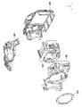
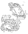
- FIG. 3 is an exploded perspective view schematically showing the assembly of the body part 100, the body side mount 200, and the front cover 300.
- FIG. 3 is an exploded perspective view schematically showing the assembly of the body part 100, the body side mount 200, and the front cover 300.
- the body part 100 has a box shape as a whole.
- the body unit 100 includes a front surface part 101 and a back surface part 102 opposite to the front surface part 101.
- the back surface portion 102 is located in the minus direction of the z-axis direction from the front surface portion 101.
- An imaging unit 160 to be described later is fixed to the back surface portion 102 of the body portion 100.
- a bracket 170 is fixed to the back surface portion 102 of the body portion 100.
- the bracket 170 is fastened to the body portion 100 at the back surface portion 102.
- An imaging unit 160 described later is fixed to the bracket 170.
- a mirror unit, a shutter unit, a finder unit, a focus detection unit, and the like are fixed to the body unit 100.
- the finder unit is fixed to the upper surface portion 104 of the body portion 100.
- the focus detection unit is fixed to the lower surface portion 105 that is the surface opposite to the upper surface portion 104 in the body portion 100.
- a power supply unit 840 and various operation members described later are attached to the front cover 300.
- the body part 100 has a fixing part 110 to which the body side mount 200 is fixed.
- the fixed part 110 protrudes from the front face part 101 in the z-axis plus direction.
- the fixed portion 110 has a first surface 150 that protrudes in the z-axis plus direction from a second surface 158 parallel to the xy plane in the front surface portion 101.
- the fixing part 110 has a substantially circular shape in the xy plane.
- the fixed part 110 has a substantially cylindrical shape.
- a concave portion 112, a concave portion 114, and a concave portion 116 are formed on the first surface 150 of the fixing portion 110.
- the recess 112 has a bottom surface 142.
- the recess 114 has a bottom surface 144.
- the recess 116 has a bottom surface 146.
- the first surface 150 is located in the z-axis plus direction from the bottom surface 142, the bottom surface 144, and the bottom surface 146.
- a convex part 113 is formed between the concave part 112 and the concave part 114.
- a convex portion 115 is formed between the concave portion 114 and the concave portion 116.
- a convex portion 111 is formed between the concave portion 116 and the concave portion 112.
- the first surface 150 forms an upper surface 151 of the convex portion 111, an upper surface 153 of the convex portion 113, and an upper surface 155 of the convex portion 115.
- a hole 121 is formed in the upper surface 151 of the convex portion 111.
- a hole 123 is formed in the upper surface 153 of the convex portion 143.
- a hole 125 is formed in the upper surface 155 of the convex portion 145.
- a screw 231 is inserted into the hole 121.
- a screw 233 is inserted into the hole 123.
- a screw 235 is inserted into the hole 125.
- a hole 122 is formed in the bottom surface 142.
- a hole 124 is formed in the bottom surface 144.
- a hole 126 is formed in the bottom surface 146.
- a screw 232 is inserted into the hole 122.
- a screw 234 is inserted into the hole 124.
- a screw 236 is inserted through the hole 126.
- the body side mount 200 includes a mounting surface 201 on which an interchangeable lens is mounted, a mount fixing surface 203 on the opposite side of the mounting surface 201, and a surface between the mounting surface 201 and the mount fixing surface 203.
- a side surface 202 and a side surface 204 opposite to the side surface 202 are provided.
- the body side mount 200 is formed with a hole 221, a hole 222, a hole 223, a hole 224, a hole 225, and a hole 226.
- the hole 221, the hole 222, the hole 223, the hole 224, the hole 225, and the hole 226 penetrate from the lens mounting surface 201 to the mount fixing surface 203.
- the hole 221, the hole 222, the hole 223, the hole 224, the hole 225, and the hole 226 are through holes that penetrate from the lens mounting surface 201 to the mount fixing surface 203 along the z-axis direction.
- the front cover 300 has a front surface portion 301, a side portion 310 that protrudes in the z-axis plus direction from the front surface portion 301 and surrounds the fixing portion 110, and a flat surface portion 340 that is parallel to the xy plane following the side portion 310. .
- the flat portion 340 has an opening 330.
- the opening 330 In the xy plane, the opening 330 has a substantially circular shape. In the xy plane, the diameter of the opening 330 is larger than the outer diameter of the fixed portion 110.
- the front cover 300 has a front cover side fastening portion 302 that protrudes from the side portion 310 to the inside of the opening 330.
- the front cover 300 includes a front cover side fastening portion 304 that protrudes from the side portion 310 to the inside of the opening 330.
- the front cover 300 includes a front cover side fastening portion 306 protruding from the side portion 310 to the inside of the opening 330.
- a hole 322 is formed in the front cover side fastening portion 302.
- a hole 324 is formed in the front cover side fastening portion 304.
- a hole 326 is formed in the front cover side fastening portion 306.
- the hole 322 is a through hole.
- the hole 324 is a through hole.
- the hole 326 is a through hole.
- a screw 232 is inserted into the hole 322.
- a screw 234 is inserted into the hole 324.
- a screw 236 is inserted through the hole 326.
- the front cover side fastening portion 302 is accommodated in the recess 112.
- the front cover side fastening portion 304 is accommodated in the recess 114.
- the front cover side fastening portion 306 is accommodated in the recess 116.
- the surface 332 of the front cover side fastening portion 302 is a surface opposite to the surface facing the bottom surface 142 of the recess 112 when the front cover side fastening portion 302 is accommodated in the recess 112.
- the surface 334 of the front cover side fastening portion 304 is a surface opposite to the surface facing the bottom surface 144 of the recess 114 when the front cover side fastening portion 304 is accommodated in the recess 114.
- the surface 336 of the front cover side fastening portion 306 is a surface opposite to the surface facing the bottom surface 146 of the recess 116 when the front cover side fastening portion 306 is accommodated in the recess 116.
- the hole 322 is formed in the surface 332 of the front cover side fastening portion 302.
- the hole 324 is formed in the surface 334 of the front cover side fastening portion 304.
- the hole 324 is formed in the surface 336 of the front cover side fastening portion 306.
- the first surface 150 and the surface 332 A plane is formed by the surface 334 and the surface 336.
- a plane parallel to the xy plane is formed by the surface 332 that the front cover side fastening portion 304 has, and the surface 334 that the front cover side fastening portion 306 has. That is, a plane including the upper surface 151, the upper surface 153, the upper surface 155, the surface 332, the surface 334, and the surface 336 is parallel to the xy plane.
- the body-side mount 200 is fastened together with the front cover 300 and the body part 100 with screws 232, screws 234, and screws 236 in contact with a plane formed by the first surface 150, the surface 332, the surface 334, and the surface 336.
- the body-side mount 200, the front cover 300, and the body portion are in a state where the mount fixing surface 203 of the body-side mount 200 is in contact with the plane formed by the first surface 150, the surface 332, the surface 334, and the surface 336. 100 is fastened together.
- the hole 322 is formed in the hole 122 on the xy plane.
- the hole 324 is positioned at the position of the hole 124
- the hole 326 is positioned at the position of the hole 126.
- the hole 221 is located at a position corresponding to the hole 121.
- the hole 222 is located at a position corresponding to the hole 122.
- the hole 223 is located at a position corresponding to the hole 123.
- the hole 224 is located at a position corresponding to the hole 124.
- the hole 225 is located at a position corresponding to the hole 125.
- the hole 226 is located at a position corresponding to the hole 126.
- the hole 221 is positioned at the position of the hole 121 on the xy plane and the hole 224 is positioned at the position of the hole 124
- the hole 222 is positioned at the hole 122 on the xy plane.
- the hole 223 is positioned at the position of the hole 123
- the hole 225 is positioned at the position of the hole 125
- the hole 226 is positioned at the position of the hole 126.
- the holes 221, 222, 223, 224, 225, and 226 of the body-side mount 200 are changed to the corresponding holes 121, 122, 123, 124, 125, and 126, respectively.
- the positioned state may be referred to as a state in which the body side mount 200 is positioned with respect to the body part 100 or the like.
- the screw 231 is inserted into the hole 221 and the hole 121, and the screw 233 is inserted into the hole 223 and the hole 123.
- the screw 235 is inserted into the hole 225 and the hole 125, and the body side mount 200 and the body part 100 are directly fastened by the screw 231, the screw 233 and the screw 235.
- the screw 232 is inserted into the hole 222, the hole 322, and the hole 122, and the screw 234 is the hole.
- the screw 236 is inserted into the hole 226, the hole 326 and the hole 126, and the body side mount 200, the front cover 300 and the body part 100 are connected by the screw 232, the screw 234 and the screw 236. It is concluded.
- the front cover side fastening portion 302, the front cover side fastening portion 304, and the front cover side fastening portion 306 are sandwiched between the body side mount 200 and the body portion 100 along the z-axis direction, and the screw 232 is placed.
- the body side mount 200 and the body part 100 are fastened together with screws 234 and screws 236.
- the front cover 300 is fastened together with the body side mount 200 and the body part 100 with screws while being sandwiched between the body side mount 200 and the body part 100 along a predetermined direction. Therefore, the front cover 300 is fixed while being sandwiched between the body-side mount 200 and the body part 100 along a predetermined direction.
- the hole 221, the hole 222, the hole 223, the hole 224, the hole 225, and the hole 226 are located on the same circumference. Specifically, the hole 221, hole 222, hole 223, hole 224, hole 225, and hole 226 are formed at positions shifted by 60 degrees around the optical axis in the xy plane. The hole 221, the hole 223, and the hole 225 are located at the vertices of an equilateral triangle. The hole 222, the hole 224, and the hole 226 are located at the vertices of an equilateral triangle.
- the body side mount 200 is fastened to the body portion 100 as a whole at six points on the same circumference. Specifically, the body-side mount 200 is directly fastened at three points on the same circumference as the body part 100 and is fastened at other three points on the same circumference with the front cover 300 interposed therebetween. The The front cover 300 is fastened to the body side mount 200 at three points, and is also fastened to the body part 100 at the same three points.
- the front cover 300 and the body part 100 are fixed to the body-side mount 200, stress is hardly transmitted from the front cover 300 to the body part 100.
- the body side mount 200, the front cover 300, and the body part 100 are fastened together, torsional stress is unlikely to occur in the body part 100. Therefore, when the front cover 300 receives stress, the body part 100 is not easily deformed. Therefore, it is possible to suppress a decrease in positioning accuracy of the imaging unit 160 that is an example of the light receiving unit.
- the front cover side fastening portion 302, the front cover side fastening portion 304, and the front cover side fastening portion 306 that the front cover 300 has are examples of exterior side fastening portions that are fastened to the body side mount 200.
- the screws 232, the screws 234, and the screws 236 are examples of first fastening members that fasten the body side mount 200, the fastening portion of the front cover 300 and the body portion 100 together.
- the screws 231, the screws 233, and the screws 235 are examples of second fastening members that fasten the body portion 100 to the body-side mount 200 without fastening the body portion 100 to the front cover 300.
- the hole 122 located on the bottom surface of the recess 112 in the fixing portion 110 is an example of a first fastening portion that is fastened together with the body side mount 200 and the front cover 300 with screws.
- the hole 121 located in the convex portion 111 in the fixing portion 110 is an example of a second fastening portion that is fastened to the body side mount 200 without being fastened to the front cover 300.
- the first fastening portion of the body portion 100 is positioned at the bottom of the recess that houses the exterior side fastening portion, and is fastened together with the body side mount 200 with screws in a state where the exterior side fastening portion is housed in the recess.
- One surface 150 and the surfaces 332, 334, and 336 of the front cover 300 form a plane that is in contact with the mount fixing surface 203 of the body-side mount 200.
- a plane may not be formed by the first surface 150 included in the body portion 100 and the surfaces 332, 334, and 336 included in the front cover 300.
- the surface shape of the surface formed by the first surface 150 of the body portion 100 and the surfaces 332, 334, and 336 of the front cover 300 corresponds to the surface shape of the mount fixing surface 203 of the body side mount 200. It may be a shape.
- the front cover side fastening portion 302, the front cover side fastening portion 304, and the front cover side fastening portion 306 may be partially accommodated in the corresponding concave portion 112, concave portion 114, and concave portion 116, respectively.
- the front cover side fastening portion 302, the front cover side fastening portion 304, and the front cover side fastening portion 306 are partly accommodated in the corresponding recess 112, recess 114, and recess 116, respectively.
- the surface 334 of the front cover side fastening portion 304 and the surface 336 of the front cover side fastening portion 306 may protrude from the first surface 150 in the z-axis plus direction. Accordingly, at least a part of the front cover side fastening portion 302, the front cover side fastening portion 304, and the front cover side fastening portion 306 may be accommodated in the corresponding concave portion 112, concave portion 114, and concave portion 116, respectively.
- the front cover 300 may be fixed to the body portion 100 as long as it is a portion in the vicinity of the portion of the body portion 100 where the body-side mount 200 is fixed.
- the front cover 300 may be fixed to a portion of the body portion 100 that protrudes in the z-axis plus direction from the front portion 301 and protrudes in the z-axis plus direction from the front portion 301.
- the side part 310 of the front cover 300 may be fixed to the fixing part 110.
- the front cover 300 is substantially parallel to a fixed surface (for example, the first surface 150) on which the body side mount 200 is fixed to the body portion 100, and is located on the optical axis side from the front surface portion 301 in the xy plane. In the case of having a surface, the plane may be fixed to the body portion 100.
- the surface 308 of the front cover 300 may be fastened to the surface 158 of the front surface portion 101.
- the front part 301 of the front cover 300 and the body part 100 may be fixed.
- the position at which the front cover 300 and the body part 100 are fixed is within a range surrounded by a rectangle in contact with the outer ring of the body-side mount 200. That is, when the distance from the optical axis to the outer ring of the body side mount 200 in the xy plane is r, the distance between the position where the front cover 300 and the body part 100 are fixed and the optical axis is the square root of 2. It is preferable that it is below the value which multiplied by r.
- the distance between the position where the front cover 300 and the body portion 100 are fixed and the optical axis is a value obtained by multiplying the square root of 2 by r. The following is preferable.
- the mounting mechanism for mounting the interchangeable lens on the body side mount 200 will be briefly described.
- the interchangeable lens is attached to the body side mount 200 by a bayonet mechanism.
- the body side mount 200 includes a claw portion 281 and a claw portion 282.
- the claw portion 281 and the claw portion 282 are used to attach the interchangeable lens to the body side mount 200.
- the body side mount 200 has three claw portions used for mounting the interchangeable lens on the mounting surface 201.
- the claw part 281 and the claw part 282 illustrated in FIG. 3 are two claw parts among the three claw parts of the body side mount 200. In some cases, the three claw portions of the body side mount 200 are simply referred to as claw portions.
- the claw portion 281 and the claw portion 282 are provided on the side surface 204 of the body side mount 200.
- the claw portion 281 and the claw portion 282 protrude toward the inside of the opening 230 of the body side mount 200.
- a stepped portion 284 is formed between the claw portion 281 and the claw portion 282 adjacent to the claw portion 281.
- the step portion 284 is a portion that does not protrude to the inside of the opening 230 on the side surface 204.
- a stepped portion similar to the stepped portion 284 is formed between the adjacent claw portions on the side surface 204 of the body side mount 200. Therefore, three step portions are formed on the side surface 204 of the body side mount 200.
- the interchangeable lens has a lens side mount for mounting on the body side mount 200.
- the lens side mount of the interchangeable lens has three claw portions for mounting the interchangeable lens on the body side mount 200.
- the three claw portions of the lens side mount of the interchangeable lens may be collectively referred to as a lens side claw portion.
- the interchangeable lens When the interchangeable lens is mounted on the body side mount 200, the interchangeable lens is mounted on the body side mount 200 in a state where the detachment index 394 provided on the front cover 300 and the detachment index provided on the interchangeable lens are aligned around the z axis. Is inserted into the opening 230. In a state where the attachment / detachment index of the interchangeable lens and the attachment / detachment index 394 are aligned, the lens side claw portion of the interchangeable lens is positioned at the step portion 284 of the body side mount 200 in the xy plane.
- the lens side claw portion of the interchangeable lens becomes the stepped portion of the body side mount 200. It passes through 284 in the negative z-axis direction and is inserted to the position behind the corresponding claw portion.
- the interchangeable lens is rotated around the z-axis in this state, the three lens side claws of the interchangeable lens enter the rear of the corresponding claws of the body side mount 200. The rotation of the interchangeable lens around the z-axis is restricted when a part of the camera mount of the interchangeable lens contacts the end 288 of the claw 281.
- the leaf spring for closely attaching the mounting surface of the lens side mount to the mounting surface 201 of the body side mount 200 is fixed by being sandwiched between the mount fixing surface 203 and the first surface 150 of the body portion 100.
- the leaf spring has a protruding portion that protrudes in the negative z-axis direction from the surface where the flat spring is fixed to the mount fixing surface 203, and the lens side mount of the interchangeable lens is biased in the negative z-axis direction by the protruding portion of the flat spring. Is done. This restricts the interchangeable lens from moving in the direction along the z-axis direction with respect to the body-side mount 200.
- the mounting surface of the lens side mount of the interchangeable lens is in close contact with the mounting surface 201 of the body side mount 200. In this way, the interchangeable lens is attached to the body side mount 200 by the bayonet mechanism.
- the mounting surface 201 is a reference surface that defines a flange back.
- the flange back is determined by the distance between the mounting surface 201 in the direction along the z-axis direction and the imaging surface of the imaging device.
- the body side mount 200 has a pin hole 290 that penetrates from the mounting surface 201 of the body side mount 200 to the mount fixing surface 203.
- a lock pin that restricts rotation of the interchangeable lens with respect to the body-side mount 200 is inserted into the pin hole 290.
- the lock pin is biased in the z-axis plus direction by the biasing force of the spring.
- the lock pin protrudes from the mounting surface 201 in the z-axis plus direction.
- a pin hole is formed in the lens side mount of the interchangeable lens.
- a part of the lock pin protruding in the z-axis plus direction from the mounting surface 201 is inserted into the pin hole of the interchangeable lens.
- the front cover 300 has an opening 390 that exposes the lock release button to the outside.
- the lock release button When the lock release button is pushed, the lock pin is displaced in the z-axis minus direction against the biasing force of the spring in conjunction with the displacement of the lock release button.
- the entire lock pin When the entire lock pin is displaced from the mounting surface 201 in the negative z-axis direction, the interchangeable lens can be rotated around the z-axis.
- the interchangeable lens When the interchangeable lens is attached to the body-side mount 200, the light that has passed through the interchangeable lens can pass inside the claw portion of the body-side mount 200.
- the claw portion of the body side mount 200 determines the diameter of the mount.
- the diameter of the mount is determined by a value that is twice the distance between the z-axis and the claw portion in the xy plane.
- the attachment / detachment indicator 394 may be colored with a color different from the surrounding color of the attachment / detachment indicator 394 in the front cover 300.
- the front cover 300 is provided with an attachment / detachment index 394.
- a similar attachment / detachment index may be provided on the body side mount 200.
- an attachment / detachment index may be formed on the attachment surface 201 of the body side mount 200.
- the attachment / detachment index 394 is formed at a location that is recessed from the mounting surface 201 of the body-side mount 200.
- the hole 221, the hole 222, the hole 223, the hole 224, the hole 225, and the hole 226 included in the body side mount 200 are located on the same circumference in the xy plane.
- the hole 222, the hole 224, and the hole 226 may be located on the same circumference.
- the hole 221, the hole 223, and the hole 225 may be located on the same circumference.
- the diameters of the circles passing through the holes 221, 223, and 225 and the diameters of the circles passing through the holes 222, 224, and 226 may be the same or different.
- the diameter of the circle passing through the center of each hole 221, hole 223, and hole 225 may be the same as the diameter of the circle passing through the center of each hole 222, hole 224, and hole 226. And may be different.
- the diameter of the circle passing through the hole 221, the hole 223, and the hole 225 is different from the diameter of the circle passing through the hole 222, the hole 224, and the hole 226, the diameter of the circle passing through the hole 222, the hole 224, and the hole 226 is It may be larger than the diameter of a circle passing through the holes 221, 223, and 225.
- the positional relationship among the holes 221, 222, 223, 224, 225, and 226 is not limited to the above-described example.
- the hole 221, the hole 222, the hole 223, the hole 224, the hole 225, and the hole 226 may be located at any position on the mounting surface 201 as long as they are formed on the mounting surface 201.
- the hole 322 may not be a through hole.
- the hole 322 may be a female screw.
- the hole 322 may be a female screw that passes through the front cover side fastening portion 302.
- the hole 324 may not be a through hole. In this case, the hole 324 may be a female screw.
- the hole 324 may be a female screw that penetrates the front cover side fastening portion 304.
- the hole 326 may not be a through hole. In this case, the hole 326 may be a female screw.
- the hole 326 may be a female screw that passes through the front cover side fastening portion 302.
- the body side mount 200 and the front cover side fastening portion 302 are fastened by screws 232. In this case, the front cover side fastening portion 302 and the body portion 100 do not have to be fastened.
- the hole 324 is a female screw
- the body side mount 200 and the front cover side fastening portion 304 are fastened by screws 234. In this case, the front cover side fastening portion 302 and the body portion 100 do not have to be fastened.
- the hole 326 is a female screw
- the body side mount 200 and the front cover side fastening portion 306 are fastened by screws 236. In this case, the front cover side fastening portion 306 and the body portion 100 do not have to be fastened.
- the holes 121, 122, 123, 124, 125, 122, and 126 may not be through holes.
- the hole 121, the hole 122, the hole 123, the hole 124, the hole 125, the hole 122, and the hole 126 may not be through holes.
- the hole 121, the hole 122, the hole 123, the hole 124, the hole 125, the hole 122, and the hole 126 may be female screws.
- the exterior of the imaging apparatus 10 is formed by the three covers of the front cover 300, the upper cover 400, and the rear cover 500.
- the exterior of the imaging device 10 may be formed by two covers.
- the exterior of the imaging device 10 may be formed by two covers.
- the body unit 100 is covered with the two covers.
- the exterior of the imaging device 10 may be formed by four covers.
- the exterior of the imaging device 10 is formed by four covers, the body unit 100 is covered by the four covers.
- the exterior of the imaging device 10 may be formed with two or more covers.
- the body side mount 200 is made of metal, and the front cover 300 is made of resin.
- the rigidity of the body side mount 200 only needs to be higher than the rigidity of the front cover 300, and the material forming the body side mount 200 is not limited to metal.
- the body side mount 200 may be formed of resin.
- the material forming the front cover 300 is not limited to resin.
- the front cover 300 may be made of metal.
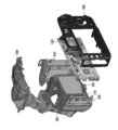
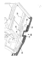
- FIG. 4 is an exploded perspective view of the imaging apparatus 10.
- FIG. 4 shows the body part 100, the front cover 300, the upper cover 400, and the rear cover 500 together with the electronic component substrate 820, the power supply unit 840, and the imaging unit 160.
- the imaging unit 160 has an imaging element that receives light from the subject.
- the imaging unit 160 is fastened to the bracket 170 and fixed to the bracket 170.
- the imaging unit 160 is fixed to the body part 100 via the bracket 170.
- the electronic component board 820 is mounted with an electronic component that processes a signal output from the image sensor included in the imaging unit 160.
- the imaging unit 160 and the electronic component board 820 are connected via a wiring board such as a flexible printed board.
- the power supply unit 840 supplies power to each unit of the imaging apparatus 10.
- the electric power from the power supply unit 840 is supplied to the electronic component board 820 via a wiring board such as a flexible printed board.
- the power from the power supply unit 840 may be supplied to the imaging unit 160 via the electronic component substrate 820.
- the substrate cover 800 is fixed to the front cover 300.
- An electronic component substrate 820 is fixed to the substrate cover 800.
- the front cover 300 is screwed at the fixing portion 110 of the body portion 100 and is rigidly connected.
- the front cover 300 is not rigidly connected to the body part 100 at portions other than the fixed part 110.
- the stress transmitted to the back surface portion 102 of the body portion 100 via the substrate cover 800, the electronic component substrate 820, and the wiring substrate is transmitted to the fixing portion 110 of the front surface portion 101. Is much smaller than the stress.
- the fixing part 110 of the body part 100 has higher rigidity than the back part 102 because the body side mount 200 is fixed to the fixing part 110. Therefore, even if stress is transmitted to the fixing part 110, the body part 100 is not greatly deformed. Therefore, the influence on the positioning accuracy of the imaging unit 160 caused by the stress applied to the front cover 300 can be significantly reduced.
- FIG. 5 is a cross-sectional view of the imaging device 10 taken along the xz plane.
- a front cover 300, an upper cover 400, and a rear cover 500 are shown.
- the front cover 300 and the upper cover 400 are connected with an inlay structure.
- the upper cover 400 has a convex portion 450 that protrudes in the z-axis plus direction from the mating surface with the front cover 300.
- the front cover 300 has a recess 350 that is recessed from the mating surface with the upper cover 400 in the z-axis plus direction.
- the front cover 300 and the upper cover 400 are connected by fitting the concave portion 350 of the front cover 300 and the convex portion 450 of the upper cover 400 together.
- the front cover 300 and the rear cover 500 are connected with an inlay structure.
- the upper cover 400 has a convex portion 460 that projects in the z-axis minus direction from the mating surface with the rear cover 500.
- the rear cover 500 has a recess 560 that is recessed in the negative z-axis direction from the mating surface with the upper cover 400.
- the rear cover 500 and the upper cover 400 are connected by fitting the concave portion 560 of the rear cover 500 and the convex portion 460 of the upper cover 400 together.
- connection portion 403 to which the front cover 300 and the upper cover 400 are connected, the front cover 300 and the upper cover 400 are connected in an inlay structure.
- connection portion 404 where the rear cover 500 and the upper cover 400 are connected, the rear cover 500 and the upper cover 400 are connected in an inlay structure.
- the front cover 300 and the rear cover 500 are connected in an inlay structure even at the mating surface between the front cover 300 and the rear cover 500.
- the front cover 300 and the upper cover 400 are connected in an inlay structure along the mating surface of the front cover 300 and the upper cover 400.
- the upper cover 400 and the rear cover 500 are connected in an inlay structure along the mating surface of the upper cover 400 and the rear cover 500.
- the front cover 300 and the rear cover 500 are connected in an inlay structure along the mating surface of the front cover 300 and the rear cover 500.
- the front cover 300, the upper cover 400, and the rear cover 500 are connected in an inlay structure along the mating surface with the other cover. Therefore, when a stress is applied to any of the front cover 300, the upper cover 400, and the rear cover 500, it is possible to suppress a shift that occurs in a direction parallel to the mating surface with the other cover.
- the exterior part formed by the front cover 300, the upper cover 400, and the rear cover 500 has a monocoque structure that handles stress.
- the front cover 300, the upper cover 400, and the rear cover 500 have mating surfaces that are connected to each other in an inlay structure. Even so, the monocoque structure can be maintained.
- the weight of the body part 100 is substantially the same as the weight of the other member which the imaging device 10 has.
- the weight of the body portion 100 is substantially the same as the weight of other members of the imaging device 10.
- the error between the weight of the body part 100 and the weight of other members is preferably within 5%.
- the body part 100 is heavier than another member.
- FIG. 6 is an exploded perspective view schematically showing the assembly of the front cover 300, the upper cover 400, the rear cover 500, and the hanging ring 600.
- FIG. 7 is an exploded perspective view showing a state in which the suspension ring 600 is positioned on the upper cover 400.
- the rear cover 500 has a screw hole 511, a screw hole 512, a screw hole 513, a screw hole 514, and a screw hole 515.
- Screw hole 511, screw hole 512, screw hole 513, screw hole 514, and screw hole 515 are each formed along the z-axis direction.
- the upper cover 400 has a screw hole 413, a screw hole 414, and a screw hole 415.
- the screw hole 413, the screw hole 414, and the screw hole 415 are each formed along the z-axis direction.
- the front cover 300 has a screw hole 311 and a screw hole 312.
- the screw hole 311 and the screw hole 312 are each formed along the z-axis direction.
- the upper cover 400 and the rear cover 500 position the screw hole 413 and the screw hole 513, position the screw hole 414 and the screw hole 514, and position the screw hole 415 and the screw hole 515, respectively. It is concluded.
- the front cover 300 and the rear cover 500 are fastened with screws in a state where the screw holes 311 and the screw holes 511 are positioned.
- a suspension ring 600 is fixed to the front cover 300 and the rear cover 500.
- the hanging ring 600 is made of metal.
- the hanging ring 600 is a metal fitting for attaching a strap for hanging the imaging device 10.
- the suspension ring 600 includes a front side fastening part 610, a rear side fastening part 620, a connecting part 630 that connects the front side fastening part 610 and the rear side fastening part 620, and an annular part 640.
- the suspension ring 600 is fixed in a state where the annular portion 640 protrudes from the opening 480 formed in the upper cover 400.
- a strap can be attached to the annular portion 640.
- the strap may be attached to the annular portion 640 via an attachment fitting such as a triangular ring to which the strap is attached.
- the front side fastening part 610 is located in the z-axis plus direction from the rear side fastening part 620.
- the front side fastening portion 610 extends from the connecting portion 630 in the positive y-axis direction and has a surface parallel to the xy plane.
- the rear side fastening portion 620 extends from the connecting portion 630 in the negative y-axis direction and has a surface parallel to the xy plane.
- the connecting portion 630 extends in the z-axis direction.
- the connection part 630 connects the upper part of the front side fastening part 610 and the lower part of the rear side fastening part 620.
- the front side fastening portion 610 has a screw hole 612 formed along the z-axis direction.
- the rear side fastening portion 620 has a screw hole 622 formed along the z-axis direction.
- the front cover 300 and the suspension ring 600 are fastened with screws in a state where the screw holes 312 and the screw holes 612 are positioned.
- the suspension ring 600 and the rear cover 500 are fastened with screws in a state where the screw holes 622 and the screw holes 512 are positioned.
- the front cover 300 and the rear cover 500 are fixed via the suspension ring 600.
- the upper cover 400 and the rear cover 500 have mating surfaces that are substantially orthogonal to the z-axis direction. Then, the upper cover 400 and the rear cover 500 are fastened by screws having fastening shafts along the z-axis direction. Similarly, the front cover 300 and the rear cover 500 have mating surfaces that are substantially orthogonal to the z-axis direction. The front cover 300 and the rear cover 500 are fastened by screws having fastening shafts along the z-axis direction. For this reason, the slip on the mating surface can be further suppressed. Although not shown in FIGS. 6 and 7, the front cover 300 and the upper cover 400 are fastened by a screw having a fastening shaft along the z-axis direction.
- the front cover 300, the upper cover 400, and the rear cover 500 have fastening shafts that are orthogonal to each other's mating surfaces, so that stress applied to one of the covers can be transmitted to the other cover properly. it can. Therefore, the monocoque structure can be maintained even if the exterior portion is formed of a plurality of members such as the front cover 300, the upper cover 400, and the rear cover 500. Therefore, the stress applied to any one of the front cover 300, the upper cover 400, and the rear cover 500 can be distributed to other covers. For example, when a stress is applied to the rear cover 500 from the outside, the stress applied from the outside to the rear cover 500 can be distributed to the front cover 300 and the upper cover 400. Therefore, the stress value received by the rear cover 500 can be reduced.
- the imaging device 10 can be reduced in weight. Further, even if there are some dimensional errors in the front cover 300, the upper cover 400, and the rear cover 500, the covers can be aligned with each other with no gaps. Therefore, the quality on the external appearance of the imaging device 10 can be improved.
- one end of the suspension ring 600 is fixed to the front cover 300, and the other end of the suspension ring 600 is fixed to the rear cover 500.
- stress is applied to the suspension ring 600 from the attached strap, since the suspension ring 600 is fixed to both the front cover 300 and the rear cover 500, the stress applied to the suspension ring 600 is applied to the front cover 300 and the rear cover 500. Can be dispersed.
- screw holes for fastening the front cover 300, the upper cover 400, and the rear cover 500 to each other are provided at corners as an overall appearance shape of the imaging device 10.
- the imaging device 10 has a box shape as a whole, but in the rear cover 500, the screw holes 511 and the screw holes 512 are provided at corners of the box shape. Therefore, stress can be distributed to two sides, and the number of fastening members such as screws can be reduced.
- the screw hole 513 and the screw hole 514 are provided at corners of the finder opening 590 included in the upper cover 400. In the upper cover 400, the screw hole 413 and the screw hole 414 are located in the vicinity of the accessory shoe 470.
- the screw hole 413 and the screw hole 414 are arranged at positions where stress can be dispersed when an external accessory is attached to the accessory shoe 470 and stress is applied.
- the screw hole 413 and the screw hole 414 are arranged at a place where a stress applied from an external accessory attached to the accessory shoe 470 is higher than a predetermined value.
- the screw hole 413 and the screw hole 414 are disposed in the vicinity of a stress line applied from an external accessory.
- FIG. 8 is an exploded perspective view schematically showing the assembly of the front cover 300, the rear cover 500, and the tripod base 700.
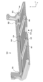
- FIG. 9 is a cross-sectional view of the yz section schematically showing a state in which the tripod base 700 is assembled to the front cover 300 and the rear cover 500.
- the front cover 300 has a rib 381 and a rib 382 on the mounting surface 370 on which a part of the tripod base 700 is mounted.
- the ribs 381 and the ribs 382 are provided apart from each other in the x-axis direction.
- the ribs 381 and the ribs 382 extend in the direction toward the position of the fixing portion 110.
- the tripod seat 700 is accommodated with a part sandwiched between the rib 381 and the rib 382.
- the front cover 300 further includes a rib 383 and a rib 384 extending to the fixing portion 110.
- the rib 383 and the rib 384 are located between the rib 381 and the rib 382 in the x-axis direction.
- the rib 383 and the rib 384 are located between the position where the tripod seat 700 is fixed and the fixing portion 110 in the z-axis direction.
- a screw hole 371 and a screw hole 372 are formed in the mounting surface 370.
- a notch 375 having a semicircular shape in the xz plane is formed.
- the mounting surface 570 includes a rib 581 and a rib 582.
- the rib 581 and the rib 582 extend in the z-axis direction.
- the rib 581 is adjacent to the rib 381 at the position of the rib 381 in the negative x-axis direction.
- the rib 582 is adjacent to the rib 382 at a position in the x-axis plus direction of the rib 382.
- the height at which the ribs 381 and ribs 382 protrude from the placement surface 370 is preferably higher than the height at which the ribs 581 and ribs 582 protrude from the placement surface 570.
- the mounting surface 570 is formed with a notch 575 having a semicircular shape in the xz plane.
- the cutout portion 375 and the cutout portion 575 are formed with an accommodation port 585 that accommodates a mounting portion 770 for attaching a tripod to the tripod seat 700.
- a screw hole 701, a screw hole 702, a screw hole 703, and a screw hole 704 are formed in the tripod seat 700.
- the screw hole 701 corresponds to the screw hole 371
- the screw hole 702 corresponds to the screw hole 372
- the screw hole 703 corresponds to the screw hole 573
- the screw hole 704 corresponds to the screw hole 574.
- the screw hole 701 is positioned at the position of the screw hole 371 in a state where the tripod seat 700 is sandwiched between the rib 381 and the rib 382 and placed on the placement surface 370. Is positioned at the position of the screw hole 372.
- the screw hole 703 is positioned at the position of the screw hole 573
- the screw hole 704 is positioned at the position of the screw hole 574.
- the rib 381 and the rib 382 protrude in the z-axis minus direction from the edge portion of the placement surface 370 located in the z-axis minus direction.
- the rib 581 and the rib 582 protrude in the z-axis plus direction from the edge portion of the placement surface 570 located in the z-axis plus direction. Therefore, it is possible to suppress the portion where the front cover 300 and the rear cover 500 are connected from being deformed in a direction away from the tripod seat 700.
- one end of the tripod base 700 is fixed to the front cover 300, and the other end of the tripod base 700 is fixed to the rear cover 500.
- stress is applied to the tripod seat 700 from the mounted tripod, since the tripod seat 700 is fastened to both the front cover 300 and the rear cover 500, the stress applied to the tripod seat 700 is applied to the front cover 300 and the rear cover 500. Can be dispersed.
- the front cover 300 includes the rib 381, the rib 382, the rib 383, and the rib 384, the front cover 300 can be prevented from being deformed by the stress applied via the tripod seat 700.
- the rib 381, the rib 382, the rib 383, and the rib 384 extend from the vicinity of the portion where the tripod seat 700 is fixed to the vicinity of the fixing portion 110. Therefore, it is possible to suppress the local concentration of stress between the portion where the tripod seat 700 is fixed and the fixing portion 110 and the front cover 300 being locally bent.
- the length of the tripod seat 700 in the z-axis direction is longer than the length of the tripod seat 700 in the x-axis direction. In order to avoid concentration of stress applied from the tripod base 700, it is more desirable that the length of the tripod base 700 in the z-axis direction is longer. It is more desirable that the tripod seat 700 extends closer to the fixed portion 110.
- the rib 381, the rib 382, the rib 383, and the rib 384 are formed so as not to be welded.
- the weld line does not intersect the extending direction of the rib 381, the rib 382, the rib 383, and the rib 384.
- the gate it is preferable to arrange the gate so that the resin flows in parallel with the extending direction of the ribs 381, ribs 382, ribs 383 and ribs 384.
- the gate gate connected from the fixing part 110 to the rib 381, the rib 382, the rib 383, and the rib 384 is disposed in the mold.
- FIG. 10 is a perspective view showing a part of the rear cover 500.
- FIG. 10 specifically shows the opening 520 and the bottom of the rear cover 500.
- the opening 520 is an opening for exposing the display surface of the display device to the outside from the imaging device 10.
- the rear cover 500 has a rib 540 located below the opening 520.
- the rib 540 extends in the x-axis direction.
- the length of the rib 540 in the x-axis direction is longer than the length of the opening 520 in the x-axis direction.
- the rib 540 extends in the x-axis minus direction from the end of the opening 520 in the x-axis minus direction.
- the rib 540 extends to the fastening portion 521 in which the screw hole 511 is formed.
- a support portion 551 and a support portion 552 for supporting the display device are provided on the rib 540.
- the support unit 551 and the support unit 552 contact the lower part of the display device to support the display device.
- the rib 581 and the rib 582 extend to the rib 540. Therefore, local concentration of stress on the mounting surface 570 can be suppressed.
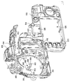
- FIG. 11 is an exploded perspective view schematically showing another example of assembling the tripod mount.
- a tripod seat fixing member 1180 to which the tripod seat 1170 is fixed is fastened together with the body side mount 200 and the body portion 1100.
- the body side mount 200 has the same configuration as the body side mount 200 described in relation to FIGS.
- Body portion 1100 is formed of resin, as is body portion 100.
- Tripod seat fixing member 1180 and tripod seat 1170 are made of metal.
- the tripod seat 1170 is a mounting bracket for attaching a tripod.
- the tripod seat fixing member 1180 has a fixing portion 1150 and a tripod seat mounting portion 1140.
- the tripod seat fixing member 1180 has an L shape as a whole when cut along the yz plane. When the tripod seat fixing member 1180 and the body portion 1100 are aligned, the tripod seat mounting portion 1140 is positioned below the body portion 1100.
- the tripod seat mounting portion 1140 is formed with four female screws 114 female screws 1141, female screws 1142, female screws 1143, and female screws 1144.
- the tripod seat 1170 is formed with four holes including a hole 1172, a hole 1173, and a hole 1174 which are through holes.
- the four screw holes formed in the tripod seat mounting portion 1140 correspond to the corresponding four holes 1172 formed in the tripod seat 1170. It is positioned at the position of one hole.
- the internal thread 1142 is positioned at the position of the hole 1172
- the internal thread 1143 is positioned at the position of the hole 1173
- the internal thread 1144 is positioned at the position of the hole 1174.
- the screw 1181 is inserted to the female screw 1141
- the screw 1182 is inserted to the female screw 1142
- the screw 1183 is inserted to the female screw 1143
- the screw 1184 is inserted to the female screw 1144
- the tripod seat 1170 is attached to the tripod seat mounting portion 1140.
- a female screw 1121, a female screw 1122, a female screw 1123, a female screw 1124, a female screw 1125, and a female screw 1126 are formed on the fixing portion 1110 of the body portion 1100.
- the fixing portion 1150 of the tripod seat fixing member 1180 is formed with a hole 1151, a hole 1152, a hole 1153, a hole 1154, a hole 1155, and a hole 1156 that are through holes.
- the body side mount 200, the fixing portion 1150, and the fixing portion 1110 have ring shapes corresponding to each other.
- the body side mount 200, the fixing portion 1150, and the fixing portion 1110 have six screw holes that are positioned at the same position in the xy plane when aligned with each other.
- the body side mount 200, the fixing portion 1150, and the fixing portion 1110 are fastened together with screws 231, 232, 233, 234, 235, and 236 while being aligned with each other.
- the tripod mount fixing member 1180 is fixed to the body side mount 200 and the body part 1100 in a state where the fixing part 1150 is sandwiched between the body side mount 200 and the body part 1100.
- the screw 231 is inserted into the hole 221, the female screw 1121, and the hole 1151 while being aligned with each other.
- a screw 232 is inserted into the hole 222, the female screw 1122, and the hole 1152 while being aligned with each other.
- a screw 233 is inserted into the hole 223, the female screw 1123, and the hole 1153 while being aligned with each other.
- a screw 234 is inserted through the hole 224, the female screw 1124, and the hole 1154 while being aligned with each other.
- a screw 235 is inserted into the hole 225, the female screw 1125, and the hole 1155 in a state of being aligned with each other.
- a screw 236 is inserted through the hole 226, the female screw 1126, and the hole 1156 while being aligned with each other.
- the tripod fixing member 1180 is fixed to the body side mount 200.
- the body-side mount 200, the tripod seat fixing member 1180, and the body portion 1100 are fixed to each other at six points located on the same circumference. Therefore, the stress applied to the tripod seat 1170 from the tripod can be received by the body side mount 200 via the tripod seat fixing member 1180.
- the front cover 300 may be fixed in the vicinity of the fixing portion 1110.
- the same configurations as those described with reference to FIGS. 1 to 10 can be applied.
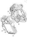
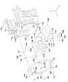
- FIG. 12 is an exploded perspective view schematically showing another example of assembling the tripod mount.
- elements similar to those described in relation to FIG. 11 may be denoted by the same reference numerals and description thereof may be omitted.
- the body-side mount 1200 has a hole 221, a hole 222, a hole 223, a hole 224, a hole 225, a hole 226, a hole 227, and a hole 228.
- the body side mount 1200 is different from the body side mount 200 in that a hole 227 and a hole 228 are formed.
- the body-side mount 1200 may have the same configuration as the body-side mount 200.
- the tripod seat fixing member 1280 includes a fixing portion 1250 and a tripod seat mounting portion 1140. A hole 1254, a female screw 1257, and a female screw 1258 are formed in the fixing portion 1250 of the tripod seat fixing member 1280.
- the screw 231 is inserted through the hole 221 and the female screw 1121.
- the screw 232 is inserted into the hole 222 and the female screw 1122.
- the screw 233 is inserted into the hole 223 and the female screw 1123.
- the screw 234 is inserted into the hole 224, the hole 1254, and the female screw 1124.
- the screw 235 is inserted through the hole 225 and the female screw 1125.
- the screw 236 is inserted through the hole 226 and the female screw 1126.
- Screw 237 is inserted through hole 227 and female screw 1257.
- the screw 238 is inserted into the hole 228 and the female screw 1258.
- the body side mount 1200 and the tripod seat fixing member 1280 are also fastened by the screws 237 and 238.
- the stress applied to the tripod seat 1170 can be received by the body side mount 1200 via the tripod seat fixing member 1280.
- the imaging unit 160 having an imaging element has been described as an example of a light receiving unit that receives light that has passed through the interchangeable lens.
- the light receiving unit may be a focus detection unit having a sensor for detecting a focused state from a subject.
- the sensor of the focus detection unit may be a line sensor that detects a phase difference.
- the light receiving unit may be a finder unit.
- the finder unit may have a photometric unit including a photometric sensor for measuring the amount of light from the subject.
- the finder unit may have a focus plate.
- one or more arbitrary combinations of light receiving units among the imaging unit 160, the finder unit, and the focus detection unit as an example of the light receiving unit may be fixed to the body unit 100.
- only one light receiving unit may be fixed to the body portion 100.
- only the imaging unit 160 may be fixed to the body unit 100.
- Only the finder unit may be fixed to the body portion 100.
- Only the focus detection unit may be fixed to the body portion 100.
- the imaging device 10 may not have a light receiving unit other than the light receiving unit fixed to the body portion 100.
- the imaging device 10 may include only the imaging unit 160 as a light receiving unit, and the imaging unit 160 included in the imaging device 10 may be fixed to the body unit 100.
- two light receiving units may be fixed to the body portion 100.
- only the imaging unit 160 and the finder unit may be fixed to the body unit 100.
- Only the imaging unit 160 and the focus detection unit may be fixed to the body unit 100.
- Only the finder unit and the focus detection unit may be fixed to the body unit 100.
- the imaging device 10 may not have a light receiving unit other than the light receiving unit fixed to the body portion 100.
- the imaging apparatus 10 may include only the imaging unit 160 and the finder unit as the light receiving unit, and the imaging unit 160 and the finder unit included in the imaging apparatus 10 may be fixed to the body unit 100.
- the imaging device 10 may include only the imaging unit 160 and the focus detection unit as light receiving units, and the imaging unit 160 and the focus detection unit included in the imaging device 10 may be fixed to the body unit 100.
- three light receiving units may be fixed to the body portion 100.
- the imaging device 10 may not have a light receiving unit other than the light receiving unit fixed to the body unit 100.
- the imaging device 10 may include only the imaging unit 160, the finder unit, and the focus detection unit as the light receiving unit, and the imaging unit 160, the finder unit, and the focus detection unit included in the imaging device 10 may be fixed to the body unit 100.
- the imaging apparatus 10 may further include a light receiving unit other than the imaging unit 160, the finder unit, and the focus detection unit. That is, the imaging device 10 may further include one or more light receiving units that are not fixed to the body unit 100.
- the configuration of the imaging apparatus has been described by taking up the camera body without the lens apparatus.
- the imaging device may include a lens unit and a camera main body.
- various types of interchangeable lens cameras can be applied to the imaging apparatus.
- the imaging device is an example of a light receiving device.
- the light receiving device is not limited to the imaging device, and may be a device other than the imaging device.
- Imaging device 100 Body part 101 Front part 102 Back part 110 Fixed part 111,113,115 Protrusion part 112,114,116 Concave part 121,122,123,124,125,126 Hole 142 Bottom face 143 Convex part 144 Bottom face 145 Convex part 146 Bottom surface 150 First surface 151, 153, 155 Top surface 158 surface 160 Imaging unit 170 Bracket 200 Body side mount 201 Mounting surface 202, 204 Side surface 203 Mount fixing surface 221, 222, 223, 224, 225, 226, 227, 228 Hole 230 Openings 231, 232, 233, 234, 235, 236, 237, 238 Screws 281 and 282 Claw portion 284 Step portion 288 End portion 290 Pin hole 300 Front cover 301 Front surface portion 310 Side portions 311 and 312 Screw holes 302 and 304, 306 Front cover side Fastening portion 308, 332, 334, 336 Surface 322, 324, 326 Hole 330 Opening 340 Flat
Abstract
Description
[先行技術文献]
[特許文献]
[特許文献1] 特開2005-215014号公報
100 ボディ部
101 前面部
102 背面部
110 固定部
111、113、115 凸部
112、114、116 凹部
121、122、123、124、125、126 孔
142 底面
143 凸部
144 底面
145 凸部
146 底面
150 第1面
151、153、155 上面
158 面
160 撮像ユニット
170 ブラケット
200 ボディ側マウント
201 装着面
202、204 側面
203 マウント固定面
221、222、223、224、225、226、227、228 孔
230 開口
231、232、233、234、235、236、237、238 ビス
281、282 爪部
284 段差部
288 端部
290 ピン孔
300 前カバー
301 前面部
310 側部
311、312 ビス孔
302、304、306 前カバー側締結部
308、332、334、336 面
322、324、326 孔
330 開口
340 平面部
350 凹部
370 載置面
371、372 ビス孔
375 切欠部
381、382、383、384 リブ
390 開口
394 着脱指標
400 上カバー
401、402、403、404 接続部
413、414、415 ビス孔
450、460 凸部
470 アクセサリシュー
480 開口部
500 後カバー
511、512、513、514、515 ビス孔
520 開口部
521 締結部
540 リブ
551、552 支持部
560 凹部
570 載置面
573、574 ビス孔
575 切欠部
581、582 リブ
585 収容口
590 ファインダ部開口
600 吊り環
610 前側締結部
612 ビス孔
620 後側締結部
622 ビス孔
630 連結部
640 環状部
700 三脚座
701、702、703、704 ビス孔
770 取付部
800 基板カバー
820 電子部品基板
840 電源ユニット
1100 ボディ部
1110 固定部
1121、1122、1123、1124、1125、1126 めねじ
1140 三脚座取付部
1141、1142、1143、1144 めねじ
1150 固定部
1151、1152、1153、1154、1155、1156 孔
1170 三脚座
1172、1173、1174 孔
1180 三脚座固定部材
1181、1182、1183、1184 ビス
1200 ボディ側マウント
1250 固定部
1254 孔
1257、1258 めねじ
1280 三脚座固定部材
Claims (26)
- 第1受光ユニットと、
前記第1受光ユニットが固定されているボディ部と、
前記ボディ部の少なくとも一部を覆う第1外装部と、
交換レンズを装着可能であり、前記ボディ部及び前記第1外装部が固定されているマウントとを備えること
を特徴とする受光装置。 - 交換レンズを装着可能なマウントに、第1受光ユニットが固定されているボディ部と、前記ボディ部の少なくとも一部を覆う第1外装部とが固定されており、
前記第1外装部に加えられた力の前記ボディ部への伝達を軽減するように、前記第1外装部に加えられた前記力を前記マウントにより受け止めること
を特徴とする受光装置。 - 請求項1または2に記載の受光装置において、
前記ボディ部は、前記第1外装部を介在して前記マウントに締結されていること
を特徴とする受光装置。 - 請求項3に記載の受光装置において、
前記ボディ部及び前記第1外装部は、前記マウントに共締めされていること
を特徴とする受光装置。 - 請求項4に記載の受光装置において、
前記マウントは、前記ボディ部及び前記第1外装部を第1締結部材により共締めするためのマウント側第1孔と、前記ボディ部及び前記第1外装部を第2締結部材により共締めするためのマウント側第2孔と、前記ボディ部及び前記第1外装部を第3締結部材により共締めするためのマウント側第3孔とを有し、前記マウント側第1孔と前記マウント側第2孔と前記マウント側第3孔とが同一円周上に配置されていること
を特徴とする受光装置。 - 請求項5に記載の受光装置において、
前記第1外装部は、開口と、前記開口の内側へ突出して設けられている第1締結部と、前記開口の内側へ突出して設けられている第2締結部と、前記開口の内側へ突出して設けられている第3締結部とを有し、
前記マウントには、前記第1締結部材により前記マウント側第1孔と前記第1締結部が有する第1貫通孔とを介して前記ボディ部及び前記第1締結部が共締めされ、前記第2締結部材により前記マウント側第2孔と前記第2締結部が有する第2貫通孔とを介して前記ボディ部及び前記第2締結部が共締めされ、前記第3締結部材により前記マウント側第3孔と前記第3締結部が有する第3貫通孔とを介して前記ボディ部及び前記第3締結部が共締めされること
を特徴とする受光装置。 - 請求項6に記載の受光装置において、
前記ボディ部において前記マウントに対向する面であるボディ側第1面には、第1凹部と、第2凹部と、第3凹部とを有し、
前記第1凹部の底部はボディ側第1孔を有し、前記第2凹部の底部はボディ側第2孔を有し、前記第3凹部の底部はボディ側第3孔を有し、
前記マウントには、前記第1締結部の少なくとも一部が前記第1凹部に収容された状態で、前記第1締結部材により前記マウント側第1孔と前記第1貫通孔と前記ボディ側第1孔とを介して前記ボディ部及び前記第1締結部が共締めされ、前記第2締結部の少なくとも一部が前記第2凹部に収容された状態で、前記第2締結部材により前記マウント側第2孔と前記第2貫通孔と前記ボディ側第2孔とを介して前記ボディ部及び前記第2締結部が共締めされ、前記第3締結部の少なくとも一部が前記第3凹部に収容された状態で、前記第3締結部材により前記マウント側第3孔と前記第3貫通孔と前記ボディ側第3孔とを介して前記ボディ部及び前記第3締結部が共締めされること
を特徴とする受光装置。 - 請求項7に記載の受光装置において、
前記第1締結部は、前記第1締結部が前記第1凹部に収容された状態において前記マウントに対向する面である第1外装側第1面を有し、
前記第2締結部は、前記第2締結部が前記第2凹部に収容された状態において前記マウントに対向する面である第1外装側第2面を有し、
前記第3締結部は、前記第3締結部が前記第3凹部に収容された状態において前記マウントに対向する面である第1外装側第3面を有し、
前記第1締結部が前記第1凹部に収容され、前記第2締結部が前記第2凹部に収容され、前記第3締結部が前記第3凹部に収容された状態において、前記ボディ側第1面と、前記第1外装側第1面と、前記第1外装側第2面と、前記第1外装側第3面とにより平面が形成され、
前記マウントには、前記ボディ側第1面と前記外装側第1面と前記外装側第2面と前記外装側第3面とにより形成される前記平面に前記マウントが接した状態で、前記第1締結部材により前記マウント側第1孔と前記第1貫通孔と前記ボディ側第1孔とを介して前記ボディ部及び前記第1締結部が共締めされ、前記第2締結部材により前記マウント側第2孔と前記第2貫通孔と前記ボディ側第2孔とを介して前記ボディ部及び前記第2締結部が共締めされ、前記第3締結部材により前記マウント側第3孔と前記第3貫通孔と前記ボディ側第3孔とを介して前記ボディ部及び前記第3締結部が共締めされること
を特徴とする受光装置。 - 請求項8に記載の受光装置において、
前記ボディ部は、前記ボディ側第1面において前記第1外装部を介在せずに前記マウントに締結されていること
を特徴とする受光装置。 - 請求項5から請求項9のいずれか一項に記載の受光装置において、
前記マウントは、前記第1外装部を介在せずに前記ボディ部を第4締結部材により締結するためのマウント側第4孔を有すること
を特徴とする受光装置。 - 請求項10に記載の受光装置において、
前記マウントは、前記第1外装部を介在せずに前記ボディ部を第5締結部材により締結するためのマウント側第5孔と、前記第1外装部を介在せずに前記ボディ部を第6締結部材により締結するためのマウント側第6孔とを有し、前記マウント側第4孔と前記マウント側第5孔と前記マウント側第6孔とが同一円周上に配置されていること
を特徴とする受光装置。 - 請求項11に記載の受光装置において、
前記マウント側第1孔と前記マウント側第2孔と前記マウント側第3孔と前記マウント側第4孔と前記マウント側第5孔と前記マウント側第6孔とが同一円周上に配置されていること
を特徴とする受光装置。 - 請求項12に記載の受光装置において、
前記第1受光ユニットから出力された信号を処理する電子部品が実装された実装基板
をさらに備え、
前記第1受光ユニットは、フレキシブル基板を介して前記実装基板に接続されること
を特徴とする受光装置。 - 請求項1または2に記載の受光装置において、
前記第1外装部は、前記マウントの第1の位置に固定され、
前記マウントの第2の位置が前記ボディ部に固定されること
を特徴とする受光装置。 - 請求項1から14のいずれか一項に記載の受光装置において、
前記第1外装部は、前記マウントに固定されている部位以外の部位において、前記ボディ部に剛接続されていないこと
を特徴とする受光装置。 - 請求項1から15のいずれか一項に記載の受光装置において、
前記第1外装部以外の第2外装部は、前記第1外装部に固定されていること
を特徴とする受光装置。 - 請求項1から15のいずれか一項に記載の受光装置において、
前記第1外装部に締結され、前記ボディ部とは締結されていない第2外装部
をさらに備えること
を特徴とする受光装置。 - 請求項16または17に記載の受光装置において、
前記第1外装部は、第1外面および前記第1外面に続く第1側面を有し、
前記第2外装部は、第2外面および前記第2外面に続く第2側面を有し、
前記第1外装部と前記第2外装部とは、前記第1外装部の前記第1側面および前記第2外装部の前記第2側面を合わせ面として、前記合わせ面に直交する方向に締結軸を持つ締結部材により締結されること
を特徴とする受光装置。 - 請求項18に記載の受光装置において、
前記第1外装部の前記第1側面と前記第2外装部の前記第2側面とはインロー構造で接すること
を特徴とする受光装置。 - 請求項16から19のいずれか一項に記載の受光装置において、
前記第1外装部の剛性および前記第2外装部の剛性より高い剛性を有し、外部装置を取り付ける取付部
をさらに備え、
前記取付部は、前記第1外装部および前記第2外装部に締結されること
を特徴とする受光装置。 - 請求項20に記載の受光装置において、
前記取付部は、前記受光装置を支える三脚が取り付けられる三脚座であること
を特徴とする受光装置。 - 請求項20に記載の受光装置において、
前記取付部は、前記受光装置を吊り下げる吊下部材が取り付けられる吊り環であること
を特徴とする受光装置。 - 請求項20から22のいずれか一項に記載の受光装置において、
前記第1外装部は、前記取付部が締結された位置から前記マウントが締結された位置へ向かう方向に延伸するリブを有すること
を特徴とする受光装置。 - 請求項1から23のいずれか一項に記載の受光装置において、
前記第1外装部および前記ボディ部は樹脂で形成され、
前記マウントは、金属で形成されること
を特徴とする受光装置。 - 請求項1から24のいずれか一項に記載の受光装置において、
前記第1受光ユニットは、前記マウントに装着された前記交換レンズを通過した光を受光する撮像素子を含む撮像ユニットであること
を特徴とする受光装置。 - 請求項1から25のいずれか一項に記載の受光装置において、
前記ボディ部に固定された第2受光ユニットをさらに備えること
を特徴とする受光装置。
Priority Applications (5)
| Application Number | Priority Date | Filing Date | Title |
|---|---|---|---|
| JP2015505266A JP6459961B2 (ja) | 2013-03-15 | 2014-03-03 | 受光装置 |
| CN201480026511.9A CN105229528A (zh) | 2013-03-15 | 2014-03-03 | 受光装置 |
| US14/854,808 US10237457B2 (en) | 2013-03-15 | 2015-09-15 | Light receiving apparatus having body and exterior portion secured to mount |
| US16/268,830 US11550206B2 (en) | 2013-03-15 | 2019-02-06 | Light receiving apparatus with shock resistance |
| US18/072,141 US20230161231A1 (en) | 2013-03-15 | 2022-11-30 | Light receiving apparatus |
Applications Claiming Priority (2)
| Application Number | Priority Date | Filing Date | Title |
|---|---|---|---|
| JP2013054441 | 2013-03-15 | ||
| JP2013-054441 | 2013-03-15 |
Related Child Applications (1)
| Application Number | Title | Priority Date | Filing Date |
|---|---|---|---|
| US14/854,808 Continuation US10237457B2 (en) | 2013-03-15 | 2015-09-15 | Light receiving apparatus having body and exterior portion secured to mount |
Publications (1)
| Publication Number | Publication Date |
|---|---|
| WO2014141624A1 true WO2014141624A1 (ja) | 2014-09-18 |
Family
ID=51536304
Family Applications (1)
| Application Number | Title | Priority Date | Filing Date |
|---|---|---|---|
| PCT/JP2014/001157 WO2014141624A1 (ja) | 2013-03-15 | 2014-03-03 | 受光装置 |
Country Status (4)
| Country | Link |
|---|---|
| US (3) | US10237457B2 (ja) |
| JP (3) | JP6459961B2 (ja) |
| CN (2) | CN105229528A (ja) |
| WO (1) | WO2014141624A1 (ja) |
Cited By (1)
| Publication number | Priority date | Publication date | Assignee | Title |
|---|---|---|---|---|
| JP2018010040A (ja) * | 2016-07-11 | 2018-01-18 | 株式会社ザクティ | 撮像装置 |
Families Citing this family (5)
| Publication number | Priority date | Publication date | Assignee | Title |
|---|---|---|---|---|
| WO2014141624A1 (ja) * | 2013-03-15 | 2014-09-18 | 株式会社ニコン | 受光装置 |
| JP6521023B2 (ja) * | 2017-10-26 | 2019-05-29 | 株式会社ニコン | アクセサリ |
| CN109946904B (zh) * | 2018-12-25 | 2021-10-29 | 卓曜(北京)科技有限公司 | 拍摄设备的卡口、转接环以及拍摄设备 |
| DK3916351T3 (da) * | 2020-05-29 | 2024-02-26 | Leica Geosystems Ag | Kamerahus med mekanisk fmc-stabilisering til en luft- eller rumbåren opmålingsanordning |
| JP1709630S (ja) * | 2021-01-19 | 2022-03-11 | デジタルカメラ本体 |
Citations (10)
| Publication number | Priority date | Publication date | Assignee | Title |
|---|---|---|---|---|
| JPH0961930A (ja) * | 1995-08-30 | 1997-03-07 | Canon Inc | カメラのフィルムカートリッジ室 |
| JPH09230548A (ja) * | 1996-02-22 | 1997-09-05 | Fuji Photo Film Co Ltd | レンズ付きフイルムユニット |
| JPH1170013A (ja) * | 1997-08-29 | 1999-03-16 | Asahi Optical Co Ltd | ストラップの着脱具 |
| JPH11174562A (ja) * | 1997-12-17 | 1999-07-02 | Canon Inc | カメラ、カメラアクセサリおよびカメラシステム |
| JP2005322717A (ja) * | 2004-05-07 | 2005-11-17 | Olympus Corp | 電子機器の筐体構造 |
| JP2006251058A (ja) * | 2005-03-08 | 2006-09-21 | Fuji Photo Film Co Ltd | デジタルカメラ及びレンズユニット |
| JP2009211895A (ja) * | 2008-03-03 | 2009-09-17 | Canon Inc | 電子機器 |
| JP2010114641A (ja) * | 2008-11-06 | 2010-05-20 | Nikon Corp | デジタルカメラ |
| JP2011010069A (ja) * | 2009-06-26 | 2011-01-13 | Panasonic Corp | カメラ本体 |
| JP2012037620A (ja) * | 2010-08-04 | 2012-02-23 | Nikon Corp | 撮像装置 |
Family Cites Families (88)
| Publication number | Priority date | Publication date | Assignee | Title |
|---|---|---|---|---|
| JPS5435076Y2 (ja) * | 1974-07-05 | 1979-10-25 | ||
| JPS56135828A (en) * | 1980-03-26 | 1981-10-23 | Minolta Camera Co Ltd | Single-lens reflex camera |
| JPS5773729A (en) * | 1980-10-27 | 1982-05-08 | Minolta Camera Co Ltd | Single-lens reflex camera incorporated with driving motor |
| JPH0299830A (ja) | 1988-10-06 | 1990-04-11 | Koujiyundo Kagaku Kenkyusho:Kk | 管内流量の測定方法とその装置 |
| US4918477A (en) * | 1988-11-15 | 1990-04-17 | W. Haking Enterprises, Ltd. | Camera housing with gripping recesses |
| JPH02230132A (ja) * | 1989-03-02 | 1990-09-12 | Minolta Camera Co Ltd | カメラの交換レンズ用ボディマウント |
| US5032919A (en) * | 1989-08-21 | 1991-07-16 | Vicon Industries, Inc. | Video camera focusing system |
| JPH078279Y2 (ja) * | 1989-09-26 | 1995-03-01 | 堀江金属工業株式会社 | 樹脂製インレツトパイプの燃料注入口構造 |
| JPH0498236A (ja) * | 1990-08-17 | 1992-03-30 | Olympus Optical Co Ltd | カメラ |
| JPH0721006Y2 (ja) * | 1990-09-25 | 1995-05-15 | リズム時計工業株式会社 | カメラにおける固体撮像素子取付け機構 |
| JP2695544B2 (ja) | 1991-06-26 | 1997-12-24 | オークマ株式会社 | 数値制御装置における走行材料切断方法 |
| JPH054115U (ja) * | 1991-07-01 | 1993-01-22 | リズム時計工業株式会社 | 撮像距離調整機構 |
| US5221964A (en) * | 1991-08-05 | 1993-06-22 | Dalsa Inc | Electronically expandable modular ccd camera |
| US5426478A (en) * | 1991-12-26 | 1995-06-20 | Olympus Optical Co., Ltd. | Camera with a built-in strobe having a gripping section and a finger intrusion prevention screen |
| JPH08122884A (ja) * | 1994-10-20 | 1996-05-17 | Fuji Photo Optical Co Ltd | テレビカメラ用マウント装置 |
| US5861654A (en) * | 1995-11-28 | 1999-01-19 | Eastman Kodak Company | Image sensor assembly |
| JPH09281539A (ja) * | 1996-04-18 | 1997-10-31 | Olympus Optical Co Ltd | カメラ |
| US6628339B1 (en) * | 1999-06-14 | 2003-09-30 | Eastman Kodak Company | Image sensor mount for a digital camera |
| US6678001B1 (en) * | 1999-11-01 | 2004-01-13 | Elbex Video Ltd. | Ball shaped camera housing with simplified positioning |
| JP4548903B2 (ja) * | 2000-06-21 | 2010-09-22 | キヤノン株式会社 | カメラおよび撮像システム |
| JP4022641B2 (ja) * | 2002-01-11 | 2007-12-19 | 株式会社ニコン | カメラボディ |
| JP2003270705A (ja) * | 2002-03-14 | 2003-09-25 | Olympus Optical Co Ltd | カメラ |
| US7492408B2 (en) * | 2002-05-17 | 2009-02-17 | Olympus Corporation | Electronic imaging apparatus with anti-dust function |
| JP4227379B2 (ja) | 2002-09-04 | 2009-02-18 | キヤノン株式会社 | 撮像装置および撮像システム |
| JP2004100868A (ja) | 2002-09-11 | 2004-04-02 | Olympus Corp | カバー装置 |
| JP4167494B2 (ja) * | 2003-01-09 | 2008-10-15 | Hoya株式会社 | カメラのマウントロック装置 |
| WO2004111721A1 (en) * | 2003-06-12 | 2004-12-23 | Olympus Corporation | Digital camera system |
| JP4167564B2 (ja) * | 2003-07-29 | 2008-10-15 | Hoya株式会社 | カメラ |
| JP2005215014A (ja) * | 2004-01-27 | 2005-08-11 | Pentax Corp | カメラ |
| JP4391838B2 (ja) * | 2004-01-27 | 2009-12-24 | Hoya株式会社 | デジタルカメラ |
| JP2006078898A (ja) | 2004-09-10 | 2006-03-23 | Konica Minolta Photo Imaging Inc | 撮像装置 |
| JP3922278B2 (ja) * | 2004-09-10 | 2007-05-30 | コニカミノルタフォトイメージング株式会社 | 振れ補正機構付きカメラ |
| JP2006133562A (ja) * | 2004-11-08 | 2006-05-25 | Nikon Corp | カメラ |
| JP4417234B2 (ja) * | 2004-12-01 | 2010-02-17 | Hoya株式会社 | 撮像装置 |
| JP4923535B2 (ja) * | 2005-01-27 | 2012-04-25 | コニカミノルタオプト株式会社 | レンズユニットおよび撮像ユニット |
| JP4123250B2 (ja) * | 2005-06-24 | 2008-07-23 | 松下電器産業株式会社 | 撮像素子駆動装置およびそれを用いた撮影装置 |
| GB2430827B (en) * | 2005-06-30 | 2011-05-04 | Pentax Corp | Flexible printed wiring board arrangement of an imaging device |
| JP4738946B2 (ja) | 2005-09-12 | 2011-08-03 | キヤノン株式会社 | 撮像装置 |
| JP4695963B2 (ja) * | 2005-11-07 | 2011-06-08 | キヤノン株式会社 | 撮像装置 |
| JP2007171506A (ja) * | 2005-12-21 | 2007-07-05 | Fujifilm Corp | カメラシステム |
| JP2008020837A (ja) | 2006-07-14 | 2008-01-31 | Fujifilm Corp | カメラ |
| JP2008236669A (ja) * | 2007-03-23 | 2008-10-02 | Canon Inc | 撮像装置及びその制御方法及びプログラム及び記憶媒体 |
| JP2010263254A (ja) * | 2007-08-29 | 2010-11-18 | Panasonic Corp | カメラシステムおよびカメラ本体 |
| KR101406800B1 (ko) * | 2007-09-06 | 2014-06-12 | 삼성전자주식회사 | 카메라 시스템 및 그 제어방법 |
| CN201203517Y (zh) * | 2007-10-25 | 2009-03-04 | 比亚迪股份有限公司 | 一种可更换镜头的测试装置 |
| JP4992687B2 (ja) * | 2007-12-03 | 2012-08-08 | ソニー株式会社 | カメラモジュールおよび撮像装置 |
| KR101475683B1 (ko) * | 2007-12-04 | 2014-12-23 | 삼성전자주식회사 | 디지털 촬영장치 |
| JP2009145580A (ja) | 2007-12-13 | 2009-07-02 | Canon Inc | 撮像装置 |
| JP2009152879A (ja) | 2007-12-20 | 2009-07-09 | Nikon Corp | 撮像装置 |
| JP2009175311A (ja) * | 2008-01-23 | 2009-08-06 | Canon Inc | 撮像装置 |
| EP2267525B1 (en) * | 2008-03-26 | 2014-05-07 | Kyocera Corporation | Image module |
| EP2285094B1 (en) * | 2008-04-24 | 2014-08-20 | Kyocera Corporation | Imaging module |
| JP2010049134A (ja) * | 2008-08-25 | 2010-03-04 | Sony Corp | 撮像装置 |
| KR101449578B1 (ko) * | 2008-10-24 | 2014-10-13 | 삼성전자주식회사 | 서브 미러 및 이를 구비하는 촬상 장치 |
| US8525925B2 (en) * | 2008-12-29 | 2013-09-03 | Red.Com, Inc. | Modular digital camera |
| WO2010095759A1 (en) * | 2009-02-19 | 2010-08-26 | Ricoh Company, Ltd. | Camera body, imaging unit mounted/removed on/from the camera body and imaging apparatus |
| JP2010243634A (ja) * | 2009-04-02 | 2010-10-28 | Sony Corp | 撮像装置 |
| US8633993B2 (en) * | 2009-04-30 | 2014-01-21 | Hoya Corporation | Flexible wiring board mounting structure of an image shake correcting apparatus |
| US8337101B2 (en) * | 2009-06-26 | 2012-12-25 | Panasonic Corporation | Imaging device |
| JP5287627B2 (ja) * | 2009-09-15 | 2013-09-11 | ソニー株式会社 | 撮像装置 |
| JP2011119782A (ja) * | 2009-11-20 | 2011-06-16 | Toshiba Corp | カメラおよびカメラの製造方法 |
| JP5482199B2 (ja) * | 2009-12-28 | 2014-04-23 | ソニー株式会社 | 撮像装置 |
| CN102365582B (zh) * | 2010-01-14 | 2014-08-27 | 松下电器产业株式会社 | 数码相机及更换透镜单元 |
| TW201134201A (en) * | 2010-03-30 | 2011-10-01 | Hon Hai Prec Ind Co Ltd | Digital camera |
| JP3163418U (ja) * | 2010-08-02 | 2010-10-14 | 日本精密測器株式会社 | レンズ固定ユニットおよびカメラ装置 |
| JP5041081B2 (ja) * | 2010-09-06 | 2012-10-03 | 株式会社ニコン | カメラ用アクセサリ、アクセサリ側マウント、カメラボディおよびボディ側マウント |
| US8548313B2 (en) * | 2010-09-30 | 2013-10-01 | Trimble Germany Gmbh | Aerial digital camera and method of controlling the same |
| WO2012077252A1 (ja) * | 2010-12-06 | 2012-06-14 | パナソニック株式会社 | 撮像装置 |
| WO2012111044A1 (ja) * | 2011-02-14 | 2012-08-23 | パナソニック株式会社 | 撮像装置 |
| JP5870491B2 (ja) * | 2011-02-14 | 2016-03-01 | 株式会社リコー | 撮像装置 |
| US8704944B1 (en) * | 2011-02-25 | 2014-04-22 | Girling Kelly Design Group, LLC | Handheld modular digital photography system |
| JP5810659B2 (ja) * | 2011-06-17 | 2015-11-11 | リコーイメージング株式会社 | カメラボディ、レンズ鏡筒、及び、レンズ交換式カメラ |
| JP5810660B2 (ja) * | 2011-06-17 | 2015-11-11 | リコーイメージング株式会社 | カメラボディ、レンズ鏡筒、及び、レンズ交換式カメラ |
| US8814449B2 (en) * | 2011-07-22 | 2014-08-26 | Nikon Corporation | Adapter, camera system, and adapter control program |
| US8649677B2 (en) * | 2011-09-20 | 2014-02-11 | Nikon Corporation | Exchangeable lens |
| US8693863B2 (en) * | 2011-09-20 | 2014-04-08 | Nikon Corporation | Exchangeable lens |
| US8947590B2 (en) * | 2011-11-22 | 2015-02-03 | Cognex Corporation | Vision system camera with mount for multiple lens types |
| KR101864319B1 (ko) * | 2012-02-20 | 2018-06-05 | 한화에어로스페이스 주식회사 | 감시 카메라 |
| JP6242042B2 (ja) * | 2012-08-27 | 2017-12-06 | キヤノン株式会社 | 撮像装置 |
| JP5995624B2 (ja) * | 2012-09-19 | 2016-09-21 | キヤノン株式会社 | 撮像装置および交換レンズ |
| WO2014141624A1 (ja) * | 2013-03-15 | 2014-09-18 | 株式会社ニコン | 受光装置 |
| JP2014204255A (ja) * | 2013-04-04 | 2014-10-27 | ソニー株式会社 | カメラ装置およびマウントアダプタ |
| US9046742B2 (en) * | 2013-07-30 | 2015-06-02 | Ricoh Imaging Company, Ltd. | Camera, control apparatus for cam drive mechanism and control method for cam drive mechanism |
| JP6255799B2 (ja) * | 2013-08-23 | 2018-01-10 | 株式会社ニコン | 受光装置 |
| US9179054B2 (en) * | 2013-12-02 | 2015-11-03 | Torrey Pines Logic, Inc. | Mountable, afocal adaptor for a camera |
| US9823552B2 (en) * | 2013-12-20 | 2017-11-21 | Back Bone Gear Inc. | Lens and sensor attachment for a digital camera and related retrofit kit and retrofit method |
| JP2016109740A (ja) * | 2014-12-02 | 2016-06-20 | オリンパス株式会社 | レンズ鏡筒 |
| JP6478945B2 (ja) * | 2016-06-03 | 2019-03-06 | キヤノン株式会社 | 電子機器 |
-
2014
- 2014-03-03 WO PCT/JP2014/001157 patent/WO2014141624A1/ja active Application Filing
- 2014-03-03 CN CN201480026511.9A patent/CN105229528A/zh active Pending
- 2014-03-03 JP JP2015505266A patent/JP6459961B2/ja active Active
- 2014-03-03 CN CN202010518356.XA patent/CN111641767B/zh active Active
-
2015
- 2015-09-15 US US14/854,808 patent/US10237457B2/en active Active
-
2018
- 2018-12-28 JP JP2018246825A patent/JP2019070834A/ja active Pending
-
2019
- 2019-02-06 US US16/268,830 patent/US11550206B2/en active Active
-
2021
- 2021-02-05 JP JP2021017810A patent/JP2021092798A/ja active Pending
-
2022
- 2022-11-30 US US18/072,141 patent/US20230161231A1/en active Pending
Patent Citations (10)
| Publication number | Priority date | Publication date | Assignee | Title |
|---|---|---|---|---|
| JPH0961930A (ja) * | 1995-08-30 | 1997-03-07 | Canon Inc | カメラのフィルムカートリッジ室 |
| JPH09230548A (ja) * | 1996-02-22 | 1997-09-05 | Fuji Photo Film Co Ltd | レンズ付きフイルムユニット |
| JPH1170013A (ja) * | 1997-08-29 | 1999-03-16 | Asahi Optical Co Ltd | ストラップの着脱具 |
| JPH11174562A (ja) * | 1997-12-17 | 1999-07-02 | Canon Inc | カメラ、カメラアクセサリおよびカメラシステム |
| JP2005322717A (ja) * | 2004-05-07 | 2005-11-17 | Olympus Corp | 電子機器の筐体構造 |
| JP2006251058A (ja) * | 2005-03-08 | 2006-09-21 | Fuji Photo Film Co Ltd | デジタルカメラ及びレンズユニット |
| JP2009211895A (ja) * | 2008-03-03 | 2009-09-17 | Canon Inc | 電子機器 |
| JP2010114641A (ja) * | 2008-11-06 | 2010-05-20 | Nikon Corp | デジタルカメラ |
| JP2011010069A (ja) * | 2009-06-26 | 2011-01-13 | Panasonic Corp | カメラ本体 |
| JP2012037620A (ja) * | 2010-08-04 | 2012-02-23 | Nikon Corp | 撮像装置 |
Cited By (1)
| Publication number | Priority date | Publication date | Assignee | Title |
|---|---|---|---|---|
| JP2018010040A (ja) * | 2016-07-11 | 2018-01-18 | 株式会社ザクティ | 撮像装置 |
Also Published As
| Publication number | Publication date |
|---|---|
| JP2019070834A (ja) | 2019-05-09 |
| CN111641767A (zh) | 2020-09-08 |
| US20160080618A1 (en) | 2016-03-17 |
| CN105229528A (zh) | 2016-01-06 |
| JPWO2014141624A1 (ja) | 2017-02-16 |
| US20190174036A1 (en) | 2019-06-06 |
| US11550206B2 (en) | 2023-01-10 |
| JP2021092798A (ja) | 2021-06-17 |
| JP6459961B2 (ja) | 2019-01-30 |
| US10237457B2 (en) | 2019-03-19 |
| CN111641767B (zh) | 2021-11-05 |
| US20230161231A1 (en) | 2023-05-25 |
Similar Documents
| Publication | Publication Date | Title |
|---|---|---|
| JP6459961B2 (ja) | 受光装置 | |
| WO2013047198A1 (ja) | レンズユニット及びその製造方法 | |
| US8454250B2 (en) | Lens device | |
| JP2008102251A (ja) | 手振補正機能付カメラにおけるジャイロセンサ取付構造 | |
| JP2013242560A (ja) | カメラモジュール及びその組立方法 | |
| JP5499828B2 (ja) | 撮像装置 | |
| JP2004032141A (ja) | カメラモジュール | |
| JP6516026B2 (ja) | 撮像装置 | |
| JP5070806B2 (ja) | 撮像装置 | |
| JP6255799B2 (ja) | 受光装置 | |
| WO2018105328A1 (ja) | 撮像装置 | |
| JP6760686B2 (ja) | 撮像装置 | |
| JP6236998B2 (ja) | 携帯機器 | |
| JP6547874B2 (ja) | 電子機器 | |
| WO2021206027A1 (ja) | 撮像装置 | |
| JP7129852B2 (ja) | レンズユニット | |
| JP2018018109A (ja) | 機器 | |
| JP2006094189A (ja) | カメラのフレーム構造 | |
| JP2007110472A (ja) | 監視カメラの取り付け装置および監視カメラ装置 | |
| JP2023182068A (ja) | 振れ補正機能付き光学ユニット | |
| JP2021167907A (ja) | 撮像装置の製造方法および撮像装置 | |
| JP2010122618A (ja) | レンズ鏡筒 | |
| JP2015031727A (ja) | レンズ交換型カメラ | |
| JP2018060218A (ja) | 受光装置 | |
| JP2019029725A (ja) | 撮像装置 |
Legal Events
| Date | Code | Title | Description |
|---|---|---|---|
| WWE | Wipo information: entry into national phase |
Ref document number: 201480026511.9 Country of ref document: CN |
|
| 121 | Ep: the epo has been informed by wipo that ep was designated in this application |
Ref document number: 14765715 Country of ref document: EP Kind code of ref document: A1 |
|
| ENP | Entry into the national phase |
Ref document number: 2015505266 Country of ref document: JP Kind code of ref document: A |
|
| NENP | Non-entry into the national phase |
Ref country code: DE |
|
| 122 | Ep: pct application non-entry in european phase |
Ref document number: 14765715 Country of ref document: EP Kind code of ref document: A1 |