WO2010107022A1 - 繊維強化樹脂組成物、成形材料および繊維強化樹脂組成物の製造方法 - Google Patents
繊維強化樹脂組成物、成形材料および繊維強化樹脂組成物の製造方法 Download PDFInfo
- Publication number
- WO2010107022A1 WO2010107022A1 PCT/JP2010/054423 JP2010054423W WO2010107022A1 WO 2010107022 A1 WO2010107022 A1 WO 2010107022A1 JP 2010054423 W JP2010054423 W JP 2010054423W WO 2010107022 A1 WO2010107022 A1 WO 2010107022A1
- Authority
- WO
- WIPO (PCT)
- Prior art keywords
- resin
- melt
- resin composition
- fiber
- weight
- Prior art date
Links
Images


Classifications
-
- C—CHEMISTRY; METALLURGY
- C08—ORGANIC MACROMOLECULAR COMPOUNDS; THEIR PREPARATION OR CHEMICAL WORKING-UP; COMPOSITIONS BASED THEREON
- C08J—WORKING-UP; GENERAL PROCESSES OF COMPOUNDING; AFTER-TREATMENT NOT COVERED BY SUBCLASSES C08B, C08C, C08F, C08G or C08H
- C08J5/00—Manufacture of articles or shaped materials containing macromolecular substances
- C08J5/04—Reinforcing macromolecular compounds with loose or coherent fibrous material
-
- C—CHEMISTRY; METALLURGY
- C08—ORGANIC MACROMOLECULAR COMPOUNDS; THEIR PREPARATION OR CHEMICAL WORKING-UP; COMPOSITIONS BASED THEREON
- C08L—COMPOSITIONS OF MACROMOLECULAR COMPOUNDS
- C08L101/00—Compositions of unspecified macromolecular compounds
-
- B—PERFORMING OPERATIONS; TRANSPORTING
- B29—WORKING OF PLASTICS; WORKING OF SUBSTANCES IN A PLASTIC STATE IN GENERAL
- B29B—PREPARATION OR PRETREATMENT OF THE MATERIAL TO BE SHAPED; MAKING GRANULES OR PREFORMS; RECOVERY OF PLASTICS OR OTHER CONSTITUENTS OF WASTE MATERIAL CONTAINING PLASTICS
- B29B7/00—Mixing; Kneading
- B29B7/30—Mixing; Kneading continuous, with mechanical mixing or kneading devices
- B29B7/34—Mixing; Kneading continuous, with mechanical mixing or kneading devices with movable mixing or kneading devices
- B29B7/38—Mixing; Kneading continuous, with mechanical mixing or kneading devices with movable mixing or kneading devices rotary
- B29B7/46—Mixing; Kneading continuous, with mechanical mixing or kneading devices with movable mixing or kneading devices rotary with more than one shaft
-
- B—PERFORMING OPERATIONS; TRANSPORTING
- B29—WORKING OF PLASTICS; WORKING OF SUBSTANCES IN A PLASTIC STATE IN GENERAL
- B29C—SHAPING OR JOINING OF PLASTICS; SHAPING OF MATERIAL IN A PLASTIC STATE, NOT OTHERWISE PROVIDED FOR; AFTER-TREATMENT OF THE SHAPED PRODUCTS, e.g. REPAIRING
- B29C48/00—Extrusion moulding, i.e. expressing the moulding material through a die or nozzle which imparts the desired form; Apparatus therefor
- B29C48/25—Component parts, details or accessories; Auxiliary operations
- B29C48/36—Means for plasticising or homogenising the moulding material or forcing it through the nozzle or die
- B29C48/395—Means for plasticising or homogenising the moulding material or forcing it through the nozzle or die using screws surrounded by a cooperating barrel, e.g. single screw extruders
- B29C48/40—Means for plasticising or homogenising the moulding material or forcing it through the nozzle or die using screws surrounded by a cooperating barrel, e.g. single screw extruders using two or more parallel screws or at least two parallel non-intermeshing screws, e.g. twin screw extruders
-
- B—PERFORMING OPERATIONS; TRANSPORTING
- B29—WORKING OF PLASTICS; WORKING OF SUBSTANCES IN A PLASTIC STATE IN GENERAL
- B29C—SHAPING OR JOINING OF PLASTICS; SHAPING OF MATERIAL IN A PLASTIC STATE, NOT OTHERWISE PROVIDED FOR; AFTER-TREATMENT OF THE SHAPED PRODUCTS, e.g. REPAIRING
- B29C48/00—Extrusion moulding, i.e. expressing the moulding material through a die or nozzle which imparts the desired form; Apparatus therefor
- B29C48/25—Component parts, details or accessories; Auxiliary operations
- B29C48/36—Means for plasticising or homogenising the moulding material or forcing it through the nozzle or die
- B29C48/50—Details of extruders
- B29C48/505—Screws
- B29C48/55—Screws having reverse-feeding elements
-
- B—PERFORMING OPERATIONS; TRANSPORTING
- B29—WORKING OF PLASTICS; WORKING OF SUBSTANCES IN A PLASTIC STATE IN GENERAL
- B29C—SHAPING OR JOINING OF PLASTICS; SHAPING OF MATERIAL IN A PLASTIC STATE, NOT OTHERWISE PROVIDED FOR; AFTER-TREATMENT OF THE SHAPED PRODUCTS, e.g. REPAIRING
- B29C48/00—Extrusion moulding, i.e. expressing the moulding material through a die or nozzle which imparts the desired form; Apparatus therefor
- B29C48/25—Component parts, details or accessories; Auxiliary operations
- B29C48/36—Means for plasticising or homogenising the moulding material or forcing it through the nozzle or die
- B29C48/50—Details of extruders
- B29C48/505—Screws
- B29C48/57—Screws provided with kneading disc-like elements, e.g. with oval-shaped elements
-
- B—PERFORMING OPERATIONS; TRANSPORTING
- B29—WORKING OF PLASTICS; WORKING OF SUBSTANCES IN A PLASTIC STATE IN GENERAL
- B29C—SHAPING OR JOINING OF PLASTICS; SHAPING OF MATERIAL IN A PLASTIC STATE, NOT OTHERWISE PROVIDED FOR; AFTER-TREATMENT OF THE SHAPED PRODUCTS, e.g. REPAIRING
- B29C48/00—Extrusion moulding, i.e. expressing the moulding material through a die or nozzle which imparts the desired form; Apparatus therefor
- B29C48/25—Component parts, details or accessories; Auxiliary operations
- B29C48/36—Means for plasticising or homogenising the moulding material or forcing it through the nozzle or die
- B29C48/50—Details of extruders
- B29C48/505—Screws
- B29C48/625—Screws characterised by the ratio of the threaded length of the screw to its outside diameter [L/D ratio]
-
- C—CHEMISTRY; METALLURGY
- C08—ORGANIC MACROMOLECULAR COMPOUNDS; THEIR PREPARATION OR CHEMICAL WORKING-UP; COMPOSITIONS BASED THEREON
- C08J—WORKING-UP; GENERAL PROCESSES OF COMPOUNDING; AFTER-TREATMENT NOT COVERED BY SUBCLASSES C08B, C08C, C08F, C08G or C08H
- C08J5/00—Manufacture of articles or shaped materials containing macromolecular substances
- C08J5/04—Reinforcing macromolecular compounds with loose or coherent fibrous material
- C08J5/0405—Reinforcing macromolecular compounds with loose or coherent fibrous material with inorganic fibres
- C08J5/042—Reinforcing macromolecular compounds with loose or coherent fibrous material with inorganic fibres with carbon fibres
-
- C—CHEMISTRY; METALLURGY
- C08—ORGANIC MACROMOLECULAR COMPOUNDS; THEIR PREPARATION OR CHEMICAL WORKING-UP; COMPOSITIONS BASED THEREON
- C08J—WORKING-UP; GENERAL PROCESSES OF COMPOUNDING; AFTER-TREATMENT NOT COVERED BY SUBCLASSES C08B, C08C, C08F, C08G or C08H
- C08J5/00—Manufacture of articles or shaped materials containing macromolecular substances
- C08J5/24—Impregnating materials with prepolymers which can be polymerised in situ, e.g. manufacture of prepregs
- C08J5/241—Impregnating materials with prepolymers which can be polymerised in situ, e.g. manufacture of prepregs using inorganic fibres
- C08J5/243—Impregnating materials with prepolymers which can be polymerised in situ, e.g. manufacture of prepregs using inorganic fibres using carbon fibres
-
- C—CHEMISTRY; METALLURGY
- C08—ORGANIC MACROMOLECULAR COMPOUNDS; THEIR PREPARATION OR CHEMICAL WORKING-UP; COMPOSITIONS BASED THEREON
- C08J—WORKING-UP; GENERAL PROCESSES OF COMPOUNDING; AFTER-TREATMENT NOT COVERED BY SUBCLASSES C08B, C08C, C08F, C08G or C08H
- C08J5/00—Manufacture of articles or shaped materials containing macromolecular substances
- C08J5/24—Impregnating materials with prepolymers which can be polymerised in situ, e.g. manufacture of prepregs
- C08J5/249—Impregnating materials with prepolymers which can be polymerised in situ, e.g. manufacture of prepregs characterised by the additives used in the prepolymer mixture
-
- C—CHEMISTRY; METALLURGY
- C08—ORGANIC MACROMOLECULAR COMPOUNDS; THEIR PREPARATION OR CHEMICAL WORKING-UP; COMPOSITIONS BASED THEREON
- C08K—Use of inorganic or non-macromolecular organic substances as compounding ingredients
- C08K7/00—Use of ingredients characterised by shape
- C08K7/02—Fibres or whiskers
-
- C—CHEMISTRY; METALLURGY
- C08—ORGANIC MACROMOLECULAR COMPOUNDS; THEIR PREPARATION OR CHEMICAL WORKING-UP; COMPOSITIONS BASED THEREON
- C08L—COMPOSITIONS OF MACROMOLECULAR COMPOUNDS
- C08L101/00—Compositions of unspecified macromolecular compounds
- C08L101/02—Compositions of unspecified macromolecular compounds characterised by the presence of specified groups, e.g. terminal or pendant functional groups
-
- C—CHEMISTRY; METALLURGY
- C08—ORGANIC MACROMOLECULAR COMPOUNDS; THEIR PREPARATION OR CHEMICAL WORKING-UP; COMPOSITIONS BASED THEREON
- C08J—WORKING-UP; GENERAL PROCESSES OF COMPOUNDING; AFTER-TREATMENT NOT COVERED BY SUBCLASSES C08B, C08C, C08F, C08G or C08H
- C08J2300/00—Characterised by the use of unspecified polymers
- C08J2300/22—Thermoplastic resins
-
- C—CHEMISTRY; METALLURGY
- C08—ORGANIC MACROMOLECULAR COMPOUNDS; THEIR PREPARATION OR CHEMICAL WORKING-UP; COMPOSITIONS BASED THEREON
- C08J—WORKING-UP; GENERAL PROCESSES OF COMPOUNDING; AFTER-TREATMENT NOT COVERED BY SUBCLASSES C08B, C08C, C08F, C08G or C08H
- C08J2300/00—Characterised by the use of unspecified polymers
- C08J2300/24—Thermosetting resins
-
- C—CHEMISTRY; METALLURGY
- C08—ORGANIC MACROMOLECULAR COMPOUNDS; THEIR PREPARATION OR CHEMICAL WORKING-UP; COMPOSITIONS BASED THEREON
- C08J—WORKING-UP; GENERAL PROCESSES OF COMPOUNDING; AFTER-TREATMENT NOT COVERED BY SUBCLASSES C08B, C08C, C08F, C08G or C08H
- C08J2363/00—Characterised by the use of epoxy resins; Derivatives of epoxy resins
-
- C—CHEMISTRY; METALLURGY
- C08—ORGANIC MACROMOLECULAR COMPOUNDS; THEIR PREPARATION OR CHEMICAL WORKING-UP; COMPOSITIONS BASED THEREON
- C08J—WORKING-UP; GENERAL PROCESSES OF COMPOUNDING; AFTER-TREATMENT NOT COVERED BY SUBCLASSES C08B, C08C, C08F, C08G or C08H
- C08J2400/00—Characterised by the use of unspecified polymers
- C08J2400/22—Thermoplastic resins
-
- C—CHEMISTRY; METALLURGY
- C08—ORGANIC MACROMOLECULAR COMPOUNDS; THEIR PREPARATION OR CHEMICAL WORKING-UP; COMPOSITIONS BASED THEREON
- C08J—WORKING-UP; GENERAL PROCESSES OF COMPOUNDING; AFTER-TREATMENT NOT COVERED BY SUBCLASSES C08B, C08C, C08F, C08G or C08H
- C08J2423/00—Characterised by the use of homopolymers or copolymers of unsaturated aliphatic hydrocarbons having only one carbon-to-carbon double bond; Derivatives of such polymers
- C08J2423/26—Characterised by the use of homopolymers or copolymers of unsaturated aliphatic hydrocarbons having only one carbon-to-carbon double bond; Derivatives of such polymers modified by chemical after-treatment
- C08J2423/28—Characterised by the use of homopolymers or copolymers of unsaturated aliphatic hydrocarbons having only one carbon-to-carbon double bond; Derivatives of such polymers modified by chemical after-treatment by reaction with halogens or halogen-containing compounds
-
- C—CHEMISTRY; METALLURGY
- C08—ORGANIC MACROMOLECULAR COMPOUNDS; THEIR PREPARATION OR CHEMICAL WORKING-UP; COMPOSITIONS BASED THEREON
- C08L—COMPOSITIONS OF MACROMOLECULAR COMPOUNDS
- C08L23/00—Compositions of homopolymers or copolymers of unsaturated aliphatic hydrocarbons having only one carbon-to-carbon double bond; Compositions of derivatives of such polymers
- C08L23/02—Compositions of homopolymers or copolymers of unsaturated aliphatic hydrocarbons having only one carbon-to-carbon double bond; Compositions of derivatives of such polymers not modified by chemical after-treatment
- C08L23/10—Homopolymers or copolymers of propene
-
- Y—GENERAL TAGGING OF NEW TECHNOLOGICAL DEVELOPMENTS; GENERAL TAGGING OF CROSS-SECTIONAL TECHNOLOGIES SPANNING OVER SEVERAL SECTIONS OF THE IPC; TECHNICAL SUBJECTS COVERED BY FORMER USPC CROSS-REFERENCE ART COLLECTIONS [XRACs] AND DIGESTS
- Y10—TECHNICAL SUBJECTS COVERED BY FORMER USPC
- Y10T—TECHNICAL SUBJECTS COVERED BY FORMER US CLASSIFICATION
- Y10T428/00—Stock material or miscellaneous articles
- Y10T428/29—Coated or structually defined flake, particle, cell, strand, strand portion, rod, filament, macroscopic fiber or mass thereof
- Y10T428/2982—Particulate matter [e.g., sphere, flake, etc.]
- Y10T428/2991—Coated
Definitions
- the present invention relates to a fiber reinforced resin composition having excellent balance between rigidity and impact resistance, a molding material, and a method for producing the same.
- Patent Documents 1 and 2 disclose a thermoplastic composition having excellent impact resistance composed of polyamide and ionomer. However, with this material, the balance between rigidity and impact resistance was not sufficient.
- Patent Document 3 in a resin composition containing a thermoplastic resin and a resin having a reactive functional group, one forms a continuous phase and the other forms a dispersed phase, and further, fine particles of 300 nm or less are formed in the continuous phase and the dispersed phase.
- a resin composition excellent in rigidity, impact resistance and appearance after deformation is disclosed.
- the amount of resin having a reactive functional group is large, and the balance between rigidity and impact resistance is not sufficient.
- Patent Document 4 discloses that in a thermoplastic resin composition containing a thermoplastic resin and a resin having a reactive functional group, one forms a continuous phase, the other forms a dispersed phase, and further has a three-dimensional structure in the dispersed phase.
- a thermoplastic resin composition excellent in heat resistance and impact absorption is disclosed.
- the blending amount of the resin having a reactive functional group is less than 15%, the balance between rigidity and impact resistance is not sufficient.
- Patent Document 5 discloses excellent impact resistance composed of polyamide resin, polyolefin elastomer and reinforcing fiber, and mechanical properties such as rigidity. A polyamide resin composition having an improved reduction in the viscosity is disclosed. However, with this material, the balance between impact resistance and rigidity was not sufficient.
- Patent Document 6 discloses a molding material in which a continuous reinforcing fiber bundle is impregnated with a relatively low molecular weight thermoplastic polymer and combined with a high molecular weight thermoplastic resin, and a method for producing the same. With this technique, the moldability and productivity of the long fiber reinforced thermoplastic resin are greatly improved, and both excellent impact resistance and rigidity can be achieved. However, the impact resistance and rigidity are not sufficient for application to electronic equipment casings, electrical and electronic parts, automotive parts, building materials, sports equipment, and the like.
- Patent Document 7 discloses a thermoplastic elastomer composition containing a microgel made of homopolymers or random copolymers in a thermoplastic resin. However, in this material, a microgel was formed before mixing with the thermoplastic resin, and the reactivity between the thermoplastic resin and the microgel was not mentioned, and the balance between impact resistance and rigidity was not sufficient.
- Patent Document 8 discloses an epoxy composition comprising an epoxy resin and rubber particles having a core-shell structure. However, in the material, rubber particles having a core-shell structure are formed before mixing with the epoxy resin, and the reactivity of the epoxy resin and the rubber particles having the core-shell structure is not mentioned. The balance between impact and rigidity was not sufficient.
- Patent Document 9 discloses a method for producing an impact resistant polymer composition obtained by melt-mixing a matrix polymer in which a rubber composition is dispersed and a second matrix polymer.
- a rubber composition in which a rubber composition is dispersed and a second matrix polymer.
- the rubber composition in order for the rubber composition to have an appropriate morphology, it is necessary to include both functionalized rubber and non-functionalized rubber. The balance was not enough.
- An object of the present invention is to provide a fiber reinforced resin composition having excellent balance between rigidity and impact resistance, a molding material, and a manufacturing method thereof.
- the present invention relates to a melt-kneaded product (A) obtained by melt-kneading the first resin (A1) and the second resin (A2) having a reactive functional group, the third resin (B), and the fibrous filling.
- a fiber reinforced resin composition comprising a material (C), wherein the content of each component is 0.1 to 75% by weight of the first resin (A1), and the second resin (A2) having a reactive functional group
- the fibrous filler (C) is 0.1 to 300 parts by weight with respect to 100 parts by weight of the resin composition consisting of 0.1 to 15% by weight and the third resin (B) 10 to 99.8% by weight.
- the first resin (A1) and the third resin (B) form a matrix resin
- the second resin (A2) is dispersed in the matrix resin in the form of particles.
- a fiber reinforced resin composition having a number average particle diameter of 10 to 1000 nm.
- the present invention also includes a step of melt-kneading the first resin (A1) and the resin (A2) having a reactive functional group to produce a melt-kneaded product (A), and the melt-kneaded product (A).
- It is a manufacturing method of a fiber reinforced resin composition including the process of mix
- the molding material of the present invention has excellent impact resistance, rigidity and the like when formed into a molded product without impairing moldability. Furthermore, the manufacturing method which can manufacture the said molding material easily, and the molded article obtained from this can also be provided.
- the fiber reinforced resin composition of the present invention comprises a first resin (A1), a second resin (A2) having a reactive functional group, a third resin (B), and a fibrous filler (C). It is a thing.
- the first resin (A1) used in the present invention is not particularly limited as long as it is a resin that can be molded by heating and melting.
- the at least 1 sort (s) chosen from a polymer, a polyalkylene oxide, etc. can be mentioned.
- At least one resin selected from polyamide, polyester, polyphenylene sulfide, polyacetal, styrene resin, polyphenylene oxide, polycarbonate, polylactic acid, polypropylene, and polyethylene is preferably used.
- Polyamide is a resin composed of a polymer having an amide bond, and is mainly composed of amino acids, lactams or diamines and dicarboxylic acids.
- Representative examples of the raw materials include amino acids such as 6-aminocaproic acid, 11-aminoundecanoic acid, 12-aminododecanoic acid and paraaminomethylbenzoic acid; lactams such as ⁇ -caprolactam and ⁇ -laurolactam; tetramethylenediamine, penta Methylenediamine, hexamethylenediamine, 2-methylpentamethylenediamine, undecameethylenediamine, dodecamethylenediamine, 2,2,4- / 2,4,4-trimethylhexamethylenediamine, 5-methylnonamethylenediamine, metaxylene Diamine, paraxylylenediamine, 1,3-bis (aminomethyl) cyclohexane, 1,4-bis (aminomethyl) cyclohexan
- polyamides in the present invention include polycaproamide (nylon 6), polyhexamethylene adipamide (nylon 66), polypentamethylene adipamide (nylon 56), polytetramethylene azide.
- nylon 6, nylon 66, nylon 610, nylon 11, nylon 12, nylon 6/66, nylon 66 / 6T, nylon 6T / 6I copolymer and the like are particularly preferable.
- nylon 6, nylon 66, nylon 610, nylon 11, and nylon 12 are most preferable.
- the degree of polymerization of these polyamides is not particularly limited, but the relative viscosity measured in a 98% concentrated sulfuric acid solution having a sample concentration of 0.01 g / ml at 25 ° C. is preferably in the range of 1.5 to 7.0, particularly A polyamide resin in the range of 1.8 to 6.0 is preferred.
- the relative viscosity is 1.5 or more, high impact resistance is imparted by the fiber reinforced resin composition.
- relative viscosity is 7.0 or less, it is excellent in a moldability.
- Polyester is a thermoplastic resin composed of a polymer having an ester bond in the main chain, and is mainly composed of dicarboxylic acid (or its ester-forming derivative) and diol (or its ester-forming derivative).
- a polymer or copolymer obtained by a condensation reaction, or a mixture thereof is preferably mentioned.
- polyesters particularly useful in the present invention include polybutylene terephthalate, polybutylene (terephthalate / isophthalate), polybutylene (terephthalate / adipate), polybutylene (terephthalate / sebacate), polybutylene (terephthalate / decanedicarboxylate), Polybutylene naphthalate, polyethylene terephthalate, polyethylene (terephthalate / isophthalate), polyethylene (terephthalate / adipate), polyethylene (terephthalate / 5-sodium sulfoisophthalate), polybutylene (terephthalate / 5-sodium sulfoisophthalate), polyethylene naphthalate , Polycyclohexanedimethylene terephthalate and mixtures or copolymers thereof. And the like. From the moldability of the polyester composition, polybutylene terephthalate, polyethylene terephthalate and the like are particularly preferably used
- the polybutylene terephthalate has an intrinsic viscosity measured in a 0.5% o-chlorophenol solution at 25 ° C. in the range of 0.35 to 2.00, more preferably in the range of 0.50 to 1.50. Those are preferred. Moreover, you may use together polybutylene terephthalate from which intrinsic viscosity differs.
- polybutylene terephthalate has a COOH end group amount determined by potentiometric titration of an m-cresol solution with an alkaline solution in the range of 1 to 50 eq / t (end group amount per ton of polymer). And from the point of anisotropy suppression effect, it can use preferably.
- polyphenylene oxide examples include poly (2,6-dimethyl-1,4-phenylene oxide), poly (2-methyl-6-ethyl-1,4-phenylene oxide), and poly (2,6-diphenyl- 1, 4-phenylene oxide), poly (2-methyl-6-phenyl-1,4-phenylene oxide), poly (2,6-dichloro-1,4-phenylene oxide) and the like.
- a copolymer such as a copolymer of 2,6-dimethylphenol and other phenols (for example, 2,3,6-trimethylphenol) can also be used.
- poly (2,6-dimethyl-1,4-phenylene oxide) or a copolymer of 2,6-dimethylphenol and 2,3,6-trimethylphenol is preferable, and in particular, poly (2,6-dimethylphenol).
- -1,4-phenylene oxide is preferred.
- polyphenylene oxide those having a reduced viscosity measured in a 0.5 g / dl chloroform solution at 30 ° C. in the range of 0.15 to 0.70 are preferable.
- the method for producing polyphenylene oxide is not particularly limited, and those obtained by known methods can be used.
- it can be easily produced by oxidative polymerization using a complex of cuprous salt and amine by Hay described in US Pat. No. 3,306,874.
- polypropylene examples include a homopolymer of propylene or a copolymer of propylene and at least one ⁇ -olefin, conjugated diene, non-conjugated diene, or the like.
- Examples of the ⁇ -olefin include ethylene, 1-butene, 3-methyl-1-butene, 4-methyl-1-pentene, 3-methyl-1-pentene, 4-methyl-1-hexene, and 4,4 dimethyl.
- Examples of the conjugated diene or non-conjugated diene include butadiene, ethylidene norbornene, dicyclopentadiene, 1,5-hexadiene, and the like. These monomers can be used alone or in combination of two or more.
- polypropylene copolymer examples include a random copolymer or a block copolymer. Moreover, the copolymer containing a monomer other than the above may be sufficient.
- Preferred polypropylenes include, for example, polypropylene homopolymer, ethylene / propylene copolymer, propylene / 1-butene copolymer, ethylene / propylene / 1-butene copolymer.
- polypropylenes as a mixture depending on required properties such as moldability, heat resistance, toughness, and surface properties.
- the polypropylene contains a modified polypropylene from the viewpoint of improving the mechanical properties of the obtained molded product.
- the modified polypropylene include acid-modified polypropylene, amine-modified polypropylene, imine-modified polypropylene, and phenol-modified polypropylene.
- the acid-modified polypropylene is a polypropylene containing a carboxylic acid and / or a salt thereof, or an acid anhydride bonded to a polymer chain as a functional group. Acid-modified polypropylene can be obtained by various methods.
- graft polymerization of a monomer having a group selected from a carboxylic acid group, a carboxylic acid group, an acid anhydride, or a carboxylic acid ester group examples include an ethylenically unsaturated carboxylic acid, an anhydride thereof, a metal salt, and an ester.
- the phenol-modified polypropylene is a polypropylene having a phenol resin bonded to a polymer chain.
- Phenol-modified propylene can be obtained by various methods. For example, it can be obtained by graft polymerization of a phenol resin to polypropylene.
- phenol resin a novolac type phenol resin or a resol type phenol resin and derivatives thereof can be preferably used. It is also practically suitable to use as a mixture according to the necessity of adjusting the number of functional groups.
- phenols used as the raw material for the phenol resin but from phenol, orthocresol, metacresol, paracresol, bisphenol A, bisphenol F, catechol, resorcin, hydroquinone, propylphenol, butylphenol, octylphenol, nonylphenol, etc.
- a combination of at least one selected from a plurality of types can be used.
- the aldehyde used as the raw material for the phenol resin is not particularly limited, but at least one selected from formaldehyde, paraformaldehyde, trioxane, acetaldehyde and the like can be used in combination.
- the modification of the phenol resin is not particularly limited, but at least one selected from alkylbenzenes, rosins, terpenes, boric acid and the like can be used in combination.
- polyethersulfone includes an aromatic group, a sulfone group and an ether group as a polymer skeleton.
- aromatic groups are arylene groups having 6 to 12 carbon atoms, and more specifically m-phenylene group, p-phenylene group, dimethyl-p-phenylene group, tetramethyl-p-phenylene group, naphthylene. Group, biphenylylene group and the like.
- the skeleton may contain a hydrocarbon group having 1 to 15 carbon atoms, and preferred examples of the hydrocarbon group include an aliphatic hydrocarbon group, an alicyclic hydrocarbon group, and an aralkylene group.
- the polyethersulfone used in the present invention preferably has a reduced viscosity measured in a 1% DMF solution at 25 ° C. in the range of 0.2 to 0.7.
- the second resin (A2) having a reactive functional group is a resin having in the molecular chain reactive functional groups that react with the functional groups present in the first resin (A1).
- the second resin (A2) is obtained by introducing a reactive functional group into the base resin.
- the resin used as the base of the second resin (A2) is not particularly limited.
- the resin used as the base of the second resin (A2) is more preferably a resin selected from polyethylene, polypropylene resin, styrene resin, and rubbery polymer because of the easy introduction of reactive functional groups. From the viewpoint of imparting impact absorbability, a rubbery polymer is more preferable.
- the rubbery polymer is a polymer containing a polymer having a low glass transition temperature, and a part of the intermolecular molecules is constrained by a covalent bond, ionic bond, van der Waals force, entanglement and the like.
- the glass transition temperature of the rubbery polymer is preferably 25 ° C. or less.
- rubber polymers include polybutadiene, polyisoprene, styrene-butadiene random copolymers and block copolymers, hydrogenated products of the block copolymers, acrylonitrile-butadiene copolymers, and butadiene-isoprene copolymers.
- Diene rubbers such as ethylene-propylene random copolymers and block copolymers; ethylene-butene random copolymers and block copolymers; ethylene- ⁇ -olefin copolymers; ethylene-acrylic acid copolymers Polymers, ethylene-unsaturated carboxylic acid copolymers such as ethylene-methacrylic acid copolymers; ethylene-unsaturated carboxylic acid ester copolymers such as ethylene-acrylic acid esters and ethylene-methacrylic acid esters; unsaturated carboxylic acids Part of which is a metal salt, ethylene-acrylic Ethylene-unsaturated carboxylic acid-unsaturated carboxylic acid metal salt copolymer such as acid-acrylic acid metal salt, ethylene-methacrylic acid-methacrylic acid metal salt; acrylic acid ester-butadiene copolymer such as butyl acrylate-butadiene copolymer Acrylic elastic polymers such as polymers;
- the first resin (A1) When polyamide or polypropylene is used as the first resin (A1), from the viewpoint of compatibility, an ethylene-unsaturated carboxylic acid ester copolymer or an ethylene-unsaturated carboxylic acid-unsaturated carboxylic acid metal salt copolymer is used. Coalescence is preferably used.
- the unsaturated carboxylic acid ester in the ethylene-unsaturated carboxylic acid ester copolymer is preferably a (meth) acrylic acid ester.
- Specific examples of the unsaturated carboxylic acid ester include (meth) acrylic acid such as methyl (meth) acrylate, ethyl (meth) acrylate, 2-ethylhexyl (meth) acrylate, and stearyl (meth) acrylate. Examples include esters.
- (meth) acrylic acid means “acrylic acid or methacrylic acid”.
- the weight ratio of the ethylene component to the unsaturated carboxylic acid ester component in the copolymer is not particularly limited, but is preferably in the range of 90/10 to 10/90, more preferably 85/15 to 15/85.
- the number average molecular weight of the ethylene-unsaturated carboxylic acid ester copolymer is not particularly limited, but is preferably in the range of 1000 to 70000 from the viewpoint of fluidity and mechanical properties.
- the unsaturated carboxylic acid in the ethylene-unsaturated carboxylic acid-unsaturated carboxylic acid metal salt copolymer include (meth) acrylic acid.
- unsaturated carboxylic acid metal salts include (meth) acrylic acid metal salts.
- the metal of unsaturated carboxylic acid metal salt is not specifically limited, Preferably, alkali metals, such as sodium, alkaline-earth metals, such as magnesium, zinc etc. are mentioned.
- the weight ratio of the unsaturated carboxylic acid component to the unsaturated carboxylic acid metal salt component in the ethylene-unsaturated carboxylic acid-unsaturated carboxylic acid metal salt copolymer is not particularly limited, but preferably 95/5 to 5/95, A range of 90/10 to 10/90 is more preferable.
- the number average molecular weight of the ethylene-unsaturated carboxylic acid-unsaturated carboxylic acid metal salt copolymer is not particularly limited, but is preferably in the range of 1000 to 70000 from the viewpoint of fluidity and mechanical properties.
- the reactive functional group contained in the second resin (A2) is not particularly limited as long as it reacts with the functional group present in the first resin (A1), but is preferably an amino group or a carboxyl group. And at least one selected from metal salts of carboxyl groups, hydroxyl groups, epoxy groups, acid anhydride groups, isocyanate groups, mercapto groups, oxazoline groups, sulfonic acid groups, and the like.
- a group selected from an amino group, a carboxyl group, a metal salt of a carboxyl group, an epoxy group, an acid anhydride group, and an oxazoline group is more preferable because it is highly reactive and has few side reactions such as decomposition and crosslinking. .
- the method can be performed by a known technique and is not particularly limited.
- maleic anhydride, itaconic anhydride, endic acid anhydride, anhydride A method of copolymerizing an acid anhydride such as citraconic acid or 1-butene-3,4-dicarboxylic acid anhydride and a monomer that is a raw material of the rubber polymer, and grafting the acid anhydride onto the rubber polymer A method or the like can be used.
- the method can be performed by a known technique, and is not particularly limited.
- glycidyl acrylate, glycidyl methacrylate, glycidyl ethacrylate, itaconic acid A method of copolymerizing a vinyl monomer having an epoxy group such as a glycidyl ester compound of an ⁇ , ⁇ -unsaturated acid such as glycidyl with a monomer which is a raw material of a rubbery polymer, initiation of polymerization having an epoxy group
- a method of polymerizing a rubbery polymer using an agent or a chain transfer agent, a method of grafting an epoxy compound onto a rubbery polymer, or the like can be used.
- the method can be carried out by a known technique and is not particularly limited.
- 2-isopropenyl-oxazoline, 2-vinyl-oxazoline, 2-vinyl For example, a method of copolymerizing a vinyl monomer having an oxazoline group such as acroyl-oxazoline or 2-styryl-oxazoline with a monomer which is a raw material of a rubbery polymer can be used.
- the number of functional groups per molecular chain is not particularly limited, but is usually preferably 1 to 10 in order to reduce side reactions such as crosslinking. 1 to 5 is preferable.
- thermoplastic resin examples include polyamide, polyester, polyphenylene sulfide, polyphenylene oxide, polycarbonate, polylactic acid, polyacetal, polysulfone, tetrafluoropolyethylene, polyetherimide, polyamideimide, polyimide, polyethersulfone, polyetherketone, polythioether.
- examples thereof include at least one resin selected from ketones, polyether ether ketones, polyethylene, polypropylene, styrene resins such as polystyrene and ABS, rubbery polymers, polyalkylene oxide resins, and the like.
- at least one resin selected from polyamide, polyester, polyphenylene sulfide, polyacetal, styrene resin, polyphenylene oxide, polycarbonate, polylactic acid, polypropylene, and polyethylene is preferable.
- thermosetting resin used for the third resin (B) examples include at least one resin selected from an epoxy resin, an unsaturated polyester resin, a phenol resin, a vinyl ester resin, and a benzoxazine resin.
- an epoxy resin is preferably used from the viewpoint of handleability.
- epoxy resin examples include bisphenol A type epoxy resin, bisphenol F type epoxy resin, bisphenol S type epoxy resin, epoxy resin having a biphenyl skeleton, phenol novolac type epoxy resin, cresol novolac type epoxy resin, resorcinol type epoxy resin, Examples thereof include cyclopentadiene type epoxy resins, epoxy resins having a naphthalene skeleton, diglycidyldiaminodiphenylmethane, diglycidylaniline, and triglycidylaminophenol.
- the epoxy resin may contain a curing agent or a curing catalyst.
- the epoxy resin curing agent is not particularly limited as long as it is a compound having an active group capable of reacting with the epoxy resin, but a compound having an amino group, an acid anhydride group or an azide group is preferably used. Examples include dicyandiamide, alicyclic amines, aliphatic amines, aromatic amines, aminobenzoic acid esters, various acid anhydrides, phenol novolac resins, cresol novolac resins, and the like.
- the curing catalyst include Lewis acid complexes such as imidazole derivatives, triphenylphosphine, boron trifluoride complexes, and boron trichloride complexes.
- the first resin (A1) and the third resin (B) are preferably the same resin in terms of impact resistance.
- the difference in solubility parameter (SP value) between the two resins is preferably within 1 from the standpoint of developing impact resistance. .
- the blend ratio of the first resin (A1), the second resin (A2) having a reactive functional group, and the third resin (B) in the fiber reinforced resin composition of the present invention is the first resin (A1). Is 0.1 to 75% by weight, the second resin (A2) is 0.1 to 15% by weight, and the third resin (B) is 10 to 99.8% by weight.
- the total of the first resin (A1), the second resin (A2), and the third resin (B) is 100% by weight. If the second resin (A2) is less than 0.1% by weight, the impact resistance characteristic of the present invention is not exhibited, and if it exceeds 15% by weight, the rigidity characteristic of the present invention is lowered, which is not preferable.
- fibrous filler (C) glass fiber, glass milled fiber, carbon fiber, potassium titanate whisker, zinc oxide whisker, aluminum borate whisker, aramid fiber, alumina fiber, silicon carbide fiber, ceramic fiber, asbestos fiber, stone Examples include koji fiber and metal fiber. These may be hollow. Furthermore, two or more of these fibrous fillers can be used in combination. In addition, it is more excellent mechanical properties that these fibrous fillers are pretreated with a coupling agent such as an isocyanate compound, an organic silane compound, an organic titanate compound, an organic borane compound, or an epoxy compound. Is preferable in terms of obtaining
- carbon fibers or glass fibers are more preferred, and carbon fibers are most preferred in order to obtain better mechanical properties.
- the fibrous filler (C) preferably has a tensile modulus of 10 GPa or more, more preferably 50 GPa, and most preferably 200 GPa or more.
- the fibrous filler (C) having a tensile modulus of 10 GPa or more the rigidity of the fiber reinforced resin composition is greatly improved.
- One or more selected from divalent or higher valent epoxy resins, resins having an alkoxysilyl group, polyurethane, polyamide, polyvinyl acetate, ionomer and unsaturated polyester are attached to the surface of the fibrous filler. Is preferable in order to obtain more excellent mechanical properties.
- the content of the fibrous filler (C) needs to be 0.1 to 300 parts by weight when the total of (A1), (A2) and (B) is 100 parts by weight.
- the amount is preferably 0.1 to 100 parts by weight.
- content is less than 0.1 parts by weight, the effect of the fibrous filler cannot be obtained sufficiently, which is not preferable.
- content exceeds 300 weight part since the fluidity
- the fiber reinforced resin composition of the present invention is (1) a step of obtaining a melt-kneaded product (A) by melt-kneading the first resin (A1) and the second resin (A2) having a reactive functional group; (2) the melt-kneaded product (A ), The third resin (B), and the fibrous filler (C).
- Step (1) provides a melt-kneaded product (A) in which the component (A1) forms a matrix phase as a continuous layer and the component (A2) is dispersed in the form of particles as a dispersed phase.
- the structure of the particles composed of the component (A2) is highly controlled and greatly contributes to the improvement of impact resistance.
- the component (A1) and the component (B) are mixed to form a matrix resin, and a fiber reinforced resin composition in which the component (A2) is dispersed in the matrix resin is obtained.
- the number average particle diameter of the particles composed of the component (A2) needs to be 10 to 1000 nm. If the number average particle diameter of the particles is less than 10 nm, the impact resistance characteristic of the present invention is not exhibited, and if it exceeds 1000 nm, the rigidity characteristic of the present invention is lowered, which is not desirable.
- a fiber-reinforced resin composition having an excellent balance between rigidity and impact resistance can be obtained by achieving an improvement in impact resistance with a small amount of particles comprising the component (A2) whose structure is highly controlled.
- the fiber reinforced resin composition of the present invention contains fine particles having a number average particle diameter of 1 to 100 nm made of a compound formed by the reaction of components (A1) and (A2) in the particles made of component (A2). It is preferable. Furthermore, in the particles composed of the component (A2), the area ratio of the fine particles composed of the compound formed by the reaction of the components (A1) and (A2) is preferably 20% or more. Even if the amount of the component (A2) forming the dispersed phase is small, it is possible to obtain a fiber reinforced resin composition having an excellent balance between rigidity and impact resistance by controlling the structure in the dispersed phase as described above. it can.
- the cross-sectional center of the test piece is cut to 1 to 2 mm square, dyed with ruthenium tetroxide (A2) having a reactive functional group, and then ultramicrotome to a thickness of 0.1 ⁇ m or less (about 80 nm)
- A2 ruthenium tetroxide
- An ultra-thin section was obtained, and the resin part (part excluding the fibrous filler in FIG. 1) consisting of the component (A1), the component (A2) and the component (B) was observed with a transmission electron microscope.
- the number average particle size (Xn) of the particles is obtained by randomly extracting 400 or more particles from the obtained image, and analyzing the particle size distribution using the image analysis software “Scion Image” manufactured by Scion Corporation. The following equation is used.
- the number average particle diameter of the particles composed of the component (A2) can be obtained from an image magnified 10,000 times. Further, the number average particle diameter of the fine particles made of the compound produced by the reaction of the components (A1) and (A2) contained in the particles made of (A2) can be obtained from an image enlarged by 35,000 times. it can.
- the area ratio of the fine particles in the particles composed of the component (A2) is determined using an image analysis software “Scion Image” manufactured by Scion Corporation from an image magnified 35,000 times using a transmission electron microscope. Then, the area of the component (A2) and the area occupied by the fine particles in the particles composed of the component (A2) are respectively analyzed and determined by the following equations.
- Sn Sp / (Sa2 + Sp)
- Sn Area ratio (Sn) occupied by the fine particles in the particles composed of the component (A2) Sa2; area Sp occupied by component (A2) Sp; area occupied by the fine particles in the particles composed of component (A2).
- the fiber reinforced resin composition of the present invention is a fiber reinforced resin composition having a flexural modulus consisting only of the components (B) and (C) from the viewpoint of achieving an excellent balance between rigidity and impact resistance. It is preferable that the flexural modulus is 0.9 times or more and the Charpy impact strength is 1.2 times or more of the impact strength of the fiber reinforced resin composition composed only of the components (B) and (C).
- the method for producing the melt-kneaded product (A) is not particularly limited, but for example, the following method is effective.
- the second resin having a first resin (A1) and the reactive functional group (A2)
- the ratio of the screw length L to the screw diameter D 0 L / D 0 is 50 or more, and it is put into a twin screw extruder having a plurality of full flight zones and kneading zones.
- the maximum resin pressure in the kneading zone in the screw is Pkmax (MPa).
- Pfmin MPa
- fill is mentioned.
- the value of L / D 0 is more preferably from 60 to 200, and even more preferably from 80 to 200.
- L / D 0 is a value obtained by dividing the screw length L by the screw diameter D 0 .
- the screw length is the upstream end of the screw segment at the position (feed port) where the first resin (A1) at the screw base and the second resin (A2) having a reactive functional group are supplied.
- the screw of the twin screw extruder is configured by combining screw segments having different lengths and shape characteristics such as full flight and kneading disc.
- upstream the side to which raw materials are supplied
- downstream the side from which molten resin is discharged
- the screw of the twin-screw extruder is full-flighted from the viewpoint of improving kneadability and reactivity. It preferably has a zone and a kneading zone.
- the full flight zone is composed of one or more full flights, and the kneading zone is composed of one or more kneading discs.
- the maximum resin pressure in the kneading zone is indicated by Pkmax (MPa)
- the resin pressure gauges installed at multiple locations in the full flight zone indicate Of the resin pressures, when the resin pressure in the minimum full flight zone is Pfmin (MPa), it is preferable to produce the Pkmax value at (Pfmin + 0.3) or more, and the Pkmax value is (Pfmin + 0.5). It is more preferable to manufacture under the above conditions.
- the kneading zone composed of one or more kneading discs is superior in the kneadability and reactivity of the molten resin than the full flight zone composed of one or more full flights.
- the kneading property and the reactivity are drastically improved.
- As an index indicating the state of filling of the molten resin there is a value of the resin pressure, and the larger the resin pressure, the more standard the molten resin is filled. That is, when using a twin screw extruder, the reaction can be effectively promoted by increasing the resin pressure in the kneading zone within a certain range from the resin pressure in the full flight zone.
- a method of introducing a seal ring zone having a gap is preferably used.
- the reverse screw zone and the seal ring zone are composed of one or more reverse screws and one or more seal rings, which can be combined.
- the length Lr / D 0 of the reverse screw zone is more preferably 0.2 to 8, and further preferably 0.3 to 6.
- each of the reverse screw zone satisfies all the above range of Lr / D 0.
- the length Lr of the reverse screw zone is defined by the perpendicular line from the upstream end of the most upstream reverse screw constituting the reverse screw zone to the screw shaft center line, and the most downstream reverse screw constituting the reverse screw zone. The distance between the downstream end and the perpendicular to the screw shaft center line.
- the extrusion amount is preferably 0.01 kg / h or more per 1 rpm of the screw, more preferably 0. 05 kg / h to 1 kg / h, more preferably 0.08 to 0.5 kg / h, and most preferably 0.1 to 0.3 kg / h.
- the amount of extrusion is the weight (kg) per hour of the melt-kneaded material discharged from the extruder.
- the preferable numerical range regarding the extrusion amount in the said twin-screw extruder is based on the extrusion amount of a twin-screw extruder with a screw diameter of 41 mm.
- the extrusion rate is preferably 2. It can be read as an increase or decrease according to the fifth power law or the third power law, more preferably according to the 2.5 power law.
- the extrusion amount of the melt-kneaded product is per screw revolution of 1 rpm.
- 0.0017 kg / h or more, more preferably 0.0083 to 0.17 kg / h, still more preferably 0.013 to 0.083 kg / h, and most preferably 0.017 to 0.050 kg / h. is there.
- the extrusion amount of the melt-kneaded product is preferably about 1 rpm per screw, assuming that the extrusion amount conforms to the 2.5 power law of the screw diameter ratio before and after the scale-up. Is 0.093 kg / h or more, more preferably 0.46 to 9.29 kg / h, still more preferably 0.74 to 4.65 kg / h, and most preferably 0.93 to 2.79 kg / h.
- the rotational speed of the screw is not particularly limited, but is preferably 10 rpm or more, more preferably 15 rpm or more, and further preferably 20 rpm or more.
- the residence time in the twin screw extruder is preferably 1 to 30 minutes, more preferably 1.5 to 25 minutes.
- the residence time is a value that represents the average residence time from when the raw material is supplied to the twin-screw extruder until it is discharged.
- the residence time is about 1 g of a colorant is charged together with the raw material from the position of the screw base to which the raw material is supplied in a steady melt-kneaded state where the uncolored melt-kneaded product is adjusted to a predetermined extrusion amount.
- the time from when the agent or the like is charged to the time when the extrudate is extruded through the discharge port of the extruder and when the coloring degree of the colorant on the extrudate is maximized.
- the screw of the twin screw extruder is not particularly limited, and is a complete mesh type, an incomplete mesh type, A non-meshing screw or the like can be used. From the viewpoint of kneadability and reactivity, a completely meshing screw is preferable. Further, the direction of rotation of the screw may be either the same direction or a different direction, but from the viewpoint of kneadability and reactivity, the same direction is preferable. As the screw, the same direction rotation complete mesh type is most preferable.
- the screw configuration of the twin screw extruder As the screw configuration of the twin screw extruder, a full flight and / or a kneading disk is used in combination, but a screw configuration that effectively applies a shear field to the molten resin composition is preferable. Therefore, as described above, it is preferable that the screw of the twin-screw extruder has a plurality of kneading zones formed of one or more kneading disks in the longitudinal direction. The total length of these kneading zones is preferably in the range of 5-50%, more preferably 10-40%, even more preferably 15-30% of the total length of the screw.
- each kneading zone in the screw of the twin-screw extruder is Lk
- the length Lk / D 0 of each kneading zone is more preferably 0.3 to 9, and further preferably 0.5 to 8.
- the length Lk of the kneading zone is defined as the perpendicular from the upstream end of the most upstream kneading disk constituting the kneading zone to the screw shaft center line and the most downstream kneading constituting the kneading zone.
- the distance between the downstream end of the disk and the perpendicular to the screw axis center line is preferable that the kneading zone of a twin-screw extruder is arrange
- the gauge pressure indicates the pressure when the atmospheric pressure is zero, and the lower the pressure, the higher the degree of vacuum and the higher the ability to remove volatile components.
- the maximum resin temperature is preferably controlled at 180 ° C. to 330 ° C. for melt kneading, more preferably 200 ° C. to 325 ° C. for melt kneading.
- the maximum resin temperature here indicates the highest temperature measured by resin thermometers installed evenly at a plurality of locations in the extruder. When the maximum resin temperature is less than 180 ° C., the reactivity between the polymers is low, and when it exceeds 330 ° C., thermal decomposition of the polymer proceeds.
- the melt-kneaded product (A) As a second method for producing the melt-kneaded product (A), there is a method in which the first resin (A1) and the second resin (A2) having a reactive functional group are melt-kneaded while stretching and flowing.
- the dispersion efficiency is higher than that of the shear flow generally used at the time of melt kneading, and therefore the reaction efficiently proceeds particularly in the case of alloying with reaction like reactive processing.
- melt-kneaded product (A) is produced by melt-kneading while stretching and flowing
- melt-kneading using an extruder is preferably used.
- the extruder include a single-screw extruder, a twin-screw extruder, a triaxial
- a single screw extruder and a twin screw extruder are preferably used, and a twin screw extruder is particularly preferably used.
- limiting in particular as a screw of this twin-screw extruder Screws, such as a complete mesh type, an incomplete mesh type, and a non-mesh type, can be used.
- the rotation direction of the screw may be either the same direction or a different direction, but from the viewpoint of kneadability and reactivity, the rotation is preferably the same direction.
- the most preferred screw is a co-rotating fully meshed type.
- the ratio of the total length of the extension flow zone to the total length of the extruder screw is preferably in the range of 5 to 60%, more preferably 10 to 55. %, More preferably in the range of 15-50%.
- the extension flow zone is preferably arranged over the entire region without being unevenly distributed at a specific position in the screw.
- the screw configuration of the extension flow zone is composed of a kneading disk, and the spiral angle ⁇ , which is the angle between the top of the kneading disk at the front end of the disk and the top of the rear surface, is 0 ° ⁇
- Preferred examples include the formation of a resin passage and a cross-sectional area through which the molten resin passes in the extruder.
- the extrusion rate with respect to 1 rpm of the screw is preferably 0.01 kg / h or more.
- the amount of extrusion is the weight (kg) extruded per hour of the melt-kneaded material discharged from an extruder.
- the amount of extrusion with respect to the screw 1 rpm is less than 0.01 kg / h, the amount of extrusion with respect to the number of rotations is not sufficient, the residence time in the extruder becomes too long, causing thermal deterioration, and the extruder
- the filling rate of the resin inside becomes very small, and there arises a problem that sufficient kneading cannot be performed.
- the extrusion rate is preferably 0.1 kg / h or more, more preferably 0.15 kg / h or more, and further preferably 0.2 kg / h or more.
- the residence time in the extruder is preferably 1 to 30 minutes, more preferably 1.5 to 28 minutes, and further preferably 2 to 25 minutes.
- the residence time is a value that represents the average residence time from when the raw material is supplied to the extruder until it is discharged.
- the residence time is about 1 g of a colorant is charged together with the raw material from the position of the screw base to which the raw material is supplied in a steady melt-kneaded state where the uncolored resin composition is adjusted to a predetermined extrusion amount.
- the time from when the agent or the like is charged to the time when the extrudate is extruded through the discharge port of the extruder and when the coloring degree of the colorant on the extrudate is maximized.
- the residence time is less than 1 minute, the reaction time in the extruder is short, and the reaction is not sufficiently promoted.
- the residence time is longer than 30 minutes, the resin is thermally deteriorated due to the long residence time, which is not preferable.
- melt-kneaded product (A) is produced using a twin screw extruder having L / D 0 of 50 or more, and where the melt-kneaded product (A) is produced by melt-kneading while stretching and flowing.
- the mixing ratio of the first resin (A1) and the resin (A2) having a reactive functional group is 80 to 60% by weight for the component (A1) and 20 to 40% by weight for the component (A2), 1-100 nm fine particles comprising a compound formed by the reaction of (A1) and component (A2) in particles comprising component (A2), wherein (A1) is a continuous phase and component (A2) is a dispersed phase Further, the area ratio of the fine particles in the particles composed of the component (A2) tends to be 20% or more, which is preferable.
- the fiber-reinforced resin composition of the present invention having an excellent balance can be obtained.
- Preferred examples of such rubbers include natural rubber and modified products thereof, thermoplastic elastomers such as polyethylene elastomer, and modified products thereof. Two or more kinds of such rubbers can be used in combination.
- a crystal nucleating agent preferably, a crystal nucleating agent, an anti-coloring agent, an antioxidant such as hindered phenol and hindered amine, a release agent such as ethylene bisstearylamide and higher fatty acid ester, a plasticizer, a heat stabilizer,
- an antioxidant such as hindered phenol and hindered amine
- a release agent such as ethylene bisstearylamide and higher fatty acid ester
- a plasticizer such as ethylene bisstearylamide and higher fatty acid ester
- a heat stabilizer examples include lubricants, ultraviolet light inhibitors, colorants, foaming agents, and the like.
- a flame retardant (E) can be added to the fiber reinforced resin composition.
- the flame retardant is not particularly limited.
- halogen-based flame retardants containing bromine or chlorine as functional groups phosphorus-based flame retardants, metal hydroxides such as aluminum hydroxide and magnesium hydroxide, zinc borate, Examples thereof include antimony trioxide, antimony pentoxide, melamine, melamine cyanurate, and silicone flame retardants.
- phosphorus flame retardants include phosphoric ester compounds such as red phosphorus, trimethyl phosphate, triphenyl phosphate, resorcinol bis (di2,6-xylyl) phosphate, resorcinol bisdiphosphate, ammonium polyphosphate, melamine polyphosphate, etc.
- Phosphazene compounds such as phosphoric acid salts, phosphinic acid metal salts such as aluminum phosphinate, magnesium phosphinate, and phosphonitrile phenyl ester.
- a halogen-based flame retardant or a phosphorus-based flame retardant is preferred because of its high flame retardancy.
- a flame retardant selected from red phosphorus, phosphate ester compounds, phosphinic acid metal salts and phosphazene compounds is more preferable, and phosphinic acid metal salts are particularly preferable.
- Such flame retardants may be used alone or in combination of two or more.
- the blending amount thereof is preferably 5 to 50 parts by weight, more preferably 15 to 40 parts by weight with respect to 100 parts by weight of the fiber reinforced resin composition.
- the blending amount is less than 5 parts by weight, flame retardancy is not sufficiently imparted.
- the blending amount is more than 50 parts by weight, the rigidity is lowered, which is not preferable.
- These rubbers, various additives and flame retardants can be blended at an arbitrary stage for producing the fiber reinforced resin composition.
- a method of adding the resin at the same time when blending the resin a method of adding the resin by a side feed or the like during melt kneading, or melting the resin in advance
- examples thereof include a method of adding after kneading, and a method of first adding to one of the resins constituting the fiber reinforced resin composition and blending the remaining resin after melt-kneading.
- the fiber reinforced resin composition of the present invention is obtained by blending the melt-kneaded product (A), the third resin (B), and the fibrous filler (C).
- a method of blending the melt-kneaded product (A), the third resin (B), and the fibrous filler (C) There is no particular limitation as a method of blending the melt-kneaded product (A), the third resin (B), and the fibrous filler (C), (1) A method of simultaneously melt-kneading the melt-kneaded product (A), the third resin (B), and the fibrous filler (C); (2) Blending either the melt-kneaded product (A) or the third resin (B) and the fibrous filler (C), the composition obtained and not contained in the composition (A) Or a method of blending any one of (B) and putting it in a molding machine, and melt-kneading in the molding machine; (3) A method of melt-kneading the melt-kneaded product (A)
- the method (1) is economically advantageous because (A), (B) and (C) can be melt-kneaded at a time.
- the method (2) is easy to adjust the blending ratio of (A) or (B), and is advantageous in terms of diversity during molding.
- the method (3) is advantageous in terms of mechanical properties of the obtained molded product because the damage of (C) during production is small.
- the melt-kneading method here is not particularly limited, and examples of an extruder include an extruder such as a single-screw extruder, a twin-screw extruder, a multi-screw extruder of three or more axes, and a twin-screw single-screw compound extruder. You can use the machine. Among these, a single screw extruder or a twin screw extruder is preferably used, and a twin screw extruder is particularly preferably used. There is no restriction
- a complete meshing type is preferably used.
- the direction of rotation of the screw may be the same direction or a different direction, but from the viewpoint of kneadability, the same direction rotation is preferably used.
- Banbury mixers, kneaders, mixing rolls, and the like, which are melt kneaders other than the extruder, can also be used.
- the fiber reinforced resin composition of the present invention is suitably used as a molding material such as a prepreg, a resin transfer molding substrate (RTM substrate), a sheet molding compound substrate (SMC substrate), a pellet molding material, a sheet molding material, etc. Can be used.
- a molding material such as a prepreg, a resin transfer molding substrate (RTM substrate), a sheet molding compound substrate (SMC substrate), a pellet molding material, a sheet molding material, etc. Can be used.
- the third resin (B) is a thermosetting resin
- it is preferably used as a prepreg, an RTM base or an SMC base because a molded article having excellent rigidity can be obtained.
- it is particularly suitably used as a prepreg and an RTM base material.
- (B) is a thermoplastic resin
- it is preferably used as a pellet-shaped molding material or a sheet-shaped molding material from the viewpoint of moldability.
- a prepreg is a molding material in which a fiber base material is impregnated with a resin composition.
- the fibrous filler (C) is a continuous reinforcing fiber bundle, and the reinforcing fiber bundle is impregnated with a resin composition comprising the melt-kneaded product (A) and the third resin (B).
- a prepreg can be preferably used.
- the fibrous filler (C) used for the reinforcing fiber bundle carbon fiber or glass fiber is more preferable, and carbon fiber is most preferable.
- the form of the fibrous filler (C) is not particularly limited, and for example, long fibers, tows, woven fabrics, mats, knits, braids and the like that are aligned in one direction are used.
- the term “long fiber” as used herein means a single fiber or fiber bundle that is substantially continuous by 50 mm or more. In particular, for applications requiring high specific strength and high inelastic modulus, an arrangement in which fiber bundles of long fibers are aligned in a single direction is most suitable, but a fabric-like arrangement that is easy to handle. Are also preferably used.
- the resin composition As a method of impregnating the reinforcing fiber bundle with the resin composition, the resin composition is dissolved in a solvent such as methyl ethyl ketone and methanol to lower the viscosity and impregnated, and the wet method to reduce the viscosity by heating and the hot melt method to impregnate (Dry method).
- a solvent such as methyl ethyl ketone and methanol
- the wet method is a method in which the fibrous filler (C) is immersed in a solution of the resin composition and then lifted and the solvent is evaporated using an oven or the like.
- the hot melt method is a method in which the fibrous filler (C) is directly impregnated with a resin composition whose viscosity has been reduced by heating. Use of the hot melt method is preferable because substantially no solvent remains in the prepreg.
- the particles (A2) may be uniformly dispersed in the matrix resin composed of (A1) and (B), or may be unevenly distributed on the prepreg surface.
- (A2) particles are unevenly distributed on the prepreg surface, the contact of the fibrous filler (C) between the prepregs during lamination is suppressed, and a molded product having excellent rigidity is obtained.
- the hot melt method is preferably used.
- a film is prepared by coating the melt-kneaded product (A) and the melt-kneaded product of the third resin (B) on a release paper or the like.
- the film is stacked from both sides or one side of the fibrous filler (C), and heated and pressed to impregnate the fibrous filler (C) with the resin composition. Since the fibrous filler (C) plays the role of a filter at the time of resin impregnation, the (A2) particles can be unevenly distributed on the prepreg surface.
- the prepreg preferably has a reinforcing fiber amount per unit area of 60 to 2000 g / m 2 .
- the amount of the reinforcing fiber is less than 60 g / m 2, it is necessary to increase the number of laminated layers in order to obtain a predetermined thickness at the time of molding, and the work may be complicated.
- the amount of reinforcing fibers exceeds 2000 g / m 2 , the prepreg drapability tends to deteriorate.
- the content of the reinforcing fiber in the prepreg is preferably 50 to 95% by weight, more preferably 55 to 90% by weight.
- the content of reinforcing fibers is less than 50% by weight, the amount of resin is too large to obtain the advantages of a fiber-reinforced composite material that is excellent in specific strength and specific elastic modulus, or the amount of heat generated during curing during molding. May be too high.
- the reinforcing fiber content exceeds 95% by weight, poor resin impregnation may occur, and the resulting composite material may have many voids.
- a molded product is produced by a method of heat curing the resin while applying pressure to the shaped product or the laminate.
- a method for applying heat and pressure a press molding method, an autoclave molding method, a bagging molding method, a wrapping tape method, an internal pressure molding method, or the like can be appropriately used.
- the manufacturing method of the molded article containing is mentioned.
- the fibrous filler (C) used for the RTM base material carbon fiber or glass fiber is more preferable, and carbon fiber is most preferable.
- the form of the fibrous filler (C) is not particularly limited, and for example, long fibers, tows, woven fabrics, mats, knits, braids and the like that are aligned in one direction are used.
- the term “long fiber” as used herein means a single fiber or fiber bundle that is substantially continuous by 50 mm or more. In particular, a woven fabric is preferably used because it is easy to handle during preforming.
- melt-kneaded product (A) as a binder to the base material containing the fibrous filler (C).
- the form of the binder is not particularly limited, and examples thereof include particles, short fibers, continuous fibers arranged in a single direction, woven fabrics, knitted fabrics, nonwoven fabrics, and perforated films.
- the binder is preferably in the form of particles because it can be uniformly distributed on the reinforcing fiber.
- the volume average particle size is preferably in the range of 0.01 to 500 ⁇ m.
- the volume average particle size of the particles is smaller than 0.01 ⁇ m, it is not preferable from the viewpoint of binding of the fiber base material because it enters the gaps of the fibrous filler.
- the reinforcing fibers may be bent when the reinforcing fiber base material is laminated, and the strength of the resulting fiber-reinforced composite material may be lowered.
- the basis weight of the particles is preferably 5 to 50 g / m 2 per unit area from the viewpoint of binding of the fiber base and impregnation of the matrix resin.
- the injection of the resin composition into the preform is usually performed using a mold.
- a closed mold made of a rigid body may be used, and a method using a combination of a rigid open mold and a flexible film (bag) is also possible. In the latter case, the reinforcing fiber base is placed between the rigid open mold and the flexible film.
- various existing materials such as metal (steel, aluminum, INVAR, etc.), FRP, wood, plaster, and the like are used.
- a material for the flexible film nylon, fluorine resin, silicone resin, or the like is used.
- a suction port separately from the injection port and perform suction by means such as a vacuum pump. It is also possible to perform the suction and inject the resin composition only at atmospheric pressure without using any special pressurizing means.
- a VaRTM (Vacuum-assisted RTM) method is generally used in which a suction port is provided and sucked by means such as a vacuum pump and injection by atmospheric pressure is used.
- the volume content of the fibrous filler is preferably 45 to 65%. If the volume content of the fibrous filler is less than 45%, the performance of the fibrous filler may not be fully utilized, and the strength and elastic modulus of the fiber-reinforced composite material may decrease. On the other hand, when the volume content of the fibrous filler is larger than 65%, the strength may be lowered by rubbing the reinforcing fibers.
- the pellet-shaped molding material is particularly excellent in moldability of complex shapes by injection molding or the like, and the sheet-shaped molding material is particularly excellent in planar or curved shape molding properties by press molding or the like.
- the fiber length of the fibrous filler (C) is not particularly limited, and both continuous fibers and discontinuous fibers are preferably used. From the viewpoint of fluidity of the molding material, discontinuous fibers are preferably used.
- the number average fiber length of the fibrous filler is preferably 0.1 to 50 mm, and more preferably 0.2 to 30 mm.
- the method for measuring the number average fiber length of the fibrous filler can be performed as follows. A part of the molded product is cut out and heated in an electric furnace at 500 ° C. for 1 hour to sufficiently incinerate and remove the resin to separate the reinforcing fibers. At least 400 separated reinforcing fibers are randomly extracted, the length is measured to the 1 ⁇ m unit with an optical microscope, and the number average fiber length (Ln) is obtained by the following formula.
- the fibrous filler (C) is a continuous fiber
- the number average fiber length of the fibrous filler (C) in the obtained molded product is long, which is preferable in terms of excellent impact resistance.
- melt-kneading melt-kneaded material (A), 3rd resin (B), and fibrous filler (C), and pultrusion technique are utilized. Then, a continuous fibrous filler (C) is melted and kneaded into a bath of a resin composition composed of a melt-kneaded product (A) and a third resin (B), taken up, and cooled to cool the resin.
- Preferred examples include a resin-impregnated pellet method in which the material is solidified and then cut, and a core-sheath pellet method in which a bundle of fibrous filler (C) is coated with the resin composition using a wire coating technique. It is done.
- the length of the pellet is preferably in the range of 1 to 50 mm.
- the resin-impregnated type pellets and the core-sheath type pellets have the fibrous filler (C) arranged in parallel to the axial direction of the molding material, and the fibrous filling
- the length of the material is substantially the same as the length of the molding material. For this reason, it is preferably used because the resulting molded article is excellent in impact resistance.
- arranged in parallel means that the long axis of the fibrous filler and the long axis of the molding material are oriented in the same direction.
- the deviation of the angle between the two axes is preferably 20 ° or less, more preferably 10 ° or less, and further preferably 5 ° or less.
- substantially the same length means that a fibrous filler that is significantly shorter than the total length of the molding material is not substantially contained. Specifically, when the content of the fibrous filler having a length of 50% or less of the total length of the molding material is 30% by weight or less with respect to the entire fibrous filler, it is more than the total length of the molding material. Assume that there is substantially no fibrous filler material that is significantly shorter. Furthermore, the content of the fibrous filler having a length of 50% or less of the total length of the molding material is preferably 20% by weight or less.
- the total length of the molding material is the length in the direction of orientation of the fibrous filler in the molding material. Since the fibrous filler has a length equivalent to that of the molding material, the length of the fibrous filler in the molded product can be increased, so that excellent mechanical properties can be obtained.
- the core-sheath type pellet contains a fibrous filler (C) as a core and a melt-kneaded product (A) and a third resin (B) as a sheath.
- the resin composition of the sheath becomes a matrix resin when it becomes a molded product.
- the melt-kneaded product (A) and the third resin (B) may be melt-kneaded. Also, either the melt-kneaded product (A) or the third resin (B) is combined with the fibrous filler (C) to form a pellet, and the pellet and the pellet not contained in the pellet (A) or ( It is also possible to blend the pellets of any of B), put them into a molding machine, and melt and knead them in the molding machine.
- the core-sheath type pellet has a weight average molecular weight of 200 to 50,000 as a component (D) in the core portion, and is a resin comprising a melt-kneaded product (A) and a third resin (B).
- a thermoplastic polymer having a melt viscosity lower than that of the composition may be included.
- the component (D) is a thermoplastic polymer having a viscosity lower than that of the melt-kneaded product (A) or the resin (B), and forms a composite with the fibrous filler (C). It serves as a so-called impregnation aid or dispersion aid that helps impregnate the fibrous filler (C) and helps the fibrous filler (C) disperse in the matrix.
- the weight average molecular weight of the component (D) When the weight average molecular weight of the component (D) is smaller than 200, it easily evaporates when heat is applied, which causes defects such as voids in the molded product. On the other hand, if the molecular weight is larger than 50,000, the melt viscosity becomes high as a result, and the impregnation into the fiber bundle becomes difficult, so that the productivity of the molding material is lowered.
- a more preferred range for the molecular weight of component (D) is 200 to 14,000, and a more preferred range is 200 to 1,000.
- Gel permeation chromatography (GPC) can be used for the measurement of the weight average molecular weight described here.
- the relationship of melt viscosity should just be that the melt viscosity of a component (D) is smaller than the melt viscosity of the said resin composition in the temperature at the time of shaping
- the melt viscosity of component (D) is desirably 100 poises or less. More desirably, it is 20 poises or less. If the melt viscosity is higher than 100 poise, impregnation into the fibrous filler (C) becomes difficult, and the productivity of the molding material is lowered.
- the melt viscosity of the resin composition is preferably 500 poise or more.
- the melt viscosity described here is a viscosity at a temperature of melting point + 30 ° C. when the substance is crystalline and has a clear melting point. If the substance does not have a clear melting point, it is the viscosity at the Vicat softening temperature + 30 ° C.
- the viscosity is measured by a JIS K7199 test method using a capillary rheometer.
- the shear rate in the measurement is 10 3 s ⁇ 1 .
- the Vicat softening temperature is measured according to the JIS K7206 test method, and the melting point is measured by DSC.
- Component (D) must be contained in the molding material of the present invention in an amount of 1 to 10% by weight.
- the fibrous filler (C) is not sufficiently impregnated, and the productivity of the molding material is lowered.
- the component (D) exceeds 10% by weight, the impact resistance, rigidity, etc. of the obtained molded product may be lowered.
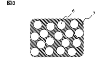
- the fibrous filler (C) and component (D) form a composite with these two.
- the form of this composite is as shown in FIG. 3, and the component (D) is filled between each single fiber of the fibrous filler (C) which is a continuous fiber bundle at the time of molding. That is, the fibrous filler (C) is dispersed like islands in the sea of component (D).
- the composite is formed by thermally melting the component (D) and impregnating the fibrous filler (C).
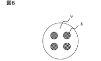
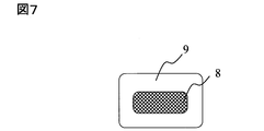
- 3 to 9 schematically show examples of cross-sectional shapes of the molding material of the present invention.
- the shape of the cross-section of the molding material is not limited to that shown in the figure as long as the resin composition is disposed so as to contact the composite composed of the fibrous filler (C) and the component (D),
- the resin composition is arranged so as to cover the periphery of the composite, or as shown in FIGS. 8 and 9, the composite and the resin composition
- a configuration in which objects are arranged in layers is desirable.
- the number of composites is preferably about 2 to 6.
- the boundary between the composite and the resin composition is desirably bonded.
- the resin composition is disposed so as to cover the periphery of the composite material composed of the fibrous filler (C) and the component (D).
- the composite and the resin composition are preferably arranged in layers. If it is such arrangement
- the component (D) belongs to a concept different from the coupling agent and sizing agent generally used for the surface treatment of the fibrous filler. That is, the treatment amount of the coupling agent and sizing agent is usually about 0.05 to 10% by weight with respect to the fiber, and is intended to be applied to the very surface portion of the fiber, so the fiber bundle is impregnated in advance. It's not something to keep.
- the fibrous filler (C) In producing the molding material, it is preferable to impregnate the fibrous filler (C) with the component (D) in advance.
- the component (D) can be easily melted and impregnated into a continuous fiber bundle (fibrous filler (C)), and in the process of continuously impregnating the fiber bundle, for example, a speed of 10 m / min or more It is possible to realize high-speed driving as described above, and it is excellent in productivity.
- the impregnation process involves complicated operations such as drastically opening the fibers, rubbing against a bar or the like so as to damage the fibers, or applying high pressure to the thermoplastic polymer. There is no need to use equipment.
- thermoplastic polymer with a solvent to reduce the viscosity and impregnating it, and then removing the solvent, or removing the medium after impregnation by emulsification and dispersion.
- the component (D) is mixed and diffused in the resin composition as a matrix in the molded body after molding. That is, if it is a combination in which the component (D) and the resin composition are easily mixed, the function as an impregnation / dispersion aid for the component (D) is excellent. More specifically, if the component (D) and the resin composition have chemical affinity and are desirably compatible, the effect is great. In addition, even if the combination is incompatible, the components (D) are microdispersed in the resin composition as long as they have moderate chemical affinity and reactivity. The effect as a sufficient impregnation and dispersion aid is exhibited.
- Whether the component (D) and the resin composition have chemical affinity and tend to be compatible can be determined to some extent using the solubility parameter.
- a detailed description of the solubility parameter is given in “Polymer Blend” (CMC) by Saburo Akiyama, Takashi Inoue and Toshio Nishi.
- CMC Polymer Blend
- Several methods for determining the solubility parameter of a polymer are known, but the same determination method may be used for comparison. Specifically, it is desirable to use the Hoy's method that is easy to calculate (see above). It can be said that the closer the solubility parameter values of the two liquids are, the easier the compatibility is.
- the solubility parameter of the component (D) is ⁇ 1 and the solubility parameter of the resin composition is ⁇ 2, it is preferable that the absolute value of the difference in solubility parameter value
- the component (D) preferably contains an aliphatic hydrocarbon.
- the aliphatic hydrocarbon may have a double bond or a cyclic structure.
- Examples of the component (D) having no cyclic structure include butadiene, isoprene, pentadiene, hexadiene and the like.
- component (D) having a cyclic structure examples include monoterpenes (dipentene, limonene) represented by the molecular formula of cyclohexadiene, vinylcyclohexene, cycloheptadiene, cyclooctadiene, C 10 H 16 as monocyclic compounds.
- component (D) those having a cyclic structure are preferable. By having a ring structure, the movement of the molecules is moderately restrained and relatively rigid.
- the component (D) having such a structure increases the elastic modulus of the molded product when a molded product dispersed in the resin composition comprising the melt-kneaded product (A) and the third resin (B) is obtained. There is no reduction.
- a particularly preferred component (D) is a monoterpene represented by a molecular formula of C 10 H 16 .
- terpene resins examples include a terpene resin, a hydrogenated terpene resin, a terpene phenol resin, and a hydrogenated terpene phenol resin.
- the terpene resin is obtained by polymerizing one or more terpene monomers such as ⁇ -pinene, ⁇ -pinene, limonene, dipentene, terpinolene, terpinene, and mentadiene.
- the hydrogenated terpene resin is a terpene resin hydrogenated and partially reduced.
- the terpene phenol resin is obtained by reacting the terpene monomer with phenols using a catalyst.
- phenols those having 1 to 3 substituents selected from an alkyl group, a halogen atom and a hydroxyl group on the benzene ring of the phenol are preferably used.
- substituents selected from an alkyl group, a halogen atom and a hydroxyl group on the benzene ring of the phenol are preferably used.
- Specific examples thereof include cresol, xylenol, ethylphenol, butylphenol, t-butylphenol, nonylphenol, 3,4,5-trimethylphenol, chlorophenol, bromophenol, chlorocresol, hydroquinone, resorcinol, orcinol and the like.
- Particularly preferred phenolic compounds include phenol and cresol. A plurality of phenol compounds may be used.
- the sheet-shaped molding material is not particularly limited as long as the fibrous filler (C) is dispersed in the resin composition composed of the melt-kneaded product (A) and the third resin (B), and is a known method.
- the resin composition having a powder form, a fiber form, a film form, or a non-woven form is laminated on a mat formed by entwining a plurality of fibrous fillers (C), and this is heated and pressurized. To obtain a molding material.
- the fibrous filler (C) may be produced from a suspension in which the fibrous filler (C) is dispersed in water.
- the resin composition is preferably a film.
- a known film forming technique can be used. For example, a method of extruding a flat film by placing a T die in an extruder, a method of obtaining a stretched film by further stretching this film in a uniaxial or biaxial direction, and a cylindrical film by arranging a circular die in an extruder A method such as an inflation method is used to inflate.
- Examples of the method for molding the molding material of the present invention include autoclave molding, press molding, filament winding molding, resin transfer molding molding, extrusion molding, injection molding, hollow molding, calendar molding, compression molding, vacuum molding, foam molding, and the like. Is possible.
- the obtained molded body can be formed into a pellet shape, a plate shape, a fiber shape, a strand shape, a film shape, a sheet shape, a pipe shape, a hollow shape, a box shape, or the like.
- the molded product thus obtained is excellent in heat resistance and impact absorption, but is particularly suitable for thin molded products, elongated molded products, and films.
- the uses of the molded product thus obtained include computers, televisions, video players, DVD players, cameras, audio equipment housings, connectors, coils, sensors, LED lamps, sockets, resistors, Relay case, small switch, coil bobbin, condenser, variable capacitor case, optical pickup, oscillator, various terminal boards, transformer, plug, printed circuit board, tuner, speaker, microphone, headphones, small motor, magnetic head base, power module, semiconductor Suitable for electronic parts such as LCD, FDD carriage, FDD chassis, motor brush holder, parabolic antenna, computer related parts, etc., generator, motor, transformer, current transformer, voltage regulator, rectifier ,I Electric and electronic parts such as barters, relays, power contacts, switches, breakers, knife switches, other pole rods, electrical parts cabinets; VTR parts, TV parts, irons, hair dryers, rice cooker parts, microwave oven parts, Audio and video equipment parts such as audio parts, audio, laser discs (registered trademark), compact discs, DVDs, lighting parts, refrigerator parts, air conditioner parts, typewriter parts, word
- Alternator -Various valves such as final, alternator connector, IC regulator, potentiometer base for light deer, exhaust gas valve; fuel related, cooling system, brake system, wiper system, various exhaust system and intake system pipes, hoses or tubes; air Intake nozzle snorkel, intake manifold, fuel pump, engine coolant joint, carburetor main body, carburetor spacer, exhaust gas sensor, coolant sensor, oil temperature sensor, brake pad wear sensor, throttle position sensor, crankshaft position sensor, air flow Meter, brake pad wear sensor, battery peripheral parts, thermostat base for air conditioner, heating hot air flow control valve, radiator motor Brush holders, water pump impellers, turbine vanes, wiper motor parts, distributors, starter switches, starter relays, transmission wire harnesses, window washer nozzles, air conditioner panel switch boards, fuel related electromagnetic valve coils, wire harnesses Connectors, SMJ connector, PCB connector, door grommet connector, various connectors such as fuse connector, horn terminal, electrical component insulation plate, step motor rot
- the fiber reinforced resin composition of the present invention is also suitable as a building material, such as civil engineering building walls, roofs, ceiling material related parts, window material related parts, heat insulating material related parts, flooring related parts, seismic isolation members. It is suitably used for related parts, lifeline related parts and the like.
- the fiber-reinforced resin composition of the present invention is also suitable as a sports equipment, golf-related equipment such as golf clubs, shafts, grips, and golf balls, sports racquet-related equipment such as tennis rackets, badminton rackets and their guts, , Masks such as baseball and softball, helmets, chest pads, elbow pads, knee pads, sports body protection products such as sports shoe bottom materials, fishing rods, reels, lures and other fishing gear related products, surfing It is suitably used for summer sports-related products such as winter sports-related products such as skis and snowboards, and other indoor and outdoor sports-related products.
- golf-related equipment such as golf clubs, shafts, grips, and golf balls
- sports racquet-related equipment such as tennis rackets, badminton rackets and their guts
- Masks such as baseball and softball, helmets, chest pads, elbow pads, knee pads, sports body protection products such as sports shoe bottom materials, fishing rods, reels, lures and other fishing gear
- the first resin (A1) used in the examples and comparative examples is as follows.
- A1-3 Nylon 66 resin having a melting point of 265 ° C. and a relative viscosity of 3.60 at 0.01 g / ml in 98% sulfuric acid.
- (A1-7): Nylon 66 / 6T 50/50 resin having a melting point of 295 ° C.
- A1-8 Polybutylene terephthalate resin having a melting point of 225 ° C., an intrinsic viscosity of 0.70 measured with a 0.5% solution in o-chlorophenol, and a carboxyl end group amount of 35 eq / t.
- A1-9) Polyethylene terephthalate resin having a melting point of 265 ° C., an intrinsic viscosity of 0.85 measured with a 0.5% solution in o-chlorophenol, and a carboxyl end group amount of 26 eq / t.
- (A1-12): Polyphenylene sulfide resin having a melting point of 280 ° C. and MFR 500 g / 30 minutes (315.5 ° C., 5 kg load).
- the second resin (A2) having a reactive functional group is as follows.
- the third resin (B) is as follows.
- (B-7): Nylon 66 / 6T 50/50 resin having a melting point of 295 ° C.
- B-8 Polybutylene terephthalate resin having a melting point of 225 ° C., an intrinsic viscosity of 0.70 measured with a 0.5% solution in o-chlorophenol, and a carboxyl end group amount of 35 eq / t.
- B-9 Polyethylene terephthalate resin having a melting point of 265 ° C., an intrinsic viscosity of 0.85 measured with a 0.5% solution in o-chlorophenol, and a carboxyl end group amount of 26 eq / t.
- (B-12): Polyphenylene sulfide resin having a melting point of 280 ° C. and MFR 500 g / 30 minutes (315.5 ° C., 5 kg load).
- the fibrous filler (C) is as follows.
- C-1) Carbon fiber “Torayca® T700S” (manufactured by Toray Industries, Inc.). O / C 0.05, Sizing agent Aromatic bifunctional epoxy resin. The number average fiber length was cut to 6 mm.
- C-2) Carbon fiber “TORAYCA® T700G” (manufactured by Toray Industries, Inc.). O / C 0.20, sizing agent Aliphatic polyfunctional epoxy resin. The number average fiber length was cut to 6 mm.
- (C-3) Glass fiber “T-249” (manufactured by JEOL Glass Co., Ltd.) Number average fiber length 3 mm
- components other than (A1), (A2), and (B) are as follows.
- (F-1) Unmodified polyethylene copolymer (hereinafter abbreviated as unmodified PE copolymer) “LOTRYL® 29MA03” (manufactured by Arkema Co., Ltd.).
- test piece (1-1) Tensile test piece, Izod impact test piece Using Nissei Plastic Industry injection molding machine (NP7-1F), a molding temperature of 260 ° C. (280 ° C. in Reference Examples 19 and 25)
- the reference examples 21 and 22 are 220 ° C.
- the reference example 23 is 310 ° C.
- the reference examples 26 and 29 and 30 are 200 ° C.
- the reference examples 27 and 28 are 300 ° C.
- the reference example 31 is 350 ° C.
- the mold temperature is 80 ° C. (130 ° C.
- test piece was obtained by cutting a flat sample.
- the number average particle size (Xn) is obtained by randomly extracting 400 or more particles from the obtained image, analyzing the particle size distribution using the image analysis software “Scion Image” manufactured by Scion Corporation, Obtained by the formula.
- the number average particle diameter of the particles composed of the component (A2) is calculated from an image magnified 10,000 times, and the number average particle diameter of the fine particles in the particles composed of the component (A2) is calculated from an image magnified 35,000 times To do.
- the number average particle diameter of the particles composed of the component (A2), the presence or absence of fine particles of 1 to 100 nm in the particles composed of the component (A2), and the presence or absence of fine particles exceeding 300 nm were confirmed.
- the area ratio of the fine particles in the particles composed of the component (A2) was determined using the image analysis software “Scion Image” manufactured by Scion Corporation from the above image enlarged 35,000 times using a transmission electron microscope. Using this, the area of the component (A2) and the area occupied by the fine particles in the particles composed of the component (A2) were respectively analyzed and determined by the following equations.
- Sn Sp / (Sa2 + Sp) Sn; area ratio Sa2 occupied by the fine particles in the particles composed of the component (A2); area Sp occupied by the component (A2); an area occupied by the fine particles in the particles composed of the component (A2).
- Average fiber length of fibrous filler A part of a 1/8 inch notched Izod impact test piece or a 1/8 inch notched Charpy impact test piece was cut out at 30 ° C. in air at 500 ° C. using an electric furnace. The resin was sufficiently removed by incineration by heating for 5 minutes to separate the fibrous filler. At least 400 separated fibrous fillers were randomly extracted, the length was measured to the 1 ⁇ m unit with an optical microscope, and the number average fiber length (Ln) was determined by the following formula.
- Flame retardancy test Flame retardancy was evaluated using a test piece (length 130 mm x width 13 mm x thickness 0.8 mm) obtained by injection molding. The UL94V vertical combustion test method was used for flame retardancy evaluation.
- the coloring agent was added together with the raw materials, and the time during which the coloration on the extrudate was maximized was measured as the residence time.
- the maximum resin pressure in the kneading zone is Pkmax (MPa)
- the resin pressure installed in multiple full flight zones Among the resin pressures indicated by the meter, the resin pressure in the full flight zone that became the minimum was defined as Pfmin (MPa). Values obtained by subtracting Pfmin (MPa) from Pkmax (MPa) are shown in Tables 1 and 3. Tables 1 and 3 show the highest resin temperature as measured by resin thermometers installed evenly at a plurality of locations in the extruder as the highest resin temperature.
- the discharged strand-shaped molten resin was cooled by passing through a cooling bath, and cut while being taken out by a pelletizer, to obtain a pellet-shaped sample of the melt-kneaded product (A).
- the sample was vacuum-dried at 80 ° C. for 12 hours or more, and then a tensile test piece was prepared by injection molding, and the morphology observation, the tensile modulus, and the tensile elongation at break were evaluated.
- the melt kneading results and various evaluation results are shown in Tables 1 and 3.
- Reference Example 8 The raw materials were mixed with the composition shown in Table 1 and charged into the feed port of the twin screw extruder.
- the coloring agent was added together with the raw materials, and the time during which the coloring of the extrudate was maximized was measured as the residence time.
- the residence time is shown in Table 1.
- the ratio of the total length of the kneading zone to the total screw length was 26%.
- the discharged strand-shaped molten resin was cooled by passing through a cooling bath, and was cut while being taken out by a pelletizer to obtain a pellet-shaped sample.
- the sample was vacuum-dried at 80 ° C. for 12 hours or more, and then charged again into the hopper of the extruder.
- the discharged strand-shaped molten resin was cooled by passing through a cooling bath and cut while being taken out by a pelletizer, thereby obtaining a pellet-shaped sample of the melt-kneaded product (A).
- the sample was vacuum-dried at 80 ° C.
- the coloring agent was added together with the raw materials, and the time during which the coloration to the extrudate was maximized was measured as the residence time.
- the residence times are shown in Tables 2, 4 and 5.
- the discharged strand-shaped molten resin was cooled by passing through a cooling bath, and cut while being taken out by a pelletizer, to obtain a pellet-shaped sample of the melt-kneaded product (A).
- the sample was vacuum-dried at 80 ° C. for 12 hours or more, and then a tensile test piece was prepared by injection molding, and the morphology observation, the tensile modulus, and the tensile elongation at break were evaluated.
- the results of melt kneading and various evaluation results are shown in Tables 2, 4 and 5.
- Reference Example 15 The raw materials were mixed with the composition shown in Table 2 and charged into the feed port of the twin screw extruder.
- the screw diameter is 30 mm
- the same direction rotating fully meshed twin screw extruder manufactured by Nippon Steel Works, TEX-30 ⁇
- the coloring agent was added together with the raw materials, and the time during which the coloration on the extrudate was maximized was measured as the residence time.
- the residence time is shown in Table 2.
- the discharged strand-shaped molten resin was cooled by passing through a cooling bath, and cut while being taken out by a pelletizer, to obtain a pellet-shaped sample of the melt-kneaded product (A).
- the sample was vacuum-dried at 80 ° C. for 12 hours or more, and then a tensile test piece was prepared by injection molding, and the morphology observation, the tensile modulus, and the tensile elongation at break were evaluated.
- the melt kneading results and various evaluation results are shown in Table 2.
- the coloring agent was added together with the raw materials, and the time during which the coloring of the extrudate was maximized was measured as the residence time.
- the residence time is shown in Table 3.
- the ratio of the total length of the kneading zone to the total screw length was 14%.
- the discharged strand-shaped molten resin was cooled by passing through a cooling bath, and cut while being taken out by a pelletizer, to obtain a pellet-shaped sample of the melt-kneaded product (A).
- the sample was vacuum-dried at 80 ° C. for 12 hours or more, and then a tensile test piece was prepared by injection molding, and the morphology observation, the tensile modulus, and the tensile elongation at break were evaluated.
- the melt kneading results and various evaluation results are shown in Table 3.
- the particles of the second resin (A2) The number average particle size is controlled in the range of 10 to 1000 nm.
- the particles made of the second resin (A2) contain 1 to 100 nm fine particles made of a compound formed by the reaction of the first resin (A1) and the second resin (A2).
- the area occupied by the fine particles in the particles made of the resin (A2) can be 20% or more. It can also be seen from the tensile test that the tensile modulus decreases and the tensile elongation at break increases as the tensile speed is increased.
- the number average particle diameter of the particles made of the second resin (A2) is not controlled in the range of 10 to 1000 nm, and fine particles are not contained in the particles made of the second resin (A2).
- the tensile test as the tensile speed is increased, the tensile elastic modulus increases and the tensile elongation at break decreases.
- a resin (F) having no reactive functional group is used. Since the dispersed phase (F) does not have a reactive functional group, even if the number average particle diameter is controlled in the range of 10 to 1000 nm, in the tensile test, the tensile modulus increases as the tensile speed increases. It increases and the tensile elongation at break also decreases. Further, no fine particles were present in the dispersed phase (F).
- Examples 1 to 28, 32 to 45, 74, Comparative Examples 1, 4 to 23, 31 The raw materials were mixed with the composition shown in Tables 6, 7, and 10 to 14, and charged into the feed port of the twin screw extruder.
- the screw diameter is 30 mm
- the coloring agent was added together with the raw materials, and the time during which the coloration on the extrudate was maximized was measured as the residence time.
- the residence times are shown in Tables 6, 7, and 10-14.
- the ratio of the total length of the kneading zone to the total screw length was 26%.
- the discharged strand-shaped molten resin was cooled by passing through a cooling bath, and was cut while being taken out by a pelletizer, thereby obtaining a pellet-shaped sample of the fiber reinforced resin composition.
- the sample was vacuum-dried at 80 ° C. for 12 hours or longer, and then a bending test piece and a Charpy impact test piece were prepared by injection molding, and morphological observation, bending elastic modulus and Charpy impact strength were evaluated.
- the melt kneading results and various evaluation results are shown in Tables 6, 7, and 10-14.
- Comparative Example 2 The raw materials were mixed with the composition shown in Table 12 and charged into the feed port of the twin screw extruder.
- the screw diameter is 41 mm
- the coloring agent was added together with the raw materials, and the time during which the coloring of the extrudate was maximized was measured as the residence time.
- the residence time is shown in Table 12.
- the screw configuration was A as in Reference Example 1.
- the resin pressure gauges installed in the multiple full flight zones from the resin pressure Pkmax (MPa) of the kneading zone that became the maximum among the resin pressures indicated by the resin pressure gauges installed in the multiple kneading zones.
- Table 12 shows values obtained by subtracting the resin pressure Pfmin (MPa) of the full flight zone that is the minimum among the resin pressures indicated by.
- Table 12 shows the highest resin temperature measured by resin thermometers installed evenly at a plurality of locations in the extruder as the highest resin temperature.
- the discharged strand-shaped molten resin was cooled by passing through a cooling bath, and cut while being taken out by a pelletizer, thereby obtaining a pellet-shaped sample of the fiber reinforced resin composition.
- the sample was vacuum-dried at 80 ° C. for 12 hours or longer, and then a bending test piece and a Charpy impact test piece were prepared by injection molding, and morphological observation, bending elastic modulus and Charpy impact strength were evaluated.
- the melt kneading results and various evaluation results are shown in Table 12.
- Comparative Example 3 The raw materials were mixed with the composition shown in Table 12 and charged into the feed port of the twin screw extruder.
- the screw diameter is 30 mm
- the coloring agent was added together with the raw materials, and the time during which the coloring of the extrudate was maximized was measured as the residence time.
- the residence time is shown in Table 12.
- the screw configuration was made in C having an extension flow zone as in Reference Example 9.
- the discharged strand-shaped molten resin was cooled by passing through a cooling bath, and was cut while being taken out by a pelletizer, thereby obtaining a pellet-shaped sample of the fiber reinforced resin composition.
- the sample was vacuum-dried at 80 ° C. for 12 hours or longer, and then a bending test piece and a Charpy impact test piece were prepared by injection molding, and morphological observation, bending elastic modulus and Charpy impact strength were evaluated.
- the melt kneading results and various evaluation results are shown in Table 12.
- Example 29 Component (A) and component (B) shown in Table 8 were mixed and charged into the feed port of the twin screw extruder.
- the screw diameter is 30 mm
- the screw configuration was F as in Example 1.
- the discharged strand-shaped molten resin was cooled by passing through a cooling bath, and was cut while being taken out by a pelletizer to obtain a resin composition.
- This resin composition and (C) shown in Table 8 were melt-kneaded under the same conditions as the kneading conditions (A) and (B) above to obtain a pellet-like sample of the fiber-reinforced resin composition.
- the sample was vacuum-dried at 80 ° C. for 12 hours or longer, and then a bending test piece and a Charpy impact test piece were prepared by injection molding, and morphological observation, bending elastic modulus and Charpy impact strength were evaluated.
- the melt kneading results and various evaluation results are shown in Table 8.
- Example 30 The components (A) and (C) shown in Table 9 were mixed and charged into the feed port of the twin screw extruder.
- the screw diameter is 30 mm
- the screw configuration was F as in Example 1.
- the discharged strand-shaped molten resin was cooled by passing through a cooling bath, and was cut while being taken out by a pelletizer to obtain a resin composition.
- This resin composition and (B) shown in Table 9 are mixed and put into a hopper of an injection molding machine (J150EII-P) manufactured by Nippon Steel Works, a molding temperature of 260 ° C., a mold temperature of 80 ° C., and an injection pressure lower limit pressure. Under the condition of +5 kgf / cm 2 , a bending test piece and a 1/8 inch notched Charpy impact test piece were prepared. Table 9 shows the evaluation results of morphology observation, flexural modulus and Charpy impact strength.
- Example 31 Component (B) and component (C) shown in Table 9 were mixed and charged into the feed port of the twin screw extruder.
- the screw diameter is 30 mm
- the screw configuration was F as in Example 1.
- the discharged strand-shaped molten resin was cooled by passing through a cooling bath, and was cut while being taken out by a pelletizer to obtain a resin composition.
- This resin composition and (A) shown in Table 9 are mixed and put into a hopper of an injection molding machine (J150EII-P) manufactured by Nippon Steel Works, a molding temperature of 260 ° C., a mold temperature of 80 ° C., and an injection pressure lower limit pressure. Under the condition of +5 kgf / cm 2 , a bending test piece and a 1/8 inch notched Charpy impact test piece were prepared. Table 9 shows the evaluation results of morphology observation, flexural modulus and Charpy impact strength.
- Example 74 is in comparison with Comparative Example 31 From Examples 1 to 10 and 14 to 23, the melt-kneaded product (A) prepared in Reference Examples 1 to 15 is composed of the second resin (A2).
- the number average particle diameter of the particles is 10 to 1000 nm, and the area occupied by the fine particles in the particles made of the second resin (A2) is 20% or more.
- the content of the resin (A2) forming the dispersed phase is small. Since the structure of the dispersed phase is highly controlled, the impact resistance can be increased while having the same rigidity as that of Comparative Example 8.
- the melt-kneaded product (A) produced in Reference Examples 2 and 9 has a number average particle diameter of the second resin (A2) of 10 to 1000 nm and the second resin.
- the area occupied by the fine particles in the particles made of (A2) is 20% or more.
- the content of the resin (A2) forming the dispersed phase is small. Since the structure of the dispersed phase is highly controlled, the impact resistance can be increased while having the same rigidity as that of Comparative Example 7.
- the melt-kneaded product (A) prepared in Reference Examples 2 and 9 has a number average particle diameter of the second resin (A2) of 10 to 1000 nm and the second resin.
- the area occupied by the fine particles in the particles made of (A2) is 20% or more.
- the content of the resin (A2) forming the dispersed phase is small. Since the structure of the dispersed phase is highly controlled, the impact resistance can be increased while having the same rigidity as that of Comparative Example 9.
- the melt-kneaded product (A) produced in Reference Examples 2 and 9 has a number average particle diameter of particles of the second resin (A2) of 10 to 1000 nm and the second resin.
- the area occupied by the fine particles in the particles made of (A2) is 20% or more.
- the content of the resin (A2) forming the dispersed phase is small. Since the structure of the dispersed phase is highly controlled, the impact resistance can be increased while having the same rigidity as that of Comparative Example 10.
- the melt-kneaded product (A) produced in Reference Example 9 has a number average particle diameter of 10 to 1000 nm of particles made of the second resin (A2), and the second resin (A2 ), The area occupied by the fine particles in the particles is 20% or more.
- the content of the resin (A2) forming the dispersed phase is small. Since the structure of the dispersed phase is highly controlled, the impact resistance can be increased while having the same rigidity as that of Comparative Example 21.
- Comparative Examples 1 to 3 for example, compared with Example 3, the content of each component in the fiber reinforced resin composition is the same, but the melt-kneaded material in which the structure of the dispersed phase is controlled as in the Example Since the components are collectively kneaded without going through the step of forming (A), the structure of the dispersed phase is not highly controlled in the obtained fiber-reinforced resin composition, and the balance between rigidity and impact resistance is not achieved. Is bad.
- the melt-kneaded product (A) produced in Reference Examples 16 and 18 was added to the third resin (B) and the fibrous filler (C), respectively.
- the number average particle diameter of the particles made of the resin (A2) was not controlled in the range of 10 to 1000 nm, and the balance between rigidity and impact resistance was not sufficient.
- Comparative Example 5 has a reactive functional group because the melt-kneaded product (A) prepared in Reference Example 17 is added to the third resin (B) and the fibrous filler (C). Resin (F) not present becomes the dispersed phase. Since the dispersed phase (F) does not have a reactive functional group, the balance between rigidity and impact resistance was not sufficient even when the number average particle size was controlled in the range of 10 to 1000 nm. Further, no fine particles were present in the dispersed phase (F).
- Example 29 a fiber-reinforced resin obtained by melt-kneading the melt-kneaded product of the melt-kneaded product (A) and the third resin (B) prepared in Reference Example 9 and the fibrous filler (C).
- the composition is excellent in the balance between rigidity and impact resistance because the structure of the dispersed phase is highly controlled in the obtained fiber-reinforced resin composition.
- the obtained fiber reinforced resin composition has an excellent balance between rigidity and impact resistance because the structure of the dispersed phase is highly controlled.
- Example 31 From Example 31, a small amount of the melt-kneaded product (A) prepared in Reference Example 9 was added to and mixed with the melt-kneaded product of the third resin (B) and the fibrous filler (C) at the time of injection molding.
- the obtained fiber-reinforced resin composition has a highly controlled structure of the dispersed phase and is excellent in the balance between rigidity and impact resistance.
- the melt-kneaded product (A) prepared in Reference Examples 9 and 19 to 30 was obtained from the second resin (A2) even if various third resins (B) were used.
- the number average particle diameter of the resulting particles is 10 to 1000 nm, and the area occupied by the fine particles in the particles made of the second resin (A2) is 20% or more.
- the content of the resin (A2) forming the dispersed phase is small. Since the structure of the dispersed phase is highly controlled, it is possible to increase the impact resistance while having the same rigidity as the corresponding Comparative Examples 12 to 22, and 31, respectively.
- Example 46 The melt-kneaded product (A) and the third resin (B) were mixed with the composition shown in Table 15, and charged into the feed port of the twin screw extruder.
- the screw diameter is 30 mm
- the coloring agent was added together with the raw materials, and the time during which the coloring of the extrudate was maximized was measured as the residence time.
- the residence time is shown in Table 15.
- the screw configuration was F as in Example 1.
- the discharged strand-shaped molten resin was cooled by passing through a cooling bath, and cut while being taken out by a pelletizer, to obtain pellets of a resin composition.
- the molding material of the present invention is obtained by combining the resin composition pellets, the carbon fiber bundle (C) with the terpene phenol polymer (D) by the following method so as to have the blending composition shown in Table 15. Manufactured.
- a liquid film obtained by heating and melting the terpene phenol polymer (D) was formed on a roll heated at 130 ° C.
- a kiss coater was used to form a film with a constant thickness on the roll.
- a continuous carbon fiber bundle (C) was passed through this roll while being in contact therewith, and a certain amount of terpene phenol polymer was adhered per unit length of the carbon fiber bundle.
- the carbon fibers to which the polymer was attached were alternately passed over 10 rolls with a diameter of 10 mm, which were heated to 180 ° C. and freely rotated by bearings, arranged in a straight line.
- the polymer was impregnated to the inside of the fiber bundle to form a continuous composite made of carbon fiber and terpene phenol polymer.
- the melt viscosity of the terpene phenol polymer (D) at 130 ° C. at a shear rate of 10 3 s ⁇ 1 was about 10 poise as measured with a capillary rheometer.
- the continuous composite was passed through a wire coating coating die disposed at the tip of a single screw extruder having a diameter of 40 mm and melted at 260 ° C. from the extruder into the die (A). And a resin composition comprising the third resin (B) were discharged. Thereby, the periphery of the composite was continuously coated with the resin composition.
- the obtained composite was cooled to near normal temperature and then cut into a 7 mm long pellet with a strand cutter to obtain a sample for injection molding.
- the production of the molding material so far was performed by a continuous process, and the take-up speed of the carbon fiber bundle was 30 m / min.
- the sample was vacuum-dried at 80 ° C. for 12 hours or longer, and then a bending test piece and a Charpy impact test piece were prepared by injection molding, and morphology observation, bending elastic modulus and Charpy impact strength were evaluated.
- Table 15 Table 15
- Example 47-51, 52-58, 60-73 Samples for injection molding were prepared in the same manner as in Example 46 with the blending compositions shown in Tables 15 to 18, and various evaluations were performed. The results are shown in Tables 15-18.
- Example 59 A composite of a continuous carbon fiber bundle (C) and a terpene phenol polymer (D) obtained by the same method as in Example 46 was used for the wire coating method installed at the tip of a single screw extruder having a diameter of 40 mm. Was passed through the coating die.
- the resin pellet obtained in Reference Example 9 and the pellet of the third resin (B) were blended and melted and discharged from the extruder into a die at 260 ° C., and continuously discharged around the composite. Coated.
- the sample for injection molding was produced similarly to Example 46, and various evaluation was performed. The results are shown in Table 16.
- Comparative Examples 24-26, 30 In the same manner as in Example 46, using the melt-kneaded product (A), the third resin (B), the terpene phenol polymer (D), and the continuous carbon fiber bundle (C) with the composition shown in Table 19. Samples for injection molding were prepared and subjected to various evaluations. The evaluation results are shown in Table 19.
- Comparative Example 27 Component (A1), component (A2) and component (B) were mixed in the formulation shown in Table 19, and charged into the feed port of the twin screw extruder.
- the screw diameter is 30 mm
- the screw configuration was F as in Example 1.
- the discharged strand-shaped molten resin was cooled by passing through a cooling bath, and cut while being taken out by a pelletizer, to obtain pellets of a resin composition.
- Samples for injection molding were prepared in the same manner as in Example 46 using resin composition pellets, continuous carbon fiber bundles (C), and terpene phenol polymer (D) with the composition shown in Table 19, Evaluation was performed. The results are shown in Table 19.
- Comparative Example 28 The resin composition was mixed with the composition shown in Table 19, and charged into the feed port of the twin screw extruder.
- the screw diameter is 41 mm
- the screw configuration was A as in Reference Example 1.
- Resin pressure gauges installed in multiple full flight zones from the maximum resin pressure Pkmax (MPa) in the kneading zone among the resin pressures indicated by the resin pressure gauges installed in multiple kneading zones
- Table 19 shows values obtained by subtracting the resin pressure Pfmin (MPa) of the full flight zone that is minimized among the resin pressures indicated by.
- Table 19 shows the highest resin temperature measured with resin thermometers installed evenly at a plurality of locations in the extruder as the highest resin temperature.
- the discharged strand-shaped molten resin was cooled by passing through a cooling bath, and cut while being taken out by a pelletizer, to obtain pellets of a resin composition.
- Samples for injection molding were prepared in the same manner as in Example 46 using the resin composition pellets (C) and (D) with the formulation shown in Table 19, and various evaluations were performed. The results are shown in Table 19.
- Comparative Example 29 It mixed with the compounding composition shown in Table 19, and injected
- the screw diameter is 30 mm
- the screw configuration was the same as that in Reference Example 9 in the configuration C having an extension flow zone.
- the discharged strand-shaped molten resin was cooled by passing through a cooling bath, and cut while being taken out by a pelletizer, to obtain pellets of a resin composition.
- Samples for injection molding were prepared in the same manner as in Example 46 using pellets of the resin composition, continuous carbon fiber bundles (C), and terpene phenol polymer (D) with the composition shown in Table 19. Evaluation was performed after producing various test pieces. The results are shown in Table 19.
- the melt-kneaded product (A) prepared in Reference Examples 2 and 9 has a number average particle diameter of particles composed of the second resin (A2) of 10 to 1000 nm, and The area occupied by the fine particles in the particles made of the second resin (A2) is 20% or more.
- the molding material obtained by adding a small amount of the melt-kneaded product (A) to the third resin (B) can greatly improve the impact resistance while having the same rigidity as that of Comparative Example 30.
- the number average particle diameter of the particles made of the second resin (A2) prepared in Reference Examples 9 and 19 to 29 is 10 to 1000 nm.
- the molding material using the melt-kneaded material (A) in which the area occupied by the fine particles in the particles of the resin (A2) 2 is 20% or more has an excellent balance between rigidity and impact resistance.
- Comparative Examples 27 to 29 the content of each component in the molding material is the same as in Example 48, but a process for highly controlling the structure in the dispersed phase as in the Example is performed. Since the components (A1), (A2), and (B) are kneaded together, the structure of the dispersed phase cannot be controlled in the obtained molding material, and the balance between rigidity and impact resistance is poor. .
- Example 75 In the same manner as in Example 46, the melt-kneaded product (A), the third resin (B), and the flame retardant (E) were melt-kneaded according to the composition and conditions shown in Table 20. Using the obtained melt-kneaded product, terpene phenol polymer (D) and continuous carbon fiber bundle (C), an injection molded sample was prepared in the same manner as in Example 46, morphological observation, bending elastic modulus, The Charpy impact strength and flame retardancy test (UL94) was evaluated. Table 20 shows the evaluation results.
- Example 76 A melt-kneaded product (A) and a third resin (B) blended with the composition shown in Table 21 are melt-kneaded at 260 ° C. and extruded from a T-die placed in an extruder to produce a resin film. Next, a sheet-like material having a fiber weight content of 30% is obtained by laminating two resin films on both sides of a nonwoven fabric composed of a fibrous filler (C) having a number average fiber length of 10 mm and impregnating the melt-kneaded material by heating and pressing. The molding material was produced.
- Comparative Example 32 With the composition shown in Table 21, a sheet-shaped molding material was prepared in the same manner as in Example 76 except that the melt-kneaded product (A) was not blended, and used for various physical property evaluations. The evaluation results are shown in Table 21.
- Example 77 The melt-kneaded product (A) and the third resin (B) were melt-kneaded with the composition shown in Table 21.
- melt kneading 13 parts by weight of melt-kneaded product (A) is added to 100 parts by weight of liquid bisphenol A in a kneader, kneaded at 160 ° C. for 30 minutes, further cooled to 80 ° C. while kneading, 19 parts of dicyandiamide By adding 2 parts of DCMU.
- the obtained melt-kneaded material was applied onto release paper using a reverse roll coater to prepare a resin film.
- the resin film is stacked on both sides of the fibrous filler (C) aligned in one direction in a sheet form, heated and pressurized, and the melt-kneaded product is impregnated into the fibrous filler (C).
- a unidirectional prepreg with a carbon fiber weight of 155 g / m 2 per area and a fiber weight content of 75% was produced.
- the obtained prepreg was heated and pressurized at 130 ° C., and from the obtained cured product, a bending test piece (length 100 mm ⁇ width 15 mm ⁇ thickness 2 mm) and a notched Charpy impact test piece (length 100 mm ⁇ width 10 mm ⁇ thickness) 3 mm, flat width) was cut out and evaluated. The evaluation results are shown in Table 21.
- Comparative Example 33 A unidirectional prepreg with a carbon fiber weight of 155 g / m 2 per unit area and a fiber weight content of 75% in the same manner as in Example 77 except that the composition shown in Table 21 is not blended with the melt-kneaded product (A). Was used for evaluation of various physical properties. The evaluation results are shown in Table 21.
- Example 78 Particles (average particle size 90 ⁇ m) obtained by freeze-pulverizing the melt-kneaded product (A) with the composition shown in Table 21 were applied to a woven fabric having a basis weight of 190 g / m 2 made of the fibrous filler (C) and 19 g / m. The two adhered materials were laminated and preformed by heating and pressing with a mold. A third resin (B) is injected into this preform. Further, it was cured by heating at 130 ° C.
- a bending test piece (length 100 mm ⁇ width 25 mm ⁇ thickness 2 mm) and a notched Charpy impact test piece (length 100 mm ⁇ width 10 mm ⁇ thickness 2 mm, flat width) were cut out from the obtained cured product and evaluated. The evaluation results are shown in Table 21.
- Comparative Example 34 A cured product having a fiber weight content of 50% was prepared in the same manner as in Example 78 except that the melt-kneaded material (A) was not adhered with the composition shown in Table 21 and used for various physical property evaluations. The evaluation results are shown in Table 21.
- Example 76 produced with the composition shown in Table 21 had the same rigidity as Comparative Example 32, but greatly improved the impact resistance.
- the number average particle diameter of the particles made of the second resin (A2) in Example 76 was 10 to 1000 nm, and the area occupied by the fine particles in the particles made of the second resin (A2) was 20% or more. It was.
- Example 77 is a prepreg manufactured with the composition shown in Table 21, and has impact resistance greatly improved while having the same rigidity as Comparative Example 33.
- the number average particle diameter of the particles made of the second resin (A2) in Example 77 is 10 to 1000 nm, and the area occupied by the fine particles in the particles made of the second resin (A2) is 20% or more. It was.
- Example 78 is a molded product molded with the composition shown in Table 21, and has the same rigidity as that of Comparative Example 34, but has greatly improved impact resistance.
- the number average particle diameter of the particles made of the second resin (A2) in Example 78 is 10 to 1000 nm, and the area occupied by the fine particles in the particles made of the second resin (A2) is 20% or more. It was.
- the molding material of the present invention has excellent impact resistance, rigidity and the like when formed into a molded product without impairing moldability. Furthermore, the manufacturing method which can manufacture the said molding material easily, and the molded article obtained from this can also be provided.
- Dispersed phase 1 Dispersed phase 2
- Dispersed phase 3 Fibrous filler 4 Part of dispersed phase consisting of component (A2) 5 Fine particles composed of compound formed by reaction of component (A1) and component (A2) 6 Fibrous filler (C ) Single fiber 7
- Thermoplastic polymer (D) 8 Core part made of fibrous filler (C) and thermoplastic polymer (D) 9 Sheath part made of melt-kneaded product (A) and third resin (B)
Landscapes
- Chemical & Material Sciences (AREA)
- Engineering & Computer Science (AREA)
- Materials Engineering (AREA)
- Polymers & Plastics (AREA)
- Health & Medical Sciences (AREA)
- Chemical Kinetics & Catalysis (AREA)
- Medicinal Chemistry (AREA)
- Organic Chemistry (AREA)
- Manufacturing & Machinery (AREA)
- Mechanical Engineering (AREA)
- Inorganic Chemistry (AREA)
- Compositions Of Macromolecular Compounds (AREA)
- Reinforced Plastic Materials (AREA)
Priority Applications (5)
| Application Number | Priority Date | Filing Date | Title |
|---|---|---|---|
| EP10753514.8A EP2410021B1 (en) | 2009-03-16 | 2010-03-16 | Fiber reinforced resin composition, molding material, and method for producing fiber reinforced resin composition |
| JP2010511836A JP5505304B2 (ja) | 2009-03-16 | 2010-03-16 | 繊維強化樹脂組成物、成形材料および繊維強化樹脂組成物の製造方法 |
| US13/138,658 US8685537B2 (en) | 2009-03-16 | 2010-03-16 | Fiber reinforced resin composition, molding material, and method for producing fiber reinforced resin composition |
| CN201080006069.5A CN102300936B (zh) | 2009-03-16 | 2010-03-16 | 纤维增强树脂组合物、成型材料及纤维增强树脂组合物的制造方法 |
| HK12101918.3A HK1161283A1 (zh) | 2009-03-16 | 2012-02-24 | 纖維增强樹脂組合物、成型材料及纖維增强樹脂組合物的製造方法 |
Applications Claiming Priority (4)
| Application Number | Priority Date | Filing Date | Title |
|---|---|---|---|
| JP2009-062473 | 2009-03-16 | ||
| JP2009062472 | 2009-03-16 | ||
| JP2009062473 | 2009-03-16 | ||
| JP2009-062472 | 2009-03-16 |
Publications (1)
| Publication Number | Publication Date |
|---|---|
| WO2010107022A1 true WO2010107022A1 (ja) | 2010-09-23 |
Family
ID=42739682
Family Applications (1)
| Application Number | Title | Priority Date | Filing Date |
|---|---|---|---|
| PCT/JP2010/054423 WO2010107022A1 (ja) | 2009-03-16 | 2010-03-16 | 繊維強化樹脂組成物、成形材料および繊維強化樹脂組成物の製造方法 |
Country Status (8)
| Country | Link |
|---|---|
| US (1) | US8685537B2 (zh) |
| EP (1) | EP2410021B1 (zh) |
| JP (1) | JP5505304B2 (zh) |
| KR (1) | KR101654389B1 (zh) |
| CN (1) | CN102300936B (zh) |
| HK (1) | HK1161283A1 (zh) |
| TW (1) | TWI477540B (zh) |
| WO (1) | WO2010107022A1 (zh) |
Cited By (26)
| Publication number | Priority date | Publication date | Assignee | Title |
|---|---|---|---|---|
| JP2010248482A (ja) * | 2009-03-26 | 2010-11-04 | Toray Ind Inc | 繊維強化プロピレン系樹脂組成物 |
| JP2010248483A (ja) * | 2009-03-26 | 2010-11-04 | Toray Ind Inc | 成形材料 |
| JP2011178914A (ja) * | 2010-03-02 | 2011-09-15 | Teijin Chem Ltd | ポリプロピレン系炭素繊維強化樹脂組成物 |
| CN102948948A (zh) * | 2012-08-27 | 2013-03-06 | 珠海市恒基业安全头盔有限公司 | 一种内置复合材料加强筋的聚苯乙烯发泡头盔的制作工艺 |
| WO2013046682A1 (ja) * | 2011-09-30 | 2013-04-04 | 東レ株式会社 | ポリフェニレンスルフィド樹脂組成物、その製造方法、およびその成形体 |
| JP2013121988A (ja) * | 2011-05-16 | 2013-06-20 | Daicel Polymer Ltd | 難燃性樹脂組成物 |
| WO2013137246A1 (ja) * | 2012-03-14 | 2013-09-19 | 帝人株式会社 | 成形用材料、その成形体、および該成形体の製造方法 |
| JP2014025060A (ja) * | 2012-06-22 | 2014-02-06 | Toyota Central R&D Labs Inc | 樹脂組成物 |
| WO2014038509A1 (ja) * | 2012-09-06 | 2014-03-13 | ジヤトコ株式会社 | トランスミッション用オイルパン |
| CN103703080A (zh) * | 2011-07-25 | 2014-04-02 | 东丽株式会社 | 冲击吸收部件用热塑性树脂组合物及其制造方法 |
| JP2014528033A (ja) * | 2011-09-28 | 2014-10-23 | エネクシス カンパニーリミテッド | 汎用機能性不織布及びその製造方法 |
| JP2016183316A (ja) * | 2015-03-26 | 2016-10-20 | Dic株式会社 | 長繊維強化ポリアリーレンスルフィド樹脂組成物、成形品およびそれらの製造方法 |
| CN106349584A (zh) * | 2016-08-27 | 2017-01-25 | 赵碧华 | 一种纤维增强复合建筑板材及其制备方法 |
| WO2017056693A1 (ja) * | 2015-09-30 | 2017-04-06 | 帝人株式会社 | プレス成形体、及び複合材料 |
| US10174453B2 (en) | 2014-07-16 | 2019-01-08 | Jsr Corporation | Sizing agent, composition, and formed article |
| JP2019065285A (ja) * | 2017-09-28 | 2019-04-25 | 東レ株式会社 | 防爆性を有する圧力筐体用ポリアミド樹脂組成物およびそれを成形してなる圧力筐体 |
| JP2019172878A (ja) * | 2018-03-29 | 2019-10-10 | 東レ株式会社 | 熱可塑性樹脂炭素繊維複合材料の製造方法、熱可塑性樹脂炭素繊維複合材料およびそれを用いる成形品の製造方法 |
| WO2019208825A1 (ja) * | 2018-04-27 | 2019-10-31 | 株式会社ブリヂストン | コンポジットプリプレグ、及び、積層体 |
| WO2019208810A1 (ja) * | 2018-04-27 | 2019-10-31 | 株式会社ブリヂストン | コンポジットプリプレグ及びコンポジット積層体 |
| JPWO2020196109A1 (zh) * | 2019-03-26 | 2020-10-01 | ||
| US10829626B2 (en) | 2016-03-31 | 2020-11-10 | Toyota Boshoku Kabushiki Kaisha | Dispersion diameter adjustment method and thermoplastic resin composition |
| US10934424B2 (en) | 2015-12-01 | 2021-03-02 | Toyota Boshoku Kabushiki Kaisha | Molded body and production method therefor |
| US11046822B2 (en) | 2015-12-01 | 2021-06-29 | Toyota Boshoku Kabushiki Kaisha | Modifier, usage therefor, production method for modifier, and carrier for additive material |
| WO2022044920A1 (ja) | 2020-08-28 | 2022-03-03 | 東レ株式会社 | 繊維強化ポリアミド樹脂組成物成形品 |
| WO2023058448A1 (ja) | 2021-10-07 | 2023-04-13 | 東レ株式会社 | 繊維強化熱可塑性樹脂組成物 |
| US11992980B2 (en) | 2016-03-11 | 2024-05-28 | Toyota Boshoku Kabushiki Kaisha | Foamed resin molded article and method for manufacturing same |
Families Citing this family (74)
| Publication number | Priority date | Publication date | Assignee | Title |
|---|---|---|---|---|
| PL2402148T3 (pl) * | 2010-06-30 | 2015-03-31 | Siemens Ag | Sposób odlewania do wytwarzania elementu obrabianego |
| US11207109B2 (en) | 2010-10-20 | 2021-12-28 | 206 Ortho, Inc. | Method and apparatus for treating bone fractures, and/or for fortifying and/or augmenting bone, including the provision and use of composite implants, and novel composite structures which may be used for medical and non-medical applications |
| WO2015095745A1 (en) | 2010-10-20 | 2015-06-25 | 206 Ortho, Inc. | Method and apparatus for treating bone fractures, and/or for fortifying and/or augmenting bone, including the provision and use of composite implants, and novel composite structures which may be used for medical and non-medical applications |
| EP2629780A4 (en) | 2010-10-20 | 2014-10-01 | 206 Ortho Inc | IMPLANTABLE POLYMER FOR BONE AND VASCULAR LESIONS |
| US11058796B2 (en) | 2010-10-20 | 2021-07-13 | 206 Ortho, Inc. | Method and apparatus for treating bone fractures, and/or for fortifying and/or augmenting bone, including the provision and use of composite implants, and novel composite structures which may be used for medical and non-medical applications |
| US11484627B2 (en) | 2010-10-20 | 2022-11-01 | 206 Ortho, Inc. | Method and apparatus for treating bone fractures, and/or for fortifying and/or augmenting bone, including the provision and use of composite implants, and novel composite structures which may be used for medical and non-medical applications |
| US11291483B2 (en) | 2010-10-20 | 2022-04-05 | 206 Ortho, Inc. | Method and apparatus for treating bone fractures, and/or for fortifying and/or augmenting bone, including the provision and use of composite implants |
| US10525169B2 (en) | 2010-10-20 | 2020-01-07 | 206 Ortho, Inc. | Method and apparatus for treating bone fractures, and/or for fortifying and/or augmenting bone, including the provision and use of composite implants, and novel composite structures which may be used for medical and non-medical applications |
| BR112013018152B1 (pt) * | 2011-01-18 | 2021-09-14 | Teijin Aramid B.V. | Artigo à prova de bala, e, processo para fabricar o mesmo |
| CA2850719A1 (en) * | 2011-10-04 | 2013-04-11 | Toray Industries, Inc. | Carbon fiber-reinforced thermoplastic resin composition, molding material, prepreg, and methods for producing same |
| US20130130846A1 (en) * | 2011-11-22 | 2013-05-23 | William B. Giannetti | Sporting implement formed with a melt-processable structural binder |
| CN102604409A (zh) * | 2012-02-29 | 2012-07-25 | 中铁伟业(北京)新技术有限公司 | 耐冲击型复合材料防护制品 |
| EP2819620A4 (en) | 2012-02-29 | 2015-11-04 | 206 Ortho Inc | METHOD AND APPARATUS FOR TREATING BONE FRACTURES, INCLUDING THE USE OF COMPOSITE IMPLANTS |
| US20130313493A1 (en) | 2012-05-24 | 2013-11-28 | Sabic Innovative Plastics Ip B.V. | Flame retardant polycarbonate compositions, methods of manufacture thereof and articles comprising the same |
| US9023922B2 (en) | 2012-05-24 | 2015-05-05 | Sabic Global Technologies B.V. | Flame retardant compositions, articles comprising the same and methods of manufacture thereof |
| CA2876160C (en) * | 2012-06-22 | 2019-12-31 | Toray Industries, Inc. | False-twisted low-fused polyester yarn and multilayer-structure woven or knitted fabric |
| US9284436B2 (en) * | 2012-07-05 | 2016-03-15 | Teijin Limited | Material for molding, shaped product therefrom, and method for manufacturing shaped product |
| CN104822741B (zh) * | 2012-11-27 | 2017-11-10 | 三菱化学株式会社 | 纤维增强热塑性树脂预浸料及其成型体、以及纤维增强热塑性树脂预浸料的制造方法 |
| CN105142741B (zh) * | 2013-04-26 | 2016-08-17 | 日本卓球株式会社 | 乒乓球及乒乓球用热塑性树脂组合物 |
| EP2999747B1 (en) | 2013-05-23 | 2020-08-12 | 206 ORTHO, Inc. | Apparatus for treating bone fractures, and/or for fortifying and/or augmenting bone |
| TWI510158B (zh) * | 2013-06-26 | 2015-11-21 | Inventec Corp | 電子裝置殼體的形成方法及所製成之電子裝置殼體結構 |
| KR20160030208A (ko) * | 2013-07-11 | 2016-03-16 | 도레이 카부시키가이샤 | 에폭시 수지 조성물, 프리프레그 및 탄소 섬유 강화 복합 재료 |
| DE102013109567B4 (de) | 2013-09-02 | 2015-09-17 | Cooper Standard GmbH | Profilstrang für ein Kraftfahrzeug, sowie Herstellungsverfahren hierfür |
| CN103571015A (zh) * | 2013-10-21 | 2014-02-12 | 虞伟财 | 一种割草机壳体用塑料制备方法 |
| CN103571017A (zh) * | 2013-10-21 | 2014-02-12 | 虞伟财 | 一种电锯壳体用塑料及制备方法 |
| CN103571016A (zh) * | 2013-10-21 | 2014-02-12 | 虞伟财 | 一种电锯壳体用塑料制备方法 |
| CN103571018A (zh) * | 2013-10-21 | 2014-02-12 | 虞伟财 | 一种电锯壳体用塑料 |
| WO2015064484A1 (ja) * | 2013-10-29 | 2015-05-07 | 東レ株式会社 | 炭素繊維強化ポリアリーレンスルフィドの製造方法 |
| CN104710724A (zh) * | 2013-12-14 | 2015-06-17 | 招远鲁娃婴幼儿用品有限公司 | 一种儿童浴桶 |
| CN103772792B (zh) * | 2014-01-23 | 2017-01-04 | 南通红石科技发展有限公司 | 一种聚乙烯阻燃塑料 |
| WO2015115306A1 (ja) | 2014-01-29 | 2015-08-06 | 住友ベークライト株式会社 | 成形品の製造方法、成形品、裏板およびブレーキパッド |
| KR20160115919A (ko) * | 2014-02-03 | 2016-10-06 | 도레이 카부시키가이샤 | 섬유 강화 다층 펠릿, 그것을 성형하여 이루어지는 성형품, 및 섬유 강화 다층 펠릿의 제조 방법 |
| CN103995329A (zh) * | 2014-05-05 | 2014-08-20 | 浙江一舟电子科技股份有限公司 | 一种新型非金属层绞式矿用光缆 |
| US9526964B2 (en) | 2014-05-05 | 2016-12-27 | Sony Corporation | Using pressure signal from racket to advise player |
| US9710612B2 (en) | 2014-05-05 | 2017-07-18 | Sony Corporation | Combining signal information from shoes and sports racket |
| WO2016021479A1 (ja) | 2014-08-06 | 2016-02-11 | 東レ株式会社 | 繊維強化熱可塑性樹脂成形材料および繊維強化熱可塑性樹脂成形品 |
| CN104445159B (zh) * | 2014-10-31 | 2017-01-11 | 荣成复合材料有限公司 | 发动机气门 |
| EP3020752A1 (de) | 2014-11-17 | 2016-05-18 | LANXESS Deutschland GmbH | Flammgeschützte Faser-Matrix-Halbzeuge |
| CN105720372B (zh) * | 2014-12-01 | 2019-07-05 | 深圳光启创新技术有限公司 | 一种缝隙共形天线及其制造方法 |
| US10435540B2 (en) | 2014-12-22 | 2019-10-08 | Sabic Global Technologies B.V. | Flame retardant long glass fibre reinforced polypropylene composition |
| US9759354B2 (en) | 2015-06-05 | 2017-09-12 | Advanced Drainage Systems, Inc. | Pipe with an outer wrap |
| US10077856B2 (en) | 2015-06-05 | 2018-09-18 | Advanced Drainage Systems Inc. | Pipe with an outer wrap |
| US10077857B2 (en) | 2015-06-05 | 2018-09-18 | Advanced Drainage Systems Inc. | Pipe with an outer wrap |
| TWI591109B (zh) * | 2015-06-11 | 2017-07-11 | Mitsubishi Rayon Co | Epoxy resin composition, molded article, prepreg, fiber reinforced Composites and structures |
| WO2017115417A1 (ja) * | 2015-12-28 | 2017-07-06 | 株式会社アシックス | 靴用部材、靴、及びその製造方法 |
| WO2017180784A1 (en) * | 2016-04-12 | 2017-10-19 | Trillium Marketing Inc. | Bi-polymer thermoplastic |
| CN107629309A (zh) * | 2016-07-19 | 2018-01-26 | 丹阳市飞利健身器材有限公司 | 一种高弹性球拍线 |
| TWI580576B (zh) * | 2016-08-05 | 2017-05-01 | 埔豊實業股份有限公司 | 異材質層疊複合材料及其製品 |
| US10707531B1 (en) | 2016-09-27 | 2020-07-07 | New Dominion Enterprises Inc. | All-inorganic solvents for electrolytes |
| US10623846B2 (en) * | 2016-12-06 | 2020-04-14 | Bose Corporation | Earpieces employing viscoelastic materials |
| KR102055974B1 (ko) * | 2016-12-27 | 2019-12-13 | 롯데첨단소재(주) | 복합재 및 그 제조방법 |
| CN107083835B (zh) * | 2017-05-02 | 2018-02-13 | 山东天畅环保科技股份有限公司 | 一种新型玻纤环保防火复合地板 |
| KR101951632B1 (ko) * | 2017-05-30 | 2019-04-29 | 주식회사 한국카본 | 계면접착성 및 내마모성이 우수한 하이브리드 프리프레그 및 이의 제조방법 |
| KR101951629B1 (ko) * | 2017-05-30 | 2019-02-25 | 주식회사 한국카본 | 내마모성이 우수한 얇은 폭 프리프레그, 이를 이용한 프리프레그 직물 및 이의 제조방법 |
| JP6879844B2 (ja) * | 2017-06-30 | 2021-06-02 | 帝人株式会社 | 釣り具用部材及びそれを用いた釣り用リールのドラグ装置 |
| DE202017003887U1 (de) | 2017-07-21 | 2017-08-17 | Lanxess Deutschland Gmbh | Sitzstrukturen |
| DE202017003888U1 (de) | 2017-07-21 | 2017-08-10 | Lanxess Deutschland Gmbh | Ölbehälter |
| DE202017003886U1 (de) | 2017-07-21 | 2017-08-17 | Lanxess Deutschland Gmbh | Türmodul |
| TWI802608B (zh) * | 2017-10-27 | 2023-05-21 | 日商Jxtg能源股份有限公司 | 硬化樹脂用組合物、該組合物之硬化物、該組合物及該硬化物之製造方法、與半導體裝置 |
| DE102017222983A1 (de) * | 2017-12-18 | 2019-06-19 | Bayerische Motoren Werke Aktiengesellschaft | Verfahren zur Herstellung eines Faserverbundbauteils |
| JP6934451B2 (ja) * | 2018-06-05 | 2021-09-15 | 株式会社豊田中央研究所 | 繊維強化樹脂組成物及びその製造方法 |
| CN109054296B (zh) * | 2018-07-04 | 2020-12-04 | 法尔胜泓昇集团有限公司 | 一种表面带树脂肋的高强度碳纤维复合材料筋材及其制备方法 |
| EP3674816B1 (fr) * | 2018-12-24 | 2022-04-27 | The Swatch Group Research and Development Ltd | Composant d'habillage d'horlogerie ou de bijouterie realise dans un materiau composite lourd |
| JP7294882B2 (ja) * | 2019-05-21 | 2023-06-20 | 芝浦機械株式会社 | 再生炭素繊維を含有する成形体および成形体の製造方法 |
| JP2021085127A (ja) * | 2019-11-29 | 2021-06-03 | セイコーエプソン株式会社 | 繊維成形物の製造方法及び製造装置、並びに結合素材及びその製造方法 |
| CN111355022B (zh) * | 2020-02-28 | 2023-03-10 | 深圳慧联达科技有限公司 | 一种天线振子及其制造方法 |
| CN111534088A (zh) * | 2020-04-13 | 2020-08-14 | 安徽宏飞钓具有限公司 | 利用高分子绝缘树脂复合材料制备仿生鱼饵的方法 |
| CN112409792A (zh) * | 2020-11-25 | 2021-02-26 | 菏泽恒天然窗饰材料科技股份有限公司 | 一种塑性树脂改性材料及其加工制造方法 |
| KR102311364B1 (ko) * | 2020-12-22 | 2021-10-13 | 주식회사 에디스플레이 | 탄소섬유 복합수지를 포함하는 합성목재 |
| CN112852051B (zh) * | 2020-12-28 | 2023-02-03 | 上海金发科技发展有限公司 | 一种耐高温高湿短玻纤增强聚丙烯复合材料及制备方法 |
| CN113248918A (zh) * | 2021-04-19 | 2021-08-13 | 深圳市博盛新材料有限公司 | 一种高硬度耐腐蚀改性塑胶材料及其制备方法 |
| WO2022261052A1 (en) * | 2021-06-07 | 2022-12-15 | Celanese International Corporation | Thermoplastic polymer composition with increased electrical tracking resistance and polymer articles made therefrom |
| WO2023076070A1 (en) * | 2021-10-29 | 2023-05-04 | Exxonmobil Chemical Patents Inc. | Extrusion processes for functionalized polymer compositions |
| CN114213818B (zh) * | 2022-01-20 | 2023-01-17 | 中国科学院兰州化学物理研究所 | 一种聚对苯二甲酸丁二醇酯基桥梁支座摩擦材料及其制备方法 |
Citations (15)
| Publication number | Priority date | Publication date | Assignee | Title |
|---|---|---|---|---|
| US3306874A (en) | 1962-07-24 | 1967-02-28 | Gen Electric | Oxidation of phenols |
| US3845163A (en) | 1966-01-24 | 1974-10-29 | Du Pont | Blends of polyamides and ionic copolymer |
| JPS51151797A (en) | 1975-06-20 | 1976-12-27 | Asahi Chem Ind Co Ltd | Impact resistant polyamide composition |
| JPH07233321A (ja) | 1994-02-24 | 1995-09-05 | Teijin Chem Ltd | 繊維強化ポリアミド樹脂組成物 |
| JPH10138379A (ja) | 1996-11-06 | 1998-05-26 | Toray Ind Inc | 成形材料およびその製造方法 |
| JP2003502464A (ja) | 1999-06-14 | 2003-01-21 | ディーエスエム エヌ.ブイ. | 耐衝撃性ポリマー組成物の調製方法 |
| JP2005187809A (ja) | 2003-12-02 | 2005-07-14 | Toray Ind Inc | 樹脂組成物およびその製造方法 |
| JP2006219513A (ja) * | 2005-02-08 | 2006-08-24 | Toray Ind Inc | エポキシ樹脂組成物・プリプレグ・繊維強化複合材料 |
| JP2007506830A (ja) | 2003-09-27 | 2007-03-22 | ライン ヘミー ライナウ ゲゼルシャフト ミット ベシュレンクテル ハフツング | ミクロゲル含有熱可塑性エラストマー組成物 |
| JP2007297549A (ja) * | 2006-05-02 | 2007-11-15 | Yokohama Rubber Co Ltd:The | エポキシ樹脂組成物 |
| JP2007314753A (ja) * | 2006-04-25 | 2007-12-06 | Yokohama Rubber Co Ltd:The | 繊維強化複合材料用エポキシ樹脂組成物 |
| JP2008156486A (ja) * | 2006-12-25 | 2008-07-10 | Yokohama Rubber Co Ltd:The | 繊維強化複合材料用エポキシ樹脂組成物 |
| JP2008156604A (ja) | 2006-11-30 | 2008-07-10 | Toray Ind Inc | 衝撃吸収部材用熱可塑性樹脂組成物およびその製造方法 |
| JP2008169344A (ja) * | 2007-01-15 | 2008-07-24 | Toray Ind Inc | 熱可塑性樹脂組成物 |
| JP2009506169A (ja) | 2005-08-24 | 2009-02-12 | ヘンケル・アクチェンゲゼルシャフト・ウント・コムパニー・コマンディットゲゼルシャフト・アウフ・アクチェン | 改善された耐衝撃性を有するエポキシ組成物 |
Family Cites Families (13)
| Publication number | Priority date | Publication date | Assignee | Title |
|---|---|---|---|---|
| NL193609C (nl) * | 1981-12-30 | 2000-04-04 | Bekaert Sa Nv | Samengestelde streng voor verwerking als granulaat in kunststofproducten en werkwijze voor het vervaardigen van een kunststofmenggranulaat. |
| JP3665660B2 (ja) * | 1995-01-31 | 2005-06-29 | ダイセル化学工業株式会社 | 繊維強化熱可塑性樹脂成形体及びその製造方法並びに長繊維強化熱可塑性樹脂構造体 |
| KR100196545B1 (ko) | 1995-08-31 | 1999-06-15 | 나카히로 마오미 | 미세 섬유-보강된 열가소성 탄성체 조성물 및 이의 제조 방법 |
| US6194495B1 (en) * | 1998-03-23 | 2001-02-27 | General Electric Company | Cyanate ester based thermoset compositions |
| KR100300184B1 (ko) * | 1998-06-17 | 2001-10-27 | 이정국 | 섬유강화수지조성물및그제조방법 |
| US6391971B1 (en) * | 1998-11-13 | 2002-05-21 | Bridgestone Corporation | Short fiber-reinforced rubber composition and pneumatic radial tire using the same |
| CN1205257C (zh) * | 2000-03-27 | 2005-06-08 | 日本复合材料有限责任公司 | 低热膨胀层压板 |
| JP4725704B2 (ja) * | 2003-05-27 | 2011-07-13 | 味の素株式会社 | 多層プリント配線板の層間絶縁用樹脂組成物、接着フィルム及びプリプレグ |
| TWI335347B (en) * | 2003-05-27 | 2011-01-01 | Ajinomoto Kk | Resin composition for interlayer insulation of multilayer printed wiring board, adhesive film and prepreg |
| KR101019738B1 (ko) * | 2006-02-24 | 2011-03-08 | 미쯔비시 가스 케미칼 컴파니, 인코포레이티드 | 수지 조성물, 프리프레그 및 금속-호일-클래드 라미네이트 |
| JP5135826B2 (ja) * | 2006-02-24 | 2013-02-06 | 三菱瓦斯化学株式会社 | 樹脂組成物、プリプレグおよび金属箔張り積層板 |
| WO2007108501A1 (ja) | 2006-03-23 | 2007-09-27 | Toray Industries, Inc. | 熱可塑性樹脂組成物、その製造方法および成形品 |
| JP4788824B2 (ja) | 2008-03-27 | 2011-10-05 | 東レ株式会社 | 熱可塑性樹脂組成物の製造方法 |
-
2010
- 2010-03-16 EP EP10753514.8A patent/EP2410021B1/en active Active
- 2010-03-16 US US13/138,658 patent/US8685537B2/en active Active
- 2010-03-16 WO PCT/JP2010/054423 patent/WO2010107022A1/ja active Application Filing
- 2010-03-16 TW TW099107543A patent/TWI477540B/zh active
- 2010-03-16 JP JP2010511836A patent/JP5505304B2/ja active Active
- 2010-03-16 KR KR1020117015752A patent/KR101654389B1/ko active IP Right Grant
- 2010-03-16 CN CN201080006069.5A patent/CN102300936B/zh active Active
-
2012
- 2012-02-24 HK HK12101918.3A patent/HK1161283A1/zh not_active IP Right Cessation
Patent Citations (15)
| Publication number | Priority date | Publication date | Assignee | Title |
|---|---|---|---|---|
| US3306874A (en) | 1962-07-24 | 1967-02-28 | Gen Electric | Oxidation of phenols |
| US3845163A (en) | 1966-01-24 | 1974-10-29 | Du Pont | Blends of polyamides and ionic copolymer |
| JPS51151797A (en) | 1975-06-20 | 1976-12-27 | Asahi Chem Ind Co Ltd | Impact resistant polyamide composition |
| JPH07233321A (ja) | 1994-02-24 | 1995-09-05 | Teijin Chem Ltd | 繊維強化ポリアミド樹脂組成物 |
| JPH10138379A (ja) | 1996-11-06 | 1998-05-26 | Toray Ind Inc | 成形材料およびその製造方法 |
| JP2003502464A (ja) | 1999-06-14 | 2003-01-21 | ディーエスエム エヌ.ブイ. | 耐衝撃性ポリマー組成物の調製方法 |
| JP2007506830A (ja) | 2003-09-27 | 2007-03-22 | ライン ヘミー ライナウ ゲゼルシャフト ミット ベシュレンクテル ハフツング | ミクロゲル含有熱可塑性エラストマー組成物 |
| JP2005187809A (ja) | 2003-12-02 | 2005-07-14 | Toray Ind Inc | 樹脂組成物およびその製造方法 |
| JP2006219513A (ja) * | 2005-02-08 | 2006-08-24 | Toray Ind Inc | エポキシ樹脂組成物・プリプレグ・繊維強化複合材料 |
| JP2009506169A (ja) | 2005-08-24 | 2009-02-12 | ヘンケル・アクチェンゲゼルシャフト・ウント・コムパニー・コマンディットゲゼルシャフト・アウフ・アクチェン | 改善された耐衝撃性を有するエポキシ組成物 |
| JP2007314753A (ja) * | 2006-04-25 | 2007-12-06 | Yokohama Rubber Co Ltd:The | 繊維強化複合材料用エポキシ樹脂組成物 |
| JP2007297549A (ja) * | 2006-05-02 | 2007-11-15 | Yokohama Rubber Co Ltd:The | エポキシ樹脂組成物 |
| JP2008156604A (ja) | 2006-11-30 | 2008-07-10 | Toray Ind Inc | 衝撃吸収部材用熱可塑性樹脂組成物およびその製造方法 |
| JP2008156486A (ja) * | 2006-12-25 | 2008-07-10 | Yokohama Rubber Co Ltd:The | 繊維強化複合材料用エポキシ樹脂組成物 |
| JP2008169344A (ja) * | 2007-01-15 | 2008-07-24 | Toray Ind Inc | 熱可塑性樹脂組成物 |
Non-Patent Citations (1)
| Title |
|---|
| See also references of EP2410021A4 |
Cited By (43)
| Publication number | Priority date | Publication date | Assignee | Title |
|---|---|---|---|---|
| JP2010248483A (ja) * | 2009-03-26 | 2010-11-04 | Toray Ind Inc | 成形材料 |
| JP2010248482A (ja) * | 2009-03-26 | 2010-11-04 | Toray Ind Inc | 繊維強化プロピレン系樹脂組成物 |
| JP2011178914A (ja) * | 2010-03-02 | 2011-09-15 | Teijin Chem Ltd | ポリプロピレン系炭素繊維強化樹脂組成物 |
| JP2013121988A (ja) * | 2011-05-16 | 2013-06-20 | Daicel Polymer Ltd | 難燃性樹脂組成物 |
| CN103703080A (zh) * | 2011-07-25 | 2014-04-02 | 东丽株式会社 | 冲击吸收部件用热塑性树脂组合物及其制造方法 |
| US9334482B2 (en) | 2011-07-25 | 2016-05-10 | Toray Industries, Inc. | Thermoplastic resin composition for impact absorbing member and method for producing same |
| US9850605B2 (en) | 2011-09-28 | 2017-12-26 | Korea Cotton Co., Ltd. | Multipurpose functional nonwoven fiber, and method for manufacturing same |
| JP2014528033A (ja) * | 2011-09-28 | 2014-10-23 | エネクシス カンパニーリミテッド | 汎用機能性不織布及びその製造方法 |
| US9068078B2 (en) | 2011-09-30 | 2015-06-30 | Toray Industries, Inc. | Polyphenylene sulfide resin composition, production method thereof and molded product thereof |
| WO2013046682A1 (ja) * | 2011-09-30 | 2013-04-04 | 東レ株式会社 | ポリフェニレンスルフィド樹脂組成物、その製造方法、およびその成形体 |
| JP5273321B1 (ja) * | 2011-09-30 | 2013-08-28 | 東レ株式会社 | ポリフェニレンスルフィド樹脂組成物、その製造方法、およびその成形体 |
| WO2013137246A1 (ja) * | 2012-03-14 | 2013-09-19 | 帝人株式会社 | 成形用材料、その成形体、および該成形体の製造方法 |
| JP2014221925A (ja) * | 2012-03-14 | 2014-11-27 | 帝人株式会社 | 成形体の製造方法 |
| JP5658418B2 (ja) * | 2012-03-14 | 2015-01-28 | 帝人株式会社 | 成形用材料、および成形体 |
| KR101546206B1 (ko) | 2012-03-14 | 2015-08-20 | 데이진 가부시키가이샤 | 성형용 재료, 그 성형체, 및 그 성형체의 제조 방법 |
| US9688854B2 (en) | 2012-03-14 | 2017-06-27 | Teijin Limited | Material for molding, shaped product therefrom, and method for manufacturing the shaped product |
| JP2014025060A (ja) * | 2012-06-22 | 2014-02-06 | Toyota Central R&D Labs Inc | 樹脂組成物 |
| CN102948948A (zh) * | 2012-08-27 | 2013-03-06 | 珠海市恒基业安全头盔有限公司 | 一种内置复合材料加强筋的聚苯乙烯发泡头盔的制作工艺 |
| WO2014038509A1 (ja) * | 2012-09-06 | 2014-03-13 | ジヤトコ株式会社 | トランスミッション用オイルパン |
| JPWO2014038509A1 (ja) * | 2012-09-06 | 2016-08-08 | ジヤトコ株式会社 | トランスミッション用オイルパン |
| US10174453B2 (en) | 2014-07-16 | 2019-01-08 | Jsr Corporation | Sizing agent, composition, and formed article |
| JP2016183316A (ja) * | 2015-03-26 | 2016-10-20 | Dic株式会社 | 長繊維強化ポリアリーレンスルフィド樹脂組成物、成形品およびそれらの製造方法 |
| WO2017056693A1 (ja) * | 2015-09-30 | 2017-04-06 | 帝人株式会社 | プレス成形体、及び複合材料 |
| US10407552B2 (en) | 2015-09-30 | 2019-09-10 | Teijin Limited | Press-molded product and composite material |
| JP6190986B1 (ja) * | 2015-09-30 | 2017-08-30 | 帝人株式会社 | プレス成形体、及び複合材料 |
| US11046822B2 (en) | 2015-12-01 | 2021-06-29 | Toyota Boshoku Kabushiki Kaisha | Modifier, usage therefor, production method for modifier, and carrier for additive material |
| US10934424B2 (en) | 2015-12-01 | 2021-03-02 | Toyota Boshoku Kabushiki Kaisha | Molded body and production method therefor |
| US11992980B2 (en) | 2016-03-11 | 2024-05-28 | Toyota Boshoku Kabushiki Kaisha | Foamed resin molded article and method for manufacturing same |
| US10829626B2 (en) | 2016-03-31 | 2020-11-10 | Toyota Boshoku Kabushiki Kaisha | Dispersion diameter adjustment method and thermoplastic resin composition |
| CN106349584A (zh) * | 2016-08-27 | 2017-01-25 | 赵碧华 | 一种纤维增强复合建筑板材及其制备方法 |
| JP2019065285A (ja) * | 2017-09-28 | 2019-04-25 | 東レ株式会社 | 防爆性を有する圧力筐体用ポリアミド樹脂組成物およびそれを成形してなる圧力筐体 |
| JP7135678B2 (ja) | 2017-09-28 | 2022-09-13 | 東レ株式会社 | 防爆性を有する圧力筐体用ポリアミド樹脂組成物およびそれを成形してなる圧力筐体 |
| JP7096036B2 (ja) | 2018-03-29 | 2022-07-05 | 東レ株式会社 | 熱可塑性樹脂炭素繊維複合材料の製造方法 |
| JP2019172878A (ja) * | 2018-03-29 | 2019-10-10 | 東レ株式会社 | 熱可塑性樹脂炭素繊維複合材料の製造方法、熱可塑性樹脂炭素繊維複合材料およびそれを用いる成形品の製造方法 |
| JPWO2019208810A1 (ja) * | 2018-04-27 | 2021-05-20 | 株式会社ブリヂストン | コンポジットプリプレグ及びコンポジット積層体 |
| JPWO2019208825A1 (ja) * | 2018-04-27 | 2021-05-27 | 株式会社ブリヂストン | コンポジットプリプレグ、及び、積層体 |
| WO2019208810A1 (ja) * | 2018-04-27 | 2019-10-31 | 株式会社ブリヂストン | コンポジットプリプレグ及びコンポジット積層体 |
| WO2019208825A1 (ja) * | 2018-04-27 | 2019-10-31 | 株式会社ブリヂストン | コンポジットプリプレグ、及び、積層体 |
| WO2020196109A1 (ja) * | 2019-03-26 | 2020-10-01 | 東レ株式会社 | 繊維強化樹脂基材 |
| JPWO2020196109A1 (zh) * | 2019-03-26 | 2020-10-01 | ||
| JP7276429B2 (ja) | 2019-03-26 | 2023-05-18 | 東レ株式会社 | 繊維強化樹脂基材 |
| WO2022044920A1 (ja) | 2020-08-28 | 2022-03-03 | 東レ株式会社 | 繊維強化ポリアミド樹脂組成物成形品 |
| WO2023058448A1 (ja) | 2021-10-07 | 2023-04-13 | 東レ株式会社 | 繊維強化熱可塑性樹脂組成物 |
Also Published As
| Publication number | Publication date |
|---|---|
| CN102300936B (zh) | 2014-03-12 |
| US8685537B2 (en) | 2014-04-01 |
| TWI477540B (zh) | 2015-03-21 |
| EP2410021A4 (en) | 2012-12-19 |
| EP2410021A1 (en) | 2012-01-25 |
| JP5505304B2 (ja) | 2014-05-28 |
| KR20110130385A (ko) | 2011-12-05 |
| CN102300936A (zh) | 2011-12-28 |
| HK1161283A1 (zh) | 2012-08-24 |
| EP2410021B1 (en) | 2014-12-31 |
| US20120028047A1 (en) | 2012-02-02 |
| TW201041944A (en) | 2010-12-01 |
| JPWO2010107022A1 (ja) | 2012-09-20 |
| KR101654389B1 (ko) | 2016-09-05 |
Similar Documents
| Publication | Publication Date | Title |
|---|---|---|
| JP5505304B2 (ja) | 繊維強化樹脂組成物、成形材料および繊維強化樹脂組成物の製造方法 | |
| EP3178870B1 (en) | Fibre-reinforced thermoplastic resin moulding material | |
| KR101376640B1 (ko) | 열가소성 수지조성물, 그 제조 방법 및 성형품 | |
| WO2013108811A1 (ja) | 繊維強化ポリプロピレン樹脂組成物、成形材料ならびにプリプレグ | |
| JP5200989B2 (ja) | 熱可塑性樹脂組成物およびその製造方法 | |
| TW200948880A (en) | Method of producing thermal plastic resin composition | |
| JP5625588B2 (ja) | 熱可塑性樹脂組成物の製造方法 | |
| TWI791582B (zh) | 纖維強化熱塑性樹脂成形品及纖維強化熱塑性樹脂成形材料 | |
| JP5292854B2 (ja) | 熱可塑性樹脂組成物およびその製造方法 | |
| JP2007254567A (ja) | 熱可塑性樹脂組成物およびその製造方法 | |
| KR20180079345A (ko) | 섬유 강화 열가소성 수지 성형품 및 섬유 강화 열가소성 수지 성형 재료 | |
| WO2015064485A1 (ja) | 成形材料、その製造方法、およびそれに用いるマスターバッチ | |
| JP2008156604A (ja) | 衝撃吸収部材用熱可塑性樹脂組成物およびその製造方法 | |
| WO2022044920A1 (ja) | 繊維強化ポリアミド樹脂組成物成形品 | |
| JP2015110749A (ja) | 繊維強化複合材料 | |
| JP7341219B2 (ja) | 樹脂組成物及びその成形体 | |
| JP2015110747A (ja) | 繊維強化複合材料 | |
| JP7401029B1 (ja) | 繊維強化樹脂成形材料および成形品 | |
| WO2024004748A1 (ja) | 繊維強化樹脂成形材料および成形品 | |
| WO2021153123A1 (ja) | エネルギー吸収部材 | |
| JP2022040017A (ja) | 繊維強化ポリアミド樹脂組成物成形品 | |
| CN118055964A (zh) | 纤维增强热塑性树脂组合物 |
Legal Events
| Date | Code | Title | Description |
|---|---|---|---|
| WWE | Wipo information: entry into national phase |
Ref document number: 201080006069.5 Country of ref document: CN |
|
| WWE | Wipo information: entry into national phase |
Ref document number: 2010511836 Country of ref document: JP |
|
| 121 | Ep: the epo has been informed by wipo that ep was designated in this application |
Ref document number: 10753514 Country of ref document: EP Kind code of ref document: A1 |
|
| ENP | Entry into the national phase |
Ref document number: 20117015752 Country of ref document: KR Kind code of ref document: A |
|
| NENP | Non-entry into the national phase |
Ref country code: DE |
|
| WWE | Wipo information: entry into national phase |
Ref document number: 13138658 Country of ref document: US Ref document number: 2010753514 Country of ref document: EP |