WO2020157867A1 - 絶縁電線およびワイヤーハーネス - Google Patents
絶縁電線およびワイヤーハーネス Download PDFInfo
- Publication number
- WO2020157867A1 WO2020157867A1 PCT/JP2019/003195 JP2019003195W WO2020157867A1 WO 2020157867 A1 WO2020157867 A1 WO 2020157867A1 JP 2019003195 W JP2019003195 W JP 2019003195W WO 2020157867 A1 WO2020157867 A1 WO 2020157867A1
- Authority
- WO
- WIPO (PCT)
- Prior art keywords
- water blocking
- conductor
- blocking agent
- water
- insulated wire
- Prior art date
- Legal status (The legal status is an assumption and is not a legal conclusion. Google has not performed a legal analysis and makes no representation as to the accuracy of the status listed.)
- Ceased
Links
Images


Classifications
-
- H—ELECTRICITY
- H01—ELECTRIC ELEMENTS
- H01B—CABLES; CONDUCTORS; INSULATORS; SELECTION OF MATERIALS FOR THEIR CONDUCTIVE, INSULATING OR DIELECTRIC PROPERTIES
- H01B7/00—Insulated conductors or cables characterised by their form
- H01B7/17—Protection against damage caused by external factors, e.g. sheaths or armouring
- H01B7/28—Protection against damage caused by moisture, corrosion, chemical attack or weather
- H01B7/282—Preventing penetration of fluid, e.g. water or humidity, into conductor or cable
- H01B7/285—Preventing penetration of fluid, e.g. water or humidity, into conductor or cable by completely or partially filling interstices in the cable
-
- Y—GENERAL TAGGING OF NEW TECHNOLOGICAL DEVELOPMENTS; GENERAL TAGGING OF CROSS-SECTIONAL TECHNOLOGIES SPANNING OVER SEVERAL SECTIONS OF THE IPC; TECHNICAL SUBJECTS COVERED BY FORMER USPC CROSS-REFERENCE ART COLLECTIONS [XRACs] AND DIGESTS
- Y02—TECHNOLOGIES OR APPLICATIONS FOR MITIGATION OR ADAPTATION AGAINST CLIMATE CHANGE
- Y02A—TECHNOLOGIES FOR ADAPTATION TO CLIMATE CHANGE
- Y02A30/00—Adapting or protecting infrastructure or their operation
- Y02A30/14—Extreme weather resilient electric power supply systems, e.g. strengthening power lines or underground power cables
Definitions
- the present invention relates to an insulated electric wire and a wire harness, and more particularly, to an insulated electric wire and a wiring harness having a water stop portion whose insulation coating is removed and which has been subjected to a water stop treatment with a water stop agent.
- Insulated wires may be subjected to water blocking treatment at some parts along the longitudinal axis.
- a stranded wire conductor and an insulating coating are provided, and the stranded wire conductor is continuous in the length direction, but the insulating coating is cut into appropriate lengths and discontinuous in the length direction.
- the gap between the strands of the stranded wire conductor, the outer circumferential surface of the stranded wire conductor, and the gap between the cut surfaces of the insulation coating are made of waterproof resin.
- an electric wire with a water blocking portion in which a water blocking portion is formed by being buried and a water blocking resin is adhered to a cut surface of an insulating coating.
- Patent Document 1 after forming the water blocking portion, after covering the outer peripheral surface of the stranded wire conductor with the water blocking resin and allowing the water blocking resin to enter the gap between the strands of the stranded wire conductor.
- the work of sandwiching the water blocking resin adhering to the outer peripheral surface of the stranded wire conductor at the cut surface of the insulating coating is performed before the liquid water blocking resin is solidified.
- the water blocking resin sandwiched between the cut surfaces of the insulating coating is said to solidify over time and adhere to the cut surface of the insulating coating.
- Patent Document 1 As described in Patent Document 1, by placing the water blocking agent in a non-solidified state in the voids between the strands or on the outer circumference of the conductor and then solidifying the water blocking agent, even in the minute voids between the strands.
- the water blocking agent can be permeated to form the water blocking portion.
- the waterproofing agent can be cured from a liquid state to a solid state by an external operation or environmental control so that it can be solidified after being placed at a predetermined position in a highly fluid state.
- a resin As the curable resin, there are those provided with a curing mechanism by various operations and environmental control.
- Patent Document 1 describes what kind of curing mechanism a resin material should be used as a water blocking agent. It has not been.
- the water blocking portion having high water blocking performance can be formed in a short time.
- An object of the present invention is to provide an insulated electric wire having a high waterproof performance and provided with a waterproof portion that can be formed in a short time, and a wire harness equipped with such an insulated electric wire.
- the insulated electric wire according to the present invention is an insulated electric wire that includes a conductor in which a plurality of strands of a metal material are twisted together, and an insulating coating that covers the outer periphery of the conductor, Has an exposed portion where the insulating coating is removed from the outer periphery of the conductor and a coating portion in a state where the insulating coating covers the outer periphery of the conductor, adjacent to each other along the longitudinal axis direction, and In the space between the strands in the exposed portion, there is a water blocking portion filled with a water blocking agent, the water blocking agent, at least a portion in contact with the wire, is a metal forming the wire. It is made of a resin material that is hardened by contact with the material.
- the water blocking agent may have an insulating property.
- At least the outer peripheral portion of the water blocking agent is made of a resin material that is cured by the supply of energy or a substance from the outside.
- at least the outer peripheral portion of the water blocking agent is preferably made of a resin material having photocurability.
- the water blocking agent is made of a resin material that is curable by contact with the metal material forming the strands and curable by supplying energy or a substance from the outside.
- the water blocking agent is preferably made of a resin material having both anaerobic curability and photocurability.
- the density of the metal material per unit length is higher in the exposed portion than at least a remote area of the covering portion excluding an area adjacent to the exposed portion. Furthermore, it is preferable that the twist pitch of the wire is smaller in the exposed portion than in the remote area of the covering portion.
- the water blocking agent forming the water blocking portion covers the outer periphery of the conductor in the exposed portion so as to be continuous with the space between the wires. Furthermore, the water blocking agent that constitutes the water blocking portion is continuous with a region that covers the outer periphery of the conductor in the exposed portion, and at the end portion of the coating portion that is adjacent to the exposed portion, the insulating coating It is good to coat the outer circumference.
- the insulated wire may have the water stop part at a midway portion in the longitudinal axis direction of the insulated wire.
- the wire harness according to the present invention has the insulated wire as described above, and is provided at both ends of the insulated wire with an electrical connection portion that can be connected to another device.
- one of the electrical connection portions provided at both ends of the insulated wire is provided with a waterproof structure that suppresses intrusion of water from the outside, and the other is not provided with the waterproof structure, and the water blocking portion is provided. May be provided at a position between the two electrical connections.
- the insulated electric wire In the insulated electric wire according to the above invention, among the water blocking agents filled in the spaces between the wires forming the conductor, at least the portion in contact with the wires is formed by contact with the metal material forming the wires of the conductor. It is made of a curable resin material. Therefore, the water blocking agent is hardened in a state of being in close contact with the wires, and it is possible to form the water blocking portion having high water blocking performance, which can effectively suppress the entry of water into the space between the wires. Moreover, when the space between the wires is filled with a water blocking agent and the water blocking agent is brought into contact with the metal material that composes the wire, the hardening of the water blocking agent starts and progresses. The formation of the water shut off portion can be completed in a short time.
- the water blocking agent causes curing in a state where the contact with oxygen is blocked. ..
- the waterproofing agent comes into contact with the metal material forming the strands, and the layer of the waterproofing agent itself causes the waterproofing agent at the interface with the strands to become external. Since the contact with the air is blocked, the water blocking agent having anaerobic curability is hardened in a state of being in close contact with the wire, and a water blocking portion exhibiting high water blocking performance can be formed in a short time. ..
- the water blocking agent when the water blocking agent has an insulating property, the water blocking agent also serves as an insulating member that insulates the exposed conductor from the outside.
- the outer peripheral portion of the water blocking agent is made of a resin material that is cured by the supply of energy or a substance from the outside, in the layer of the water blocking agent, at the inner portion that comes into contact with the strands.
- the waterproofing agent can be adhered to the strand and cured in a short time, while at the outer periphery, energy or substance from the outside can be applied.
- the outer peripheral portion of the water blocking agent is made of a resin material having a photo-curing property, the outer peripheral portion of the water blocking agent can be efficiently cured in a short time by utilizing a particularly high curability. Can be completed.
- the water blocking agent is made of a resin material that can be cured by contact with the metal material forming the strands and can be cured by the supply of energy or a substance from the outside
- the water blocking agent can be used. Since the agent has two types of curing mechanism, the curing mechanism by contact with the metal material is mainly used at the interface between the wire and the waterproof agent, and the energy from the outside is mainly used in the outer peripheral portion of the waterproof agent.
- the entire region of the water blocking agent can be cured in a short time by utilizing the curing mechanism by supplying the substance. Therefore, it is excellent in the effect of forming the layer of the waterproof agent having high waterproof performance in a short time.
- the water stop agent is made of a resin material having both anaerobic curability and photocurability, a water stop agent layer having high water stop performance is formed over the entire area of the water stop agent layer. Particularly excellent in the effect of forming in a short time.
- the exposed portion is exposed during formation of the water blocking portion.
- the water blocking agent can easily penetrate into the space between the wires of the exposed portion with high uniformity, and the water blocking portion having high water blocking performance between the wires can be easily formed.
- the twist pitch of the wire is smaller in the exposed part than in the remote area of the coating part, the uncured space filled in the space between the exposed wires during the formation of the water blocking part.
- the water-stopping agent of 1 is easily retained in the space between the wires, and the resin material has the property of being cured by contact with the metal material forming the wires, so that In addition to the effect of being cured by, it is easy to form a water blocking portion having high water blocking performance while avoiding the effect of drooping or outflow of the water blocking agent before curing.
- the water blocking agent forming the water blocking portion is continuous with the space between the wires, and when the outer circumferential surface of the conductor is covered, the water blocking agent disposed on the outer periphery of the conductor is It can play the role of a protective member that physically protects the water shutoff portion.
- the waterproofing agent that constitutes the water blocking portion covers the outer periphery of the insulating coating at the end portion of the coating portion that is adjacent to the exposed portion and is continuous with the area that covers the outer periphery of the conductor in the exposed portion
- the water blocking agent can also perform the water blocking between the insulating coating of the coating portion and the conductor.
- the insulated wire When the insulated wire has a water stop in the middle of the insulated wire in the longitudinal axis direction, it is easy to form a water stop on the insulated wire and the water that has entered the space between the wires from one end of the insulated wire. However, it is possible to effectively suppress the movement of the wire along the wire conductor to the other end by the water stop part provided in the middle part of the insulated wire.
- the wire harness according to the above invention has the insulated wire as described above, and is provided with an electrical connection portion that can be connected to another device at each end of the insulated wire.
- the water blocking agent forming the water blocking portion is made of a resin material that is hardened by contact with the metal material forming the conductor wire of the conductor, and thus the water blocking portion has high water blocking performance. Therefore, the wire harness has a high waterproof performance. In particular, even if water contacts one of the electrical connection parts at both ends, the water travels through the conductor that constitutes the insulated wire and enters the other electrical connection part and the equipment connected to the electrical connection part. This can be effectively suppressed. Further, such a water blocking portion having high water blocking performance can be formed in a short time and incorporated into the wire harness.
- one of the electrical connection portions provided at both ends of the insulated wire is provided with a waterproof structure that suppresses intrusion of water from the outside, the other is not provided with the waterproof structure, and the water blocking portion is When it is provided between the two electric connection parts, even if water may enter the electric connection part that is not equipped with the waterproof structure, the water may cause the conductor that constitutes the insulated electric wire to flow. Therefore, it is possible to effectively suppress the intrusion into the electric connection portion having the waterproof structure and the device connected to the electric connection portion. Therefore, it is possible to enhance the effectiveness of the waterproof performance by the waterproof structure formed in one of the electric connection parts and to highly protect the device in which the electric connection part is formed from the intrusion of water.
- FIG. 1 shows an outline of an insulated wire 1 according to an embodiment of the present invention.
- the insulated wire 1 includes a conductor 2 in which a plurality of strands 2a made of a metal material are twisted together, and an insulating coating 3 that covers the outer periphery of the conductor 2.
- the water stop part 4 is formed in the midway part of the insulated wire 1 in the longitudinal axis direction.
- the strand 2a forming the conductor 2 may be made of any metal material, and a metal material such as copper, aluminum, magnesium, or iron can also be used. These metallic materials may be alloys. Examples of the additive metal element for forming the alloy include iron, nickel, magnesium, silicon, and combinations thereof. All the wires 2a may be made of the same metal material, or the wires 2a made of a plurality of metal materials may be mixed. Among the metal materials listed above, copper and aluminum, and alloys containing them as the main components are generally used as the constituent material of the conductor of the insulated wire for automobiles. When the water agent 5 having an anaerobic curability is used, copper or a copper alloy can be particularly preferably used as a constituent material of the wire 2a from the viewpoint of exhibiting a high curability for the water stop agent 5. .
- the twisted structure of the strands 2a in the conductor 2 is not particularly specified, but from the viewpoint that it is easy to widen the intervals between the strands 2a when forming the water blocking portion 4, a simple twisted structure is used. Is preferred. For example, it is better to have a structure in which all the strands 2a are collectively twisted, rather than a parent-child twist structure in which a plurality of strands formed by twisting a plurality of strands 2a are gathered and further twisted.
- the diameter of the entire conductor 2 and each of the strands 2a is not particularly specified, but the smaller the diameter of the entire conductor 2 and each of the strands 2a is, the finer the gap between the strands 2a in the water stop portion 4 is. Since the effect and significance of increasing the reliability of the water stop by filling the gaps with the water stop agent 5 are large, the conductor cross section is preferably 8 mm 2 or less and the wire diameter is 0.45 mm or less.
- the material forming the insulating coating 3 is not particularly specified as long as it is an insulating polymer material, and examples thereof include polyvinyl chloride (PVC) resin and olefin resin. Further, in addition to the polymer material, a filler or an additive may be appropriately contained. Further, the polymeric material may be crosslinked.
- PVC polyvinyl chloride
- a filler or an additive may be appropriately contained. Further, the polymeric material may be crosslinked.
- the water blocking part 4 includes an exposed part 10 in which the insulating coating 3 is removed from the outer periphery of the conductor 2. Then, in the exposed portion 10, the water blocking agent 5 is filled in the space between the strands 2 a of the conductor 2.
- the water blocking agent 5 is preferably continuous with the space between the strands 2 a of the exposed portion 10 and also covers the outer periphery of the conductor 2 of the exposed portion 10. Furthermore, as shown in FIG. 1, the waterproofing agent 5 is continuous with the space between the strands 2 a of the exposed portion 10 and the outer peripheral portion of the conductor 2, and is an end portion of the covering portion 20 adjacent to both sides of the exposed portion 10. It is preferable that the outer periphery of the insulating coating 3, that is, the outer periphery of the conductor 2 is also disposed on the outer periphery of the insulating coating 3 at the end of the region.
- the water blocking agent 5 is continuously applied to the outer circumference of the region extending from the end of the covering portion 20 located on one side of the exposed portion 10 to the end of the covering portion 20 located on the other side, preferably the entire circumference.
- the outer peripheral portion of the exposed portion 10 is continuously filled with the coating material, and is filled in the region between the strands 2a of the exposed portion 10.
- the water blocking agent 5 is made of a hardened material of a resin material that is hardened by contact with the metal material forming the wire 2a, at least at the inner portion, that is, the portion in contact with the wire 2a of the conductor 2.
- the constituent materials of the water blocking agent 5 will be described in detail later. In the state after hardening, the water blocking agent 5 does not easily permeate a fluid such as water and can exhibit water blocking property.
- the region between the strands 2a of the exposed portion 10 is filled with water. It is possible to suppress the fluid such as intrusion from the outside. Further, even if water invades between the wires 2a at a part of the insulated wire 1, it is possible to prevent the water from moving to other parts of the insulated wire 1 through the wires 2a. To be done. For example, it is possible to prevent the water attached to one end of the insulated wire 1 from moving in the space between the wires 2a toward the other end of the insulated wire 1.
- the waterproofing agent 5 When the waterproofing agent 5 covers the outer peripheral portion of the conductor 2 of the exposed portion 10, it plays a role of physically protecting the exposed portion 10.
- the water blocking agent 5 when the water blocking agent 5 is made of an insulating material, it serves to insulate the conductor 2 of the exposed portion 10 from the outside.
- the outer periphery of the end portion of the coating portion 20 adjacent to the exposed portion 10 is also integrally coated with the water blocking agent 5, so that water blocking between the insulating coating 3 and the conductor 2 can be performed. That is, fluid such as water is suppressed from entering the space between the insulating coating 3 and the conductor 2 from the outside.
- the water stop portion 4 is provided at a midway portion in the longitudinal axis direction of the insulated wire 1 from the viewpoint of the demand, the ease of widening the interval between the strands 2a, and the like.
- the water stop portion 4 may be provided at the end of the insulated wire 1 in the longitudinal axis direction. In that case, the end portion of the insulated wire 1 may be in a state in which another member such as a terminal fitting is connected or in a state in which nothing is connected.
- another member such as a connecting member may be included in the water blocking portion 4 covered with the water blocking agent 5.
- a form in which the water stop part 4 is provided by including a splice part in which a plurality of insulated electric wires 1 are joined can be mentioned.
- the water blocking agent 5 that forms the water blocking portion 4 has at least an inner portion that contacts the wire 2a of the conductor 2 that forms the metal that forms the wire 2a. It is a cured product of a resin material having a property of being cured by contact with a material (hereinafter, sometimes referred to as contact curability).
- the water blocking agent 5 Since the water blocking agent 5 has a contact hardening property, it is filled with the water blocking agent 5 at a predetermined position including the space between the strands 2a in a state where it has an uncured fluidity, and then it is stopped in that state.
- the water solution 5 can be hardened to form the water blocking portion 4.
- the water blocking agent 5 When the water blocking agent 5 is permeated into a portion between the wires 2a forming the conductor 2 by coating, dipping or the like, the water blocking agent 5 comes into contact with the surface of the metal material forming the wire 2a. Therefore, after filling the space between the strands 2a with the water blocking agent 5, the layer of the water blocking agent 5 is in contact with the metal material forming the strands 2a without any special operation. The curing of the water blocking agent 5 is started and progresses from the site.
- the water blocking agent 5 is used. It is important that the wire is hardened in a state of closely contacting the wire 2a without any gap. If the water blocking agent 5 does not have contact curability, and has only a curing mechanism such as light curability, heat curability, moisture curability, or a combination thereof that is supplied by energy or a substance from the outside. At the interface between the wire 2a and the water blocking agent 5, there is a possibility that the water blocking portion 4 having sufficiently high water blocking performance cannot be formed.
- the factor that initiates the curing reaction is energy, such as light, heat, or moisture, which is supplied from the outside of the layer of the waterproofing agent 5, at the outer portion of the layer of the waterproofing agent 5.
- energy such as light, heat, or moisture
- the curing reaction easily proceeds, at the contact interface with the wire 2a located on the innermost side of the layer of the waterproofing agent 5, those energy and substances do not sufficiently reach, and the curing reaction does not easily proceed. Is.
- the water blocking agent 5 has a contact hardening property, and the contact itself with the wire 2a made of a metal material is a factor for initiating the hardening reaction.
- the contact part with it shows particularly higher adhesion and curability than other parts. Therefore, the waterproofing agent 5 is adhered and hardened to each of the strands 2a, and a high stopping property that strongly suppresses the invasion of water into the space between the strands 2a and the movement of water in the space between the strands 2a.
- the water stop part 4 having water performance can be formed.
- the space between the strands 2a is filled with the water blocking agent 5 by coating, dipping or the like, the curing reaction is started immediately and proceeds, so that the strands 2a do not have to take a long time.
- the water blocking agent 5 that comes into contact with the surface of the can be cured. Therefore, even when the water blocking portion 4 is formed for many insulated wires 1, the water blocking portion 4 can be formed in a short time.
- the ability to form the water blocking portion 4 in a short time not only improves productivity but also prevents the uncured water blocking agent 5 from hanging down or flowing out and staying at a predetermined position. It is also effective in avoiding a situation where the performance becomes low.
- the water blocking agent 5 has contact curability, that is, the property of being cured by contact with a metal material, but even if it causes a curing reaction only on contact with the metal material. Alternatively, it may cause a curing reaction when both the contact with the metal material and the other conditions are satisfied. Examples of the conditions to be satisfied together with the contact with the metal material include blocking of oxygen molecules and contact with other substances such as water (hereinafter sometimes referred to as a curing initiation substance). Further, when the water blocking agent 5 comes into contact with the curing initiation substance, curing may occur without directly contacting the metal material forming the strand 2a. In such a case, the surface of the strand 2a may be cured.
- the water stop agent 5 can be cured by bringing the water stop agent 5 into contact with the surface of the wire 2a covered with the curing start material.
- a curing mechanism can also be included in the contact curability in that the water blocking agent 5 is cured by contact with the surface of the metal material coated with the curing initiation substance.
- An anaerobic curable material is known as a resin material that cures under the condition of contact with metal and blocking of oxygen molecules.
- the anaerobic curable material cures from a liquid state to a solid state when it contacts a metal (solid metal or metal ion) in a state where oxygen molecules contained in air or the like are blocked.
- the water blocking agent 5 permeates into the site between the wires 2a constituting the conductor 2 by coating, dipping or the like, the water blocking agent 5 is located outside the interface at the interface between the wire 2a and the water blocking agent 5.
- the layer of the waterproofing agent 5 formed on the surface itself blocks the contact with air.
- the water blocking agent 5 When a resin material that cures under the condition of contact with a curing initiation substance is used as the water blocking agent 5, the water blocking agent 5 is cured before being penetrated into a portion between the strands 2a of the conductor 2.
- the starting material may be placed on the surface of the strand 2a by coating, dipping, or the like. After that, when the space between the strands 2a is filled with the waterproofing agent 5, the surface of the strand 2a on which the curing initiation substance is arranged is brought into contact with the layer of the waterproofing agent 5 without any special operation.
- the curing of the water blocking agent 5 is started and progresses from the part where the water blocking agent 5 is applied.
- two-component curability can be mentioned.
- the metal material forming the strand 2a of the conductor 2 is not particularly limited.
- the wire 2a is made of copper or a copper alloy.
- the water blocking agent 5 is likely to exhibit high anaerobic curability at the contact interface with the wire 2a, as compared with the case of being made of aluminum or an aluminum alloy. This is because the electrons released when the oxidation number of copper changes from +2 to +1 facilitates the anaerobic curing of the water blocking agent 5.
- the water blocking agent 5 is also provided with other types of curing mechanisms, such as curing by supplying energy or a substance from the outside, if at least the portion of the conductor 2 that comes into contact with the strands 2a has contact curability. May be Rather, from the viewpoint of assisting the curing of the water blocking agent 5 by the contact curability and further improving the curability and shortening the curing time, those other types of curability are referred to as one type or two or more types, the contact curability. It is preferable to have both. For example, at least the inner part of the water blocking agent 5 that comes into contact with the strand 2a of the conductor 2 has a contact hardening property, and at least the outer peripheral portion facing the external environment is exposed from the outside of the water blocking agent 5.
- the waterproofing agent 5 is composed of a plurality of layers, the inner layer that comes into contact with the wire 2a is made of a resin material having a contact curability, and the outer layer facing the outer periphery has an extrinsic curability. It can be made of a resin material.
- the entire layer of the waterproofing agent 5 is made of a resin material having both contact curability and extrinsic curability. Then, the curability can be improved and the curing time can be shortened in the entire layer of the water blocking agent 5. In the relatively inner region of the layer of the water blocking agent 5, the curing mechanism by contact curability is dominant, and in the relatively outer region, the curing mechanism by extrinsic curability is dominant.
- the extrinsic curability used in combination with the contact curability photocurability, thermosetting, moisture curability and the like can be mentioned.
- the photo-curing property and the heat-curing property correspond to a curing mechanism by supplying energy from the outside
- the moisture-curing property corresponds to a curing mechanism by supplying a substance from the outside.
- the water blocking agent 5 may also have a plurality of extrinsic curability.
- photocurability can be most preferably used.
- the photocuring reaction can be easily and rapidly advanced by external light irradiation, and has a high effect on improving the curability of the water blocking agent 5 and shortening the curing time.
- the layer of the water blocking agent 5 cures efficiently and in a short time from the surface layer to a certain depth.
- ultraviolet curability can be used particularly preferably.
- a material having an anaerobic curability as a contact curability and a photocurability as an extrinsic curability can be most suitably used as the water blocking agent 5.
- thermoplasticity instead of curability as the water blocking agent 5
- curability such as contact curability
- the component composition of the water blocking agent 5 and characteristics other than the curing characteristics are not particularly limited, but an insulating material is preferably used as the water blocking agent 5 from the viewpoint of insulating the conductor 2 from the outside. preferable.
- the specific resin species constituting the water blocking agent 5 is not particularly limited. Examples thereof include silicone resin, acrylic resin, epoxy resin, urethane resin and the like. Among them, acrylic resins can be particularly preferably used from the viewpoints of high curing speed, high reactivity, and easy viscosity adjustment. Various additives may be appropriately added to these resin materials as long as the characteristics of the resin material as the water blocking agent 5 are not impaired.
- the addition to the resin material of contact curability such as anaerobic curability and extrinsic curability such as photocurability can be performed by adding a reaction initiator or a catalyst, introducing a functional group into the polymer chain, and the like.
- the anaerobic curability can be imparted by adding an organic peroxide or the like.
- the organic peroxide include hydroperoxides such as cumene hydroperoxide, t-butyl hydroperoxide, p-methane hydroperoxide, methyl ethyl ketone peroxide, cyclohexane peroxide, dicumyl peroxide and diisopropylbenzene hydroperoxide.
- examples thereof include oxides, ketone peroxides, diallyl peroxides, and peroxyesters. These organic peroxides may be used alone or as a mixture of two or more kinds.
- the waterproofing agent 5 it is preferable to use a resin composition having a viscosity of 4 Pa ⁇ s or more, further 5 Pa ⁇ s or more, 10 Pa ⁇ s or more in the state of filling. This is because when the waterproofing agent 5 is placed in the region between the strands 2a or in the outer peripheral region, particularly in the outer peripheral region, it does not cause outflow or drooping and is easily held in those regions in a highly uniform state. is there.
- the viscosity of the water blocking agent 5 at the time of filling is preferably suppressed to 200 Pa ⁇ s or less. This is because, if the viscosity is not excessively increased, the water blocking agent 5 can be easily permeated into the region between the strands 2a.
- the water blocking agent 5 has contact curability that requires contact with a metal for curing, so that the water blocking agent 5 adheres to the surface of the wires 2a forming the conductor 2 and the space between the wires 2a.
- the water blocking portion 4 having high water blocking performance can be formed on the outer periphery of the conductor 2.
- the waterproof agent 5 integrally covers not only the space between the strands 2 a and the outer peripheral portion of the conductor 2 of the exposed portion 10 but also the outer periphery of the end portion of the coating portion 20 adjacent to the exposed portion 10.
- Preferably has high adhesion to the insulating coating 3.
- the water stopping agent 5 may be composed of a plurality of layers, or the outer circumference of the layer of the water stopping agent 5 may be made of a water stopping material. By arranging such a shrinkable tube or the like, it is possible to supplement the water stopping performance in the outer peripheral portion of the conductor 2 or in the portion between the insulating coating 3 and the conductor 2.
- the water blocking agent 5 is allowed to penetrate between the strands 2a of the conductor 2 exposed as the exposed portion 10 to be cured.
- the state of the conductor 2 that constitutes the exposed portion 10 may be the same as the state of the conductor 2 in the coating portion 20 that is coated with the insulating coating 3, but if the conductor 2 has a different state, the strand 2a It is advantageous in permeation and retention of the waterproofing agent 5 in the space between.
- each wire 2a is provided as a continuous wire material having a substantially uniform diameter over the entire length of the insulated wire 1 in the longitudinal axis direction, and in this specification, the density per unit length of the metal material is different between the areas.
- the state refers to a state in which the diameter and the number of the strands 2a are constant, but the aggregated state of the strands 2a is changing, such as a twisted state.
- the density of the metal material per unit length in the conductor 2 may be higher in the exposed portion 10 than in the covering portion 20.
- the density of the metal material per unit length may be lower than that of the exposed portion 10 in the adjacent area 21 immediately adjacent to the exposed portion 10. That is, the density of the metal material per unit length is higher in the exposed portion 10 than at least the remote area 22 excluding the adjacent area 21 in the entire covering portion 20.
- the state of the conductor 2 including the density of the metal material per unit length is substantially the same as the state of the insulated wire 1 without the water blocking portion 4.
- the reason why the density of the metal material per unit length may be low in the adjacent area 21 is to apply the metal material to the exposed portion 10 and to ensure continuity between the exposed portion 10 and the covering portion 20.
- the conductor 2 may be deformed.
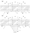
- FIG. 6B schematically shows the state of the conductor 2 including the density distribution of the metal material as described above.
- FIGS. 4 to 6 diagonal lines are drawn inside the region occupied by the conductor 2, but the higher the density of the diagonal lines, the smaller the twist pitch of the wires 2a, that is, the narrower the intervals between the wires 2a. Is shown. Further, it is shown that the larger the width (upper and lower dimensions) of the region shown as the conductor 2, the larger the diameter of the conductor 2.
- the illustrated parameters are not proportional to the twist pitch and the conductor diameter of the strand 2a, but schematically show the relative magnitude relationship for each region. Further, the illustrated parameters are discontinuous between the regions, but in the actual insulated wire 1, the state of the conductor 2 continuously changes between the regions.
- the diameter of the conductor 2 is wider than in the remote area 22 of the covering portion 20, and the conductor 2 includes the strand 2a per unit length.
- the amount of metal materials used is increasing.
- the strands 2a are bent so that the gap between the strands 2a is widened and a large space is secured between the strands 2a, and the water blocking agent 5 permeates into the space between the strands 2a. It can be performed. As a result, the water blocking agent 5 can easily penetrate into the space between the strands 2a, and the water blocking agent 5 can be filled into each part of the exposed portion 10 with high uniformity.
- the twist pitch of the wire 2a is larger than that of the covering portion 20. It is preferably smaller than the twist pitch in the remote area 22. This is because, in the exposed portion 10, the twist pitch of the wires 2a is reduced and the interval between the wires 2a is narrowed, which is also effective in improving the water blocking performance. That is, the water blocking agent 5 is filled in the space between the strands 2a in a liquid state, and the gap between the strands 2a is narrowed while the water blocking portion 4 is being formed. It is easy to make it stay uniformly in the space between the strands 2a without hanging or flowing out.
- the water blocking agent 5 When the water blocking agent 5 is cured from that state, high water blocking performance is obtained in the exposed portion 10. Further, in the exposed portion 10, since the twist pitch is smaller than that in the remote area 22, even if the density of the metal material per unit length is higher than that in the remote area 22, the conductor diameter in the exposed area 10 is reduced. In comparison with the conductor diameter in the remote area 22, it can be suppressed so as not to become excessively large. Then, the outer diameter of the entire water blocking portion 4 can be suppressed so as not to be the same or significantly larger than the outer diameter of the insulated wire 1 in the remote area 22.
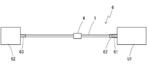
- a wire harness 6 according to an embodiment of the present invention has an insulated electric wire 1 provided with a water blocking part 4 according to the embodiment of the present invention.
- FIG. 2 shows an example of the wire harness 6 according to the present embodiment.
- electric connection portions 61 and 63 which can be connected to other devices U1 and U2 such as connectors are provided respectively.
- the wire harness 6 may include an insulated electric wire of another type in addition to the insulated electric wire 1 according to the above-described embodiment (not shown).
- the types of the electrical connecting portions 61 and 63 provided at both ends of the insulated electric wire 1 and the devices U1 and U2 to which the electrical connecting portions 61 and 63 are connected may be any type. From the viewpoint of effectively utilizing the water blocking performance of the water blocking portion 4, a preferred example is a form in which one end of the insulated wire 1 is waterproof and the other end is not waterproof.
- a waterproof structure 62 is formed on the first electrical connection portion 61 provided at one end of the insulated wire 1.
- a rubber plug that seals a space between the connector housing and the connector terminal in the connector that constitutes the first electrical connection portion 61 is provided.
- the second electric connecting portion 63 provided at the other end of the insulated wire 1 is not formed with the waterproof structure as provided in the first electric connecting portion 61. Therefore, if water adheres to the surface or the like of the second electric connecting portion 63, the water may possibly enter the inside of the second electric connecting portion 63.
- An exposed portion 10 in which the conductor 2 is exposed is formed at a midway portion of the insulated electric wire 1 that constitutes the wire harness 6, that is, a position between the first electric connection portion 61 and the second electric connection portion 63.
- a water stop portion 4 filled with a water stop agent 5 is formed in a region including the exposed portion 10.
- the specific position and the number of the water blocking portions 4 are not particularly limited, from the viewpoint of effectively suppressing the influence of water on the first electrical connection portion 61 in which the waterproof structure 62 is formed, It is preferable that at least one water shut off portion 4 be provided at a position closer to the first electrical connection portion 61 than the second electrical connection portion 63.
- the wire harness 6 having the electric connection portions 61 and 63 at both ends of the insulated wire 1 can be used to electrically connect the two devices U1 and U2.
- a device such as an electric control unit (ECU) that requires waterproofing may be applied.
- ECU electric control unit
- the second device U2 to which the second electric connection portion 63 having no waterproof structure is connected a device that does not need waterproofing may be applied.
- the insulated electric wire 1 that forms the wire harness 6 has the water blocking portion 4, even if water that has entered from the outside of the wire harness 6 travels along the wire 2a that forms the conductor 2, it is insulated.
- the movement of water along the electric wire 1 can be suppressed from proceeding beyond the water blocking portion 4. That is, the water that has entered from the outside moves beyond the water stop portion 4, reaches the electric connection portions 61 and 63 at both ends, and further enters the devices U1 and U2 connected to the electric connection portions 61 and 63. Can be suppressed.
- water adhering to the surface of the second electrical connection portion 63 that does not have a waterproof structure enters the inside of the second electrical connection portion 63, travels along the wire 2a forming the conductor 2, and is insulated. Even if the water moves along the electric wire 1, the movement of the water is blocked by the water blocking agent 5 with which the water blocking portion 4 is filled. As a result, the water cannot move beyond the water stop portion 4 toward the side where the first electrical connection portion 61 is provided, and reaches the position of the first electrical connection portion 61, where the first electrical connection is generated. It cannot enter the connection part 61 and the first device U1. In this way, by suppressing the movement of water by the water blocking portion 4, it is possible to effectively use the waterproof property of the waterproof structure 62 for the first electrical connection part 61 and the device U1.
- the effect of suppressing the movement of water by the water blocking portion 4 provided in the insulated wire 1 is irrespective of the place where the water is attached, the cause of the attachment of the water, the time when the water is attached, and the environment thereafter.
- the wire harness 6 when the wire harness 6 is provided in an automobile, water that has entered the inside of the insulated wire 1 from the non-waterproof second electrical connection portion 63 into the insulated wire 1 such as the space between the wires 2a is subject to capillarity and cold heat. It is possible to effectively suppress the intrusion into the first electrical connection portion 61 having the waterproof structure 62 and the first device U1 due to the breathing phenomenon.
- the cold-heat breathing phenomenon means that when the first electrical connection portion 61 having the waterproof structure 62 and the first device U1 are heated and then allowed to cool along with the traveling of the vehicle, the insulated electric wire 1 Then, a pressure difference is generated in which the first electric connection portion 61 side has a low pressure and the second electric connection portion 63 side has a relatively high pressure, so that the water attached to the second electric connection portion 63 is This is a phenomenon in which the electric connection portion 61 and the first device U1 are pulled up.
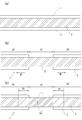
- Fig. 3 shows an outline of this manufacturing method.
- the water blocking part 4 is formed in a part of the insulated wire 1 in the longitudinal axis direction.
- the (2) density modulation step can be composed of (2-1) a compaction step and a subsequent (2-2) relaxation step.
- each step will be described.
- the specific operation in each step and the order of each step include the position where the water stop portion 4 is formed and the like. It may be appropriately adjusted according to the details of the configuration of the water shut off portion 4.
- the exposed portion 10 is formed as shown in FIG. 4B using the continuous linear insulated wire 1 as shown in FIG. 4A. ..
- the covering portions 20 are adjacent to each other on both sides in the longitudinal direction of the exposed portion 10.
- a substantially annular cut is formed on the outer periphery of the insulating coating 3 at a position corresponding to the approximate center of the region where the exposed portion 10 is to be formed. Then, the insulating coating 3 is gripped from the outer periphery on both sides of the cut and is moved along the axial direction of the insulated wire 1 so as to be separated from each other (movement M1). With the movement, the conductor 2 is exposed between the insulating coatings 3 on both sides. In this way, the exposed portion 10 can be formed adjacent to the covering portion 20.
- the filling step is performed as it is, in the space between the strands 2a forming the conductor 2 of the exposed portion 10,
- the water blocking agent 5 may be filled, but it is preferable to perform the density modulation step before the filling step so that the gaps between the wires 2a can be widened and the water blocking agent 5 can be filled with high uniformity. ..
- the density modulation step a non-uniform distribution of the density of the metal material is formed between the exposed portion 10 and the adjacent area 21 and the remote area 22 of the covering portion 20, and the wire 2a of the conductor 2 in the exposed portion 10 is formed. Widen the intervals.
- the uneven distribution of the density of the metal material specifically, the density of the metal material per unit length is higher in the exposed portion 10 than in the remote area 22.
- the formation of such a density distribution can be achieved at the same time as the interval between the wires 2a in the exposed portion 10 is increased by, for example, a compacting step and a subsequent relaxing step.
- the conductor 2 can be extended from the grip portion 30 to the exposed portion 10.
- the twist pitch of the wires 2a becomes larger in the grip portion 30 than in the beginning, and the density of the metal material per unit length becomes lower.
- a part of the metal material originally present in the grip portion 30 is applied to the exposed portion 10, and the twist pitch of the strand 2a in the exposed portion 10 becomes smaller.
- the density of the metal material per unit length in the exposed portion 10 becomes high.
- the force for gripping the insulated wire 1 from the outer periphery in the grip portion 30 should be suppressed to such an extent that the conductor 2 can move relative to the insulating coating 3. It is preferable to set.
- the conductor 2 unwound from the grips 30 on both sides of the exposed portion 10 in the compacting step does not completely return to the region covered with the insulating coating 3 again. At least a portion remains on the exposed portion 10.
- the conductor 2 is unwound to the exposed portion 10, and the twist of the strand 2a in the conductor 2 is loosened. 2a is bent and arranged. That is, as shown in FIG. 5A, in the exposed portion 10, the diameter of the region occupied by the conductor 2 as a whole becomes larger than that in the state before performing the compaction process (FIG. 4B), and the unit length is increased. The density of the metallic material per hit becomes high.
- the twist pitch in the exposed portion 10 is at least larger than that in a state in which the twist is made tight by the tightening step, and becomes larger than that before the tightening step is performed depending on the degree of relaxation. From the viewpoint of widening the interval between the strands 2a, it is better to make the twist pitch larger than that before the tightening step.
- the gripping portion 30 that grips the insulating coating 3 from the outside in the tightening step has a density of the metal material per unit length lower than that of the exposed portion 10 after the relaxing step, and is further tightened.
- the adjacent area 21 becomes lower than that before the process is performed.
- a region that is not the grip portion 30 in the compacting process, that is, a region separated from the exposed portion 10 becomes a remote region 22.
- the state of the conductor 2 such as the density of the metal material per unit length, the twisting pitch of the wires 2a, etc. is not substantially changed from before the implementation of the compacting step.
- the metal material having a lower density per unit length in the adjacent area 21 is applied to the exposed portion 10 and contributes to increase the density of the metal material per unit length in the exposed portion 10.
- the density of the metal material per unit length is highest in the exposed portion 10, second highest in the remote area 22, and lowest in the adjacent area 21.
- the uncured water blocking agent 5 is filled into the space between the strands 2 a of the exposed portion 10.
- the filling operation of the water blocking agent 5 can be performed by applying a liquid resin composition in the space between the strands 2a by any method such as coating, dipping, dropping, pouring, etc. according to the characteristics such as the viscosity of the water blocking agent 5. It can be done by introducing.
- the filling step it is preferable to fill the space between the wires 2a with the water blocking agent 5 and to dispose the water blocking agent 5 also on the outer periphery of the conductor 2 of the exposed portion 10.
- the amount of the water blocking agent 5 introduced into the exposed portion 10 may be set to an amount in which a surplus is generated even if the space between the wires 2a is filled.
- the water blocking agent 5 may be arranged not only on the outer periphery of the exposed portion 10 but also on the outer periphery of the insulating coating 3 at the end of the coating portion 20, but the coating moving step may be performed after the filling step.
- a part of the water blocking agent 5 introduced into the exposed portion 10 can be moved to the outer peripheral portion of the insulating coating 3 of the coating portion 20. Therefore, in the filling step, it is sufficient to dispose the water blocking agent 5 on the outer periphery of the exposed portion 10 in addition to the space between the strands 2a.
- the gap between the strands 2a of the exposed portion 10 is widened, and then the waterproofing agent 5 is introduced into the exposed portion 10 in the filling step, so that the portion between the spread strands 2a is introduced.
- the water blocking agent 5 easily penetrates. Therefore, the water blocking agent 5 can easily penetrate the exposed portions 10 with high uniformity and evenly.
- the highly reliable water blocking portion 4 having excellent water blocking performance can be formed. Even if the water blocking agent 5 has a relatively high viscosity of 4 Pa ⁇ s or more, by sufficiently widening the interval between the wires 2a, the space between the wires 2a can be The water blocking agent 5 can be permeated with high uniformity.
- the water blocking agent 5 may be filled in a predetermined portion of the insulated wire 1 including the region between the wires 2a by any method such as coating or dipping.
- any method such as coating or dipping.
- the immersion of the water blocking agent 5 by dipping Filling is preferred.
- the insulated wire may be brought into contact with the jet stream of the water blocking agent 5 while rotating the insulated wire 1 axially.
- the water blocking agent 5 When the space between the strands 2a of the exposed portion 10 is narrowed by the re-tightening step, the water blocking agent 5 is confined in the narrow space, so that the fluidity of the water blocking agent 5 is sufficient due to curing or the like.
- the water stop agent 5 is likely to stay in the space between the wires 2a without causing outflow or drooping until the water stops. Thereby, it becomes easy to form the highly reliable water blocking part 4 having excellent water blocking performance after the water blocking agent 5 is cured.
- the re-tightening step is preferably performed while the waterproofing agent 5 filled between the strands 2a has fluidity, that is, before the waterproofing agent 5 is cured or during curing. Then, the operation of re-tightening is less likely to be hindered by the presence of the water blocking agent 5.
- the previous filling step is performed by immersing the insulated wire 1 in the waterproof agent 5 using a jet device or the like
- re-tightening is performed while the insulated wire 1 is immersed in the waterproof agent 5. It is preferred to carry out the steps. Then, it is easy to avoid a situation in which the water blocking agent 5 is squeezed out and removed from the space between the wires 2a due to the re-tightening operation itself.
- the conductor 2 may be rotated so as to be twisted (movement M4), and the re-tightening step may be performed.
- the coating moving step As shown in FIG. 6A, the insulating coatings 3 arranged on the coating portions 20 on both sides of the exposed portion 10 are brought close to each other, It is moved toward the exposed portion 10 (movement M5).
- the coating transfer step is preferably performed while the water blocking agent 5 with which the exposed portion 10 is filled has fluidity, that is, before the water blocking agent 5 is cured or during curing.
- the coating transfer step may be performed in a substantially single operation together with the re-densification step.
- the coating transfer step is also performed.
- the insulated wire 1 may be immersed in the waterproofing agent 5 and then carried out.
- the water blocking agent 5 also spreads to such regions, and the water blocking agent 5 is filled between the strands 2a in the entire area of the exposed portion 10 where the conductor 2 is exposed. Further, a part of the water blocking agent 5 arranged on the outer periphery of the conductor 2 of the exposed portion 10 can be moved to the outer periphery of the insulating coating 3 of the coating portion 20.
- the waterproofing agent 5 is continuously formed in the three regions of the space between the wires 2a of the exposed portion 10, the outer periphery of the conductor 2 of the exposed portion 10, and the outer periphery of the insulating coating 3 at the end of the coating portion 20. It will be placed.
- the water blocking agent 5 By arranging the water blocking agent 5 in the above three regions, the water blocking performance in the region between the wires 2a is excellent, and the outer circumference is physically protected and electrically insulated through the subsequent curing step. Further, the water blocking portion 4 having excellent water blocking performance between the conductor 2 and the insulating coating 3 can be simultaneously formed from a common material. In the filling step, if the water blocking agent 5 can be sufficiently introduced into a region including the end of the exposed portion 10 and the end portions of the covering portions 20 on both sides, the coating moving step is omitted. May be.
- the water blocking agent 5 is cured.
- the water blocking agent 5 has only a contact hardening property as a hardening mechanism, at least the elapse of time may be waited until the water blocking agent 5 in contact with the wire 2a forming the conductor 2 is sufficiently hardened. ..
- the curing step it is possible to obtain the insulated electric wire 1 including the water blocking portion 4 having high water blocking performance in the space between the wires 2a.
- the water blocking agent 5 When the water blocking agent 5 has a contact hardening property as well as an extrinsic hardening property as a hardening mechanism, an operation for supplying energy or a substance from the outside to cause hardening by the extrinsic hardening mechanism is combined. You can do it.
- the light source 80 When the water blocking agent 5 has photocurability as an extrinsic curability, the light source 80 may be used to irradiate the light L as shown in FIG. 6B.
- the water blocking agent 5 When the water blocking agent 5 has a thermosetting property as an extrinsic hardening property, it may be heated by a heater or the like.
- the water blocking agent 5 When the water blocking agent 5 has a moisture hardening property as an extrinsic hardening property, it may be brought into contact with water by introducing an atmosphere containing water vapor.
- the insulated wire 1 may be rotated axially (movement M6) as shown in FIG. 6(b) until the water blocking agent 5 is sufficiently cured. If the waterproofing agent 5 is cured while the insulated electric wire 1 is kept stationary without rotating, the uncured waterproofing agent 5 hangs down due to gravity, so that the position is below the gravity direction. The water blocking agent 5 is cured in the state where the layer of the water blocking agent 5 thicker than the position above is formed. Then, in the water blocking portion 4 obtained after the water blocking agent 5 is cured, the conductor 2 becomes eccentric, and the water blocking performance and the physical characteristics may be nonuniform along the circumferential direction of the insulated wire 1. There is a nature.
- the curing step is performed while rotating the insulated electric wire 1 axially, so that the entire area of the insulated electric wire 1 along the circumferential direction, The light L from the light source 80 can be irradiated, and the photocuring of the water blocking agent 5 on the entire circumference can be advanced with high uniformity. If time is required due to movement of the insulated wire 1 between the processing devices after performing the filling step, the re-densification step, and the coating moving step and before starting the curing step, the time is required. Also during this period, it is preferable to rotate the insulated electric wire 1 so as to prevent the waterproofing agent 5 from hanging down at a specific position along the circumferential direction.
- Test method (1) Preparation of sample Insulation in which a 0.35 mm thick insulating coating made of PVC is formed on the outer circumference of a copper stranded wire conductor having a conductor cross-sectional area of 0.5 mm 2 (element wire diameter 0.18 mm, number of wires 20) An exposed portion having a length of 13 to 15 mm was formed in the middle of the electric wire. And the water stop part was formed in the exposed part using the water stop agent. At this time, as shown in the flow chart of FIG. 3, each step was sequentially performed.
- the filling step, the re-densification step, and the coating transfer step were performed using a jet device in a state where the site including the exposed portion of the insulated wire was in contact with the jet of the water blocking agent.
- the curing step was performed while rotating the insulated wire.
- the water blocking agent was cured by an operation according to the type of curability of each curing agent.
- the curing time that is, the time during which each operation for curing was continued, was set to 1 minute and 8 hours.
- the specific material used as the water blocking agent, the type of curability of each material, and the operation performed for curing each material are as follows. All the water blocking agents are made of acrylic resin. -Example 1: "1377B” manufactured by ThreeBond; anaerobic curability; cured by contact with metal and anaerobic conditions. Example 2: “3062F” manufactured by ThreeBond; anaerobic curability and ultraviolet (UV) curability; UV irradiation.
- Table 1 summarizes the characteristics of the water blocking agent and the results of the leak test when two different curing times are adopted.
- the PVC adhesive force is a value measured by adhering a waterproofing agent layer having an inner diameter of 6 mm and a thickness of 3 mm to the surface of PVC and pulling it vertically.
- the viscosity is a value measured by a BL type rotational viscometer.
- the curing mechanism in the curing mechanism of factors such as UV curability, moisture curability, and heat curability, which are supplied from the outside, the curing mechanism is located inside the layer of the waterproofing agent, and factors such as light, moisture, and heat. It is construed that the hardening of the waterproofing agent cannot be sufficiently advanced in a short time at the interface between the waterproofing agent and the conductor wire, which is hard to reach from the outside. In particular, in Comparative Examples 1 and 3, the curing can be sufficiently promoted even at a long time at the interface with the strand, which requires sufficient curing of the waterproofing agent from the viewpoint of ensuring the waterproof performance with respect to the conductor. Absent.
- the water blocking agent exhibits an adhesive force of 0.3 MPa or more with respect to PVC, and the water blocking performance obtained in the leak test is evaluated to be insufficient. It can be associated with insufficient adhesion at the interface between the wire constituting the conductor and the waterproof agent, not at the interface between the insulating coating and the waterproof agent.
- the water blocking agent has anaerobic curability
- the water blocking agent was cured in a short time of 1 minute, not only when the water blocking agent was cured over a long period of 8 hours. Even after the termination, a high leakproof performance was confirmed between the strands in the leak test. In other words, even in the case of curing for a short time, the water blocking agent is sufficiently hardened in the state where it is in close contact with the interface of the conductor and the wire, and a water blocking portion showing high water blocking performance for the electric wire conductor can be formed. ..
- the water-stopping agent has anaerobic curability, so that even at the interface with the wire located inside the layer of the water-stopping agent, contact with the metal forming the wire and the water-stopping agent It can be construed that the curing of the waterproofing agent is sufficiently advanced by blocking the air by the layer itself.
- the water blocking agent has photo-curing property but does not have anaerobic curing property, one wire becomes a shade of another wire and stops.
- the anaerobic curing mechanism can sufficiently cure the waterproofing agent.
- Example 2 in which the water blocking agent has adhesiveness to PVC and also has UV curability in addition to anaerobic curability, even when the curing is completed in a short time of 1 minute, a leak occurs.
- bubbles were not generated not only between the wires, but also in the middle of the water stop and the end of the insulated wire. It has been confirmed that the portion between the liquid medicine and the insulating coating also has high water-stopping performance. This is because the water blocking agent has UV curability in addition to anaerobic curability, so that the outer peripheral portion is also cured in a short time.
- the insulating coating layer that adheres to the outer periphery of the conductor and covers the conductor. Since the water blocking agent has UV curability, the outer peripheral portion of the layer of the water blocking agent can be easily hardened, so that it is easy to prevent the water blocking agent from hanging during curing. preferable.
- the waterproof agent when provided with only external hardening, such as photo-curing property, moisture-curing property, and thermosetting property, at the interface with the strand of the conductor located inside the waterproofing agent layer, Whereas the water blocking agent cannot be sufficiently hardened in a short time to form a water blocking portion having high water blocking performance, when the water blocking agent has an anaerobic curability which is a kind of contact curability, It is confirmed that at the interface with the line, the water blocking agent can be sufficiently cured in a short time to form a water blocking portion having high water blocking performance. Further, in the case where the water blocking agent has both the contact curability and the extrinsic curability, the outer peripheral portion of the water blocking agent can be cured in a short time.
Landscapes
- Insulated Conductors (AREA)
Priority Applications (17)
| Application Number | Priority Date | Filing Date | Title |
|---|---|---|---|
| DE112019006760.5T DE112019006760B4 (de) | 2019-01-30 | 2019-01-30 | Isolierter elektrischer draht und verkabelung |
| CN201980089342.6A CN113316828A (zh) | 2019-01-30 | 2019-01-30 | 绝缘电线及线束 |
| JP2020569238A JP7226455B2 (ja) | 2019-01-30 | 2019-01-30 | 絶縁電線およびワイヤーハーネス |
| US17/426,577 US11908598B2 (en) | 2019-01-30 | 2019-01-30 | Insulated electric wire and harness with water-stopping agent and wire harness |
| PCT/JP2019/003195 WO2020157867A1 (ja) | 2019-01-30 | 2019-01-30 | 絶縁電線およびワイヤーハーネス |
| JP2019219009A JP7318512B2 (ja) | 2019-01-30 | 2019-12-03 | 絶縁電線およびワイヤーハーネス |
| US17/426,530 US11887757B2 (en) | 2019-01-30 | 2020-01-17 | Insulated electric wire and wire harness |
| CN202080011525.9A CN113396460B (zh) | 2019-01-30 | 2020-01-17 | 绝缘电线及线束 |
| PCT/JP2020/001453 WO2020158445A1 (ja) | 2019-01-30 | 2020-01-17 | 絶縁電線およびワイヤーハーネス |
| DE112020000594.1T DE112020000594B4 (de) | 2019-01-30 | 2020-01-17 | Isolierter elektrischer Draht und Verkabelung |
| JP2020569720A JP7103440B2 (ja) | 2019-01-30 | 2020-01-30 | 絶縁電線およびワイヤーハーネス |
| PCT/JP2020/003430 WO2020158862A1 (ja) | 2019-01-30 | 2020-01-30 | 絶縁電線およびワイヤーハーネス |
| CN202080011663.7A CN113366588B (zh) | 2019-01-30 | 2020-01-30 | 绝缘电线及线束 |
| DE112020000604.2T DE112020000604B4 (de) | 2019-01-30 | 2020-01-30 | Isolierter elektrischer draht und verkabelung |
| US17/426,581 US11887758B2 (en) | 2019-01-30 | 2020-01-30 | Wire harness and insulated electric wire thereof having water-stopping agent |
| JP2023018571A JP7405289B2 (ja) | 2019-01-30 | 2023-02-09 | 絶縁電線およびワイヤーハーネス |
| US18/411,937 US12249444B2 (en) | 2019-01-30 | 2024-01-12 | Insulated electric wire and wire harness |
Applications Claiming Priority (1)
| Application Number | Priority Date | Filing Date | Title |
|---|---|---|---|
| PCT/JP2019/003195 WO2020157867A1 (ja) | 2019-01-30 | 2019-01-30 | 絶縁電線およびワイヤーハーネス |
Related Child Applications (2)
| Application Number | Title | Priority Date | Filing Date |
|---|---|---|---|
| US17/426,577 A-371-Of-International US11908598B2 (en) | 2019-01-30 | 2019-01-30 | Insulated electric wire and harness with water-stopping agent and wire harness |
| US18/411,937 Continuation US12249444B2 (en) | 2019-01-30 | 2024-01-12 | Insulated electric wire and wire harness |
Publications (1)
| Publication Number | Publication Date |
|---|---|
| WO2020157867A1 true WO2020157867A1 (ja) | 2020-08-06 |
Family
ID=71841435
Family Applications (1)
| Application Number | Title | Priority Date | Filing Date |
|---|---|---|---|
| PCT/JP2019/003195 Ceased WO2020157867A1 (ja) | 2019-01-30 | 2019-01-30 | 絶縁電線およびワイヤーハーネス |
Country Status (5)
| Country | Link |
|---|---|
| US (2) | US11908598B2 (https=) |
| JP (2) | JP7226455B2 (https=) |
| CN (1) | CN113316828A (https=) |
| DE (1) | DE112019006760B4 (https=) |
| WO (1) | WO2020157867A1 (https=) |
Cited By (4)
| Publication number | Priority date | Publication date | Assignee | Title |
|---|---|---|---|---|
| US20220028581A1 (en) * | 2019-01-30 | 2022-01-27 | Autonetworks Technologies, Ltd. | Insulated electric wire, wire harness, and insulated electric wire production method |
| US20220157491A1 (en) * | 2019-01-30 | 2022-05-19 | Autonetworks Technologies, Ltd. | Insulated electric wire and wire harness |
| US20220165453A1 (en) * | 2019-01-30 | 2022-05-26 | Autonetworks Technologies, Ltd. | Insulated electric wire and wire harness |
| US11887757B2 (en) | 2019-01-30 | 2024-01-30 | Autonetworks Technologies, Ltd. | Insulated electric wire and wire harness |
Families Citing this family (1)
| Publication number | Priority date | Publication date | Assignee | Title |
|---|---|---|---|---|
| JP7421751B2 (ja) * | 2020-03-30 | 2024-01-25 | 住友電装株式会社 | ワイヤハーネス |
Citations (4)
| Publication number | Priority date | Publication date | Assignee | Title |
|---|---|---|---|---|
| WO2007013589A1 (ja) * | 2005-07-29 | 2007-02-01 | Yazaki Corporation | アース用電線の止水方法およびアース用電線 |
| JP2007226999A (ja) * | 2006-02-21 | 2007-09-06 | Auto Network Gijutsu Kenkyusho:Kk | 止水用液剤の供給方法、供給装置、およびこれを用いた車載用電線の止水処理方法ならびに車載用電線 |
| DE102011083952A1 (de) * | 2011-10-04 | 2013-04-04 | Sumitomo Electric Bordnetze Gmbh | Verfahren zur Herstellung einer längswasserdichten Anordnung |
| JP2013097922A (ja) * | 2011-10-28 | 2013-05-20 | Yazaki Corp | 芯線止水構造及び芯線止水方法 |
Family Cites Families (107)
| Publication number | Priority date | Publication date | Assignee | Title |
|---|---|---|---|---|
| US2396702A (en) * | 1942-05-05 | 1946-03-19 | Ellis A Johnson | Water stop device for electrical cables |
| US3639567A (en) * | 1968-11-05 | 1972-02-01 | Minnesota Mining & Mfg | Method for cable-blocking with polyurethane foam |
| US3737557A (en) * | 1972-06-27 | 1973-06-05 | British Insulated Callenders | Electric cables with ethylene-propylene insulation |
| JPS5314169U (https=) | 1976-07-19 | 1978-02-06 | ||
| US4333706A (en) * | 1979-12-26 | 1982-06-08 | Siecor Corporation | Filling materials for communications cable |
| US4361507A (en) * | 1980-10-20 | 1982-11-30 | Arco Polymers, Inc. | Cable filler composition containing (a) crystalline polypropylene homopolymer, (b) styrene block copolymer and (c) mineral oil |
| IT1135514B (it) * | 1981-02-18 | 1986-08-27 | Pirelli Cavi Spa | Cavo elettrico |
| JPH0629889B2 (ja) * | 1985-08-19 | 1994-04-20 | 日本大洋海底電線株式会社 | 海底光ケーブル |
| US4711022A (en) * | 1986-03-26 | 1987-12-08 | Freeman Clarence S | Method for wire insulation |
| DE3708216A1 (de) * | 1987-03-12 | 1988-09-22 | Siemens Ag | Optisches und/oder elektrisches kabel |
| JP2588888B2 (ja) * | 1987-03-31 | 1997-03-12 | 昭和電線電纜株式会社 | 水密ow電線 |
| US4978694A (en) * | 1987-04-23 | 1990-12-18 | Dow Corning Corporation | Silicone water block for electrical cables |
| ATE91562T1 (de) * | 1988-03-18 | 1993-07-15 | Dsg Schrumpfschlauch Gmbh | Verfahren und vorrichtung zum laengswasserabdichten vieladriger kabelbuendel. |
| US5171635A (en) * | 1990-10-10 | 1992-12-15 | E. I. Du Pont De Nemours And Company | Composite wire construction |
| US5902849A (en) * | 1991-11-07 | 1999-05-11 | Henkel Kommanditgesellschaft Auf Aktien | Filling compound |
| US5281757A (en) * | 1992-08-25 | 1994-01-25 | Pirelli Cable Corporation | Multi-layer power cable with metal sheath free to move relative to adjacent layers |
| JPH0777090B2 (ja) * | 1993-05-31 | 1995-08-16 | タツタ電線株式会社 | 屋外用塩化ビニル絶縁電線 |
| JPH08185722A (ja) * | 1994-12-28 | 1996-07-16 | Sumitomo Wiring Syst Ltd | 止水電線および該止水電線の製造方法 |
| JPH08335411A (ja) * | 1995-06-06 | 1996-12-17 | Fujikura Ltd | 走水防止電力ケーブル |
| JPH09102222A (ja) * | 1995-10-05 | 1997-04-15 | Nitto Denko Corp | ワイヤーハーネスの止水方法及び止水材料 |
| JPH09205714A (ja) | 1996-01-26 | 1997-08-05 | Furukawa Electric Co Ltd:The | 難着雪電線 |
| JPH09204822A (ja) * | 1996-01-29 | 1997-08-05 | Sumitomo Wiring Syst Ltd | 止水機能付ケーブル及びその製造方法 |
| US6064007A (en) * | 1996-04-29 | 2000-05-16 | Electric Power Research Institute Inc. | Moisture resistant underground cable |
| JP3680878B2 (ja) * | 1996-07-26 | 2005-08-10 | 三洋化成工業株式会社 | 保護管付地下埋設ケーブル用止水材及び止水性構造体 |
| JPH10204227A (ja) * | 1997-01-27 | 1998-08-04 | Fujikura Ltd | 水密組成物および水密絶縁電線 |
| JPH11224541A (ja) * | 1998-02-05 | 1999-08-17 | Sumitomo Wiring Syst Ltd | ワイヤハーネスの防水方法および該方法に用いる装置 |
| JP4028091B2 (ja) | 1998-06-22 | 2007-12-26 | 古河電気工業株式会社 | 止水部付き電線の製造方法 |
| JP4069513B2 (ja) | 1998-09-04 | 2008-04-02 | 旭硝子株式会社 | リード線および該リード線の接続された太陽電池パネル |
| JP2002209323A (ja) * | 2001-01-09 | 2002-07-26 | Sumitomo Wiring Syst Ltd | ワイヤハーネスの防水処理方法及び装置 |
| JP3692315B2 (ja) * | 2001-08-06 | 2005-09-07 | 住友電気工業株式会社 | 圧縮導体を使用した水密絶縁電線。 |
| AU2003236055A1 (en) * | 2002-04-11 | 2003-10-20 | Nok Corporation | Sealing structure |
| JP2004018652A (ja) * | 2002-06-14 | 2004-01-22 | Fujikura Ltd | 半導電水密組成物 |
| JP4105055B2 (ja) * | 2002-12-27 | 2008-06-18 | 矢崎総業株式会社 | 被覆電線の止水構造 |
| JP2004355897A (ja) * | 2003-05-28 | 2004-12-16 | Hitachi Unisia Automotive Ltd | 電線のシール構造 |
| JP2005019392A (ja) | 2003-05-30 | 2005-01-20 | Kurabe Ind Co Ltd | 気密電線と気密電線製造方法 |
| JP2005032621A (ja) | 2003-07-08 | 2005-02-03 | Union Machinery Co Ltd | ケーブルハーネスの防水構造 |
| JP4445727B2 (ja) * | 2003-07-29 | 2010-04-07 | 株式会社フジクラ | 水密樹脂組成物および水密絶縁電線 |
| JP2006032127A (ja) * | 2004-07-16 | 2006-02-02 | Furukawa Electric Co Ltd:The | 止水部を有する電線束及びその製造方法 |
| DE102004040293B3 (de) * | 2004-08-19 | 2006-03-30 | Airbus Deutschland Gmbh | Montageteil für eine flüssigkeitsdichte Kabeldurchführung |
| US7186929B2 (en) * | 2005-07-08 | 2007-03-06 | 3M Innovative Properties Company | Sealing member for an entry port |
| CN101300645B (zh) * | 2005-11-02 | 2011-12-28 | 株式会社自动网络技术研究所 | 车载电线类的止水处理方法 |
| JP2006074068A (ja) * | 2005-11-09 | 2006-03-16 | Fuji Electric Holdings Co Ltd | 太陽電池モジュールの固定方法ならびに太陽電池モジュール |
| JP4794988B2 (ja) | 2005-11-09 | 2011-10-19 | 平河ヒューテック株式会社 | 絶縁ケーブル端末 |
| JP4918248B2 (ja) | 2005-11-16 | 2012-04-18 | 矢崎総業株式会社 | 線間止水方法、線間止水装置、およびワイヤハーネス |
| JP5188713B2 (ja) * | 2006-02-02 | 2013-04-24 | 株式会社オートネットワーク技術研究所 | ドレン線止水構造を備えたシールド線およびドレン線止水方法 |
| JP5117008B2 (ja) | 2006-03-22 | 2013-01-09 | 古河電気工業株式会社 | 電線芯線の止水処理構造及び電線芯線の止水処理方法 |
| JP5075356B2 (ja) * | 2006-05-25 | 2012-11-21 | 矢崎総業株式会社 | シールド電線の止水治具 |
| DE102006047199A1 (de) * | 2006-10-05 | 2008-04-17 | Siemens Ag | Anordnung mit einem Basiselement und mindestens einem ersten flexiblen Leiterbahnträger und einem zweiten flexiblen Leiterbahnträger |
| JP2008117616A (ja) | 2006-11-02 | 2008-05-22 | Yazaki Corp | 電線間止水構造及び電線間止水方法 |
| JP4996205B2 (ja) * | 2006-11-08 | 2012-08-08 | 株式会社オートネットワーク技術研究所 | 電線の止水処理方法 |
| JP2008226487A (ja) * | 2007-03-08 | 2008-09-25 | Auto Network Gijutsu Kenkyusho:Kk | シールド電線及びシールド電線のシール方法 |
| JP2009093952A (ja) * | 2007-10-10 | 2009-04-30 | Sumitomo Electric Ind Ltd | 絶縁電線および絶縁電線の製造方法 |
| WO2009060639A1 (ja) | 2007-11-08 | 2009-05-14 | Sumitomo Wiring Systems, Ltd. | 電線の止水方法及び該止水方法で形成された止水部を有する電線 |
| JP5304001B2 (ja) * | 2007-11-08 | 2013-10-02 | 住友電装株式会社 | 電線の止水方法及び該止水方法で形成された止水部を有する電線 |
| JP5176533B2 (ja) * | 2007-12-19 | 2013-04-03 | 住友電装株式会社 | 電線の止水方法及び該止水方法で形成された止水部を有する電線 |
| JP2009231099A (ja) * | 2008-03-24 | 2009-10-08 | Furukawa Electric Co Ltd:The | 止水部付き電線の製造方法および止水部付き電線 |
| JP5320809B2 (ja) * | 2008-05-08 | 2013-10-23 | 住友電装株式会社 | ワイヤハーネスの止水構造および止水部の形成方法 |
| US8337227B2 (en) * | 2008-05-15 | 2012-12-25 | Sumitomo Wiring Systems, Ltd. | Water stop structure for wire harness |
| JP5586142B2 (ja) * | 2008-11-10 | 2014-09-10 | 矢崎総業株式会社 | 線材の止水方法 |
| JP5402225B2 (ja) * | 2008-11-26 | 2014-01-29 | Jsr株式会社 | 電線止水材用キット、電線止水材、止水部材、止水処理された電線および止水処理方法 |
| JP5382848B2 (ja) * | 2008-12-02 | 2014-01-08 | 矢崎総業株式会社 | 線材の止水構造および線材の止水方法 |
| JP5383264B2 (ja) * | 2009-03-16 | 2014-01-08 | ユニチカ株式会社 | 電線、電線構造体、電線の製造方法、および電線構造体の製造方法 |
| JP5391773B2 (ja) * | 2009-03-26 | 2014-01-15 | 株式会社オートネットワーク技術研究所 | ワイヤハーネスへの線間止水方法 |
| JP5541901B2 (ja) | 2009-10-30 | 2014-07-09 | 矢崎総業株式会社 | 止水処理方法および絶縁被覆電線 |
| EP2506267A4 (en) * | 2009-11-25 | 2014-12-31 | Autonetworks Technologies Ltd | METHOD FOR PRODUCING ELECTRICAL BEAM, AND ELECTRICAL BEAM |
| JP5482140B2 (ja) * | 2009-11-25 | 2014-04-23 | 株式会社オートネットワーク技術研究所 | ワイヤーハーネスの製造方法、及びワイヤーハーネス |
| JP5526732B2 (ja) * | 2009-11-25 | 2014-06-18 | 株式会社オートネットワーク技術研究所 | ワイヤーハーネスの製造方法、及びワイヤーハーネス |
| JP5581929B2 (ja) * | 2010-09-15 | 2014-09-03 | 住友電装株式会社 | ワイヤハーネスの防水構造 |
| JP5418457B2 (ja) * | 2010-09-30 | 2014-02-19 | 住友電装株式会社 | 電線の止水中間スプライス部の製造方法及び電線の止水中間スプライス部 |
| US8748741B2 (en) * | 2010-10-25 | 2014-06-10 | Tyco Electronics Corporation | Corrosion resistant multiple tap connectors |
| KR20140002014A (ko) | 2011-04-29 | 2014-01-07 | 스미토모 덴키 고교 가부시키가이샤 | 소경 케이블 하네스 및 그것의 제조 방법 |
| JP2012248527A (ja) * | 2011-05-31 | 2012-12-13 | Auto Network Gijutsu Kenkyusho:Kk | ワイヤーハーネス及びその製造方法 |
| FR2982454B1 (fr) * | 2011-11-04 | 2015-11-20 | Somfy Sas | Boitier electrique ou electronique destine a etre monte sur une structure presentant des irregularites de surface |
| JP2013251166A (ja) * | 2012-06-01 | 2013-12-12 | Auto Network Gijutsu Kenkyusho:Kk | ワイヤーハーネス及びその製造方法 |
| JP5944300B2 (ja) * | 2012-11-15 | 2016-07-05 | 株式会社フジクラ | ガス保守可能なケーブルの止水構造、止水構造の製造方法及び止水キット |
| JP2014107976A (ja) | 2012-11-28 | 2014-06-09 | Fujikura Ltd | 被覆電線の止水処理方法および被覆電線の止水構造 |
| JP5924288B2 (ja) * | 2013-02-15 | 2016-05-25 | 住友電装株式会社 | 電線スプライス部の止水方法及び電線群整列装置 |
| CH708104A2 (de) | 2013-03-07 | 2014-11-14 | Huber+Suhner Ag | Abgedichtetes Leiterkabel. |
| JP5475158B1 (ja) * | 2013-03-25 | 2014-04-16 | タツタ電線株式会社 | 水密絶縁電線 |
| JP2014203806A (ja) | 2013-04-10 | 2014-10-27 | 矢崎総業株式会社 | 電線の止水構造及びその製造方法 |
| JP2014203808A (ja) * | 2013-04-10 | 2014-10-27 | 矢崎総業株式会社 | 止水用電線及び電線止水構造 |
| JP2015173008A (ja) * | 2014-03-11 | 2015-10-01 | 株式会社オートネットワーク技術研究所 | ワイヤーハーネスおよび止水剤 |
| US9419388B2 (en) * | 2014-05-30 | 2016-08-16 | Ppc Broadband, Inc. | Transition device for coaxial cables |
| CN106457738B (zh) * | 2014-07-15 | 2019-05-03 | 住友电工超效能高分子股份有限公司 | 热收缩管、热收缩帽以及电线束的防水方法 |
| JP6264239B2 (ja) * | 2014-09-11 | 2018-01-24 | 株式会社オートネットワーク技術研究所 | ワイヤーハーネス |
| JP6393582B2 (ja) * | 2014-10-30 | 2018-09-19 | 株式会社オートネットワーク技術研究所 | ワイヤーハーネス |
| JP6172127B2 (ja) * | 2014-11-28 | 2017-08-02 | 株式会社オートネットワーク技術研究所 | ワイヤーハーネス |
| JP2016119168A (ja) | 2014-12-18 | 2016-06-30 | 住友電装株式会社 | 端子金具付電線の端末止水構造 |
| JP2016163509A (ja) * | 2015-03-05 | 2016-09-05 | 住友電装株式会社 | ワイヤハーネスの防水構造 |
| JP2016225112A (ja) | 2015-05-29 | 2016-12-28 | 株式会社オートネットワーク技術研究所 | 端子付き電線及びその製造方法 |
| US9853342B2 (en) * | 2015-07-14 | 2017-12-26 | At&T Intellectual Property I, L.P. | Dielectric transmission medium connector and methods for use therewith |
| JP2017079544A (ja) * | 2015-10-20 | 2017-04-27 | 住友電装株式会社 | 被覆電線の中間スプライス部防水構造 |
| JP6439743B2 (ja) | 2016-04-27 | 2018-12-19 | 株式会社オートネットワーク技術研究所 | ワイヤーハーネス |
| CN106847407A (zh) | 2016-12-13 | 2017-06-13 | 张长增 | 数据线缆及其制造方法和设备以及数据连接线及其制造方法 |
| CN206370303U (zh) * | 2017-01-12 | 2017-08-01 | 福建建润电子科技股份有限公司 | 一种抗挠漂浮电源线 |
| CN106898419A (zh) * | 2017-04-14 | 2017-06-27 | 杭州富通电线电缆有限公司 | 一种光电复合缆 |
| US9949392B1 (en) * | 2017-05-02 | 2018-04-17 | Omron Corporation | Electronic apparatus |
| JP6525032B2 (ja) * | 2017-07-26 | 2019-06-05 | 株式会社オートネットワーク技術研究所 | 絶縁電線 |
| JP6798438B2 (ja) * | 2017-07-26 | 2020-12-09 | 株式会社オートネットワーク技術研究所 | 絶縁電線の製造方法および絶縁電線 |
| CN111788639B (zh) | 2018-03-14 | 2022-06-14 | 株式会社自动网络技术研究所 | 电线导体、包覆电线、线束及电线导体的制造方法 |
| JP6856047B2 (ja) * | 2018-03-30 | 2021-04-07 | 株式会社オートネットワーク技術研究所 | 電線の防水構造 |
| CN109065232B (zh) * | 2018-06-25 | 2024-07-19 | 江苏华能电缆股份有限公司 | 油气勘探机器人用碳纤维光纤承荷探测电缆 |
| CN109215857A (zh) * | 2018-08-31 | 2019-01-15 | 江苏艾立可电子科技有限公司 | 一种高性能水下焊接电缆 |
| JP7318512B2 (ja) * | 2019-01-30 | 2023-08-01 | 株式会社オートネットワーク技術研究所 | 絶縁電線およびワイヤーハーネス |
| DE112020000594B4 (de) * | 2019-01-30 | 2025-05-28 | Autonetworks Technologies, Ltd. | Isolierter elektrischer Draht und Verkabelung |
| JP7226455B2 (ja) * | 2019-01-30 | 2023-02-21 | 株式会社オートネットワーク技術研究所 | 絶縁電線およびワイヤーハーネス |
| JP7226456B2 (ja) * | 2019-01-30 | 2023-02-21 | 株式会社オートネットワーク技術研究所 | 絶縁電線、ワイヤーハーネス、絶縁電線の製造方法 |
-
2019
- 2019-01-30 JP JP2020569238A patent/JP7226455B2/ja active Active
- 2019-01-30 US US17/426,577 patent/US11908598B2/en active Active
- 2019-01-30 CN CN201980089342.6A patent/CN113316828A/zh active Pending
- 2019-01-30 WO PCT/JP2019/003195 patent/WO2020157867A1/ja not_active Ceased
- 2019-01-30 DE DE112019006760.5T patent/DE112019006760B4/de active Active
-
2023
- 2023-02-09 JP JP2023018571A patent/JP7405289B2/ja active Active
-
2024
- 2024-01-12 US US18/411,937 patent/US12249444B2/en active Active
Patent Citations (4)
| Publication number | Priority date | Publication date | Assignee | Title |
|---|---|---|---|---|
| WO2007013589A1 (ja) * | 2005-07-29 | 2007-02-01 | Yazaki Corporation | アース用電線の止水方法およびアース用電線 |
| JP2007226999A (ja) * | 2006-02-21 | 2007-09-06 | Auto Network Gijutsu Kenkyusho:Kk | 止水用液剤の供給方法、供給装置、およびこれを用いた車載用電線の止水処理方法ならびに車載用電線 |
| DE102011083952A1 (de) * | 2011-10-04 | 2013-04-04 | Sumitomo Electric Bordnetze Gmbh | Verfahren zur Herstellung einer längswasserdichten Anordnung |
| JP2013097922A (ja) * | 2011-10-28 | 2013-05-20 | Yazaki Corp | 芯線止水構造及び芯線止水方法 |
Cited By (8)
| Publication number | Priority date | Publication date | Assignee | Title |
|---|---|---|---|---|
| US20220028581A1 (en) * | 2019-01-30 | 2022-01-27 | Autonetworks Technologies, Ltd. | Insulated electric wire, wire harness, and insulated electric wire production method |
| US20220157491A1 (en) * | 2019-01-30 | 2022-05-19 | Autonetworks Technologies, Ltd. | Insulated electric wire and wire harness |
| US20220165453A1 (en) * | 2019-01-30 | 2022-05-26 | Autonetworks Technologies, Ltd. | Insulated electric wire and wire harness |
| US11887759B2 (en) | 2019-01-30 | 2024-01-30 | Autonetworks Technologies, Ltd. | Insulated electric wire with water-stopping agent, wire harness, and insulated electric wire production method |
| US11887757B2 (en) | 2019-01-30 | 2024-01-30 | Autonetworks Technologies, Ltd. | Insulated electric wire and wire harness |
| US11887758B2 (en) * | 2019-01-30 | 2024-01-30 | Autonetworks Technologies, Ltd. | Wire harness and insulated electric wire thereof having water-stopping agent |
| US11908598B2 (en) * | 2019-01-30 | 2024-02-20 | Autonetworks Technologies, Ltd. | Insulated electric wire and harness with water-stopping agent and wire harness |
| US12249444B2 (en) * | 2019-01-30 | 2025-03-11 | Autonetworks Technologies, Ltd. | Insulated electric wire and wire harness |
Also Published As
| Publication number | Publication date |
|---|---|
| US20240153671A1 (en) | 2024-05-09 |
| CN113316828A (zh) | 2021-08-27 |
| JPWO2020157867A1 (ja) | 2021-12-02 |
| US11908598B2 (en) | 2024-02-20 |
| JP7405289B2 (ja) | 2023-12-26 |
| DE112019006760T5 (de) | 2021-11-18 |
| JP2023053120A (ja) | 2023-04-12 |
| DE112019006760B4 (de) | 2025-05-28 |
| US12249444B2 (en) | 2025-03-11 |
| JP7226455B2 (ja) | 2023-02-21 |
| US20220165453A1 (en) | 2022-05-26 |
Similar Documents
| Publication | Publication Date | Title |
|---|---|---|
| JP7405289B2 (ja) | 絶縁電線およびワイヤーハーネス | |
| JP6798438B2 (ja) | 絶縁電線の製造方法および絶縁電線 | |
| WO2020157868A1 (ja) | 絶縁電線、ワイヤーハーネス、絶縁電線の製造方法 | |
| JP7103440B2 (ja) | 絶縁電線およびワイヤーハーネス | |
| CN102598161A (zh) | 止水处理方法和绝缘套电线 | |
| JP2010153344A (ja) | シールド線の端末止水方法および端末止水部を備えたシールド線 | |
| JP2016163509A (ja) | ワイヤハーネスの防水構造 | |
| WO2020158445A1 (ja) | 絶縁電線およびワイヤーハーネス | |
| JP2019029093A (ja) | 絶縁電線 | |
| JP7298756B2 (ja) | 絶縁電線の製造方法および絶縁電線 | |
| JP2009136039A (ja) | スプライス部の防水方法および防水スプライス部を備えたワイヤハーネス | |
| JP7095727B2 (ja) | 絶縁電線の製造方法および絶縁電線 | |
| JP6299048B2 (ja) | 熱収縮チューブ及び熱収縮キャップ | |
| TW200836219A (en) | Method of making sealed harness, sealing agent for harness and sealed harness | |
| JP2014128135A (ja) | 電力ケーブルの接続方法及び接続構造 | |
| JP2024143134A (ja) | 接続電線及び接続電線の製造方法 | |
| JP2009283341A (ja) | 電線スプライス部の防水構造 |
Legal Events
| Date | Code | Title | Description |
|---|---|---|---|
| 121 | Ep: the epo has been informed by wipo that ep was designated in this application |
Ref document number: 19913578 Country of ref document: EP Kind code of ref document: A1 |
|
| ENP | Entry into the national phase |
Ref document number: 2020569238 Country of ref document: JP Kind code of ref document: A |
|
| 122 | Ep: pct application non-entry in european phase |
Ref document number: 19913578 Country of ref document: EP Kind code of ref document: A1 |
|
| WWG | Wipo information: grant in national office |
Ref document number: 112019006760 Country of ref document: DE |