WO2013129496A1 - Séparateur d'huile - Google Patents
Séparateur d'huile Download PDFInfo
- Publication number
- WO2013129496A1 WO2013129496A1 PCT/JP2013/055188 JP2013055188W WO2013129496A1 WO 2013129496 A1 WO2013129496 A1 WO 2013129496A1 JP 2013055188 W JP2013055188 W JP 2013055188W WO 2013129496 A1 WO2013129496 A1 WO 2013129496A1
- Authority
- WO
- WIPO (PCT)
- Prior art keywords
- drain
- housing
- air
- oil separator
- oil
- Prior art date
Links
Images


Classifications
-
- F—MECHANICAL ENGINEERING; LIGHTING; HEATING; WEAPONS; BLASTING
- F01—MACHINES OR ENGINES IN GENERAL; ENGINE PLANTS IN GENERAL; STEAM ENGINES
- F01M—LUBRICATING OF MACHINES OR ENGINES IN GENERAL; LUBRICATING INTERNAL COMBUSTION ENGINES; CRANKCASE VENTILATING
- F01M13/00—Crankcase ventilating or breathing
- F01M13/02—Crankcase ventilating or breathing by means of additional source of positive or negative pressure
-
- F—MECHANICAL ENGINEERING; LIGHTING; HEATING; WEAPONS; BLASTING
- F04—POSITIVE - DISPLACEMENT MACHINES FOR LIQUIDS; PUMPS FOR LIQUIDS OR ELASTIC FLUIDS
- F04B—POSITIVE-DISPLACEMENT MACHINES FOR LIQUIDS; PUMPS
- F04B39/00—Component parts, details, or accessories, of pumps or pumping systems specially adapted for elastic fluids, not otherwise provided for in, or of interest apart from, groups F04B25/00 - F04B37/00
- F04B39/04—Measures to avoid lubricant contaminating the pumped fluid
-
- B—PERFORMING OPERATIONS; TRANSPORTING
- B01—PHYSICAL OR CHEMICAL PROCESSES OR APPARATUS IN GENERAL
- B01D—SEPARATION
- B01D45/00—Separating dispersed particles from gases or vapours by gravity, inertia, or centrifugal forces
- B01D45/02—Separating dispersed particles from gases or vapours by gravity, inertia, or centrifugal forces by utilising gravity
-
- B—PERFORMING OPERATIONS; TRANSPORTING
- B01—PHYSICAL OR CHEMICAL PROCESSES OR APPARATUS IN GENERAL
- B01D—SEPARATION
- B01D45/00—Separating dispersed particles from gases or vapours by gravity, inertia, or centrifugal forces
- B01D45/04—Separating dispersed particles from gases or vapours by gravity, inertia, or centrifugal forces by utilising inertia
- B01D45/08—Separating dispersed particles from gases or vapours by gravity, inertia, or centrifugal forces by utilising inertia by impingement against baffle separators
-
- B—PERFORMING OPERATIONS; TRANSPORTING
- B01—PHYSICAL OR CHEMICAL PROCESSES OR APPARATUS IN GENERAL
- B01D—SEPARATION
- B01D46/00—Filters or filtering processes specially modified for separating dispersed particles from gases or vapours
- B01D46/0027—Filters or filtering processes specially modified for separating dispersed particles from gases or vapours with additional separating or treating functions
- B01D46/003—Filters or filtering processes specially modified for separating dispersed particles from gases or vapours with additional separating or treating functions including coalescing means for the separation of liquid
- B01D46/0031—Filters or filtering processes specially modified for separating dispersed particles from gases or vapours with additional separating or treating functions including coalescing means for the separation of liquid with collecting, draining means
-
- F—MECHANICAL ENGINEERING; LIGHTING; HEATING; WEAPONS; BLASTING
- F04—POSITIVE - DISPLACEMENT MACHINES FOR LIQUIDS; PUMPS FOR LIQUIDS OR ELASTIC FLUIDS
- F04B—POSITIVE-DISPLACEMENT MACHINES FOR LIQUIDS; PUMPS
- F04B39/00—Component parts, details, or accessories, of pumps or pumping systems specially adapted for elastic fluids, not otherwise provided for in, or of interest apart from, groups F04B25/00 - F04B37/00
- F04B39/16—Filtration; Moisture separation
-
- F—MECHANICAL ENGINEERING; LIGHTING; HEATING; WEAPONS; BLASTING
- F01—MACHINES OR ENGINES IN GENERAL; ENGINE PLANTS IN GENERAL; STEAM ENGINES
- F01M—LUBRICATING OF MACHINES OR ENGINES IN GENERAL; LUBRICATING INTERNAL COMBUSTION ENGINES; CRANKCASE VENTILATING
- F01M13/00—Crankcase ventilating or breathing
- F01M13/04—Crankcase ventilating or breathing having means for purifying air before leaving crankcase, e.g. removing oil
- F01M2013/045—Crankcase ventilating or breathing having means for purifying air before leaving crankcase, e.g. removing oil using compression or decompression of the gas
-
- F—MECHANICAL ENGINEERING; LIGHTING; HEATING; WEAPONS; BLASTING
- F01—MACHINES OR ENGINES IN GENERAL; ENGINE PLANTS IN GENERAL; STEAM ENGINES
- F01M—LUBRICATING OF MACHINES OR ENGINES IN GENERAL; LUBRICATING INTERNAL COMBUSTION ENGINES; CRANKCASE VENTILATING
- F01M13/00—Crankcase ventilating or breathing
- F01M13/04—Crankcase ventilating or breathing having means for purifying air before leaving crankcase, e.g. removing oil
- F01M2013/0472—Crankcase ventilating or breathing having means for purifying air before leaving crankcase, e.g. removing oil using heating means
Definitions
- This invention relates to the oil separator which isolate
- Vehicles such as trucks, buses, and construction machinery control systems such as brakes and suspensions using compressed air sent from a compressor directly connected to the engine.
- This compressed air contains moisture contained in the atmosphere and oil that lubricates the inside of the compressor.
- this compressed air containing moisture and oil enters each system, it causes rust generation and swelling of a rubber member (O-ring or the like), which causes malfunction.
- moisture content and oil content in compressed air is provided downstream of the compressor of an air system (for example, refer patent document 1).
- a filter In the air dryer, a filter, a desiccant such as silica gel and zeolite are provided.
- the air dryer performs a dehumidifying action for removing moisture from the compressed air and a regeneration action for regenerating the desiccant by removing the moisture adsorbed on the desiccant and releasing it to the outside.
- the oil released from the air dryer during regeneration of the desiccant contains oil as well as moisture, it is considered to provide an oil separator downstream of the air system compressor in consideration of environmental load.
- the collision plate type oil separator collects oil from the air and discharges clean air by performing gas-liquid separation by causing air containing moisture and oil to collide with the collision plate provided in the housing. (For example, patent document 2).
- the above oil separator stores drain, which is a liquid containing oil separated from air, at the bottom of the expansion chamber. Since this drain also contains moisture, when there is a lot of moisture separated from the air, the drain collection time (collection cycle) is shortened because the period until the drain accumulates to the limit of the storage amount is shortened. There is a fear. Therefore, there has been a demand for an oil separator in which the drain collection time (collection cycle) is extended.
- An object of the present invention is to provide an oil separator with a long drain recovery time (collection cycle).
- an oil including a housing having an air inlet, an expansion chamber provided in the housing, and a heating device that heats a lower portion of the expansion chamber.
- a separator Provides a separator.
- the oil separator introduces air containing oil into the casing through the introduction port, and separates and collects the oil from the introduced air.
- the expansion area of the expansion chamber is larger than the opening area of the inlet.
- a lid provided with an inlet for introducing purge air from an air dryer and an outlet for discharging clean air, a plurality of expansion chambers provided side by side in the vertical direction,
- An oil separator is provided that includes a housing attached to a lid and an attachment / detachment mechanism that allows the lid to be attached to and detached from the housing.
- the oil separator causes the purge air to flow into the casing and collide with a collision material, thereby separating oil from the purge air, collecting drain containing the oil, and discharging clean air.
- a through hole is formed between the expansion chambers to allow the purge air introduced from the introduction port to pass vertically downward.
- a casing provided with an inlet for introducing purge air from an air dryer and an outlet for discharging clean air, an expansion chamber provided in the casing,
- An oil separator comprising: a heating device that warms the casing. The oil separator causes the purge air to flow into the housing, separates the oil from the purge air, collects drain containing the oil, and discharges clean air.
- a housing having an air inlet and a drain outlet;
- An oil separator is provided that includes a collision material provided in the housing.
- the oil separator separates and collects oil from the introduced air by introducing air containing oil into the casing through the inlet and causing it to collide with a collision material.
- the oil separator further includes an expansion tank that is connected to the drain discharge port and stores the drain accumulated in the casing.
- FIG. 4 is a sectional view taken along line AA in FIG. 3.
- FIG. 4 is a sectional view taken along line BB in FIG. 3.
- the longitudinal cross-sectional view which shows the internal structure of the oil separator in the 2nd Embodiment of this invention.
- the block diagram which shows the structure of the oil separator of FIG.
- FIG. 14 is a cross-sectional view taken along line 14-14 of FIG.
- FIG. 15 is a sectional view taken along line 15-15 in FIG. 12;
- Sectional drawing which shows the internal structure of the elbow member of FIG. 16, and a dripping prevention member.
- the bottom view which shows the attachment / detachment mechanism of the oil separator of another example.
- Sectional drawing which shows the attachment / detachment mechanism of the oil separator of another example.
- Sectional drawing which shows the structure of the lower part of the oil separator of another example.
- the figure which shows the attachment state of the oil separator in the 4th Embodiment of this invention, and the connection state of an oil separator and an air dryer.
- the fragmentary broken view which shows the structure of the heating apparatus of the oil separator of FIG.
- FIG. 23 is a cross-sectional view showing the internal structure of the oil separator of FIG. FIG.
- FIG. 23 is a cross-sectional view showing the internal structure of the oil separator of FIG.
- the block diagram which shows the installation position of the oil separator in the air system of another example.
- the partially broken figure which shows the structure of the heating apparatus of the oil separator of another example.
- the block diagram which shows the installation position of the oil separator in the air system which concerns on the 5th Embodiment of this invention.
- FIG. 29 is a cross-sectional view of the expansion tank in FIG. 28.
- the block diagram which shows the installation position of the oil separator in the air system which concerns on another example.
- an air dryer 2 is provided downstream of the compressor 1 of the air system for removing oil and water from the compressed air and providing dried air.
- a desiccant is provided in the air dryer 2. The air dryer 2 performs a dehumidifying action for removing oil and water from the compressed air and a regenerating action for regenerating the desiccant by removing the oil and water adsorbed on the desiccant and releasing it to the outside.
- the air (purge air) released from the air dryer 2 during regeneration of the desiccant contains oil as well as moisture, so an oil separator 3 is provided downstream of the compressor 1 of the air system in consideration of environmental load.
- the oil separator 3 is provided in the exhaust system of the air dryer 2 and separates and recovers oil and moisture from the purge air discharged when the desiccant in the air dryer 2 is regenerated.
- the oil separator 3 is a collision plate type oil separator, and a plurality of collision plates in which air containing oil and moisture collides are provided in the casing.
- the collision plate type oil separator 3 collects oil from the air by colliding air containing oil and water with the collision plate to perform gas-liquid separation, and discharges clean air.
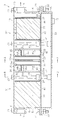
- the oil separator 3 includes a rectangular parallelepiped casing 4 extending in the horizontal direction.
- An introduction port 7 and a discharge port 8 are respectively formed on the front surface 5 and the back surface 6 of the housing 4 facing in the longitudinal direction. That is, in FIG. 2, air passes through the oil separator 3 from the left side to the right side.
- a drain reservoir 50 for retaining drain separated from the air is attached to the bottom surface of the housing 4 with bolts 21 and nuts 22.
- the drain is a liquid containing oil and moisture.
- the drain reservoir 50 has a box shape that opens upward. Note that the bolt 21 and the nut 22 constitute an attaching / detaching mechanism.
- a drain communication portion 45 is fitted into the opening 16 on the bottom surface of the housing 4.
- the drain communication portion 45 is formed with a plurality of drain communication holes 46 that allow the inside of the housing 4 to communicate with the drain reservoir 50.
- the drain communication part 45 and the opening part 16 comprise the attachment / detachment mechanism.
- a drain discharge port 17 for discharging drain is formed in a portion near the back surface 6 in the bottom surface 51 of the drain reservoir 50.
- an opening 18 is formed on the upper surface of the housing 4.
- the opening 18 is closed by a rectangular lid 19.
- a sealing sheet 20 that covers the entire surface of the opening 18 is sandwiched between the opening 18 and the lid 19.
- the lid 19, the sealing sheet 20, and the housing 4 are fastened and fixed by a plurality of bolts 21 and nuts 22.
- the lid 19 restricts the movement of the member accommodated in the housing 4.
- a plate-like partition wall 30 is provided at the central portion in the longitudinal direction in the housing 4.
- the interior of the housing 4 is partitioned in a horizontal direction by a partition wall 30 into a primary expansion chamber 31 near the introduction port 14 and a secondary expansion chamber 32 near the discharge port 15.
- the cross-sectional areas of the primary expansion chamber 31 and the secondary expansion chamber 32 are each formed larger than the cross-sectional area of the introduction port 7.
- the cross-sectional area here corresponds to the area in a cross section perpendicular to the longitudinal direction of the housing 4.
- a through-hole (orifice hole) 30a is formed at one location in the upper part of the partition wall 30. Therefore, the partition wall 30 functions as an orifice that controls the flow of air from the primary expansion chamber 31 to the secondary expansion chamber 32 by the orifice hole 30a.
- a communication hole 33 is formed at one location in the lower part of the partition wall 30 near the opening 16. The communication hole 33 allows the drain separated and collected from the air to pass between the expansion chambers 31 and 32.
- a pair of opposing collision plates 34 and 35 are provided on both sides of the partition wall 30 in the housing 4.
- the first collision plate 34 on the upstream side includes a first standing plate 34 a extending from the opening 16 of the housing 4 to the lid 19, and a first standing plate toward the discharge port 8 in the longitudinal direction of the housing 4. And a first baffle plate 34b extending vertically from 34a.
- the first standing plate 34a has a rectangular first through hole 34c extending in the width direction of the collision plates 34 and 35 below the connecting portion to the first baffle plate 34b.
- the second collision plate 35 on the downstream side includes a second standing plate 35 a extending from the opening 16 of the housing 4 to the lid 19, and a second standing plate toward the introduction port 7 in the longitudinal direction of the housing 4. And a second baffle plate 35b extending vertically from the installation plate 35a.
- the second standing plate 35a has a rectangular second through hole 35c extending in the width direction of the collision plates 34 and 35 above the connection portion to the second baffle plate 35b.
- the first baffle plate 34b and the second baffle plate 35b protrude so as to obstruct the air flow path, and an extremely narrow portion that is a narrow gap between the surfaces by bringing the large surfaces close to each other 36 is formed.
- the first baffle plate 34b is located closer to the lid 19 than the second baffle plate 35b.
- the extremely narrow portion 36 increases the passage speed of air, and further increases the chance of collision of the oil / water particles with the plate by meandering the flow path, so that the oil / water is further separated from the air.
- the baffle plates 34 b and 35 b are present, the oil and water dropped while passing between the first collision plate 34 and the second collision plate 35 is between the first collision plate 34 and the second collision plate 35.
- One communication hole 33 is formed in the lower part of the first collision plate 34 and the second collision plate 35 near the opening 16. The communication hole 33 allows the drain separated and collected from the air to pass through.
- a pair of collision plates 34 and 35 are provided in the space inside the primary expansion chamber 31.
- a urethane foam 38 such as a sponge is installed between the introduction port 7 and the pair of collision plates 34 and 35.
- a punching metal plate 37 having a plurality of holes is attached to a surface of the urethane foam 38 facing the collision plate 34.
- the urethane foam 38 captures oil moisture contained in the air.
- a pair of collision plates 34 and 35 are also provided in the space inside the secondary expansion chamber 32.
- a crashed aluminum 39 is installed between the pair of collision plates 34 and 35 and the discharge port 8.
- a punching metal plate 37 having a plurality of holes is attached to the surfaces of the crashed aluminum 39 facing the collision plates 34 and 35, respectively. That is, the crashed aluminum 39 is sandwiched between a pair of punching metal plates 37.
- the crashed aluminum 39 captures oil moisture contained in the air.
- Each of the expansion chambers 31 and 32 is provided with a rib 40 for increasing the strength of the housing 4.
- the drain reservoir 50 is provided with four ribs 52 for increasing the strength.
- Two drain communication holes 46 of the drain communication portion 45 are formed in each of the expansion chambers 31 and 32, and correspond to the urethane foam 38, the collision plates 34 and 35, and the crashed aluminum 39, respectively.
- the drain communication portion 45 and the drain reservoir portion 50 can be attached to and detached from the housing 4. That is, the drain communication portion 45 is fitted into the opening 16 of the housing 4, and the drain reservoir 50 is attached to the bottom surface of the housing 4. For this reason, the drain accumulated in the drain communicating portion 45 and the drain reservoir 50 can be easily removed by removing the drain communicating portion 45 and the drain reservoir 50 from the housing 4.
- the drain reservoir 50 attached to the lower part of the housing 4 is hollow and can accumulate drain until the drain liquid level reaches the lower surface of the drain communication part 45.
- a columnar accommodating portion 23 for accommodating a heater 41 as a heating means (heating device) is formed near the bottom surface 51 of the rib 52 of the drain reservoir 50.
- An insertion port 24 for inserting the heater 41 is formed on the outer surface of the drain reservoir 50, and the insertion port 24 penetrates the housing unit 23.
- the heater 41 has a columnar shape and is inserted into the accommodating portion 23 from the outer surface of the drain reservoir 50.
- the heater 41 is connected to a power source.
- a mounting hole 25 for attaching the thermostat 42 is formed above the insertion port 24 on the outer surface of the drain reservoir 50.
- the thermostat 42 is attached to the attachment hole 25 and connected to the power source and the heater 41.
- the thermostat 42 detects the temperature of the drain reservoir 50 and controls the heating of the heater 41 based on the detected temperature.
- the air introduced into the primary expansion chamber 31 from the introduction port 7 passes through the urethane foam 38 while capturing oil and moisture by the urethane foam 38, and the first through hole 34 c of the first collision plate 34 of the primary expansion chamber 31. Pass through. At this time, the oil and water colliding with the first standing plate 34a is separated from the air.
- the air that has passed through the first through hole 34c is directed to the narrow portion 36 formed by the first baffle plate 34b and the second baffle plate 35b, and passes through the narrow portion 36. At this time, the oil and water colliding with the second upright plate 35a and the second baffle plate 35b are separated from the air.
- the drain containing moisture and oil captured by the urethane foam 38 moves along the urethane foam 38.
- the drain falls from the drain communication hole 46 located below the urethane foam 38 to the drain reservoir 50 and is accumulated in the drain reservoir 50.
- the drain that collides with and is separated from the first collision plate 34 of the primary expansion chamber 31 passes through the communication hole 33 of the first collision plate 34 and drains from the drain communication hole 46 located below the collision plates 34 and 35. It falls into the reservoir 50 and accumulates in the drain reservoir 50.
- the air that has passed through the extremely narrow portion 36 passes through the second through hole 35c of the second standing plate 35a toward the orifice hole 30a of the partition wall 30, and passes through the orifice hole 30a. At this time, the oil and water colliding with the partition wall 30 are separated from the air.
- the drain that collides with and is separated from the second collision plate 35 of the primary expansion chamber 31 passes through the communication hole 33 of the second collision plate 35 and drains from the drain communication hole 46 located below the collision plates 34 and 35. It falls into the reservoir 50 and accumulates in the drain reservoir 50.
- the air that has passed through the orifice hole 30 a of the partition wall 30 passes through the first through hole 34 c of the first standing plate 34 a of the secondary expansion chamber 32. At this time, the oil and water colliding with the first standing plate 34a is separated from the air.
- the air that has passed through the first through hole 34c is directed to the narrow portion 36 formed by the first baffle plate 34b and the second baffle plate 35b, and passes through the narrow portion 36. At this time, the oil and water colliding with the second upright plate 35a and the second baffle plate 35b are separated from the air.
- the drain that collides and is separated from the partition wall 30 passes through the communication hole 33 of the partition wall 30 and the communication hole 33 of the first collision plate 34 of the secondary expansion chamber 32, and is located below the collision plates 34 and 35.
- the fluid falls from the communication hole 46 to the drain reservoir 50 and accumulates in the drain reservoir 50.
- the air that has passed through the extremely narrow portion 36 passes through the second through hole 35 c of the second standing plate 35 a, travels toward the crashed aluminum 39, and passes through the crashed aluminum 39. At this time, the air introduced into the crushed aluminum 39 passes through the crushed aluminum 39 while further capturing oil and moisture by the crushed aluminum 39, and clean air that does not contain oil is discharged from the discharge port 15 to the outside.
- the drain that collides with and is separated from the first collision plate 34 of the secondary expansion chamber 32 passes through the communication hole 33 of the first collision plate 34 and passes through the drain communication hole 46 located below the collision plates 34 and 35. It falls into the drain reservoir 50 and accumulates in the drain reservoir 50.
- the drain that collides with and is separated from the second collision plate 35 of the secondary expansion chamber 32 passes through the communication hole 33 of the second collision plate 35 and passes through the drain communication hole 46 located below the collision plates 34 and 35. It falls into the drain reservoir 50 and accumulates in the drain reservoir 50.
- the drain captured by the crashed aluminum 39 moves along the crashed aluminum 39, falls from the drain communication hole 46 located below the crashed aluminum 39 to the drain reservoir 50, and enters the drain reservoir 50. Accumulate.
- the drain accumulated in the drain reservoir 50 is heated by the heater 41. Thereby, the water in the drain is evaporated. Drain containing oil at a high concentration is discharged from the drain discharge port 17.
- the inside of the drain reservoir 50 can be cleaned by removing the drain reservoir 50 from the housing 4.
- the heater 41 Since the heater 41 is provided below the expansion chambers 31 and 32, the drain containing oil and water that collides with the collision plates 34 and 35 and accumulates at the bottom of the expansion chambers 31 and 32 is heated by the heater 41. . Therefore, the water in the drain can be evaporated. Therefore, by reducing the water content from the accumulated drain, the concentration of oil can be increased, the amount of drain stored can be reduced, and the drain recovery time (recovery cycle) can be prolonged. Furthermore, by heating the housing 4 with the heater 41, it is possible to prevent the drain from being discharged from the drain discharge port 17 due to the freezing of the drain even in a cold region.
- the heater 41 is accommodated in the accommodating portion 23 provided in the lower part of the housing 4. Since the heater 41 heats the housing 4, it is possible to prevent the heater 41 from being deteriorated by the drain containing oil and moisture.
- the drain reservoir 50 can be detached from the housing 4 by the attaching / detaching mechanism using the bolt 21 and the nut 22, the drain reservoir 50 can be cleaned while being detached from the housing 4.
- the oil can be easily removed when the oil adheres to the inner wall of the drain reservoir. Further, if the drain reservoir is made disposable, the drain can be easily recovered.
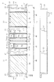
- a first drain receiver 55 for collecting the collected drain is provided at the lower part of the housing 4.
- the bottom portion of the first drain receiver 55 is inclined so that the depth in the vertical direction becomes deeper toward the secondary expansion chamber 32 along the longitudinal direction of the housing 4.
- a box-shaped second drain receiver 57 is provided on the outer surface of the first drain receiver 55 near the secondary expansion chamber 32.
- the first drain receiver 55 communicates with the second drain receiver 57 near their bottom surfaces. For this reason, only the moisture contained in the drain moves from the first drain receiver 55 to the second drain receiver 57 through the communicating portion.
- a drain filter 56 is installed at the communication portion to prevent oil from entering. Near the bottom surface of the second drain receiver 57, a heater 41 for heating the drain is installed.
- a water vapor filter 58 that passes only water vapor is installed so that only water is discharged to the outside.
- the oil is separated from the air through the primary expansion chamber 31, the collision plates 34 and 35, and the secondary expansion chamber 32, so that cleaning air that does not contain the oil is discharged to the outside.
- the drain separated and collected from the air by the primary expansion chamber 31, the collision plates 34 and 35, and the secondary expansion chamber 32 is stored in the first drain receiver 55.
- the drain accumulated in the first drain receiver 55 contains oil at a relatively high concentration. When water and oil are separated in the drain, the oil moves upward and the water moves downward.
- the drain accumulated in the first drain receiver 55 passes through the drain filter 56 and moves to the second drain receiver 57.
- the drain stored in the second drain receiver 57 contains oil at a relatively low concentration because the moisture moves downward.
- the drain stored in the second drain receiver 57 is heated by the heater 41, and the water in the drain is evaporated. Water vapor generated by the heating of the heater 41 is discharged to the outside through the water vapor filter 58.
- the air dryer 2 includes a bottomed cylindrical case 121 whose top is closed vertically, and a support member 122 that closes the opening of the case 121 and supports the case 121. .
- a purge air discharge port 123 that discharges purge air when the drying agent is regenerated is formed below the support member 122.
- a purge air discharge cover 124 to which a connection hose 125 is connected is attached to the purge air discharge port 123.
- the connection hose 125 is connected to the oil separator 103.
- the support member 122 of the air dryer 2 is provided with an inlet (not shown) for introducing the compressed air compressed by the compressor 1 and an outlet (not shown) for discharging the dried compressed air. ing.
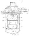
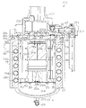
- the oil separator 103 includes a case 131 as a bottomed cylindrical casing extending in the vertical direction and a lid 132 that closes the opening of the case 131.
- the bottom 131a of the case 131 is provided with a drain discharge port 133 for discharging the accumulated drain.
- a drain hose 134 used for draining is connected to the drain outlet 133.
- an inlet 135 for introducing purge air from the air dryer 2 through the connection hose 125 and an outlet 140 for discharging clean air from which oil has been separated are formed separately.
- the introduction port 135 and the connection hose 125 are connected by a connecting member 127.
- a mounting member 137 is integrally provided on the lid 132 of the oil separator 103 with respect to the lid 132.
- the attachment member 137 is fixed to the chassis 138 with bolts 139.
- the distal end of the drain hose 134 is detachably attached to a support member 190 fixed to the vehicle chassis 138 and the like. That is, the fixing member 191 is fixed to the support member 190.
- a one-touch coupler 192 to which the tip end of the drain hose 134 can be attached with one touch is fixed to the lower end of the fixing member 191.
- the drain hose 134 is fixed to the fixing member 191 by inserting the distal end portion of the drain hose 134 into the one-touch coupler 192, and can be removed from the fixing member 191 by operating the one-touch coupler 192.
- the distal end portion of the drain hose 134 is attached to the fixing member 191 vertically upward.
- An elbow member 160 that bends vertically upward from the horizontal direction is screwed to the discharge port 140 of the oil separator 103.
- a dripping prevention member 170 is attached to the tip of the elbow member 160, and a cover 180 that prevents intrusion of dust and the like is attached.
- the inlet 132 and the outlet 140 are opened in the same direction (right side in the figure) in the lid 132.
- the introduction port 135 and the discharge port 140 are respectively provided on the surface in the horizontal direction.
- a connection hose 125 is connected to the introduction port 135 via a connecting member 127.
- An elbow member 160 is connected to the discharge port 140. That is, the connecting member 127 and the elbow member 160 are provided side by side.
- the lid 132 has a bottomed cylindrical shape with the top vertically closed.
- Two baffle plates 146 are erected on the inner wall of the lid 132 in the vicinity of the inlet 135 so as to be orthogonal to the traveling direction of the purge air introduced from the inlet 135.
- the internal space of the lid 132 functions as a first expansion chamber 145 that expands the purge air introduced from the introduction port 135.
- the cross-sectional area of the purge air path formed in the first expansion chamber 145 is larger than the cross-sectional area of the inlet 135.
- the cross-sectional area here corresponds to the area in a cross section perpendicular to the traveling direction of the purge air.
- the lid 132 is formed with a communication portion 132 a that communicates from the inside of the case 131 to the discharge port 140.
- a disc-shaped cover 147 that closes the case 131 and closes the opening of the lid 132 is provided between the case 131 and the lid 132.
- the cover 147 is fastened to the lid 132 together with the case 131 by bolts 136. That is, the bolt 136 is fastened to the screw hole 132 c formed in the flange portion 132 b provided in the lid 132.
- the bolt 136 and the screw hole 132c function as an attaching / detaching mechanism. Further, the screw portion of the bolt 136 is passed through a through hole formed in the flange portion 131 b provided in the case 131.
- the cover 147 is formed with a through hole through which the threaded portion of the bolt 136 passes.
- the screw part of the bolt 136 is passed through the through hole of the flange part 131b of the case 131 and the through hole of the flange part 147a of the cover 147, and the bolt 136 is screwed into the screw hole 132c of the flange part 132b of the lid 132.
- the case 131 can be removed from the lid 132 by removing the bolt 136 from the screw hole 132c.
- the cover 147 is formed with a communication hole 147 c that communicates from the inside of the case 131 to the discharge port 140.
- a space formed by the lid 132 and the cover 147 functions as the first expansion chamber 145.
- a cylindrical housing member 148 with a bottom closed vertically is fixed to the cover 147 with bolts 136.
- the accommodating member 148 accommodates the urethane foam 150 such as a sponge. Note that the urethane foam 150 functions as a collision material.
- a flange portion 148 a and a flange portion 148 b are formed on the upper edge portion and the lower edge portion of the housing member 148.
- a bolt 136 is passed through a flange portion 148 a formed at the upper edge of the housing member 148, and the housing member 148 is fastened to the cover 147.
- a space formed by the cover 147 and the upper surface of the housing member 148 functions as the second expansion chamber 151.
- the cover 147 is formed with a plurality of through holes 147 b that allow the first expansion chamber 145 to communicate with the second expansion chamber 151.
- a plurality of through holes 149 a are formed in the central portion of the upper bottom portion 149 of the housing member 148.
- the through hole 147b of the cover 147 and the through hole 149a of the upper bottom portion 149 of the housing member 148 are formed at positions that do not face each other.
- a plurality of through-holes 148c are formed on the lower end portion side of the side surface of the housing member 148 at intervals in the radial direction.
- a disk-shaped support lid 152 is fixed to the flange portion 148 b formed at the lower edge of the housing member 148 with a screw 153.
- the support lid 152 supports the urethane foam 150 accommodated in the accommodation member 148.
- the inner diameter of the support lid 152 is substantially the same as the inner diameter of the case 131.
- a space formed by the upper bottom portion 149 of the housing member 148 and the support lid 152 functions as the third expansion chamber 159.
- the support lid 152 is formed with a plurality of through holes 152a through which oil and water removed by the urethane foam 150 are dropped. Therefore, the lower part in the case 131 functions as the drain reservoir 154.
- the drain reservoir 154 is provided with a heater 155 as a heating device for heating the accumulated drain and evaporating water in the drain.
- the heater 155 is inserted into the case 131 through an insertion hole 156 formed in the side surface of the case 131.
- the heater 155 directly heats the drain accumulated in the drain reservoir 154. Heating of the heater 155 is controlled by a thermostat (not shown).
- the elbow member 160 includes a horizontal portion 161 extending in the horizontal direction and a vertical portion 162 extending in the vertical direction continuously to the horizontal portion 161.
- a male screw portion 163 that is screwed into the female screw portion 140 a of the discharge port 140 is formed at the base end portion of the elbow member 160.
- the male screw part 163 of the elbow member 160 is formed such that when the elbow member 160 is screwed to the female screw part 140a of the discharge port 140, fastening is stopped at a position where the tip of the elbow member 160 faces upward.
- a female screw part 164 to which the dripping prevention member 170 is screwed is formed at the tip of the elbow member 160.
- a through-hole 171 that connects the base end and the distal end is formed inside the liquid dripping prevention member 170, and four partition plates 172 that prevent large foreign substances from entering the flow path and blocking the flow path are provided. ing.
- the partition plates 172 are formed to extend in the axial direction at equal intervals in the circumferential direction.
- a cylindrical portion 173 is formed at the center of the through-hole 171 and at the intersection of the partition plates 172.
- a male screw portion 174 that is screwed to the female screw portion 164 of the elbow member 160 is formed at the base end portion of the liquid dripping prevention member 170.
- a liquid dripping part 176 that receives liquid dripping from the opening 175 is formed over the entire circumference.
- a return hole 177 serving as a return portion for returning the liquid received by the liquid drooping portion 176 to the through hole 171 is formed at the bottom of the liquid drooping portion 176.
- the return hole 177 penetrates from the liquid dripping part 176 to the through hole 171. Therefore, the liquid dripping on the liquid dripping part 176 returns to the elbow member 160 through the return hole 177.
- a stepped portion 182 is formed in the insertion portion 181. The stepped portion 182 sets the insertion position of the cover 180 with respect to the dripping prevention member 170.
- the cover 180 covers the opening 175 of the dripping prevention member 170.
- the outer diameter of cover 180 is smaller than the inner diameter of liquid drooping portion 176. Therefore, the clean air that has passed through the dripping prevention member 170 passes between the opening 175 of the dripping prevention member 170 and the inner surface of the cover 180 and is discharged to the outside.
- purge air discharged from the air dryer 2 is introduced into the oil separator 103.
- the purge air is air containing oily moisture.
- the purge air introduced from the introduction port 135 collides with the baffle plate 146, is introduced into the oil separator 103 along the baffle plate 146, and expands in the first expansion chamber 145.
- the air expanded in the first expansion chamber 145 enters the second expansion chamber 151 through a through hole 147 b formed in the cover 147.
- the air expanded in the second expansion chamber 151 enters the third expansion chamber 159 through the through hole 149a in the upper bottom portion 149 of the housing member 148.
- the drain containing water and oil captured by the urethane foam 150 moves along the urethane foam 150.
- the drain reaches the upper surface of the support lid 152, falls from the through hole 152 a of the support lid 152 to the drain reservoir 154, and accumulates in the drain reservoir 154.
- the drain accumulated in the drain reservoir 154 enters the drain hose 134 from the drain discharge port 133.
- the drain accumulated in the drain reservoir 154 is heated by the heater 155. Thereby, the water in the drain is evaporated.
- the drain in the drain hose 134 is positioned at the same height as the drain in the drain reservoir 154. Therefore, by visually checking the drain in the drain hose 134, the amount of drain in the drain reservoir 154 can be confirmed.
- air that has entered the third expansion chamber 159 from the through hole 149 a of the upper bottom portion 149 of the housing member 148 and has been separated from oil and moisture is passed through the through hole 148 c on the side surface of the housing member 148. Enters the case 131.
- the air that has entered the case 131 passes through the communication hole 147c of the cover 147 and the communication part 132a of the lid 132, flows into the elbow member 160 from the discharge port 140, and is discharged to the atmosphere. Therefore, the air that has entered the case 131 is discharged from the discharge port 140 with almost no contact with the drain of the drain reservoir 154.
- the air discharged from the discharge port 140 is clean air that does not contain oil.
- the one-touch coupler 192 When discharging the drain accumulated in the drain reservoir 154, the one-touch coupler 192 is operated to remove the tip of the drain hose 134 from the one-touch coupler 192, and the tip of the drain hose 134 is drained from the drain reservoir 154. Lower than the surface of the water. As a result, the drain can be discharged from the drain reservoir 154.
- the case 131 and the cover 147 are removed from the lid 132 by removing the bolt 136 from the screw hole 132c.
- the removed case 131 and cover 147 can be cleaned.
- the screw 153 fixing the support lid 152 to the housing member 148 is removed, the urethane foam 150 is taken out from the housing member 148, and the urethane foam 150 is replaced.
- the case 131 and the cover 147 are attached to the lid 132 by fixing the support lid 152 to the housing member 148 with screws 153 and fastening the bolt 136 to the screw hole 132c of the lid 132.
- the inlet 135 and the outlet 140 are provided in the lid 132, and purge air introduced into the case 131 from the inlet 135 passes vertically downward through the plurality of expansion chambers 145, 151, 159, and the outlet 140. Clean air is discharged from
- the case 131 can be removed from or attached to the lid 132 by a bolt 136 and a screw hole 132c as an attaching / detaching mechanism. For this reason, the case can be easily separated by removing the case 131 from the lid 132.
- the inlet 135 and the outlet 140 are provided on the horizontal surface of the lid 132, respectively. For this reason, since the inlet 131 and the outlet 140 are not provided in the case 131, there is no pipe connected to the case 131 when the case 131 is removed from the lid 132, and the case 131 can be easily removed. In addition, since the pipe is not connected to the upper surface or the bottom surface in the vertical direction of the lid 132, the length in the vertical direction can be suppressed.
- the heater 155 is inserted from the insertion hole 156 provided in the lower part of the case 131, and the heater 155 directly heats the drain. For this reason, the water
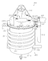
- the oil separator 203 is provided with a heating device 280.
- the heating device 280 warms the oil separator 203 by allowing high-temperature compressed air supplied from the compressor 1 to pass through the outer periphery of the oil separator 203. That is, the compressed air of the compressor 1 is supplied to the air dryer 2 via the outer periphery of the oil separator 203.
- the temperature of the compressed air supplied from the compressor 1 is as high as 160 ° C.
- the air dryer 2 includes a bottomed cylindrical case 221 whose top is closed and a support member 222 that closes the opening of the case 221 and supports the case 221. .
- a purge air discharge port 223 that discharges purge air when the drying agent is regenerated is formed below the support member 222.
- a purge air discharge cover 224 to which a connection hose 225 is connected is attached to the purge air discharge port 223.
- the connection hose 225 is connected to the oil separator 203.
- the support member 222 of the air dryer 2 is provided with an inlet 228 for introducing compressed air compressed by the compressor 1 and an outlet 229 for discharging the dried compressed air.
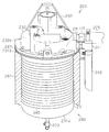
- the oil separator 203 includes a case 231 as a bottomed cylindrical casing extending in the vertical direction, and a lid 232 that closes the opening of the case 231.
- a drain discharge port 233 for discharging the accumulated drain is provided at the bottom 231a of the case 231.
- a drain hose 234 is connected to the drain outlet 233 for use when taking out the drain.
- the lid 232 is separately formed with an inlet 235 for introducing purge air from the air dryer 2 via a connection hose 225 and an outlet 240 for discharging clean air from which oil has been separated.
- the introduction port 235 and the connection hose 225 are connected by a connecting member 227.
- An attachment member 237 is integrally provided on the lid 232 of the oil separator 203 with respect to the lid 232.
- the attachment member 237 is fixed to the chassis 238 by bolts.
- the distal end of the drain hose 234 is detachably attached to a support member 260 fixed to a vehicle chassis 238 or the like. That is, the fixing member 261 is fixed to the support member 260.
- a one-touch coupler 262 to which the tip end of the drain hose 234 can be attached with one touch is fixed to the lower end portion of the fixing member 261.
- the drain hose 234 is fixed to the fixing member 261 by inserting the distal end portion of the drain hose 234 into the one-touch coupler 262, and can be detached from the fixing member 261 by operating the one-touch coupler 262.
- the distal end portion of the drain hose 234 is attached to the fixing member 261 upward in the vertical direction.
- the leading end of the drain hose 234 is located above the lid 232 of the oil separator 203. For this reason, it is possible to prevent the drain from leaking from the tip of the drain hose 234.
- a cylindrical jacket 281 constituting the heating device 280 is attached to the outer periphery of the case 231 of the oil separator 203.
- the jacket 281 is detachable from the case 231.
- An inlet connecting pipe 282 for connecting the compressor 1 and introducing compressed air from the compressor 1 is connected to the upper side surface of the jacket 281.
- a discharge connection pipe 283 for connecting the air dryer 2 and discharging compressed air to the air dryer 2 is connected to the lower side of the jacket 281.
- the discharge connection pipe 283 is connected to the inlet 228 of the air dryer 2.
- the heating device 280 warms the case 231 by drawing the compressed air of the compressor 1 into the jacket 281.
- the heating device 280 cools the compressed air supplied from the compressor 1 and discharges it to the air dryer 2 by moving the amount of heat of the compressed air supplied from the compressor 1 to the case 231 via the jacket 281.
- the temperature of the compressed air cooled through the jacket 281 is about 60 ° C.
- the jacket 281 is provided with a guide tube 284 that extends spirally along the outer periphery of the case 231.
- the guide pipe 284 connects the introduction connection pipe 282 to the discharge connection pipe 283.
- the introduction port 235 and the discharge port 240 provided in the lid 232 are open in the same direction (right side in the figure).
- a connection hose 225 is connected to the introduction port 235 via a connecting member 227.
- a discharge hose 242 is connected to the discharge port 240 via a connection member 241 that bends downward from the horizontal direction. That is, the connecting member 227 and the connecting member 241 are provided side by side.
- the tip opening of the discharge hose 242 is formed such that the length in the vertical direction of the portion near the case 231 is shorter than the length in the opposite portion, and the end surface of the tip opening is formed obliquely with respect to the horizontal direction. . This enhances waterproofness while facilitating the discharge of clean air from the discharge hose 242.
- the lid 232 has a bottomed cylindrical shape with the top vertically closed.
- Two baffle plates 246 are erected on the inner wall of the lid 232 in the vicinity of the inlet 235 so as to be orthogonal to the traveling direction of the purge air introduced from the inlet 235.
- the internal space of the lid 232 functions as a first expansion chamber 245 that expands purge air introduced from the introduction port 235.
- the lid 232 is formed with a communication portion 232 a that communicates from the inside of the case 231 to the discharge port 240.
- a disc-shaped cover 247 that closes the case 231 and closes the opening of the lid 232 is provided between the case 231 and the lid 232.
- the cover 247 is fastened to the lid 232 together with the case 231 by bolts 236. That is, the bolt 236 is fastened to the screw hole formed in the flange portion 232 b provided in the lid 232. Further, the screw portion of the bolt 236 is passed through the through-hole formed in the flange portion 231b provided in the case 231.
- the cover 247 is formed with a through hole through which the screw portion of the bolt 236 passes.
- the screw portion of the bolt 236 is passed through the through hole of the flange portion 231b of the case 231 and the through hole of the flange portion 247a of the cover 247, and the bolt 236 is screwed into the screw hole of the flange portion 232b of the lid 232.
- the cover 247 has a communication hole 247 c that communicates from the inside of the case 231 to the discharge port 240.
- a space formed by the lid 232 and the cover 247 functions as the first expansion chamber 245.
- a cylindrical housing member 248 with a bottom closed vertically is fixed to the cover 247 with bolts 239.
- the accommodating member 248 accommodates a urethane foam 250 such as a sponge.
- the urethane foam 250 functions as a collision material.
- a flange portion 248 a and a flange portion 248 b are formed on the upper edge portion and the lower edge portion of the housing member 248.
- a bolt 239 is passed through a flange portion 248 a formed at the upper edge of the housing member 248, and the housing member 248 is fastened to the cover 247.
- a space formed by the cover 247 and the upper surface of the housing member 248 functions as the second expansion chamber 251.
- the cover 247 is formed with a plurality of through holes 247 b that allow the first expansion chamber 245 to communicate with the second expansion chamber 251.
- a plurality of through holes 249 a are formed in the central portion of the upper bottom portion 249 of the housing member 248.
- the through hole 247b of the cover 247 and the through hole 249a of the upper bottom portion 249 of the housing member 248 are formed at positions that do not face each other.
- a plurality of through holes 248c are formed at intervals in the radial direction on the lower end portion side of the side surface of the housing member 248.
- a disk-shaped support lid 252 is fixed to the flange portion 248 b formed at the lower edge of the housing member 248 with a screw 253.
- the support lid 252 supports the urethane foam 250 accommodated in the accommodation member 248.
- the inner diameter of the support lid 252 is substantially the same as the inner diameter of the case 231.
- a space formed by the upper bottom portion 249 of the housing member 248 and the support lid 252 functions as the third expansion chamber 259.
- the support lid 252 is formed with a plurality of through holes 252a through which oil and moisture removed by the urethane foam 250 are dropped. Therefore, the lower part in the case 231 functions as the drain reservoir 254.
- the compressed air supplied from the compressor 1 through the introduction connecting pipe 282 is introduced into the induction pipe 284 in the jacket 281 of the heating device 280 and passes through the induction pipe 284 so as to pass through the jacket 281.
- the case 231 is warmed through.
- the compressed air that has passed through the jacket 281 is cooled more than when it is introduced into the jacket 281.
- the compressed air discharged from the jacket 281 is introduced into the air dryer 2 through the discharge connecting pipe 283.
- the compressed air introduced into the air dryer 2 is dried and then stored in an air tank (not shown).
- the air dryer 2 is introduced into the oil separator 203 from the purge air discharge port 223 during unloading for regenerating the desiccant.
- the purge air is air containing oily moisture.
- the air expanded in the first expansion chamber 245 enters the second expansion chamber 251 through a through hole 247b formed in the cover 247.
- the air expanded in the second expansion chamber 251 enters the third expansion chamber 259 through the through hole 249a in the upper bottom portion 249 of the housing member 248.
- the oil and water colliding with the urethane foam 250 is separated from the air.
- the drain containing moisture and oil captured by the urethane foam 250 travels through the urethane foam 250 and reaches the upper surface of the support lid 252. This drain falls from the through hole 252 a of the support lid 252 to the drain reservoir 254 and accumulates in the drain reservoir 254.
- the drain accumulated in the drain reservoir 254 enters the drain hose 234 from the drain discharge port 233.
- the air that has entered the housing member 248 from the through hole 249 a of the upper bottom portion 249 of the housing member 248 and has been separated from oil and moisture is removed from the through hole 248 c on the side surface of the housing member 248.
- the air that has entered the case 231 passes through the communication hole 247c of the cover 247 and the communication portion 232a of the lid 232, flows into the discharge hose 242 from the discharge port 240 via the connection member 241, and is discharged to the atmosphere. Therefore, the air that has entered the case 231 is discharged from the discharge port 240 with almost no contact with the drain of the drain reservoir 254.
- the air discharged from the discharge port 240 is clean air that does not contain oil.
- the one-touch coupler 262 When discharging the drain accumulated in the drain reservoir 254, the one-touch coupler 262 is operated to remove the tip of the drain hose 234 from the one-touch coupler 262, and the drain hose 234 is drained from the drain reservoir 254. Lower than the surface of the water. Thereby, the drain can be discharged from the drain reservoir 254.
- high-temperature compressed air supplied from the compressor 1 is drawn into the jacket 281 constituting the heating device 280, and the drawn compressed air warms the case 231 of the oil separator 3. Thereby, freezing of moisture in the case 231 of the oil separator 203 can be suppressed in a cold district or the like.
- the heating device 280 that warms the case 231 is provided, the case 231 is warmed by the heating device 280, and freezing of moisture in the case 231 can be suppressed in a cold district or the like.
- the heating device 280 Since the heating device 280 is provided on the outer periphery of the case 231, it is not necessary to employ a complicated configuration, and the installation of the heating device 280 with respect to the oil separator 203 is easy.
- the heating device 280 warms the case 231 with the compressed air heated by the compression heat of the compressor 1, it is not necessary to generate warm air or the like. Further, since it is not necessary to draw in warm air or the like separately, it can be easily realized by drawing in compressed air supplied to the air dryer 2.
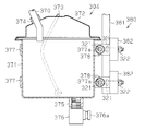
- the oil separator main body 303 is fixed to a frame 309 such as a ladder frame by bolts 321 and nuts 322 via a pair of plate-like attachment members 308. As shown in FIG. The oil separator body 303 and the expansion tank 304 are connected by a hose 370. One end of the hose 370 is connected to the drain outlet 317 of the oil separator main body 303.
- the expansion tank 304 includes a bottomed cylindrical main body container 371 for containing drain and a lid 372 for closing the opening of the main body container 371.
- a handle 373 for lifting the expansion tank 304 is attached to the main body container 371.
- the lid 372 is provided with a cylindrical inlet port 374 communicating with the inside.
- the other end of the hose 370 is connected to the inlet port 374.
- the inlet port 374 functions as an inlet for supplying drain to the expansion tank 304.
- the inlet port 374 is located below the drain discharge port 317. For this reason, when the drain accumulated in the drain reservoir 345 of the oil separator main body 303 reaches the drain discharge port 317, it is naturally transferred from the drain discharge port 317 through the hose 370 to the additional tank 304 by gravity.
- a cylindrical discharge port 375 communicating with the inside of the main body container 371 is provided on the lower surface of the main body container 371.
- a ball cock 376 that can open and close the communicating portion is attached to the discharge port 375. The ball cock 376 opens and closes the communicating portion by operating the lever 376a, and discharges and stops the drain.
- Two ⁇ -shaped attachment members 377 that are attached to the vehicle body are fastened and fixed to the main body container 371 of the expansion tank 304.
- a cylindrical spacer 378 is attached to the opening of the attachment member 377.
- Bolts 321 are inserted into the spacers 378 and mounting holes 377 a formed in the attachment member 377 and are fastened and fixed by nuts 322.
- the spacer 378 defines the tightening amount of the nut 322 with respect to the bolt 321.
- the attachment member 377 is fixed to a side guard 380 as an entrainment prevention member attached to the vehicle body 310 of the truck.
- the side guard 380 prevents an object from being caught in the space between the tires around the undercarriage.
- the side guard 380 includes a rectangular stay 381 that is fixed to the vehicle body 310 with bolts 321 and hangs down from the vehicle body 310, and a rectangular bar 382 that is welded to the stay 381 and extends in the extending direction of the vehicle body 310.
- the attachment member 377 attached to the expansion tank 304 is fixed to the bar 382 of the side guard 380 by bolts 321 and nuts 322.
- the drain accumulated in the casing 311 is heated by the heater 326, and the water in the drain is evaporated.
- the accumulated drain reaches the drain discharge port 317, it is naturally discharged from the drain discharge port 317 by gravity and transferred to the expansion tank 304 through the hose 370.
- Drain can be collected by placing a bucket or the like under the expansion tank 304.
- the amount of oil that can be separated and recovered by the oil separator main body 303 can be increased by the capacity of the expansion tank 304, so that the number of occurrences (occurrence frequency) of the collected drain collecting operation can be suppressed. Further, since the expansion tank 304 is attached to the side guard 380 so that the inlet port 374 is located below the drain discharge port 317 of the oil separator main body 303, the drain is naturally discharged from the drain reservoir 345 to the expansion tank 304 by gravity. It can be transferred, and the operator can easily collect the drain.
- the separated drain can be stored separately from the casing 311. For this reason, it is possible to increase the total amount of drain that can be stored, and thus to suppress the number of occurrences (occurrence frequency) of the collected operation of collecting the drain.
- the expansion tank 304 is attached to the side guard 380 provided in the vehicle. For this reason, since the expansion tank 304 is located in a place where the worker can reach, the operation of collecting the drain accumulated in the expansion tank 304 is easy.
- the sealing sheet 20 is provided between the opening 18 of the housing 4 and the lid 19, but the sealing sheet 20 may be omitted. In addition, it is desirable that a hermetic seal is maintained between the opening 18 of the housing 4 and the lid 19.
- the baffle plates 34b and 35b extending perpendicular to the standing plates 34a and 35a are provided. However, if the extremely narrow portion 36 can be maintained, the baffle plates 34b and 35b are raised. It is not necessary to form perpendicularly with respect to the installation plates 34a and 35a.
- the extremely narrow portion 36 including a pair of baffle plates 34b and 35b is provided.
- an extremely narrow portion including a plurality of pairs of baffle plates may be provided.
- the communication hole 33 is formed in the lower part of the partition wall 30.
- the communication hole 33 of the partition wall 30 is omitted. May be.
- the movement of the collision plates 34, 35, the partition wall 30, the urethane foam 38, the crashed aluminum 39, etc. is restricted by the lid 19.
- the collision plates 34 and 35, the partition wall 30, the urethane foam 38, the crashed aluminum 39, and the like are fixed, the movement may not be restricted by the lid 19.
- the crashed aluminum 39 is installed in the secondary expansion chamber 32, but urethane foam 38 may be installed in place of the crashed aluminum 39.
- the order of the members arranged in the housing 4 is as follows: urethane foam 38 ⁇ impact plate 34, 35 ⁇ partition wall 30 (orifice hole 30a) ⁇ impact plate 34, 35 ⁇ crashed Aluminum 39.
- these arrangements may be changed, some members may be omitted, some members may be increased, or the members may be changed. .
- the drain communication hole 46 is provided in a portion where the urethane foam 38 or the crashed aluminum 39 is in contact with the drain communication portion 45, the drain drop is promoted, and the drain expansion chamber 31 is provided. , 32 can be suppressed.
- the expansion chambers 31 and 32 are provided in the horizontal direction, but may be provided in the vertical direction.
- the introduction port 14 is formed on the front surface 12 and the discharge port 15 is formed on the back surface. However, if there is a space in the vertical direction, the upper cover 19 and the opening 16 may be provided. The introduction port 14 and the discharge port 15 may be formed.
- the attachment / detachment mechanism between the casing 4 and the drain reservoir 50 is the bolt 21 and the nut 22, but other configurations such as an engagement structure may be adopted.
- the attachment / detachment mechanism between the housing 4 and the drain communication portion 45 is an insertion structure, but other configurations such as an engagement structure may be adopted.
- the drain reservoir 50 is heated by the heater 41.
- the drain itself stored in the drain reservoir 50 may be directly heated.
- an insertion hole 53 for inserting the heater 41 is formed on the side surface of the drain reservoir 50, and the heater 41 is inserted from the insertion hole 53.
- the heater 41 directly heats the accumulated drain.
- the thermostat 42 is installed on the inner wall of the drain reservoir 50 in order to perform accurate temperature control. In this way, heat transfer from the heater 41 to the drain is high, and the drain can be heated more efficiently than indirectly heating the drain.
- the drain reservoir 50 may be omitted and the drain may be accumulated inside the housing 4.
- the heater 41 is provided on the rib 40 of the housing 4.
- the heater 41 is installed on the rib 52 (40), but the heater 41 may be installed at a place other than the rib 52 (40).
- the number of heaters 41 can be changed as necessary.
- the primary expansion chamber 31 and the secondary expansion chamber 32 have substantially the same size, that is, volume, but the volume of the secondary expansion chamber 32 is larger than the volume of the primary expansion chamber 31. May be increased. In this way, the saturated vapor pressure in the secondary expansion chamber 32 is further reduced and oil and water are likely to aggregate, and the mass of the particles is increased to easily collide with the collision plate. Therefore, more oil and water separated from the air can be stored in the secondary expansion chamber 32 than in the primary expansion chamber 31.
- the oil separator 3 is provided in the exhaust system of the air dryer 2 that is downstream of the compressor 1 of the air system.
- the oil separator 3 may be provided downstream of the air system compressor 1 and upstream of the air dryer 2. If it does in this way, an oil component can be isolate
- the oil separator 3 is provided in the air system in which the air dryer 2 is provided in a vehicle such as a truck, a bus, and a construction machine.
- the oil separator 3 is used for separating oil from air containing moisture. Can be used anywhere.
- the exhaust from the air dryer that dries the compressed air to the atmosphere in a factory or the like may be cleaned by an oil separator.
- the bolt 136 is fastened to the screw hole 132c as the attachment / detachment mechanism, but other attachment / detachment mechanisms may be employed.
- a clamp ring 110 that sandwiches the flange portion 132b of the lid 132 and the flange portion 131b of the case 131 and tightens the inner diameter side may be employed as the attachment / detachment mechanism.
- the clamp ring 110 includes a ring 111 having a U-shaped cross section that sandwiches the flange portions 132b and 131b, a bolt 113 and a nut 114 for tightening the tightening portion 112 of the ring 111.
- a concave-convex fitting structure may be employed as an attaching / detaching mechanism.
- a convex portion 115 protruding inside the case 131 is provided along the circumferential direction, and the concave portion 116 is provided instead of the flange portion 132 b of the lid 132.
- the case 131 is pressed toward the lid 132, and the convex portion 115 of the case 131 is fitted into the concave portion 116 of the lid 132.
- the case 131 may be provided with a recess, and the lid 132 may be provided with a protrusion. If the concave / convex fitting is employed, the case 131 can be attached to the lid 132 simply by fitting, so that it can be easily detached. Moreover, you may provide the set screw which prevents rotation with respect to the lid
- the heater 155 is inserted into the drain reservoir 154 through the insertion hole 156 and the drain is directly heated.
- the housing portion that houses the heater 155 in the case 131. 157 may be provided to heat the case 131. If it does in this way, the water
- the introduction port 135 and the discharge port 140 are provided on the surface in the horizontal direction of the lid 132, but the introduction port 135 and the discharge port 140 are provided on the vertical surface such as the upper portion of the lid 132. May be provided.
- the drain hose 134 is connected to the drain discharge port 133 of the case 131, but the drain hose 134 may be omitted and the drain hose 134 may be directly discharged.
- a drain outflow suppressing member is provided at the drain discharge port 133.
- the first expansion chamber 145, the second expansion chamber 151, and the third expansion chamber 159 are provided in the oil separator 103.
- the first expansion chamber 145, the second expansion chamber 151, and the third expansion chamber 159 are provided. It may be at least one with the expansion chamber 159.
- the drain hose 134 may be provided with a scale.
- a member such as a nonwoven fabric filter may be disposed upstream or downstream of the urethane foam 150 or in the expansion chambers 145, 151.
- static electricity may be applied to a member such as a urethane foam 150 such as a sponge or a nonwoven fabric filter.
- members can be charged with static electricity by a method such as utilizing a flow of dry air from a dryer.
- members, such as urethane foam 150, such as sponge, and a nonwoven fabric filter may be formed from the material electrically charged from the beginning. In this way, the oil component removal rate can be further improved.
- the urethane foam 150 is used as the impact material, but other members such as crashed aluminum may be used. Further, instead of the expansion chamber having the collision material, a simple expansion chamber having no collision material may be used.
- the jacket 281 is preferably a heat insulating material.
- the compressed air supplied from the compressor 1 is supplied to the air dryer 2 via the jacket 281 of the heating device 280. However, only a part of the compressed air supplied from the compressor 1 is heated. It may be routed through 280 jacket 281.
- the hot compressed air supplied from the compressor 1 is drawn into the jacket 281 of the heating device 280 to warm the case 231, but the exhaust discharged from the internal combustion engine is supplied to the heating device 280. May be. That is, as shown in FIG. 25, high-temperature exhaust discharged from the engine 204 as an internal combustion engine is supplied to the heating device 280. The exhaust from the engine 204 supplied to the heating device 280 is discharged to the exhaust system of the internal combustion engine.
- the case 231 and the jacket 281 may be integrated.
- the case 231 is warmed by supplying the compressed air of the compressor 1 or the exhaust of the engine 204 to the heating device 280.
- the case 231 may be warmed by electric heat without relying on warm air. That is, as shown in FIG. 26, the case 231 may be warmed by winding a heating wire 285 as an electric heating portion around the case 231 and covering it with a jacket 281. In this way, the oil separator 203 can be warmed even when the vehicle is not driven.
- the outer periphery of the case 231 is warmed by the heating device 280, but a heating device may be provided inside the case 231.
- a heating device may be provided inside the case 231.
- a guide pipe through which the compressed air of the compressor 1 passes is provided in the case 231.
- the exhaust of the engine 204 may be passed through this guide pipe.
- the amount of drain may be reduced by evaporating moisture contained in the drain accumulated in the drain reservoir 254 by a heating means (heating device). In this way, since the period during which the drain accumulates to the capacity limit can be extended, the drain discharge interval can be lengthened and the maintenance burden can be reduced.
- the inlet 235 of the oil separator 3 is positioned above the connection port of the purge air discharge cover 224 in the vertical direction. However, if it is not necessary to suppress the height in the vertical direction including the air dryer 2 and the oil separator 203, the inlet 235 of the oil separator 203 may be positioned below the connection port of the purge air discharge cover 224 in the vertical direction. Good.
- the tip of the drain hose 234 is positioned above the lid 232 of the oil separator 203.
- the tip of the drain hose 234 may be positioned below the lid 232 of the oil separator 203 as long as the drain can be prevented from leaking from the tip of the drain hose 234.
- the drain hose 234 is connected to the drain discharge port 233 of the case 231, but the drain hose 234 is omitted and a plug is provided in the drain discharge port 233, and the drain discharge port 233 is directly discharged. May be.
- the first expansion chamber 245, the second expansion chamber 251, and the third expansion chamber 259 are provided in the oil separator 203.
- the first expansion chamber 245, the second expansion chamber 251, and the third expansion chamber 259 are provided. It may be at least one with the expansion chamber 259. Further, four or more expansion chambers may be provided.
- a member such as a nonwoven fabric filter may be disposed upstream or downstream of the urethane foam 250 or in the expansion chambers 245 and 251.
- static electricity may be applied to a member such as a urethane foam 250 such as a sponge or a nonwoven fabric filter.
- members can be charged with static electricity by a method such as utilizing a flow of dry air from a dryer.
- members, such as urethane foam 250, such as sponge, and a nonwoven fabric filter may be formed from the material electrically charged from the beginning. In this way, the oil component removal rate can be further improved.
- the urethane foam 250 is used as the impact material, but other members such as crashed aluminum may be used. Further, instead of the expansion chamber having the collision material, a simple expansion chamber having no collision material may be used.
- the expansion tank 304 is attached to the side guard 380 that is an entrainment preventing member, but it is not limited to the entrainment prevention member, and may be attached to another member such as a side member or a ladder frame.
- the main body container 371 of the expansion tank 304 may be provided with a viewing window for confirming the drain capacity. In this way, the amount of drain accumulated in the expansion tank 304 can be visually confirmed.
- the hose 370 may be formed of a transparent material. In this way, it can be confirmed whether or not the drain is accumulated in the expansion tank 304 beyond its capacity.
- the structure inside the casing 311 of the oil separator main body 303 can be changed as appropriate.
- the main body container 371 of the expansion tank 304 may be covered with a heat insulating material 379 as shown in FIG. In this way, since the expansion tank 304 is covered with the heat insulating material, it is possible to suppress the moisture in the drain from freezing, and it is possible to prevent the drain from being difficult to be discharged due to the freezing.
- a pump 305 is provided between the oil separator body 303 and the expansion tank 304 to forcibly transfer the drain from the housing 311 to the expansion tank 304. May be. In this way, since the drain is sent from the drain reservoir 345 of the housing 311 to the expansion tank 304 by the pump 305, the drain can be reliably transferred from the housing 311 to the expansion tank 304.
- the expansion tank 304 is a cylindrical container, but the shape of the expansion tank 304 can be changed as appropriate according to the installation space and capacity. Further, the shape of the attachment member 377 can be changed as appropriate.
- the oil separator main body 303 is provided in the exhaust system of the air dryer 2 downstream of the air system compressor 1.
- the oil separator body 303 may be provided downstream of the air system compressor 1 and upstream of the air dryer 2. If it does in this way, an oil component can be isolate
- An additional tank 304 may be attached to the oil separators 3, 103, 203 in the first to fourth embodiments.
Landscapes
- Engineering & Computer Science (AREA)
- Mechanical Engineering (AREA)
- General Engineering & Computer Science (AREA)
- Chemical & Material Sciences (AREA)
- Chemical Kinetics & Catalysis (AREA)
- Separating Particles In Gases By Inertia (AREA)
Abstract
Ce séparateur d'huile est pourvu d'un boîtier ayant un orifice d'entrée pour l'air, une chambre d'expansion disposée à l'intérieur du boîtier et un dispositif de chauffage pour chauffer le fond de la chambre d'expansion. Le séparateur d'huile introduit de l'air contenant de l'huile qui est passée à travers l'entrée à l'intérieur du boîtier et sépare et récupère l'huile à partir de l'air qui a été introduit. La surface de section transversale de la chambre d'expansion est plus grande que la zone d'ouverture de l'orifice d'entrée.
Priority Applications (3)
| Application Number | Priority Date | Filing Date | Title |
|---|---|---|---|
| CN201380020964.6A CN104302878B (zh) | 2012-02-27 | 2013-02-27 | 具备压缩机、空气干燥器以及油分离器的系统 |
| US14/380,810 US10087798B2 (en) | 2012-02-27 | 2013-02-27 | Oil separator |
| EP13755157.8A EP2821604B1 (fr) | 2012-02-27 | 2013-02-27 | Séparateur d'huile |
Applications Claiming Priority (8)
| Application Number | Priority Date | Filing Date | Title |
|---|---|---|---|
| JP2012040584A JP5973186B2 (ja) | 2012-02-27 | 2012-02-27 | オイルセパレータ |
| JP2012-040584 | 2012-02-27 | ||
| JP2012147748A JP2014008471A (ja) | 2012-06-29 | 2012-06-29 | オイルセパレータ |
| JP2012-147748 | 2012-06-29 | ||
| JP2012241234A JP6096472B2 (ja) | 2012-10-31 | 2012-10-31 | オイルセパレータ |
| JP2012-241234 | 2012-10-31 | ||
| JP2013036394A JP6138517B2 (ja) | 2013-02-26 | 2013-02-26 | オイルセパレータ |
| JP2013-036394 | 2013-02-26 |
Publications (1)
| Publication Number | Publication Date |
|---|---|
| WO2013129496A1 true WO2013129496A1 (fr) | 2013-09-06 |
Family
ID=49082690
Family Applications (1)
| Application Number | Title | Priority Date | Filing Date |
|---|---|---|---|
| PCT/JP2013/055188 WO2013129496A1 (fr) | 2012-02-27 | 2013-02-27 | Séparateur d'huile |
Country Status (4)
| Country | Link |
|---|---|
| US (1) | US10087798B2 (fr) |
| EP (1) | EP2821604B1 (fr) |
| CN (3) | CN106194662B (fr) |
| WO (1) | WO2013129496A1 (fr) |
Cited By (4)
| Publication number | Priority date | Publication date | Assignee | Title |
|---|---|---|---|---|
| JP2014008472A (ja) * | 2012-06-29 | 2014-01-20 | Nabtesco Automotive Corp | オイルセパレータ |
| JP2015073969A (ja) * | 2013-10-11 | 2015-04-20 | 日野自動車株式会社 | エアドライヤ装置用排出ミスト捕捉装置 |
| WO2015088027A1 (fr) * | 2013-12-12 | 2015-06-18 | ナブテスコオートモーティブ 株式会社 | Dispositif de séchage d'air comprimé |
| JPWO2015105185A1 (ja) * | 2014-01-10 | 2017-03-23 | ナブテスコオートモーティブ株式会社 | 圧縮空気乾燥装置 |
Families Citing this family (10)
| Publication number | Priority date | Publication date | Assignee | Title |
|---|---|---|---|---|
| JP6622184B2 (ja) | 2014-02-27 | 2019-12-18 | ナブテスコオートモーティブ株式会社 | 圧縮空気乾燥システム |
| WO2015182583A1 (fr) | 2014-05-27 | 2015-12-03 | ナブテスコオートモーティブ 株式会社 | Dessiccateur d'air |
| DE102015205216A1 (de) * | 2015-03-23 | 2016-05-19 | Mtu Friedrichshafen Gmbh | Abscheideeinrichtung, Kurbelgehäuse-Entlüftung für eine Brennkraftmaschine und Brennkraftmaschine |
| JP6949904B2 (ja) * | 2015-05-20 | 2021-10-13 | ナブテスコオートモーティブ株式会社 | オイルセパレータ |
| WO2016186213A1 (fr) * | 2015-05-20 | 2016-11-24 | ナブテスコオートモーティブ 株式会社 | Séparateur d'huile |
| CN105169814B (zh) * | 2015-10-15 | 2017-11-07 | 中国商用飞机有限责任公司 | 气液分离装置 |
| KR102496707B1 (ko) * | 2018-03-22 | 2023-02-06 | 현대자동차주식회사 | 압축공기를 활용한 에어 드라이어 제어 방법 및 히터리스 에어 드라이어 |
| US20200179856A1 (en) * | 2018-12-10 | 2020-06-11 | Bendix Commercial Vehicle Systems Llc | Effluent Processing Apparatus and Method for a Vehicle Air Brake Charging System |
| CN110594136A (zh) * | 2019-10-24 | 2019-12-20 | 廖日森 | 加热式油水分离系统 |
| JP7439710B2 (ja) * | 2020-09-17 | 2024-02-28 | トヨタ紡織株式会社 | オイルミストセパレータ |
Citations (10)
| Publication number | Priority date | Publication date | Assignee | Title |
|---|---|---|---|---|
| JPS63157234U (fr) * | 1987-04-02 | 1988-10-14 | ||
| JPH02106526U (fr) * | 1989-02-14 | 1990-08-24 | ||
| JPH03246149A (ja) * | 1990-02-26 | 1991-11-01 | Nabco Ltd | 車両用圧力源装置 |
| JPH06330720A (ja) * | 1993-05-25 | 1994-11-29 | Honda Motor Co Ltd | 水冷式内燃機関のブローバイガス還流装置 |
| JPH07269326A (ja) * | 1995-03-31 | 1995-10-17 | Yamaha Motor Co Ltd | エンジンのブローバイガス用油分離装置 |
| JPH08290027A (ja) * | 1995-04-24 | 1996-11-05 | Mitsubishi Heavy Ind Ltd | ガス圧縮装置 |
| JPH09177532A (ja) * | 1995-12-27 | 1997-07-08 | Sanyo Electric Co Ltd | オイルセパレータおよびそれを利用したエンジン駆動動力装置 |
| JPH10296038A (ja) | 1997-04-28 | 1998-11-10 | Nabco Ltd | 圧縮空気供給システムおよびエアドライヤ |
| JP2008002377A (ja) | 2006-06-23 | 2008-01-10 | Mahle Filter Systems Japan Corp | オイルミストセパレータ |
| JP2010270743A (ja) * | 2009-05-22 | 2010-12-02 | Fukuhara Co Ltd | 圧縮空気より発生したドレン水の処理方法および処理装置 |
Family Cites Families (147)
| Publication number | Priority date | Publication date | Assignee | Title |
|---|---|---|---|---|
| US1621026A (en) | 1923-05-24 | 1927-03-15 | Westinghouse Electric & Mfg Co | Separating device for circuit interrupters |
| US2082863A (en) | 1935-11-11 | 1937-06-08 | Master Separator And Valve Com | Oil and gas separator |
| DE742669C (de) | 1941-08-23 | 1943-12-09 | Demag Ag | Filter fuer Gas- und Luftverdichter |
| US2776054A (en) | 1954-02-23 | 1957-01-01 | Ruth R Newman | Grease and oil interceptor |
| US2756837A (en) | 1954-06-28 | 1956-07-31 | Sivalls Tanks Inc | Liquid and gas separator |
| US2942691A (en) | 1956-09-27 | 1960-06-28 | Watts Regulator Co | Air line filter |
| US3000467A (en) | 1958-03-17 | 1961-09-19 | Gen Motors Corp | Vapor separation units for internal combustion engines |
| US2966233A (en) | 1959-04-24 | 1960-12-27 | Robert E Nelson | Exhaust condensers |
| US3075336A (en) * | 1960-03-23 | 1963-01-29 | Leroy D Hays | Separator for removing oil and water from compressed air system |
| US3201924A (en) | 1962-07-24 | 1965-08-24 | Fram Corp | Gas separator/filter apparatus |
| US3432991A (en) | 1967-04-10 | 1969-03-18 | Sauder Tank Co Inc | Method and apparatus for treating fluid streams containing gas,water and water-in-oil emulsions |
| JPS5213336U (fr) * | 1975-07-18 | 1977-01-29 | ||
| JPS5265381U (fr) * | 1975-11-10 | 1977-05-14 | ||
| JPS5518100Y2 (fr) | 1976-05-21 | 1980-04-25 | ||
| CH606779A5 (fr) | 1977-01-31 | 1978-11-15 | Max Bachmann | |
| US4136009A (en) | 1977-11-17 | 1979-01-23 | David Samiran | Adjustable float and filter assembly |
| GB2033247B (en) | 1978-10-18 | 1982-11-03 | Process Scient Innovations | Filter silencer for compressed gas stream |
| JPS55126919U (fr) | 1979-02-28 | 1980-09-08 | ||
| US4226726A (en) | 1979-03-05 | 1980-10-07 | Technical Systems Co. | Desilter |
| US4298465A (en) | 1979-06-07 | 1981-11-03 | Racor Industries, Inc. | Fuel filter and water separator apparatus |
| JPS56163918U (fr) | 1980-05-09 | 1981-12-05 | ||
| JPS57181913A (en) * | 1981-05-02 | 1982-11-09 | Honda Motor Co Ltd | Heater for lubricating oil of internal combustion engine |
| JPS5864812U (ja) | 1981-10-27 | 1983-05-02 | 本田技研工業株式会社 | 自動二輪車の気液分離装置 |
| JPS59109284A (ja) * | 1982-12-13 | 1984-06-23 | Toshiba Corp | 濃縮廃液貯蔵装置 |
| US4982569A (en) | 1983-03-25 | 1991-01-08 | Ormat Turbines, Ltd. | Parallel hybrid system for generating power |
| JPS6080615A (ja) | 1983-10-12 | 1985-05-08 | Sumitomo Electric Ind Ltd | 可撓性膜製起伏堰 |
| JPS6084714U (ja) | 1983-11-16 | 1985-06-11 | 日産自動車株式会社 | ミストセパレータ |
| US4534861A (en) | 1984-04-30 | 1985-08-13 | Beckman Instruments, Inc. | Vacuum pump purging apparatus |
| US4541933A (en) | 1984-05-14 | 1985-09-17 | Armold Clark W | Process for separation of ash from waste activated sludge |
| US4668256A (en) | 1984-11-23 | 1987-05-26 | Domnick Hunter Filters Limited | Liquid/gas separation |
| US4627406A (en) | 1984-12-05 | 1986-12-09 | Kabushiki Kaisha Tsuchiya Seisakusho | Oil separator for recycled blow-by gas |
| BR8605102A (pt) | 1985-10-21 | 1987-07-21 | Stauffer Chemical Co | Composicao fitoativa liquida e composicao herbicida liquida |
| JPS62179014U (fr) | 1986-05-02 | 1987-11-13 | ||
| JPH0218259Y2 (fr) | 1986-06-02 | 1990-05-22 | ||
| DE3786782T2 (de) | 1986-10-13 | 1993-11-18 | Ki Jang Sung | Feuchtigkeitsbeseitiger in verdichtetem luftsystem. |
| US4892569A (en) | 1987-02-23 | 1990-01-09 | Nippon Air Brake Co., Ltd. | Compressed air pressure supply system |
| JPH0639782Y2 (ja) | 1987-11-26 | 1994-10-19 | 株式会社ナブコ | 圧縮空気圧力源装置 |
| JPH0647548Y2 (ja) | 1988-01-26 | 1994-12-07 | 株式会社ナブコ | 圧縮空気圧力源 |
| CH675278A5 (fr) | 1988-02-25 | 1990-09-14 | Burckhardt Ag Maschf | |
| JPH078020Y2 (ja) | 1988-04-22 | 1995-03-01 | いすゞ自動車株式会社 | エアドライヤシステム |
| JPH0646496Y2 (ja) | 1988-09-28 | 1994-11-30 | 株式会社ナブコ | 圧縮空気源装置 |
| JPH02147212A (ja) | 1988-11-29 | 1990-06-06 | Ikeda Bussan Co Ltd | 表皮材とパッド材との一体成形品 |
| JPH0746342Y2 (ja) | 1989-04-04 | 1995-10-25 | 三輪精機株式会社 | 除湿器 |
| JP2670856B2 (ja) | 1989-06-28 | 1997-10-29 | 株式会社ナブコ | 圧縮空気乾燥装置 |
| JPH03164584A (ja) | 1989-11-20 | 1991-07-16 | Tokico Ltd | ドレン分離排出装置 |
| JPH0751148Y2 (ja) | 1990-03-05 | 1995-11-22 | 株式会社ナブコ | 圧縮空気乾燥装置 |
| JPH0427780A (ja) | 1990-05-19 | 1992-01-30 | Matsushita Refrig Co Ltd | 冷媒ガス圧縮機 |
| US5024203A (en) * | 1990-08-22 | 1991-06-18 | Sealed Power Technologies, L.P. | PCV oil separator system |
| JP2530765B2 (ja) | 1990-08-31 | 1996-09-04 | 株式会社神戸製鋼所 | 油冷式圧縮機の運転方法 |
| JPH0453174U (fr) | 1990-09-12 | 1992-05-07 | ||
| JPH0459321U (fr) | 1990-09-28 | 1992-05-21 | ||
| JPH0470970U (fr) | 1990-11-01 | 1992-06-23 | ||
| JPH0478481U (fr) | 1990-11-19 | 1992-07-08 | ||
| JP2543671Y2 (ja) | 1991-03-13 | 1997-08-13 | 株式会社前田シェルサービス | 圧縮空気用フィルタ装置 |
| JPH0537628U (ja) | 1991-10-30 | 1993-05-21 | 日野自動車工業株式会社 | エアドライヤの消音装置 |
| JPH05296173A (ja) * | 1992-04-14 | 1993-11-09 | Hokuetsu Kogyo Co Ltd | 油冷式回転圧縮機の自動ドレン排出装置 |
| JPH0583382U (ja) | 1992-04-15 | 1993-11-12 | いすゞ自動車株式会社 | エアコンプレッサのオイル放散防止装置 |
| DE4221885C2 (de) | 1992-07-03 | 1996-03-28 | Freudenberg Carl Fa | Flüssigkeitsabscheider |
| JPH06346855A (ja) | 1993-06-03 | 1994-12-20 | Tsutomu Kamata | 圧縮空気の除湿装置 |
| JPH074880U (ja) | 1993-06-16 | 1995-01-24 | 株式会社ナブコ | オイルミストセパレータ |
| JPH078020U (ja) | 1993-07-08 | 1995-02-03 | 株式会社ゼクセル | センサの取付具 |
| JP2514133Y2 (ja) | 1993-08-02 | 1996-10-16 | フジ産業株式会社 | メンブランエアドライヤの制御装置及びコンプレッサに於ける除菌装置 |
| DE4339725C1 (de) * | 1993-11-22 | 1995-01-19 | Man Nutzfahrzeuge Ag | Druckluftanlage eines Fahrzeuges |
| JPH07197886A (ja) | 1993-12-28 | 1995-08-01 | Tokico Ltd | 油冷式空気圧縮機 |
| JP2835491B2 (ja) | 1994-02-18 | 1998-12-14 | 株式会社 フクハラ | エアーコンプレッサーに於ける除菌装置 |
| JPH07243318A (ja) | 1994-02-28 | 1995-09-19 | Tsuchiya Mfg Co Ltd | オイルミストセパレ−タ |
| JPH07332810A (ja) | 1994-06-08 | 1995-12-22 | Daikin Ind Ltd | 冷凍装置用オイルミストセパレータ |
| JPH08173740A (ja) | 1994-12-27 | 1996-07-09 | Tokai Rubber Ind Ltd | ミスト除去装置 |
| JPH08233415A (ja) | 1995-02-27 | 1996-09-13 | Daikin Ind Ltd | 油分離器 |
| US5595588A (en) | 1995-07-24 | 1997-01-21 | Alliedsignal Truck Brake Systems Co. | Air dryer cartridge mounting system |
| CN2264687Y (zh) * | 1996-04-23 | 1997-10-15 | 赵联芳 | 车用空气干燥器 |
| BE1010782A3 (nl) | 1996-12-03 | 1999-01-05 | Atlas Copco Airpower Nv | Compressorinstallatie met olie-afscheiding uit condensaat en daarbij gebruikte inrichting voor het afscheiden van olie uit condensaat. |
| JP3390120B2 (ja) | 1996-12-16 | 2003-03-24 | 株式会社神戸製鋼所 | 油冷式圧縮機用油分離器 |
| JPH10323529A (ja) | 1997-05-26 | 1998-12-08 | Nissan Diesel Motor Co Ltd | 圧縮空気の乾燥装置 |
| JPH11108474A (ja) | 1997-10-03 | 1999-04-23 | Mitsubishi Heavy Ind Ltd | 空気調和機 |
| US6186128B1 (en) | 1999-05-12 | 2001-02-13 | Gekko International, L.C. | Apparatus for treatment of crankcase emissions materials in a positive crankcase ventilation system |
| US6000383A (en) | 1997-11-13 | 1999-12-14 | Gekko International L.C. | Apparatus for the treatment of crankcase emissions materials in a positive crankcase ventilation system |
| JP2000045749A (ja) | 1998-07-31 | 2000-02-15 | Tennex Corp | ブローバイガスにおけるオイルの分離装置 |
| CN1069844C (zh) * | 1998-09-22 | 2001-08-22 | 王重生 | 多功能组合式压缩空气净化器 |
| US6058917A (en) | 1999-01-14 | 2000-05-09 | Vortex Automotive Corporation | Method and apparatus for treating crankcase emissions |
| JP2000282839A (ja) | 1999-03-29 | 2000-10-10 | Suzuki Motor Corp | 自動車エンジンのマウント装置 |
| DE29908116U1 (de) | 1999-05-06 | 2000-09-28 | Hengst Walter Gmbh & Co Kg | Ölabscheider zur Entölung von Kurbelgehäuse-Entlüftungsgasen einer Brennkraftmaschine |
| WO2001052973A1 (fr) | 2000-01-20 | 2001-07-26 | Bendix Commercial Vehicle Systems Llc | Cartouche de dessiccateur d'air a filtre coalescent |
| AU3799400A (en) | 2000-04-12 | 2001-10-30 | Vortex Automotive Corporaton | Method and apparatus for treating crankcase emissions |
| JP2002097919A (ja) | 2000-09-26 | 2002-04-05 | Kubota Corp | エンジンのブリーザ装置 |
| MXPA03003577A (es) | 2000-10-23 | 2004-09-10 | Henry B Lewin | Aparato y metodo para tratar aire comprimido. |
| EP1241327A1 (fr) * | 2001-03-13 | 2002-09-18 | Mitsubishi Heavy Industries, Ltd. | Séparateur d'huile |
| US7008472B2 (en) | 2001-06-13 | 2006-03-07 | Bendix Commercial Vehicle Systems, Llc | Spin-on filtering oil removal cartridge |
| ITVI20010216A1 (it) | 2001-10-18 | 2003-04-18 | Virgilio Mietto | Serbatoio separatore aria/olio |
| JP4199465B2 (ja) | 2002-02-27 | 2008-12-17 | トヨタ紡織株式会社 | 気液分離装置 |
| JP3734454B2 (ja) | 2002-04-26 | 2006-01-11 | 北越工業株式会社 | 圧縮機におけるアフタクーラドレンの排出部構造 |
| US6730143B1 (en) * | 2002-11-18 | 2004-05-04 | Bendix Commercial Vehicle Systems, Llc | Truck air dryer purge air cleaner |
| JP4400137B2 (ja) | 2003-01-07 | 2010-01-20 | パナソニック株式会社 | 密閉型電動圧縮機 |
| US7001524B2 (en) | 2003-06-02 | 2006-02-21 | Steven Clay Moore | Method for removing scale causing chemicals in hot water systems |
| JP2005066470A (ja) | 2003-08-25 | 2005-03-17 | Hino Motors Ltd | 車両用圧縮空気の浄化装置 |
| US7285149B2 (en) | 2003-10-31 | 2007-10-23 | Bendix Commercial Vehicle Systems Llc | Oil separator for vehicle air system |
| US7306654B2 (en) * | 2004-01-30 | 2007-12-11 | Ronald King | Method and apparatus for recovering water from atmospheric air |
| US7097696B2 (en) | 2004-02-27 | 2006-08-29 | Skf Usa Inc. | Dual cartridge air dryer with oil separator and readily changeable valves |
| DE102004016742B3 (de) * | 2004-04-05 | 2005-09-15 | Dichtungstechnik G. Bruss Gmbh & Co. Kg | Ölabscheider und Verfahren zum Abscheiden von Öl aus den Blow-by-Gasen einer Brennkraftmaschine |
| JP2006075814A (ja) | 2004-09-10 | 2006-03-23 | Cnk:Kk | 油中水分分離装置 |
| US8075654B2 (en) | 2004-09-21 | 2011-12-13 | Cummins Filtration Ip, Inc. | Gas-liquid separator with expansion transition flow |
| US20060248921A1 (en) * | 2004-11-18 | 2006-11-09 | Hosford Christian S | Landfill gas purification and liquefaction process |
| JP4581829B2 (ja) | 2005-05-10 | 2010-11-17 | トヨタ自動車株式会社 | オイルセパレータ及びブローバイガス還元装置 |
| JP4639999B2 (ja) | 2005-07-06 | 2011-02-23 | トヨタ自動車株式会社 | 内燃機関のオイル戻し構造 |
| DE102005046810B4 (de) | 2005-09-30 | 2008-07-17 | Zander Aufbereitungstechnik Gmbh & Co. Kg | Abscheider für Flüssigkeiten, insbesondere Kondensat, aus flüssigkeitsbeladenen, komprimierten Gasen |
| JP2007162248A (ja) | 2005-12-12 | 2007-06-28 | Shin Caterpillar Mitsubishi Ltd | 作動油タンクのドレン装置 |
| US7604676B2 (en) * | 2006-02-02 | 2009-10-20 | Detroit Diesel Corporation | Inertial impactor for closed crankcase ventilation |
| BRPI0700233B1 (pt) | 2006-02-07 | 2017-04-18 | Safety-Kleen Europe Ltd | aparelho de separação para separar uma substância de um líquido, e, método para separar uma substância de um líquido |
| DE102006008516A1 (de) | 2006-02-23 | 2007-08-30 | Fev Motorentechnik Gmbh | Zylinderkopf einer Brennkraftmaschine |
| JP4169763B2 (ja) | 2006-03-20 | 2008-10-22 | 小島プレス工業株式会社 | ブローバイガス用オイルセパレータ |
| JP2007255397A (ja) | 2006-03-27 | 2007-10-04 | Mitsubishi Electric Corp | 車両用空気圧縮装置 |
| DE102006024817A1 (de) | 2006-05-29 | 2007-12-06 | Mahle International Gmbh | Zylinderkopf eines Verbrennungsmotors |
| JP2008008259A (ja) * | 2006-06-30 | 2008-01-17 | Calsonic Compressor Inc | 気体圧縮機 |
| US8187370B2 (en) | 2006-07-13 | 2012-05-29 | Shi-Apd Cryogenics, Inc. | Horizontal bulk oil separator |
| DE102006041213B4 (de) | 2006-09-02 | 2017-06-29 | Mahle International Gmbh | Einrichtung zur Kurbelraumentlüftung |
| US20080105125A1 (en) * | 2006-11-07 | 2008-05-08 | Lauson Robert G | Method and device for disposing of air compression system effluent |
| JP2008202894A (ja) | 2007-02-21 | 2008-09-04 | Yanmar Co Ltd | オイルセパレータ |
| US9504956B2 (en) | 2007-03-27 | 2016-11-29 | Mycelx Technologies Corporation | Visual quality indicator for gaseous streams |
| US7708793B2 (en) | 2007-08-29 | 2010-05-04 | Bendix Commercial Vehicle Systems Llc | Purge exhaust processor |
| JP2009109102A (ja) | 2007-10-31 | 2009-05-21 | Nippon Soken Inc | オイルセパレータおよびこれを備える冷媒圧縮機 |
| DE102008047447B4 (de) | 2007-09-19 | 2019-03-14 | Denso Corporation | Ölabscheider und Kältemittelkompressor mit diesem |
| DE202007014378U1 (de) | 2007-10-12 | 2009-02-26 | Hengst Gmbh & Co.Kg | Ölnebelabscheider einer Brennkraftmaschine |
| DE102007049725A1 (de) | 2007-10-16 | 2009-04-23 | Mann + Hummel Gmbh | Ölabscheidevorrichtung, insbesondere zur Kurbelgehäuseentlüftung in einer Brennkraftmaschine |
| US7857882B1 (en) | 2007-12-13 | 2010-12-28 | Johnson Welded Products Inc. | Water and oil mist elimination apparatus for a vehicular compressed air storage system |
| CN201221882Y (zh) * | 2008-05-23 | 2009-04-15 | 上海富田空调冷冻设备有限公司 | 制冷机用油分离器 |
| JP2010017823A (ja) | 2008-07-11 | 2010-01-28 | Toyota Motor Corp | オイルミスト除去装置 |
| DE102008050038A1 (de) * | 2008-08-11 | 2010-02-18 | Elringklinger Ag | Partikel-Abscheidevorrichtung für eine Aerosol-Strömung |
| JP2009008096A (ja) | 2008-09-29 | 2009-01-15 | Kojima Press Co Ltd | ブローバイガス用オイルセパレータ |
| US7927577B2 (en) * | 2009-01-12 | 2011-04-19 | Worleyparsons Group, Inc. | Sulfur collection systems and processes with integrated degassing |
| JP2011025205A (ja) | 2009-07-29 | 2011-02-10 | Nabtesco Automotive Corp | 空気乾燥装置に於ける除湿及びオイル吸着構造 |
| US8663375B2 (en) | 2009-01-14 | 2014-03-04 | Nabtesco Automotive Corporation | Oil suppressing structure in air drying device |
| CN201380018Y (zh) * | 2009-04-02 | 2010-01-13 | 王长宝 | 油气分离滤芯 |
| EP2529839B1 (fr) | 2009-07-10 | 2017-10-11 | Alfa Laval Corporate AB | Séparateur |
| JP5509710B2 (ja) | 2009-07-27 | 2014-06-04 | ダイキン工業株式会社 | 空気調和機 |
| JP5542388B2 (ja) * | 2009-08-11 | 2014-07-09 | ナブテスコオートモーティブ株式会社 | 空気乾燥装置 |
| JP5412231B2 (ja) | 2009-10-19 | 2014-02-12 | 本田技研工業株式会社 | ブリーザ機構付きエンジン |
| DE102011002582B4 (de) | 2010-01-28 | 2015-10-01 | Toyota Boshoku Kabushiki Kaisha | Ölabscheider |
| JP5504934B2 (ja) | 2010-02-03 | 2014-05-28 | トヨタ紡織株式会社 | オイルセパレータ |
| CN201787779U (zh) * | 2010-08-02 | 2011-04-06 | 麦克维尔空调制冷(武汉)有限公司 | 新型高效离心式立式油分离器 |
| US9372004B2 (en) * | 2010-09-10 | 2016-06-21 | Blissfield Manufacturing Company | Filter units, filtration methods, and filtration systems |
| US8945263B2 (en) * | 2010-09-10 | 2015-02-03 | Blissfield Manufacturing Company | Filter and method for grease filtration |
| US9017460B2 (en) * | 2010-11-15 | 2015-04-28 | Nabtesco Automotive Corporation | Silencer, exhaust valve, valve device, air dryer, compressed air supply device for vehicle, and compressed air supply system |
| DE102010055441A1 (de) | 2010-12-21 | 2012-06-21 | GM Global Technology Operations LLC | Luftfilter für ein Kraftfahrzeug |
| CN201916154U (zh) * | 2010-12-30 | 2011-08-03 | 北京当升材料科技股份有限公司 | 一种新型空压站系统 |
| WO2012100074A2 (fr) * | 2011-01-21 | 2012-07-26 | Heartland Technology Partners Llc | Système d'atténuation du panache de condensation pour cheminées de ventilation |
| GB2499620B (en) | 2012-02-21 | 2019-05-22 | Caltec Production Solutions Ltd | Fluid separator |
| CN104641114B (zh) | 2012-07-02 | 2017-05-17 | 纳薄特斯克汽车零部件有限公司 | 油分离器 |
-
2013
- 2013-02-27 WO PCT/JP2013/055188 patent/WO2013129496A1/fr active Application Filing
- 2013-02-27 CN CN201610644832.6A patent/CN106194662B/zh active Active
- 2013-02-27 CN CN201380020964.6A patent/CN104302878B/zh active Active
- 2013-02-27 EP EP13755157.8A patent/EP2821604B1/fr active Active
- 2013-02-27 US US14/380,810 patent/US10087798B2/en active Active
- 2013-02-27 CN CN201610644776.6A patent/CN106215533B/zh active Active
Patent Citations (10)
| Publication number | Priority date | Publication date | Assignee | Title |
|---|---|---|---|---|
| JPS63157234U (fr) * | 1987-04-02 | 1988-10-14 | ||
| JPH02106526U (fr) * | 1989-02-14 | 1990-08-24 | ||
| JPH03246149A (ja) * | 1990-02-26 | 1991-11-01 | Nabco Ltd | 車両用圧力源装置 |
| JPH06330720A (ja) * | 1993-05-25 | 1994-11-29 | Honda Motor Co Ltd | 水冷式内燃機関のブローバイガス還流装置 |
| JPH07269326A (ja) * | 1995-03-31 | 1995-10-17 | Yamaha Motor Co Ltd | エンジンのブローバイガス用油分離装置 |
| JPH08290027A (ja) * | 1995-04-24 | 1996-11-05 | Mitsubishi Heavy Ind Ltd | ガス圧縮装置 |
| JPH09177532A (ja) * | 1995-12-27 | 1997-07-08 | Sanyo Electric Co Ltd | オイルセパレータおよびそれを利用したエンジン駆動動力装置 |
| JPH10296038A (ja) | 1997-04-28 | 1998-11-10 | Nabco Ltd | 圧縮空気供給システムおよびエアドライヤ |
| JP2008002377A (ja) | 2006-06-23 | 2008-01-10 | Mahle Filter Systems Japan Corp | オイルミストセパレータ |
| JP2010270743A (ja) * | 2009-05-22 | 2010-12-02 | Fukuhara Co Ltd | 圧縮空気より発生したドレン水の処理方法および処理装置 |
Non-Patent Citations (1)
| Title |
|---|
| See also references of EP2821604A4 |
Cited By (6)
| Publication number | Priority date | Publication date | Assignee | Title |
|---|---|---|---|---|
| JP2014008472A (ja) * | 2012-06-29 | 2014-01-20 | Nabtesco Automotive Corp | オイルセパレータ |
| JP2015073969A (ja) * | 2013-10-11 | 2015-04-20 | 日野自動車株式会社 | エアドライヤ装置用排出ミスト捕捉装置 |
| WO2015088027A1 (fr) * | 2013-12-12 | 2015-06-18 | ナブテスコオートモーティブ 株式会社 | Dispositif de séchage d'air comprimé |
| JPWO2015088027A1 (ja) * | 2013-12-12 | 2017-03-16 | ナブテスコオートモーティブ株式会社 | 圧縮空気乾燥装置 |
| US10105634B2 (en) | 2013-12-12 | 2018-10-23 | Nabtesco Automotive Corporation | Compressed air-drying device |
| JPWO2015105185A1 (ja) * | 2014-01-10 | 2017-03-23 | ナブテスコオートモーティブ株式会社 | 圧縮空気乾燥装置 |
Also Published As
| Publication number | Publication date |
|---|---|
| CN106194662B (zh) | 2020-03-13 |
| CN106215533A (zh) | 2016-12-14 |
| EP2821604A4 (fr) | 2016-01-20 |
| CN106215533B (zh) | 2019-01-22 |
| CN104302878A (zh) | 2015-01-21 |
| CN106194662A (zh) | 2016-12-07 |
| EP2821604A1 (fr) | 2015-01-07 |
| US10087798B2 (en) | 2018-10-02 |
| US20150052861A1 (en) | 2015-02-26 |
| CN104302878B (zh) | 2020-03-13 |
| EP2821604B1 (fr) | 2022-01-12 |
Similar Documents
| Publication | Publication Date | Title |
|---|---|---|
| WO2013129496A1 (fr) | Séparateur d'huile | |
| WO2013129497A1 (fr) | Séparateur d'huile | |
| JP6238382B2 (ja) | オイルセパレータ | |
| US10815849B2 (en) | Oil separator | |
| JP6652587B2 (ja) | 圧縮空気供給システム | |
| EP2835534B1 (fr) | Systeme avec sechoir a air et séparateur d'huile | |
| EP2889484B1 (fr) | Séparateur d'huile | |
| JP2013234632A (ja) | オイルセパレータ | |
| JP6096472B2 (ja) | オイルセパレータ | |
| JP5973185B2 (ja) | オイルセパレータ | |
| JP2017131889A (ja) | エア系統 | |
| JP6138517B2 (ja) | オイルセパレータ | |
| JP6247351B2 (ja) | オイルセパレータ | |
| JP5973186B2 (ja) | オイルセパレータ | |
| JP2014008471A (ja) | オイルセパレータ |
Legal Events
| Date | Code | Title | Description |
|---|---|---|---|
| 121 | Ep: the epo has been informed by wipo that ep was designated in this application |
Ref document number: 13755157 Country of ref document: EP Kind code of ref document: A1 |
|
| WWE | Wipo information: entry into national phase |
Ref document number: 14380810 Country of ref document: US |
|
| NENP | Non-entry into the national phase |
Ref country code: DE |
|
| WWE | Wipo information: entry into national phase |
Ref document number: 2013755157 Country of ref document: EP |