EP3595009A1 - Dispositif semiconducteur, son procédé de fabrication et appareil électronique - Google Patents
Dispositif semiconducteur, son procédé de fabrication et appareil électronique Download PDFInfo
- Publication number
- EP3595009A1 EP3595009A1 EP19192125.3A EP19192125A EP3595009A1 EP 3595009 A1 EP3595009 A1 EP 3595009A1 EP 19192125 A EP19192125 A EP 19192125A EP 3595009 A1 EP3595009 A1 EP 3595009A1
- Authority
- EP
- European Patent Office
- Prior art keywords
- wiring
- imaging device
- semiconductor
- semiconductor substrate
- layer
- Prior art date
- Legal status (The legal status is an assumption and is not a legal conclusion. Google has not performed a legal analysis and makes no representation as to the accuracy of the status listed.)
- Granted
Links
- 239000004065 semiconductor Substances 0.000 title claims abstract description 302
- 238000004519 manufacturing process Methods 0.000 title description 67
- 238000003384 imaging method Methods 0.000 claims abstract description 144
- 239000000758 substrate Substances 0.000 claims abstract description 141
- 239000004020 conductor Substances 0.000 claims description 79
- 230000002093 peripheral effect Effects 0.000 claims description 7
- 238000009792 diffusion process Methods 0.000 claims description 5
- 239000010409 thin film Substances 0.000 abstract description 14
- 239000010410 layer Substances 0.000 description 124
- 235000012431 wafers Nutrition 0.000 description 65
- 238000012545 processing Methods 0.000 description 48
- 238000010586 diagram Methods 0.000 description 32
- 238000000034 method Methods 0.000 description 30
- 239000010408 film Substances 0.000 description 29
- 239000010949 copper Substances 0.000 description 26
- 230000008569 process Effects 0.000 description 21
- 239000011229 interlayer Substances 0.000 description 19
- 238000009413 insulation Methods 0.000 description 18
- RYGMFSIKBFXOCR-UHFFFAOYSA-N Copper Chemical compound [Cu] RYGMFSIKBFXOCR-UHFFFAOYSA-N 0.000 description 17
- 229910052802 copper Inorganic materials 0.000 description 15
- 229910052751 metal Inorganic materials 0.000 description 15
- 239000002184 metal Substances 0.000 description 15
- 230000015572 biosynthetic process Effects 0.000 description 14
- 238000005516 engineering process Methods 0.000 description 13
- VYPSYNLAJGMNEJ-UHFFFAOYSA-N Silicium dioxide Chemical compound O=[Si]=O VYPSYNLAJGMNEJ-UHFFFAOYSA-N 0.000 description 12
- 239000011241 protective layer Substances 0.000 description 10
- 238000005530 etching Methods 0.000 description 9
- 230000000875 corresponding effect Effects 0.000 description 8
- 238000002161 passivation Methods 0.000 description 8
- 238000000605 extraction Methods 0.000 description 7
- 230000003287 optical effect Effects 0.000 description 7
- 230000009467 reduction Effects 0.000 description 7
- 238000012546 transfer Methods 0.000 description 7
- WFKWXMTUELFFGS-UHFFFAOYSA-N tungsten Chemical compound [W] WFKWXMTUELFFGS-UHFFFAOYSA-N 0.000 description 7
- 229910052721 tungsten Inorganic materials 0.000 description 7
- 239000010937 tungsten Substances 0.000 description 7
- XUIMIQQOPSSXEZ-UHFFFAOYSA-N Silicon Chemical compound [Si] XUIMIQQOPSSXEZ-UHFFFAOYSA-N 0.000 description 6
- 238000002955 isolation Methods 0.000 description 6
- 229910052710 silicon Inorganic materials 0.000 description 6
- 239000010703 silicon Substances 0.000 description 6
- 229910052581 Si3N4 Inorganic materials 0.000 description 5
- 238000006243 chemical reaction Methods 0.000 description 5
- 235000012239 silicon dioxide Nutrition 0.000 description 5
- 239000000377 silicon dioxide Substances 0.000 description 5
- HQVNEWCFYHHQES-UHFFFAOYSA-N silicon nitride Chemical compound N12[Si]34N5[Si]62N3[Si]51N64 HQVNEWCFYHHQES-UHFFFAOYSA-N 0.000 description 5
- 230000004888 barrier function Effects 0.000 description 4
- 230000006870 function Effects 0.000 description 4
- 239000000463 material Substances 0.000 description 4
- 229910052814 silicon oxide Inorganic materials 0.000 description 4
- 239000000853 adhesive Substances 0.000 description 3
- 230000003321 amplification Effects 0.000 description 3
- 238000005520 cutting process Methods 0.000 description 3
- 230000000694 effects Effects 0.000 description 3
- 238000000227 grinding Methods 0.000 description 3
- 239000012535 impurity Substances 0.000 description 3
- 238000003199 nucleic acid amplification method Methods 0.000 description 3
- 238000005498 polishing Methods 0.000 description 3
- BOTDANWDWHJENH-UHFFFAOYSA-N Tetraethyl orthosilicate Chemical compound CCO[Si](OCC)(OCC)OCC BOTDANWDWHJENH-UHFFFAOYSA-N 0.000 description 2
- 239000012790 adhesive layer Substances 0.000 description 2
- 238000007689 inspection Methods 0.000 description 2
- 229910021420 polycrystalline silicon Inorganic materials 0.000 description 2
- 229920005591 polysilicon Polymers 0.000 description 2
- 230000004075 alteration Effects 0.000 description 1
- 229910052782 aluminium Inorganic materials 0.000 description 1
- XAGFODPZIPBFFR-UHFFFAOYSA-N aluminium Chemical compound [Al] XAGFODPZIPBFFR-UHFFFAOYSA-N 0.000 description 1
- 238000000137 annealing Methods 0.000 description 1
- 230000003139 buffering effect Effects 0.000 description 1
- 230000001413 cellular effect Effects 0.000 description 1
- 230000000295 complement effect Effects 0.000 description 1
- 230000001276 controlling effect Effects 0.000 description 1
- 230000002596 correlated effect Effects 0.000 description 1
- 238000013461 design Methods 0.000 description 1
- 238000011049 filling Methods 0.000 description 1
- 238000010438 heat treatment Methods 0.000 description 1
- 238000005468 ion implantation Methods 0.000 description 1
- 239000007769 metal material Substances 0.000 description 1
- 229910044991 metal oxide Inorganic materials 0.000 description 1
- 150000004706 metal oxides Chemical class 0.000 description 1
- 238000012986 modification Methods 0.000 description 1
- 230000004048 modification Effects 0.000 description 1
- 230000003647 oxidation Effects 0.000 description 1
- 238000007254 oxidation reaction Methods 0.000 description 1
- 230000035515 penetration Effects 0.000 description 1
- 108091008695 photoreceptors Proteins 0.000 description 1
- 238000009832 plasma treatment Methods 0.000 description 1
- 238000005070 sampling Methods 0.000 description 1
- 238000003860 storage Methods 0.000 description 1
Images


Classifications
-
- H—ELECTRICITY
- H01—ELECTRIC ELEMENTS
- H01L—SEMICONDUCTOR DEVICES NOT COVERED BY CLASS H10
- H01L27/00—Devices consisting of a plurality of semiconductor or other solid-state components formed in or on a common substrate
- H01L27/14—Devices consisting of a plurality of semiconductor or other solid-state components formed in or on a common substrate including semiconductor components sensitive to infrared radiation, light, electromagnetic radiation of shorter wavelength or corpuscular radiation and specially adapted either for the conversion of the energy of such radiation into electrical energy or for the control of electrical energy by such radiation
- H01L27/144—Devices controlled by radiation
- H01L27/146—Imager structures
- H01L27/14601—Structural or functional details thereof
- H01L27/14634—Assemblies, i.e. Hybrid structures
-
- H—ELECTRICITY
- H01—ELECTRIC ELEMENTS
- H01L—SEMICONDUCTOR DEVICES NOT COVERED BY CLASS H10
- H01L21/00—Processes or apparatus adapted for the manufacture or treatment of semiconductor or solid state devices or of parts thereof
- H01L21/70—Manufacture or treatment of devices consisting of a plurality of solid state components formed in or on a common substrate or of parts thereof; Manufacture of integrated circuit devices or of parts thereof
- H01L21/71—Manufacture of specific parts of devices defined in group H01L21/70
- H01L21/768—Applying interconnections to be used for carrying current between separate components within a device comprising conductors and dielectrics
- H01L21/76898—Applying interconnections to be used for carrying current between separate components within a device comprising conductors and dielectrics formed through a semiconductor substrate
-
- H—ELECTRICITY
- H01—ELECTRIC ELEMENTS
- H01L—SEMICONDUCTOR DEVICES NOT COVERED BY CLASS H10
- H01L23/00—Details of semiconductor or other solid state devices
- H01L23/48—Arrangements for conducting electric current to or from the solid state body in operation, e.g. leads, terminal arrangements ; Selection of materials therefor
- H01L23/481—Internal lead connections, e.g. via connections, feedthrough structures
-
- H—ELECTRICITY
- H01—ELECTRIC ELEMENTS
- H01L—SEMICONDUCTOR DEVICES NOT COVERED BY CLASS H10
- H01L27/00—Devices consisting of a plurality of semiconductor or other solid-state components formed in or on a common substrate
- H01L27/14—Devices consisting of a plurality of semiconductor or other solid-state components formed in or on a common substrate including semiconductor components sensitive to infrared radiation, light, electromagnetic radiation of shorter wavelength or corpuscular radiation and specially adapted either for the conversion of the energy of such radiation into electrical energy or for the control of electrical energy by such radiation
- H01L27/144—Devices controlled by radiation
- H01L27/146—Imager structures
- H01L27/14601—Structural or functional details thereof
- H01L27/14609—Pixel-elements with integrated switching, control, storage or amplification elements
- H01L27/14612—Pixel-elements with integrated switching, control, storage or amplification elements involving a transistor
-
- H—ELECTRICITY
- H01—ELECTRIC ELEMENTS
- H01L—SEMICONDUCTOR DEVICES NOT COVERED BY CLASS H10
- H01L27/00—Devices consisting of a plurality of semiconductor or other solid-state components formed in or on a common substrate
- H01L27/14—Devices consisting of a plurality of semiconductor or other solid-state components formed in or on a common substrate including semiconductor components sensitive to infrared radiation, light, electromagnetic radiation of shorter wavelength or corpuscular radiation and specially adapted either for the conversion of the energy of such radiation into electrical energy or for the control of electrical energy by such radiation
- H01L27/144—Devices controlled by radiation
- H01L27/146—Imager structures
- H01L27/14601—Structural or functional details thereof
- H01L27/1462—Coatings
- H01L27/14621—Colour filter arrangements
-
- H—ELECTRICITY
- H01—ELECTRIC ELEMENTS
- H01L—SEMICONDUCTOR DEVICES NOT COVERED BY CLASS H10
- H01L27/00—Devices consisting of a plurality of semiconductor or other solid-state components formed in or on a common substrate
- H01L27/14—Devices consisting of a plurality of semiconductor or other solid-state components formed in or on a common substrate including semiconductor components sensitive to infrared radiation, light, electromagnetic radiation of shorter wavelength or corpuscular radiation and specially adapted either for the conversion of the energy of such radiation into electrical energy or for the control of electrical energy by such radiation
- H01L27/144—Devices controlled by radiation
- H01L27/146—Imager structures
- H01L27/14601—Structural or functional details thereof
- H01L27/14625—Optical elements or arrangements associated with the device
- H01L27/14627—Microlenses
-
- H—ELECTRICITY
- H01—ELECTRIC ELEMENTS
- H01L—SEMICONDUCTOR DEVICES NOT COVERED BY CLASS H10
- H01L27/00—Devices consisting of a plurality of semiconductor or other solid-state components formed in or on a common substrate
- H01L27/14—Devices consisting of a plurality of semiconductor or other solid-state components formed in or on a common substrate including semiconductor components sensitive to infrared radiation, light, electromagnetic radiation of shorter wavelength or corpuscular radiation and specially adapted either for the conversion of the energy of such radiation into electrical energy or for the control of electrical energy by such radiation
- H01L27/144—Devices controlled by radiation
- H01L27/146—Imager structures
- H01L27/14601—Structural or functional details thereof
- H01L27/14632—Wafer-level processed structures
-
- H—ELECTRICITY
- H01—ELECTRIC ELEMENTS
- H01L—SEMICONDUCTOR DEVICES NOT COVERED BY CLASS H10
- H01L27/00—Devices consisting of a plurality of semiconductor or other solid-state components formed in or on a common substrate
- H01L27/14—Devices consisting of a plurality of semiconductor or other solid-state components formed in or on a common substrate including semiconductor components sensitive to infrared radiation, light, electromagnetic radiation of shorter wavelength or corpuscular radiation and specially adapted either for the conversion of the energy of such radiation into electrical energy or for the control of electrical energy by such radiation
- H01L27/144—Devices controlled by radiation
- H01L27/146—Imager structures
- H01L27/14601—Structural or functional details thereof
- H01L27/14636—Interconnect structures
-
- H—ELECTRICITY
- H01—ELECTRIC ELEMENTS
- H01L—SEMICONDUCTOR DEVICES NOT COVERED BY CLASS H10
- H01L27/00—Devices consisting of a plurality of semiconductor or other solid-state components formed in or on a common substrate
- H01L27/14—Devices consisting of a plurality of semiconductor or other solid-state components formed in or on a common substrate including semiconductor components sensitive to infrared radiation, light, electromagnetic radiation of shorter wavelength or corpuscular radiation and specially adapted either for the conversion of the energy of such radiation into electrical energy or for the control of electrical energy by such radiation
- H01L27/144—Devices controlled by radiation
- H01L27/146—Imager structures
- H01L27/14601—Structural or functional details thereof
- H01L27/1464—Back illuminated imager structures
-
- H—ELECTRICITY
- H01—ELECTRIC ELEMENTS
- H01L—SEMICONDUCTOR DEVICES NOT COVERED BY CLASS H10
- H01L27/00—Devices consisting of a plurality of semiconductor or other solid-state components formed in or on a common substrate
- H01L27/14—Devices consisting of a plurality of semiconductor or other solid-state components formed in or on a common substrate including semiconductor components sensitive to infrared radiation, light, electromagnetic radiation of shorter wavelength or corpuscular radiation and specially adapted either for the conversion of the energy of such radiation into electrical energy or for the control of electrical energy by such radiation
- H01L27/144—Devices controlled by radiation
- H01L27/146—Imager structures
- H01L27/14643—Photodiode arrays; MOS imagers
- H01L27/14645—Colour imagers
-
- H—ELECTRICITY
- H01—ELECTRIC ELEMENTS
- H01L—SEMICONDUCTOR DEVICES NOT COVERED BY CLASS H10
- H01L27/00—Devices consisting of a plurality of semiconductor or other solid-state components formed in or on a common substrate
- H01L27/14—Devices consisting of a plurality of semiconductor or other solid-state components formed in or on a common substrate including semiconductor components sensitive to infrared radiation, light, electromagnetic radiation of shorter wavelength or corpuscular radiation and specially adapted either for the conversion of the energy of such radiation into electrical energy or for the control of electrical energy by such radiation
- H01L27/144—Devices controlled by radiation
- H01L27/146—Imager structures
- H01L27/14683—Processes or apparatus peculiar to the manufacture or treatment of these devices or parts thereof
- H01L27/14687—Wafer level processing
-
- H—ELECTRICITY
- H01—ELECTRIC ELEMENTS
- H01L—SEMICONDUCTOR DEVICES NOT COVERED BY CLASS H10
- H01L27/00—Devices consisting of a plurality of semiconductor or other solid-state components formed in or on a common substrate
- H01L27/14—Devices consisting of a plurality of semiconductor or other solid-state components formed in or on a common substrate including semiconductor components sensitive to infrared radiation, light, electromagnetic radiation of shorter wavelength or corpuscular radiation and specially adapted either for the conversion of the energy of such radiation into electrical energy or for the control of electrical energy by such radiation
- H01L27/144—Devices controlled by radiation
- H01L27/146—Imager structures
- H01L27/14683—Processes or apparatus peculiar to the manufacture or treatment of these devices or parts thereof
- H01L27/1469—Assemblies, i.e. hybrid integration
-
- H—ELECTRICITY
- H04—ELECTRIC COMMUNICATION TECHNIQUE
- H04N—PICTORIAL COMMUNICATION, e.g. TELEVISION
- H04N23/00—Cameras or camera modules comprising electronic image sensors; Control thereof
-
- H—ELECTRICITY
- H04—ELECTRIC COMMUNICATION TECHNIQUE
- H04N—PICTORIAL COMMUNICATION, e.g. TELEVISION
- H04N25/00—Circuitry of solid-state image sensors [SSIS]; Control thereof
- H04N25/70—SSIS architectures; Circuits associated therewith
- H04N25/76—Addressed sensors, e.g. MOS or CMOS sensors
-
- H—ELECTRICITY
- H04—ELECTRIC COMMUNICATION TECHNIQUE
- H04N—PICTORIAL COMMUNICATION, e.g. TELEVISION
- H04N25/00—Circuitry of solid-state image sensors [SSIS]; Control thereof
- H04N25/70—SSIS architectures; Circuits associated therewith
- H04N25/79—Arrangements of circuitry being divided between different or multiple substrates, chips or circuit boards, e.g. stacked image sensors
-
- H—ELECTRICITY
- H01—ELECTRIC ELEMENTS
- H01L—SEMICONDUCTOR DEVICES NOT COVERED BY CLASS H10
- H01L2224/00—Indexing scheme for arrangements for connecting or disconnecting semiconductor or solid-state bodies and methods related thereto as covered by H01L24/00
- H01L2224/01—Means for bonding being attached to, or being formed on, the surface to be connected, e.g. chip-to-package, die-attach, "first-level" interconnects; Manufacturing methods related thereto
- H01L2224/10—Bump connectors; Manufacturing methods related thereto
- H01L2224/11—Manufacturing methods
Definitions
- 2007-13089 discloses a device on which a sensor chip and a signal processing chip are mounted on an interposer (intermediate substrate).
- the sensor chip is a back-illuminated MOS solid-state imaging device with an imaging pixel section and the signal processing chip is provided with a peripheral circuit performing signal processing.
- an imaging device includes an image sensor chip, a thin-layer circuit board, and a logic circuit chip for signal processing.
- the configuration of the device in which the thin-layer circuit board and the logic circuit chip are electrically connected to each other.
- the thin-layer circuit board is electrically connected from the backside of the image sensor chip through a through-hole-via.
- a method of manufacturing a semiconductor device prepares a first semiconductor wafer with a half-finished pixel array and a second semiconductor wafer with a half-finished logic circuit.
- the method includes steps of bonding the first semiconductor wafer and the second semiconductor wafer together, thinning the first semiconductor wafer, and electrically connecting the pixel array and the logic circuit together.
- the method further includes steps of completing the first semiconductor wafer and the second semiconductor wafer which are bonded together and cutting them into pieces for the respective microchips. Consequently, the back-illuminated solid-state imaging device can be produced.
- MOS solid-state imaging devices according to the above embodiments are found in their manufacturing methods and their configurations based on such methods as described later.
- a half-finished image sensor, or an pixel array (hereinafter, also referred to as a pixel region) 23, and a control circuit (control region) 24 are formed on a region to be provided as each microchip part of a first semiconductor wafer (hereinafter, also referred to as a semiconductor substrate) 31.
- a photodiode (PD) which acts as a photoelectric conversion part of each pixel, is formed on a region to be formed as each microchip part of the semiconductor substrate (for example, a silicon substrate) 31.
- a source/drain region 33 of each pixel transistor is formed on a semiconductor well region 32 in the semiconductor substrate 31.
- the unit pixels 30 are separated from one another by isolation regions 38 respectively.
- the isolation regions 38 are formed by LOCOS (Local Oxidation of Silicon), STI (Shallow Trench Isolation), or using an impurity diffusion layer having a conductivity type different from that of a diffusion layer formed as a node.
- LOCOS is a process where the semiconductor substrate 31 is oxidized to form a silicon oxide layer.
- STI is a process of providing trenches in the semiconductor substrate 31 and filling the trenches with a silicon oxide layer.
- connection conductors 44 connecting to the desired transistors through the connection holes.
- the formation of the connection conductors 44 with different heights may be performed by stacking a first insulation thin layer 43a, such as a silicon dioxide film, and a second insulation thin layer 43b, such as a silicon nitride film, on the entire surface of the semiconductor substrate 31 including the upper surfaces of the respective transistors.
- the second insulation thin layer 43b acts as an etching stopper in an etching process for providing a contact hole connected to the gate electrode 36 and source/drain region 33 and afterward filled with a connection conductor 44.
- a multi-wiring layer 41 is formed by the formation of three metal wiring layers 40.
- the metal wiring layer 40 is formed of a copper (CU) wiring line.
- each copper wiring line is covered with a barrier metal layer that prevents Cu from dispersing.
- a cap layer, a so-called protective layer 42, of the copper wiring line 40 is formed on the multi-wiring layer 41.
- the first semiconductor substrate 31 having the half-finished pixel region 23 and control circuit 24 is formed.
- a half-finished logic circuit 25 including a signal processing circuit for signal processing is formed on a region to be provided as each of microchip parts on a second semiconductor substrate (semiconductor wafer) 45. Furthermore, on a p-type semiconductor well region 46 on the surface side of the second semiconductor substrate (for example, the silicon wafer) 45, a plurality of MOS transistors, which forms a logic circuit, is formed so that the MOS transistors can be separated from each other by isolation regions 50, respectively.
- the plurality of the MOS transistors is represented by MOS transistors Tr6, Tr7, and Tr8.
- Each of the MOS transistors Tr6, Tr7, and Tr8 is formed using a pair of n-type source/drain regions 47 and a gate electrode 48 formed on a gate insulation layer.
- the logic circuit 25 can be constructed of CMOS transistors.
- a plurality of layers is formed through the insulating interlayer 49 so that they can be connected to the respective connection conductors 54 and the extraction connection conductor 51.
- a multi-wiring layer 55 is formed by the formation of three metal wiring layers 53.
- the metal wiring layer 53 is formed of a copper (CU) wiring line.
- a cap layer, a so-called protective layer 56, of the copper wiring line 53 is formed on the multi-wiring layer 49.
- the first semiconductor substrate 45 having the half-finished logic circuit 25 is formed.
- connection through-hole 61 is formed in the thin-filmed first semiconductor substrate 31 at a desired position of a region to be provided as each microchip part.
- the connection through-hole 61 extends from the back side 31b to the uppermost layer of the wiring 53 of the second semiconductor substrate 45 through the first semiconductor substrate 31.
- a connection hole 62 is formed near the connection through-hole 61 in the first semiconductor substrate 31, extending from the back side 31b to the first layer wiring 40 on the first semiconductor substrate 31.
- Each of the connection through-hole 61 and connection hole 62 may have a contact area of 1 to 5 ⁇ m in diameter.
- connection wiring 72 is connected to both the through-connection conductor 64 and the connection conductor 65 through the barrier metal layer 71.
- the connection wiring 72 is used for connecting the pixel region 23 and the control circuit 24 to the logic circuit 25 and serves as an extraction electrode from the upper side, or serves as a so-called electrode pad.
- the connection wiring 72 is also referred to as an electrode pad.
- an image sensor constructed of the image region 23 and the control circuit 24 formed on the first semiconductor substrate 31 is electrically connected to the logic circuit 25 formed on the second semiconductor substrate 45 through the connection conductor 65, the electrode pad 72, and the through-connection conductor 64. After that, a planarizing layer 73 is formed on these structural components.
- red (R), green (G), and blue (B) on-chip color filters 74 are formed on the planarizing layer 73, corresponding to the respective pixels, and on-chip microlenses 75 are then formed on the respective color filters 74.
- both the on-chip color filters 74 and the on-chip microlenses 75 are formed so that each of them corresponds to each unit pixel of the pixel array.
- FIG. 12 is an enlarged cross-sectional diagram illustrating the configuration of the substrate, but the on-chip color filters 74 and on-chip microlenses 75 are not shown in the figure.
- the pitch sizes of the on-chip color filters 74 and the on-chip microlenses 75 are reduced with reference to the pitch size of the unit pixels.
- the resulting product is divided into the respective microchips, thereby obtaining a desired back-illuminated solid-state imaging device 79 as shown in FIG. 3 .
- the sold-state imaging device can be inspected using the electrode pad 72 with respect to the semiconductor wafers.
- the inspection includes two inspection steps, one in the state of wafer and the other in the final module state after cutting into chips.
- both the pixel region 23 and the control circuit 24 are formed on the microchip part from the first semiconductor substrate 31.
- the logic circuit 25 for signal processing is formed on the microchip part from the second semiconductor substrate 45.
- the pixel array and the logic circuit can be mounted in combination using the typical wafer-processing technology, the production of the device can be also facilitated.
- the metal materials which can be used may include those with low coatability, such as copper (Cu), as well as those with high coatability, such as tungsten (W).
- the connection conductor materials hardly impose restrictions on the device.
- the pixel region and the control circuit can be electrically connected to the logic circuit with high precision. Therefore, it becomes possible to manufacture a high performance solid-state imaging device with high mass productivity while keeping production costs down.
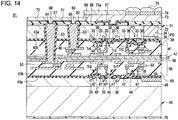
- the solid-state imaging device 81 according to the second embodiment of the present invention is constructed in a manner similar to that of the first embodiment, except for the followings: In this embodiment, only the electrode pad 72 on the side of the first semiconductor substrate 31 is formed, while the connection conductor 51, the insulating layer 52, and the electrode bump 78 on the side of the second semiconductor substrate 45 are omitted. In addition, a passivation layer 76 is formed on the back side of the second semiconductor substrate 45. Other structural components are the same as those described in the first embodiment.
- the corresponding structural components are designated by the same reference numerals as those in FIG. 3 to omit the duplicated explanations thereof.
- the manufacture of the solid-stage imaging device 81 is performed by the same method as that of the first embodiment shown in FIG. 4 to FIG. 13 , except for the followings: The method of the present embodiment does not include the steps of forming the connection conductor 51, the insulating layer 52, and the electrode bump 78 as well as the formation of the connection hole desired for forming the connection conductor 51.
- the solid-state imaging device of the second embodiment exerts the same advantageous effects as those of the first embodiment because of having the similar configuration to that of the first embodiment except for the electrode bump 78.
- the connection hole, the insulating layer 62, and the connection conductor 61 are not formed on the side of the logic circuit in advance. Thus, lower costs can be expected.
- a semiconductor device i.e., a MOS solid-state imaging device
- the pixel region 23 and the control circuit 24 formed on the side of the first semiconductor substrate 31 are electrically connected to the logic circuit 25 on the side of the second semiconductor substrate 45 through one through-connection conductor 84 formed in the first semiconductor substrate 31.
- connection through-hole 85 is formed such that it extends from the back side 31b of the first semiconductor substrate to the uppermost layer of the wiring 53 of the second semiconductor substrate 45 through the first semiconductor substrate 31. In addition, part of the connection through-hole 85 reaches to the uppermost layer of the wiring 40 of the first semiconductor substrate 31.
- the through-connection conductor 84 is embedded in the connection through-hole 85 to connect the wiring 40 on the side of the pixel region 23 and the control circuit 24 to the wiring 53 on the side of the logic circuit 25.
- the connection conductor 65 is connected to the first layer of the wiring 40 while the connection conductor 65 serves as a connection end.
- the manufacture of the solid-stage imaging device 83 is performed by the same method as that of the first embodiment shown in FIG. 4 to FIG. 13 , except for the steps of forming the connection conductor 65 and the electric pad 72 and the steps of selectively etching the lens material layer 75a and the planarizing layer 73.
- a half-finished logic circuit 25 for signal processing circuit is formed on a region to be provided as each of microchip parts on a second semiconductor substrate 45.
- the manufacturing steps in the present embodiment are the same as those illustrated in FIG. 5 of the aforementioned first embodiment.
- the same reference numerals as in FIG. 5 are used to denote the corresponding structural components. Thus, redundant descriptions will be omitted.
- the multi-wiring layer 55 is formed on the second semiconductor substrate 45 and the process is completed at the time of forming the uppermost layer of the wiring 53. In other words, the process is completed when the uppermost layer of the wiring 53 is exposed.
- the protective layer 56 shown in FIG. 5 is not formed on the exposed layer.
- the first semiconductor substrate 31 and the second semiconductor substrate 45 are bonded together so that their respective multi-wiring layers 41 and 55 can be faced with each other, while their wiring 40 and 53 are connected to each other and their insulating interlayers 39 and 49 are connected to each other.
- the wiring 40 and 53 are copper (Cu) wiring and the insulating interlayers 39 and 40 are silicon dioxide films.
- both the semiconductor substrates 31 and 45 are placed over one another and heated while receiving a predetermined load while their respective Cu wirings 40 and 50 are directly touched with each other.
- the insulating interlayers 39 and 49 may be connected with each other.
- the heating temperature at this time is, for example, about 300°C, which prevents Cu wiring from being deteriorated.
- connection hole 88 is formed in the thin-filmed first semiconductor substrate 31.
- the connection hole 88 is located at a desired position in a region to be provided as each microchip part and extends from the back side 31b of the substrate 31 to the first layer of the wiring 40.
- An insulating layer 63 is formed on the inner wall surface of the connection hole 88.
- connection hole 62 and the connection through-hole 61 are formed.
- the connection trough-hole 61 reaches to the uppermost layer of the wiring 53 on the side of the second semiconductor substrate 45.
- a through-connection conductor 64 and a connection conductor 65 are embedded in the connection through-hole 61 and the connection hole 62, respectively.
- an insulating protective layer 66 is formed on the entire surface on the back side 31b of the first semiconductor substrate 31.
- the manufacturing steps illustrated in FIG. 20 are the same as those illustrated in FIGS. 9 to 11 .
- the same reference numerals as in FIGS. 9 to 11 are used to denote the corresponding structural components. Thus, redundant descriptions will be omitted.
- an electronic pad 72 and a light-shielding layer 67 are formed on the side of the first semiconductor substrate 31.
- the electric pad 72 is connected to the connection conductor 62 and the through-connection conductor 61.
- a planarizing layer 73, an on-chip color filter 74, and an on-chip microlens 74 are formed on the same side.
- the back side of the substrate is ground and polished to expose the connection conductor 51.
- a passivation layer 76 is formed and an electrode bump 78 is then formed on the connection conductor 51 (see FIG. 16 ).
- the manufacturing steps illustrated in FIG. 21 are the same as those illustrated in FIG. 13 as described above.
- the same reference numerals as in FIG. 13 are used to denote the corresponding structural components. Thus, redundant descriptions will be omitted.
- the resulting product is divided into the respective microchips, thereby obtaining a desired back-illuminated solid-state imaging device 91 as shown in FIG. 16 .
- the configuration of the device illustrated in FIG. 2B is employed.
- the configuration of the device illustrated in FIG. 2C may be employed.
- the solid-state imaging device 91 and the manufacturing method thereof according to the fourth embodiment of the present invention in the step of combining the first semiconductor substrate 31 and the second semiconductor substrate 45, simultaneously, the wiring 40 and the wiring 53 are directly connected to each other.
- the pixel region 23 and the control circuit 24 are electrically connected to the logic circuit 25, completing their electrical connection. Therefore, the number of the manufacturing steps can be further reduced and a further reduction in manufacturing costs can be also attained.
- the device of the present embodiment exerts the same advantageous effects as those described in the first embodiment.
- the semiconductor device of the present embodiment is a semiconductor device on which a first semiconductor integrated circuit and a second semiconductor integrated circuit are mounted in combination.
- a half-finished first semiconductor integrated circuit (logic circuit 102 in this example) is formed on a region to be provided as each of microchip parts on a first semiconductor substrate (semiconductor wafer) 101.
- a first semiconductor substrate semiconductor wafer
- a plurality of MOS transistors Tr11, Tr12, and Tr13 are formed on the region to be provided as each of microchip parts on the semiconductor well region 104 formed in the semiconductor substrate (e.g., silicon substrate) 103.
- a plurality of MOS transistors Tr11, Tr12, and Tr13 are formed on the region to be provided as each of microchip parts on the semiconductor well region 104 formed in the semiconductor substrate (e.g., silicon substrate) 103.
- Each of the MOS transistors Tr11 to Trl3 includes a pair of source/drain regions 105 and a gate electrode 106 with a gate insulating layer placed therebetween.
- MOS transistors Tr11 to Tr13 are separated from one another by the presence of isolation regions 107, respectively.
- the MOS transistors are represented by MOS transistors Tr11 to Tr13.
- the logic circuit 102 includes CMOS transistors. Therefore, these MOS transistors may be n-channel MOS transistors or p-channel MOS transistors. Thus, when the n-channel MOS transistor is formed, an n-type source/drain region is formed on a p-type semiconductor well region. When a p-channel MOS transistor is formed, a p-type source/drain region is formed in an n-type semiconductor well region.
- the first semiconductor integrated circuit may be a semiconductor memory circuit instead of the logic circuit 102.
- the logic circuit to be used as a second semiconductor integrated circuit is subjected to the signal processing of the semiconductor memory circuit.
- a multi-wiring layer 111 is formed by laminated three metal wiring layers 109.
- the metal wiring 109 may be made of copper, or Cu wiring.
- the respective MOS transistors Tr11 to Tr13 are connected to one another through the desired first layer of the wiring 109 and a connection conductor 112.
- three layers of the wiring 109 are connected to one another through the connection conductor.
- MOS transistors Tr21 to Tr23 are separated from one another by the presence of isolation regions 123, respectively.
- MOS transistors are represented by MOS transistors Tr21 to Tr23.
- the logic circuit 117 includes CMOS transistors. Therefore, these MOS transistors may be n-channel MOS transistors or p-channel MOS transistors. Thus, when the n-channel MOS transistor is formed, an n-type source/drain region is formed on a p-type semiconductor well region. When a p-channel MOS transistor is formed, a p-type source/drain region is formed in an n-type semiconductor well region.
- a plurality of layers is formed on the conductive substrate 118 through an interlayer insulating layer 124.
- a multi-wiring layer 126 is formed by laminated three metal wiring layers 125.
- the metal wiring 125 may be made of copper, or Cu wiring.
- the respective MOS transistors Tr21 to Tr23 are connected to one another through the desired first layer of the wiring 125 and a connection conductor 112. Furthermore, three layers of the wiring 125 are connected to one another through the connection conductor.
- connection hole is formed from the surface of the first insulating interlayer 124 to a predetermined depth position in the semiconductor substrate 118. Then, a connection conductor 128 for extraction electrode is embedded in the resulting connection hole.
- the connection conductor 128 may be made of copper (Cu), tungsten (W), polysilicon, or the like. Before embedding the connection conductor 128, an insulation layer 129 is formed on the inner wall surface of the connection hole to insulate the connection conductor 128 from the semiconductor substrate 118. Then, a cap layer, a so-called protective layer 127 which prevent the copper wiring 125 from being dispersed, is formed on the multi-wiring layer 126.
- the first semiconductor substrate 101 and the second semiconductor substrate 116 are bonded together so that their respective multi-wiring layers 111 and 126 can be faced with each other.
- the bonding may be performed using plasma bonding, an adhesive agent, or the like.
- a layer 129 such as a plasma TEOS film, a plasma SiN film, a SiON film (block film), or a SiC film, is formed and bonded together by plasma bonding.
- the semiconductor substrate 101 with a thickness of 600 ⁇ m may be thinned to about 5 to 10 ⁇ m.
- connection through-hole 131 is formed in the thin-filmed first semiconductor substrate 101 at a desired position of a region to be provided as each microchip part.
- the connection through-hole 131 extends from the back side 101b to the uppermost layer of the wiring 125 of the second semiconductor substrate 116 through the first semiconductor substrate 101.
- a connection hole 132 is formed near the connection through-hole 131 in the first semiconductor substrate 101, extending from the back side 101b to a first layer portion of wiring 109 on the first semiconductor substrate 101. Since the connection through-hole 131 and the connection hole 132 are formed after making the first semiconductor substrate 101 into a thin film, these holes 131 and 132 can be formed as micropores with a smaller aspect ratio.
- an insulating layer 133 for electric insulation with the semiconductor substrate 101 is formed on the inner wall surface of each of the connection through-hole 131 and the connection hole 132.
- a through-connection conductor 134 and a connection conductor 135 are embedded in the connection through-hole 131 and the connection hole 132, respectively.
- Each of the through-connection conductor 134 and the connection conductor 135 may be made of a metal, such as copper (Cu) or tungsten (W).
- connection wiring 136 is formed on the back side of the first semiconductor substrate 101 to make a connection between the through-connection conductor 134 and the connection conductor 135.
- the first semiconductor integrated circuit 102 is electrically connected to the second semiconductor integrated circuit 117 through the connection conductor 135, the through-connection conductor 134, and the connection wiring 136.
- the connection wiring 136 serves as an electrode pad used as an extraction electrode.
- An insulating layer is applied to the surface except for the connection wiring 136 to form an overcoat layer 139.
- the overcoat layer 139 may be, for example, a plasma silicon nitride film.
- connection conductor 128 On the other hand, on the side of the second semiconductor substrate 116, the surface of the substrate 116 is ground to expose the surface of the connection conductor 128 that serves as an extraction electrode. After forming a passivation layer 137 on the exposed surface of the connection conductor 128 of the second semiconductor substrate 116, a spherical electrode bump 138 is formed so that it can be electrically connected to the connection conductor 128 (see FIG. 22 ).
- the first semiconductor integrated circuit and the second semiconductor integrated circuit can be independently formed on different microchip parts by their optimal process technologies, respectively. Therefore, a high-performance semiconductor integrated circuit can be provided.
- a reduction in manufacturing costs can be attained by bonding and thinning the first and second semiconductor wafers together in a half-finished product state, electrically connecting the first and second integrated circuits to each other, and dividing the resulting combination in a completed product state into microchips.
- the solid-state imaging device uses electrons as signal electric charges, a p-type as a first-conductivity type, and an n-type as a second-conductivity type, it may be also applied to one using electron holes as signal electronic charges.
- the conductivity types of the semiconductor substrates, semiconductor well regions, or semiconductor regions are reversed.
- the n-type is provided as the first-conductivity type and the p-type is provided as the second-conductivity type.
- the first semiconductor chip section 22 may have a thickness smaller than the thickness of the second semiconductor chip section 26.
- FIG. 29 illustrates the configuration of a camera as an exemplary electronic apparatus according to the sixth embodiment of the present invention.
- An example of the camera according to the present embodiment is a video camera which can shoot a still picture or video.
- the camera 141 of the present embodiment includes a solid-state imaging device 142, an optical system 143 that introduces incident light into a photoreceptor of the solid-state imaging device 142, and a shutter device 144. Furthermore, the camera 141 includes a drive circuit 145 for driving the solid-state imaging device 142 and a signal processing circuit 146 for processing an output signal from the solid-state imaging device 142.
- the driving signals (timing signals) supplied from the drive circuit 145 allow the solid-state imaging device 142 to transmit signals.
- the signal-processing circuit 146 performs various kinds of signal processing. Video signals subjected to the signal processing are stored in a storage medium such as a memory or outputted to a monitor.
- the electronic apparatus such as a camera, according to the sixth embodiment of the present invention includes a high-performance solid-state imaging device 142 with a lower production cost. Therefore, an inexpensive and reliable electronic apparatus can be provided.
Landscapes
- Engineering & Computer Science (AREA)
- Physics & Mathematics (AREA)
- Power Engineering (AREA)
- General Physics & Mathematics (AREA)
- Condensed Matter Physics & Semiconductors (AREA)
- Computer Hardware Design (AREA)
- Microelectronics & Electronic Packaging (AREA)
- Electromagnetism (AREA)
- Signal Processing (AREA)
- Multimedia (AREA)
- Manufacturing & Machinery (AREA)
- Solid State Image Pick-Up Elements (AREA)
- Transforming Light Signals Into Electric Signals (AREA)
Priority Applications (1)
| Application Number | Priority Date | Filing Date | Title |
|---|---|---|---|
| EP23181743.8A EP4276906A3 (fr) | 2009-03-19 | 2010-03-12 | Dispositif semiconducteur, son procédé de fabrication et appareil électronique |
Applications Claiming Priority (3)
| Application Number | Priority Date | Filing Date | Title |
|---|---|---|---|
| JP2009068582 | 2009-03-19 | ||
| JP2010012586A JP5985136B2 (ja) | 2009-03-19 | 2010-01-22 | 半導体装置とその製造方法、及び電子機器 |
| EP10156350.0A EP2230691B1 (fr) | 2009-03-19 | 2010-03-12 | Procédé de fabrication d'un dispositif semi-conducteur |
Related Parent Applications (2)
| Application Number | Title | Priority Date | Filing Date |
|---|---|---|---|
| EP10156350.0A Division EP2230691B1 (fr) | 2009-03-19 | 2010-03-12 | Procédé de fabrication d'un dispositif semi-conducteur |
| EP10156350.0A Division-Into EP2230691B1 (fr) | 2009-03-19 | 2010-03-12 | Procédé de fabrication d'un dispositif semi-conducteur |
Related Child Applications (1)
| Application Number | Title | Priority Date | Filing Date |
|---|---|---|---|
| EP23181743.8A Division EP4276906A3 (fr) | 2009-03-19 | 2010-03-12 | Dispositif semiconducteur, son procédé de fabrication et appareil électronique |
Publications (2)
| Publication Number | Publication Date |
|---|---|
| EP3595009A1 true EP3595009A1 (fr) | 2020-01-15 |
| EP3595009B1 EP3595009B1 (fr) | 2023-06-28 |
Family
ID=42235257
Family Applications (5)
| Application Number | Title | Priority Date | Filing Date |
|---|---|---|---|
| EP16167541.8A Active EP3118898B1 (fr) | 2009-03-19 | 2010-03-12 | Dispositif semi-conducteur et appareil électronique |
| EP10156350.0A Active EP2230691B1 (fr) | 2009-03-19 | 2010-03-12 | Procédé de fabrication d'un dispositif semi-conducteur |
| EP21182487.5A Active EP3937245B1 (fr) | 2009-03-19 | 2010-03-12 | Dispositif semiconducteur, son procédé de fabrication et appareil électronique |
| EP23181743.8A Pending EP4276906A3 (fr) | 2009-03-19 | 2010-03-12 | Dispositif semiconducteur, son procédé de fabrication et appareil électronique |
| EP19192125.3A Active EP3595009B1 (fr) | 2009-03-19 | 2010-03-12 | Dispositif semiconducteur, son procédé de fabrication et appareil électronique |
Family Applications Before (4)
| Application Number | Title | Priority Date | Filing Date |
|---|---|---|---|
| EP16167541.8A Active EP3118898B1 (fr) | 2009-03-19 | 2010-03-12 | Dispositif semi-conducteur et appareil électronique |
| EP10156350.0A Active EP2230691B1 (fr) | 2009-03-19 | 2010-03-12 | Procédé de fabrication d'un dispositif semi-conducteur |
| EP21182487.5A Active EP3937245B1 (fr) | 2009-03-19 | 2010-03-12 | Dispositif semiconducteur, son procédé de fabrication et appareil électronique |
| EP23181743.8A Pending EP4276906A3 (fr) | 2009-03-19 | 2010-03-12 | Dispositif semiconducteur, son procédé de fabrication et appareil électronique |
Country Status (7)
| Country | Link |
|---|---|
| US (11) | US9451131B2 (fr) |
| EP (5) | EP3118898B1 (fr) |
| JP (1) | JP5985136B2 (fr) |
| KR (9) | KR101679853B1 (fr) |
| CN (2) | CN103247648B (fr) |
| DE (1) | DE202010018528U1 (fr) |
| TW (2) | TWI495092B (fr) |
Cited By (1)
| Publication number | Priority date | Publication date | Assignee | Title |
|---|---|---|---|---|
| TWI786535B (zh) * | 2020-03-31 | 2022-12-11 | 南亞科技股份有限公司 | 半導體元件 |
Families Citing this family (188)
| Publication number | Priority date | Publication date | Assignee | Title |
|---|---|---|---|---|
| US8569876B2 (en) | 2006-11-22 | 2013-10-29 | Tessera, Inc. | Packaged semiconductor chips with array |
| JP2010098219A (ja) * | 2008-10-20 | 2010-04-30 | Toshiba Corp | 裏面照射型固体撮像装置 |
| US9142586B2 (en) | 2009-02-24 | 2015-09-22 | Taiwan Semiconductor Manufacturing Company, Ltd. | Pad design for backside illuminated image sensor |
| JP5985136B2 (ja) | 2009-03-19 | 2016-09-06 | ソニー株式会社 | 半導体装置とその製造方法、及び電子機器 |
| JP5304536B2 (ja) * | 2009-08-24 | 2013-10-02 | ソニー株式会社 | 半導体装置 |
| KR101648200B1 (ko) * | 2009-10-22 | 2016-08-12 | 삼성전자주식회사 | 이미지 센서 및 그 제조 방법 |
| JP5442394B2 (ja) * | 2009-10-29 | 2014-03-12 | ソニー株式会社 | 固体撮像装置とその製造方法、及び電子機器 |
| TWI515885B (zh) | 2009-12-25 | 2016-01-01 | 新力股份有限公司 | 半導體元件及其製造方法,及電子裝置 |
| EP3514831B1 (fr) | 2009-12-26 | 2021-10-13 | Canon Kabushiki Kaisha | Appareil de capture d'images à l'état solide et système de capture d'images |
| IT1398204B1 (it) | 2010-02-16 | 2013-02-14 | St Microelectronics Srl | Sistema e metodo per eseguire il test elettrico di vie passanti nel silicio (tsv - through silicon vias). |
| JP5553693B2 (ja) * | 2010-06-30 | 2014-07-16 | キヤノン株式会社 | 固体撮像装置及び撮像システム |
| JP5709418B2 (ja) * | 2010-06-30 | 2015-04-30 | キヤノン株式会社 | 固体撮像装置 |
| JP6173410B2 (ja) * | 2010-06-30 | 2017-08-02 | キヤノン株式会社 | 固体撮像装置および固体撮像装置の製造方法 |
| JP5843475B2 (ja) * | 2010-06-30 | 2016-01-13 | キヤノン株式会社 | 固体撮像装置および固体撮像装置の製造方法 |
| JP5693060B2 (ja) * | 2010-06-30 | 2015-04-01 | キヤノン株式会社 | 固体撮像装置、及び撮像システム |
| JP2012033894A (ja) | 2010-06-30 | 2012-02-16 | Canon Inc | 固体撮像装置 |
| JP2012015400A (ja) * | 2010-07-02 | 2012-01-19 | Canon Inc | 固体撮像装置 |
| US9640437B2 (en) | 2010-07-23 | 2017-05-02 | Tessera, Inc. | Methods of forming semiconductor elements using micro-abrasive particle stream |
| US8847380B2 (en) | 2010-09-17 | 2014-09-30 | Tessera, Inc. | Staged via formation from both sides of chip |
| JP5570377B2 (ja) * | 2010-09-30 | 2014-08-13 | キヤノン株式会社 | 固体撮像装置 |
| JP5640630B2 (ja) * | 2010-10-12 | 2014-12-17 | ソニー株式会社 | 固体撮像装置、固体撮像装置の製造方法、及び電子機器 |
| JP5716347B2 (ja) * | 2010-10-21 | 2015-05-13 | ソニー株式会社 | 固体撮像装置及び電子機器 |
| JP2012094720A (ja) * | 2010-10-27 | 2012-05-17 | Sony Corp | 固体撮像装置、半導体装置、固体撮像装置の製造方法、半導体装置の製造方法、及び電子機器 |
| JP5857399B2 (ja) * | 2010-11-12 | 2016-02-10 | ソニー株式会社 | 固体撮像装置及び電子機器 |
| US8587126B2 (en) | 2010-12-02 | 2013-11-19 | Tessera, Inc. | Stacked microelectronic assembly with TSVs formed in stages with plural active chips |
| US8736066B2 (en) | 2010-12-02 | 2014-05-27 | Tessera, Inc. | Stacked microelectronic assemby with TSVS formed in stages and carrier above chip |
| TWI467746B (zh) * | 2010-12-15 | 2015-01-01 | Sony Corp | 半導體元件及其製造方法與電子裝置 |
| US20120193744A1 (en) * | 2011-01-31 | 2012-08-02 | Swarnal Borthakur | Imagers with buried metal trenches and though-silicon vias |
| JP5696513B2 (ja) | 2011-02-08 | 2015-04-08 | ソニー株式会社 | 固体撮像装置とその製造方法、及び電子機器 |
| US8872293B2 (en) * | 2011-02-15 | 2014-10-28 | Sony Corporation | Solid-state imaging device and method of manufacturing the same and electronic apparatus |
| JP2012174937A (ja) * | 2011-02-22 | 2012-09-10 | Sony Corp | 半導体装置、半導体装置の製造方法、半導体ウエハの貼り合わせ方法及び電子機器 |
| JP2012195509A (ja) | 2011-03-17 | 2012-10-11 | Canon Inc | 半導体装置及びその製造方法 |
| JP5853389B2 (ja) | 2011-03-28 | 2016-02-09 | ソニー株式会社 | 半導体装置及び半導体装置の製造方法。 |
| JP6019599B2 (ja) * | 2011-03-31 | 2016-11-02 | ソニー株式会社 | 半導体装置、および、その製造方法 |
| JP5842368B2 (ja) | 2011-04-11 | 2016-01-13 | ソニー株式会社 | 半導体装置 |
| JP5729100B2 (ja) | 2011-04-11 | 2015-06-03 | ソニー株式会社 | 半導体装置の製造方法、半導体装置、電子機器 |
| JP2012227328A (ja) | 2011-04-19 | 2012-11-15 | Sony Corp | 半導体装置、半導体装置の製造方法、固体撮像装置及び電子機器 |
| US8637800B2 (en) * | 2011-04-19 | 2014-01-28 | Altasens, Inc. | Image sensor with hybrid heterostructure |
| DE102011101835A1 (de) * | 2011-05-16 | 2012-11-22 | Arnold & Richter Cine Technik Gmbh & Co. Betriebs Kg | Bildsensor |
| US8896125B2 (en) * | 2011-07-05 | 2014-11-25 | Sony Corporation | Semiconductor device, fabrication method for a semiconductor device and electronic apparatus |
| JP5987275B2 (ja) * | 2011-07-25 | 2016-09-07 | ソニー株式会社 | 固体撮像装置、固体撮像装置の製造方法、および電子機器 |
| US9153490B2 (en) | 2011-07-19 | 2015-10-06 | Sony Corporation | Solid-state imaging device, manufacturing method of solid-state imaging device, manufacturing method of semiconductor device, semiconductor device, and electronic device |
| JP2013077711A (ja) * | 2011-09-30 | 2013-04-25 | Sony Corp | 半導体装置および半導体装置の製造方法 |
| JP5760923B2 (ja) * | 2011-10-04 | 2015-08-12 | ソニー株式会社 | 固体撮像装置の製造方法 |
| JP5957840B2 (ja) | 2011-10-04 | 2016-07-27 | ソニー株式会社 | 半導体装置の製造方法 |
| TWI577001B (zh) | 2011-10-04 | 2017-04-01 | Sony Corp | 固體攝像裝置、固體攝像裝置之製造方法及電子機器 |
| JP2013090127A (ja) * | 2011-10-18 | 2013-05-13 | Olympus Corp | 固体撮像装置および撮像装置 |
| JP6056126B2 (ja) * | 2011-10-21 | 2017-01-11 | ソニー株式会社 | 固体撮像装置およびカメラシステム |
| JP2013115289A (ja) | 2011-11-30 | 2013-06-10 | Sony Corp | 半導体装置、半導体装置の製造方法、および電子機器 |
| KR20140113633A (ko) | 2011-12-19 | 2014-09-24 | 소니 주식회사 | 고체 촬상 장치, 고체 촬상 장치의 제조 방법, 및 전자 기기 |
| JP5970826B2 (ja) | 2012-01-18 | 2016-08-17 | ソニー株式会社 | 半導体装置、半導体装置の製造方法、固体撮像装置および電子機器 |
| WO2013115075A1 (fr) * | 2012-02-03 | 2013-08-08 | ソニー株式会社 | Dispositif à semi-conducteurs, et appareil électronique |
| JP6214132B2 (ja) | 2012-02-29 | 2017-10-18 | キヤノン株式会社 | 光電変換装置、撮像システムおよび光電変換装置の製造方法 |
| KR20130099425A (ko) * | 2012-02-29 | 2013-09-06 | 삼성전자주식회사 | 이미지 센서 |
| US8772899B2 (en) * | 2012-03-01 | 2014-07-08 | Taiwan Semiconductor Manufacturing Company, Ltd. | Method and apparatus for backside illumination sensor |
| JP2013187360A (ja) * | 2012-03-08 | 2013-09-19 | Sony Corp | 固体撮像装置、及び、電子機器 |
| CN102569328B (zh) | 2012-03-16 | 2015-05-13 | 上海丽恒光微电子科技有限公司 | 感光成像装置、半导体器件的制作方法 |
| US20130264688A1 (en) * | 2012-04-06 | 2013-10-10 | Omnivision Technologies, Inc. | Method and apparatus providing integrated circuit system with interconnected stacked device wafers |
| US8629524B2 (en) * | 2012-04-27 | 2014-01-14 | Taiwan Semiconductor Manufacturing Company, Ltd. | Apparatus for vertically integrated backside illuminated image sensors |
| JP6012262B2 (ja) | 2012-05-31 | 2016-10-25 | キヤノン株式会社 | 半導体装置の製造方法 |
| US9406711B2 (en) * | 2012-06-15 | 2016-08-02 | Taiwan Semiconductor Manufacturing Company, Ltd. | Apparatus and method for backside illuminated image sensors |
| WO2014002852A1 (fr) * | 2012-06-29 | 2014-01-03 | ソニー株式会社 | Dispositif semi-conducteur, procédé de fabrication pour dispositif semi-conducteur, et dispositif électronique |
| US8710607B2 (en) | 2012-07-12 | 2014-04-29 | Taiwan Semiconductor Manufacturing Company, Ltd. | Method and apparatus for image sensor packaging |
| JP2014022561A (ja) | 2012-07-18 | 2014-02-03 | Sony Corp | 固体撮像装置、及び、電子機器 |
| WO2014013742A1 (fr) | 2012-07-20 | 2014-01-23 | 株式会社ニコン | Unité d'imagerie, dispositif d'imagerie et procédé de fabrication d'une unité d'imagerie |
| TWI595637B (zh) | 2012-09-28 | 2017-08-11 | Sony Corp | 半導體裝置及電子機器 |
| JP6128787B2 (ja) * | 2012-09-28 | 2017-05-17 | キヤノン株式会社 | 半導体装置 |
| JP6041607B2 (ja) * | 2012-09-28 | 2016-12-14 | キヤノン株式会社 | 半導体装置の製造方法 |
| JP6376245B2 (ja) * | 2012-10-18 | 2018-08-22 | ソニー株式会社 | 固体撮像装置、および電子機器 |
| JP2014099582A (ja) | 2012-10-18 | 2014-05-29 | Sony Corp | 固体撮像装置 |
| JP5543567B2 (ja) | 2012-10-22 | 2014-07-09 | 誠 雫石 | 半導体素子の製造方法 |
| KR101334220B1 (ko) * | 2012-11-16 | 2013-11-29 | (주)실리콘화일 | 버팅 콘택 방식을 이용한 웨이퍼 간의 전기적 연결방법 및 이를 이용하여 구현한 반도체 장치 |
| CN103123924B (zh) * | 2013-01-28 | 2015-07-08 | 豪威科技(上海)有限公司 | 背照式cmos影像传感器的制造方法 |
| CN103066096B (zh) * | 2013-01-28 | 2016-01-20 | 豪威科技(上海)有限公司 | 背照式cmos影像传感器的制造方法 |
| US8773562B1 (en) | 2013-01-31 | 2014-07-08 | Apple Inc. | Vertically stacked image sensor |
| US9252180B2 (en) * | 2013-02-08 | 2016-02-02 | Taiwan Semiconductor Manufacturing Company, Ltd. | Bonding pad on a back side illuminated image sensor |
| JP2014154812A (ja) * | 2013-02-13 | 2014-08-25 | Olympus Corp | 固体撮像装置、撮像装置、および固体撮像装置の製造方法 |
| US20150187701A1 (en) | 2013-03-12 | 2015-07-02 | Taiwan Semiconductor Manufacturing Company, Ltd. | Semiconductor Devices and Methods of Manufacture Thereof |
| US9076715B2 (en) | 2013-03-12 | 2015-07-07 | Taiwan Semiconductor Manufacturing Company, Ltd. | Interconnect structure for connecting dies and methods of forming the same |
| JP2014187261A (ja) * | 2013-03-25 | 2014-10-02 | Toshiba Corp | 固体撮像装置 |
| JP6308727B2 (ja) | 2013-06-13 | 2018-04-11 | キヤノン株式会社 | 電子デバイスの製造方法 |
| JP2015026675A (ja) * | 2013-07-25 | 2015-02-05 | ソニー株式会社 | 固体撮像素子およびその製造方法、並びに電子機器 |
| JP6184240B2 (ja) | 2013-08-08 | 2017-08-23 | オリンパス株式会社 | 固体撮像装置および撮像装置 |
| JP6116437B2 (ja) | 2013-08-13 | 2017-04-19 | オリンパス株式会社 | 固体撮像装置およびその製造方法、ならびに撮像装置 |
| KR102136845B1 (ko) | 2013-09-16 | 2020-07-23 | 삼성전자 주식회사 | 적층형 이미지 센서 및 그 제조방법 |
| TWI676279B (zh) * | 2013-10-04 | 2019-11-01 | 新力股份有限公司 | 半導體裝置及固體攝像元件 |
| TWI809268B (zh) * | 2013-11-06 | 2023-07-21 | 日商新力股份有限公司 | 攝像裝置及電子機器 |
| CN105531822A (zh) * | 2013-11-06 | 2016-04-27 | 索尼公司 | 半导体装置、固态成像元件和电子设备 |
| US9667900B2 (en) * | 2013-12-09 | 2017-05-30 | Optiz, Inc. | Three dimensional system-on-chip image sensor package |
| JP6299406B2 (ja) * | 2013-12-19 | 2018-03-28 | ソニー株式会社 | 半導体装置、半導体装置の製造方法、及び電子機器 |
| US9412719B2 (en) | 2013-12-19 | 2016-08-09 | Taiwan Semiconductor Manufacturing Company, Ltd. | 3DIC interconnect apparatus and method |
| US10056353B2 (en) | 2013-12-19 | 2018-08-21 | Taiwan Semiconductor Manufacturing Company, Ltd. | 3DIC interconnect apparatus and method |
| JP6658782B2 (ja) * | 2013-12-19 | 2020-03-04 | ソニー株式会社 | 半導体装置の製造方法 |
| US9806119B2 (en) * | 2014-01-09 | 2017-10-31 | Taiwan Semiconductor Manufacturing Company, Ltd. | 3DIC seal ring structure and methods of forming same |
| US9425150B2 (en) | 2014-02-13 | 2016-08-23 | Taiwan Semiconductor Manufacturing Company, Ltd. | Multi-via interconnect structure and method of manufacture |
| US9679936B2 (en) * | 2014-02-27 | 2017-06-13 | Semiconductor Components Industries, Llc | Imaging systems with through-oxide via connections |
| JP2015195235A (ja) | 2014-03-31 | 2015-11-05 | ソニー株式会社 | 固体撮像素子、電子機器、および撮像方法 |
| TWI648986B (zh) * | 2014-04-15 | 2019-01-21 | 日商新力股份有限公司 | 攝像元件、電子機器 |
| US9324755B2 (en) * | 2014-05-05 | 2016-04-26 | Semiconductor Components Industries, Llc | Image sensors with reduced stack height |
| US9614000B2 (en) * | 2014-05-15 | 2017-04-04 | Taiwan Semiconductor Manufacturing Company, Ltd. | Biased backside illuminated sensor shield structure |
| US9543257B2 (en) | 2014-05-29 | 2017-01-10 | Taiwan Semiconductor Manufacturing Company, Ltd. | 3DIC interconnect devices and methods of forming same |
| US9455158B2 (en) | 2014-05-30 | 2016-09-27 | Taiwan Semiconductor Manufacturing Company, Ltd. | 3DIC interconnect devices and methods of forming same |
| US9729809B2 (en) | 2014-07-11 | 2017-08-08 | Semiconductor Energy Laboratory Co., Ltd. | Semiconductor device and driving method of semiconductor device or electronic device |
| US9449914B2 (en) * | 2014-07-17 | 2016-09-20 | Taiwan Semiconductor Manufacturing Company, Ltd. | Stacked integrated circuits with redistribution lines |
| JP6598436B2 (ja) * | 2014-08-08 | 2019-10-30 | キヤノン株式会社 | 光電変換装置、撮像システム、及び光電変換装置の製造方法 |
| TWI747805B (zh) * | 2014-10-08 | 2021-12-01 | 日商索尼半導體解決方案公司 | 攝像裝置及製造方法、以及電子機器 |
| US9515111B2 (en) | 2014-10-20 | 2016-12-06 | Semiconductor Components Industries, Llc | Circuitry for biasing light shielding structures and deep trench isolation structures |
| GB2532728A (en) * | 2014-11-25 | 2016-06-01 | Nokia Technologies Oy | A semiconductor chip, a method, an apparatus and a computer program product for image capturing |
| US9525001B2 (en) | 2014-12-30 | 2016-12-20 | Taiwan Semiconductor Manufacturing Co., Ltd. | Semiconductor device and manufacturing method thereof |
| US9659985B2 (en) * | 2015-02-17 | 2017-05-23 | Taiwan Semiconductor Manufacturing Company Ltd. | Integrated circuit and image sensing device having metal shielding layer and related fabricating method |
| JP6295983B2 (ja) * | 2015-03-05 | 2018-03-20 | ソニー株式会社 | 半導体装置およびその製造方法、並びに電子機器 |
| JP6693068B2 (ja) * | 2015-03-12 | 2020-05-13 | ソニー株式会社 | 固体撮像装置および製造方法、並びに電子機器 |
| JP5994887B2 (ja) * | 2015-04-06 | 2016-09-21 | ソニー株式会社 | 固体撮像装置、固体撮像装置の製造方法、および電子機器 |
| US10217783B2 (en) * | 2015-04-08 | 2019-02-26 | Semiconductor Components Industries, Llc | Methods for forming image sensors with integrated bond pad structures |
| US9848146B2 (en) * | 2015-04-23 | 2017-12-19 | Semiconductor Energy Laboratory Co., Ltd. | Imaging device and electronic device |
| EP3288081B1 (fr) | 2015-04-24 | 2022-07-27 | Sony Group Corporation | Capteur d'image à l'état solide et dispositif électronique le comprenant |
| WO2017057291A1 (fr) * | 2015-10-01 | 2017-04-06 | オリンパス株式会社 | Élément d'imagerie, endoscope et système d'endoscope |
| JP6939568B2 (ja) | 2016-01-15 | 2021-09-22 | ソニーグループ株式会社 | 半導体装置および撮像装置 |
| US10854657B2 (en) | 2016-01-18 | 2020-12-01 | Sony Corporation | Solid-state image pickup element and electronic apparatus |
| JP2017139431A (ja) * | 2016-02-05 | 2017-08-10 | キヤノン株式会社 | 固体撮像装置及びその製造方法 |
| WO2017169822A1 (fr) * | 2016-03-30 | 2017-10-05 | ソニー株式会社 | Élément de capture d'image à semi-conducteurs, dispositif de capture d'image, dispositif d'endoscope et instrument électronique |
| DE112017002162T5 (de) | 2016-04-25 | 2019-01-10 | Olympus Corporation | Bildgebungselement, endoskop und endoskopsystem |
| EP3258493B1 (fr) * | 2016-06-16 | 2021-01-27 | ams AG | Caméra de système sur puce avec capteur(s) de lumière intégré(s) et procédé de production d'une caméra de système sur puce |
| JP6677594B2 (ja) * | 2016-06-30 | 2020-04-08 | キヤノン株式会社 | 光電変換装置 |
| KR102544782B1 (ko) * | 2016-08-04 | 2023-06-20 | 삼성전자주식회사 | 반도체 패키지 및 그 제조 방법 |
| KR102460077B1 (ko) | 2016-08-05 | 2022-10-28 | 삼성전자주식회사 | 스택 이미지 센서 패키지 및 이를 포함하는 스택 이미지 센서 모듈 |
| US10163771B2 (en) * | 2016-08-08 | 2018-12-25 | Qualcomm Incorporated | Interposer device including at least one transistor and at least one through-substrate via |
| KR102576349B1 (ko) * | 2016-08-24 | 2023-09-07 | 삼성전자주식회사 | 이미지 센서 |
| KR102605618B1 (ko) * | 2016-11-14 | 2023-11-23 | 삼성전자주식회사 | 이미지 센서 패키지 |
| JP2018081945A (ja) * | 2016-11-14 | 2018-05-24 | ソニーセミコンダクタソリューションズ株式会社 | 固体撮像素子および製造方法、並びに電子機器 |
| JP2018101699A (ja) * | 2016-12-20 | 2018-06-28 | ソニーセミコンダクタソリューションズ株式会社 | 固体撮像装置、固体撮像装置の製造方法および電子機器 |
| US9911780B1 (en) * | 2016-12-22 | 2018-03-06 | Omnivision Technologies, Inc. | Backside metal grid and metal pad simplification |
| KR102621752B1 (ko) * | 2017-01-13 | 2024-01-05 | 삼성전자주식회사 | Mram을 포함한 씨모스 이미지 센서 |
| US9966318B1 (en) * | 2017-01-31 | 2018-05-08 | Stmicroelectronics S.R.L. | System for electrical testing of through silicon vias (TSVs) |
| JP2018129412A (ja) * | 2017-02-09 | 2018-08-16 | ソニーセミコンダクタソリューションズ株式会社 | 半導体装置、および半導体装置の製造方法 |
| JP6580111B2 (ja) * | 2017-02-10 | 2019-09-25 | キヤノン株式会社 | 撮像素子および撮像装置 |
| US11044411B2 (en) * | 2017-02-10 | 2021-06-22 | Canon Kabushiki Kaisha | Imaging element and imaging apparatus |
| JP2018133392A (ja) * | 2017-02-14 | 2018-08-23 | キヤノン株式会社 | 光電変換装置 |
| JP2018174246A (ja) * | 2017-03-31 | 2018-11-08 | ソニーセミコンダクタソリューションズ株式会社 | 半導体装置および電子機器 |
| JP2018190766A (ja) * | 2017-04-28 | 2018-11-29 | ソニーセミコンダクタソリューションズ株式会社 | 半導体デバイス、製造方法、撮像素子、および電子機器 |
| JP6804395B2 (ja) * | 2017-06-21 | 2020-12-23 | ソニー株式会社 | 固体撮像装置 |
| EP4235793A3 (fr) * | 2017-06-29 | 2023-10-04 | Sony Semiconductor Solutions Corporation | Imageur rétroéclairé lié à une tranche |
| JP2017216480A (ja) * | 2017-09-01 | 2017-12-07 | ルネサスエレクトロニクス株式会社 | 半導体装置およびその製造方法 |
| CN107564927A (zh) * | 2017-09-19 | 2018-01-09 | 德淮半导体有限公司 | 图像传感器及其制作方法 |
| US10727217B2 (en) | 2017-09-29 | 2020-07-28 | Taiwan Semiconductor Manufacturing Company, Ltd. | Method of manufacturing semiconductor device that uses bonding layer to join semiconductor substrates together |
| US11251157B2 (en) * | 2017-11-01 | 2022-02-15 | Taiwan Semiconductor Manufacturing Company, Ltd. | Die stack structure with hybrid bonding structure and method of fabricating the same and package |
| US10535698B2 (en) | 2017-11-28 | 2020-01-14 | Taiwan Semiconductor Manufacturing Co., Ltd. | Image sensor with pad structure |
| WO2019130702A1 (fr) | 2017-12-27 | 2019-07-04 | ソニーセミコンダクタソリューションズ株式会社 | Dispositif de capture d'images |
| TW202408216A (zh) * | 2018-01-23 | 2024-02-16 | 日商索尼半導體解決方案公司 | 光檢測裝置 |
| JP2019140237A (ja) * | 2018-02-09 | 2019-08-22 | キヤノン株式会社 | 光電変換装置および撮像システム |
| US10950178B2 (en) * | 2018-02-20 | 2021-03-16 | Emagin Corporation | Microdisplay with reduced pixel size and method of forming same |
| CN108538874B (zh) * | 2018-05-07 | 2021-03-02 | 德淮半导体有限公司 | 图像传感器及其形成方法 |
| US11355536B2 (en) | 2018-07-12 | 2022-06-07 | Sony Semiconductor Solutions Corporation | Image sensor, signal processing device, signal processing method, and electronic device |
| WO2020035898A1 (fr) * | 2018-08-13 | 2020-02-20 | ウルトラメモリ株式会社 | Module semi-conducteur et son procédé de production |
| SG11202012288PA (en) * | 2018-08-24 | 2021-01-28 | Kioxia Corp | Semiconductor device and method of manufacturing same |
| KR102582669B1 (ko) | 2018-10-02 | 2023-09-25 | 삼성전자주식회사 | 이미지 센서 |
| JP7372258B2 (ja) * | 2018-10-16 | 2023-10-31 | ソニーセミコンダクタソリューションズ株式会社 | 半導体素子およびその製造方法 |
| TW202029487A (zh) * | 2018-10-17 | 2020-08-01 | 日商索尼半導體解決方案公司 | 攝像元件及電子機器 |
| WO2020105713A1 (fr) | 2018-11-21 | 2020-05-28 | ソニーセミコンダクタソリューションズ株式会社 | Élément d'imagerie à semi-conducteurs |
| US11984466B2 (en) | 2018-12-13 | 2024-05-14 | Sony Semiconductor Solutions Corporation | Solid-state imaging element and video recording apparatus |
| CN113228230A (zh) | 2018-12-20 | 2021-08-06 | 索尼半导体解决方案公司 | 摄像装置 |
| JP2022043369A (ja) * | 2018-12-26 | 2022-03-16 | ソニーセミコンダクタソリューションズ株式会社 | 半導体装置および電子機器 |
| EP3853893A4 (fr) * | 2019-02-11 | 2023-08-16 | Yangtze Memory Technologies Co., Ltd. | Structures semi-conductrices liées ayant des contacts de liaison faits de matériaux conducteurs non diffusibles et leurs procédés de formation |
| TW202044335A (zh) | 2019-03-15 | 2020-12-01 | 日商索尼半導體解決方案公司 | 攝像元件及半導體元件 |
| JP2020155711A (ja) * | 2019-03-22 | 2020-09-24 | ソニーセミコンダクタソリューションズ株式会社 | 半導体装置および固体撮像素子 |
| WO2020203141A1 (fr) * | 2019-03-29 | 2020-10-08 | ソニーセミコンダクタソリューションズ株式会社 | Dispositif de capture d'image |
| JP2020182112A (ja) | 2019-04-25 | 2020-11-05 | ソニーセミコンダクタソリューションズ株式会社 | 撮像装置 |
| CN110085614A (zh) * | 2019-04-30 | 2019-08-02 | 德淮半导体有限公司 | 背照式图像传感器及其制造方法 |
| DE112020003133T5 (de) | 2019-06-26 | 2022-03-10 | Sony Semiconductor Solutions Corporation | Bildgebungsvorrichtung |
| US20220262832A1 (en) | 2019-06-26 | 2022-08-18 | Sony Semiconductor Solutions Corporation | Semiconductor device and imaging device |
| TW202118028A (zh) | 2019-06-26 | 2021-05-01 | 日商索尼半導體解決方案公司 | 攝像裝置 |
| TW202109615A (zh) | 2019-06-26 | 2021-03-01 | 日商索尼半導體解決方案公司 | 攝像裝置 |
| EP3993040A4 (fr) | 2019-06-26 | 2023-03-29 | Sony Semiconductor Solutions Corporation | Appareil d'imagerie à semi-conducteurs |
| DE112020003071T5 (de) | 2019-06-26 | 2022-03-10 | Sony Semiconductor Solutions Corporation | Festkörper-bildgebungsvorrichtung |
| TW202107722A (zh) | 2019-06-26 | 2021-02-16 | 日商索尼半導體解決方案公司 | 攝像裝置 |
| TW202109616A (zh) | 2019-06-26 | 2021-03-01 | 日商索尼半導體解決方案公司 | 攝像裝置 |
| CN110491890B (zh) * | 2019-07-03 | 2022-03-15 | 芯盟科技有限公司 | 半导体结构及其形成方法 |
| CN110379799B (zh) * | 2019-07-18 | 2020-04-03 | 武汉新芯集成电路制造有限公司 | 一种芯片结构、晶圆结构及其制造方法 |
| US11973102B2 (en) * | 2019-11-29 | 2024-04-30 | Sony Semiconductor Solutions Corporation | Imaging device and electronic apparatus |
| EP4095911A4 (fr) * | 2020-01-22 | 2023-10-25 | BOE Technology Group Co., Ltd. | Fond de panier d'attaque et son procédé de préparation, panneau d'affichage et appareil d'affichage |
| US20210390233A1 (en) | 2020-06-10 | 2021-12-16 | Texas Instruments Incorporated | Automated geometry optimization for analog, mixed-signal circuit design |
| KR20220052612A (ko) | 2020-10-21 | 2022-04-28 | 삼성전자주식회사 | 반도체 패키지 |
| US20230411926A1 (en) * | 2020-11-23 | 2023-12-21 | Sense Photonics, Inc. | Multi-wafer integrated vcsel-electronics module |
| US11477368B1 (en) | 2021-04-26 | 2022-10-18 | Sony Semiconductor Solutions Corporation | Imaging device, imaging method, and electronic apparatus |
| US20230029763A1 (en) * | 2021-07-30 | 2023-02-02 | Cree, Inc. | Interconnect metal openings through dielectric films |
| US11758302B2 (en) | 2021-09-03 | 2023-09-12 | Sony Semiconductor Solutions Corporation | Imaging device, imaging method, and electronic apparatus |
| TW202329256A (zh) * | 2021-10-21 | 2023-07-16 | 日商東京威力科創股份有限公司 | 半導體裝置的製造方法及半導體裝置 |
| DE102022124675A1 (de) | 2022-09-26 | 2024-03-28 | Ifm Electronic Gmbh | PMD-Sensor mit mehreren Halbleiterebenen |
Citations (10)
| Publication number | Priority date | Publication date | Assignee | Title |
|---|---|---|---|---|
| JP2003031785A (ja) | 2001-07-11 | 2003-01-31 | Sony Corp | X−yアドレス型固体撮像素子およびその製造方法 |
| JP2006049361A (ja) | 2004-07-30 | 2006-02-16 | Sony Corp | 半導体モジュール及びmos型固体撮像装置 |
| WO2006109937A1 (fr) * | 2005-04-13 | 2006-10-19 | Siliconfile Technologies Inc. | Pixel d'unite de type separation a structure 3d destine a un capteur d'images et son procede de production |
| JP2007013089A (ja) | 2005-06-02 | 2007-01-18 | Sony Corp | 固体撮像素子及びその製造方法 |
| JP4000507B2 (ja) | 2001-10-04 | 2007-10-31 | ソニー株式会社 | 固体撮像装置の製造方法 |
| WO2007148891A1 (fr) * | 2006-06-19 | 2007-12-27 | Siliconfile Technologies Inc. | Capteur d'image utilisant une photodiode rétroéclairée et son procédé de fabrication |
| JP2008130603A (ja) | 2006-11-16 | 2008-06-05 | Toshiba Corp | イメージセンサ用ウェハレベルパッケージ及びその製造方法 |
| FR2910707A1 (fr) * | 2006-12-20 | 2008-06-27 | E2V Semiconductors Soc Par Act | Capteur d'image a haute densite d'integration |
| WO2008156274A1 (fr) * | 2007-06-19 | 2008-12-24 | Siliconfile Technologies Inc. | Réseau de pixels empêchant la diaphonie entre des pixels individuels et détecteur d'images utilisant les pixels |
| JP2009068582A (ja) | 2007-09-12 | 2009-04-02 | Ntn Corp | 車輪用軸受装置 |
Family Cites Families (91)
| Publication number | Priority date | Publication date | Assignee | Title |
|---|---|---|---|---|
| JPS5713189A (en) | 1980-06-26 | 1982-01-23 | Osaka Soda Co Ltd | Cathode for electrolysis |
| JPS63120779A (ja) | 1986-11-11 | 1988-05-25 | Toray Ind Inc | 水なし平版用インキ組成物 |
| JP3166220B2 (ja) | 1991-08-09 | 2001-05-14 | ソニー株式会社 | 固体撮像装置 |
| GB2289983B (en) * | 1994-06-01 | 1996-10-16 | Simage Oy | Imaging devices,systems and methods |
| DE19516487C1 (de) | 1995-05-05 | 1996-07-25 | Fraunhofer Ges Forschung | Verfahren zur vertikalen Integration mikroelektronischer Systeme |
| JP3139339B2 (ja) | 1995-09-13 | 2001-02-26 | 株式会社村田製作所 | 真空封止デバイスおよびその製造方法 |
| KR100192576B1 (ko) | 1995-11-17 | 1999-06-15 | 윤종용 | 콘택 이미지 센서 |
| US6882030B2 (en) * | 1996-10-29 | 2005-04-19 | Tru-Si Technologies, Inc. | Integrated circuit structures with a conductor formed in a through hole in a semiconductor substrate and protruding from a surface of the substrate |
| US6809421B1 (en) | 1996-12-02 | 2004-10-26 | Kabushiki Kaisha Toshiba | Multichip semiconductor device, chip therefor and method of formation thereof |
| US6207005B1 (en) | 1997-07-29 | 2001-03-27 | Silicon Genesis Corporation | Cluster tool apparatus using plasma immersion ion implantation |
| DE19813239C1 (de) * | 1998-03-26 | 1999-12-23 | Fraunhofer Ges Forschung | Verdrahtungsverfahren zur Herstellung einer vertikalen integrierten Schaltungsstruktur und vertikale integrierte Schaltungsstruktur |
| US6355950B1 (en) * | 1998-09-23 | 2002-03-12 | Intel Corporation | Substrate interconnect for power distribution on integrated circuits |
| US6228675B1 (en) | 1999-07-23 | 2001-05-08 | Agilent Technologies, Inc. | Microcap wafer-level package with vias |
| US6489241B1 (en) | 1999-09-17 | 2002-12-03 | Applied Materials, Inc. | Apparatus and method for surface finishing a silicon film |
| US6500694B1 (en) | 2000-03-22 | 2002-12-31 | Ziptronix, Inc. | Three dimensional device integration method and integrated device |
| JP2001189423A (ja) | 1999-12-28 | 2001-07-10 | Sanyo Electric Co Ltd | 半導体集積回路 |
| JP2002009193A (ja) | 2000-04-18 | 2002-01-11 | Matsushita Electric Ind Co Ltd | 半導体装置 |
| JP3713418B2 (ja) * | 2000-05-30 | 2005-11-09 | 光正 小柳 | 3次元画像処理装置の製造方法 |
| JP3843708B2 (ja) * | 2000-07-14 | 2006-11-08 | 日本電気株式会社 | 半導体装置およびその製造方法ならびに薄膜コンデンサ |
| JP3619773B2 (ja) * | 2000-12-20 | 2005-02-16 | 株式会社ルネサステクノロジ | 半導体装置の製造方法 |
| US6803324B2 (en) * | 2001-01-31 | 2004-10-12 | Sony Corporation | Semiconductor device and its manufacturing method |
| US20030049925A1 (en) * | 2001-09-10 | 2003-03-13 | Layman Paul Arthur | High-density inter-die interconnect structure |
| US7265402B2 (en) | 2001-11-05 | 2007-09-04 | Zycube Co., Ltd. | Solid-state image sensor including a microlens |
| JP4237966B2 (ja) | 2002-03-08 | 2009-03-11 | 浜松ホトニクス株式会社 | 検出器 |
| JP4123415B2 (ja) | 2002-05-20 | 2008-07-23 | ソニー株式会社 | 固体撮像装置 |
| US7153757B2 (en) * | 2002-08-29 | 2006-12-26 | Analog Devices, Inc. | Method for direct bonding two silicon wafers for minimising interfacial oxide and stresses at the bond interface, and an SOI structure |
| JP2004095876A (ja) | 2002-08-30 | 2004-03-25 | Aisin Seiki Co Ltd | ウェーハレベルパッケージの構造および製造方法 |
| JP4440554B2 (ja) | 2002-09-24 | 2010-03-24 | 浜松ホトニクス株式会社 | 半導体装置 |
| US6853046B2 (en) | 2002-09-24 | 2005-02-08 | Hamamatsu Photonics, K.K. | Photodiode array and method of making the same |
| JP4819320B2 (ja) | 2003-05-28 | 2011-11-24 | 株式会社オクテック | 半導体装置の製造方法 |
| JP2005019543A (ja) * | 2003-06-24 | 2005-01-20 | Shimadzu Corp | 二次元半導体検出器および二次元撮像装置 |
| JP2005044861A (ja) | 2003-07-23 | 2005-02-17 | Seiko Epson Corp | 半導体装置、半導体装置の使用方法、半導体装置の製造方法および電子機器 |
| JP4401181B2 (ja) * | 2003-08-06 | 2010-01-20 | 三洋電機株式会社 | 半導体装置及びその製造方法 |
| JP3980539B2 (ja) | 2003-08-29 | 2007-09-26 | 唯知 須賀 | 基板接合方法、照射方法、および基板接合装置 |
| US6953990B2 (en) | 2003-09-19 | 2005-10-11 | Agilent Technologies, Inc. | Wafer-level packaging of optoelectronic devices |
| JP4574153B2 (ja) | 2003-09-30 | 2010-11-04 | 中川特殊鋼株式会社 | 磁性基材の製造方法 |
| JP4046069B2 (ja) * | 2003-11-17 | 2008-02-13 | ソニー株式会社 | 固体撮像素子及び固体撮像素子の製造方法 |
| US7642642B2 (en) | 2004-03-23 | 2010-01-05 | Avago Technologies Wireless Ip (Singapore) Pte. Ltd. | Microcap wafer bonding apparatus |
| JP4389626B2 (ja) | 2004-03-29 | 2009-12-24 | ソニー株式会社 | 固体撮像素子の製造方法 |
| JP2007250561A (ja) | 2004-04-12 | 2007-09-27 | Japan Science & Technology Agency | 半導体素子および半導体システム |
| JP2005322745A (ja) | 2004-05-07 | 2005-11-17 | Sony Corp | 半導体素子、半導体素子の製造方法、固体撮像素子、並びに固体撮像素子の製造方法 |
| JP2005347707A (ja) | 2004-06-07 | 2005-12-15 | Sony Corp | 固体撮像素子及びその製造方法 |
| JP4483442B2 (ja) | 2004-07-13 | 2010-06-16 | ソニー株式会社 | 固体撮像素子と固体撮像装置、固体撮像素子の製造方法 |
| JP4379295B2 (ja) * | 2004-10-26 | 2009-12-09 | ソニー株式会社 | 半導体イメージセンサー・モジュール及びその製造方法 |
| KR100610481B1 (ko) * | 2004-12-30 | 2006-08-08 | 매그나칩 반도체 유한회사 | 수광영역을 넓힌 이미지센서 및 그 제조 방법 |
| JP2006261638A (ja) | 2005-02-21 | 2006-09-28 | Sony Corp | 固体撮像装置および固体撮像装置の駆動方法 |
| US8049293B2 (en) * | 2005-03-07 | 2011-11-01 | Sony Corporation | Solid-state image pickup device, electronic apparatus using such solid-state image pickup device and method of manufacturing solid-state image pickup device |
| JP4667094B2 (ja) | 2005-03-18 | 2011-04-06 | 富士通株式会社 | 電子装置の製造方法 |
| JP4979893B2 (ja) | 2005-03-23 | 2012-07-18 | ソニー株式会社 | 物理量分布検知装置並びに物理情報取得方法および物理情報取得装置 |
| US7253083B2 (en) | 2005-06-17 | 2007-08-07 | Northrop Grumman Corporation | Method of thinning a semiconductor structure |
| KR100718878B1 (ko) | 2005-06-28 | 2007-05-17 | (주)실리콘화일 | 3차원 구조를 갖는 이미지 센서의 분리형 단위화소 및 그제조방법 |
| US20070004079A1 (en) | 2005-06-30 | 2007-01-04 | Geefay Frank S | Method for making contact through via contact to an offset contactor inside a cap for the wafer level packaging of FBAR chips |
| US8217473B2 (en) * | 2005-07-29 | 2012-07-10 | Hewlett-Packard Development Company, L.P. | Micro electro-mechanical system packaging and interconnect |
| JP4892886B2 (ja) | 2005-08-04 | 2012-03-07 | ソニー株式会社 | 固体撮像素子及び撮像装置 |
| US7485968B2 (en) | 2005-08-11 | 2009-02-03 | Ziptronix, Inc. | 3D IC method and device |
| JP4997879B2 (ja) | 2005-08-26 | 2012-08-08 | ソニー株式会社 | 半導体装置及びその製造方法並びに固体撮像装置及びその製造方法並びに撮像装置 |
| JP4752447B2 (ja) | 2005-10-21 | 2011-08-17 | ソニー株式会社 | 固体撮像装置およびカメラ |
| US7528494B2 (en) | 2005-11-03 | 2009-05-05 | International Business Machines Corporation | Accessible chip stack and process of manufacturing thereof |
| US7671460B2 (en) * | 2006-01-25 | 2010-03-02 | Teledyne Licensing, Llc | Buried via technology for three dimensional integrated circuits |
| US7586139B2 (en) * | 2006-02-17 | 2009-09-08 | International Business Machines Corporation | Photo-sensor and pixel array with backside illumination and method of forming the photo-sensor |
| JP4915107B2 (ja) | 2006-02-28 | 2012-04-11 | ソニー株式会社 | 固体撮像装置および固体撮像装置の製造方法 |
| US7378339B2 (en) | 2006-03-30 | 2008-05-27 | Freescale Semiconductor, Inc. | Barrier for use in 3-D integration of circuits |
| JP2007294652A (ja) | 2006-04-25 | 2007-11-08 | Matsushita Electric Ind Co Ltd | 半導体集積回路装置及びその製造方法 |
| US7866364B2 (en) | 2006-04-28 | 2011-01-11 | Hewlett-Packard Development Company, L.P. | Fabrication tool for bonding |
| JP2007311385A (ja) | 2006-05-16 | 2007-11-29 | Sony Corp | 半導体装置の製造方法および半導体装置 |
| KR100870109B1 (ko) | 2006-06-19 | 2008-11-25 | (주)실리콘화일 | 단위픽셀들 사이의 신호간섭을 방지하는 3차원 구조를 갖는픽셀어레이 및 이를 구비하는 이미지센서 |
| US7777287B2 (en) * | 2006-07-12 | 2010-08-17 | Micron Technology, Inc. | System and apparatus providing analytical device based on solid state image sensor |
| JP5026025B2 (ja) | 2006-08-24 | 2012-09-12 | 株式会社フジクラ | 半導体装置 |
| US7791012B2 (en) * | 2006-09-29 | 2010-09-07 | Semiconductor Energy Laboratory Co., Ltd. | Semiconductor device comprising photoelectric conversion element and high-potential and low-potential electrodes |
| US8049256B2 (en) | 2006-10-05 | 2011-11-01 | Omnivision Technologies, Inc. | Active pixel sensor having a sensor wafer connected to a support circuit wafer |
| US20080084815A1 (en) | 2006-10-06 | 2008-04-10 | Interdigital Technology Corporation | Method and apparatus of control signaling |
| JP4403424B2 (ja) | 2006-11-30 | 2010-01-27 | ソニー株式会社 | 固体撮像装置 |
| TWI418036B (zh) * | 2006-12-05 | 2013-12-01 | Semiconductor Energy Lab | 半導體裝置及其製造方法 |
| KR100860467B1 (ko) | 2006-12-27 | 2008-09-25 | 동부일렉트로닉스 주식회사 | 씨모스 이미지센서 및 그 제조방법 |
| JP2008227253A (ja) | 2007-03-14 | 2008-09-25 | Fujifilm Corp | 裏面照射型固体撮像素子 |
| JP2008235478A (ja) * | 2007-03-19 | 2008-10-02 | Nikon Corp | 撮像素子 |
| TWI413240B (zh) | 2007-05-07 | 2013-10-21 | Sony Corp | A solid-state imaging device, a manufacturing method thereof, and an image pickup device |
| WO2008146211A1 (fr) * | 2007-05-29 | 2008-12-04 | Koninklijke Philips Electronics N.V. | Dispositif de détecteur superposable |
| JP5055026B2 (ja) | 2007-05-31 | 2012-10-24 | 富士フイルム株式会社 | 撮像素子、撮像素子の製造方法、及び、撮像素子用の半導体基板 |
| US7772054B2 (en) | 2007-06-15 | 2010-08-10 | Semiconductor Energy Laboratory Co., Ltd. | Method for manufacturing semiconductor device |
| JP4609497B2 (ja) * | 2008-01-21 | 2011-01-12 | ソニー株式会社 | 固体撮像装置とその製造方法、及びカメラ |
| JP5269425B2 (ja) * | 2008-01-29 | 2013-08-21 | 株式会社東芝 | 固体撮像素子および固体撮像装置 |
| US7897428B2 (en) * | 2008-06-03 | 2011-03-01 | International Business Machines Corporation | Three-dimensional integrated circuits and techniques for fabrication thereof |
| KR20100101461A (ko) * | 2009-03-09 | 2010-09-17 | 삼성전자주식회사 | 절연층들의 경계면이 길어진 반도체 소자 |
| JP5985136B2 (ja) | 2009-03-19 | 2016-09-06 | ソニー株式会社 | 半導体装置とその製造方法、及び電子機器 |
| JP5773379B2 (ja) | 2009-03-19 | 2015-09-02 | ソニー株式会社 | 半導体装置とその製造方法、及び電子機器 |
| JP5418044B2 (ja) * | 2009-07-30 | 2014-02-19 | ソニー株式会社 | 固体撮像装置およびその製造方法 |
| US8841777B2 (en) * | 2010-01-12 | 2014-09-23 | International Business Machines Corporation | Bonded structure employing metal semiconductor alloy bonding |
| JP5716347B2 (ja) * | 2010-10-21 | 2015-05-13 | ソニー株式会社 | 固体撮像装置及び電子機器 |
| JP6668838B2 (ja) | 2016-03-10 | 2020-03-18 | 東洋インキScホールディングス株式会社 | 感温性材料およびこれを用いた温度センサー |
| US9936153B1 (en) * | 2016-10-04 | 2018-04-03 | Omnivision Technologies, Inc. | CMOS image sensor with dual floating diffusions per pixel for flicker-free detection of light emitting diodes |
-
2010
- 2010-01-22 JP JP2010012586A patent/JP5985136B2/ja active Active
- 2010-03-04 KR KR1020100019306A patent/KR101679853B1/ko active IP Right Grant
- 2010-03-08 TW TW099106623A patent/TWI495092B/zh active
- 2010-03-08 TW TW103110878A patent/TWI527204B/zh active
- 2010-03-11 US US12/722,069 patent/US9451131B2/en active Active
- 2010-03-12 EP EP16167541.8A patent/EP3118898B1/fr active Active
- 2010-03-12 EP EP10156350.0A patent/EP2230691B1/fr active Active
- 2010-03-12 CN CN201310092864.6A patent/CN103247648B/zh active Active
- 2010-03-12 EP EP21182487.5A patent/EP3937245B1/fr active Active
- 2010-03-12 EP EP23181743.8A patent/EP4276906A3/fr active Pending
- 2010-03-12 EP EP19192125.3A patent/EP3595009B1/fr active Active
- 2010-03-12 CN CN201010134092A patent/CN101840925A/zh active Pending
- 2010-03-12 DE DE202010018528.9U patent/DE202010018528U1/de not_active Expired - Lifetime
-
2015
- 2015-08-24 US US14/834,010 patent/US9319569B2/en active Active
-
2016
- 2016-03-31 US US15/087,695 patent/US9530812B2/en active Active
- 2016-09-07 KR KR1020160114757A patent/KR101711347B1/ko active IP Right Grant
- 2016-12-09 US US15/374,864 patent/US9799695B2/en active Active
-
2017
- 2017-02-22 KR KR1020170023487A patent/KR101831555B1/ko active IP Right Grant
- 2017-09-22 US US15/713,226 patent/US10141361B2/en active Active
- 2017-11-15 US US15/814,177 patent/US10403670B2/en active Active
-
2018
- 2018-01-11 KR KR1020180003807A patent/KR101942680B1/ko active IP Right Grant
-
2019
- 2019-01-21 KR KR1020190007329A patent/KR102056021B1/ko active IP Right Grant
- 2019-03-19 US US16/358,348 patent/US10916577B2/en active Active
- 2019-12-02 KR KR1020190158069A patent/KR20190137044A/ko not_active Application Discontinuation
-
2020
- 2020-01-17 US US16/746,188 patent/US11094729B2/en active Active
- 2020-06-26 US US16/913,075 patent/US10950647B2/en active Active
- 2020-10-30 KR KR1020200143062A patent/KR102343428B1/ko active IP Right Grant
- 2020-12-02 US US17/110,145 patent/US11764243B2/en active Active
-
2021
- 2021-11-11 KR KR1020210154506A patent/KR102396501B1/ko active IP Right Grant
- 2021-12-23 KR KR1020210186159A patent/KR102663337B1/ko active IP Right Grant
-
2023
- 2023-05-22 US US18/321,439 patent/US20230290800A1/en active Pending
Patent Citations (10)
| Publication number | Priority date | Publication date | Assignee | Title |
|---|---|---|---|---|
| JP2003031785A (ja) | 2001-07-11 | 2003-01-31 | Sony Corp | X−yアドレス型固体撮像素子およびその製造方法 |
| JP4000507B2 (ja) | 2001-10-04 | 2007-10-31 | ソニー株式会社 | 固体撮像装置の製造方法 |
| JP2006049361A (ja) | 2004-07-30 | 2006-02-16 | Sony Corp | 半導体モジュール及びmos型固体撮像装置 |
| WO2006109937A1 (fr) * | 2005-04-13 | 2006-10-19 | Siliconfile Technologies Inc. | Pixel d'unite de type separation a structure 3d destine a un capteur d'images et son procede de production |
| JP2007013089A (ja) | 2005-06-02 | 2007-01-18 | Sony Corp | 固体撮像素子及びその製造方法 |
| WO2007148891A1 (fr) * | 2006-06-19 | 2007-12-27 | Siliconfile Technologies Inc. | Capteur d'image utilisant une photodiode rétroéclairée et son procédé de fabrication |
| JP2008130603A (ja) | 2006-11-16 | 2008-06-05 | Toshiba Corp | イメージセンサ用ウェハレベルパッケージ及びその製造方法 |
| FR2910707A1 (fr) * | 2006-12-20 | 2008-06-27 | E2V Semiconductors Soc Par Act | Capteur d'image a haute densite d'integration |
| WO2008156274A1 (fr) * | 2007-06-19 | 2008-12-24 | Siliconfile Technologies Inc. | Réseau de pixels empêchant la diaphonie entre des pixels individuels et détecteur d'images utilisant les pixels |
| JP2009068582A (ja) | 2007-09-12 | 2009-04-02 | Ntn Corp | 車輪用軸受装置 |
Cited By (1)
| Publication number | Priority date | Publication date | Assignee | Title |
|---|---|---|---|---|
| TWI786535B (zh) * | 2020-03-31 | 2022-12-11 | 南亞科技股份有限公司 | 半導體元件 |
Also Published As
Similar Documents
| Publication | Publication Date | Title |
|---|---|---|
| US11764243B2 (en) | Semiconductor device and method of manufacturing the same, and electronic apparatus | |
| JP6200035B2 (ja) | 半導体装置 |
Legal Events
| Date | Code | Title | Description |
|---|---|---|---|
| PUAI | Public reference made under article 153(3) epc to a published international application that has entered the european phase |
Free format text: ORIGINAL CODE: 0009012 |
|
| STAA | Information on the status of an ep patent application or granted ep patent |
Free format text: STATUS: REQUEST FOR EXAMINATION WAS MADE |
|
| 17P | Request for examination filed |
Effective date: 20190816 |
|
| AC | Divisional application: reference to earlier application |
Ref document number: 2230691 Country of ref document: EP Kind code of ref document: P |
|
| AK | Designated contracting states |
Kind code of ref document: A1 Designated state(s): AT BE BG CH CY CZ DE DK EE ES FI FR GB GR HR HU IE IS IT LI LT LU LV MC MK MT NL NO PL PT RO SE SI SK SM TR |
|
| STAA | Information on the status of an ep patent application or granted ep patent |
Free format text: STATUS: EXAMINATION IS IN PROGRESS |
|
| 17Q | First examination report despatched |
Effective date: 20200918 |
|
| STAA | Information on the status of an ep patent application or granted ep patent |
Free format text: STATUS: EXAMINATION IS IN PROGRESS |
|
| RAP3 | Party data changed (applicant data changed or rights of an application transferred) |
Owner name: SONY GROUP CORPORATION |
|
| GRAP | Despatch of communication of intention to grant a patent |
Free format text: ORIGINAL CODE: EPIDOSNIGR1 |
|
| STAA | Information on the status of an ep patent application or granted ep patent |
Free format text: STATUS: GRANT OF PATENT IS INTENDED |
|
| INTG | Intention to grant announced |
Effective date: 20230123 |
|
| GRAS | Grant fee paid |
Free format text: ORIGINAL CODE: EPIDOSNIGR3 |
|
| GRAA | (expected) grant |
Free format text: ORIGINAL CODE: 0009210 |
|
| STAA | Information on the status of an ep patent application or granted ep patent |
Free format text: STATUS: THE PATENT HAS BEEN GRANTED |
|
| AC | Divisional application: reference to earlier application |
Ref document number: 2230691 Country of ref document: EP Kind code of ref document: P |
|
| AK | Designated contracting states |
Kind code of ref document: B1 Designated state(s): AT BE BG CH CY CZ DE DK EE ES FI FR GB GR HR HU IE IS IT LI LT LU LV MC MK MT NL NO PL PT RO SE SI SK SM TR |
|
| REG | Reference to a national code |
Ref country code: CH Ref legal event code: EP |
|
| REG | Reference to a national code |
Ref country code: AT Ref legal event code: REF Ref document number: 1583507 Country of ref document: AT Kind code of ref document: T Effective date: 20230715 |
|
| REG | Reference to a national code |
Ref country code: IE Ref legal event code: FG4D |
|
| REG | Reference to a national code |
Ref country code: DE Ref legal event code: R096 Ref document number: 602010068894 Country of ref document: DE |
|
| REG | Reference to a national code |
Ref country code: LT Ref legal event code: MG9D |
|
| PG25 | Lapsed in a contracting state [announced via postgrant information from national office to epo] |
Ref country code: SE Free format text: LAPSE BECAUSE OF FAILURE TO SUBMIT A TRANSLATION OF THE DESCRIPTION OR TO PAY THE FEE WITHIN THE PRESCRIBED TIME-LIMIT Effective date: 20230628 Ref country code: NO Free format text: LAPSE BECAUSE OF FAILURE TO SUBMIT A TRANSLATION OF THE DESCRIPTION OR TO PAY THE FEE WITHIN THE PRESCRIBED TIME-LIMIT Effective date: 20230928 |
|
| REG | Reference to a national code |
Ref country code: NL Ref legal event code: MP Effective date: 20230628 |
|
| REG | Reference to a national code |
Ref country code: AT Ref legal event code: MK05 Ref document number: 1583507 Country of ref document: AT Kind code of ref document: T Effective date: 20230628 |
|
| PG25 | Lapsed in a contracting state [announced via postgrant information from national office to epo] |
Ref country code: NL Free format text: LAPSE BECAUSE OF FAILURE TO SUBMIT A TRANSLATION OF THE DESCRIPTION OR TO PAY THE FEE WITHIN THE PRESCRIBED TIME-LIMIT Effective date: 20230628 Ref country code: LV Free format text: LAPSE BECAUSE OF FAILURE TO SUBMIT A TRANSLATION OF THE DESCRIPTION OR TO PAY THE FEE WITHIN THE PRESCRIBED TIME-LIMIT Effective date: 20230628 Ref country code: LT Free format text: LAPSE BECAUSE OF FAILURE TO SUBMIT A TRANSLATION OF THE DESCRIPTION OR TO PAY THE FEE WITHIN THE PRESCRIBED TIME-LIMIT Effective date: 20230628 Ref country code: HR Free format text: LAPSE BECAUSE OF FAILURE TO SUBMIT A TRANSLATION OF THE DESCRIPTION OR TO PAY THE FEE WITHIN THE PRESCRIBED TIME-LIMIT Effective date: 20230628 Ref country code: GR Free format text: LAPSE BECAUSE OF FAILURE TO SUBMIT A TRANSLATION OF THE DESCRIPTION OR TO PAY THE FEE WITHIN THE PRESCRIBED TIME-LIMIT Effective date: 20230929 |
|
| PG25 | Lapsed in a contracting state [announced via postgrant information from national office to epo] |
Ref country code: FI Free format text: LAPSE BECAUSE OF FAILURE TO SUBMIT A TRANSLATION OF THE DESCRIPTION OR TO PAY THE FEE WITHIN THE PRESCRIBED TIME-LIMIT Effective date: 20230628 |
|
| PG25 | Lapsed in a contracting state [announced via postgrant information from national office to epo] |
Ref country code: SK Free format text: LAPSE BECAUSE OF FAILURE TO SUBMIT A TRANSLATION OF THE DESCRIPTION OR TO PAY THE FEE WITHIN THE PRESCRIBED TIME-LIMIT Effective date: 20230628 |
|
| PG25 | Lapsed in a contracting state [announced via postgrant information from national office to epo] |
Ref country code: ES Free format text: LAPSE BECAUSE OF FAILURE TO SUBMIT A TRANSLATION OF THE DESCRIPTION OR TO PAY THE FEE WITHIN THE PRESCRIBED TIME-LIMIT Effective date: 20230628 |
|
| PG25 | Lapsed in a contracting state [announced via postgrant information from national office to epo] |
Ref country code: IS Free format text: LAPSE BECAUSE OF FAILURE TO SUBMIT A TRANSLATION OF THE DESCRIPTION OR TO PAY THE FEE WITHIN THE PRESCRIBED TIME-LIMIT Effective date: 20231028 |
|
| PG25 | Lapsed in a contracting state [announced via postgrant information from national office to epo] |
Ref country code: SM Free format text: LAPSE BECAUSE OF FAILURE TO SUBMIT A TRANSLATION OF THE DESCRIPTION OR TO PAY THE FEE WITHIN THE PRESCRIBED TIME-LIMIT Effective date: 20230628 Ref country code: SK Free format text: LAPSE BECAUSE OF FAILURE TO SUBMIT A TRANSLATION OF THE DESCRIPTION OR TO PAY THE FEE WITHIN THE PRESCRIBED TIME-LIMIT Effective date: 20230628 Ref country code: RO Free format text: LAPSE BECAUSE OF FAILURE TO SUBMIT A TRANSLATION OF THE DESCRIPTION OR TO PAY THE FEE WITHIN THE PRESCRIBED TIME-LIMIT Effective date: 20230628 Ref country code: PT Free format text: LAPSE BECAUSE OF FAILURE TO SUBMIT A TRANSLATION OF THE DESCRIPTION OR TO PAY THE FEE WITHIN THE PRESCRIBED TIME-LIMIT Effective date: 20231030 Ref country code: IS Free format text: LAPSE BECAUSE OF FAILURE TO SUBMIT A TRANSLATION OF THE DESCRIPTION OR TO PAY THE FEE WITHIN THE PRESCRIBED TIME-LIMIT Effective date: 20231028 Ref country code: ES Free format text: LAPSE BECAUSE OF FAILURE TO SUBMIT A TRANSLATION OF THE DESCRIPTION OR TO PAY THE FEE WITHIN THE PRESCRIBED TIME-LIMIT Effective date: 20230628 Ref country code: EE Free format text: LAPSE BECAUSE OF FAILURE TO SUBMIT A TRANSLATION OF THE DESCRIPTION OR TO PAY THE FEE WITHIN THE PRESCRIBED TIME-LIMIT Effective date: 20230628 Ref country code: CZ Free format text: LAPSE BECAUSE OF FAILURE TO SUBMIT A TRANSLATION OF THE DESCRIPTION OR TO PAY THE FEE WITHIN THE PRESCRIBED TIME-LIMIT Effective date: 20230628 Ref country code: AT Free format text: LAPSE BECAUSE OF FAILURE TO SUBMIT A TRANSLATION OF THE DESCRIPTION OR TO PAY THE FEE WITHIN THE PRESCRIBED TIME-LIMIT Effective date: 20230628 |
|
| PG25 | Lapsed in a contracting state [announced via postgrant information from national office to epo] |
Ref country code: PL Free format text: LAPSE BECAUSE OF FAILURE TO SUBMIT A TRANSLATION OF THE DESCRIPTION OR TO PAY THE FEE WITHIN THE PRESCRIBED TIME-LIMIT Effective date: 20230628 |
|
| REG | Reference to a national code |
Ref country code: DE Ref legal event code: R097 Ref document number: 602010068894 Country of ref document: DE |
|
| PG25 | Lapsed in a contracting state [announced via postgrant information from national office to epo] |
Ref country code: DK Free format text: LAPSE BECAUSE OF FAILURE TO SUBMIT A TRANSLATION OF THE DESCRIPTION OR TO PAY THE FEE WITHIN THE PRESCRIBED TIME-LIMIT Effective date: 20230628 |
|
| PGFP | Annual fee paid to national office [announced via postgrant information from national office to epo] |
Ref country code: DE Payment date: 20240220 Year of fee payment: 15 Ref country code: GB Payment date: 20240221 Year of fee payment: 15 |
|
| PLBE | No opposition filed within time limit |
Free format text: ORIGINAL CODE: 0009261 |
|
| STAA | Information on the status of an ep patent application or granted ep patent |
Free format text: STATUS: NO OPPOSITION FILED WITHIN TIME LIMIT |
|
| P01 | Opt-out of the competence of the unified patent court (upc) registered |
Effective date: 20240329 |