EP1502640B1 - Structure en nid d'abeille - Google Patents
Structure en nid d'abeille Download PDFInfo
- Publication number
- EP1502640B1 EP1502640B1 EP03795441A EP03795441A EP1502640B1 EP 1502640 B1 EP1502640 B1 EP 1502640B1 EP 03795441 A EP03795441 A EP 03795441A EP 03795441 A EP03795441 A EP 03795441A EP 1502640 B1 EP1502640 B1 EP 1502640B1
- Authority
- EP
- European Patent Office
- Prior art keywords
- holes
- capacity
- cross
- group
- honeycomb structural
- Prior art date
- Legal status (The legal status is an assumption and is not a legal conclusion. Google has not performed a legal analysis and makes no representation as to the accuracy of the status listed.)
- Expired - Lifetime
Links
Images


Classifications
-
- B—PERFORMING OPERATIONS; TRANSPORTING
- B01—PHYSICAL OR CHEMICAL PROCESSES OR APPARATUS IN GENERAL
- B01D—SEPARATION
- B01D46/00—Filters or filtering processes specially modified for separating dispersed particles from gases or vapours
- B01D46/24—Particle separators, e.g. dust precipitators, using rigid hollow filter bodies
- B01D46/2403—Particle separators, e.g. dust precipitators, using rigid hollow filter bodies characterised by the physical shape or structure of the filtering element
- B01D46/2418—Honeycomb filters
- B01D46/2451—Honeycomb filters characterized by the geometrical structure, shape, pattern or configuration or parameters related to the geometry of the structure
- B01D46/247—Honeycomb filters characterized by the geometrical structure, shape, pattern or configuration or parameters related to the geometry of the structure of the cells
-
- B—PERFORMING OPERATIONS; TRANSPORTING
- B01—PHYSICAL OR CHEMICAL PROCESSES OR APPARATUS IN GENERAL
- B01D—SEPARATION
- B01D46/00—Filters or filtering processes specially modified for separating dispersed particles from gases or vapours
- B01D46/24—Particle separators, e.g. dust precipitators, using rigid hollow filter bodies
- B01D46/2403—Particle separators, e.g. dust precipitators, using rigid hollow filter bodies characterised by the physical shape or structure of the filtering element
- B01D46/2418—Honeycomb filters
- B01D46/2451—Honeycomb filters characterized by the geometrical structure, shape, pattern or configuration or parameters related to the geometry of the structure
- B01D46/2474—Honeycomb filters characterized by the geometrical structure, shape, pattern or configuration or parameters related to the geometry of the structure of the walls along the length of the honeycomb
-
- B—PERFORMING OPERATIONS; TRANSPORTING
- B01—PHYSICAL OR CHEMICAL PROCESSES OR APPARATUS IN GENERAL
- B01D—SEPARATION
- B01D46/00—Filters or filtering processes specially modified for separating dispersed particles from gases or vapours
- B01D46/24—Particle separators, e.g. dust precipitators, using rigid hollow filter bodies
- B01D46/2403—Particle separators, e.g. dust precipitators, using rigid hollow filter bodies characterised by the physical shape or structure of the filtering element
- B01D46/2418—Honeycomb filters
- B01D46/2451—Honeycomb filters characterized by the geometrical structure, shape, pattern or configuration or parameters related to the geometry of the structure
- B01D46/2478—Structures comprising honeycomb segments
-
- B—PERFORMING OPERATIONS; TRANSPORTING
- B01—PHYSICAL OR CHEMICAL PROCESSES OR APPARATUS IN GENERAL
- B01D—SEPARATION
- B01D46/00—Filters or filtering processes specially modified for separating dispersed particles from gases or vapours
- B01D46/24—Particle separators, e.g. dust precipitators, using rigid hollow filter bodies
- B01D46/2403—Particle separators, e.g. dust precipitators, using rigid hollow filter bodies characterised by the physical shape or structure of the filtering element
- B01D46/2418—Honeycomb filters
- B01D46/2451—Honeycomb filters characterized by the geometrical structure, shape, pattern or configuration or parameters related to the geometry of the structure
- B01D46/2484—Cell density, area or aspect ratio
-
- B—PERFORMING OPERATIONS; TRANSPORTING
- B01—PHYSICAL OR CHEMICAL PROCESSES OR APPARATUS IN GENERAL
- B01D—SEPARATION
- B01D46/00—Filters or filtering processes specially modified for separating dispersed particles from gases or vapours
- B01D46/24—Particle separators, e.g. dust precipitators, using rigid hollow filter bodies
- B01D46/2403—Particle separators, e.g. dust precipitators, using rigid hollow filter bodies characterised by the physical shape or structure of the filtering element
- B01D46/2418—Honeycomb filters
- B01D46/2451—Honeycomb filters characterized by the geometrical structure, shape, pattern or configuration or parameters related to the geometry of the structure
- B01D46/2486—Honeycomb filters characterized by the geometrical structure, shape, pattern or configuration or parameters related to the geometry of the structure characterised by the shapes or configurations
- B01D46/249—Quadrangular e.g. square or diamond
-
- B—PERFORMING OPERATIONS; TRANSPORTING
- B01—PHYSICAL OR CHEMICAL PROCESSES OR APPARATUS IN GENERAL
- B01D—SEPARATION
- B01D46/00—Filters or filtering processes specially modified for separating dispersed particles from gases or vapours
- B01D46/42—Auxiliary equipment or operation thereof
- B01D46/4263—Means for active heating or cooling
-
- B—PERFORMING OPERATIONS; TRANSPORTING
- B01—PHYSICAL OR CHEMICAL PROCESSES OR APPARATUS IN GENERAL
- B01D—SEPARATION
- B01D46/00—Filters or filtering processes specially modified for separating dispersed particles from gases or vapours
- B01D46/66—Regeneration of the filtering material or filter elements inside the filter
- B01D46/80—Chemical processes for the removal of the retained particles, e.g. by burning
- B01D46/84—Chemical processes for the removal of the retained particles, e.g. by burning by heating only
-
- F—MECHANICAL ENGINEERING; LIGHTING; HEATING; WEAPONS; BLASTING
- F01—MACHINES OR ENGINES IN GENERAL; ENGINE PLANTS IN GENERAL; STEAM ENGINES
- F01N—GAS-FLOW SILENCERS OR EXHAUST APPARATUS FOR MACHINES OR ENGINES IN GENERAL; GAS-FLOW SILENCERS OR EXHAUST APPARATUS FOR INTERNAL COMBUSTION ENGINES
- F01N3/00—Exhaust or silencing apparatus having means for purifying, rendering innocuous, or otherwise treating exhaust
- F01N3/02—Exhaust or silencing apparatus having means for purifying, rendering innocuous, or otherwise treating exhaust for cooling, or for removing solid constituents of, exhaust
- F01N3/021—Exhaust or silencing apparatus having means for purifying, rendering innocuous, or otherwise treating exhaust for cooling, or for removing solid constituents of, exhaust by means of filters
- F01N3/022—Exhaust or silencing apparatus having means for purifying, rendering innocuous, or otherwise treating exhaust for cooling, or for removing solid constituents of, exhaust by means of filters characterised by specially adapted filtering structure, e.g. honeycomb, mesh or fibrous
- F01N3/0222—Exhaust or silencing apparatus having means for purifying, rendering innocuous, or otherwise treating exhaust for cooling, or for removing solid constituents of, exhaust by means of filters characterised by specially adapted filtering structure, e.g. honeycomb, mesh or fibrous the structure being monolithic, e.g. honeycombs
-
- F—MECHANICAL ENGINEERING; LIGHTING; HEATING; WEAPONS; BLASTING
- F01—MACHINES OR ENGINES IN GENERAL; ENGINE PLANTS IN GENERAL; STEAM ENGINES
- F01N—GAS-FLOW SILENCERS OR EXHAUST APPARATUS FOR MACHINES OR ENGINES IN GENERAL; GAS-FLOW SILENCERS OR EXHAUST APPARATUS FOR INTERNAL COMBUSTION ENGINES
- F01N3/00—Exhaust or silencing apparatus having means for purifying, rendering innocuous, or otherwise treating exhaust
- F01N3/02—Exhaust or silencing apparatus having means for purifying, rendering innocuous, or otherwise treating exhaust for cooling, or for removing solid constituents of, exhaust
- F01N3/021—Exhaust or silencing apparatus having means for purifying, rendering innocuous, or otherwise treating exhaust for cooling, or for removing solid constituents of, exhaust by means of filters
- F01N3/023—Exhaust or silencing apparatus having means for purifying, rendering innocuous, or otherwise treating exhaust for cooling, or for removing solid constituents of, exhaust by means of filters using means for regenerating the filters, e.g. by burning trapped particles
- F01N3/027—Exhaust or silencing apparatus having means for purifying, rendering innocuous, or otherwise treating exhaust for cooling, or for removing solid constituents of, exhaust by means of filters using means for regenerating the filters, e.g. by burning trapped particles using electric or magnetic heating means
-
- B—PERFORMING OPERATIONS; TRANSPORTING
- B01—PHYSICAL OR CHEMICAL PROCESSES OR APPARATUS IN GENERAL
- B01D—SEPARATION
- B01D46/00—Filters or filtering processes specially modified for separating dispersed particles from gases or vapours
- B01D46/24—Particle separators, e.g. dust precipitators, using rigid hollow filter bodies
- B01D46/2403—Particle separators, e.g. dust precipitators, using rigid hollow filter bodies characterised by the physical shape or structure of the filtering element
- B01D46/2418—Honeycomb filters
- B01D46/2498—The honeycomb filter being defined by mathematical relationships
-
- F—MECHANICAL ENGINEERING; LIGHTING; HEATING; WEAPONS; BLASTING
- F01—MACHINES OR ENGINES IN GENERAL; ENGINE PLANTS IN GENERAL; STEAM ENGINES
- F01N—GAS-FLOW SILENCERS OR EXHAUST APPARATUS FOR MACHINES OR ENGINES IN GENERAL; GAS-FLOW SILENCERS OR EXHAUST APPARATUS FOR INTERNAL COMBUSTION ENGINES
- F01N2330/00—Structure of catalyst support or particle filter
- F01N2330/06—Ceramic, e.g. monoliths
-
- F—MECHANICAL ENGINEERING; LIGHTING; HEATING; WEAPONS; BLASTING
- F01—MACHINES OR ENGINES IN GENERAL; ENGINE PLANTS IN GENERAL; STEAM ENGINES
- F01N—GAS-FLOW SILENCERS OR EXHAUST APPARATUS FOR MACHINES OR ENGINES IN GENERAL; GAS-FLOW SILENCERS OR EXHAUST APPARATUS FOR INTERNAL COMBUSTION ENGINES
- F01N2330/00—Structure of catalyst support or particle filter
- F01N2330/30—Honeycomb supports characterised by their structural details
- F01N2330/34—Honeycomb supports characterised by their structural details with flow channels of polygonal cross section
-
- F—MECHANICAL ENGINEERING; LIGHTING; HEATING; WEAPONS; BLASTING
- F01—MACHINES OR ENGINES IN GENERAL; ENGINE PLANTS IN GENERAL; STEAM ENGINES
- F01N—GAS-FLOW SILENCERS OR EXHAUST APPARATUS FOR MACHINES OR ENGINES IN GENERAL; GAS-FLOW SILENCERS OR EXHAUST APPARATUS FOR INTERNAL COMBUSTION ENGINES
- F01N2330/00—Structure of catalyst support or particle filter
- F01N2330/30—Honeycomb supports characterised by their structural details
- F01N2330/48—Honeycomb supports characterised by their structural details characterised by the number of flow passages, e.g. cell density
-
- F—MECHANICAL ENGINEERING; LIGHTING; HEATING; WEAPONS; BLASTING
- F01—MACHINES OR ENGINES IN GENERAL; ENGINE PLANTS IN GENERAL; STEAM ENGINES
- F01N—GAS-FLOW SILENCERS OR EXHAUST APPARATUS FOR MACHINES OR ENGINES IN GENERAL; GAS-FLOW SILENCERS OR EXHAUST APPARATUS FOR INTERNAL COMBUSTION ENGINES
- F01N2450/00—Methods or apparatus for fitting, inserting or repairing different elements
- F01N2450/28—Methods or apparatus for fitting, inserting or repairing different elements by using adhesive material, e.g. cement
-
- F—MECHANICAL ENGINEERING; LIGHTING; HEATING; WEAPONS; BLASTING
- F01—MACHINES OR ENGINES IN GENERAL; ENGINE PLANTS IN GENERAL; STEAM ENGINES
- F01N—GAS-FLOW SILENCERS OR EXHAUST APPARATUS FOR MACHINES OR ENGINES IN GENERAL; GAS-FLOW SILENCERS OR EXHAUST APPARATUS FOR INTERNAL COMBUSTION ENGINES
- F01N3/00—Exhaust or silencing apparatus having means for purifying, rendering innocuous, or otherwise treating exhaust
- F01N3/08—Exhaust or silencing apparatus having means for purifying, rendering innocuous, or otherwise treating exhaust for rendering innocuous
- F01N3/10—Exhaust or silencing apparatus having means for purifying, rendering innocuous, or otherwise treating exhaust for rendering innocuous by thermal or catalytic conversion of noxious components of exhaust
- F01N3/24—Exhaust or silencing apparatus having means for purifying, rendering innocuous, or otherwise treating exhaust for rendering innocuous by thermal or catalytic conversion of noxious components of exhaust characterised by constructional aspects of converting apparatus
- F01N3/28—Construction of catalytic reactors
- F01N3/2803—Construction of catalytic reactors characterised by structure, by material or by manufacturing of catalyst support
- F01N3/2825—Ceramics
- F01N3/2828—Ceramic multi-channel monoliths, e.g. honeycombs
-
- Y—GENERAL TAGGING OF NEW TECHNOLOGICAL DEVELOPMENTS; GENERAL TAGGING OF CROSS-SECTIONAL TECHNOLOGIES SPANNING OVER SEVERAL SECTIONS OF THE IPC; TECHNICAL SUBJECTS COVERED BY FORMER USPC CROSS-REFERENCE ART COLLECTIONS [XRACs] AND DIGESTS
- Y10—TECHNICAL SUBJECTS COVERED BY FORMER USPC
- Y10S—TECHNICAL SUBJECTS COVERED BY FORMER USPC CROSS-REFERENCE ART COLLECTIONS [XRACs] AND DIGESTS
- Y10S55/00—Gas separation
- Y10S55/10—Residue burned
-
- Y—GENERAL TAGGING OF NEW TECHNOLOGICAL DEVELOPMENTS; GENERAL TAGGING OF CROSS-SECTIONAL TECHNOLOGIES SPANNING OVER SEVERAL SECTIONS OF THE IPC; TECHNICAL SUBJECTS COVERED BY FORMER USPC CROSS-REFERENCE ART COLLECTIONS [XRACs] AND DIGESTS
- Y10—TECHNICAL SUBJECTS COVERED BY FORMER USPC
- Y10S—TECHNICAL SUBJECTS COVERED BY FORMER USPC CROSS-REFERENCE ART COLLECTIONS [XRACs] AND DIGESTS
- Y10S55/00—Gas separation
- Y10S55/30—Exhaust treatment
Definitions
- the present invention relates to a honeycomb structural body used as a filter, for example for removing particulates, for example, contained in exhaust gases discharged from an internal combustion engine such as a diesel engine.
- particulates contained in exhaust gases that are discharged from internal combustion engines of vehicles such as buses and trucks and construction equipment, have raised serious problems since those particulates are harmful to the environment and the human body.
- a columnar honeycomb structural body 30 in which, as shown in Fig. 6 , a number of through holes 31 are placed in parallel with one another in the length direction with partition wall 33 interposed therebetween has been known.
- the through hole 31 is sealed with a sealing material 32 at either of ends of its exhaust gas inlet side or exhaust gas outlet side, so that exhaust gases that have entered one through hole 31 are discharged from another through hole 31 after having always passed through the partition wall 33 that separates the through holes 31.
- the honeycomb structural body 30 is installed in an exhaust gas passage of an internal combustion engine, particulates in exhaust gases discharged from the internal combustion engine are captured by the partition wall 33 when passing through the honeycomb structural body 30, so that the exhaust gases are purified.
- a through hole with the end on the exhaust gas outlet side being sealed (hereinafter, also referred to as inlet-side through hole) is formed as a through hole with a larger capacity (hereinafter, also referred to as large-capacity through hole) and a through hole with the end on the exhaust gas inlet side being sealed (hereinafter, also referred to as outlet-side through hole) is formed as a through hole with a smaller capacity (hereinafter, also referred to as small-capacity through hole), so that the aperture ratio on the exhaust gas inlet side is made relatively greater than the aperture ratio on the exhaust gas outlet side.
- JP Kokai Sho 56-124418 has disclosed a ceramic filter in which through holes having shapes, such as a triangle, a hexagonal shape, a circular shape and a swelled shape, are formed.
- U.S. PatentNo. 4276071 Figs. 5a and 5p
- JP Kokai Sho 56-124417 JP Kokai Sho 62-96717
- U.S. Patent No. 4364761 Figs. 5a to 5p
- Microfilms of Japanese Utility Model Application No. 56-187890 JU Kokai Sho 58-92409 ( Fig. 6 , page 4) have disclosed an exhaust gas filter in which triangular through holes and hexagonal through holes are formed with cell pitches of large-capacity through holes being set approximately in a range from 1.0 to 2.5 mm.
- U.S. Patent No. 4416676 ( Figs. 1 to 4 ) has disclosed a honeycomb filter in which through holes having shapes, such as a triangle, a square, an octagonal shape and a round shape, are formed while the relation ship between: the wall thickness between large-capacity through holes; and the wall thickness between the large-capacity through hole and the small-capacity through hole; being defined.
- JP Kokai Sho 58-196820 , JP Kokoku Hei 3-49608 and U.S. Patent No. 4417908 have disclosed honeycomb filters in which through holes having shapes such as a triangle, a square and a hexagonal shape as well as honeycomb filters in which the number of through holes on the inlet side is made greater than the number of through holes on the outlet side so that the aperture rate on the exhaust gas inlet side is made relatively greater than the aperture rate on the exhaust gas outlet side.
- U.S. Patent No. 4420316 ( Figs. 6 to 9 ) has disclosed a honeycomb filter in which the number of sealed through holes is modified, which relates to a technique for improving the gas flow rate in the wall portions.
- JP Kokai Sho 58-150015 has disclosed a filter which is provided with square through holes and rectangular through holes , with the cross-sectional shape of the through holes being formed into a tapered shape so as to be changed from the gas inlet side toward the outlet side.
- JP Kokai Hei 5-68828 and the Japanese Patent gazette No. 3130587 have disclosed honeycomb filters in which triangular through holes and hexagonal through holes are formed and the capacity rate of the large-capacity through holes is set to 60 to 70% while the capacity rate of the small-capacity through holes is set to 20 to 30%, with the cell pitch of the large-capacity through holes being set to approximately in a range from 2.5 to 5.0 mm.
- French Patent No. 2789327 has disclosed a filter that is provided with through holes having shapes such as a rectangular shape, a square shape, a hexagonal shape and an octagonal shape, with the cross-sectional shape of the through holes being formed into a tapered shape so as to be changed from the gas inlet side toward the outlet side.
- honeycomb structural bodies slightly reduce the rate of increase in pressure loss upon collection of particulates in comparison with a honeycomb structural body in which the aperture ratio on the exhaust gas inlet side and the aperture ratio on the exhaust gas outlet side are equal to each other, they already have high pressure loss even in a state having collected no particulates before the start of use, and consequently have high pressure loss over the entire period of use.
- the flow rate of exhaust gases is affected not only by the relationship between the displacement of an internal combustion engine that discharges exhaust gases and honeycomb structural body, but also by the operation condition of the internal combustion engine.
- the flow rate of exhaust gases discharged from the internal combustion engine fluctuates every moment in response to the driving modes (such as, flat-way driving, slope-way driving, high speed driving and low speed driving), and when the flow rate of exhaust gases increases, the back pressure caused by the honeycomb structural body becomes higher, resulting in an abrupt rise in pressure loss.
- the driving modes such as, flat-way driving, slope-way driving, high speed driving and low speed driving
- EP 1 142 619 A1 discloses a honeycomb filter assembly produced by adhering with a ceramic seal layer outer surfaces of a plurality of filters, each of which is formed from a sintered porous ceramic body.
- DE 100 37 403 A1 discloses a monolithic ceramic honeycomb particulate filter, wherein the inlet and outlet through holes are of different sizes.
- the present invention has been made so as to solve the above-mentioned problems, and an object thereof is to provide a honeycomb structural body capable of increasing the limiting collection amount of particulates, reducing the pressure loss in the use and reducing fluctuations in the pressure loss even when the flow rate of exhaust gases from the internal combustion engine fluctuates.
- the honeycomb structural body according to the present invention is a columnar honeycomb structure according to claim 1, in which a number of through holes that are placed in parallel with one another in the length direction with partition wall interposed therebetween, wherein the above-mentioned plurality of through holes comprises:
- the area of the cross section of the through holes constituting the group of large-capacity through holes is greater, with the numbers of the through holes of the two groups being the same.
- those through holes may be formed by using the through holes of one type having the same shape and the same area of cross sections perpendicular to the length direction, or may be formed by using the through holes of two or more types having different shapes and different areas of cross sections perpendicular to the length direction.
- the shape, the cross-sectional area perpendicular to the length direction may be different depending on portions from one end toward the other end, and, for example, through holes having a taper shape may be used.
- the aperture ratio on the exhaust gas inlet side is made relatively greater by using the group of large-capacity through holes as the through holes on the inlet side, so that it becomes possible to reduce the rise width of the pressure loss at the time the particulates are accumulated.
- the honeycomb structural body of the present invention includes apluralityof columnar porous ceramic members, it becomes possible to greatly reduce the rise width of the pressure loss at the time the particulates are accumulated, and to suppress fluctuations in the pressure loss even at the time that the flow rate of exhaust gases fluctuates in response to the driving state of the internal combustion engine. Furthermore, the structure having a plurality of columnar porous ceramic members makes it possible to reduce a thermal stress that is generated in the use so that the heat resistance is improved, and also to freely adjust the size thereof by properly increasing or reducing the number of the columnar porous ceramic members.
- the plurality of columnar porous ceramic members are desirably combined with one another through a sealing material layer.
- the columnar porous ceramic members are combined with one another through the sealing material layers, it becomes possible to effectively reduce the rise width of the pressure loss at the time the particulates are accumulated, and to suppress fluctuations in the pressure loss even at the time that the flow rate of exhaust gases fluctuates in response to the driving state of the internal combustion engine.
- the distance between centers of gravity of cross sections perpendicular to the length direction of the adjacently located through holes constituting the group of large-capacity through holes is desirably set to the same as the distance between centers of gravity of cross-sections perpendicular to the length direction of the adjacently located through holes constituting the group of small-capacity through holes.
- the shapes of cross-section perpendicular to the length direction of the through holes constituting the group of large-capacity through holes and/or the through holes constituting the group of small-capacity through holes are desirably formed into a polygonal shape.
- those through holes constituting the group of large-capacity through holes and/or those through holes constituting the group of small-capacity through holes desirably have cross-sections perpendicular to the length direction, each of which has a curved shape in the vicinity of each of the corner portions.
- those through holes constituting the group of large-capacity through holes and/or those through holes constituting the group of small-capacity through holes have R-chamfered and/or C-chamfered corner portions in their cross sections perpendicular to the length direction, in the honeycomb structural body of the present invention, it becomes possible to prevent concentration of stress at each of the corners of the through holes, and consequently to prevent the generation of cracks.
- a cross-section perpendicular to the length direction of each of the through holes constituting the group of the small-capacity through holes is desirably formed into a quadrangle or square shape.
- the cross section perpendicular to the length direction of each of the through holes constituting the group of the small-capacity through holes is formed into a quadrangle or square shape in the honeycomb structural body of the present invention, it becomes possible to easily reduce the area of the partition wall in the cross section perpendicular to the length direction, and consequently to easily increase the aperture ratio; thus, it is possible to achieve a honeycomb structural body that is superior in durability and has a long service life.
- the area ratio of the cross section perpendicular to the length direction of the group of the large-capacity through holes to the above-mentioned cross section of the group of the small-capacity through holes is desirably set in a range from 1.01 to 9.00.
- the aperture ratio on the exhaust gas inlet side is made relatively greater so that it becomes possible to effectively reduce the rise width of the pressure loss at the time the particulates are accumulated, and consequently to prevent the pressure loss from becoming too high at the initial stage of the use.
- the honeycomb structural body of the present invention is desirably used for an exhaust gas purifying apparatus for vehicles.
- the application of the honeycomb structural body of the present invention to an exhaust gas purifying apparatus for vehicles makes it possible to lengthen the period up to the recovery process, to lengthen the service life, to reduce fluctuations in the pressure loss even when the flow rate of exhaust gases fluctuates in response to the driving state of the combustion engine, to improve heat resistance, and to freely adjust the size of the structure.
- a honeycomb structural body of the present invention relates to a columnar honeycomb structural body according to claim 1, in which a number of through holes are placed in parallel with one another in the length direction with partition wall being interposed therebetween, and the through holes are constituted by a group of large-capacity through holes, with one end thereof being sealed so as to make the total of areas of the cross-section perpendicular to the length direction relatively greater, and a group of small-capacity through holes, with the other end thereof being sealed so as to make the total of areas of the cross-section relatively smaller, and the above-mentioned honeycomb structural body includes a plurality of columnar porous ceramic members.
- Fig. 1 is a perspective view that schematically shows one example of a honeycomb structural body of the present invention
- Fig. 2(a) is a perspective view that schematically shows one example of a columnar porous ceramic member that constitutes the honeycomb structural body shown in Fig. 1
- Fig. 2(b) is a cross-sectional view taken along line A-A of the columnar porous ceramic member shown in Fig. 2(a) .
- a plurality of columnar porous ceramic members 20 are combined with one another through sealing material layers 14 to form a ceramic block 15, and a sealing material layer 13 that prevents exhaust gas leak is formed on the circumference of the ceramic block 15.
- honeycomb structural body 10 of the present invention shown in Figs. 1 and 2 is provided with the sealing material layers 13 and 14; however, the honeycomb structural body of the present invention may have a structure in which columnar porous ceramic members 20 are just physically combined with one another physically without the sealing material layers.
- the through holes 21 are constituted by two kinds of through holes having the same number, that is, large-capacity through holes 21a with one end thereof being sealed by a sealing member 22 on the outlet side of the columnar porous ceramic member 20 and small-capacity through holes 21b with one end thereof being sealed by the sealing member 22 on the inlet side of the columnar porous ceramic member 20.
- the respective large-capacity through holes 21a constituting the group of large-capacity through holes and small-capacity through holes 21b constituting the group of small-capacity through holes constitute a structure wherein cross sections perpendicular to the length direction of the large-capacity through holes 21a constituting the group of large-capacity through holes occupy a greater area, with the numbers of the two kinds of through holes being set to the same. Therefore, the group of large-capacity through holes 21a has a relatively greater area of cross sections perpendicular to the length direction in comparison with the group of small-capacity through holes 21b. Exhaust gases entered the large-capacity through holes 21a are allowed to flow out from the small-capacity through holes 21b after always passing through the partition wall 23 that separate the through holes 21; thus, the partition wall 23 is allowed to function as a filter.
- Fig. 10 is a conceptual diagram that shows main factors that cause a pressure loss in the honeycomb structural body.
- the main factors that cause a pressure loss in the honeycomb structural body are: 1an aperture ratio on the exhaust gas inlet side: ⁇ Pa, 2 friction upon passage through through holes (2-1 inlet-side through hole: ⁇ Pb - 1, 2-2 outlet-side through hole: ⁇ Pb - 2), 3 resistance upon passage through partition wall: ⁇ Pc and the like.
- the total cross-sectional areas perpendicular to the length direction are made different from each other, so that, in comparison with a honeycomb structural body in which the capacities of all the through holes are substantially equal, in a state prior to collection of particulates, since the cross-sectional area of the inlet-side through holes becomes greater, exhaust gases are allowed to easily enter the inlet-side through holes; thus, a pressure loss derived from the aperture ratio on the inlet side and friction exerted upon passage through inlet-side through holes (1: ⁇ Pa + 2-1: ⁇ Pb - 1) can be reduced.
- the honeycomb structural body 10 of the present invention since the group of large-capacity through holes 21a into which exhaust gases are allowed to flow has a relatively greater capacity than the group of small-capacity through holes 21b through which, after passing through the partition wall 23, the exhaust gases are allowed to pass, the area of (filtration area) partition wall through which the exhaust gases pass is made smaller in comparison with the honeycomb structural body in which all the through holes have the same capacity, with the result that upon transmission of exhaust gases and the like, the pressure loss becomes slightly higher in the initial stage of particulate collection.
- the present inventors have studied hard, and found that when the aperture ratio on the exhaust gas inlet side is increased, the collection state of particulates in the honeycomb structural body tends to vary, and that this variation in the collection state further causes a rise in the pressure loss in the honeycomb structural body in response to the collection of particulates.
- the particulates tend to be deposited in a greater amount at the portion close to the outlet side (in the vicinity of the sealing section) of the inlet-side through holes, and also tend to be deposited in a smaller amount at the portion close to the inlet side thereof.
- the honeycomb structural body 10 of the present invention makes it possible to prevent the occurrence of uneven collecting processes even when the collection state of particulates changes due to an increased aperture ratio on the exhaust gas inlet side, and consequently to solve the problem of high pressure loss; thus, even when the aperture ratio on the exhaust gas inlet side is made higher, it becomes possible to suppress a rise in the pressure loss due to collecting processes of particulates.
- the honeycomb structural body 10 of the present invention includes a plurality of columnarporous ceramic members 20.
- the honeycomb structural body 10 of the present invention is constituted by a plurality of columnar porous ceramic members 20, there are portions at which the columnar porous ceramic members 20 are made in contact with each other through a sealing material layer 14 (through a partition wall 23, when no sealingmaterial layer is formed) so that the aperture ratio is slightly reduced in comparison with a honeycomb structural body that is constituted by a single columnar porous ceramic member.
- a sealing material layer 14 through a partition wall 23, when no sealingmaterial layer is formed
- the end face on the exhaust gas inlet side is constituted by three kinds of members, that is, through holes constituting a group of large-capacity through holes, sealing members that seal the through holes constituting a group of small-capacity through holes and a wall (basically formed by repeated partition wall having a fixed thickness), and most of exhaust gases that are allowed to flow toward the end face directly flow into the through holes constituting the group of large-capacity through holes.
- the end face on the exhaust gas inlet side is constituted by four kinds of members, that is, through holes constituting a group of large-capacity through holes, sealing members that seal the through holes constituting a group of small-capacity through holes, thin wall (basically formed by a partition wall 23 having a fixed thickness) and a thick wall (formed by a partition wall 23 of one columnar porous ceramic member 20 and a partition wall 23 of another columnar porous ceramic member 20 that are adjacent to each other and made in contact with each other), and part of exhaust gases that are allowed to flow toward the end face directly collide with the above-mentioned thick wall to generate flows that expand in surface directions on the end face so that a turbulence is caused in the flow that is directly introduced into the through holes that constitute the group of large-capacity through holes.
- the honeycomb structural body 10 of the present invention includes apluralityof columnarporous ceramic members 20, it is possible to reduce fluctuations in the pressure loss even when the flow rate of exhaust gases fluctuates in response to the driving state of the internal combustion engine. This is because, as the flow rate of exhaust gases that are allowed to flow into the end face becomes higher, the exhaust gases are more easily allowed to enter as parallel flows so that the effect for reducing the flow rate of exhaust gases is exerted more efficiently, and in contrast, in the case where the flow rate of exhaust gases that are allowed to flow to the end face is low, since the flow of the exhaust gases has a disturbance, the honeycomb structural body is inherently unlikely to cause uneven collection, the effect for reducing the flow rate of exhaust gases becomes smaller.
- the honeycomb structural body of the present invention exerts effects more efficiently in accordance with an increase in the flow rate of exhaust gases so that it becomes possible to reduce adverse effects that are given to the driver and the vehicle due to changes in the driving mode.
- the honeycomb structural body 10 of the present invention includes a plurality of columnar porous ceramic members 20, it is possible to reduce thermal stress generated in the use, and consequently to improve the heat resistance, and it is also possible to freely change the size by properly reducing or increasing the number of the columnar porous ceramic members 20. For example, even in the case where, in an attempt to increase the aperture ratio, the honeycomb structural body substantially has a low density to become insufficient in strength, the thermal stress can be reduced by using smaller divided members.
- the honeycomb structural body 10 of the present invention since a plurality of columnar porous ceramic members 20 are combined with one another through sealingmaterial layers 14, it becomes possible to reduce the rise width of the pressure loss at the time the particulates are accumulated more effectively, and also to suppress fluctuations in the pressure loss even at the time that the flow rate of exhaust gases fluctuates in response to the driving state of the internal combustion engine. These effects are obtained presumably because the formation of the sealingmaterial layer 14 further reduces the aperture ratio, and the thickness of the partition wall 23 is considered to become thicker at a portion in which the columnar porous ceramic members 20 are made in contact with each other.
- the sealing material layer 14 is desirably allowed to have a bonding function.
- the sealing material layer 14 desirably has an elastic property that is different from the elastic property of the columnar porous ceramic member 20.
- the sealing material layer 14 and the columnar porous ceramic member 20 have different elastic properties from each other, for example, upon receipt of a pressure from exhaust gases in only one of the columnar porous ceramic members 20, only the corresponding one of the columnar porous ceramic members 20 is allowed to finely vibrate even when all the columnar porous ceramic members 20 are integrated by the sealing material layers 14. Inthismanner, since the individual columnar porous ceramic members 20 are allowed to vibrate independently, the individual columnar porous ceramic members 20 make it possible to individually collect particulates evenly.
- the sealingmaterial layers 14 and the columnar porous ceramic members 20 have completely the same elastic property, even when the individual columnar porous ceramic members 20 try to vibrate independently, the entire honeycomb structural body tends to move in the same manner, and since considerably large vibration energy is required to generate such a vibration in the entire honeycomb structural body, the vibration actually tends to be cancelled. Therefore, in order to accelerate even particulate-collecting processes and to reduce the pressure loss, the columnar porous ceramic members 20 and sealing material layers 14 desirably have mutually different elastic properties.
- the size of the honeycomb structural body 10 of the present invention is properly determined by taking the size of an exhaust gas passage of the internal combustion engine to be used into consideration.
- the shape of the honeycomb structural body of the present invention not particularly limited as long as it is a column shape, for example, a desired shape, such as a cylinder shape, an elliptical column shape and a rectangular column shape, maybe used; and, in general, a cylinder shape as shown in Fig. 1 is used.
- examples thereof may include, but not limited to, nitride ceramics such as aluminumnitride, silicon nitride, boron nitride, titanium nitride, carbide ceramics such as silicon carbide, zirconium carbide, titanium carbide, tantalum carbide and tungsten carbide, and oxide ceramics such as alumina, zirconia, cordierite, mullite.
- the columnar porous ceramic member may be made from two kinds or more materials, such as a composite material of silicon and silicon carbide, and aluminum titanate.
- silicon carbide which is superior in heat resistance and mechanical properties, and also has high thermal conductivity, is desirably used.
- the porosity of the columnar porous ceramic members is desirably set to about 20 to 80%.
- the porosity is less than 20%, the honeycomb structural body of the present invention is more susceptible to clogging, while the porosity exceeding 80% causes degradation in the strength of the columnar porous ceramic members, with the result that it might be easily broken.
- the above-mentioned porosity can be measured through known methods such as a mercury press-in method, Archimedes's method and a measuring method using a scanning electronic microscope (SEM).
- known methods such as a mercury press-in method, Archimedes's method and a measuring method using a scanning electronic microscope (SEM).
- the average pore diameter of the columnar porous ceramic members is desirably set in a range from 5 to 100 ⁇ m.
- the average pore diameter of less than 5 ⁇ m tends to cause clogging of particulates easily.
- the average pore diameter exceeding 100 ⁇ m tends to cause particulates to pass through the pores, with the result that the particulates cannot be collected, making the structural body unable to function as a filter.
- ceramic particles to be used upon manufacturing the columnar porous ceramic members although not particularly limited, however ceramic particles which are less susceptible to shrinkage in the succeeding firing process are desirably used.
- those particles prepared by combining 100 parts by weight of ceramic particles having an average particle size from 0.3 to 50 ⁇ m with 5 to 65 parts by weight of ceramic particles having an average particle size from 0. 1 to 1.0 ⁇ m, are desirably used.
- ceramic powders having the above-mentioned respective particle sizes at the above-mentioned blending rate it is possible to provide a porous material.
- the sealing member is desirably made from porous ceramics.
- the above-mentioned columnar porous ceramic member is made from porous ceramics, by forming the sealing member using the same porous ceramics as the porous ceramic member, it becomes possible to increase the bonding strength of the two members, and by adjusting the porosity of the sealing material in the same manner as the above-mentioned columnar porous ceramic member, it becomes possible to make the coefficient of thermal expansion of the columnar porous ceramic member consistent with the coefficient of thermal expansion of the sealing member; and it becomes possible to prevent a gap from appearing between the sealing member and the partition wall due to a thermal stress exerted upon manufacturing and using, and also to prevent cracks from occurring in the sealing member and the portion of the partition wall that is made in contact with the sealing member.
- the above-mentioned sealing member is made fromporous ceramics, not particularly limited, for example, the same material as the ceramic material forming the above-mentioned columnar porous ceramic members may be used.
- the sealing material layers 13 and 14 are formed between the columnar porous ceramicmembers 20 as well as on the circumference of the ceramic block 15.
- the sealing material layer 14, formed between the columnar porous ceramic members 20, is allowed to function as a bonding agent used for combining the columnar porous ceramic members 20 with each other, and the sealing material layer 13, formed on the circumference of the ceramic block 15, is allowed to function as a sealing member for preventing exhaust gas leak from the circumference of the ceramic block 15, when the honeycomb structural body 10 of the present invention is installed in an exhaust gas passage of an internal combustion engine.
- examples thereof include an inorganic binder, an organic binder and a material made from inorganic fibers and/or inorganic particles.
- the sealing material layers are formed between the columnar porous ceramic members as well as on the circumference of the ceramic block; and these sealing material layers may be made from the same material or may be made from different materials. In the case where the sealing material layers are made from the same material, the blending ratio of the material may be the same or different.
- silica sol for example, silica sol, alumina sol may be used. Each of these may be used alone or two or more kinds of these may be used in combination. Among the inorganic binders, silica sol is more desirably used.
- organic binder examples thereof may include polyvinyl alcohol, methyl cellulose, ethyl cellulose and carboxymethyl cellulose. Each of these may be used alone or two or more kinds of these may be used in combination. Among the organic binders, carboxymethyl cellulose is more desirably used.
- examples thereof may include ceramic fibers, such as silica-alumina, mullite, alumina, silica. Each of these may be used alone or two or more kinds of these may be used in combination. Among the inorganic fibers, silica-alumina fibers are more desirably used.
- examples thereof include carbides, nitrides, and specific examples may include inorganic powder or whiskers made from silicon carbide, silicon nitride, boron nitride. Each of these may be used alone, or two or more kinds of these may be used in combination.
- silicon carbide having superior thermal conductivity is desirably used.
- the sealing material layer 14 may be made from a dense material or may be made from a porous material so as to allow exhaust gases to enter the inside thereof, and on the contrary, the sealing material layer 13 is desirably made from a dense material. This is because the sealing material layer 13 is formed so as to prevent exhaust gas leak from the circumference of the ceramic block 15 when the honeycomb structural body 10 of the present invention is placed in an exhaust passage of an internal combustion engine.
- the distance between centers of gravity of cross-sections perpendicular to the length direction of the adjacently located through holes constituting the group of large-capacity through holes is desirably equal to the distance between centers of gravity of cross-sections perpendicular to the length direction of the adj acently located through holes constituting the group of small-capacity through holes.
- a difference in thickness of partition wall may be formed based upon a difference in sizes of the through holes on the peripheral portion, or, for example, as shown in the honeycomb structural body 90 of Fig. 3 (f) , a flow of exhaust gases to enter the honeycomb structural body on the peripheral portion is allowed to easily form a turbulent flow by installing through holes 92 having an intermediate size on the peripheral portion.
- the distance between centers of gravity of cross-sections perpendicular to the length direction of the adjacently located through holes constituting the group of large-capacity through holes refers to a minimum distance between the center of gravity of a cross-section perpendicular to the length direction of one through hole that constitutes the group of large-capacity through holes and the center of gravity of a cross-section perpendicular to the length direction of another through hole that constitutes the group of large-capacity through holes
- the distance between centers of gravity of cross-sections perpendicular to the length direction of the adjacently located through holes constituting the group of small-capacity through holes refers to a minimum distance between the center of gravity of a cross-section perpendicular to the length direction of one through hole that constitutes the group of small-capacity through holes and the center of gravity of a cross-section perpendicular to the length direction of another through hole that constitutes the group of small-capacity through holes.
- the through holes constituting the group of large-capacity through holes and the through holes constituting the group of small-capacity through holes are alternately arranged in the longitudinal direction and/or in the lateral direction with a partition wall being interposed therebetween, and the center of gravity of a cross-section perpendicular to the length direction of each of through holes that constitute the group of large-capacity through holes and the center of gravity of a cross-section perpendicular to the length direction of each of through holes that constitute the group of small-capacity through holes in each of the directions are located on a straight line.
- the distance between centers of gravity of cross-sections perpendicular to the length direction of the adjacently located through holes constituting a group of large-capacity through holes and “the distance between centers of gravity of the cross-sections of the adjacently located through holes constituting a group of small-capacity through holes” refer to a distance between centers of gravity of each large-capacity through hole 21a and each small-capacity through hole 21b that are diagonally adjacent to each other in cross sections perpendicular to the length direction of the honeycomb structural body 10.
- the shapes of cross section perpendicular to the length direction of each of through holes constituting the group of large-capacity through holes and/or a cross section perpendicular to the length direction of each of through holes constituting the group of small-capacity through holes is desirably a polygonal shape.
- the application of a polygonal shape makes it possible to reduce the area of partition wall in the cross section perpendicular to the length direction of the honeycomb structural body; thus, it becomes possible to easily increase the aperture ratio, and consequently to achieve a honeycomb structural body that has superior durability and a long service life.
- the cross-sectional shape of the large-capacity through hole is desirably set to an octagonal shape. This is because, when a round shape or an elliptical shape is used, the cross-sectional area of the partition wall becomes greater, making it difficult to increase the aperture ratio.
- only the cross section of through holes constituting the group of large-capacity through holes may be a polygonal shape such as a quadrangle shape, a pentagonal shape, a hexagonal shape, a trapezoidal shape and an octagonal shape, or only the cross section of through holes constituting the group of small-capacity through holes may be the above-mentioned polygonal shape, or both of them may be a polygonal shape.
- various polygonal shapes may be used in a mixed manner.
- the honeycomb structural body of the present invention the cross-sectional shape of the through holes is desirably unchanged from the end face on the exhaust gas inlet side to the end face on the exhaust gas outlet side.
- the area ratio of the cross section perpendicular to the length direction of the group of the large-capacity through holes to the above-mentioned cross section of the group of the small-capacity through holes is desirably set to have a lower limit value of 1.01 and an upper limit value of 9.00.
- the aperture ratio is less than 1.01, the effects of installation of the group of large-capacity through holes and the group of small-capacity through holes are hardly obtained.
- the aperture ratio exceeds 9.00, the capacity of the group of small-capacity through holes becomes too small, with the result that the pressure loss tends to become too large.
- the lower limit value of the aperture ratio in the honeycomb structural body of the present invention is set to 2.0.
- the upper limit value of the aperture ratio is set to 2.75.
- the recovery limit value refers to a collected quantity (g/1) of particulates that might cause cracks and the like in the honeycomb structural body and subsequent damages to the honeycomb structural body, upon carrying out the recovery process, if particulates are collected beyond this value. Therefore, when the recovery limit value is increased, it becomes possible to increase the quantity of particulates that can be collected until the recovery process is required, and consequently to lengthen the period up to the recovery process.
- Figs. 3(a) to 3(d) and Figs. 11(a) to 11(f) are cross-sectional views each of which schematically shows one portion of a cross section of each of columnar porous ceramic members that constitute a honeycomb structural body of the present invention; and Fig. 3 (e) is a cross-sectional view that schematically shows one portion of a cross section of a conventional honeycomb structural body.
- the above-mentioned aperture ratio is set to about 1.55 in Fig. 3(a) , it is set to about 2.54 in Fig. 3(b) , it is set to about 4.45 in Fig. 3 (c) , it is set to about 6.00 in Fig. 3 (d) , and it is set to about 1.00 in Fig. 3 (e) .
- the above-mentioned aperture ratio is set to about 4.45
- the above-mentioned aperture ratio is set to about 6.00.
- the above-mentioned aperture ratio is set to about 6.00.
- the distance between centers of gravity in cross sections of large-capacity through holes 71a constituting a group of large-capacity through holes is equal to the distance between centers of gravity in cross sections of small-capacity through holes 71b constituting a group of small-capacity through holes, and the aperture ratio thereof is 9.86, which is a very big value.
- the large-capacity through holes and the small-capacity through holes are arranged alternately; thus, the cross-sectional area of the small-capacity through hole is changed, with the cross-sectional shape of the large-capacity through hole being slightly changed, so that the aperture ratio is easily varied desirably.
- the aperture ratio can be varied optionally.
- the cross-sectional shape perpendicular to the length direction of each of the large-capacity through holes that constitute a group of large-capacity through holes is set to an octagonal shape
- the cross-sectional shape of each of the small-capacity through holes that constitute a group of large-capacity through holes is set to a quadrangle shape (square)
- the cross-sectional shape perpendicular to the length direction of each of the small-capacity through holes that constitute the group of small-capacity through holes is desirably set to a quadrangle shape (square) .
- honeycomb structural bodies 160 and 260 shown in Figs. 11 (a) and 11 (b) the cross-sectional shapes of large-capacity through holes 161a and 261a that constitute the groups of large-capacity through holes are set to a pentagonal shape, and in this shape, three angles are set to substantially right angles, and the cross-sectional shapes of small-capacity through holes 161b and 261b that constitute the groups of small-capacity through holes are set to a quadrangle shape so that these are allowed to respectively occupy portions of a larger quadrangle shape (square) that diagonally face each other.
- a partition wall shared by each of large-capacity through holes 171a, 271a constituting the group of large-capacity through holes and each of small-capacity through holes 171b, 271b constituting the group of small-capacity through holes is expanded toward the small-capacity through hole side with a certain curvature. This curvature is optionally set.
- This curvature is optionally set.
- the curved line forming the partition wall that is shared by each of large-capacity through holes 171a, 271a and each of small-capacity through holes 171b, 271b may correspond to a 1/4 of the circle.
- the shape that makes the aperture ratio smallest is approximately represented by a shape shown in Fig. 11 (c) , and the aperture ratio at this time is set to about 3.66.
- honeycomb structural bodies 180, 280 shown in Figs. 11(e) to 11 (f) rectangular constituent units, each of which has a large-capacity through hole 181a, 281a having a quadrangle shape (rectangular shape) and a small-capacity through hole 281b, 281b that are adjacent to each other longitudinally, are prepared, and these constituent units are continuously placed in the longitudinal direction, and also aligned in the lateral direction in a staggered manner.
- an integrated honeycomb structural body 400 shown in Fig. 12 which has large-capacity through holes 401 constituting the group of large capacity through holes and small-capacity through holes 402 constituting the group of small capacity through holes, is proposed.
- corner portions of a cross section perpendicular to the length direction of each of the through holes constituting the group of large-capacity through holes and/or each of the through holes constituting the group of small-capacity through holes desirably have chamfered faces, such as an R-chamfered face and/or a C-chamfered face.
- the R-chamfering refers to a chamfering process which makes the corner circular arc.
- the C-chamfering refers to a chamfering process in which, by increasing the number of sides forming the corner, neither acute angles nor right angles are present on the corner.
- the corner portions on the circumference of the columnar porous ceramic member desirably have chamfered faces.
- a material paste mainly composed of ceramics as described earlier is subjected to an extrusion-molding process so that a ceramic formed body, which has a shape corresponding to the above-mentioned columnar porous ceramicmember 20 as shown in Fig. 2 , is formed.
- those pastes which allow the columnar porous ceramic block 20 after the manufacturing processes to have a porosity of 20 to 80% after the manufacturing processes and, for example, those pastes prepared by adding a binder and a dispersant solution to the above-mentioned ceramic powder are desirably used.
- binder examples thereof include: methyl cellulose, carboxymethyl cellulose, hydroxyethyl cellulose, polyethylene glycol, phenolic resins, epoxy resins.
- the blend ratio of the above-mentioned binder is desirably set to about 1 to 10 parts by weight to 100 parts by weight of ceramic powder.
- an organic solvent such as benzene, alcohol such as methanol, water may be used.
- These ceramic powder, binder and dispersant solution are mixed by a attritor, for example, and sufficiently kneaded by a kneader, for example, and then extrusion-molded so that the above-mentioned ceramic formed body is formed.
- a molding auxiliary may be added to the above-mentioned material paste, if necessary.
- molding auxiliary not particularly limited, examples thereof include: ethylene glycol, dextrin, fatty acid soap and polyalcohol.
- a pore-forming agent such as balloons that are fine hollow spheres composed of oxide-based ceramics, spherical acrylic particles and graphite, may be added to the above-mentioned material paste, if necessary.
- balloons not particularly limited, for example, alumina balloons, glass micro-balloons, shirasuballoons, flyashballoons (FAballoons) andmulliteballoonsmaybeused. Inparticular, flyashballoons are more desirably used.
- a drier such as a microwave drier, a hot-air drier, a dielectric drier, a reduced-pressure drier, a vacuum drier and a frozen drier
- predetermined through holes are filled with sealing material paste to form sealing members so that a mouth-sealing process for plugging the through holes is carried out.
- those pastes which allow the resulting sealing members after the manufacturing process to have a porosity of 20 to 80% and, for example, the same material paste as described above may be used; however, those pastes, prepared by adding a lubricant, a solvent, a binder and a dispersant solution to ceramic powder used as the above-mentioned material paste, are desirably used. With this arrangement, it becomes possible to prevent ceramics particles in the sealing material paste from settling during the sealing process.
- the above-mentioned ceramic compact that has been subjected to the drying process and the mouth-sealing process is subjected to degreasing and sintering processes under predetermined conditions so that the columnar ceramic member in which a plurality of through holes are placed side by side in the length direction with a partition wall interposed therebetween is manufactured.
- columnar porous ceramic members 20 are placed on a base 80 the upper portion of which is designed to have a V-shape in its cross-section so as to allow the columnar ceramic members 20 to be stacked thereon in a tilted manner, and sealing material paste to form a sealing material layer 14 is then applied onto two side faces 20a and 20b facing upward with an even thickness to form a sealing material paste layer 81; thereafter, a laminating process for forming another columnar porous ceramic member 20 on this sealing material paste layer 81 is successively repeated so that a laminated body of rectangular columnar porous ceramic members 20 having a predetermined size is manufactured.
- this laminated body of columnar porous ceramic members 20 is heated so that the sealing material paste layer 81 is dried and solidified to form a sealing material layer 14, and the circumferential face of this is then cut into a shape as shown in Fig. 1 by using a diamond cutter, for example, thus, a ceramic block 15 is manufactured.
- a sealing material layer 13 is formed on the circumference of the ceramic block 15 by using the above-mentioned sealing material paste so that the honeycomb structural body 10 of the present invention, formed by combining a plurality of columnar ceramic members 20 with one another through the sealing material layers 14, is manufactured.
- honeycomb structural body of the present invention although not particularly limited, it is desirably used for exhaust gas purifying apparatuses for use in vehicles.
- Fig. 5 is a cross-sectional view that schematically shows one example of an exhaust gas purifying apparatus for use in vehicles, which is provided with the honeycomb structural body of the present invention.
- an exhaust gas purifying apparatus 600 is mainly constituted by a honeycomb structural body 60 of the present invention, a casing 630 that covers the external portion of the honeycomb structural body 60, a holding sealing material 620 that is placed between the honeycomb structural body 60 and the casing 630 and a heating means 610 placed on the exhaust gas inlet side of the honeycomb structural body 60, and an introducing pipe 640, which is connected to an internal combustion device such as an engine, is connected to one end of the casing 630 on the exhaust gas inlet side, and a discharging pipe 650 externally coupled is connected to the other end of the casing 630.
- arrows show flows of exhaust gases.
- exhaust gases discharged from the internal combustion device such as an engine, are directed into the casing 630 through the introducing pipe 640, and allowed to flow into the honeycomb structural body 60 through the inlet-side through holes and to pass through the partition wall; thus, the exhaust gases are purified, with particulates thereof being collected in the partition wall, and are then discharged out of the honeycomb structural body 60 through the outlet-side through holes, and discharged outside through the exhaust pipe 650.
- the honeycomb structural body 60 After a great quantity of particulates have been accumulated on the partition wall of the honeycomb structural body 60 to cause an increase in pressure losses, the honeycomb structural body 60 is subjected to a recovering process.
- a gas heated by using a heating means 610, is allowed to flow into the through holes of the honeycomb structural body 60 so that the honeycomb structural body 60 is heated to burn and eliminate the particulates deposited on the partition wall.
- the particulates may be burned and eliminated by using a post-injection system.
- the honeycomb structural body of the present invention may have a catalyst capable of purifying CO, HC, Nox, for example, in the exhaust gases.
- the honeycomb structural body of the present invention is allowed to function as a filter capable of collecting particulates in exhaust gases, and also to function as a catalyst converter for purifying CO, HC, NOx, for example contained in exhaust gases.
- the above-mentioned catalyst may be supported on the porous surface of the honeycomb structural body of the present invention, or may be supported on the partition wall with a certain thickness. Moreover, the above-mentioned catalyst may be evenly supported on the porous surface and/or the surfaces, or may be supported on a specific place in a biased manner. In particular, when the catalyst is supported on the surfaces of the partition wall of the inlet-side through holes or on the surfaces of pores in the vicinity of the surface, or on both of the surfaces of these, the catalyst is easily made in contact with the particulates so that the particulates can be efficiently burned.
- the catalyst to be supported on the honeycomb structural body of the present invention not particularly limited as long as it can purify CO, HC, NOx, for example, examples thereof include noble metals such as platinum, palladium and rhodium.
- the catalyst made from platinum, palladium and rhodium, is a so-called three-way catalyst, and the honeycomb structural body of the present invention which is provided with such a three-way catalyst is allowed to function in the same manner as conventionally known catalyst converters. Therefore, with respect to the case where the honeycomb structural body of the present invention also functions as a catalyst converter, detailed description thereof will not be given.
- the above-mentioned formed product was dried by using a micro-wave drier to form a ceramic dried body, and predetermined through holes were then filled with a paste having the same composition as the formed product.
- this was degreased at 400°C, and sintered at 2200°C in a normal-pressure argon atmosphere for 3 hours to manufacture a columnar porous ceramic member 20, which was a silicon carbide sintered body, and had a porosity of 42%, an average pore diameter of 9 ⁇ m, a size of 36 mm ⁇ 36 mm ⁇ 150 mm, the number of through holes of 289 and a thickness of the partition wall 23 of 0.4 mm, with the same number of large-capacity through holes 21a and small-capacity through holes 21b being formed therein.
- the width of a cross section perpendicular to the length direction of the large-capacity through hole 21a was 1.65 mm
- the width of the cross section of the small-capacity through hole 21b was 1.33mm
- the ratio of areas of the large-capacity through holes 21a was 38.2%
- the ratio of areas of the small-capacity through holes 21b was 24.6%.
- the distance between centers of gravity in cross sections of adjacently located large-capacity through holes 21a and the distance between centers of gravity in cross sections of adjacently located small-capacity through holes 21b were 2.68 mm, and the aperture ratio was 1.55.
- the thickness of the sealing material layers used for combining the columnar porous ceramic members 20 was adjusted to 1.0 mm.
- ceramic fibers made from alumina silicate shot content: 3%, fiber length: 0.1 to 100 mm (23.3% by weight), which served as inorganic fibers, silicon carbide powder having an average particle size of 0.3 ⁇ m (30.2% by weight), which served as inorganic particles, silica sol (SiO 2 content in the sol: 30% by weight) (7% by weight), which served as an inorganic binder, carboxymethyl cellulose (0.5% by weight), which served as an organic binder, and water (39% by weight) were mixed and kneaded to prepare a sealing material paste.
- alumina silicate shot content: 3%, fiber length: 0.1 to 100 mm
- a sealing material paste layer having a thickness of 1. 0 mm was formed on the circumferential portion of the ceramic block by using the above-mentioned sealing material paste. Further, this sealing material paste layer was dried at 120°C so that a cylinder-shaped honeycomb structural body was manufactured.
- Example 2 The same processes as Example 1 were carried out except that the cross-sectional shape of the columnar porous ceramic member was made almost the same as a cross-sectional shape shown in Fig. 3 (b) so that a honeycomb structural body was manufactured.
- the thickness of the partition wall 43 of a columnar porous ceramic member 40 in accordance with Example 2 was 0.4 mm, the width of a cross section perpendicular to the length direction of the large-capacity through hole 41a was 1.84 mm, and the width of the cross section of the small-capacity through hole 41b was 1.14mm, and with respect to a cross section perpendicular to the length direction of the columnar porous ceramic member 40, the ratio of areas of the large-capacity through holes 41a was 46.0%, and the ratio of areas of the small-capacity through holes 41b was 18.1%.
- the distance between centers of gravity in cross sections of adjacently located large-capacity through holes 41a and the distance between centers of gravity in_cross sections of adjacently located small-capacity through holes 41b were 2.72 mm, and the aperture ratio was 2.54.
- Example 2 The same processes as Example 1 were carried out except that the cross-sectional shape of the columnar porous ceramic member was made almost the same as a cross-sectional shape shown in Fig. 3 (c) so that a honeycomb structural body was manufactured.
- the thickness of the partition wall 53 of a columnar porous ceramic member 50 in accordance with Example 3 was 0.4 mm, the width of a cross section perpendicular to the length direction of the large-capacity through hole 51a was 2.05 mm, and the width of the cross section of the small-capacity through hole 51b was 0.93mm, and with respect to a cross section perpendicular to the length direction of the columnar porous ceramic member 50, the ratio of areas of the large-capacity through holes 51a was 53.5%, and the ratio of areas of the small-capacity through holes 51b was 12.0%.
- the distance between centers of gravity in cross sections of adjacently located large-capacity through holes 51a and the distance between centers of gravity in cross sections of adjacently located small-capacity through holes 51b were 2.79 mm, and the aperture ratio was 4.45.
- a columnar porous ceramic member which was made of a silicon carbide sintered body having a porosity of 42%, an average pore diameter of 9 ⁇ m, a size of 72 mm ⁇ 72 mm ⁇ 150 mm, the number of through holes of 1156 and a thickness of the partition wall of 0.4 mm, with the same number of large-capacity through holes 21a and small-capacity through holes 21b being formed therein, was manufactured, and the same processes as those of Examples 1 to 3 were carried out except that, as shown in Fig.
- Example 4 the cross-sectional shape of the columnar porous ceramic member was made almost the same as a cross-sectional shape shown in Fig. 3(a) ; in Example 5, the cross-sectional shape of the columnar porous ceramic member was made almost the same as a cross-sectional shape shown in Fig. 3 (b) ; and in Example 6, the cross-sectional shape of the columnar porous ceramic member was made substantially the same as a cross-sectional shape shown in Fig. 3(c) .
- a columnar porous ceramic member which had almost the same cross-sectional shape as that shown in Fig. 11(a), Fig. 11 (c) or Fig. 11 (e) , and was made of a silicon carbide sintered body having a porosity of 42%, an average pore diameter of 9 ⁇ m, a size of 36 mm ⁇ 36 mm ⁇ 150 mm and a thickness of the partition wall of 0 . 4 mm, was manufactured, and the same processes as those of Example 1 were carried out except that 16 (4 ⁇ 4) of these columnar porous ceramic members were combined with one another so that a ceramic block was manufactured; thus, a cylinder-shaped honeycomb structural body having a size of 144 mm in diameter ⁇ 150 mm in length was manufactured.
- Example 7 the cross-sectional shape of the columnar porous ceramic member was made almost the same as a cross-sectional shape shown in Fig. 11(a) ; in Example 8, the cross-sectional shape of the columnar porous ceramic member was made almost the same as a cross-sectional shape shown in Fig. 11 (c) ; and in Example 9 , the cross-sectional shape of the columnar porous ceramic member was made almost the same as a cross-sectional shape shown in Fig. 11(e) .
- the ratio of areas of the large-capacity through holes was about 52% in any one of the members, and the ratio of areas of the small-capacity through holes was about 13% in any one of the members, with the aperture ratio being set to 4.45.
- the distance between centers of gravity in cross sections of adjacently located large-capacity through holes and the distance between centers of gravity in cross sections of adj acently located small-capacity through holes were set to the same value.
- a columnar porous ceramic member which was made of a silicon carbide sintered body having a porosity of 42%, an average pore diameter of 9 ⁇ m, a size of 72 mm ⁇ 72 mm ⁇ 150 mm and a thickness of the partition wall of 0.4 mm, was manufactured, and the same processes as those of Examples 7 to 9 were carried out except that four (2 ⁇ 2) of these columnar porous ceramic members were combined with one another so that a ceramic block was manufactured; thus, a cylinder-shaped honeycomb structural body having a size of 144 mm in diameter ⁇ 150 mm in length was manufactured.
- Example 10 the cross-sectional shape of the columnar porous ceramic member was made substantially the same as a cross-sectional shape shown in Fig. 11 (a) ; in Example 11, the cross-sectional shape of the columnar porous ceramic member was made almost the same as a cross-sectional shape shown in Fig. 11 (c) ; and in Example 12, the cross-sectional shape of the columnar porous ceramic member was made almost the same as a cross-sectional shape shown in Fig. 11(e) .
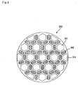
- a columnar porous ceramic member which had almost the same cross-sectional shape as that shown in Fig. 7 , Fig. 8 or Fig. 12 , and was made of a silicon carbide sintered body having a porosity of 42%, an average pore diameter of 9 ⁇ m, a size of 72 mm ⁇ 72 mm ⁇ 150 mm (square column shape) and a thickness of the partition wall of 0.4 mm, was manufactured, and the same processes as those of Example 1 were carried out except that four (2 ⁇ 2 ) of these columnar porous ceramic members were combined with one another so that a ceramic block was manufactured; thus, a cylinder-shaped honeycomb structural body having a size of 144 mm in diameter ⁇ 150 mm in length was manufactured.
- Fig. 7 is a cross-sectional view that schematically shows a cross section perpendicular to the length direction of a honeycomb structural body 200, and this honeycomb structural body 200 has a structure in which small-capacity through holes 202 having a triangle shape in the cross section are placed on the circumference of each large-capacity through hole 201 having a hexagonal shape in the cross section.
- Fig. 8 is a cross-sectional view that schematically shows a cross section perpendicular to the length direction of a honeycomb structural body 300, and this honeycomb structural body 300 has a structure in which small-capacity through holes 302 having a laterally elongated hexagonal shape in the cross section are placed on the circumference of each large-capacity through hole 301 having a positive hexagonal shape in the cross section. Further, large-capacity through holes 301 having a positive hexagonal shape and large-capacity through holes 303 having a trapezoidal shape are placed side by side.
- Example 13 the cross-sectional shape of the columnar porous ceramic member is made almost the same as the cross-sectional shape shown in Fig. 7 ; in Example 14, the cross-sectional shape of the columnar porous ceramic member is made almost the same as the cross-sectional shape shown in Fig. 8 ; and in Example 15, the cross-sectional shape of the columnar porous ceramic member is made substantially the same as the cross-sectional shape shown in Fig. 12 .
- the ratios of areas of the large-capacity through holes in a cross section perpendicular to the length direction were respectively set to about 48% (Example 13), about 34% (Example 14) and about 51% (Example 15), the ratios of areas of the small-capacity through holes were respectively set to about 16% (Example 13), about 26% (Example 14) and about 10% (Example 15), and the aperture ratios were respectively set to 3 (Example 13), 1.28 (Example 14) and 5 (Example 15).
- Example 16 corresponds to Example 1
- Example 17 corresponds to Example 2
- Example 18 corresponds to Example 3.
- the columnar porous ceramic members 20 are not bonded to one another; however, upon using as an exhaust gas purifying apparatus, for example, these are physically tightened together, and used as one integral part.
- Example 19 corresponds to Example 1
- Example 20 corresponds to Example 2
- Example 21 corresponds to Example 3.
- a columnar porous ceramic member which was made of a silicon carbide sinteredbody having a porosity of 42%, an average pore diameter of 9 ⁇ m, a size of 144 mm ⁇ 144 mm ⁇ 150 mm, the number of through holes of 4624 and a thickness of the partition wall of 0.4 mm, with the same number of large-capacity through holes 21a and small-capacity through holes 21b being formed therein, was manufactured, and the same processes as those of Examples 1 to 3 were carried out except that the peripheral portion of each of these columnar porous ceramic members was processed so that a ceramic block was manufactured; thus, a cylinder-shaped honeycomb structural body having a size of 144 mm in diameter ⁇ 150 mm in length was manufactured.
- Example 2 The same processes as Example 1 were carried out except that the cross-sectional shape of the columnar porous ceramic member was made almost the same as a cross-sectional shape shown in Fig. 3 (e) so that a honeycomb structural body was manufactured.
- the thickness of the partition wall of a columnar porous ceramic member in accordance with Comparative Example 4 was 0.4 mm, the width of one side in a cross section perpendicular to the length direction of the through hole was 1.49 mm, and with respect to a cross section perpendicular to the length direction of the columnar porous ceramic member, the ratio of areas of the through holes was 30.6%.
- a columnar porous ceramic member which was made of a silicon carbide sinteredbody having a porosity of 42%, an average pore diameter of 9 ⁇ m, a size of 144 mm ⁇ 144 mm ⁇ 150 mm and a thickness of the partition wall of 0.4 mm, was manufactured, and the same processes as those of Examples 7 to 9 were carried out except that the circumferential portion of each of these columnar porous ceramic members was processed so that a ceramic block was manufactured; thus, a cylinder-shaped honeycomb structural body having a size of 144 mm in diameter ⁇ 150 mm in length was manufactured.
- a columnar porous ceramic member which was made of a silicon carbide sinteredbody having a porosity of 42%, an average pore diameter of 9 ⁇ m, a size of 144 mm ⁇ 144 mm ⁇ 150 mm (rectangular column shape) and a thickness of the partition wall of 0.4 mm, was manufactured, and the same processes as those of Examples 13 to 15 were carried out except that the circumferential portion of each of these columnar porous ceramic members was processed so that a ceramic block was manufactured; thus, a cylinder-shaped honeycomb structural body having a size of 144 mm in diameter ⁇ 150 mm in length was manufactured.
- An exhaust gas purifying apparatus shown in Fig. 5 was manufactured by installing each of the honeycomb structural bodies relating to the respective examples and comparative examples in an exhaust passage of an engine, and the engine was driven at the number of revolutions of 2000 min -1 and a torque of 50 Nm for a predetermined period of time so that the honeycomb structural body was allowed to collect particulates of about 7g/L. Then, the honeycomb structural body was cut, and by observing the cross section, the thickness of the collected particulates was measured. The measured portions were set to portions respectively 50 mm and 130 mm apart from the end face of the exhaust gas inlet side, in the vicinity of the center (portions apart from the center by two cells) of a cross section perpendicular to the length direction. The ratio (50 mm measured value/130 mm measured value) between the measured value at the portion of 50 mm and the measured value at the portion of 130 mm was found. The results are shown in Table 1.
- An exhaust gas purifying apparatus shown in Fig. 5 was manufactured by installing each of the honeycomb structural bodies relating to the respective examples and comparative examples in an exhaust passage of an engine, and the engine was driven at the number of revolutions of 2000 min -1 and a torque of 50 Nm for a predetermined period of time, and the recovering process was then successively carried out while increasing the driving time so that the honeycomb structural body was examined for occurrence of any cracks.
- the quantity of particulates that had been collected at the time of occurrence of a crack was defined as a collection limit value.
- Table 1 The results are shown in Table 1.
- Example 1 Thickness ratio of particulates Collection limit (g/L) Example 1 0.92 8.6 Example 2 0.85 9.5 Example 3 0.82 8.7 Example 4 0.80 7.9 Example 5 0.72 8.8 Example 6 0.65 8.0 Example 7 0.84 8.5 Example 8 0.86 8.6 Example 9 0.86 8.6 Example 10 0.72 7.8 Example 11 0.74 7.9 Example 12 0.73 7.9 Example 13 0.68 7.1 Example 14 0.66 7.6 Example 15 0.64 7.0 Example 16 0.80 8.5 Example 17 0.80 9.3 Example 18 0.75 8.6 Example 19 0.75 8.3 Example 20 0.71 9.0 Example 21 0.68 8.0 Comparative Example 1 0.45 6.1 Comparative Example 2 0.40 7.0 Comparative Example 3 0.32 6.2 Comparative Example 4 0.92 7.8 Comparative Example 5 0.37 6.0 Comparative Example 6 0.39 6.1 Comparative Example 7 0.39 6.1 Comparative Example 8 0.31 4.6 Comparative Example 9 0.29 5.1 Comparative Example 10 0.27 4.5
- the honeycomb structural bodies in accordance with the examples can collect more particulates than the honeycomb structural bodies in accordance with the comparative examples, thereby making it possible to lengthen the period up to the recovery process.
- each of the honeycomb structural bodies in accordance with the examples makes the rise width of the pressure loss smaller in comparison with the honeycomb structural bodies in accordance with the comparative examples.
- the results shown in Fig. 9 indicate that, upon increasing the flow rate of exhaust gases by changing the load at the same number of revolutions, although the initial pressure loss becomes higher than that of the integrated structure (comparative examples), the divided structure, prepared by the examples, gradually suppresses the rise in the pressure loss, thereby making it possible to avoid abrupt changes in the pressure loss.
- the honeycomb structural body of the present invention is provided with a group of large-capacity through holes and a group of small-capacity through holes so that by using the group of large-capacity through holes as inlet-side through holes, the aperture ratio on the exhaust gas inlet side is made relatively greater; thus, it becomes possible to reduce the rise width of pressure loss upon accumulation of particulates. Consequently, in comparison with the honeycomb structural body in which the aperture ratio on the exhaust gas inlet side and the aperture ratio on the exhaust gas outlet side are equal to each other, it becomes possible to increase the limiting amount of particulate collection to consequently lengthen the period up to the recovery process, and to accumulate a greater amount of ashes remaining after the particulates have been burned to consequently lengthen the service life.
- the honeycomb structural body of the present invention is constituted by a plurality of columnar porous ceramic members; therefore, it becomes possible to effectively reduce the rise width of the pressure loss at the time the particulates are accumulated, and to suppress fluctuations in the pressure loss even at the time that the flow rate of exhaust gases fluctuates in response to the driving state of the internal combustion engine. Furthermore, it is possible to reduce a thermal stress that is generated in the use so that the heat resistance is improved, and to freely adjust the size thereof by properly increasing or reducing the number of the columnar porous ceramic members.
Landscapes
- Physics & Mathematics (AREA)
- Geometry (AREA)
- Chemical & Material Sciences (AREA)
- Engineering & Computer Science (AREA)
- Chemical Kinetics & Catalysis (AREA)
- Combustion & Propulsion (AREA)
- Mechanical Engineering (AREA)
- General Engineering & Computer Science (AREA)
- Filtering Materials (AREA)
- Filtering Of Dispersed Particles In Gases (AREA)
- Processes For Solid Components From Exhaust (AREA)
- Porous Artificial Stone Or Porous Ceramic Products (AREA)
Claims (6)
- Structure en nid d'abeilles colonnaire (10) destinée à être utilisée dans un appareil de purification de gaz d'échappement, un certain nombre de trous traversants (21, 41, 51, 71, 91) dans une telle structure en nid d'abeilles colonnaire sont placés en parallèle les uns aux autres dans la direction de la longueur avec une paroi de séparation (23, 43, 53, 73, 93) interposée entre eux,
dans laquelle
ladite pluralité de trous traversants (21, 41, 51, 71, 91) comprend :un groupe de trous traversants de grande capacité (21a, 41a, 51a, 71a, 91a), avec l'une de ses extrémités étant scellée de manière à rendre l'ensemble des surfaces de sections transversales perpendiculaires à la direction de la longueur relativement plus grandes ; etun groupe de trous traversants de faible capacité (21b, 41b, 51b, 71b, 91b), avec l'autre de ses extrémité étant scellée de manière à rendre l'ensemble des surfaces desdites sections transversales relativement plus petites,ladite structure en nid d'abeilles colonnaire (10) comprenant une pluralité d'éléments en céramique poreuse colonnaires (20, 40, 50, 70, 90), dans l'élément en céramique poreuse colonnaire, les trous traversants de grande capacité respectifs constituant le groupe de trous traversants de grande capacité (21a, 41a, 51a, 71a, 91a) et les trous traversants de faible capacité constituant le groupe de trous traversants de faible capacité (21b, 41b, 51b, 71b, 91b) constituent une structure où des sections transversales perpendiculaires à la direction de la longueur des trous traversants de grande capacité constituant le groupe de trous traversants de grande capacité occupent une surface de sections transversales perpendiculaires à la direction de la longueur plus grande que celle du groupe de trous traversants de faible capacité, les nombres des deux types de trous traversants étant établis à la même valeur,où le rapport de la surface des sections transversales du groupe de trous traversants de grande capacité (21a, 41a, 51a, 71a, 91a) sur la surface des sections transversales du groupe de trous traversants de faible capacité (21b, 41b, 51b, 71b, 91b) se trouve dans la plage allant de 2,0 à 2,75. - Structure en nid d'abeilles colonnaire (10) selon la revendication 1,
dans laquelle
la pluralité d'éléments en céramique poreuse colonnaires (20, 40, 50, 70, 90) sont combinés les uns avec les autres par l'intermédiaire d'une couche de matériau d'étanchéité (14). - Structure en nid d'abeilles colonnaire (10) selon la revendication 1 ou 2,
dans laquelle
la distance entre les centres de gravité de sections transversales perpendiculaires à la direction de la longueur des trous traversants disposés de manière adjacente constituant le groupe de trous traversants de grande capacité (21a, 41a, 51a, 71a, 91a) est égale à la distance entre les centres de gravité desdites sections transversales perpendiculaires à la direction de la longueur des trous traversants disposés de manière adjacente constituant le groupe de trous traversants de faible capacité (21b, 41b, 51b, 71b, 91b). - Structure en nid d'abeilles colonnaire (10) selon l'une des revendications 1 à 3,
dans laquelle
des sections transversales perpendiculaires à la direction de la longueur des trous traversants constituant le groupe de trous traversants de grande capacité et/ou des trous traversants constituant le groupe de trous traversants de petite capacité présentent des formes polygonales. - Structure en nid d'abeilles colonnaire (10) selon l'une des revendications 1 à 4,
dans laquelle
les trous traversants constituant le groupe de trous traversants de grande capacité et/ou les trous traversants constituant le groupe de trous traversants de petite capacité présentent des parties de coin chanfreinées en R et/ou des parties de coin chanfreinées en C dans leurs sections transversales perpendiculaires à la direction de la longueur. - Structure en nid d'abeilles colonnaire (10) selon l'une des revendications 1 à 5,
dans laquelle
une section transversale perpendiculaire à la direction de la longueur des trous traversants constituant le groupe de trous traversants de faible capacité présente une forme quadrilatère ou rectangulaire.
Applications Claiming Priority (5)
| Application Number | Priority Date | Filing Date | Title |
|---|---|---|---|
| JP2002267819 | 2002-09-13 | ||
| JP2002267819 | 2002-09-13 | ||
| JP2003057631 | 2003-03-04 | ||
| JP2003057631 | 2003-03-04 | ||
| PCT/JP2003/011769 WO2004024293A1 (fr) | 2002-09-13 | 2003-09-16 | Structure en nid d'abeille |
Publications (3)
| Publication Number | Publication Date |
|---|---|
| EP1502640A1 EP1502640A1 (fr) | 2005-02-02 |
| EP1502640A4 EP1502640A4 (fr) | 2005-03-09 |
| EP1502640B1 true EP1502640B1 (fr) | 2013-03-20 |
Family
ID=31996168
Family Applications (2)
| Application Number | Title | Priority Date | Filing Date |
|---|---|---|---|
| EP03795441A Expired - Lifetime EP1502640B1 (fr) | 2002-09-13 | 2003-09-16 | Structure en nid d'abeille |
| EP03795443A Expired - Lifetime EP1495791B1 (fr) | 2002-09-13 | 2003-09-16 | Filtre |
Family Applications After (1)
| Application Number | Title | Priority Date | Filing Date |
|---|---|---|---|
| EP03795443A Expired - Lifetime EP1495791B1 (fr) | 2002-09-13 | 2003-09-16 | Filtre |
Country Status (6)
| Country | Link |
|---|---|
| US (3) | US7326270B2 (fr) |
| EP (2) | EP1502640B1 (fr) |
| JP (3) | JPWO2004024294A1 (fr) |
| CN (2) | CN1306985C (fr) |
| DE (1) | DE20321503U1 (fr) |
| WO (2) | WO2004024293A1 (fr) |
Families Citing this family (136)
| Publication number | Priority date | Publication date | Assignee | Title |
|---|---|---|---|---|
| US20050169819A1 (en) * | 2002-03-22 | 2005-08-04 | Ibiden Co., Ltd | Honeycomb filter for purifying exhaust gas |
| JP3719232B2 (ja) * | 2002-06-18 | 2005-11-24 | トヨタ自動車株式会社 | 内燃機関のパティキュレートフィルタ |
| US7326270B2 (en) | 2002-09-13 | 2008-02-05 | Ibiden Co., Ltd. | Filter |
| EP1493479B1 (fr) * | 2002-09-13 | 2013-03-20 | Ibiden Co., Ltd. | Structure en nid d'abeilles |
| JP2004261664A (ja) * | 2003-02-28 | 2004-09-24 | Ngk Insulators Ltd | ハニカム構造体及びハニカム構造体押出し成形用口金 |
| ATE386874T1 (de) | 2003-06-05 | 2008-03-15 | Ibiden Co Ltd | Wabenkörperstruktur |
| KR20060103551A (ko) * | 2003-06-10 | 2006-10-02 | 이비덴 가부시키가이샤 | 벌집형 구조체 |
| PL1514588T3 (pl) | 2003-06-23 | 2007-09-28 | Ibiden Co Ltd | Korpus o strukturze plastra miodu |
| JP4295279B2 (ja) * | 2003-06-23 | 2009-07-15 | イビデン株式会社 | ハニカム構造体 |
| JP4827530B2 (ja) * | 2003-07-15 | 2011-11-30 | イビデン株式会社 | ハニカム構造体 |
| EP1686107A4 (fr) * | 2003-09-12 | 2008-12-03 | Ibiden Co Ltd | Comprime en ceramique frittee et filtre en ceramique |
| US7601194B2 (en) * | 2003-09-25 | 2009-10-13 | Corning Incorporated | Asymmetric honeycomb wall-flow filter having improved structural strength |
| US7247184B2 (en) * | 2003-09-25 | 2007-07-24 | Corning Incorporated | Asymmetric honeycomb wall-flow filter having improved structural strength |
| EP1676621A1 (fr) * | 2003-10-20 | 2006-07-05 | Ibiden Co., Ltd. | Structure en nids d'abeille |
| JP4439236B2 (ja) * | 2003-10-23 | 2010-03-24 | イビデン株式会社 | ハニカム構造体 |
| JP4849891B2 (ja) * | 2003-11-05 | 2012-01-11 | イビデン株式会社 | ハニカム構造体の製造方法 |
| WO2005044422A1 (fr) | 2003-11-07 | 2005-05-19 | Ibiden Co., Ltd. | Corps a structure en nid d'abeille |
| PL1686108T3 (pl) * | 2003-11-12 | 2012-02-29 | Ngk Insulators Ltd | Struktura plastra miodu |
| FR2864576B1 (fr) * | 2003-12-24 | 2006-03-03 | Saint Gobain Ct Recherches | Bloc pour la filtration de particules contenues dans les gaz d'echappement d'un moteur a combustion interne |
| JPWO2005064128A1 (ja) * | 2003-12-25 | 2007-07-19 | イビデン株式会社 | 排気ガス浄化装置および排気ガス浄化装置の再生方法 |
| US7387829B2 (en) | 2004-01-13 | 2008-06-17 | Ibiden Co., Ltd. | Honeycomb structure, porous body, pore forming material for the porous body, and methods for manufacturing the pore forming material, the porous body and the honeycomb structure |
| CN100577995C (zh) * | 2004-02-23 | 2010-01-06 | 揖斐电株式会社 | 蜂窝结构体及废气净化装置 |
| JP4666390B2 (ja) * | 2004-04-05 | 2011-04-06 | イビデン株式会社 | ハニカム構造体、ハニカム構造体の製造方法及び排気ガス浄化装置 |
| KR100796471B1 (ko) * | 2004-04-30 | 2008-01-21 | 니뽄 가이시 가부시키가이샤 | 허니컴 구조체 및 그 제조 방법 |
| WO2005108328A1 (fr) * | 2004-05-06 | 2005-11-17 | Ibiden Co., Ltd. | Structure en nid d’abeilles et procédé de production de celle-ci |
| WO2005110578A1 (fr) * | 2004-05-18 | 2005-11-24 | Ibiden Co., Ltd. | Structure en nid d'abeilles et dispositif d'epuration des gaz d'echappement |
| DE502005006473D1 (de) * | 2004-05-25 | 2009-03-05 | Bosch Gmbh Robert | Esondere für partikelfilter |
| DE102004027818A1 (de) * | 2004-06-08 | 2006-01-05 | Robert Bosch Gmbh | Filtereinrichtung für ein Abgassystem einer Brennkraftmaschine, sowie Verfahren zum Herstellen einer solchen Filtereinrichtung |
| DE102004028764A1 (de) | 2004-06-16 | 2006-01-12 | Henkel Kgaa | Strahlungshärtbares elektrisch leitfähiges Beschichtungsgemisch |
| ATE392594T1 (de) * | 2004-08-04 | 2008-05-15 | Ibiden Co Ltd | Durchlaufbrennofen und verfahren zur herstellung eines porösen keramikglieds damit |
| ATE408110T1 (de) | 2004-08-04 | 2008-09-15 | Ibiden Co Ltd | Brennofen und verfahren zur herstellung eines porösen keramikglieds damit |
| DE602005003538T2 (de) | 2004-08-10 | 2008-10-23 | Ibiden Co., Ltd., Ogaki | Brennofen und verfahren zur herstellung von keramischen teilen mit diesem brennofen |
| FR2874647B1 (fr) * | 2004-08-25 | 2009-04-10 | Saint Gobain Ct Recherches | Bloc filtrant a ailettes pour la filtration de particules contenues dans les gaz d'echappement d'un moteur a combustion interne |
| DE602005019182D1 (de) | 2004-09-30 | 2010-03-18 | Ibiden Co Ltd | Wabenstruktur |
| JP4870558B2 (ja) * | 2004-12-27 | 2012-02-08 | イビデン株式会社 | ハニカム構造体及びシール材層 |
| JP5237630B2 (ja) * | 2005-02-01 | 2013-07-17 | イビデン株式会社 | ハニカム構造体 |
| KR100911641B1 (ko) * | 2005-03-30 | 2009-08-12 | 이비덴 가부시키가이샤 | 탄화 규소 함유 입자, 탄화 규소질 소결체를 제조하는방법, 탄화 규소질 소결체, 및 필터 |
| FR2886868B1 (fr) * | 2005-06-14 | 2007-08-31 | Saint Gobain Ct Recherches | Structure et filtre catalytique pour la filtration d'un gaz comprenant un revetement et/ou un joint de porosite controlee |
| JP2008537510A (ja) * | 2005-04-08 | 2008-09-18 | サン−ゴバン サントル ドゥ ルシェルシェ エ デトゥーデ ユーロペン | 制御された多孔性を有するコーティング及び/又はジョイントを含む、気体を濾過するための触媒フィルタ |
| WO2006126278A1 (fr) * | 2005-05-27 | 2006-11-30 | Ibiden Co., Ltd. | Corps de structure alveolaire |
| FR2886869B1 (fr) * | 2005-06-14 | 2007-08-31 | Saint Gobain Ct Recherches | Structure et filtre catalytique pour la filtration d'un gaz comprenant un ciment hydrophobe ou oleophobe |
| WO2006137157A1 (fr) | 2005-06-24 | 2006-12-28 | Ibiden Co., Ltd. | Corps à structure en nid d’abeilles |
| WO2006137151A1 (fr) * | 2005-06-24 | 2006-12-28 | Ibiden Co., Ltd. | Structure en nid d’abeille et épurateur de gaz d’échapement |
| FR2889184B1 (fr) * | 2005-07-29 | 2007-10-19 | Saint Gobain Ct Recherches | Procede de preparation d'une structure poreuse utilisant des agents porogenes a base de silice |
| CN100386150C (zh) * | 2005-08-17 | 2008-05-07 | 云南菲尔特环保科技有限公司 | 一种陶瓷催化剂载体、微粒捕集器和微粒捕集装置及其制备方法 |
| JP5000873B2 (ja) * | 2005-09-21 | 2012-08-15 | 日本碍子株式会社 | 多孔質体の製造方法 |
| JPWO2007043245A1 (ja) | 2005-10-12 | 2009-04-16 | イビデン株式会社 | ハニカムユニット及びハニカム構造体 |
| KR20080073792A (ko) * | 2005-12-14 | 2008-08-11 | 니뽄 가이시 가부시키가이샤 | 접합재와 그 제조 방법 및 그것을 이용한 허니컴 구조체 |
| US7517379B2 (en) * | 2005-12-16 | 2009-04-14 | Corning Incorporated | Honeycomb filters with reduced number of unplugged partial peripheral cells and methods of manufacturing same |
| WO2007096986A1 (fr) * | 2006-02-24 | 2007-08-30 | Ibiden Co., Ltd. | Dispositif de chauffage de face d'extremite, procede de sechage de la face d'extremite d'un assemblage en nid d'abeille et procede de production de structures en nid d'abeille |
| JP4890903B2 (ja) * | 2006-03-28 | 2012-03-07 | 日本碍子株式会社 | ハニカム構造体 |
| WO2007116665A1 (fr) | 2006-03-30 | 2007-10-18 | Ngk Insulators, Ltd. | Element raccord, element raccord d'un segment en nid d'abeille et structure en nid d'abeille ainsi obtenue |
| DE202006007876U1 (de) * | 2006-05-15 | 2007-09-20 | Bauer Technologies Gmbh | Optimierung von zellulären Strukturen, insbesondere für die Abgasreinigung von Verbrennungsaggregaten und andere Anwendungsbereiche |
| US20100216657A1 (en) * | 2006-05-16 | 2010-08-26 | Arcxis Biotechnologies, Inc. | Pcr-free sample preparation and detection systems for high speed biologic analysis and identification |
| DE102006024075A1 (de) | 2006-05-23 | 2007-11-29 | Robert Bosch Gmbh | Filtereinrichtung, insbesondere für ein Abgassystem einer Brennkraftmaschine |
| DE102006026161A1 (de) | 2006-05-23 | 2007-11-29 | Robert Bosch Gmbh | Filtereinrichtung, insbesondere für ein Abgassystem einer Brennkraftmaschine |
| FR2902424B1 (fr) * | 2006-06-19 | 2008-10-17 | Saint Gobain Ct Recherches | Ciment de jointoiement a spheres creuses pour filtre a particules. |
| FR2902423B1 (fr) * | 2006-06-19 | 2008-09-12 | Saint Gobain Ct Recherches | Ciment de jointoiement pour filtre a particules. |
| FR2906159B1 (fr) * | 2006-09-27 | 2008-10-31 | Saint Gobain Ct Recherches | Element monolithique a coins renforces pour la filtration de particules |
| KR101046899B1 (ko) * | 2006-10-05 | 2011-07-06 | 이비덴 가부시키가이샤 | 허니컴 구조체 |
| US20080264842A1 (en) * | 2006-10-11 | 2008-10-30 | Arcxis Biotechnologies, Llc | Disposable micropurification cards, methods, and systems thereof |
| JPWO2008059576A1 (ja) * | 2006-11-16 | 2010-02-25 | イビデン株式会社 | ハニカム構造体及びその製造方法 |
| US8092624B2 (en) * | 2006-12-07 | 2012-01-10 | Ngk Insulators, Ltd. | Bonding material composition and method for manufacturing the same, and joined body and method for manufacturing the same |
| EP1939261B1 (fr) * | 2006-12-25 | 2010-03-31 | Ngk Insulators, Ltd. | Corps assemblé et son procédé de fabrication |
| EP2108430A4 (fr) * | 2007-02-02 | 2011-08-24 | Ngk Insulators Ltd | Structure en nid d'abeille |
| JP5498705B2 (ja) * | 2007-02-02 | 2014-05-21 | 日本碍子株式会社 | ハニカム構造体 |
| FR2912069B1 (fr) * | 2007-02-05 | 2011-04-01 | Saint Gobain Ct Recherches | Structure de filtration d'un gaz a paroi ondulee |
| WO2008099454A1 (fr) | 2007-02-09 | 2008-08-21 | Ibiden Co., Ltd. | Structure en nid d'abeilles et appareil de traitement de gaz d'échappement |
| EP2130574B1 (fr) * | 2007-03-28 | 2017-11-08 | NGK Insulators, Ltd. | Filtre en nid d'abeilles |
| EP2130575B1 (fr) * | 2007-03-29 | 2014-11-12 | NGK Insulators, Ltd. | Corps à nids d'abeille comprenant des segments |
| JPWO2008126335A1 (ja) * | 2007-03-30 | 2010-07-22 | イビデン株式会社 | ハニカム構造体及びハニカム構造体の製造方法 |
| WO2008126329A1 (fr) * | 2007-03-30 | 2008-10-23 | Ibiden Co., Ltd. | Filtre en nid d'abeilles |
| WO2008129671A1 (fr) * | 2007-04-17 | 2008-10-30 | Ibiden Co., Ltd. | Nid d'abeille porteur de catalyseur et processus de production de ce nid d'abeille |
| CA2683133A1 (fr) * | 2007-05-04 | 2008-11-13 | Dow Global Technologies Inc. | Elements de filtre en nid d'abeilles ameliores |
| EP2065575B1 (fr) * | 2007-11-29 | 2012-08-15 | Corning Incorporated | Filtre en nids d'abeille à écoulement à travers des parois ayant une grande capacité de stockage et une faible contre-pression |
| FR2925354B1 (fr) * | 2007-12-20 | 2009-12-11 | Saint Gobain Ct Recherches | Structure de filtration d'un gaz a canaux hexagonaux asymetriques |
| KR101621983B1 (ko) * | 2008-02-05 | 2016-05-31 | 바스프 코포레이션 | 미립자 트랩을 갖는 가솔린 엔진 배출물 처리 시스템 |
| WO2009101682A1 (fr) | 2008-02-13 | 2009-08-20 | Ibiden Co., Ltd. | Structure en nid d'abeilles, appareil de purification de gaz d'échappement et processus de production d'une structure en nid d'abeilles |
| JP5328174B2 (ja) * | 2008-02-20 | 2013-10-30 | 日本碍子株式会社 | 目封止ハニカム構造体 |
| US8043394B2 (en) * | 2008-03-21 | 2011-10-25 | GM Global Technology Operations LLC | Particulate matter filter assembly with a flow device |
| JP5139856B2 (ja) * | 2008-03-26 | 2013-02-06 | 日本碍子株式会社 | 目封止ハニカム構造体の製造方法 |
| JP5456268B2 (ja) * | 2008-03-28 | 2014-03-26 | 日本碍子株式会社 | ハニカム構造体 |
| JP2009243274A (ja) * | 2008-03-28 | 2009-10-22 | Mazda Motor Corp | パティキュレートフィルタ |
| US8007557B2 (en) * | 2008-11-26 | 2011-08-30 | Corning Incorporated | High-strength low-microcracked ceramic honeycombs and methods therefor |
| US7855168B2 (en) * | 2008-12-19 | 2010-12-21 | Schlumberger Technology Corporation | Method and composition for removing filter cake |
| KR20110114542A (ko) | 2008-12-23 | 2011-10-19 | 생-고뱅 생트레 드 레체르체 에 데투드 유로삐엔 | 상이한 플러깅 재료와 입구 및 출구 표면을 갖는 여과 구조체 |
| EP2383028B1 (fr) | 2008-12-25 | 2015-07-01 | Kyocera Corporation | Structure alvéolaire, et filtre et dispositif de traitement des gaz d'échappement utilisant ladite structure |
| JP5345429B2 (ja) * | 2009-03-19 | 2013-11-20 | 日本碍子株式会社 | ハニカム構造体 |
| JP2010227755A (ja) * | 2009-03-26 | 2010-10-14 | Ngk Insulators Ltd | セラミックハニカム構造体 |
| JP5231305B2 (ja) * | 2009-03-27 | 2013-07-10 | 日本碍子株式会社 | ハニカム構造体及び接合型ハニカム構造体 |
| WO2011029481A1 (fr) * | 2009-09-14 | 2011-03-17 | Aft Auto Filter Technology Gmbh | Élément céramique et procédé de fabrication de celui-ci |
| CN102470310B (zh) * | 2009-10-08 | 2014-07-23 | 揖斐电株式会社 | 废气净化装置和废气净化方法 |
| GB2475097A (en) * | 2009-11-06 | 2011-05-11 | Total Vehicle Technology Ltd | Analysing an exhaust gas using an inorganic filter |
| DE102011004343A1 (de) | 2010-02-19 | 2011-08-25 | DENSO CORPORATION, Aichi-pref. | Abgasreinigungsfilter |
| US8636821B2 (en) * | 2010-02-22 | 2014-01-28 | Hitachi Metals, Ltd. | Ceramic honeycomb structure and its production method |
| WO2011114511A1 (fr) | 2010-03-19 | 2011-09-22 | イビデン株式会社 | Structure en nid d'abeille |
| US8815189B2 (en) | 2010-04-19 | 2014-08-26 | Basf Corporation | Gasoline engine emissions treatment systems having particulate filters |
| US8444730B2 (en) * | 2010-09-27 | 2013-05-21 | Ford Global Technologies, Llc | Even-loading DPF and regeneration thereof |
| WO2012133846A1 (fr) | 2011-03-31 | 2012-10-04 | 日本碍子株式会社 | Structure étanche en nid d'abeilles |
| CN103458990B (zh) * | 2011-03-31 | 2016-08-17 | 现代自动车株式会社 | 封孔蜂窝结构体 |
| KR101588784B1 (ko) * | 2011-03-31 | 2016-01-27 | 현대자동차 주식회사 | 밀봉된 하니컴 구조체 및 배기 가스 정화 장치 |
| JP2012254443A (ja) * | 2011-05-17 | 2012-12-27 | Sumitomo Chemical Co Ltd | ハニカムフィルタの再生方法 |
| WO2012157423A1 (fr) * | 2011-05-17 | 2012-11-22 | 住友化学株式会社 | Filtre en nid d'abeilles |
| JP2012254442A (ja) * | 2011-05-17 | 2012-12-27 | Sumitomo Chemical Co Ltd | ハニカムフィルタの再生方法 |
| US8865084B2 (en) | 2011-11-30 | 2014-10-21 | Corning Incorporated | Pass-through catalytic substrate including porous ceramic beveled corner portions and methods |
| US9724634B2 (en) | 2012-03-30 | 2017-08-08 | Ibiden Co., Ltd. | Honeycomb filter and method for producing honeycomb filter |
| WO2013186923A1 (fr) | 2012-06-15 | 2013-12-19 | イビデン株式会社 | Filtre en nid d'abeilles |
| WO2013186922A1 (fr) | 2012-06-15 | 2013-12-19 | イビデン株式会社 | Filtre en nid d'abeilles |
| JP6170492B2 (ja) * | 2012-06-15 | 2017-07-26 | イビデン株式会社 | ハニカムフィルタ |
| EP2698191B1 (fr) | 2012-08-13 | 2018-07-18 | NGK Insulators, Ltd. | Structure en nid d'abeille raccordée |
| EP2698190B1 (fr) | 2012-08-13 | 2018-06-27 | NGK Insulators, Ltd. | Structure en nid d'abeille raccordée |
| JP6068067B2 (ja) * | 2012-09-06 | 2017-01-25 | 日本碍子株式会社 | 目封止ハニカム構造体 |
| WO2014054159A1 (fr) * | 2012-10-04 | 2014-04-10 | イビデン株式会社 | Filtre en structure alvéolaire |
| EP2939808A4 (fr) * | 2012-12-27 | 2016-08-17 | Sumitomo Chemical Co | Procédé permettant de fabriquer une structure en nid d'abeilles |
| KR101735304B1 (ko) | 2013-01-25 | 2017-05-15 | 야라 인터내셔널 아에스아 | 세장형 횡단면을 가지는 셀들을 구비한 벌집형 모놀리스 구조물 |
| JP6068219B2 (ja) * | 2013-03-26 | 2017-01-25 | 日本碍子株式会社 | ハニカムフィルタ |
| JP6140509B2 (ja) * | 2013-04-04 | 2017-05-31 | 日本碍子株式会社 | ウォールフロー型排ガス浄化フィルタ |
| JP6239305B2 (ja) | 2013-07-31 | 2017-11-29 | イビデン株式会社 | ハニカムフィルタ |
| JP6239306B2 (ja) | 2013-07-31 | 2017-11-29 | イビデン株式会社 | ハニカムフィルタ |
| JP6239307B2 (ja) | 2013-07-31 | 2017-11-29 | イビデン株式会社 | ハニカムフィルタ |
| JP6267452B2 (ja) | 2013-07-31 | 2018-01-24 | イビデン株式会社 | ハニカムフィルタ |
| JP6239304B2 (ja) | 2013-07-31 | 2017-11-29 | イビデン株式会社 | ハニカムフィルタ |
| JP6239303B2 (ja) | 2013-07-31 | 2017-11-29 | イビデン株式会社 | ハニカムフィルタ |
| CN104147872A (zh) * | 2014-06-04 | 2014-11-19 | 苏州博讯仪器有限公司 | 一种风质过滤器 |
| NO20140934A1 (no) | 2014-07-23 | 2016-01-25 | Yara Int Asa | Bikake-monolittstruktur |
| WO2016013513A1 (fr) | 2014-07-23 | 2016-01-28 | イビデン株式会社 | Filtre en nid d'abeilles |
| EP3173138B1 (fr) | 2014-07-23 | 2018-12-05 | Ibiden Co., Ltd. | Filtre en nid d'abeilles |
| KR101814459B1 (ko) * | 2016-08-16 | 2018-01-04 | 희성촉매 주식회사 | 알킬 방향족 화합물 제조용 고형 촉매 캐리어로서 필터 구조체 |
| JP2018038941A (ja) * | 2016-09-05 | 2018-03-15 | 株式会社デンソー | 排ガス浄化フィルタ |
| JP7111741B2 (ja) | 2017-01-31 | 2022-08-02 | コーニング インコーポレイテッド | パターン状に施栓されたハニカム体、微粒子フィルタ、およびそのための押出ダイ |
| DE102017103341A1 (de) * | 2017-02-17 | 2018-08-23 | Umicore Ag & Co. Kg | Russpartikelfilter mit speicherzellen für katalysator |
| CN107490482B (zh) * | 2017-08-18 | 2024-04-19 | 湖南天雁机械有限责任公司 | 涡轮增压器耐久考核试验积炭收集器及收集积炭的方法 |
| CN108286466A (zh) * | 2017-12-27 | 2018-07-17 | 山东国瓷功能材料股份有限公司 | 一种高抗热震性能的蜂窝陶瓷过滤器 |
| WO2019187126A1 (fr) * | 2018-03-30 | 2019-10-03 | 日本碍子株式会社 | Segment en nid d'abeilles bouché, et structure en nid d'abeilles bouchée |
| US11554339B2 (en) | 2018-11-16 | 2023-01-17 | Corning Incorporated | Plugged honeycomb bodies, extrusion dies and methods of manufacturing thereof |
| CN117323743A (zh) * | 2019-09-11 | 2024-01-02 | 日本碍子株式会社 | 蜂窝结构体及尾气净化装置 |
Family Cites Families (102)
| Publication number | Priority date | Publication date | Assignee | Title |
|---|---|---|---|---|
| US97370A (en) * | 1869-11-30 | Improved support tor elliptic springs | ||
| US41730A (en) * | 1864-02-23 | Improved mosquito-canopy | ||
| US167755A (en) * | 1875-09-14 | Improvement in processes and apparatus for preventing the accumulation of tar | ||
| US180117A (en) * | 1876-07-25 | Improvement in drill-chucks | ||
| DE2953502T1 (de) * | 1979-01-29 | 1982-01-28 | Origoverken Ab | Apparatus for burning spirit or similar liquid fuels |
| GB2064360B (en) | 1979-12-03 | 1984-05-16 | Gen Motors Corp | Ceramic filters for diesel exhaust particulates and methods for making such filters |
| CA1145270A (fr) | 1979-12-03 | 1983-04-26 | Morris Berg | Filtres en ceramique pour particules imbrules dans les gaz d'echappement de moteurs diesel et methode de fabrication |
| US4276071A (en) * | 1979-12-03 | 1981-06-30 | General Motors Corporation | Ceramic filters for diesel exhaust particulates |
| US4335023A (en) * | 1980-01-24 | 1982-06-15 | Engelhard Corporation | Monolithic catalyst member and support therefor |
| JPS5881420A (ja) * | 1981-11-10 | 1983-05-16 | Nippon Denso Co Ltd | セラミツクフイルタ |
| JPS5892409A (ja) | 1981-11-27 | 1983-06-01 | Asahi Glass Co Ltd | 選択性透過膜 |
| JPS58124418A (ja) * | 1982-01-20 | 1983-07-25 | 松下電器産業株式会社 | 便座暖房装置 |
| US4417908A (en) | 1982-02-22 | 1983-11-29 | Corning Glass Works | Honeycomb filter and method of making it |
| US4420316A (en) | 1982-02-22 | 1983-12-13 | Corning Glass Works | Filter apparatus and method of making it |
| US4416676A (en) * | 1982-02-22 | 1983-11-22 | Corning Glass Works | Honeycomb filter and method of making it |
| JPS58150015A (ja) | 1982-03-01 | 1983-09-06 | Mazda Motor Corp | デイ−ゼルエンジンの排気浄化装置 |
| JPS61424A (ja) * | 1984-06-12 | 1986-01-06 | Nippon Denso Co Ltd | セラミツクフイルタ |
| JPS62225249A (ja) * | 1985-12-27 | 1987-10-03 | Ngk Insulators Ltd | コ−ジエライトハニカム構造触媒担体及びその製造方法 |
| JPS63185425A (ja) | 1987-01-28 | 1988-08-01 | Ngk Insulators Ltd | 排ガス浄化用セラミツクハニカムフイルタ |
| JPH0634923B2 (ja) * | 1987-03-14 | 1994-05-11 | 日本碍子株式会社 | セラミツクハニカム構造体 |
| JPH0751008B2 (ja) | 1989-07-15 | 1995-06-05 | ヤンマー農機株式会社 | 乗用田植機における動力伝達構造 |
| JP2619291B2 (ja) | 1989-09-18 | 1997-06-11 | キヤノン株式会社 | 自動給紙装置 |
| JPH03121213A (ja) * | 1989-09-30 | 1991-05-23 | Ibiden Co Ltd | 排気ガス浄化装置のハニカムフィルター |
| JPH03102016U (fr) * | 1990-02-02 | 1991-10-24 | ||
| JPH04164111A (ja) * | 1990-10-29 | 1992-06-09 | Toyota Motor Corp | パティキュレートフィルタ |
| DE4200995C2 (de) * | 1991-01-21 | 2002-02-14 | Seibu Giken Fukuoka Kk | Verfahren zur Herstellung eines wabenförmigen Gasadsorptionselements oder eines wabenförmigen Katalysatorträgers |
| JP3130567B2 (ja) | 1991-07-15 | 2001-01-31 | 株式会社東芝 | ゲッタ容器支持装置の製造方法 |
| JP3130587B2 (ja) | 1991-09-17 | 2001-01-31 | イビデン株式会社 | 排気ガス浄化装置のハニカムフィルタ |
| JPH0647620A (ja) | 1991-10-11 | 1994-02-22 | Isuzu Motors Ltd | 歯車類の加工方法 |
| JPH0623215A (ja) * | 1992-07-08 | 1994-02-01 | Isuzu Motors Ltd | パティキュレートトラップフィルタ |
| JP2590943Y2 (ja) * | 1992-10-22 | 1999-02-24 | イビデン株式会社 | 排気ガス浄化装置 |
| JPH07124428A (ja) * | 1993-11-08 | 1995-05-16 | Noritake Co Ltd | モノリス型セラミックフィルター |
| JP2726616B2 (ja) | 1993-12-15 | 1998-03-11 | 日本碍子株式会社 | 多孔質セラミックハニカムフィルタ |
| EP1382442B1 (fr) * | 1996-01-12 | 2013-04-24 | Ibiden Co., Ltd. | Filtre pour purifier de gaz d'échappement |
| US5930994A (en) | 1996-07-02 | 1999-08-03 | Ibiden Co., Ltd. | Reverse cleaning regeneration type exhaust emission control device and method of regenerating the same |
| JP2000167329A (ja) | 1998-09-30 | 2000-06-20 | Ibiden Co Ltd | 排気ガス浄化装置の再生システム |
| JP2002530175A (ja) * | 1998-11-20 | 2002-09-17 | コーニンクレッカ フィリップス エレクトロニクス エヌ ヴィ | コードレス走査ヘッドの充電器を備える超音波診断イメージングシステム |
| FR2789327B1 (fr) * | 1999-02-09 | 2001-04-20 | Ecia Equip Composants Ind Auto | Structure de filtration poreuse et dispositif de depollution la comportant |
| JP3967034B2 (ja) * | 1999-03-30 | 2007-08-29 | イビデン株式会社 | セラミックフィルタユニットの製造方法 |
| JP4094771B2 (ja) * | 1999-06-08 | 2008-06-04 | 日本碍子株式会社 | セラミックフィルタ用基材とその製造方法 |
| JP4642955B2 (ja) | 1999-06-23 | 2011-03-02 | イビデン株式会社 | 触媒担体およびその製造方法 |
| JP3784718B2 (ja) * | 1999-08-30 | 2006-06-14 | 日本碍子株式会社 | 波壁ハニカム構造体及びその製造方法 |
| DE60032391T2 (de) * | 1999-09-29 | 2007-10-11 | Ibiden Co., Ltd., Ogaki | Wabenfömiger Filter und Anordnung von keramischen Filtern |
| JP3803009B2 (ja) | 1999-09-29 | 2006-08-02 | イビデン株式会社 | セラミックフィルタ集合体 |
| JP4051163B2 (ja) | 1999-09-29 | 2008-02-20 | イビデン株式会社 | セラミックフィルタ集合体 |
| KR100641549B1 (ko) | 1999-11-16 | 2006-10-31 | 이비덴 가부시키가이샤 | 촉매 및 그의 제조방법 |
| JP4455708B2 (ja) * | 2000-01-17 | 2010-04-21 | 日本碍子株式会社 | ハニカム構造体及びその製造方法 |
| JP4049501B2 (ja) | 2000-01-24 | 2008-02-20 | 日本碍子株式会社 | セラミックス構造体 |
| JP2001329830A (ja) * | 2000-03-15 | 2001-11-30 | Ibiden Co Ltd | 排気ガス浄化フィルタの再生装置及びフィルタ再生方法、排気ガス浄化フィルタの再生プログラム及びそのプログラムを格納する記録媒体 |
| JP4471452B2 (ja) | 2000-05-29 | 2010-06-02 | 日本碍子株式会社 | フィルターエレメントの製造方法 |
| DE10037403A1 (de) * | 2000-08-01 | 2002-02-14 | Daimler Chrysler Ag | Partikelfilter |
| JP4473505B2 (ja) * | 2000-08-03 | 2010-06-02 | 日本碍子株式会社 | セラミック製ハニカム構造体 |
| JP2002070531A (ja) | 2000-08-24 | 2002-03-08 | Ibiden Co Ltd | 排気ガス浄化装置、排気ガス浄化装置のケーシング構造 |
| EP1371825B1 (fr) * | 2001-03-22 | 2006-06-14 | Ibiden Co., Ltd. | Appareil de purification de gaz d'echappement |
| JP2002320807A (ja) * | 2001-04-27 | 2002-11-05 | Mitsui Eng & Shipbuild Co Ltd | ハニカムフィルタ及びその製造方法 |
| EP1403231B1 (fr) | 2001-05-31 | 2012-11-21 | Ibiden Co., Ltd. | Procede de production d'un corps ceramique fritté poreux |
| JP2003001029A (ja) | 2001-06-18 | 2003-01-07 | Hitachi Metals Ltd | 多孔質セラミックハニカムフィルタ |
| JP2003040327A (ja) | 2001-08-01 | 2003-02-13 | Sanden Corp | 梱包材及びこれを用いた梱包構造 |
| EP1415072B1 (fr) | 2001-08-08 | 2006-12-13 | Toyota Jidosha Kabushiki Kaisha | Dispositif epurateur de gaz d'echappement |
| JP3826265B2 (ja) | 2001-08-08 | 2006-09-27 | トヨタ自動車株式会社 | 排気浄化装置 |
| US20030041730A1 (en) | 2001-08-30 | 2003-03-06 | Beall Douglas M. | Honeycomb with varying channel size |
| JP3893049B2 (ja) | 2001-11-20 | 2007-03-14 | 日本碍子株式会社 | ハニカム構造体及びその製造方法 |
| CN101126335B (zh) | 2002-02-05 | 2011-10-26 | 揖斐电株式会社 | 废气净化用蜂巢式过滤器 |
| EP1479881B1 (fr) | 2002-02-05 | 2017-05-10 | Ibiden Co., Ltd. | Filtre a nid d'abeille pour la decontamination des gaz d'echappement, matiere adhesive et de revetement, et procede d'obtention dudit filtre |
| CN100365252C (zh) | 2002-03-04 | 2008-01-30 | 揖斐电株式会社 | 废气净化用蜂巢式过滤器以及废气净化装置 |
| ATE374069T1 (de) | 2002-03-15 | 2007-10-15 | Ibiden Co Ltd | Keramikfilter zur abgasreinigung |
| US20050169819A1 (en) | 2002-03-22 | 2005-08-04 | Ibiden Co., Ltd | Honeycomb filter for purifying exhaust gas |
| JP2004000896A (ja) | 2002-03-25 | 2004-01-08 | Ngk Insulators Ltd | ハニカムフィルター |
| JP4303599B2 (ja) | 2002-03-25 | 2009-07-29 | イビデン株式会社 | 排ガス浄化用フィルタ |
| EP1491248B1 (fr) | 2002-03-29 | 2008-10-15 | Ibiden Co., Ltd. | Filtre en ceramique et unite de decontamination de gaz d'echappement |
| JPWO2003084640A1 (ja) | 2002-04-09 | 2005-08-11 | イビデン株式会社 | 排気ガス浄化用ハニカムフィルタ |
| JPWO2003093657A1 (ja) | 2002-04-10 | 2005-09-08 | イビデン株式会社 | 排気ガス浄化用ハニカムフィルタ |
| ES2295617T3 (es) | 2002-04-11 | 2008-04-16 | Ibiden Co., Ltd. | Filtro de nido de abejas para clarificar gas de escape. |
| FR2840545B1 (fr) | 2002-06-07 | 2008-07-04 | Saint Gobain Ct Recherches | Corps filtrant pour la filtration de particules contenues dans les gaz d'echappement d'un moteur a combustion interne |
| EP1493479B1 (fr) | 2002-09-13 | 2013-03-20 | Ibiden Co., Ltd. | Structure en nid d'abeilles |
| US7326270B2 (en) | 2002-09-13 | 2008-02-05 | Ibiden Co., Ltd. | Filter |
| WO2004031100A1 (fr) | 2002-10-07 | 2004-04-15 | Ibiden Co., Ltd. | Corps structural en nid d'abeilles |
| WO2004031101A1 (fr) | 2002-10-07 | 2004-04-15 | Ibiden Co., Ltd. | Corps structural en nid d'abeilles |
| JP4369141B2 (ja) * | 2003-02-18 | 2009-11-18 | 日本碍子株式会社 | ハニカムフィルタ及び排ガス浄化システム |
| KR100632161B1 (ko) | 2003-02-28 | 2006-10-11 | 이비덴 가부시키가이샤 | 세라믹 하니컴 구조체 |
| JPWO2004106702A1 (ja) | 2003-05-06 | 2006-07-20 | イビデン株式会社 | ハニカム構造体 |
| ATE386874T1 (de) | 2003-06-05 | 2008-03-15 | Ibiden Co Ltd | Wabenkörperstruktur |
| KR20060103551A (ko) | 2003-06-10 | 2006-10-02 | 이비덴 가부시키가이샤 | 벌집형 구조체 |
| PL1514588T3 (pl) | 2003-06-23 | 2007-09-28 | Ibiden Co Ltd | Korpus o strukturze plastra miodu |
| JP4295279B2 (ja) * | 2003-06-23 | 2009-07-15 | イビデン株式会社 | ハニカム構造体 |
| JP4827530B2 (ja) | 2003-07-15 | 2011-11-30 | イビデン株式会社 | ハニカム構造体 |
| JP4439236B2 (ja) | 2003-10-23 | 2010-03-24 | イビデン株式会社 | ハニカム構造体 |
| JP4849891B2 (ja) | 2003-11-05 | 2012-01-11 | イビデン株式会社 | ハニカム構造体の製造方法 |
| ATE431321T1 (de) | 2003-11-12 | 2009-05-15 | Ibiden Co Ltd | Verfahren zur herstellung der keramikstruktur |
| JPWO2005064128A1 (ja) | 2003-12-25 | 2007-07-19 | イビデン株式会社 | 排気ガス浄化装置および排気ガス浄化装置の再生方法 |
| US7387829B2 (en) | 2004-01-13 | 2008-06-17 | Ibiden Co., Ltd. | Honeycomb structure, porous body, pore forming material for the porous body, and methods for manufacturing the pore forming material, the porous body and the honeycomb structure |
| CN100577995C (zh) * | 2004-02-23 | 2010-01-06 | 揖斐电株式会社 | 蜂窝结构体及废气净化装置 |
| JP4666390B2 (ja) * | 2004-04-05 | 2011-04-06 | イビデン株式会社 | ハニカム構造体、ハニカム構造体の製造方法及び排気ガス浄化装置 |
| WO2005108328A1 (fr) | 2004-05-06 | 2005-11-17 | Ibiden Co., Ltd. | Structure en nid d’abeilles et procédé de production de celle-ci |
| WO2005110578A1 (fr) | 2004-05-18 | 2005-11-24 | Ibiden Co., Ltd. | Structure en nid d'abeilles et dispositif d'epuration des gaz d'echappement |
| WO2006003736A1 (fr) * | 2004-07-01 | 2006-01-12 | Ibiden Co., Ltd. | Dispositif de serrage pour céramique de cuisson et méthode de fabrication de corps en céramique poreuse |
| ATE408110T1 (de) * | 2004-08-04 | 2008-09-15 | Ibiden Co Ltd | Brennofen und verfahren zur herstellung eines porösen keramikglieds damit |
| ATE392594T1 (de) * | 2004-08-04 | 2008-05-15 | Ibiden Co Ltd | Durchlaufbrennofen und verfahren zur herstellung eines porösen keramikglieds damit |
| DE602005003538T2 (de) | 2004-08-10 | 2008-10-23 | Ibiden Co., Ltd., Ogaki | Brennofen und verfahren zur herstellung von keramischen teilen mit diesem brennofen |
| WO2006126278A1 (fr) | 2005-05-27 | 2006-11-30 | Ibiden Co., Ltd. | Corps de structure alveolaire |
| KR101046899B1 (ko) | 2006-10-05 | 2011-07-06 | 이비덴 가부시키가이샤 | 허니컴 구조체 |
| WO2008129671A1 (fr) | 2007-04-17 | 2008-10-30 | Ibiden Co., Ltd. | Nid d'abeille porteur de catalyseur et processus de production de ce nid d'abeille |
-
2003
- 2003-09-16 US US10/490,206 patent/US7326270B2/en not_active Expired - Lifetime
- 2003-09-16 DE DE20321503U patent/DE20321503U1/de not_active Expired - Lifetime
- 2003-09-16 US US10/493,056 patent/US7314496B2/en not_active Expired - Lifetime
- 2003-09-16 WO PCT/JP2003/011769 patent/WO2004024293A1/fr active Application Filing
- 2003-09-16 CN CNB038178052A patent/CN1306985C/zh not_active Expired - Lifetime
- 2003-09-16 CN CNB038178060A patent/CN1322909C/zh not_active Expired - Lifetime
- 2003-09-16 EP EP03795441A patent/EP1502640B1/fr not_active Expired - Lifetime
- 2003-09-16 JP JP2004571941A patent/JPWO2004024294A1/ja active Pending
- 2003-09-16 WO PCT/JP2003/011776 patent/WO2004024294A1/fr active Application Filing
- 2003-09-16 EP EP03795443A patent/EP1495791B1/fr not_active Expired - Lifetime
- 2003-09-16 JP JP2004571940A patent/JP4553737B2/ja not_active Expired - Lifetime
-
2007
- 2007-06-11 US US11/760,833 patent/US7857885B2/en active Active
-
2011
- 2011-06-22 JP JP2011138916A patent/JP5202693B2/ja not_active Expired - Lifetime
Also Published As
| Publication number | Publication date |
|---|---|
| EP1495791B1 (fr) | 2013-03-06 |
| JP4553737B2 (ja) | 2010-09-29 |
| CN1306985C (zh) | 2007-03-28 |
| US7857885B2 (en) | 2010-12-28 |
| US20070227109A1 (en) | 2007-10-04 |
| EP1502640A4 (fr) | 2005-03-09 |
| EP1495791A4 (fr) | 2005-02-09 |
| JP5202693B2 (ja) | 2013-06-05 |
| CN1322909C (zh) | 2007-06-27 |
| JPWO2004024294A1 (ja) | 2006-01-05 |
| CN1671460A (zh) | 2005-09-21 |
| US20050016141A1 (en) | 2005-01-27 |
| CN1671459A (zh) | 2005-09-21 |
| US7314496B2 (en) | 2008-01-01 |
| WO2004024293A1 (fr) | 2004-03-25 |
| EP1495791A1 (fr) | 2005-01-12 |
| EP1502640A1 (fr) | 2005-02-02 |
| WO2004024294A1 (fr) | 2004-03-25 |
| US20050011174A1 (en) | 2005-01-20 |
| US7326270B2 (en) | 2008-02-05 |
| DE20321503U1 (de) | 2007-08-30 |
| JPWO2004024293A1 (ja) | 2006-01-05 |
| JP2011224567A (ja) | 2011-11-10 |
Similar Documents
| Publication | Publication Date | Title |
|---|---|---|
| EP1502640B1 (fr) | Structure en nid d'abeille | |
| EP1752630B1 (fr) | Corps a structure en nids-d'abeilles | |
| EP1493479B1 (fr) | Structure en nid d'abeilles | |
| EP1514588B1 (fr) | Corps a structure en nid d'abeilles | |
| EP1676622B2 (fr) | Corps structure en nid d'abeille | |
| EP1795262B1 (fr) | Structure alvéolaire | |
| EP1775008B1 (fr) | Procéde de fabrication d'une unité en nid d'abeilles et un corps structuré en nid d'abeilles | |
| US7556782B2 (en) | Honeycomb structured body | |
| US8178185B2 (en) | Honeycomb structured body, method for manufacturing honeycomb structured body and exhaust gas purifying device | |
| EP1867374A1 (fr) | Corps a structure de nid d abeille | |
| EP1849754A1 (fr) | Structure en nid d abeille |
Legal Events
| Date | Code | Title | Description |
|---|---|---|---|
| PUAI | Public reference made under article 153(3) epc to a published international application that has entered the european phase |
Free format text: ORIGINAL CODE: 0009012 |
|
| 17P | Request for examination filed |
Effective date: 20041124 |
|
| AK | Designated contracting states |
Kind code of ref document: A1 Designated state(s): AT BE BG CH CY CZ DE DK EE ES FI FR GB GR HU IE IT LI LU MC NL PT RO SE SI SK TR |
|
| AX | Request for extension of the european patent |
Extension state: AL LT LV MK |
|
| A4 | Supplementary search report drawn up and despatched |
Effective date: 20050125 |
|
| DAX | Request for extension of the european patent (deleted) | ||
| APBN | Date of receipt of notice of appeal recorded |
Free format text: ORIGINAL CODE: EPIDOSNNOA2E |
|
| APBR | Date of receipt of statement of grounds of appeal recorded |
Free format text: ORIGINAL CODE: EPIDOSNNOA3E |
|
| APAF | Appeal reference modified |
Free format text: ORIGINAL CODE: EPIDOSCREFNE |
|
| APBT | Appeal procedure closed |
Free format text: ORIGINAL CODE: EPIDOSNNOA9E |
|
| GRAP | Despatch of communication of intention to grant a patent |
Free format text: ORIGINAL CODE: EPIDOSNIGR1 |
|
| GRAS | Grant fee paid |
Free format text: ORIGINAL CODE: EPIDOSNIGR3 |
|
| GRAA | (expected) grant |
Free format text: ORIGINAL CODE: 0009210 |
|
| AK | Designated contracting states |
Kind code of ref document: B1 Designated state(s): AT BE BG CH CY CZ DE DK EE ES FI FR GB GR HU IE IT LI LU MC NL PT RO SE SI SK TR |
|
| REG | Reference to a national code |
Ref country code: GB Ref legal event code: FG4D |
|
| REG | Reference to a national code |
Ref country code: CH Ref legal event code: EP |
|
| REG | Reference to a national code |
Ref country code: IE Ref legal event code: FG4D |
|
| REG | Reference to a national code |
Ref country code: AT Ref legal event code: REF Ref document number: 601696 Country of ref document: AT Kind code of ref document: T Effective date: 20130415 |
|
| REG | Reference to a national code |
Ref country code: DE Ref legal event code: R096 Ref document number: 60343574 Country of ref document: DE Effective date: 20130516 |
|
| PG25 | Lapsed in a contracting state [announced via postgrant information from national office to epo] |
Ref country code: ES Free format text: LAPSE BECAUSE OF FAILURE TO SUBMIT A TRANSLATION OF THE DESCRIPTION OR TO PAY THE FEE WITHIN THE PRESCRIBED TIME-LIMIT Effective date: 20130701 Ref country code: BG Free format text: LAPSE BECAUSE OF FAILURE TO SUBMIT A TRANSLATION OF THE DESCRIPTION OR TO PAY THE FEE WITHIN THE PRESCRIBED TIME-LIMIT Effective date: 20130620 Ref country code: SE Free format text: LAPSE BECAUSE OF FAILURE TO SUBMIT A TRANSLATION OF THE DESCRIPTION OR TO PAY THE FEE WITHIN THE PRESCRIBED TIME-LIMIT Effective date: 20130320 |
|
| REG | Reference to a national code |
Ref country code: AT Ref legal event code: MK05 Ref document number: 601696 Country of ref document: AT Kind code of ref document: T Effective date: 20130320 |
|
| PG25 | Lapsed in a contracting state [announced via postgrant information from national office to epo] |
Ref country code: GR Free format text: LAPSE BECAUSE OF FAILURE TO SUBMIT A TRANSLATION OF THE DESCRIPTION OR TO PAY THE FEE WITHIN THE PRESCRIBED TIME-LIMIT Effective date: 20130621 Ref country code: SI Free format text: LAPSE BECAUSE OF FAILURE TO SUBMIT A TRANSLATION OF THE DESCRIPTION OR TO PAY THE FEE WITHIN THE PRESCRIBED TIME-LIMIT Effective date: 20130320 Ref country code: FI Free format text: LAPSE BECAUSE OF FAILURE TO SUBMIT A TRANSLATION OF THE DESCRIPTION OR TO PAY THE FEE WITHIN THE PRESCRIBED TIME-LIMIT Effective date: 20130320 |
|
| REG | Reference to a national code |
Ref country code: NL Ref legal event code: VDEP Effective date: 20130320 |
|
| PG25 | Lapsed in a contracting state [announced via postgrant information from national office to epo] |
Ref country code: BE Free format text: LAPSE BECAUSE OF FAILURE TO SUBMIT A TRANSLATION OF THE DESCRIPTION OR TO PAY THE FEE WITHIN THE PRESCRIBED TIME-LIMIT Effective date: 20130320 |
|
| PG25 | Lapsed in a contracting state [announced via postgrant information from national office to epo] |
Ref country code: PT Free format text: LAPSE BECAUSE OF FAILURE TO SUBMIT A TRANSLATION OF THE DESCRIPTION OR TO PAY THE FEE WITHIN THE PRESCRIBED TIME-LIMIT Effective date: 20130722 Ref country code: EE Free format text: LAPSE BECAUSE OF FAILURE TO SUBMIT A TRANSLATION OF THE DESCRIPTION OR TO PAY THE FEE WITHIN THE PRESCRIBED TIME-LIMIT Effective date: 20130320 Ref country code: NL Free format text: LAPSE BECAUSE OF FAILURE TO SUBMIT A TRANSLATION OF THE DESCRIPTION OR TO PAY THE FEE WITHIN THE PRESCRIBED TIME-LIMIT Effective date: 20130320 Ref country code: SK Free format text: LAPSE BECAUSE OF FAILURE TO SUBMIT A TRANSLATION OF THE DESCRIPTION OR TO PAY THE FEE WITHIN THE PRESCRIBED TIME-LIMIT Effective date: 20130320 Ref country code: RO Free format text: LAPSE BECAUSE OF FAILURE TO SUBMIT A TRANSLATION OF THE DESCRIPTION OR TO PAY THE FEE WITHIN THE PRESCRIBED TIME-LIMIT Effective date: 20130320 Ref country code: AT Free format text: LAPSE BECAUSE OF FAILURE TO SUBMIT A TRANSLATION OF THE DESCRIPTION OR TO PAY THE FEE WITHIN THE PRESCRIBED TIME-LIMIT Effective date: 20130320 Ref country code: CZ Free format text: LAPSE BECAUSE OF FAILURE TO SUBMIT A TRANSLATION OF THE DESCRIPTION OR TO PAY THE FEE WITHIN THE PRESCRIBED TIME-LIMIT Effective date: 20130320 |
|
| PG25 | Lapsed in a contracting state [announced via postgrant information from national office to epo] |
Ref country code: CY Free format text: LAPSE BECAUSE OF FAILURE TO SUBMIT A TRANSLATION OF THE DESCRIPTION OR TO PAY THE FEE WITHIN THE PRESCRIBED TIME-LIMIT Effective date: 20130320 |
|
| PLBE | No opposition filed within time limit |
Free format text: ORIGINAL CODE: 0009261 |
|
| STAA | Information on the status of an ep patent application or granted ep patent |
Free format text: STATUS: NO OPPOSITION FILED WITHIN TIME LIMIT |
|
| PG25 | Lapsed in a contracting state [announced via postgrant information from national office to epo] |
Ref country code: DK Free format text: LAPSE BECAUSE OF FAILURE TO SUBMIT A TRANSLATION OF THE DESCRIPTION OR TO PAY THE FEE WITHIN THE PRESCRIBED TIME-LIMIT Effective date: 20130320 |
|
| 26N | No opposition filed |
Effective date: 20140102 |
|
| PG25 | Lapsed in a contracting state [announced via postgrant information from national office to epo] |
Ref country code: IT Free format text: LAPSE BECAUSE OF FAILURE TO SUBMIT A TRANSLATION OF THE DESCRIPTION OR TO PAY THE FEE WITHIN THE PRESCRIBED TIME-LIMIT Effective date: 20130320 |
|
| REG | Reference to a national code |
Ref country code: DE Ref legal event code: R097 Ref document number: 60343574 Country of ref document: DE Effective date: 20140102 |
|
| PG25 | Lapsed in a contracting state [announced via postgrant information from national office to epo] |
Ref country code: MC Free format text: LAPSE BECAUSE OF FAILURE TO SUBMIT A TRANSLATION OF THE DESCRIPTION OR TO PAY THE FEE WITHIN THE PRESCRIBED TIME-LIMIT Effective date: 20130320 |
|
| REG | Reference to a national code |
Ref country code: CH Ref legal event code: PL |
|
| REG | Reference to a national code |
Ref country code: IE Ref legal event code: MM4A |
|
| PG25 | Lapsed in a contracting state [announced via postgrant information from national office to epo] |
Ref country code: CH Free format text: LAPSE BECAUSE OF NON-PAYMENT OF DUE FEES Effective date: 20130930 Ref country code: LI Free format text: LAPSE BECAUSE OF NON-PAYMENT OF DUE FEES Effective date: 20130930 Ref country code: IE Free format text: LAPSE BECAUSE OF NON-PAYMENT OF DUE FEES Effective date: 20130916 |
|
| PG25 | Lapsed in a contracting state [announced via postgrant information from national office to epo] |
Ref country code: TR Free format text: LAPSE BECAUSE OF FAILURE TO SUBMIT A TRANSLATION OF THE DESCRIPTION OR TO PAY THE FEE WITHIN THE PRESCRIBED TIME-LIMIT Effective date: 20130320 |
|
| PG25 | Lapsed in a contracting state [announced via postgrant information from national office to epo] |
Ref country code: HU Free format text: LAPSE BECAUSE OF FAILURE TO SUBMIT A TRANSLATION OF THE DESCRIPTION OR TO PAY THE FEE WITHIN THE PRESCRIBED TIME-LIMIT; INVALID AB INITIO Effective date: 20030916 Ref country code: LU Free format text: LAPSE BECAUSE OF NON-PAYMENT OF DUE FEES Effective date: 20130916 |
|
| REG | Reference to a national code |
Ref country code: FR Ref legal event code: PLFP Year of fee payment: 14 |
|
| REG | Reference to a national code |
Ref country code: FR Ref legal event code: PLFP Year of fee payment: 15 |
|
| REG | Reference to a national code |
Ref country code: FR Ref legal event code: PLFP Year of fee payment: 16 |
|
| PGFP | Annual fee paid to national office [announced via postgrant information from national office to epo] |
Ref country code: GB Payment date: 20220728 Year of fee payment: 20 Ref country code: DE Payment date: 20220621 Year of fee payment: 20 |
|
| PGFP | Annual fee paid to national office [announced via postgrant information from national office to epo] |
Ref country code: FR Payment date: 20220808 Year of fee payment: 20 |
|
| REG | Reference to a national code |
Ref country code: DE Ref legal event code: R071 Ref document number: 60343574 Country of ref document: DE |
|
| REG | Reference to a national code |
Ref country code: GB Ref legal event code: PE20 Expiry date: 20230915 |
|
| PG25 | Lapsed in a contracting state [announced via postgrant information from national office to epo] |
Ref country code: GB Free format text: LAPSE BECAUSE OF EXPIRATION OF PROTECTION Effective date: 20230915 |