WO2013186922A1 - Filtre en nid d'abeilles - Google Patents
Filtre en nid d'abeilles Download PDFInfo
- Publication number
- WO2013186922A1 WO2013186922A1 PCT/JP2012/065390 JP2012065390W WO2013186922A1 WO 2013186922 A1 WO2013186922 A1 WO 2013186922A1 JP 2012065390 W JP2012065390 W JP 2012065390W WO 2013186922 A1 WO2013186922 A1 WO 2013186922A1
- Authority
- WO
- WIPO (PCT)
- Prior art keywords
- exhaust gas
- cell
- gas introduction
- cross
- introduction cell
- Prior art date
Links
Images


Classifications
-
- B—PERFORMING OPERATIONS; TRANSPORTING
- B01—PHYSICAL OR CHEMICAL PROCESSES OR APPARATUS IN GENERAL
- B01D—SEPARATION
- B01D46/00—Filters or filtering processes specially modified for separating dispersed particles from gases or vapours
- B01D46/10—Particle separators, e.g. dust precipitators, using filter plates, sheets or pads having plane surfaces
-
- B—PERFORMING OPERATIONS; TRANSPORTING
- B01—PHYSICAL OR CHEMICAL PROCESSES OR APPARATUS IN GENERAL
- B01D—SEPARATION
- B01D39/00—Filtering material for liquid or gaseous fluids
- B01D39/14—Other self-supporting filtering material ; Other filtering material
- B01D39/20—Other self-supporting filtering material ; Other filtering material of inorganic material, e.g. asbestos paper, metallic filtering material of non-woven wires
- B01D39/2068—Other inorganic materials, e.g. ceramics
-
- B—PERFORMING OPERATIONS; TRANSPORTING
- B01—PHYSICAL OR CHEMICAL PROCESSES OR APPARATUS IN GENERAL
- B01D—SEPARATION
- B01D46/00—Filters or filtering processes specially modified for separating dispersed particles from gases or vapours
- B01D46/0002—Casings; Housings; Frame constructions
- B01D46/0005—Mounting of filtering elements within casings, housings or frames
-
- B—PERFORMING OPERATIONS; TRANSPORTING
- B01—PHYSICAL OR CHEMICAL PROCESSES OR APPARATUS IN GENERAL
- B01D—SEPARATION
- B01D46/00—Filters or filtering processes specially modified for separating dispersed particles from gases or vapours
- B01D46/24—Particle separators, e.g. dust precipitators, using rigid hollow filter bodies
- B01D46/2403—Particle separators, e.g. dust precipitators, using rigid hollow filter bodies characterised by the physical shape or structure of the filtering element
- B01D46/2418—Honeycomb filters
- B01D46/2425—Honeycomb filters characterized by parameters related to the physical properties of the honeycomb structure material
- B01D46/2429—Honeycomb filters characterized by parameters related to the physical properties of the honeycomb structure material of the honeycomb walls or cells
-
- B—PERFORMING OPERATIONS; TRANSPORTING
- B01—PHYSICAL OR CHEMICAL PROCESSES OR APPARATUS IN GENERAL
- B01D—SEPARATION
- B01D46/00—Filters or filtering processes specially modified for separating dispersed particles from gases or vapours
- B01D46/24—Particle separators, e.g. dust precipitators, using rigid hollow filter bodies
- B01D46/2403—Particle separators, e.g. dust precipitators, using rigid hollow filter bodies characterised by the physical shape or structure of the filtering element
- B01D46/2418—Honeycomb filters
- B01D46/2425—Honeycomb filters characterized by parameters related to the physical properties of the honeycomb structure material
- B01D46/24491—Porosity
-
- B—PERFORMING OPERATIONS; TRANSPORTING
- B01—PHYSICAL OR CHEMICAL PROCESSES OR APPARATUS IN GENERAL
- B01D—SEPARATION
- B01D46/00—Filters or filtering processes specially modified for separating dispersed particles from gases or vapours
- B01D46/24—Particle separators, e.g. dust precipitators, using rigid hollow filter bodies
- B01D46/2403—Particle separators, e.g. dust precipitators, using rigid hollow filter bodies characterised by the physical shape or structure of the filtering element
- B01D46/2418—Honeycomb filters
- B01D46/2425—Honeycomb filters characterized by parameters related to the physical properties of the honeycomb structure material
- B01D46/24492—Pore diameter
-
- B—PERFORMING OPERATIONS; TRANSPORTING
- B01—PHYSICAL OR CHEMICAL PROCESSES OR APPARATUS IN GENERAL
- B01D—SEPARATION
- B01D46/00—Filters or filtering processes specially modified for separating dispersed particles from gases or vapours
- B01D46/24—Particle separators, e.g. dust precipitators, using rigid hollow filter bodies
- B01D46/2403—Particle separators, e.g. dust precipitators, using rigid hollow filter bodies characterised by the physical shape or structure of the filtering element
- B01D46/2418—Honeycomb filters
- B01D46/2451—Honeycomb filters characterized by the geometrical structure, shape, pattern or configuration or parameters related to the geometry of the structure
- B01D46/247—Honeycomb filters characterized by the geometrical structure, shape, pattern or configuration or parameters related to the geometry of the structure of the cells
-
- B—PERFORMING OPERATIONS; TRANSPORTING
- B01—PHYSICAL OR CHEMICAL PROCESSES OR APPARATUS IN GENERAL
- B01D—SEPARATION
- B01D46/00—Filters or filtering processes specially modified for separating dispersed particles from gases or vapours
- B01D46/24—Particle separators, e.g. dust precipitators, using rigid hollow filter bodies
- B01D46/2403—Particle separators, e.g. dust precipitators, using rigid hollow filter bodies characterised by the physical shape or structure of the filtering element
- B01D46/2418—Honeycomb filters
- B01D46/2451—Honeycomb filters characterized by the geometrical structure, shape, pattern or configuration or parameters related to the geometry of the structure
- B01D46/2474—Honeycomb filters characterized by the geometrical structure, shape, pattern or configuration or parameters related to the geometry of the structure of the walls along the length of the honeycomb
-
- B—PERFORMING OPERATIONS; TRANSPORTING
- B01—PHYSICAL OR CHEMICAL PROCESSES OR APPARATUS IN GENERAL
- B01D—SEPARATION
- B01D46/00—Filters or filtering processes specially modified for separating dispersed particles from gases or vapours
- B01D46/24—Particle separators, e.g. dust precipitators, using rigid hollow filter bodies
- B01D46/2403—Particle separators, e.g. dust precipitators, using rigid hollow filter bodies characterised by the physical shape or structure of the filtering element
- B01D46/2418—Honeycomb filters
- B01D46/2451—Honeycomb filters characterized by the geometrical structure, shape, pattern or configuration or parameters related to the geometry of the structure
- B01D46/2478—Structures comprising honeycomb segments
-
- B—PERFORMING OPERATIONS; TRANSPORTING
- B01—PHYSICAL OR CHEMICAL PROCESSES OR APPARATUS IN GENERAL
- B01D—SEPARATION
- B01D46/00—Filters or filtering processes specially modified for separating dispersed particles from gases or vapours
- B01D46/24—Particle separators, e.g. dust precipitators, using rigid hollow filter bodies
- B01D46/2403—Particle separators, e.g. dust precipitators, using rigid hollow filter bodies characterised by the physical shape or structure of the filtering element
- B01D46/2418—Honeycomb filters
- B01D46/2451—Honeycomb filters characterized by the geometrical structure, shape, pattern or configuration or parameters related to the geometry of the structure
- B01D46/2482—Thickness, height, width, length or diameter
-
- B—PERFORMING OPERATIONS; TRANSPORTING
- B01—PHYSICAL OR CHEMICAL PROCESSES OR APPARATUS IN GENERAL
- B01D—SEPARATION
- B01D46/00—Filters or filtering processes specially modified for separating dispersed particles from gases or vapours
- B01D46/24—Particle separators, e.g. dust precipitators, using rigid hollow filter bodies
- B01D46/2403—Particle separators, e.g. dust precipitators, using rigid hollow filter bodies characterised by the physical shape or structure of the filtering element
- B01D46/2418—Honeycomb filters
- B01D46/2451—Honeycomb filters characterized by the geometrical structure, shape, pattern or configuration or parameters related to the geometry of the structure
- B01D46/2484—Cell density, area or aspect ratio
-
- B—PERFORMING OPERATIONS; TRANSPORTING
- B01—PHYSICAL OR CHEMICAL PROCESSES OR APPARATUS IN GENERAL
- B01D—SEPARATION
- B01D46/00—Filters or filtering processes specially modified for separating dispersed particles from gases or vapours
- B01D46/24—Particle separators, e.g. dust precipitators, using rigid hollow filter bodies
- B01D46/2403—Particle separators, e.g. dust precipitators, using rigid hollow filter bodies characterised by the physical shape or structure of the filtering element
- B01D46/2418—Honeycomb filters
- B01D46/2451—Honeycomb filters characterized by the geometrical structure, shape, pattern or configuration or parameters related to the geometry of the structure
- B01D46/2486—Honeycomb filters characterized by the geometrical structure, shape, pattern or configuration or parameters related to the geometry of the structure characterised by the shapes or configurations
- B01D46/249—Quadrangular e.g. square or diamond
-
- B—PERFORMING OPERATIONS; TRANSPORTING
- B01—PHYSICAL OR CHEMICAL PROCESSES OR APPARATUS IN GENERAL
- B01D—SEPARATION
- B01D46/00—Filters or filtering processes specially modified for separating dispersed particles from gases or vapours
- B01D46/24—Particle separators, e.g. dust precipitators, using rigid hollow filter bodies
- B01D46/2403—Particle separators, e.g. dust precipitators, using rigid hollow filter bodies characterised by the physical shape or structure of the filtering element
- B01D46/2418—Honeycomb filters
- B01D46/2451—Honeycomb filters characterized by the geometrical structure, shape, pattern or configuration or parameters related to the geometry of the structure
- B01D46/2486—Honeycomb filters characterized by the geometrical structure, shape, pattern or configuration or parameters related to the geometry of the structure characterised by the shapes or configurations
- B01D46/2494—Octagonal
-
- F—MECHANICAL ENGINEERING; LIGHTING; HEATING; WEAPONS; BLASTING
- F01—MACHINES OR ENGINES IN GENERAL; ENGINE PLANTS IN GENERAL; STEAM ENGINES
- F01N—GAS-FLOW SILENCERS OR EXHAUST APPARATUS FOR MACHINES OR ENGINES IN GENERAL; GAS-FLOW SILENCERS OR EXHAUST APPARATUS FOR INTERNAL COMBUSTION ENGINES
- F01N3/00—Exhaust or silencing apparatus having means for purifying, rendering innocuous, or otherwise treating exhaust
- F01N3/02—Exhaust or silencing apparatus having means for purifying, rendering innocuous, or otherwise treating exhaust for cooling, or for removing solid constituents of, exhaust
- F01N3/021—Exhaust or silencing apparatus having means for purifying, rendering innocuous, or otherwise treating exhaust for cooling, or for removing solid constituents of, exhaust by means of filters
- F01N3/022—Exhaust or silencing apparatus having means for purifying, rendering innocuous, or otherwise treating exhaust for cooling, or for removing solid constituents of, exhaust by means of filters characterised by specially adapted filtering structure, e.g. honeycomb, mesh or fibrous
- F01N3/0222—Exhaust or silencing apparatus having means for purifying, rendering innocuous, or otherwise treating exhaust for cooling, or for removing solid constituents of, exhaust by means of filters characterised by specially adapted filtering structure, e.g. honeycomb, mesh or fibrous the structure being monolithic, e.g. honeycombs
-
- F—MECHANICAL ENGINEERING; LIGHTING; HEATING; WEAPONS; BLASTING
- F01—MACHINES OR ENGINES IN GENERAL; ENGINE PLANTS IN GENERAL; STEAM ENGINES
- F01N—GAS-FLOW SILENCERS OR EXHAUST APPARATUS FOR MACHINES OR ENGINES IN GENERAL; GAS-FLOW SILENCERS OR EXHAUST APPARATUS FOR INTERNAL COMBUSTION ENGINES
- F01N2330/00—Structure of catalyst support or particle filter
- F01N2330/30—Honeycomb supports characterised by their structural details
- F01N2330/34—Honeycomb supports characterised by their structural details with flow channels of polygonal cross section
-
- F—MECHANICAL ENGINEERING; LIGHTING; HEATING; WEAPONS; BLASTING
- F01—MACHINES OR ENGINES IN GENERAL; ENGINE PLANTS IN GENERAL; STEAM ENGINES
- F01N—GAS-FLOW SILENCERS OR EXHAUST APPARATUS FOR MACHINES OR ENGINES IN GENERAL; GAS-FLOW SILENCERS OR EXHAUST APPARATUS FOR INTERNAL COMBUSTION ENGINES
- F01N2330/00—Structure of catalyst support or particle filter
- F01N2330/30—Honeycomb supports characterised by their structural details
- F01N2330/48—Honeycomb supports characterised by their structural details characterised by the number of flow passages, e.g. cell density
-
- Y—GENERAL TAGGING OF NEW TECHNOLOGICAL DEVELOPMENTS; GENERAL TAGGING OF CROSS-SECTIONAL TECHNOLOGIES SPANNING OVER SEVERAL SECTIONS OF THE IPC; TECHNICAL SUBJECTS COVERED BY FORMER USPC CROSS-REFERENCE ART COLLECTIONS [XRACs] AND DIGESTS
- Y02—TECHNOLOGIES OR APPLICATIONS FOR MITIGATION OR ADAPTATION AGAINST CLIMATE CHANGE
- Y02T—CLIMATE CHANGE MITIGATION TECHNOLOGIES RELATED TO TRANSPORTATION
- Y02T10/00—Road transport of goods or passengers
- Y02T10/10—Internal combustion engine [ICE] based vehicles
- Y02T10/12—Improving ICE efficiencies
Definitions
- the present invention relates to a honeycomb filter.
- particulates such as soot (hereinafter also referred to as PM) are included, and in recent years, it has been a problem that this PM is harmful to the environment or the human body. ing. Further, since harmful gas components such as CO, HC or NOx are contained in the exhaust gas, there is a concern about the influence of the harmful gas components on the environment or the human body.
- cordierite is used as an exhaust gas purification device that collects PM in exhaust gas by being connected to an internal combustion engine and purifies harmful gas components in exhaust gas such as CO, HC or NOx contained in the exhaust gas.
- Various filters honeycomb filters having a honeycomb structure made of a porous ceramic such as silicon carbide have been proposed.
- honeycomb filters in order to improve the fuel efficiency of the internal combustion engine and eliminate troubles during operation caused by the increase in pressure loss, a honeycomb filter with a low initial pressure loss and a predetermined amount of PM are deposited. At the same time, various honeycomb filters having a low rate of increase in pressure loss have been proposed.
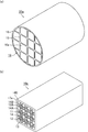
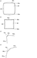
- FIG. 17A is a perspective view schematically showing the honeycomb filter described in Patent Document 1
- FIG. 17B is a perspective view schematically showing the honeycomb fired body constituting the honeycomb filter. is there.
- FIGS. 17C to 17D are enlarged end views schematically showing the honeycomb filter.
- an exhaust gas introduction cell 102 having an end portion on the exhaust gas inlet side opened and an end portion on the exhaust gas outlet side plugged, and an exhaust gas outlet port are disclosed.
- the exhaust gas discharge cell 101 is open at the end of the exhaust gas side and plugged at the end of the exhaust gas inlet side, and the cross-sectional shape of the cross section perpendicular to the longitudinal direction of the exhaust gas exhaust cell 101 is square, the exhaust gas introduction cell
- a plurality of honeycomb fired bodies 100 each having an octagonal cross-sectional shape perpendicular to the longitudinal direction of the cells 102 and the exhaust gas exhaust cells 101 and the exhaust gas introduction cells 102 arranged alternately (in a check pattern) are adhesive layers.
- a honeycomb filter 90 is disclosed which is bound by 105 and has an outer peripheral coat layer 106 formed on the outer periphery.
- a cell in which an end portion on the exhaust gas outlet side is opened and an end portion on the exhaust gas inlet side is plugged may be simply referred to as an exhaust gas discharge cell.
- a cell in which the end on the exhaust gas inlet side is opened and the end on the exhaust gas outlet side is plugged may be simply referred to as an exhaust gas introduction cell, a first exhaust gas introduction cell, or a second exhaust gas introduction cell.
- an exhaust gas discharge cell and an exhaust gas introduction cell are shown.
- a cross section perpendicular to the longitudinal direction of the cells such as the exhaust gas introduction cell and the exhaust gas discharge cell may be simply referred to as a cross section of the exhaust gas introduction cell and the exhaust gas discharge cell.
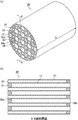
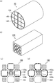
- FIG. 18 (a) is a perspective view schematically showing the honeycomb filter described in Patent Document 2
- FIGS. 18 (b) to 18 (c) are enlarged end views schematically showing the honeycomb filter. is there.
- each cell has a square honeycomb filter having the same cross-sectional shape, the end on the exhaust gas outlet side being opened, and the exhaust gas inlet Exhaust gas introduction cells 112 and 114 having an exhaust gas inlet side end portion opened and an exhaust gas outlet side end portion plugged around the entire periphery of the exhaust gas exhaust cell 111 whose end portion on the side is plugged are cell partition walls 113.
- An adjacent honeycomb filter 110 is disclosed.
- the exhaust gas introduction cell 112 faces one side of the exhaust gas exhaust cell 111 and the cell partition wall 113, but the exhaust gas introduction cell 114 faces the exhaust gas exhaust cell 111 at the corners.
- the sides constituting the cross-sectional shape of the exhaust gas introduction cell 114 do not face the exhaust gas discharge cell 111.
- the cross-sectional area of the exhaust gas introduction cells 112 and 114 is the same as the cross-sectional area of the exhaust gas exhaust cell 111, the total exhaust gas exhaust cell with respect to the total cross-sectional area of the exhaust gas introduction cell. Due to the small ratio of the cross-sectional area, the small cross-sectional area of each exhaust gas discharge cell, and the tendency of PM deposition to be biased, there was a problem that the pressure loss after PM deposition increased.
- the present inventors have arranged an exhaust gas introduction cell across a porous cell partition wall around the exhaust gas exhaust cell, and the exhaust gas introduction cell is replaced with the first exhaust gas introduction cell. And a second exhaust gas introduction cell having a cross-sectional area perpendicular to the longitudinal direction of the cell and a second exhaust gas introduction cell larger than the first exhaust gas introduction cell.
- the side length of the two exhaust gas introduction cells which are set to be equal to or larger than the cross-sectional area of the exhaust gas introduction cell and which face each other with the cell partition wall therebetween Alternatively, by adjusting the thickness of the cell partition wall, it has been found that the pressure loss can be reduced overall compared to the conventional honeycomb filter over the entire use range after PM deposition from the initial stage. In which it has been reached.
- the honeycomb filter of the present invention includes a porous cell partition wall that partitions and forms a plurality of cells serving as exhaust gas flow paths, an end portion on the exhaust gas inlet side is opened, and an end portion on the exhaust gas outlet side is plugged
- An exhaust gas introduction cell An exhaust gas outlet cell having an end portion on the exhaust gas outlet side opened and an end portion on the exhaust gas inlet side plugged, and a cross-sectional shape in a direction perpendicular to the longitudinal direction of the exhaust gas introduction cell and the exhaust gas exhaust cell is A honeycomb filter that is the same at all locations in each cell from the end on the exhaust gas inlet side to the end on the exhaust gas outlet side except for the plugged portion,
- the exhaust gas introduction cell is adjacent to the entire periphery of the exhaust gas exhaust cell with a porous cell partition wall, and the exhaust gas introduction cell has a cross section perpendicular to the longitudinal direction of the first exhaust gas introduction cell and the cell.
- the cross-sectional area of the cross section perpendicular to the longitudinal direction of the cell of the exhaust gas discharge cell is equal to or greater than the cross-sectional area of the cross section perpendicular to the longitudinal direction of the cell of the second exhaust gas introduction cell.
- the exhaust gas exhaust cell and the exhaust gas introduction cell are both polygonal and face the exhaust gas exhaust cell among the sides constituting the cross-sectional shape of the first exhaust gas introduction cell.
- the side length of the side is longer than the length of the side facing the exhaust gas discharge cell among the sides constituting the cross-sectional shape of the second exhaust gas introduction cell, or the first exhaust gas introduction cell
- the exhaust gas discharge cell and the exhaust gas introduction cell have a curved shape, and the thickness of the cell partition wall that separates the first exhaust gas introduction cell and the exhaust gas discharge cell. Is characterized in that it is thinner than the thickness of the cell partition wall separating the second exhaust gas introduction cell and the exhaust gas discharge cell.
- the cross-sectional shape as used in the field of this invention relates to the cross section perpendicular
- the cross-sectional area as used in the field of this invention is related to the cross section perpendicular
- the cell inner wall refers to a surface portion on the inner side of the cell among the surfaces of the cell partition walls constituting the cell.
- the side in the present invention relates to a cross section perpendicular to the longitudinal direction of the cell, and the cross-sectional shape formed by the inner walls of the exhaust gas exhaust cell, the first exhaust gas introduction cell, or the second exhaust gas introduction cell is a polygon.
- the line segment between the vertices of the polygon is called an edge.
- the length of the side means the length of the line segment, and when the apex portion has a so-called chamfered shape constituted by a curve, it means the length of the straight line portion excluding the curve portion.
- the permeation resistance increases because the cell walls separating the cells are thick, and the exhaust gas flows preferentially into the straight portion. Because it is necessary to adjust the length of the part, it is appropriate to exclude the curved part.
- the length of the side of the straight line portion excluding the curved line portion is such that when the straight line portion of the polygon is virtually extended and the intersection at which the virtual straight lines intersect is a virtual vertex, It is desirable that the length is 80% or more of the length of a virtual side formed by connecting vertices.
- the cross-sectional shape of the cell is a polygonal shape
- the mainstream which is the effect of the present invention, is adjusted by adjusting the length of the side. This is because the effect of the road switch can be realized.
- the side facing the exhaust gas discharge cell relates to a cross section perpendicular to the longitudinal direction of the cell,
- virtual perpendicular lines (hereinafter referred to as vertical bisectors) that bisect these sides are defined as When drawn toward the outside of the exhaust gas introduction cell or the second exhaust gas introduction cell, the vertical bisector is adjacent to the side of the first exhaust gas introduction cell or the second exhaust gas introduction cell across the cell partition wall. When it intersects with the graphic area composed of the cell inner wall of the cell, the side faces the exhaust gas discharge cell.
- the side facing the first exhaust gas introduction cell or the second exhaust gas introduction cell relates to a cross section perpendicular to the longitudinal direction of the cell,
- a virtual perpendicular line hereinafter referred to as a vertical bisector
- the perpendicular bisector intersects with the graphic area formed by the cell inner wall of the cell first exhaust gas introduction cell or the second exhaust gas introduction cell adjacent to the side of the exhaust gas exhaust cell across the cell partition wall, The side is said to face the first exhaust gas introduction cell or the second exhaust gas introduction cell.
- the side facing the second exhaust gas introduction cell relates to a cross section perpendicular to the longitudinal direction of the cell, and the cell of the first exhaust gas introduction cell
- virtual perpendicular lines hereinafter referred to as vertical bisectors
- the bisector intersects the graphic area formed by the cell inner wall of the second exhaust gas introduction cell adjacent to the side of the first exhaust gas introduction cell across the cell partition wall, the side is connected to the second exhaust gas introduction cell. They are facing each other.
- the side facing the first exhaust gas introduction cell relates to a cross section perpendicular to the longitudinal direction of the cell, and the cell of the second exhaust gas introduction cell.
- a virtual perpendicular line that bisects these sides (hereinafter referred to as a vertical bisector) is drawn vertically.
- the bisector intersects the graphic area formed by the cell inner wall of the first exhaust gas introduction cell adjacent to the side of the second exhaust gas introduction cell across the cell partition wall, the side is connected to the first exhaust gas introduction cell. They are facing each other.
- the thickness of the cell partition wall that separates the two cells is defined as follows. That is, in the cross section perpendicular to the longitudinal direction of the cell, the geometric centroid of the cross-sectional figure formed by the cell inner wall is obtained for each of the two cells, a straight line connecting the centroids is drawn, and the straight line overlaps the cell partition area.
- the length of the line segment is defined as the thickness of the cell partition wall.
- a cell is a space, but the center of gravity here means the geometric center of gravity of the cross-sectional figure formed by the inner wall of the cell. The definition of the center of gravity is possible.
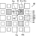
- FIG. 1 is an enlarged end view showing a part of an end face of a honeycomb filter according to an embodiment of the present invention in an enlarged manner.
- FIG. An exhaust gas introduction cell 14 is displayed.
- the side facing the exhaust gas discharge cell 11 is perpendicular to the longitudinal direction of the cell shown in FIG.
- the polygonal sides 12a, 14a formed by the inner walls of the first exhaust gas introduction cell 12 or the second exhaust gas introduction cell 14 are assumed to be imaginary perpendicular lines (hereinafter referred to as vertical two). 1 is drawn toward the outside of the first exhaust gas introduction cell 12 or the second exhaust gas introduction cell 14, the vertical bisector A and the vertical bisector B are as shown in FIG.
- the reason for facing each other with the intersection of vertical bisectors is that the exhaust gas permeates through the vicinity of the center in the length direction of the side, that is, the central part of the cell partition wall separating the exhaust gas introduction cell and the exhaust gas discharge cell. This is because the permeation resistance received at this time represents the pressure loss that occurs when the exhaust gas permeates the entire partition wall.
- the cross section perpendicular to the longitudinal direction of the cell if the cross-sectional shape formed by the inner walls of each of the exhaust gas discharge cell, the first exhaust gas introduction cell or the second exhaust gas introduction cell is a polygon,
- the vertical bisector of each side is a vertical bisector of the line segment excluding the curve.
- this curve is not treated as a side.
- the apex portion of the cross-sectional shape is a chamfered shape
- the sides constituting the cross-sectional shape are virtually extended, and the intersection of the extension lines is regarded as the apex and treated as a polygon.
- the vertex portion may be configured with a curve so that stress is not concentrated on the vertex portion. Yes, even if such a vertex portion is configured by a curve, it is handled as a polygon.
- the thickness of the cell partition wall separating the two cells is defined as follows. That is, in the cross section perpendicular to the longitudinal direction of the cell shown in FIG. 1, the geometric center of gravity of the cross-sectional figure formed by the cell inner wall is obtained for each of the two cells (in FIG. 1, the center of gravity of the exhaust gas discharge cell 11 is O 11 , the center of gravity of the second exhaust gas introduction cell 14 is O 14 ), a straight line Z 14 connecting the centers of gravity is drawn, and the length D of the line segment where the straight line Z 14 overlaps the cell partition wall region is defined as the thickness of the cell partition wall.
- a cell is a space, but the center of gravity here means the geometric center of gravity of the cross-sectional figure formed by the inner wall of the cell. The definition of the center of gravity is possible.
- the reason why the thickness of the cell partition wall is defined as described above is as follows.
- the resistance when the gas permeates the cell partition is highest at the portion where the flow velocity of the gas passing through the cell partition is the highest, and this portion can represent the permeation resistance of the cell partition.
- the flow rate of gas in the longitudinal direction of the honeycomb filter is highest at the position corresponding to the geometric center of gravity of the cross-sectional shape formed by the inner wall of the cell, and decreases concentrically in the cross section of the cell.
- the intersection of the cell connecting the center of gravity of the cell and the cell partition wall corresponds to the highest part of the flow velocity of the gas passing through the cell partition wall.
- the measurement of the length of the cell side and the thickness of the cell partition and the specification of the cell cross-sectional shape are performed using an electron micrograph.
- the electron micrograph is taken with an electron microscope (FE-SEM: S-4800, a high-resolution field emission scanning electron microscope manufactured by Hitachi High-Technologies Corporation).
- FE-SEM electron microscope
- the magnification of the electron micrograph shows that the particle on the surface (inner wall) of the cell partition walls and the irregularities of the pores that make up the cell specify the cross-sectional shape of the cell, the length of the side, the partition wall thickness, and the cross-sectional area of the cell.
- the cross-sectional area of the cell cross section can be calculated from the weight ratio.
- the cross-sectional shape formed by the inner walls of the exhaust gas exhaust cell and the second exhaust gas exhaust cell is an octagon, and the cross-sectional areas thereof are the same.
- the cross-sectional shape formed by the inner wall is a square (the vertex is formed by a curve and has a so-called chamfered shape, but in the present invention, four straight lines extending at four sides intersect at four points, and the four intersections are the vertexes. Treated as a square).
- a scale of 500 ⁇ m is displayed in the photograph, and a square (corresponding to a unit area) having a length corresponding to 500 ⁇ m in this photograph as one side is cut out from this photograph and its weight is measured.
- the octagon and the square are cut out from the photograph (the four vertex portions of the square are cut out along the curve), and the weight is measured.
- the cross-sectional area is calculated from the weight ratio with the 500 ⁇ m scale square. If only the ratio of the cell cross-sectional area is measured, the area ratio can be calculated as it is from the weight ratio of the octagon and the square.
- the measurement of the length of the cell, the thickness of the cell partition wall, and the cross-sectional area are taken from the above-described manual measurement, and an electron micrograph is taken as image data, or image data taken directly from the electron microscope is used. It is also possible to input a photo scale and replace it with electronic measurement.
- both the manual measurement method and the digitized measurement method are measurements based on the scale of the electron microscope image, and are based on the same principle, and it goes without saying that no wrinkles occur in the measurement results of both.
- measurement software such as image analysis type particle size distribution software (manufactured by Mountech Co., Ltd.) MAC-View (Version 3.5) can be used.
- the cross-sectional area can be measured by taking an electron micrograph with a scanner or using image data taken directly from the electron microscope, inputting the scale of the photo, and specifying a range along the inner wall of the cell. Moreover, the distance between any points in the image can be measured based on the scale of the electron micrograph.
- photographing a cell cross section with an electron microscope cut the filter perpendicular to the longitudinal direction of the cell, prepare a 1 cm x 1 cm x 1 cm sample so that the cut surface enters, and clean the sample ultrasonically. Or, embed with resin and take an electron micrograph. Embedding with resin does not affect the measurement of the cell side length and cell partition wall thickness.
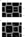
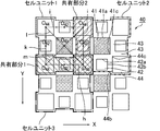
- FIGS. 2A to 2B are photographs showing an example of the shape of a cell cross section taken by an electron microscope.
- Fig.2 (a) it turns out that the cross-sectional shape of the waste gas exhaust cell 11 and the 2nd waste gas introduction cell 14 is an octagon.
- the cross-sectional shape of the first exhaust gas introduction cell 12 is a square.
- the apex portion of the first exhaust gas introduction cell is composed of a slight curve, but if the side composed of the four straight lines of the first exhaust gas introduction cell 12 is extended, there will be four intersections. Since a square with the intersection as a vertex can be formed, the cross-sectional shape of this cell is treated as a square according to the definition in the present invention.
- the cross-sectional area (cross-sectional area) of the exhaust gas discharge cell 11 and the second exhaust gas introduction cell 14 is 2.14 mm 2
- the cross-sectional shape of the first exhaust gas introduction cell 12. Can be calculated as 0.92 mm 2 .
- the length of the side Ls facing the exhaust gas discharge cell 11 among the sides constituting the cross-sectional shape of the first exhaust gas introduction cell 12 is the four apexes of the first exhaust gas introduction cell. Since the portion is composed of a curved line, the length excluding the curved portion is obtained.
- the length Lo of the side facing the exhaust gas discharge cell 11 among the sides constituting the cross-sectional shape of the second exhaust gas introduction cell 14 is the octagonal vertex distance.
- the side lengths Ls and Lo and the cross-sectional area can be measured from the electron micrograph.
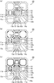
- FIGS. 3A and 3B are scanning electron micrographs (SEM photographs) showing an example of the shape of a cell cross section of a cell different from the cell shown in FIG.
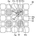
- the cross-sectional shapes of the exhaust gas discharge cell 41, the second exhaust gas introduction cell 44, and the first exhaust gas introduction cell 42 are all straight lines obtained by virtually extending four sides of equal length. It can be seen that the shape intersects perpendicularly and the intersection (vertex) portion is formed by a curve.
- the cross-sectional shapes of these cells are all made up of curved lines, but if you extend the four straight lines that make up each cell, there will be four intersections, and these intersections will become virtual vertices.
- the side constituting the first exhaust gas introduction cell 42 has its perpendicular bisector intersecting with the exhaust gas discharge cell 41, so the side constituting the first exhaust gas introduction cell 42 is It can be said that it faces the exhaust gas discharge cell 41.
- the side that forms the second exhaust gas introduction cell 44 does not intersect the vertical bisector with the exhaust gas discharge cell 41, the side that forms the second exhaust gas discharge cell 44 faces the exhaust gas discharge cell 41. do not do. In this way, it can be determined from the electron micrograph whether or not the sides constituting the second exhaust gas introduction cell 44 and the first exhaust gas introduction cell 42 face the exhaust gas exhaust cell 41.
- the swollen square used in the present invention is a figure composed of four curves having the same length, which curves toward the outside of the figure, as if the sides of the square are outward from the geometric center of gravity.
- a contracted square is a figure composed of four curves with the same length that curves toward the inside of the figure, as if the sides of the square shrunk toward the geometric center of gravity. The figure of.
- the first exhaust gas introduction cell, the second exhaust gas introduction cell, and the exhaust gas exhaust cell are cross sections constituted by inner walls of the cells at all locations in each cell except for the plugging portion from the exhaust gas inlet end to the exhaust gas outlet end.
- the shape is the same. That is, when only the first exhaust gas introduction cell is viewed in a cross section perpendicular to the longitudinal direction, the cross-sectional figure formed by the inner wall is the cross section of any portion from the exhaust gas inlet end to the exhaust gas outlet end except for the plugging portion. It is the same shape even if you look at. The same shape means congruence and does not include similarity.
- the shape having a similar relationship is a different shape.
- the first exhaust gas introduction cell but also the second exhaust gas introduction cell and the exhaust gas discharge cell have the same explanation as in the case of the first exhaust gas introduction cell.
- the reason for excluding the plugged portion is that the cross-sectional figure formed by the inner wall of the cell partition wall does not physically exist because the plugged material exists in the plugged portion.
- the pressure loss can be reduced comprehensively from the initial stage until the amount of PM deposited near the limit.
- the inventors of the present invention have the following pressure loss: (a) inflow resistance when exhaust gas flows into the honeycomb filter, (b) passage resistance of the exhaust gas introduction cell, (c) permeation resistance of the cell partition, (d) accumulated PM It is considered to be generated by the permeation resistance generated when the exhaust gas permeates the layer, (e) the passage resistance of the exhaust gas discharge cell, and (f) the outflow resistance when the exhaust gas flows out of the honeycomb filter.
- the initial pressure loss before PM is deposited is that the (c), (e) and (f) are the controlling factors, and the transient that occurs after a certain amount of PM is deposited.
- the pressure loss has determined that (a), (b) and (d) are the controlling factors.
- One of the factors controlling the initial pressure loss is not (b) the passage resistance of the exhaust gas introduction cell, but (e) the passage resistance of the exhaust gas discharge cell. This is because the aperture ratio of the honeycomb filter by the cell is small.
- the reason why the initial pressure loss is governed by (a) not the inflow resistance when the exhaust gas flows into the honeycomb filter but (f) the outflow resistance when the exhaust gas flows out of the honeycomb filter is because the gas is compressed It is presumed that the vortex is generated near the outlet of the cell when the gas is discharged from the cell and rapidly expands rather than the resistance, and this vortex causes the resistance generated by inhibiting the outflow of the exhaust gas to be higher. In order to reduce the initial pressure loss, it is necessary to reduce the passage resistance and the outflow resistance.
- the cross-sectional area of the exhaust gas exhaust cell is made equal to or larger than that of the exhaust gas introduction cell.
- the cross-sectional area of the exhaust gas introduction cell must be relatively larger than that of the exhaust gas discharge cell.
- the inventors have further studied and completed the present invention. That is, two types of exhaust gas introduction cells, one having a large cross-sectional area (second exhaust gas introduction cell) and one having a small cross-sectional area (first exhaust gas introduction cell), are employed, and the cross-sectional area is the second exhaust gas introduction cell.
- the same or relatively large exhaust gas exhaust cell is adopted, two types of exhaust gas introduction cells are arranged around the exhaust gas exhaust cell, and the length of the inner wall of the partition wall separating the first exhaust gas introduction cell and the exhaust gas exhaust cell is 2 Relative to the length of the inner wall of the partition wall separating the exhaust gas introduction cell and the exhaust gas discharge cell, or the thickness of the partition wall separating the first exhaust gas introduction cell and the exhaust gas discharge cell is separated from the second exhaust gas introduction cell and the exhaust gas discharge cell.
- the thickness is first introduced preferentially into the first exhaust gas introduction cell.
- the partition wall between the first exhaust gas introduction cell and the exhaust gas discharge cell has a large permeation area (long side in terms of the cross-sectional shape of the polygonal cell) or a thin thickness, and the exhaust gas It is possible to pass through a convenient partition, and the transmission resistance of (c) can be reduced.
- the cross-sectional area of the exhaust gas discharge cell is relatively larger than that of the first exhaust gas introduction cell, the passage resistance of (e) can be reduced. That is, both the transmission resistance (c) and the passage resistance (e) can be lowered, and the initial pressure loss can be lowered.
- the cross-sectional area of the first exhaust gas introduction cell is relatively smaller than that of the second exhaust gas introduction cell, so that the PM layer deposited on the first exhaust gas introduction cell
- the second exhaust gas introduction cell having a large cross-sectional area has a large cross-sectional area because the permeation resistance is increased early, and the main flow path of the exhaust gas is “switched” so that the exhaust gas naturally (ie, spontaneously) enters the second exhaust gas introduction cell more Even when PM is deposited widely and thinly, the passage resistance of (b) and the transmission resistance of (d) can be reduced even after PM deposition, and the transient pressure loss can be lowered.
- the surprising effect of simultaneously reducing the transient pressure loss and the initial pressure loss which has been impossible in the past, is realized by self-switching the main flow path.
- Patent Document 1 As shown in FIG. 17, International Publication No. 2004/024294 (Patent Document 1) described above includes a honeycomb filter in which the cross-sectional shape of the exhaust gas introduction cell 102 is octagonal and the cross-sectional shape of the exhaust gas exhaust cell 101 is square. It is disclosed that by increasing the cross-sectional area of the exhaust gas introduction cell 102, it is possible to deposit PM widely and thinly to reduce transient pressure loss.
- Patent Document 1 in order to reach the present invention from Patent Document 1, a part of the exhaust gas discharge cell 101 having a small cross-sectional area is changed to the exhaust gas introduction cell 102, and a part of the exhaust gas introduction cell 102 having a large cross-sectional area is changed to the exhaust gas exhaust cell. 101, however, such a change negates the inventive idea described in Patent Document 1 that attempts to increase the cross-sectional area of the exhaust gas introduction cell 102. It is never derived.
- Patent Document 2 In addition, as described based on FIG. 18, in US Pat. No. 4,417,908 (Patent Document 2), the number of exhaust gas introduction cells having the same cross-sectional area is increased, and the total area of the exhaust gas introduction cells is increased. Thus, a honeycomb filter capable of reducing the transient pressure loss by depositing PM widely and thinly is disclosed. However, in order to reach the present invention from Patent Document 2, it is necessary to change a part of the exhaust gas introduction cell to a cell having a small cross-sectional area. The invention idea of Document 2 is denied and the present invention is not derived with Patent Document 2 as the closest document. Thus, the known technology denies the present invention, and the present invention is not derived from known literature.
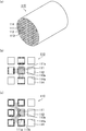
- FIG. 4 (a) to 4 (c) are enlarged end views showing a part of the end face of the honeycomb filter according to the embodiment of the present invention.
- a porous portion is formed around the exhaust gas discharge cell 11 whose end on the exhaust gas outlet side is opened and whose end on the exhaust gas inlet side is plugged.
- the first exhaust gas introduction cell 12 and the second exhaust gas introduction cell 14 which are open at the end on the exhaust gas inlet side and plugged at the end on the exhaust gas outlet side are formed adjacent to each other with the cell partition wall 13 therebetween. .
- the exhaust gas exhaust cell 11 is an octagon having the same shape as the exhaust gas introduction cell 102 shown in FIG. 17, the first exhaust gas introduction cell 12 is square, and the second exhaust gas.
- the introduction cell 14 is an octagon having the same shape as the exhaust gas discharge cell 11.
- the cross sectional area of the second exhaust gas introduction cell 14 is larger than the cross sectional area of the first exhaust gas introduction cell 12 and is the same as the cross sectional area of the exhaust gas discharge cell 11.
- the cross-sectional area of the second exhaust gas introduction cell 14 is the same as the cross-sectional area of the exhaust gas discharge cell 11, and the cross-sectional area of the exhaust gas discharge cell 11 is larger than the cross-sectional area of the first exhaust gas introduction cell 12. Therefore, the resistance when exhaust gas passes through the exhaust gas discharge cell 11 and the resistance when exhaust gas is discharged to the outside of the filter can be kept low, and the pressure loss can be reduced.
- the length of the side 12a facing the exhaust gas discharge cell 11 is the side constituting the cross-sectional shape of the second exhaust gas introduction cell 14, It is longer than the length of the side 14 a facing the exhaust gas discharge cell 11.
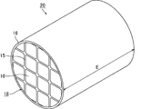
- the exhaust gas flows in the direction of the honeycomb filter 20, the exhaust gas flows into the first exhaust gas introduction cell 12 and the second exhaust gas introduction cell 14 whose end portions on the inlet side are open.
- the exhaust gas flows so that the entire flow becomes equal in order from the easy-to-flow portion in the filter.
- the length (Ls) of the side 12a of the first exhaust gas introduction cell 12 is longer than the length (Lo) of the side 14a of the second exhaust gas introduction cell 14, so
- the surface area of the cell partition wall 13a separating the first exhaust gas introduction cell 12 is larger than the surface area of the cell partition wall 13b separating the exhaust gas exhaust cell 11 and the second exhaust gas introduction cell 14, and the exhaust gas passes through the cell partition wall 13a more.
- the reason why the relationship between the length of the side constituting the cell and the surface area is concluded as described above is as follows.
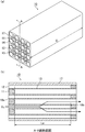
- the surface area of the cell partition wall 13a that separates the exhaust gas exhaust cell 11 and the first exhaust gas introduction cell 12 is the surface area on the inner wall side of the first exhaust gas introduction cell 12, and the distance between the exhaust gas inlet end surface and the outlet end surface is Assuming that the effective filter length excluding the length of the sealing portion is Le (see FIG. 6B), the surface area on the inner wall side of the first exhaust gas introduction cell 12 is represented by Ls ⁇ Le.
- the surface area of the cell partition wall 13b that separates the exhaust gas exhaust cell 11 and the second exhaust gas introduction cell 14 is the surface area on the inner wall side of the second exhaust gas introduction cell 14, and the inlet is determined from the distance between the exhaust gas inlet end face and the outlet end face.
- the effective filter length excluding the lengths of the side and outlet side sealing portions is Le
- the surface area on the inner wall side of the second exhaust gas introduction cell 14 is represented by Lo ⁇ Le. Note that, as an effective length of the filter, in FIG. 6B, a length based on the tip of the sealing material 11 is taken.
- the length (Ls) of the side 12a is relatively longer than the length (Lo) of the side 14a, the surface area of Ls ⁇ Le is relatively larger than that of Lo ⁇ Le. That is, the length of the side and the size of the surface area are synonymous. Therefore, if the length (Ls) of the side 12a of the exhaust gas discharge cell 11 is longer than the length (Lo) of the side 14a of the second exhaust gas introduction cell 14, the exhaust gas discharge cell 11 and the first exhaust gas introduction cell 12 are connected.
- the surface area of the cell partition wall 13a that separates is larger than the surface area of the cell partition wall 13b that separates the exhaust gas discharge cell 11 and the second exhaust gas introduction cell.
- FIGS. 4 (a) to 4 (c) matters relating to actions and effects are written in only a part of the figure. The same applies to FIGS. 17 and 18.
- the cell partition wall 13c that separates the first exhaust gas introduction cell 12 and the second exhaust gas introduction cell 14 as shown in FIG. 4 (c). Also flows through the exhaust gas discharge cell 11.
- the exhaust gas enters the cell partition wall 13c also from the second exhaust gas introduction cell 14 side, and also enters the cell partition wall 13c from the first exhaust gas introduction cell 12 side.
- the PM gradually increases not only in the entire inner wall surface of the exhaust gas introduction cell 12 of the cell partition walls 13a and 13c around the first exhaust gas introduction cell 12, but rather in the second exhaust gas introduction cell around the second exhaust gas introduction cell 14.
- the cell partition walls 13b and 13c are deposited on the entire inner wall surface of the exhaust gas introduction cell, but widely and thinly. Since the cross-sectional area of the first exhaust gas introduction cell 12 is smaller than the cross-sectional area of the second exhaust gas introduction cell 11, PM is deposited thickly, the passage resistance of the PM layer is increased, and the exhaust gas is first introduced early after the introduction of the exhaust gas.
- the inner wall surface area of the exhaust gas introduction cell of the cell partition walls 13b and 13c around the second exhaust gas introduction cell 14 is wider than the inner wall surface area of the exhaust gas introduction cell of the cell partition walls 13a and 13c around the first exhaust gas introduction cell 12, Even if PM is deposited on the entire periphery of the cell partition walls 13b and 13c around the second exhaust gas introduction cell 14, the thickness of the deposited layer can be reduced. Therefore, even if PM accumulates, the rate of increase in exhaust gas pressure loss is small. As a result, even if the amount of accumulated PM increases, an excellent effect is achieved in that the pressure loss can be kept low. As a result, in a vehicle equipped with the honeycomb filter according to the present invention, an inconvenience in driving due to an increase in pressure loss hardly occurs over the entire use region, and fuel consumption can be suppressed low.
- the exhaust gas discharge cells 101 having a square cross section and the exhaust gas introduction cells 102 having an octagonal cross section are alternately ( Arranged in the check pattern).
- the exhaust gas flows into the exhaust gas introduction cell 102 having an octagonal cross section and larger than the cross sectional area of the exhaust gas exhaust cell 101, and then passes through the cell partition wall 103a separating the exhaust gas introduction cell 102 and the exhaust gas exhaust cell 101. It flows into the discharge cell 101.
- resistance when flowing from the exhaust gas introduction cell 102 having a large cross-sectional area into the exhaust gas exhaust cell 101 having a small cross-sectional area, resistance when passing through the exhaust gas exhaust cell 101 having a small cross-sectional area, and from the exhaust gas exhaust cell 101 having a small cross-sectional area The resistance when discharged to the outside is high, and the initial pressure loss is higher than that of the honeycomb filter according to the present invention.
- the exhaust gas passes through the cell partition walls 103b separating the exhaust gas introduction cells 102, but the cell partition surface where PM is deposited has a smaller surface area than the honeycomb filter 10 according to the present invention. PM accumulates thickly, and it is difficult to suppress an increase in pressure loss.
- the cross sections perpendicular to the longitudinal direction of each cell are all the same square, and the exhaust gas introduction cell 112 is disposed around the entire exhaust gas discharge cell 111. , 114 are adjacent to each other across the cell partition wall 113b. Further, regarding the cross-sectional shape, the exhaust gas introduction cell 112 faces one side across the exhaust gas discharge cell 111 and the cell partition wall 113a, but the exhaust gas introduction cell 114 has a relationship in which corners face each other. Therefore, the side 114 a constituting the exhaust gas introduction cell 114 does not face the side 111 a constituting the exhaust gas discharge cell 111.
- the exhaust gas flows into the exhaust gas introduction cell 112 facing the exhaust gas discharge cell 111 across the cell partition wall 113a, and the cell partition wall. After passing through 113a, it flows into the exhaust gas discharge cell 111.
- the first exhaust gas discharge cell 111 and the first exhaust gas introduction cell 112 have the same cross-sectional area, so that the exhaust gas introduction cell 12 has a larger cross-sectional area than the exhaust gas introduction cell 12.
- the initial pressure loss is higher.
- the cross-sectional shape thereof is a polygon
- the side facing the first exhaust gas introduction cell adjacent to the exhaust gas discharge cell with the cell partition wall therebetween, is parallel to each other.
- the thickness of the cell partition wall separating the exhaust gas discharge cell and the first exhaust gas introduction cell is uniform everywhere, the filter has a high breaking strength, easily allows the exhaust gas to permeate, and deposits PM uniformly. This is because the pressure loss can be reduced.
- the vertex part of a polygon is comprised with the curve in cross-sectional shape, the curve part is not handled as an edge. This is because they are not parallel in the first place.
- the length of the side of the cross-sectional shape excluding the curved portion virtually extends the straight line portion regarded as the side, and the intersection of the virtual straight lines intersects the virtual vertex
- the length is 80% or more of the length of the virtual side of the polygon formed by connecting the virtual vertices.
- the portion not treated as a side is less than 20% of the length of the virtual side.
- the thickness of the partition wall separating the exhaust gas discharge cell and the second exhaust gas introduction cell is uniform everywhere, the filter has a high breaking strength, easily allows the exhaust gas to permeate, and deposits PM uniformly. This is because the pressure loss can be reduced.
- the vertex part of a polygon is comprised with the curve in cross-sectional shape, the curve part is not handled as an edge. This is because they are not parallel in the first place.
- the length of the side of the cross-sectional shape excluding the curved portion virtually extends the straight line portion regarded as the side, and the intersection of the virtual straight lines intersects the virtual vertex
- the length is 80% or more of the length of the virtual side of the polygon formed by connecting the virtual vertices.
- the portion not treated as a side is less than 20% of the length of the virtual side.
- the first exhaust gas introduction cell and the second exhaust gas introduction cell that are adjacent to each other with the cell partition wall interposed therebetween are perpendicular to the cell longitudinal direction.
- the sides constituting the cross-sectional shape of the exhaust gas introduction cell the side adjacent to the second exhaust gas introduction cell with the cell partition wall therebetween, and the side facing the second exhaust gas introduction cell constitute the cross-sectional shape of the second exhaust gas introduction cell.
- the side facing the first exhaust gas introduction cell with the cell partition wall therebetween is parallel to the side facing the first exhaust gas introduction cell.
- the thickness of the partition wall separating the first exhaust gas introduction cell and the second exhaust gas introduction cell is uniform everywhere, and the honeycomb filter has a high breaking strength. This is because the exhaust gas can be easily transmitted from the cell to the exhaust gas discharge cell side, and PM can be deposited widely and thinly on the inner wall of the second exhaust gas introduction cell, so that the pressure loss can be reduced after PM deposition.
- the vertex part of a polygon is comprised with the curve in cross-sectional shape, the curve part is not handled as an edge. This is because they are not parallel in the first place.
- the length of the side of the cross-sectional shape excluding the curved portion virtually extends the straight line portion regarded as the side, and the intersection of the virtual straight lines intersects the virtual vertex
- the length is 80% or more of the length of the virtual side of the polygon formed by connecting the virtual vertices.
- the portion not treated as a side is less than 20% of the length of the virtual side.
- the cross sections perpendicular to the cell longitudinal direction of the exhaust gas discharge cells, the first exhaust gas introduction cells, and the second exhaust gas introduction cells that are adjacent to each other across the cell partition walls are polygonal.
- (A) Of the sides constituting the cross-sectional shape of the exhaust gas discharge cell, the side adjacent to the first exhaust gas introduction cell with the cell partition wall therebetween and facing the first exhaust gas introduction cell, and the cross-sectional shape of the first exhaust gas introduction cell Are adjacent to the exhaust gas exhaust cell across the cell partition, and the sides facing the exhaust gas exhaust cell are parallel to each other
- (B) Of the sides constituting the cross-sectional shape of the exhaust gas exhaust cell the side adjacent to the second exhaust gas introduction cell across the cell partition wall and facing the second exhaust gas introduction cell, and the cross-sectional shape of the second exhaust gas introduction cell Are adjacent to the exhaust gas exhaust cell across the cell partition, and the sides facing the exhaust gas exhaust cell are parallel to each other
- the first exhaust gas introduction cell, the second exhaust gas introduction cell, and the cross section perpendicular to the longitudinal direction of the exhaust gas exhaust cell, and when the cross-sectional shape thereof is a polygon In addition to the configuration including a), (b), and (c), the distance between the parallel sides in (a), and between the parallel sides in (b) And the distance between the parallel sides in (c) are preferably equal. Note that the distance between the sides is that a perpendicular is drawn from an arbitrary point P on one side toward the other side, and Q is a point where the perpendicular intersects the other side. The distance between is defined as the distance between parallel sides.
- the honeycomb filter has the highest breaking strength, the pressure loss can be reduced most before and after the PM deposition, and the filter is prevented from being damaged by the thermal shock generated when the PM is regenerated. Because it can be done.
- the vertex part of a polygon is comprised with the curve in cross-sectional shape, the curve part is not handled as an edge. This is because they are not parallel in the first place.
- the length of the side of the cross-sectional shape excluding the curved portion virtually extends the straight line portion regarded as the side, and the intersection of the virtual straight lines intersects the virtual vertex
- the length is 80% or more of the length of the virtual side of the polygon formed by connecting the virtual vertices.
- the portion not treated as a side is less than 20% of the length of the virtual side.
- the honeycomb filter of the present invention is preferably used for purifying PM in exhaust gas discharged from an internal combustion engine of an automobile. This is because both the initial pressure loss generated in the filter before PM deposition and the transient pressure loss generated in the filter due to PM deposition can be reduced at the same time, so that the fuel efficiency of the engine can be improved.
- the honeycomb filter of the present invention is optimal when a diesel engine is adopted as an internal combustion engine of an automobile. This is because the amount of PM discharged from the diesel engine is larger than that of the gasoline engine, and the demand for reducing the transient pressure loss generated in the filter due to PM accumulation is higher than that of the gasoline engine.
- the honeycomb filter of the present invention When the honeycomb filter of the present invention is used for purifying PM in exhaust gas discharged from an internal combustion engine of an automobile, the honeycomb filter of the present invention is fixed in the exhaust pipe via a holding material.
- both the exhaust gas discharge cell and the exhaust gas introduction cell are polygonal, Of the sides constituting the cross-sectional shape of the second exhaust gas introduction cell, the length of the side facing the exhaust gas discharge cell is the length of the side constituting the cross-sectional shape of the first exhaust gas introduction cell. It is desirable that the length is 0.8 times or less the length of the side facing the.
- the exhaust gas can more easily pass through the cell partition wall separating the exhaust gas discharge cell and the first exhaust gas introduction cell, the initial pressure loss can be effectively suppressed, and the pressure loss can be reduced even after PM is deposited. An increase in the increase rate can be suppressed. If the ratio of the side length of the second exhaust gas introduction cell to the length of the side of the first exhaust gas introduction cell exceeds 0.8, there is no significant difference between the lengths of both sides, so the initial pressure loss is kept low. It becomes difficult.
- the exhaust gas discharge cell is preferably octagonal
- the first exhaust gas introduction cell is square
- the second exhaust gas introduction cell is preferably octagonal.
- the honeycomb filter having the above configuration has the same shape as that of the honeycomb filter according to FIG. 4, which describes the operation and effect, and can effectively suppress the initial pressure loss and increase the surface area on which PM is deposited. And pressure loss can be kept low.
- the cross-sectional area of the second exhaust gas introduction cell is the same as the cross-sectional area of the exhaust gas discharge cell
- the cross-sectional area of the first exhaust gas introduction cell is preferably 20 to 50% of the cross-sectional area of the second exhaust gas introduction cell. In this case, it is possible to make a difference between the resistance when the exhaust gas passes through the first exhaust gas introduction cell and the resistance when it passes through the second exhaust gas introduction cell, and the pressure loss can be effectively suppressed.
- the cross-sectional area of the first exhaust gas introduction cell When the cross-sectional area of the first exhaust gas introduction cell is less than 20% of the cross-sectional area of the second exhaust gas introduction cell, the cross-sectional area of the first exhaust gas introduction cell becomes too small, and the passage resistance through which the exhaust gas passes through the first exhaust gas introduction cell. Tends to increase and pressure loss tends to increase. On the other hand, if the cross-sectional area of the first exhaust gas introduction cell exceeds 50% of the cross-sectional area of the second exhaust gas introduction cell, the difference in the passage resistance between the two becomes small and it is difficult to reduce the pressure loss.
- the exhaust gas exhaust cell and the exhaust gas introduction cell are both polygonal with respect to the cross section perpendicular to the longitudinal direction of the cell, and the thickness of the cell partition walls separating the cells of the honeycomb filter is set at all locations. It is desirable that In this case, the above-described effects can be achieved with the entire honeycomb filter.
- the cell partition wall thickness of the above-described honeycomb filter is 0.10 to 0.46 mm.
- the cell partition wall having the above thickness has a sufficient thickness to collect PM in the gas and can effectively suppress an increase in pressure loss. Therefore, the honeycomb filter of the present invention can sufficiently exhibit the above-described effects as the honeycomb filter of the present invention. If the cell partition wall thickness is less than 0.10 mm, the cell partition wall thickness becomes too thin, so that the mechanical strength of the honeycomb filter decreases. On the other hand, if the thickness of the cell partition wall exceeds 0.46 mm, the cell partition wall becomes too thick, and the pressure loss when exhaust gas passes through the cell partition wall increases.
- the cross-sectional shape of the exhaust gas discharge cell is octagonal
- the cross-sectional shape of the first exhaust gas introduction cell is square
- the cross-sectional shape of the second exhaust gas introduction cell is octagonal
- the cross-sectional shapes of the second exhaust gas introduction cell and the exhaust gas discharge cell are the same as each other
- Around the exhaust gas exhaust cell four first exhaust gas introduction cells and four second exhaust gas introduction cells are alternately arranged with a cell partition wall therebetween to surround the exhaust gas exhaust cell, Further, a figure composed of the cross-sectional shape of the exhaust gas exhaust cell among virtual line segments connecting the geometric centers of gravity of the octagons that are the cross-sectional shapes of the four second exhaust gas introduction cells surrounding the exhaust gas exhaust cell.
- the intersection of two line segments that pass through the region coincides with the geometric center of gravity of the octagon that is the cross-sectional shape of the exhaust gas exhaust cell, And among the virtual line segments that connect the geometric centers of gravity of the octagons that are the cross-sectional shapes of the four second exhaust gas introduction cells, the four that do not pass through the graphic region consisting of the cross-sectional shape of the exhaust gas discharge cells are The square is formed so that the midpoint of each side coincides with the geometric center of gravity of each square, which is the cross-sectional shape of the four first exhaust gas introduction cells surrounding the exhaust gas discharge cell.
- the exhaust gas discharge cell, the first exhaust gas introduction cell, and the second exhaust gas introduction cell are respectively disposed,
- the side facing the exhaust gas discharge cell is parallel,
- the side facing the exhaust gas discharge cell is parallel to the side of the first exhaust gas introduction cell, and the side facing the second exhaust gas introduction cell across the cell partition wall, 2
- Sides constituting the cross-sectional shape of the exhaust gas introduction cell are parallel to the side facing the first exhaust gas introduction cell across the cell partition wall, and the distance between the parallel sides is any combination. It is desirable that they are equal to each other.
- the exhaust gas discharge cell, the first exhaust gas introduction cell, and the second exhaust gas introduction cell are all preferably square. Even when the first exhaust gas introduction cell and the second exhaust gas introduction cell are both square, the relationship among the sizes of the exhaust gas exhaust cell, the first exhaust gas introduction cell, and the second exhaust gas introduction cell. For example, since the area of the cross section of the first exhaust gas introduction cell is smaller than the cross sectional area of the exhaust gas exhaust cell, the honeycomb filter 110 described in the related art is different from the honeycomb filter 110 described above. There is an effect.
- the cross-sectional area of the second exhaust gas introduction cell is the same as the cross-sectional area of the exhaust gas discharge cell
- the cross-sectional area of the first exhaust gas introduction cell is preferably 20 to 50% of the cross-sectional area of the second exhaust gas introduction cell.
- the cross-sectional area of the first exhaust gas introduction cell When the cross-sectional area of the first exhaust gas introduction cell is less than 20% of the cross-sectional area of the second exhaust gas introduction cell, the cross-sectional area of the first exhaust gas introduction cell becomes too small, and the passage resistance through which the exhaust gas passes through the first exhaust gas introduction cell. Tends to increase and pressure loss tends to increase. On the other hand, if the cross-sectional area of the first exhaust gas introduction cell exceeds 50% of the cross-sectional area of the second exhaust gas introduction cell, the difference in the passage resistance between the two becomes small and it is difficult to reduce the pressure loss.
- the cross-sectional shape of the exhaust gas discharge cell is square
- the cross-sectional shape of the first exhaust gas introduction cell is square
- the cross-sectional shape of the second exhaust gas introduction cell is square
- the cross-sectional shapes of the second exhaust gas introduction cell and the exhaust gas discharge cell are the same as each other
- Around the exhaust gas exhaust cell four first exhaust gas introduction cells and four second exhaust gas introduction cells are alternately arranged with a cell partition wall therebetween to surround the exhaust gas exhaust cell
- a graphic region consisting of the cross-sectional shape of the exhaust gas exhaust cell The intersection of the two line segments that pass through is coincident with the square geometric center of gravity, which is the cross-sectional shape of the exhaust gas discharge cell, And among the virtual line segments that connect the geometric center of gravity of each square
- the exhaust gas discharge cell, the first exhaust gas introduction cell, and the second exhaust gas introduction cell are respectively disposed,
- the side facing the exhaust gas discharge cell is parallel,
- the corners of the polygonal cell have a curved chamfered shape with respect to the cross section perpendicular to the longitudinal direction of the cell.
- the corners of the cells have a curved chamfered shape, stress due to heat or the like is hardly concentrated at the corners of the cells, and cracks are not easily generated.
- the exhaust gas discharge cell, the first exhaust gas introduction cell, and the second exhaust gas introduction cell are preferably point-symmetrical polygons, and the number of sides thereof is eight or less.
- the polygon is a point-symmetric polygon and the number of sides is eight or less, the resistance of exhaust gas passing through the cell can be reduced, and the pressure loss can be further reduced.
- the exhaust gas exhaust cell and the exhaust gas introduction cell have a shape constituted by a curve
- the thickness of the cell partition wall separating the first exhaust gas introduction cell and the exhaust gas discharge cell is preferably 40 to 75% of the thickness of the cell partition wall separating the second exhaust gas introduction cell and the exhaust gas discharge cell.
- the thickness of the cell partition wall separating the first exhaust gas introduction cell and the exhaust gas discharge cell is 40 to 40% of the thickness of the cell partition wall separating the second exhaust gas introduction cell and the exhaust gas discharge cell.
- the exhaust gas easily passes through the cell partition wall separating the first exhaust gas introduction cell and the exhaust gas exhaust cell, and when the PM is accumulated to some extent, the second exhaust gas introduction cell and the exhaust gas emission It passes through the cell partition that separates the cells.
- the cross-sectional area of the cell of the second exhaust gas introduction cell is larger than the cross-sectional area of the cell of the first exhaust gas introduction cell, and the cross-sectional area of the exhaust gas exhaust cell is the same as or larger than the cross-sectional area of the second exhaust gas introduction cell, The operational effects of the present invention are achieved.
- the thickness of the cell partition wall separating the first exhaust gas introduction cell and the exhaust gas discharge cell is less than 40% of the thickness of the cell partition wall separating the second exhaust gas introduction cell and the exhaust gas discharge cell, the first Since the thickness of the cell partition wall that separates the exhaust gas introduction cell from the exhaust gas discharge cell needs to be extremely thin, the mechanical characteristics of the honeycomb filter are lowered. On the other hand, if the thickness of the cell partition wall separating the first exhaust gas introduction cell and the exhaust gas discharge cell exceeds 75% of the thickness of the cell partition wall separating the second exhaust gas introduction cell and the exhaust gas discharge cell, Since there is no significant difference in the thickness of the cell partition walls, the above-described effect of reducing the pressure loss may not be obtained.
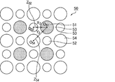
- the exhaust gas discharge cell, the first exhaust gas introduction cell, and the second exhaust gas introduction cell are all preferably circular. Even if the cross-sectional shapes of the exhaust gas discharge cell, the first exhaust gas introduction cell, and the second exhaust gas introduction cell are all circular, the effects and advantages of the present invention can be achieved.
- the cross-sectional shape of the exhaust gas exhaust cell and the second exhaust gas introduction cell is a swollen square composed of four curves curved toward the outside of the cell, while the cross-sectional shape of the first exhaust gas introduction cell is It is desirable that it is a shrinking square composed of four curves that curve inward.
- the exhaust gas exhaust cell since the exhaust gas exhaust cell, the first exhaust gas introduction cell, and the second exhaust gas introduction cell have the above-described configuration, the exhaust gas exhaust cell has a larger cross-sectional area than the first exhaust gas introduction cell.
- the size relationship between the exhaust gas introduction cell and the second exhaust gas introduction cell is also a honeycomb filter having the relationship of the present invention. Therefore, the effects of the present invention can be achieved.
- the cross-sectional area of the second exhaust gas introduction cell is the same as the cross-sectional area of the exhaust gas discharge cell
- the cross-sectional area of the first exhaust gas introduction cell is preferably 20 to 50% of the cross-sectional area of the second exhaust gas introduction cell.
- the cross-sectional area of the first exhaust gas introduction cell When the cross-sectional area of the first exhaust gas introduction cell is less than 20% of the cross-sectional area of the second exhaust gas introduction cell, the cross-sectional area of the first exhaust gas introduction cell becomes too small, and the passage resistance through which the exhaust gas passes through the first exhaust gas introduction cell. Tends to increase and pressure loss tends to increase. On the other hand, if the cross-sectional area of the first exhaust gas introduction cell exceeds 50% of the cross-sectional area of the second exhaust gas introduction cell, the difference in the passage resistance between the two becomes small and it is difficult to reduce the pressure loss.
- the exhaust gas introduction cell includes a first exhaust gas introduction cell and a second exhaust gas introduction cell having a cross-sectional area in a direction perpendicular to the longitudinal direction of the cell larger than the first exhaust gas introduction cell. It is desirable to consist only of types. This is because a smaller number of exhaust gas introduction cells having a smaller cross-sectional area than that of the second exhaust gas introduction cell can increase the effective area as the introduction cell, and allows PM to be deposited thinly and widely.
- the honeycomb filter includes the exhaust gas discharge cell, the first exhaust gas introduction cell, and the second exhaust gas introduction cell, and a plurality of honeycomb fired bodies having outer peripheral walls on the outer periphery have an adhesive layer. It is desirable that it is formed by being bonded via. Even in such a structure formed by bonding a plurality of honeycomb fired bodies through an adhesive layer, the cells constituting one honeycomb fired body have the structure of the present invention. The assembly can also exert the effects of the present invention.
- the honeycomb filter includes the exhaust gas discharge cell, the first exhaust gas introduction cell, and the second exhaust gas introduction cell, and is configured by one honeycomb fired body having an outer peripheral wall on the outer periphery. It is desirable.
- the honeycomb filter is composed of one honeycomb fired body, and the honeycomb fired body can achieve the effects of the present invention.
- the honeycomb filter is composed of a honeycomb fired body, and the honeycomb fired body is preferably composed of silicon carbide or silicon-containing silicon carbide.
- the silicon carbide and the silicon-containing silicon carbide are materials having excellent heat resistance. For this reason, this honeycomb filter is a honeycomb filter having more excellent heat resistance.
- the honeycomb filter is composed of a honeycomb fired body, and the honeycomb fired body is preferably made of cordierite or aluminum titanate.
- the cordierite and aluminum titanate are materials having a low coefficient of thermal expansion. For this reason, this honeycomb filter is a honeycomb filter in which cracks and the like are unlikely to occur even when a large thermal stress is generated during regeneration or the like.
- the porosity of the cell partition wall is preferably 40 to 65%.
- the cell partition wall can trap PM in the exhaust gas well and can suppress an increase in pressure loss due to the cell partition wall. Accordingly, the honeycomb filter has a low initial pressure loss and is unlikely to increase even when PM is deposited.
- the porosity of the cell partition is less than 40%, the ratio of the pores in the cell partition is too small, so that the exhaust gas does not easily pass through the cell partition, and the pressure loss when the exhaust gas passes through the cell partition increases.
- the porosity of the cell partition wall exceeds 65%, the mechanical properties of the cell partition wall are low, and cracks are likely to occur during regeneration.
- the average pore diameter of the pores contained in the cell partition wall is 8 to 25 ⁇ m.
- PM can be collected with high collection efficiency while suppressing an increase in pressure loss.
- the average pore diameter of the pores contained in the cell partition walls is less than 8 ⁇ m, the pores are too small, and the pressure loss when the exhaust gas permeates the cell partition walls increases.
- the average pore diameter of the pores contained in the cell partition wall exceeds 25 ⁇ m, the pore diameter becomes too large, and the PM collection efficiency is lowered.
- the honeycomb filter of the present invention it is desirable that an outer peripheral coat layer is formed on the outer periphery.
- This outer peripheral coat layer plays a role of mechanically protecting internal cells. Therefore, the honeycomb filter is excellent in mechanical properties such as compressive strength.
- the first exhaust gas introduction cell, the second exhaust gas introduction cell, and the exhaust gas exhaust cell are the same in all locations in each cell except for a plugging portion from an end portion on the exhaust gas outlet side to an end portion on the exhaust gas outlet side. It is desirable that the cross-sectional shapes of the first exhaust gas introduction cell and the second exhaust gas introduction cell are different from each other, and the cross-sectional shapes of the exhaust gas discharge cell and the first exhaust gas introduction cell are also different from each other. This difference means that they are not congruent, but similar forms are meant to be included.
- the cross-sectional shapes are similar, the cross-sectional shapes are interpreted as different from each other.
- the first exhaust gas introduction cell itself has the same shape in any cross section
- the second exhaust gas introduction cell and the exhaust gas exhaust cell have the same shape in any cross section.
- the following cell structure is regarded as one cell unit, and the cell unit is arranged around the exhaust gas discharge cell in the cell structure below. It is desirable that the honeycomb filter is configured by repeating two-dimensionally while sharing the introduction cell and the second exhaust gas cell.
- Cell structure The exhaust gas introduction cell is adjacent to the entire periphery of the exhaust gas exhaust cell with a porous cell partition wall, and the exhaust gas introduction cell is perpendicular to the longitudinal direction of the first exhaust gas introduction cell and the cell.
- the cross sectional area of the second exhaust gas introduction cell is larger than the first exhaust gas introduction cell, and the cross sectional area of the cross section perpendicular to the cell longitudinal direction of the exhaust gas exhaust cell is the second exhaust gas introduction cell.
- the cross-sectional area of the cross section perpendicular to the cell longitudinal direction is the same as or larger than the cross-sectional area of the cell, and the exhaust gas exhaust cell and the exhaust gas introduction cell both relate to the cross section perpendicular to the cell longitudinal direction.
- the side that faces the exhaust gas discharge cell is the side that forms the cross-sectional shape of the second exhaust gas introduction cell
- the thickness of the cell partition wall separating the first exhaust gas introduction cell and the exhaust gas exhaust cell is as follows: The cell structure is thinner than the thickness of the cell partition wall separating the second exhaust gas introduction cell and the exhaust gas discharge cell.
- the filter has an outer peripheral wall, and naturally the cell unit does not spread outward from the outer peripheral wall. For this reason, a cell unit receives a defect
- FIG. 1 is an enlarged end view illustrating a part of an end face of a honeycomb filter according to an embodiment of the present invention.
- FIGS. 2A to 2B are scanning electron micrographs (SEM photographs) showing an example of the shape of the cell cross section.
- FIGS. 3A and 3B are scanning electron micrographs (SEM photographs) showing an example of the shape of a cell cross section of a cell different from the cell shown in FIG. 4 (a) to 4 (c) are enlarged end views showing a part of the end face of the honeycomb filter according to the embodiment of the present invention.
- FIG. 5 is a perspective view schematically showing an example of the honeycomb filter according to the first embodiment of the present invention.
- Fig.6 (a) is a perspective view which shows typically an example of the honeycomb fired body which comprises the honeycomb filter shown in FIG.
- FIG. 6B is a cross-sectional view taken along the line AA of the honeycomb fired body shown in FIG.
- FIG. 7 shows that the cell unit (cell structure) is two-dimensionally dimensional when the second exhaust gas introduction cell and the exhaust gas exhaust cell are octagonal and the first exhaust gas introduction cell is square in the cross-sectional shape of the cell. I.e., in the cell longitudinal direction of the honeycomb filter, showing how the first exhaust gas introduction cell and the second exhaust gas cell are shared between the cell units (cell structures) in the X and Y directions. It is an enlarged view of a vertical cross section.
- FIG. 8 (a) is a perspective view showing an example of a modification of the first embodiment of the honeycomb filter of the present invention
- Fig. 8 (b) is a honeycomb firing that constitutes the honeycomb filter shown in Fig. 8 (a).
- It is a perspective view which shows a body typically.
- FIG. 9 is a cross-sectional view schematically showing a pressure loss measuring method.
- FIG. 10 is a graph showing the relationship between the amount of collected PM and the pressure loss measured in Example 1 and Comparative Example 1.
- FIG. 11 (a) is a perspective view schematically showing an example of the integrated honeycomb filter according to the second embodiment of the present invention
- FIG. 11 (b) is a cross-sectional view taken along the line BB of the integrated honeycomb filter.
- FIG. 12 is an enlarged end view schematically showing an example of cell arrangement on the end face of the honeycomb fired body constituting the honeycomb filter according to the third embodiment of the present invention.
- FIG. 13 shows that the cell unit (cell structure) is two-dimensionally, that is, in the X and Y directions when the first exhaust gas introduction cell, the second exhaust gas introduction cell, and the exhaust gas exhaust cell are square in the cross-sectional shape of the cell.
- FIG. 2 is an enlarged view of a cross section perpendicular to the cell longitudinal direction of the honeycomb filter showing how the first exhaust gas introduction cell and the second exhaust gas cell are shared between the cell units (cell structures). is there.
- FIG. 14 is an enlarged end view schematically showing an example of cell arrangement on the end face of the honeycomb fired body constituting the honeycomb filter according to the fourth embodiment of the present invention.
- FIG. 15 is an enlarged end view schematically showing an example of cell arrangement on the end face of the honeycomb fired body constituting the honeycomb filter according to the fifth embodiment of the present invention.
- 16A is a side view schematically showing an example of a swollen square cell shape
- FIG. 16B is a side view schematically showing an example of a contracted square cell shape.
- FIG. 16C is a side view schematically showing an example of a shape chamfered near the apex of the shrinking square
- FIG. 16D is an example of a shape chamfered near the apex of the swollen square. It is a side view which shows typically.
- Fig. 17 (a) is a perspective view schematically showing the honeycomb filter described in Patent Document 1
- Fig. 17 (b) schematically shows a honeycomb fired body constituting the honeycomb filter shown in Fig. 17 (a).
- 17 (c) and 17 (d) are enlarged end views schematically showing the honeycomb filter.
- 18 (a) is a perspective view schematically showing the honeycomb filter described in Patent Document 2
- FIGS. 18 (b) to 18 (c) are enlarged end views schematically showing the honeycomb filter. is there.
- Fig. 17 (a) is a perspective view schematically showing the honeycomb filter described in Patent Document 1
- FIGS. 18 (b) to 18 (c) are enlarged end views schematically showing the honeycomb filter. is there.
- Fig. 17 (a) is a perspective view schematically showing the honeycomb filter described in
- FIG. 19 (a) is a perspective view schematically showing a honeycomb filter according to a comparative example, and Fig. 19 (b) schematically shows a honeycomb fired body constituting the honeycomb filter shown in Fig. 19 (a). It is a perspective view.
- the honeycomb filter according to the first embodiment of the present invention includes an exhaust gas discharge cell in which an end portion on the exhaust gas outlet side is opened and an end portion on the exhaust gas inlet side is plugged, and an end portion on the exhaust gas inlet side is opened and As the exhaust gas introduction cell whose end on the exhaust gas outlet side is plugged, a plurality of honeycomb fired bodies having a first exhaust gas introduction cell and a second exhaust gas introduction cell and having an outer peripheral wall on the outer periphery are interposed via an adhesive layer It is formed by bonding.
- first exhaust gas introduction cell and the second exhaust gas introduction cell are adjacent to each other around the exhaust gas discharge cell with a porous cell partition wall therebetween, Regarding the cross section perpendicular to the longitudinal direction of the cell, the cross-sectional area of the second exhaust gas introduction cell is larger than the cross-sectional area of the first exhaust gas introduction cell, and the cross-sectional area of the exhaust gas exhaust cell is the same as that of the second exhaust gas introduction cell. Is the same as the cross-sectional area, Regarding the cross section perpendicular to the longitudinal direction of the cell, the exhaust gas exhaust cell and the exhaust gas introduction cell are both polygonal and face the exhaust gas exhaust cell among the sides constituting the cross-sectional shape of the first exhaust gas introduction cell.
- the length of the side which is carrying out is longer than the length of the side which has faced the said exhaust gas discharge cell among the sides which comprise the cross-sectional shape of the said 2nd exhaust gas introduction cell.
- the cross-sectional shape perpendicular to the longitudinal direction of the cell the cross-sectional shapes of the exhaust gas introduction cell and the exhaust gas exhaust cell are from the end on the exhaust gas inlet side to the end on the exhaust gas outlet side, except for the plugging portion, respectively. Is the same in all locations in the cell.
- FIG. 5 is a perspective view schematically showing an example of the honeycomb filter according to the first embodiment of the present invention.
- Fig.6 (a) is a perspective view which shows typically an example of the honeycomb fired body which comprises the honeycomb filter shown in FIG.
- FIG. 6B is a cross-sectional view taken along the line AA of the honeycomb fired body shown in FIG.
- honeycomb filter 20 shown in FIG. 5, a plurality of honeycomb fired bodies 10 are bundled through an adhesive layer 15 to form a ceramic block 18, and the outer periphery of the ceramic block 18 is for preventing leakage of exhaust gas.
- the outer peripheral coat layer 16 is formed.
- the outer periphery coating layer 16 should just be formed as needed.
- honeycomb filter formed by binding a plurality of honeycomb fired bodies is also referred to as a collective honeycomb filter.
- the honeycomb fired body 10 has a quadrangular prism shape, but as shown in FIG. 6A, the corners at the end faces are chamfered so as to have a curved shape. Concentrates and prevents damage such as cracks.
- the corner may be chamfered so as to have a linear shape.
- the exhaust gas discharge cell has an end on the exhaust gas outlet side opened and the end on the exhaust gas inlet side is plugged, and the exhaust gas introduction cell has an exhaust gas inlet side.
- the plugging material 11 is preferably the same material as the honeycomb fired body.
- a first exhaust gas introduction cell having a square cross section with a porous cell partition wall is provided around the entire periphery of the exhaust gas exhaust cell 11 having an octagonal cross section. 12 and the second exhaust gas introduction cell 14 having an octagonal cross section are adjacent to each other.
- the first exhaust gas introduction cell 12 and the second exhaust gas introduction cell 14 are alternately arranged around the exhaust gas discharge cell 11, and the sectional area of the second exhaust gas introduction cell 14 is larger than the sectional area of the first exhaust gas introduction cell 12.
- the cross-sectional area of the exhaust gas discharge cell 11 is the same as the cross-sectional area of the second exhaust gas introduction cell 14.
- An outer peripheral wall 17 is formed on the outer periphery of the honeycomb fired body 10.
- the cross-sectional shapes of the second exhaust gas introduction cell 14 and the exhaust gas discharge cell 11 are both octagons and are congruent with each other.
- the exhaust gas discharge cell 11 and the second exhaust gas introduction cell 14 have the same octagonal shape, but this octagon is point-symmetric with respect to the center of gravity, and the hypotenuse (shown as 14a in FIG. 4).
- octagons having the same length and horizontal and vertical sides (indicated by 14b in FIG. 4), and the four first sides (the oblique sides) and the four second sides. (Vertical and horizontal sides) are alternately arranged, and the angle formed by the first side and the second side is 135 °.
- the “slope side” generally refers to a longer side opposite to the right angle of a right triangle, but in this specification, for the convenience of explanation, the hypothetical side includes four hypothetical line segments described below.
- the side 14a and the side 11b having a predetermined angle that is not 90 ° or 0 ° are expressed as “slopes”.
- the side 14b and the side 11a that are parallel or perpendicular to the four virtual line segments described below are expressed as "longitudinal and lateral sides”.
- the hypothetical line segments in the description of “slanted side” and “longitudinal and lateral sides” connect between the geometric gravity centers of the cross-sectional figures of the four second exhaust gas introduction cells 14 arranged around the exhaust gas discharge cell 11.
- four line segments that do not intersect with the cross-sectional shape of the exhaust gas discharge cell 11 are meant.
- the first exhaust gas introduction cell 12 has a square cross-sectional shape. Further, regarding the cross-sectional shapes of the three adjacent cells, that is, the exhaust gas discharge cell 11, the second exhaust gas introduction cell 14, and the first exhaust gas introduction cell 12, the cell partition wall 13 is separated at the side of the octagonal exhaust gas discharge cell 11. Thus, the side 11a facing the first exhaust gas introduction cell 12 and the side 12a facing the exhaust gas discharge cell 11 across the cell partition wall 13 are parallel to the side of the square first exhaust gas introduction cell 12.
- the cell partition wall The side 14 a facing the exhaust gas discharge cell 11 across 13 is parallel.
- the side of the first exhaust gas introduction cell 12 faces the second exhaust gas introduction cell 14 across the cell partition wall 13 and the side of the second exhaust gas introduction cell 14 separates the cell partition wall 13 and the first exhaust gas.
- the side 14b facing the introduction cell 12 is parallel.
- the distance between the sides parallel to each other is equal to each other in any combination. That is, the distance between the sides 11a and 12a parallel to each other, the distance between the sides 11b and 14a parallel to each other, and the distance between the sides 12b and 14b parallel to each other are equal to each other.
- the exhaust gas discharge cell 11, the first exhaust gas introduction cell 12, and the second exhaust gas introduction cell 14 are arranged so as to satisfy the following conditions, respectively. That is, it passes through the octagonal graphic region of the exhaust gas exhaust cell 11 among the virtual line segments connecting the geometric centers of gravity of the octagonal graphics of the four second exhaust gas introduction cells 14 surrounding the exhaust gas exhaust cell 11.
- the imaginary line segments connecting the geometric centers of gravity of the octagonal figures of the four second exhaust gas introduction cells 14 four that do not pass through the octagonal figure area of the exhaust gas discharge cells 11 constitute a square.
- the middle point of each side coincides with the geometric gravity center of the square shape of the four first exhaust gas introduction cells 12 surrounding the exhaust gas discharge cell 11.
- first exhaust gas introduction cells 12 and four octagonal second exhaust gas introduction cells 14 are alternately arranged around the octagonal exhaust gas discharge cells 11 with the cell partition wall 13 therebetween, and the exhaust gas is discharged.
- the structure surrounding the discharge cell 11 is regarded as one unit, and this unit repeatedly arranges two-dimensionally to form a honeycomb filter while sharing the first exhaust gas introduction cell 12 and the second exhaust gas introduction cell 14 with each other. It is. Since each unit shares the first exhaust gas introduction cell 12 and the second exhaust gas introduction cell 14 with each other, the first exhaust gas introduction cell 12 and the second exhaust gas which are in contact with each other with the exhaust gas exhaust cell 11 and the cell partition wall 13 therebetween.
- the introduction cell 14 is in contact with the exhaust gas discharge cell 11 and the cell partition wall 13 in an adjacent unit.
- FIG. 7 is a cross-sectional shape of the cell, where the second exhaust gas introduction cell 14 and the exhaust gas discharge cell 11 are octagonal, the first exhaust gas introduction cell 12 is square, and the arrangement satisfies the above-described conditions.
- the cell unit (cell structure) repeats two-dimensionally, that is, in the X and Y directions described in FIG. 7, the first exhaust gas introduction cell 12 and the second exhaust gas cell 14 are between the cell units (cell structure). It is an enlarged view of a cross section perpendicular
- the cell unit 1, the cell unit 2, and the cell unit 3 all have the first exhaust gas introduction cell 12 and the second exhaust gas introduction cell 14 through the cell partition wall 13 around the exhaust gas exhaust cell 11 so as to satisfy the conditions described above. 4 are alternately arranged.
- the cell unit 2 has the same structure as the cell unit 1, and is adjacent to the X direction sharing the cell unit 1, one first exhaust gas introduction cell 12 and two second exhaust gas introduction cells 14. A cell shared by the cell unit 1 and the cell unit 2 is described as “shared part 2” in FIG.
- the unit cell 3 has the same structure as the cell unit 1 and shares the cell unit 1 with one first exhaust gas introduction cell 12 and two second exhaust gas introduction cells 14 and is adjacent to the Y direction. .
- a cell shared by the cell unit 1 and the cell unit 3 is described as “shared portion 1” in FIG.
- the virtual line segments connecting the geometric centers of the octagonal figures of the four second exhaust gas introduction cells 14 four line segments H and I that do not pass through the octagonal graphic area of the exhaust gas discharge cell 11.
- J, K, and two virtual line segments L and M passing through the octagonal graphic region of the exhaust gas discharge cell 11 are shown in FIG.
- the “shared part 2” is drawn by hatching consisting of line segments in the same direction as the line segment M
- the “shared part 1” is drawn by hatching consisting of line segments in the same direction as the line segment L.
- the intersection of the two line segments L and M coincides with the geometric center of gravity of the exhaust gas discharge cell 11.
- the cross sections of the exhaust gas exhaust cell 11 and the second exhaust gas introduction cell 14 are octagonal, and the cross section of the first exhaust gas introduction cell 12 is square.
- the cross-sectional shape of the exhaust gas exhaust cell and the exhaust gas introduction cell constituting the honeycomb filter of the invention is not limited to the above shape, and may be all square as described below, or a combination of other polygons. .
- angular part of the exhaust gas exhaust cell 11, the 1st exhaust gas introduction cell 12, and the 2nd exhaust gas introduction cell 14 of a cell with such a polygonal cross section may be a curve chamfering shape where a cross section becomes a curve.
- the curve include a curve obtained when a circle is divided into four equal parts, a curve obtained when an ellipse is divided into four equal parts by a straight line perpendicular to the major axis and the major axis, and the like.
- the cross section has a curved chamfered shape in which a cross section becomes a curve at a corner of a square cell. It is because it can prevent that a crack enters into a cell partition because stress concentrates on a corner.
- the honeycomb filter 20 may include a part of cells having a curved cross section as necessary.
- the cross-sectional area of the first exhaust gas introduction cell 12 is preferably 20 to 50%, more preferably 22 to 45% of the cross-sectional area of the second exhaust gas introduction cell 14.
- the cross-sectional area of the exhaust gas discharge cell 11 is the same as the cross-sectional area of the second exhaust gas introduction cell 14, but the cross-sectional area of the exhaust gas discharge cell 11 is the same as the second exhaust gas introduction cell.
- the cross-sectional area may be larger than 14. In that case, the cross-sectional area of the exhaust gas discharge cell 11 is preferably 1.05 to 1.5 times the cross-sectional area of the second exhaust gas introduction cell 14.
- the length of the side 12a facing the exhaust gas discharge cell 11 is the side constituting the cross-sectional shape of the second exhaust gas introduction cell 14, It is longer than the length of the side 14 a facing the exhaust gas discharge cell 11. According to the definition of the present invention described above, the sides 12 a and 14 a are sides facing the exhaust gas discharge cell 11.
- the ratio of the length of the side 14a of the second exhaust gas introduction cell 14 to the length of the side 12a of the first exhaust gas introduction cell 12 is not particularly limited. 0.8 or less, more preferably 0.7 or less, and even more preferably 0.5 or less.
- the exhaust gas G 1 flowing into the first exhaust gas introduction cell 12 or the second exhaust gas introduction cell 14 (in FIG. 6B, the exhaust gas is indicated by G 1 , and the flow of the exhaust gas is indicated by an arrow. Is always discharged from the exhaust gas discharge cell 11 after passing through the cell partition wall 13 that separates the exhaust gas discharge cell 11 from the first exhaust gas introduction cell 12 or the second exhaust gas introduction cell 14.
- the cell partition wall 13 functions as a filter.
- the exhaust gas discharge cell 11, the first exhaust gas introduction cell 12, and the second exhaust gas introduction cell 14 can circulate gas such as exhaust gas.
- gas such as exhaust gas.
- the end of the honeycomb fired body 10 on the first end face 10a side (the end on the side where the exhaust gas discharge cells 11 are plugged) is the exhaust gas inlet side.
- the end of the honeycomb fired body 10 on the second end face 10b side (the end on the side where the first exhaust gas introduction cell 12 and the second exhaust gas introduction cell 14 are plugged) is the exhaust gas outlet side. The end of the.
- the initial pressure loss can be made lower than that of the conventional honeycomb filter, and a considerable amount of PM can be obtained. Even at the stage of depositing on the cell partition wall, the rate of increase in pressure loss is small, and the pressure loss can be greatly improved over the entire use range from the initial stage until PM is deposited in an amount close to the limit.
- the honeycomb filter 20 is composed of a plurality of honeycomb fired bodies 10, and examples of the constituent material of the honeycomb fired body 10 include carbides such as silicon carbide, titanium carbide, tantalum carbide, and tungsten carbide.
- carbides such as silicon carbide, titanium carbide, tantalum carbide, and tungsten carbide.
- examples thereof include nitride ceramics such as ceramic, aluminum nitride, silicon nitride, boron nitride, and titanium nitride, and oxide ceramics such as alumina, zirconia, cordierite, mullite, aluminum titanate, and silicon-containing silicon carbide.
- silicon carbide or silicon-containing silicon carbide is preferable. It is because it is excellent in heat resistance, mechanical strength, thermal conductivity and the like.
- the silicon-containing silicon carbide is a mixture of silicon carbide and metal silicon, and silicon-containing silicon carbide containing 60 wt% or more of silicon carbide is preferable.
- the thickness of the cell partition walls that separate the cells of the honeycomb fired body 10 constituting the honeycomb filter 20 according to the first embodiment is desirably equal in all places.
- the thickness of the cell partition wall is preferably 0.10 to 0.46 mm, more preferably 0.15 to 0.31 mm.
- the thickness of the outer peripheral wall 17 is preferably 0.10 to 0.50 mm.
- the thickness of a cell partition is the value measured as thickness D shown in FIG. 1 based on an above-described definition.
- the porosity of the cell partition walls and the outer peripheral wall of the honeycomb fired body 10 constituting the honeycomb filter 20 according to the first embodiment is preferably 40 to 65%.
- the average pore diameter of the pores contained in the cell partition walls of the honeycomb fired body 10 constituting the honeycomb filter 20 according to the first embodiment is preferably 8 to 25 ⁇ m.
- the number of cells per unit area in the cross section of the honeycomb fired body 10 is desirably 31 to 62 cells / cm 2 (200 to 400 cells / inch 2 ).
- honeycomb filter 20 a plurality of honeycomb fired bodies having outer peripheral walls on the outer periphery are bonded together through an adhesive layer.
- the adhesive for bonding the honeycomb fired body is obtained by applying and drying an adhesive paste containing an inorganic binder and inorganic particles.
- the adhesive may further contain inorganic fibers and / or whiskers.
- the thickness of the adhesive layer is preferably 0.5 to 2.0 mm.
- the outer peripheral coat layer may be provided on the outer periphery of the honeycomb filter, but the material of the outer peripheral coat layer is preferably the same as the material of the adhesive.
- the thickness of the outer peripheral coat layer is preferably 0.1 to 3.0 mm.
- a forming step of producing a honeycomb formed body by extruding a wet mixture containing a ceramic powder and a binder is performed. Specifically, first, a wet mixture for manufacturing a honeycomb formed body is prepared by mixing silicon carbide powder having different average particle sizes as ceramic powder, an organic binder, a liquid plasticizer, a lubricant, and water. To prepare.
- a pore-forming agent such as balloons that are fine hollow spheres containing oxide ceramics, spherical acrylic particles, and graphite may be added to the wet mixture.
- the balloon is not particularly limited, and examples thereof include an alumina balloon, a glass micro balloon, a shirasu balloon, a fly ash balloon (FA balloon), and a mullite balloon. Of these, alumina balloons are desirable.
- a honeycomb formed body having a predetermined shape.
- a honeycomb formed body is manufactured using a mold that has a cross-sectional shape having the cell structure (cell shape and cell arrangement) shown in FIGS.
- the honeycomb formed body is cut to a predetermined length, dried using a microwave dryer, hot air dryer, dielectric dryer, vacuum dryer, vacuum dryer, freeze dryer, etc.
- a plugging step is performed in which the cells are plugged by filling the cells with a plug material paste as a plug.
- the wet mixture can be used as the sealing material paste.
- the honeycomb formed body is heated to 300 to 650 ° C. in a degreasing furnace, and after performing a degreasing process for removing organic substances in the honeycomb formed body, the degreased honeycomb formed body is conveyed to a firing furnace, and 2000 to By performing a firing step of heating to 2200 ° C., a honeycomb fired body as shown in FIGS. 4 to 6 is manufactured.
- the sealing material paste with which the edge part of the cell was filled is baked and becomes a plugging material.
- the conditions conventionally used when manufacturing a honeycomb fired body can be applied to the cutting process, drying process, plugging process, degreasing process, and firing process.
- a bundling process is performed in which a plurality of honeycomb fired bodies are sequentially stacked and bonded via an adhesive paste on a support stand to produce a honeycomb aggregate in which a plurality of honeycomb fired bodies are stacked.
- the adhesive paste for example, a paste made of an inorganic binder, an organic binder, and inorganic particles is used.
- the adhesive paste may further contain inorganic fibers and / or whiskers.
- Examples of the inorganic particles contained in the adhesive paste include carbide particles and nitride particles. Specific examples include silicon carbide particles, silicon nitride particles, and boron nitride particles. These may be used alone or in combination of two or more. Among the inorganic particles, silicon carbide particles having excellent thermal conductivity are desirable.
- Examples of the inorganic fibers and / or whiskers contained in the adhesive paste include inorganic fibers and / or whiskers made of silica-alumina, mullite, alumina, silica, and the like. These may be used alone or in combination of two or more. Among inorganic fibers, alumina fiber is desirable.
- the inorganic fiber may be a biosoluble fiber.
- the balloon which is a micro hollow sphere which uses an oxide type ceramic as a component, spherical acrylic particle, graphite, etc.
- the balloon is not particularly limited, and examples thereof include an alumina balloon, a glass micro balloon, a shirasu balloon, a fly ash balloon (FA balloon), and a mullite balloon.
- the adhesive paste is heated and solidified to form an adhesive layer, and a square columnar ceramic block is produced.
- the conditions for heating and solidifying the adhesive paste the conditions conventionally used when producing a honeycomb filter can be applied.
- a cutting process for cutting the ceramic block is performed. Specifically, a ceramic block whose outer periphery is processed into a substantially cylindrical shape is manufactured by cutting the outer periphery of the ceramic block using a diamond cutter.
- An outer peripheral coating layer forming step is performed in which an outer peripheral coating material paste is applied to the outer peripheral surface of the substantially cylindrical ceramic block, and dried and solidified to form an outer peripheral coating layer.
- the said adhesive paste can be used as an outer periphery coating material paste.
- the outer peripheral coat layer is not necessarily provided, and may be provided as necessary.
- a honeycomb filter having a predetermined shape was manufactured by performing a cutting process.
- a honeycomb fired body having a plurality of shapes having an outer peripheral wall on the entire outer periphery was manufactured.
- a honeycomb fired body having a shape may be combined with an adhesive layer to form a predetermined shape such as a cylinder. In this case, the cutting process can be omitted.
- the initial pressure loss can be made lower than that of the conventional honeycomb filter, and the increase rate of the pressure loss even when a considerable amount of PM is deposited on the cell partition walls.
- the pressure loss can be greatly improved over the entire use range from the initial stage until PM is deposited in an amount close to the limit.
- the cross-sectional area of the first exhaust gas introduction cell can be 20 to 50% of the cross-sectional area of the second exhaust gas introduction cell.
- the ratio of the side length of the second exhaust gas introduction cell to the length of the side of the first exhaust gas introduction cell can be 0.8 or less.
- the constituent material of the honeycomb fired body can be silicon carbide or silicon-containing silicon carbide, and the honeycomb filter can be excellent in heat resistance.
- the thickness of the cell partition walls that separate the cells can be made equal at all locations.
- the thickness of the cell partition wall can be set to 0.10 to 0.46 mm.
- the cell partition wall has a sufficient thickness to collect PM in the exhaust gas, and an increase in pressure loss can be effectively suppressed.
- the porosity of the cell partition walls and the outer peripheral wall constituting the honeycomb filter 20 can be 40 to 65%.
- the cell partition can capture PM in the exhaust gas well, and can suppress an increase in pressure loss caused by the cell partition.
- the average pore diameter of the pores contained in the cell partition walls of the honeycomb fired body constituting the honeycomb filter can be 8 to 25 ⁇ m.
- the cross-sectional shapes of the exhaust gas introduction cell and the exhaust gas discharge cell are the above from the end on the exhaust gas inlet side except for the plugging portion. It is the same at all locations in each cell from the end on the exhaust gas outlet side. Therefore, the same effect can be obtained with the entire honeycomb filter, and the occurrence of inconvenience due to non-uniform shape depending on the location of the honeycomb filter can be prevented.
- the sealing portion provided at the end portion on the exhaust gas outlet side that is, the sealing portion filled in the first exhaust gas introduction cell and the second exhaust gas introduction cell is connected to the first through the cell partition wall.
- Exhaust gas introduction cell exists in rows and columns with a width greater than the length of one side.
- the outlet side of the honeycomb filter is exposed to a higher temperature, and a temperature difference in the radial direction of the honeycomb filter is likely to occur, and cracks are generated due to thermal stress.
- a crack has a large and small relationship in the cross-sectional area of the cell, and stress concentration tends to occur when the cross-sectional shape of the exhaust gas introduction cell on which PM is deposited includes a square.
- the sealing portions arranged in rows and columns at the end portion on the exhaust gas outlet side become the heat conduction layer and the heat radiation layer to the outside, and the radial direction at the end portion on the exhaust gas outlet side of the honeycomb filter The temperature difference can be reduced, the generated thermal stress is reduced, and cracks are less likely to occur.
- the honeycomb filter of the present embodiment the amount of the sealing material filled in the second exhaust gas introduction cell in which more PM is deposited than the first exhaust gas introduction cell increases according to the cross-sectional area, and the sealing is performed accordingly.
- the heat capacity of the part is also increasing. Therefore, with this sealing portion, even if considered in units of cells, it is possible to suppress the temperature rise of the second exhaust gas introduction cell where the combustion heat of PM is larger, and to reduce the temperature difference in the radial direction of the honeycomb filter, It is thought that the generated thermal stress can be reduced. For this reason, it is considered that the honeycomb filter of the present embodiment can suppress cracks during regeneration even if the exhaust gas introduction cell includes a square as a cross-sectional shape.
- Fig. 8 (a) is a perspective view showing an example of a modification of the first embodiment of the honeycomb filter according to the present invention
- Fig. 8 (b) is a honeycomb constituting the honeycomb filter shown in Fig. 8 (a). It is a perspective view which shows a sintered body typically.
- the entire cross section of the exhaust gas discharge cell 11 having an octagonal cross section is square with a porous cell partition wall therebetween.
- the first exhaust gas introduction cell 12 and the second exhaust gas introduction cell 14 having an octagonal cross section are adjacent to each other.
- the first exhaust gas introduction cell 12 and the second exhaust gas introduction cell 14 are alternately arranged around the exhaust gas discharge cell 11, and the sectional area of the second exhaust gas introduction cell 14 is larger than the sectional area of the first exhaust gas introduction cell 12.
- the cross-sectional area of the exhaust gas discharge cell 11 is the same as the cross-sectional area of the second exhaust gas introduction cell 14.
- An outer peripheral wall 17a is formed on the outer periphery of the honeycomb fired body 10a, and all the cells adjacent to the outer peripheral wall 17a are exhaust gas introduction cells (the first exhaust gas introduction cell 12 and the second exhaust gas introduction cell 14). It has become.
- the cross-sectional shapes of the second exhaust gas introduction cell 14 and the exhaust gas discharge cell 11 are both octagons and are congruent with each other.
- the outer peripheral wall 17a of the exhaust gas introduction cell adjacent to the outer peripheral wall 17a in the cross section perpendicular to the longitudinal direction of the cell is formed so that the thickness of the outer peripheral wall 17a other than the corners is uniform.
- the side that contacts is formed in parallel and linearly with the side that forms the outer wall of the outer peripheral wall 17a.
- the cross section of the second exhaust gas introduction cell 14A closest to the outer peripheral wall 17a is partially cut, it changes from an octagon to a hexagon.
- the cross-sectional shape of the first exhaust gas introduction cell 12A may be a partially cut shape, but is preferably congruent with the cross-sectional shape of the first exhaust gas introduction cell 12.
- the second exhaust gas introduction cell 14B existing at the corner of the honeycomb fired body 10a is changed from an octagon to a substantially pentagon having a chamfered portion 140 made of a curve.
- the strength of the honeycomb fired body is improved by the outer peripheral wall, and the partial variation in the volume ratio of the exhaust gas discharge cell and the exhaust gas introduction cell in the honeycomb fired body is further suppressed, and the flow of the exhaust gas is further increased. Since it becomes uniform, pressure loss can be reduced.
- Example 1 Example 1
- a silicon carbide coarse powder of 52.8% by weight having an average particle size of 22 ⁇ m and a silicon carbide fine powder of 22.6% by weight of an average particle size of 0.5 ⁇ m were mixed, and the resulting mixture was mixed with an organic binder.
- (Methylcellulose) 4.6% by weight, lubricant (Unilube manufactured by NOF Corporation) 0.8% by weight, glycerin 1.3% by weight, pore former (acrylic resin) 1.9% by weight, oleic acid 2. 8% by weight and 13.2% by weight of water were added and kneaded to obtain a wet mixture, followed by a molding step of extrusion molding. In this step, a raw honeycomb molded body having the same shape as the honeycomb fired body 10a shown in FIG. 8A and having no cell plugged was produced.
- the dried honeycomb molded body was produced by drying the raw honeycomb molded body using a microwave dryer. Thereafter, the plugging paste was filled in predetermined cells of the dried honeycomb molded body to plug the cells. Specifically, the cells were plugged such that the end on the exhaust gas inlet side and the end on the exhaust gas outlet side were plugged at the positions shown in FIG. The wet mixture was used as a sealing material paste. After plugging the cells, the dried honeycomb molded body filled with the plug paste was dried again using a dryer.
- a degreasing treatment was performed by degreasing the dried honeycomb molded body on which the cells were plugged at 400 ° C., and further, a firing treatment was performed under conditions of 2200 ° C. and 3 hours in an atmospheric argon atmosphere. Thereby, a square pillar honeycomb fired body was produced.
- the side length and cross-sectional area are measured using the previously described electron micrograph and image analysis type particle size distribution software (manufactured by Mountech Co., Ltd.) MAC-View (Version 3.5). be able to.
- the manufactured honeycomb fired body has a porosity of 45%, an average pore diameter of 15 ⁇ m, a size of 34.3 mm ⁇ 34.3 mm ⁇ 150 mm, and the number of cells (cell density) of 290 cells / inch 2 (in the honeycomb fired body). The number of cells is 529), the honeycomb fired body shown in FIG. 8 (b) is made of a silicon carbide sintered body having a cell partition wall thickness of 0.25 mm (10 mil) and an outermost peripheral wall thickness of 0.35 mm. It was body 10a.
- the first exhaust gas introduction cells 12, 12A and the second exhaust gas introduction cells 14, 14A, 14B were adjacent to the entire periphery of the exhaust gas exhaust cell 11. .
- the first exhaust gas introduction cells 12 and 12A are square, and the length of the side constituting the cross-sectional shape of the first exhaust gas introduction cells 12 and 12A is 0.96 mm.
- the second exhaust gas introduction cell 14 is octagonal except for the second exhaust gas introduction cells 14A and 14B adjacent to the outer peripheral wall 17, and the length of the hypotenuse that is the side facing the exhaust gas discharge cell is 0.27 mm. Yes, the length of the vertical and horizontal sides not facing the exhaust gas discharge cell 11 was 1.11 mm.
- the length of the side facing the exhaust gas discharge cell 11 is the exhaust gas length among the sides constituting the cross-sectional shape of the first exhaust gas introduction cell 12.
- the length of the side facing the discharge cell 11 was 0.28 times.
- the length of the side adjacent to the outer peripheral wall 17 is 1.23 mm
- the length of the vertical and horizontal sides is 1.04 mm
- the length of the hypotenuse was 0.27 mm and the cross-sectional area was 1.48 mm 2 .
- the length of the side adjacent to the outer peripheral wall 17 is 1.49 mm, and the length of the vertical side parallel to the side adjacent to the outer peripheral wall 17 is 1.11 mm.
- the length of the side that is perpendicular to the side adjacent to the outer peripheral wall 17 is 1.04 mm, the length of the hypotenuse is 0.27 mm, and the cross-sectional area is 1.79 mm 2. Met.
- the exhaust gas discharge cell 11 has an octagonal shape, the shape thereof is the same as that of the second exhaust gas introduction cell 14, the length of the hypotenuse facing the second exhaust gas introduction cell 14 is 0.27 mm, and the first exhaust gas The length of the vertical and horizontal sides facing the introduction cell 12 was 1.11 mm.
- the cross-sectional area of the first exhaust gas introduction cell 12 was 0.93 mm 2
- the cross-sectional areas of the second exhaust gas introduction cell 14 and the exhaust gas discharge cell 11 were both 2.17 mm 2 . That is, the cross-sectional area of the first exhaust gas introduction cell 12 was 43% of the cross-sectional area of the second exhaust gas introduction cell 14.
- the cross-sectional area of the exhaust gas discharge cell 11 is the same as the cross-sectional area of the second exhaust gas introduction cell 14 and is larger than the cross-sectional area of the first exhaust gas introduction cell 12.
- honeycomb fired body had a quadrangular prism shape that was chamfered so that the corners at the end face had a curved shape.
- alumina fibers having an average fiber length of 20 ⁇ m, 21% by weight of silicon carbide particles having an average particle diameter of 0.6 ⁇ m, 15% by weight of silica sol, 5.6% by weight of carboxymethylcellulose, and 28.4% by weight of water were added.
- a number of honeycomb fired bodies were bundled using the heat-resistant adhesive paste contained, and the adhesive paste was dried and solidified at 120 ° C. to form an adhesive layer, thereby producing a prismatic ceramic block.
- a substantially cylindrical ceramic block was produced by cutting the outer periphery of the prismatic ceramic block using a diamond cutter.
- a sealing material paste having the same composition as the adhesive paste is applied to the outer peripheral surface of the ceramic block, and the outer peripheral coating layer is formed by drying and solidifying the sealing material paste at 120 ° C., thereby forming a cylindrical honeycomb filter.
- the honeycomb filter had a diameter of 143.8 mm and a length in the longitudinal direction of 150 mm.
- Example 1 A forming process was performed in the same manner as in Example 1 to obtain a raw honeycomb formed body, and then the raw honeycomb formed body was dried using a microwave dryer to prepare a dried body of the honeycomb formed body. . Thereafter, the plugging paste was filled in predetermined cells of the dried honeycomb molded body to plug the cells.
- the position for plugging the cells is changed from that in Example 1, and the end face serving as the end on the exhaust gas outlet side plugs all of the octagonal cells, and the end face serving as the end on the exhaust gas inlet side. Then, all of the square cells were plugged so that the cells were alternately plugged on both end faces.
- Example 1 As a result, an end portion on the exhaust gas inlet side and an end portion on the exhaust gas outlet side were plugged at the positions shown in FIG. Thereafter, the same process as in Example 1 was performed to produce a honeycomb fired body 130 shown in FIGS. 19A and 19B, and a honeycomb filter 120 was produced.
- the exhaust gas introduction cells 132 were all octagonal except for the exhaust gas introduction cells 132A and 132B adjacent to the outer peripheral wall 137.
- the side facing the exhaust gas discharge cell 131 was a vertical and horizontal side, and its length was 1.11 mm.
- the side facing the other exhaust gas introduction cells 132, 132A, 132B is a hypotenuse, and its length was 0.27 mm.
- the exhaust gas exhaust cells 131 and 131A were all square, and the length of the side constituting the cross-sectional shape of the exhaust gas exhaust cells 131 and 131A was 0.96 mm.
- the length of the side adjacent to the outer peripheral wall 137 is 1.23 mm
- the length of the vertical and horizontal sides is 1.04 mm
- the length of the oblique side is The cross-sectional area was 0.28 mm and the cross-sectional area was 1.48 mm 2 .
- the length of the side adjacent to the outer peripheral wall 137 is 1.49 mm
- the length of the vertical side parallel to the side adjacent to the outer peripheral wall 17 is 1.11 mm.
- the length of the side that is perpendicular to the side adjacent to the outer peripheral wall 17 is 1.04 mm, the length of the hypotenuse is 0.27 mm, and the cross-sectional area is 1.79 mm 2. It was. Moreover, the thickness of the cell partition wall 133 was 0.25 mm, and the thickness of the outer peripheral wall was 0.35 mm.
- the cross-sectional area of the exhaust gas introduction cell 132 was 2.17 mm 2 , and the cross-sectional area of the exhaust gas discharge cell 131 was 0.93 mm 2 . That is, the cross-sectional area of the exhaust gas introduction cell 132 was larger than the cross-sectional area of the exhaust gas discharge cell 131.
- FIG. 9 is a cross-sectional view schematically showing a pressure loss measuring method.
- This pressure loss measuring device 210 is arranged to fix the honeycomb filter 20 in the metal casing 213 to the exhaust gas pipe 212 of the 1.6 liter diesel engine 211 so that the pressure before and after the honeycomb filter 20 can be detected.
- the pressure gauge 214 is attached so that.
- the end of the exhaust gas inlet side of the honeycomb filter 20 is disposed on the side close to the exhaust gas pipe 212 of the diesel engine 211.
- the exhaust gas is arranged so that the exhaust gas flows into a cell having an open end on the exhaust gas inlet side.
- the diesel engine 211 was operated at a rotational speed of 3100 rpm and a torque of 50 Nm, and exhaust gas from the diesel engine 211 was circulated through the honeycomb filter 20 to collect PM in the honeycomb filter. Then, the relationship between the amount of collected PM (g / L) per liter apparent volume of the honeycomb filter and the pressure loss (kPa) was measured.
- FIG. 10 is a graph showing the relationship between the amount of collected PM and the pressure loss measured in Example 1 and Comparative Example 1. From this result, in the honeycomb filter according to Example 1, the initial pressure loss, which is the pressure loss when the amount of PM trapped was 0 g / L, was as low as 1.1 kPa, and PM was further collected up to 8 g / L. Even in this case, the pressure loss is as low as 6.6 kPa, and the PM collection amount is significantly lower than that of the honeycomb filter according to Comparative Example 1 at all time points from 0 g / L to 8 g / L. The effect was shown.
- the initial pressure loss which is the pressure loss when the amount of PM trapped was 0 g / L
- PM was further collected up to 8 g / L.
- the pressure loss is as low as 6.6 kPa
- the PM collection amount is significantly lower than that of the honeycomb filter according to Comparative Example 1 at all time points from 0 g / L to 8 g / L.
- the initial pressure loss which is the pressure loss when the amount of collected PM is 0 g / L, is 1.3 kPa, and the pressure loss when PM is collected up to 8 g / L. Is 7.2 kPa.
- the honeycomb filter according to the second embodiment includes an exhaust gas discharge cell having an end portion on the exhaust gas outlet side and an end portion on the exhaust gas inlet side plugged, an end portion on the exhaust gas inlet side, and an exhaust gas outlet side.
- an exhaust gas introduction cell whose end is plugged, the first exhaust gas introduction cell and the second exhaust gas introduction cell are provided, and one honeycomb fired body having an outer peripheral wall on the outer periphery is formed.
- first exhaust gas introduction cell and the second exhaust gas introduction cell are adjacent to each other around the exhaust gas discharge cell with a porous cell partition wall therebetween, Regarding the cross section perpendicular to the longitudinal direction of the cell, the cross-sectional area of the second exhaust gas introduction cell is larger than the cross-sectional area of the first exhaust gas introduction cell, and the cross-sectional area of the exhaust gas exhaust cell is the same as that of the second exhaust gas introduction cell. Is the same as the cross-sectional area, Regarding the cross section perpendicular to the longitudinal direction of the cell, the exhaust gas exhaust cell and the exhaust gas introduction cell are both polygonal and face the exhaust gas exhaust cell among the sides constituting the cross-sectional shape of the first exhaust gas introduction cell.
- the length of the side which is carrying out is longer than the length of the side which has faced the said exhaust gas discharge cell among the sides which comprise the cross-sectional shape of the said 2nd exhaust gas introduction cell.
- the cross-sectional shape perpendicular to the longitudinal direction of the cell the cross-sectional shapes of the exhaust gas introduction cell and the exhaust gas exhaust cell are from the end on the exhaust gas inlet side to the end on the exhaust gas outlet side, except for the plugging portion, respectively. Is the same in all locations in the cell.
- the honeycomb filter according to the second embodiment is different from the aggregated honeycomb filter according to the first embodiment, except that the honeycomb filter is configured by one honeycomb fired body having an outer peripheral wall on the outer periphery.
- the configuration is the same as the honeycomb filter.
- Such a honeycomb filter constituted by one honeycomb fired body is also referred to as an integral honeycomb filter.
- FIG. 11 (a) is a perspective view schematically showing an example of the integrated honeycomb filter according to the second embodiment of the present invention
- FIG. 11 (b) is a cross-sectional view taken along the line BB of the integrated honeycomb filter.
- the first exhaust gas introduction cell 32 having a square cross section with a porous cell partition wall is provided around the entire periphery of the exhaust gas exhaust cell 31 having an octagonal cross section. Is adjacent to the octagonal second exhaust gas introduction cell 34.
- the first exhaust gas introduction cell 32 and the second exhaust gas introduction cell 34 are alternately arranged around the exhaust gas discharge cell 31, and the cross-sectional area of the second exhaust gas introduction cell 34 is larger than the cross-sectional area of the first exhaust gas introduction cell 32.
- the cross-sectional area of the exhaust gas discharge cell 31 is the same as the cross-sectional area of the second exhaust gas introduction cell 34.
- the length of the side 32a facing the exhaust gas discharge cell 31 is the side constituting the cross-sectional shape of the second exhaust gas introduction cell 34. It is longer than the length of the side 34 a facing the exhaust gas discharge cell 11.
- the honeycomb filter 30 according to the present embodiment is composed of one honeycomb fired body, and an outer peripheral wall 37 is formed on the outer periphery.
- a material constituting the honeycomb filter 30 according to the present embodiment cordierite and aluminum titanate are preferable. Since these materials have a low coefficient of thermal expansion, cracks and the like due to thermal stress generated at the time of regeneration or the like hardly occur even in a large honeycomb filter. Since the contents of the embodiment other than the contents described above are the same as the contents described in the first embodiment, the description thereof is omitted here.
- the honeycomb filter 30 of the present embodiment is the same method as that described in the first embodiment of the present invention except that the honeycomb fired body manufactured in the first embodiment is used as it is or an outer peripheral coat layer is formed on the outer periphery. Can be used. Therefore, when the honeycomb filter manufacturing method according to the first embodiment of the present invention does not require the steps (4), (5), and (6) and the outer peripheral coat layer is not formed, the step (7) is performed. It is not necessary.
- the honeycomb filter 30 according to the present embodiment is the same as the honeycomb filter 20 according to the first embodiment because the basic cell arrangement, shape, plugging mode, and the like are described in the first embodiment (1 ) To (10), the same actions and effects can be achieved.
- the honeycomb filter according to the third embodiment of the present invention includes an exhaust gas discharge cell in which an end portion on the exhaust gas outlet side is opened and an end portion on the exhaust gas inlet side is plugged, and an end portion on the exhaust gas inlet side is opened.
- an exhaust gas introduction cell whose end on the exhaust gas outlet side is plugged, a plurality of honeycomb fired bodies having a first exhaust gas introduction cell and a second exhaust gas introduction cell and having an outer peripheral wall on the outer periphery are interposed via an adhesive layer It is formed by bonding.
- first exhaust gas introduction cell and the second exhaust gas introduction cell are adjacent to each other around the exhaust gas discharge cell with a porous cell partition wall therebetween, Regarding the cross section perpendicular to the longitudinal direction of the cell, the cross-sectional area of the second exhaust gas introduction cell is larger than the cross-sectional area of the first exhaust gas introduction cell, and the cross-sectional area of the exhaust gas exhaust cell is the same as that of the second exhaust gas introduction cell. Is the same as the cross-sectional area, Regarding the cross section perpendicular to the longitudinal direction of the cell, the exhaust gas exhaust cell and the exhaust gas introduction cell are both square, and any one of the sides constituting the cross-sectional shape of the first exhaust gas introduction cell is the exhaust gas exhaust.
- the cross-sectional shapes of the exhaust gas introduction cell and the exhaust gas exhaust cell are respectively the cells from the end on the exhaust gas inlet side to the end on the exhaust gas outlet side except for the plugging portion. Is the same in all places.
- the honeycomb filter according to the third embodiment is the same as the first embodiment except that the exhaust gas discharge cell, the first exhaust gas introduction cell, and the second exhaust gas introduction cell are all square, and the matters described below are the same.
- the configuration is the same as the honeycomb filter.
- FIG. 12 is an enlarged end view schematically showing an example of cell arrangement on the end face of the honeycomb fired body constituting the honeycomb filter according to the third embodiment of the present invention.
- a first exhaust gas introduction cell 42 having a square cross section and a second exhaust gas introduction cell having a square cross section across a porous cell partition wall are disposed around the exhaust gas exhaust cell 41 having a square cross section. 44 is adjacent.
- the first exhaust gas introduction cells 42 and the second exhaust gas introduction cells 44 are alternately arranged around the exhaust gas discharge cells 41, and the sectional area of the second exhaust gas introduction cells 44 is larger than the sectional area of the first exhaust gas introduction cells 42.
- the cross-sectional area of the exhaust gas exhaust cell 41 is the same as the cross-sectional area of the second exhaust gas introduction cell 44.
- the first side of the square exhaust gas exhaust cell 41 is separated by the cell partition wall 43.
- the side 41a facing the one exhaust gas introduction cell 42 and the side 42a facing the exhaust gas discharge cell 41 across the cell partition wall 43 are parallel to each other at the side of the square first exhaust gas introduction cell 42.
- the side of the first exhaust gas introduction cell 42 faces the second exhaust gas introduction cell 44 across the cell partition wall 43 and the side of the second exhaust gas introduction cell 44 separates the cell partition wall 43 and the first exhaust gas.
- the side 44b facing the introduction cell 42 is parallel.
- the distance between the sides parallel to each other is equal to each other in any combination. That is, the distance between the sides 41a and 42a that are parallel to each other and the distance between the sides 42b and 44b that are parallel to each other are equal to each other.
- Four square first exhaust gas introduction cells 42 and four square second exhaust gas introduction cells 44 are alternately arranged around the exhaust gas exhaust cell 41 having a square shape with a cell partition wall 43 interposed therebetween. Beête.
- the cross-sectional area of the second exhaust gas introduction cell 44 is larger than the cross-sectional area of the first exhaust gas introduction cell 42.
- the exhaust gas discharge cell 41, the first exhaust gas introduction cell 42, and the second exhaust gas introduction cell 44 are arranged so as to satisfy the following conditions, respectively. That is, 2 passes through the square figure region of the exhaust gas exhaust cell 41 among the virtual line segments connecting the geometric centers of gravity of the square figures of the four second exhaust gas introduction cells 44 surrounding the exhaust gas exhaust cell 41. The intersection of the book line segments coincides with the geometric center of gravity of the square figure of the exhaust gas discharge cell 41.
- first exhaust gas introduction cells 42 and four square second exhaust gas introduction cells 44 are alternately arranged around the exhaust gas exhaust cell 41 having a square shape with the cell partition wall 43 therebetween, and the exhaust gas exhaust cell.
- the structure surrounding 41 is regarded as one unit, and this unit repeatedly arranges two-dimensionally to constitute a honeycomb filter while sharing the first exhaust gas introduction cell 42 and the second exhaust gas introduction cell 44 with each other. Since each unit shares the first exhaust gas introduction cell 42 and the second exhaust gas introduction cell 44 with each other, the first exhaust gas introduction cell 42 and the second exhaust gas which are in contact with the exhaust gas exhaust cell 41 with the cell partition wall 43 therebetween.
- the introduction cell 44 is in contact with the exhaust gas discharge cell 41 and the cell partition wall 43 in adjacent units.
- FIG. 13 shows a cell unit (cell structure) when the first exhaust gas introduction cell 42, the second exhaust gas introduction cell 44, and the exhaust gas exhaust cell 41 are square in the cross-sectional shape of the cell and are arranged to satisfy the above-described conditions. ) Is repeated two-dimensionally, that is, in the X and Y directions described in FIG. 13, how the first exhaust gas introduction cell 12 and the second exhaust gas cell 14 are shared between the cell units (cell structures).
- FIG. 4 is an enlarged view of a cross section perpendicular to the cell longitudinal direction of the honeycomb filter showing how it is formed.
- the cell unit 1, the cell unit 2, and the cell unit 3 all have a first exhaust gas introduction cell 42 and a second exhaust gas introduction cell 44 through a cell partition wall 43 around the exhaust gas exhaust cell 41 so as to satisfy the conditions described above. 4 are alternately arranged.
- the cell unit 2 has the same structure as the cell unit 1, and is adjacent to the cell unit 1 in the X direction while sharing one first exhaust gas introduction cell 42 and two second exhaust gas introduction cells 44.
- a cell shared by the cell unit 1 and the cell unit 2 is described as “shared part 2” in FIG.
- the unit cell 3 has the same structure as the cell unit 1 and shares the cell unit 1 with one first exhaust gas introduction cell 42 and two second exhaust gas introduction cells 44 and is adjacent to the Y direction. .
- a cell shared by the cell unit 1 and the cell unit 3 is described as “shared part 1” in FIG.
- any one of the sides constituting the cross-sectional shape of the first exhaust gas introduction cell 42 faces the exhaust gas exhaust cell 41, and the second exhaust gas introduction cell 44 and the exhaust gas exhaust cell 41 are: Since the corners are arranged so as to face each other, none of the sides constituting the cross-sectional shape of the second exhaust gas introduction cell 44 face the exhaust gas discharge cell 41. In this embodiment, since the second exhaust gas introduction cell and the exhaust gas discharge cell do not face each other, the exhaust gas flows more easily in the first exhaust gas introduction cell in the initial stage than in the first embodiment.
- the sealing portion provided at the end portion on the exhaust gas outlet side that is, the sealing portion filled in the first exhaust gas introduction cell and the second exhaust gas introduction cell is connected to the first through the cell partition wall.
- Exhaust gas introduction cell exists in rows and columns with a width greater than the length of one side.
- the outlet side of the honeycomb filter is exposed to a higher temperature, and a temperature difference in the radial direction of the honeycomb filter is likely to occur, and cracks are generated due to thermal stress.
- a crack has a large and small relationship in the cross-sectional area of the cell, and stress concentration tends to occur when the cross-sectional shape of the exhaust gas introduction cell on which PM is deposited includes a square.
- the sealing portions arranged in rows and columns at the end portion on the exhaust gas outlet side become the heat conduction layer and the heat radiation layer to the outside, and the radial direction at the end portion on the exhaust gas outlet side of the honeycomb filter The temperature difference can be reduced, the generated thermal stress is reduced, and cracks are less likely to occur.
- the honeycomb filter of the present embodiment the amount of the sealing material filled in the second exhaust gas introduction cell in which more PM is deposited than the first exhaust gas introduction cell increases according to the cross-sectional area, and the sealing is performed accordingly.
- the heat capacity of the part is also increasing. Therefore, with this sealing portion, even if considered in units of cells, it is possible to suppress the temperature rise of the second exhaust gas introduction cell where the combustion heat of PM is larger, and to reduce the temperature difference in the radial direction of the honeycomb filter, It is thought that the generated thermal stress can be reduced. For this reason, it is considered that the honeycomb filter of the present embodiment can suppress cracks during regeneration even if the exhaust gas introduction cell includes a square as a cross-sectional shape.
- the cross-sectional area of the first exhaust gas introduction cell 42 is preferably 20 to 50%, more preferably 22 to 45% of the cross-sectional area of the second exhaust gas introduction cell 44.
- the cross-sectional area of the exhaust gas discharge cell 41 is the same as the cross-sectional area of the second exhaust gas introduction cell 44, but the cross-sectional area of the exhaust gas discharge cell 41 is the same as that of the second exhaust gas introduction cell 44. It may be larger than the cross-sectional area. In that case, the cross-sectional area of the exhaust gas discharge cell 41 is preferably 1.05 to 1.5 times the cross-sectional area of the second exhaust gas introduction cell 44.
- the center of gravity O 41 of the exhaust gas exhaust cell 41 and the center of gravity O 42 of the first exhaust gas introduction cell 42 are obtained in the cross section of the honeycomb filter 40 according to the third embodiment.
- the thickness of the portion of the partition wall overlapping the cell partition walls 43 thickness between sides 42a and the side 41a
- X thickness between sides 42a and the side 41a
- the thickness of the cell partition wall of the honeycomb filter 40 varies depending on the part as shown in FIG. 12, but the thickness including the thicknesses X 1 and Y 1 should be within the range of 0.10 to 0.46 mm. Can do.
- honeycomb filter of the present embodiment can be manufactured using a method similar to the method described in the first embodiment of the present invention, except that the shape of the mold used in the extrusion process is changed.
- the honeycomb filter of the present embodiment is a collective honeycomb filter, but may be an integrated honeycomb filter.
- the side portions constituting the cross-sectional shape of the second exhaust gas introduction cell 44 are different from the case of the first embodiment in which the cross-sectional shapes of the exhaust gas exhaust cell 41 and the second exhaust gas introduction cell 44 are square. None of them face the exhaust gas discharge cell 41.
- the sides constituting the cross-sectional shape of the first exhaust gas introduction cell 42 there is a side 42 a that faces the exhaust gas discharge cell 41. Therefore, similarly to the honeycomb filter according to the first embodiment, in the initial stage, the exhaust gas is easily introduced into the first exhaust gas introduction cell 42, and after a predetermined amount of PM is deposited, the exhaust gas is introduced into the second exhaust gas introduction cell 44. It is thought that it becomes easy to be done.
- the basic cell arrangement, plugging mode, the size relationship of the cross-sectional area of each cell, and the like are the same as those of the honeycomb filter 20 according to the first embodiment. Actions and effects similar to the actions (1) to (4) and (7) to (10) described in the embodiment can be achieved.
- a honeycomb filter according to a fourth embodiment of the present invention includes an exhaust gas discharge cell having an end portion on the exhaust gas outlet side opened and an end portion on the exhaust gas inlet side plugged, an end portion on the exhaust gas inlet side being opened, and As an exhaust gas introduction cell whose end on the exhaust gas outlet side is plugged, a second exhaust gas introduction cell having a cross-sectional area perpendicular to the longitudinal direction of the first exhaust gas introduction cell and the cell is larger than the first exhaust gas introduction cell.
- a plurality of honeycomb fired bodies including cells and having an outer peripheral wall on the outer periphery are bonded to each other through an adhesive layer.
- the cross-sectional area of the cross section perpendicular to the cell longitudinal direction of the exhaust gas discharge cell is perpendicular to the cell longitudinal direction of the second exhaust gas introduction cell.
- the exhaust gas exhaust cell and the exhaust gas introduction cell have a shape constituted by curves with respect to a cross section perpendicular to the longitudinal direction of the cell, and the exhaust gas exhaust cell, the first exhaust gas introduction cell, and the second exhaust gas introduction cell
- Each of the cross-sectional shapes is circular.
- the honeycomb filter according to the fourth embodiment of the present invention relates to a cross section perpendicular to the longitudinal direction of the cell, except that the cross sectional shapes of the exhaust gas discharge cell, the second exhaust gas introduction cell, and the first exhaust gas introduction cell are different. It has the same configuration as the honeycomb filter according to one embodiment.
- FIG. 14 is an enlarged end view schematically showing an example of cell arrangement on the end face of the honeycomb fired body constituting the honeycomb filter according to the fourth embodiment of the present invention.
- the honeycomb filter 50 includes an exhaust gas discharge cell 51, a first exhaust gas introduction cell 52, a cell partition wall 53, and a second exhaust gas introduction cell.
- the first exhaust gas introduction cell 52 and the second exhaust gas introduction cell 54 are adjacent to each other around the exhaust gas discharge cell 51 with a porous cell partition wall 53 interposed therebetween.
- the cross-sectional area of the second exhaust gas introduction cell 54 is the same as the cross-sectional area of the exhaust gas discharge cell 51 with respect to the cross section perpendicular to the longitudinal direction of the cell. Is smaller than the cross-sectional area of the second exhaust gas introduction cell 54.
- the cross-sectional area of the first exhaust gas introduction cell 52 is desirably 20 to 50% of the cross-sectional area of the second exhaust gas introduction cell 54.
- the cross-sectional shapes of the exhaust gas discharge cell 51, the first exhaust gas introduction cell 52, and the second exhaust gas introduction cell 54 are all circular.
- the center of gravity O 51 of the exhaust gas discharge cell 51 and the first exhaust gas introduction cell 52 When a straight line connecting the center of gravity O 52 is drawn, it is assumed that the partition wall thickness X 2 overlaps the cell partition wall 53.
- the thickness of the partition wall that separates the second exhaust gas introduction cells 54 and exhaust gas discharge cell 51, when drawn straight Z 54 connecting the center of gravity O 51 of the center of gravity O 54 and exhaust gas discharge cell 51 of the second exhaust gas introducing cells 54 A portion where the straight line Z 54 overlaps the cell partition wall 53 is defined as a cell partition wall thickness Y 2 .
- the thickness X 2 of the cell partition wall 53 separating the first exhaust introduction cell 52 and the exhaust gas discharge cell 51, the cell partition walls partitioning the second exhaust gas introduction cells 54 and exhaust gas discharge cell 51 53 It is thinner than the thickness of the Y 2.
- the difference between the thickness of the cell partition wall that separates the first exhaust gas introduction cell and the exhaust gas discharge cell and the thickness of the cell partition wall that separates the second exhaust gas introduction cell and the exhaust gas discharge cell is made wider than in the first embodiment. It is a possible shape.
- the exhaust gas is easier to flow to the first exhaust gas introduction cell in the initial stage, and on the inner wall of the first exhaust gas introduction cell of the cell partition wall separating the first exhaust gas introduction cell and the exhaust gas introduction cell.
- PM accumulates at an early stage, and the above-described main flow path switch occurs earlier. Therefore, PM is easily deposited uniformly on the inner wall of the first exhaust gas introduction cell and the inner wall of the second exhaust gas introduction cell, and the pressure loss after a certain amount of PM is deposited can be further reduced.
- the thickness X 2 of the cell partition wall 53 separating the first exhaust introduction cell 52 and the exhaust gas discharge cell 51, the thinnest thickness of the portion Y 2 of the cell partition wall 53 separating the second exhaust gas introduction cells 54 and exhaust gas discharge cell 51 It is preferably 40 to 75%.
- the thickness of the cell partition wall 53 that separates the first exhaust gas introduction cell 52 and the second exhaust gas introduction cell 54 separates the first exhaust gas introduction cell 52 and the exhaust gas discharge cell 54. It can be determined similarly to the thickness of the cell partition wall 53.
- the thickness of the cell partition wall 53 that separates the first exhaust gas introduction cell 52 and the second exhaust gas introduction cell 54 is such that the cell partition wall that separates the first exhaust gas introduction cell 52 and the exhaust gas discharge cell 51. It is the same as the thickness of 53.
- honeycomb filter of the present embodiment can be manufactured using a method similar to the method described in the first embodiment of the present invention, except that the shape of the mold used in the extrusion process is changed.
- the honeycomb filter of the present embodiment is a collective honeycomb filter, but may be an integrated honeycomb filter.
- the length of the side 12a facing the exhaust gas discharge cell 11 among the sides constituting the cross-sectional shape of the first exhaust gas introduction cell 12 is the second exhaust gas introduction.
- the sides constituting the cross-sectional shape of the cell 14 one of the features is that it is longer than the length of the side 14 a facing the exhaust gas discharge cell 11.
- Each cell has a circular cross-sectional shape, and the thickness of the cell partition wall separating the first exhaust gas introduction cell and the exhaust gas discharge cell is smaller than the thickness of the cell partition wall separating the second exhaust gas introduction cell and the exhaust gas discharge cell.
- the honeycomb filter according to the fourth embodiment of the present invention can achieve the effects (1), (2), (4) and (7) to (9) described in the first embodiment.
- honeycomb filter according to the fifth embodiment of the present invention will be described.
- the matters other than those described below are configured in the same manner as the honeycomb filter according to the first embodiment.
- the honeycomb filter according to the fifth embodiment of the present invention includes an exhaust gas discharge cell having an end portion on the exhaust gas outlet side opened and an end portion on the exhaust gas inlet side plugged, an end portion on the exhaust gas inlet side being opened, and As an exhaust gas introduction cell whose end on the exhaust gas outlet side is plugged, a second exhaust gas introduction cell having a cross-sectional area perpendicular to the longitudinal direction of the first exhaust gas introduction cell and the cell is larger than the first exhaust gas introduction cell.
- a plurality of honeycomb fired bodies including cells and having an outer peripheral wall on the outer periphery are bonded to each other through an adhesive layer.
- the cross-sectional area of the cross section perpendicular to the cell longitudinal direction of the exhaust gas discharge cell is the cross section perpendicular to the cell longitudinal direction of the second exhaust gas introduction cell.
- the cross-sectional area of the exhaust gas exhaust cell and the exhaust gas introduction cell are configured by curves with respect to the cross section perpendicular to the longitudinal direction of the cell, and the cross-sectional shapes of the exhaust gas exhaust cell and the second exhaust gas introduction cell are
- the cross-sectional shape of the first exhaust gas introduction cell is a contraction square composed of four curves curved toward the inside of the cell.
- the honeycomb filter according to the fifth embodiment of the present invention relates to a cross section perpendicular to the longitudinal direction of the cell, except that the cross sectional shapes of the exhaust gas discharge cell, the second exhaust gas introduction cell, and the first exhaust gas introduction cell are different. It has the same configuration as the honeycomb filter according to one embodiment.
- FIG. 15 is an enlarged end view schematically showing an example of cell arrangement on the end face of the honeycomb fired body constituting the honeycomb filter according to the fifth embodiment of the present invention.
- the honeycomb filter 60 includes an exhaust gas discharge cell 61, a first exhaust gas introduction cell 62, a cell partition wall 63, and a second exhaust gas introduction cell 64, and is porous around the entire exhaust gas discharge cell 61.
- a first exhaust gas introduction cell 62 and a second exhaust gas introduction cell 64 are adjacent to each other with a quality cell partition wall 63 interposed therebetween.
- the cross-sectional area of the second exhaust gas introduction cell 64 is the same as the cross-sectional area of the exhaust gas discharge cell 61 with respect to the cross section perpendicular to the longitudinal direction of the cell. Is smaller than the cross-sectional area of the second exhaust gas introduction cell 64.
- the cross-sectional area of the first exhaust gas introduction cell 62 is preferably 20 to 50% of the cross-sectional area of the second exhaust gas introduction cell 64.
- FIG. 16A is a side view schematically showing an example of a swollen square cell shape
- FIG. 16B is a side view schematically showing an example of a contracted square cell shape
- FIG. 16C is a side view schematically showing an example of a shape chamfered near the apex of the contraction square
- FIG. 16D is a chamfer near the apex of the swollen square. It is a side view which shows typically an example of the shape given.
- FIG. 16A
- FIG. 16A shows a second exhaust gas introduction cell 64 whose cross-sectional shape is a swelling square, and a square 65 connecting four apexes 64 e of the second exhaust gas introduction cell 64.
- the swollen square in this specification is a substantially square figure having four sides with four curves, and the four sides are curved outward than the square formed by connecting the four vertices of the substantially square figure. It is a figure.
- FIG. 16A shows that the side 64 a constituting the cross-sectional shape of the second exhaust gas introduction cell 64 is curved (inflated) from the geometric center of gravity toward the outside of the square 65. ing.
- FIG. 16A shows the cross-sectional shape of the second exhaust gas introduction cell 64 as an example of the swelling square cell shape, but the cross-sectional shape of the exhaust gas discharge cell 61 is the same as the cross-sectional shape of the second exhaust gas introduction cell 64.
- the first exhaust gas introduction cell has an acute angle portion that inhibits the gas flow and becomes a resistance
- the second exhaust gas introduction cell has a gas flow. It is formed with an easy obtuse angle. Therefore, as compared with the first embodiment, the exhaust gas easily flows into the first exhaust gas introduction cell when PM is slightly deposited on the inner wall of the cell wall separating the second exhaust gas introduction cell and the exhaust gas discharge cell. Therefore, PM is easily deposited uniformly on the inner wall of the first exhaust gas introduction cell and the inner wall of the second exhaust gas introduction cell, and the pressure loss after a certain amount of PM is deposited can be further reduced.
- the cross-sectional shape of the first exhaust gas introduction cell 62 is a contracted square composed of four curves curved toward the inside of the cell.
- FIG. 16B shows a first exhaust gas introduction cell 62 whose cross-sectional shape is a contraction square, and a square 66 connecting the four apexes 62e of the first exhaust gas introduction cell 62.
- the contraction square in this specification is a substantially square figure having four sides with four curves, and the four sides have a geometric center of gravity rather than the square formed by connecting the four vertices of the substantially square figure. It is a figure that is curved (contracted) toward.
- FIG. 16B shows that the side 62 a constituting the cross-sectional shape of the first exhaust gas introduction cell 62 is curved (contracted) toward the geometric center of gravity rather than the square 66.
- the swelling square and the shrinking square in this specification include a shape in which chamfering is performed near the apex thereof.
- the side 62a1 and the side 62a2 which are curves constituting the contraction squares are not directly coupled, and the side 62a1 and the side 62a2 are coupled via the chamfered portion 62b which is a straight chamfer. ing.
- the sides that are the curves constituting the contraction squares are connected via the chamfered portion, as shown by the dotted line in FIG. 16C, a virtual curve obtained by extending the sides 62a1 and 62a2 is drawn, The intersection point 62c can be obtained to determine the intersection point 62c as a vertex.
- the side 64a1 and the side 64a2 which are curved lines respectively constituting the swelling square are not joined, and the side 64a1 and the side 64a2 are joined via a chamfered portion 64b which is a straight chamfer. Yes.
- a virtual curve obtained by extending the sides 64a1 and 64a2 is drawn, The intersection point 64c can be obtained to determine the intersection point 64c as a vertex.
- the chamfered portion is not limited to a straight chamfer, and may be a curved chamfer.
- the center of gravity O 61 of the exhaust gas discharge cell 61 and the first exhaust gas introduction cell 62 when depicting straight line connecting the a center of gravity O 62, the thickness of the portion of the partition wall overlapping the cell partition walls 63 (thickness between sides 62a and the side 61a) and X 3.
- the thickness X 3 of the first exhaust gas introduction cell 62 and the cell partition walls 63 separating the exhaust gas discharge cell 61, the cell partition walls partitioning the second exhaust gas introduction cells 64 and exhaust gas discharge cell 61 63 It is thinner than the thickness Y 3 of.
- the thickness of the cell partition that separates the first exhaust gas introduction cell 62 and the second exhaust gas introduction cell 64 is the cell that separates the first exhaust gas introduction cell 62 and the exhaust gas exhaust cell 61. It can be determined similarly to the thickness of the partition wall.
- the thickness of the cell partition wall 63 separating the first exhaust gas introduction cell 62 and the second exhaust gas introduction cell 64 is constant, and the first exhaust gas introduction cell 62 and the exhaust gas exhaust cell 61 are separated. It is the same as the thickness of the separating cell partition 63.
- honeycomb filter of the present embodiment can be manufactured using a method similar to the method described in the first embodiment of the present invention, except that the shape of the mold used in the extrusion process is changed.
- the honeycomb filter of the present embodiment is a collective honeycomb filter, but may be an integrated honeycomb filter.
- the length of the side 12a facing the exhaust gas discharge cell 11 among the sides constituting the cross-sectional shape of the first exhaust gas introduction cell 12 is the second exhaust gas introduction.
- a cell partition that separates the first exhaust gas introduction cell from the exhaust gas discharge cell characterized in that it is longer than the length of the side 14a facing the exhaust gas discharge cell 11 among the sides constituting the cross-sectional shape of the cell 14.
- Is different from the honeycomb filter according to the fifth embodiment which is characterized in that it is thinner than the thickness of the cell partition wall that separates the second exhaust gas introduction cell and the exhaust gas discharge cell. .
- other configurations are almost the same.
- the honeycomb filter according to the fifth embodiment of the present invention can achieve the effects (1), (2) and (7) to (9) described in the first embodiment.
Abstract
Le filtre en nid d'abeilles ci-décrit comprend une alvéole d'introduction des gaz d'échappement ayant une extrémité côté admission des gaz d'échappement qui est ouverte et une extrémité côté évacuation des gaz d'échappement qui est scellée, et une alvéole d'évacuation des gaz d'échappement ayant une extrémité côté évacuation des gaz d'échappement qui est ouverte et une extrémité côté admission des gaz d'échappement qui est scellée. Le filtre en nid d'abeilles selon l'invention est caractérisé en ce que l'alvéole d'introduction des gaz d'échappement est adjacente à toute la périphérie de l'alvéole d'évacuation des gaz d'échappement et séparée de celle-ci par une paroi alvéolaire poreuse, en ce que l'alvéole d'introduction des gaz d'échappement est constituée de deux types : une première alvéole d'introduction des gaz d'échappement, et une seconde alvéole d'introduction des gaz d'échappement dont la surface en section transversale dans le sens perpendiculaire au sens longitudinal de l'alvéole est supérieure à celle de la première alvéole d'introduction des gaz d'échappement, en ce que la surface en section transversale de l'alvéole d'évacuation des gaz d'échappement est égale ou supérieure à celle de la seconde alvéole d'introduction des gaz d'échappement, en ce que l'alvéole d'évacuation des gaz d'échappement et l'alvéole d'introduction des gaz d'échappement sont toutes deux formées par un polygone, et en ce que la longueur de l'arête qui est en regard de l'alvéole d'évacuation des gaz d'échappement parmi les arêtes composant la forme en coupe transversale de la première alvéole d'introduction des gaz d'échappement est plus longue que celle de l'arête qui est en regard de l'alvéole d'évacuation des gaz d'échappement parmi les arêtes composant la forme en coupe transversale de la seconde alvéole d'introduction des gaz d'échappement.
Priority Applications (7)
| Application Number | Priority Date | Filing Date | Title |
|---|---|---|---|
| PCT/JP2012/065390 WO2013186922A1 (fr) | 2012-06-15 | 2012-06-15 | Filtre en nid d'abeilles |
| PCT/JP2013/066240 WO2013187444A1 (fr) | 2012-06-15 | 2013-06-12 | Filtre en nid d'abeilles |
| IN2913KON2014 IN2014KN02913A (fr) | 2012-06-15 | 2013-06-12 | |
| CN201380031060.3A CN104379232B (zh) | 2012-06-15 | 2013-06-12 | 蜂窝过滤器 |
| EP13804944.0A EP2862611B1 (fr) | 2012-06-15 | 2013-06-12 | Filtre en nid d'abeilles |
| JP2014521377A JP6239502B2 (ja) | 2012-06-15 | 2013-06-12 | ハニカムフィルタ |
| US14/565,438 US9861923B2 (en) | 2012-06-15 | 2014-12-10 | Honeycomb filter |
Applications Claiming Priority (1)
| Application Number | Priority Date | Filing Date | Title |
|---|---|---|---|
| PCT/JP2012/065390 WO2013186922A1 (fr) | 2012-06-15 | 2012-06-15 | Filtre en nid d'abeilles |
Publications (1)
| Publication Number | Publication Date |
|---|---|
| WO2013186922A1 true WO2013186922A1 (fr) | 2013-12-19 |
Family
ID=49757783
Family Applications (2)
| Application Number | Title | Priority Date | Filing Date |
|---|---|---|---|
| PCT/JP2012/065390 WO2013186922A1 (fr) | 2012-06-15 | 2012-06-15 | Filtre en nid d'abeilles |
| PCT/JP2013/066240 WO2013187444A1 (fr) | 2012-06-15 | 2013-06-12 | Filtre en nid d'abeilles |
Family Applications After (1)
| Application Number | Title | Priority Date | Filing Date |
|---|---|---|---|
| PCT/JP2013/066240 WO2013187444A1 (fr) | 2012-06-15 | 2013-06-12 | Filtre en nid d'abeilles |
Country Status (5)
| Country | Link |
|---|---|
| US (1) | US9861923B2 (fr) |
| EP (1) | EP2862611B1 (fr) |
| CN (1) | CN104379232B (fr) |
| IN (1) | IN2014KN02913A (fr) |
| WO (2) | WO2013186922A1 (fr) |
Cited By (6)
| Publication number | Priority date | Publication date | Assignee | Title |
|---|---|---|---|---|
| JP2015029940A (ja) * | 2013-07-31 | 2015-02-16 | イビデン株式会社 | ハニカムフィルタ |
| JP2015029937A (ja) * | 2013-07-31 | 2015-02-16 | イビデン株式会社 | ハニカムフィルタ |
| JP2015029936A (ja) * | 2013-07-31 | 2015-02-16 | イビデン株式会社 | ハニカムフィルタ |
| JP2015029941A (ja) * | 2013-07-31 | 2015-02-16 | イビデン株式会社 | ハニカムフィルタ |
| JP2015029939A (ja) * | 2013-07-31 | 2015-02-16 | イビデン株式会社 | ハニカムフィルタ |
| CN106481390A (zh) * | 2015-09-02 | 2017-03-08 | 日本碍子株式会社 | 封孔蜂窝结构体以及封孔蜂窝单元 |
Families Citing this family (12)
| Publication number | Priority date | Publication date | Assignee | Title |
|---|---|---|---|---|
| MX2014011907A (es) * | 2012-04-05 | 2014-11-12 | Sumitomo Chemical Co | Estructura de panal de miel. |
| WO2013186923A1 (fr) | 2012-06-15 | 2013-12-19 | イビデン株式会社 | Filtre en nid d'abeilles |
| US9665138B2 (en) * | 2014-04-07 | 2017-05-30 | Microsoft Technology Licensing, Llc | Micro-hole vents for device ventilation systems |
| WO2016013513A1 (fr) | 2014-07-23 | 2016-01-28 | イビデン株式会社 | Filtre en nid d'abeilles |
| WO2016013516A1 (fr) | 2014-07-23 | 2016-01-28 | イビデン株式会社 | Filtre en nid d'abeilles |
| JP6436824B2 (ja) * | 2015-03-23 | 2018-12-12 | 日本碍子株式会社 | ハニカム構造体 |
| JP6581851B2 (ja) * | 2015-09-02 | 2019-09-25 | 日本碍子株式会社 | 目封止ハニカム構造体、及び目封止ハニカムセグメント |
| WO2017185091A2 (fr) * | 2016-04-22 | 2017-10-26 | Corning Incorporated | Structures en nid d'abeilles de sortie rectangulaires, filtres à particules, matrices d'extrusion et leur procédé de fabrication |
| WO2019104057A1 (fr) | 2017-11-21 | 2019-05-31 | Corning Incorporated | Corps en nid d'abeilles à stockage élevé de cendres, à motifs fixes et filtres à particules |
| CN108286466A (zh) * | 2017-12-27 | 2018-07-17 | 山东国瓷功能材料股份有限公司 | 一种高抗热震性能的蜂窝陶瓷过滤器 |
| CN110905630A (zh) * | 2019-11-22 | 2020-03-24 | 上海创怡环境技术有限公司 | Dpf清理系统及清理方法 |
| CN114669084B (zh) * | 2022-03-17 | 2023-06-06 | 山东渤泰能源科技有限公司 | 一种矿物涡轮机油脱水装置及其脱水系统 |
Citations (3)
| Publication number | Priority date | Publication date | Assignee | Title |
|---|---|---|---|---|
| JP2009095827A (ja) * | 2007-09-26 | 2009-05-07 | Denso Corp | 排ガス浄化フィルタ |
| JP2010131586A (ja) * | 2008-11-06 | 2010-06-17 | Denso Corp | ハニカムフィルタ及びその製造方法 |
| JP2011506093A (ja) * | 2007-12-20 | 2011-03-03 | サン−ゴバン サントル ドゥ ルシェルシェ エ デトゥードゥ ユーロペン | 非対称六角形の流路を有するガス濾過構造 |
Family Cites Families (52)
| Publication number | Priority date | Publication date | Assignee | Title |
|---|---|---|---|---|
| US4420316A (en) | 1982-02-22 | 1983-12-13 | Corning Glass Works | Filter apparatus and method of making it |
| US4417908A (en) | 1982-02-22 | 1983-11-29 | Corning Glass Works | Honeycomb filter and method of making it |
| JPS5928010A (ja) | 1982-08-05 | 1984-02-14 | Nippon Denso Co Ltd | 排気ガス浄化用構造物 |
| US5962103A (en) | 1997-01-13 | 1999-10-05 | General Electric Company | Silicon carbide-silicon composite having improved oxidation resistance and method of making |
| EP1516659B1 (fr) | 1999-09-29 | 2006-12-13 | Ibiden Co., Ltd. | Filtre en nid d' abeilles et ensemble de filtres céramiques |
| JP4049501B2 (ja) | 2000-01-24 | 2008-02-20 | 日本碍子株式会社 | セラミックス構造体 |
| JP4426083B2 (ja) | 2000-11-17 | 2010-03-03 | 日本碍子株式会社 | 炭化珪素質多孔体及びその製造方法 |
| JP4094830B2 (ja) | 2000-11-24 | 2008-06-04 | 日本碍子株式会社 | 多孔質ハニカムフィルター及びその製造方法 |
| EP1415072B1 (fr) * | 2001-08-08 | 2006-12-13 | Toyota Jidosha Kabushiki Kaisha | Dispositif epurateur de gaz d'echappement |
| JP2004000896A (ja) | 2002-03-25 | 2004-01-08 | Ngk Insulators Ltd | ハニカムフィルター |
| US7452591B2 (en) | 2002-03-29 | 2008-11-18 | Ngk Insulators, Ltd. | Silicon carbide based porous material and method for production thereof |
| DE60324121D1 (de) | 2002-03-29 | 2008-11-27 | Ibiden Co Ltd | Keramikfilter und abgasdekontaminierungseinheit |
| EP1502640B1 (fr) | 2002-09-13 | 2013-03-20 | Ibiden Co., Ltd. | Structure en nid d'abeille |
| EP1568669B1 (fr) | 2002-11-20 | 2012-09-05 | NGK Insulators, Ltd. | Corps poreux a base de carbure de silicium, procede de production dudit corps et structure en nid d'abeille |
| JP4369141B2 (ja) | 2003-02-18 | 2009-11-18 | 日本碍子株式会社 | ハニカムフィルタ及び排ガス浄化システム |
| JP2004261664A (ja) * | 2003-02-28 | 2004-09-24 | Ngk Insulators Ltd | ハニカム構造体及びハニカム構造体押出し成形用口金 |
| CN1717271A (zh) | 2003-06-23 | 2006-01-04 | 揖斐电株式会社 | 蜂窝结构体 |
| JP4640987B2 (ja) | 2003-08-12 | 2011-03-02 | 日本碍子株式会社 | セラミックフィルタ |
| US7601194B2 (en) | 2003-09-25 | 2009-10-13 | Corning Incorporated | Asymmetric honeycomb wall-flow filter having improved structural strength |
| US7247184B2 (en) | 2003-09-25 | 2007-07-24 | Corning Incorporated | Asymmetric honeycomb wall-flow filter having improved structural strength |
| EP1676621A4 (fr) | 2003-10-20 | 2006-07-05 | Ibiden Co Ltd | Structure en nids d'abeille |
| JP4439236B2 (ja) | 2003-10-23 | 2010-03-24 | イビデン株式会社 | ハニカム構造体 |
| WO2005079165A2 (fr) | 2004-02-23 | 2005-09-01 | Ibiden Co Ltd | Corps structurel en nid d'abeilles et appareil d'epuration de gaz d'echappement |
| EP1867374A4 (fr) | 2005-03-31 | 2008-05-07 | Ibiden Co Ltd | Corps a structure de nid d abeille |
| EP1974791A4 (fr) | 2005-12-26 | 2010-08-11 | Ngk Insulators Ltd | Structure alvéolaire et son procédé de fabrication |
| JP2007204331A (ja) | 2006-02-03 | 2007-08-16 | Ngk Insulators Ltd | 目封止ハニカム構造体の製造方法及び目封止ハニカム構造体 |
| JP2007260595A (ja) | 2006-03-29 | 2007-10-11 | Ngk Insulators Ltd | ハニカム構造体 |
| DE102006026161A1 (de) * | 2006-05-23 | 2007-11-29 | Robert Bosch Gmbh | Filtereinrichtung, insbesondere für ein Abgassystem einer Brennkraftmaschine |
| CN101534921B (zh) | 2006-12-27 | 2012-05-23 | 日立金属株式会社 | 陶瓷蜂窝过滤器及其制造方法 |
| WO2008099454A1 (fr) | 2007-02-09 | 2008-08-21 | Ibiden Co., Ltd. | Structure en nid d'abeilles et appareil de traitement de gaz d'échappement |
| WO2008099450A1 (fr) * | 2007-02-09 | 2008-08-21 | Ibiden Co., Ltd. | Structure en nid d'abeilles et appareil de traitement de gaz d'échappement |
| JP5478259B2 (ja) | 2007-11-30 | 2014-04-23 | 日本碍子株式会社 | 炭化珪素質多孔体 |
| US20090169752A1 (en) | 2007-12-27 | 2009-07-02 | Ming Fu | Method for Improving Resistance to CMAS Infiltration |
| JP5604046B2 (ja) | 2008-03-28 | 2014-10-08 | 日本碍子株式会社 | ハニカム構造体 |
| EP2261192A4 (fr) | 2008-03-31 | 2011-08-31 | Ibiden Co Ltd | Procédé de production d'une structure en nid d'abeilles |
| CN102470310B (zh) | 2009-10-08 | 2014-07-23 | 揖斐电株式会社 | 废气净化装置和废气净化方法 |
| JP5390438B2 (ja) | 2010-03-11 | 2014-01-15 | 日本碍子株式会社 | ハニカム触媒体 |
| EP2441513B1 (fr) | 2010-10-13 | 2013-08-07 | Ibiden Co., Ltd. | Corps de catalyseur en nid d'abeille et son procédé de fabrication |
| EP2671857B1 (fr) | 2011-02-04 | 2021-10-13 | NGK Insulators, Ltd. | Structure en nid d'abeilles en matériau carbure de silicium, et support de catalyseur de type à chauffage électrique |
| WO2012132004A1 (fr) | 2011-03-31 | 2012-10-04 | イビデン株式会社 | Structure en nid d'abeille et épurateur de gaz d'échappement |
| JP5771549B2 (ja) | 2012-03-14 | 2015-09-02 | 日本碍子株式会社 | フィルタエレメント |
| JP5990572B2 (ja) | 2012-03-29 | 2016-09-14 | イビデン株式会社 | ハニカム構造体、排ガス浄化用ハニカムフィルタ及び排ガス浄化装置 |
| JP5916487B2 (ja) | 2012-04-05 | 2016-05-11 | 住友化学株式会社 | ハニカム構造体 |
| WO2013186923A1 (fr) * | 2012-06-15 | 2013-12-19 | イビデン株式会社 | Filtre en nid d'abeilles |
| JP6068067B2 (ja) | 2012-09-06 | 2017-01-25 | 日本碍子株式会社 | 目封止ハニカム構造体 |
| WO2014054159A1 (fr) * | 2012-10-04 | 2014-04-10 | イビデン株式会社 | Filtre en structure alvéolaire |
| JP6140509B2 (ja) | 2013-04-04 | 2017-05-31 | 日本碍子株式会社 | ウォールフロー型排ガス浄化フィルタ |
| JP6239303B2 (ja) | 2013-07-31 | 2017-11-29 | イビデン株式会社 | ハニカムフィルタ |
| JP6239304B2 (ja) | 2013-07-31 | 2017-11-29 | イビデン株式会社 | ハニカムフィルタ |
| JP6239306B2 (ja) | 2013-07-31 | 2017-11-29 | イビデン株式会社 | ハニカムフィルタ |
| JP6239307B2 (ja) | 2013-07-31 | 2017-11-29 | イビデン株式会社 | ハニカムフィルタ |
| JP6267452B2 (ja) * | 2013-07-31 | 2018-01-24 | イビデン株式会社 | ハニカムフィルタ |
-
2012
- 2012-06-15 WO PCT/JP2012/065390 patent/WO2013186922A1/fr active Application Filing
-
2013
- 2013-06-12 EP EP13804944.0A patent/EP2862611B1/fr active Active
- 2013-06-12 WO PCT/JP2013/066240 patent/WO2013187444A1/fr active Application Filing
- 2013-06-12 IN IN2913KON2014 patent/IN2014KN02913A/en unknown
- 2013-06-12 CN CN201380031060.3A patent/CN104379232B/zh active Active
-
2014
- 2014-12-10 US US14/565,438 patent/US9861923B2/en active Active
Patent Citations (3)
| Publication number | Priority date | Publication date | Assignee | Title |
|---|---|---|---|---|
| JP2009095827A (ja) * | 2007-09-26 | 2009-05-07 | Denso Corp | 排ガス浄化フィルタ |
| JP2011506093A (ja) * | 2007-12-20 | 2011-03-03 | サン−ゴバン サントル ドゥ ルシェルシェ エ デトゥードゥ ユーロペン | 非対称六角形の流路を有するガス濾過構造 |
| JP2010131586A (ja) * | 2008-11-06 | 2010-06-17 | Denso Corp | ハニカムフィルタ及びその製造方法 |
Cited By (7)
| Publication number | Priority date | Publication date | Assignee | Title |
|---|---|---|---|---|
| JP2015029940A (ja) * | 2013-07-31 | 2015-02-16 | イビデン株式会社 | ハニカムフィルタ |
| JP2015029937A (ja) * | 2013-07-31 | 2015-02-16 | イビデン株式会社 | ハニカムフィルタ |
| JP2015029936A (ja) * | 2013-07-31 | 2015-02-16 | イビデン株式会社 | ハニカムフィルタ |
| JP2015029941A (ja) * | 2013-07-31 | 2015-02-16 | イビデン株式会社 | ハニカムフィルタ |
| JP2015029939A (ja) * | 2013-07-31 | 2015-02-16 | イビデン株式会社 | ハニカムフィルタ |
| CN106481390A (zh) * | 2015-09-02 | 2017-03-08 | 日本碍子株式会社 | 封孔蜂窝结构体以及封孔蜂窝单元 |
| CN106481390B (zh) * | 2015-09-02 | 2021-05-25 | 日本碍子株式会社 | 封孔蜂窝结构体以及封孔蜂窝单元 |
Also Published As
| Publication number | Publication date |
|---|---|
| CN104379232B (zh) | 2018-05-18 |
| WO2013187444A1 (fr) | 2013-12-19 |
| US20150096274A1 (en) | 2015-04-09 |
| IN2014KN02913A (fr) | 2015-05-08 |
| EP2862611A1 (fr) | 2015-04-22 |
| EP2862611A4 (fr) | 2016-03-09 |
| EP2862611B1 (fr) | 2019-05-29 |
| CN104379232A (zh) | 2015-02-25 |
| US9861923B2 (en) | 2018-01-09 |
Similar Documents
| Publication | Publication Date | Title |
|---|---|---|
| WO2013186922A1 (fr) | Filtre en nid d'abeilles | |
| JP6239303B2 (ja) | ハニカムフィルタ | |
| JP6190379B2 (ja) | ハニカムフィルタ | |
| JP6239307B2 (ja) | ハニカムフィルタ | |
| JP6239305B2 (ja) | ハニカムフィルタ | |
| JP6239304B2 (ja) | ハニカムフィルタ | |
| JP6267452B2 (ja) | ハニカムフィルタ | |
| JP6239306B2 (ja) | ハニカムフィルタ | |
| WO2013187442A1 (fr) | Filtre en nid d'abeilles | |
| WO2016013516A1 (fr) | Filtre en nid d'abeilles | |
| WO2016013511A1 (fr) | Filtre en nid d'abeilles | |
| JP6239502B2 (ja) | ハニカムフィルタ | |
| JP6170492B2 (ja) | ハニカムフィルタ | |
| JP2023136733A (ja) | ハニカムフィルタ |
Legal Events
| Date | Code | Title | Description |
|---|---|---|---|
| 121 | Ep: the epo has been informed by wipo that ep was designated in this application |
Ref document number: 12879019 Country of ref document: EP Kind code of ref document: A1 |
|
| NENP | Non-entry into the national phase |
Ref country code: DE |
|
| 122 | Ep: pct application non-entry in european phase |
Ref document number: 12879019 Country of ref document: EP Kind code of ref document: A1 |
|
| NENP | Non-entry into the national phase |
Ref country code: JP |