WO2013186922A1 - ハニカムフィルタ - Google Patents
ハニカムフィルタ Download PDFInfo
- Publication number
- WO2013186922A1 WO2013186922A1 PCT/JP2012/065390 JP2012065390W WO2013186922A1 WO 2013186922 A1 WO2013186922 A1 WO 2013186922A1 JP 2012065390 W JP2012065390 W JP 2012065390W WO 2013186922 A1 WO2013186922 A1 WO 2013186922A1
- Authority
- WO
- WIPO (PCT)
- Prior art keywords
- exhaust gas
- cell
- gas introduction
- cross
- introduction cell
- Prior art date
Links
Images


Classifications
-
- B—PERFORMING OPERATIONS; TRANSPORTING
- B01—PHYSICAL OR CHEMICAL PROCESSES OR APPARATUS IN GENERAL
- B01D—SEPARATION
- B01D46/00—Filters or filtering processes specially modified for separating dispersed particles from gases or vapours
- B01D46/10—Particle separators, e.g. dust precipitators, using filter plates, sheets or pads having plane surfaces
-
- B—PERFORMING OPERATIONS; TRANSPORTING
- B01—PHYSICAL OR CHEMICAL PROCESSES OR APPARATUS IN GENERAL
- B01D—SEPARATION
- B01D39/00—Filtering material for liquid or gaseous fluids
- B01D39/14—Other self-supporting filtering material ; Other filtering material
- B01D39/20—Other self-supporting filtering material ; Other filtering material of inorganic material, e.g. asbestos paper, metallic filtering material of non-woven wires
- B01D39/2068—Other inorganic materials, e.g. ceramics
-
- B—PERFORMING OPERATIONS; TRANSPORTING
- B01—PHYSICAL OR CHEMICAL PROCESSES OR APPARATUS IN GENERAL
- B01D—SEPARATION
- B01D46/00—Filters or filtering processes specially modified for separating dispersed particles from gases or vapours
- B01D46/0002—Casings; Housings; Frame constructions
- B01D46/0005—Mounting of filtering elements within casings, housings or frames
-
- B—PERFORMING OPERATIONS; TRANSPORTING
- B01—PHYSICAL OR CHEMICAL PROCESSES OR APPARATUS IN GENERAL
- B01D—SEPARATION
- B01D46/00—Filters or filtering processes specially modified for separating dispersed particles from gases or vapours
- B01D46/24—Particle separators, e.g. dust precipitators, using rigid hollow filter bodies
- B01D46/2403—Particle separators, e.g. dust precipitators, using rigid hollow filter bodies characterised by the physical shape or structure of the filtering element
- B01D46/2418—Honeycomb filters
- B01D46/2425—Honeycomb filters characterized by parameters related to the physical properties of the honeycomb structure material
- B01D46/2429—Honeycomb filters characterized by parameters related to the physical properties of the honeycomb structure material of the honeycomb walls or cells
-
- B—PERFORMING OPERATIONS; TRANSPORTING
- B01—PHYSICAL OR CHEMICAL PROCESSES OR APPARATUS IN GENERAL
- B01D—SEPARATION
- B01D46/00—Filters or filtering processes specially modified for separating dispersed particles from gases or vapours
- B01D46/24—Particle separators, e.g. dust precipitators, using rigid hollow filter bodies
- B01D46/2403—Particle separators, e.g. dust precipitators, using rigid hollow filter bodies characterised by the physical shape or structure of the filtering element
- B01D46/2418—Honeycomb filters
- B01D46/2425—Honeycomb filters characterized by parameters related to the physical properties of the honeycomb structure material
- B01D46/24491—Porosity
-
- B—PERFORMING OPERATIONS; TRANSPORTING
- B01—PHYSICAL OR CHEMICAL PROCESSES OR APPARATUS IN GENERAL
- B01D—SEPARATION
- B01D46/00—Filters or filtering processes specially modified for separating dispersed particles from gases or vapours
- B01D46/24—Particle separators, e.g. dust precipitators, using rigid hollow filter bodies
- B01D46/2403—Particle separators, e.g. dust precipitators, using rigid hollow filter bodies characterised by the physical shape or structure of the filtering element
- B01D46/2418—Honeycomb filters
- B01D46/2425—Honeycomb filters characterized by parameters related to the physical properties of the honeycomb structure material
- B01D46/24492—Pore diameter
-
- B—PERFORMING OPERATIONS; TRANSPORTING
- B01—PHYSICAL OR CHEMICAL PROCESSES OR APPARATUS IN GENERAL
- B01D—SEPARATION
- B01D46/00—Filters or filtering processes specially modified for separating dispersed particles from gases or vapours
- B01D46/24—Particle separators, e.g. dust precipitators, using rigid hollow filter bodies
- B01D46/2403—Particle separators, e.g. dust precipitators, using rigid hollow filter bodies characterised by the physical shape or structure of the filtering element
- B01D46/2418—Honeycomb filters
- B01D46/2451—Honeycomb filters characterized by the geometrical structure, shape, pattern or configuration or parameters related to the geometry of the structure
- B01D46/247—Honeycomb filters characterized by the geometrical structure, shape, pattern or configuration or parameters related to the geometry of the structure of the cells
-
- B—PERFORMING OPERATIONS; TRANSPORTING
- B01—PHYSICAL OR CHEMICAL PROCESSES OR APPARATUS IN GENERAL
- B01D—SEPARATION
- B01D46/00—Filters or filtering processes specially modified for separating dispersed particles from gases or vapours
- B01D46/24—Particle separators, e.g. dust precipitators, using rigid hollow filter bodies
- B01D46/2403—Particle separators, e.g. dust precipitators, using rigid hollow filter bodies characterised by the physical shape or structure of the filtering element
- B01D46/2418—Honeycomb filters
- B01D46/2451—Honeycomb filters characterized by the geometrical structure, shape, pattern or configuration or parameters related to the geometry of the structure
- B01D46/2474—Honeycomb filters characterized by the geometrical structure, shape, pattern or configuration or parameters related to the geometry of the structure of the walls along the length of the honeycomb
-
- B—PERFORMING OPERATIONS; TRANSPORTING
- B01—PHYSICAL OR CHEMICAL PROCESSES OR APPARATUS IN GENERAL
- B01D—SEPARATION
- B01D46/00—Filters or filtering processes specially modified for separating dispersed particles from gases or vapours
- B01D46/24—Particle separators, e.g. dust precipitators, using rigid hollow filter bodies
- B01D46/2403—Particle separators, e.g. dust precipitators, using rigid hollow filter bodies characterised by the physical shape or structure of the filtering element
- B01D46/2418—Honeycomb filters
- B01D46/2451—Honeycomb filters characterized by the geometrical structure, shape, pattern or configuration or parameters related to the geometry of the structure
- B01D46/2478—Structures comprising honeycomb segments
-
- B—PERFORMING OPERATIONS; TRANSPORTING
- B01—PHYSICAL OR CHEMICAL PROCESSES OR APPARATUS IN GENERAL
- B01D—SEPARATION
- B01D46/00—Filters or filtering processes specially modified for separating dispersed particles from gases or vapours
- B01D46/24—Particle separators, e.g. dust precipitators, using rigid hollow filter bodies
- B01D46/2403—Particle separators, e.g. dust precipitators, using rigid hollow filter bodies characterised by the physical shape or structure of the filtering element
- B01D46/2418—Honeycomb filters
- B01D46/2451—Honeycomb filters characterized by the geometrical structure, shape, pattern or configuration or parameters related to the geometry of the structure
- B01D46/2482—Thickness, height, width, length or diameter
-
- B—PERFORMING OPERATIONS; TRANSPORTING
- B01—PHYSICAL OR CHEMICAL PROCESSES OR APPARATUS IN GENERAL
- B01D—SEPARATION
- B01D46/00—Filters or filtering processes specially modified for separating dispersed particles from gases or vapours
- B01D46/24—Particle separators, e.g. dust precipitators, using rigid hollow filter bodies
- B01D46/2403—Particle separators, e.g. dust precipitators, using rigid hollow filter bodies characterised by the physical shape or structure of the filtering element
- B01D46/2418—Honeycomb filters
- B01D46/2451—Honeycomb filters characterized by the geometrical structure, shape, pattern or configuration or parameters related to the geometry of the structure
- B01D46/2484—Cell density, area or aspect ratio
-
- B—PERFORMING OPERATIONS; TRANSPORTING
- B01—PHYSICAL OR CHEMICAL PROCESSES OR APPARATUS IN GENERAL
- B01D—SEPARATION
- B01D46/00—Filters or filtering processes specially modified for separating dispersed particles from gases or vapours
- B01D46/24—Particle separators, e.g. dust precipitators, using rigid hollow filter bodies
- B01D46/2403—Particle separators, e.g. dust precipitators, using rigid hollow filter bodies characterised by the physical shape or structure of the filtering element
- B01D46/2418—Honeycomb filters
- B01D46/2451—Honeycomb filters characterized by the geometrical structure, shape, pattern or configuration or parameters related to the geometry of the structure
- B01D46/2486—Honeycomb filters characterized by the geometrical structure, shape, pattern or configuration or parameters related to the geometry of the structure characterised by the shapes or configurations
- B01D46/249—Quadrangular e.g. square or diamond
-
- B—PERFORMING OPERATIONS; TRANSPORTING
- B01—PHYSICAL OR CHEMICAL PROCESSES OR APPARATUS IN GENERAL
- B01D—SEPARATION
- B01D46/00—Filters or filtering processes specially modified for separating dispersed particles from gases or vapours
- B01D46/24—Particle separators, e.g. dust precipitators, using rigid hollow filter bodies
- B01D46/2403—Particle separators, e.g. dust precipitators, using rigid hollow filter bodies characterised by the physical shape or structure of the filtering element
- B01D46/2418—Honeycomb filters
- B01D46/2451—Honeycomb filters characterized by the geometrical structure, shape, pattern or configuration or parameters related to the geometry of the structure
- B01D46/2486—Honeycomb filters characterized by the geometrical structure, shape, pattern or configuration or parameters related to the geometry of the structure characterised by the shapes or configurations
- B01D46/2494—Octagonal
-
- F—MECHANICAL ENGINEERING; LIGHTING; HEATING; WEAPONS; BLASTING
- F01—MACHINES OR ENGINES IN GENERAL; ENGINE PLANTS IN GENERAL; STEAM ENGINES
- F01N—GAS-FLOW SILENCERS OR EXHAUST APPARATUS FOR MACHINES OR ENGINES IN GENERAL; GAS-FLOW SILENCERS OR EXHAUST APPARATUS FOR INTERNAL COMBUSTION ENGINES
- F01N3/00—Exhaust or silencing apparatus having means for purifying, rendering innocuous, or otherwise treating exhaust
- F01N3/02—Exhaust or silencing apparatus having means for purifying, rendering innocuous, or otherwise treating exhaust for cooling, or for removing solid constituents of, exhaust
- F01N3/021—Exhaust or silencing apparatus having means for purifying, rendering innocuous, or otherwise treating exhaust for cooling, or for removing solid constituents of, exhaust by means of filters
- F01N3/022—Exhaust or silencing apparatus having means for purifying, rendering innocuous, or otherwise treating exhaust for cooling, or for removing solid constituents of, exhaust by means of filters characterised by specially adapted filtering structure, e.g. honeycomb, mesh or fibrous
- F01N3/0222—Exhaust or silencing apparatus having means for purifying, rendering innocuous, or otherwise treating exhaust for cooling, or for removing solid constituents of, exhaust by means of filters characterised by specially adapted filtering structure, e.g. honeycomb, mesh or fibrous the structure being monolithic, e.g. honeycombs
-
- F—MECHANICAL ENGINEERING; LIGHTING; HEATING; WEAPONS; BLASTING
- F01—MACHINES OR ENGINES IN GENERAL; ENGINE PLANTS IN GENERAL; STEAM ENGINES
- F01N—GAS-FLOW SILENCERS OR EXHAUST APPARATUS FOR MACHINES OR ENGINES IN GENERAL; GAS-FLOW SILENCERS OR EXHAUST APPARATUS FOR INTERNAL COMBUSTION ENGINES
- F01N2330/00—Structure of catalyst support or particle filter
- F01N2330/30—Honeycomb supports characterised by their structural details
- F01N2330/34—Honeycomb supports characterised by their structural details with flow channels of polygonal cross section
-
- F—MECHANICAL ENGINEERING; LIGHTING; HEATING; WEAPONS; BLASTING
- F01—MACHINES OR ENGINES IN GENERAL; ENGINE PLANTS IN GENERAL; STEAM ENGINES
- F01N—GAS-FLOW SILENCERS OR EXHAUST APPARATUS FOR MACHINES OR ENGINES IN GENERAL; GAS-FLOW SILENCERS OR EXHAUST APPARATUS FOR INTERNAL COMBUSTION ENGINES
- F01N2330/00—Structure of catalyst support or particle filter
- F01N2330/30—Honeycomb supports characterised by their structural details
- F01N2330/48—Honeycomb supports characterised by their structural details characterised by the number of flow passages, e.g. cell density
-
- Y—GENERAL TAGGING OF NEW TECHNOLOGICAL DEVELOPMENTS; GENERAL TAGGING OF CROSS-SECTIONAL TECHNOLOGIES SPANNING OVER SEVERAL SECTIONS OF THE IPC; TECHNICAL SUBJECTS COVERED BY FORMER USPC CROSS-REFERENCE ART COLLECTIONS [XRACs] AND DIGESTS
- Y02—TECHNOLOGIES OR APPLICATIONS FOR MITIGATION OR ADAPTATION AGAINST CLIMATE CHANGE
- Y02T—CLIMATE CHANGE MITIGATION TECHNOLOGIES RELATED TO TRANSPORTATION
- Y02T10/00—Road transport of goods or passengers
- Y02T10/10—Internal combustion engine [ICE] based vehicles
- Y02T10/12—Improving ICE efficiencies
Definitions
- the present invention relates to a honeycomb filter.
- particulates such as soot (hereinafter also referred to as PM) are included, and in recent years, it has been a problem that this PM is harmful to the environment or the human body. ing. Further, since harmful gas components such as CO, HC or NOx are contained in the exhaust gas, there is a concern about the influence of the harmful gas components on the environment or the human body.
- cordierite is used as an exhaust gas purification device that collects PM in exhaust gas by being connected to an internal combustion engine and purifies harmful gas components in exhaust gas such as CO, HC or NOx contained in the exhaust gas.
- Various filters honeycomb filters having a honeycomb structure made of a porous ceramic such as silicon carbide have been proposed.
- honeycomb filters in order to improve the fuel efficiency of the internal combustion engine and eliminate troubles during operation caused by the increase in pressure loss, a honeycomb filter with a low initial pressure loss and a predetermined amount of PM are deposited. At the same time, various honeycomb filters having a low rate of increase in pressure loss have been proposed.
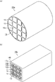
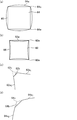
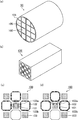
- FIG. 17A is a perspective view schematically showing the honeycomb filter described in Patent Document 1
- FIG. 17B is a perspective view schematically showing the honeycomb fired body constituting the honeycomb filter. is there.
- FIGS. 17C to 17D are enlarged end views schematically showing the honeycomb filter.
- an exhaust gas introduction cell 102 having an end portion on the exhaust gas inlet side opened and an end portion on the exhaust gas outlet side plugged, and an exhaust gas outlet port are disclosed.
- the exhaust gas discharge cell 101 is open at the end of the exhaust gas side and plugged at the end of the exhaust gas inlet side, and the cross-sectional shape of the cross section perpendicular to the longitudinal direction of the exhaust gas exhaust cell 101 is square, the exhaust gas introduction cell
- a plurality of honeycomb fired bodies 100 each having an octagonal cross-sectional shape perpendicular to the longitudinal direction of the cells 102 and the exhaust gas exhaust cells 101 and the exhaust gas introduction cells 102 arranged alternately (in a check pattern) are adhesive layers.
- a honeycomb filter 90 is disclosed which is bound by 105 and has an outer peripheral coat layer 106 formed on the outer periphery.
- a cell in which an end portion on the exhaust gas outlet side is opened and an end portion on the exhaust gas inlet side is plugged may be simply referred to as an exhaust gas discharge cell.
- a cell in which the end on the exhaust gas inlet side is opened and the end on the exhaust gas outlet side is plugged may be simply referred to as an exhaust gas introduction cell, a first exhaust gas introduction cell, or a second exhaust gas introduction cell.
- an exhaust gas discharge cell and an exhaust gas introduction cell are shown.
- a cross section perpendicular to the longitudinal direction of the cells such as the exhaust gas introduction cell and the exhaust gas discharge cell may be simply referred to as a cross section of the exhaust gas introduction cell and the exhaust gas discharge cell.
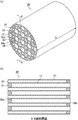
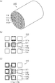
- FIG. 18 (a) is a perspective view schematically showing the honeycomb filter described in Patent Document 2
- FIGS. 18 (b) to 18 (c) are enlarged end views schematically showing the honeycomb filter. is there.
- each cell has a square honeycomb filter having the same cross-sectional shape, the end on the exhaust gas outlet side being opened, and the exhaust gas inlet Exhaust gas introduction cells 112 and 114 having an exhaust gas inlet side end portion opened and an exhaust gas outlet side end portion plugged around the entire periphery of the exhaust gas exhaust cell 111 whose end portion on the side is plugged are cell partition walls 113.
- An adjacent honeycomb filter 110 is disclosed.
- the exhaust gas introduction cell 112 faces one side of the exhaust gas exhaust cell 111 and the cell partition wall 113, but the exhaust gas introduction cell 114 faces the exhaust gas exhaust cell 111 at the corners.
- the sides constituting the cross-sectional shape of the exhaust gas introduction cell 114 do not face the exhaust gas discharge cell 111.
- the cross-sectional area of the exhaust gas introduction cells 112 and 114 is the same as the cross-sectional area of the exhaust gas exhaust cell 111, the total exhaust gas exhaust cell with respect to the total cross-sectional area of the exhaust gas introduction cell. Due to the small ratio of the cross-sectional area, the small cross-sectional area of each exhaust gas discharge cell, and the tendency of PM deposition to be biased, there was a problem that the pressure loss after PM deposition increased.
- the present inventors have arranged an exhaust gas introduction cell across a porous cell partition wall around the exhaust gas exhaust cell, and the exhaust gas introduction cell is replaced with the first exhaust gas introduction cell. And a second exhaust gas introduction cell having a cross-sectional area perpendicular to the longitudinal direction of the cell and a second exhaust gas introduction cell larger than the first exhaust gas introduction cell.
- the side length of the two exhaust gas introduction cells which are set to be equal to or larger than the cross-sectional area of the exhaust gas introduction cell and which face each other with the cell partition wall therebetween Alternatively, by adjusting the thickness of the cell partition wall, it has been found that the pressure loss can be reduced overall compared to the conventional honeycomb filter over the entire use range after PM deposition from the initial stage. In which it has been reached.
- the honeycomb filter of the present invention includes a porous cell partition wall that partitions and forms a plurality of cells serving as exhaust gas flow paths, an end portion on the exhaust gas inlet side is opened, and an end portion on the exhaust gas outlet side is plugged
- An exhaust gas introduction cell An exhaust gas outlet cell having an end portion on the exhaust gas outlet side opened and an end portion on the exhaust gas inlet side plugged, and a cross-sectional shape in a direction perpendicular to the longitudinal direction of the exhaust gas introduction cell and the exhaust gas exhaust cell is A honeycomb filter that is the same at all locations in each cell from the end on the exhaust gas inlet side to the end on the exhaust gas outlet side except for the plugged portion,
- the exhaust gas introduction cell is adjacent to the entire periphery of the exhaust gas exhaust cell with a porous cell partition wall, and the exhaust gas introduction cell has a cross section perpendicular to the longitudinal direction of the first exhaust gas introduction cell and the cell.
- the cross-sectional area of the cross section perpendicular to the longitudinal direction of the cell of the exhaust gas discharge cell is equal to or greater than the cross-sectional area of the cross section perpendicular to the longitudinal direction of the cell of the second exhaust gas introduction cell.
- the exhaust gas exhaust cell and the exhaust gas introduction cell are both polygonal and face the exhaust gas exhaust cell among the sides constituting the cross-sectional shape of the first exhaust gas introduction cell.
- the side length of the side is longer than the length of the side facing the exhaust gas discharge cell among the sides constituting the cross-sectional shape of the second exhaust gas introduction cell, or the first exhaust gas introduction cell
- the exhaust gas discharge cell and the exhaust gas introduction cell have a curved shape, and the thickness of the cell partition wall that separates the first exhaust gas introduction cell and the exhaust gas discharge cell. Is characterized in that it is thinner than the thickness of the cell partition wall separating the second exhaust gas introduction cell and the exhaust gas discharge cell.
- the cross-sectional shape as used in the field of this invention relates to the cross section perpendicular
- the cross-sectional area as used in the field of this invention is related to the cross section perpendicular
- the cell inner wall refers to a surface portion on the inner side of the cell among the surfaces of the cell partition walls constituting the cell.
- the side in the present invention relates to a cross section perpendicular to the longitudinal direction of the cell, and the cross-sectional shape formed by the inner walls of the exhaust gas exhaust cell, the first exhaust gas introduction cell, or the second exhaust gas introduction cell is a polygon.
- the line segment between the vertices of the polygon is called an edge.
- the length of the side means the length of the line segment, and when the apex portion has a so-called chamfered shape constituted by a curve, it means the length of the straight line portion excluding the curve portion.
- the permeation resistance increases because the cell walls separating the cells are thick, and the exhaust gas flows preferentially into the straight portion. Because it is necessary to adjust the length of the part, it is appropriate to exclude the curved part.
- the length of the side of the straight line portion excluding the curved line portion is such that when the straight line portion of the polygon is virtually extended and the intersection at which the virtual straight lines intersect is a virtual vertex, It is desirable that the length is 80% or more of the length of a virtual side formed by connecting vertices.
- the cross-sectional shape of the cell is a polygonal shape
- the mainstream which is the effect of the present invention, is adjusted by adjusting the length of the side. This is because the effect of the road switch can be realized.
- the side facing the exhaust gas discharge cell relates to a cross section perpendicular to the longitudinal direction of the cell,
- virtual perpendicular lines (hereinafter referred to as vertical bisectors) that bisect these sides are defined as When drawn toward the outside of the exhaust gas introduction cell or the second exhaust gas introduction cell, the vertical bisector is adjacent to the side of the first exhaust gas introduction cell or the second exhaust gas introduction cell across the cell partition wall. When it intersects with the graphic area composed of the cell inner wall of the cell, the side faces the exhaust gas discharge cell.
- the side facing the first exhaust gas introduction cell or the second exhaust gas introduction cell relates to a cross section perpendicular to the longitudinal direction of the cell,
- a virtual perpendicular line hereinafter referred to as a vertical bisector
- the perpendicular bisector intersects with the graphic area formed by the cell inner wall of the cell first exhaust gas introduction cell or the second exhaust gas introduction cell adjacent to the side of the exhaust gas exhaust cell across the cell partition wall, The side is said to face the first exhaust gas introduction cell or the second exhaust gas introduction cell.
- the side facing the second exhaust gas introduction cell relates to a cross section perpendicular to the longitudinal direction of the cell, and the cell of the first exhaust gas introduction cell
- virtual perpendicular lines hereinafter referred to as vertical bisectors
- the bisector intersects the graphic area formed by the cell inner wall of the second exhaust gas introduction cell adjacent to the side of the first exhaust gas introduction cell across the cell partition wall, the side is connected to the second exhaust gas introduction cell. They are facing each other.
- the side facing the first exhaust gas introduction cell relates to a cross section perpendicular to the longitudinal direction of the cell, and the cell of the second exhaust gas introduction cell.
- a virtual perpendicular line that bisects these sides (hereinafter referred to as a vertical bisector) is drawn vertically.
- the bisector intersects the graphic area formed by the cell inner wall of the first exhaust gas introduction cell adjacent to the side of the second exhaust gas introduction cell across the cell partition wall, the side is connected to the first exhaust gas introduction cell. They are facing each other.
- the thickness of the cell partition wall that separates the two cells is defined as follows. That is, in the cross section perpendicular to the longitudinal direction of the cell, the geometric centroid of the cross-sectional figure formed by the cell inner wall is obtained for each of the two cells, a straight line connecting the centroids is drawn, and the straight line overlaps the cell partition area.
- the length of the line segment is defined as the thickness of the cell partition wall.
- a cell is a space, but the center of gravity here means the geometric center of gravity of the cross-sectional figure formed by the inner wall of the cell. The definition of the center of gravity is possible.
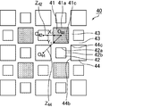
- FIG. 1 is an enlarged end view showing a part of an end face of a honeycomb filter according to an embodiment of the present invention in an enlarged manner.
- FIG. An exhaust gas introduction cell 14 is displayed.
- the side facing the exhaust gas discharge cell 11 is perpendicular to the longitudinal direction of the cell shown in FIG.
- the polygonal sides 12a, 14a formed by the inner walls of the first exhaust gas introduction cell 12 or the second exhaust gas introduction cell 14 are assumed to be imaginary perpendicular lines (hereinafter referred to as vertical two). 1 is drawn toward the outside of the first exhaust gas introduction cell 12 or the second exhaust gas introduction cell 14, the vertical bisector A and the vertical bisector B are as shown in FIG.
- the reason for facing each other with the intersection of vertical bisectors is that the exhaust gas permeates through the vicinity of the center in the length direction of the side, that is, the central part of the cell partition wall separating the exhaust gas introduction cell and the exhaust gas discharge cell. This is because the permeation resistance received at this time represents the pressure loss that occurs when the exhaust gas permeates the entire partition wall.
- the cross section perpendicular to the longitudinal direction of the cell if the cross-sectional shape formed by the inner walls of each of the exhaust gas discharge cell, the first exhaust gas introduction cell or the second exhaust gas introduction cell is a polygon,
- the vertical bisector of each side is a vertical bisector of the line segment excluding the curve.
- this curve is not treated as a side.
- the apex portion of the cross-sectional shape is a chamfered shape
- the sides constituting the cross-sectional shape are virtually extended, and the intersection of the extension lines is regarded as the apex and treated as a polygon.
- the vertex portion may be configured with a curve so that stress is not concentrated on the vertex portion. Yes, even if such a vertex portion is configured by a curve, it is handled as a polygon.
- the thickness of the cell partition wall separating the two cells is defined as follows. That is, in the cross section perpendicular to the longitudinal direction of the cell shown in FIG. 1, the geometric center of gravity of the cross-sectional figure formed by the cell inner wall is obtained for each of the two cells (in FIG. 1, the center of gravity of the exhaust gas discharge cell 11 is O 11 , the center of gravity of the second exhaust gas introduction cell 14 is O 14 ), a straight line Z 14 connecting the centers of gravity is drawn, and the length D of the line segment where the straight line Z 14 overlaps the cell partition wall region is defined as the thickness of the cell partition wall.
- a cell is a space, but the center of gravity here means the geometric center of gravity of the cross-sectional figure formed by the inner wall of the cell. The definition of the center of gravity is possible.
- the reason why the thickness of the cell partition wall is defined as described above is as follows.
- the resistance when the gas permeates the cell partition is highest at the portion where the flow velocity of the gas passing through the cell partition is the highest, and this portion can represent the permeation resistance of the cell partition.
- the flow rate of gas in the longitudinal direction of the honeycomb filter is highest at the position corresponding to the geometric center of gravity of the cross-sectional shape formed by the inner wall of the cell, and decreases concentrically in the cross section of the cell.
- the intersection of the cell connecting the center of gravity of the cell and the cell partition wall corresponds to the highest part of the flow velocity of the gas passing through the cell partition wall.
- the measurement of the length of the cell side and the thickness of the cell partition and the specification of the cell cross-sectional shape are performed using an electron micrograph.
- the electron micrograph is taken with an electron microscope (FE-SEM: S-4800, a high-resolution field emission scanning electron microscope manufactured by Hitachi High-Technologies Corporation).
- FE-SEM electron microscope
- the magnification of the electron micrograph shows that the particle on the surface (inner wall) of the cell partition walls and the irregularities of the pores that make up the cell specify the cross-sectional shape of the cell, the length of the side, the partition wall thickness, and the cross-sectional area of the cell.
- the cross-sectional area of the cell cross section can be calculated from the weight ratio.
- the cross-sectional shape formed by the inner walls of the exhaust gas exhaust cell and the second exhaust gas exhaust cell is an octagon, and the cross-sectional areas thereof are the same.
- the cross-sectional shape formed by the inner wall is a square (the vertex is formed by a curve and has a so-called chamfered shape, but in the present invention, four straight lines extending at four sides intersect at four points, and the four intersections are the vertexes. Treated as a square).
- a scale of 500 ⁇ m is displayed in the photograph, and a square (corresponding to a unit area) having a length corresponding to 500 ⁇ m in this photograph as one side is cut out from this photograph and its weight is measured.
- the octagon and the square are cut out from the photograph (the four vertex portions of the square are cut out along the curve), and the weight is measured.
- the cross-sectional area is calculated from the weight ratio with the 500 ⁇ m scale square. If only the ratio of the cell cross-sectional area is measured, the area ratio can be calculated as it is from the weight ratio of the octagon and the square.
- the measurement of the length of the cell, the thickness of the cell partition wall, and the cross-sectional area are taken from the above-described manual measurement, and an electron micrograph is taken as image data, or image data taken directly from the electron microscope is used. It is also possible to input a photo scale and replace it with electronic measurement.
- both the manual measurement method and the digitized measurement method are measurements based on the scale of the electron microscope image, and are based on the same principle, and it goes without saying that no wrinkles occur in the measurement results of both.
- measurement software such as image analysis type particle size distribution software (manufactured by Mountech Co., Ltd.) MAC-View (Version 3.5) can be used.
- the cross-sectional area can be measured by taking an electron micrograph with a scanner or using image data taken directly from the electron microscope, inputting the scale of the photo, and specifying a range along the inner wall of the cell. Moreover, the distance between any points in the image can be measured based on the scale of the electron micrograph.
- photographing a cell cross section with an electron microscope cut the filter perpendicular to the longitudinal direction of the cell, prepare a 1 cm x 1 cm x 1 cm sample so that the cut surface enters, and clean the sample ultrasonically. Or, embed with resin and take an electron micrograph. Embedding with resin does not affect the measurement of the cell side length and cell partition wall thickness.
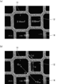
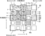
- FIGS. 2A to 2B are photographs showing an example of the shape of a cell cross section taken by an electron microscope.
- Fig.2 (a) it turns out that the cross-sectional shape of the waste gas exhaust cell 11 and the 2nd waste gas introduction cell 14 is an octagon.
- the cross-sectional shape of the first exhaust gas introduction cell 12 is a square.
- the apex portion of the first exhaust gas introduction cell is composed of a slight curve, but if the side composed of the four straight lines of the first exhaust gas introduction cell 12 is extended, there will be four intersections. Since a square with the intersection as a vertex can be formed, the cross-sectional shape of this cell is treated as a square according to the definition in the present invention.
- the cross-sectional area (cross-sectional area) of the exhaust gas discharge cell 11 and the second exhaust gas introduction cell 14 is 2.14 mm 2
- the cross-sectional shape of the first exhaust gas introduction cell 12. Can be calculated as 0.92 mm 2 .
- the length of the side Ls facing the exhaust gas discharge cell 11 among the sides constituting the cross-sectional shape of the first exhaust gas introduction cell 12 is the four apexes of the first exhaust gas introduction cell. Since the portion is composed of a curved line, the length excluding the curved portion is obtained.
- the length Lo of the side facing the exhaust gas discharge cell 11 among the sides constituting the cross-sectional shape of the second exhaust gas introduction cell 14 is the octagonal vertex distance.
- the side lengths Ls and Lo and the cross-sectional area can be measured from the electron micrograph.
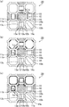
- FIGS. 3A and 3B are scanning electron micrographs (SEM photographs) showing an example of the shape of a cell cross section of a cell different from the cell shown in FIG.
- the cross-sectional shapes of the exhaust gas discharge cell 41, the second exhaust gas introduction cell 44, and the first exhaust gas introduction cell 42 are all straight lines obtained by virtually extending four sides of equal length. It can be seen that the shape intersects perpendicularly and the intersection (vertex) portion is formed by a curve.
- the cross-sectional shapes of these cells are all made up of curved lines, but if you extend the four straight lines that make up each cell, there will be four intersections, and these intersections will become virtual vertices.
- the side constituting the first exhaust gas introduction cell 42 has its perpendicular bisector intersecting with the exhaust gas discharge cell 41, so the side constituting the first exhaust gas introduction cell 42 is It can be said that it faces the exhaust gas discharge cell 41.
- the side that forms the second exhaust gas introduction cell 44 does not intersect the vertical bisector with the exhaust gas discharge cell 41, the side that forms the second exhaust gas discharge cell 44 faces the exhaust gas discharge cell 41. do not do. In this way, it can be determined from the electron micrograph whether or not the sides constituting the second exhaust gas introduction cell 44 and the first exhaust gas introduction cell 42 face the exhaust gas exhaust cell 41.
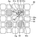
- the swollen square used in the present invention is a figure composed of four curves having the same length, which curves toward the outside of the figure, as if the sides of the square are outward from the geometric center of gravity.
- a contracted square is a figure composed of four curves with the same length that curves toward the inside of the figure, as if the sides of the square shrunk toward the geometric center of gravity. The figure of.
- the first exhaust gas introduction cell, the second exhaust gas introduction cell, and the exhaust gas exhaust cell are cross sections constituted by inner walls of the cells at all locations in each cell except for the plugging portion from the exhaust gas inlet end to the exhaust gas outlet end.
- the shape is the same. That is, when only the first exhaust gas introduction cell is viewed in a cross section perpendicular to the longitudinal direction, the cross-sectional figure formed by the inner wall is the cross section of any portion from the exhaust gas inlet end to the exhaust gas outlet end except for the plugging portion. It is the same shape even if you look at. The same shape means congruence and does not include similarity.
- the shape having a similar relationship is a different shape.
- the first exhaust gas introduction cell but also the second exhaust gas introduction cell and the exhaust gas discharge cell have the same explanation as in the case of the first exhaust gas introduction cell.
- the reason for excluding the plugged portion is that the cross-sectional figure formed by the inner wall of the cell partition wall does not physically exist because the plugged material exists in the plugged portion.
- the pressure loss can be reduced comprehensively from the initial stage until the amount of PM deposited near the limit.
- the inventors of the present invention have the following pressure loss: (a) inflow resistance when exhaust gas flows into the honeycomb filter, (b) passage resistance of the exhaust gas introduction cell, (c) permeation resistance of the cell partition, (d) accumulated PM It is considered to be generated by the permeation resistance generated when the exhaust gas permeates the layer, (e) the passage resistance of the exhaust gas discharge cell, and (f) the outflow resistance when the exhaust gas flows out of the honeycomb filter.
- the initial pressure loss before PM is deposited is that the (c), (e) and (f) are the controlling factors, and the transient that occurs after a certain amount of PM is deposited.
- the pressure loss has determined that (a), (b) and (d) are the controlling factors.
- One of the factors controlling the initial pressure loss is not (b) the passage resistance of the exhaust gas introduction cell, but (e) the passage resistance of the exhaust gas discharge cell. This is because the aperture ratio of the honeycomb filter by the cell is small.
- the reason why the initial pressure loss is governed by (a) not the inflow resistance when the exhaust gas flows into the honeycomb filter but (f) the outflow resistance when the exhaust gas flows out of the honeycomb filter is because the gas is compressed It is presumed that the vortex is generated near the outlet of the cell when the gas is discharged from the cell and rapidly expands rather than the resistance, and this vortex causes the resistance generated by inhibiting the outflow of the exhaust gas to be higher. In order to reduce the initial pressure loss, it is necessary to reduce the passage resistance and the outflow resistance.
- the cross-sectional area of the exhaust gas exhaust cell is made equal to or larger than that of the exhaust gas introduction cell.
- the cross-sectional area of the exhaust gas introduction cell must be relatively larger than that of the exhaust gas discharge cell.
- the inventors have further studied and completed the present invention. That is, two types of exhaust gas introduction cells, one having a large cross-sectional area (second exhaust gas introduction cell) and one having a small cross-sectional area (first exhaust gas introduction cell), are employed, and the cross-sectional area is the second exhaust gas introduction cell.
- the same or relatively large exhaust gas exhaust cell is adopted, two types of exhaust gas introduction cells are arranged around the exhaust gas exhaust cell, and the length of the inner wall of the partition wall separating the first exhaust gas introduction cell and the exhaust gas exhaust cell is 2 Relative to the length of the inner wall of the partition wall separating the exhaust gas introduction cell and the exhaust gas discharge cell, or the thickness of the partition wall separating the first exhaust gas introduction cell and the exhaust gas discharge cell is separated from the second exhaust gas introduction cell and the exhaust gas discharge cell.
- the thickness is first introduced preferentially into the first exhaust gas introduction cell.
- the partition wall between the first exhaust gas introduction cell and the exhaust gas discharge cell has a large permeation area (long side in terms of the cross-sectional shape of the polygonal cell) or a thin thickness, and the exhaust gas It is possible to pass through a convenient partition, and the transmission resistance of (c) can be reduced.
- the cross-sectional area of the exhaust gas discharge cell is relatively larger than that of the first exhaust gas introduction cell, the passage resistance of (e) can be reduced. That is, both the transmission resistance (c) and the passage resistance (e) can be lowered, and the initial pressure loss can be lowered.
- the cross-sectional area of the first exhaust gas introduction cell is relatively smaller than that of the second exhaust gas introduction cell, so that the PM layer deposited on the first exhaust gas introduction cell
- the second exhaust gas introduction cell having a large cross-sectional area has a large cross-sectional area because the permeation resistance is increased early, and the main flow path of the exhaust gas is “switched” so that the exhaust gas naturally (ie, spontaneously) enters the second exhaust gas introduction cell more Even when PM is deposited widely and thinly, the passage resistance of (b) and the transmission resistance of (d) can be reduced even after PM deposition, and the transient pressure loss can be lowered.
- the surprising effect of simultaneously reducing the transient pressure loss and the initial pressure loss which has been impossible in the past, is realized by self-switching the main flow path.
- Patent Document 1 As shown in FIG. 17, International Publication No. 2004/024294 (Patent Document 1) described above includes a honeycomb filter in which the cross-sectional shape of the exhaust gas introduction cell 102 is octagonal and the cross-sectional shape of the exhaust gas exhaust cell 101 is square. It is disclosed that by increasing the cross-sectional area of the exhaust gas introduction cell 102, it is possible to deposit PM widely and thinly to reduce transient pressure loss.
- Patent Document 1 in order to reach the present invention from Patent Document 1, a part of the exhaust gas discharge cell 101 having a small cross-sectional area is changed to the exhaust gas introduction cell 102, and a part of the exhaust gas introduction cell 102 having a large cross-sectional area is changed to the exhaust gas exhaust cell. 101, however, such a change negates the inventive idea described in Patent Document 1 that attempts to increase the cross-sectional area of the exhaust gas introduction cell 102. It is never derived.
- Patent Document 2 In addition, as described based on FIG. 18, in US Pat. No. 4,417,908 (Patent Document 2), the number of exhaust gas introduction cells having the same cross-sectional area is increased, and the total area of the exhaust gas introduction cells is increased. Thus, a honeycomb filter capable of reducing the transient pressure loss by depositing PM widely and thinly is disclosed. However, in order to reach the present invention from Patent Document 2, it is necessary to change a part of the exhaust gas introduction cell to a cell having a small cross-sectional area. The invention idea of Document 2 is denied and the present invention is not derived with Patent Document 2 as the closest document. Thus, the known technology denies the present invention, and the present invention is not derived from known literature.
- FIG. 4 (a) to 4 (c) are enlarged end views showing a part of the end face of the honeycomb filter according to the embodiment of the present invention.
- a porous portion is formed around the exhaust gas discharge cell 11 whose end on the exhaust gas outlet side is opened and whose end on the exhaust gas inlet side is plugged.
- the first exhaust gas introduction cell 12 and the second exhaust gas introduction cell 14 which are open at the end on the exhaust gas inlet side and plugged at the end on the exhaust gas outlet side are formed adjacent to each other with the cell partition wall 13 therebetween. .
- the exhaust gas exhaust cell 11 is an octagon having the same shape as the exhaust gas introduction cell 102 shown in FIG. 17, the first exhaust gas introduction cell 12 is square, and the second exhaust gas.
- the introduction cell 14 is an octagon having the same shape as the exhaust gas discharge cell 11.
- the cross sectional area of the second exhaust gas introduction cell 14 is larger than the cross sectional area of the first exhaust gas introduction cell 12 and is the same as the cross sectional area of the exhaust gas discharge cell 11.
- the cross-sectional area of the second exhaust gas introduction cell 14 is the same as the cross-sectional area of the exhaust gas discharge cell 11, and the cross-sectional area of the exhaust gas discharge cell 11 is larger than the cross-sectional area of the first exhaust gas introduction cell 12. Therefore, the resistance when exhaust gas passes through the exhaust gas discharge cell 11 and the resistance when exhaust gas is discharged to the outside of the filter can be kept low, and the pressure loss can be reduced.
- the length of the side 12a facing the exhaust gas discharge cell 11 is the side constituting the cross-sectional shape of the second exhaust gas introduction cell 14, It is longer than the length of the side 14 a facing the exhaust gas discharge cell 11.
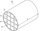
- the exhaust gas flows in the direction of the honeycomb filter 20, the exhaust gas flows into the first exhaust gas introduction cell 12 and the second exhaust gas introduction cell 14 whose end portions on the inlet side are open.
- the exhaust gas flows so that the entire flow becomes equal in order from the easy-to-flow portion in the filter.
- the length (Ls) of the side 12a of the first exhaust gas introduction cell 12 is longer than the length (Lo) of the side 14a of the second exhaust gas introduction cell 14, so
- the surface area of the cell partition wall 13a separating the first exhaust gas introduction cell 12 is larger than the surface area of the cell partition wall 13b separating the exhaust gas exhaust cell 11 and the second exhaust gas introduction cell 14, and the exhaust gas passes through the cell partition wall 13a more.
- the reason why the relationship between the length of the side constituting the cell and the surface area is concluded as described above is as follows.
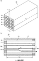
- the surface area of the cell partition wall 13a that separates the exhaust gas exhaust cell 11 and the first exhaust gas introduction cell 12 is the surface area on the inner wall side of the first exhaust gas introduction cell 12, and the distance between the exhaust gas inlet end surface and the outlet end surface is Assuming that the effective filter length excluding the length of the sealing portion is Le (see FIG. 6B), the surface area on the inner wall side of the first exhaust gas introduction cell 12 is represented by Ls ⁇ Le.
- the surface area of the cell partition wall 13b that separates the exhaust gas exhaust cell 11 and the second exhaust gas introduction cell 14 is the surface area on the inner wall side of the second exhaust gas introduction cell 14, and the inlet is determined from the distance between the exhaust gas inlet end face and the outlet end face.
- the effective filter length excluding the lengths of the side and outlet side sealing portions is Le
- the surface area on the inner wall side of the second exhaust gas introduction cell 14 is represented by Lo ⁇ Le. Note that, as an effective length of the filter, in FIG. 6B, a length based on the tip of the sealing material 11 is taken.
- the length (Ls) of the side 12a is relatively longer than the length (Lo) of the side 14a, the surface area of Ls ⁇ Le is relatively larger than that of Lo ⁇ Le. That is, the length of the side and the size of the surface area are synonymous. Therefore, if the length (Ls) of the side 12a of the exhaust gas discharge cell 11 is longer than the length (Lo) of the side 14a of the second exhaust gas introduction cell 14, the exhaust gas discharge cell 11 and the first exhaust gas introduction cell 12 are connected.
- the surface area of the cell partition wall 13a that separates is larger than the surface area of the cell partition wall 13b that separates the exhaust gas discharge cell 11 and the second exhaust gas introduction cell.
- FIGS. 4 (a) to 4 (c) matters relating to actions and effects are written in only a part of the figure. The same applies to FIGS. 17 and 18.
- the cell partition wall 13c that separates the first exhaust gas introduction cell 12 and the second exhaust gas introduction cell 14 as shown in FIG. 4 (c). Also flows through the exhaust gas discharge cell 11.
- the exhaust gas enters the cell partition wall 13c also from the second exhaust gas introduction cell 14 side, and also enters the cell partition wall 13c from the first exhaust gas introduction cell 12 side.
- the PM gradually increases not only in the entire inner wall surface of the exhaust gas introduction cell 12 of the cell partition walls 13a and 13c around the first exhaust gas introduction cell 12, but rather in the second exhaust gas introduction cell around the second exhaust gas introduction cell 14.
- the cell partition walls 13b and 13c are deposited on the entire inner wall surface of the exhaust gas introduction cell, but widely and thinly. Since the cross-sectional area of the first exhaust gas introduction cell 12 is smaller than the cross-sectional area of the second exhaust gas introduction cell 11, PM is deposited thickly, the passage resistance of the PM layer is increased, and the exhaust gas is first introduced early after the introduction of the exhaust gas.
- the inner wall surface area of the exhaust gas introduction cell of the cell partition walls 13b and 13c around the second exhaust gas introduction cell 14 is wider than the inner wall surface area of the exhaust gas introduction cell of the cell partition walls 13a and 13c around the first exhaust gas introduction cell 12, Even if PM is deposited on the entire periphery of the cell partition walls 13b and 13c around the second exhaust gas introduction cell 14, the thickness of the deposited layer can be reduced. Therefore, even if PM accumulates, the rate of increase in exhaust gas pressure loss is small. As a result, even if the amount of accumulated PM increases, an excellent effect is achieved in that the pressure loss can be kept low. As a result, in a vehicle equipped with the honeycomb filter according to the present invention, an inconvenience in driving due to an increase in pressure loss hardly occurs over the entire use region, and fuel consumption can be suppressed low.
- the exhaust gas discharge cells 101 having a square cross section and the exhaust gas introduction cells 102 having an octagonal cross section are alternately ( Arranged in the check pattern).
- the exhaust gas flows into the exhaust gas introduction cell 102 having an octagonal cross section and larger than the cross sectional area of the exhaust gas exhaust cell 101, and then passes through the cell partition wall 103a separating the exhaust gas introduction cell 102 and the exhaust gas exhaust cell 101. It flows into the discharge cell 101.
- resistance when flowing from the exhaust gas introduction cell 102 having a large cross-sectional area into the exhaust gas exhaust cell 101 having a small cross-sectional area, resistance when passing through the exhaust gas exhaust cell 101 having a small cross-sectional area, and from the exhaust gas exhaust cell 101 having a small cross-sectional area The resistance when discharged to the outside is high, and the initial pressure loss is higher than that of the honeycomb filter according to the present invention.
- the exhaust gas passes through the cell partition walls 103b separating the exhaust gas introduction cells 102, but the cell partition surface where PM is deposited has a smaller surface area than the honeycomb filter 10 according to the present invention. PM accumulates thickly, and it is difficult to suppress an increase in pressure loss.
- the cross sections perpendicular to the longitudinal direction of each cell are all the same square, and the exhaust gas introduction cell 112 is disposed around the entire exhaust gas discharge cell 111. , 114 are adjacent to each other across the cell partition wall 113b. Further, regarding the cross-sectional shape, the exhaust gas introduction cell 112 faces one side across the exhaust gas discharge cell 111 and the cell partition wall 113a, but the exhaust gas introduction cell 114 has a relationship in which corners face each other. Therefore, the side 114 a constituting the exhaust gas introduction cell 114 does not face the side 111 a constituting the exhaust gas discharge cell 111.
- the exhaust gas flows into the exhaust gas introduction cell 112 facing the exhaust gas discharge cell 111 across the cell partition wall 113a, and the cell partition wall. After passing through 113a, it flows into the exhaust gas discharge cell 111.
- the first exhaust gas discharge cell 111 and the first exhaust gas introduction cell 112 have the same cross-sectional area, so that the exhaust gas introduction cell 12 has a larger cross-sectional area than the exhaust gas introduction cell 12.
- the initial pressure loss is higher.
- the cross-sectional shape thereof is a polygon
- the side facing the first exhaust gas introduction cell adjacent to the exhaust gas discharge cell with the cell partition wall therebetween, is parallel to each other.
- the thickness of the cell partition wall separating the exhaust gas discharge cell and the first exhaust gas introduction cell is uniform everywhere, the filter has a high breaking strength, easily allows the exhaust gas to permeate, and deposits PM uniformly. This is because the pressure loss can be reduced.
- the vertex part of a polygon is comprised with the curve in cross-sectional shape, the curve part is not handled as an edge. This is because they are not parallel in the first place.
- the length of the side of the cross-sectional shape excluding the curved portion virtually extends the straight line portion regarded as the side, and the intersection of the virtual straight lines intersects the virtual vertex
- the length is 80% or more of the length of the virtual side of the polygon formed by connecting the virtual vertices.
- the portion not treated as a side is less than 20% of the length of the virtual side.
- the thickness of the partition wall separating the exhaust gas discharge cell and the second exhaust gas introduction cell is uniform everywhere, the filter has a high breaking strength, easily allows the exhaust gas to permeate, and deposits PM uniformly. This is because the pressure loss can be reduced.
- the vertex part of a polygon is comprised with the curve in cross-sectional shape, the curve part is not handled as an edge. This is because they are not parallel in the first place.
- the length of the side of the cross-sectional shape excluding the curved portion virtually extends the straight line portion regarded as the side, and the intersection of the virtual straight lines intersects the virtual vertex
- the length is 80% or more of the length of the virtual side of the polygon formed by connecting the virtual vertices.
- the portion not treated as a side is less than 20% of the length of the virtual side.
- the first exhaust gas introduction cell and the second exhaust gas introduction cell that are adjacent to each other with the cell partition wall interposed therebetween are perpendicular to the cell longitudinal direction.
- the sides constituting the cross-sectional shape of the exhaust gas introduction cell the side adjacent to the second exhaust gas introduction cell with the cell partition wall therebetween, and the side facing the second exhaust gas introduction cell constitute the cross-sectional shape of the second exhaust gas introduction cell.
- the side facing the first exhaust gas introduction cell with the cell partition wall therebetween is parallel to the side facing the first exhaust gas introduction cell.
- the thickness of the partition wall separating the first exhaust gas introduction cell and the second exhaust gas introduction cell is uniform everywhere, and the honeycomb filter has a high breaking strength. This is because the exhaust gas can be easily transmitted from the cell to the exhaust gas discharge cell side, and PM can be deposited widely and thinly on the inner wall of the second exhaust gas introduction cell, so that the pressure loss can be reduced after PM deposition.
- the vertex part of a polygon is comprised with the curve in cross-sectional shape, the curve part is not handled as an edge. This is because they are not parallel in the first place.
- the length of the side of the cross-sectional shape excluding the curved portion virtually extends the straight line portion regarded as the side, and the intersection of the virtual straight lines intersects the virtual vertex
- the length is 80% or more of the length of the virtual side of the polygon formed by connecting the virtual vertices.
- the portion not treated as a side is less than 20% of the length of the virtual side.
- the cross sections perpendicular to the cell longitudinal direction of the exhaust gas discharge cells, the first exhaust gas introduction cells, and the second exhaust gas introduction cells that are adjacent to each other across the cell partition walls are polygonal.
- (A) Of the sides constituting the cross-sectional shape of the exhaust gas discharge cell, the side adjacent to the first exhaust gas introduction cell with the cell partition wall therebetween and facing the first exhaust gas introduction cell, and the cross-sectional shape of the first exhaust gas introduction cell Are adjacent to the exhaust gas exhaust cell across the cell partition, and the sides facing the exhaust gas exhaust cell are parallel to each other
- (B) Of the sides constituting the cross-sectional shape of the exhaust gas exhaust cell the side adjacent to the second exhaust gas introduction cell across the cell partition wall and facing the second exhaust gas introduction cell, and the cross-sectional shape of the second exhaust gas introduction cell Are adjacent to the exhaust gas exhaust cell across the cell partition, and the sides facing the exhaust gas exhaust cell are parallel to each other
- the first exhaust gas introduction cell, the second exhaust gas introduction cell, and the cross section perpendicular to the longitudinal direction of the exhaust gas exhaust cell, and when the cross-sectional shape thereof is a polygon In addition to the configuration including a), (b), and (c), the distance between the parallel sides in (a), and between the parallel sides in (b) And the distance between the parallel sides in (c) are preferably equal. Note that the distance between the sides is that a perpendicular is drawn from an arbitrary point P on one side toward the other side, and Q is a point where the perpendicular intersects the other side. The distance between is defined as the distance between parallel sides.
- the honeycomb filter has the highest breaking strength, the pressure loss can be reduced most before and after the PM deposition, and the filter is prevented from being damaged by the thermal shock generated when the PM is regenerated. Because it can be done.
- the vertex part of a polygon is comprised with the curve in cross-sectional shape, the curve part is not handled as an edge. This is because they are not parallel in the first place.
- the length of the side of the cross-sectional shape excluding the curved portion virtually extends the straight line portion regarded as the side, and the intersection of the virtual straight lines intersects the virtual vertex
- the length is 80% or more of the length of the virtual side of the polygon formed by connecting the virtual vertices.
- the portion not treated as a side is less than 20% of the length of the virtual side.
- the honeycomb filter of the present invention is preferably used for purifying PM in exhaust gas discharged from an internal combustion engine of an automobile. This is because both the initial pressure loss generated in the filter before PM deposition and the transient pressure loss generated in the filter due to PM deposition can be reduced at the same time, so that the fuel efficiency of the engine can be improved.
- the honeycomb filter of the present invention is optimal when a diesel engine is adopted as an internal combustion engine of an automobile. This is because the amount of PM discharged from the diesel engine is larger than that of the gasoline engine, and the demand for reducing the transient pressure loss generated in the filter due to PM accumulation is higher than that of the gasoline engine.
- the honeycomb filter of the present invention When the honeycomb filter of the present invention is used for purifying PM in exhaust gas discharged from an internal combustion engine of an automobile, the honeycomb filter of the present invention is fixed in the exhaust pipe via a holding material.
- both the exhaust gas discharge cell and the exhaust gas introduction cell are polygonal, Of the sides constituting the cross-sectional shape of the second exhaust gas introduction cell, the length of the side facing the exhaust gas discharge cell is the length of the side constituting the cross-sectional shape of the first exhaust gas introduction cell. It is desirable that the length is 0.8 times or less the length of the side facing the.
- the exhaust gas can more easily pass through the cell partition wall separating the exhaust gas discharge cell and the first exhaust gas introduction cell, the initial pressure loss can be effectively suppressed, and the pressure loss can be reduced even after PM is deposited. An increase in the increase rate can be suppressed. If the ratio of the side length of the second exhaust gas introduction cell to the length of the side of the first exhaust gas introduction cell exceeds 0.8, there is no significant difference between the lengths of both sides, so the initial pressure loss is kept low. It becomes difficult.
- the exhaust gas discharge cell is preferably octagonal
- the first exhaust gas introduction cell is square
- the second exhaust gas introduction cell is preferably octagonal.
- the honeycomb filter having the above configuration has the same shape as that of the honeycomb filter according to FIG. 4, which describes the operation and effect, and can effectively suppress the initial pressure loss and increase the surface area on which PM is deposited. And pressure loss can be kept low.
- the cross-sectional area of the second exhaust gas introduction cell is the same as the cross-sectional area of the exhaust gas discharge cell
- the cross-sectional area of the first exhaust gas introduction cell is preferably 20 to 50% of the cross-sectional area of the second exhaust gas introduction cell. In this case, it is possible to make a difference between the resistance when the exhaust gas passes through the first exhaust gas introduction cell and the resistance when it passes through the second exhaust gas introduction cell, and the pressure loss can be effectively suppressed.
- the cross-sectional area of the first exhaust gas introduction cell When the cross-sectional area of the first exhaust gas introduction cell is less than 20% of the cross-sectional area of the second exhaust gas introduction cell, the cross-sectional area of the first exhaust gas introduction cell becomes too small, and the passage resistance through which the exhaust gas passes through the first exhaust gas introduction cell. Tends to increase and pressure loss tends to increase. On the other hand, if the cross-sectional area of the first exhaust gas introduction cell exceeds 50% of the cross-sectional area of the second exhaust gas introduction cell, the difference in the passage resistance between the two becomes small and it is difficult to reduce the pressure loss.
- the exhaust gas exhaust cell and the exhaust gas introduction cell are both polygonal with respect to the cross section perpendicular to the longitudinal direction of the cell, and the thickness of the cell partition walls separating the cells of the honeycomb filter is set at all locations. It is desirable that In this case, the above-described effects can be achieved with the entire honeycomb filter.
- the cell partition wall thickness of the above-described honeycomb filter is 0.10 to 0.46 mm.
- the cell partition wall having the above thickness has a sufficient thickness to collect PM in the gas and can effectively suppress an increase in pressure loss. Therefore, the honeycomb filter of the present invention can sufficiently exhibit the above-described effects as the honeycomb filter of the present invention. If the cell partition wall thickness is less than 0.10 mm, the cell partition wall thickness becomes too thin, so that the mechanical strength of the honeycomb filter decreases. On the other hand, if the thickness of the cell partition wall exceeds 0.46 mm, the cell partition wall becomes too thick, and the pressure loss when exhaust gas passes through the cell partition wall increases.
- the cross-sectional shape of the exhaust gas discharge cell is octagonal
- the cross-sectional shape of the first exhaust gas introduction cell is square
- the cross-sectional shape of the second exhaust gas introduction cell is octagonal
- the cross-sectional shapes of the second exhaust gas introduction cell and the exhaust gas discharge cell are the same as each other
- Around the exhaust gas exhaust cell four first exhaust gas introduction cells and four second exhaust gas introduction cells are alternately arranged with a cell partition wall therebetween to surround the exhaust gas exhaust cell, Further, a figure composed of the cross-sectional shape of the exhaust gas exhaust cell among virtual line segments connecting the geometric centers of gravity of the octagons that are the cross-sectional shapes of the four second exhaust gas introduction cells surrounding the exhaust gas exhaust cell.
- the intersection of two line segments that pass through the region coincides with the geometric center of gravity of the octagon that is the cross-sectional shape of the exhaust gas exhaust cell, And among the virtual line segments that connect the geometric centers of gravity of the octagons that are the cross-sectional shapes of the four second exhaust gas introduction cells, the four that do not pass through the graphic region consisting of the cross-sectional shape of the exhaust gas discharge cells are The square is formed so that the midpoint of each side coincides with the geometric center of gravity of each square, which is the cross-sectional shape of the four first exhaust gas introduction cells surrounding the exhaust gas discharge cell.
- the exhaust gas discharge cell, the first exhaust gas introduction cell, and the second exhaust gas introduction cell are respectively disposed,
- the side facing the exhaust gas discharge cell is parallel,
- the side facing the exhaust gas discharge cell is parallel to the side of the first exhaust gas introduction cell, and the side facing the second exhaust gas introduction cell across the cell partition wall, 2
- Sides constituting the cross-sectional shape of the exhaust gas introduction cell are parallel to the side facing the first exhaust gas introduction cell across the cell partition wall, and the distance between the parallel sides is any combination. It is desirable that they are equal to each other.
- the exhaust gas discharge cell, the first exhaust gas introduction cell, and the second exhaust gas introduction cell are all preferably square. Even when the first exhaust gas introduction cell and the second exhaust gas introduction cell are both square, the relationship among the sizes of the exhaust gas exhaust cell, the first exhaust gas introduction cell, and the second exhaust gas introduction cell. For example, since the area of the cross section of the first exhaust gas introduction cell is smaller than the cross sectional area of the exhaust gas exhaust cell, the honeycomb filter 110 described in the related art is different from the honeycomb filter 110 described above. There is an effect.
- the cross-sectional area of the second exhaust gas introduction cell is the same as the cross-sectional area of the exhaust gas discharge cell
- the cross-sectional area of the first exhaust gas introduction cell is preferably 20 to 50% of the cross-sectional area of the second exhaust gas introduction cell.
- the cross-sectional area of the first exhaust gas introduction cell When the cross-sectional area of the first exhaust gas introduction cell is less than 20% of the cross-sectional area of the second exhaust gas introduction cell, the cross-sectional area of the first exhaust gas introduction cell becomes too small, and the passage resistance through which the exhaust gas passes through the first exhaust gas introduction cell. Tends to increase and pressure loss tends to increase. On the other hand, if the cross-sectional area of the first exhaust gas introduction cell exceeds 50% of the cross-sectional area of the second exhaust gas introduction cell, the difference in the passage resistance between the two becomes small and it is difficult to reduce the pressure loss.
- the cross-sectional shape of the exhaust gas discharge cell is square
- the cross-sectional shape of the first exhaust gas introduction cell is square
- the cross-sectional shape of the second exhaust gas introduction cell is square
- the cross-sectional shapes of the second exhaust gas introduction cell and the exhaust gas discharge cell are the same as each other
- Around the exhaust gas exhaust cell four first exhaust gas introduction cells and four second exhaust gas introduction cells are alternately arranged with a cell partition wall therebetween to surround the exhaust gas exhaust cell
- a graphic region consisting of the cross-sectional shape of the exhaust gas exhaust cell The intersection of the two line segments that pass through is coincident with the square geometric center of gravity, which is the cross-sectional shape of the exhaust gas discharge cell, And among the virtual line segments that connect the geometric center of gravity of each square
- the exhaust gas discharge cell, the first exhaust gas introduction cell, and the second exhaust gas introduction cell are respectively disposed,
- the side facing the exhaust gas discharge cell is parallel,
- the corners of the polygonal cell have a curved chamfered shape with respect to the cross section perpendicular to the longitudinal direction of the cell.
- the corners of the cells have a curved chamfered shape, stress due to heat or the like is hardly concentrated at the corners of the cells, and cracks are not easily generated.
- the exhaust gas discharge cell, the first exhaust gas introduction cell, and the second exhaust gas introduction cell are preferably point-symmetrical polygons, and the number of sides thereof is eight or less.
- the polygon is a point-symmetric polygon and the number of sides is eight or less, the resistance of exhaust gas passing through the cell can be reduced, and the pressure loss can be further reduced.
- the exhaust gas exhaust cell and the exhaust gas introduction cell have a shape constituted by a curve
- the thickness of the cell partition wall separating the first exhaust gas introduction cell and the exhaust gas discharge cell is preferably 40 to 75% of the thickness of the cell partition wall separating the second exhaust gas introduction cell and the exhaust gas discharge cell.
- the thickness of the cell partition wall separating the first exhaust gas introduction cell and the exhaust gas discharge cell is 40 to 40% of the thickness of the cell partition wall separating the second exhaust gas introduction cell and the exhaust gas discharge cell.
- the exhaust gas easily passes through the cell partition wall separating the first exhaust gas introduction cell and the exhaust gas exhaust cell, and when the PM is accumulated to some extent, the second exhaust gas introduction cell and the exhaust gas emission It passes through the cell partition that separates the cells.
- the cross-sectional area of the cell of the second exhaust gas introduction cell is larger than the cross-sectional area of the cell of the first exhaust gas introduction cell, and the cross-sectional area of the exhaust gas exhaust cell is the same as or larger than the cross-sectional area of the second exhaust gas introduction cell, The operational effects of the present invention are achieved.
- the thickness of the cell partition wall separating the first exhaust gas introduction cell and the exhaust gas discharge cell is less than 40% of the thickness of the cell partition wall separating the second exhaust gas introduction cell and the exhaust gas discharge cell, the first Since the thickness of the cell partition wall that separates the exhaust gas introduction cell from the exhaust gas discharge cell needs to be extremely thin, the mechanical characteristics of the honeycomb filter are lowered. On the other hand, if the thickness of the cell partition wall separating the first exhaust gas introduction cell and the exhaust gas discharge cell exceeds 75% of the thickness of the cell partition wall separating the second exhaust gas introduction cell and the exhaust gas discharge cell, Since there is no significant difference in the thickness of the cell partition walls, the above-described effect of reducing the pressure loss may not be obtained.
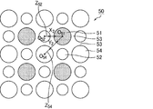
- the exhaust gas discharge cell, the first exhaust gas introduction cell, and the second exhaust gas introduction cell are all preferably circular. Even if the cross-sectional shapes of the exhaust gas discharge cell, the first exhaust gas introduction cell, and the second exhaust gas introduction cell are all circular, the effects and advantages of the present invention can be achieved.
- the cross-sectional shape of the exhaust gas exhaust cell and the second exhaust gas introduction cell is a swollen square composed of four curves curved toward the outside of the cell, while the cross-sectional shape of the first exhaust gas introduction cell is It is desirable that it is a shrinking square composed of four curves that curve inward.
- the exhaust gas exhaust cell since the exhaust gas exhaust cell, the first exhaust gas introduction cell, and the second exhaust gas introduction cell have the above-described configuration, the exhaust gas exhaust cell has a larger cross-sectional area than the first exhaust gas introduction cell.
- the size relationship between the exhaust gas introduction cell and the second exhaust gas introduction cell is also a honeycomb filter having the relationship of the present invention. Therefore, the effects of the present invention can be achieved.
- the cross-sectional area of the second exhaust gas introduction cell is the same as the cross-sectional area of the exhaust gas discharge cell
- the cross-sectional area of the first exhaust gas introduction cell is preferably 20 to 50% of the cross-sectional area of the second exhaust gas introduction cell.
- the cross-sectional area of the first exhaust gas introduction cell When the cross-sectional area of the first exhaust gas introduction cell is less than 20% of the cross-sectional area of the second exhaust gas introduction cell, the cross-sectional area of the first exhaust gas introduction cell becomes too small, and the passage resistance through which the exhaust gas passes through the first exhaust gas introduction cell. Tends to increase and pressure loss tends to increase. On the other hand, if the cross-sectional area of the first exhaust gas introduction cell exceeds 50% of the cross-sectional area of the second exhaust gas introduction cell, the difference in the passage resistance between the two becomes small and it is difficult to reduce the pressure loss.
- the exhaust gas introduction cell includes a first exhaust gas introduction cell and a second exhaust gas introduction cell having a cross-sectional area in a direction perpendicular to the longitudinal direction of the cell larger than the first exhaust gas introduction cell. It is desirable to consist only of types. This is because a smaller number of exhaust gas introduction cells having a smaller cross-sectional area than that of the second exhaust gas introduction cell can increase the effective area as the introduction cell, and allows PM to be deposited thinly and widely.
- the honeycomb filter includes the exhaust gas discharge cell, the first exhaust gas introduction cell, and the second exhaust gas introduction cell, and a plurality of honeycomb fired bodies having outer peripheral walls on the outer periphery have an adhesive layer. It is desirable that it is formed by being bonded via. Even in such a structure formed by bonding a plurality of honeycomb fired bodies through an adhesive layer, the cells constituting one honeycomb fired body have the structure of the present invention. The assembly can also exert the effects of the present invention.
- the honeycomb filter includes the exhaust gas discharge cell, the first exhaust gas introduction cell, and the second exhaust gas introduction cell, and is configured by one honeycomb fired body having an outer peripheral wall on the outer periphery. It is desirable.
- the honeycomb filter is composed of one honeycomb fired body, and the honeycomb fired body can achieve the effects of the present invention.
- the honeycomb filter is composed of a honeycomb fired body, and the honeycomb fired body is preferably composed of silicon carbide or silicon-containing silicon carbide.
- the silicon carbide and the silicon-containing silicon carbide are materials having excellent heat resistance. For this reason, this honeycomb filter is a honeycomb filter having more excellent heat resistance.
- the honeycomb filter is composed of a honeycomb fired body, and the honeycomb fired body is preferably made of cordierite or aluminum titanate.
- the cordierite and aluminum titanate are materials having a low coefficient of thermal expansion. For this reason, this honeycomb filter is a honeycomb filter in which cracks and the like are unlikely to occur even when a large thermal stress is generated during regeneration or the like.
- the porosity of the cell partition wall is preferably 40 to 65%.
- the cell partition wall can trap PM in the exhaust gas well and can suppress an increase in pressure loss due to the cell partition wall. Accordingly, the honeycomb filter has a low initial pressure loss and is unlikely to increase even when PM is deposited.
- the porosity of the cell partition is less than 40%, the ratio of the pores in the cell partition is too small, so that the exhaust gas does not easily pass through the cell partition, and the pressure loss when the exhaust gas passes through the cell partition increases.
- the porosity of the cell partition wall exceeds 65%, the mechanical properties of the cell partition wall are low, and cracks are likely to occur during regeneration.
- the average pore diameter of the pores contained in the cell partition wall is 8 to 25 ⁇ m.
- PM can be collected with high collection efficiency while suppressing an increase in pressure loss.
- the average pore diameter of the pores contained in the cell partition walls is less than 8 ⁇ m, the pores are too small, and the pressure loss when the exhaust gas permeates the cell partition walls increases.
- the average pore diameter of the pores contained in the cell partition wall exceeds 25 ⁇ m, the pore diameter becomes too large, and the PM collection efficiency is lowered.
- the honeycomb filter of the present invention it is desirable that an outer peripheral coat layer is formed on the outer periphery.
- This outer peripheral coat layer plays a role of mechanically protecting internal cells. Therefore, the honeycomb filter is excellent in mechanical properties such as compressive strength.
- the first exhaust gas introduction cell, the second exhaust gas introduction cell, and the exhaust gas exhaust cell are the same in all locations in each cell except for a plugging portion from an end portion on the exhaust gas outlet side to an end portion on the exhaust gas outlet side. It is desirable that the cross-sectional shapes of the first exhaust gas introduction cell and the second exhaust gas introduction cell are different from each other, and the cross-sectional shapes of the exhaust gas discharge cell and the first exhaust gas introduction cell are also different from each other. This difference means that they are not congruent, but similar forms are meant to be included.
- the cross-sectional shapes are similar, the cross-sectional shapes are interpreted as different from each other.
- the first exhaust gas introduction cell itself has the same shape in any cross section
- the second exhaust gas introduction cell and the exhaust gas exhaust cell have the same shape in any cross section.
- the following cell structure is regarded as one cell unit, and the cell unit is arranged around the exhaust gas discharge cell in the cell structure below. It is desirable that the honeycomb filter is configured by repeating two-dimensionally while sharing the introduction cell and the second exhaust gas cell.
- Cell structure The exhaust gas introduction cell is adjacent to the entire periphery of the exhaust gas exhaust cell with a porous cell partition wall, and the exhaust gas introduction cell is perpendicular to the longitudinal direction of the first exhaust gas introduction cell and the cell.
- the cross sectional area of the second exhaust gas introduction cell is larger than the first exhaust gas introduction cell, and the cross sectional area of the cross section perpendicular to the cell longitudinal direction of the exhaust gas exhaust cell is the second exhaust gas introduction cell.
- the cross-sectional area of the cross section perpendicular to the cell longitudinal direction is the same as or larger than the cross-sectional area of the cell, and the exhaust gas exhaust cell and the exhaust gas introduction cell both relate to the cross section perpendicular to the cell longitudinal direction.
- the side that faces the exhaust gas discharge cell is the side that forms the cross-sectional shape of the second exhaust gas introduction cell
- the thickness of the cell partition wall separating the first exhaust gas introduction cell and the exhaust gas exhaust cell is as follows: The cell structure is thinner than the thickness of the cell partition wall separating the second exhaust gas introduction cell and the exhaust gas discharge cell.
- the filter has an outer peripheral wall, and naturally the cell unit does not spread outward from the outer peripheral wall. For this reason, a cell unit receives a defect
- FIG. 1 is an enlarged end view illustrating a part of an end face of a honeycomb filter according to an embodiment of the present invention.
- FIGS. 2A to 2B are scanning electron micrographs (SEM photographs) showing an example of the shape of the cell cross section.
- FIGS. 3A and 3B are scanning electron micrographs (SEM photographs) showing an example of the shape of a cell cross section of a cell different from the cell shown in FIG. 4 (a) to 4 (c) are enlarged end views showing a part of the end face of the honeycomb filter according to the embodiment of the present invention.
- FIG. 5 is a perspective view schematically showing an example of the honeycomb filter according to the first embodiment of the present invention.
- Fig.6 (a) is a perspective view which shows typically an example of the honeycomb fired body which comprises the honeycomb filter shown in FIG.
- FIG. 6B is a cross-sectional view taken along the line AA of the honeycomb fired body shown in FIG.
- FIG. 7 shows that the cell unit (cell structure) is two-dimensionally dimensional when the second exhaust gas introduction cell and the exhaust gas exhaust cell are octagonal and the first exhaust gas introduction cell is square in the cross-sectional shape of the cell. I.e., in the cell longitudinal direction of the honeycomb filter, showing how the first exhaust gas introduction cell and the second exhaust gas cell are shared between the cell units (cell structures) in the X and Y directions. It is an enlarged view of a vertical cross section.
- FIG. 8 (a) is a perspective view showing an example of a modification of the first embodiment of the honeycomb filter of the present invention
- Fig. 8 (b) is a honeycomb firing that constitutes the honeycomb filter shown in Fig. 8 (a).
- It is a perspective view which shows a body typically.
- FIG. 9 is a cross-sectional view schematically showing a pressure loss measuring method.
- FIG. 10 is a graph showing the relationship between the amount of collected PM and the pressure loss measured in Example 1 and Comparative Example 1.
- FIG. 11 (a) is a perspective view schematically showing an example of the integrated honeycomb filter according to the second embodiment of the present invention
- FIG. 11 (b) is a cross-sectional view taken along the line BB of the integrated honeycomb filter.
- FIG. 12 is an enlarged end view schematically showing an example of cell arrangement on the end face of the honeycomb fired body constituting the honeycomb filter according to the third embodiment of the present invention.
- FIG. 13 shows that the cell unit (cell structure) is two-dimensionally, that is, in the X and Y directions when the first exhaust gas introduction cell, the second exhaust gas introduction cell, and the exhaust gas exhaust cell are square in the cross-sectional shape of the cell.
- FIG. 2 is an enlarged view of a cross section perpendicular to the cell longitudinal direction of the honeycomb filter showing how the first exhaust gas introduction cell and the second exhaust gas cell are shared between the cell units (cell structures). is there.
- FIG. 14 is an enlarged end view schematically showing an example of cell arrangement on the end face of the honeycomb fired body constituting the honeycomb filter according to the fourth embodiment of the present invention.
- FIG. 15 is an enlarged end view schematically showing an example of cell arrangement on the end face of the honeycomb fired body constituting the honeycomb filter according to the fifth embodiment of the present invention.
- 16A is a side view schematically showing an example of a swollen square cell shape
- FIG. 16B is a side view schematically showing an example of a contracted square cell shape.
- FIG. 16C is a side view schematically showing an example of a shape chamfered near the apex of the shrinking square
- FIG. 16D is an example of a shape chamfered near the apex of the swollen square. It is a side view which shows typically.
- Fig. 17 (a) is a perspective view schematically showing the honeycomb filter described in Patent Document 1
- Fig. 17 (b) schematically shows a honeycomb fired body constituting the honeycomb filter shown in Fig. 17 (a).
- 17 (c) and 17 (d) are enlarged end views schematically showing the honeycomb filter.
- 18 (a) is a perspective view schematically showing the honeycomb filter described in Patent Document 2
- FIGS. 18 (b) to 18 (c) are enlarged end views schematically showing the honeycomb filter. is there.
- Fig. 17 (a) is a perspective view schematically showing the honeycomb filter described in Patent Document 1
- FIGS. 18 (b) to 18 (c) are enlarged end views schematically showing the honeycomb filter. is there.
- Fig. 17 (a) is a perspective view schematically showing the honeycomb filter described in
- FIG. 19 (a) is a perspective view schematically showing a honeycomb filter according to a comparative example, and Fig. 19 (b) schematically shows a honeycomb fired body constituting the honeycomb filter shown in Fig. 19 (a). It is a perspective view.
- the honeycomb filter according to the first embodiment of the present invention includes an exhaust gas discharge cell in which an end portion on the exhaust gas outlet side is opened and an end portion on the exhaust gas inlet side is plugged, and an end portion on the exhaust gas inlet side is opened and As the exhaust gas introduction cell whose end on the exhaust gas outlet side is plugged, a plurality of honeycomb fired bodies having a first exhaust gas introduction cell and a second exhaust gas introduction cell and having an outer peripheral wall on the outer periphery are interposed via an adhesive layer It is formed by bonding.
- first exhaust gas introduction cell and the second exhaust gas introduction cell are adjacent to each other around the exhaust gas discharge cell with a porous cell partition wall therebetween, Regarding the cross section perpendicular to the longitudinal direction of the cell, the cross-sectional area of the second exhaust gas introduction cell is larger than the cross-sectional area of the first exhaust gas introduction cell, and the cross-sectional area of the exhaust gas exhaust cell is the same as that of the second exhaust gas introduction cell. Is the same as the cross-sectional area, Regarding the cross section perpendicular to the longitudinal direction of the cell, the exhaust gas exhaust cell and the exhaust gas introduction cell are both polygonal and face the exhaust gas exhaust cell among the sides constituting the cross-sectional shape of the first exhaust gas introduction cell.
- the length of the side which is carrying out is longer than the length of the side which has faced the said exhaust gas discharge cell among the sides which comprise the cross-sectional shape of the said 2nd exhaust gas introduction cell.
- the cross-sectional shape perpendicular to the longitudinal direction of the cell the cross-sectional shapes of the exhaust gas introduction cell and the exhaust gas exhaust cell are from the end on the exhaust gas inlet side to the end on the exhaust gas outlet side, except for the plugging portion, respectively. Is the same in all locations in the cell.
- FIG. 5 is a perspective view schematically showing an example of the honeycomb filter according to the first embodiment of the present invention.
- Fig.6 (a) is a perspective view which shows typically an example of the honeycomb fired body which comprises the honeycomb filter shown in FIG.
- FIG. 6B is a cross-sectional view taken along the line AA of the honeycomb fired body shown in FIG.
- honeycomb filter 20 shown in FIG. 5, a plurality of honeycomb fired bodies 10 are bundled through an adhesive layer 15 to form a ceramic block 18, and the outer periphery of the ceramic block 18 is for preventing leakage of exhaust gas.
- the outer peripheral coat layer 16 is formed.
- the outer periphery coating layer 16 should just be formed as needed.
- honeycomb filter formed by binding a plurality of honeycomb fired bodies is also referred to as a collective honeycomb filter.
- the honeycomb fired body 10 has a quadrangular prism shape, but as shown in FIG. 6A, the corners at the end faces are chamfered so as to have a curved shape. Concentrates and prevents damage such as cracks.
- the corner may be chamfered so as to have a linear shape.
- the exhaust gas discharge cell has an end on the exhaust gas outlet side opened and the end on the exhaust gas inlet side is plugged, and the exhaust gas introduction cell has an exhaust gas inlet side.
- the plugging material 11 is preferably the same material as the honeycomb fired body.
- a first exhaust gas introduction cell having a square cross section with a porous cell partition wall is provided around the entire periphery of the exhaust gas exhaust cell 11 having an octagonal cross section. 12 and the second exhaust gas introduction cell 14 having an octagonal cross section are adjacent to each other.
- the first exhaust gas introduction cell 12 and the second exhaust gas introduction cell 14 are alternately arranged around the exhaust gas discharge cell 11, and the sectional area of the second exhaust gas introduction cell 14 is larger than the sectional area of the first exhaust gas introduction cell 12.
- the cross-sectional area of the exhaust gas discharge cell 11 is the same as the cross-sectional area of the second exhaust gas introduction cell 14.
- An outer peripheral wall 17 is formed on the outer periphery of the honeycomb fired body 10.
- the cross-sectional shapes of the second exhaust gas introduction cell 14 and the exhaust gas discharge cell 11 are both octagons and are congruent with each other.
- the exhaust gas discharge cell 11 and the second exhaust gas introduction cell 14 have the same octagonal shape, but this octagon is point-symmetric with respect to the center of gravity, and the hypotenuse (shown as 14a in FIG. 4).
- octagons having the same length and horizontal and vertical sides (indicated by 14b in FIG. 4), and the four first sides (the oblique sides) and the four second sides. (Vertical and horizontal sides) are alternately arranged, and the angle formed by the first side and the second side is 135 °.
- the “slope side” generally refers to a longer side opposite to the right angle of a right triangle, but in this specification, for the convenience of explanation, the hypothetical side includes four hypothetical line segments described below.
- the side 14a and the side 11b having a predetermined angle that is not 90 ° or 0 ° are expressed as “slopes”.
- the side 14b and the side 11a that are parallel or perpendicular to the four virtual line segments described below are expressed as "longitudinal and lateral sides”.
- the hypothetical line segments in the description of “slanted side” and “longitudinal and lateral sides” connect between the geometric gravity centers of the cross-sectional figures of the four second exhaust gas introduction cells 14 arranged around the exhaust gas discharge cell 11.
- four line segments that do not intersect with the cross-sectional shape of the exhaust gas discharge cell 11 are meant.
- the first exhaust gas introduction cell 12 has a square cross-sectional shape. Further, regarding the cross-sectional shapes of the three adjacent cells, that is, the exhaust gas discharge cell 11, the second exhaust gas introduction cell 14, and the first exhaust gas introduction cell 12, the cell partition wall 13 is separated at the side of the octagonal exhaust gas discharge cell 11. Thus, the side 11a facing the first exhaust gas introduction cell 12 and the side 12a facing the exhaust gas discharge cell 11 across the cell partition wall 13 are parallel to the side of the square first exhaust gas introduction cell 12.
- the cell partition wall The side 14 a facing the exhaust gas discharge cell 11 across 13 is parallel.
- the side of the first exhaust gas introduction cell 12 faces the second exhaust gas introduction cell 14 across the cell partition wall 13 and the side of the second exhaust gas introduction cell 14 separates the cell partition wall 13 and the first exhaust gas.
- the side 14b facing the introduction cell 12 is parallel.
- the distance between the sides parallel to each other is equal to each other in any combination. That is, the distance between the sides 11a and 12a parallel to each other, the distance between the sides 11b and 14a parallel to each other, and the distance between the sides 12b and 14b parallel to each other are equal to each other.
- the exhaust gas discharge cell 11, the first exhaust gas introduction cell 12, and the second exhaust gas introduction cell 14 are arranged so as to satisfy the following conditions, respectively. That is, it passes through the octagonal graphic region of the exhaust gas exhaust cell 11 among the virtual line segments connecting the geometric centers of gravity of the octagonal graphics of the four second exhaust gas introduction cells 14 surrounding the exhaust gas exhaust cell 11.
- the imaginary line segments connecting the geometric centers of gravity of the octagonal figures of the four second exhaust gas introduction cells 14 four that do not pass through the octagonal figure area of the exhaust gas discharge cells 11 constitute a square.
- the middle point of each side coincides with the geometric gravity center of the square shape of the four first exhaust gas introduction cells 12 surrounding the exhaust gas discharge cell 11.
- first exhaust gas introduction cells 12 and four octagonal second exhaust gas introduction cells 14 are alternately arranged around the octagonal exhaust gas discharge cells 11 with the cell partition wall 13 therebetween, and the exhaust gas is discharged.
- the structure surrounding the discharge cell 11 is regarded as one unit, and this unit repeatedly arranges two-dimensionally to form a honeycomb filter while sharing the first exhaust gas introduction cell 12 and the second exhaust gas introduction cell 14 with each other. It is. Since each unit shares the first exhaust gas introduction cell 12 and the second exhaust gas introduction cell 14 with each other, the first exhaust gas introduction cell 12 and the second exhaust gas which are in contact with each other with the exhaust gas exhaust cell 11 and the cell partition wall 13 therebetween.
- the introduction cell 14 is in contact with the exhaust gas discharge cell 11 and the cell partition wall 13 in an adjacent unit.
- FIG. 7 is a cross-sectional shape of the cell, where the second exhaust gas introduction cell 14 and the exhaust gas discharge cell 11 are octagonal, the first exhaust gas introduction cell 12 is square, and the arrangement satisfies the above-described conditions.
- the cell unit (cell structure) repeats two-dimensionally, that is, in the X and Y directions described in FIG. 7, the first exhaust gas introduction cell 12 and the second exhaust gas cell 14 are between the cell units (cell structure). It is an enlarged view of a cross section perpendicular
- the cell unit 1, the cell unit 2, and the cell unit 3 all have the first exhaust gas introduction cell 12 and the second exhaust gas introduction cell 14 through the cell partition wall 13 around the exhaust gas exhaust cell 11 so as to satisfy the conditions described above. 4 are alternately arranged.
- the cell unit 2 has the same structure as the cell unit 1, and is adjacent to the X direction sharing the cell unit 1, one first exhaust gas introduction cell 12 and two second exhaust gas introduction cells 14. A cell shared by the cell unit 1 and the cell unit 2 is described as “shared part 2” in FIG.
- the unit cell 3 has the same structure as the cell unit 1 and shares the cell unit 1 with one first exhaust gas introduction cell 12 and two second exhaust gas introduction cells 14 and is adjacent to the Y direction. .
- a cell shared by the cell unit 1 and the cell unit 3 is described as “shared portion 1” in FIG.
- the virtual line segments connecting the geometric centers of the octagonal figures of the four second exhaust gas introduction cells 14 four line segments H and I that do not pass through the octagonal graphic area of the exhaust gas discharge cell 11.
- J, K, and two virtual line segments L and M passing through the octagonal graphic region of the exhaust gas discharge cell 11 are shown in FIG.
- the “shared part 2” is drawn by hatching consisting of line segments in the same direction as the line segment M
- the “shared part 1” is drawn by hatching consisting of line segments in the same direction as the line segment L.
- the intersection of the two line segments L and M coincides with the geometric center of gravity of the exhaust gas discharge cell 11.
- the cross sections of the exhaust gas exhaust cell 11 and the second exhaust gas introduction cell 14 are octagonal, and the cross section of the first exhaust gas introduction cell 12 is square.
- the cross-sectional shape of the exhaust gas exhaust cell and the exhaust gas introduction cell constituting the honeycomb filter of the invention is not limited to the above shape, and may be all square as described below, or a combination of other polygons. .
- angular part of the exhaust gas exhaust cell 11, the 1st exhaust gas introduction cell 12, and the 2nd exhaust gas introduction cell 14 of a cell with such a polygonal cross section may be a curve chamfering shape where a cross section becomes a curve.
- the curve include a curve obtained when a circle is divided into four equal parts, a curve obtained when an ellipse is divided into four equal parts by a straight line perpendicular to the major axis and the major axis, and the like.
- the cross section has a curved chamfered shape in which a cross section becomes a curve at a corner of a square cell. It is because it can prevent that a crack enters into a cell partition because stress concentrates on a corner.
- the honeycomb filter 20 may include a part of cells having a curved cross section as necessary.
- the cross-sectional area of the first exhaust gas introduction cell 12 is preferably 20 to 50%, more preferably 22 to 45% of the cross-sectional area of the second exhaust gas introduction cell 14.
- the cross-sectional area of the exhaust gas discharge cell 11 is the same as the cross-sectional area of the second exhaust gas introduction cell 14, but the cross-sectional area of the exhaust gas discharge cell 11 is the same as the second exhaust gas introduction cell.
- the cross-sectional area may be larger than 14. In that case, the cross-sectional area of the exhaust gas discharge cell 11 is preferably 1.05 to 1.5 times the cross-sectional area of the second exhaust gas introduction cell 14.
- the length of the side 12a facing the exhaust gas discharge cell 11 is the side constituting the cross-sectional shape of the second exhaust gas introduction cell 14, It is longer than the length of the side 14 a facing the exhaust gas discharge cell 11. According to the definition of the present invention described above, the sides 12 a and 14 a are sides facing the exhaust gas discharge cell 11.
- the ratio of the length of the side 14a of the second exhaust gas introduction cell 14 to the length of the side 12a of the first exhaust gas introduction cell 12 is not particularly limited. 0.8 or less, more preferably 0.7 or less, and even more preferably 0.5 or less.
- the exhaust gas G 1 flowing into the first exhaust gas introduction cell 12 or the second exhaust gas introduction cell 14 (in FIG. 6B, the exhaust gas is indicated by G 1 , and the flow of the exhaust gas is indicated by an arrow. Is always discharged from the exhaust gas discharge cell 11 after passing through the cell partition wall 13 that separates the exhaust gas discharge cell 11 from the first exhaust gas introduction cell 12 or the second exhaust gas introduction cell 14.
- the cell partition wall 13 functions as a filter.
- the exhaust gas discharge cell 11, the first exhaust gas introduction cell 12, and the second exhaust gas introduction cell 14 can circulate gas such as exhaust gas.
- gas such as exhaust gas.
- the end of the honeycomb fired body 10 on the first end face 10a side (the end on the side where the exhaust gas discharge cells 11 are plugged) is the exhaust gas inlet side.
- the end of the honeycomb fired body 10 on the second end face 10b side (the end on the side where the first exhaust gas introduction cell 12 and the second exhaust gas introduction cell 14 are plugged) is the exhaust gas outlet side. The end of the.
- the initial pressure loss can be made lower than that of the conventional honeycomb filter, and a considerable amount of PM can be obtained. Even at the stage of depositing on the cell partition wall, the rate of increase in pressure loss is small, and the pressure loss can be greatly improved over the entire use range from the initial stage until PM is deposited in an amount close to the limit.
- the honeycomb filter 20 is composed of a plurality of honeycomb fired bodies 10, and examples of the constituent material of the honeycomb fired body 10 include carbides such as silicon carbide, titanium carbide, tantalum carbide, and tungsten carbide.
- carbides such as silicon carbide, titanium carbide, tantalum carbide, and tungsten carbide.
- examples thereof include nitride ceramics such as ceramic, aluminum nitride, silicon nitride, boron nitride, and titanium nitride, and oxide ceramics such as alumina, zirconia, cordierite, mullite, aluminum titanate, and silicon-containing silicon carbide.
- silicon carbide or silicon-containing silicon carbide is preferable. It is because it is excellent in heat resistance, mechanical strength, thermal conductivity and the like.
- the silicon-containing silicon carbide is a mixture of silicon carbide and metal silicon, and silicon-containing silicon carbide containing 60 wt% or more of silicon carbide is preferable.
- the thickness of the cell partition walls that separate the cells of the honeycomb fired body 10 constituting the honeycomb filter 20 according to the first embodiment is desirably equal in all places.
- the thickness of the cell partition wall is preferably 0.10 to 0.46 mm, more preferably 0.15 to 0.31 mm.
- the thickness of the outer peripheral wall 17 is preferably 0.10 to 0.50 mm.
- the thickness of a cell partition is the value measured as thickness D shown in FIG. 1 based on an above-described definition.
- the porosity of the cell partition walls and the outer peripheral wall of the honeycomb fired body 10 constituting the honeycomb filter 20 according to the first embodiment is preferably 40 to 65%.
- the average pore diameter of the pores contained in the cell partition walls of the honeycomb fired body 10 constituting the honeycomb filter 20 according to the first embodiment is preferably 8 to 25 ⁇ m.
- the number of cells per unit area in the cross section of the honeycomb fired body 10 is desirably 31 to 62 cells / cm 2 (200 to 400 cells / inch 2 ).
- honeycomb filter 20 a plurality of honeycomb fired bodies having outer peripheral walls on the outer periphery are bonded together through an adhesive layer.
- the adhesive for bonding the honeycomb fired body is obtained by applying and drying an adhesive paste containing an inorganic binder and inorganic particles.
- the adhesive may further contain inorganic fibers and / or whiskers.
- the thickness of the adhesive layer is preferably 0.5 to 2.0 mm.
- the outer peripheral coat layer may be provided on the outer periphery of the honeycomb filter, but the material of the outer peripheral coat layer is preferably the same as the material of the adhesive.
- the thickness of the outer peripheral coat layer is preferably 0.1 to 3.0 mm.
- a forming step of producing a honeycomb formed body by extruding a wet mixture containing a ceramic powder and a binder is performed. Specifically, first, a wet mixture for manufacturing a honeycomb formed body is prepared by mixing silicon carbide powder having different average particle sizes as ceramic powder, an organic binder, a liquid plasticizer, a lubricant, and water. To prepare.
- a pore-forming agent such as balloons that are fine hollow spheres containing oxide ceramics, spherical acrylic particles, and graphite may be added to the wet mixture.
- the balloon is not particularly limited, and examples thereof include an alumina balloon, a glass micro balloon, a shirasu balloon, a fly ash balloon (FA balloon), and a mullite balloon. Of these, alumina balloons are desirable.
- a honeycomb formed body having a predetermined shape.
- a honeycomb formed body is manufactured using a mold that has a cross-sectional shape having the cell structure (cell shape and cell arrangement) shown in FIGS.
- the honeycomb formed body is cut to a predetermined length, dried using a microwave dryer, hot air dryer, dielectric dryer, vacuum dryer, vacuum dryer, freeze dryer, etc.
- a plugging step is performed in which the cells are plugged by filling the cells with a plug material paste as a plug.
- the wet mixture can be used as the sealing material paste.
- the honeycomb formed body is heated to 300 to 650 ° C. in a degreasing furnace, and after performing a degreasing process for removing organic substances in the honeycomb formed body, the degreased honeycomb formed body is conveyed to a firing furnace, and 2000 to By performing a firing step of heating to 2200 ° C., a honeycomb fired body as shown in FIGS. 4 to 6 is manufactured.
- the sealing material paste with which the edge part of the cell was filled is baked and becomes a plugging material.
- the conditions conventionally used when manufacturing a honeycomb fired body can be applied to the cutting process, drying process, plugging process, degreasing process, and firing process.
- a bundling process is performed in which a plurality of honeycomb fired bodies are sequentially stacked and bonded via an adhesive paste on a support stand to produce a honeycomb aggregate in which a plurality of honeycomb fired bodies are stacked.
- the adhesive paste for example, a paste made of an inorganic binder, an organic binder, and inorganic particles is used.
- the adhesive paste may further contain inorganic fibers and / or whiskers.
- Examples of the inorganic particles contained in the adhesive paste include carbide particles and nitride particles. Specific examples include silicon carbide particles, silicon nitride particles, and boron nitride particles. These may be used alone or in combination of two or more. Among the inorganic particles, silicon carbide particles having excellent thermal conductivity are desirable.
- Examples of the inorganic fibers and / or whiskers contained in the adhesive paste include inorganic fibers and / or whiskers made of silica-alumina, mullite, alumina, silica, and the like. These may be used alone or in combination of two or more. Among inorganic fibers, alumina fiber is desirable.
- the inorganic fiber may be a biosoluble fiber.
- the balloon which is a micro hollow sphere which uses an oxide type ceramic as a component, spherical acrylic particle, graphite, etc.
- the balloon is not particularly limited, and examples thereof include an alumina balloon, a glass micro balloon, a shirasu balloon, a fly ash balloon (FA balloon), and a mullite balloon.
- the adhesive paste is heated and solidified to form an adhesive layer, and a square columnar ceramic block is produced.
- the conditions for heating and solidifying the adhesive paste the conditions conventionally used when producing a honeycomb filter can be applied.
- a cutting process for cutting the ceramic block is performed. Specifically, a ceramic block whose outer periphery is processed into a substantially cylindrical shape is manufactured by cutting the outer periphery of the ceramic block using a diamond cutter.
- An outer peripheral coating layer forming step is performed in which an outer peripheral coating material paste is applied to the outer peripheral surface of the substantially cylindrical ceramic block, and dried and solidified to form an outer peripheral coating layer.
- the said adhesive paste can be used as an outer periphery coating material paste.
- the outer peripheral coat layer is not necessarily provided, and may be provided as necessary.
- a honeycomb filter having a predetermined shape was manufactured by performing a cutting process.
- a honeycomb fired body having a plurality of shapes having an outer peripheral wall on the entire outer periphery was manufactured.
- a honeycomb fired body having a shape may be combined with an adhesive layer to form a predetermined shape such as a cylinder. In this case, the cutting process can be omitted.
- the initial pressure loss can be made lower than that of the conventional honeycomb filter, and the increase rate of the pressure loss even when a considerable amount of PM is deposited on the cell partition walls.
- the pressure loss can be greatly improved over the entire use range from the initial stage until PM is deposited in an amount close to the limit.
- the cross-sectional area of the first exhaust gas introduction cell can be 20 to 50% of the cross-sectional area of the second exhaust gas introduction cell.
- the ratio of the side length of the second exhaust gas introduction cell to the length of the side of the first exhaust gas introduction cell can be 0.8 or less.
- the constituent material of the honeycomb fired body can be silicon carbide or silicon-containing silicon carbide, and the honeycomb filter can be excellent in heat resistance.
- the thickness of the cell partition walls that separate the cells can be made equal at all locations.
- the thickness of the cell partition wall can be set to 0.10 to 0.46 mm.
- the cell partition wall has a sufficient thickness to collect PM in the exhaust gas, and an increase in pressure loss can be effectively suppressed.
- the porosity of the cell partition walls and the outer peripheral wall constituting the honeycomb filter 20 can be 40 to 65%.
- the cell partition can capture PM in the exhaust gas well, and can suppress an increase in pressure loss caused by the cell partition.
- the average pore diameter of the pores contained in the cell partition walls of the honeycomb fired body constituting the honeycomb filter can be 8 to 25 ⁇ m.
- the cross-sectional shapes of the exhaust gas introduction cell and the exhaust gas discharge cell are the above from the end on the exhaust gas inlet side except for the plugging portion. It is the same at all locations in each cell from the end on the exhaust gas outlet side. Therefore, the same effect can be obtained with the entire honeycomb filter, and the occurrence of inconvenience due to non-uniform shape depending on the location of the honeycomb filter can be prevented.
- the sealing portion provided at the end portion on the exhaust gas outlet side that is, the sealing portion filled in the first exhaust gas introduction cell and the second exhaust gas introduction cell is connected to the first through the cell partition wall.
- Exhaust gas introduction cell exists in rows and columns with a width greater than the length of one side.
- the outlet side of the honeycomb filter is exposed to a higher temperature, and a temperature difference in the radial direction of the honeycomb filter is likely to occur, and cracks are generated due to thermal stress.
- a crack has a large and small relationship in the cross-sectional area of the cell, and stress concentration tends to occur when the cross-sectional shape of the exhaust gas introduction cell on which PM is deposited includes a square.
- the sealing portions arranged in rows and columns at the end portion on the exhaust gas outlet side become the heat conduction layer and the heat radiation layer to the outside, and the radial direction at the end portion on the exhaust gas outlet side of the honeycomb filter The temperature difference can be reduced, the generated thermal stress is reduced, and cracks are less likely to occur.
- the honeycomb filter of the present embodiment the amount of the sealing material filled in the second exhaust gas introduction cell in which more PM is deposited than the first exhaust gas introduction cell increases according to the cross-sectional area, and the sealing is performed accordingly.
- the heat capacity of the part is also increasing. Therefore, with this sealing portion, even if considered in units of cells, it is possible to suppress the temperature rise of the second exhaust gas introduction cell where the combustion heat of PM is larger, and to reduce the temperature difference in the radial direction of the honeycomb filter, It is thought that the generated thermal stress can be reduced. For this reason, it is considered that the honeycomb filter of the present embodiment can suppress cracks during regeneration even if the exhaust gas introduction cell includes a square as a cross-sectional shape.
- Fig. 8 (a) is a perspective view showing an example of a modification of the first embodiment of the honeycomb filter according to the present invention
- Fig. 8 (b) is a honeycomb constituting the honeycomb filter shown in Fig. 8 (a). It is a perspective view which shows a sintered body typically.
- the entire cross section of the exhaust gas discharge cell 11 having an octagonal cross section is square with a porous cell partition wall therebetween.
- the first exhaust gas introduction cell 12 and the second exhaust gas introduction cell 14 having an octagonal cross section are adjacent to each other.
- the first exhaust gas introduction cell 12 and the second exhaust gas introduction cell 14 are alternately arranged around the exhaust gas discharge cell 11, and the sectional area of the second exhaust gas introduction cell 14 is larger than the sectional area of the first exhaust gas introduction cell 12.
- the cross-sectional area of the exhaust gas discharge cell 11 is the same as the cross-sectional area of the second exhaust gas introduction cell 14.
- An outer peripheral wall 17a is formed on the outer periphery of the honeycomb fired body 10a, and all the cells adjacent to the outer peripheral wall 17a are exhaust gas introduction cells (the first exhaust gas introduction cell 12 and the second exhaust gas introduction cell 14). It has become.
- the cross-sectional shapes of the second exhaust gas introduction cell 14 and the exhaust gas discharge cell 11 are both octagons and are congruent with each other.
- the outer peripheral wall 17a of the exhaust gas introduction cell adjacent to the outer peripheral wall 17a in the cross section perpendicular to the longitudinal direction of the cell is formed so that the thickness of the outer peripheral wall 17a other than the corners is uniform.
- the side that contacts is formed in parallel and linearly with the side that forms the outer wall of the outer peripheral wall 17a.
- the cross section of the second exhaust gas introduction cell 14A closest to the outer peripheral wall 17a is partially cut, it changes from an octagon to a hexagon.
- the cross-sectional shape of the first exhaust gas introduction cell 12A may be a partially cut shape, but is preferably congruent with the cross-sectional shape of the first exhaust gas introduction cell 12.
- the second exhaust gas introduction cell 14B existing at the corner of the honeycomb fired body 10a is changed from an octagon to a substantially pentagon having a chamfered portion 140 made of a curve.
- the strength of the honeycomb fired body is improved by the outer peripheral wall, and the partial variation in the volume ratio of the exhaust gas discharge cell and the exhaust gas introduction cell in the honeycomb fired body is further suppressed, and the flow of the exhaust gas is further increased. Since it becomes uniform, pressure loss can be reduced.
- Example 1 Example 1
- a silicon carbide coarse powder of 52.8% by weight having an average particle size of 22 ⁇ m and a silicon carbide fine powder of 22.6% by weight of an average particle size of 0.5 ⁇ m were mixed, and the resulting mixture was mixed with an organic binder.
- (Methylcellulose) 4.6% by weight, lubricant (Unilube manufactured by NOF Corporation) 0.8% by weight, glycerin 1.3% by weight, pore former (acrylic resin) 1.9% by weight, oleic acid 2. 8% by weight and 13.2% by weight of water were added and kneaded to obtain a wet mixture, followed by a molding step of extrusion molding. In this step, a raw honeycomb molded body having the same shape as the honeycomb fired body 10a shown in FIG. 8A and having no cell plugged was produced.
- the dried honeycomb molded body was produced by drying the raw honeycomb molded body using a microwave dryer. Thereafter, the plugging paste was filled in predetermined cells of the dried honeycomb molded body to plug the cells. Specifically, the cells were plugged such that the end on the exhaust gas inlet side and the end on the exhaust gas outlet side were plugged at the positions shown in FIG. The wet mixture was used as a sealing material paste. After plugging the cells, the dried honeycomb molded body filled with the plug paste was dried again using a dryer.
- a degreasing treatment was performed by degreasing the dried honeycomb molded body on which the cells were plugged at 400 ° C., and further, a firing treatment was performed under conditions of 2200 ° C. and 3 hours in an atmospheric argon atmosphere. Thereby, a square pillar honeycomb fired body was produced.
- the side length and cross-sectional area are measured using the previously described electron micrograph and image analysis type particle size distribution software (manufactured by Mountech Co., Ltd.) MAC-View (Version 3.5). be able to.
- the manufactured honeycomb fired body has a porosity of 45%, an average pore diameter of 15 ⁇ m, a size of 34.3 mm ⁇ 34.3 mm ⁇ 150 mm, and the number of cells (cell density) of 290 cells / inch 2 (in the honeycomb fired body). The number of cells is 529), the honeycomb fired body shown in FIG. 8 (b) is made of a silicon carbide sintered body having a cell partition wall thickness of 0.25 mm (10 mil) and an outermost peripheral wall thickness of 0.35 mm. It was body 10a.
- the first exhaust gas introduction cells 12, 12A and the second exhaust gas introduction cells 14, 14A, 14B were adjacent to the entire periphery of the exhaust gas exhaust cell 11. .
- the first exhaust gas introduction cells 12 and 12A are square, and the length of the side constituting the cross-sectional shape of the first exhaust gas introduction cells 12 and 12A is 0.96 mm.
- the second exhaust gas introduction cell 14 is octagonal except for the second exhaust gas introduction cells 14A and 14B adjacent to the outer peripheral wall 17, and the length of the hypotenuse that is the side facing the exhaust gas discharge cell is 0.27 mm. Yes, the length of the vertical and horizontal sides not facing the exhaust gas discharge cell 11 was 1.11 mm.
- the length of the side facing the exhaust gas discharge cell 11 is the exhaust gas length among the sides constituting the cross-sectional shape of the first exhaust gas introduction cell 12.
- the length of the side facing the discharge cell 11 was 0.28 times.
- the length of the side adjacent to the outer peripheral wall 17 is 1.23 mm
- the length of the vertical and horizontal sides is 1.04 mm
- the length of the hypotenuse was 0.27 mm and the cross-sectional area was 1.48 mm 2 .
- the length of the side adjacent to the outer peripheral wall 17 is 1.49 mm, and the length of the vertical side parallel to the side adjacent to the outer peripheral wall 17 is 1.11 mm.
- the length of the side that is perpendicular to the side adjacent to the outer peripheral wall 17 is 1.04 mm, the length of the hypotenuse is 0.27 mm, and the cross-sectional area is 1.79 mm 2. Met.
- the exhaust gas discharge cell 11 has an octagonal shape, the shape thereof is the same as that of the second exhaust gas introduction cell 14, the length of the hypotenuse facing the second exhaust gas introduction cell 14 is 0.27 mm, and the first exhaust gas The length of the vertical and horizontal sides facing the introduction cell 12 was 1.11 mm.
- the cross-sectional area of the first exhaust gas introduction cell 12 was 0.93 mm 2
- the cross-sectional areas of the second exhaust gas introduction cell 14 and the exhaust gas discharge cell 11 were both 2.17 mm 2 . That is, the cross-sectional area of the first exhaust gas introduction cell 12 was 43% of the cross-sectional area of the second exhaust gas introduction cell 14.
- the cross-sectional area of the exhaust gas discharge cell 11 is the same as the cross-sectional area of the second exhaust gas introduction cell 14 and is larger than the cross-sectional area of the first exhaust gas introduction cell 12.
- honeycomb fired body had a quadrangular prism shape that was chamfered so that the corners at the end face had a curved shape.
- alumina fibers having an average fiber length of 20 ⁇ m, 21% by weight of silicon carbide particles having an average particle diameter of 0.6 ⁇ m, 15% by weight of silica sol, 5.6% by weight of carboxymethylcellulose, and 28.4% by weight of water were added.
- a number of honeycomb fired bodies were bundled using the heat-resistant adhesive paste contained, and the adhesive paste was dried and solidified at 120 ° C. to form an adhesive layer, thereby producing a prismatic ceramic block.
- a substantially cylindrical ceramic block was produced by cutting the outer periphery of the prismatic ceramic block using a diamond cutter.
- a sealing material paste having the same composition as the adhesive paste is applied to the outer peripheral surface of the ceramic block, and the outer peripheral coating layer is formed by drying and solidifying the sealing material paste at 120 ° C., thereby forming a cylindrical honeycomb filter.
- the honeycomb filter had a diameter of 143.8 mm and a length in the longitudinal direction of 150 mm.
- Example 1 A forming process was performed in the same manner as in Example 1 to obtain a raw honeycomb formed body, and then the raw honeycomb formed body was dried using a microwave dryer to prepare a dried body of the honeycomb formed body. . Thereafter, the plugging paste was filled in predetermined cells of the dried honeycomb molded body to plug the cells.
- the position for plugging the cells is changed from that in Example 1, and the end face serving as the end on the exhaust gas outlet side plugs all of the octagonal cells, and the end face serving as the end on the exhaust gas inlet side. Then, all of the square cells were plugged so that the cells were alternately plugged on both end faces.
- Example 1 As a result, an end portion on the exhaust gas inlet side and an end portion on the exhaust gas outlet side were plugged at the positions shown in FIG. Thereafter, the same process as in Example 1 was performed to produce a honeycomb fired body 130 shown in FIGS. 19A and 19B, and a honeycomb filter 120 was produced.
- the exhaust gas introduction cells 132 were all octagonal except for the exhaust gas introduction cells 132A and 132B adjacent to the outer peripheral wall 137.
- the side facing the exhaust gas discharge cell 131 was a vertical and horizontal side, and its length was 1.11 mm.
- the side facing the other exhaust gas introduction cells 132, 132A, 132B is a hypotenuse, and its length was 0.27 mm.
- the exhaust gas exhaust cells 131 and 131A were all square, and the length of the side constituting the cross-sectional shape of the exhaust gas exhaust cells 131 and 131A was 0.96 mm.
- the length of the side adjacent to the outer peripheral wall 137 is 1.23 mm
- the length of the vertical and horizontal sides is 1.04 mm
- the length of the oblique side is The cross-sectional area was 0.28 mm and the cross-sectional area was 1.48 mm 2 .
- the length of the side adjacent to the outer peripheral wall 137 is 1.49 mm
- the length of the vertical side parallel to the side adjacent to the outer peripheral wall 17 is 1.11 mm.
- the length of the side that is perpendicular to the side adjacent to the outer peripheral wall 17 is 1.04 mm, the length of the hypotenuse is 0.27 mm, and the cross-sectional area is 1.79 mm 2. It was. Moreover, the thickness of the cell partition wall 133 was 0.25 mm, and the thickness of the outer peripheral wall was 0.35 mm.
- the cross-sectional area of the exhaust gas introduction cell 132 was 2.17 mm 2 , and the cross-sectional area of the exhaust gas discharge cell 131 was 0.93 mm 2 . That is, the cross-sectional area of the exhaust gas introduction cell 132 was larger than the cross-sectional area of the exhaust gas discharge cell 131.
- FIG. 9 is a cross-sectional view schematically showing a pressure loss measuring method.
- This pressure loss measuring device 210 is arranged to fix the honeycomb filter 20 in the metal casing 213 to the exhaust gas pipe 212 of the 1.6 liter diesel engine 211 so that the pressure before and after the honeycomb filter 20 can be detected.
- the pressure gauge 214 is attached so that.
- the end of the exhaust gas inlet side of the honeycomb filter 20 is disposed on the side close to the exhaust gas pipe 212 of the diesel engine 211.
- the exhaust gas is arranged so that the exhaust gas flows into a cell having an open end on the exhaust gas inlet side.
- the diesel engine 211 was operated at a rotational speed of 3100 rpm and a torque of 50 Nm, and exhaust gas from the diesel engine 211 was circulated through the honeycomb filter 20 to collect PM in the honeycomb filter. Then, the relationship between the amount of collected PM (g / L) per liter apparent volume of the honeycomb filter and the pressure loss (kPa) was measured.
- FIG. 10 is a graph showing the relationship between the amount of collected PM and the pressure loss measured in Example 1 and Comparative Example 1. From this result, in the honeycomb filter according to Example 1, the initial pressure loss, which is the pressure loss when the amount of PM trapped was 0 g / L, was as low as 1.1 kPa, and PM was further collected up to 8 g / L. Even in this case, the pressure loss is as low as 6.6 kPa, and the PM collection amount is significantly lower than that of the honeycomb filter according to Comparative Example 1 at all time points from 0 g / L to 8 g / L. The effect was shown.
- the initial pressure loss which is the pressure loss when the amount of PM trapped was 0 g / L
- PM was further collected up to 8 g / L.
- the pressure loss is as low as 6.6 kPa
- the PM collection amount is significantly lower than that of the honeycomb filter according to Comparative Example 1 at all time points from 0 g / L to 8 g / L.
- the initial pressure loss which is the pressure loss when the amount of collected PM is 0 g / L, is 1.3 kPa, and the pressure loss when PM is collected up to 8 g / L. Is 7.2 kPa.
- the honeycomb filter according to the second embodiment includes an exhaust gas discharge cell having an end portion on the exhaust gas outlet side and an end portion on the exhaust gas inlet side plugged, an end portion on the exhaust gas inlet side, and an exhaust gas outlet side.
- an exhaust gas introduction cell whose end is plugged, the first exhaust gas introduction cell and the second exhaust gas introduction cell are provided, and one honeycomb fired body having an outer peripheral wall on the outer periphery is formed.
- first exhaust gas introduction cell and the second exhaust gas introduction cell are adjacent to each other around the exhaust gas discharge cell with a porous cell partition wall therebetween, Regarding the cross section perpendicular to the longitudinal direction of the cell, the cross-sectional area of the second exhaust gas introduction cell is larger than the cross-sectional area of the first exhaust gas introduction cell, and the cross-sectional area of the exhaust gas exhaust cell is the same as that of the second exhaust gas introduction cell. Is the same as the cross-sectional area, Regarding the cross section perpendicular to the longitudinal direction of the cell, the exhaust gas exhaust cell and the exhaust gas introduction cell are both polygonal and face the exhaust gas exhaust cell among the sides constituting the cross-sectional shape of the first exhaust gas introduction cell.
- the length of the side which is carrying out is longer than the length of the side which has faced the said exhaust gas discharge cell among the sides which comprise the cross-sectional shape of the said 2nd exhaust gas introduction cell.
- the cross-sectional shape perpendicular to the longitudinal direction of the cell the cross-sectional shapes of the exhaust gas introduction cell and the exhaust gas exhaust cell are from the end on the exhaust gas inlet side to the end on the exhaust gas outlet side, except for the plugging portion, respectively. Is the same in all locations in the cell.
- the honeycomb filter according to the second embodiment is different from the aggregated honeycomb filter according to the first embodiment, except that the honeycomb filter is configured by one honeycomb fired body having an outer peripheral wall on the outer periphery.
- the configuration is the same as the honeycomb filter.
- Such a honeycomb filter constituted by one honeycomb fired body is also referred to as an integral honeycomb filter.
- FIG. 11 (a) is a perspective view schematically showing an example of the integrated honeycomb filter according to the second embodiment of the present invention
- FIG. 11 (b) is a cross-sectional view taken along the line BB of the integrated honeycomb filter.
- the first exhaust gas introduction cell 32 having a square cross section with a porous cell partition wall is provided around the entire periphery of the exhaust gas exhaust cell 31 having an octagonal cross section. Is adjacent to the octagonal second exhaust gas introduction cell 34.
- the first exhaust gas introduction cell 32 and the second exhaust gas introduction cell 34 are alternately arranged around the exhaust gas discharge cell 31, and the cross-sectional area of the second exhaust gas introduction cell 34 is larger than the cross-sectional area of the first exhaust gas introduction cell 32.
- the cross-sectional area of the exhaust gas discharge cell 31 is the same as the cross-sectional area of the second exhaust gas introduction cell 34.
- the length of the side 32a facing the exhaust gas discharge cell 31 is the side constituting the cross-sectional shape of the second exhaust gas introduction cell 34. It is longer than the length of the side 34 a facing the exhaust gas discharge cell 11.
- the honeycomb filter 30 according to the present embodiment is composed of one honeycomb fired body, and an outer peripheral wall 37 is formed on the outer periphery.
- a material constituting the honeycomb filter 30 according to the present embodiment cordierite and aluminum titanate are preferable. Since these materials have a low coefficient of thermal expansion, cracks and the like due to thermal stress generated at the time of regeneration or the like hardly occur even in a large honeycomb filter. Since the contents of the embodiment other than the contents described above are the same as the contents described in the first embodiment, the description thereof is omitted here.
- the honeycomb filter 30 of the present embodiment is the same method as that described in the first embodiment of the present invention except that the honeycomb fired body manufactured in the first embodiment is used as it is or an outer peripheral coat layer is formed on the outer periphery. Can be used. Therefore, when the honeycomb filter manufacturing method according to the first embodiment of the present invention does not require the steps (4), (5), and (6) and the outer peripheral coat layer is not formed, the step (7) is performed. It is not necessary.
- the honeycomb filter 30 according to the present embodiment is the same as the honeycomb filter 20 according to the first embodiment because the basic cell arrangement, shape, plugging mode, and the like are described in the first embodiment (1 ) To (10), the same actions and effects can be achieved.
- the honeycomb filter according to the third embodiment of the present invention includes an exhaust gas discharge cell in which an end portion on the exhaust gas outlet side is opened and an end portion on the exhaust gas inlet side is plugged, and an end portion on the exhaust gas inlet side is opened.
- an exhaust gas introduction cell whose end on the exhaust gas outlet side is plugged, a plurality of honeycomb fired bodies having a first exhaust gas introduction cell and a second exhaust gas introduction cell and having an outer peripheral wall on the outer periphery are interposed via an adhesive layer It is formed by bonding.
- first exhaust gas introduction cell and the second exhaust gas introduction cell are adjacent to each other around the exhaust gas discharge cell with a porous cell partition wall therebetween, Regarding the cross section perpendicular to the longitudinal direction of the cell, the cross-sectional area of the second exhaust gas introduction cell is larger than the cross-sectional area of the first exhaust gas introduction cell, and the cross-sectional area of the exhaust gas exhaust cell is the same as that of the second exhaust gas introduction cell. Is the same as the cross-sectional area, Regarding the cross section perpendicular to the longitudinal direction of the cell, the exhaust gas exhaust cell and the exhaust gas introduction cell are both square, and any one of the sides constituting the cross-sectional shape of the first exhaust gas introduction cell is the exhaust gas exhaust.
- the cross-sectional shapes of the exhaust gas introduction cell and the exhaust gas exhaust cell are respectively the cells from the end on the exhaust gas inlet side to the end on the exhaust gas outlet side except for the plugging portion. Is the same in all places.
- the honeycomb filter according to the third embodiment is the same as the first embodiment except that the exhaust gas discharge cell, the first exhaust gas introduction cell, and the second exhaust gas introduction cell are all square, and the matters described below are the same.
- the configuration is the same as the honeycomb filter.
- FIG. 12 is an enlarged end view schematically showing an example of cell arrangement on the end face of the honeycomb fired body constituting the honeycomb filter according to the third embodiment of the present invention.
- a first exhaust gas introduction cell 42 having a square cross section and a second exhaust gas introduction cell having a square cross section across a porous cell partition wall are disposed around the exhaust gas exhaust cell 41 having a square cross section. 44 is adjacent.
- the first exhaust gas introduction cells 42 and the second exhaust gas introduction cells 44 are alternately arranged around the exhaust gas discharge cells 41, and the sectional area of the second exhaust gas introduction cells 44 is larger than the sectional area of the first exhaust gas introduction cells 42.
- the cross-sectional area of the exhaust gas exhaust cell 41 is the same as the cross-sectional area of the second exhaust gas introduction cell 44.
- the first side of the square exhaust gas exhaust cell 41 is separated by the cell partition wall 43.
- the side 41a facing the one exhaust gas introduction cell 42 and the side 42a facing the exhaust gas discharge cell 41 across the cell partition wall 43 are parallel to each other at the side of the square first exhaust gas introduction cell 42.
- the side of the first exhaust gas introduction cell 42 faces the second exhaust gas introduction cell 44 across the cell partition wall 43 and the side of the second exhaust gas introduction cell 44 separates the cell partition wall 43 and the first exhaust gas.
- the side 44b facing the introduction cell 42 is parallel.
- the distance between the sides parallel to each other is equal to each other in any combination. That is, the distance between the sides 41a and 42a that are parallel to each other and the distance between the sides 42b and 44b that are parallel to each other are equal to each other.
- Four square first exhaust gas introduction cells 42 and four square second exhaust gas introduction cells 44 are alternately arranged around the exhaust gas exhaust cell 41 having a square shape with a cell partition wall 43 interposed therebetween. Beête.
- the cross-sectional area of the second exhaust gas introduction cell 44 is larger than the cross-sectional area of the first exhaust gas introduction cell 42.
- the exhaust gas discharge cell 41, the first exhaust gas introduction cell 42, and the second exhaust gas introduction cell 44 are arranged so as to satisfy the following conditions, respectively. That is, 2 passes through the square figure region of the exhaust gas exhaust cell 41 among the virtual line segments connecting the geometric centers of gravity of the square figures of the four second exhaust gas introduction cells 44 surrounding the exhaust gas exhaust cell 41. The intersection of the book line segments coincides with the geometric center of gravity of the square figure of the exhaust gas discharge cell 41.
- first exhaust gas introduction cells 42 and four square second exhaust gas introduction cells 44 are alternately arranged around the exhaust gas exhaust cell 41 having a square shape with the cell partition wall 43 therebetween, and the exhaust gas exhaust cell.
- the structure surrounding 41 is regarded as one unit, and this unit repeatedly arranges two-dimensionally to constitute a honeycomb filter while sharing the first exhaust gas introduction cell 42 and the second exhaust gas introduction cell 44 with each other. Since each unit shares the first exhaust gas introduction cell 42 and the second exhaust gas introduction cell 44 with each other, the first exhaust gas introduction cell 42 and the second exhaust gas which are in contact with the exhaust gas exhaust cell 41 with the cell partition wall 43 therebetween.
- the introduction cell 44 is in contact with the exhaust gas discharge cell 41 and the cell partition wall 43 in adjacent units.
- FIG. 13 shows a cell unit (cell structure) when the first exhaust gas introduction cell 42, the second exhaust gas introduction cell 44, and the exhaust gas exhaust cell 41 are square in the cross-sectional shape of the cell and are arranged to satisfy the above-described conditions. ) Is repeated two-dimensionally, that is, in the X and Y directions described in FIG. 13, how the first exhaust gas introduction cell 12 and the second exhaust gas cell 14 are shared between the cell units (cell structures).
- FIG. 4 is an enlarged view of a cross section perpendicular to the cell longitudinal direction of the honeycomb filter showing how it is formed.
- the cell unit 1, the cell unit 2, and the cell unit 3 all have a first exhaust gas introduction cell 42 and a second exhaust gas introduction cell 44 through a cell partition wall 43 around the exhaust gas exhaust cell 41 so as to satisfy the conditions described above. 4 are alternately arranged.
- the cell unit 2 has the same structure as the cell unit 1, and is adjacent to the cell unit 1 in the X direction while sharing one first exhaust gas introduction cell 42 and two second exhaust gas introduction cells 44.
- a cell shared by the cell unit 1 and the cell unit 2 is described as “shared part 2” in FIG.
- the unit cell 3 has the same structure as the cell unit 1 and shares the cell unit 1 with one first exhaust gas introduction cell 42 and two second exhaust gas introduction cells 44 and is adjacent to the Y direction. .
- a cell shared by the cell unit 1 and the cell unit 3 is described as “shared part 1” in FIG.
- any one of the sides constituting the cross-sectional shape of the first exhaust gas introduction cell 42 faces the exhaust gas exhaust cell 41, and the second exhaust gas introduction cell 44 and the exhaust gas exhaust cell 41 are: Since the corners are arranged so as to face each other, none of the sides constituting the cross-sectional shape of the second exhaust gas introduction cell 44 face the exhaust gas discharge cell 41. In this embodiment, since the second exhaust gas introduction cell and the exhaust gas discharge cell do not face each other, the exhaust gas flows more easily in the first exhaust gas introduction cell in the initial stage than in the first embodiment.
- the sealing portion provided at the end portion on the exhaust gas outlet side that is, the sealing portion filled in the first exhaust gas introduction cell and the second exhaust gas introduction cell is connected to the first through the cell partition wall.
- Exhaust gas introduction cell exists in rows and columns with a width greater than the length of one side.
- the outlet side of the honeycomb filter is exposed to a higher temperature, and a temperature difference in the radial direction of the honeycomb filter is likely to occur, and cracks are generated due to thermal stress.
- a crack has a large and small relationship in the cross-sectional area of the cell, and stress concentration tends to occur when the cross-sectional shape of the exhaust gas introduction cell on which PM is deposited includes a square.
- the sealing portions arranged in rows and columns at the end portion on the exhaust gas outlet side become the heat conduction layer and the heat radiation layer to the outside, and the radial direction at the end portion on the exhaust gas outlet side of the honeycomb filter The temperature difference can be reduced, the generated thermal stress is reduced, and cracks are less likely to occur.
- the honeycomb filter of the present embodiment the amount of the sealing material filled in the second exhaust gas introduction cell in which more PM is deposited than the first exhaust gas introduction cell increases according to the cross-sectional area, and the sealing is performed accordingly.
- the heat capacity of the part is also increasing. Therefore, with this sealing portion, even if considered in units of cells, it is possible to suppress the temperature rise of the second exhaust gas introduction cell where the combustion heat of PM is larger, and to reduce the temperature difference in the radial direction of the honeycomb filter, It is thought that the generated thermal stress can be reduced. For this reason, it is considered that the honeycomb filter of the present embodiment can suppress cracks during regeneration even if the exhaust gas introduction cell includes a square as a cross-sectional shape.
- the cross-sectional area of the first exhaust gas introduction cell 42 is preferably 20 to 50%, more preferably 22 to 45% of the cross-sectional area of the second exhaust gas introduction cell 44.
- the cross-sectional area of the exhaust gas discharge cell 41 is the same as the cross-sectional area of the second exhaust gas introduction cell 44, but the cross-sectional area of the exhaust gas discharge cell 41 is the same as that of the second exhaust gas introduction cell 44. It may be larger than the cross-sectional area. In that case, the cross-sectional area of the exhaust gas discharge cell 41 is preferably 1.05 to 1.5 times the cross-sectional area of the second exhaust gas introduction cell 44.
- the center of gravity O 41 of the exhaust gas exhaust cell 41 and the center of gravity O 42 of the first exhaust gas introduction cell 42 are obtained in the cross section of the honeycomb filter 40 according to the third embodiment.
- the thickness of the portion of the partition wall overlapping the cell partition walls 43 thickness between sides 42a and the side 41a
- X thickness between sides 42a and the side 41a
- the thickness of the cell partition wall of the honeycomb filter 40 varies depending on the part as shown in FIG. 12, but the thickness including the thicknesses X 1 and Y 1 should be within the range of 0.10 to 0.46 mm. Can do.
- honeycomb filter of the present embodiment can be manufactured using a method similar to the method described in the first embodiment of the present invention, except that the shape of the mold used in the extrusion process is changed.
- the honeycomb filter of the present embodiment is a collective honeycomb filter, but may be an integrated honeycomb filter.
- the side portions constituting the cross-sectional shape of the second exhaust gas introduction cell 44 are different from the case of the first embodiment in which the cross-sectional shapes of the exhaust gas exhaust cell 41 and the second exhaust gas introduction cell 44 are square. None of them face the exhaust gas discharge cell 41.
- the sides constituting the cross-sectional shape of the first exhaust gas introduction cell 42 there is a side 42 a that faces the exhaust gas discharge cell 41. Therefore, similarly to the honeycomb filter according to the first embodiment, in the initial stage, the exhaust gas is easily introduced into the first exhaust gas introduction cell 42, and after a predetermined amount of PM is deposited, the exhaust gas is introduced into the second exhaust gas introduction cell 44. It is thought that it becomes easy to be done.
- the basic cell arrangement, plugging mode, the size relationship of the cross-sectional area of each cell, and the like are the same as those of the honeycomb filter 20 according to the first embodiment. Actions and effects similar to the actions (1) to (4) and (7) to (10) described in the embodiment can be achieved.
- a honeycomb filter according to a fourth embodiment of the present invention includes an exhaust gas discharge cell having an end portion on the exhaust gas outlet side opened and an end portion on the exhaust gas inlet side plugged, an end portion on the exhaust gas inlet side being opened, and As an exhaust gas introduction cell whose end on the exhaust gas outlet side is plugged, a second exhaust gas introduction cell having a cross-sectional area perpendicular to the longitudinal direction of the first exhaust gas introduction cell and the cell is larger than the first exhaust gas introduction cell.
- a plurality of honeycomb fired bodies including cells and having an outer peripheral wall on the outer periphery are bonded to each other through an adhesive layer.
- the cross-sectional area of the cross section perpendicular to the cell longitudinal direction of the exhaust gas discharge cell is perpendicular to the cell longitudinal direction of the second exhaust gas introduction cell.
- the exhaust gas exhaust cell and the exhaust gas introduction cell have a shape constituted by curves with respect to a cross section perpendicular to the longitudinal direction of the cell, and the exhaust gas exhaust cell, the first exhaust gas introduction cell, and the second exhaust gas introduction cell
- Each of the cross-sectional shapes is circular.
- the honeycomb filter according to the fourth embodiment of the present invention relates to a cross section perpendicular to the longitudinal direction of the cell, except that the cross sectional shapes of the exhaust gas discharge cell, the second exhaust gas introduction cell, and the first exhaust gas introduction cell are different. It has the same configuration as the honeycomb filter according to one embodiment.
- FIG. 14 is an enlarged end view schematically showing an example of cell arrangement on the end face of the honeycomb fired body constituting the honeycomb filter according to the fourth embodiment of the present invention.
- the honeycomb filter 50 includes an exhaust gas discharge cell 51, a first exhaust gas introduction cell 52, a cell partition wall 53, and a second exhaust gas introduction cell.
- the first exhaust gas introduction cell 52 and the second exhaust gas introduction cell 54 are adjacent to each other around the exhaust gas discharge cell 51 with a porous cell partition wall 53 interposed therebetween.
- the cross-sectional area of the second exhaust gas introduction cell 54 is the same as the cross-sectional area of the exhaust gas discharge cell 51 with respect to the cross section perpendicular to the longitudinal direction of the cell. Is smaller than the cross-sectional area of the second exhaust gas introduction cell 54.
- the cross-sectional area of the first exhaust gas introduction cell 52 is desirably 20 to 50% of the cross-sectional area of the second exhaust gas introduction cell 54.
- the cross-sectional shapes of the exhaust gas discharge cell 51, the first exhaust gas introduction cell 52, and the second exhaust gas introduction cell 54 are all circular.
- the center of gravity O 51 of the exhaust gas discharge cell 51 and the first exhaust gas introduction cell 52 When a straight line connecting the center of gravity O 52 is drawn, it is assumed that the partition wall thickness X 2 overlaps the cell partition wall 53.
- the thickness of the partition wall that separates the second exhaust gas introduction cells 54 and exhaust gas discharge cell 51, when drawn straight Z 54 connecting the center of gravity O 51 of the center of gravity O 54 and exhaust gas discharge cell 51 of the second exhaust gas introducing cells 54 A portion where the straight line Z 54 overlaps the cell partition wall 53 is defined as a cell partition wall thickness Y 2 .
- the thickness X 2 of the cell partition wall 53 separating the first exhaust introduction cell 52 and the exhaust gas discharge cell 51, the cell partition walls partitioning the second exhaust gas introduction cells 54 and exhaust gas discharge cell 51 53 It is thinner than the thickness of the Y 2.
- the difference between the thickness of the cell partition wall that separates the first exhaust gas introduction cell and the exhaust gas discharge cell and the thickness of the cell partition wall that separates the second exhaust gas introduction cell and the exhaust gas discharge cell is made wider than in the first embodiment. It is a possible shape.
- the exhaust gas is easier to flow to the first exhaust gas introduction cell in the initial stage, and on the inner wall of the first exhaust gas introduction cell of the cell partition wall separating the first exhaust gas introduction cell and the exhaust gas introduction cell.
- PM accumulates at an early stage, and the above-described main flow path switch occurs earlier. Therefore, PM is easily deposited uniformly on the inner wall of the first exhaust gas introduction cell and the inner wall of the second exhaust gas introduction cell, and the pressure loss after a certain amount of PM is deposited can be further reduced.
- the thickness X 2 of the cell partition wall 53 separating the first exhaust introduction cell 52 and the exhaust gas discharge cell 51, the thinnest thickness of the portion Y 2 of the cell partition wall 53 separating the second exhaust gas introduction cells 54 and exhaust gas discharge cell 51 It is preferably 40 to 75%.
- the thickness of the cell partition wall 53 that separates the first exhaust gas introduction cell 52 and the second exhaust gas introduction cell 54 separates the first exhaust gas introduction cell 52 and the exhaust gas discharge cell 54. It can be determined similarly to the thickness of the cell partition wall 53.
- the thickness of the cell partition wall 53 that separates the first exhaust gas introduction cell 52 and the second exhaust gas introduction cell 54 is such that the cell partition wall that separates the first exhaust gas introduction cell 52 and the exhaust gas discharge cell 51. It is the same as the thickness of 53.
- honeycomb filter of the present embodiment can be manufactured using a method similar to the method described in the first embodiment of the present invention, except that the shape of the mold used in the extrusion process is changed.
- the honeycomb filter of the present embodiment is a collective honeycomb filter, but may be an integrated honeycomb filter.
- the length of the side 12a facing the exhaust gas discharge cell 11 among the sides constituting the cross-sectional shape of the first exhaust gas introduction cell 12 is the second exhaust gas introduction.
- the sides constituting the cross-sectional shape of the cell 14 one of the features is that it is longer than the length of the side 14 a facing the exhaust gas discharge cell 11.
- Each cell has a circular cross-sectional shape, and the thickness of the cell partition wall separating the first exhaust gas introduction cell and the exhaust gas discharge cell is smaller than the thickness of the cell partition wall separating the second exhaust gas introduction cell and the exhaust gas discharge cell.
- the honeycomb filter according to the fourth embodiment of the present invention can achieve the effects (1), (2), (4) and (7) to (9) described in the first embodiment.
- honeycomb filter according to the fifth embodiment of the present invention will be described.
- the matters other than those described below are configured in the same manner as the honeycomb filter according to the first embodiment.
- the honeycomb filter according to the fifth embodiment of the present invention includes an exhaust gas discharge cell having an end portion on the exhaust gas outlet side opened and an end portion on the exhaust gas inlet side plugged, an end portion on the exhaust gas inlet side being opened, and As an exhaust gas introduction cell whose end on the exhaust gas outlet side is plugged, a second exhaust gas introduction cell having a cross-sectional area perpendicular to the longitudinal direction of the first exhaust gas introduction cell and the cell is larger than the first exhaust gas introduction cell.
- a plurality of honeycomb fired bodies including cells and having an outer peripheral wall on the outer periphery are bonded to each other through an adhesive layer.
- the cross-sectional area of the cross section perpendicular to the cell longitudinal direction of the exhaust gas discharge cell is the cross section perpendicular to the cell longitudinal direction of the second exhaust gas introduction cell.
- the cross-sectional area of the exhaust gas exhaust cell and the exhaust gas introduction cell are configured by curves with respect to the cross section perpendicular to the longitudinal direction of the cell, and the cross-sectional shapes of the exhaust gas exhaust cell and the second exhaust gas introduction cell are
- the cross-sectional shape of the first exhaust gas introduction cell is a contraction square composed of four curves curved toward the inside of the cell.
- the honeycomb filter according to the fifth embodiment of the present invention relates to a cross section perpendicular to the longitudinal direction of the cell, except that the cross sectional shapes of the exhaust gas discharge cell, the second exhaust gas introduction cell, and the first exhaust gas introduction cell are different. It has the same configuration as the honeycomb filter according to one embodiment.
- FIG. 15 is an enlarged end view schematically showing an example of cell arrangement on the end face of the honeycomb fired body constituting the honeycomb filter according to the fifth embodiment of the present invention.
- the honeycomb filter 60 includes an exhaust gas discharge cell 61, a first exhaust gas introduction cell 62, a cell partition wall 63, and a second exhaust gas introduction cell 64, and is porous around the entire exhaust gas discharge cell 61.
- a first exhaust gas introduction cell 62 and a second exhaust gas introduction cell 64 are adjacent to each other with a quality cell partition wall 63 interposed therebetween.
- the cross-sectional area of the second exhaust gas introduction cell 64 is the same as the cross-sectional area of the exhaust gas discharge cell 61 with respect to the cross section perpendicular to the longitudinal direction of the cell. Is smaller than the cross-sectional area of the second exhaust gas introduction cell 64.
- the cross-sectional area of the first exhaust gas introduction cell 62 is preferably 20 to 50% of the cross-sectional area of the second exhaust gas introduction cell 64.
- FIG. 16A is a side view schematically showing an example of a swollen square cell shape
- FIG. 16B is a side view schematically showing an example of a contracted square cell shape
- FIG. 16C is a side view schematically showing an example of a shape chamfered near the apex of the contraction square
- FIG. 16D is a chamfer near the apex of the swollen square. It is a side view which shows typically an example of the shape given.
- FIG. 16A
- FIG. 16A shows a second exhaust gas introduction cell 64 whose cross-sectional shape is a swelling square, and a square 65 connecting four apexes 64 e of the second exhaust gas introduction cell 64.
- the swollen square in this specification is a substantially square figure having four sides with four curves, and the four sides are curved outward than the square formed by connecting the four vertices of the substantially square figure. It is a figure.
- FIG. 16A shows that the side 64 a constituting the cross-sectional shape of the second exhaust gas introduction cell 64 is curved (inflated) from the geometric center of gravity toward the outside of the square 65. ing.
- FIG. 16A shows the cross-sectional shape of the second exhaust gas introduction cell 64 as an example of the swelling square cell shape, but the cross-sectional shape of the exhaust gas discharge cell 61 is the same as the cross-sectional shape of the second exhaust gas introduction cell 64.
- the first exhaust gas introduction cell has an acute angle portion that inhibits the gas flow and becomes a resistance
- the second exhaust gas introduction cell has a gas flow. It is formed with an easy obtuse angle. Therefore, as compared with the first embodiment, the exhaust gas easily flows into the first exhaust gas introduction cell when PM is slightly deposited on the inner wall of the cell wall separating the second exhaust gas introduction cell and the exhaust gas discharge cell. Therefore, PM is easily deposited uniformly on the inner wall of the first exhaust gas introduction cell and the inner wall of the second exhaust gas introduction cell, and the pressure loss after a certain amount of PM is deposited can be further reduced.
- the cross-sectional shape of the first exhaust gas introduction cell 62 is a contracted square composed of four curves curved toward the inside of the cell.
- FIG. 16B shows a first exhaust gas introduction cell 62 whose cross-sectional shape is a contraction square, and a square 66 connecting the four apexes 62e of the first exhaust gas introduction cell 62.
- the contraction square in this specification is a substantially square figure having four sides with four curves, and the four sides have a geometric center of gravity rather than the square formed by connecting the four vertices of the substantially square figure. It is a figure that is curved (contracted) toward.
- FIG. 16B shows that the side 62 a constituting the cross-sectional shape of the first exhaust gas introduction cell 62 is curved (contracted) toward the geometric center of gravity rather than the square 66.
- the swelling square and the shrinking square in this specification include a shape in which chamfering is performed near the apex thereof.
- the side 62a1 and the side 62a2 which are curves constituting the contraction squares are not directly coupled, and the side 62a1 and the side 62a2 are coupled via the chamfered portion 62b which is a straight chamfer. ing.
- the sides that are the curves constituting the contraction squares are connected via the chamfered portion, as shown by the dotted line in FIG. 16C, a virtual curve obtained by extending the sides 62a1 and 62a2 is drawn, The intersection point 62c can be obtained to determine the intersection point 62c as a vertex.
- the side 64a1 and the side 64a2 which are curved lines respectively constituting the swelling square are not joined, and the side 64a1 and the side 64a2 are joined via a chamfered portion 64b which is a straight chamfer. Yes.
- a virtual curve obtained by extending the sides 64a1 and 64a2 is drawn, The intersection point 64c can be obtained to determine the intersection point 64c as a vertex.
- the chamfered portion is not limited to a straight chamfer, and may be a curved chamfer.
- the center of gravity O 61 of the exhaust gas discharge cell 61 and the first exhaust gas introduction cell 62 when depicting straight line connecting the a center of gravity O 62, the thickness of the portion of the partition wall overlapping the cell partition walls 63 (thickness between sides 62a and the side 61a) and X 3.
- the thickness X 3 of the first exhaust gas introduction cell 62 and the cell partition walls 63 separating the exhaust gas discharge cell 61, the cell partition walls partitioning the second exhaust gas introduction cells 64 and exhaust gas discharge cell 61 63 It is thinner than the thickness Y 3 of.
- the thickness of the cell partition that separates the first exhaust gas introduction cell 62 and the second exhaust gas introduction cell 64 is the cell that separates the first exhaust gas introduction cell 62 and the exhaust gas exhaust cell 61. It can be determined similarly to the thickness of the partition wall.
- the thickness of the cell partition wall 63 separating the first exhaust gas introduction cell 62 and the second exhaust gas introduction cell 64 is constant, and the first exhaust gas introduction cell 62 and the exhaust gas exhaust cell 61 are separated. It is the same as the thickness of the separating cell partition 63.
- honeycomb filter of the present embodiment can be manufactured using a method similar to the method described in the first embodiment of the present invention, except that the shape of the mold used in the extrusion process is changed.
- the honeycomb filter of the present embodiment is a collective honeycomb filter, but may be an integrated honeycomb filter.
- the length of the side 12a facing the exhaust gas discharge cell 11 among the sides constituting the cross-sectional shape of the first exhaust gas introduction cell 12 is the second exhaust gas introduction.
- a cell partition that separates the first exhaust gas introduction cell from the exhaust gas discharge cell characterized in that it is longer than the length of the side 14a facing the exhaust gas discharge cell 11 among the sides constituting the cross-sectional shape of the cell 14.
- Is different from the honeycomb filter according to the fifth embodiment which is characterized in that it is thinner than the thickness of the cell partition wall that separates the second exhaust gas introduction cell and the exhaust gas discharge cell. .
- other configurations are almost the same.
- the honeycomb filter according to the fifth embodiment of the present invention can achieve the effects (1), (2) and (7) to (9) described in the first embodiment.
Abstract
本発明のハニカムフィルタは、排ガス入口側の端部が開口され且つ排ガス出口側の端部が目封止された排ガス導入セルと、排ガス出口側の端部が開口され且つ排ガス入口側の端部が目封止された排ガス排出セルとを備えたハニカムフィルタであって、排ガス排出セルの周囲全体に、多孔質のセル隔壁を隔てて排ガス導入セルが隣接し、排ガス導入セルは、第1排ガス導入セルとセルの長手方向に対して垂直方向の断面の断面積が第1排ガス導入セルより大きい第2排ガス導入セルの2種類からなり、かつ、排ガス排出セルのセルの断面積は、第2排ガス導入セルのセルの断面積と同じであるかそれよりも大きく、排ガス排出セルおよび排ガス導入セルは、いずれも多角形からなり、第1排ガス導入セルの断面形状を構成する辺のうち、排ガス排出セルと対面している辺の長さが、第2排ガス導入セルの断面形状を構成する辺のうち、排ガス排出セルと対面している辺の長さよりも長いことを特徴とする。
Description
本発明は、ハニカムフィルタに関する。
ディーゼルエンジン等の内燃機関から排出される排ガス中には、スス等のパティキュレート(以下、PMともいう)が含まれており、近年、このPMが環境または人体に害を及ぼすことが問題となっている。また、排ガス中には、CO、HCまたはNOx等の有害なガス成分も含まれていることから、この有害なガス成分が環境または人体に及ぼす影響についても懸念されている。
そこで、内燃機関と連結されることにより排ガス中のPMを捕集したり、排ガスに含まれるCO、HCまたはNOx等の排ガス中の有害なガス成分を浄化したりする排ガス浄化装置として、コージェライトや炭化ケイ素等の多孔質セラミックからなるハニカム構造のフィルタ(ハニカムフィルタ)が種々提案されている。
また、これらのハニカムフィルタでは、内燃機関の燃費を改善し、圧力損失の上昇に起因する運転時のトラブル等をなくすために、初期の圧力損失が低いハニカムフィルタや、所定量のPMが堆積した際に圧力損失の上昇割合が低いハニカムフィルタが種々提案されている。
このようなフィルタを開示した発明として、特許文献1および特許文献2が挙げられる。
図17(a)は、特許文献1に記載のハニカムフィルタを模式的に示した斜視図であり、図17(b)は、上記ハニカムフィルタを構成するハニカム焼成体を模式的に示す斜視図である。また、図17(c)~(d)は、上記ハニカムフィルタを模式的に示した端面拡大図である。
図17(a)は、特許文献1に記載のハニカムフィルタを模式的に示した斜視図であり、図17(b)は、上記ハニカムフィルタを構成するハニカム焼成体を模式的に示す斜視図である。また、図17(c)~(d)は、上記ハニカムフィルタを模式的に示した端面拡大図である。
特許文献1には、図17(a)~(d)に示すように、排ガス入口側の端部が開口され且つ排ガス出口側の端部が目封止された排ガス導入セル102と、排ガス出口側の端部が開口され且つ排ガス入口側の端部が目封止された排ガス排出セル101とを備え、排ガス排出セル101のセルの長手方向に垂直な断面の断面形状が正方形、排ガス導入セル102のセルの長手方向に垂直な断面の断面形状が八角形で、これら排ガス排出セル101と排ガス導入セル102とが交互に(チェックパターンに)配置されたハニカム焼成体100が複数個接着材層105により結束され、外周に外周コート層106が形成されたハニカムフィルタ90が開示されている。
以下、本明細書においては、排ガス出口側の端部が開口され且つ排ガス入口側の端部が目封止されたセルを、単に、排ガス排出セルと表記する場合がある。また、排ガス入口側の端部が開口され且つ排ガス出口側の端部が目封止されたセルを、単に、排ガス導入セル、第1排ガス導入セル、第2排ガス導入セルと表記する場合がある。
単に、セルと記載した場合は、排ガス排出セルおよび排ガス導入セルの両方を示す。
単に、セルと記載した場合は、排ガス排出セルおよび排ガス導入セルの両方を示す。
さらに、排ガス導入セル、排ガス排出セル等のセルの長手方向に対して垂直方向の断面を、単に、排ガス導入セル、排ガス排出セル等の断面と表記する場合がある。
図18(a)は、特許文献2に記載のハニカムフィルタを模式的に示した斜視図であり、図18(b)~(c)は、上記ハニカムフィルタを模式的に示した端面拡大図である。
特許文献2には、図18(a)~(c)に示すような、各セルの断面の断面形状が全て同じ正方形のハニカムフィルタであって、排ガス出口側の端部が開口され且つ排ガス入口側の端部が目封止された排ガス排出セル111の周囲全体に排ガス入口側の端部が開口され且つ排ガス出口側の端部が目封止された排ガス導入セル112、114がセル隔壁113を隔てて隣接するハニカムフィルタ110が開示されている。なお、断面の形状に関し、排ガス導入セル112は、排ガス排出セル111とセル隔壁113を隔てた1辺が対面しているが、排ガス導入セル114は、排ガス排出セル111と角部同士が対向する関係にあり、排ガス導入セル114の断面形状を構成する辺は、いずれも排ガス排出セル111と対面していない。
特許文献2には、図18(a)~(c)に示すような、各セルの断面の断面形状が全て同じ正方形のハニカムフィルタであって、排ガス出口側の端部が開口され且つ排ガス入口側の端部が目封止された排ガス排出セル111の周囲全体に排ガス入口側の端部が開口され且つ排ガス出口側の端部が目封止された排ガス導入セル112、114がセル隔壁113を隔てて隣接するハニカムフィルタ110が開示されている。なお、断面の形状に関し、排ガス導入セル112は、排ガス排出セル111とセル隔壁113を隔てた1辺が対面しているが、排ガス導入セル114は、排ガス排出セル111と角部同士が対向する関係にあり、排ガス導入セル114の断面形状を構成する辺は、いずれも排ガス排出セル111と対面していない。
この特許文献1に開示されたハニカムフィルタ90では、PMが堆積する排ガス導入セル102の表面積が比較的大きいので、圧力損失の増加の割合は大きくなりにくいものの、排ガス排出セル101の断面積が排ガス導入セル102の断面積に比べて小さいため、初期の圧力損失が高くなり易く、全体的に圧力損失が十分に低くならないいう問題があった。
また、特許文献2に開示されたハニカムフィルタ110では、排ガス導入セル112、114の断面積が排ガス排出セル111の断面積と同じであるので、排ガス導入セルの総断面積に対する排ガス排出セルの総断面積の割合が小さいこと、各排ガス排出セルの断面積が小さいこと、PMの堆積が偏り易いことに起因して、PMが堆積した後の圧力損失が高くなるという問題があった。
なお、後述する本発明の作用・効果の説明において、特許文献1に開示されたハニカムフィルタ90および特許文献2に開示されたハニカムフィルタ110と、本発明に係るハニカムフィルタ10との作用・効果を具体的に比較することとする。
本発明者らは、上記問題に鑑み、鋭意検討した結果、排ガス排出セルの周囲全体に、多孔質のセル隔壁を隔てて排ガス導入セルを配置するとともに、排ガス導入セルを、第1排ガス導入セルと、セルの長手方向に対して垂直方向の断面の断面積が該第1排ガス導入セルより大きい第2排ガス導入セルとの2種類とし、上記排ガス排出セルの断面の断面積を、上記第2排ガス導入セルの断面の断面積と同じであるかそれよりも大きく設定し、さらに、排ガス排出セルとセル隔壁を隔てて対面しているこれら2種類の排ガス導入セルとを構成する辺の長さ又は上記セル隔壁の厚さを調節することにより、初期からPM堆積後の使用範囲全体に渡り総合的に圧力損失を従来のハニカムフィルタに比べて低くすることができることを見出し、本発明に到達したものである。
すなわち、本発明のハニカムフィルタは、排ガスの流路となる複数のセルを区画形成する多孔質のセル隔壁を備え、排ガス入口側の端部が開口され且つ排ガス出口側の端部が目封止された排ガス導入セルと、
排ガス出口側の端部が開口され且つ排ガス入口側の端部が目封止された排ガス排出セルとを備えてなり、上記排ガス導入セルおよび上記排ガス排出セルの長手方向に垂直方向の断面形状は、目封止部分を除き上記排ガス入口側の端部から上記排ガス出口側の端部にかけて、それぞれのセルにおける全ての場所において同じであるハニカムフィルタであって、
上記排ガス排出セルの周囲全体に、多孔質のセル隔壁を隔てて上記排ガス導入セルが隣接してなり、上記排ガス導入セルは、第1排ガス導入セルとセルの長手方向に対して垂直方向の断面の断面積が該第1排ガス導入セルより大きい第2排ガス導入セルの2種類からなり、かつ、
上記排ガス排出セルのセルの長手方向に対して垂直方向の断面の断面積は、上記第2排ガス導入セルのセルの長手方向に対して垂直方向の断面の断面積と同じであるかそれよりも大きく形成されており、
セルの長手方向に垂直な断面に関し、上記排ガス排出セルおよび上記排ガス導入セルは、いずれも多角形からなり、上記第1排ガス導入セルの断面形状を構成する辺のうち、上記排ガス排出セルと対面している辺の長さが、上記第2排ガス導入セルの断面形状を構成する辺のうち、上記排ガス排出セルと対面している辺の長さよりも長いか、もしくは、上記第1排ガス導入セルの断面形状を構成する辺のうちいずれか一辺は、上記排ガス排出セルと対面し、かつ上記第2排ガス導入セルの断面形状を構成する辺はいずれも上記排ガス排出セルと対面しないことを特徴とするか
または、
セルの長手方向に垂直な断面に関し、上記排ガス排出セルと上記排ガス導入セルとは、曲線により構成された形状であり、上記第1排ガス導入セルと上記排ガス排出セルとを隔てるセル隔壁の厚さは、上記第2排ガス導入セルと上記排ガス排出セルとを隔てるセル隔壁の厚さよりも薄いことを特徴とする。
なお、本発明でいう断面形状とは、セルの長手方向に垂直な断面に関し、排ガス排出セル、第1排ガス導入セルまたは第2排ガス導入セルの各セル内壁で構成される形状をいう。
また、本発明でいう断面積とは、セルの長手方向に垂直な断面に関し、排ガス排出セル、第1排ガス導入セルまたは第2排ガス導入セルの各セル内壁で構成される断面形状の面積をいう。なお、セル内壁とはセルを構成するセル隔壁の表面のうち、セルの内部側の表面部分をいう。
また、本発明でいう断面積とは、セルの長手方向に垂直な断面に関し、排ガス排出セル、第1排ガス導入セルまたは第2排ガス導入セルの各セル内壁で構成される断面形状の面積をいう。なお、セル内壁とはセルを構成するセル隔壁の表面のうち、セルの内部側の表面部分をいう。
さらに、本発明でいう辺とは、セルの長手方向に垂直な断面に関し、排ガス排出セル、第1排ガス導入セルまたは第2排ガス導入セルの各セル内壁で構成される断面形状が多角形である場合に、その多角形の頂点間の線分を辺という。
また、辺の長さとはその線分の長さをいい、頂点部分が曲線によって構成されるいわゆる面取り形状となっている場合には、その曲線部分を除外した直線部分の長さをいう。
頂点部分が曲線となっている場合には、その曲線部位においては、セル間を隔てるセル壁が厚くなっていることから透過抵抗が高くなり、排ガスは直線部分に優先的に流れ込むため、この直線部分の長さを調整する必要があることから、曲線部分を除外して考えた方が妥当だからである。
なお、曲線部分を除外した直線部分の辺の長さは、多角形の直線部分を仮想的に延長し、この仮想の直線同士が交差する交点を仮想的な頂点とするとき、この仮想的な頂点間を結んで構成される仮想的な辺の長さの80%以上とすることが望ましい。セルの断面形状が多角形状の場合には、辺の長さが仮想的な辺の長さの80%以上であれば、当該辺の長さを調整することで本発明の作用効果である主流路スイッチの効果を実現できるからである。
本発明のハニカムフィルタにおいて、第1排ガス導入セルまたは第2排ガス導入セルの断面形状を構成する辺のうち、排ガス排出セルと対面している辺とは、セルの長手方向に垂直な断面に関し、第1排ガス導入セルまたは第2排ガス導入セルのセル内壁で構成される多角形の辺について、これらの辺を2等分する仮想的な垂線(以下、垂直二等分線という)を、第1排ガス導入セルまたは第2排ガス導入セルの外側へ向かって描いた場合に、垂直二等分線が、セル隔壁を隔ててそれら第1排ガス導入セルまたは第2排ガス導入セルの辺と隣接する排ガス排出セルのセル内壁で構成される図形領域と交わる場合に、その辺は排ガス排出セルと対面しているという。
また、本発明のハニカムフィルタにおいて、排ガス排出セルの断面形状を構成する辺のうち、第1排ガス導入セルまたは第2排ガス導入セルと対面する辺とは、セルの長手方向に垂直な断面に関し、排ガス排出セルのセル内壁で構成される多角形の辺について、これらの辺を2等分する仮想的な垂線(以下、垂直二等分線という)を排ガス排出セルの外側へ向かって描いた場合に、垂直二等分線が、セル隔壁を隔ててその排ガス排出セルの辺と隣接するセル第1排ガス導入セルまたは第2排ガス導入セルのセル内壁で構成される図形領域と交わる場合に、その辺は第1排ガス導入セルまたは第2排ガス導入セルと対面しているという。
さらに、本発明のハニカムフィルタにおいて、第1排ガス導入セルを構成する辺のうち、第2排ガス導入セルと対面する辺とは、セルの長手方向に垂直な断面に関し、第1排ガス導入セルのセル内壁で構成される多角形の辺について、これらの辺を2等分する仮想的な垂線(以下、垂直二等分線という)を第1排ガス導入セルの外側へ向かって描いた場合に、垂直二等分線が、セル隔壁を隔ててその第1排ガス導入セルの辺と隣接する第2排ガス導入セルのセル内壁で構成される図形領域と交わる場合に、その辺は第2排ガス導入セルと対面しているという。
また、本発明のハニカムフィルタにおいて、第2排ガス導入セルを構成する辺のうち、第1排ガス導入セルと対面する辺とは、セルの長手方向に垂直な断面に関し、第2排ガス導入セルのセル内壁で構成される多角形の辺について、これらの辺を2等分する仮想的な垂線(以下、垂直二等分線という)を第2排ガス導入セルの外側へ向かって描いた場合に、垂直二等分線が、セル隔壁を隔ててその第2排ガス導入セルの辺と隣接する第1排ガス導入セルのセル内壁で構成される図形領域と交わる場合に、その辺は第1排ガス導入セルと対面しているという。
また、2つのセル間を隔てるセル隔壁の厚さは、次のように定義される。
すなわち、セルの長手方向に垂直な断面において、セル内壁により構成される断面図形の幾何学的な重心を2つのセルについてそれぞれ求め、その重心間を結ぶ直線を描き、直線がセル隔壁領域と重なる部分の線分の長さをセル隔壁の厚さとする。なお、セルはいうまでもなく空間であるが、ここでいう重心はセル内壁により構成される断面図形の幾何学的な重心を意味しており、セルのような空間の断面図形であっても重心の定義は可能である。
すなわち、セルの長手方向に垂直な断面において、セル内壁により構成される断面図形の幾何学的な重心を2つのセルについてそれぞれ求め、その重心間を結ぶ直線を描き、直線がセル隔壁領域と重なる部分の線分の長さをセル隔壁の厚さとする。なお、セルはいうまでもなく空間であるが、ここでいう重心はセル内壁により構成される断面図形の幾何学的な重心を意味しており、セルのような空間の断面図形であっても重心の定義は可能である。
次に、図面に基づき、セルと対面している辺、及び、2つのセル間を隔てるセル隔壁の厚さに関する説明を行う。
図1は、本発明の一実施形態に係るハニカムフィルタの端面の一部を拡大して示した拡大端面図であり、排ガス排出セル11及びその周囲に存在する第1排ガス導入セル12および第2排ガス導入セル14が表示されている。
図1は、本発明の一実施形態に係るハニカムフィルタの端面の一部を拡大して示した拡大端面図であり、排ガス排出セル11及びその周囲に存在する第1排ガス導入セル12および第2排ガス導入セル14が表示されている。
本発明において、第1排ガス導入セル12または第2排ガス導入セル14の断面形状を構成する辺のうち、排ガス排出セル11と対面している辺とは、図1に示すセルの長手方向に垂直な断面に関し、第1排ガス導入セル12または第2排ガス導入セル14のセル内壁で構成される多角形の辺12a、14aについて、これらの辺を2等分する仮想的な垂線(以下、垂直二等分線という)を、第1排ガス導入セル12または第2排ガス導入セル14の外側へ向かって描いた場合に、垂直二等分線A、垂直二等分線Bが、図1に示すように、セル隔壁を隔ててそれら第1排ガス導入セル12または第2排ガス導入セル14の辺12a、14aと隣接する排ガス排出セル11のセル内壁で構成される図形領域(辺11a、11b)と交わる場合に、辺12a、14aは排ガス排出セル11と対面しているという。
本発明において、垂直二等分線の交わりをもって対面しているとする理由は、辺の長さ方向について中央付近、つまり排ガス導入セルと排ガス排出セルを隔てるセル隔壁の中央部分を排ガスが透過する際に受ける透過抵抗が、隔壁全体を排ガスが透過することで発生する圧力損失を代表しているからである。
本発明においては、セルの長手方向に垂直な断面に関し、排ガス排出セル、第1排ガス導入セルまたは第2排ガス導入セルの各セル内壁で構成される断面形状が多角形である場合に、その多角形の頂点部分が曲線によって構成されるいわゆる面取り形状となっている場合には、各辺の垂直二等分線は、当該曲線を除外した線分の垂直二等分線とする。
また、頂点部分が曲線によって構成されるいわゆる面取り形状となっている場合には、この曲線は辺として扱わない。また、断面形状の頂点部分が面取形状となっている場合には、断面形状を構成する辺を仮想的に延長して、その延長線の交点を頂点とみなして多角形として扱う。
押し出し成形によりハニカムフィルタを製造する場合には、セルの長手方向に垂直な断面の形状が多角形である場合に、その頂点部分に応力が集中しないように、頂点部分を曲線で構成する場合があり、そのような頂点部分が曲線で構成される場合であっても多角形として取り扱う趣旨である。
また、頂点部分が曲線によって構成されるいわゆる面取り形状となっている場合には、この曲線は辺として扱わない。また、断面形状の頂点部分が面取形状となっている場合には、断面形状を構成する辺を仮想的に延長して、その延長線の交点を頂点とみなして多角形として扱う。
押し出し成形によりハニカムフィルタを製造する場合には、セルの長手方向に垂直な断面の形状が多角形である場合に、その頂点部分に応力が集中しないように、頂点部分を曲線で構成する場合があり、そのような頂点部分が曲線で構成される場合であっても多角形として取り扱う趣旨である。
本発明において、2つのセル間を隔てるセル隔壁の厚さは、次のように定義される。
すなわち、図1に示すセルの長手方向に垂直な断面において、セル内壁により構成される断面図形の幾何学的な重心を2つのセルについてそれぞれ求め(図1では、排ガス排出セル11の重心をO11、第2排ガス導入セル14の重心をO14とし)、その重心間を結ぶ直線Z14を描き、直線Z14がセル隔壁領域と重なる部分の線分の長さDをセル隔壁の厚さとする。なお、セルはいうまでもなく空間であるが、ここでいう重心はセル内壁により構成される断面図形の幾何学的な重心を意味しており、セルのような空間の断面図形であっても重心の定義は可能である。
すなわち、図1に示すセルの長手方向に垂直な断面において、セル内壁により構成される断面図形の幾何学的な重心を2つのセルについてそれぞれ求め(図1では、排ガス排出セル11の重心をO11、第2排ガス導入セル14の重心をO14とし)、その重心間を結ぶ直線Z14を描き、直線Z14がセル隔壁領域と重なる部分の線分の長さDをセル隔壁の厚さとする。なお、セルはいうまでもなく空間であるが、ここでいう重心はセル内壁により構成される断面図形の幾何学的な重心を意味しており、セルのような空間の断面図形であっても重心の定義は可能である。
セル隔壁の厚さを上記のように定義した理由は、以下の通りである。ガスがセル隔壁を透過する際の抵抗が最も高くなるのは、セル隔壁を透過するガスの流速の最も高い部分であり、その部分がセル隔壁の透過抵抗を代表できる。ハニカムフィルタの長手方向に対するガスの流速は、セル内壁により構成される断面形状の幾何学的な重心に相当する位置が最も高く、セルの断面において同心円状に低くなるため、排ガス導入セルと排ガス排出セルの重心間を結ぶ線とセル隔壁との交点が、セル隔壁を透過するガスの流速の最も高い部分にあたる。このように圧力損失の面で考えた時には、重心間を結ぶ直線を描き、直線がセル隔壁領域と重なる部分の線分の長さDをセル隔壁と定義することは、理にかなっているといえる。
なお、本発明においては、セルの辺の長さおよびセル隔壁の厚さの測定、セル断面形状の特定は、電子顕微鏡写真を用いて行う。電子顕微鏡写真の撮影は、電子顕微鏡(FE-SEM:(株)日立ハイテクノロジーズ製 高分解能電界放出形走査電子顕微鏡 S-4800)にて行う。
また、電子顕微鏡写真の拡大倍率は、セルを構成するセル隔壁の表面(内壁)の粒子や気孔の凹凸が、セルの断面形状の特定や、辺の長さ、隔壁厚さおよびセルの断面積の計測に支障にならない程度の倍率であり、かつセルの断面形状の特定や、辺の長さ、セル隔壁の厚さおよびセルの断面積の計測が可能となる倍率を採用することが必要である、拡大倍率30倍の電子顕微鏡写真を用いて計測することが最適である。
すなわち、上述したセルの長さやセル隔壁の厚さの定義に基づき、電子顕微鏡写真のスケールを利用してセルの各辺の長さを測定して、その値を求め、断面積については、得られたセルの長さ等の値に基づき、算術的に求める。また、断面積について算術的に計測することが煩雑な場合は、電子顕微鏡写真のスケールから単位面積に相当する正方形(スケール長さを1辺とする正方形)を切り取り、この重量を測定、一方でセルの断面形状に沿ってセル断面を切り取り(多角形の場合に頂点部分が曲線となっている場合にはその曲線に沿って切り取り)、その切り取った部分の重量を測定する。重量比率からセルの断面の断面積を計算することができる。
例えば、添付の図2(a)であれば、排ガス排出セルおよび第2排ガス排出セルの内壁で構成される断面形状が八角形でありそれらの断面積が同一であり、第1排ガス導入セルの内壁で構成される断面形状が正方形(頂点は曲線で構成されいわゆる面取り形状となっているが、本発明では4つの辺を延長した直線が4点で交わっており、4つの交点を頂点とする正方形として扱う)である。写真には500μmのスケールが表示されており、この写真中の500μmに相当する長さを1辺とする正方形(単位面積に相当する)をこの写真から切り出し、その重量を測定する。次に、八角形と正方形を写真から切り取り(正方形の4つの頂点部分が曲線で構成されているのでその曲線に沿って切り取る)、その重量を測定する。500μmスケールの正方形との重量比率から断面積を算出する。セルの断面積の比率のみを計測する場合であれば、八角形と正方形の重量比からそのまま面積比率が算出できる。
また、本発明においては、セルの長さやセル隔壁の厚さ、断面積の計測について、上述した人手による計測から、電子顕微鏡写真を画像データとして取り込むか、電子顕微鏡から直接取り込んだ画像データを用い、写真のスケールを入力して、電子的な計測に置き換えることも可能である。もちろん、人手による計測方法も電子化した計測方法も電子顕微鏡画像のスケールに基づいた計測であって、同一原理に基づいており、両者の計測結果に齟齬が発生しないことは言うまでもない。
電子的な計測としては、画像解析式粒度分布ソフトウェア(株式会社マウンテック(Mountech)製)MAC-View (Version3.5)なる計測ソフトウエアを用いることができる。このソフトウエアでは電子顕微鏡写真をスキャナーで取り込むか、電子顕微鏡から直接取り込んだ画像データを用い、当該写真のスケールを入力し、セルの内壁に沿って範囲を指定することで断面積を計測できる。また、画像中の任意の点間距離も電子顕微鏡写真のスケールを基に計測できる。電子顕微鏡によりセル断面を撮影する際には、セルの長手方向に垂直にフィルタを切断し、その切断面が入るように、1cm×1cm×1cmのサンプルを準備し、サンプルを超音波洗浄するか、もしくは樹脂で包埋して、電子顕微鏡写真を撮影する。樹脂による包埋を行っても、セルの辺の長さおよびセル隔壁の厚さの計測には影響を与えない。
電子的な計測としては、画像解析式粒度分布ソフトウェア(株式会社マウンテック(Mountech)製)MAC-View (Version3.5)なる計測ソフトウエアを用いることができる。このソフトウエアでは電子顕微鏡写真をスキャナーで取り込むか、電子顕微鏡から直接取り込んだ画像データを用い、当該写真のスケールを入力し、セルの内壁に沿って範囲を指定することで断面積を計測できる。また、画像中の任意の点間距離も電子顕微鏡写真のスケールを基に計測できる。電子顕微鏡によりセル断面を撮影する際には、セルの長手方向に垂直にフィルタを切断し、その切断面が入るように、1cm×1cm×1cmのサンプルを準備し、サンプルを超音波洗浄するか、もしくは樹脂で包埋して、電子顕微鏡写真を撮影する。樹脂による包埋を行っても、セルの辺の長さおよびセル隔壁の厚さの計測には影響を与えない。
図2(a)~(b)は、電子顕微鏡により撮影されたセル断面の形状の一例を示す写真である。
図2(a)では、排ガス排出セル11および第2排ガス導入セル14の断面形状が八角形であることがわかる。また、第1排ガス導入セル12の断面形状は正方形である。第1排ガス導入セルの頂点部分は、わずかに曲線で構成されているが、第1排ガス導入セル12の4本の直線で構成される辺を延長すると、4つの交点が存在することとなり、この交点を頂点とした正方形を構成できるので、本発明における定義に従い、このセルの断面形状は正方形として扱う。
また、MAC-View (Version3.5)を用いることで、排ガス排出セル11および第2排ガス導入セル14の断面形状の面積(断面積)を2.14mm2、第1排ガス導入セル12の断面形状の面積(断面積)を0.92mm2と算出できる。
さらに、図2(b)に示すように、第1排ガス導入セル12の断面形状を構成する辺のうち排ガス排出セル11と対面する辺Lsの長さは、第1排ガス導入セルの4つの頂点部分が曲線で構成されているため、この曲線部分を除いた長さとなる。また、第2排ガス導入セル14の断面形状を構成する辺のうち排ガス排出セル11と対面する辺の長さLoは、八角形の頂点間距離となる。
このように、辺の長さLs、Lo、断面積とも電子顕微鏡写真から測定できる。
図3(a)~(b)は、図2に示したセルとは別のセルのセル断面の形状の一例を示す走査型電子顕微鏡写真(SEM写真)である。
さらに、図3(a)によれば、排ガス排出セル41、第2排ガス導入セル44、第1排ガス導入セル42の断面形状はいずれも4つの等しい長さの辺を仮想的に延長した直線が互いに垂直に交わり、その交点(頂点)部分が曲線で構成された形状であることがわかる。これらのセルの断面形状は、いずれも頂点部分が曲線で構成されているが、各セルを構成する4本の直線を延長すると、4つの交点が存在することとなり、この交点を仮想的な頂点とすると、頂点間距離は4つとも等しく正方形を構成するので、本発明における定義に従い、これらのセルの断面形状は正方形として扱う。
また、図3(b)から理解できるように、第1排ガス導入セル42を構成する辺はその垂直二等分線が排ガス排出セル41と交わるため、第1排ガス導入セル42を構成する辺は排ガス排出セル41と対面すると言える。その一方で、第2排ガス導入セル44を構成する辺は、その垂直二等分線が排ガス排出セル41と交わらないため、第2排ガス排出セル44を構成する辺は、排ガス排出セル41と対面しない。このように第2排ガス導入セル44および第1排ガス導入セル42を構成する辺が排ガス排出セル41と対面するか否かを電子顕微鏡写真から特定することができる。
本発明において使用される膨潤正方形とは、図形の外側に向けて湾曲する、同じ長さをもつ4つの曲線から構成された図形であり、あたかも正方形の辺がその幾何学的な重心から外側方向へ膨らんだ形状の図形をいう。また、収縮正方形とは、図形の内側へ向けて湾曲する、同じ長さをもつ4つの曲線から構成された図形であり、あたかも正方形の辺がその幾何学的な重心方向に向けて収縮した形状の図形をいう。
本発明においては、ハニカムフィルタを構成するセルの長手方向に垂直な断面に関し、
第1排ガス導入セル、第2排ガス導入セルおよび排ガス排出セルは、排ガス入口端から排ガス出口端にかけて目封止部分を除き、それぞれのセルにおける全ての場所において、それらセルの内壁で構成される断面形状は同じである。つまり、第1排ガス導入セルだけについて、その長手方向に垂直な断面を見た場合、その内壁で構成される断面図形は目封止部分を除いて排ガス入口端から排ガス出口端のどの部分の断面を見ても同じ形状である。同じ形状というのは合同という意味であり、相似は含まない。すなわち、相似関係となる形状は、異なる形状となる。第1排ガス導入セルのみならず、第2排ガス導入セルおよび排ガス排出セルもまた、それぞれ第1排ガス導入セルの場合と同じ説明が成り立つ。目封止部分を除外した理由は、目封止部分には目封止材が存在するためセル隔壁の内壁により構成される断面図形が物理的に存在しないからである。
第1排ガス導入セル、第2排ガス導入セルおよび排ガス排出セルは、排ガス入口端から排ガス出口端にかけて目封止部分を除き、それぞれのセルにおける全ての場所において、それらセルの内壁で構成される断面形状は同じである。つまり、第1排ガス導入セルだけについて、その長手方向に垂直な断面を見た場合、その内壁で構成される断面図形は目封止部分を除いて排ガス入口端から排ガス出口端のどの部分の断面を見ても同じ形状である。同じ形状というのは合同という意味であり、相似は含まない。すなわち、相似関係となる形状は、異なる形状となる。第1排ガス導入セルのみならず、第2排ガス導入セルおよび排ガス排出セルもまた、それぞれ第1排ガス導入セルの場合と同じ説明が成り立つ。目封止部分を除外した理由は、目封止部分には目封止材が存在するためセル隔壁の内壁により構成される断面図形が物理的に存在しないからである。
本発明のハニカムフィルタでは、従来のハニカムフィルタに比べて、初期からPMが限界に近い量堆積するまでの全体にわたって総合的に圧力損失を低くすることができる。
本発明者らは、圧力損失は、(a)排ガスがハニカムフィルタに流入する際の流入抵抗、(b)排ガス導入セルの通過抵抗、(c)セル隔壁の透過抵抗、(d)堆積したPM層を排ガスが透過する際に生じる透過抵抗、(e)排ガス排出セルの通過抵抗、(f)排ガスがハニカムフィルタから流出する際の流出抵抗、により発生すると考えている。また、本発明者らの研究により、PMが堆積する前の初期圧損は、(c)、(e)および(f)が支配因子であること、および、一定量PMが堆積した後に発生する過渡圧損は、(a)、(b)および(d)が支配因子であることを突き止めている。なお、初期圧損の支配因子の一つとして(b)排ガス導入セルの通過抵抗ではなく、(e)排ガス排出セルの通過抵抗が挙げられる理由は、排ガス導入セルによるハニカムフィルタの開口率より排ガス排出セルによるハニカムフィルタの開口率が小さいことに起因している。同様に、初期圧損の支配因子として(a)排ガスがハニカムフィルタに流入する際の流入抵抗ではなく、(f)排ガスがハニカムフィルタから流出する際の流出抵抗が挙げられる理由は、ガスを圧縮する抵抗よりもガスがセルから排出されて急速膨張する際にセル出口付近に渦流が発生し、この渦流が排ガスの流出を阻害することにより生じる抵抗の方が高いためであると推測している。
初期圧損を低下させるためには、通過抵抗ならびに流出抵抗を下げる必要があることから、急速膨張を抑制するために排ガス排出セルの断面積を排ガス導入セルのそれと同じかそれより相対的に大きくする必要があり、一方、過渡圧損を低下させるためには、PMを広く薄く堆積させる必要があることから、排ガス導入セルの断面積を排ガス排出セルのそれよりも相対的に大きくしなければならない。
初期圧損を低下させるためには、通過抵抗ならびに流出抵抗を下げる必要があることから、急速膨張を抑制するために排ガス排出セルの断面積を排ガス導入セルのそれと同じかそれより相対的に大きくする必要があり、一方、過渡圧損を低下させるためには、PMを広く薄く堆積させる必要があることから、排ガス導入セルの断面積を排ガス排出セルのそれよりも相対的に大きくしなければならない。
つまり、過渡圧損と初期圧損を同時に低減させることは不可能とされてきた。本発明者らは、さらに研究を進めて以下、本発明を完成させた。
即ち、排ガス導入セルとして、断面積が大きなもの(第2排ガス導入セル)と断面積が小さなもの(第1排ガス導入セル)の2種類を採用するとともに、その断面積が第2排ガス導入セルと同じか相対的に大きな排ガス排出セルを採用し、この排ガス排出セルの全周囲に2種類の排ガス導入セルを配置し、かつ第1排ガス導入セルと排ガス排出セルを隔てる隔壁内壁の長さを第2排ガス導入セルと排ガス排出セルを隔てる隔壁内壁の長さよりも相対的に長くするか、第1排ガス導入セルと排ガス排出セルを隔てる隔壁の厚さを第2排ガス導入セルと排ガス排出セルを隔てる隔壁の厚さよりも相対的に薄くすることにより、排ガスをまず第1排ガス導入セルに優先的に導入する。
即ち、排ガス導入セルとして、断面積が大きなもの(第2排ガス導入セル)と断面積が小さなもの(第1排ガス導入セル)の2種類を採用するとともに、その断面積が第2排ガス導入セルと同じか相対的に大きな排ガス排出セルを採用し、この排ガス排出セルの全周囲に2種類の排ガス導入セルを配置し、かつ第1排ガス導入セルと排ガス排出セルを隔てる隔壁内壁の長さを第2排ガス導入セルと排ガス排出セルを隔てる隔壁内壁の長さよりも相対的に長くするか、第1排ガス導入セルと排ガス排出セルを隔てる隔壁の厚さを第2排ガス導入セルと排ガス排出セルを隔てる隔壁の厚さよりも相対的に薄くすることにより、排ガスをまず第1排ガス導入セルに優先的に導入する。
第1排ガス導入セルと排ガス排出セルの間の隔壁は、透過領域が大きい(多角形セルの断面形状で言えば辺の長さが長い)かまたはその厚さが薄くなっており、排ガスはこの都合のよい隔壁を通過することができ、(c)の透過抵抗を低減させることができる。また、排ガス排出セルの断面積が第1排ガス導入セルより相対的に大きいことから(e)の通過抵抗を低減せしめることができる。つまり、(c)の透過抵抗および(e)の通過抵抗をいずれも下げることができ、初期圧損を低くすることができるのである。次に、PMが一定量堆積した後は、第1排ガス導入セルの断面積を第2排ガス導入セルのそれよりも相対的に小さくしてあるため、第1排ガス導入セルに堆積したPM層の透過抵抗が早期に高くなり、排ガスが自然に(つまり自発的に)第2排ガス導入セルにより多く入り込むように排ガスの主流路が“スイッチ”されることとなり、断面積の大きな第2排ガス導入セルにPMが広く薄く堆積されて、PM堆積後であっても、(b)の通過抵抗および(d)の透過抵抗を低減せしめることができ、過渡圧損を低くすることができる。
このように、本発明では主流路を自己スイッチさせることで従来不可能とされてきた過渡圧損と初期圧損を同時に低減させるという驚くべき効果を実現したのである。
このように、本発明では主流路を自己スイッチさせることで従来不可能とされてきた過渡圧損と初期圧損を同時に低減させるという驚くべき効果を実現したのである。
このような排ガスがより多く流れ込む主流路の“スイッチ”による初期圧損、過渡圧損の同時低減効果は、先に説明した全ての構成要件が一体的に作用した場合に発現するものであり、このような構成、効果は公知文献には存在しない。
先に示した国際公開第2004/024294号(特許文献1)には、図17に示すように、排ガス導入セル102の断面形状が八角形、排ガス排出セル101の断面形状が四角形のハニカムフィルタが開示されており、排ガス導入セル102の断面積を大きくすることで、PMを広く薄く堆積させ過渡圧損を下げられることが開示されている。しかし、この特許文献1から本発明に至るためには、断面積が小さい排ガス排出セル101の一部を排ガス導入セル102に変更し、断面積の大きな排ガス導入セル102の一部を排ガス排出セル101にする必要があるが、このような変更は排ガス導入セル102の断面積を大きくしようとする特許文献1記載の発明思想を否定することとなり、特許文献1を最近接文献として、本発明が導出されることはない。
また、図18に基づいて説明したように、米国特許第4417908号明細書(特許文献2)には、断面積が同一の排ガス導入セルの数を増やし、排ガス導入セルの総面積を大きくすることで、PMを広く薄く堆積させて過渡圧損を下げることができるハニカムフィルタが開示されている。
しかしながら、この特許文献2から本発明に至るためには、排ガス導入セルの一部を断面積が小さいセルに変更する必要があるが、排ガス導入セルの断面積を減らすこととなるため、結局特許文献2の発明思想の否定となり、特許文献2を最近接文献として、本発明が導出されることはない。
このように、公知技術は、本発明を否定しており、本発明は、公知文献から導かれるものではない。
しかしながら、この特許文献2から本発明に至るためには、排ガス導入セルの一部を断面積が小さいセルに変更する必要があるが、排ガス導入セルの断面積を減らすこととなるため、結局特許文献2の発明思想の否定となり、特許文献2を最近接文献として、本発明が導出されることはない。
このように、公知技術は、本発明を否定しており、本発明は、公知文献から導かれるものではない。
以下、本発明の作用効果について、以下に詳しく説明する。
図4(a)~(c)は、本発明の一実施形態に係るハニカムフィルタの端面の一部を拡大して示した拡大端面図である。
図4(a)に示すように、このハニカムフィルタ20では、排ガス出口側の端部が開口され且つ排ガス入口側の端部が目封止された排ガス排出セル11の周囲全体に、多孔質のセル隔壁13を隔てて排ガス入口側の端部が開口され且つ排ガス出口側の端部が目封止された第1排ガス導入セル12と第2排ガス導入セル14とが隣接して形成されている。
図4(a)~(c)は、本発明の一実施形態に係るハニカムフィルタの端面の一部を拡大して示した拡大端面図である。
図4(a)に示すように、このハニカムフィルタ20では、排ガス出口側の端部が開口され且つ排ガス入口側の端部が目封止された排ガス排出セル11の周囲全体に、多孔質のセル隔壁13を隔てて排ガス入口側の端部が開口され且つ排ガス出口側の端部が目封止された第1排ガス導入セル12と第2排ガス導入セル14とが隣接して形成されている。
セルの長手方向に垂直な断面の形状に関し、排ガス排出セル11は図17に示した排ガス導入セル102と同様の形状の八角形であり、第1排ガス導入セル12は正方形であり、第2排ガス導入セル14は、排ガス排出セル11と同じ形状の八角形である。 第2排ガス導入セル14のセルの断面積は、第1排ガス導入セル12のセルの断面積より大きく、排ガス排出セル11の断面積と同じである。従って、第2排ガス導入セル14の断面積は、排ガス排出セル11の断面積と同じであり、第1排ガス導入セル12の断面積よりは、排ガス排出セル11の断面積の方が大きい。そのため、排ガスが排ガス排出セル11を通過する際の抵抗、排ガスがフィルタの外部に排出される際の抵抗を低く抑えることができ、圧力損失を低くすることが可能となる。
また、第1排ガス導入セル12の断面形状を構成する辺のうち、排ガス排出セル11と対面している辺12aの長さが、第2排ガス導入セル14の断面形状を構成する辺のうち、排ガス排出セル11と対面している辺14aの長さよりも長い。
排ガスがハニカムフィルタ20の方向に向かって流れてくると、入口側の端部が開口している第1排ガス導入セル12と第2排ガス導入セル14に流れ込む。排ガスは、フィルタ内の流れ易い部分から順に、全体の流れが均等になるように流れる。本発明のハニカムフィルタは、第1排ガス導入セル12の辺12aの長さ(Ls)が、第2排ガス導入セル14の辺14aの長さ(Lo)よりも長いので、排ガス排出セル11と第1排ガス導入セル12とを隔てるセル隔壁13aの表面積は、排ガス排出セル11と第2排ガス導入セル14とを隔てるセル隔壁13bの表面積よりも大きいこととなり、排ガスは、セル隔壁13aをより通過し易く、初期においては、セル隔壁13aの表面にPMが堆積する。
以上のように、排ガス排出セルの通過抵抗、排ガスがハニカムフィルタから流出する際の流出抵抗を同時に低くできるため、PMが堆積する前の初期の圧力損失を低減できる。
以上のように、排ガス排出セルの通過抵抗、排ガスがハニカムフィルタから流出する際の流出抵抗を同時に低くできるため、PMが堆積する前の初期の圧力損失を低減できる。
セルを構成する辺の長さと表面積との関係を上記のように結論づけたのは、以下の理由による。
排ガス排出セル11と第1排ガス導入セル12とを隔てるセル隔壁13aの表面積は、第1排ガス導入セル12の内壁側の表面積であり、排ガス入口端面および出口端面間距離から入口側、出口側の封止部の長さを除いた実効的なフィルタの長さをLe(図6(b)参照)とすると、第1排ガス導入セル12の内壁側の表面積は、Ls×Leで表わされる。また、同様に、排ガス排出セル11と第2排ガス導入セル14とを隔てるセル隔壁13bの表面積は、第2排ガス導入セル14の内壁側の表面積であり、排ガス入口端面および出口端面間距離から入口側、出口側の封止部の長さを除いた実効的なフィルタ長さをLeとすると、第2排ガス導入セル14の内壁側の表面積は、Lo×Leで表わされる。なお、フィルタの実効的長さとして、図6(b)では、封止材11の先端を基準とした長さをとっている。
従って、辺12aの長さ(Ls)が、辺14aの長さ(Lo)よりも相対的に長くなれば、表面積もLs×Leの方がLo×Leに比べて相対的に大きくなる。つまり、辺の長さと表面積の大きさは同義である。従って、排ガス排出セル11の辺12aの長さ(Ls)が、第2排ガス導入セル14の辺14aの長さ(Lo)よりも長いと、排ガス排出セル11と第1排ガス導入セル12とを隔てるセル隔壁13aの表面積が排ガス排出セル11と第2排ガス導入セル14とを隔てるセル隔壁13bの表面積よりも大きいこととなるのである。
なお、図4(a)~(c)では、図の一部分についてのみ、作用・効果に関する事項を書き入れている。図17、図18についても同様である。
次に、図4(b)に示すように、PMがセル隔壁13aの第1排ガス導入セル12の内壁表面にある程度の量堆積すると、第1排ガス導入セル12の断面積が小さいため、PMが厚く堆積し、その結果、PMの堆積に起因する抵抗が増加し、排ガスがセル隔壁13aを通過しにくくなってくる。このような状況になると、上記したように、排ガスは、排ガス排出セル11と第2排ガス導入セル14とを隔てるセル隔壁13bを通過し(主流路のスイッチ)、セル隔壁13bの第2排ガス導入セル14の内壁表面にもPMが堆積する。
次に、排ガスは、セル隔壁の中をかなり自由に通過することができるので、図4(c)に示すように、第1排ガス導入セル12と第2排ガス導入セル14とを隔てるセル隔壁13cの内部も通過し排ガス排出セル11に流れるようになる。この場合、排ガスは、第2排ガス導入セル14側からもセル隔壁13cに侵入するとともに、第1排ガス導入セル12側からセル隔壁13cに侵入することとなる。
このように、PMは、次第に第1排ガス導入セル12の周囲のセル隔壁13a、13cの排ガス導入セル12の内壁表面全体のみならず、むしろ第2排ガス導入セル14の周囲の第2排ガス導入セルのセル隔壁13b、13cの排ガス導入セルの内壁表面全体により多く、しかし広く薄く堆積するようになる。第1排ガス導入セル12の断面積は、第2排ガス導入セル11の断面積よりも小さいので、PMが厚く堆積し、PM層の通過抵抗が高くなり、排ガス導入後、早期に排ガスが第1排ガス導入セルよりも第2排ガス導入セルに流れやすくなり(先に説明した排ガスの主流路のスイッチ)、上述したようなPM堆積の推移が起こり、第1排ガス導入セル12の周囲のセル隔壁13a、13cの排ガス導入セルの内壁表面よりむしろ、第2排ガス導入セル14の周囲のセル隔壁13b、13cの排ガス導入セルの内壁表面全体にPMが堆積する。このため、第2排ガス導入セル14の周囲のセル隔壁13b、13cの排ガス導入セルの内壁表面全体を早期にPM堆積のために活用することができる。また、第2排ガス導入セル14の周囲のセル隔壁13b、13cの排ガス導入セルの内壁表面積は第1排ガス導入セル12の周囲のセル隔壁13a、13cの排ガス導入セルの内壁表面積に比べて広く、PMが第2排ガス導入セル14の周囲のセル隔壁13b、13cの周囲全体に堆積しても堆積層の厚さを薄くできる。そのため、PMが堆積しても、排ガスの圧力損失の増加の割合が小さい。その結果、PMの堆積量が増加しても、圧力損失を低く保つことができるという極めて優れた効果を奏する。
その結果、本発明に係るハニカムフィルタを搭載した車両では、使用領域全体にわたって、圧力損失の上昇に起因する運転に不都合な現象が発生しにくく、燃費も低く抑えることができる。
その結果、本発明に係るハニカムフィルタを搭載した車両では、使用領域全体にわたって、圧力損失の上昇に起因する運転に不都合な現象が発生しにくく、燃費も低く抑えることができる。
次に、上述した従来のハニカムフィルタと本発明に係るハニカムフィルタとの作用・効果を比較することとする。
特許文献1に開示されたハニカムフィルタ90では、図17(a)~(d)に示すように、断面が正方形の排ガス排出セル101と、断面が八角形の排ガス導入セル102とが交互に(チェックパターンに)配置されている。
特許文献1に開示されたハニカムフィルタ90では、図17(a)~(d)に示すように、断面が正方形の排ガス排出セル101と、断面が八角形の排ガス導入セル102とが交互に(チェックパターンに)配置されている。
従って、排ガスは、断面形状が八角形で、排ガス排出セル101の断面積より大きい排ガス導入セル102に流れ込んだ後、排ガス導入セル102と排ガス排出セル101とを隔てるセル隔壁103aを通過して排ガス排出セル101に流れ込む。
この際、断面積の大きい排ガス導入セル102から断面積の小さい排ガス排出セル101に流れ込む際の抵抗、断面積の小さい排ガス排出セル101を通過する際の抵抗、断面積の小さい排ガス排出セル101から外部に排出される際の抵抗が高く、本発明に係るハニカムフィルタと比べて初期の圧力損失が高くなる。
この際、断面積の大きい排ガス導入セル102から断面積の小さい排ガス排出セル101に流れ込む際の抵抗、断面積の小さい排ガス排出セル101を通過する際の抵抗、断面積の小さい排ガス排出セル101から外部に排出される際の抵抗が高く、本発明に係るハニカムフィルタと比べて初期の圧力損失が高くなる。
PMがある程度堆積すると、排ガス導入セル102同士を隔てるセル隔壁103bのなかも排ガスが通過するようになるが、本発明に係るハニカムフィルタ10と比較すると、PMが堆積するセル隔壁の表面積が小さいため、PMが厚く堆積し、圧力損失の増加を抑制することが難しい。
特許文献2に開示されたハニカムフィルタ110では、図18(a)に示すように、各セルの長手方向に垂直な断面が全て同じ正方形であり、排ガス排出セル111の周囲全体に排ガス導入セル112、114がセル隔壁113bを隔てて隣接している。また、断面形状に関し、排ガス導入セル112は、排ガス排出セル111とセル隔壁113aを隔てて1辺が対面しているが、排ガス導入セル114は、排ガス排出セル11と角部同士が対向する関係にあり、排ガス導入セル114を構成する辺114aは、排ガス排出セル111を構成する辺111aと対面する関係とはなっていない。
このような構造のハニカムフィルタ110では、図18(b)に示すように、まず、排ガスは、排ガス排出セル111にセル隔壁113aを隔てて対向している排ガス導入セル112に流入し、セル隔壁113aを通過した後、排ガス排出セル111に流れ込む。
このハニカムフィルタ110では、第1排ガス排出セル111と第1排ガス導入セル112とは断面積が同一であるので、排ガス導入セル12から排ガス導入セル12と比べて断面積の大きい排ガス排出セル11に排ガスが通過する本発明に係るハニカムフィルタ10と比べると、初期の圧力損失はより高くなる。
このハニカムフィルタ110では、第1排ガス排出セル111と第1排ガス導入セル112とは断面積が同一であるので、排ガス導入セル12から排ガス導入セル12と比べて断面積の大きい排ガス排出セル11に排ガスが通過する本発明に係るハニカムフィルタ10と比べると、初期の圧力損失はより高くなる。
ある程度、PMがセル隔壁113aの表面に堆積すると、図18(c)に示すように、排ガス排出セル111と角部同士が対向する関係にある排ガス導入セル114から、その間に介在するセル隔壁113bを通過し、排ガス排出セル111に流れ込む。しかしながら、排ガス導入セル112と排ガス導入セル114の断面積が同一であるので、排ガス導入セルを通過する際の抵抗が等しいため、排ガス導入セル114に流れ込むまでの時間が長く、PMの堆積の偏りも大きいことになる。また、PM堆積のための表面積が、本発明のハニカムフィルタ10と比べると小さいため、圧力損失が高くなる。
本発明のハニカムフィルタにおいては、セル隔壁を隔てて隣接する排ガス排出セルと第1排ガス導入セルのセル長手方向に垂直な断面に関し、それらの断面形状が多角形である場合に、排ガス排出セルの断面形状を構成する辺のうち、セル隔壁を隔てて第1排ガス導入セルと隣接し、当該第1排ガス導入セルと対面する辺と、第1排ガス導入セルの断面形状を構成する辺のうち、セル隔壁を隔てて排ガス排出セルと隣接し、当該排ガス排出セルと対面する辺とは互いに平行であることが望ましい。
このことは、排ガス排出セルと第1排ガス導入セルを隔てるセル隔壁の厚みはどこでも均一であることを意味しており、フィルタの破壊強度が高い上、排ガスを透過させやすく、PMを均一に堆積させることができることから、圧力損失を低くできるからである。
なお、断面形状において多角形の頂点部分が曲線で構成されている場合には、その曲線部分は辺としては扱わない。そもそも平行にはならないからである。
セル長手方向に垂直な断面において、曲線部分を除外した断面形状の辺の長さは、辺とみなされる直線部分を仮想的に延長し、この仮想の直線同士が交差する交点を仮想的な頂点とするとき、この仮想的な頂点の間を結んで構成される多角形の仮想的な辺の長さの80%以上とすることが望ましい。逆に言えば、辺として扱われない部分は、仮想的な辺の長さの20%未満とすることが望ましい。
セルの断面形状が多角形状の場合には、辺の長さが仮想的な辺の長さの80%以上であれば、辺の長さを調整することで本発明の作用効果である主流路スイッチの効果を実現できるからである。
また、本発明のハニカムフィルタにおいては、セル隔壁を隔てて隣接する排ガス排出セルと第2排ガス導入セルのセル長手方向に垂直な断面に関し、それらの断面形状が多角形である場合に、排ガス排出セルの断面形状を構成する辺のうち、セル隔壁を隔てて第2排ガス導入セルと隣接し、当該第2排ガス導入セルと対面する辺と、第2排ガス導入セルの断面形状を構成する辺のうち、セル隔壁を隔てて排ガス排出セルと隣接し、当該排ガス排出セルと対面する辺とは互いに平行であることが望ましい。
このことは、排ガス排出セルと第2排ガス導入セルを隔てる隔壁の厚みはどこでも均一であることを意味しており、フィルタの破壊強度が高い上、排ガスを透過させやすく、PMを均一に堆積させることができることから、圧力損失を低くできるからである。
なお、断面形状において多角形の頂点部分が曲線で構成されている場合には、その曲線部分は辺としては扱わない。そもそも平行にはならないからである。
セル長手方向に垂直な断面において、曲線部分を除外した断面形状の辺の長さは、辺とみなされる直線部分を仮想的に延長し、この仮想の直線同士が交差する交点を仮想的な頂点とするとき、この仮想的な頂点の間を結んで構成される多角形の仮想的な辺の長さの80%以上とすることが望ましい。逆に言えば、辺として扱われない部分は、仮想的な辺の長さの20%未満とすることが望ましい。
セルの断面形状が多角形状の場合には、辺の長さが仮想的な辺の長さの80%以上であれば、辺の長さを調整することで本発明の作用効果である主流路スイッチの効果を実現できるからである。
本発明のハニカムフィルタにおいては、セル隔壁を隔てて隣接する第1排ガス導入セルと第2排ガス導入セルのセル長手方向に垂直な断面に関し、それらの断面形状が多角形である場合に、第1排ガス導入セルの断面形状を構成する辺のうち、セル隔壁を隔てて第2排ガス導入セルと隣接し、当該第2排ガス導入セルと対面する辺と、第2排ガス導入セルの断面形状を構成する辺のうち、セル隔壁を隔てて第1排ガス導入セルと隣接し、当該第1排ガス導入セルと対面する辺とは互いに平行であることが望ましい。
このことは、第1排ガス導入セルと第2排ガス導入セルを隔てる隔壁の厚みはどこでも均一であることを意味しており、ハニカムフィルタの破壊強度が高く、この隔壁を透過せしめて第2排ガス導入セルから排ガス排出セル側へ排ガスを透過させやすく、第2排ガス導入セル内壁にPMを広く薄く均一に堆積させることができることから、PM堆積後に圧力損失を低くできるからである。
なお、断面形状において多角形の頂点部分が曲線で構成されている場合には、その曲線部分は辺としては扱わない。そもそも平行にはならないからである。
セル長手方向に垂直な断面において、曲線部分を除外した断面形状の辺の長さは、辺とみなされる直線部分を仮想的に延長し、この仮想の直線同士が交差する交点を仮想的な頂点とするとき、この仮想的な頂点の間を結んで構成される多角形の仮想的な辺の長さの80%以上とすることが望ましい。逆に言えば、辺として扱われない部分は、仮想的な辺の長さの20%未満とすることが望ましい。
セルの断面形状が多角形状の場合には、辺の長さが仮想的な辺の長さの80%以上であれば、辺の長さを調整することで本発明の作用効果である主流路スイッチの効果を実現できるからである。
本発明のハニカムフィルタにおいては、セル隔壁を隔ててそれぞれ隣接する排ガス排出セル、第1排ガス導入セルおよび第2排ガス導入セルのセル長手方向に垂直な断面に関し、それらの断面形状が多角形である場合に、
(a)排ガス排出セルの断面形状を構成する辺のうち、セル隔壁を隔てて第1排ガス導入セルと隣接し、当該第1排ガス導入セルと対面する辺と、第1排ガス導入セルの断面形状を構成する辺のうち、セル隔壁を隔てて排ガス排出セルと隣接し、当該排ガス排出セルと対面する辺とは互いに平行であり、
かつ、
(b)排ガス排出セルの断面形状を構成する辺のうち、セル隔壁を隔てて第2排ガス導入セルと隣接し、当該第2排ガス導入セルと対面する辺と、第2排ガス導入セルの断面形状を構成する辺のうち、セル隔壁を隔てて排ガス排出セルと隣接し、当該排ガス排出セルと対面する辺とは互いに平行であり、
かつ、
(c)第1排ガス導入セルの断面形状を構成する辺のうち、セル隔壁を隔てて第2排ガス導入セルと隣接し、当該第2排ガス導入セルと対面する辺と、第2排ガス導入セルの断面形状を構成する辺のうち、セル隔壁を隔てて第1排ガス導入セルと隣接し、当該第1排ガス導入セルと対面する辺とは互いに平行であることが望ましい。
また、本発明のハニカムフィルタにあっては、第1排ガス導入セル、第2排ガス導入セルおよび排ガス排出セルの長手方向に垂直な断面に関し、それらの断面形状が多角形である場合、上述の(a)、(b)、(c)を同時に備えた構成に加えて、さらに、(a)において平行となっている辺同士の間の距離、(b)において平行となっている辺同士の間の距離および(c)において平行となっているの辺同士の間の距離はそれぞれ等しいことが望ましい。なお、辺同士の間の距離は、一方の辺の任意の点Pから垂線を他方の辺に向かって仮想的に描き、この垂線が他方の辺と交わった点をQとするとPとQの間の距離が平行な辺同士の間の距離として定義される。
上述した構成によれば、ハニカムフィルタの破壊強度も最も高く、PM堆積前と堆積後のいずれにおいても最も圧力損失を低減でき、かつPMを再生した場合に発生する熱衝撃によるフィルタの破損を抑制することができるからである。
なお、断面形状において多角形の頂点部分が曲線で構成されている場合には、その曲線部分は辺としては扱わない。そもそも平行にはならないからである。
セル長手方向に垂直な断面において、曲線部分を除外した断面形状の辺の長さは、辺とみなされる直線部分を仮想的に延長し、この仮想の直線同士が交差する交点を仮想的な頂点とするとき、この仮想的な頂点の間を結んで構成される多角形の仮想的な辺の長さの80%以上とすることが望ましい。逆に言えば、辺として扱われない部分は、仮想的な辺の長さの20%未満とすることが望ましい。
セルの断面形状が多角形状の場合には、辺の長さが仮想的な辺の長さの80%以上であれば、辺の長さを調整することで本発明の作用効果である主流路スイッチの効果を実現できるからである。
本発明のハニカムフィルタは、自動車の内燃機関から排出される排ガス中のPMを浄化するために用いられることが望ましい。PM堆積前にフィルタに生じる初期圧損、PM堆積によりフィルタに生じる過渡圧損の両方を同時に低減できるため、エンジンの燃費を改善できるからである。
本発明のハニカムフィルタは、自動車の内燃機関としてディーゼルエンジンを採用した場合に最適である。ディーゼルエンジンから排出されるPMの量はガソリンエンジンよりも多く、PM堆積によってフィルタに生じる過渡圧損を低減する要請がガソリンエンジンに比べて高いからである。
本発明のハニカムフィルタを自動車の内燃機関から排出される排ガス中のPMを浄化するために用いる場合には、排気管内に保持材を介して本発明のハニカムフィルタを固定して使用する。
本発明のハニカムフィルタでは、セルの長手方向に垂直な断面に関し、
上記排ガス排出セルおよび上記排ガス導入セルは、いずれも多角形からなり、
上記第2排ガス導入セルの断面形状を構成する辺のうち、排ガス排出セルと対面している辺の長さは、上記第1排ガス導入セルの断面形状を構成する辺のうち、上記排ガス排出セルと対面している辺の長さの0.8倍以下であることが望ましい。
上記排ガス排出セルおよび上記排ガス導入セルは、いずれも多角形からなり、
上記第2排ガス導入セルの断面形状を構成する辺のうち、排ガス排出セルと対面している辺の長さは、上記第1排ガス導入セルの断面形状を構成する辺のうち、上記排ガス排出セルと対面している辺の長さの0.8倍以下であることが望ましい。
この場合、排ガスが、排ガス排出セルと第1排ガス導入セルとを隔てるセル隔壁をより通過し易くなり、初期の圧力損失を効果的に抑制することができ、PMが堆積した後も圧力損失の増加割合が大きくなるのを抑制することができる。
第1排ガス導入セルの辺の長さに対する第2排ガス導入セルの辺の長さの比が、0.8を超えると、両辺の長さに大きな差がなくなるため、初期の圧力損失を低く抑えるのが難しくなる。
第1排ガス導入セルの辺の長さに対する第2排ガス導入セルの辺の長さの比が、0.8を超えると、両辺の長さに大きな差がなくなるため、初期の圧力損失を低く抑えるのが難しくなる。
本発明のハニカムフィルタでは、セルの長手方向に垂直な断面に関し、
上記排ガス排出セルは、八角形であり、上記第1排ガス導入セルは正方形であり、上記第2排ガス導入セルは、八角形であることが望ましい。
上記構成のハニカムフィルタは、作用・効果について説明した図4に係るハニカムフィルタと同様の形状であり、初期の圧力損失を効果的に抑制することができるとともに、PMが堆積する表面積を大きくとることが可能となり、圧力損失を低く保つことができる。
上記排ガス排出セルは、八角形であり、上記第1排ガス導入セルは正方形であり、上記第2排ガス導入セルは、八角形であることが望ましい。
上記構成のハニカムフィルタは、作用・効果について説明した図4に係るハニカムフィルタと同様の形状であり、初期の圧力損失を効果的に抑制することができるとともに、PMが堆積する表面積を大きくとることが可能となり、圧力損失を低く保つことができる。
本発明のハニカムフィルタでは、セルの長手方向に垂直な断面に関し、
上記第2排ガス導入セルの断面積は、上記排ガス排出セルの断面積と同じであり、
上記第1排ガス導入セルの断面積は、上記第2排ガス導入セルの断面積の20~50%であることが望ましい。
この場合、排ガスが第1排ガス導入セルを通過する際の抵抗と第2排ガス導入セルを通過する際の抵抗に差をつけることができ、圧力損失を効果的に抑制することができる。
第1排ガス導入セルの断面積が第2排ガス導入セルの断面積の20%未満であると、第1排ガス導入セルの断面積が小さくなりすぎ、排ガスが第1排ガス導入セルを通過する通過抵抗が大きくなり、圧力損失が高くなり易い。一方、第1排ガス導入セルの断面積が第2排ガス導入セルの断面積の50%を超えると、両者の通過抵抗の差が小さくなり、圧力損失を低くすることが難しくなる。
本発明のハニカムフィルタでは、排ガス排出セル及び排ガス導入セルはセルの長手方向に垂直な断面に関し、いずれも多角形からなり、上記ハニカムフィルタのセル同士を隔てるセル隔壁の厚さは、全ての場所において等しいことが望ましい。
この場合、ハニカムフィルタの全体で上述した効果を奏することができる。
この場合、ハニカムフィルタの全体で上述した効果を奏することができる。
本発明のハニカムフィルタでは、上記したハニカムフィルタのセル隔壁の厚さは、0.10~0.46mmであることが望ましい。
上記厚さのセル隔壁は、該ガス中のPMを捕集するのに充分な厚さを有するとともに、圧力損失の増加を効果的に抑制することができる。そのため、本発明のハニカムフィルタでは、上述した本発明のハニカムフィルタとしての効果を充分に奏するすることができる。
上記セル隔壁の厚さが0.10mm未満では、セル隔壁の厚さが薄くなりすぎるため、ハニカムフィルタの機械的強度が低下する。一方、セル隔壁の厚さが0.46mmを超えると、セル隔壁が厚くなりすぎるため、排ガスがセル隔壁を通過する際の圧力損失が大きくなる。
上記厚さのセル隔壁は、該ガス中のPMを捕集するのに充分な厚さを有するとともに、圧力損失の増加を効果的に抑制することができる。そのため、本発明のハニカムフィルタでは、上述した本発明のハニカムフィルタとしての効果を充分に奏するすることができる。
上記セル隔壁の厚さが0.10mm未満では、セル隔壁の厚さが薄くなりすぎるため、ハニカムフィルタの機械的強度が低下する。一方、セル隔壁の厚さが0.46mmを超えると、セル隔壁が厚くなりすぎるため、排ガスがセル隔壁を通過する際の圧力損失が大きくなる。
本発明のハニカムフィルタでは、セルの長手方向に垂直な断面に関し、
上記排ガス排出セルの断面形状は八角形であり、上記第1排ガス導入セルの断面形状は正方形であり、上記第2排ガス導入セルの断面形状は八角形であり、
上記第2排ガス導入セルと上記排ガス排出セルの断面形状は互いに合同であるとともに、
上記排ガス排出セルの周囲にはセル隔壁を隔てて上記第1排ガス導入セルと第2排ガス導入セルとがそれぞれ4つずつ交互に配置されて排ガス排出セルを包囲してなり、
また、排ガス排出セルを包囲している4つの第2排ガス導入セルの断面形状である各八角形の幾何学的な重心を結ぶ仮想的な線分のうち、排ガス排出セルの断面形状からなる図形領域を通過する2本の線分の交点は、排ガス排出セルの断面形状である八角形の幾何学的な重心と一致してなり、
かつ、上記4つの第2排ガス導入セルの断面形状である各八角形の幾何学的な重心を結ぶ仮想的な線分のうち、排ガス排出セルの断面形状からなる図形領域を通過しない4本は、正方形を構成し、その各辺の中点は排ガス排出セルを包囲している4つの第1排ガス導入セルの断面形状である各正方形の幾何学的な重心と一致するように、
上記排ガス排出セル、第1排ガス導入セルおよび第2排ガス導入セルがそれぞれ配置されてなるとともに、
上記排ガス排出セルの断面形状を構成する辺において、セル隔壁を隔てて第1排ガス導入セルと対面する辺と、上記第1排ガス導入セルの断面形状を構成する辺において、上記セル隔壁を隔てて排ガス排出セルと対面する辺とは平行であり、
上記排ガス排出セルの断面形状を構成する辺において、セル隔壁を隔てて上記第2排ガス導入セルと対面する辺と、上記第2排ガス導入セルの断面形状を構成する辺において、上記セル隔壁を隔てて排ガス排出セルと対面する辺とは平行であり、また、上記第1排ガス導入セルの断面形状を構成する辺において、セル隔壁を隔てて上記第2排ガス導入セルと対面する辺と、上記第2排ガス導入セルの断面形状を構成する辺において、上記セル隔壁を隔てて第1排ガス導入セルと対面する辺とは平行であり、かつ上記平行な辺の間の距離は、いずれの組み合わせにおいても互いに等しいことが望ましい。
本発明のハニカムフィルタでは、セルの長手方向に垂直な断面に関し、
上記排ガス排出セル、上記第1排ガス導入セルおよび上記第2排ガス導入セルは、いずれも正方形であることが望ましい。
このような上記第1排ガス導入セルおよび上記第2排ガス導入セルが、いずれも正方形である場合であっても、排ガス排出セルと第1排ガス導入セルと第2排ガス導入セルとの大きさの関係や位置関係等が異なり、例えば、第1排ガス導入セルの断面の面積は、排ガス排出セルの断面積と比較して小さいので、従来技術で説明したハニカムフィルタ110とは異なり、上述した本発明の効果を奏することができる。
上記排ガス排出セル、上記第1排ガス導入セルおよび上記第2排ガス導入セルは、いずれも正方形であることが望ましい。
このような上記第1排ガス導入セルおよび上記第2排ガス導入セルが、いずれも正方形である場合であっても、排ガス排出セルと第1排ガス導入セルと第2排ガス導入セルとの大きさの関係や位置関係等が異なり、例えば、第1排ガス導入セルの断面の面積は、排ガス排出セルの断面積と比較して小さいので、従来技術で説明したハニカムフィルタ110とは異なり、上述した本発明の効果を奏することができる。
本発明のハニカムフィルタでは、セルの長手方向に垂直な断面に関し、
上記第2排ガス導入セルの断面積は、上記排ガス排出セルの断面積と同じであり、
上記第1排ガス導入セルの断面積は、上記第2排ガス導入セルの断面積の20~50%であることが望ましい。
上記構成のハニカムフィルタでは、排ガスが第1排ガス導入セルを通過する際の抵抗と第2排ガス導入セルを通過する際の抵抗に差をつけることができ、圧力損失を効果的に抑制することができる。
第1排ガス導入セルの断面積が第2排ガス導入セルの断面積の20%未満であると、第1排ガス導入セルの断面積が小さくなりすぎ、排ガスが第1排ガス導入セルを通過する通過抵抗が大きくなり、圧力損失が高くなり易い。一方、第1排ガス導入セルの断面積が第2排ガス導入セルの断面積の50%を超えると、両者の通過抵抗の差が小さくなり、圧力損失を低くすることが難しくなる。
本発明のハニカムフィルタでは、セルの長手方向に垂直な断面に関し、
上記排ガス排出セルの断面形状は正方形であり、上記第1排ガス導入セルの断面形状は正方形であり、上記第2排ガス導入セルの断面形状は正方形であり、
上記第2排ガス導入セルと上記排ガス排出セルの断面形状は互いに合同であるとともに、
上記排ガス排出セルの周囲にはセル隔壁を隔てて上記第1排ガス導入セルと第2排ガス導入セルとがそれぞれ4つずつ交互に配置されて排ガス排出セルを包囲してなり、
また、排ガス排出セルを包囲している4つの第2排ガス導入セルの断面形状である各正方形の幾何学的な重心を結ぶ仮想的な線分のうち、排ガス排出セルの断面形状からなる図形領域を通過する2本の線分の交点は、排ガス排出セルの断面形状である正方形の幾何学的な重心と一致してなり、
かつ、上記4つの第2排ガス導入セルの断面形状である各正方形の幾何学的な重心を結ぶ仮想的な線分のうち、排ガス排出セルの断面形状からなる図形領域を通過しない4本は、正方形を構成し、その各辺の中点は排ガス排出セルを包囲している4つの第1排ガス導入セルの断面形状である各正方形の幾何学的な重心と一致するように、
上記排ガス排出セル、第1排ガス導入セルおよび第2排ガス導入セルがそれぞれ配置されてなるとともに、
上記排ガス排出セルの断面形状を構成する辺において、セル隔壁を隔てて第1排ガス導入セルと対面する辺と、上記第1排ガス導入セルの断面形状を構成する辺において、上記セル隔壁を隔てて排ガス排出セルと対面する辺とは平行であり、
上記第1排ガス導入セルの断面形状を構成する辺において、セル隔壁を隔てて上記第2排ガス導入セルと対面する辺と、上記第2排ガス導入セルの断面形状を構成する辺において、上記セル隔壁を隔てて第1排ガス導入セルと対面する辺とは平行であり、かつ上記平行な辺の間の距離は、いずれの組み合わせにおいても互いに等しいことが望ましい。
本発明のハニカムフィルタでは、上述したセルの長手方向に垂直な断面に関し、上記多角形からなるセルの角部が、曲線面取り形状となっていることが望ましい。
このような態様のハニカムフィルタでは、セルの角部が曲線面取り形状となっているので、セルの角部に熱等に起因する応力が集中しにくく、クラックが発生しにくい。
このような態様のハニカムフィルタでは、セルの角部が曲線面取り形状となっているので、セルの角部に熱等に起因する応力が集中しにくく、クラックが発生しにくい。
本発明のハニカムフィルタでは、セルの長手方向に垂直な断面に関し、
上記排ガス排出セル、上記前記第1排ガス導入セルおよび上記第2排ガス導入セルは、点対称な多角形であって、その辺の数が八本以下の多角形であることが望ましい。
点対称な多角形であって、その辺の数を八本以下とすることで、排ガスがセルを通過する抵抗を小さくすることができ、圧力損失をより低くすることが可能となる。
上記排ガス排出セル、上記前記第1排ガス導入セルおよび上記第2排ガス導入セルは、点対称な多角形であって、その辺の数が八本以下の多角形であることが望ましい。
点対称な多角形であって、その辺の数を八本以下とすることで、排ガスがセルを通過する抵抗を小さくすることができ、圧力損失をより低くすることが可能となる。
本発明のハニカムフィルタでは、セルの長手方向に垂直な断面に関し、
上記排ガス排出セルおよび上記排ガス導入セルは、曲線により構成された形状であり、
上記第1排ガス導入セルと上記排ガス排出セルとを隔てるセル隔壁の厚さは、上記第2排ガス導入セルと上記排ガス排出セルとを隔てるセル隔壁の厚さの40~75%であることが望ましい。
上記排ガス排出セルおよび上記排ガス導入セルは、曲線により構成された形状であり、
上記第1排ガス導入セルと上記排ガス排出セルとを隔てるセル隔壁の厚さは、上記第2排ガス導入セルと上記排ガス排出セルとを隔てるセル隔壁の厚さの40~75%であることが望ましい。
本発明のハニカムフィルタにおいて、上記第1排ガス導入セルと上記排ガス排出セルとを隔てるセル隔壁の厚さが、上記第2排ガス導入セルと上記排ガス排出セルとを隔てるセル隔壁の厚さの40~75%である場合、初期においては、排ガスは、第1排ガス導入セルと排ガス排出セルとを隔てるセル隔壁を通過し易く、ある程度、PMが堆積した段階で、第2排ガス導入セルと上記排ガス排出セルとを隔てるセル隔壁を通過するようになる。また、第2排ガス導入セルのセルの断面積は、第1排ガス導入セルのセルの断面積より大きく、排ガス排出セルの断面積は、第2排ガス導入セルの断面積と同じか大きいので、上述した本発明の作用効果を奏する。
上記第1排ガス導入セルと上記排ガス排出セルとを隔てるセル隔壁の厚さが、上記第2排ガス導入セルと上記排ガス排出セルとを隔てるセル隔壁の厚さの40%未満であると、上記第1排ガス導入セルと上記排ガス排出セルとを隔てるセル隔壁の厚さを極めて薄くする必要があるので、ハニカムフィルタの機械的特性が低くなる。一方、上記第1排ガス導入セルと上記排ガス排出セルとを隔てるセル隔壁の厚さが、上記第2排ガス導入セルと上記排ガス排出セルとを隔てるセル隔壁の厚さの75%を超えると、両者のセル隔壁の厚さに大きな差がなくなるため、上述した圧損低減の効果が得られないことがある。
本発明のハニカムフィルタでは、セルの長手方向に垂直な断面に関し、
上記排ガス排出セル、上記第1排ガス導入セルおよび上記第2排ガス導入セルは、いずれも円形であることが望ましい。
排ガス排出セル、第1排ガス導入セルおよび第2排ガス導入セルの断面形状がいずれも円形であっても、本発明の作用・効果を奏することができる。
上記排ガス排出セル、上記第1排ガス導入セルおよび上記第2排ガス導入セルは、いずれも円形であることが望ましい。
排ガス排出セル、第1排ガス導入セルおよび第2排ガス導入セルの断面形状がいずれも円形であっても、本発明の作用・効果を奏することができる。
本発明のハニカムフィルタでは、セルの長手方向に垂直な断面に関し、
上記排ガス排出セルおよび上記第2排ガス導入セルの断面形状は、セルの外側に向けて湾曲する4つの曲線から構成された膨潤正方形であり、一方上記第1排ガス導入セルの断面形状は、セルの内側に向けて湾曲する4つの曲線から構成された収縮正方形であることが望ましい。
上記排ガス排出セルおよび上記第2排ガス導入セルの断面形状は、セルの外側に向けて湾曲する4つの曲線から構成された膨潤正方形であり、一方上記第1排ガス導入セルの断面形状は、セルの内側に向けて湾曲する4つの曲線から構成された収縮正方形であることが望ましい。
このハニカムフィルタでは、排ガス排出セル、第1排ガス導入セルおよび第2排ガス導入セルが上述の構成を有するので、排ガス排出セルが第1排ガス導入セルより断面積が大きくなり、排ガス排出セル、第1排ガス導入セルおよび第2排ガス導入セルの大きさの関係も、本発明の関係を有するハニカムフィルタとなる。従って、本発明の作用効果を奏することができる。
本発明のハニカムフィルタでは、セルの長手方向に垂直な断面に関し、
上記第2排ガス導入セルの断面積は、上記排ガス排出セルの断面積と同じであり、
上記第1排ガス導入セルの断面積は、上記第2排ガス導入セルの断面積の20~50%であることが望ましい。
上記構成のハニカムフィルタでは、排ガスが第1排ガス導入セルを通過する際の抵抗と第2排ガス導入セルを通過する際の抵抗に差をつけることができ、圧力損失を効果的に抑制することができる。
第1排ガス導入セルの断面積が第2排ガス導入セルの断面積の20%未満であると、第1排ガス導入セルの断面積が小さくなりすぎ、排ガスが第1排ガス導入セルを通過する通過抵抗が大きくなり、圧力損失が高くなり易い。一方、第1排ガス導入セルの断面積が第2排ガス導入セルの断面積の50%を超えると、両者の通過抵抗の差が小さくなり、圧力損失を低くすることが難しくなる。
本発明のハニカムフィルタでは、上記排ガス導入セルとしては、第1排ガス導入セルとセルの長手方向に対して垂直方向の断面の断面積が該第1排ガス導入セルより大きい第2排ガス導入セルの2種類のみからなることが望ましい。
第2排ガス導入セルよりも断面積が小さい排ガス導入セルの数が少ない方が導入セルとしての実効的な面積を大きくすることができ、PMを薄く広く堆積させられるからである。
第2排ガス導入セルよりも断面積が小さい排ガス導入セルの数が少ない方が導入セルとしての実効的な面積を大きくすることができ、PMを薄く広く堆積させられるからである。
本発明のハニカムフィルタでは、上記ハニカムフィルタは、上記排ガス排出セルおよび上記第1排ガス導入セルおよび上記第2排ガス導入セルを有し、外周に外周壁を有する複数のハニカム焼成体が接着材層を介して接着されることにより形成されていることが望ましい。
このような複数のハニカム焼成体が接着材層を介して接着されることにより形成された構造体であっても、一のハニカム焼成体を構成するセルは、本発明の構成となっているので、その集合体も、本発明の効果を奏することができる。
このような複数のハニカム焼成体が接着材層を介して接着されることにより形成された構造体であっても、一のハニカム焼成体を構成するセルは、本発明の構成となっているので、その集合体も、本発明の効果を奏することができる。
本発明のハニカムフィルタでは、上記ハニカムフィルタは、上記排ガス排出セル、上記第1排ガス導入セルおよび上記第2排ガス導入セルを有し、外周に外周壁を有する一のハニカム焼成体により構成されていることが望ましい。
このハニカムフィルタでは、上記ハニカムフィルタは、一のハニカム焼成体により構成されており、上記ハニカム焼成体は、本発明の効果を奏することができる。
このハニカムフィルタでは、上記ハニカムフィルタは、一のハニカム焼成体により構成されており、上記ハニカム焼成体は、本発明の効果を奏することができる。
本発明のハニカムフィルタでは、上記ハニカムフィルタは、ハニカム焼成体から構成されてなり、当該ハニカム焼成体は、炭化ケイ素、または、ケイ素含有炭化ケイ素からなることが望ましい。
上記炭化ケイ素、上記ケイ素含有炭化ケイ素は、耐熱性に優れた材料である。このため、このハニカムフィルタは、より耐熱性に優れたハニカムフィルタとなる。
上記炭化ケイ素、上記ケイ素含有炭化ケイ素は、耐熱性に優れた材料である。このため、このハニカムフィルタは、より耐熱性に優れたハニカムフィルタとなる。
本発明のハニカムフィルタでは、上記ハニカムフィルタはハニカム焼成体から構成されてなり、当該ハニカム焼成体は、コージェライト、または、チタン酸アルミニウムからなることが望ましい。
上記コージェライト、チタン酸アルミニウムは、熱膨張率の低い材料である。このため、このハニカムフィルタは、再生時等において大きな熱応力が発生した場合であっても、クラック等の発生しにくいハニカムフィルタとなる。
上記コージェライト、チタン酸アルミニウムは、熱膨張率の低い材料である。このため、このハニカムフィルタは、再生時等において大きな熱応力が発生した場合であっても、クラック等の発生しにくいハニカムフィルタとなる。
本発明のハニカムフィルタでは、上記セル隔壁の気孔率は、40~65%であることが望ましい。
セル隔壁の気孔率が40~65%である場合、セル隔壁は、排ガス中のPMを良好に捕集することができ、かつ、セル隔壁に起因する圧力損失の上昇を抑制することができる。従って、初期の圧力損失が低く、PMを堆積しても圧力損失が上昇しにくいハニカムフィルタとなる。
セル隔壁の気孔率が40~65%である場合、セル隔壁は、排ガス中のPMを良好に捕集することができ、かつ、セル隔壁に起因する圧力損失の上昇を抑制することができる。従って、初期の圧力損失が低く、PMを堆積しても圧力損失が上昇しにくいハニカムフィルタとなる。
セル隔壁の気孔率が40%未満では、セル隔壁の気孔の割合が小さすぎるため、排ガスがセル隔壁を通過しにくくなり、排ガスがセル隔壁を通過する際の圧力損失が大きくなる。一方、セル隔壁の気孔率が65%を超えると、セル隔壁の機械的特性が低く、再生時等において、クラックが発生し易くなる。
本発明のハニカムフィルタでは、上記セル隔壁に含まれる気孔の平均気孔径は、8~25μmであることが望ましい。
上記構成のハニカムフィルタでは、圧力損失の増加を抑制しながら、高い捕集効率でPMを捕集することができる。セル隔壁に含まれる気孔の平均気孔径が8μm未満であると、気孔が小さすぎるため、排ガスがセル隔壁を透過する際の圧力損失が大きくなる。一方、セル隔壁に含まれる気孔の平均気孔径が25μmを超えると、気孔径が大きくなりすぎるので、PMの捕集効率が低下してしまう。
上記構成のハニカムフィルタでは、圧力損失の増加を抑制しながら、高い捕集効率でPMを捕集することができる。セル隔壁に含まれる気孔の平均気孔径が8μm未満であると、気孔が小さすぎるため、排ガスがセル隔壁を透過する際の圧力損失が大きくなる。一方、セル隔壁に含まれる気孔の平均気孔径が25μmを超えると、気孔径が大きくなりすぎるので、PMの捕集効率が低下してしまう。
本発明のハニカムフィルタでは、外周には、外周コート層が形成されていることが望ましい。
この外周コート層は、内部のセルを機械的に保護する役割を果たす。そのため、圧縮強度等の機械的特性に優れたハニカムフィルタとなる。
この外周コート層は、内部のセルを機械的に保護する役割を果たす。そのため、圧縮強度等の機械的特性に優れたハニカムフィルタとなる。
本発明のハニカムフィルタでは、
ハニカムフィルタを構成するセルの長手方向に垂直な断面形状に関し、
上記第1排ガス導入セル、上記第2排ガス導入セルおよび上記排ガス排出セルは、排ガス出口側の端部から排ガス出口側の端部にかけて目封止部分を除き、それぞれのセルにおける全ての場所において同じであり、上記第1排ガス導入セルおよび上記第2排ガス導入セルの断面形状は互いに異なり、かつ上記排ガス排出セルおよび上記第1排ガス導入セルの断面形状もまた互いに異なっていることが望ましい。この異なるというのは、すなわち合同ではないということであり、しかし相似形は含む趣旨である。すなわち、断面形状が相似形である場合には、断面形状が互いに異なると解釈される。
第1排ガス導入セルそれ自体は、どの断面を見ても同じ形状であり、第2排ガス導入セルおよび排ガス排出セルもまた、それぞれ、どの断面を見ても同じ形状であるが、第1排ガス導入セルおよび第2排ガス導入セルを比較した場合、それらの断面形状は互いに異なり、また、排ガス排出セルおよび第1排ガス導入セルの断面形状を比較した場合もまた互いに異なっている。
本発明のハニカムフィルタでは、セルの長手方向に対して垂直な断面に関して、下記セル構造を1つのセルユニットとして、このセルユニットが、下記セル構造における排ガス排出セルの周囲に配置される第1排ガス導入セルおよび第2排ガスセルを互いに共有しながら、2次元的に繰り返されることにより、ハニカムフィルタを構成していることが望ましい。
セル構造:排ガス排出セルの周囲全体に、多孔質のセル隔壁を隔てて排ガス導入セルが隣接してなり、上記排ガス導入セルは、第1排ガス導入セルとセルの長手方向に対して垂直方向の断面の断面積が該第1排ガス導入セルより大きい第2排ガス導入セルの2種類からなるとともに、上記排ガス排出セルのセル長手方向に対して垂直な断面の断面積は、上記第2排ガス導入セルのセル長手方向に対して垂直な断面の断面積と同じであるかそれよりも大きく形成されてなり、セルの長手方向に垂直な断面に関し、上記排ガス排出セル及び上記排ガス導入セルは、いずれも多角形からなり、上記第1排ガス導入セルの断面形状を構成する辺のうち、上記排ガス排出セルと対面している辺の長さが、上記第2排ガス導入セルの断面形状を構成する辺のうち、上記排ガス排出セルと対面している辺の長さよりも長いか、もしくは、上記第1排ガス導入セルの断面形状を構成する辺のうちいずれか一辺は、上記排ガス排出セルと対面し、かつ上記第2排ガス導入セルの断面形状を構成する辺はいずれも上記排ガス排出セルと対面しないセル構造
または、
セルの長手方向に垂直な断面に関し、上記排ガス排出セルと上記排ガス導入セルは、曲線により構成された形状であり、上記第1排ガス導入セルと上記排ガス排出セルとを隔てるセル隔壁の厚さは、上記第2排ガス導入セルと上記排ガス排出セルとを隔てるセル隔壁の厚さよりも薄いセル構造
上記セルユニットが2次元的に繰り返されて大きな容積のフィルタが構成されるからである。フィルタには外周壁が存在しており、当然セルユニットはこの外周壁から外へは広がらない。このため、セルユニットはこの外周壁の形状に合わせて適宜欠損を受ける。
以下、本発明の実施形態について具体的に説明する。しかしながら、本発明は、以下の実施形態に限定されるものではなく、本発明の要旨を変更しない範囲において適宜変更して適用することができる。
(第一実施形態)
以下、本発明のハニカムフィルタの一実施形態である第一実施形態について説明する。
以下、本発明のハニカムフィルタの一実施形態である第一実施形態について説明する。
本発明の第一実施形態に係るハニカムフィルタは、排ガス出口側の端部が開口され且つ排ガス入口側の端部が目封止された排ガス排出セルと、排ガス入口側の端部が開口され且つ排ガス出口側の端部が目封止された排ガス導入セルとして、第1排ガス導入セルおよび第2排ガス導入セルとを備え、外周に外周壁を有する複数のハニカム焼成体が接着材層を介して接着されることにより形成されている。
また、上記排ガス排出セルの周囲全体に、多孔質のセル隔壁を隔てて第1排ガス導入セルと第2排ガス導入セルとが隣接しており、
セルの長手方向に対して垂直方向の断面に関し、上記第2排ガス導入セルの断面積が第1排ガス導入セルの断面積より大きく、上記排ガス排出セルの断面積は、上記第2排ガス導入セルの断面積と同じであり、
セルの長手方向に垂直な断面に関し、上記排ガス排出セルおよび上記排ガス導入セルは、いずれも多角形からなり、上記第1排ガス導入セルの断面形状を構成する辺のうち、上記排ガス排出セルと対面している辺の長さが、上記第2排ガス導入セルの断面形状を構成する辺のうち、上記排ガス排出セルと対面している辺の長さよりも長い。
なお、セルの長手方向に垂直方向の断面形状に関し、上記排ガス導入セルおよび排ガス排出セルの断面形状は、目封止部分を除き排ガス入口側の端部から上記排ガス出口側の端部にかけて、それぞれのセルにおける全ての場所において同じである。
図5は、本発明の第一実施形態に係るハニカムフィルタの一例を模式的に示す斜視図である。
図6(a)は、図5に示すハニカムフィルタを構成するハニカム焼成体の一例を模式的に示す斜視図である。図6(b)は、図6(a)に示すハニカム焼成体のA-A線断面図である。
図6(a)は、図5に示すハニカムフィルタを構成するハニカム焼成体の一例を模式的に示す斜視図である。図6(b)は、図6(a)に示すハニカム焼成体のA-A線断面図である。
図5に示すハニカムフィルタ20では、複数個のハニカム焼成体10が接着材層15を介して結束されてセラミックブロック18を構成し、このセラミックブロック18の外周には、排ガスの漏れを防止するための外周コート層16が形成されている。なお、外周コート層16は、必要に応じて形成されていればよい。
このような、複数個のハニカム焼成体が結束されてなるハニカムフィルタは、集合型ハニカムフィルタともいう。
なお、ハニカム焼成体10は、四角柱形状であるが、図6(a)に示すように、端面における角部が曲線形状となるように面取りが施されており、これにより角部に熱応力が集中し、クラック等の損傷が発生するのを防止している。上記角部は、直線形状となるように面取りされていてもよい。
なお、ハニカム焼成体10は、四角柱形状であるが、図6(a)に示すように、端面における角部が曲線形状となるように面取りが施されており、これにより角部に熱応力が集中し、クラック等の損傷が発生するのを防止している。上記角部は、直線形状となるように面取りされていてもよい。
なお、第一実施形態に係るハニカムフィルタでは、排ガス排出セルは、排ガス出口側の端部が開口され且つ排ガス入口側の端部が目封止されており、排ガス導入セルは、排ガス入口側の端部が開口され且つ排ガス出口側の端部が目封止されているが、目封止材11は、ハニカム焼成体と同じ材料が好ましい。
図6(a)および図6(b)に示すハニカム焼成体10では、断面が八角形状の排ガス排出セル11の周囲全体に、多孔質のセル隔壁を隔てて断面が正方形の第1排ガス導入セル12と断面が八角形状の第2排ガス導入セル14とが隣接している。第1排ガス導入セル12と第2排ガス導入セル14とは、排ガス排出セル11の周囲に交互に配置されており、第2排ガス導入セル14の断面積が第1排ガス導入セル12の断面積より大きく、排ガス排出セル11の断面積は、第2排ガス導入セル14の断面積と同じである。また、このハニカム焼成体10の外周には、外周壁17が形成されている。
第2排ガス導入セル14と排ガス排出セル11の断面形状は、いずれも八角形であり、互いに合同である。
第2排ガス導入セル14と排ガス排出セル11の断面形状は、いずれも八角形であり、互いに合同である。
排ガス排出セル11と第2排ガス導入セル14とは、同じ八角形の形状を有しているが、この八角形は、重心に対して点対称であり、斜辺(図4において、14aで示す)の長さが全て等しく、縦横の辺(図4において、14bで示す)の長さが全て等しい形状の八角形であり、かつ、4つの第1の辺(斜辺)と4つの第2の辺(縦横の辺)とが交互に配置されており、第1の辺と第2の辺とのなす角度が135°である。
なお、「斜辺」とは一般的には直角三角形の直角と相対するもっと長い辺をいうが、この明細書中では、説明の便宜のために、下記に説明する4つの仮想的な線分に対して90°もしくは0°ではない所定の角度を持つ辺14aや辺11bを「斜辺」と表現する。また、これと区別する意味で、下記に説明する仮想的な4つの線分に対して平行または垂直な辺14bや辺11aを「縦横の辺」と表現する。
「斜辺」、「縦横の辺」の説明における仮想的な線分とは、排ガス排出セル11の周囲に配置された4つの第2排ガス導入セル14の断面図形の幾何学的な重心間を結ぶ仮想的な線分のうち、排ガス排出セル11の断面図形と交わらない4つの線分(これら4つの線分は正方形を構成する)をいう。
第1排ガス導入セル12は、正方形の断面形状を有している。
また、隣り合う3種類のセル、すなわち排ガス排出セル11と第2排ガス導入セル14と第1排ガス導入セル12との断面形状に関し、八角形状の排ガス排出セル11の辺において、セル隔壁13を隔てて第1排ガス導入セル12と対面する辺11aと、正方形の第1排ガス導入セル12の辺において、セル隔壁13を隔てて排ガス排出セル11と対面する辺12aとは平行である。
また、八角形の排ガス排出セル11の辺において、八角形の第2排ガス導入セル14とセル隔壁13を隔てて対面する辺11bと、八角形の第2排ガス導入セル14の辺において、セル隔壁13を隔てて排ガス排出セル11と対面する辺14aとは平行である。また、第1排ガス導入セル12の辺において、セル隔壁13を隔てて第2排ガス導入セル14と対面する辺12bと、第2排ガス導入セル14の辺において、セル隔壁13を隔てて第1排ガス導入セル12と対面する辺14bとは平行である。また、互いに平行な辺の間の距離は、いずれの組み合わせにおいても互いに等しい。すなわち、互いに平行な辺11aと辺12aの間の距離、互いに平行な辺11bと辺14aの間の距離および互いに平行な辺12bと辺14bとの間の距離は互いに等しい。
さらに、排ガス排出セル11、第1排ガス導入セル12、第2排ガス導入セル14は、それぞれ以下の条件を満たすように配置されている。
すなわち、排ガス排出セル11を包囲している4つの第2排ガス導入セル14の八角形図形の幾何学的な重心を結ぶ仮想的な線分のうち、排ガス排出セル11の八角形図形領域を通過する2本の線分の交点は、排ガス排出セル11の八角形図形の幾何学的な重心と一致する。
また、4つの第2排ガス導入セル14の八角形図形の幾何学的な重心を結ぶ仮想的な線分のうち、排ガス排出セル11の八角形図形領域を通過しない4本は、正方形を構成し、その各辺の中点は排ガス排出セル11を包囲している4つの第1排ガス導入セル12の正方形図形の幾何学的な重心と一致する。
すなわち、排ガス排出セル11を包囲している4つの第2排ガス導入セル14の八角形図形の幾何学的な重心を結ぶ仮想的な線分のうち、排ガス排出セル11の八角形図形領域を通過する2本の線分の交点は、排ガス排出セル11の八角形図形の幾何学的な重心と一致する。
また、4つの第2排ガス導入セル14の八角形図形の幾何学的な重心を結ぶ仮想的な線分のうち、排ガス排出セル11の八角形図形領域を通過しない4本は、正方形を構成し、その各辺の中点は排ガス排出セル11を包囲している4つの第1排ガス導入セル12の正方形図形の幾何学的な重心と一致する。
このように、八角形である排ガス排出セル11の周囲にセル隔壁13を隔てて正方形の第1排ガス導入セル12と八角形の第2排ガス導入セル14がそれぞれ4つずつ交互に配置されて排ガス排出セル11を包囲した構造を1つのユニットとして、このユニットが、互いに第1排ガス導入セル12および第2排ガス導入セル14を共有しながら、2次元的に繰り返して配列してハニカムフィルタを構成するのである。各ユニットは、互いに第1排ガス導入セル12および第2排ガス導入セル14を共有しているのであるから、排ガス排出セル11とセル隔壁13を隔てて接するする第1排ガス導入セル12および第2排ガス導入セル14は、隣接するユニットにおける排ガス排出セル11とセル隔壁13を隔てて接しているのである。
図7は、セルの断面形状において、第2排ガス導入セル14および排ガス排出セル11が八角形であり、第1排ガス導入セル12が正方形であり、上記説明の条件を満たす配置である場合に、セルユニット(セル構造)が2次元的に、すなわち図7中に記載したX、Y方向にどのように繰り返し、第1排ガス導入セル12および第2排ガスセル14が各セルユニット(セル構造)間においてどのように共有されるかを示したハニカムフィルタのセル長手方向に垂直な断面の拡大図である。
セルユニット1、セルユニット2およびセルユニット3は、いずれも上記説明の条件を満たすように排ガス排出セル11の全周囲にセル隔壁13を介して第1排ガス導入セル12および第2排ガス導入セル14をそれぞれ4つずつ交互に配置した構造を有している。セルユニット2はセルユニット1と同じ構造を持っており、セルユニット1と1つの第1排ガス導入セル12および2つの第2排ガス導入セル14を共有してX方向に隣接している。セルユニット1およびセルユニット2によって共有されているセルは図7中に「共有部分2」と記載している。また、ユニットセル3は、セルユニット1と同じ構造を持っており、セルユニット1と1つの第1排ガス導入セル12および2つの第2排ガス導入セル14を共有してY方向に隣接している。セルユニット1およびセルユニット3によって共有されているセルは図7中に「共有部分1」と記載している。
なお、4つの第2排ガス導入セル14の八角形図形の幾何学的な重心を結ぶ仮想的な線分のうち、排ガス排出セル11の八角形図形領域を通過しない4本の線分H、I、J、K、および、排ガス排出セル11の八角形図形領域を通過する仮想的な2本の線分L、Mを、図7中に示している。そして、「共有部分2」は、線分Mと同じ方向の線分からなるハッチングにより描かれており、「共有部分1」は、線分Lと同じ方向の線分からなるハッチングにより描かれている。
図7に示すように、2本の線分L、Mの交点は、排ガス排出セル11の幾何学的な重心と一致している。
上記したセルの形状に関し、図4~6に示すハニカムフィルタ20では、排ガス排出セル11および第2排ガス導入セル14の断面は八角形、第1排ガス導入セル12の断面は正方形であるが、本発明のハニカムフィルタを構成する排ガス排出セルおよび排ガス導入セルの断面の形状は、上記形状に限定されず、下記するように全て正方形であってもよく、他の多角形の組み合わせであってもよい。
また、このような断面が多角形のセルの排ガス排出セル11、第1排ガス導入セル12、および第2排ガス導入セル14の角部は、断面が曲線となる曲線面取り形状となってもよい。
上記曲線としては、円を4等分に分割した際に得られる曲線、楕円を長軸および長軸に垂直な直線で4等分に分割した際に得られる曲線等が挙げられる。特に断面が四角形状のセルの角部に断面が曲線となる曲線面取り形状となっていることが好ましい。角部に応力が集中することによりセル隔壁にクラックが入るのを防止することができるからである。
また、このハニカムフィルタ20では、必要に応じて、断面が円形等の曲線からなるセルが一部含まれていてもよい。
上記曲線としては、円を4等分に分割した際に得られる曲線、楕円を長軸および長軸に垂直な直線で4等分に分割した際に得られる曲線等が挙げられる。特に断面が四角形状のセルの角部に断面が曲線となる曲線面取り形状となっていることが好ましい。角部に応力が集中することによりセル隔壁にクラックが入るのを防止することができるからである。
また、このハニカムフィルタ20では、必要に応じて、断面が円形等の曲線からなるセルが一部含まれていてもよい。
第1排ガス導入セル12の断面積は、第2排ガス導入セル14の断面積の20~50%であることが好ましく、22~45%であることがより好ましい。
図4~6に示したハニカムフィルタ20では、排ガス排出セル11の断面積は、第2排ガス導入セル14の断面積と同じであるが、排ガス排出セル11の断面積は、第2排ガス導入セル14の断面積より大きくてもよい。
その場合、排ガス排出セル11の断面積は、第2排ガス導入セル14の断面積の1.05~1.5倍であることが好ましい。
その場合、排ガス排出セル11の断面積は、第2排ガス導入セル14の断面積の1.05~1.5倍であることが好ましい。
また、第1排ガス導入セル12の断面形状を構成する辺のうち、排ガス排出セル11と対面している辺12aの長さが、第2排ガス導入セル14の断面形状を構成する辺のうち、排ガス排出セル11と対面している辺14aの長さよりも長い。上述した本発明の定義によれば、辺12a、14aは、排ガス排出セル11と対面している辺である。
第1排ガス導入セル12の辺12aの長さに対する第2排ガス導入セル14の辺14aの長さの比(辺14aの長さ/辺12aの長さ)は、特に限定されるものではないが、0.8以下が好ましく、0.7以下がより好ましく、0.5以下がさらに好ましい。
図6(b)に示すように、第1排ガス導入セル12または第2排ガス導入セル14に流入した排ガスG1(図6(b)中、排ガスをG1で示し、排ガスの流れを矢印で示す)は、必ず、排ガス排出セル11と第1排ガス導入セル12または第2排ガス導入セル14とを隔てるセル隔壁13を通過した後、排ガス排出セル11から流出するようになっている。排ガスG1がセル隔壁13を通過する際に、排ガス中のPM等が捕集されるため、セル隔壁13は、フィルタとして機能する。
このように、排ガス排出セル11、第1排ガス導入セル12および第2排ガス導入セル14は、排ガス等の気体を流通させることができる。図6(b)に示す方向に排ガスを流通させる場合、ハニカム焼成体10の第1の端面10a側の端部(排ガス排出セル11が目封止されている側の端部)を排ガス入口側の端部といい、ハニカム焼成体10の第2の端面10b側の端部(第1排ガス導入セル12および第2排ガス導入セル14が目封止されている側の端部)を排ガス出口側の端部という。
このような構成のハニカムフィルタ20では、本発明に係るハニカムフィルタの作用・効果で説明したように、初期の圧力損失を従来のハニカムフィルタに比べて低くすることができるとともに、かなりの量のPMがセル隔壁に堆積した段階においても、圧力損失の上昇割合が小さく、初期からPMが限界に近い量堆積するまでの使用範囲の全体にわたって圧力損失を大幅に改善することができる。
第一実施形態に係るハニカムフィルタ20は、複数のハニカム焼成体10により構成されているが、ハニカム焼成体10の構成材料としては、例えば、炭化ケイ素、炭化チタン、炭化タンタル、炭化タングステン等の炭化物セラミック、窒化アルミニウム、窒化ケイ素、窒化ホウ素、窒化チタン等の窒化物セラミック、アルミナ、ジルコニア、コージェライト、ムライト、チタン酸アルミニウム、ケイ素含有炭化ケイ素等の酸化物セラミック等が挙げられる。これらのなかでは、炭化ケイ素、または、ケイ素含有炭化ケイ素が好ましい。耐熱性、機械強度、熱伝導性等に優れるからである。
なお、ケイ素含有炭化ケイ素は、炭化ケイ素に金属ケイ素が配合されたものであり、炭化ケイ素を60wt%以上含むケイ素含有炭化ケイ素が好ましい。
なお、ケイ素含有炭化ケイ素は、炭化ケイ素に金属ケイ素が配合されたものであり、炭化ケイ素を60wt%以上含むケイ素含有炭化ケイ素が好ましい。
第一実施形態に係るハニカムフィルタ20を構成するハニカム焼成体10のセル同士を隔てるセル隔壁の厚さは、全ての場所において等しいことが望ましい。また、セル隔壁の厚さは、0.10~0.46mmであることが好ましく、0.15~0.31mmがより好ましい。外周壁17の厚さは、0.10~0.50mmが好ましい。なお、セル隔壁の厚さは、上記した定義に基づき、図1に示した厚さDとして測定された値である。
第一実施形態に係るハニカムフィルタ20を構成するハニカム焼成体10のセル隔壁及び外周壁の気孔率は、40~65%であることが好ましい。
第一実施形態に係るハニカムフィルタ20を構成するハニカム焼成体10のセル隔壁に含まれる気孔の平均気孔径は、8~25μmであることが好ましい。
ハニカム焼成体10の断面におけるセルの単位面積あたりの数は、31~62個/cm2(200~400個/inch2)であることが望ましい。
本発明の実施形態に係るハニカムフィルタ20では、外周に外周壁を有する複数のハニカム焼成体が接着材層を介して接着されることにより形成されている。ハニカム焼成体を接着する接着材は、無機バインダと無機粒子とを含む接着材ペーストを塗布、乾燥させたものである。上記接着材は、さらに無機繊維および/またはウィスカを含んでいてもよい。
接着材層の厚さは、0.5~2.0mmが好ましい。
接着材層の厚さは、0.5~2.0mmが好ましい。
本発明の第一実施形態に係るハニカムフィルタでは、ハニカムフィルタの外周に外周コート層を備えていてもよいが、外周コート層の材料は、接着材の材料と同じであることが望ましい。
外周コート層の厚さは、0.1~3.0mmが好ましい。
外周コート層の厚さは、0.1~3.0mmが好ましい。
次に、本発明の第一実施形態に係るハニカムフィルタの製造方法について説明する。
なお、以下においては、セラミック粉末として、炭化ケイ素を用いる場合について説明する。
(1)セラミック粉末とバインダとを含む湿潤混合物を押出成形することによってハニカム成形体を作製する成形工程を行う。
具体的には、まず、セラミック粉末として平均粒子径の異なる炭化ケイ素粉末と、有機バインダと、液状の可塑剤と、潤滑剤と、水とを混合することにより、ハニカム成形体製造用の湿潤混合物を調製する。
なお、以下においては、セラミック粉末として、炭化ケイ素を用いる場合について説明する。
(1)セラミック粉末とバインダとを含む湿潤混合物を押出成形することによってハニカム成形体を作製する成形工程を行う。
具体的には、まず、セラミック粉末として平均粒子径の異なる炭化ケイ素粉末と、有機バインダと、液状の可塑剤と、潤滑剤と、水とを混合することにより、ハニカム成形体製造用の湿潤混合物を調製する。
上記湿潤混合物には、必要に応じて酸化物系セラミックを成分とする微小中空球体であるバルーンや、球状アクリル粒子、グラファイト等の造孔剤を添加してもよい。
バルーンとしては特に限定されず、例えば、アルミナバルーン、ガラスマイクロバルーン、シラスバルーン、フライアッシュバルーン(FAバルーン)、ムライトバルーン等が挙げられる。これらの中では、アルミナバルーンが望ましい。
バルーンとしては特に限定されず、例えば、アルミナバルーン、ガラスマイクロバルーン、シラスバルーン、フライアッシュバルーン(FAバルーン)、ムライトバルーン等が挙げられる。これらの中では、アルミナバルーンが望ましい。
続いて、上記湿潤混合物を押出成形機に投入し、押出成形することにより所定の形状のハニカム成形体を作製する。
この際、図4、6に示すセル構造(セルの形状およびセルの配置)を有する断面形状が作製されるような金型を用いてハニカム成形体を作製する。
この際、図4、6に示すセル構造(セルの形状およびセルの配置)を有する断面形状が作製されるような金型を用いてハニカム成形体を作製する。
(2)ハニカム成形体を所定の長さに切断し、マイクロ波乾燥機、熱風乾燥機、誘電乾燥機、減圧乾燥機、真空乾燥機、凍結乾燥機等を用いて乾燥させた後、所定のセルに封止材となる封止材ペーストを充填して上記セルを目封止する目封止工程を行う。
ここで、封止材ペーストとしては、上記湿潤混合物を用いることができる。
ここで、封止材ペーストとしては、上記湿潤混合物を用いることができる。
(3)ハニカム成形体を脱脂炉中、300~650℃に加熱し、ハニカム成形体中の有機物を除去する脱脂工程を行った後、脱脂されたハニカム成形体を焼成炉に搬送し、2000~2200℃に加熱する焼成工程を行うことにより、図4~6に示したようなハニカム焼成体を作製する。
なお、セルの端部に充填された封止材ペーストは、焼成され、目封止材となる。
また、切断工程、乾燥工程、目封止工程、脱脂工程および焼成工程の条件は、従来からハニカム焼成体を作製する際に用いられている条件を適用することができる。
なお、セルの端部に充填された封止材ペーストは、焼成され、目封止材となる。
また、切断工程、乾燥工程、目封止工程、脱脂工程および焼成工程の条件は、従来からハニカム焼成体を作製する際に用いられている条件を適用することができる。
(4)支持台上で複数個のハニカム焼成体を接着材ペーストを介して順次積み上げて結束する結束工程を行い、ハニカム焼成体が複数個積み上げられてなるハニカム集合体を作製する。
接着材ペーストとしては、例えば、無機バインダと有機バインダと無機粒子とからなるものを使用する。また、上記接着材ペーストは、さらに無機繊維および/またはウィスカを含んでいてもよい。
接着材ペーストとしては、例えば、無機バインダと有機バインダと無機粒子とからなるものを使用する。また、上記接着材ペーストは、さらに無機繊維および/またはウィスカを含んでいてもよい。
上記接着材ペーストに含まれる無機粒子としては、例えば、炭化物粒子、窒化物粒子等が挙げられる。具体的には、炭化ケイ素粒子、窒化ケイ素粒子、窒化ホウ素粒子等が挙げられる。これらは、単独で用いてもよく、2種以上を併用してもよい。無機粒子の中では、熱伝導性に優れる炭化ケイ素粒子が望ましい。
上記接着材ペーストに含まれる無機繊維及び/又はウィスカとしては、例えば、シリカ-アルミナ、ムライト、アルミナ、シリカ等からなる無機繊維及び/又はウィスカ等が挙げられる。これらは、単独で用いてもよく、2種以上を併用してもよい。無機繊維の中では、アルミナファイバが望ましい。また、無機繊維は、生体溶解性ファイバであってもよい。
さらに、上記接着材ペーストには、必要に応じて酸化物系セラミックを成分とする微小中空球体であるバルーンや、球状アクリル粒子、グラファイト等を添加してもよい。バルーンとしては特に限定されず、例えば、アルミナバルーン、ガラスマイクロバルーン、シラスバルーン、フライアッシュバルーン(FAバルーン)、ムライトバルーン等が挙げられる。
(5)ハニカム集合体を加熱することにより接着材ペーストを加熱固化して接着材層とし、四角柱状のセラミックブロックを作製する。
接着材ペーストの加熱固化の条件は、従来からハニカムフィルタを作製する際に用いられている条件を適用することができる。
接着材ペーストの加熱固化の条件は、従来からハニカムフィルタを作製する際に用いられている条件を適用することができる。
(6)セラミックブロックに切削加工を施す切削加工工程を行う。
具体的には、ダイヤモンドカッターを用いてセラミックブロックの外周を切削することにより、外周が略円柱状に加工されたセラミックブロックを作製する。
具体的には、ダイヤモンドカッターを用いてセラミックブロックの外周を切削することにより、外周が略円柱状に加工されたセラミックブロックを作製する。
(7)略円柱状のセラミックブロックの外周面に、外周コート材ペーストを塗布し、乾燥固化して外周コート層を形成する外周コート層形成工程を行う。
ここで、外周コート材ペーストとしては、上記接着材ペーストを使用することができる。なお、外周コート材ペーストとして、上記接着材ペーストと異なる組成のペーストを使用してもよい。
なお、外周コート層は必ずしも設ける必要はなく、必要に応じて設ければよい。
外周コート層を設けることによって、セラミックブロックの外周の形状を整えて、円柱状のハニカムフィルタとすることができる。
以上の工程によって、ハニカム焼成体を含むハニカムフィルタを作製することができる。
ここで、外周コート材ペーストとしては、上記接着材ペーストを使用することができる。なお、外周コート材ペーストとして、上記接着材ペーストと異なる組成のペーストを使用してもよい。
なお、外周コート層は必ずしも設ける必要はなく、必要に応じて設ければよい。
外周コート層を設けることによって、セラミックブロックの外周の形状を整えて、円柱状のハニカムフィルタとすることができる。
以上の工程によって、ハニカム焼成体を含むハニカムフィルタを作製することができる。
上記工程では、切削工程を行うことにより所定形状のハニカムフィルタを作製していたが、ハニカム焼成体を作製する工程において、外周全体に外周壁を有する複数形状のハニカム焼成体を作製し、それら複数形状のハニカム焼成体を接着材層を介して組み合わせることにより円柱等の所定形状となるようにしてもよい。この場合には、切削工程を省略することができる。
以下、本発明の第一実施形態に係るハニカムフィルタの作用効果について列挙する。
(1)本実施形態のハニカムフィルタでは、初期の圧力損失を従来のハニカムフィルタに比べて低くすることができるとともに、かなりの量のPMがセル隔壁に堆積した段階においても、圧力損失の上昇割合が小さく、初期からPMが限界に近い量堆積するまでの使用範囲の全体にわたって圧力損失を大幅に改善することができる。
(1)本実施形態のハニカムフィルタでは、初期の圧力損失を従来のハニカムフィルタに比べて低くすることができるとともに、かなりの量のPMがセル隔壁に堆積した段階においても、圧力損失の上昇割合が小さく、初期からPMが限界に近い量堆積するまでの使用範囲の全体にわたって圧力損失を大幅に改善することができる。
(2)本実施形態のハニカムフィルタでは、第1排ガス導入セルの断面積は、第2排ガス導入セルの断面積の20~50%とすることができる。
第1排ガス導入セルと第2排ガス導入セルの断面比率を上記のようにすることにより、排ガスが第1排ガス導入セルを通過する際の抵抗と第2排ガス導入セルを通過する際の抵抗に差をつけることができ、圧力損失を効果的に抑制することができる。
第1排ガス導入セルと第2排ガス導入セルの断面比率を上記のようにすることにより、排ガスが第1排ガス導入セルを通過する際の抵抗と第2排ガス導入セルを通過する際の抵抗に差をつけることができ、圧力損失を効果的に抑制することができる。
(3)本実施形態のハニカムフィルタでは、第1排ガス導入セルの辺の長さに対する第2排ガス導入セルの辺の長さの比を0.8以下とすることができる。
第1排ガス導入セルの辺の長さに対する第2排ガス導入セルの辺の長さの比をこのようにすることにより、排ガスが、排ガス排出セルと第1排ガス導入セルとを隔てるセル隔壁をより通過し易くなり、初期の圧力損失を効果的に抑制することができ、PMが堆積した後も圧力損失の増加割合の上昇を抑制することができる。
第1排ガス導入セルの辺の長さに対する第2排ガス導入セルの辺の長さの比をこのようにすることにより、排ガスが、排ガス排出セルと第1排ガス導入セルとを隔てるセル隔壁をより通過し易くなり、初期の圧力損失を効果的に抑制することができ、PMが堆積した後も圧力損失の増加割合の上昇を抑制することができる。
(4)本実施形態のハニカムフィルタでは、ハニカム焼成体の構成材料として、炭化ケイ素又はケイ素含有炭化ケイ素とすることができ、耐熱性に優れたハニカムフィルタとすることができる。
(5)本実施形態のハニカムフィルタでは、セル同士を隔てるセル隔壁の厚さは、全ての場所において等しくすることができる。
セル隔壁の全体の厚さをこのように設定することにより、ハニカムフィルタの全体で同じ効果を奏するようにすることができる。
セル隔壁の全体の厚さをこのように設定することにより、ハニカムフィルタの全体で同じ効果を奏するようにすることができる。
(6)本実施形態のハニカムフィルタでは、セル隔壁の厚さを、0.10~0.46mmとすることができる。
セル隔壁をこのような厚さに設定することにより、排ガス中のPMを捕集するのに充分な厚さを有するとともに、圧力損失の増加を効果的に抑制することができる。
セル隔壁をこのような厚さに設定することにより、排ガス中のPMを捕集するのに充分な厚さを有するとともに、圧力損失の増加を効果的に抑制することができる。
(7)本実施形態のハニカムフィルタでは、ハニカムフィルタ20を構成するセル隔壁及び外周壁の気孔率は、40~65%とすることができる。
気孔率をこのように設定することにより、セル隔壁は、排ガス中のPMを良好に捕集することができ、かつ、セル隔壁に起因する圧力損失の上昇を抑制することができる。
気孔率をこのように設定することにより、セル隔壁は、排ガス中のPMを良好に捕集することができ、かつ、セル隔壁に起因する圧力損失の上昇を抑制することができる。
(8)本実施形態のハニカムフィルタでは、ハニカムフィルタを構成するハニカム焼成体のセル隔壁に含まれる気孔の平均気孔径を8~25μmとすることができる。
上記セル隔壁に含まれる気孔の平均気孔径をこのように設定することにより、圧力損失の増加を抑制しながら、高い捕集効率でPMを捕集することができる。
上記セル隔壁に含まれる気孔の平均気孔径をこのように設定することにより、圧力損失の増加を抑制しながら、高い捕集効率でPMを捕集することができる。
(9)本実施形態のハニカムフィルタでは、セルの長手方向に垂直方向の断面形状に関し、上記排ガス導入セルおよび排ガス排出セルの断面形状は、目封止部分を除き排ガス入口側の端部から上記排ガス出口側の端部にかけて、それぞれのセルにおける全ての場所において同じである。
従って、ハニカムフィルタの全体で同様の効果を奏することができ、ハニカムフィルタの場所による形状の不均一に起因する不都合の発生を防止することができる。
従って、ハニカムフィルタの全体で同様の効果を奏することができ、ハニカムフィルタの場所による形状の不均一に起因する不都合の発生を防止することができる。
(10)本実施形態のハニカムフィルタは、ハニカムフィルタに堆積したPMを燃焼除去する再生時に発生する熱衝撃によるクラックが発生しにくい。
本実施形態のハニカムフィルタにおいては、排ガス出口側の端部に設けられる封止部、すなわち第1排ガス導入セルおよび第2排ガス導入セルに充填される封止部が、セル隔壁を介して、第1排ガス導入セルの1つの辺の長さ以上の幅をもって、縦横に列になり存在する。一般にハニカムフィルタを再生させる場合、ハニカムフィルタの排ガス入口側に堆積したPMから順に燃焼し、排ガスの流れにのって、ハニカムフィルタの出口側に熱を伝播しながら出口側まで全てのPMが燃焼する。そのため、ハニカムフィルタの出口側ほど高温に曝され、ハニカムフィルタの径方向の温度差がつきやすく、熱応力によってクラックが発生してしまう。このようなクラックは、セルの断面積に大小関係があり、PMが堆積する排ガス導入セルの断面形状として正方形を含む場合に応力集中が生じやすく顕著である。しかし本実施形態のハニカムフィルタでは、排ガス出口側の端部に縦横に列になっている封口部が熱伝導層および外部への放熱層となり、ハニカムフィルタの排ガス出口側の端部での径方向の温度差を小さくすることができ、発生する熱応力を小さくし、クラックが発生しにくくなる。さらに、本実施形態のハニカムフィルタでは、第1排ガス導入セルより多くPMが堆積する第2排ガス導入セルに充填される封止材の量が、その断面積に応じて多くなり、それに伴い封止部の熱容量も大きくなっている。そのため、この封止部によって、各セル単位で考えても、PMの燃焼熱のより大きい第2排ガス導入セルの温度上昇を抑制し、ハニカムフィルタの径方向の温度差を小さくすることができ、発生する熱応力を小さくできると考えられる。
このため、本実施形態のハニカムフィルタは、その排ガス導入セルの断面形状として正方形を含んでいても再生時のクラックを抑制できると考えられる。
図8(a)は、本発明に係るハニカムフィルタの第一実施形態の変形例の一例を示す斜視図であり、図8(b)は、図8(a)に示すハニカムフィルタを構成するハニカム焼成体を模式的に示す斜視図である。
図8(a)および図8(b)に示すハニカムフィルタ20aを構成するハニカム焼成体10aでは、断面が八角形状の排ガス排出セル11の周囲全体に、多孔質のセル隔壁を隔てて断面が正方形の第1排ガス導入セル12と断面が八角形状の第2排ガス導入セル14とが隣接している。第1排ガス導入セル12と第2排ガス導入セル14とは、排ガス排出セル11の周囲に交互に配置されており、第2排ガス導入セル14の断面積が第1排ガス導入セル12の断面積より大きく、排ガス排出セル11の断面積は、第2排ガス導入セル14の断面積と同じである。また、このハニカム焼成体10aの外周には、外周壁17aが形成されており、外周壁17aに隣接するセルは、全て排ガス導入セル(第1排ガス導入セル12および第2排ガス導入セル14)となっている。
第2排ガス導入セル14と排ガス排出セル11の断面形状は、いずれも八角形であり、互いに合同である。
本実施形態に係るハニカムフィルタ20aでは、角部以外の外周壁17aの厚さが均一になるように、セルの長手方向に垂直な断面における外周壁17aに隣接する排ガス導入セルの外周壁17aに接する辺は、外周壁17aの外壁をなす辺と平行かつ直線的に形成されている。
従って、外周壁17aに一番近い第2排ガス導入セル14Aの断面は、一部がカットされているため、八角形から六角形に変化している。第1排ガス導入セル12Aの断面形状は、一部カットされた形状でもよいが、第1排ガス導入セル12の断面形状と合同であることが好ましい。
また、ハニカム焼成体10aの角部に存在する第2排ガス導入セル14Bは、八角形から、曲線からなる面取り部140を有する略五角形に変化している。このように構成することにより、外周壁によりハニカム焼成体の強度が向上すると共に、ハニカム焼成体における排ガス排出セルと排ガス導入セルの容積比率の部分的なバラツキがより抑えられ、より排ガスの流れが均一になるため、圧力損失を低減させることができる。
また、ハニカム焼成体10aの角部に存在する第2排ガス導入セル14Bは、八角形から、曲線からなる面取り部140を有する略五角形に変化している。このように構成することにより、外周壁によりハニカム焼成体の強度が向上すると共に、ハニカム焼成体における排ガス排出セルと排ガス導入セルの容積比率の部分的なバラツキがより抑えられ、より排ガスの流れが均一になるため、圧力損失を低減させることができる。
以下、本発明の第一実施形態をより具体的に開示した実施例を示す。なお、本発明はこれらの実施例のみに限定されるものではない。
(実施例1)
(実施例1)
平均粒子径22μmを有する炭化ケイ素の粗粉末52.8重量%と、平均粒子径0.5μmの炭化ケイ素の微粉末22.6重量%とを混合し、得られた混合物に対して、有機バインダ(メチルセルロース)4.6重量%、潤滑剤(日油(株)製 ユニルーブ)0.8重量%、グリセリン1.3重量%、造孔材(アクリル樹脂)1.9重量%、オレイン酸2.8重量%、及び、水13.2重量%を加えて混練して湿潤混合物を得た後、押出成形する成形工程を行った。
本工程では、図8(a)に示したハニカム焼成体10aと同様の形状であって、セルの目封じをしていない生のハニカム成形体を作製した。
本工程では、図8(a)に示したハニカム焼成体10aと同様の形状であって、セルの目封じをしていない生のハニカム成形体を作製した。
次いで、マイクロ波乾燥機を用いて上記生のハニカム成形体を乾燥させることにより、ハニカム成形体の乾燥体を作製した。その後、ハニカム成形体の乾燥体の所定のセルに封止材ペーストを充填してセルの目封止を行った。
具体的には、排ガス入口側の端部及び排ガス出口側の端部が図8(b)に示す位置で目封止されるようにセルの目封止を行った。
なお、上記湿潤混合物を封止材ペーストとして使用した。セルの目封止を行った後、封止材ペーストを充填したハニカム成形体の乾燥体を再び乾燥機を用いて乾燥させた。
具体的には、排ガス入口側の端部及び排ガス出口側の端部が図8(b)に示す位置で目封止されるようにセルの目封止を行った。
なお、上記湿潤混合物を封止材ペーストとして使用した。セルの目封止を行った後、封止材ペーストを充填したハニカム成形体の乾燥体を再び乾燥機を用いて乾燥させた。
続いて、セルの目封止を行ったハニカム成形体の乾燥体を400℃で脱脂する脱脂処理を行い、さらに、常圧のアルゴン雰囲気下2200℃、3時間の条件で焼成処理を行った。
これにより、四角柱のハニカム焼成体を作製した。
これにより、四角柱のハニカム焼成体を作製した。
以下、辺の長さおよび断面積を先に説明した電子顕微鏡写真および画像解析式粒度分布ソフトウェア(株式会社マウンテック(Mountech)製)MAC-View (Version3.5)なる計測ソフトウエアを用いて計測することができる。
作製したハニカム焼成体は、気孔率が45%、平均気孔径が15μm、大きさが34.3mm×34.3mm×150mm、セルの数(セル密度)が290個/inch2(ハニカム焼成体内のセルの数は529個)、セル隔壁の厚さが0.25mm(10mil)、最外周壁の厚さが0.35mmの炭化ケイ素焼結体からなる図8(b)に示す形態のハニカム焼成体10aであった。
作製したハニカム焼成体は、気孔率が45%、平均気孔径が15μm、大きさが34.3mm×34.3mm×150mm、セルの数(セル密度)が290個/inch2(ハニカム焼成体内のセルの数は529個)、セル隔壁の厚さが0.25mm(10mil)、最外周壁の厚さが0.35mmの炭化ケイ素焼結体からなる図8(b)に示す形態のハニカム焼成体10aであった。
作製したハニカム焼成体10aのセルの長手方向に垂直な断面に関し、排ガス排出セル11の周囲全体には第1排ガス導入セル12、12A及び第2排ガス導入セル14、14A、14Bが隣接していた。第1排ガス導入セル12、12Aは、正方形からなり、第1排ガス導入セル12、12Aの断面形状を構成する辺の長さは0.96mmであった。
第2排ガス導入セル14は、外周壁17に隣接する第2排ガス導入セル14A、14Bを除き、八角形であり、排ガス排出セルと対面している辺である斜辺の長さは0.27mmであり、排ガス排出セル11と対面していない縦横辺の長さは1.11mmであった。
すなわち、第2排ガス導入セル14の断面形状を構成する辺のうち、排ガス排出セル11と対面している辺の長さは、第1排ガス導入セル12の断面形状を構成する辺のうち、排ガス排出セル11と対面している辺の長さの0.28倍であった。
なお、四隅に位置する第2排ガス導入セル14Bに関し、外周壁17と隣接する辺の長さは、1.23mmであり、縦横の辺の長さは、1.04mmであり、斜辺の長さは、0.27mmであり、断面積は、1.48mm2であった。
一方、第2排ガス導入セル14Aに関し、外周壁17と隣接する辺の長さは、1.49mmであり、外周壁17と隣接する辺と平行な縦の辺の長さは、1.11mmであり、外周壁17と隣接する辺と直角に結合している横の辺の長さは、1.04mmであり、斜辺の長さは、0.27mmであり、断面積は、1.79mm2であった。
排ガス排出セル11は、八角形であり、その形状は第2排ガス導入セル14と同様であり、第2排ガス導入セル14と対面している斜辺の長さは0.27mmであり、第1排ガス導入セル12と対面している縦横辺の長さは1.11mmであった。
第1排ガス導入セル12の断面積は、0.93mm2であり、第2排ガス導入セル14及び排ガス排出セル11の断面積はともに2.17mm2であった。すなわち、第1排ガス導入セル12の断面積は、第2排ガス導入セル14の断面積の43%であった。
また、排ガス排出セル11の断面積は、第2排ガス導入セル14の断面積と同じであり、かつ、第1排ガス導入セル12の断面積よりも大きくなっていた。
また、排ガス排出セル11の断面積は、第2排ガス導入セル14の断面積と同じであり、かつ、第1排ガス導入セル12の断面積よりも大きくなっていた。
なお、ハニカム焼成体は、端面における角部が曲線形状となるように面取りが施された四角柱形状であった。
続いて、平均繊維長20μmのアルミナファイバ30重量%、平均粒子径0.6μmの炭化ケイ素粒子21重量%、シリカゾル15重量%、カルボキシメチルセルロース5.6重量%、及び、水28.4重量%を含む耐熱性の接着材ペーストを用いてハニカム焼成体を多数結束させ、さらに、接着材ペーストを120℃で乾燥固化させて接着材層を形成して角柱状のセラミックブロックを作製した。
続いて、角柱状のセラミックブロックの外周をダイヤモンドカッターを用いて切断することにより略円柱状のセラミックブロックを作製した。
続いて、接着材ペーストと同様の組成からなるシール材ペーストをセラミックブロックの外周面に塗布し、シール材ペーストを120℃で乾燥固化させて外周コート層を形成することにより、円柱状のハニカムフィルタの製造を完了した。
ハニカムフィルタの直径は143.8mm、長手方向の長さは150mmであった。
ハニカムフィルタの直径は143.8mm、長手方向の長さは150mmであった。
(比較例1)
実施例1と同様に成形工程を行い、生のハニカム成形体を得て、次いで、マイクロ波乾燥機を用いて上記生のハニカム成形体を乾燥させることにより、ハニカム成形体の乾燥体を作製した。その後、ハニカム成形体の乾燥体の所定のセルに封止材ペーストを充填してセルの目封止を行った。
ここで、セルの目封止を行う位置を実施例1から変更し、排ガス出口側の端部となる端面では八角形のセルの全てを目封止し、排ガス入口側の端部となる端面では正方形のセルの全てを目封止して、両方の端面においてセルが交互に目封止されるようにした。
その結果、排ガス入口側の端部及び排ガス出口側の端部が図19(b)に示す位置で目封止されたハニカム成形体となった。
以後、実施例1と同様の工程を行い、図19(a)、(b)に示すハニカム焼成体130を作製し、ハニカムフィルタ120を作製した。
作製したハニカム焼成体130のセルの長手方向に垂直な断面に関し、排ガス導入セル132は、外周壁137に隣接する排ガス導入セル132A、132Bを除き、全て八角形であった。
排ガス排出セル131と対面している辺は縦横辺であり、その長さは1.11mmであった。
他の排ガス導入セル132、132A、132Bと対面している辺は斜辺であり、その長さは0.27mmであった。
排ガス排出セル131、131Aは、全て正方形であり、排ガス排出セル131、131Aの断面形状を構成する辺の長さは0.96mmであった。
なお、四隅に位置する排ガス導入セル132Bに関し、外周壁137と隣接する辺の長さは、1.23mmであり、縦横の辺の長さは、1.04mmであり、斜辺の長さは、0.27mmであり、断面積は、1.48mm2であった。
一方、排ガス導入セル132Aに関し、外周壁137と隣接する辺の長さは、1.49mmであり、外周壁17と隣接する辺と平行な縦の辺の長さは、1.11mmであり、外周壁17と隣接する辺と直角に結合している横の辺の長さは、1.04mmであり、斜辺の長さは、0.27mmであり、断面積は、1.79mm2であった。
また、セル隔壁133の厚さは、0.25mmであり、外周壁の厚さは、0.35mmであった。
排ガス導入セル132の断面積は、2.17mm2であり、排ガス排出セル131の断面積は0.93mm2であった。すなわち、排ガス導入セル132の断面積は、排ガス排出セル131の断面積よりも大きくなっていた。
実施例1及び比較例1で製造したハニカムフィルタについて、図9に示したような圧力損失測定装置を用いて、PM捕集量と圧力損失の関係を測定した。
図9は、圧力損失測定方法を模式的に示す断面図である。
この圧力損失測定装置210は、排気量1.6リットルのディーゼルエンジン211の排ガス管212に、ハニカムフィルタ20を金属ケーシング213内に固定して配置し、ハニカムフィルタ20の前後の圧力を検出可能になるように圧力計214が取り付けられている。
ハニカムフィルタ20は、その排ガス入口側の端部がディーゼルエンジン211の排ガス管212に近い側に配置される。すなわち、排ガス入口側の端部が開口されたセルに排ガスが流入するように配置される。
ディーゼルエンジン211を回転数3100rpm、トルク50Nmで運転して、ディーゼルエンジン211からの排ガスをハニカムフィルタ20に流通させてPMをハニカムフィルタに捕集させた。
そして、ハニカムフィルタの見かけ体積1リットルあたりのPMの捕集量(g/L)と圧力損失(kPa)の関係を測定した。
図10は、実施例1及び比較例1において測定したPM捕集量と圧力損失の関係を示すグラフである。
この結果から、実施例1に係るハニカムフィルタでは、PM捕集量が0g/Lの時点の圧力損失である初期圧力損失が1.1kPaと低く、さらに、PMを8g/Lまで捕集させた場合でも圧力損失が6.6kPaと低くなっており、PM捕集量が0g/Lから8g/Lまでの全ての時点において、比較例1に係るハニカムフィルタと比べて低くなっているという顕著な効果が示された。なお、比較例1に係るハニカムフィルタでは、PM捕集量が0g/Lの時点の圧力損失である初期圧力損失が1.3kPaであり、PMを8g/Lまで捕集させた場合の圧力損失が7.2kPaである。
この結果から、実施例1に係るハニカムフィルタでは、PM捕集量が0g/Lの時点の圧力損失である初期圧力損失が1.1kPaと低く、さらに、PMを8g/Lまで捕集させた場合でも圧力損失が6.6kPaと低くなっており、PM捕集量が0g/Lから8g/Lまでの全ての時点において、比較例1に係るハニカムフィルタと比べて低くなっているという顕著な効果が示された。なお、比較例1に係るハニカムフィルタでは、PM捕集量が0g/Lの時点の圧力損失である初期圧力損失が1.3kPaであり、PMを8g/Lまで捕集させた場合の圧力損失が7.2kPaである。
(第二実施形態)
以下、本発明の第二実施形態に係るハニカムフィルタについて説明する。
第二実施形態に係るハニカムフィルタは、排ガス出口側の端部が開口され且つ排ガス入口側の端部が目封止された排ガス排出セルと、排ガス入口側の端部が開口され且つ排ガス出口側の端部が目封止された排ガス導入セルとして、第1排ガス導入セルおよび第2排ガス導入セルとを備え、外周に外周壁を有する一のハニカム焼成体により構成されている。
以下、本発明の第二実施形態に係るハニカムフィルタについて説明する。
第二実施形態に係るハニカムフィルタは、排ガス出口側の端部が開口され且つ排ガス入口側の端部が目封止された排ガス排出セルと、排ガス入口側の端部が開口され且つ排ガス出口側の端部が目封止された排ガス導入セルとして、第1排ガス導入セルおよび第2排ガス導入セルとを備え、外周に外周壁を有する一のハニカム焼成体により構成されている。
また、上記排ガス排出セルの周囲全体に、多孔質のセル隔壁を隔てて第1排ガス導入セルと第2排ガス導入セルとが隣接しており、
セルの長手方向に対して垂直方向の断面に関し、上記第2排ガス導入セルの断面積が第1排ガス導入セルの断面積より大きく、上記排ガス排出セルの断面積は、上記第2排ガス導入セルの断面積と同じであり、
セルの長手方向に垂直な断面に関し、上記排ガス排出セルおよび上記排ガス導入セルは、いずれも多角形からなり、上記第1排ガス導入セルの断面形状を構成する辺のうち、上記排ガス排出セルと対面している辺の長さが、上記第2排ガス導入セルの断面形状を構成する辺のうち、上記排ガス排出セルと対面している辺の長さよりも長い。
なお、セルの長手方向に垂直方向の断面形状に関し、上記排ガス導入セルおよび排ガス排出セルの断面形状は、目封止部分を除き排ガス入口側の端部から上記排ガス出口側の端部にかけて、それぞれのセルにおける全ての場所において同じである。
セルの長手方向に対して垂直方向の断面に関し、上記第2排ガス導入セルの断面積が第1排ガス導入セルの断面積より大きく、上記排ガス排出セルの断面積は、上記第2排ガス導入セルの断面積と同じであり、
セルの長手方向に垂直な断面に関し、上記排ガス排出セルおよび上記排ガス導入セルは、いずれも多角形からなり、上記第1排ガス導入セルの断面形状を構成する辺のうち、上記排ガス排出セルと対面している辺の長さが、上記第2排ガス導入セルの断面形状を構成する辺のうち、上記排ガス排出セルと対面している辺の長さよりも長い。
なお、セルの長手方向に垂直方向の断面形状に関し、上記排ガス導入セルおよび排ガス排出セルの断面形状は、目封止部分を除き排ガス入口側の端部から上記排ガス出口側の端部にかけて、それぞれのセルにおける全ての場所において同じである。
すなわち、第二実施形態に係るハニカムフィルタは、第一実施形態に係る集合型のハニカムフィルタと異なり、外周に外周壁を有する一のハニカム焼成体により構成されている以外は、第一実施形態に係るハニカムフィルタと同様に構成されている。このような一のハニカム焼成体により構成されたハニカムフィルタは、一体型ハニカムフィルタともいう。
図11(a)は、本発明の第二実施形態に係る一体型ハニカムフィルタの一例を模式的に示す斜視図であり、図11(b)は、上記一体型ハニカムフィルタのB-B線断面を示す断面図である。
図11(a)、(b)に示すハニカムフィルタ30では、断面が八角形状の排ガス排出セル31の周囲全体に、多孔質のセル隔壁を隔てて断面が正方形の第1排ガス導入セル32と断面が八角形状の第2排ガス導入セル34とが隣接している。第1排ガス導入セル32と第2排ガス導入セル34とは、排ガス排出セル31の周囲に交互に配置されており、第2排ガス導入セル34の断面積が第1排ガス導入セル32の断面積より大きく、排ガス排出セル31の断面積は、第2排ガス導入セル34の断面積と同じである。
また、第1排ガス導入セル32の断面形状を構成する辺のうち、排ガス排出セル31と対面している辺32aの長さが、第2排ガス導入セル34の断面形状を構成する辺のうち、排ガス排出セル11と対面している辺34aの長さよりも長い。
本実施形態に係るハニカムフィルタ30は、一のハニカム焼成体により構成されており、外周には、外周壁37が形成されている。本実施形態に係るハニカムフィルタ30を構成する材料としては、コージェライト、チタン酸アルミニウムが好ましい。これらの材料は、熱膨張率が低いため、大型のハニカムフィルタであっても、再生時等において発生する熱応力に起因するクラック等が発生しにくい。
上述した内容以外の実施形態の内容は、第一実施形態に記載した内容と同様であるので、ここでは、その説明を省略する。
上述した内容以外の実施形態の内容は、第一実施形態に記載した内容と同様であるので、ここでは、その説明を省略する。
本実施形態のハニカムフィルタ30は、第一実施形態で製造するハニカム焼成体をそのまま用いるか、外周に外周コート層を形成する他は、本発明の第一実施形態で説明した方法と同様の方法を用いて製造することができる。従って、本発明の第一実施形態に係るハニカムフィルタの製造方法における(4)、(5)及び(6)の工程を必要とせず、外周コート層を形成しない場合には、(7)の工程も必要としない。
本実施形態に係るハニカムフィルタ30は、基本的なセルの配置、形状、目封止の態様等が第一実施形態に係るハニカムフィルタ20と同様であるので、第一実施形態に記載した(1)~(10)の作用・効果と同様の作用・効果を奏することができる。
(第三実施形態)
以下、本発明の第三実施形態に係るハニカムフィルタについて説明するが、以下に説明する事項以外の事項は、第一実施形態に係るハニカムフィルタと同様に構成されている。
以下、本発明の第三実施形態に係るハニカムフィルタについて説明するが、以下に説明する事項以外の事項は、第一実施形態に係るハニカムフィルタと同様に構成されている。
本発明の第三実施形態に係るハニカムフィルタは、排ガス出口側の端部が開口され且つ排ガス入口側の端部が目封止された排ガス排出セルと、排ガス入口側の端部が開口され且つ排ガス出口側の端部が目封止された排ガス導入セルとして、第1排ガス導入セルおよび第2排ガス導入セルとを備え、外周に外周壁を有する複数のハニカム焼成体が接着材層を介して接着されることにより形成されている。
また、上記排ガス排出セルの周囲全体に、多孔質のセル隔壁を隔てて第1排ガス導入セルと第2排ガス導入セルとが隣接しており、
セルの長手方向に対して垂直方向の断面に関し、上記第2排ガス導入セルの断面積が第1排ガス導入セルの断面積より大きく、上記排ガス排出セルの断面積は、上記第2排ガス導入セルの断面積と同じであり、
セルの長手方向に垂直な断面に関し、上記排ガス排出セルおよび上記排ガス導入セルは、いずれも正方形からなり、上記第1排ガス導入セルの断面形状を構成する辺のうちいずれか一辺は、上記排ガス排出セルと対面し、かつ上記第2排ガス導入セルの断面形状を構成する辺は、いずれも上記排ガス排出セルを構成する辺と対面しない。
セルの長手方向に垂直方向の断面形状に関し、上記排ガス導入セルおよび排ガス排出セルの断面形状は、目封止部分を除き排ガス入口側の端部から上記排ガス出口側の端部にかけて、それぞれのセルにおける全ての場所において同じである。
すなわち、第三実施形態に係るハニカムフィルタは、排ガス排出セル、第1排ガス導入セル及び第2排ガス導入セルのいずれも正方形からなること、及び、以下に説明する事項以外は、第一実施形態に係るハニカムフィルタと同様に構成されている。
図12は、本発明の第三実施形態に係るハニカムフィルタを構成するハニカム焼成体の端面におけるセルの配置例の一例を模式的に示す拡大端面図である。
図12に示すハニカムフィルタ40では、断面が正方形の排ガス排出セル41の周囲全体に、多孔質のセル隔壁を隔てて断面が正方形の第1排ガス導入セル42と断面が正方形の第2排ガス導入セル44とが隣接している。第1排ガス導入セル42と第2排ガス導入セル44とは、排ガス排出セル41の周囲に交互に配置されており、第2排ガス導入セル44の断面積が第1排ガス導入セル42の断面積より大きく、排ガス排出セル41の断面積は、第2排ガス導入セル44の断面積と同じである。
また、隣り合う3種類のセル、すなわち排ガス排出セル41と第2排ガス導入セル44と第1排ガス導入セル42の断面形状に関し、正方形の排ガス排出セル41の辺において、セル隔壁43を隔てて第1排ガス導入セル42と対面する辺41aと、正方形の第1排ガス導入セル42の辺において、セル隔壁43を隔てて排ガス排出セル41と対面する辺42aとは平行である。
また、第1排ガス導入セル42の辺において、セル隔壁43を隔てて第2排ガス導入セル44と対面する辺42bと、第2排ガス導入セル44の辺において、セル隔壁43を隔てて第1排ガス導入セル42と対面する辺44bとは平行である。また、互いに平行な辺の間の距離は、いずれの組み合わせにおいても互いに等しい。すなわち、互いに平行な辺41aと辺42aの間の距離、および互いに平行な辺42bと辺44bとの間の距離は互いに等しい。
また、正方形である排ガス排出セル41の周囲にはセル隔壁43を隔てて正方形の第1排ガス導入セル42と正方形の第2排ガス導入セル44がそれぞれ4つずつ交互に配置されて排ガス排出セル41を包囲している。第2排ガス導入セル44の断面積の方が第1排ガス導入セル42よりの断面積よりも大きい。
さらに、排ガス排出セル41、第1排ガス導入セル42、第2排ガス導入セル44は、それぞれ以下の条件を満たすように配置されている。
すなわち、排ガス排出セル41を包囲している4つの第2排ガス導入セル44の正方形図形の幾何学的な重心を結ぶ仮想的な線分のうち、排ガス排出セル41の正方形図形領域を通過する2本の線分の交点は、排ガス排出セル41の正方形図形の幾何学的な重心と一致する。
また、4つの第2排ガス導入セル44の正方形図形の幾何学的な重心を結ぶ仮想的な線分のうち、排ガス排出セル41の正方形図形領域を通過しない4本は、正方形を構成し、その各辺の中点は排ガス排出セル41を包囲している4つの第1排ガス導入セル42の正方形図形の幾何学的な重心と一致する。
すなわち、排ガス排出セル41を包囲している4つの第2排ガス導入セル44の正方形図形の幾何学的な重心を結ぶ仮想的な線分のうち、排ガス排出セル41の正方形図形領域を通過する2本の線分の交点は、排ガス排出セル41の正方形図形の幾何学的な重心と一致する。
また、4つの第2排ガス導入セル44の正方形図形の幾何学的な重心を結ぶ仮想的な線分のうち、排ガス排出セル41の正方形図形領域を通過しない4本は、正方形を構成し、その各辺の中点は排ガス排出セル41を包囲している4つの第1排ガス導入セル42の正方形図形の幾何学的な重心と一致する。
このように、正方形である排ガス排出セル41の周囲にセル隔壁43を隔てて正方形の第1排ガス導入セル42と正方形の第2排ガス導入セル44がそれぞれ4つずつ交互に配置されて排ガス排出セル41を包囲した構造を1つのユニットとして、このユニットが、互いに第1排ガス導入セル42および第2排ガス導入セル44を共有しながら、2次元的に繰り返し配列してハニカムフィルタを構成するのである。各ユニットは、互いに第1排ガス導入セル42および第2排ガス導入セル44を共有しているのであるから、排ガス排出セル41とセル隔壁43を隔てて接するする第1排ガス導入セル42および第2排ガス導入セル44は、隣接するユニットにおける排ガス排出セル41とセル隔壁43を隔てて接しているのである。
図13は、セルの断面形状において、第1排ガス導入セル42、第2排ガス導入セル44および排ガス排出セル41が正方形であり、上記説明の条件を満たす配置である場合に、セルユニット(セル構造)が2次元的に、すなわち図13中に記載したX、Y方向にどのように繰り返し、第1排ガス導入セル12および第2排ガスセル14が各セルユニット(セル構造)間においてどのように共有されるかを示したハニカムフィルタのセル長手方向に垂直な断面の拡大図である。セルユニット1、セルユニット2およびセルユニット3は、いずれも上記説明の条件を満たすように排ガス排出セル41の全周囲にセル隔壁43を介して第1排ガス導入セル42および第2排ガス導入セル44をそれぞれ4つずつ交互に配置した構造を有している。
セルユニット2はセルユニット1と同じ構造を持っており、セルユニット1と1つの第1排ガス導入セル42および2つの第2排ガス導入セル44を共有してX方向に隣接している。セルユニット1およびセルユニット2によって共有されているセルは図13中に「共有部分2」と記載している。また、ユニットセル3は、セルユニット1と同じ構造を持っており、セルユニット1と1つの第1排ガス導入セル42および2つの第2排ガス導入セル44を共有してY方向に隣接している。セルユニット1およびセルユニット3によって共有されているセルは図13中に「共有部分1」と記載している。
なお、4つの第2排ガス導入セル44の八角形図形の幾何学的な重心を結ぶ仮想的な線分のうち、排ガス排出セル41の八角形図形領域を通過しない4本の線分h、i、j、k、および、排ガス排出セル41の八角形図形領域を通過する仮想的な2本の線分l、mを、図13中に示している。そして、「共有部分2」は、線分mと同じ方向の線分からなるハッチングにより描かれており、「共有部分1」は、線分lと同じ方向の線分からなるハッチングにより描かれている。
図13に示すように、2本の線分l、mの交点は、排ガス排出セル41の幾何学的な重心と一致している。
図13に示すように、2本の線分l、mの交点は、排ガス排出セル41の幾何学的な重心と一致している。
また、セルの断面に関し、第1排ガス導入セル42の断面形状を構成する辺のうちいずれか一辺は、排ガス排出セル41と対面し、かつ第2排ガス導入セル44と排ガス排出セル41とは、角部が対向するように配置されているので、第2排ガス導入セル44の断面形状を構成する辺は、いずれも排ガス排出セル41と対面しない。
この実施形態では、第2排ガス導入セルと排ガス排出セルが対面しないため、第一実施形態と比較して、初期に、より第1排ガス導入セルに排ガスが流れ易い。そのため、第1排ガス導入セルと排ガス排出セルを隔てるセル隔壁の、第1排ガス導入セルの内壁に早期にPMが溜まることとなり、上述した主流路のスイッチが、より早期に起こる。そのため、PMが第1排ガス導入セルの内壁と第2排ガス導入セルの内壁に均一に堆積しやすく、一定量のPMが堆積した後の圧力損失をより低くすることが可能となる。本実施形態のハニカムフィルタは、ハニカムフィルタに堆積したPMを燃焼除去する再生時に発生する熱衝撃によるクラックが発生しにくい。
この実施形態では、第2排ガス導入セルと排ガス排出セルが対面しないため、第一実施形態と比較して、初期に、より第1排ガス導入セルに排ガスが流れ易い。そのため、第1排ガス導入セルと排ガス排出セルを隔てるセル隔壁の、第1排ガス導入セルの内壁に早期にPMが溜まることとなり、上述した主流路のスイッチが、より早期に起こる。そのため、PMが第1排ガス導入セルの内壁と第2排ガス導入セルの内壁に均一に堆積しやすく、一定量のPMが堆積した後の圧力損失をより低くすることが可能となる。本実施形態のハニカムフィルタは、ハニカムフィルタに堆積したPMを燃焼除去する再生時に発生する熱衝撃によるクラックが発生しにくい。
本実施形態のハニカムフィルタにおいては、排ガス出口側の端部に設けられる封止部、すなわち第1排ガス導入セルおよび第2排ガス導入セルに充填される封止部が、セル隔壁を介して、第1排ガス導入セルの1つの辺の長さ以上の幅をもって、縦横に列になり存在する。一般にハニカムフィルタを再生させる場合、ハニカムフィルタの排ガス入口側に堆積したPMから順に燃焼し、排ガスの流れにのって、ハニカムフィルタの出口側に熱を伝播しながら出口側まで全てのPMが燃焼する。そのため、ハニカムフィルタの出口側ほど高温に曝され、ハニカムフィルタの径方向の温度差がつきやすく、熱応力によってクラックが発生してしまう。このようなクラックは、セルの断面積に大小関係があり、PMが堆積する排ガス導入セルの断面形状として正方形を含む場合に応力集中が生じやすく顕著である。しかし本実施形態のハニカムフィルタでは、排ガス出口側の端部に縦横に列になっている封口部が熱伝導層および外部への放熱層となり、ハニカムフィルタの排ガス出口側の端部での径方向の温度差を小さくすることができ、発生する熱応力を小さくし、クラックが発生しにくくなる。さらに、本実施形態のハニカムフィルタでは、第1排ガス導入セルより多くPMが堆積する第2排ガス導入セルに充填される封止材の量が、その断面積に応じて多くなり、それに伴い封止部の熱容量も大きくなっている。そのため、この封止部によって、各セル単位で考えても、PMの燃焼熱のより大きい第2排ガス導入セルの温度上昇を抑制し、ハニカムフィルタの径方向の温度差を小さくすることができ、発生する熱応力を小さくできると考えられる。
このため、本実施形態のハニカムフィルタは、その排ガス導入セルの断面形状として正方形を含んでいても再生時のクラックを抑制できると考えられる。
このため、本実施形態のハニカムフィルタは、その排ガス導入セルの断面形状として正方形を含んでいても再生時のクラックを抑制できると考えられる。
第1排ガス導入セル42の断面積は、第2排ガス導入セル44の断面積の20~50%であることが好ましく、22~45%であることがより好ましい。
図12に示したハニカムフィルタ40では、排ガス排出セル41の断面積は、第2排ガス導入セル44の断面積と同じであるが、排ガス排出セル41の断面積は、第2排ガス導入セル44の断面積より大きくてもよい。
その場合、排ガス排出セル41の断面積は、第2排ガス導入セル44の断面積の1.05~1.5倍であることが好ましい。
その場合、排ガス排出セル41の断面積は、第2排ガス導入セル44の断面積の1.05~1.5倍であることが好ましい。
セル隔壁の厚さに関し、上述したセル隔壁の厚さの定義に従い、第三実施形態に係るハニカムフィルタ40の断面では、排ガス排出セル41の重心O41と第1排ガス導入セル42の重心O42とを結ぶ直線Z42を描いた際に、セル隔壁43と重なる部分の隔壁の厚さ(辺42aと辺41aとの間の厚さ)をX1とする。第2排ガス導入セル44と排ガス排出セル41とを隔てる隔壁43の厚さは、第2排ガス導入セル44の重心O44と排ガス排出セル41の重心O41とを結ぶ直線Z44を描いた際に、直線がセル隔壁43と重なる部分(第2排ガス導入セル44の角部44cと排ガス排出セル41の角部41cとの間の距離)を、セル隔壁の厚さY1とする。
ハニカムフィルタ40のセル隔壁の厚さは、図12に示すように部分によって異なるが、厚さX1、Y1を含むその厚さを0.10~0.46mmの範囲内の厚さとすることができる。
ハニカムフィルタ40のセル隔壁の厚さは、図12に示すように部分によって異なるが、厚さX1、Y1を含むその厚さを0.10~0.46mmの範囲内の厚さとすることができる。
上述した内容以外の実施形態の内容は、第一実施形態に記載した内容と同様であるので、ここでは、その説明を省略する。
本実施形態のハニカムフィルタは、押出成形工程において用いる金型の形状を変更する他は、本発明の第一実施形態で説明した方法と同様の方法を用いて製造することができる。
本実施形態のハニカムフィルタは、集合型のハニカムフィルタであったが、一体型のハニカムフィルタであってもよい。
本実施形態に係るハニカムフィルタ40では、排ガス排出セル41及び第2排ガス導入セル44の断面形状が正方形と第一実施形態の場合と異なり、第2排ガス導入セル44の断面形状を構成する辺はいずれも排ガス排出セル41と対面しない。一方、第1排ガス導入セル42の断面形状を構成する辺のうち、排ガス排出セル41と対面する辺42aが存在する。このため、第一実施形態に係るハニカムフィルタと同様、初期においては、第1排ガス導入セル42に排ガスが導入され易く、PMが所定量堆積した後は、第2排ガス導入セル44に排ガスが導入され易くなると考えられる。
本実施形態に係るハニカムフィルタ40では、基本的なセルの配置、目封止の態様、各セルの断面積の大小関係等が第一実施形態に係るハニカムフィルタ20と同様であるので、第一実施形態に記載した(1)~(4)及び(7)~(10)の作用・効果と同様の作用・効果を奏することができる。
本実施形態に係るハニカムフィルタ40では、基本的なセルの配置、目封止の態様、各セルの断面積の大小関係等が第一実施形態に係るハニカムフィルタ20と同様であるので、第一実施形態に記載した(1)~(4)及び(7)~(10)の作用・効果と同様の作用・効果を奏することができる。
(第四実施形態)
以下、本発明の第四実施形態に係るハニカムフィルタについて説明するが、以下に説明する事項以外の事項は、第一実施形態に係るハニカムフィルタと同様に構成されている。
以下、本発明の第四実施形態に係るハニカムフィルタについて説明するが、以下に説明する事項以外の事項は、第一実施形態に係るハニカムフィルタと同様に構成されている。
本発明の第四実施形態に係るハニカムフィルタは、排ガス出口側の端部が開口され且つ排ガス入口側の端部が目封止された排ガス排出セルと、排ガス入口側の端部が開口され且つ排ガス出口側の端部が目封止された排ガス導入セルとして、第1排ガス導入セルとセルの長手方向に対して垂直方向の断面の断面積が該第1排ガス導入セルより大きい第2排ガス導入セルとを備え、外周に外周壁を有する複数のハニカム焼成体が接着材層を介して接着されることにより形成されている。
本発明の第四実施形態に係るハニカムフィルタでは、上記排ガス排出セルのセル長手方向に対して垂直方向の断面の断面積は、上記第2排ガス導入セルのセル長手方向に対して垂直方向の断面の断面積と同じであり、セルの長手方向に垂直な断面に関し、排ガス排出セルと排ガス導入セルは曲線により構成された形状であり、排ガス排出セル、第1排ガス導入セル及び第2排ガス導入セルの断面形状は、いずれも円形である。
本発明の第四実施形態に係るハニカムフィルタは、セルの長手方向に垂直な断面に関し、排ガス排出セル、第2排ガス導入セル及び第1排ガス導入セルの断面形状が異なる他は、本発明の第一実施形態に係るハニカムフィルタと同様の構成を有している。
図14は、本発明の第四実施形態に係るハニカムフィルタを構成するハニカム焼成体の端面におけるセルの配置例の一例を模式的に示す拡大端面図である。
本発明の第四実施形態に係るハニカムフィルタ50は、排ガス排出セル51、第1排ガス導入セル52、セル隔壁53及び第2排ガス導入セル54を備えている。
また、排ガス排出セル51の周囲全体に多孔質のセル隔壁53を隔てて第1排ガス導入セル52及び第2排ガス導入セル54が隣接している。
また、排ガス排出セル51の周囲全体に多孔質のセル隔壁53を隔てて第1排ガス導入セル52及び第2排ガス導入セル54が隣接している。
図14に示すハニカムフィルタ50においては、セルの長手方向に垂直な断面に対し、第2排ガス導入セル54の断面積は、排ガス排出セル51の断面積と同じであり、第1排ガス導入セル52の断面積は第2排ガス導入セル54の断面積より小さい。第1排ガス導入セル52の断面積は第2排ガス導入セル54の断面積の20~50%であることが望ましい。
排ガス排出セル51、第1排ガス導入セル52及び第2排ガス導入セル54の断面形状は、いずれも円形である。
セル隔壁の厚さに関し、上述したセル隔壁の厚さの定義に従い、図14に示す第四実施形態に係るハニカムフィルタ50の断面では、排ガス排出セル51の重心O51と第1排ガス導入セル52の重心O52とを結ぶ直線を描いた際に、セル隔壁53と重なる部分の隔壁の厚さX2とする。第2排ガス導入セル54と排ガス排出セル51とを隔てる隔壁の厚さは、第2排ガス導入セル54の重心O54と排ガス排出セル51の重心O51とを結ぶ直線Z54を描いた際に、直線Z54がセル隔壁53と重なる部分を、セル隔壁の厚さY2とする。
本実施形態のハニカムフィルタ50では、第1排ガス導入セル52と排ガス排出セル51とを隔てるセル隔壁53の厚さX2は、第2排ガス導入セル54と排ガス排出セル51とを隔てるセル隔壁53の厚さY2よりも薄くなっている。
この実施形態では、第1排ガス導入セルと排ガス排出セルを隔てるセル隔壁の厚さと、第2排ガス導入セルと排ガス排出セルを隔てるセル隔壁の厚さの差を、第一実施形態よりも広く取ることが可能な形状である。そのため、第一実施形態と比較し、排ガスは初期には、より第1排ガス導入セルに流れ易くなり、第1排ガス導入セルと排ガス導入セルを隔てるセル隔壁の、第1排ガス導入セルの内壁に早期にPMが溜まることとなり、上述した主流路のスイッチが、より早期に起こる。そのため、PMが第1排ガス導入セルの内壁と第2排ガス導入セルの内壁に均一に堆積しやすく、一定量のPMが堆積した後の圧力損失をより低くすることが可能となる。
この実施形態では、第1排ガス導入セルと排ガス排出セルを隔てるセル隔壁の厚さと、第2排ガス導入セルと排ガス排出セルを隔てるセル隔壁の厚さの差を、第一実施形態よりも広く取ることが可能な形状である。そのため、第一実施形態と比較し、排ガスは初期には、より第1排ガス導入セルに流れ易くなり、第1排ガス導入セルと排ガス導入セルを隔てるセル隔壁の、第1排ガス導入セルの内壁に早期にPMが溜まることとなり、上述した主流路のスイッチが、より早期に起こる。そのため、PMが第1排ガス導入セルの内壁と第2排ガス導入セルの内壁に均一に堆積しやすく、一定量のPMが堆積した後の圧力損失をより低くすることが可能となる。
第1排ガス導入セル52と排ガス排出セル51とを隔てるセル隔壁53の厚さX2は、第2排ガス導入セル54と排ガス排出セル51とを隔てるセル隔壁53の最も薄い部分Y2の厚さの40~75%であることが好ましい。
また、本実施形態のハニカムフィルタ50においては、第1排ガス導入セル52と第2排ガス導入セル54とを隔てるセル隔壁53の厚さは、第1排ガス導入セル52と排ガス排出セル54とを隔てるセル隔壁53の厚さと同様に定めることができる。
図14に示すハニカムフィルタ50においては、第1排ガス導入セル52と第2排ガス導入セル54とを隔てるセル隔壁53の厚さは、第1排ガス導入セル52と排ガス排出セル51とを隔てるセル隔壁53の厚さと同じである。
図14に示すハニカムフィルタ50においては、第1排ガス導入セル52と第2排ガス導入セル54とを隔てるセル隔壁53の厚さは、第1排ガス導入セル52と排ガス排出セル51とを隔てるセル隔壁53の厚さと同じである。
上述した内容以外の実施形態の内容は、第一実施形態に記載した内容と同様であるので、ここでは、その説明を省略する。
本実施形態のハニカムフィルタは、押出成形工程において用いる金型の形状を変更する他は、本発明の第一実施形態で説明した方法と同様の方法を用いて製造することができる。
本実施形態のハニカムフィルタは、集合型のハニカムフィルタであったが、一体型のハニカムフィルタであってもよい。
以下に、本発明の第四実施形態に係るハニカムフィルタの作用効果について列挙する。
本発明の第一実施形態で説明したハニカムフィルタでは、第1排ガス導入セル12の断面形状を構成する辺のうち、排ガス排出セル11と対面している辺12aの長さが、第2排ガス導入セル14の断面形状を構成する辺のうち、排ガス排出セル11と対面している辺14aの長さよりも長いことを特徴の一つとし、排ガス排出セル、第1排ガス導入セルおよび第2排ガス導入セルの断面形状がいずれも円で、第1排ガス導入セルと排ガス排出セルとを隔てるセル隔壁の厚さは、第2排ガス導入セルと排ガス排出セルとを隔てるセル隔壁の厚さよりも薄くなっていることを特徴の一つとする第四実施形態に係るハニカムフィルタとは、上記の点で異なる。しかし、その他の構成はほぼ同様である。
本発明の第一実施形態で説明したハニカムフィルタでは、第1排ガス導入セル12の断面形状を構成する辺のうち、排ガス排出セル11と対面している辺12aの長さが、第2排ガス導入セル14の断面形状を構成する辺のうち、排ガス排出セル11と対面している辺14aの長さよりも長いことを特徴の一つとし、排ガス排出セル、第1排ガス導入セルおよび第2排ガス導入セルの断面形状がいずれも円で、第1排ガス導入セルと排ガス排出セルとを隔てるセル隔壁の厚さは、第2排ガス導入セルと排ガス排出セルとを隔てるセル隔壁の厚さよりも薄くなっていることを特徴の一つとする第四実施形態に係るハニカムフィルタとは、上記の点で異なる。しかし、その他の構成はほぼ同様である。
排ガス排出セル、第1排ガス導入セルおよび第2排ガス導入セルの断面形状がいずれも円であっても、セル隔壁の厚さが薄いと排ガスはセル隔壁を通過し易く、圧力損失が低くなると考えられることから、セルの断面形状を構成する辺の長さは、セルを隔てるセル隔壁の厚さとほぼ対応関係を有すると考えることができる。従って、本発明の第四実施形態に係るハニカムフィルタは、第一実施形態に記載した(1)、(2)、(4)及び(7)~(9)の作用効果を奏することができる。
(第五実施形態)
以下、本発明の第五実施形態に係るハニカムフィルタについて説明するが、以下に説明する事項以外の事項は、第一実施形態に係るハニカムフィルタと同様に構成されている。
以下、本発明の第五実施形態に係るハニカムフィルタについて説明するが、以下に説明する事項以外の事項は、第一実施形態に係るハニカムフィルタと同様に構成されている。
本発明の第五実施形態に係るハニカムフィルタは、排ガス出口側の端部が開口され且つ排ガス入口側の端部が目封止された排ガス排出セルと、排ガス入口側の端部が開口され且つ排ガス出口側の端部が目封止された排ガス導入セルとして、第1排ガス導入セルとセルの長手方向に対して垂直方向の断面の断面積が該第1排ガス導入セルより大きい第2排ガス導入セルとを備え、外周に外周壁を有する複数のハニカム焼成体が接着材層を介して接着されることにより形成されている。
本発明の第五実施形態に係るハニカムフィルタでは、上記排ガス排出セルのセル長手方向に対して垂直方向の断面の断面積は、上記第2排ガス導入セルのセル長手方向に対して垂直方向の断面の断面積と同じであり、セルの長手方向に垂直な断面に関し、排ガス排出セルと排ガス導入セルは曲線により構成された形状であり、排ガス排出セル及び第2排ガス導入セルの断面形状は、セルの外側に向けて湾曲する4つの曲線から構成された膨潤正方形であり、一方第1排ガス導入セルの断面形状は、セルの内側に向けて湾曲する4つの曲線から構成された収縮正方形である。
本発明の第五実施形態に係るハニカムフィルタは、セルの長手方向に垂直な断面に関し、排ガス排出セル、第2排ガス導入セル及び第1排ガス導入セルの断面形状が異なる他は、本発明の第一実施形態に係るハニカムフィルタと同様の構成を有している。
図15は、本発明の第五実施形態に係るハニカムフィルタを構成するハニカム焼成体の端面におけるセルの配置例の一例を模式的に示す拡大端面図である。
本発明の第五実施形態に係るハニカムフィルタ60は、排ガス排出セル61、第1排ガス導入セル62、セル隔壁63及び第2排ガス導入セル64を備えてなり、排ガス排出セル61の周囲全体に多孔質のセル隔壁63を隔てて第1排ガス導入セル62及び第2排ガス導入セル64が隣接している。
図15に示すハニカムフィルタ60においては、セルの長手方向に垂直な断面に対し、第2排ガス導入セル64の断面積は、排ガス排出セル61の断面積と同じであり、第1排ガス導入セル62の断面積は第2排ガス導入セル64の断面積より小さい。第1排ガス導入セル62の断面積は第2排ガス導入セル64の断面積の20~50%であることが望ましい。
排ガス排出セル61及び第2排ガス導入セル64の断面形状は、セルの外側に向けて湾曲する4つの曲線から構成された膨潤正方形である。
ここで、図16(a)は、膨潤正方形のセル形状の一例を模式的に示す側面図であり、ここで、図16(b)は、収縮正方形のセル形状の一例を模式的に示す側面図であり、図16(c)は、収縮正方形の頂点付近に面取りが施された形状の一例を模式的に示す側面図であり、図16(d)は、膨潤正方形の頂点付近に面取りが施された形状の一例を模式的に示す側面図である。
図16(a)には断面形状が膨潤正方形である第2排ガス導入セル64と、第2排ガス導入セル64の4つの頂点64eを結んでなる正方形65を示している。
本明細書における膨潤正方形とは、4つの曲線を4辺とする略正方形の図形であり、その略正方形の図形の4つの頂点を結んでなる正方形よりも、4辺が外側に向けて湾曲している図形である。
図16(a)には、第2排ガス導入セル64の断面形状を構成する辺64aが、その幾何学的な重心から正方形65よりも外側に向けて湾曲して(膨らんで)いることを示している。
図16(a)には膨潤正方形のセル形状の例として第2排ガス導入セル64の断面形状を示したが、排ガス排出セル61の断面形状も第2排ガス導入セル64の断面形状と同様である。
本実施形態では、長手方向の垂直な断面に関し、第1排ガス導入セルには、ガスの流れを阻害し抵抗となる鋭角な部分が存在し、一方で第2排ガス導入セルには、ガスが流れ易い鈍角で形成されている。そのため、第一実施形態と比較して、第2排ガス導入セルと排ガス排出セルの隔てるセル壁の内壁に、僅かにPMが堆積した段階で、第1排ガス導入セルにも排ガスが流れ易くなる。そのため、PMが第1排ガス導入セルの内壁と第2排ガス導入セルの内壁に均一に堆積しやすく、一定量のPMが堆積した後の圧力損失をより低くすることが可能となる。
本実施形態では、長手方向の垂直な断面に関し、第1排ガス導入セルには、ガスの流れを阻害し抵抗となる鋭角な部分が存在し、一方で第2排ガス導入セルには、ガスが流れ易い鈍角で形成されている。そのため、第一実施形態と比較して、第2排ガス導入セルと排ガス排出セルの隔てるセル壁の内壁に、僅かにPMが堆積した段階で、第1排ガス導入セルにも排ガスが流れ易くなる。そのため、PMが第1排ガス導入セルの内壁と第2排ガス導入セルの内壁に均一に堆積しやすく、一定量のPMが堆積した後の圧力損失をより低くすることが可能となる。
第1排ガス導入セル62の断面形状は、セルの内側に向けて湾曲する4つの曲線から構成された収縮正方形である。
図16(b)には断面形状が収縮正方形である第1排ガス導入セル62と、第1排ガス導入セル62の4つの頂点62eを結んでなる正方形66を示している。
本明細書における収縮正方形とは、4つの曲線を4辺とする略正方形の図形であり、その略正方形の図形の4つの頂点を結んでなる正方形よりも、4辺がその幾何学的な重心に向けて湾曲(収縮)している図形である。
図16(b)には、第1排ガス導入セル62の断面形状を構成する辺62aが、正方形66よりもその幾何学的な重心に向けて湾曲(収縮)していることを示している。
図16(b)には断面形状が収縮正方形である第1排ガス導入セル62と、第1排ガス導入セル62の4つの頂点62eを結んでなる正方形66を示している。
本明細書における収縮正方形とは、4つの曲線を4辺とする略正方形の図形であり、その略正方形の図形の4つの頂点を結んでなる正方形よりも、4辺がその幾何学的な重心に向けて湾曲(収縮)している図形である。
図16(b)には、第1排ガス導入セル62の断面形状を構成する辺62aが、正方形66よりもその幾何学的な重心に向けて湾曲(収縮)していることを示している。
また、本明細書における膨潤正方形及び収縮正方形には、その頂点付近に面取りが施された形状も含まれる。
図16(c)に示す形状では、収縮正方形をそれぞれ構成する曲線である辺62a1と辺62a2が直接結合されておらず、直線面取りである面取り部62bを介して辺62a1と辺62a2が結合されている。
収縮正方形をそれぞれ構成する曲線である辺が面取り部を介して結合されている場合、図16(c)に点線で示すように、辺62a1と辺62a2を延長した仮想曲線を引き、仮想曲線の交点62cを求めてこの交点62cを頂点と定めることができる。
図16(c)に示す形状では、収縮正方形をそれぞれ構成する曲線である辺62a1と辺62a2が直接結合されておらず、直線面取りである面取り部62bを介して辺62a1と辺62a2が結合されている。
収縮正方形をそれぞれ構成する曲線である辺が面取り部を介して結合されている場合、図16(c)に点線で示すように、辺62a1と辺62a2を延長した仮想曲線を引き、仮想曲線の交点62cを求めてこの交点62cを頂点と定めることができる。
図16(d)に示す形状では、膨潤正方形をそれぞれ構成する曲線である辺64a1と辺64a2が結合されておらず、直線面取りである面取り部64bを介して辺64a1と辺64a2が結合されている。
膨潤正方形をそれぞれ構成する曲線である辺が面取り部を介して結合されている場合、図16(d)に点線で示すように、辺64a1と辺64a2を延長した仮想曲線を引き、仮想曲線の交点64cを求めてこの交点64cを頂点と定めることができる。
そして、この頂点(交点62c又は交点64c)を結んで正方形を描くことで、セルの断面形状を構成する曲線が膨潤正方形を構成しているか、収縮正方形を構成しているかを決定することができる。
なお、面取り部は直線面取りに限定されるものではなく、曲線面取りであっても構わない。
膨潤正方形をそれぞれ構成する曲線である辺が面取り部を介して結合されている場合、図16(d)に点線で示すように、辺64a1と辺64a2を延長した仮想曲線を引き、仮想曲線の交点64cを求めてこの交点64cを頂点と定めることができる。
そして、この頂点(交点62c又は交点64c)を結んで正方形を描くことで、セルの断面形状を構成する曲線が膨潤正方形を構成しているか、収縮正方形を構成しているかを決定することができる。
なお、面取り部は直線面取りに限定されるものではなく、曲線面取りであっても構わない。
セル隔壁の厚さに関し、上述したセル隔壁の厚さの定義に従い、図15に示す第五実施形態に係るハニカムフィルタ60の断面では、排ガス排出セル61の重心O61と第1排ガス導入セル62の重心O62とを結ぶ直線を描いた際に、セル隔壁63と重なる部分の隔壁の厚さ(辺62aと辺61aとの間の厚さ)をX3とする。第2排ガス導入セル64と排ガス排出セル61とを隔てる隔壁63の厚さは、第2排ガス導入セル64の重心O64と排ガス排出セル61の重心O61とを結ぶ直線Z64を描いた際に、直線Z64がセル隔壁63と重なる部分(第2排ガス導入セル64の頂点64eと排ガス排出セル61の頂点61eとの間の距離)を、セル隔壁の厚さY3とする。
本実施形態のハニカムフィルタ60では、第1排ガス導入セル62と排ガス排出セル61とを隔てるセル隔壁63の厚さX3は、第2排ガス導入セル64と排ガス排出セル61とを隔てるセル隔壁63の厚さY3よりも薄くなっている。
また、本実施形態のハニカムフィルタ60においては、第1排ガス導入セル62と第2排ガス導入セル64とを隔てるセル隔壁の厚さは、第1排ガス導入セル62と排ガス排出セル61とを隔てるセル隔壁の厚さと同様に定めることができる。
図15に示すハニカムフィルタ60においては、第1排ガス導入セル62と第2排ガス導入セル64とを隔てるセル隔壁63の厚さは一定であり、第1排ガス導入セル62と排ガス排出セル61とを隔てるセル隔壁63の厚さと同じである。
図15に示すハニカムフィルタ60においては、第1排ガス導入セル62と第2排ガス導入セル64とを隔てるセル隔壁63の厚さは一定であり、第1排ガス導入セル62と排ガス排出セル61とを隔てるセル隔壁63の厚さと同じである。
本実施形態のハニカムフィルタは、押出成形工程において用いる金型の形状を変更する他は、本発明の第一実施形態で説明した方法と同様の方法を用いて製造することができる。
本実施形態のハニカムフィルタは、集合型のハニカムフィルタであったが、一体型のハニカムフィルタであってもよい。
以下に、本発明の第五実施形態に係るハニカムフィルタの作用効果について列挙する。
本発明の第一実施形態で説明したハニカムフィルタでは、第1排ガス導入セル12の断面形状を構成する辺のうち、排ガス排出セル11と対面している辺12aの長さが、第2排ガス導入セル14の断面形状を構成する辺のうち、排ガス排出セル11と対面している辺14aの長さよりも長いことを特徴の一つとし、第1排ガス導入セルと排ガス排出セルとを隔てるセル隔壁の厚さは、第2排ガス導入セルと排ガス排出セルとを隔てるセル隔壁の厚さよりも薄くなっていることを特徴の一つとする第五実施形態に係るハニカムフィルタとは、上記の点で異なる。しかし、その他の構成はほぼ同様である。
本発明の第一実施形態で説明したハニカムフィルタでは、第1排ガス導入セル12の断面形状を構成する辺のうち、排ガス排出セル11と対面している辺12aの長さが、第2排ガス導入セル14の断面形状を構成する辺のうち、排ガス排出セル11と対面している辺14aの長さよりも長いことを特徴の一つとし、第1排ガス導入セルと排ガス排出セルとを隔てるセル隔壁の厚さは、第2排ガス導入セルと排ガス排出セルとを隔てるセル隔壁の厚さよりも薄くなっていることを特徴の一つとする第五実施形態に係るハニカムフィルタとは、上記の点で異なる。しかし、その他の構成はほぼ同様である。
セル隔壁の厚さが薄いと排ガスはセル隔壁を通過し易く、圧力損失は低くなると考えられることから、セルの断面形状を構成する辺の長さは、セルを隔てるセル隔壁の厚さとほぼ対応関係を有すると考えることができる。従って、本発明の第五実施形態に係るハニカムフィルタは、第一実施形態に記載した(1)、(2)及び(7)~(9)の作用効果を奏することができる。
10 ハニカム焼成体
20、30、40、50、60 ハニカムフィルタ
11、31、41、51、61 排ガス排出セル
11a、11b、41a 辺(排ガス排出セルの辺)
12、32、42、52、62 第1排ガス導入セル
12a、32a、62a 辺(第1排ガス導入セルの辺)
13、13a、13b、33、43、53、63 セル隔壁
14、34、44、54、64 第2排ガス導入セル
14a、34a 辺(第2排ガス導入セルの辺)
15 接着材層
16 外周コート層
17、37 外周壁
18 セラミックブロック
41c 角部(排ガス排出セルの角部)
44c 角部(第2排ガス導入セルの角部)
61a 辺(排ガス排出セルの辺)
62b 面取り部
61e 頂点(排ガス排出セルの頂点)
62e 頂点(第1排ガス導入セルの頂点)
65、66 正方形
64e 頂点(第2排ガス導入セルの頂点)
Claims (26)
- 排ガスの流路となる複数のセルを区画形成する多孔質のセル隔壁を備え、排ガス入口側の端部が開口され且つ排ガス出口側の端部が目封止された排ガス導入セルと、
排ガス出口側の端部が開口され且つ排ガス入口側の端部が目封止された排ガス排出セルとを備えてなり、前記排ガス導入セルおよび前記排ガス排出セルの長手方向に垂直方向の断面形状は、目封止部分を除き前記排ガス入口側の端部から前記排ガス出口側の端部にかけて、それぞれのセルにおける全ての場所において同じであるハニカムフィルタであって、
前記排ガス排出セルの周囲全体に、多孔質のセル隔壁を隔てて前記排ガス導入セルが隣接してなり、前記排ガス導入セルは、第1排ガス導入セルとセルの長手方向に対して垂直方向の断面の断面積が該第1排ガス導入セルより大きい第2排ガス導入セルの2種類からなり、かつ、
前記排ガス排出セルのセルの長手方向に対して垂直方向の断面の断面積は、前記第2排ガス導入セルのセルの長手方向に対して垂直方向の断面の断面積と同じであるかそれよりも大きく形成されており、
セルの長手方向に垂直な断面に関し、前記排ガス排出セルおよび前記排ガス導入セルは、いずれも多角形からなり、前記第1排ガス導入セルの断面形状を構成する辺のうち、前記排ガス排出セルと対面している辺の長さが、前記第2排ガス導入セルの断面形状を構成する辺のうち、前記排ガス排出セルと対面している辺の長さよりも長いか、もしくは、前記第1排ガス導入セルの断面形状を構成する辺のうちいずれか一辺は、前記排ガス排出セルと対面し、かつ前記第2排ガス導入セルの断面形状を構成する辺はいずれも前記排ガス排出セルと対面しないことを特徴とするか
または、
セルの長手方向に垂直な断面に関し、前記排ガス排出セルと前記排ガス導入セルとは、曲線により構成された形状であり、前記第1排ガス導入セルと前記排ガス排出セルとを隔てるセル隔壁の厚さは、前記第2排ガス導入セルと前記排ガス排出セルとを隔てるセル隔壁の厚さよりも薄いことを特徴とするハニカムフィルタ。 - セルの長手方向に垂直な断面に関し、
前記排ガス排出セルおよび前記排ガス導入セルは、いずれも多角形からなり、
前記第2排ガス導入セルの断面形状を構成する辺のうち、排ガス排出セルと対面している辺の長さは、前記第1排ガス導入セルの断面形状を構成する辺のうち、前記排ガス排出セルと対面している辺の長さの0.8倍以下である請求項1に記載のハニカムフィルタ。 - セルの長手方向に垂直な断面に関し、
前記排ガス排出セルは、八角形であり、前記第1排ガス導入セルは正方形であり、前記第2排ガス導入セルは、八角形である請求項1または2に記載のハニカムフィルタ。 - セルの長手方向に垂直な断面に関し、
前記第2排ガス導入セルの断面積は、前記排ガス排出セルの断面積と同じであり、
前記第1排ガス導入セルの断面積は、前記第2排ガス導入セルの断面積の20~50%である請求項1~3のいずれかに記載のハニカムフィルタ。 - 前記ハニカムフィルタのセル同士を隔てるセル隔壁の厚さは、全ての場所において等しい請求項3または4に記載のハニカムフィルタ。
- セルの長手方向に垂直な断面に関し、
前記排ガス排出セルの断面形状は八角形であり、前記第1排ガス導入セルの断面形状は正方形であり、前記第2排ガス導入セルの断面形状は八角形であり、
前記第2排ガス導入セルと前記排ガス排出セルの断面形状は互いに合同であるとともに、
前記排ガス排出セルの周囲にはセル隔壁を隔てて前記第1排ガス導入セルと第2排ガス導入セルとがそれぞれ4つずつ交互に配置されて排ガス排出セルを包囲してなり、
また、排ガス排出セルを包囲している4つの第2排ガス導入セルの断面形状である各八角形の幾何学的な重心を結ぶ仮想的な線分のうち、排ガス排出セルの断面形状からなる図形領域を通過する2本の線分の交点は、排ガス排出セルの断面形状である八角形の幾何学的な重心と一致してなり、
かつ、前記4つの第2排ガス導入セルの断面形状である各八角形の幾何学的な重心を結ぶ仮想的な線分のうち、排ガス排出セルの断面形状からなる図形領域を通過しない4本は、正方形を構成し、その各辺の中点は排ガス排出セルを包囲している4つの第1排ガス導入セルの断面形状である各正方形の幾何学的な重心と一致するように、
前記排ガス排出セル、第1排ガス導入セルおよび第2排ガス導入セルがそれぞれ配置されてなるとともに、
前記排ガス排出セルの断面形状を構成する辺において、セル隔壁を隔てて第1排ガス導入セルと対面する辺と、前記第1排ガス導入セルの断面形状を構成する辺において、前記セル隔壁を隔てて排ガス排出セルと対面する辺とは平行であり、
前記排ガス排出セルの断面形状を構成する辺において、セル隔壁を隔てて前記第2排ガス導入セルと対面する辺と、前記第2排ガス導入セルの断面形状を構成する辺において、前記セル隔壁を隔てて排ガス排出セルと対面する辺とは平行であり、また、前記第1排ガス導入セルの断面形状を構成する辺において、セル隔壁を隔てて前記第2排ガス導入セルと対面する辺と、前記第2排ガス導入セルの断面形状を構成する辺において、前記セル隔壁を隔てて第1排ガス導入セルと対面する辺とは平行であり、かつ前記平行な辺の間の距離は、いずれの組み合わせにおいても互いに等しい請求項3~5のいずれかに記載のハニカムフィルタ。 - セルの長手方向に垂直な断面に関し、
前記排ガス排出セル、前記第1排ガス導入セルおよび前記第2排ガス導入セルは、いずれも正方形である請求項1または2に記載のハニカムフィルタ。 - セルの長手方向に垂直な断面に関し、
前記第2排ガス導入セルの断面積は、前記排ガス排出セルの断面積と同じであり、
前記第1排ガス導入セルの断面積は、前記第2排ガス導入セルの断面積の20~50%である請求項7に記載のハニカムフィルタ。 - セルの長手方向に垂直な断面に関し、
前記排ガス排出セルの断面形状は正方形であり、前記第1排ガス導入セルの断面形状は正方形であり、前記第2排ガス導入セルの断面形状は正方形であり、
前記第2排ガス導入セルと前記排ガス排出セルの断面形状は互いに合同であるとともに、
前記排ガス排出セルの周囲にはセル隔壁を隔てて前記第1排ガス導入セルと第2排ガス導入セルとがそれぞれ4つずつ交互に配置されて排ガス排出セルを包囲してなり、
また、排ガス排出セルを包囲している4つの第2排ガス導入セルの断面形状である各正方形の幾何学的な重心を結ぶ仮想的な線分のうち、排ガス排出セルの断面形状からなる図形領域を通過する2本の線分の交点は、排ガス排出セルの断面形状である正方形の幾何学的な重心と一致してなり、
かつ、前記4つの第2排ガス導入セルの断面形状である各正方形の幾何学的な重心を結ぶ仮想的な線分のうち、排ガス排出セルの断面形状からなる図形領域を通過しない4本は、正方形を構成し、その各辺の中点は排ガス排出セルを包囲している4つの第1排ガス導入セルの断面形状である各正方形の幾何学的な重心と一致するように、
前記排ガス排出セル、第1排ガス導入セルおよび第2排ガス導入セルがそれぞれ配置されてなるとともに、
前記排ガス排出セルの断面形状を構成する辺において、セル隔壁を隔てて第1排ガス導入セルと対面する辺と、前記第1排ガス導入セルの断面形状を構成する辺において、前記セル隔壁を隔てて排ガス排出セルと対面する辺とは平行であり、
前記第1排ガス導入セルの断面形状を構成する辺において、セル隔壁を隔てて前記第2排ガス導入セルと対面する辺と、前記第2排ガス導入セルの断面形状を構成する辺において、前記セル隔壁を隔てて第1排ガス導入セルと対面する辺とは平行であり、かつ前記平行な辺の間の距離は、いずれの組み合わせにおいても互いに等しい請求項7または8に記載のハニカムフィルタ。 - セルの長手方向に垂直な断面に関し、
前記多角形からなるセルの角部が、曲線面取り形状となっている請求項1~9のいずれかに記載のハニカムフィルタ。 - セルの長手方向に垂直な断面に関し、
前記排ガス排出セル、前記前記第1排ガス導入セルおよび前記第2排ガス導入セルは、点対称な多角形であって、その辺の数が八本以下の多角形である請求項1~10のいずれかに記載のハニカムフィルタ。 - セルの長手方向に垂直な断面に関し、
前記排ガス排出セルおよび前記排ガス導入セルは、曲線により構成された形状であり、
前記第1排ガス導入セルと前記排ガス排出セルとを隔てるセル隔壁の厚さは、前記第2排ガス導入セルと前記排ガス排出セルとを隔てるセル隔壁の厚さの40~75%である請求項1に記載のハニカムフィルタ。 - セルの長手方向に垂直な断面に関し、
前記排ガス排出セル、前記第1排ガス導入セルおよび前記第2排ガス導入セルは、いずれも円形である請求項1または12に記載のハニカムフィルタ。 - セルの長手方向に垂直な断面に関し、
前記排ガス排出セルおよび前記第2排ガス導入セルの断面形状は、セルの外側に向けて湾曲する4つの曲線から構成された膨潤正方形であり、一方前記第1排ガス導入セルの断面形状は、セルの内側に向けて湾曲する4つの曲線から構成された収縮正方形である請求項1または12に記載のハニカムフィルタ。 - セルの長手方向に垂直な断面に関し、
前記第2排ガス導入セルの断面積は、排ガス排出セルの断面積と同じであり、
前記第1排ガス導入セルの断面積は、前記第2排ガス導入セルの断面積の20~50%である請求項12~14のいずれかに記載のハニカムフィルタ。 - 前記排ガス導入セルは、第1排ガス導入セルと第2排ガス導入セルのみからなる請求項1~15のいずれかに記載のハニカムフィルタ。
- 前記ハニカムフィルタは、
前記排ガス排出セル、前記第1排ガス導入セルおよび前記第2排ガス導入セルを有し、外周に外周壁を有する複数のハニカム焼成体が接着材層を介して接着されることにより形成されている請求項1~16のいずれかに記載のハニカムフィルタ。 - 前記ハニカムフィルタは、
前記排ガス排出セル、前記第1排ガス導入セルおよび前記第2排ガス導入セルを有し、外周に外周壁を有する一のハニカム焼成体により構成されている請求項1~17のいずれかに記載のハニカムフィルタ。 - 前記ハニカムフィルタは、ハニカム焼成体から構成されてなり、当該ハニカム焼成体は、炭化ケイ素、または、ケイ素含有炭化ケイ素からなる請求項17に記載のハニカムフィルタ。
- 前記ハニカムフィルタはハニカム焼成体から構成されてなり、当該ハニカム焼成体は、コージェライト、または、チタン酸アルミニウムからなる請求項18に記載のハニカムフィルタ。
- 前記セル隔壁の厚さは、0.10~0.46mmである請求項1~20のいずれかに記載のハニカムフィルタ。
- 前記セル隔壁の気孔率は、40~65%である請求項1~21のいずれかに記載のハニカムフィルタ。
- 前記セル隔壁に含まれる気孔の平均気孔径は、8~25μmである請求項1~22のいずれかに記載のハニカムフィルタ。
- 外周には、外周コート層が形成されている請求項1~23のいずれかに記載のハニカムフィルタ。
- 前記ハニカムフィルタを構成するセルの長手方向に垂直な断面形状に関し、
前記第1排ガス導入セル、前記第2排ガス導入セルおよび前記排ガス排出セルは、排ガス入口側の端部から排ガス出口側の端部にかけて目封止部分を除き、それぞれのセルにおける全ての場所において同じであり、前記第1排ガス導入セルおよび前記第2排ガス導入セルの断面形状は互いに異なり、かつ前記排ガス排出セルおよび前記第1排ガス導入セルの断面形状もまた互いに異なる請求項1~24のいずれかに記載のハニカムフィルタ。 - セルの長手方向に対して垂直な断面に関して、下記セル構造を1つのセルユニットとして、このセルユニットが下記セル構造における排ガス排出セルの周囲に配置される第1排ガス導入セルおよび第2排ガス導入セルを互いに共有しながら2次元的に繰り返されることにより、ハニカムフィルタを構成する請求項1~25のいずれかに記載のハニカムフィルタ。
セル構造:排ガス排出セルの周囲全体に、多孔質のセル隔壁を隔てて排ガス導入セルが隣接してなり、前記排ガス導入セルは、第1排ガス導入セルとセルの長手方向に対して垂直方向の断面の断面積が該第1排ガス導入セルより大きい第2排ガス導入セルの2種類からなるとともに、前記排ガス排出セルのセル長手方向に対して垂直な断面の断面積は、前記第2排ガス導入セルのセル長手方向に対して垂直な断面の断面積と同じであるかそれよりも大きく形成されてなり、
セルの長手方向に垂直な断面に関し、前記排ガス排出セル及び前記排ガス導入セルは、いずれも多角形からなり、前記第1排ガス導入セルの断面形状を構成する辺のうち、前記排ガス排出セルと対面している辺の長さが、前記第2排ガス導入セルの断面形状を構成する辺のうち、前記排ガス排出セルと対面している辺の長さよりも長いか、もしくは、前記第1排ガス導入セルの断面形状を構成する辺のうちいずれか一辺は、前記排ガス排出セルと対面し、かつ前記第2排ガス導入セルの断面形状を構成する辺はいずれも前記排ガス排出セルと対面しないセル構造
または、
セルの長手方向に垂直な断面に関し、前記排ガス排出セルと前記排ガス導入セルとは、曲線により構成された形状であり、前記第1排ガス導入セルと前記排ガス排出セルとを隔てるセル隔壁の厚さは、前記第2排ガス導入セルと前記排ガス排出セルとを隔てるセル隔壁の厚さよりも薄いセル構造
Priority Applications (7)
| Application Number | Priority Date | Filing Date | Title |
|---|---|---|---|
| PCT/JP2012/065390 WO2013186922A1 (ja) | 2012-06-15 | 2012-06-15 | ハニカムフィルタ |
| PCT/JP2013/066240 WO2013187444A1 (ja) | 2012-06-15 | 2013-06-12 | ハニカムフィルタ |
| JP2014521377A JP6239502B2 (ja) | 2012-06-15 | 2013-06-12 | ハニカムフィルタ |
| EP13804944.0A EP2862611B1 (en) | 2012-06-15 | 2013-06-12 | Honeycomb filter |
| CN201380031060.3A CN104379232B (zh) | 2012-06-15 | 2013-06-12 | 蜂窝过滤器 |
| IN2913KON2014 IN2014KN02913A (ja) | 2012-06-15 | 2013-06-12 | |
| US14/565,438 US9861923B2 (en) | 2012-06-15 | 2014-12-10 | Honeycomb filter |
Applications Claiming Priority (1)
| Application Number | Priority Date | Filing Date | Title |
|---|---|---|---|
| PCT/JP2012/065390 WO2013186922A1 (ja) | 2012-06-15 | 2012-06-15 | ハニカムフィルタ |
Publications (1)
| Publication Number | Publication Date |
|---|---|
| WO2013186922A1 true WO2013186922A1 (ja) | 2013-12-19 |
Family
ID=49757783
Family Applications (2)
| Application Number | Title | Priority Date | Filing Date |
|---|---|---|---|
| PCT/JP2012/065390 WO2013186922A1 (ja) | 2012-06-15 | 2012-06-15 | ハニカムフィルタ |
| PCT/JP2013/066240 WO2013187444A1 (ja) | 2012-06-15 | 2013-06-12 | ハニカムフィルタ |
Family Applications After (1)
| Application Number | Title | Priority Date | Filing Date |
|---|---|---|---|
| PCT/JP2013/066240 WO2013187444A1 (ja) | 2012-06-15 | 2013-06-12 | ハニカムフィルタ |
Country Status (5)
| Country | Link |
|---|---|
| US (1) | US9861923B2 (ja) |
| EP (1) | EP2862611B1 (ja) |
| CN (1) | CN104379232B (ja) |
| IN (1) | IN2014KN02913A (ja) |
| WO (2) | WO2013186922A1 (ja) |
Cited By (6)
| Publication number | Priority date | Publication date | Assignee | Title |
|---|---|---|---|---|
| JP2015029936A (ja) * | 2013-07-31 | 2015-02-16 | イビデン株式会社 | ハニカムフィルタ |
| JP2015029941A (ja) * | 2013-07-31 | 2015-02-16 | イビデン株式会社 | ハニカムフィルタ |
| JP2015029937A (ja) * | 2013-07-31 | 2015-02-16 | イビデン株式会社 | ハニカムフィルタ |
| JP2015029939A (ja) * | 2013-07-31 | 2015-02-16 | イビデン株式会社 | ハニカムフィルタ |
| JP2015029940A (ja) * | 2013-07-31 | 2015-02-16 | イビデン株式会社 | ハニカムフィルタ |
| CN106481390A (zh) * | 2015-09-02 | 2017-03-08 | 日本碍子株式会社 | 封孔蜂窝结构体以及封孔蜂窝单元 |
Families Citing this family (12)
| Publication number | Priority date | Publication date | Assignee | Title |
|---|---|---|---|---|
| KR20140141702A (ko) * | 2012-04-05 | 2014-12-10 | 스미또모 가가꾸 가부시끼가이샤 | 허니컴 구조체 |
| WO2013186923A1 (ja) | 2012-06-15 | 2013-12-19 | イビデン株式会社 | ハニカムフィルタ |
| US9665138B2 (en) * | 2014-04-07 | 2017-05-30 | Microsoft Technology Licensing, Llc | Micro-hole vents for device ventilation systems |
| WO2016013513A1 (ja) | 2014-07-23 | 2016-01-28 | イビデン株式会社 | ハニカムフィルタ |
| EP3173138B1 (en) | 2014-07-23 | 2018-12-05 | Ibiden Co., Ltd. | Honeycomb filter |
| JP6436824B2 (ja) * | 2015-03-23 | 2018-12-12 | 日本碍子株式会社 | ハニカム構造体 |
| JP6581851B2 (ja) * | 2015-09-02 | 2019-09-25 | 日本碍子株式会社 | 目封止ハニカム構造体、及び目封止ハニカムセグメント |
| US11148089B2 (en) * | 2016-04-22 | 2021-10-19 | Corning Incorporated | Rectangular outlet honeycomb structures, particulate filters, extrusion dies, and method of manufacture thereof |
| US11536176B2 (en) | 2017-11-21 | 2022-12-27 | Corning Incorporated | High ash storage, pattern-plugged, honeycomb bodies and particulate filters |
| CN108286466A (zh) * | 2017-12-27 | 2018-07-17 | 山东国瓷功能材料股份有限公司 | 一种高抗热震性能的蜂窝陶瓷过滤器 |
| CN110905630A (zh) * | 2019-11-22 | 2020-03-24 | 上海创怡环境技术有限公司 | Dpf清理系统及清理方法 |
| CN114669084B (zh) * | 2022-03-17 | 2023-06-06 | 山东渤泰能源科技有限公司 | 一种矿物涡轮机油脱水装置及其脱水系统 |
Citations (3)
| Publication number | Priority date | Publication date | Assignee | Title |
|---|---|---|---|---|
| JP2009095827A (ja) * | 2007-09-26 | 2009-05-07 | Denso Corp | 排ガス浄化フィルタ |
| JP2010131586A (ja) * | 2008-11-06 | 2010-06-17 | Denso Corp | ハニカムフィルタ及びその製造方法 |
| JP2011506093A (ja) * | 2007-12-20 | 2011-03-03 | サン−ゴバン サントル ドゥ ルシェルシェ エ デトゥードゥ ユーロペン | 非対称六角形の流路を有するガス濾過構造 |
Family Cites Families (52)
| Publication number | Priority date | Publication date | Assignee | Title |
|---|---|---|---|---|
| US4417908A (en) | 1982-02-22 | 1983-11-29 | Corning Glass Works | Honeycomb filter and method of making it |
| US4420316A (en) | 1982-02-22 | 1983-12-13 | Corning Glass Works | Filter apparatus and method of making it |
| JPS5928010A (ja) | 1982-08-05 | 1984-02-14 | Nippon Denso Co Ltd | 排気ガス浄化用構造物 |
| US5962103A (en) | 1997-01-13 | 1999-10-05 | General Electric Company | Silicon carbide-silicon composite having improved oxidation resistance and method of making |
| DE60033977T2 (de) | 1999-09-29 | 2007-12-20 | Ibiden Co., Ltd., Ogaki | Wabenförmiger Filter und Anordnung von keramischen Filtern |
| JP4049501B2 (ja) | 2000-01-24 | 2008-02-20 | 日本碍子株式会社 | セラミックス構造体 |
| JP4426083B2 (ja) | 2000-11-17 | 2010-03-03 | 日本碍子株式会社 | 炭化珪素質多孔体及びその製造方法 |
| JP4094830B2 (ja) | 2000-11-24 | 2008-06-04 | 日本碍子株式会社 | 多孔質ハニカムフィルター及びその製造方法 |
| KR100518112B1 (ko) * | 2001-08-08 | 2005-10-04 | 도요타지도샤가부시키가이샤 | 배기가스 정화장치 |
| JP2004000896A (ja) | 2002-03-25 | 2004-01-08 | Ngk Insulators Ltd | ハニカムフィルター |
| AU2003221017A1 (en) | 2002-03-29 | 2003-10-13 | Ngk Insulators, Ltd. | Silicon carbide based porous material and method for production thereof |
| ATE411095T1 (de) | 2002-03-29 | 2008-10-15 | Ibiden Co Ltd | Keramikfilter und abgasdekontaminierungseinheit |
| US7314496B2 (en) | 2002-09-13 | 2008-01-01 | Ibiden Co., Ltd. | Honeycomb structure |
| JP4426459B2 (ja) | 2002-11-20 | 2010-03-03 | 日本碍子株式会社 | 炭化珪素質多孔体及びその製造方法、並びにハニカム構造体 |
| JP4369141B2 (ja) | 2003-02-18 | 2009-11-18 | 日本碍子株式会社 | ハニカムフィルタ及び排ガス浄化システム |
| JP2004261664A (ja) * | 2003-02-28 | 2004-09-24 | Ngk Insulators Ltd | ハニカム構造体及びハニカム構造体押出し成形用口金 |
| KR100679190B1 (ko) | 2003-06-23 | 2007-02-06 | 이비덴 가부시키가이샤 | 벌집형 구조체 |
| EP1669123B1 (en) | 2003-08-12 | 2010-10-06 | NGK Insulators, Ltd. | Ceramic filter |
| US7247184B2 (en) | 2003-09-25 | 2007-07-24 | Corning Incorporated | Asymmetric honeycomb wall-flow filter having improved structural strength |
| US7601194B2 (en) | 2003-09-25 | 2009-10-13 | Corning Incorporated | Asymmetric honeycomb wall-flow filter having improved structural strength |
| DE602004011971T3 (de) | 2003-10-20 | 2012-10-18 | Ibiden Co., Ltd. | Wabenstruktur |
| JP4439236B2 (ja) | 2003-10-23 | 2010-03-24 | イビデン株式会社 | ハニカム構造体 |
| KR100680097B1 (ko) | 2004-02-23 | 2007-02-09 | 이비덴 가부시키가이샤 | 허니콤 구조체 및 배기 가스 정화 장치 |
| JPWO2006106785A1 (ja) | 2005-03-31 | 2008-09-11 | イビデン株式会社 | ハニカム構造体 |
| EP1974791A4 (en) | 2005-12-26 | 2010-08-11 | Ngk Insulators Ltd | WAVE STRUCTURE AND MANUFACTURING METHOD THEREFOR |
| JP2007204331A (ja) | 2006-02-03 | 2007-08-16 | Ngk Insulators Ltd | 目封止ハニカム構造体の製造方法及び目封止ハニカム構造体 |
| JP2007260595A (ja) | 2006-03-29 | 2007-10-11 | Ngk Insulators Ltd | ハニカム構造体 |
| DE102006026161A1 (de) * | 2006-05-23 | 2007-11-29 | Robert Bosch Gmbh | Filtereinrichtung, insbesondere für ein Abgassystem einer Brennkraftmaschine |
| KR101436878B1 (ko) | 2006-12-27 | 2014-09-02 | 히타치 긴조쿠 가부시키가이샤 | 세라믹 벌집형 필터 및 그의 제조 방법 |
| WO2008099454A1 (ja) | 2007-02-09 | 2008-08-21 | Ibiden Co., Ltd. | ハニカム構造体および排気ガス処理装置 |
| WO2008099450A1 (ja) * | 2007-02-09 | 2008-08-21 | Ibiden Co., Ltd. | ハニカム構造体および排気ガス処理装置 |
| JP5478259B2 (ja) | 2007-11-30 | 2014-04-23 | 日本碍子株式会社 | 炭化珪素質多孔体 |
| US20090169752A1 (en) | 2007-12-27 | 2009-07-02 | Ming Fu | Method for Improving Resistance to CMAS Infiltration |
| JP5604046B2 (ja) | 2008-03-28 | 2014-10-08 | 日本碍子株式会社 | ハニカム構造体 |
| JPWO2009122535A1 (ja) | 2008-03-31 | 2011-07-28 | イビデン株式会社 | ハニカム構造体の製造方法 |
| CN102470310B (zh) | 2009-10-08 | 2014-07-23 | 揖斐电株式会社 | 废气净化装置和废气净化方法 |
| JP5390438B2 (ja) | 2010-03-11 | 2014-01-15 | 日本碍子株式会社 | ハニカム触媒体 |
| EP2441513B1 (en) | 2010-10-13 | 2013-08-07 | Ibiden Co., Ltd. | Honeycomb catalyst body and method for manufacturing honeycomb catalyst body |
| WO2012105478A1 (ja) | 2011-02-04 | 2012-08-09 | 日本碍子株式会社 | 炭化珪素質材料、ハニカム構造体及び電気加熱式触媒担体 |
| WO2012132004A1 (ja) | 2011-03-31 | 2012-10-04 | イビデン株式会社 | ハニカム構造体及び排ガス浄化装置 |
| JP5771549B2 (ja) | 2012-03-14 | 2015-09-02 | 日本碍子株式会社 | フィルタエレメント |
| EP2832710B1 (en) | 2012-03-29 | 2019-06-19 | Ibiden Co., Ltd. | Honeycomb structure, honeycomb filter for exhaust gas purification, and exhaust gas purification device |
| JP5916487B2 (ja) | 2012-04-05 | 2016-05-11 | 住友化学株式会社 | ハニカム構造体 |
| WO2013186923A1 (ja) * | 2012-06-15 | 2013-12-19 | イビデン株式会社 | ハニカムフィルタ |
| JP6068067B2 (ja) | 2012-09-06 | 2017-01-25 | 日本碍子株式会社 | 目封止ハニカム構造体 |
| WO2014054159A1 (ja) * | 2012-10-04 | 2014-04-10 | イビデン株式会社 | ハニカムフィルタ |
| JP6140509B2 (ja) | 2013-04-04 | 2017-05-31 | 日本碍子株式会社 | ウォールフロー型排ガス浄化フィルタ |
| JP6239306B2 (ja) | 2013-07-31 | 2017-11-29 | イビデン株式会社 | ハニカムフィルタ |
| JP6267452B2 (ja) * | 2013-07-31 | 2018-01-24 | イビデン株式会社 | ハニカムフィルタ |
| JP6239304B2 (ja) | 2013-07-31 | 2017-11-29 | イビデン株式会社 | ハニカムフィルタ |
| JP6239307B2 (ja) | 2013-07-31 | 2017-11-29 | イビデン株式会社 | ハニカムフィルタ |
| JP6239303B2 (ja) | 2013-07-31 | 2017-11-29 | イビデン株式会社 | ハニカムフィルタ |
-
2012
- 2012-06-15 WO PCT/JP2012/065390 patent/WO2013186922A1/ja active Application Filing
-
2013
- 2013-06-12 WO PCT/JP2013/066240 patent/WO2013187444A1/ja active Application Filing
- 2013-06-12 EP EP13804944.0A patent/EP2862611B1/en active Active
- 2013-06-12 CN CN201380031060.3A patent/CN104379232B/zh active Active
- 2013-06-12 IN IN2913KON2014 patent/IN2014KN02913A/en unknown
-
2014
- 2014-12-10 US US14/565,438 patent/US9861923B2/en active Active
Patent Citations (3)
| Publication number | Priority date | Publication date | Assignee | Title |
|---|---|---|---|---|
| JP2009095827A (ja) * | 2007-09-26 | 2009-05-07 | Denso Corp | 排ガス浄化フィルタ |
| JP2011506093A (ja) * | 2007-12-20 | 2011-03-03 | サン−ゴバン サントル ドゥ ルシェルシェ エ デトゥードゥ ユーロペン | 非対称六角形の流路を有するガス濾過構造 |
| JP2010131586A (ja) * | 2008-11-06 | 2010-06-17 | Denso Corp | ハニカムフィルタ及びその製造方法 |
Cited By (7)
| Publication number | Priority date | Publication date | Assignee | Title |
|---|---|---|---|---|
| JP2015029936A (ja) * | 2013-07-31 | 2015-02-16 | イビデン株式会社 | ハニカムフィルタ |
| JP2015029941A (ja) * | 2013-07-31 | 2015-02-16 | イビデン株式会社 | ハニカムフィルタ |
| JP2015029937A (ja) * | 2013-07-31 | 2015-02-16 | イビデン株式会社 | ハニカムフィルタ |
| JP2015029939A (ja) * | 2013-07-31 | 2015-02-16 | イビデン株式会社 | ハニカムフィルタ |
| JP2015029940A (ja) * | 2013-07-31 | 2015-02-16 | イビデン株式会社 | ハニカムフィルタ |
| CN106481390A (zh) * | 2015-09-02 | 2017-03-08 | 日本碍子株式会社 | 封孔蜂窝结构体以及封孔蜂窝单元 |
| CN106481390B (zh) * | 2015-09-02 | 2021-05-25 | 日本碍子株式会社 | 封孔蜂窝结构体以及封孔蜂窝单元 |
Also Published As
| Publication number | Publication date |
|---|---|
| IN2014KN02913A (ja) | 2015-05-08 |
| US20150096274A1 (en) | 2015-04-09 |
| CN104379232A (zh) | 2015-02-25 |
| EP2862611A4 (en) | 2016-03-09 |
| EP2862611B1 (en) | 2019-05-29 |
| CN104379232B (zh) | 2018-05-18 |
| EP2862611A1 (en) | 2015-04-22 |
| WO2013187444A1 (ja) | 2013-12-19 |
| US9861923B2 (en) | 2018-01-09 |
Similar Documents
| Publication | Publication Date | Title |
|---|---|---|
| WO2013186922A1 (ja) | ハニカムフィルタ | |
| JP6239303B2 (ja) | ハニカムフィルタ | |
| JP6190379B2 (ja) | ハニカムフィルタ | |
| JP6239307B2 (ja) | ハニカムフィルタ | |
| JP6239305B2 (ja) | ハニカムフィルタ | |
| JP6239304B2 (ja) | ハニカムフィルタ | |
| JP6267452B2 (ja) | ハニカムフィルタ | |
| JP6239306B2 (ja) | ハニカムフィルタ | |
| WO2013187442A1 (ja) | ハニカムフィルタ | |
| WO2016013511A1 (ja) | ハニカムフィルタ | |
| WO2016013516A1 (ja) | ハニカムフィルタ | |
| JP6239502B2 (ja) | ハニカムフィルタ | |
| JP6170492B2 (ja) | ハニカムフィルタ | |
| JP2023136733A (ja) | ハニカムフィルタ |
Legal Events
| Date | Code | Title | Description |
|---|---|---|---|
| 121 | Ep: the epo has been informed by wipo that ep was designated in this application |
Ref document number: 12879019 Country of ref document: EP Kind code of ref document: A1 |
|
| NENP | Non-entry into the national phase |
Ref country code: DE |
|
| 122 | Ep: pct application non-entry in european phase |
Ref document number: 12879019 Country of ref document: EP Kind code of ref document: A1 |
|
| NENP | Non-entry into the national phase |
Ref country code: JP |