EP1493564A1 - Offsetdruckmaschine - Google Patents
Offsetdruckmaschine Download PDFInfo
- Publication number
- EP1493564A1 EP1493564A1 EP04023532A EP04023532A EP1493564A1 EP 1493564 A1 EP1493564 A1 EP 1493564A1 EP 04023532 A EP04023532 A EP 04023532A EP 04023532 A EP04023532 A EP 04023532A EP 1493564 A1 EP1493564 A1 EP 1493564A1
- Authority
- EP
- European Patent Office
- Prior art keywords
- cylinder
- electric motor
- offset printing
- printing machine
- unit
- Prior art date
- Legal status (The legal status is an assumption and is not a legal conclusion. Google has not performed a legal analysis and makes no representation as to the accuracy of the status listed.)
- Withdrawn
Links
Images


Classifications
-
- B—PERFORMING OPERATIONS; TRANSPORTING
- B41—PRINTING; LINING MACHINES; TYPEWRITERS; STAMPS
- B41F—PRINTING MACHINES OR PRESSES
- B41F31/00—Inking arrangements or devices
- B41F31/004—Driving means for ink rollers
-
- B—PERFORMING OPERATIONS; TRANSPORTING
- B41—PRINTING; LINING MACHINES; TYPEWRITERS; STAMPS
- B41F—PRINTING MACHINES OR PRESSES
- B41F13/00—Common details of rotary presses or machines
- B41F13/004—Electric or hydraulic features of drives
- B41F13/0045—Electric driving devices
-
- B—PERFORMING OPERATIONS; TRANSPORTING
- B41—PRINTING; LINING MACHINES; TYPEWRITERS; STAMPS
- B41F—PRINTING MACHINES OR PRESSES
- B41F13/00—Common details of rotary presses or machines
- B41F13/08—Cylinders
- B41F13/24—Cylinder-tripping devices; Cylinder-impression adjustments
- B41F13/26—Arrangement of cylinder bearings
- B41F13/28—Bearings mounted eccentrically of the cylinder axis
-
- B—PERFORMING OPERATIONS; TRANSPORTING
- B41—PRINTING; LINING MACHINES; TYPEWRITERS; STAMPS
- B41P—INDEXING SCHEME RELATING TO PRINTING, LINING MACHINES, TYPEWRITERS, AND TO STAMPS
- B41P2213/00—Arrangements for actuating or driving printing presses; Auxiliary devices or processes
- B41P2213/70—Driving devices associated with particular installations or situations
- B41P2213/73—Driving devices for multicolour presses
- B41P2213/734—Driving devices for multicolour presses each printing unit being driven by its own electric motor, i.e. electric shaft
Definitions
- the invention relates to drives and drive methods for cylinders and functional groups of offset printing machines.
- Offset printing machines usually have a longitudinal shaft that is of one or more electric motors is driven (DE 42 19 969 A1). From this longitudinal shaft branches via gearboxes and clutches drive shafts starting with which on the printing units, unwinds, folding units and functional groups, such as Pulling and transfer rollers, hopper rollers, Schnefdwalzen, Kühtwerke, is driven.
- the transmissions usually contain more clutches and gears. The drive is so technically very expensive and expensive.
- the invention is based on the object in an offset printing press Cytinder and functional groups with To drive low technical effort and to provide this process and devices.
- the present divisional application differs from the originally filed application (parent application) only by virtue of the fact that in the present divisional application for features referring to the preselection of Pressure units with respect to adaptation to different web paths and / or production configurations, the rotation the clamping pits in a position for the plate change and the adjustment of the cutting register of a turning strand by means of length regulator and adjustment of the cut register of the web, no protection is claimed.
- the subject-matter of the divisional application does not cover the subject-matter of claims 1 to 11 of the parent application 95 113 017.8 as amended pursuant to Rule 51 (4) EPC of 27.09.2000.
- printing units are shown, each of which is a separate, angle-controlled Electric motor to be driven.
- the printing unit contains two of each of a forme cylinder 1.1, 1.2 and a printing cylinder 2.1, 2.2 formed printing units 3, 4.
- Each forming and transfer cylinders 1.1, 1.2, 2.1, 2.2 is mounted with its pins in side walls 5, 6 (Fig. 5).
- On the operating side wall 5 is an angle controlled Electric motor 7 is arranged, which drives the forme cylinder 1.1.
- the journals mounted in the side wall 6 each carry a spur gear 8 to 11, with which the cylinders 1.1, 1.2, 2.1, 2.2 are in driving connection with the respectively adjacent cylinder. Consequently are driven by the electric motor 7 (in Fig. 1 following symbolically represented by hatching) all four cylinders.
- the printing unit shown in Fig. Is the printing unit 12 with the forme cylinder 1.3 and the Transfer cylinder 2.3 added.
- the printing unit 12 is attached to the printing unit 4, wherein, not shown, the drive-side pin also carry sprockets and the spur gear of the transfer cylinder 2.3 with the Stimrad 11 of the transfer cylinder .2 is engaged.
- Fig. 3 are the printing units 3, 4 of FIG. 1, the cooperating printing units 13, 14 with the Form cylinders 1.4, 1.5 and the transfer cylinders 2.4, 2.5 added. Not shown each carries drive-side Spigot of the cylinders 1.4, 1.5, 2.4, 2.5 a spur gear with which the cylinders are engaged with each other. Farther is the spur gear 11 of the transfer cylinder 2.2. via a gear chain 15 with the spur gear of the transfer cylinder 2.5 in drive connection, so that all cylinders are driven by the electric motor 7.
- the printing unit according to FIG. 4 is supplemented with respect to FIG. 3 by a satellite cylinder 16. This one is wearing on the drive-side pin, not shown, a spur gear. On the latter and on the spur gear of the forme cylinder 1.4 drives a sprocket 17 outgoing from the spur gear 8 of the forme cylinder 1.1, so that all cylinders of the printing unit be driven by the electric motor 7.
- FIG. 8 the wheel chain 15 is compared with FIG. 3 unfold.
- the resulting lower printing unit bridge double printing unit with the forme cylinders 1.1 and 1.2 and the Kochtregungszylindern 2.1 and 2.2 is in the same manner as in driven Figures 6 and 7.
- the resulting upper printing unit bridge with the form cylinders 1.4, 1.5 and the Transfer cylinders 2.4, 2.5 is driven by an angle-controlled electric motor 7, which on the forme cylinder 1.4 attacks.
- the latter drives not shown spur gears on the journal of the cylinder 1.4, 2.4, 2.5, 1.5 this.
- Fig. 9 the situation is similar to Fig. 8. It will only be from the forme cylinder 1.1 a satellite cylinder 16 driven by the gear chain 18. Same or different types of printing unit bridges of FIGS to 9 can be combined to different pressure units. The following can also be described below Drive cases are used.
- any other form, transmission or the satellite cylinder are driven by the electric motor.
- the double printing unit shown in FIG. 11 contains the printing units 3, 4, each with a forme cylinder 1.1, 1.2 and a transfer cylinder 2.1, 2.2. These cylinders are likewise mounted in side walls 5, 6 (FIG. 15), As in Figures 1 and 6. However, it is each printing unit 3, 4 of its own angle-controlled electric motor 7, in each case the forme cylinder 1.1 or 1.2 is driven.
- the drive-side pins of the form cylinder 1.1, 1.2 each carry a spur gear 8, 19, with which they each with a spur gear 10, 20 on the pin of the Transfer cylinder 2.1, 2.2 comb.
- the spur gears 8, 10 and 19, 20 lie in two different levels, as the Transfer cylinder 2.1, 2.2 must not be in driving connection with each other, to the user-side pin the form cylinder 1.1, 1.2 engages in each case an angle-controlled electric motor 7 and drives the printing units 3, 4 at.
- the electric motors each drive the form cylinder at.
- the transfer cylinders As such, drive example the printing unit according to FIG. 12, the electric motors 7 respectively the transfer cylinder 2.1, 2.2, 2.3 of the printing units 3, 4, 12 on.
- the spur gears of the printing unit 4 and the printing unit 3 may not lie in one plane, as well not the spur gears of the printing units 4 and 12.
- the forme cylinders 1.1, 1.2, 1.4, 1.5 of the printing units 3, 4, 13, 14 each driven by an angle-controlled electric motor 7.
- the spur gears of cooperating printing units are located each in two different levels.
- each forme cylinder 1.1 to 1.5 and each transfer cylinder 2.1 to 2.5 and, if present, the satellite cylinder 16 each of a separate, angle-controlled Electric motor 7 driven.
- the storage of the cylinder is carried out as in the previous embodiments in the side walls 5, 6. Deviating from the previous embodiments but are the electric motors 7 are each arranged on the journal of the so-called drive side S 2 (FIG. 20). Likewise, the electric motors could also be attached to the user-side pin. Also, in the previous embodiments could the electric motors 7 may be attached to the drive-side pin.
- the equipment of each printing unit With its own drive motor (FIGS.
- a printing unit always includes a form and a transfer cylinder and works with just such a printing unit in rubber-rubber principle or with a satellite cylinder together.
- Such a printing unit can also be supplemented with a counter-pressure cylinder to a Drelzylinder horrtechnik, wherein each cylinder is driven by a separate electric motor or only one cylinder by an electric motor is driven and the three cylinders are in driving connection via gears.
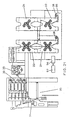
- Fig. 21 is a printing machine in the side view and in Fig, 22 a folding unit in the view with shown such functional groups.
- the printing press according to FIG. 21 contains four printing units 21 to 24 and a folding unit 25.
- the printing units 23 and 24 are drivingly similar to the printing unit shown in FIG Printing units 21 and 22 are similar to those shown in FIG.
- the drive motors of the cylinders as well as the following Function groups described above are symbolically marked with an "M" or hatching.
- the In Fig. 22 shown folding unit includes the folding units 26 and 27.
- Fig. 21.1 shows the same printing machine with each cylinder of these functional groups driven directly by a motor becomes.
- the funnel rollers 31 and the pull and transfer fins 32 are each provided with a separate, angle-controlled electric motor directly driven.
- the two folding units 26 and 27 each have a separate, angle-controlled motor, each of which drives a folding cylinder, here the knife cylinder 143, 144, directly. With In this cylinder, the other folding cylinders are engaged by sprockets arranged on their spigots.
- the funnel rollers 31 and the pulling and transfer rollers 32 of FIG each driven by a common motor indirectly via a toothed belt.
- Even the only folding unit 27.1 is driven by a separate, angle-controlled electric motor.
- the drive is indirectly by means of belt drive on, for example, the NOTEur folding knife cylinder 145.
- the other folding cylinders With their cylindrical wheels in drive connection.
- these electric motors is a sensitive adjustment of the speed of the driven Cylinder possible.
- the web tension is then also correspondingly sensitive adjustable. Also, there are major cost advantages through the elimination of such drives previously customary PIV transmission.
- Fig. 23 shows a device for color register adjustment in a double printing unit with the printing units 34 and 35, each containing a forme cylinder 36, 38 and a mecanicszytinder 37, 39. The device will be described with reference to the forme cylinder 38, which carries two pressure forms on the circumference.
- the the Form cylinder 38 driving electric motor 40 is angle-controlled by a computer engine control 41. Continue a position indicator 42 of the printing unit 35 and a register marks on the printing unit 35 leaving the web 43 scanning transmitter 44 connected to a comparator 45 whose output to the input of Computer engine control 41 is guided.
- the transmitter 44 scans the printed by the printing unit 35 on the web 43 Register marks and thus determines the position of the two images printed per revolution of the forme cylinder become. With the signal of the position sensor 42 is the reference to the rotation of the Form cylinder 38 produced. In a staggered arrangement of a printed image in the circumferential direction to half the circumference of the forme cylinder, d. H. at a deviating from half the circumference arrangement of the printed image, the form cylinder 38 with a compensatory lead or lag before printing in this area. this will accomplished by the computer engine control according to the output signal of the comparator 45. This can, for example, copying errors or assembly errors of the printing form be compensated. Under acceptance certain Degrading the registration quality at the beginning of the print can be the acceleration or deceleration phase can also be extended to this range, whereby the electric motor with lower power dimensions can.
- the device shown in FIG. 24 serves to regulate the circumferential register between two pressure points, here between printing unit 46 and 47.
- the printed by these printing units 46, 47 on the web 48 registration marks are sampled by transducers 49, 50.
- the signals of the transducers 49, 50 are in the comparator 51 headed. This gives the comparison result to the computer-Motarregetung 52.
- the electric motor 54 is operated with a lead or lag. If also the transfer cylinder 55 is driven by a separate electric motor, this is also in a register correction advantageously corrected in terms of its speed.
- the device is according to the number of controlled Passer according to multiple or fully extended accordingly apply. With the device, the traditional expensive mechanical transmission z. B. slides, saved for circumferential register adjustment of the form cylinder become.
- the web 55 may be fed from the printing unit 23 to either the printing unit 21 or on the dashed path to the printing unit 22 are performed.
- the different one Way are the printing units of the printing units 21 and 22 by means of their drive motors in the required Position driven.
- the possible web path calculation and storage unit 57 contains the cylinder positions the printing units for the cut register are stored. To the cut register inserting line are selected according to the selected Production configuration of the computer engine control 56, the required cylinder positions specified. Corresponding the default adjusts the computer motor control 56, the drive motors of all the web 55 printing printing units.
- the cut register for the cut in the folder is therefore involved in the cylinder positions of all involved in the pressure Printing units set. It eliminates the hitherto customary, costly Linearregister issueden. Only for the turning strand is still such a length adjustment is necessary.
- the cylinder positions for the Arithmetic and storage unit containing cut register can also be applied to the computer motor control 66 of FIG. 25 be shown, described below device, this device then both the cut register control as well as adjustment serves.
- Fig. 25 shows a device for cutting register control.
- they print on the printing units 58 to 61 a web 62.
- a transmitter 63 scans a printed register mark.
- the transmitter 63 as well the position transmitter 64 of an electric motor of a driven through pressure unit, advantageously the first traversed Pressure unit 59, are connected to the inputs of a comparator 65, the output side to the input the computer motor control of the electric motors of the printing units 58 to 61 is connected.
- One in the comparator 65 detected register error is caused by leading or lagging drive of the web 62 printing Printing units 58 to 61 by appropriate control of their electric motors by means of the computer engine control 66th corrected.
- Fig. 26 shows a device by means of which the forme cylinder in a suitable position for the change of shape be driven.
- the printing unit of the embodiment includes two printing units 67, 68 each having a forme cylinder 69, 70 and a transfer cylinder 71, 72.
- the drive motors of the printing units 67, 68, here, for example the transfer cylinders 71, 72 drive, are connected to a computer engine control 73 in connection, the a computing and storage unit 74 is powered.
- the arithmetic and storage unit 74 are the cylinder positions the form cylinder 69, 70 stored for the Druckfoms grill.
- Fig. 27 shows a printing unit with a transfer cylinder 77.1 and a forme cylinder 78.1, wherein the latter an inking unit 79.1 and a dampening unit 80.1 are arranged.
- the inking unit 79.1 contains u. a. the inkjet cylinders 81.1 and 82.1, and the dampening unit 80.1 the dampening cylinder 83.1.
- Each distribution cylinder 81.1, 82.1, 83.1 contributes Spur gear 84.1, 85.1, 86.1, all of which are in engagement with a central wheel 87.
- the central wheel 87 is of a angle-controlled electric motor 88 driven.
- the central wheel 87 In the exemplary embodiment is the central wheel 87, not shown, on the rotor pin of the electric motor 88.
- the electric motor but could also be next to the central wheel 87 be arranged and engage with a pinion in this.
- the electric motor 88 thus drives both Farbreibzylinder 81.1, 82.1 and the dampening cylinder 83.1.
- the inking cylinders 81.2 and 82.2 are driven by an angle-controlled electric motor 89.
- the dampening cylinder 83.2 of the dampening unit 80.2 is driven by an angle-controlled electric motor 90.
- the electric motor 89 drives directly on the Farbreibzylinder 82.2. This carries a spur 85.2, with which he over an idler gear 91 drives on a spur gear 84.2 of the inking 81.2.
- Fig. 29 shows a drive variant, according to which each Farbreibzylinder 81.3, 82.3 of the inking unit 79.3 and the Moisture drive cylinder 83.3 of the dampening unit 80.3 driven by a separate, angle-controlled electric motor 92, 93, 94 becomes.
- This drive of the inking and dampening unit eliminates old. previously customary gears.
- Fig. 30 shows the side view the ink and dampening cylinder 81.3, 82.3, 83.3, which are mounted in 39 catalystdeh 95, 96. At one pin each 97 to 99 of these cylinders 81.3 to 83.3, which are advantageously designed as a rotor of the driving electric motors 92 to 94 are, z. B. a linear motor 100 to 102 at.
- the angle-controlled electric motors 92 to 94 are of a Computer engine control 103, driven.
- the motor controller 103 advantageously controls the linear motors 100 to 102 with a same movement.
- the anilox roller and the inking roller can work together by one or one by one Electric motor to be driven.
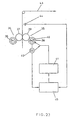
- FIG. 31 shows a form cylinder 105, the with its pins 106, 107 stored in side walls 108,109 of the printing press.
- the pins 106,107 carry flanges 110, 111, with which they are screwed to the end faces of the cylinder body.
- the pin 106 is as a rotor 112 of the forme cylinder driving electric motor 113 is formed, d. H. he carries at his extended end the elements of the rotor.
- the stator 114 is fixed to the side wall 108. At the pin 106 continues to grip a device for lateral displacement of the forme cylinder 105 for side register adjustment.
- Beispiefiller comes For this purpose, a linear motor 115 for use. It could be z. As well as a motor in conjunction with one of its rotary motion be used in a rectilinear motion forming gear.
- the shift amount Z of the page register is dimensioned so that when both sides of the pin 106, 107 to each Z / 2 from the forme cylinder body this is released and can be removed from the printing press. It is then a sleeve-shaped Printing form of the forme cylinder 105 replaceable.
- Fig. 32 shows the drive-side part of a forme cylinder 116, at the pin 117 of the rotor 118 a Electric motor 119 is screwed on the front side.
- the stator 120 of the electric motor 119 becomes one together with one attached bush 121, which contains the bearing 122 of the forme cylinder 116, received in bearing plates 123, 124.
- the end shields 123, 124 are moved apart and give in the extended state a Opening 125 of the side wall 126 of the printing press free. Through the exposed opening 125 is then a sleeve-shaped Print form 139 on or from the former 116 feasible.
- the contour of the passed Printing form 139 is indicated by dash-dotted lines.
- FIG 33 shows the fastening of the stator 127 of an electric motor 128 on the eccentric ring 129 of a three-ring bearing 130 of a cylinder mounted in the side wall 131.
- This may be, for example, a transfer cylinder, of which only the pin 132 is shown.
- the eccentric bearing ring 129 By turning the eccentric bearing ring 129, for example, the pressure and Druckabgna done.
- the stator 127 is advantageously carried along in the arrival and Abstellterrorism of the pin together with the rotor 133 mounted on it.
- the stator 127 is attached to a flange 134 which is screwed to the bearing ring 129.
- the flange 134 is axially fixed with downers 135 on the side wall 131 and receives the tilting moment from the weight of the stator.
- the operation of the bearing ring 129 is shown in Fig. 34.
- the bearing ring 129 carries a hub 136 to which the Druckan- and Abstellmechanismus, for example, a lever 137 engages.
- the bearing ring 129 advantageously abuts against a frame-fixed, suitably adjustable stop 138 and, assuming the corresponding direction of rotation of the cylinder, assumes the counter-torque of the stator 127.
- the cylinder bearing is designed without play.
- angle-controlled electric motors are used for driving the cylinders and functional groups for use.
- Using the invention can in drive cases with not too high requirements to synchronism, such as drive train of track elements and Reibzylindem, also speed or torquegeregelta electric motors come into use.
- the applied computer engine regulations can be done from case to case other motor controls are realized.
Abstract
Description
- Fig. 1 bis 4
- verschiedene Druckeinheiten mit Antrieben in der Seitenansicht,
- Fig. 5
- die Draufsicht der Druckeinheit nach Fig. 1,
- Fig. 6 bis 9
- verschiedene Druckwerksbrücken mit Antrieben,
- Fig. 10
- die Draufsicht der Druckwerksbrücke nach Fig. 6,
- Fig. 11 bis 14 und 16 bis 19
- weitere Varianten von Antrieben,
- Fig. 15
- die Draufsicht der Druckeinheit nach Fig. 11,
- Fig. 20
- die Draufsicht der Druckeinheit nach Fig. 16,
- Fig. 21 und 21.1
- eine Druckmaschine mit Funktionsgruppen,
- Fig. 22 und 22.1
- jeweils eine Falzeinheit mit Funktionsgruppen,
- Fig. 23
- eine Vorrichtung zur Farbregisterverstellung der Druckformen eines Formzylinders,
- Fig. 24
- eine Vorrichtung zur Farbregisterverstellung von Druckstelle zu Druckstelle,
- Fig. 25
- eine Vorrichtung zur Schnittregisterverstellung,
- Fig. 26
- eine Vorichtung zur Einstellung der Piattenwechseiposrtion,
- Fig. 27
- den Antrieb eines Farb- und Feuchtwerkes in der Seitenansicht,
- Fig. 28
- eine weitere Variante des Antriebs eines Farb- und Feuchtwerkes,
- Fig. 30
- die Ansicht der Reibzylinder aus Fig. 29,
- Fig. 31
- die Anordnung eines Elektromotors an einem Formzylinder,
- Fig. 32
- eine weitere Variante der Anordnung eines Elektromotors,
- Fig. 33
- eine dritte Variante der Anordung eines Elektromotors,
- Fig. 34
- die Ansicht γ aus Fig. 33.
Vorteilhaft ist die Zylinderlagerung spielfrei ausgeführt.
Claims (36)
- Offsetdruckmaschine mit mindestens einer Druckeinheit mit mindestens einem Form- und einem Übertragungszylinder sowie mit mindestens einer Falzeinheit und einem Antrieb, dadurch gekennzeichnet, daß pro Druckeinheit wenigstens einer dieser Zylinder mit einem separaten Elektromotor (7) in Antriebsverbindung steht und dieser Zylinder (1.1 bis 1.5; 2.1 bis 2.5) mit einem wahlweise weiteren, von einem separaten Elektromotor direkt oder indirekt angetriebenen Zylinder (1.1 bis 1.5; 2.1 bis 2.5) nicht in mechanischer Antriebsverbindung steht.
- Offsetdruckmaschine nach Anspruch 1, dadurch gekennzeichnet, daß bei einer Druckeinheit mit mehreren zusammenwirkenden Druckwerken (3, 4, 12, 13, 14) ein Form- oder Übertragungszylinder (1.1 bis 1.5; 2.1 bis 2.5) von einem Elektromotor (7) angetrieben wird und dieser Zylinder über Stirnräder (B bis 11, 15, 17) mit den weiteren Form- und Übertragungszylindem (1.1 bis 1.5; 2.1 bis 2.5) und wahlweise einem Satellitzylinder (16) in Antriebsverbindung steht.
- Offsetdruckmaschine nach Anspruch 1, dadurch gekennzeichnet, daß bei einer Druckwerksbrücke einer Druckeinheit ein Formoder Übertragungszylinder (1.1 bis 1.5; 2.1 bis 2.5) von einem Elektromotor (7) angetrieben wird und dieser Zylinder (1.1 bis 1.5; 2.1 bis 2.5) über Stirnräder (8 bis 11) mit den weiteren Form- und Übertragungszylindern (1.1 bis 1.5; 2.1 bis 2.5) dieser Druckwerksbrücke und wahlweise einem Satellitenzylinder (16) in Antriebsverbindung steht.
- Offsetdruckmaschine nach Anspruch 1, dadurch gekennzeichnet, daß bei einer Druckeinheit die Formzylinder (1.1 bis 1.5) jeweils von einem separaten Elektromotor (7) angetrieben werden und über Stirnräder (8, 10, 19, 20) mit dem jeweiligen zugehörigen Übertragungszylinder (2.1 bis 2.5) in Antriebsverbindung stehen.
- Offsetdruckmaschine nach Anspruch 1, dadurch gekennzeichnet, daß bei einer Druckeinheitdie Übertragungszylinder (2.1 bis 2.5) jeweils von einem separaten Elektromotor (7) angetrieben werden und über Stirnräder (8, 10, 19, 20) mit dem jeweiligen zugehörigen Formzylinder (1.1 bis 1.5) in Antriebsverbindung stehen.
- Offsetdruckmaschine nach Anspruch 1, dadurch gekennzeichnet, daß sämtliche Form- und Übertragungszylinder (1.1 bis 1.5; 2.1 bis 2.5) und gegebenenfalls der Satellitenzylinder (16) von jeweils einem separaten Elektromotor (7) angetrieben werden.
- Offsetdruckmaschine, insbesondere nach einem der vorherigen Ansprüche, dadurch gekennzeichnet, daß Funktionsgruppen, insbesondere Einzugwerke (28), Kühlwalzen (29), Zylinder im Falzwerk (26, 27), sowie Gruppen mit Voreilungsregelung, wie Schneidwalzen (30) vor den Wendestangen, Trichterwalzen (31) im Falzapparat, Zugund Überführwalzen (32), von jeweils einem separaten Elektromotor (33) direkt oder indirekt angetrieben werden.
- Offsetdruckmaschine, insbesondere nach einem der Ansprüche 4 bis 6, dadurch gekennzeichnet, daß zur Verstellung des Farbregisters der den zu verstellenden Formzylinder (1.1 bis 1.5) antreibende Elektromotor (7) als Stellglied fungiert.
- Offsetdruckmaschine, insbesondere nach einem der Ansprüche 4 bis 6 oder 8, dadurch gekennzeichnet, daß zur Verstellung des Umfangregisters mehrerer Druckbilder am Umfang eines Formzylinders (38) eines Druckwerkes (35) zueinander ein Stellungsgeber (42) des Druckwerkes (35) und ein die Registermarken auf der das Druckwerk (35) verlassenden Bahn (43) abtastender Meßwertgeber (44) auf eine Vergleichseinrichtung (45) geschaltet sind, deren Ausgang auf den Eingang der Motorregelung (41) des bzw. der Elektromotoren (40) des Druckwerkes (35) geführt ist zu deren periodischem Antreiben mit der erforderlichen Vor- oder Nacheilung pro Umdrehung.
- Offsetdruckmaschine, insbesondere nach einem der Ansprüche 4 bis 6 oder 8, dadurch gekennzeichnet, daß zur Verstellung des Farbregisters zwischen zwei die Bahn (48) nacheinander bedruckenden Druckwerken (46, 47) zwei die Registermarken auf der die Druckwerke verlassenden Bahn (4) abtastende Meßwertgeber (49, 50) auf eine Vergleichseinrichtung (51) geschaltet sind, deren Ausgang auf den Eingang der Motorregelung (52) des bzw. der Elektromotoren (54) des zu verstellenden Druckwerkes (47) geführt ist.
- Offsetdruckmaschine, insbesondere nach einem der vorherigen Ansprüche, dadurch gekennzeichnet, daß zur Regelung des Schnittregisters einer von mindestens einem Druckwerk bedruckten Bahn (62) ein Meßwertgeber (63) für das Schnittregister und ein Stellungsgeber (64) eines Elektromotors eines der die Bahn (62) bedruckenden Druckwerke (58 bis 61) auf eine Vergleichseinrichtung (65) geschaltet sind, deren Ausgang auf den Eingang der Motorregelung (66) des bzw. der Elektromotoren der die Bahn (62) bedruckenden Druckwerke (58 bis 61) geführt ist zu deren vor- oder nacheitendem Antrieb bis zu deren erforderlichen Position.
- Offsetdruckmaschine, insbesondere nach einem der vorherigen Ansprüche, dadurch gekennzeichnet, daß alle Farb- und Feuchtreibzylinder (81.1, 82.1, 83.1) eines Farb- und eines Feuchtwerkes (79.1, 80.1) gemeinsam von einem Elektromotor (88) angetrieben werden.
- Offsetdruckmaschine, insbesondere nach einem der Ansprüche 1 bis 11, dadurch gekennzeichnet, daß alle Farbreibzylinder (81.2, 82.2) eines Farbwerkes (79.2) von einem gemeinsamen Elektromotor (89) angetrieben werden und der Feuchtreibzylinder (83.2) von einem separaten Elektromotor (90) angetrieben wird.
- Offsetdruckmaschine, insbesondere nach einem der Ansprüche 1 bis 11, dadurch gekennzeichnet, daß alle Farb- und Feuchtreibzylinder (81.3, 82.3, 83.3) eines Druckwerkes von jeweils einem separaten Elektromotor (92, 93, 94) angetrieben werden.
- Offsetdruckmaschine, insbesondere nach einem der Ansprüche 1 bis 11, mit einem eine Rasterwalze und eine Farbauftragwalze enthaltenden Kurzfarbwerk, dadurch gekennzeichnet, daß die Rasterwalze und die Farbauftragwalze von einem gemeinsamen Elektromotor angetrieben werden.
- Offsetdruckmaschine, insbesondere nach einem der Ansprüche 1 bis 11, mit einem eine Rasterwalze und eine Farbauftragwalze enthaltenden Kurzfarbwerk, dadurch gekennzeichnet, daß die Rasterwalze und die Farbauftragwalze von jeweils einem separaten Elektromotor angetrieben werden.
- Offsetdruckmaschine nach einem der vorhergehenden Ansprüche mit einem Zylinder, insbesondere Formzylinder, Übertragungszylinder oder Reibzylinder, dadurch gekennzeichnet, daß der Rotor (112, 118) des Elektromotors (113, 119) mit dem Zylinder (105, 116) starr verbunden ist.
- Offsetdruckmaschine nach Anspruch 17, dadurch gekennzeichnet, daß der Rotor (118) stirnseitig an einen Zapfen (117) des Zylinders (116) geschraubt ist.
- Offsetdruckmaschine nach Anspruch 17, dadurch gekennzeichnet, daß die Zapfen (106, 107) des Zylinders (105)-stimseitig am Zylinderkörper angeschraubt sind und das Ende eines Zapfens (106) als Rotor (112) ausgebildet ist.
- Offsetdruckmaschine, insbesondere nach einem der Ansprüche 17 bis 19 mit einem Formzylinder, dadurch gekennzeichnet, daß an einem Zapfen (106) ein Motor (115) für die Seitenregisterverstellung angreift.
- Offsetdruckmaschine, insbesondere nach einem der Ansprüche 14, 17 bis 19 mit einem Reibzylinder, dadurch gekennzeichnet, daß an einem Zapfen ein Motor(100, 101, 102) für die seitliche Verreibung angreift.
- Offsetdruckmaschine mit einem Farb- und einem Feuchtwerk mit drei Reibzylindern, insbesondere nach einem der Ansprüche 14, 17 bis 21, dadurch gekennzeichnet, daß an jedem Reibzylinder (81.3, 82.3, 83.3) zu dessen axialen Verschiebung ein Motor (100, 101, 102) angreift und die Motoren (100, 101, 102) von einer Motorsteuerung (103) angesteuert werden mit folgenden Parameterngleicher Bewegungsablauf der drei Reibzylindersinusförmiger Verlauf der ChangierbewegungChangierbewegung linear proportional zur Geschwindigkeit der OffsetdruckmaschineVersatz der Reiberhübe zueinander um 120° Phasenlage
- Offsetdruckmaschine nach einem der vorhergehenden Ansprüche, dadurch gekennzeichnet, daß der Stator (114) des Elektromotors (113) fest an der Seitenwand (108) der Druckmaschine angeordnet ist.
- Offsetdruckmaschine nach einem der Ansprüche 1 bis 22, dadurch gekennzeichnet, daß der Stator (127) des Elektromotors (128) an einem exzentrischen Lagerring (129) des Zylinders befestigt ist.
- Offsetdruckmaschine nach Anspruch 24, dadurch gekennzeichnet, daß der exzentrische Lagerring (129) einen Flansch (134) trägt, mit dem er zur Aufnahme von Kippmomenten mittels Niederhalter (135) an der Seitenwand (131) gehalten wird, und der Lagerring (129) mit einem gestellfesten Anschlag (138) zusammenarbeitet.
- Offsetdruckmaschine nach einem der Ansprüche 1 bis 22, 24 oder 25, dadurch gekennzeichnet, daß der Zylinder (116) mit einem Zapfen (117) in auseinanderfahrbaren Lagerschilden (123, 124) lagert, die beim Auseinanderfahren eine Öffnung (125) in der Seitenwand (126) der Druckmaschine freigeben, durch die eine hülsenförmige Druckoder Übertragungsform (139) führbar ist.
- Offsetdruckmaschine nach einem der vorhergehenden Ansprüche, dadurch gekennzeichnet, daß der Elektromotor (7) an der Bedienseite (S1) der Druckmaschine angeordnet ist.
- Offsetdruckmaschine nach einem der Ansprüche 1 bis 25, dadurch gekennzeichnet, daß der Elektromotor (7) an der Antriebsseite (S2) der Druckmaschine angeordnet ist.
- Offsetdruckmaschine bzw. Zylinder einer Offsetdruckmaschine nach einem der vorherigen Ansprüche, dadurch gekennzeichnet, daß der Elektromotor (7) winkelgeregelt ausgeführt ist.
- Offsetdruckmaschine nach Anspruch 20 oder 21, dadurch gekennzeichnet, daß der Verschiebebetrag (Z) des Formzylinders (105) für das Seitenregister bzw. der Reiberhub des Reibzylinders (81, 82, 83) so bemessen ist, daß beim Abrücken der vom Zylinderkörper dieser Zylinder abgeschraubten Zapfen (106, 107) der Zylinderkörper aus der Druckmaschine entnehmbar ist.
- Verfahren zur Verstellung des Umfangsregisters mehrerer Druckbilder am Umfang eines Formzylinders eines Druckwerkes, insbesondere nach einem der Ansprüche 4 bis 6, wobei das Druckwerk Registermarken auf die Bahn druckt, die Registermarken mit einem Meßwertgeber abgetastet werden, dessen Signale mit Sollwertsignalen verglichen werden und anhand des Vergleichssignales der den Formzylinder antreibende Elektromotor periodisch pro Umdrehung mit der erforderlichen Vor- oder Nacheilung betrieben wird.
- Verfahren zur Regelung des Schnittregisters einer von mindestens einem Druckwerk einer Offsetdruckmaschine bedruckten Bahn, insbesondere nach einem der Ansprüche 1 bis 6, wobei ein Druckwerk eine Registermarke auf die Bahn druckt, ein Meßwertgeber die Registermarke abtastet, das Signal des Meßwertgebers mit einem Sollwertsignal verglichen wird und anhand des Vergleichssignals alle die Bahn bedruckenden Druckwerke mit Vor- bzw. Nacheilung angetrieben werden, bis sie die erforderlichen Positionen einnehmen.
- Verfahren zum Umsteuern eines separat angetriebenen Druckwerkes einer Offsetdruckmaschine, insbesondere nach einem der Ansprüche 1 bis 29, wobei der bzw. die das Druckwerk antreibenden Elektromotoren in ihrer Drehrichtung umgesteuert werden.
- Offsetdruckmaschine nach einem der Ansprüche 7 bis 30, dadurch gekennzeichnet, daß zur Voreinstellung von Druckeinheiten (21 bis 24) zur Anpassung an unterschiedliche Bahnwege die Motorregelung (56) der Elektromotoren der zu verstellenden Druckwerke eingangsseitig mit einer Rechen- und Speichereinheit (57) in Verbindung stehen, in die die einzustellenden Zylinderpositionen eingespeichert sind.
- Offsetdruckmaschine nach einem der Ansprüche 7 bis 30, dadurch gekennzeichnet, daß zur Verdrehung der Formzylinder (75, 76) in eine Position für den Formwechsel die Motorregelungen (73) der die Formzylinder (75, 76) antreibenden Elektromotoren eingangsseitig mit einer Rechenund Speichereinheit (74) in Verbindung stehen, in die die einzustellenden Zylinderpositionen eingespeichert sind.
- Offsetdruckmaschine, nach einem der Ansprüche 7 bis 30, dadurch gekennzeichnet, daß zur Einstellung des Schnittregisters einer bedruckten Bahn (55) die Motorregelung (56) der Elektromotoren der die Bahn (55) bedrukkenden Druckwerke eingangsseitig mit einer Rechen- und Speichereinheit (57) in Verbindung steht, in die die Zylinderpositionen für das Schnittregister eingespeichert sind zur Stellung der Zylinder aller die Bahn bedruckenden Druckwerke in die vorgegebenen Positionen.
Applications Claiming Priority (4)
| Application Number | Priority Date | Filing Date | Title |
|---|---|---|---|
| DE4430693A DE4430693B4 (de) | 1994-08-30 | 1994-08-30 | Antriebe für eine Rollenrotations-Offsetdruckmaschine |
| DE4430693 | 1994-08-30 | ||
| EP01101495A EP1110722B1 (de) | 1994-08-30 | 1995-08-18 | Offsetdruckmaschine |
| EP02023919A EP1277575B2 (de) | 1994-08-30 | 1995-08-18 | Offsetdruckmaschine |
Related Parent Applications (1)
| Application Number | Title | Priority Date | Filing Date |
|---|---|---|---|
| EP02023919A Division EP1277575B2 (de) | 1994-08-30 | 1995-08-18 | Offsetdruckmaschine |
Publications (1)
| Publication Number | Publication Date |
|---|---|
| EP1493564A1 true EP1493564A1 (de) | 2005-01-05 |
Family
ID=6526867
Family Applications (5)
| Application Number | Title | Priority Date | Filing Date |
|---|---|---|---|
| EP95113017A Expired - Lifetime EP0699524B2 (de) | 1994-08-30 | 1995-08-18 | Rollenrotationsoffsetdruckmaschine |
| EP04023533A Withdrawn EP1493563A3 (de) | 1994-08-30 | 1995-08-18 | Offsetdruckmaschine |
| EP02023919A Expired - Lifetime EP1277575B2 (de) | 1994-08-30 | 1995-08-18 | Offsetdruckmaschine |
| EP01113489A Expired - Lifetime EP1132202B1 (de) | 1994-08-30 | 1995-08-18 | Offsetdruckmaschine |
| EP04023532A Withdrawn EP1493564A1 (de) | 1994-08-30 | 1995-08-18 | Offsetdruckmaschine |
Family Applications Before (4)
| Application Number | Title | Priority Date | Filing Date |
|---|---|---|---|
| EP95113017A Expired - Lifetime EP0699524B2 (de) | 1994-08-30 | 1995-08-18 | Rollenrotationsoffsetdruckmaschine |
| EP04023533A Withdrawn EP1493563A3 (de) | 1994-08-30 | 1995-08-18 | Offsetdruckmaschine |
| EP02023919A Expired - Lifetime EP1277575B2 (de) | 1994-08-30 | 1995-08-18 | Offsetdruckmaschine |
| EP01113489A Expired - Lifetime EP1132202B1 (de) | 1994-08-30 | 1995-08-18 | Offsetdruckmaschine |
Country Status (4)
| Country | Link |
|---|---|
| US (1) | US6408748B1 (de) |
| EP (5) | EP0699524B2 (de) |
| JP (5) | JP3059081B2 (de) |
| DE (5) | DE4430693B4 (de) |
Families Citing this family (149)
| Publication number | Priority date | Publication date | Assignee | Title |
|---|---|---|---|---|
| WO2003016058A1 (de) | 2001-08-03 | 2003-02-27 | Koenig & Bauer Aktiengesellschaft | Druckwerke einer druckmaschine |
| DE4430693B4 (de) | 1994-08-30 | 2005-12-22 | Man Roland Druckmaschinen Ag | Antriebe für eine Rollenrotations-Offsetdruckmaschine |
| US6644184B1 (en) | 1995-02-09 | 2003-11-11 | Man Roland Druckmaschinen Ag | Offset printing machine |
| DE19525169C2 (de) * | 1995-03-18 | 2000-02-03 | Koenig & Bauer Ag | Verfahren zum Antreiben eines Falzapparates |
| EP0814959B1 (de) * | 1995-03-18 | 2004-05-26 | Koenig & Bauer Aktiengesellschaft | Verfahren zum antreiben eines aggregates z.b. eines falzapparates einer rotationsdruckmaschine |
| EP0738591B1 (de) * | 1995-04-15 | 1999-01-27 | Heidelberger Druckmaschinen Aktiengesellschaft | Übertragungszylinder mit elektromotorischer Antriebseinheit |
| DE19516445A1 (de) * | 1995-05-04 | 1996-11-07 | Wifag Maschf | Rotationsdruckmaschine mit frei aufstellbarem Falzapparat |
| DE19516443A1 (de) * | 1995-05-04 | 1996-11-07 | Wifag Maschf | Einzeln angetriebener Falzapparat für eine Rotationsdruckmaschine |
| CH691225A8 (fr) * | 1996-02-09 | 2001-08-15 | Bobst Sa | Machine d'impression rotative. |
| DE19629605C2 (de) * | 1996-07-23 | 2000-02-03 | Koenig & Bauer Ag | Antrieb einer Druckeinheit |
| WO1998006581A1 (de) * | 1996-08-09 | 1998-02-19 | Koenig & Bauer Aktiengesellschaft | Zylinderantrieb |
| EP0826494B2 (de) * | 1996-08-28 | 2004-01-28 | Koenig & Bauer Aktiengesellschaft | Druckeinheit |
| GB9621324D0 (en) * | 1996-10-12 | 1996-11-27 | Rockwell Graphic Syst | Printing apparatus |
| DE19732330C2 (de) * | 1997-07-28 | 2001-04-19 | Koenig & Bauer Ag | Antrieb für eine Druckeinheit |
| DE19733644B4 (de) * | 1997-08-04 | 2005-07-14 | Man Roland Druckmaschinen Ag | Auftragwalze mit veränderbarer Drehzahl |
| DE19739283C2 (de) * | 1997-09-08 | 2002-10-24 | Roland Man Druckmasch | Verfahren zum Erreichen des Fortdruckzustandes in einer Rollenrotationsdruckmaschine |
| DE19742560A1 (de) * | 1997-09-26 | 1999-04-01 | Roland Man Druckmasch | Vorrichtung zur Veränderung der Bahnlage einer Bedruckstoffbahn |
| JP3037650B2 (ja) * | 1997-10-29 | 2000-04-24 | 株式会社東京機械製作所 | 輪転機の印刷ユニットの駆動装置 |
| DE19755316C2 (de) * | 1997-12-12 | 1999-10-07 | Koenig & Bauer Ag | Antrieb für Zylinder einer Druckeinheit |
| US6601681B1 (en) | 1998-01-30 | 2003-08-05 | Koenig & Bauer Aktiengesellschaft | Drive mechanism for a rotating component of a printing machine |
| DE19803557C2 (de) * | 1998-01-30 | 1999-12-23 | Koenig & Bauer Ag | Antrieb für ein rotierendes Bauteil einer Druckmaschine |
| DE59900478D1 (de) | 1998-04-24 | 2002-01-10 | Koenig & Bauer Ag | Walze für eine rotationsdruckmaschine |
| DE19903847C5 (de) * | 1999-02-01 | 2014-09-04 | Manroland Ag | Vorrichtung zum axialen Führen und Verstellen eines Zylinders |
| DE19959152A1 (de) * | 1999-12-08 | 2001-06-13 | Heidelberger Druckmasch Ag | Einrichtung zur Führung von Materialbahnen in Rotationsdruckmaschinen |
| IT1314383B1 (it) † | 2000-02-18 | 2002-12-13 | Uteco S P A Roto Flexo & Conve | Macchina da stampa rotativa flessografica a piu' colori |
| US6345574B1 (en) * | 2000-05-17 | 2002-02-12 | Heidelberger, Druckmaschinen Ag | Printing unit arrangement in a web-fed rotary printing press |
| JP3363872B2 (ja) * | 2000-06-23 | 2003-01-08 | 株式会社東京機械製作所 | 切断見当及び印刷見当自動調整機能を有する同期制御装置 |
| DE10038551A1 (de) | 2000-08-03 | 2002-02-14 | Roland Man Druckmasch | Ermittlung der Voreinstelldaten für das Schnittregister (und das Farbregister) für längswellenlose Druckwerke |
| EP1364780A3 (de) | 2000-09-20 | 2008-11-26 | Koenig & Bauer Aktiengesellschaft | Druckeinheit |
| DE10046368C2 (de) * | 2000-09-20 | 2003-02-06 | Koenig & Bauer Ag | Antrieb einer Druckeinheit |
| AU2002213798A1 (en) * | 2000-09-20 | 2002-04-02 | Koenig And Bauer Aktiengesellschaft | Printing unit |
| DE10046378C2 (de) * | 2000-09-20 | 2002-12-12 | Koenig & Bauer Ag | Antrieb einer Druckeinheit |
| DE10046373B4 (de) * | 2000-09-20 | 2005-09-08 | Koenig & Bauer Ag | Antrieb einer Druckeinheit |
| DE10046377B4 (de) * | 2000-09-20 | 2006-02-09 | Koenig & Bauer Ag | Antrieb einer Druckeinheit |
| DE10046376C2 (de) * | 2000-09-20 | 2002-12-12 | Koenig & Bauer Ag | Antrieb einer Druckeinheit |
| ATE448941T1 (de) | 2000-09-20 | 2009-12-15 | Koenig & Bauer Ag | Druckeinheit |
| DE10046370B4 (de) * | 2000-09-20 | 2005-02-03 | Koenig & Bauer Ag | Druckeinheit |
| DE10046366C2 (de) * | 2000-09-20 | 2002-11-14 | Koenig & Bauer Ag | Antrieb einer Druckeinheit |
| DE10046374B4 (de) * | 2000-09-20 | 2014-05-15 | Koenig & Bauer Aktiengesellschaft | Verfahren zum Betreiben einer Druckeinheit |
| DE10046365B4 (de) * | 2000-09-20 | 2004-09-23 | Koenig & Bauer Ag | Verfahren und Vorrichtung zum Antrieb einer Druckeinheit |
| DE10046375B4 (de) * | 2000-09-20 | 2005-04-07 | Koenig & Bauer Ag | Antrieb einer Druckeinheit |
| JP3431894B2 (ja) * | 2000-09-22 | 2003-07-28 | 株式会社東京機械製作所 | 印刷画像情報に基づいて制御対象を選択する輪転機の同期制御装置 |
| JP3662852B2 (ja) | 2001-01-11 | 2005-06-22 | 株式会社東京機械製作所 | 印刷画像情報に基づいて制御対象を選択する輪転機の同期制御装置 |
| US7216585B2 (en) | 2001-01-24 | 2007-05-15 | Goss International Americas, Inc. | Shaftless motor drive for a printing press with an anilox inker |
| US6752751B2 (en) * | 2001-02-23 | 2004-06-22 | Heidelberger Druckmaschinen Ag | Folder with multiple-motor drive |
| DE10113338B4 (de) * | 2001-03-20 | 2004-10-28 | Koenig & Bauer Ag | Verfahren und Vorrichtungen zum Antrieb einer Druckeinheit |
| DE10114801B4 (de) * | 2001-03-26 | 2005-10-13 | Koenig & Bauer Ag | Antrieb eines Druckwerks |
| DE10154838A1 (de) * | 2001-11-08 | 2003-05-22 | Koenig & Bauer Ag | Antrieb eines Druckwerks |
| EP1377457B1 (de) | 2001-03-26 | 2005-09-28 | Koenig & Bauer Aktiengesellschaft | Antrieb eines druckwerks |
| RU2262449C2 (ru) * | 2001-03-26 | 2005-10-20 | Кениг Унд Бауер Акциенгезельшафт | Привод печатного аппарата |
| DE10114806A1 (de) | 2001-03-26 | 2002-10-17 | Koenig & Bauer Ag | Antrieb eines Zylinders |
| CN1220588C (zh) | 2001-03-26 | 2005-09-28 | 柯尼格及包尔公开股份有限公司 | 印刷单元的驱动装置 |
| CN100446974C (zh) * | 2001-04-09 | 2008-12-31 | 柯尼格及包尔公开股份有限公司 | 印刷机的印刷装置 |
| DE10163963B4 (de) * | 2001-12-23 | 2006-06-08 | Koenig & Bauer Ag | Antrieb eines Druckwerkes |
| DE10215261A1 (de) | 2001-04-09 | 2002-10-10 | Koenig & Bauer Ag | Druckwerk einer Druckmaschine, Verfahren zum An- und Abstellen eines Zylinders sowie Verfahren zur Herstellung eines Druckproduktes |
| WO2002081219A2 (de) | 2001-04-09 | 2002-10-17 | Koenig & Bauer Aktiengesellschaft | Druckwerk einer druckmaschine |
| DE10121945B4 (de) * | 2001-05-05 | 2007-04-05 | Koenig & Bauer Ag | Vorrichtung zum Einziehen einer Materialbahn |
| DE10129762B4 (de) | 2001-06-20 | 2004-07-29 | Koenig & Bauer Ag | Druckeinheit |
| DE10131976B4 (de) * | 2001-07-02 | 2005-12-29 | Koenig & Bauer Ag | Druckmaschine mit mehreren Sektionen |
| DE10163962B4 (de) * | 2001-12-23 | 2006-05-18 | Koenig & Bauer Ag | Antrieb eines Druckwerkes |
| CN1781703A (zh) † | 2001-08-03 | 2006-06-07 | 柯尼格及包尔公开股份有限公司 | 印刷机的印刷装置 |
| DE10163961B4 (de) * | 2001-12-23 | 2006-06-01 | Koenig & Bauer Ag | Antrieb eines Druckwerkes |
| CN1325251C (zh) * | 2001-08-03 | 2007-07-11 | 柯尼格及包尔公开股份有限公司 | 印刷机的印刷装置 |
| EP1412183A1 (de) * | 2001-08-03 | 2004-04-28 | Koenig & Bauer Aktiengesellschaft | Druckwerke einer druckmaschine |
| DE10234402B4 (de) * | 2001-09-21 | 2015-10-08 | Heidelberger Druckmaschinen Ag | Unabhängiger Direktantrieb für Papier verarbeitende Druckmaschinen |
| ATE312714T1 (de) | 2001-10-05 | 2005-12-15 | Koenig & Bauer Ag | Rollenrotationsdruckmaschine |
| EP1932662A2 (de) | 2001-11-08 | 2008-06-18 | Koenig & Bauer AG | Antrieb eines Druckwerkes |
| ATE490084T1 (de) | 2001-11-08 | 2010-12-15 | Koenig & Bauer Ag | Antrieb eines druckwerkes |
| DE10157243A1 (de) * | 2001-11-22 | 2003-06-05 | Roland Man Druckmasch | Reibzylinder einer Rotationsdruckmaschine |
| DE10164778A1 (de) | 2001-12-21 | 2003-07-10 | Koenig & Bauer Ag | Vorrichtung zur Herstellung von Falzprodukten |
| DE10163211C2 (de) * | 2001-12-21 | 2003-10-23 | Koenig & Bauer Ag | Vorrichtung zur Herstellung von Falzprodukten |
| US20040231535A1 (en) * | 2002-07-03 | 2004-11-25 | Gerner Erich Max Karl | Printing groups of a printing press |
| NL1022116C2 (nl) | 2002-12-09 | 2004-06-11 | Skf Ab | Aandrijfbesturingseenheid voor groep van axiale actuatoren. |
| DE10260491A1 (de) * | 2002-12-21 | 2004-07-01 | Koenig & Bauer Ag | Vorrichtung zur Lageverstellung eines Drehkörpers mit Direktantrieb |
| DE20320704U1 (de) * | 2003-01-30 | 2004-12-23 | Koenig & Bauer Ag | Druckmaschine |
| KR100501959B1 (ko) * | 2003-02-06 | 2005-07-20 | 조충 | 윤전기구조 |
| DE10307202B4 (de) | 2003-02-20 | 2006-09-28 | Koenig & Bauer Ag | Verfahren zur Voreinstellung von Produktionen einer Rollenrotationsdruckmaschine |
| US7521481B2 (en) * | 2003-02-27 | 2009-04-21 | Mclaurin Joanne | Methods of preventing, treating and diagnosing disorders of protein aggregation |
| DE502004006043D1 (de) * | 2003-04-23 | 2008-03-13 | Koenig & Bauer Ag | Rollenrotationsdruckmaschine |
| CN100436129C (zh) * | 2003-06-09 | 2008-11-26 | 戈斯国际公司 | 可变版式胶印机 |
| DE10327218B4 (de) | 2003-06-17 | 2015-08-06 | Schaeffler Technologies AG & Co. KG | Direktantrieb für einen Zylinder einer Druckmaschine |
| US7044058B2 (en) * | 2003-07-02 | 2006-05-16 | Goss International Americas, Inc. | Automatic motor phase presetting for a web printing press |
| DE10352618B4 (de) * | 2003-07-11 | 2007-01-11 | Koenig & Bauer Ag | Antrieb einer Druckeinheit |
| US7549372B2 (en) * | 2003-07-11 | 2009-06-23 | Koenig & Bauer Aktiengesellschaft | Printing machine and printing machine system |
| DE10352614A1 (de) | 2003-07-11 | 2005-02-10 | Koenig & Bauer Ag | Walze eines Farb- oder Feuchtwerkes |
| JP4307202B2 (ja) * | 2003-09-29 | 2009-08-05 | 株式会社日立製作所 | 記憶システム及び記憶制御装置 |
| US6829991B1 (en) | 2003-10-29 | 2004-12-14 | Goss International Americas, Inc. | Inker driven shaftless unit |
| ES2327742T3 (es) * | 2003-12-12 | 2009-11-03 | Wifag Maschinenfabrik Ag | Dispositivo de arrastre con rotor externo. |
| DE102004009861B4 (de) * | 2004-03-01 | 2007-09-20 | Koenig & Bauer Aktiengesellschaft | Verfahren und Vorrichtung für den Betrieb von Druckeinheiten |
| WO2005097505A2 (de) * | 2004-04-05 | 2005-10-20 | Koenig & Bauer Aktiengesellschaft | Druckeinheit einer rollenrotationsdruckmaschine |
| DE502005003569D1 (de) * | 2004-04-05 | 2008-05-15 | Koenig & Bauer Ag | Antriebe einer druckeinheit |
| DE102004037889B4 (de) | 2004-04-05 | 2006-05-11 | Koenig & Bauer Ag | Vorrichtung zur Lagerung eines Zylinders und Druckeinheit mit wenigstens drei als Druckwerk zusammen wirkenden Zylindern |
| DE102004063944B4 (de) | 2004-04-05 | 2008-04-10 | Koenig & Bauer Aktiengesellschaft | Druckeinheiten einer Rollenrotationsdruckmaschine |
| DE102004019136A1 (de) * | 2004-04-16 | 2005-11-10 | Man Roland Druckmaschinen Ag | Direktantrieb für einen Zylinder einer Verarbeitungsmaschine |
| US20050257704A1 (en) * | 2004-05-21 | 2005-11-24 | Pas Jon V | Method for lateral adjustment of a directly driven load without shifting the entire drive assembly |
| DE102004040150A1 (de) * | 2004-08-19 | 2006-02-23 | Man Roland Druckmaschinen Ag | Druckeinheit sowie Farbwerk |
| DE202004021518U1 (de) | 2004-09-09 | 2008-09-04 | Koenig & Bauer Aktiengesellschaft | Druckmaschinen |
| EP1833674B1 (de) | 2005-01-05 | 2011-01-05 | Koenig & Bauer Aktiengesellschaft | Druckeinheit einer druckmaschine mit mindestens einem farbwerk und mindestens einem feuchtwerk |
| DE102005014060B4 (de) | 2005-03-23 | 2008-11-20 | Koenig & Bauer Aktiengesellschaft | Farbwerk einer Druckmaschine |
| US7819057B2 (en) | 2005-03-30 | 2010-10-26 | Goss International Americas, Inc. | Print unit having blanket cylinder throw-off bearer surfaces |
| CN101111379B (zh) | 2005-03-30 | 2011-12-07 | 高斯国际美洲公司 | 带有枢接折页器的轮转胶版印刷机 |
| US7775159B2 (en) | 2005-03-30 | 2010-08-17 | Goss International Americas, Inc. | Cantilevered blanket cylinder lifting mechanism |
| US8037818B2 (en) | 2005-04-11 | 2011-10-18 | Goss International Americas, Inc. | Print unit with single motor drive permitting autoplating |
| PL1867478T3 (pl) * | 2005-04-21 | 2009-07-31 | Koenig & Bauer Ag | Zespół drukujący z co najmniej dwoma współpracującymi cylindrami |
| US7187142B2 (en) * | 2005-05-25 | 2007-03-06 | Rockwell Automation Technologies, Inc. | Motor drive with velocity noise filter |
| US7109670B1 (en) * | 2005-05-25 | 2006-09-19 | Rockwell Automation Technologies, Inc. | Motor drive with velocity-second compensation |
| EP1728628A1 (de) * | 2005-06-01 | 2006-12-06 | Kba-Giori S.A. | Hochdruckmaschine mit separaten Antriebe |
| DE102006003013B4 (de) * | 2005-06-17 | 2011-03-03 | Koenig & Bauer Aktiengesellschaft | Flexodruckmaschine |
| EP1736698B1 (de) * | 2005-06-23 | 2011-02-09 | Koenig & Bauer Aktiengesellschaft | Vorrichtung zur Anbindung eines rotierenden Bauteils in einer Druckmaschine zur Übertragung von Druckmittel |
| DE102005047661B4 (de) * | 2005-06-23 | 2008-07-10 | Koenig & Bauer Aktiengesellschaft | Antrieb eines rotierenden Bauteils einer Druckmaschine |
| JP2007021858A (ja) | 2005-07-15 | 2007-02-01 | Komori Corp | 移動型インキユニットを備えた印刷機 |
| DE102005061028B4 (de) * | 2005-08-19 | 2010-11-11 | Koenig & Bauer Aktiengesellschaft | Antriebe zweier seitlich changierbarer Walzen eines Farb- oder Feuchtwerkes |
| DE102005063492B4 (de) * | 2005-08-19 | 2013-11-28 | Koenig & Bauer Aktiengesellschaft | Antriebe einer seitlich changierbaren Walze |
| DE102005050651A1 (de) | 2005-10-20 | 2007-04-26 | Schaeffler Kg | Direktantrieb einer Druckmaschine |
| DE102005052497B4 (de) * | 2005-10-31 | 2011-09-01 | Koenig & Bauer Aktiengesellschaft | Antrieb eines Zylinders einer Druckmaschine |
| DE102006007581A1 (de) * | 2006-02-18 | 2007-08-23 | Schaeffler Kg | Changierantrieb eines Zylinders einer Druckmaschine |
| US20070203433A1 (en) * | 2006-02-27 | 2007-08-30 | Murphy Martin P | Relaxation inducing apparatus |
| DE102006030290B3 (de) * | 2006-03-03 | 2007-10-18 | Koenig & Bauer Aktiengesellschaft | Druckwerk |
| DE102006047846B4 (de) * | 2006-10-10 | 2020-02-20 | Robert Bosch Gmbh | Verfahren zum Betreiben einer Verarbeitungsmaschine, insbesondere Druckmaschine, sowie Verarbeitungsmaschine, insbesondere Druckmaschine |
| DE102006052763A1 (de) * | 2006-11-09 | 2008-05-15 | Robert Bosch Gmbh | Direktantrieb |
| JP2008126432A (ja) * | 2006-11-16 | 2008-06-05 | Mitsubishi Heavy Ind Ltd | 画像形成装置 |
| DE102006054381A1 (de) * | 2006-11-17 | 2008-05-21 | Koenig & Bauer Aktiengesellschaft | Druckeinheit einer Druckmaschine mit zwei übereinander angeordneten Doppeldruckwerken |
| DE102006054382A1 (de) * | 2006-11-17 | 2008-05-21 | Koenig & Bauer Aktiengesellschaft | Druckeinheit einer Druckmaschine mit zwei übereinander angeordneten Doppeldruckwerken |
| FR2910375B1 (fr) * | 2006-12-26 | 2009-10-30 | Goss Int Montataire Sa | Presse d'impression offset a reglage du registre de coupe et procede correspondant. |
| DE102007010289A1 (de) * | 2007-02-13 | 2008-08-14 | Man Roland Druckmaschinen Ag | Druckeinheit einer Rollendruckmaschine |
| GB2444563B (en) * | 2007-03-15 | 2009-04-22 | M & A Thomson Litho Ltd | Printing apparatus |
| US9547271B2 (en) * | 2007-04-26 | 2017-01-17 | Hewlett-Packard Development Company, L.P. | Printing assembly |
| DE102007000745A1 (de) | 2007-09-18 | 2009-03-19 | Koenig & Bauer Aktiengesellschaft | Vorrichtung und Verfahren zur Erzeugung eines Druckproduktes sowie Druckprodukt |
| DE102007000763B3 (de) * | 2007-09-19 | 2008-09-18 | Koenig & Bauer Aktiengesellschaft | Vorrichtung und Verfahren zur Erzeugung eines Druckproduktes sowie Druckprodukt |
| FR2921583B1 (fr) * | 2007-10-02 | 2010-04-30 | Goss Int Montataire Sa | Unite de distribution de liquide et presse d'impression offset correspondante |
| DE102008014810B4 (de) * | 2008-03-18 | 2018-05-30 | Koenig & Bauer Ag | Rotationsdruckmaschine |
| DE102008001318A1 (de) | 2008-04-22 | 2009-10-29 | Manroland Ag | Druckmaschine |
| DE102008001979A1 (de) * | 2008-05-26 | 2009-12-24 | Koenig & Bauer Aktiengesellschaft | Antrieb einer Druckeinheit einer Druckmaschine |
| DE102008025345A1 (de) | 2008-05-27 | 2009-12-03 | Heidelberger Druckmaschinen Ag | Verfahren zum Betreiben einer Druckmaschine |
| DE102008042939B4 (de) | 2008-10-17 | 2021-01-21 | Koenig & Bauer Ag | Direktantrieb mit axialer Lageverstellung |
| DE102009028208B4 (de) * | 2009-08-04 | 2017-04-13 | Koenig & Bauer Ag | Koppelvorrichtung eines Zylinders einer Druckmaschine und ein Verfahren zum Ankoppeln eines Zylinders einer Druckmaschine |
| DE102009045922B4 (de) * | 2009-10-22 | 2014-08-14 | Koenig & Bauer Aktiengesellschaft | Vorrichtung in einem Druckwerk einer Druckmaschine |
| US20110132216A1 (en) * | 2009-12-09 | 2011-06-09 | 7242514 Canada Inc. | Stack angle compensation arrangement for a skewing adjustment system in an offset printing press |
| US8919250B2 (en) * | 2010-08-02 | 2014-12-30 | Goss International Americas, Inc. | Printing press and method for positioning cylinders therein |
| DE102010039175B4 (de) | 2010-08-11 | 2015-04-09 | Koenig & Bauer Aktiengesellschaft | Antrieb einer Druckeinheit |
| DE102011089197A1 (de) | 2011-12-20 | 2013-06-20 | Koenig & Bauer Aktiengesellschaft | Seitengestell einer Druckmaschine |
| DE102011089185B4 (de) | 2011-12-20 | 2015-09-10 | Koenig & Bauer Aktiengesellschaft | Druckeinheit |
| DE102012206802B4 (de) | 2012-04-25 | 2015-04-02 | Koenig & Bauer Aktiengesellschaft | Druckeinheit mit wenigstens zwei mechanisch unabhängig voneinander angetriebenen, ein Doppeldruckwerk ausbildenden Druckwerken |
| WO2014038425A1 (ja) * | 2012-09-04 | 2014-03-13 | 三菱重工印刷紙工機械株式会社 | 印刷機及びインキ供給方法 |
| DE202014102625U1 (de) | 2014-06-05 | 2015-07-09 | Siggset + Print & Media Ag | Anlage zur Herstellung von Plattenmaterial aus Papier und damit hergestelltes Plattenmaterial |
| DE102014107941A1 (de) | 2014-06-05 | 2015-12-17 | Siggset + Print & Media Ag | Verwendungsverfahren einer Anlage zur Herstellung von Plattenmaterial aus Papier, damit hergestelltes Plattenmaterial sowie Anlage dazu |
| EP3028856B2 (de) † | 2014-12-04 | 2023-07-26 | Ball Beverage Packaging Europe Limited | Druckvorrichtung |
| DE102016205342B4 (de) | 2016-03-31 | 2019-06-13 | Koenig & Bauer Ag | Verfahren zur Regelung eines Drehmomentes eines Formzylinderantriebs |
| CN106240142A (zh) * | 2016-08-24 | 2016-12-21 | 常州市群星印刷有限公司 | 嵌入安装的印刷机双轴承 |
Citations (5)
| Publication number | Priority date | Publication date | Assignee | Title |
|---|---|---|---|---|
| JPS63236651A (ja) * | 1987-03-25 | 1988-10-03 | Hitachi Seiko Ltd | 印刷機の駆動装置 |
| GB2261629A (en) * | 1991-11-19 | 1993-05-26 | Heidelberger Druckmasch Ag | Drive for a printing press with a plurality of printing units |
| DE4138479A1 (de) * | 1991-11-22 | 1993-06-03 | Baumueller Nuernberg Gmbh | Verfahren und anordnung fuer einen elektromotor zum antrieb eines drehkoerpers, insbesondere des druckgebenden zylinders einer druckmaschine |
| EP0567741A1 (de) * | 1992-04-30 | 1993-11-03 | Asea Brown Boveri Ag | Rotationsdruckmaschine |
| EP0644048A2 (de) * | 1993-12-29 | 1995-03-22 | Maschinenfabrik Wifag | Rotationsdruckmaschine mit paarweise zu Zylindergruppen zusammengefassten Gummituch- und Platten- bzw. Formzylinder |
Family Cites Families (55)
| Publication number | Priority date | Publication date | Assignee | Title |
|---|---|---|---|---|
| US2022696A (en) * | 1932-06-17 | 1935-12-03 | Irving Trust Co | Printing machine |
| US3557692A (en) * | 1968-09-09 | 1971-01-26 | Harris Intertype Corp | Plural independently operable motor drive arrangement in printing press |
| FR1603899A (de) * | 1968-12-31 | 1971-06-07 | ||
| DE7046973U (de) * | 1970-12-19 | 1973-11-22 | Koenig & Bauer Ag | Zugwalzenantrieb |
| US3765328A (en) * | 1972-08-16 | 1973-10-16 | Harris Intertype Corp | Inker cam drive system |
| DE2336061C3 (de) * | 1973-07-16 | 1978-06-29 | Roland Offsetmaschinenfabrik Faber & Schleicher Ag, 6050 Offenbach | Antrieb für die Verreibwalzen eines Farbwerks einer Druckmaschine |
| DE2604623A1 (de) * | 1976-02-06 | 1977-08-11 | Maschf Augsburg Nuernberg Ag | Rotationsdruckmaschine |
| DE2924616C2 (de) * | 1979-06-19 | 1986-04-17 | M.A.N. Maschinenfabrik Augsburg-Nürnberg AG, 8900 Augsburg | Elektromotorische Antriebsvorrichtung für eine Rotations-Offsetdruckmaschine |
| JPS5621860A (en) * | 1979-07-30 | 1981-02-28 | Ryobi Ltd | Cylinder driving device of offset printing machine |
| DE3136704A1 (de) † | 1981-09-16 | 1983-03-31 | M.A.N.- Roland Druckmaschinen AG, 6050 Offenbach | Vorrichtung zum justieren von auf plattenzylindern montierten druckplatten |
| US4495582A (en) * | 1982-06-04 | 1985-01-22 | Harris Graphics Corporation | Control system for pre-setting and operation of a printing press and collator |
| US4514819A (en) † | 1982-06-04 | 1985-04-30 | Harris Graphics Corporation | Apparatus and method for measuring rotational position |
| JPS5987157A (ja) | 1982-11-10 | 1984-05-19 | Akira Seisakusho:Kk | フオ−ム輪転印刷機 |
| JPS6072731A (ja) † | 1983-09-30 | 1985-04-24 | Dainippon Printing Co Ltd | 色間見当プリセツト装置 |
| GB2149149A (en) † | 1983-10-28 | 1985-06-05 | Rockwell Graphic Syst | Printing press synchronization |
| DE3342662A1 (de) † | 1983-11-25 | 1985-06-05 | M.A.N.- Roland Druckmaschinen AG, 6050 Offenbach | Vorrichtung an einer druckmaschine, bestehend aus einem platten- und/oder gummizylinder |
| DE3407428C1 (de) * | 1984-02-29 | 1985-10-17 | M.A.N.- Roland Druckmaschinen AG, 6050 Offenbach | Anordnung zum Antrieb einer Walze oder eines Zylinders einer von Buchdruck auf Flexodruck umruestbaren Rotationsdruckmaschine |
| US4619198A (en) * | 1984-12-24 | 1986-10-28 | Moll Joseph P | Method and apparatus for keyless offset printing |
| JPS61167556A (ja) † | 1985-01-19 | 1986-07-29 | Hitachi Seiko Ltd | 印刷機の補正ロ−ラプリセツト装置 |
| DE3602894A1 (de) * | 1986-01-31 | 1987-08-06 | Roland Man Druckmasch | Schnittregister-kompensationsvorrichtung |
| DE3614979C3 (de) * | 1986-05-02 | 1999-12-16 | Heidelberger Druckmasch Ag | Sicherheitssystem für eine Druckmaschine |
| JPH0677088B2 (ja) | 1986-07-03 | 1994-09-28 | 住友電気工業株式会社 | 平面光導波路の製造方法 |
| DE3712702A1 (de) | 1987-04-14 | 1988-11-03 | Roland Man Druckmasch | Registerstellvorrichtung |
| DE3715536A1 (de) * | 1987-05-09 | 1988-12-01 | Roland Man Druckmasch | Lagerung fuer einen druckwerkzylinder |
| JPS6482947A (en) | 1988-02-27 | 1989-03-28 | Jpe Kk | Humidifier of printing press |
| JPH0224937A (ja) | 1988-07-14 | 1990-01-26 | Matsushita Electron Corp | マグネトロン装置 |
| JPH0224937U (de) * | 1988-08-02 | 1990-02-19 | ||
| JPH02103145A (ja) † | 1988-10-13 | 1990-04-16 | Mitsubishi Heavy Ind Ltd | 印刷ユニット単独駆動装置 |
| DE3915482C2 (de) * | 1989-05-11 | 1995-01-26 | Stork Mbk Gmbh | Vorrichtung zum winkelsynchronen Antreiben einzelner Druckzylinder einer Rotationsdruckmaschine |
| EP0421145B2 (de) † | 1989-10-05 | 1999-06-16 | Heidelberger Druckmaschinen Aktiengesellschaft | Offsetdruckmaschine |
| DE4012396A1 (de) * | 1990-04-19 | 1991-10-31 | Roland Man Druckmasch | Druckmaschinenanlage |
| JPH03205152A (ja) | 1990-05-14 | 1991-09-06 | Komori Corp | 印刷機の給水装置 |
| JPH0451349A (ja) * | 1990-06-20 | 1992-02-19 | Hitachi Ltd | バスインターフェース変換装置 |
| FR2663588B1 (fr) | 1990-06-21 | 1992-10-09 | Marinoni Harris Sa | Systeme de mouillage a film pour presse offset rotative. |
| US5239892A (en) * | 1990-08-27 | 1993-08-31 | Mitutoyo Corporation | Rotating device |
| JP3068682B2 (ja) † | 1990-10-04 | 2000-07-24 | ハマダ印刷機械株式会社 | ウェブ加工機 |
| US5127324A (en) * | 1990-11-06 | 1992-07-07 | Heidelberg Harris Gmbh | Adjustment apparatus with DC drive system for use in a printing press |
| US5150115A (en) * | 1990-12-13 | 1992-09-22 | Xerox Corporation | Inductive type incremental angular position transducer and rotary motion encoder having once-around index pulse |
| JP2831162B2 (ja) | 1991-06-26 | 1998-12-02 | 三菱重工業株式会社 | 多色印刷機用見当制御方法および装置 |
| JP3053670B2 (ja) | 1991-07-11 | 2000-06-19 | 大日本印刷株式会社 | 断裁位置制御装置 |
| DE4127321C2 (de) * | 1991-08-17 | 1999-01-07 | Roland Man Druckmasch | Antrieb für eine Rollen-Rotationsdruckmaschine |
| DE4202722B4 (de) * | 1992-01-31 | 2005-09-29 | Heidelberger Druckmaschinen Ag | Sicherheitseinrichtung für Regelungen oder Steuerungen von Antriebseinheiten einer Druckmaschine |
| DE4215227C2 (de) * | 1992-05-09 | 1996-07-04 | Kba Planeta Ag | Verfahren und Einrichtung zum Positionieren eines Druckwerkzylinders von Druckmaschinen |
| DE4219969A1 (de) * | 1992-06-19 | 1993-12-23 | Koenig & Bauer Ag | Antrieb für eine Mehrfarben-Rollenrotationsdruckmaschine |
| DE4234308C2 (de) * | 1992-10-12 | 1996-08-29 | Heidelberger Druckmasch Ag | Verfahren zum Einstellen des Schnittregisters an einer einer Rollendruckmaschine nachgeordneten Querschneidvorrichtung |
| DE4234331A1 (de) * | 1992-10-12 | 1994-04-14 | Heidelberger Druckmasch Ag | Antrieb für eine Druckmaschine mit mehreren Druckwerken |
| JPH08454B2 (ja) | 1992-10-23 | 1996-01-10 | 株式会社東京機械製作所 | ウェブ料紙の調幅方法及び調幅装置及び調幅装置を有する平版輪転印刷機 |
| FR2697205B1 (fr) † | 1992-10-26 | 1995-03-24 | Heidelberger Druckmasch Ag | Machine à couper et plier une bande de papier imprimée ininterrompue. |
| US5241905A (en) * | 1992-10-27 | 1993-09-07 | Heidelberg Harris Inc. | Printing unit with releasable bearing clamp |
| DE4241807A1 (de) * | 1992-12-11 | 1994-06-16 | Heidelberger Druckmasch Ag | Antrieb für eine Druckmaschine |
| US5309833A (en) * | 1993-03-04 | 1994-05-10 | Heidelberg Druckmaschinen Ag | Printing unit with vibrator mechanism |
| EP0722831B1 (de) * | 1993-04-22 | 1999-08-18 | Baumüller Nürnberg Gmbh | Verfahren und Anordnung für einen Elektromotor zum Antrieb eines Drehkörpers, insbesondere des druckgebenden Zylinders einer Druckmaschine |
| US6005318A (en) * | 1994-02-04 | 1999-12-21 | Schelenker Enterprises Ltd. | Motor including embedded permanent-magnet rotor and method for making the same |
| DE4430693B4 (de) | 1994-08-30 | 2005-12-22 | Man Roland Druckmaschinen Ag | Antriebe für eine Rollenrotations-Offsetdruckmaschine |
| US5668455A (en) * | 1994-09-16 | 1997-09-16 | Gotz; Fritz Rainer | Angle encoder for rotating equipment |
-
1994
- 1994-08-30 DE DE4430693A patent/DE4430693B4/de not_active Expired - Fee Related
-
1995
- 1995-02-09 US US08/386,371 patent/US6408748B1/en not_active Expired - Fee Related
- 1995-08-18 DE DE59509776T patent/DE59509776D1/de not_active Expired - Lifetime
- 1995-08-18 DE DE59510957T patent/DE59510957D1/de not_active Expired - Lifetime
- 1995-08-18 EP EP95113017A patent/EP0699524B2/de not_active Expired - Lifetime
- 1995-08-18 DE DE59510638T patent/DE59510638D1/de not_active Expired - Lifetime
- 1995-08-18 DE DE59510955T patent/DE59510955D1/de not_active Expired - Fee Related
- 1995-08-18 EP EP04023533A patent/EP1493563A3/de not_active Withdrawn
- 1995-08-18 EP EP02023919A patent/EP1277575B2/de not_active Expired - Lifetime
- 1995-08-18 EP EP01113489A patent/EP1132202B1/de not_active Expired - Lifetime
- 1995-08-18 EP EP04023532A patent/EP1493564A1/de not_active Withdrawn
- 1995-08-30 JP JP7222284A patent/JP3059081B2/ja not_active Expired - Fee Related
-
1998
- 1998-09-22 JP JP10268708A patent/JPH11147305A/ja active Pending
-
2005
- 2005-07-29 JP JP2005221835A patent/JP2005313655A/ja not_active Withdrawn
-
2007
- 2007-06-29 JP JP2007173008A patent/JP2007290403A/ja active Pending
-
2008
- 2008-05-02 JP JP2008120639A patent/JP2008230252A/ja active Pending
Patent Citations (5)
| Publication number | Priority date | Publication date | Assignee | Title |
|---|---|---|---|---|
| JPS63236651A (ja) * | 1987-03-25 | 1988-10-03 | Hitachi Seiko Ltd | 印刷機の駆動装置 |
| GB2261629A (en) * | 1991-11-19 | 1993-05-26 | Heidelberger Druckmasch Ag | Drive for a printing press with a plurality of printing units |
| DE4138479A1 (de) * | 1991-11-22 | 1993-06-03 | Baumueller Nuernberg Gmbh | Verfahren und anordnung fuer einen elektromotor zum antrieb eines drehkoerpers, insbesondere des druckgebenden zylinders einer druckmaschine |
| EP0567741A1 (de) * | 1992-04-30 | 1993-11-03 | Asea Brown Boveri Ag | Rotationsdruckmaschine |
| EP0644048A2 (de) * | 1993-12-29 | 1995-03-22 | Maschinenfabrik Wifag | Rotationsdruckmaschine mit paarweise zu Zylindergruppen zusammengefassten Gummituch- und Platten- bzw. Formzylinder |
Non-Patent Citations (1)
| Title |
|---|
| PATENT ABSTRACTS OF JAPAN vol. 13, no. 25 (M - 787) 20 January 1989 (1989-01-20) * |
Also Published As
| Publication number | Publication date |
|---|---|
| JPH11147305A (ja) | 1999-06-02 |
| EP0699524B2 (de) | 2009-11-11 |
| EP1493563A2 (de) | 2005-01-05 |
| US6408748B1 (en) | 2002-06-25 |
| EP1132202B1 (de) | 2004-10-06 |
| EP1277575A1 (de) | 2003-01-22 |
| DE59509776D1 (de) | 2001-12-06 |
| EP1277575B1 (de) | 2004-10-06 |
| EP0699524B1 (de) | 2001-10-31 |
| JP3059081B2 (ja) | 2000-07-04 |
| JP2008230252A (ja) | 2008-10-02 |
| JP2005313655A (ja) | 2005-11-10 |
| EP1132202A1 (de) | 2001-09-12 |
| JP2007290403A (ja) | 2007-11-08 |
| EP1493563A3 (de) | 2009-11-25 |
| DE4430693B4 (de) | 2005-12-22 |
| DE59510955D1 (de) | 2004-11-11 |
| EP1277575B2 (de) | 2010-01-20 |
| EP0699524A3 (de) | 1997-02-05 |
| JPH0885196A (ja) | 1996-04-02 |
| DE59510957D1 (de) | 2004-11-11 |
| EP0699524A2 (de) | 1996-03-06 |
| DE4430693A1 (de) | 1996-03-07 |
| DE59510638D1 (de) | 2003-05-15 |
Similar Documents
| Publication | Publication Date | Title |
|---|---|---|
| EP0699524B2 (de) | Rollenrotationsoffsetdruckmaschine | |
| DE19742461C2 (de) | Vorrichtung zum Antrieb einer Bogendruckmaschine mit Mehrmotorenantrieb | |
| DE4136792C2 (de) | Verstelleinrichtung für falzproduktführende Zylinder in Falzapparaten an Rotationsdruckmaschinen | |
| DE19521827A1 (de) | Druckmaschinen-Direktantrieb | |
| EP1125734B1 (de) | Vorrichtung zum Antreiben von Druckzylindern | |
| DE19930998A1 (de) | Druckmaschinenantrieb | |
| EP1318910B1 (de) | Druckeinheiten mit antriebsverbund und kupplung | |
| EP1110722B1 (de) | Offsetdruckmaschine | |
| EP1871603B1 (de) | Farbwerke einer druckmaschine und verfahren zum betreiben eines farbwerkes | |
| DE102006036511A1 (de) | Antrieb für eine Offsetdruckmaschine | |
| EP3370965B1 (de) | Antrieb für bogenrotationsdruckmaschinen | |
| DE102005029142B4 (de) | Druckeinheit sowie ein Verfahren zur Einstellung der Druckeinheit | |
| DE19853114B4 (de) | Doppeldruckwerk einer Rotationsdruckmaschine | |
| DE102015118911A1 (de) | Antrieb für Bogenrotationsdruckmaschinen | |
| DE102009028658A1 (de) | Verfahren zum Steuern einer Verarbeitungsmaschine für Bogenmaterial | |
| DE102004051686B4 (de) | Verfahren zur Regelung einer Rollenrotationsdruckeinheit | |
| DE10206891A1 (de) | Druckwerksantrieb | |
| DE10046365A1 (de) | Verfahren und Vorrichtung zum Antrieb einer Druckeinheit | |
| DE102008010009A1 (de) | Vorrichtung zur Druckan- und Druckabstellung eines Gummizylinders zu einem Plattenzylinder und einem Druckzylinder | |
| EP0668160A1 (de) | Einrichtung zum synchronen Antreiben von mehreren Wellen einer Anlage | |
| DE102013226314A1 (de) | Verfahren zum Betreiben einer Druckmaschine und Druckmaschine | |
| DE1625117B2 (de) | Regelgetriebe |
Legal Events
| Date | Code | Title | Description |
|---|---|---|---|
| PUAI | Public reference made under article 153(3) epc to a published international application that has entered the european phase |
Free format text: ORIGINAL CODE: 0009012 |
|
| AC | Divisional application: reference to earlier application |
Ref document number: 1277575 Country of ref document: EP Kind code of ref document: P Ref document number: 1110722 Country of ref document: EP Kind code of ref document: P |
|
| AK | Designated contracting states |
Kind code of ref document: A1 Designated state(s): CH DE FR GB LI |
|
| 17P | Request for examination filed |
Effective date: 20050204 |
|
| AKX | Designation fees paid |
Designated state(s): CH DE FR GB LI |
|
| RAP1 | Party data changed (applicant data changed or rights of an application transferred) |
Owner name: MANROLAND AG |
|
| 17Q | First examination report despatched |
Effective date: 20091020 |
|
| 19U | Interruption of proceedings before grant |
Effective date: 20120201 |
|
| 19W | Proceedings resumed before grant after interruption of proceedings |
Effective date: 20140203 |
|
| STAA | Information on the status of an ep patent application or granted ep patent |
Free format text: STATUS: THE APPLICATION HAS BEEN WITHDRAWN |
|
| 18W | Application withdrawn |
Effective date: 20140311 |