EP1455244A1 - Sheet processing apparatus - Google Patents
Sheet processing apparatus Download PDFInfo
- Publication number
- EP1455244A1 EP1455244A1 EP04005150A EP04005150A EP1455244A1 EP 1455244 A1 EP1455244 A1 EP 1455244A1 EP 04005150 A EP04005150 A EP 04005150A EP 04005150 A EP04005150 A EP 04005150A EP 1455244 A1 EP1455244 A1 EP 1455244A1
- Authority
- EP
- European Patent Office
- Prior art keywords
- sheet
- processing
- sheets
- processing apparatus
- stack
- Prior art date
- Legal status (The legal status is an assumption and is not a legal conclusion. Google has not performed a legal analysis and makes no representation as to the accuracy of the status listed.)
- Withdrawn
Links
Images


Classifications
-
- B—PERFORMING OPERATIONS; TRANSPORTING
- B65—CONVEYING; PACKING; STORING; HANDLING THIN OR FILAMENTARY MATERIAL
- B65H—HANDLING THIN OR FILAMENTARY MATERIAL, e.g. SHEETS, WEBS, CABLES
- B65H31/00—Pile receivers
- B65H31/30—Arrangements for removing completed piles
- B65H31/3027—Arrangements for removing completed piles by the nip between moving belts or rollers
-
- B—PERFORMING OPERATIONS; TRANSPORTING
- B42—BOOKBINDING; ALBUMS; FILES; SPECIAL PRINTED MATTER
- B42C—BOOKBINDING
- B42C1/00—Collating or gathering sheets combined with processes for permanently attaching together sheets or signatures or for interposing inserts
- B42C1/12—Machines for both collating or gathering and permanently attaching together the sheets or signatures
-
- B—PERFORMING OPERATIONS; TRANSPORTING
- B65—CONVEYING; PACKING; STORING; HANDLING THIN OR FILAMENTARY MATERIAL
- B65H—HANDLING THIN OR FILAMENTARY MATERIAL, e.g. SHEETS, WEBS, CABLES
- B65H31/00—Pile receivers
- B65H31/24—Pile receivers multiple or compartmented, e.d. for alternate, programmed, or selective filling
-
- B—PERFORMING OPERATIONS; TRANSPORTING
- B65—CONVEYING; PACKING; STORING; HANDLING THIN OR FILAMENTARY MATERIAL
- B65H—HANDLING THIN OR FILAMENTARY MATERIAL, e.g. SHEETS, WEBS, CABLES
- B65H39/00—Associating, collating, or gathering articles or webs
- B65H39/10—Associating articles from a single source, to form, e.g. a writing-pad
-
- G—PHYSICS
- G03—PHOTOGRAPHY; CINEMATOGRAPHY; ANALOGOUS TECHNIQUES USING WAVES OTHER THAN OPTICAL WAVES; ELECTROGRAPHY; HOLOGRAPHY
- G03G—ELECTROGRAPHY; ELECTROPHOTOGRAPHY; MAGNETOGRAPHY
- G03G15/00—Apparatus for electrographic processes using a charge pattern
- G03G15/65—Apparatus which relate to the handling of copy material
- G03G15/6538—Devices for collating sheet copy material, e.g. sorters, control, copies in staples form
-
- B—PERFORMING OPERATIONS; TRANSPORTING
- B65—CONVEYING; PACKING; STORING; HANDLING THIN OR FILAMENTARY MATERIAL
- B65H—HANDLING THIN OR FILAMENTARY MATERIAL, e.g. SHEETS, WEBS, CABLES
- B65H2301/00—Handling processes for sheets or webs
- B65H2301/40—Type of handling process
- B65H2301/42—Piling, depiling, handling piles
- B65H2301/421—Forming a pile
- B65H2301/4213—Forming a pile of a limited number of articles, e.g. buffering, forming bundles
-
- B—PERFORMING OPERATIONS; TRANSPORTING
- B65—CONVEYING; PACKING; STORING; HANDLING THIN OR FILAMENTARY MATERIAL
- B65H—HANDLING THIN OR FILAMENTARY MATERIAL, e.g. SHEETS, WEBS, CABLES
- B65H2301/00—Handling processes for sheets or webs
- B65H2301/40—Type of handling process
- B65H2301/42—Piling, depiling, handling piles
- B65H2301/422—Handling piles, sets or stacks of articles
- B65H2301/4222—Squaring-up piles
-
- B—PERFORMING OPERATIONS; TRANSPORTING
- B65—CONVEYING; PACKING; STORING; HANDLING THIN OR FILAMENTARY MATERIAL
- B65H—HANDLING THIN OR FILAMENTARY MATERIAL, e.g. SHEETS, WEBS, CABLES
- B65H2301/00—Handling processes for sheets or webs
- B65H2301/40—Type of handling process
- B65H2301/42—Piling, depiling, handling piles
- B65H2301/422—Handling piles, sets or stacks of articles
- B65H2301/4226—Delivering, advancing piles
- B65H2301/42262—Delivering, advancing piles by acting on surface of outermost articles of the pile, e.g. in nip between pair of belts or rollers
-
- B—PERFORMING OPERATIONS; TRANSPORTING
- B65—CONVEYING; PACKING; STORING; HANDLING THIN OR FILAMENTARY MATERIAL
- B65H—HANDLING THIN OR FILAMENTARY MATERIAL, e.g. SHEETS, WEBS, CABLES
- B65H2405/00—Parts for holding the handled material
- B65H2405/30—Other features of supports for sheets
- B65H2405/33—Compartmented support
- B65H2405/332—Superposed compartments
-
- B—PERFORMING OPERATIONS; TRANSPORTING
- B65—CONVEYING; PACKING; STORING; HANDLING THIN OR FILAMENTARY MATERIAL
- B65H—HANDLING THIN OR FILAMENTARY MATERIAL, e.g. SHEETS, WEBS, CABLES
- B65H2511/00—Dimensions; Position; Numbers; Identification; Occurrences
- B65H2511/50—Occurence
- B65H2511/51—Presence
- B65H2511/514—Particular portion of element
-
- B—PERFORMING OPERATIONS; TRANSPORTING
- B65—CONVEYING; PACKING; STORING; HANDLING THIN OR FILAMENTARY MATERIAL
- B65H—HANDLING THIN OR FILAMENTARY MATERIAL, e.g. SHEETS, WEBS, CABLES
- B65H2701/00—Handled material; Storage means
- B65H2701/10—Handled articles or webs
- B65H2701/13—Parts concerned of the handled material
- B65H2701/131—Edges
- B65H2701/1313—Edges trailing edge
-
- B—PERFORMING OPERATIONS; TRANSPORTING
- B65—CONVEYING; PACKING; STORING; HANDLING THIN OR FILAMENTARY MATERIAL
- B65H—HANDLING THIN OR FILAMENTARY MATERIAL, e.g. SHEETS, WEBS, CABLES
- B65H2801/00—Application field
- B65H2801/24—Post -processing devices
- B65H2801/27—Devices located downstream of office-type machines
-
- G—PHYSICS
- G03—PHOTOGRAPHY; CINEMATOGRAPHY; ANALOGOUS TECHNIQUES USING WAVES OTHER THAN OPTICAL WAVES; ELECTROGRAPHY; HOLOGRAPHY
- G03G—ELECTROGRAPHY; ELECTROPHOTOGRAPHY; MAGNETOGRAPHY
- G03G2215/00—Apparatus for electrophotographic processes
- G03G2215/00362—Apparatus for electrophotographic processes relating to the copy medium handling
- G03G2215/00367—The feeding path segment where particular handling of the copy medium occurs, segments being adjacent and non-overlapping. Each segment is identified by the most downstream point in the segment, so that for instance the segment labelled "Fixing device" is referring to the path between the "Transfer device" and the "Fixing device"
- G03G2215/00375—Package, e.g. a ream
Definitions
- the present invention relates to a sheet processing apparatus, which is provided, for example, in an apparatus main body of an image forming apparatus such as a copying machine or a printer, and applies processing to sheets to be sent from the apparatus main body.
- the present invention relates to a sheet processing apparatus, which can store sheets to be sent while processing is applied to the sheets, and an image forming apparatus including the sheet processing apparatus.
- a sheet processing apparatus such as a sorter for sorting sheets, on which an image has been formed, as an option for an image forming apparatus such as an electrophotographic copying machine or a laser beam printer.
- This kind of sheet processing apparatus is adapted to apply one of sort processing, stitch processing, alignment processing, and the like to sheets.
- a sheet processing apparatus including a stapler for stitching sheets with needles is adapted to, after causing sheets, which are conveyed into a sheet processing apparatus main body, to pass through a conveyance path formed in the inside of the main body and stacking the sheets on a processing tray, perform a stitching action.
- a sheet processing apparatus for stitching a sheet stack is adapted to stack sheets on a processing tray in bundles and move a stapler serving as stitching means to perform one position stitch or multiple-position stitch (usually two-position stitch). While a stitching action is performed, sheets of the next job cannot be stacked on the processing tray. Consequently, sheets are required to be supplied on the basis of job unit in which the stitching action is performed.
- sheets are required to be supplied at intervals on the basis of job unit while the processing is applied to the sheets.
- a sheet processing apparatus for preventing the decline in productivity there is a sheet processing apparatus which includes a sheet holding portion (buffer portion) for storing to cause sheets to stand by in a conveyance path in the course of conveyance of the sheets to a processing tray.
- This sheet processing apparatus is adapted to, while processing is applied to plural sheets stacked on the processing tray, store subsequent plural sheets in the sheet holding portion and, at the point when the processing ends, stack the sheets stored in the sheet holding portion on the processing tray and supply the subsequent sheets to the processing tray until the sheets on the processing tray reach a desired number (e.g., see Japanese Patent Application Laid-Open No. H9-48545).
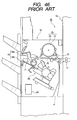
- a conventional sheet processing apparatus 10 shown in Fig. 46 includes a buffer roller path 14, which winds sheets around a rotating buffer roller 13 to cause the sheets to stand by for conveyance to a post-processing tray 11, in a conveyance path 12 in the course of conveyance of the sheets to the post-processing tray 11.
- the conventional sheet processing apparatus 10 stores sheets, which are conveyed from a discharge roller pair 17 in an apparatus main body 16 of an image forming apparatus 15, in the buffer roller path 14. After a preceding sheet stack has undergone, for example, a stitch action on the post-processing tray 11, and an upper roller 18a and a lower roller 18b of an oscillation roller pair 18 have nipped to discharge sheets, while rotating, from the post-processing tray 11, the sheet processing apparatus 10 conveys the sheet stack stored in the buffer roller 13 to the post-processing tray 11 to thereby prevent the decline in productivity without increasing conveyance intervals among the sheets during the stitch action.
- the conventional sheet processing apparatus 10 includes the buffer roller path 14 and requires a space for setting the buffer roller 13 and the buffer roller path 14, which stop conveyance of subsequent sheets to the post-processing tray 11 to cause sheets to stand by during a stitch action, a size of the sheet processing apparatus itself increases to cause an increase in costs.
- the conventional sheet processing apparatus 10 is adapted to stack sheets, which are stored in the buffer roller path, on the post-processing tray 11 after discharging sheets on the post-processing tray 11, the sheet processing apparatus 10 is not suitable for the recent actual situation in which high-speed processing is required. Thus, an apparatus with shorter processing time has been expected.
- the number of sheets to be stored in the sheet holding portion is fixed regardless of time required for processing sheets.
- the sheet processing apparatus for stitching sheets in the case of a sheet processing apparatus for stitching sheets, as the number of positions to be stitched increases, longer time is required for the processing.
- sheets of a number corresponding to longest required time for processing are stored in the sheet holding portion. Consequently, in the sheet processing apparatus for stitching sheets, in the case in which there are a small number of positions to be stitched, the sheet holding portion continues an action for storing sheets regardless of the fact that the processing has ended, and sheet processing efficiency is low.
- the sheet processing efficiency is also low in sheet processing apparatuses which perform other sheet processing.
- a sheet processing apparatus including: a sheet holding portion which stores plural supplied sheets with upstream edges in a conveying direction thereof aligned; sheet stacking means for stacking the sheets discharged from the sheet holding portion; and sheet conveying means for conveying the sheets discharged to the sheet stacking means, bringing the upstream edges of the sheets into abutment against a receiving stopper for receiving the upstream edges to align the upstream edges, and discharging the sheets from the sheet stacking means, in which the plural supplied sheets are discharged to the sheet stacking means from the sheet holding portion when a downstream edge in a conveying direction of a sheet to be supplied last has preceded the downstream edges in the conveying direction of the sheets stored in the sheet holding portion by a predetermined amount.
- the sheet processing apparatus further includes sheet processing means for applying processing to the sheets stacked on the sheet stacking means, and a subsequent sheet stored in the sheet holding portion and a preceding sheet stacked on the sheet stacking means are conveyed together by the sheet conveying means in a state in which a downstream edge of the preceding sheet projects further than a downstream edge of the subsequent sheet by a predetermined amount and, after the preceding sheet has been discharged from the sheet stacking means, the subsequent sheet is stacked on the sheet stacking means.
- the sheet processing apparatus further includes control means for controlling the number of sheets to be stored in the sheet holding portion according to a processing time of the sheet processing means.
- the sheet processing apparatus further includes control means for performing: a first action in a case in which the sheet is an ordinary sheet, the first action including subjecting a preceding sheet stacked on the sheet stacking means to processing with the sheet processing means and simultaneously causing a subsequent sheet to be held in the sheet holding portion and, after the processing of the preceding sheet ends, conveying the subsequent sheet and the preceding sheet together using the sheet conveying means to discharge the preceding sheet from the sheet stacking means, and then stacking the subsequent sheet on the sheet stacking means; and a second action in a case in which the sheet is a specific sheet, the second action including not causing the specific sheet to be held in the sheet holding portion but causing the specific sheet to pass through the sheet holding portion to be stacked on the sheet stacking means, processing the sheet with the sheet processing means, and then discharging the sheet from the sheet stacking means with the sheet conveying means.
- an image forming apparatus including: image forming means for forming an image on a sheet; and the sheet processing apparatus according to any one of the aspects described above, which applies processing to the sheet on which the image is formed by the mage forming means.
- the sheet processing apparatus of the present invention is adapted not to apply an alignment action to a sheet to be supplied last in the sheet holding portion.
- productivity can be improved.
- a return alignment property can also be improved.
- the sheet processing apparatus of the present invention can change the number of sheets to be stored in the sheet holding portion according to post-processing time, whereby productivity can be maintained.
- the number of sheets stored in the sheet holding portion, which are stacked on the sheet stacking means may be reduced, whereby an alignment property of sheets in the sheet stacking means can be improved.
- the sheet processing means is a stapler, it is possible to accurately stitch sheets.
- the image forming apparatus of the present invention includes the sheet processing apparatus with increased sheet processing efficiency.
- sheets can be processed efficiently, whereby image processing efficiency can be improved.
- a sheet processing apparatus of an embodiment of the present invention and a copying machine which is an example of an image forming apparatus including this sheet processing apparatus, will be hereinafter described with reference to the accompanying drawings.
- the image forming apparatus include a copying machine, a facsimile apparatus, a printer, and a multifunction machine of these apparatuses, and the image forming apparatus including the sheet processing apparatus is not limited to a copying machine.
- the sheet processing apparatus is an optional apparatus, which is constituted to be detachably mountable to an apparatus main body of the image forming apparatus as an independent apparatus, will be described as an example.
- the sheet processing apparatus of the present invention is also applied to a case in which the sheet processing apparatus is integrally provided in the image forming apparatus.
- this case is not particularly different in function from the case of a sheet processing apparatus, which is described later, a description of the case will be omitted.
- Fig. 1 is a schematic sectional view showing a state in which a sheet processing apparatus is mounted to a copying machine.
- the sheet processing apparatus is specifically, for example, a finisher.
- a copying machine 100 is constituted by an apparatus main body 101 and a sheet processing apparatus 119.
- An original feeding apparatus 102 is mounted above the apparatus main body 101.
- Originals D are mounted on an original mounting portion 103 and are sequentially separated one by one by a feeding portion 104 to be supplied to a registration roller pair 105. Subsequently, the original D is stopped by the registration roller pair 105 once and looped to correct skew feeding. Thereafter, the original D passes on an introduction path 106 to pass through a reading position 107, whereby an image formed on the surface of the original is read.
- the original D having passed through the reading position 108 passes on a discharge path 107 to be discharged on a discharge tray 109.
- the original D passes through the reading position 108, whereby an image on one side of the original is read. Thereafter, the original D passes on the discharge path 107 and is conveyed by a reverse roller pair 110 in a switch-back manner and sent to the registration roller pair 105 again in a state in which the sides are reversed.
- skew feeding of the original D is corrected in the registration roller pair 105 in the same manner as reading the image on the one side.
- the original D passes on the introduction path 106, and an image on the other side is read in the reading position 108. Then, the original D passes on the discharge path 107 to be discharged to the discharge tray 109.
- light of a lighting system 111 is applied on an image of an original passing through the reading position 108. Reflected light from the original is guided to an optical element 113 (CCD or other elements) by mirrors 112, and image data is obtained. Then, a laser beam based upon this image data is applied on, for example, a photosensitive drum 114 serving as image forming means to form a latent image. Note that, although not shown in the figure, it is also possible to constitute the image forming apparatus such that the reflected light is directly applied on the photosensitive drum 114 by the mirrors 112 to form a latent image.
- a toner image is formed from the latent image formed on the photosensitive drum 114 by a toner supplied from a toner supply apparatus (not shown).
- Recording media which are sheets of paper or plastic film, are stacked on a cassette 115.
- a sheet is fed from the cassette 115 in response to a recording signal and enters between the photosensitive drum 114 and a transfer apparatus 116 with timing for entering adjusted by a registration roller pair 150.
- a toner image on the photosensitive drum 114 is transferred onto the sheet by transfer apparatus 116.
- the sheet having the toner image transferred thereon is heated and pressurized by a fixing apparatus 117 while the sheet passes through the fixing apparatus 117, whereby the toner image is fixed.
- a sheet In the case in which images are formed on both sides of a recording medium, a sheet, on one side of which an image is fixed by the fixing apparatus 117, passes on a two-side path 118 provided on a downstream side of the fixing apparatus 117, fed into between the photosensitive drum 114 and the transfer apparatus 116 again, and a toner image is transferred onto a back side as well. Then, the toner image is fixed by the fixing apparatus 117, and the sheet is discharged to the outside (a finisher 119 side).
- Fig. 2 is a control block diagram of the entire copying machine.
- the entire copying machine 100 is adapted to be controlled by a CPU circuit portion 200.
- a ROM 202 which has stored therein sequences for each portion, that is, control procedures of respective portions, and a RAM 203, in which various kinds of information are temporarily stored as required, are provided in the CPU circuit portion 200.
- An original feeding apparatus control portion 204 is adapted to control an original feeding action of an original deeding apparatus 102.
- An image reader control portion 205 is adapted to control a lighting system 111 or the like to control reading of an original.
- An image signal control portion 206 is adapted to receive reading information of the image reader control portion 205 or image information, which is sent from an external computer 207, via an external I/F 208, process the information, and send a processing signal to a printer control portion 209.
- the printer control portion 209 is adapted to control the photosensitive drums 114 and the like on the basis of the image processing signal from the image signal control portion 206 to make it possible to form an image on a sheet.
- An operation portion 210 is adapted to be able to input information on what kind of processing is applied to a sheet, for example, information for performing staple processing.
- the operation portion 210 is adapted to be able to display information on an action state or the like of the apparatus main body 101 of the copying machine and the finisher 119 serving as a sheet post-processing apparatus.
- a finisher control portion 21 is adapted to control actions in the finisher 119 serving as a sheet post-processing apparatus.
- a FAX control portion 212 is adapted to control the copying machine such that the copying machine can be used as a facsimile apparatus to transmit/receive signals with other facsimile apparatuses.
- Fig. 3 is a longitudinal sectional view of a sheet processing apparatus.
- Fig. 4 is a longitudinal sectional view showing respective drive systems.
- Fig. 8 is a control block diagram of the sheet processing apparatus.
- Fig. 9 is a flowchart for explaining actions of the sheet processing apparatus.
- Figs. 10 to 12 are diagrams showing a relation between a moving speed of a trailing edge assist 134 and a sheet conveyance speed of an oscillation roller pair 127 with respect to an elapsed time.
- Fig. 10 is a solo discharge sequence for feeding a sheet stack with the trailing edge assist 134 and the oscillation roller pair 127.
- Fig. 10 is a solo discharge sequence for feeding a sheet stack with the trailing edge assist 134 and the oscillation roller pair 127.
- FIG. 11 is a diagram of stack delivery control in the case in which start speeds of the trailing edge assist 134 and the oscillation roller pair 127 are different.
- Fig. 12 is a diagram of a simultaneous discharge sequence for simultaneously conveying a sheet stack and a buffer sheet stored in a buffer unit 140 with the trailing edge assist, the oscillation roller pair, and the first conveyance roller pair.
- the sheet processing apparatus 119 is provided with a function for bookbinding a sheet stack and includes a stapler unit 132 which stitches parts near the edge of the sheet stack, a stapler 138 which stitches the center of the sheet stack, a folding unit 139 which folds the parts of stitch positions of the sheet stack stitched by the stapler 138 to form the sheet stack in a book shape, and the like.
- the sheet processing apparatus 119 of this embodiment includes the buffer unit 140 serving as a sheet holding portion which stacks and stores plural sheets, which will be processed next, on a lower conveyance guide plate 123b in a straight state during operation of the stapler unit 132.
- this buffer unit 140 is adapted to stack and store plural sheets in a straight state, unlike the conventional mechanism having the buffer roller 13 shown in Fig. 46, the sheets can be made flat along a guide 123 constituted linearly, and a size and a weight of the sheet processing apparatus can be reduced. Moreover, since the sheets can be stored in a straight state, unlike the case of the buffer roller, the sheets are not rolled up. Thus, since the sheets can be easily handled, a processing time for the sheets of the sheet processing apparatus can be reduced.
- the sheet processing apparatus 119 is adapted to be controlled by a finisher control portion 211 shown in Figs. 6 and 7.
- a ROM 222 which has stored therein a control procedure (sequence) of the sheet processing apparatus 119 operating on the basis of an instruction from the CPU circuit portion 200 of the apparatus main body of the copying machine, a RAM 203, which temporarily stores information required for controlling the sheet processing apparatus 119 each time it is controlled, and the like are provided in a CPU 221 of the finisher control portion 211.
- a sheet surface detection sensor 224 which operates on the basis of an action of a sheet surface detection lever 133 to be described later, is connected to the finisher control portion 211.
- the CPU 221 is adapted to control ascent and decent of a stack tray 128 on the basis of a sheet detection signal of the sheet surface detection sensor 224.
- the finisher control portion 211 is adapted to control to operate an inlet conveyance motor M2 which rotates an inlet roller pair 121, a buffer roller 124, and a first discharge roller pair, a stack delivery motor M3 which rotates an oscillation roller pair 127 and a return roller 130, an under-stack clutch CL which transmits the rotation of the stack delivery motor M3 to a lower roller 127b or disconnects the rotation, and the like on the basis of the above-mentioned sequence.
- CPU circuit portion 200 and the finisher control portion 211 may be integrally formed.
- the under-stack clutch CL shown in Fig. 4 is provided in order to absorb a speed difference. This is because, since the lower roller 127b and the return roller 130 to be described later are rotated by the common stack delivery motor M3, if slip occurs or a sheet conveyance speed difference is generated in both the rollers when a sheet or a sheet stack is conveyed by the lower roller 127b and the return roller 130, it is likely that wrinkles are formed on the sheet or the sheet stack or that the sheet or the sheet stack is scratched.
- the CPU circuit portion 200 controls the respective portions of the apparatus main body to shift the copying machine to a copying action and, at the same time, sends a sheet stitch processing signal to the finisher control portion 211.
- the explanation of actions on the basis of Figs. 13A and 13B to 19 is an explanation of a case in which the CPU circuit portion 200 judges that a sheet is long on the basis of sheet size information inputted by the user in the operation portion 210 (e.g., the case of an A3 size sheet), or a case in which a sheet is a special sheet, which is provided with attributes different from an ordinary sheet, such as a thick sheet, a thin sheet, a tab sheet, or a sheet for color image formation, depending upon sheet type information.
- 13A and 13B to 19 is an explanation of a case in which an action for stacking a buffer sheet to be described later on a processing tray 129 serving as sheet stacking means is started after a sheet stack is discharged to the stack tray 128, that is, a case in which sheets do not have to be stored during sheet processing. Note that it is needless to mention that actions to be described below may be performed regardless of a length of a sheet and whether or not a sheet is a special sheet.
- the finisher control portion 211 activates the inlet conveyance motor M2 and the stack delivery motor M3 on the basis of a sheet stitch processing signal.
- the finisher control portion 211 operates a buffer roller estrangement plunger SL1 (see Fig. 4) to estrange the buffer roller 124 from the lower conveyance guide plate 123b, and further operates a not-shown plunger to estrange an upper roller 127a of the oscillation roller pair 127 from the lower roller 127b.
- the activation and stop of the inlet conveyance motor M2 and the stack delivery motor M3 may be controlled in accordance with movement of a sheet one by one.
- the receiving roller pair 137 is adapted to be rotated by the common conveyance motor M1 which rotates the discharge roller pair 120.
- the inlet roller pair 121 is rotated by the inlet conveyance motor M2 (see Fig. 4) to convey a first sheet P1.
- the sheet P1 is conveyed to a first discharge roller pair 126 according to guidance of the linearly constituted guide 123 which is composed of an upper conveyance guide plate 123a and a lower conveyance guide plate 123b.
- the sheet P1 is further conveyed by the rotation of the first discharge roller pair 126 to be discharged to the stack tray 128 as shown in Fig. 14A.
- the sheet P1 falls over the stack tray 128 and the processing tray 129.
- the upper roller 127a is lowered by the not-shown plunger to nip the sheet with the lower roller 127b.
- the lower roller 127b has already been rotated in a direction of arrow by the upper roller 127a and the stack delivery motor M3 (see Fig. 4). Moreover, The return roller 130, which comes into contact with and moves away from the processing tray 129 freely, is also rotated in a direction of arrow by the stack delivery motor M3 (see Fig. 4). However, the lower roller 127b is adapted to be coupled with a driving force by an operation of the under-stack clutch CL (see Fig. 4) when a first sheet is conveyed, but is turned off and rotates idly when second and subsequent sheets are conveyed.
- CL under-stack clutch
- the sheet P1 slides down in a direction of arrow on the processing tray 129 slanting to the lower right according to the rotation of the oscillation roller pair 127 and the return roller 130.
- the trailing edge assist 134 stands by in a standby position.
- the upper roller 127a moves away from the sheet P1.
- the sheet P1 is brought into abutment against the stopper 131 by the return roller 130.
- width alignment of the sheet P1 is performed by a pair of alignment plates 144a and 114b (see Fig. 5).
- the subsequent sheets are stacked on the processing tray 129 in the same manner.
- the sheets in bundles are stitched by the stapler unit 132 shown in Figs. 3 and 4.
- punch processing may be applied with a not-shown punch unit.
- the upper roller 127a nips the sheet stack P with the lower roller 127b and rotates in a direction of arrow, and the trailing edge assist 134 pushes the trailing edge of the sheet stack P to discharge the sheet stack to the stack tray 128.
- the trailing edge assist 134 is provided in a belt 142 which is rotated regularly and reversely by a trailing edge assist motor M4.
- the oscillation roller pair 127 and the trailing edge assist 134 can discharge the sheet stack without applying a tensile force or a compression force to the sheet stack (S106).
- the start speed of the trailing edge assist 134 may be lower than the start speed of the oscillation roller pair 127 due to belts 143, 142, and the like which transmit a rotation force of the trailing edge assist motor M4 to the trailing edge assist 134 (the start speed of the trailing edge assist 134 is assumed to be 300 mm/sec).
- the trailing edge assist 134 is at rest without starting movement until a time T3 when the sheet conveyance speed of the oscillation roller pair 127 reaches 300 mm/sec, and starts movement when the sheet conveyance speed of the oscillation roller pair 127 has reached 300 mm/sec.
- the oscillation roller pair 127 and the trailing edge assist 134 can discharge the sheet stack without applying a tensile force and a compression force to the sheet stack.
- the sheet stack is started to be fed to the stack tray 128 by the oscillation roller pair 127, the trailing edge assist 134, and the return roller 130 (S108).
- the trailing edge assist 134 returns to an original position (home position) (S110, an action equivalent to "HP delivery control" in Fig. 12) at the point when the trailing edge assist 134 has moved about 15 mm (S109).
- the sheet stack is discharged onto the stack tray 128 by the oscillation roller pair 127. Thereafter, at the point when the upper roller 127a of the oscillation roller pair 127 has estranged from the lower roller 127b, a series of sheet stack delivery actions end (S111, S112).
- the trailing edge assist 134 pushes the trailing edge of the sheet stack to convey the sheet stack, unlike a case in which a roller is brought into pressed contact with the surface of the sheet stack and rotated to discharge the sheet stack, it is possible to convey the sheet stack surely without scratching the surface of the sheet stack.
- the above explanation of actions is an explanation of actions in the case in which a large interval is provided between sheets to be conveyed and stitch processing can be applied to a sheet stack while the next sheet is being fed into the sheet processing apparatus.
- the following explanation of actions is an explanation about a buffer action for, in the case in which an interval of conveyance of sheets is short and subsequent sheets are fed into the sheet processing apparatus while processing is being applied to a sheet stack, storing (buffering) the subsequent sheets only during stitch processing.
- the sheet processing apparatus 119 performs a buffer action on the basis of a buffer action command of the finisher control portion 211 at the point when the CPU circuit portion 200 judges that an interval of sheets to be sent from the apparatus main body 101 of the copying machine 100 is shorter than a sheet stitch processing time.
- the buffer roller 124 is lowered by the plunger SL1 (see Fig. 4) and is in contact with the lower conveyance guide plate 123b.
- a sheet stack is stacked on the processing tray 129 on the basis of the above-mentioned action. It is also assumed that the stitch processing is applied to the sheet stack by the stapler unit 132 (see Figs. 3 and 4) .
- a first sheet P1 of the next sheet stack is fed into the sheet processing apparatus 119 while staple processing is being applied to a sheet stack P stacked on the processing tray 129
- the sheet P1 is fed into the buffer roller 124 by the inlet roller pair 121.
- the buffer roller 124 is rotated by the inlet conveyance motor M2 (see Fig. 4) to convey the sheet P1 downstream.
- an upper first discharge roller pair 126a of the first discharge roller pair 126 is estranged from a lower first discharge roller pair 126b by a first discharge roller estrangement plunger SL2 (see Fig. 4).
- the first discharge roller estrangement plunger SL2 is not shown in Fig. 4 because it overlaps the buffer roller estrangement plunger SL1.
- the upper roller 127a of the oscillation roller pair 127 is also estranged from the lower roller 127b by the not-shown plunger.
- a trailing edge holding-down member 135 is estranged from the lower conveyance guide plate 123b, and a trailing edge receiving portion 136 is opened. It can be detected that the trailing edge of the sheet P1 has reached the switch-back point SP when a predetermined time has elapsed after an inlet path sensor S1, which is disposed in the vicinity of the downstream side of the inlet roller pair 121 shown in Fig. 4, is operated by the leading edge (downstream side edge) of the sheet or according to the rpm of rotations or the like of the buffer roller 124.
- the upstream edge side of the sheet P1 after the downstream edge of the sheet is detected is received by the trailing edge receiving portion 136 as shown in Fig. 21A. Thereafter, as shown in Fig. 21B, the trailing edge holding-down member 135 returns to the original position and presses the sheet P1 against the lower conveyance guide plate 123b with a friction member 141 provided in the trailing edge holding-down member 135.
- a second sheet P2 is fed into the sheet processing apparatus 119.
- the second sheet P2 is conveyed by the inlet roller pair 121.
- the sheet P2 passes on the trailing edge holding-down member 135.
- the sheet P2 is also conveyed by the buffer roller 124.
- the first sheet P1 is pressed against the lower conveyance guide plate 123b together with the second sheet P2 by the buffer roller 124 and is about to move to the downstream side following the second sheet P2 being conveyed.
- the first sheet P1 since the first sheet P1 is pressed against the lower conveyance guide plate 123b by the friction member 141 provided in the trailing edge holding-down member 135, the first sheet P1 never moves.
- the second sheet P2 is also returned to the upstream side as shown in Figs. 23A, 23B, and 24 when the trailing edge thereof has reached the switch-back point SP in the same manner as the first sheet P1. Then, the second sheet P2 is laid on the first sheet P1 and pressed against the lower conveyance guide plate 123b by the friction member 141 of the trailing edge holding-down member 135.
- the upper roller 127a also moves down and nips the three sheets P1, P2 and P3, and the sheet stack P with the lower roller 127b.
- the trailing edge holding-down member 135 is estranged from the second sheet P2 to release the first sheet P1 and the second sheet P2.
- the three sheets P1, P2 and P3, and the sheet stack P are nipped and conveyed by the oscillation roller pair 127. Then, as shown in Figs. 27A and 27B, when the sheet stack P is discharged to the stack tray 128, the trailing edges of the first sheet P1 and the second sheet P2 slip out of the first discharge roller pair 126, and the upstream side portions of the three sheets are received by the processing tray 129.
- Fig. 27B as shown in Figs. 11 and 12, if the first discharge roller pair 126, the oscillation roller pair 127, and the trailing edge assist 134 have the same start time (T1) and the same start speed (132 mm/sec) and reach the same acceleration end speed (500 mm/sec) at the same time (T2), the first discharge roller pair 126, the oscillation roller pair 127, and the trailing edge assist 134 can discharge the sheet stack without applying a tensile force or a compression force to the sheet stack and the three sheets. However, in the case in which there is a difference in start speeds, as in S107 in Fig.
- the first discharge roller pair 126, the oscillation roller pair 127, and the trailing edge assist 134 can discharge the sheet stack without applying a tensile force or a compression force to the sheet stack and the three sheets if a time difference of ⁇ T is provided to start them.
- the three sheets are slid down and conveyed on the processing tray 129 by the oscillation roller pair 127 and the return roller 130 and received by the stopper 131.
- the stack tray 128 moves down once and moves up again after lowering the upper surface of the sheet stack to a position lower than the sheet surface detection lever 133.
- the stack tray 128 stops moving up.
- the upper surface of the sheet stack on the stack tray 128 can be held at a predetermined height.
- the sheets are sequentially stacked on the processing tray 129 without being stored on the lower conveyance guide plate 123b.
- the sheets are stitched. During this stitch action, first three sheets of the next sheet stack are stored on the lower conveyance guide plate 123b.
- the number of sheets (buffer sheets) to be stored is not limited to three because the number of sheets that can be stored varies according to a length of sheets, a stitching time, a conveyance speed of sheets, and the like.
- the downstream edge Pa of the sheet stack P is projected to the downstream side P3a of the third sheet P3 by a length L.
- the reason for this is as described below. Note that the downstream edges P1a and P2a of the first and the second sheets P1 and P2 are located further on the upstream side than the downstream edge P3a of the third sheet P3.
- a projecting length of the downstream edge of the sheet stack P is L1 which is shorter than the length L
- a projecting length of the upstream edge of the sheet P3 is also L1. Consequently, after the oscillation roller pair 127 has discharged the sheet stack P to the stack tray 128, it is possible that a length for gripping three buffer sheets is reduced, and the oscillation roller pair 127 fails to grip the three buffer sheets and cannot feed them to the processing tray 129 surely. Therefore, the sheet stack is projected by the length L with respect to the downstream edge P3a of the sheet P3 such that the oscillation roller pair 127 can grip buffer sheets surely and feed them into the processing tray 129.
- the projecting length is short, a contact area of a buffer sheet and a sheet stack is increased, and the sheet stack tends to adhere to the buffer sheet and fall on the stack tray 128 slowly.
- the oscillation roller pair 127 rotates reversely to feed the buffer sheet into the processing tray 129, it is likely that the sheet stack enters the oscillation roller pair 127 while keeping on sticking to the buffer sheet to scratch the sheet stack or cause sheet jam. Therefore, in order to improve a separation property of the sheet stack and the buffer sheet, the sheet stack is projected by the length L with respect to the downstream edge P3a of the sheet P3.
- the sheet processing apparatus 119 of this embodiment is adapted such that the trailing edge assist 134 pushes the trailing edge of a sheet stack. If the trailing edge of the sheet stack is pushed by the trailing edge assist 134 to convey the sheet stack in this way, unlike a case in which a roller is brought into pressed contact with the surface of the sheet stack and rotated to discharge the sheet stack, it is possible to convey the sheet stack surely without scratching the surface of the sheet stack.
- a sheet stack is discharged only by the oscillation roller pair 127, it is possible that deviation occurs between an upper sheet and a lower sheet because an amount of conveyance of sheets is different due to the difference in friction between the upper roller 127a and the lower roller 127b against a sheet, the difference in rotation speed, or the like.
- the oscillation roller pair 127 may slide and rotate with respect to the sheet causing scratches on the sheet.
- the oscillation roller pair 127 may discharge the sheet stack while twisting the entire sheet stack. As a result, the sheet stack cannot be discharged smoothly, and processing requires long time.
- the entire sheet stack is twisted, it is likely that the sheet is torn in stitched parts, and the sheet stack cannot be used.
- the sheet processing apparatus of this embodiment is adapted to discharge the sheet stack not only by the oscillation roller pair 127 but also by the trailing edge assist 134. Therefore, the oscillation roller pair 127 never slides and rotates with respect to the sheet or twists the sheet stack as described above, and the oscillation roller pair 127 can discharge the sheet stack smoothly and promptly without scratching the sheet and the sheet stack. In addition, the sheet stack can be discharged even if the nipping pressure of the oscillation roller pair 127 is not controlled strictly.
- Fig. 31 is a flowchart for explaining schematic operations of the entire sheet processing apparatus 119 and is also a flowchart of sort processing. Note that the flowchart explains sort processing for performing two-sheet buffer. Operations of respective portions shown in the flowchart are performed by the control of the finisher control portion 211 shown in Fig. 8.
- the sheet processing apparatus 119 upon judgment on whether or not a sheet to be stacked on the processing tray 129 is a first sheet (S302), whether or not a buffer counter is 1 (S303), and whether or not a previous sheet is the last sheet of a sheet stack (S304), the sheet processing apparatus 119 performs any one of an action for first sheet in machine (S307), an action for buffer last sheet (S308), an action for buffer sheet (S309), and an action for sheet in mid-flow (S310).
- the action for first sheet in machine (S307) in Fig. 31 is an action from stacking of a first sheet on the processing tray 129 until start of sheet processing as indicated by reference signs S401 to S420 in Figs. 32A and 32B.
- the action for buffer last sheet (S308) in Fig. 31 is an action from stacking of a buffer sheet on the processing tray 129 until start of a post-processing operation as indicated by reference signs S501 to S535 in Figs. 33A, 33B, 34A, 34B and 34C.
- the action for buffer sheet (S309) in Fig. 31 is an action for storing (buffering) a buffer sheet in the guide 123 as indicated by reference signs S601 to S613 in Figs. 35A and 35B (see Figs. 20A and 20B to 25A and 25B).
- the action for sheet in mid-flow (S310) in Fig. 31 is an action from stacking of second and subsequent sheets on the processing tray 129 until start of the sheet processing as indicated by reference signs S701 to S716 in Figs. 36A and 34B.
- Symbol S419 in Figs. 32A and 32B, symbol S534 in Figs. 34A and 34B, and symbol S715 in Figs. 36A and 36B defined as start of post-processing action is an action for performing post-processing after stacking a sheet, which is discharged from the apparatus main body 101 of the copying machine 100, on the processing tray 129 as indicated by reference signs S801 to S824 in Figs. 37 and 38.
- the CPU 221 controls a front alignment motor M5 and an inside alignment motor M6 to bring a front alignment plate 144a and an inside alignment plate 144b (see Fig. 5), which are disposed along both sides in a sheet conveying direction and approach and separate from a direction crossing the sheet conveying direction, close to a sheet and align both sides of the sheet (S801, S802).
- a large sheet such as an B4 sheet requiring two times alignment (S803)
- S804 after 100 msec has elapsed (S804)
- the front alignment plate 144a and the inside alignment plate 144b are estranged from the sheet once and retracted (S805, S806).
- the CPU 221 controls the stack delivery motor M3 to stop a reverse rotation action of the oscillation roller pair 127 (S810).
- the CPU 221 judges whether or not the sheet is the last sheet in the stack according to last sheet information of the sheet stack from the CPU circuit portion 200 of the apparatus main body 101 or on the basis of the number of sheets from a counter which counts the number of sheets (Fig. 38, S811). If the sheet is not the last sheet in the stack, the CPU 221 controls the front alignment motor M5 and the inside alignment motor M6 (see Fig. 8) to return the front alignment plate 144a and the inside alignment plate 144b (see Fig. 5) to the retracted position (S822, S823).
- the CPU 221 moves a stapler shift motor M8 to move a stapler 166 to a stitching position and controls a stapler motor M9 to stitch the sheet stack with the stapler 166 (S813, S814). Thereafter, the CPU 221 controls the trailing edge assist motor M4 (see Figs. 5 to 8) to project only the sheet stack by the length L from the sheet stored in advance with the trailing edge assist 134 as shown in Figs. 26A and 26B (pre-discharge) (S815, S816).
- the CPU 221 controls the stack delivery motor M3 to discharge only the stitched sheets to the stack tray 128 from the processing tray 129 and completes the post-processing operation (S821, S824).
- the buffer mode discrimination processing in S818 of Fig. 38 is processing for changing the buffer flag from 1 to 0 such that a buffer mode can be discriminated.
- the buffer flag is 0.
- the buffer flag is 1.
- the CPU 221 judges that attribute information of a sheet such as a thick sheet, a thin sheet, a sheet for an overhead projector (OHP), a sheet with a length equal to or larger than a predetermined length, a color print sheet, a sheet for a top cover, or a tab sheet, which is inputted in the operation portion 210 (see Fig. 2) by a user, belongs to a specific sheet and cannot allow the stitched sheet stack and the stored sheet (buffer sheet) to be discharged simultaneously (S819). Then, the CPU 221 controls the stack delivery motor M3 to discharge only the stitched sheet stack to the stack tray 128 from the processing tray 129 (second action) and completes the post-processing action (S821, S824).
- a sheet such as a thick sheet, a thin sheet, a sheet for an overhead projector (OHP), a sheet with a length equal to or larger than a predetermined length, a color print sheet, a sheet for a top cover, or a tab sheet,
- the CPU 221 controls the inlet conveyance motor M2, the stack delivery motor M3, and the under-stack clutch CL to discharge the sheet stack on the processing tray 129 to the stack tray 128 and, at the same time, discharges the stored sheets to the processing tray 129 from the guide 123.
- a simultaneous discharge action is performed (first action) (S820, S824).
- the sheet processing apparatus 119 of this embodiment is adapted, when a sheet is a specific sheet, perform solo discharge action (second action) for discharging the sheet individually, a thick sheet never stuffs the buffer unit 140 or thin sheets, sheets for color image formation, or sheets for an overhead projector never stick with each other to cause sheet jam.
- sheet processing efficiency can be improved.
- a preceding sheet stacked on the sheet stacking means and a subsequent sheet held in the sheet holding portion are not discharged simultaneously, an alignment property at the time when a sheet is moved from the sheet holding portion to the sheet stacking means can be improved. Further, occurrence of sheet jam during conveyance of a sheet can be prevented.
- Fig. 40 is a flowchart showing a motion mode discrimination processing procedure. An action discrimination processing program for this procedure is stored in the ROM 222 in the finisher control portion 221 (see Fig. 8) and is adapted to be executed by the CPU 221.
- the CPU 221 waits for finisher (sorter) start to be turned ON (S1101).
- finisher sorter
- a start key for copy start provided in the operation portion 210 (see Fig. 2) of the apparatus main body 101 of the copying machine 100 is pressed, and a signal for starting an action of the finisher is inputted to the CPU 221 in the finisher control portion 211 (see Fig. 8) from the apparatus main body 101 of the copying machine 100 via a communication IC (IPC)
- the finisher start comes into an ON state (S1101).
- the CPU 221 starts driving of the inlet conveyance motor M2 (see Fig. 4) (S1102).
- S1101 if the signal for starting the finisher is not inputted to the CPU 221, the finisher is in a standby state.
- the CPU 221 discriminates an action mode (S1103) and, if the action mode is a non-sort mode, executes the non-sort processing (S1104). In addition, if the action mode is a sort mode, the CPU 221 executes the sort processing (S1105).
- the CPU 221 executes the staple sort processing (S1106).
- the CPU 221 stops the driving of the inlet conveyance motor M2 (S1107) and returns to the processing of step S1101, and the finisher returns to the standby state.
- Fig. 41 is a flowchart showing a procedure of the non-sort processing (S1104) in Fig. 40.
- the CPU 221 discriminates whether or not the finisher start (sorter start) is in the ON state (S1201). If the finisher start is in the ON state, the sheet discharged from the apparatus main body 101 of the copying machine is delivered to the guide 123 (see Fig. 4) in the finisher.
- the CPU 221 waits for the delivered sheet to be conveyed by the inlet conveyance motor M2 and the leading edge thereof to be detected by the inlet path sensor S1 disposed in the guide 123 to turn ON the inlet path sensor S1 (S1202).
- the inlet path sensor S1 is turned ON, the CPU 221 waits for the trailing edge of the conveyed sheet to pass through the inlet path sensor S1 and to be turned OFF (S1203).
- the CPU 221 When the inlet path sensor S1 is turned OFF, the CPU 221 returns to the processing of S1201, and in the case in which the finisher start comes into the OFF state again, continues the processing in the same manner. On the other hand, in the case in which the finisher start comes into the OFF state, the CPU 221 waits for all the sheets to be discharged to the stack tray 128 (S1204), and if all the sheets are discharged to the stack tray 128, the CPU 221 ends the non-sort processing.
- Fig. 42 is a flowchart showing a procedure of the sort processing (S1105).
- the CPU 221 discriminates whether or not the finisher start is in the ON state (S1301). If the finisher start is in the ON state, the sheet discharged from the apparatus main body 101 of the copying machine is delivered to the guide 123 (see Fig. 4) in the finisher. The delivered sheet is conveyed by the inlet conveyance motor M2, and the CPU 221 waits for the leading edge thereof to be detected by the inlet path sensor S1 arranged in the guide 123 (S1302). When the inlet path sensor S1 is turned ON, the CPU 221 starts a sort sheet sequence (S1303). Then, the CPU 221 waits for the trailing edge of the conveyed sheet to pass through the inlet path sensor S1 and the inlet path sensor S1 to be turned OFF (S1304).
- the CPU 221 When the inlet path sensor S1 is turned OFF, the CPU 221 returns to the processing of S1301, and if the finisher start comes into the OFF state again, the CPU 221 repeats the same processing. On the other hand, when the finisher start comes into the OFF state, the CPU 221 waits for all the sheets to be discharged to the stack tray 128 (S1305), and if all the sheets have been discharged, the CPU 221 ends the sort processing.
- Fig. 43 is a flowchart showing a procedure of the staple sort processing (S1106) in Fig. 40.
- the CPU 221 discriminates whether or not the finisher start is in the ON state (S1401). If the finisher start is in the ON state, the sheet discharged from the apparatus main body 101 of the copying machine is delivered to the guide 123 (see Fig. 4) in the finisher. The delivered sheet is conveyed by the inlet conveyance motor M2, and the CPU 221 waits for the leading edge thereof to be detected by the inlet path sensor S1 disposed in the guide 123 (S1402). When the inlet path sensor S1 is turned ON, the CPU 221 starts the sort sheet sequence (S1403). Then, the CPU 221 waits for the trailing edge of the conveyed sheet to pass through the inlet path sensor S1 to be turned OFF (S1404).
- the CPU 221 When the inlet path sensor S1 is turned off, the CPU 221 returns to the processing of S1401 and, when the finisher start comes into the OFF state again, repeats the same processing. On the other hand, when the finisher start comes into the OFF state, the CPU 221 waits for all the sheet to be discharged to the stack tray 128 (S1405), and if all the sheets have been discharged, the CPU 221 ends the non-sort processing.
- Fig. 44 is a flowchart showing a procedure of the sort sheet sequence (S1303, S1403) in Figs. 42 and 43. Processing of this sort sheet sequence is applied to each sheet to be conveyed. In addition, a program for this processing is carried out by the CPU 221 (see Fig. 8) in multitask.
- the CPU 221 performs sheet attribute discrimination processing (S1501). A detailed description of this sheet attribute discrimination processing will be made later on the basis of Fig. 45.
- the sheet attribute discrimination processing is processing for discriminating whether an attribute of a sheet to be conveyed is "a sheet to be subjected to buffering", "a sheet to be discharged simultaneously with a stack already subjected to the post-processing on the processing tray", or "a sheet to be subjected to the post-processing after a stack is stacked on the processing tray".
- the CPU 221 discriminates whether or not the sheet is a buffer sheet (S1502). If the sheet is designated as the buffer sheet, the CPU 221 buffers the sheet on the guide 123 (see Fig. 4) (S1511) and ends the processing.
- the buffering is a series of actions for once stopping the sheet to be conveyed with the guide 123, lifting the trailing edge holding-down member 135, moving back the sheet upstream in the conveying direction by the buffer roller 124 to abut the trailing edge of the sheet against the trailing edge receiving portion 136, and lowering the trailing edge holding-down member 135 to hold down the buffer sheet (see Figs. 20 to 25).
- the CPU 221 judges whether or not the sheet is a simultaneous discharge sheet (S1503). If it is judged in S1503 that the sheet is a simultaneous discharge sheet, the CPU 221 executes simultaneous discharge processing (S1504) and waits for discharge of the simultaneous discharge sheet to the processing tray 129 (for the buffer sheet) to be completed (S1505).
- the CPU 221 waits for discharge of the sheet to the processing tray 129 to be completed (S1505).
- the CPU 221 aligns the sheet discharged to the processing tray 129 (S1506) and judges whether or not the sheet is the last sheet of the stack (S1507). If it is judged in S1507 that the sheet is the last sheet in the stack, the CPU 221 judges whether or not the action mode is the staple sort mode (S1508). If it is judged in S1508 that the action mode is the staple sort mode, the CPU 221 executes staple processing (S1509). Next, the CPU 221 moves the sheet stack to a position for simultaneous discharge (S1510) and ends the processing.
- the CPU 221 moves the sheet stack to the position for simultaneous discharge (S1510) and ends the processing. On the other hand, if it is judged in S1507 that the sheet is not the last sheet of the sheet stack, the CPU 221 ends the processing.
- Fig. 45 is a flowchart showing a procedure of the sheet attribute discrimination processing (S1501) in Fig. 44.
- the CPU 221 discriminates whether or not the sheet is the last sheet in one stack (S1601).
- one stack means a unit for sorting in the case in which the action mode is the sort mode.
- the action mode is the staple sort mode
- one stack is a unit for performing stapling.
- the action mode is the non-sort mode
- one stack is a unit of one job.
- the CPU 221 judges whether or not the buffer counter is 1 (S1609). If it is judged in S1609 that the buffer counter is 1, the CPU 221 designates the sheet as a simultaneous discharge sheet (S1610) and judges whether or not the post-processing mode is an unstitch mode (S1611).
- the sheet designated as a simultaneous discharge sheet is once stopped in the buffer position and laid on the sheet which has already been subjected to buffering. Thereafter, the sheet stack on the processing tray 129 which has been subjected to the post-processing and the buffer sheet are simultaneously conveyed. The buffer sheet is discharged to the processing tray 129, and the sheet stack that has been subjected to the post-processing is discharged to the stack tray.
- the buffer counter is a counter to be used for limiting the number of sheets to be subjected to buffering and is counted down every time a sheet is subjected to buffering.
- the CPU 221 judges whether or not the post-processing mode is the unstitch mode (S1611).
- the CPU 221 sets the buffer counter to 2 (S1614). Consequently, the number of sheets to be subjected to buffering (the number of sheets to be laid one on top of another), which is usually three, is reduced to two. As a result, an alignment property of the buffer sheets after the simultaneous discharge on the processing tray 129 can be improved.
- the CPU 221 judges whether or not the post-processing mode is a one position stitch mode (S1612).
- the CPU 221 sets the buffer counter to 2 (S1614). Consequently, the number of sheets to be subjected to buffering (the number of sheets to be laid one on top of another), which is usually three, is reduced to two. As a result, an alignment property of the buffer sheets after the simultaneous discharge on the processing tray 129 can be improved.
- the CPU 221 sets the buffer counter to 3 (S1613) and sets the number of sheets to be subjected to buffering to 3 which is the number of sheets to be set usually.
- the CPU 221 judges whether or not the sheet is a sheet of a buffer possible size (S1602). If it is judged in S1602 that the sheet is not a sheet of a buffer possible size, the CPU 221 ends the processing.
- the CPU 221 judges whether or not the buffer counter is 0 (S1603). If it is judged in S1603 that the buffer counter is 0, the CPU 221 ends the processing.
- the CPU 221 judges whether or not the buffer counter is 1. If it is judged in S1604 that the buffer counter is 1, the CPU 221 decrements the buffer counter by one (S1605), designates the sheet as a simultaneous discharge sheet (S1606), and ends the processing.
- the CPU 221 decrements the buffer counter by one (S1607), designates the sheet as the buffer sheet (S1608), and ends the processing.
- the above-mentioned sheet processing apparatus is a sheet processing apparatus of a simultaneous discharge system.
- the number of sheets to be subjected to buffering can also be adjusted according to stitching positions.
- This sheet processing apparatus 10 is also adapted to be mounted to the apparatus main body 16 of an image forming apparatus, for example, a copying machine and used as a copying machine 15.
- This sheet processing apparatus 10 causes sheets fed from the apparatus main body 16 by the discharge roller pair 17 to pass through a strait path 20, sequentially stacks the sheets on the processing tray 11 and, when a predetermined number of sheets have been stacked, stitches the sheets with a stapler unit 19. Thereafter, the sheet stack is nipped by the upper roller 18a and the lower roller 18b of the oscillation roller pair 18 to be rotated and discharged.
- the number of sheets to be stored (buffer sheets) is the number of sheets corresponding to a time required of the stapler unit 19 to stitch the sheet stack.
- the buffer roller 13, the buffer roller path 14, and the like constitute the buffer unit 23.
- sheet processing efficiency can also be improved by controlling the number of sheets that are subjected to buffering in the buffer unit 23, with the control portion 24 according to stitching positions for a sheet stack in the stapler unit 19.
- the third sheet P3 is slightly projected to further the downstream side than the first and the second sheets P1 and P2. The reason for this will be described below on the basis of Figs. 47A to 47D, 48 and 49. Note that, in Figs. 47A to 47D, it is assumed that the upper roller 127a and the lower roller 127b nips a sheet stack and buffer sheets.
- the sheet stack P stacked on the processing tray 129 and the three buffer sheets P1, P2 and P3 are simultaneously discharged by the oscillation roller pair 127 and the first discharge roller pair 128.
- the upper roller 127a moves down by a thickness of the sheet stack P.
- the buffer sheets fall on the processing tray 129 and are conveyed by the oscillation roller pair 127 and the return roller 130 until the buffer sheets come into abutment against the stopper 131.
- the lowermost first sheet P1 is conveyed by the lower roller 127b and brought into abutment against the stopper 131.
- the second sheet P2 is brought into abutment against the stopper 131 by the return roller 130.
- the third sheet P3 is brought into abutment against the stopper 131 by the upper roller 127a. Therefore, since the three sheets are brought into abutment against the stopper 131 by the respective rollers and aligned, the three sheets are stitched by the stapler unit surely.
- the sheet processing apparatus 119 of this embodiment can perform return alignment of sheets on the processing tray 129 satisfactorily and improve processing accuracy by dislocating the third sheet P3 further to the stack tray 128 side than the other sheets.
- sheet conveying means comes into contact with the respective sheets surely to convey the sheets to a receiving stopper and bring the sheets into abutment against the stopper, and accuracy of return alignment can be improved.
- processing accuracy with respect to the sheets after that can be improved.
- the third sheet is not aligned by the buffer unit 140, a conveying time of the sheets can be reduced to improve processing efficiency of the sheets so much more for that.
- a position of a sheet is detected by a sensor.
- a position of a sheet may be judged according to sheet holding information (memory information) managed in the CPU 221.
- the sheet processing apparatus 119 performs the width alignment for aligning a sheet stack on the processing tray 129 from both sides thereof and the trailing edge alignment, and then stitches the sheet stack.
- the sheet stack may be discharged to the stack tray 128 in a state in which the sheet stack has been subjected to the width alignment and the trailing edge alignment without being stitched.
- a sheet processing apparatus includes: a buffer unit which stores plural supplied sheets with upstream edges in a conveying direction thereof aligned; a processing tray on which sheets discharged from the buffer unit are stacked; and an oscillation roller pair and a return roller which convey the sheet stacked on the processing tray to bring the sheet into abutment against a stopper for receiving the upstream edge of the sheet.
- the buffer unit is adapted to align the upstream edges of only sheets to be stored before a sheet to be supplied last among the sheets to be stored.
Landscapes
- Engineering & Computer Science (AREA)
- Mechanical Engineering (AREA)
- Physics & Mathematics (AREA)
- General Physics & Mathematics (AREA)
- Pile Receivers (AREA)
- Folding Of Thin Sheet-Like Materials, Special Discharging Devices, And Others (AREA)
Applications Claiming Priority (2)
| Application Number | Priority Date | Filing Date | Title |
|---|---|---|---|
| JP2003108394A JP4298360B2 (ja) | 2003-03-07 | 2003-03-07 | シート処理装置及び該装置を備えた画像形成装置 |
| JP2003108394 | 2003-03-07 |
Publications (1)
| Publication Number | Publication Date |
|---|---|
| EP1455244A1 true EP1455244A1 (en) | 2004-09-08 |
Family
ID=32821660
Family Applications (1)
| Application Number | Title | Priority Date | Filing Date |
|---|---|---|---|
| EP04005150A Withdrawn EP1455244A1 (en) | 2003-03-07 | 2004-03-04 | Sheet processing apparatus |
Country Status (4)
| Country | Link |
|---|---|
| US (3) | US7192020B2 (zh) |
| EP (1) | EP1455244A1 (zh) |
| JP (1) | JP4298360B2 (zh) |
| CN (2) | CN100557519C (zh) |
Families Citing this family (112)
| Publication number | Priority date | Publication date | Assignee | Title |
|---|---|---|---|---|
| JP4058374B2 (ja) | 2003-03-07 | 2008-03-05 | キヤノンファインテック株式会社 | シート処理装置及び該装置を備えた画像形成装置 |
| JP4058391B2 (ja) * | 2003-07-16 | 2008-03-05 | コニカミノルタビジネステクノロジーズ株式会社 | 用紙束排出装置,用紙束処理装置,及び画像形成装置 |
| US7392983B2 (en) * | 2003-09-18 | 2008-07-01 | Canon Finetech Inc. | Sheet post-processing unit and image forming apparatus |
| CN100456145C (zh) * | 2003-09-18 | 2009-01-28 | 佳能精技股份有限公司 | 纸张后处理装置和图像形成装置 |
| JP4731933B2 (ja) * | 2004-04-01 | 2011-07-27 | キヤノン株式会社 | シート処理装置及び画像形成装置 |
| US7300046B2 (en) * | 2004-04-16 | 2007-11-27 | Canon Finetech Inc. | Sheet processing apparatus and image forming apparatus having the same |
| JP2005306505A (ja) * | 2004-04-16 | 2005-11-04 | Canon Finetech Inc | シート処理装置及びこれを備えた画像形成装置 |
| JP4581568B2 (ja) * | 2004-09-02 | 2010-11-17 | 富士ゼロックス株式会社 | 後処理装置 |
| JP4018683B2 (ja) * | 2004-09-28 | 2007-12-05 | 東芝テック株式会社 | シート後処理装置及び待機トレイ |
| JP2006096461A (ja) * | 2004-09-28 | 2006-04-13 | Toshiba Tec Corp | シート後処理装置 |
| JP2006096451A (ja) | 2004-09-28 | 2006-04-13 | Toshiba Tec Corp | シート後処理装置及び待機トレイ |
| JP4164058B2 (ja) * | 2004-09-28 | 2008-10-08 | 東芝テック株式会社 | シート後処理装置及び待機トレイ |
| JP4034300B2 (ja) * | 2004-09-28 | 2008-01-16 | 東芝テック株式会社 | シート後処理装置及び待機トレイ |
| JP4280220B2 (ja) * | 2004-09-28 | 2009-06-17 | 東芝テック株式会社 | シート後処理装置及び待機トレイ |
| JP2006096444A (ja) | 2004-09-28 | 2006-04-13 | Toshiba Tec Corp | シート後処理装置 |
| JP4297361B2 (ja) * | 2004-09-28 | 2009-07-15 | 東芝テック株式会社 | シート後処理装置 |
| JP4291243B2 (ja) * | 2004-09-28 | 2009-07-08 | 東芝テック株式会社 | シート後処理装置 |
| JP4021888B2 (ja) * | 2004-09-28 | 2007-12-12 | 東芝テック株式会社 | シート後処理装置 |
| JP2006096467A (ja) * | 2004-09-28 | 2006-04-13 | Toshiba Tec Corp | シート後処理装置 |
| JP2006096468A (ja) * | 2004-09-28 | 2006-04-13 | Toshiba Tec Corp | シート後処理装置 |
| JP4057574B2 (ja) * | 2004-09-28 | 2008-03-05 | 東芝テック株式会社 | シート後処理装置及び待機トレイ |
| JP2006096443A (ja) * | 2004-09-28 | 2006-04-13 | Toshiba Tec Corp | シート後処理装置 |
| JP4057575B2 (ja) * | 2004-09-28 | 2008-03-05 | 東芝テック株式会社 | シート後処理装置 |
| JP4471207B2 (ja) * | 2004-09-28 | 2010-06-02 | 東芝テック株式会社 | シート後処理装置 |
| JP2006096447A (ja) * | 2004-09-28 | 2006-04-13 | Toshiba Tec Corp | シート後処理装置及び待機トレイ |
| US7300045B2 (en) * | 2004-09-28 | 2007-11-27 | Toshiba Tec Kabushiki Kaisha | Waiting tray for sheet processing tray |
| JP2006096453A (ja) | 2004-09-28 | 2006-04-13 | Toshiba Tec Corp | シート後処理装置及び処理トレイ |
| JP4034307B2 (ja) * | 2004-09-29 | 2008-01-16 | 東芝テック株式会社 | 用紙後処理装置 |
| JP2006124164A (ja) * | 2004-09-29 | 2006-05-18 | Toshiba Tec Corp | 用紙後処理装置 |
| JP4315343B2 (ja) * | 2004-09-29 | 2009-08-19 | 東芝テック株式会社 | 用紙後処理装置 |
| JP2006124170A (ja) * | 2004-09-29 | 2006-05-18 | Toshiba Tec Corp | 用紙後処理装置 |
| JP2006124171A (ja) * | 2004-09-29 | 2006-05-18 | Toshiba Tec Corp | 用紙後処理装置 |
| JP2006124166A (ja) * | 2004-09-29 | 2006-05-18 | Toshiba Tec Corp | 用紙後処理装置 |
| US7665730B2 (en) * | 2004-10-01 | 2010-02-23 | Canon Finetech Inc. | Sheet processing apparatus and image forming apparatus having the same |
| US20060163795A1 (en) * | 2005-01-27 | 2006-07-27 | Xerox Corporation | Sheet compiler for use in a finisher, such as used with a printing apparatus |
| US7280888B2 (en) * | 2005-03-02 | 2007-10-09 | Pitney Bowes Deutschland Gmbh | Method and system for prepaid inserter machine |
| JP4801915B2 (ja) * | 2005-03-15 | 2011-10-26 | ニスカ株式会社 | シート後処理装置 |
| US20060214346A1 (en) * | 2005-03-22 | 2006-09-28 | Toshiba Tec Kabushiki Kaisha | Sheet finishing apparatus |
| US7364149B2 (en) * | 2005-03-22 | 2008-04-29 | Toshiba Tec Kabushiki Kaisha | Sheet finishing apparatus |
| US7328894B2 (en) * | 2005-03-22 | 2008-02-12 | Toshiba Tec Kabushiki Kaisha | Sheet finishing apparatus |
| US7407156B2 (en) * | 2005-03-22 | 2008-08-05 | Toshiba Tec Kabushiki Kaisha | Sheet finishing apparatus |
| JP4589781B2 (ja) * | 2005-03-29 | 2010-12-01 | 京セラミタ株式会社 | シート処理装置 |
| JP4708081B2 (ja) * | 2005-04-28 | 2011-06-22 | キヤノンファインテック株式会社 | シート処理装置、および画像形成装置 |
| JP4528674B2 (ja) * | 2005-06-15 | 2010-08-18 | ニスカ株式会社 | 製本装置及びこれを用いた画像形成装置 |
| JP2006347691A (ja) * | 2005-06-15 | 2006-12-28 | Nisca Corp | シート集積装置及びこれを用いた製本装置 |
| JP4612880B2 (ja) * | 2005-08-29 | 2011-01-12 | キヤノン株式会社 | シート処理装置 |
| JP4871551B2 (ja) * | 2005-08-31 | 2012-02-08 | キヤノン株式会社 | シート処理装置及び画像形成装置並びに画像形成システム |
| JP4939123B2 (ja) * | 2005-08-31 | 2012-05-23 | キヤノン株式会社 | シート搬送装置とシート後処理装置及びそれらを備えた画像形成装置 |
| US7658372B2 (en) * | 2005-09-08 | 2010-02-09 | Canon Finetech Inc. | Sheet processing apparatus and image forming apparatus |
| JP4627706B2 (ja) * | 2005-09-15 | 2011-02-09 | 東芝テック株式会社 | 紙葉類処理装置、および紙葉類処理方法 |
| US8020857B2 (en) | 2005-09-15 | 2011-09-20 | Toshiba Tec Kabushiki Kaisha | Paper sheet processing apparatus, and paper sheet processing method |
| JP4627707B2 (ja) * | 2005-09-15 | 2011-02-09 | 東芝テック株式会社 | 紙葉類処理装置 |
| JP4681405B2 (ja) * | 2005-09-15 | 2011-05-11 | 東芝テック株式会社 | シート後処理装置 |
| JP2007106597A (ja) * | 2005-09-15 | 2007-04-26 | Ricoh Co Ltd | シート揃え装置、シート処理装置及び画像形成装置 |
| JP4746946B2 (ja) | 2005-09-15 | 2011-08-10 | 東芝テック株式会社 | シート処理装置、およびシート処理方法 |
| JP4746950B2 (ja) * | 2005-09-21 | 2011-08-10 | 東芝テック株式会社 | シート処理装置、およびシート処理方法 |
| JP2007153617A (ja) * | 2005-11-11 | 2007-06-21 | Canon Inc | シート処理装置および画像形成装置 |
| JP2007168965A (ja) | 2005-12-21 | 2007-07-05 | Toshiba Tec Corp | 用紙後処理装置 |
| JP4495079B2 (ja) * | 2005-12-26 | 2010-06-30 | 東芝テック株式会社 | 用紙後処理装置 |
| JP4948838B2 (ja) * | 2006-01-17 | 2012-06-06 | 株式会社東芝 | 用紙後処理装置 |
| JP4758242B2 (ja) * | 2006-02-06 | 2011-08-24 | 株式会社東芝 | 用紙後処理装置 |
| US7416184B2 (en) * | 2006-03-09 | 2008-08-26 | Xerox Corporation | Sheet buffer device with rotating disk |
| JP4810396B2 (ja) | 2006-10-31 | 2011-11-09 | キヤノン株式会社 | シート積載装置及び画像形成装置 |
| JP4448121B2 (ja) * | 2006-10-31 | 2010-04-07 | キヤノン株式会社 | シート積載装置及び画像形成装置 |
| JP5248785B2 (ja) * | 2007-01-31 | 2013-07-31 | ニスカ株式会社 | 後処理装置及びこれを備えた画像形成システム |
| US7946563B2 (en) | 2007-01-31 | 2011-05-24 | Nisca Corporation | Sheet post-processing apparatus and image forming system comprising the same |
| US7975999B2 (en) | 2007-01-31 | 2011-07-12 | Nisca Corporation | Sheet post-processing apparatus and image forming system comprising the same |
| JP4660506B2 (ja) * | 2007-05-30 | 2011-03-30 | ニスカ株式会社 | シート後処理装置及びこれを備えた画像形成システム |
| US8070155B2 (en) * | 2007-06-13 | 2011-12-06 | Kabushiki Kaisha Toshiba | Sheet aligning method and sheet post-processing apparatus including aligning device |
| US7896333B2 (en) * | 2007-06-19 | 2011-03-01 | Kabushiki Kaisha Toshiba | Sheet processing apparatus |
| US7874551B2 (en) * | 2007-09-11 | 2011-01-25 | Kabushiki Kaisha Toshiba | Holding unit having delayed conveyance time |
| JP5298772B2 (ja) * | 2008-03-17 | 2013-09-25 | 株式会社リコー | シート整合装置、シート処理装置、及び画像形成装置 |
| GB2459113A (en) * | 2008-04-10 | 2009-10-14 | Pfe Internat Ltd | Document collating apparatus |
| JP2009292639A (ja) * | 2008-06-09 | 2009-12-17 | Canon Finetech Inc | シート後処理装置及びこれを備えた画像形成装置 |
| CN102514970A (zh) * | 2008-06-18 | 2012-06-27 | 株式会社东芝 | 薄片处理装置以及薄片处理装置的处理方法 |
| CN101289148B (zh) * | 2008-06-18 | 2011-12-21 | 株式会社东芝 | 纸张后处理装置和后处理纸张的缓冲方法 |
| JP5298902B2 (ja) * | 2008-07-23 | 2013-09-25 | 株式会社リコー | シート後処理装置及び画像形成システム |
| JP5538794B2 (ja) * | 2008-09-30 | 2014-07-02 | キヤノン株式会社 | シート処理装置 |
| JP2010095340A (ja) * | 2008-10-16 | 2010-04-30 | Laurel Precision Machines Co Ltd | 紙葉類収納繰出装置 |
| JP5301975B2 (ja) * | 2008-12-11 | 2013-09-25 | ニスカ株式会社 | シート集積方法、シート集積装置および後処理装置並びに画像形成システム |
| JP4891385B2 (ja) * | 2008-12-26 | 2012-03-07 | キヤノン株式会社 | シート積載装置と画像形成装置 |
| JP5365269B2 (ja) * | 2009-03-09 | 2013-12-11 | コニカミノルタ株式会社 | 後処理装置、及び後処理装置を備えた画像形成システム |
| JP5267231B2 (ja) * | 2009-03-11 | 2013-08-21 | コニカミノルタビジネステクノロジーズ株式会社 | 穿孔装置、後処理装置及び画像形成システム |
| CN101948052B (zh) * | 2009-07-10 | 2015-04-01 | 立志凯株式会社 | 片材后处理装置以及具备该装置的图像形成系统 |
| JP5493715B2 (ja) | 2009-10-30 | 2014-05-14 | 株式会社リコー | 搬送装置、背面形成装置、及び画像形成システム |
| CN102639419B (zh) * | 2009-12-08 | 2015-02-25 | 佳能株式会社 | 片材处理装置及装备有片材处理装置的成像装置 |
| JP2012082069A (ja) * | 2010-10-15 | 2012-04-26 | Gradco Japan Ltd | 用紙処理装置 |
| US8371576B2 (en) * | 2010-12-27 | 2013-02-12 | Lexmark International, Inc. | Media sheet stacking implement |
| JP5637872B2 (ja) * | 2011-01-17 | 2014-12-10 | 理想科学工業株式会社 | 排紙装置 |
| JP5386526B2 (ja) * | 2011-02-17 | 2014-01-15 | 京セラドキュメントソリューションズ株式会社 | 用紙後処理装置 |
| JP5742299B2 (ja) * | 2011-02-28 | 2015-07-01 | 株式会社リコー | 用紙処理装置、画像形成装置、及び用紙処理方法 |
| JP2013018582A (ja) * | 2011-07-08 | 2013-01-31 | Fuji Xerox Co Ltd | 記録材処理装置および画像形成システム |
| JP5921108B2 (ja) * | 2011-08-05 | 2016-05-24 | キヤノン株式会社 | シート後処理装置 |
| JP6000718B2 (ja) * | 2011-08-19 | 2016-10-05 | キヤノン株式会社 | シート処理装置及び画像形成装置 |
| JP6115061B2 (ja) * | 2011-12-07 | 2017-04-19 | 株式会社リコー | 用紙処理装置及び画像形成システム |
| JP6057722B2 (ja) * | 2012-01-26 | 2017-01-11 | キヤノン株式会社 | シート後処理装置および画像形成装置 |
| JP5969822B2 (ja) * | 2012-05-28 | 2016-08-17 | ニスカ株式会社 | シート収納装置 |
| CN103723552B (zh) * | 2012-10-12 | 2017-11-07 | 立志凯株式会社 | 片材收纳装置及使用片材收纳装置的图像形成系统 |
| JP6197694B2 (ja) * | 2014-02-27 | 2017-09-20 | コニカミノルタ株式会社 | フィニッシャ、排出方法、およびコンピュータプログラム |
| US9897962B2 (en) * | 2014-11-28 | 2018-02-20 | Canon Finetech Nisca Inc. | Sheet processing device and image forming apparatus provided with the same |
| US9454122B1 (en) * | 2015-03-06 | 2016-09-27 | Kabushiki Kaisha Toshiba | Sheet post-processing apparatus and image forming system |
| JP2017064963A (ja) * | 2015-09-29 | 2017-04-06 | ニスカ株式会社 | シート束綴じ処理装置及びこれを備えた画像形成システム |
| JP6704619B2 (ja) * | 2015-12-24 | 2020-06-03 | キヤノンファインテックニスカ株式会社 | シート排出装置、画像形成システムおよびシート後処理装置 |
| JP6971556B2 (ja) * | 2016-10-21 | 2021-11-24 | キヤノンファインテックニスカ株式会社 | シート処理装置およびこれを備える画像形成装置 |
| US10322902B2 (en) | 2016-10-21 | 2019-06-18 | Canon Finetech Nisca Inc. | Sheet processing apparatus and image forming apparatus having the same |
| JP6889536B2 (ja) * | 2016-10-21 | 2021-06-18 | キヤノンファインテックニスカ株式会社 | シート処理装置およびこれを備える画像形成装置 |
| US10048635B2 (en) * | 2016-12-28 | 2018-08-14 | Kabushiki Kaisha Toshiba | Sheet post-processing apparatus and image forming system |
| US10042305B2 (en) * | 2016-12-28 | 2018-08-07 | Kabushiki Kaisha Toshiba | Sheet processing device and sheet processing method |
| US10479636B2 (en) * | 2017-03-02 | 2019-11-19 | Canon Finetech Nisca Inc. | Sheet processing apparatus and image forming apparatus having the same |
| US10246277B1 (en) * | 2017-09-11 | 2019-04-02 | Lightning Source LLC | System and apparatus for print media manufacturing buffering and sorting, and corresponding method thereof |
| JP7306146B2 (ja) * | 2019-08-05 | 2023-07-11 | 京セラドキュメントソリューションズ株式会社 | シート後処理装置およびそれを備えた画像形成システム |
| JP2022044325A (ja) * | 2020-09-07 | 2022-03-17 | キヤノンファインテックニスカ株式会社 | シート処理装置 |
Citations (5)
| Publication number | Priority date | Publication date | Assignee | Title |
|---|---|---|---|---|
| EP0315734A1 (en) | 1987-11-10 | 1989-05-17 | Canon Kabushiki Kaisha | Sheet handling apparatus |
| EP0792832A2 (en) | 1996-02-29 | 1997-09-03 | Konica Corporation | Sheet finisher |
| JPH1160054A (ja) * | 1997-08-06 | 1999-03-02 | Ricoh Co Ltd | シート集積装置 |
| JP2002347949A (ja) * | 2001-05-21 | 2002-12-04 | Canon Inc | 画像形成装置 |
| US20030214091A1 (en) | 2002-05-14 | 2003-11-20 | Canon Kabushiki Kaisha | Sheet processing with sheet inserting device |
Family Cites Families (25)
| Publication number | Priority date | Publication date | Assignee | Title |
|---|---|---|---|---|
| US632606A (en) * | 1898-03-26 | 1899-09-05 | Carl Robert Weidmueller | Button for gloves. |
| JPH05286619A (ja) * | 1992-04-07 | 1993-11-02 | Ricoh Co Ltd | 画像形成装置の排紙装置 |
| JPH0643710A (ja) | 1992-05-22 | 1994-02-18 | Canon Inc | 中間トレイを有する画像形成装置 |
| US5289251A (en) * | 1993-05-19 | 1994-02-22 | Xerox Corporation | Trail edge buckling sheet buffering system |
| US6176480B1 (en) * | 1995-08-09 | 2001-01-23 | Canon Aptex Kabushiki Kaisha | Sheet stacking apparatus |
| JP3415708B2 (ja) | 1995-08-09 | 2003-06-09 | キヤノンファインテック株式会社 | シート積載装置及びそれを備えた画像形成装置 |
| US5897250A (en) | 1996-04-26 | 1999-04-27 | Canon Kabushiki Kaisha | Sheet processing apparatus |
| JP3618898B2 (ja) | 1996-05-10 | 2005-02-09 | キヤノン株式会社 | シート搬送装置、自動原稿搬送装置及び画像形成装置 |
| US6241234B1 (en) | 1996-12-27 | 2001-06-05 | Canon Kabushiki Kaisha | Sheet processing apparatus and image forming apparatus using same |
| US5911414A (en) | 1996-12-27 | 1999-06-15 | Canon Kabushiki Kaisha | Sheet transport apparatus having a hole puncher, and sheet processing device |
| US6199850B1 (en) * | 1997-01-09 | 2001-03-13 | Ricoh Company, Ltd. | Sheet transport system for an image-forming apparatus including a plural path sheet piling system |
| JPH1135222A (ja) | 1997-07-15 | 1999-02-09 | Canon Inc | 製本装置 |
| US6315288B1 (en) * | 1998-03-18 | 2001-11-13 | Kyocera Mita Corporation | Sheet post-processing apparatus |
| JP3526226B2 (ja) | 1998-11-11 | 2004-05-10 | キヤノン株式会社 | シート処理装置及びこれを備える画像形成装置 |
| JP2001277619A (ja) | 2000-03-31 | 2001-10-09 | Canon Aptex Inc | 画像形成装置、画像形成方法、画像形成システム、及び媒体 |
| JP3868719B2 (ja) | 2000-06-07 | 2007-01-17 | シャープ株式会社 | 用紙後処理装置および画像形成装置 |
| JP3931544B2 (ja) | 2000-08-30 | 2007-06-20 | 富士ゼロックス株式会社 | 後処理装置 |
| US6826374B2 (en) | 2001-08-31 | 2004-11-30 | Canon Kabushiki Kaisha | Sheet processing apparatus with discharge sheet cover and control based on open/close state of cover |
| JP2003076155A (ja) * | 2001-09-04 | 2003-03-14 | Canon Inc | 画像形成装置、中間転写ユニット及び記録材搬送ユニット |
| JP2003155156A (ja) | 2001-09-07 | 2003-05-27 | Canon Inc | シート処理装置及び画像形成装置 |
| JP3740400B2 (ja) | 2001-09-14 | 2006-02-01 | キヤノンファインテック株式会社 | シート材処理装置及び画像形成装置 |
| JP2003122118A (ja) * | 2001-10-09 | 2003-04-25 | Canon Inc | 画像形成装置 |
| JP3768965B2 (ja) | 2002-04-01 | 2006-04-19 | キヤノン株式会社 | シート処理装置及び該装置を備えた画像形成装置 |
| JP4058374B2 (ja) * | 2003-03-07 | 2008-03-05 | キヤノンファインテック株式会社 | シート処理装置及び該装置を備えた画像形成装置 |
| JP4340582B2 (ja) * | 2003-07-28 | 2009-10-07 | 株式会社リコー | 用紙処理装置及び画像形成装置 |
-
2003
- 2003-03-07 JP JP2003108394A patent/JP4298360B2/ja not_active Expired - Fee Related
-
2004
- 2004-03-02 US US10/789,985 patent/US7192020B2/en not_active Expired - Lifetime
- 2004-03-04 EP EP04005150A patent/EP1455244A1/en not_active Withdrawn
- 2004-03-05 CN CNB2007101095189A patent/CN100557519C/zh not_active Expired - Fee Related
- 2004-03-05 CN CNB2004100077796A patent/CN100335388C/zh not_active Expired - Fee Related
-
2006
- 2006-11-16 US US11/560,466 patent/US7354036B2/en not_active Expired - Lifetime
-
2008
- 2008-02-06 US US12/026,667 patent/US7552917B2/en not_active Expired - Fee Related
Patent Citations (5)
| Publication number | Priority date | Publication date | Assignee | Title |
|---|---|---|---|---|
| EP0315734A1 (en) | 1987-11-10 | 1989-05-17 | Canon Kabushiki Kaisha | Sheet handling apparatus |
| EP0792832A2 (en) | 1996-02-29 | 1997-09-03 | Konica Corporation | Sheet finisher |
| JPH1160054A (ja) * | 1997-08-06 | 1999-03-02 | Ricoh Co Ltd | シート集積装置 |
| JP2002347949A (ja) * | 2001-05-21 | 2002-12-04 | Canon Inc | 画像形成装置 |
| US20030214091A1 (en) | 2002-05-14 | 2003-11-20 | Canon Kabushiki Kaisha | Sheet processing with sheet inserting device |
Non-Patent Citations (3)
| Title |
|---|
| PATENT ABSTRACTS OF JAPAN vol. 1998, no. 03 27 February 1998 (1998-02-27) * |
| PATENT ABSTRACTS OF JAPAN vol. 1999, no. 08 30 June 1999 (1999-06-30) * |
| PATENT ABSTRACTS OF JAPAN vol. 2003, no. 04 2 April 2003 (2003-04-02) * |
Also Published As
| Publication number | Publication date |
|---|---|
| US20080136083A1 (en) | 2008-06-12 |
| US20070102860A1 (en) | 2007-05-10 |
| US7192020B2 (en) | 2007-03-20 |
| US20040181308A1 (en) | 2004-09-16 |
| JP4298360B2 (ja) | 2009-07-15 |
| JP2004269249A (ja) | 2004-09-30 |
| US7354036B2 (en) | 2008-04-08 |
| CN101118395A (zh) | 2008-02-06 |
| CN100335388C (zh) | 2007-09-05 |
| US7552917B2 (en) | 2009-06-30 |
| CN1541926A (zh) | 2004-11-03 |
| CN100557519C (zh) | 2009-11-04 |
Similar Documents
| Publication | Publication Date | Title |
|---|---|---|
| EP1455244A1 (en) | Sheet processing apparatus | |
| JP4058374B2 (ja) | シート処理装置及び該装置を備えた画像形成装置 | |
| JP4143446B2 (ja) | シート処理装置及び該装置を備えた画像形成装置 | |
| JP3740400B2 (ja) | シート材処理装置及び画像形成装置 | |
| JP4217566B2 (ja) | シート処理装置および画像形成装置 | |
| JP2004269250A (ja) | シート排出装置と該装置を備えたシート処理装置及び画像形成装置 | |
| US8905394B2 (en) | Sheet post-processing apparatus with an alignment-side determination feature | |
| JP4761303B2 (ja) | シート処理装置及び画像形成装置 | |
| JP4800022B2 (ja) | シート処理装置及び画像形成装置 | |
| JP4143626B2 (ja) | シート材処理装置および画像形成装置 | |
| JP2005075573A (ja) | シート処理装置および該装置を備えた画像形成装置 | |
| JP4944929B2 (ja) | 後処理装置及び後処理システム | |
| JP2005060092A (ja) | シート処理装置及び画像形成システム | |
| JP4072386B2 (ja) | シート搬送装置および画像形成システム | |
| JP2020104959A (ja) | シート搬送装置、シート後処理装置、画像形成装置、及び画像形成システム | |
| JP2000211803A (ja) | 画像形成装置および製本化方法 | |
| JP2004035228A (ja) | シート搬送装置および画像形成システム | |
| JP2003160272A (ja) | 画像形成装置 | |
| JP2003252521A (ja) | シート処理装置及び画像形成装置 | |
| JP2004045464A (ja) | 画像形成装置および画像形成方法 | |
| JP2009102136A (ja) | シート搬送装置、シート処理装置及び画像形成装置 |
Legal Events
| Date | Code | Title | Description |
|---|---|---|---|
| PUAI | Public reference made under article 153(3) epc to a published international application that has entered the european phase |
Free format text: ORIGINAL CODE: 0009012 |
|
| AK | Designated contracting states |
Kind code of ref document: A1 Designated state(s): AT BE BG CH CY CZ DE DK EE ES FI FR GB GR HU IE IT LI LU MC NL PL PT RO SE SI SK TR |
|
| AX | Request for extension of the european patent |
Extension state: AL LT LV MK |
|
| 17P | Request for examination filed |
Effective date: 20050119 |
|
| AKX | Designation fees paid |
Designated state(s): DE FR GB IT |
|
| 17Q | First examination report despatched |
Effective date: 20120216 |
|
| RAP1 | Party data changed (applicant data changed or rights of an application transferred) |
Owner name: CANON KABUSHIKI KAISHA Owner name: CANON FINETECH INC. |
|
| RAP1 | Party data changed (applicant data changed or rights of an application transferred) |
Owner name: CANON KABUSHIKI KAISHA Owner name: CANON FINETECH NISCA INC. |
|
| STAA | Information on the status of an ep patent application or granted ep patent |
Free format text: STATUS: THE APPLICATION HAS BEEN WITHDRAWN |
|
| 18W | Application withdrawn |
Effective date: 20190611 |