WO2012169657A1 - Récipient de remplissage de révélateur et système de remplissage de révélateur - Google Patents
Récipient de remplissage de révélateur et système de remplissage de révélateur Download PDFInfo
- Publication number
- WO2012169657A1 WO2012169657A1 PCT/JP2012/065062 JP2012065062W WO2012169657A1 WO 2012169657 A1 WO2012169657 A1 WO 2012169657A1 JP 2012065062 W JP2012065062 W JP 2012065062W WO 2012169657 A1 WO2012169657 A1 WO 2012169657A1
- Authority
- WO
- WIPO (PCT)
- Prior art keywords
- developer
- supply container
- developer supply
- shutter
- developer receiving
- Prior art date
Links
Images


Classifications
-
- G—PHYSICS
- G03—PHOTOGRAPHY; CINEMATOGRAPHY; ANALOGOUS TECHNIQUES USING WAVES OTHER THAN OPTICAL WAVES; ELECTROGRAPHY; HOLOGRAPHY
- G03G—ELECTROGRAPHY; ELECTROPHOTOGRAPHY; MAGNETOGRAPHY
- G03G15/00—Apparatus for electrographic processes using a charge pattern
- G03G15/06—Apparatus for electrographic processes using a charge pattern for developing
- G03G15/08—Apparatus for electrographic processes using a charge pattern for developing using a solid developer, e.g. powder developer
- G03G15/0822—Arrangements for preparing, mixing, supplying or dispensing developer
- G03G15/0865—Arrangements for supplying new developer
- G03G15/0867—Arrangements for supplying new developer cylindrical developer cartridges, e.g. toner bottles for the developer replenishing opening
- G03G15/087—Developer cartridges having a longitudinal rotational axis, around which at least one part is rotated when mounting or using the cartridge
- G03G15/0872—Developer cartridges having a longitudinal rotational axis, around which at least one part is rotated when mounting or using the cartridge the developer cartridges being generally horizontally mounted parallel to its longitudinal rotational axis
-
- G—PHYSICS
- G03—PHOTOGRAPHY; CINEMATOGRAPHY; ANALOGOUS TECHNIQUES USING WAVES OTHER THAN OPTICAL WAVES; ELECTROGRAPHY; HOLOGRAPHY
- G03G—ELECTROGRAPHY; ELECTROPHOTOGRAPHY; MAGNETOGRAPHY
- G03G21/00—Arrangements not provided for by groups G03G13/00 - G03G19/00, e.g. cleaning, elimination of residual charge
- G03G21/16—Mechanical means for facilitating the maintenance of the apparatus, e.g. modular arrangements
- G03G21/1661—Mechanical means for facilitating the maintenance of the apparatus, e.g. modular arrangements means for handling parts of the apparatus in the apparatus
- G03G21/1676—Mechanical means for facilitating the maintenance of the apparatus, e.g. modular arrangements means for handling parts of the apparatus in the apparatus for the developer unit
-
- G—PHYSICS
- G03—PHOTOGRAPHY; CINEMATOGRAPHY; ANALOGOUS TECHNIQUES USING WAVES OTHER THAN OPTICAL WAVES; ELECTROGRAPHY; HOLOGRAPHY
- G03G—ELECTROGRAPHY; ELECTROPHOTOGRAPHY; MAGNETOGRAPHY
- G03G15/00—Apparatus for electrographic processes using a charge pattern
- G03G15/06—Apparatus for electrographic processes using a charge pattern for developing
- G03G15/08—Apparatus for electrographic processes using a charge pattern for developing using a solid developer, e.g. powder developer
-
- G—PHYSICS
- G03—PHOTOGRAPHY; CINEMATOGRAPHY; ANALOGOUS TECHNIQUES USING WAVES OTHER THAN OPTICAL WAVES; ELECTROGRAPHY; HOLOGRAPHY
- G03G—ELECTROGRAPHY; ELECTROPHOTOGRAPHY; MAGNETOGRAPHY
- G03G15/00—Apparatus for electrographic processes using a charge pattern
-
- G—PHYSICS
- G03—PHOTOGRAPHY; CINEMATOGRAPHY; ANALOGOUS TECHNIQUES USING WAVES OTHER THAN OPTICAL WAVES; ELECTROGRAPHY; HOLOGRAPHY
- G03G—ELECTROGRAPHY; ELECTROPHOTOGRAPHY; MAGNETOGRAPHY
- G03G15/00—Apparatus for electrographic processes using a charge pattern
- G03G15/06—Apparatus for electrographic processes using a charge pattern for developing
- G03G15/08—Apparatus for electrographic processes using a charge pattern for developing using a solid developer, e.g. powder developer
- G03G15/0822—Arrangements for preparing, mixing, supplying or dispensing developer
- G03G15/0877—Arrangements for metering and dispensing developer from a developer cartridge into the development unit
- G03G15/0879—Arrangements for metering and dispensing developer from a developer cartridge into the development unit for dispensing developer from a developer cartridge not directly attached to the development unit
-
- G—PHYSICS
- G03—PHOTOGRAPHY; CINEMATOGRAPHY; ANALOGOUS TECHNIQUES USING WAVES OTHER THAN OPTICAL WAVES; ELECTROGRAPHY; HOLOGRAPHY
- G03G—ELECTROGRAPHY; ELECTROPHOTOGRAPHY; MAGNETOGRAPHY
- G03G15/00—Apparatus for electrographic processes using a charge pattern
- G03G15/06—Apparatus for electrographic processes using a charge pattern for developing
- G03G15/08—Apparatus for electrographic processes using a charge pattern for developing using a solid developer, e.g. powder developer
- G03G15/0822—Arrangements for preparing, mixing, supplying or dispensing developer
- G03G15/0877—Arrangements for metering and dispensing developer from a developer cartridge into the development unit
- G03G15/0881—Sealing of developer cartridges
- G03G15/0886—Sealing of developer cartridges by mechanical means, e.g. shutter, plug
-
- G—PHYSICS
- G03—PHOTOGRAPHY; CINEMATOGRAPHY; ANALOGOUS TECHNIQUES USING WAVES OTHER THAN OPTICAL WAVES; ELECTROGRAPHY; HOLOGRAPHY
- G03G—ELECTROGRAPHY; ELECTROPHOTOGRAPHY; MAGNETOGRAPHY
- G03G2215/00—Apparatus for electrophotographic processes
- G03G2215/06—Developing structures, details
- G03G2215/066—Toner cartridge or other attachable and detachable container for supplying developer material to replace the used material
- G03G2215/0663—Toner cartridge or other attachable and detachable container for supplying developer material to replace the used material having a longitudinal rotational axis, around which at least one part is rotated when mounting or using the cartridge
- G03G2215/0665—Generally horizontally mounting of said toner cartridge parallel to its longitudinal rotational axis
- G03G2215/0668—Toner discharging opening at one axial end
Definitions
- the present invention relates to a developer supply container that is detachable from a developer receiving apparatus.
- This developer supply container is used in, for example, an electrophotographic image forming apparatus such as a copying machine, a facsimile machine, a printer, and a multifunction machine having a plurality of these functions.
- a fine powder developer is used in an electrophotographic image forming apparatus such as a copying machine.
- Such an image forming apparatus is configured to replenish the developer that is consumed in the image formation from the developer supply container. Since the developer is an extremely fine powder, there is a possibility that the developer may scatter when the developer supply container is attached to and detached from the image forming apparatus. For this reason, various methods for connecting the developer supply container and the image forming apparatus have been proposed and put into practical use.
- Such a conventional connection method is disclosed in, for example, Japanese Patent Application Laid-Open No. 08-110692. In the apparatus described in Japanese Patent Application Laid-Open No.
- a developer supply device pulled out of the image forming apparatus receives the supply of the developer from the developer container and forms an image again. It is configured to be set in the apparatus.
- the opening of the developer supply device is positioned directly above the opening of the developing device.
- the entire developer is moved upward to bring the developer supply device into close contact with the developer (a state in which both openings are in communication). Accordingly, developer replenishment from the developer supply device to the developing device is appropriately performed, and developer leakage during that time can be suppressed.
- the developer supplying device is separated from the developing device by moving the entire developing device downward.
- the apparatus described in Japanese Patent Application Laid-Open No. 08-110692 requires a drive source and a drive transmission mechanism for automatically moving the developing device up and down.
- an object of the present invention is to provide a developer supply container that can simplify a mechanism for displacing the developer receiving portion and connecting it to the developer supply container.
- Another object of the present invention is to provide a developer replenishment container that can improve the connection between the developer replenishment container and the developer receiving device by utilizing the mounting operation of the developer replenishment container. It is.
- the present invention provides a developer replenishment container that is detachable from a developer receiving device and replenishes the developer through a developer receiving portion that is displaceably provided in the developer receiving device.
- a developer accommodating portion for accommodating a developer, and an engaging portion engageable with the developer receiving portion, wherein the developer replenishment container is connected to the developer receiving portion. And an engaging portion that displaces the developer receiving portion toward the developer supply container in accordance with the container mounting operation.
- the present invention also provides a developer supply container that is detachable from the developer receiving device and replenishes the developer through a developer receiving portion that is displaceably provided in the developer receiving device.
- the developer supply container With the mounting operation of the developer container and the developer supply container, the developer supply container is engaged so as to displace the developer receiving part toward the developer supply container. And an inclined portion that is inclined with respect to the insertion direction. According to the present invention, it is possible to simplify the mechanism for displacing the developer receiving portion and connecting it to the developer supply container. Further, the connection state between the developer supply container and the developer receiving device can be improved by utilizing the operation of mounting the developer supply container.
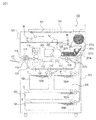
- FIG. 1 is a cross-sectional view of the image forming apparatus main body.
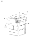
- FIG. 2 is a perspective view of the image forming apparatus main body.
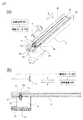
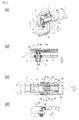
- 3A is a perspective view of the developer receiving device, and FIG. 3B is a cross-sectional view of the developer receiving device.
- 4A is a partially enlarged perspective view of the developer receiving device, FIG. 4B is a partially enlarged cross-sectional view of the developer receiving device, and
- FIG. 4C is a perspective view of the developer receiving portion.
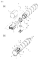
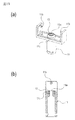
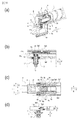
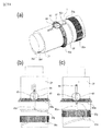
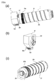
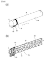
- 5A is an exploded perspective view of the developer supply container of the first embodiment, and FIG. 5B is a perspective view of the developer supply container of the first embodiment.
- FIG. 6 is a perspective view of the container body.
- FIG. 7A is a perspective view (upper surface side) of the upper flange portion
- FIG. 7B is a perspective view (lower surface side) of the upper flange portion
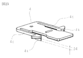
- 8A is a perspective view (upper surface side) of the lower flange portion of the first embodiment
- FIG. 8B is a perspective view (lower surface side) of the lower flange portion of the first embodiment
- FIG. It is a front view of a lower flange part.
- 9A is a top view of the shutter of the first embodiment
- FIG. 9B is a perspective view of the shutter of the first embodiment.
- 10A is a perspective view of the pump
- FIG. 10B is a front view of the pump.
- 11A is a perspective view (upper surface side) of the reciprocating member, and FIG.
- FIG. 11B is a perspective view (lower surface side) of the reciprocating member.
- 12A is a perspective view (upper surface side) of the cover
- FIG. 12B is a perspective view (lower surface side) of the cover.
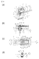
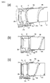
- 13A is a partial sectional perspective view of the developer supply / removal operation of the developer supply container of Example 1
- FIG. 13B is a partial sectional front view
- FIG. 13C is a top view
- FIG. 13D is a relationship between a lower flange portion and a developer receiving portion.
- FIG. 14A is a partial sectional perspective view of the developer supply / removal operation of the developer supply container according to the first embodiment
- FIG. 14B is a partial sectional front view
- FIG. 14C is a top view
- FIG. 14A is a partial sectional perspective view of the developer supply / removal operation of the developer supply container according to the first embodiment
- FIG. 14B is a partial sectional front view
- FIG. 14C is a top view
- FIG. 14D is a relationship between a lower flange portion and a developer receiving portion.
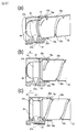
- FIGS. 15A and 15B are (a) a partial cross-sectional perspective view, (b) a partial cross-sectional front view, (c) a top view, and (d) a relationship between the lower flange portion and the developer receiving portion in the attaching / detaching operation of the developer supply container of Example 1.
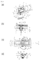
- FIG. 16A is a partial cross-sectional perspective view of the developer supply / removal operation of the developer supply container of Example 1
- FIG. 16B is a partial cross-sectional front view thereof
- FIG. 16C is a top view
- FIG. 16D is a relationship between a lower flange portion and a developer receiving portion.
- FIG. 17 is a timing chart of the attaching / detaching operation of the developer supply container according to the first embodiment.
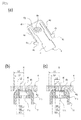
- FIG. 18, (a), (b), and (c) are views showing modifications of the engaging portion of the developer supply container.
- 19A is a perspective view of the developer receiving portion of the second embodiment
- FIG. 19B is a sectional view of the developer receiving portion of the second embodiment.
- 20A is a perspective view (upper surface side) of the lower flange portion of the second embodiment
- FIG. 20B is a perspective view (lower surface side) of the lower flange portion of the second embodiment.
- FIG. 21 is a perspective view of the shutter of Example 2
- FIG. 23 is a perspective view of a shutter according to the second embodiment.
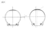
- FIG. 24 is a front view of the developer supply container according to the second embodiment.
- 25A is a perspective view of a second modified example of the shutter
- FIGS. 25B and 25C are simplified views of the shutter and the developer receiving portion.
- 26A is a partial cross-sectional perspective view of the developer supply / removal operation of the developer supply container of Example 2, FIG.
- FIG. 26B is a partial cross-sectional front view
- FIG. 26C is a top view
- FIG. 26D is a relationship between the lower flange portion and the developer receiving portion.
- FIG. 27A is a partial sectional perspective view of the developer supply / removal operation of the developer supply container of Example 2
- FIG. 27B is a partial sectional front view
- FIG. 27C is a top view
- FIG. 27D is a relationship between the lower flange portion and the developer receiving portion.
- FIG. 28A is a partial sectional perspective view of the developer supply / removal operation of the developer supply container of Example 2
- FIG. 28B is a partial sectional front view
- FIG. 28C is a top view
- FIG. 28D is a relationship between the lower flange portion and the developer receiving portion.
- FIG. FIG. 29A is a partial sectional perspective view of the developer supply / removal operation of the developer supply container of Example 2
- FIG. 29B is a partial sectional front view
- FIG. 29C is a top view
- FIG. 29D is a relationship between a lower flange portion and a developer receiving portion.
- FIG. 30A is a partial sectional perspective view of the developer supply / removal operation of the developer supply container of Example 2
- FIG. 30B is a partial sectional front view
- FIG. 30C is a top view
- FIG. 30D is a relationship between the lower flange portion and the developer receiving portion.
- FIG. 31A is a partial sectional perspective view of the developer supply / removal operation of the developer supply container of Example 2
- FIG. 31A is a partial sectional perspective view of the developer supply / removal operation of the developer supply container of Example 2
- FIG. 31B is a partial sectional front view
- FIG. 31C is a top view
- FIG. 31D is a relationship between a lower flange portion and a developer receiving portion.
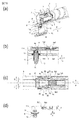
- FIG. FIG. 32 is a timing chart of the attaching / detaching operation of the developer supply container according to the second embodiment. 33, (a) a partially enlarged view of the developer supply container of Example 3, and (b) a partially enlarged sectional view of the developer supply container and developer receiving apparatus of Example 3.
- FIG. 34 is an operation diagram of the developer receiving portion with respect to the lower flange portion in the operation of taking out the developer supply container of the third embodiment.
- FIG. 35 is a view showing a comparative example of the developer supply container.
- FIG. 36 is a cross-sectional view showing an example of an image forming apparatus.
- FIG. 37 is a perspective view showing the image forming apparatus of FIG.
- FIG. 38 is a perspective view showing an embodiment of the developer receiving apparatus.
- FIG. 39 is a perspective view of the developer receiving apparatus of FIG. 38 viewed from another angle.
- 40 is a cross-sectional view of the developer receiving apparatus of FIG.
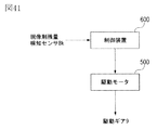
- FIG. 41 is a block diagram illustrating a functional configuration of the control device.
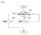
- FIG. 42 is a flowchart for explaining the flow of the replenishment operation.
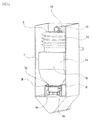
- FIG. 43 is a cross-sectional view showing a mounted state of the developer receiving apparatus and the developer supply container without the hopper.
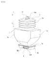
- FIG. 44 is a perspective view showing an embodiment of the developer supply container.
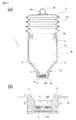
- FIG. 45 is a sectional view showing an embodiment of the developer supply container.
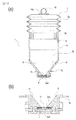
- FIG. 46 is a cross-sectional view showing a developer supply container in which a discharge port and an inclined surface are connected.
- 47A is a perspective view of a blade used in a device for measuring fluidity energy
- FIG. 47B is a schematic diagram of the measuring device.
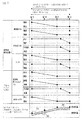
- FIG. 48 is a graph showing the relationship between the diameter of the discharge port and the discharge amount.
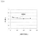
- FIG. 49 is a graph showing the relationship between the filling amount and the discharge amount in the container.
- FIG. 50 is a perspective view showing a part of the operating state of the developer supply container and the developer receiving apparatus.
- FIG. 51 is a perspective view showing a developer supply container and a developer receiving device.
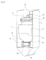
- FIG. 52 is a cross-sectional view showing a developer supply container and a developer receiving device.
- FIG. 53 is a cross-sectional view showing a developer supply container and a developer receiving device.
- FIG. 54 is a diagram illustrating a transition of the internal pressure of the developer accommodating portion according to the fourth embodiment.
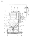
- 55A is a block diagram showing a developer supply system (Example 4) used in the verification experiment, and
- FIG. 55B is a schematic view showing a phenomenon occurring in the developer supply container.
- 56A is a block diagram showing a developer supply system (comparative example) used in the verification experiment, and
- FIG. 56B is a schematic diagram showing a phenomenon occurring in the developer supply container.
- FIG. 57 is a perspective view illustrating a developer supply container of Example 5.
- FIG. 58 is a cross-sectional view of the developer supply container of FIG.
- FIG. 59 is a perspective view showing a developer supply container of Embodiment 6.
- FIG. 60 is a perspective view showing a developer supply container of Example 6.
- FIG. 61 is a perspective view showing a developer supply container of Embodiment 6.
- FIG. 62 is a perspective view showing a developer supply container of Example 7.
- FIG. 63 is a cross-sectional perspective view showing the developer supply container of Example 7.
- FIG. 64 is a partial cross-sectional view showing a developer supply container of Example 7.
- 65 is a cross-sectional view showing another embodiment of Example 7.
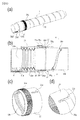
- FIG. 66 (a) is a front view of the mounting portion, and (b) is a partially enlarged perspective view inside the mounting portion.
- FIG. 67 (a) is a perspective view showing a developer supply container according to Embodiment 8
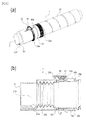
- FIG. 67 (b) is a perspective view showing the state around the discharge port
- FIG. 67 (c) and (d) show development of the developer supply container. It is the front view and sectional drawing which show the state with which the mounting part of the agent acceptance apparatus was mounted
- FIG. 68 (a) is a partial perspective view showing a developer accommodating portion according to Embodiment 8
- (b) is a sectional perspective view showing a developer supply container
- (c) is a sectional view showing an inner surface of the flange portion. It is.
- (D) is sectional drawing which shows a developer supply container.
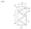
- FIG. 70 is a development view showing the cam groove shape of the developer supply container.
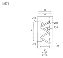
- FIG. 71 is a development view showing an example of the cam groove shape of the developer supply container.
- FIG. 72 is a development view showing an example of the cam groove shape of the developer supply container.
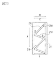
- FIG. 73 is a development view showing an example of the cam groove shape of the developer supply container.
- FIG. 74 is a development view showing an example of the cam groove shape of the developer supply container.
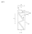
- FIG. 75 is a development view showing an example of the cam groove shape of the developer supply container.
- FIG. 76 is a development view showing an example of the cam groove shape of the developer supply container.
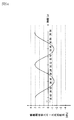
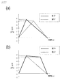
- FIG. 77 is a graph showing changes in the internal pressure of the developer supply container.
- 78A is a perspective view illustrating the configuration of a developer supply container according to Embodiment 9
- FIG. 78B is a cross-sectional view illustrating the configuration of the developer supply container.
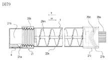
- FIG. 79 is a cross-sectional view illustrating the configuration of the developer supply container according to the tenth embodiment.
- 80 (a) is a perspective view showing a configuration of a developer supply container according to Example 11, (b) is a sectional view of the developer supply container, (c) is a perspective view showing a cam gear, and (d) is a perspective view.
- FIG. 81A is a perspective view illustrating the configuration of a developer supply container according to Embodiment 12, and FIG. 81B is a cross-sectional view illustrating the configuration of the developer supply container.
- 82A is a perspective view illustrating the configuration of a developer supply container according to Embodiment 13
- FIG. 82B is a cross-sectional view illustrating the configuration of the developer supply container.
- 83 (a) to (d) are diagrams showing the operation of the drive conversion mechanism.
- FIG. 84 (a) is a perspective view showing the configuration of the developer supply container according to Embodiment 14, and (b) and (c) are views showing the operation of the drive conversion mechanism.
- FIG. 85A is a cross-sectional perspective view showing a configuration of a developer supply container according to Embodiment 15, and FIGS. 85B and 85C are cross-sectional views showing an intake / exhaust operation by the pump unit.
- 86A is a perspective view showing another example of the developer supply container according to Embodiment 15, and FIG. 86B is a view showing a coupling portion of the developer supply container.
- 87 (a) is a cross-sectional perspective view showing the configuration of the developer supply container according to Embodiment 16, and FIGS. 87 (b) and (c) are cross-sectional views showing the state of the intake / exhaust operation by the pump unit.
- 88A is a perspective view showing the configuration of a developer supply container according to Embodiment 17, FIG.
- FIG. 88B is a cross-sectional perspective view showing the configuration of the developer supply container
- FIG. 88C is an end portion of the developer container.
- (e) is a figure which shows the mode at the time of the intake / exhaust operation
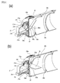
- (a) is a perspective view showing a configuration of a developer supply container according to Embodiment 18,
- (b) is a perspective view showing a configuration of a flange portion, and
- (c) is a perspective view showing a configuration of a cylindrical portion. is there.
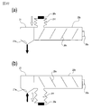
- 90 (a) and 90 (b) are cross-sectional views showing the state of the intake / exhaust operation by the pump portion of the developer supply container according to the eighteenth embodiment.
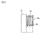
- FIG. 91 is a diagram illustrating the configuration of the pump portion of the developer supply container according to the eighteenth embodiment.
- 92 (a) and 92 (b) are schematic cross-sectional views showing the configuration of the developer supply container according to the nineteenth embodiment.
- 93, (a) and (b) are perspective views showing a cylindrical portion and a flange portion of the developer supply container according to the twentieth embodiment.
- FIG. 94, (a) and (b) are related to the twentieth embodiment.
- FIG. 4 is a partial cross-sectional perspective view of a developer supply container.
- FIG. 95 is a time chart illustrating the relationship between the operating state of the pump and the opening / closing timing of the rotary shutter according to the twentieth embodiment.
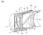
- FIG. 96 is a partial cross-sectional perspective view showing the developer supply container according to Embodiment 21.
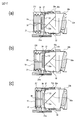
- 97 (a) to (c) are partial cross-sectional views illustrating the operating state of the pump unit according to the twenty-first embodiment.
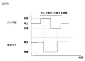
- FIG. 98 is a time chart showing the relationship between the operating state of the pump according to Example 21 and the opening / closing timing of the gate valve.
- FIG. 99 (a) is a partial perspective view of a developer supply container according to Embodiment 22, (b) is a perspective view of a flange portion, and (c) is a cross-sectional view of the developer supply container.
- FIG. 99 (a) is a partial perspective view of a developer supply container according to Embodiment 22
- b is a perspective view of a flange portion
- (c) is a cross-sectional view of the developer supply container.
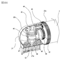
- FIG. 100 (a) is a perspective view showing a configuration of a developer supply container according to Embodiment 23, and (b) is a cross-sectional perspective view of the developer supply container.
- FIG. 101 is a partial cross-sectional perspective view illustrating the configuration of the developer supply container according to the twenty-third embodiment.
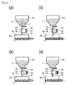
- FIG. 102 (a) to (d) are sectional views of a developer supply container and a developer receiving apparatus according to a comparative example, and are diagrams for explaining the flow of the developer supply process.
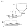
- FIG. 103 is a cross-sectional view showing a developer supply container and a developer receiving device according to another comparative example.
- image forming device As an example of an image forming apparatus equipped with a developer receiving device in which a developer supply container (so-called toner cartridge) is detachably mounted (removable), an electrophotographic copying machine (electrophotographic image forming apparatus) is adopted. ) Will be described with reference to FIG.
- reference numeral 100 denotes a copying machine main body (hereinafter referred to as an image forming apparatus main body or an apparatus main body).
- a document 101 is placed on the document glass 102.
- an electrostatic image is formed by forming an optical image corresponding to the image information of the original on an electrophotographic photosensitive member 104 (hereinafter referred to as a photosensitive member) by a plurality of mirrors M and lenses Ln of the optical unit 103.
- This electrostatic latent image is visualized by a dry developing device (one component developing device) 201 using toner (one component magnetic toner) as a developer (dry powder).
- toner one component magnetic toner
- the one-component nonmagnetic toner is supplied as a developer.
- the nonmagnetic toner is replenished as the developer.
- the developer may be replenished together with the magnetic carrier as well as the non-magnetic toner.
- the developing device 201 shown in FIG. 1 develops the electrostatic latent image formed on the photoconductor 104 as the image carrier based on the image information of the document 101 using toner as a developer. Is.
- the developing device 201 is provided with a developing roller 201f in addition to the developer hopper 201a.
- the developer hopper 201a is provided with a stirring member 201c for stirring the developer supplied from the developer supply container 1.
- the developer stirred by the stirring member 201c is sent to the transport member 201e side by the transport member 201d.
- the developer sequentially conveyed by the conveying members 201e and 201b is carried on the developing roller 201f and finally supplied to the developing unit with the photoconductor 104.
- the toner as the developer is supplied from the developer supply container 1 to the developing device 201.
- the toner and carrier as the developer may be supplied from the developer supply container 1. Absent.
- Reference numerals 105 to 108 denote cassettes for storing recording media (hereinafter also referred to as “sheets”) S.
- sheets recording media
- the recording medium is not limited to paper, and can be appropriately used and selected, for example, an OHP sheet.
- one sheet S conveyed by the feeding / separating devices 105A to 108A is conveyed to the registration roller 110 via the conveying unit 109, and the rotation of the photosensitive member 104 and the scanning timing of the optical unit 103 are synchronized. Then transport.
- Reference numerals 111 and 112 denote a transfer charger and a separation charger.
- the image formed by the developer formed on the photosensitive member 104 is transferred to the sheet S by the transfer charger 111.
- the sheet S to which the developer image (toner image) has been transferred is separated from the photoreceptor 104 by the separation charger 112.
- the sheet S conveyed by the conveying unit 113 is fixed on the developer image on the sheet by heat and pressure in the fixing unit 114, and then passes through the discharge reversing unit 115 in the case of single-sided copying.
- the paper is discharged to the discharge tray 117 by the roller 116.
- the sheet S passes through the discharge reversing unit 115 and is once discharged out of the apparatus by the discharge roller 116. Thereafter, the trailing edge of the sheet S passes through the flapper 118, and is controlled by the flapper 118 at the timing when it is still nipped by the discharge roller 116, and is reversely rotated to be conveyed into the apparatus again. . Further, after being conveyed to the registration roller 110 via the re-feed conveyance units 119 and 120, the sheet is discharged to the discharge tray 117 along the same path as in the case of single-sided copying.
- an image forming process device such as a developing unit 201 as a developing unit, a cleaner unit 202 as a cleaning unit, and a primary charger 203 as a charging unit is installed around the photosensitive member 104.
- the developing unit 201 develops the developer by attaching a developer to the electrostatic latent image formed on the photosensitive member 104 by the optical unit 103 based on the image information of the document 101.
- the primary charger 203 is for uniformly charging the surface of the photoconductor in order to form a desired electrostatic image on the photoconductor 104.
- the cleaner unit 202 is for removing the developer remaining on the photosensitive member 104.
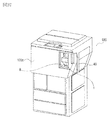
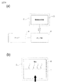
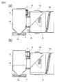
- FIG. 2 is an external view of the image forming apparatus.
- the developer supply container 1 When the operator opens the replacement cover 40 which is a part of the exterior cover of the image forming apparatus, a part of the developer receiving device 8 described later appears. Then, by inserting (attaching) the developer supply container 1 into the developer receiving apparatus 8, the developer supply container 1 is set in a state where the developer can be supplied to the developer receiving apparatus 8. On the other hand, when the operator replaces the developer supply container 1, the developer supply container 1 is taken out (detached) from the developer receiving device 8 by performing an operation reverse to that at the time of mounting, and a new developer supply is performed. What is necessary is just to set the container 1 again.
- the replacement cover 40 is a dedicated cover for attaching and detaching (replacing) the developer supply container 1 and is opened and closed for attaching and detaching the developer supply container 1.
- the maintenance of the apparatus main body 100 is performed by opening and closing the front cover 100c.
- the replacement cover 40 and the front cover 100c may be integrated.
- the replacement of the developer supply container 1 and the maintenance of the apparatus main body 100 are performed by opening and closing the integrated cover (not shown). Is done. (Developer receiving device)
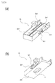
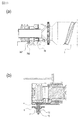
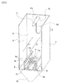
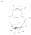
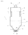
- FIGS. 3A is a schematic perspective view of the developer receiving device 8
- FIG. 3B is a schematic cross-sectional view of the developer receiving device 8.
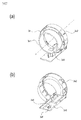
- FIG. 4A is a partially enlarged perspective view of the developer receiving device 8
- FIG. 4B is a partially enlarged cross-sectional view of the developer receiving device 8
- FIG. 4C is a perspective view of the developer receiving portion 11.
- the developer receiving device 8 is provided with a mounting portion (mounting space) 8f on which the developer supply container 1 is detachably mounted (detachable).
- a developer receiving portion 11 for receiving the developer discharged from a discharge port 3a4 (see FIG. 7B) of the developer supply container 1 described later is provided.
- the developer receiving unit 11 is attached to the developer receiving device 8 so as to be movable (displaceable) in the vertical direction. Further, as shown in FIG.
- the developer receiving portion 11 is provided with a main body seal 13, and a developer receiving port 11a is formed at the center thereof.
- the main body seal 13 is made of an elastic body, foam, or the like, and is in close contact with an opening seal 3a5 (see FIG. 7B) having a discharge port 3a4 of the developer supply container 1 in part, and discharged from the discharge port 3a4.
- the developed developer is prevented from leaking out of the developer receiving port 11a which is the developer transport path.
- the diameter of the developer receiving port 11a is substantially the same as the diameter of the discharge port 3a4 of the developer supply container 1 in order to prevent the inside of the mounting portion 8f from being contaminated by the developer as much as possible. It is desirable to make it a little larger.
- the diameter of the developer receiving port 11a is smaller than the diameter of the discharging port 3a4, the developer discharged from the developer supply container 1 adheres to the upper surface of the main body seal 13 in which the developer receiving port 11a is formed. This is because the adhered developer is transferred to the lower surface of the developer supply container 1 during the loading and unloading operation of the developer supply container 1 and contributes to contamination by the developer. Further, when the developer transferred to the developer supply container 1 is scattered to the mounting portion 8f, the mounting portion 8f is soiled by the developer.
- the diameter of the developer receiving port 11a is considerably larger than the diameter of the discharge port 3a4, the area where the developer scattered from the developer receiving port 11a adheres to the vicinity of the discharge port 3a4 formed in the opening seal 3a5 becomes large. . That is, it is not preferable because the area of the stain due to the developer in the developer supply container 1 becomes large. Therefore, in view of the above circumstances, it is desirable that the diameter of the developer receiving port 11a is approximately the same diameter to about 2 mm larger than the diameter of the discharge port 3a4. In this example, since the diameter of the discharge port 3a4 of the developer supply container 1 is a fine port (pin hole) having a diameter of about 2 mm, the diameter of the developer receiving port 11a is set to about 3 mm.
- the developer receiving portion 11 is urged downward in the vertical direction by the urging member 12. That is, the developer receiving portion 11 moves against the urging force of the urging member 12 when moving upward in the vertical direction.
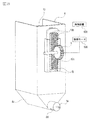
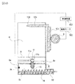
- the developer receiving device 8 is provided with a sub hopper 8c for temporarily storing the developer as shown in FIG.
- a conveying screw 14 for conveying the developer to the developer hopper 201a, which is a part of the developing device 201, and an opening 8d communicating with the developer hopper 201a are provided.
- the developer receiving port 11a is in a closed state so that foreign matter and dust do not enter the sub hopper 8c when the developer supply container 1 is not mounted.
- the developer receiving port 11a is closed by the main body shutter 15 when the developer receiving portion 11 is not moved vertically upward.
- the developer receiving portion 11 moves vertically upward (in the direction of arrow E) toward the developer supply container 1 from the position shown in FIG.
- FIG. 15B the developer receiving port 11a and the main body shutter 15 are separated from each other, and the developer receiving port 11a is opened.
- an engaging portion 11b is provided on the side surface of the developer receiving portion 11 as shown in FIG.
- the engaging portion 11b is directly engaged with and guided by engaging portions 3b2 and 3b4 (see FIG. 8) provided on the developer supply container 1 side, which will be described later, so that the developer receiving portion 11 is supplied with developer. It is lifted upward in the vertical direction toward the container 1.
- the mounting portion 8f of the developer receiving device 8 is provided with an insertion guide 8e for guiding the developer supply container 1 in the attaching / detaching direction.
- the mounting direction of the developer supply container 1 is configured to be an arrow A direction. It should be noted that the direction in which the developer supply container 1 is taken out (detachment direction) is opposite to the arrow A direction (arrow B direction). Further, as shown in FIG.
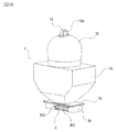
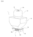
- the developer receiving device 8 has a drive gear 9 that functions as a drive mechanism for driving the developer supply container 1. Further, the drive gear 9 has a function of applying a rotational driving force to the developer supply container 1 in a state where the rotational driving force is transmitted from the driving motor 500 via the driving gear train and is set in the mounting portion 8f. Have. Further, as shown in FIGS. 3 and 4, the drive motor 500 is configured such that its operation is controlled by a control device (CPU) 600. (Developer supply container) Next, the developer supply container 1 will be described with reference to FIG. 5A is a schematic exploded perspective view of the developer supply container 1, and FIG. 5B is a schematic perspective view of the developer supply container 1. FIG. For convenience of explanation, FIG.
- FIG. 5B shows a cross section of a cover 7 described later.
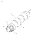
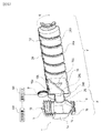
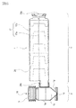
- the developer supply container 1 mainly includes a container body 2, a flange part 3, a shutter 4, a pump part 5, a reciprocating member 6, and a cover 7.
- the developer replenishing container 1 replenishes the developer receiving device 8 with the developer by rotating in the direction of arrow R around the rotation axis P shown in FIG. 5B in the developer receiving device 8.
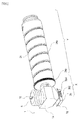
- FIG. 6 is a perspective view of the container body 2. As shown in FIG.
- the container main body (developer transport chamber) 2 mainly includes a developer accommodating portion 2 c that accommodates the developer therein, and the container main body 2 rotates in the arrow R direction with respect to the rotation axis P.
- a conveying groove 2a conveying portion
- the cam groove 2 b and the drive receiving portion (drive input portion) 2 d that receives drive from the main body side are integrated over the entire circumference of the outer peripheral surface on one end surface side of the container main body 2. Is formed.
- the cam groove 2b and the drive receiving portion 2d are formed integrally with the container main body 2.
- the cam groove 2b or the drive receiving portion 2d is formed as a separate body, and the container main body is formed.
- the structure attached to 2 may be sufficient.
- toner having a volume average particle diameter of 5 ⁇ m to 6 ⁇ m is accommodated in the developer accommodating portion 2 c of the container body 2 as the developer.
- the developer accommodating portion (developer accommodating space) 2c is a combination of not only the container main body 2 but also the internal space of the container main body 2, the flange portion 3 and the pump portion 5 described later. (Flange part) Then, the flange part 3 is demonstrated using FIG. As shown in FIG.
- the flange portion (developer discharge chamber) 3 is attached so as to be rotatable relative to the container body 2 and the rotation shaft P, and the developer supply container 1 is attached to the developer receiving device 8.
- the holding part 8f (see FIG. 3A) is held so as not to rotate in the direction of arrow R.
- a discharge port 3a4 (see FIG. 7) is provided in part.
- the flange portion 3 is composed of an upper flange portion 3a and a lower flange portion 3b in consideration of assemblability.
- a cover 7 is assembled.
- the pump part 5 is screw-joined to the one end side of the upper flange part 3a, and the container main body 2 is joined to the other end side via a seal member (not shown).
- the reciprocating member 6 is disposed so as to sandwich the pump portion 5, and the engaging protrusion 6 b (see FIG. 11) provided on the reciprocating member 6 is fitted into the cam groove 2 b of the container body 2.
- a shutter 4 is incorporated in the gap between the upper flange portion 3a and the lower flange portion 3b.
- FIG. 7 shows the upper flange portion 3a.
- FIG. 7A is a perspective view of the upper flange portion 3a viewed from an obliquely upward direction
- FIG. 7B is a perspective view of the upper flange portion 3a viewed from an obliquely downward direction.
- the upper flange portion 3a includes a pump joint portion 3a1 (screw not shown) shown in FIG. 7A to which the pump portion 5 is screwed and a container body joint portion shown in FIG.
- FIG. 7B to which the container main body 2 is joined. 3a2 and a reservoir 3a3 shown in FIG. 7A for storing the developer conveyed from the container main body 2. Further, as shown in FIG. 7B, a circular discharge port (opening) 3a4 for discharging the developer in the storage unit 3a3 described above to the developer receiving device 8 and a developer receiving unit 11 described later are connected.
- An opening seal 3a5 having a part 3a6 formed in part is provided.
- the opening seal 3a5 is affixed to the lower surface of the upper flange portion 3a with double-sided tape, and is sandwiched between a shutter 4 and an upper flange portion 3a, which will be described later, to prevent leakage of the developer from the discharge port 3a4. .
- the discharge port 3a4 is provided in the opening seal 3a5 which is a separate body from the upper flange portion 3a.
- the discharge port 3a4 may be provided directly in the upper flange portion 3a.
- the diameter of the discharge port 3a4 is such that the developer is unnecessarily discharged when the shutter 4 is opened / closed due to the attaching / detaching operation of the developer supply container 1 to / from the developer receiving device 8, and the periphery is developed. In order to prevent contamination with the agent as much as possible, it is set to about ⁇ 2 mm.
- the discharge port 3a4 is provided on the lower surface of the developer supply container 1, that is, on the lower surface side of the upper flange portion 3a.
- the developer supply container 1 is attached to and detached from the developer receiving device 8.
- the connection configuration shown in this example can be applied as long as it is provided on a side surface other than the upstream end surface or the downstream end surface in the direction.
- the position on the side surface of the discharge port 3a4 can be set in view of individual product circumstances. The details of the connection operation between the developer supply container 1 and the developer receiving device 8 in this example will be described later. (Lower flange)
- FIG. 8 shows the lower flange portion 3b.
- FIG. 8A is a perspective view of the lower flange portion 3b as viewed obliquely from above
- FIG. 8B is a perspective view of the lower flange portion 3b as viewed from obliquely downward
- FIG. 8C is a front view.
- the lower flange portion 3b includes a shutter insertion portion 3b1 into which the shutter 4 (see FIG. 9) is inserted.
- the lower flange portion 3b has engaging portions 3b2 and 3b4 that can engage with the developer receiving portion 11 (see FIG. 4).
- the engaging portions 3b2 and 3b4 are connected to the developer replenishing container 1 in accordance with the mounting operation of the developer replenishing container 1 so that the developer replenishing container 1 and the developer receiving portion 11 can be replenished with each other.
- the receiving portion 11 is displaced toward the developer supply container 1.
- the engaging portions 3b2 and 3b4 are designed so that the developer receiving portion 11 develops so that the connection state between the developer supplying container 1 and the developer receiving portion 11 is cut off with the operation of taking out the developer supplying container 1. It is guided so as to be displaced in a direction away from the medicine supply container 1.
- the first engaging portion 3b2 is a developer receiving portion in a direction crossing the mounting direction of the developer supply container 1 so that the developer receiving portion 11 is opened. 11 is displaced.
- the first engaging portion 3b2 is a connecting portion 3a6 in which the developer receiving portion 11 is formed on a part of the opening seal 3a5 of the developer supply container 1 in accordance with the mounting operation of the developer supply container 1.
- the developer receiving portion 11 is displaced toward the developer supply container 1 so as to be in a connected state.
- the first engaging portion 3b2 extends in a direction intersecting with the mounting direction of the developer supply container 1.
- the first engaging portion 3b2 crosses the direction in which the developer supply container 1 is taken out so that the developer receiving portion 11 is resealed with the removal operation of the developer supply container 1.
- the developer receiving portion 11 is guided so as to be displaced.
- the first engagement portion 3b2 is connected to the developer receiving portion 11 and the connecting portion 3a6 of the developer replenishing container 1 so that the connection state between the developer receiving portion 11 and the developer replenishing container 1 is disconnected.
- the developer receiving portion 11 is guided so as to be separated vertically from the developer supply container 1.
- the second engaging portion 3b4 is connected to the developer supply container 1 so that the discharge port 3a4 communicates with the developer receiving port 11a of the developer receiving unit 11 in accordance with the mounting operation of the developer supplying container 1.
- the main body seal 13 and the opening seal 3a5 are maintained in a state in which the main body seal 13 and the opening seal 3a5 are connected while the developer 1 moves relative to the shutter 4 described later, that is, while the developer receiving port 11a moves from the connecting portion 3a6 to the discharge port 3a4.
- the second engaging portion 3 b 4 is an extending portion that extends in a direction parallel to the mounting direction of the developer supply container 1. Further, the second engaging portion 3b4 moves during the relative movement of the developer supply container 1 with respect to the shutter 4 so that the discharge port 3a4 is resealed as the developer supply container 1 is taken out.
- the first engagement portion 3b2 preferably has a configuration having an inclined surface (inclined portion) that intersects with the direction in which the developer supply container 1 is inserted, as shown in FIG. It is not limited to a typical inclined surface.
- the shape of the first engagement portion 3b2 may be, for example, a curved inclined surface as shown in FIG. Furthermore, as shown in FIG. 18B, a stepped shape including a parallel surface and an inclined surface may be used. The shape of the first engaging portion 3b2 is limited to the shape shown in FIGS.
- the inclination angle of the first engaging portion 3b2 with respect to the loading / unloading direction of the developer supply container 1 is preferably set to about 10 to 50 degrees in view of various circumstances described later. In this example, the angle is about 40 degrees.
- FIG.18 (c) it is good also as 1st engaging part 3b2 and 2nd engaging part 3b4, and making it a uniform linear inclined surface.
- the first engaging portion 3 b 2 displaces the developer receiving unit 11 in a direction crossing the mounting direction of the developer supply container 1, and the main body seal 13.
- the concealing unit 3b6 is connected. Thereafter, while the main body seal 13 and the opening seal 3a5 are compressed, the developer receiving portion 11 is displaced until the developer receiving port 11a and the discharge port 3a4 communicate with each other.
- the first engaging portion 3b2 when used, the relationship between the first engaging portion 3b2 and the engaging portion 11b of the developer receiving portion 11 at the mounting completion position of the developer supply container 1 to be described later.
- the force in the B direction (see FIG. 16A) always acts on the developer supply container 1.
- the developer replenishing container 1 is provided with the second engaging portion 3b4 described above so that the force in the B direction does not act on the developer replenishing container 1 at the mounting completion position. It is desirable that the connection state of the opening seal 3a5 is stably maintained.
- the first engaging portion 3b2 of FIG. 18C is a uniform linear inclined surface, for example, as in FIGS. 18A and 18B, a curved shape or a stepped shape is used.
- a straight inclined surface is desirable from the viewpoint of making the operation force associated with the loading and unloading operation of the developer supply container 1 constant.
- the lower flange portion 3b restricts or allows elastic deformation of the support portion 4d of the shutter 4 to be described later in accordance with the operation of mounting the developer supply container 1 on the developer receiving device 8 or taking it out of the developer receiving device 8.
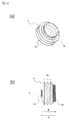
- FIG. 9A is a top view of the shutter 4
- FIG. 9B is a perspective view of the shutter 4 as viewed obliquely from above.
- the shutter 4 is movably provided in the developer supply container 1, and opens and closes the discharge port 3 a 4 when the developer supply container 1 is attached and detached.
- the shutter 4 When the developer supply container 1 is not mounted on the mounting portion 8 f of the developer receiving device 8, the shutter 4 includes a developer sealing portion 4 a that prevents leakage of the developer from the discharge port 3 a 4, and a developer sealing A sliding surface 4i that slides on the shutter insertion portion 3b1 of the lower flange portion 3b is provided on the back side (back side) of the portion 4a.
- the shutter 4 has shutter stoppers 8a and 8b of the developer receiving device 8 in accordance with the loading / unloading operation of the developer supply container 1 so that the developer supply container 1 can move relative to the shutter 4. It has stopper portions (holding portions) 4b and 4c held by (see FIG. 4A).
- the first stopper portion 4b is engaged with the first shutter stopper portion 8a of the developer receiving device 8 during the mounting operation of the developer supply container 1, and the developer of the shutter 4 is engaged.
- the position with respect to the receiving device 8 is fixed.
- the second stopper portion 4 c engages with the second shutter stopper portion 8 b of the developer receiving device 8 during the operation of taking out the developer supply container 1.
- the shutter 4 has a support portion 4d that supports the stopper portions 4b and 4c so that they can be displaced.
- the support portion 4d extends from the developer sealing portion 4a and is elastically deformable so as to displaceably support the first stopper portion 4b and the second stopper portion 4c.
- the first stopper portion 4b is inclined so that the angle ⁇ formed by the first stopper portion 4b and the support portion 4d is an acute angle.
- the second stopper portion 4c is inclined so that the angle ⁇ formed by the second stopper portion 4c and the support portion 4d becomes an obtuse angle.
- the entire developer sealing portion 4a may have a shape corresponding to the amount of contact between the lock protrusion 4e and the opening seal 3a5. In this case, unlike the case where the lock protrusion 4e is provided, the shutter 4 moves. Since the dynamic frictional force with the opening seal 3a5 increases, the operating force when the developer supply container 1 is attached to the developer receiving device 8 is increased, which is preferable in terms of usability. Therefore, a configuration in which the lock protrusion 4e is provided in part as in this example is desirable.
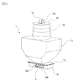
- the pump unit 5 is shown in FIG. FIG. 10A is a perspective view of the pump unit 5, and FIG. 10B is a front view of the pump unit 5.
- the pump unit 5 operates so that the internal pressure of the developer storage unit 2c is alternately and repeatedly switched between a state lower than atmospheric pressure and a state higher than the atmospheric pressure by the driving force received by the drive receiving unit (drive input unit) 2d. It is.
- the above-described pump unit 5 is provided in a part of the developer supply container 1 in order to stably discharge the developer from the small discharge port 3a4.
- the pump unit 5 is a variable volume pump whose volume can be varied.
- the pump portion 5 of this example has a bellows-like stretchable portion (bellows portion, stretchable member) 5a in which a “mountain fold” portion and a “valley fold” portion are periodically formed. Is provided.
- the stretchable part 5a can be folded in the direction of the arrow B or extended in the direction of the arrow A along the crease (based on the crease). Therefore, when the bellows-like pump unit 5 is employed as in this example, the variation in the volume change amount with respect to the expansion / contraction amount can be reduced, so that a stable volume variable operation can be performed.
- a polypropylene resin (hereinafter abbreviated as PP) is used as the material of the pump unit 5, but is not limited thereto.
- PP polypropylene resin
- any material may be used as long as it is capable of exhibiting an expansion / contraction function and capable of changing the internal pressure of the developer accommodating unit by changing the volume.
- ABS acrylonitrile / butadiene / styrene copolymer
- polystyrene polyester, polyethylene or the like may be formed thin. It is also possible to use rubber or other elastic materials.
- the junction part 5b is provided in the opening end side of the pump part 5 so that it can join with the upper flange part 3a.
- FIG. 11A is a perspective view of the reciprocating member 6 viewed from an obliquely upward direction
- FIG. 11B is a perspective view of the reciprocating member 6 viewed from an obliquely downward direction.
- the reciprocating member 6 has a pump engaging portion 6a that engages with the reciprocating member engaging portion 5c provided in the pump portion 5 in order to vary the volume of the pump portion 5 described above. I have. Further, as shown in FIGS. 11A and 11B, the reciprocating member 6 includes an engaging protrusion 6b that is fitted into the cam groove 2b (see FIG. 5) when assembled. The engaging protrusion 6b is provided at the tip of the arm 6c extending from the vicinity of the pump engaging portion 6a. The reciprocating member 6 is restricted from rotational displacement about the axis P (see FIG. 5B) of the arm 6c by a reciprocating member holding portion 7b (see FIG. 12) of the cover 7 described later.
- FIG. 12 shows the cover 7.
- FIG. 12A is a perspective view of the cover 7 viewed from an obliquely upward direction, and FIG.
- FIG. 12B is a perspective view of the cover 7 viewed from an obliquely downward direction.
- the cover 7 is provided as shown in FIG. 5B for the purpose of improving the appearance of the developer supply container 1 and protecting the reciprocating member 6 and the pump unit 5.
- the cover 7 is integrated with the upper flange portion 3a and the lower flange portion 3b by a mechanism (not shown) so as to cover the entire flange portion 3, the pump portion 5, and the reciprocating member 6 as shown in FIG. Provided.
- the cover 7 is provided with a guide groove 7a guided by an insertion guide 8e (see FIG. 3A) provided in the developer receiving device 8.
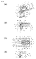
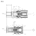
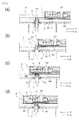
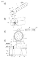
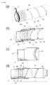
- FIG. . 13A to 16D show the vicinity of the connecting portion between the developer supply container 1 and the developer receiving device 8, respectively.
- FIG. 16 is a partial cross-sectional perspective view
- (b) is a partial cross-sectional front view
- (c) is a top view of (b)
- (d) is a view of the lower flange portion 3b and the developer receiving portion 11.
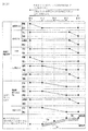
- FIG. 17 is a timing chart showing a list of operations for each element related to the mounting operation of the developer supply container 1 shown in FIGS. 13 to 16 to the developer receiving device 8.
- the mounting operation refers to an operation until the developer can be supplied from the developer supply container 1 to the developer receiving device 8.
- FIG. 13 shows a connection start position (first position) between the first engaging portion 3 b 2 of the developer supply container 1 and the engaging portion 11 b of the developer receiving portion 11. As shown in FIG.
- the developer supply container 1 is inserted into the developer receiving device 8 in the direction of arrow A.
- the first stopper portion 4b of the shutter 4 abuts on the first shutter stopper portion 8a of the developer receiving device 8, and the position of the shutter 4 with respect to the developer receiving device 8 is fixed. Is done. In this state, the positions of the lower flange portion 3b and upper flange portion 3a of the flange portion 3 and the shutter 4 are not relatively displaced, and the discharge port 3a4 is reliably sealed by the developer sealing portion 4a of the shutter 4. Yes. Further, as shown in FIG. 13 (b), the connection portion 3 a 6 of the opening seal 3 a 5 is concealed by the shutter 4.
- FIG. 13 (b) the connection portion 3 a 6 of the opening seal 3 a 5 is concealed by the shutter 4.
- the support portion 4d of the shutter 4 is displaceable in the directions of arrows C and D because the regulating rib 3b3 of the lower flange portion 3b does not enter the inside of the support portion 4d.
- the first stopper portion 4b is inclined so that the angle ⁇ (see FIG. 9A) formed with the support portion 4d is an acute angle, and the first shutter stopper portion is corresponding to the angle ⁇ . 8a is also inclined.
- the inclination angle ⁇ described above is configured to be about 80 degrees.
- the first stopper portion 4b receives a reaction force in the direction of the arrow B from the first shutter stopper portion 8a, and the support portion 4d tends to be displaced in the direction of arrow D. That is, since the first stopper portion 4b of the shutter 4 is displaced to the side where the developer receiving device 8 is engaged with the first shutter stopper portion 8a, the position of the shutter 4 is shifted to the developer receiving device 8. It is securely held against. Further, as shown in FIG. 13D, the engaging portion 11b of the developer receiving portion 11 and the first engaging portion 3b2 of the lower flange portion 3b are in a positional relationship at which engagement begins.
- the developer receiving portion 11 is not displaced from the initial position and is separated from the developer supply container 1. More specifically, as shown in FIG. 13B, the developer receiving portion 11 is separated from the connection portion 3a6 formed in a part of the opening seal 3a5. Further, as shown in FIG. 13B, the developer receiving port 11a is sealed by the main body shutter 15. Further, the drive gear 9 of the developer receiving device 8 and the drive receiving portion 2d of the developer supply container 1 are not connected, and the drive is not transmitted.
- the separation distance between the developer receiving portion 11 and the developer supply container 1 was set to be about 2 mm.
- the separation distance is small, for example, when the distance is about 1.5 mm or less, the surface of the main body seal 13 provided in the developer receiving portion 11 due to an air flow locally generated by the loading and unloading operation of the developer supply container 1 The developer adhering to the surface rises and adheres to the lower surface of the developer replenishing container 1 to cause contamination by the developer.
- the separation distance is too long, a stroke for displacing the developer receiving portion 11 from the separation position to the connection position becomes large, leading to an increase in the size of the image forming apparatus.
- the inclination angle of the first engaging portion 3b2 of the lower flange portion 3b becomes steep with respect to the loading / unloading direction of the developer supply container 1, the load for displacing the developer receiving portion 11 increases. Therefore, it is desirable that the distance between the developer supply container 1 and the developer receiving portion 11 is appropriately set in consideration of the specifications of the main body. Further, as described above, the inclination angle of the first engaging portion 3b2 with respect to the loading / unloading direction of the developer supply container 1 in this example is set to about 40 degrees. Regardless of this example, the same configuration is used in the examples described later. Subsequently, as shown in FIG. 14A, the developer supply container 1 is further inserted into the developer receiving device 8 in the direction of arrow A.
- the developer receiving portion 11 is displaced in the direction of arrow E against the urging force of the urging member 12 in the direction of arrow F to the position shown in FIG.
- the opening 11a is separated from the main body shutter 15 and starts to be opened.
- the developer receiving port 11a and the connection part 3a6 are spaced apart.
- the regulating rib 3b3 of the lower flange portion 3b enters the inside of the support portion 4d of the shutter 4, and the support portion 4d cannot be displaced in the arrow C direction or the arrow D direction. State. That is, the support portion 4d is in a state where elastic deformation is restricted by the restriction rib 3b3. Subsequently, as shown in FIG.
- the developer supply container 1 is further inserted into the developer receiving device 8 in the direction of arrow A. Then, as shown in FIG. 15C, since the position of the shutter 4 is held with respect to the developer receiving device 8, the developer supply container 1 moves relative to the shutter 4 in the arrow A direction. At this time, the connecting portion 3a6 formed in a part of the opening seal 3a5 is completely exposed from the shutter 4. Further, the discharge port 3a4 is not exposed from the shutter 4, and is still sealed by the developer sealing portion 4a.
- the regulating rib 3b3 of the lower flange portion 3b is inserted inside the support portion 4d of the shutter 4, and the support portion 4d is in a state where it cannot be displaced in the arrow C direction or the arrow D direction.
- the engaging portion 11b of the developer receiving portion 11 that is directly engaged reaches the upper end side of the first engaging portion 3b2. Accordingly, the developer receiving portion 11 is displaced in the direction of arrow E against the biasing force of the biasing member 12 in the direction of arrow F to the position shown in FIG. Fully separated and opened.
- the main body seal 13 in which the developer receiving port 11a is formed is connected in close contact with the connection portion 3a6 of the opening seal 3a5. That is, when the developer receiving portion 11 is directly engaged with the first engaging portion 3b2 of the developer supply container 1, the developer supply container 1 is accessed from below in the vertical direction intersecting the mounting direction. Therefore, the end surface Y on the downstream side in the mounting direction of the developer supply container 1 generated in the configuration in which the developer receiving portion 11 that has been widely used in the past accesses the developer supply container 1 from the mounting direction (see FIG. 5B). No developer stains occur. Details of the above-described conventional configuration will be described later. Subsequently, as shown in FIG.
- the engaging portion 11b of the developer receiving portion 11 is connected to the lower flange portion 3b. It engages with the second engaging portion 3b4 through the engaging relationship with the first engaging portion 3b2. And the engaging part 11b will be in the state pressed by the 2nd engaging part 3b4 by the urging
- the developer receiving port 11a slides on the opening seal 3a5 and communicates with the discharge port 3a4 while maintaining the state in which the main body seal 13 and the connecting portion 3a6 formed on the opening seal 3a5 are in close contact with each other. Therefore, the developer that has dropped from the discharge port 3a4 is less likely to scatter to positions other than the developer receiving port 11a. That is, the developer receiving device 8 is configured to have a low risk of being contaminated by the scattering of the developer. (Operation to remove developer supply container) Subsequently, an operation of taking out the developer supply container 1 from the developer receiving device 8 will be described mainly with reference to FIGS. 13 to 16 and 17.
- FIG. 17 is a timing chart showing a list of operations of each element related to the operation of taking out the developer supply container 1 from the developer receiving device 8 shown in FIGS. 13 to 16.
- the operation of taking out the developer supply container 1 is performed in the reverse order of the mounting operation described above. That is, the developer supply container 1 is removed from the developer receiving device 8 in the order shown in FIGS. Further, the removal operation (removal operation) refers to the operation until the developer supply container 1 is ready to be removed from the developer receiving device 8.
- the amount of developer in the developer supply container 1 decreases at the replenishment position shown in FIG. 16
- development is performed by the operator on a monitor (not shown) provided in the image forming apparatus main body 100 (see FIG. 1). A message prompting replacement of the medicine supply container 1 is displayed.
- An operator who has prepared a new developer supply container 1 opens the replacement cover 40 provided in the image forming apparatus main body 100 shown in FIG. 2, and pulls out the developer supply container 1 in the direction of arrow B shown in FIG. .
- the support portion 4d of the shutter 4 cannot be displaced in the arrow C direction or the arrow D direction by the restriction rib 3b3 of the lower flange portion 3b. Accordingly, as shown in FIG. 16A, when the developer replenishing container 1 is removed, if the second stopper portion 4c of the shutter 4 is displaced in the direction of the arrow B in the figure, the developer receiving device 8 is moved.
- the second shutter stopper portion 8b is in contact with the shutter 4, and the shutter 4 is not displaced in the arrow B direction. That is, the developer supply container 1 moves relative to the shutter 4. Thereafter, when the developer supply container 1 is taken out to the position shown in FIG. 15, the shutter 4 seals the discharge port 3a4 as shown in FIG. 15B. Further, as shown in FIG. 15 (d), the engaging portion 11b of the developer receiving portion 11 extends from the second engaging portion 3b4 of the lower flange portion 3b to the downstream end in the take-out direction of the first engaging portion 3b2. Displace. As shown in FIG.
- the main body seal 13 of the developer receiving portion 11 slides on the opening seal 3a5 from the discharge port 3a4 of the opening seal 3a5 to the connection portion 3a6 and is connected to the connection portion 3a6. Is maintained.
- the shutter 4 is engaged with the restricting rib 3b3 and cannot be displaced in the direction of arrow B in the figure. That is, when the developer supply container 1 is taken out from the position of FIG. 15 to FIG. 13, the shutter 4 cannot be displaced with respect to the developer receiving device 8. Moving. Subsequently, the developer supply container 1 is taken out from the developer receiving device 8 to the position shown in FIG. Then, as shown in FIG.
- the developer receiving portion 11 slides down the first engaging portion 3b2 by the urging force of the urging member 12, and the first engaging portion 3b2 Reach approximately the middle point. Accordingly, the main body seal 13 provided in the developer receiving portion 11 is separated downward from the connecting portion 3a6 of the opening seal 3a5 in the vertical direction, and the connection between the developer receiving portion 11 and the developer supply container 1 is released. At this time, the developer adheres only to the connection portion 3a6 to which the developer receiving portion 11 of the opening seal 3a5 is connected. Subsequently, the developer supply container 1 is taken out from the developer receiving device 8 to the position shown in FIG. Then, as shown in FIG.
- the developer receiving portion 11 further slides down the first engaging portion 3b2 by the urging force of the urging member 12, and the first engaging portion 3b2 To the upstream end in the take-out direction. Therefore, the developer receiving port 11 a of the developer receiving portion 11 that is disconnected from the developer supply container 1 is sealed by the main body shutter 15. This prevents foreign matters from entering from the developer receiving port 11a, and prevents the developer in the sub hopper 8c (see FIG. 4) from scattering from the developer receiving port 11a. Further, the shutter 4 is displaced to the connecting portion 3a6 of the opening seal 3a5 to which the main body seal 13 of the developer receiving portion 11 has been connected, thereby concealing the connecting portion 3a6 to which the developer has adhered.
- the developer receiving portion 11 is guided by the first engaging portion 3b2, and after the separation operation from the developer supply container 1 is completed, FIG.
- the support portion 4d of the shutter 4 is released from the engagement relationship with the regulating rib 3b3, and elastic deformation is allowed.
- the position where the engagement relationship is released is substantially the same as the position where the shutter 4 was inserted when the developer supply container 1 was not attached to the developer receiving device 8 and the support rib 4b3 and the support portion 4d.
- the shape is appropriately set. Therefore, when the developer supply container 1 is further taken out in the direction of arrow B shown in FIG.
- the second stopper portion 4c of the shutter 4 is moved to the second position of the developer receiving device 8 as shown in FIG. 2 abuts against the shutter stopper portion 8b.
- the second stopper portion 4c of the shutter 4 is displaced (elastically deformed) in the direction of arrow C along the tapered surface of the second shutter stopper portion 8b, and the shutter 4 together with the developer supply container 1 is a developer receiving device. 8 can be displaced in the direction of arrow B. That is, when the developer supply container 1 is completely removed from the developer receiving device 8, the shutter 4 is returned to the position when the developer supply container 1 is not attached to the developer receiving device 8.
- FIG. 17 is a diagram showing the flow of the operation of attaching the developer supply container 1 to the developer receiving device 8 shown in FIGS. 13 to 16 and the flow of the operation of removing the developer supply container 1 from the developer receiving device 8. It is. That is, when the developer supply container 1 is mounted on the developer receiving device 8, the engaging portion 11 b of the developer receiving portion 11 is engaged with the first engaging portion 3 b 2 of the developer supplying container 1. The developer receiving port is displaced toward the developer supply container.
- the engaging portion 11 b of the developer receiving portion 11 is engaged with the first engaging portion 3 b 2 of the developer supplying container 1.
- the developer receiving port is displaced away from the developer supply container.
- the mechanism for displacing the developer receiving portion 11 to connect / separate from the developer supply container 1 can be simplified. That is, since the drive source and drive transmission mechanism for moving the entire developing device upward are unnecessary, the structure on the image forming apparatus side is not complicated, and there is no increase in cost due to an increase in the number of parts. According to the prior art, a large space is required so as not to interfere with the developing device when the entire developing device moves up and down, but according to this example, the space becomes unnecessary.
- An increase in the size of the image forming apparatus can also be prevented. Further, by utilizing the mounting operation of the developer supply container 1, the connection state between the developer supply container 1 and the developer receiving device 8 can be improved with minimum contamination due to the developer. Similarly, separation and re-sealing from the connected state of the developer supply container 1 and the developer receiving device 8 by using the operation of taking out the developer supply container 1 can be performed with minimal contamination by the developer. , Can be good. That is, the developer supply container 1 in this example uses the engaging portions 3b2 and 3b4 provided in the lower flange portion 3b, and the developer receiving portion 11 is attached to the developer receiving device 8 along with the attaching / detaching operation to the developer receiving device 8.
- the developer supply container 1 can be connected from the lower side in the vertical direction intersecting the mounting direction of the developer supply container 1 or can be separated from the lower side in the vertical direction.
- the developer receiving portion 11 is sufficiently small with respect to the developer supply container 1. Therefore, the developer on the end surface Y (see FIG. 5B) on the downstream side in the mounting direction of the developer supply container 1 with a simple and space-saving configuration. Dirt can be prevented. Further, contamination by the developer due to the main body seal 13 dragging the protective portion 3b5 and the sliding surface (shutter lower surface) 4i of the lower flange portion 3b can be prevented.
- the developer receiving portion 11 is connected to the developer supply container 1 in accordance with the operation of mounting the developer supply container 1 on the developer receiving device 8, and then is discharged from the shutter 4 to the discharge port 3 a 4. Can be exposed to allow the discharge port 3a4 and the developer receiving port 11a to communicate with each other. That is, since the timing of each step described above is controlled by the engaging portions 3b2 and 3b4 of the developer supply container 1, the developer can be surely and more reliably provided with a simpler configuration without depending on how the operator operates. Scattering can be suppressed. Further, as the developer supply container 1 is removed from the developer receiving device 8, the discharge port 3a4 is sealed and the developer receiving portion 11 is separated from the developer supply container 1, and then the opening seal 3a5 is opened.
- the shutter 4 can hide the developer adhesion portion. That is, since the timing of each step in the take-out operation is also controlled by the engaging portions 3b2 and 3b4 of the developer supply container 1, the scattering of the developer can be suppressed and the exposure of the developer adhering portion is also prevented. it can. Furthermore, in the prior art, the connection side and the connected side are configured to indirectly establish a connection relationship via other mechanisms, and it is difficult to accurately control the connection relationship between the two. . However, in this example, the connection relationship is established by directly engaging the connecting side (developer receiving part 11) and the connecting side (developer supply container 1).
- the timing of connection between the developer receiving portion 11 and the developer supply container 1 is the first relationship between the engaging portion 11b of the developer receiving portion 11 and the lower flange portion 3b of the developer supply container 1. It can be easily controlled by the positional relationship between the joint portion 3b2, the second engaging portion 3b4, and the discharge port 3a4 in the mounting direction. In other words, the timing only causes a deviation within the range of the component accuracy of the three components, and control with very high accuracy is possible. Therefore, the connection operation of the developer receiving portion 11 to the developer supply container 1 and the separation operation from the developer supply container 1 associated with the mounting operation and the removal operation of the developer supply container 1 described above are reliably performed. I can do things.
- the engaging portion 11b of the developer receiving portion 11 and the second engaging portion 3b4 of the lower flange portion 3b can be controlled by the position. Due to the same idea as before, the deviation of the displacement amount only occurs within the range of the two parts accuracy, and control with very high accuracy is possible. Therefore, for example, the close contact state (seal compression amount or the like) between the main body seal 13 and the discharge port 3a4 can be easily controlled, and the developer discharged from the discharge port 3a4 can be reliably sent to the developer receiving port 11a.
- FIG. 19 shows the developer receiving portion 11 of the second embodiment.
- FIG. 19A is a perspective view of the developer receiving portion 11, and FIG.
- FIG. 19B is a cross-sectional view of the developer receiving portion 11.
- the developer receiving portion 11 of the second embodiment is provided with a taper-shaped anti-centering taper portion 11 c at the end on the downstream side in the connection direction connected to the developer supply container 1.
- the end surface continuing from the tapered portion 11c has a substantially annular shape.
- the misalignment prevention taper portion 11c engages with a misalignment prevention taper engagement portion 4g (see FIG. 21) provided on the shutter 4.
- the misalignment prevention taper portion 11c causes misalignment between the developer receiving port 11a and the shutter opening 4f (see FIG.
- FIG. 20 shows the lower flange portion 3b of the second embodiment.
- FIG. 20A is a perspective view (upward) of the lower flange portion 3b
- FIG. 20B is a perspective view (downward) of the lower flange portion 3b
- the lower flange portion 3b of this embodiment includes a concealing portion 3b6 that conceals a shutter opening 4f described later when the developer supply container 1 is not attached to the developer receiving device 8.
- the point provided with this concealing part 3b6 differs from the lower flange part 3b of Example 1 mentioned above.
- the concealing portion 3b6 is provided on the downstream side in the mounting direction of the developer supply container 1 of the lower flange portion 3b.
- the lower flange portion 3b is, as shown in FIG.
- the engaging portion 3b2 that can engage with the engaging portion 11b (see FIG. 19) of the developer receiving portion 11. , 3b4.
- the first engaging portion 3b2 is a shutter 4 described later by a main body seal 13 provided in the developer receiving portion 11 in accordance with the mounting operation of the developer supply container 1.
- the developer receiving portion 11 is displaced toward the developer supply container 1 so as to be in a connected state.
- the first engaging portion 3b2 is developed along with the mounting operation of the developer supply container 1 so that the developer receiving port 11a formed in the developer receiving portion 11 is connected to the shutter opening (communication port) 4f.
- the agent receiving portion 11 is displaced toward the developer supply container 1.
- the first engaging portion 3b2 is connected to the developer receiving portion so that the connection state between the developer receiving portion 11 and the shutter opening 4f of the shutter 4 is cut off as the developer supply container 1 is taken out. 11 is guided away from the developer supply container 1.
- the second engaging portion 3b4 is connected to the developer supply container 1 so that the discharge port 3a4 communicates with the developer receiving port 11a of the developer receiving unit 11 in accordance with the mounting operation of the developer supplying container 1.
- FIG. 21C is a simplified diagram showing a connection relationship between the shutter 4 and the developer receiving portion 11, and FIG. d) is also a simplified diagram similar to FIG.
- the shutter 4 of the second embodiment is provided with a shutter opening (communication port) 4f that can communicate with the discharge port 3a4.
- the shutter 4 is provided with a convex close contact portion (protrusion portion, convex portion) 4h surrounding the outside of the shutter opening 4f, and a misalignment prevention taper engagement portion 4g disposed further outside the close contact portion 4h. ing.
- the close contact portion 4h is set to have a convex height that is one step lower than the sliding surface 4i of the shutter 4, and the diameter of the shutter opening 4f is set to about ⁇ 2 mm.
- the purpose is synonymous with the purpose of setting the discharge port 3a4 to about ⁇ 2 mm in the first embodiment, and thus the description thereof is omitted here.
- the shutter 4 has an approximately longitudinal direction of the shutter 4 as a retreat space for the support portion 4d when the support portion 4d of the shutter 4 is displaced in the C direction (see FIG. 26C) in accordance with the loading / unloading operation.
- a concave shape is provided at the center.
- the gap formed by the concave shape and the support portion 4d is larger than the overlap amount between the first stopper portion 4b and the first shutter stopper portion 8a of the developer supply device 8, and the shutter 4
- the developer receiving device 8 is configured to be able to smoothly engage and disengage.
- the shape of the shutter 4 will be described in more detail with reference to FIGS. 22A shows a position where the developer supply container 1 described later is engaged with the developer receiving device 8 (the same position as FIG. 27), and FIG. 22B shows that the developer supply container 1 similarly receives the developer.
- the position completely attached to the apparatus 8 (the same position as FIG. 31) is shown.
- the length D2 of the support portion 4d is larger than the displacement amount D1 of the developer supply container 1 accompanying the mounting operation of the developer supply container 1 (D1) as shown in FIG. ⁇ D2) is set.
- This displacement amount D1 is a displacement amount that the developer supply container 1 moves relative to the shutter in accordance with the mounting operation of the developer supply container 1. That is, the amount of displacement of the developer supply container 1 when the stopper portions (holding portions) 4b and 4c of the shutter 4 are engaged with the shutter stopper portions 8a and 8b of the developer receiving device 8 (FIG. 22A). .
- the support rib 4b of the shutter 4 and the restriction rib 3b3 are arranged on the support portion 4d of the shutter 4 as shown in FIG.
- a regulated protrusion (protrusion) 4k that is positively engaged is provided.
- the developer supply container 1 can be placed in the developer receiving device 8 regardless of the magnitude relationship between the displacement D1 due to the mounting operation of the developer supply container 1 and the length D2 of the support portion 4d of the shutter 4. Can be installed.
- the size of the developer supply container 1 is increased by the height D4 of the regulated protrusion 4k.
- FIG. 23 is a perspective view of the shutter 4 used in the developer supply container 1 where D1> D2. Therefore, when the position of the developer receiving device 8 in the image forming apparatus main body 100 is unchanged, as shown in FIG. 24, the cross-sectional area is larger by S than the developer supply container 1 according to the present embodiment. It is necessary to secure that much space.
- FIG. 21B is a first modification of the shutter 4 and is different in shape from the shutter 4 of the present embodiment in that the misalignment prevention taper engaging portion 4g is divided into a plurality of parts. Other than that, it has substantially the same performance.
- FIGS. 21 (c) and 21 (d) the engagement relationship between the shutter 4 and the developer receiving portion 11 will be described with reference to FIGS. 21 (c) and 21 (d).
- FIG. 21C is a diagram illustrating the engagement relationship between the misalignment prevention taper engaging portion 4g of the shutter 4 and the misalignment prevention taper portion 11c of the developer receiving portion 11 according to the second embodiment. As shown in FIGS.
- the shutter opening 4f (see FIG. 21 (a)) is formed at each ridge line constituting the close contact portion 4h and the misalignment prevention taper engagement portion 4g of the shutter 4.
- the distances from the center R are defined as L1, L2, L3, and L4, respectively.
- the distance from the center R of the developer receiving port 11a (see FIG. 19) of the ridge line constituting the misalignment preventing taper portion 11c of the developer receiving portion 11 is defined as M1, Defined as M2 and M3. Note that the positions of the centers of the shutter opening 4f and the developer receiving port 11a are set so as to be substantially coaxial.
- the respective ridge line positions are set so that L1 ⁇ L2 ⁇ M1 ⁇ L3 ⁇ M2 ⁇ L4 ⁇ M3. That is, as shown in FIG. 21C, the ridge line at a distance M2 from the center R of the developer receiving port 11a of the developer receiving portion 11 engages with the misalignment prevention taper engaging portion 4g of the shutter 4. It was set as follows. Therefore, even if the positional relationship between the shutter 4 and the developer receiving portion 11 is slightly shifted due to vibration from the drive source of the apparatus main body or component accuracy, the misalignment preventing taper engaging portion 4g and the misalignment preventing taper portion 11c are tapered. Invited by the face and aligned.
- FIG. 21D is a diagram showing a modified example of the engagement relationship between the misalignment prevention taper engaging portion 4g of the shutter 4 and the misalignment prevention taper portion 11c of the developer receiving portion 11 in the second embodiment.
- the configuration of this modification is such that the positional relationship between the ridge lines constituting the misalignment prevention taper engaging portion 4g and the misalignment prevention taper portion 11c is L1 ⁇ L2 ⁇ M1 ⁇ M2 ⁇ L3. Except for ⁇ L4 ⁇ M3, the configuration is the same as that shown in FIG.
- FIG. 25A is a second modification of the shutter 4
- FIGS. 25B and 25C are simplified diagrams showing a connection relationship between the shutter 4 and the developer receiving unit 11 according to the second modification.
- the structure of the modification 2 of the shutter 4 provides the contact
- Other shapes are not different from those of the shutter 4 of this embodiment (see FIG. 21A).
- the close contact portion 4h is provided for the purpose of adjusting the compression amount of the main body seal 13 (see FIG. 19A).
- from the center R of the shutter opening 4f of the ridgeline that constitutes the close contact portion 4h and the misalignment prevention taper engagement portion 4g of the shutter 4 (see FIG. 25 (a)).
- the distances from the center R of the developer receiving port 11a see FIG.
- the ridge line constituting the misalignment prevention taper portion 11c of the developer receiving portion 11 are M1, M2, and M3 (see FIGS. 21 and 25). Defined. As shown in FIG. 25B, the positional relationship between the ridge lines was set to satisfy L1 ⁇ M1 ⁇ M2 ⁇ L2 ⁇ M3 ⁇ L3 ⁇ L4. Further, as shown in FIG. 25C, the positional relationship between the ridge lines may be M1 ⁇ L1 ⁇ L2 ⁇ M2 ⁇ M3 ⁇ L3 ⁇ L4. In any case, similarly to the relationship between the shutter 4 and the developer receiving portion 11 shown in FIG.
- the shutter is caused by the alignment action between the misalignment prevention taper engaging portion 4g and the misalignment prevention taper portion 11c. It is possible to prevent misalignment between the central axes of the opening 4f and the developer receiving port 11a.
- the misalignment prevention taper engaging portion 4g of the shutter 4 has a uniform linear taper shape.
- the taper surface portion may have a bow shape. Further, it may be a piecewise tapered shape with a part cut away. The same applies to the shape of the misalignment prevention taper portion 11c of the developer receiving portion 11 corresponding to the misalignment prevention taper engaging portion 4g.
- the center positions of the developer receiving port 11a and the shutter opening 4f coincide with each other.
- the developer can be smoothly discharged from the container 1 to the sub hopper 8c. This is because when the shutter opening 4f is ⁇ 2 mm and the diameter of the developer receiving port 11a is a small opening such as ⁇ 3 mm, if the center position of both is shifted by 1 mm, the substantial opening area Becomes about half, and the developer cannot be discharged smoothly.
- the deviation between the shutter opening 4f and the developer receiving port 11a can be suppressed to within about 0.2 mm (part tolerance of each part), and the opening area of both can be secured. can do.
- FIG. 26 shows a position before the developer supply container 1 is inserted into the developer receiving device 8 and the shutter 4 is engaged with the developer receiving device 8.
- FIG. 27 shows a position where the shutter 4 of the developer supply container 1 is engaged with the developer receiving device 8 (corresponding to FIG. 13 of the first embodiment).
- FIG. 28 shows a position where the shutter 4 of the developer supply container 1 is exposed from the concealing portion 3b6.
- FIG. 29 shows a halfway position (corresponding to FIG. 14 of Example 1) where the developer supply container 1 and the developer receiving portion 11 are connected.
- FIG. 30 shows a position where the developer supply container 1 and the developer receiving unit 11 are connected (corresponding to FIG. 15 of the first embodiment).
- FIG. 31 shows a position where the developer supply container 1 is completely attached to the developer receiving device 8, and the developer receiving port 11a, the shutter opening 4f, and the discharge port 3a4 communicate with each other so that the developer can be supplied.
- FIG. 32 is a timing chart showing a list of operations for each element related to the mounting operation of the developer supply container 1 shown in FIGS. 27 to 31 to the developer receiving device 8.
- FIG. 26A in the mounting operation of the developer supply container 1, the developer supply container 1 is inserted into the developer receiving device 8 in the direction of arrow A in the figure. At this time, as shown in FIG.
- the shutter opening 4f and the close contact portion 4h of the shutter 4 are concealed by the concealing portion 3b6 of the lower flange and are not exposed to the outside. That is, it is possible to prevent the operator from touching the shutter opening 4f and the close contact portion 4h that are soiled with the developer carelessly.
- the first stopper portion 4b provided on the upstream side in the mounting direction of the support portion 4d of the shutter 4 contacts the insertion guide 8e of the developer receiving device 8, The support 4d is displaced in the direction of arrow C in the figure. Further, as shown in FIG.
- the developer receiving portion 11 is held at the initial position by the urging force of the urging member 12 in the direction of arrow F, and is separated from the developer supply container 1. Further, the developer receiving port 11a is sealed by the main body shutter 15, and foreign matter or the like is mixed from the developer receiving port 11a, or the developer in the sub hopper 8c (see FIG. 4) becomes the developer receiving port 11a. To prevent splashing. Subsequently, when the developer supply container 1 is inserted into the developer receiving device 8 in the direction of arrow A to the position shown in FIG.
- the shutter 4 engages with the developer receiving device 8. That is, similar to the developer supply container 1 of the first embodiment, as shown in FIG. 27C, the support portion 4d of the shutter 4 is released from the insertion guide 8e and is displaced in the direction of arrow D in the figure by the elastic restoring force. . Therefore, the first stopper portion 4b of the shutter 4 and the first shutter stopper portion 8a of the developer receiving device 8 are engaged. In the subsequent insertion process of the developer supply container 1, the shutter 4 is held immovably with respect to the developer receiving device 8 due to the relationship between the support portion 4 d and the regulation rib 3 b 3 described in the first embodiment.
- the positional relationship between the shutter 4 and the lower flange portion 3b is not displaced from the position shown in FIG. Therefore, similarly, as shown in FIG. 27B, the shutter opening 4f of the shutter 4 remains concealed by the concealing portion 3b6 of the lower flange portion 3b, and the discharge port 3a4 remains sealed by the shutter 4. Even at this position, as shown in FIG. 27 (d), the engaging portion 11b of the developer receiving portion 11 and the first engaging portion 3b2 of the lower flange portion 3b are not engaged. That is, as shown in FIG. 27B, the developer receiving portion 11 is held at the initial position and is separated from the developer supply container 1. Therefore, the developer receiving port 11 a is sealed by the main body shutter 15.
- the central axes of the shutter opening 4f and the developer receiving port 11a are located on substantially the same straight line.
- the developer supply container 1 is inserted into the developer receiving device 8 in the direction of arrow A to the position shown in FIG.
- the developer supply container 1 moves relative to the shutter 4 as shown in FIG.
- the shutter opening 4f and the close contact portion 4h are exposed from the concealing portion 3b6.
- the shutter 4 still seals the discharge port 3a4. As shown in FIG.
- the engaging portion 11b of the developer receiving portion 11 is located in the vicinity of the lower end portion of the first engaging portion 3b2 of the lower flange portion 3b. Therefore, as shown in FIG. 28B, the developer receiving portion 11 is held at the initial position and is separated from the developer supply container 1, so that the developer receiving port 11 a is sealed by the main body shutter 15. Yes. Subsequently, the developer supply container 1 is inserted in the developer receiving device 8 in the direction of arrow A to the position shown in FIG. At this time, since the position of the shutter 4 is held with respect to the developer receiving device 8 in the same manner as described above, the developer replenishing container 1 is in the direction of the arrow A with respect to the shutter 4 as shown in FIG. Move relative to the direction. As shown in FIG.
- the shutter 4 still seals the discharge port 3a4.
- the engaging portion 11b of the developer receiving portion 11 is displaced to approximately the middle portion of the first engaging portion 3b2 of the lower flange portion 3b. That is, as shown in FIG. 29 (b), the developer receiving portion 11 is engaged with the first engaging portion 3b2, and as shown in FIG. 29 (b), the shutter opening 4f and the contact portion exposed from the concealing portion 3b6. It is displaced in the direction of arrow E in the figure toward 4h (see FIG. 25). Therefore, as shown in FIG. 29B, the developer receiving port 11a sealed by the main body shutter 15 starts to be gradually opened.
- the developer supply container 1 is inserted in the developer receiving device 8 in the direction of arrow A to the position shown in FIG.
- the engagement portion 11b of the developer receiving portion 11 is directly engaged with the first engagement portion 3b2, thereby intersecting with the mounting direction.
- the developer receiving portion 11 is displaced in the direction of arrow E in the figure, which is a direction intersecting the mounting direction of the developer supply container 1, and the main body seal 13 is in contact with the shutter 4
- the shutter 4 is connected in a state of being in close contact with 4h (see FIG. 25).
- the misalignment prevention taper portion 11c of the developer receiving portion 11 and the misalignment prevention taper engaging portion 4g of the shutter 4 are engaged (see FIG. 21C), and the developer receiving port 11a. And the shutter opening 4f communicate with each other. Further, the main body shutter 15 is further separated from the developer receiving port 11a due to the displacement of the developer receiving portion 11 in the direction of arrow E, and the developer receiving port 11a is completely opened. Even at this time, the shutter 4 still seals the discharge port 3a4.
- the start of the displacement of the developer receiving portion 11 is set to the timing after the shutter opening 4f and the close contact portion 4h of the shutter 4 are reliably exposed.
- the present invention is not limited to this.
- the timing until the developer receiving portion 11 reaches the vicinity of the position where the developer receiving portion 11 is connected to the shutter 4, that is, the engaging portion 11b of the developer receiving portion 11 is the first engaging portion. It is only necessary that the shutter opening 4f and the close contact portion 4h are completely exposed from the concealing portion 3b6 before being displaced to the vicinity of the upper end of 3b2.
- the developer receiving portion after the shutter opening 4f and the close contact portion 4h of the shutter 4 are exposed from the concealing portion 3b6.
- the structure which displaces 11 as mentioned above is desirable. Subsequently, as shown in FIG.
- the developer supply container 1 is further inserted into the developer receiving device 8 in the direction of arrow A. Then, as shown in FIG. 31C, the developer supply container 1 moves relative to the shutter 4 in the direction of arrow A and reaches the supply position, as before. At this time, as shown in FIG. 31 (d), the engaging portion 11b of the developer receiving portion 11 is displaced relative to the lower flange portion 3b up to the downstream end in the mounting direction of the second engaging portion 3b4. Then, the position of the developer receiving portion 11 is held at a position connected to the shutter 4. Further, as shown in FIG. 31 (b), the shutter 4 opens the discharge port 3a4. That is, the discharge port 3a4 communicates with the shutter opening 4f and the developer receiving port 11a.
- the drive receiving portion 2d is engaged with the drive gear 9, so that the developer supply container 1 can be driven by the developer receiving device 8. Therefore, the detection mechanism (not shown) provided in the developer receiving device 8 detects that the developer supply container 1 is at a predetermined position (position where replenishment is possible).
- the drive gear 9 rotates in the arrow Q direction in the figure
- the container main body 2 rotates in the arrow R direction
- the developer is supplied to the sub hopper 8c by the action of the pump unit 5 described above.
- the main body seal 13 of the developer receiving portion 11 is connected to the close contact portion 4h of the shutter 4 in a state where the positions of the shutter 4 and the developer receiving portion 11 in the mounting direction of the developer supply container 1 are maintained. I am letting. Further, when the developer supply container 1 moves relative to the shutter 4 thereafter, the discharge port 3a4, the shutter opening 4f, and the developer receiving port 11a are communicated with each other. Therefore, the positional relationship of the shutter 4 connected to the main body seal 13 that forms the developer receiving port 11a with respect to the mounting direction of the developer supply container 1 is maintained as compared with the first embodiment. There is no sliding on the top.
- the developer receiving unit 11 and the developer supply container 1 are connected until the developer can be supplied after the developer receiving unit 11 starts to connect. There is no direct dragging in the mounting direction. Therefore, in addition to the effects of the above-described embodiment, the contamination by the developer due to the main body seal 13 of the developer receiving portion 11 being dragged by the developer supply container 1 can be prevented. Further, the wear of the main body seal 13 of the developer receiving portion 11 due to the drag can be prevented. Therefore, it is possible to suppress a decrease in the durability of the main body seal 13 of the developer receiving portion 11 due to wear, and it is also possible to suppress a decrease in the sealing performance of the main body seal 13 due to wear.
- FIG. 32 is a timing chart showing a list of operations for each element related to the operation of taking out the developer supply container 1 from the developer receiving device 8 shown in FIGS. 27 to 31. Similar to the first embodiment, the operation for removing the developer supply container 1 (removing operation) is the reverse of the mounting operation. As described above, when the developer in the developer supply container 1 becomes small at the position shown in FIG. 31A, the operator takes out the developer supply container 1 in the direction of arrow B in the figure.
- the position of the shutter 4 with respect to the developer receiving device 8 is held by the relationship between the support portion 4d and the regulating rib 3b3 as described above. Therefore, the developer supply container 1 moves relative to the shutter 4.
- the discharge port 3a4 is sealed by the shutter 4, as shown in FIG. That is, at this position, the developer is not supplied from the developer supply container 1. Further, since the discharge port 3a4 is sealed, the developer in the developer supply container 1 does not scatter from the discharge port 3a4 due to vibrations associated with the take-out operation. Note that the developer receiving portion 11 remains connected to the shutter 4, and the developer receiving port 11a and the shutter opening 4f remain in communication.
- the developer receiving port 11 a is sealed by the main body shutter 15. Subsequently, when the developer supply container 1 is taken out to the position shown in FIG. 27A, the shutter opening 4f is concealed by the concealing portion 3b6 of the lower flange portion 3b. That is, the vicinity of the shutter opening 4f and the close contact portion 4h, which is connected to the developer receiving port 11a and is only soiled by the developer, is concealed by the concealing portion 3b6. Therefore, the operator handling the developer supply container 1 is not visually recognized near the shutter opening 4f and the close contact portion 4h. Further, it is possible to prevent the operator from touching the vicinity of the shutter opening 4f and the close contact portion 4h that are inadvertently soiled by the developer.
- the contact portion 4h of the shutter 4 is formed one step lower than the sliding surface 4i. Therefore, when the shutter opening 4f and the close contact part 4h are concealed by the concealing part 3b6, the end face X (see FIG. 20B) on the downstream side in the take-out direction of the developer supply container 1 of the concealing part 3b6 is replaced with the shutter opening 4f and It is not soiled by the developer attached to the contact portion 4h. Further, as the developer supply container 1 is taken out, after the separating operation of the developer receiving portion 11 by the engaging portions 3b2 and 3b4 is completed, as shown in FIG. 4d is disengaged from the engaging rib 3b3 and is allowed to be elastically deformed.
- the shutter 4 is released from the developer receiving device 8 and can be displaced (movable) together with the developer supply container 1. Subsequently, when the developer supply container 1 is taken out to the position shown in FIG. 26A, the support portion 4d of the shutter 4 comes into contact with the insertion guide 8e of the developer receiving device 8 as shown in FIG. As a result, it is displaced in the direction of arrow C in the figure. Thus, the engagement relationship between the second stopper portion 4c of the shutter 4 and the second shutter stopper portion 8b of the developer receiving device 8 is released, and the lower flange portion 3b of the developer supply container 1 and the shutter 4 are integrated. And is displaced in the direction of arrow B.
- the developer supply container 1 is completely removed from the developer receiving device 8 by taking out the developer supply container 1 from the developer receiving device 8 in the direction of arrow B.
- the developer supply container 1 thus taken out has the shutter 4 returned to the initial position, and even if it is reattached to the developer receiving device 8, it can be mounted without any problem.
- the shutter opening 4f and the close contact portion 4h of the shutter 4 are concealed by the concealing portion 3b6, it is not possible for the operator handling the developer supply container 1 to visually recognize the portion soiled by the developer. Absent. Therefore, the portion of the developer supply container 1 that is contaminated by the only developer is concealed, so that the removed developer supply container 1 is developed in appearance as if it was an unused developer supply container 1.
- FIG. 32 is a diagram showing a flow of the mounting operation of the developer supply container 1 to the developer receiving device 8 shown in FIGS. 26 to 31 and a flow of the removal operation of the developer supply container 1 from the developer receiving device 8. It is. That is, when the developer supply container 1 is mounted on the developer receiving device 8, the engaging portion 11 b of the developer receiving portion 11 is engaged with the first engaging portion 3 b 2 of the developer supplying container 1. The developer receiving port is displaced toward the developer supply container. On the other hand, when the image supply container 1 is removed from the developer receiving device 8, the engaging portion 11 b of the developer receiving portion 11 is engaged with the first engaging portion 3 b 2 of the developer supplying container 1. The developer receiving port is displaced away from the developer supply container.
- the developer supply container 1 of this embodiment connects the developer receiving portion 11 and the developer supply container 1 via the shutter opening 4f.
- the misalignment prevention taper portion 11c of the developer receiving portion 11 and the misalignment prevention taper engaging portion 4g of the shutter 4 are engaged.
- the discharge port 3a4 is reliably opened by the alignment operation by this engagement, which is excellent in that a stable developer discharge amount can be obtained.
- the discharge port 3a4 formed in a part of the opening seal 3a5 is configured to communicate with the developer receiving port 11a by moving on the shutter 4.
- the developer enters the joint between the developer receiving portion 11 and the shutter 4 from when the discharge port 3a4 is exposed from the shutter 4 until it completely communicates with the developer receiving port 11a.
- the developer will be scattered in the developer receiving device 8 with a small amount.
- the shutter opening 4f and the discharge port 3a4 are connected. It is the structure which communicates.
- the shutter 4 conceals the developer contaminated portion of the opening seal 3a5 in the first embodiment by concealing the shutter opening 4f and the close contact portion 4h which are the only contaminated portions by the developer by providing the concealing portion 3b6.
- the developer-contaminated part is not exposed to the outside. Therefore, similarly to the first embodiment, it is possible to provide the developer supply container 1 that does not allow the operator to visually recognize the portion stained with the developer from the outside. Furthermore, as described in the first embodiment, in this example as well, the connected side (developer receiving portion 11) and the connected side (developer supply container 1) are directly engaged, A connection relationship between the two is established. More specifically, the timing of connection between the developer receiving portion 11 and the developer supply container 1 is the first relationship between the engaging portion 11b of the developer receiving portion 11 and the lower flange portion 3b of the developer supply container 1. It can be easily controlled by the positional relationship between the joint portion 3b2, the second engagement portion 3b4, and the shutter opening 4f of the shutter 4 in the mounting direction.
- the timing only causes a deviation within the range of the component accuracy of the three components, and control with very high accuracy is possible. Therefore, the connection operation of the developer receiving portion 11 to the developer supply container 1 and the separation operation from the developer supply container 1 associated with the mounting operation and the removal operation of the developer supply container 1 described above are reliably performed. I can do things.
- the displacement amount of the developer receiving portion 11 in the direction intersecting with the mounting direction of the developer supply container 1, the engaging portion 11b of the developer receiving portion 11 and the second engaging portion 3b4 of the lower flange portion 3b. Can be controlled by. Due to the same idea as before, the deviation of the displacement amount only occurs within the range of the two parts accuracy, and control with very high accuracy is possible. Therefore, for example, the close contact state between the main body seal 13 and the shutter 4 can be easily controlled, and the developer discharged from the shutter opening 4f can be reliably sent to the developer receiving port 11a.
- FIG. 33A shows a partially enlarged view of the vicinity of the first engaging portion 3 b 2 of the developer supply container 1
- FIG. 33B shows a partially enlarged view of the developer receiving device 8.
- FIGS. 34 (a) to 34 (c) are diagrams for modeling the movement of the developer receiving portion 11 in the take-out operation for convenience.
- the position in FIG. 34 (a) corresponds to the positions in FIGS. 15 and 30, the position in FIG. 34 (c) corresponds to the positions in FIGS. 13 and 28, and FIG. This corresponds to the intermediate position shown in FIGS.
- FIG. 34 (a) corresponds to the positions in FIGS. 15 and 30
- FIG. 34 (c) corresponds to the positions in FIGS. 13 and 28,
- FIG. This corresponds to the intermediate position shown in FIGS. In this example, as shown in FIG.
- the configuration of the first engaging portion 3b2 is partially different from that of the first and second embodiments. Other configurations are almost the same as those in the first and second embodiments. Therefore, in this example, the same components as those in the first embodiment described above are denoted by the same reference numerals and detailed description thereof is omitted.
- the developer receiving portion 11 is newly moved downward in the vertical direction above the engaging portions 3b2 and 3b4 for moving the developer receiving portion 11 upward in the vertical direction.
- An engaging portion 3b7 for moving is provided.
- the engaging portion including the first engaging portion 3b2 and the second engaging portion 3b4 for moving the developer receiving portion 11 upward in the vertical direction is referred to as a lower engaging portion.
- the engaging portion 3b7 for moving the newly provided developer receiving portion 11 downward in the vertical direction is referred to as an upper engaging portion.
- the engaging relationship between the lower engaging portion including the first engaging portion 3b2 and the second engaging portion 3b4 and the developer receiving portion 11 is the same as that in the above-described embodiment, and the description thereof is omitted. To do.
- the engagement relationship between the upper engaging portion including the engaging portion 3b7 and the developer receiving portion 11 will be described.
- the developer supply container 1 of the first and second embodiments although it is an unexpected operation that is unlikely to be performed by the operator, for example, when the developer supply container 1 is ejected vigorously at a very high speed.
- the developer receiving portion 11 is not guided by the first engaging portion 3b2, and a phenomenon occurs in which the developer is displaced with a slight delay in timing, and as a result, the developer supply container 1 On the lower surface, the developer receiving portion 11 and the main body seal 13 were confirmed to be smudged with a slight level of developer that is not problematic in actual specifications. Therefore, the developer supply container 1 of Example 3 has the upper engaging portion 3b7 in order to further improve the stain due to the developer.
- the developer receiving portion 11 reaches an area in contact with the first engaging portion (FIG. 34 (a)). Even if the developer supply container 1 is taken out at a very high speed, as shown in FIG.
- the developer receiving part is inserted into the above-mentioned upper engagement part 3b7 in accordance with the operation of taking out the developer supply container 1.
- the developer receiving portion 11 is positively moved in the direction of arrow F in the figure.
- the upper engagement portion 3b7 extends upstream from the first engagement portion 3b2. That is, the upper end upper engagement portion 3b70 of the upper engagement portion 3b7 is positioned upstream of the distal end portion 3b20 of the first engagement portion 3b2 in the direction (arrow B direction) in which the developer supply container 1 is taken out. ing.
- the timing of starting the downward movement of the developer receiving portion 11 when the developer supply container 1 is taken out is such that the discharge port 3a4 is sealed by the shutter 4 as in the second embodiment. It is set. This movement start timing is controlled by the position of the upper engagement portion 3b7 shown in FIG. If the developer receiving portion 11 is separated from the developer supply container 1 before the discharge port 3a4 is sealed by the shutter 4, the developer is transferred from the discharge port 3a4 to the developer receiving device 8 due to vibration during removal. There is a possibility of scattering. Therefore, it is preferable that the developer receiving portion 11 is separated after the discharge port 3a4 is securely sealed to the shutter 4.
- the developer supply container 1 of this embodiment it is possible to reliably separate the developer receiving portion 11 from the discharge port 3a4 with the operation of taking out the developer supply container 1. Further, in the configuration of this example, the upper receiving portion 3b7 can reliably move the developer receiving portion 11 without using the biasing member 12 for moving the developer receiving portion 11 downward in the vertical direction. Therefore, even when the developer supply container 1 is quickly taken out as described above, the upper engaging portion 3b7 can reliably guide the developer receiving portion 11 and move downward in the vertical direction at a predetermined timing. Accordingly, it is possible to prevent the developer replenishment container 1 from being soiled by the developer due to the quick removal that has occurred in the first and second embodiments.
- the developer receiving portion 11 is moved against the urging force of the urging member 12 when the developer supply container 1 is mounted. Therefore, the operation force of the operator at the time of mounting is increased, and conversely, at the time of removal, the structure can be smoothly removed by the urging force of the urging member 12.
- this example it is not necessary to provide a member for urging the developer receiving portion 11 downward on the developer receiving device 8 side as shown in FIG. In this case, since the urging member 12 is not provided, the developer replenishing container 1 can be operated with the same operating force when the developer supply container 1 is attached to the developer receiving device 8 and when it is taken out from the developer receiving device 8.
- the developer receiving portion 11 of the developer receiving device 8 is attached / removed in accordance with the loading / unloading operation of the developer supply container 1 regardless of the configuration. Can be connected / separated in the direction intersecting with. That is, compared with the developer supply container 1 configured to connect / separate the developer receiving portion 11 from the same direction as the installation direction or the take-out direction, the end surface Y on the downstream side in the installation direction of the developer supply container 1 (FIG. 5B). Can be prevented from being stained by the developer. Further, it is possible to prevent contamination by the developer due to the main body seal 13 dragging the lower surface of the lower flange portion 3b.
- FIG. 35A is a cross-sectional view of the developer supply container 1 and the developer receiving device 8 before mounting.
- FIGS. 35A is a cross-sectional view of the developer supply container 1 and the developer receiving device 8 before mounting.
- 35B and 35C are views of mounting the developer supply container 1 on the developer receiving device 8.
- FIG. 35D shows a cross-sectional view after the developer supply container 1 is connected to the developer receiving device 8.
- those having the same functions as those of the above-described embodiment are denoted by the same reference numerals, and detailed description thereof is omitted.
- the developer receiving portion 11 referred to in the first and second embodiments is fixed to the developer receiving device 8 and cannot move up and down. That is, the developer receiving portion 11 and the developer supply container 1 are connected or separated in the loading / demounting direction of the developer supply container 1.
- the main body seal 13 of the comparative example has a longer vertical length than the main body seal 13 of the second embodiment.
- the main body seal 13 is made of an elastic body, foam, or the like. Even when the developer supply container 1 is loaded and unloaded, even if it interferes with the developer supply container 1, FIG. As shown in FIG.
- the developer receiving device 8 is used to compare the discharge amount and the operability in addition to the degree of developer contamination. Verified. In the verification method, the developer supply container 1 was filled with a predetermined amount of a predetermined developer, and the developer supply container 1 was once attached to the developer receiving device 8. Thereafter, the replenishment operation was performed until about 1/10 of the filling amount was discharged, and the discharge amount during the replenishment operation was measured.
- the developer supply container 1 was taken out from the developer receiving device 8, and the state of contamination by the developer in the developer supply container 1 and the developer receiving device 8 was observed. Furthermore, operability such as operation force and operation feeling during the loading / unloading operation of the developer supply container 1 was confirmed.
- the developer supply container 1 of Example 3 was configured based on the developer supply container 1 of Example 2. Each evaluation was performed five times for the purpose of increasing the reliability of the evaluation results. Table 1 shows the respective verification results. First, the level of contamination due to the developer in the developer supply container 1 and the developer reception apparatus 8 taken out from the developer receiving device 8 after replenishment, the lower surface of the lower flange portion 3b in the developer supply container 1 of the comparative example.
- the developer adhered to the main body seal 13 was transferred to the sliding surface 4i (see FIG. 35) of the shutter 4. Further, the developer adhered to the end surface Y (see FIG. 5B) of the developer supply container 1 and was dirty. Therefore, in this state, if the operator carelessly touches the developer adhering portion described above, the hand becomes dirty with the developer. Further, a lot of developer was confirmed to be scattered in the developer receiving device 8. This is because, in the configuration of the comparative example, when the developer supply container 1 is mounted in the mounting direction (in the direction of arrow A in the figure) from the position shown in FIG. The upper surface of the main body seal 13 contacts the end surface Y (see FIG. 5B) on the downstream side in the mounting direction of the developer supply container 1.
- the connecting portion 3a6 of the opening seal 3a5 previously hidden by the shutter 4 is exposed by the mounting operation of the developer supply container 1, and the main body seal 13 of the developer receiving portion 11 is exposed to the mounting direction. Connect from the crossing direction.
- the shutter opening 4f and the close contact portion 4h are exposed from the concealing portion 3b6, and the developer receiving portion 11 is mounted in the mounting direction immediately before the discharge port 3a4 coincides with the shutter opening 4f. Displacement is made in a direction that intersects (in the embodiment, in the vertical direction above) and connected to the shutter 4. Therefore, it is possible to prevent contamination of the end surface Y (see FIG.
- connection portion 3a6 formed in the opening seal 3a5 that is soiled with the developer so that the main body seal 13 of the developer receiving portion 11 is connected is Along with the take-out operation, it is concealed in the shutter 4. Accordingly, the connection portion 3a6 of the opening seal 3a5 of the removed developer supply container 1 cannot be visually recognized from the outside. Further, it is possible to prevent the developer adhering to the connecting portion 3a6 of the opening seal 3a5 of the removed developer supply container 1 from being scattered.
- the contact portion 4h and the shutter opening 4f of the shutter 4 that are soiled with the developer by connecting the developer receiving portion 11 are the developer supply container 1. Is hidden in the concealing unit 3b6. Therefore, the contact portion 4h and the shutter opening 4f of the shutter 4 that are soiled with the developer in the developer supply container 1 that has been taken out cannot be visually recognized from the outside. In addition, the developer adhering to the close contact portion 4h of the shutter 4 or the shutter opening 4f can be prevented from scattering. Subsequently, the level of contamination by the developer in the quick removal of the developer supply container 1 was verified.
- each developer replenishment container 1 may be slightly displaced from the mounting position in the take-out direction due to vibration during operation. there were.
- the developer supply container 1 of Example 1 was attached to and detached from the developer receiving device 8 several times, and the connection state was confirmed each time. It was confirmed that the positions of the outlet 3a4 and the developer receiving port 11a were shifted and the opening communication area was small. Therefore, it is considered that the discharge amount per unit time from the developer supply container 1 has decreased.
- the developer replenishing container 1 according to the second and third embodiments is related to the misalignment prevention taper portion 11c and the misalignment prevention taper, although the position of the developer receiving device 8 is slightly deviated.
- the shutter opening 4f and the developer receiving port 11a communicate with each other without being misaligned by the aligning action by the engaging effect of the joint portion 4g.
- Example 1 Charge amount per unit time
- Example 2 Charge amount per unit time
- Example 3 The mounting force of the developer supply container 1 to the developer receiving device 8 was slightly higher in Example 1, Example 2, and Example 3 than in the comparative example. As described above, this is considered to be because the developer receiving portion 11 is displaced vertically upward against the biasing force of the biasing member 12 that biases the developer receiving portion 11 downward in the vertical direction.
- each operation force of Example 1 to Example 3 is about 8N to 15N, which is not a particularly problematic level.
- the mounting force was also confirmed for the configuration in which the urging member 12 was not provided.
- the operating force in the mounting operation was not different from the comparative example, and was about 5N to 10N.
- the developer replenishing containers 1 of Example 1, Example 2 and Example 3 were smaller than the mounting force, and about 5 N to 9 N. there were. That is, as described above, the developer receiving portion 11 moves downward in the vertical direction with the assistance of the urging force of the urging member 12.
- the urging member 12 was not provided in the configuration of Example 3, there was no great difference between the mounting force and the detaching force, which was about 6N to 10N. Further, in any developer supply container 1, the operational feeling was not at a particularly problematic level.
- the developer supply container of this embodiment can simplify a mechanism for displacing the developer receiving portion 11 and connecting it to the developer supply container 1 as compared with the conventional technique. That is, since a drive source and a drive transmission mechanism for moving the entire developing device upward are not required, the structure on the image forming apparatus side is not complicated, and the cost is not increased due to an increase in the number of parts.
- the image forming apparatus it is possible to prevent the image forming apparatus from becoming large as compared with the conventional technique in which a large space is required so as not to interfere with the developing device when the entire developing device moves up and down.
- the connection state between the developer supply container 1 and the developer receiving device 8 can be improved with minimum contamination due to the developer.
- separation and re-sealing from the connected state of the developer supply container 1 and the developer receiving device 8 by using the operation of taking out the developer supply container 1 can be performed with minimal contamination by the developer. , Can be good.
- the developer supply container 1 is provided with a developer that is attached to and detached from the developer supply container 1 by the engaging portion including the first engaging portion 3b2 and the second engaging portion 3b4.
- the timing at which the replenishing container 1 displaces the developer receiving portion 11 in the direction intersecting the attaching / detaching direction can be reliably controlled. That is, the developer supply container 1 and the developer receiving portion 11 can be reliably connected / separated regardless of the operation of the operator.
- Example 4 is demonstrated using drawing.
- the fourth embodiment is partially different from the first or second embodiment described above in the configuration of the developer receiving device and the developer supply container.
- Other configurations are substantially the same as those of the first or second embodiment. Therefore, in this example, the same reference numerals are given to the same configurations as those in the first embodiment or the second embodiment, and the detailed description is omitted.
- FIG. 36 and FIG. 37 show an example of an image forming apparatus equipped with a developer receiving device in which a developer supply container (so-called toner cartridge) is detachably mounted (removable).
- the configuration of the image forming apparatus is substantially the same as that of the first embodiment or the second embodiment except for a part of the configuration of the developer receiving device and the developer supply container.
- FIG. FIG. 38 is a schematic perspective view of the developer receiving device 8.
- FIG. 39 is a schematic perspective view of the developer receiving device 8 as seen from the back side of FIG.
- FIG. 40 is a schematic cross-sectional view of the developer receiving device 8.
- the developer receiving device 8 is provided with a mounting portion (mounting space) 8f on which the developer supply container 1 is detachably mounted (detachable). Further, a developer receiving portion 11 for receiving the developer discharged from the discharge port (opening) 1c (see FIG. 43) of the developer supply container 1 is provided.
- the developer receiving unit 11 is attached to the developer receiving device 8 so as to be movable (displaceable) in the vertical direction.
- a main body seal 13 is provided at the upper end surface of the developer receiving portion 11, and a developer receiving port 11a is provided at the center thereof.
- the main body seal 13 is made of an elastic body, foam, or the like, and is in close contact with an opening seal (not shown) having a discharge port 1c of the developer replenishing container 1 to be described later. Prevent developer leakage.
- the diameter of the developer receiving port 11a is substantially the same as the diameter of the discharge port 1c of the developer supply container 1 for the purpose of preventing the mounting portion 8f from being contaminated by the developer as much as possible. It is desirable to make it a little larger.
- the diameter of the developer receiving port 11a is smaller than the diameter of the discharge port 1c, the developer discharged from the developer supply container 1 adheres to the upper surface of the developer receiving port 11a, and the attached developer is This is because the toner is transferred to the lower surface of the developer supply container 1 during the loading and unloading operation of the developer supply container 1 and contributes to the contamination by the developer. Further, when the developer transferred to the developer supply container 1 is scattered to the mounting portion 8f, the mounting portion 8f is soiled by the developer. On the contrary, if the diameter of the developer receiving port 11a is considerably larger than the diameter of the discharge port 1c, the area where the developer scattered from the developer receiving port 11a adheres to the vicinity of the discharge port 1c increases.
- the diameter of the developer receiving port 11a be approximately the same diameter to about 2 mm larger than the diameter of the discharge port 1c.
- the diameter of the discharge port 1c of the developer supply container 1 is a fine port (pinhole) having a diameter of about 2 mm
- the diameter of the developer receiving port 11a is set to about 3 mm.
- the developer receiving device 8 is provided with a hopper 8c under which the developer is temporarily stored.
- a conveying screw 14 for conveying the developer to a developer hopper part 201a (see FIG. 36) which is a part of the developing device 201, and a developer hopper part 201a A communicating opening 8d is provided.
- the developer receiving port 11a is closed so that foreign matter and dust do not enter the sub hopper 8c when the developer supply container 1 is not mounted.
- the developer receiving port 11a is closed by the main body shutter 15 when the developer receiving portion 11 is not moved vertically upward. As shown in FIG.
- the developer receiving portion 11 moves vertically upward (in the direction of arrow E) toward the developer supply container 1 in accordance with the mounting operation of the developer supply container 1.
- the developer receiving port 11a and the main body shutter 15 are separated from each other, and the developer receiving port 11a is opened.
- the developer received at the developer receiving port 11a from the discharge port 1c of the developer supply container 1 can be moved to the sub hopper 8c.
- an engaging portion 11b (see FIGS. 4 and 19) is provided on a side surface of the developer receiving portion 11.
- the engaging portion 11b is directly engaged with and guided by engaging portions 3b2 and 3b4 (see FIGS. 8 and 20) provided on the developer supply container 1 described later, so that the developer receiving portion 11 is guided.
- the mounting portion 8f of the developer receiving device 8 is provided with an L-shaped positioning guide (holding member) 8l for fixing the position of the developer supply container 1. Further, the mounting portion 8f of the developer receiving device 8 is provided with an insertion guide 8e for guiding the developer supply container 1 in the attaching / detaching direction.
- the positioning guide 8l and the insertion guide 8e are configured so that the mounting direction of the developer supply container 1 is the arrow A direction. It should be noted that the direction in which the developer supply container 1 is taken out (detachment direction) is opposite to the arrow A direction (arrow B direction). Further, the developer receiving device 8 includes a drive gear 9 (see FIG.
- the lock member 10 functions as a drive input unit for the developer supply container 1 (see FIG. 44). It is comprised so that it may latch.
- the locking member 10 is loosely fitted in a long hole portion 8g formed in the mounting portion 8f of the developer receiving device 8 and is It is configured to be movable in the direction.
- the locking member 10 is provided with a tapered portion 10d at the tip thereof in consideration of the insertion property with a locking portion 18 (see FIG. 44) of the developer supply container 1 described later, It has become.
- the locking portion 10a of the locking member 10 (the engagement portion that engages with the locking portion 18) is connected to the rail portion 10b shown in FIG.
- the rail portion 10b is configured such that its both end portions are held by the guide portion 8j of the developer receiving device 8 and is movable in the vertical direction in the drawing.
- the rail portion 10 b is provided with a gear portion 10 c and is engaged with the drive gear 9.
- the drive gear 9 is connected to the drive motor 500.
- the control member (CPU) 600 provided in the image forming apparatus main body 100 performs control to periodically reverse the rotation direction of the drive motor 500, whereby the locking member 10 is moved along the long hole portion 8g. In the figure, it is configured to reciprocate in the vertical direction.
- FIG. 41 is a block diagram showing the functional configuration of the control device 600
- FIG. 42 is a flowchart for explaining the flow of the replenishment operation.
- the development temporarily stored in the hopper 8c is prevented so that the developer does not flow backward from the developer receiving device 8 side into the developer supply container 1 in accordance with an intake operation of the developer supply container 1 described later.
- the amount of the agent (height of the agent surface) is limited. Therefore, in this example, a developer sensor 8k (see FIG. 40) that detects the amount of developer accommodated in the hopper 8c is provided. Then, as shown in FIG.
- the control device 600 controls whether the drive motor 500 is activated / deactivated according to the output of the developer sensor 8k, whereby a certain amount of developer is accommodated in the hopper 8c. It is configured not to be.
- the control flow will be described.
- the developer sensor 8k checks the remaining amount of developer in the hopper 8c (S100). When it is determined that the developer storage amount detected by the developer sensor 8k is less than a predetermined value, that is, when no developer is detected by the developer sensor 8k, the drive motor 500 is driven for a certain period of time. Replenishment of developer is executed (S101).
- the developer supply operation is stopped (S102).
- a series of developer replenishment steps is completed.
- Such a developer replenishment step is configured to be repeatedly executed when the developer is consumed in association with image formation and the developer storage amount in the hopper 8c becomes less than a predetermined amount.
- the developer discharged from the developer supply container 1 is temporarily stored in the hopper 8c and then replenished to the developing device. It does not matter as a configuration.
- FIG. 43 shows an example in which a two-component developing device 201 is used as a developer receiving device.
- the developing device 201 has a stirring chamber for supplying the developer and a developing chamber for supplying the developer to the developing roller 201f, and the developer transport directions are opposite to each other in the stirring chamber and the developing chamber.
- a conveying member (screw) 201d is installed.
- the stirring chamber and the developing chamber communicate with each other at both ends in the longitudinal direction, and the two-component developer is circulated and conveyed between these two chambers.
- a magnetic sensor 201g for detecting the toner concentration in the developer is installed in the stirring chamber, and the control device 600 controls the operation of the drive motor 500 based on the detection result of the magnetic sensor 201g. Yes.
- the developer supplied from the developer supply container 1 is nonmagnetic toner, or nonmagnetic toner and a magnetic carrier.
- the developer receiving portion is not shown. However, in the case where the developer is supplied directly from the developer supply container 1 to the developing device 201 without the hopper 8c, the developer receiving portion described above is used.
- the unit 11 may be provided in the developing device 201.
- the installation space for the developer receiving portion 11 in the developing device 201 may be appropriately set or secured.
- the developer in the developer replenishing container 1 is hardly discharged from the discharge port 1c only by the gravitational action, and the developer is discharged by the pumping operation by the pump unit 5. Variation can be suppressed. Therefore, even in the example shown in FIG. 43 in which the hopper 8c is omitted, the developer supply container 1 described later can be similarly applied. (Developer supply container)
- FIG. FIG. 44 is a schematic perspective view of the developer supply container 1.
- FIG. 44 is a schematic perspective view of the developer supply container 1.
- the developer supply container 1 has a container main body (developer discharge chamber) 1a that functions as a developer storage section for storing the developer.
- a developer accommodating space 1b shown in FIG. 45 indicates a developer accommodating space in which the developer in the container main body 1a is accommodated. That is, in this example, the developer accommodating space 1b that functions as the developer accommodating portion is a combination of the container main body 1a and the internal space of the pump portion 5 described later.
- a one-component toner which is a dry powder having a volume average particle diameter of 5 ⁇ m to 6 ⁇ m is stored in the developer storage space 1b.
- a variable volume pump unit 5 having a variable volume is employed as the pump unit.
- a pump provided with a bellows-like stretchable portion (bellows portion, stretchable member) 5 a that can be stretched by a driving force received from the developer receiving device 8 is employed as the pump portion 5.
- the bellows-shaped pump portion 5 of this example is provided with “mountain fold” portions and “valley fold” portions alternately and periodically along the fold line (the Can be folded or stretched (based on the crease). Therefore, when the bellows-like pump unit 5 is employed as in this example, the variation in the volume change amount with respect to the expansion / contraction amount can be reduced, so that a stable volume variable operation can be performed.
- the total volume of the developer accommodating space 1b is 480 cm. 3
- the volume of the pump unit 5 is 160 cm. 3
- the pumping operation is set so as to extend from the natural length.
- the volume change amount by expansion / contraction of the expansion-contraction part 5a of the pump part 5 is 15 cm 3
- the total volume of the pump unit 5 at the maximum extension is 495 cm. 3 Is set to
- the developer supply container 1 is filled with 240 g of developer.
- the control device 600 controls the drive motor 500 that drives the locking member 10 shown in FIG. 3 / Sec.
- the volume change amount and the volume change speed can be appropriately set in view of the required discharge amount from the developer receiving device 8 side.
- the pump portion 5 of the present example employs a bellows-like shape, but any other configuration can be used as long as the pump portion can change the amount of air (pressure) in the developer accommodating space 1b. It doesn't matter.
- the pump unit 5 may be configured to use a uniaxial eccentric screw pump. In this case, an opening for performing intake / exhaust by the uniaxial eccentric screw pump is separately required, and a mechanism such as a filter for preventing the developer from leaking from the opening is required. Further, since the torque for driving the uniaxial eccentric screw pump is very high, the load on the image forming apparatus main body 100 increases. Therefore, an accordion-like pump unit that does not have such a harmful effect is more preferable.
- the developer accommodating space 1b is only the internal space of the pump unit 5. That is, in this case, the pump unit 5 also functions as the developer storage space 1b. Further, the joint portion 5b of the pump portion 5 and the joined portion 1i of the container body 1a are integrated by heat welding so that the airtightness of the developer accommodating space 1b is maintained so that the developer does not leak from here. It is configured. Further, the developer supply container 1 is provided so as to be engageable with a drive mechanism of the developer receiving device 8, and a drive input unit (drive force) to which a drive force for driving the pump unit 5 is input from this drive mechanism. A locking portion 18 is provided as a receiving portion, a drive connecting portion, and an engaging portion.
- the locking portion 18 that can be locked with the locking member 10 of the developer receiving device 8 is attached to the upper end of the pump portion 5 with an adhesive. Further, as shown in FIG. 44, the locking portion 18 is formed with a locking hole 18a at the center.
- the locking member 10 see FIG. 43
- the locking member 10 is inserted into the locking hole 18a, so that both are substantially integrated ( There is a slight backlash considering the insertion).
- the relative positions of the locking portion 18 and the locking member 10 are fixed with respect to the directions of the arrows p and q, which are the directions of expansion and contraction of the expansion / contraction portion 5a.
- locking part 18 it is more preferable to use what was integrally formed, for example using the injection molding method, the blow molding method, etc.
- the locking portion 18 that is substantially integrated with the locking member 10 receives a driving force for expanding and contracting the expansion / contraction portion 5 a of the pump portion 5 from the locking member 10.
- the pump unit 5 alternately repeats the air flow directed to the inside of the developer supply container through the discharge port 1c and the air flow directed to the outside from the developer supply container by the driving force received by the locking unit 18 functioning as the drive input unit.
- the expansion-contraction direction of the expansion-contraction part 5a ( Any other structure may be used as long as the relative positions can be fixed with respect to the p direction and the q direction.
- the locking portion 18 is a rod-shaped member and the locking member 10 is a locking hole
- the cross-sectional shape of the locking portion 18 and the locking member 10 is a polygon such as a triangle or a quadrangle, an ellipse, or a star. Other shapes such as a shape are also possible.
- an upper flange portion 1g that constitutes a flange that is held so as to be unrotatable by the developer receiving device 8 is provided at the lower end portion of the container body 1a.
- the upper flange portion 1g is formed with a discharge port 1c that allows the developer in the developer storage space 1b to be discharged out of the developer supply container 1. Details of the discharge port 1c will be described later.
- an inclined surface 1f is formed in the lower part of the container body 1a toward the discharge port 1c, and the developer stored in the developer storage space 1b slides down the inclined surface 1f due to gravity. Thus, the shape gathers in the vicinity of the discharge port 1c.
- the inclination angle of the inclined surface 1f (the angle formed with the horizontal plane when the developer supply container 1 is set in the developer receiving device 8) is larger than the repose angle of the toner as the developer. Is set.
- the shape of the periphery of the discharge port 1c as shown in FIG. 45, the shape of the connecting portion between the discharge port 1c and the inside of the container body 1a is made flat (1W in FIG. 45).
- the inclined surface 1f and the discharge port 1c are connected. In the flat shape shown in FIG. 45, the space efficiency in the height direction of the developer supply container 1 is good, and in the shape connected to the inclined surface 1f shown in FIG.
- the shape of the periphery of the discharge port 1c can be appropriately selected as necessary. In this embodiment, the flat shape shown in FIG. 45 is selected. Further, only the discharge port 1c of the developer supply container 1 communicates with the outside of the developer supply container 1, and is substantially sealed except for the discharge port 1c. Next, a shutter mechanism for opening and closing the discharge port 1c will be described with reference to FIGS.
- an opening seal (seal member) 3a5 formed of an elastic body so as to surround the discharge port 1c is adhered to the lower surface of the upper flange portion 1g. It is fixed.
- the opening seal 3a5 includes a circular discharge port (opening) 3a4 through which the developer is discharged to the developer receiving device 8 as in the above-described embodiment.
- a shutter 4 for sealing the discharge port 3a4 (discharge port 1c) is provided so that the opening seal 3a5 is compressed between the lower surface of the upper flange portion 1g.
- the opening seal 3a5 is attached to the lower surface of the upper flange portion 1g, and is sandwiched between the shutter 4 and the upper flange portion 1g, which will be described later, to prevent leakage of the developer from the discharge port 3a4.
- the discharge port 3a4 is provided in the opening seal 3a5 that is separate from the upper flange portion 1g.
- the discharge port 3a4 may be provided directly in the upper flange portion 1g (discharge port 1c). Even in this case, in order to prevent the leakage of the developer, it is desirable that the opening seal 3a5 is provided at a position sandwiched between the upper flange portion 1g and the shutter 4.
- a lower flange portion 3b constituting a flange is attached via a shutter 4 to the lower portion of the upper flange portion 1g.
- the lower flange portion 3b has engaging portions 3b2 and 3b4 that can be engaged with the developer receiving portion 11 (see FIG. 4), similarly to the lower flange shown in FIG. 8 or FIG. Since the structure of the lower flange portion 3b having the engaging portions 3b2 and 3b4 is the same as that of the above-described embodiment, the description thereof is omitted.
- the shutter 4 is also provided in the shutter stopper portion of the developer receiving device 8 so that the developer supply container 1 can move relative to the shutter 4 in the same manner as the shutter shown in FIG. 9 or FIG. It has a stopper portion (holding portion) to be held.
- the shutter 4 is fixed to the developer receiving device 8 by engaging the shutter portion with a shutter stopper portion formed in the developer receiving device 8 in accordance with the operation of mounting the developer supply container 1. . Then, the developer supply container 1 starts to move relative to the fixed shutter 4. At this time, as in the above-described embodiment, first, the engaging portion 3b2 of the developer supply container 1 is directly engaged with the engaging portion 11b of the developer receiving portion 11, and the developer receiving portion 11 is moved upward in the vertical direction. Move.
- the developer receiving portion 11 is brought into close contact with the developer supply container 1 (or the shutter opening 4f of the shutter 4), and the developer receiving port 11a of the developer receiving portion 11 is opened.
- the engaging portion 3b4 of the developer replenishing container 1 is directly engaged with the engaging portion 11b of the developer receiving portion 11, and the developer replenishing container 1 is moved along with the mounting operation while maintaining the above-mentioned close contact state. It moves relative to the shutter 4.
- the shutter 4 is opened, and the positions of the discharge port 1c of the developer supply container 1 and the developer receiving port 11a of the developer receiving unit 11 are matched.
- the upper flange portion 1g of the developer supply container 1 is guided by the positioning guide 8l on the developer receiving apparatus 8 side, and the side surface 1k (see FIG. 44) of the developer supply container 1 is guided by the developer receiving apparatus 8. Abuts against the stopper portion 8i. As a result, the position in the mounting direction (A direction) with respect to the developer receiving device 8 is determined (see FIG. 52). In this way, when the insertion operation of the developer supply container 1 is completed while the upper flange portion 1g of the developer supply container 1 is guided by the positioning guide 8l, the discharge port 1c of the developer supply container 1 and the developer receiving portion are completed. The positions of the 11 developer receiving ports 11a coincide.
- the gap between the discharge port 1c and the developer receiving port 11a is sealed by the opening seal 3a5 (FIG. 52) so that the developer does not leak to the outside.
- the locking member 10 is inserted into the locking hole 18a of the locking portion 18 of the developer supply container 1, and the both are integrated.
- the position in the direction (vertical direction in FIG. 38) orthogonal to the mounting direction (direction A) of the developer supply container 1 with respect to the developer receiving device 8 is also determined by the L-shaped portion of the positioning guide 8l.
- the upper flange portion 1g as the positioning portion also serves to prevent the developer supply container 1 from moving in the vertical direction (the reciprocating direction of the pump portion 5).
- the process up to here is a series of mounting steps of the developer supply container 1. That is, the mounting process is completed when the operator closes the replacement cover 40.
- the step of taking out the developer supply container 1 from the developer receiving device 8 may be performed according to the reverse procedure of the mounting step described above. Specifically, in the above-described embodiment, the operation may be performed according to the procedure described as the operation for mounting the developer supply container 1 and the operation for taking out the developer supply container 1. More specifically, the operation may be performed according to the procedure described with reference to FIGS.
- the internal pressure of the container main body 1a (developer storage space 1b) is lower than the atmospheric pressure (external pressure) (depressurized state, negative pressure state) and higher than the atmospheric pressure (pressurized). Pressure state and positive pressure state) are alternately and repeatedly changed at a predetermined cycle.
- the atmospheric pressure (external pressure) is in an environment where the developer supply container 1 is installed.
- the developer is discharged from the discharge port 1c by changing the internal pressure of the container body 1a.
- 480 cm 3 ⁇ 495cm 3 Is changed (reciprocating) with a period of about 0.3 seconds.
- the container main body 1a As a material of the container main body 1a, it is preferable to employ a material having such a rigidity that it does not collapse greatly or bulges greatly with respect to changes in internal pressure. Therefore, in this example, polystyrene resin is used as the material of the container body 1a, and polypropylene resin is used as the material of the pump unit 5.
- a resin such as ABS (acrylonitrile / butadiene / styrene copolymer), polyester, polyethylene, or polypropylene can be used. . Further, it may be made of metal.
- any material may be used as long as it exhibits an expansion / contraction function and can change the internal pressure of the developer accommodating space 1b by changing the volume.
- ABS acrylonitrile / butadiene / styrene copolymer
- polystyrene polystyrene
- polyester polyethylene or the like
- rubber or other elastic materials it is also possible to use rubber or other elastic materials. If the container body 1a and the pump unit 5 satisfy the above-described functions by adjusting the thickness of the resin material, etc., the container body 1a and the pump unit 5 are made of the same material, for example, an injection molding method or What was integrally shape
- the developer supply container 1 communicates with the outside only through the discharge port 1c, and is substantially sealed from the outside except for the discharge port 1c. That is, since the pump unit 5 employs a configuration in which the internal pressure of the developer supply container 1 is increased and decreased to discharge the developer from the discharge port 1c, the airtightness to the extent that stable discharge performance is maintained. Is required. On the other hand, when the developer supply container 1 is transported (especially by air transportation) or stored for a long period of time, the internal pressure of the container may fluctuate rapidly due to a sudden change in the environment.
- the developer supply container 1 when the developer supply container 1 is used in a high altitude area, or when the developer supply container 1 stored in a low temperature place is brought into a room having a high temperature, the inside of the developer supply container 1 is protected from the outside air. There is a risk of pressure. When such a situation occurs, problems such as deformation of the container and ejection of the developer at the time of opening may occur. Therefore, in this example, as a countermeasure, an opening having a diameter ⁇ of 3 mm is formed in the developer supply container 1, and a filter is provided in this opening.
- TEMISH registered trade name
- Nitto Denko Corporation which has a characteristic of allowing ventilation inside and outside the container while preventing developer leakage to the outside, was used.
- the discharge port 1c of the developer supply container 1 is set to such a size that the developer supply container 1 is not sufficiently discharged only by gravity action when the developer supply container 1 is in a posture to supply the developer to the developer receiving device 8. is doing. That is, the opening size of the discharge port 1c is set to be small enough to cause the developer to be insufficiently discharged from the developer supply container 1 by the gravitational action alone (also referred to as a fine port (pinhole)).
- the size of the opening is set so that the discharge port 1c is substantially blocked by the developer.
- the following effects can be expected.
- (3) The discharge of the developer can be made to depend predominantly on the exhaust operation by the pump unit. Therefore, the present inventors conducted a verification experiment to determine how large the discharge port 1c that is not sufficiently discharged only by the gravitational action should be set.
- the verification experiment measurement method
- determination criteria will be described below.
- This rectangular parallelepiped container has a volume of about 1000 cm. 3 The size is 90 mm long ⁇ 92 mm wide ⁇ 120 mm high. Thereafter, as soon as possible, the discharge port is opened with the discharge port directed vertically downward, and the amount of the developer discharged from the discharge port is measured. At this time, this rectangular parallelepiped container is completely sealed except for the discharge port.
- the verification experiment was performed in an environment of a temperature of 24 ° C. and a relative humidity of 55%.
- the amount of discharge is measured while changing the type of developer and the size of the discharge port.
- the amount of the discharged developer is 2 g or less, the amount is negligible, and it is determined that the discharge port has a size that cannot be discharged sufficiently only by the gravitational action.
- Table 2 shows the developers used in the verification experiment.
- the type of developer is a one-component magnetic toner, a two-component nonmagnetic toner used in a two-component developer, and a mixture of a two-component nonmagnetic toner used in a two-component developer and a magnetic carrier.
- FIG. 47 is a schematic diagram of an apparatus for measuring fluidity energy.
- the principle of this powder fluidity analyzer is to measure the fluidity energy necessary for moving a blade in a powder sample and moving the blade in the powder. Since the blade is a propeller type and moves in the direction of the rotation axis at the same time as rotating, the tip of the blade draws a spiral.
- a SUS blade (model number: C210) having a diameter of 48 mm and smoothly twisted counterclockwise was used. More specifically, a rotation axis exists in the direction normal to the rotation surface of the blade plate at the center of the blade plate of 48 mm ⁇ 10 mm, and the twist angle of both outermost edges (24 mm portion from the rotation axis) of the blade plate is 70. The twist angle of a portion 12 mm from the rotation axis is 35 °.
- the fluidity energy means that the blade 51 rotating spirally as described above enters the powder layer, and the total of the rotational torque and vertical load obtained when the blade moves in the powder layer is integrated over time. Refers to the total energy obtained.
- This value represents the ease of unraveling of the developer powder layer, which means that it is difficult to unravel when the fluidity energy is large, and is easy to unravel when the fluidity energy is small.
- the rotational speed of the blade 51 (tip speed, the peripheral speed of the outermost edge of the blade) is 60 mm / sec, and the blade entrance speed in the vertical direction to the powder layer is the blade that is moving.
- the angle ⁇ between the locus drawn by the outermost edge portion 51 and the powder layer surface was a speed at which the angle formed by the powder layer surface was 10 °.
- This measurement was also performed in an environment at a temperature of 24 ° C. and a relative humidity of 55%.
- FIG. 48 shows the result of a verification experiment performed on the developer having the fluidity energy measured in this way (Table 2).
- FIG. 48 is a graph showing the relationship between the diameter of the discharge port and the discharge amount for each type of developer. From the verification results shown in FIG. 48, for developer A to developer E, the diameter ⁇ of the discharge port is 4 mm (the opening area is 12.6 mm).
- the amount discharged from the outlet was 2 g or less. It was confirmed that when the diameter ⁇ of the discharge port is larger than 4 mm, the discharge amount increases rapidly for all the developers. That is, the flowability energy of the developer (bulk density is 0.5 g / cm 3 ) Is 4.3 ⁇ 10 -4 (Kg ⁇ m 2 / Sec 2 (J)) 4.14 ⁇ 10 -3 (Kg ⁇ m 2 / Sec 2 (J)) In the following cases, the diameter ⁇ of the discharge port is 4 mm (the opening area is 12.6 mm) 2 )))) The following is sufficient.
- the bulk density of the developer is measured in a state where the developer is sufficiently fluidized and fluidized in this verification experiment, which is more than a state assumed in a normal use environment (a state in which it is left unattended). Measurement is performed under the condition that the bulk density is low and the discharge is easier.
- the developer A having the largest discharge amount from the result of FIG. 48 fixing the diameter ⁇ of the discharge port to 4 mm and shaking the filling amount in the container from 30 g to 300 g, the same verification experiment Went.
- the verification result is shown in FIG. From the verification result of FIG. 49, it was confirmed that even when the developer filling amount was changed, the discharge amount from the discharge port was hardly changed.
- the discharge port is 4 mm (area 12.6 mm). 2 )
- the outlet be larger than the particle size of the developer contained in the developer supply container 1 (volume average particle size for toner, number average particle size for carrier).
- the developer for replenishment contains a two-component non-magnetic toner and a two-component magnetic carrier
- the larger particle size that is, a discharge port larger than the number average particle size of the two-component magnetic carrier Is preferred.
- the outlet 1c Diameter 0.05mm (opening area 0.002mm 2 It is preferable to set the above.
- any opening having the following opening area can be changed to a square, a rectangle, an ellipse, or a combination of straight lines and curves.
- the opening area of the circular discharge port is the same, the circumferential length of the edge of the opening where the developer adheres and becomes dirty is the smallest compared to other shapes. Therefore, the amount of the developer that spreads in conjunction with the opening / closing operation of the shutter 4 is small, and it is hard to get dirty.
- the circular discharge port has the lowest discharge resistance and the highest discharge performance. Therefore, the shape of the discharge port 1c is more preferably a circular shape having the best balance between the discharge amount and the prevention of contamination.
- the size of the discharge port 1c is preferably such that the discharge port 1c is not sufficiently discharged only by the gravitational action in a state where the discharge port 1c is directed vertically downward (assuming a replenishment posture to the developer receiving device 8).
- the diameter ⁇ of the discharge port 1c is 0.05 mm (opening area 0.002 mm). 2 ) 4 mm (opening area 12.6 mm) 2 ) It is preferable to set the following range.
- the diameter ⁇ of the discharge port 1c is 0.5 mm (opening area 0.2 mm). 2 ) 4 mm (opening area 12.6 mm) 2 ) It is more preferable to set the following range.
- the discharge port 1c has a circular shape, and the diameter ⁇ of the opening is set to 2 mm.
- the number of the discharge ports 1c is one, but the number is not limited to this, and a plurality of discharge ports 1c may be provided so that each opening area satisfies the above-described range of the opening area. Absent.
- two discharge ports 1c having a diameter ⁇ of 0.7 mm are provided for one developer receiving port 11a having a diameter ⁇ of 2 mm.
- a configuration in which one discharge port 1c having a diameter ⁇ of 2 mm is provided is more preferable.
- FIG. 50 is a schematic perspective view showing a state where the expansion / contraction part 5a of the pump part 5 is contracted.
- FIG. 51 is a schematic perspective view showing a state where the expansion / contraction part 5a of the pump part 5 is extended.
- FIG. 52 is a schematic cross-sectional view showing a state where the expansion / contraction part 5a of the pump part 5 is contracted.
- FIG. 53 is a schematic cross-sectional view showing a state where the expansion / contraction part 5a of the pump part 5 is extended.
- the drive conversion mechanism reduces the rotational force so that the intake process (intake operation through the discharge port 1c) and the exhaust process (exhaust operation through the discharge port 1c) are alternately repeated.
- the drive conversion is performed.
- the intake process and the exhaust process will be described in detail in order.
- the operating principle of the expansion / contraction part 5a of the pump part 5 is as described above. If it says again, as shown in FIG. 45, the lower end of the expansion-contraction part 5a is joined to the container main body 1a. Further, the container main body 1a is prevented from moving in the arrow p direction and the arrow q direction (see FIG.
- the lower end of the expansion / contraction part 5a joined to the container main body 1a is in a state where the position in the vertical direction is fixed with respect to the developer receiving device 8.
- the upper end of the telescopic portion 5a is locked to the locking member 10 via the locking portion 18, and when the locking member 10 moves up and down, it reciprocates in the direction of the arrow p and the direction of the arrow q. To do. Therefore, since the expansion / contraction part 5a of the pump part 5 exists in the state where the lower end was fixed, the part above it will perform expansion-contraction operation
- the internal pressure of the developer storage space 1b increases.
- the developer is pressure between the developer accommodating space 1b and the hopper 8c as shown in FIG. Due to the difference, it is pushed out pneumatically. That is, the developer T is discharged from the developer storage space 1b to the hopper 8c.
- the arrows in FIG. 52 indicate the direction of the force acting on the developer T in the developer accommodating space 1b. Thereafter, the air in the developer accommodating space 1b is also discharged together with the developer, so that the internal pressure of the developer accommodating space 1b decreases.
- the air in the upper part of the hopper 8c moves into the developer accommodating space 1b through the discharge port 1c due to the pressure difference between the developer accommodating space 1b and the hopper 8c.
- the arrow in FIG. 53 indicates the direction of the force acting on the developer T in the developer accommodating space 1b.
- Z indicated by an ellipse in FIG. 53 schematically shows air taken in from the hopper 8c.
- the developer located in the vicinity of the discharge port 1c can be removed.
- the developer can be fluidized by reducing the bulk density by including air in the developer located near the discharge port 1c.
- FIG. 54 shows a change in pressure when the pump unit 5 is expanded and contracted in a state where the shutter 4 of the developer supply container 1 filled with the developer is opened and the discharge port 1c can communicate with external air. Show.
- the horizontal axis indicates time, and the vertical axis indicates the relative pressure in the developer supply container 1 with respect to atmospheric pressure (reference (0)) (+ indicates the positive pressure side, and ⁇ indicates the negative pressure side). ing).
- the internal pressure of the developer supply container 1 becomes positive with respect to the atmospheric pressure, and the developer is discharged when pressure is applied to the internal developer. It could be confirmed.
- the absolute value of the pressure on the negative pressure side was 1.3 kPa
- the absolute value of the pressure on the positive pressure side was 3.0 kPa.
- the internal pressure of the developer supply container 1 is alternately switched between the negative pressure state and the positive pressure state in accordance with the intake operation and the exhaust operation by the pump unit 5. It was confirmed that the developer can be discharged properly.
- the developer replenishment container 1 is provided with a simple pump unit for performing the intake operation and the exhaust operation, so that the developer discharge effect by the air is obtained while the developer release effect by the air is obtained. Can be performed stably. That is, with the configuration of this example, even when the size of the discharge port 1c is extremely small, the developer can be passed through the discharge port 1c in a fluidized state with a low bulk density. High discharge performance can be ensured without imposing large stress on the water. Further, in this example, since the inside of the variable volume type pump unit 5 is used as the developer storage space 1b, when the internal pressure is reduced by increasing the volume of the pump unit 5, a new developer is stored. A space can be formed.
- the developer can contain air with a simple configuration, and the bulk density can be reduced (the developer is fluidized). be able to). Therefore, the developer supply container 1 can be filled with the developer at a higher density than before.
- the internal space of the pump unit 5 is not used as the developer storage space 1b, but the filter (a filter through which air can pass but toner cannot pass) is connected between the pump unit 5 and the developer storage space 1b.
- a configuration for partitioning may be used.
- the configuration of the above-described embodiment is more preferable in that a new developer accommodating space can be formed when the volume of the pump unit 5 is increased.
- FIGS. 55A and 56A are block diagrams simply showing the configuration of the developer supply system used in the verification experiment.
- 55 (b) and 56 (b) are schematic diagrams showing the phenomenon that occurs in the developer supply container.
- FIG. 55 shows the case of the same system as in this example, and the developer supply container C is provided with a pump unit P together with the developer storage unit C1. Then, by the expansion and contraction operation of the pump part P, the intake operation and the exhaust operation through the discharge port of the developer supply container C (the discharge port 1c (not shown) similar to this example) are alternately performed, and the developer is supplied to the hopper H. To be discharged.
- FIG. 56 shows the case of the comparative example, in which the pump unit P is provided on the developer receiving apparatus side, and the air supply operation to the developer storage unit C1 and the developer storage unit C1 These suction operations are alternately performed, and the developer is discharged to the hopper H.
- the developer accommodating portion C1 and the hopper H have the same internal volume, and the pump portion P also has the same internal volume (volume change amount).
- the developer supply container C is filled with 200 g of developer.
- the vibration is applied for 15 minutes, and then the hopper H is connected.
- the pump portion P was operated, and the peak value of the internal pressure reached during the intake operation was measured as a condition of the intake step necessary to immediately start discharging the developer in the exhaust step.
- the volume of the developer container C1 is 480 cm. 3
- the volume of the hopper H is 480 cm.
- the peak value (positive pressure) of the internal pressure during the air supply operation is not at least 1.7 kPa, the developer could not be started immediately in the next exhaust process. . That is, if the system is the same as this example shown in FIG. 55, the intake pressure is increased as the volume of the pump part P increases, so the internal pressure of the developer supply container C is lower than the atmospheric pressure (pressure outside the container). The negative pressure side can be achieved, and it has been confirmed that the developer releasing effect is remarkably high. As shown in FIG.
- the volume of the developer supply container C increases with the extension of the pump part P, so that the air layer R above the developer layer T is depressurized with respect to the atmospheric pressure. It is because it will be in a state. For this reason, a force acts in the direction in which the volume of the developer layer T expands due to this pressure reducing action (broken line arrow), so that the developer layer can be efficiently solved. Further, in the system shown in FIG. 55, this decompression action causes air to be taken into the developer supply container C from the outside (white arrow), and even when this air reaches the air layer R, the developer. It can be said that the layer T is solved and it is a very excellent system.
- this pressurizing action exerts a force in the direction in which the volume of the developer layer T contracts (broken line arrow), and the developer layer T becomes consolidated.
- this comparative example it was not possible to confirm a phenomenon in which the apparent volume of the entire developer in the developer supply container C increased during the intake operation. Therefore, in the method of FIG. 56, there is a high possibility that the subsequent developer discharging step cannot be appropriately performed due to the consolidation of the developer layer T.
- an air bleeding filter or the like is provided in a portion corresponding to the air layer R to reduce the pressure increase.
- the pressure of the air layer R increases due to the air resistance of a filter or the like. Moreover, even if the pressure rise is eliminated, the unraveling effect obtained by bringing the air layer R into a reduced pressure state cannot be obtained. From the above, it was confirmed that by adopting the method of this example, the role of “intake operation through the discharge port” accompanying the increase in the volume of the pump part plays a large role. As described above, the pump unit 5 alternately and repeatedly performs the exhaust operation and the intake operation, whereby the developer can be efficiently discharged from the discharge port 1c of the developer supply container 1.
- the exhaust operation and the intake operation are stopped once in the middle and then operated again. It doesn't matter.
- the compression operation of the pump unit may be stopped once in the middle, and then compressed and exhausted again.
- each operation may be performed in multiple stages on the assumption that the discharge amount and the discharge speed are satisfied.
- the operation of the pump unit is basically the same as repeating the exhaust operation and the intake operation after performing the intake operation after the exhaust operation divided into multiple stages.
- the developer is taken in by taking air from the discharge port 1c by reducing the internal pressure of the developer accommodating space 1b.
- the developer is released by sending air from the outside of the developer supply container 1 to the developer storage space 1b. At that time, the internal pressure of the developer storage space 1b is in a pressurized state. And the developer aggregates. That is, as an effect of unraveling the developer, the present example that can be unraveled in a reduced pressure state in which the developer hardly aggregates is preferable. Also in this example, similarly to the first and second embodiments, a mechanism for displacing the developer receiving portion 11 to connect / separate from the developer supply container 1 can be simplified.
- the drive source and drive transmission mechanism for moving the entire developing device upward are unnecessary, the structure on the image forming apparatus side is not complicated, and there is no increase in cost due to an increase in the number of parts.
- a large space is required so as not to interfere with the developing device when the entire developing device moves up and down, but according to this example, the space becomes unnecessary.
- An increase in the size of the image forming apparatus can also be prevented.
- the connection state between the developer supply container 1 and the developer receiving device 8 can be improved with minimum contamination due to the developer.
- separation and re-sealing from the connected state of the developer supply container 1 and the developer receiving device 8 by using the operation of taking out the developer supply container 1 can be performed with minimal contamination by the developer. , Can be good.
- FIG. 57 shows a schematic perspective view of the developer supply container 1
- FIG. 58 shows a schematic cross-sectional view of the developer supply container 1.
- the same reference numerals are given to the same configurations as those in the above-described fourth embodiment, and detailed description thereof is omitted.
- a plunger type pump unit is used instead of the bellows-like variable volume pump unit as in the fourth embodiment.
- This plunger type pump part has the outer cylinder part 36 provided in the vicinity of the outer peripheral surface of the inner cylinder part 1h so that relative movement with respect to the inner cylinder part 1h was possible. Further, as in the fourth embodiment, the locking portion 18 is bonded and fixed to the upper surface of the outer cylinder portion 36. In other words, the locking portion 18 fixed to the upper surface of the outer cylinder portion 36 is substantially integrated as a result of the locking member 10 of the developer receiving device 8 being inserted, and the outer cylinder portion 36 is locked. It is possible to move up and down (reciprocating) together with the member 10.
- the inner cylinder portion 1h is connected to the container body 1a, and the inner space functions as a developer storage space 1b.
- an elastic seal 37 is provided on the outer peripheral surface of the inner cylinder part 1h. Bonded and fixed.
- the elastic seal 37 is configured to be compressed between the inner cylinder portion 1 h and the outer cylinder portion 36. Therefore, the outer cylinder 36 is reciprocated in the direction of the arrow p and the direction of the arrow q with respect to the container main body 1a (inner cylinder 1h) fixedly fixed to the developer receiving device 8, so The volume can be changed. That is, the internal pressure of the developer accommodating space 1b can be alternately and repeatedly changed between a negative pressure state and a positive pressure state.
- the configuration of the developer discharge mechanism can be simplified. Furthermore, since the inside of the developer supply container can be brought into a reduced pressure state (negative pressure state) by an intake operation via the discharge port, the developer can be efficiently unraveled.
- the shape of the outer cylinder portion 36 is a cylindrical shape.
- the cross section may be another shape such as a quadrangle. In this case, it is preferable that the shape of the inner cylinder portion 1 h corresponds to the shape of the outer cylinder portion 36.
- the pump unit of this example when used, a seal configuration for preventing developer leakage from the gap between the inner cylinder and the outer cylinder is required. As a result, the configuration becomes complicated and the pump unit is driven. Since the driving force becomes large, the fourth embodiment is more preferable. Further, in this example, since the engaging portion similar to that in the fourth embodiment is provided in the developer supply container 1, the developer receiving portion 11 of the developer receiving device 8 is displaced as in the above-described embodiment. A mechanism for connecting / separating to the developer supply container 1 can be simplified. That is, since the drive source and drive transmission mechanism for moving the entire developing device upward are unnecessary, the structure on the image forming apparatus side is not complicated, and there is no increase in cost due to an increase in the number of parts.
- connection state between the developer supply container 1 and the developer receiving device 8 can be improved with minimum contamination due to the developer.
- separation and re-sealing from the connected state of the developer supply container 1 and the developer receiving device 8 by using the operation of taking out the developer supply container 1 can be performed with minimal contamination by the developer. , Can be good.
- FIG. 59 is an external perspective view showing a state where the pump portion 38 of the developer supply container 1 of the present embodiment is extended
- FIG. 60 is an external perspective view showing a state where the pump portion 38 of the developer supply container 1 is contracted. is there.
- the same reference numerals are given to the same configurations as those in the above-described fourth embodiment, and detailed description thereof is omitted.
- FIGS. 59 and 60 are shown in FIGS.
- a membrane-like pump portion 38 that can be expanded and contracted without a fold.
- the membrane portion of the pump portion 38 is made of rubber.
- a flexible material such as a resin film may be used instead of rubber.
- the film-like pump unit 38 is connected to the container main body 1a, and the internal space functions as a developer storage space 1b.
- the locking portion 18 is bonded and fixed to the upper portion of the membrane-like pump portion 38 as in the above embodiment. Therefore, as the locking member 10 (see FIG. 38) moves up and down, the pump unit 38 can alternately repeat expansion and contraction.
- the configuration of the developer discharge mechanism can be simplified. Furthermore, since the inside of the developer supply container can be brought into a reduced pressure state (negative pressure state) by an intake operation through the discharge port, the developer can be efficiently unraveled.
- a plate-like member 39 having a rigidity higher than that of the membrane-like portion is attached to the upper surface of the membrane-like portion of the pump portion 38, and the locking portion 18 is attached to the plate-like member 39. It is preferable to install.
- the drive source and drive transmission mechanism for moving the entire developing device upward are unnecessary, the structure on the image forming apparatus side is not complicated, and there is no increase in cost due to an increase in the number of parts.
- the connection state between the developer supply container 1 and the developer receiving device 8 can be improved with minimum contamination due to the developer.
- separation and re-sealing from the connected state of the developer supply container 1 and the developer receiving device 8 by using the operation of taking out the developer supply container 1 can be performed with minimal contamination by the developer. , Can be good.
- FIG. 62 is an external perspective view of the developer supply container 1
- FIG. 63 is a sectional perspective view of the developer supply container 1
- FIG. 64 is a partial cross-sectional view of the developer supply container 1.
- the configuration of the developer accommodating space is only different from that of the fourth embodiment, and other configurations are almost the same as those of the fourth embodiment. Therefore, in this example, the same reference numerals are given to the same configurations as those in the above-described fourth embodiment, and detailed description thereof is omitted. As shown in FIGS.
- the developer replenishing container 1 of the present example is composed of a container body (developer discharge chamber) 1a, a part X of the pump unit 5 and a part Y of the cylindrical portion (developer transport chamber) 24. It consists of two elements.
- the structure of the portion X of the developer supply container 1 is substantially the same as that described in the fourth embodiment, and a detailed description thereof is omitted.
- a cylinder is provided on the side of the portion X (also referred to as a discharge portion where the discharge port 1c is formed) via a connection portion 24c.
- the portion 24 is connected.
- the cylindrical portion (developer containing rotating portion) 24 is closed at one end in the longitudinal direction, and is open at the other end, which is the side connected to the opening of the portion X. It is an agent storage space 1b. Therefore, in this example, the internal space of the container body 1a, the internal space of the pump unit 5, and the internal space of the cylindrical portion 24 are all the developer storage space 1b, and a large amount of developer can be stored. It has become.
- the cross-sectional shape of the cylindrical portion 24 as the developer containing rotating portion is circular, but it does not necessarily have to be circular.
- the cross-sectional shape of the developer containing rotating portion may be a non-circular shape such as a polygonal shape as long as the rotational movement is not hindered during developer conveyance.
- the cylindrical portion (developer conveyance chamber) 24 is provided with a spiral conveyance projection (conveyance portion) 24a.
- the conveyance projection 24a is configured so that the cylindrical portion 24 rotates in the direction of arrow R. Accordingly, it has a function of transporting the stored developer toward the portion X (discharge port 1c).
- the developer conveyed by the conveying protrusion 24a is delivered to the inside of the cylindrical portion 24 to the portion X side as the cylindrical portion 24 rotates in the direction of arrow R (the rotation axis is substantially horizontal).
- a member (conveying unit) 16 is erected inside the cylindrical unit 24.
- the delivery member 16 has a plate-like portion 16a for scooping up the developer and inclined protrusions 16b for conveying (guide) the developer scooped up by the plate-like portion 16a toward the portion X on both surfaces of the plate-like portion 16a. Is provided.
- the plate-like portion 16a is formed with a through hole 16c that allows the developer to come and go in order to improve the stirring property of the developer.
- a gear portion 24b as a drive input portion is bonded and fixed to the outer peripheral surface of one end side in the longitudinal direction of the cylindrical portion 24 (downstream end side in the developer transport direction).
- a connecting portion 24c serving as a connecting pipe with the portion X is provided on one end side in the longitudinal direction of the cylindrical portion 24 (downstream end side in the developer transport direction).
- the end of the inclination protrusion 16b mentioned above may extend to the vicinity of this connection part 24c. Accordingly, the developer conveyed by the inclined protrusion 16b is prevented from falling again to the bottom surface side of the cylindrical portion 24 as much as possible, and is appropriately delivered to the connecting portion 24c side.
- the container body 1a and the pump portion 5 are immovable to the developer receiving device 8 via the upper flange portion 1g as in the fourth embodiment (
- the cylindrical portion 24 is held so as to be prevented from moving in the rotation axis direction and the rotation direction. Therefore, the cylindrical part 24 is connected to the container body 1a so as to be rotatable relative to the container body 1a.
- a ring-shaped elastic seal 25 is provided between the cylindrical portion 24 and the container main body 1a. The elastic seal 25 is sealed by being compressed by a predetermined amount between the cylindrical portion 24 and the container main body 1a. This prevents the developer from leaking from the cylindrical portion 24 during rotation.
- the developer supply container 1 has no opening that communicates substantially inside and outside except the discharge port 1c. (Developer replenishment process) Next, the developer supply process will be described.
- the locking portion 18 of the developer supply container 1 is engaged with the locking member 10 of the developer receiving device 8 as in the fourth embodiment.
- the gear portion 24 b of the developer supply container 1 is engaged with the drive gear 9 of the developer receiving device 8.
- the drive gear 9 is rotationally driven by another drive motor (not shown) for rotational drive, and the locking member 10 is driven in the vertical direction by the drive motor 500 described above.
- the cylindrical portion 24 rotates in the direction of arrow R, and accordingly, the internal developer is transported toward the transfer member 16 by the transport protrusion 24a.
- the transfer member 16 scoops up the developer and conveys it to the connecting portion 24c.
- the developer conveyed from the connection portion 24 c into the container main body 1 a is discharged from the discharge port 1 c along with the expansion / contraction operation of the pump portion 5 as in the fourth embodiment.
- the above is a series of mounting to replenishment steps of the developer replenishment container 1.
- the operator may take out the developer supply container 1 from the developer receiving device 8 and insert and install a new developer supply container 1 again.
- the developer supply container 1 In the case of a vertical container configuration in which the developer storage space 1b is long in the vertical direction as in Embodiments 4 to 6, if the volume of the developer supply container 1 is increased and the filling amount is increased, the developer is discharged by its own weight. The gravity action is more concentrated in the vicinity of the outlet 1c. As a result, the developer in the vicinity of the discharge port 1c is likely to be consolidated, which hinders intake / exhaust from the discharge port 1c.
- the internal pressure (negative pressure) of the developer accommodating space 1b is increased by increasing the volume change amount of the pump unit 5. (Pressure / positive pressure) must be further increased.
- the driving force for driving the pump unit 5 also increases, and the load on the image forming apparatus main body 100 may become excessive.
- the container body 1a and the part X of the pump part 5 and the part Y of the cylindrical part 24 are arranged side by side in the horizontal direction. Therefore, in the structure shown in FIG. The thickness of the developer layer on the discharge port 1c can be set thin.
- the developer is less likely to be consolidated by the gravitational action, and as a result, the developer can be stably discharged without imposing a load on the image forming apparatus main body 100.
- the capacity of the developer supply container 1 can be increased without applying a load to the image forming apparatus main body by providing the cylindrical portion 24.
- the configuration of the developer discharge mechanism can be simplified.
- the developer transport mechanism in the cylindrical portion 24 is not limited to the example described above, and the developer supply container 1 may be configured to vibrate, swing, or use other methods. Specifically, for example, the configuration shown in FIG. That is, as shown in FIG.
- the cylindrical portion 24 itself is fixed to the developer receiving device 8 so as to be substantially immovable (slightly loose), and relative to the cylindrical portion 24 instead of the transport protrusion 24a.
- a conveying member 17 that conveys the developer by rotating is internally provided in the cylindrical portion.
- the conveying member 17 includes a shaft portion 17a and a flexible conveying blade 17b fixed to the shaft portion 17a. Moreover, this conveyance blade 17b has the inclination part S in which the front end side inclined with respect to the axial direction of the axial part 17a. Therefore, the developer in the cylindrical portion 24 can be transported toward the portion X while stirring.
- a coupling portion 24e as a rotational force receiving portion is provided on one end surface in the longitudinal direction of the cylindrical portion 24, and this coupling portion 24e is drivingly connected to a coupling member (not shown) of the developer receiving device 8.
- the coupling portion 24e is coaxially coupled to the shaft portion 17a of the transport member 17, and is configured to transmit a rotational driving force to the shaft portion 17a. Therefore, the conveying blade 17b fixed to the shaft portion 17a is rotated by the rotational driving force applied from the coupling member (not shown) of the developer receiving device 8, and the developer in the cylindrical portion 24 is directed toward the portion X. It is conveyed while being stirred.
- the stress applied to the developer tends to increase in the developer transporting process, and the driving torque also increases. Is more desirable.
- the configuration of the developer discharge mechanism can be simplified.
- the inside of the developer supply container can be brought into a reduced pressure state (negative pressure state) by an intake operation through the discharge port, the developer can be efficiently unraveled.
- the engaging portion similar to that in the fourth embodiment is provided in the developer supply container 1, the developer receiving portion 11 of the developer receiving device 8 is displaced as in the above-described embodiment.
- a mechanism for connecting / separating to the developer supply container 1 can be simplified.
- the drive source and drive transmission mechanism for moving the entire developing device upward are unnecessary, the structure on the image forming apparatus side is not complicated, and there is no increase in cost due to an increase in the number of parts.
- the connection state between the developer supply container 1 and the developer receiving device 8 can be improved with minimum contamination due to the developer.
- separation and re-sealing from the connected state of the developer supply container 1 and the developer receiving device 8 by using the operation of taking out the developer supply container 1 can be performed with minimal contamination by the developer. , Can be good.
- FIG. 66A is a front view of the developer receiving device 8 as viewed from the mounting direction of the developer supply container 1 and FIG. 66B is a perspective view of the inside of the developer receiving device 8.
- FIG. 67A is an overall perspective view of the developer supply container 1
- FIG. 67B is a partially enlarged view around the discharge port 21a of the developer supply container 1, and FIGS. It is the front view and sectional drawing which show the state with which the mounting part 8f was mounted
- FIG. 68 (a) is a perspective view of the developer accommodating portion 20, (b) is a partial cross-sectional view showing the inside of the developer supply container 1, (c) is a cross-sectional view of the flange portion 21, and (d) is a developer. 2 is a cross-sectional view showing a supply container 1.
- FIG. In the above-described fourth to seventh embodiments, the example in which the pump unit 5 is expanded and contracted by moving the locking member 10 (see FIG. 38) of the developer receiving device 8 up and down has been described. On the other hand, this example illustrates a configuration in which the developer supply container 1 receives only the rotational driving force from the developer receiving device 8 as in the first to third embodiments.
- the same configurations as those in the above-described embodiment are denoted by the same reference numerals, and detailed description thereof is omitted.
- the rotational driving force input from the developer receiving device 8 is converted into a force in a direction for reciprocating the pump unit 5, and this is transmitted to the pump unit 5.
- the configurations of the developer receiving device 8 and the developer supply container 1 will be described in order. (Developer receiving device) First, the developer receiving device 8 will be described with reference to FIG.
- the developer receiving device 8 is provided with a mounting portion (mounting space) 8f on which the developer supply container 1 is detachably mounted (detachable). As shown in FIG.
- the developer supply container 1 is configured to be mounted in the direction of arrow A with respect to the mounting portion 8f. That is, the developer supply container 1 is mounted on the mounting portion 8f so that the longitudinal direction (rotation axis direction) thereof substantially coincides with the arrow A direction.
- the direction of arrow A is substantially parallel to the direction of arrow X in FIG.
- the direction in which the developer supply container 1 is taken out from the mounting portion 8f is the direction opposite to the arrow A direction (arrow B direction).
- the mounting portion 8f of the developer receiving device 8 is connected to the flange portion 21 (see FIG. 67) of the developer supply container 1 when the developer supply container 1 is mounted.
- a rotation direction restricting portion (holding mechanism) 29 for restricting movement of the flange portion 21 in the rotation direction by abutting is provided. Further, as shown in FIG. 66 (b), when the developer supply container 1 is mounted, the mounting portion 8 f is engaged with the flange portion 21 of the developer supply container 1, thereby rotating the rotation axis of the flange portion 21.
- a rotation axis direction restricting portion (holding mechanism) 30 is provided for restricting movement in the direction. The rotation axis direction restricting portion 30 is elastically deformed with the interference with the flange portion 21, and then is elastically restored when the interference with the flange portion 21 (see FIG. 67 (b)) is released.
- 21 is a resin-made snap lock mechanism for locking 21.
- the mounting portion 8f of the developer receiving device 8 has a developer receiving portion for receiving the developer discharged from a discharge port (opening) 21a (see FIG. 68B) of the developer supply container 1 described later. 11 is provided.
- the developer receiving portion 11 is attached to the developer receiving device 8 so as to be movable (displaceable) in the vertical direction, as in the first or second embodiment.
- a main body seal 13 is provided on the upper end surface of the developer receiving portion 11, and a developer receiving port 11 a is provided in the center portion thereof.
- the main body seal 13 is made of an elastic body, foam, or the like, and is in close contact with an opening seal 3a5 (see FIG.
- the developer is prevented from leaking from the receiving port 11a.
- it is in close contact with the shutter 4 (see FIG. 25A) including the shutter opening 4f, and prevents leakage of the developer from the discharge port 21a, the shutter opening 4f, and the developer receiving port 11a.
- the diameter of the developer receiving port 11a is substantially the same as the diameter of the discharge port 21a of the developer supply container 1 for the purpose of preventing the mounting portion 8f from being contaminated by the developer as much as possible. It is desirable to make it a little larger.
- the diameter of the developer receiving port 11a is approximately the same diameter to about 2 mm larger than the diameter of the discharge port 21a.
- the diameter of the discharge port 21a of the developer supply container 1 is a fine port (pinhole) having a diameter of about ⁇ 2 mm
- the diameter of the developer receiving port 11a is set to about ⁇ 3 mm.
- the developer receiving portion 11 is urged downward in the vertical direction by the urging member 12 (see FIGS. 3 and 4). That is, the developer receiving portion 11 moves against the urging force of the urging member 12 when moving upward in the vertical direction.
- the developer receiving device 8 is provided with a sub hopper 8c for temporarily storing the developer at a lower portion thereof (see FIGS. 3 and 4).
- a conveying screw 14 for conveying the developer to the developer hopper 201a, which is a part of the developing device 201, and an opening 8d communicating with the developer hopper 201a are provided.
- the developer receiving port 11a is closed so that foreign matter and dust do not enter the sub hopper 8c when the developer supply container 1 is not mounted.
- the developer receiving port 11a is closed by the main body shutter 15 when the developer receiving portion 11 is not moved vertically upward.
- the developer receiving portion 11 moves vertically upward (in the direction of arrow E) from the position away from the developer supply container 1 toward the developer supply container 1.
- the developer receiving port 11a and the main body shutter 15 are separated from each other, and the developer receiving port 11a is opened.
- the developer received at the developer receiving port 11a from the discharge port 21a of the developer supply container 1 or the shutter opening 4f can be moved to the sub hopper 8c.
- an engaging portion 11 b (see FIGS. 3 and 4) is provided on the side surface of the developer receiving portion 11.
- the engaging portion 11b is directly engaged with and guided by engaging portions 3b2 and 3b4 (see FIG. 8 or FIG. 20) provided on the developer supply container 1 described later, so that the developer receiving portion 11 is guided.
- the developer is lifted upward in the vertical direction toward the developer supply container 1.
- the mounting portion 8f of the developer receiving device 8 is provided with an insertion guide 8e (see FIGS. 3 and 4) for guiding the developer supply container 1 in the attaching / detaching direction.
- the mounting direction of the agent supply container 1 is configured to be in the direction of arrow A. It should be noted that the direction in which the developer supply container 1 is taken out (detachment direction) is opposite to the arrow A direction (arrow B direction).
- the developer receiving device 8 has a drive gear 9 that functions as a drive mechanism for driving the developer supply container 1 described later.
- the drive gear 9 has a function of receiving a rotational driving force from the driving motor 500 via the driving gear train and applying the rotational driving force to the developer supply container 1 set in the mounting portion 8f.
- the drive motor 500 has a configuration in which the operation is controlled by a control device (CPU) 600.
- the drive gear 9 is set to rotate only in one direction in order to simplify the control of the drive motor 500. That is, the control device 600 is configured to control only on (operation) / off (non-operation) of the drive motor 500. Therefore, the developer receiving device 8 is compared with the configuration in which the reverse driving force obtained by periodically reversing the drive motor 500 (drive gear 9) in the forward direction and the reverse direction is applied to the developer supply container 1.
- the drive mechanism can be simplified. (Developer supply container) Next, the configuration of the developer supply container 1 will be described with reference to FIGS. 67 and 68.
- FIG. 67 and 68 the configuration of the developer supply container 1 will be described with reference to FIGS. 67 and 68.
- the developer supply container 1 has a developer storage portion 20 (also referred to as a container main body) that is formed in a hollow cylindrical shape and has an internal space for storing the developer therein. Yes.
- the cylindrical portion 20k and the pump portion 20b function as the developer accommodating portion 20.
- the developer supply container 1 has a flange portion 21 (also referred to as a non-rotating portion) on one end side in the longitudinal direction (developer transport direction) of the developer accommodating portion 20.
- the developer accommodating portion 20 is configured to be rotatable relative to the flange portion 21.
- FIG. a developer storage portion 20 also referred to as a container main body
- the developer supply container 1 has a flange portion 21 (also referred to as a non-rotating portion) on one end side in the longitudinal direction (developer transport direction) of the developer accommodating portion 20.
- the developer accommodating portion 20 is configured to be rotatable relative to the flange portion 21.
- the overall length L1 of the cylindrical portion 20k that functions as the developer accommodating portion is set to about 300 mm, and the outer diameter R1 is set to about 70 mm.
- the total length L2 of the pump portion 20b (when the pump portion 20b is in the most stretchable range in use) is about 50 mm, and the length L3 of the region where the gear portion 20a of the flange portion 21 is installed is about 20 mm. It has become.
- the length L4 of the region where the discharge portion 21h that functions as the developer accommodating portion is installed is about 25 mm.
- the maximum outer diameter R2 of the pump portion 20b (when the pump portion 20b is in the most stretchable range in use) is about 65 mm, and the total volume capable of accommodating the developer in the developer supply container 1 is about 1250 cm. 3 It has become.
- the discharge part 21h is an area where the developer can be accommodated together with the cylindrical part 20k and the pump part 20b functioning as the developer accommodating part.
- the cylindrical portion 20k and the discharge portion 21h are arranged in the horizontal direction when the developer supply container 1 is mounted on the developer receiving device 8. ing.
- the cylindrical portion 20k has a structure in which the horizontal length is sufficiently longer than the vertical length, and one end in the horizontal direction is connected to the discharge portion 21h. Therefore, when the developer supply container 1 is mounted on the developer receiving device 8, the intake / exhaust operation is smoothly performed as compared with the case where the cylindrical portion 20k is positioned vertically above the discharge portion 21h. It becomes possible. This is because the amount of toner present on the discharge port 21a is reduced, so that the developer near the discharge port 21a is hardly consolidated. As shown in FIG. 67 (b), the flange portion 21 has a hollow for temporarily storing the developer conveyed from the developer accommodating portion (developer accommodating chamber, developer conveying chamber) 20.
- a discharge portion (developer discharge chamber) 21h is provided (see FIGS. 68B and 68C as necessary).
- the size of the discharge port 21a is as described above.
- the internal shape of the bottom of the discharge portion 21h (developer discharge chamber) is a funnel shape that is reduced in diameter toward the discharge port 21a in order to reduce the amount of remaining developer as much as possible. Provided (see FIGS. 68B and 68C as necessary). As shown in FIG.
- the flange portion 21 can be engaged with the developer receiving portion 11 provided in the developer receiving device 8 so as to be displaceable, as in the first or second embodiment.
- Engagement portions 3b2 and 3b4 are provided. Since the configuration of the engaging portions 3b2 and 3b4 is the same as that of the first embodiment or the second embodiment, the description thereof is omitted here.
- a shutter 4 for opening and closing the discharge port 21a is provided in the same manner as in the first or second embodiment. Since the configuration of the shutter 4 and the movement and positional relationship associated with the attaching / detaching operation of the developer supply container 1 are the same as those in the first embodiment or the second embodiment, the description thereof is omitted here.
- the flange portion 21 is configured to be substantially immovable (non-rotatable) when the developer supply container 1 is mounted on the mounting portion 8f of the developer receiving device 8. Specifically, as shown in FIG. 67 (c), the flange portion 21 is restricted from rotating in the direction around the rotation axis of the developer accommodating portion 20 by the rotation direction restricting portion 29 provided in the mounting portion 8f. (Blocked) That is, the flange portion 21 is held by the developer receiving device 8 so as to be substantially unrotatable (a slight negligible rotation such as a backlash is possible). Further, the flange portion 21 is locked to the rotation axis direction regulating portion 30 provided in the mounting portion 8 f in accordance with the mounting operation of the developer supply container 1.
- the flange portion 21 elastically deforms the rotation axis direction regulating portion 30 by contacting the rotation axis direction regulating portion 30 during the mounting operation of the developer supply container 1. Thereafter, the flange portion 21 abuts against an inner wall portion 28a (see FIG. 67 (d)) that is a stopper provided in the mounting portion 8f, whereby the mounting step of the developer supply container 1 is completed. At this time, almost simultaneously with the completion of the mounting, the state of interference by the flange portion 21 is released, and the elastic deformation of the rotation axis direction regulating portion 30 is released. As a result, as shown in FIG.
- the rotation axis direction restricting portion 30 is engaged with the edge portion (functioning as an engagement portion) of the flange portion 21, thereby causing the rotation axis direction (developer containing portion 20) to move. In the direction of the rotation axis) is substantially blocked (restricted). At this time, a slight negligible movement is possible.
- the flange portion 21 is held by the rotation axis direction regulating portion 30 of the developer receiving device 8 so that the flange portion 21 does not move in the rotation axis direction of the developer accommodating portion 20. Yes.
- the flange portion 21 is held by the rotation direction restricting portion 29 of the developer receiving device 8 so that the flange portion 21 does not rotate in the rotation direction of the developer accommodating portion 20.
- the rotation axis direction regulating portion 30 is elastically deformed by the action from the flange portion 21, and the engagement with the flange portion 21 is released.
- the rotation axis direction of the developer accommodating portion 20 substantially coincides with the rotation axis direction of the gear portion 20a (FIG. 68).
- the discharge portion 21 h provided in the flange portion 21 is also substantially moved in the rotation axis direction and the rotation direction of the developer storage portion 20. It will be in a blocked state (allowing movement of looseness).
- the developer container 20 is configured to rotate in the developer replenishment process without being restricted by the developer receiving device 8 in the rotation direction. However, the developer container 20 is in a state in which movement in the direction of the rotation axis is substantially prevented by the flange portion 21 (movement of about a backlash is allowed).
- a pump part (pump capable of reciprocation) 20b whose volume is variable with reciprocation will be described with reference to FIGS.
- FIG. 69A shows a state in which the pump unit 20b is extended to the maximum in use in the developer supply step
- FIG. 69B shows a state in which the pump unit 20b is compressed to the maximum in use in the developer supply step.
- FIG. 2 is a cross-sectional view of a developer supply container 1 showing The pump unit 20b of this example functions as an intake / exhaust mechanism that alternately performs intake and exhaust operations via the discharge port 21a.
- the pump part 20b is provided between the discharge part 21h and the cylindrical part 20k, and is connected and fixed to the cylindrical part 20k. That is, the pump part 20b can rotate integrally with the cylindrical part 20k.
- the pump unit 20b of the present example is configured to be able to accommodate the developer therein.
- the developer accommodating space in the pump portion 20b plays a large role in fluidizing the developer during the intake operation.
- a resin variable volume pump portion (bellows pump) whose volume is variable with reciprocation is adopted.
- a bellows-like pump is employed, and a plurality of “mountain folds” and “valley folds” are periodically and alternately formed. Yes. Therefore, the pump unit 20b can repeatedly perform compression and expansion alternately by the driving force received from the developer receiving device 8.
- the volume change amount at the time of expansion / contraction of the pump part 20b is 15 cm. 3 (Cc) is set.
- the total length L2 of the pump portion 20b (when the pump portion 20b is in its most stretchable range) is about 50 mm, and the pump portion 20b has a maximum outer diameter R2 (expandable stretch). In the most extended state in the possible range), it is about 65 mm.
- the internal pressure of the developer supply container 1 (the developer storage unit 20 and the discharge unit 21h) is set to a predetermined level between a state higher than atmospheric pressure and a state lower than atmospheric pressure.
- the pump portion 20b is connected to the discharge portion 21h in a state where the end portion on the discharge portion 21h side compresses the ring-shaped seal member 27 provided on the inner surface of the flange portion 21. On the other hand, it is fixed so as to be relatively rotatable.
- the pump portion 20b rotates while sliding with the seal member 27, so that the developer in the pump portion 20b does not leak during rotation and the airtightness is maintained.
- the air enters and exits appropriately through the discharge port 21a, and the internal pressure of the developer supply container 1 (pump unit 20b, developer storage unit 20, discharge unit 21h) during the replenishment is in a desired state. Can be made.
- Drive transmission mechanism Next, the drive receiving mechanism (drive input unit, drive force receiving unit) of the developer supply container 1 that receives the rotational driving force for rotating the transport unit 20c from the developer receiving device 8 will be described. As shown in FIG.
- the developer supply container 1 includes a drive receiving mechanism (drive input unit) that can be engaged (drive coupled) with a drive gear 9 (functioning as a drive mechanism) of the developer receiving device 8.
- a gear portion 20a functioning as a driving force receiving portion is provided.
- the gear portion 20a is fixed to one end side in the longitudinal direction of the pump portion 20b. That is, the gear part 20a, the pump part 20b, and the cylindrical part 20k are configured to be integrally rotatable. Accordingly, the rotational driving force input from the drive gear 9 to the gear portion 20a is transmitted to the cylindrical portion 20k (conveyance portion 20c) via the pump portion 20b.
- the pump unit 20b functions as a drive transmission mechanism that transmits the rotational driving force input to the gear unit 20a to the conveyance unit 20c of the developer storage unit 20. Therefore, the bellows-like pump part 20b of this example is manufactured using a resin material having a strong resistance to twisting in the rotation direction within a range that does not hinder its expansion and contraction operation.
- the gear portion 20a is provided at one end side in the longitudinal direction (developer transport direction) of the developer accommodating portion 20, that is, one end on the discharge portion 21h side.
- the present invention is not limited to this example. For example, it may be provided on the other end side in the longitudinal direction of the developer accommodating portion 20, that is, on the rearmost side.
- the drive gear 9 is installed at a corresponding position.
- a gear mechanism is used as a drive coupling mechanism between the drive input unit of the developer supply container 1 and the drive unit of the developer receiving device 8, but the present invention is not limited to this example.
- a known coupling mechanism may be used.
- a non-circular concave portion is provided as a drive input portion on the bottom surface at one end in the longitudinal direction of the developer accommodating portion 20 (the right end surface in FIG. 68 (d)), while the drive portion of the developer receiving device 8 is provided.
- a convex portion having a shape corresponding to the concave portion described above may be provided, and these may be driven and connected to each other.
- the developer supply container 1 is provided with a drive conversion mechanism (drive conversion unit) that converts a rotational driving force for rotating the conveying unit 20c received by the gear unit 20a into a force in a direction in which the pump unit 20b reciprocates. It has been.
- a drive conversion mechanism drive conversion unit
- a cam mechanism is employed as a drive conversion mechanism
- the present invention is not limited to such an example, and other configurations described in the ninth and subsequent embodiments are employed. It doesn't matter.
- the driving force for driving the transport unit 20c and the pump unit 20b is received by one drive input unit (gear unit 20a), and the rotational driving force received by the gear unit 20a is used as the developer. It is set as the structure converted into reciprocating power on the supply container 1 side. This is because the configuration of the drive input mechanism of the developer supply container 1 can be simplified as compared with the case where two drive input units are separately provided in the developer supply container 1. Furthermore, since the driving force is received from one drive gear of the developer receiving device 8, the driving mechanism of the developer receiving device 8 can be simplified. Further, when the reciprocating power is received from the developer receiving device 8, the driving connection between the developer receiving device 8 and the developer supply container 1 as described above is not properly performed, and the pump unit 20 b is driven.
- a plurality of cam protrusions 20d functioning as rotating portions are provided on the outer peripheral surface of the cylindrical portion 20k of the developer accommodating portion 20 so as to be substantially equally spaced in the circumferential direction.
- two cam projections 20d are provided on the outer peripheral surface of the cylindrical portion 20k so as to face each other by about 180 °.
- the number of cam protrusions 20d may be at least one.
- smooth reciprocation may not be performed, so that the relationship with the shape of the cam groove 21b, which will be described later, is not broken. It is preferable to provide it.
- a cam groove 21b that functions as a driven portion into which the cam projection 20d is fitted is formed on the inner peripheral surface of the flange portion 21 over the entire circumference.
- the cam groove 21b will be described with reference to FIG.
- the arrow A indicates the rotation direction of the cylindrical portion 20k (the movement direction of the cam projection 20d)
- the arrow B indicates the extension direction of the pump portion 20b
- the arrow C indicates the compression direction of the pump portion 20b.
- an angle formed by the cam groove 21c with respect to the rotation direction A of the cylindrical portion 20k is ⁇
- an angle formed by the cam groove 21d is ⁇ .
- the cam groove 21c is inclined from the cylindrical portion 20k side to the discharge portion 21h side, and is inclined from the discharge portion 21h side to the cylindrical portion 20k side.
- the cam grooves 21d are alternately connected to each other.
- ⁇ ⁇ is set. Therefore, in this example, the cam protrusion 20d and the cam groove 21b function as a drive transmission mechanism to the pump portion 20b.
- the cam protrusion 20d and the cam groove 21b are configured to force the rotational driving force received by the gear portion 20a from the driving gear 9 to reciprocate the pump portion 20b (force in the direction of the rotation axis of the cylindrical portion 20k). And functions as a mechanism for transmitting this to the pump unit 20b.
- the cylindrical portion 20k rotates together with the pump portion 20b by the rotational driving force input from the drive gear 9 to the gear portion 20a, and the cam protrusion 20d rotates as the cylindrical portion 20k rotates.
- the pump groove 20b reciprocates in the direction of the rotation axis (in the direction of arrow X in FIG. 68) together with the cylindrical portion 20k by the cam groove 21b engaged with the cam protrusion 20d.
- This arrow X direction is substantially parallel to the arrow A direction in FIGS.
- the cam protrusion 20d and the cam groove 21b are alternately arranged so that the pump portion 20b is extended (FIG. 69 (a)) and the pump portion 20b is contracted (FIG. 69 (b)).
- the rotational driving force input from the drive gear 9 is converted. Therefore, in this example, since the pump part 20b is configured to rotate together with the cylindrical part 20k as described above, when the developer in the cylindrical part 20k passes through the pump part 20b, the pump part 50b The developer can be stirred (unwound) by rotation.
- the pump portion 20b is provided between the cylindrical portion 20k and the discharge portion 21h, the developer fed to the discharge portion 21h can be agitated, and a more preferable configuration is achieved.
- the cylindrical portion 20k is configured to reciprocate together with the pump portion 20b. Therefore, the developer in the cylindrical portion 20k is agitated (resolved) by the reciprocating motion of the cylindrical portion 20k. Can do. (Setting conditions of drive conversion mechanism)
- the developer transport amount (per unit time) transported to the discharge portion 21h as the cylindrical portion 20k rotates is discharged from the discharge portion 21h to the developer receiving device 8 by a pump action.
- the drive conversion mechanism of this example sets the developer conveyance amount by the conveyance unit 20c to the discharge unit 21h to 2.0 g / sec and the developer discharge amount by the pump unit 20b to 1.2 g / sec. Yes.
- the drive conversion mechanism performs drive conversion so that the pump portion 20b reciprocates a plurality of times while the cylindrical portion 20k rotates once. This is due to the following reasons.
- the drive motor 500 is set to an output necessary for constantly rotating the cylindrical portion 20k.
- the output required for the drive motor 500 is calculated from the rotational torque and the rotational speed of the cylindrical portion 20k, in order to reduce the output of the drive motor 500, the rotational speed of the cylindrical portion 20k is made as low as possible.
- the pump portion 20b is operated for a plurality of cycles while the cylindrical portion 20k rotates once.
- the developer discharge amount per unit time can be reduced without increasing the volume change amount of the pump unit 20b as compared with the case where the pump unit 20b is operated only for one cycle while the cylindrical unit 20k rotates once. It becomes possible to increase. And since the amount of developer discharged can be increased, the rotational speed of the cylindrical portion 20k can be reduced.
- the experiment conditions are: the number of operations of the pump unit 20b per rotation of the cylindrical unit 20k is twice, the number of rotations of the cylindrical unit 20k is 30 rpm, and the volume change amount of the pump unit 20b is 15 cm.
- the amount of developer discharged from the developer supply container 1 was about 1.2 g / sec.
- X Number of revolutions (rpm) 0.1047 was calculated as a unit conversion coefficient.
- the number of operations of the pump part 20b per rotation of the cylindrical part 20k was set to 1 and the rotational speed of the cylindrical part 20k was set to 60 rpm, and a comparative experiment was performed in the same manner as above except for the other conditions.
- the developer discharge amount was the same as that in the above-described verification experiment, which was about 1.2 g / sec.
- the rotational torque (average torque during steady state) of the cylindrical portion 20k was 0.66 N ⁇ m
- the output of the drive motor 500 was calculated to be about 4W. From the above results, it has been confirmed that it is preferable to use a configuration in which the pump portion 20b is operated for a plurality of cycles while the cylindrical portion 20k rotates once. That is, it was confirmed that the discharge performance of the developer supply container 1 can be maintained even when the rotational speed of the cylindrical portion 20k is reduced.
- the drive motor 500 can be set to a smaller output, which can contribute to reduction of energy consumption in the image forming apparatus main body 100.
- a drive conversion mechanism (a cam mechanism including a cam protrusion 20d and a cam groove 21b) is provided outside the developer accommodating portion 20. That is, the drive conversion mechanism is removed from the internal space of the cylindrical portion 20k, the pump portion 20b, and the flange portion 21 so as not to contact the developer contained in the cylindrical portion 20k, the pump portion 20b, and the flange portion 21. It is provided in a separated position.
- the problem assumed when the drive conversion mechanism is provided in the internal space of the developer container 20 can be solved.
- the developer enters the rubbing area of the drive conversion mechanism heat and pressure are applied to the developer particles and soften, and some particles stick together to form a large lump (coarse particles). Further, it is possible to prevent the torque from being increased due to the developer biting into the conversion mechanism. (Developer discharge principle by pump part)
- the drive conversion mechanism causes the rotational force to be generated so that the intake process (intake operation through the discharge port 21a) and the exhaust process (exhaust operation through the discharge port 21a) are alternately repeated.
- the intake process (intake operation through the discharge port 21a) will be described.
- the pump portion 20b is expanded in the direction of the arrow ⁇ by the drive conversion mechanism (cam mechanism) described above, whereby the intake operation is performed. That is, with this intake operation, the volume of the portion (pump portion 20b, cylindrical portion 20k, flange portion 21) that can store the developer in the developer supply container 1 increases.
- the inside of the developer supply container 1 is substantially sealed except for the discharge port 21a, and the discharge port 21a is substantially closed with the developer T.
- the internal pressure of the developer supply container 1 decreases as the volume of the portion of the developer supply container 1 that can store the developer T increases. At this time, the internal pressure of the developer supply container 1 becomes lower than the atmospheric pressure (external pressure). Therefore, the air outside the developer supply container 1 moves into the developer supply container 1 through the discharge port 21a due to a pressure difference between the inside and outside of the developer supply container 1. At that time, since air is taken in from the outside of the developer supply container 1 through the discharge port 21a, the developer T located in the vicinity of the discharge port 21a can be unwound (fluidized). Specifically, the developer located near the discharge port 21a can be reduced in bulk density by including air, and the developer T can be fluidized appropriately.
- the pumping unit 20b is compressed in the direction of the arrow ⁇ by the drive conversion mechanism (cam mechanism) described above, whereby the exhaust operation is performed. Specifically, the volume of the portion (pump portion 20b, cylindrical portion 20k, flange portion 21) that can store the developer in the developer supply container 1 is reduced along with this exhausting operation. At that time, the inside of the developer supply container 1 is substantially sealed except for the discharge port 21a, and the discharge port 21a is substantially closed with the developer T until the developer is discharged. Yes. Accordingly, the internal pressure of the developer supply container 1 increases as the volume of the portion of the developer supply container 1 that can store the developer T decreases.
- 71 to 76 will be described with respect to the influence on the operating conditions of the pump portion 20b when the shape of the cam groove 21b is changed.
- the arrow A indicates the rotation direction of the developer accommodating portion 20 (the movement direction of the cam projection 20d)
- the arrow B indicates the extension direction of the pump portion 20b
- the arrow C indicates the compression direction of the pump portion 20b.
- the cam grooves 21b the groove used when compressing the pump portion 20b is referred to as a cam groove 21c, and the groove used when extending the pump portion 20b is referred to as a cam groove 21d.
- the angle formed by the cam groove 21c with respect to the rotation direction A of the developer accommodating portion 20 is ⁇
- the angle formed by the cam groove 21d is ⁇
- the expansion / contraction length is L.
- the expansion / contraction length L of the pump part 20b will be described. For example, when the expansion / contraction length L is shortened, the volume change amount of the pump part 20b is reduced, and therefore the pressure difference that can be generated with respect to the external air pressure is also reduced.
- the cam protrusion 20d that moves when the developer container 20 rotates for a certain time is used. Since the moving distance increases, the extension / contraction speed of the pump unit 20b increases as a result. On the other hand, since the resistance received from the cam groove 21b when the cam protrusion 20d moves in the cam groove 21b increases, as a result, the torque required to rotate the developer accommodating portion 20 increases. Therefore, as shown in FIG. 72, when the expansion / contraction length L is constant, the angle ⁇ ′ of the cam groove 21c and the angle ⁇ ′ of the cam groove 21d are set to ⁇ ′> ⁇ and ⁇ ′> ⁇ .
- the expansion / contraction speed of the pump part 20b can be increased.
- the number of expansions / contractions of the pump unit 20b per rotation of the developer accommodating unit 20 can be increased.
- the rotational torque of the developer accommodating portion 20 can be reduced. For example, when a developer with high fluidity is used, when the pump portion 20b is extended, the developer present around the discharge port 21a is easily blown away by the air that has entered from the discharge port 21a.
- the extension speed of the pump unit 20b is reduced by this setting, the discharge capacity can be improved by suppressing the blowing of the developer. Further, if the angle ⁇ ⁇ angle ⁇ is set as in the cam groove 21b shown in FIG. 73, the extension speed of the pump portion 20b can be increased with respect to the compression speed. Conversely, if the angle ⁇ > the angle ⁇ is set as shown in FIG. 75, the extension speed of the pump unit 20b can be reduced with respect to the compression speed.
- the operating force of the pump unit 20b is larger when the pump unit 20b is compressed than when the pump unit 20b is expanded.
- the rotational torque of the developer accommodating unit 20 tends to be higher.
- the cam groove 21b is set to the configuration shown in FIG. 73, the developer releasing effect when the pump portion 20b is extended can be increased compared to the configuration of FIG.
- the resistance that the cam projection 20d receives from the cam groove 21b during compression is reduced, and it is possible to suppress an increase in rotational torque when the pump portion 20b is compressed. As shown in FIG.
- a cam groove 21e substantially parallel to the rotation direction of the developer accommodating portion 20 may be provided between the cam grooves 21c and 21d.
- the cam action does not work while the cam protrusion 20d passes through the cam groove 21e, it is possible to provide a process in which the pump portion 20b stops the expansion / contraction operation.
- the developer is always present in the vicinity of the discharge port 21a. Since the reduced pressure state is maintained, the developer releasing effect is further improved.
- the developer discharge amount per cycle of the pump unit 20b when the developer discharge amount per cycle of the pump unit 20b is increased, it can be achieved by setting the cam groove expansion / contraction length L to be long as described above.
- the volume change amount of the pump unit 20b increases, so that the pressure difference that can be generated with respect to the external air pressure also increases. Therefore, the driving force for driving the pump unit 20b is also increased, and the driving load required for the developer receiving device 8 may be excessive. Therefore, in order to increase the developer discharge amount per cycle of the pump unit 20b without causing the above-described adverse effects, the angle ⁇ > the angle ⁇ is set as in the cam groove 21b shown in FIG. Thus, the compression speed of the pump unit 20b may be increased with respect to the expansion speed.
- the developer replenishing container 1 having the cam groove 21b shown in FIG. 75 is filled with developer, the volume of the pump unit 20b is changed in the order of compression operation ⁇ extension operation, and a discharge experiment is performed.
- the amount was measured.
- the volume change amount of the pump unit 20b is set to 50 cm. 3
- the compression speed of the pump part 20b is 180 cm. 3 / Sec
- the extension speed of the pump part 20b is 60 cm 3 / Sec.
- the operation period of the pump unit 20b is about 1.1 seconds.
- the developer discharge amount was measured in the same manner. However, the compression speed and extension speed of the pump part 20b are both 90 cm.
- FIG. 77 (a) shows changes in the internal pressure of the developer supply container 1 when the volume of the pump unit 50b is changed.
- the horizontal axis represents time
- the vertical axis represents the relative pressure in the developer supply container 1 with respect to atmospheric pressure (reference (0)) (+ is a positive pressure side, ⁇ is negative). Pressure side).
- the solid line shows the pressure transition in the developer supply container 1 having the cam groove 21b shown in FIG. 75 and the dotted line in FIG.
- the internal pressure rises with time and reaches a peak at the end of the compression operation.
- the inside of the developer supply container 1 changes at a positive pressure with respect to the atmospheric pressure (external pressure)
- a pressure is applied to the internal developer, and the developer is discharged from the discharge port 21a.
- the pump portion 20b is extended, so that the internal pressure of the developer supply container 1 decreases in both cases.
- the inside of the developer supply container 1 is changed from a positive pressure to a negative pressure with respect to the atmospheric pressure (external pressure), and the pressure is continuously applied to the developer until the air is taken in from the discharge port 21a.
- the developer is discharged from the discharge port 21a. That is, when the volume of the pump portion 20b is changed, the developer is discharged while the developer supply container 1 is in a positive pressure state, that is, while the pressure is applied to the internal developer.
- the developer discharge amount increases in accordance with the time integral amount of pressure.
- the ultimate pressure at the end of the compression operation of the pump unit 50b is 5.7 kPa in the configuration of FIG. 75 and 5.4 kPa in the configuration of FIG. Despite the same amount of change, the configuration of FIG. 75 is higher.
- a cam groove 21e substantially parallel to the rotation direction of the developer accommodating portion 20 is provided between the cam groove 21c and the cam groove 21d, as in FIG.
- the cam groove 21e is a position where the pump part 20b is stopped in a state where the pump part 20b is compressed after the compression operation of the pump part 20b in one cycle of the pump part 20b.
- the developer discharge amount was also measured for the configuration of FIG.
- the compression speed and extension speed of the pump unit 20b are set to 180 cm. 3 / Sec was set, and the others were the same as the example shown in FIG. The verification experiment result will be described.
- FIG. 77 (b) shows changes in the internal pressure of the developer supply container 1 during the expansion / contraction operation of the pump unit 20b.
- the solid line shows the pressure transition in the developer supply container 1 having the cam groove 21b shown in FIG. 76 and the dotted line in FIG.
- the internal pressure rises with time and reaches a peak at the end of the compression operation.
- the compression speed of the pump part 20b in the example of FIG. 76 was set to be the same as the example of FIG.
- the ultimate pressure at the end of the compression operation of the pump part 20b was 5.7 kPa, which was the same as in FIG. .
- the internal pressure of the developer supply container 1 gradually decreases. This is because even after the operation of the pump unit 20b is stopped, the pressure generated by the compression operation of the pump unit 20b remains, so that the internal developer and air are discharged by the action.
- the internal pressure can be maintained at a higher level than when the extension operation is started immediately after the compression operation is completed, more developer is discharged during that time.
- the internal pressure of the developer supply container 1 decreases as in the example of FIG.
- the example of FIG. 76 has a configuration in which, after the compressing operation of the pump unit 20b, the operation is stopped while the pump unit 20b is compressed. Therefore, the developer discharge amount per one cycle of the pump unit 20b is further increased by causing the developer supply container 1 to reach a higher pressure during the compression operation of the pump unit 20b and maintaining the pressure as high as possible. Can be increased. As described above, since the discharge capacity of the developer supply container 1 can be adjusted by changing the shape of the cam groove 21b, the amount of developer required from the developer receiving device 8 and the developer used.
- the exhaust operation and the intake operation by the pump unit 20b are alternately switched.
- the exhaust operation and the intake operation are temporarily interrupted in the middle, and the exhaust operation is performed after a predetermined time has elapsed.
- the intake operation may be resumed.
- the compression operation of the pump unit may be temporarily stopped in the middle, and then compressed and exhausted again.
- the exhaust operation and the intake operation may be performed in multiple stages within a range where the developer discharge amount and discharge speed can be satisfied.
- the configuration of the drive input mechanism of the developer supply container can be simplified. Further, since the driving force is applied to the developer supply container by one driving mechanism (driving gear 9) provided in the developer receiving device, it can contribute to simplification of the driving mechanism of the developer receiving device. it can. Further, a simple mechanism for positioning the developer supply container relative to the developer receiving device can be employed. Further, according to the configuration of this example, the rotational drive force for rotating the transport unit received from the developer receiving device is configured to be driven and converted by the drive conversion mechanism of the developer supply container. It is possible to reciprocate appropriately. That is, it is possible to avoid the problem that the pump unit cannot be properly driven in the system in which the developer supply container receives the input of the reciprocating driving force from the developer receiving device.
- the developer receiving device is similar to the above-described embodiment. It is possible to simplify the mechanism for displacing the developer receiving portion 11 of 8 and connecting / separating to the developer supply container 1. That is, since the drive source and drive transmission mechanism for moving the entire developing device upward are unnecessary, the structure on the image forming apparatus side is not complicated, and there is no increase in cost due to an increase in the number of parts. Further, by utilizing the mounting operation of the developer supply container 1, the connection state between the developer supply container 1 and the developer receiving device 8 can be improved with minimum contamination due to the developer. Similarly, separation and re-sealing from the connected state of the developer supply container 1 and the developer receiving device 8 by using the operation of taking out the developer supply container 1 can be performed with minimal contamination by the developer. , Can be good.
- 78 (a) is a schematic perspective view of the developer supply container 1
- FIG. 78 (b) is a schematic sectional view showing a state where the pump portion 20b is extended.
- the same components as those in the above-described embodiment are denoted by the same reference numerals, and detailed description thereof is omitted.
- the point which provided the drive conversion mechanism (cam mechanism) with the pump part 20b in the position which divides the cylindrical part 20k in the rotating shaft direction of the developer supply container 1 differs greatly from Example 8.
- Other configurations are substantially the same as those of the eighth embodiment. As shown in FIG.
- the cylindrical portion 20k that conveys the developer toward the discharge portion 21h with rotation is constituted by a cylindrical portion 20k1 and a cylindrical portion 20k2.
- the pump part 20b is provided between the cylindrical part 20k1 and the cylindrical part 20k2.
- a cam flange portion 19 that functions as a drive conversion mechanism is provided at a position corresponding to the pump portion 20b.
- a cam groove 19a is formed on the inner surface of the cam flange portion 19 over the entire circumference.
- a cam projection 20d functioning as a drive conversion mechanism is formed on the outer peripheral surface of the cylindrical portion 20k2 so as to be fitted into the cam groove 19a.
- the developer receiving device 8 is formed with a portion similar to the rotation direction restricting portion 29 (see FIG. 66 if necessary), and functions as a holding portion for the cam flange portion 19 so that it cannot substantially rotate. To be held. Further, the developer receiving device 8 is formed with a portion similar to the rotation axis direction restricting portion 30 (see FIG. 66 if necessary), and functions as a holding portion of the cam flange portion 19 so that it cannot move substantially. Is held to be. Therefore, when a rotational driving force is input to the gear portion 20a, the pump portion 20b reciprocates (expands and contracts) in the arrow ⁇ direction and the arrow ⁇ direction together with the cylindrical portion 20k2.
- the configuration of the developer discharge mechanism can be simplified. Furthermore, since the inside of the developer supply container can be brought into a reduced pressure state (negative pressure state) by an intake operation through the discharge port, the developer can be efficiently unraveled. Further, even if the installation position of the pump part 20b is provided at a position where the cylindrical part is divided, the pump part 20b can be reciprocated by the rotational driving force received from the developer receiving device 8 as in the eighth embodiment. It becomes possible.
- the configuration of the eighth embodiment in which the pump portion 20b is directly connected to the discharge portion 21h in that the developer stored in the discharge portion 21h can be efficiently operated by the pump portion 20b. Is more preferable.
- a cam flange portion (drive conversion mechanism) 19 that must be held so as to be substantially immovable by the developer receiving device 8 is separately required. Further, a separate mechanism for restricting the cam flange portion 19 from moving in the direction of the rotation axis of the cylindrical portion 20k is required on the developer receiving device 8 side. Therefore, in view of such a complicated mechanism, the configuration of the eighth embodiment using the flange portion 21 is more preferable. This is because in the eighth embodiment, the portion directly connected to the developer receiving device side and the developer supply container side (the portion corresponding to the developer receiving port 11a and the shutter opening 4f in the second embodiment) is substantially immovable.
- the flange portion 21 is configured to be held by the developer receiving device 8, and one cam mechanism constituting the drive conversion mechanism is provided in the flange portion 21 by paying attention to this point. That is, the drive conversion mechanism is simplified. Also in this example, as in the above-described example, the flange portion 21 of the developer supply container 1 is provided with the engaging portions 3b2 and 3b4 similar to those in Example 1 or Example 2, and therefore the developer receiving device. It is possible to simplify the mechanism for displacing the developer receiving portion 11 of 8 and connecting / separating to the developer supply container 1.
- the drive source and drive transmission mechanism for moving the entire developing device upward are unnecessary, the structure on the image forming apparatus side is not complicated, and there is no increase in cost due to an increase in the number of parts.
- the connection state between the developer supply container 1 and the developer receiving device 8 can be improved with minimum contamination due to the developer.
- separation and re-sealing from the connected state of the developer supply container 1 and the developer receiving device 8 by using the operation of taking out the developer supply container 1 can be performed with minimal contamination by the developer. , Can be good.
- Embodiment 10 will be described with reference to FIG.
- the same components as those in the above-described embodiment are denoted by the same reference numerals, and detailed description thereof is omitted.
- the drive conversion mechanism (cam mechanism) is provided at the upstream end of the developer supply container 1 in the developer conveyance direction, and the developer in the cylindrical portion 20k is conveyed using the stirring member 20m.
- the point is greatly different from the eighth embodiment.
- Other configurations are substantially the same as those of the eighth embodiment.
- a stirring member 20m is provided in the cylindrical portion 20k as a conveying portion that rotates relative to the cylindrical portion 20k.
- the stirring member 20m is discharged while stirring the developer by rotating relative to the cylindrical portion 20k fixed to the developer receiving device 8 so as not to rotate by the rotational driving force received by the gear portion 20a. It has a function of conveying in the rotation axis direction toward the portion 21h.
- the stirring member 20m has a configuration including a shaft portion and a transport blade portion fixed to the shaft portion.
- a gear portion 20a as a drive input portion is provided on one end side in the longitudinal direction of the developer supply container 1 (on the right side in FIG. 79), and the gear portion 20a is coaxial with the stirring member 20m. It has a combined configuration.
- a hollow cam flange portion 21i integrated with the gear portion 20a so as to rotate coaxially with the gear portion 20a is provided on one end side in the longitudinal direction of the developer supply container (right side in FIG. 79).
- cam grooves 21b that fit with two cam projections 20d provided at positions facing the outer peripheral surface of the cylindrical portion 20k by about 180 ° are formed on the inner surface over the entire circumference.
- the cylindrical portion 20k has one end portion (on the discharge portion 21h side) fixed to the pump portion 20b, and the pump portion 20b has one end portion (on the discharge portion 21h side) fixed to the flange portion 21 (each of which is heat welded). Both are fixed by law).
- the pump portion 20 b and the cylindrical portion 20 k are substantially unrotatable with respect to the flange portion 21.
- the flange portion 21 discharge portion 21 h
- the cam flange portion 21i rotates together with the stirring member 20m.
- the cam protrusion 20d receives a cam action by the cam groove 21b of the cam flange portion 21i, and the pump portion 20b expands and contracts when the cylindrical portion 20k reciprocates in the rotation axis direction.
- the stirring member 20m rotates, the developer is conveyed to the discharge portion 21h, and the developer in the discharge portion 21h is finally discharged from the discharge port 21a by the intake / exhaust operation of the pump portion 20b.
- the inside of the developer supply container can be brought into a reduced pressure state (negative pressure state) by an intake operation through the discharge port, the developer can be efficiently unraveled.
- the rotational operation of the stirring member 20m incorporated in the cylindrical portion 20k is caused by the rotational driving force received by the gear portion 20a from the developer receiving device 8.
- the pump unit 20b can be reciprocated.
- the stress applied to the developer tends to increase in the developer conveying process in the cylindrical portion 20k, and the driving torque also increases. Is more preferable.
- the flange portion 21 of the developer supply container 1 is provided with the engaging portions 3b2 and 3b4 similar to those in Example 1 or Example 2, and therefore the developer receiving device. It is possible to simplify the mechanism for displacing the developer receiving portion 11 of 8 and connecting / separating to the developer supply container 1. That is, since the drive source and drive transmission mechanism for moving the entire developing device upward are unnecessary, the structure on the image forming apparatus side is not complicated, and there is no increase in cost due to an increase in the number of parts. Further, by utilizing the mounting operation of the developer supply container 1, the connection state between the developer supply container 1 and the developer receiving device 8 can be improved with minimum contamination due to the developer. Similarly, separation and re-sealing from the connected state of the developer supply container 1 and the developer receiving device 8 by using the operation of taking out the developer supply container 1 can be performed with minimal contamination by the developer. , Can be good.
- FIGS. 80A is a schematic perspective view of the developer supply container 1
- FIG. 80B is an enlarged cross-sectional view of the developer supply container 1
- FIGS. 80A and 80B the same components as those in the above-described embodiment are denoted by the same reference numerals, and detailed description thereof is omitted.
- This example is largely different in that the pump unit 20b is fixed by the developer receiving device 8 so as not to rotate, and the other configuration is substantially the same as that of the eighth example.
- a relay portion 20 f is provided between the pump portion 20 b and the cylindrical portion 20 k of the developer accommodating portion 20.
- Two relay portions 20f are provided at positions where the cam projections 20d face the outer peripheral surface at about 180 °, and one end side (discharge portion 21h side) thereof is connected and fixed to the pump portion 20b (heat). Both are fixed by the welding method).
- the pump portion 20b has one end portion (the discharge portion 21h side) fixed to the flange portion 21 (both are fixed by a thermal welding method), and in a state where the pump portion 20b is attached to the developer receiving device 8, It becomes impossible to rotate substantially.
- the sealing member 27 may be compressed between the cylindrical part 20k and the relay part 20f, and the cylindrical part 20k is integrated so that it can rotate relatively with respect to the relay part 20f.
- a rotation receiving portion (convex portion) 20g for receiving a rotational driving force from a cam gear portion 22 to be described later is provided on the outer peripheral portion of the cylindrical portion 20k.
- a cylindrical cam gear portion 22 is provided so as to cover the outer peripheral surface of the relay portion 20f.
- the cam gear portion 22 is engaged with the flange portion 21 so as to be substantially immovable in the direction of the rotation axis of the cylindrical portion 20k (allowing movement of looseness), and can be rotated relative to the flange portion 21. It is provided as follows. As shown in FIG.
- the cam gear portion 22 has a gear portion 22a as a drive input portion to which a rotational driving force is inputted from the developer receiving device 8, and a cam groove 22b engaged with the cam projection 20d. Is provided. Further, as shown in FIG. 80 (d), the cam gear portion 22 is provided with a rotation engaging portion (concave portion) 7c for engaging with the rotation receiving portion 20g and rotating with the cylindrical portion 20k. In other words, the rotation engaging portion (recessed portion) 7c has an engagement relationship that allows the rotation receiving portion 20g to rotate integrally in the rotation direction while allowing relative movement in the rotation axis direction relative to the rotation receiving portion 20g. A developer replenishing step of the developer replenishing container 1 in this example will be described.
- the cam gear portion 22 When the gear portion 22a receives the rotational driving force from the driving gear 9 of the developer receiving device 8 and the cam gear portion 22 rotates, the cam gear portion 22 is engaged with the rotation receiving portion 20g by the rotation engaging portion 7c. It rotates with the part 20k. That is, the rotation engaging portion 7c and the rotation receiving portion 20g play a role of transmitting the rotational driving force input from the developer receiving device 8 to the gear portion 22a to the cylindrical portion 20k (conveying portion 20c).
- the developer supply container 1 is attached to the developer receiving device 8 as in the eighth to tenth embodiments, the flange portion 21 is held by the developer receiving device 8 so as not to rotate.
- the pump part 20b and the relay part 20f fixed to the flange part 21 also cannot be rotated.
- the flange portion 21 is prevented from moving in the rotation axis direction by the developer receiving device 8. Therefore, when the cam gear portion 22 rotates, a cam action works between the cam groove 22b of the cam gear portion 22 and the cam protrusion 20d of the relay portion 20f. That is, the rotational driving force input to the gear portion 22a from the developer receiving device 8 is converted into a force for reciprocating the relay portion 20f and the cylindrical portion 20k in the direction of the rotation axis (of the developer accommodating portion 20). As a result, the pump portion 20b in which the position of one end side in the reciprocating direction (the left side in FIG.
- the configuration of the developer discharge mechanism can be simplified. Furthermore, since the inside of the developer supply container can be brought into a reduced pressure state (negative pressure state) by an intake operation through the discharge port, the developer can be efficiently unraveled.
- the rotational driving force received from the developer receiving device 8 is simultaneously converted into a force for rotating the cylindrical portion 20k and a force for reciprocating (extending / contracting) the pump portion 20b in the direction of the rotation axis, and transmitted. ing.
- the rotational driving force received from the developer receiving device 8 causes the rotation operation of the cylindrical portion 20k (conveying portion 20c) and the reciprocating operation of the pump portion 20b. Both can be done.
- the flange portion 21 of the developer supply container 1 is provided with the engaging portions 3b2 and 3b4 similar to those in Example 1 or Example 2, and therefore the developer receiving device.
- Example 12 will be described with reference to FIGS. 81 (a) and 81 (b).
- 81A is a schematic perspective view of the developer supply container 1
- FIG. 81B is an enlarged sectional view of the developer supply container 1.
- FIG. the same components as those in the above-described embodiment are denoted by the same reference numerals, and detailed description thereof is omitted.
- the reciprocating driving force is converted into the rotational driving force.
- the point which rotates the cylindrical part 20k by converting into is a point greatly different from the said Example 8.
- a relay portion 20f is provided between the pump portion 20b and the cylindrical portion 20k.
- Two relay portions 20f are provided on the outer peripheral surface at positions where cam protrusions 20d face each other by about 180 °, and one end side (discharge portion 21h side) thereof is connected and fixed to the pump portion 20b ( Both are fixed by heat welding method).
- the pump portion 20b has one end portion (the discharge portion 21h side) fixed to the flange portion 21 (both are fixed by a thermal welding method), and in a state where the pump portion 20b is attached to the developer receiving device 8, It becomes impossible to rotate substantially.
- the sealing member 27 is configured to be compressed between one end of the cylindrical portion 20k and the relay portion 20f, and the cylindrical portion 20k is integrated so as to be rotatable relative to the relay portion 20f. ing. Further, two cam projections 20i are provided on the outer peripheral portion of the cylindrical portion 20k at positions facing each other by about 180 °. On the other hand, a cylindrical cam gear portion 22 is provided so as to cover the outer peripheral surfaces of the pump portion 20b and the relay portion 20f. The cam gear portion 22 is engaged with the flange portion 21 so as to be immovable in the direction of the rotation axis of the cylindrical portion 20k and is relatively rotatable.
- the cam gear portion 22 includes a gear portion 22a as a drive input portion to which a rotational driving force is input from the developer receiving device 8, and a cam groove 22b that engages with the cam protrusion 20d.
- the cam flange part 19 is provided so that the outer peripheral surface of the cylindrical part 20k or the relay part 20f may be covered.
- the cam flange portion 19 is configured to be substantially immovable when the developer supply container 1 is mounted on the mounting portion 8 f of the developer receiving device 8.
- the cam flange portion 19 is provided with a cam groove 19a that engages with the cam protrusion 20i.
- the gear portion 22a receives the rotational driving force from the drive gear 9 of the developer receiving device 8, and the cam gear portion 22 rotates. Then, since the pump part 20b and the relay part 20f are non-rotatably held by the flange part 21, a cam action works between the cam groove 22b of the cam gear part 22 and the cam protrusion 20d of the relay part 20f. That is, the rotational driving force input to the gear portion 22a from the developer receiving device 8 is converted into a force for reciprocating the relay portion 20f in the rotational axis direction (of the cylindrical portion 20k). As a result, the pump portion 20b in a state where the position of one end side in the reciprocating direction (the left side in FIG.
- the configuration of the developer discharge mechanism can be simplified. Furthermore, since the inside of the developer supply container can be brought into a reduced pressure state (negative pressure state) by an intake operation through the discharge port, the developer can be efficiently unraveled.
- the rotational driving force received from the developer receiving device 8 is converted into a force that reciprocates (extends or retracts) the pump portion 20b in the direction of the rotation axis, and then the force rotates the cylindrical portion 20k. It is converted into force and transmitted.
- the rotational driving force received from the developer receiving device 8 causes the rotating operation of the cylindrical portion 20k (conveying portion 20c) and the reciprocating operation of the pump portion 20b. Both can be done.
- the rotational driving force input from the developer receiving device 8 must be converted into a reciprocating driving force and then converted again into a rotational force, which complicates the configuration of the drive conversion mechanism. Therefore, the configurations of the eighth to eleventh embodiments that do not require reconversion are more preferable.
- the flange portion 21 of the developer supply container 1 is provided with the engaging portions 3b2 and 3b4 similar to those in Example 1 or Example 2, and therefore the developer receiving device. It is possible to simplify the mechanism for displacing the developer receiving portion 11 of 8 and connecting / separating to the developer supply container 1. That is, since the drive source and drive transmission mechanism for moving the entire developing device upward are unnecessary, the structure on the image forming apparatus side is not complicated, and there is no increase in cost due to an increase in the number of parts. Further, by utilizing the mounting operation of the developer supply container 1, the connection state between the developer supply container 1 and the developer receiving device 8 can be improved with minimum contamination due to the developer. Similarly, separation and re-sealing from the connected state of the developer supply container 1 and the developer receiving device 8 by using the operation of taking out the developer supply container 1 can be performed with minimal contamination by the developer. , Can be good.
- 82A is a schematic perspective view of the developer supply container
- FIG. 82B is an enlarged sectional view of the developer supply container
- FIGS. 83A to 83D are enlarged views of the drive conversion mechanism.
- 83 (a) to 83 (d) are diagrams schematically showing a state in which the part is always on the upper surface for convenience of explanation of operations of the gear ring 60 and the rotation engaging part 60b described later. Further, in this example, the same components as those in the above-described embodiment are denoted by the same reference numerals, and detailed description thereof is omitted.
- the point which used the bevel gear as a drive conversion mechanism is a point which differs greatly from the above-mentioned Example.
- a relay portion 20f is provided between the pump portion 20b and the cylindrical portion 20k.
- the relay portion 20f is provided with an engaging protrusion 20h that engages with a connecting portion 62 described later.
- the pump portion 20b has one end portion (the discharge portion 21h side) fixed to the flange portion 21 (both are fixed by a thermal welding method), and in a state where the pump portion 20b is attached to the developer receiving device 8, It becomes impossible to rotate substantially.
- the sealing member 27 is configured to be compressed between the one end of the cylindrical portion 20k on the discharge portion 21h side and the relay portion 20f, and the cylindrical portion 20k can rotate relative to the relay portion 20f. So that they are integrated. Further, a rotation receiving portion (convex portion) 20g for receiving a rotational driving force from a gear ring 60 described later is provided on the outer peripheral portion of the cylindrical portion 20k. On the other hand, a cylindrical gear ring 60 is provided so as to cover the outer peripheral surface of the cylindrical portion 20k. The gear ring 60 is provided so as to be rotatable relative to the flange portion 21. As shown in FIGS.
- the gear ring 60 is engaged with a gear portion 60a for transmitting a rotational driving force to a bevel gear 61, which will be described later, and a rotation receiving portion 20g.
- a rotation engaging part (recessed part) 60b is provided for rotating together with the cylindrical part 20k.
- the rotation engagement portion (concave portion) 60b is in an engagement relationship such that it can rotate integrally in the rotation direction while allowing relative movement in the rotation axis direction relative to the rotation receiving portion 20g.
- a bevel gear 61 is provided on the outer peripheral surface of the flange portion 21 so as to be rotatable with respect to the flange portion 21.
- the bevel gear 61 and the engaging protrusion 20 h are connected by a connecting portion 62.
- the developer supply process of the developer supply container 1 will be described.
- the gear portion 20a of the developer accommodating portion 20 receives a rotational driving force from the drive gear 9 of the developer receiving device 8 and the cylindrical portion 20k rotates
- the cylindrical portion 20k is engaged with the gear ring 60 by the rotation receiving portion 20g.
- the gear ring 60 rotates with the cylindrical portion 20k. That is, the rotation receiving portion 20g and the rotation engaging portion 60b serve to transmit the rotational driving force input from the developer receiving device 8 to the gear portion 20a to the gear ring 60.
- the developer As described above, as the cylindrical portion 20k rotates, the developer is transported to the discharge portion 21h by the transport portion 20c, and the developer in the discharge portion 21h is finally discharged by the suction / exhaust operation by the pump portion 20b. It is discharged from 21a.
- the intake operation and the exhaust operation can be performed by one pump unit, the configuration of the developer discharge mechanism can be simplified. Furthermore, since the inside of the developer supply container can be brought into a reduced pressure state (negative pressure state) by an intake operation through the discharge port, the developer can be efficiently unraveled.
- the rotation driving force received from the developer receiving device 8 causes the rotation operation of the cylindrical portion 20k (conveying portion 20c) and the reciprocating operation of the pump portion 20b. Both can be done.
- the number of parts increases, so the configurations of the eighth to twelfth embodiments are more preferable.
- the flange portion 21 of the developer supply container 1 is provided with the engaging portions 3b2 and 3b4 similar to those in Example 1 or Example 2, and therefore the developer receiving device. It is possible to simplify the mechanism for displacing the developer receiving portion 11 of 8 and connecting / separating to the developer supply container 1.
- the drive source and drive transmission mechanism for moving the entire developing device upward are unnecessary, the structure on the image forming apparatus side is not complicated, and there is no increase in cost due to an increase in the number of parts.
- the connection state between the developer supply container 1 and the developer receiving device 8 can be improved with minimum contamination due to the developer.
- separation and re-sealing from the connected state of the developer supply container 1 and the developer receiving device 8 by using the operation of taking out the developer supply container 1 can be performed with minimal contamination by the developer. , Can be good.
- Example 14 will be described with reference to FIGS. 84 (a) to (c).
- 84A is an enlarged perspective view of the drive conversion mechanism
- FIGS. 84B to C are enlarged views of the drive conversion mechanism as viewed from above.
- 84 (b) and 84 (c) are diagrams schematically showing a state in which the portion is always on the upper surface for convenience of explanation of operations of the gear ring 60 and the rotation engagement portion 60b described later.
- a magnet magnetic field generating means
- the point that a magnet (magnetic field generating means) is used as the drive conversion mechanism is a point greatly different from the above-described embodiment.
- a rectangular parallelepiped magnet 63 is provided on the bevel gear 61, and one of the magnetic poles faces the engaging protrusion 20h of the relay portion 20f with respect to the magnet 63.
- a bar-shaped magnet 64 is provided.
- the rectangular parallelepiped magnet 63 has an N pole at one end in the longitudinal direction and an S pole at the other end, and is configured to change its direction as the bevel gear 61 rotates.
- the rod-shaped magnet 64 has an S-pole at one end in the longitudinal direction and an N-pole at the other end located outside the container, and is configured to be movable in the rotation axis direction.
- the magnet 64 is configured so as not to be rotated by an elongated circular guide groove formed on the outer peripheral surface of the flange portion 21. In this configuration, when the magnet 63 is rotated by the rotation of the bevel gear 61, the magnetic poles facing the magnet 64 are interchanged, so that the action of attracting and repelling the magnet 63 and the magnet 64 at that time are alternately repeated. As a result, the pump unit 20b fixed to the relay unit 20f reciprocates in the rotation axis direction.
- the configuration of the developer discharge mechanism can be simplified. Furthermore, since the inside of the developer supply container can be brought into a reduced pressure state (negative pressure state) by an intake operation through the discharge port, the developer can be efficiently unraveled. Also in the configuration of the present example, similarly to the eighth to thirteenth examples, the rotational driving force received from the developer receiving device 8 causes the rotation operation of the transport unit 20c (cylindrical unit 20k) and the reciprocation of the pump unit 20b. Both of the operations can be performed.
- the example which provided the magnet in the bevel gear 61 was demonstrated in this example, as long as it is the structure using a magnetic force (magnetic field) as a drive conversion mechanism, such a structure may not be sufficient. In consideration of the reliability of drive conversion, the configurations of the eighth to thirteenth embodiments are more preferable.
- the developer stored in the developer supply container 1 is a magnetic developer (for example, one-component magnetic toner, two-component magnetic carrier), the developer is trapped in the container inner wall near the magnet. There is a fear. That is, since the amount of developer remaining in the developer supply container 1 may increase, the configurations of the eighth to thirteenth embodiments are more preferable.
- the flange portion 21 of the developer supply container 1 is provided with the engaging portions 3b2 and 3b4 similar to those in Example 1 or Example 2, and therefore the developer receiving device. It is possible to simplify the mechanism for displacing the developer receiving portion 11 of 8 and connecting / separating to the developer supply container 1. That is, since the drive source and drive transmission mechanism for moving the entire developing device upward are unnecessary, the structure on the image forming apparatus side is not complicated, and there is no increase in cost due to an increase in the number of parts. Further, by utilizing the mounting operation of the developer supply container 1, the connection state between the developer supply container 1 and the developer receiving device 8 can be improved with minimum contamination due to the developer. Similarly, separation and re-sealing from the connected state of the developer supply container 1 and the developer receiving device 8 by using the operation of taking out the developer supply container 1 can be performed with minimal contamination by the developer. , Can be good.
- Example 15 will be described with reference to FIGS. 85 (a) to 85 (c) and FIGS. 86 (a) to 86 (b).
- 85A is a cross-sectional perspective view showing the inside of the developer supply container 1
- FIG. 85B is a state in which the pump portion 20b is extended to the maximum in the developer supply step
- FIG. FIG. 3 is a cross-sectional view of the developer supply container 1 showing a state in which it is compressed to the maximum in the developer supply process.
- 86A is a schematic view showing the inside of the developer supply container 1
- FIG. 86B is a partial perspective view showing the rear end side of the cylindrical portion 20k.
- the pump unit 20b is provided at the tip of the developer supply container 1, and the pump unit 20b has no function / role for transmitting the rotational driving force received from the drive gear 9 to the cylindrical unit 20k.
- the point is greatly different from the above-described embodiment. That is, in this example, from the drive conversion path by the drive conversion mechanism, that is, from the coupling portion 20s (see FIG. 86 (b)) receiving the rotational driving force from the drive gear 9 (see FIG. 66) to the cam groove 20n.
- a pump unit 20b is provided outside the drive transmission path.
- the rotational driving force input from the drive gear 9 is converted to the reciprocating power after being transmitted to the cylindrical portion 20k via the pump portion 20b.
- a force in the rotational direction always acts on the pump unit 20b.
- the pump portion 20b may be twisted in the rotational direction and the pump function may be impaired. Details will be described below.
- the pump part 20b has an open part at one end (on the discharge part 21h side) fixed to the flange part 21 (fixed by a thermal welding method), and accepts the developer. In a state where it is mounted on the device 8, it cannot substantially rotate together with the flange portion 21.
- a cam flange portion 19 that functions as a drive conversion mechanism is provided so as to cover the outer peripheral surfaces of the flange portion 21 and the cylindrical portion 20k.
- two cam protrusions 19b are provided on the inner peripheral surface of the cam flange portion 19 so as to face each other by about 180 °.
- the cam flange portion 19 is fixed to the closed side of one end portion (opposite the discharge portion 21h side) of the pump portion 20b.
- a cam groove 20n functioning as a drive conversion mechanism is formed on the outer peripheral surface of the cylindrical portion 20k over the entire circumference, and the cam protrusion 19b is fitted into the cam groove 20n.
- unlike Example 8 as shown in FIG.
- the flange portion 21 is in a state in which the developer receiving device 8 is prevented from moving in the rotation axis direction and the rotation direction.
- the cylindrical portion 20k is connected to the flange portion 21 and the seal member 27, and the cylindrical portion 20k is provided so as to be rotatable relative to the flange portion 21.
- the seal member 27 prevents air and developer from entering and leaving between the cylindrical portion 20k and the flange portion 21 within a range that does not adversely affect the replenishment of the developer using the pump portion 20b and the cylindrical portion 20k.
- the cam projection 19b in engagement with the cam groove 20n has a cam portion against the cylindrical portion 20k and the flange portion 21 held by the developer receiving device 8 so as to be prevented from moving in the rotation axis direction.
- the flange portion 19 reciprocates in the direction of the rotation axis. Since the cam flange portion 19 and the pump portion 20b are fixed, the pump portion 20b reciprocates together with the cam flange portion 19 (arrow ⁇ direction and arrow ⁇ direction). As a result, as shown in FIGS. 85B and 85C, the pump portion 20b expands and contracts in conjunction with the reciprocating motion of the cam flange portion 19, and the pumping operation is performed.
- the configuration of the developer discharge mechanism can be simplified. Furthermore, since the inside of the developer supply container can be brought into a reduced pressure state (negative pressure state) by an intake operation via the discharge port 21a, the developer can be efficiently unraveled. Also in this example, as in the eighth to fourteenth examples, the rotational driving force received from the developer receiving device 8 is converted into a force in the direction in which the pump unit 20b is operated in the developer supply container 1. By adopting, it becomes possible to operate the pump part 20b appropriately.
- the pump portion 20b since the rotational driving force received from the developer receiving device 8 is converted to reciprocating power without passing through the pump portion 20b, the pump portion 20b can be prevented from being damaged due to twisting in the rotational direction. It becomes possible. Accordingly, there is no need to transiently increase the strength of the pump portion 20b, so that the thickness of the pump portion 20b can be made thinner or a cheaper material can be selected. Further, in the configuration of the present example, the pump unit 20b is not installed between the discharge unit 21h and the cylindrical unit 20k as in the configurations of the eighth to fourteenth examples, and is separated from the cylindrical unit 20k of the discharge unit 21h. Therefore, the amount of developer remaining in the developer supply container 1 can be reduced. As shown in FIG.
- the internal space of the pump portion 20b may not be used as the developer storage space, and the pump 65 may be separated from the discharge portion 21h by the filter 65.
- This filter has a characteristic that allows air to pass through easily but prevents toner from passing through substantially. By adopting such a configuration, it is possible to prevent the developer existing in the “valley fold” portion from being stressed when the “valley fold” portion of the pump portion 20b is compressed. . However, in the point that a new developer accommodating space can be formed when the volume of the pump unit 20b is increased, that is, a new space in which the developer can move is formed, and the developer can be easily unraveled, as described above with reference to FIG.
- the configurations of a) to (c) are more preferable.
- the flange portion 21 of the developer supply container 1 is provided with the engaging portions 3b2 and 3b4 similar to those in Example 1 or Example 2, and therefore the developer receiving device. It is possible to simplify the mechanism for displacing the developer receiving portion 11 of 8 and connecting / separating to the developer supply container 1. That is, since the drive source and drive transmission mechanism for moving the entire developing device upward are unnecessary, the structure on the image forming apparatus side is not complicated, and there is no increase in cost due to an increase in the number of parts. Further, by utilizing the mounting operation of the developer supply container 1, the connection state between the developer supply container 1 and the developer receiving device 8 can be improved with minimum contamination due to the developer. Similarly, separation and re-sealing from the connected state of the developer supply container 1 and the developer receiving device 8 by using the operation of taking out the developer supply container 1 can be performed with minimal contamination by the developer. , Can be good.
- 87A to 87C are enlarged sectional views of the developer supply container 1.
- FIG. 87 (a) to 87 (c) the configuration other than the pump is substantially the same as the configuration shown in FIGS. 85 and 86, and the same components are denoted by the same reference numerals and detailed description thereof is omitted. .
- there is no crease as shown in FIG. 87 instead of a bellows-shaped pump portion in which a plurality of “mountain folds” and “valley folds” as shown in FIG.
- a membrane-like pump unit 38 capable of expansion and contraction is employed.
- a rubber-made pump unit 38 is used, but not only such an example but also a flexible material such as a resin film may be used.
- the film-like pump portion 38 reciprocates together with the cam flange portion 19.
- the film-shaped pump portion 38 expands and contracts in conjunction with the reciprocating motion ( ⁇ direction, ⁇ direction) of the cam flange portion 19, and the pumping is performed. Operation will be performed.
- the configuration of the developer discharge mechanism can be simplified.
- the inside of the developer supply container can be brought into a reduced pressure state (negative pressure state) by an intake operation via the discharge port 21a, the developer can be efficiently unraveled.
- the rotational driving force received from the developer receiving device 8 is converted into the force in the direction in which the pump unit 38 is operated in the developer supply container 1. By adopting it, it becomes possible to operate the pump part 38 appropriately.
- the flange portion 21 of the developer supply container 1 is provided with the engaging portions 3b2 and 3b4 similar to those in Example 1 or Example 2, and therefore the developer receiving device.
- 88 (a) is a schematic perspective view of the developer supply container 1
- FIG. 88 (b) is an enlarged cross-sectional view of the developer supply container 1
- (c) to (e) are schematic enlarged views of the drive conversion mechanism.
- the same components as those in the above-described embodiment are denoted by the same reference numerals, and detailed description thereof is omitted.
- the point that the pump unit is reciprocated in a direction orthogonal to the rotation axis direction is a point that is greatly different from the above example. (Drive conversion mechanism)
- a bellows type pump portion 21f is connected to the flange portion 21, that is, above the discharge portion 21h. Furthermore, a cam projection 21g that functions as a drive conversion unit is bonded and fixed to the upper end of the pump unit 21f. On the other hand, a cam groove 20e that functions as a drive converting portion into which the cam protrusion 21g is fitted is formed on one end surface in the longitudinal direction of the developer accommodating portion 20. Further, as shown in FIG. 88 (b), the developer accommodating portion 20 is in a state where the end on the discharge portion 21h side compresses the seal member 27 provided on the inner surface of the flange portion 21, with respect to the discharge portion 21h. It is fixed so that it can rotate relative to the other.
- both side surfaces (both end surfaces in the direction orthogonal to the rotation axis direction X) of the discharge portion 21h are held by the developer receiving device 8. Yes. Therefore, when the developer is replenished, the portion of the discharge portion 21h is fixed so as not to rotate substantially.
- the developer receiving device 11 for receiving the developer discharged from the discharge port (opening) 21a of the developer supply container 1 described later is provided in the mounting portion 8f of the developer receiving device 8 (FIG. 40). Or, see FIG. 66). Since the configuration of the developer receiving portion 11 is the same as that of the first embodiment or the second embodiment, the description thereof is omitted here.
- the flange portion 21 of the developer supply container can be engaged with a developer receiving portion 11 that is displaceably provided in the developer receiving device 8, as in the first or second embodiment.
- Portions 3b2 and 3b4 are provided. Since the configuration of the engaging portions 3b2 and 3b4 is the same as that of the first embodiment or the second embodiment, the description thereof is omitted here.
- the shape of the cam groove 20e is an elliptical shape as shown in FIGS. 88 (c) to 88 (e), and the cam projection 21g moving along the cam groove 20e is formed in the developer accommodating portion 20. The distance from the rotation axis (the shortest distance in the radial direction) is changed. Also, as shown in FIG.
- a plate-shaped partition wall 32 for transporting the developer transported from the cylindrical portion 20k by the spiral convex portion (transport portion) 20c to the discharge portion 21h.
- the partition wall 32 is provided so as to divide a part of the developer accommodating portion 20 into two substantially, and is configured to rotate integrally with the developer accommodating portion 20.
- the partition wall 32 is provided with inclined projections 32a that are inclined with respect to the direction of the rotation axis of the developer supply container 1 on both sides thereof.
- the inclined protrusion 32a is connected to the inlet portion of the discharge portion 21h. Accordingly, the developer conveyed by the conveying unit 20c is scraped up from the lower side in the gravity direction by the partition wall 32 in conjunction with the rotation of the cylindrical unit 20k.
- FIG. 88 (d) shows a state in which the pump portion 21f is most extended because the cam protrusion 21g is positioned at the intersection (the Y point in FIG. 88 (c)) of the ellipse in the cam groove 20e and its long axis La. Is shown.
- FIG. 88 (e) shows a state in which the pump portion 21f is most compressed because the cam protrusion 21g is located at the intersection (also the Z point) of the ellipse in the cam groove 20e and its short axis Lb.
- the intake / exhaust operation by the pump unit 21f is performed by alternately repeating the states of FIG. 88 (d) and FIG. 88 (e) at a predetermined cycle.
- the developer discharging operation is performed smoothly.
- the developer is transported to the discharge portion 21h by the transport portion 20c and the inclined protrusion 32a, and the developer in the discharge portion 21h is finally sucked and exhausted by the pump portion 21f. It is discharged from the discharge port 21a by the operation.
- the intake operation and the exhaust operation can be performed with one pump, the configuration of the developer discharge mechanism can be simplified.
- the inside of the developer supply container can be brought into a reduced pressure state (negative pressure state) by an intake operation through the discharge port, the developer can be efficiently unraveled.
- the gear unit 20a receives the rotational driving force from the developer receiving device 8
- the rotation operation of the transport unit 20c (cylindrical unit 20k) and the pump unit are performed. Both of the 21f reciprocal motions can be performed.
- the pump part 21f is provided in the upper part in the gravity direction of the discharge part 21h (when the developer supply container 1 is attached to the developer receiving device 8).
- the amount of developer remaining in the pump portion 21f can be reduced as much as possible.
- a bellows-like pump is adopted as the pump part 21f.
- the membrane pump described in Example 16 may be adopted as the pump part 21f.
- the cam protrusion 21g as a drive transmission portion is fixed to the upper surface of the pump portion 21f with an adhesive, but the cam protrusion 21g may not be fixed to the pump portion 21f.
- a conventionally known patch-on stop or a configuration in which the cam protrusion 3g is formed in a round bar shape and a round hole shape into which the round bar-shaped cam protrusion 3g can be fitted in the pump portion 3f may be provided. Even in such an example, the same effect can be obtained.
- the flange portion 21 of the developer supply container 1 is provided with the engaging portions 3b2 and 3b4 similar to those in Example 1 or Example 2, and therefore the developer receiving device.
- FIG. 89 (a) is a schematic perspective view of the developer supply container 1
- (b) is a schematic perspective view of the flange portion 21
- (c) is a schematic perspective view of the cylindrical portion 20k
- FIGS. 90 (a) and 90 (b) Is an enlarged cross-sectional view of the developer supply container 1
- FIG. 91 is a schematic view of the pump portion 21f.
- the same components as those in the above-described embodiment are denoted by the same reference numerals, and detailed description thereof is omitted.
- the present embodiment is greatly different from the above embodiment in that the rotational driving force is converted into the force in the direction in which the pump section is operated without converting into the force in the direction in which the pump unit is operated backward.
- a bellows type pump portion 21f is provided on the side surface of the flange portion 21 on the cylindrical portion 20k side.
- a gear portion 20a is provided on the outer peripheral surface of the cylindrical portion 20k over the entire circumference.
- two compression protrusions 201 for compressing the pump portion 21f by contacting the pump portion 21f by the rotation of the cylindrical portion 20k are provided at positions facing each other by about 180 °.
- the shape of these compression protrusions 201 on the downstream side in the rotation direction is tapered so as to gradually compress the pump portion 21f in order to reduce a shock at the time of contact with the pump portion 21f.
- the shape of the compression protrusion 20l on the upstream side in the rotation direction extends from the end surface of the cylindrical portion 20k so as to be substantially parallel to the rotation axis direction of the cylindrical portion 20k in order to extend the pump portion 21f instantaneously by its own elastic restoring force. It has a vertical surface shape.
- a plate-shaped partition wall 32 is provided in the cylindrical portion 20k for transporting the developer transported by the spiral convex portion 20c to the discharge portion 21h.
- the developer receiving device 11 for receiving the developer discharged from the discharge port (opening) 21a of the developer supply container 1 described later is provided in the mounting portion 8f of the developer receiving device 8 (FIG. 40). Or, see FIG. 66). Since the configuration of the developer receiving portion 11 is the same as that of the first embodiment or the second embodiment, the description thereof is omitted here.
- the flange portion 21 of the developer supply container 1 can be engaged with a developer receiving portion 11 that is displaceably provided in the developer receiving device 8 as in the first or second embodiment. Joint portions 3b2 and 3b4 are provided. Since the configuration of the engaging portions 3b2 and 3b4 is the same as that of the first embodiment or the second embodiment, the description thereof is omitted here.
- the flange portion 21 is configured to be substantially immovable (non-rotatable) when the developer supply container 1 is mounted on the mounting portion 8f of the developer receiving device 8. Therefore, when the developer is replenished, the flange portion 21 is fixed so as not to rotate substantially.
- the developer supply process of the developer supply container 1 of this example will be described. After the developer supply container 1 is mounted on the developer receiving device 8, the cylindrical portion 20k as the developer containing portion 20 is rotated by the rotational driving force input from the drive gear 9 of the developer receiving device 8 to the gear portion 20a. The compression protrusion 20l also rotates.
- the developer is conveyed to the discharge portion 21h by the spiral convex portion (conveyance portion) 20c and the inclined protrusion (conveyance portion) 32a (see FIG. 88).
- the developer in the discharge portion 21h is finally discharged from the discharge port 21a by the exhaust operation by the pump portion 21f.
- the intake operation and the exhaust operation can be performed with one pump, the configuration of the developer discharge mechanism can be simplified.
- the inside of the developer supply container can be brought into a reduced pressure state (negative pressure state) by an intake operation through the discharge port, the developer can be efficiently unraveled.
- both the rotational operation of the developer supply container 1 and the reciprocating operation of the pump unit 21f are performed by the rotational driving force received from the developer receiving device 8. be able to.
- the pump portion 21f is compressed by contact with the compression projection 201 and is extended by the self-restoring force of the pump portion 21f when the contact is released. It doesn't matter.
- both are configured to be locked when the pump portion 21f comes into contact with the compression protrusion 201, and the pump portion 21f is forcibly extended as the rotation of the cylindrical portion 20k proceeds.
- the pump portion 21f returns to the original shape by the self-restoring force (elastic restoring force).
- the self-restoring force of the pump part 21f may be reduced by repeating the expansion / contraction operation a plurality of times over a long period of time.
- the configuration is more preferable.
- such a problem can be dealt with by employing the configuration shown in FIG. As shown in FIG. 91, the compression plate 20q is fixed to the end surface of the pump portion 21f on the cylindrical portion 20k side.
- a spring 20r that functions as a biasing member is provided between the outer surface of the flange portion 21 and the compression plate 20q so as to cover the pump portion 21f.
- the spring 20r is configured to constantly urge the pump portion 21f in the extending direction.
- the number of installation is not limited to this example, and one or three are provided. It does not matter as a case. Also.
- the following configuration may be adopted as the drive conversion mechanism.
- the shape of the end surface of the cylindrical portion 20k facing the pump portion 21f is not a surface perpendicular to the rotational axis of the cylindrical portion 20k as in this example, but a surface inclined with respect to the rotational axis. In this case, since this inclined surface is provided so as to act on the pump portion 21f, it is possible to perform the same action as the compression protrusion.
- a swash plate (disc) that extends from the rotation center of the end surface of the cylindrical portion 20k facing the pump portion 21f toward the pump portion 21f in the rotation axis direction and is inclined with respect to the rotation axis.
- a shape-like member is provided.
- this swash plate is provided so as to act on the pump portion 21f, it is possible to perform the same action as the compression protrusion.
- the flange portion 21 of the developer supply container 1 is provided with the engaging portions 3b2 and 3b4 similar to those in Example 1 or Example 2, and therefore the developer receiving device.
- 92 (a) to 92 (b) are cross-sectional views schematically showing 1 of the developer supply container.
- the pump part 21f is provided in the cylindrical part 20k, and this pump part 21f is configured to rotate together with the cylindrical part 20k.
- the pump portion 21f is configured to reciprocate with rotation by the weight 20v provided in the pump portion 21f.
- Other configurations of the present example are the same as those of the seventeenth embodiment (FIG. 88), and detailed description thereof is omitted by attaching the same reference numerals. As shown in FIG.
- the cylindrical portion 20k, the flange portion 21, and the pump portion 21f function as the developer storage space of the developer supply container 1.
- the pump part 21f is connected to the outer peripheral part of the cylindrical part 20k, and it is comprised so that the effect
- a coupling portion (rectangular convex portion) 20s that functions as a drive input portion is provided on one end surface in the rotation axis direction of the cylindrical portion 20k, and the coupling portion 20s receives a rotational driving force from the developer receiving device 8. .
- a weight 20v is fixed to the upper surface of one end of the pump portion 21f in the reciprocating direction.
- the weight 20v functions as a drive conversion mechanism. That is, as the pump part 21f rotates together with the cylindrical part 20k, the pump part 21f expands and contracts in the vertical direction by the gravity action of the weight 20v.
- FIG. 92A shows a state in which the weight is positioned above the pump portion 21f in the gravity direction, and the pump portion 21f is contracted by the gravity action (white arrow) of the weight 20v. ing. At this time, exhaust from the discharge port 21a, that is, discharge of the developer is performed (black arrow).
- FIG. 92A shows a state in which the weight is positioned above the pump portion 21f in the gravity direction, and the pump portion 21f is contracted by the gravity action (white arrow) of the weight 20v. ing. At this time, exhaust from the discharge port 21a, that is, discharge of the developer is performed (black arrow).
- both the rotational operation of the developer supply container 1 and the reciprocating operation of the pump unit 21f are performed by the rotational driving force received from the developer receiving device 8. be able to.
- the pump portion 21f is configured to rotate around the cylindrical portion 20k, the space for the mounting portion 8f of the developer receiving device 8 is increased, and the device is increased in size.
- the configurations of Examples 8 to 18 are more preferable.
- the flange portion 21 of the developer supply container 1 is provided with the engaging portions 3b2 and 3b4 similar to those in Example 1 or Example 2, and therefore the developer receiving device.
- FIGS. 93A shows a perspective view of the cylindrical portion 20k
- FIG. 93B shows a perspective view of the flange portion 21.
- FIG. 94 (a) to 94 (b) are partial sectional perspective views of the developer supply container 1.
- FIG. 94 (a) shows a state where the rotary shutter is open
- FIG. 94 (b) shows a state where the rotary shutter is closed.
- FIG. 95 is a timing chart showing the relationship between the operation timing of the pump unit 21f and the opening / closing timing of the rotary shutter.
- “shrinkage” represents the exhaust process by the pump unit 21f
- “extension” represents the intake process by the pump unit 21f.
- This example is greatly different from the above-described embodiment in that a mechanism for partitioning between the discharge part 21h and the cylindrical part 20k is provided during the expansion / contraction operation of the pump part 21f. That is, in this example, between the cylindrical portion 20k and the discharge portion 21h, the cylindrical portion 20k and the discharge portion 21h are partitioned so that the pressure fluctuation accompanying the volume change of the pump portion 21f is selectively generated in the discharge portion 21h. It is composed.
- the discharge portion 21h functions as a developer accommodating portion that receives the developer conveyed from the cylindrical portion 20k as will be described later. Configurations other than the above-described points in this example are substantially the same as those in Example 17 (FIG.
- one end surface in the longitudinal direction of the cylindrical portion 20k has a function as a rotary shutter. That is, a communication opening 20 u and a closing portion 20 w for discharging the developer to the flange portion 21 are provided on one end surface in the longitudinal direction of the cylindrical portion 20 k.
- the communication opening 20u has a fan shape.
- the flange portion 21 is provided with a communication opening 21k for receiving the developer from the cylindrical portion 20k.
- the communication opening 21k has a fan shape like the communication opening 20u, and the other part on the same plane as the communication opening 21k is a closed portion 21m.
- 94 (a) to 94 (b) show a state in which the cylindrical portion 20k shown in FIG. 93 (a) and the flange portion 21 shown in FIG. 93 (b) are assembled.
- the outer peripheral surfaces of the communication opening 20u and the communication opening 21k are connected so as to compress the seal member 27, and are connected so as to be rotatable relative to the flange portion 21 to which the cylindrical portion 20k is fixed.
- the reason for providing such a partition mechanism (rotating shutter) that isolates the discharge portion 21h at least during the expansion / contraction operation of the pump portion 21f is as follows.
- the developer is discharged from the developer supply container 1 by increasing the internal pressure of the developer supply container 1 above the atmospheric pressure by contracting the pump portion 21f. Therefore, in the case where there is no partition mechanism as in the above-described eighth to eighteenth embodiments, not only the internal space of the flange portion 21 but also the internal space of the cylindrical portion 20k is included as a target space for the change in internal pressure. This is because the volume change amount of 21f must be increased.
- the internal pressure depends on the ratio of the volume of the internal space of the developer supply container 1 immediately after the pump section 21f is fully contracted to the volume of the internal space of the developer supply container 1 immediately before the pump section 21f contracts. Because it is.
- the partition mechanism when the partition mechanism is provided, there is no movement of air from the flange portion 21 to the cylindrical portion 20k, so that only the internal space of the flange portion 21 needs to be targeted. That is, if the same internal pressure value is used, the volume change amount of the pump portion 21f can be reduced when the volume of the original internal space is small.
- the volume change amount (reciprocation amount) of the pump portion 21f is set to 2 cm 3 (the configuration of the eighth embodiment) by setting the volume of the discharge portion 21h partitioned by the rotary shutter to 40 cm 3. Then, it is 15 cm 3 ). Even with such a small volume change amount, it is possible to supply the developer with a sufficient intake / exhaust effect as in the eighth embodiment.
- the volume change amount of the pump portion 21f can be made as small as possible as compared with the configurations of the above-described eighth to nineteenth embodiments. As a result, the pump unit 21f can be downsized. Further, the distance (volume change amount) for reciprocating the pump unit 21f can be shortened (decreased).
- FIG. 95 is a timing chart when the cylindrical portion 20k rotates once.
- “shrinkage” is the contraction operation of the pump unit 21f (exhaust operation by the pump unit 21f)
- “extension” is the expansion operation of the pump unit 21f (intake operation by the pump unit 21f). Shows when it is done.
- “stop” indicates a time when the pump unit 21f stops its operation.
- “Communication” indicates that the rotary shutter is open
- “non-communication” indicates that the rotary shutter is closed.
- the drive conversion mechanism is arranged in the gear portion 20a so that the pumping operation by the pump portion 21f is stopped when the positions of the communication opening 21k and the communication opening 20u coincide with each other. Converts the input rotational driving force. Specifically, in this example, when the communication opening 21k and the communication opening 20u are in communication, the cam from the rotation center of the cylindrical portion 20k is prevented so that the pump portion 21f does not operate even if the cylindrical portion 20k rotates.
- the radial distance to the groove 20e is set to be the same.
- the drive conversion mechanism has a gear portion so that the pumping operation by the pump portion 21f is performed when the positions of the communication opening 21k and the communication opening 20u are shifted and are in a non-communication state.
- the rotational driving force input to 20a is converted.
- the rotation phase of the communication opening 21k and the communication opening 20u shifts, so that the communication opening 21k is closed by the closing portion 20w, and the internal space of the flange portion 21 is isolated. It becomes a state.
- the pump portion 21f is reciprocated while the non-communication state is maintained (the rotary shutter is located at the closed position).
- the cam groove 20e is also rotated by the rotation of the cylindrical portion 20k, and the radial distance from the rotation center of the cylindrical portion 20k to the cam groove 20e is changed with the rotation.
- the pump part 21f performs a pumping operation in response to the cam action.
- the cylindrical portion 20k further rotates, the rotational phases of the communication opening 21k and the communication opening 20u overlap again, and the cylindrical portion 20k and the flange portion 21 are in communication with each other.
- the developer supply process from the developer supply container 1 is performed while repeating the above flow.
- the intake operation and the exhaust operation can be performed by one pump unit, the configuration of the developer discharge mechanism can be simplified.
- the inside of the developer supply container can be brought into a reduced pressure state (negative pressure state) by an intake operation via the discharge port 21a, the developer can be efficiently unraveled.
- both the rotation operation of the cylindrical portion 20k and the intake / exhaust operation by the pump portion 21f can be performed.
- the pump unit 21f can be downsized.
- the volume change amount (reciprocating amount) of the pump unit 21f can be reduced, and as a result, the load required to reciprocate the pump unit 21f can be reduced.
- the rotational driving force received for the transport unit (cylindrical portion 20k, spiral convex portion 20c) is not separately configured from the developer receiving device 8 to receive the driving force for rotating the rotary shutter. Since it is used, it is possible to simplify the partition mechanism.
- the volume change amount of the pump portion 21f can be set by the internal volume of the flange portion 21 without depending on the total volume of the developer supply container 1 including the cylindrical portion 20k. Therefore, for example, when manufacturing a plurality of types of developer supply containers having different developer filling amounts, the capacity (diameter) of the cylindrical portion 20k is changed to cope with this, and a cost reduction effect can be expected. . That is, it is possible to reduce the manufacturing cost by configuring the flange portion 21 including the pump portion 21f as a common unit and assembling the unit to the plurality of types of cylindrical portions 20k in common. .
- the pump portion 21f is reciprocated by one cycle while the cylindrical portion 20k and the flange portion 21 are not in communication with each other.
- the part 21f may be reciprocated.
- it is set as the structure which isolate
- the discharge unit 21h may be slightly opened during the contraction operation and the extension operation of the pump unit. I do not care.
- the flange portion 21 of the developer supply container 1 is provided with the engaging portions 3b2 and 3b4 similar to those in Example 1 or Example 2, and therefore the developer receiving device. It is possible to simplify the mechanism for displacing the developer receiving portion 11 of 8 and connecting / separating to the developer supply container 1.
- the drive source and drive transmission mechanism for moving the entire developing device upward are unnecessary, the structure on the image forming apparatus side is not complicated, and there is no increase in cost due to an increase in the number of parts.
- the connection state between the developer supply container 1 and the developer receiving device 8 can be improved with minimum contamination due to the developer.
- separation and re-sealing from the connected state of the developer supply container 1 and the developer receiving device 8 by using the operation of taking out the developer supply container 1 can be performed with minimal contamination by the developer. , Can be good.
- FIG. 96 is a partial sectional perspective view of the developer supply container 1.
- 97 (a) to (c) are partial cross-sections showing the operating state of the partition mechanism (gate valve 35).
- FIG. 98 is a timing chart showing the timing of the pumping operation (contraction operation, expansion operation) of the pump unit 21f and the opening / closing timing of the gate valve 35 described later.
- “contraction” means that the contraction operation of the pump portion 21f (exhaust operation by the pump portion 21f) is performed
- “extension” means the extension operation of the pump portion 21f (intake operation by the pump portion 21f). Shows when it is done.
- stop indicates a time when the pump unit 21f stops its operation.
- Open indicates when the gate valve 35 is open, and “closed” indicates when the gate valve 35 is closed.
- the present embodiment is greatly different from the above-described embodiment in that the gate valve 35 is provided as a mechanism for partitioning the discharge portion 21h and the cylindrical portion 20k when the pump portion 21f is expanded and contracted.
- the configuration of the present example other than the above points is substantially the same as that of the fifteenth embodiment (FIGS. 85 and 86), and the same reference numerals are given to the same configurations, and detailed description thereof is omitted.
- Example 17 which concerns on Example 17 is provided with respect to the structure of Example 15 shown in FIG.85 and FIG.86.
- the partition mechanism rotary shutter
- the partition mechanism the partition valve
- FIG. 96 the discharge part 3h is provided between the cylindrical part 20k and the pump part 21f.
- the wall part 33 is provided in the cylindrical part 20k side of the discharge part 3h, and also the discharge port 21a is provided below the left side in the figure from the wall part 33.
- a partition valve 35 that functions as a partition mechanism that opens and closes the communication port 33a (see FIG.
- FIG. 97 formed in the wall 33 and an elastic body (hereinafter referred to as a seal) 34 are provided.
- the gate valve 35 is fixed to one end side inside the pump portion 21f (the side opposite to the discharge portion 21h), and reciprocates in the direction of the rotation axis of the developer supply container 1 as the pump portion 21f expands and contracts.
- the seal 34 is fixed to the gate valve 35 and moves integrally with the movement of the gate valve 35.
- FIG. 97 (a) shows a state in which the pump portion 21f is extended to the maximum, and the gate valve 35 is separated from the wall portion 33 provided between the discharge portion 21h and the cylindrical portion 20k.
- the developer in the cylindrical portion 20k is transferred (conveyed) into the discharge portion 21h through the communication port 33a by the inclined protrusion 32a as the cylindrical portion 20k rotates.
- the pump portion 21f contracts, the state shown in FIG. 97 (b) is obtained.
- the seal 34 comes into contact with the wall portion 33 and closes the communication port 33a. That is, the discharge part 21h is isolated from the cylindrical part 20k.
- the pump part 21f further contracts, the pump part 21f shown in FIG.
- the seal 34 Since the seal 34 remains in contact with the wall portion 33 from the state shown in FIG. 97 (b) to the state shown in FIG. 97 (c), the internal pressure of the discharge portion 21h is increased and the atmospheric pressure is increased. Becomes a high positive pressure state, and the developer is discharged from the discharge port 21a. Thereafter, the seal 34 remains in contact with the wall portion 33 from the state shown in FIG. 97 (c) to the state shown in FIG. 97 (b) along with the extension operation of the pump portion 21f. The internal pressure of 21 h is reduced to a negative pressure state lower than the atmospheric pressure. That is, an intake operation is performed through the discharge port 21a. When the pump portion 21f further expands, the state returns to the state shown in FIG. 97 (a).
- the developer supply step is performed by repeating the above operation.
- the gate valve 35 since the gate valve 35 is moved using the reciprocating operation of the pump unit, the initial period of the contraction operation (exhaust operation) and the later period of the expansion operation (intake operation) of the pump unit 21f.
- the gate valve is open.
- the seal 34 will be described in detail.
- the seal 34 is compressed with the contraction operation of the pump portion 21f while ensuring the sealing performance of the discharge portion 21h by abutting against the wall portion 33. Therefore, the seal 34 is a material having both sealing properties and flexibility. Are preferably used.
- foamed polyurethane having such characteristics manufactured by Inoac Corporation, trade name: Moltoprene SM-55: thickness 5 mm
- the thickness of the pump portion 21f at the time of maximum contraction is used. Is set to 2 mm (compression amount 3 mm).
- the volume fluctuation (pump action) with respect to the discharge part 21h by the pump part 21f is substantially limited until the seal 34 is compressed 3 mm after contacting the wall part 33, but is limited by the gate valve 35.
- the pump part 21f can be made to operate in a limited range. Therefore, even if such a gate valve 35 is used, the developer can be discharged stably.
- the configuration of the developer discharge mechanism can be simplified. Furthermore, since the inside of the developer supply container can be brought into a reduced pressure state (negative pressure state) by an intake operation via the discharge port 21a, the developer can be efficiently unraveled. Also in this example, as in the eighth to twentieth examples, when the gear portion 20a receives the rotational driving force from the developer receiving device 8, the rotation operation of the cylindrical portion 20k and the intake / exhaust operation by the pump portion 21f are performed. Can do both. Further, similarly to the twentieth embodiment, it is possible to reduce the size of the pump unit 21f and the volume change amount of the pump unit 21f. In addition, a cost reduction merit by sharing the pump part is expected.
- the reciprocating power of the pump portion 21f is used without separately receiving the driving force for operating the gate valve 35 from the developer receiving device 8, so that the partition mechanism can be simplified.
- the flange portion 21 of the developer supply container 1 is provided with the engaging portions 3b2 and 3b4 similar to those in Example 1 or Example 2, and therefore the developer receiving device. It is possible to simplify the mechanism for displacing the developer receiving portion 11 of 8 and connecting / separating to the developer supply container 1. That is, since the drive source and drive transmission mechanism for moving the entire developing device upward are unnecessary, the structure on the image forming apparatus side is not complicated, and there is no increase in cost due to an increase in the number of parts.
- connection state between the developer supply container 1 and the developer receiving device 8 can be improved with minimum contamination due to the developer.
- separation and re-sealing from the connected state of the developer supply container 1 and the developer receiving device 8 by using the operation of taking out the developer supply container 1 can be performed with minimal contamination by the developer. , Can be good.
- Example 22 will be described with reference to FIGS. 99 (a) to 99 (c).
- (a) of FIG. 99 is a partial cross-sectional perspective view of the developer supply container 1
- (b) is a perspective view of the flange portion 21
- (c) is a cross-sectional view of the developer supply container.
- the buffer part 23 is provided as a mechanism for partitioning the discharge part 21h and the cylindrical part 20k.
- Configurations other than the above-described points in this example are substantially the same as those in Example 17 (FIG. 88), and the detailed description is omitted by attaching the same reference numerals to the same configurations. As shown in FIG.
- the buffer portion 23 is provided on the flange portion 21 in a fixed state so as not to rotate.
- the buffer unit 23 is provided with a receiving port 23a opened upward and a supply port 23b communicating with the discharging unit 21h.
- FIGS. 99 (a) and 99 (c) such a flange portion 21 is assembled to the cylindrical portion 20k so that the buffer portion 23 is positioned in the cylindrical portion 20k.
- the cylindrical portion 20k is connected to the flange portion 21 so as to be relatively rotatable with respect to the flange portion 21 held immovably by the developer receiving device 8.
- a ring-shaped seal is incorporated in the connecting portion, and the air and developer are prevented from leaking. In this example, as shown in FIG.
- inclined protrusions 32a are provided on the partition wall 32 in order to convey the developer toward the receiving port 23a of the buffer unit 23.
- the developer in the developer container 20 is received by the partition wall 32 and the inclined protrusion 32a in accordance with the rotation of the developer supply container 1.
- the data is transferred from the buffer 23 a to the buffer unit 23. Therefore, as shown in FIG. 99 (c), it is possible to maintain the state in which the internal space of the buffer unit 23 is filled with the developer.
- the developer present so as to fill the internal space of the buffer part 23 substantially blocks the movement of air from the cylindrical part 20k to the discharge part 21h, and the buffer part 23 serves as a partition mechanism. become.
- the pump unit 21f reciprocates, at least the discharge unit 21h can be separated from the cylindrical unit 20k, thereby reducing the size of the pump unit and the volume change of the pump unit. Is possible.
- the configuration of the developer discharge mechanism can be simplified.
- the inside of the developer supply container can be brought into a reduced pressure state (negative pressure state) by an intake operation via the discharge port 21a, the developer can be efficiently unraveled.
- the rotational driving force received from the developer receiving device 8 causes the rotation operation of the transport unit 20c (cylindrical unit 20k) and the reciprocating operation of the pump unit 21f. You can do both.
- the partition mechanism can be simplified. Also in this example, as in the above-described example, the flange portion 21 of the developer supply container 1 is provided with the engaging portions 3b2 and 3b4 similar to those in Example 1 or Example 2, and therefore the developer receiving device. It is possible to simplify the mechanism for displacing the developer receiving portion 11 of 8 and connecting / separating to the developer supply container 1.
- the drive source and drive transmission mechanism for moving the entire developing device upward are unnecessary, the structure on the image forming apparatus side is not complicated, and there is no increase in cost due to an increase in the number of parts.
- the connection state between the developer supply container 1 and the developer receiving device 8 can be improved with minimum contamination due to the developer.
- separation and re-sealing from the connected state of the developer supply container 1 and the developer receiving device 8 by using the operation of taking out the developer supply container 1 can be performed with minimal contamination by the developer. , Can be good.
- FIG. 100A is a perspective view of the developer supply container 1
- FIG. 100B is a cross-sectional view of the developer supply container 1
- FIG. 101 is a cross-sectional perspective view showing the nozzle portion 47.
- a nozzle portion 47 is connected to the pump portion 20b, and the developer once sucked into the nozzle portion 47 is discharged from the discharge port 21a.
- the other configuration of this example is substantially the same as that of the above-described Example 17, and detailed description thereof will be omitted by attaching the same reference numerals. As shown in FIG.
- the developer supply container 1 includes a flange portion 21 and a developer storage portion 20.
- the developer accommodating portion 20 is composed of a cylindrical portion 20k.
- a partition wall 32 that functions as a conveying portion is provided over the entire region in the rotation axis direction.
- a plurality of inclined protrusions 32a are provided on one end surface of the partition wall 32 at different positions in the rotation axis direction, and the developer is directed from one end side to the other end side (side closer to the flange portion 21) in the rotation axis direction. It is configured to carry.
- a plurality of inclined protrusions 32 a are also provided on the other end surface of the partition wall 32.
- a through-hole 32b that allows the developer to pass therethrough is provided between adjacent inclined projections 32a.
- This through-hole 32b is for stirring the developer.
- the partition wall 32 for sending a developer into the conveyance part (helical protrusion) 20c and the flange part 21 in the cylindrical part 20k as shown in another Example is combined. It does not matter.
- the flange part 21 including the pump part 20b will be described in detail.
- the flange portion 21 is connected to the cylindrical portion 20k through a small diameter portion 49 and a seal member 48 so as to be relatively rotatable.
- a replenishment amount adjustment unit (hereinafter also referred to as a flow rate adjustment unit) 52 that receives the developer conveyed from the cylindrical portion 20 k is provided in the flange portion 21.
- a nozzle portion 47 extending from the pump portion 20b toward the discharge port 21a is provided in the replenishment amount adjusting portion 52.
- the pump unit 20b is driven in the vertical direction by a drive conversion mechanism that converts the rotational drive received by the gear unit 20a into reciprocating power.
- the nozzle portion 47 is configured to suck the developer in the replenishment amount adjusting portion 52 and discharge it from the discharge port 21a in accordance with the volume change of the pump portion 20b.
- the structure of the drive transmission to the pump part 20b in this example is demonstrated.
- the cylindrical portion 20k is rotated by receiving the rotational drive from the drive gear 9 by the gear portion 20a provided in the cylindrical portion 20k. Further, the rotational drive is transmitted to the gear portion 43 via the gear portion 42 provided in the small diameter portion 49 of the cylindrical portion 20k.
- the gear portion 43 is provided with a shaft portion 44 that rotates integrally with the gear portion 43. One end of the shaft portion 44 is rotatably supported by the housing 46.
- an eccentric cam 45 is provided at a position of the shaft portion 44 opposite to the pump portion 20b, and the eccentric cam 45 has different distances from the rotation center (rotation center of the shaft portion 44) by the transmitted rotational force.
- the pump 20b is pushed down (reducing the volume) by rotating at. By this depression, the developer in the nozzle portion 47 is discharged through the discharge port 21a. Further, when the pressing force by the eccentric cam 45 disappears, the pump portion 20b returns to its original position (the volume increases) by the restoring force of the pump portion 20b. By the restoration (increase in volume) of the pump unit, an intake operation is performed through the discharge port 21a, and it is possible to perform a releasing action on the developer located in the vicinity of the discharge port 21a.
- the developer is efficiently discharged by the volume change of the pump unit 20b.
- an urging member such as a spring in the pump portion 20b so as to support at the time of restoration (or when pushed down).
- the nozzle portion 47 is provided with an opening 53 in the outer peripheral portion, and the nozzle portion 47 has a discharge port 54 for discharging the developer toward the discharge port 21a on the tip side. .
- the nozzle portion 47 can achieve the same effect as in the partition mechanism of the twentieth to twenty-second embodiments.
- the configuration of the developer discharge mechanism can be simplified. Furthermore, since the inside of the developer supply container can be brought into a reduced pressure state (negative pressure state) by an intake operation via the discharge port 21a, the developer can be efficiently unraveled. Also in this example, similarly to the eighth to twenty-second examples, the rotational driving force received from the developer receiving device 8 causes the rotational movement of the developer accommodating portion 20 (cylindrical portion 20k) and the reciprocation of the pump portion 20b. Both operations can be performed. Further, as in the case of the twentieth to the twenty-second embodiment, cost merit can be expected due to the common use of the flange portion 21 including the pump portion 20b and the nozzle portion 47.
- the developer and the partition mechanism do not rub against each other as in the configurations of Examples 20 to 21, and damage to the developer can be avoided.
- the flange portion 21 of the developer supply container 1 is provided with the engaging portions 3b2 and 3b4 similar to those in Example 1 or Example 2, and therefore the developer receiving device. It is possible to simplify the mechanism for displacing the developer receiving portion 11 of 8 and connecting / separating to the developer supply container 1. That is, since the drive source and drive transmission mechanism for moving the entire developing device upward are unnecessary, the structure on the image forming apparatus side is not complicated, and there is no increase in cost due to an increase in the number of parts.
- FIG. 102A is a cross-sectional view showing a state in which air is being fed into the developer supply container 150
- FIG. 102B is a cross-sectional view showing a state in which air (developer) is being discharged from the developer supply container 150. It is.
- FIG. 102A is a cross-sectional view showing a state in which air is being fed into the developer supply container 150
- FIG. 102B is a cross-sectional view showing a state in which air (developer) is being discharged from the developer supply container 150. It is.
- FIG. 102 (c) is a cross-sectional view showing a state in which the developer is being conveyed from the storage portion 123 to the hopper 8c
- FIG. 102 (d) is a cross-section showing a state in which air is being taken into the storage portion 123 from the hopper 8c.
- a pump unit that performs intake and exhaust, specifically, a variable volume type pump unit 122 is provided not on the developer supply container 150 side but on the developer receiving device 180 side.
- the pump part 5 and the locking part 18 are omitted from the developer supply container 1 shown in FIG. 44 described in Example 8, and instead, a connection part with the pump part 5 is used.
- the upper surface of a certain container main body 1a is closed. That is, the developer supply container 150 includes a container main body 1a, a discharge port 1c, an upper flange portion 1g, an opening seal (seal member) 3a5, and a shutter 4. (Omitted in FIG. 102)
- the developer receiving device 180 of this comparative example omits the locking member 10 and the mechanism for driving the locking member 10 from the developer receiving device 8 shown in FIGS. 38 and 40 described in the eighth embodiment.
- the developer receiving device 180 is positioned between the volume-variable bellows-shaped pump portion 122 that performs intake and exhaust, the developer supply container 150 and the hopper 8c, and is discharged from the developer supply container 150.
- a storage part 123 is provided for temporarily storing the developer.
- the storage portion 123 is connected to a supply pipe portion 126 for connection to the developer supply container 150 and a supply pipe portion 127 for connection to the hopper 8c.
- the pump unit 122 is reciprocated (expanded / contracted) by a pump driving mechanism provided in the developer receiving device 180.
- the developer receiving device 180 includes a valve 125 provided at a connection portion between the storage portion 123 and the supply pipe portion 126 on the developer supply container 150 side, and a supply pipe portion 127 on the storage portion 123 and the hopper 8c side. It has a valve 124 provided at the connecting portion. These valves 124 and 125 are electromagnetic valves and are opened and closed by a valve drive mechanism provided in the developer receiving device 180. The developer discharging process in the configuration of this comparative example in which the pump unit 122 is provided on the developer receiving device 180 side will be described. First, as shown in FIG. 102 (a), the valve drive mechanism is operated to close the valve 124, while the valve 125 is opened. In this state, the pump unit 122 is contracted by the pump drive mechanism.
- the internal pressure of the storage unit 123 rises due to the contraction operation of the pump unit 122, and air is sent from the storage unit 123 into the developer supply container 150.
- the developer near the discharge port 1c in the developer supply container 150 is unraveled.
- the pump unit 122 is extended by the pump drive mechanism while the valve 124 is closed and the valve 125 is kept open.
- the internal pressure of the storage unit 123 decreases due to the extension operation of the pump unit 122, and the pressure of the air layer in the developer supply container 150 relatively increases.
- the air in the developer supply container 150 is discharged to the storage part 123 due to the pressure difference between the storage part 123 and the developer supply container 150.
- the developer is discharged together with air from the discharge port 1 c of the developer supply container 150 and is temporarily stored in the storage unit 123.
- the valve drive mechanism is operated to open the valve 124, while the valve 125 is closed.
- the pump unit 122 is contracted by the pump drive mechanism.
- the internal pressure of the storage unit 123 increases due to the contraction operation of the pump unit 122, and the developer in the storage unit 123 is conveyed and discharged into the hopper 8c.
- the pump unit 122 is extended by the pump drive mechanism while maintaining the state where the valve 124 is opened and the valve 125 is closed.
- the internal pressure of the storage unit 123 decreases due to the extension operation of the pump unit 122, and air is taken into the storage unit 123 from the hopper 8c.
- the developer is discharged from the discharge port 1c of the developer supply container 150 while fluidizing the developer in the developer supply container 150.
- the valves 124 and 125 and the valve driving mechanism for controlling the opening and closing of these valves as shown in FIGS. 102 (a) to (d) are required. That is, in the case of the configuration of this comparative example, the valve opening / closing control is complicated.
- Examples 1 to 23 which can be discharged from the developer replenishing container after the developer has been sufficiently dissolved, are more preferable.
- a method of performing intake and exhaust by forward / reverse rotation of the rotor 401 using a uniaxial eccentric pump unit 400 instead of the pump unit 122 is also conceivable.
- the developer discharged from the developer replenishing container 150 is stressed by the friction between the rotor 401 and the stator 402 to generate agglomerates, which may affect the image quality.
- the present invention it is possible to simplify the mechanism for displacing the developer receiving portion and connecting it to the developer supply container. Further, the connection state between the developer supply container and the developer receiving device can be improved by utilizing the operation of mounting the developer supply container.
Landscapes
- Physics & Mathematics (AREA)
- General Physics & Mathematics (AREA)
- Dry Development In Electrophotography (AREA)
- Electrophotography Configuration And Component (AREA)
- Photographic Developing Apparatuses (AREA)
Abstract
Priority Applications (47)
| Application Number | Priority Date | Filing Date | Title |
|---|---|---|---|
| BR122015013202-9A BR122015013202A2 (pt) | 2011-06-06 | 2012-06-06 | Recipiente de suprimento de revelador e sistema de suprimento de revelador |
| KR1020187032637A KR102074408B1 (ko) | 2011-06-06 | 2012-06-06 | 현상제 보급 용기 및 현상제 보급 시스템 |
| RS20230178A RS64024B1 (sr) | 2011-06-06 | 2012-06-06 | Kontejner za dopunu razvijača i sistem za dopunu razvijača |
| CN201280036697.7A CN103733141B (zh) | 2011-06-06 | 2012-06-06 | 显影剂供应容器和显影剂供应系统 |
| KR1020197014194A KR102145341B1 (ko) | 2011-06-06 | 2012-06-06 | 현상제 보급 용기 및 현상제 보급 시스템 |
| MYPI2013702359A MY185742A (en) | 2011-06-06 | 2012-06-06 | Developer supply container and developer supplying system |
| EP12797466.5A EP2720088B1 (fr) | 2011-06-06 | 2012-06-06 | Récipient de remplissage de révélateur et système de remplissage de révélateur |
| PL12797466.5T PL2720088T3 (pl) | 2011-06-06 | 2012-06-06 | Zbiornik do uzupełniania wywoływacza oraz układ uzupełniania wywoływacza |
| BR122015013207-0A BR122015013207A2 (pt) | 2011-06-06 | 2012-06-06 | Recipiente de suprimento de revelador e sistema de suprimento de revelador |
| RU2013158314A RU2628667C2 (ru) | 2011-06-06 | 2012-06-06 | Контейнер подачи проявителя и система подачи проявителя |
| DE201211002369 DE112012002369T5 (de) | 2011-06-06 | 2012-06-06 | Entwicklerzuführbehälter und Entwicklerzuführsystem |
| ES12797466T ES2936989T3 (es) | 2011-06-06 | 2012-06-06 | Recipiente de rellenado de revelador y sistema de rellenado de revelador |
| EA201391799A EA028327B1 (ru) | 2011-06-06 | 2012-06-06 | Контейнер подачи проявителя и система подачи проявителя |
| EP22208215.8A EP4202555A3 (fr) | 2011-06-06 | 2012-06-06 | Récipient d'alimentation en révélateur et système d'alimentation en révélateur |
| EP23172493.1A EP4235311A3 (fr) | 2011-06-06 | 2012-06-06 | Récipient d'alimentation en révélateur et système d'alimentation en révélateur |
| BR122015013212A BR122015013212A2 (pt) | 2011-06-06 | 2012-06-06 | recipiente de suprimento de revelador e sistema de suprimento de revelador |
| MX2016001512A MX358302B (es) | 2011-06-06 | 2012-06-06 | Contenedor de suministro de revelador y sistema de suministro de revelador. |
| EP23172494.9A EP4235312A3 (fr) | 2011-06-06 | 2012-06-06 | Récipient d'alimentation en révélateur et système d'alimentation en révélateur |
| KR1020237003699A KR20230020027A (ko) | 2011-06-06 | 2012-06-06 | 현상제 보급 용기 |
| CA 2837690 CA2837690A1 (fr) | 2011-06-06 | 2012-06-06 | Recipient de remplissage de revelateur et systeme de remplissage de revelateur |
| KR1020217024634A KR102356867B1 (ko) | 2011-06-06 | 2012-06-06 | 현상제 보급 용기 |
| BR122015013213A BR122015013213A2 (pt) | 2011-06-06 | 2012-06-06 | recipiente de suprimento de revelador e sistema de suprimento de revelador |
| KR1020137034597A KR101981815B1 (ko) | 2011-06-06 | 2012-06-06 | 현상제 보급 용기 및 현상제 보급 시스템 |
| KR1020227002660A KR102496069B1 (ko) | 2011-06-06 | 2012-06-06 | 현상제 보급 용기 |
| BR112013031300-5A BR112013031300B1 (pt) | 2011-06-06 | 2012-06-06 | Recipiente de suprimento de revelador e sistema de suprimento de revelador |
| KR1020207023150A KR102215788B1 (ko) | 2011-06-06 | 2012-06-06 | 현상제 보급 용기 및 현상제 보급 시스템 |
| MX2013014343A MX336982B (es) | 2011-06-06 | 2012-06-06 | Contenedor de suministro de revelador y sistema de suministro de revelador. |
| CN201810571336.1A CN108873650B (zh) | 2011-06-06 | 2012-06-06 | 显影剂供应容器和显影剂供应系统 |
| AU2012267805A AU2012267805A1 (en) | 2011-06-06 | 2012-06-06 | Developer replenishment container and developer replenishment system |
| KR1020217003811A KR102288083B1 (ko) | 2011-06-06 | 2012-06-06 | 현상제 보급 용기 |
| EP22208214.1A EP4180875A1 (fr) | 2011-06-06 | 2012-06-06 | Récipient d'alimentation en révélateur et système d'alimentation en révélateur |
| BR122015013206-1A BR122015013206B1 (pt) | 2011-06-06 | 2012-06-06 | recipiente de suprimento de revelador e sistema de suprimento de revelador |
| ZA2013/08759A ZA201308759B (en) | 2011-06-06 | 2013-11-21 | Developer replenishment container and developer replenishment system |
| US14/088,760 US11137714B2 (en) | 2011-06-06 | 2013-11-25 | Developer supply container and developer supplying system |
| US15/835,856 US10295957B2 (en) | 2011-06-06 | 2017-12-08 | Developer supply container and developer supplying system |
| US15/836,182 US10209667B2 (en) | 2011-06-06 | 2017-12-08 | Developer supply container and developer supplying system |
| US15/835,947 US10289060B2 (en) | 2011-06-06 | 2017-12-08 | Developer supply container and developer supplying system |
| US15/836,212 US10289061B2 (en) | 2011-06-06 | 2017-12-08 | Developer supply container and developer supplying system |
| US15/835,986 US10514654B2 (en) | 2011-06-06 | 2017-12-08 | Developer supply container and developer supplying system |
| US16/260,363 US10496032B2 (en) | 2011-06-06 | 2019-01-29 | Developer supply container and developer supplying system |
| US16/260,175 US10520881B2 (en) | 2011-06-06 | 2019-01-29 | Developer supply container and developer supplying system |
| US16/260,694 US10496033B2 (en) | 2011-06-06 | 2019-01-29 | Developer supply container and developer supplying system |
| US16/260,669 US10488814B2 (en) | 2011-06-06 | 2019-01-29 | Developer supply container and developer supplying system |
| US16/260,179 US10520882B2 (en) | 2011-06-06 | 2019-01-29 | Developer supply container and developer supplying system |
| US17/398,112 US11687027B2 (en) | 2011-06-06 | 2021-08-10 | Developer supply container and developer supplying system |
| US18/075,708 US11906926B2 (en) | 2011-06-06 | 2022-12-06 | Developer supply container and developer supplying system |
| US18/075,552 US11860569B2 (en) | 2011-06-06 | 2022-12-06 | Developer supply container and developer supplying system |
Applications Claiming Priority (2)
| Application Number | Priority Date | Filing Date | Title |
|---|---|---|---|
| JP2011126137 | 2011-06-06 | ||
| JP2011-126137 | 2011-06-06 |
Related Child Applications (1)
| Application Number | Title | Priority Date | Filing Date |
|---|---|---|---|
| US14/088,760 Continuation US11137714B2 (en) | 2011-06-06 | 2013-11-25 | Developer supply container and developer supplying system |
Publications (1)
| Publication Number | Publication Date |
|---|---|
| WO2012169657A1 true WO2012169657A1 (fr) | 2012-12-13 |
Family
ID=47296204
Family Applications (1)
| Application Number | Title | Priority Date | Filing Date |
|---|---|---|---|
| PCT/JP2012/065062 WO2012169657A1 (fr) | 2011-06-06 | 2012-06-06 | Récipient de remplissage de révélateur et système de remplissage de révélateur |
Country Status (22)
| Country | Link |
|---|---|
| US (14) | US11137714B2 (fr) |
| EP (5) | EP4202555A3 (fr) |
| JP (7) | JP6083954B2 (fr) |
| KR (8) | KR102215788B1 (fr) |
| CN (9) | CN103733141B (fr) |
| AU (1) | AU2012267805A1 (fr) |
| BR (6) | BR112013031300B1 (fr) |
| CA (3) | CA3087462A1 (fr) |
| DE (1) | DE112012002369T5 (fr) |
| EA (2) | EA033822B1 (fr) |
| ES (1) | ES2936989T3 (fr) |
| HK (8) | HK1255543A1 (fr) |
| HU (1) | HUE061058T2 (fr) |
| MX (3) | MX336982B (fr) |
| MY (1) | MY185742A (fr) |
| PL (1) | PL2720088T3 (fr) |
| PT (1) | PT2720088T (fr) |
| RS (1) | RS64024B1 (fr) |
| RU (5) | RU2698477C2 (fr) |
| TW (5) | TWI722406B (fr) |
| WO (1) | WO2012169657A1 (fr) |
| ZA (1) | ZA201308759B (fr) |
Cited By (9)
| Publication number | Priority date | Publication date | Assignee | Title |
|---|---|---|---|---|
| WO2014141489A1 (fr) * | 2013-03-11 | 2014-09-18 | キヤノン株式会社 | Récipient et système de remplissage de révélateur |
| WO2014147848A1 (fr) * | 2013-03-19 | 2014-09-25 | キヤノン株式会社 | Récipient d'alimentation en révélateur et système d'alimentation en révélateur |
| EP2837973A1 (fr) * | 2013-08-12 | 2015-02-18 | Canon Kabushiki Kaisha | Appareil d'alimentation en révélateur |
| EP2924511A1 (fr) * | 2014-03-25 | 2015-09-30 | Canon Kabushiki Kaisha | Appareil de formation d'image |
| JP2016224473A (ja) * | 2016-10-05 | 2016-12-28 | キヤノン株式会社 | 現像剤補給容器及び現像剤補給システム |
| JP2018120239A (ja) * | 2018-03-27 | 2018-08-02 | キヤノン株式会社 | 現像剤補給容器及び現像剤補給システム |
| RU2739998C1 (ru) * | 2017-09-21 | 2020-12-30 | Кэнон Кабусики Кайся | Резервуар для подачи проявителя и система подачи проявителя |
| RU2740203C1 (ru) * | 2017-09-21 | 2021-01-12 | Кэнон Кабусики Кайся | Резервуар для подачи проявителя и система подачи проявителя |
| US11531290B2 (en) * | 2018-07-17 | 2022-12-20 | Tangshan Caofeidian Imaging Technology Ltd. Co. | Pressurization device for toner cartridge and toner cartridge |
Families Citing this family (55)
| Publication number | Priority date | Publication date | Assignee | Title |
|---|---|---|---|---|
| KR102077508B1 (ko) | 2010-06-11 | 2020-02-14 | 가부시키가이샤 리코 | 정보 저장 장치가 탈착 장치로부터 이탈하는 것을 방지하는 장치 및 방법 |
| CN103562801B (zh) * | 2011-03-31 | 2016-12-21 | 株式会社理光 | 粉末材料容器和具有该粉末材料容器的图像形成设备及粉末材料补充方法 |
| JP6083954B2 (ja) | 2011-06-06 | 2017-02-22 | キヤノン株式会社 | 現像剤補給容器及び現像剤補給システム |
| JP6137882B2 (ja) | 2013-03-11 | 2017-05-31 | キヤノン株式会社 | 現像剤補給容器 |
| JP6091270B2 (ja) * | 2013-03-19 | 2017-03-08 | キヤノン株式会社 | 現像剤補給装置 |
| JP6180140B2 (ja) | 2013-03-19 | 2017-08-16 | キヤノン株式会社 | 現像剤補給容器 |
| US9244382B2 (en) * | 2013-06-25 | 2016-01-26 | Canon Kabushiki Kaisha | Image forming apparatus |
| JP6320082B2 (ja) * | 2014-02-28 | 2018-05-09 | キヤノン株式会社 | 画像形成装置 |
| KR102661370B1 (ko) * | 2014-08-01 | 2024-04-25 | 캐논 가부시끼가이샤 | 토너 카트리지 및 토너 공급 기구 |
| US20160091825A1 (en) * | 2014-09-25 | 2016-03-31 | Fuji Xerox Co., Ltd. | Powder container device |
| US20160091824A1 (en) * | 2014-09-29 | 2016-03-31 | Canon Kabushiki Kaisha | Developer supply cartridge |
| JP6610870B2 (ja) * | 2014-12-17 | 2019-11-27 | 株式会社リコー | 画像形成装置 |
| JP6550845B2 (ja) * | 2015-03-27 | 2019-07-31 | 富士ゼロックス株式会社 | 粉体収容容器、現像剤補給装置及び画像形成装置 |
| JP6566787B2 (ja) * | 2015-08-27 | 2019-08-28 | キヤノン株式会社 | 現像剤補給容器 |
| JP6584228B2 (ja) | 2015-08-27 | 2019-10-02 | キヤノン株式会社 | 現像剤補給容器 |
| JP6639156B2 (ja) * | 2015-08-31 | 2020-02-05 | キヤノン株式会社 | 画像形成装置及び現像剤補給容器 |
| CN206249008U (zh) * | 2016-11-23 | 2017-06-13 | 上福全球科技股份有限公司 | 碳粉匣 |
| JP6532498B2 (ja) * | 2017-04-24 | 2019-06-19 | キヤノン株式会社 | 現像剤補給容器 |
| JP7005250B2 (ja) | 2017-09-21 | 2022-01-21 | キヤノン株式会社 | 現像剤補給容器 |
| JP7230248B2 (ja) * | 2017-09-21 | 2023-02-28 | キヤノン株式会社 | 現像剤補給容器 |
| JP7009132B2 (ja) | 2017-09-21 | 2022-01-25 | キヤノン株式会社 | 現像剤補給容器及び現像剤補給システム |
| JP7268127B2 (ja) * | 2017-09-21 | 2023-05-02 | キヤノン株式会社 | 現像剤補給容器 |
| JP7247393B2 (ja) * | 2017-09-21 | 2023-03-28 | キヤノン株式会社 | 現像剤補給容器及び現像剤補給システム |
| JP7230247B2 (ja) * | 2017-09-21 | 2023-02-28 | キヤノン株式会社 | 現像剤補給容器及び現像剤補給システム |
| JP7051347B2 (ja) | 2017-09-21 | 2022-04-11 | キヤノン株式会社 | 現像剤補給容器及び現像剤補給システム |
| JP7009133B2 (ja) * | 2017-09-21 | 2022-01-25 | キヤノン株式会社 | 現像剤補給容器 |
| JP7000091B2 (ja) | 2017-09-21 | 2022-01-19 | キヤノン株式会社 | 現像剤補給容器及び現像剤補給システム |
| JP7254896B2 (ja) * | 2017-09-21 | 2023-04-10 | キヤノン株式会社 | 現像剤補給容器 |
| JP7005366B2 (ja) * | 2018-01-30 | 2022-01-21 | キヤノン株式会社 | 現像剤受入れ装置及び現像剤補給システム |
| JP6862388B2 (ja) * | 2018-04-19 | 2021-04-21 | キヤノン株式会社 | 現像剤補給容器 |
| KR20200025325A (ko) * | 2018-08-30 | 2020-03-10 | 휴렛-팩커드 디벨롭먼트 컴퍼니, 엘.피. | 탄성력을 이용하여 토너를 충전할 수 있는 토너 카트리지 |
| EP3680720B1 (fr) * | 2019-01-14 | 2022-05-18 | Jiangxi Kilider Technology Co., Ltd. | Récipient d'approvisionnement en révélateur |
| KR102541857B1 (ko) | 2019-01-16 | 2023-06-09 | 휴렛-팩커드 디벨롭먼트 컴퍼니, 엘.피. | 스프링 오거를 구비하는 현상제 카트리지 |
| JP2019152877A (ja) * | 2019-05-20 | 2019-09-12 | キヤノン株式会社 | 現像剤補給容器 |
| JP7341772B2 (ja) * | 2019-07-30 | 2023-09-11 | キヤノン株式会社 | 現像剤補給容器、現像剤補給装置及び画像形成装置 |
| JP7289751B2 (ja) * | 2019-07-31 | 2023-06-12 | キヤノン株式会社 | 現像剤補給容器及び現像剤補給システム |
| KR20210024938A (ko) * | 2019-08-26 | 2021-03-08 | 휴렛-팩커드 디벨롭먼트 컴퍼니, 엘.피. | 화상형성장치의 현상 카트리지 장착 구조 |
| CN110658704A (zh) * | 2019-09-04 | 2020-01-07 | 江西凯利德科技有限公司 | 一种新型显影剂供应容器和显影剂供应方法 |
| JP7362382B2 (ja) | 2019-09-17 | 2023-10-17 | キヤノン株式会社 | 現像剤補給カートリッジ、トナー搬送装置、及び画像形成装置 |
| KR20210147048A (ko) * | 2019-09-17 | 2021-12-06 | 캐논 가부시끼가이샤 | 토너 카트리지 및 화상 형성 장치 |
| TWI788636B (zh) * | 2020-03-06 | 2023-01-01 | 上福全球科技股份有限公司 | 碳粉匣 |
| JP7379223B2 (ja) | 2020-03-12 | 2023-11-14 | キヤノン株式会社 | 現像剤供給装置 |
| JP7413094B2 (ja) | 2020-03-12 | 2024-01-15 | キヤノン株式会社 | 現像剤受け入れ装置、画像形成装置 |
| TWI727779B (zh) * | 2020-05-01 | 2021-05-11 | 上福全球科技股份有限公司 | 用於碳粉匣之連動機構 |
| CN113031415A (zh) * | 2021-03-24 | 2021-06-25 | 珠海天威飞马打印耗材有限公司 | 碳粉筒 |
| CN113156784A (zh) * | 2021-04-12 | 2021-07-23 | 珠海天威飞马打印耗材有限公司 | 碳粉筒 |
| CN113281973A (zh) * | 2021-04-16 | 2021-08-20 | 珠海天威飞马打印耗材有限公司 | 碳粉筒 |
| CN115407630A (zh) | 2021-05-26 | 2022-11-29 | 北京新晨办公设备有限公司 | 一种用于墨粉供应容器的卡爪装置、转动盘和安装输送装置 |
| CN115407629A (zh) | 2021-05-26 | 2022-11-29 | 北京新晨办公设备有限公司 | 一种用于墨粉供应容器的连杆装置和安装输送装置 |
| CN115616878A (zh) | 2021-07-15 | 2023-01-17 | 北京新晨办公设备有限公司 | 一种墨粉供给器出粉口的开关装置 |
| CN113917815B (zh) * | 2021-11-01 | 2024-03-22 | 广州众诺微电子有限公司 | 粉盒及打印机 |
| EP4235308A1 (fr) * | 2021-12-07 | 2023-08-30 | General Plastic Industrial Co., Ltd. | Mécanisme de couplage de cartouche d'alimentation |
| JP7423832B2 (ja) | 2022-01-12 | 2024-01-29 | キヤノン株式会社 | 現像剤補給容器 |
| CN114571350B (zh) * | 2022-05-07 | 2022-08-02 | 成都泰美克晶体技术有限公司 | 一种晶片用滚磨设备 |
| TWI831497B (zh) * | 2022-12-01 | 2024-02-01 | 上福全球科技股份有限公司 | 填充碳粉匣之方法 |
Citations (7)
| Publication number | Priority date | Publication date | Assignee | Title |
|---|---|---|---|---|
| JPH0659605A (ja) * | 1992-08-05 | 1994-03-04 | Brother Ind Ltd | 粉体回収装置 |
| JPH0621051U (ja) * | 1992-08-17 | 1994-03-18 | ミノルタカメラ株式会社 | トナ−シャッタ−装置 |
| JPH0811069A (ja) | 1994-06-16 | 1996-01-16 | Hilti Ag | ドリル/チゼル工具用収納容器 |
| JPH08110692A (ja) | 1994-10-13 | 1996-04-30 | Canon Inc | 画像形成装置 |
| WO2010114154A1 (fr) * | 2009-03-30 | 2010-10-07 | キヤノン株式会社 | Contenant de remplissage de développateur et système de remplissage de développateur |
| JP2011008144A (ja) * | 2009-06-29 | 2011-01-13 | Konica Minolta Business Technologies Inc | トナー補給装置及びトナー補給機構 |
| JP2012093736A (ja) * | 2010-09-29 | 2012-05-17 | Canon Inc | 現像剤補給容器、現像剤補給システム及び画像形成装置 |
Family Cites Families (86)
| Publication number | Priority date | Publication date | Assignee | Title |
|---|---|---|---|---|
| US110692A (en) | 1871-01-03 | Improvement in reversible plows | ||
| JPH0813462B2 (ja) * | 1988-06-28 | 1996-02-14 | 株式会社松井製作所 | 樹脂材料の圧力スイング式熱風乾燥方法及び装置 |
| JP3072117B2 (ja) | 1990-07-03 | 2000-07-31 | 株式会社リコー | 自動原稿給送装置 |
| JP2887046B2 (ja) | 1993-06-25 | 1999-04-26 | キヤノン株式会社 | トナー補給装置とそれに使用されるトナーカートリッジ |
| JP3387596B2 (ja) | 1993-12-28 | 2003-03-17 | キヤノン株式会社 | トナーカートリッジ及び現像剤受け入れ装置 |
| KR0158371B1 (ko) * | 1994-03-18 | 1999-03-20 | 켄지 히루마 | 현상제 재충전 기구 및 이에 사용되는 현상제 용기 |
| JP3031829B2 (ja) | 1994-10-18 | 2000-04-10 | キヤノン株式会社 | 現像剤補給容器 |
| US5734953A (en) | 1995-02-17 | 1998-03-31 | Ricoh Company, Ltd. | Detachable toner supply and processing assembly for an image forming apparatus and having a shutter mechanism for toner flow control |
| JP3452296B2 (ja) | 1995-02-17 | 2003-09-29 | 株式会社リコー | 画像形成装置 |
| EP0736818A1 (fr) | 1995-04-03 | 1996-10-09 | Canon Kabushiki Kaisha | Méthode d'alimentation en toner, réservoir de distribution de toner, unité de traitement et appareil de formation d'images électrophotographique |
| JPH08286940A (ja) | 1995-04-17 | 1996-11-01 | Hitachi Ltd | 自動評価システム |
| KR100227914B1 (ko) | 1995-10-11 | 1999-11-01 | 이토가 미찌야 | 화상형성장치 및 토너보급장치, 및 그에 탑재된 토너용기 |
| JP3471992B2 (ja) | 1995-10-26 | 2003-12-02 | キヤノン株式会社 | トナー補給容器及び画像形成装置 |
| JPH09160366A (ja) * | 1995-12-14 | 1997-06-20 | Canon Inc | 画像形成装置 |
| JPH10333426A (ja) * | 1997-06-04 | 1998-12-18 | Ricoh Co Ltd | 回転型現像装置及び画像形成装置 |
| JPH11692A (ja) | 1997-06-11 | 1999-01-06 | Nippon Gesuido Jigyodan | オキシデーションディッチの運転制御方法 |
| FR2767393B1 (fr) | 1997-08-18 | 2001-09-28 | Ricoh Kk | Dispositif et procede d'alimentation, recipient de developpateur, et appareil de formation d'image |
| JP3495914B2 (ja) | 1998-06-24 | 2004-02-09 | キヤノン株式会社 | トナー補給容器及びトナー補給装置ならびにこれらを用いたトナー補給方法 |
| JP3450757B2 (ja) | 1998-09-22 | 2003-09-29 | キヤノン株式会社 | トナー補給容器 |
| CA2300651C (fr) | 1999-03-17 | 2002-12-10 | Canon Kabushiki Kaisha | Contenant a toner et mecanisme de remplissage de toner |
| JP3450741B2 (ja) | 1999-03-29 | 2003-09-29 | キヤノン株式会社 | トナー補給容器 |
| TW517179B (en) | 1999-03-29 | 2003-01-11 | Canon Kk | Developer replenishing container, cartridge and image forming apparatus |
| JP3445202B2 (ja) | 1999-03-29 | 2003-09-08 | キヤノン株式会社 | トナー補給容器 |
| US6591077B2 (en) * | 2000-05-08 | 2003-07-08 | Ricoh Company, Ltd. | Image forming apparatus and toner container therefor |
| EP1184739B1 (fr) | 2000-09-04 | 2010-06-09 | Canon Kabushiki Kaisha | Pièce de transmission de force d'entraînement et mécanisme de transmission |
| JP3907408B2 (ja) | 2000-12-28 | 2007-04-18 | キヤノン株式会社 | 画像形成装置 |
| EP1233311B1 (fr) | 2001-02-19 | 2012-08-29 | Canon Kabushiki Kaisha | Récipient d'alimentation en toner |
| ES2382727T3 (es) | 2001-02-19 | 2012-06-12 | Canon Kabushiki Kaisha | Contenedor para suministro de toner |
| JP2003030985A (ja) | 2001-07-11 | 2003-01-31 | Mitsubishi Electric Corp | 半導体記憶装置の電源制御回路 |
| JP3997112B2 (ja) * | 2002-05-24 | 2007-10-24 | キヤノン株式会社 | 現像剤補給装置 |
| JP4422956B2 (ja) | 2002-10-16 | 2010-03-03 | キヤノン株式会社 | 現像剤補給機構 |
| JP4323852B2 (ja) | 2003-04-11 | 2009-09-02 | キヤノン株式会社 | トナー補給容器の製造方法 |
| JP4208645B2 (ja) | 2003-06-03 | 2009-01-14 | キヤノン株式会社 | 現像剤補給容器 |
| JP4256731B2 (ja) * | 2003-07-30 | 2009-04-22 | 株式会社東芝 | 現像剤補給装置 |
| JP4343625B2 (ja) | 2003-08-29 | 2009-10-14 | キヤノン株式会社 | 現像剤補給容器 |
| JP4109177B2 (ja) * | 2003-09-30 | 2008-07-02 | 京セラミタ株式会社 | トナー供給装置およびシャッタ構造 |
| JP4693393B2 (ja) | 2003-11-19 | 2011-06-01 | キヤノン株式会社 | 現像剤補給装置 |
| JP4154439B2 (ja) * | 2004-03-18 | 2008-09-24 | 大日本塗料株式会社 | 無公害防錆顔料組成物 |
| JP4456957B2 (ja) | 2004-08-06 | 2010-04-28 | 株式会社リコー | トナーカートリッジ及び画像形成装置 |
| JP4006426B2 (ja) | 2004-09-08 | 2007-11-14 | キヤノン株式会社 | 現像剤補給装置及び画像形成装置 |
| JP2006107141A (ja) * | 2004-10-05 | 2006-04-20 | Canon Inc | プロセス生成支援装置及び方法及びプログラム及び記憶媒体 |
| JP4636853B2 (ja) | 2004-11-12 | 2011-02-23 | キヤノン株式会社 | 現像剤供給容器および画像形成装置 |
| US7450890B2 (en) | 2004-11-12 | 2008-11-11 | Canon Kabushiki Kaisha | Developer supply container having a shutter cleaning feature |
| JP4579655B2 (ja) | 2004-11-12 | 2010-11-10 | キヤノン株式会社 | トナーカートリッジおよび画像形成装置 |
| JP4459025B2 (ja) | 2004-11-12 | 2010-04-28 | キヤノン株式会社 | 現像剤供給容器 |
| RU2407049C2 (ru) | 2004-11-24 | 2010-12-20 | Кэнон Кабусики Кайся | Контейнер подачи проявителя |
| JP4134061B2 (ja) | 2005-02-14 | 2008-08-13 | シャープ株式会社 | トナーカートリッジ及びそれが装着される画像形成装置 |
| US8190068B2 (en) | 2005-03-04 | 2012-05-29 | Canon Kabushiki Kaisha | Developer supply container with mounting attitude regulation and drive receiving member rotation suppression features |
| TWI335867B (en) | 2005-03-04 | 2011-01-11 | Canon Kk | Toner supply container |
| JP4368331B2 (ja) * | 2005-04-27 | 2009-11-18 | 株式会社リコー | トナーボトル及び画像形成装置 |
| CN100549860C (zh) * | 2005-06-07 | 2009-10-14 | 株式会社理光 | 墨粉容器和成像装置 |
| ES2533553T3 (es) | 2005-06-07 | 2015-04-13 | Ricoh Company, Ltd. | Recipiente de tóner y aparato de formación de imagen |
| JP4347331B2 (ja) | 2005-11-08 | 2009-10-21 | キヤノン株式会社 | 現像剤補給容器 |
| WO2007100141A1 (fr) | 2006-02-28 | 2007-09-07 | Canon Kabushiki Kaisha | Dispositif et procede de remplissage de poudre et cartouche de traitement |
| JP4368356B2 (ja) | 2006-03-27 | 2009-11-18 | シャープ株式会社 | 画像形成装置および画像形成装置のトナー容器離脱方法 |
| JP4984619B2 (ja) * | 2006-04-13 | 2012-07-25 | 富士ゼロックス株式会社 | 静電潜像現像用トナー、及び画像形成方法 |
| BRPI0711775B1 (pt) | 2006-05-23 | 2018-10-09 | Canon Kk | recipiente e sistema de suprimento de revelador |
| JP4355715B2 (ja) * | 2006-05-23 | 2009-11-04 | キヤノン株式会社 | 現像剤補給容器 |
| JP2008112109A (ja) | 2006-10-31 | 2008-05-15 | Optrex Corp | 液晶表示装置の電圧印加方法 |
| US8050597B2 (en) | 2006-11-09 | 2011-11-01 | Ricoh Company, Limited | Toner container having a gear portion and image forming apparatus |
| JP5130784B2 (ja) | 2007-05-15 | 2013-01-30 | 富士ゼロックス株式会社 | 現像剤収容器および画像形成装置 |
| JP5092544B2 (ja) | 2007-05-29 | 2012-12-05 | 富士ゼロックス株式会社 | 画像形成装置 |
| JP2009036952A (ja) * | 2007-08-01 | 2009-02-19 | Konica Minolta Business Technologies Inc | 画像形成装置 |
| JP4445022B2 (ja) * | 2008-01-28 | 2010-04-07 | 京セラミタ株式会社 | トナー供給装置およびシャッタ構造 |
| JP5281837B2 (ja) * | 2008-07-17 | 2013-09-04 | オリンパス株式会社 | 曲率半径測定方法および装置 |
| JP4645703B2 (ja) * | 2008-08-29 | 2011-03-09 | 富士ゼロックス株式会社 | 収容容器 |
| JP5143674B2 (ja) * | 2008-08-29 | 2013-02-13 | シャープ株式会社 | トナー受入装置および画像形成装置 |
| JP5078847B2 (ja) | 2008-11-13 | 2012-11-21 | キヤノン株式会社 | 現像剤補給容器 |
| KR101052818B1 (ko) | 2008-11-18 | 2011-07-29 | 세메스 주식회사 | 기판 처리 장치 및 기판 처리 장치에서의 정비 방법 |
| US8918030B2 (en) * | 2008-11-27 | 2014-12-23 | Ricoh Company, Limited | Powder supplying device and image forming apparatus |
| JP5359248B2 (ja) * | 2008-12-17 | 2013-12-04 | コニカミノルタ株式会社 | 現像装置及び画像形成装置 |
| JP5311029B2 (ja) | 2009-02-16 | 2013-10-09 | 村田機械株式会社 | 画像形成装置 |
| CA2757329C (fr) | 2009-03-30 | 2017-07-25 | Canon Kabushiki Kaisha | Contenant de remplissage de developpateur et systeme de remplissage de developpateur |
| CN102597887B (zh) | 2009-09-04 | 2014-06-18 | 株式会社理光 | 调色剂容器和成像设备 |
| JP5483101B2 (ja) | 2009-09-04 | 2014-05-07 | 株式会社リコー | トナー容器及び画像形成装置 |
| JP2011126137A (ja) | 2009-12-17 | 2011-06-30 | Canon Inc | 印刷制御装置、方法及びプログラム |
| EP2378374B1 (fr) | 2010-04-01 | 2019-09-25 | Ricoh Company, Ltd. | Récipient de poudre, ensemble de fourniture de poudre et appareil de formation d'images |
| JP5777469B2 (ja) | 2010-09-29 | 2015-09-09 | キヤノン株式会社 | 現像剤補給容器及び現像剤補給システム |
| JP5660378B2 (ja) | 2011-01-20 | 2015-01-28 | 株式会社リコー | トナー容器、及び、画像形成装置 |
| JP6083954B2 (ja) | 2011-06-06 | 2017-02-22 | キヤノン株式会社 | 現像剤補給容器及び現像剤補給システム |
| JP5836704B2 (ja) | 2011-08-29 | 2015-12-24 | キヤノン株式会社 | 現像剤補給容器及び現像剤補給システム |
| JP5950611B2 (ja) | 2012-02-17 | 2016-07-13 | キヤノン株式会社 | 現像剤補給容器及び現像剤補給システム |
| US10303324B2 (en) | 2014-02-10 | 2019-05-28 | Samsung Electronics Co., Ltd. | Electronic device configured to display three dimensional (3D) virtual space and method of controlling the electronic device |
| JP6507876B2 (ja) | 2015-06-17 | 2019-05-08 | コニカミノルタ株式会社 | 画像形成装置 |
| JP6292180B2 (ja) | 2015-06-25 | 2018-03-14 | 京セラドキュメントソリューションズ株式会社 | 画像形成装置 |
| CN109160366A (zh) | 2018-10-30 | 2019-01-08 | 国网河南省电力公司新野县供电公司 | 一种输电线路架设用收放线装置 |
-
2012
- 2012-06-04 JP JP2012126954A patent/JP6083954B2/ja active Active
- 2012-06-06 BR BR112013031300-5A patent/BR112013031300B1/pt active IP Right Grant
- 2012-06-06 EP EP22208215.8A patent/EP4202555A3/fr active Pending
- 2012-06-06 KR KR1020207023150A patent/KR102215788B1/ko active IP Right Grant
- 2012-06-06 EP EP12797466.5A patent/EP2720088B1/fr active Active
- 2012-06-06 BR BR122015013206-1A patent/BR122015013206B1/pt active IP Right Grant
- 2012-06-06 TW TW108111335A patent/TWI722406B/zh active
- 2012-06-06 BR BR122015013202-9A patent/BR122015013202A2/pt not_active Application Discontinuation
- 2012-06-06 WO PCT/JP2012/065062 patent/WO2012169657A1/fr active Application Filing
- 2012-06-06 TW TW101120307A patent/TWI608313B/zh active
- 2012-06-06 EP EP23172493.1A patent/EP4235311A3/fr active Pending
- 2012-06-06 AU AU2012267805A patent/AU2012267805A1/en not_active Abandoned
- 2012-06-06 RS RS20230178A patent/RS64024B1/sr unknown
- 2012-06-06 EP EP23172494.9A patent/EP4235312A3/fr active Pending
- 2012-06-06 PL PL12797466.5T patent/PL2720088T3/pl unknown
- 2012-06-06 EA EA201791465A patent/EA033822B1/ru unknown
- 2012-06-06 KR KR1020137034597A patent/KR101981815B1/ko active IP Right Grant
- 2012-06-06 CN CN201280036697.7A patent/CN103733141B/zh active Active
- 2012-06-06 KR KR1020217024634A patent/KR102356867B1/ko active IP Right Grant
- 2012-06-06 CN CN201810582962.0A patent/CN108776425A/zh active Pending
- 2012-06-06 KR KR1020227002660A patent/KR102496069B1/ko active IP Right Grant
- 2012-06-06 CN CN201610467083.4A patent/CN106019897B/zh active Active
- 2012-06-06 EP EP22208214.1A patent/EP4180875A1/fr active Pending
- 2012-06-06 CN CN201810571336.1A patent/CN108873650B/zh active Active
- 2012-06-06 ES ES12797466T patent/ES2936989T3/es active Active
- 2012-06-06 BR BR122015013212A patent/BR122015013212A2/pt not_active Application Discontinuation
- 2012-06-06 CN CN201810571326.8A patent/CN108873649A/zh active Pending
- 2012-06-06 MY MYPI2013702359A patent/MY185742A/en unknown
- 2012-06-06 KR KR1020187032637A patent/KR102074408B1/ko active IP Right Grant
- 2012-06-06 CN CN201810571327.2A patent/CN108594610B/zh active Active
- 2012-06-06 KR KR1020197014194A patent/KR102145341B1/ko active IP Right Grant
- 2012-06-06 HU HUE12797466A patent/HUE061058T2/hu unknown
- 2012-06-06 KR KR1020217003811A patent/KR102288083B1/ko active IP Right Grant
- 2012-06-06 DE DE201211002369 patent/DE112012002369T5/de active Pending
- 2012-06-06 TW TW106132662A patent/TWI663464B/zh active
- 2012-06-06 RU RU2017129879A patent/RU2698477C2/ru active
- 2012-06-06 CA CA3087462A patent/CA3087462A1/fr active Pending
- 2012-06-06 TW TW110105981A patent/TWI777420B/zh active
- 2012-06-06 PT PT127974665T patent/PT2720088T/pt unknown
- 2012-06-06 CN CN201810582963.5A patent/CN108762018A/zh active Pending
- 2012-06-06 CN CN201810582965.4A patent/CN108710275A/zh active Pending
- 2012-06-06 BR BR122015013207-0A patent/BR122015013207A2/pt not_active Application Discontinuation
- 2012-06-06 TW TW111131535A patent/TWI810031B/zh active
- 2012-06-06 BR BR122015013213A patent/BR122015013213A2/pt not_active Application Discontinuation
- 2012-06-06 MX MX2013014343A patent/MX336982B/es active IP Right Grant
- 2012-06-06 KR KR1020237003699A patent/KR20230020027A/ko not_active Application Discontinuation
- 2012-06-06 RU RU2013158314A patent/RU2628667C2/ru active
- 2012-06-06 CN CN201810582969.2A patent/CN108762019A/zh active Pending
- 2012-06-06 CA CA3223147A patent/CA3223147A1/fr active Pending
- 2012-06-06 MX MX2016001512A patent/MX358302B/es unknown
- 2012-06-06 EA EA201391799A patent/EA028327B1/ru unknown
- 2012-06-06 CA CA 2837690 patent/CA2837690A1/fr active Pending
-
2013
- 2013-11-21 ZA ZA2013/08759A patent/ZA201308759B/en unknown
- 2013-11-25 US US14/088,760 patent/US11137714B2/en active Active
- 2013-12-06 MX MX2018009150A patent/MX2018009150A/es unknown
-
2014
- 2014-07-03 HK HK18114533.5A patent/HK1255543A1/zh unknown
- 2014-07-03 HK HK19100248.9A patent/HK1257887A1/zh unknown
- 2014-07-03 HK HK18116011.1A patent/HK1256900A1/zh unknown
- 2014-07-03 HK HK19100240.7A patent/HK1257879A1/zh unknown
- 2014-07-03 HK HK18116012.0A patent/HK1256901A1/zh unknown
- 2014-07-03 HK HK16114572A patent/HK1226491A1/zh unknown
- 2014-07-03 HK HK18116010.2A patent/HK1256899A1/zh unknown
- 2014-07-03 HK HK18116009.5A patent/HK1256898A1/zh unknown
-
2017
- 2017-01-18 JP JP2017006548A patent/JP2017068285A/ja active Pending
- 2017-12-08 US US15/835,986 patent/US10514654B2/en active Active
- 2017-12-08 US US15/835,856 patent/US10295957B2/en active Active
- 2017-12-08 US US15/835,947 patent/US10289060B2/en active Active
- 2017-12-08 US US15/836,182 patent/US10209667B2/en active Active
- 2017-12-08 US US15/836,212 patent/US10289061B2/en active Active
-
2018
- 2018-03-29 JP JP2018064329A patent/JP6587708B2/ja active Active
-
2019
- 2019-01-29 US US16/260,363 patent/US10496032B2/en active Active
- 2019-01-29 US US16/260,179 patent/US10520882B2/en active Active
- 2019-01-29 US US16/260,694 patent/US10496033B2/en active Active
- 2019-01-29 US US16/260,175 patent/US10520881B2/en active Active
- 2019-01-29 US US16/260,669 patent/US10488814B2/en active Active
- 2019-08-08 RU RU2019125147A patent/RU2720537C1/ru active
- 2019-09-12 JP JP2019165856A patent/JP2019207441A/ja active Pending
-
2020
- 2020-04-09 RU RU2020113205A patent/RU2743278C1/ru active
-
2021
- 2021-02-10 RU RU2021103103A patent/RU2755875C1/ru active
- 2021-07-29 JP JP2021124511A patent/JP7150949B2/ja active Active
- 2021-08-10 US US17/398,112 patent/US11687027B2/en active Active
-
2022
- 2022-09-22 JP JP2022151350A patent/JP2022171980A/ja active Pending
- 2022-12-06 US US18/075,552 patent/US11860569B2/en active Active
- 2022-12-06 US US18/075,708 patent/US11906926B2/en active Active
-
2024
- 2024-02-16 JP JP2024022085A patent/JP2024040514A/ja active Pending
Patent Citations (7)
| Publication number | Priority date | Publication date | Assignee | Title |
|---|---|---|---|---|
| JPH0659605A (ja) * | 1992-08-05 | 1994-03-04 | Brother Ind Ltd | 粉体回収装置 |
| JPH0621051U (ja) * | 1992-08-17 | 1994-03-18 | ミノルタカメラ株式会社 | トナ−シャッタ−装置 |
| JPH0811069A (ja) | 1994-06-16 | 1996-01-16 | Hilti Ag | ドリル/チゼル工具用収納容器 |
| JPH08110692A (ja) | 1994-10-13 | 1996-04-30 | Canon Inc | 画像形成装置 |
| WO2010114154A1 (fr) * | 2009-03-30 | 2010-10-07 | キヤノン株式会社 | Contenant de remplissage de développateur et système de remplissage de développateur |
| JP2011008144A (ja) * | 2009-06-29 | 2011-01-13 | Konica Minolta Business Technologies Inc | トナー補給装置及びトナー補給機構 |
| JP2012093736A (ja) * | 2010-09-29 | 2012-05-17 | Canon Inc | 現像剤補給容器、現像剤補給システム及び画像形成装置 |
Cited By (23)
| Publication number | Priority date | Publication date | Assignee | Title |
|---|---|---|---|---|
| US9588461B2 (en) | 2013-03-11 | 2017-03-07 | Canon Kabushiki Kaisha | Developer supply container and developer supplying system |
| JP2014174386A (ja) * | 2013-03-11 | 2014-09-22 | Canon Inc | 現像剤補給容器及び現像剤補給システム |
| WO2014141489A1 (fr) * | 2013-03-11 | 2014-09-18 | キヤノン株式会社 | Récipient et système de remplissage de révélateur |
| CN105164589B (zh) * | 2013-03-11 | 2019-11-26 | 佳能株式会社 | 显影剂供应容器和显影剂供应系统 |
| CN105164589A (zh) * | 2013-03-11 | 2015-12-16 | 佳能株式会社 | 显影剂供应容器和显影剂供应系统 |
| TWI674487B (zh) * | 2013-03-11 | 2019-10-11 | 日商佳能股份有限公司 | 顯像劑收容容器及顯像劑補給系統 |
| US10088775B2 (en) | 2013-03-11 | 2018-10-02 | Canon Kabushiki Kaisha | Developer supply container and developer supplying system |
| WO2014147848A1 (fr) * | 2013-03-19 | 2014-09-25 | キヤノン株式会社 | Récipient d'alimentation en révélateur et système d'alimentation en révélateur |
| JP2014182264A (ja) * | 2013-03-19 | 2014-09-29 | Canon Inc | 現像剤補給容器及び現像剤補給システム |
| US9535369B2 (en) | 2013-03-19 | 2017-01-03 | Canon Kabushiki Kaisha | Developer supply container and developer supplying system |
| EP2837973A1 (fr) * | 2013-08-12 | 2015-02-18 | Canon Kabushiki Kaisha | Appareil d'alimentation en révélateur |
| US9229422B2 (en) | 2013-08-12 | 2016-01-05 | Canon Kabushiki Kaisha | Developer supplying apparatus |
| EP2924511A1 (fr) * | 2014-03-25 | 2015-09-30 | Canon Kabushiki Kaisha | Appareil de formation d'image |
| KR101749391B1 (ko) | 2014-03-25 | 2017-06-20 | 캐논 가부시끼가이샤 | 화상 형성 장치 |
| US9477179B2 (en) | 2014-03-25 | 2016-10-25 | Canon Kabushiki Kaisha | Image forming apparatus |
| CN104950634A (zh) * | 2014-03-25 | 2015-09-30 | 佳能株式会社 | 成像设备 |
| CN104950634B (zh) * | 2014-03-25 | 2020-05-08 | 佳能株式会社 | 成像设备 |
| JP2016224473A (ja) * | 2016-10-05 | 2016-12-28 | キヤノン株式会社 | 現像剤補給容器及び現像剤補給システム |
| RU2739998C1 (ru) * | 2017-09-21 | 2020-12-30 | Кэнон Кабусики Кайся | Резервуар для подачи проявителя и система подачи проявителя |
| RU2740203C1 (ru) * | 2017-09-21 | 2021-01-12 | Кэнон Кабусики Кайся | Резервуар для подачи проявителя и система подачи проявителя |
| US11181851B2 (en) | 2017-09-21 | 2021-11-23 | Canon Kabushiki Kaisha | Developer supply container and developer supplying system |
| JP2018120239A (ja) * | 2018-03-27 | 2018-08-02 | キヤノン株式会社 | 現像剤補給容器及び現像剤補給システム |
| US11531290B2 (en) * | 2018-07-17 | 2022-12-20 | Tangshan Caofeidian Imaging Technology Ltd. Co. | Pressurization device for toner cartridge and toner cartridge |
Also Published As
Similar Documents
| Publication | Publication Date | Title |
|---|---|---|
| JP6587708B2 (ja) | 現像剤補給容器及び現像剤補給システム | |
| JP6282335B2 (ja) | 現像剤補給容器 | |
| JP5836736B2 (ja) | 現像剤補給容器、現像剤補給システム及び画像形成装置 | |
| JP5777469B2 (ja) | 現像剤補給容器及び現像剤補給システム | |
| JP5511471B2 (ja) | 現像剤補給容器及び現像剤補給システム | |
| JP5836704B2 (ja) | 現像剤補給容器及び現像剤補給システム | |
| JP6444484B2 (ja) | 現像剤補給容器 |
Legal Events
| Date | Code | Title | Description |
|---|---|---|---|
| 121 | Ep: the epo has been informed by wipo that ep was designated in this application |
Ref document number: 12797466 Country of ref document: EP Kind code of ref document: A1 |
|
| ENP | Entry into the national phase |
Ref document number: 2837690 Country of ref document: CA |
|
| WWE | Wipo information: entry into national phase |
Ref document number: 1120120023692 Country of ref document: DE Ref document number: 112012002369 Country of ref document: DE Ref document number: MX/A/2013/014343 Country of ref document: MX |
|
| ENP | Entry into the national phase |
Ref document number: 2012267805 Country of ref document: AU Date of ref document: 20120606 Kind code of ref document: A |
|
| ENP | Entry into the national phase |
Ref document number: 20137034597 Country of ref document: KR Kind code of ref document: A |
|
| WWE | Wipo information: entry into national phase |
Ref document number: 201391799 Country of ref document: EA |
|
| ENP | Entry into the national phase |
Ref document number: 2013158314 Country of ref document: RU Kind code of ref document: A |
|
| REG | Reference to national code |
Ref country code: BR Ref legal event code: B01A Ref document number: 112013031300 Country of ref document: BR |
|
| ENP | Entry into the national phase |
Ref document number: 112013031300 Country of ref document: BR Kind code of ref document: A2 Effective date: 20131205 |