EP4202555A2 - Récipient d'alimentation en révélateur et système d'alimentation en révélateur - Google Patents
Récipient d'alimentation en révélateur et système d'alimentation en révélateur Download PDFInfo
- Publication number
- EP4202555A2 EP4202555A2 EP22208215.8A EP22208215A EP4202555A2 EP 4202555 A2 EP4202555 A2 EP 4202555A2 EP 22208215 A EP22208215 A EP 22208215A EP 4202555 A2 EP4202555 A2 EP 4202555A2
- Authority
- EP
- European Patent Office
- Prior art keywords
- developer
- supply container
- developer supply
- shutter
- track
- Prior art date
- Legal status (The legal status is an assumption and is not a legal conclusion. Google has not performed a legal analysis and makes no representation as to the accuracy of the status listed.)
- Pending
Links
- 238000007599 discharging Methods 0.000 claims description 326
- 238000004891 communication Methods 0.000 claims description 72
- 230000000694 effects Effects 0.000 claims description 58
- 230000033001 locomotion Effects 0.000 claims description 51
- 230000001105 regulatory effect Effects 0.000 claims description 29
- 239000012530 fluid Substances 0.000 claims description 23
- 230000005489 elastic deformation Effects 0.000 claims description 10
- 230000007246 mechanism Effects 0.000 description 195
- 238000011109 contamination Methods 0.000 description 89
- 239000003570 air Substances 0.000 description 73
- 230000006870 function Effects 0.000 description 67
- 230000008859 change Effects 0.000 description 55
- 230000002265 prevention Effects 0.000 description 36
- 238000002474 experimental method Methods 0.000 description 35
- 230000036961 partial effect Effects 0.000 description 35
- 239000000463 material Substances 0.000 description 34
- 230000005540 biological transmission Effects 0.000 description 30
- 230000007423 decrease Effects 0.000 description 29
- 230000009467 reduction Effects 0.000 description 29
- 230000008602 contraction Effects 0.000 description 28
- 238000007789 sealing Methods 0.000 description 28
- 125000004122 cyclic group Chemical group 0.000 description 26
- 238000012795 verification Methods 0.000 description 25
- 238000006073 displacement reaction Methods 0.000 description 23
- 239000000843 powder Substances 0.000 description 22
- 238000003860 storage Methods 0.000 description 22
- 238000000034 method Methods 0.000 description 21
- 230000002829 reductive effect Effects 0.000 description 21
- 238000003756 stirring Methods 0.000 description 20
- 238000005192 partition Methods 0.000 description 17
- 230000033228 biological regulation Effects 0.000 description 16
- 230000006835 compression Effects 0.000 description 16
- 238000007906 compression Methods 0.000 description 16
- 238000000638 solvent extraction Methods 0.000 description 16
- 230000008878 coupling Effects 0.000 description 15
- 238000010168 coupling process Methods 0.000 description 15
- 238000005859 coupling reaction Methods 0.000 description 15
- 238000003780 insertion Methods 0.000 description 14
- 230000037431 insertion Effects 0.000 description 14
- 239000002245 particle Substances 0.000 description 12
- 230000008569 process Effects 0.000 description 11
- 238000006243 chemical reaction Methods 0.000 description 9
- 238000005086 pumping Methods 0.000 description 9
- 229920005989 resin Polymers 0.000 description 9
- 239000011347 resin Substances 0.000 description 9
- 238000011144 upstream manufacturing Methods 0.000 description 8
- 238000003466 welding Methods 0.000 description 8
- 230000003247 decreasing effect Effects 0.000 description 7
- 238000005259 measurement Methods 0.000 description 7
- KAKZBPTYRLMSJV-UHFFFAOYSA-N Butadiene Chemical compound C=CC=C KAKZBPTYRLMSJV-UHFFFAOYSA-N 0.000 description 6
- PPBRXRYQALVLMV-UHFFFAOYSA-N Styrene Chemical compound C=CC1=CC=CC=C1 PPBRXRYQALVLMV-UHFFFAOYSA-N 0.000 description 6
- 230000007774 longterm Effects 0.000 description 6
- -1 polypropylene Polymers 0.000 description 6
- 238000010586 diagram Methods 0.000 description 5
- 229920001971 elastomer Polymers 0.000 description 5
- 230000002093 peripheral effect Effects 0.000 description 5
- 239000004743 Polypropylene Substances 0.000 description 4
- 230000004308 accommodation Effects 0.000 description 4
- 230000009471 action Effects 0.000 description 4
- 238000000151 deposition Methods 0.000 description 4
- 239000006260 foam Substances 0.000 description 4
- 230000005484 gravity Effects 0.000 description 4
- 230000010354 integration Effects 0.000 description 4
- 238000004519 manufacturing process Methods 0.000 description 4
- 230000000717 retained effect Effects 0.000 description 4
- NLHHRLWOUZZQLW-UHFFFAOYSA-N Acrylonitrile Chemical compound C=CC#N NLHHRLWOUZZQLW-UHFFFAOYSA-N 0.000 description 3
- 239000004698 Polyethylene Substances 0.000 description 3
- 238000005054 agglomeration Methods 0.000 description 3
- 230000002776 aggregation Effects 0.000 description 3
- 230000008901 benefit Effects 0.000 description 3
- 229920006026 co-polymeric resin Polymers 0.000 description 3
- 230000008021 deposition Effects 0.000 description 3
- 239000000428 dust Substances 0.000 description 3
- 238000005243 fluidization Methods 0.000 description 3
- 238000001746 injection moulding Methods 0.000 description 3
- 239000002184 metal Substances 0.000 description 3
- 230000003287 optical effect Effects 0.000 description 3
- 229920000728 polyester Polymers 0.000 description 3
- 229920000573 polyethylene Polymers 0.000 description 3
- 229920001155 polypropylene Polymers 0.000 description 3
- 239000004793 Polystyrene Substances 0.000 description 2
- 230000001154 acute effect Effects 0.000 description 2
- 230000015572 biosynthetic process Effects 0.000 description 2
- 238000000071 blow moulding Methods 0.000 description 2
- 238000004364 calculation method Methods 0.000 description 2
- 230000000052 comparative effect Effects 0.000 description 2
- 230000006837 decompression Effects 0.000 description 2
- 238000005265 energy consumption Methods 0.000 description 2
- 238000011156 evaluation Methods 0.000 description 2
- 230000000670 limiting effect Effects 0.000 description 2
- 238000012423 maintenance Methods 0.000 description 2
- 238000012856 packing Methods 0.000 description 2
- 229920002223 polystyrene Polymers 0.000 description 2
- 239000003566 sealing material Substances 0.000 description 2
- 238000000926 separation method Methods 0.000 description 2
- 239000000243 solution Substances 0.000 description 2
- 238000012546 transfer Methods 0.000 description 2
- 229920005830 Polyurethane Foam Polymers 0.000 description 1
- 239000000853 adhesive Substances 0.000 description 1
- 230000001070 adhesive effect Effects 0.000 description 1
- 230000002411 adverse Effects 0.000 description 1
- 239000012080 ambient air Substances 0.000 description 1
- 238000004140 cleaning Methods 0.000 description 1
- 239000011362 coarse particle Substances 0.000 description 1
- 230000001276 controlling effect Effects 0.000 description 1
- 230000003111 delayed effect Effects 0.000 description 1
- 238000001514 detection method Methods 0.000 description 1
- 230000006866 deterioration Effects 0.000 description 1
- 239000013013 elastic material Substances 0.000 description 1
- 238000005516 engineering process Methods 0.000 description 1
- 239000000284 extract Substances 0.000 description 1
- 238000012840 feeding operation Methods 0.000 description 1
- 239000010419 fine particle Substances 0.000 description 1
- 239000011521 glass Substances 0.000 description 1
- 230000006872 improvement Effects 0.000 description 1
- 238000011835 investigation Methods 0.000 description 1
- 239000004973 liquid crystal related substance Substances 0.000 description 1
- 239000000203 mixture Substances 0.000 description 1
- 238000012986 modification Methods 0.000 description 1
- 230000004048 modification Effects 0.000 description 1
- 229920005990 polystyrene resin Polymers 0.000 description 1
- 239000011496 polyurethane foam Substances 0.000 description 1
- 230000002035 prolonged effect Effects 0.000 description 1
- 230000001737 promoting effect Effects 0.000 description 1
- 230000001846 repelling effect Effects 0.000 description 1
- 230000006641 stabilisation Effects 0.000 description 1
- 238000011105 stabilization Methods 0.000 description 1
- 230000000087 stabilizing effect Effects 0.000 description 1
- 230000003068 static effect Effects 0.000 description 1
- 230000001629 suppression Effects 0.000 description 1
- 230000001360 synchronised effect Effects 0.000 description 1
Images


Classifications
-
- G—PHYSICS
- G03—PHOTOGRAPHY; CINEMATOGRAPHY; ANALOGOUS TECHNIQUES USING WAVES OTHER THAN OPTICAL WAVES; ELECTROGRAPHY; HOLOGRAPHY
- G03G—ELECTROGRAPHY; ELECTROPHOTOGRAPHY; MAGNETOGRAPHY
- G03G21/00—Arrangements not provided for by groups G03G13/00 - G03G19/00, e.g. cleaning, elimination of residual charge
- G03G21/16—Mechanical means for facilitating the maintenance of the apparatus, e.g. modular arrangements
- G03G21/1661—Mechanical means for facilitating the maintenance of the apparatus, e.g. modular arrangements means for handling parts of the apparatus in the apparatus
- G03G21/1676—Mechanical means for facilitating the maintenance of the apparatus, e.g. modular arrangements means for handling parts of the apparatus in the apparatus for the developer unit
-
- G—PHYSICS
- G03—PHOTOGRAPHY; CINEMATOGRAPHY; ANALOGOUS TECHNIQUES USING WAVES OTHER THAN OPTICAL WAVES; ELECTROGRAPHY; HOLOGRAPHY
- G03G—ELECTROGRAPHY; ELECTROPHOTOGRAPHY; MAGNETOGRAPHY
- G03G15/00—Apparatus for electrographic processes using a charge pattern
- G03G15/06—Apparatus for electrographic processes using a charge pattern for developing
- G03G15/08—Apparatus for electrographic processes using a charge pattern for developing using a solid developer, e.g. powder developer
- G03G15/0822—Arrangements for preparing, mixing, supplying or dispensing developer
- G03G15/0865—Arrangements for supplying new developer
- G03G15/0867—Arrangements for supplying new developer cylindrical developer cartridges, e.g. toner bottles for the developer replenishing opening
- G03G15/087—Developer cartridges having a longitudinal rotational axis, around which at least one part is rotated when mounting or using the cartridge
- G03G15/0872—Developer cartridges having a longitudinal rotational axis, around which at least one part is rotated when mounting or using the cartridge the developer cartridges being generally horizontally mounted parallel to its longitudinal rotational axis
-
- G—PHYSICS
- G03—PHOTOGRAPHY; CINEMATOGRAPHY; ANALOGOUS TECHNIQUES USING WAVES OTHER THAN OPTICAL WAVES; ELECTROGRAPHY; HOLOGRAPHY
- G03G—ELECTROGRAPHY; ELECTROPHOTOGRAPHY; MAGNETOGRAPHY
- G03G15/00—Apparatus for electrographic processes using a charge pattern
- G03G15/06—Apparatus for electrographic processes using a charge pattern for developing
- G03G15/08—Apparatus for electrographic processes using a charge pattern for developing using a solid developer, e.g. powder developer
-
- G—PHYSICS
- G03—PHOTOGRAPHY; CINEMATOGRAPHY; ANALOGOUS TECHNIQUES USING WAVES OTHER THAN OPTICAL WAVES; ELECTROGRAPHY; HOLOGRAPHY
- G03G—ELECTROGRAPHY; ELECTROPHOTOGRAPHY; MAGNETOGRAPHY
- G03G15/00—Apparatus for electrographic processes using a charge pattern
-
- G—PHYSICS
- G03—PHOTOGRAPHY; CINEMATOGRAPHY; ANALOGOUS TECHNIQUES USING WAVES OTHER THAN OPTICAL WAVES; ELECTROGRAPHY; HOLOGRAPHY
- G03G—ELECTROGRAPHY; ELECTROPHOTOGRAPHY; MAGNETOGRAPHY
- G03G15/00—Apparatus for electrographic processes using a charge pattern
- G03G15/06—Apparatus for electrographic processes using a charge pattern for developing
- G03G15/08—Apparatus for electrographic processes using a charge pattern for developing using a solid developer, e.g. powder developer
- G03G15/0822—Arrangements for preparing, mixing, supplying or dispensing developer
- G03G15/0877—Arrangements for metering and dispensing developer from a developer cartridge into the development unit
- G03G15/0879—Arrangements for metering and dispensing developer from a developer cartridge into the development unit for dispensing developer from a developer cartridge not directly attached to the development unit
-
- G—PHYSICS
- G03—PHOTOGRAPHY; CINEMATOGRAPHY; ANALOGOUS TECHNIQUES USING WAVES OTHER THAN OPTICAL WAVES; ELECTROGRAPHY; HOLOGRAPHY
- G03G—ELECTROGRAPHY; ELECTROPHOTOGRAPHY; MAGNETOGRAPHY
- G03G15/00—Apparatus for electrographic processes using a charge pattern
- G03G15/06—Apparatus for electrographic processes using a charge pattern for developing
- G03G15/08—Apparatus for electrographic processes using a charge pattern for developing using a solid developer, e.g. powder developer
- G03G15/0822—Arrangements for preparing, mixing, supplying or dispensing developer
- G03G15/0877—Arrangements for metering and dispensing developer from a developer cartridge into the development unit
- G03G15/0881—Sealing of developer cartridges
- G03G15/0886—Sealing of developer cartridges by mechanical means, e.g. shutter, plug
-
- G—PHYSICS
- G03—PHOTOGRAPHY; CINEMATOGRAPHY; ANALOGOUS TECHNIQUES USING WAVES OTHER THAN OPTICAL WAVES; ELECTROGRAPHY; HOLOGRAPHY
- G03G—ELECTROGRAPHY; ELECTROPHOTOGRAPHY; MAGNETOGRAPHY
- G03G2215/00—Apparatus for electrophotographic processes
- G03G2215/06—Developing structures, details
- G03G2215/066—Toner cartridge or other attachable and detachable container for supplying developer material to replace the used material
- G03G2215/0663—Toner cartridge or other attachable and detachable container for supplying developer material to replace the used material having a longitudinal rotational axis, around which at least one part is rotated when mounting or using the cartridge
- G03G2215/0665—Generally horizontally mounting of said toner cartridge parallel to its longitudinal rotational axis
- G03G2215/0668—Toner discharging opening at one axial end
Definitions
- the present invention relates to a developer supply container detachably mountable to a developer receiving apparatus.
- Such a developer supply container is usable with an image forming apparatus of an electrophotographic type such as a copying machine, a facsimile machine, a printer or a complex machine having a plurality of functions of them.
- an image forming apparatus of an electrophotographic type such as an electrophotographic copying machine uses a developer (toner) of fine particles.
- the developer is supplied from the developer supply container with the consumption thereof by the image forming operation.
- a developer supplying device drawn out of the image forming apparatus receives the developer from a developer accommodating container, and then is reception reset into the image forming apparatus.
- an opening of the developer supplying device takes the position right above the opening of a developing device.
- the entirety of the developing device is lifted up to closely contact the developing device to the developer supplying device (openings of them are in fluid communication with each other).
- the entirety of the developing device is lowered, so that the developer supplying device is spaced from the developing device.
- the device disclosed in the Japanese Laid-open Patent Application Hei 08-110692 requires a driving source and a drive transmission mechanism for automatically moving up a down the developing device.
- a developer supply container for supplying a developer through a developer receiving portion displacably provided in a developer receiving apparatus to which said developer supply container is detachably mountable, said developer supply container comprising a developer accommodating portion for accommodating a developer; and an engaging portion, engageable with said developer receiving portion, for displacing said developer receiving portion toward said developer supply container with a mounting operation of said developer supply container to establish a connected state between said developer supply container and said developer receiving portion.
- a developer supply container for supplying a developer through a developer receiving portion displacably provided in a developer receiving apparatus to which said developer supply container is detachably mountable, said developer supply container comprising a developer accommodating portion for accommodating a developer; and an inclined portion, inclined relative to an inserting direction of said developer supply container, for engaging with said developer receiving portion with a mounting operation of said developer supply container to displace said developer receiving portion toward said developer supply container.
- a mechanism for displacing the developer receiving portion to connect with the developer supply container can be simplified.
- the connecting state between the developer supply container and the developer receiving portion can be made proper.
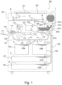
- FIG. 1 the description will be made as to a structure of a copying machine (electrophotographic image forming apparatus) of an electrophotographic type as an example of an image forming apparatus comprising a developer receiving apparatus to which a developer supply container (so-called toner cartridge) is detachably (removably) mounted.
- a developer supply container so-called toner cartridge
- a main assembly of the copying machine main assembly of the image forming apparatus or main assembly of the apparatus.
- Designated by 101 is an original which is placed on an original supporting platen glass 102.
- a light image corresponding to image information of the original is imaged on an electrophotographic photosensitive member 104 (photosensitive member) by way of a plurality of mirrors M of an optical portion 103 and a lens Ln, so that an electrostatic latent image is formed.
- the electrostatic latent image is visualized with toner (one component magnetic toner) as a developer (dry powder) by a dry type developing device (one component developing device) 201a.
- the one component magnetic toner is used as the developer to be supplied from a developer supply container 1, but the present invention is not limited to the example and includes other examples which will be described hereinafter.
- the one component non-magnetic toner is supplied as the developer.
- the non-magnetic toner is supplied as the developer.
- both of the non-magnetic toner and the magnetic carrier may be supplied as the developer.
- the developing device 201 of Figure 1 develops, using the developer, the electrostatic latent image formed on the photosensitive member 104 as an image bearing member on the basis of image information of the original 101.
- the developing device 201 is provided with a developing roller 201f in addition to the developer hopper portion 201a.
- the developer hopper portion 201a is provided with a stirring member 201c for stirring the developer supplied from the developer supply container 1. The developer stirred by the stirring member 201c is fed to the feeding member 201e by a feeding member 201d.
- the developer having been fed by the feeding members 201e, 201b in the order named is supplied finally to a developing zone relative to the photosensitive member 104 while being carried on the developing roller 201f.
- the toner as the developer is supplied from the developer supply container 1 to the developing device 201, but another system may be used, and the toner and the carrier functioning developer may be supplied from the developer supply container 1, for example.
- an optimum cassette is selected on the basis of a sheet size of the original 101 or information inputted by the operator (user) from a liquid crystal operating portion of the copying machine.
- the recording material is not limited to a sheet of paper, but OHP sheet or another material can be used as desired.
- One sheet S supplied by a separation and feeding device 105A-108A is fed to registration rollers 110 along a feeding portion 109, and is fed at timing synchronized with rotation of a photosensitive member 104 and with scanning of an optical portion 103.
- Designated by 111, 112 are a transfer charger and a separation charger. An image of the developer formed on the photosensitive member 104 is transferred onto the sheet S by a transfer charger 111.
- the sheet S fed by the feeding portion 113 is subjected to heat and pressure in a fixing portion 114 so that the developed image on the sheet is fixed, and then passes through a discharging/reversing portion 115, in the case of one-sided copy mode, and subsequently the sheet S is discharged to a discharging tray 117 by discharging rollers 116.
- the trailing end thereof passes through a flapper 118, and a flapper 118 is controlled when it is still nipped by the discharging rollers 116, and the discharging rollers 116 are rotated reversely, so that the sheet S is refed into the apparatus.
- the sheet S is fed to the registration rollers 110 by way of re-feeding portions 119, 120, and then conveyed along the path similarly to the case of the one-sided copy mode and is discharged to the discharging tray 117.
- image forming process equipment such as a developing device 201a as the developing means a cleaner portion 202 as a cleaning means, a primary charger 203 as charging means.
- the developing device 201 develops the electrostatic latent image formed on the photosensitive member 104 by the optical portion 103 in accordance with image information of the 101, by depositing the developer onto the latent image.
- the primary charger 203 uniformly charges a surface of the photosensitive member for the purpose of forming a desired electrostatic image on the photosensitive member 104.
- the cleaner portion 202 removes the developer remaining on the photosensitive member 104.
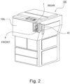
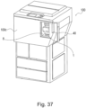
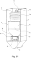
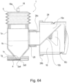
- Figure 2 is an outer appearance of the image forming apparatus.
- an exchange cover 40 which is a part of an outer casing of the image forming apparatus, a part of a developer receiving apparatus 8 which will be described hereinafter is exposed.
- the developer supply container 1 By inserting (mounting) the developer supply container 1 into the developer receiving apparatus 8, the developer supply container 1 is set in the state capable of supplying the developer into the developer receiving apparatus 8.
- the exchange cover 40 is exclusively for mounting and demounting (exchange) of the developer supply container 1, and is opened and closed for mounting and demounting the developer supply container 1.
- a front cover 100c is opened and closed.
- the exchange cover 40 and the front cover 100c may be made integral with each other, and in this case, the exchange of the developer supply container 1 and the maintenance of the main assembly of the apparatus 100 are carried out with opening and closing of the integral cover (unshown).
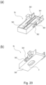
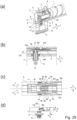
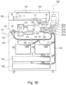
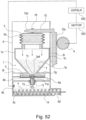
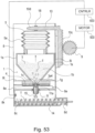
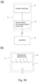
- Part (a) of Figure 3 is a schematic perspective view of the developer receiving apparatus 8, and part (b) of Figure 3 is a schematic sectional view of the developer receiving apparatus 8.
- Part (a) of Figure 4 is a partial enlarged perspective view of the developer receiving apparatus 8
- part (b) of Figure 4 is a partial enlarged sectional view of the developer receiving apparatus 8
- a part (c) of Figure 4 is a perspective view of a developer receiving portion 11.
- the developer receiving apparatus 8 is provided with a mounting portion (mounting space) 8f into which the developer supply container 1 is removably (detachably) mounted. It is also provided with a developer receiving portion 11 for receiving the developer discharged through a discharge opening 3a4 (part (b) of Figure 7 ), which will be described hereinafter, of the developer supply container 1.
- the developer receiving portion 11 is mounted so as to be movable (displaceable) relative to the developer receiving apparatus 8 in the vertical direction.
- the developer receiving portion 11 is provided with a main assembly seal 13 having a developer receiving port 11a at the central portion thereof.
- the main assembly seal 13 is made of an elastic member, a foam member or the like, and is close-contacted with an opening seal 3a5 (part (b) of Figure 7 ) having a discharge opening 3a4 of the developer supply container 1, by which the developer discharged through the discharge opening 3a4 is prevented from leaking out of a developer feeding path including developer receiving port 11a.
- a diameter of the developer receiving port 11a is desirably substantially the same as or slightly larger than a diameter of the discharge opening 3a4 of the developer supply container 1. This is because if the diameter of the developer receiving port 11a is smaller than the diameter of the discharge opening 3a4, the developer discharged from the developer supply container 1 is deposited on the upper surface of the main assembly seal 13 having the developer receiving port 11a, and the deposited developer is transferred onto the lower surface of the developer supply container 1 during the dismounting operation of the developer supply container 1, with the result of contamination with the developer.
- the developer transferred onto the developer supply container 1 may be scattered to the mounting portion 8f with the result of contamination of the mounting portion 8f with the developer.
- the diameter of the developer receiving port 11a is quite larger than the diameter of the discharge opening 3a4, an area in which the developer scattered from the developer receiving port 11a is deposited around the discharge opening 3a4 formed in the opening seal 3a5 is large. That is, the contaminated area of the developer supply container 1 by the developer is large, which is not preferable.
- the difference between the diameter of the developer receiving port 11a and the diameter of the discharge opening 3a4 is preferably substantially 0 to approx. 2 mm.
- the diameter of the discharge opening 3a4 of the developer supply container 1 is approx. ⁇ 2 mm (pin hole), and therefore, the diameter of the developer receiving port 11a is approx. ⁇ 3 mm.
- the developer receiving portion 11 is urged downwardly by an urging member 12.
- the developer receiving portion 11 moves upwardly, it has to move against an urging force of the urging member 12.
- a sub-hopper 8c for temporarily storing the developer.
- a feeding screw 14 for feeding the developer into the developer hopper portion 201a which is a part of the developing device 201, and an opening 8d which is in fluid communication with the developer hopper portion 201a.
- the developer receiving port 11a is closed so as to prevent foreign matter and/or dust entering the sub-hopper 8c in a state that the developer supply container 1 is not mounted. More specifically, the developer receiving port 11a is closed by a main assembly shutter 15 in the state that the developer receiving portion 11 is away to the upside. The developer receiving portion 11 moves upwardly (arrow E) from the position shown in part (b) of Figure 13 toward the developer supply container 1. By this, as shown in part (b) of Figure 15 , the developer receiving port 11a and the main assembly shutter 15 are spaced from each other so that the developer receiving port 11a is open. With this open state, the developer is discharged from the developer supply container 1 through the discharge opening 3a4, so that the developer received by the developer receiving port 11a is movable to the sub-hopper 8c.
- a side surface of the developer receiving portion 11 is provided with an engaging portion 11b.
- the engaging portion 11b is directly engaged with an engaging portion 3b2, 3b4 ( Figure 8 ) provided on the developer supply container 1 which will be described hereinafter, and is guided thereby so that the developer receiving portion 11 is raised toward the developer supply container 1.
- the mounting portion 8f of the developer receiving apparatus 8 is provided with an insertion guide 8e for guiding the developer supply container 1 in the mounting and demounting direction, and by the insertion guide 8e, the mounting direction of the developer supply container 1 is made along the arrow A.
- the dismounting direction of the developer supply container 1 is the opposite (arrow B) to the direction of the arrow A.
- the developer receiving apparatus 8 is provided with a driving gear 9 functioning as a driving mechanism for driving the developer supply container 1.
- the driving gear 9 receives a rotational force from a driving motor 500 through a driving gear train, and functions to apply a rotational force to the developer supply container 1 which is set in the mounting portion 8f.
- the driving motor 500 is controlled by a control device (CPU) 600.
- CPU control device
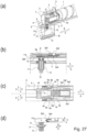
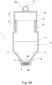
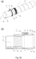
- Part (a) of Figure 5 a schematic exploded perspective view of the developer supply container 1
- part (b) of Figure 5 is a schematic perspective view of the developer supply container 1.
- a cover 7 is partly broken for better understanding.
- the developer supply container 1 mainly comprises a container body 2, a flange portion 3, a shutter 4, a pump portion 5, a reciprocating member 6 and the cover 7.
- the developer supply container 1 is rotated about a rotational axis P shown in part (b) of Figure 5 in a direction of an arrow R in the developer receiving apparatus 8, by which the developer is supplied into the developer receiving apparatus 8.
- a rotational axis P shown in part (b) of Figure 5 in a direction of an arrow R in the developer receiving apparatus 8, by which the developer is supplied into the developer receiving apparatus 8.
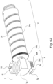
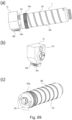
- Figure 6 is a perspective view of a container body.
- the container body (developer feeding chamber) 2 mainly comprises a developer accommodating portion 2c for accommodating the developer, and a helical feeding groove 2a (feeding portion) for feeding the developer in the developer accommodating portion 2c by rotation of the container body 2 about a rotational axis P in the direction of the arrow R.
- a cam groove 2b and drive receiving portion (drive inputting portion) for receiving the drive from the main assembly side are formed integrally with the body 2, over the full circumference at one end portion of the container body 2.
- the cam groove 2b and the drive receiving portion 2d are integrally formed with the container body 2, but the cam groove 2b or the drive receiving portion 2d may be formed as another member, and may be mounted to the container body 2.
- the developer containing the toner having a volume average particle size of 5 ⁇ m-6 um is accommodated in the developer accommodating portion 2c of the container body 2.
- the developer accommodating portion (developer accommodating space) 2c is provided not only by the container body 2 but also by the inside space of the flange portion 3 and the pump portion 5.
- the flange portion 25 will be described.
- the flange portion (developer discharging chamber) 3 is rotatably the rotational axis P relative to the container body 2, and when the developer supply container 1 is mounted to the developer receiving apparatus 8, it is not rotatable in the direction of the arrow R relative to the mounting portion 8f (part (a) of Figure 3 ).
- it is provided with the discharge opening 3a4 ( Figure 7 ).
- the flange portion 3 is divided into an upper flange portion 3a, a lower flange portion 3b taking into account an assembling property, and the pump portion 5, the reciprocating member 6, the shutter 4 and the cover 7 are mounted thereto.
- the pump portion 5 is connected with one end portion side of-the upper flange portion 3a by screws, and the container body 2 is connected with the other end portion side through a sealing member (unshown).
- the pump portion 5 is sandwiched between the reciprocating members 6, and engaging projections 6b ( Figure 11 ) of the reciprocating member 6 are fitted in the cam groove 2b of the container body 2.
- the shutter 4 is inserted into a gap between the upper flange portion 3a and the lower flange portion 3b.
- the cover 7 is integrally provided so as to cover the entirety of the flange portion 3, the pump portion 5 and the reciprocating member 6.
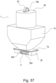
- Figure 7 illustrates the upper flange portion 3a.
- Part (a) of Figure 7 is a perspective view of the upper flange portion 3a as seen obliquely from an upper portion
- part (b) of Figure 7 is a perspective view of the upper flange portion 3ea as seen obliquely from bottom.
- the upper flange portion 3a includes a pump connecting portion 3a1 (screw is not shown) shown in part (a) of Figure 7 to which the pump portion 5 is threaded, a container body connecting portion 3a2 shown in part (b) of Figure 7 to which the container body 2 is connected, and a storage portion 3a2 shown in part (a) of Figure 7 for storing the developer fed from the container body 2.
- a circular discharge opening (opening) 3a4 for permitting discharging of the developer into the developer receiving apparatus 8 from the storage portion 3a3, and a opening seal 3a5 forming a connecting portion 3a6 connecting with the developer receiving portion 11 provided in the developer receiving apparatus 8.
- the opening seal 3a5 is stuck on the bottom surface of the upper flange portion 35a by a double coated tape and is nipped by shutter 4 which will be described hereinafter and the flange portion 3a to prevent leakage of the developer through the discharge opening 3a4.
- the discharge opening 3a4 is provided to opening seal 3a5 which is unintegral with the flange portion 3a, but the discharge opening 3a4 may be provided directly in the upper flange portion 35a.
- the diameter of the discharge opening 3a4 is approx. 2 mm for the purpose of minimizing the contamination with the developer which may be unintentionally discharged by the opening and closing of the shutter 4 in the mounting and demounting operation of the developer supply container 1 relative to the developer receiving apparatus 8.
- the discharge opening 3a4 is provided in the lower surface of the developer supply container 1, that is, the lower surface of the upper flange portion 3a, but the connecting structure of this example can be accomplished if it is fundamentally provided in a side except for an upstream side end surface or a downstream side end surface with respect to the mounting and dismounting direction of the developer supply container 1 relative to the developer receiving apparatus 8.
- the position of the discharge opening 25a4 may be properly selected taking situation of the specific apparatus into account. A connecting operation between the developer supply container 1 and the developer receiving apparatus 8 in this example will be described hereinafter.
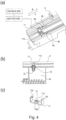
- Figure 8 shows the lower flange portion 25b.
- Part (a) of Figure 8 is a perspective view of the lower flange portion 3b as seen obliquely from an upper position
- part (b) of Figure 8 is a perspective view of the lower flange portion 3b as seen obliquely from a lower position
- part (c) of Figure 8 is a front view.
- the lower flange portion 3b is provided with a shutter inserting portion 3b1 into which the shutter 4 ( Figure 9 ) is inserted.
- the lower flange portion 3b is provided with engaging portions 3b2, 3b4 engageable with the developer receiving portion 11 ( Figure 4 ).
- the engaging portions 3b2, 3b4 displace the developer receiving portion 11 toward the developer supply container 1 with the mounting operation of the developer supply container 1 so that the connected state is established in which the developer supply from the developer supply container 1 to the developer receiving portion 11 is enabled.
- the engaging portions 3b2, 3b4 guide the developer receiving portion 11 to space away from the developer supply container 1 so that the connection between the developer supply container 1 and the developer receiving portion 39 is broken with the dismounting operation of the developer supply container1.
- a first engaging portion 3b2 of the engaging portions 3b2, 3b4 displaces the developer receiving portion 11 in the direction crossing with the mounting direction of the developer supply container 1 for permitting an unsealing operation of the developer receiving portion 1.
- the first engaging portion 3b2 displaces the developer receiving portion 11 toward the developer supply container 1 so that the developer receiving portion 11 is connected with the connecting portion 3a6 formed in a part of the opening seal 3a5 of the developer supply container1 with the mounting operation of the developer supply container 1.
- the first engaging portion 3b2 extends in the direction crossing with the mounting direction of the developer supply container1.
- the first engaging portion 3b2 effects a guiding operation so as to displace the developer receiving portion 11 in the direction crossing with the dismounting direction of the developer supply container 1 such that the developer receiving portion 11 is resealed with the dismounting operation of the developer supply container 1.
- the first engaging portion 3b2 effects the guiding so that the developer receiving portion 11 is spaced away from the developer supply container 1 downwardly, so that the connection state between the developer receiving portion 11 and the connecting portion 3a6 of the developer supply container 1 is broken with the dismounting operation of the developer supply container 1.
- a second engaging portion 3b4 maintains the connection stated between the opening seal 3a5 and a main assembly seal 13 during the developer supply container 1 moving relative to the shutter 4 which will be described hereinafter, that is, during the developer receiving port 11a moving from the connecting portion 3a6 to the discharge opening 3a4, so that the discharge opening 3a4 is brought into communication with a developer receiving port 11a of the developer receiving portion 11 accompanying the mounting operation of the developer supply container 1.
- the second engaging portion 3b4 extends in parallel with the mounting direction of the developer supply container 1.
- the second engaging portion 3b4 maintains the connection between the main assembly seal 13 and the opening seal 3a5 during the developer supply container 1 moving relative to the shutter 4, that is, during the developer receiving port 11a moving from the discharge opening 3a4 to the connecting portion 3a6, so that the discharge opening 3a4 is resealed accompanying the dismounting operation of the developer supply container 1.
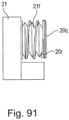
- a configuration of the first engaging portion 3b2 desirably includes an inclined surface (inclined portion) crossing the inserting direction of the developer supply container 1, and it is not limited to the linear inclined surface as shown in part (a) of Figure 8 .
- the configuration of the first engaging portion 3b2 may be a curved and inclined surface as shown in part (a) of Figure 18 , for example.
- Furthermore, as shown in part (b) of Figure 18 may be stepped including a parallel surface and an inclined surface.
- the configuration of the first engaging portion 3b2 is not limited to the configuration shown in parts (a) or (b) of Figures 8 and 18 , if it can displace the developer receiving portion 11 toward the discharge opening 3a4, but a linear inclined surface is desirable from the standpoint of constant manipulating force required by the mounting and dismounting operation of the developer supply container 1.
- An inclination angle of the first engaging portion 3b2 relative to the mounting and dismounting direction of the developer supply container 1 is desirably approx. 10 - 50 degrees in view of the situation which will be described hereinafter. In this example, the angle is approx. 40 degrees.
- the first engaging portion 3b2 and the second engaging portion 3b4 may be unified to provide a uniformly linear inclined surface.
- the first engaging portion 3b2 displaces the developer receiving portion to connect the main assembly seal 13 with the shield portion 3b6 developer receiving portion 11 in the direction crossing with the mounting direction of the developer supply container 1. Thereafter, it displaces the developer receiving portion 11 while compressing the main assembly seal 13 and the opening seal 3a5, until the developer receiving port 11a and the discharge opening 3a4 are brought into fluid communication with each other.
- the developer supply container 1 when such a first engaging portion 3b2 is used, the developer supply container 1 always receives a force in the direction of B (part (a) of Figure 16 ) by the relationship between the first engaging portion 3b2 and the engaging portion 11b of the developer receiving portion 11 in the completed position of the mounting of the developer supply container 1 which will be described hereinafter. Therefore, the developer receiving apparatus 8 is required to have a holding mechanism for holding the developer supply container 1 in the mounting completed position, with the result of increase in cost and/or increase in the number of parts.
- the developer supply container 1 is provided with the above-described second engaging portion 3b4 so that the force in the B direction is not applied to the developer supply container 1 in the mounting completed position, thus stabilizing the connection state between the main assembly seal 13 and the opening seal 3a5.
- the first engaging portion 3b2 shown in part (c) of Figure 18 has a linear inclined surface, but similar to the part (a) of Figure 18 or part (b) of Figure 18 , for example, a curved or stepped configuration is usable, although the linear inclined surface is preferable from the standpoint of constant manipulating force in the mounting and dismounting operations of the developer supply container 1, as described hereinbefore.
- the lower flange portion 3b is provided with a regulation rib (regulating portion) 3b3 (part (a) of Figure 3 ) for preventing or permitting an elastic deformation of a supporting portion 4d of the shutter 4 which will be described hereinafter, with the mounting or dismounting operation of the developer supply container 1 relative to the developer receiving apparatus 8.
- the regulation rib 3b3 protrudes upwardly from an insertion surface of the shutter inserting portion 3b1 and extends along the mounting direction of the developer supply container 1.
- the protecting portion 3b5 is provided to protect the shutter 4 from damage during transportation and/or mishandling of the operator.
- the lower flange portion 3b is integral with the upper flange portion 3a in the state that the shutter 4 is inserted in the shutter inserting portion 3b1.
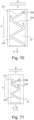
- Figure 9 shows the shutter 4.
- Part (a) of Figure 9 is a top plan view of the shutter 4
- part (b) of Figure 9 is a perspective view of shutter 4 as seen obliquely from an upper position.
- the shutter 4 is movable relative to the developer supply container 1 to open and close the discharge opening 3a4 with the mounting operation and the dismounting operation of the developer supply container 1.
- the shutter 4 is provided with a developer sealing portion 4a for preventing leakage of the developer through the discharge opening 3a4 when the developer supply container 1 is not mounted to the mounting portion 8f of the developer receiving apparatus 8, and a sliding surface 4i which slides on the shutter inserting portion 3b1 of the lower flange portion 3b on the rear side (back side) of the developer sealing portion 4a.
- Shutter 4 is provided with a stopper portion (holding portion) 4b, 4c held by shutter stopper portions 8n, 8p (part (a) of Figure 4 ) of the developer receiving apparatus 8 with the mounting and dismounting operations of the developer supply container 1 so that the developer supply container 1 moves relative to the shutter 4.
- a first stopper portion 5b of the stopper portions 4b, 4c engages with a first shutter stopper portion 8n of the developer receiving apparatus 8 to fix the position of the shutter 4 relative to the developer receiving apparatus 8 at the time of mounting operation of the developer supply container 1.
- a second stopper portion 4c engages with a second shutter stopper portion 8b of the developer receiving apparatus 8 at the time of the dismounting operation of the developer supply container 1.
- the shutter 4 is provided with a supporting portion 4d so that the stopper portions 4b, 4c are displaceable.
- the supporting portion 4d extends from the developer sealing portion 4a and is elastically deformable to displaceably support the first stopper portion 4b and the second stopper portion 4c.
- the first stopper portion 4b is inclined such that an angle ⁇ formed between the first stopper portion 4b and the supporting portion 4d is acute.
- the second stopper portion 4c is inclined such that an angle ⁇ formed between the second stopper portion 4c and the supporting portion 4d is obtuse.
- the developer sealing portion 4a of the shutter 4 is provided with a locking projection 4e at a position downstream of the position opposing the discharge opening 3a4 with respect to the mounting direction when the developer supply container 1 is not mounted to the mounting portion 8f of the developer receiving apparatus 8.
- a contact amount of the locking projection 4e relative to the opening seal 3a5 (part (b) of Figure 7 ) is larger than relative to the developer sealing portion 4a so that a static friction force between the shutter 4 and the opening seal 3a5 is large. Therefore, an unexpected movement (displacement) of the shutter 4 due to a vibration during the transportation or the like can be prevented. Therefore, an unexpected movement (displacement) of the shutter 4 due to a vibration during the transportation or the like can be prevented.
- the entirety of the developer sealing portion 4a may correspond to the contact amount between the locking projection 4e and the opening seal 3a5, but in such a case, the dynamic friction force relative to the opening seal 3a5 at the time when the shutter 4 moves is large as compared with the case of the locking projection 4e provided, and therefore, a manipulating force required when the developer supply container 1 is mounted to the developer replenishing apparatus 8 is large, which is not preferable from the standpoint of the usability. Therefore, it is desired to provide the locking projection 4e in a part as in this example. (Pump portion)
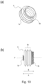
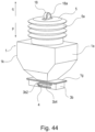
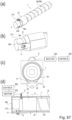
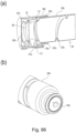
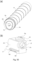
- Figure 10 shows the pump portion 5.
- Part (a) of Figure 10 is a perspective view of the pump portion 5, and part (b) is a front view of the pump portion 5.
- the pump portion 5 is operated by the driving force received by the drive receiving portion (drive inputting portion) 2d so as to alternately produce a state in which the internal pressure of the developer accommodating portion 2c is lower than the ambient pressure and a state in which it is higher than the ambient pressure.
- the pump portion 5 is provided as a part of the developer supply container 1 in order to discharge the developer stably from the small discharge opening 3a4.
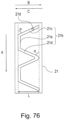
- the pump portion 5 is a displacement type pump in which the volume changes. More specifically, the pump includes a bellow-like expansion-and-contraction member.
- the pressure in the developer supply container 1 is changed, and the developer is discharged using the pressure. More specifically, when the pump portion 5 is contracted, the inside of the developer supply container 1 is pressurized so that the developer is discharged through the discharge opening 3a4.
- the pump portion 5 expands, the inside of the developer supply container 1 is depressurized so that the air is taken in through the discharge opening 3a4 from the outside.
- the take-in air the developer in the neighborhood of the discharge opening 3a4 and/or the storage portion 3a3 is loosened so as to make the subsequent discharging smooth.
- the pump portion 5 of this modified example has the bellow-like expansion-and-contraction portion (bellow portion, expansion-and-contraction member) 5a in which the crests and bottoms are periodically provided.
- the expansion-and-contraction portion 5a expands and contracts in the directions of arrows A and B.
- the material of the pump portion 2 is polypropylene resin material (PP), but this is not inevitable.
- the material of the pump portion 5 may be any if it can provide the expansion and contraction function and can change the internal pressure of the developer accommodating portion by the volume change.
- the examples includes thin formed ABS (acrylonitrile, butadiene, styrene copolymer resin material), polystyrene, polyester, polyethylene materials.
- other expandable-and-contractable materials such as rubber are usable.
- the opening end side of the pump portion 5 is provided with a connecting portion 5b connectable with the upper flange portion 3a.
- the connecting portion 5b is a screw.
- the other end portion side is provided with a reciprocating member engaging portion 5c engaged with the reciprocating member 5 to displace in synchronism with the reciprocating member 6 which will be described hereinafter.
- Figure 11 shows the reciprocating member 6.
- Part (a) of Figure 11 is a perspective view of the reciprocating member 6 as seen obliquely from an upper position
- part (b) is perspective view of the reciprocating member 6 as seen obliquely from a lower position.
- the reciprocating member 6 is provided with a pump engaging portion 6a engaged with the reciprocating member engaging portion 5c provided on the pump portion 5 to change the volume of the pump portion 5 as described above. Furthermore, as shown in part (a) and part (b) of Figure 11 the reciprocating member 6 is provided with the engaging projection 6b fitted in the above-described cam groove 2b ( Figure 5 ) when the container is assembled. The engaging projection 6b is provided at a free end portion of the arm 6c extending from a neighborhood of the pump engaging portion 6a.
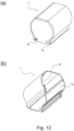
- Figure 12 shows the cover 7.
- Part (a) of Figure 12 is a perspective view of the cover 7 as seen obliquely from a upper position
- part (b) is a perspective view of the cover 7 as seen obliquely from a lower position.
- the cover 24 is provided as shown in part (b) of Figure 69 in order to protect the reciprocating member 38 and/or the pump portion 2 and to improve the outer appearance.
- the cover 7 is provided integrally with the upper flange portion 3a and/or the lower flange portion 3b and so on by a mechanism (unshown) so as to cover the entirety of the flange portion 3, the pump portion 5 and the reciprocating member 6.
- the cover 7 is provided with a guide groove 7a to be guided by the insertion guide 8e (part (a) of Figure 3 ) of the developer receiving apparatus 8.
- the cover 7 is provided with a reciprocating member holding portion 7b for regulating a rotation displacement about the axis P (part (b) of Figure 5 ) of the reciprocating member 6 as described above.
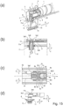
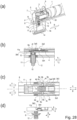
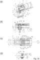
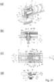
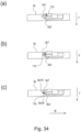
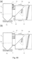
- Parts (a) - (d) of Figures 13 - Figure 16 show the neighborhood of the connecting portion between the developer supply container 1 and the developer receiving apparatus 8.
- Parts (a) of Figure 13 - Figure 16 are perspective view of a partial section, (b) is a front view of the partial section, (c) is a top plan view of (b), and (d) show the relation between the lower flange portion 3b and the developer receiving portion 11, particularly.
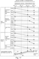
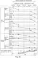
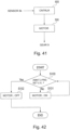
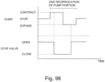
- Figure 17 is a timing chart of operations of each elements relating to the mounting operation of the developer supply container 1 to the developer receiving apparatus 8 as shown in Figure 13 - Figure 16 .
- the mounting operation is the operation until the developer becomes able to be supplied to the developer receiving apparatus 8 from the developer supply container 1.
- Figure 13 shows a connection starting position (first position) between the first engaging portion 3b2 of the developer supply container 1 and the engaging portion 11b of the developer receiving portion 11.
- the developer supply container 1 is inserted into the developer receiving apparatus 8 in the direction of an arrow A.
- the first stopper portion 4b of the shutter 4 contacts the first shutter stopper portion 8a of developer receiving apparatus 8, so that the position of the shutter 4 relative to the developer receiving apparatus 8 is fixed.
- the relative position between the lower flange portion 3b and the upper flange portion 3a of the flange portion 3 and the shutter 4 remains unchanged, and therefore, the discharge opening 3a4 is sealed assuredly by the developer sealing portion 4a of the shutter 4.
- the connecting portion 3a6 of the opening seal 3a5 is shielded by the shutter 4.
- the supporting portion 4d of the shutter 4 is displaceable in the direction of arrows C and D, since the regulation rib 3b3 of the lower flange portion 3b does not enter the supporting portion 4d.
- the first stopper portion 4b is inclined such that the angle ⁇ (part (a) of Figure 9 ) relative to the supporting portion 4d is acute, and the first shutter stopper portion 8a is also inclined, correspondingly.
- the inclination angle ⁇ is approx. 80 degrees.
- the first stopper portion 4b receives a reaction force in the arrow B direction from the first shutter stopper portion 8a, so that the supporting portion 4d is displaced in an arrow D direction. That is, the first stopper portion 4b of the shutter 4 displaces in the direction of holding the engagement state with the first shutter stopper portion 8a of the developer receiving apparatus 8, and therefore, the position of the shutter 4 is held assuredly relative to the developer receiving apparatus 8.
- the positional relation between the engaging portion 11b of the developer receiving portion 11 and the first engaging portion 3b2 of the lower flange portion 3b is such that they start engagement with each other. Therefore, the developer receiving portion 11 remains in the initial position in which it is spaced from the developer supply container 1. More specifically, as shown in part (b) of Figure 13 , the developer receiving portion 11 is spaced from the connecting portion 3a6 formed on a part of the opening seal 3a5. As shown in part (b) of Figure 13 , the developer receiving port 11a is in the sealed state by the main assembly shutter 15. In addition, the driving gear 9 of the developer receiving apparatus 8 and the drive receiving portion 2d of the developer supply container 1 are not connected with each other, that is, in the non-transmission state.
- the distance between the developer receiving portion 11 and the developer supply container 1 is approx. 2 mm.
- the distance is too small, not more than approx. 1.5 mm, for example, the developer deposited on the surface of the main assembly seal 13 provided on the developer receiving portion 11 may be scattered by air flow produced locally by the mounting and dismounting operation of the developer supply container 1, the scattered developer may be deposited on the lower surface of the developer supply container 1.
- the distance is too large, a stroke required to displace the developer receiving portion 11 from the spacing position to the connected position is large with the result of upsizing of the image forming apparatus.
- the inclination angle of the first engaging portion 3b2 of the lower flange portion 3b is steep relative to the mounting and dismounting direction of the developer supply container 1 with the result of increase of the load required to displace the developer receiving portion 11. Therefore, the distance between the developer supply container 1 and the developer receiving portion 11 is properly determined taking the specifications of the main assembly or the like into account.
- the inclination angle of the first engaging portion 3b2 relative to the mounting and dismounting direction of the developer supply container 1 is approx. 40 degrees. The same applies to the following embodiments.
- the developer supply container 1 is further inserted in the direction of the arrow A.
- the developer supply container 1 moves relative to the shutter 4 in the direction of the arrow A, since the position of the shutter 4 is held relative to the developer receiving apparatus 8.
- a part of the connecting portion 3a6 of the opening seal 3a5 is exposed through the shutter 4.
- the first engaging portion 3b2 of the lower flange portion 3b directly engages with the engaging portion 11b of the developer receiving portion 11 so that the engaging portion 11b is displaced in the direction of the arrow E by the first engaging portion 3b2.
- the developer receiving portion 11 is displaced in the direction of the arrow E against the urging force of the urging member 12 (arrow F) to the position shown in part (b) of Figure 14 , so that the developer receiving port 11a is spaced from the main assembly shutter 15, thus starting to unseal.
- the developer receiving port 11a and the connecting portion 3a6 are spaced from each other.
- the regulation rib 3b3 of the lower flange portion 3b enters of supporting portion 4d of the shutter 4, so that the supporting portion 4d can not displace in the direction of arrow C or arrow D. That is, the elastic deformation of the supporting portion 4d is limited by the regulation rib 3b3.
- the developer supply container 1 is further inserted in the direction of the arrow A.
- the developer supply container 1 moves relative to the shutter 4 in the direction of the arrow A, since the position of the shutter 4 is held relative to the developer receiving apparatus 8.
- the connecting portion 3a6 formed on the part of the opening seal 3a5 is completely exposed from the shutter 4.
- the discharge opening 3a4 is not exposed from the shutter 4, so that it is still sealed by the developer sealing portion 4a.
- the regulation rib 3b3 of the lower flange portion 3b enters the supporting portion 4d of the shutter 4, by which the supporting portion 4d can not displace in the direction of arrow C or arrow D.
- the directly engaged engaging portion 11b of the developer receiving portion 11 reaches the upper end side of the first engaging portion 3b2.
- the developer receiving portion 11 is displaced in the direction of the arrow E against the urging force (arrow F) of the urging member 12, to the position shown in part (b) of Figure 15 , so that the developer receiving port 11a is completely spaced from the main assembly shutter 15 to be unsealed.
- the connection is established in the state that the main assembly seal 13 having the developer receiving port 11a is close-contacted to the connecting portion 3a6 of the opening seal 3a5.
- the developer receiving portion 11 directly engaging with the first engaging portion 3b2 of the developer supply container 1
- the developer supply container 1 can be accessed by the developer receiving portion 11 from the lower side in the vertical direction which is crossed with the mounting direction.
- the above-described the structure can avoid the developer contamination at the end surface Y (part (b) of Figure 5 ) in the downstream side with respect to the mounting direction of the developer supply container 1, the developer contamination having been produced in the conventional structure in which the developer receiving portion 11 accesses the developer supply container 1 in the mounting direction.
- the conventional structure will be described hereinafter.
- the developer receiving port 11a slides on the opening seal 3a5 to communicate with the discharge opening 3a4 while keeping the close-contact state between the main assembly seal 13 and the connecting portion 3a6 formed on the opening seal 3a5. Therefore, the amount of the developer falling from the discharge opening 3a4 and scattering to the position other than the developer receiving port 11a. Thus, the contamination of the developer receiving apparatus 8 by the scattering of the developer is less.
- Figure 17 is a timing chart of operations of each elements relating to the dismounting operation of the developer supply container 1 from the developer receiving apparatus 8 as shown in Figure 13 - Figure 16 .
- the dismounting operation of the developer supply container 1 is a reciprocal of the above-described mounting operation.
- the dismounting operation (removing operation) is the operation to the state in which the developer supply container 1 can be take out of the developer receiving apparatus 8.
- the supporting portion 4d of the shutter 4 can not displace in the direction of arrow C or arrow D by the limitation of the regulation rib 3b3 of the lower flange portion 3b. Therefore, as shown in part (a) of Figure 16 , when the developer supply container 1 tends to move in the direction of the arrow B with the dismounting operation, the second stopper portion 4c of the shutter 4 abuts to the second shutter stopper portion 8b of the developer receiving apparatus 8, so that the shutter 4 does not displace in the direction of the arrow B. In other words, the developer supply container 1 moves relative to the shutter 4.
- the shutter 4 seals the discharge opening 3a4 as shown in part (b) of Figure 15 .
- the engaging portion 11b of the developer receiving portion 11 displaces to the downstream lateral edge of the first engaging portion 3b2 from the second engaging portion 3b4 of the lower flange portion 3b with respect to the dismounting direction.
- the main assembly seal 13 of the developer receiving portion 11 slides on the opening seal 3a5 from the discharge opening 3a4 of the opening seal 3a5 to the connecting portion 3a6, and maintains the connection state with the connecting portion 3a6.
- the supporting portion 4d is in engagement with the regulation rib 3b3, so that it can not displace in the direction of the arrow B in the Figure.
- the developer supply container 1 moves relative to the shutter 4, since the shutter 4 can not displace relative to the developer receiving apparatus 8.
- the developer supply container 1 is drawn from the developer receiving apparatus 8 to the position shown in part (a) of Figure 14 .
- the engaging portion 11b slides down on the first engaging portion 3b2 to the position of the generally middle point of the first engaging portion 3b2 by the urging force of the urging member 12. Therefore, the main assembly seal 13 provided on the developer receiving portion 11 downwardly spaces from the connecting portion 3a6 of the opening seal 3a5, thus releasing the connection between the developer receiving portion 11 and the developer supply container 1.
- the developer is deposited substantially on the connecting portion 3a6 of the opening seal 3a5 with which the developer receiving portion 11 has been connected.
- the developer supply container 1 is drawn from the developer receiving apparatus 8 to the position shown in part (a) of Figure 13 .
- the engaging portion 11b slides down on the first engaging portion 3b2 to reach the upstream lateral edge with respect to dismounting direction of the first engaging portion 3b2, by the urging force of the urging member 12. Therefore, the developer receiving port 11a of the developer receiving portion 11 released from the developer supply container 1 is sealed by the main assembly shutter 15.
- the shutter 4 displaces to the connecting portion 3a6 of the opening seal 3a5 with which the main assembly seal 13 of the developer receiving portion 11 has been connected to shield the connecting portion 3a6 on which the developer is deposited.
- the developer receiving portion 11 is guided by the first engaging portion 3b2, and after the completion of the spacing operation from the developer supply container 1, the supporting portion 4d of the shutter 4 is disengaged from the regulation rib 3b3 so as to be elastically deformable.
- the configurations of the regulation rib 3b3 and/or the supporting portion 4d are properly selected so that the position where the engaging relation is released is substantially the same as the position where the shutter 4 enters when developer supply container 1 is not mounted to the developer receiving apparatus 8.
- the second stopper portion 4c of the shutter 4 abuts to the second shutter stopper portion 8b of the developer receiving apparatus 8, as shown in part (c) of Figure 13 .
- the second stopper portion 4c of the shutter 4 displaces (elastically deforms) in the direction of arrow C along a taper surface of the second shutter stopper portion 8b, so that the shutter 4 becomes displaceable in the direction of the arrow B relative to the developer receiving apparatus 8 together with the developer supply container 1.
- the shutter 4 returns to the position taken when the developer supply container 1 is not mounted to the developer receiving apparatus 8. Therefore, the discharge opening 3a4 is assuredly sealed by the shutter 4, and therefore, the developer is not scattered from the developer supply container 1 demounted from the developer receiving apparatus 8. Even if the developer supply container 1 is mounted to the developer receiving apparatus 8, again, it can be mountable without any problem.
- Figure 17 shows flow of the mounting operation of the developer supply container 1 to the developer receiving apparatus 8 ( Figures 13 - 16 ) and the flow of the dismounting operation of the developer supply container 1 from the developer receiving apparatus 8.
- the engaging portion 11b of the developer receiving portion 11 is engaged with the first engaging portion 3b2 of the developer supply container 1, by which the developer receiving port displaces toward the developer supply container.
- the engaging portion 11b of the developer receiving portion 11 engages with the first engaging portion 3b2 of the developer supply container 1, by which the developer receiving port displaces away from the developer supply container.
- the mechanism for connecting and spacing the developer receiving portion 11 relative to the developer supply container 1 by displacement of the developer receiving portion 11 can be simplified. More particularly, a driving source and/or a drive transmission mechanism for moving the entirety of the developing device upwardly is unnecessary, and therefore, a complication of the structure of the image forming apparatus side and/or the increase in cost due to increase of the number of parts can be avoided.
- connection between the developer supply container 1 and the developer receiving apparatus 8 can be properly established using the mounting operation of the developer supply container 1 with minimum contamination with the developer. Similarly, utilizing the dismounting operation of the developer supply container 1, the spacing and resealing between the developer supply container 1 and the developer receiving apparatus 8 can be carried out with minimum contamination with the developer.
- the developer supply container 1 of this example can cause the developer receiving portion 11 to connect upwardly and space downwardly in the direction crossing with the mounting direction of developer supply container 1, using the engaging portions 3b2, 3b4 of the lower flange portion 3b with the mounting and demounting operation to the developer receiving apparatus 8.
- the developer receiving portion 11 is sufficiently small relative to developer supply container 1, and therefore, the developer contamination of the downstream side end surface Y (part (b) of Figure 5 ) of the developer supply container 1 with respect to the mounting direction, with the simple and space saving structure.
- the developer contamination by the main assembly seal 13 slides on the protecting portion 3b5 of the lower flange portion 3b and the sliding surface (lower surface of the shutter) 4i.
- the discharge opening 3a4 is exposed from the shutter 4 so that the discharge opening 3a4 and the developer receiving port 11a can be brought into communication with each other.
- the timing of each step is controlled by the engaging portions 3b2, 3b4 of the developer supply container 1, and therefore, the scattering of the developer can be suppressed assuredly with a simple and easy structure, without the being influenced by the way of operation by the operator.
- the shutter 4 can shield the developer deposition portion of the opening seal 3a5.
- the timing of each step in the dismounting operation can be controlled by the engaging portions 3b2 and 3b4 of the developer supply container 1, and therefore, the scattering of the developer can be suppressed, and the developer deposition portion can be prevented from the exposing to the outside.
- connection relation between the connecting portion and the connected portion is established indirectly through another mechanism, and therefore, it is difficulty to control the connection relation with high precision
- connection relation can be established by the directly engagement between the connecting portion (developer receiving portion 11) and the connected portion (developer supply container 1). More specifically, the timing of the connection between the developer receiving portion 11 and the developer supply container 1 can be controlled easily by the positional relation, in the mounting direction, among the engaging portion 11b of the developer receiving portion 11, the first and second engaging portions 3b2 and 3a4 of the lower flange portion 3b of the developer supply container 1 and discharge opening 3a4. In other words, the timing may deviate within the tolerances of the three elements, and therefore, very high accuracy control can be performed. Therefore, the connecting operation of the developer receiving portion 11 to the developer supply container 1 and the spacing operation from the developer supply container 1 can be carried out assuredly, with the mounting operation and the dismounting operation of the developer supply container 1.
- the displacement amount of the developer receiving portion 11 in the direction crossing with the mounting direction of the developer supply container 1 can be controlled by the positions of the engaging portion 11b of the developer receiving portion 11 and the second engaging portion 3b4 of the lower flange portion 3b.
- the deviation of the displacement amount may deviate within the tolerances of the two elements, and therefore, very high accuracy control can be performed. Therefore, for example, close-contact state (amount of sealing compression or the like) between the main assembly seal 13 and the discharge opening 3a4 can be controlled easily, so that the developer discharged from the discharge opening 3a4 can be fed into the developer receiving port 11a assuredly.
- Embodiment 2 is partly different from Embodiment 1 in the configuration and structure developer receiving portion 11, the shutter 4, the lower flange portion 3b, and the mounting and demounting operations of the developer supply container 1 to the developer receiving apparatus 8 are partly different, correspondingly.
- the same reference numerals as in the foregoing embodiments are assigned to the elements having the corresponding functions in this embodiment, and the detailed description thereof is omitted.
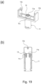
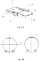
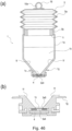
- Figure 19 shows the developer receiving portion 11 of Embodiment 2. Part (a) of Figure 19 is a perspective view of the developer receiving portion 11, and part (b) of Figure 19 is a sectional view of the developer receiving portion 11.
- the developer receiving portion 11 of Embodiment 2 is provided with a tapered portion 11c for misalignment prevention at the end portion of the downstream side with respect to the connecting direction to the developer supply container 1, and the end surface continuing from the tapered portion 11c is substantially annular.
- the misalignment prevention tapered portion 11c is engaged with a misalignment prevention taper engaging portion 4 g ( Figure 21 ) provided on the shutter 4, as will be described hereinafter.
- the misalignment prevention tapered portion 11c is provided in order to prevent a misalignment between the developer receiving port 11a and a shutter opening 4f ( Figure 21 ) of the shutter 4 due to a vibration by a driving source inner the image forming apparatus and/or a deformation of a part.
- the detail of the engaging relation (contact relation) between the misalignment prevention tapered portion 11c and the misalignment prevention taper engaging portion 4 g will be described hereinafter.
- the material and/or configuration and dimensions of the main assembly seal 13 such as a width and/or height or the like are properly selected so that the leakage of the developer can be prevented in relation with a configuration of a close-contact portion 4h provided around the shutter opening 4f of the shutter 4 which will be described hereinafter, to which the main assembly seal 13 is connected with the mounting operation of the developer supply container 1.
- Figure 20 shows the lower flange portion 3b in Embodiment 2.
- Part (a) of Figure 20 is a perspective view (upward direction) of the lower flange portion 3b
- part (b) of Figure 20 is a perspective view (downward direction) of lower flange portion 3b.
- the lower flange portion 3b in this embodiment is provided with a shielding portion 3b6 for shielding the shutter opening 4f which will be described hereinafter, when the developer supply container 1 is not mounted to the developer receiving apparatus 8.
- the provision of the shielding portion 3b6 is different from the above-described lower flange portion 3b of Embodiment 1.
- the shielding portion 3b6 is provided in the downstream side of the lower flange portion 3b with respect to the mounting direction of the developer supply container 1.
- the lower flange portion 3b is provided with engaging portions 3b2 and 3b4 engageable with an engaging portion 11b ( Figure 19 ) of the developer receiving portion 11 as shown in Figure 20 .
- the first engaging portion 3b2 displaces the developer receiving portion 11 toward the developer supply container 1 so that the main assembly seal 13 provided in the developer receiving portion 11 is connected with the shutter 4 which will be described hereinafter, with the mounting operation of the developer supply container 1.
- the first engaging portion 3b2 displaces the developer receiving portion 11 toward the developer supply container 1 with the mounting operation of the developer supply container 1 so that the developer receiving port 11a formed in the developer receiving portion 11 is connected with the shutter opening (communication port) 4f.
- the first engaging portion 3b2 guides the developer receiving portion 11 away from the developer supply container 1 so that the connection state between the developer receiving portion 11 and the shutter opening 4f of the shutter 4 is broken, with the dismounting operation of the developer supply container 1.
- a second engaging portion 3b4 holds the connected state between the shutter 4 and the main assembly seal 13 of the developer receiving portion 11 in the movement of the developer supply container 1 relative to the shutter 4, so that a discharge opening 3a4 is brought into fluid communication with the developer receiving port 11a of the developer receiving portion 11, with the mounting operation of the developer supply container 1.
- the second engaging portion 3b4 maintains the connected state between the developer receiving port 11a and the shutter opening 4f in the movement of the lower flange portion 3b relative to the shutter 4 with the mounting operation of the developer supply container 1, so that the discharge opening 3a4 is brought into fluid communication with the shutter opening 4f.
- the second engaging portion 3b4 holds the connected state between the developer receiving portion 11 and the shutter 4 in the movement of the developer supply container 1 relative to the shutter 4 so that the discharge opening 3a4 is resealed, with the dismounting operation of the developer supply container 1.
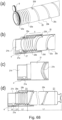
- Figure 21 - Figure 25 show the shutter 4 in Embodiment 2.
- Part (a) of Figure 21 is a perspective view of the shutter 4, part (b) of Figure 21 illustrates a modified example 1 of the shutter 4, part (c) of Figure 21 illustrates a connection relation between the shutter 4 and the developer receiving portion 11, part (d) of Figure 21 is a illustration similar to the part (c) of Figure 21 .
- the shutter 4 of Embodiment 2 is provided with the shutter opening (communication port) 4f communicatable with the discharge opening 3a4. Further, the shutter 4 is provided with a close-contact portion (projected portion, projection) 4h surrounding an outside of the shutter opening 4f, and the misalignment prevention taper engaging portion 4 g further outside the close-contact portion 4h.
- the close-contact portion 4h has a projection height such that it is lower than a sliding surface 4i of the shutter 4, and a diameter of the shutter opening 4f is approx. ⁇ 2 mm. The size is selected for the same reason as with Embodiment 1, and therefore, the explanation is omitted for simplicity.
- the shutter 4 is provided with a recess at a substantially central portion with respect to the longitudinal direction of the shutter 4, as a retraction space for the supporting portion 4d at the time when the supporting portion 4d of shutter 4 displaces in the direction C (part (c) of Figure 26 ) with the dismounting operation.
- a gap between the recessed configuration and the supporting portion 4d is larger than an amount of overlapping between the first stopper portion 4b and a first shutter stopper portion 8a of the developer replenishing apparatus 8, so that the shutter 4 can be engaged with and disengaged from the developer receiving apparatus 8 smoothly.
- Part (a) of Figure 22 shows a position (the same position as Figure 27 ) where the developer supply container 1 is engaged with the developer receiving apparatus 8, which will be described hereinafter, and part (b) of Figure 22 shows a position (the same position as Figure 31 ) where the developer supply container 1 is completely mounted to the developer receiving apparatus 8.
- a length D2 of supporting portion 4d is set such that it is larger than a displacement amount D1 of the developer supply container 1 with the mounting operation of the developer supply container 1 (D1 ⁇ D2).
- the displacement amount D1 is the amount of the displacement of the developer supply container 1 relative to the shutter in the mounting operation of the developer supply container 1. That is, it is the displacement amount of the developer supply container 1 in the state (part (a) of Figure 22 ) in which stopper portions (holding portions) 4b and 4c of the shutter 4 is in engagement with shutter stopper portions 8a and 8b of the developer receiving apparatus 8.
- the supporting portion 4d of the shutter 4 may be provided with a regulated projection (projection) 4k positively engageable with the regulation rib 3b3 as shown in Figure 23 to prevent the interference between the supporting portion 4d and the regulation rib 3b3.
- the developer supply container 1 can be mounted to the developer receiving apparatus 8 irrespective of the size relation between the displacement amount D1 in the mounting operation of the developer supply container 1 and the length D2 of the supporting portion 4d of the shutter 4.
- the size of the developer supply container 1 is larger only a height D4 of the regulated projection 4k.
- Figure 23 is a perspective view of the shutter 4 for the developer supply container 1 when D1>D2. Therefore, if the position of the developer receiving apparatus 8 inner the main assembly of the image forming apparatus 100 is the same, a cross-sectional area is larger by S than of the developer supply container 1 of this embodiment as shown in Figure 24 , and therefore, a corresponding larger space is required.
- a cross-sectional area is larger by S than of the developer supply container 1 of this embodiment as shown in Figure 24 , and therefore, a corresponding larger space is required.
- Part (b) of Figure 21 shows a modified example 1 of the shutter 4 in which the misalignment prevention taper engaging portion 4 g is divided into a plurality of parts, as is different from the shutter 4 of this embodiment. In the other respects, substantially the equivalent performance is provided.
- Part (c) of Figure 21 shows the engaging relation between the misalignment prevention taper engaging portion 4 g of the shutter 4 and the misalignment prevention tapered portion 11c of the developer receiving portion 11 in Embodiment 2.
- distances of the corner lines constituting the close-contact portion 4h and the misalignment prevention taper engaging portion 4 g of the shutter 4 from a center R of the shutter opening 4f are L1, L2, L3, L4.
- distances of corner lines constituting the misalignment prevention tapered portion 11c of the developer receiving portion 11 from the center R of the developer receiving port 11a are M1, M2, M3.
- the positions of the centers of the shutter opening 4f and the developer receiving port 11a are set to be aligned with each other.
- the positions of the corner lines are selected to satisfy L1 ⁇ L2 ⁇ M1 ⁇ L3 ⁇ M2 ⁇ L4 ⁇ M3.
- the corner lines at the distance M2 from the center R of the developer receiving port 11a of the developer receiving portion 11 abuts to the misalignment prevention taper engaging portion 4 g of the shutter 4. Therefore, even if the positional relation between the shutter 4 and the developer receiving portion 11 is deviated more or less due to the vibration from the driving source of the main assembly of the apparatus and/or part accuracies, the misalignment prevention taper engaging portion 4 g and the misalignment prevention are guided by the tapered surfaces to align with each other. Therefore, the deviation between the center shafts of and opening 4f and the developer receiving port 11a can be suppressed.
- part (d) of Figure 21 shows a modified example of the engaging relation between the misalignment prevention taper engaging portion 4 g of the shutter 4 and the misalignment prevention tapered portion 11c of the developer receiving portion 11, according to Embodiment 2.
- the structure of this modified example is different from the structure shown in part (c) of Figure 21 only in that the positional relation of the corner lines is L1 ⁇ L2 ⁇ M1 ⁇ M2 ⁇ L3 ⁇ L4 ⁇ M3.
- the corner lines at the position L4 away from the center R of the shutter opening 4f of the misalignment prevention taper engaging portion 4 g abuts to the tapered surface of the tapered portion 11c. Also in this case, the deviation of the center shafts of the shutter and the developer receiving port 11a can be suppressed, similarly.
- FIG. 25 a modified example 2 of the shutter 4 will be described.
- Part (a) of Figure 25 shows modified example 2 of the shutter 4
- the part (b) of Figure 25 and part (c) of Figure 25 show the connection relation between the shutter 4 and the developer receiving portion 11 in the modified example 2.
- the shutter 4 of modified example 2 is provided with the misalignment prevention taper engaging portion 4 g in the close-contact portion 4h.
- the other configurations are the same as those of the shutter 4 (part (a) of Figure 21 ) of this embodiment.
- the close-contact portion 4h is provided in order to control the amount of compression of the main assembly seal 13 (part (a) of Figure 19 ).
- distances of the corner lines constituting the close-contact portion 4h and the misalignment prevention taper engaging portion 4 g of the shutter 4 from the center R of the shutter opening 4f are M1, M2, M3 ( Figures 21 , 25 ).
- the positional relation of the corner lines satisfy L1 ⁇ M1 ⁇ M2 ⁇ L2 ⁇ M3 ⁇ L3 ⁇ L4.
- the positional relation of the corner lines may be M1 ⁇ L1 ⁇ L2 ⁇ M2 ⁇ M3 ⁇ L3 ⁇ L4.
- the misalignment between the center axes of the opening 4f and the developer receiving port 11a can be prevented.
- the misalignment prevention taper engaging portion 4 g of the shutter 4 is monotonically linearly tapered, but the tapered surface portion may be curved, that is, may be an arcuate. Furthermore, it may be a contiguous taper, having a cut-away portion or portions. The same applies to the configuration of the misalignment prevention tapered portion 11c of the developer receiving portion 11 corresponding to the misalignment prevention taper engaging portion 4g.
- Figure 26 shows the position when the developer supply container 1 is inserted into the developer receiving apparatus 8, and the shutter 4 has not yet been engaged with the developer receiving apparatus 8.
- Figure 27 shows the position (corresponding to Figure 13 of Embodiment 1) in which the shutter 4 of the developer supply container 1 is engaged with the developer receiving apparatus 8.
- Figure 28 shows the position in which the shutter 4 of the developer supply container 1 is exposed from the shielding portion 3b6.
- Figure 29 shows a position (corresponding to Figure 14 of Embodiment 1) in the process of connection between the developer supply container 1 and the developer receiving portion 11.
- Figure 30 shows the position (corresponding to Figure 15 of Embodiment 1) in which the developer supply container 1 has been connected with the developer receiving portion 11.
- Figure 31 shows the position in which the developer supply container 1 is completely mounted to the developer receiving apparatus 8, and the developer receiving port 11a, the shutter opening 4f and the discharge opening 3a4 are in fluid communication therethrough, thus enabling supply of the developer.
- Figure 32 is a timing chart of operations of each elements relating to the mounting operation of the developer supply container 1 to the developer receiving apparatus 8 as shown in Figure 27 - Figure 31 .
- a first stopper portion 4b provided in the upstream side, with respect to the mounting direction, of the supporting portion 4d of the shutter 4 abuts to an insertion guide 8e of the developer receiving apparatus 8, so that the supporting portion 4d displaces in the direction of an arrow C in the Figure.
- first engaging portion 3b2 of the lower flange portion 3b and the engaging portion 11b of the developer receiving portion 11 are not engaged with each other. Therefore, as shown in part (b) of Figure 26 , the developer receiving portion 11 is held in the initial position by an urging force of an urging member 12 in the direction of an arrow F.
- the developer receiving port 11a is sealed by a main assembly shutter 15, so that entering of a foreign matter or the like through the developer receiving port 11a and scattering of the developer through the developer receiving port 11a from the sub-hopper 8c ( Figure 4 ) are prevented.
- the shutter 4 is engaged with the developer receiving apparatus 8. That is, similarly to the developer supply container 1 of Embodiment 1 the supporting portion 4d of the shutter 4 is released from the insertion guide 8e and displaces in the direction of an arrow D in the Figure by an elastic restoring force, as shown in part (c) of Figure 27 . Therefore, the first stopper portion 4b of the shutter 4 and the first shutter stopper portion 8a of the developer receiving apparatus 8 are engaged with each other.
- the shutter 4 is held immovably relative to the developer receiving apparatus 8 by the relation between the supporting portion 4d and the regulation rib 3b3 having been described with Embodiment 1.
- the positional relation between the shutter 4 and the lower flange portion 3b remains unchanged from the position shown in Figure 26 . Therefore, as shown in part (b) of Figure 27 , the shutter opening 4f of the shutter 4 keeps shielded by the shielding portion 3b6 of the lower flange portion 3b, and the discharge opening 3a4 keeps sealed by the shutter 4.
- the engaging portion 11b of the developer receiving portion 11 is not engaged with the first engaging portion 3b2 of the lower flange portion 3b.
- the developer receiving portion 11 is kept in the initial position, and therefore, is spaced from the developer supply container 1. Therefore, the developer receiving port 11a is sealed by the main assembly shutter 15.
- the center axes of the shutter opening 4f and the developer receiving port 11a are substantially coaxial.
- the developer supply container 1 is further inserted into the developer receiving apparatus 8 in the direction of an arrow A to the position shown in part (a) of Figure 28 .
- the developer supply container 1 moves relative to the shutter 4, and therefore, the close-contact portion 4h ( Figure 25 ) and the shutter opening 4f of the shutter 4 are exposed through the shielding portion 3b6.
- the shutter 4 still seals the discharge opening 3a4.
- the engaging portion 11b of the developer receiving portion 11 is in the neighborhood of bottom end portion of the first engaging portion 3b2 of the lower flange portion 3b. Therefore, the developer receiving portion 11 is held at the initial position as shown in part (b) of Figure 28 , and is spaced from the developer supply container 1, and therefore, the developer receiving port 11a is sealed by the main assembly shutter 15.
- the developer supply container 1 is further inserted into the developer receiving apparatus 8 in the direction of an arrow A to the position shown in part (a) of Figure 29 .
- the position of the shutter 4 is held relative to the developer receiving apparatus 8, and therefore, as shown in part (b) of Figure 29 , the developer supply container 1 moves relative the shutter 4 in the direction of an arrow A.
- the shutter 4 still seals the discharge opening 3a4.
- the engaging portion 11b of the developer receiving portion 11 is substantially in a middle part of the first engaging portion 3b2 of the lower flange portion 3b.
- the developer supply container 1 is further inserted into the developer receiving apparatus 8 in the direction of an arrow A to the position shown in part (a) of Figure 30 . Then, as shown in part (d) of Figure 30 , by the direct engagement between the engaging portion 11b of the developer receiving portion 11 and the first engaging portion 3b2, the developer supply container 1 displaces to the upper end of the first engaging portion 3b2 in the direction of the arrow E in the Figure, which is a direction crossing with the mounting direction.
- the developer receiving portion 11 displaces in the direction of the arrow E in the Figure, that is, in the direction crossing with the mounting direction of the developer supply container 1, so that the main assembly seal 13 connects with the shutter 4 in the state of being closely contacted with the close-contact portion 4h of the shutter 4 ( Figure 25 ).
- the misalignment prevention tapered portion 11c of the developer receiving portion 11 and the misalignment prevention taper engaging portion 4 g of the shutter 4 are engaged with each other (part (c) of Figure 21 ), and therefore, the developer receiving port 11a and the shutter opening 4f are brought into fluid communication with each other.
- the main assembly shutter 15 is further spaced from the developer receiving port 11a, and therefore, the developer receiving port 11a is completely unsealed.
- the shutter 4 still seals the discharge opening 3a4.
- the start timing of the displacement of the developer receiving portion 11 is after the shutter opening 4f of the shutter 4 and the close-contact portion 4h are exposed assuredly, but this is not inevitable. For example, it may be before the completion of the exposure, if the shutter opening 4f and the close-contact portion 4h are completely uncovered by the shielding portion 3b6 by the time the developer receiving portion 11 reaches the neighborhood of the position of connecting to the shutter 4, that is, the engaging portion 11b of the developer receiving portion 11 comes to the neighborhood of the upper end of the first engaging portion 3b2.
- the developer supply container 1 is further inserted in the direction of the arrow A into the developer receiving apparatus 8. Then, as shown in part (c) of Figure 31 , similarly to the foregoing, the developer supply container 1 moves relative to the shutter 4 in the direction of the arrow A and reaches a supply position.
- the engaging portion 11b of the developer receiving portion 11 displaces relative to the lower flange portion 3b to the downstream end of the second engaging portion 3b4 with respect to the mounting direction, and the position of the developer receiving portion 11 is kept at the position wherein it is connected with the shutter 4.
- the shutter 4 unseals the discharge opening 3a4.
- the discharge opening 3a4, the shutter opening 4f and the developer receiving port 11a are in fluid communication with each other.
- a drive receiving portion 2d is engaged with a driving gear 9 so that the developer supply container 1 is capable of receiving a drive from the developer receiving apparatus 8.
- a detecting mechanism (unshown) provided in the developer receiving apparatus 8 detects that the developer supply container 1 is in the predetermined position (position) capable of supplying.
- the driving gear 9 rotates in the direction of an arrow Q in the Figure
- the container body 2 rotates in the direction of an arrow R, and the developer it supplied into the sub-hopper 8c by the operation of the above-described pump portion 5.
- the main assembly seal 13 of the developer receiving portion 11 is connected with the close-contact portion 4h of the shutter 4 in the state that the position of the developer receiving portion 11 with respect to the mounting direction of the developer supply container 1.
- the discharge opening 3a4, the shutter opening 4f and the developer receiving port 11a a brought into fluid communication with each other. Therefore, as compared with Embodiment 1, the positional relation, with respect to the mounting direction of the developer supply container 1 between the main assembly seal 13 forming the developer receiving port 11a and the shutter 4 is maintained, and therefore, the main assembly seal 13 does not slide on the shutter 4.
- Figure 32 is a timing chart of operations of each elements relating to the dismounting operation of the developer supply container 1 from the developer receiving apparatus 8 as shown in Figure 27 - Figure 31 .
- the removing operation of developer supply container 1 is a reciprocal of the mounting operation.
- the developer does not scatter through the discharge opening 3a4 from the developer supply container 1 due to the vibration or the like resulting from the dismounting operation.
- the developer receiving portion 11 keeps connected with the shutter 4, and therefore, the developer receiving port 11a and the shutter are still in communication with each other.
- the shutter opening 4f is shielded by the shielding portion 3b6 of the lower flange portion 3b. More particularly, the neighborhood of the shutter opening 4f and the close-contact portion 4h which is the only contaminated part is shielded by the shielding portion 3b6. Therefore, the neighborhood of the shutter opening 4f and the close-contact portion 4h are not seen by the operator handling the developer supply container 1. In addition, the operator is protected from touching inadvertently the neighborhood of the shutter opening 4f and the close-contact portion 4h contaminated with the developer. Furthermore, the close-contact portion 4h of the shutter 4 is stepped lower than the sliding surface 4i.
- the space operation of the developer receiving portion 11 by the engaging portions 3b2, 3b4 is completed, and thereafter, the supporting portion 4d of the shutter 4 is disengaged from the regulation rib 3b3 so as to become elastically deformable. Therefore, the shutter 4 is released from the developer receiving apparatus 8, so that it becomes displaceable (movable) together with the developer supply container 1.
- the shutter 4 of the developer supply container 1 thus taken out has returned to the initial position, and therefore, even if the developer receiving apparatus 8 is remounted, no problem arises.
- the shutter opening 4f and the close-contact portion 4h of shutter 4 are shielded by the shielding portion 3b6, and therefore, the portion contaminated with the developer is not seen by the operator handling the developer supply container 1. Therefore, by the only portion of the developer supply container 1 that is contaminated with the developer is shielded, and therefore, the taken-out developer supply container 1 looks as if it is an unused developer supply container 1.
- Figure 32 shows flow of the mounting operation of the developer supply container 1 to the developer receiving apparatus 8 ( Figures 26 - 31 ) and the flow of the dismounting operation of the developer supply container 1 from the developer receiving apparatus 8.
- the engaging portion 11b of the developer receiving portion 11 is engaged with the first engaging portion 3b2 of the developer supply container 1, by which the developer receiving port displaces toward the developer supply container.
- the engaging portion 11b of the developer receiving portion 11 engages with the first engaging portion 3b2 of the developer supply container 1, by which the developer receiving port displaces away from the developer supply container.
- the developer supply container 1 of this embodiment the developer receiving portion 11 and the developer supply container 1 are connected with each other through the shutter opening 4f. And, by the connection, the misalignment prevention of the developer receiving portion 11 and the misalignment prevention taper engaging portion 4 g of the shutter 4 are engaged with each other. By the aligning function of such engagement, the discharge opening 3a4 is assuredly unsealed, and therefore, the discharge amount of the developer is stabilized.
- the discharge opening 3a4 formed in the part of the opening seal 3a5 moves on the shutter 4 the become in fluid communication with the developer receiving port 11a.
- the developer might enter into a seam existing between the developer receiving portion 11 and the shutter 4 in the process to completely connect with the developer receiving port 11a after the discharge opening 3a4 is uncovered by the shutter 4 with the result that a small amount of the developer scatters to the developer receiving apparatus 8.
- the shutter opening 4f and the discharge opening 3a4 are brought into communication with each other after completion of the connection (communication) between the developer receiving port 11a of the developer receiving portion 11 and the shutter opening 4f of the shutter 4. For this reason, there is no seam between the developer receiving portion 11 and the shutter 4.
- Embodiment 1 positional relation between the shutter and the developer receiving port 11a does not change. Therefore, the developer contamination by the developer entered into the gap between the developer receiving portion 11 and the shutter 4 and the developer contamination caused by the dragging of the main assembly seal 13 on the surface of the opening seal 3a5 can be avoided. Therefore, this example is preferable to Embodiment 1 from the standpoint of the reduction of the contamination with the developer.
- the shielding portion 3b6 the shutter opening 4f and the close-contact portion 4h that are the only portion contaminated by the developer are shielded, the developer contamination dye portion is not exposed to the outside, similarly to the Embodiment 1 in which the developer contamination dye portion of the opening seal 3a5 is shielded by the shutter 4. Therefore, similarly to Embodiment 1, the portion contaminated with the developer is not seen from the outside by the operator.
- the connecting side (developer receiving portion 11) and the connected side (developer supply container 1) are directly engaged to establish the connection relation therebetween. More specifically, the timing of the connection between the developer receiving portion 11 and the developer supply container 1 can be controlled easily by the positional relation, with respect to mounting direction, among the engaging portion 11b of the developer receiving portion 11, the first engaging portion 3b2 and the second engaging portion 3b4 of the lower flange portion 3b of the developer supply container 1, and the shutter opening 4f of the shutter 4. In other words, the timing may deviate within the tolerances of the three elements, and therefore, very high accuracy control can be performed. Therefore, the connecting operation of the developer receiving portion 11 to the developer supply container 1 and the spacing operation from the developer supply container 1 can be carried out assuredly, with the mounting operation and the dismounting operation of the developer supply container 1.
- the displacement amount of the developer receiving portion 11 in the direction crossing with the mounting direction of the developer supply container 1 can be controlled by the positions of the engaging portion 11b of the developer receiving portion 11 and the second engaging portion 3b4 of the lower flange portion 3b.
- the deviation of the displacement amount may deviate within the tolerances of the two elements, and therefore, very high accuracy control can be performed. Therefore, for example, the close-contact state between the main assembly seal 13 and the shutter 4 can be controlled easily, so that the developer discharged from the opening 4f can be fed into the developer receiving port 11a assuredly.
- Part (a) of Figure 33 is a partial enlarged view around a first engaging portion 3b2 of a developer supply container 1, and part (b) of Figure 33 is a partial enlarged view of a developer receiving apparatus 8.
- Part (a) - part (c) of Figure 34 are schematic view illustrating the movement of a developer receiving portion 11 in a dismounting operation.
- the position of part (a) of Figure 34 corresponding to the position of Figures 15 , 30
- the position of part (c) of Figure 34 corresponds to the position of Figures 13 and 28
- the position of part (b) of Figure 34 is therebetween and corresponds to the position of Figures 14 , 29 .
- the structure of the first engaging portion 3b2 is partly different from those of Embodiment 1 and Embodiment 2.
- the other structures are substantially similar to Embodiment 1 and/or Embodiment 2.
- the same reference numerals as in the foregoing Embodiment 1 are assigned to the elements having the corresponding functions in this embodiment, and the detailed description thereof is omitted.
- an engaging portion 3b7 for moving the developer receiving portion 11 downwardly is provided.
- the engaging portion comprising the first engaging portion 3b2 and the second engaging portion 3b4 for moving the developer receiving portion 11 upwardly is called a lower engaging portion.
- the engaging portion 3b7 provided in this embodiment to move the developer receiving portion 11 downwardly is called an upper engaging portion.
- the engaging relation between the developer receiving portion 11 and the lower engaging portion comprising the first engaging portion 3b2 and the second engaging portion 3b4 are similar to the above-described embodiments, and therefore, the description thereof is omitted.
- the engaging relation between the developer receiving portion 11 and the upper engaging portion comprising the engaging portion 3b7 will be described.
- the developer receiving portion 11 might not be guided by the first engaging portion 3b2 and would be lowered at delayed timing, with the result of a slight contamination with the developer to a practically no problem extent on the lower surface of the developer supply container 1, the developer receiving portion 11 and/or the main assembly seal 13. This was confirmed.
- the developer supply container 1 of Embodiment 3 is improved in this respect by providing it with the upper engaging portion 3b7.
- the developer receiving portion 11 When the developer supply container 1 is dismounted, the developer receiving portion 11 reaches a region contacting the first engaging portion. Even if the developer supply container 1 is taken out extremely quickly, an engaging portion 11b of the developer receiving portion 11 is engaged with the upper engaging portion 3b7 and is guided thereby, with the dismounting operation of the developer supply container 1, so that the developer receiving portion 11 is positively moved in the direction of an arrow F in the Figure.
- the upper engaging portion 3b7 extends to an upstream side beyond the first engaging portion 3b2 in the direction (arrow B) in which the developer supply container 1 is taken out. More particularly, a free end portion 3b70 of the upper engaging portion 3b7 is upstream of a free end portion 3b20 of the first engaging portion 3b2 with respect to the direction (arrow B) in which the developer supply container 1 is taken out.
- the start timing of the downward movement of the developer receiving portion 11 in the dismounting of the developer supply container 1 is after the sealing of the discharge opening 3a4 by the shutter 4 similarly to Embodiment 2.
- the movement start timing is controlled by the position of the upper engaging portion 3b7 shown in part (a) of Figure 33 . If the developer receiving portion 11 is spaced from the developer supply container 1 before the discharge opening 3a4 is sealed by the shutter 4, the developer may scatter in the developer receiving apparatus 8 from the discharge opening 3a4 by vibration or the like during the dismounting. Therefore, it is preferable to space the developer receiving portion 11 after the discharge opening 3a4 is sealed assuredly by the shutter 4.
- the developer receiving portion 11 can be spaced assuredly from the discharge opening 3a4 in the dismounting operation of the developer supply container 1.
- the developer receiving portion 11 can be moved assuredly by the upper engaging portion 3b7 without using the urging member 12 for moving the developer receiving portion 11 downwardly. Therefore, as described above, even in the case of the quick dismounting of the developer supply container 1, the upper engaging portion 3b7 assuredly guides the developer receiving portion 11 so that the downward movement can be effected at the predetermined timing. Therefore, the contamination of the developer supply container 1 with the developer can be prevented even in the quick dismounting.
- the developer receiving portion 11 is moved against the urging force of the urging member 12 in the mounting of the developer supply container 1. Therefore, a manipulating force required to the operator in the mounting increases correspondingly, and on the contrary, in the dismounting, it can be dismounted smoothly with the aid of the urging force of the urging member 12.
- a manipulating force required to the operator in the mounting increases correspondingly, and on the contrary, in the dismounting, it can be dismounted smoothly with the aid of the urging force of the urging member 12.
- the developer receiving portion 11 of the developer receiving apparatus 8 can be connected and spaced in the direction crossing with the mounting and dismounting directions with the mounting and dismounting operation of the developer supply container 1.
- the developer contamination caused by the main assembly seal 13 dragging on the lower surface of the lower flange portion 3b can be prevented.
- the omission of the urging member 12 is desired.
- the developer receiving apparatus 8 is desirably provided with the urging member 12. A proper selection therebetween can be made depending on the specifications of the main assembly and/or the developer supply container.
- Part (a) of Figure 35 is a sectional view of a developer supply container 1 and a developer receiving apparatus 8 prior to the mounting
- parts (b) and (c) of Figure 35 are sectional views during the process of mounting the developer supply container 1 to the developer receiving apparatus 8
- part (d) of Figure 35 is a sectional view thereof after the developer supply container 1 is connected to the developer receiving apparatus 8.
- the same reference numerals as in the foregoing embodiments are assigned to the elements having the corresponding functions in this embodiment, and the detailed description thereof is omitted for simplicity.
- the developer receiving portion 11 is fixed to the developer receiving apparatus 8 and is immovable in the upward or downward direction, as contrasted to Embodiment 1 or Embodiment 2.
- the developer receiving portion 11 and the developer supply container 1 are connected and spaced relative to each other in the mounting and dismounting direction of the developer supply container 1. Therefore, in order to prevent an interference of the developer receiving portion 11 with the shielding portion 3b6 provided in the downstream side of the lower flange portion 3b with respect to the mounting direction in Embodiment 2, for example, an upper end of the developer receiving portion 11 is lower than the shielding portion 3b6 as shown in part (a) of Figure 35 .
- the main assembly seal 13 of the comparison example is longer than that of the main assembly seal 13 of Embodiment 2 in the vertical direction.
- the main assembly seal 13 is made of an elastic member or foam member or the like, and therefore, even if the interference occurs between the developer supply container 1 and the developer supply container 1 in the mounting and dismounting operations, the interference does not prevent the mounting and dismounting operations of the developer supply container 1 because of the elastic deformation as shown in part (b) of Figure 35 and part (c) of Figure 35 .
- the developer deposited on the main assembly seal 13 is transferred onto the lower surface of the lower flange portion 3b and/or the sliding surface 4i ( Figure 35 ) of the shutter 4, in the developer supply container 1 of the comparison example.
- the developer is deposited on the end surface Y (part (b) of Figure 5 ) of the developer supply container 1. Therefore, in this state, if the operator touches inadvertently the developer deposited portion, the operator's finger will be contaminated with the developer. In addition, a large amount of the developer is scattered on the developer receiving apparatus 8.
- Embodiment 1 by the mounting operation of the developer supply container 1, the connecting portion 3a6 of the opening seal 3a5 having been shielded by the shutter 4 is exposed, and the main assembly seal 13 of the developer receiving portion 11 is connected to the exposed portion in the direction crossing with the mounting direction.
- the shutter opening 4f and the close-contact portion 4h are uncovered by the shielding portion 3b6, and by the time immediately before the alignment between the discharge opening 3a4 and the shutter opening 4f, the developer receiving portion 11 displaces in the (upwardly in the embodiments) direction crossing with the mounting direction to connect with the shutter 4. Therefore, the developer contamination of the downstream end surface Y (part (b) of Figure 5 ) with respect to the mounting direction of the developer supply container 1 can be prevented.
- the connecting portion 3a6 formed on the opening seal 3a5 which is contaminated by the developer to be connected by the main assembly seal 13 of the developer receiving portion 11 is shielded in the shutter 4, with the dismounting operation of the developer supply container 1. Therefore, the connecting portion 3a6 of the opening seal 3a5 of the taken-out developer supply container 1 is not seen from the outside. In addition, the scattering of the developer deposited on the connecting portion 3a6 of the opening seal 3a5 of the taken-out developer supply container 1 can prevented.
- the close-contact portion 4h of the shutter 4 and the shutter opening 4f contaminated with the developer in the connection of the developer receiving portion 11 is shielded in the shielding portion 3b6 with the dismounting operation of the developer supply container 1. Therefore, close-contact portion 4h of the shutter 4 and the shutter opening 4f contaminated with the developer is not seen from the outside. In addition, the scattering of the developer deposited on the close-contact portion 4h and the shutter of the shutter 4 can be prevented.
- the levels of the contaminations with the developer are checked in the case of the quick dismounting of the developer supply container 1.
- a slight level of developer contamination is seen, and with the structure of Embodiment 3, no developer contamination is seen on the developer supply container 1 or the developer receiving portion 11.
- the developer receiving portion 11 is assuredly guiding downwardly at the predetermined timing by the upper engaging portion 3b7, and therefore, no deviation of the timing of the movement of the developer receiving portion 11 occurs.
- the structure of Embodiment 3 is better than the structures of Embodiment 1 and Embodiment 2 with respect to the developer contamination level in the quick dismounting.
- Discharging performance during the supplying operation of the developer supply containers 1 is checked. For this checking, the discharge amount of the developer discharged from the developer supply container 1 per unit time is measured, and the repeatability is checked. The results show that in Embodiment 2 and Embodiment 3, the discharge amount from the developer supply container 1 per unit time is sufficient the and the repeatability is excellent. With Embodiment 1 and the comparison example, the discharge amount from the developer supply container 1 per unit time are sufficient is an occasion and is 70 % in another occasion. When the developer supply container 1 is observed during the supplying operation, the developer supply containers 1 sometimes slightly offset in the dismounting direction from the mounting position by the vibration during the operation.
- the developer supply container 1 of Embodiment 1 is mounted and demounted relative to the developer receiving apparatus 8 a plurality of times, and the connection state is checked each time, and in one case out of five, the positions of the discharge opening 3a4 of the developer supply container 1 and the developer receiving port 11a are offset with the result that the opening communication area is relatively small. It is considered that the discharge amount from the developer supply container 1 per unit time is relatively small.
- a mounting force for the developer supply container 1 to the developer receiving apparatus 8 is slightly higher in Embodiment 1, Embodiment 2 and Embodiment 3 than the comparison example. This is because, as described above, the developer receiving portion 11 is displaced upwardly against the urging force of the urging member 12 urging the developer receiving portion 11 downwardly.
- the manipulating force in Embodiment 1 to Embodiment 3 is approx. 8N-15N, which is not a problem.
- the mounting force was checked with the structure not having the urging member 12. At this time, the manipulating force in the mounting operation is substantially the same as that of the comparison example and was approx. 5N-10N.
- the demounting force in the dismounting operation of the developer supply container 1 was measured.
- the results show that the demounting force is smaller than the mounting force in the case of the developer supply containers 1 of Embodiment 1, Embodiment 2 and Embodiment 3 and is approx. 5N-9N. As described above, this is because the developer receiving portion 11 moves downwardly by the assisting of the urging force of the urging member 12.
- the urging member 12 is not provided in Embodiment 3, there is no significant difference between the mounting force and the demounting force and is approx. 6N-10N.
- the developer supply container 1 of this embodiment is overwhelmingly better than the developer supply container 1 of the comparison example from the standpoint of prevention of the developer contamination.
- developer supply container 1 of these embodiments have solved to various problems with conventional developer supply container.
- the mechanism for displacing the developer receiving portion 11 and connecting it with the developer supply container 1 can be simplified, as compared with the conventional art. More particularly, a driving source or a drive transmission mechanism for moving the entirety of the developing device upwardly is not required, and therefore, the structure of the image forming apparatus side is not complicated, and increase in cost due to the increase of the number of parts can be avoided.
- a large space is required, but such upsizing of the image forming apparatus can be prevented in the present invention.
- connection between the developer supply container 1 and the developer receiving apparatus 8 can be properly established using the mounting operation of the developer supply container 1 with the minimum contamination with the developer. Similarly, utilizing the dismounting operation of the developer supply container 1, the spacing and resealing between the developer supply container 1 and the developer receiving apparatus 8 can be carried out with minimum contamination with the developer.
- the timing of displacing the developer receiving portion 11 in the direction crossing with the mounting and demounting direction by the developer supply container 1 in the mounting and dismounting operation of the developer supply container 1 can be controlled assuredly by the engaging portion comprising the first engaging portion 3b2 and the second engaging portion 3b4.
- the developer supply container 1 and the developer receiving portion 11 can be connected and spaced relative to each other without relying on the operation of the operator.
- Embodiment 4 will be described.
- the structure of the developer receiving apparatus and the developer supply container are partly different from those of Embodiment 1 and Embodiment 2.
- the other structures are substantially the same as with Embodiment 1 or Embodiment 2.
- the same reference numerals as in Embodiments 1 and 2 are assigned to the elements having the corresponding functions in this embodiment, and the detailed description thereof is omitted for simplicity.
- Figure 36 and 37 illustrate an example of the image forming apparatus comprising a developer receiving apparatus to which a developer supply container (so-called toner cartridge) is detachably mounted.
- the structure of the image forming apparatus is substantially the same as with Embodiment 1 or Embodiment 2 except for a structure of a part of the developer supply container and a part of the developer receiving apparatus, and therefore, the detailed description of the common parts is omitted for simplicity.
- Figure 3 is a schematic perspective view of the developer receiving apparatus 8.
- Figure 39 is a schematic perspective view of the developer receiving apparatus 8 as seen from a back side of Figure 38 .
- Figure 40 is a schematic sectional view of the developer receiving apparatus 8.
- the developer receiving apparatus 8 is provided with a mounting portion (mounting space) 8f to which the developer supply container 1 is detachably mounted. Further, there is provided an developer receiving portion 11 for receiving a developer discharged from the developer supply container 1 through a discharge opening (opening) 1c ( Figure 43 ). The developer receiving portion 11 is mounted so as to be movable (displaceable) relative to the developer receiving apparatus 8 in the vertical direction. As shown in Figure 40 , the upper end surface of the developer receiving portion 11 is provided with a main assembly seal 13 having a developer receiving port 11a at the central portion.
- the main assembly seal 13 comprises an elastic member, a foam member or the like, and the main assembly seal 13 is closely-contacted with an opening seal (unshown) provided with a discharge opening 1c for the developer supply container 1 which will be described hereinafter to prevent leakage of the developer from the discharge opening 1c and/or the developer receiving port 11a.
- a diameter of the developer receiving port 11a is desirably substantially the same as or slightly larger than a diameter of the discharge opening 3a4 of the developer supply container 1. This is because if the diameter of the developer receiving port 11a is smaller than the diameter of the discharge opening 1c, the developer discharged from the developer supply container 1 is deposited on the upper surface of developer receiving port 11a, and the deposited developer is transferred onto the lower surface of the developer supply container 1 during the dismounting operation of the developer supply container 1, with the result of contamination with the developer. In addition, the developer transferred onto the developer supply container 1 may be scattered to the mounting portion 8f with the result of contamination of the mounting portion 8f with the developer.
- the diameter of the developer receiving port 11a is quite larger than the diameter of the discharge opening 1c, an area in which the developer scattered from the developer receiving port 11a is deposited on the neighborhood of the discharge opening 1c is large. That is, the contaminated area of the developer supply container 1 by the developer is large, which is not preferable.
- the difference between the diameter of the developer receiving port 11a and the diameter of the discharge opening 1c is preferably substantially 0 to approx. 2 mm.
- the diameter of the discharge opening 1c of the developer supply container 1 is approx. ⁇ 2 mm (pin hole), and therefore, the diameter of the developer receiving port 11a is approx. ⁇ 3 mm.
- the developer receiving portion 11 is urged downwardly by an urging member 12.
- the developer receiving portion 11 moves upwardly, it has to move against an urging force of the urging member 12.
- a sub-hopper 8c for temporarily storing the developer.
- a feeding screw 14 for feeding the developer into the developer hopper portion 201a ( Figure 36 ) which is a part of the developing device 201, and an opening 8d which is in fluid communication with the developer hopper portion 201a.
- the developer receiving port 11a is closed so as to prevent foreign matter and/or dust entering the sub-hopper 8c in a state that the developer supply container 1 is not mounted. More specifically, the developer receiving port 11a is closed by a main assembly shutter 15 in the state that the developer receiving portion 11 is away to the upside. The developer receiving portion 11 moves upwardly (arrow E) from the position shown in Figure 43 toward the developer supply container 1 with the mounting operation of the developer supply container 1. By this, the developer receiving port 11a and the main assembly shutter 15 are spaced from each other to unseal the developer receiving port 11a. With this open state, the developer is discharged from the developer supply container 1 through the discharge opening 1c, so that the developer received by the developer receiving port 11a is movable to the sub-hopper 8c.
- a side surface of the developer receiving portion 11 is provided with an engaging portion 11b ( Figures 4 , 19 ).
- the engaging portion 11b is directly engaged with an engaging portion 3b2, 3b4 ( Figures 8 and 20 ) provided on the developer supply container 1 which will be described hereinafter, and is guided thereby so that the developer receiving portion 11 is raised toward the developer supply container 1.
- mounting portion 8f of the developer receiving apparatus 8 is provided with a positioning guide (holding member) 81 having a L-like shape to fix the position of the developer supply container 1.
- the mounting portion 8f of the developer receiving apparatus 8 is provided with an insertion guide 8e for guiding the developer supply container 1 in the mounting and demounting direction.
- the positioning guide 81 and the insertion guide 8e the mounting direction of the developer supply container 1 is determined as being the direction of an arrow A.
- the dismounting direction of the developer supply container 1 is the opposite (arrow B) to the direction of the arrow A.
- the developer receiving apparatus 8 is provided with a driving gear 9 ( Figure 39 ) functioning as a driving mechanism for driving the developer supply container 1 and is provided with a locking member 10 ( Figure 38 ).
- the locking member 10 is locked with a locking portion 18 ( Figure 44 the functioning as a drive inputting portion of the developer supply container 1 when the developer supply container 1 is mounted to the mounting portion 8fed of the developer receiving apparatus 8.
- the locking member 10 is loose fitted in an elongate hole portion 8 g formed in the mounting portion 8f of the developer receiving apparatus 8, and is movable relative to the mounting portion 8f in the up and down directions in the Figure.
- the locking member 10 is in the form of a round bar configuration and is provided at the free end with a tapered portion 10d in consideration of easy insertion into a locking portion 18 ( Figure 44 ) of the developer supply container 1 which will be described hereinafter.
- the locking portion 10a (engaging portion engageable with locking portion 18) of the locking member 10 is connected with a rail portion 10b shown in Figure 39 .
- the sides of the rail portion 10b are held by a guide portion 8j of the developer receiving apparatus 8 and is movable in the up and down direction in the Figure.
- the rail portion 10b is provided with a gear portion 10c which is engaged with a driving gear 9.
- the driving gear 9 is connected with a driving motor 500.
- Figure 41 is a block diagram illustrating the function and the structure of the control device 600
- Figure 42 is a flow chart illustrating a flow of the supplying operation.
- an amount of the developer temporarily accumulated in the hopper 8c (height of the developer level) is limited so that the developer does not flow reversely into the developer supply container 1 from the developer receiving apparatus 8 by the sucking operation of the developer supply container 1 which will be described hereinafter.
- a developer sensor 8k ( Figure 40 ) is provided to detect the amount of the developer accommodated in the hopper 8g.
- the control device 600 controls the operation/non-operation of the driving motor 500 in accordance with an output of the developer sensor 8k by which the developer is not accommodated in the hopper 8c beyond a predetermined amount.
- the developer sensor 8k checks the accommodated developer amount in the hopper 8c.
- the driving motor 500 is actuated to execute a developer supplying operation for a predetermined time period (S101).
- the driving motor 500 is deactuated to stop the developer supplying operation (S102). By the stop of the supplying operation, a series of developer supplying steps is completed.
- Such developer supplying steps are carried out repeatedly whenever the accommodated developer amount in the hopper 8c becomes less than a predetermined amount as a result of consumption of the developer by the image forming operations.
- the developer discharged from the developer supply container 1 is stored temporarily in the hopper 8c, and then is supplied into the developing device, but the following structure of the developer receiving apparatus can be employed.
- the main assembly is required to be compact and low in cost.
- the developer is supplied directly to the developing device 201, as shown in Figure 43 .
- the above-described hopper 8c is omitted, and the developer is supplied directly into the developing device 201a from the developer supply container 1.
- Figure 43 shows an example using a two-component type developing device 201 as the developer receiving apparatus.
- the developing device 201 comprises a stirring chamber into which the developer is supplied, and a developer chamber for supplying the developer to the developing roller 201f, wherein the stirring chamber and the developer chamber are provided with screws 201d rotatable in such directions that the developer is fed in the opposite directions from each other.
- the stirring chamber and the developer chamber are communicated with each other in the opposite longitudinal end portions, and the two component developer are circulated the two chambers.
- the stirring chamber is provided with a magnetometric sensor 201 g for detecting a toner content of the developer, and on the basis of the detection result of the magnetometric sensor 201g, the control device 600 controls the operation of the driving motor 500.
- the developer supplied from the developer supply container is non-magnetic toner or non-magnetic toner plus magnetic carrier.
- the developer receiving portion is not illustrated in Figure 43 , but in the case where the hopper 8c is omitted, and the developer is supplied directly to the developing device 201 from the developer supply container 1, the developer receiving portion 11 is provided in the developing device 201.
- the arrangement of the developer receiving portion 11 in the developing device 201 may be properly determined.
- the developer in the developer supply container 1 is hardly discharged through the discharge opening 1c only by the gravitation, but the developer is by a discharging operation by a pump portion 2, and therefore, variation in the discharge amount can be suppressed. Therefore, the developer supply container 1 which will be described hereinafter is usable for the example of Figure 8 lacking the hopper 8c.
- Figure 44 is a schematic perspective view of the developer supply container1.
- Figure 45 is a schematic sectional view of the developer supply container 1.
- the developer supply container 1 has a container body 1a (developer discharging chamber) functioning as a developer accommodating portion for accommodating the developer.
- Designated by 1b in Figure 45 is a developer accommodating space in which the developer is accommodated in the container body 1a.
- the developer accommodating space 1b functioning as the developer accommodating portion is the space in the container body 1a plus an inside space in the pump portion 5.
- the developer accommodating space 1b accommodates toner which is dry powder having a volume average particle size of 5 ⁇ m - 6 um.
- the pump portion is a displacement type pump portion 5 in which the volume changes. More particularly, the pump portion 5 has a bellow-like expansion-and-contraction portion 5a (bellow portion, expansion-and-contraction member) which can be contracted and expanded by a driving force received from the developer receiving apparatus 8.
- a bellow-like expansion-and-contraction portion 5a (bellow portion, expansion-and-contraction member) which can be contracted and expanded by a driving force received from the developer receiving apparatus 8.
- the bellow-like pump portion 5 of this example is folded to provide crests and bottoms which are provided alternately and periodically, and is contractable and expandable.
- a variation in the volume change amount relative to the amount of expansion and contraction can be reduced, and therefore, a stable volume change can be accomplished.
- the entire volume of the developer accommodating space 1b is 480 cm ⁇ 3, of which the volume of the pump portion 2 is 160 cm ⁇ 3 (in the free state of the expansion-and-contraction portion 5a), and in this example, the pumping operation is effected in the pump portion (2) expansion direction from the length in the free state.
- the volume change amount by the expansion and contraction of the expansion-and-contraction portion 5a of the pump portion 5 is 15 cm ⁇ 3, and the total volume at the time of maximum expansion of the pump portion 5 is 495 cm ⁇ 3.
- the developer supply container 1 filled with 240 g of developer.
- the driving motor 500 for driving the locking member 10 shown in Figure 43 is controlled by the control device 600 to provide a volume change speed of 90 cm ⁇ 3/s.
- the volume change amount and the volume change speed may be properly selected in consideration of a required discharge amount of the developer receiving apparatus 8.
- the pump portion 5 in this example is a bellow-like pump, but another pump is usable if the air amount (pressure) in the developer accommodating space 1b can be changed.
- the pump portion 5 may be a single-shaft eccentric screw pump.
- an opening for suction and discharging of the single-shaft eccentric screw pump is required, and such an opening requires a additional filter or the like in addition to the above-described filter, in order to prevent the leakage of the developer therethrough.
- a single-shaft eccentric screw pump requires a very high torque to operate, and therefore, the load to the main assembly 100 of the image forming apparatus increases. Therefore, the bellow-like pump is preferable since it is free of such problems.
- the developer accommodating space 1b may be only the inside space of the pump portion 5. In such a case, the pump portion 5 functions simultaneously as the developer accommodating space 1b.
- a connecting portion 5b of the pump portion 5 and the connected portion 1i of the container body 1a are unified by welding to prevent leakage of the developer, that is, to keep the hermetical property of the developer accommodating space 1b.
- the developer supply container 1 is provided with a locking portion 18 as a drive inputting portion (driving force receiving portion, drive connecting portion, engaging portion) which is engageable with the driving mechanism of the developer receiving apparatus 8 and which receives a driving force for driving the pump portion 5 from the driving mechanism.
- a locking portion 18 as a drive inputting portion (driving force receiving portion, drive connecting portion, engaging portion) which is engageable with the driving mechanism of the developer receiving apparatus 8 and which receives a driving force for driving the pump portion 5 from the driving mechanism.
- the locking portion 18 engageable with the locking member 10 of the developer receiving apparatus 8 is mounted to an upper end of the pump portion 5.
- the locking portion 18 is provided with a locking hole 18a in the center portion as shown in Figure 44 .
- the locking member 10 is inserted into a locking hole 18a, so that they are unified (slight play is provided for easy insertion).
- the relative position between the locking portion 18 and the locking member 10 in arrow p direction and arrow q direction which are expansion and contracting directions of the expansion-and-contraction portion 5a.
- the pump portion 5 and the locking portion 18 are molded integrally using an injection molding method or a blow molding method.
- the locking portion 18 unified substantially with the locking member 10 in this manner receives a driving force for expanding and contracting the expansion-and-contraction portion 5a of the pump portion 2 from the locking member 10.
- the expansion-and-contraction portion 5a of the pump portion 5 is expanded and contracted.
- the pump portion 5 functions as an air flow generating mechanism for producing alternately and repeatedly the air flow into the developer supply container and the air flow to the outside of the developer supply container through the discharge opening 1c by the driving force received by the locking portion 18 functioning as the drive inputting portion.
- the use is made with the round bar locking member 10 and the round hole locking portion 18 to substantially unify them, but another structure is usable if the relative position therebetween can be fixed with respect to the expansion and contracting direction (arrow p direction and arrow q direction) of the expansion-and-contraction portion 5a.
- the locking portion 18 is a rod-like member, and the locking member 10 is a locking hole; the cross-sectional configurations of the locking portion 18 and the locking member 10 may be triangular, rectangular or another polygonal, or may be ellipse, star shape or another shape.
- another known locking structure is usable.
- the bottom end portion of the container body 1a is provided with an upper flange portion 1 g constituting a flange held by the developer receiving apparatus 8 so as to be non-rotatable.
- the upper flange portion 1 g is provided with a discharge opening 1c for permitting discharging of the developer to the outer of the developer supply container 1 from the developer accommodating space 1b.
- the discharge opening 1c will be described in detail hereinafter.
- an inclined surface 1f is formed toward the discharge opening 1c in a lower portion of the container body 1a, the developer accommodated in the developer accommodating space 1b slides down on the inclined surface 1f by the gravity toward a neighborhood of the discharge opening 1c.
- the inclination angle of the inclined surface 1f (angle relative to a horizontal surface in the state that the developer supply container 1 is set in the developer receiving apparatus 8) is larger than an angle of rest of the toner (developer).
- the configuration of the connecting portion between the discharge opening 1c and the inside of the container body 1a may be flat (1W in Figure 45 ), or as shown in Figure 46 , the discharge opening 1c may be connected with the inclined surface 1f.
- the flat configuration shown in Figure 45 provides high space efficiency in the direction of the height of the developer supply container 1, and the configuration connecting with the inclined surface 1f shown in Figure 46 provides the reduction of the remaining developer because the developer remaining on the inclined surface 1f falls to the discharge opening 1c.
- the configuration of the peripheral portion of the discharge opening 1c may be selected properly depending on the situation.
- the developer supply container 1 is in fluid communication with the outside of the developer supply container 1 only through the discharge opening 1c, and is sealed substantially except for the discharge opening 1c.
- An opening seal (sealing member) 3a5 of an elastic material is fixed by bonding to a lower surface of the upper flange portion 1 g so as to surround the circumference of the discharge opening 1c to prevent developer leakage.
- the opening seal 3a5 is provided with a circular discharge opening (opening) 3a4 for discharging the developer into the developer receiving apparatus 8 similarly to the above-described embodiments.
- the discharge opening 3a4 is provided on the opening seal 3a5 is unintegral with the upper flange portion 1g, but the discharge opening 3a4 may be provided directly on the upper flange portion 1 g (discharge opening 1c). Also in this case, in order to prevent the leakage of the developer, it is desired to nip the opening seal 3a5 by the upper flange portion 1 g and the shutter 4.
- a lower flange portion 3b constituting a flange through the shutter 4 is mounted below the upper flange portion 1g.
- the lower flange portion 3b includes engaging portions 3b2, 3b4 engageable with the developer receiving portion 11 ( Figure 4 ) similarly to the lower flange shown in Figure 8 or Figure 20 .
- the structure of the lower flange portion 3b having the engaging portions 3b2 and 3b4 is similar to the above-described embodiments, and the description thereof is omitted.
- the shutter 4 is provided with a stopper portion (holding portion) held by a shutter stopper portion of the developer receiving apparatus 8 so that the developer supply container 1 is movable relative to the shutter 4, similarly to the shutter shown in Figure 9 or Figure 21 .
- the structure of the shutter 4 having the stopper portion (holding portion) is similar to that of the above-described embodiments, and the description thereof is omitted.
- the shutter 4 is fixed to the developer receiving apparatus 8 by the stopper portion engaging with the shutter stopper portion formed on the developer receiving apparatus 8, with the operation of mounting the developer supply container 1. Then, the developer supply container 1 starts the relative movement relative to the fixed shutter 4.
- the engaging portion 3b2 of the developer supply container 1 is first engaged directly with the engaging portion 11b of the developer receiving portion 11 to move the developer receiving portion 11 upwardly.
- the developer receiving portion 11 is close-contacted to the developer supply container 1 (or the shutter opening 4f of the shutter 4), and the developer receiving port 11a of the developer receiving portion 11 is unsealed.
- the engaging portion 3b4 of the developer supply container 1 is engaged directly with the engaging portion 11b of the developer receiving portion 11, and the developer supply container 1 moves relative to the shutter 4 while maintaining the above-described close-contact state, with the mounting operation.
- the shutter 4 is unsealed, and the discharge opening 1c of the developer supply container 1 and the developer receiving port 11a of the developer receiving portion 11 are aligned with each other.
- the upper flange portion 1 g of the developer supply container 1 is guided by the positioning guide 81 of the developer receiving apparatus 8 so that a side surface 1k ( Figure 44 ) of the developer supply container 1 abuts to the stopper portion 8i of the developer receiving apparatus 8.
- the position of the developer supply container 1 relative to the developer receiving apparatus 8 in the mounting direction (A direction) is determined ( Figure 52 ).
- the upper flange portion 1 g of the developer supply container 1 is guided by the positioning guide 81, and at the time when the inserting operation of the developer supply container 1 is completed, the discharge opening 1c of the developer supply container 1 and the developer receiving port 11a of the developer receiving portion 11 are aligned with each other.
- the opening seal 3a5 ( Figure 52 ) seals between the discharge opening 1c and the developer receiving port 11a to prevent leakage of the developer to the outside.
- the locking member 109 is inserted into the locking hole 18a of the locking portion 18 of the developer supply container 1 so that they are unified.
- the position thereof is determined by the L shape portion of the positioning guide 81 in the direction (up and down direction in Figure 38 ) perpendicular to the mounting direction (A direction), relative to the developer receiving apparatus 8, of the developer supply container 1.
- the flange portion 1 g as the positioning portion also functions to prevent movement of the developer supply container 1 in the up and down direction (reciprocating direction of the pump portion 5).
- the operations up to here are the series of mounting steps for the developer supply container 1. By the operator closing the front cover 40, the mounting step is finished.
- the steps for dismounting the developer supply container 1 from the developer receiving apparatus 8 are opposite from those in the mounting step.
- the steps for dismounting the developer supply container 1 from the developer receiving apparatus 8 are opposite from those in the mounting step.
- the state (decompressed state, negative pressure state) in which the internal pressure of the container body 1a (developer accommodating space 1b) is lower than the ambient pressure (external air pressure) and the state (compressed state, positive pressure state) in which the internal pressure is higher than the ambient pressure are alternately repeated at a predetermined cyclic period.
- the ambient pressure (external air pressure) is the pressure under the ambient condition in which the developer supply container 1 is placed.
- the developer is discharged through the discharge opening 1c by changing a pressure (internal pressure) of the container body 1a. In this example, it is changed (reciprocated) between 480 - 495 cm ⁇ 3 at a cyclic period of 0.3 sec.
- the material of the container body 1a is preferably such that it provides an enough rigidity to avoid collision or extreme expansion.
- this example employs polystyrene resin material as the materials of the developer container body 1a and employs polypropylene resin material as the material of the pump portion 2.
- the material for the container body 1a other resin materials such as ABS (acrylonitrile, butadiene, styrene copolymer resin material), polyester, polyethylene, polypropylene, for example are usable if they have enough durability against the pressure. Alternatively, they may be metal.
- ABS acrylonitrile, butadiene, styrene copolymer resin material
- polyester polyethylene
- polypropylene for example are usable if they have enough durability against the pressure.
- they may be metal.
- any material is usable if it is expansible and contractable enough to change the internal pressure of the space in the developer accommodating space 1b by the volume change.
- the examples includes thin formed ABS (acrylonitrile, butadiene, styrene copolymer resin material), polystyrene, polyester, polyethylene materials.
- other expandable-and-contractable materials such as rubber are usable.
- They may be integrally molded of the same material through an injection molding method, a blow molding method or the like if the thicknesses are properly adjusted for the pump portion 5b and the container body 1a.
- the developer supply container 1 is in fluid communication with the outside only through the discharge opening 1c, and therefore, it is substantially sealed from the outside except for the discharge opening 1c. That is, the developer is discharged through discharge opening 1c by compressing and decompressing the inside of the developer supply container 1 by the pump portion 5, and therefore, the hermetical property is desired to maintain the stabilized discharging performance.
- the internal pressure of the container may abruptly changes due to abrupt variation of the ambient conditions.
- the inside of the developer supply container 1 may be pressurized as compared with the ambient air pressure. In such a case, the container may deform, and/or the developer may splash when the container is unsealed.
- the developer supply container 1 is provided with an opening of a diameter ⁇ 3 mm, and the opening is provided with a filter, in this example.
- the filter is TEMISH (registered Trademark) available from Nitto Denko Kabushiki Kaisha, Japan, which is provided with a property preventing developer leakage to the outside but permitting air passage between inside and outside of the container.
- TEMISH registered Trademark
- the influence thereof to the sucking operation and the discharging operation through the discharge opening 1c by the pump portion 5 can be ignored, and therefore, the hermetical property of the developer supply container 1 is kept in effect.
- the size of the discharge opening 1c of the developer supply container 1 is so selected that in the orientation of the developer supply container 1 for supplying the developer into the developer receiving apparatus 8, the developer is not discharged to a sufficient extent, only by the gravitation.
- the opening size of the discharge opening 1c is so small that the discharging of the developer from the developer supply container is insufficient only by the gravitation, and therefore, the opening is called pin hole hereinafter.
- the size of the opening is determined such that the discharge opening 1c is substantially clogged. This is expectedly advantageous in the following points: .
- the inventors have investigated as to the size of the discharge opening 1c not enough to discharge the toner to a sufficient extent only by the gravitation.
- the verification experiment (measuring method) and criteria will be described.
- a rectangular parallelepiped container of a predetermined volume in which a discharge opening (circular) is formed at the center portion of the bottom portion is prepared, and is filled with 200 g of developer; then, the filling port is sealed, and the discharge opening is plugged; in this state, the container is shaken enough to loosen the developer.
- the rectangular parallelepiped container has a volume of 1000 cm ⁇ 3, 90 mm in length, 92 mm width and 120 mm in height.
- the discharge opening is unsealed in the state that the discharge opening is directed downwardly, and the amount of the developer discharged through the discharge opening is measured.
- the rectangular parallelepiped container is sealed completely except for the discharge opening.
- the verification experiments were carried out under the conditions of the temperature of 24 degree C and the relative humidity of 55 %.
- the discharge amounts are measured while changing the kind of the developer and the size of the discharge opening.
- the amount of the discharged developer is not more than 2g, the amount is negligible, and therefore, the size of the discharge opening at that time is deemed as being not enough to discharge the developer sufficiently only by the gravitation.
- the developers used in the verification experiment are shown in Table 1.
- the kinds of the developer are one component magnetic toner, non-magnetic toner for two component developer developing device and a mixture of the non-magnetic toner and the magnetic carrier.
- the measurements are made as to angles of rest indicating flowabilities, and fluidity energy indicating easiness of loosing of the developer layer, which is measured by a powder flowability analyzing device (Powder Rheometer FT4 available from Freeman Technology).
- Figure 47 is a schematic view of a device for measuring the fluidity energy.
- the principle of the powder flowability analyzing device is that a blade is moved in a powder sample, and the energy required for the blade to move in the powder, that is, the fluidity energy, is measured.
- the blade is of a propeller type, and when it rotates, it moves in the rotational axis direction simultaneously, and therefore, a free end of the blade moves helically.
- the fluidity energy is total energy provided by integrating with time a total sum of a rotational torque and a vertical load when the helical rotating blade 51 enters the powder layer and advances in the powder layer.
- the value thus obtained indicates easiness of loosening of the developer powder layer, and large fluidity energy means less easiness and small fluidity energy means greater easiness.
- the filling amount is adjusted in accordance with a bulk density of the developer to measure.
- the blade 54 of ⁇ 48 mm which is the standard part is advanced into the powder layer, and the energy required to advance from depth 10 mm to depth 30 mm is displayed.
- the set conditions at the time of measurement are, The set conditions at the time of measurement are,
- the blade advancing speed in the vertical direction into the powder layer is such a speed that an angle ⁇ (helix angle) formed between a track of the outermost edge portion of the blade 51 during advancement and the surface of the powder layer is 10°:
- the measurement is carried out under the condition of temperature of 24 degree C and relative humidity of 55 %
- the bulk density of the developer when the fluidity energy of the developer is measured is close to that when the experiments for verifying the relation between the discharge amount of the developer and the size of the discharge opening, is less changing and is stable, and more particularly is adjusted to be 0.5g/cm ⁇ 3.
- Figure 48 is a graph showing relations between the diameters of the discharge openings and the discharge amounts with respect to the respective developers
- the diameter ⁇ of the discharge opening is preferably not more than 4 mm (12.6 mm ⁇ 2 of the opening area) when the fluidity energy of the developer (0.5g/cm ⁇ 3 of the bulk density) is not less than 4.3 ⁇ 10 - 4 kg-m ⁇ 2/s ⁇ 2 (J) and not more than 4.14 ⁇ 10 ⁇ -3 kg-m ⁇ 2/s ⁇ 2 (J).
- the bulk density of the developer As for the bulk density of the developer, the developer has been loosened and fluidized sufficiently in the verification experiments, and therefore, the bulk density is lower than that expected in the normal use condition (left state), that is, the measurements are carried out in the condition in which the developer is more easily discharged than in the normal use condition.
- the lower limit value of the size of the discharge opening 1c is preferably such that the developer to be supplied from the developer supply container 1 (one component magnetic toner, one component non-magnetic toner, two component non-magnetic toner or two component magnetic carrier) can at least pass therethrough.
- the discharge opening is preferably larger than a particle size of the developer (volume average particle size in the case of toner, number average particle size in the case of carrier) contained in the developer supply container 1.
- the discharge opening is larger than a larger particle size, that is, the number average particle size of the two component magnetic carrier.
- the diameter of the discharge opening 1c is preferably not less than 0.05 mm (0.002 mm ⁇ 2 in the opening area).
- the size of the discharge opening 1c is too close to the particle size of the developer, the energy required for discharging a desired amount from the developer supply container 1, that is, the energy required for operating the pump portion 5 is large. It may be the case that a restriction is imparted to the manufacturing of the developer supply container 1.
- a durable of a metal mold part forming the portion of the discharge opening 1c has to be high. From the foregoing, the diameter ⁇ of the discharge opening 1c is preferably not less than 0.5 mm.
- the configuration of the discharge opening 1c is circular, but this is not inevitable.
- a square, a rectangular, an ellipse or a combination of lines and curves or the like are usable if the opening area is not more than 12.6 mm ⁇ 2 which is the opening area corresponding to the diameter of 4 mm.
- a circular discharge opening has a minimum circumferential edge length among the configurations having the same opening area, the edge being contaminated by the deposition of the developer. Therefore, the amount of the developer dispersing with the opening and closing operation of the shutter 5 is small, and therefore, the contamination is decreased.
- the configuration of the discharge opening 1c is preferably circular which is excellent in the balance between the discharge amount and the contamination prevention.
- the size of the discharge opening 1c is preferably such that the developer is not discharged sufficiently only by the gravitation in the state that the discharge opening 1c is directed downwardly (supposed supplying attitude into the developer receiving apparatus 8). More particularly, a diameter ⁇ of the discharge opening 1c is not less than 0.05 mm (0.002 mm ⁇ 2 in the opening area) and not more than 4 mm (12.6 mm ⁇ 2 in the opening area). Furthermore, the diameter ⁇ of the discharge opening 1c is preferably not less than 0.5 mm (0.2 mm ⁇ 2 in the opening area and not more than 4 mm (12.6 mm ⁇ 2 in the opening area). In this example, on the basis of the foregoing investigation, the discharge opening 1c is circular, and the diameter ⁇ of the opening is 2 mm.
- the number of discharge openings 1c is one, but this is not inevitable, and a plurality of discharge openings 1c a total opening area of the opening areas satisfies the above-described range.
- a plurality of discharge openings 1c a total opening area of the opening areas satisfies the above-described range.
- two discharge openings 3a each having a diameter ⁇ of 0.7 mm are employed.
- the discharge amount of the developer per unit time tends to decrease, and therefore, one discharge opening 1c having a diameter ⁇ of 2 mm is preferable.
- Figure 50 is a schematic perspective view in which the expansion-and-contraction portion 5a of the pump portion 5 is contracted.
- Figure 51 is a schematic perspective view in which the expansion-and-contraction portion 5a of the pump portion 5 is expanded.
- Figure 52 is a schematic sectional view in which the expansion-and-contraction portion 5a of the pump portion 5 is contracted.
- Figure 53 is a schematic sectional view in which the expansion-and-contraction portion 5a of the pump portion 5 is expanded.
- the drive conversion of the rotational force is carries out by the drive converting mechanism so that the suction step (sucking operation through discharge opening 3a) and the discharging step (discharging operation through the discharge opening 3a) are repeated alternately.
- the suction step and the discharging step will be described.
- the operation principle of the expansion-and-contraction portion 5a of the pump portion 5 is as has been in the foregoing.
- the lower end of the expansion-and-contraction portion 5a is connected to the container body 1a.
- the container body 1a is prevented in the movement in the arrow p direction and in the arrow q direction ( Figure 44 ) by the positioning guide 8l of the developer supplying apparatus 8 through the upper flange portion 1 g at the lower end. Therefore, the vertical position of the lower end of the expansion-and-contraction portion 5a connected with the container body 1a is fixed relative to the developer receiving apparatus 8.
- the upper end of the expansion-and-contraction portion 5a is engaged with the locking member 10 through the locking portion 18, and is reciprocated in the arrow p direction and in the arrow q direction by the vertical movement of the locking member 10.
- the upper end of the expansion-and-contraction portion 5a displaces in the p direction (contraction of the expansion-and-contraction portion), by which discharging operation is effected. More particularly, with the discharging operation, the volume of the developer accommodating space 1b decreases. At this time, the inside of the container body 1a is sealed except for the discharge opening 1c, and therefore, until the developer is discharged, the discharge opening 1c is substantially clogged or closed by the developer, so that the volume in the developer accommodating space 1b decreases to increase the internal pressure of the developer accommodating space 1b. Therefore, the volume of the developer accommodating space 1b decreases, so that the internal pressure of the developer accommodating space 1b increases.
- the air in the developer accommodating space 1b is also discharged together with the developer, and therefore, the internal pressure of the developer accommodating space 1b decreases.
- the upper end of the expansion-and-contraction portion 5a of the pump portion 5 displaces in the p direction (the expansion-and-contraction portion expands) so that the sucking operation is effected. More particularly, the volume of the developer accommodating space 1b increases with the sucking operation. At this time, the inside of the container body 1a is sealed except of the discharge opening 1c, and the discharge opening 1c is clogged by the developer and is substantially closed. Therefore, with the increase of the volume in the developer accommodating space 1b, the internal pressure of the developer accommodating space 1b decreases.
- the internal pressure of the developer accommodating space 1b at this time becomes lower than the internal pressure in the hopper 8c (substantially equivalent to the ambient pressure). Therefore, as shown in Figure 53 , the air in the upper portion in the hopper 8c enters the developer accommodating space 1b through the discharge opening 1c by the pressure difference between the developer accommodating space 1b and the hopper 8gc.
- An arrow in Figure 53 indicates a direction of a force applied to the developer T in the developer accommodating space 1b.
- Ovals Z in Figure 53 schematically show the air taken in from the hopper 8c.
- the air is taken-in from the outside of the developer receiving device 8 side, and therefore, the developer in the neighborhood of the discharge opening 1c can be loosened. More particularly, the air impregnated into the developer powder existing in the neighborhood of the discharge opening 1c, reduces the bulk density of the developer powder and fluidizing.
- the amount of the developer T (per unit time) discharged through the discharge opening 1c can be maintained substantially at a constant level for a long term.
- the developer is filled such that the developer accommodating space 1b in the developer supply container 1 is filled with the developer; and the change of the internal pressure of the developer supply container 1 is measured when the pump portion 5 is expanded and contracted in the range of 15 cm ⁇ 3 of volume change.
- the internal pressure of the developer supply container 1 is measured using a pressure gauge (AP-C40 available from Kabushiki Kaisha KEYENCE) connected with the developer supply container 1.
- Figure 54 shows a pressure change when the pump portion 5 is expanded and contracted in the state that the shutter 4 of the developer supply container 1 filled with the developer is open, and therefore, in the communicatable state with the outside air.
- the abscissa represents the time, and the ordinate represents a relative pressure in the developer supply container 1 relative to the ambient pressure (reference (0)) (+ is a positive pressure side, and - is a negative pressure side).
- the internal pressure of the developer supply container 1 switches between the negative pressure and the positive pressure alternately by the sucking operation and the discharging operation of the pump portion 5, and the discharging of the developer is carried out properly.
- a simple and easy pump capable of effecting the sucking operation and the discharging operation of the developer supply container 1 is provided, by which the discharging of the developer by the air can be carries out stably while providing the developer loosening effect by the air.
- the inside of the displacement type pump portion 5 is utilized as a developer accommodating space, and therefore, when the internal pressure is reduced by increasing the volume of the pump portion 5, an additional developer accommodating space can be formed. Therefore, even when the inside of the pump portion 5 is filled with the developer, the bulk density can be decreased (the developer can be fluidized) by impregnating the air in the developer powder. Therefore, the developer can be filled in the developer supply container 1 with a higher density than in the conventional art.
- the inside space in the pump portion 5 is used as a developer accommodating space 1b, but in an alternative, a filter which permits passage of the air but prevents passage of the toner may be provided to partition between the pump portion 5 and the developer accommodating space 1b.
- a filter which permits passage of the air but prevents passage of the toner may be provided to partition between the pump portion 5 and the developer accommodating space 1b.
- the embodiment described in the form of is preferable in that when the volume of the pump 5 increases, an additional developer accommodating space can be provided
- Verification has been carried out as to the developer loosening effect by the sucking operation through the discharge opening 1c in the suction step.
- a low discharge pressure small volume change of the pump
- This verification is to demonstrate remarkable enhancement of the developer loosening effect in the structure of this example. This will be described in detail.
- Part (a) of Figure 55 and part (a) of Figure 56 are block diagrams schematically showing a structure of the developer supplying system used in the verification experiment.
- Part (b) of Figure 55 and part (b) of Figure 56 are schematic views showing a phenomenon-occurring in the developer supply container.
- the system of Figure 55 is analogous to this example, and a developer supply container C is provided with a developer accommodating portion C1 and a pump portion P.
- the pump portion P By the expanding-and-contracting operation of the pump portion P, the sucking operation and the discharging operation through a discharge opening (the discharge opening 1c of this example (unshown)) of the developer supply container C are carried out alternately to discharge the developer into a hopper H.
- the system of Figure 56 is a comparison example wherein a pump portion P is provided in the developer receiving apparatus side, and by the expanding-and-contracting operation of the pump portion P, an air-supply operation into the developer accommodating portion C1 and the sucking operation from the developer accommodating portion C1 are carried out alternately to discharge the developer into a hopper H.
- the developer accommodating portions C1 have the same internal volumes
- the hoppers H have the same internal volumes
- the pump portions P have the same internal volumes (volume change amounts).
- the developer supply container C is shaken for 15 minutes in view of the state after transportation, and thereafter, it is connected to the hopper H.
- the pump portion P is operated, and a peak value of the internal pressure in the sucking operation is measured as a condition of the suction step required for starting the developer discharging immediately in the discharging step.
- the start position of the operation of the pump portion P corresponds to 480 cm ⁇ 3 of the volume of the developer accommodating portion C1
- the start position of the operation of the pump portion P corresponds to 480 cm ⁇ 3 of the volume of the hopper H.
- the hopper H is filled with 200 g of the developer beforehand to make the conditions of the air volume the same as with the structure of Figure 55 .
- the internal pressures of the developer accommodating portion C1 and the hopper H are measured by the pressure gauge (AP-C40 available from Kabushiki Kaisha KEYENCE) connected to the developer accommodating portion C1.
- the developer can be discharged through the discharge opening 1c of the developer supply container 1. That is, in this example, the discharging operation and the sucking operation are not in parallel or simultaneous, but are alternately repeated, and therefore, the energy required for the discharging of the developer can be minimized.
- the developer receiving apparatus includes the air-supply pump and the suction pump, separately, it is necessary to control the operations of the two pumps, and in addition it is not easy to rapidly switch the air-supply and the suction alternately.
- one pump is effective to efficiently discharge the developer, and therefore, the structure of the developer discharging mechanism can be simplified.
- the discharging operation and the sucking operation of the pump are repeated alternately to efficiently discharge the developer, but in an alternative structure, the discharging operation or the sucking operation is temporarily stopped and then resumed.
- the discharging operation of the pump is not effected monotonically, but the compressing operation may be once stopped partway and then resumed to discharge.
- Each operation may be made in a multi-stage form as long as the discharge amount and the discharging speed are enough. It is still necessary that after the multi-stage discharging operation, the sucking operation is effected, and they are repeated.
- the internal pressure of the developer accommodating space 1b is reduced to take the air through the discharge opening 1c to loosen the developer.
- the developer is loosened by feeding the air into the developer accommodating space 1b from the outside of the developer supply container 1, but at this time, the internal pressure of the developer accommodating space 1b is in a compressed state with the result of agglomeration of the developer.
- This example is preferable since the developer is loosened in the pressure reduced state in which is the developer is not easily agglomerated.
- the mechanism for connecting and separating the developer receiving portion 11 relative to the developer supply container 1 by displacing the developer receiving portion 11 can be simplified, similarly to Embodiments 1 and 2. More particularly, a driving source and/or a drive transmission mechanism for moving the entirety of the developing device upwardly is unnecessary, and therefore, a complication of the structure of the image forming apparatus side and/or the increase in cost due to increase of the number of parts can be avoided.
- connection between the developer supply container 1 and the developer receiving apparatus 8 can be properly established using the mounting operation of the developer supply container 1 with minimum contamination with the developer. Similarly, utilizing the dismounting operation of the developer supply container 1, the spacing and resealing between the developer supply container 1 and the developer receiving apparatus 8 can be carried out with minimum contamination with the developer.
- Figure 57 is a schematic perspective view of a developer supply container 1
- Figure 58 is a schematic sectional view of the developer supply container 1.
- the structure of the pump is different from that of Embodiment 4, and the other structures are substantially the same as with Embodiment 4.
- the same reference numerals as in Embodiment 4 are assigned to the elements having the corresponding functions in this embodiment, and the detailed description thereof is omitted.
- a plunger type pump is used in place of the bellow-like displacement type pump as in Embodiment 4. More specifically, the plunger type pump of this example includes an inner cylindrical portion 1h and an outer cylindrical portion 6 extending outside the outer surface of the inner cylindrical portion 1h and movable relative to the inner cylindrical portion 1h.
- the upper surface of the outer cylindrical portion 36 is provided with a locking portion 18, fixed by bonding similarly to Embodiment 4. More particularly, the locking portion 18 fixed to the upper surface of the outer cylindrical portion 36 receives a locking member 10 of the developer receiving apparatus 8, by which they a substantially unified, the outer cylindrical portion 36 can move in the up and down directions (reciprocation) together with the locking member 10.
- the inner cylindrical portion 1h is connected with the container body 1a, and the inside space thereof functions as a developer accommodating space 1b.
- a sealing member (elastic seal 7) is fixed by bonding on the outer surface of the inner cylindrical portion 1h.
- the elastic seal 37 is compressed between the inner cylindrical portion 1h and the outer cylindrical portion 35.
- the volume in the developer accommodating space 1b can be changed (increased and decreased). That is, the internal pressure of the developer accommodating space 1b can be repeated alternately between the negative pressure state and the positive pressure state.
- one pump is enough to effect the sucking operation and the discharging operation, and therefore, the structure of the developer discharging mechanism can be simplified.
- a decompressed state negative pressure state
- the developer accommodation supply container can be efficiently loosened.
- the configuration of the outer cylindrical portion 36 is cylindrical, but may be of another form, such as a rectangular section. In such a case, it is preferable that the configuration of the inner cylindrical portion 1h meets the configuration of the outer cylindrical portion 36.
- the pump is not limited to the plunger type pump, but may be a piston pump.
- Embodiment 4 is preferable.
- the developer supply container 1 is provided with the engaging portion similar to Embodiment 4, and therefore, similarly to the above-described embodiments, the mechanism for connecting and separating the developer receiving portion 11 relative to the developer supply container 1 by displacing the developer receiving portion 11 of the developer receiving apparatus 8 can be simplified. More particularly, a driving source and/or a drive transmission mechanism for moving the entirety of the developing device upwardly is unnecessary, and therefore, a complication of the structure of the image forming apparatus side and/or the increase in cost due to increase of the number of parts can be avoided.
- connection between the developer supply container 1 and the developer receiving apparatus 8 can be properly established using the mounting operation of the developer supply container 1 with minimum contamination with the developer. Similarly, utilizing the dismounting operation of the developer supply container 1, the spacing and resealing between the developer supply container 1 and the developer receiving apparatus 8 can be carried out with minimum contamination with the developer.
- Figure 59 is a perspective view of an outer appearance in which a pump portion 38 of a developer supply container 1 according to this embodiment is in an expanded state
- Figure 60 is a perspective view of an outer appearance in which the pump portion 38 of the developer supply container 1 is in a contracted state.
- the structure of the pump is different from that of Embodiment 4, and the other structures are substantially the same as with Embodiment 4.
- the same reference numerals as in Embodiment 4 are assigned to the elements having the corresponding functions in this embodiment, and the detailed description thereof is omitted.
- a film-like pump portion 38 capable of expansion and contraction not having a folded portion is used.
- the film-like portion of the pump portion 38 is made of rubber.
- the material of the film-like portion of the pump portion 12 may be a flexible material such as resin film rather than the rubber.
- the film-like pump portion 38 is connected with the container body 1a, and the inside space thereof functions as a developer accommodating space 1b.
- the upper portion of the film-like pump portion 38 is provided with a locking portion 18 fixed thereto by bonding, similarly to the foregoing embodiments. Therefore, the pump portion 38 can alternately repeat the expansion and the contraction by the vertical movement of the locking member 10 ( Figure 38 ).
- one pump is enough to effect both of the sucking operation and the discharging operation, and therefore, the structure of the developer discharging mechanism can be simplified.
- a pressure reduction state negative pressure state
- the developer can be efficiently loosened.
- a plate-like member 39 having a higher rigid than the film-like portion is mounted to the upper surface of the film-like portion of the pump portion 38, and the locking member 18 is provided on the plate-like member 39.
- the developer supply container 1 is provided with the engaging portion similar to Embodiment 4, and therefore, similarly to the above-described embodiments, the mechanism for connecting and separating the developer receiving portion 11 relative to the developer supply container 1 by displacing the developer receiving portion 11 of the developer receiving apparatus 8 can be simplified. More particularly, a driving source and/or a drive transmission mechanism for moving the entirety of the developing device upwardly is unnecessary, and therefore, a complication of the structure of the image forming apparatus side and/or the increase in cost due to increase of the number of parts can be avoided.
- connection between the developer supply container 1 and the developer receiving apparatus 8 can be properly established using the mounting operation of the developer supply container 1 with minimum contamination with the developer. Similarly, utilizing the dismounting operation of the developer supply container 1, the spacing and resealing between the developer supply container 1 and the developer receiving apparatus 8 can be carried out with minimum contamination with the developer.
- Figure 62 is a perspective view of an outer appearance of a developer supply container 1
- Figure 63 is a sectional perspective view of the developer supply container 1
- Figure 64 is a partially sectional view of the developer supply container 1.
- the structure is different from that of Embodiment 4 only in the structure of a developer accommodating space, and the other structure is substantially the same.
- the same reference numerals as in Embodiment 4 are assigned to the elements having the corresponding functions in this embodiment, and the detailed description thereof is omitted.
- the developer supply container 1 of this example comprises two components, namely, a portion X including a container body 1a and a pump portion 5 and a portion Y including a cylindrical portion 24.
- the structure of the portion X of the developer supply container 1 is substantially the same as that of Embodiment 4, and therefore, detailed description thereof is omitted.
- the cylindrical portion 24 is connected by a connecting portion 14c to a side of the portion X (a discharging portion in which a discharge opening 1c is formed), as shown in Figure 63 .
- the cylindrical portion (developer accommodation rotatable portion) 24 has a closed end at one longitudinal end thereof and an open end at the other end which is connected with an opening of the portion X, and the space therebetween is a developer accommodating space 1b.
- an inside space of the container body 1a, an inside space of the pump portion 5 and the inside space of the cylindrical portion 24 are all developer accommodating space 1b, and therefore, a large amount of the developer can be accommodated.
- the cylindrical portion 24 as the developer accommodation rotatable portion has a circular cross-sectional configuration, but the circular shape is not restrictive to the present invention.
- the cross-sectional configuration of the developer accommodation rotatable portion may be of non-circular configuration such as a polygonal configuration as long as the rotational motion is not obstructed during the developer feeding operation.
- a inside of the cylindrical portion (developer feeding chamber) 24 is provided with a helical feeding projection (feeding portion) 24a, which has a function of feeding the inside developer accommodated therein toward the portion X (discharge opening 1c) when the cylindrical portion 24 rotates in a direction indicated by an arrow R.
- the inside of the cylindrical portion 24 is provided with a receiving-and-feeding member (feeding portion) 16 for receiving the developer fed by the feeding projection 24a and supplying it to the portion X side by rotation of the cylindrical portion 24 in the direction of arrow R (the rotational axis is substantially extends in the horizontal direction), the moving member upstanding from the inside of the cylindrical portion 24.
- the receiving-and-feeding member 16 is provided with a plate-like portion 16a for scooping the developer up, and inclined projections 16b for feeding (guiding) the developer scooped up by the plate-like portion 16a toward the portion X, the inclined projections 16b being provided on respective sides of the plate-like portion 16a.
- the plate-like portion 16a is provided with a through-hole 16c for permitting passage of the developer in both directions to improve the stirring property for the developer.
- a gear portion 24b as a drive inputting mechanism is fixed by bonding on an outer surface at the other longitudinal end (with respect to the feeding direction of the developer) of the cylindrical portion 24.
- the gear portion 24b engages with the driving gear (driving portion) 9 functioning as a driving mechanism provided in the developer receiving apparatus 8.
- the cylindrical portion 24 rotates in the direction or arrow R ( Figure 63 ).
- the gear portion 24b is not restrictive to the present invention, but another drive inputting mechanism such as a belt or friction wheel is usable as long as it can rotate the cylindrical portion 24.
- one longitudinal end of the cylindrical portion 24 (downstream end with respect to the developer feeding direction) is provided with a connecting portion 24c as a connecting tube for connection with portion X.
- the above-described inclined projection 16b extends to a neighborhood of the connecting portion 24c. Therefore, the developer fed by the inclined projection 16b is prevented as much as possible from falling toward the bottom side of the cylindrical portion 24 again, so that the developer is properly supplied to the connecting portion 24c.
- the cylindrical portion 24 rotates as described above, but on the contrary, the container body 1a and the pump portion 5 are connected to the cylindrical portion 24 through a flange portion 1 g so that the container body 1a and the pump portion 5 are non-rotatable relative to the developer receiving apparatus 8 (non-rotatable in the rotational axis direction of the cylindrical portion 24 and non-movable in the rotational moving direction), similarly to Embodiment 4. Therefore, the cylindrical portion 24 is rotatable relative to the container body 1a.
- a ring-like elastic seal 25 is provided between the cylindrical portion 24 and the container body 1a and is compressed by a predetermined amount between the cylindrical portion 24 and the container body 1a. By this, the developer leakage there is prevented during the rotation of the cylindrical portion 24. In addition, the structure, the hermetical property can be maintained, and therefore, the loosening and discharging effects by the pump portion 5 are applied to the developer without loss.
- the developer supply container 1 does not have an opening for substantial fluid communication between the inside and the outside except for the discharge opening 1c.
- the driving gear 9 is rotated by another driving motor (not shown) for rotation, and the locking member 10 is driven in the vertical direction by the above-described driving motor 500.
- the cylindrical portion 24 rotates in the direction of the arrow R, by which the developer therein is fed to the receiving-and-feeding member 16 by the feeding projection 24a.
- the receiving-and-feeding member 16 scoops the developer, and feeds it to the connecting portion 24c.
- the developer fed into the container body 1a from the connecting portion 24c is discharged from the discharge opening 1c by the expanding-and-contracting operation of the pump portion 5, similarly to Embodiment 4.
- container body 1a and the portion X of the pump portion 5 and the portion Y of the cylindrical portion 24 are arranged in the horizontal direction, and therefore, the thickness of the developer layer above the discharge opening 1c in the container body 1a can be thinner than in the structure of Figure 44 .
- the developer is not easily compacted by the gravity, and therefore, the developer can be stably discharged without load to the main assembly of the image forming apparatus 100.
- the provision of the cylindrical portion 24 is effective to accomplish a large capacity developer supply container 1 without load to the main assembly of the image forming apparatus.
- one pump is enough to effect both of the sucking operation and the discharging operation, and therefore, the structure of the developer discharging mechanism can be simplified.
- the developer feeding mechanism in the cylindrical portion 24 is not restrictive to the present invention, and the developer supply container 1 may be vibrated or swung, or may be another mechanism. Specifically, the structure of Figure 65 is usable.
- the cylindrical portion 24 per se is not movable substantially relative to the developer receiving apparatus 8 (with slight play), and a feeding member 17 is provided in the cylindrical portion in place of the feeding projection 24a, the feeding member 17 being effective to feed the developer by rotation relative to the cylindrical portion 24.
- the feeding member 17 includes a shaft portion 17a and flexible feeding blades 17b fixed to the shaft portion 17a.
- the feeding blade 17b is provided at a free end portion with an inclined portion S inclined relative to an axial direction of the shaft portion 17a. Therefore, it can feed the developer toward the portion X while stirring the developer in the cylindrical portion 24.
- One longitudinal end surface of the cylindrical portion 24 is provided with a coupling portion 24e as the rotational driving force receiving portion, and the coupling portion 24e is operatively connected with a coupling member (not shown) of the developer receiving apparatus 8, by which the rotational force can be transmitted.
- the coupling portion 24e is coaxially connected with the shaft portion 17a of the feeding member 17 to transmit the rotational force to the shaft portion 17a.
- the feeding blade 17b fixed to the shaft portion 17a is rotated, so that the developer in the cylindrical portion 24 is fed toward the portion X while being stirred.
- one pump is enough to effect the sucking operation and the discharging operation, and therefore, the structure of the developer discharging mechanism can be simplified.
- a pressure reduction state negative pressure state
- the developer can be efficiently loosened.
- the developer supply container 1 is provided with the engaging portion similar to Embodiment 4, and therefore, similarly to the above-described embodiments, the mechanism for connecting and separating the developer receiving portion 11 relative to the developer supply container 1 by displacing the developer receiving portion 11 of the developer receiving apparatus 8 can be simplified. More particularly, a driving source and/or a drive transmission mechanism for moving the entirety of the developing device upwardly is unnecessary, and therefore, a complication of the structure of the image forming apparatus side and/or the increase in cost due to increase of the number of parts can be avoided.
- connection between the developer supply container 1 and the developer receiving apparatus 8 can be properly established using the mounting operation of the developer supply container 1 with minimum contamination with the developer. Similarly, utilizing the dismounting operation of the developer supply container 1, the spacing and resealing between the developer supply container 1 and the developer receiving apparatus 8 can be carried out with minimum contamination with the developer.
- Part (a) of Figure 66 is a front view of a developer receiving apparatus 8, as seen in a mounting direction of a developer supply container 1, and (b) is a perspective view of an inside of the developer receiving apparatus 8.
- Part (a) of Figure 67 is a perspective view of the entire developer supply container 1
- (b) is a partial enlarged view of a neighborhood of a discharge opening 21a of the developer supply container 1
- (c) - (d) are a front view and a sectional view illustrating a state that the developer supply container 1 is mounted to a mounting portion 8f.
- Part (a) of Figure 68 is a perspective view of the developer accommodating portion 20, (b) is a partially sectional view illustrating an inside of the developer supply container 1, (c) is a sectional view of a flange portion 21, and (d) is a sectional view illustrating the developer supply container 1.
- the pump is expanded and contracted by moving the locking member 10 ( Figure 38 ) of the developer receiving apparatus 8 vertically.
- the developer supply container 1 receives only a rotational force from the developer receiving apparatus 8, similarly to the Embodiment 1 - Embodiment 3.
- the structure is similar to the foregoing embodiments, and therefore, the same reference numerals as in the foregoing embodiments are assigned to the elements having the corresponding functions in this embodiment, and the detailed description thereof is omitted for simplicity.
- the rotational force inputted from the developer receiving apparatus 8 is converted to the force in the direction of reciprocation of the pump, and the converted force is transmitted to the pump portion 5.
- the developer receiving apparatus 8 is provided with a mounting portion (mounting space) 8f to which the developer supply container 1 is detachably mounted. As shown in part (b) of Figure 66 , the developer supply container 1 is mountable in a direction indicated by an arrow A to the mounting portion 8f.
- a longitudinal direction (rotational axis direction) of the developer supply container 1 is substantially the same as the direction of an arrow A.
- the direction of the arrow A is substantially parallel with a direction indicated by X of part (b) of Figure 68 which will be described hereinafter.
- a dismounting direction of the developer supply container 1 from the mounting portion 8f is opposite (the direction of arrow B) the direction of the arrow A.
- the mounting portion 8f of the developer receiving apparatus 8 is provided with a rotation regulating portion (holding mechanism) 29 for limiting movement of the flange portion 21 in the rotational moving direction by abutting to a flange portion 21 ( Figure 67 ) of the developer supply container 1 when the developer supply container 1 is mounted. Furthermore, as shown in part (b) of Figure 66 , the mounting portion 8f is provided with a regulating portion (holding mechanism) 30 for regulating the movement of the flange portion 21 in the rotational axis direction by locking with the flange portion 21 of the developer supply container 1 when the developer supply container 1 is mounted.
- the rotational axis direction regulating portion 30 elastic deforms with the interference with the flange portion 21, and thereafter, upon release of the interference with the flange portion 21 (part (b) of Figure 67 ), it elastically restores to lock the flange portion 21 (resin material snap locking mechanism).
- the mounting portion 8f of the developer receiving apparatus 8 is provided with a developer receiving portion 11 for receiving the developer discharged through the discharge opening (opening) 21a (part (b) of Figure 68 ) of the developer supply container 1 which will be described hereinafter.
- the developer receiving portion 11 is movable (displaceable) in the vertical direction relative to the developer receiving apparatus 8.
- An upper end surface of the developer receiving portion 11 is provided with a main assembly seal 13 having a developer receiving port 11a in the central portion thereof.
- the main assembly seal 13 is made of an elastic member, a foam member or the like, and is close-contacted with an opening seal 3a5 (part (b) of Figure 7 ) having a discharge opening 3a4 of the developer supply container 1, by which the developer discharged through the discharge opening 3a4 is prevented from leaking out of a developer feeding path including developer receiving port 11a. Or, it is close-contacted with the shutter 4 (part (a) of Figure 25 ) having a shutter opening 4f to prevent leakage of the developer through the discharge opening 21a, the shutter opening 4f and the developer receiving port 11a.
- a diameter of the developer receiving port 11a is desirably substantially the same as or slightly larger than a diameter of the discharge opening 21a of the developer supply container 1. This is because if the diameter of the developer receiving port 11a is smaller than the diameter of the discharge opening 21a, the developer discharged from the developer supply container 1 is deposited on the upper surface of developer receiving port 11a, and the deposited developer is transferred onto the lower surface of the developer supply container 1 during the dismounting operation of the developer supply container 1, with the result of contamination with the developer. In addition, the developer transferred onto the developer supply container 1 may be scattered to the mounting portion 8f with the result of contamination of the mounting portion 8f with the developer.
- the diameter of the developer receiving port 11a is quite larger than the diameter of the discharge opening 21a, an area in which the developer scattered from the developer receiving port 11a is deposited on the neighborhood of the discharge opening 21a is large. That is, the contaminated area of the developer supply container 1 by the developer is large, which is not preferable.
- the difference between the diameter of the developer receiving port 11a and the diameter of the discharge opening 21a is preferably substantially 0 to approx. 2 mm.
- the diameter of the discharge opening 21a of the developer supply container 1 is approx. ⁇ 2 mm (pin hole), and therefore, the diameter of the developer receiving port 11a is approx. ⁇ 3 mm.
- the developer receiving portion 11 is urged downwardly by an urging member 12 ( Figures 3 and 4 ).
- an urging member 12 Figures 3 and 4 .
- a sub-hopper 8c for temporarily storing the developer.
- a feeding screw 14 for feeding the developer into the developer hopper portion 201a which is a part of the developing device 201, and an opening 8d which is in fluid communication with the developer hopper portion 201a.
- the developer receiving port 11a is closed so as to prevent foreign matter and/or dust entering the sub-hopper 8c in a state that the developer supply container 1 is not mounted. More specifically, the developer receiving port 11a is closed by a main assembly shutter 15 in the state that the developer receiving portion 11 is away to the upside. The developer receiving portion 11 moves upwardly (arrow E) from the position spaced from the developer supply container 1 toward the developer supply container 1. By this, the developer receiving port 11a and the main assembly shutter 15 are spaced from each other so that the developer receiving port 11a is open. With this open state, the developer discharged from the developer supply container 1 through the discharge opening 21a or the shutter and received by the developer receiving port 11a becomes movable to the sub-hopper 8c.
- a side surface of the developer receiving portion 11 is provided with an engaging portion 11b ( Figure 3 and 4 ).
- the engaging portion 11b is directly engaged with an engaging portion 3b2, 3b4 ( Figure 8 or 20 ) provided on the developer supply container 1 which will be described hereinafter, and is guided thereby so that the developer receiving portion 11 is raised toward the developer supply container 1.
- the mounting portion 8f of the developer receiving apparatus 8 is provided with an insertion guide 8e for guiding the developer supply container 1 in the mounting and demounting direction, and by the insertion guide 8e ( Figures 3 and 4 ), the mounting direction of the developer supply container 1 is made along the arrow A.
- the dismounting direction of the developer supply container 1 is the opposite (arrow B) to the direction of the arrow A.
- the developer receiving apparatus 8 is provided with a driving gear 9 functioning as a driving mechanism for driving the developer supply container 1.
- the driving gear 9 receives a rotational force from a driving motor 500 through a driving gear train, and functions to apply a rotational force to the developer supply container 1 which is set in the mounting portion 8f.
- the driving motor 500 is controlled by a control device (CPU) 600.
- CPU control device
- the driving gear 9 is rotatable unidirectionally to simplify the control for the driving motor 500.
- the control device 600 controls only ON (operation) and OFF (non-operation) of the driving motor 500. This simplifies the driving mechanism for the developer replenishing apparatus 8 as compared with a structure in which forward and backward driving forces are provided by periodically rotating the driving motor 500 (driving gear 9) in the forward direction and backward direction.
- the developer supply container 1 includes a developer accommodating portion 20 (container body) having a hollow cylindrical inside space for accommodating the developer.
- a cylindrical portion 20k and the pump portion 20b functions as the developer accommodating portion 20.
- the developer supply container 1 is provided with a flange portion 21 (non-rotatable portion) at one end of the developer accommodating portion 20 with respect to the longitudinal direction (developer feeding direction).
- the developer accommodating portion 20 is rotatable relative to the flange portion 21.
- a total length L1 of the cylindrical portion 20k functioning as the developer accommodating portion is approx. 300 mm, and an outer diameter R1 is approx. 70 mm.
- a total length L2 of the pump portion 20b (in the state that it is most expanded in the expansible range in use) is approx. 50 mm, and a length L3 of a region in which a gear portion 20a of the flange portion 21 is provided is approx. 20 mm.
- a length L4 of a region of a discharging portion 21h functioning as a developer discharging portion is approx. 25 mm.
- a maximum outer diameter R2 (in the state that it is most expanded in the expansible range in use in the diametrical direction) of the pump portion 20b is approx. 65 mm, and a total volume capacity accommodating the developer in the developer supply container 1 is the 1250 cm ⁇ 3.
- the developer can be accommodated in the cylindrical portion 20k and the pump portion 20b and in addition the discharging portion 21h, that is, they function as a developer accommodating portion.
- the cylindrical portion 20k and the discharging portion 21h are substantially on line along a horizontal direction. That is, the cylindrical portion 20k has a sufficiently long length in the horizontal direction as compared with the length in the vertical direction, and one end part with respect to the horizontal direction is connected with the discharging portion 21h. For this reason, the suction and discharging operations can be carried out smoothly as compared with the case in which the cylindrical portion 20k is above the discharging portion 21h in the state that the developer supply container 1 is mounted to the developer receiving apparatus 8. This is because the amount of the toner existing above the discharge opening 21a is small, and therefore, the developer in the neighborhood of the discharge opening 21a is less compressed.
- the flange portion 21 is provided with a hollow discharging portion (developer discharging chamber) 21h for temporarily storing the developer having been fed from the inside of the developer accommodating portion (inside of the developer accommodating chamber) 20 (see parts (b) and (c) of Figure 33 if necessary).
- a bottom portion of the discharging portion 21h is provided with the small discharge opening 21a for permitting discharge of the developer to the outside of the developer supply container 1, that is, for supplying the developer into the developer receiving apparatus 8.
- the size of the discharge opening 21a is as has been described hereinbefore.
- An inner shape of the bottom portion of the inner of the discharging portion 21h (inside of the developer discharging chamber) is like a funnel converging toward the discharge opening 21a in order to reduce as much as possible the amount of the developer remaining therein (parts (b) and (c) of Figure 68 , if necessary).
- the flange portion 21 is provided with engaging portions 3b2, 3b4 engageable with the developer receiving portion 11displacably provided in the developer receiving apparatus 8, similarly to the above-described Embodiment 1 or Embodiment 2.
- the structures of the engaging portions 3b2, 3b4 are similar to those of above-described Embodiment 1 or Embodiment 2, and therefore, the description is omitted.
- the flange portion 21 is provided therein with the shutter 4 for opening and closing discharge opening 21a, similarly to the above-described Embodiment 1 or Embodiment 2.
- the structure of the shutter 4 and the movement of the developer supply container 1 in the mounting and demounting operation are similar to the above-described Embodiment 1 or Embodiment 2, and therefore, the description thereof is omitted.
- the flange portion 21 is constructed such that when the developer supply container 1 is mounted to the mounting portion 8f of the developer receiving apparatus 8, it is stationary substantially.
- the flange portion 21 is regulated (prevented) from rotating in the rotational direction about the rotational axis of the developer accommodating portion 20 by a rotational moving direction regulating portion 29 provided in the mounting portion 8f.
- the flange portion 21 is retained such that it is substantially non-rotatable by the developer receiving apparatus 8 (although the rotation within the play is possible).
- the flange portion 21 is locked by the rotational axis direction regulating portion 30 provided in the mounting portion 8f with the mounting operation of the developer supply container1. More specifically, the flange portion 21 contacts to the rotational axis direction regulating portion 30 in the process of the mounting operation of the developer supply container 1 to elastically deform the rotational axis direction regulating portion 30. Thereafter, the flange portion 21 abuts to an inner wall portion 28a (part (d) of Figure 67 ) which is a stopper provided in the mounting portion 8f, by which the mounting step of the developer supply container 1 is completed. At this time, substantially simultaneously with and completion of the mounting, the interference by the flange portion 21 is released, so that the elastic deformation of the regulating portion 30 is released.
- the rotational axis direction regulating portion 30 is locked with the edge portion (functioning as a locking portion) of the flange portion 21 so that the movement in the rotational axis direction (rotational axis direction of the developer accommodating portion 20) is substantially prevented (regulated). At this time, a slight negligible movement within the play is possible.
- the flange portion 21 is retained by the rotational axis direction regulating portion 30 of the developer receiving apparatus 8 so that it does not move in the rotational axis direction of the developer accommodating portion 20. Furthermore, the flange portion 21 is retained by the rotational moving direction regulating portion 29 of the developer receiving apparatus 8 such that it does not rotate in the rotational moving direction of the developer accommodating portion 20.
- the rotational axis direction regulating portion 30 elastically deforms by the flange portion 21 so as to be released from the flange portion 21.
- the rotational axis direction of the developer accommodating portion 20 is substantially coaxial with the rotational axis direction of the gear portion 20a ( Figure 68 ).
- the discharging portion 21h provided in the flange portion 21 is prevented substantially in the movement of the developer accommodating portion 20 in the axial direction and in the rotational moving direction (movement within the play is permitted).
- the developer accommodating portion 20 is not limited in the rotational moving direction by the developer receiving apparatus 8, and therefore, is rotatable in the developer supplying step. However, the movement of the developer accommodating portion 20 in the rotational axis direction is substantially prevented by the flange portion 21 (the movement within the play is permitted).
- part (a) of Figure 69 is a sectional view of the developer supply container 1 in which the pump portion 20b is expanded to the maximum extent in operation of the developer supplying step
- part (b) of Figure 69 is a sectional view of the developer supply container 1 in which the pump portion 20b is compressed to the maximum extent in operation of the developer supplying step.
- the pump portion 20b of this example functions as a suction and discharging mechanism for repeating the sucking operation and the discharging operation alternately through the discharge opening 21a.
- the pump portion 20b is provided between the discharging portion 21h and the cylindrical portion 20k, and is fixedly connected to the cylindrical portion 20k.
- the pump portion 20b is rotatable integrally with the cylindrical portion 20k.
- the developer can be accommodated therein.
- the developer accommodating space in the pump portion 20b has a significant function of fluidizing the developer in the sucking operation, as will be described hereinafter.
- the pump portion 20b is a displacement type pump (bellow-like pump) of resin material in which the volume thereof changes with the reciprocation. More particularly, as shown in (a) - (b) of Figure 68 , the bellow-like pump includes crests and bottoms periodically and alternately. The pump portion 20b repeats the compression and the expansion alternately by the driving force received from the developer receiving apparatus 8. In this example, the volume change of the pump portion 20b by the expansion and contraction is 15 cm ⁇ 3 (cc). As shown in part (d) of Figure 68 , a total length L2 (most expanded state within the expansion and contraction range in operation) of the pump portion 20b is approx. 50 mm, and a maximum outer diameter (largest state within the expansion and contraction range in operation) R2 of the pump portion 20b is approx. 65 mm.
- the internal pressure of the developer supply container 1 (developer accommodating portion 20 and discharging portion 21h) higher than the ambient pressure and the internal pressure lower than the ambient pressure are produced alternately and repeatedly at a predetermined cyclic period (approx. 0.9 sec in this example).
- the ambient pressure is the pressure of the ambient condition in which the developer supply container 1 is placed.
- the pump portion 20b is connected to the discharging portion 21h rotatably relative thereto in the state that a discharging portion 21h side end is compressed against a ring-like sealing member 27 provided on an inner surface of the flange portion 21.
- the pump portion 20b rotates sliding on the sealing member 27, and therefore, the developer does not leak from the pump portion 20b, and the hermetical property is maintained, during rotation.
- the internal pressure of the developer supply container 1 pump portion 20b, developer accommodating portion 20 and discharging portion 21h
- the developer supply container 1 is provided with a gear portion 20a which functions as a drive receiving mechanism (drive inputting portion, driving force receiving portion) engageable (driving connection) with a driving gear 9 (functioning as driving portion, driving mechanism) of the developer receiving apparatus 8.
- the gear portion 20a is fixed to one longitudinal end portion of the pump portion 20b.
- the gear portion 20a, the pump portion 20b, and the cylindrical portion 20k are integrally rotatable.
- the pump portion 20b functions as a drive transmission mechanism for transmitting the rotational force inputted to the gear portion 20a to the feeding portion 20c of the developer accommodating portion 20.
- the bellow-like pump portion 20b of this example is made of a resin material having a high property against torsion or twisting about the axis within a limit of not adversely affecting the expanding-and-contracting operation.
- the gear portion 20a is provided at one longitudinal end (developer feeding direction) of the developer accommodating portion 20, that is, at the discharging portion 21h side end, but this is not inevitable, and for example, it may be provided in the other longitudinal end portion of the developer accommodating portion 20, that is, most rear part.
- the driving gear 9 is provided at a corresponding position.
- a gear mechanism is employed as the driving connection mechanism between the drive inputting portion of the developer supply container 1 and the driver of the developer receiving apparatus 8, but this is not inevitable, and a known coupling mechanism, for example is usable.
- the structure may be such that a non-circular recess is provided in a bottom surface of one longitudinal end portion (righthand side end surface of (d) of Figure 68 ) as a drive inputting portion, and correspondingly, a projection having a configuration corresponding to the recess as a driver for the developer receiving apparatus 8, so that they are in driving connection with each other.
- a drive converting mechanism (drive converting portion) for the developer supply container 1 will be described.
- the developer supply container 1 is provided with the cam mechanism for converting the rotational force for rotating the feeding portion 20c received by the gear portion 20a to a force in the reciprocating directions of the pump portion 20b. That is, in the example, the description will be made as to an example using a cam mechanism as the drive converting mechanism, but the present invention is not limited to this example, and other structures such as with Embodiments 9 et seqq. Are usable.
- one drive inputting portion receives the driving force for driving the feeding portion 20c and the pump portion 20b, and the rotational force received by the gear portion 20a is converted to a reciprocation force in the developer supply container 1 side.
- the structure of the drive inputting mechanism for the developer supply container 1 is simplified as compared with the case of providing the developer supply container 1 with two separate drive inputting portions.
- the drive is received by a single driving gear of developer receiving apparatus 8, and therefore, the driving mechanism of the developer receiving apparatus 8 is also simplified.
- the pump portion 20b is not driven. More particularly, when the developer supply container 1 is taken out of the image forming apparatus 100 and then is mounted again, the pump portion 20b may not be properly reciprocated.
- the pump portion 20b restores spontaneously to the normal length when the developer supply container is taken out.
- the position of the drive inputting portion for the pump portion 20b changes when the developer supply container 1 is taken out, despite the fact that a stop position of the drive outputting portion of the image forming apparatus 100 side remains unchanged.
- the driving connection is not properly established between the drive outputting portion of the image forming apparatus 100 sides and pump portion 20b drive inputting portion of the developer supply container 1 side, and therefore, the pump portion 20b cannot be reciprocated. Then, the developer supply is not carries out, and sooner or later, the image formation becomes impossible.
- Such a problem may similarly arise when the expansion and contraction state of the pump portion 20b is changed by the user while the developer supply container 1 is outside the apparatus. Such a problem similarly arises when developer supply container 1 is exchanged with a new one.
- the outer surface of the cylindrical portion 20k of the developer accommodating portion 20 is provided with a plurality of cam projections 20d functioning as a rotatable portion substantially at regular intervals in the circumferential direction. More particularly, two cam projections 20d are disposed on the outer surface of the cylindrical portion 20k at diametrically opposite positions, that is, approx. 180° opposing positions.
- the number of the cam projections 20d may be at least one. However, there is a liability that a moment is produced in the drive converting mechanism and so on by a drag at the time of expansion or contraction of the pump portion 20b, and therefore, smooth reciprocation is disturbed, and therefore, it is preferable that a plurality of them are provided so that the relation with the configuration of the cam groove 21b which will be described hereinafter is maintained.
- a cam groove 21b engaged with the cam projections 20d is formed in an inner surface of the flange portion 21 over an entire circumference, and it functions as a follower portion.
- the cam groove 21b will be described.
- an arrow An indicates a rotational moving direction of the cylindrical portion 20k (moving direction of cam projection 20d)
- an arrow B indicates a direction of expansion of the pump portion 20b
- an arrow C indicates a direction of compression of the pump portion 20b.
- an arrow An indicates a rotational moving direction of the cylindrical portion 20k (moving direction of cam projection 20d)
- an arrow B indicates a direction of expansion of the pump portion 20b
- an arrow C indicates a direction of compression of the pump portion 20b.
- an angle ⁇ is formed between a cam groove 21c and a rotational moving direction An of the cylindrical portion 20k
- an angle ⁇ is formed between a cam groove 21d and the rotational moving direction A.
- a groove portion 21c inclining from the cylindrical portion 20k side toward the discharging portion 21h side and a groove portion 21d inclining from the discharging portion 21h side toward the cylindrical portion 20k side are connected alternately.
- the cam projection 20d and the cam groove 21b function as a drive transmission mechanism to the pump portion 20b. More particularly, the cam projection 20d and the cam groove 21b function as a mechanism for converting the rotational force received by the gear portion 20a from the driving gear 300 to the force (force in the rotational axis direction of the cylindrical portion 20k) in the directions of reciprocal movement of the pump portion 20b and for transmitting the force to the pump portion 20b.
- the cylindrical portion 20k is rotated with the pump portion 20b by the rotational force inputted to the gear portion 20a from the driving gear 9, and the cam projections 20d are rotated by the rotation of the cylindrical portion 20k. Therefore, by the cam groove 21b engaged with the cam projection 20d, the pump portion 20b reciprocates in the rotational axis direction (X direction of Figure 68 ) together with the cylindrical portion 20k.
- the arrow X direction is substantially parallel with the arrow M direction of Figures 66 and 67 .
- the cam projection 20d and the cam groove 21b convert the rotational force inputted from the driving gear 9 so that the state in which the pump portion 20b is expanded (part (a) of Figure 69 ) and the state in which the pump portion 20b is contracted (part (b) of Figure 69 ) are repeated alternately.
- the pump portion 20b rotates with the cylindrical portion 20k, and therefore, when the developer in the cylindrical portion 20k moves in the pump portion 20b, the developer can be stirred (loosened) by the rotation of the pump portion 20b.
- the pump portion 20b is provided between the cylindrical portion 20k and the discharging portion 21h, and therefore, stirring action can be imparted on the developer fed to the discharging portion 21h, which is further advantageous.
- the cylindrical portion 20k reciprocates together with the pump portion 20b, and therefore, the reciprocation of the cylindrical portion 20k can stir (loosen) the developer inside cylindrical portion 20k.
- the drive converting mechanism effects the drive conversion such that an amount (per unit time) of developer feeding to the discharging portion 21h by the rotation of the cylindrical portion 20k is larger than a discharging amount (per unit time) to the developer receiving apparatus 8 from the discharging portion 21h by the pump function.
- the feeding amount of the developer by the feeding portion 20c to the discharging portion 21h is 2.0g/s
- the discharge amount of the developer by pump portion 20b is 1.2g/s.
- the drive conversion is such that the pump portion 20b reciprocates a plurality of times per one full rotation of the cylindrical portion 20k. This is for the following reasons.
- the driving motor 500 is set at an output required to rotate the cylindrical portion 20k stably at all times.
- the output required by the driving motor 500 is calculated from the rotational torque and the rotational frequency of the cylindrical portion 20k, and therefore, in order to reduce the output of the driving motor 500, the rotational frequency of the cylindrical portion 20k is minimized.
- the developer discharging amount per unit cyclic period of the pump portion 20b can be increased, and therefore, the requirement of the main assembly of the image forming apparatus 100 can be met, but doing so gives rise to the following problem.
- the pump portion 20b operates a plurality of cyclic periods per one full rotation of the cylindrical portion 20k.
- the developer discharge amount per unit time can be increased as compared with the case in which the pump portion 20b operates one cyclic period per one full rotation of the cylindrical portion 20k, without increasing the volume change amount of the pump portion 20b.
- the rotational frequency of the cylindrical portion 20k can be reduced.
- Verification experiments were carried out as to the effects of the plural cyclic operations per one full rotation of the cylindrical portion 20k.
- the developer is filled into the developer supply container 1, and a developer discharge amount and a rotational torque of the cylindrical portion 20k are measured.
- the experimental conditions are that the number of operations of the pump portion 20b per one full rotation of the cylindrical portion 20k is two, the rotational frequency of the cylindrical portion 20k is 30rpm, and the volume change of the pump portion 20b is 15 cm ⁇ 3.
- the developer discharging amount from the developer supply container 1 is approx. 1.2g/s.
- the rotational torque of the cylindrical portion 20k (average torque in the normal state) is 0.66N ⁇ m, and the output of the driving motor 500 is approx. 4W by the calculation.
- the pump portion 20b carries out preferably the cyclic operation a plurality of times per one full rotation of the cylindrical portion 20k. In other words, it has been confirmed that by doing so, the discharging performance of the developer supply container 1 can be maintained with a low rotational frequency of the cylindrical portion 20k.
- the required output of the driving motor 500 may be low, and therefore, the energy consumption of the main assembly of the image forming apparatus 100 can be reduced.
- the drive converting mechanism (cam mechanism constituted by the cam projection 20d and the cam groove 21b) is provided outside of developer accommodating portion 20. More particularly, the drive converting mechanism is disposed at a position separated from the inside spaces of the cylindrical portion 20k, the pump portion 20b and the flange portion 21, so that the drive converting mechanism does not contact the developer accommodated inside the cylindrical portion 20k, the pump portion 20b and the flange portion 21.
- the problem is that by the developer entering portions of the drive converting mechanism where sliding motions occur, the particles of the developer are subjected to heat and pressure to soften and therefore, they agglomerate into masses (coarse particle), or they enter into a converting mechanism with the result of torque increase. The problem can be avoided.
- the drive conversion of the rotational force is carries out by the drive converting mechanism so that the suction step (sucking operation through discharge opening 21a) and the discharging step (discharging operation through the discharge opening 21a) are repeated alternately.
- the suction step and the discharging step will be described.
- the sucking operation is effected by the pump portion 20b being expanded in a direction indicated by an arrow w by the above-described drive converting mechanism (cam mechanism). More particularly, by the sucking operation, a volume of a portion of the developer supply container 1 (pump portion 20b, cylindrical portion 20k and flange portion 21) which can accommodate the developer increases.
- the developer supply container 1 is substantially hermetically sealed except for the discharge opening 21a, and the discharge opening 21a is plugged substantially by the developer T. Therefore, the internal pressure of the developer supply container 1 decreases with the increase of the volume of the portion of the developer supply container 1 capable of containing the developer T.
- the internal pressure of the developer supply container 1 is lower than the ambient pressure (external air pressure). For this reason, the air outside the developer supply container 1 enters the developer supply container 1 through the discharge opening 21a by a pressure difference between the inside and the outside of the developer supply container 1.
- the air is taken-in from the outside of the developer supply container 1, and therefore, the developer T in the neighborhood of the discharge opening 21a can be loosened (fluidized). More particularly, by the air impregnated into the developer powder existing in the neighborhood of the discharge opening 21a, the bulk density of the developer powder T is reduced and the developer is and fluidized.
- the internal pressure of the developer supply container 1 changes in the neighborhood of the ambient pressure (external air pressure) despite the increase of the volume of the developer supply container 1.
- the amount of the developer T (per unit time) discharged through the discharge opening 3a can be maintained substantially at a constant level for a long term.
- the discharging operation is effected by the pump portion 20b being compressed in a direction indicated by an arrow ⁇ by the above-described drive converting mechanism (cam mechanism). More particularly, by the discharging operation, a volume of a portion of the developer supply container 1 (pump portion 20b, cylindrical portion 20k and flange portion 21) which can accommodate the developer decreases. At this time, the developer supply container 1 is substantially hermetically sealed except for the discharge opening 21a, and the discharge opening 21a is plugged substantially by the developer T until the developer is discharged. Therefore, the internal pressure of the developer supply container 1 rises with the decrease of the volume of the portion of the developer supply container 1 capable of containing the developer T.
- the developer T Since the internal pressure of the developer supply container 1 is higher than the ambient pressure (the external air pressure), the developer T is pushed out by the pressure difference between the inside and the outside of the developer supply container 1, as shown in part (b) of Figure 69 . That is, the developer T is discharged from the developer supply container 1 into the developer receiving apparatus 8.
- the discharging of the developer can be effected efficiently using one reciprocation type pump, and therefore, the mechanism for the developer discharging can be simplified.
- Figures 71 - 76 modified examples of the set condition of the cam groove 21b will be described.
- Figures 71 - 76 are developed views of cam grooves 3b. Referring to the developed views of Figures 71 - 76 , the description will be made as to the influence to the operational condition of the pump portion 20b when the configuration of the cam groove 21b is changed.
- an arrow A indicates a rotational moving direction of the developer accommodating portion 20 (moving direction of the cam projection 20d); an arrow B indicates the expansion direction of the pump portion 20b; and an arrow C indicates a compression direction of the pump portion 20b.
- a groove portion of the cam groove 21b for compressing the pump portion 20b is indicated as a cam groove 21c, and a groove portion for expanding the pump portion 20b is indicated as a cam groove 21d.
- an angle formed between the cam groove 21c and the rotational moving direction An of the developer accommodating portion 20 is ⁇ ; an angle formed between the cam groove 21d and the rotational moving direction An is ⁇ ; and an amplitude (expansion and contraction length of the pump portion 20b), in the expansion and contracting directions B, C of the pump portion 20b, of the cam groove is L.
- the volume change amount of the pump portion 20b decreases, and therefore, the pressure difference from the external air pressure is reduced. Then, the pressure imparted to the developer in the developer supply container 1 decreases, with the result that the amount of the developer discharged from the developer supply container 1 per one cyclic period (one reciprocation, that is, one expansion and contracting operation of the pump portion 20b) decreases.
- the amount of the developer discharged when the pump portion 20b is reciprocated once can be decreased as compared with the structure of Figure 70 , if an amplitude L' is selected so as to satisfy L' ⁇ L under the condition that the angles ⁇ and ⁇ are constant. On the contrary, if L' > L, the developer discharge amount can be increased.
- angles ⁇ and ⁇ of the cam groove when the angles are increased, for example, the movement distance of the cam projection 20d when the developer accommodating portion 20 rotates for a constant time increases if the rotational speed of the developer accommodating portion 20 is constant, and therefore, as a result, the expansion-and-contraction speed of the pump portion 20b increases.
- the rotational torque of the developer accommodating portion 20 can be decreased.
- the expansion of the pump portion 20b tends to cause the air entered through the discharge opening 21a to blow out the developer existing in the neighborhood of the discharge opening 21a.
- the developer discharge amount decreases.
- the blowing-out of the developer can be suppressed, and therefore, the discharging power can be improved.
- the angle of the cam groove 21b is selected so as to satisfy ⁇ ⁇ ⁇ , the expanding speed of the pump portion 20b can be increased as compared with a compressing speed.
- the angle ⁇ > the angle ⁇ the expanding speed of the pump portion 20b can be reduced as compared with the compressing speed.
- the operation force of the pump portion 20b is larger in a compression stroke of the pump portion 20b than in an expansion stroke thereof.
- the rotational torque for the developer accommodating portion 20 tends to be higher in the compression stroke of the pump portion 20b.
- the cam groove 21b is constructed as shown in Figure 73 , the developer loosening effect in the expansion stroke of the pump portion 20b can be enhanced as compared with the structure of Figure 70 .
- the resistance received by the cam projection 20d from the cam groove 21b in the compression stroke is small, and therefore, the increase of the rotational torque in the compression of the pump portion 20b can be suppressed.
- a cam groove 21e substantially parallel with the rotational moving direction (arrow A in the Figure) of the developer accommodating portion 20 may be provided between the cam grooves 21c, 21d.
- the cam does not function while the cam projection 20d is moving in the cam groove 21e, and therefore, a step in which the pump portion 20b does not carry out the expanding-and-contracting operation can be provided.
- the developer is not stored sufficiently in the discharging portion 21h, because the amount of the developer inside the developer supply container 1 is small and because the developer existing in the neighborhood of the discharge opening 21a is blown out by the air entered through the discharge opening 21a.
- the developer discharge amount tends to gradually decrease, but even in such a case, by continuing to feed the developer by rotating is developer accommodating portion 20 during the rest period with the expanded state, the discharging portion 21h can be filled sufficiently with the developer. Therefore, a stabilization developer discharge amount can be maintained until the developer supply container 1 becomes empty.
- the angle of the cam groove 21b is selected so as to satisfy ⁇ > ⁇ , by which the compressing speed of a pump portion 20b can be increased as compared with the expanding speed, as shown in Figure 75 .
- the developer is filled in the developer supply container 1 having the cam groove 21b shown in Figure 75 ; the volume change of the pump portion 20b is carried out in the order of the compressing operation and then the expanding operation to discharge the developer; and the discharge amounts are measured.
- the experimental conditions are that the amount of the volume change of the pump portion 20b is 50 cm ⁇ 3, the compressing speed of the pump portion 20b the 180 cm ⁇ 3/s, and the expanding speed of the pump portion 20b is 60 cm ⁇ 3/s.
- the cyclic period of the operation of the pump portion 20b is approx. 1.1 seconds.
- the developer discharge amounts are measured in the case of the structure of Figure 70 .
- the compressing speed and the expanding speed of the pump portion 20b are 90 cm ⁇ 3/s, and the amount of the volume change of the pump portion 20b and one cyclic period of the pump portion 20b is the same as in the example of Figure 75 .
- Part (a) of Figure 77 shows the change of the internal pressure of the developer supply container 1 in the volume change of the pump portion 50b.
- the abscissa represents the time
- the ordinate represents a relative pressure in the developer supply container 1 (+ is positive pressure side, is negative pressure side) relative to the ambient pressure (reference (0)).
- Solid lines and broken lines are for the developer supply container 1 having the cam groove 21b of Figure 75 , and that of Figure 70 , respectively.
- the internal pressures rise with elapse of time and reach the peaks upon completion of the compressing operation, in both examples.
- the pressure in the developer supply container 1 changes within a positive range relative to the ambient pressure (external air pressure), and therefore, the inside developer is pressurized, and the developer is discharged through the discharge opening 21a.
- the volume of the pump portion 20b increases for the internal pressures of the developer supply container 1 decrease, in both examples.
- the pressure in the developer supply container 1 changes from the positive pressure to the negative pressure relative to the ambient pressure (external air pressure), and the pressure continues to apply to the inside developer until the air is taken in through the discharge opening 21a, and therefore, the developer is discharged through the discharge opening 21a.
- the developer discharge amount in the volume change of the pump portion 20b increases with a time-integration amount of the pressure.
- the peak pressure at the time of completion of the compressing operation of the pump portion 2b is 5.7kPa with the structure of Figure 75 and is 5.4kPa with the structure of the Figure 70 , and it is higher in the structure of Figure 75 despite the fact that the volume change amounts of the pump portion 20b are the same.
- the peak pressure at the time of completion of the compressing operation of the pump portion 2b is 5.7kPa with the structure of Figure 75 and is 5.4kPa with the structure of the Figure 70 , and it is higher in the structure of Figure 75 despite the fact that the volume change amounts of the pump portion 20b are the same.
- the inside of the developer supply container 1 is pressurized abruptly, and the developer is concentrated to the discharge opening 21a at once, with the result that a discharge resistance in the discharging of the developer through the discharge opening 21a becomes large.
- the discharge openings 21a have small diameters in both examples, the tendency is remarkable.
- the time required for one cyclic period of the pump portion is the same in both examples as shown
- Table 3 shows measured data of the developer discharge amount per one cyclic period operation of the pump portion 20b.
- Table 3 Amount of developer discharge (g) Figure 67 3.4 Figure 72 3.7 Figure 73 4.5
- the developer discharge amount is 3.7 g in the structure of Figure 75 , and is 3.4 g in the structure of Figure 70 , that is, it is larger in the case of Figure 75 structure. From these results and, the results of part (a) of the Figure 77 , it has been confirmed that the developer discharge amount per one cyclic period of the pump portion 20b increases with the time integration amount of the pressure.
- the developer discharging amount per one cyclic period of the pump portion 20b can be increased by making the compressing speed of the pump portion 20b higher as compared with the expansion speed and making the peak pressure in the compressing operation of the pump portion 20b higher as shown in Figure 75 .
- cam groove 21b shown in Figure 76 similarly to the case of Figure 74 , a cam groove 21e substantially parallel with the rotational moving direction of the developer accommodating portion 20 is provided between the cam groove 21c and the cam groove 21d. However, in the case of the cam groove 21b shown in Figure 76 , the cam groove 21e is provided at such a position that in a cyclic period of the pump portion 20b, the operation of the pump portion 20b stops in the state that the pump portion 20b is compressed, after the compressing operation of the pump portion 20b.
- Part (b) of the Figure 77 shows changes of the internal pressure of the developer supply container 1 in the expanding-and-contracting operation of the pump portion 2b. Solid lines and broken lines are for the developer supply container 1 having the cam groove 21b of Figure 76 , and that of Figure 75 , respectively.
- the internal pressure of the developer supply container 1 gradually decreases. This is because the pressure produced by the compressing operation of the pump portion 2b remains after the operation stop of the pump portion 2b, and the inside developer and the air are discharged by the pressure.
- the internal pressure can be maintained at a level higher than in the case that the expanding operation is started immediately after completion of the compressing operation, and therefore, a larger amount of the developer is discharged during it.
- the measured developer discharge amounts per one cyclic period of the pump portion 20b is 4.5 g in the case of Figure 76 , and is larger than in the case of Figure 75 (3.7g). From the results of the Table 3 and the results shown in part (b) of Figure 77 , it has been confirmed that the developer discharge amount per one cyclic period of the pump portion 20b increases with time integration amount of the pressure.
- the apparatus of this embodiment can respond to a developer amount required by the developer receiving apparatus 8 and to a property or the like of the developer to use.
- the discharging operation of the pump portion 20b is not carried out monotonically, but the compressing operation of the pump portion is temporarily stopped partway, and then, the compressing operation is compressed to effect discharge.
- the sucking operation may be multistep type, as long as the developer discharge amount and the discharging speed are satisfied. Thus, even when the discharging operation and/or the sucking operation are divided into multi-steps, the situation is still that the discharging operation and the sucking operation are alternately repeated.
- one pump is enough to effect the sucking operation and the discharging operation, and therefore, the structure of the developer discharging mechanism can be simplified.
- a pressure reduction state negative pressure state
- the developer can be efficiently loosened.
- the driving force for rotating the feeding portion (helical projection 20c) and the driving force for reciprocating the pump portion (bellow-like pump portion 20b) are received by a single drive inputting portion (gear portion 20a). Therefore, the structure of the drive inputting mechanism of the developer supply container can be simplified.
- the single driving mechanism (driving gear 300) provided in the developer receiving apparatus the driving force is applied to the developer supply container, and therefore, the driving mechanism for the developer receiving apparatus can be simplified.
- a simple and easy mechanism can be employed positioning the developer supply container relative to the developer receiving apparatus.
- the rotational force for rotating the feeding portion received from the developer receiving apparatus is converted by the drive converting mechanism of the developer supply container, by which the pump portion can be reciprocated properly.
- the appropriate drive of the pump portion is assured.
- the flange portion 21 of the developer supply container 1 is provided with the engaging portions 3b2, 3b4 similar to Embodiments 1 and 2, and therefore, similarly to the above-described embodiment, the mechanism for connecting and spacing the developer receiving portion 11 of the developer receiving apparatus 8 relative to the developer supply container 1 by displacing the developer receiving portion 11 can be simplified. More particularly, a driving source and/or a drive transmission mechanism for moving the entirety of the developing device upwardly is unnecessary, and therefore, a complication of the structure of the image forming apparatus side and/or the increase in cost due to increase of the number of parts can be avoided.
- connection between the developer supply container 1 and the developer receiving apparatus 8 can be properly established using the mounting operation of the developer supply container 1 with minimum contamination with the developer. Similarly, utilizing the dismounting operation of the developer supply container 1, the spacing and resealing between the developer supply container 1 and the developer receiving apparatus 8 can be carried out with minimum contamination with the developer.
- Part (a) of the Figure 78 is a schematic perspective view of the developer supply container 1
- part (b) of the Figure 78 is a schematic sectional view illustrating a state in which a pump portion 20b expands
- (c) is a schematic perspective view around the regulating member 56.
- the same reference numerals as in the foregoing embodiments are assigned to the elements having the corresponding functions in this embodiment, and the detailed description thereof is omitted.
- a drive converting mechanism (cam mechanism) is provided together with a pump portion 20b in a position dividing a cylindrical portion 20k with respect to a rotational axis direction of the developer supply container 1, as is significantly different from Embodiment 8.
- the other structures are substantially similar to the structures of Embodiment 8.
- the cylindrical portion 20k which feeds the developer toward a discharging portion 21h with rotation comprises a cylindrical portion 20k1 and a cylindrical portion 20k2.
- the pump portion 20b is provided between the cylindrical portion 20k1 and the cylindrical portion 20k2.
- a cam flange portion 19 functioning as a drive converting mechanism is provided at a position corresponding to the pump portion 20b.
- An inner surface of the cam flange portion 19 is provided with a cam groove 19a extending over the entire circumference as in Embodiment 8.
- an outer surface of the cylindrical portion 20k2 is provided a cam projection 20d functioning as a drive converting mechanism and is locked with the cam groove 19a.
- the developer receiving apparatus 8 is provided with a portion similar to the rotational moving direction regulating portion 29 ( Figure 66 ), which functions as a holding portion for the cam flange portion 19 so as to prevent the rotation. Furthermore, the developer receiving apparatus 8 is provided with a portion similar to the rotational moving direction regulating portion 30 ( Figure 66 ), which functions as a holding portion for the cam flange portion 19 so as to prevent the rotation.
- the pump portion 20b reciprocates together with the cylindrical portion 20k2 in the directions ⁇ and ⁇ .
- one pump is enough to effect the sucking operation and the discharging operation, and therefore, the structure of the developer discharging mechanism can be simplified.
- a pressure reduction state negative pressure state
- the developer can be efficiently loosened.
- the pump portion 20b can be reciprocated by the rotational driving force received from the developer receiving apparatus 8, as in Embodiment 8.
- Embodiment 8 in which the pump portion 20b is directly connected with the discharging portion 21h is preferable from the standpoint that the pumping action of the pump portion 20b can be efficiently applied to the developer stored in the discharging portion 21h.
- this embodiment requires an additional cam flange portion (drive converting mechanism) 19 which has to be held substantially stationary by the developer receiving apparatus 8. Furthermore, this embodiment requires an additional mechanism, in the developer receiving apparatus 8, for limiting movement of the cam flange portion 19 in the rotational axis direction of the cylindrical portion 20k. Therefore, in view of such a complication, the structure of Embodiment 8 using the flange portion 21 is preferable.
- the flange portion 21 is held by the developer receiving apparatus 8 in order to make substantially immovable the portion where the developer receiving apparatus side and the developer supply container side are directly connected (the portion corresponding to the developer receiving port 11a and the shutter opening 4f in Embodiment 2), and one of cam mechanisms constituting the drive converting mechanism is provided on the flange portion 21. That is, the drive converting mechanism is simplified in this manner.
- the flange portion 21 of the developer supply container 1 is provided with the engaging portions 3b2, 3b4 similar to those of Embodiments 1 and 2, and therefore, similarly to the above-described embodiment, the mechanism for connecting and spacing the developer receiving portion 11 of the developer receiving apparatus 8 relative to the developer supply container 1 by displacing the developer receiving portion 11 can be simplified. More particularly, a driving source and/or a drive transmission mechanism for moving the entirety of the developing device upwardly is unnecessary, and therefore, a complication of the structure of the image forming apparatus side and/or the increase in cost due to increase of the number of parts can be avoided.
- connection between the developer supply container 1 and the developer receiving apparatus 8 can be properly established using the mounting operation of the developer supply container 1 with minimum contamination with the developer. Similarly, utilizing the dismounting operation of the developer supply container 1, the spacing and resealing between the developer supply container 1 and the developer receiving apparatus 8 can be carried out with minimum contamination with the developer.
- Embodiment 8 This example is significantly different from Embodiment 5 in that a drive converting mechanism (cam mechanism) is provided at an upstream end of the developer supply container 1 with respect to the feeding direction for the developer and in that the developer in the cylindrical portion 20k is fed using a stirring member 20m.
- the other structures are substantially similar to the structures of Embodiment 8.
- the stirring member 20m is provided in the cylindrical portion 2kt as the feeding portion and rotates relative to the cylindrical portion 20k.
- the stirring member 20m rotates by the rotational force received by the gear portion 20a, relative to the cylindrical portion 20k fixed to the developer receiving apparatus 8 non-rotatably, by which the developer is fed in a rotational axis direction toward the discharging portion 21h while being stirred.
- the stirring member 20m is provided with a shaft portion and a feeding blade portion fixed to the shaft portion.
- the gear portion 20a as the drive inputting portion is provided at one longitudinal end portion of the developer supply container 1 (right-hand side in Figure 79 ), and the gear portion 20a is connected co-axially with the stirring member 20m.
- a hollow cam flange portion 21i which is integral with the gear portion 20a is provided at one longitudinal end portion of the developer supply container (right-hand side in Figure 79 ) so as to rotate co-axially with the gear portion 20a.
- the cam flange portion 21i is provided with a cam groove 21b which extends in an inner surface over the entire inner circumference, and the cam groove 21b is engaged with two cam projections 20d provided on an outer surface of the cylindrical portion 20k at substantially diametrically opposite positions, respectively.
- One end portion (discharging portion 21h side) of the cylindrical portion 20k is fixed to the pump portion 20b, and the pump portion 20b is fixed to a flange portion 21 at one end portion (discharging portion 21h side) thereof. They are fixed by welding method. Therefore, in the state that it is mounted to the developer receiving apparatus 8, the pump portion 20b and the cylindrical portion 20k are substantially non-rotatable relative to the flange portion 21.
- the flange portion 21 (discharging portion 21h) is prevented from the movements in the rotational moving direction and the rotational axis direction by the developer receiving apparatus 8.
- one pump is enough to effect the sucking operation and the discharging operation, and therefore, the structure of the developer discharging mechanism can be simplified.
- a pressure reduction state negative pressure state
- the developer can be efficiently loosened.
- both of the rotating operation of the stirring member 20m provided in the cylindrical portion 20k and the reciprocation of the pump portion 20b can be performed by the rotational force received by the gear portion 20a from the developer receiving apparatus 8.
- the stress applied to the developer in the developer feeding step at the cylindrical portion 20t tends to be relatively large, and the driving torque is relatively large, and from this standpoint, the structures of Embodiment 8 and Embodiment 6 are preferable.
- the flange portion 21 of the developer supply container 1 is provided with the engaging portions 3b2, 3b4 similar to those of Embodiments 1 and 2, and therefore, similarly to the above-described embodiment, the mechanism for connecting and spacing the developer receiving portion 11 of the developer receiving apparatus 8 relative to the developer supply container 1 by displacing the developer receiving portion 11 can be simplified. More particularly, a driving source and/or a drive transmission mechanism for moving the entirety of the developing device upwardly is unnecessary, and therefore, a complication of the structure of the image forming apparatus side and/or the increase in cost due to increase of the number of parts can be avoided.
- connection between the developer supply container 1 and the developer receiving apparatus 8 can be properly established using the mounting operation of the developer supply container 1 with minimum contamination with the developer. Similarly, utilizing the dismounting operation of the developer supply container 1, the spacing and resealing between the developer supply container 1 and the developer receiving apparatus 8 can be carried out with minimum contamination with the developer.
- Part (a) of Figure 80 is a schematic perspective view of a developer supply container 1
- (b) is an enlarged sectional view of the developer supply container 1
- (c) - (d) are enlarged perspective views of the cam portions.
- the same reference numerals as in the foregoing embodiments are assigned to the elements having the corresponding functions in this embodiment, and the detailed description thereof is omitted.
- This example is substantially the same as Embodiment 8 except that the pump portion 20b is made non-rotatable by a developer receiving apparatus 8.
- relaying portion 20f is provided between a pump portion 20b and a cylindrical portion 20k of a developer accommodating portion 20.
- the relaying portion 20f is provided with two cam projections 20d on the outer surface thereof at the positions substantially diametrically opposed to each other, and one end thereof (discharging portion 21h side) is connected to and fixed to the pump portion 20b (welding method).
- Another end (discharging portion 21h side) of the pump portion 20b is fixed to a flange portion 21 (welding method), and in the state that it is mounted to the developer receiving apparatus 8, it is substantially non-rotatable.
- a sealing member 27 is compressed between the cylindrical portion 20k and the relaying portion 20f, and the cylindrical portion 20k is unified so as to be rotatable relative to the relaying portion 20f.
- the outer peripheral portion of the cylindrical portion 20k is provided with a rotation receiving portion (projection) 20 g for receiving a rotational force from a cam gear portion 7, as will be described hereinafter.
- the cam gear portion 7 which is cylindrical is provided so as to cover the outer surface of the relaying portion 20f.
- the cam gear portion 22 is engaged with the flange portion 21 so as to be substantially stationary (movement within the limit of play is permitted), and is rotatable relative to the flange portion 21.
- the cam gear portion 22 is provided with a gear portion 22a as a drive inputting portion for receiving the rotational force from the developer receiving apparatus 8, and a cam groove 22b engaged with the cam projection 20d.
- the cam gear portion 22 is provided with a rotational engaging portion (recess) 7c engaged with the rotation receiving portion 20 g to rotate together with the cylindrical portion 20k.
- the rotational engaging portion (recess) 7c is permitted to move relative to the rotation receiving portion 20 g in the rotational axis direction, but it can rotate integrally in the rotational moving direction.
- the cam gear portion 22 rotates together with the cylindrical portion 20k because of the engaging relation with the rotation receiving portion 20 g by the rotational engaging portion 7c. That is, the rotational engaging portion 7c and the rotation receiving portion 20 g function to transmit the rotational force which is received by the gear portion 22a from the developer receiving apparatus 8, to the cylindrical portion 20k (feeding portion 20c).
- Embodiments 8 - 10 when the developer supply container 1 is mounted to the developer receiving apparatus 8, the flange portion 21 is non-rotatably supported by the developer receiving apparatus 8, and therefore, the pump portion 20b and the relaying portion 20f fixed to the flange portion 21 is also non-rotatable. In addition, the movement of the flange portion 21 in the rotational axis direction is prevented by the developer receiving apparatus 8.
- the developer is fed to the discharging portion 21h by the feeding portion 20c, and the developer in the discharging portion 21h is finally discharged through a discharge opening 21a by the suction and discharging operation of the pump portion 20b.
- one pump is enough to effect the sucking operation and the discharging operation, and therefore, the structure of the developer discharging mechanism can be simplified.
- a pressure reduction state negative pressure state
- the developer can be efficiently loosened.
- the rotational force received from the developer receiving apparatus 8 is transmitted and converted simultaneously to the force rotating the cylindrical portion 20k and to the force reciprocating (expanding-and-contracting operation) the pump portion 20b in the rotational axis direction.
- the flange portion 21 of the developer supply container 1 is provided with the engaging portions 3b2, 3b4 similar to those of Embodiments 1 and 2, and therefore, similarly to the above-described embodiment, the mechanism for connecting and spacing the developer receiving portion 11 of the developer receiving apparatus 8 relative to the developer supply container 1 by displacing the developer receiving portion 11 can be simplified. More particularly, a driving source and/or a drive transmission mechanism for moving the entirety of the developing device upwardly is unnecessary, and therefore, a complication of the structure of the image forming apparatus side and/or the increase in cost due to increase of the number of parts can be avoided.
- connection between the developer supply container 1 and the developer receiving apparatus 8 can be properly established using the mounting operation of the developer supply container 1 with minimum contamination with the developer. Similarly, utilizing the dismounting operation of the developer supply container 1, the spacing and resealing between the developer supply container 1 and the developer receiving apparatus 8 can be carried out with minimum contamination with the developer.
- Part (a) of the Figure 81 is a schematic perspective view of a developer supply container 1
- part (b) is an enlarged sectional view of the developer supply container.
- the same reference numerals as in the foregoing embodiments are assigned to the elements having the corresponding functions in this embodiment, and the detailed description thereof is omitted.
- Embodiment 8 is significantly different from Embodiment 8 in that a rotational force received from a driving gear 9 of a developer receiving apparatus 8 is converted to a reciprocating force for reciprocating a pump portion 20b, and then the reciprocating force is converted to a rotational force, by which a cylindrical portion 20k is rotated.
- a relaying portion 20f is provided between the pump portion 20b and the cylindrical portion 20k.
- the relaying portion 20f includes two cam projections 20d at substantially diametrically opposite positions, respectively, and one end sides thereof (discharging portion 21h side) are connected and fixed to the pump portion 20b by welding method.
- Another end (discharging portion 21h side) of the pump portion 20b is fixed to a flange portion 21 (welding method), and in the state that it is mounted to the developer receiving apparatus 8, it is substantially non-rotatable.
- a sealing member 27 is compressed, and the cylindrical portion 20k is unified such that it is rotatable relative to the relaying portion 20f.
- An outer periphery portion of the cylindrical portion 20k is provided with two cam projections 20i at substantially diametrically opposite positions, respectively.
- a cylindrical cam gear portion 22 is provided so as to cover the outer surfaces of the pump portion 20b and the relaying portion 20f.
- the cam gear portion 22 is engaged so that it is non-movable relative to the flange portion 21 in a rotational axis direction of the cylindrical portion 20k but it is rotatable relative thereto.
- the cam gear portion 22 is provided with a gear portion 22a as a drive inputting portion for receiving the rotational force from the developer replenishing apparatus 8, and a cam groove 22a engaged with the cam projection 20d.
- cam flange portion 19 covering the outer surfaces of the relaying portion 20f and the cylindrical portion 20k.
- cam flange portion 19 is substantially non-movable.
- the cam flange portion 19 is provided with a cam projection 20i and a cam groove 19a.
- the gear portion 22a receives a rotational force from a driving gear 300 of the developer receiving apparatus 8 by which the cam gear portion 22 rotates. Then, since the pump portion 20b and the relaying portion 20f are held non-rotatably by the flange portion 21, a cam function occurs between the cam groove 22b of the cam gear portion 22 and the cam projection 20d of the relaying portion 20f.
- the rotational force inputted to the gear portion 7a from the developer receiving apparatus 8 is converted to a reciprocation force the relaying portion 20f in the rotational axis direction of the cylindrical portion 20k.
- the pump portion 20b which is fixed to the flange portion 21 at one end with respect to the reciprocating direction the left side of the part (b) of the Figure 81 ) expands and contracts in interrelation with the reciprocation of the relaying portion 20f, thus effecting the pump operation.
- one pump is enough to effect the sucking operation and the discharging operation, and therefore, the structure of the developer discharging mechanism can be simplified.
- a pressure reduction state negative pressure state
- the developer can be efficiently loosened.
- the rotational force received from the developer receiving apparatus 8 is converted to the force reciprocating the pump portion 20b in the rotational axis direction (expanding-and-contracting operation), and then the force is converted to a force rotation the cylindrical portion 20k and is transmitted.
- the rotational force inputted from the developer receiving apparatus 8 is converted to the reciprocating force and then is converted to the force in the rotational moving direction with the result of complicated structure of the drive converting mechanism, and therefore, Embodiments 8 - 11 in which the re-conversion is unnecessary are preferable.
- the flange portion 21 of the developer supply container 1 is provided with the engaging portions 3b2, 3b4 similar to those of Embodiments 1 and 2, and therefore, similarly to the above-described embodiment, the mechanism for connecting and spacing the developer receiving portion 11 of the developer receiving apparatus 8 relative to the developer supply container 1 by displacing the developer receiving portion 11 can be simplified. More particularly, a driving source and/or a drive transmission mechanism for moving the entirety of the developing device upwardly is unnecessary, and therefore, a complication of the structure of the image forming apparatus side and/or the increase in cost due to increase of the number of parts can be avoided.
- connection between the developer supply container 1 and the developer receiving apparatus 8 can be properly established using the mounting operation of the developer supply container 1 with minimum contamination with the developer. Similarly, utilizing the dismounting operation of the developer supply container 1, the spacing and resealing between the developer supply container 1 and the developer receiving apparatus 8 can be carried out with minimum contamination with the developer.
- Part (a) of Figure 82 is a schematic perspective view of a developer supply container
- part (b) is an enlarged sectional view of the developer supply container 1
- parts (a) - (d) of Figure 83 are enlarged views of a drive converting mechanism.
- a gear ring 60 and a rotational engaging portion 8b are shown as always taking top positions for better illustration of the operations thereof.
- the same reference numerals as in the foregoing embodiments are assigned to the elements having the corresponding functions in this embodiment, and the detailed description thereof is omitted.
- the drive converting mechanism employs a bevel gear, as is contrasted to the foregoing examples.
- a relaying portion 20f is provided between a pump portion 20b and a cylindrical portion 20k.
- the relaying portion 20f is provided with an engaging projection 20h engaged with a connecting portion 62 which will be described hereinafter.
- Another end (discharging portion 21h side) of the pump portion 20b is fixed to a flange portion 21 (welding method), and in the state that it is mounted to the developer receiving apparatus 8, it is substantially non-rotatable.
- a sealing member 27 is compressed between the discharging portion 21h side end of the cylindrical portion 20k and the relaying portion 20f, and the cylindrical portion 20k is unified so as to be rotatable relative to the relaying portion 20f.
- An outer periphery portion of the cylindrical portion 20k is provided with a rotation receiving portion (projection) 20 g for receiving a rotational force from the gear ring 60 which will be described hereinafter.
- a cylindrical gear ring 60 is provided so as to cover the outer surface of the cylindrical portion 20k.
- the gear ring 60 is rotatable relative to the flange portion 21.
- the gear ring 60 includes a gear portion 60a for transmitting the rotational force to the bevel gear 61 which will be described hereinafter and a rotational engaging portion (recess) 60b for engaging with the rotation receiving portion 20 g to rotate together with the cylindrical portion 20k.
- the rotational engaging portion (recess) 60b is permitted to move relative to the rotation receiving portion 20 g in the rotational axis direction, but it can rotate integrally in the rotational moving direction.
- the bevel 61 is provided so as to be rotatable relative to the flange portion 21. Furthermore, the bevel 61 and the engaging projection 20h are connected by a connecting portion 62.
- a developer supplying step of the developer supply container 1 will be described.
- gear ring 60 rotates with the cylindrical portion 20k since the cylindrical portion 20k is in engagement with the gear ring 60 by the receiving portion 20g. That is, the rotation receiving portion 20 g and the rotational engaging portion 60b function to transmit the rotational force inputted from the developer receiving apparatus 8 to the gear portion 20a to the gear ring 60.
- the developer is fed to the discharging portion 21h by the feeding portion 20c, and the developer in the discharging portion 21h is finally discharged through a discharge opening 21a by the suction and discharging operation of the pump portion 20b.
- one pump is enough to effect the sucking operation and the discharging operation, and therefore, the structure of the developer discharging mechanism can be simplified.
- a pressure reduction state negative pressure state
- the developer can be efficiently loosened.
- both of the reciprocation of the pump portion 20b and the rotating operation of the cylindrical portion 20k (feeding portion 20c) are effected by the rotational force received from the developer receiving apparatus 8.
- Embodiment 8 - Embodiment 12 are preferable from this standpoint.
- the flange portion 21 of the developer supply container 1 is provided with the engaging portions 3b2, 3b4 similar to those of Embodiments 1 and 2, and therefore, similarly to the above-described embodiment, the mechanism for connecting and spacing the developer receiving portion 11 of the developer receiving apparatus 8 relative to the developer supply container 1 by displacing the developer receiving portion 11 can be simplified. More particularly, a driving source and/or a drive transmission mechanism for moving the entirety of the developing device upwardly is unnecessary, and therefore, a complication of the structure of the image forming apparatus side and/or the increase in cost due to increase of the number of parts can be avoided.
- connection between the developer supply container 1 and the developer receiving apparatus 8 can be properly established using the mounting operation of the developer supply container 1 with minimum contamination with the developer. Similarly, utilizing the dismounting operation of the developer supply container 1, the spacing and resealing between the developer supply container 1 and the developer receiving apparatus 8 can be carried out with minimum contamination with the developer.
- Part (a) of Figure 84 is an enlarged perspective view of a drive converting mechanism
- (b) - (c) are enlarged views thereof as seen from the top.
- the same reference numerals as in the foregoing embodiments are assigned to the elements having the corresponding functions in this embodiment, and the detailed description thereof is omitted.
- parts (b) and (c) of Figure 84 a gear ring 60 and a rotational engaging portion 60b are schematically shown as being at the top for the convenience of illustration of the operation.
- the drive converting mechanism includes a magnet (magnetic field generating means) as is significantly different from Embodiments.
- the bevel gear 61 is provided with a rectangular parallelepiped shape magnet 63, and an engaging projection 20h of a relaying portion 20f is provided with a bar-like magnet 64 having a magnetic pole directed to the magnet 63.
- the rectangular parallelepiped shape magnet 63 has a N pole at one longitudinal end thereof and a S pole as the other end, and the orientation thereof changes with the rotation of the bevel gear 61.
- the bar-like magnet 64 has a S pole at one longitudinal end adjacent an outside of the container and a N pole at the other end, and it is movable in the rotational axis direction.
- the magnet 64 is non-rotatable by an elongated guide groove formed in the outer peripheral surface of the flange portion 21.
- one pump is enough to effect the sucking operation and the discharging operation, and therefore, the structure of the developer discharging mechanism can be simplified.
- a pressure reduction state negative pressure state
- the developer can be efficiently loosened.
- both of the reciprocation of the pump portion 20b and the rotating operation of the feeding portion 20c can be effected by the rotational force received from the developer receiving apparatus 8.
- the bevel gear 61 is provided with the magnet, but this is not inevitable, and another way of use of magnetic force (magnetic field) is applicable.
- Embodiments 8 - 13 are preferable.
- the developer accommodated in the developer supply container 1 is a magnetic developer (one component magnetic toner, two component magnetic carrier)
- an amount of the developer remaining in the developer supply container 1 may be large, and from this standpoint, the structures of Embodiments 5 - 10 are preferable.
- the flange portion 21 of the developer supply container 1 is provided with the engaging portions 3b2, 3b4 similar to those of Embodiments 1 and 2, and therefore, similarly to the above-described embodiment, the mechanism for connecting and spacing the developer receiving portion 11 of the developer receiving apparatus 8 relative to the developer supply container 1 by displacing the developer receiving portion 11 can be simplified. More particularly, a driving source and/or a drive transmission mechanism for moving the entirety of the developing device upwardly is unnecessary, and therefore, a complication of the structure of the image forming apparatus side and/or the increase in cost due to increase of the number of parts can be avoided.
- connection between the developer supply container 1 and the developer receiving apparatus 8 can be properly established using the mounting operation of the developer supply container 1 with minimum contamination with the developer. Similarly, utilizing the dismounting operation of the developer supply container 1, the spacing and resealing between the developer supply container 1 and the developer receiving apparatus 8 can be carried out with minimum contamination with the developer.
- Part (a) of the Figure 85 is a schematic view illustrating an inside of a developer supply container 1
- (b) is a sectional view in a state that the pump portion 20b is expanded to the maximum in the developer supplying step
- (c) is a sectional view of the developer supply container 1 in a state that the pump portion 20b is compressed to the maximum in the developer supplying step.
- Part (a) of Figure 86 is a schematic view illustrating an inside of the developer supply container 1, (b) is a perspective view of a rear end portion of the cylindrical portion 20k, and (c) is a schematic perspective view around a regulating member 56.
- the same reference numerals as in the foregoing embodiments are assigned to the elements having the corresponding functions in this embodiment, and the detailed description thereof is omitted.
- This embodiment is significantly different from the structures of the above-described embodiments in that the pump portion 20b is provided at a leading end portion of the developer supply container 1 and in that the pump portion 20b does not have the functions of transmitting the rotational force received from the driving gear 9 to the cylindrical portion 20k. More particularly, the pump portion 20b is provided outside a drive conversion path of the drive converting mechanism, that is, outside a drive transmission path extending from the coupling portion 20s (part (b) of Figure 86 ) received the rotational force from the driving gear 9 ( Figure 66 ) to the cam groove 20n.
- an opening portion of one end portion (discharging portion 21h side) of the pump portion 20b is fixed to a flange portion 21 (welding method), and when the container is mounted to the developer receiving apparatus 8, the pump portion 20b is substantially non-rotatable with the flange portion 21.
- a cam flange portion 19 is provided covering the outer surface of the flange portion 21 and/or the cylindrical portion 20k, and the cam flange portion 15 functions as a drive converting mechanism.
- the inner surface of the cam flange portion 19 is provided with two cam projections 19a at diametrically opposite positions, respectively.
- the cam flange portion 19 is fixed to the closed side (opposite the discharging portion 21h side) of the pump portion 20b.
- the outer surface of the cylindrical portion 20k is provided with a cam groove 20n functioning as the drive converting mechanism, the cam groove 20n extending over the entire circumference, and the cam projection 19a is engaged with the cam groove 20n.
- one end surface of the cylindrical portion 20k (upstream side with respect to the feeding direction of the developer) is provided with a non-circular (rectangular in this example) male coupling portion 20s functioning as the drive inputting portion.
- the developer receiving apparatus 8 includes non-circular (rectangular) female coupling portion) for driving connection with the male coupling portion 20s to apply a rotational force.
- the female coupling portion similarly to Embodiment 8, is driven by a driving motor 500.
- the flange portion 21 is prevented, similarly to Embodiment 5, from moving in the rotational axis direction and in the rotational moving direction by the developer receiving apparatus 8.
- the cylindrical portion 20k is connected with the flange portion 21 through a sealing member 27, and the cylindrical portion 20k is rotatable relative to the flange portion 21.
- the sealing member 27 is a sliding type seal which prevents incoming and outgoing leakage of air (developer) between the cylindrical portion 20k and the flange portion 21 within a range not influential to the developer supply using the pump portion 20b and which permits rotation of the cylindrical portion 20k.
- a developer supplying step of the developer supply container 1 will be described.
- the developer supply container 1 is mounted to the developer receiving apparatus 8, and then the cylindrical portion 20k receptions the rotational force from the female coupling portion of the developer receiving apparatus 8, by which the cam groove 20n rotates.
- the cam flange portion 19 reciprocates in the rotational axis direction relative to the flange portion 21 and the cylindrical portion 20k by the cam projection 19a engaged with the cam groove 20n, while the cylindrical portion 20k and the flange portion 21 are prevented from movement in the rotational axis direction by the developer receiving apparatus 8.
- one pump is enough to effect the sucking operation and the discharging operation, and therefore, the structure of the developer discharging mechanism can be simplified.
- a pressure reduction state negative pressure state
- the developer can be efficiently loosened.
- the rotational force received from the developer receiving apparatus 8 is converted a force operating the pump portion 20b, in the developer supply container 1, so that the pump portion 20b can be operated properly.
- the rotational force received from the developer receiving apparatus 8 is converted to the reciprocation force without using the pump portion 20b, by which the pump portion 20b is prevented from being damaged due to the torsion in the rotational moving direction. Therefore, it is unnecessary to increase the strength of the pump portion 20b, and the thickness of the pump portion 20b may be small, and the material thereof may be an inexpensive one.
- the pump portion 20b is not provided between the discharging portion 21h and the cylindrical portion 20k as in Embodiment 8 - Embodiment 14, but is provided at a position away from the cylindrical portion 20k of the discharging portion 21h, and therefore, the developer amount remaining in the developer supply container 1 can be reduced.
- the internal space of the pump portion 20b is not uses as a developer accommodating space, and the filter 65 partitions between the pump portion 20b and the discharging portion 21h.
- the filter has such a property that the air is easily passed, but the toner is not passed substantially.
- the structure of parts (a) - (c) of Figure 85 is preferable from the standpoint that in the expanding stroke of the pump portion 20b, an additional developer accommodating space can be formed, that is, an additional space through which the developer can move is provided, so that the developer is easily loosened.
- the flange portion 21 of the developer supply container 1 is provided with the engaging portions 3b2, 3b4 similar to those of Embodiments 1 and 2, and therefore, similarly to the above-described embodiment, the mechanism for connecting and spacing the developer receiving portion 11 of the developer receiving apparatus 8 relative to the developer supply container 1 by displacing the developer receiving portion 11 can be simplified. More particularly, a driving source and/or a drive transmission mechanism for moving the entirety of the developing device upwardly is unnecessary, and therefore, a complication of the structure of the image forming apparatus side and/or the increase in cost due to increase of the number of parts can be avoided.
- connection between the developer supply container 1 and the developer receiving apparatus 8 can be properly established using the mounting operation of the developer supply container 1 with minimum contamination with the developer. Similarly, utilizing the dismounting operation of the developer supply container 1, the spacing and resealing between the developer supply container 1 and the developer receiving apparatus 8 can be carried out with minimum contamination with the developer.
- Parts (a) and (b) of Figure 87 are enlarged sectional views of a developer supply container 1.
- the structures except for the pump are substantially the same as structures shown in Figures 85 and 86 , and therefore, the detailed description thereof is omitted.
- the pump does not have the alternating peak folding portions and bottom folding portions, but it has a film-like pump portion 38 capable of expansion and contraction substantially without a folding portion, as shown in Figure 87 .
- the film-like pump portion 38 is made of rubber, but this is not inevitable, and flexible material such as resin film is usable.
- one pump 38 is enough to effect the sucking operation and the discharging operation, and therefore, the structure of the developer discharging mechanism can be simplified.
- a pressure reduction state negative pressure state
- the developer can be efficiently loosened.
- the flange portion 21 of the developer supply container 1 is provided with the engaging portions 3b2, 3b4 similar to those of Embodiments 1 and 2, and therefore, similarly to the above-described embodiment, the mechanism for connecting and spacing the developer receiving portion 11 of the developer receiving apparatus 8 relative to the developer supply container 1 by displacing the developer receiving portion 11 can be simplified. More particularly, a driving source and/or a drive transmission mechanism for moving the entirety of the developing device upwardly is unnecessary, and therefore, a complication of the structure of the image forming apparatus side and/or the increase in cost due to increase of the number of parts can be avoided.
- connection between the developer supply container 1 and the developer receiving apparatus 8 can be properly established using the mounting operation of the developer supply container 1 with minimum contamination with the developer. Similarly, utilizing the dismounting operation of the developer supply container 1, the spacing and resealing between the developer supply container 1 and the developer receiving apparatus 8 can be carried out with minimum contamination with the developer.
- Part (a) of Figure 88 is a schematic perspective view of the developer supply container 1
- (b) is an enlarged sectional view of the developer supply container 1
- (c) - (e) are schematic enlarged views of a drive converting mechanism.
- the same reference numerals as in the foregoing embodiments are assigned to the elements having the corresponding functions in this embodiment, and the detailed description thereof is omitted.
- the pump portion is reciprocated in a direction perpendicular to a rotational axis direction, as is contrasted to the foregoing embodiments.
- a pump portion 21f of bellow type is connected at an upper portion of the flange portion 21, that is, the discharging portion 21h.
- a cam projection 21 g functioning as a drive converting portion is fixed by bonding.
- a cam groove 20e engageable with a cam projection 21 g is formed and it function as a drive converting portion.
- the developer accommodating portion 20 is fixed so as to be rotatable relative to discharging portion 21h in the state that a discharging portion 21h side end compresses a sealing member 27 provided on an inner surface of the flange portion 21.
- both sides of the discharging portion 21h are supported by the developer receiving apparatus 8. Therefore, during the developer supply operation, the discharging portion 21h is substantially non-rotatable.
- the mounting portion 8f of the developer receiving apparatus 8 is provided with a developer receiving portion 11 ( Figure 40 or Figure 66 ) for receiving the developer discharged from the developer supply container 1 through the discharge opening (opening) 21a which will be described hereinafter.
- the structure of the developer receiving portion 11 is similar to the those of Embodiment 1 or Embodiment 2, and therefore, the description thereof is omitted.
- the flange portion 21 of the developer supply container is provided with engaging portions 3b2 and 3b4 engageable with the developer receiving portion 11 displaceably provided on the developer receiving apparatus 8 similarly to the above-described Embodiment 1 or Embodiment 2.
- the structures of the engaging portions 3b2, 3b4 are similar to those of above-described Embodiment 1 or Embodiment 2, and therefore, the description is omitted.
- the configuration of the cam groove 20e is elliptical configuration as shown in (c) - (e) of Figure 88 , and the cam projection 21 g moving along the cam groove 20e changes in the distance from the rotational axis of the developer accommodating portion 20 (minimum distance in the diametrical direction).
- a plate-like partition wall 32 is provided and is effective to feed, to the discharging portion 21h, a developer fed by a helical projection (feeding portion) 20c from the cylindrical portion 20k.
- the partition wall 32 divides a part of the developer accommodating portion 20 substantially into two parts and is rotatable integrally with the developer accommodating portion 20.
- the partition wall 32 is provided with an inclined projection 32a slanted relative to the rotational axis direction of the developer supply container 1.
- the inclined projection 32a is connected with an inlet portion of the discharging portion 21h.
- the developer fed from the feeding portion 20c is scooped up by the partition wall 32 in interrelation with the rotation of the cylindrical portion 20k. Thereafter, with a further rotation of the cylindrical portion 20k, the developer slide down on the surface of the partition wall 32 by the gravity, and is fed to the discharging portion 21h side by the inclined projection 32a.
- the inclined projection 32a is provided on each of the sides of the partition wall 32 so that the developer is fed into the discharging portion 21h every one half rotation of the cylindrical portion 20k.
- the flange portion 21 (discharging portion 21h) is prevented from movement in the rotational moving direction and in the rotational axis direction by the developer receiving apparatus 8.
- the pump portion 21f and the cam projection 21 g are fixed to the flange portion 21, and are prevented from movement in the rotational moving direction and in the rotational axis direction, similarly.
- part (d) of Figure 88 illustrates a state in which the pump portion 21f is most expanded, that is, the cam projection 21 g is at the intersection between the ellipse of the cam groove 20e and the major axis La (point Y in (c) of Figure 88 ).
- Part (e) of Figure 88 illustrates a state in which the pump portion 21f is most contracted, that is, the cam projection 21 g is at the intersection between the ellipse of the cam groove 20e and the minor axis La (point Z in (c) of Figure 53 ).
- the developer With such rotation of the cylindrical portion 20k, the developer is fed to the discharging portion 21h by the feeding portion 20c and the inclined projection 32a, and the developer in the discharging portion 21h is finally discharged through the discharge opening 21a by the suction and discharging operation of the pump portion 21f.
- one pump is enough to effect the sucking operation and the discharging operation, and therefore, the structure of the developer discharging mechanism can be simplified.
- a pressure reduction state negative pressure state
- the developer can be efficiently loosened.
- both of the reciprocation of the pump portion 21f and the rotating operation of the feeding portion 20c can be effected by gear portion 20a receiving the rotational force from the developer receiving apparatus 8.
- the pump portion 21f is provided at a top of the discharging portion 21h (in the state that the developer supply container 1 is mounted to the developer receiving apparatus 8), the amount of the developer unavoidably remaining in the pump portion 21f can be minimized as compared with Embodiment 8.
- the pump portion 21f is a bellow-like pump, but it may be replaced with a film-like pump described in Embodiment 13.
- the cam projection 21 g as the drive transmitting portion is fixed by an adhesive material to the upper surface of the pump portion 21f, but the cam projection 21 g is not necessarily fixed to the pump portion 21f.
- a known snap hook engagement is usable, or a round rod-like cam projection 21 g and a pump portion 3f having a hole engageable with the cam projection 21 g may be used in combination. With such a structure, the similar advantageous effects can be provided.
- the flange portion 21 of the developer supply container 1 is provided with the engaging portions 3b2, 3b4 similar to those of Embodiments 1 and 2, and therefore, similarly to the above-described embodiment, the mechanism for connecting and spacing the developer receiving portion 11 of the developer receiving apparatus 8 relative to the developer supply container 1 by displacing the developer receiving portion 11 can be simplified. More particularly, a driving source and/or a drive transmission mechanism for moving the entirety of the developing device upwardly is unnecessary, and therefore, a complication of the structure of the image forming apparatus side and/or the increase in cost due to increase of the number of parts can be avoided.
- connection between the developer supply container 1 and the developer receiving apparatus 8 can be properly established using the mounting operation of the developer supply container 1 with minimum contamination with the developer. Similarly, utilizing the dismounting operation of the developer supply container 1, the spacing and resealing between the developer supply container 1 and the developer receiving apparatus 8 can be carried out with minimum contamination with the developer.
- FIG. 89 Part of (a) of Figure 89 is a schematic perspective view of a developer supply container 1, (b) is a schematic perspective view of a flange portion 21, (c) is a schematic perspective view of a cylindrical portion 20k, part art (a) - (b) of Figure 90 are enlarged sectional views of the developer supply container 1, and Figure 91 is a schematic view of a pump portion 21f.
- the same reference numerals as in the foregoing embodiments are assigned to the elements having the corresponding functions in this embodiment, and the detailed description thereof is omitted.
- a rotational force is converted to a force for forward operation of the pump portion 21f without converting the rotational force to a force for backward operation of the pump portion, as is contrasted to the foregoing embodiments.
- a bellow type pump portion 21f is provided at a side of the flange portion 21 adjacent the cylindrical portion 20k.
- An outer surface of the cylindrical portion 20k is provided with a gear portion 20a which extends on the full circumference.
- two compressing projections 21 for compressing the pump portion 21f by abutting to the pump portion 21f by the rotation of the cylindrical portion 20k are provided at diametrically opposite positions, respectively.
- a configuration of the compressing projection 201 at a downstream side with respect to the rotational moving direction is slanted to gradually compress the pump portion 21f so as to reduce the impact upon abutment to the pump portion 21f.
- a configuration of the compressing projection 201 at the upstream side with respect to the rotational moving direction is a surface perpendicular to the end surface of the cylindrical portion 20k to be substantially parallel with the rotational axis direction of the cylindrical portion 20k so that the pump portion 21f instantaneously expands by the restoring elastic force thereof.
- the inside of the cylindrical portion 20k is provided with a plate-like partition wall 32 for feeding the developer fed by a helical projection 20c to the discharging portion 21h.
- the mounting portion 8f of the developer receiving apparatus 8 is provided with a developer receiving portion 11 ( Figure 40 or Figure 66 ) for receiving the developer discharged from the developer supply container 1 through the discharge opening (opening) 21a which will be described hereinafter.
- the structure of the developer receiving portion 11 is similar to the those of Embodiment 1 or Embodiment 2, and therefore, the description thereof is omitted.
- the flange portion 21 of the developer supply container is provided with engaging portions 3b2 and 3b4 engageable with the developer receiving portion 11 displaceably provided on the developer receiving apparatus 8 similarly to the above-described Embodiment 1 or Embodiment 2.
- the structures of the engaging portions 3b2, 3b4 are similar to those of above-described Embodiment 1 or Embodiment 2, and therefore, the description is omitted.
- the flange portion 21 is substantial stationary (non-rotatable) when the developer supply container 1 is mounted to the mounting portion 8f of the developer receiving apparatus 8. Therefore, during the developer supply, the flange portion 21 does not substantially rotate.
- cylindrical portion 20k which is the developer accommodating portion 20 rotates by the rotational force inputted from the driving gear 300 to the gear portion 20a, so that the compressing projection 21 rotates.
- the pump portion 21f is compressed in the direction of an arrow ⁇ , as shown in part (a) of Figure 90 , so that a discharging operation is effected.
- one pump is enough to effect the sucking operation and the discharging operation, and therefore, the structure of the developer discharging mechanism can be simplified.
- a pressure reduction state negative pressure state
- the developer can be efficiently loosened.
- both of the reciprocation of the pump portion 21f and the rotating operation of the developer supply container 1 can be effected by the rotational force received from the developer receiving apparatus 8.
- the pump portion 21f is compressed by the contact to the compressing projection 201, and expands by the self-restoring force of the pump portion 21f when it is released from the compressing projection 2l, but the structure may be opposite.
- the pump portion 21f when the pump portion 21f is contacted by the compressing projection 2l, they are locked, and with the rotation of the cylindrical portion 20k, the pump portion 21f is forcedly expanded. With further rotation of the cylindrical portion 20k, the pump portion 21f is released, by which the pump portion 21f restores to the original shape by the self-restoring force (restoring elastic force). Thus, the sucking operation and the discharging operation are alternately repeated.
- the self restoring power of the pump portion 21f is likely to be deteriorated by repetition of the expansion and contraction of the pump portion 21f for a long term, and from this standpoint, the structures of Embodiments 8 - 17 are preferable. Or, by employing the structure of Figure 91 , the likelihood can be avoided.
- compression plate 20q is fixed to an end surface of the pump portion 21f adjacent the cylindrical portion 20k. Between the outer surface of the flange portion 21 and the compression plate 20q, a spring 20r functioning as an urging member is provided covering the pump portion 21f. The spring 20r normally urges the pump portion 21f in the expanding direction.
- two compressing projections 201 functioning as the drive converting mechanism are provided at the diametrically opposite positions, but this is not inevitable, and the number thereof may be one or three, for example.
- the following structure may be employed as the drive converting mechanism.
- the configuration of the end surface opposing the pump portion 21f of the cylindrical portion 20k is not a perpendicular surface relative to the rotational axis of the cylindrical portion 20k as in this example, but is a surface inclined relative to the rotational axis. In this case, the inclined surface acts on the pump portion 21f to be equivalent to the compressing projection.
- a shaft portion is extended from a rotation axis at the end surface of the cylindrical portion 20k opposed to the pump portion 21f toward the pump portion 21f in the rotational axis direction, and a swash plate (disk) inclined relative to the rotational axis of the shaft portion is provided.
- the swash plate acts on the pump portion 21f, and therefore, it is equivalent to the compressing projection.
- the flange portion 21 of the developer supply container 1 is provided with the engaging portions 3b2, 3b4 similar to those of Embodiments 1 and 2, and therefore, similarly to the above-described embodiment, the mechanism for connecting and spacing the developer receiving portion 11 of the developer receiving apparatus 8 relative to the developer supply container 1 by displacing the developer receiving portion 11 can be simplified. More particularly, a driving source and/or a drive transmission mechanism for moving the entirety of the developing device upwardly is unnecessary, and therefore, a complication of the structure of the image forming apparatus side and/or the increase in cost due to increase of the number of parts can be avoided.
- connection between the developer supply container 1 and the developer receiving apparatus 8 can be properly established using the mounting operation of the developer supply container 1 with minimum contamination with the developer. Similarly, utilizing the dismounting operation of the developer supply container 1, the spacing and resealing between the developer supply container 1 and the developer receiving apparatus 8 can be carried out with minimum contamination with the developer.
- Parts (a) and (b) of Figure 92 are sectional views schematically illustrating a developer supply container 1.
- the pump portion 21f is provided at the cylindrical portion 20k, and the pump portion 21f rotates together with the cylindrical portion 20k.
- the pump portion 21f is provided with a weight 20v, by which the pump portion 21f reciprocates with the rotation.
- the other structures of this example are similar to those of Embodiment 17 ( Figure 88 ), and the detailed description thereof is omitted by assigning the same reference numerals to the corresponding elements.
- the cylindrical portion 20k, the flange portion 21 and the pump portion 21f function as a developer accommodating space of the developer supply container 1.
- the pump portion 21f is connected to an outer periphery portion of the cylindrical portion 20k, and the action of the pump portion 21f works to the cylindrical portion 20k and the discharging portion 21h.
- One end surface of the cylindrical portion 20k with respect to the rotational axis direction is provided with coupling portion (rectangular configuration projection) 20s functioning as a drive inputting portion, and the coupling portion 20s receives a rotational force from the developer receiving apparatus 8.
- the weight 20v On the top of one end of the pump portion 21f with respect to the reciprocating direction, the weight 20v is fixed. In this example, the weight 20v functions as the drive converting mechanism.
- the pump portion 21f expands and contract in the up and down directions by the gravitation to the weight 20v.
- the weight takes a position upper than the pump portion 21f, and the pump portion 21f is contracted by the weight 20v in the direction of the gravitation (white arrow). At this time, the developer is discharged through the discharge opening 21a (black arrow).
- weight takes a position lower than the pump portion 21f, and the pump portion 21f is expanded by the weight 20v in the direction of the gravitation (white arrow).
- the sucking operation is effected through the discharge opening 21a (black arrow), by which the developer is loosened.
- one pump is enough to effect the sucking operation and the discharging operation, and therefore, the structure of the developer discharging mechanism can be simplified.
- a pressure reduction state negative pressure state
- the developer can be efficiently loosened.
- both of the reciprocation of the pump portion 21f and the rotating operation of the developer supply container 1 can be effected by the rotational force received from the developer receiving apparatus 8.
- the pump portion 21f rotates about the cylindrical portion 20k, and therefore, the space required by the mounting portion 8f of the developer receiving apparatus 8 is relatively large with the result of upsizing of the device, and from this standpoint, the structures of Embodiment 8 - Embodiment 18 are preferable.
- the flange portion 21 of the developer supply container 1 is provided with the engaging portions 3b2, 3b4 similar to those of Embodiments 1 and 2, and therefore, similarly to the above-described embodiment, the mechanism for connecting and spacing the developer receiving portion 11 of the developer receiving apparatus 8 relative to the developer supply container 1 by displacing the developer receiving portion 11 can be simplified. More particularly, a driving source and/or a drive transmission mechanism for moving the entirety of the developing device upwardly is unnecessary, and therefore, a complication of the structure of the image forming apparatus side and/or the increase in cost due to increase of the number of parts can be avoided.
- connection between the developer supply container 1 and the developer receiving apparatus 8 can be properly established using the mounting operation of the developer supply container 1 with minimum contamination with the developer. Similarly, utilizing the dismounting operation of the developer supply container 1, the spacing and resealing between the developer supply container 1 and the developer receiving apparatus 8 can be carried out with minimum contamination with the developer.
- Part (a) of Figure 93 is a perspective view of a cylindrical portion 20k
- Part (b) is a perspective view of a flange portion 21.
- Parts (a) and (b) of Figure 94 are partially sectional perspective views of a developer supply container 1, and (a) shows a state in which a rotatable shutter is open, and (b) shows a state in which the rotatable shutter is closed.
- Figure 95 is a timing chart illustrating a relation between operation timing of the pump portion 21f and timing of opening and closing of the rotatable shutter. In Figure 95 , contraction is a discharging step of the pump portion 21f, expansion is a suction step of the pump portion 21f.
- a mechanism for separating between a discharging chamber 21h and the cylindrical portion 20k during the expanding-and-contracting operation of the pump portion 21f is provided, as is contrasted to the foregoing embodiments.
- a mechanism for separating between a discharging chamber 21h and the cylindrical portion 20k during the expanding-and-contracting operation of the pump portion 21f is provided.
- the inside of the discharging portion 21h functions as a developer accommodating portion for receiving the developer fed from the cylindrical portion 20k as will be described hereinafter.
- the structures of this example in the other respects are substantially the same as those of Embodiment 17 ( Figure 88 ), and the description thereof is omitted by assigning the same reference numerals to the corresponding elements.
- one longitudinal end surface of the cylindrical portion 20k functions as a rotatable shutter. More particularly, said one longitudinal end surface of the cylindrical portion 20k is provided with a communication opening 20u for discharging the developer to the flange portion 21, and is provided with a closing portion 20h.
- the communication opening 20u has a sector-shape.
- the flange portion 21 is provided with a communication opening 21k for receiving the developer from the cylindrical portion 20k.
- the communication opening 21k has a sector-shape configuration similar to the communication opening 20u, and the portion other than that is closed to provide a closing portion 21m.
- Parts (a) - (b) of Figure 94 illustrate a state in which the cylindrical portion 20k shown in part (a) of Figure 93 and the flange portion 21 shown in part (b) of Figure 93 have been assembled.
- the communication opening 20u and the outer surface of the communication opening 21k are connected with each other so as to compress the sealing member 27, and the cylindrical portion 20k is rotatable relative to the stationary flange portion 21.
- Such a partitioning mechanism for isolating the discharging portion 21h at least in the expanding-and-contracting operation of the pump portion 21f is provided for the following reasons.
- the discharging of the developer from the developer supply container 1 is effected by making the internal pressure of the developer supply container 1 higher than the ambient pressure by contracting the pump portion 21f. Therefore, if the partitioning mechanism is not provided as in foregoing Embodiments 8 - 18, the space of which the internal pressure is changed is not limited to the inside space of the flange portion 21 but includes the inside space of the cylindrical portion 20k, and therefore, the amount of volume change of the pump portion 21f has to be made eager.
- the partitioning mechanism when the partitioning mechanism is provided, there is no movement of the air from the flange portion 21 to the cylindrical portion 20k, and therefore, it is enough to change the pressure of the inside space of the flange portion 21. That is, under the condition of the same internal pressure value, the amount of the volume change of the pump portion 21f may be smaller when the original volume of the inside space is smaller.
- the volume of the discharging portion 21h separated by the rotatable shutter is 40 cm ⁇ 3, and the volume change of the pump portion 21f (reciprocation movement distance) is 2 cm ⁇ 3 (it is 15 cm ⁇ 3 in Embodiment 5). Even with such a small volume change, developer supply by a sufficient suction and discharging effect can be effected, similarly to Embodiment 5.
- the volume change amount of the pump portion 21f can be minimized.
- the pump portion 21f can be downsized.
- the distance through which the pump portion 21f is reciprocated (volume change amount) can be made smaller.
- the provision of such a partitioning mechanism is effective particularly in the case that the capacity of the cylindrical portion 20k is large in order to make the filled amount of the developer in the developer supply container 1 is large.
- Figure 95 is a timing chart when the cylindrical portion 20k rotates one full turn.
- contraction means contracting operation of the pump portion 21f the discharging operation of the pump portion 21f
- expansion means the expanding operation of the pump portion 21f (sucking operation of the pump portion 21f).
- stop means a rest state of the pump portion 21f.
- opening means the opening state of the rotatable shutter
- close means the closing state of the rotatable shutter.
- the drive converting mechanism converts the rotational force inputted to the gear portion 20a so that the pumping operation of the pump portion 21f stops.
- the structure is such that when the communication opening 21k and the communication opening 20u are aligned with each other, a radius distance from the rotation axis of the cylindrical portion 20k to the cam groove 20e is constant so that the pump portion 21f does not operate even when the cylindrical portion 20k rotates.
- the rotatable shutter is in the opening position, and therefore, the developer is fed from the cylindrical portion 20k to the flange portion 21. More particularly, with the rotation of the cylindrical portion 20k, the developer is scooped up by the partition wall 32, and thereafter, it slides down on the inclined projection 32a by the gravity, so that the developer moves via the communication opening 20u and the communication opening 21k to the flange 21.
- the drive converting mechanism converts the rotational force inputted to the gear portion 20b so that the pumping operation of the pump portion 21f is effected.
- the pump portion 21f is reciprocated in the state that the non-communication state is maintained (the rotatable shutter is in the closing position). More particularly, by the rotation of the cylindrical portion 20k, the cam groove 20e rotates, and the radius distance from the rotation axis of the cylindrical portion 20k to the cam groove 20e changes. By this, the pump portion 21f effects the pumping operation through the cam function.
- the developer supplying step from the developer supply container 1 is carried out while repeating these operations.
- one pump is enough to effect the sucking operation and the discharging operation, and therefore, the structure of the developer discharging mechanism can be simplified.
- a pressure reduction state negative pressure state
- the developer can be efficiently loosened.
- both of the rotating operation of the cylindrical portion 20k and the suction and discharging operation of the pump portion 21f can be effected.
- the pump portion 21f can be downsized. Furthermore, the volume change amount (reciprocation movement distance) can be reduced, and as a result, the load required to reciprocate the pump portion 21f can be reduced.
- the volume change amount of the pump portion 21f does not depend on the all volume of the developer supply container 1 including the cylindrical portion 20k, but it is selectable by the inside volume of the flange portion 21. Therefore, for example, in the case that the capacity (the diameter of the cylindrical portion 20k is changed when manufacturing developer supply containers having different developer filling capacity, a cost reduction effect can be expected. That is, the flange portion 21 including the pump portion 21f may be used as a common unit, which is assembled with different kinds of cylindrical portions 2k. By doing so, there is no need of increasing the number of kinds of the metal molds, thus reducing the manufacturing cost.
- the pump portion 21f is reciprocated by one cyclic period, but similarly to Embodiment 8, the pump portion 21f may be reciprocated by a plurality of cyclic periods.
- the discharging portion 21h is isolated, but this is not inevitable, and the following in an alternative. If the pump portion 21f can be downsized, and the volume change amount (reciprocation movement distance) of the pump portion 21f can be reduced, the discharging portion 21h may be opened slightly during the contracting operation and the expanding operation of the pump portion.
- the flange portion 21 of the developer supply container 1 is provided with the engaging portions 3b2, 3b4 similar to those of Embodiments 1 and 2, and therefore, similarly to the above-described embodiment, the mechanism for connecting and spacing the developer receiving portion 11 of the developer receiving apparatus 8 relative to the developer supply container 1 by displacing the developer receiving portion 11 can be simplified. More particularly, a driving source and/or a drive transmission mechanism for moving the entirety of the developing device upwardly is unnecessary, and therefore, a complication of the structure of the image forming apparatus side and/or the increase in cost due to increase of the number of parts can be avoided.
- connection between the developer supply container 1 and the developer receiving apparatus 8 can be properly established using the mounting operation of the developer supply container 1 with minimum contamination with the developer. Similarly, utilizing the dismounting operation of the developer supply container 1, the spacing and resealing between the developer supply container 1 and the developer receiving apparatus 8 can be carried out with minimum contamination with the developer.
- Figure 96 is a partly sectional perspective view of a developer supply container 1.
- Parts (a) - (c) of Figure 97 are a partial section illustrating an operation of a partitioning mechanism (stop valve 35).
- Figure 98 is a timing chart showing timing of a pumping operation (contracting operation and expanding operation) of the pump portion 21f and opening and closing timing of the stop valve 35 which will be described hereinafter.
- contraction means contracting operation of the pump portion 21f the discharging operation of the pump portion 21f
- expansion means the expanding operation of the pump portion 21f (sucking operation of the pump portion 21f).
- stop means a rest state of the pump portion 21f.
- opening means an open state of the stop valve 35 and close means a state in which the stop valve 35 is closed.
- This example is significantly different from the above-described embodiments in that the stop valve 35 is employed as a mechanism for separating between a discharging portion 21h and a cylindrical portion 20k in an expansion and contraction stroke of the pump portion 21f.
- the structures of this example in the other respects are substantially the same as those of Embodiment 12 ( Figures 85 and 86 ), and the description thereof is omitted by assigning the same reference numerals to the corresponding elements.
- a plate-like partition wall 32 of Embodiment 17 shown in Figure 88 is provided.
- a partitioning mechanism (rotatable shutter) using a rotation of the cylindrical portion 20k is employed, but in this example, a partitioning mechanism (stop valve) using reciprocation of the pump portion 21f is employed. This will be described in detail.
- a discharging portion 3h is provided between the cylindrical portion 20k and the pump portion 21f.
- a wall portion 33 is provided at a cylindrical portion 20k side of the discharging portion 3h, and a discharge opening 21a is provided lower at a left part of the wall portion 33 in the Figure.
- a stop valve 35 and an elastic member (seal) 34 as a partitioning mechanism for opening and closing a communication port 33a ( Figure 97 ) formed in the wall portion 33 are provided.
- the stop valve 35 is fixed to one internal end of the pump portion 20b (opposite the discharging portion 21h), and reciprocates in a rotational axis direction of the developer supply container 1 with expanding-and-contracting operations of the pump portion 21f.
- the seal 34 is fixed to the stop valve 35, and moves with the movement of the stop valve 35.
- Figure 97 illustrates in (a) a maximum expanded state of the pump portion 21f in which the stop valve 35 is spaced from the wall portion 33 provided between the discharging portion 21h and the cylindrical portion 20k. At this time, the developer in the cylindrical portion 20k is fed into the discharging portion 21h through the communication port 33a by the inclined projection 32a with the rotation of the cylindrical portion 20k.
- the pump portion 21f When the pump portion 21f further expands, it returns to the state shown in part (a) of Figure 97 .
- the foregoing operations are repeated to carry out the developer supplying step.
- the stop valve 35 is moved using the reciprocation of the pump portion, and therefore, the stop valve is opening during an initial stage of the contracting operation (discharging operation) of the pump portion 21f and in the final stage of the expanding operation (sucking operation) thereof.
- the seal 34 will be described in detail.
- the seal 34 is contacted to the wall portion 33 to assure the sealing property of the discharging portion 21h, and is compressed with the contracting operation of the pump portion 21f, and therefore, it is preferable to have both of sealing property and flexibility.
- a sealing material having such properties the use is made with polyurethane foam the available from Kabushiki Kaisha INOAC Corporation, Japan (tradename is MOLTOPREN, SM-55 having a thickness of 5 mm).
- the thickness of the sealing material in the maximum contraction state of the pump portion 21f is 2 mm (the compression amount of 3 mm).
- the volume variation (pump function) for the discharging portion 21h by the pump portion 21f is substantially limited to the duration after the seal 34 is contacted to the wall portion 33 until it is compressed to 3 mm, but the pump portion 21f works in the range limited by the stop valve 35. Therefore, even when such a stop valve 35 is used, the developer can be stably discharged.
- one pump is enough to effect the sucking operation and the discharging operation, and therefore, the structure of the developer discharging mechanism can be simplified.
- a pressure reduction state negative pressure state
- the developer can be efficiently loosened.
- both of the suction and discharging operation of the pump portion 21f and the rotating operation of the cylindrical portion 20k can be carried out by the gear portion 20a receiving the rotational force from the developer receiving apparatus 8.
- the pump portion 21f can be downsized, and the volume change volume of the pump portion 21f can be reduced.
- the cost reduction advantage by the common structure of the pump portion can be expected.
- the driving force for operating the stop valve 35 does not particularly received from the developer receiving apparatus 8, but the reciprocation force for the pump portion 21f is utilized, so that the partitioning mechanism can be simplified.
- the flange portion 21 of the developer supply container 1 is provided with the engaging portions 3b2, 3b4 similar to those of Embodiments 1 and 2, and therefore, similarly to the above-described embodiment, the mechanism for connecting and spacing the developer receiving portion 11 of the developer receiving apparatus 8 relative to the developer supply container 1 by displacing the developer receiving portion 11 can be simplified. More particularly, a driving source and/or a drive transmission mechanism for moving the entirety of the developing device upwardly is unnecessary, and therefore, a complication of the structure of the image forming apparatus side and/or the increase in cost due to increase of the number of parts can be avoided.
- connection between the developer supply container 1 and the developer receiving apparatus 8 can be properly established using the mounting operation of the developer supply container 1 with minimum contamination with the developer. Similarly, utilizing the dismounting operation of the developer supply container 1, the spacing and resealing between the developer supply container 1 and the developer receiving apparatus 8 can be carried out with minimum contamination with the developer.
- Part (a) of Figure 99 is a partially sectional perspective view of the developer supply container 1
- (b) is a perspective view of the flange portion 21, and
- (c) is a sectional view of the developer supply container.
- This example is significantly different from the foregoing embodiments in that a buffer portion 23 is provided as a mechanism separating between discharging chamber 21h and the cylindrical portion 20k.
- the structures of this example in the other respects are substantially the same as those of Embodiment 17 ( Figure 88 ), and the description thereof is omitted by assigning the same reference numerals to the corresponding elements.
- a buffer portion 23 is fixed to the flange portion 21 non-rotatably.
- the buffer portion 23 is provided with a receiving port 23a which opens upward and a supply port 23b which is in fluid communication with a discharging portion 21h.
- such a flange portion 21 is mounted to the cylindrical portion 20k such that the buffer portion 23 is in the cylindrical portion 20k.
- the cylindrical portion 20k is connected to the flange portion 21 rotatably relative to the flange portion 21 immovably supported by the developer receiving apparatus 8.
- the connecting portion is provided with a ring seal to prevent leakage of air or developer.
- an inclined projection 32a is provided on the partition wall 32 to feed the developer toward the receiving port 23a of the buffer portion 23.
- the developer in the developer accommodating portion 20 is fed through the receiving port 23a into the buffer portion 23 by the partition wall 32 and the inclined projection 32a with the rotation of the developer supply container1.
- the developer filling the inside space of the buffer portion 23 substantially blocks the movement of the air toward the discharging portion 21h from the cylindrical portion 20k, so that the buffer portion 23 functions as a partitioning mechanism.
- the pump portion 21f reciprocates, at least the discharging portion 21h can be isolated from the cylindrical portion 20k, and for this reason, the pump portion can be downsized, and the volume change of the pump portion can be reduced.
- one pump is enough to effect the sucking operation and the discharging operation, and therefore, the structure of the developer discharging mechanism can be simplified.
- a pressure reduction state negative pressure state
- the developer can be efficiently loosened.
- both of the reciprocation of the pump portion 21f and the rotating operation of the feeding portion 20c can be carried out by the rotational force received from the developer receiving apparatus 8.
- the pump portion can be downsized, and the volume change amount of the pump portion can be reduced.
- the cost reduction advantage by the common structure of the pump portion can be expected.
- the partitioning mechanism can be simplified.
- the flange portion 21 of the developer supply container 1 is provided with the engaging portions 3b2, 3b4 similar to those of Embodiments 1 and 2, and therefore, similarly to the above-described embodiment, the mechanism for connecting and spacing the developer receiving portion 11 of the developer receiving apparatus 8 relative to the developer supply container 1 by displacing the developer receiving portion 11 can be simplified. More particularly, a driving source and/or a drive transmission mechanism for moving the entirety of the developing device upwardly is unnecessary, and therefore, a complication of the structure of the image forming apparatus side and/or the increase in cost due to increase of the number of parts can be avoided.
- connection between the developer supply container 1 and the developer receiving apparatus 8 can be properly established using the mounting operation of the developer supply container 1 with minimum contamination with the developer. Similarly, utilizing the dismounting operation of the developer supply container 1, the spacing and resealing between the developer supply container 1 and the developer receiving apparatus 8 can be carried out with minimum contamination with the developer.
- Figure 100 Part (a) of Figure 100 is a perspective view of a developer supply container 1, and (b) is a sectional view of the developer supply container 1, and Figure 101 is a sectional perspective view of a nozzle portion 47.
- the nozzle portion 47 is connected to the pump portion 20b, and the developer once sucked in the nozzle portion 47 is discharged through the discharge opening 21a, as is contrasted to the foregoing embodiments.
- the structures are substantially the same as in Embodiment 14, and the detailed description thereof is omitted by assigning the same reference numerals to the corresponding elements.
- the developer supply container 1 comprises a flange portion 21 and a developer accommodating portion 20.
- the developer accommodating portion 20 comprises a cylindrical portion 20k.
- a partition wall 32 functioning as a feeding portion extends over the entire area in the rotational axis direction.
- One end surface of the partition wall 32 is provided with a plurality of inclined projections 32a at different positions in the rotational axis direction, and the developer is fed from one end with respect to the rotational axis direction to the other end (the side adjacent the flange portion 21).
- the inclined projections 32a are provided on the other end surface of the partition wall 32 similarly.
- a through-opening 32b for permitting passing of the developer is provided between the adjacent inclined projections 32a.
- the through-opening 32b functions to stir the developer.
- the structure of the feeding portion may be a combination of the feeding portion (helical projection 20c) in the cylindrical portion 20k and a partition wall 32 for feeding the developer to the flange portion 21, as in the foregoing embodiments.
- the flange portion 21 including the pump portion 20b will be described.
- the flange portion 21 is connected to the cylindrical portion 20k rotatably through a small diameter portion 49 and a sealing member 48. In the state that the container is mounted to the developer receiving apparatus 8, the flange portion 21 is immovably held by the developer receiving apparatus 8 (rotating operation and reciprocation is not permitted).
- a supply amount adjusting portion (flow rate adjusting portion) 52 which receives the developer fed from the cylindrical portion 20k.
- a nozzle portion 47 which extends from the pump portion 20b toward the discharge opening 21a.
- the rotation driving force received by the gear portion 20a is converted to a reciprocation force by a drive converting mechanism to vertically drive the pump portion 20b. Therefore, with the volume change of the pump portion 20b, the nozzle portion 47 sucks the developer in the supply amount adjusting portion 52, and discharges it through discharge opening 21a.
- the cylindrical portion 20k rotates when the gear portion 20a provided on the cylindrical portion 20k receives the rotation force from the driving gear 9.
- the rotation force is transmitted to the gear portion 43 through the gear portion 42 provided on the small diameter portion 49 of the cylindrical portion 20k.
- the gear portion 43 is provided with a shaft portion 44 integrally rotatable with the gear portion 43.
- shaft portion 44 is rotatably supported by the housing 46.
- the shaft 44 is provided with an eccentric cam 45 at a position opposing the pump portion 20b, and the eccentric cam 45 is rotated along a track with a changing distance from the rotation axis of the shaft 44 by the rotational force transmitted thereto, so that the pump portion 20b is pushed down (reduced in the volume).
- the developer in the nozzle portion 47 is discharged through the discharge opening 21a.
- the pump portion 20b When the pump portion 20b is released from the eccentric cam 45, it restores to the original position by its restoring force (the volume expands). By the restoration of the pump portion (increase of the volume), sucking operation is effected through the discharge opening 21a, and the developer existing in the neighborhood of the discharge opening 21a can be loosened.
- the pump portion 20b may be provided with an urging member such as a spring to assist the restoration (or pushing down).
- the hollow conical nozzle portion 47 will be described.
- the nozzle portion 47 is provided with an opening 53 in an outer periphery thereof, and the nozzle portion 47 is provided at its free end with an ejection outlet 54 for ejecting the developer toward the discharge opening 21a.
- At least the opening 53 of the nozzle portion 47 can be in the developer layer in the supply amount adjusting portion 52, by which the pressure produced by the pump portion 20b can be efficiently applied to the developer in the supply amount adjusting portion 52.
- the developer in the supply amount adjusting portion 52 (around the nozzle 47) functions as a partitioning mechanism relative to the cylindrical portion 20k, so that the effect of the volume change of the pump portion 20b is applied to the limited range, that is, within the supply amount adjusting portion 52.
- the nozzle portion 47 can provide similar effects.
- one pump is enough to effect the sucking operation and the discharging operation, and therefore, the structure of the developer discharging mechanism can be simplified.
- a pressure reduction state negative pressure state
- the developer can be efficiently loosened.
- the developer does not slide on the partitioning mechanism as is different from Embodiment 20 - Embodiment 21, the damage to the developer can be avoided.
- the flange portion 21 of the developer supply container 1 is provided with the engaging portions 3b2, 3b4 similar to those of Embodiments 1 and 2, and therefore, similarly to the above-described embodiment, the mechanism for connecting and spacing the developer receiving portion 11 of the developer receiving apparatus 8 relative to the developer supply container 1 by displacing the developer receiving portion 11 can be simplified. More particularly, a driving source and/or a drive transmission mechanism for moving the entirety of the developing device upwardly is unnecessary, and therefore, a complication of the structure of the image forming apparatus side and/or the increase in cost due to increase of the number of parts can be avoided.
- connection between the developer supply container 1 and the developer receiving apparatus 8 can be properly established using the mounting operation of the developer supply container 1 with minimum contamination with the developer. Similarly, utilizing the dismounting operation of the developer supply container 1, the spacing and resealing between the developer supply container 1 and the developer receiving apparatus 8 can be carried out with minimum contamination with the developer.
- Part (a) of Figure 102 is a sectional view illustrating a state in which the air is fed into a developer supply container 150
- part (b) of Figure 102 is a sectional view illustrating a state in which the air (developer) is discharged from the developer supply container 150
- Part (c) of Figure 102 is a sectional view illustrating a state in which the developer is fed into a hopper 8c from a storage portion 123
- part (d) of Figure 102 is a sectional view illustrating a state in which the air is taken into the storage portion 123 from the hopper 8c.
- the same reference numerals as in the foregoing Embodiments are assigned to the elements having the corresponding functions in this embodiment, and the detailed description thereof is omitted for simplicity.
- the pump portion for effecting the suction and discharging more specifically, a displacement type pump portion 122 is provided not on the side of the developer supply container 150 but on the side of the developer receiving apparatus 180.
- the developer supply container 150 of the comparison example corresponds to the structure of Figure 44 (Embodiment 8) from which the pump portion 5 and the locking portion 18 are removed, and the upper surface of the container body 1a which is the connecting portion with the pump portion 5 is closed. That is, the developer supply container 150 is provided with the container body 1a, a discharge opening 1c, an upper flange portion 1g, an opening seal (sealing member) 3a5 and a shutter 4 (omitted in Figure 102 ).
- the developer receiving apparatus 180 of this comparison example corresponds to the developer receiving apparatus 8 shown in Figures 38 and 40 (Embodiment 8) from which the locking member 10 and the mechanism for driving the locking member 10 are removed, and in place thereof, the pump portion, a storage portion and a valve mechanism or the like are added.
- the developer receiving apparatus 180 includes the bellow-like pump portion 122 of a displacement type for effecting suction and discharging, and the storage portion 123 positioned between the developer supply container 150 and the hopper 8c to temporarily storage the developer having been discharged from the developer supply container 150.
- the pump portion 122 carries out the reciprocation (expanding-and-contracting operation) by a pump driving mechanism provided in the developer receiving apparatus 180.
- the developer receiving apparatus 180 is provided with a valve 125 provided in a connecting portion between the storage portion 123 and the supply pipe portion 126 on the developer supply container 150 side, and a valve 124 provided in a connecting portion between the storage portion 123 and the hopper 8c side supply pipe portion 127.
- the valves 124, 125 are solenoid valves which are opened and closed by a valve driving mechanism provided in the developer receiving apparatus 180.
- the valve driving mechanism is operated to close the valve 124 and open the valve 125.
- the pump portion 122 is contracted by the pump driving mechanism.
- the contracting operation of the pump portion 122 increases the internal pressure of the storage portion 123 so that the air is fed from the storage portion 123 into the developer supply container 150.
- the developer adjacent to the discharge opening 1c in the developer supply container 150 is loosened.
- the pump portion 122 is expanded by the pump driving mechanism, while the valve 124 is kept closed, and the valve 125 is kept opened.
- the internal pressure of the storage portion 123 decreases, so that the pressure of the air layer inside developer supply container 150 relatively rises.
- the air in the developer supply container 150 is discharged into the storage portion 123.
- the developer is discharged together with the air from the discharge opening 1c of the developer supply container 150 and is stored in the storage portion 123 temporarily.
- the valve driving mechanism is operated to open the valve 124 and close the valve 125.
- the pump portion 122 is contracted by the pump driving mechanism.
- the contracting operation of the pump portion 122 increases the internal pressure of the storage portion 123 to feed and discharge the developer from the storage portion 123 into the hopper 8c.
- the pump portion 122 is expanded by the pump driving mechanism, while the valve 124 is kept opened, and the valve 125 is kept closed. At this time, by the expanding operation of the pump portion 122, the internal pressure of the storage portion 123 decreases, so that the air is taken into the storage portion 123 from the hopper 8c.
- the developer in the developer supply container 150 can be discharged through the discharge opening 1c of developer supply container 150 while fluidizing the developer.
- valves 124, 125 and the valve driving mechanism for controlling opening and closing of the valves as shown in parts (a) - (d) of Figure 102 are required.
- the comparison example requires the complicated opening and closing control of the valves.
- the developer may be bitten between the valve and the seat with the result of stressed to the developer which may lead to formation of agglomeration masses. If this occurs, the properly opening and closing operation of the valves is not carried out, with the result that long term stability of the developer discharging is not expected.
- Embodiment 1 - Embodiment 23 prefers to the comparison example because the developer can be discharged from the developer supply container after it is sufficiently loosened.
- a single shaft eccentric pump 400 is used in place of the pump 122 to effect the suction and discharging by the forward and backward rotations of the rotor 401, as shown in Figure 103 .
- the developer discharged from the developer supply container 150 may be stressed by sliding between the rotor 401 and a stator 402 of such a pump, with the result of production of agglomeration mass of the developer to an extent the image quality is deteriorated.
- the mechanism for connecting the developer receiving portion to the developer supply container by displacing the developer receiving portion can be simplified.
- the connection state between the developer supply container and the developer receiving apparatus can be established properly using the mounting operation of the developer supply container.
- a developer supply container for supplying a developer through a developer receiving portion displacably provided in a developer receiving apparatus to which said developer supply container is detachably mountable, said developer supply container comprising:
- Item 2 A developer supply container according to Item 1, wherein said engaging portion displaces said developer receiving portion with the mounting operation of said developer supply container so as to unseal said developer receiving portion.
- Item 3 A developer supply container according to Item 1 or 2, wherein said engaging portion displaces said developer receiving portion in a direction crossing with a mounting direction of said developer supply container.
- Item 4 A developer supply container according to any one of Items 1 - 3, further comprising an opening formed in said developer accommodating portion, a communicatable with said opening, a shutter for opening and closing said opening with a mounting and demounting operations of said developer supply container,
- Item 5 A developer supply container according to Item 4, wherein said first engaging portion extends in the direction crossing with the mounting direction of said developer supply container.
- Item 6 A developer supply container according to any one of Items 4 or 5, wherein said shutter includes a holding portion held by said developer receiving apparatus with the mounting operation of said developer supply container so as to permit the movement of said developer accommodating portion relative to said shutter.
- Item 7 A developer supply container according to Item 6, wherein said shutter includes a supporting portion for displacably supporting said holding portion, and said developer supply container includes, a regulating portion for maintaining held state of said holding portion by said developer receiving apparatus, by regulating an elastic deformation of said supporting portion with mounting operation of said developer supply container, and by permitting the elastic deformation of said supporting portion after completion of a spacing operation of said developer receiving portion by said engaging portion.
- Item 8 A developer supply container according to any one of Items 4 - 7, further comprising a shielding portion for shielding said communication port when said shutter is in a resealing position.
- Item 9 A developer supply container any one of Items 1 - 3, further comprising a removal engaging portion for displacing said developer receiving portion in a direction of spacing from said developer supply container with a dismounting operation of said developer supply container.
- Item 10 A developer supply container according to Item 9, wherein said removal engaging portion displaces said developer receiving portion with the dismounting operation of said developer supply container to effect a resealing operation of said developer receiving portion.
- Item 11 A developer supply container according to any one of Items 9 - 10, wherein said removal engaging portion displaces said developer receiving portion in a direction crossing with the dismounting direction of said developer supply container.
- a developer supply container according to any one of Items 1 - 11, further comprising a drive inputting portion to which a driving force is inputted from said developer receiving apparatus and a pump portion so that an internal pressure of said developer accommodating portion alternately and repetitively changes between a pressure lower than a ambient pressure and a pressure higher than the ambient pressure,
- a developer supplying system comprising a developer supply container according to any one of Items 1 - 12, and a developer receiving apparatus to which said developer supply container is detachably mounted,
- a developer supply container for supplying a developer through a developer receiving portion displacably provided in a developer receiving apparatus to which said developer supply container is detachably mountable, said developer supply container comprising:
- Item 15 A developer supply container according to Item 14, wherein said inclined portion displaces said developer receiving portion with the mounting operation of said developer supply container so as to effect an unsealing operation of said developer receiving portion.
- Item 16 A developer supply container according to Item 14 or 15, wherein said inclined portion displaces said developer receiving portion in a direction crossing with a mounting direction of said developer supply container.
- a developer supply container according to any one of Items 1 - 3, further comprising an opening formed in said developer accommodating portion, a communicatable with said opening, a shutter for opening and closing said opening with a mounting and demounting operations of said developer supply container, an expanded portion for maintaining the connected state between said communication port and said receiving port so as to communicate said opening with said communication port when said developer accommodating portion moves relative to said shutter with the mounting operation of said developer supply container, wherein said inclined portion and said expanded portion are connected with each other.
- Item 18 A developer supply container according to Item 17, wherein said shutter includes a holding portion held by said developer receiving apparatus with the mounting operation of said developer supply container so as to permit the movement of said developer accommodating portion relative to said shutter.
- Item 19 A developer supply container according to Item 19, wherein said shutter includes a supporting portion for displacably supporting said holding portion, and said developer supply container includes, a regulating portion for maintaining a held state of said holding portion by said developer receiving apparatus by regulating an elastic deformation of said supporting portion with mounting operation of said developer supply container, and by permitting the elastic deformation of said supporting portion after completion of a spacing operation of said developer receiving portion by said engaging portion.
- Item 20 A developer supply container according to any one of Items 17 - 20, further comprising a shielding portion for shielding said communication port when said shutter is in a resealing position.
- Item 21 A developer supply container any one of Items 14 - 16, further comprising a removal engaging portion for displacing said developer receiving portion in a direction of spacing from said developer supply container with a dismounting operation of said developer supply container.
- Item 22 A developer supply container according to Item 21, wherein said removal engaging portion displaces said developer receiving portion with the dismounting operation of said developer supply container to effect a resealing operation of said developer receiving portion.
- Item 23 A developer supply container according to Item 21 or 22, wherein said removal engaging portion displaces said developer receiving portion in a direction crossing with the dismounting direction of said developer supply container.
- Item 24 A developer supply container according to any one of Items 14 - 23, further comprising a drive inputting portion to which a driving force is inputted from said developer receiving apparatus and a pump portion so that an internal pressure of said developer accommodating portion alternately and repetitively changes between a pressure lower than a ambient pressure and a pressure higher than the ambient pressure,
- a developer supplying system comprising a developer supply container according to any one of Items 14 - 24, and a developer receiving apparatus to which said developer supply container is detachably mounted,
Priority Applications (2)
| Application Number | Priority Date | Filing Date | Title |
|---|---|---|---|
| EP23172493.1A EP4235311A3 (fr) | 2011-06-06 | 2012-06-06 | Récipient d'alimentation en révélateur et système d'alimentation en révélateur |
| EP23172494.9A EP4235312A3 (fr) | 2011-06-06 | 2012-06-06 | Récipient d'alimentation en révélateur et système d'alimentation en révélateur |
Applications Claiming Priority (3)
| Application Number | Priority Date | Filing Date | Title |
|---|---|---|---|
| JP2011126137 | 2011-06-06 | ||
| PCT/JP2012/065062 WO2012169657A1 (fr) | 2011-06-06 | 2012-06-06 | Récipient de remplissage de révélateur et système de remplissage de révélateur |
| EP12797466.5A EP2720088B1 (fr) | 2011-06-06 | 2012-06-06 | Récipient de remplissage de révélateur et système de remplissage de révélateur |
Related Parent Applications (2)
| Application Number | Title | Priority Date | Filing Date |
|---|---|---|---|
| EP12797466.5A Division-Into EP2720088B1 (fr) | 2011-06-06 | 2012-06-06 | Récipient de remplissage de révélateur et système de remplissage de révélateur |
| EP12797466.5A Division EP2720088B1 (fr) | 2011-06-06 | 2012-06-06 | Récipient de remplissage de révélateur et système de remplissage de révélateur |
Related Child Applications (4)
| Application Number | Title | Priority Date | Filing Date |
|---|---|---|---|
| EP23172493.1A Division EP4235311A3 (fr) | 2011-06-06 | 2012-06-06 | Récipient d'alimentation en révélateur et système d'alimentation en révélateur |
| EP23172493.1A Division-Into EP4235311A3 (fr) | 2011-06-06 | 2012-06-06 | Récipient d'alimentation en révélateur et système d'alimentation en révélateur |
| EP23172494.9A Division EP4235312A3 (fr) | 2011-06-06 | 2012-06-06 | Récipient d'alimentation en révélateur et système d'alimentation en révélateur |
| EP23172494.9A Division-Into EP4235312A3 (fr) | 2011-06-06 | 2012-06-06 | Récipient d'alimentation en révélateur et système d'alimentation en révélateur |
Publications (2)
| Publication Number | Publication Date |
|---|---|
| EP4202555A2 true EP4202555A2 (fr) | 2023-06-28 |
| EP4202555A3 EP4202555A3 (fr) | 2023-09-06 |
Family
ID=47296204
Family Applications (5)
| Application Number | Title | Priority Date | Filing Date |
|---|---|---|---|
| EP23172494.9A Pending EP4235312A3 (fr) | 2011-06-06 | 2012-06-06 | Récipient d'alimentation en révélateur et système d'alimentation en révélateur |
| EP12797466.5A Active EP2720088B1 (fr) | 2011-06-06 | 2012-06-06 | Récipient de remplissage de révélateur et système de remplissage de révélateur |
| EP22208215.8A Pending EP4202555A3 (fr) | 2011-06-06 | 2012-06-06 | Récipient d'alimentation en révélateur et système d'alimentation en révélateur |
| EP22208214.1A Pending EP4180875A1 (fr) | 2011-06-06 | 2012-06-06 | Récipient d'alimentation en révélateur et système d'alimentation en révélateur |
| EP23172493.1A Pending EP4235311A3 (fr) | 2011-06-06 | 2012-06-06 | Récipient d'alimentation en révélateur et système d'alimentation en révélateur |
Family Applications Before (2)
| Application Number | Title | Priority Date | Filing Date |
|---|---|---|---|
| EP23172494.9A Pending EP4235312A3 (fr) | 2011-06-06 | 2012-06-06 | Récipient d'alimentation en révélateur et système d'alimentation en révélateur |
| EP12797466.5A Active EP2720088B1 (fr) | 2011-06-06 | 2012-06-06 | Récipient de remplissage de révélateur et système de remplissage de révélateur |
Family Applications After (2)
| Application Number | Title | Priority Date | Filing Date |
|---|---|---|---|
| EP22208214.1A Pending EP4180875A1 (fr) | 2011-06-06 | 2012-06-06 | Récipient d'alimentation en révélateur et système d'alimentation en révélateur |
| EP23172493.1A Pending EP4235311A3 (fr) | 2011-06-06 | 2012-06-06 | Récipient d'alimentation en révélateur et système d'alimentation en révélateur |
Country Status (22)
| Country | Link |
|---|---|
| US (14) | US11137714B2 (fr) |
| EP (5) | EP4235312A3 (fr) |
| JP (7) | JP6083954B2 (fr) |
| KR (8) | KR102215788B1 (fr) |
| CN (9) | CN108710275A (fr) |
| AU (1) | AU2012267805A1 (fr) |
| BR (6) | BR112013031300B1 (fr) |
| CA (3) | CA3087462A1 (fr) |
| DE (1) | DE112012002369T5 (fr) |
| EA (2) | EA033822B1 (fr) |
| ES (1) | ES2936989T3 (fr) |
| HK (8) | HK1255543A1 (fr) |
| HU (1) | HUE061058T2 (fr) |
| MX (3) | MX358302B (fr) |
| MY (1) | MY185742A (fr) |
| PL (1) | PL2720088T3 (fr) |
| PT (1) | PT2720088T (fr) |
| RS (1) | RS64024B1 (fr) |
| RU (5) | RU2628667C2 (fr) |
| TW (6) | TWI810031B (fr) |
| WO (1) | WO2012169657A1 (fr) |
| ZA (1) | ZA201308759B (fr) |
Families Citing this family (63)
| Publication number | Priority date | Publication date | Assignee | Title |
|---|---|---|---|---|
| TWI684837B (zh) | 2010-06-11 | 2020-02-11 | 日商理光股份有限公司 | 容器及影像形成裝置 |
| CN103562801B (zh) * | 2011-03-31 | 2016-12-21 | 株式会社理光 | 粉末材料容器和具有该粉末材料容器的图像形成设备及粉末材料补充方法 |
| JP6083954B2 (ja) * | 2011-06-06 | 2017-02-22 | キヤノン株式会社 | 現像剤補給容器及び現像剤補給システム |
| JP6137882B2 (ja) * | 2013-03-11 | 2017-05-31 | キヤノン株式会社 | 現像剤補給容器 |
| JP6021699B2 (ja) * | 2013-03-11 | 2016-11-09 | キヤノン株式会社 | 現像剤補給容器及び現像剤補給システム |
| JP6091270B2 (ja) * | 2013-03-19 | 2017-03-08 | キヤノン株式会社 | 現像剤補給装置 |
| JP6180140B2 (ja) | 2013-03-19 | 2017-08-16 | キヤノン株式会社 | 現像剤補給容器 |
| JP6021701B2 (ja) * | 2013-03-19 | 2016-11-09 | キヤノン株式会社 | 現像剤補給容器及び現像剤補給システム |
| US9244382B2 (en) * | 2013-06-25 | 2016-01-26 | Canon Kabushiki Kaisha | Image forming apparatus |
| JP6150661B2 (ja) * | 2013-08-12 | 2017-06-21 | キヤノン株式会社 | 現像剤補給装置 |
| JP6320082B2 (ja) | 2014-02-28 | 2018-05-09 | キヤノン株式会社 | 画像形成装置 |
| JP6234293B2 (ja) * | 2014-03-25 | 2017-11-22 | キヤノン株式会社 | 画像形成装置 |
| ES2907765T3 (es) * | 2014-08-01 | 2022-04-26 | Canon Kk | Cartucho de tóner, mecanismo de suministro de tóner y obturador |
| US20160091825A1 (en) * | 2014-09-25 | 2016-03-31 | Fuji Xerox Co., Ltd. | Powder container device |
| US20160091824A1 (en) * | 2014-09-29 | 2016-03-31 | Canon Kabushiki Kaisha | Developer supply cartridge |
| JP6610870B2 (ja) * | 2014-12-17 | 2019-11-27 | 株式会社リコー | 画像形成装置 |
| JP6550845B2 (ja) * | 2015-03-27 | 2019-07-31 | 富士ゼロックス株式会社 | 粉体収容容器、現像剤補給装置及び画像形成装置 |
| JP6584228B2 (ja) | 2015-08-27 | 2019-10-02 | キヤノン株式会社 | 現像剤補給容器 |
| JP6566787B2 (ja) | 2015-08-27 | 2019-08-28 | キヤノン株式会社 | 現像剤補給容器 |
| JP6639156B2 (ja) * | 2015-08-31 | 2020-02-05 | キヤノン株式会社 | 画像形成装置及び現像剤補給容器 |
| JP6316368B2 (ja) * | 2016-10-05 | 2018-04-25 | キヤノン株式会社 | 現像剤補給容器及び現像剤補給システム |
| CN206249008U (zh) * | 2016-11-23 | 2017-06-13 | 上福全球科技股份有限公司 | 碳粉匣 |
| JP6532498B2 (ja) * | 2017-04-24 | 2019-06-19 | キヤノン株式会社 | 現像剤補給容器 |
| JP7247393B2 (ja) * | 2017-09-21 | 2023-03-28 | キヤノン株式会社 | 現像剤補給容器及び現像剤補給システム |
| JP7230248B2 (ja) * | 2017-09-21 | 2023-02-28 | キヤノン株式会社 | 現像剤補給容器 |
| JP7254896B2 (ja) * | 2017-09-21 | 2023-04-10 | キヤノン株式会社 | 現像剤補給容器 |
| JP7005249B2 (ja) * | 2017-09-21 | 2022-01-21 | キヤノン株式会社 | 現像剤補給容器及び現像剤補給システム |
| JP7005250B2 (ja) | 2017-09-21 | 2022-01-21 | キヤノン株式会社 | 現像剤補給容器 |
| JP7268127B2 (ja) * | 2017-09-21 | 2023-05-02 | キヤノン株式会社 | 現像剤補給容器 |
| JP7039226B2 (ja) * | 2017-09-21 | 2022-03-22 | キヤノン株式会社 | 現像剤補給容器及び現像剤補給システム |
| JP7230247B2 (ja) * | 2017-09-21 | 2023-02-28 | キヤノン株式会社 | 現像剤補給容器及び現像剤補給システム |
| JP7051347B2 (ja) | 2017-09-21 | 2022-04-11 | キヤノン株式会社 | 現像剤補給容器及び現像剤補給システム |
| JP7009133B2 (ja) | 2017-09-21 | 2022-01-25 | キヤノン株式会社 | 現像剤補給容器 |
| JP7009132B2 (ja) * | 2017-09-21 | 2022-01-25 | キヤノン株式会社 | 現像剤補給容器及び現像剤補給システム |
| JP7000091B2 (ja) * | 2017-09-21 | 2022-01-19 | キヤノン株式会社 | 現像剤補給容器及び現像剤補給システム |
| JP7005366B2 (ja) * | 2018-01-30 | 2022-01-21 | キヤノン株式会社 | 現像剤受入れ装置及び現像剤補給システム |
| JP6552663B2 (ja) * | 2018-03-27 | 2019-07-31 | キヤノン株式会社 | 現像剤補給容器 |
| JP6862388B2 (ja) * | 2018-04-19 | 2021-04-21 | キヤノン株式会社 | 現像剤補給容器 |
| CN108614399B (zh) * | 2018-07-17 | 2023-07-07 | 北京新晨办公设备有限公司 | 粉筒增压装置及粉筒 |
| KR20200025325A (ko) * | 2018-08-30 | 2020-03-10 | 휴렛-팩커드 디벨롭먼트 컴퍼니, 엘.피. | 탄성력을 이용하여 토너를 충전할 수 있는 토너 카트리지 |
| US10599065B1 (en) * | 2019-01-14 | 2020-03-24 | Jiangxi Kilider Technology Co., Ltd | Developer supply container with discharge of developer using gas |
| KR102541857B1 (ko) | 2019-01-16 | 2023-06-09 | 휴렛-팩커드 디벨롭먼트 컴퍼니, 엘.피. | 스프링 오거를 구비하는 현상제 카트리지 |
| JP2019152877A (ja) * | 2019-05-20 | 2019-09-12 | キヤノン株式会社 | 現像剤補給容器 |
| JP7341772B2 (ja) * | 2019-07-30 | 2023-09-11 | キヤノン株式会社 | 現像剤補給容器、現像剤補給装置及び画像形成装置 |
| JP7289751B2 (ja) * | 2019-07-31 | 2023-06-12 | キヤノン株式会社 | 現像剤補給容器及び現像剤補給システム |
| KR20210024938A (ko) * | 2019-08-26 | 2021-03-08 | 휴렛-팩커드 디벨롭먼트 컴퍼니, 엘.피. | 화상형성장치의 현상 카트리지 장착 구조 |
| CN110658704A (zh) * | 2019-09-04 | 2020-01-07 | 江西凯利德科技有限公司 | 一种新型显影剂供应容器和显影剂供应方法 |
| ES2952219T3 (es) * | 2019-09-17 | 2023-10-30 | Canon Kk | Cartucho de tóner y aparato de formación de imágenes |
| JP7362382B2 (ja) | 2019-09-17 | 2023-10-17 | キヤノン株式会社 | 現像剤補給カートリッジ、トナー搬送装置、及び画像形成装置 |
| TWI788636B (zh) * | 2020-03-06 | 2023-01-01 | 上福全球科技股份有限公司 | 碳粉匣 |
| JP7379223B2 (ja) | 2020-03-12 | 2023-11-14 | キヤノン株式会社 | 現像剤供給装置 |
| JP7413094B2 (ja) | 2020-03-12 | 2024-01-15 | キヤノン株式会社 | 現像剤受け入れ装置、画像形成装置 |
| TWI727779B (zh) * | 2020-05-01 | 2021-05-11 | 上福全球科技股份有限公司 | 用於碳粉匣之連動機構 |
| CN113031415A (zh) * | 2021-03-24 | 2021-06-25 | 珠海天威飞马打印耗材有限公司 | 碳粉筒 |
| CN113156784A (zh) * | 2021-04-12 | 2021-07-23 | 珠海天威飞马打印耗材有限公司 | 碳粉筒 |
| CN113281973A (zh) * | 2021-04-16 | 2021-08-20 | 珠海天威飞马打印耗材有限公司 | 碳粉筒 |
| CN115407630A (zh) | 2021-05-26 | 2022-11-29 | 北京新晨办公设备有限公司 | 一种用于墨粉供应容器的卡爪装置、转动盘和安装输送装置 |
| CN115407629A (zh) | 2021-05-26 | 2022-11-29 | 北京新晨办公设备有限公司 | 一种用于墨粉供应容器的连杆装置和安装输送装置 |
| CN115616878A (zh) | 2021-07-15 | 2023-01-17 | 北京新晨办公设备有限公司 | 一种墨粉供给器出粉口的开关装置 |
| CN113917815B (zh) * | 2021-11-01 | 2024-03-22 | 广州众诺微电子有限公司 | 粉盒及打印机 |
| EP4235308A1 (fr) * | 2021-12-07 | 2023-08-30 | General Plastic Industrial Co., Ltd. | Mécanisme de couplage de cartouche d'alimentation |
| JP7423832B2 (ja) | 2022-01-12 | 2024-01-29 | キヤノン株式会社 | 現像剤補給容器 |
| CN114571350B (zh) * | 2022-05-07 | 2022-08-02 | 成都泰美克晶体技术有限公司 | 一种晶片用滚磨设备 |
Citations (2)
| Publication number | Priority date | Publication date | Assignee | Title |
|---|---|---|---|---|
| JPH0811069A (ja) | 1994-06-16 | 1996-01-16 | Hilti Ag | ドリル/チゼル工具用収納容器 |
| JPH08110692A (ja) | 1994-10-13 | 1996-04-30 | Canon Inc | 画像形成装置 |
Family Cites Families (91)
| Publication number | Priority date | Publication date | Assignee | Title |
|---|---|---|---|---|
| US110692A (en) | 1871-01-03 | Improvement in reversible plows | ||
| JPH0813462B2 (ja) * | 1988-06-28 | 1996-02-14 | 株式会社松井製作所 | 樹脂材料の圧力スイング式熱風乾燥方法及び装置 |
| JP3072117B2 (ja) | 1990-07-03 | 2000-07-31 | 株式会社リコー | 自動原稿給送装置 |
| JPH0659605A (ja) * | 1992-08-05 | 1994-03-04 | Brother Ind Ltd | 粉体回収装置 |
| JPH0621051U (ja) * | 1992-08-17 | 1994-03-18 | ミノルタカメラ株式会社 | トナ−シャッタ−装置 |
| JP2887046B2 (ja) | 1993-06-25 | 1999-04-26 | キヤノン株式会社 | トナー補給装置とそれに使用されるトナーカートリッジ |
| JP3387596B2 (ja) | 1993-12-28 | 2003-03-17 | キヤノン株式会社 | トナーカートリッジ及び現像剤受け入れ装置 |
| KR0158371B1 (ko) * | 1994-03-18 | 1999-03-20 | 켄지 히루마 | 현상제 재충전 기구 및 이에 사용되는 현상제 용기 |
| JP3031829B2 (ja) | 1994-10-18 | 2000-04-10 | キヤノン株式会社 | 現像剤補給容器 |
| US5734953A (en) | 1995-02-17 | 1998-03-31 | Ricoh Company, Ltd. | Detachable toner supply and processing assembly for an image forming apparatus and having a shutter mechanism for toner flow control |
| JP3452296B2 (ja) | 1995-02-17 | 2003-09-29 | 株式会社リコー | 画像形成装置 |
| EP0736818A1 (fr) | 1995-04-03 | 1996-10-09 | Canon Kabushiki Kaisha | Méthode d'alimentation en toner, réservoir de distribution de toner, unité de traitement et appareil de formation d'images électrophotographique |
| JPH08286940A (ja) | 1995-04-17 | 1996-11-01 | Hitachi Ltd | 自動評価システム |
| KR100227914B1 (ko) | 1995-10-11 | 1999-11-01 | 이토가 미찌야 | 화상형성장치 및 토너보급장치, 및 그에 탑재된 토너용기 |
| JP3471992B2 (ja) | 1995-10-26 | 2003-12-02 | キヤノン株式会社 | トナー補給容器及び画像形成装置 |
| JPH09160366A (ja) * | 1995-12-14 | 1997-06-20 | Canon Inc | 画像形成装置 |
| JPH10333426A (ja) * | 1997-06-04 | 1998-12-18 | Ricoh Co Ltd | 回転型現像装置及び画像形成装置 |
| JPH11692A (ja) | 1997-06-11 | 1999-01-06 | Nippon Gesuido Jigyodan | オキシデーションディッチの運転制御方法 |
| FR2767393B1 (fr) | 1997-08-18 | 2001-09-28 | Ricoh Kk | Dispositif et procede d'alimentation, recipient de developpateur, et appareil de formation d'image |
| JP3495914B2 (ja) | 1998-06-24 | 2004-02-09 | キヤノン株式会社 | トナー補給容器及びトナー補給装置ならびにこれらを用いたトナー補給方法 |
| JP3450757B2 (ja) | 1998-09-22 | 2003-09-29 | キヤノン株式会社 | トナー補給容器 |
| US6314261B1 (en) | 1999-03-17 | 2001-11-06 | Canon Kabushiki Kaisha | Toner container and toner replenishing mechanism |
| JP3445202B2 (ja) | 1999-03-29 | 2003-09-08 | キヤノン株式会社 | トナー補給容器 |
| JP3450741B2 (ja) | 1999-03-29 | 2003-09-29 | キヤノン株式会社 | トナー補給容器 |
| TW517179B (en) * | 1999-03-29 | 2003-01-11 | Canon Kk | Developer replenishing container, cartridge and image forming apparatus |
| US6591077B2 (en) | 2000-05-08 | 2003-07-08 | Ricoh Company, Ltd. | Image forming apparatus and toner container therefor |
| DE60142325D1 (de) | 2000-09-04 | 2010-07-22 | Canon Kk | Antriebskupplungsteil und Antriebsmechanismus |
| JP3907408B2 (ja) | 2000-12-28 | 2007-04-18 | キヤノン株式会社 | 画像形成装置 |
| DE60234794D1 (de) | 2001-02-19 | 2010-02-04 | Canon Kk | Tonerzufuhrbehälter und Tonerzufuhrsystem |
| EP1233311B1 (fr) | 2001-02-19 | 2012-08-29 | Canon Kabushiki Kaisha | Récipient d'alimentation en toner |
| JP2003030985A (ja) | 2001-07-11 | 2003-01-31 | Mitsubishi Electric Corp | 半導体記憶装置の電源制御回路 |
| JP3997112B2 (ja) * | 2002-05-24 | 2007-10-24 | キヤノン株式会社 | 現像剤補給装置 |
| JP4422956B2 (ja) | 2002-10-16 | 2010-03-03 | キヤノン株式会社 | 現像剤補給機構 |
| JP4323852B2 (ja) | 2003-04-11 | 2009-09-02 | キヤノン株式会社 | トナー補給容器の製造方法 |
| JP4208645B2 (ja) | 2003-06-03 | 2009-01-14 | キヤノン株式会社 | 現像剤補給容器 |
| JP4256731B2 (ja) * | 2003-07-30 | 2009-04-22 | 株式会社東芝 | 現像剤補給装置 |
| JP4343625B2 (ja) | 2003-08-29 | 2009-10-14 | キヤノン株式会社 | 現像剤補給容器 |
| JP4109177B2 (ja) * | 2003-09-30 | 2008-07-02 | 京セラミタ株式会社 | トナー供給装置およびシャッタ構造 |
| JP4693393B2 (ja) | 2003-11-19 | 2011-06-01 | キヤノン株式会社 | 現像剤補給装置 |
| CN1934204B (zh) * | 2004-03-18 | 2010-08-18 | 大日本涂料株式会社 | 无公害防锈颜料组合物 |
| JP4456957B2 (ja) | 2004-08-06 | 2010-04-28 | 株式会社リコー | トナーカートリッジ及び画像形成装置 |
| JP4006426B2 (ja) | 2004-09-08 | 2007-11-14 | キヤノン株式会社 | 現像剤補給装置及び画像形成装置 |
| JP2006107141A (ja) * | 2004-10-05 | 2006-04-20 | Canon Inc | プロセス生成支援装置及び方法及びプログラム及び記憶媒体 |
| JP4459025B2 (ja) | 2004-11-12 | 2010-04-28 | キヤノン株式会社 | 現像剤供給容器 |
| JP4579655B2 (ja) | 2004-11-12 | 2010-11-10 | キヤノン株式会社 | トナーカートリッジおよび画像形成装置 |
| JP4636853B2 (ja) | 2004-11-12 | 2011-02-23 | キヤノン株式会社 | 現像剤供給容器および画像形成装置 |
| US7450890B2 (en) | 2004-11-12 | 2008-11-11 | Canon Kabushiki Kaisha | Developer supply container having a shutter cleaning feature |
| RU2407049C2 (ru) | 2004-11-24 | 2010-12-20 | Кэнон Кабусики Кайся | Контейнер подачи проявителя |
| JP4134061B2 (ja) | 2005-02-14 | 2008-08-13 | シャープ株式会社 | トナーカートリッジ及びそれが装着される画像形成装置 |
| PT1859323E (pt) | 2005-03-04 | 2014-07-16 | Canon Kk | Recipiente de fornecimento de revelador e sistema de fornecimento de revelador |
| US8190068B2 (en) | 2005-03-04 | 2012-05-29 | Canon Kabushiki Kaisha | Developer supply container with mounting attitude regulation and drive receiving member rotation suppression features |
| JP4368331B2 (ja) * | 2005-04-27 | 2009-11-18 | 株式会社リコー | トナーボトル及び画像形成装置 |
| EP2741142A1 (fr) | 2005-06-07 | 2014-06-11 | Ricoh Company, Ltd. | Récipient de toner et appareil de formation d'image |
| CN100549860C (zh) * | 2005-06-07 | 2009-10-14 | 株式会社理光 | 墨粉容器和成像装置 |
| JP4347331B2 (ja) | 2005-11-08 | 2009-10-21 | キヤノン株式会社 | 現像剤補給容器 |
| WO2007100141A1 (fr) | 2006-02-28 | 2007-09-07 | Canon Kabushiki Kaisha | Dispositif et procede de remplissage de poudre et cartouche de traitement |
| JP4368356B2 (ja) | 2006-03-27 | 2009-11-18 | シャープ株式会社 | 画像形成装置および画像形成装置のトナー容器離脱方法 |
| JP4984619B2 (ja) | 2006-04-13 | 2012-07-25 | 富士ゼロックス株式会社 | 静電潜像現像用トナー、及び画像形成方法 |
| JP4355715B2 (ja) * | 2006-05-23 | 2009-11-04 | キヤノン株式会社 | 現像剤補給容器 |
| CN101479669B (zh) | 2006-05-23 | 2011-12-07 | 佳能株式会社 | 显影剂供应容器和显影剂供应系统 |
| JP2008112109A (ja) | 2006-10-31 | 2008-05-15 | Optrex Corp | 液晶表示装置の電圧印加方法 |
| US8050597B2 (en) * | 2006-11-09 | 2011-11-01 | Ricoh Company, Limited | Toner container having a gear portion and image forming apparatus |
| JP5130784B2 (ja) | 2007-05-15 | 2013-01-30 | 富士ゼロックス株式会社 | 現像剤収容器および画像形成装置 |
| JP5092544B2 (ja) | 2007-05-29 | 2012-12-05 | 富士ゼロックス株式会社 | 画像形成装置 |
| JP2009036952A (ja) * | 2007-08-01 | 2009-02-19 | Konica Minolta Business Technologies Inc | 画像形成装置 |
| JP4445022B2 (ja) * | 2008-01-28 | 2010-04-07 | 京セラミタ株式会社 | トナー供給装置およびシャッタ構造 |
| JP5281837B2 (ja) * | 2008-07-17 | 2013-09-04 | オリンパス株式会社 | 曲率半径測定方法および装置 |
| JP5143674B2 (ja) * | 2008-08-29 | 2013-02-13 | シャープ株式会社 | トナー受入装置および画像形成装置 |
| JP4645703B2 (ja) * | 2008-08-29 | 2011-03-09 | 富士ゼロックス株式会社 | 収容容器 |
| JP5078847B2 (ja) | 2008-11-13 | 2012-11-21 | キヤノン株式会社 | 現像剤補給容器 |
| KR101052818B1 (ko) | 2008-11-18 | 2011-07-29 | 세메스 주식회사 | 기판 처리 장치 및 기판 처리 장치에서의 정비 방법 |
| US8918030B2 (en) * | 2008-11-27 | 2014-12-23 | Ricoh Company, Limited | Powder supplying device and image forming apparatus |
| JP5359248B2 (ja) | 2008-12-17 | 2013-12-04 | コニカミノルタ株式会社 | 現像装置及び画像形成装置 |
| JP5311029B2 (ja) | 2009-02-16 | 2013-10-09 | 村田機械株式会社 | 画像形成装置 |
| RU2616067C1 (ru) | 2009-03-30 | 2017-04-12 | Кэнон Кабусики Кайся | Контейнер подачи проявителя и система подачи проявителя |
| CN102378941B (zh) | 2009-03-30 | 2014-03-12 | 佳能株式会社 | 显影剂供给容器和显影剂供给系统 |
| JP2011008144A (ja) * | 2009-06-29 | 2011-01-13 | Konica Minolta Business Technologies Inc | トナー補給装置及びトナー補給機構 |
| JP5483101B2 (ja) * | 2009-09-04 | 2014-05-07 | 株式会社リコー | トナー容器及び画像形成装置 |
| MX2012002508A (es) | 2009-09-04 | 2012-04-10 | Ricoh Co Ltd | Contenedor de toner y dispositivo formador de imagen. |
| JP2011126137A (ja) | 2009-12-17 | 2011-06-30 | Canon Inc | 印刷制御装置、方法及びプログラム |
| EP2378374B1 (fr) | 2010-04-01 | 2019-09-25 | Ricoh Company, Ltd. | Récipient de poudre, ensemble de fourniture de poudre et appareil de formation d'images |
| JP5777469B2 (ja) * | 2010-09-29 | 2015-09-09 | キヤノン株式会社 | 現像剤補給容器及び現像剤補給システム |
| JP5836736B2 (ja) | 2010-09-29 | 2015-12-24 | キヤノン株式会社 | 現像剤補給容器、現像剤補給システム及び画像形成装置 |
| JP5660378B2 (ja) | 2011-01-20 | 2015-01-28 | 株式会社リコー | トナー容器、及び、画像形成装置 |
| JP6083954B2 (ja) * | 2011-06-06 | 2017-02-22 | キヤノン株式会社 | 現像剤補給容器及び現像剤補給システム |
| JP5836704B2 (ja) | 2011-08-29 | 2015-12-24 | キヤノン株式会社 | 現像剤補給容器及び現像剤補給システム |
| JP5950611B2 (ja) | 2012-02-17 | 2016-07-13 | キヤノン株式会社 | 現像剤補給容器及び現像剤補給システム |
| US10303324B2 (en) | 2014-02-10 | 2019-05-28 | Samsung Electronics Co., Ltd. | Electronic device configured to display three dimensional (3D) virtual space and method of controlling the electronic device |
| JP6507876B2 (ja) | 2015-06-17 | 2019-05-08 | コニカミノルタ株式会社 | 画像形成装置 |
| JP6292180B2 (ja) | 2015-06-25 | 2018-03-14 | 京セラドキュメントソリューションズ株式会社 | 画像形成装置 |
| CN109160366A (zh) | 2018-10-30 | 2019-01-08 | 国网河南省电力公司新野县供电公司 | 一种输电线路架设用收放线装置 |
-
2012
- 2012-06-04 JP JP2012126954A patent/JP6083954B2/ja active Active
- 2012-06-06 RS RS20230178A patent/RS64024B1/sr unknown
- 2012-06-06 RU RU2013158314A patent/RU2628667C2/ru active
- 2012-06-06 TW TW111131535A patent/TWI810031B/zh active
- 2012-06-06 TW TW101120307A patent/TWI608313B/zh active
- 2012-06-06 CN CN201810582965.4A patent/CN108710275A/zh active Pending
- 2012-06-06 KR KR1020207023150A patent/KR102215788B1/ko active IP Right Grant
- 2012-06-06 TW TW112123923A patent/TW202343170A/zh unknown
- 2012-06-06 CA CA3087462A patent/CA3087462A1/fr active Pending
- 2012-06-06 CN CN201810582962.0A patent/CN108776425A/zh active Pending
- 2012-06-06 EA EA201791465A patent/EA033822B1/ru unknown
- 2012-06-06 CN CN201810571336.1A patent/CN108873650B/zh active Active
- 2012-06-06 HU HUE12797466A patent/HUE061058T2/hu unknown
- 2012-06-06 EP EP23172494.9A patent/EP4235312A3/fr active Pending
- 2012-06-06 BR BR112013031300-5A patent/BR112013031300B1/pt active IP Right Grant
- 2012-06-06 KR KR1020197014194A patent/KR102145341B1/ko active IP Right Grant
- 2012-06-06 KR KR1020227002660A patent/KR102496069B1/ko active IP Right Grant
- 2012-06-06 BR BR122015013213A patent/BR122015013213A2/pt not_active Application Discontinuation
- 2012-06-06 CN CN201810582969.2A patent/CN108762019A/zh active Pending
- 2012-06-06 TW TW110105981A patent/TWI777420B/zh active
- 2012-06-06 PL PL12797466.5T patent/PL2720088T3/pl unknown
- 2012-06-06 BR BR122015013206-1A patent/BR122015013206B1/pt active IP Right Grant
- 2012-06-06 KR KR1020137034597A patent/KR101981815B1/ko active IP Right Grant
- 2012-06-06 AU AU2012267805A patent/AU2012267805A1/en not_active Abandoned
- 2012-06-06 WO PCT/JP2012/065062 patent/WO2012169657A1/fr active Application Filing
- 2012-06-06 EP EP12797466.5A patent/EP2720088B1/fr active Active
- 2012-06-06 CN CN201810582963.5A patent/CN108762018A/zh active Pending
- 2012-06-06 CA CA3223147A patent/CA3223147A1/fr active Pending
- 2012-06-06 TW TW106132662A patent/TWI663464B/zh active
- 2012-06-06 MX MX2016001512A patent/MX358302B/es unknown
- 2012-06-06 KR KR1020217024634A patent/KR102356867B1/ko active IP Right Grant
- 2012-06-06 EP EP22208215.8A patent/EP4202555A3/fr active Pending
- 2012-06-06 BR BR122015013207-0A patent/BR122015013207A2/pt not_active Application Discontinuation
- 2012-06-06 PT PT127974665T patent/PT2720088T/pt unknown
- 2012-06-06 EA EA201391799A patent/EA028327B1/ru unknown
- 2012-06-06 CA CA 2837690 patent/CA2837690A1/fr active Pending
- 2012-06-06 EP EP22208214.1A patent/EP4180875A1/fr active Pending
- 2012-06-06 CN CN201810571327.2A patent/CN108594610B/zh active Active
- 2012-06-06 MY MYPI2013702359A patent/MY185742A/en unknown
- 2012-06-06 KR KR1020237003699A patent/KR20230020027A/ko not_active Application Discontinuation
- 2012-06-06 BR BR122015013212A patent/BR122015013212A2/pt not_active Application Discontinuation
- 2012-06-06 CN CN201610467083.4A patent/CN106019897B/zh active Active
- 2012-06-06 DE DE201211002369 patent/DE112012002369T5/de active Pending
- 2012-06-06 CN CN201810571326.8A patent/CN108873649A/zh active Pending
- 2012-06-06 ES ES12797466T patent/ES2936989T3/es active Active
- 2012-06-06 CN CN201280036697.7A patent/CN103733141B/zh active Active
- 2012-06-06 KR KR1020217003811A patent/KR102288083B1/ko active IP Right Grant
- 2012-06-06 BR BR122015013202-9A patent/BR122015013202A2/pt not_active Application Discontinuation
- 2012-06-06 TW TW108111335A patent/TWI722406B/zh active
- 2012-06-06 RU RU2017129879A patent/RU2698477C2/ru active
- 2012-06-06 EP EP23172493.1A patent/EP4235311A3/fr active Pending
- 2012-06-06 MX MX2013014343A patent/MX336982B/es active IP Right Grant
- 2012-06-06 KR KR1020187032637A patent/KR102074408B1/ko active IP Right Grant
-
2013
- 2013-11-21 ZA ZA2013/08759A patent/ZA201308759B/en unknown
- 2013-11-25 US US14/088,760 patent/US11137714B2/en active Active
- 2013-12-06 MX MX2018009150A patent/MX2018009150A/es unknown
-
2014
- 2014-07-03 HK HK18114533.5A patent/HK1255543A1/zh unknown
- 2014-07-03 HK HK18116012.0A patent/HK1256901A1/zh unknown
- 2014-07-03 HK HK19100248.9A patent/HK1257887A1/zh unknown
- 2014-07-03 HK HK18116010.2A patent/HK1256899A1/zh unknown
- 2014-07-03 HK HK18116011.1A patent/HK1256900A1/zh unknown
- 2014-07-03 HK HK16114572A patent/HK1226491A1/zh unknown
- 2014-07-03 HK HK19100240.7A patent/HK1257879A1/zh unknown
- 2014-07-03 HK HK18116009.5A patent/HK1256898A1/zh unknown
-
2017
- 2017-01-18 JP JP2017006548A patent/JP2017068285A/ja active Pending
- 2017-12-08 US US15/836,182 patent/US10209667B2/en active Active
- 2017-12-08 US US15/836,212 patent/US10289061B2/en active Active
- 2017-12-08 US US15/835,947 patent/US10289060B2/en active Active
- 2017-12-08 US US15/835,856 patent/US10295957B2/en active Active
- 2017-12-08 US US15/835,986 patent/US10514654B2/en active Active
-
2018
- 2018-03-29 JP JP2018064329A patent/JP6587708B2/ja active Active
-
2019
- 2019-01-29 US US16/260,179 patent/US10520882B2/en active Active
- 2019-01-29 US US16/260,363 patent/US10496032B2/en active Active
- 2019-01-29 US US16/260,175 patent/US10520881B2/en active Active
- 2019-01-29 US US16/260,694 patent/US10496033B2/en active Active
- 2019-01-29 US US16/260,669 patent/US10488814B2/en active Active
- 2019-08-08 RU RU2019125147A patent/RU2720537C1/ru active
- 2019-09-12 JP JP2019165856A patent/JP2019207441A/ja active Pending
-
2020
- 2020-04-09 RU RU2020113205A patent/RU2743278C1/ru active
-
2021
- 2021-02-10 RU RU2021103103A patent/RU2755875C1/ru active
- 2021-07-29 JP JP2021124511A patent/JP7150949B2/ja active Active
- 2021-08-10 US US17/398,112 patent/US11687027B2/en active Active
-
2022
- 2022-09-22 JP JP2022151350A patent/JP2022171980A/ja active Pending
- 2022-12-06 US US18/075,708 patent/US11906926B2/en active Active
- 2022-12-06 US US18/075,552 patent/US11860569B2/en active Active
-
2024
- 2024-02-16 JP JP2024022085A patent/JP2024040514A/ja active Pending
Patent Citations (2)
| Publication number | Priority date | Publication date | Assignee | Title |
|---|---|---|---|---|
| JPH0811069A (ja) | 1994-06-16 | 1996-01-16 | Hilti Ag | ドリル/チゼル工具用収納容器 |
| JPH08110692A (ja) | 1994-10-13 | 1996-04-30 | Canon Inc | 画像形成装置 |
Also Published As
Similar Documents
| Publication | Publication Date | Title |
|---|---|---|
| EP2720088B1 (fr) | Récipient de remplissage de révélateur et système de remplissage de révélateur | |
| EP2966511B1 (fr) | Récipient et système d'alimentation en révélateur | |
| EP2624069B1 (fr) | Récipient de remplissage de développateur, système de remplissage de développateur et dispositif de formation d'image | |
| AU2022256128A1 (en) | Developer supply container and developer supplying system | |
| US20240134310A1 (en) | Developer supply container and developer supplying system |
Legal Events
| Date | Code | Title | Description |
|---|---|---|---|
| PUAI | Public reference made under article 153(3) epc to a published international application that has entered the european phase |
Free format text: ORIGINAL CODE: 0009012 |
|
| STAA | Information on the status of an ep patent application or granted ep patent |
Free format text: STATUS: THE APPLICATION HAS BEEN PUBLISHED |
|
| AC | Divisional application: reference to earlier application |
Ref document number: 2720088 Country of ref document: EP Kind code of ref document: P |
|
| AK | Designated contracting states |
Kind code of ref document: A2 Designated state(s): AL AT BE BG CH CY CZ DE DK EE ES FI FR GB GR HR HU IE IS IT LI LT LU LV MC MK MT NL NO PL PT RO RS SE SI SK SM TR |
|
| PUAL | Search report despatched |
Free format text: ORIGINAL CODE: 0009013 |
|
| AK | Designated contracting states |
Kind code of ref document: A3 Designated state(s): AL AT BE BG CH CY CZ DE DK EE ES FI FR GB GR HR HU IE IS IT LI LT LU LV MC MK MT NL NO PL PT RO RS SE SI SK SM TR |
|
| RIC1 | Information provided on ipc code assigned before grant |
Ipc: G03G 21/16 20060101ALI20230803BHEP Ipc: G03G 15/00 20060101ALI20230803BHEP Ipc: G03G 15/08 20060101AFI20230803BHEP |
|
| STAA | Information on the status of an ep patent application or granted ep patent |
Free format text: STATUS: REQUEST FOR EXAMINATION WAS MADE |
|
| 17P | Request for examination filed |
Effective date: 20240306 |
|
| RAX | Requested extension states of the european patent have changed |
Extension state: BA Payment date: 20240306 |
|
| RBV | Designated contracting states (corrected) |
Designated state(s): AL AT BE BG CH CY CZ DE DK EE ES FI FR GB GR HR HU IE IS IT LI LT LU LV MC MK MT NL NO PL PT RO RS SE SI SK SM TR |