WO2012169657A1 - 現像剤補給容器および現像剤補給システム - Google Patents
現像剤補給容器および現像剤補給システム Download PDFInfo
- Publication number
- WO2012169657A1 WO2012169657A1 PCT/JP2012/065062 JP2012065062W WO2012169657A1 WO 2012169657 A1 WO2012169657 A1 WO 2012169657A1 JP 2012065062 W JP2012065062 W JP 2012065062W WO 2012169657 A1 WO2012169657 A1 WO 2012169657A1
- Authority
- WO
- WIPO (PCT)
- Prior art keywords
- developer
- supply container
- developer supply
- shutter
- developer receiving
- Prior art date
Links
Images


Classifications
-
- G—PHYSICS
- G03—PHOTOGRAPHY; CINEMATOGRAPHY; ANALOGOUS TECHNIQUES USING WAVES OTHER THAN OPTICAL WAVES; ELECTROGRAPHY; HOLOGRAPHY
- G03G—ELECTROGRAPHY; ELECTROPHOTOGRAPHY; MAGNETOGRAPHY
- G03G15/00—Apparatus for electrographic processes using a charge pattern
- G03G15/06—Apparatus for electrographic processes using a charge pattern for developing
- G03G15/08—Apparatus for electrographic processes using a charge pattern for developing using a solid developer, e.g. powder developer
- G03G15/0822—Arrangements for preparing, mixing, supplying or dispensing developer
- G03G15/0865—Arrangements for supplying new developer
- G03G15/0867—Arrangements for supplying new developer cylindrical developer cartridges, e.g. toner bottles for the developer replenishing opening
- G03G15/087—Developer cartridges having a longitudinal rotational axis, around which at least one part is rotated when mounting or using the cartridge
- G03G15/0872—Developer cartridges having a longitudinal rotational axis, around which at least one part is rotated when mounting or using the cartridge the developer cartridges being generally horizontally mounted parallel to its longitudinal rotational axis
-
- G—PHYSICS
- G03—PHOTOGRAPHY; CINEMATOGRAPHY; ANALOGOUS TECHNIQUES USING WAVES OTHER THAN OPTICAL WAVES; ELECTROGRAPHY; HOLOGRAPHY
- G03G—ELECTROGRAPHY; ELECTROPHOTOGRAPHY; MAGNETOGRAPHY
- G03G21/00—Arrangements not provided for by groups G03G13/00 - G03G19/00, e.g. cleaning, elimination of residual charge
- G03G21/16—Mechanical means for facilitating the maintenance of the apparatus, e.g. modular arrangements
- G03G21/1661—Mechanical means for facilitating the maintenance of the apparatus, e.g. modular arrangements means for handling parts of the apparatus in the apparatus
- G03G21/1676—Mechanical means for facilitating the maintenance of the apparatus, e.g. modular arrangements means for handling parts of the apparatus in the apparatus for the developer unit
-
- G—PHYSICS
- G03—PHOTOGRAPHY; CINEMATOGRAPHY; ANALOGOUS TECHNIQUES USING WAVES OTHER THAN OPTICAL WAVES; ELECTROGRAPHY; HOLOGRAPHY
- G03G—ELECTROGRAPHY; ELECTROPHOTOGRAPHY; MAGNETOGRAPHY
- G03G15/00—Apparatus for electrographic processes using a charge pattern
- G03G15/06—Apparatus for electrographic processes using a charge pattern for developing
- G03G15/08—Apparatus for electrographic processes using a charge pattern for developing using a solid developer, e.g. powder developer
-
- G—PHYSICS
- G03—PHOTOGRAPHY; CINEMATOGRAPHY; ANALOGOUS TECHNIQUES USING WAVES OTHER THAN OPTICAL WAVES; ELECTROGRAPHY; HOLOGRAPHY
- G03G—ELECTROGRAPHY; ELECTROPHOTOGRAPHY; MAGNETOGRAPHY
- G03G15/00—Apparatus for electrographic processes using a charge pattern
-
- G—PHYSICS
- G03—PHOTOGRAPHY; CINEMATOGRAPHY; ANALOGOUS TECHNIQUES USING WAVES OTHER THAN OPTICAL WAVES; ELECTROGRAPHY; HOLOGRAPHY
- G03G—ELECTROGRAPHY; ELECTROPHOTOGRAPHY; MAGNETOGRAPHY
- G03G15/00—Apparatus for electrographic processes using a charge pattern
- G03G15/06—Apparatus for electrographic processes using a charge pattern for developing
- G03G15/08—Apparatus for electrographic processes using a charge pattern for developing using a solid developer, e.g. powder developer
- G03G15/0822—Arrangements for preparing, mixing, supplying or dispensing developer
- G03G15/0877—Arrangements for metering and dispensing developer from a developer cartridge into the development unit
- G03G15/0879—Arrangements for metering and dispensing developer from a developer cartridge into the development unit for dispensing developer from a developer cartridge not directly attached to the development unit
-
- G—PHYSICS
- G03—PHOTOGRAPHY; CINEMATOGRAPHY; ANALOGOUS TECHNIQUES USING WAVES OTHER THAN OPTICAL WAVES; ELECTROGRAPHY; HOLOGRAPHY
- G03G—ELECTROGRAPHY; ELECTROPHOTOGRAPHY; MAGNETOGRAPHY
- G03G15/00—Apparatus for electrographic processes using a charge pattern
- G03G15/06—Apparatus for electrographic processes using a charge pattern for developing
- G03G15/08—Apparatus for electrographic processes using a charge pattern for developing using a solid developer, e.g. powder developer
- G03G15/0822—Arrangements for preparing, mixing, supplying or dispensing developer
- G03G15/0877—Arrangements for metering and dispensing developer from a developer cartridge into the development unit
- G03G15/0881—Sealing of developer cartridges
- G03G15/0886—Sealing of developer cartridges by mechanical means, e.g. shutter, plug
-
- G—PHYSICS
- G03—PHOTOGRAPHY; CINEMATOGRAPHY; ANALOGOUS TECHNIQUES USING WAVES OTHER THAN OPTICAL WAVES; ELECTROGRAPHY; HOLOGRAPHY
- G03G—ELECTROGRAPHY; ELECTROPHOTOGRAPHY; MAGNETOGRAPHY
- G03G2215/00—Apparatus for electrophotographic processes
- G03G2215/06—Developing structures, details
- G03G2215/066—Toner cartridge or other attachable and detachable container for supplying developer material to replace the used material
- G03G2215/0663—Toner cartridge or other attachable and detachable container for supplying developer material to replace the used material having a longitudinal rotational axis, around which at least one part is rotated when mounting or using the cartridge
- G03G2215/0665—Generally horizontally mounting of said toner cartridge parallel to its longitudinal rotational axis
- G03G2215/0668—Toner discharging opening at one axial end
Definitions
- the present invention relates to a developer supply container that is detachable from a developer receiving apparatus.
- This developer supply container is used in, for example, an electrophotographic image forming apparatus such as a copying machine, a facsimile machine, a printer, and a multifunction machine having a plurality of these functions.
- a fine powder developer is used in an electrophotographic image forming apparatus such as a copying machine.
- Such an image forming apparatus is configured to replenish the developer that is consumed in the image formation from the developer supply container. Since the developer is an extremely fine powder, there is a possibility that the developer may scatter when the developer supply container is attached to and detached from the image forming apparatus. For this reason, various methods for connecting the developer supply container and the image forming apparatus have been proposed and put into practical use.
- Such a conventional connection method is disclosed in, for example, Japanese Patent Application Laid-Open No. 08-110692. In the apparatus described in Japanese Patent Application Laid-Open No.
- a developer supply device pulled out of the image forming apparatus receives the supply of the developer from the developer container and forms an image again. It is configured to be set in the apparatus.
- the opening of the developer supply device is positioned directly above the opening of the developing device.
- the entire developer is moved upward to bring the developer supply device into close contact with the developer (a state in which both openings are in communication). Accordingly, developer replenishment from the developer supply device to the developing device is appropriately performed, and developer leakage during that time can be suppressed.
- the developer supplying device is separated from the developing device by moving the entire developing device downward.
- the apparatus described in Japanese Patent Application Laid-Open No. 08-110692 requires a drive source and a drive transmission mechanism for automatically moving the developing device up and down.
- an object of the present invention is to provide a developer supply container that can simplify a mechanism for displacing the developer receiving portion and connecting it to the developer supply container.
- Another object of the present invention is to provide a developer replenishment container that can improve the connection between the developer replenishment container and the developer receiving device by utilizing the mounting operation of the developer replenishment container. It is.
- the present invention provides a developer replenishment container that is detachable from a developer receiving device and replenishes the developer through a developer receiving portion that is displaceably provided in the developer receiving device.
- a developer accommodating portion for accommodating a developer, and an engaging portion engageable with the developer receiving portion, wherein the developer replenishment container is connected to the developer receiving portion. And an engaging portion that displaces the developer receiving portion toward the developer supply container in accordance with the container mounting operation.
- the present invention also provides a developer supply container that is detachable from the developer receiving device and replenishes the developer through a developer receiving portion that is displaceably provided in the developer receiving device.
- the developer supply container With the mounting operation of the developer container and the developer supply container, the developer supply container is engaged so as to displace the developer receiving part toward the developer supply container. And an inclined portion that is inclined with respect to the insertion direction. According to the present invention, it is possible to simplify the mechanism for displacing the developer receiving portion and connecting it to the developer supply container. Further, the connection state between the developer supply container and the developer receiving device can be improved by utilizing the operation of mounting the developer supply container.
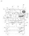
- FIG. 1 is a cross-sectional view of the image forming apparatus main body.
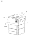
- FIG. 2 is a perspective view of the image forming apparatus main body.
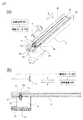
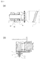
- 3A is a perspective view of the developer receiving device, and FIG. 3B is a cross-sectional view of the developer receiving device.
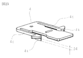
- 4A is a partially enlarged perspective view of the developer receiving device, FIG. 4B is a partially enlarged cross-sectional view of the developer receiving device, and
- FIG. 4C is a perspective view of the developer receiving portion.
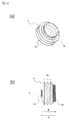
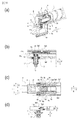
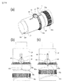
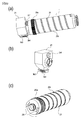
- 5A is an exploded perspective view of the developer supply container of the first embodiment, and FIG. 5B is a perspective view of the developer supply container of the first embodiment.
- FIG. 6 is a perspective view of the container body.
- FIG. 7A is a perspective view (upper surface side) of the upper flange portion
- FIG. 7B is a perspective view (lower surface side) of the upper flange portion
- 8A is a perspective view (upper surface side) of the lower flange portion of the first embodiment
- FIG. 8B is a perspective view (lower surface side) of the lower flange portion of the first embodiment
- FIG. It is a front view of a lower flange part.
- 9A is a top view of the shutter of the first embodiment
- FIG. 9B is a perspective view of the shutter of the first embodiment.
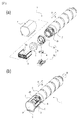
- 10A is a perspective view of the pump
- FIG. 10B is a front view of the pump.
- 11A is a perspective view (upper surface side) of the reciprocating member, and FIG.
- FIG. 11B is a perspective view (lower surface side) of the reciprocating member.
- 12A is a perspective view (upper surface side) of the cover
- FIG. 12B is a perspective view (lower surface side) of the cover.
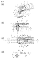
- 13A is a partial sectional perspective view of the developer supply / removal operation of the developer supply container of Example 1
- FIG. 13B is a partial sectional front view
- FIG. 13C is a top view
- FIG. 13D is a relationship between a lower flange portion and a developer receiving portion.
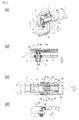
- FIG. 14A is a partial sectional perspective view of the developer supply / removal operation of the developer supply container according to the first embodiment
- FIG. 14B is a partial sectional front view
- FIG. 14C is a top view
- FIG. 14A is a partial sectional perspective view of the developer supply / removal operation of the developer supply container according to the first embodiment
- FIG. 14B is a partial sectional front view
- FIG. 14C is a top view
- FIG. 14D is a relationship between a lower flange portion and a developer receiving portion.
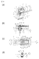
- FIGS. 15A and 15B are (a) a partial cross-sectional perspective view, (b) a partial cross-sectional front view, (c) a top view, and (d) a relationship between the lower flange portion and the developer receiving portion in the attaching / detaching operation of the developer supply container of Example 1.
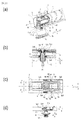
- FIG. 16A is a partial cross-sectional perspective view of the developer supply / removal operation of the developer supply container of Example 1
- FIG. 16B is a partial cross-sectional front view thereof
- FIG. 16C is a top view
- FIG. 16D is a relationship between a lower flange portion and a developer receiving portion.
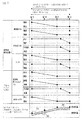
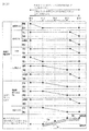
- FIG. 17 is a timing chart of the attaching / detaching operation of the developer supply container according to the first embodiment.
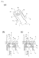
- FIG. 18, (a), (b), and (c) are views showing modifications of the engaging portion of the developer supply container.
- 19A is a perspective view of the developer receiving portion of the second embodiment
- FIG. 19B is a sectional view of the developer receiving portion of the second embodiment.
- 20A is a perspective view (upper surface side) of the lower flange portion of the second embodiment
- FIG. 20B is a perspective view (lower surface side) of the lower flange portion of the second embodiment.
- FIG. 21 is a perspective view of the shutter of Example 2
- FIG. 23 is a perspective view of a shutter according to the second embodiment.
- FIG. 24 is a front view of the developer supply container according to the second embodiment.
- 25A is a perspective view of a second modified example of the shutter
- FIGS. 25B and 25C are simplified views of the shutter and the developer receiving portion.
- 26A is a partial cross-sectional perspective view of the developer supply / removal operation of the developer supply container of Example 2, FIG.
- FIG. 26B is a partial cross-sectional front view
- FIG. 26C is a top view
- FIG. 26D is a relationship between the lower flange portion and the developer receiving portion.
- FIG. 27A is a partial sectional perspective view of the developer supply / removal operation of the developer supply container of Example 2
- FIG. 27B is a partial sectional front view
- FIG. 27C is a top view
- FIG. 27D is a relationship between the lower flange portion and the developer receiving portion.
- FIG. 28A is a partial sectional perspective view of the developer supply / removal operation of the developer supply container of Example 2
- FIG. 28B is a partial sectional front view
- FIG. 28C is a top view
- FIG. 28D is a relationship between the lower flange portion and the developer receiving portion.
- FIG. FIG. 29A is a partial sectional perspective view of the developer supply / removal operation of the developer supply container of Example 2
- FIG. 29B is a partial sectional front view
- FIG. 29C is a top view
- FIG. 29D is a relationship between a lower flange portion and a developer receiving portion.
- FIG. 30A is a partial sectional perspective view of the developer supply / removal operation of the developer supply container of Example 2
- FIG. 30B is a partial sectional front view
- FIG. 30C is a top view
- FIG. 30D is a relationship between the lower flange portion and the developer receiving portion.
- FIG. 31A is a partial sectional perspective view of the developer supply / removal operation of the developer supply container of Example 2
- FIG. 31A is a partial sectional perspective view of the developer supply / removal operation of the developer supply container of Example 2
- FIG. 31B is a partial sectional front view
- FIG. 31C is a top view
- FIG. 31D is a relationship between a lower flange portion and a developer receiving portion.
- FIG. FIG. 32 is a timing chart of the attaching / detaching operation of the developer supply container according to the second embodiment. 33, (a) a partially enlarged view of the developer supply container of Example 3, and (b) a partially enlarged sectional view of the developer supply container and developer receiving apparatus of Example 3.
- FIG. 34 is an operation diagram of the developer receiving portion with respect to the lower flange portion in the operation of taking out the developer supply container of the third embodiment.
- FIG. 35 is a view showing a comparative example of the developer supply container.
- FIG. 36 is a cross-sectional view showing an example of an image forming apparatus.
- FIG. 37 is a perspective view showing the image forming apparatus of FIG.
- FIG. 38 is a perspective view showing an embodiment of the developer receiving apparatus.
- FIG. 39 is a perspective view of the developer receiving apparatus of FIG. 38 viewed from another angle.
- 40 is a cross-sectional view of the developer receiving apparatus of FIG.
- FIG. 41 is a block diagram illustrating a functional configuration of the control device.
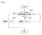
- FIG. 42 is a flowchart for explaining the flow of the replenishment operation.
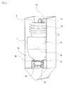
- FIG. 43 is a cross-sectional view showing a mounted state of the developer receiving apparatus and the developer supply container without the hopper.
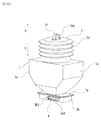
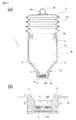
- FIG. 44 is a perspective view showing an embodiment of the developer supply container.
- FIG. 45 is a sectional view showing an embodiment of the developer supply container.
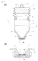
- FIG. 46 is a cross-sectional view showing a developer supply container in which a discharge port and an inclined surface are connected.
- 47A is a perspective view of a blade used in a device for measuring fluidity energy
- FIG. 47B is a schematic diagram of the measuring device.
- FIG. 48 is a graph showing the relationship between the diameter of the discharge port and the discharge amount.
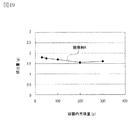
- FIG. 49 is a graph showing the relationship between the filling amount and the discharge amount in the container.
- FIG. 50 is a perspective view showing a part of the operating state of the developer supply container and the developer receiving apparatus.
- FIG. 51 is a perspective view showing a developer supply container and a developer receiving device.
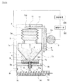
- FIG. 52 is a cross-sectional view showing a developer supply container and a developer receiving device.
- FIG. 53 is a cross-sectional view showing a developer supply container and a developer receiving device.
- FIG. 54 is a diagram illustrating a transition of the internal pressure of the developer accommodating portion according to the fourth embodiment.
- 55A is a block diagram showing a developer supply system (Example 4) used in the verification experiment, and
- FIG. 55B is a schematic view showing a phenomenon occurring in the developer supply container.
- 56A is a block diagram showing a developer supply system (comparative example) used in the verification experiment, and
- FIG. 56B is a schematic diagram showing a phenomenon occurring in the developer supply container.
- FIG. 57 is a perspective view illustrating a developer supply container of Example 5.
- FIG. 58 is a cross-sectional view of the developer supply container of FIG.
- FIG. 59 is a perspective view showing a developer supply container of Embodiment 6.
- FIG. 60 is a perspective view showing a developer supply container of Example 6.
- FIG. 61 is a perspective view showing a developer supply container of Embodiment 6.
- FIG. 62 is a perspective view showing a developer supply container of Example 7.
- FIG. 63 is a cross-sectional perspective view showing the developer supply container of Example 7.
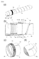
- FIG. 64 is a partial cross-sectional view showing a developer supply container of Example 7.
- 65 is a cross-sectional view showing another embodiment of Example 7.
- FIG. 66 (a) is a front view of the mounting portion, and (b) is a partially enlarged perspective view inside the mounting portion.
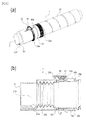
- FIG. 67 (a) is a perspective view showing a developer supply container according to Embodiment 8
- FIG. 67 (b) is a perspective view showing the state around the discharge port
- FIG. 67 (c) and (d) show development of the developer supply container. It is the front view and sectional drawing which show the state with which the mounting part of the agent acceptance apparatus was mounted
- FIG. 68 (a) is a partial perspective view showing a developer accommodating portion according to Embodiment 8
- (b) is a sectional perspective view showing a developer supply container
- (c) is a sectional view showing an inner surface of the flange portion. It is.
- (D) is sectional drawing which shows a developer supply container.
- FIG. 70 is a development view showing the cam groove shape of the developer supply container.
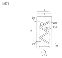
- FIG. 71 is a development view showing an example of the cam groove shape of the developer supply container.
- FIG. 72 is a development view showing an example of the cam groove shape of the developer supply container.
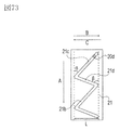
- FIG. 73 is a development view showing an example of the cam groove shape of the developer supply container.
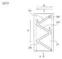
- FIG. 74 is a development view showing an example of the cam groove shape of the developer supply container.
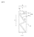
- FIG. 75 is a development view showing an example of the cam groove shape of the developer supply container.
- FIG. 76 is a development view showing an example of the cam groove shape of the developer supply container.
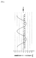
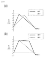
- FIG. 77 is a graph showing changes in the internal pressure of the developer supply container.
- 78A is a perspective view illustrating the configuration of a developer supply container according to Embodiment 9
- FIG. 78B is a cross-sectional view illustrating the configuration of the developer supply container.
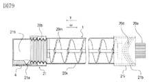
- FIG. 79 is a cross-sectional view illustrating the configuration of the developer supply container according to the tenth embodiment.
- 80 (a) is a perspective view showing a configuration of a developer supply container according to Example 11, (b) is a sectional view of the developer supply container, (c) is a perspective view showing a cam gear, and (d) is a perspective view.
- FIG. 81A is a perspective view illustrating the configuration of a developer supply container according to Embodiment 12, and FIG. 81B is a cross-sectional view illustrating the configuration of the developer supply container.
- 82A is a perspective view illustrating the configuration of a developer supply container according to Embodiment 13
- FIG. 82B is a cross-sectional view illustrating the configuration of the developer supply container.
- 83 (a) to (d) are diagrams showing the operation of the drive conversion mechanism.
- FIG. 84 (a) is a perspective view showing the configuration of the developer supply container according to Embodiment 14, and (b) and (c) are views showing the operation of the drive conversion mechanism.
- FIG. 85A is a cross-sectional perspective view showing a configuration of a developer supply container according to Embodiment 15, and FIGS. 85B and 85C are cross-sectional views showing an intake / exhaust operation by the pump unit.
- 86A is a perspective view showing another example of the developer supply container according to Embodiment 15, and FIG. 86B is a view showing a coupling portion of the developer supply container.
- 87 (a) is a cross-sectional perspective view showing the configuration of the developer supply container according to Embodiment 16, and FIGS. 87 (b) and (c) are cross-sectional views showing the state of the intake / exhaust operation by the pump unit.
- 88A is a perspective view showing the configuration of a developer supply container according to Embodiment 17, FIG.
- FIG. 88B is a cross-sectional perspective view showing the configuration of the developer supply container
- FIG. 88C is an end portion of the developer container.
- (e) is a figure which shows the mode at the time of the intake / exhaust operation
- (a) is a perspective view showing a configuration of a developer supply container according to Embodiment 18,
- (b) is a perspective view showing a configuration of a flange portion, and
- (c) is a perspective view showing a configuration of a cylindrical portion. is there.
- 90 (a) and 90 (b) are cross-sectional views showing the state of the intake / exhaust operation by the pump portion of the developer supply container according to the eighteenth embodiment.
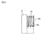
- FIG. 91 is a diagram illustrating the configuration of the pump portion of the developer supply container according to the eighteenth embodiment.
- 92 (a) and 92 (b) are schematic cross-sectional views showing the configuration of the developer supply container according to the nineteenth embodiment.
- 93, (a) and (b) are perspective views showing a cylindrical portion and a flange portion of the developer supply container according to the twentieth embodiment.
- FIG. 94, (a) and (b) are related to the twentieth embodiment.
- FIG. 4 is a partial cross-sectional perspective view of a developer supply container.
- FIG. 95 is a time chart illustrating the relationship between the operating state of the pump and the opening / closing timing of the rotary shutter according to the twentieth embodiment.
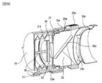
- FIG. 96 is a partial cross-sectional perspective view showing the developer supply container according to Embodiment 21.
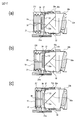
- 97 (a) to (c) are partial cross-sectional views illustrating the operating state of the pump unit according to the twenty-first embodiment.
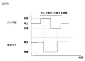
- FIG. 98 is a time chart showing the relationship between the operating state of the pump according to Example 21 and the opening / closing timing of the gate valve.
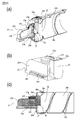
- FIG. 99 (a) is a partial perspective view of a developer supply container according to Embodiment 22, (b) is a perspective view of a flange portion, and (c) is a cross-sectional view of the developer supply container.
- FIG. 99 (a) is a partial perspective view of a developer supply container according to Embodiment 22
- b is a perspective view of a flange portion
- (c) is a cross-sectional view of the developer supply container.
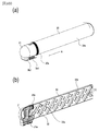
- FIG. 100 (a) is a perspective view showing a configuration of a developer supply container according to Embodiment 23, and (b) is a cross-sectional perspective view of the developer supply container.
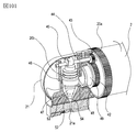
- FIG. 101 is a partial cross-sectional perspective view illustrating the configuration of the developer supply container according to the twenty-third embodiment.
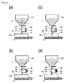
- FIG. 102 (a) to (d) are sectional views of a developer supply container and a developer receiving apparatus according to a comparative example, and are diagrams for explaining the flow of the developer supply process.
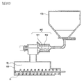
- FIG. 103 is a cross-sectional view showing a developer supply container and a developer receiving device according to another comparative example.
- image forming device As an example of an image forming apparatus equipped with a developer receiving device in which a developer supply container (so-called toner cartridge) is detachably mounted (removable), an electrophotographic copying machine (electrophotographic image forming apparatus) is adopted. ) Will be described with reference to FIG.
- reference numeral 100 denotes a copying machine main body (hereinafter referred to as an image forming apparatus main body or an apparatus main body).
- a document 101 is placed on the document glass 102.
- an electrostatic image is formed by forming an optical image corresponding to the image information of the original on an electrophotographic photosensitive member 104 (hereinafter referred to as a photosensitive member) by a plurality of mirrors M and lenses Ln of the optical unit 103.
- This electrostatic latent image is visualized by a dry developing device (one component developing device) 201 using toner (one component magnetic toner) as a developer (dry powder).
- toner one component magnetic toner
- the one-component nonmagnetic toner is supplied as a developer.
- the nonmagnetic toner is replenished as the developer.
- the developer may be replenished together with the magnetic carrier as well as the non-magnetic toner.
- the developing device 201 shown in FIG. 1 develops the electrostatic latent image formed on the photoconductor 104 as the image carrier based on the image information of the document 101 using toner as a developer. Is.
- the developing device 201 is provided with a developing roller 201f in addition to the developer hopper 201a.
- the developer hopper 201a is provided with a stirring member 201c for stirring the developer supplied from the developer supply container 1.
- the developer stirred by the stirring member 201c is sent to the transport member 201e side by the transport member 201d.
- the developer sequentially conveyed by the conveying members 201e and 201b is carried on the developing roller 201f and finally supplied to the developing unit with the photoconductor 104.
- the toner as the developer is supplied from the developer supply container 1 to the developing device 201.
- the toner and carrier as the developer may be supplied from the developer supply container 1. Absent.
- Reference numerals 105 to 108 denote cassettes for storing recording media (hereinafter also referred to as “sheets”) S.
- sheets recording media
- the recording medium is not limited to paper, and can be appropriately used and selected, for example, an OHP sheet.
- one sheet S conveyed by the feeding / separating devices 105A to 108A is conveyed to the registration roller 110 via the conveying unit 109, and the rotation of the photosensitive member 104 and the scanning timing of the optical unit 103 are synchronized. Then transport.
- Reference numerals 111 and 112 denote a transfer charger and a separation charger.
- the image formed by the developer formed on the photosensitive member 104 is transferred to the sheet S by the transfer charger 111.
- the sheet S to which the developer image (toner image) has been transferred is separated from the photoreceptor 104 by the separation charger 112.
- the sheet S conveyed by the conveying unit 113 is fixed on the developer image on the sheet by heat and pressure in the fixing unit 114, and then passes through the discharge reversing unit 115 in the case of single-sided copying.
- the paper is discharged to the discharge tray 117 by the roller 116.
- the sheet S passes through the discharge reversing unit 115 and is once discharged out of the apparatus by the discharge roller 116. Thereafter, the trailing edge of the sheet S passes through the flapper 118, and is controlled by the flapper 118 at the timing when it is still nipped by the discharge roller 116, and is reversely rotated to be conveyed into the apparatus again. . Further, after being conveyed to the registration roller 110 via the re-feed conveyance units 119 and 120, the sheet is discharged to the discharge tray 117 along the same path as in the case of single-sided copying.
- an image forming process device such as a developing unit 201 as a developing unit, a cleaner unit 202 as a cleaning unit, and a primary charger 203 as a charging unit is installed around the photosensitive member 104.
- the developing unit 201 develops the developer by attaching a developer to the electrostatic latent image formed on the photosensitive member 104 by the optical unit 103 based on the image information of the document 101.
- the primary charger 203 is for uniformly charging the surface of the photoconductor in order to form a desired electrostatic image on the photoconductor 104.
- the cleaner unit 202 is for removing the developer remaining on the photosensitive member 104.
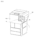
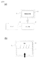
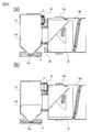
- FIG. 2 is an external view of the image forming apparatus.
- the developer supply container 1 When the operator opens the replacement cover 40 which is a part of the exterior cover of the image forming apparatus, a part of the developer receiving device 8 described later appears. Then, by inserting (attaching) the developer supply container 1 into the developer receiving apparatus 8, the developer supply container 1 is set in a state where the developer can be supplied to the developer receiving apparatus 8. On the other hand, when the operator replaces the developer supply container 1, the developer supply container 1 is taken out (detached) from the developer receiving device 8 by performing an operation reverse to that at the time of mounting, and a new developer supply is performed. What is necessary is just to set the container 1 again.
- the replacement cover 40 is a dedicated cover for attaching and detaching (replacing) the developer supply container 1 and is opened and closed for attaching and detaching the developer supply container 1.
- the maintenance of the apparatus main body 100 is performed by opening and closing the front cover 100c.
- the replacement cover 40 and the front cover 100c may be integrated.
- the replacement of the developer supply container 1 and the maintenance of the apparatus main body 100 are performed by opening and closing the integrated cover (not shown). Is done. (Developer receiving device)
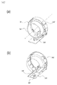
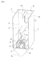
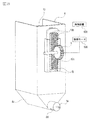
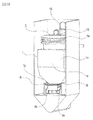
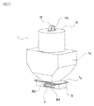
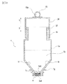
- FIGS. 3A is a schematic perspective view of the developer receiving device 8
- FIG. 3B is a schematic cross-sectional view of the developer receiving device 8.
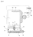
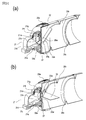
- FIG. 4A is a partially enlarged perspective view of the developer receiving device 8
- FIG. 4B is a partially enlarged cross-sectional view of the developer receiving device 8
- FIG. 4C is a perspective view of the developer receiving portion 11.
- the developer receiving device 8 is provided with a mounting portion (mounting space) 8f on which the developer supply container 1 is detachably mounted (detachable).
- a developer receiving portion 11 for receiving the developer discharged from a discharge port 3a4 (see FIG. 7B) of the developer supply container 1 described later is provided.
- the developer receiving unit 11 is attached to the developer receiving device 8 so as to be movable (displaceable) in the vertical direction. Further, as shown in FIG.
- the developer receiving portion 11 is provided with a main body seal 13, and a developer receiving port 11a is formed at the center thereof.
- the main body seal 13 is made of an elastic body, foam, or the like, and is in close contact with an opening seal 3a5 (see FIG. 7B) having a discharge port 3a4 of the developer supply container 1 in part, and discharged from the discharge port 3a4.
- the developed developer is prevented from leaking out of the developer receiving port 11a which is the developer transport path.
- the diameter of the developer receiving port 11a is substantially the same as the diameter of the discharge port 3a4 of the developer supply container 1 in order to prevent the inside of the mounting portion 8f from being contaminated by the developer as much as possible. It is desirable to make it a little larger.
- the diameter of the developer receiving port 11a is smaller than the diameter of the discharging port 3a4, the developer discharged from the developer supply container 1 adheres to the upper surface of the main body seal 13 in which the developer receiving port 11a is formed. This is because the adhered developer is transferred to the lower surface of the developer supply container 1 during the loading and unloading operation of the developer supply container 1 and contributes to contamination by the developer. Further, when the developer transferred to the developer supply container 1 is scattered to the mounting portion 8f, the mounting portion 8f is soiled by the developer.
- the diameter of the developer receiving port 11a is considerably larger than the diameter of the discharge port 3a4, the area where the developer scattered from the developer receiving port 11a adheres to the vicinity of the discharge port 3a4 formed in the opening seal 3a5 becomes large. . That is, it is not preferable because the area of the stain due to the developer in the developer supply container 1 becomes large. Therefore, in view of the above circumstances, it is desirable that the diameter of the developer receiving port 11a is approximately the same diameter to about 2 mm larger than the diameter of the discharge port 3a4. In this example, since the diameter of the discharge port 3a4 of the developer supply container 1 is a fine port (pin hole) having a diameter of about 2 mm, the diameter of the developer receiving port 11a is set to about 3 mm.
- the developer receiving portion 11 is urged downward in the vertical direction by the urging member 12. That is, the developer receiving portion 11 moves against the urging force of the urging member 12 when moving upward in the vertical direction.
- the developer receiving device 8 is provided with a sub hopper 8c for temporarily storing the developer as shown in FIG.
- a conveying screw 14 for conveying the developer to the developer hopper 201a, which is a part of the developing device 201, and an opening 8d communicating with the developer hopper 201a are provided.
- the developer receiving port 11a is in a closed state so that foreign matter and dust do not enter the sub hopper 8c when the developer supply container 1 is not mounted.
- the developer receiving port 11a is closed by the main body shutter 15 when the developer receiving portion 11 is not moved vertically upward.
- the developer receiving portion 11 moves vertically upward (in the direction of arrow E) toward the developer supply container 1 from the position shown in FIG.
- FIG. 15B the developer receiving port 11a and the main body shutter 15 are separated from each other, and the developer receiving port 11a is opened.
- an engaging portion 11b is provided on the side surface of the developer receiving portion 11 as shown in FIG.
- the engaging portion 11b is directly engaged with and guided by engaging portions 3b2 and 3b4 (see FIG. 8) provided on the developer supply container 1 side, which will be described later, so that the developer receiving portion 11 is supplied with developer. It is lifted upward in the vertical direction toward the container 1.
- the mounting portion 8f of the developer receiving device 8 is provided with an insertion guide 8e for guiding the developer supply container 1 in the attaching / detaching direction.
- the mounting direction of the developer supply container 1 is configured to be an arrow A direction. It should be noted that the direction in which the developer supply container 1 is taken out (detachment direction) is opposite to the arrow A direction (arrow B direction). Further, as shown in FIG.
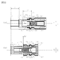
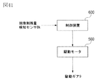
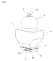
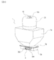
- the developer receiving device 8 has a drive gear 9 that functions as a drive mechanism for driving the developer supply container 1. Further, the drive gear 9 has a function of applying a rotational driving force to the developer supply container 1 in a state where the rotational driving force is transmitted from the driving motor 500 via the driving gear train and is set in the mounting portion 8f. Have. Further, as shown in FIGS. 3 and 4, the drive motor 500 is configured such that its operation is controlled by a control device (CPU) 600. (Developer supply container) Next, the developer supply container 1 will be described with reference to FIG. 5A is a schematic exploded perspective view of the developer supply container 1, and FIG. 5B is a schematic perspective view of the developer supply container 1. FIG. For convenience of explanation, FIG.
- FIG. 5B shows a cross section of a cover 7 described later.
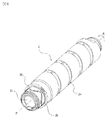
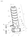
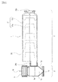
- the developer supply container 1 mainly includes a container body 2, a flange part 3, a shutter 4, a pump part 5, a reciprocating member 6, and a cover 7.
- the developer replenishing container 1 replenishes the developer receiving device 8 with the developer by rotating in the direction of arrow R around the rotation axis P shown in FIG. 5B in the developer receiving device 8.
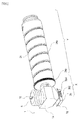
- FIG. 6 is a perspective view of the container body 2. As shown in FIG.
- the container main body (developer transport chamber) 2 mainly includes a developer accommodating portion 2 c that accommodates the developer therein, and the container main body 2 rotates in the arrow R direction with respect to the rotation axis P.
- a conveying groove 2a conveying portion
- the cam groove 2 b and the drive receiving portion (drive input portion) 2 d that receives drive from the main body side are integrated over the entire circumference of the outer peripheral surface on one end surface side of the container main body 2. Is formed.
- the cam groove 2b and the drive receiving portion 2d are formed integrally with the container main body 2.
- the cam groove 2b or the drive receiving portion 2d is formed as a separate body, and the container main body is formed.
- the structure attached to 2 may be sufficient.
- toner having a volume average particle diameter of 5 ⁇ m to 6 ⁇ m is accommodated in the developer accommodating portion 2 c of the container body 2 as the developer.
- the developer accommodating portion (developer accommodating space) 2c is a combination of not only the container main body 2 but also the internal space of the container main body 2, the flange portion 3 and the pump portion 5 described later. (Flange part) Then, the flange part 3 is demonstrated using FIG. As shown in FIG.
- the flange portion (developer discharge chamber) 3 is attached so as to be rotatable relative to the container body 2 and the rotation shaft P, and the developer supply container 1 is attached to the developer receiving device 8.
- the holding part 8f (see FIG. 3A) is held so as not to rotate in the direction of arrow R.
- a discharge port 3a4 (see FIG. 7) is provided in part.
- the flange portion 3 is composed of an upper flange portion 3a and a lower flange portion 3b in consideration of assemblability.
- a cover 7 is assembled.
- the pump part 5 is screw-joined to the one end side of the upper flange part 3a, and the container main body 2 is joined to the other end side via a seal member (not shown).
- the reciprocating member 6 is disposed so as to sandwich the pump portion 5, and the engaging protrusion 6 b (see FIG. 11) provided on the reciprocating member 6 is fitted into the cam groove 2 b of the container body 2.
- a shutter 4 is incorporated in the gap between the upper flange portion 3a and the lower flange portion 3b.
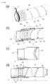
- FIG. 7 shows the upper flange portion 3a.
- FIG. 7A is a perspective view of the upper flange portion 3a viewed from an obliquely upward direction
- FIG. 7B is a perspective view of the upper flange portion 3a viewed from an obliquely downward direction.
- the upper flange portion 3a includes a pump joint portion 3a1 (screw not shown) shown in FIG. 7A to which the pump portion 5 is screwed and a container body joint portion shown in FIG.
- FIG. 7B to which the container main body 2 is joined. 3a2 and a reservoir 3a3 shown in FIG. 7A for storing the developer conveyed from the container main body 2. Further, as shown in FIG. 7B, a circular discharge port (opening) 3a4 for discharging the developer in the storage unit 3a3 described above to the developer receiving device 8 and a developer receiving unit 11 described later are connected.
- An opening seal 3a5 having a part 3a6 formed in part is provided.
- the opening seal 3a5 is affixed to the lower surface of the upper flange portion 3a with double-sided tape, and is sandwiched between a shutter 4 and an upper flange portion 3a, which will be described later, to prevent leakage of the developer from the discharge port 3a4. .
- the discharge port 3a4 is provided in the opening seal 3a5 which is a separate body from the upper flange portion 3a.
- the discharge port 3a4 may be provided directly in the upper flange portion 3a.
- the diameter of the discharge port 3a4 is such that the developer is unnecessarily discharged when the shutter 4 is opened / closed due to the attaching / detaching operation of the developer supply container 1 to / from the developer receiving device 8, and the periphery is developed. In order to prevent contamination with the agent as much as possible, it is set to about ⁇ 2 mm.
- the discharge port 3a4 is provided on the lower surface of the developer supply container 1, that is, on the lower surface side of the upper flange portion 3a.
- the developer supply container 1 is attached to and detached from the developer receiving device 8.
- the connection configuration shown in this example can be applied as long as it is provided on a side surface other than the upstream end surface or the downstream end surface in the direction.
- the position on the side surface of the discharge port 3a4 can be set in view of individual product circumstances. The details of the connection operation between the developer supply container 1 and the developer receiving device 8 in this example will be described later. (Lower flange)
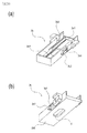
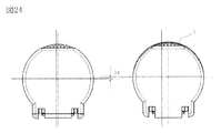
- FIG. 8 shows the lower flange portion 3b.
- FIG. 8A is a perspective view of the lower flange portion 3b as viewed obliquely from above
- FIG. 8B is a perspective view of the lower flange portion 3b as viewed from obliquely downward
- FIG. 8C is a front view.
- the lower flange portion 3b includes a shutter insertion portion 3b1 into which the shutter 4 (see FIG. 9) is inserted.
- the lower flange portion 3b has engaging portions 3b2 and 3b4 that can engage with the developer receiving portion 11 (see FIG. 4).
- the engaging portions 3b2 and 3b4 are connected to the developer replenishing container 1 in accordance with the mounting operation of the developer replenishing container 1 so that the developer replenishing container 1 and the developer receiving portion 11 can be replenished with each other.
- the receiving portion 11 is displaced toward the developer supply container 1.
- the engaging portions 3b2 and 3b4 are designed so that the developer receiving portion 11 develops so that the connection state between the developer supplying container 1 and the developer receiving portion 11 is cut off with the operation of taking out the developer supplying container 1. It is guided so as to be displaced in a direction away from the medicine supply container 1.
- the first engaging portion 3b2 is a developer receiving portion in a direction crossing the mounting direction of the developer supply container 1 so that the developer receiving portion 11 is opened. 11 is displaced.
- the first engaging portion 3b2 is a connecting portion 3a6 in which the developer receiving portion 11 is formed on a part of the opening seal 3a5 of the developer supply container 1 in accordance with the mounting operation of the developer supply container 1.
- the developer receiving portion 11 is displaced toward the developer supply container 1 so as to be in a connected state.
- the first engaging portion 3b2 extends in a direction intersecting with the mounting direction of the developer supply container 1.
- the first engaging portion 3b2 crosses the direction in which the developer supply container 1 is taken out so that the developer receiving portion 11 is resealed with the removal operation of the developer supply container 1.
- the developer receiving portion 11 is guided so as to be displaced.
- the first engagement portion 3b2 is connected to the developer receiving portion 11 and the connecting portion 3a6 of the developer replenishing container 1 so that the connection state between the developer receiving portion 11 and the developer replenishing container 1 is disconnected.
- the developer receiving portion 11 is guided so as to be separated vertically from the developer supply container 1.
- the second engaging portion 3b4 is connected to the developer supply container 1 so that the discharge port 3a4 communicates with the developer receiving port 11a of the developer receiving unit 11 in accordance with the mounting operation of the developer supplying container 1.
- the main body seal 13 and the opening seal 3a5 are maintained in a state in which the main body seal 13 and the opening seal 3a5 are connected while the developer 1 moves relative to the shutter 4 described later, that is, while the developer receiving port 11a moves from the connecting portion 3a6 to the discharge port 3a4.
- the second engaging portion 3 b 4 is an extending portion that extends in a direction parallel to the mounting direction of the developer supply container 1. Further, the second engaging portion 3b4 moves during the relative movement of the developer supply container 1 with respect to the shutter 4 so that the discharge port 3a4 is resealed as the developer supply container 1 is taken out.
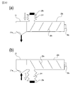
- the first engagement portion 3b2 preferably has a configuration having an inclined surface (inclined portion) that intersects with the direction in which the developer supply container 1 is inserted, as shown in FIG. It is not limited to a typical inclined surface.
- the shape of the first engagement portion 3b2 may be, for example, a curved inclined surface as shown in FIG. Furthermore, as shown in FIG. 18B, a stepped shape including a parallel surface and an inclined surface may be used. The shape of the first engaging portion 3b2 is limited to the shape shown in FIGS.
- the inclination angle of the first engaging portion 3b2 with respect to the loading / unloading direction of the developer supply container 1 is preferably set to about 10 to 50 degrees in view of various circumstances described later. In this example, the angle is about 40 degrees.
- FIG.18 (c) it is good also as 1st engaging part 3b2 and 2nd engaging part 3b4, and making it a uniform linear inclined surface.
- the first engaging portion 3 b 2 displaces the developer receiving unit 11 in a direction crossing the mounting direction of the developer supply container 1, and the main body seal 13.
- the concealing unit 3b6 is connected. Thereafter, while the main body seal 13 and the opening seal 3a5 are compressed, the developer receiving portion 11 is displaced until the developer receiving port 11a and the discharge port 3a4 communicate with each other.
- the first engaging portion 3b2 when used, the relationship between the first engaging portion 3b2 and the engaging portion 11b of the developer receiving portion 11 at the mounting completion position of the developer supply container 1 to be described later.
- the force in the B direction (see FIG. 16A) always acts on the developer supply container 1.
- the developer replenishing container 1 is provided with the second engaging portion 3b4 described above so that the force in the B direction does not act on the developer replenishing container 1 at the mounting completion position. It is desirable that the connection state of the opening seal 3a5 is stably maintained.
- the first engaging portion 3b2 of FIG. 18C is a uniform linear inclined surface, for example, as in FIGS. 18A and 18B, a curved shape or a stepped shape is used.
- a straight inclined surface is desirable from the viewpoint of making the operation force associated with the loading and unloading operation of the developer supply container 1 constant.
- the lower flange portion 3b restricts or allows elastic deformation of the support portion 4d of the shutter 4 to be described later in accordance with the operation of mounting the developer supply container 1 on the developer receiving device 8 or taking it out of the developer receiving device 8.
- FIG. 9A is a top view of the shutter 4
- FIG. 9B is a perspective view of the shutter 4 as viewed obliquely from above.
- the shutter 4 is movably provided in the developer supply container 1, and opens and closes the discharge port 3 a 4 when the developer supply container 1 is attached and detached.
- the shutter 4 When the developer supply container 1 is not mounted on the mounting portion 8 f of the developer receiving device 8, the shutter 4 includes a developer sealing portion 4 a that prevents leakage of the developer from the discharge port 3 a 4, and a developer sealing A sliding surface 4i that slides on the shutter insertion portion 3b1 of the lower flange portion 3b is provided on the back side (back side) of the portion 4a.
- the shutter 4 has shutter stoppers 8a and 8b of the developer receiving device 8 in accordance with the loading / unloading operation of the developer supply container 1 so that the developer supply container 1 can move relative to the shutter 4. It has stopper portions (holding portions) 4b and 4c held by (see FIG. 4A).
- the first stopper portion 4b is engaged with the first shutter stopper portion 8a of the developer receiving device 8 during the mounting operation of the developer supply container 1, and the developer of the shutter 4 is engaged.
- the position with respect to the receiving device 8 is fixed.
- the second stopper portion 4 c engages with the second shutter stopper portion 8 b of the developer receiving device 8 during the operation of taking out the developer supply container 1.
- the shutter 4 has a support portion 4d that supports the stopper portions 4b and 4c so that they can be displaced.
- the support portion 4d extends from the developer sealing portion 4a and is elastically deformable so as to displaceably support the first stopper portion 4b and the second stopper portion 4c.
- the first stopper portion 4b is inclined so that the angle ⁇ formed by the first stopper portion 4b and the support portion 4d is an acute angle.
- the second stopper portion 4c is inclined so that the angle ⁇ formed by the second stopper portion 4c and the support portion 4d becomes an obtuse angle.
- the entire developer sealing portion 4a may have a shape corresponding to the amount of contact between the lock protrusion 4e and the opening seal 3a5. In this case, unlike the case where the lock protrusion 4e is provided, the shutter 4 moves. Since the dynamic frictional force with the opening seal 3a5 increases, the operating force when the developer supply container 1 is attached to the developer receiving device 8 is increased, which is preferable in terms of usability. Therefore, a configuration in which the lock protrusion 4e is provided in part as in this example is desirable.
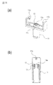
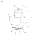
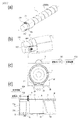
- the pump unit 5 is shown in FIG. FIG. 10A is a perspective view of the pump unit 5, and FIG. 10B is a front view of the pump unit 5.
- the pump unit 5 operates so that the internal pressure of the developer storage unit 2c is alternately and repeatedly switched between a state lower than atmospheric pressure and a state higher than the atmospheric pressure by the driving force received by the drive receiving unit (drive input unit) 2d. It is.
- the above-described pump unit 5 is provided in a part of the developer supply container 1 in order to stably discharge the developer from the small discharge port 3a4.
- the pump unit 5 is a variable volume pump whose volume can be varied.
- the pump portion 5 of this example has a bellows-like stretchable portion (bellows portion, stretchable member) 5a in which a “mountain fold” portion and a “valley fold” portion are periodically formed. Is provided.
- the stretchable part 5a can be folded in the direction of the arrow B or extended in the direction of the arrow A along the crease (based on the crease). Therefore, when the bellows-like pump unit 5 is employed as in this example, the variation in the volume change amount with respect to the expansion / contraction amount can be reduced, so that a stable volume variable operation can be performed.
- a polypropylene resin (hereinafter abbreviated as PP) is used as the material of the pump unit 5, but is not limited thereto.
- PP polypropylene resin
- any material may be used as long as it is capable of exhibiting an expansion / contraction function and capable of changing the internal pressure of the developer accommodating unit by changing the volume.
- ABS acrylonitrile / butadiene / styrene copolymer
- polystyrene polyester, polyethylene or the like may be formed thin. It is also possible to use rubber or other elastic materials.
- the junction part 5b is provided in the opening end side of the pump part 5 so that it can join with the upper flange part 3a.
- FIG. 11A is a perspective view of the reciprocating member 6 viewed from an obliquely upward direction
- FIG. 11B is a perspective view of the reciprocating member 6 viewed from an obliquely downward direction.
- the reciprocating member 6 has a pump engaging portion 6a that engages with the reciprocating member engaging portion 5c provided in the pump portion 5 in order to vary the volume of the pump portion 5 described above. I have. Further, as shown in FIGS. 11A and 11B, the reciprocating member 6 includes an engaging protrusion 6b that is fitted into the cam groove 2b (see FIG. 5) when assembled. The engaging protrusion 6b is provided at the tip of the arm 6c extending from the vicinity of the pump engaging portion 6a. The reciprocating member 6 is restricted from rotational displacement about the axis P (see FIG. 5B) of the arm 6c by a reciprocating member holding portion 7b (see FIG. 12) of the cover 7 described later.
- FIG. 12 shows the cover 7.
- FIG. 12A is a perspective view of the cover 7 viewed from an obliquely upward direction, and FIG.
- FIG. 12B is a perspective view of the cover 7 viewed from an obliquely downward direction.
- the cover 7 is provided as shown in FIG. 5B for the purpose of improving the appearance of the developer supply container 1 and protecting the reciprocating member 6 and the pump unit 5.
- the cover 7 is integrated with the upper flange portion 3a and the lower flange portion 3b by a mechanism (not shown) so as to cover the entire flange portion 3, the pump portion 5, and the reciprocating member 6 as shown in FIG. Provided.
- the cover 7 is provided with a guide groove 7a guided by an insertion guide 8e (see FIG. 3A) provided in the developer receiving device 8.
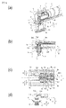
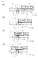
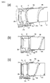
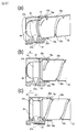
- FIG. . 13A to 16D show the vicinity of the connecting portion between the developer supply container 1 and the developer receiving device 8, respectively.
- FIG. 16 is a partial cross-sectional perspective view
- (b) is a partial cross-sectional front view
- (c) is a top view of (b)
- (d) is a view of the lower flange portion 3b and the developer receiving portion 11.
- FIG. 17 is a timing chart showing a list of operations for each element related to the mounting operation of the developer supply container 1 shown in FIGS. 13 to 16 to the developer receiving device 8.
- the mounting operation refers to an operation until the developer can be supplied from the developer supply container 1 to the developer receiving device 8.
- FIG. 13 shows a connection start position (first position) between the first engaging portion 3 b 2 of the developer supply container 1 and the engaging portion 11 b of the developer receiving portion 11. As shown in FIG.
- the developer supply container 1 is inserted into the developer receiving device 8 in the direction of arrow A.
- the first stopper portion 4b of the shutter 4 abuts on the first shutter stopper portion 8a of the developer receiving device 8, and the position of the shutter 4 with respect to the developer receiving device 8 is fixed. Is done. In this state, the positions of the lower flange portion 3b and upper flange portion 3a of the flange portion 3 and the shutter 4 are not relatively displaced, and the discharge port 3a4 is reliably sealed by the developer sealing portion 4a of the shutter 4. Yes. Further, as shown in FIG. 13 (b), the connection portion 3 a 6 of the opening seal 3 a 5 is concealed by the shutter 4.
- FIG. 13 (b) the connection portion 3 a 6 of the opening seal 3 a 5 is concealed by the shutter 4.
- the support portion 4d of the shutter 4 is displaceable in the directions of arrows C and D because the regulating rib 3b3 of the lower flange portion 3b does not enter the inside of the support portion 4d.
- the first stopper portion 4b is inclined so that the angle ⁇ (see FIG. 9A) formed with the support portion 4d is an acute angle, and the first shutter stopper portion is corresponding to the angle ⁇ . 8a is also inclined.
- the inclination angle ⁇ described above is configured to be about 80 degrees.
- the first stopper portion 4b receives a reaction force in the direction of the arrow B from the first shutter stopper portion 8a, and the support portion 4d tends to be displaced in the direction of arrow D. That is, since the first stopper portion 4b of the shutter 4 is displaced to the side where the developer receiving device 8 is engaged with the first shutter stopper portion 8a, the position of the shutter 4 is shifted to the developer receiving device 8. It is securely held against. Further, as shown in FIG. 13D, the engaging portion 11b of the developer receiving portion 11 and the first engaging portion 3b2 of the lower flange portion 3b are in a positional relationship at which engagement begins.
- the developer receiving portion 11 is not displaced from the initial position and is separated from the developer supply container 1. More specifically, as shown in FIG. 13B, the developer receiving portion 11 is separated from the connection portion 3a6 formed in a part of the opening seal 3a5. Further, as shown in FIG. 13B, the developer receiving port 11a is sealed by the main body shutter 15. Further, the drive gear 9 of the developer receiving device 8 and the drive receiving portion 2d of the developer supply container 1 are not connected, and the drive is not transmitted.
- the separation distance between the developer receiving portion 11 and the developer supply container 1 was set to be about 2 mm.
- the separation distance is small, for example, when the distance is about 1.5 mm or less, the surface of the main body seal 13 provided in the developer receiving portion 11 due to an air flow locally generated by the loading and unloading operation of the developer supply container 1 The developer adhering to the surface rises and adheres to the lower surface of the developer replenishing container 1 to cause contamination by the developer.
- the separation distance is too long, a stroke for displacing the developer receiving portion 11 from the separation position to the connection position becomes large, leading to an increase in the size of the image forming apparatus.
- the inclination angle of the first engaging portion 3b2 of the lower flange portion 3b becomes steep with respect to the loading / unloading direction of the developer supply container 1, the load for displacing the developer receiving portion 11 increases. Therefore, it is desirable that the distance between the developer supply container 1 and the developer receiving portion 11 is appropriately set in consideration of the specifications of the main body. Further, as described above, the inclination angle of the first engaging portion 3b2 with respect to the loading / unloading direction of the developer supply container 1 in this example is set to about 40 degrees. Regardless of this example, the same configuration is used in the examples described later. Subsequently, as shown in FIG. 14A, the developer supply container 1 is further inserted into the developer receiving device 8 in the direction of arrow A.
- the developer receiving portion 11 is displaced in the direction of arrow E against the urging force of the urging member 12 in the direction of arrow F to the position shown in FIG.
- the opening 11a is separated from the main body shutter 15 and starts to be opened.
- the developer receiving port 11a and the connection part 3a6 are spaced apart.
- the regulating rib 3b3 of the lower flange portion 3b enters the inside of the support portion 4d of the shutter 4, and the support portion 4d cannot be displaced in the arrow C direction or the arrow D direction. State. That is, the support portion 4d is in a state where elastic deformation is restricted by the restriction rib 3b3. Subsequently, as shown in FIG.
- the developer supply container 1 is further inserted into the developer receiving device 8 in the direction of arrow A. Then, as shown in FIG. 15C, since the position of the shutter 4 is held with respect to the developer receiving device 8, the developer supply container 1 moves relative to the shutter 4 in the arrow A direction. At this time, the connecting portion 3a6 formed in a part of the opening seal 3a5 is completely exposed from the shutter 4. Further, the discharge port 3a4 is not exposed from the shutter 4, and is still sealed by the developer sealing portion 4a.
- the regulating rib 3b3 of the lower flange portion 3b is inserted inside the support portion 4d of the shutter 4, and the support portion 4d is in a state where it cannot be displaced in the arrow C direction or the arrow D direction.
- the engaging portion 11b of the developer receiving portion 11 that is directly engaged reaches the upper end side of the first engaging portion 3b2. Accordingly, the developer receiving portion 11 is displaced in the direction of arrow E against the biasing force of the biasing member 12 in the direction of arrow F to the position shown in FIG. Fully separated and opened.
- the main body seal 13 in which the developer receiving port 11a is formed is connected in close contact with the connection portion 3a6 of the opening seal 3a5. That is, when the developer receiving portion 11 is directly engaged with the first engaging portion 3b2 of the developer supply container 1, the developer supply container 1 is accessed from below in the vertical direction intersecting the mounting direction. Therefore, the end surface Y on the downstream side in the mounting direction of the developer supply container 1 generated in the configuration in which the developer receiving portion 11 that has been widely used in the past accesses the developer supply container 1 from the mounting direction (see FIG. 5B). No developer stains occur. Details of the above-described conventional configuration will be described later. Subsequently, as shown in FIG.
- the engaging portion 11b of the developer receiving portion 11 is connected to the lower flange portion 3b. It engages with the second engaging portion 3b4 through the engaging relationship with the first engaging portion 3b2. And the engaging part 11b will be in the state pressed by the 2nd engaging part 3b4 by the urging
- the developer receiving port 11a slides on the opening seal 3a5 and communicates with the discharge port 3a4 while maintaining the state in which the main body seal 13 and the connecting portion 3a6 formed on the opening seal 3a5 are in close contact with each other. Therefore, the developer that has dropped from the discharge port 3a4 is less likely to scatter to positions other than the developer receiving port 11a. That is, the developer receiving device 8 is configured to have a low risk of being contaminated by the scattering of the developer. (Operation to remove developer supply container) Subsequently, an operation of taking out the developer supply container 1 from the developer receiving device 8 will be described mainly with reference to FIGS. 13 to 16 and 17.
- FIG. 17 is a timing chart showing a list of operations of each element related to the operation of taking out the developer supply container 1 from the developer receiving device 8 shown in FIGS. 13 to 16.
- the operation of taking out the developer supply container 1 is performed in the reverse order of the mounting operation described above. That is, the developer supply container 1 is removed from the developer receiving device 8 in the order shown in FIGS. Further, the removal operation (removal operation) refers to the operation until the developer supply container 1 is ready to be removed from the developer receiving device 8.
- the amount of developer in the developer supply container 1 decreases at the replenishment position shown in FIG. 16
- development is performed by the operator on a monitor (not shown) provided in the image forming apparatus main body 100 (see FIG. 1). A message prompting replacement of the medicine supply container 1 is displayed.
- An operator who has prepared a new developer supply container 1 opens the replacement cover 40 provided in the image forming apparatus main body 100 shown in FIG. 2, and pulls out the developer supply container 1 in the direction of arrow B shown in FIG. .
- the support portion 4d of the shutter 4 cannot be displaced in the arrow C direction or the arrow D direction by the restriction rib 3b3 of the lower flange portion 3b. Accordingly, as shown in FIG. 16A, when the developer replenishing container 1 is removed, if the second stopper portion 4c of the shutter 4 is displaced in the direction of the arrow B in the figure, the developer receiving device 8 is moved.
- the second shutter stopper portion 8b is in contact with the shutter 4, and the shutter 4 is not displaced in the arrow B direction. That is, the developer supply container 1 moves relative to the shutter 4. Thereafter, when the developer supply container 1 is taken out to the position shown in FIG. 15, the shutter 4 seals the discharge port 3a4 as shown in FIG. 15B. Further, as shown in FIG. 15 (d), the engaging portion 11b of the developer receiving portion 11 extends from the second engaging portion 3b4 of the lower flange portion 3b to the downstream end in the take-out direction of the first engaging portion 3b2. Displace. As shown in FIG.
- the main body seal 13 of the developer receiving portion 11 slides on the opening seal 3a5 from the discharge port 3a4 of the opening seal 3a5 to the connection portion 3a6 and is connected to the connection portion 3a6. Is maintained.
- the shutter 4 is engaged with the restricting rib 3b3 and cannot be displaced in the direction of arrow B in the figure. That is, when the developer supply container 1 is taken out from the position of FIG. 15 to FIG. 13, the shutter 4 cannot be displaced with respect to the developer receiving device 8. Moving. Subsequently, the developer supply container 1 is taken out from the developer receiving device 8 to the position shown in FIG. Then, as shown in FIG.
- the developer receiving portion 11 slides down the first engaging portion 3b2 by the urging force of the urging member 12, and the first engaging portion 3b2 Reach approximately the middle point. Accordingly, the main body seal 13 provided in the developer receiving portion 11 is separated downward from the connecting portion 3a6 of the opening seal 3a5 in the vertical direction, and the connection between the developer receiving portion 11 and the developer supply container 1 is released. At this time, the developer adheres only to the connection portion 3a6 to which the developer receiving portion 11 of the opening seal 3a5 is connected. Subsequently, the developer supply container 1 is taken out from the developer receiving device 8 to the position shown in FIG. Then, as shown in FIG.
- the developer receiving portion 11 further slides down the first engaging portion 3b2 by the urging force of the urging member 12, and the first engaging portion 3b2 To the upstream end in the take-out direction. Therefore, the developer receiving port 11 a of the developer receiving portion 11 that is disconnected from the developer supply container 1 is sealed by the main body shutter 15. This prevents foreign matters from entering from the developer receiving port 11a, and prevents the developer in the sub hopper 8c (see FIG. 4) from scattering from the developer receiving port 11a. Further, the shutter 4 is displaced to the connecting portion 3a6 of the opening seal 3a5 to which the main body seal 13 of the developer receiving portion 11 has been connected, thereby concealing the connecting portion 3a6 to which the developer has adhered.
- the developer receiving portion 11 is guided by the first engaging portion 3b2, and after the separation operation from the developer supply container 1 is completed, FIG.
- the support portion 4d of the shutter 4 is released from the engagement relationship with the regulating rib 3b3, and elastic deformation is allowed.
- the position where the engagement relationship is released is substantially the same as the position where the shutter 4 was inserted when the developer supply container 1 was not attached to the developer receiving device 8 and the support rib 4b3 and the support portion 4d.
- the shape is appropriately set. Therefore, when the developer supply container 1 is further taken out in the direction of arrow B shown in FIG.
- the second stopper portion 4c of the shutter 4 is moved to the second position of the developer receiving device 8 as shown in FIG. 2 abuts against the shutter stopper portion 8b.
- the second stopper portion 4c of the shutter 4 is displaced (elastically deformed) in the direction of arrow C along the tapered surface of the second shutter stopper portion 8b, and the shutter 4 together with the developer supply container 1 is a developer receiving device. 8 can be displaced in the direction of arrow B. That is, when the developer supply container 1 is completely removed from the developer receiving device 8, the shutter 4 is returned to the position when the developer supply container 1 is not attached to the developer receiving device 8.
- FIG. 17 is a diagram showing the flow of the operation of attaching the developer supply container 1 to the developer receiving device 8 shown in FIGS. 13 to 16 and the flow of the operation of removing the developer supply container 1 from the developer receiving device 8. It is. That is, when the developer supply container 1 is mounted on the developer receiving device 8, the engaging portion 11 b of the developer receiving portion 11 is engaged with the first engaging portion 3 b 2 of the developer supplying container 1. The developer receiving port is displaced toward the developer supply container.
- the engaging portion 11 b of the developer receiving portion 11 is engaged with the first engaging portion 3 b 2 of the developer supplying container 1.
- the developer receiving port is displaced away from the developer supply container.
- the mechanism for displacing the developer receiving portion 11 to connect / separate from the developer supply container 1 can be simplified. That is, since the drive source and drive transmission mechanism for moving the entire developing device upward are unnecessary, the structure on the image forming apparatus side is not complicated, and there is no increase in cost due to an increase in the number of parts. According to the prior art, a large space is required so as not to interfere with the developing device when the entire developing device moves up and down, but according to this example, the space becomes unnecessary.
- An increase in the size of the image forming apparatus can also be prevented. Further, by utilizing the mounting operation of the developer supply container 1, the connection state between the developer supply container 1 and the developer receiving device 8 can be improved with minimum contamination due to the developer. Similarly, separation and re-sealing from the connected state of the developer supply container 1 and the developer receiving device 8 by using the operation of taking out the developer supply container 1 can be performed with minimal contamination by the developer. , Can be good. That is, the developer supply container 1 in this example uses the engaging portions 3b2 and 3b4 provided in the lower flange portion 3b, and the developer receiving portion 11 is attached to the developer receiving device 8 along with the attaching / detaching operation to the developer receiving device 8.
- the developer supply container 1 can be connected from the lower side in the vertical direction intersecting the mounting direction of the developer supply container 1 or can be separated from the lower side in the vertical direction.
- the developer receiving portion 11 is sufficiently small with respect to the developer supply container 1. Therefore, the developer on the end surface Y (see FIG. 5B) on the downstream side in the mounting direction of the developer supply container 1 with a simple and space-saving configuration. Dirt can be prevented. Further, contamination by the developer due to the main body seal 13 dragging the protective portion 3b5 and the sliding surface (shutter lower surface) 4i of the lower flange portion 3b can be prevented.
- the developer receiving portion 11 is connected to the developer supply container 1 in accordance with the operation of mounting the developer supply container 1 on the developer receiving device 8, and then is discharged from the shutter 4 to the discharge port 3 a 4. Can be exposed to allow the discharge port 3a4 and the developer receiving port 11a to communicate with each other. That is, since the timing of each step described above is controlled by the engaging portions 3b2 and 3b4 of the developer supply container 1, the developer can be surely and more reliably provided with a simpler configuration without depending on how the operator operates. Scattering can be suppressed. Further, as the developer supply container 1 is removed from the developer receiving device 8, the discharge port 3a4 is sealed and the developer receiving portion 11 is separated from the developer supply container 1, and then the opening seal 3a5 is opened.
- the shutter 4 can hide the developer adhesion portion. That is, since the timing of each step in the take-out operation is also controlled by the engaging portions 3b2 and 3b4 of the developer supply container 1, the scattering of the developer can be suppressed and the exposure of the developer adhering portion is also prevented. it can. Furthermore, in the prior art, the connection side and the connected side are configured to indirectly establish a connection relationship via other mechanisms, and it is difficult to accurately control the connection relationship between the two. . However, in this example, the connection relationship is established by directly engaging the connecting side (developer receiving part 11) and the connecting side (developer supply container 1).
- the timing of connection between the developer receiving portion 11 and the developer supply container 1 is the first relationship between the engaging portion 11b of the developer receiving portion 11 and the lower flange portion 3b of the developer supply container 1. It can be easily controlled by the positional relationship between the joint portion 3b2, the second engaging portion 3b4, and the discharge port 3a4 in the mounting direction. In other words, the timing only causes a deviation within the range of the component accuracy of the three components, and control with very high accuracy is possible. Therefore, the connection operation of the developer receiving portion 11 to the developer supply container 1 and the separation operation from the developer supply container 1 associated with the mounting operation and the removal operation of the developer supply container 1 described above are reliably performed. I can do things.
- the engaging portion 11b of the developer receiving portion 11 and the second engaging portion 3b4 of the lower flange portion 3b can be controlled by the position. Due to the same idea as before, the deviation of the displacement amount only occurs within the range of the two parts accuracy, and control with very high accuracy is possible. Therefore, for example, the close contact state (seal compression amount or the like) between the main body seal 13 and the discharge port 3a4 can be easily controlled, and the developer discharged from the discharge port 3a4 can be reliably sent to the developer receiving port 11a.
- FIG. 19 shows the developer receiving portion 11 of the second embodiment.
- FIG. 19A is a perspective view of the developer receiving portion 11, and FIG.
- FIG. 19B is a cross-sectional view of the developer receiving portion 11.
- the developer receiving portion 11 of the second embodiment is provided with a taper-shaped anti-centering taper portion 11 c at the end on the downstream side in the connection direction connected to the developer supply container 1.
- the end surface continuing from the tapered portion 11c has a substantially annular shape.
- the misalignment prevention taper portion 11c engages with a misalignment prevention taper engagement portion 4g (see FIG. 21) provided on the shutter 4.
- the misalignment prevention taper portion 11c causes misalignment between the developer receiving port 11a and the shutter opening 4f (see FIG.
- FIG. 20 shows the lower flange portion 3b of the second embodiment.
- FIG. 20A is a perspective view (upward) of the lower flange portion 3b
- FIG. 20B is a perspective view (downward) of the lower flange portion 3b
- the lower flange portion 3b of this embodiment includes a concealing portion 3b6 that conceals a shutter opening 4f described later when the developer supply container 1 is not attached to the developer receiving device 8.
- the point provided with this concealing part 3b6 differs from the lower flange part 3b of Example 1 mentioned above.
- the concealing portion 3b6 is provided on the downstream side in the mounting direction of the developer supply container 1 of the lower flange portion 3b.
- the lower flange portion 3b is, as shown in FIG.
- the engaging portion 3b2 that can engage with the engaging portion 11b (see FIG. 19) of the developer receiving portion 11. , 3b4.
- the first engaging portion 3b2 is a shutter 4 described later by a main body seal 13 provided in the developer receiving portion 11 in accordance with the mounting operation of the developer supply container 1.
- the developer receiving portion 11 is displaced toward the developer supply container 1 so as to be in a connected state.
- the first engaging portion 3b2 is developed along with the mounting operation of the developer supply container 1 so that the developer receiving port 11a formed in the developer receiving portion 11 is connected to the shutter opening (communication port) 4f.
- the agent receiving portion 11 is displaced toward the developer supply container 1.
- the first engaging portion 3b2 is connected to the developer receiving portion so that the connection state between the developer receiving portion 11 and the shutter opening 4f of the shutter 4 is cut off as the developer supply container 1 is taken out. 11 is guided away from the developer supply container 1.
- the second engaging portion 3b4 is connected to the developer supply container 1 so that the discharge port 3a4 communicates with the developer receiving port 11a of the developer receiving unit 11 in accordance with the mounting operation of the developer supplying container 1.
- FIG. 21C is a simplified diagram showing a connection relationship between the shutter 4 and the developer receiving portion 11, and FIG. d) is also a simplified diagram similar to FIG.
- the shutter 4 of the second embodiment is provided with a shutter opening (communication port) 4f that can communicate with the discharge port 3a4.
- the shutter 4 is provided with a convex close contact portion (protrusion portion, convex portion) 4h surrounding the outside of the shutter opening 4f, and a misalignment prevention taper engagement portion 4g disposed further outside the close contact portion 4h. ing.
- the close contact portion 4h is set to have a convex height that is one step lower than the sliding surface 4i of the shutter 4, and the diameter of the shutter opening 4f is set to about ⁇ 2 mm.
- the purpose is synonymous with the purpose of setting the discharge port 3a4 to about ⁇ 2 mm in the first embodiment, and thus the description thereof is omitted here.
- the shutter 4 has an approximately longitudinal direction of the shutter 4 as a retreat space for the support portion 4d when the support portion 4d of the shutter 4 is displaced in the C direction (see FIG. 26C) in accordance with the loading / unloading operation.
- a concave shape is provided at the center.
- the gap formed by the concave shape and the support portion 4d is larger than the overlap amount between the first stopper portion 4b and the first shutter stopper portion 8a of the developer supply device 8, and the shutter 4
- the developer receiving device 8 is configured to be able to smoothly engage and disengage.
- the shape of the shutter 4 will be described in more detail with reference to FIGS. 22A shows a position where the developer supply container 1 described later is engaged with the developer receiving device 8 (the same position as FIG. 27), and FIG. 22B shows that the developer supply container 1 similarly receives the developer.
- the position completely attached to the apparatus 8 (the same position as FIG. 31) is shown.
- the length D2 of the support portion 4d is larger than the displacement amount D1 of the developer supply container 1 accompanying the mounting operation of the developer supply container 1 (D1) as shown in FIG. ⁇ D2) is set.
- This displacement amount D1 is a displacement amount that the developer supply container 1 moves relative to the shutter in accordance with the mounting operation of the developer supply container 1. That is, the amount of displacement of the developer supply container 1 when the stopper portions (holding portions) 4b and 4c of the shutter 4 are engaged with the shutter stopper portions 8a and 8b of the developer receiving device 8 (FIG. 22A). .
- the support rib 4b of the shutter 4 and the restriction rib 3b3 are arranged on the support portion 4d of the shutter 4 as shown in FIG.
- a regulated protrusion (protrusion) 4k that is positively engaged is provided.
- the developer supply container 1 can be placed in the developer receiving device 8 regardless of the magnitude relationship between the displacement D1 due to the mounting operation of the developer supply container 1 and the length D2 of the support portion 4d of the shutter 4. Can be installed.
- the size of the developer supply container 1 is increased by the height D4 of the regulated protrusion 4k.
- FIG. 23 is a perspective view of the shutter 4 used in the developer supply container 1 where D1> D2. Therefore, when the position of the developer receiving device 8 in the image forming apparatus main body 100 is unchanged, as shown in FIG. 24, the cross-sectional area is larger by S than the developer supply container 1 according to the present embodiment. It is necessary to secure that much space.
- FIG. 21B is a first modification of the shutter 4 and is different in shape from the shutter 4 of the present embodiment in that the misalignment prevention taper engaging portion 4g is divided into a plurality of parts. Other than that, it has substantially the same performance.
- FIGS. 21 (c) and 21 (d) the engagement relationship between the shutter 4 and the developer receiving portion 11 will be described with reference to FIGS. 21 (c) and 21 (d).
- FIG. 21C is a diagram illustrating the engagement relationship between the misalignment prevention taper engaging portion 4g of the shutter 4 and the misalignment prevention taper portion 11c of the developer receiving portion 11 according to the second embodiment. As shown in FIGS.
- the shutter opening 4f (see FIG. 21 (a)) is formed at each ridge line constituting the close contact portion 4h and the misalignment prevention taper engagement portion 4g of the shutter 4.
- the distances from the center R are defined as L1, L2, L3, and L4, respectively.
- the distance from the center R of the developer receiving port 11a (see FIG. 19) of the ridge line constituting the misalignment preventing taper portion 11c of the developer receiving portion 11 is defined as M1, Defined as M2 and M3. Note that the positions of the centers of the shutter opening 4f and the developer receiving port 11a are set so as to be substantially coaxial.
- the respective ridge line positions are set so that L1 ⁇ L2 ⁇ M1 ⁇ L3 ⁇ M2 ⁇ L4 ⁇ M3. That is, as shown in FIG. 21C, the ridge line at a distance M2 from the center R of the developer receiving port 11a of the developer receiving portion 11 engages with the misalignment prevention taper engaging portion 4g of the shutter 4. It was set as follows. Therefore, even if the positional relationship between the shutter 4 and the developer receiving portion 11 is slightly shifted due to vibration from the drive source of the apparatus main body or component accuracy, the misalignment preventing taper engaging portion 4g and the misalignment preventing taper portion 11c are tapered. Invited by the face and aligned.
- FIG. 21D is a diagram showing a modified example of the engagement relationship between the misalignment prevention taper engaging portion 4g of the shutter 4 and the misalignment prevention taper portion 11c of the developer receiving portion 11 in the second embodiment.
- the configuration of this modification is such that the positional relationship between the ridge lines constituting the misalignment prevention taper engaging portion 4g and the misalignment prevention taper portion 11c is L1 ⁇ L2 ⁇ M1 ⁇ M2 ⁇ L3. Except for ⁇ L4 ⁇ M3, the configuration is the same as that shown in FIG.
- FIG. 25A is a second modification of the shutter 4
- FIGS. 25B and 25C are simplified diagrams showing a connection relationship between the shutter 4 and the developer receiving unit 11 according to the second modification.
- the structure of the modification 2 of the shutter 4 provides the contact
- Other shapes are not different from those of the shutter 4 of this embodiment (see FIG. 21A).
- the close contact portion 4h is provided for the purpose of adjusting the compression amount of the main body seal 13 (see FIG. 19A).
- from the center R of the shutter opening 4f of the ridgeline that constitutes the close contact portion 4h and the misalignment prevention taper engagement portion 4g of the shutter 4 (see FIG. 25 (a)).
- the distances from the center R of the developer receiving port 11a see FIG.
- the ridge line constituting the misalignment prevention taper portion 11c of the developer receiving portion 11 are M1, M2, and M3 (see FIGS. 21 and 25). Defined. As shown in FIG. 25B, the positional relationship between the ridge lines was set to satisfy L1 ⁇ M1 ⁇ M2 ⁇ L2 ⁇ M3 ⁇ L3 ⁇ L4. Further, as shown in FIG. 25C, the positional relationship between the ridge lines may be M1 ⁇ L1 ⁇ L2 ⁇ M2 ⁇ M3 ⁇ L3 ⁇ L4. In any case, similarly to the relationship between the shutter 4 and the developer receiving portion 11 shown in FIG.
- the shutter is caused by the alignment action between the misalignment prevention taper engaging portion 4g and the misalignment prevention taper portion 11c. It is possible to prevent misalignment between the central axes of the opening 4f and the developer receiving port 11a.
- the misalignment prevention taper engaging portion 4g of the shutter 4 has a uniform linear taper shape.
- the taper surface portion may have a bow shape. Further, it may be a piecewise tapered shape with a part cut away. The same applies to the shape of the misalignment prevention taper portion 11c of the developer receiving portion 11 corresponding to the misalignment prevention taper engaging portion 4g.
- the center positions of the developer receiving port 11a and the shutter opening 4f coincide with each other.
- the developer can be smoothly discharged from the container 1 to the sub hopper 8c. This is because when the shutter opening 4f is ⁇ 2 mm and the diameter of the developer receiving port 11a is a small opening such as ⁇ 3 mm, if the center position of both is shifted by 1 mm, the substantial opening area Becomes about half, and the developer cannot be discharged smoothly.
- the deviation between the shutter opening 4f and the developer receiving port 11a can be suppressed to within about 0.2 mm (part tolerance of each part), and the opening area of both can be secured. can do.
- FIG. 26 shows a position before the developer supply container 1 is inserted into the developer receiving device 8 and the shutter 4 is engaged with the developer receiving device 8.
- FIG. 27 shows a position where the shutter 4 of the developer supply container 1 is engaged with the developer receiving device 8 (corresponding to FIG. 13 of the first embodiment).
- FIG. 28 shows a position where the shutter 4 of the developer supply container 1 is exposed from the concealing portion 3b6.
- FIG. 29 shows a halfway position (corresponding to FIG. 14 of Example 1) where the developer supply container 1 and the developer receiving portion 11 are connected.
- FIG. 30 shows a position where the developer supply container 1 and the developer receiving unit 11 are connected (corresponding to FIG. 15 of the first embodiment).
- FIG. 31 shows a position where the developer supply container 1 is completely attached to the developer receiving device 8, and the developer receiving port 11a, the shutter opening 4f, and the discharge port 3a4 communicate with each other so that the developer can be supplied.
- FIG. 32 is a timing chart showing a list of operations for each element related to the mounting operation of the developer supply container 1 shown in FIGS. 27 to 31 to the developer receiving device 8.
- FIG. 26A in the mounting operation of the developer supply container 1, the developer supply container 1 is inserted into the developer receiving device 8 in the direction of arrow A in the figure. At this time, as shown in FIG.
- the shutter opening 4f and the close contact portion 4h of the shutter 4 are concealed by the concealing portion 3b6 of the lower flange and are not exposed to the outside. That is, it is possible to prevent the operator from touching the shutter opening 4f and the close contact portion 4h that are soiled with the developer carelessly.
- the first stopper portion 4b provided on the upstream side in the mounting direction of the support portion 4d of the shutter 4 contacts the insertion guide 8e of the developer receiving device 8, The support 4d is displaced in the direction of arrow C in the figure. Further, as shown in FIG.
- the developer receiving portion 11 is held at the initial position by the urging force of the urging member 12 in the direction of arrow F, and is separated from the developer supply container 1. Further, the developer receiving port 11a is sealed by the main body shutter 15, and foreign matter or the like is mixed from the developer receiving port 11a, or the developer in the sub hopper 8c (see FIG. 4) becomes the developer receiving port 11a. To prevent splashing. Subsequently, when the developer supply container 1 is inserted into the developer receiving device 8 in the direction of arrow A to the position shown in FIG.
- the shutter 4 engages with the developer receiving device 8. That is, similar to the developer supply container 1 of the first embodiment, as shown in FIG. 27C, the support portion 4d of the shutter 4 is released from the insertion guide 8e and is displaced in the direction of arrow D in the figure by the elastic restoring force. . Therefore, the first stopper portion 4b of the shutter 4 and the first shutter stopper portion 8a of the developer receiving device 8 are engaged. In the subsequent insertion process of the developer supply container 1, the shutter 4 is held immovably with respect to the developer receiving device 8 due to the relationship between the support portion 4 d and the regulation rib 3 b 3 described in the first embodiment.
- the positional relationship between the shutter 4 and the lower flange portion 3b is not displaced from the position shown in FIG. Therefore, similarly, as shown in FIG. 27B, the shutter opening 4f of the shutter 4 remains concealed by the concealing portion 3b6 of the lower flange portion 3b, and the discharge port 3a4 remains sealed by the shutter 4. Even at this position, as shown in FIG. 27 (d), the engaging portion 11b of the developer receiving portion 11 and the first engaging portion 3b2 of the lower flange portion 3b are not engaged. That is, as shown in FIG. 27B, the developer receiving portion 11 is held at the initial position and is separated from the developer supply container 1. Therefore, the developer receiving port 11 a is sealed by the main body shutter 15.
- the central axes of the shutter opening 4f and the developer receiving port 11a are located on substantially the same straight line.
- the developer supply container 1 is inserted into the developer receiving device 8 in the direction of arrow A to the position shown in FIG.
- the developer supply container 1 moves relative to the shutter 4 as shown in FIG.
- the shutter opening 4f and the close contact portion 4h are exposed from the concealing portion 3b6.
- the shutter 4 still seals the discharge port 3a4. As shown in FIG.
- the engaging portion 11b of the developer receiving portion 11 is located in the vicinity of the lower end portion of the first engaging portion 3b2 of the lower flange portion 3b. Therefore, as shown in FIG. 28B, the developer receiving portion 11 is held at the initial position and is separated from the developer supply container 1, so that the developer receiving port 11 a is sealed by the main body shutter 15. Yes. Subsequently, the developer supply container 1 is inserted in the developer receiving device 8 in the direction of arrow A to the position shown in FIG. At this time, since the position of the shutter 4 is held with respect to the developer receiving device 8 in the same manner as described above, the developer replenishing container 1 is in the direction of the arrow A with respect to the shutter 4 as shown in FIG. Move relative to the direction. As shown in FIG.
- the shutter 4 still seals the discharge port 3a4.
- the engaging portion 11b of the developer receiving portion 11 is displaced to approximately the middle portion of the first engaging portion 3b2 of the lower flange portion 3b. That is, as shown in FIG. 29 (b), the developer receiving portion 11 is engaged with the first engaging portion 3b2, and as shown in FIG. 29 (b), the shutter opening 4f and the contact portion exposed from the concealing portion 3b6. It is displaced in the direction of arrow E in the figure toward 4h (see FIG. 25). Therefore, as shown in FIG. 29B, the developer receiving port 11a sealed by the main body shutter 15 starts to be gradually opened.
- the developer supply container 1 is inserted in the developer receiving device 8 in the direction of arrow A to the position shown in FIG.
- the engagement portion 11b of the developer receiving portion 11 is directly engaged with the first engagement portion 3b2, thereby intersecting with the mounting direction.
- the developer receiving portion 11 is displaced in the direction of arrow E in the figure, which is a direction intersecting the mounting direction of the developer supply container 1, and the main body seal 13 is in contact with the shutter 4
- the shutter 4 is connected in a state of being in close contact with 4h (see FIG. 25).
- the misalignment prevention taper portion 11c of the developer receiving portion 11 and the misalignment prevention taper engaging portion 4g of the shutter 4 are engaged (see FIG. 21C), and the developer receiving port 11a. And the shutter opening 4f communicate with each other. Further, the main body shutter 15 is further separated from the developer receiving port 11a due to the displacement of the developer receiving portion 11 in the direction of arrow E, and the developer receiving port 11a is completely opened. Even at this time, the shutter 4 still seals the discharge port 3a4.
- the start of the displacement of the developer receiving portion 11 is set to the timing after the shutter opening 4f and the close contact portion 4h of the shutter 4 are reliably exposed.
- the present invention is not limited to this.
- the timing until the developer receiving portion 11 reaches the vicinity of the position where the developer receiving portion 11 is connected to the shutter 4, that is, the engaging portion 11b of the developer receiving portion 11 is the first engaging portion. It is only necessary that the shutter opening 4f and the close contact portion 4h are completely exposed from the concealing portion 3b6 before being displaced to the vicinity of the upper end of 3b2.
- the developer receiving portion after the shutter opening 4f and the close contact portion 4h of the shutter 4 are exposed from the concealing portion 3b6.
- the structure which displaces 11 as mentioned above is desirable. Subsequently, as shown in FIG.
- the developer supply container 1 is further inserted into the developer receiving device 8 in the direction of arrow A. Then, as shown in FIG. 31C, the developer supply container 1 moves relative to the shutter 4 in the direction of arrow A and reaches the supply position, as before. At this time, as shown in FIG. 31 (d), the engaging portion 11b of the developer receiving portion 11 is displaced relative to the lower flange portion 3b up to the downstream end in the mounting direction of the second engaging portion 3b4. Then, the position of the developer receiving portion 11 is held at a position connected to the shutter 4. Further, as shown in FIG. 31 (b), the shutter 4 opens the discharge port 3a4. That is, the discharge port 3a4 communicates with the shutter opening 4f and the developer receiving port 11a.
- the drive receiving portion 2d is engaged with the drive gear 9, so that the developer supply container 1 can be driven by the developer receiving device 8. Therefore, the detection mechanism (not shown) provided in the developer receiving device 8 detects that the developer supply container 1 is at a predetermined position (position where replenishment is possible).
- the drive gear 9 rotates in the arrow Q direction in the figure
- the container main body 2 rotates in the arrow R direction
- the developer is supplied to the sub hopper 8c by the action of the pump unit 5 described above.
- the main body seal 13 of the developer receiving portion 11 is connected to the close contact portion 4h of the shutter 4 in a state where the positions of the shutter 4 and the developer receiving portion 11 in the mounting direction of the developer supply container 1 are maintained. I am letting. Further, when the developer supply container 1 moves relative to the shutter 4 thereafter, the discharge port 3a4, the shutter opening 4f, and the developer receiving port 11a are communicated with each other. Therefore, the positional relationship of the shutter 4 connected to the main body seal 13 that forms the developer receiving port 11a with respect to the mounting direction of the developer supply container 1 is maintained as compared with the first embodiment. There is no sliding on the top.
- the developer receiving unit 11 and the developer supply container 1 are connected until the developer can be supplied after the developer receiving unit 11 starts to connect. There is no direct dragging in the mounting direction. Therefore, in addition to the effects of the above-described embodiment, the contamination by the developer due to the main body seal 13 of the developer receiving portion 11 being dragged by the developer supply container 1 can be prevented. Further, the wear of the main body seal 13 of the developer receiving portion 11 due to the drag can be prevented. Therefore, it is possible to suppress a decrease in the durability of the main body seal 13 of the developer receiving portion 11 due to wear, and it is also possible to suppress a decrease in the sealing performance of the main body seal 13 due to wear.
- FIG. 32 is a timing chart showing a list of operations for each element related to the operation of taking out the developer supply container 1 from the developer receiving device 8 shown in FIGS. 27 to 31. Similar to the first embodiment, the operation for removing the developer supply container 1 (removing operation) is the reverse of the mounting operation. As described above, when the developer in the developer supply container 1 becomes small at the position shown in FIG. 31A, the operator takes out the developer supply container 1 in the direction of arrow B in the figure.
- the position of the shutter 4 with respect to the developer receiving device 8 is held by the relationship between the support portion 4d and the regulating rib 3b3 as described above. Therefore, the developer supply container 1 moves relative to the shutter 4.
- the discharge port 3a4 is sealed by the shutter 4, as shown in FIG. That is, at this position, the developer is not supplied from the developer supply container 1. Further, since the discharge port 3a4 is sealed, the developer in the developer supply container 1 does not scatter from the discharge port 3a4 due to vibrations associated with the take-out operation. Note that the developer receiving portion 11 remains connected to the shutter 4, and the developer receiving port 11a and the shutter opening 4f remain in communication.
- the developer receiving port 11 a is sealed by the main body shutter 15. Subsequently, when the developer supply container 1 is taken out to the position shown in FIG. 27A, the shutter opening 4f is concealed by the concealing portion 3b6 of the lower flange portion 3b. That is, the vicinity of the shutter opening 4f and the close contact portion 4h, which is connected to the developer receiving port 11a and is only soiled by the developer, is concealed by the concealing portion 3b6. Therefore, the operator handling the developer supply container 1 is not visually recognized near the shutter opening 4f and the close contact portion 4h. Further, it is possible to prevent the operator from touching the vicinity of the shutter opening 4f and the close contact portion 4h that are inadvertently soiled by the developer.
- the contact portion 4h of the shutter 4 is formed one step lower than the sliding surface 4i. Therefore, when the shutter opening 4f and the close contact part 4h are concealed by the concealing part 3b6, the end face X (see FIG. 20B) on the downstream side in the take-out direction of the developer supply container 1 of the concealing part 3b6 is replaced with the shutter opening 4f and It is not soiled by the developer attached to the contact portion 4h. Further, as the developer supply container 1 is taken out, after the separating operation of the developer receiving portion 11 by the engaging portions 3b2 and 3b4 is completed, as shown in FIG. 4d is disengaged from the engaging rib 3b3 and is allowed to be elastically deformed.
- the shutter 4 is released from the developer receiving device 8 and can be displaced (movable) together with the developer supply container 1. Subsequently, when the developer supply container 1 is taken out to the position shown in FIG. 26A, the support portion 4d of the shutter 4 comes into contact with the insertion guide 8e of the developer receiving device 8 as shown in FIG. As a result, it is displaced in the direction of arrow C in the figure. Thus, the engagement relationship between the second stopper portion 4c of the shutter 4 and the second shutter stopper portion 8b of the developer receiving device 8 is released, and the lower flange portion 3b of the developer supply container 1 and the shutter 4 are integrated. And is displaced in the direction of arrow B.
- the developer supply container 1 is completely removed from the developer receiving device 8 by taking out the developer supply container 1 from the developer receiving device 8 in the direction of arrow B.
- the developer supply container 1 thus taken out has the shutter 4 returned to the initial position, and even if it is reattached to the developer receiving device 8, it can be mounted without any problem.
- the shutter opening 4f and the close contact portion 4h of the shutter 4 are concealed by the concealing portion 3b6, it is not possible for the operator handling the developer supply container 1 to visually recognize the portion soiled by the developer. Absent. Therefore, the portion of the developer supply container 1 that is contaminated by the only developer is concealed, so that the removed developer supply container 1 is developed in appearance as if it was an unused developer supply container 1.
- FIG. 32 is a diagram showing a flow of the mounting operation of the developer supply container 1 to the developer receiving device 8 shown in FIGS. 26 to 31 and a flow of the removal operation of the developer supply container 1 from the developer receiving device 8. It is. That is, when the developer supply container 1 is mounted on the developer receiving device 8, the engaging portion 11 b of the developer receiving portion 11 is engaged with the first engaging portion 3 b 2 of the developer supplying container 1. The developer receiving port is displaced toward the developer supply container. On the other hand, when the image supply container 1 is removed from the developer receiving device 8, the engaging portion 11 b of the developer receiving portion 11 is engaged with the first engaging portion 3 b 2 of the developer supplying container 1. The developer receiving port is displaced away from the developer supply container.
- the developer supply container 1 of this embodiment connects the developer receiving portion 11 and the developer supply container 1 via the shutter opening 4f.
- the misalignment prevention taper portion 11c of the developer receiving portion 11 and the misalignment prevention taper engaging portion 4g of the shutter 4 are engaged.
- the discharge port 3a4 is reliably opened by the alignment operation by this engagement, which is excellent in that a stable developer discharge amount can be obtained.
- the discharge port 3a4 formed in a part of the opening seal 3a5 is configured to communicate with the developer receiving port 11a by moving on the shutter 4.
- the developer enters the joint between the developer receiving portion 11 and the shutter 4 from when the discharge port 3a4 is exposed from the shutter 4 until it completely communicates with the developer receiving port 11a.
- the developer will be scattered in the developer receiving device 8 with a small amount.
- the shutter opening 4f and the discharge port 3a4 are connected. It is the structure which communicates.
- the shutter 4 conceals the developer contaminated portion of the opening seal 3a5 in the first embodiment by concealing the shutter opening 4f and the close contact portion 4h which are the only contaminated portions by the developer by providing the concealing portion 3b6.
- the developer-contaminated part is not exposed to the outside. Therefore, similarly to the first embodiment, it is possible to provide the developer supply container 1 that does not allow the operator to visually recognize the portion stained with the developer from the outside. Furthermore, as described in the first embodiment, in this example as well, the connected side (developer receiving portion 11) and the connected side (developer supply container 1) are directly engaged, A connection relationship between the two is established. More specifically, the timing of connection between the developer receiving portion 11 and the developer supply container 1 is the first relationship between the engaging portion 11b of the developer receiving portion 11 and the lower flange portion 3b of the developer supply container 1. It can be easily controlled by the positional relationship between the joint portion 3b2, the second engagement portion 3b4, and the shutter opening 4f of the shutter 4 in the mounting direction.
- the timing only causes a deviation within the range of the component accuracy of the three components, and control with very high accuracy is possible. Therefore, the connection operation of the developer receiving portion 11 to the developer supply container 1 and the separation operation from the developer supply container 1 associated with the mounting operation and the removal operation of the developer supply container 1 described above are reliably performed. I can do things.
- the displacement amount of the developer receiving portion 11 in the direction intersecting with the mounting direction of the developer supply container 1, the engaging portion 11b of the developer receiving portion 11 and the second engaging portion 3b4 of the lower flange portion 3b. Can be controlled by. Due to the same idea as before, the deviation of the displacement amount only occurs within the range of the two parts accuracy, and control with very high accuracy is possible. Therefore, for example, the close contact state between the main body seal 13 and the shutter 4 can be easily controlled, and the developer discharged from the shutter opening 4f can be reliably sent to the developer receiving port 11a.
- FIG. 33A shows a partially enlarged view of the vicinity of the first engaging portion 3 b 2 of the developer supply container 1
- FIG. 33B shows a partially enlarged view of the developer receiving device 8.
- FIGS. 34 (a) to 34 (c) are diagrams for modeling the movement of the developer receiving portion 11 in the take-out operation for convenience.
- the position in FIG. 34 (a) corresponds to the positions in FIGS. 15 and 30, the position in FIG. 34 (c) corresponds to the positions in FIGS. 13 and 28, and FIG. This corresponds to the intermediate position shown in FIGS.
- FIG. 34 (a) corresponds to the positions in FIGS. 15 and 30
- FIG. 34 (c) corresponds to the positions in FIGS. 13 and 28,
- FIG. This corresponds to the intermediate position shown in FIGS. In this example, as shown in FIG.
- the configuration of the first engaging portion 3b2 is partially different from that of the first and second embodiments. Other configurations are almost the same as those in the first and second embodiments. Therefore, in this example, the same components as those in the first embodiment described above are denoted by the same reference numerals and detailed description thereof is omitted.
- the developer receiving portion 11 is newly moved downward in the vertical direction above the engaging portions 3b2 and 3b4 for moving the developer receiving portion 11 upward in the vertical direction.
- An engaging portion 3b7 for moving is provided.
- the engaging portion including the first engaging portion 3b2 and the second engaging portion 3b4 for moving the developer receiving portion 11 upward in the vertical direction is referred to as a lower engaging portion.
- the engaging portion 3b7 for moving the newly provided developer receiving portion 11 downward in the vertical direction is referred to as an upper engaging portion.
- the engaging relationship between the lower engaging portion including the first engaging portion 3b2 and the second engaging portion 3b4 and the developer receiving portion 11 is the same as that in the above-described embodiment, and the description thereof is omitted. To do.
- the engagement relationship between the upper engaging portion including the engaging portion 3b7 and the developer receiving portion 11 will be described.
- the developer supply container 1 of the first and second embodiments although it is an unexpected operation that is unlikely to be performed by the operator, for example, when the developer supply container 1 is ejected vigorously at a very high speed.
- the developer receiving portion 11 is not guided by the first engaging portion 3b2, and a phenomenon occurs in which the developer is displaced with a slight delay in timing, and as a result, the developer supply container 1 On the lower surface, the developer receiving portion 11 and the main body seal 13 were confirmed to be smudged with a slight level of developer that is not problematic in actual specifications. Therefore, the developer supply container 1 of Example 3 has the upper engaging portion 3b7 in order to further improve the stain due to the developer.
- the developer receiving portion 11 reaches an area in contact with the first engaging portion (FIG. 34 (a)). Even if the developer supply container 1 is taken out at a very high speed, as shown in FIG.
- the developer receiving part is inserted into the above-mentioned upper engagement part 3b7 in accordance with the operation of taking out the developer supply container 1.
- the developer receiving portion 11 is positively moved in the direction of arrow F in the figure.
- the upper engagement portion 3b7 extends upstream from the first engagement portion 3b2. That is, the upper end upper engagement portion 3b70 of the upper engagement portion 3b7 is positioned upstream of the distal end portion 3b20 of the first engagement portion 3b2 in the direction (arrow B direction) in which the developer supply container 1 is taken out. ing.
- the timing of starting the downward movement of the developer receiving portion 11 when the developer supply container 1 is taken out is such that the discharge port 3a4 is sealed by the shutter 4 as in the second embodiment. It is set. This movement start timing is controlled by the position of the upper engagement portion 3b7 shown in FIG. If the developer receiving portion 11 is separated from the developer supply container 1 before the discharge port 3a4 is sealed by the shutter 4, the developer is transferred from the discharge port 3a4 to the developer receiving device 8 due to vibration during removal. There is a possibility of scattering. Therefore, it is preferable that the developer receiving portion 11 is separated after the discharge port 3a4 is securely sealed to the shutter 4.
- the developer supply container 1 of this embodiment it is possible to reliably separate the developer receiving portion 11 from the discharge port 3a4 with the operation of taking out the developer supply container 1. Further, in the configuration of this example, the upper receiving portion 3b7 can reliably move the developer receiving portion 11 without using the biasing member 12 for moving the developer receiving portion 11 downward in the vertical direction. Therefore, even when the developer supply container 1 is quickly taken out as described above, the upper engaging portion 3b7 can reliably guide the developer receiving portion 11 and move downward in the vertical direction at a predetermined timing. Accordingly, it is possible to prevent the developer replenishment container 1 from being soiled by the developer due to the quick removal that has occurred in the first and second embodiments.
- the developer receiving portion 11 is moved against the urging force of the urging member 12 when the developer supply container 1 is mounted. Therefore, the operation force of the operator at the time of mounting is increased, and conversely, at the time of removal, the structure can be smoothly removed by the urging force of the urging member 12.
- this example it is not necessary to provide a member for urging the developer receiving portion 11 downward on the developer receiving device 8 side as shown in FIG. In this case, since the urging member 12 is not provided, the developer replenishing container 1 can be operated with the same operating force when the developer supply container 1 is attached to the developer receiving device 8 and when it is taken out from the developer receiving device 8.
- the developer receiving portion 11 of the developer receiving device 8 is attached / removed in accordance with the loading / unloading operation of the developer supply container 1 regardless of the configuration. Can be connected / separated in the direction intersecting with. That is, compared with the developer supply container 1 configured to connect / separate the developer receiving portion 11 from the same direction as the installation direction or the take-out direction, the end surface Y on the downstream side in the installation direction of the developer supply container 1 (FIG. 5B). Can be prevented from being stained by the developer. Further, it is possible to prevent contamination by the developer due to the main body seal 13 dragging the lower surface of the lower flange portion 3b.
- FIG. 35A is a cross-sectional view of the developer supply container 1 and the developer receiving device 8 before mounting.
- FIGS. 35A is a cross-sectional view of the developer supply container 1 and the developer receiving device 8 before mounting.
- 35B and 35C are views of mounting the developer supply container 1 on the developer receiving device 8.
- FIG. 35D shows a cross-sectional view after the developer supply container 1 is connected to the developer receiving device 8.
- those having the same functions as those of the above-described embodiment are denoted by the same reference numerals, and detailed description thereof is omitted.
- the developer receiving portion 11 referred to in the first and second embodiments is fixed to the developer receiving device 8 and cannot move up and down. That is, the developer receiving portion 11 and the developer supply container 1 are connected or separated in the loading / demounting direction of the developer supply container 1.
- the main body seal 13 of the comparative example has a longer vertical length than the main body seal 13 of the second embodiment.
- the main body seal 13 is made of an elastic body, foam, or the like. Even when the developer supply container 1 is loaded and unloaded, even if it interferes with the developer supply container 1, FIG. As shown in FIG.
- the developer receiving device 8 is used to compare the discharge amount and the operability in addition to the degree of developer contamination. Verified. In the verification method, the developer supply container 1 was filled with a predetermined amount of a predetermined developer, and the developer supply container 1 was once attached to the developer receiving device 8. Thereafter, the replenishment operation was performed until about 1/10 of the filling amount was discharged, and the discharge amount during the replenishment operation was measured.
- the developer supply container 1 was taken out from the developer receiving device 8, and the state of contamination by the developer in the developer supply container 1 and the developer receiving device 8 was observed. Furthermore, operability such as operation force and operation feeling during the loading / unloading operation of the developer supply container 1 was confirmed.
- the developer supply container 1 of Example 3 was configured based on the developer supply container 1 of Example 2. Each evaluation was performed five times for the purpose of increasing the reliability of the evaluation results. Table 1 shows the respective verification results. First, the level of contamination due to the developer in the developer supply container 1 and the developer reception apparatus 8 taken out from the developer receiving device 8 after replenishment, the lower surface of the lower flange portion 3b in the developer supply container 1 of the comparative example.
- the developer adhered to the main body seal 13 was transferred to the sliding surface 4i (see FIG. 35) of the shutter 4. Further, the developer adhered to the end surface Y (see FIG. 5B) of the developer supply container 1 and was dirty. Therefore, in this state, if the operator carelessly touches the developer adhering portion described above, the hand becomes dirty with the developer. Further, a lot of developer was confirmed to be scattered in the developer receiving device 8. This is because, in the configuration of the comparative example, when the developer supply container 1 is mounted in the mounting direction (in the direction of arrow A in the figure) from the position shown in FIG. The upper surface of the main body seal 13 contacts the end surface Y (see FIG. 5B) on the downstream side in the mounting direction of the developer supply container 1.
- the connecting portion 3a6 of the opening seal 3a5 previously hidden by the shutter 4 is exposed by the mounting operation of the developer supply container 1, and the main body seal 13 of the developer receiving portion 11 is exposed to the mounting direction. Connect from the crossing direction.
- the shutter opening 4f and the close contact portion 4h are exposed from the concealing portion 3b6, and the developer receiving portion 11 is mounted in the mounting direction immediately before the discharge port 3a4 coincides with the shutter opening 4f. Displacement is made in a direction that intersects (in the embodiment, in the vertical direction above) and connected to the shutter 4. Therefore, it is possible to prevent contamination of the end surface Y (see FIG.
- connection portion 3a6 formed in the opening seal 3a5 that is soiled with the developer so that the main body seal 13 of the developer receiving portion 11 is connected is Along with the take-out operation, it is concealed in the shutter 4. Accordingly, the connection portion 3a6 of the opening seal 3a5 of the removed developer supply container 1 cannot be visually recognized from the outside. Further, it is possible to prevent the developer adhering to the connecting portion 3a6 of the opening seal 3a5 of the removed developer supply container 1 from being scattered.
- the contact portion 4h and the shutter opening 4f of the shutter 4 that are soiled with the developer by connecting the developer receiving portion 11 are the developer supply container 1. Is hidden in the concealing unit 3b6. Therefore, the contact portion 4h and the shutter opening 4f of the shutter 4 that are soiled with the developer in the developer supply container 1 that has been taken out cannot be visually recognized from the outside. In addition, the developer adhering to the close contact portion 4h of the shutter 4 or the shutter opening 4f can be prevented from scattering. Subsequently, the level of contamination by the developer in the quick removal of the developer supply container 1 was verified.
- each developer replenishment container 1 may be slightly displaced from the mounting position in the take-out direction due to vibration during operation. there were.
- the developer supply container 1 of Example 1 was attached to and detached from the developer receiving device 8 several times, and the connection state was confirmed each time. It was confirmed that the positions of the outlet 3a4 and the developer receiving port 11a were shifted and the opening communication area was small. Therefore, it is considered that the discharge amount per unit time from the developer supply container 1 has decreased.
- the developer replenishing container 1 according to the second and third embodiments is related to the misalignment prevention taper portion 11c and the misalignment prevention taper, although the position of the developer receiving device 8 is slightly deviated.
- the shutter opening 4f and the developer receiving port 11a communicate with each other without being misaligned by the aligning action by the engaging effect of the joint portion 4g.
- Example 1 Charge amount per unit time
- Example 2 Charge amount per unit time
- Example 3 The mounting force of the developer supply container 1 to the developer receiving device 8 was slightly higher in Example 1, Example 2, and Example 3 than in the comparative example. As described above, this is considered to be because the developer receiving portion 11 is displaced vertically upward against the biasing force of the biasing member 12 that biases the developer receiving portion 11 downward in the vertical direction.
- each operation force of Example 1 to Example 3 is about 8N to 15N, which is not a particularly problematic level.
- the mounting force was also confirmed for the configuration in which the urging member 12 was not provided.
- the operating force in the mounting operation was not different from the comparative example, and was about 5N to 10N.
- the developer replenishing containers 1 of Example 1, Example 2 and Example 3 were smaller than the mounting force, and about 5 N to 9 N. there were. That is, as described above, the developer receiving portion 11 moves downward in the vertical direction with the assistance of the urging force of the urging member 12.
- the urging member 12 was not provided in the configuration of Example 3, there was no great difference between the mounting force and the detaching force, which was about 6N to 10N. Further, in any developer supply container 1, the operational feeling was not at a particularly problematic level.
- the developer supply container of this embodiment can simplify a mechanism for displacing the developer receiving portion 11 and connecting it to the developer supply container 1 as compared with the conventional technique. That is, since a drive source and a drive transmission mechanism for moving the entire developing device upward are not required, the structure on the image forming apparatus side is not complicated, and the cost is not increased due to an increase in the number of parts.
- the image forming apparatus it is possible to prevent the image forming apparatus from becoming large as compared with the conventional technique in which a large space is required so as not to interfere with the developing device when the entire developing device moves up and down.
- the connection state between the developer supply container 1 and the developer receiving device 8 can be improved with minimum contamination due to the developer.
- separation and re-sealing from the connected state of the developer supply container 1 and the developer receiving device 8 by using the operation of taking out the developer supply container 1 can be performed with minimal contamination by the developer. , Can be good.
- the developer supply container 1 is provided with a developer that is attached to and detached from the developer supply container 1 by the engaging portion including the first engaging portion 3b2 and the second engaging portion 3b4.
- the timing at which the replenishing container 1 displaces the developer receiving portion 11 in the direction intersecting the attaching / detaching direction can be reliably controlled. That is, the developer supply container 1 and the developer receiving portion 11 can be reliably connected / separated regardless of the operation of the operator.
- Example 4 is demonstrated using drawing.
- the fourth embodiment is partially different from the first or second embodiment described above in the configuration of the developer receiving device and the developer supply container.
- Other configurations are substantially the same as those of the first or second embodiment. Therefore, in this example, the same reference numerals are given to the same configurations as those in the first embodiment or the second embodiment, and the detailed description is omitted.
- FIG. 36 and FIG. 37 show an example of an image forming apparatus equipped with a developer receiving device in which a developer supply container (so-called toner cartridge) is detachably mounted (removable).
- the configuration of the image forming apparatus is substantially the same as that of the first embodiment or the second embodiment except for a part of the configuration of the developer receiving device and the developer supply container.
- FIG. FIG. 38 is a schematic perspective view of the developer receiving device 8.
- FIG. 39 is a schematic perspective view of the developer receiving device 8 as seen from the back side of FIG.
- FIG. 40 is a schematic cross-sectional view of the developer receiving device 8.
- the developer receiving device 8 is provided with a mounting portion (mounting space) 8f on which the developer supply container 1 is detachably mounted (detachable). Further, a developer receiving portion 11 for receiving the developer discharged from the discharge port (opening) 1c (see FIG. 43) of the developer supply container 1 is provided.
- the developer receiving unit 11 is attached to the developer receiving device 8 so as to be movable (displaceable) in the vertical direction.
- a main body seal 13 is provided at the upper end surface of the developer receiving portion 11, and a developer receiving port 11a is provided at the center thereof.
- the main body seal 13 is made of an elastic body, foam, or the like, and is in close contact with an opening seal (not shown) having a discharge port 1c of the developer replenishing container 1 to be described later. Prevent developer leakage.
- the diameter of the developer receiving port 11a is substantially the same as the diameter of the discharge port 1c of the developer supply container 1 for the purpose of preventing the mounting portion 8f from being contaminated by the developer as much as possible. It is desirable to make it a little larger.
- the diameter of the developer receiving port 11a is smaller than the diameter of the discharge port 1c, the developer discharged from the developer supply container 1 adheres to the upper surface of the developer receiving port 11a, and the attached developer is This is because the toner is transferred to the lower surface of the developer supply container 1 during the loading and unloading operation of the developer supply container 1 and contributes to the contamination by the developer. Further, when the developer transferred to the developer supply container 1 is scattered to the mounting portion 8f, the mounting portion 8f is soiled by the developer. On the contrary, if the diameter of the developer receiving port 11a is considerably larger than the diameter of the discharge port 1c, the area where the developer scattered from the developer receiving port 11a adheres to the vicinity of the discharge port 1c increases.
- the diameter of the developer receiving port 11a be approximately the same diameter to about 2 mm larger than the diameter of the discharge port 1c.
- the diameter of the discharge port 1c of the developer supply container 1 is a fine port (pinhole) having a diameter of about 2 mm
- the diameter of the developer receiving port 11a is set to about 3 mm.
- the developer receiving device 8 is provided with a hopper 8c under which the developer is temporarily stored.
- a conveying screw 14 for conveying the developer to a developer hopper part 201a (see FIG. 36) which is a part of the developing device 201, and a developer hopper part 201a A communicating opening 8d is provided.
- the developer receiving port 11a is closed so that foreign matter and dust do not enter the sub hopper 8c when the developer supply container 1 is not mounted.
- the developer receiving port 11a is closed by the main body shutter 15 when the developer receiving portion 11 is not moved vertically upward. As shown in FIG.
- the developer receiving portion 11 moves vertically upward (in the direction of arrow E) toward the developer supply container 1 in accordance with the mounting operation of the developer supply container 1.
- the developer receiving port 11a and the main body shutter 15 are separated from each other, and the developer receiving port 11a is opened.
- the developer received at the developer receiving port 11a from the discharge port 1c of the developer supply container 1 can be moved to the sub hopper 8c.
- an engaging portion 11b (see FIGS. 4 and 19) is provided on a side surface of the developer receiving portion 11.
- the engaging portion 11b is directly engaged with and guided by engaging portions 3b2 and 3b4 (see FIGS. 8 and 20) provided on the developer supply container 1 described later, so that the developer receiving portion 11 is guided.
- the mounting portion 8f of the developer receiving device 8 is provided with an L-shaped positioning guide (holding member) 8l for fixing the position of the developer supply container 1. Further, the mounting portion 8f of the developer receiving device 8 is provided with an insertion guide 8e for guiding the developer supply container 1 in the attaching / detaching direction.
- the positioning guide 8l and the insertion guide 8e are configured so that the mounting direction of the developer supply container 1 is the arrow A direction. It should be noted that the direction in which the developer supply container 1 is taken out (detachment direction) is opposite to the arrow A direction (arrow B direction). Further, the developer receiving device 8 includes a drive gear 9 (see FIG.
- the lock member 10 functions as a drive input unit for the developer supply container 1 (see FIG. 44). It is comprised so that it may latch.
- the locking member 10 is loosely fitted in a long hole portion 8g formed in the mounting portion 8f of the developer receiving device 8 and is It is configured to be movable in the direction.
- the locking member 10 is provided with a tapered portion 10d at the tip thereof in consideration of the insertion property with a locking portion 18 (see FIG. 44) of the developer supply container 1 described later, It has become.
- the locking portion 10a of the locking member 10 (the engagement portion that engages with the locking portion 18) is connected to the rail portion 10b shown in FIG.
- the rail portion 10b is configured such that its both end portions are held by the guide portion 8j of the developer receiving device 8 and is movable in the vertical direction in the drawing.
- the rail portion 10 b is provided with a gear portion 10 c and is engaged with the drive gear 9.
- the drive gear 9 is connected to the drive motor 500.
- the control member (CPU) 600 provided in the image forming apparatus main body 100 performs control to periodically reverse the rotation direction of the drive motor 500, whereby the locking member 10 is moved along the long hole portion 8g. In the figure, it is configured to reciprocate in the vertical direction.
- FIG. 41 is a block diagram showing the functional configuration of the control device 600
- FIG. 42 is a flowchart for explaining the flow of the replenishment operation.
- the development temporarily stored in the hopper 8c is prevented so that the developer does not flow backward from the developer receiving device 8 side into the developer supply container 1 in accordance with an intake operation of the developer supply container 1 described later.
- the amount of the agent (height of the agent surface) is limited. Therefore, in this example, a developer sensor 8k (see FIG. 40) that detects the amount of developer accommodated in the hopper 8c is provided. Then, as shown in FIG.
- the control device 600 controls whether the drive motor 500 is activated / deactivated according to the output of the developer sensor 8k, whereby a certain amount of developer is accommodated in the hopper 8c. It is configured not to be.
- the control flow will be described.
- the developer sensor 8k checks the remaining amount of developer in the hopper 8c (S100). When it is determined that the developer storage amount detected by the developer sensor 8k is less than a predetermined value, that is, when no developer is detected by the developer sensor 8k, the drive motor 500 is driven for a certain period of time. Replenishment of developer is executed (S101).
- the developer supply operation is stopped (S102).
- a series of developer replenishment steps is completed.
- Such a developer replenishment step is configured to be repeatedly executed when the developer is consumed in association with image formation and the developer storage amount in the hopper 8c becomes less than a predetermined amount.
- the developer discharged from the developer supply container 1 is temporarily stored in the hopper 8c and then replenished to the developing device. It does not matter as a configuration.
- FIG. 43 shows an example in which a two-component developing device 201 is used as a developer receiving device.
- the developing device 201 has a stirring chamber for supplying the developer and a developing chamber for supplying the developer to the developing roller 201f, and the developer transport directions are opposite to each other in the stirring chamber and the developing chamber.
- a conveying member (screw) 201d is installed.
- the stirring chamber and the developing chamber communicate with each other at both ends in the longitudinal direction, and the two-component developer is circulated and conveyed between these two chambers.
- a magnetic sensor 201g for detecting the toner concentration in the developer is installed in the stirring chamber, and the control device 600 controls the operation of the drive motor 500 based on the detection result of the magnetic sensor 201g. Yes.
- the developer supplied from the developer supply container 1 is nonmagnetic toner, or nonmagnetic toner and a magnetic carrier.
- the developer receiving portion is not shown. However, in the case where the developer is supplied directly from the developer supply container 1 to the developing device 201 without the hopper 8c, the developer receiving portion described above is used.
- the unit 11 may be provided in the developing device 201.
- the installation space for the developer receiving portion 11 in the developing device 201 may be appropriately set or secured.
- the developer in the developer replenishing container 1 is hardly discharged from the discharge port 1c only by the gravitational action, and the developer is discharged by the pumping operation by the pump unit 5. Variation can be suppressed. Therefore, even in the example shown in FIG. 43 in which the hopper 8c is omitted, the developer supply container 1 described later can be similarly applied. (Developer supply container)
- FIG. FIG. 44 is a schematic perspective view of the developer supply container 1.
- FIG. 44 is a schematic perspective view of the developer supply container 1.
- the developer supply container 1 has a container main body (developer discharge chamber) 1a that functions as a developer storage section for storing the developer.
- a developer accommodating space 1b shown in FIG. 45 indicates a developer accommodating space in which the developer in the container main body 1a is accommodated. That is, in this example, the developer accommodating space 1b that functions as the developer accommodating portion is a combination of the container main body 1a and the internal space of the pump portion 5 described later.
- a one-component toner which is a dry powder having a volume average particle diameter of 5 ⁇ m to 6 ⁇ m is stored in the developer storage space 1b.
- a variable volume pump unit 5 having a variable volume is employed as the pump unit.
- a pump provided with a bellows-like stretchable portion (bellows portion, stretchable member) 5 a that can be stretched by a driving force received from the developer receiving device 8 is employed as the pump portion 5.
- the bellows-shaped pump portion 5 of this example is provided with “mountain fold” portions and “valley fold” portions alternately and periodically along the fold line (the Can be folded or stretched (based on the crease). Therefore, when the bellows-like pump unit 5 is employed as in this example, the variation in the volume change amount with respect to the expansion / contraction amount can be reduced, so that a stable volume variable operation can be performed.
- the total volume of the developer accommodating space 1b is 480 cm. 3
- the volume of the pump unit 5 is 160 cm. 3
- the pumping operation is set so as to extend from the natural length.
- the volume change amount by expansion / contraction of the expansion-contraction part 5a of the pump part 5 is 15 cm 3
- the total volume of the pump unit 5 at the maximum extension is 495 cm. 3 Is set to
- the developer supply container 1 is filled with 240 g of developer.
- the control device 600 controls the drive motor 500 that drives the locking member 10 shown in FIG. 3 / Sec.
- the volume change amount and the volume change speed can be appropriately set in view of the required discharge amount from the developer receiving device 8 side.
- the pump portion 5 of the present example employs a bellows-like shape, but any other configuration can be used as long as the pump portion can change the amount of air (pressure) in the developer accommodating space 1b. It doesn't matter.
- the pump unit 5 may be configured to use a uniaxial eccentric screw pump. In this case, an opening for performing intake / exhaust by the uniaxial eccentric screw pump is separately required, and a mechanism such as a filter for preventing the developer from leaking from the opening is required. Further, since the torque for driving the uniaxial eccentric screw pump is very high, the load on the image forming apparatus main body 100 increases. Therefore, an accordion-like pump unit that does not have such a harmful effect is more preferable.
- the developer accommodating space 1b is only the internal space of the pump unit 5. That is, in this case, the pump unit 5 also functions as the developer storage space 1b. Further, the joint portion 5b of the pump portion 5 and the joined portion 1i of the container body 1a are integrated by heat welding so that the airtightness of the developer accommodating space 1b is maintained so that the developer does not leak from here. It is configured. Further, the developer supply container 1 is provided so as to be engageable with a drive mechanism of the developer receiving device 8, and a drive input unit (drive force) to which a drive force for driving the pump unit 5 is input from this drive mechanism. A locking portion 18 is provided as a receiving portion, a drive connecting portion, and an engaging portion.
- the locking portion 18 that can be locked with the locking member 10 of the developer receiving device 8 is attached to the upper end of the pump portion 5 with an adhesive. Further, as shown in FIG. 44, the locking portion 18 is formed with a locking hole 18a at the center.
- the locking member 10 see FIG. 43
- the locking member 10 is inserted into the locking hole 18a, so that both are substantially integrated ( There is a slight backlash considering the insertion).
- the relative positions of the locking portion 18 and the locking member 10 are fixed with respect to the directions of the arrows p and q, which are the directions of expansion and contraction of the expansion / contraction portion 5a.
- locking part 18 it is more preferable to use what was integrally formed, for example using the injection molding method, the blow molding method, etc.
- the locking portion 18 that is substantially integrated with the locking member 10 receives a driving force for expanding and contracting the expansion / contraction portion 5 a of the pump portion 5 from the locking member 10.
- the pump unit 5 alternately repeats the air flow directed to the inside of the developer supply container through the discharge port 1c and the air flow directed to the outside from the developer supply container by the driving force received by the locking unit 18 functioning as the drive input unit.
- the expansion-contraction direction of the expansion-contraction part 5a ( Any other structure may be used as long as the relative positions can be fixed with respect to the p direction and the q direction.
- the locking portion 18 is a rod-shaped member and the locking member 10 is a locking hole
- the cross-sectional shape of the locking portion 18 and the locking member 10 is a polygon such as a triangle or a quadrangle, an ellipse, or a star. Other shapes such as a shape are also possible.
- an upper flange portion 1g that constitutes a flange that is held so as to be unrotatable by the developer receiving device 8 is provided at the lower end portion of the container body 1a.
- the upper flange portion 1g is formed with a discharge port 1c that allows the developer in the developer storage space 1b to be discharged out of the developer supply container 1. Details of the discharge port 1c will be described later.
- an inclined surface 1f is formed in the lower part of the container body 1a toward the discharge port 1c, and the developer stored in the developer storage space 1b slides down the inclined surface 1f due to gravity. Thus, the shape gathers in the vicinity of the discharge port 1c.
- the inclination angle of the inclined surface 1f (the angle formed with the horizontal plane when the developer supply container 1 is set in the developer receiving device 8) is larger than the repose angle of the toner as the developer. Is set.
- the shape of the periphery of the discharge port 1c as shown in FIG. 45, the shape of the connecting portion between the discharge port 1c and the inside of the container body 1a is made flat (1W in FIG. 45).
- the inclined surface 1f and the discharge port 1c are connected. In the flat shape shown in FIG. 45, the space efficiency in the height direction of the developer supply container 1 is good, and in the shape connected to the inclined surface 1f shown in FIG.
- the shape of the periphery of the discharge port 1c can be appropriately selected as necessary. In this embodiment, the flat shape shown in FIG. 45 is selected. Further, only the discharge port 1c of the developer supply container 1 communicates with the outside of the developer supply container 1, and is substantially sealed except for the discharge port 1c. Next, a shutter mechanism for opening and closing the discharge port 1c will be described with reference to FIGS.
- an opening seal (seal member) 3a5 formed of an elastic body so as to surround the discharge port 1c is adhered to the lower surface of the upper flange portion 1g. It is fixed.
- the opening seal 3a5 includes a circular discharge port (opening) 3a4 through which the developer is discharged to the developer receiving device 8 as in the above-described embodiment.
- a shutter 4 for sealing the discharge port 3a4 (discharge port 1c) is provided so that the opening seal 3a5 is compressed between the lower surface of the upper flange portion 1g.
- the opening seal 3a5 is attached to the lower surface of the upper flange portion 1g, and is sandwiched between the shutter 4 and the upper flange portion 1g, which will be described later, to prevent leakage of the developer from the discharge port 3a4.
- the discharge port 3a4 is provided in the opening seal 3a5 that is separate from the upper flange portion 1g.
- the discharge port 3a4 may be provided directly in the upper flange portion 1g (discharge port 1c). Even in this case, in order to prevent the leakage of the developer, it is desirable that the opening seal 3a5 is provided at a position sandwiched between the upper flange portion 1g and the shutter 4.
- a lower flange portion 3b constituting a flange is attached via a shutter 4 to the lower portion of the upper flange portion 1g.
- the lower flange portion 3b has engaging portions 3b2 and 3b4 that can be engaged with the developer receiving portion 11 (see FIG. 4), similarly to the lower flange shown in FIG. 8 or FIG. Since the structure of the lower flange portion 3b having the engaging portions 3b2 and 3b4 is the same as that of the above-described embodiment, the description thereof is omitted.
- the shutter 4 is also provided in the shutter stopper portion of the developer receiving device 8 so that the developer supply container 1 can move relative to the shutter 4 in the same manner as the shutter shown in FIG. 9 or FIG. It has a stopper portion (holding portion) to be held.
- the shutter 4 is fixed to the developer receiving device 8 by engaging the shutter portion with a shutter stopper portion formed in the developer receiving device 8 in accordance with the operation of mounting the developer supply container 1. . Then, the developer supply container 1 starts to move relative to the fixed shutter 4. At this time, as in the above-described embodiment, first, the engaging portion 3b2 of the developer supply container 1 is directly engaged with the engaging portion 11b of the developer receiving portion 11, and the developer receiving portion 11 is moved upward in the vertical direction. Move.
- the developer receiving portion 11 is brought into close contact with the developer supply container 1 (or the shutter opening 4f of the shutter 4), and the developer receiving port 11a of the developer receiving portion 11 is opened.
- the engaging portion 3b4 of the developer replenishing container 1 is directly engaged with the engaging portion 11b of the developer receiving portion 11, and the developer replenishing container 1 is moved along with the mounting operation while maintaining the above-mentioned close contact state. It moves relative to the shutter 4.
- the shutter 4 is opened, and the positions of the discharge port 1c of the developer supply container 1 and the developer receiving port 11a of the developer receiving unit 11 are matched.
- the upper flange portion 1g of the developer supply container 1 is guided by the positioning guide 8l on the developer receiving apparatus 8 side, and the side surface 1k (see FIG. 44) of the developer supply container 1 is guided by the developer receiving apparatus 8. Abuts against the stopper portion 8i. As a result, the position in the mounting direction (A direction) with respect to the developer receiving device 8 is determined (see FIG. 52). In this way, when the insertion operation of the developer supply container 1 is completed while the upper flange portion 1g of the developer supply container 1 is guided by the positioning guide 8l, the discharge port 1c of the developer supply container 1 and the developer receiving portion are completed. The positions of the 11 developer receiving ports 11a coincide.
- the gap between the discharge port 1c and the developer receiving port 11a is sealed by the opening seal 3a5 (FIG. 52) so that the developer does not leak to the outside.
- the locking member 10 is inserted into the locking hole 18a of the locking portion 18 of the developer supply container 1, and the both are integrated.
- the position in the direction (vertical direction in FIG. 38) orthogonal to the mounting direction (direction A) of the developer supply container 1 with respect to the developer receiving device 8 is also determined by the L-shaped portion of the positioning guide 8l.
- the upper flange portion 1g as the positioning portion also serves to prevent the developer supply container 1 from moving in the vertical direction (the reciprocating direction of the pump portion 5).
- the process up to here is a series of mounting steps of the developer supply container 1. That is, the mounting process is completed when the operator closes the replacement cover 40.
- the step of taking out the developer supply container 1 from the developer receiving device 8 may be performed according to the reverse procedure of the mounting step described above. Specifically, in the above-described embodiment, the operation may be performed according to the procedure described as the operation for mounting the developer supply container 1 and the operation for taking out the developer supply container 1. More specifically, the operation may be performed according to the procedure described with reference to FIGS.
- the internal pressure of the container main body 1a (developer storage space 1b) is lower than the atmospheric pressure (external pressure) (depressurized state, negative pressure state) and higher than the atmospheric pressure (pressurized). Pressure state and positive pressure state) are alternately and repeatedly changed at a predetermined cycle.
- the atmospheric pressure (external pressure) is in an environment where the developer supply container 1 is installed.
- the developer is discharged from the discharge port 1c by changing the internal pressure of the container body 1a.
- 480 cm 3 ⁇ 495cm 3 Is changed (reciprocating) with a period of about 0.3 seconds.
- the container main body 1a As a material of the container main body 1a, it is preferable to employ a material having such a rigidity that it does not collapse greatly or bulges greatly with respect to changes in internal pressure. Therefore, in this example, polystyrene resin is used as the material of the container body 1a, and polypropylene resin is used as the material of the pump unit 5.
- a resin such as ABS (acrylonitrile / butadiene / styrene copolymer), polyester, polyethylene, or polypropylene can be used. . Further, it may be made of metal.
- any material may be used as long as it exhibits an expansion / contraction function and can change the internal pressure of the developer accommodating space 1b by changing the volume.
- ABS acrylonitrile / butadiene / styrene copolymer
- polystyrene polystyrene
- polyester polyethylene or the like
- rubber or other elastic materials it is also possible to use rubber or other elastic materials. If the container body 1a and the pump unit 5 satisfy the above-described functions by adjusting the thickness of the resin material, etc., the container body 1a and the pump unit 5 are made of the same material, for example, an injection molding method or What was integrally shape
- the developer supply container 1 communicates with the outside only through the discharge port 1c, and is substantially sealed from the outside except for the discharge port 1c. That is, since the pump unit 5 employs a configuration in which the internal pressure of the developer supply container 1 is increased and decreased to discharge the developer from the discharge port 1c, the airtightness to the extent that stable discharge performance is maintained. Is required. On the other hand, when the developer supply container 1 is transported (especially by air transportation) or stored for a long period of time, the internal pressure of the container may fluctuate rapidly due to a sudden change in the environment.
- the developer supply container 1 when the developer supply container 1 is used in a high altitude area, or when the developer supply container 1 stored in a low temperature place is brought into a room having a high temperature, the inside of the developer supply container 1 is protected from the outside air. There is a risk of pressure. When such a situation occurs, problems such as deformation of the container and ejection of the developer at the time of opening may occur. Therefore, in this example, as a countermeasure, an opening having a diameter ⁇ of 3 mm is formed in the developer supply container 1, and a filter is provided in this opening.
- TEMISH registered trade name
- Nitto Denko Corporation which has a characteristic of allowing ventilation inside and outside the container while preventing developer leakage to the outside, was used.
- the discharge port 1c of the developer supply container 1 is set to such a size that the developer supply container 1 is not sufficiently discharged only by gravity action when the developer supply container 1 is in a posture to supply the developer to the developer receiving device 8. is doing. That is, the opening size of the discharge port 1c is set to be small enough to cause the developer to be insufficiently discharged from the developer supply container 1 by the gravitational action alone (also referred to as a fine port (pinhole)).
- the size of the opening is set so that the discharge port 1c is substantially blocked by the developer.
- the following effects can be expected.
- (3) The discharge of the developer can be made to depend predominantly on the exhaust operation by the pump unit. Therefore, the present inventors conducted a verification experiment to determine how large the discharge port 1c that is not sufficiently discharged only by the gravitational action should be set.
- the verification experiment measurement method
- determination criteria will be described below.
- This rectangular parallelepiped container has a volume of about 1000 cm. 3 The size is 90 mm long ⁇ 92 mm wide ⁇ 120 mm high. Thereafter, as soon as possible, the discharge port is opened with the discharge port directed vertically downward, and the amount of the developer discharged from the discharge port is measured. At this time, this rectangular parallelepiped container is completely sealed except for the discharge port.
- the verification experiment was performed in an environment of a temperature of 24 ° C. and a relative humidity of 55%.
- the amount of discharge is measured while changing the type of developer and the size of the discharge port.
- the amount of the discharged developer is 2 g or less, the amount is negligible, and it is determined that the discharge port has a size that cannot be discharged sufficiently only by the gravitational action.
- Table 2 shows the developers used in the verification experiment.
- the type of developer is a one-component magnetic toner, a two-component nonmagnetic toner used in a two-component developer, and a mixture of a two-component nonmagnetic toner used in a two-component developer and a magnetic carrier.
- FIG. 47 is a schematic diagram of an apparatus for measuring fluidity energy.
- the principle of this powder fluidity analyzer is to measure the fluidity energy necessary for moving a blade in a powder sample and moving the blade in the powder. Since the blade is a propeller type and moves in the direction of the rotation axis at the same time as rotating, the tip of the blade draws a spiral.
- a SUS blade (model number: C210) having a diameter of 48 mm and smoothly twisted counterclockwise was used. More specifically, a rotation axis exists in the direction normal to the rotation surface of the blade plate at the center of the blade plate of 48 mm ⁇ 10 mm, and the twist angle of both outermost edges (24 mm portion from the rotation axis) of the blade plate is 70. The twist angle of a portion 12 mm from the rotation axis is 35 °.
- the fluidity energy means that the blade 51 rotating spirally as described above enters the powder layer, and the total of the rotational torque and vertical load obtained when the blade moves in the powder layer is integrated over time. Refers to the total energy obtained.
- This value represents the ease of unraveling of the developer powder layer, which means that it is difficult to unravel when the fluidity energy is large, and is easy to unravel when the fluidity energy is small.
- the rotational speed of the blade 51 (tip speed, the peripheral speed of the outermost edge of the blade) is 60 mm / sec, and the blade entrance speed in the vertical direction to the powder layer is the blade that is moving.
- the angle ⁇ between the locus drawn by the outermost edge portion 51 and the powder layer surface was a speed at which the angle formed by the powder layer surface was 10 °.
- This measurement was also performed in an environment at a temperature of 24 ° C. and a relative humidity of 55%.
- FIG. 48 shows the result of a verification experiment performed on the developer having the fluidity energy measured in this way (Table 2).
- FIG. 48 is a graph showing the relationship between the diameter of the discharge port and the discharge amount for each type of developer. From the verification results shown in FIG. 48, for developer A to developer E, the diameter ⁇ of the discharge port is 4 mm (the opening area is 12.6 mm).
- the amount discharged from the outlet was 2 g or less. It was confirmed that when the diameter ⁇ of the discharge port is larger than 4 mm, the discharge amount increases rapidly for all the developers. That is, the flowability energy of the developer (bulk density is 0.5 g / cm 3 ) Is 4.3 ⁇ 10 -4 (Kg ⁇ m 2 / Sec 2 (J)) 4.14 ⁇ 10 -3 (Kg ⁇ m 2 / Sec 2 (J)) In the following cases, the diameter ⁇ of the discharge port is 4 mm (the opening area is 12.6 mm) 2 )))) The following is sufficient.
- the bulk density of the developer is measured in a state where the developer is sufficiently fluidized and fluidized in this verification experiment, which is more than a state assumed in a normal use environment (a state in which it is left unattended). Measurement is performed under the condition that the bulk density is low and the discharge is easier.
- the developer A having the largest discharge amount from the result of FIG. 48 fixing the diameter ⁇ of the discharge port to 4 mm and shaking the filling amount in the container from 30 g to 300 g, the same verification experiment Went.
- the verification result is shown in FIG. From the verification result of FIG. 49, it was confirmed that even when the developer filling amount was changed, the discharge amount from the discharge port was hardly changed.
- the discharge port is 4 mm (area 12.6 mm). 2 )
- the outlet be larger than the particle size of the developer contained in the developer supply container 1 (volume average particle size for toner, number average particle size for carrier).
- the developer for replenishment contains a two-component non-magnetic toner and a two-component magnetic carrier
- the larger particle size that is, a discharge port larger than the number average particle size of the two-component magnetic carrier Is preferred.
- the outlet 1c Diameter 0.05mm (opening area 0.002mm 2 It is preferable to set the above.
- any opening having the following opening area can be changed to a square, a rectangle, an ellipse, or a combination of straight lines and curves.
- the opening area of the circular discharge port is the same, the circumferential length of the edge of the opening where the developer adheres and becomes dirty is the smallest compared to other shapes. Therefore, the amount of the developer that spreads in conjunction with the opening / closing operation of the shutter 4 is small, and it is hard to get dirty.
- the circular discharge port has the lowest discharge resistance and the highest discharge performance. Therefore, the shape of the discharge port 1c is more preferably a circular shape having the best balance between the discharge amount and the prevention of contamination.
- the size of the discharge port 1c is preferably such that the discharge port 1c is not sufficiently discharged only by the gravitational action in a state where the discharge port 1c is directed vertically downward (assuming a replenishment posture to the developer receiving device 8).
- the diameter ⁇ of the discharge port 1c is 0.05 mm (opening area 0.002 mm). 2 ) 4 mm (opening area 12.6 mm) 2 ) It is preferable to set the following range.
- the diameter ⁇ of the discharge port 1c is 0.5 mm (opening area 0.2 mm). 2 ) 4 mm (opening area 12.6 mm) 2 ) It is more preferable to set the following range.
- the discharge port 1c has a circular shape, and the diameter ⁇ of the opening is set to 2 mm.
- the number of the discharge ports 1c is one, but the number is not limited to this, and a plurality of discharge ports 1c may be provided so that each opening area satisfies the above-described range of the opening area. Absent.
- two discharge ports 1c having a diameter ⁇ of 0.7 mm are provided for one developer receiving port 11a having a diameter ⁇ of 2 mm.
- a configuration in which one discharge port 1c having a diameter ⁇ of 2 mm is provided is more preferable.
- FIG. 50 is a schematic perspective view showing a state where the expansion / contraction part 5a of the pump part 5 is contracted.
- FIG. 51 is a schematic perspective view showing a state where the expansion / contraction part 5a of the pump part 5 is extended.
- FIG. 52 is a schematic cross-sectional view showing a state where the expansion / contraction part 5a of the pump part 5 is contracted.
- FIG. 53 is a schematic cross-sectional view showing a state where the expansion / contraction part 5a of the pump part 5 is extended.
- the drive conversion mechanism reduces the rotational force so that the intake process (intake operation through the discharge port 1c) and the exhaust process (exhaust operation through the discharge port 1c) are alternately repeated.
- the drive conversion is performed.
- the intake process and the exhaust process will be described in detail in order.
- the operating principle of the expansion / contraction part 5a of the pump part 5 is as described above. If it says again, as shown in FIG. 45, the lower end of the expansion-contraction part 5a is joined to the container main body 1a. Further, the container main body 1a is prevented from moving in the arrow p direction and the arrow q direction (see FIG.
- the lower end of the expansion / contraction part 5a joined to the container main body 1a is in a state where the position in the vertical direction is fixed with respect to the developer receiving device 8.
- the upper end of the telescopic portion 5a is locked to the locking member 10 via the locking portion 18, and when the locking member 10 moves up and down, it reciprocates in the direction of the arrow p and the direction of the arrow q. To do. Therefore, since the expansion / contraction part 5a of the pump part 5 exists in the state where the lower end was fixed, the part above it will perform expansion-contraction operation
- the internal pressure of the developer storage space 1b increases.
- the developer is pressure between the developer accommodating space 1b and the hopper 8c as shown in FIG. Due to the difference, it is pushed out pneumatically. That is, the developer T is discharged from the developer storage space 1b to the hopper 8c.
- the arrows in FIG. 52 indicate the direction of the force acting on the developer T in the developer accommodating space 1b. Thereafter, the air in the developer accommodating space 1b is also discharged together with the developer, so that the internal pressure of the developer accommodating space 1b decreases.
- the air in the upper part of the hopper 8c moves into the developer accommodating space 1b through the discharge port 1c due to the pressure difference between the developer accommodating space 1b and the hopper 8c.
- the arrow in FIG. 53 indicates the direction of the force acting on the developer T in the developer accommodating space 1b.
- Z indicated by an ellipse in FIG. 53 schematically shows air taken in from the hopper 8c.
- the developer located in the vicinity of the discharge port 1c can be removed.
- the developer can be fluidized by reducing the bulk density by including air in the developer located near the discharge port 1c.
- FIG. 54 shows a change in pressure when the pump unit 5 is expanded and contracted in a state where the shutter 4 of the developer supply container 1 filled with the developer is opened and the discharge port 1c can communicate with external air. Show.
- the horizontal axis indicates time, and the vertical axis indicates the relative pressure in the developer supply container 1 with respect to atmospheric pressure (reference (0)) (+ indicates the positive pressure side, and ⁇ indicates the negative pressure side). ing).
- the internal pressure of the developer supply container 1 becomes positive with respect to the atmospheric pressure, and the developer is discharged when pressure is applied to the internal developer. It could be confirmed.
- the absolute value of the pressure on the negative pressure side was 1.3 kPa
- the absolute value of the pressure on the positive pressure side was 3.0 kPa.
- the internal pressure of the developer supply container 1 is alternately switched between the negative pressure state and the positive pressure state in accordance with the intake operation and the exhaust operation by the pump unit 5. It was confirmed that the developer can be discharged properly.
- the developer replenishment container 1 is provided with a simple pump unit for performing the intake operation and the exhaust operation, so that the developer discharge effect by the air is obtained while the developer release effect by the air is obtained. Can be performed stably. That is, with the configuration of this example, even when the size of the discharge port 1c is extremely small, the developer can be passed through the discharge port 1c in a fluidized state with a low bulk density. High discharge performance can be ensured without imposing large stress on the water. Further, in this example, since the inside of the variable volume type pump unit 5 is used as the developer storage space 1b, when the internal pressure is reduced by increasing the volume of the pump unit 5, a new developer is stored. A space can be formed.
- the developer can contain air with a simple configuration, and the bulk density can be reduced (the developer is fluidized). be able to). Therefore, the developer supply container 1 can be filled with the developer at a higher density than before.
- the internal space of the pump unit 5 is not used as the developer storage space 1b, but the filter (a filter through which air can pass but toner cannot pass) is connected between the pump unit 5 and the developer storage space 1b.
- a configuration for partitioning may be used.
- the configuration of the above-described embodiment is more preferable in that a new developer accommodating space can be formed when the volume of the pump unit 5 is increased.
- FIGS. 55A and 56A are block diagrams simply showing the configuration of the developer supply system used in the verification experiment.
- 55 (b) and 56 (b) are schematic diagrams showing the phenomenon that occurs in the developer supply container.
- FIG. 55 shows the case of the same system as in this example, and the developer supply container C is provided with a pump unit P together with the developer storage unit C1. Then, by the expansion and contraction operation of the pump part P, the intake operation and the exhaust operation through the discharge port of the developer supply container C (the discharge port 1c (not shown) similar to this example) are alternately performed, and the developer is supplied to the hopper H. To be discharged.
- FIG. 56 shows the case of the comparative example, in which the pump unit P is provided on the developer receiving apparatus side, and the air supply operation to the developer storage unit C1 and the developer storage unit C1 These suction operations are alternately performed, and the developer is discharged to the hopper H.
- the developer accommodating portion C1 and the hopper H have the same internal volume, and the pump portion P also has the same internal volume (volume change amount).
- the developer supply container C is filled with 200 g of developer.
- the vibration is applied for 15 minutes, and then the hopper H is connected.
- the pump portion P was operated, and the peak value of the internal pressure reached during the intake operation was measured as a condition of the intake step necessary to immediately start discharging the developer in the exhaust step.
- the volume of the developer container C1 is 480 cm. 3
- the volume of the hopper H is 480 cm.
- the peak value (positive pressure) of the internal pressure during the air supply operation is not at least 1.7 kPa, the developer could not be started immediately in the next exhaust process. . That is, if the system is the same as this example shown in FIG. 55, the intake pressure is increased as the volume of the pump part P increases, so the internal pressure of the developer supply container C is lower than the atmospheric pressure (pressure outside the container). The negative pressure side can be achieved, and it has been confirmed that the developer releasing effect is remarkably high. As shown in FIG.
- the volume of the developer supply container C increases with the extension of the pump part P, so that the air layer R above the developer layer T is depressurized with respect to the atmospheric pressure. It is because it will be in a state. For this reason, a force acts in the direction in which the volume of the developer layer T expands due to this pressure reducing action (broken line arrow), so that the developer layer can be efficiently solved. Further, in the system shown in FIG. 55, this decompression action causes air to be taken into the developer supply container C from the outside (white arrow), and even when this air reaches the air layer R, the developer. It can be said that the layer T is solved and it is a very excellent system.
- this pressurizing action exerts a force in the direction in which the volume of the developer layer T contracts (broken line arrow), and the developer layer T becomes consolidated.
- this comparative example it was not possible to confirm a phenomenon in which the apparent volume of the entire developer in the developer supply container C increased during the intake operation. Therefore, in the method of FIG. 56, there is a high possibility that the subsequent developer discharging step cannot be appropriately performed due to the consolidation of the developer layer T.
- an air bleeding filter or the like is provided in a portion corresponding to the air layer R to reduce the pressure increase.
- the pressure of the air layer R increases due to the air resistance of a filter or the like. Moreover, even if the pressure rise is eliminated, the unraveling effect obtained by bringing the air layer R into a reduced pressure state cannot be obtained. From the above, it was confirmed that by adopting the method of this example, the role of “intake operation through the discharge port” accompanying the increase in the volume of the pump part plays a large role. As described above, the pump unit 5 alternately and repeatedly performs the exhaust operation and the intake operation, whereby the developer can be efficiently discharged from the discharge port 1c of the developer supply container 1.
- the exhaust operation and the intake operation are stopped once in the middle and then operated again. It doesn't matter.
- the compression operation of the pump unit may be stopped once in the middle, and then compressed and exhausted again.
- each operation may be performed in multiple stages on the assumption that the discharge amount and the discharge speed are satisfied.
- the operation of the pump unit is basically the same as repeating the exhaust operation and the intake operation after performing the intake operation after the exhaust operation divided into multiple stages.
- the developer is taken in by taking air from the discharge port 1c by reducing the internal pressure of the developer accommodating space 1b.
- the developer is released by sending air from the outside of the developer supply container 1 to the developer storage space 1b. At that time, the internal pressure of the developer storage space 1b is in a pressurized state. And the developer aggregates. That is, as an effect of unraveling the developer, the present example that can be unraveled in a reduced pressure state in which the developer hardly aggregates is preferable. Also in this example, similarly to the first and second embodiments, a mechanism for displacing the developer receiving portion 11 to connect / separate from the developer supply container 1 can be simplified.
- the drive source and drive transmission mechanism for moving the entire developing device upward are unnecessary, the structure on the image forming apparatus side is not complicated, and there is no increase in cost due to an increase in the number of parts.
- a large space is required so as not to interfere with the developing device when the entire developing device moves up and down, but according to this example, the space becomes unnecessary.
- An increase in the size of the image forming apparatus can also be prevented.
- the connection state between the developer supply container 1 and the developer receiving device 8 can be improved with minimum contamination due to the developer.
- separation and re-sealing from the connected state of the developer supply container 1 and the developer receiving device 8 by using the operation of taking out the developer supply container 1 can be performed with minimal contamination by the developer. , Can be good.
- FIG. 57 shows a schematic perspective view of the developer supply container 1
- FIG. 58 shows a schematic cross-sectional view of the developer supply container 1.
- the same reference numerals are given to the same configurations as those in the above-described fourth embodiment, and detailed description thereof is omitted.
- a plunger type pump unit is used instead of the bellows-like variable volume pump unit as in the fourth embodiment.
- This plunger type pump part has the outer cylinder part 36 provided in the vicinity of the outer peripheral surface of the inner cylinder part 1h so that relative movement with respect to the inner cylinder part 1h was possible. Further, as in the fourth embodiment, the locking portion 18 is bonded and fixed to the upper surface of the outer cylinder portion 36. In other words, the locking portion 18 fixed to the upper surface of the outer cylinder portion 36 is substantially integrated as a result of the locking member 10 of the developer receiving device 8 being inserted, and the outer cylinder portion 36 is locked. It is possible to move up and down (reciprocating) together with the member 10.
- the inner cylinder portion 1h is connected to the container body 1a, and the inner space functions as a developer storage space 1b.
- an elastic seal 37 is provided on the outer peripheral surface of the inner cylinder part 1h. Bonded and fixed.
- the elastic seal 37 is configured to be compressed between the inner cylinder portion 1 h and the outer cylinder portion 36. Therefore, the outer cylinder 36 is reciprocated in the direction of the arrow p and the direction of the arrow q with respect to the container main body 1a (inner cylinder 1h) fixedly fixed to the developer receiving device 8, so The volume can be changed. That is, the internal pressure of the developer accommodating space 1b can be alternately and repeatedly changed between a negative pressure state and a positive pressure state.
- the configuration of the developer discharge mechanism can be simplified. Furthermore, since the inside of the developer supply container can be brought into a reduced pressure state (negative pressure state) by an intake operation via the discharge port, the developer can be efficiently unraveled.
- the shape of the outer cylinder portion 36 is a cylindrical shape.
- the cross section may be another shape such as a quadrangle. In this case, it is preferable that the shape of the inner cylinder portion 1 h corresponds to the shape of the outer cylinder portion 36.
- the pump unit of this example when used, a seal configuration for preventing developer leakage from the gap between the inner cylinder and the outer cylinder is required. As a result, the configuration becomes complicated and the pump unit is driven. Since the driving force becomes large, the fourth embodiment is more preferable. Further, in this example, since the engaging portion similar to that in the fourth embodiment is provided in the developer supply container 1, the developer receiving portion 11 of the developer receiving device 8 is displaced as in the above-described embodiment. A mechanism for connecting / separating to the developer supply container 1 can be simplified. That is, since the drive source and drive transmission mechanism for moving the entire developing device upward are unnecessary, the structure on the image forming apparatus side is not complicated, and there is no increase in cost due to an increase in the number of parts.
- connection state between the developer supply container 1 and the developer receiving device 8 can be improved with minimum contamination due to the developer.
- separation and re-sealing from the connected state of the developer supply container 1 and the developer receiving device 8 by using the operation of taking out the developer supply container 1 can be performed with minimal contamination by the developer. , Can be good.
- FIG. 59 is an external perspective view showing a state where the pump portion 38 of the developer supply container 1 of the present embodiment is extended
- FIG. 60 is an external perspective view showing a state where the pump portion 38 of the developer supply container 1 is contracted. is there.
- the same reference numerals are given to the same configurations as those in the above-described fourth embodiment, and detailed description thereof is omitted.
- FIGS. 59 and 60 are shown in FIGS.
- a membrane-like pump portion 38 that can be expanded and contracted without a fold.
- the membrane portion of the pump portion 38 is made of rubber.
- a flexible material such as a resin film may be used instead of rubber.
- the film-like pump unit 38 is connected to the container main body 1a, and the internal space functions as a developer storage space 1b.
- the locking portion 18 is bonded and fixed to the upper portion of the membrane-like pump portion 38 as in the above embodiment. Therefore, as the locking member 10 (see FIG. 38) moves up and down, the pump unit 38 can alternately repeat expansion and contraction.
- the configuration of the developer discharge mechanism can be simplified. Furthermore, since the inside of the developer supply container can be brought into a reduced pressure state (negative pressure state) by an intake operation through the discharge port, the developer can be efficiently unraveled.
- a plate-like member 39 having a rigidity higher than that of the membrane-like portion is attached to the upper surface of the membrane-like portion of the pump portion 38, and the locking portion 18 is attached to the plate-like member 39. It is preferable to install.
- the drive source and drive transmission mechanism for moving the entire developing device upward are unnecessary, the structure on the image forming apparatus side is not complicated, and there is no increase in cost due to an increase in the number of parts.
- the connection state between the developer supply container 1 and the developer receiving device 8 can be improved with minimum contamination due to the developer.
- separation and re-sealing from the connected state of the developer supply container 1 and the developer receiving device 8 by using the operation of taking out the developer supply container 1 can be performed with minimal contamination by the developer. , Can be good.
- FIG. 62 is an external perspective view of the developer supply container 1
- FIG. 63 is a sectional perspective view of the developer supply container 1
- FIG. 64 is a partial cross-sectional view of the developer supply container 1.
- the configuration of the developer accommodating space is only different from that of the fourth embodiment, and other configurations are almost the same as those of the fourth embodiment. Therefore, in this example, the same reference numerals are given to the same configurations as those in the above-described fourth embodiment, and detailed description thereof is omitted. As shown in FIGS.
- the developer replenishing container 1 of the present example is composed of a container body (developer discharge chamber) 1a, a part X of the pump unit 5 and a part Y of the cylindrical portion (developer transport chamber) 24. It consists of two elements.
- the structure of the portion X of the developer supply container 1 is substantially the same as that described in the fourth embodiment, and a detailed description thereof is omitted.
- a cylinder is provided on the side of the portion X (also referred to as a discharge portion where the discharge port 1c is formed) via a connection portion 24c.
- the portion 24 is connected.
- the cylindrical portion (developer containing rotating portion) 24 is closed at one end in the longitudinal direction, and is open at the other end, which is the side connected to the opening of the portion X. It is an agent storage space 1b. Therefore, in this example, the internal space of the container body 1a, the internal space of the pump unit 5, and the internal space of the cylindrical portion 24 are all the developer storage space 1b, and a large amount of developer can be stored. It has become.
- the cross-sectional shape of the cylindrical portion 24 as the developer containing rotating portion is circular, but it does not necessarily have to be circular.
- the cross-sectional shape of the developer containing rotating portion may be a non-circular shape such as a polygonal shape as long as the rotational movement is not hindered during developer conveyance.
- the cylindrical portion (developer conveyance chamber) 24 is provided with a spiral conveyance projection (conveyance portion) 24a.
- the conveyance projection 24a is configured so that the cylindrical portion 24 rotates in the direction of arrow R. Accordingly, it has a function of transporting the stored developer toward the portion X (discharge port 1c).
- the developer conveyed by the conveying protrusion 24a is delivered to the inside of the cylindrical portion 24 to the portion X side as the cylindrical portion 24 rotates in the direction of arrow R (the rotation axis is substantially horizontal).
- a member (conveying unit) 16 is erected inside the cylindrical unit 24.
- the delivery member 16 has a plate-like portion 16a for scooping up the developer and inclined protrusions 16b for conveying (guide) the developer scooped up by the plate-like portion 16a toward the portion X on both surfaces of the plate-like portion 16a. Is provided.
- the plate-like portion 16a is formed with a through hole 16c that allows the developer to come and go in order to improve the stirring property of the developer.
- a gear portion 24b as a drive input portion is bonded and fixed to the outer peripheral surface of one end side in the longitudinal direction of the cylindrical portion 24 (downstream end side in the developer transport direction).
- a connecting portion 24c serving as a connecting pipe with the portion X is provided on one end side in the longitudinal direction of the cylindrical portion 24 (downstream end side in the developer transport direction).
- the end of the inclination protrusion 16b mentioned above may extend to the vicinity of this connection part 24c. Accordingly, the developer conveyed by the inclined protrusion 16b is prevented from falling again to the bottom surface side of the cylindrical portion 24 as much as possible, and is appropriately delivered to the connecting portion 24c side.
- the container body 1a and the pump portion 5 are immovable to the developer receiving device 8 via the upper flange portion 1g as in the fourth embodiment (
- the cylindrical portion 24 is held so as to be prevented from moving in the rotation axis direction and the rotation direction. Therefore, the cylindrical part 24 is connected to the container body 1a so as to be rotatable relative to the container body 1a.
- a ring-shaped elastic seal 25 is provided between the cylindrical portion 24 and the container main body 1a. The elastic seal 25 is sealed by being compressed by a predetermined amount between the cylindrical portion 24 and the container main body 1a. This prevents the developer from leaking from the cylindrical portion 24 during rotation.
- the developer supply container 1 has no opening that communicates substantially inside and outside except the discharge port 1c. (Developer replenishment process) Next, the developer supply process will be described.
- the locking portion 18 of the developer supply container 1 is engaged with the locking member 10 of the developer receiving device 8 as in the fourth embodiment.
- the gear portion 24 b of the developer supply container 1 is engaged with the drive gear 9 of the developer receiving device 8.
- the drive gear 9 is rotationally driven by another drive motor (not shown) for rotational drive, and the locking member 10 is driven in the vertical direction by the drive motor 500 described above.
- the cylindrical portion 24 rotates in the direction of arrow R, and accordingly, the internal developer is transported toward the transfer member 16 by the transport protrusion 24a.
- the transfer member 16 scoops up the developer and conveys it to the connecting portion 24c.
- the developer conveyed from the connection portion 24 c into the container main body 1 a is discharged from the discharge port 1 c along with the expansion / contraction operation of the pump portion 5 as in the fourth embodiment.
- the above is a series of mounting to replenishment steps of the developer replenishment container 1.
- the operator may take out the developer supply container 1 from the developer receiving device 8 and insert and install a new developer supply container 1 again.
- the developer supply container 1 In the case of a vertical container configuration in which the developer storage space 1b is long in the vertical direction as in Embodiments 4 to 6, if the volume of the developer supply container 1 is increased and the filling amount is increased, the developer is discharged by its own weight. The gravity action is more concentrated in the vicinity of the outlet 1c. As a result, the developer in the vicinity of the discharge port 1c is likely to be consolidated, which hinders intake / exhaust from the discharge port 1c.
- the internal pressure (negative pressure) of the developer accommodating space 1b is increased by increasing the volume change amount of the pump unit 5. (Pressure / positive pressure) must be further increased.
- the driving force for driving the pump unit 5 also increases, and the load on the image forming apparatus main body 100 may become excessive.
- the container body 1a and the part X of the pump part 5 and the part Y of the cylindrical part 24 are arranged side by side in the horizontal direction. Therefore, in the structure shown in FIG. The thickness of the developer layer on the discharge port 1c can be set thin.
- the developer is less likely to be consolidated by the gravitational action, and as a result, the developer can be stably discharged without imposing a load on the image forming apparatus main body 100.
- the capacity of the developer supply container 1 can be increased without applying a load to the image forming apparatus main body by providing the cylindrical portion 24.
- the configuration of the developer discharge mechanism can be simplified.
- the developer transport mechanism in the cylindrical portion 24 is not limited to the example described above, and the developer supply container 1 may be configured to vibrate, swing, or use other methods. Specifically, for example, the configuration shown in FIG. That is, as shown in FIG.
- the cylindrical portion 24 itself is fixed to the developer receiving device 8 so as to be substantially immovable (slightly loose), and relative to the cylindrical portion 24 instead of the transport protrusion 24a.
- a conveying member 17 that conveys the developer by rotating is internally provided in the cylindrical portion.
- the conveying member 17 includes a shaft portion 17a and a flexible conveying blade 17b fixed to the shaft portion 17a. Moreover, this conveyance blade 17b has the inclination part S in which the front end side inclined with respect to the axial direction of the axial part 17a. Therefore, the developer in the cylindrical portion 24 can be transported toward the portion X while stirring.
- a coupling portion 24e as a rotational force receiving portion is provided on one end surface in the longitudinal direction of the cylindrical portion 24, and this coupling portion 24e is drivingly connected to a coupling member (not shown) of the developer receiving device 8.
- the coupling portion 24e is coaxially coupled to the shaft portion 17a of the transport member 17, and is configured to transmit a rotational driving force to the shaft portion 17a. Therefore, the conveying blade 17b fixed to the shaft portion 17a is rotated by the rotational driving force applied from the coupling member (not shown) of the developer receiving device 8, and the developer in the cylindrical portion 24 is directed toward the portion X. It is conveyed while being stirred.
- the stress applied to the developer tends to increase in the developer transporting process, and the driving torque also increases. Is more desirable.
- the configuration of the developer discharge mechanism can be simplified.
- the inside of the developer supply container can be brought into a reduced pressure state (negative pressure state) by an intake operation through the discharge port, the developer can be efficiently unraveled.
- the engaging portion similar to that in the fourth embodiment is provided in the developer supply container 1, the developer receiving portion 11 of the developer receiving device 8 is displaced as in the above-described embodiment.
- a mechanism for connecting / separating to the developer supply container 1 can be simplified.
- the drive source and drive transmission mechanism for moving the entire developing device upward are unnecessary, the structure on the image forming apparatus side is not complicated, and there is no increase in cost due to an increase in the number of parts.
- the connection state between the developer supply container 1 and the developer receiving device 8 can be improved with minimum contamination due to the developer.
- separation and re-sealing from the connected state of the developer supply container 1 and the developer receiving device 8 by using the operation of taking out the developer supply container 1 can be performed with minimal contamination by the developer. , Can be good.
- FIG. 66A is a front view of the developer receiving device 8 as viewed from the mounting direction of the developer supply container 1 and FIG. 66B is a perspective view of the inside of the developer receiving device 8.
- FIG. 67A is an overall perspective view of the developer supply container 1
- FIG. 67B is a partially enlarged view around the discharge port 21a of the developer supply container 1, and FIGS. It is the front view and sectional drawing which show the state with which the mounting part 8f was mounted
- FIG. 68 (a) is a perspective view of the developer accommodating portion 20, (b) is a partial cross-sectional view showing the inside of the developer supply container 1, (c) is a cross-sectional view of the flange portion 21, and (d) is a developer. 2 is a cross-sectional view showing a supply container 1.
- FIG. In the above-described fourth to seventh embodiments, the example in which the pump unit 5 is expanded and contracted by moving the locking member 10 (see FIG. 38) of the developer receiving device 8 up and down has been described. On the other hand, this example illustrates a configuration in which the developer supply container 1 receives only the rotational driving force from the developer receiving device 8 as in the first to third embodiments.
- the same configurations as those in the above-described embodiment are denoted by the same reference numerals, and detailed description thereof is omitted.
- the rotational driving force input from the developer receiving device 8 is converted into a force in a direction for reciprocating the pump unit 5, and this is transmitted to the pump unit 5.
- the configurations of the developer receiving device 8 and the developer supply container 1 will be described in order. (Developer receiving device) First, the developer receiving device 8 will be described with reference to FIG.
- the developer receiving device 8 is provided with a mounting portion (mounting space) 8f on which the developer supply container 1 is detachably mounted (detachable). As shown in FIG.
- the developer supply container 1 is configured to be mounted in the direction of arrow A with respect to the mounting portion 8f. That is, the developer supply container 1 is mounted on the mounting portion 8f so that the longitudinal direction (rotation axis direction) thereof substantially coincides with the arrow A direction.
- the direction of arrow A is substantially parallel to the direction of arrow X in FIG.
- the direction in which the developer supply container 1 is taken out from the mounting portion 8f is the direction opposite to the arrow A direction (arrow B direction).
- the mounting portion 8f of the developer receiving device 8 is connected to the flange portion 21 (see FIG. 67) of the developer supply container 1 when the developer supply container 1 is mounted.
- a rotation direction restricting portion (holding mechanism) 29 for restricting movement of the flange portion 21 in the rotation direction by abutting is provided. Further, as shown in FIG. 66 (b), when the developer supply container 1 is mounted, the mounting portion 8 f is engaged with the flange portion 21 of the developer supply container 1, thereby rotating the rotation axis of the flange portion 21.
- a rotation axis direction restricting portion (holding mechanism) 30 is provided for restricting movement in the direction. The rotation axis direction restricting portion 30 is elastically deformed with the interference with the flange portion 21, and then is elastically restored when the interference with the flange portion 21 (see FIG. 67 (b)) is released.
- 21 is a resin-made snap lock mechanism for locking 21.
- the mounting portion 8f of the developer receiving device 8 has a developer receiving portion for receiving the developer discharged from a discharge port (opening) 21a (see FIG. 68B) of the developer supply container 1 described later. 11 is provided.
- the developer receiving portion 11 is attached to the developer receiving device 8 so as to be movable (displaceable) in the vertical direction, as in the first or second embodiment.
- a main body seal 13 is provided on the upper end surface of the developer receiving portion 11, and a developer receiving port 11 a is provided in the center portion thereof.
- the main body seal 13 is made of an elastic body, foam, or the like, and is in close contact with an opening seal 3a5 (see FIG.
- the developer is prevented from leaking from the receiving port 11a.
- it is in close contact with the shutter 4 (see FIG. 25A) including the shutter opening 4f, and prevents leakage of the developer from the discharge port 21a, the shutter opening 4f, and the developer receiving port 11a.
- the diameter of the developer receiving port 11a is substantially the same as the diameter of the discharge port 21a of the developer supply container 1 for the purpose of preventing the mounting portion 8f from being contaminated by the developer as much as possible. It is desirable to make it a little larger.
- the diameter of the developer receiving port 11a is approximately the same diameter to about 2 mm larger than the diameter of the discharge port 21a.
- the diameter of the discharge port 21a of the developer supply container 1 is a fine port (pinhole) having a diameter of about ⁇ 2 mm
- the diameter of the developer receiving port 11a is set to about ⁇ 3 mm.
- the developer receiving portion 11 is urged downward in the vertical direction by the urging member 12 (see FIGS. 3 and 4). That is, the developer receiving portion 11 moves against the urging force of the urging member 12 when moving upward in the vertical direction.
- the developer receiving device 8 is provided with a sub hopper 8c for temporarily storing the developer at a lower portion thereof (see FIGS. 3 and 4).
- a conveying screw 14 for conveying the developer to the developer hopper 201a, which is a part of the developing device 201, and an opening 8d communicating with the developer hopper 201a are provided.
- the developer receiving port 11a is closed so that foreign matter and dust do not enter the sub hopper 8c when the developer supply container 1 is not mounted.
- the developer receiving port 11a is closed by the main body shutter 15 when the developer receiving portion 11 is not moved vertically upward.
- the developer receiving portion 11 moves vertically upward (in the direction of arrow E) from the position away from the developer supply container 1 toward the developer supply container 1.
- the developer receiving port 11a and the main body shutter 15 are separated from each other, and the developer receiving port 11a is opened.
- the developer received at the developer receiving port 11a from the discharge port 21a of the developer supply container 1 or the shutter opening 4f can be moved to the sub hopper 8c.
- an engaging portion 11 b (see FIGS. 3 and 4) is provided on the side surface of the developer receiving portion 11.
- the engaging portion 11b is directly engaged with and guided by engaging portions 3b2 and 3b4 (see FIG. 8 or FIG. 20) provided on the developer supply container 1 described later, so that the developer receiving portion 11 is guided.
- the developer is lifted upward in the vertical direction toward the developer supply container 1.
- the mounting portion 8f of the developer receiving device 8 is provided with an insertion guide 8e (see FIGS. 3 and 4) for guiding the developer supply container 1 in the attaching / detaching direction.
- the mounting direction of the agent supply container 1 is configured to be in the direction of arrow A. It should be noted that the direction in which the developer supply container 1 is taken out (detachment direction) is opposite to the arrow A direction (arrow B direction).
- the developer receiving device 8 has a drive gear 9 that functions as a drive mechanism for driving the developer supply container 1 described later.
- the drive gear 9 has a function of receiving a rotational driving force from the driving motor 500 via the driving gear train and applying the rotational driving force to the developer supply container 1 set in the mounting portion 8f.
- the drive motor 500 has a configuration in which the operation is controlled by a control device (CPU) 600.
- the drive gear 9 is set to rotate only in one direction in order to simplify the control of the drive motor 500. That is, the control device 600 is configured to control only on (operation) / off (non-operation) of the drive motor 500. Therefore, the developer receiving device 8 is compared with the configuration in which the reverse driving force obtained by periodically reversing the drive motor 500 (drive gear 9) in the forward direction and the reverse direction is applied to the developer supply container 1.
- the drive mechanism can be simplified. (Developer supply container) Next, the configuration of the developer supply container 1 will be described with reference to FIGS. 67 and 68.
- FIG. 67 and 68 the configuration of the developer supply container 1 will be described with reference to FIGS. 67 and 68.
- the developer supply container 1 has a developer storage portion 20 (also referred to as a container main body) that is formed in a hollow cylindrical shape and has an internal space for storing the developer therein. Yes.
- the cylindrical portion 20k and the pump portion 20b function as the developer accommodating portion 20.
- the developer supply container 1 has a flange portion 21 (also referred to as a non-rotating portion) on one end side in the longitudinal direction (developer transport direction) of the developer accommodating portion 20.
- the developer accommodating portion 20 is configured to be rotatable relative to the flange portion 21.
- FIG. a developer storage portion 20 also referred to as a container main body
- the developer supply container 1 has a flange portion 21 (also referred to as a non-rotating portion) on one end side in the longitudinal direction (developer transport direction) of the developer accommodating portion 20.
- the developer accommodating portion 20 is configured to be rotatable relative to the flange portion 21.
- the overall length L1 of the cylindrical portion 20k that functions as the developer accommodating portion is set to about 300 mm, and the outer diameter R1 is set to about 70 mm.
- the total length L2 of the pump portion 20b (when the pump portion 20b is in the most stretchable range in use) is about 50 mm, and the length L3 of the region where the gear portion 20a of the flange portion 21 is installed is about 20 mm. It has become.
- the length L4 of the region where the discharge portion 21h that functions as the developer accommodating portion is installed is about 25 mm.
- the maximum outer diameter R2 of the pump portion 20b (when the pump portion 20b is in the most stretchable range in use) is about 65 mm, and the total volume capable of accommodating the developer in the developer supply container 1 is about 1250 cm. 3 It has become.
- the discharge part 21h is an area where the developer can be accommodated together with the cylindrical part 20k and the pump part 20b functioning as the developer accommodating part.
- the cylindrical portion 20k and the discharge portion 21h are arranged in the horizontal direction when the developer supply container 1 is mounted on the developer receiving device 8. ing.
- the cylindrical portion 20k has a structure in which the horizontal length is sufficiently longer than the vertical length, and one end in the horizontal direction is connected to the discharge portion 21h. Therefore, when the developer supply container 1 is mounted on the developer receiving device 8, the intake / exhaust operation is smoothly performed as compared with the case where the cylindrical portion 20k is positioned vertically above the discharge portion 21h. It becomes possible. This is because the amount of toner present on the discharge port 21a is reduced, so that the developer near the discharge port 21a is hardly consolidated. As shown in FIG. 67 (b), the flange portion 21 has a hollow for temporarily storing the developer conveyed from the developer accommodating portion (developer accommodating chamber, developer conveying chamber) 20.
- a discharge portion (developer discharge chamber) 21h is provided (see FIGS. 68B and 68C as necessary).
- the size of the discharge port 21a is as described above.
- the internal shape of the bottom of the discharge portion 21h (developer discharge chamber) is a funnel shape that is reduced in diameter toward the discharge port 21a in order to reduce the amount of remaining developer as much as possible. Provided (see FIGS. 68B and 68C as necessary). As shown in FIG.
- the flange portion 21 can be engaged with the developer receiving portion 11 provided in the developer receiving device 8 so as to be displaceable, as in the first or second embodiment.
- Engagement portions 3b2 and 3b4 are provided. Since the configuration of the engaging portions 3b2 and 3b4 is the same as that of the first embodiment or the second embodiment, the description thereof is omitted here.
- a shutter 4 for opening and closing the discharge port 21a is provided in the same manner as in the first or second embodiment. Since the configuration of the shutter 4 and the movement and positional relationship associated with the attaching / detaching operation of the developer supply container 1 are the same as those in the first embodiment or the second embodiment, the description thereof is omitted here.
- the flange portion 21 is configured to be substantially immovable (non-rotatable) when the developer supply container 1 is mounted on the mounting portion 8f of the developer receiving device 8. Specifically, as shown in FIG. 67 (c), the flange portion 21 is restricted from rotating in the direction around the rotation axis of the developer accommodating portion 20 by the rotation direction restricting portion 29 provided in the mounting portion 8f. (Blocked) That is, the flange portion 21 is held by the developer receiving device 8 so as to be substantially unrotatable (a slight negligible rotation such as a backlash is possible). Further, the flange portion 21 is locked to the rotation axis direction regulating portion 30 provided in the mounting portion 8 f in accordance with the mounting operation of the developer supply container 1.
- the flange portion 21 elastically deforms the rotation axis direction regulating portion 30 by contacting the rotation axis direction regulating portion 30 during the mounting operation of the developer supply container 1. Thereafter, the flange portion 21 abuts against an inner wall portion 28a (see FIG. 67 (d)) that is a stopper provided in the mounting portion 8f, whereby the mounting step of the developer supply container 1 is completed. At this time, almost simultaneously with the completion of the mounting, the state of interference by the flange portion 21 is released, and the elastic deformation of the rotation axis direction regulating portion 30 is released. As a result, as shown in FIG.
- the rotation axis direction restricting portion 30 is engaged with the edge portion (functioning as an engagement portion) of the flange portion 21, thereby causing the rotation axis direction (developer containing portion 20) to move. In the direction of the rotation axis) is substantially blocked (restricted). At this time, a slight negligible movement is possible.
- the flange portion 21 is held by the rotation axis direction regulating portion 30 of the developer receiving device 8 so that the flange portion 21 does not move in the rotation axis direction of the developer accommodating portion 20. Yes.
- the flange portion 21 is held by the rotation direction restricting portion 29 of the developer receiving device 8 so that the flange portion 21 does not rotate in the rotation direction of the developer accommodating portion 20.
- the rotation axis direction regulating portion 30 is elastically deformed by the action from the flange portion 21, and the engagement with the flange portion 21 is released.
- the rotation axis direction of the developer accommodating portion 20 substantially coincides with the rotation axis direction of the gear portion 20a (FIG. 68).
- the discharge portion 21 h provided in the flange portion 21 is also substantially moved in the rotation axis direction and the rotation direction of the developer storage portion 20. It will be in a blocked state (allowing movement of looseness).
- the developer container 20 is configured to rotate in the developer replenishment process without being restricted by the developer receiving device 8 in the rotation direction. However, the developer container 20 is in a state in which movement in the direction of the rotation axis is substantially prevented by the flange portion 21 (movement of about a backlash is allowed).
- a pump part (pump capable of reciprocation) 20b whose volume is variable with reciprocation will be described with reference to FIGS.
- FIG. 69A shows a state in which the pump unit 20b is extended to the maximum in use in the developer supply step
- FIG. 69B shows a state in which the pump unit 20b is compressed to the maximum in use in the developer supply step.
- FIG. 2 is a cross-sectional view of a developer supply container 1 showing The pump unit 20b of this example functions as an intake / exhaust mechanism that alternately performs intake and exhaust operations via the discharge port 21a.
- the pump part 20b is provided between the discharge part 21h and the cylindrical part 20k, and is connected and fixed to the cylindrical part 20k. That is, the pump part 20b can rotate integrally with the cylindrical part 20k.
- the pump unit 20b of the present example is configured to be able to accommodate the developer therein.
- the developer accommodating space in the pump portion 20b plays a large role in fluidizing the developer during the intake operation.
- a resin variable volume pump portion (bellows pump) whose volume is variable with reciprocation is adopted.
- a bellows-like pump is employed, and a plurality of “mountain folds” and “valley folds” are periodically and alternately formed. Yes. Therefore, the pump unit 20b can repeatedly perform compression and expansion alternately by the driving force received from the developer receiving device 8.
- the volume change amount at the time of expansion / contraction of the pump part 20b is 15 cm. 3 (Cc) is set.
- the total length L2 of the pump portion 20b (when the pump portion 20b is in its most stretchable range) is about 50 mm, and the pump portion 20b has a maximum outer diameter R2 (expandable stretch). In the most extended state in the possible range), it is about 65 mm.
- the internal pressure of the developer supply container 1 (the developer storage unit 20 and the discharge unit 21h) is set to a predetermined level between a state higher than atmospheric pressure and a state lower than atmospheric pressure.
- the pump portion 20b is connected to the discharge portion 21h in a state where the end portion on the discharge portion 21h side compresses the ring-shaped seal member 27 provided on the inner surface of the flange portion 21. On the other hand, it is fixed so as to be relatively rotatable.
- the pump portion 20b rotates while sliding with the seal member 27, so that the developer in the pump portion 20b does not leak during rotation and the airtightness is maintained.
- the air enters and exits appropriately through the discharge port 21a, and the internal pressure of the developer supply container 1 (pump unit 20b, developer storage unit 20, discharge unit 21h) during the replenishment is in a desired state. Can be made.
- Drive transmission mechanism Next, the drive receiving mechanism (drive input unit, drive force receiving unit) of the developer supply container 1 that receives the rotational driving force for rotating the transport unit 20c from the developer receiving device 8 will be described. As shown in FIG.
- the developer supply container 1 includes a drive receiving mechanism (drive input unit) that can be engaged (drive coupled) with a drive gear 9 (functioning as a drive mechanism) of the developer receiving device 8.
- a gear portion 20a functioning as a driving force receiving portion is provided.
- the gear portion 20a is fixed to one end side in the longitudinal direction of the pump portion 20b. That is, the gear part 20a, the pump part 20b, and the cylindrical part 20k are configured to be integrally rotatable. Accordingly, the rotational driving force input from the drive gear 9 to the gear portion 20a is transmitted to the cylindrical portion 20k (conveyance portion 20c) via the pump portion 20b.
- the pump unit 20b functions as a drive transmission mechanism that transmits the rotational driving force input to the gear unit 20a to the conveyance unit 20c of the developer storage unit 20. Therefore, the bellows-like pump part 20b of this example is manufactured using a resin material having a strong resistance to twisting in the rotation direction within a range that does not hinder its expansion and contraction operation.
- the gear portion 20a is provided at one end side in the longitudinal direction (developer transport direction) of the developer accommodating portion 20, that is, one end on the discharge portion 21h side.
- the present invention is not limited to this example. For example, it may be provided on the other end side in the longitudinal direction of the developer accommodating portion 20, that is, on the rearmost side.
- the drive gear 9 is installed at a corresponding position.
- a gear mechanism is used as a drive coupling mechanism between the drive input unit of the developer supply container 1 and the drive unit of the developer receiving device 8, but the present invention is not limited to this example.
- a known coupling mechanism may be used.
- a non-circular concave portion is provided as a drive input portion on the bottom surface at one end in the longitudinal direction of the developer accommodating portion 20 (the right end surface in FIG. 68 (d)), while the drive portion of the developer receiving device 8 is provided.
- a convex portion having a shape corresponding to the concave portion described above may be provided, and these may be driven and connected to each other.
- the developer supply container 1 is provided with a drive conversion mechanism (drive conversion unit) that converts a rotational driving force for rotating the conveying unit 20c received by the gear unit 20a into a force in a direction in which the pump unit 20b reciprocates. It has been.
- a drive conversion mechanism drive conversion unit
- a cam mechanism is employed as a drive conversion mechanism
- the present invention is not limited to such an example, and other configurations described in the ninth and subsequent embodiments are employed. It doesn't matter.
- the driving force for driving the transport unit 20c and the pump unit 20b is received by one drive input unit (gear unit 20a), and the rotational driving force received by the gear unit 20a is used as the developer. It is set as the structure converted into reciprocating power on the supply container 1 side. This is because the configuration of the drive input mechanism of the developer supply container 1 can be simplified as compared with the case where two drive input units are separately provided in the developer supply container 1. Furthermore, since the driving force is received from one drive gear of the developer receiving device 8, the driving mechanism of the developer receiving device 8 can be simplified. Further, when the reciprocating power is received from the developer receiving device 8, the driving connection between the developer receiving device 8 and the developer supply container 1 as described above is not properly performed, and the pump unit 20 b is driven.
- a plurality of cam protrusions 20d functioning as rotating portions are provided on the outer peripheral surface of the cylindrical portion 20k of the developer accommodating portion 20 so as to be substantially equally spaced in the circumferential direction.
- two cam projections 20d are provided on the outer peripheral surface of the cylindrical portion 20k so as to face each other by about 180 °.
- the number of cam protrusions 20d may be at least one.
- smooth reciprocation may not be performed, so that the relationship with the shape of the cam groove 21b, which will be described later, is not broken. It is preferable to provide it.
- a cam groove 21b that functions as a driven portion into which the cam projection 20d is fitted is formed on the inner peripheral surface of the flange portion 21 over the entire circumference.
- the cam groove 21b will be described with reference to FIG.
- the arrow A indicates the rotation direction of the cylindrical portion 20k (the movement direction of the cam projection 20d)
- the arrow B indicates the extension direction of the pump portion 20b
- the arrow C indicates the compression direction of the pump portion 20b.
- an angle formed by the cam groove 21c with respect to the rotation direction A of the cylindrical portion 20k is ⁇
- an angle formed by the cam groove 21d is ⁇ .
- the cam groove 21c is inclined from the cylindrical portion 20k side to the discharge portion 21h side, and is inclined from the discharge portion 21h side to the cylindrical portion 20k side.
- the cam grooves 21d are alternately connected to each other.
- ⁇ ⁇ is set. Therefore, in this example, the cam protrusion 20d and the cam groove 21b function as a drive transmission mechanism to the pump portion 20b.
- the cam protrusion 20d and the cam groove 21b are configured to force the rotational driving force received by the gear portion 20a from the driving gear 9 to reciprocate the pump portion 20b (force in the direction of the rotation axis of the cylindrical portion 20k). And functions as a mechanism for transmitting this to the pump unit 20b.
- the cylindrical portion 20k rotates together with the pump portion 20b by the rotational driving force input from the drive gear 9 to the gear portion 20a, and the cam protrusion 20d rotates as the cylindrical portion 20k rotates.
- the pump groove 20b reciprocates in the direction of the rotation axis (in the direction of arrow X in FIG. 68) together with the cylindrical portion 20k by the cam groove 21b engaged with the cam protrusion 20d.
- This arrow X direction is substantially parallel to the arrow A direction in FIGS.
- the cam protrusion 20d and the cam groove 21b are alternately arranged so that the pump portion 20b is extended (FIG. 69 (a)) and the pump portion 20b is contracted (FIG. 69 (b)).
- the rotational driving force input from the drive gear 9 is converted. Therefore, in this example, since the pump part 20b is configured to rotate together with the cylindrical part 20k as described above, when the developer in the cylindrical part 20k passes through the pump part 20b, the pump part 50b The developer can be stirred (unwound) by rotation.
- the pump portion 20b is provided between the cylindrical portion 20k and the discharge portion 21h, the developer fed to the discharge portion 21h can be agitated, and a more preferable configuration is achieved.
- the cylindrical portion 20k is configured to reciprocate together with the pump portion 20b. Therefore, the developer in the cylindrical portion 20k is agitated (resolved) by the reciprocating motion of the cylindrical portion 20k. Can do. (Setting conditions of drive conversion mechanism)
- the developer transport amount (per unit time) transported to the discharge portion 21h as the cylindrical portion 20k rotates is discharged from the discharge portion 21h to the developer receiving device 8 by a pump action.
- the drive conversion mechanism of this example sets the developer conveyance amount by the conveyance unit 20c to the discharge unit 21h to 2.0 g / sec and the developer discharge amount by the pump unit 20b to 1.2 g / sec. Yes.
- the drive conversion mechanism performs drive conversion so that the pump portion 20b reciprocates a plurality of times while the cylindrical portion 20k rotates once. This is due to the following reasons.
- the drive motor 500 is set to an output necessary for constantly rotating the cylindrical portion 20k.
- the output required for the drive motor 500 is calculated from the rotational torque and the rotational speed of the cylindrical portion 20k, in order to reduce the output of the drive motor 500, the rotational speed of the cylindrical portion 20k is made as low as possible.
- the pump portion 20b is operated for a plurality of cycles while the cylindrical portion 20k rotates once.
- the developer discharge amount per unit time can be reduced without increasing the volume change amount of the pump unit 20b as compared with the case where the pump unit 20b is operated only for one cycle while the cylindrical unit 20k rotates once. It becomes possible to increase. And since the amount of developer discharged can be increased, the rotational speed of the cylindrical portion 20k can be reduced.
- the experiment conditions are: the number of operations of the pump unit 20b per rotation of the cylindrical unit 20k is twice, the number of rotations of the cylindrical unit 20k is 30 rpm, and the volume change amount of the pump unit 20b is 15 cm.
- the amount of developer discharged from the developer supply container 1 was about 1.2 g / sec.
- X Number of revolutions (rpm) 0.1047 was calculated as a unit conversion coefficient.
- the number of operations of the pump part 20b per rotation of the cylindrical part 20k was set to 1 and the rotational speed of the cylindrical part 20k was set to 60 rpm, and a comparative experiment was performed in the same manner as above except for the other conditions.
- the developer discharge amount was the same as that in the above-described verification experiment, which was about 1.2 g / sec.
- the rotational torque (average torque during steady state) of the cylindrical portion 20k was 0.66 N ⁇ m
- the output of the drive motor 500 was calculated to be about 4W. From the above results, it has been confirmed that it is preferable to use a configuration in which the pump portion 20b is operated for a plurality of cycles while the cylindrical portion 20k rotates once. That is, it was confirmed that the discharge performance of the developer supply container 1 can be maintained even when the rotational speed of the cylindrical portion 20k is reduced.
- the drive motor 500 can be set to a smaller output, which can contribute to reduction of energy consumption in the image forming apparatus main body 100.
- a drive conversion mechanism (a cam mechanism including a cam protrusion 20d and a cam groove 21b) is provided outside the developer accommodating portion 20. That is, the drive conversion mechanism is removed from the internal space of the cylindrical portion 20k, the pump portion 20b, and the flange portion 21 so as not to contact the developer contained in the cylindrical portion 20k, the pump portion 20b, and the flange portion 21. It is provided in a separated position.
- the problem assumed when the drive conversion mechanism is provided in the internal space of the developer container 20 can be solved.
- the developer enters the rubbing area of the drive conversion mechanism heat and pressure are applied to the developer particles and soften, and some particles stick together to form a large lump (coarse particles). Further, it is possible to prevent the torque from being increased due to the developer biting into the conversion mechanism. (Developer discharge principle by pump part)
- the drive conversion mechanism causes the rotational force to be generated so that the intake process (intake operation through the discharge port 21a) and the exhaust process (exhaust operation through the discharge port 21a) are alternately repeated.
- the intake process (intake operation through the discharge port 21a) will be described.
- the pump portion 20b is expanded in the direction of the arrow ⁇ by the drive conversion mechanism (cam mechanism) described above, whereby the intake operation is performed. That is, with this intake operation, the volume of the portion (pump portion 20b, cylindrical portion 20k, flange portion 21) that can store the developer in the developer supply container 1 increases.
- the inside of the developer supply container 1 is substantially sealed except for the discharge port 21a, and the discharge port 21a is substantially closed with the developer T.
- the internal pressure of the developer supply container 1 decreases as the volume of the portion of the developer supply container 1 that can store the developer T increases. At this time, the internal pressure of the developer supply container 1 becomes lower than the atmospheric pressure (external pressure). Therefore, the air outside the developer supply container 1 moves into the developer supply container 1 through the discharge port 21a due to a pressure difference between the inside and outside of the developer supply container 1. At that time, since air is taken in from the outside of the developer supply container 1 through the discharge port 21a, the developer T located in the vicinity of the discharge port 21a can be unwound (fluidized). Specifically, the developer located near the discharge port 21a can be reduced in bulk density by including air, and the developer T can be fluidized appropriately.
- the pumping unit 20b is compressed in the direction of the arrow ⁇ by the drive conversion mechanism (cam mechanism) described above, whereby the exhaust operation is performed. Specifically, the volume of the portion (pump portion 20b, cylindrical portion 20k, flange portion 21) that can store the developer in the developer supply container 1 is reduced along with this exhausting operation. At that time, the inside of the developer supply container 1 is substantially sealed except for the discharge port 21a, and the discharge port 21a is substantially closed with the developer T until the developer is discharged. Yes. Accordingly, the internal pressure of the developer supply container 1 increases as the volume of the portion of the developer supply container 1 that can store the developer T decreases.
- 71 to 76 will be described with respect to the influence on the operating conditions of the pump portion 20b when the shape of the cam groove 21b is changed.
- the arrow A indicates the rotation direction of the developer accommodating portion 20 (the movement direction of the cam projection 20d)
- the arrow B indicates the extension direction of the pump portion 20b
- the arrow C indicates the compression direction of the pump portion 20b.
- the cam grooves 21b the groove used when compressing the pump portion 20b is referred to as a cam groove 21c, and the groove used when extending the pump portion 20b is referred to as a cam groove 21d.
- the angle formed by the cam groove 21c with respect to the rotation direction A of the developer accommodating portion 20 is ⁇
- the angle formed by the cam groove 21d is ⁇
- the expansion / contraction length is L.
- the expansion / contraction length L of the pump part 20b will be described. For example, when the expansion / contraction length L is shortened, the volume change amount of the pump part 20b is reduced, and therefore the pressure difference that can be generated with respect to the external air pressure is also reduced.
- the cam protrusion 20d that moves when the developer container 20 rotates for a certain time is used. Since the moving distance increases, the extension / contraction speed of the pump unit 20b increases as a result. On the other hand, since the resistance received from the cam groove 21b when the cam protrusion 20d moves in the cam groove 21b increases, as a result, the torque required to rotate the developer accommodating portion 20 increases. Therefore, as shown in FIG. 72, when the expansion / contraction length L is constant, the angle ⁇ ′ of the cam groove 21c and the angle ⁇ ′ of the cam groove 21d are set to ⁇ ′> ⁇ and ⁇ ′> ⁇ .
- the expansion / contraction speed of the pump part 20b can be increased.
- the number of expansions / contractions of the pump unit 20b per rotation of the developer accommodating unit 20 can be increased.
- the rotational torque of the developer accommodating portion 20 can be reduced. For example, when a developer with high fluidity is used, when the pump portion 20b is extended, the developer present around the discharge port 21a is easily blown away by the air that has entered from the discharge port 21a.
- the extension speed of the pump unit 20b is reduced by this setting, the discharge capacity can be improved by suppressing the blowing of the developer. Further, if the angle ⁇ ⁇ angle ⁇ is set as in the cam groove 21b shown in FIG. 73, the extension speed of the pump portion 20b can be increased with respect to the compression speed. Conversely, if the angle ⁇ > the angle ⁇ is set as shown in FIG. 75, the extension speed of the pump unit 20b can be reduced with respect to the compression speed.
- the operating force of the pump unit 20b is larger when the pump unit 20b is compressed than when the pump unit 20b is expanded.
- the rotational torque of the developer accommodating unit 20 tends to be higher.
- the cam groove 21b is set to the configuration shown in FIG. 73, the developer releasing effect when the pump portion 20b is extended can be increased compared to the configuration of FIG.
- the resistance that the cam projection 20d receives from the cam groove 21b during compression is reduced, and it is possible to suppress an increase in rotational torque when the pump portion 20b is compressed. As shown in FIG.
- a cam groove 21e substantially parallel to the rotation direction of the developer accommodating portion 20 may be provided between the cam grooves 21c and 21d.
- the cam action does not work while the cam protrusion 20d passes through the cam groove 21e, it is possible to provide a process in which the pump portion 20b stops the expansion / contraction operation.
- the developer is always present in the vicinity of the discharge port 21a. Since the reduced pressure state is maintained, the developer releasing effect is further improved.
- the developer discharge amount per cycle of the pump unit 20b when the developer discharge amount per cycle of the pump unit 20b is increased, it can be achieved by setting the cam groove expansion / contraction length L to be long as described above.
- the volume change amount of the pump unit 20b increases, so that the pressure difference that can be generated with respect to the external air pressure also increases. Therefore, the driving force for driving the pump unit 20b is also increased, and the driving load required for the developer receiving device 8 may be excessive. Therefore, in order to increase the developer discharge amount per cycle of the pump unit 20b without causing the above-described adverse effects, the angle ⁇ > the angle ⁇ is set as in the cam groove 21b shown in FIG. Thus, the compression speed of the pump unit 20b may be increased with respect to the expansion speed.
- the developer replenishing container 1 having the cam groove 21b shown in FIG. 75 is filled with developer, the volume of the pump unit 20b is changed in the order of compression operation ⁇ extension operation, and a discharge experiment is performed.
- the amount was measured.
- the volume change amount of the pump unit 20b is set to 50 cm. 3
- the compression speed of the pump part 20b is 180 cm. 3 / Sec
- the extension speed of the pump part 20b is 60 cm 3 / Sec.
- the operation period of the pump unit 20b is about 1.1 seconds.
- the developer discharge amount was measured in the same manner. However, the compression speed and extension speed of the pump part 20b are both 90 cm.
- FIG. 77 (a) shows changes in the internal pressure of the developer supply container 1 when the volume of the pump unit 50b is changed.
- the horizontal axis represents time
- the vertical axis represents the relative pressure in the developer supply container 1 with respect to atmospheric pressure (reference (0)) (+ is a positive pressure side, ⁇ is negative). Pressure side).
- the solid line shows the pressure transition in the developer supply container 1 having the cam groove 21b shown in FIG. 75 and the dotted line in FIG.
- the internal pressure rises with time and reaches a peak at the end of the compression operation.
- the inside of the developer supply container 1 changes at a positive pressure with respect to the atmospheric pressure (external pressure)
- a pressure is applied to the internal developer, and the developer is discharged from the discharge port 21a.
- the pump portion 20b is extended, so that the internal pressure of the developer supply container 1 decreases in both cases.
- the inside of the developer supply container 1 is changed from a positive pressure to a negative pressure with respect to the atmospheric pressure (external pressure), and the pressure is continuously applied to the developer until the air is taken in from the discharge port 21a.
- the developer is discharged from the discharge port 21a. That is, when the volume of the pump portion 20b is changed, the developer is discharged while the developer supply container 1 is in a positive pressure state, that is, while the pressure is applied to the internal developer.
- the developer discharge amount increases in accordance with the time integral amount of pressure.
- the ultimate pressure at the end of the compression operation of the pump unit 50b is 5.7 kPa in the configuration of FIG. 75 and 5.4 kPa in the configuration of FIG. Despite the same amount of change, the configuration of FIG. 75 is higher.
- a cam groove 21e substantially parallel to the rotation direction of the developer accommodating portion 20 is provided between the cam groove 21c and the cam groove 21d, as in FIG.
- the cam groove 21e is a position where the pump part 20b is stopped in a state where the pump part 20b is compressed after the compression operation of the pump part 20b in one cycle of the pump part 20b.
- the developer discharge amount was also measured for the configuration of FIG.
- the compression speed and extension speed of the pump unit 20b are set to 180 cm. 3 / Sec was set, and the others were the same as the example shown in FIG. The verification experiment result will be described.
- FIG. 77 (b) shows changes in the internal pressure of the developer supply container 1 during the expansion / contraction operation of the pump unit 20b.
- the solid line shows the pressure transition in the developer supply container 1 having the cam groove 21b shown in FIG. 76 and the dotted line in FIG.
- the internal pressure rises with time and reaches a peak at the end of the compression operation.
- the compression speed of the pump part 20b in the example of FIG. 76 was set to be the same as the example of FIG.
- the ultimate pressure at the end of the compression operation of the pump part 20b was 5.7 kPa, which was the same as in FIG. .
- the internal pressure of the developer supply container 1 gradually decreases. This is because even after the operation of the pump unit 20b is stopped, the pressure generated by the compression operation of the pump unit 20b remains, so that the internal developer and air are discharged by the action.
- the internal pressure can be maintained at a higher level than when the extension operation is started immediately after the compression operation is completed, more developer is discharged during that time.
- the internal pressure of the developer supply container 1 decreases as in the example of FIG.
- the example of FIG. 76 has a configuration in which, after the compressing operation of the pump unit 20b, the operation is stopped while the pump unit 20b is compressed. Therefore, the developer discharge amount per one cycle of the pump unit 20b is further increased by causing the developer supply container 1 to reach a higher pressure during the compression operation of the pump unit 20b and maintaining the pressure as high as possible. Can be increased. As described above, since the discharge capacity of the developer supply container 1 can be adjusted by changing the shape of the cam groove 21b, the amount of developer required from the developer receiving device 8 and the developer used.
- the exhaust operation and the intake operation by the pump unit 20b are alternately switched.
- the exhaust operation and the intake operation are temporarily interrupted in the middle, and the exhaust operation is performed after a predetermined time has elapsed.
- the intake operation may be resumed.
- the compression operation of the pump unit may be temporarily stopped in the middle, and then compressed and exhausted again.
- the exhaust operation and the intake operation may be performed in multiple stages within a range where the developer discharge amount and discharge speed can be satisfied.
- the configuration of the drive input mechanism of the developer supply container can be simplified. Further, since the driving force is applied to the developer supply container by one driving mechanism (driving gear 9) provided in the developer receiving device, it can contribute to simplification of the driving mechanism of the developer receiving device. it can. Further, a simple mechanism for positioning the developer supply container relative to the developer receiving device can be employed. Further, according to the configuration of this example, the rotational drive force for rotating the transport unit received from the developer receiving device is configured to be driven and converted by the drive conversion mechanism of the developer supply container. It is possible to reciprocate appropriately. That is, it is possible to avoid the problem that the pump unit cannot be properly driven in the system in which the developer supply container receives the input of the reciprocating driving force from the developer receiving device.
- the developer receiving device is similar to the above-described embodiment. It is possible to simplify the mechanism for displacing the developer receiving portion 11 of 8 and connecting / separating to the developer supply container 1. That is, since the drive source and drive transmission mechanism for moving the entire developing device upward are unnecessary, the structure on the image forming apparatus side is not complicated, and there is no increase in cost due to an increase in the number of parts. Further, by utilizing the mounting operation of the developer supply container 1, the connection state between the developer supply container 1 and the developer receiving device 8 can be improved with minimum contamination due to the developer. Similarly, separation and re-sealing from the connected state of the developer supply container 1 and the developer receiving device 8 by using the operation of taking out the developer supply container 1 can be performed with minimal contamination by the developer. , Can be good.
- 78 (a) is a schematic perspective view of the developer supply container 1
- FIG. 78 (b) is a schematic sectional view showing a state where the pump portion 20b is extended.
- the same components as those in the above-described embodiment are denoted by the same reference numerals, and detailed description thereof is omitted.
- the point which provided the drive conversion mechanism (cam mechanism) with the pump part 20b in the position which divides the cylindrical part 20k in the rotating shaft direction of the developer supply container 1 differs greatly from Example 8.
- Other configurations are substantially the same as those of the eighth embodiment. As shown in FIG.
- the cylindrical portion 20k that conveys the developer toward the discharge portion 21h with rotation is constituted by a cylindrical portion 20k1 and a cylindrical portion 20k2.
- the pump part 20b is provided between the cylindrical part 20k1 and the cylindrical part 20k2.
- a cam flange portion 19 that functions as a drive conversion mechanism is provided at a position corresponding to the pump portion 20b.
- a cam groove 19a is formed on the inner surface of the cam flange portion 19 over the entire circumference.
- a cam projection 20d functioning as a drive conversion mechanism is formed on the outer peripheral surface of the cylindrical portion 20k2 so as to be fitted into the cam groove 19a.
- the developer receiving device 8 is formed with a portion similar to the rotation direction restricting portion 29 (see FIG. 66 if necessary), and functions as a holding portion for the cam flange portion 19 so that it cannot substantially rotate. To be held. Further, the developer receiving device 8 is formed with a portion similar to the rotation axis direction restricting portion 30 (see FIG. 66 if necessary), and functions as a holding portion of the cam flange portion 19 so that it cannot move substantially. Is held to be. Therefore, when a rotational driving force is input to the gear portion 20a, the pump portion 20b reciprocates (expands and contracts) in the arrow ⁇ direction and the arrow ⁇ direction together with the cylindrical portion 20k2.
- the configuration of the developer discharge mechanism can be simplified. Furthermore, since the inside of the developer supply container can be brought into a reduced pressure state (negative pressure state) by an intake operation through the discharge port, the developer can be efficiently unraveled. Further, even if the installation position of the pump part 20b is provided at a position where the cylindrical part is divided, the pump part 20b can be reciprocated by the rotational driving force received from the developer receiving device 8 as in the eighth embodiment. It becomes possible.
- the configuration of the eighth embodiment in which the pump portion 20b is directly connected to the discharge portion 21h in that the developer stored in the discharge portion 21h can be efficiently operated by the pump portion 20b. Is more preferable.
- a cam flange portion (drive conversion mechanism) 19 that must be held so as to be substantially immovable by the developer receiving device 8 is separately required. Further, a separate mechanism for restricting the cam flange portion 19 from moving in the direction of the rotation axis of the cylindrical portion 20k is required on the developer receiving device 8 side. Therefore, in view of such a complicated mechanism, the configuration of the eighth embodiment using the flange portion 21 is more preferable. This is because in the eighth embodiment, the portion directly connected to the developer receiving device side and the developer supply container side (the portion corresponding to the developer receiving port 11a and the shutter opening 4f in the second embodiment) is substantially immovable.
- the flange portion 21 is configured to be held by the developer receiving device 8, and one cam mechanism constituting the drive conversion mechanism is provided in the flange portion 21 by paying attention to this point. That is, the drive conversion mechanism is simplified. Also in this example, as in the above-described example, the flange portion 21 of the developer supply container 1 is provided with the engaging portions 3b2 and 3b4 similar to those in Example 1 or Example 2, and therefore the developer receiving device. It is possible to simplify the mechanism for displacing the developer receiving portion 11 of 8 and connecting / separating to the developer supply container 1.
- the drive source and drive transmission mechanism for moving the entire developing device upward are unnecessary, the structure on the image forming apparatus side is not complicated, and there is no increase in cost due to an increase in the number of parts.
- the connection state between the developer supply container 1 and the developer receiving device 8 can be improved with minimum contamination due to the developer.
- separation and re-sealing from the connected state of the developer supply container 1 and the developer receiving device 8 by using the operation of taking out the developer supply container 1 can be performed with minimal contamination by the developer. , Can be good.
- Embodiment 10 will be described with reference to FIG.
- the same components as those in the above-described embodiment are denoted by the same reference numerals, and detailed description thereof is omitted.
- the drive conversion mechanism (cam mechanism) is provided at the upstream end of the developer supply container 1 in the developer conveyance direction, and the developer in the cylindrical portion 20k is conveyed using the stirring member 20m.
- the point is greatly different from the eighth embodiment.
- Other configurations are substantially the same as those of the eighth embodiment.
- a stirring member 20m is provided in the cylindrical portion 20k as a conveying portion that rotates relative to the cylindrical portion 20k.
- the stirring member 20m is discharged while stirring the developer by rotating relative to the cylindrical portion 20k fixed to the developer receiving device 8 so as not to rotate by the rotational driving force received by the gear portion 20a. It has a function of conveying in the rotation axis direction toward the portion 21h.
- the stirring member 20m has a configuration including a shaft portion and a transport blade portion fixed to the shaft portion.
- a gear portion 20a as a drive input portion is provided on one end side in the longitudinal direction of the developer supply container 1 (on the right side in FIG. 79), and the gear portion 20a is coaxial with the stirring member 20m. It has a combined configuration.
- a hollow cam flange portion 21i integrated with the gear portion 20a so as to rotate coaxially with the gear portion 20a is provided on one end side in the longitudinal direction of the developer supply container (right side in FIG. 79).
- cam grooves 21b that fit with two cam projections 20d provided at positions facing the outer peripheral surface of the cylindrical portion 20k by about 180 ° are formed on the inner surface over the entire circumference.
- the cylindrical portion 20k has one end portion (on the discharge portion 21h side) fixed to the pump portion 20b, and the pump portion 20b has one end portion (on the discharge portion 21h side) fixed to the flange portion 21 (each of which is heat welded). Both are fixed by law).
- the pump portion 20 b and the cylindrical portion 20 k are substantially unrotatable with respect to the flange portion 21.
- the flange portion 21 discharge portion 21 h
- the cam flange portion 21i rotates together with the stirring member 20m.
- the cam protrusion 20d receives a cam action by the cam groove 21b of the cam flange portion 21i, and the pump portion 20b expands and contracts when the cylindrical portion 20k reciprocates in the rotation axis direction.
- the stirring member 20m rotates, the developer is conveyed to the discharge portion 21h, and the developer in the discharge portion 21h is finally discharged from the discharge port 21a by the intake / exhaust operation of the pump portion 20b.
- the inside of the developer supply container can be brought into a reduced pressure state (negative pressure state) by an intake operation through the discharge port, the developer can be efficiently unraveled.
- the rotational operation of the stirring member 20m incorporated in the cylindrical portion 20k is caused by the rotational driving force received by the gear portion 20a from the developer receiving device 8.
- the pump unit 20b can be reciprocated.
- the stress applied to the developer tends to increase in the developer conveying process in the cylindrical portion 20k, and the driving torque also increases. Is more preferable.
- the flange portion 21 of the developer supply container 1 is provided with the engaging portions 3b2 and 3b4 similar to those in Example 1 or Example 2, and therefore the developer receiving device. It is possible to simplify the mechanism for displacing the developer receiving portion 11 of 8 and connecting / separating to the developer supply container 1. That is, since the drive source and drive transmission mechanism for moving the entire developing device upward are unnecessary, the structure on the image forming apparatus side is not complicated, and there is no increase in cost due to an increase in the number of parts. Further, by utilizing the mounting operation of the developer supply container 1, the connection state between the developer supply container 1 and the developer receiving device 8 can be improved with minimum contamination due to the developer. Similarly, separation and re-sealing from the connected state of the developer supply container 1 and the developer receiving device 8 by using the operation of taking out the developer supply container 1 can be performed with minimal contamination by the developer. , Can be good.
- FIGS. 80A is a schematic perspective view of the developer supply container 1
- FIG. 80B is an enlarged cross-sectional view of the developer supply container 1
- FIGS. 80A and 80B the same components as those in the above-described embodiment are denoted by the same reference numerals, and detailed description thereof is omitted.
- This example is largely different in that the pump unit 20b is fixed by the developer receiving device 8 so as not to rotate, and the other configuration is substantially the same as that of the eighth example.
- a relay portion 20 f is provided between the pump portion 20 b and the cylindrical portion 20 k of the developer accommodating portion 20.
- Two relay portions 20f are provided at positions where the cam projections 20d face the outer peripheral surface at about 180 °, and one end side (discharge portion 21h side) thereof is connected and fixed to the pump portion 20b (heat). Both are fixed by the welding method).
- the pump portion 20b has one end portion (the discharge portion 21h side) fixed to the flange portion 21 (both are fixed by a thermal welding method), and in a state where the pump portion 20b is attached to the developer receiving device 8, It becomes impossible to rotate substantially.
- the sealing member 27 may be compressed between the cylindrical part 20k and the relay part 20f, and the cylindrical part 20k is integrated so that it can rotate relatively with respect to the relay part 20f.
- a rotation receiving portion (convex portion) 20g for receiving a rotational driving force from a cam gear portion 22 to be described later is provided on the outer peripheral portion of the cylindrical portion 20k.
- a cylindrical cam gear portion 22 is provided so as to cover the outer peripheral surface of the relay portion 20f.
- the cam gear portion 22 is engaged with the flange portion 21 so as to be substantially immovable in the direction of the rotation axis of the cylindrical portion 20k (allowing movement of looseness), and can be rotated relative to the flange portion 21. It is provided as follows. As shown in FIG.
- the cam gear portion 22 has a gear portion 22a as a drive input portion to which a rotational driving force is inputted from the developer receiving device 8, and a cam groove 22b engaged with the cam projection 20d. Is provided. Further, as shown in FIG. 80 (d), the cam gear portion 22 is provided with a rotation engaging portion (concave portion) 7c for engaging with the rotation receiving portion 20g and rotating with the cylindrical portion 20k. In other words, the rotation engaging portion (recessed portion) 7c has an engagement relationship that allows the rotation receiving portion 20g to rotate integrally in the rotation direction while allowing relative movement in the rotation axis direction relative to the rotation receiving portion 20g. A developer replenishing step of the developer replenishing container 1 in this example will be described.
- the cam gear portion 22 When the gear portion 22a receives the rotational driving force from the driving gear 9 of the developer receiving device 8 and the cam gear portion 22 rotates, the cam gear portion 22 is engaged with the rotation receiving portion 20g by the rotation engaging portion 7c. It rotates with the part 20k. That is, the rotation engaging portion 7c and the rotation receiving portion 20g play a role of transmitting the rotational driving force input from the developer receiving device 8 to the gear portion 22a to the cylindrical portion 20k (conveying portion 20c).
- the developer supply container 1 is attached to the developer receiving device 8 as in the eighth to tenth embodiments, the flange portion 21 is held by the developer receiving device 8 so as not to rotate.
- the pump part 20b and the relay part 20f fixed to the flange part 21 also cannot be rotated.
- the flange portion 21 is prevented from moving in the rotation axis direction by the developer receiving device 8. Therefore, when the cam gear portion 22 rotates, a cam action works between the cam groove 22b of the cam gear portion 22 and the cam protrusion 20d of the relay portion 20f. That is, the rotational driving force input to the gear portion 22a from the developer receiving device 8 is converted into a force for reciprocating the relay portion 20f and the cylindrical portion 20k in the direction of the rotation axis (of the developer accommodating portion 20). As a result, the pump portion 20b in which the position of one end side in the reciprocating direction (the left side in FIG.
- the configuration of the developer discharge mechanism can be simplified. Furthermore, since the inside of the developer supply container can be brought into a reduced pressure state (negative pressure state) by an intake operation through the discharge port, the developer can be efficiently unraveled.
- the rotational driving force received from the developer receiving device 8 is simultaneously converted into a force for rotating the cylindrical portion 20k and a force for reciprocating (extending / contracting) the pump portion 20b in the direction of the rotation axis, and transmitted. ing.
- the rotational driving force received from the developer receiving device 8 causes the rotation operation of the cylindrical portion 20k (conveying portion 20c) and the reciprocating operation of the pump portion 20b. Both can be done.
- the flange portion 21 of the developer supply container 1 is provided with the engaging portions 3b2 and 3b4 similar to those in Example 1 or Example 2, and therefore the developer receiving device.
- Example 12 will be described with reference to FIGS. 81 (a) and 81 (b).
- 81A is a schematic perspective view of the developer supply container 1
- FIG. 81B is an enlarged sectional view of the developer supply container 1.
- FIG. the same components as those in the above-described embodiment are denoted by the same reference numerals, and detailed description thereof is omitted.
- the reciprocating driving force is converted into the rotational driving force.
- the point which rotates the cylindrical part 20k by converting into is a point greatly different from the said Example 8.
- a relay portion 20f is provided between the pump portion 20b and the cylindrical portion 20k.
- Two relay portions 20f are provided on the outer peripheral surface at positions where cam protrusions 20d face each other by about 180 °, and one end side (discharge portion 21h side) thereof is connected and fixed to the pump portion 20b ( Both are fixed by heat welding method).
- the pump portion 20b has one end portion (the discharge portion 21h side) fixed to the flange portion 21 (both are fixed by a thermal welding method), and in a state where the pump portion 20b is attached to the developer receiving device 8, It becomes impossible to rotate substantially.
- the sealing member 27 is configured to be compressed between one end of the cylindrical portion 20k and the relay portion 20f, and the cylindrical portion 20k is integrated so as to be rotatable relative to the relay portion 20f. ing. Further, two cam projections 20i are provided on the outer peripheral portion of the cylindrical portion 20k at positions facing each other by about 180 °. On the other hand, a cylindrical cam gear portion 22 is provided so as to cover the outer peripheral surfaces of the pump portion 20b and the relay portion 20f. The cam gear portion 22 is engaged with the flange portion 21 so as to be immovable in the direction of the rotation axis of the cylindrical portion 20k and is relatively rotatable.
- the cam gear portion 22 includes a gear portion 22a as a drive input portion to which a rotational driving force is input from the developer receiving device 8, and a cam groove 22b that engages with the cam protrusion 20d.
- the cam flange part 19 is provided so that the outer peripheral surface of the cylindrical part 20k or the relay part 20f may be covered.
- the cam flange portion 19 is configured to be substantially immovable when the developer supply container 1 is mounted on the mounting portion 8 f of the developer receiving device 8.
- the cam flange portion 19 is provided with a cam groove 19a that engages with the cam protrusion 20i.
- the gear portion 22a receives the rotational driving force from the drive gear 9 of the developer receiving device 8, and the cam gear portion 22 rotates. Then, since the pump part 20b and the relay part 20f are non-rotatably held by the flange part 21, a cam action works between the cam groove 22b of the cam gear part 22 and the cam protrusion 20d of the relay part 20f. That is, the rotational driving force input to the gear portion 22a from the developer receiving device 8 is converted into a force for reciprocating the relay portion 20f in the rotational axis direction (of the cylindrical portion 20k). As a result, the pump portion 20b in a state where the position of one end side in the reciprocating direction (the left side in FIG.
- the configuration of the developer discharge mechanism can be simplified. Furthermore, since the inside of the developer supply container can be brought into a reduced pressure state (negative pressure state) by an intake operation through the discharge port, the developer can be efficiently unraveled.
- the rotational driving force received from the developer receiving device 8 is converted into a force that reciprocates (extends or retracts) the pump portion 20b in the direction of the rotation axis, and then the force rotates the cylindrical portion 20k. It is converted into force and transmitted.
- the rotational driving force received from the developer receiving device 8 causes the rotating operation of the cylindrical portion 20k (conveying portion 20c) and the reciprocating operation of the pump portion 20b. Both can be done.
- the rotational driving force input from the developer receiving device 8 must be converted into a reciprocating driving force and then converted again into a rotational force, which complicates the configuration of the drive conversion mechanism. Therefore, the configurations of the eighth to eleventh embodiments that do not require reconversion are more preferable.
- the flange portion 21 of the developer supply container 1 is provided with the engaging portions 3b2 and 3b4 similar to those in Example 1 or Example 2, and therefore the developer receiving device. It is possible to simplify the mechanism for displacing the developer receiving portion 11 of 8 and connecting / separating to the developer supply container 1. That is, since the drive source and drive transmission mechanism for moving the entire developing device upward are unnecessary, the structure on the image forming apparatus side is not complicated, and there is no increase in cost due to an increase in the number of parts. Further, by utilizing the mounting operation of the developer supply container 1, the connection state between the developer supply container 1 and the developer receiving device 8 can be improved with minimum contamination due to the developer. Similarly, separation and re-sealing from the connected state of the developer supply container 1 and the developer receiving device 8 by using the operation of taking out the developer supply container 1 can be performed with minimal contamination by the developer. , Can be good.
- 82A is a schematic perspective view of the developer supply container
- FIG. 82B is an enlarged sectional view of the developer supply container
- FIGS. 83A to 83D are enlarged views of the drive conversion mechanism.
- 83 (a) to 83 (d) are diagrams schematically showing a state in which the part is always on the upper surface for convenience of explanation of operations of the gear ring 60 and the rotation engaging part 60b described later. Further, in this example, the same components as those in the above-described embodiment are denoted by the same reference numerals, and detailed description thereof is omitted.
- the point which used the bevel gear as a drive conversion mechanism is a point which differs greatly from the above-mentioned Example.
- a relay portion 20f is provided between the pump portion 20b and the cylindrical portion 20k.
- the relay portion 20f is provided with an engaging protrusion 20h that engages with a connecting portion 62 described later.
- the pump portion 20b has one end portion (the discharge portion 21h side) fixed to the flange portion 21 (both are fixed by a thermal welding method), and in a state where the pump portion 20b is attached to the developer receiving device 8, It becomes impossible to rotate substantially.
- the sealing member 27 is configured to be compressed between the one end of the cylindrical portion 20k on the discharge portion 21h side and the relay portion 20f, and the cylindrical portion 20k can rotate relative to the relay portion 20f. So that they are integrated. Further, a rotation receiving portion (convex portion) 20g for receiving a rotational driving force from a gear ring 60 described later is provided on the outer peripheral portion of the cylindrical portion 20k. On the other hand, a cylindrical gear ring 60 is provided so as to cover the outer peripheral surface of the cylindrical portion 20k. The gear ring 60 is provided so as to be rotatable relative to the flange portion 21. As shown in FIGS.
- the gear ring 60 is engaged with a gear portion 60a for transmitting a rotational driving force to a bevel gear 61, which will be described later, and a rotation receiving portion 20g.
- a rotation engaging part (recessed part) 60b is provided for rotating together with the cylindrical part 20k.
- the rotation engagement portion (concave portion) 60b is in an engagement relationship such that it can rotate integrally in the rotation direction while allowing relative movement in the rotation axis direction relative to the rotation receiving portion 20g.
- a bevel gear 61 is provided on the outer peripheral surface of the flange portion 21 so as to be rotatable with respect to the flange portion 21.
- the bevel gear 61 and the engaging protrusion 20 h are connected by a connecting portion 62.
- the developer supply process of the developer supply container 1 will be described.
- the gear portion 20a of the developer accommodating portion 20 receives a rotational driving force from the drive gear 9 of the developer receiving device 8 and the cylindrical portion 20k rotates
- the cylindrical portion 20k is engaged with the gear ring 60 by the rotation receiving portion 20g.
- the gear ring 60 rotates with the cylindrical portion 20k. That is, the rotation receiving portion 20g and the rotation engaging portion 60b serve to transmit the rotational driving force input from the developer receiving device 8 to the gear portion 20a to the gear ring 60.
- the developer As described above, as the cylindrical portion 20k rotates, the developer is transported to the discharge portion 21h by the transport portion 20c, and the developer in the discharge portion 21h is finally discharged by the suction / exhaust operation by the pump portion 20b. It is discharged from 21a.
- the intake operation and the exhaust operation can be performed by one pump unit, the configuration of the developer discharge mechanism can be simplified. Furthermore, since the inside of the developer supply container can be brought into a reduced pressure state (negative pressure state) by an intake operation through the discharge port, the developer can be efficiently unraveled.
- the rotation driving force received from the developer receiving device 8 causes the rotation operation of the cylindrical portion 20k (conveying portion 20c) and the reciprocating operation of the pump portion 20b. Both can be done.
- the number of parts increases, so the configurations of the eighth to twelfth embodiments are more preferable.
- the flange portion 21 of the developer supply container 1 is provided with the engaging portions 3b2 and 3b4 similar to those in Example 1 or Example 2, and therefore the developer receiving device. It is possible to simplify the mechanism for displacing the developer receiving portion 11 of 8 and connecting / separating to the developer supply container 1.
- the drive source and drive transmission mechanism for moving the entire developing device upward are unnecessary, the structure on the image forming apparatus side is not complicated, and there is no increase in cost due to an increase in the number of parts.
- the connection state between the developer supply container 1 and the developer receiving device 8 can be improved with minimum contamination due to the developer.
- separation and re-sealing from the connected state of the developer supply container 1 and the developer receiving device 8 by using the operation of taking out the developer supply container 1 can be performed with minimal contamination by the developer. , Can be good.
- Example 14 will be described with reference to FIGS. 84 (a) to (c).
- 84A is an enlarged perspective view of the drive conversion mechanism
- FIGS. 84B to C are enlarged views of the drive conversion mechanism as viewed from above.
- 84 (b) and 84 (c) are diagrams schematically showing a state in which the portion is always on the upper surface for convenience of explanation of operations of the gear ring 60 and the rotation engagement portion 60b described later.
- a magnet magnetic field generating means
- the point that a magnet (magnetic field generating means) is used as the drive conversion mechanism is a point greatly different from the above-described embodiment.
- a rectangular parallelepiped magnet 63 is provided on the bevel gear 61, and one of the magnetic poles faces the engaging protrusion 20h of the relay portion 20f with respect to the magnet 63.
- a bar-shaped magnet 64 is provided.
- the rectangular parallelepiped magnet 63 has an N pole at one end in the longitudinal direction and an S pole at the other end, and is configured to change its direction as the bevel gear 61 rotates.
- the rod-shaped magnet 64 has an S-pole at one end in the longitudinal direction and an N-pole at the other end located outside the container, and is configured to be movable in the rotation axis direction.
- the magnet 64 is configured so as not to be rotated by an elongated circular guide groove formed on the outer peripheral surface of the flange portion 21. In this configuration, when the magnet 63 is rotated by the rotation of the bevel gear 61, the magnetic poles facing the magnet 64 are interchanged, so that the action of attracting and repelling the magnet 63 and the magnet 64 at that time are alternately repeated. As a result, the pump unit 20b fixed to the relay unit 20f reciprocates in the rotation axis direction.
- the configuration of the developer discharge mechanism can be simplified. Furthermore, since the inside of the developer supply container can be brought into a reduced pressure state (negative pressure state) by an intake operation through the discharge port, the developer can be efficiently unraveled. Also in the configuration of the present example, similarly to the eighth to thirteenth examples, the rotational driving force received from the developer receiving device 8 causes the rotation operation of the transport unit 20c (cylindrical unit 20k) and the reciprocation of the pump unit 20b. Both of the operations can be performed.
- the example which provided the magnet in the bevel gear 61 was demonstrated in this example, as long as it is the structure using a magnetic force (magnetic field) as a drive conversion mechanism, such a structure may not be sufficient. In consideration of the reliability of drive conversion, the configurations of the eighth to thirteenth embodiments are more preferable.
- the developer stored in the developer supply container 1 is a magnetic developer (for example, one-component magnetic toner, two-component magnetic carrier), the developer is trapped in the container inner wall near the magnet. There is a fear. That is, since the amount of developer remaining in the developer supply container 1 may increase, the configurations of the eighth to thirteenth embodiments are more preferable.
- the flange portion 21 of the developer supply container 1 is provided with the engaging portions 3b2 and 3b4 similar to those in Example 1 or Example 2, and therefore the developer receiving device. It is possible to simplify the mechanism for displacing the developer receiving portion 11 of 8 and connecting / separating to the developer supply container 1. That is, since the drive source and drive transmission mechanism for moving the entire developing device upward are unnecessary, the structure on the image forming apparatus side is not complicated, and there is no increase in cost due to an increase in the number of parts. Further, by utilizing the mounting operation of the developer supply container 1, the connection state between the developer supply container 1 and the developer receiving device 8 can be improved with minimum contamination due to the developer. Similarly, separation and re-sealing from the connected state of the developer supply container 1 and the developer receiving device 8 by using the operation of taking out the developer supply container 1 can be performed with minimal contamination by the developer. , Can be good.
- Example 15 will be described with reference to FIGS. 85 (a) to 85 (c) and FIGS. 86 (a) to 86 (b).
- 85A is a cross-sectional perspective view showing the inside of the developer supply container 1
- FIG. 85B is a state in which the pump portion 20b is extended to the maximum in the developer supply step
- FIG. FIG. 3 is a cross-sectional view of the developer supply container 1 showing a state in which it is compressed to the maximum in the developer supply process.
- 86A is a schematic view showing the inside of the developer supply container 1
- FIG. 86B is a partial perspective view showing the rear end side of the cylindrical portion 20k.
- the pump unit 20b is provided at the tip of the developer supply container 1, and the pump unit 20b has no function / role for transmitting the rotational driving force received from the drive gear 9 to the cylindrical unit 20k.
- the point is greatly different from the above-described embodiment. That is, in this example, from the drive conversion path by the drive conversion mechanism, that is, from the coupling portion 20s (see FIG. 86 (b)) receiving the rotational driving force from the drive gear 9 (see FIG. 66) to the cam groove 20n.
- a pump unit 20b is provided outside the drive transmission path.
- the rotational driving force input from the drive gear 9 is converted to the reciprocating power after being transmitted to the cylindrical portion 20k via the pump portion 20b.
- a force in the rotational direction always acts on the pump unit 20b.
- the pump portion 20b may be twisted in the rotational direction and the pump function may be impaired. Details will be described below.
- the pump part 20b has an open part at one end (on the discharge part 21h side) fixed to the flange part 21 (fixed by a thermal welding method), and accepts the developer. In a state where it is mounted on the device 8, it cannot substantially rotate together with the flange portion 21.
- a cam flange portion 19 that functions as a drive conversion mechanism is provided so as to cover the outer peripheral surfaces of the flange portion 21 and the cylindrical portion 20k.
- two cam protrusions 19b are provided on the inner peripheral surface of the cam flange portion 19 so as to face each other by about 180 °.
- the cam flange portion 19 is fixed to the closed side of one end portion (opposite the discharge portion 21h side) of the pump portion 20b.
- a cam groove 20n functioning as a drive conversion mechanism is formed on the outer peripheral surface of the cylindrical portion 20k over the entire circumference, and the cam protrusion 19b is fitted into the cam groove 20n.
- unlike Example 8 as shown in FIG.
- the flange portion 21 is in a state in which the developer receiving device 8 is prevented from moving in the rotation axis direction and the rotation direction.
- the cylindrical portion 20k is connected to the flange portion 21 and the seal member 27, and the cylindrical portion 20k is provided so as to be rotatable relative to the flange portion 21.
- the seal member 27 prevents air and developer from entering and leaving between the cylindrical portion 20k and the flange portion 21 within a range that does not adversely affect the replenishment of the developer using the pump portion 20b and the cylindrical portion 20k.
- the cam projection 19b in engagement with the cam groove 20n has a cam portion against the cylindrical portion 20k and the flange portion 21 held by the developer receiving device 8 so as to be prevented from moving in the rotation axis direction.
- the flange portion 19 reciprocates in the direction of the rotation axis. Since the cam flange portion 19 and the pump portion 20b are fixed, the pump portion 20b reciprocates together with the cam flange portion 19 (arrow ⁇ direction and arrow ⁇ direction). As a result, as shown in FIGS. 85B and 85C, the pump portion 20b expands and contracts in conjunction with the reciprocating motion of the cam flange portion 19, and the pumping operation is performed.
- the configuration of the developer discharge mechanism can be simplified. Furthermore, since the inside of the developer supply container can be brought into a reduced pressure state (negative pressure state) by an intake operation via the discharge port 21a, the developer can be efficiently unraveled. Also in this example, as in the eighth to fourteenth examples, the rotational driving force received from the developer receiving device 8 is converted into a force in the direction in which the pump unit 20b is operated in the developer supply container 1. By adopting, it becomes possible to operate the pump part 20b appropriately.
- the pump portion 20b since the rotational driving force received from the developer receiving device 8 is converted to reciprocating power without passing through the pump portion 20b, the pump portion 20b can be prevented from being damaged due to twisting in the rotational direction. It becomes possible. Accordingly, there is no need to transiently increase the strength of the pump portion 20b, so that the thickness of the pump portion 20b can be made thinner or a cheaper material can be selected. Further, in the configuration of the present example, the pump unit 20b is not installed between the discharge unit 21h and the cylindrical unit 20k as in the configurations of the eighth to fourteenth examples, and is separated from the cylindrical unit 20k of the discharge unit 21h. Therefore, the amount of developer remaining in the developer supply container 1 can be reduced. As shown in FIG.
- the internal space of the pump portion 20b may not be used as the developer storage space, and the pump 65 may be separated from the discharge portion 21h by the filter 65.
- This filter has a characteristic that allows air to pass through easily but prevents toner from passing through substantially. By adopting such a configuration, it is possible to prevent the developer existing in the “valley fold” portion from being stressed when the “valley fold” portion of the pump portion 20b is compressed. . However, in the point that a new developer accommodating space can be formed when the volume of the pump unit 20b is increased, that is, a new space in which the developer can move is formed, and the developer can be easily unraveled, as described above with reference to FIG.
- the configurations of a) to (c) are more preferable.
- the flange portion 21 of the developer supply container 1 is provided with the engaging portions 3b2 and 3b4 similar to those in Example 1 or Example 2, and therefore the developer receiving device. It is possible to simplify the mechanism for displacing the developer receiving portion 11 of 8 and connecting / separating to the developer supply container 1. That is, since the drive source and drive transmission mechanism for moving the entire developing device upward are unnecessary, the structure on the image forming apparatus side is not complicated, and there is no increase in cost due to an increase in the number of parts. Further, by utilizing the mounting operation of the developer supply container 1, the connection state between the developer supply container 1 and the developer receiving device 8 can be improved with minimum contamination due to the developer. Similarly, separation and re-sealing from the connected state of the developer supply container 1 and the developer receiving device 8 by using the operation of taking out the developer supply container 1 can be performed with minimal contamination by the developer. , Can be good.
- 87A to 87C are enlarged sectional views of the developer supply container 1.
- FIG. 87 (a) to 87 (c) the configuration other than the pump is substantially the same as the configuration shown in FIGS. 85 and 86, and the same components are denoted by the same reference numerals and detailed description thereof is omitted. .
- there is no crease as shown in FIG. 87 instead of a bellows-shaped pump portion in which a plurality of “mountain folds” and “valley folds” as shown in FIG.
- a membrane-like pump unit 38 capable of expansion and contraction is employed.
- a rubber-made pump unit 38 is used, but not only such an example but also a flexible material such as a resin film may be used.
- the film-like pump portion 38 reciprocates together with the cam flange portion 19.
- the film-shaped pump portion 38 expands and contracts in conjunction with the reciprocating motion ( ⁇ direction, ⁇ direction) of the cam flange portion 19, and the pumping is performed. Operation will be performed.
- the configuration of the developer discharge mechanism can be simplified.
- the inside of the developer supply container can be brought into a reduced pressure state (negative pressure state) by an intake operation via the discharge port 21a, the developer can be efficiently unraveled.
- the rotational driving force received from the developer receiving device 8 is converted into the force in the direction in which the pump unit 38 is operated in the developer supply container 1. By adopting it, it becomes possible to operate the pump part 38 appropriately.
- the flange portion 21 of the developer supply container 1 is provided with the engaging portions 3b2 and 3b4 similar to those in Example 1 or Example 2, and therefore the developer receiving device.
- 88 (a) is a schematic perspective view of the developer supply container 1
- FIG. 88 (b) is an enlarged cross-sectional view of the developer supply container 1
- (c) to (e) are schematic enlarged views of the drive conversion mechanism.
- the same components as those in the above-described embodiment are denoted by the same reference numerals, and detailed description thereof is omitted.
- the point that the pump unit is reciprocated in a direction orthogonal to the rotation axis direction is a point that is greatly different from the above example. (Drive conversion mechanism)
- a bellows type pump portion 21f is connected to the flange portion 21, that is, above the discharge portion 21h. Furthermore, a cam projection 21g that functions as a drive conversion unit is bonded and fixed to the upper end of the pump unit 21f. On the other hand, a cam groove 20e that functions as a drive converting portion into which the cam protrusion 21g is fitted is formed on one end surface in the longitudinal direction of the developer accommodating portion 20. Further, as shown in FIG. 88 (b), the developer accommodating portion 20 is in a state where the end on the discharge portion 21h side compresses the seal member 27 provided on the inner surface of the flange portion 21, with respect to the discharge portion 21h. It is fixed so that it can rotate relative to the other.
- both side surfaces (both end surfaces in the direction orthogonal to the rotation axis direction X) of the discharge portion 21h are held by the developer receiving device 8. Yes. Therefore, when the developer is replenished, the portion of the discharge portion 21h is fixed so as not to rotate substantially.
- the developer receiving device 11 for receiving the developer discharged from the discharge port (opening) 21a of the developer supply container 1 described later is provided in the mounting portion 8f of the developer receiving device 8 (FIG. 40). Or, see FIG. 66). Since the configuration of the developer receiving portion 11 is the same as that of the first embodiment or the second embodiment, the description thereof is omitted here.
- the flange portion 21 of the developer supply container can be engaged with a developer receiving portion 11 that is displaceably provided in the developer receiving device 8, as in the first or second embodiment.
- Portions 3b2 and 3b4 are provided. Since the configuration of the engaging portions 3b2 and 3b4 is the same as that of the first embodiment or the second embodiment, the description thereof is omitted here.
- the shape of the cam groove 20e is an elliptical shape as shown in FIGS. 88 (c) to 88 (e), and the cam projection 21g moving along the cam groove 20e is formed in the developer accommodating portion 20. The distance from the rotation axis (the shortest distance in the radial direction) is changed. Also, as shown in FIG.
- a plate-shaped partition wall 32 for transporting the developer transported from the cylindrical portion 20k by the spiral convex portion (transport portion) 20c to the discharge portion 21h.
- the partition wall 32 is provided so as to divide a part of the developer accommodating portion 20 into two substantially, and is configured to rotate integrally with the developer accommodating portion 20.
- the partition wall 32 is provided with inclined projections 32a that are inclined with respect to the direction of the rotation axis of the developer supply container 1 on both sides thereof.
- the inclined protrusion 32a is connected to the inlet portion of the discharge portion 21h. Accordingly, the developer conveyed by the conveying unit 20c is scraped up from the lower side in the gravity direction by the partition wall 32 in conjunction with the rotation of the cylindrical unit 20k.
- FIG. 88 (d) shows a state in which the pump portion 21f is most extended because the cam protrusion 21g is positioned at the intersection (the Y point in FIG. 88 (c)) of the ellipse in the cam groove 20e and its long axis La. Is shown.
- FIG. 88 (e) shows a state in which the pump portion 21f is most compressed because the cam protrusion 21g is located at the intersection (also the Z point) of the ellipse in the cam groove 20e and its short axis Lb.
- the intake / exhaust operation by the pump unit 21f is performed by alternately repeating the states of FIG. 88 (d) and FIG. 88 (e) at a predetermined cycle.
- the developer discharging operation is performed smoothly.
- the developer is transported to the discharge portion 21h by the transport portion 20c and the inclined protrusion 32a, and the developer in the discharge portion 21h is finally sucked and exhausted by the pump portion 21f. It is discharged from the discharge port 21a by the operation.
- the intake operation and the exhaust operation can be performed with one pump, the configuration of the developer discharge mechanism can be simplified.
- the inside of the developer supply container can be brought into a reduced pressure state (negative pressure state) by an intake operation through the discharge port, the developer can be efficiently unraveled.
- the gear unit 20a receives the rotational driving force from the developer receiving device 8
- the rotation operation of the transport unit 20c (cylindrical unit 20k) and the pump unit are performed. Both of the 21f reciprocal motions can be performed.
- the pump part 21f is provided in the upper part in the gravity direction of the discharge part 21h (when the developer supply container 1 is attached to the developer receiving device 8).
- the amount of developer remaining in the pump portion 21f can be reduced as much as possible.
- a bellows-like pump is adopted as the pump part 21f.
- the membrane pump described in Example 16 may be adopted as the pump part 21f.
- the cam protrusion 21g as a drive transmission portion is fixed to the upper surface of the pump portion 21f with an adhesive, but the cam protrusion 21g may not be fixed to the pump portion 21f.
- a conventionally known patch-on stop or a configuration in which the cam protrusion 3g is formed in a round bar shape and a round hole shape into which the round bar-shaped cam protrusion 3g can be fitted in the pump portion 3f may be provided. Even in such an example, the same effect can be obtained.
- the flange portion 21 of the developer supply container 1 is provided with the engaging portions 3b2 and 3b4 similar to those in Example 1 or Example 2, and therefore the developer receiving device.
- FIG. 89 (a) is a schematic perspective view of the developer supply container 1
- (b) is a schematic perspective view of the flange portion 21
- (c) is a schematic perspective view of the cylindrical portion 20k
- FIGS. 90 (a) and 90 (b) Is an enlarged cross-sectional view of the developer supply container 1
- FIG. 91 is a schematic view of the pump portion 21f.
- the same components as those in the above-described embodiment are denoted by the same reference numerals, and detailed description thereof is omitted.
- the present embodiment is greatly different from the above embodiment in that the rotational driving force is converted into the force in the direction in which the pump section is operated without converting into the force in the direction in which the pump unit is operated backward.
- a bellows type pump portion 21f is provided on the side surface of the flange portion 21 on the cylindrical portion 20k side.
- a gear portion 20a is provided on the outer peripheral surface of the cylindrical portion 20k over the entire circumference.
- two compression protrusions 201 for compressing the pump portion 21f by contacting the pump portion 21f by the rotation of the cylindrical portion 20k are provided at positions facing each other by about 180 °.
- the shape of these compression protrusions 201 on the downstream side in the rotation direction is tapered so as to gradually compress the pump portion 21f in order to reduce a shock at the time of contact with the pump portion 21f.
- the shape of the compression protrusion 20l on the upstream side in the rotation direction extends from the end surface of the cylindrical portion 20k so as to be substantially parallel to the rotation axis direction of the cylindrical portion 20k in order to extend the pump portion 21f instantaneously by its own elastic restoring force. It has a vertical surface shape.
- a plate-shaped partition wall 32 is provided in the cylindrical portion 20k for transporting the developer transported by the spiral convex portion 20c to the discharge portion 21h.
- the developer receiving device 11 for receiving the developer discharged from the discharge port (opening) 21a of the developer supply container 1 described later is provided in the mounting portion 8f of the developer receiving device 8 (FIG. 40). Or, see FIG. 66). Since the configuration of the developer receiving portion 11 is the same as that of the first embodiment or the second embodiment, the description thereof is omitted here.
- the flange portion 21 of the developer supply container 1 can be engaged with a developer receiving portion 11 that is displaceably provided in the developer receiving device 8 as in the first or second embodiment. Joint portions 3b2 and 3b4 are provided. Since the configuration of the engaging portions 3b2 and 3b4 is the same as that of the first embodiment or the second embodiment, the description thereof is omitted here.
- the flange portion 21 is configured to be substantially immovable (non-rotatable) when the developer supply container 1 is mounted on the mounting portion 8f of the developer receiving device 8. Therefore, when the developer is replenished, the flange portion 21 is fixed so as not to rotate substantially.
- the developer supply process of the developer supply container 1 of this example will be described. After the developer supply container 1 is mounted on the developer receiving device 8, the cylindrical portion 20k as the developer containing portion 20 is rotated by the rotational driving force input from the drive gear 9 of the developer receiving device 8 to the gear portion 20a. The compression protrusion 20l also rotates.
- the developer is conveyed to the discharge portion 21h by the spiral convex portion (conveyance portion) 20c and the inclined protrusion (conveyance portion) 32a (see FIG. 88).
- the developer in the discharge portion 21h is finally discharged from the discharge port 21a by the exhaust operation by the pump portion 21f.
- the intake operation and the exhaust operation can be performed with one pump, the configuration of the developer discharge mechanism can be simplified.
- the inside of the developer supply container can be brought into a reduced pressure state (negative pressure state) by an intake operation through the discharge port, the developer can be efficiently unraveled.
- both the rotational operation of the developer supply container 1 and the reciprocating operation of the pump unit 21f are performed by the rotational driving force received from the developer receiving device 8. be able to.
- the pump portion 21f is compressed by contact with the compression projection 201 and is extended by the self-restoring force of the pump portion 21f when the contact is released. It doesn't matter.
- both are configured to be locked when the pump portion 21f comes into contact with the compression protrusion 201, and the pump portion 21f is forcibly extended as the rotation of the cylindrical portion 20k proceeds.
- the pump portion 21f returns to the original shape by the self-restoring force (elastic restoring force).
- the self-restoring force of the pump part 21f may be reduced by repeating the expansion / contraction operation a plurality of times over a long period of time.
- the configuration is more preferable.
- such a problem can be dealt with by employing the configuration shown in FIG. As shown in FIG. 91, the compression plate 20q is fixed to the end surface of the pump portion 21f on the cylindrical portion 20k side.
- a spring 20r that functions as a biasing member is provided between the outer surface of the flange portion 21 and the compression plate 20q so as to cover the pump portion 21f.
- the spring 20r is configured to constantly urge the pump portion 21f in the extending direction.
- the number of installation is not limited to this example, and one or three are provided. It does not matter as a case. Also.
- the following configuration may be adopted as the drive conversion mechanism.
- the shape of the end surface of the cylindrical portion 20k facing the pump portion 21f is not a surface perpendicular to the rotational axis of the cylindrical portion 20k as in this example, but a surface inclined with respect to the rotational axis. In this case, since this inclined surface is provided so as to act on the pump portion 21f, it is possible to perform the same action as the compression protrusion.
- a swash plate (disc) that extends from the rotation center of the end surface of the cylindrical portion 20k facing the pump portion 21f toward the pump portion 21f in the rotation axis direction and is inclined with respect to the rotation axis.
- a shape-like member is provided.
- this swash plate is provided so as to act on the pump portion 21f, it is possible to perform the same action as the compression protrusion.
- the flange portion 21 of the developer supply container 1 is provided with the engaging portions 3b2 and 3b4 similar to those in Example 1 or Example 2, and therefore the developer receiving device.
- 92 (a) to 92 (b) are cross-sectional views schematically showing 1 of the developer supply container.
- the pump part 21f is provided in the cylindrical part 20k, and this pump part 21f is configured to rotate together with the cylindrical part 20k.
- the pump portion 21f is configured to reciprocate with rotation by the weight 20v provided in the pump portion 21f.
- Other configurations of the present example are the same as those of the seventeenth embodiment (FIG. 88), and detailed description thereof is omitted by attaching the same reference numerals. As shown in FIG.
- the cylindrical portion 20k, the flange portion 21, and the pump portion 21f function as the developer storage space of the developer supply container 1.
- the pump part 21f is connected to the outer peripheral part of the cylindrical part 20k, and it is comprised so that the effect
- a coupling portion (rectangular convex portion) 20s that functions as a drive input portion is provided on one end surface in the rotation axis direction of the cylindrical portion 20k, and the coupling portion 20s receives a rotational driving force from the developer receiving device 8. .
- a weight 20v is fixed to the upper surface of one end of the pump portion 21f in the reciprocating direction.
- the weight 20v functions as a drive conversion mechanism. That is, as the pump part 21f rotates together with the cylindrical part 20k, the pump part 21f expands and contracts in the vertical direction by the gravity action of the weight 20v.
- FIG. 92A shows a state in which the weight is positioned above the pump portion 21f in the gravity direction, and the pump portion 21f is contracted by the gravity action (white arrow) of the weight 20v. ing. At this time, exhaust from the discharge port 21a, that is, discharge of the developer is performed (black arrow).
- FIG. 92A shows a state in which the weight is positioned above the pump portion 21f in the gravity direction, and the pump portion 21f is contracted by the gravity action (white arrow) of the weight 20v. ing. At this time, exhaust from the discharge port 21a, that is, discharge of the developer is performed (black arrow).
- both the rotational operation of the developer supply container 1 and the reciprocating operation of the pump unit 21f are performed by the rotational driving force received from the developer receiving device 8. be able to.
- the pump portion 21f is configured to rotate around the cylindrical portion 20k, the space for the mounting portion 8f of the developer receiving device 8 is increased, and the device is increased in size.
- the configurations of Examples 8 to 18 are more preferable.
- the flange portion 21 of the developer supply container 1 is provided with the engaging portions 3b2 and 3b4 similar to those in Example 1 or Example 2, and therefore the developer receiving device.
- FIGS. 93A shows a perspective view of the cylindrical portion 20k
- FIG. 93B shows a perspective view of the flange portion 21.
- FIG. 94 (a) to 94 (b) are partial sectional perspective views of the developer supply container 1.
- FIG. 94 (a) shows a state where the rotary shutter is open
- FIG. 94 (b) shows a state where the rotary shutter is closed.
- FIG. 95 is a timing chart showing the relationship between the operation timing of the pump unit 21f and the opening / closing timing of the rotary shutter.
- “shrinkage” represents the exhaust process by the pump unit 21f
- “extension” represents the intake process by the pump unit 21f.
- This example is greatly different from the above-described embodiment in that a mechanism for partitioning between the discharge part 21h and the cylindrical part 20k is provided during the expansion / contraction operation of the pump part 21f. That is, in this example, between the cylindrical portion 20k and the discharge portion 21h, the cylindrical portion 20k and the discharge portion 21h are partitioned so that the pressure fluctuation accompanying the volume change of the pump portion 21f is selectively generated in the discharge portion 21h. It is composed.
- the discharge portion 21h functions as a developer accommodating portion that receives the developer conveyed from the cylindrical portion 20k as will be described later. Configurations other than the above-described points in this example are substantially the same as those in Example 17 (FIG.
- one end surface in the longitudinal direction of the cylindrical portion 20k has a function as a rotary shutter. That is, a communication opening 20 u and a closing portion 20 w for discharging the developer to the flange portion 21 are provided on one end surface in the longitudinal direction of the cylindrical portion 20 k.
- the communication opening 20u has a fan shape.
- the flange portion 21 is provided with a communication opening 21k for receiving the developer from the cylindrical portion 20k.
- the communication opening 21k has a fan shape like the communication opening 20u, and the other part on the same plane as the communication opening 21k is a closed portion 21m.
- 94 (a) to 94 (b) show a state in which the cylindrical portion 20k shown in FIG. 93 (a) and the flange portion 21 shown in FIG. 93 (b) are assembled.
- the outer peripheral surfaces of the communication opening 20u and the communication opening 21k are connected so as to compress the seal member 27, and are connected so as to be rotatable relative to the flange portion 21 to which the cylindrical portion 20k is fixed.
- the reason for providing such a partition mechanism (rotating shutter) that isolates the discharge portion 21h at least during the expansion / contraction operation of the pump portion 21f is as follows.
- the developer is discharged from the developer supply container 1 by increasing the internal pressure of the developer supply container 1 above the atmospheric pressure by contracting the pump portion 21f. Therefore, in the case where there is no partition mechanism as in the above-described eighth to eighteenth embodiments, not only the internal space of the flange portion 21 but also the internal space of the cylindrical portion 20k is included as a target space for the change in internal pressure. This is because the volume change amount of 21f must be increased.
- the internal pressure depends on the ratio of the volume of the internal space of the developer supply container 1 immediately after the pump section 21f is fully contracted to the volume of the internal space of the developer supply container 1 immediately before the pump section 21f contracts. Because it is.
- the partition mechanism when the partition mechanism is provided, there is no movement of air from the flange portion 21 to the cylindrical portion 20k, so that only the internal space of the flange portion 21 needs to be targeted. That is, if the same internal pressure value is used, the volume change amount of the pump portion 21f can be reduced when the volume of the original internal space is small.
- the volume change amount (reciprocation amount) of the pump portion 21f is set to 2 cm 3 (the configuration of the eighth embodiment) by setting the volume of the discharge portion 21h partitioned by the rotary shutter to 40 cm 3. Then, it is 15 cm 3 ). Even with such a small volume change amount, it is possible to supply the developer with a sufficient intake / exhaust effect as in the eighth embodiment.
- the volume change amount of the pump portion 21f can be made as small as possible as compared with the configurations of the above-described eighth to nineteenth embodiments. As a result, the pump unit 21f can be downsized. Further, the distance (volume change amount) for reciprocating the pump unit 21f can be shortened (decreased).
- FIG. 95 is a timing chart when the cylindrical portion 20k rotates once.
- “shrinkage” is the contraction operation of the pump unit 21f (exhaust operation by the pump unit 21f)
- “extension” is the expansion operation of the pump unit 21f (intake operation by the pump unit 21f). Shows when it is done.
- “stop” indicates a time when the pump unit 21f stops its operation.
- “Communication” indicates that the rotary shutter is open
- “non-communication” indicates that the rotary shutter is closed.
- the drive conversion mechanism is arranged in the gear portion 20a so that the pumping operation by the pump portion 21f is stopped when the positions of the communication opening 21k and the communication opening 20u coincide with each other. Converts the input rotational driving force. Specifically, in this example, when the communication opening 21k and the communication opening 20u are in communication, the cam from the rotation center of the cylindrical portion 20k is prevented so that the pump portion 21f does not operate even if the cylindrical portion 20k rotates.
- the radial distance to the groove 20e is set to be the same.
- the drive conversion mechanism has a gear portion so that the pumping operation by the pump portion 21f is performed when the positions of the communication opening 21k and the communication opening 20u are shifted and are in a non-communication state.
- the rotational driving force input to 20a is converted.
- the rotation phase of the communication opening 21k and the communication opening 20u shifts, so that the communication opening 21k is closed by the closing portion 20w, and the internal space of the flange portion 21 is isolated. It becomes a state.
- the pump portion 21f is reciprocated while the non-communication state is maintained (the rotary shutter is located at the closed position).
- the cam groove 20e is also rotated by the rotation of the cylindrical portion 20k, and the radial distance from the rotation center of the cylindrical portion 20k to the cam groove 20e is changed with the rotation.
- the pump part 21f performs a pumping operation in response to the cam action.
- the cylindrical portion 20k further rotates, the rotational phases of the communication opening 21k and the communication opening 20u overlap again, and the cylindrical portion 20k and the flange portion 21 are in communication with each other.
- the developer supply process from the developer supply container 1 is performed while repeating the above flow.
- the intake operation and the exhaust operation can be performed by one pump unit, the configuration of the developer discharge mechanism can be simplified.
- the inside of the developer supply container can be brought into a reduced pressure state (negative pressure state) by an intake operation via the discharge port 21a, the developer can be efficiently unraveled.
- both the rotation operation of the cylindrical portion 20k and the intake / exhaust operation by the pump portion 21f can be performed.
- the pump unit 21f can be downsized.
- the volume change amount (reciprocating amount) of the pump unit 21f can be reduced, and as a result, the load required to reciprocate the pump unit 21f can be reduced.
- the rotational driving force received for the transport unit (cylindrical portion 20k, spiral convex portion 20c) is not separately configured from the developer receiving device 8 to receive the driving force for rotating the rotary shutter. Since it is used, it is possible to simplify the partition mechanism.
- the volume change amount of the pump portion 21f can be set by the internal volume of the flange portion 21 without depending on the total volume of the developer supply container 1 including the cylindrical portion 20k. Therefore, for example, when manufacturing a plurality of types of developer supply containers having different developer filling amounts, the capacity (diameter) of the cylindrical portion 20k is changed to cope with this, and a cost reduction effect can be expected. . That is, it is possible to reduce the manufacturing cost by configuring the flange portion 21 including the pump portion 21f as a common unit and assembling the unit to the plurality of types of cylindrical portions 20k in common. .
- the pump portion 21f is reciprocated by one cycle while the cylindrical portion 20k and the flange portion 21 are not in communication with each other.
- the part 21f may be reciprocated.
- it is set as the structure which isolate
- the discharge unit 21h may be slightly opened during the contraction operation and the extension operation of the pump unit. I do not care.
- the flange portion 21 of the developer supply container 1 is provided with the engaging portions 3b2 and 3b4 similar to those in Example 1 or Example 2, and therefore the developer receiving device. It is possible to simplify the mechanism for displacing the developer receiving portion 11 of 8 and connecting / separating to the developer supply container 1.
- the drive source and drive transmission mechanism for moving the entire developing device upward are unnecessary, the structure on the image forming apparatus side is not complicated, and there is no increase in cost due to an increase in the number of parts.
- the connection state between the developer supply container 1 and the developer receiving device 8 can be improved with minimum contamination due to the developer.
- separation and re-sealing from the connected state of the developer supply container 1 and the developer receiving device 8 by using the operation of taking out the developer supply container 1 can be performed with minimal contamination by the developer. , Can be good.
- FIG. 96 is a partial sectional perspective view of the developer supply container 1.
- 97 (a) to (c) are partial cross-sections showing the operating state of the partition mechanism (gate valve 35).
- FIG. 98 is a timing chart showing the timing of the pumping operation (contraction operation, expansion operation) of the pump unit 21f and the opening / closing timing of the gate valve 35 described later.
- “contraction” means that the contraction operation of the pump portion 21f (exhaust operation by the pump portion 21f) is performed
- “extension” means the extension operation of the pump portion 21f (intake operation by the pump portion 21f). Shows when it is done.
- stop indicates a time when the pump unit 21f stops its operation.
- Open indicates when the gate valve 35 is open, and “closed” indicates when the gate valve 35 is closed.
- the present embodiment is greatly different from the above-described embodiment in that the gate valve 35 is provided as a mechanism for partitioning the discharge portion 21h and the cylindrical portion 20k when the pump portion 21f is expanded and contracted.
- the configuration of the present example other than the above points is substantially the same as that of the fifteenth embodiment (FIGS. 85 and 86), and the same reference numerals are given to the same configurations, and detailed description thereof is omitted.
- Example 17 which concerns on Example 17 is provided with respect to the structure of Example 15 shown in FIG.85 and FIG.86.
- the partition mechanism rotary shutter
- the partition mechanism the partition valve
- FIG. 96 the discharge part 3h is provided between the cylindrical part 20k and the pump part 21f.
- the wall part 33 is provided in the cylindrical part 20k side of the discharge part 3h, and also the discharge port 21a is provided below the left side in the figure from the wall part 33.
- a partition valve 35 that functions as a partition mechanism that opens and closes the communication port 33a (see FIG.
- FIG. 97 formed in the wall 33 and an elastic body (hereinafter referred to as a seal) 34 are provided.
- the gate valve 35 is fixed to one end side inside the pump portion 21f (the side opposite to the discharge portion 21h), and reciprocates in the direction of the rotation axis of the developer supply container 1 as the pump portion 21f expands and contracts.
- the seal 34 is fixed to the gate valve 35 and moves integrally with the movement of the gate valve 35.
- FIG. 97 (a) shows a state in which the pump portion 21f is extended to the maximum, and the gate valve 35 is separated from the wall portion 33 provided between the discharge portion 21h and the cylindrical portion 20k.
- the developer in the cylindrical portion 20k is transferred (conveyed) into the discharge portion 21h through the communication port 33a by the inclined protrusion 32a as the cylindrical portion 20k rotates.
- the pump portion 21f contracts, the state shown in FIG. 97 (b) is obtained.
- the seal 34 comes into contact with the wall portion 33 and closes the communication port 33a. That is, the discharge part 21h is isolated from the cylindrical part 20k.
- the pump part 21f further contracts, the pump part 21f shown in FIG.
- the seal 34 Since the seal 34 remains in contact with the wall portion 33 from the state shown in FIG. 97 (b) to the state shown in FIG. 97 (c), the internal pressure of the discharge portion 21h is increased and the atmospheric pressure is increased. Becomes a high positive pressure state, and the developer is discharged from the discharge port 21a. Thereafter, the seal 34 remains in contact with the wall portion 33 from the state shown in FIG. 97 (c) to the state shown in FIG. 97 (b) along with the extension operation of the pump portion 21f. The internal pressure of 21 h is reduced to a negative pressure state lower than the atmospheric pressure. That is, an intake operation is performed through the discharge port 21a. When the pump portion 21f further expands, the state returns to the state shown in FIG. 97 (a).
- the developer supply step is performed by repeating the above operation.
- the gate valve 35 since the gate valve 35 is moved using the reciprocating operation of the pump unit, the initial period of the contraction operation (exhaust operation) and the later period of the expansion operation (intake operation) of the pump unit 21f.
- the gate valve is open.
- the seal 34 will be described in detail.
- the seal 34 is compressed with the contraction operation of the pump portion 21f while ensuring the sealing performance of the discharge portion 21h by abutting against the wall portion 33. Therefore, the seal 34 is a material having both sealing properties and flexibility. Are preferably used.
- foamed polyurethane having such characteristics manufactured by Inoac Corporation, trade name: Moltoprene SM-55: thickness 5 mm
- the thickness of the pump portion 21f at the time of maximum contraction is used. Is set to 2 mm (compression amount 3 mm).
- the volume fluctuation (pump action) with respect to the discharge part 21h by the pump part 21f is substantially limited until the seal 34 is compressed 3 mm after contacting the wall part 33, but is limited by the gate valve 35.
- the pump part 21f can be made to operate in a limited range. Therefore, even if such a gate valve 35 is used, the developer can be discharged stably.
- the configuration of the developer discharge mechanism can be simplified. Furthermore, since the inside of the developer supply container can be brought into a reduced pressure state (negative pressure state) by an intake operation via the discharge port 21a, the developer can be efficiently unraveled. Also in this example, as in the eighth to twentieth examples, when the gear portion 20a receives the rotational driving force from the developer receiving device 8, the rotation operation of the cylindrical portion 20k and the intake / exhaust operation by the pump portion 21f are performed. Can do both. Further, similarly to the twentieth embodiment, it is possible to reduce the size of the pump unit 21f and the volume change amount of the pump unit 21f. In addition, a cost reduction merit by sharing the pump part is expected.
- the reciprocating power of the pump portion 21f is used without separately receiving the driving force for operating the gate valve 35 from the developer receiving device 8, so that the partition mechanism can be simplified.
- the flange portion 21 of the developer supply container 1 is provided with the engaging portions 3b2 and 3b4 similar to those in Example 1 or Example 2, and therefore the developer receiving device. It is possible to simplify the mechanism for displacing the developer receiving portion 11 of 8 and connecting / separating to the developer supply container 1. That is, since the drive source and drive transmission mechanism for moving the entire developing device upward are unnecessary, the structure on the image forming apparatus side is not complicated, and there is no increase in cost due to an increase in the number of parts.
- connection state between the developer supply container 1 and the developer receiving device 8 can be improved with minimum contamination due to the developer.
- separation and re-sealing from the connected state of the developer supply container 1 and the developer receiving device 8 by using the operation of taking out the developer supply container 1 can be performed with minimal contamination by the developer. , Can be good.
- Example 22 will be described with reference to FIGS. 99 (a) to 99 (c).
- (a) of FIG. 99 is a partial cross-sectional perspective view of the developer supply container 1
- (b) is a perspective view of the flange portion 21
- (c) is a cross-sectional view of the developer supply container.
- the buffer part 23 is provided as a mechanism for partitioning the discharge part 21h and the cylindrical part 20k.
- Configurations other than the above-described points in this example are substantially the same as those in Example 17 (FIG. 88), and the detailed description is omitted by attaching the same reference numerals to the same configurations. As shown in FIG.
- the buffer portion 23 is provided on the flange portion 21 in a fixed state so as not to rotate.
- the buffer unit 23 is provided with a receiving port 23a opened upward and a supply port 23b communicating with the discharging unit 21h.
- FIGS. 99 (a) and 99 (c) such a flange portion 21 is assembled to the cylindrical portion 20k so that the buffer portion 23 is positioned in the cylindrical portion 20k.
- the cylindrical portion 20k is connected to the flange portion 21 so as to be relatively rotatable with respect to the flange portion 21 held immovably by the developer receiving device 8.
- a ring-shaped seal is incorporated in the connecting portion, and the air and developer are prevented from leaking. In this example, as shown in FIG.
- inclined protrusions 32a are provided on the partition wall 32 in order to convey the developer toward the receiving port 23a of the buffer unit 23.
- the developer in the developer container 20 is received by the partition wall 32 and the inclined protrusion 32a in accordance with the rotation of the developer supply container 1.
- the data is transferred from the buffer 23 a to the buffer unit 23. Therefore, as shown in FIG. 99 (c), it is possible to maintain the state in which the internal space of the buffer unit 23 is filled with the developer.
- the developer present so as to fill the internal space of the buffer part 23 substantially blocks the movement of air from the cylindrical part 20k to the discharge part 21h, and the buffer part 23 serves as a partition mechanism. become.
- the pump unit 21f reciprocates, at least the discharge unit 21h can be separated from the cylindrical unit 20k, thereby reducing the size of the pump unit and the volume change of the pump unit. Is possible.
- the configuration of the developer discharge mechanism can be simplified.
- the inside of the developer supply container can be brought into a reduced pressure state (negative pressure state) by an intake operation via the discharge port 21a, the developer can be efficiently unraveled.
- the rotational driving force received from the developer receiving device 8 causes the rotation operation of the transport unit 20c (cylindrical unit 20k) and the reciprocating operation of the pump unit 21f. You can do both.
- the partition mechanism can be simplified. Also in this example, as in the above-described example, the flange portion 21 of the developer supply container 1 is provided with the engaging portions 3b2 and 3b4 similar to those in Example 1 or Example 2, and therefore the developer receiving device. It is possible to simplify the mechanism for displacing the developer receiving portion 11 of 8 and connecting / separating to the developer supply container 1.
- the drive source and drive transmission mechanism for moving the entire developing device upward are unnecessary, the structure on the image forming apparatus side is not complicated, and there is no increase in cost due to an increase in the number of parts.
- the connection state between the developer supply container 1 and the developer receiving device 8 can be improved with minimum contamination due to the developer.
- separation and re-sealing from the connected state of the developer supply container 1 and the developer receiving device 8 by using the operation of taking out the developer supply container 1 can be performed with minimal contamination by the developer. , Can be good.
- FIG. 100A is a perspective view of the developer supply container 1
- FIG. 100B is a cross-sectional view of the developer supply container 1
- FIG. 101 is a cross-sectional perspective view showing the nozzle portion 47.
- a nozzle portion 47 is connected to the pump portion 20b, and the developer once sucked into the nozzle portion 47 is discharged from the discharge port 21a.
- the other configuration of this example is substantially the same as that of the above-described Example 17, and detailed description thereof will be omitted by attaching the same reference numerals. As shown in FIG.
- the developer supply container 1 includes a flange portion 21 and a developer storage portion 20.
- the developer accommodating portion 20 is composed of a cylindrical portion 20k.
- a partition wall 32 that functions as a conveying portion is provided over the entire region in the rotation axis direction.
- a plurality of inclined protrusions 32a are provided on one end surface of the partition wall 32 at different positions in the rotation axis direction, and the developer is directed from one end side to the other end side (side closer to the flange portion 21) in the rotation axis direction. It is configured to carry.
- a plurality of inclined protrusions 32 a are also provided on the other end surface of the partition wall 32.
- a through-hole 32b that allows the developer to pass therethrough is provided between adjacent inclined projections 32a.
- This through-hole 32b is for stirring the developer.
- the partition wall 32 for sending a developer into the conveyance part (helical protrusion) 20c and the flange part 21 in the cylindrical part 20k as shown in another Example is combined. It does not matter.
- the flange part 21 including the pump part 20b will be described in detail.
- the flange portion 21 is connected to the cylindrical portion 20k through a small diameter portion 49 and a seal member 48 so as to be relatively rotatable.
- a replenishment amount adjustment unit (hereinafter also referred to as a flow rate adjustment unit) 52 that receives the developer conveyed from the cylindrical portion 20 k is provided in the flange portion 21.
- a nozzle portion 47 extending from the pump portion 20b toward the discharge port 21a is provided in the replenishment amount adjusting portion 52.
- the pump unit 20b is driven in the vertical direction by a drive conversion mechanism that converts the rotational drive received by the gear unit 20a into reciprocating power.
- the nozzle portion 47 is configured to suck the developer in the replenishment amount adjusting portion 52 and discharge it from the discharge port 21a in accordance with the volume change of the pump portion 20b.
- the structure of the drive transmission to the pump part 20b in this example is demonstrated.
- the cylindrical portion 20k is rotated by receiving the rotational drive from the drive gear 9 by the gear portion 20a provided in the cylindrical portion 20k. Further, the rotational drive is transmitted to the gear portion 43 via the gear portion 42 provided in the small diameter portion 49 of the cylindrical portion 20k.
- the gear portion 43 is provided with a shaft portion 44 that rotates integrally with the gear portion 43. One end of the shaft portion 44 is rotatably supported by the housing 46.
- an eccentric cam 45 is provided at a position of the shaft portion 44 opposite to the pump portion 20b, and the eccentric cam 45 has different distances from the rotation center (rotation center of the shaft portion 44) by the transmitted rotational force.
- the pump 20b is pushed down (reducing the volume) by rotating at. By this depression, the developer in the nozzle portion 47 is discharged through the discharge port 21a. Further, when the pressing force by the eccentric cam 45 disappears, the pump portion 20b returns to its original position (the volume increases) by the restoring force of the pump portion 20b. By the restoration (increase in volume) of the pump unit, an intake operation is performed through the discharge port 21a, and it is possible to perform a releasing action on the developer located in the vicinity of the discharge port 21a.
- the developer is efficiently discharged by the volume change of the pump unit 20b.
- an urging member such as a spring in the pump portion 20b so as to support at the time of restoration (or when pushed down).
- the nozzle portion 47 is provided with an opening 53 in the outer peripheral portion, and the nozzle portion 47 has a discharge port 54 for discharging the developer toward the discharge port 21a on the tip side. .
- the nozzle portion 47 can achieve the same effect as in the partition mechanism of the twentieth to twenty-second embodiments.
- the configuration of the developer discharge mechanism can be simplified. Furthermore, since the inside of the developer supply container can be brought into a reduced pressure state (negative pressure state) by an intake operation via the discharge port 21a, the developer can be efficiently unraveled. Also in this example, similarly to the eighth to twenty-second examples, the rotational driving force received from the developer receiving device 8 causes the rotational movement of the developer accommodating portion 20 (cylindrical portion 20k) and the reciprocation of the pump portion 20b. Both operations can be performed. Further, as in the case of the twentieth to the twenty-second embodiment, cost merit can be expected due to the common use of the flange portion 21 including the pump portion 20b and the nozzle portion 47.
- the developer and the partition mechanism do not rub against each other as in the configurations of Examples 20 to 21, and damage to the developer can be avoided.
- the flange portion 21 of the developer supply container 1 is provided with the engaging portions 3b2 and 3b4 similar to those in Example 1 or Example 2, and therefore the developer receiving device. It is possible to simplify the mechanism for displacing the developer receiving portion 11 of 8 and connecting / separating to the developer supply container 1. That is, since the drive source and drive transmission mechanism for moving the entire developing device upward are unnecessary, the structure on the image forming apparatus side is not complicated, and there is no increase in cost due to an increase in the number of parts.
- FIG. 102A is a cross-sectional view showing a state in which air is being fed into the developer supply container 150
- FIG. 102B is a cross-sectional view showing a state in which air (developer) is being discharged from the developer supply container 150. It is.
- FIG. 102A is a cross-sectional view showing a state in which air is being fed into the developer supply container 150
- FIG. 102B is a cross-sectional view showing a state in which air (developer) is being discharged from the developer supply container 150. It is.
- FIG. 102 (c) is a cross-sectional view showing a state in which the developer is being conveyed from the storage portion 123 to the hopper 8c
- FIG. 102 (d) is a cross-section showing a state in which air is being taken into the storage portion 123 from the hopper 8c.
- a pump unit that performs intake and exhaust, specifically, a variable volume type pump unit 122 is provided not on the developer supply container 150 side but on the developer receiving device 180 side.
- the pump part 5 and the locking part 18 are omitted from the developer supply container 1 shown in FIG. 44 described in Example 8, and instead, a connection part with the pump part 5 is used.
- the upper surface of a certain container main body 1a is closed. That is, the developer supply container 150 includes a container main body 1a, a discharge port 1c, an upper flange portion 1g, an opening seal (seal member) 3a5, and a shutter 4. (Omitted in FIG. 102)
- the developer receiving device 180 of this comparative example omits the locking member 10 and the mechanism for driving the locking member 10 from the developer receiving device 8 shown in FIGS. 38 and 40 described in the eighth embodiment.
- the developer receiving device 180 is positioned between the volume-variable bellows-shaped pump portion 122 that performs intake and exhaust, the developer supply container 150 and the hopper 8c, and is discharged from the developer supply container 150.
- a storage part 123 is provided for temporarily storing the developer.
- the storage portion 123 is connected to a supply pipe portion 126 for connection to the developer supply container 150 and a supply pipe portion 127 for connection to the hopper 8c.
- the pump unit 122 is reciprocated (expanded / contracted) by a pump driving mechanism provided in the developer receiving device 180.
- the developer receiving device 180 includes a valve 125 provided at a connection portion between the storage portion 123 and the supply pipe portion 126 on the developer supply container 150 side, and a supply pipe portion 127 on the storage portion 123 and the hopper 8c side. It has a valve 124 provided at the connecting portion. These valves 124 and 125 are electromagnetic valves and are opened and closed by a valve drive mechanism provided in the developer receiving device 180. The developer discharging process in the configuration of this comparative example in which the pump unit 122 is provided on the developer receiving device 180 side will be described. First, as shown in FIG. 102 (a), the valve drive mechanism is operated to close the valve 124, while the valve 125 is opened. In this state, the pump unit 122 is contracted by the pump drive mechanism.
- the internal pressure of the storage unit 123 rises due to the contraction operation of the pump unit 122, and air is sent from the storage unit 123 into the developer supply container 150.
- the developer near the discharge port 1c in the developer supply container 150 is unraveled.
- the pump unit 122 is extended by the pump drive mechanism while the valve 124 is closed and the valve 125 is kept open.
- the internal pressure of the storage unit 123 decreases due to the extension operation of the pump unit 122, and the pressure of the air layer in the developer supply container 150 relatively increases.
- the air in the developer supply container 150 is discharged to the storage part 123 due to the pressure difference between the storage part 123 and the developer supply container 150.
- the developer is discharged together with air from the discharge port 1 c of the developer supply container 150 and is temporarily stored in the storage unit 123.
- the valve drive mechanism is operated to open the valve 124, while the valve 125 is closed.
- the pump unit 122 is contracted by the pump drive mechanism.
- the internal pressure of the storage unit 123 increases due to the contraction operation of the pump unit 122, and the developer in the storage unit 123 is conveyed and discharged into the hopper 8c.
- the pump unit 122 is extended by the pump drive mechanism while maintaining the state where the valve 124 is opened and the valve 125 is closed.
- the internal pressure of the storage unit 123 decreases due to the extension operation of the pump unit 122, and air is taken into the storage unit 123 from the hopper 8c.
- the developer is discharged from the discharge port 1c of the developer supply container 150 while fluidizing the developer in the developer supply container 150.
- the valves 124 and 125 and the valve driving mechanism for controlling the opening and closing of these valves as shown in FIGS. 102 (a) to (d) are required. That is, in the case of the configuration of this comparative example, the valve opening / closing control is complicated.
- Examples 1 to 23 which can be discharged from the developer replenishing container after the developer has been sufficiently dissolved, are more preferable.
- a method of performing intake and exhaust by forward / reverse rotation of the rotor 401 using a uniaxial eccentric pump unit 400 instead of the pump unit 122 is also conceivable.
- the developer discharged from the developer replenishing container 150 is stressed by the friction between the rotor 401 and the stator 402 to generate agglomerates, which may affect the image quality.
- the present invention it is possible to simplify the mechanism for displacing the developer receiving portion and connecting it to the developer supply container. Further, the connection state between the developer supply container and the developer receiving device can be improved by utilizing the operation of mounting the developer supply container.
Abstract
Description
この現像剤補給容器は、例えば、複写機、ファクシミリ、プリンタ、及びこれらの機能を複数備えた複合機等の電子写真式の画像形成装置において用いられる。
尚、現像剤は極めて微細な粉末であるため、現像剤補給容器の画像形成装置への装脱着作業時には現像剤が飛散する可能性がある。このため、現像剤補給容器と画像形成装置の接続方式については様々な方式が提案、実用されている。
こうした従来の接続方式は、例えば、特開平08−110692号公報に開示されている。
特開平08−110692号公報に記載の装置では、画像形成装置の外側に引き出された現像剤供給装置(所謂、ホッパ)は、現像剤収容容器から現像剤の補給を受けて、再び、画像形成装置内にセットされる構成となっている。
このように、現像剤供給装置が画像形成装置内にセットされると、現像剤供給装置の開口が現像器の開口の真上に位置するようになる。そして、現像時には、現像器全体を上方へ移動させることにより現像剤供給装置が現像器と密着した接続状態(両開口が連通した状態)となる。従って、現像剤供給装置から現像器への現像剤補給が適切に行われ、その間での現像剤漏れを抑制することができる。
一方、非現像時には、現像器全体を下方へ移動させることにより現像剤供給装置が現像器から離間した状態となる。
このように、特開平08−110692号公報に記載の装置では、現像器を上下に自動的に移動させるための駆動源や駆動伝達機構が必要な構成となっている。
そこで、本発明の目的は、現像剤受入れ部を変位させて現像剤補給容器に接続させるための機構を簡易化することができる現像剤補給容器を提供することである。
また、本発明の他の目的は、現像剤補給容器の装着動作を利用して、現像剤補給容器と現像剤受入れ装置との接続状態を良好にせしめることができる現像剤補給容器を提供することである。
上記目的を達成するため、本発明は、現像剤受入れ装置に着脱可能とされ、前記現像剤受入れ装置に変位可能に設けられた現像剤受入れ部を通して現像剤を補給する現像剤補給容器において、現像剤を収容する現像剤収容部と、前記現像剤受入れ部と係合可能な係合部であって、前記現像剤補給容器が前記現像剤受入れ部と接続した状態となるように前記現像剤補給容器の装着動作に伴い前記現像剤受入れ部を前記現像剤補給容器に向けて変位させる係合部と、を有することを特徴とする。
また、本発明は、現像剤受入れ装置に着脱可能とされ、前記現像剤受入れ装置に変位可能に設けられた現像剤受入れ部を通して現像剤を補給する現像剤補給容器において、現像剤を収容する現像剤収容部と、前記現像剤補給容器の装着動作に伴い、前記現像剤受入れ部と係合して前記現像剤受入れ部を前記現像剤補給容器に向けて変位させるように前記現像剤補給容器の挿入方向に対して傾斜している傾斜部と、を有することを特徴とする。
本発明によれば、現像剤受入れ部を変位させて現像剤補給容器に接続させるための機構を簡易化することができる。
また、現像剤補給容器の装着動作を利用して、現像剤補給容器と現像剤受入れ装置との接続状態を良好にせしめることができる。
図2は画像形成装置本体の斜視図である。
図3において、(a)は現像剤受入れ装置の斜視図、(b)は現像剤受入れ装置の断面図である。
図4において、(a)は現像剤受入れ装置の部分拡大斜視図、(b)は現像剤受入れ装置の部分拡大断面図、(c)は現像剤受入れ部の斜視図である。
図5において、(a)は実施例1の現像剤補給容器の分解斜視図、(b)は実施例1の現像剤補給容器の斜視図である。
図6は容器本体の斜視図である。
図7において、(a)は上フランジ部の斜視図(上面側)、(b)は上フランジ部の斜視図(下面側)である。
図8において、(a)は実施例1の下フランジ部の斜視図(上面側)、(b)は実施例1の下フランジ部の斜視図(下面側)、(c)は実施例1の下フランジ部の正面図である。
図9において、(a)実施例1のシャッタの上面図、(b)実施例1のシャッタの斜視図である。
図10において、(a)はポンプの斜視図、(b)はポンプの正面図である。
図11において、(a)は往復部材の斜視図(上面側)、(b)は往復部材の斜視図(下面側)である。
図12において、(a)はカバーの斜視図(上面側)、(b)はカバーの斜視図(下面側)である。
図13は実施例1の現像剤補給容器の着脱動作の(a)部分断面斜視図、(b)部分断面正面図、(c)上面図、(d)下フランジ部と現像剤受入れ部の関係図である。
図14は実施例1の現像剤補給容器の着脱動作の(a)部分断面斜視図、(b)部分断面正面図、(c)上面図、(d)下フランジ部と現像剤受入れ部の関係図である。
図15は実施例1の現像剤補給容器の着脱動作の(a)部分断面斜視図、(b)部分断面正面図、(c)上面図、(d)下フランジ部と現像剤受入れ部の関係図である。
図16は実施例1の現像剤補給容器の着脱動作の(a)部分断面斜視図、(b)部分断面正面図、(c)上面図、(d)下フランジ部と現像剤受入れ部の関係図である。
図17は実施例1の現像剤補給容器の着脱動作のタイミングチャート図である。
図18において、(a)(b)(c)は現像剤補給容器の係合部の変形例を示す図である。
図19において、(a)は実施例2の現像剤受入れ部の斜視図、(b)は実施例2の現像剤受入れ部の断面図である。
図20において、(a)は実施例2の下フランジ部の斜視図(上面側)、(b)は実施例2の下フランジ部の斜視図(下面側)である。
図21において、(a)は実施例2のシャッタの斜視図、(b)はシャッタの変形例1の斜視図、(c)(d)はシャッタと現像剤受入れ部の簡略図である。
図22において、(a)~(b)は実施例2に係るシャッタ動作の断面図である。
図23は実施例2に係るシャッタの斜視図である。
図24は実施例2に係る現像剤補給容器の正面図である。
図25において、(a)はシャッタの変形例2の斜視図、(b)(c)はシャッタと現像剤受入れ部の簡略図である。
図26は実施例2の現像剤補給容器の着脱動作の(a)部分断面斜視図、(b)部分断面正面図、(c)上面図、(d)下フランジ部と現像剤受入れ部の関係図である。
図27は実施例2の現像剤補給容器の着脱動作の(a)部分断面斜視図、(b)部分断面正面図、(c)上面図、(d)下フランジ部と現像剤受入れ部の関係図である。
図28は実施例2の現像剤補給容器の着脱動作の(a)部分断面斜視図、(b)部分断面正面図、(c)上面図、(d)下フランジ部と現像剤受入れ部の関係図である。
図29は実施例2の現像剤補給容器の着脱動作の(a)部分断面斜視図、(b)部分断面正面図、(c)上面図、(d)下フランジ部と現像剤受入れ部の関係図である。
図30は実施例2の現像剤補給容器の着脱動作の(a)部分断面斜視図、(b)部分断面正面図、(c)上面図、(d)下フランジ部と現像剤受入れ部の関係図である。
図31は実施例2の現像剤補給容器の着脱動作の(a)部分断面斜視図、(b)部分断面正面図、(c)上面図、(d)下フランジ部と現像剤受入れ部の関係図である。
図32は実施例2の現像剤補給容器の着脱動作のタイミングチャート図である。
図33において、(a)実施例3の現像剤補給容器の部分拡大図、(b)実施例3の現像剤補給容器と現像剤受入れ装置の部分拡大断面図である。
図34は実施例3の現像剤補給容器の取り出し動作における下フランジ部に対する現像剤受入れ部の動作図である。
図35は現像剤補給容器の比較例を示す図である。
図36は画像形成装置の一例を示す断面図である。
図37は図36の画像形成装置を示す斜視図である。
図38は現像剤受入れ装置の一実施例を示す斜視図である。
図39は図38の現像剤受入れ装置を別角度からみた斜視図である。
図40は図38の現像剤受入れ装置の断面図である。
図41は制御装置の機能構成を示すブロック図である。
図42は補給動作の流れを説明するフローチャートである。
図43はホッパが無い現像剤受入れ装置と現像剤補給容器の装着状態を示す断面図である。
図44は現像剤補給容器の一実施例を示す斜視図である。
図45は現像剤補給容器の一実施例を示す断面図である。
図46は排出口と傾斜面を繋いだ現像剤補給容器を示す断面図である。
図47において、(a)は流動性エネルギーを測定する装置で用いるブレードの斜視図、(b)は測定装置の模式図である。
図48は排出口の径と排出量との関係を示したグラフである。
図49は容器内の充填量と排出量との関係を示したグラフである。
図50は現像剤補給容器と現像剤受入れ装置の動作状態の一部を示す斜視図である。
図51は現像剤補給容器と現像剤受入れ装置を示す斜視図である。
図52は現像剤補給容器と現像剤受入れ装置を示す断面図である。
図53は現像剤補給容器と現像剤受入れ装置を示す断面図である。
図54は実施例4に係る現像剤収容部の内圧の推移を示す図である。
図55において、(a)は検証実験に用いた現像剤補給システム(実施例4)を示すブロック図、(b)は現像剤補給容器内で生じる現象を示す概略図である。
図56において、(a)は検証実験に用いた現像剤補給システム(比較例)を示すブロック図、(b)は現像剤補給容器内で生じる現象を示す概略図である。
図57は実施例5の現像剤補給容器を示す斜視図である。
図58は図57の現像剤補給容器の断面図である。
図59は実施例6の現像剤補給容器を示す斜視図である。
図60は実施例6の現像剤補給容器を示す斜視図である。
図61は実施例6の現像剤補給容器を示す斜視図である。
図62は実施例7の現像剤補給容器を示す斜視図である。
図63は実施例7の現像剤補給容器を示す断面斜視図である。
図64は実施例7の現像剤補給容器を示す部分断面図である。
図65は実施例7の別の実施形態を示す断面図である。
図66において、(a)は装着部の正面図、(b)は装着部内部の部分拡大斜視図である。
図67において、(a)は実施例8に係る現像剤補給容器を示す斜視図、(b)は排出口周辺の様子を示す斜視図、(c)、(d)は現像剤補給容器を現像剤受入れ装置の装着部に装着した状態を示す正面図及び断面図である。
図68において、(a)は実施例8に係る現像剤収容部を示す部分斜視図、(b)は現像剤補給容器を示す断面斜視図で、(c)はフランジ部の内面を示す断面図である。(d)は現像剤補給容器を示す断面図である。
図69において、(a)、(b)は実施例8に係る現像剤補給容器でのポンプ部による吸排気動作時の様子を示す断面図である。
図70は現像剤補給容器のカム溝形状を示す展開図である。
図71は現像剤補給容器のカム溝形状の1例を示す展開図である。
図72は現像剤補給容器のカム溝形状の1例を示す展開図である。
図73は現像剤補給容器のカム溝形状の1例を示す展開図である。
図74は現像剤補給容器のカム溝形状の1例を示す展開図である。
図75は現像剤補給容器のカム溝形状の1例を示す展開図である。
図76は現像剤補給容器のカム溝形状の1例を示す展開図である。
図77は現像剤補給容器の内圧変化の推移を示すグラフである。
図78において、(a)は実施例9に係る現像剤補給容器の構成を示す斜視図、(b)は現像剤補給容器の構成を示す断面図である。
図79は実施例10に係る現像剤補給容器の構成を示す断面図である。
図80において、(a)は実施例11に係る現像剤補給容器の構成を示す斜視図、(b)は現像剤補給容器の断面図、(c)はカムギアを示す斜視図、(d)はカムギアの回転係合部を示す部分拡大図である。
図81において、(a)は実施例12に係る現像剤補給容器の構成を示す斜視図、(b)は現像剤補給容器の構成を示す断面図である。
図82において、(a)は実施例13に係る現像剤補給容器の構成を示す斜視図、(b)は現像剤補給容器の構成を示す断面図である。
図83において、(a)~(d)は駆動変換機構の動作を示す図である。
図84において、(a)は実施例14に係る現像剤補給容器の構成を示す斜視図、(b)、(c)は駆動変換機構の動作を示す図である。
図85は(a)は実施例15に係る現像剤補給容器の構成を示す断面斜視図、(b)、(c)はポンプ部による吸排気動作の様子を示す断面図である。
図86において、(a)は実施例15に係る現像剤補給容器の他の例を示す斜視図、(b)は現像剤補給容器のカップリング部を示す図である。
図87において、(a)は実施例16に係る現像剤補給容器の構成を示す断面斜視図、(b)、(c)はポンプ部による吸排気動作の様子を示す断面図である。
図88において、(a)は実施例17に係る現像剤補給容器の構成を示す斜視図、(b)は現像剤補給容器の構成を示す断面斜視図、(c)は現像剤収容部端部の構成を示す図、(d)、(e)はポンプ部の吸排気動作時の様子を示す図である。
図89において、(a)は実施例18に係る現像剤補給容器の構成を示す斜視図、(b)はフランジ部の構成を示す斜視図、(c)は円筒部の構成を示す斜視図である。
図90において、(a)、(b)は実施例18に係る現像剤補給容器のポンプ部による吸排気動作の様子を示す断面図である。
図91は実施例18に係る現像剤補給容器のポンプ部の構成を示す図である。
図92において、(a)、(b)は実施例19に係る現像剤補給容器の構成を示す概略断面図である。
図93において、(a)、(b)は実施例20に係る現像剤補給容器の円筒部及びフランジ部を示す斜視図である
図94において、(a)、(b)は実施例20に係る現像剤補給容器の部分断面斜視図である。
図95は実施例20に係るポンプの動作状態と回転シャッタの開閉タイミングとの関係を示すタイムチャートである。
図96は実施例21に係る現像剤補給容器を示す部分断面斜視図である。
図97において、(a)~(c)は実施例21に係るポンプ部の動作状態を示す部分断面図である。
図98は実施例21に係るポンプの動作状態と仕切り弁の開閉タイミングとの関係を示すタイムチャートである。
図99において、(a)は実施例22に係る現像剤補給容器の部分斜視図、(b)はフランジ部の斜視図、(c)は現像剤補給容器の断面図である。
図100において、(a)は実施例23に係る現像剤補給容器の構成を示す斜視図、(b)は現像剤補給容器の断面斜視図である。
図101は実施例23に係る現像剤補給容器の構成を示す部分断面斜視図である。
図102において、(a)~(d)は比較例に係る現像剤補給容器と現像剤受入れ装置の断面図を示したものであり、現像剤補給工程の流れを説明するための図である。
図103は他の比較例に係る現像剤補給容器と現像剤受入れ装置を示す断面図である。
(画像形成装置)
現像剤補給容器(所謂、トナーカートリッジ)が着脱可能(取り出し可能)に装着される現像剤受入れ装置が搭載された画像形成装置の一例として、電子写真方式を採用した複写機(電子写真画像形成装置)の構成について図1を用いて説明する。
同図において、100は複写機本体(以下、画像形成装置本体もしくは装置本体という)である。また、101は原稿であり、原稿台ガラス102の上に置かれる。そして、原稿の画像情報に応じた光像を光学部103の複数のミラーMとレンズLnにより、電子写真感光体104(以下、感光体)上に結像させることにより静電潜像を形成する。この静電潜像は乾式の現像器(1成分現像器)201により現像剤(乾式粉体)としてのトナー(1成分磁性トナー)を用いて可視化される。
なお、本例では、現像剤補給容器1から補給すべき現像剤として1成分磁性トナーを用いた例について説明するが、このような例だけではなく、後述するような構成としても構わない。
具体的には、1成分非磁性トナーを用いて現像を行う1成分現像器を用いる場合、現像剤として1成分非磁性トナーを補給することになる。また、磁性キャリアと非磁性トナーを混合した2成分現像剤を用いて現像を行う2成分現像器を用いる場合、現像剤として非磁性トナーを補給することになる。なお、この場合、現像剤として非磁性トナーとともに磁性キャリアも併せて補給する構成としても構わない。
図1に示す現像器201は、上述したように、原稿101の画像情報に基づいて像担持体としての感光体104上に形成された静電潜像を、現像剤としてトナーを用いて現像するものである。また、現像器201には、現像剤ホッパ部201aの他に、現像ローラ201fが設けられている。この現像剤ホッパ部201aには、現像剤補給容器1から補給された現像剤を撹拌するための撹拌部材201cが設けられている。そして、この撹拌部材201cにより撹拌された現像剤は、搬送部材201dにより搬送部材201e側へと送られる。
そして、搬送部材201e、201bにより順に搬送されてきた現像剤は、現像ローラ201fに担持され、最終的に感光体104との現像部へと供給される。
本例では、現像剤補給容器1から現像剤としてのトナーを、現像器201へ補給する構成としているが、例えば、現像剤補給容器1から現像剤としてのトナー及びキャリアを補給する構成としても構わない。
105~108は記録媒体(以下、「シート」ともいう)Sを収容するカセットである。これらカセット105~108に積載されたシートSのうち、複写機の液晶操作部から操作者(ユーザ)が入力した情報もしくは原稿101のシートサイズを基に最適なカセットが選択される。ここで記録媒体としては用紙に限定されずに、例えばOHPシート等適宜使用、選択できる。
そして、給送分離装置105A~108Aにより搬送された1枚のシートSを、搬送部109を経由してレジストローラ110まで搬送し、感光体104の回転と、光学部103のスキャンのタイミングを同期させて搬送する。
111、112は転写帯電器、分離帯電器である。ここで、転写帯電器111によって、感光体104上に形成された現像剤による像をシートSに転写する。そして、分離帯電器112によって、現像剤像(トナー像)の転写されたシートSを感光体104から分離する。
この後、搬送部113により搬送されたシートSは、定着部114において熱と圧によりシート上の現像剤像を定着させた後、片面コピーの場合には、排出反転部115を通過し、排出ローラ116により排出トレイ117へ排出される。
また、両面コピーの場合には、シートSは排出反転部115を通り、一度排出ローラ116により一部が装置外へ排出される。そして、この後、シートSの終端がフラッパ118を通過し、排出ローラ116にまだ挟持されているタイミングでフラッパ118を制御すると共に排出ローラ116を逆回転させることにより、再度装置内へ搬送される。さらに、この後、再給送搬送部119,120を経由してレジストローラ110まで搬送された後、片面コピーの場合と同様の経路をたどって排出トレイ117へ排出される。
上記構成の装置本体100において、感光体104の回りには現像手段としての現像器201、クリーニング手段としてのクリーナ部202、帯電手段としての一次帯電器203等の画像形成プロセス機器が設置されている。尚、現像器201は原稿101の画像情報に基づき光学部103により感光体104に形成された静電潜像に現像剤を付着させることにより現像するものである。また、一次帯電器203は、感光体104上に所望の静電像を形成するため感光体表面を一様に帯電するためのものである。また、クリーナ部202は感光体104に残留している現像剤を除去するためのものである。
図2は、画像形成装置の外観図である。画像形成装置の外装カバーの一部である交換用カバー40を操作者が開けると、後述する現像剤受入れ装置8の一部が現れる。
そして、この現像剤受入れ装置8内に現像剤補給容器1を挿入(装着)することで、現像剤補給容器1は現像剤受入れ装置8へ現像剤を補給可能な状態にセットされる。一方、操作者が現像剤補給容器1を交換する際は、装着時とは逆の操作を行うことで現像剤受入れ装置8から現像剤補給容器1を取り出し(脱離し)、新たな現像剤補給容器1を再度セットすれば良い。ここでは、交換用カバー40は現像剤補給容器1を着脱(交換)するための専用カバーであって、現像剤補給容器1を着脱するために開閉される。尚、装置本体100のメンテナンスは、前面カバー100cを開閉することにより行われる。ここで、交換用カバー40と前面カバー100cが一体であってもよく、その場合、現像剤補給容器1の交換や、装置本体100のメンテナンスは一体化されたカバー(不図示)を開閉する事により行われる。
(現像剤受入れ装置)
次に、現像剤受入れ装置8について、図3、図4を用いて説明する。図3(a)は現像剤受入れ装置8の概略斜視図、図3(b)は現像剤受入れ装置8の概略断面図である。図4(a)は現像剤受入れ装置8の部分拡大斜視図、図4(b)は現像剤受入れ装置8の部分拡大断面図、図4(c)は現像剤受入れ部11の斜視図である。
現像剤受入れ装置8には、図3(a)に示すように、現像剤補給容器1が取り出し可能(着脱可能)に装着される装着部(装着スペース)8fが設けられている。さらに、後述する現像剤補給容器1の排出口3a4(図7(b)参照)から排出された現像剤を受入れるための現像剤受入れ部11が設けられている。現像剤受入れ部11は、現像剤受入れ装置8に対し、鉛直方向に移動可能(変位可能)に取り付けられている。また、図4(c)に示すように現像剤受入れ部11には本体シール13が設けられており、その中央部に現像剤受入れ口11aが形成されている。本体シール13は弾性体、発泡体等で構成されており、一部に現像剤補給容器1の排出口3a4を備える開口シール3a5(図7(b)参照)と密着し、排出口3a4から排出された現像剤が、現像剤搬送経路である現像剤受入れ口11a外へ漏れることを防ぐ。
尚、現像剤受入れ口11aの直径は、装着部8f内が現像剤により汚れてしまうのを可及的に防止する目的で、現像剤補給容器1の排出口3a4の直径よりも略同径からやや大きくする事が望ましい。これは、排出口3a4の直径よりも現像剤受入れ口11aの直径が小さくなると、現像剤補給容器1から排出された現像剤が、現像剤受入れ口11aが形成された本体シール13の上面に付着し、付着した現像剤は、現像剤補給容器1の装脱着動作時に現像剤補給容器1の下面に転写し、現像剤による汚れの一因となるためである。また、現像剤補給容器1へ転写した現像剤が、装着部8fへ飛散する事によって装着部8fが現像剤によって汚れてしまう。逆に、現像剤受入れ口11aの直径を排出口3a4の直径よりかなり大きくすると、現像剤受入れ口11aより飛散した現像剤が開口シール3a5に形成された排出口3a4近傍へ付着する面積が大きくなる。つまり、現像剤補給容器1の現像剤による汚れの面積が大きくなるため好ましくない。したがって、上記の事情を鑑みて現像剤受入れ口11aの直径は、排出口3a4の直径に対して略同径~約2mm大きくすることが望ましい。
本例では、現像剤補給容器1の排出口3a4の直径が約Φ2mmの微細口(ピンホール)とされているため、現像剤受入れ口11aの直径は約φ3mmに設定している。
さらに、図3(b)に示すように、現像剤受入れ部11は付勢部材12により鉛直方向下方に付勢されている。つまり現像剤受入れ部11は鉛直方向上方へ移動する際に、付勢部材12による付勢力に抗して移動することとなる。
また、現像剤受入れ装置8は、その下部には図3(b)に示すように現像剤を一時的に溜めておくサブホッパ8cが設けられている。このサブホッパ8c内には、現像器201の一部である現像剤ホッパ部201aへ現像剤を搬送するための搬送スクリュー14と、現像剤ホッパ部201aと連通した開口8dが設けられている。
また、図13(b)に示すように、現像剤受入れ口11aは現像剤補給容器1が装着されていない状態でサブホッパ8c内に異物やホコリが入らないよう、閉止状態となっている。具体的には、現像剤受入れ口11aは、現像剤受入れ部11が鉛直上方に移動していない状態では、本体シャッタ15により閉止されている。この現像剤受入れ部11が図13(b)に示す位置から現像剤補給容器1に向けて鉛直上方(矢印E方向)に移動する。これにより、図15(b)に示すように現像剤受入れ口11aと本体シャッタ15が離間し、現像剤受入れ口11aが開封状態になる構成となっている。開封状態になることによって、現像剤補給容器1の排出口3a4から排出され、現像剤受入れ口11aで受入れた現像剤がサブホッパ8cへ移動可能となる。
また、現像剤受入れ部11の側面には図4(c)に示すように係合部11bが設けられている。この係合部11bは後述する現像剤補給容器1側に設けられた係合部3b2,3b4(図8参照)と直接係合し、ガイドされることで、現像剤受入れ部11が現像剤補給容器1へ向けて鉛直方向上方へ持ち上げられる。
また、図3(a)に示すように現像剤受入れ装置8の装着部8fには、現像剤補給容器1を着脱方向に案内するための挿入ガイド8eが設けられており、この挿入ガイド8eにより現像剤補給容器1の装着方向が矢印A方向となるように構成されている。尚、現像剤補給容器1の取り出し方向(脱着方向)は、矢印A方向とは逆方向(矢印B方向)となる。
また、現像剤受入れ装置8は、図3(a)に示すように、現像剤補給容器1を駆動する駆動機構として機能する駆動ギア9を有している。
また、この駆動ギア9は、駆動モータ500から駆動ギア列を介して回転駆動力が伝達され、装着部8fにセットされた状態にある現像剤補給容器1に対し回転駆動力を付与する機能を有している。
また、駆動モータ500は、図3及び図4に示すように、制御装置(CPU)600によりその動作を制御される構成となっている。
(現像剤補給容器)
次に、現像剤補給容器1について、図5を用いて説明する。図5(a)は現像剤補給容器1の概略分解斜視図、図5(b)は現像剤補給容器1の概略斜視図である。尚、説明の便宜上、図5(b)は後述するカバー7を断面表示している。
図5(a)に示すように、現像剤補給容器1は、主に容器本体2、フランジ部3、シャッタ4、ポンプ部5、往復部材6、カバー7から構成される。そして現像剤補給容器1は現像剤受入れ装置8内で図5(b)に示す回転軸Pを中心に矢印R方向へ回転することにより、現像剤を現像剤受入れ装置8へ補給する。以下に、現像剤補給容器1を構成する各要素について、詳細に説明する。
(容器本体)
図6は、容器本体2の斜視図である。容器本体(現像剤搬送室)2は、主に、図6に示すように内部に現像剤を収容する現像剤収容部2cと、容器本体2が回転軸Pに対して矢印R方向へ回転することによって現像剤収容部2c内の現像剤を搬送する螺旋状に形成された搬送溝2a(搬送部)から構成される。また、図6に示すように、容器本体2の一端面側の外周面の全周に渡って、カム溝2bと、本体側から駆動を受ける駆動受け部(駆動入力部)2dが、一体的に形成されている。尚、本例では、カム溝2bと駆動受け部2dが容器本体2に対して一体的に形成されていると記したが、カム溝2bあるいは駆動受け部2dを別体として形成し、容器本体2に一体的に取り付ける構成であってもよい。また、本例では現像剤として、体積平均粒径が5μm~6μmのトナーが容器本体2の現像剤収容部2c内に収容されている。尚、本例では、現像剤収容部(現像剤収容スペース)2cは、容器本体2だけでなく、容器本体2と後述するフランジ部3及びポンプ部5の内部スペースを合わせたものとなる。
(フランジ部)
続いて、フランジ部3について図5を用いて説明する。図5(b)に示すように、フランジ部(現像剤排出室)3は、容器本体2と回転軸Pに対して相対回転可能に取り付けられ、現像剤補給容器1が現像剤受入れ装置8に装着されると、装着部8f(図3(a)参照)に対して矢印R方向の回転が不可となるように保持される。また、一部に排出口3a4(図7参照)が設けられている。さらに、図5(a)に示すようにフランジ部3は、組み立て性を考慮して、上フランジ部3a、下フランジ部3bからなり、以下に説明するが、ポンプ部5、往復部材6、シャッタ4、カバー7が組み付けられている。まず、図5(a)に示すように、上フランジ部3aの一端側にはポンプ部5がネジ接合され、他端側には容器本体2がシール部材(不図示)を介して接合される。また、ポンプ部5を挟み込むようにして、往復部材6が配置され、往復部材6に設けられた係合突起6b(図11参照)が容器本体2のカム溝2bに嵌め込まれる。さらに、上フランジ部3aと下フランジ部3bの隙間にはシャッタ4が組み込まれる。また、外観上の見た目を向上させる目的と往復部材6、ポンプ部5を保護するために、上記したフランジ部3、ポンプ部5、往復部材6の全体を覆うようにカバー7が一体的に組み付けられ、図5(b)のように構成される。
(上フランジ部)
図7に上フランジ部3aを示す。図7(a)は上フランジ部3aを斜め上方向から見た斜視図、図7(b)は上フランジ部3aを斜め下方向から見た斜視図である。上フランジ部3aは、ポンプ部5がネジ接合される図7(a)に示すポンプ接合部3a1(ネジ不図示)と、容器本体2が接合される図7(b)に示す容器本体接合部3a2と、容器本体2から搬送された現像剤をため込む図7(a)に示す貯留部3a3を備えている。また、図7(b)に示すように、前述した貯留部3a3の現像剤を現像剤受入れ装置8へ排出する円形の排出口(開口)3a4と、後述する現像剤受入れ部11が接続する接続部3a6を一部に形成した開口シール3a5を備えている。ここで、開口シール3a5は両面テープで上フランジ部3aの下面に貼りつけられ、後述するシャッタ4と上フランジ部3aとに挟持されており、排出口3a4からの現像剤の漏れを防いでいる。尚、本例では排出口3a4を上フランジ部3aと別体である開口シール3a5に設けたが、排出口3a4を上フランジ部3aに直接設けてもよい。
ここで、前述したように排出口3a4の直径は、現像剤補給容器1の現像剤受入れ装置8への着脱動作に伴うシャッタ4の開閉時に現像剤が不要に排出されてしまい、その周囲が現像剤で汚れてしまうのを可及的に防止する目的で、約Φ2mmに設定されている。また、本例では現像剤補給容器1の下面に、すなわち上フランジ部3aの下面側に排出口3a4を設けたが、基本的には現像剤補給容器1の現像剤受入れ装置8への装脱着方向の上流側端面もしくは下流側端面以外の側面に設けられていれば、本例で示す接続構成を適用することができる。排出口3a4の側面上の位置については、製品個別の事情を鑑みて設定することができる。尚、本例における現像剤補給容器1と現像剤受入れ装置8の接続動作の詳細については後述する。
(下フランジ部)
図8に下フランジ部3bを示す。図8(a)は下フランジ部3bを斜め上方向から見た斜視図、図8(b)は下フランジ部3bを斜め下方向から見た斜視図、図8(c)は正面図である。下フランジ部3bは、図8(a)に示すように、シャッタ4(図9参照)が挿入されるシャッタ挿入部3b1を備えている。また下フランジ部3bは、現像剤受入れ部11(図4参照)と係合可能な係合部3b2,3b4を有している。
係合部3b2,3b4は、現像剤補給容器1から現像剤受入れ部11への現像剤補給が可能な互いが接続した状態となるように、現像剤補給容器1の装着動作に伴い、現像剤受入れ部11を現像剤補給容器1に向けて変位させる。また、係合部3b2,3b4は、現像剤補給容器1の取り出し動作に伴い、現像剤補給容器1と現像剤受入れ部11との接続状態が断たれるように、現像剤受入れ部11が現像剤補給容器1から離間する方向へ変位するようにガイドする。
前記係合部3b2,3b4のうち、第1の係合部3b2は、現像剤受入れ部11の開封動作が行われるように、現像剤補給容器1の装着方向と交差する方向へ現像剤受入れ部11を変位させる。本例では、第1の係合部3b2は、現像剤補給容器1の装着動作に伴い、現像剤受入れ部11が現像剤補給容器1の開口シール3a5上の一部に形成された接続部3a6と接続した状態となるように、現像剤受入れ部11を現像剤補給容器1に向けて変位させる。第1の係合部3b2は、現像剤補給容器1の装着方向と交差する方向に延びている。
また、第1の係合部3b2は、現像剤補給容器1の取り出し動作に伴い、現像剤受入れ部11の再封動作が行われるように、現像剤補給容器1の取り出し方向と交差する方向へ現像剤受入れ部11が変位するようにガイドする。本例では、第1の係合部3b2は、現像剤補給容器1の取り出し動作に伴い、現像剤受入れ部11と現像剤補給容器1の接続部3a6との接続状態が断たれるように、現像剤受入れ部11が現像剤補給容器1から鉛直下方向へ離間するようにガイドする。
一方、第2の係合部3b4は、現像剤補給容器1の装着動作に伴い、排出口3a4が現像剤受入れ部11の現像剤受入れ口11aと連通した状態となるように、現像剤補給容器1が後述するシャッタ4に対し相対移動する間、すなわち現像剤受入れ口11aが前記接続部3a6から排出口3a4まで移動する間、本体シール13と開口シール3a5が接続した状態を維持させる。第2の係合部3b4は、現像剤補給容器1の装着方向と平行な方向に延びている延伸部となる。
また、第2の係合部3b4は、現像剤補給容器1の取り出し動作に伴い、排出口3a4が再封されるように、現像剤補給容器1が前記シャッタ4に対し相対移動する間、すなわち現像剤受入れ口11aが排出口3a4から前記接続部3a6まで移動する間、本体シール13と開口シール3a5が接続した状態を維持させる。
尚、第1の係合部3b2の形状は、現像剤補給容器1の挿入方向と交差する傾斜面(傾斜部)を有する構成があることが望ましく、図8(a)に示すような、直線的な傾斜面に限定されるものではない。第1の係合部3b2の形状は、例えば図18(a)に示すような湾曲した傾斜面の形状でも良い。さらには、図18(b)に示すような、平行面と傾斜面と~成る階段状の形状でもよい。第1の係合部3b2の形状は、現像剤受入れ部11を排出口3a4側へ変位させることが可能な形状であれば図8及び図18(a)、(b)に示した形状に限定されるものではないが、現像剤補給容器1の装脱着動作に伴う操作力を一定にするという観点においては、直線的な傾斜面である事が望ましい。尚、第1の係合部3b2の現像剤補給容器1の装脱着方向に対する傾斜角度は、後述する諸般の事情を鑑みて約10~50度に設定する事が望ましい。本例においては、該角度を約40度とした。
また、図18(c)に示すように、第1の係合部3b2と第2の係合部3b4と一体化させ、一様な直線状の傾斜面としてもよい。この場合、現像剤補給容器1の装着動作に伴って、第1の係合部3b2は、現像剤補給容器1の装着方向と交差する方向へ現像剤受入れ部11を変位させ、本体シール13と隠蔽部3b6を接続させる。その後、本体シール13と開口シール3a5を圧縮させながら現像剤受入れ口11aと排出口3a4が連通するまで現像剤受入れ部11を変位させる。
ここで、上記第1の係合部3b2を用いた場合、後述する現像剤補給容器1の装着完了位置において、第1の係合部3b2と現像剤受入れ部11の係合部11bの関係により、現像剤補給容器1には常にB方向(図16(a)参照)の力が作用する。したがって、現像剤補給容器1を装着完了位置に保持するための保持機構が現像剤受入れ装置8に必要となりコストアップや部品点数増につながる。したがって、上記観点からみれば、現像剤補給容器1に上記した第2の係合部3b4を設け、装着完了位置において現像剤補給容器1にB方向の力が作用しないよう構成し、本体シール13と開口シール3a5の接続状態を安定的に維持するよう構成する方が望ましい。
尚、図18(c)の第1の係合部3b2を一様な直線状の傾斜面としたが、例えば図18(a)や図18(b)と同様に、湾曲した形状や階段状としてもよいが、前述したように、現像剤補給容器1の装脱着動作に伴う操作力を一定にするという観点においては、直線的な傾斜面である事が望ましい。
また、下フランジ部3bは、現像剤補給容器1を現像剤受入れ装置8に装着又は現像剤受入れ装置8から取り出す動作に伴い、後述するシャッタ4が有する支持部4dの弾性変形を規制又は許容する図8(a)に示す規制リブ(規制部)3b3を備えている。尚、規制リブ3b3は、シャッタ挿入部3b1の挿入面より鉛直上方向に突出し、現像剤補給容器1の装着方向に沿って形成されている。さらに、図8(b)に示すように、物流による破損や、操作者による誤操作からシャッタ4を保護する保護部3b5が設けられている。尚、下フランジ部3bはシャッタ4がシャッタ挿入部3b1に挿入された状態で上フランジ部3aと一体化されている。
(シャッタ)
シャッタ4を図9に示す。図9(a)はシャッタ4の上面図、図9(b)はシャッタ4の斜め上方向から見た斜視図である。シャッタ4は、現像剤補給容器1に移動可能に設けられ、現像剤補給容器1の着脱動作に伴い、排出口3a4を開閉する。シャッタ4には、現像剤補給容器1が現像剤受入れ装置8の装着部8fに装着されていない時に、排出口3a4からの現像剤の漏れを防ぐ現像剤封止部4aと、現像剤封止部4aの背面側(裏側)に下フランジ部3bのシャッタ挿入部3b1上を摺動する摺動面4iが設けられている。
シャッタ4は、現像剤補給容器1がシャッタ4に対して相対移動することが可能となるように、現像剤補給容器1の装脱着動作に伴い、現像剤受入れ装置8のシャッタストッパ部8a,8b(図4(a)参照)に保持されるストッパ部(保持部)4b,4cを有している。このストッパ部4b,4cのうち、第1のストッパ部4bは、現像剤補給容器1の装着動作時に、現像剤受入れ装置8の第1のシャッタストッパ部8aと係合し、シャッタ4の現像剤受入れ装置8に対する位置を固定する。第2のストッパ部4cは、現像剤補給容器1の取り出し動作時に、現像剤受入れ装置8の第2のシャッタストッパ部8bに係合する。
また、シャッタ4は、前記ストッパ部4b,4cが変位可能となるように支持する支持部4dを有している。支持部4dは、第1のストッパ部4bと第の2ストッパ部4cを変位可能に支持するために、現像剤封止部4aより延設されて弾性変形可能に設けられている。尚、第1のストッパ部4bと支持部4dが形成する角度αは鋭角となるよう、第1のストッパ部4bは傾斜している。それに対して、第2のストッパ部4cと支持部4dが形成する角度βは鈍角となるように、第2のストッパ部4cは傾斜している。
さらに、現像剤補給容器1が現像剤受入れ装置8の装着部8fに非装着時に、シャッタ4の現像剤封止部4aには、排出口3a4と対向する位置よりも装着方向下流側にロック突起4eが設けられている。ロック突起4eは、開口シール3a5(図7(b)参照)との当接量が現像剤封止部4aよりも大きくなるため、シャッタ4と開口シール3a5の静止摩擦力が大きくなる。したがって、物流などによる振動によるシャッタ4の予期せぬ移動(変位)を防止する事ができる。また、現像剤封止部4a全体をロック突起4eと開口シール3a5との当接量に相当する形状としてもよいが、その場合、ロック突起4eを設けた場合と異なり、シャッタ4が移動する際の開口シール3a5との動摩擦力が大きくなるため、現像剤補給容器1を現像剤受入れ装置8へ装着する際の操作力が大きくなり、ユーザビリティ上好ましくい。したがって、本例のように一部にロック突起4eを設ける構成が望ましい。
(ポンプ部)
ポンプ部5を図10に示す。図10(a)はポンプ部5の斜視図、図10(b)はポンプ部5の正面図である。ポンプ部5は、前記駆動受け部(駆動入力部)2dが受けた駆動力により現像剤収容部2cの内圧が大気圧よりも低い状態と高い状態とに交互に繰り返し切り替わるように動作するポンプ部である。
本例では前述したように小さな排出口3a4から現像剤を安定的に排出させるために、現像剤補給容器1の一部に上記したポンプ部5を設けている。ポンプ部5はその容積が可変可能な容積可変型ポンプとなっている。具体的には、ポンプ部として、伸縮可能な蛇腹状の伸縮部材で構成されているものを採用している。このポンプ部5の伸縮動作により現像剤補給容器1内の圧力を変化させ、その圧力を利用して現像剤の排出を行っている。具体的には、ポンプ部5を縮める際には現像剤補給容器1内が加圧状態となり、その圧力に押し出される形で現像剤が排出口3a4から排出される。またポンプ部5を伸ばす際には現像剤補給容器1内が減圧状態になり、外部から排出口3a4を介してエアが取り込まれる。この取り込まれたエアにより排出口3a4や貯留部3a3付近の現像剤が解れ、次の排出がスムーズに行われるようになっている。以上のような伸縮動作を繰り返し行うことで排出が行われる。
本例のポンプ部5は、図10(b)に示すように、「山折り」部と「谷折り」部が周期的に形成された蛇腹状の伸縮部(蛇腹部、伸縮部材)5aが設けられている。伸縮部5aは、その折り目に沿って(その折り目を基点として)、矢印B方向に折り畳まれたり、矢印A方向に伸びたりすることができる。従って、本例のように、蛇腹状のポンプ部5を採用した場合、伸縮量に対する容積変化量のばらつきを少なくすることができるので、安定した容積可変動作を行うことが可能となる。
また、本例ではポンプ部5の材料としてはポリプロピレン樹脂(以下、PPと略す)を採用したが、これに限定されるものではない。ポンプ部5の材料(材質)に関しては、伸縮機能を発揮し容積変化によって現像剤収容部の内圧を変化させることができる前提の材料であれば何でも良い。例えば、ABS(アクリロニトリル・ブタジエン・スチレン共重合体)、ポリスチレン、ポリエステル、ポリエチレン等を肉薄で形成したものでも構わない。また、ゴムや、その他の伸縮性材料などを使用することも可能である。
また、図10(a)に示すように、ポンプ部5の開口端側には、上フランジ部3aと接合可能なように接合部5bが設けられている。ここでは、接合部5bとしてネジが形成された構成を例示している。さらに、図10(b)に示すように他端側には後述する往復部材6と同期して変位するために往復部材6と係合する往復部材係合部5cを備えている。
(往復部材)
往復部材6を図11に示す。図11(a)は往復部材6を斜め上方向から見た斜視図、図11(b)は往復部材6を斜め下方向から見た斜視図である。
図11(b)に示すように、往復部材6は前述したポンプ部5の容積を可変するために、ポンプ部5に設けられた往復部材係合部5cに係合するポンプ係合部6aを備えている。さらに往復部材6は、図11(a)、図11(b)に示すように、組み立てられた際に、前述したカム溝2b(図5参照)に嵌め込まれる係合突起6bを備えている。係合突起6bは、ポンプ係合部6a近傍より延在するアーム6cの先端部に設けられている。また、往復部材6は、後述するカバー7の往復部材保持部7b(図12参照)によってアーム6cの軸P(図5(b)参照)中心の回転変位が規制されている。したがって、容器本体2が駆動ギア9によって駆動受け部2dより駆動を受け、カム溝2bが一体となって回転する際に、カム溝2bに嵌め込まれた係合突起6bとカバー7の往復部材保持部7bの作用により、往復部材6は矢印A、B方向へ往復運動する。それに伴い、さらに、往復部材6のポンプ係合部6aと往復部材係合部5cを介して係合したポンプ部5が矢印A、B方向へ伸縮運動する。
(カバー)
図12にカバー7を示す。図12(a)はカバー7を斜め上方向から見た斜視図、図12(b)はカバー7を斜め下方向から見た斜視図である。
前述したが、カバー7は、現像剤補給容器1の外観の見た目向上と、往復部材6やポンプ部5の保護を目的として、図5(b)に示すように設けられている。詳しくは、カバー7は、図5(b)に示すようにフランジ部3、ポンプ部5、往復部材6の全体を覆うように不図示の機構によって上フランジ部3aや下フランジ部3b等と一体的に設けられている。また、カバー7には、現像剤受入れ装置8が備える挿入ガイド8e(図3(a)参照)にガイドされるガイド溝7aが設けられている。さらに、カバー7には、前述した往復部材6の軸P(図5(b)参照)に回転変位を規制する往復部材保持部7bが設けられている。
(現像剤補給容器の装着動作)
次に、上述した現像剤補給容器1の現像剤受入れ装置8への装着動作の詳細について、装着動作の時系列順に図13、図14、図15、図16、及び図17を用いて説明する。尚、図13から図16の(a)から(d)はそれぞれ現像剤補給容器1と現像剤受入れ装置8の接続部近傍を示している。図13から図16の(a)は部分断面斜視図、(b)は部分断面正面図、(c)は(b)の上面図、(d)は下フランジ部3bと現像剤受入れ部11の関係に特化した図となっている。図17は、図13から図16で示す現像剤補給容器1の現像剤受入れ装置8への装着動作に関係する各要素について、その動作一覧を記載したタイミングチャート図である。また、装着動作とは、現像剤補給容器1から現像剤受入れ装置8に対して、現像剤が補給可能になるまでの動作のことを指す。
図13は、現像剤補給容器1の第一の係合部3b2と現像剤受入れ部11の係合部11bとの接続開始位置(第一位置)を示す。
図13(a)に示すように、現像剤補給容器1は矢印A方向より現像剤受入れ装置8へ挿入される。
まず、図13(c)に示すように、シャッタ4の第1ストッパ部4bが現像剤受入れ装置8の第1のシャッタストッパ部8aと当接し、シャッタ4の現像剤受入れ装置8に対する位置が固定される。この状態において、フランジ部3の下フランジ部3bおよび上フランジ部3aとシャッタ4の位置は相対変位しておらず、排出口3a4はシャッタ4の現像剤封止部4aによって確実に封止されている。また、図13(b)に示すように、開口シール3a5の接続部3a6がシャッタ4によって隠蔽されている。
ここで、図13(c)に示すようにシャッタ4の支持部4dは、下フランジ部3bの規制リブ3b3が支持部4dの内側に入り込んでいないため、矢印C、D方向へ変位自在である。尚、前述したが、第1のストッパ部4bは、支持部4dと成す角度α(図9(a)参照)が鋭角となるよう傾斜しており、それに対応するように第1のシャッタストッパ部8aも傾斜している。本例では上述した傾斜角度αを約80度となるように構成した。したがって、これ以降、現像剤補給容器1が矢印A方向へ挿入されると、シャッタ4において、第1のストッパ部4bは第1のシャッタストッパ部8aより矢印B方向の反力を受け、支持部4dは矢印D方向へ変位しようとする。すなわち、シャッタ4の第1のストッパ部4bが現像剤受入れ装置8の第1のシャッタストッパ部8aとの係合状態を保持する側へ変位するため、シャッタ4の位置は現像剤受入れ装置8に対して確実に保持される。
また、図13(d)に示すように、現像剤受入れ部11の係合部11bと下フランジ部3bの第1の係合部3b2は係合し始めの位置関係にある。したがって、現像剤受入れ部11は初期位置より変位しておらず、現像剤補給容器1と離間している。より具体的には、図13(b)に示すように、現像剤受入れ部11は、開口シール3a5の一部に形成された接続部3a6と離間している。また、図13(b)に示すように、本体シャッタ15によって、現像剤受入れ口11aは封止された状態である。また、現像剤受入れ装置8の駆動ギア9と現像剤補給容器1の駆動受け部2dも連結しておらず駆動の非伝達状態である。
ここで、本例において、現像剤受入れ部11と現像剤補給容器1の離間距離は約2mmとなるように設定した。離間距離が小さい場合、例えば約1.5mm以下とした場合、現像剤補給容器1の装脱着動作に伴って局所的に発生した気流によって、現像剤受入れ部11に設けられた本体シール13の表面に付着した現像剤が舞い上がり、現像剤補給容器1の下面に付着し現像剤による汚れが発生する。一方で、離間距離を長く設けすぎると現像剤受入れ部11を離間位置から接続位置へ変位させるためのストロークが大きくなり、画像形成装置の大型化につながる。もしくは、下フランジ部3bの第1の係合部3b2の傾斜角度が現像剤補給容器1の装脱着方向に対して急になるため、現像剤受入れ部11を変位させるための負荷が増大する。したがって、現像剤補給容器1と現像剤受入れ部11との離間距離は、本体のスペックなどを鑑みながら適宜設定する事が望ましい。また、前述したように本例における、第1の係合部3b2の現像剤補給容器1の装脱着方向に対する傾斜角度を約40度に設定した。尚、本例に関わらず後述する実施例においても同様の構成とした。
続いて、図14(a)に示すように、現像剤補給容器1が現像剤受入れ装置8へさらに矢印A方向に挿入される。すると、図14(c)に示すように、シャッタ4の位置が現像剤受入れ装置8に対して保持されているため、現像剤補給容器1がシャッタ4に対して矢印A方向へ相対移動する。この時、図14(b)に示すように、開口シール3a5の接続部3a6の一部が、シャッタ4から露出する。さらに、図14(d)に示すように、下フランジ部3bの第1の係合部3b2が現像剤受入れ部11の係合部11bと直接的に係合し、係合部11bは第1の係合部3b2によって矢印E方向へ変位する。したがって、現像剤受入れ部11は、図14(b)に示す位置まで付勢部材12の矢印F方向の付勢力に抗して現像剤受入れ部11が矢印E方向へ変位させられ、現像剤受入れ口11aが本体シャッタ15より離間し開封し始める。尚、図14の位置において、現像剤受入れ口11aと接続部3a6は離間している。さらに、図14(c)に示すように、シャッタ4の支持部4dの内側に、下フランジ部3bの規制リブ3b3が入り込み、支持部4dは矢印C方向にも、矢印D方向にも変位できない状態である。すなわち、支持部4dは、規制リブ3b3により弾性変形が規制された状態である。
続いて、図15(a)に示すように、現像剤補給容器1が現像剤受入れ装置8へさらに矢印A方向に挿入される。すると、図15(c)に示すように、シャッタ4の位置が現像剤受入れ装置8に対して保持されているため、現像剤補給容器1がシャッタ4に対して矢印A方向へ相対移動する。この時、開口シール3a5の一部に形成された接続部3a6はシャッタ4より完全に露出する。また、排出口3a4はシャッタ4から露出しておらず、現像剤封止部4aによって未だ封止されたままである。
さらに、前述したように、シャッタ4の支持部4dの内側に、下フランジ部3bの規制リブ3b3が入り込んでおり、支持部4dは矢印C方向にも、矢印D方向にも変位できない状態である。この時、図15(d)に示すように、直接係合している現像剤受入れ部11の係合部11bが第1の係合部3b2の上端側まで到達する。したがって、図15(b)に示す位置まで付勢部材12の矢印F方向の付勢力に抗して現像剤受入れ部11が矢印E方向へ変位させられ、現像剤受入れ口11aが本体シャッタ15より完全に離間し開封される。
この時、現像剤受入れ口11aが形成された本体シール13が開口シール3a5の接続部3a6に密着した状態で接続する。つまり、現像剤受入れ部11が現像剤補給容器1の第1の係合部3b2と直接的に係合する事により装着方向と交差する鉛直方向下方より現像剤補給容器1へアクセスする。そのため、従来広く用いられている現像剤受入れ部11が装着方向より現像剤補給容器1へアクセスする構成において発生する現像剤補給容器1の装着方向下流側の端面Y(図5(b)参照)の現像剤汚れが発生しない。尚、上記した従来の構成の詳細については後述する。
続いて、図16(a)に示すように、現像剤補給容器1が現像剤受入れ装置8へさらに矢印A方向に挿入されると、図16(c)に示すように、先ほどと同様に、現像剤補給容器1がシャッタ4に対して矢印A方向へ相対移動し補給位置(第二位置)へ到達する。この位置で、駆動ギア9と駆動受け部2dが連結する。そして、駆動ギア9が矢印Q方向へ回転することにより、容器本体2が矢印R方向へ回転する。その結果、容器本体2の回転に連動して往復部材6の往復動によりポンプ部5が往復動する。したがって、現像剤収容部2c内の現像剤が前述したポンプ部5の往復動により、貯留部3a3より排出口3a4を経て、現像剤受入れ口11aを介してサブホッパ8cへ補給される。
また、図16(d)に示すように、現像剤補給容器1が現像剤受入れ装置8に対して補給位置まで到達した際に、現像剤受入れ部11の係合部11bは下フランジ部3bの第1の係合部3b2との係合関係を経て、第2の係合部3b4と係合する。そして、付勢部材12の矢印F方向の付勢力によって、係合部11bは第2の係合部3b4に押し付けられた状態となる。したがって、現像剤受入れ部11の鉛直方向の位置は安定した状態で保たれている。さらに、図16(b)に示すように、排出口3a4がシャッタ4から開封され、排出口3a4と現像剤受入れ口11aが連通する。
この時、現像剤受入れ口11aが、本体シール13と開口シール3a5に形成された接続部3a6とが密着した状態を保持したまま、開口シール3a5上を摺動し、排出口3a4と連通する。そのため、排出口3a4から落下した現像剤が現像剤受入れ口11a以外の位置に飛散することが少ない。つまり、現像剤受入れ装置8が現像剤の飛散によって汚れるリスクが少ないよう構成されている。
(現像剤補給容器の取り出し動作)
続いて、現像剤受入れ装置8から現像剤補給容器1を取り出す動作について、主に図13から図16、図17を用いて説明する。図17は、図13から図16で示す現像剤補給容器1の現像剤受入れ装置8からの取り出し動作に関係する各要素について、その動作一覧を記載したタイミングチャート図である。尚、現像剤補給容器1の取り出し動作は前述した装着動作の逆の手順で行われる。つまり、図16から図13の順にしたがって、現像剤補給容器1は現像剤受入れ装置8から取り外される。また、取り出し動作(取外し動作)とは、現像剤補給容器1が現像剤受入れ装置8から取り出し可能な状態になる動作までを指す。
まず、図16に示す補給位置にて、現像剤補給容器1内の現像剤が少なくなると、画像形成装置本体100(図1参照)に設けられたモニタ(不図示)にて、操作者に現像剤補給容器1の交換を促すメッセージが表示される。新しい現像剤補給容器1を準備した操作者は図2に示した画像形成装置本体100に設けられた交換用カバー40を開き現像剤補給容器1を図16(a)に示す矢印B方向へ抜き出す。
この工程において、先ほど説明したが、図16(c)に示すように、シャッタ4の支持部4dは下フランジ部3bの規制リブ3b3によって、矢印C方向にも矢印D方向にも変位できない。したがって、図16(a)に示すように、現像剤補給容器1を取り出す操作に伴い、図中矢印B方向へ変位させようとすると、シャッタ4の第2のストッパ部4cが現像剤受入れ装置8の第2のシャッタストッパ部8bに当接し、シャッタ4は矢印B方向へ変位しない。つまり、現像剤補給容器1がシャッタ4に対して相対的に移動する。
その後、現像剤補給容器1を図15に示す位置まで取り出すと、図15(b)に示すように、シャッタ4が排出口3a4を封止する。さらに、図15(d)に示すように、現像剤受入れ部11の係合部11bが下フランジ部3bの第2の係合部3b4から第1の係合部3b2の取り出し方向下流側端まで変位する。尚、図15(b)に示すように現像剤受入れ部11の本体シール13は開口シール3a5の排出口3a4から接続部3a6へ開口シール3a5上を摺動し、接続部3a6に接続した状態を維持している。
また、シャッタ4は先ほどと同様に、図15(c)に示すように、支持部4dが規制リブ3b3と係合しており、図中矢印B方向へ変位できない。つまり、図15から図13の位置まで現像剤補給容器1を取り出す際、シャッタ4は現像剤受入れ装置8に対して変位不可であるため、現像剤補給容器1がシャッタ4に対して相対的に移動する。
続いて、現像剤補給容器1が図14(a)に示す位置まで現像剤受入れ装置8から取り出される。すると、図14(d)に示すように、現像剤受入れ部11が付勢部材12の付勢力によって係合部11bが第1の係合部3b2を滑り下り、第1の係合部3b2のおよそ中間地点まで到達する。したがって、現像剤受入れ部11に設けられた本体シール13は鉛直方向下方へ開口シール3a5の接続部3a6から離間し、現像剤受入れ部11と現像剤補給容器1との接続が解除される。この時、現像剤は、開口シール3a5の現像剤受入れ部11が接続されていた接続部3a6のみに付着している。
続いて、現像剤補給容器1が図13(a)に示す位置まで現像剤受入れ装置8から取り出される。すると、図13(d)に示すように、さらに現像剤受入れ部11が付勢部材12の付勢力によって係合部11bが第1の係合部3b2を滑り下り、第1の係合部3b2の取り出し方向上流側端まで到達する。したがって、現像剤補給容器1との接続が解除された現像剤受入れ部11の現像剤受入れ口11aは、本体シャッタ15によって封止される。これにより、現像剤受入れ口11aから異物等が混入することや、サブホッパ8c(図4参照)内の現像剤が現像剤受入れ口11aから飛散することを防いでいる。さらに、現像剤受入れ部11の本体シール13が接続していた開口シール3a5の接続部3a6までシャッタ4が変位し、現像剤が付着した接続部3a6を隠蔽する。
さらに、前述の現像剤補給容器1の取り出し動作に伴い、現像剤受入れ部11が、第1の係合部3b2にガイドされ現像剤補給容器1より離間動作が終了した後、図13(c)に示すように、シャッタ4の支持部4dは規制リブ3b3との係合関係が解除され、弾性変形が許容される。尚、係合関係が解除される位置は、現像剤補給容器1が現像剤受入れ装置8へ未装着時にシャッタ4が挿入されていた位置とほぼ同位置となるよう、規制リブ3b3や支持部4dの形状は適宜設定されている。したがって、現像剤補給容器1を図13(a)に示す矢印B方向へさらに取り出すと、図13(c)に示すように、シャッタ4の第2のストッパ部4cが現像剤受入れ装置8の第2のシャッタストッパ部8bに当接する。これにより、シャッタ4の第2のストッパ部4cが第2のシャッタストッパ部8bのテーパ面に沿って矢印C方向へ変位(弾性変形)し、シャッタ4が現像剤補給容器1とともに現像剤受入れ装置8に対して矢印B方向に変位可能となる。つまり、現像剤補給容器1が現像剤受入れ装置8から完全に取り出された時、シャッタ4は現像剤補給容器1が現像剤受入れ装置8へ未装着時の位置まで戻った状態となっている。したがって、排出口3a4はシャッタ4によって確実に封止されており、現像剤受入れ装置8から脱着された現像剤補給容器1から現像剤が飛散することがない。また、仮に同現像剤補給容器1を再度現像剤受入れ装置8へ装着したとしても、問題なく装着可能である。
図17は、図13~図16に示した現像剤受入れ装置8への現像剤補給容器1の装着動作の流れと現像剤受入れ装置8からの現像剤補給容器1の取外し動作の流れを示す図である。即ち、現像剤補給容器1を現像剤受入れ装置8へ装着する際には、現像剤受入れ部11の係合部11bは現像剤補給容器1の第1の係合部3b2と係合することで、現像剤受入れ口が現像剤補給容器に向かって変位する。一方、像剤補給容器1を現像剤受入れ装置8から取り外す際には、現像剤受入れ部11の係合部11bは現像剤補給容器1の第1の係合部3b2と係合することで、現像剤受入れ口が現像剤補給容器から離れる方向に変位する。
以上説明したように、本例によれば、現像剤受入れ部11を変位させて現像剤補給容器1に接続/離間させるための機構を簡易化することができる。すなわち、現像器全体を上方へ移動させるための駆動源や駆動伝達機構が不要な構成となっていることから、画像形成装置側の構造が複雑化したり、部品点数増によるコストアップがない。
なお、従来の技術によれば、現像器全体が上下に移動する際に現像器と干渉しないようにそのための大きなスペースが必要となるが、本例によれば、そのスペースが不要となるため、画像形成装置の大型化も防止できる。
また、現像剤補給容器1の装着動作を利用して、現像剤補給容器1と現像剤受入れ装置8との接続状態を、現像剤による汚れを最小限に抑えて、良好にせしめることができる。同様に、現像剤補給容器1の取り出し動作を利用して、現像剤補給容器1と現像剤受入れ装置8との接続状態からの離間および再封止を、現像剤による汚れを最小限に抑えて、良好にせしめることができる。
すなわち、本例における現像剤補給容器1は、下フランジ部3bに設けられた係合部3b2,3b4を利用して、現像剤受入れ装置8への着脱動作に伴って、現像剤受入れ部11を現像剤補給容器1の装着方向と交差する鉛直方向下方より接続、あるいは鉛直方向下方へ離間させることができる。現像剤受入れ部11は現像剤補給容器1に対して十分小さく、したがって、簡単かつ省スペースな構成で現像剤補給容器1の装着方向下流側の端面Y(図5(b)参照)の現像剤汚れを防止できる。また、本体シール13が下フランジ部3bの保護部3b5や摺動面(シャッタ下面)4iを引き摺ることによる現像剤による汚れを防止することができる。
さらに、本例によれば、現像剤補給容器1の現像剤受入れ装置8へ装着する動作に伴って、現像剤受入れ部11を現像剤補給容器1に接続させた後、シャッタ4から排出口3a4を露出させて排出口3a4と現像剤受入れ口11aを連通させることができる。つまり、上記した各工程のタイミングが現像剤補給容器1の係合部3b2,3b4によってコントロールされるため、操作者の操作の仕方に依存することなく、より簡易な構成でより確実に現像剤が飛散することを抑制することができる。
また、現像剤補給容器1の現像剤受入れ装置8からの取り出し動作に伴って、排出口3a4を封止し、現像剤受入れ部11を現像剤補給容器1から離間させた後、開口シール3a5の現像剤付着部をシャッタ4が隠蔽することができる。つまり、取り出し動作における各工程のタイミングも現像剤補給容器1の係合部3b2,3b4によってコントロールされるため、現像剤の飛散を抑制することができ、現像剤付着部の外部への露出も防止できる。
またさらには、従来技術では、接続する側と接続される側が、それら以外の機構を介して間接的に接続関係を構築する構成であり、双方の接続関係を精度よくコントロールする事は困難である。
しかしながら本例においては、接続する側(現像剤受入れ部11)と接続される側(現像剤補給容器1)が、直接的に係合する事により接続関係を構築する構成である。より具体的には、現像剤受入れ部11と現像剤補給容器1との接続のタイミングは、現像剤受入れ部11の係合部11bと現像剤補給容器1の下フランジ部3bの第1の係合部3b2と第2の係合部3b4、排出口3a4との装着方向の位置関係によって、容易にコントロールする事ができる。つまり、該タイミングは3者の部品精度の範囲のズレしか発生せず、非常に精度の高いコントロールができる。したがって、先に説明した現像剤補給容器1の装着動作や取り出し動作に伴う現像剤受入れ部11の現像剤補給容器1への接続動作や、現像剤補給容器1からの離間動作を確実に実施する事ができる。
次に、現像剤受入れ部11の現像剤補給容器1の装着方向と交差する方向の変位量に関しては、現像剤受入れ部11の係合部11bと下フランジ部3bの第2の係合部3b4の位置によってコントロールできる。該変位量のズレは、先ほどと同様の考えにより、2者の部品精度の範囲のズレしか発生せず、非常に精度の高いコントロールができる。したがって、例えば、本体シール13と排出口3a4の密着状態(シール圧縮量等)を容易にコントロールでき、排出口3a4から排出された現像剤を確実に現像剤受入れ口11aへ送り込む事ができる。
(現像剤受入れ部)
図19に実施例2の現像剤受入れ部11を示す。図19(a)は現像剤受入れ部11の斜視図、図19(b)は現像剤受入れ部11の断面図である。
図19(a)に示すように、実施例2の現像剤受入れ部11は、現像剤補給容器1へ接続する接続方向下流側の端部にテーパ形状である芯ズレ防止テーパ部11cが設けられており、該テーパ部11cから続く端面は略円環形状となっている。この芯ズレ防止テーパ部11cは、後述するが、シャッタ4に設けられた芯ズレ防止テーパ係合部4g(図21参照)と係合する。芯ズレ防止テーパ部11cは、画像形成装置内での駆動源からの振動や部品の変形などによる現像剤受入れ口11aとシャッタ4に設けられたシャッタ開口4f(図21参照)との芯ズレを防止する目的で設けられている。尚、芯ズレ防止テーパ部11cと芯ズレ防止テーパ係合部4gとの係合関係(当接関係)についての詳細は後述する。また、本体シール13の大きさや幅、高さといった形状や材質等は、現像剤補給容器1の装着動作に伴って、本体シール13と接続する、後述するシャッタ4のシャッタ開口4fの周囲に設けられた密着部4hの形状によって、現像剤の漏れを防ぐ事が可能となるように、適宜設定されている。
(下フランジ)
図20に実施例2の下フランジ部3bを示す。図20(a)は下フランジ部3bの斜視図(上方向)、図20(b)は下フランジ部3bの斜視図(下方向)である。本実施例の下フランジ部3bは、現像剤補給容器1が現像剤受入れ装置8に未装着時に後述するシャッタ開口4fを隠蔽する隠蔽部3b6を備えている。この隠蔽部3b6を備えている点が、前述した実施例1の下フランジ部3bと異なる。尚、本実施例では、隠蔽部3b6を下フランジ部3bの現像剤補給容器1の装着方向下流側に設けている。
本例においても、前述した実施例と同様に、下フランジ部3bは、図20に示すように、現像剤受入れ部11の係合部11b(図19参照)と係合可能な係合部3b2,3b4を有している。
本例では、前記係合部3b2,3b4のうち、第1の係合部3b2は、現像剤補給容器1の装着動作に伴い、現像剤受入れ部11に設けた本体シール13が後述するシャッタ4と接続した状態となるように、現像剤受入れ部11を現像剤補給容器1に向けて変位させる。第1の係合部3b2は、現像剤受入れ部11に形成された現像剤受入れ口11aがシャッタ開口(連通口)4fと接続した状態となるように現像剤補給容器1の装着動作に伴い現像剤受入れ部11を現像剤補給容器1に向けて変位させる。
また、第1の係合部3b2は、現像剤補給容器1の取り出し動作に伴い、現像剤受入れ部11と前記シャッタ4のシャッタ開口4fとの接続状態が断たれるように、現像剤受入れ部11を現像剤補給容器1から離間するようガイドする。
一方、第2の係合部3b4は、現像剤補給容器1の装着動作に伴い、排出口3a4が現像剤受入れ部11の現像剤受入れ口11aと連通した状態となるように、現像剤補給容器1が前記シャッタ4に対し相対移動するとき、現像剤受入れ部11の本体シール13と前記シャッタ4が接続した状態を保持する。第2の係合部3b4は、排出口3a4が前記シャッタ開口4fと連通した状態となるように現像剤補給容器1の装着動作に伴い下フランジ部3bがシャッタ4に相対移動するとき、前記現像剤受入れ口11aが前記シャッタ開口4fと接続した状態を維持させる。
また、第2の係合部3b4は、現像剤補給容器1の取り出し動作に伴い、排出口3a4が再封されるように、現像剤補給容器1が前記シャッタ4に対し相対移動するとき、現像剤受入れ部11が前記シャッタ4と接続した状態を保持する。
(シャッタ)
図21から図25に実施例2のシャッタ4を示す。図21(a)はシャッタ4の斜視図、図21(b)はシャッタ4の変形例1、図21(c)はシャッタ4と現像剤受入れ部11の接続関係を示す簡略図、図21(d)も図21(c)と同様の簡略図である。
図21(a)に示すように、実施例2のシャッタ4には、排出口3a4と連通可能なシャッタ開口(連通口)4fが設けられている。さらにシャッタ4には、シャッタ開口4fの外側を取り囲むような凸状の密着部(突出部、凸部)4h、密着部4hのさらに外側に配置された芯ズレ防止テーパ係合部4gが設けられている。尚、密着部4hはシャッタ4の摺動面4iよりも一段低くなるよう凸高さが設定されており、またシャッタ開口4fの直径は約Φ2mmと設定されている。その目的は、実施例1で排出口3a4を約Φ2mmの設定とした目的と同義であるため、ここでの説明は割愛する。
さらに、シャッタ4には、シャッタ4の支持部4dが装脱着動作に伴ってC方向(図26(c)参照)へ変位する際の、支持部4dの退避スペースとしてシャッタ4の長手方向の略中央部に凹形状が設けられている。尚、前記凹形状と支持部4dとによって形成される隙間は、前記第1のストッパ部4bと現像剤補給装置8の第1のシャッタストッパ部8aとのオーバーラップ量よりも大きく、シャッタ4が現像剤受入れ装置8に対してスムーズに係合、係合解除できるよう構成されている。
ここで、図22から図24を用いてさらに詳しくシャッタ4の形状について説明する。図22(a)は後述する現像剤補給容器1が現像剤受入れ装置8に係合する位置(図27と同位置)、図22(b)は、同様に現像剤補給容器1が現像剤受入れ装置8に完全に装着された位置(図31と同位置)を示す。
上記してきた各種シャッタ4において、支持部4dの長さD2は図22に示すように、現像剤補給容器1の装着動作に伴う現像剤補給容器1の変位量D1よりも大きくなるように(D1≦D2)設定されている。この変位量D1は、現像剤補給容器1の装着動作に伴う現像剤補給容器1がシャッタに対して相対移動する変位量である。即ち、シャッタ4のストッパ部(保持部)4b、4cが現像剤受入れ装置8のシャッタストッパ部8a、8bと係合した状態(図22(a))における現像剤補給容器1の変位量である。この構成により、下フランジ3bの規制リブ3b3が現像剤補給容器1の装着途中にシャッタ4の支持部4dと干渉することを低減することができる。
一方、D1よりもD2が小さい場合の構成として、前述したような支持部4dと規制リブ3b3の干渉を防ぐ方法としては、図23に示すように、シャッタ4の支持部4dに規制リブ3b3と積極的に係合する被規制突起(突起部)4kを設ける構成がある。この構成を用いれば、現像剤補給容器1の装着動作にともなう変位量D1とシャッタ4の支持部4dの長さD2との大小関係に関わらず、現像剤補給容器1を現像剤受入れ装置8に装着することができる。一方で、図23に示す構成を用いた場合、現像剤補給容器1の大きさが被規制突起4kの高さD4だけ大きくなる。図23はD1>D2とした現像剤補給容器1に用いるシャッタ4の斜視図である。したがって、画像形成装置本体100内での現像剤受入れ装置8の位置を不変とした場合、図24に示すように、本実施形態である現像剤補給容器1よりも断面積がSだけ大きくなり、その分のスペースの確保が必要となる。尚、上述した内容は本実施形態だけではなく、前述した実施形態1の現像剤補給容器1、後述する現像剤補給容器1についても同様の事が言える。
図21(b)は、シャッタ4の変形例1であり、芯ズレ防止テーパ係合部4gが複数に分割されている点が本実施例のシャッタ4と形状が異なる。それ以外は、ほぼ同等の性能を有するものである。
続いて、シャッタ4と現像剤受入れ部11との係合関係について、図21(c)および図21(d)を用いて説明する。
図21(c)は実施例2におけるシャッタ4の芯ズレ防止テーパ係合部4gと現像剤受入れ部11の芯ズレ防止テーパ部11cの係合関係を示した図である。
図21(c)、図21(d)に示すように、シャッタ4の密着部4h、芯ズレ防止テーパ係合部4gを構成する各稜線において、シャッタ開口4f(図21(a)参照)の中心Rからの距離を、それぞれL1,L2,L3,L4と定義する。また同様に、図21(c)に示すように、現像剤受入れ部11の芯ズレ防止テーパ部11cを構成する稜線の現像剤受入れ口11a(図19参照)の中心Rからの距離をM1,M2,M3と定義する。尚、シャッタ開口4fと現像剤受入れ口11aの中心は略同軸状となるようその位置は設定されている。その際、本実施例ではL1<L2<M1<L3<M2<L4<M3となるように、各々の稜線位置を設定した。つまり図21(c)に示すように、現像剤受入れ部11の現像剤受入れ口11aの中心Rからの距離M2の位置にある稜線がシャッタ4の芯ズレ防止テーパ係合部4gに係合するよう設定した。したがって、シャッタ4と現像剤受入れ部11の位置関係が装置本体の駆動源からの振動や、部品精度によって多少ズレたとしても、芯ズレ防止テーパ係合部4gと芯ズレ防止テーパ部11cがテーパ面によって誘い込まれて調芯される。そのため、シャッタ開口4fと現像剤受入れ口11aの中心軸のズレを抑えることができる。
同様に、図21(d)は実施例2におけるシャッタ4の芯ズレ防止テーパ係合部4gと現像剤受入れ部11の芯ズレ防止テーパ部11cの係合関係の変形例を示した図である。
図21(d)に示すように、本変形例の構成は、芯ズレ防止テーパ係合部4gと芯ズレ防止テーパ部11cを構成する各稜線の位置関係をL1<L2<M1<M2<L3<L4<M3とした以外は、図21(c)に示す構成と同様である。本変形例の場合、芯ズレ防止テーパ係合部4gのシャッタ開口4fの中心Rからの距離L4の位置にある稜線が芯ズレ防止テーパ部11cのテーパ面に係合する。この場合においても、同様にシャッタ開口4fと現像剤受入れ口11aの中心軸のズレを抑えることができる。
続いて、図25を用いて、シャッタ4の変形例2について説明する。図25(a)はシャッタ4の変形例2、図25(b)、図25(c)は変形例2のシャッタ4と現像剤受入れ部11の接続関係を示す簡略図である。
図25(a)に示すように、シャッタ4の変形例2の構成は、密着部4hに芯ズレ防止テーパ係合部4gを設けている。その他の形状については本実施例のシャッタ4(図21(a)参照)と何ら違いはない。尚、密着部4hは本体シール13(図19(a)参照)の圧縮量を調節する目的で設けられている。
本変形例では、図25(b)に示すように、シャッタ4の密着部4h、芯ズレ防止テーパ係合部4gを構成する稜線のシャッタ開口4f(図25(a)参照)の中心Rからの距離をL1,L2,L3,L4と定義した。同様に、現像剤受入れ部11の芯ズレ防止テーパ部11cを構成する稜線の現像剤受入れ口11a(図19参照)の中心Rからの距離をM1、M2、M3(図21、図25参照)と定義した。
図25(b)に示すように、各稜線の位置関係はL1<M1<M2<L2<M3<L3<L4となるように設定した。また、図25(c)に示すように、各稜線の位置関係をM1<L1<L2<M2<M3<L3<L4としてもよい。いずれにしても、図21(a)に示したシャッタ4と現像剤受入れ部11の関係と同様に、芯ズレ防止テーパ係合部4gと芯ズレ防止テーパ部11cとの調芯作用により、シャッタ開口4fと現像剤受入れ口11aの中心軸の芯ズレを防止することができる。尚、本例においてシャッタ4の芯ズレ防止テーパ係合部4gは一様な直線上のテーパ形状としたが、例えばテーパ面部に曲率を持たせた弓なりの形状としてもよい。さらには一部が切り欠かれた断片的なテーパ形状でもよい。また、芯ズレ防止テーパ係合部4gに対応する現像剤受入れ部11の芯ズレ防止テーパ部11cの形状においても同様である。
以上のような構成にすることで、本体シール13(図19参照)とシャッタ4の密着部4hが接続した際、現像剤受入れ口11aとシャッタ開口4fの中心位置が一致するため、現像剤補給容器1からサブホッパ8cへと現像剤のスムーズな排出が行える。なぜならばシャッタ開口4fがΦ2mmであり、現像剤受入れ口11aの直径がそれよりも若干大きいΦ3mmのような小さな開口であるとき、両者の中心位置が1mmでもズレてしまうと、実質的な開口面積は約半分程度になってしまい、現像剤のスムーズな排出ができなくなる。それに対して、本例の構成を用いることでシャッタ開口4fと現像剤受入れ口11aのズレを0.2mm程度以内(それぞれの部品の部品公差程度)に抑えることができ、両者の開口面積を確保することができる。そのため、現像剤をスムーズに排出させることができる。
(現像剤補給容器の装着動作)
続いて、図26から図31、及び図32を用いて、本実施例の現像剤補給容器1の現像剤受入れ装置8への装着動作について説明する。図26は現像剤補給容器1が現像剤受入れ装置8へ挿入され、シャッタ4が現像剤受入れ装置8へ係合する前の位置を示す。図27は現像剤補給容器1のシャッタ4が現像剤受入れ装置8へ係合した位置(実施例1の図13に相当)を示す。図28は現像剤補給容器1のシャッタ4が隠蔽部3b6から露出した位置を示す。図29は現像剤補給容器1と現像剤受入れ部11が接続する途中位置(実施例1の図14に相当)を示す。図30は現像剤補給容器1と現像剤受入れ部11が接続した位置(実施例1の図15に相当)を示す。図31は現像剤補給容器1が現像剤受入れ装置8に対して完全に装着され、現像剤受入れ口11aとシャッタ開口4f、排出口3a4が連通し現像剤を補給可能となる位置を示す。図32は、図27から図31で示す現像剤補給容器1の現像剤受入れ装置8への装着動作に関係する各要素について、その動作一覧を記載したタイミングチャート図である。
図26(a)に示すように、現像剤補給容器1の装着動作において、現像剤補給容器1は現像剤受入れ装置8へ図中矢印A方向に挿入される。この時、図26(b)に示すように、シャッタ4のシャッタ開口4fおよび密着部4hは下フランジの隠蔽部3b6によって隠蔽されており、外部へ露出していない。つまり、操作者が、不用意に現像剤によって汚れたシャッタ開口4fや密着部4hに触れてしまうことを防止できる。
また挿入の際、図26(c)に示すように、現像剤受入れ装置8の挿入ガイド8eにシャッタ4の支持部4dの装着方向上流側に設けられた第1のストッパ部4bが当接し、支持部4dは図中矢印C方向へ変位する。また、図26(d)に示すように、下フランジ部3bの第1の係合部3b2と現像剤受入れ部11の係合部11bは何ら係合関係にない。したがって、図26(b)に示すように、現像剤受入れ部11は付勢部材12の矢印F方向の付勢力によって初期位置に保持されており、現像剤補給容器1とは離間している。また、現像剤受入れ口11aは、本体シャッタ15によって封止されており、現像剤受入れ口11aから異物等が混入することや、サブホッパ8c(図4参照)内の現像剤が現像剤受入れ口11aから飛散することを防いでいる。
続いて、現像剤受入れ装置8に現像剤補給容器1を、図27(a)に示す位置まで矢印A方向に挿入すると、シャッタ4が現像剤受入れ装置8に係合する。つまり、実施例1の現像剤補給容器1と同様で、図27(c)に示すように、シャッタ4の支持部4dが挿入ガイド8eから解放され弾性復元力によって図中矢印D方向へ変位する。したがって、シャッタ4の第1のストッパ部4bと現像剤受入れ装置8の第1のシャッタストッパ部8aとが係合状態となる。シャッタ4はその後の現像剤補給容器1の挿入行程において、実施例1で述べた支持部4dと規制リブ3b3との関係により、現像剤受入れ装置8に対して移動不可に保持される。この時、シャッタ4と下フランジ部3bの位置関係は、図26に示す位置から変位していない。そのため、同様に図27(b)に示すように、シャッタ4のシャッタ開口4fは下フランジ部3bの隠蔽部3b6に隠蔽されたままであり、排出口3a4もシャッタ4によって封止されたままである。
尚、この位置においても、図27(d)に示すように、現像剤受入れ部11の係合部11bと下フランジ部3bの第1の係合部3b2は係合していない。つまり、図27(b)に示すように現像剤受入れ部11は初期位置に保持され現像剤補給容器1とは離間している。したがって、現像剤受入れ口11aは本体シャッタ15によって封止されている。また、シャッタ開口4fと現像剤受入れ口11aの中心軸はほぼ同一直線上に位置している。
続いて、現像剤受入れ装置8に現像剤補給容器1を、図28(a)に示す位置まで矢印A方向に挿入する。この時、シャッタ4の位置は、現像剤受入れ装置8に対して保持されているため、図28(b)に示すように、現像剤補給容器1がシャッタ4に対して相対移動し、シャッタ4のシャッタ開口4fおよび密着部4h(図25参照)が隠蔽部3b6より露出する。尚、この時点では、まだシャッタ4は排出口3a4を封止している。また、図28(d)に示すように、現像剤受入れ部11の係合部11bは下フランジ部3bの第1の係合部3b2の下端部の近傍に位置している。したがって、現像剤受入れ部11は、図28(b)に示すように、初期位置に保持され現像剤補給容器1と離間しているため、現像剤受入れ口11aは本体シャッタ15によって封止されている。
続いて、現像剤受入れ装置8に現像剤補給容器1を、図29(a)に示す位置まで矢印A方向に挿入する。この時、先ほどと同様にシャッタ4の位置は、現像剤受入れ装置8に対して保持されているため、図29(b)に示すように、現像剤補給容器1がシャッタ4に対して矢印A方向に相対移動する。尚、図29(b)に示すように、この時点では、まだシャッタ4は排出口3a4を封止している。この時、図29(d)に示すように、現像剤受入れ部11の係合部11bは下フランジ部3bの第1の係合部3b2のおよそ中間部まで変位する。つまり、現像剤受入れ部11は、第1の係合部3b2との係合により、装着動作に伴って、図29(b)に示すように、隠蔽部3b6より露出したシャッタ開口4fおよび密着部4h(図25参照)へ向けて図中矢印E方向へ変位する。したがって、図29(b)に示すように、本体シャッタ15によって封止されていた現像剤受入れ口11aは徐々に開封し始める。
続いて、現像剤受入れ装置8に現像剤補給容器1を、図30(a)に示す位置まで矢印A方向に挿入する。すると、図30(d)に示すように、現像剤受入れ部11の係合部11bが第1の係合部3b2と直接係合する事により装着方向と交差する方向である図中矢印E方向へ変位し、第1の係合部3b2の上端側まで到達する。つまり、図30(b)に示すように、現像剤受入れ部11は現像剤補給容器1の装着方向と交差する方向である図中矢印E方向へ変位し、本体シール13がシャッタ4の密着部4h(図25参照)と密着した状態でシャッタ4と接続する。この時、前述したように、現像剤受入れ部11の芯ズレ防止テーパ部11cとシャッタ4の芯ズレ防止テーパ係合部4gが係合し(図21(c)参照)、現像剤受入れ口11aとシャッタ開口4fが連通する。また、現像剤受入れ部11の矢印E方向の変位によって、本体シャッタ15が現像剤受入れ口11aよりさらに離間し、現像剤受入れ口11aが完全に開封される。尚、この時点においても、まだシャッタ4は排出口3a4を封止している。
ここで、本実施例においては現像剤受入れ部11の変位開始をシャッタ4のシャッタ開口4fおよび密着部4hが確実に露出してからのタイミングに設定したが、これに限定されるものではない。例えば、そのタイミングについては露出が完了する前でも、現像剤受入れ部11がシャッタ4に接続する位置近傍に到達するまでに、すなわち現像剤受入れ部11の係合部11bが第1の係合部3b2の上端近傍まで変位するまでに、シャッタ開口4fおよび密着部4hが隠蔽部3b6より完全に露出されていればよい。ただ、より確実に現像剤受入れ部11とシャッタ4を接続させるためには、本実施例で示すように、シャッタ4のシャッタ開口4fおよび密着部4hが隠蔽部3b6より露出した後に現像剤受入れ部11を上記のように変位させる構成が望ましい。
続いて、図31(a)に示すように、現像剤補給容器1を現像剤受入れ装置8へさらに矢印A方向に挿入する。すると、図31(c)に示すように、先ほどと同様に、現像剤補給容器1がシャッタ4に対して矢印A方向へ相対移動し補給位置へ到達する。
この時、図31(d)に示すように、現像剤受入れ部11の係合部11bは第2の係合部3b4の装着方向下流側の端まで下フランジ部3bに対して相対的に変位し、現像剤受入れ部11の位置はシャッタ4と接続した位置に保持される。さらに、図31(b)に示すように、シャッタ4が排出口3a4を開封する。つまり、排出口3a4とシャッタ開口4f、現像剤受入れ口11aが連通する。また、図31(a)に示すように、駆動受け部2dが駆動ギア9と係合し、現像剤補給容器1は現像剤受入れ装置8より駆動を受けることが可能となる。したがって、現像剤補給容器1が所定の位置(補給可能な位置)にあることを現像剤受入れ装置8に設けられた検知機構(不図示)で検知する。駆動ギア9が図中矢印Q方向へ回転すると容器本体2が矢印R方向へ回転し、前述したポンプ部5の作用により、現像剤がサブホッパ8cへ補給される。
このように本例では、シャッタ4と現像剤受入れ部11の現像剤補給容器1の装着方向の位置を保持した状態で、シャッタ4の密着部4hに現像剤受入れ部11の本体シール13を接続させている。また、その後シャッタ4に対して現像剤補給容器1が相対移動する事により、排出口3a4とシャッタ開口4f、現像剤受入れ口11aを連通させている。そのため、実施例1に比べて、現像剤受入れ口11aを形成する本体シール13と接続されるシャッタ4の現像剤補給容器1の装着方向に対する位置関係が保持されるため、本体シール13がシャッタ4上を摺動する事がない。つまり、現像剤補給容器1の現像剤受入れ装置8への装着動作において、現像剤受入れ部11と現像剤補給容器1が接続し始めてから、現像剤を補給が可能となるまで、両者の間で直接的な装着方向の引き摺り動作は一切発生しない。したがって、前述した実施例による効果に加えてさらに、現像剤受入れ部11の本体シール13が現像剤補給容器1の引き摺ることによる現像剤による汚れを防止することができる。また前述の引き摺りに起因する現像剤受入れ部11の本体シール13の摩耗を防止できる。そのため、摩耗による現像剤受入れ部11の本体シール13の耐性の低下を抑制でき、なおかつ摩耗による本体シール13のシール性の低下も抑制できる。
(現像剤補給容器の取り出し動作)
続いて、図26から図31、及び図32を用いて、現像剤補給容器1を現像剤受入れ装置8から取り出す動作について説明する。図32は、図27から図31で示す現像剤補給容器1の現像剤受入れ装置8からの取り出し動作に関係する各要素について、その動作一覧を記載したタイミングチャート図である。実施例1と同様に、現像剤補給容器1の取り出し動作(取外し動作)は、その装着動作と逆の手順となる。
前述したように、図31(a)の位置において、現像剤補給容器1内の現像剤が少なくなると、操作者が現像剤補給容器1を図中矢印B方向へ取り出す。尚、シャッタ4の現像剤受入れ装置8に対する位置は前述したように、支持部4dと規制リブ3b3との関係により保持されている。そのため、現像剤補給容器1がシャッタ4に対して相対移動する。現像剤補給容器1が図30(a)の位置まで取り出されると、図30(b)に示すように、排出口3a4はシャッタ4に封止される。つまり、この位置において、現像剤補給容器1から現像剤は補給されない状態となる。また、排出口3a4が封止されていることにより、取り出し動作に伴う振動等によって、現像剤補給容器1内の現像剤が排出口3a4より飛散することがない。尚、現像剤受入れ部11はシャッタ4と接続したままであり、現像剤受入れ口11aとシャッタ開口4fは連通したままである。
続いて、図28(a)の位置まで現像剤補給容器1が取り出されると、図28(d)に示すように、現像剤受入れ部11の係合部11bが付勢部材12の矢印F方向の付勢力によって、第1の係合部3b2に沿って矢印F方向へ変位する。これにより、図28(b)に示すようにシャッタ4と現像剤受入れ部11が離間する。したがって、この位置に至る過程において、現像剤受入れ部11が鉛直方向下向きに矢印F方向へ変位する。そのため、例えば現像剤受入れ口11aに現像剤がパッキングした状態であったとしても、その現像剤は取り出し動作の振動等により、サブホッパ8cの内部に収容される。これにより、現像剤が外部へ飛散することがない。その後、図28(b)に示すように、現像剤受入れ口11aは本体シャッタ15によって封止される。
続いて、図27(a)に示す位置まで現像剤補給容器1が取り出されると、シャッタ開口4fが下フランジ部3bの隠蔽部3b6に隠蔽される。つまり、現像剤受入れ口11aと接続され、現像剤によって唯一汚れていたシャッタ開口4fおよび密着部4h近傍が隠蔽部3b6によって隠蔽される。そのため、シャッタ開口4fおよび密着部4h近傍を、現像剤補給容器1を扱う操作者に視認させることはない。また、操作者が、不用意に現像剤によって汚れたシャッタ開口4fおよび密着部4h近傍に触れてしまうことを防止できる。さらに、シャッタ4の密着部4hを摺動面4iに対して、一段低く形成している。したがって、シャッタ開口4fおよび密着部4hが隠蔽部3b6に隠蔽される時に、隠蔽部3b6の現像剤補給容器1の取り出し方向下流側の端面X(図20(b)参照)を、シャッタ開口4fおよび密着部4hに付着した現像剤で汚すこともない。
さらに、前述の現像剤補給容器1の取り出し動作に伴い、係合部3b2,3b4による現像剤受入れ部11の離間動作が終了した後、図27(c)に示すように、シャッタ4の支持部4dは規制リブ3b3との係合関係が解除され、弾性変形が許容される。そのため、シャッタ4は現像剤受入れ装置8から解放され、現像剤補給容器1とともに変位可能(移動可能)となる。
続いて、図26(a)の位置まで現像剤補給容器1が取り出されると、図26(c)に示すように、シャッタ4の支持部4dが現像剤受入れ装置8の挿入ガイド8eと当接することにより、図中矢印C方向へ変位する。これにより、シャッタ4の第2のストッパ部4cと現像剤受入れ装置8の第2のシャッタストッパ部8bとの係合関係が解除され、現像剤補給容器1の下フランジ部3bとシャッタ4が一体となって矢印B方向へ変位する。さらに、現像剤補給容器1を現像剤受入れ装置8から矢印B方向へ取り出すことにより、現像剤補給容器1は完全に現像剤受入れ装置8より取り出される。取り出された現像剤補給容器1はシャッタ4が初期位置に戻っており、仮に現像剤受入れ装置8に再装着したとしても何ら問題なく装着動作が可能となっている。また、前述したように、シャッタ4のシャッタ開口4fおよび密着部4hは隠蔽部3b6によって隠蔽されているため、現像剤によって汚れた部分を、現像剤補給容器1を扱う操作者に視認させることはない。したがって、現像剤補給容器1の唯一の現像剤によって汚染された部分が隠蔽されていることにより、取り出された現像剤補給容器1はあたかも未使用の現像剤補給容器1のように外観上は現像剤の付着がない。
図32は、図26~図31に示した現像剤受入れ装置8への現像剤補給容器1の装着動作の流れと現像剤受入れ装置8からの現像剤補給容器1の取外し動作の流れを示す図である。即ち、現像剤補給容器1を現像剤受入れ装置8へ装着する際には、現像剤受入れ部11の係合部11bは現像剤補給容器1の第1の係合部3b2と係合することで、現像剤受入れ口が現像剤補給容器に向かって変位する。一方、像剤補給容器1を現像剤受入れ装置8から取り外す際には、現像剤受入れ部11の係合部11bは現像剤補給容器1の第1の係合部3b2と係合することで、現像剤受入れ口が現像剤補給容器から離れる方向に変位する。
以上説明したように、本実施例の現像剤補給容器1によれば、実施例1で述べた作用効果と同様の効果の他に、以下に記す作用効果を得ることができる。
本実施例の現像剤補給容器1は、実施例1の現像剤補給容器1と比較して、シャッタ開口4fを介して現像剤受入れ部11と現像剤補給容器1を接続させている。そして、この接続により、前述したように現像剤受入れ部11の芯ズレ防止テーパ部11cとシャッタ4の芯ズレ防止テーパ係合部4gを係合させている。この係合による調芯作用によって、排出口3a4が確実に開封されるため、安定した現像剤の排出量を得られる点において優れている。
また、実施例1の場合、開口シール3a5の一部に形成された排出口3a4がシャッタ4上を移動することにより現像剤受入れ口11aと連通する構成である。この場合、排出口3a4がシャッタ4から露出してから現像剤受入れ口11aと完全に連通するまでの間、現像剤受入れ部11とシャッタ4と存在する繋ぎ目に現像剤が侵入し、現像剤が微量ながら現像剤受入れ装置8に飛散する可能性があった。これに対して本例では、前述したように、現像剤受入れ部11の現像剤受入れ口11aとシャッタ4のシャッタ開口4fとの接続(連通)が完了した後に、シャッタ開口4fと排出口3a4を連通する構成である。そのため、上記した現像剤受入れ部11とシャッタ4の繋ぎ目が存在しない。また、シャッタ開口4fと現像剤受入れ口11aの位置関係は変わらない。したがって、現像剤受入れ部11とシャッタ4の隙間に現像剤が侵入して生じる現像剤汚れや、実施例1で開口シール3a5の表面を本体シール13が引き摺ることによって生じる現像剤汚れが発生しない。そのため、現像剤による汚れ低減という観点において本例は実施例1よりもより好ましい。また、隠蔽部3b6を設けることで唯一の現像剤によって汚染された部分であるシャッタ開口4fおよび密着部4hを隠蔽することにより、実施例1で開口シール3a5の現像剤汚染部をシャッタ4が隠蔽したのと同様に、現像剤汚染部を外部へ露出させることがない。したがって、実施例1と同様に、操作者に現像剤で汚れた部分を外部より全く視認させない現像剤補給容器1を提供することができる。
またさらには、実施例1で説明したように、本例においても、接続する側(現像剤受入れ部11)と接続される側(現像剤補給容器1)が直接的に係合する事により、両者の接続関係が構築される。より具体的には、現像剤受入れ部11と現像剤補給容器1との接続のタイミングは、現像剤受入れ部11の係合部11bと現像剤補給容器1の下フランジ部3bの第1の係合部3b2と第2の係合部3b4、シャッタ4のシャッタ開口4fとの装着方向の位置関係によって、容易にコントロールする事ができる。つまり、該タイミングは3者の部品精度の範囲のズレしか発生せず、非常に精度の高いコントロールができる。したがって、先に説明した現像剤補給容器1の装着動作や取り出し動作に伴う現像剤受入れ部11の現像剤補給容器1への接続動作や、現像剤補給容器1からの離間動作を確実に実施する事ができる。
次に、現像剤受入れ部11の現像剤補給容器1の装着方向と交差する方向の変位量に関しては、現像剤受入れ部11の係合部11bと下フランジ部3bの第2の係合部3b4によってコントロールできる。該変位量のズレは、先ほどと同様の考えにより、2者の部品精度の範囲のズレしか発生せず、非常に精度の高いコントロールができる。したがって、例えば、本体シール13とシャッタ4の密着状態を容易にコントロールでき、シャッタ開口4fから排出された現像剤を確実に現像剤受入れ口11aへ送り込む事ができる。
尚、本例は、図33(a)に示すように、第1の係合部3b2の構成が実施例1や実施例2とは一部異なっている。その他の構成は実施例1や実施例2とほぼ同様である。したがって本例では、上述した実施例1と同様な構成に関しては同符号を付すことで詳細な説明を省略する。
本例は、図33(a)に示すように、現像剤受入れ部11を鉛直方向上方に移動させるための係合部3b2,3b4の上方に、新たに現像剤受入れ部11を鉛直方向下方に移動させるための係合部3b7を設けている。ここでは、現像剤受入れ部11を鉛直方向上方に移動させるための第1の係合部3b2と第2の係合部3b4からなる係合部を下側係合部という。一方、新たに設けた現像剤受入れ部11を鉛直方向下方に移動させるための係合部3b7を上側係合部という。
なお、第1の係合部3b2と第2の係合部3b4からなる下側係合部と現像剤受入れ部11との係合関係は前述した実施例と同様であるため、その説明は省略する。以下、係合部3b7からなる上側係合部と現像剤受入れ部11との係合関係について説明する。
実施例1や実施例2の現像剤補給容器1において、操作者が到底実行するとは考えづらい想定外の操作ではあるが、例えば現像剤補給容器1を非常に早い速度で勢いよく取り出し動作した場合(以下、クイック取り出し、と記す)、現像剤受入れ部11が第1の係合部3b2にガイドされず、少しタイミングが遅れて下方へ変位する現象が発生し、その結果、現像剤補給容器1の下面や現像剤受入れ部11や本体シール13に、実仕様上問題ないレベルの軽微な現像剤による汚れが確認された。
したがって、実施例3の現像剤補給容器1では、更なる現像剤による汚れの改善のために、上側係合部3b7を有する。現像剤補給容器1が取り外される際に、現像剤受入れ部11は第1の係合部と接触する領域に到達する(図34(a))。現像剤補給容器1を非常に早い速度で取り出されても、図34(b)に示すように、現像剤補給容器1の取り出し動作に伴って、前述の上側係合部3b7に現像剤受入れ部11の係合部11bを係合させてガイドすることで、現像剤受入れ部11を積極的に図中矢印F方向に移動させるよう構成している。そして、現像剤補給容器1が取り出される方向(矢印B方向)において、上側係合部3b7は第1の係合部3b2よりも上流側に延伸している。即ち、上側係合部3b7の先端上側係合部3b70が、第1の係合部3b2の先端部3b20よりも、現像剤補給容器1が取り出される方向(矢印B方向)において上流側に位置している。
尚、現像剤補給容器1の取り出し時における現像剤受入れ部11の鉛直方向下方への移動開始タイミングは、実施例2と同様に、排出口3a4がシャッタ4により封止された後となるように設定している。この移動開始タイミングは、図33(a)に示す上側係合部3b7の位置で制御している。排出口3a4がシャッタ4に封止される前に現像剤受入れ部11が現像剤補給容器1と離間してしまうと、取り出し時の振動等により排出口3a4から現像剤が現像剤受入れ装置8に飛散する可能性がある。したがって、排出口3a4がシャッタ4に確実に封止された後に現像剤受入れ部11が離間することが好ましい。
本実施例の現像剤補給容器1を用いることで、現像剤補給容器1の取り出し動作に伴って現像剤受入れ部11を排出口3a4から確実に離間させることが可能である。また、本例の構成では、現像剤受入れ部11を鉛直方向下方へ移動させるための付勢部材12を用いなくとも、上側係合部3b7により確実に移動させることができる。したがって、上記したように現像剤補給容器1をクイック取り出しした場合でも、上側係合部3b7が確実に現像剤受入れ部11をガイドし、所定のタイミングで鉛直方向下方へ移動させることができる。したがって、実施例1や実施例2で発生したクイック取り出しによる現像剤補給容器1の現像剤による汚れを防止できる。
また、実施例1や実施例2の構成では現像剤補給容器1の装着時は、付勢部材12の付勢力に抗して現像剤受入れ部11を移動させる構成となっている。したがって、その分、装着時における操作者の操作力が上がり、逆に取り出し時は、付勢部材12の付勢力によりスムーズに取り外せる構成となっている。これに対して、本例を用いれば図3(b)に示すように現像剤受入れ装置8側には現像剤受入れ部11を下方に付勢するような部材を設けなくて済むようにできる。この場合、付勢部材12が無いため、現像剤補給容器1を現像剤受入れ装置8へ装着する時も、現像剤受入れ装置8から取り出す時も同じ操作力で操作できる。
また、付勢部材12の有無に関わらず、どちらの構成であっても、現像剤補給容器1の装脱着動作に伴って、現像剤受入れ装置8の現像剤受入れ部11を装着方向/取り出し方向と交差する方向へ接続/離間させることができる。つまり、装着方向あるいは取り出し方向と同じ方向から現像剤受入れ部11を接続/離間させる構成の現像剤補給容器1に比べて、現像剤補給容器1の装着方向下流側端面Y(図5(b)参照)の現像剤による汚れを防ぐことができる。また、本体シール13が下フランジ部3bの下面を引き摺ることによる現像剤による汚れを防止することができる。
また、本例の現像剤補給容器1を用いるにあたって、装着/取り出し時の操作力の最大値を抑制するという観点でみれば、現像剤受入れ装置8より付勢部材12を除いた方が望まし。一方で、取り出し時の操作力を低減させるという観点や現像剤受入れ部11の初期位置を確実に保証するという観点で見れば、現像剤受入れ装置8に付勢部材12を設けた方が好ましい。つまり、本体や現像剤補給容器のスペックによって、何れかを適宜選択することが望ましい。
[比較例]
次に、比較例について図35を用いて説明する。図35(a)は、現像剤補給容器1と現像剤受入れ装置8の装着前の断面図を、図35(b)、(c)は、現像剤受入れ装置8へ現像剤補給容器1を装着する過程の断面図を、図35(d)は、現像剤補給容器1が現像剤受入れ装置8に接続された後の断面図を示している。また、比較例では、前述した実施例と同様な機能を奏するものについては同符号を付すことで詳細な説明を省略する。
比較例では、実施例1や実施例2で言うところの現像剤受入れ部11が現像剤受入れ装置8に固定されて上下に移動できない構成である。つまり、現像剤補給容器1の装脱着方向に現像剤受入れ部11と現像剤補給容器1が接続又は離間する構成である。したがって、例えば実施例2で下フランジ部3bの装着方向下流側に設けていた隠蔽部3b6と現像剤受入れ部11の干渉を防ぐために、図35(a)に示すように、現像剤受入れ部11の上端は隠蔽部3b6よりも低く設定している。また、シャッタ4と本体シール13の圧縮状態を実施例2と同等とするために、比較例の本体シール13は実施例2の本体シール13と比較して鉛直方向長さを長く設定している。尚、前述したように本体シール13は弾性体、発泡体等で構成されており、現像剤補給容器1の装脱着動作において、現像剤補給容器1と干渉しても、図35(b)や図35(c)に示すように、弾性変形するため、現像剤補給容器1の装脱着動作の妨げにならない。
比較例で示す現像剤補給容器1と実施例1~実施例3の現像剤補給容器1について、現像剤受入れ装置8を用いて実際に現像剤汚れの程度の他に排出量、操作性について比較検証した。尚、検証方法は、現像剤補給容器1には所定の現像剤を所定量充填し、一旦現像剤補給容器1を現像剤受入れ装置8に装着した。その後、充填量の10分の1程度を排出するまで補給動作を行い、補給動作中の排出量を測定した。続いて、現像剤受入れ装置8から現像剤補給容器1を取り出し、現像剤補給容器1および現像剤受入れ装置8の現像剤による汚れの状態を観察した。さらに、現像剤補給容器1の装脱着動作時の、操作力、操作感といった操作性について確認した。尚、本検証にあたっては、実施例3の現像剤補給容器1は実施例2の現像剤補給容器1をベースに構成した。また、各々の評価は、評価結果の信頼性を増す目的で各5回実施した。表1はそれぞれの検証結果を示す。

上記した比較例の現像剤による汚れレベルに対して、実施例1~実施例3の現像剤補給容器1の現像剤による汚れレベルは遥かに改善されていることが確認された。実施例1では現像剤補給容器1の装着動作によって、予めシャッタ4に隠蔽されていた開口シール3a5の接続部3a6が露出し、該露出部分に現像剤受入れ部11の本体シール13が装着方向と交差する方向より接続する。また、実施例2、実施例3の構成では、シャッタ開口4fおよび密着部4hが隠蔽部3b6から露出し、排出口3a4がシャッタ開口4fと一致する直前までに、現像剤受入れ部11が装着方向と交差する方向(実施例中は鉛直方向上方)に変位してシャッタ4へ接続する。したがって、上記した現像剤補給容器1の装着方向下流側の端面Y(図5(b)参照)の現像剤による汚れを防ぐことができる。また、実施例1の現像剤補給容器1において、現像剤受入れ部11の本体シール13が接続するために現像剤で汚される開口シール3a5に形成された接続部3a6は、現像剤補給容器1の取り出し動作に伴って、シャッタ4内に隠蔽される。したがって、取り出された現像剤補給容器1の開口シール3a5の接続部3a6は、外部から視認できない。また、取り出された現像剤補給容器1の開口シール3a5の接続部3a6に付着した現像剤の飛散を防ぐことができる。同様に、実施例2や実施例3の現像剤補給容器1において、現像剤受入れ部11が接続することによって現像剤で汚れたシャッタ4の密着部4hやシャッタ開口4fは、現像剤補給容器1の取り出し動作に伴って、隠蔽部3b6内に隠蔽される。したがって、取り出された現像剤補給容器1の現像剤で汚れたシャッタ4の密着部4hやシャッタ開口4fは、外部から視認できない。また、シャッタ4の密着部4hやシャッタ開口4fに付着した現像剤の飛散を防ぐことができる。
続いて、現像剤補給容器1のクイック取り出しでの現像剤による汚れのレベルを検証した。実施例1や実施例2の構成においては、若干の(付着レベル)現像剤による汚れが確認されたのに対して、実施例3の現像剤補給容器1や現像剤受入れ部11は現像剤による汚れが確認されなかった。これは、実施例3の現像剤補給容器1をクイック取り出ししても、上側係合部3b7によって現像剤受入れ部11が所定のタイミングで確実に鉛直方向下方へガイドされており、現像剤受入れ部11の移動のタイミングのズレが発生しなかったためである。つまり、クイック取り出しでの現像剤による汚れレベルに対して、実施例3の構成が実施例1や実施例2の構成より優位である事が確認された。
続いて、各々の現像剤補給容器1の補給動作中の排出性能について確認した。尚、排出性能の確認は、現像剤補給容器1から排出された現像剤の単位時間あたりの排出量を測定し、その再現性について検証した。その結果、実施例2、実施例3は、現像剤補給容器1からの単位時間あたりの排出量が十分であり、かつその再現性が優れていた。それに対して、比較例および実施例1は、現像剤補給容器1からの単位時間あたりの排出量が十分な場合と、約70%程度に落ち込む場合が確認された。この時、観点を変えて補給動作中の現像剤補給容器1の様子を観察すると、それぞれの現像剤補給容器1は動作中の振動によって、僅かながら装着位置から取り出し方向に変位している場合があった。また、実施例1の現像剤補給容器1を現像剤受入れ装置8に何度か着脱し、その都度接続状態を確認したところ、5回中1回であったが、現像剤補給容器1の排出口3a4と現像剤受入れ口11aの位置がズレ、開口連通面積が小さくなっている事が確認された。したがって、現像剤補給容器1からの単位時間あたりの排出量が少なくなったと考えられる。
上記現象と構成を鑑みると、実施例2や実施例3の現像剤補給容器1は、現像剤受入れ装置8の位置が多少ズレるにも関わらず、芯ズレ防止テーパ部11cと芯ズレ防止テーパ係合部4gの係合効果による調芯作用によって、シャッタ開口4fと現像剤受入れ口11aが芯ズレすることなく連通している。そのため、安定した排出性能(単位時間あたりの排出量)を得ることができたと考えられる。
続いて、操作性について検証を実施した。現像剤補給容器1の現像剤受入れ装置8への装着力は、比較例に対して実施例1、実施例2、実施例3、が若干高い結果となった。これは前述したが、現像剤受入れ部11を鉛直方向下向きに付勢する付勢部材12の付勢力に抗して、現像剤受入れ部11を鉛直方向上向きに変位させるためであると考えられる。尚、実施例1から実施例3のそれぞれの操作力は約8N~15Nであり、特に問題となるレベルではない。また、実施例3の構成においては、付勢部材12を設けない構成についても装着力を確認した。その際、装着動作における操作力は比較例と差はなく、約5N~10Nであった。次に、現像剤補給容器1の取り出し動作における脱着力を測定したところ、実施例1、実施例2、実施例3の現像剤補給容器1は、装着力よりも小さく、約5N~9N程度であった。つまり、前述したように現像剤受入れ部11が付勢部材12の付勢力のアシストによって、鉛直方向下向きに移動するためである。また、先ほどと同様に、実施例3の構成に付勢部材12を設けない場合は、装着力と脱着力に大差はなく、約6N~10Nであった。
また、何れの現像剤補給容器1においても操作感については特に問題となるレベルではなかった。
以上の検証によって、比較例の現像剤補給容器1に対して、本実施例の現像剤補給容器1は現像剤による汚れの防止という観点において、圧倒的に優位であることが確認された。
また、従来の技術の種々の課題に対して、本実施例の現像剤補給容器1は以下に示すように解決している。
本実施例の現像剤補給容器は、従来の技術と比べて、現像剤受入れ部11を変位させて現像剤補給容器1に接続させるための機構を簡易化することができる。すなわち、現像器全体を上方へ移動させるための駆動源や駆動伝達機構が不要となることから、画像形成装置側の構造が複雑化したり、部品点数増によるコストアップすることがない。また、現像器全体が上下に移動する際に現像器と干渉しないようにそのための大きなスペースが必要となる従来の技術に比べて、画像形成装置の大型化を防止できる。
また、現像剤補給容器1の装着動作を利用して、現像剤補給容器1と現像剤受入れ装置8との接続状態を、現像剤による汚れを最小限に抑えて、良好にせしめることができる。同様に、現像剤補給容器1の取り出し動作を利用して、現像剤補給容器1と現像剤受入れ装置8との接続状態からの離間および再封止を、現像剤による汚れを最小限に抑えて、良好にせしめることができる。
また、本実施例の現像剤補給容器1は、第1の係合部3b2と第2の係合部3b4からなる係合部により、現像剤補給容器1の装脱着動作に伴って、現像剤補給容器1が現像剤受入れ部11を着脱方向と交差する方向へ変位させるタイミングを確実にコントロールできる。つまり、操作者の操作によらず、確実に現像剤補給容器1と現像剤受入れ部11を接続/離間させることができる。
(画像形成装置)
図36及び図37は、現像剤補給容器(所謂、トナーカートリッジ)が着脱可能(取り出し可能)に装着される現像剤受入れ装置が搭載された画像形成装置の一例を示すものである。この画像形成装置の構成は、現像剤受入れ装置および現像剤補給容器の一部の構成を除いて、前述した実施例1又は実施例2とほぼ同様であるため、同様な構成に関しては同符号を付すことで説明は省略する。
(現像剤受入れ装置)
次に、現像剤受入れ装置8について、図38、図39、図40を用いて説明する。図38は、現像剤受入れ装置8の概略斜視図である。図39は図38の裏側から見た現像剤受入れ装置8の概略斜視図である。図40は現像剤受入れ装置8の概略断面図である。
現像剤受入れ装置8には、現像剤補給容器1が取り出し可能(着脱可能)に装着される装着部(装着スペース)8fが設けられている。さらに、現像剤補給容器1の排出口(開口)1c(図43参照)から排出された現像剤を受入れるための現像剤受入れ部11が設けられている。現像剤受入れ部11は、現像剤受入れ装置8に対し、鉛直方向に移動可能(変位可能)に取り付けられている。また、図40に示すように現像剤受入れ部11の上端面には本体シール13が設けられており、その中央部に現像剤受入れ口11aが設けられている。本体シール13は弾性体、発泡体等で構成されており、後述する現像剤補給容器1の排出口1cを備える開口シール(不図示)と密着し、排出口1cや現像剤受入れ口11aからの現像剤の漏れを防ぐ。
尚、現像剤受入れ口11aの直径は、装着部8f内が現像剤により汚れてしまうのを可及的に防止する目的で、現像剤補給容器1の排出口1cの直径よりも略同径からやや大きくする事が望ましい。これは、排出口1cの直径よりも現像剤受入れ口11aの直径が小さくなると、現像剤補給容器1から排出された現像剤が、現像剤受入れ口11aの上面に付着し、付着した現像剤は、現像剤補給容器1の装脱着動作時に現像剤補給容器1の下面に転写し、現像剤による汚れの一因となるためである。また、現像剤補給容器1へ転写した現像剤が、装着部8fへ飛散する事によって装着部8fが現像剤によって汚れてしまう。逆に、現像剤受入れ口11aの直径を排出口1cの直径よりかなり大きくすると、現像剤受入れ口11aより飛散した現像剤が排出口1c近傍へ付着する面積が大きくなる。つまり、現像剤補給容器1の現像剤による汚れの面積が大きくなるため好ましくない。したがって、上記の事情を鑑みて現像剤受入れ口11aの直径は、排出口1cの直径に対して略同径~約2mm大きくすることが望ましい。
本例では、現像剤補給容器1の排出口1cの直径が約Φ2mmの微細口(ピンホール)とされているため、現像剤受入れ口11aの直径は約φ3mmに設定している。
さらに、図40に示すように、現像剤受入れ部11は付勢部材12により鉛直方向下方に付勢されている。つまり現像剤受入れ部11は鉛直方向上方へ移動する際に、付勢部材12による付勢力に抗して移動することとなる。
また、現像剤受入れ装置8は、その下部に現像剤を一時的に溜めておくホッパ8cが設けられている。このホッパ8c内には、図40に示すように現像器201の一部である現像剤ホッパ部201a(図36参照)へ現像剤を搬送するための搬送スクリュー14と、現像剤ホッパ部201aと連通した開口8dが設けられている。
また、現像剤受入れ口11aは現像剤補給容器1が装着されていない状態でサブホッパ8c内に異物やホコリが入らないよう、閉止状態となっている。具体的には、現像剤受入れ口11aは、現像剤受入れ部11が鉛直上方に移動していない状態では、本体シャッタ15により閉止されている。現像剤受入れ部11は、図43に示すように、現像剤補給容器1の装着動作に伴って現像剤補給容器1に向けて鉛直上方(矢印E方向)に移動する。これにより、現像剤受入れ口11aと本体シャッタ15が離間し、現像剤受入れ口11aが開封状態になる。開封状態になることによって、現像剤補給容器1の排出口1cから現像剤受入れ口11aで受入れた現像剤がサブホッパ8cへ移動可能となる。
また、現像剤受入れ部11の側面には係合部11b(図4、図19参照)が設けられている。この係合部11bは後述する現像剤補給容器1側に設けられた係合部3b2,3b4(図8、図20参照)と直接係合し、ガイドされることで、現像剤受入れ部11が現像剤補給容器1へ向けて鉛直方向上方へ持ち上げられる。
さらに、図38に示すように、現像剤受入れ装置8の装着部8fには、現像剤補給容器1の位置を固定するためのL字状の位置決めガイド(保持部材)8lが設けられている。また、現像剤受入れ装置8の装着部8fには、現像剤補給容器1を着脱方向に案内するための挿入ガイド8eが設けられている。この位置決めガイド8lと挿入ガイド8eにより現像剤補給容器1の装着方向が矢印A方向となるように構成されている。尚、現像剤補給容器1の取り出し方向(脱着方向)は、矢印A方向とは逆方向(矢印B方向)となる。
また、現像剤受入れ装置8は、後述する現像剤補給容器1を駆動する駆動機構として機能する駆動ギア9(図39参照)と係止部材10(図38参照)を有している。
この係止部材10は、現像剤補給容器1が現像剤受入れ装置8の装着部8fに装着された際に、現像剤補給容器1の駆動入力部として機能する係止部18(図44参照)と係止するように構成されている。
また、図38に示すように、この係止部材10は、現像剤受入れ装置8の装着部8fに形成された長穴部8gに遊嵌されており、装着部8fに対し、図中、上下方向に移動可能な構成となっている。また、この係止部材10は、後述する現像剤補給容器1の係止部18(図44参照)との差し込み性を考慮してその先端にテーパ部10dが設けられており、丸棒形状となっている。
さらに、この係止部材10の係止部10a(係止部18と係合する係合部位)は、図39に示すレール部10bに繋がっている。レール部10bは現像剤受入れ装置8のガイド部8jにその両側端部が保持され、図中、上下方向に移動可能な構成となっている。
そして、レール部10bには、ギア部10cが設けられており、駆動ギア9と係合している。また、この駆動ギア9は駆動モータ500と連結されている。従って、画像形成装置本体100に設けられた制御装置(CPU)600により駆動モータ500の回転方向を周期的に逆転させる制御を行うことにより、係止部材10が、長穴部8gに沿って、図中、上下方向に往復動する構成となっている。
(現像剤受入れ装置による現像剤補給制御)
次に現像剤受入れ装置8による現像剤補給制御について、図41、図42を用いて説明する。図41は制御装置600の機能構成を示すブロック図であり、図42は補給動作の流れを説明するフローチャートである。
本例では、後述する現像剤補給容器1の吸気動作に伴い現像剤受入れ装置8側から現像剤補給容器1内へと現像剤が逆流しないように、ホッパ8c内に一時的に貯留される現像剤の量(剤面の高さ)を制限している。そこで、本例では、ホッパ8c内に収容されている現像剤の量を検出する現像剤センサ8k(図40参照)を設けている。そして、図41に示すように、その現像剤センサ8kの出力に応じて制御装置600が駆動モータ500を作動/非作動の制御を行うことにより、ホッパ8c内に一定量以上の現像剤が収容されないように構成している。
その制御フローについて説明する。まず図42に示すように、現像剤センサ8kがホッパ8c内の現像剤残量をチェックする(S100)。そして、現像剤センサ8kにより検出された現像剤収容量が所定未満であると判定された場合、つまり現像剤センサ8kにより現像剤が検出されなかった場合、駆動モータ500を駆動し、一定時間、現像剤の補給を実行する(S101)。
その結果、現像剤センサ8kにより検出された現像剤収容量が所定量に達したと判定された場合、つまり、現像剤センサ8kにより現像剤が検出された場合、駆動モータ500の駆動をオフし、現像剤の補給動作を停止する(S102)。この補給動作の停止により、一連の現像剤補給工程が終了する。
このような現像剤補給工程は、画像形成に伴い現像剤が消費されてホッパ8c内の現像剤収容量が所定量未満となると、繰り返し実行される構成となっている。
なお、本例では、現像剤補給容器1から排出された現像剤を、ホッパ8c内に一時的に貯留し、その後、現像器へ補給する構成としているが、以下のような現像剤受入れ装置の構成としても構わない。
特に装置本体100が低速機の場合には、本体のコンパクト化、低コスト化が要求される。この場合、図43に示すように現像剤補給容器1から現像剤を直接現像器201に補給する構成が望ましい。具体的には、上述したホッパ8cを省き、現像剤補給容器1から現像器201へ直接的に現像剤を補給する構成である。この図43は、現像剤受入れ装置として2成分現像器201を用いた例である。この現像器201には、現像剤が補給される撹拌室と現像ローラ201fへ現像剤を供給する現像室を有しており、撹拌室と現像室には現像剤搬送方向が互いに逆向きとなる搬送部材(スクリュー)201dが設置されている。そして、撹拌室と現像室は長手方向両端部において互いに連通しており、2成分現像剤はこれらの2つの部屋を循環搬送される構成となっている。また、撹拌室には現像剤中のトナー濃度を検出する磁気センサ201gが設置されており、この磁気センサ201gの検出結果に基づいて制御装置600が駆動モータ500の動作を制御する構成となっている。この構成の場合、現像剤補給容器1から補給される現像剤は、非磁性トナー、もしくは非磁性トナー及び磁性キャリアとなる。
なお、図43には、現像剤受入れ部を図示していないが、ホッパ8cを省き、現像剤補給容器1から現像器201へ直接的に現像剤を補給する構成の場合、前述の現像剤受入れ部11を現像器201に設ければ良い。現像器201における現像剤受入れ部11の設置スペースの確保や配置などは適宜設定すれば良い。
本例では、後述するように、現像剤補給容器1内の現像剤は排出口1cから重力作用のみではほとんど排出されず、ポンプ部5による排気動作によって現像剤が排出されるため、排出量のばらつきを抑えることができる。そのため、ホッパ8cを省いた図43のような例であっても、同様に、後述する現像剤補給容器1の適用が可能である。
(現像剤補給容器)
次に、本実施例に係る現像剤補給容器1について、図44、図45を用いて説明する。図44は、現像剤補給容器1の概略斜視図である。また、図45は、現像剤補給容器1の概略断面図である。
図44に示すように、現像剤補給容器1は、現像剤を収容する現像剤収容部として機能する容器本体(現像剤排出室)1aを有している。なお、図45に示す現像剤収容スペース1bは、容器本体1a内の現像剤が収容される現像剤収容スペースを示している。つまり、本例では、現像剤収容部として機能する現像剤収容スペース1bは、容器本体1aと後述するポンプ部5の内部スペースを合せたものとなる。本例では、体積平均粒径が5μm~6μmの乾式粉体である1成分トナーが現像剤収容スペース1bに収容されている。
また、本例では、ポンプ部として、その容積が可変な容積可変型ポンプ部5を採用している。具体的には、ポンプ部5として、現像剤受入れ装置8から受けた駆動力により伸縮可能な蛇腹状の伸縮部(蛇腹部、伸縮部材)5aが設けられたものを採用している。
本例の蛇腹状のポンプ部5は、図44、図45に示すように、「山折り」部と「谷折り」部が周期的に交互に設けられており、その折り目に沿って(その折り目を基点として)、折り畳まれたり伸びたりすることができる。従って、本例のように、蛇腹状のポンプ部5を採用した場合、伸縮量に対する容積変化量のばらつきを少なくすることができるので、安定した容積可変動作を行うことが可能となる。
ここで本実施例においては、現像剤収容スペース1bの全容積は480cm3で、そのうち、ポンプ部5の容積は160cm3(伸縮部5aが自然長の時)であり、本例ではポンプ部5を自然長から伸張する方向にポンピング動作を行う設定となっている。
また、ポンプ部5の伸縮部5aの伸縮による容積変化量は15cm3であり、ポンプ部5の最大伸張時の全容積は495cm3に設定されている。
なお、現像剤補給容器1には、240gの現像剤が充填されている。また、図43に示す係止部材10を駆動する駆動モータ500を制御装置600が制御することにより、容積変化速度が90cm3/secとなるように設定されている。なお、容積変化量、容積変化速度は現像剤受入れ装置8側からの要求排出量を鑑みて適宜設定することができる。
なお、本例のポンプ部5は、蛇腹状のものを採用しているが、現像剤収容スペース1b内の空気量(圧力)を変化させることができるポンプ部であれば、他の構成であっても構わない。例えば、ポンプ部5として、一軸偏芯スクリューポンプを用いる構成であっても構わない。この場合、一軸偏芯スクリューポンプによる吸排気を行うための開口が別途必要となり、その開口から現像剤が漏れ出てしまうのを防止するためのフィルタ等の機構が必要となってしまう。また一軸偏芯スクリューポンプを駆動する為のトルクが非常に高いことから画像形成装置本体100への負荷が増大する。従って、このような弊害の無い、蛇腹状のポンプ部の方がより好ましい。
また、現像剤収容スペース1bがポンプ部5の内部空間だけとなる構成であっても何ら構わない。つまり、この場合、ポンプ部5が現像剤収容スペース1bとしての機能も同時に果たすことになる。
また、ポンプ部5の接合部5bと容器本体1aの被接合部1iが熱溶着により一体化されており、ここから現像剤が漏れないように現像剤収容スペース1bの気密性が保たれるように構成されている。
さらに、現像剤補給容器1には、現像剤受入れ装置8の駆動機構と係合可能に設けられ、この駆動機構からポンプ部5を駆動するための駆動力が入力される駆動入力部(駆動力受け部、駆動連結部、係合部)として係止部18が設けられている。
具体的には、現像剤受入れ装置8の係止部材10と係止可能な係止部18は、ポンプ部5の上端に接着剤により取り付けられている。また、係止部18には、図44に示すように、中央に係止穴18aが形成されている。現像剤補給容器1が装着部8f(図38参照)に装着された際にこの係止穴18aに係止部材10(図43参照)が差し込まれることで、両者が実質的に一体化する(差し込み性を考慮して僅かにガタがある)。これにより、図44に示すように、伸縮部5aの伸縮方向である矢印p方向、矢印q方向に対して係止部18と係止部材10の相対位置が固定される。なお、ポンプ部5と係止部18は、例えば、射出成形法やブロー成形法等を用いて一体的に形成されたものを用いるのがより好ましい。
このようにして係止部材10と実質的に一体化された係止部18は、係止部材10からポンプ部5の伸縮部5aを伸縮させるための駆動力が入力される。その結果、係止部材10の上下動に伴い、これに追従してポンプ部5の伸縮部5aを伸縮させることが可能となる。
つまり、ポンプ部5は、駆動入力部として機能する係止部18が受けた駆動力により排出口1cを通して現像剤補給容器の内部に向かう気流と現像剤補給容器から外部に向かう気流を交互に繰り返し発生させる気流発生機構として機能する。
なお、本例では、丸棒形状とされる係止部材10と丸穴形状とされる係止部18を用いて両者を実質的に一体化させる例としているが、伸縮部5aの伸縮方向(p方向、q方向)に対して互いの相対位置が固定できれば、他の構造としても構わない。例えば、係止部18を棒状部材としつつ係止部材10を係止穴とする例や、係止部18と係止部材10の断面形状を、三角形や四角形などの多角形や、楕円や星形などその他の形状とすることも可能である。または、従来公知の別の係止構成を採用しても構わない。
また、容器本体1aの下端部には、現像剤受入れ装置8に回転不可となるように保持されるフランジを構成する上フランジ部1gが設けられている。この上フランジ部1gには、現像剤収容スペース1bにある現像剤の現像剤補給容器1外への排出を許容する排出口1cが形成されている。排出口1cについては詳細を後で説明する。
また、図45に示すように、容器本体1aの下部は排出口1cへ向かって傾斜面1fが形成されており、現像剤収容スペース1bに収容された現像剤は重力により傾斜面1fを滑り落ちて排出口1c近傍へ集まる形状となっている。本例では、この傾斜面1fの傾斜角度(現像剤補給容器1が現像剤受入れ装置8にセットされた状態における水平面とのなす角度)は、現像剤であるトナーの安息角よりも大きい角度に設定されている。
なお、排出口1c周辺部の形状については、図45に示すように排出口1cと容器本体1a内部との接続部の形状を平らな形状(図45中の1W)にする以外には、図46に示すように傾斜面1fと排出口1cを接続した形状もある。
図45に示す平らな形状では現像剤補給容器1の高さ方向のスペース効率が良く、図46に示す傾斜面1fと接続した形状では傾斜面1fに残る現像剤が排出口1cへと導かれるため残量が少ないといった利点がある。以上のように排出口1c周辺部の形状については必要に応じて適宜選択することが可能である。
本実施例では、図45に示した平らな形状を選択する。
また、現像剤補給容器1は排出口1cのみが現像剤補給容器1外部と連通しており、排出口1cを除いて実質密閉されている。
次に、排出口1cを開閉するシャッタ機構について図38、図45を用いて説明する。
現像剤補給容器1を輸送する際の現像剤漏れを防止するため、排出口1cの周囲を取り囲むように弾性体で形成された開口シール(シール部材)3a5が上フランジ部1gの下面に接着、固定されている。開口シール3a5は、前述した実施例と同様に、現像剤を現像剤受入れ装置8へ排出する円形の排出口(開口)3a4を備えている。この開口シール3a5が上フランジ部1gの下面との間で圧縮されるように、排出口3a4(排出口1c)を密閉するためのシャッタ4が設けられている。このように、開口シール3a5は上フランジ部1gの下面に貼りつけられ、後述するシャッタ4と上フランジ部1gとに挟持されており、排出口3a4からの現像剤の漏れを防いでいる。
尚、本例では排出口3a4を上フランジ部1gと別体である開口シール3a5に設けたが、排出口3a4を上フランジ部1gに直接設けてもよい(排出口1c)。この場合においても、現像剤の漏れを防ぐために、開口シール3a5は、上フランジ部1gとシャッタ4に挟持される位置に設けられることが望ましい。
上フランジ部1gの下部には、シャッタ4を介してフランジを構成する下フランジ部3bが取り付けられている。この下フランジ部3bは、図8又は図20に示す下フランジと同様に、現像剤受入れ部11(図4参照)と係合可能な係合部3b2,3b4を有している。この係合部3b2,3b4を有する下フランジ部3bの構成は前述した実施例と同様であるため、説明は省略する。
また、シャッタ4も、図9又は図21に示すシャッタと同様に、現像剤補給容器1がシャッタ4に対して相対移動することが可能となるように、現像剤受入れ装置8のシャッタストッパ部に保持されるストッパ部(保持部)を有している。このストッパ部(保持部)を有するシャッタ4の構成も前述した実施例と同様であるため、説明は省略する。
このシャッタ4は、現像剤補給容器1を装着する動作に伴って、現像剤受入れ装置8に形成されたシャッタストッパ部に前記ストッパ部が係合することで、現像剤受入れ装置8に固定される。そして、固定されたシャッタ4に対して現像剤補給容器1が相対移動を始める。
このとき、前述した実施例と同様に、まず現像剤補給容器1の係合部3b2が現像剤受入れ部11の係合部11bに直接係合して、現像剤受入れ部11を鉛直方向上方に移動させる。これにより、現像剤受入れ部11を現像剤補給容器1(又はシャッタ4のシャッタ開口4f)に密着させるとともに、現像剤受入れ部11の現像剤受入れ口11aが開封状態になる。
その後、現像剤補給容器1の係合部3b4が現像剤受入れ部11の係合部11bに直接係合して、前述の密着状態を維持したまま、装着動作に伴って現像剤補給容器1がシャッタ4に対して相対移動する。これにより、シャッタ4が開封されるとともに、現像剤補給容器1の排出口1cと現像剤受入れ部11の現像剤受入れ口11aの位置を合致する。そして、このとき、現像剤補給容器1の上フランジ部1gが、現像剤受入れ装置8側の位置決めガイド8lにガイドされ、現像剤補給容器1の側面1k(図44参照)が現像剤受入れ装置8のストッパ部8iに当接する。その結果、現像剤受入れ装置8に対する装着方向(A方向)の位置が決まる(図52参照)。
このように、現像剤補給容器1の上フランジ部1gが位置決めガイド8lにガイドされながら現像剤補給容器1の挿入動作が完了した時点で、現像剤補給容器1の排出口1cと現像剤受入れ部11の現像剤受入れ口11aの位置が合致する。
また、現像剤補給容器1の挿入動作が完了した時点で、排出口1cと現像剤受入れ口11aの間は開口シール3a5(図52)により、外部へ現像剤が漏れないようシールされる。
そして、現像剤補給容器1の挿入動作に伴い、現像剤補給容器1の係止部18の係止穴18aに係止部材10が差し込まれ、両者が一体化する。
また、このとき、現像剤補給容器1の現像剤受入れ装置8に対する装着方向(A方向)と直交する方向(図38において上下方向)の位置も位置決めガイド8lのL字部によって決まる。つまり、位置決め部としての上フランジ部1gは現像剤補給容器1が上下方向(ポンプ部5の往復動方向)に動いてしまうのを防止する役目も果たしている。
ここまでが、現像剤補給容器1の一連の装着工程となる。つまり、操作者が交換用カバー40を閉じることで、装着工程が完了する。
なお、現像剤受入れ装置8からの現像剤補給容器1の取り出し工程は、上述した装着工程とは逆の手順で操作を行えば良い。
具体的には、前述した実施例において、現像剤補給容器1の装着動作および現像剤補給容器1の取り出し動作として説明した通りの手順で操作を行えば良い。さらに詳しくは、実施例1にて図13~図17を用いて説明した通りの手順で、また、実施例2にて図26~29を用いて説明した通りの手順で操作を行えば良い。
また、本例では、容器本体1a(現像剤収容スペース1b)の内圧を、大気圧(外気圧)よりも低くした状態(減圧状態、負圧状態)と、大気圧よりも高くした状態(加圧状態、正圧状態)とに所定の周期で交互に繰り返し変化させている。ここで大気圧(外気圧)は、現像剤補給容器1が設置された環境におけるものである。このように、容器本体1aの内圧を変化させることにより、排出口1cから現像剤を排出させる構成となっている。本例では、480cm3~495cm3の間を約0.3秒の周期で変化(往復動)させる構成となっている。
容器本体1aの材質としては、内圧の変化に対して大きく潰れてしまったり、大きく膨らんでしまったりしない程度の剛性を有したものを採用するのが好ましい。
そこで、本例では、容器本体1aの材質としてポリスチレン樹脂を採用し、ポンプ部5の材質としてポリプロピレン樹脂を用いている。
なお、使用する材質に関して、容器本体1aは圧力に耐えうる素材であれば、例えば、ABS(アクリロニトリル・ブタジエン・スチレン共重合体)、ポリエステル、ポリエチレン、ポリプロピレン等の樹脂を使用することが可能である。また、金属製であっても構わない。
また、ポンプ部5の材質に関しては、伸縮機能を発揮し容積変化によって現像剤収容スペース1bの内圧を変化させることができる前提の材料であれば良い。例えば、ABS(アクリロニトリル・ブタジエン・スチレン共重合体)、ポリスチレン、ポリエステル、ポリエチレン等を肉薄で形成したものでも構わない。また、ゴムや、その他の伸縮性材料などを使用することも可能である。
なお、樹脂材料の厚みを調整するなどして、容器本体1a、ポンプ部5のそれぞれが上述した機能を満たすのであれば、容器本体1aとポンプ部5を同じ材質で、例えば、射出成形法やブロー成形法等を用いて一体的に成形されたものを用いても構わない。
また、本例では、現像剤補給容器1は、外部とは排出口1cを通じてのみ連通しており、排出口1cを除き外部から実質密閉された構成としている。つまり、ポンプ部5により現像剤補給容器1の内圧を加圧、減圧させて排出口1cから現像剤を排出する構成を採用していることから、安定した排出性能が保たれる程度の気密性が求められる。
一方、現像剤補給容器1を運搬する(特に、空輸)際や長期間保存する際に、環境の急激な変動により容器の内圧が急激に変動してしまう恐れがある。例えば、標高の高い地域で使用する場合や、気温の低い場所に保管されていた現像剤補給容器1を気温の高い室内に持ち込み使用する場合など、現像剤補給容器1の内部が外気に対して加圧状態になってしまう恐れがある。このような事態になると、容器が変形したり、開封時に現像剤が噴出してしまう等の問題が生じ得る。
そこで、本例では、その対策として、現像剤補給容器1に直径φが3mmの開口を形成し、この開口にフィルタを設けている。フィルタとしては、外部への現像剤漏れは防止しつつ容器内外の通気を許容する特性を備えた、日東電工株式会社製のTEMISH(登録商標名)を用いた。なお、本例では、このような対策を施してはいるが、ポンプ部5による排出口1cを介した吸気動作並びに排気動作への影響は無視することができ、事実上、現像剤補給容器1の気密性は保たれていると言える。
(現像剤補給容器の排出口について)
本例では、現像剤補給容器1の排出口1cについて、現像剤補給容器1が現像剤受入れ装置8に現像剤を補給する姿勢のとき、重力作用のみでは十分に排出されない程度の大きさに設定している。つまり、排出口1cの開口サイズは、重力作用のみでは現像剤補給容器1から現像剤の排出が不充分となる程度に小さく設定している(微細口(ピンホール)とも言う)。言い換えると、排出口1cが現像剤で実質閉塞されるようにその開口の大きさを設定している。これにより、以下の効果を期待できる。
(1)排出口1cから現像剤が漏れ難くなる。
(2)排出口1cを開放した際の現像剤の過剰排出を抑制できる。
(3)現像剤の排出をポンプ部による排気動作に支配的に依存させることができる。
そこで、本発明者等は、重力作用のみで十分に排出されない排出口1cをどのくらいの大きさに設定すべきか、検証実験を行った。以下、その検証実験(測定方法)とその判断基準を以下に説明する。
底部中央に排出口(円形状)が形成された所定容積の直方体容器を用意し、容器内に現像剤を200g充填した後、充填口を密閉し排出口を塞いだ状態で容器をよく振って現像剤を十分に解す。この直方体容器は、容積が約1000cm3、大きさは、縦90mm×横92mm×高さ120mmとなっている。
その後、可及的速やかに排出口を鉛直下方に向けた状態で排出口を開封し、排出口から排出された現像剤の量を測定する。このとき、この直方体容器は、排出口以外は完全に密閉されたままの状態とする。また、検証実験は温度24℃、相対湿度55%の環境下で行った。
上記手順で、現像剤の種類と排出口の大きさを変えて排出量を測定する。なお、本例では、排出された現像剤の量が2g以下である場合、その量は無視できるレベルであり、その排出口が重力作用のみでは十分に排出されない大きさであると判断した。
検証実験に用いた現像剤を表2に示す。現像剤の種類は、1成分磁性トナー、2成分現像器に用いられる2成分非磁性トナー、2成分現像器に用いられる2成分非磁性トナーと磁性キャリアの混合物である。
これらの現像剤の特性を表す物性値として、流動性を示す安息角の他に、粉体流動性分析装置(Freeman Technology社製 パウダーレオメータFT4)により、現像剤層の解れ易さを示す流動性エネルギーについて測定した。
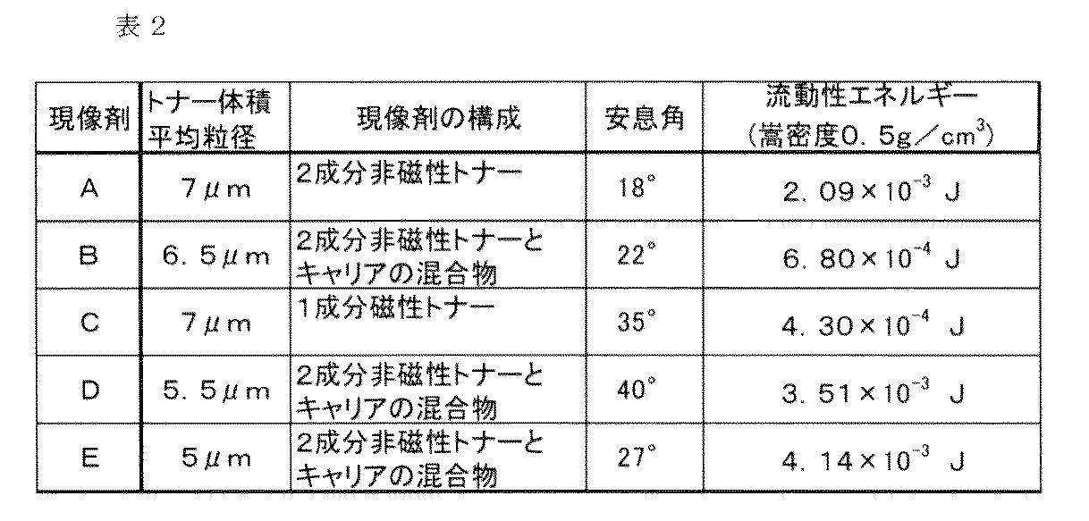
この粉体流動性分析装置の原理は、粉体サンプル中でブレードを移動させ、そのブレードが粉体中を移動するのに必要な流動性エネルギーを測定するものである。ブレードはプロペラ型で、回転すると同時に回転軸方向にも移動するためブレードの先端はらせんを描くことになる。
プロペラ型のブレード51(以下、ブレードと呼ぶ)として、径が48mmで、反時計回りになめらかにねじられたSUS製のブレード(型番:C210)を使用した。詳細には、48mm×10mmのブレード板の中心にブレード板の回転面に対して法線方向に回転軸が存在し、ブレード板の両最外縁部(回転軸から24mm部分)のねじれ角が70°、回転軸から12mmの部分のねじれ角が35°となっている。
流動性エネルギーとは、粉体層中に上述の如くらせん状に回転するブレード51を侵入させ、ブレードが粉体層中を移動する際に得られる回転トルクと垂直荷重の総和を時間積分して得られたトータルエネルギーを指す。この値が、現像剤粉体層の解れ易さを表しており、流動性エネルギーが大きい場合は解れにくく、流動性エネルギーが小さい場合は解れ易いことを意味している。
今回の測定では、図47に示す通り、この装置の標準部品であるφが50mmの円筒容器50(容積200cm3、図47のL1=50mm)に各現像剤Tを粉面高さ70mm(図47のL2)となるように充填した。充填量は、測定する嵩密度に合せて調整する。更に、標準部品であるφ48mmのブレード51を粉体層に侵入させ、侵入深さ10mm~30mm間に得られたエネルギーを表示する。
測定時の設定条件としては、ブレード51の回転速度(tip speed。ブレードの最外縁部の周速)を60mm/sec、また、粉体層への鉛直方向のブレード進入速度を、移動中のブレード51の最外縁部が描く軌跡と粉体層表面とのなす角θ(helixangle。以後なす角と呼ぶ)が10°になるスピードとした。粉体層への垂直方向の進入速度は11mm/secである(粉体層への鉛直方向のブレード進入速度=ブレードの回転速度×tan(なす角×π/180))。また、この測定についても温度24℃、相対湿度55%の環境下で行った。
なお、現像剤の流動性エネルギーを測定する際の現像剤の嵩密度は、現像剤の排出量と排出口の大きさとの関係を検証する実験の際の嵩密度に近く、嵩密度の変化が少なく安定して測定ができる嵩密度として0.5g/cm3に調整した。
このようにして測定された流動性エネルギーをもつ現像剤(表2)について、検証実験を行った結果を図48に示す。図48は、排出口の径と排出量との関係を、現像剤の種類毎に示したグラフである。
図48に示す検証結果より、現像剤A~現像剤Eについて、排出口の直径φが4mm(開口面積が12.6mm2:円周率は3.14で計算、以下同じ)以下であれば、排出口からの排出量が2g以下になることが確認された。排出口の直径φが4mmよりも大きくなると、いずれの現像剤とも、排出量が急激に多くなることが確認された。
つまり、現像剤の流動性エネルギー(嵩密度が0.5g/cm3)が4.3×10−4(kg・m2/sec2(J))以上4.14×10−3(kg・m2/sec2(J))以下のとき、排出口の直径φが4mm(開口面積が12.6(mm2))以下であれば良い。
また、現像剤の嵩密度については、この検証実験では十分に現像剤を解して流動化した状態で測定を行っており、通常の使用環境で想定される状態(放置された状態)よりも嵩密度が低く、より排出し易い条件で測定を行っている。
次に、図48の結果から最も排出量が多くなる現像剤Aを用いて、排出口の直径φを4mmに固定して、容器内の充填量を30g~300gに振って、同様の検証実験を行った。その検証結果を図49に示す。図49の検証結果から、現像剤の充填量を変化させても、排出口からの排出量はほとんど変わらないことが確認できた。
以上の結果から、排出口をφ4mm(面積12.6mm2)以下にすることで、現像剤の種類や嵩密度状態に依らず、排出口を下にした状態(現像剤受入れ装置への補給姿勢を想定)で、排出口から重力作用のみでは十分に排出されないことが確認できた。
一方、排出口1cの大きさの下限値としては、現像剤補給容器1から補給すべき現像剤(1成分磁性トナー、1成分非磁性トナー、2成分非磁性トナー、2成分磁性キャリア)が少なくとも通過できる値に設定するのが好ましい。つまり、現像剤補給容器1に収容されている現像剤の粒径(トナーの場合は体積平均粒径、キャリアの場合は個数平均粒径)よりも大きい排出口にするのが好ましい。例えば、補給用の現像剤に2成分非磁性トナーと2成分磁性キャリアが含まれている場合、大きい方の粒径、つまり、2成分磁性キャリアの個数平均粒径よりも大きな排出口にするのが好ましい。
具体的には、補給用の現像剤に2成分非磁性トナー(体積平均粒径が5.5μm)及び2成分磁性キャリア(個数平均粒径が40μm)が含まれている場合、排出口1cの径を0.05mm(開口面積0.002mm2)以上に設定するのが好ましい。
但し、排出口1cの大きさを現像剤の粒径に近い大きさに設定してしまうと、現像剤補給容器1から所望の量を排出させるのに要するエネルギー、つまり、ポンプ部5を動作させるのに要するエネルギーが大きくなってしまう。また、現像剤補給容器1の製造上においても制約が生じる場合がある。射出成形法を用いて樹脂部品に排出口1cを成形するには、排出口1cの部分を形成する金型部品の耐久性が厳しくなってしまう。以上から、排出口1cの直径φは0.5mm以上に設定するのが好ましい。
なお、本例では、排出口1cの形状を円形状としているが、このような形状に限定されるものでは無い。つまり、直径が4mmの場合に相当する開口面積である12.6mm2以下の開口面積を有する開口であれば、正方形、長方形、楕円や、直線と曲線を組合せた形状等、に変更可能である。
但し、円形状の排出口は、開口の面積を同じとした場合、他の形状に比べて現像剤が付着して汚れてしまう開口の縁の周長が最も小さい。そのため、シャッタ4の開閉動作に連動して広がってしまう現像剤の量も少なく、汚れ難い。また、円形状の排出口は、排出時の抵抗も少なく最も排出性が高い。従って、排出口1cの形状としては、排出量と汚れ防止のバランスが最も優れた円形状がより好ましい。
以上より、排出口1cの大きさについては、排出口1cを鉛直下方に向けた状態(現像剤受入れ装置8への補給姿勢を想定)で、重力作用のみで十分に排出されない大きさが好ましい。具体的には、排出口1cの直径φは、0.05mm(開口面積0.002mm2)以上4mm(開口面積12.6mm2)以下の範囲に設定するのが好ましい。さらに、排出口1cの直径φは、0.5mm(開口面積0.2mm2)以上4mm(開口面積12.6mm2)以下の範囲に設定するのがより好ましい。本例では、以上の観点から、排出口1cを円形状とし、その開口の直径φを2mmに設定している。
なお、本例では、排出口1cの数を1個としているがそれに限るものではなく、それぞれの開口面積が上述した開口面積の範囲を満足するように、排出口1cを複数設ける構成としても構わない。例えば、直径φが2mmの1つの現像剤受入れ口11aに対して、直径φが0.7mmの排出口1cを2つ設ける構成である。但し、この場合、現像剤の排出量(単位時間当たり)が低下してしまう傾向となるため、直径φが2mmの排出口1cを1つ設ける構成の方がより好ましい。
(現像剤補給工程)
次に、図50~図53を用いて、ポンプ部5による現像剤補給工程について説明する。図50はポンプ部5の伸縮部5aが縮んだ状態を示す概略斜視図である。図51はポンプ部5の伸縮部5aが伸びた状態を示す概略斜視図である。図52はポンプ部5の伸縮部5aが縮んだ状態を示す概略断面図である。図53はポンプ部5の伸縮部5aが伸びた状態を示す概略断面図である。
本例では、後述するように、吸気工程(排出口1cを介した吸気動作)と排気工程(排出口1cを介した排気動作)が交互に繰り返し行われるように、駆動変換機構により回転力の駆動変換が行われる構成となっている。以下、吸気工程と排気工程について、順に、詳細に説明する。
まず、ポンプ部を用いた現像剤の排出原理について説明する。
ポンプ部5の伸縮部5aの動作原理は上述した通りである。再度述べると、図45に示すように、伸縮部5aの下端は容器本体1aに接合されている。また、この容器本体1aは下端の上フランジ部1gを介して現像剤受入れ装置8の位置決めガイド8lにより、矢印p方向、矢印q方向(必要に応じて図44参照)への移動が阻止された状態となる。そのため、容器本体1aと接合されている伸縮部5aの下端は、現像剤受入れ装置8に対して上下方向の位置が固定された状態になる。
一方、伸縮部5aの上端は係止部18を介して、係止部材10に係止されており、この係止部材10が上下動することで、矢印p方向、矢印q方向へと往復動する。
従って、ポンプ部5の伸縮部5aは、下端が固定された状態にあるので、それよりも上側の部分が伸縮動作を行うことになる。
次に、ポンプ部5の伸縮部5aの伸縮動作(排気動作及び吸気動作)と現像剤排出との関係について説明する。
(排気動作)
まず、排出口1cを介した排気動作について説明する。
係止部材10が下方へ移動することに伴い、伸縮部5aの上端が矢印p方向へ変位する(伸縮部が縮む)ことで、排気動作が行われる。具体的には、この排気動作に伴い現像剤収容スペース1bの容積が減少していく。その際、容器本体1aの内部は排出口1cを除き密閉されており、現像剤が排出されるまでは、排出口1cが現像剤で実質的に塞がれた状態となっているため、現像剤収容スペース1b内の容積が減少していくことで現像剤収容スペース1bの内圧が上昇していく。
このとき、現像剤収容スペース1bの内圧はホッパ8c内の圧力(大気圧とほぼ同等)よりも大きくなるため、図52に示すように、現像剤は現像剤収容スペース1bとホッパ8cとの圧力差により、空気圧で押し出される。つまり、現像剤収容スペース1bからホッパ8cへと現像剤Tが排出される。図52の矢印は、現像剤収容スペース1b内の現像剤Tへ作用する力の方向を示したものである。
その後、現像剤とともに現像剤収容スペース1b内のエアも排出されていくため、現像剤収容スペース1bの内圧は低下していく。
(吸気動作)
次に、排出口1cを介した吸気動作について説明する。
係止部材10が上方へ移動することに伴い、ポンプ部5の伸縮部5aの上端が矢印q方向へ変位する(伸縮部が伸びる)ことで、吸気動作が行われる。具体的には、この吸気動作に伴い現像剤収容スペース1bの容積が増大していく。その際、容器本体1aの内部は排出口1cを除き密閉された状態となっており、排出口1cが現像剤で実質的に塞がれた状態となっている。そのため現像剤収容スペース1b内の容積増加に伴い、現像剤収容スペース1bの内圧が減少していく。
このとき、現像剤収容スペース1bの内圧はホッパ8cの内圧(大気圧とほぼ同等)よりも小さくなる。そのため、図53に示すように、ホッパ8c内の上部にあるエアが、現像剤収容スペース1bとホッパ8cの圧力差により、排出口1cを通って現像剤収容スペース1b内へと移動する。図53の矢印は、現像剤収容スペース1b内の現像剤Tへ作用する力の方向を示している。また、図53の楕円で示したZは、ホッパ8cから取り込まれたエアを模式的に示したものである。
その際、排出口1cを通して現像剤受入れ装置8側からエアが取り込まれるため、排出口1c近傍に位置する現像剤を解すことができる。具体的には、排出口1c近傍に位置する現像剤に対して、エアを含ませることで嵩密度を低下させ、現像剤を流動化させることができる。
このように、現像剤を流動化させておくことにより、次の排気動作時に、排出口1cから現像剤を閉塞することなく排出させることが可能となるのである。従って、排出口1cから排出される現像剤Tの量(単位時間当たり)を、長期に亘り、ほぼ一定とすることが可能となる。
(現像剤収容部の内圧の推移)
次に、現像剤補給容器1の内圧がどのように変化しているかについての検証実験を行った。以下、この検証実験について説明する。
現像剤補給容器1内の現像剤収容スペース1bが現像剤で満たされるように現像剤を充填した上で、ポンプ部5を15cm3の容積変化量で伸縮させた際の、現像剤補給容器1の内圧の推移を測定した。現像剤補給容器1の内圧の測定は、現像剤補給容器1に圧力計(株式会社キーエンス社製、型名:AP−C40)を接続して行った。
現像剤を充填した現像剤補給容器1のシャッタ4を開いて排出口1cを外部のエアと連通可能とした状態で、ポンプ部5を伸縮動作させている際の圧力変化の推移を図54に示す。
図54において、横軸は時間を示し、縦軸は大気圧(基準(0))に対する現像剤補給容器1内の相対的な圧力を示している(+が正圧側、−が負圧側を示している)。
現像剤補給容器1の容積が増加し、現像剤補給容器1の内圧が外部の大気圧に対して負圧になると、その気圧差により排出口1cからエアが取り込まれる。また、現像剤補給容器1の容積が減少し、現像剤補給容器1の内圧が大気圧に対して正圧になると、内部の現像剤に圧力が掛かる。このとき、現像剤及びエアが排出された分だけ内部の圧力が緩和される。
この検証実験により、現像剤補給容器1の容積が増加することで現像剤補給容器1の内圧が外部の大気圧に対して負圧になり、その気圧差によりエアが取り込まれることを確認できた。また、現像剤補給容器1の容積が減少することで現像剤補給容器1の内圧が大気圧に対して正圧になり、内部の現像剤に圧力が掛かることで現像剤が排出されることを確認できた。この検証実験では、負圧側の圧力の絶対値は1.3kPa、正圧側の圧力の絶対値は3.0kPaであった。
このように、本例の構成の現像剤補給容器1であれば、ポンプ部5による吸気動作と排気動作に伴い現像剤補給容器1の内圧が負圧状態と正圧状態とに交互に切り替わり、現像剤の排出を適切に行うことが可能となることが確認された。
以上説明した通り、本例では、現像剤補給容器1に吸気動作と排気動作を行う簡易なポンプ部を設けたことで、エアによる現像剤の解し効果を得ながら、エアによる現像剤の排出を安定的に行うことができる。
つまり、本例の構成であれば、排出口1cの大きさが極めて小さい場合であっても、現像剤を嵩密度の小さい流動化した状態で排出口1cを通過させることが出来るため、現像剤に大きなストレスをかけることなく、高い排出性能を確保することができる。
また、本例では、容積可変型のポンプ部5の内部を現像剤収容スペース1bとして利用する構成としているため、ポンプ部5の容積を増大させて内圧を減圧させる際に、新たな現像剤収容空間を形成することができる。従って、ポンプ部5の内部が現像剤で満たされている場合であっても、簡易な構成で、現像剤にエアを含ませて、嵩密度を低下させることができる(現像剤を流動化させることができる)。よって、現像剤補給容器1に現像剤を従来以上に高密度に充填させることが可能となる。
なお、以上のように、ポンプ部5の内部空間を現像剤収容スペース1bとして使用せずに、フィルタ(エアは通過できるもののトナーは通過できないフィルタ)によりポンプ部5と現像剤収容スペース1bとの間を仕切る構成としても構わない。但し、ポンプ部5の容積増大時に新たな現像剤収容空間を形成することができる点で、上述した実施例の構成の方がより好ましい。
(吸気工程における現像剤の解し効果について)
次に、吸気工程での排出口1cを介した吸気動作による現像剤の解し効果について検証を行った。なお、排出口1cを介した吸気動作に伴う現像剤の解し効果が大きければ、小さな排気圧(少ないポンプ容積変化量)で、次の排気工程において現像剤補給容器1内の現像剤の排出をただちに開始させることができる。従って、本検証は、本例の構成であれば、現像剤の解し効果が顕著に高まることを示すためのものである。以下、詳しく説明する。
図55(a)、図56(a)に検証実験に用いた現像剤補給システムの構成を簡易に示したブロック図を示す。図55(b)、図56(b)は現像剤補給容器内で生じる現象を示す概略図である。なお、図55は本例と同様な方式の場合であり、現像剤補給容器Cに現像剤収容部C1とともにポンプ部Pが設けられている。そして、ポンプ部Pの伸縮動作により現像剤補給容器Cの排出口(本例と同様な排出口1c(不図示))を介した吸気動作と排気動作を交互に行い、ホッパHに現像剤を排出するものである。一方、図56は比較例の方式の場合であり、ポンプ部Pを現像剤受入れ装置側に設け、ポンプ部Pの伸縮動作により現像剤収容部C1への送気動作と現像剤収容部C1からの吸引動作を交互に行い、ホッパHに現像剤を排出させるものである。なお、図55、図56において、現像剤収容部C1、ホッパHは同じ内容積であり、ポンプ部Pも同じ内容積(容積変化量)となっている。
まず、現像剤補給容器Cに200gの現像剤を充填する。
次に、現像剤補給容器Cの物流後の状態を想定して15分間に亘り加振を行った後、ホッパHに接続する。
そして、ポンプ部Pを動作させて、排気工程において直ちに現像剤を排出開始させるために必要となる吸気工程の条件として、吸気動作時に達する内圧のピーク値を測定した。なお、図55の場合は現像剤収容部C1の容積が480cm3となる状態、図56の場合はホッパHの容積が480cm3となる状態を各々ポンプ部Pの動作をスタートさせる位置としている。
また、図56の構成での実験は、図55の構成と空気容積の条件を揃えるため、予めホッパHに200gの現像剤を充填した上で行った。また、現像剤収容部C1及びホッパHの内圧は、それぞれに圧力計(株式会社キーエンス社製、型名:AP−C40)を接続することで測定を行った。
検証の結果、図55に示す本例と同様な方式では、吸気動作時の内圧のピーク値(負圧)の絶対値が少なくとも1.0kPaであれば、次の排気工程において現像剤を直ちに排出開始させることができた。一方、図56に示す比較例の方式では、送気動作時の内圧のピーク値(正圧)が少なくとも1.7kPaでないと、次の排気工程において現像剤を直ちに排出開始させることができなかった。
つまり、図55に示す本例と同様な方式であれば、ポンプ部Pの容積増加に伴い吸気が行われることから、現像剤補給容器Cの内圧を大気圧(容器外の圧力)よりも低い負圧側にすることができ、現像剤の解し効果が顕著に高いことが確認された。これは、図55(b)に示すように、ポンプ部Pの伸張に伴い現像剤補給容器Cの容積が増加することにより、現像剤層Tの上部の空気層Rが大気圧に対して減圧状態となるからである。そのため、この減圧作用により現像剤層Tの体積が膨張する方向に力が働くため(波線矢印)、現像剤層を効率的に解すことが可能となるのである。さらに、図55の方式においては、この減圧作用により、現像剤補給容器C内へ外部からエアが取り込まれることになり(白抜き矢印)、このエアが空気層Rへ到達する際にも現像剤層Tが解されることになり、非常に優れたシステムと言える。現像剤補給容器C内の現像剤が解されている証拠に、本実験では吸気動作時に現像剤補給容器C内の現像剤全体の見かけ体積が増加している現象を確認した(現像剤の上面が上に動く現象)。
一方、図56に示す比較例の方式では、現像剤収容部C1への送気動作に伴い現像剤補給容器Cの内圧が高まり大気圧よりも正圧側となってしまい現像剤が凝集してしまうため、現像剤の解し効果が認められなかった。これは、図56(b)に示すように、現像剤補給容器Cの外部からエアが強制的に送り込まれるため、現像剤層Tの上部の空気層Rが大気圧に対して加圧状態となるからである。そのため、この加圧作用により、現像剤層Tの体積が収縮する方向に力が働くため(波線矢印)、現像剤層Tが圧密化してしまうのである。実際、本比較例では吸気動作時に現像剤補給容器C内の現像剤全体の見かけ体積が増加する現象を確認することが出来なかった。従って、図56の方式においては、現像剤層Tの圧密化により、その後の現像剤排出工程を適切に行うことができない恐れが高い。
また、上記した空気層Rが加圧状態となることによる現像剤層Tの圧密化を防ぐ為に、空気層Rに相当する部位にエア抜き用のフィルタ等を設けて、圧力上昇を低減することも考えられるが、フィルタ等の透気抵抗分は空気層Rの圧力が上昇してしまう。また、圧力上昇を仮に無くしたとしても、上述した空気層Rを減圧状態とすることによる解し効果は得られない。
以上から、本例の方式を採用することにより、ポンプ部の容積増加に伴う「排出口を介した吸気動作」が果たす役割が大きいことが確認された。
以上のように、ポンプ部5が排気動作と吸気動作を、交互に繰り返し行うことにより、現像剤補給容器1の排出口1cから現像剤の排出を効率良く行うことが可能となる。つまり、本例では、排気動作と吸気動作を同時に並行して行うのではなく、交互に繰り返し行う構成としているので、現像剤の排出に要するエネルギーを可及的に少なくすることができる。
一方、従来のように現像剤受入れ装置側に送気用のポンプ部と吸引用のポンプ部を別々に設けた場合には、2つのポンプ部の動作を制御する必要があり、特に急速に送気と吸気を交互に切り換えることは容易ではない。
従って、本例では、1つのポンプ部を用いて現像剤の排出を効率良く行うことができるので、現像剤排出機構の構成を簡易化することができる。
なお、上述したようにポンプ部の排気動作と吸気動作を交互に繰り返すことで現像剤の排出を効率良く行うことができるが、排気動作、吸気動作を途中で一度停止して、再び動作させても構わない。
例えば、ポンプ部の排気動作を一気に行うのではなく、ポンプ部の圧縮動作を途中で一度停止して、その後再び圧縮して排気しても良い。吸気動作も同様である。更に、排出量及び排出速度を満足する前提で、各動作を多段階にしても構わない。ただし、あくまでポンプ部の動作は多段階に分割した排気動作の後、吸気動作を行い、基本的に排気動作と吸気動作を繰り返すことに変わりは無い。
また、本例では、現像剤収容スペース1bの内圧を減圧状態にすることにより排出口1cからエアを取り込み現像剤を解している。一方、上述した従来例では、現像剤補給容器1外部から現像剤収容スペース1bにエアを送り込むことにより現像剤を解しているが、その際、現像剤収容スペース1bの内圧は加圧状態となっており、現像剤が凝集してしまう。つまり、現像剤を解す効果としては現像剤が凝集しにくい減圧状態で解すことができる本例の方が好ましい。
また、本例においても前述した実施例1,2と同様に、現像剤受入れ部11を変位させて現像剤補給容器1に接続/離間させるための機構を簡易化することができる。すなわち、現像器全体を上方へ移動させるための駆動源や駆動伝達機構が不要な構成となっていることから、画像形成装置側の構造が複雑化したり、部品点数増によるコストアップがない。
なお、従来の技術によれば、現像器全体が上下に移動する際に現像器と干渉しないようにそのための大きなスペースが必要となるが、本例によれば、そのスペースが不要となるため、画像形成装置の大型化も防止できる。
また、現像剤補給容器1の装着動作を利用して、現像剤補給容器1と現像剤受入れ装置8との接続状態を、現像剤による汚れを最小限に抑えて、良好にせしめることができる。同様に、現像剤補給容器1の取り出し動作を利用して、現像剤補給容器1と現像剤受入れ装置8との接続状態からの離間および再封止を、現像剤による汚れを最小限に抑えて、良好にせしめることができる。
本例では、図57、図58に示すように、実施例4のような蛇腹状の容積可変型ポンプ部の代わりに、プランジャー型ポンプ部を用いている。このプランジャー型ポンプ部は、内筒部1hの外周面の近傍を内筒部1hに対して相対移動可能に設けられた外筒部36を有している。また、外筒部36の上面には、実施例4と同様に、係止部18が接着、固定されている。つまり、外筒部36の上面に固定された係止部18は、現像剤受入れ装置8の係止部材10が差し込まれることで、実質的に両者が一体化され、外筒部36が係止部材10とともに上下動(往復動)することが可能となる。
なお、内筒部1hは、容器本体1aと接続されており、その内部空間は現像剤収容スペース1bとして機能する。
また、この内筒部1hと外筒部36の隙間からエアの漏れを防止するため(気密性を保つことで現像剤が漏れないように)、弾性シール37が内筒部1hの外周面に接着、固定されている。この弾性シール37は内筒部1hと外筒部36の間で圧縮されるように構成されている。
従って、現像剤受入れ装置8に不動に固定された容器本体1a(内筒部1h)に対し、外筒部36を矢印p方向、矢印q方向へ往復動させることで現像剤収容スペース1b内の容積を変化させることができる。つまり、現像剤収容スペース1bの内圧を負圧状態と正圧状態とに交互に繰り返し変化させることができる。
このように、本例においても、1つのポンプ部で吸気動作と排気動作を行うことができるので、現像剤排出機構の構成を簡易にすることができる。さらに、排出口を介した吸気動作により現像剤収補給容器内を減圧状態(負圧状態)にできることから、現像剤を効率良く解すことが可能となる。
なお、本例では、外筒部36の形状が円筒形状の例について説明したが、例えば、断面が四角形などの他の形状であっても構わない。この場合、内筒部1hの形状も外筒部36の形状に対応させるのが好ましい。また、プランジャー型ポンプ部に限らず、ピストンポンプ部を用いても構わない。
また、本例のポンプ部を用いた場合、内筒と外筒の隙間からの現像剤漏れを防止するためのシール構成が必要となり、その結果構成が複雑になるとともにポンプ部を駆動するための駆動力が大きくなってしまうことから、実施例4の方がより好ましい。
また、本例では、現像剤補給容器1に実施例4と同様の係合部を設けているため、前述した実施例と同様に、現像剤受入れ装置8の現像剤受入れ部11を変位させて現像剤補給容器1に接続/離間させるための機構を簡易化することができる。すなわち、現像器全体を上方へ移動させるための駆動源や駆動伝達機構が不要な構成となっていることから、画像形成装置側の構造が複雑化したり、部品点数増によるコストアップがない。
また、現像剤補給容器1の装着動作を利用して、現像剤補給容器1と現像剤受入れ装置8との接続状態を、現像剤による汚れを最小限に抑えて、良好にせしめることができる。同様に、現像剤補給容器1の取り出し動作を利用して、現像剤補給容器1と現像剤受入れ装置8との接続状態からの離間および再封止を、現像剤による汚れを最小限に抑えて、良好にせしめることができる。
本例では、図59、図60に示すように、実施例4のような蛇腹状の折り目が付けられたポンプ部の代わりに、折り目の無い、膨張と収縮が可能な膜状のポンプ部38を用いている。このポンプ部38の膜状部はゴム製とされている。なお、ポンプ部38の膜状部の材質としては、ゴムではなく、樹脂フィルムなどの柔軟材料を用いても構わない。
この膜状のポンプ部38は、容器本体1aと接続されており、その内部空間は現像剤収容スペース1bとして機能する。また、この膜状のポンプ部38には、上記実施例と同様に、その上部に係止部18が接着、固定されている。従って、係止部材10(図38参照)の上下動に伴い、ポンプ部38は膨張と収縮を交互に繰り返すことができる。
このように、本例においても、1つのポンプ部で吸気動作と排気動作を行うことができるので、現像剤排出機構の構成を簡易化することができる。さらに、排出口を介した吸気動作により現像剤補給容器内を減圧状態(負圧状態)にできることから、現像剤を効率良く解すことが可能となる。
また、本例の場合、図61に示すように、ポンプ部38の膜状部の上面に膜状部よりも剛性の高い板状部材39を取り付け、この板状部材39に係止部18を設置するのが好ましい。このような構成とすることで、ポンプ部38の係止部18の近傍のみが変形してしまうことに起因して、ポンプ部38の容積変化量が少なくなってしまうのを抑制することができる。つまり、係止部材10の上下動に対するポンプ部38の追従性を向上させることが可能となり、ポンプ部38の膨張、収縮を効率良く行わせることができる。つまり、現像剤の排出性を向上させることが可能となる。
また、本例では、現像剤補給容器1に実施例4と同様の係合部を設けているため、前述した実施例と同様に、現像剤受入れ装置8の現像剤受入れ部11を変位させて現像剤補給容器1に接続/離間させるための機構を簡易化することができる。すなわち、現像器全体を上方へ移動させるための駆動源や駆動伝達機構が不要な構成となっていることから、画像形成装置側の構造が複雑化したり、部品点数増によるコストアップがない。
また、現像剤補給容器1の装着動作を利用して、現像剤補給容器1と現像剤受入れ装置8との接続状態を、現像剤による汚れを最小限に抑えて、良好にせしめることができる。同様に、現像剤補給容器1の取り出し動作を利用して、現像剤補給容器1と現像剤受入れ装置8との接続状態からの離間および再封止を、現像剤による汚れを最小限に抑えて、良好にせしめることができる。
図62、図63のように、本例の現像剤補給容器1は、容器本体(現像剤排出室)1a及びポンプ部5の部分Xと円筒部(現像剤搬送室)24の部分Yの2つの要素から構成されている。なお、現像剤補給容器1の部分Xの構造は、実施例4で説明したものとほぼ同様であり、詳細な説明を省略する。
(現像剤補給容器の構成)
本例の現像剤補給容器1では、実施例4とは異なり、図63に示すように、部分X(排出口1cが形成された排出部とも呼ぶ)の側方に接続部24cを介して円筒部24が接続された構造となっている。
この円筒部(現像剤収容回転部)24は、長手方向一端側は塞がれている一方、部分Xの開口と接続される側である他端側は開口しており、その内部空間は現像剤収容スペース1bとなっている。従って、本例では、容器本体1aの内部空間、ポンプ部5の内部空間、円筒部24の内部空間の全てが現像剤収容スペース1bとなっており、多量の現像剤を収容することが可能となっている。なお、本例では、現像剤収容回転部としての円筒部24の断面形状が円形となっているが、必ずしも円形でなくても構わない。例えば、現像剤搬送時において回転運動を阻害しない範囲であれば、現像剤収容回転部の断面形状を多角形形状など、非円形形状としても構わない。
そして、この円筒部(現像剤搬送室)24の内部には螺旋状の搬送突起(搬送部)24aが設けられており、この搬送突起24aは、円筒部24が矢印R方向へ回転することに伴い、収容された現像剤を部分X(排出口1c)に向けて搬送する機能を有している。
また、円筒部24の内部には、搬送突起24aにより搬送されてきた現像剤を、円筒部24の矢印R方向への回転(回転軸線は略水平方向)に伴い、部分X側へ受け渡す受け渡し部材(搬送部)16が円筒部24の内部に立設されている。この受け渡し部材16は、現像剤を掬い上げる板状部16aと、板状部16aにより掬い上げられた現像剤を部分Xに向けて搬送(ガイド)する傾斜突起16bが板状部16aの両面に設けられている。また、板状部16aには、現像剤の撹拌性を向上させるべく、現像剤の往来を許容する貫通穴16cが形成されている。
さらに、円筒部24の長手方向一端側(現像剤搬送方向下流端側)の外周面には駆動入力部としてのギア部24bが接着、固定されている。このギア部24bは、現像剤補給容器1が現像剤受入れ装置8に装着されると、現像剤受入れ装置8に設けられた駆動機構として機能する駆動ギア9と係合する。従って、駆動ギア9からの回転駆動力が回転力受け部としてのギア部24bに入力されると、円筒部24が矢印R方向(図63)へ回転することになる。なお、このようなギア部24bの構成に限らず、円筒部24を回転させることができるのであれば、例えば、ベルトや摩擦車を用いるもの等、他の駆動入力機構を採用しても構わない。
そして、図64に示すように、円筒部24の長手方向一端側(現像剤搬送方向下流端側)には、部分Xとの接続管の役割を果たす接続部24cが設けられている。なお、上述した傾斜突起16bの一端がこの接続部24cの近傍に至るまで延出するように設けられている。従って、傾斜突起16bにより搬送される現像剤が、再度、円筒部24の底面側へ落下することを可及的に防止し、接続部24c側へ適切に受け渡されるように構成されている。
また、以上のように円筒部24は回転するのに対し、実施例4と同様に、容器本体1aやポンプ部5は上フランジ部1gを介して現像剤受入れ装置8に不動となるように(円筒部24の回転軸線方向及び回転方向への移動が阻止されるように)保持されている。それ故、円筒部24は容器本体1aに対して相対回転自在に接続されている。
また、円筒部24と容器本体1a間にはリング状の弾性シール25が設けられており、この弾性シール25は円筒部24と容器本体1aとの間で所定量圧縮されることでシールする。これにより、円筒部24の回転中にそこから現像剤が漏れてしまうのを防止している。また、これにより、気密性も保たれるので、ポンプ部5による解し作用と排出作用を現像剤に対して無駄無く生じさせることが可能となる。つまり、現像剤補給容器1として排出口1c以外には実質内部と外部が連通する開口が無い。
(現像剤補給工程)
次に、現像剤補給工程について説明する。
操作者が現像剤補給容器1を現像剤受入れ装置8に挿入、装着させると、実施例4と同様に現像剤補給容器1の係止部18が現像剤受入れ装置8の係止部材10と係止するとともに、現像剤補給容器1のギア部24bが現像剤受入れ装置8の駆動ギア9と係合する。
その後、駆動ギア9を回転駆動用の別の駆動モータ(不図示)により回転駆動するとともに、係止部材10を上述した駆動モータ500により上下方向に駆動させる。すると、円筒部24が矢印R方向へ回転し、それに伴い、内部の現像剤が搬送突起24aにより受け渡し部材16に向けて搬送される。そして、円筒部24の矢印R方向への回転に伴い、受け渡し部材16は現像剤を掬い上げるとともに接続部24cへと搬送する。そして、接続部24cから容器本体1a内へ搬送されてきた現像剤は、実施例4と同様に、ポンプ部5の伸縮動作に伴い、排出口1cから排出される。
以上が、現像剤補給容器1の一連の装着~補給工程である。なお、現像剤補給容器1を交換する際は、操作者が現像剤受入れ装置8から現像剤補給容器1を取り出し、再度、新たな現像剤補給容器1を挿入、装着すれば良い。
実施例4~実施例6のような現像剤収容スペース1bが鉛直方向に長い縦型の容器構成の場合、現像剤補給容器1の容積を大きくし充填量を増やすと、現像剤の自重により排出口1c近傍に重力作用がより集中してしまう。その結果、排出口1c近傍の現像剤が圧密されやすくなり、排出口1cからの吸気/排気の妨げとなる。この場合、排出口1cからの吸気で圧密された現像剤を解す、または、排気で現像剤を排出させるためには、ポンプ部5の容積変化量の増加により現像剤収容スペース1bの内圧(負圧/正圧)を更に大きくしなければならなくなる。しかし、その結果、ポンプ部5を駆動させるための駆動力も増加し、画像形成装置本体100への負荷が過大になる恐れがある。
それに対し、本実施例では、容器本体1a及びポンプ部5の部分Xと円筒部24の部分Yを水平方向に並べて設置しているため、図44に示す構成に対して、容器本体1a内における排出口1c上の現像剤層の厚さを薄く設定することができる。これにより、重力作用により現像剤が圧密されにくくなるため、その結果画像形成装置本体100へ負荷をかけることなく、安定した現像剤の排出が可能になる。
以上のように、本例の構成であれば、円筒部24を設けたことにより画像形成装置本体に負荷をかけることなく現像剤補給容器1を大容量化することができる。
また、本例においても、1つのポンプ部で吸気動作と排気動作を行うことができるので、現像剤排出機構の構成を簡易化することができる。
なお、円筒部24における現像剤搬送機構として、上述した例に限らず、現像剤補給容器1を振動、或いは、揺動、又はその他の方式を用いる構成としても構わない。具体的には、例えば、図65のような構成にしても構わない。
つまり、図65に示すように、円筒部24自体は現像剤受入れ装置8に実質不動(僅かにガタがある)に固定される構成としつつ、搬送突起24aの代わりに、円筒部24に対し相対回転することで現像剤を搬送する搬送部材17が円筒部内に内装されている。
搬送部材17は、軸部17aと軸部17aに固定された可撓性の搬送翼17bから構成されている。また、この搬送翼17bは、軸部17aの軸線方向に対して先端側が傾斜した傾斜部Sを有している。そのため、円筒部24内の現像剤を撹拌しながら部分Xに向けて搬送することが可能となる。
また、円筒部24の長手方向一端面には回転力受け部としてのカップリング部24eが設けられており、このカップリング部24eは現像剤受入れ装置8のカップリング部材(不図示)と駆動連結することで回転駆動力が入力される構成となっている。そして、このカップリング部24eは搬送部材17の軸部17aと同軸的に結合されており、軸部17aに回転駆動力が伝達される構成となっている。
従って、現像剤受入れ装置8のカップリング部材(不図示)から付与された回転駆動力により軸部17aに固定されている搬送翼17bが回転し、円筒部24内の現像剤が部分Xに向けて撹拌されながら搬送される。
但し、図65に示す変形例では、現像剤搬送工程において現像剤に与えるストレスが大きくなってしまう傾向にあり、また、駆動トルクも大きくなってしまうことから、本実施例のような構成の方がより望ましい。
本例においても、1つのポンプ部で吸気動作と排気動作を行うことができるので、現像剤排出機構の構成を簡易にすることができる。さらに、排出口を介した吸気動作により現像剤補給容器内を減圧状態(負圧状態)にできることから、現像剤を効率良く解すことが可能となる。
また、本例では、現像剤補給容器1に実施例4と同様の係合部を設けているため、前述した実施例と同様に、現像剤受入れ装置8の現像剤受入れ部11を変位させて現像剤補給容器1に接続/離間させるための機構を簡易化することができる。すなわち、現像器全体を上方へ移動させるための駆動源や駆動伝達機構が不要な構成となっていることから、画像形成装置側の構造が複雑化したり、部品点数増によるコストアップがない。
また、現像剤補給容器1の装着動作を利用して、現像剤補給容器1と現像剤受入れ装置8との接続状態を、現像剤による汚れを最小限に抑えて、良好にせしめることができる。同様に、現像剤補給容器1の取り出し動作を利用して、現像剤補給容器1と現像剤受入れ装置8との接続状態からの離間および再封止を、現像剤による汚れを最小限に抑えて、良好にせしめることができる。
上述した実施例4~実施例7では、現像剤受入れ装置8の係止部材10(図38参照)を上下動させることでポンプ部5を伸縮させる例について説明した。これに対し、本例では、上述した実施例1~実施例3と同様に、現像剤受入れ装置8から現像剤補給容器1が回転駆動力のみを受ける構成を例示している。その他の構成について、上述した実施例と同様な構成については同符号を付すことで詳細な説明を省略する。
具体的には、本例では、現像剤受入れ装置8から入力された回転駆動力を、ポンプ部5を往復動させる方向の力へ変換し、これをポンプ部5に伝達する構成としている。
以下、現像剤受入れ装置8、現像剤補給容器1の構成について、順に説明する。
(現像剤受入れ装置)
まず、現像剤受入れ装置8について、図66を用いて説明する。
現像剤受入れ装置8には、現像剤補給容器1が取り出し可能(着脱可能)に装着される装着部(装着スペース)8fが設けられている。現像剤補給容器1は、図66(b)に示すように、装着部8fに対して矢印A方向に装着される構成となっている。つまり、現像剤補給容器1の長手方向(回転軸線方向)がほぼこの矢印A方向と一致するように装着部8fに装着される。なお、この矢印A方向は、後述する図68(b)の矢印X方向と実質平行である。また、現像剤補給容器1の装着部8fからの取り出し方向はこの矢印A方向とは反対の方向(矢印B方向)となる。
また、現像剤受入れ装置8の装着部8fには、図66(a)に示すように、現像剤補給容器1が装着された際に現像剤補給容器1のフランジ部21(図67参照)と当接することでフランジ部21の回転方向への移動を規制するための回転方向規制部(保持機構)29が設けられている。さらに、装着部8fには、図66(b)に示すように、現像剤補給容器1が装着された際に現像剤補給容器1のフランジ部21と係止することでフランジ部21の回転軸線方向への移動を規制するための、回転軸線方向規制部(保持機構)30が設けられている。この回転軸線方向規制部30は、フランジ部21との干渉に伴い弾性変形し、その後、フランジ部21(図67(b)参照)との干渉が解除された段階で弾性復帰することでフランジ部21を係止する樹脂製のスナップロック機構とされている。
さらに、現像剤受入れ装置8の装着部8fには、後述する現像剤補給容器1の排出口(開口)21a(図68(b)参照)から排出された現像剤を受入れるための現像剤受入れ部11が設けられている。現像剤受入れ部11は、前述した実施例1又は実施例2と同様に、現像剤受入れ装置8に対し、鉛直方向に移動可能(変位可能)に取り付けられている。また、現像剤受入れ部11の上端面には本体シール13が設けられており、その中央部に現像剤受入れ口11aが設けられている。本体シール13は弾性体、発泡体等で構成されており、後述する現像剤補給容器1の排出口21aを備える開口シール3a5(図7(b)参照)と密着し、排出口21aや現像剤受入れ口11aからの現像剤の漏れを防ぐ。あるいは、シャッタ開口4fを備えるシャッタ4(図25(a)参照)と密着し、排出口21aやシャッタ開口4f、現像剤受入れ口11aからの現像剤の漏れを防ぐ。
尚、現像剤受入れ口11aの直径は、装着部8f内が現像剤により汚れてしまうのを可及的に防止する目的で、現像剤補給容器1の排出口21aの直径よりも略同径からやや大きくする事が望ましい。これは、排出口21aの直径よりも現像剤受入れ口11aの直径が小さくなると、現像剤補給容器1から排出された現像剤が、現像剤受入れ口11aの上面に付着し、付着した現像剤は、現像剤補給容器1の装脱着動作時に現像剤補給容器1の下面に転写し、現像剤による汚れの一因となるためである。また、現像剤補給容器1へ転写した現像剤が、装着部8fへ飛散する事によって装着部8fが現像剤によって汚れてしまう。逆に、現像剤受入れ口11aの直径を排出口21aの直径よりかなり大きくすると、現像剤受入れ口11aより飛散した現像剤が排出口21a近傍へ付着する面積が大きくなる。つまり、現像剤補給容器1の現像剤による汚れの面積が大きくなるため好ましくない。したがって、上記の事情を鑑みて現像剤受入れ口11aの直径は、排出口21aの直径に対して略同径~約2mm大きくすることが望ましい。
本例では、現像剤補給容器1の排出口21aの直径が約Φ2mmの微細口(ピンホール)とされているため、現像剤受入れ口11aの直径は約φ3mmに設定している。
さらに、現像剤受入れ部11は付勢部材12により鉛直方向下方に付勢されている(図3及び図4参照)。つまり現像剤受入れ部11は鉛直方向上方へ移動する際に、付勢部材12による付勢力に抗して移動することとなる。
また、現像剤受入れ装置8は、その下部には現像剤を一時的に溜めておくサブホッパ8cが設けられている(図3及び図4参照)。このサブホッパ8c内には、現像器201の一部である現像剤ホッパ部201aへ現像剤を搬送するための搬送スクリュー14と、現像剤ホッパ部201aと連通した開口8dが設けられている。
また、現像剤受入れ口11aは現像剤補給容器1が装着されていない状態でサブホッパ8c内に異物やホコリが入らないよう、閉止状態となっている。具体的には、現像剤受入れ口11aは、現像剤受入れ部11が鉛直上方に移動していない状態では、本体シャッタ15により閉止されている。この現像剤受入れ部11が現像剤補給容器1から離間した位置から現像剤補給容器1に向けて鉛直上方(矢印E方向)に移動する。これにより、現像剤受入れ口11aと本体シャッタ15が離間し、現像剤受入れ口11aが開封状態になる構成となっている。開封状態になることによって、現像剤補給容器1の排出口21a、あるいはシャッタ開口4fから現像剤受入れ口11aで受入れた現像剤がサブホッパ8cへ移動可能となる。
また、現像剤受入れ部11の側面には係合部11b(図3及び図4参照)が設けられている。この係合部11bは後述する現像剤補給容器1側に設けられた係合部3b2,3b4(図8又は図20参照)と直接係合し、ガイドされることで、現像剤受入れ部11が現像剤補給容器1へ向けて鉛直方向上方へ持ち上げられる。
また、現像剤受入れ装置8の装着部8fには、現像剤補給容器1を着脱方向に案内するための挿入ガイド8e(図3及び図4参照)が設けられており、この挿入ガイド8eにより現像剤補給容器1の装着方向が矢印A方向となるように構成されている。尚、現像剤補給容器1の取り出し方向(脱着方向)は、矢印A方向とは逆方向(矢印B方向)となる。
また、現像剤受入れ装置8は、図66(a)に示すように、後述する現像剤補給容器1を駆動する駆動機構として機能する駆動ギア9を有している。この駆動ギア9は、駆動モータ500から駆動ギア列を介して回転駆動力が伝達され、装着部8fにセットされた状態にある現像剤補給容器1に対し回転駆動力を付与する機能を有している。
また、駆動モータ500は、図66に示すように、制御装置(CPU)600によりその動作を制御される構成となっている。
なお、本例において、駆動ギア9は、駆動モータ500の制御を簡易化させるため、一方向にのみ回転するように設定されている。つまり、制御装置600は、駆動モータ500について、そのオン(作動)/オフ(非作動)のみを制御する構成となっている。従って、駆動モータ500(駆動ギア9)を正方向と逆方向とに周期的に反転させることで得られる反転駆動力を現像剤補給容器1に付与する構成に比して、現像剤受入れ装置8の駆動機構の簡易化を図ることができる。
(現像剤補給容器)
次に現像剤補給容器1の構成について、図67、図68を用いて説明する。
現像剤補給容器1は、図67(a)に示すように、中空円筒状に形成され内部に現像剤を収容する内部空間を備えた現像剤収容部20(容器本体とも呼ぶ)を有している。本例では、円筒部20kとポンプ部20bが現像剤収容部20として機能する。さらに、現像剤補給容器1は、現像剤収容部20の長手方向(現像剤搬送方向)一端側にフランジ部21(非回転部とも呼ぶ)を有している。また、現像剤収容部20はこのフランジ部21に対して相対回転可能に構成されている。
なお、本例では、図68(d)に示すように、現像剤収容部として機能する円筒部20kの全長L1が約300mm、外径R1が約70mmに設定されている。また、ポンプ部20bの全長L2(使用上の伸縮可能範囲の中で最も伸びた状態のとき)は約50mm、フランジ部21のギア部20aが設置されている領域の長さL3は約20mmとなっている。また、現像剤収容部として機能する排出部21hが設置されている領域の長さL4は約25mmとなっている。さらに、ポンプ部20bの最大外径R2(使用上の伸縮可能範囲の中で最も伸びた状態のとき)が約65mm、現像剤補給容器1の現像剤を収容し得る全容積が約1250cm3となっている。なお、本例では、現像剤収容部として機能する円筒部20kとポンプ部20bとともに、排出部21hが現像剤を収容し得る領域となっている。
また、本例では、図67、図68に示すように、現像剤補給容器1が現像剤受入れ装置8に装着された状態のとき円筒部20kと排出部21hが水平方向に並ぶように構成されている。つまり、円筒部20kは、その水平方向長さがその鉛直方向長さよりも充分に長く、その水平方向一端側が排出部21hと接続された構成となっている。従って、現像剤補給容器1が現像剤受入れ装置8に装着された状態のとき排出部21hの鉛直上方に円筒部20kが位置するように構成する場合に比して、吸排気動作を円滑に行うことが可能となる。なぜなら、排出口21a上に存在するトナーの量が少なくなる為、排出口21a近傍の現像剤が圧密され難くなるからである。
このフランジ部21には、図67(b)に示すように、現像剤収容部(現像剤収容室、現像剤搬送室)20内から搬送されてきた現像剤を一時的に貯留するための中空の排出部(現像剤排出室)21hが設けられている(必要に応じて図68(b)、(c)参照)。この排出部21hの底部には、現像剤補給容器1の外へ現像剤の排出を許容する、つまり、現像剤受入れ装置8へ現像剤を補給するための小さな排出口21aが形成されている。この排出口21aの大きさについては前述の通りである。
また、排出部21h内(現像剤排出室内)の底部の内部形状は、残留してしまう現像剤の量を可能な限り低減させるため、排出口21aに向けて縮径する漏斗(じょうご)状に設けられている(必要に応じて図68(b)、(c)参照)。
また、図67に示すように、フランジ部21には、前述した実施例1又は実施例2と同様に、現像剤受入れ装置8に変位可能に設けられた現像剤受入れ部11と係合可能な係合部3b2,3b4が設けられている。この係合部3b2,3b4の構成は、前述した実施例1又は実施例2と同様であるため、ここでは説明は省略する。
さらに、フランジ部21の内部には、前述した実施例1又は実施例2と同様に、排出口21aを開閉するシャッタ4が設けられている。このシャッタ4の構成、及び現像剤補給容器1の着脱動作に伴う動きや位置関係などは、前述した実施例1又は実施例2と同様であるため、ここでは説明は省略する。
また、フランジ部21は、現像剤補給容器1が現像剤受入れ装置8の装着部8fに装着されると、実質不動(回転不可)となるように構成されている。
具体的には、フランジ部21は、図67(c)に示すように、装着部8fに設けられた回転方向規制部29により現像剤収容部20の回転軸線周りの方向へ回転しないように規制(阻止)される。つまり、フランジ部21は現像剤受入れ装置8により実質回転不可となるように保持される(ガタ程度の僅かな無視できる回転は可能となっている)。
さらに、フランジ部21は、現像剤補給容器1の装着動作に伴い装着部8fに設けられた回転軸線方向規制部30に係止される。具体的には、フランジ部21は、現像剤補給容器1の装着動作の途中で回転軸線方向規制部30に当接することで、回転軸線方向規制部30を弾性変形させる。その後、フランジ部21は、装着部8fに設けられたストッパである内壁部28a(図67(d)参照)に突き当たることで現像剤補給容器1の装着工程が完了する。このとき、装着完了とほぼ同時に、フランジ部21による干渉した状態が解かれて、回転軸線方向規制部30の弾性変形が解除される。
その結果、図67(d)に示すように、回転軸線方向規制部30がフランジ部21のエッジ部(係止部として機能する)と係止することにより、回転軸線方向(現像剤収容部20の回転軸線方向)への移動が実質阻止(規制)された状態となる。このとき、ガタ程度の僅かな無視できる移動は可能となっている。
以上のように、本例では、フランジ部21が、現像剤収容部20の回転軸線方向へ自らが移動することがないように、現像剤受入れ装置8の回転軸線方向規制部30により保持されている。更に、フランジ部21は、現像剤収容部20の回転方向へ自らが回転することがないように、現像剤受入れ装置8の回転方向規制部29により保持されている。
なお、操作者により現像剤補給容器1が装着部8fから取り出される際に、フランジ部21からの作用により回転軸線方向規制部30は弾性変形し、フランジ部21との係止が解除される。なお、現像剤収容部20の回転軸線方向は、ギア部20a(図68)の回転軸線方向とほぼ一致している。
従って、現像剤補給容器1が現像剤受入れ装置8に装着された状態では、フランジ部21に設けられている排出部21hも、現像剤収容部20の回転軸線方向及び回転方向への移動が実質阻止された状態となる(ガタ程度の移動は許容する)。
一方、現像剤収容部20は現像剤受入れ装置8により回転方向への規制は受けることなく、現像剤補給工程において回転する構成となっている。但し、現像剤収容部20は、フランジ部21により、回転軸線方向への移動が実質阻止された状態となる(ガタ程度の移動は許容する)。
(ポンプ部)
次に、往復動に伴いその容積が可変なポンプ部(往復動可能なポンプ)20bについて図68、図69を用いて説明する。ここで、図69(a)はポンプ部20bが現像剤補給工程において使用上最大限伸張された状態、図69(b)はポンプ部20bが現像剤補給工程において使用上最大限圧縮された状態を示す現像剤補給容器1の断面図である。
本例のポンプ部20bは、排出口21aを介して吸気動作と排気動作を交互に行わせる吸排気機構として機能する。
ポンプ部20bは、図68(b)に示すように、排出部21hと円筒部20kとの間に設けられており、円筒部20kに接続、固定されている。つまり、ポンプ部20bは円筒部20kとともに一体的に回転可能となる。
また、本例のポンプ部20bは、その内部に現像剤を収容可能な構成となっている。このポンプ部20b内の現像剤収容スペースは、後述するように、吸気動作時における現像剤の流動化に大きな役割を担っている。
そして、本例では、ポンプ部20bとして、往復動に伴いその容積が可変な樹脂製の容積可変型ポンプ部(蛇腹状ポンプ)を採用している。具体的には、図68(a)~(b)に示すように、蛇腹状のポンプを採用しており、「山折り」部と「谷折り」部が周期的に交互に複数形成されている。従って、このポンプ部20bは、現像剤受入れ装置8から受けた駆動力により、圧縮、伸張を交互に繰り返し行うことができる。なお、本例では、ポンプ部20bの伸縮時の容積変化量は、15cm3(cc)に設定されている。図68(d)に示すように、ポンプ部20bの全長L2(使用上の伸縮可能範囲の中で最も伸びた状態のとき)は約50mm、ポンプ部20bの最大外径R2(使用上の伸縮可能範囲の中で最も伸びた状態のとき)は約65mmとなっている。
このようなポンプ部20bを採用することにより、現像剤補給容器1(現像剤収容部20及び排出部21h)の内圧を、大気圧よりも高い状態と大気圧よりも低い状態とに、所定の周期(本例では約0.9秒)で、交互に繰り返し変化させることができる。この大気圧は、現像剤補給容器1が設置された環境におけるものである。その結果、小径(直径が約Φ2mm)の排出口21aから排出部21h内にある現像剤を効率良く、排出させることが可能となる。
また、ポンプ部20bは、図68(b)に示すように、排出部21h側の端部がフランジ部21の内面に設けられたリング状のシール部材27を圧縮した状態で、排出部21hに対して相対回転可能に固定されている。
これにより、ポンプ部20bは、シール部材27と摺動しながら回転するため、回転中においてポンプ部20b内の現像剤が漏れることなく、また、気密性が保たれる。つまり、排出口21aを介した空気の出入りが適切に行われるようになり、補給中における、現像剤補給容器1(ポンプ部20b、現像剤収容部20、排出部21h)の内圧を所望の状態にすることができるようになっている。
(駆動伝達機構)
次に、搬送部20cを回転させるための回転駆動力を現像剤受入れ装置8から受ける、現像剤補給容器1の駆動受け機構(駆動入力部、駆動力受け部)について説明する。
現像剤補給容器1には、図68(a)に示すように、現像剤受入れ装置8の駆動ギア9(駆動機構として機能する)と係合(駆動連結)可能な駆動受け機構(駆動入力部、駆動力受け部)として機能するギア部20aが設けられている。このギア部20aは、ポンプ部20bの長手方向一端側に固定されている。つまり、ギア部20a、ポンプ部20b、円筒部20kは、一体的に回転可能な構成となっている。
従って、駆動ギア9からギア部20aに入力された回転駆動力はポンプ部20bを介して円筒部20k(搬送部20c)へ伝達される仕組みとなっている。
つまり、本例では、このポンプ部20bが、ギア部20aに入力された回転駆動力を現像剤収容部20の搬送部20cへ伝達する駆動伝達機構として機能している。
従って、本例の蛇腹状のポンプ部20bは、その伸縮動作を阻害しない範囲内で、回転方向へのねじれに強い特性を備えた樹脂材を用いて製造されている。
なお、本例では、現像剤収容部20の長手方向(現像剤搬送方向)一端側、つまり、排出部21h側の一端にギア部20aを設けているが、このような例に限られるものではなく、例えば、現像剤収容部20の長手方向他端側、つまり、最後尾側に設けても構わない。この場合、対応する位置に駆動ギア9が設置されることになる。
また、本例では、現像剤補給容器1の駆動入力部と現像剤受入れ装置8の駆動部間の駆動連結機構としてギア機構を用いているが、このような例に限られるものではなく、例えば、公知のカップリング機構を用いるようにしても構わない。具体的には、現像剤収容部20の長手方向一端の底面(図68(d)の右側の端面)に駆動入力部として非円形状の凹部を設け、一方、現像剤受入れ装置8の駆動部として前述の凹部と対応した形状の凸部を設け、これらが互いに駆動連結する構成としても構わない。
(駆動変換機構)
次に、現像剤補給容器1の駆動変換機構(駆動変換部)について説明する。
現像剤補給容器1には、ギア部20aが受けた搬送部20cを回転させるための回転駆動力を、ポンプ部20bを往復動させる方向の力へ変換する駆動変換機構(駆動変換部)が設けられている。なお、本例では、後述するように、駆動変換機構としてカム機構を採用した例について説明するが、このような例だけに限らず、実施例9以降で説明するような他の構成を採用しても構わない。
つまり、本例では、搬送部20cとポンプ部20bを駆動するための駆動力を1つの駆動入力部(ギア部20a)で受ける構成としつつ、ギア部20aが受けた回転駆動力を、現像剤補給容器1側で往復動力へ変換する構成としている。
これは、現像剤補給容器1に駆動入力部を2つ別々に設ける場合に比して、現像剤補給容器1の駆動入力機構の構成を簡易化できるからである。更に、現像剤受入れ装置8の1つの駆動ギアから駆動を受ける構成としたため、現像剤受入れ装置8の駆動機構の簡易化にも貢献することができる。
また、現像剤受入れ装置8から往復動力を受ける構成にした場合、前述したような、現像剤受入れ装置8と現像剤補給容器1間の駆動連結が適切に行われずに、ポンプ部20bを駆動することができなくなる恐れがある。具体的には、現像剤補給容器1を画像形成装置本体100から取り出した後、再度これを装着するような場合に、ポンプ部20bを適切に往復動させることができない問題が懸念される。
例えば、ポンプ部20bが自然長よりも圧縮された状態でポンプ部20bへの駆動入力を停止させた場合、現像剤補給容器1を取り出すと、ポンプ部20bが自己復元して伸張された状態となる。つまり、画像形成装置本体100側の駆動出力部の停止位置はそのままであるにも関わらず、ポンプ部20b用の駆動入力部の位置は、現像剤補給容器1が取り出されている間に変わってしまう。その結果、画像形成装置本体100側の駆動出力部と現像剤補給容器1側のポンプ部20b用の駆動入力部との駆動連結が適切に行われず、ポンプ部20bを往復動させることができなくなってしまう。すると、現像剤補給が行われないことになり、その後の画像形成ができない状況に陥ってしまう懸念がある。
なお、このような問題は、現像剤補給容器1が取り出されている際に、ユーザによりポンプ部20bの伸縮状態を変えられてしまう場合も同様に発生し得る。また、このような問題は、新品の現像剤補給容器1へ交換する際にも同様に発生し得る。
本例の構成であれば、このような問題を解決することが可能である。以下、詳細に説明する。
現像剤収容部20の円筒部20kの外周面には、図68、図69に示すように、周方向において、実質等間隔となるように、回転部として機能するカム突起20dが複数設けられている。具体的には、円筒部20kの外周面に2つのカム突起20dが約180°対向するように設けられている。
ここで、カム突起20dの配置個数については、少なくとも1つ設けられていれば構わない。但し、ポンプ部20bの伸縮時の抗力により駆動変換機構等にモーメントが発生し、スムーズな往復動が行われない恐れがあるため、後述するカム溝21bの形状との関係が破綻しないよう複数個設けるのが好ましい。
一方、フランジ部21の内周面には、このカム突起20dが嵌り込む従動部として機能するカム溝21bが全周に亘り形成されている。このカム溝21bについて、図70を用いて説明する。図70において、矢印Aは円筒部20kの回転方向(カム突起20dの移動方向)、矢印Bはポンプ部20bの伸張方向、矢印Cはポンプ部20bの圧縮方向を示している。また、円筒部20kの回転方向Aに対するカム溝21cのなす角度をα、カム溝21dのなす角度をβとする。また、カム溝21bのポンプ部20bの伸縮方向B、Cにおける振幅(=ポンプ部20bの伸縮長さ)をLとする。
具体的には、このカム溝21bは、これを展開した図70に示すように、円筒部20k側から排出部21h側へ傾斜したカム溝21cと、排出部21h側から円筒部20k側へ傾斜したカム溝21dとが、交互に連結された構造となっている。本例では、α=βに設定している。
従って、本例では、このカム突起20dとカム溝21bが、ポンプ部20bへの駆動伝達機構として機能する。つまり、このカム突起20dとカム溝21bは、駆動ギア9からギア部20aが受けた回転駆動力を、ポンプ部20bを往復移動させる方向への力(円筒部20kの回転軸線方向への力)に変換し、これをポンプ部20bへ伝達する機構として機能する。
具体的には、駆動ギア9からギア部20aに入力された回転駆動力によりポンプ部20bとともに円筒部20kが回転し、この円筒部20kの回転に伴いカム突起20dが回転することになる。従って、このカム突起20dと係合関係にあるカム溝21bにより、ポンプ部20bが円筒部20kとともに回転軸線方向(図68の矢印X方向)へ往復移動することになる。この矢印X方向は、図66、図67の矢印A方向とほぼ平行な方向となっている。
つまり、このカム突起20dとカム溝21bは、ポンプ部20bが伸張した状態(図69の(a))とポンプ部20bが収縮した状態(図69の(b))が交互に繰り返されるように、駆動ギア9から入力された回転駆動力を変換している。
従って、本例では、前述のようにポンプ部20bが円筒部20kとともに回転するように構成されているため、円筒部20k内の現像剤がポンプ部20b内を経由する際に、ポンプ部50bの回転により現像剤を撹拌する(解す)ことができる。つまり、ポンプ部20bを円筒部20kと排出部21hとの間に設けているため、排出部21hへ送り込まれる現像剤に対して撹拌作用を施すことができるようになっており、更に好ましい構成と言える。
また、本例では、前述のように円筒部20kがポンプ部20bとともに往復動するように構成されているため、円筒部20kの往復動により円筒部20k内の現像剤を撹拌する(解す)ことができる。
(駆動変換機構の設定条件)
本例では、駆動変換機構は、円筒部20kの回転に伴い排出部21hへ搬送される現像剤搬送量(単位時間当たり)が、排出部21hからポンプ作用により現像剤受入れ装置8へ排出される量(単位時間当たり)よりも多くなるように駆動変換している。
これは、排出部21hへの搬送部20cによる現像剤の搬送能力に対してポンプ部20bによる現像剤の排出能力の方が大きいと、排出部21hに存在する現像剤の量が次第に減少してしまうからである。つまり、現像剤補給容器1から現像剤受入れ装置8への現像剤補給に要する時間が長くなってしまうことを防止するためである。
そこで、本例の駆動変換機構は、排出部21hへの搬送部20cによる現像剤の搬送量を2.0g/sec、ポンプ部20bによる現像剤の排出量を1.2g/secに設定している。
また、本例では、駆動変換機構は、円筒部20kが1回転する間にポンプ部20bが複数回往復動するように、駆動変換している。これは以下の理由に依るものである。
円筒部20kを現像剤受入れ装置8内で回転させる構成の場合、駆動モータ500は円筒部20kを常時安定して回転させるために必要な出力に設定するのが好ましい。但し、画像形成装置本体100における消費エネルギーを可能な限り削減するためには、駆動モータ500の出力を極力小さくする方が好ましい。ここで、駆動モータ500に必要な出力は、円筒部20kの回転トルクと回転数から算出されることから、駆動モータ500の出力を小さくするには、円筒部20kの回転数を可能な限り低く設定するのが好ましい。
しかし、本例の場合、円筒部20kの回転数を小さくしてしまうと、単位時間当たりのポンプ部20bの動作回数が減ってしまうことから、現像剤補給容器1から排出される現像剤の量(単位時間当たり)が減ってしまう。つまり、画像形成装置本体100から要求される現像剤の補給量を短時間で満足させるには、現像剤補給容器1から排出される現像剤の量では不足してしまう恐れがある。
そこで、ポンプ部20bの容積変化量を増加させれば、ポンプ部20bの1周期当たりの現像剤排出量を増やすことができるため、画像形成装置本体100からの要求に応えることが可能となるが、このような対処方法では以下のような問題がある。
つまり、ポンプ部20bの容積変化量を増加させると、排気工程における現像剤補給容器1の内圧(正圧)のピーク値が大きくなるため、ポンプ部20bを往復動させるのに要する負荷が増大してしまう。
このような理由から、本例では、円筒部20kが1回転する間にポンプ部20bを複数周期動作させているのである。これにより、円筒部20kが1回転する間にポンプ部20bを1周期しか動作させない場合に比して、ポンプ部20bの容積変化量を大きくすることなく、単位時間当たりの現像剤の排出量を増やすことが可能となる。そして、現像剤の排出量を増やすことができた分、円筒部20kの回転数を低減することが可能となる。
ここで、円筒部20kが1回転する間にポンプ部20bを複数周期動作させることに伴う効果について検証実験を行った。実験方法は、現像剤補給容器1に現像剤を充填し、現像剤補給工程における現像剤の排出量と円筒部20kの回転トルクを測定した。そして、円筒部20kの回転トルクと予め設定された円筒部20kの回転数から、円筒部20kの回転に必要な駆動モータ500の出力(=回転トルク×回転数)を算出した。実験条件は、円筒部20kの1回転当たりのポンプ部20bの動作回数を2回、円筒部20kの回転数を30rpm、ポンプ部20bの容積変化量を15cm3とした。
検証実験の結果、現像剤補給容器1からの現像剤排出量は、約1.2g/secとなった。また、円筒部20kの回転トルク(定常時の平均トルク)は0.64N・mで、駆動モータ500の出力は、約2W(モータ負荷(W)=0.1047×回転トルク(N・m)×回転数(rpm)。0.1047は単位換算係数)と算出された。
一方、円筒部20kの1回転当たりのポンプ部20bの動作回数を1回、円筒部20kの回転数を60rpmに設定して、それ以外の条件は上記と同様にして比較実験を行った。つまり、上記の検証実験と現像剤の排出量が同じ、約1.2g/secとなるようにした。
すると、比較実験の場合、円筒部20kの回転トルク(定常時の平均トルク)は0.66N・mで、駆動モータ500の出力は、約4Wと算出された。
以上の結果から、円筒部20kが1回転する間にポンプ部20bを複数周期動作させる構成にした方が好ましいことが確認できた。つまり、円筒部20kの回転数を低減させたままでも、現像剤補給容器1の排出性能を維持することが可能になることが確認できた。従って、本例のような構成とすることにより、駆動モータ500をより小さい出力に設定できるため、画像形成装置本体100での消費エネルギーの削減に貢献することができる。
(駆動変換機構の配置位置)
本例では、図68、図69に示すように、駆動変換機構(カム突起20dとカム溝21bにより構成されるカム機構)を、現像剤収容部20の外部に設けている。つまり、駆動変換機構を、円筒部20k、ポンプ部20b、フランジ部21の内部に収容された現像剤と接触することが無いように、円筒部20k、ポンプ部20b、フランジ部21の内部空間から隔てられた位置に設けている。
これにより、駆動変換機構を現像剤収容部20の内部空間に設けた場合に想定される問題を解消することができる。つまり、駆動変換機構の摺擦箇所への現像剤の侵入により、現像剤の粒子に熱と圧が加わって軟化していくつかの粒子同士がくっついて大きな塊(粗粒)となってしまったり、変換機構への現像剤の噛み込みによりトルクアップするのを防止することができる。
(ポンプ部による現像剤排出原理)
次に、図69を用いて、ポンプ部による現像剤補給工程について説明する。
本例では、後述するように、吸気工程(排出口21aを介した吸気動作)と排気工程(排出口21aを介した排気動作)が交互に繰り返し行われるように、駆動変換機構により回転力の駆動変換が行われる構成となっている。以下、吸気工程と排気工程について、順に、詳細に説明する。
(吸気工程)
まず、吸気工程(排出口21aを介した吸気動作)について説明する。
図69(a)に示すように、上述した駆動変換機構(カム機構)によりポンプ部20bが矢印ω方向に伸張されることで、吸気動作が行われる。つまり、この吸気動作に伴い、現像剤補給容器1の現像剤を収容し得る部位(ポンプ部20b、円筒部20k、フランジ部21)の容積が増大する。
その際、現像剤補給容器1の内部は排出口21aを除き実質密閉された状態となっており、さらに、排出口21aが現像剤Tで実質的に塞がれた状態となっている。そのため、現像剤補給容器1の現像剤Tを収容し得る部位の容積増加に伴い、現像剤補給容器1の内圧が減少する。
このとき、現像剤補給容器1の内圧は大気圧(外気圧)よりも低くなる。そのため、現像剤補給容器1外にあるエアが、現像剤補給容器1内外の圧力差により、排出口21aを通って現像剤補給容器1内へと移動する。
その際、排出口21aを通して現像剤補給容器1外からエアが取り込まれるため、排出口21a近傍に位置する現像剤Tを解す(流動化させる)ことができる。具体的には、排出口21a近傍に位置する現像剤に対して、エアを含ませることで嵩密度を低下させ、現像剤Tを適切に流動化させることができる。
また、その結果、エアが排出口21aを介して現像剤補給容器1内に取り込まれるため、現像剤補給容器1の内圧はその容積が増加しているにも関わらず大気圧(外気圧)近傍を推移することになる。
このように、現像剤Tを流動化させておくことにより、後述する排気動作時に、現像剤Tが排出口21aに詰まってしまうことなく、排出口21aから現像剤をスムーズに排出させることが可能となるのである。従って、排出口21aから排出される現像剤Tの量(単位時間当たり)を、長期に亘り、ほぼ一定とすることが可能となる。
(排気工程)
次に、排気工程(排出口21aを介した排気動作)について説明する。
図69(b)に示すように、上述した駆動変換機構(カム機構)によりポンプ部20bが矢印γ方向に圧縮されることで、排気動作が行われる。具体的には、この排気動作に伴い現像剤補給容器1の現像剤を収容し得る部位(ポンプ部20b、円筒部20k、フランジ部21)の容積が減少する。その際、現像剤補給容器1の内部は排出口21aを除き実質密閉されており、現像剤が排出されるまでは、排出口21aが現像剤Tで実質的に塞がれた状態となっている。従って、現像剤補給容器1の現像剤Tを収容し得る部位の容積が減少していくことで現像剤補給容器1の内圧が上昇する。
このとき、現像剤補給容器1の内圧は大気圧(外気圧)よりも高くなるため、図69(b)に示すように、現像剤Tは現像剤補給容器1内外の圧力差により、排出口21aから押し出される。つまり、現像剤補給容器1から現像剤受入れ装置8へ現像剤Tが排出される。
その後、現像剤Tとともに現像剤補給容器1内のエアも排出されていくため、現像剤補給容器1の内圧は低下する。
以上のように、本例では、1つの往復動式のポンプ部を用いて現像剤の排出を効率良く行うことができるので、現像剤排出に要する機構を簡易化することができる。
(カム溝の設定条件)
次に、図71~図76を用いてカム溝21bの設定条件の変形例について説明する。図71~図76は、いずれも、カム溝21bの展開図を示したものである。図71~図76に示すフランジ部21の展開図を用いて、カム溝21bの形状を変更した場合のポンプ部20bの運転条件に与える影響について説明する。
ここで、図71~図76において、矢印Aは現像剤収容部20の回転方向(カム突起20dの移動方向)、矢印Bはポンプ部20bの伸張方向、矢印Cはポンプ部20bの圧縮方向を示す。また、カム溝21bのうち、ポンプ部20bを圧縮させる際に使用される溝部をカム溝21c、ポンプ部20bを伸張させる際に使用する溝部をカム溝21dとする。更に、現像剤収容部20の回転方向Aに対するカム溝21cのなす角度をα、カム溝21dのなす角度をβ、カム溝のポンプ部20bの伸縮方向B、Cにおける振幅(=ポンプ部20bの伸縮長さ)をLとする。
まず、ポンプ部20bの伸縮長さLに関して説明する。
例えば、伸縮長さLを短くした場合、ポンプ部20bの容積変化量が減少してしまうことから、外気圧に対し発生させることができる圧力差も小さくなってしまう。そのため、現像剤補給容器1内の現像剤にかかる圧力が減少し、結果としてポンプ部の1周期(=ポンプ部20bを1往復伸縮)当たりの現像剤補給容器1から排出される現像剤の量が減少する。
このことから、図71に示すように、角度α、βが一定の状態でカム溝の振幅L′をL′<Lに設定すれば、図70の構成に対し、ポンプ部20bを1往復させた際に排出される現像剤の量を減少させることができる。逆に、L′>Lに設定すれば、現像剤の排出量を増加させることも当然可能となる。
また、カム溝の角度α、βに関して、例えば、角度を大きくした場合、現像剤収容部20の回転速度が一定であれば、現像剤収容部20が一定時間回転した時に移動するカム突起20dの移動距離が増えるため、結果としてポンプ部20bの伸縮速度は増加する。
その一方、カム突起20dがカム溝21bを移動する際にカム溝21bから受ける抵抗が大きくなるため、結果として現像剤収容部20を回転させるのに要するトルクが増加する。
このことから、図72に示すように、伸縮長さLが一定の状態でカム溝21cの角度α′、カム溝21dの角度β′を、α′>α及びβ′>βに設定すれば、図70の構成に対しポンプ部20bの伸縮速度を増加できる。その結果、現像剤収容部20の1回転当たりのポンプ部20bの伸縮回数を増加させることができる。更に、排出口21aから現像剤補給容器1内へ入り込む空気の流速が増加するため、排出口21a周辺に存在する現像剤の解し効果は向上する。
逆に、α′<α及びβ′<βに設定すれば現像剤収容部20の回転トルクを減少させることができる。また、例えば、流動性の高い現像剤を使用した場合、ポンプ部20bを伸張させた際に、排出口21aから入り込んだ空気により排出口21a周辺に存在する現像剤が吹き飛ばされやすくなる。その結果、排出部21h内に現像剤を十分に貯留することができなくなり、現像剤の排出量が低下する可能性がある。この場合は、本設定によりポンプ部20bの伸張速度を減少させれば、現像剤の吹き飛ばしを抑えることで排出能力を向上することができる。
また、図73に示すカム溝21bのように、角度α<角度βに設定すれば、ポンプ部20bの伸張速度を圧縮速度に対して大きくすることができる。逆に、図75に示すように角度α>角度βに設定すれば、ポンプ部20bの伸張速度を圧縮速度に対して小さくすることができる。
例えば、現像剤補給容器1内の現像剤が高密度状態にある場合、ポンプ部20bを伸張する時よりも圧縮する時の方がポンプ部20bの動作力が大きくなってしまう。その結果、ポンプ部20bを圧縮する時の方が現像剤収容部20の回転トルクが高くなりやすい。しかし、この場合は、カム溝21bを図73に示す構成に設定すれば、図70の構成に対しポンプ部20bの伸張時における現像剤の解し効果を増加させることができる。更に、圧縮時にカム突起20dがカム溝21bから受ける抵抗が小さくなり、ポンプ部20bの圧縮時における回転トルクの増加を抑制することが可能になる。
なお、図74に示すように、カム溝21c,21dの間に現像剤収容部20の回転方向(図中矢印A)に対して実質平行なカム溝21eを設けても良い。この場合、カム突起20dがカム溝21eを通過している間はカム作用が働かないので、ポンプ部20bが伸縮動作を停止する過程を設けることが可能となる。
それにより、例えば、ポンプ部20bが伸張した状態で動作停止する過程を設ければ、排出口21a周辺に常に現像剤が存在する排出初期には、動作停止の間、現像剤補給容器1内の減圧状態が維持されるため現像剤の解し効果がより向上する。
一方、排出末期には、現像剤補給容器1内の現像剤が少なくなるのと、排出口21aから入り込んだ空気により排出口21a周辺に存在する現像剤が吹き飛ばされることにより、排出部21h内に現像剤を十分に貯留することができなくなる。
つまり、現像剤の排出量が次第に減少してしまう傾向となるが、この場合も伸張した状態で動作を停止することで、その間に現像剤収容部20を回転し現像剤を搬送し続ければ、排出部21hを現像剤で十分に満たすことができる。従って、現像剤補給容器1内の現像剤が空となるまで安定した現像剤の排出量を維持することができる。
また、図70の構成において、ポンプ部20bの1周期当たりの現像剤排出量を増加させる場合、前述のようにカム溝の伸縮長さLを長く設定することで達成できる。しかし、この場合、ポンプ部20bの容積変化量が増加することになるから、外気圧に対し発生できる圧力差も大きくなる。そのため、ポンプ部20bを駆動させるための駆動力も増加し、現像剤受入れ装置8で必要となる駆動負荷が過大になる恐れがある。
そこで、上記の弊害を発生させることなく、ポンプ部20bの1周期当たりの現像剤の排出量を増加させるために、図75に示すカム溝21bのように、角度α>角度βに設定することで、ポンプ部20bの圧縮速度を伸張速度に対して大きくしても構わない。
ここで、図75の構成の場合について検証実験を行った。
検証方法は、図75に示すカム溝21bを有する現像剤補給容器1に現像剤を充填し、ポンプ部20bを圧縮動作→伸張動作の順で容積変化させて排出実験を行い、その際の排出量を測定した。また実験条件として、ポンプ部20bの容積変化量を50cm3、ポンプ部20bの圧縮速度を180cm3/sec、ポンプ部20bの伸張速度を60cm3/secに設定した。ポンプ部20bの動作周期は約1.1秒である。
なお、図70の構成の場合についても、同様に、現像剤の排出量を測定した。但し、ポンプ部20bの圧縮速度及び伸張速度は、いずれも90cm3/secに設定し、ポンプ部20bの容積変化量とポンプ部20bの1周期にかかる時間は、図75の例と同じである。
検証実験結果について説明する。まず図77(a)に、ポンプ部50bの容積変化時における現像剤補給容器1の内圧変化の推移を示す。図77(a)において、横軸は時間を示し、縦軸は大気圧(基準(0))に対する現像剤補給容器1内の相対的な圧力を示している(+が正圧側、−が負圧側を示している)。また、実線は図75、点線は図70に示すカム溝21bを有する現像剤補給容器1での圧力推移を示す。
まず、ポンプ部20bの圧縮動作時において、両例とも時間経過とともに内圧は上昇し、圧縮動作終了時にピークに達する。この際、現像剤補給容器1内が大気圧(外気圧)に対して正圧で推移するため、内部の現像剤に対して圧力が掛かり現像剤は排出口21aから排出される。
続いて、ポンプ部20bの伸張動作時には、ポンプ部20bの容積が増加するため、両例とも現像剤補給容器1の内圧は減少していく。この際は、現像剤補給容器1内が大気圧(外気圧)に対して正圧から負圧になり、エアが排出口21aから取り込まれるまでは、内部の現像剤に対して圧力が掛かり続けるため、現像剤は排出口21aから排出される。
つまり、ポンプ部20bの容積変化時において、現像剤補給容器1が正圧状態、即ち内部の現像剤に圧力が掛かっている間は現像剤が排出されるため、ポンプ部20bの容積変化時における現像剤の排出量は、圧力の時間積分量に応じて増加する。
ここで、図77(a)に示すように、ポンプ部50bの圧縮動作終了時の到達圧は、図75の構成では5.7kPa、図70の構成では5.4kPaとなり、ポンプ部20bの容積変化量が同一にもかかわらず図75の構成の方が高くなっている。これは、ポンプ部20bの圧縮速度を大きくすることで現像剤補給容器1内が一気に加圧され、圧力に押されて現像剤が排出口21aに一気に集中することで、現像剤が排出口21aから排出される際の排出抵抗が大きくなったためである。両例とも排出口21aは小径に設定されているため、更にその傾向は顕著なものとなる。従って、図77(a)に示すように、両例ともポンプ部の1周期にかかる時間は同じであるため、圧力の時間積分量は図75の例の方が大きくなっている。
次に、表3に、ポンプ部20bの1周期当たりにおける現像剤の排出量の実測値を示す。
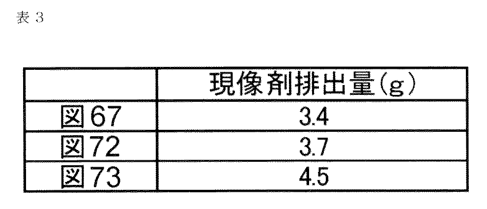
以上のように、図75のように、ポンプ部20bの圧縮速度を伸張速度に対して大きく設定し、ポンプ部20bの圧縮動作時に現像剤補給容器1内をより高い圧力に到達させることで、ポンプ部20bの1周期当たりの現像剤排出量を増加させることができる。
次に、ポンプ部20bの1周期当たりの現像剤排出量を増加させる別の方法について説明する。
図76に示すカム溝21bでは、図74と同様に、カム溝21cとカム溝21dの間に現像剤収容部20の回転方向に対して実質平行なカム溝21eを設けている。但し、図76に示すカム溝21bでは、カム溝21eはポンプ部20bの1周期の中で、ポンプ部20bの圧縮動作の後にポンプ部20bを圧縮した状態で、ポンプ部20bを動作停止させる位置に設けている。
ここで、同様に、図76の構成についても、現像剤の排出量の測定を行った。検証実験方法は、ポンプ部20bの圧縮速度及び伸張速度を180cm3/secに設定し、それ以外は図75に示す例と同様とした。
検証実験結果について説明する。図77(b)に、ポンプ部20bの伸縮動作中における現像剤補給容器1の内圧変化の推移を示す。ここで、実線は図76、点線は図75に示すカム溝21bを有する現像剤補給容器1での圧力推移を示す。
図76の場合においても、ポンプ部20bの圧縮動作時は時間経過とともに内圧は上昇して圧縮動作終了時にピークに達する。この際、図75と同様に、現像剤補給容器1内が正圧状態で推移するため、内部の現像剤は排出される。なお、図76の例におけるポンプ部20bの圧縮速度は図75の例と同一に設定したので、ポンプ部20bの圧縮動作終了時の到達圧は5.7kPaで、図75の時と同等だった。
続いて、ポンプ部20bを圧縮した状態で動作を停止すると、現像剤補給容器1の内圧は緩やかに減少していく。これは、ポンプ部20bの動作停止後も、ポンプ部20bの圧縮動作で発生した圧力が残っているため、その作用により内部の現像剤とエアが排出されるためである。但し、圧縮動作終了後、即伸張動作を開始するよりは、内圧を高い状態で維持することができるため、その間に現像剤はより多く排出される。
更に、その後伸張動作を開始させると、図75の例と同様に現像剤補給容器1の内圧は減少していき、現像剤補給容器1内が正圧から負圧になるまでは、内部の現像剤に対して圧力が掛かり続けるため現像剤は排出される。
ここで、図77(b)において圧力の時間積分値を比較すると、両例ともポンプ部20bの1周期にかかる時間は同じであるため、ポンプ部20bの動作停止時に高い内圧を維持している分、圧力の時間積分量は図76の例の方が大きくなっている。
また、表3に示すように、ポンプ部20bの1周期当たりにおける現像剤の排出量の実測値は、図76の場合では4.5gで、図75の場合(3.7g)より多く排出されていた。図77(b)と表3の結果から、ポンプ部20bの1周期当たりにおける現像剤の排出量が、圧力の時間積分量に応じて増加することが改めて確認された。
このように、図76の例は、ポンプ部20bの圧縮動作の後、ポンプ部20bを圧縮した状態で動作停止するように設定した構成である。そのため、ポンプ部20bの圧縮動作時に現像剤補給容器1内をより高い圧力に到達させ、かつその圧力をできるだけ高い状態で維持することにより、ポンプ部20bの1周期当たりの現像剤排出量を更に増加させることができる。
以上のように、カム溝21bの形状を変更することにより、現像剤補給容器1の排出能力を調整することができるため、現像剤受入れ装置8から要求される現像剤の量や使用する現像剤の物性等に適宜対応することが可能となる。
なお、図70~図76においては、ポンプ部20bによる排気動作と吸気動作が交互に切り替わる構成となっているが、排気動作や吸気動作をその途中で一旦中断させて、所定時間経過後に排気動作や吸気動作を再開させるようにしても構わない。
例えば、ポンプ部20bによる排気動作を一気に行うのではなく、ポンプ部の圧縮動作を途中で一旦停止させて、その後再び圧縮して排気しても良い。吸気動作も同様である。更に、現像剤の排出量や排出速度を満足できる範囲内において、排気動作や吸気動作を多段階にしても構わない。このように、排気動作や吸気動作をそれぞれ多段階に分割して実行するように構成したとしても、「排気動作と吸気動作を交互に繰り返し行う」ことに変わりは無い。
以上のように、本例においても、1つのポンプで吸気動作と排気動作を行うことができるので、現像剤排出機構の構成を簡易にすることができる。さらに、排出口を介した吸気動作により現像剤補給容器内を減圧状態(負圧状態)にできることから、現像剤を効率良く解すことが可能となる。
また、本例では、搬送部(螺旋状の凸部20c)を回転させるための駆動力とポンプ部(蛇腹状のポンプ部20b)を往復動させるための駆動力を1つの駆動入力部(ギア部20a)で受ける構成としている。従って、現像剤補給容器の駆動入力機構の構成を簡易化することができる。また、現像剤受入れ装置に設けられた1つの駆動機構(駆動ギア9)により現像剤補給容器へ駆動力を付与する構成としたため、現像剤受入れ装置の駆動機構の簡易化にも貢献することができる。また、現像剤受入れ装置に対する現像剤補給容器の位置決め機構として簡易なものを採用することが可能となる。
また、本例の構成によれば、現像剤受入れ装置から受けた搬送部を回転させるための回転駆動力を、現像剤補給容器の駆動変換機構により駆動変換する構成としたことで、ポンプ部を適切に往復動させることが可能となる。つまり、現像剤補給容器が現像剤受入れ装置から往復駆動力の入力を受ける方式においてポンプ部の駆動を適切に行えなくなってしまう問題を回避することが可能となる。
また、本例では、現像剤補給容器1のフランジ部21に実施例1又は実施例2と同様の係合部3b2,3b4を設けているため、前述した実施例と同様に、現像剤受入れ装置8の現像剤受入れ部11を変位させて現像剤補給容器1に接続/離間させるための機構を簡易化することができる。すなわち、現像器全体を上方へ移動させるための駆動源や駆動伝達機構が不要な構成となっていることから、画像形成装置側の構造が複雑化したり、部品点数増によるコストアップがない。
また、現像剤補給容器1の装着動作を利用して、現像剤補給容器1と現像剤受入れ装置8との接続状態を、現像剤による汚れを最小限に抑えて、良好にせしめることができる。同様に、現像剤補給容器1の取り出し動作を利用して、現像剤補給容器1と現像剤受入れ装置8との接続状態からの離間および再封止を、現像剤による汚れを最小限に抑えて、良好にせしめることができる。
本例では、現像剤補給容器1の回転軸線方向において円筒部20kを分断する位置にポンプ部20bとともに駆動変換機構(カム機構)を設けた点が実施例8と大きく異なる。その他の構成は実施例8とほぼ同様である。
図78(a)に示すように、本例では、回転に伴い現像剤を排出部21hに向けて搬送する円筒部20kは、円筒部20k1と円筒部20k2により構成されている。そして、ポンプ部20bはこの円筒部20k1と円筒部20k2との間に設けられている。
このポンプ部20bと対応する位置に駆動変換機構として機能するカムフランジ部19が設けられている。このカムフランジ部19の内面には、実施例8と同様に、カム溝19aが全周に亘って形成されている。一方、円筒部20k2の外周面には、カム溝19aに嵌まり込むように構成された、駆動変換機構として機能するカム突起20dが形成されている。
また、現像剤受入れ装置8には回転方向規制部29(必要に応じて図66参照)と同様な部位が形成されており、カムフランジ部19の保持部として機能することにより実質回転不可となるように保持される。さらに、現像剤受入れ装置8には回転軸線方向規制部30(必要に応じて図66参照)と同様な部位が形成されており、カムフランジ部19の保持部として機能することにより実質移動不可となるように保持される。
従って、ギア部20aに回転駆動力が入力されると、円筒部20k2とともにポンプ部20bが矢印ω方向と矢印γ方向へ往復動(伸縮)することになる。
以上のように、本例においても、1つのポンプ部で吸気動作と排気動作を行うことができるので、現像剤排出機構の構成を簡易にすることができる。さらに、排出口を介した吸気動作により現像剤補給容器内を減圧状態(負圧状態)にできることから、現像剤を効率良く解すことが可能となる。
また、ポンプ部20bの設置位置を、円筒部を分断する位置に設けたとしても、実施例8と同様に、現像剤受入れ装置8から受けた回転駆動力によりポンプ部20bを往復動させることが可能となる。
なお、排出部21hに貯留されている現像剤に対して効率良くポンプ部20bによる作用を施せるという点で、ポンプ部20bが排出部21hに直接的に接続されている実施例8の構成の方がより好ましい。
さらに、現像剤受入れ装置8により実質不動となるように保持しなければならないカムフランジ部(駆動変換機構)19が別途必要となってしまう。また、現像剤受入れ装置8側にカムフランジ部19が円筒部20kの回転軸線方向に移動するのを規制する機構が別途必要となってしまう。従って、このような機構の複雑化を考慮すると、フランジ部21を利用する実施例8の構成の方がより好ましい。
なぜなら、実施例8では、現像剤受入れ装置側と現像剤補給容器側の直接的に接続される部分(実施例2における現像剤受入れ口11aとシャッタ開口4fに相当する部分)を実質不動とするためフランジ部21が現像剤受入れ装置8により保持される構成となっており、この点に着目して駆動変換機構を構成する一方のカム機構をフランジ部21に設けているからである。つまり、駆動変換機構の簡易化を図っているからである。
また、本例でも、前述した実施例と同様に、現像剤補給容器1のフランジ部21に実施例1又は実施例2と同様の係合部3b2,3b4を設けているため、現像剤受入れ装置8の現像剤受入れ部11を変位させて現像剤補給容器1に接続/離間させるための機構を簡易化することができる。すなわち、現像器全体を上方へ移動させるための駆動源や駆動伝達機構が不要な構成となっていることから、画像形成装置側の構造が複雑化したり、部品点数増によるコストアップがない。
また、現像剤補給容器1の装着動作を利用して、現像剤補給容器1と現像剤受入れ装置8との接続状態を、現像剤による汚れを最小限に抑えて、良好にせしめることができる。同様に、現像剤補給容器1の取り出し動作を利用して、現像剤補給容器1と現像剤受入れ装置8との接続状態からの離間および再封止を、現像剤による汚れを最小限に抑えて、良好にせしめることができる。
本例では、現像剤補給容器1の現像剤搬送方向上流側の端部に駆動変換機構(カム機構)を設けた点と、円筒部20k内の現像剤を、撹拌部材20mを用いて搬送する点が実施例8と大きく異なる。その他の構成は実施例8とほぼ同様である。
本例では、図79に示すように、円筒部20k内に円筒部20kに対して相対回転する搬送部としての撹拌部材20mが設けられている。この撹拌部材20mは、現像剤受入れ装置8に回転不可となるように固定された円筒部20kに対し、ギア部20aが受けた回転駆動力により、相対回転することにより現像剤を撹拌しながら排出部21hに向けて回転軸線方向に搬送する機能を有している。具体的には、撹拌部材20mは、軸部と、この軸部に固定された搬送翼部と、を備えた構成となっている。
また、本例では、駆動入力部としてのギア部20aが、現像剤補給容器1の長手方向一端側(図79において右側)に設けられており、このギア部20aが撹拌部材20mと同軸的に結合された構成となっている。
さらに、ギア部20aと同軸的に回転するようにギア部20aと一体化された中空のカムフランジ部21iが現像剤補給容器の長手方向一端側(図79において右側)に設けられている。このカムフランジ部21iには、円筒部20kの外周面に約180°対向する位置に2つ設けられたカム突起20dと嵌合するカム溝21bが、内面に全周に亘って形成されている。
また、円筒部20kはその一端部(排出部21h側)がポンプ部20bに固定され、更にポンプ部20bはその一端部(排出部21h側)がフランジ部21に固定されている(それぞれ熱溶着法により両者が固定されている)。従って、現像剤受入れ装置8に装着された状態では、ポンプ部20bと円筒部20kはフランジ部21に対して実質回転不可となる。
なお、本例においても、実施例8と同様に、現像剤補給容器1が現像剤受入れ装置8に装着されると、フランジ部21(排出部21h)は現像剤受入れ装置8により回転方向並びに回転軸線方向への移動が阻止された状態となる。
従って、現像剤受入れ装置8からギア部20aに回転駆動力が入力されると、撹拌部材20mとともにカムフランジ部21iが回転する。その結果、カム突起20dはカムフランジ部21iのカム溝21bによってカム作用を受け、円筒部20kが回転軸線方向へ往復移動を行うことにより、ポンプ部20bが伸縮するようになる。
このように、撹拌部材20mが回転するに連れて現像剤が排出部21hへと搬送され、排出部21h内にある現像剤は最終的にポンプ部20bによる吸排気動作により排出口21aから排出される。
以上のように、本例においても、1つのポンプ部で吸気動作と排気動作を行うことができるので、現像剤排出機構の構成を簡易にすることができる。さらに、排出口を介した吸気動作により現像剤補給容器内を減圧状態(負圧状態)にできることから、現像剤を効率良く解すことが可能となる。
また、本例の構成においても、実施例8~実施例9と同様に、現像剤受入れ装置8からギア部20aが受けた回転駆動力により、円筒部20kに内蔵された撹拌部材20mの回転動作とポンプ部20bの往復動作の双方を行うことが可能となる。
なお、本例の場合、円筒部20kでの現像剤搬送工程において現像剤に与えるストレスが大きくなってしまう傾向にあり、また、駆動トルクも大きくなってしまうことから、実施例8や6の構成の方がより好ましい。
また、本例でも、前述した実施例と同様に、現像剤補給容器1のフランジ部21に実施例1又は実施例2と同様の係合部3b2,3b4を設けているため、現像剤受入れ装置8の現像剤受入れ部11を変位させて現像剤補給容器1に接続/離間させるための機構を簡易化することができる。すなわち、現像器全体を上方へ移動させるための駆動源や駆動伝達機構が不要な構成となっていることから、画像形成装置側の構造が複雑化したり、部品点数増によるコストアップがない。
また、現像剤補給容器1の装着動作を利用して、現像剤補給容器1と現像剤受入れ装置8との接続状態を、現像剤による汚れを最小限に抑えて、良好にせしめることができる。同様に、現像剤補給容器1の取り出し動作を利用して、現像剤補給容器1と現像剤受入れ装置8との接続状態からの離間および再封止を、現像剤による汚れを最小限に抑えて、良好にせしめることができる。
本例では、ポンプ部20bが現像剤受入れ装置8により回転不可となるように固定されている点が大きく異なり、その他の構成は実施例8とほぼ同様である。
本例では、図80(a)、(b)に示すように、ポンプ部20bと現像剤収容部20の円筒部20kとの間に中継部20fが設けられている。この中継部20fは、その外周面にカム突起20dが約180°対向する位置に2つ設けられており、その一端側(排出部21h側)はポンプ部20bに接続、固定されている(熱溶着法により両者が固定されている)。
また、ポンプ部20bは、その一端部(排出部21h側)がフランジ部21に固定(熱溶着法により両者が固定されている)されており、現像剤受入れ装置8に装着された状態では、実質回転不可となる。
そして、円筒部20kと中継部20fとの間でシール部材27が圧縮されるように構成されており、円筒部20kは中継部20fに対して相対回転可能となるように一体化されている。また、円筒部20kの外周部には、後述するカムギア部22から回転駆動力を受けるための回転受け部(凸部)20gが設けられている。
一方、中継部20fの外周面を覆うように、円筒形状のカムギア部22が設けられている。このカムギア部22はフランジ部21に対して円筒部20kの回転軸線方向には実質不動(ガタ程度の移動は許容する)となるよう係合し、且つフランジ部21に対して相対回転可能となるように設けられている。
このカムギア部22には、図80(c)に示すように、現像剤受入れ装置8から回転駆動力が入力される駆動入力部としてのギア部22aと、カム突起20dと係合するカム溝22bが設けられている。さらに、カムギア部22には、図80(d)に示すように、回転受け部20gと係合して円筒部20kと連れ回りするための回転係合部(凹部)7cが設けられている。つまり、回転係合部(凹部)7cは、回転受け部20gに対し回転軸線方向への相対移動が許容されながらも、回転方向へは一体的に回転できるような係合関係となっている。
本例における現像剤補給容器1の現像剤補給工程について説明する。
現像剤受入れ装置8の駆動ギア9からギア部22aが回転駆動力を受けてカムギア部22が回転すると、カムギア部22は回転係合部7cにより回転受け部20gと係合関係にあるので、円筒部20kとともに回転する。つまり、回転係合部7cと回転受け部20gが、現像剤受入れ装置8からギア部22aに入力された回転駆動力を円筒部20k(搬送部20c)へ伝達する役割を果たしている。
一方、実施例8~実施例10と同様に、現像剤補給容器1が現像剤受入れ装置8に装着されると、フランジ部21は回転不可となるように現像剤受入れ装置8に保持され、その結果、フランジ部21に固定されたポンプ部20bと中継部20fも回転不可となる。また同時に、フランジ部21は回転軸線方向への移動が現像剤受入れ装置8により阻止された状態となる。
従って、カムギア部22が回転すると、カムギア部22のカム溝22bと中継部20fのカム突起20dとの間にカム作用が働く。つまり、現像剤受入れ装置8からギア部22aに入力された回転駆動力が、中継部20fと円筒部20kを(現像剤収容部20の)回転軸線方向へ往復動させる力へ変換される。その結果、フランジ部21にその往復動方向一端側(図80(b)の左側)の位置が固定された状態にあるポンプ部20bは、中継部20fと円筒部20kの往復動に連動して伸縮することになり、ポンプ動作が行われることになる。
このように、円筒部20kが回転するに連れて搬送部20cにより現像剤が排出部21hへと搬送され、排出部21h内にある現像剤は最終的にポンプ部20bによる吸排気動作により排出口21aから排出される。
以上のように、本例においても、1つのポンプ部で吸気動作と排気動作を行うことができるので、現像剤排出機構の構成を簡易にすることができる。さらに、排出口を介した吸気動作により現像剤補給容器内を減圧状態(負圧状態)にできることから、現像剤を効率良く解すことが可能となる。
また、本例では、現像剤受入れ装置8から受けた回転駆動力を、円筒部20kを回転させる力とポンプ部20bを回転軸線方向へ往復動(伸縮動作)させる力に同時変換し、伝達している。
従って、本例においても、実施例8~実施例10と同様に、現像剤受入れ装置8から受けた回転駆動力により、円筒部20k(搬送部20c)の回転動作とポンプ部20bの往復動作の両方を行うことが可能となる。
また、本例でも、前述した実施例と同様に、現像剤補給容器1のフランジ部21に実施例1又は実施例2と同様の係合部3b2,3b4を設けているため、現像剤受入れ装置8の現像剤受入れ部11を変位させて現像剤補給容器1に接続/離間させるための機構を簡易化することができる。すなわち、現像器全体を上方へ移動させるための駆動源や駆動伝達機構が不要な構成となっていることから、画像形成装置側の構造が複雑化したり、部品点数増によるコストアップがない。
また、現像剤補給容器1の装着動作を利用して、現像剤補給容器1と現像剤受入れ装置8との接続状態を、現像剤による汚れを最小限に抑えて、良好にせしめることができる。同様に、現像剤補給容器1の取り出し動作を利用して、現像剤補給容器1と現像剤受入れ装置8との接続状態からの離間および再封止を、現像剤による汚れを最小限に抑えて、良好にせしめることができる。
本例では、現像剤受入れ装置8の駆動機構(駆動ギア9)から受けた回転駆動力を、ポンプ部20bを往復動させるための往復駆動力に変換した後、その往復駆動力を回転駆動力に変換することで円筒部20kを回転させる点が、上記実施例8と大きく異なる点である。
本例では、図81(b)に示すように、ポンプ部20bと円筒部20kとの間に中継部20fが設けられている。この中継部20fは、その外周面にカム突起20dが各々約180°対向する位置に2つ設けられており、その一端側(排出部21h側)はポンプ部20bに接続、固定されている(熱溶着法により両者が固定されている)。
また、ポンプ部20bは、その一端部(排出部21h側)がフランジ部21に固定(熱溶着法により両者が固定されている)されており、現像剤受入れ装置8に装着された状態では、実質回転不可となる。
そして、円筒部20kの一端部と中継部20fとの間でシール部材27が圧縮されるように構成されており、円筒部20kは中継部20fに対して相対回転可能となるように一体化されている。また、円筒部20kの外周部には、カム突起20iが各々約180°対向する位置に2つ設けられている。
一方、ポンプ部20bや中継部20fの外周面を覆うように、円筒形状のカムギア部22が設けられている。このカムギア部22は、フランジ部21に対して円筒部20kの回転軸線方向には不動となるよう係合し、且つ相対回転可能となるように設けられている。また、このカムギア部22には、実施例11と同様に、現像剤受入れ装置8から回転駆動力が入力される駆動入力部としてのギア部22aと、カム突起20dと係合するカム溝22bが設けられている。
更に、円筒部20kや中継部20fの外周面を覆うように、カムフランジ部19が設けられている。カムフランジ部19は、現像剤補給容器1が現像剤受入れ装置8の装着部8fに装着されると、実質不動となるように構成されている。また、このカムフランジ部19には、カム突起20iと係合するカム溝19aが設けられている。
次に、本例における現像剤補給工程について説明する。
現像剤受入れ装置8の駆動ギア9からギア部22aが回転駆動力を受けてカムギア部22が回転する。すると、ポンプ部20bと中継部20fはフランジ部21に回転不可に保持されているため、カムギア部22のカム溝22bと中継部20fのカム突起20dとの間にカム作用が働く。
つまり、現像剤受入れ装置8からギア部22aに入力された回転駆動力が、中継部20fを(円筒部20kの)回転軸線方向へ往復動させる力へ変換される。その結果、フランジ部21にその往復動方向一端側(図81(b)の左側)の位置が固定された状態にあるポンプ部20bは、中継部20fの往復動に連動して伸縮することになり、ポンプ動作が行われることになる。
更に、中継部20fが往復動すると、カムフランジ部19のカム溝19aとカム突起20iとの間にカム作用が働き、回転軸線方向への力が回転方向への力に変換され、これが円筒部20kへ伝達される。その結果、円筒部20k(搬送部20c)が回転することになる。よって、円筒部20kが回転するに連れて搬送部20cにより現像剤が排出部21hへと搬送され、排出部21h内にある現像剤は最終的にポンプ部20bによる吸排気動作により排出口21aから排出される。
以上のように、本例においても、1つのポンプ部で吸気動作と排気動作を行うことができるので、現像剤排出機構の構成を簡易にすることができる。さらに、排出口を介した吸気動作により現像剤補給容器内を減圧状態(負圧状態)にできることから、現像剤を効率良く解すことが可能となる。
また、本例では、現像剤受入れ装置8から受けた回転駆動力を、ポンプ部20bを回転軸線方向へ往復動(伸縮動作)させる力に変換させた後、その力を円筒部20kを回転させる力に変換し、伝達している。
従って、本例においても、実施例8~実施例11と同様に、現像剤受入れ装置8から受けた回転駆動力により、円筒部20k(搬送部20c)の回転動作とポンプ部20bの往復動作の両方を行うことが可能となる。
但し、本例の場合、現像剤受入れ装置8から入力された回転駆動力を往復駆動力に変換した上で再度回転方向の力へ変換しなければならず、駆動変換機構の構成が複雑化してしまうため、再変換が不要な実施例8~実施例11の構成の方がより好ましい。
また、本例でも、前述した実施例と同様に、現像剤補給容器1のフランジ部21に実施例1又は実施例2と同様の係合部3b2,3b4を設けているため、現像剤受入れ装置8の現像剤受入れ部11を変位させて現像剤補給容器1に接続/離間させるための機構を簡易化することができる。すなわち、現像器全体を上方へ移動させるための駆動源や駆動伝達機構が不要な構成となっていることから、画像形成装置側の構造が複雑化したり、部品点数増によるコストアップがない。
また、現像剤補給容器1の装着動作を利用して、現像剤補給容器1と現像剤受入れ装置8との接続状態を、現像剤による汚れを最小限に抑えて、良好にせしめることができる。同様に、現像剤補給容器1の取り出し動作を利用して、現像剤補給容器1と現像剤受入れ装置8との接続状態からの離間および再封止を、現像剤による汚れを最小限に抑えて、良好にせしめることができる。
本例では、駆動変換機構としてかさ歯ギアを用いた点が、上記した実施例と大きく異なる点である。
図82(b)に示すように、ポンプ部20bと円筒部20kとの間に中継部20fが設けられている。この中継部20fは、後述する連結部62が係合する係合突起20hが設けられている。
また、ポンプ部20bは、その一端部(排出部21h側)がフランジ部21に固定(熱溶着法により両者が固定されている)されており、現像剤受入れ装置8に装着された状態では、実質回転不可となる。
そして、円筒部20kの排出部21h側の一端部と中継部20fとの間でシール部材27が圧縮されるように構成されており、円筒部20kは中継部20fに対して相対回転可能となるように一体化されている。また、円筒部20kの外周部には、後述するギアリング60から回転駆動力を受けるための回転受け部(凸部)20gが設けられている。
一方、円筒部20kの外周面を覆うように、円筒形状のギアリング60が設けられている。このギアリング60はフランジ部21に対して相対回転可能となるように設けられている。
このギアリング60には、図82(a)、(b)に示すように、後述するかさ歯ギア61に回転駆動力を伝達するためのギア部60aと、回転受け部20gと係合して円筒部20kと連れ回りするための回転係合部(凹部)60bが設けられている。回転係合部(凹部)60bは、回転受け部20gに対し回転軸線方向への相対移動が許容されながらも、回転方向へは一体的に回転できるような係合関係となっている。
また、フランジ部21の外周面には、かさ歯ギア61がフランジ部21に対して回転可能となるように設けられている。更に、かさ歯ギア61と係合突起20hは連結部62により接続されている。
次に、現像剤補給容器1の現像剤補給工程について説明する。
現像剤受入れ装置8の駆動ギア9から現像剤収容部20のギア部20aが回転駆動力を受けて円筒部20kが回転すると、円筒部20kは回転受け部20gによりギアリング60と係合関係にあるので、ギアリング60は円筒部20kとともに回転する。つまり、回転受け部20gと回転係合部60bが、現像剤受入れ装置8からギア部20aに入力された回転駆動力をギアリング60へ伝達する役割を果たしている。
一方、ギアリング60が回転すると、その回転駆動力はギア部60aからかさ歯ギア61に伝達され、かさ歯ギア61は回転する。そして、このかさ歯ギア61の回転駆動は、図83(a)~(d)に示すように、連結部62を介して係合突起20hの往復運動に変換される。これにより、係合突起20hを有する中継部20fは往復運動される。その結果、ポンプ部20bは、中継部20fの往復動に連動して伸縮することになり、ポンプ動作が行われることになる。
このように、円筒部20kが回転するに連れて搬送部20cにより現像剤が排出部21hへと搬送され、排出部21h内にある現像剤は最終的にポンプ部20bによる吸排気動作により排出口21aから排出される。
以上のように、本例においても、1つのポンプ部で吸気動作と排気動作を行うことができるので、現像剤排出機構の構成を簡易にすることができる。さらに、排出口を介した吸気動作により現像剤補給容器内を減圧状態(負圧状態)にできることから、現像剤を効率良く解すことが可能となる。
また、本例においても、実施例8~実施例12と同様に、現像剤受入れ装置8から受けた回転駆動力により、円筒部20k(搬送部20c)の回転動作とポンプ部20bの往復動作の両方を行うことが可能となる。
なお、かさ歯ギアを用いた駆動変換機構の場合、部品点数が多くなってしまうことから、実施例8~実施例12の構成の方がより好ましい。
また、本例でも、前述した実施例と同様に、現像剤補給容器1のフランジ部21に実施例1又は実施例2と同様の係合部3b2,3b4を設けているため、現像剤受入れ装置8の現像剤受入れ部11を変位させて現像剤補給容器1に接続/離間させるための機構を簡易化することができる。すなわち、現像器全体を上方へ移動させるための駆動源や駆動伝達機構が不要な構成となっていることから、画像形成装置側の構造が複雑化したり、部品点数増によるコストアップがない。
また、現像剤補給容器1の装着動作を利用して、現像剤補給容器1と現像剤受入れ装置8との接続状態を、現像剤による汚れを最小限に抑えて、良好にせしめることができる。同様に、現像剤補給容器1の取り出し動作を利用して、現像剤補給容器1と現像剤受入れ装置8との接続状態からの離間および再封止を、現像剤による汚れを最小限に抑えて、良好にせしめることができる。
本例では、駆動変換機構として磁石(磁界発生手段)を用いた点が、上記した実施例と大きく異なる点である。
図84(必要に応じて図83参照)に示すように、かさ歯ギア61に直方体状の磁石63を設けるとともに、中継部20fの係合突起20hに磁石63に対して一方の磁極が向くように棒状の磁石64が設けられている。直方体状の磁石63は長手方向一端側がN極で他端側がS極となっており、かさ歯ギア61の回転とともにその向きを変える構成となっている。また、棒状の磁石64は容器の外側に位置する長手方向一端側がS極で他端側がN極となっており、回転軸線方向へ移動可能な構成となっている。なお、磁石64は、フランジ部21の外周面に形成された長丸形状のガイド溝により回転できないように構成されている。
この構成では、かさ歯ギア61の回転により磁石63が回転すると、磁石64と向き合う磁極が入れ替わるため、その際の磁石63と磁石64が引き合う作用と反発し合う作用が交互に繰り返される。その結果、中継部20fに固定されたポンプ部20bが回転軸線方向に往復動することになる。
以上のように、本例においても、1つのポンプ部で吸気動作と排気動作を行うことができるので、現像剤排出機構の構成を簡易にすることができる。さらに、排出口を介した吸気動作により現像剤補給容器内を減圧状態(負圧状態)にできることから、現像剤を効率良く解すことが可能となる。
また、本例の構成においても、実施例8~実施例13と同様に、現像剤受入れ装置8から受けた回転駆動力により、搬送部20c(円筒部20k)の回転動作とポンプ部20bの往復動作の両方を行うことが可能となる。
なお、本例では、かさ歯ギア61に磁石を設けた例について説明したが、駆動変換機構として磁力(磁界)を利用する構成であれば、このような構成でなくても構わない。
また、駆動変換の確実性を考慮すると、上記の実施例8~実施例13の構成の方がより好ましい。また、現像剤補給容器1に収容されている現像剤が磁性現像剤である場合(例えば、1成分磁性トナー、2成分磁性キャリア)、磁石の近傍の容器内壁部分に現像剤が捕捉されてしまう恐れがある。つまり、現像剤補給容器1に残留する現像剤の量が多くなってしまう恐れがあるため、実施例8~実施例13の構成の方がより好ましい。
また、本例でも、前述した実施例と同様に、現像剤補給容器1のフランジ部21に実施例1又は実施例2と同様の係合部3b2,3b4を設けているため、現像剤受入れ装置8の現像剤受入れ部11を変位させて現像剤補給容器1に接続/離間させるための機構を簡易化することができる。すなわち、現像器全体を上方へ移動させるための駆動源や駆動伝達機構が不要な構成となっていることから、画像形成装置側の構造が複雑化したり、部品点数増によるコストアップがない。
また、現像剤補給容器1の装着動作を利用して、現像剤補給容器1と現像剤受入れ装置8との接続状態を、現像剤による汚れを最小限に抑えて、良好にせしめることができる。同様に、現像剤補給容器1の取り出し動作を利用して、現像剤補給容器1と現像剤受入れ装置8との接続状態からの離間および再封止を、現像剤による汚れを最小限に抑えて、良好にせしめることができる。
本例では、ポンプ部20bを現像剤補給容器1の先端部に設けた点と、ポンプ部20bに駆動ギア9から受けた回転駆動力を円筒部20kへ伝達する機能/役割を担わせていない点が上述した実施例と大きく異なる点である。つまり、本例では、駆動変換機構による駆動変換経路外、つまり、駆動ギア9(図66参照)からの回転駆動力を受けるカップリング部20s(図86(b)参照)からカム溝20nへ至る駆動伝達経路外にポンプ部20bを設けている。
これは、実施例8の構成では、駆動ギア9から入力された回転駆動力は、ポンプ部20bを介して円筒部20kに伝達された後に往復動力へ変換されるため、現像剤補給工程中はポンプ部20bに常時回転方向への力が働いてしまうからである。そのため、現像剤補給工程中において、ポンプ部20bが回転方向に捻れてしまいポンプ機能を損ねてしまう恐れがある。以下、詳細に説明する。
図85(a)に示すように、ポンプ部20bは、その一端部(排出部21h側)の開放部がフランジ部21に固定(熱溶着法により固定されている)されており、現像剤受入れ装置8に装着された状態では、フランジ部21とともに実質回転不可となる。
一方、フランジ部21や円筒部20kの外周面を覆うように、駆動変換機構として機能するカムフランジ部19が設けられている。このカムフランジ部19の内周面には、図85に示すように、2つのカム突起19bが約180°対向するように設けられている。更に、カムフランジ部19は、ポンプ部20bの一端部(排出部21h側の反対側)の閉鎖された側に固定されている。
一方、円筒部20kの外周面には駆動変換機構として機能するカム溝20nが全周に亘り形成されており、このカム溝20nにカム突起19bが嵌り込む構成となっている。
また、本例では、実施例8とは異なり、図86(b)に示すように、円筒部20kの一端面(現像剤搬送方向上流側)に駆動入力部として機能する非円形(本例では四角形)の凸状のカップリング部20secが形成されている。一方、現像剤受入れ装置8には、凸状のカップリング部20secと駆動連結し、回転駆動力を付与するため、非円形(四角形)の凹状のカップリング部(不図示)が設置されている。この凹状のカップリング部は、実施例8と同様に、駆動モータ500により駆動される構成となっている。
さらに、フランジ部21は、実施例8と同様に、現像剤受入れ装置8により回転軸線方向及び回転方向への移動を阻止された状態にある。一方、円筒部20kはフランジ部21とシール部材27を介して互いに接続関係にあり、また、円筒部20kはフランジ部21に対して相対回転可能となるように設けられている。このシール部材27としては、円筒部20kとフランジ部21の間からのエアや現像剤の出入りを、ポンプ部20bを用いた現像剤補給に悪影響を与えない範囲内で防止するとともに円筒部20kの回転を許すように構成された摺動型シールを採用している。
次に、現像剤補給容器1の現像剤補給工程について説明する。
現像剤補給容器1が現像剤受入れ装置8に装着された後、現像剤受入れ装置8の凹状のカップリング部から回転駆動力を受けて円筒部20kが回転すると、それに伴いカム溝20nが回転する。
従って、このカム溝20nと係合関係にあるカム突起19bにより、現像剤受入れ装置8により回転軸線方向への移動が阻止されるように保持された円筒部20k及びフランジ部21に対して、カムフランジ部19が回転軸線方向へ往復移動することになる。
そして、カムフランジ部19とポンプ部20bは固定されているため、ポンプ部20bはカムフランジ部19とともに往復運動(矢印ω方向、矢印γ方向)する。その結果、ポンプ部20bは、図85(b)、(c)に示すように、カムフランジ部19の往復動に連動して伸縮することになり、ポンピング動作が行われることになる。
以上のように、本例においても、1つのポンプ部で吸気動作と排気動作を行うことができるので、現像剤排出機構の構成を簡易にすることができる。さらに、排出口21aを介した吸気動作により現像剤補給容器内を減圧状態(負圧状態)にできることから、現像剤を効率良く解すことが可能となる。
また、本例においても、実施例8~実施例14と同様に、現像剤受入れ装置8から受けた回転駆動力を現像剤補給容器1においてポンプ部20bを動作させる方向の力へ変換する構成を採用したことにより、ポンプ部20bを適切に動作させることが可能となる。
また、現像剤受入れ装置8から受けた回転駆動力をポンプ部20bを介することなく往復動力への変換を行う構成としたことにより、ポンプ部20bの回転方向への捻れによる破損を防止することも可能となる。従って、ポンプ部20bの強度を過渡に大きくする必要性がなくなることから、ポンプ部20bの厚さをより薄くしたり、その材質としてより安価な材料のものを選ぶことが可能となる。
さらに、本例の構成では、実施例8~実施例14の構成のようにポンプ部20bを排出部21hと円筒部20kとの間に設置せずに、排出部21hの円筒部20kから離れた側に設置しているので、現像剤補給容器1に残留する現像剤の量を少なくすることが可能となる。
なお、図86(a)に示すように、ポンプ部20bの内部空間を現像剤収容スペースとして使用せずに、フィルタ65によりポンプ部20bと排出部21hとの間を仕切る構成としても構わない。このフィルタは、エアは容易に通過させるもののトナーは実質通過させない特性を備えたものである。このような構成を採用することにより、ポンプ部20bの「谷折り」部が圧縮された際に「谷折り」部内に存在する現像剤にストレスを与えてしまうことを防止することが可能となる。但し、ポンプ部20bの容積増大時に新たな現像剤収容スペースを形成できる点、つまり、現像剤が移動し得る新たな空間を形成し現像剤がより解れ易くなるという点で、上述した図85(a)~(c)の構成の方がより好ましい。
また、本例でも、前述した実施例と同様に、現像剤補給容器1のフランジ部21に実施例1又は実施例2と同様の係合部3b2,3b4を設けているため、現像剤受入れ装置8の現像剤受入れ部11を変位させて現像剤補給容器1に接続/離間させるための機構を簡易化することができる。すなわち、現像器全体を上方へ移動させるための駆動源や駆動伝達機構が不要な構成となっていることから、画像形成装置側の構造が複雑化したり、部品点数増によるコストアップがない。
また、現像剤補給容器1の装着動作を利用して、現像剤補給容器1と現像剤受入れ装置8との接続状態を、現像剤による汚れを最小限に抑えて、良好にせしめることができる。同様に、現像剤補給容器1の取り出し動作を利用して、現像剤補給容器1と現像剤受入れ装置8との接続状態からの離間および再封止を、現像剤による汚れを最小限に抑えて、良好にせしめることができる。
本例では、図87に示すような「山折り」部と「谷折り」部が周期的に交互に複数形成された蛇腹状のポンプ部ではなく、図87に示すような、折り目が実質無く、膨張と収縮が可能な膜状のポンプ部38を採用している。
本例ではこの膜状のポンプ部38としてゴム製のものを用いているが、このような例だけではなく、樹脂フィルムなどの柔軟材料を用いても構わない。
このような構成において、カムフランジ部19が回転軸線方向へ往復移動すると、膜状のポンプ部38がカムフランジ部19とともに往復運動する。その結果、膜状のポンプ部38は、図87(b)、(c)に示すように、カムフランジ部19の往復動(ω方向、γ方向)に連動して伸縮することになり、ポンピング動作が行われることになる。
以上のように、本例においても、1つのポンプ部38で吸気動作と排気動作を行うことができるので、現像剤排出機構の構成を簡易にすることができる。さらに、排出口21aを介した吸気動作により現像剤補給容器内を減圧状態(負圧状態)にできることから、現像剤を効率良く解すことが可能となる。
また、本例においても、実施例8~実施例15と同様に、現像剤受入れ装置8から受けた回転駆動力を現像剤補給容器1においてポンプ部38を動作させる方向の力へ変換する構成を採用したことにより、ポンプ部38を適切に動作させることが可能となる。
また、本例でも、前述した実施例と同様に、現像剤補給容器1のフランジ部21に実施例1又は実施例2と同様の係合部3b2,3b4を設けているため、現像剤受入れ装置8の現像剤受入れ部11を変位させて現像剤補給容器1に接続/離間させるための機構を簡易化することができる。すなわち、現像器全体を上方へ移動させるための駆動源や駆動伝達機構が不要な構成となっていることから、画像形成装置側の構造が複雑化したり、部品点数増によるコストアップがない。
また、現像剤補給容器1の装着動作を利用して、現像剤補給容器1と現像剤受入れ装置8との接続状態を、現像剤による汚れを最小限に抑えて、良好にせしめることができる。同様に、現像剤補給容器1の取り出し動作を利用して、現像剤補給容器1と現像剤受入れ装置8との接続状態からの離間および再封止を、現像剤による汚れを最小限に抑えて、良好にせしめることができる。
本例では、ポンプ部を回転軸線方向と直交する方向に往復動させる点が、上記実施例と大きく異なる点である。
(駆動変換機構)
本例では、図88(a)~(e)に示すように、フランジ部21に、つまり、排出部21hの上部に蛇腹タイプのポンプ部21fが接続されている。更に、ポンプ部21fの上端部には駆動変換部として機能するカム突起21gが接着、固定されている。一方、現像剤収容部20の長手方向一端面には、カム突起21gが嵌り込む関係となる駆動変換部として機能するカム溝20eが形成されている。
また、現像剤収容部20は、図88(b)に示すように、排出部21h側の端部がフランジ部21の内面に設けられたシール部材27を圧縮した状態で、排出部21hに対して相対回転可能に固定されている。
また、本例でも、現像剤補給容器1の装着動作に伴い、排出部21hの両側面部(回転軸線方向Xと直交する方向における両端面)が現像剤受入れ装置8により保持される構成となっている。従って、現像剤補給時に、排出部21hの部位が実質回転しないように固定された状態となる。
なお、本例でも、現像剤受入れ装置8の装着部8fには、後述する現像剤補給容器1の排出口(開口)21aから排出された現像剤を受入れるための現像剤受入れ部11(図40又は図66参照)が設けられている。この現像剤受入れ部11の構成は、前述した実施例1又は実施例2と同様にであるため、ここでは説明を省略する。
また、現像剤補給容器のフランジ部21には、前述した実施例1又は実施例2と同様に、現像剤受入れ装置8に変位可能に設けられた現像剤受入れ部11と係合可能な係合部3b2,3b4が設けられている。この係合部3b2,3b4の構成は、前述した実施例1又は実施例2と同様であるため、ここでは説明は省略する。
ここで、カム溝20eの形状は、図88(c)~(e)に示すように楕円形状となっており、このカム溝20eに沿って移動するカム突起21gは、現像剤収容部20の回転軸線からの距離(径方向への最短距離)が変化するように構成されている。
また、図88(b)に示すように、円筒部20kから螺旋状の凸部(搬送部)20cにより搬送されてきた現像剤を、排出部21hへと搬送するための板状の仕切り壁32が設けられている。この仕切り壁32は、現像剤収容部20の一部の領域を略2分割するように設けられており、現像剤収容部20とともに一体的に回転する構成とされている。そして、この仕切り壁32にはその両面に現像剤補給容器1の回転軸線方向に対し傾斜した傾斜突起32aが設けられている。この傾斜突起32aは排出部21hの入口部に接続されている。
従って、搬送部20cにより搬送されてきた現像剤は、円筒部20kの回転に連動してこの仕切り壁32により重力方向下方から上方へと掻き上げられる。その後、円筒部20kの回転が進むに連れて重力によって仕切り壁32表面上を滑り落ち、やがて傾斜突起32aによって排出部21h側へと受け渡される。この傾斜突起32aは、円筒部20kが半周する毎に現像剤が排出部21hへと送り込まれるように、仕切り壁32の両面に設けられている。
(現像剤補給工程)
次に、本例の現像剤補給容器1の現像剤補給工程について説明する。
操作者により現像剤補給容器1が現像剤受入れ装置8に装着されると、フランジ部21(排出部21h)は現像剤受入れ装置8により回転方向及び回転軸線方向への移動が阻止された状態になる。また、ポンプ部21fとカム突起21gはフランジ部21に固定されているため、同様に、回転方向及び回転軸線方向への移動が阻止された状態となる。
そして、駆動ギア9(図67、図68参照)からギア部20aに入力された回転駆動力により現像剤収容部20が回転し、カム溝20eも回転する。一方、回転しないように固定されているカム突起21gはカム溝20eからカム作用を受けることから、ギア部20aに入力された回転駆動力がポンプ部21fを上下方向に往復移動させる力へと変換される。ここで、図88(d)は、カム突起21gがカム溝20eにおける楕円とその長軸Laの交点(図88(c)のY点)に位置することでポンプ部21fが最も伸張された状態を示している。一方、図88(e)は、カム突起21gがカム溝20eにおける楕円とその短軸Lbの交点(同じくZ点)に位置することでポンプ部21fが最も圧縮された状態を示している。
このような、図88(d)と図88(e)の状態を交互に所定の周期で繰り返すことで、ポンプ部21fによる吸排気動作が行われる。つまり、現像剤の排出動作が円滑に行われる。
このように、円筒部20kが回転するに連れて搬送部20c及び傾斜突起32aにより現像剤が排出部21hへと搬送され、排出部21h内にある現像剤は最終的にポンプ部21fによる吸排気動作により排出口21aから排出される。
以上のように、本例においても、1つのポンプで吸気動作と排気動作を行うことができるので、現像剤排出機構の構成を簡易にすることができる。さらに、排出口を介した吸気動作により現像剤補給容器内を減圧状態(負圧状態)にできることから、現像剤を効率良く解すことが可能となる。
また、本例においても、実施例8~実施例16と同様に、現像剤受入れ装置8からギア部20aが回転駆動力を受けることにより、搬送部20c(円筒部20k)の回転動作とポンプ部21fの往復動作の両方を行うことが可能となる。
また、本例のように、ポンプ部21fを排出部21hの重力方向上部(現像剤補給容器1が現像剤受入れ装置8に装着された状態のとき)に設けたことで、実施例8に比して、ポンプ部21f内に残留してしまう現像剤の量を可及的に少なくすることが可能となる。
なお、本例では、ポンプ部21fとして蛇腹状のポンプを採用しているが、実施例16で説明した膜状ポンプをポンプ部21fとして採用しても構わない。
また、本例では駆動伝達部としてのカム突起21gをポンプ部21fの上面に接着剤にて固定しているが、カム突起21gをポンプ部21fに固定しなくても良い。例えば、従来公知のパッチン止めや、カム突起3gを丸棒状に、ポンプ部3fに丸棒状のカム突起3gが嵌入可能な丸穴形状を設ける、と言った構成でも構わない。このような例であっても同様の効果を奏することが可能である。
また、本例でも、前述した実施例と同様に、現像剤補給容器1のフランジ部21に実施例1又は実施例2と同様の係合部3b2,3b4を設けているため、現像剤受入れ装置8の現像剤受入れ部11を変位させて現像剤補給容器1に接続/離間させるための機構を簡易化することができる。すなわち、現像器全体を上方へ移動させるための駆動源や駆動伝達機構が不要な構成となっていることから、画像形成装置側の構造が複雑化したり、部品点数増によるコストアップがない。
また、現像剤補給容器1の装着動作を利用して、現像剤補給容器1と現像剤受入れ装置8との接続状態を、現像剤による汚れを最小限に抑えて、良好にせしめることができる。同様に、現像剤補給容器1の取り出し動作を利用して、現像剤補給容器1と現像剤受入れ装置8との接続状態からの離間および再封止を、現像剤による汚れを最小限に抑えて、良好にせしめることができる。
本例では、ポンプ部を復動作させる方向の力へ変換することなく往動作させる方向の力へ回転駆動力を変換する点が、上記実施例と大きく異なる点である。
本例では、図89~図91に示すように、フランジ部21の円筒部20k側の側面に、蛇腹タイプのポンプ部21fが設けられている。また、この円筒部20kの外周面にはギア部20aが全周に亘って設けられている。さらに、円筒部20kの排出部21h側の端部には、円筒部20kの回転によりポンプ部21fと当接することでポンプ部21fを圧縮させる圧縮突起20lが約180°対向する位置に2つ設けられている。これらの圧縮突起20lの回転方向下流側の形状は、ポンプ部21fへの当接時のショックを軽減させるため、ポンプ部21fを徐々に圧縮させるようにテーパ状とされている。一方、圧縮突起20lの回転方向上流側の形状は、ポンプ部21fを自らの弾性復帰力により瞬時に伸張させるため、円筒部20kの回転軸線方向と実質平行となるように円筒部20kの端面から垂直な面形状とされている。
また、実施例13と同様に、円筒部20k内には、螺旋状の凸部20cにより搬送されてきた現像剤を排出部21hへ搬送するための板状の仕切り壁32が設けられている。
なお、本例でも、現像剤受入れ装置8の装着部8fには、後述する現像剤補給容器1の排出口(開口)21aから排出された現像剤を受入れるための現像剤受入れ部11(図40又は図66参照)が設けられている。この現像剤受入れ部11の構成は、前述した実施例1又は実施例2と同様にであるため、ここでは説明を省略する。
また、現像剤補給容器1のフランジ部21には、前述した実施例1又は実施例2と同様に、現像剤受入れ装置8に変位可能に設けられた現像剤受入れ部11と係合可能な係合部3b2,3b4が設けられている。この係合部3b2,3b4の構成は、前述した実施例1又は実施例2と同様であるため、ここでは説明は省略する。
また、本例でも、フランジ部21は、現像剤補給容器1が現像剤受入れ装置8の装着部8fに装着されると、実質不動(回転不可)となるように構成されている。従って、現像剤補給時に、フランジ部21が実質回転しないように固定された状態となる。
次に、本例の現像剤補給容器1の現像剤補給工程について説明する。
現像剤補給容器1が現像剤受入れ装置8に装着された後、現像剤受入れ装置8の駆動ギア9からギア部20aに入力された回転駆動力により現像剤収容部20である円筒部20kが回転し、圧縮突起20lも回転する。その際、圧縮突起20lがポンプ部21fと当接すると、図90(a)に示すように、ポンプ部21fは矢印γの方向に圧縮され、それにより排気動作が行われる。
一方、更に円筒部20kの回転が進行し、圧縮突起20lとポンプ部21fの当接が解除されると、図90(b)に示すように、ポンプ部21fは自己復元力により矢印ω方向に伸張されて元の形状に復帰し、それにより吸気動作が行われる。
このような、図90(a)と(b)の状態を交互に所定の周期で繰り返すことで、ポンプ部21fによる吸排気動作が行われる。つまり、現像剤の排出動作が円滑に行われる。
このように、円筒部20kが回転するに連れて螺旋状の凸部(搬送部)20c及び傾斜突起(搬送部)32a(図88参照)により現像剤が排出部21hへと搬送される。そして、排出部21h内にある現像剤は最終的にポンプ部21fによる排気動作により排出口21aから排出される。
以上のように、本例においても、1つのポンプで吸気動作と排気動作を行うことができるので、現像剤排出機構の構成を簡易にすることができる。さらに、排出口を介した吸気動作により現像剤補給容器内を減圧状態(負圧状態)にできることから、現像剤を効率良く解すことが可能となる。
また、本例においても、実施例8~実施例17と同様に、現像剤受入れ装置8から受けた回転駆動力により、現像剤補給容器1の回転動作とポンプ部21fの往復動作の両方を行うことができる。
なお、本例では、ポンプ部21fは圧縮突起20lとの当接により圧縮され、当接が解除されることでポンプ部21fの自己復元力により伸張する構成とされているが、逆の構成としても構わない。
具体的には、ポンプ部21fが圧縮突起20lに当接した際に両方が係止するように構成し、円筒部20kの回転が進行するに連れてポンプ部21fが強制的に伸張される。そして、更に円筒部20kの回転が進行して係止が解除されると、ポンプ部21fが自己復元力(弾性復帰力)により元の形状に復帰する。これにより吸気動作と排気動作が交互に行われる構成である。
また、本例の場合、ポンプ部21fが長期間に亘り複数回伸縮動作を繰り返すことでポンプ部21fの自己復元力が低下してしまう恐れがあるので、上記した実施例8~実施例17の構成の方がより好ましい。または、図91に示す構成を採用することにより、このような問題に対処することが可能である。
図91に示すように、ポンプ部21fの円筒部20k側の端面に圧縮板20qが固定されている。また、フランジ部21の外面と圧縮板20qとの間に、付勢部材として機能するバネ20rがポンプ部21fを覆うように設けられている。このバネ20rは、ポンプ部21fに常時伸張方向への付勢をかけるように構成されている。
このような構成とすることにより、圧縮突起20lとポンプ部21fの当接が解除された際のポンプ部21fの自己復元を補助することができるため、ポンプ部21fの伸縮動作を長期間に亘り複数回行った場合でも確実に吸気動作を実行させることができる。
なお、本例では、駆動変換機構として機能する圧縮突起20lを約180°対向するように2つ設けているが、設置個数についてはこのような例に限らず、1つ設ける場合や3つ設ける場合などとしても構わない。また。圧縮突起を1つ設ける代わりに、駆動変換機構として次のような構成を採用しても構わない。例えば、円筒部20kのポンプ部21fと対向する端面の形状を、本例のように円筒部20kの回転軸線に垂直な面とはせずに回転軸線に対し傾斜した面とする場合である。この場合、この傾斜面がポンプ部21fに作用するように設けられることから、圧縮突起と同等な作用を施すことが可能である。また、例えば、円筒部20kのポンプ部21fと対向する端面の回転中心からポンプ部21fに向けて回転軸線方向へ軸部を延出させ、この軸部に回転軸線に対し傾斜した斜板(円盤状の部材)を設けた場合である。この場合、この斜板がポンプ部21fに作用するように設けられることから、圧縮突起と同等な作用を施すことが可能である。
また、本例でも、前述した実施例と同様に、現像剤補給容器1のフランジ部21に実施例1又は実施例2と同様の係合部3b2,3b4を設けているため、現像剤受入れ装置8の現像剤受入れ部11を変位させて現像剤補給容器1に接続/離間させるための機構を簡易化することができる。すなわち、現像器全体を上方へ移動させるための駆動源や駆動伝達機構が不要な構成となっていることから、画像形成装置側の構造が複雑化したり、部品点数増によるコストアップがない。
また、現像剤補給容器1の装着動作を利用して、現像剤補給容器1と現像剤受入れ装置8との接続状態を、現像剤による汚れを最小限に抑えて、良好にせしめることができる。同様に、現像剤補給容器1の取り出し動作を利用して、現像剤補給容器1と現像剤受入れ装置8との接続状態からの離間および再封止を、現像剤による汚れを最小限に抑えて、良好にせしめることができる。
本例では、ポンプ部21fを円筒部20kに設け、このポンプ部21fが円筒部20kとともに回転する構成となっている。さらに、本例では、ポンプ部21fに設けた錘20vにより、ポンプ部21fが回転に伴い往復動を行う構成となっている。本例のその他の構成は、実施例17(図88)と同様であり、同符号を付すことで詳細な説明を省略する。
図92(a)に示すように、現像剤補給容器1の現像剤収容スペースとして、円筒部20k、フランジ部21、ポンプ部21fが機能する。また、ポンプ部21fは円筒部20kの外周部に接続されており、ポンプ部21fによる作用が円筒部20k及び排出部21hに生じるように構成されている。
次に、本例の駆動変換機構について説明する。
円筒部20kの回転軸線方向一端面に駆動入力部として機能するカップリング部(四角形状の凸部)20sが設けられており、このカップリング部20sが現像剤受入れ装置8より回転駆動力を受ける。また、ポンプ部21fの往復動方向一端の上面には錘20vが固定されている。本例では、この錘20vが駆動変換機構として機能する。
つまり、円筒部20kとともにポンプ部21fが一体的に回転するのに伴い、ポンプ部21fが錘20vの重力作用により上下方向に伸縮を行う。
具体的には、図92(a)は、錘がポンプ部21fよりも重力方向上側に位置しており、錘20vの重力作用(白抜き矢印)によりポンプ部21fが収縮している状態を示している。このとき、排出口21aから排気、つまり、現像剤の排出が行われる(黒塗り矢印)。
一方、図92(b)は、錘20vがポンプ部21fよりも重力方向下側に位置しており、錘20vの重力作用(白抜き矢印)によりポンプ部21fが伸張している状態を示している。このとき、排出口21aから吸気が行われ(黒塗り矢印)、現像剤が解される。
以上のように、本例においても、1つのポンプ部で吸気動作と排気動作を行うことができるので、現像剤排出機構の構成を簡易にすることができる。さらに、排出口を介した吸気動作により現像剤補給容器内を減圧状態(負圧状態)にできることから、現像剤を効率良く解すことが可能となる。
また、本例においても、実施例8~実施例18と同様に、現像剤受入れ装置8から受けた回転駆動力により、現像剤補給容器1の回転動作とポンプ部21fの往復動作の両方を行うことができる。
なお、本例の場合、ポンプ部21fが円筒部20kを中心に回転する構成とされているので、現像剤受入れ装置8の装着部8fのスペースが大きくなり、装置が大型化してしまうことから、実施例8~実施例18の構成の方がより好ましい。
また、本例でも、前述した実施例と同様に、現像剤補給容器1のフランジ部21に実施例1又は実施例2と同様の係合部3b2,3b4を設けているため、現像剤受入れ装置8の現像剤受入れ部11を変位させて現像剤補給容器1に接続/離間させるための機構を簡易化することができる。すなわち、現像器全体を上方へ移動させるための駆動源や駆動伝達機構が不要な構成となっていることから、画像形成装置側の構造が複雑化したり、部品点数増によるコストアップがない。
また、現像剤補給容器1の装着動作を利用して、現像剤補給容器1と現像剤受入れ装置8との接続状態を、現像剤による汚れを最小限に抑えて、良好にせしめることができる。同様に、現像剤補給容器1の取り出し動作を利用して、現像剤補給容器1と現像剤受入れ装置8との接続状態からの離間および再封止を、現像剤による汚れを最小限に抑えて、良好にせしめることができる。
本例は、ポンプ部21fの伸縮動作中において排出部21hと円筒部20kとの間を仕切る機構を設けた点が、上述の実施例と大きく異なる点である。つまり、本例では、円筒部20kと排出部21hのうちポンプ部21fの容積変化に伴う圧力変動が排出部21hに選択的に生じるように円筒部20kと排出部21hとの間を仕切るように構成している。
なお、排出部21h内は後述するように円筒部20k内から搬送されてきた現像剤を受入れる現像剤収容部としての機能を持つ。本例の上記の点以外の構成は、実施例17(図88)とほぼ同様であり、同様な構成については同符号を付すことで詳細な説明を省略する。
図93(a)に示すように、円筒部20kの長手方向一端面は、回転シャッタとしての機能を有している。つまり、円筒部20kの長手方向一端面には、フランジ部21へ現像剤を排出するための連通開口20uと閉止部20wが設けられている。この連通開口20uは扇形形状となっている。
一方、フランジ部21には、図93(b)に示すように、円筒部20kからの現像剤を受入れるための連通開口21kが設けられている。この連通開口21kは連通開口20uと同様に扇形形状となっており、連通開口21kと同一面上におけるそれ以外の部分は閉じられた閉止部21mとなっている。
図94(a)~(b)は、上述の図93(a)に示す円筒部20kと図93(b)に示すフランジ部21を組み立てた状態のものである。連通開口20u、連通開口21kの外周面はシール部材27を圧縮するよう接続されており、円筒部20kが固定されたフランジ部21に対して相対回転可能となるように接続されている。
このような構成において、ギア部20aが受けた回転駆動力により円筒部20kが相対回転すると、円筒部20kとフランジ部21との間の関係が連通状態と非通連状態とに交互に切り替わる。
つまり、円筒部20kの回転に伴い、円筒部20kの連通開口20uがフランジ部21の連通開口21kと位置が合致し連通した状態(図94(a))となる。そして、円筒部20kの更なる回転に伴い、円筒部20kの連通開口20uの位置がフランジ部21の連通開口21kの位置と合わずに、フランジ部21が仕切られてフランジ部21を実質密閉空間にする非連通な状態(図94(b))に切り替わる。
このような、少なくともポンプ部21fの伸縮動作時において排出部21hを隔離させる仕切り機構(回転シャッタ)を設けるのは以下の理由によるものである。
現像剤補給容器1からの現像剤の排出は、ポンプ部21fを収縮させることにより現像剤補給容器1の内圧を大気圧よりも高めることで行っている。従って、上述した実施例8~実施例18のように仕切り機構がない場合、その内圧変化の対象となる空間がフランジ部21の内部空間だけでなく円筒部20kの内部空間も含まれ、ポンプ部21fの容積変化量を大きくせざるを得なくなるからである。
これは、ポンプ部21fが収縮する直前における現像剤補給容器1の内部空間の容積に対する、ポンプ部21fが収縮し切った直後における現像剤補給容器1の内部空間の容積の割合に、内圧が依存しているからである。
それに対し、仕切り機構を設けた場合、フランジ部21から円筒部20kへの空気の移動がないため、フランジ部21の内部空間のみを対象にすればよくなる。つまり、同じ内圧値にするのであれば、元の内部空間の容積量が小さい方がポンプ部21fの容積変化量を小さくすることができるからである。
本例では、具体的には、回転シャッタにて仕切られた排出部21hの容積を40cm3とすることで、ポンプ部21fの容積変化量(往復移動量)を2cm3(実施例8の構成では15cm3)としている。このような少ない容積変化量であっても、実施例8と同様に、充分な吸排気効果による現像剤補給を行うことが可能である。
このように、本例では、上述の実施例8~実施例19の構成に比して、ポンプ部21fの容積変化量を可及的に小さくすることが可能となるのである。その結果、ポンプ部21fの小型化が可能となる。また、ポンプ部21fを往復動させる距離(容積変化量)を短く(小さく)することが可能となる。特に、現像剤補給容器1への現像剤の充填量を多くするため円筒部20kの容量を大きくする構成の場合、このような仕切り機構を設けることは効果的である。
次に、本例の現像剤補給工程について説明する。
現像剤補給容器1が現像剤受入れ装置8に装着され、フランジ部21が固定された状態で駆動ギア9からギア部20aに駆動が入力されることで円筒部20kが回転し、カム溝20eも回転する。一方、フランジ部21とともに現像剤受入れ装置8に回転不可に保持されているポンプ部21fに固定されたカム突起21gはカム溝20eからカム作用を受ける。従って、円筒部20kの回転に伴い、ポンプ部21fが上下方向へ往復動する。
このような構成において、ポンプ部21fのポンピング動作(吸気動作、排気動作)のタイミングと回転シャッタの開閉タイミングについて、図95を用いて説明する。図95は円筒部20kが1回転する際のタイミングチャートである。なお、図95において、「収縮」はポンプ部21fの収縮動作(ポンプ部21fによる排気動作)が行われているとき、「伸張」はポンプ部21fの伸張動作(ポンプ部21fによる吸気動作)が行われているときを示している。また、「停止」はポンプ部21fが動作を停止しているときを示している。また、「連通」は回転シャッタが開いているとき、「非連通」は回転シャッタが閉じているときを示している。
まず、図95に示すように、駆動変換機構は、連通開口21kと連通開口20uの位置が合致し連通状態となっているとき、ポンプ部21fによるポンピング動作が停止するように、ギア部20aに入力された回転駆動力を変換する。具体的には、本例では、連通開口21kと連通開口20uが連通している状態のとき、円筒部20kが回転してもポンプ部21fが動作しないように、円筒部20kの回転中心からカム溝20eまでの半径距離を同一とするように設定されている。
このとき、回転シャッタが開位置に位置しているので、円筒部20kからフランジ部21への現像剤の搬送が行われる。具体的には、円筒部20kの回転に伴い、現像剤が仕切り壁32によって掻き上げられ、その後、重力によって傾斜突起32a上を滑り落ちることで、現像剤が連通開口20uと連通開口21kを通ってフランジ部21へと移動する。
次に、図95に示すように、駆動変換機構は、連通開口21kと連通開口20uの位置がずれて非連通状態となっているとき、ポンプ部21fによるポンピング動作が行われるように、ギア部20aに入力された回転駆動力を変換する。
つまり、円筒部20kの更なる回転に伴い、連通開口21kと連通開口20uの回転位相がずれることで、閉止部20wにより連通開口21kが閉止され、フランジ部21の内部空間が隔離された非連通状態となる。
そして、このとき、円筒部20kの回転に伴い、非連通状態を維持させたままで(回転シャッタが閉位置に位置している)、ポンプ部21fを往復動させる。具体的には、円筒部20kの回転によりカム溝20eも回転し、その回転に対して円筒部20kの回転中心からカム溝20eまでの半径距離が変化する。それにより、カム作用を受けてポンプ部21fがポンピング動作を行う。
その後、更に円筒部20kが回転すると、再び連通開口21kと連通開口20uの回転位相が重なり、円筒部20kとフランジ部21が連通した状態となる。
以上の流れを繰り返しながら、現像剤補給容器1からの現像剤補給工程が行われる。
以上のように、本例においても、1つのポンプ部で吸気動作と排気動作を行うことができるので、現像剤排出機構の構成を簡易にすることができる。さらに、排出口21aを介した吸気動作により現像剤補給容器内を減圧状態(負圧状態)にできることから、現像剤を効率良く解すことが可能となる。
また、本例においても、現像剤受入れ装置8からギア部20aが回転駆動力を受けることにより、円筒部20kの回転動作とポンプ部21fによる吸排気動作の両方を行うことができる。
さらに、本例の構成によれば、ポンプ部21fの小型化が可能となる。また、ポンプ部21fの容積変化量(往復移動量)を小さくすることが可能となり、その結果、ポンプ部21fを往復動させるのに要する負荷を小さくすることが可能となる。
また、本例では、回転シャッタを回転動作させる駆動力を現像剤受入れ装置8から別途受ける構成とせずに、搬送部(円筒部20k、螺旋状の凸部20c)のために受ける回転駆動力を利用していることから、仕切り機構の簡易化も図ることが可能である。
また、ポンプ部21fの容積変化量が、円筒部20kを含めた現像剤補給容器1の全容積に依存することなく、フランジ部21の内部容積により設定可能であることは上述した通りである。従って、例えば、現像剤充填量が異なる複数種類の現像剤補給容器を製造するにあたりこれに対応するべく円筒部20kの容量(径)を変えた場合には、コストダウン効果をも見込むことができる。つまり、ポンプ部21fを含めたフランジ部21を共通のユニットとして構成し、このユニットを複数種類の円筒部20kに対して共通に組み付ける構成とすることにより、製造コストを削減することが可能となる。つまり、共通化をしない場合に比べて、金型の種類を増やす必要が無いなど、製造コストを削減することが可能となる。なお、本例では、円筒部20kとフランジ部21とが非連通状態の間に、ポンプ部21fを1周期分往復動させる例としたが、実施例8と同様に、この間に複数周期分ポンプ部21fを往復動させても構わない。
また、本例では、ポンプ部の収縮動作及び伸張動作の間中、ずっと排出部21hを隔離する構成としているが、以下のような構成としても構わない。つまり、ポンプ部21fの小型化やポンプ部21fの容積変化量(往復移動量)を小さくできるのであれば、ポンプ部の収縮動作及び伸張動作の間に、僅かに排出部21hを開放させても構わない。
また、本例でも、前述した実施例と同様に、現像剤補給容器1のフランジ部21に実施例1又は実施例2と同様の係合部3b2,3b4を設けているため、現像剤受入れ装置8の現像剤受入れ部11を変位させて現像剤補給容器1に接続/離間させるための機構を簡易化することができる。すなわち、現像器全体を上方へ移動させるための駆動源や駆動伝達機構が不要な構成となっていることから、画像形成装置側の構造が複雑化したり、部品点数増によるコストアップがない。
また、現像剤補給容器1の装着動作を利用して、現像剤補給容器1と現像剤受入れ装置8との接続状態を、現像剤による汚れを最小限に抑えて、良好にせしめることができる。同様に、現像剤補給容器1の取り出し動作を利用して、現像剤補給容器1と現像剤受入れ装置8との接続状態からの離間および再封止を、現像剤による汚れを最小限に抑えて、良好にせしめることができる。
本例は、ポンプ部21fの伸縮時において排出部21hと円筒部20kとの間を仕切る機構として仕切り弁35を設けた点が、上述の実施例と大きく異なる点である。本例の上記の点以外の構成は、実施例15(図85及び図86)とほぼ同様であり、同様な構成については同符号を付すことで詳細な説明を省略する。なお、本例では、図85及び図86に示す実施例15の構成に対し、実施例17に係る図88に示す板状の仕切り壁32が設けられている。
上述した実施例20では円筒部20kの回転を利用した仕切り機構(回転シャッタ)を採用しているが、本例ではポンプ部21fの往復動を利用した仕切り機構(仕切り弁)を採用している。以下、詳細に説明する。
図96に示すように、排出部3hが円筒部20kとポンプ部21fの間に設けられている。そして、排出部3hの円筒部20k側には壁部33が設けられ、更に壁部33から図中左側の下方に排出口21aが設けられている。そして、この壁部33に形成された連通口33a(図97参照)を開閉する仕切り機構として機能する仕切り弁35と弾性体(以下、シール)34が設けられている。仕切り弁35は、ポンプ部21fの内部の一端側(排出部21hとは反対側)に固定されており、ポンプ部21fの伸縮動作に伴って現像剤補給容器1の回転軸線方向に往復移動する。また、シール34は、仕切り弁35に固定されており、仕切り弁35の移動に伴って一体的に移動する。
次に、現像剤補給工程における仕切り弁35の動作について、図97(a)~(c)を用いて詳細を説明する(必要に応じて図98参照)。
図97(a)はポンプ部21fが最大限伸張した状態を示しており、仕切り弁35は排出部21hと円筒部20kとの間に設けられた壁部33から離間している。このとき、円筒部20k内の現像剤は、円筒部20kの回転に伴い、傾斜突起32aにより連通口33aを介して排出部21h内へと受け渡される(搬送される)。
その後、ポンプ部21fが収縮すると、図97(b)に示す状態となる。このとき、シール34は壁部33に当接し、連通口33aを閉鎖した状態となる。つまり、排出部21hが円筒部20kから隔離された状態となる。
そこから、更に、ポンプ部21fが収縮すると、図97(c)に示すポンプ部21fが最大限収縮した状態になる。
図97(b)に示す状態から図97(c)に示す状態までの間は、シール34が壁部33に当接したままであるので、排出部21hの内圧が加圧されて大気圧よりも高い正圧状態となり、排出口21aから現像剤が排出される。
その後、ポンプ部21fの伸張動作に伴い、図97(c)に示す状態から図97(b)に示す状態までの間は、シール34が壁部33に当接したままであるので、排出部21hの内圧が減圧されて大気圧よりも低い負圧状態となる。つまり、排出口21aを介して吸気動作が行われる。
ポンプ部21fが更に伸張すると、図97(a)に示す状態に戻る。本例では、以上の動作を繰り返すことで、現像剤補給工程が行われる。このように、本例では、ポンプ部の往復動作を利用して仕切り弁35を移動させているため、ポンプ部21fの収縮動作(排気動作)の初期と伸張動作(吸気動作)の後期の期間は仕切り弁が開いた状態となっている。
ここで、シール34について詳述する。このシール34は、壁部33に当接することにより排出部21hの密閉性を確保しつつ、ポンプ部21fの収縮動作に伴い圧縮されるものであることから、シール性と柔軟性を兼ね備えた材質のものを用いるのが好ましい。本例においては、そのような特性を備えた発泡ポリウレタン(株式会社イノアックコーポレーション社製、商品名:モルトプレンSM−55:厚さ5mm)を使用しており、ポンプ部21fの最大収縮時の厚さが2mm(圧縮量3mm)となるように設定されている。
このように、ポンプ部21fによる排出部21hに対する容積変動(ポンプ作用)については、実質、シール34が壁部33に当接後3mm圧縮されるまでの間に限られるが、仕切り弁35により限られた範囲に限定してポンプ部21fを作用させることができる。そのため、このような仕切り弁35を用いたとしても、現像剤の安定した排出が可能となる。
以上のように、本例においても、1つのポンプ部で吸気動作と排気動作を行うことができるので、現像剤排出機構の構成を簡易にすることができる。さらに、排出口21aを介した吸気動作により現像剤補給容器内を減圧状態(負圧状態)にできることから、現像剤を効率良く解すことが可能となる。
また、本例においても、実施例8~実施例20と同様に、現像剤受入れ装置8からギア部20aが回転駆動力を受けることにより、円筒部20kの回転動作とポンプ部21fによる吸排気動作の両方を行うことができる。
さらに、実施例20と同様に、ポンプ部21fの小型化やポンプ部21fの容積変化量を小さくすることが可能となる。また、ポンプ部の共通化によるコストダウンメリットも見込まれる。
また、本例では、現像剤受入れ装置8から仕切り弁35を動作させる駆動力を別途受ける構成とせずに、ポンプ部21fの往復動力を利用していることから、仕切り機構の簡易化を図ることが可能である。
また、本例でも、前述した実施例と同様に、現像剤補給容器1のフランジ部21に実施例1又は実施例2と同様の係合部3b2,3b4を設けているため、現像剤受入れ装置8の現像剤受入れ部11を変位させて現像剤補給容器1に接続/離間させるための機構を簡易化することができる。すなわち、現像器全体を上方へ移動させるための駆動源や駆動伝達機構が不要な構成となっていることから、画像形成装置側の構造が複雑化したり、部品点数増によるコストアップがない。
また、現像剤補給容器1の装着動作を利用して、現像剤補給容器1と現像剤受入れ装置8との接続状態を、現像剤による汚れを最小限に抑えて、良好にせしめることができる。同様に、現像剤補給容器1の取り出し動作を利用して、現像剤補給容器1と現像剤受入れ装置8との接続状態からの離間および再封止を、現像剤による汚れを最小限に抑えて、良好にせしめることができる。
本例は、排出部21hと円筒部20kとの間を仕切る機構としてバッファ部23を設けた点が、上述の実施例と大きく異なる点である。本例の上記の点以外の構成は、実施例17(図88)とほぼ同様であり、同様な構成については同符号を付すことで詳細な説明を省略する。
図99(b)に示すように、バッファ部23が、フランジ部21に、回転不可となるように固定された状態で設けられている。このバッファ部23には、上方に開口した受入れ口23aと、排出部21hと連通した供給口23bが設けられている。
このようなフランジ部21が、図99(a)、(c)に示すように、バッファ部23が円筒部20k内に位置するように、円筒部20kに組み付けられる。また、円筒部20kは、現像剤受入れ装置8に移動不可に保持されたフランジ部21に対して、相対回転可能となるようにフランジ部21に接続されている。この接続部には、リング状のシールが組み込まれており、エアや現像剤の漏れを防止する構成となっている。
また、本例では、図99(a)に示すように、バッファ部23の受入れ口23aに向けて現像剤を搬送するため、傾斜突起32aが仕切り壁32に設置されている。
本実施形態では、現像剤補給容器1の現像剤補給動作が終了するまで、現像剤収容部20内の現像剤は現像剤補給容器1の回転に合わせて仕切り壁32及び傾斜突起32aにより受入れ口23aからバッファ部23内に受け渡される。
従って、図99(c)に示すように、バッファ部23の内部空間が現像剤で満たされた状態を維持することができる。
その結果、バッファ部23の内部空間を満たすように存在する現像剤が、円筒部20kから排出部21hへの空気の移動を実質遮ることになり、バッファ部23は仕切り機構としての役割を果たすことになる。
従って、ポンプ部21fが往復動作する際には、少なくとも、排出部21hを円筒部20kから隔離させた状態とすることが可能となり、ポンプ部の小型化やポンプ部の容積変化量を少なくすることが可能となる。
以上のように、本例においても、1つのポンプ部で吸気動作と排気動作を行うことができるので、現像剤排出機構の構成を簡易にすることができる。さらに、排出口21aを介した吸気動作により現像剤補給容器内を減圧状態(負圧状態)にできることから、現像剤を効率良く解すことが可能となる。
また、本例においても、実施例8~実施例21と同様に、現像剤受入れ装置8から受けた回転駆動力により、搬送部20c(円筒部20k)の回転動作とポンプ部21fの往復動作の両方を行うことができる。
さらに、実施例20~実施例21と同様に、ポンプ部の小型化やポンプ部の容積変化量を小さくすることが可能となる。また、ポンプ部の共通化によるコストダウンメリットも見込まれる。
また、本例では、仕切り機構として現像剤を利用していることから、仕切り機構の簡易化を図ることが可能である。
また、本例でも、前述した実施例と同様に、現像剤補給容器1のフランジ部21に実施例1又は実施例2と同様の係合部3b2,3b4を設けているため、現像剤受入れ装置8の現像剤受入れ部11を変位させて現像剤補給容器1に接続/離間させるための機構を簡易化することができる。すなわち、現像器全体を上方へ移動させるための駆動源や駆動伝達機構が不要な構成となっていることから、画像形成装置側の構造が複雑化したり、部品点数増によるコストアップがない。
また、現像剤補給容器1の装着動作を利用して、現像剤補給容器1と現像剤受入れ装置8との接続状態を、現像剤による汚れを最小限に抑えて、良好にせしめることができる。同様に、現像剤補給容器1の取り出し動作を利用して、現像剤補給容器1と現像剤受入れ装置8との接続状態からの離間および再封止を、現像剤による汚れを最小限に抑えて、良好にせしめることができる。
本例では、ポンプ部20bにノズル部47を接続しこのノズル部47に一旦吸入した現像剤を排出口21aから排出させており、この構成が上述した実施例と大きく異なるところである。本例のその他の構成については、前述した実施例17とほぼ同様であり、同符号を付すことで詳細な説明を省略する。
図100(a)に示すように、現像剤補給容器1は、フランジ部21と現像剤収容部20より構成されている。この現像剤収容部20は円筒部20kより構成されている。
円筒部20k内には、図100(b)に示すように、搬送部として機能する仕切り壁32が、回転軸線方向の全域に亘って設けられている。この仕切り壁32の一端面には、傾斜突起32aが回転軸線方向の異なる位置に複数設けられており、回転軸線方向一端側から他端側(フランジ部21に近い側)に向けて現像剤を搬送する構成となっている。また、傾斜突起32aは、仕切り壁32の他端面にも、同様に、複数設けられている。さらに、隣り合う傾斜突起32a間には現像剤の通過を許す貫通口32bが設けられている。この貫通口32bは現像剤を撹拌するためのものである。なお、搬送部の構成としては他の実施例で示したような、円筒部20k内に搬送部(螺旋状の突起)20cとフランジ部21に現像剤を送り込むための仕切り壁32を組み合わせたものであっても構わない。
次に、ポンプ部20bを含むフランジ部21について詳述する。
フランジ部21は、円筒部20kに対して小径部49、及びシール部材48を介して相対回転可能に接続されている。フランジ部21は現像剤受入れ装置8に装着された状態においては、現像剤受入れ装置8に移動不可となるように(回転動作及び往復動作ができないように)保持される。
更に、フランジ部21内には、図101に示すように、円筒部20kから搬送された現像剤を受入れる、補給量調整部(以下流量調整部とも言う)52が設けられている。更に、補給量調整部52内にはポンプ部20bから排出口21a方向に向けて延在するノズル部47が設けられている。また、ギア部20aが受けた回転駆動を往復動力に変換する駆動変換機構によりポンプ部20bが上下方向に駆動される。従って、ノズル部47は、ポンプ部20bの容積変化に伴い、補給量調整部52内の現像剤を吸入するとともにこれを排出口21aから排出させる構成となっている。
次に、本例におけるポンプ部20bへの駆動伝達の構成について説明する。
前述の通り、駆動ギア9からの回転駆動を、円筒部20kに設けられたギア部20aで受ける事で、円筒部20kが回転する。更に、円筒部20kの小径部49に設けられたギア部42を介してギア部43に回転駆動が伝達される。ここで、ギア部43には、ギア部43と一体で回転するシャフト部44が設けられている。
シャフト部44の一端はハウジング46に回転可能に軸支されている。また、シャフト部44のポンプ部20bに相対する位置には偏心カム45が設けられ、伝達された回転力により偏心カム45が回転中心(シャフト部44の回転中心)からの距離を異にする軌跡で回転することで、ポンプ部20bを押し下げる(容積を縮める)。この押し下げにより、ノズル部47内の現像剤が排出口21aを通して排出される。
また、偏心カム45による押し下げ力が無くなると、ポンプ部20bの復元力によりポンプ部20bは元の位置に戻る(容積が広がる)。このポンプ部の復元(容積増加)により、排出口21aを介して吸気動作が行われ、排出口21a近傍に位置する現像剤に対して解し作用を施すことが可能となる。
以上の動作を繰り返すことで、ポンプ部20bの容積変化により、現像剤を効率的に排出する構成となっている。なお、前述した通り、ポンプ部20bにバネ等の付勢部材を設け、復元時(若しくは押し下げ時)のサポートをする構成とすることも可能である。
次に、中空の円錐状のノズル部47について更に詳しく述べる。ノズル部47には、外周部に開口53が設けられており、また、ノズル部47には、その先端側に排出口21aに向けて現像剤を吐出する吐出口54を有する構成となっている。
現像剤補給工程の際に、ノズル部47の少なくとも開口53が補給量調整部52内の現像剤層中に侵入した状態を作り出すことで、ポンプ部20bにより生じる圧力を補給量調整部52内の現像剤に効率的に作用させる効果を発揮する。
つまり、補給量調整部52内(ノズル部47周囲の)の現像剤が、円筒部20kとの仕切り機構の役割を果たすため、ポンプ部20bの容積変化の効果を補給量調整部52内と言う限定された範囲において発揮させることが可能となる。
このような構成とすることで、実施例20~実施例22の仕切り機構と同様に、ノズル部47が同様な効果を奏することが可能となる。
以上のように、本例においても、1つのポンプ部で吸気動作と排気動作を行うことができるので、現像剤排出機構の構成を簡易にすることができる。さらに、排出口21aを介した吸気動作により現像剤補給容器内を減圧状態(負圧状態)にできることから、現像剤を効率良く解すことが可能となる。
また、本例においても、実施例8~実施例22と同様に、現像剤受入れ装置8から受けた回転駆動力により、現像剤収容部20(円筒部20k)の回転動作とポンプ部20bの往復動作の両方を行うことができる。また、実施例20~実施例22と同様に、ポンプ部20bやノズル部47を含むフランジ部21の共通化によるコストメリットも見込める。
なお、本例では、実施例20~実施例21の構成のように現像剤と仕切り機構とが互いに摺擦する関係とならず、現像剤へのダメージを回避することが可能となる。
また、本例でも、前述した実施例と同様に、現像剤補給容器1のフランジ部21に実施例1又は実施例2と同様の係合部3b2,3b4を設けているため、現像剤受入れ装置8の現像剤受入れ部11を変位させて現像剤補給容器1に接続/離間させるための機構を簡易化することができる。すなわち、現像器全体を上方へ移動させるための駆動源や駆動伝達機構が不要な構成となっていることから、画像形成装置側の構造が複雑化したり、部品点数増によるコストアップがない。
また、現像剤補給容器1の装着動作を利用して、現像剤補給容器1と現像剤受入れ装置8との接続状態を、現像剤による汚れを最小限に抑えて、良好にせしめることができる。同様に、現像剤補給容器1の取り出し動作を利用して、現像剤補給容器1と現像剤受入れ装置8との接続状態からの離間および再封止を、現像剤による汚れを最小限に抑えて、良好にせしめることができる。
〔比較例〕
次に、比較例について、図102を用いて説明する。図102(a)は現像剤補給容器150にエアを送り込んでいる状態を示す断面図、図102(b)は現像剤補給容器150からエアー(現像剤)を排出させている状態を示す断面図である。また、図102(c)は貯留部123からホッパ8cへ現像剤を搬送している状態を示す断面図、図102(d)はホッパ8cから貯留部123へエアを取り込んでいる状態を示す断面図である。また、本比較例では、上述した実施例と同様な機能を奏するものについては同符号を付すことで詳細な説明を省略する。
本比較例では、現像剤補給容器150側ではなく、現像剤受入れ装置180側に吸排気を行うポンプ部、具体的には、容積可変型のポンプ部122が設けられている。
本比較例の現像剤補給容器150は、実施例8で説明した図44に示す現像剤補給容器1からポンプ部5、係止部18を省き、その代わりに、ポンプ部5との接続部である容器本体1aの上面が塞がれた構成となっている。つまり、現像剤補給容器150は、容器本体1a、排出口1c、上フランジ部1g、開口シール(シール部材)3a5、シャッタ4を備えている。(図102では省略)
また、本比較例の現像剤受入れ装置180は、実施例8で説明した図38、図40に示す現像剤受入れ装置8から係止部材10やこの係止部材10を駆動するための機構を省き、その代わりに、後述するポンプ部、貯留部、弁機構等が追加された構成となっている。
具体的には、現像剤受入れ装置180には、吸排気を行う容積可変型の蛇腹状のポンプ部122、現像剤補給容器150とホッパ8cとの間に位置し現像剤補給容器150から排出されてきた現像剤を一時的に貯留する貯留部123が設けられている。
この貯留部123には、現像剤補給容器150との接続を行うための補給パイプ部126と、ホッパ8cとの接続を行うための補給パイプ部127が連結されている。また、ポンプ部122は、現像剤受入れ装置180に設けられたポンプ駆動機構により往復動作(伸縮動作)が行われる。
さらに、現像剤受入れ装置180は、貯留部123と現像剤補給容器150側の補給パイプ部126との連結部に設けられた弁125と、貯留部123とホッパ8c側の補給パイプ部127との連結部に設けられた弁124を有している。これらの弁124、125は、電磁弁とされ、現像剤受入れ装置180に設けられた弁駆動機構により開閉動作が行われる。
このように、現像剤受入れ装置180側にポンプ部122を設けた本比較例の構成における現像剤排出工程について説明する。
まず、図102(a)に示すように、弁駆動機構を作動させて弁124を閉める一方、弁125を開ける。この状態で、ポンプ駆動機構によりポンプ部122を縮ませる。このときポンプ部122の収縮動作により貯留部123の内圧が上昇し、貯留部123から現像剤補給容器150内へとエアが送り込まれる。その結果、現像剤補給容器150内の排出口1c近傍の現像剤が解される。
次に、図102(b)に示すように、弁124が閉められ、且つ弁125が開けられた状態を維持したまま、ポンプ駆動機構によりポンプ部122を伸張させる。このとき、ポンプ部122の伸張動作により貯留部123の内圧が低下し、現像剤補給容器150内のエア層の圧力が相対的に高まる。そして、貯留部123と現像剤補給容器150の圧力差により現像剤補給容器150内のエアが貯留部123に排出される。これに伴い、現像剤補給容器150の排出口1cからエアとともに現像剤が排出され、貯留部123に一時的に溜められる。
次に、図102(c)に示すように、弁駆動機構を作動させて弁124を開ける一方、弁125を閉める。この状態で、ポンプ駆動機構によりポンプ部122を縮ませる。このとき、ポンプ部122の収縮動作により貯留部123の内圧が上昇し、貯留部123内の現像剤がホッパ8c内へと搬送、排出される。
次に、図102(d)に示すように、弁124が開けられ、且つ弁125が閉められた状態を維持したまま、ポンプ駆動機構によりポンプ部122を伸張させる。このとき、ポンプ部122の伸張動作により貯留部123の内圧が低下し、ホッパ8cから貯留部123内にエアが取り込まれる。
以上説明した図102(a)~(d)の工程を繰り返すことで、現像剤補給容器150内の現像剤を流動化させつつ、現像剤補給容器150の排出口1cから現像剤を排出させることができる。
しかしながら、この比較例の構成の場合、図102(a)~(d)に示すような、弁124、125とこれらの弁の開閉を制御する弁駆動機構が必要となってしまう。つまり、この比較例の構成の場合、弁の開閉制御が複雑化してしまう。また、弁とこの弁が突き当たる壁部との間に現像剤が噛み込まれてしまい、現像剤へストレスを与えて凝集塊を生じてしまう可能性が高い。このような状態になると、弁の開閉動作を適切に行うことができなくなり、その結果、現像剤の排出を長期に亘り安定して行うことができなくなってしまう。
また、この比較例では現像剤補給容器150の外部からエアを供給することに伴い現像剤補給容器150の内圧が加圧状態となり現像剤が凝集してしまうため、前述した検証実験で示した通り(図55と図56の比較)、現像剤を解す効果は極めて小さい。つまり、現像剤を充分に解した上で現像剤補給容器から排出させることができる上述した実施例1~実施例23の方が好ましい。
また、図103に示すように、ポンプ部122の代わりに、一軸偏芯ポンプ部400を用いて、ローター401の正逆回転により吸排気を行う方法も考えられる。しかし、この場合、現像剤補給容器150から排出された現像剤に対し、ローター401とステーター402の摺擦によりストレスを与えて凝集塊を生じてしまい、画質に影響を及ぼす懸念がある。
以上のように、吸排気を行うポンプ部を現像剤補給容器1に設ける上述した各実施例の構成の方が、上述の比較例に比して、エアを利用した現像剤排出機構を簡易化することができる。また、上述した各実施例の構成の方が、図103に示す比較例に比して、現像剤に掛かるストレスを小さくすることができる。
以上本発明の実施例について説明したが、本発明は上記実施例に何ら限定されるものではなく、本発明の技術思想内であらゆる変形が可能である。
Claims (25)
- 現像剤受入れ装置に着脱可能とされ、前記現像剤受入れ装置に変位可能に設けられた現像剤受入れ部を通して現像剤を補給する現像剤補給容器において、
現像剤を収容する現像剤収容部と、
前記現像剤受入れ部と係合可能な係合部であって、前記現像剤補給容器が前記現像剤受入れ部と接続した状態となるように前記現像剤補給容器の装着動作に伴い前記現像剤受入れ部を前記現像剤補給容器に向けて変位させる係合部と、
を有することを特徴とする現像剤補給容器。 - 前記係合部は、前記現像剤受入れ部の開封動作が行われるように前記現像剤補給容器の装着動作に伴い前記現像剤受入れ部を変位させることを特徴とする請求項1に記載の現像剤補給容器。
- 前記係合部は、前記現像剤補給容器の装着方向と交差する方向へ前記現像剤受入れ部を変位させることを特徴とする請求項1又は2に記載の現像剤補給容器。
- 前記現像剤収容部に形成された開口と、前記開口と連通可能な連通口を備え前記現像剤補給容器の着脱動作に伴い前記開口を開閉するシャッタと、を有し、
前記係合部は、
前記現像剤受入れ部に形成された受入れ口が前記連通口と接続した状態となるように前記現像剤補給容器の装着動作に伴い前記現像剤受入れ部を前記現像剤補給容器に向けて変位させる第1の係合部と、
前記開口が前記連通口と連通した状態となるように前記現像剤補給容器の装着動作に伴い前記現像剤収容部が前記シャッタに対し相対移動するとき、前記受入れ口が前記連通口と接続した状態を維持させる第2の係合部と、
を有することを特徴とする請求項1乃至3のいずれか1項に記載の現像剤補給容器。 - 前記第1の係合部は前記現像剤補給容器の装着方向と交差する方向に延びており、前記第2の係合部は前記現像剤補給容器の装着方向と平行な方向に延びていることを特徴とする請求項4に記載の現像剤補給容器。
- 前記シャッタは、前記現像剤収容部が前記シャッタに対して相対移動することが可能となるように、前記現像剤補給容器の装着動作に伴い、前記現像剤受入れ装置に保持される保持部を有することを特徴とする請求項4又は5に記載の現像剤補給容器。
- 前記シャッタは、前記保持部が変位可能となるように支持する支持部を有し、前記保持部が前記現像剤受入れ装置に保持された状態を維持するように前記現像剤補給容器の装着動作に伴い前記支持部の弾性変形を規制する規制部であって、前記現像剤補給容器の取り出し動作に伴い前記係合部による前記現像剤受入れ部の離間動作が終了した後、前記支持部の弾性変形を許容する規制部を有することを特徴とする請求項6に記載の現像剤補給容器。
- 前記シャッタが再封した位置にあるとき前記連通口を隠蔽する隠蔽部を有することを特徴とする請求項4乃至7のいずれか1項に記載の現像剤補給容器。
- 前記現像剤補給容器と前記現像剤受入れ部との接続状態が断たれるように前記現像剤補給容器の取り出し動作に伴い前記現像剤受入れ部を前記現像剤補給容器から離間する方向へ変位させる取り出し用の係合部を有することを特徴とする請求項1乃至3のいずれか1項に記載の現像剤補給容器。
- 前記取り出し用の係合部は、前記現像剤受入れ部の再封動作が行われるように前記現像剤補給容器の取り出し動作に伴い前記現像剤受入れ部を変位させることを特徴とする請求項9に記載の現像剤補給容器。
- 前記取り出し用の係合部は、前記現像剤補給容器の取り出し方向と交差する方向へ前記現像剤受入れ部を変位させることを特徴とする請求項9又は10に記載の現像剤補給容器。
- 前記現像剤受入れ装置から駆動力が入力される駆動入力部と、
前記駆動入力部が受けた駆動力により前記現像剤収容部の内圧が大気圧よりも低い状態と高い状態とに交互に繰り返し切り替わるように動作するポンプ部と、
を有し、
前記現像剤収容部は、現像剤を搬送するべく回転可能に設けられた現像剤搬送室と、前記現像剤受入れ装置に回転不可となるように保持されるとともに現像剤を排出する開口が設けられた現像剤排出室と、を有し、
前記係合部は前記現像剤排出室に一体的に設けられていることを特徴とする請求項1乃至11のいずれか1項に記載の現像剤補給容器。 - 請求項1乃至12のいずれか1項に記載の現像剤補給容器と、前記現像剤補給容器が着脱可能に装着される現像剤受入れ装置と、を有する現像剤補給システムであって、
前記現像剤補給容器から現像剤を受け入れる現像剤受入れ部を有し、
前記現像剤受入れ部は、前記現像剤補給容器の装着動作に伴い前記現像剤補給容器に向けて変位し、前記現像剤補給容器と接続した状態となるように構成されていることを特徴とする現像剤補給システム。 - 現像剤受入れ装置に着脱可能とされ、前記現像剤受入れ装置に変位可能に設けられた現像剤受入れ部を通して現像剤を補給する現像剤補給容器において、
現像剤を収容する現像剤収容部と、
前記現像剤補給容器の装着動作に伴い、前記現像剤受入れ部と係合して前記現像剤受入れ部を前記現像剤補給容器に向けて変位させるように前記現像剤補給容器の挿入方向に対して傾斜している傾斜部と、
を有することを特徴とする現像剤補給容器。 - 前記傾斜部は、前記現像剤受入れ部の開封動作が行われるように前記現像剤補給容器の装着動作に伴い前記現像剤受入れ部を変位させることを特徴とする請求項14に記載の現像剤補給容器。
- 前記傾斜部は、前記現像剤補給容器の装着方向と交差する方向へ前記現像剤受入れ部を変位させることを特徴とする請求項14又は15に記載の現像剤補給容器。
- 前記現像剤収容部に形成された開口と、前記開口と連通可能な連通口を備え前記現像剤補給容器の着脱動作に伴い前記開口を開閉するシャッタと、
前記開口が前記連通口と連通した状態となるように前記現像剤補給容器の装着動作に伴い前記現像剤収容部が前記シャッタに対し相対移動するとき、前記受入れ口が前記連通口と接続した状態を維持させるために前記現像剤補給容器の挿入方向に沿って延伸する延伸部と、を有し、前記傾斜部と前記延伸部とは連結していることを特徴とする請求項1乃至3のいずれか1項に記載の現像剤補給容器。 - 前記シャッタは、前記現像剤収容部が前記シャッタに対して相対移動することが可能となるように、前記現像剤補給容器の装着動作に伴い、前記現像剤受入れ装置に保持される保持部を有することを特徴とする請求項17に記載の現像剤補給容器。
- 前記シャッタは、前記保持部が変位可能となるように支持する支持部を有し、前記保持部が前記現像剤受入れ装置に保持された状態を維持するように前記現像剤補給容器の装着動作に伴い前記支持部の弾性変形を規制する規制部であって、前記現像剤補給容器の取り出し動作に伴い前記傾斜部による前記現像剤受入れ部の離間動作が終了した後、前記支持部の弾性変形を許容する規制部を有することを特徴とする請求項19に記載の現像剤補給容器。
- 前記シャッタが再封した位置にあるとき前記連通口を隠蔽する隠蔽部を有することを特徴とする請求項17乃至20のいずれか1項に記載の現像剤補給容器。
- 前記現像剤補給容器と前記現像剤受入れ部との接続状態が断たれるように前記現像剤補給容器の取り出し動作に伴い前記現像剤受入れ部を前記現像剤補給容器から離間する方向へ変位させる取り出し用の係合部を有することを特徴とする請求項14乃至16のいずれか1項に記載の現像剤補給容器。
- 前記取り出し用の係合部は、前記現像剤受入れ部の再封動作が行われるように前記現像剤補給容器の取り出し動作に伴い前記現像剤受入れ部を変位させることを特徴とする請求項21に記載の現像剤補給容器。
- 前記取り出し用の係合部は、前記現像剤補給容器の取り出し方向と交差する方向へ前記現像剤受入れ部を変位させることを特徴とする請求項21又は22に記載の現像剤補給容器。
- 前記現像剤受入れ装置から駆動力が入力される駆動入力部と、
前記駆動入力部が受けた駆動力により前記現像剤収容部の内圧が大気圧よりも低い状態と高い状態とに交互に繰り返し切り替わるように動作するポンプ部と、
を有し、
前記現像剤収容部は、現像剤を搬送するべく回転可能に設けられた現像剤搬送室と、前記現像剤受入れ装置に回転不可となるように保持されるとともに現像剤を排出する開口が設けられた現像剤排出室と、を有し、
前記係合部は前記現像剤排出室に一体的に設けられていることを特徴とする請求項14乃至23のいずれか1項に記載の現像剤補給容器。 - 請求項14乃至24のいずれか1項に記載の現像剤補給容器と、前記現像剤補給容器が着脱可能に装着される現像剤受入れ装置と、を有する現像剤補給システムであって、
前記現像剤補給容器から現像剤を受け入れる現像剤受入れ部を有し、
前記現像剤受入れ部は、前記現像剤補給容器の装着動作に伴い前記現像剤補給容器に向けて変位し、前記現像剤補給容器と接続した状態となるように構成されていることを特徴とする現像剤補給システム。
Priority Applications (47)
| Application Number | Priority Date | Filing Date | Title |
|---|---|---|---|
| BR122015013207-0A BR122015013207A2 (pt) | 2011-06-06 | 2012-06-06 | Recipiente de suprimento de revelador e sistema de suprimento de revelador |
| KR1020187032637A KR102074408B1 (ko) | 2011-06-06 | 2012-06-06 | 현상제 보급 용기 및 현상제 보급 시스템 |
| KR1020197014194A KR102145341B1 (ko) | 2011-06-06 | 2012-06-06 | 현상제 보급 용기 및 현상제 보급 시스템 |
| MX2013014343A MX336982B (es) | 2011-06-06 | 2012-06-06 | Contenedor de suministro de revelador y sistema de suministro de revelador. |
| KR1020227002660A KR102496069B1 (ko) | 2011-06-06 | 2012-06-06 | 현상제 보급 용기 |
| PL12797466.5T PL2720088T3 (pl) | 2011-06-06 | 2012-06-06 | Zbiornik do uzupełniania wywoływacza oraz układ uzupełniania wywoływacza |
| ES12797466T ES2936989T3 (es) | 2011-06-06 | 2012-06-06 | Recipiente de rellenado de revelador y sistema de rellenado de revelador |
| CN201810571336.1A CN108873650B (zh) | 2011-06-06 | 2012-06-06 | 显影剂供应容器和显影剂供应系统 |
| KR1020217003811A KR102288083B1 (ko) | 2011-06-06 | 2012-06-06 | 현상제 보급 용기 |
| EP23172494.9A EP4235312A3 (en) | 2011-06-06 | 2012-06-06 | Developer supply container and developer supplying system |
| EA201391799A EA028327B1 (ru) | 2011-06-06 | 2012-06-06 | Контейнер подачи проявителя и система подачи проявителя |
| KR1020237003699A KR20230020027A (ko) | 2011-06-06 | 2012-06-06 | 현상제 보급 용기 |
| BR122015013212A BR122015013212A2 (pt) | 2011-06-06 | 2012-06-06 | recipiente de suprimento de revelador e sistema de suprimento de revelador |
| KR1020207023150A KR102215788B1 (ko) | 2011-06-06 | 2012-06-06 | 현상제 보급 용기 및 현상제 보급 시스템 |
| EP12797466.5A EP2720088B1 (en) | 2011-06-06 | 2012-06-06 | Developer replenishment container and developer replenishment system |
| AU2012267805A AU2012267805A1 (en) | 2011-06-06 | 2012-06-06 | Developer replenishment container and developer replenishment system |
| CN201280036697.7A CN103733141B (zh) | 2011-06-06 | 2012-06-06 | 显影剂供应容器和显影剂供应系统 |
| RS20230178A RS64024B1 (sr) | 2011-06-06 | 2012-06-06 | Kontejner za dopunu razvijača i sistem za dopunu razvijača |
| RU2013158314A RU2628667C2 (ru) | 2011-06-06 | 2012-06-06 | Контейнер подачи проявителя и система подачи проявителя |
| MX2016001512A MX358302B (es) | 2011-06-06 | 2012-06-06 | Contenedor de suministro de revelador y sistema de suministro de revelador. |
| BR112013031300-5A BR112013031300B1 (pt) | 2011-06-06 | 2012-06-06 | Recipiente de suprimento de revelador e sistema de suprimento de revelador |
| EP22208215.8A EP4202555A3 (en) | 2011-06-06 | 2012-06-06 | Developer supply container and developer supplying system |
| KR1020217024634A KR102356867B1 (ko) | 2011-06-06 | 2012-06-06 | 현상제 보급 용기 |
| EP23172493.1A EP4235311A3 (en) | 2011-06-06 | 2012-06-06 | Developer supply container and developer supplying system |
| EP22208214.1A EP4180875A1 (en) | 2011-06-06 | 2012-06-06 | Developer supply container and developer supplying system |
| KR1020137034597A KR101981815B1 (ko) | 2011-06-06 | 2012-06-06 | 현상제 보급 용기 및 현상제 보급 시스템 |
| BR122015013206-1A BR122015013206B1 (pt) | 2011-06-06 | 2012-06-06 | recipiente de suprimento de revelador e sistema de suprimento de revelador |
| BR122015013213A BR122015013213A2 (pt) | 2011-06-06 | 2012-06-06 | recipiente de suprimento de revelador e sistema de suprimento de revelador |
| BR122015013202-9A BR122015013202A2 (pt) | 2011-06-06 | 2012-06-06 | Recipiente de suprimento de revelador e sistema de suprimento de revelador |
| CA 2837690 CA2837690A1 (en) | 2011-06-06 | 2012-06-06 | Developer supply container and developer supplying system |
| MYPI2013702359A MY185742A (en) | 2011-06-06 | 2012-06-06 | Developer supply container and developer supplying system |
| DE201211002369 DE112012002369T5 (de) | 2011-06-06 | 2012-06-06 | Entwicklerzuführbehälter und Entwicklerzuführsystem |
| ZA2013/08759A ZA201308759B (en) | 2011-06-06 | 2013-11-21 | Developer replenishment container and developer replenishment system |
| US14/088,760 US11137714B2 (en) | 2011-06-06 | 2013-11-25 | Developer supply container and developer supplying system |
| US15/835,947 US10289060B2 (en) | 2011-06-06 | 2017-12-08 | Developer supply container and developer supplying system |
| US15/835,986 US10514654B2 (en) | 2011-06-06 | 2017-12-08 | Developer supply container and developer supplying system |
| US15/836,182 US10209667B2 (en) | 2011-06-06 | 2017-12-08 | Developer supply container and developer supplying system |
| US15/836,212 US10289061B2 (en) | 2011-06-06 | 2017-12-08 | Developer supply container and developer supplying system |
| US15/835,856 US10295957B2 (en) | 2011-06-06 | 2017-12-08 | Developer supply container and developer supplying system |
| US16/260,669 US10488814B2 (en) | 2011-06-06 | 2019-01-29 | Developer supply container and developer supplying system |
| US16/260,694 US10496033B2 (en) | 2011-06-06 | 2019-01-29 | Developer supply container and developer supplying system |
| US16/260,175 US10520881B2 (en) | 2011-06-06 | 2019-01-29 | Developer supply container and developer supplying system |
| US16/260,179 US10520882B2 (en) | 2011-06-06 | 2019-01-29 | Developer supply container and developer supplying system |
| US16/260,363 US10496032B2 (en) | 2011-06-06 | 2019-01-29 | Developer supply container and developer supplying system |
| US17/398,112 US11687027B2 (en) | 2011-06-06 | 2021-08-10 | Developer supply container and developer supplying system |
| US18/075,552 US11860569B2 (en) | 2011-06-06 | 2022-12-06 | Developer supply container and developer supplying system |
| US18/075,708 US11906926B2 (en) | 2011-06-06 | 2022-12-06 | Developer supply container and developer supplying system |
Applications Claiming Priority (2)
| Application Number | Priority Date | Filing Date | Title |
|---|---|---|---|
| JP2011126137 | 2011-06-06 | ||
| JP2011-126137 | 2011-06-06 |
Related Child Applications (1)
| Application Number | Title | Priority Date | Filing Date |
|---|---|---|---|
| US14/088,760 Continuation US11137714B2 (en) | 2011-06-06 | 2013-11-25 | Developer supply container and developer supplying system |
Publications (1)
| Publication Number | Publication Date |
|---|---|
| WO2012169657A1 true WO2012169657A1 (ja) | 2012-12-13 |
Family
ID=47296204
Family Applications (1)
| Application Number | Title | Priority Date | Filing Date |
|---|---|---|---|
| PCT/JP2012/065062 WO2012169657A1 (ja) | 2011-06-06 | 2012-06-06 | 現像剤補給容器および現像剤補給システム |
Country Status (22)
| Country | Link |
|---|---|
| US (14) | US11137714B2 (ja) |
| EP (5) | EP4235312A3 (ja) |
| JP (7) | JP6083954B2 (ja) |
| KR (8) | KR101981815B1 (ja) |
| CN (9) | CN103733141B (ja) |
| AU (1) | AU2012267805A1 (ja) |
| BR (6) | BR122015013206B1 (ja) |
| CA (3) | CA3223147A1 (ja) |
| DE (1) | DE112012002369T5 (ja) |
| EA (2) | EA033822B1 (ja) |
| ES (1) | ES2936989T3 (ja) |
| HK (8) | HK1256900A1 (ja) |
| HU (1) | HUE061058T2 (ja) |
| MX (3) | MX336982B (ja) |
| MY (1) | MY185742A (ja) |
| PL (1) | PL2720088T3 (ja) |
| PT (1) | PT2720088T (ja) |
| RS (1) | RS64024B1 (ja) |
| RU (5) | RU2628667C2 (ja) |
| TW (6) | TWI608313B (ja) |
| WO (1) | WO2012169657A1 (ja) |
| ZA (1) | ZA201308759B (ja) |
Cited By (9)
| Publication number | Priority date | Publication date | Assignee | Title |
|---|---|---|---|---|
| WO2014141489A1 (ja) * | 2013-03-11 | 2014-09-18 | キヤノン株式会社 | 現像剤補給容器及び現像剤補給システム |
| WO2014147848A1 (ja) * | 2013-03-19 | 2014-09-25 | キヤノン株式会社 | 現像剤補給容器及び現像剤補給システム |
| EP2837973A1 (en) * | 2013-08-12 | 2015-02-18 | Canon Kabushiki Kaisha | Developer supplying apparatus |
| EP2924511A1 (en) * | 2014-03-25 | 2015-09-30 | Canon Kabushiki Kaisha | Image forming apparatus |
| JP2016224473A (ja) * | 2016-10-05 | 2016-12-28 | キヤノン株式会社 | 現像剤補給容器及び現像剤補給システム |
| JP2018120239A (ja) * | 2018-03-27 | 2018-08-02 | キヤノン株式会社 | 現像剤補給容器及び現像剤補給システム |
| RU2739998C1 (ru) * | 2017-09-21 | 2020-12-30 | Кэнон Кабусики Кайся | Резервуар для подачи проявителя и система подачи проявителя |
| RU2740203C1 (ru) * | 2017-09-21 | 2021-01-12 | Кэнон Кабусики Кайся | Резервуар для подачи проявителя и система подачи проявителя |
| US11531290B2 (en) * | 2018-07-17 | 2022-12-20 | Tangshan Caofeidian Imaging Technology Ltd. Co. | Pressurization device for toner cartridge and toner cartridge |
Families Citing this family (54)
| Publication number | Priority date | Publication date | Assignee | Title |
|---|---|---|---|---|
| SG10201903208SA (en) | 2010-06-11 | 2019-05-30 | Ricoh Co Ltd | Information storage device, removable device, developer container, and image forming apparatus |
| US9207574B2 (en) * | 2011-03-31 | 2015-12-08 | Ricoh Company, Ltd. | Powder material container and image forming apparatus provided therewith, and powder material replenishing method |
| JP6083954B2 (ja) | 2011-06-06 | 2017-02-22 | キヤノン株式会社 | 現像剤補給容器及び現像剤補給システム |
| JP6137882B2 (ja) * | 2013-03-11 | 2017-05-31 | キヤノン株式会社 | 現像剤補給容器 |
| JP6180140B2 (ja) * | 2013-03-19 | 2017-08-16 | キヤノン株式会社 | 現像剤補給容器 |
| JP6091270B2 (ja) * | 2013-03-19 | 2017-03-08 | キヤノン株式会社 | 現像剤補給装置 |
| US9244382B2 (en) * | 2013-06-25 | 2016-01-26 | Canon Kabushiki Kaisha | Image forming apparatus |
| JP6320082B2 (ja) | 2014-02-28 | 2018-05-09 | キヤノン株式会社 | 画像形成装置 |
| BR112017001779B1 (pt) * | 2014-08-01 | 2023-05-09 | Canon Kabushiki Kaisha | Cartucho de toner e mecanismo de suprimento de toner |
| US20160091825A1 (en) * | 2014-09-25 | 2016-03-31 | Fuji Xerox Co., Ltd. | Powder container device |
| US20160091824A1 (en) * | 2014-09-29 | 2016-03-31 | Canon Kabushiki Kaisha | Developer supply cartridge |
| JP6610870B2 (ja) * | 2014-12-17 | 2019-11-27 | 株式会社リコー | 画像形成装置 |
| JP6550845B2 (ja) * | 2015-03-27 | 2019-07-31 | 富士ゼロックス株式会社 | 粉体収容容器、現像剤補給装置及び画像形成装置 |
| JP6584228B2 (ja) | 2015-08-27 | 2019-10-02 | キヤノン株式会社 | 現像剤補給容器 |
| JP6566787B2 (ja) | 2015-08-27 | 2019-08-28 | キヤノン株式会社 | 現像剤補給容器 |
| JP6639156B2 (ja) * | 2015-08-31 | 2020-02-05 | キヤノン株式会社 | 画像形成装置及び現像剤補給容器 |
| CN206249008U (zh) * | 2016-11-23 | 2017-06-13 | 上福全球科技股份有限公司 | 碳粉匣 |
| JP6532498B2 (ja) * | 2017-04-24 | 2019-06-19 | キヤノン株式会社 | 現像剤補給容器 |
| JP7009133B2 (ja) * | 2017-09-21 | 2022-01-25 | キヤノン株式会社 | 現像剤補給容器 |
| JP7009132B2 (ja) | 2017-09-21 | 2022-01-25 | キヤノン株式会社 | 現像剤補給容器及び現像剤補給システム |
| JP7268127B2 (ja) * | 2017-09-21 | 2023-05-02 | キヤノン株式会社 | 現像剤補給容器 |
| JP7230247B2 (ja) * | 2017-09-21 | 2023-02-28 | キヤノン株式会社 | 現像剤補給容器及び現像剤補給システム |
| JP7254896B2 (ja) * | 2017-09-21 | 2023-04-10 | キヤノン株式会社 | 現像剤補給容器 |
| JP7051347B2 (ja) | 2017-09-21 | 2022-04-11 | キヤノン株式会社 | 現像剤補給容器及び現像剤補給システム |
| JP7005250B2 (ja) | 2017-09-21 | 2022-01-21 | キヤノン株式会社 | 現像剤補給容器 |
| JP7230248B2 (ja) * | 2017-09-21 | 2023-02-28 | キヤノン株式会社 | 現像剤補給容器 |
| JP7247393B2 (ja) * | 2017-09-21 | 2023-03-28 | キヤノン株式会社 | 現像剤補給容器及び現像剤補給システム |
| JP7000091B2 (ja) * | 2017-09-21 | 2022-01-19 | キヤノン株式会社 | 現像剤補給容器及び現像剤補給システム |
| JP7005366B2 (ja) * | 2018-01-30 | 2022-01-21 | キヤノン株式会社 | 現像剤受入れ装置及び現像剤補給システム |
| JP6862388B2 (ja) * | 2018-04-19 | 2021-04-21 | キヤノン株式会社 | 現像剤補給容器 |
| KR20200025325A (ko) * | 2018-08-30 | 2020-03-10 | 휴렛-팩커드 디벨롭먼트 컴퍼니, 엘.피. | 탄성력을 이용하여 토너를 충전할 수 있는 토너 카트리지 |
| US10599065B1 (en) * | 2019-01-14 | 2020-03-24 | Jiangxi Kilider Technology Co., Ltd | Developer supply container with discharge of developer using gas |
| KR102541857B1 (ko) | 2019-01-16 | 2023-06-09 | 휴렛-팩커드 디벨롭먼트 컴퍼니, 엘.피. | 스프링 오거를 구비하는 현상제 카트리지 |
| JP2019152877A (ja) * | 2019-05-20 | 2019-09-12 | キヤノン株式会社 | 現像剤補給容器 |
| JP7341772B2 (ja) * | 2019-07-30 | 2023-09-11 | キヤノン株式会社 | 現像剤補給容器、現像剤補給装置及び画像形成装置 |
| JP7289751B2 (ja) * | 2019-07-31 | 2023-06-12 | キヤノン株式会社 | 現像剤補給容器及び現像剤補給システム |
| KR20210024938A (ko) * | 2019-08-26 | 2021-03-08 | 휴렛-팩커드 디벨롭먼트 컴퍼니, 엘.피. | 화상형성장치의 현상 카트리지 장착 구조 |
| CN110658704A (zh) * | 2019-09-04 | 2020-01-07 | 江西凯利德科技有限公司 | 一种新型显影剂供应容器和显影剂供应方法 |
| JP7362382B2 (ja) | 2019-09-17 | 2023-10-17 | キヤノン株式会社 | 現像剤補給カートリッジ、トナー搬送装置、及び画像形成装置 |
| TWI788636B (zh) * | 2020-03-06 | 2023-01-01 | 上福全球科技股份有限公司 | 碳粉匣 |
| JP7379223B2 (ja) | 2020-03-12 | 2023-11-14 | キヤノン株式会社 | 現像剤供給装置 |
| JP7413094B2 (ja) | 2020-03-12 | 2024-01-15 | キヤノン株式会社 | 現像剤受け入れ装置、画像形成装置 |
| TWI727779B (zh) * | 2020-05-01 | 2021-05-11 | 上福全球科技股份有限公司 | 用於碳粉匣之連動機構 |
| CN113031415A (zh) * | 2021-03-24 | 2021-06-25 | 珠海天威飞马打印耗材有限公司 | 碳粉筒 |
| CN113156784A (zh) * | 2021-04-12 | 2021-07-23 | 珠海天威飞马打印耗材有限公司 | 碳粉筒 |
| CN113281973A (zh) * | 2021-04-16 | 2021-08-20 | 珠海天威飞马打印耗材有限公司 | 碳粉筒 |
| CN115407629A (zh) | 2021-05-26 | 2022-11-29 | 北京新晨办公设备有限公司 | 一种用于墨粉供应容器的连杆装置和安装输送装置 |
| CN115407630A (zh) | 2021-05-26 | 2022-11-29 | 北京新晨办公设备有限公司 | 一种用于墨粉供应容器的卡爪装置、转动盘和安装输送装置 |
| CN115616878A (zh) | 2021-07-15 | 2023-01-17 | 北京新晨办公设备有限公司 | 一种墨粉供给器出粉口的开关装置 |
| CN113917815B (zh) * | 2021-11-01 | 2024-03-22 | 广州众诺微电子有限公司 | 粉盒及打印机 |
| US20230176502A1 (en) * | 2021-12-07 | 2023-06-08 | General Plastics Industrial Co., Ltd. | Powder container coupling mechanism |
| JP7423832B2 (ja) | 2022-01-12 | 2024-01-29 | キヤノン株式会社 | 現像剤補給容器 |
| CN114571350B (zh) * | 2022-05-07 | 2022-08-02 | 成都泰美克晶体技术有限公司 | 一种晶片用滚磨设备 |
| TWI831497B (zh) * | 2022-12-01 | 2024-02-01 | 上福全球科技股份有限公司 | 填充碳粉匣之方法 |
Citations (7)
| Publication number | Priority date | Publication date | Assignee | Title |
|---|---|---|---|---|
| JPH0659605A (ja) * | 1992-08-05 | 1994-03-04 | Brother Ind Ltd | 粉体回収装置 |
| JPH0621051U (ja) * | 1992-08-17 | 1994-03-18 | ミノルタカメラ株式会社 | トナ−シャッタ−装置 |
| JPH0811069A (ja) | 1994-06-16 | 1996-01-16 | Hilti Ag | ドリル/チゼル工具用収納容器 |
| JPH08110692A (ja) | 1994-10-13 | 1996-04-30 | Canon Inc | 画像形成装置 |
| WO2010114154A1 (ja) * | 2009-03-30 | 2010-10-07 | キヤノン株式会社 | 現像剤補給容器及び現像剤補給システム |
| JP2011008144A (ja) * | 2009-06-29 | 2011-01-13 | Konica Minolta Business Technologies Inc | トナー補給装置及びトナー補給機構 |
| JP2012093736A (ja) * | 2010-09-29 | 2012-05-17 | Canon Inc | 現像剤補給容器、現像剤補給システム及び画像形成装置 |
Family Cites Families (86)
| Publication number | Priority date | Publication date | Assignee | Title |
|---|---|---|---|---|
| US110692A (en) | 1871-01-03 | Improvement in reversible plows | ||
| JPH0813462B2 (ja) * | 1988-06-28 | 1996-02-14 | 株式会社松井製作所 | 樹脂材料の圧力スイング式熱風乾燥方法及び装置 |
| JP3072117B2 (ja) | 1990-07-03 | 2000-07-31 | 株式会社リコー | 自動原稿給送装置 |
| JP2887046B2 (ja) | 1993-06-25 | 1999-04-26 | キヤノン株式会社 | トナー補給装置とそれに使用されるトナーカートリッジ |
| JP3387596B2 (ja) | 1993-12-28 | 2003-03-17 | キヤノン株式会社 | トナーカートリッジ及び現像剤受け入れ装置 |
| KR0158371B1 (ko) * | 1994-03-18 | 1999-03-20 | 켄지 히루마 | 현상제 재충전 기구 및 이에 사용되는 현상제 용기 |
| JP3031829B2 (ja) | 1994-10-18 | 2000-04-10 | キヤノン株式会社 | 現像剤補給容器 |
| JP3452296B2 (ja) | 1995-02-17 | 2003-09-29 | 株式会社リコー | 画像形成装置 |
| US5734953A (en) | 1995-02-17 | 1998-03-31 | Ricoh Company, Ltd. | Detachable toner supply and processing assembly for an image forming apparatus and having a shutter mechanism for toner flow control |
| US5832343A (en) | 1995-04-03 | 1998-11-03 | Canon Kabushiki Kaisha | Toner supply method, toner accommodation container, process cartridge and electrophotographic image forming apparatus |
| JPH08286940A (ja) | 1995-04-17 | 1996-11-01 | Hitachi Ltd | 自動評価システム |
| KR100227914B1 (ko) | 1995-10-11 | 1999-11-01 | 이토가 미찌야 | 화상형성장치 및 토너보급장치, 및 그에 탑재된 토너용기 |
| JP3471992B2 (ja) | 1995-10-26 | 2003-12-02 | キヤノン株式会社 | トナー補給容器及び画像形成装置 |
| JPH09160366A (ja) * | 1995-12-14 | 1997-06-20 | Canon Inc | 画像形成装置 |
| JPH10333426A (ja) * | 1997-06-04 | 1998-12-18 | Ricoh Co Ltd | 回転型現像装置及び画像形成装置 |
| JPH11692A (ja) | 1997-06-11 | 1999-01-06 | Nippon Gesuido Jigyodan | オキシデーションディッチの運転制御方法 |
| US6097903A (en) | 1997-08-18 | 2000-08-01 | Ricoh Company, Ltd. | Toner supplying device, toner container therefor and image forming apparatus using same toner supplying device and toner container |
| JP3495914B2 (ja) | 1998-06-24 | 2004-02-09 | キヤノン株式会社 | トナー補給容器及びトナー補給装置ならびにこれらを用いたトナー補給方法 |
| JP3450757B2 (ja) | 1998-09-22 | 2003-09-29 | キヤノン株式会社 | トナー補給容器 |
| CA2300651C (en) | 1999-03-17 | 2002-12-10 | Canon Kabushiki Kaisha | Toner container and toner replenishing mechanism |
| JP3450741B2 (ja) | 1999-03-29 | 2003-09-29 | キヤノン株式会社 | トナー補給容器 |
| JP3445202B2 (ja) | 1999-03-29 | 2003-09-08 | キヤノン株式会社 | トナー補給容器 |
| TW517179B (en) * | 1999-03-29 | 2003-01-11 | Canon Kk | Developer replenishing container, cartridge and image forming apparatus |
| US6591077B2 (en) | 2000-05-08 | 2003-07-08 | Ricoh Company, Ltd. | Image forming apparatus and toner container therefor |
| DE60142325D1 (de) | 2000-09-04 | 2010-07-22 | Canon Kk | Antriebskupplungsteil und Antriebsmechanismus |
| JP3907408B2 (ja) | 2000-12-28 | 2007-04-18 | キヤノン株式会社 | 画像形成装置 |
| EP1233311B1 (en) | 2001-02-19 | 2012-08-29 | Canon Kabushiki Kaisha | Toner supply container |
| ES2433741T3 (es) | 2001-02-19 | 2013-12-12 | Canon Kabushiki Kaisha | Contenedor para suministro de tóner y sistema de suministro de tóner |
| JP2003030985A (ja) | 2001-07-11 | 2003-01-31 | Mitsubishi Electric Corp | 半導体記憶装置の電源制御回路 |
| JP3997112B2 (ja) * | 2002-05-24 | 2007-10-24 | キヤノン株式会社 | 現像剤補給装置 |
| JP4422956B2 (ja) | 2002-10-16 | 2010-03-03 | キヤノン株式会社 | 現像剤補給機構 |
| JP4323852B2 (ja) | 2003-04-11 | 2009-09-02 | キヤノン株式会社 | トナー補給容器の製造方法 |
| JP4208645B2 (ja) | 2003-06-03 | 2009-01-14 | キヤノン株式会社 | 現像剤補給容器 |
| JP4256731B2 (ja) * | 2003-07-30 | 2009-04-22 | 株式会社東芝 | 現像剤補給装置 |
| JP4343625B2 (ja) | 2003-08-29 | 2009-10-14 | キヤノン株式会社 | 現像剤補給容器 |
| JP4109177B2 (ja) * | 2003-09-30 | 2008-07-02 | 京セラミタ株式会社 | トナー供給装置およびシャッタ構造 |
| JP4693393B2 (ja) | 2003-11-19 | 2011-06-01 | キヤノン株式会社 | 現像剤補給装置 |
| EP1731580B1 (en) * | 2004-03-18 | 2009-12-23 | Dai Nippon Toryo Co., Ltd. | Pollution-free rustproof pigment composition |
| JP4456957B2 (ja) | 2004-08-06 | 2010-04-28 | 株式会社リコー | トナーカートリッジ及び画像形成装置 |
| JP4006426B2 (ja) | 2004-09-08 | 2007-11-14 | キヤノン株式会社 | 現像剤補給装置及び画像形成装置 |
| JP2006107141A (ja) * | 2004-10-05 | 2006-04-20 | Canon Inc | プロセス生成支援装置及び方法及びプログラム及び記憶媒体 |
| JP4579655B2 (ja) | 2004-11-12 | 2010-11-10 | キヤノン株式会社 | トナーカートリッジおよび画像形成装置 |
| JP4459025B2 (ja) | 2004-11-12 | 2010-04-28 | キヤノン株式会社 | 現像剤供給容器 |
| JP4636853B2 (ja) | 2004-11-12 | 2011-02-23 | キヤノン株式会社 | 現像剤供給容器および画像形成装置 |
| US7450890B2 (en) | 2004-11-12 | 2008-11-11 | Canon Kabushiki Kaisha | Developer supply container having a shutter cleaning feature |
| RU2407049C2 (ru) | 2004-11-24 | 2010-12-20 | Кэнон Кабусики Кайся | Контейнер подачи проявителя |
| JP4134061B2 (ja) | 2005-02-14 | 2008-08-13 | シャープ株式会社 | トナーカートリッジ及びそれが装着される画像形成装置 |
| KR101556871B1 (ko) | 2005-03-04 | 2015-10-01 | 캐논 가부시끼가이샤 | 현상제 공급 용기 |
| US8190068B2 (en) | 2005-03-04 | 2012-05-29 | Canon Kabushiki Kaisha | Developer supply container with mounting attitude regulation and drive receiving member rotation suppression features |
| JP4368331B2 (ja) * | 2005-04-27 | 2009-11-18 | 株式会社リコー | トナーボトル及び画像形成装置 |
| WO2006132259A1 (ja) | 2005-06-07 | 2006-12-14 | Ricoh Company, Limited | トナー容器及び画像形成装置 |
| CN100549860C (zh) * | 2005-06-07 | 2009-10-14 | 株式会社理光 | 墨粉容器和成像装置 |
| JP4347331B2 (ja) | 2005-11-08 | 2009-10-21 | キヤノン株式会社 | 現像剤補給容器 |
| WO2007100141A1 (ja) | 2006-02-28 | 2007-09-07 | Canon Kabushiki Kaisha | 粉体充填装置、粉体充填方法及びプロセスカートリッジ |
| JP4368356B2 (ja) | 2006-03-27 | 2009-11-18 | シャープ株式会社 | 画像形成装置および画像形成装置のトナー容器離脱方法 |
| JP4984619B2 (ja) * | 2006-04-13 | 2012-07-25 | 富士ゼロックス株式会社 | 静電潜像現像用トナー、及び画像形成方法 |
| US8180259B2 (en) | 2006-05-23 | 2012-05-15 | Canon Kabushiki Kaisha | Developer supply container and developer supplying system |
| JP4355715B2 (ja) | 2006-05-23 | 2009-11-04 | キヤノン株式会社 | 現像剤補給容器 |
| JP2008112109A (ja) | 2006-10-31 | 2008-05-15 | Optrex Corp | 液晶表示装置の電圧印加方法 |
| US8050597B2 (en) | 2006-11-09 | 2011-11-01 | Ricoh Company, Limited | Toner container having a gear portion and image forming apparatus |
| JP5130784B2 (ja) | 2007-05-15 | 2013-01-30 | 富士ゼロックス株式会社 | 現像剤収容器および画像形成装置 |
| JP5092544B2 (ja) | 2007-05-29 | 2012-12-05 | 富士ゼロックス株式会社 | 画像形成装置 |
| JP2009036952A (ja) * | 2007-08-01 | 2009-02-19 | Konica Minolta Business Technologies Inc | 画像形成装置 |
| JP4445022B2 (ja) * | 2008-01-28 | 2010-04-07 | 京セラミタ株式会社 | トナー供給装置およびシャッタ構造 |
| JP5281837B2 (ja) * | 2008-07-17 | 2013-09-04 | オリンパス株式会社 | 曲率半径測定方法および装置 |
| JP5143674B2 (ja) * | 2008-08-29 | 2013-02-13 | シャープ株式会社 | トナー受入装置および画像形成装置 |
| JP4645703B2 (ja) * | 2008-08-29 | 2011-03-09 | 富士ゼロックス株式会社 | 収容容器 |
| JP5078847B2 (ja) | 2008-11-13 | 2012-11-21 | キヤノン株式会社 | 現像剤補給容器 |
| KR101052818B1 (ko) * | 2008-11-18 | 2011-07-29 | 세메스 주식회사 | 기판 처리 장치 및 기판 처리 장치에서의 정비 방법 |
| US8918030B2 (en) * | 2008-11-27 | 2014-12-23 | Ricoh Company, Limited | Powder supplying device and image forming apparatus |
| JP5359248B2 (ja) | 2008-12-17 | 2013-12-04 | コニカミノルタ株式会社 | 現像装置及び画像形成装置 |
| JP5311029B2 (ja) | 2009-02-16 | 2013-10-09 | 村田機械株式会社 | 画像形成装置 |
| KR101707253B1 (ko) | 2009-03-30 | 2017-02-15 | 캐논 가부시끼가이샤 | 현상제 보급 용기 및 현상제 보급 시스템 |
| MX2012002508A (es) | 2009-09-04 | 2012-04-10 | Ricoh Co Ltd | Contenedor de toner y dispositivo formador de imagen. |
| JP5483101B2 (ja) * | 2009-09-04 | 2014-05-07 | 株式会社リコー | トナー容器及び画像形成装置 |
| JP2011126137A (ja) | 2009-12-17 | 2011-06-30 | Canon Inc | 印刷制御装置、方法及びプログラム |
| EP2378374B1 (en) | 2010-04-01 | 2019-09-25 | Ricoh Company, Ltd. | Powder container, powder supply assembly, and image forming apparatus |
| JP5777469B2 (ja) | 2010-09-29 | 2015-09-09 | キヤノン株式会社 | 現像剤補給容器及び現像剤補給システム |
| JP5660378B2 (ja) | 2011-01-20 | 2015-01-28 | 株式会社リコー | トナー容器、及び、画像形成装置 |
| JP6083954B2 (ja) | 2011-06-06 | 2017-02-22 | キヤノン株式会社 | 現像剤補給容器及び現像剤補給システム |
| JP5836704B2 (ja) | 2011-08-29 | 2015-12-24 | キヤノン株式会社 | 現像剤補給容器及び現像剤補給システム |
| JP5950611B2 (ja) | 2012-02-17 | 2016-07-13 | キヤノン株式会社 | 現像剤補給容器及び現像剤補給システム |
| US10303324B2 (en) | 2014-02-10 | 2019-05-28 | Samsung Electronics Co., Ltd. | Electronic device configured to display three dimensional (3D) virtual space and method of controlling the electronic device |
| JP6507876B2 (ja) | 2015-06-17 | 2019-05-08 | コニカミノルタ株式会社 | 画像形成装置 |
| JP6292180B2 (ja) | 2015-06-25 | 2018-03-14 | 京セラドキュメントソリューションズ株式会社 | 画像形成装置 |
| CN109160366A (zh) | 2018-10-30 | 2019-01-08 | 国网河南省电力公司新野县供电公司 | 一种输电线路架设用收放线装置 |
-
2012
- 2012-06-04 JP JP2012126954A patent/JP6083954B2/ja active Active
- 2012-06-06 BR BR122015013206-1A patent/BR122015013206B1/pt active IP Right Grant
- 2012-06-06 BR BR122015013202-9A patent/BR122015013202A2/pt not_active Application Discontinuation
- 2012-06-06 TW TW101120307A patent/TWI608313B/zh active
- 2012-06-06 CN CN201280036697.7A patent/CN103733141B/zh active Active
- 2012-06-06 BR BR122015013212A patent/BR122015013212A2/pt not_active Application Discontinuation
- 2012-06-06 TW TW108111335A patent/TWI722406B/zh active
- 2012-06-06 EA EA201791465A patent/EA033822B1/ru unknown
- 2012-06-06 EP EP23172494.9A patent/EP4235312A3/en active Pending
- 2012-06-06 EA EA201391799A patent/EA028327B1/ru unknown
- 2012-06-06 CN CN201610467083.4A patent/CN106019897B/zh active Active
- 2012-06-06 CA CA3223147A patent/CA3223147A1/en active Pending
- 2012-06-06 CN CN201810571326.8A patent/CN108873649A/zh active Pending
- 2012-06-06 TW TW110105981A patent/TWI777420B/zh active
- 2012-06-06 KR KR1020137034597A patent/KR101981815B1/ko active IP Right Grant
- 2012-06-06 RS RS20230178A patent/RS64024B1/sr unknown
- 2012-06-06 KR KR1020237003699A patent/KR20230020027A/ko not_active Application Discontinuation
- 2012-06-06 CN CN201810571336.1A patent/CN108873650B/zh active Active
- 2012-06-06 EP EP22208215.8A patent/EP4202555A3/en active Pending
- 2012-06-06 ES ES12797466T patent/ES2936989T3/es active Active
- 2012-06-06 KR KR1020207023150A patent/KR102215788B1/ko active IP Right Grant
- 2012-06-06 CN CN201810582969.2A patent/CN108762019A/zh active Pending
- 2012-06-06 TW TW111131535A patent/TWI810031B/zh active
- 2012-06-06 BR BR122015013213A patent/BR122015013213A2/pt not_active Application Discontinuation
- 2012-06-06 EP EP22208214.1A patent/EP4180875A1/en active Pending
- 2012-06-06 MX MX2013014343A patent/MX336982B/es active IP Right Grant
- 2012-06-06 KR KR1020197014194A patent/KR102145341B1/ko active IP Right Grant
- 2012-06-06 DE DE201211002369 patent/DE112012002369T5/de active Pending
- 2012-06-06 CN CN201810582962.0A patent/CN108776425A/zh active Pending
- 2012-06-06 EP EP23172493.1A patent/EP4235311A3/en active Pending
- 2012-06-06 PL PL12797466.5T patent/PL2720088T3/pl unknown
- 2012-06-06 RU RU2013158314A patent/RU2628667C2/ru active
- 2012-06-06 CA CA 2837690 patent/CA2837690A1/en active Pending
- 2012-06-06 AU AU2012267805A patent/AU2012267805A1/en not_active Abandoned
- 2012-06-06 CN CN201810571327.2A patent/CN108594610B/zh active Active
- 2012-06-06 TW TW112123923A patent/TW202343170A/zh unknown
- 2012-06-06 CN CN201810582963.5A patent/CN108762018A/zh active Pending
- 2012-06-06 CN CN201810582965.4A patent/CN108710275A/zh active Pending
- 2012-06-06 KR KR1020227002660A patent/KR102496069B1/ko active IP Right Grant
- 2012-06-06 MX MX2016001512A patent/MX358302B/es unknown
- 2012-06-06 PT PT127974665T patent/PT2720088T/pt unknown
- 2012-06-06 RU RU2017129879A patent/RU2698477C2/ru active
- 2012-06-06 BR BR112013031300-5A patent/BR112013031300B1/pt active IP Right Grant
- 2012-06-06 BR BR122015013207-0A patent/BR122015013207A2/pt not_active Application Discontinuation
- 2012-06-06 KR KR1020187032637A patent/KR102074408B1/ko active IP Right Grant
- 2012-06-06 CA CA3087462A patent/CA3087462A1/en active Pending
- 2012-06-06 MY MYPI2013702359A patent/MY185742A/en unknown
- 2012-06-06 WO PCT/JP2012/065062 patent/WO2012169657A1/ja active Application Filing
- 2012-06-06 EP EP12797466.5A patent/EP2720088B1/en active Active
- 2012-06-06 KR KR1020217024634A patent/KR102356867B1/ko active IP Right Grant
- 2012-06-06 KR KR1020217003811A patent/KR102288083B1/ko active IP Right Grant
- 2012-06-06 TW TW106132662A patent/TWI663464B/zh active
- 2012-06-06 HU HUE12797466A patent/HUE061058T2/hu unknown
-
2013
- 2013-11-21 ZA ZA2013/08759A patent/ZA201308759B/en unknown
- 2013-11-25 US US14/088,760 patent/US11137714B2/en active Active
- 2013-12-06 MX MX2018009150A patent/MX2018009150A/es unknown
-
2014
- 2014-07-03 HK HK18116011.1A patent/HK1256900A1/zh unknown
- 2014-07-03 HK HK18114533.5A patent/HK1255543A1/zh unknown
- 2014-07-03 HK HK18116012.0A patent/HK1256901A1/zh unknown
- 2014-07-03 HK HK18116010.2A patent/HK1256899A1/zh unknown
- 2014-07-03 HK HK19100248.9A patent/HK1257887A1/zh unknown
- 2014-07-03 HK HK19100240.7A patent/HK1257879A1/zh unknown
- 2014-07-03 HK HK18116009.5A patent/HK1256898A1/zh unknown
- 2014-07-03 HK HK16114572A patent/HK1226491A1/zh unknown
-
2017
- 2017-01-18 JP JP2017006548A patent/JP2017068285A/ja active Pending
- 2017-12-08 US US15/835,856 patent/US10295957B2/en active Active
- 2017-12-08 US US15/836,182 patent/US10209667B2/en active Active
- 2017-12-08 US US15/835,947 patent/US10289060B2/en active Active
- 2017-12-08 US US15/835,986 patent/US10514654B2/en active Active
- 2017-12-08 US US15/836,212 patent/US10289061B2/en active Active
-
2018
- 2018-03-29 JP JP2018064329A patent/JP6587708B2/ja active Active
-
2019
- 2019-01-29 US US16/260,694 patent/US10496033B2/en active Active
- 2019-01-29 US US16/260,669 patent/US10488814B2/en active Active
- 2019-01-29 US US16/260,175 patent/US10520881B2/en active Active
- 2019-01-29 US US16/260,179 patent/US10520882B2/en active Active
- 2019-01-29 US US16/260,363 patent/US10496032B2/en active Active
- 2019-08-08 RU RU2019125147A patent/RU2720537C1/ru active
- 2019-09-12 JP JP2019165856A patent/JP2019207441A/ja active Pending
-
2020
- 2020-04-09 RU RU2020113205A patent/RU2743278C1/ru active
-
2021
- 2021-02-10 RU RU2021103103A patent/RU2755875C1/ru active
- 2021-07-29 JP JP2021124511A patent/JP7150949B2/ja active Active
- 2021-08-10 US US17/398,112 patent/US11687027B2/en active Active
-
2022
- 2022-09-22 JP JP2022151350A patent/JP2022171980A/ja active Pending
- 2022-12-06 US US18/075,708 patent/US11906926B2/en active Active
- 2022-12-06 US US18/075,552 patent/US11860569B2/en active Active
-
2024
- 2024-02-16 JP JP2024022085A patent/JP2024040514A/ja active Pending
Patent Citations (7)
| Publication number | Priority date | Publication date | Assignee | Title |
|---|---|---|---|---|
| JPH0659605A (ja) * | 1992-08-05 | 1994-03-04 | Brother Ind Ltd | 粉体回収装置 |
| JPH0621051U (ja) * | 1992-08-17 | 1994-03-18 | ミノルタカメラ株式会社 | トナ−シャッタ−装置 |
| JPH0811069A (ja) | 1994-06-16 | 1996-01-16 | Hilti Ag | ドリル/チゼル工具用収納容器 |
| JPH08110692A (ja) | 1994-10-13 | 1996-04-30 | Canon Inc | 画像形成装置 |
| WO2010114154A1 (ja) * | 2009-03-30 | 2010-10-07 | キヤノン株式会社 | 現像剤補給容器及び現像剤補給システム |
| JP2011008144A (ja) * | 2009-06-29 | 2011-01-13 | Konica Minolta Business Technologies Inc | トナー補給装置及びトナー補給機構 |
| JP2012093736A (ja) * | 2010-09-29 | 2012-05-17 | Canon Inc | 現像剤補給容器、現像剤補給システム及び画像形成装置 |
Cited By (23)
| Publication number | Priority date | Publication date | Assignee | Title |
|---|---|---|---|---|
| US9588461B2 (en) | 2013-03-11 | 2017-03-07 | Canon Kabushiki Kaisha | Developer supply container and developer supplying system |
| JP2014174386A (ja) * | 2013-03-11 | 2014-09-22 | Canon Inc | 現像剤補給容器及び現像剤補給システム |
| WO2014141489A1 (ja) * | 2013-03-11 | 2014-09-18 | キヤノン株式会社 | 現像剤補給容器及び現像剤補給システム |
| CN105164589B (zh) * | 2013-03-11 | 2019-11-26 | 佳能株式会社 | 显影剂供应容器和显影剂供应系统 |
| CN105164589A (zh) * | 2013-03-11 | 2015-12-16 | 佳能株式会社 | 显影剂供应容器和显影剂供应系统 |
| TWI674487B (zh) * | 2013-03-11 | 2019-10-11 | 日商佳能股份有限公司 | 顯像劑收容容器及顯像劑補給系統 |
| US10088775B2 (en) | 2013-03-11 | 2018-10-02 | Canon Kabushiki Kaisha | Developer supply container and developer supplying system |
| WO2014147848A1 (ja) * | 2013-03-19 | 2014-09-25 | キヤノン株式会社 | 現像剤補給容器及び現像剤補給システム |
| JP2014182264A (ja) * | 2013-03-19 | 2014-09-29 | Canon Inc | 現像剤補給容器及び現像剤補給システム |
| US9535369B2 (en) | 2013-03-19 | 2017-01-03 | Canon Kabushiki Kaisha | Developer supply container and developer supplying system |
| EP2837973A1 (en) * | 2013-08-12 | 2015-02-18 | Canon Kabushiki Kaisha | Developer supplying apparatus |
| US9229422B2 (en) | 2013-08-12 | 2016-01-05 | Canon Kabushiki Kaisha | Developer supplying apparatus |
| EP2924511A1 (en) * | 2014-03-25 | 2015-09-30 | Canon Kabushiki Kaisha | Image forming apparatus |
| KR101749391B1 (ko) | 2014-03-25 | 2017-06-20 | 캐논 가부시끼가이샤 | 화상 형성 장치 |
| US9477179B2 (en) | 2014-03-25 | 2016-10-25 | Canon Kabushiki Kaisha | Image forming apparatus |
| CN104950634A (zh) * | 2014-03-25 | 2015-09-30 | 佳能株式会社 | 成像设备 |
| CN104950634B (zh) * | 2014-03-25 | 2020-05-08 | 佳能株式会社 | 成像设备 |
| JP2016224473A (ja) * | 2016-10-05 | 2016-12-28 | キヤノン株式会社 | 現像剤補給容器及び現像剤補給システム |
| RU2739998C1 (ru) * | 2017-09-21 | 2020-12-30 | Кэнон Кабусики Кайся | Резервуар для подачи проявителя и система подачи проявителя |
| RU2740203C1 (ru) * | 2017-09-21 | 2021-01-12 | Кэнон Кабусики Кайся | Резервуар для подачи проявителя и система подачи проявителя |
| US11181851B2 (en) | 2017-09-21 | 2021-11-23 | Canon Kabushiki Kaisha | Developer supply container and developer supplying system |
| JP2018120239A (ja) * | 2018-03-27 | 2018-08-02 | キヤノン株式会社 | 現像剤補給容器及び現像剤補給システム |
| US11531290B2 (en) * | 2018-07-17 | 2022-12-20 | Tangshan Caofeidian Imaging Technology Ltd. Co. | Pressurization device for toner cartridge and toner cartridge |
Also Published As
Similar Documents
| Publication | Publication Date | Title |
|---|---|---|
| JP6587708B2 (ja) | 現像剤補給容器及び現像剤補給システム | |
| JP6282335B2 (ja) | 現像剤補給容器 | |
| JP5836736B2 (ja) | 現像剤補給容器、現像剤補給システム及び画像形成装置 | |
| JP5777469B2 (ja) | 現像剤補給容器及び現像剤補給システム | |
| JP5511471B2 (ja) | 現像剤補給容器及び現像剤補給システム | |
| JP5836704B2 (ja) | 現像剤補給容器及び現像剤補給システム | |
| JP6444484B2 (ja) | 現像剤補給容器 |
Legal Events
| Date | Code | Title | Description |
|---|---|---|---|
| 121 | Ep: the epo has been informed by wipo that ep was designated in this application |
Ref document number: 12797466 Country of ref document: EP Kind code of ref document: A1 |
|
| ENP | Entry into the national phase |
Ref document number: 2837690 Country of ref document: CA |
|
| WWE | Wipo information: entry into national phase |
Ref document number: 1120120023692 Country of ref document: DE Ref document number: 112012002369 Country of ref document: DE Ref document number: MX/A/2013/014343 Country of ref document: MX |
|
| ENP | Entry into the national phase |
Ref document number: 2012267805 Country of ref document: AU Date of ref document: 20120606 Kind code of ref document: A |
|
| ENP | Entry into the national phase |
Ref document number: 20137034597 Country of ref document: KR Kind code of ref document: A |
|
| WWE | Wipo information: entry into national phase |
Ref document number: 201391799 Country of ref document: EA |
|
| ENP | Entry into the national phase |
Ref document number: 2013158314 Country of ref document: RU Kind code of ref document: A |
|
| REG | Reference to national code |
Ref country code: BR Ref legal event code: B01A Ref document number: 112013031300 Country of ref document: BR |
|
| ENP | Entry into the national phase |
Ref document number: 112013031300 Country of ref document: BR Kind code of ref document: A2 Effective date: 20131205 |