WO2014147848A1 - Récipient d'alimentation en révélateur et système d'alimentation en révélateur - Google Patents
Récipient d'alimentation en révélateur et système d'alimentation en révélateur Download PDFInfo
- Publication number
- WO2014147848A1 WO2014147848A1 PCT/JP2013/060413 JP2013060413W WO2014147848A1 WO 2014147848 A1 WO2014147848 A1 WO 2014147848A1 JP 2013060413 W JP2013060413 W JP 2013060413W WO 2014147848 A1 WO2014147848 A1 WO 2014147848A1
- Authority
- WO
- WIPO (PCT)
- Prior art keywords
- developer
- unit
- developer supply
- reciprocating member
- supply container
- Prior art date
Links
Images


Classifications
-
- G—PHYSICS
- G03—PHOTOGRAPHY; CINEMATOGRAPHY; ANALOGOUS TECHNIQUES USING WAVES OTHER THAN OPTICAL WAVES; ELECTROGRAPHY; HOLOGRAPHY
- G03G—ELECTROGRAPHY; ELECTROPHOTOGRAPHY; MAGNETOGRAPHY
- G03G15/00—Apparatus for electrographic processes using a charge pattern
- G03G15/06—Apparatus for electrographic processes using a charge pattern for developing
- G03G15/08—Apparatus for electrographic processes using a charge pattern for developing using a solid developer, e.g. powder developer
- G03G15/0822—Arrangements for preparing, mixing, supplying or dispensing developer
- G03G15/0877—Arrangements for metering and dispensing developer from a developer cartridge into the development unit
-
- G—PHYSICS
- G03—PHOTOGRAPHY; CINEMATOGRAPHY; ANALOGOUS TECHNIQUES USING WAVES OTHER THAN OPTICAL WAVES; ELECTROGRAPHY; HOLOGRAPHY
- G03G—ELECTROGRAPHY; ELECTROPHOTOGRAPHY; MAGNETOGRAPHY
- G03G15/00—Apparatus for electrographic processes using a charge pattern
- G03G15/06—Apparatus for electrographic processes using a charge pattern for developing
- G03G15/08—Apparatus for electrographic processes using a charge pattern for developing using a solid developer, e.g. powder developer
- G03G15/0822—Arrangements for preparing, mixing, supplying or dispensing developer
- G03G15/0865—Arrangements for supplying new developer
- G03G15/0867—Arrangements for supplying new developer cylindrical developer cartridges, e.g. toner bottles for the developer replenishing opening
- G03G15/087—Developer cartridges having a longitudinal rotational axis, around which at least one part is rotated when mounting or using the cartridge
- G03G15/0872—Developer cartridges having a longitudinal rotational axis, around which at least one part is rotated when mounting or using the cartridge the developer cartridges being generally horizontally mounted parallel to its longitudinal rotational axis
-
- G—PHYSICS
- G03—PHOTOGRAPHY; CINEMATOGRAPHY; ANALOGOUS TECHNIQUES USING WAVES OTHER THAN OPTICAL WAVES; ELECTROGRAPHY; HOLOGRAPHY
- G03G—ELECTROGRAPHY; ELECTROPHOTOGRAPHY; MAGNETOGRAPHY
- G03G2215/00—Apparatus for electrophotographic processes
- G03G2215/06—Developing structures, details
- G03G2215/066—Toner cartridge or other attachable and detachable container for supplying developer material to replace the used material
- G03G2215/0663—Toner cartridge or other attachable and detachable container for supplying developer material to replace the used material having a longitudinal rotational axis, around which at least one part is rotated when mounting or using the cartridge
- G03G2215/0678—Bottle shaped container having a bottle neck for toner discharge
Definitions
- the present invention relates to a developer supply container that can be attached to and detached from a developer supply device, and a developer supply system having these.
- the developer supply container and developer supply system can be used in, for example, an image forming apparatus such as a copying machine, a facsimile machine, a printer, and a multifunction machine having a plurality of these functions.
- a fine powder developer is used in an image forming apparatus such as an electrophotographic copying machine.
- Such an image forming apparatus is configured to replenish the developer that is consumed in the image formation from the developer supply container.
- a conventional developer supply container for example, there is an apparatus described in JP2013-015826A.
- the apparatus described in Japanese Patent Application Laid-Open No. 2013-015826 employs a drive conversion mechanism that converts a rotational driving force input from the image forming apparatus into a developer supply container into a reciprocating operating force in the direction of the rotation axis. Further, in the apparatus described in Japanese Patent Application Laid-Open No.
- a rotation shaft that engages with a drive conversion mechanism that converts a rotation driving force input from the image forming apparatus into the developer supply container into a reciprocating operation force in the rotation axis direction.
- a reciprocating member that reciprocates in the direction is adopted.
- a reciprocating member restricts movement in the rotation direction and restricts only reciprocation in the rotation axis direction so that the reciprocation member easily moves in the rotation axis direction. It is the structure which provided the slight clearance gap between.
- a force in the rotational direction is applied to a part of the reciprocating member that converts the rotational driving force into the reciprocating operation.
- the collision between the reciprocating member and the restricting portion is caused by the magnitude of the force in the rotation direction, and thus a contact sound is likely to be generated.
- the present invention solves the above-mentioned problems, and an object thereof is to provide a developer replenishing container and a developer replenishing system that reduce the contact noise between the reciprocating member and the restricting portion.
- the present invention is a developer replenishment container that is detachable from a developer replenishing device, a developer accommodating portion that accommodates the developer, a developer discharging portion that includes a discharge port for discharging the developer, and the developer Acting on at least the developer discharging unit, a conveying unit that conveys the developer in the housing unit toward the developer discharging unit as it rotates, a drive receiving unit that receives a rotational driving force for rotating the conveying unit, and A pump unit whose volume changes with reciprocation, a drive conversion unit that converts rotational driving force input to the drive receiving unit into a force that operates the pump unit, and a drive conversion unit A reciprocating member provided to reciprocate in order to convert a rotational driving force into a force for operating the pump unit; a restricting unit for restricting movement of the reciprocating member in a direction crossing the reciprocating direction; and the reciprocating member.
- An elastically deformable biasing unit that biases toward the restriction portion to provide a developer supply container having a
- the contact sound between the reciprocating member and the restricting portion can be reduced.
- FIG. 1 is a cross-sectional explanatory view showing the overall configuration of an image forming apparatus equipped with a developer supply system having a developer supply container according to the present invention.
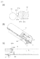
- 2A is a partial cross-sectional explanatory view showing the configuration of the developer supply device
- FIG. 2B is a perspective explanatory view showing the configuration of the mounting portion
- FIG. 2C is a cross-sectional explanatory view showing the configuration of the mounting portion.
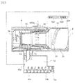
- FIG. 3 is a cross-sectional explanatory view showing the configuration of the developer supply container and the developer supply device.
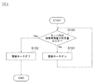
- FIG. 4 is a flowchart for explaining the flow of developer replenishment.
- FIG. 5 is an enlarged cross-sectional view showing a configuration of a modified example of the developer supply device.
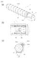
- FIG. 6A is a perspective explanatory view showing the configuration of the developer supply container
- FIG. 6B is a partially enlarged view showing the configuration around the discharge port
- FIG. 6C is a mounting portion of the developer supply device with the developer supply container. It is front explanatory drawing which shows the state mounted
- FIG. 7 is a cross-sectional perspective view showing the configuration of the developer supply container.
- FIG. 8A is a partial cross-sectional view showing a state in which the pump portion is fully extended in use
- FIG. 8B is a partial cross-sectional view showing a state in which the pump portion is maximally contracted in use.
- FIG. 9A is a partial cross-sectional view showing a state in which the pump portion is fully extended in use
- FIG. 9B is a partial cross-sectional view showing a state in which the pump portion is maximally contracted in use
- FIG. FIG. 3 is a partial cross-sectional view of the pump unit as viewed from the front.
- FIG. 10 is a development view showing the shape of the cam groove of the developer supply container.
- FIG. 11 is a diagram showing the transition of the internal pressure of the developer supply container.
- 12A is a cross-sectional explanatory view showing the configuration of the developer supply container and the developer supply device
- FIG. 12B is a partial cross-sectional view showing the state of the instruction section when the drive motor rotates
- FIG. It is a fragmentary sectional view which shows the state of the instruction
- FIG. 13 is a flowchart for explaining the rotation control of the drive motor.
- FIG. 14A is a perspective explanatory view showing the configuration of the reciprocating member of the first embodiment of the developer replenishing system having the developer replenishing container according to the present invention
- FIG. 14B is the attachment of the reciprocating member of the first embodiment. It is the elements on larger scale which show the structure of a force part.
- FIG. 15 is a cross-sectional explanatory view showing the configuration of the reciprocating member and the restricting portion of the first embodiment.
- FIG. 16 is a perspective explanatory view showing the configuration of a reciprocating member in which a biasing portion is formed on the downstream side in the rotation direction in the second embodiment of the developer supply system having a developer supply container according to the present invention.
- an image forming apparatus 100 configured as an example equipped with a developer supply system having the developer supply container 1 according to the present invention will be described.
- FIG. 1 An image forming apparatus 100 is an example of a copying machine.
- the document 101 is placed on the document glass 102.
- an optical image corresponding to the image information of the original 101 is imaged on the surface of the photoconductor 104 made of an electrophotographic photoconductor serving as an image carrier by a plurality of mirrors 8 and lenses 9 of the optical unit 103, thereby statically.
- An electrostatic latent image is formed.
- This electrostatic latent image is visualized using a toner (one-component magnetic toner) as a developer T (dry powder) by a developing device 201a including a dry one-component developing device.
- a toner one-component magnetic toner
- a developer T dry powder
- the one-component nonmagnetic toner is supplied as the developer T.
- the nonmagnetic toner is supplied as the developer T.
- the developer T may be replenished with a nonmagnetic toner and a magnetic carrier.
- Reference numerals 105 to 108 denote feeding cassettes for storing sheets 7 as an example of a recording medium.
- the optimum feeding cassettes 105 to 108 are determined based on the size information input by the user from the liquid crystal operation unit of the image forming apparatus 100 or the size of the document 101. Selected. Then, the single sheet 7 separated and conveyed by the feeding / separating devices 105A to 108A is conveyed to the registration roller 110 via the conveying unit 109. Then, the sheet 7 is conveyed by the registration roller 110 in synchronization with the rotation of the photosensitive member 104 and the scanning timing of the optical unit 103.
- Reference numeral 111 denotes a transfer charger.
- Reference numeral 112 denotes a separation charger.
- the developer image (toner image) formed on the surface of the photoreceptor 104 is transferred to the sheet 7 by the transfer charger 111. Then, the sheet 7 on which the developer image (toner image) is transferred is separated from the photoreceptor 104 by the separation charger 112. Thereafter, the sheet 7 conveyed by the conveying unit 113 is fixed to the developer image on the sheet 7 by heat and pressure in the fixing unit 114, and then passes through the discharge reversing unit 115 in the case of single-sided copying. The paper is discharged to the discharge tray 117 by the discharge roller 116.
- the sheet 7 passes through the discharge reversing unit 115, and a part of the sheet 7 is once discharged out of the image forming apparatus 100 by the discharge roller 116. Thereafter, the trailing edge of the sheet 7 passes through the flapper 118, and the flapper 118 is controlled and the discharge roller 116 is rotated in reverse at the timing when it is sandwiched between the discharge rollers 116. As a result, the sheet is conveyed again into the image forming apparatus 100. Further, after being conveyed to the registration roller 110 via the re-feed conveyance units 119 and 120, the sheet is discharged to the discharge tray 117 along the same conveyance path as in the case of single-sided copying.
- an image forming process device such as a developing device 201a as a developing unit, a cleaner unit 202 as a cleaning unit, and a primary charger 203 as a charging unit is installed around the photosensitive member 104.
- the developing device 201 a develops the developer T by attaching the developer T to the electrostatic latent image formed on the photosensitive member 104 by the optical unit 103 based on the image information of the document 101.
- the primary charger 203 uniformly charges the surface of the photoconductor 104 in order to form a desired electrostatic latent image on the surface of the photoconductor 104.
- the cleaner unit 202 removes the developer T remaining on the surface of the photoconductor 104.
- FIG. 2A is a partial cross-sectional view of the developer supply device 201.
- FIG. 2B is a perspective view of the mounting portion 10 to which the developer supply container 1 is mounted.
- FIG. 2C is a cross-sectional view of the mounting portion 10.
- FIG. 3 is a partially enlarged cross-sectional view of the configuration of the control system and the developer supply container 1 and the developer supply device 201.
- FIG. 4 is a flowchart for explaining the developer supply operation. As shown in FIG.
- the developer supply device 201 includes a mounting portion 10 including a mounting space for detachably mounting the developer supply container 1, and a developer T discharged from the developer supply container 1.
- the developer supply container 1 is configured to be mounted in the direction of arrow M in FIG. That is, the developer supply container 1 is mounted on the mounting portion 10 so that the longitudinal direction thereof substantially coincides with the arrow M direction. Further, the direction in which the developer supply container 1 is removed from the mounting portion 10 is opposite to the arrow M direction. As shown in FIGS.
- the developing device 201a includes a developing roller 201f, a stirring member 201c, and feeding members 201d and 201e.
- the developer supplied from the developer supply container 1 is stirred by the stirring member 201c, sent to the developing roller 201f by the feeding members 201d and 201e, and supplied onto the surface of the photoreceptor 104 by the developing roller 201f.
- the developing roller 201f is provided with a developing blade 201g that controls the coating amount of the developer T on the surface of the developing roller 201f. Further, in order to prevent the leakage of the developer T between the developing roller 201f and the developing device 201a, a leakage preventing sheet 201h disposed in contact with the developing roller 201f is provided.
- the flange 10 is brought into contact with the flange portion 4 shown in FIG. 6 of the developer supply container 1 when the developer supply container 1 is mounted on the mounting portion 10.
- a rotation restricting portion 11 serving as a restricting portion for restricting movement of the portion 4 in the rotation direction is provided.
- the rotation restricting portion 11 restricts the movement of the reciprocating member 3b in the direction intersecting with the reciprocating direction.
- the developer T is supplied from the discharge hole 4 a of the developer supply container 1 to the developing device 201 a through the developer receiving hole 13.
- the discharge hole 4a serving as a discharge port discharges the developer T that has been transported by the transport unit 2k formed of a cylindrical portion.
- the diameter ⁇ of the developer receiving hole 13 shown in FIG. 2C is a pinhole formed of a fine opening in order to prevent contamination by the developer T in the mounting portion 10 as much as possible. Is set to about 3 mm.
- the diameter ⁇ of the developer receiving hole 13 may be any diameter that allows the developer T to be discharged from the discharge hole 4a. Further, as shown in FIG.
- the hopper 10a includes a conveying screw 10b for conveying the developer T to the developing device 201a and an opening 10c communicating with the developing device 201a. Further, a developer sensor 10d including a magnetic sensor for detecting the amount of the developer T accommodated in the hopper 10a is provided. Furthermore, as shown in FIGS. 2B and 2C, the mounting unit 10 has a drive gear 300 that serves as a drive unit. The drive gear 300 has a function of receiving a rotational driving force from the driving motor 500 via a driving gear train and applying the rotational driving force to the developer supply container 1 set in the mounting portion 10. is doing. Further, as shown in FIG. 3, the drive motor 500 is configured such that its operation is controlled by a control device 600 including a CPU (Central Processing Unit).
- a control device 600 including a CPU (Central Processing Unit).
- the control device 600 is configured to control the operation of the drive motor 500 based on the developer remaining amount information input from the developer sensor 10d.
- the drive gear 300 shown in FIGS. 2B and 2C is set so as to rotate only in one direction in order to simplify the control of the drive motor 500. That is, the control device 600 is configured to control only on (operation) / off (non-operation) of the drive motor 500. Therefore, the developer replenishing device 201 has a reversal driving force obtained by periodically reversing the drive motor 500 (drive gear 300) in the forward direction and the reverse direction.
- the drive unit can be simplified.
- the image forming apparatus 100 is provided with a detection unit 600a that includes an optical sensor that assists the control device 600 when the drive motor 500 is turned off.
- a detection unit 600a that includes an optical sensor that assists the control device 600 when the drive motor 500 is turned off.
- a certain amount of developer T is accommodated in the hopper 10a by the control device 600 controlling the operation / non-operation of the drive motor 500 in accordance with the output of the developer sensor 10d shown in FIG. It is constituted so that. Specifically, first, the developer sensor 10d checks the amount of developer contained in the hopper 10a (step S100). When it is determined that the developer storage amount detected by the developer sensor 10d is less than a predetermined amount, that is, when the developer T is not detected by the developer sensor 10d, the drive motor 500 is driven, The developer T replenishment operation is executed for a predetermined time (step S101).
- the developer replenishment operation it may be determined that the developer storage amount detected by the developer sensor 10d has reached a predetermined amount, that is, the developer T may be detected by the developer sensor 10d. In that case, the drive of the drive motor 500 is turned off, and the replenishment operation of the developer T is stopped (step S102). By stopping the replenishment operation, a series of developer replenishment steps is completed.
- Such a developer replenishing step is configured to be repeatedly executed when the developer T is consumed in association with image formation and the amount of developer contained in the hopper 10a becomes less than a predetermined amount.
- FIG. 5 shows an example in which a two-component developing device 800 is used as the developer supply device 201.
- the two-component developing device 800 has a developer stirring chamber 12 to which the developer T is replenished and a developing chamber 14 for supplying the developer T to the developing sleeve 800a.
- the developer stirring chamber 12 and the developing chamber 14 are provided.
- a stirring screw 800b in which the developer conveying directions are opposite to each other.
- the developer stirring chamber 12 and the developing chamber 14 communicate with each other at both ends in the longitudinal direction (from the back side to the front side in FIG. 5), and the two-component developer T circulates and conveys these two chambers. It becomes the composition which is done.
- a developer sensor 800c including a magnetic sensor for detecting the toner concentration of the developer T is installed in the developer stirring chamber 12. Based on the detection result of the developer sensor 800c, the controller 600 controls the drive motor 500. The operation is controlled.
- the developer T supplied from the developer supply container 1 is nonmagnetic toner, or nonmagnetic toner and a magnetic carrier.
- FIG. 6A is an overall perspective view of the developer supply container 1.
- FIG. 6B is a partially enlarged view around the discharge hole 4 a of the developer supply container 1.
- FIG. 6C is a front view showing a state in which the developer supply container 1 is detachably mounted on the mounting portion 10 of the developer supply device 201.
- FIG. 7 is a cross-sectional perspective view of the developer supply container 1.
- FIG. 8A is a partial cross-sectional view of the pump unit 3a that expands and contracts and changes its capacity to the maximum when used.
- the developer supply container 1 is formed in a hollow cylindrical shape as a whole, and has a developer accommodating portion 2 having an internal space for accommodating the developer T therein.
- the developer accommodating section 2 (in the developer accommodating section) conveys the developer T as it rotates, and the developer discharging section 4c and the pump section 3a shown in FIG. Functions as 2.
- the transport unit 2 c has a shape protruding from the inner surface of the developer storage unit 2. In this embodiment, when the developer accommodating portion 2 rotates, the conveying portion 2c formed integrally with the developer accommodating portion 2 is also rotated.
- the developer supply container 1 has a flange portion 4 serving as a non-rotating portion on one end side in the longitudinal direction which is the developer transport direction of the developer accommodating portion 2.
- the transport unit 2 c is configured to be rotatable relative to the flange unit 4.
- the cross-sectional shape of the transport unit 2c may be a non-circular shape as long as it does not affect the rotation operation in the developer supply process. For example, an elliptical section or a polygonal section may be employed. In the present embodiment, as shown in FIG.
- the total length L1 of the developer accommodating portion 2 is set to about 460 mm, and the outer diameter R1 of the developer accommodating portion 2 is set to about 60 mm.
- the length L2 of the area where the developer discharge portion 4c is installed is about 21 mm.
- the full length L3 in the state extended most in the expansion-contraction range on use of the pump part 3a is about 29 mm.
- the full length L4 in the state shrunk most in the expansion-contraction possible range on use of the pump part 3a is about 24 mm.
- the developer storage portion 2 and the developer discharge portion 4c are horizontal. It is configured to line up in the direction. That is, the developer accommodating portion 2 has a structure in which the horizontal length is sufficiently longer than the vertical length, and the horizontal direction side is connected to the developer discharge portion 4c. Accordingly, when the developer replenishing container 1 is mounted on the developer replenishing device 201, compared to the case where the developer containing portion 2 is positioned vertically above the developer ejecting portion 4c, the upper portion of the discharge hole 4a is higher. The amount of the developer T present in the toner can be reduced. Therefore, the developer T in the vicinity of the discharge hole 4a is not easily consolidated, and the intake / exhaust operation by the pump unit 3a can be performed smoothly.
- the developer T is discharged from the discharge hole 4a by changing the volume in the developer supply container 1 by the pump unit 3a shown in FIGS. . Therefore, it is preferable to employ a material having a rigidity that does not collapse or swell greatly with respect to the change in volume as the material of the developer supply container 1.
- the developer supply container 1 communicates with the outside only through the discharge hole 4a, and is configured to be sealed from the outside except for the discharge hole 4a.
- the material of the developer accommodating portion 2 and the developer discharging portion 4c is made of polystyrene resin
- the material of the pump portion 3a is made of polypropylene resin.
- the developer accommodating portion 2 and the developer discharging portion 4c may be any material that can withstand the change in volume.
- ABS acrylonitrile / butadiene / styrene copolymer
- polyester polyethylene
- polypropylene can be used.
- the material of the pump unit 3a may be any material that exhibits an expansion / contraction function and can change the volume of the developer supply container 1 by changing the volume.
- ABS acrylonitrile / butadiene / styrene copolymer
- polystyrene polyester, polyethylene or the like may be formed thin. It is also possible to use rubber or other stretchable materials.
- each of the pump part 3a, the developer accommodating part 2, and the developer discharging part 4c satisfies the above-described functions by adjusting the thickness of the resin material, etc.
- each is made of the same material, for example, injection molding What is integrally molded using a method, a blow molding method, or the like may be used.
- the gear portion 2d serving as a drive receiving portion to which the rotational driving force for rotating the conveyance portion 2c from the flange portion 4, the developer accommodating portion 2, the pump portion 3a, and the developer supply device 201 is input will be described.
- the flange portion 4 is provided with a developer discharge portion 4 c serving as a hollow discharge portion for temporarily storing the developer T conveyed from the developer storage portion 2. It has been.
- a discharge hole 4a for allowing the developer T to be discharged out of the developer supply container 1, that is, for supplying the developer T to the developer supply device 201 is formed at the bottom of the developer discharge portion 4c. ing.
- the flange portion 4 is provided with a shutter 4b for opening and closing the discharge hole 4a.
- the shutter 4b is configured to abut against the abutting portion 21 shown in FIG. 2B provided on the mounting portion 10 in accordance with the mounting operation of the developer supply container 1 to the mounting portion 10. Therefore, the shutter 4b slides relative to the developer supply container 1 in the direction opposite to the arrow M direction in FIG. 7 in accordance with the mounting operation of the developer supply container 1 to the mounting portion 10. As a result, the shutter 4b is retracted from the position covering the discharge hole 4a to expose the discharge hole 4a, and the opening operation is completed. At this time, as shown in FIG.
- the discharge hole 4 a is in communication with each other because the position of the discharge hole 4 a coincides with the developer receiving hole 13 of the mounting portion 10, so that the developer can be supplied from the developer supply container 1. It becomes a state.
- the flange portion 4 is configured so that the flange portion 4 does not rotate with respect to the rotation of the developer accommodating portion 2 when the developer supply container 1 is attached to the attachment portion 10 of the developer supply device 201. .
- a rotation restricting portion 11 shown in FIG. 2B is provided so that the flange portion 4 does not rotate in the rotation direction of the gear portion 2d serving as a drive receiving portion.
- the developer accommodating portion 2 is configured to rotate in the developer replenishing step without being restricted by the developer replenishing device 201 in the rotation direction.
- the developer accommodating portion 2 has a cylindrical shape (conveying portion 2k). As shown in FIGS.
- the inner surface of the transport unit 2k is spiraled on the inner side to transport the developer T stored therein toward the developer discharge unit 4c (discharge hole 4a) as it rotates.
- the conveyance part 2c protruded in the shape is provided.
- the conveyance part 2k is formed by the blow molding method using resin of the material mentioned above. Note that when the developer supply container 1 is increased in volume to increase the filling amount of the developer T, a method of increasing the volume of the flange portion 4 of the developer container 2 in the height direction is conceivable. However, with such a configuration, the gravity effect on the developer T in the vicinity of the discharge hole 4a is further increased by the dead weight of the developer T.
- the developer T in the vicinity of the discharge hole 4a is easily consolidated, which hinders intake and exhaust through the discharge hole 4a.
- the driving force for driving the pump unit 3a also increases, and the load on the main body of the image forming apparatus 100 increases.
- the axial direction of the conveyance part 2k and the axial direction of the flange part 4 are installed side by side in the horizontal direction. For this reason, the thickness of the developer layer on the discharge hole 4a in the developer supply container 1 can be set thin.
- the transport unit 2 k is fixed so as to be rotatable relative to the flange unit 4 in a compressed state of a flange seal 5 b made of a ring-shaped seal member provided on the inner surface of the flange unit 4. Has been. Thereby, the conveyance part 2k rotates, sliding with the flange seal 5b. For this reason, the developer T does not leak during the rotation of the transport unit 2k, and airtightness is maintained.
- the air can be appropriately entered and exited through the discharge hole 4a, and the changeable state of the volume of the developer supply container 1 during the supply of the developer T can be changed to a desired state.
- a description will be given of the pump unit 3 a that can change its volume as it reciprocates in the rotation axis direction of the transport unit 2 k.
- the pump unit 3 a of this embodiment is communicated with the inside of the developer supply container 1. And it has the intake / exhaust function which performs an intake operation and an exhaust operation alternately via the discharge hole 4a.
- the pump unit 3a has an airflow generation function that alternately and repeatedly generates an airflow that goes to the inside of the developer supply container 1 through the discharge hole 4a and an airflow that goes from the developer supply container 1 to the outside.
- the pump portion 3a is provided in the direction of arrow M in FIG. 8A from the developer discharge portion 4c.
- the pump part 3a of this embodiment is provided so that it may not rotate in the rotation direction of the conveyance part 2k together with the developer discharge part 4c.
- the pump unit 3a plays a major role in fluidizing the developer T during the intake operation.
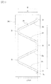
- the pump unit 3a a resin volume changeable pump unit (bellows pump) whose volume can be changed in accordance with a reciprocating operation is adopted. Specifically, as shown in FIGS. 7 and 8, a bellows-like pump portion 3a is employed, and “mountain fold portions” and “valley fold portions” are periodically formed on the peripheral surface of the pump portion 3a. A plurality are alternately formed. Therefore, the pump unit 3a can repeatedly perform compression and expansion alternately by the driving force received from the developer supply device 201. In the present embodiment, the volume change amount during expansion / contraction of the pump unit 3a is 5 cm. 3 (Cc) is set.
- the volume of the developer supply container 1 can be alternately and repeatedly changed at a predetermined cycle.
- the developer T in the developer discharge portion 4c can be efficiently discharged from the discharge hole 4a.
- the gear portion 2d serving as the drive receiving portion of the developer supply container 1 to which the rotational driving force for rotating the transport portion 2k is input from the developer supply device 201 will be described.
- the developer supply container 1 has a gear portion 2d that functions as a drive receiving portion that can be engaged with and driven by a drive gear 300 that functions as a drive portion of the developer supply device 201. Is provided.
- the gear part 2d is configured to be rotatable integrally with the transport part 2k. Therefore, the rotational driving force input from the drive gear 300 to the gear portion 2d is generated in the direction of the rotation axis of the drive conversion portion including the cam groove 2e and the protrusion 3c and the conveyance portion 2k shown in FIGS. 9A and 9B. It is transmitted to the pump unit 3a via the reciprocating member 3b that reciprocates.
- the bellows-like pump part 3a of the present embodiment is manufactured using a resin material that has a strong resistance to twisting in the rotational direction within a range that does not hinder its expansion and contraction operation.
- the gear portion 2d is provided on the outer peripheral surface of the end portion of the transport portion 2k on the developer transport direction side, but the present invention is not limited to this.
- it may be provided on the other end side in the longitudinal direction of the developer accommodating portion 2, that is, on the opposite side to the developer transport direction which is the rearmost end of the developer accommodating portion 2.
- the drive gear 300 is installed at a position corresponding to the gear portion 2d.
- a gear mechanism is used as a drive coupling mechanism between a gear portion 2 d that is a drive receiving portion of the developer supply container 1 and a drive gear 300 that is a drive portion of the developer supply device 201.
- the developer supply container 1 is provided with a cam mechanism serving as a drive conversion unit that converts a rotational driving force for rotating the conveying unit 2k received by the gear unit 2d serving as a drive receiving unit into a reciprocating force of the pump unit 3a.
- the gear portion 2d is configured to receive the rotation of the conveying portion 2k and the driving force for reciprocating (extending / contracting) the pump portion 3a by the gear portion 2d serving as one drive receiving portion. Is converted into a reciprocating force on the developer supply container 1 side.
- FIG. 9A is a partial cross-sectional view showing a state in which the pump portion 3a is extended to the maximum in use.
- FIG. 9B is a partial cross-sectional view showing a state in which the pump portion 3a is contracted to the maximum in use.
- FIG. 9C is a cross-sectional explanatory view of the pump portion 3a as viewed from the front. As shown in FIGS.
- the cam mechanism constitutes a drive conversion portion that converts the rotational driving force received by the gear portion 2d into the reciprocating force of the pump portion 3a.
- the cam mechanism includes a cam groove 2e formed on the outer peripheral surface of the conveyance portion 2k1 provided in communication with the conveyance portion 2k, and a protrusion 3c that engages with the cam groove 2e and engages with the reciprocating member 3b. Configured. Specifically, the cam groove 2e provided over the entire outer periphery of the conveying portion 2k1 provided integrally with the gear portion 2d serving as a drive receiving portion that receives the rotational driving force from the drive gear 300 is a gear. It rotates with the rotation of the part 2d. As shown in FIG.
- the cam groove 2e is engaged with a protrusion 3c protruding inwardly at the ends of the pair of arms 3h of the U-shaped reciprocating member 3b.
- the protrusion 3c of this embodiment is engaged with being fixed to the arm portion 3h of the reciprocating member 3b.
- the reciprocating member 3b is restricted by a rotation restricting portion 3f serving as a restricting portion in the rotation direction of the transport portion 2k.
- the projections 3c provided at the ends of the pair of arms 3h of the reciprocating member 3b configured in a U shape are fitted into the cam grooves 2e, and along the cam grooves 2e.
- the pump unit 3a is regulated so as to reciprocate in the extending and contracting direction.
- the number of protrusions 3c that engage with the reciprocating member 3b may be at least one.
- the protrusion 3c sliding along the cam groove 2e. It is preferable to provide a plurality.
- two protrusions 3c that engage with the reciprocating member 3b are provided so as to be engaged at two locations along the cam groove 2e.
- the protrusion 3c that engages with the reciprocating member 3b is configured to be disposed at a position that opposes 180 ° around the rotation axis of the transport unit 2k. That is, the rotational driving force input from the drive gear 300 is transmitted to the gear portion 2d, and the cam groove 2e rotates integrally with the gear portion 2d. Accordingly, the protrusion 3c that engages with the reciprocating member 3b along the cam groove 2e reciprocates in the direction of arrow M in FIG. 8 or in the opposite direction. Further, the reciprocating member 3b formed integrally with the protrusion 3c reciprocates in the direction of the rotation axis of the transport unit 2k. As a result, the pump unit 3a alternately repeats the expanded state shown in FIG.
- the transport amount of the developer T per unit time transported to the developer discharge unit 4c with the rotation of the transport unit 2k is set as follows.
- the drive conversion unit including the cam groove 2e and the protrusion 3c is larger than the developer discharge amount per unit time discharged from the developer discharge unit 4c to the developer supply device 201 by the action of the pump unit 3a. Is configured. If the discharge capacity of the developer T by the pump section 3a is larger than the transport capacity of the developer T to the developer discharge section 4c by the transport section 2c provided in the transport section 2k, it exists in the developer discharge section 4c.
- the drive conversion unit composed of the cam groove 2e and the projection 3c is configured such that the pump unit 3a reciprocates a plurality of times while the transport unit 2k rotates once.
- the drive motor 500 is set to an output necessary for constantly rotating the transport unit 2k.
- the output required for the drive motor 500 is calculated from the rotational torque and the rotational speed of the transport unit 2k.
- the rotational speed of the transport unit 2k it is preferable to set the rotational speed of the transport unit 2k as low as possible.
- the rotation speed of the transport unit 2k is reduced in order to reduce the load on the drive motor 500, the number of reciprocating operations of the pump unit 3a per unit time is reduced. For this reason, the amount of the developer T discharged from the developer supply container 1 per unit time is reduced. That is, in order to satisfy the replenishment amount of the developer T required from the main body of the image forming apparatus 100 in a short time, the amount of the developer T discharged from the developer replenishment container 1 may be insufficient.
- the volume change amount of the pump unit 3a is increased, the discharge amount of the developer T per cycle of the pump unit 3a can be increased. Thereby, it becomes possible to meet the supply amount of the developer T required from the main body of the image forming apparatus 100.
- a countermeasure has the following problems. That is, when the volume change amount of the pump unit 3a is increased, the peak value of the internal pressure (positive pressure) of the developer supply container 1 in the exhaust process increases. For this reason, the load required to reciprocate the pump unit 3a increases. For this reason, in the present embodiment, the pump unit 3a is reciprocated in a plurality of cycles while the transport unit 2k rotates once.
- a drive conversion portion including a cam groove 2 e and a protrusion 3 c is provided on the outer peripheral portion of the developer accommodating portion 2.
- FIG. 10 is a development view of the cam groove 2e provided on the outer peripheral surface of the transport unit 2k1.
- the direction of arrow A is the rotational direction of the transport unit 2k (the moving direction of the cam groove 2e).
- the arrow B direction in FIG. 10 indicates the extending direction of the pump unit 3a.
- the arrow C direction of FIG. 10 shows the compression direction of the pump part 3a.
- the cam groove 2e includes a cam groove 2g used when the pump portion 3a is compressed, a cam groove 2h used when the pump portion 3a is extended, and a pump portion non-operating portion where the pump portion 3a does not reciprocate. And a cam groove 2i constituting the.
- the amplitude which is the expansion-contraction length of the pump part 3a in the arrow B and C direction of FIG. 10 used as the expansion-contraction direction of the pump part 3a of the cam groove 2e is set as follows. That is, it is expressed by (L3-L4) by using the full length L3 in the most extended state of the pump portion 3a shown in FIG. 8A and the full length L4 in the most contracted state of the pump portion 3a shown in FIG. .
- the cam groove 2e rotates in the direction of arrow A in FIG. 10 along with the rotation of the gear portion 2d
- the protrusion 3c that engages with the reciprocating member 3b shown in FIG. 14A becomes the cam groove 2i and cam groove shown in FIG.
- the instruction unit 6 is configured to issue an instruction to stop the rotation drive of the drive motor 500 to the control device 600 in the intake process or the exhaust process.
- the intake process, the exhaust process, and the operation stop process will be described.
- ⁇ Intake process> First, an intake process including an intake operation via the discharge hole 4a will be described. The state shown in FIG. 9A, in which the pump portion 3a is extended the most, from the state shown in FIG. Thus, the intake operation is performed. That is, with this intake operation, the volumes in the pump unit 3a, the transport unit 2k, and the flange unit 4 that can store the developer T in the developer supply container 1 increase.
- the inside of the developer supply container 1 is substantially sealed except for the discharge hole 4a, and the discharge hole 4a is substantially closed with the developer T. . Therefore, the internal pressure of the developer supply container 1 decreases as the volume of the portion of the developer supply container 1 that can store the developer T increases. At this time, the internal pressure of the developer supply container 1 becomes lower than the atmospheric pressure (external pressure). Therefore, the air outside the developer supply container 1 moves into the developer supply container 1 through the discharge hole 4a due to the pressure difference between the inside and outside of the developer supply container 1. At that time, since air is taken in from the outside of the developer supply container 1 through the discharge hole 4a, the developer T located in the vicinity of the discharge hole 4a can be released and fluidized.
- the developer T located in the vicinity of the discharge hole 4a can include air to reduce the bulk density and appropriately fluidize the developer T. Further, at this time, since air is taken into the developer supply container 1 through the discharge hole 4a, the internal pressure of the developer supply container 1 is close to the atmospheric pressure (outside air pressure) even though the volume is increased. Will change. In this way, by allowing the developer T to be fluidized, the developer T can be smoothly discharged from the discharge hole 4a without the developer T being clogged in the discharge hole 4a during the exhaust operation described later. Is possible. Therefore, the amount of developer T discharged from the discharge hole 4a per unit time can be made substantially constant over a long period of time.
- the pump unit 3a is not limited to the state shown in FIG. 9 (a), which is the most extended state from the state shown in FIG. 9 (b).
- the intake operation is performed if the internal pressure of the developer supply container 1 is changed. That is, the intake process is a state where the protrusion 3c that engages with the reciprocating member 3b is engaged with the cam groove 2h shown in FIG. ⁇ Exhaust process>
- an exhaust process including an exhaust operation via the exhaust hole 4a will be described. The exhaust operation is performed by changing from the state shown in FIG. 9A in which the pump part 3a is extended to the state shown in FIG.
- the pump unit 3a is not limited to the state shown in FIG. 9A in which the pump unit 3a is extended to the state shown in FIG.
- the pump unit 3a performs a predetermined volume change every time. For example, if the cam groove 2e is configured only by the exhaust process and the intake process, the drive motor 500 is stopped during the exhaust process or the intake process. At that time, even after the drive motor 500 stops rotating, the conveying portion 2k rotates due to inertia, and the protrusion 3c that engages with the cam groove 2e and engages the reciprocating member 3b moves until the conveying portion 2k stops. The pump unit 3a also continues to reciprocate in conjunction with it. Thus, even after the drive motor 500 stops rotating, the exhaust process or the intake process is performed by inertia.
- the distance that the conveyance unit 2k rotates due to inertia depends on the rotation speed of the conveyance unit 2k. Furthermore, the rotational speed of the transport unit 2k depends on the torque applied to the drive motor 500. From this, the torque applied to the drive motor 500 changes depending on the amount of the developer T in the developer supply container 1, and the rotational speed of the transport unit 2k also changes. Therefore, it is difficult to make the stop position of the pump unit 3a the same every time. Therefore, in order to stop the pump unit 3a at a predetermined position every time, it is necessary to provide the cam groove 2e with a cam groove 2i that is a region where the pump unit 3a does not reciprocate even when the transport unit 2k is rotating. .
- the cam groove 2i arranged in parallel with the arrow A direction which is the rotation direction of the transport unit 2k (the movement direction of the cam groove 2e).
- the cam groove 2i is formed with a straight groove at a predetermined distance parallel to the direction of the arrow A, which is the rotation direction of the transport unit 2k, and the protrusion 3c that engages the reciprocating member 3b is engaged with the cam groove 2i. While the transfer unit 2k rotates, the reciprocating member 3b does not move. That is, the operation stop process is a state in which the protrusion 3c that engages with the reciprocating member 3b is engaged with the cam groove 2i.
- the pump unit 3a does not reciprocate, the developer T is not discharged from the discharge hole 4a.
- the cam groove 2i is inclined at a predetermined angle with respect to the rotational axis direction of the transport section 2k with respect to the rotational direction of the transport section 2k if the exhaust process and intake process through the discharge hole 4a are not performed. It does not matter. Further, it is assumed that the reciprocating motion of the pump part 3a accompanying the inclination of the cam groove 2i is allowable.
- the instruction unit 6 is provided to control the protrusion 3c that engages with the reciprocating member 3b to engage with the cam groove 2i.
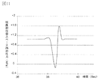
- the verification experiment result about how the internal pressure of the developer supply container 1 is changed will be described.
- the pump unit 3a is moved to 5 cm. 3
- the change in the internal pressure of the developer supply container 1 was measured when it was expanded and contracted by the volume change amount.
- the internal pressure of the developer supply container 1 was measured by connecting a pressure gauge (manufactured by Keyence Corporation, model name: AP-C40) to the developer supply container 1.
- FIG. 11 The transition of the pressure change is shown in FIG. In FIG. 11, the horizontal axis indicates time, and the vertical axis indicates the relative pressure in the developer supply container 1 with respect to the atmospheric pressure of 1 kPa as a reference. “+” Shown on the vertical axis in FIG. 11 indicates the positive pressure side with respect to the external atmospheric pressure, and “ ⁇ ” indicates the negative pressure side with respect to the external atmospheric pressure.
- the internal pressure of the developer supply container 1 becomes positive with respect to the atmospheric pressure, and when the pressure is applied to the internal developer T, the developer T is discharged from the discharge hole. It was confirmed that it was discharged from 4a to the outside.
- the absolute value of the pressure on the negative pressure side was about 1.2 kPa
- the absolute value of the pressure on the positive pressure side was about 0.5 kPa.
- the internal pressure of the developer supply container 1 is alternately switched between the negative pressure state and the positive pressure state in accordance with the intake operation and the exhaust operation by the pump unit 3a, and is discharged.
- the developer supply container 1 is provided with the pump unit 3a having a simple configuration for performing the intake operation and the exhaust operation.
- the developer T can be discharged stably.
- the inside of the pump unit 3a that can change the volume is used as the developer storage space, a new developer is used when the volume of the pump unit 3a is increased to reduce the internal pressure. An accommodation space can be formed. Accordingly, even if the inside of the pump unit 3a is filled with the developer T, the developer T can be fluidized by adding air to the developer T with a simple configuration, thereby reducing the bulk density. it can.
- the developer supply container 1 can be filled with the developer T at a higher density than before.
- the driving force for rotating the transport unit 2k provided with the transport unit 2c and the driving force for reciprocating the pump unit 3a are received by the gear unit 2d serving as one drive receiving unit. . Therefore, the configuration of the drive receiving portion of the developer supply container 1 can be simplified.
- the driving gear 300 serving as one driving unit provided in the developer supply device 201 is configured to apply a driving force to the developer supply container 1, it contributes to simplification of the drive unit of the developer supply device 201. can do.
- the rotational driving force received from the developer supply device 201 for rotating the transport unit 2k is set as follows.
- the drive conversion is performed by the drive conversion unit including the cam groove 2e of the developer supply container 1 and the protrusion 3c engaged with the reciprocating member 3b.
- the pump unit 3a can be appropriately reciprocated.
- the drive motor 500 is controlled by a control device 600 including a CPU.
- the instruction unit 6 instructs the control device 600 to stop the rotation drive.
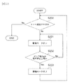
- FIG. 13 is a flowchart for explaining the rotation control of the drive motor 500.
- the developer T replenishment process will be described with reference to FIG. As shown in FIGS.
- the control device 600 causes the drive motor 500 to respond to the outputs of the developer sensors 10 d and 800 c that are magnetic sensors that detect the toner concentration in the developer T in the developer stirring chamber 12. Controls the rotation of the. Specifically, the developer sensors 10d and 800c shown in FIGS. 3 and 5 check the toner concentration in the developer T in the developer stirring chamber 12 (step S200). If the toner concentration in the developer T in the developer stirring chamber 12 is low, the controller 600 is instructed to rotate the drive motor 500 (step S201). The gear portion 2d starts rotating by the rotational drive of the drive motor 500. Next, in step S202, when the protrusion 3c that engages with the reciprocating member 3b engages with the cam groove 2i shown in FIG.
- the control device 600 is instructed to stop the drive motor 500. Then, the rotation of the gear unit 2d is stopped by stopping the rotation of the drive motor 500.
- step S202 when the pump unit 3a is not in the operation stop process, the process returns to step S201 and the drive motor 500 continues to rotate. Then, after repeating the series of operations in steps S200 to S203, the developer sensors 10d and 800c shown in FIGS. 3 and 5 again detect the toner concentration in the developer T in the developer stirring chamber 12 (step). S200). In step S200, when the toner concentration in the developer T in the developer stirring chamber 12 is sufficient, this series of developer replenishment steps is completed.
- FIG. 12A is a partial cross-sectional explanatory view showing the configuration of the developer supply container 1 and the developer supply device 201.
- FIG. 12B is a partially enlarged view showing the state of the instruction unit 6 when the drive motor 500 rotates.
- FIG. 12C is a partially enlarged view showing the state of the instruction unit 6 when the rotation of the drive motor 500 is stopped.
- the detection unit 600a uses an optical photosensor, and stops the rotation of the drive motor 500 when the light shielding unit 600b blocks the optical path of the detection unit 600a. Further, when the light shielding unit 600b does not block the optical path of the detection unit 600a, the drive motor 500 continues to rotate.
- FIG. 12B shows a state in which the pump unit 3a is in the operation stop process, and the instruction unit 6 protruding to a part of the outer peripheral surface of the transport unit 2k1 lifts the light shielding unit 600b to block the optical path of the detection unit 600a.
- FIG. 12C shows a case where the pump unit 3a is an exhaust process or an intake process, and is not an operation stop process.
- the instruction unit 6 is located away from the light shielding unit 600b, and is in a state where the light shielding unit 600b is not lifted and the optical path of the detection unit 600a is not blocked by the light shielding unit 600b. That is, the instruction unit 6 raises the light shielding unit 600b to block the optical path of the detection unit 600a, thereby giving an instruction to stop the rotation driving of the drive motor 500 to the control device 600.
- the rotation of the drive motor 500 is stopped every time when the pump unit 3a is in the operation stop process. Thereby, the pump part 3a can perform the volume change decided each time.
- the present invention is not limited to this embodiment, and a configuration in which rotation driving is stopped in an intake process or an exhaust process may be used.
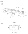
- FIG. 14A is an explanatory perspective view showing the configuration of the reciprocating member 3b.
- FIG. 14B is a partially enlarged view showing the configuration of the elastically deformable urging portions 3g1 and 3g2 provided at both ends of the U-shaped reciprocating member 3b.
- FIG. 15 is a partial cross-sectional view showing the configuration of the reciprocating member 3b and the rotation restricting portion 3f serving as the restricting portion. As shown in FIG.
- the reciprocating member 3b includes a protrusion 3c, a pump engaging portion 3d, an arm portion 3h, and urging portions 3g1 and 3g2.
- the urging portions 3g1 and 3g2 are provided on one side of the reciprocating member 3b.
- contact portions 3g3 and 3g4 that contact the rotation restricting portion 3f are provided on the other side of the reciprocating member 3b.
- a cam groove 2e provided on the outer peripheral surface of the transport portion 2k1 is slidably engaged with a protrusion 3c formed on the reciprocating member 3b.
- the pump engaging portion 3d is engaged with the pump portion 3a, and transmits the reciprocating motion of the transport portion 2k in the rotation axis direction to the pump portion 3a.
- the arm portion 3h of the reciprocating member 3b is formed so as to connect the protrusion 3c and the pump engaging portion 3d in the rotation axis direction of the transport portion 2k.
- the rotation restricting portion 3f is formed in the direction of the rotation axis of the conveying portion 2k (the direction of expansion and contraction of the pump portion 3a) and has a shape that covers the arm portion 3h of the reciprocating member 3b except for a part (see FIG. 9C). ).
- the arm portion 3h of the reciprocating member 3b is configured to be able to reciprocate by sliding in the rotation axis direction inside the rotation restricting portion 3f.
- the rotation restricting portions 3f are arranged on both sides of the reciprocating member 3b in a direction orthogonal to the rotation axis direction.
- the rotation control part 3f also has a function as a guide part which guides the movement of the reciprocating member 3b. Further, there is a backlash (gap) between the arm portion 3h of the reciprocating member 3b and the rotation restricting portion 3f.
- the width F3 of the restricting portion 3f has a relationship of ⁇ F1 ⁇ F3 ⁇ .
- the width of the arm portion 3h of the reciprocating member 3b is the width of the arm portion 3h of the reciprocating member 3b, and the width F3 shown in FIG. 15 restricts the reciprocating member 3b only to the reciprocating operation in the rotation axis direction of the transport portion 2k. It is the width
- the relationship between the width F1 of the arm 3h of the reciprocating member 3b shown in FIG. 14B and the width F3 of the rotation restricting portion 3f shown in FIG. 15 is ⁇ F1 ⁇ F3 ⁇ . Then, the arm portion 3h of the reciprocating member 3b is fitted into the rotation restricting portion 3f, and the reciprocating member 3b cannot reciprocate in the rotation axis direction (left and right direction in FIG.
- the width F1 of the arm portion 3h of the reciprocating member 3b shown in FIG. 14B and the width F3 of the rotation restricting portion 3f shown in FIG. 15 need to have a relationship of ⁇ F1 ⁇ F3 ⁇ . Further, a predetermined gap is provided between the arm portion 3h of the reciprocating member 3b and the rotation restricting portion 3f so that the reciprocating member 3b can easily reciprocate in the rotation axis direction (left and right direction in FIG. 15) of the transport portion 2k. Is preferable.
- the developer supply container 1 is provided with a reciprocating member 3b that reciprocates in the direction of the rotation axis of the transport unit 2k (the direction of the arrow M in FIGS. 7 and 8 or the direction opposite to the direction of the arrow M).
- the reciprocating member 3b is provided with urging portions 3g1 and 3g2 having elasticity.
- a backlash between the arm portion 3h of the reciprocating member 3b and the rotation restricting portion 3f is filled with elastic biasing portions 3g1 and 3g2. That is, the relationship between the width F2 including the U-shaped biasing portions 3g1 and 3g2 in the arm portion 3h of the reciprocating member 3b shown in FIG.
- the width F2 is a length in a state where no force is applied to the urging portions 3g1 and 3g2.
- the biasing portions 3g1 and 3g2 having elasticity are always in contact with the rotation restricting portion 3f.
- the width F1 of the arm portion 3h of the reciprocating member 3b is set to about 8.9 mm.
- a width F2 including the urging portions 3g1 and 3g2 in the arm portion 3h of the reciprocating member 3b is set to about 9.2 mm.
- the width F3 of the rotation restricting portion 3f is set to about 9.0 mm.
- the contact portions 3g3 and 3g4 that contact the rotation restricting portion 3f by the urging force of the urging portions 3g1 and 3g2 continue to rub against the rotation restricting portion 3f.
- the contact portions 3g3 and 3g4 are a part of the arm portion 3h of the reciprocating member 3b. That is, the contact portions 3g3 and 3g4 of the reciprocating member 3b in which the urging portions 3g1 and 3g2 are not provided rotate in a direction orthogonal to the rotation axis direction of the conveyance unit 2k formed of a cylindrical portion (the width direction of the reciprocating member 3b). Stable rubbing with the restricting portion 3f.
- the urging portions 3g1 and 3g2 are provided in the vicinity of the protrusion 3c to which the rotational driving force is input. This is because the protrusion 3c is most susceptible to the rotational driving force. That is, the protrusion 3c has the fastest transmission timing of the force in the rotation direction of the transport unit 2k and the moving speed of the reciprocating member 3b.
- the urging portions 3g1 and 3g2 in the vicinity of the protrusion 3c.
- the moving speed in the rotation direction of the transport portion 2k can be reduced, and the contact sound between the reciprocating member 3b and the rotation restricting portion 3f is reduced. can do.
- two protrusions 3c are provided at both ends of the U-shaped reciprocating member 3b, and two urging portions 3g1 and 3g2 having the same number as the protrusions 3c are provided in the vicinity of the respective protrusions 3c. It is an example.
- the number of U-shaped and elastic urging portions 3g1 and 3g2 be equal to or more than the number of protrusions 3c provided on the reciprocating member 3b.
- it has the two urging
- one urging portion 3g1 is an example formed on the downstream side (downstream in the rotational direction) of the reciprocating member 3b in the rotational direction (the rotational direction of the transport unit 2k).
- FIG. 16 is an explanatory perspective view showing a configuration in which both of the urging portions 3g1 and 3g5 of the reciprocating member 3b are formed on the downstream side (the downstream side in the rotational direction) of the reciprocating member 3b in the rotational direction (rotating direction of the transport unit 2k). is there.
- This embodiment is different from the first embodiment in that the formation position of the urging portion 3g5 of the reciprocating member 3b is moved from the upstream side to the downstream side in the rotating direction of the reciprocating member 3b (the rotating direction of the transport unit 2k).
- the arm portion 3h of the reciprocating member 3b is filled by filling the backlash between the arm portion 3h of the reciprocating member 3b and the rotation restricting portion 3f with elastic biasing portions 3g1 and 3g2. And the contact sound of the rotation control part 3f is reduced.
- the relationship between the width F2 of the arm portion 3h of the reciprocating member 3b including the urging portions 3g1 and 3g2 and the width F3 of the rotation restricting portion 3f is ⁇ F2> F3 ⁇ .
- the arm 3h of the reciprocating member 3b including the biasing portions 3g1 and 3g2 is always in contact with the rotation restricting portion 3f, so that the reciprocating member 3b slides in the direction of the rotation axis of the transport unit 2k.
- the frictional force at the time increases, and the reciprocating member 3b becomes difficult to reciprocate.
- the reciprocating member 3b is easily reciprocated by reducing the frictional force when the reciprocating member 3b slides in the direction of the rotation axis of the transport unit 2k.
- the width F2 of the arm portion 3h of the reciprocating member 3b including the U-shaped elastic urging portions 3g1 and 3g5 and the width F3 of the rotation restricting portion 3f have a relationship of ⁇ F2 ⁇ F3 ⁇ .
- the contact sound of the arm part 3h of the reciprocating member 3b and the rotation restricting part 3f can be reduced.
- the relationship between the width F2 of the arm portion 3h of the reciprocating member 3b including the biasing portions 3g1 and 3g5 and the width F3 of the rotation restricting portion 3f is ⁇ F2 ⁇ F3 ⁇
- the reciprocating member 3b is loose. An attempt is made to move in the rotation direction of the transport unit 2k by the amount. Therefore, the biasing portions 3g1 and 3g5 are brought into contact with the rotation restricting portion 3f before the arm portion 3h of the reciprocating member 3b and the rotation restricting portion 3f come into contact with each other. That is, as shown in FIG.
- both of the two urging portions 3g1 and 3g5 provided at both ends of the U-shaped reciprocating member 3b are moved in the rotational direction of the reciprocating member 3b (the rotational direction of the transport unit 2k). Provided on the downstream side (downstream in the rotational direction). Thereby, before the arm part 3h of the reciprocating member 3b excluding the urging parts 3g1 and 3g5 contacts the rotation restricting part 3f, the contact speed between the arm part 3h of the reciprocating member 3b and the rotation restricting part 3f. The contact noise can be reduced.
- the contact portions 3g3 and 3g6 that contact the rotation restricting portion 3f by the urging force of the urging portions 3g1 and 3g5 continue to rub against the rotation restricting portion 3f.
- the protrusion 3c of the reciprocating member 3b is fitted in the cam groove 2e.
- the urging portions 3g1 and 3g5 first contact the rotation restricting portion 3f.
- the frictional force when the reciprocating member 3b slides in the direction of the rotation axis of the transport unit 2k is reduced as compared with the first embodiment while reducing the contact sound.
- the reciprocating member 3b can be easily reciprocated in the direction of the rotation axis of the transport unit 2k.
- Other configurations are the same as those in the first embodiment, and the same effects can be obtained.
Landscapes
- Physics & Mathematics (AREA)
- General Physics & Mathematics (AREA)
- Dry Development In Electrophotography (AREA)
Abstract
La présente invention porte sur un récipient d'alimentation en révélateur et un système d'alimentation en révélateur qui comprennent : une unité (2c) de transport qui lors d'une rotation transporte un agent de développement (T) dans un récipient (2) d'agent de développement vers une unité (4c) de décharge d'agent de développement ; un engrenage (2d) destiné à recevoir la force d'entraînement rotationnelle utilisée pour faire tourner l'unité (2c) de transport ; une unité (3a) de pompe fournie pour agir sur au moins l'unité (4c) de décharge d'agent de développement, le volume de l'unité de pompe changeant avec le mouvement de va-et-vient ; une unité de conversion d'entraînement destinée à convertir la force d'entraînement rotationnelle mise en entrée dans l'engrenage (2d) en une force destinée à mettre en œuvre l'unité (3a) de pompe ; un élément (3d) de va-et-vient qui est disposé sur l'unité de conversion d'entraînement et se déplace selon un mouvement de va-et-vient pour convertir la force d'entraînement rotationnelle en la force destinée à mettre en œuvre l'unité (3a) de pompe ; une unité (3f) de restriction de rotation destinée à restreindre un déplacement de l'élément (3b) de va-et-vient dans une direction intersectant la direction du mouvement de va-et-vient de l'élément (3b) de va-et-vient ; et des parties (3g1, 3g2) d'excitation élastiquement déformables qui sont disposées sur l'élément (3b) de va-et-vient et sollicitent l'élément (3b) de va-et-vient vers l'unité (3f) de restriction de rotation.
Priority Applications (1)
| Application Number | Priority Date | Filing Date | Title |
|---|---|---|---|
| US14/856,956 US9535369B2 (en) | 2013-03-19 | 2015-09-17 | Developer supply container and developer supplying system |
Applications Claiming Priority (2)
| Application Number | Priority Date | Filing Date | Title |
|---|---|---|---|
| JP2013056444A JP6021701B2 (ja) | 2013-03-19 | 2013-03-19 | 現像剤補給容器及び現像剤補給システム |
| JP2013-056444 | 2013-03-19 |
Related Child Applications (1)
| Application Number | Title | Priority Date | Filing Date |
|---|---|---|---|
| US14/856,956 Continuation US9535369B2 (en) | 2013-03-19 | 2015-09-17 | Developer supply container and developer supplying system |
Publications (1)
| Publication Number | Publication Date |
|---|---|
| WO2014147848A1 true WO2014147848A1 (fr) | 2014-09-25 |
Family
ID=51579572
Family Applications (1)
| Application Number | Title | Priority Date | Filing Date |
|---|---|---|---|
| PCT/JP2013/060413 WO2014147848A1 (fr) | 2013-03-19 | 2013-03-29 | Récipient d'alimentation en révélateur et système d'alimentation en révélateur |
Country Status (3)
| Country | Link |
|---|---|
| US (1) | US9535369B2 (fr) |
| JP (1) | JP6021701B2 (fr) |
| WO (1) | WO2014147848A1 (fr) |
Cited By (1)
| Publication number | Priority date | Publication date | Assignee | Title |
|---|---|---|---|---|
| US10154993B2 (en) * | 2014-10-23 | 2018-12-18 | Kyorin Pharmaceutical Co., Ltd. | Solid pharmaceutical composition |
Families Citing this family (11)
| Publication number | Priority date | Publication date | Assignee | Title |
|---|---|---|---|---|
| JP6021699B2 (ja) | 2013-03-11 | 2016-11-09 | キヤノン株式会社 | 現像剤補給容器及び現像剤補給システム |
| JP6180140B2 (ja) | 2013-03-19 | 2017-08-16 | キヤノン株式会社 | 現像剤補給容器 |
| JP2016090932A (ja) | 2014-11-10 | 2016-05-23 | キヤノン株式会社 | 現像剤補給容器、現像剤補給装置、及び、画像形成装置 |
| JP6429597B2 (ja) | 2014-11-10 | 2018-11-28 | キヤノン株式会社 | 現像剤補給容器 |
| JP6385251B2 (ja) | 2014-11-10 | 2018-09-05 | キヤノン株式会社 | 現像剤補給容器、現像剤補給装置、及び、画像形成装置 |
| JP6727924B2 (ja) * | 2016-05-27 | 2020-07-22 | キヤノン株式会社 | 画像形成装置 |
| JP7000091B2 (ja) | 2017-09-21 | 2022-01-19 | キヤノン株式会社 | 現像剤補給容器及び現像剤補給システム |
| JP7005250B2 (ja) | 2017-09-21 | 2022-01-21 | キヤノン株式会社 | 現像剤補給容器 |
| JP7039226B2 (ja) | 2017-09-21 | 2022-03-22 | キヤノン株式会社 | 現像剤補給容器及び現像剤補給システム |
| JP7005249B2 (ja) | 2017-09-21 | 2022-01-21 | キヤノン株式会社 | 現像剤補給容器及び現像剤補給システム |
| JP7009133B2 (ja) | 2017-09-21 | 2022-01-25 | キヤノン株式会社 | 現像剤補給容器 |
Citations (12)
| Publication number | Priority date | Publication date | Assignee | Title |
|---|---|---|---|---|
| JPH04143781A (ja) * | 1990-10-04 | 1992-05-18 | Canon Inc | 複写機のトナー補給装置 |
| JPH04505899A (ja) * | 1989-06-07 | 1992-10-15 | アレイ プリンター アーベ | プリンターの印刷性能改良の方法と該方法のための装置 |
| JPH06130812A (ja) * | 1992-10-22 | 1994-05-13 | Ricoh Co Ltd | トナー供給装置 |
| JPH06250520A (ja) * | 1993-02-23 | 1994-09-09 | Ricoh Co Ltd | 画像形成装置 |
| JP2009128429A (ja) * | 2007-11-20 | 2009-06-11 | Ricoh Co Ltd | 画像形成装置 |
| JP2009175703A (ja) * | 2007-12-28 | 2009-08-06 | Ricoh Co Ltd | 粉体搬送装置及び画像形成装置 |
| WO2010114154A1 (fr) * | 2009-03-30 | 2010-10-07 | キヤノン株式会社 | Contenant de remplissage de développateur et système de remplissage de développateur |
| WO2010114153A1 (fr) * | 2009-03-30 | 2010-10-07 | キヤノン株式会社 | Contenant de remplissage de développateur et système de remplissage de développateur |
| WO2012043876A1 (fr) * | 2010-09-29 | 2012-04-05 | キヤノン株式会社 | Récipient de remplissage de développateur, système de remplissage de développateur et dispositif de formation d'image |
| WO2012043875A1 (fr) * | 2010-09-29 | 2012-04-05 | キヤノン株式会社 | Récipient et système d'alimentation en révélateur |
| WO2012169657A1 (fr) * | 2011-06-06 | 2012-12-13 | キヤノン株式会社 | Récipient de remplissage de révélateur et système de remplissage de révélateur |
| WO2013031996A1 (fr) * | 2011-08-29 | 2013-03-07 | キヤノン株式会社 | Récipient d'alimentation en révélateur et système d'alimentation en révélateur |
Family Cites Families (5)
| Publication number | Priority date | Publication date | Assignee | Title |
|---|---|---|---|---|
| US2028718A (en) * | 1931-07-09 | 1936-01-21 | Ernst Leitz | Ball-bearing for scientific instruments |
| US5805353A (en) * | 1992-12-25 | 1998-09-08 | Canon Kabushiki Kaisha | Optical system moving device |
| JPH1062670A (ja) * | 1996-08-20 | 1998-03-06 | Nikon Corp | レンズ鏡筒 |
| US7050728B2 (en) | 2003-04-25 | 2006-05-23 | Canon Kabushiki Kaisha | Developer supply container detachably mountable to image forming apparatus detecting the amount of developer remaining in the container |
| JP4603905B2 (ja) | 2005-02-24 | 2010-12-22 | キヤノン株式会社 | 現像剤補給容器及び現像剤補給システム |
-
2013
- 2013-03-19 JP JP2013056444A patent/JP6021701B2/ja active Active
- 2013-03-29 WO PCT/JP2013/060413 patent/WO2014147848A1/fr active Application Filing
-
2015
- 2015-09-17 US US14/856,956 patent/US9535369B2/en active Active
Patent Citations (12)
| Publication number | Priority date | Publication date | Assignee | Title |
|---|---|---|---|---|
| JPH04505899A (ja) * | 1989-06-07 | 1992-10-15 | アレイ プリンター アーベ | プリンターの印刷性能改良の方法と該方法のための装置 |
| JPH04143781A (ja) * | 1990-10-04 | 1992-05-18 | Canon Inc | 複写機のトナー補給装置 |
| JPH06130812A (ja) * | 1992-10-22 | 1994-05-13 | Ricoh Co Ltd | トナー供給装置 |
| JPH06250520A (ja) * | 1993-02-23 | 1994-09-09 | Ricoh Co Ltd | 画像形成装置 |
| JP2009128429A (ja) * | 2007-11-20 | 2009-06-11 | Ricoh Co Ltd | 画像形成装置 |
| JP2009175703A (ja) * | 2007-12-28 | 2009-08-06 | Ricoh Co Ltd | 粉体搬送装置及び画像形成装置 |
| WO2010114154A1 (fr) * | 2009-03-30 | 2010-10-07 | キヤノン株式会社 | Contenant de remplissage de développateur et système de remplissage de développateur |
| WO2010114153A1 (fr) * | 2009-03-30 | 2010-10-07 | キヤノン株式会社 | Contenant de remplissage de développateur et système de remplissage de développateur |
| WO2012043876A1 (fr) * | 2010-09-29 | 2012-04-05 | キヤノン株式会社 | Récipient de remplissage de développateur, système de remplissage de développateur et dispositif de formation d'image |
| WO2012043875A1 (fr) * | 2010-09-29 | 2012-04-05 | キヤノン株式会社 | Récipient et système d'alimentation en révélateur |
| WO2012169657A1 (fr) * | 2011-06-06 | 2012-12-13 | キヤノン株式会社 | Récipient de remplissage de révélateur et système de remplissage de révélateur |
| WO2013031996A1 (fr) * | 2011-08-29 | 2013-03-07 | キヤノン株式会社 | Récipient d'alimentation en révélateur et système d'alimentation en révélateur |
Cited By (1)
| Publication number | Priority date | Publication date | Assignee | Title |
|---|---|---|---|---|
| US10154993B2 (en) * | 2014-10-23 | 2018-12-18 | Kyorin Pharmaceutical Co., Ltd. | Solid pharmaceutical composition |
Also Published As
| Publication number | Publication date |
|---|---|
| US20160004188A1 (en) | 2016-01-07 |
| JP2014182264A (ja) | 2014-09-29 |
| US9535369B2 (en) | 2017-01-03 |
| JP6021701B2 (ja) | 2016-11-09 |
Similar Documents
| Publication | Publication Date | Title |
|---|---|---|
| JP6021701B2 (ja) | 現像剤補給容器及び現像剤補給システム | |
| JP6025631B2 (ja) | 現像剤補給容器 | |
| JP6021699B2 (ja) | 現像剤補給容器及び現像剤補給システム | |
| JP6429597B2 (ja) | 現像剤補給容器 | |
| JP6566787B2 (ja) | 現像剤補給容器 | |
| JP7289751B2 (ja) | 現像剤補給容器及び現像剤補給システム | |
| JP6584228B2 (ja) | 現像剤補給容器 | |
| JP6711686B2 (ja) | 現像剤補給容器 | |
| JP2015152769A (ja) | 現像剤の補給容器 | |
| JP6808331B2 (ja) | 現像剤補給容器 | |
| JP6316368B2 (ja) | 現像剤補給容器及び現像剤補給システム | |
| JP7293029B2 (ja) | 現像剤補給容器 | |
| JP7358197B2 (ja) | 現像剤補給容器 | |
| JP7297588B2 (ja) | 現像剤補給容器 | |
| JP6479146B2 (ja) | 現像剤収容容器 | |
| JP6882424B2 (ja) | 現像剤補給容器、現像剤補給装置、及び、画像形成装置 | |
| JP6257727B2 (ja) | 現像剤収容容器 | |
| JP2020076809A (ja) | 現像剤補給容器 | |
| JP6552663B2 (ja) | 現像剤補給容器 | |
| JP2018128611A (ja) | 現像剤補給容器 | |
| JP2020056827A (ja) | 現像剤補給容器 | |
| JP2019200429A (ja) | 現像剤補給容器 | |
| JP2021071587A (ja) | 現像剤補給容器 | |
| JP2022057859A (ja) | 現像剤補給容器 | |
| JP2023070878A (ja) | 画像形成装置 |
Legal Events
| Date | Code | Title | Description |
|---|---|---|---|
| 121 | Ep: the epo has been informed by wipo that ep was designated in this application |
Ref document number: 13878838 Country of ref document: EP Kind code of ref document: A1 |
|
| NENP | Non-entry into the national phase |
Ref country code: DE |
|
| 122 | Ep: pct application non-entry in european phase |
Ref document number: 13878838 Country of ref document: EP Kind code of ref document: A1 |