WO2014147848A1 - Developer supply container and developer supply system - Google Patents
Developer supply container and developer supply system Download PDFInfo
- Publication number
- WO2014147848A1 WO2014147848A1 PCT/JP2013/060413 JP2013060413W WO2014147848A1 WO 2014147848 A1 WO2014147848 A1 WO 2014147848A1 JP 2013060413 W JP2013060413 W JP 2013060413W WO 2014147848 A1 WO2014147848 A1 WO 2014147848A1
- Authority
- WO
- WIPO (PCT)
- Prior art keywords
- developer
- unit
- developer supply
- reciprocating member
- supply container
- Prior art date
Links
Images


Classifications
-
- G—PHYSICS
- G03—PHOTOGRAPHY; CINEMATOGRAPHY; ANALOGOUS TECHNIQUES USING WAVES OTHER THAN OPTICAL WAVES; ELECTROGRAPHY; HOLOGRAPHY
- G03G—ELECTROGRAPHY; ELECTROPHOTOGRAPHY; MAGNETOGRAPHY
- G03G15/00—Apparatus for electrographic processes using a charge pattern
- G03G15/06—Apparatus for electrographic processes using a charge pattern for developing
- G03G15/08—Apparatus for electrographic processes using a charge pattern for developing using a solid developer, e.g. powder developer
- G03G15/0822—Arrangements for preparing, mixing, supplying or dispensing developer
- G03G15/0877—Arrangements for metering and dispensing developer from a developer cartridge into the development unit
-
- G—PHYSICS
- G03—PHOTOGRAPHY; CINEMATOGRAPHY; ANALOGOUS TECHNIQUES USING WAVES OTHER THAN OPTICAL WAVES; ELECTROGRAPHY; HOLOGRAPHY
- G03G—ELECTROGRAPHY; ELECTROPHOTOGRAPHY; MAGNETOGRAPHY
- G03G15/00—Apparatus for electrographic processes using a charge pattern
- G03G15/06—Apparatus for electrographic processes using a charge pattern for developing
- G03G15/08—Apparatus for electrographic processes using a charge pattern for developing using a solid developer, e.g. powder developer
- G03G15/0822—Arrangements for preparing, mixing, supplying or dispensing developer
- G03G15/0865—Arrangements for supplying new developer
- G03G15/0867—Arrangements for supplying new developer cylindrical developer cartridges, e.g. toner bottles for the developer replenishing opening
- G03G15/087—Developer cartridges having a longitudinal rotational axis, around which at least one part is rotated when mounting or using the cartridge
- G03G15/0872—Developer cartridges having a longitudinal rotational axis, around which at least one part is rotated when mounting or using the cartridge the developer cartridges being generally horizontally mounted parallel to its longitudinal rotational axis
-
- G—PHYSICS
- G03—PHOTOGRAPHY; CINEMATOGRAPHY; ANALOGOUS TECHNIQUES USING WAVES OTHER THAN OPTICAL WAVES; ELECTROGRAPHY; HOLOGRAPHY
- G03G—ELECTROGRAPHY; ELECTROPHOTOGRAPHY; MAGNETOGRAPHY
- G03G2215/00—Apparatus for electrophotographic processes
- G03G2215/06—Developing structures, details
- G03G2215/066—Toner cartridge or other attachable and detachable container for supplying developer material to replace the used material
- G03G2215/0663—Toner cartridge or other attachable and detachable container for supplying developer material to replace the used material having a longitudinal rotational axis, around which at least one part is rotated when mounting or using the cartridge
- G03G2215/0678—Bottle shaped container having a bottle neck for toner discharge
Definitions
- the present invention relates to a developer supply container that can be attached to and detached from a developer supply device, and a developer supply system having these.
- the developer supply container and developer supply system can be used in, for example, an image forming apparatus such as a copying machine, a facsimile machine, a printer, and a multifunction machine having a plurality of these functions.
- a fine powder developer is used in an image forming apparatus such as an electrophotographic copying machine.
- Such an image forming apparatus is configured to replenish the developer that is consumed in the image formation from the developer supply container.
- a conventional developer supply container for example, there is an apparatus described in JP2013-015826A.
- the apparatus described in Japanese Patent Application Laid-Open No. 2013-015826 employs a drive conversion mechanism that converts a rotational driving force input from the image forming apparatus into a developer supply container into a reciprocating operating force in the direction of the rotation axis. Further, in the apparatus described in Japanese Patent Application Laid-Open No.
- a rotation shaft that engages with a drive conversion mechanism that converts a rotation driving force input from the image forming apparatus into the developer supply container into a reciprocating operation force in the rotation axis direction.
- a reciprocating member that reciprocates in the direction is adopted.
- a reciprocating member restricts movement in the rotation direction and restricts only reciprocation in the rotation axis direction so that the reciprocation member easily moves in the rotation axis direction. It is the structure which provided the slight clearance gap between.
- a force in the rotational direction is applied to a part of the reciprocating member that converts the rotational driving force into the reciprocating operation.
- the collision between the reciprocating member and the restricting portion is caused by the magnitude of the force in the rotation direction, and thus a contact sound is likely to be generated.
- the present invention solves the above-mentioned problems, and an object thereof is to provide a developer replenishing container and a developer replenishing system that reduce the contact noise between the reciprocating member and the restricting portion.
- the present invention is a developer replenishment container that is detachable from a developer replenishing device, a developer accommodating portion that accommodates the developer, a developer discharging portion that includes a discharge port for discharging the developer, and the developer Acting on at least the developer discharging unit, a conveying unit that conveys the developer in the housing unit toward the developer discharging unit as it rotates, a drive receiving unit that receives a rotational driving force for rotating the conveying unit, and A pump unit whose volume changes with reciprocation, a drive conversion unit that converts rotational driving force input to the drive receiving unit into a force that operates the pump unit, and a drive conversion unit A reciprocating member provided to reciprocate in order to convert a rotational driving force into a force for operating the pump unit; a restricting unit for restricting movement of the reciprocating member in a direction crossing the reciprocating direction; and the reciprocating member.
- An elastically deformable biasing unit that biases toward the restriction portion to provide a developer supply container having a
- the contact sound between the reciprocating member and the restricting portion can be reduced.
- FIG. 1 is a cross-sectional explanatory view showing the overall configuration of an image forming apparatus equipped with a developer supply system having a developer supply container according to the present invention.
- 2A is a partial cross-sectional explanatory view showing the configuration of the developer supply device
- FIG. 2B is a perspective explanatory view showing the configuration of the mounting portion
- FIG. 2C is a cross-sectional explanatory view showing the configuration of the mounting portion.
- FIG. 3 is a cross-sectional explanatory view showing the configuration of the developer supply container and the developer supply device.
- FIG. 4 is a flowchart for explaining the flow of developer replenishment.
- FIG. 5 is an enlarged cross-sectional view showing a configuration of a modified example of the developer supply device.
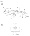
- FIG. 6A is a perspective explanatory view showing the configuration of the developer supply container
- FIG. 6B is a partially enlarged view showing the configuration around the discharge port
- FIG. 6C is a mounting portion of the developer supply device with the developer supply container. It is front explanatory drawing which shows the state mounted
- FIG. 7 is a cross-sectional perspective view showing the configuration of the developer supply container.
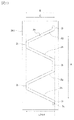
- FIG. 8A is a partial cross-sectional view showing a state in which the pump portion is fully extended in use
- FIG. 8B is a partial cross-sectional view showing a state in which the pump portion is maximally contracted in use.
- FIG. 9A is a partial cross-sectional view showing a state in which the pump portion is fully extended in use
- FIG. 9B is a partial cross-sectional view showing a state in which the pump portion is maximally contracted in use
- FIG. FIG. 3 is a partial cross-sectional view of the pump unit as viewed from the front.
- FIG. 10 is a development view showing the shape of the cam groove of the developer supply container.
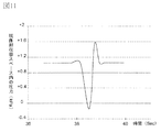
- FIG. 11 is a diagram showing the transition of the internal pressure of the developer supply container.
- 12A is a cross-sectional explanatory view showing the configuration of the developer supply container and the developer supply device
- FIG. 12B is a partial cross-sectional view showing the state of the instruction section when the drive motor rotates
- FIG. It is a fragmentary sectional view which shows the state of the instruction
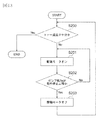
- FIG. 13 is a flowchart for explaining the rotation control of the drive motor.
- FIG. 14A is a perspective explanatory view showing the configuration of the reciprocating member of the first embodiment of the developer replenishing system having the developer replenishing container according to the present invention
- FIG. 14B is the attachment of the reciprocating member of the first embodiment. It is the elements on larger scale which show the structure of a force part.
- FIG. 15 is a cross-sectional explanatory view showing the configuration of the reciprocating member and the restricting portion of the first embodiment.
- FIG. 16 is a perspective explanatory view showing the configuration of a reciprocating member in which a biasing portion is formed on the downstream side in the rotation direction in the second embodiment of the developer supply system having a developer supply container according to the present invention.
- an image forming apparatus 100 configured as an example equipped with a developer supply system having the developer supply container 1 according to the present invention will be described.
- FIG. 1 An image forming apparatus 100 is an example of a copying machine.
- the document 101 is placed on the document glass 102.
- an optical image corresponding to the image information of the original 101 is imaged on the surface of the photoconductor 104 made of an electrophotographic photoconductor serving as an image carrier by a plurality of mirrors 8 and lenses 9 of the optical unit 103, thereby statically.
- An electrostatic latent image is formed.
- This electrostatic latent image is visualized using a toner (one-component magnetic toner) as a developer T (dry powder) by a developing device 201a including a dry one-component developing device.
- a toner one-component magnetic toner
- a developer T dry powder
- the one-component nonmagnetic toner is supplied as the developer T.
- the nonmagnetic toner is supplied as the developer T.
- the developer T may be replenished with a nonmagnetic toner and a magnetic carrier.
- Reference numerals 105 to 108 denote feeding cassettes for storing sheets 7 as an example of a recording medium.
- the optimum feeding cassettes 105 to 108 are determined based on the size information input by the user from the liquid crystal operation unit of the image forming apparatus 100 or the size of the document 101. Selected. Then, the single sheet 7 separated and conveyed by the feeding / separating devices 105A to 108A is conveyed to the registration roller 110 via the conveying unit 109. Then, the sheet 7 is conveyed by the registration roller 110 in synchronization with the rotation of the photosensitive member 104 and the scanning timing of the optical unit 103.
- Reference numeral 111 denotes a transfer charger.
- Reference numeral 112 denotes a separation charger.
- the developer image (toner image) formed on the surface of the photoreceptor 104 is transferred to the sheet 7 by the transfer charger 111. Then, the sheet 7 on which the developer image (toner image) is transferred is separated from the photoreceptor 104 by the separation charger 112. Thereafter, the sheet 7 conveyed by the conveying unit 113 is fixed to the developer image on the sheet 7 by heat and pressure in the fixing unit 114, and then passes through the discharge reversing unit 115 in the case of single-sided copying. The paper is discharged to the discharge tray 117 by the discharge roller 116.
- the sheet 7 passes through the discharge reversing unit 115, and a part of the sheet 7 is once discharged out of the image forming apparatus 100 by the discharge roller 116. Thereafter, the trailing edge of the sheet 7 passes through the flapper 118, and the flapper 118 is controlled and the discharge roller 116 is rotated in reverse at the timing when it is sandwiched between the discharge rollers 116. As a result, the sheet is conveyed again into the image forming apparatus 100. Further, after being conveyed to the registration roller 110 via the re-feed conveyance units 119 and 120, the sheet is discharged to the discharge tray 117 along the same conveyance path as in the case of single-sided copying.
- an image forming process device such as a developing device 201a as a developing unit, a cleaner unit 202 as a cleaning unit, and a primary charger 203 as a charging unit is installed around the photosensitive member 104.
- the developing device 201 a develops the developer T by attaching the developer T to the electrostatic latent image formed on the photosensitive member 104 by the optical unit 103 based on the image information of the document 101.
- the primary charger 203 uniformly charges the surface of the photoconductor 104 in order to form a desired electrostatic latent image on the surface of the photoconductor 104.
- the cleaner unit 202 removes the developer T remaining on the surface of the photoconductor 104.
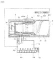
- FIG. 2A is a partial cross-sectional view of the developer supply device 201.
- FIG. 2B is a perspective view of the mounting portion 10 to which the developer supply container 1 is mounted.
- FIG. 2C is a cross-sectional view of the mounting portion 10.
- FIG. 3 is a partially enlarged cross-sectional view of the configuration of the control system and the developer supply container 1 and the developer supply device 201.
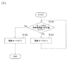
- FIG. 4 is a flowchart for explaining the developer supply operation. As shown in FIG.
- the developer supply device 201 includes a mounting portion 10 including a mounting space for detachably mounting the developer supply container 1, and a developer T discharged from the developer supply container 1.
- the developer supply container 1 is configured to be mounted in the direction of arrow M in FIG. That is, the developer supply container 1 is mounted on the mounting portion 10 so that the longitudinal direction thereof substantially coincides with the arrow M direction. Further, the direction in which the developer supply container 1 is removed from the mounting portion 10 is opposite to the arrow M direction. As shown in FIGS.
- the developing device 201a includes a developing roller 201f, a stirring member 201c, and feeding members 201d and 201e.
- the developer supplied from the developer supply container 1 is stirred by the stirring member 201c, sent to the developing roller 201f by the feeding members 201d and 201e, and supplied onto the surface of the photoreceptor 104 by the developing roller 201f.
- the developing roller 201f is provided with a developing blade 201g that controls the coating amount of the developer T on the surface of the developing roller 201f. Further, in order to prevent the leakage of the developer T between the developing roller 201f and the developing device 201a, a leakage preventing sheet 201h disposed in contact with the developing roller 201f is provided.
- the flange 10 is brought into contact with the flange portion 4 shown in FIG. 6 of the developer supply container 1 when the developer supply container 1 is mounted on the mounting portion 10.
- a rotation restricting portion 11 serving as a restricting portion for restricting movement of the portion 4 in the rotation direction is provided.
- the rotation restricting portion 11 restricts the movement of the reciprocating member 3b in the direction intersecting with the reciprocating direction.
- the developer T is supplied from the discharge hole 4 a of the developer supply container 1 to the developing device 201 a through the developer receiving hole 13.
- the discharge hole 4a serving as a discharge port discharges the developer T that has been transported by the transport unit 2k formed of a cylindrical portion.
- the diameter ⁇ of the developer receiving hole 13 shown in FIG. 2C is a pinhole formed of a fine opening in order to prevent contamination by the developer T in the mounting portion 10 as much as possible. Is set to about 3 mm.
- the diameter ⁇ of the developer receiving hole 13 may be any diameter that allows the developer T to be discharged from the discharge hole 4a. Further, as shown in FIG.
- the hopper 10a includes a conveying screw 10b for conveying the developer T to the developing device 201a and an opening 10c communicating with the developing device 201a. Further, a developer sensor 10d including a magnetic sensor for detecting the amount of the developer T accommodated in the hopper 10a is provided. Furthermore, as shown in FIGS. 2B and 2C, the mounting unit 10 has a drive gear 300 that serves as a drive unit. The drive gear 300 has a function of receiving a rotational driving force from the driving motor 500 via a driving gear train and applying the rotational driving force to the developer supply container 1 set in the mounting portion 10. is doing. Further, as shown in FIG. 3, the drive motor 500 is configured such that its operation is controlled by a control device 600 including a CPU (Central Processing Unit).
- a control device 600 including a CPU (Central Processing Unit).
- the control device 600 is configured to control the operation of the drive motor 500 based on the developer remaining amount information input from the developer sensor 10d.
- the drive gear 300 shown in FIGS. 2B and 2C is set so as to rotate only in one direction in order to simplify the control of the drive motor 500. That is, the control device 600 is configured to control only on (operation) / off (non-operation) of the drive motor 500. Therefore, the developer replenishing device 201 has a reversal driving force obtained by periodically reversing the drive motor 500 (drive gear 300) in the forward direction and the reverse direction.
- the drive unit can be simplified.
- the image forming apparatus 100 is provided with a detection unit 600a that includes an optical sensor that assists the control device 600 when the drive motor 500 is turned off.
- a detection unit 600a that includes an optical sensor that assists the control device 600 when the drive motor 500 is turned off.
- a certain amount of developer T is accommodated in the hopper 10a by the control device 600 controlling the operation / non-operation of the drive motor 500 in accordance with the output of the developer sensor 10d shown in FIG. It is constituted so that. Specifically, first, the developer sensor 10d checks the amount of developer contained in the hopper 10a (step S100). When it is determined that the developer storage amount detected by the developer sensor 10d is less than a predetermined amount, that is, when the developer T is not detected by the developer sensor 10d, the drive motor 500 is driven, The developer T replenishment operation is executed for a predetermined time (step S101).
- the developer replenishment operation it may be determined that the developer storage amount detected by the developer sensor 10d has reached a predetermined amount, that is, the developer T may be detected by the developer sensor 10d. In that case, the drive of the drive motor 500 is turned off, and the replenishment operation of the developer T is stopped (step S102). By stopping the replenishment operation, a series of developer replenishment steps is completed.
- Such a developer replenishing step is configured to be repeatedly executed when the developer T is consumed in association with image formation and the amount of developer contained in the hopper 10a becomes less than a predetermined amount.
- FIG. 5 shows an example in which a two-component developing device 800 is used as the developer supply device 201.
- the two-component developing device 800 has a developer stirring chamber 12 to which the developer T is replenished and a developing chamber 14 for supplying the developer T to the developing sleeve 800a.
- the developer stirring chamber 12 and the developing chamber 14 are provided.
- a stirring screw 800b in which the developer conveying directions are opposite to each other.
- the developer stirring chamber 12 and the developing chamber 14 communicate with each other at both ends in the longitudinal direction (from the back side to the front side in FIG. 5), and the two-component developer T circulates and conveys these two chambers. It becomes the composition which is done.
- a developer sensor 800c including a magnetic sensor for detecting the toner concentration of the developer T is installed in the developer stirring chamber 12. Based on the detection result of the developer sensor 800c, the controller 600 controls the drive motor 500. The operation is controlled.
- the developer T supplied from the developer supply container 1 is nonmagnetic toner, or nonmagnetic toner and a magnetic carrier.
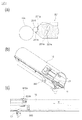
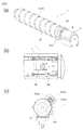
- FIG. 6A is an overall perspective view of the developer supply container 1.
- FIG. 6B is a partially enlarged view around the discharge hole 4 a of the developer supply container 1.
- FIG. 6C is a front view showing a state in which the developer supply container 1 is detachably mounted on the mounting portion 10 of the developer supply device 201.
- FIG. 7 is a cross-sectional perspective view of the developer supply container 1.
- FIG. 8A is a partial cross-sectional view of the pump unit 3a that expands and contracts and changes its capacity to the maximum when used.
- the developer supply container 1 is formed in a hollow cylindrical shape as a whole, and has a developer accommodating portion 2 having an internal space for accommodating the developer T therein.
- the developer accommodating section 2 (in the developer accommodating section) conveys the developer T as it rotates, and the developer discharging section 4c and the pump section 3a shown in FIG. Functions as 2.
- the transport unit 2 c has a shape protruding from the inner surface of the developer storage unit 2. In this embodiment, when the developer accommodating portion 2 rotates, the conveying portion 2c formed integrally with the developer accommodating portion 2 is also rotated.
- the developer supply container 1 has a flange portion 4 serving as a non-rotating portion on one end side in the longitudinal direction which is the developer transport direction of the developer accommodating portion 2.
- the transport unit 2 c is configured to be rotatable relative to the flange unit 4.
- the cross-sectional shape of the transport unit 2c may be a non-circular shape as long as it does not affect the rotation operation in the developer supply process. For example, an elliptical section or a polygonal section may be employed. In the present embodiment, as shown in FIG.
- the total length L1 of the developer accommodating portion 2 is set to about 460 mm, and the outer diameter R1 of the developer accommodating portion 2 is set to about 60 mm.
- the length L2 of the area where the developer discharge portion 4c is installed is about 21 mm.
- the full length L3 in the state extended most in the expansion-contraction range on use of the pump part 3a is about 29 mm.
- the full length L4 in the state shrunk most in the expansion-contraction possible range on use of the pump part 3a is about 24 mm.
- the developer storage portion 2 and the developer discharge portion 4c are horizontal. It is configured to line up in the direction. That is, the developer accommodating portion 2 has a structure in which the horizontal length is sufficiently longer than the vertical length, and the horizontal direction side is connected to the developer discharge portion 4c. Accordingly, when the developer replenishing container 1 is mounted on the developer replenishing device 201, compared to the case where the developer containing portion 2 is positioned vertically above the developer ejecting portion 4c, the upper portion of the discharge hole 4a is higher. The amount of the developer T present in the toner can be reduced. Therefore, the developer T in the vicinity of the discharge hole 4a is not easily consolidated, and the intake / exhaust operation by the pump unit 3a can be performed smoothly.
- the developer T is discharged from the discharge hole 4a by changing the volume in the developer supply container 1 by the pump unit 3a shown in FIGS. . Therefore, it is preferable to employ a material having a rigidity that does not collapse or swell greatly with respect to the change in volume as the material of the developer supply container 1.
- the developer supply container 1 communicates with the outside only through the discharge hole 4a, and is configured to be sealed from the outside except for the discharge hole 4a.
- the material of the developer accommodating portion 2 and the developer discharging portion 4c is made of polystyrene resin
- the material of the pump portion 3a is made of polypropylene resin.
- the developer accommodating portion 2 and the developer discharging portion 4c may be any material that can withstand the change in volume.
- ABS acrylonitrile / butadiene / styrene copolymer
- polyester polyethylene
- polypropylene can be used.
- the material of the pump unit 3a may be any material that exhibits an expansion / contraction function and can change the volume of the developer supply container 1 by changing the volume.
- ABS acrylonitrile / butadiene / styrene copolymer
- polystyrene polyester, polyethylene or the like may be formed thin. It is also possible to use rubber or other stretchable materials.
- each of the pump part 3a, the developer accommodating part 2, and the developer discharging part 4c satisfies the above-described functions by adjusting the thickness of the resin material, etc.
- each is made of the same material, for example, injection molding What is integrally molded using a method, a blow molding method, or the like may be used.
- the gear portion 2d serving as a drive receiving portion to which the rotational driving force for rotating the conveyance portion 2c from the flange portion 4, the developer accommodating portion 2, the pump portion 3a, and the developer supply device 201 is input will be described.
- the flange portion 4 is provided with a developer discharge portion 4 c serving as a hollow discharge portion for temporarily storing the developer T conveyed from the developer storage portion 2. It has been.
- a discharge hole 4a for allowing the developer T to be discharged out of the developer supply container 1, that is, for supplying the developer T to the developer supply device 201 is formed at the bottom of the developer discharge portion 4c. ing.
- the flange portion 4 is provided with a shutter 4b for opening and closing the discharge hole 4a.
- the shutter 4b is configured to abut against the abutting portion 21 shown in FIG. 2B provided on the mounting portion 10 in accordance with the mounting operation of the developer supply container 1 to the mounting portion 10. Therefore, the shutter 4b slides relative to the developer supply container 1 in the direction opposite to the arrow M direction in FIG. 7 in accordance with the mounting operation of the developer supply container 1 to the mounting portion 10. As a result, the shutter 4b is retracted from the position covering the discharge hole 4a to expose the discharge hole 4a, and the opening operation is completed. At this time, as shown in FIG.
- the discharge hole 4 a is in communication with each other because the position of the discharge hole 4 a coincides with the developer receiving hole 13 of the mounting portion 10, so that the developer can be supplied from the developer supply container 1. It becomes a state.
- the flange portion 4 is configured so that the flange portion 4 does not rotate with respect to the rotation of the developer accommodating portion 2 when the developer supply container 1 is attached to the attachment portion 10 of the developer supply device 201. .
- a rotation restricting portion 11 shown in FIG. 2B is provided so that the flange portion 4 does not rotate in the rotation direction of the gear portion 2d serving as a drive receiving portion.
- the developer accommodating portion 2 is configured to rotate in the developer replenishing step without being restricted by the developer replenishing device 201 in the rotation direction.
- the developer accommodating portion 2 has a cylindrical shape (conveying portion 2k). As shown in FIGS.
- the inner surface of the transport unit 2k is spiraled on the inner side to transport the developer T stored therein toward the developer discharge unit 4c (discharge hole 4a) as it rotates.
- the conveyance part 2c protruded in the shape is provided.
- the conveyance part 2k is formed by the blow molding method using resin of the material mentioned above. Note that when the developer supply container 1 is increased in volume to increase the filling amount of the developer T, a method of increasing the volume of the flange portion 4 of the developer container 2 in the height direction is conceivable. However, with such a configuration, the gravity effect on the developer T in the vicinity of the discharge hole 4a is further increased by the dead weight of the developer T.
- the developer T in the vicinity of the discharge hole 4a is easily consolidated, which hinders intake and exhaust through the discharge hole 4a.
- the driving force for driving the pump unit 3a also increases, and the load on the main body of the image forming apparatus 100 increases.
- the axial direction of the conveyance part 2k and the axial direction of the flange part 4 are installed side by side in the horizontal direction. For this reason, the thickness of the developer layer on the discharge hole 4a in the developer supply container 1 can be set thin.
- the transport unit 2 k is fixed so as to be rotatable relative to the flange unit 4 in a compressed state of a flange seal 5 b made of a ring-shaped seal member provided on the inner surface of the flange unit 4. Has been. Thereby, the conveyance part 2k rotates, sliding with the flange seal 5b. For this reason, the developer T does not leak during the rotation of the transport unit 2k, and airtightness is maintained.
- the air can be appropriately entered and exited through the discharge hole 4a, and the changeable state of the volume of the developer supply container 1 during the supply of the developer T can be changed to a desired state.
- a description will be given of the pump unit 3 a that can change its volume as it reciprocates in the rotation axis direction of the transport unit 2 k.
- the pump unit 3 a of this embodiment is communicated with the inside of the developer supply container 1. And it has the intake / exhaust function which performs an intake operation and an exhaust operation alternately via the discharge hole 4a.
- the pump unit 3a has an airflow generation function that alternately and repeatedly generates an airflow that goes to the inside of the developer supply container 1 through the discharge hole 4a and an airflow that goes from the developer supply container 1 to the outside.
- the pump portion 3a is provided in the direction of arrow M in FIG. 8A from the developer discharge portion 4c.
- the pump part 3a of this embodiment is provided so that it may not rotate in the rotation direction of the conveyance part 2k together with the developer discharge part 4c.
- the pump unit 3a plays a major role in fluidizing the developer T during the intake operation.
- the pump unit 3a a resin volume changeable pump unit (bellows pump) whose volume can be changed in accordance with a reciprocating operation is adopted. Specifically, as shown in FIGS. 7 and 8, a bellows-like pump portion 3a is employed, and “mountain fold portions” and “valley fold portions” are periodically formed on the peripheral surface of the pump portion 3a. A plurality are alternately formed. Therefore, the pump unit 3a can repeatedly perform compression and expansion alternately by the driving force received from the developer supply device 201. In the present embodiment, the volume change amount during expansion / contraction of the pump unit 3a is 5 cm. 3 (Cc) is set.
- the volume of the developer supply container 1 can be alternately and repeatedly changed at a predetermined cycle.
- the developer T in the developer discharge portion 4c can be efficiently discharged from the discharge hole 4a.
- the gear portion 2d serving as the drive receiving portion of the developer supply container 1 to which the rotational driving force for rotating the transport portion 2k is input from the developer supply device 201 will be described.
- the developer supply container 1 has a gear portion 2d that functions as a drive receiving portion that can be engaged with and driven by a drive gear 300 that functions as a drive portion of the developer supply device 201. Is provided.
- the gear part 2d is configured to be rotatable integrally with the transport part 2k. Therefore, the rotational driving force input from the drive gear 300 to the gear portion 2d is generated in the direction of the rotation axis of the drive conversion portion including the cam groove 2e and the protrusion 3c and the conveyance portion 2k shown in FIGS. 9A and 9B. It is transmitted to the pump unit 3a via the reciprocating member 3b that reciprocates.
- the bellows-like pump part 3a of the present embodiment is manufactured using a resin material that has a strong resistance to twisting in the rotational direction within a range that does not hinder its expansion and contraction operation.
- the gear portion 2d is provided on the outer peripheral surface of the end portion of the transport portion 2k on the developer transport direction side, but the present invention is not limited to this.
- it may be provided on the other end side in the longitudinal direction of the developer accommodating portion 2, that is, on the opposite side to the developer transport direction which is the rearmost end of the developer accommodating portion 2.
- the drive gear 300 is installed at a position corresponding to the gear portion 2d.
- a gear mechanism is used as a drive coupling mechanism between a gear portion 2 d that is a drive receiving portion of the developer supply container 1 and a drive gear 300 that is a drive portion of the developer supply device 201.
- the developer supply container 1 is provided with a cam mechanism serving as a drive conversion unit that converts a rotational driving force for rotating the conveying unit 2k received by the gear unit 2d serving as a drive receiving unit into a reciprocating force of the pump unit 3a.
- the gear portion 2d is configured to receive the rotation of the conveying portion 2k and the driving force for reciprocating (extending / contracting) the pump portion 3a by the gear portion 2d serving as one drive receiving portion. Is converted into a reciprocating force on the developer supply container 1 side.
- FIG. 9A is a partial cross-sectional view showing a state in which the pump portion 3a is extended to the maximum in use.
- FIG. 9B is a partial cross-sectional view showing a state in which the pump portion 3a is contracted to the maximum in use.
- FIG. 9C is a cross-sectional explanatory view of the pump portion 3a as viewed from the front. As shown in FIGS.
- the cam mechanism constitutes a drive conversion portion that converts the rotational driving force received by the gear portion 2d into the reciprocating force of the pump portion 3a.
- the cam mechanism includes a cam groove 2e formed on the outer peripheral surface of the conveyance portion 2k1 provided in communication with the conveyance portion 2k, and a protrusion 3c that engages with the cam groove 2e and engages with the reciprocating member 3b. Configured. Specifically, the cam groove 2e provided over the entire outer periphery of the conveying portion 2k1 provided integrally with the gear portion 2d serving as a drive receiving portion that receives the rotational driving force from the drive gear 300 is a gear. It rotates with the rotation of the part 2d. As shown in FIG.
- the cam groove 2e is engaged with a protrusion 3c protruding inwardly at the ends of the pair of arms 3h of the U-shaped reciprocating member 3b.
- the protrusion 3c of this embodiment is engaged with being fixed to the arm portion 3h of the reciprocating member 3b.
- the reciprocating member 3b is restricted by a rotation restricting portion 3f serving as a restricting portion in the rotation direction of the transport portion 2k.
- the projections 3c provided at the ends of the pair of arms 3h of the reciprocating member 3b configured in a U shape are fitted into the cam grooves 2e, and along the cam grooves 2e.
- the pump unit 3a is regulated so as to reciprocate in the extending and contracting direction.
- the number of protrusions 3c that engage with the reciprocating member 3b may be at least one.
- the protrusion 3c sliding along the cam groove 2e. It is preferable to provide a plurality.
- two protrusions 3c that engage with the reciprocating member 3b are provided so as to be engaged at two locations along the cam groove 2e.
- the protrusion 3c that engages with the reciprocating member 3b is configured to be disposed at a position that opposes 180 ° around the rotation axis of the transport unit 2k. That is, the rotational driving force input from the drive gear 300 is transmitted to the gear portion 2d, and the cam groove 2e rotates integrally with the gear portion 2d. Accordingly, the protrusion 3c that engages with the reciprocating member 3b along the cam groove 2e reciprocates in the direction of arrow M in FIG. 8 or in the opposite direction. Further, the reciprocating member 3b formed integrally with the protrusion 3c reciprocates in the direction of the rotation axis of the transport unit 2k. As a result, the pump unit 3a alternately repeats the expanded state shown in FIG.
- the transport amount of the developer T per unit time transported to the developer discharge unit 4c with the rotation of the transport unit 2k is set as follows.
- the drive conversion unit including the cam groove 2e and the protrusion 3c is larger than the developer discharge amount per unit time discharged from the developer discharge unit 4c to the developer supply device 201 by the action of the pump unit 3a. Is configured. If the discharge capacity of the developer T by the pump section 3a is larger than the transport capacity of the developer T to the developer discharge section 4c by the transport section 2c provided in the transport section 2k, it exists in the developer discharge section 4c.
- the drive conversion unit composed of the cam groove 2e and the projection 3c is configured such that the pump unit 3a reciprocates a plurality of times while the transport unit 2k rotates once.
- the drive motor 500 is set to an output necessary for constantly rotating the transport unit 2k.
- the output required for the drive motor 500 is calculated from the rotational torque and the rotational speed of the transport unit 2k.
- the rotational speed of the transport unit 2k it is preferable to set the rotational speed of the transport unit 2k as low as possible.
- the rotation speed of the transport unit 2k is reduced in order to reduce the load on the drive motor 500, the number of reciprocating operations of the pump unit 3a per unit time is reduced. For this reason, the amount of the developer T discharged from the developer supply container 1 per unit time is reduced. That is, in order to satisfy the replenishment amount of the developer T required from the main body of the image forming apparatus 100 in a short time, the amount of the developer T discharged from the developer replenishment container 1 may be insufficient.
- the volume change amount of the pump unit 3a is increased, the discharge amount of the developer T per cycle of the pump unit 3a can be increased. Thereby, it becomes possible to meet the supply amount of the developer T required from the main body of the image forming apparatus 100.
- a countermeasure has the following problems. That is, when the volume change amount of the pump unit 3a is increased, the peak value of the internal pressure (positive pressure) of the developer supply container 1 in the exhaust process increases. For this reason, the load required to reciprocate the pump unit 3a increases. For this reason, in the present embodiment, the pump unit 3a is reciprocated in a plurality of cycles while the transport unit 2k rotates once.
- a drive conversion portion including a cam groove 2 e and a protrusion 3 c is provided on the outer peripheral portion of the developer accommodating portion 2.
- FIG. 10 is a development view of the cam groove 2e provided on the outer peripheral surface of the transport unit 2k1.
- the direction of arrow A is the rotational direction of the transport unit 2k (the moving direction of the cam groove 2e).
- the arrow B direction in FIG. 10 indicates the extending direction of the pump unit 3a.
- the arrow C direction of FIG. 10 shows the compression direction of the pump part 3a.
- the cam groove 2e includes a cam groove 2g used when the pump portion 3a is compressed, a cam groove 2h used when the pump portion 3a is extended, and a pump portion non-operating portion where the pump portion 3a does not reciprocate. And a cam groove 2i constituting the.
- the amplitude which is the expansion-contraction length of the pump part 3a in the arrow B and C direction of FIG. 10 used as the expansion-contraction direction of the pump part 3a of the cam groove 2e is set as follows. That is, it is expressed by (L3-L4) by using the full length L3 in the most extended state of the pump portion 3a shown in FIG. 8A and the full length L4 in the most contracted state of the pump portion 3a shown in FIG. .
- the cam groove 2e rotates in the direction of arrow A in FIG. 10 along with the rotation of the gear portion 2d
- the protrusion 3c that engages with the reciprocating member 3b shown in FIG. 14A becomes the cam groove 2i and cam groove shown in FIG.
- the instruction unit 6 is configured to issue an instruction to stop the rotation drive of the drive motor 500 to the control device 600 in the intake process or the exhaust process.
- the intake process, the exhaust process, and the operation stop process will be described.
- ⁇ Intake process> First, an intake process including an intake operation via the discharge hole 4a will be described. The state shown in FIG. 9A, in which the pump portion 3a is extended the most, from the state shown in FIG. Thus, the intake operation is performed. That is, with this intake operation, the volumes in the pump unit 3a, the transport unit 2k, and the flange unit 4 that can store the developer T in the developer supply container 1 increase.
- the inside of the developer supply container 1 is substantially sealed except for the discharge hole 4a, and the discharge hole 4a is substantially closed with the developer T. . Therefore, the internal pressure of the developer supply container 1 decreases as the volume of the portion of the developer supply container 1 that can store the developer T increases. At this time, the internal pressure of the developer supply container 1 becomes lower than the atmospheric pressure (external pressure). Therefore, the air outside the developer supply container 1 moves into the developer supply container 1 through the discharge hole 4a due to the pressure difference between the inside and outside of the developer supply container 1. At that time, since air is taken in from the outside of the developer supply container 1 through the discharge hole 4a, the developer T located in the vicinity of the discharge hole 4a can be released and fluidized.
- the developer T located in the vicinity of the discharge hole 4a can include air to reduce the bulk density and appropriately fluidize the developer T. Further, at this time, since air is taken into the developer supply container 1 through the discharge hole 4a, the internal pressure of the developer supply container 1 is close to the atmospheric pressure (outside air pressure) even though the volume is increased. Will change. In this way, by allowing the developer T to be fluidized, the developer T can be smoothly discharged from the discharge hole 4a without the developer T being clogged in the discharge hole 4a during the exhaust operation described later. Is possible. Therefore, the amount of developer T discharged from the discharge hole 4a per unit time can be made substantially constant over a long period of time.
- the pump unit 3a is not limited to the state shown in FIG. 9 (a), which is the most extended state from the state shown in FIG. 9 (b).
- the intake operation is performed if the internal pressure of the developer supply container 1 is changed. That is, the intake process is a state where the protrusion 3c that engages with the reciprocating member 3b is engaged with the cam groove 2h shown in FIG. ⁇ Exhaust process>
- an exhaust process including an exhaust operation via the exhaust hole 4a will be described. The exhaust operation is performed by changing from the state shown in FIG. 9A in which the pump part 3a is extended to the state shown in FIG.
- the pump unit 3a is not limited to the state shown in FIG. 9A in which the pump unit 3a is extended to the state shown in FIG.
- the pump unit 3a performs a predetermined volume change every time. For example, if the cam groove 2e is configured only by the exhaust process and the intake process, the drive motor 500 is stopped during the exhaust process or the intake process. At that time, even after the drive motor 500 stops rotating, the conveying portion 2k rotates due to inertia, and the protrusion 3c that engages with the cam groove 2e and engages the reciprocating member 3b moves until the conveying portion 2k stops. The pump unit 3a also continues to reciprocate in conjunction with it. Thus, even after the drive motor 500 stops rotating, the exhaust process or the intake process is performed by inertia.
- the distance that the conveyance unit 2k rotates due to inertia depends on the rotation speed of the conveyance unit 2k. Furthermore, the rotational speed of the transport unit 2k depends on the torque applied to the drive motor 500. From this, the torque applied to the drive motor 500 changes depending on the amount of the developer T in the developer supply container 1, and the rotational speed of the transport unit 2k also changes. Therefore, it is difficult to make the stop position of the pump unit 3a the same every time. Therefore, in order to stop the pump unit 3a at a predetermined position every time, it is necessary to provide the cam groove 2e with a cam groove 2i that is a region where the pump unit 3a does not reciprocate even when the transport unit 2k is rotating. .
- the cam groove 2i arranged in parallel with the arrow A direction which is the rotation direction of the transport unit 2k (the movement direction of the cam groove 2e).
- the cam groove 2i is formed with a straight groove at a predetermined distance parallel to the direction of the arrow A, which is the rotation direction of the transport unit 2k, and the protrusion 3c that engages the reciprocating member 3b is engaged with the cam groove 2i. While the transfer unit 2k rotates, the reciprocating member 3b does not move. That is, the operation stop process is a state in which the protrusion 3c that engages with the reciprocating member 3b is engaged with the cam groove 2i.
- the pump unit 3a does not reciprocate, the developer T is not discharged from the discharge hole 4a.
- the cam groove 2i is inclined at a predetermined angle with respect to the rotational axis direction of the transport section 2k with respect to the rotational direction of the transport section 2k if the exhaust process and intake process through the discharge hole 4a are not performed. It does not matter. Further, it is assumed that the reciprocating motion of the pump part 3a accompanying the inclination of the cam groove 2i is allowable.
- the instruction unit 6 is provided to control the protrusion 3c that engages with the reciprocating member 3b to engage with the cam groove 2i.
- the verification experiment result about how the internal pressure of the developer supply container 1 is changed will be described.
- the pump unit 3a is moved to 5 cm. 3
- the change in the internal pressure of the developer supply container 1 was measured when it was expanded and contracted by the volume change amount.
- the internal pressure of the developer supply container 1 was measured by connecting a pressure gauge (manufactured by Keyence Corporation, model name: AP-C40) to the developer supply container 1.
- FIG. 11 The transition of the pressure change is shown in FIG. In FIG. 11, the horizontal axis indicates time, and the vertical axis indicates the relative pressure in the developer supply container 1 with respect to the atmospheric pressure of 1 kPa as a reference. “+” Shown on the vertical axis in FIG. 11 indicates the positive pressure side with respect to the external atmospheric pressure, and “ ⁇ ” indicates the negative pressure side with respect to the external atmospheric pressure.
- the internal pressure of the developer supply container 1 becomes positive with respect to the atmospheric pressure, and when the pressure is applied to the internal developer T, the developer T is discharged from the discharge hole. It was confirmed that it was discharged from 4a to the outside.
- the absolute value of the pressure on the negative pressure side was about 1.2 kPa
- the absolute value of the pressure on the positive pressure side was about 0.5 kPa.
- the internal pressure of the developer supply container 1 is alternately switched between the negative pressure state and the positive pressure state in accordance with the intake operation and the exhaust operation by the pump unit 3a, and is discharged.
- the developer supply container 1 is provided with the pump unit 3a having a simple configuration for performing the intake operation and the exhaust operation.
- the developer T can be discharged stably.
- the inside of the pump unit 3a that can change the volume is used as the developer storage space, a new developer is used when the volume of the pump unit 3a is increased to reduce the internal pressure. An accommodation space can be formed. Accordingly, even if the inside of the pump unit 3a is filled with the developer T, the developer T can be fluidized by adding air to the developer T with a simple configuration, thereby reducing the bulk density. it can.
- the developer supply container 1 can be filled with the developer T at a higher density than before.
- the driving force for rotating the transport unit 2k provided with the transport unit 2c and the driving force for reciprocating the pump unit 3a are received by the gear unit 2d serving as one drive receiving unit. . Therefore, the configuration of the drive receiving portion of the developer supply container 1 can be simplified.
- the driving gear 300 serving as one driving unit provided in the developer supply device 201 is configured to apply a driving force to the developer supply container 1, it contributes to simplification of the drive unit of the developer supply device 201. can do.
- the rotational driving force received from the developer supply device 201 for rotating the transport unit 2k is set as follows.
- the drive conversion is performed by the drive conversion unit including the cam groove 2e of the developer supply container 1 and the protrusion 3c engaged with the reciprocating member 3b.
- the pump unit 3a can be appropriately reciprocated.
- the drive motor 500 is controlled by a control device 600 including a CPU.
- the instruction unit 6 instructs the control device 600 to stop the rotation drive.
- FIG. 13 is a flowchart for explaining the rotation control of the drive motor 500.
- the developer T replenishment process will be described with reference to FIG. As shown in FIGS.
- the control device 600 causes the drive motor 500 to respond to the outputs of the developer sensors 10 d and 800 c that are magnetic sensors that detect the toner concentration in the developer T in the developer stirring chamber 12. Controls the rotation of the. Specifically, the developer sensors 10d and 800c shown in FIGS. 3 and 5 check the toner concentration in the developer T in the developer stirring chamber 12 (step S200). If the toner concentration in the developer T in the developer stirring chamber 12 is low, the controller 600 is instructed to rotate the drive motor 500 (step S201). The gear portion 2d starts rotating by the rotational drive of the drive motor 500. Next, in step S202, when the protrusion 3c that engages with the reciprocating member 3b engages with the cam groove 2i shown in FIG.
- the control device 600 is instructed to stop the drive motor 500. Then, the rotation of the gear unit 2d is stopped by stopping the rotation of the drive motor 500.
- step S202 when the pump unit 3a is not in the operation stop process, the process returns to step S201 and the drive motor 500 continues to rotate. Then, after repeating the series of operations in steps S200 to S203, the developer sensors 10d and 800c shown in FIGS. 3 and 5 again detect the toner concentration in the developer T in the developer stirring chamber 12 (step). S200). In step S200, when the toner concentration in the developer T in the developer stirring chamber 12 is sufficient, this series of developer replenishment steps is completed.
- FIG. 12A is a partial cross-sectional explanatory view showing the configuration of the developer supply container 1 and the developer supply device 201.
- FIG. 12B is a partially enlarged view showing the state of the instruction unit 6 when the drive motor 500 rotates.
- FIG. 12C is a partially enlarged view showing the state of the instruction unit 6 when the rotation of the drive motor 500 is stopped.
- the detection unit 600a uses an optical photosensor, and stops the rotation of the drive motor 500 when the light shielding unit 600b blocks the optical path of the detection unit 600a. Further, when the light shielding unit 600b does not block the optical path of the detection unit 600a, the drive motor 500 continues to rotate.
- FIG. 12B shows a state in which the pump unit 3a is in the operation stop process, and the instruction unit 6 protruding to a part of the outer peripheral surface of the transport unit 2k1 lifts the light shielding unit 600b to block the optical path of the detection unit 600a.
- FIG. 12C shows a case where the pump unit 3a is an exhaust process or an intake process, and is not an operation stop process.
- the instruction unit 6 is located away from the light shielding unit 600b, and is in a state where the light shielding unit 600b is not lifted and the optical path of the detection unit 600a is not blocked by the light shielding unit 600b. That is, the instruction unit 6 raises the light shielding unit 600b to block the optical path of the detection unit 600a, thereby giving an instruction to stop the rotation driving of the drive motor 500 to the control device 600.
- the rotation of the drive motor 500 is stopped every time when the pump unit 3a is in the operation stop process. Thereby, the pump part 3a can perform the volume change decided each time.
- the present invention is not limited to this embodiment, and a configuration in which rotation driving is stopped in an intake process or an exhaust process may be used.
- FIG. 14A is an explanatory perspective view showing the configuration of the reciprocating member 3b.
- FIG. 14B is a partially enlarged view showing the configuration of the elastically deformable urging portions 3g1 and 3g2 provided at both ends of the U-shaped reciprocating member 3b.
- FIG. 15 is a partial cross-sectional view showing the configuration of the reciprocating member 3b and the rotation restricting portion 3f serving as the restricting portion. As shown in FIG.
- the reciprocating member 3b includes a protrusion 3c, a pump engaging portion 3d, an arm portion 3h, and urging portions 3g1 and 3g2.
- the urging portions 3g1 and 3g2 are provided on one side of the reciprocating member 3b.
- contact portions 3g3 and 3g4 that contact the rotation restricting portion 3f are provided on the other side of the reciprocating member 3b.
- a cam groove 2e provided on the outer peripheral surface of the transport portion 2k1 is slidably engaged with a protrusion 3c formed on the reciprocating member 3b.
- the pump engaging portion 3d is engaged with the pump portion 3a, and transmits the reciprocating motion of the transport portion 2k in the rotation axis direction to the pump portion 3a.
- the arm portion 3h of the reciprocating member 3b is formed so as to connect the protrusion 3c and the pump engaging portion 3d in the rotation axis direction of the transport portion 2k.
- the rotation restricting portion 3f is formed in the direction of the rotation axis of the conveying portion 2k (the direction of expansion and contraction of the pump portion 3a) and has a shape that covers the arm portion 3h of the reciprocating member 3b except for a part (see FIG. 9C). ).
- the arm portion 3h of the reciprocating member 3b is configured to be able to reciprocate by sliding in the rotation axis direction inside the rotation restricting portion 3f.
- the rotation restricting portions 3f are arranged on both sides of the reciprocating member 3b in a direction orthogonal to the rotation axis direction.
- the rotation control part 3f also has a function as a guide part which guides the movement of the reciprocating member 3b. Further, there is a backlash (gap) between the arm portion 3h of the reciprocating member 3b and the rotation restricting portion 3f.
- the width F3 of the restricting portion 3f has a relationship of ⁇ F1 ⁇ F3 ⁇ .
- the width of the arm portion 3h of the reciprocating member 3b is the width of the arm portion 3h of the reciprocating member 3b, and the width F3 shown in FIG. 15 restricts the reciprocating member 3b only to the reciprocating operation in the rotation axis direction of the transport portion 2k. It is the width
- the relationship between the width F1 of the arm 3h of the reciprocating member 3b shown in FIG. 14B and the width F3 of the rotation restricting portion 3f shown in FIG. 15 is ⁇ F1 ⁇ F3 ⁇ . Then, the arm portion 3h of the reciprocating member 3b is fitted into the rotation restricting portion 3f, and the reciprocating member 3b cannot reciprocate in the rotation axis direction (left and right direction in FIG.
- the width F1 of the arm portion 3h of the reciprocating member 3b shown in FIG. 14B and the width F3 of the rotation restricting portion 3f shown in FIG. 15 need to have a relationship of ⁇ F1 ⁇ F3 ⁇ . Further, a predetermined gap is provided between the arm portion 3h of the reciprocating member 3b and the rotation restricting portion 3f so that the reciprocating member 3b can easily reciprocate in the rotation axis direction (left and right direction in FIG. 15) of the transport portion 2k. Is preferable.
- the developer supply container 1 is provided with a reciprocating member 3b that reciprocates in the direction of the rotation axis of the transport unit 2k (the direction of the arrow M in FIGS. 7 and 8 or the direction opposite to the direction of the arrow M).
- the reciprocating member 3b is provided with urging portions 3g1 and 3g2 having elasticity.
- a backlash between the arm portion 3h of the reciprocating member 3b and the rotation restricting portion 3f is filled with elastic biasing portions 3g1 and 3g2. That is, the relationship between the width F2 including the U-shaped biasing portions 3g1 and 3g2 in the arm portion 3h of the reciprocating member 3b shown in FIG.
- the width F2 is a length in a state where no force is applied to the urging portions 3g1 and 3g2.
- the biasing portions 3g1 and 3g2 having elasticity are always in contact with the rotation restricting portion 3f.
- the width F1 of the arm portion 3h of the reciprocating member 3b is set to about 8.9 mm.
- a width F2 including the urging portions 3g1 and 3g2 in the arm portion 3h of the reciprocating member 3b is set to about 9.2 mm.
- the width F3 of the rotation restricting portion 3f is set to about 9.0 mm.
- the contact portions 3g3 and 3g4 that contact the rotation restricting portion 3f by the urging force of the urging portions 3g1 and 3g2 continue to rub against the rotation restricting portion 3f.
- the contact portions 3g3 and 3g4 are a part of the arm portion 3h of the reciprocating member 3b. That is, the contact portions 3g3 and 3g4 of the reciprocating member 3b in which the urging portions 3g1 and 3g2 are not provided rotate in a direction orthogonal to the rotation axis direction of the conveyance unit 2k formed of a cylindrical portion (the width direction of the reciprocating member 3b). Stable rubbing with the restricting portion 3f.
- the urging portions 3g1 and 3g2 are provided in the vicinity of the protrusion 3c to which the rotational driving force is input. This is because the protrusion 3c is most susceptible to the rotational driving force. That is, the protrusion 3c has the fastest transmission timing of the force in the rotation direction of the transport unit 2k and the moving speed of the reciprocating member 3b.
- the urging portions 3g1 and 3g2 in the vicinity of the protrusion 3c.
- the moving speed in the rotation direction of the transport portion 2k can be reduced, and the contact sound between the reciprocating member 3b and the rotation restricting portion 3f is reduced. can do.
- two protrusions 3c are provided at both ends of the U-shaped reciprocating member 3b, and two urging portions 3g1 and 3g2 having the same number as the protrusions 3c are provided in the vicinity of the respective protrusions 3c. It is an example.
- the number of U-shaped and elastic urging portions 3g1 and 3g2 be equal to or more than the number of protrusions 3c provided on the reciprocating member 3b.
- it has the two urging
- one urging portion 3g1 is an example formed on the downstream side (downstream in the rotational direction) of the reciprocating member 3b in the rotational direction (the rotational direction of the transport unit 2k).
- FIG. 16 is an explanatory perspective view showing a configuration in which both of the urging portions 3g1 and 3g5 of the reciprocating member 3b are formed on the downstream side (the downstream side in the rotational direction) of the reciprocating member 3b in the rotational direction (rotating direction of the transport unit 2k). is there.
- This embodiment is different from the first embodiment in that the formation position of the urging portion 3g5 of the reciprocating member 3b is moved from the upstream side to the downstream side in the rotating direction of the reciprocating member 3b (the rotating direction of the transport unit 2k).
- the arm portion 3h of the reciprocating member 3b is filled by filling the backlash between the arm portion 3h of the reciprocating member 3b and the rotation restricting portion 3f with elastic biasing portions 3g1 and 3g2. And the contact sound of the rotation control part 3f is reduced.
- the relationship between the width F2 of the arm portion 3h of the reciprocating member 3b including the urging portions 3g1 and 3g2 and the width F3 of the rotation restricting portion 3f is ⁇ F2> F3 ⁇ .
- the arm 3h of the reciprocating member 3b including the biasing portions 3g1 and 3g2 is always in contact with the rotation restricting portion 3f, so that the reciprocating member 3b slides in the direction of the rotation axis of the transport unit 2k.
- the frictional force at the time increases, and the reciprocating member 3b becomes difficult to reciprocate.
- the reciprocating member 3b is easily reciprocated by reducing the frictional force when the reciprocating member 3b slides in the direction of the rotation axis of the transport unit 2k.
- the width F2 of the arm portion 3h of the reciprocating member 3b including the U-shaped elastic urging portions 3g1 and 3g5 and the width F3 of the rotation restricting portion 3f have a relationship of ⁇ F2 ⁇ F3 ⁇ .
- the contact sound of the arm part 3h of the reciprocating member 3b and the rotation restricting part 3f can be reduced.
- the relationship between the width F2 of the arm portion 3h of the reciprocating member 3b including the biasing portions 3g1 and 3g5 and the width F3 of the rotation restricting portion 3f is ⁇ F2 ⁇ F3 ⁇
- the reciprocating member 3b is loose. An attempt is made to move in the rotation direction of the transport unit 2k by the amount. Therefore, the biasing portions 3g1 and 3g5 are brought into contact with the rotation restricting portion 3f before the arm portion 3h of the reciprocating member 3b and the rotation restricting portion 3f come into contact with each other. That is, as shown in FIG.
- both of the two urging portions 3g1 and 3g5 provided at both ends of the U-shaped reciprocating member 3b are moved in the rotational direction of the reciprocating member 3b (the rotational direction of the transport unit 2k). Provided on the downstream side (downstream in the rotational direction). Thereby, before the arm part 3h of the reciprocating member 3b excluding the urging parts 3g1 and 3g5 contacts the rotation restricting part 3f, the contact speed between the arm part 3h of the reciprocating member 3b and the rotation restricting part 3f. The contact noise can be reduced.
- the contact portions 3g3 and 3g6 that contact the rotation restricting portion 3f by the urging force of the urging portions 3g1 and 3g5 continue to rub against the rotation restricting portion 3f.
- the protrusion 3c of the reciprocating member 3b is fitted in the cam groove 2e.
- the urging portions 3g1 and 3g5 first contact the rotation restricting portion 3f.
- the frictional force when the reciprocating member 3b slides in the direction of the rotation axis of the transport unit 2k is reduced as compared with the first embodiment while reducing the contact sound.
- the reciprocating member 3b can be easily reciprocated in the direction of the rotation axis of the transport unit 2k.
- Other configurations are the same as those in the first embodiment, and the same effects can be obtained.
Abstract
A developer supply container and a developer supply system comprise: a conveyance unit (2c) which upon rotation conveys a developer (T) in a developer container (2) to a developer discharging unit (4c); a gear (2d) for receiving the rotational driving force used to rotate the conveyance unit (2c); a pump unit (3a) provided to act on at least the developer discharging unit (4c), the volume of the pump unit changing with reciprocating motion; a drive conversion unit for converting the rotational driving force input into the gear (2d) into a force for operating the pump unit (3a); a reciprocating member (3b) which is provided on the drive conversion unit and moves in reciprocating motion to convert the rotational driving force into the force for operating the pump unit (3a); a rotation restriction unit (3f) for restricting movement of the reciprocating member (3b) in a direction intersecting the direction of the reciprocating motion of the reciprocating member (3b) ; and elastically deformable energizing parts (3g1, 3g2) which are provided on the reciprocating member (3b) and bias the reciprocating member (3b) toward the rotation restriction unit (3f).
Description
本発明は、現像剤補給装置に着脱可能な現像剤補給容器及びこれらを有する現像剤補給システムに関する。この現像剤補給容器及び現像剤補給システムは、例えば、複写機、ファクシミリ、プリンタ、及びこれらの機能を複数備えた複合機等の画像形成装置において用いられ得る。
The present invention relates to a developer supply container that can be attached to and detached from a developer supply device, and a developer supply system having these. The developer supply container and developer supply system can be used in, for example, an image forming apparatus such as a copying machine, a facsimile machine, a printer, and a multifunction machine having a plurality of these functions.
従来、電子写真複写機等の画像形成装置には微粉末の現像剤が使用されている。このような画像形成装置では、画像形成に伴い消費されてしまう現像剤を、現像剤補給容器から補給される構成となっている。
こうした従来の現像剤補給容器として、例えば、特開2013−015826号公報に記載された装置がある。
特開2013−015826号公報に記載された装置では、現像剤補給容器に画像形成装置から入力された回転駆動力を回転軸方向の往復動作力へ変換する駆動変換機構を採用している。
更に、特開2013−015826号公報に記載の装置では、現像剤補給容器に画像形成装置から入力された回転駆動力を回転軸方向の往復動作力へ変換する駆動変換機構と係合する回転軸方向に往復動作する往復部材を採用している。 Conventionally, a fine powder developer is used in an image forming apparatus such as an electrophotographic copying machine. Such an image forming apparatus is configured to replenish the developer that is consumed in the image formation from the developer supply container.
As such a conventional developer supply container, for example, there is an apparatus described in JP2013-015826A.
The apparatus described in Japanese Patent Application Laid-Open No. 2013-015826 employs a drive conversion mechanism that converts a rotational driving force input from the image forming apparatus into a developer supply container into a reciprocating operating force in the direction of the rotation axis.
Further, in the apparatus described in Japanese Patent Application Laid-Open No. 2013-015826, a rotation shaft that engages with a drive conversion mechanism that converts a rotation driving force input from the image forming apparatus into the developer supply container into a reciprocating operation force in the rotation axis direction. A reciprocating member that reciprocates in the direction is adopted.
特開2013−015826号公報の構成において、往復部材は回転軸方向に移動し易くするために、回転方向への移動を規制し、回転軸方向への往復動作だけに規制する規制部と往復部材との間に僅かな隙間を設けた構成となっている。そして、回転駆動力を往復動作に変換する往復部材の一部には回転方向への力がかかる。回転方向への力の大きさによって往復部材と規制部との衝突が生じることで接触音が生じ易くなる。
本発明は前記課題を解決するものであり、その目的とするところは、往復部材と規制部との接触音の低減をする現像剤補給容器及び現像剤補給システムを提供するものである。 In the configuration of Japanese Patent Application Laid-Open No. 2013-015826, a reciprocating member restricts movement in the rotation direction and restricts only reciprocation in the rotation axis direction so that the reciprocation member easily moves in the rotation axis direction. It is the structure which provided the slight clearance gap between. A force in the rotational direction is applied to a part of the reciprocating member that converts the rotational driving force into the reciprocating operation. The collision between the reciprocating member and the restricting portion is caused by the magnitude of the force in the rotation direction, and thus a contact sound is likely to be generated.
The present invention solves the above-mentioned problems, and an object thereof is to provide a developer replenishing container and a developer replenishing system that reduce the contact noise between the reciprocating member and the restricting portion.
本発明は、現像剤補給装置に着脱可能な現像剤補給容器であって、現像剤を収容する現像剤収容部と、現像剤を排出する排出口を備えた現像剤排出部と、前記現像剤収容部内の現像剤を回転に伴い現像剤排出部に向けて搬送する搬送部と、前記搬送部を回転させるための回転駆動力を受ける駆動受け部と、少なくとも前記現像剤排出部に対して作用するように設けられ往復動に伴いその容積が変化するポンプ部と、前記駆動受け部に入力された回転駆動力を前記ポンプ部を動作させる力へ変換する駆動変換部と、前記駆動変換部に設けられ、回転駆動力を前記ポンプ部を動作させる力へ変換するために往復動する往復部材と、前記往復部材が往復する方向と交差する方向への移動を規制する規制部と、前記往復部材に設けられ、前記往復部材を規制部に向かって付勢する弾性変形可能な付勢部と、を有する現像剤補給容器を提供する。
The present invention is a developer replenishment container that is detachable from a developer replenishing device, a developer accommodating portion that accommodates the developer, a developer discharging portion that includes a discharge port for discharging the developer, and the developer Acting on at least the developer discharging unit, a conveying unit that conveys the developer in the housing unit toward the developer discharging unit as it rotates, a drive receiving unit that receives a rotational driving force for rotating the conveying unit, and A pump unit whose volume changes with reciprocation, a drive conversion unit that converts rotational driving force input to the drive receiving unit into a force that operates the pump unit, and a drive conversion unit A reciprocating member provided to reciprocate in order to convert a rotational driving force into a force for operating the pump unit; a restricting unit for restricting movement of the reciprocating member in a direction crossing the reciprocating direction; and the reciprocating member. Provided in the reciprocating part An elastically deformable biasing unit that biases toward the restriction portion to provide a developer supply container having a.
本発明によれば、往復部材と規制部との接触音の低減をすることができる。
According to the present invention, the contact sound between the reciprocating member and the restricting portion can be reduced.
図1は本発明に係る現像剤補給容器を有する現像剤補給システムを搭載した画像形成装置の全体構成を示す断面説明図である。
図2の(a)は現像剤補給装置の構成を示す部分断面説明図、(b)は装着部の構成を示す斜視説明図、(c)は装着部の構成を示す断面説明図である。
図3は現像剤補給容器と現像剤補給装置の構成を示す断面説明図である。
図4は現像剤補給の流れを説明するフローチャートである。
図5は現像剤補給装置の変形例の構成を示す拡大断面図である。
図6の(a)は現像剤補給容器の構成を示す斜視説明図、(b)は排出口周辺の構成を示す部分拡大図、(c)は現像剤補給容器を現像剤補給装置の装着部に装着した状態を示す正面説明図である。
図7は現像剤補給容器の構成を示す断面斜視図である。
図8の(a)はポンプ部が使用上、最大限伸張された状態を示す部分断面図、(b)はポンプ部が使用上、最大限収縮された状態を示す部分断面図である。
図9の(a)はポンプ部が使用上、最大限伸張された状態を示す部分断面図、(b)はポンプ部が使用上、最大限収縮された状態を示す部分断面図、(c)はポンプ部を正面から見た部分断面図である。
図10は現像剤補給容器のカム溝の形状を示す展開図である。
図11は現像剤補給容器の内圧の推移を示す図である。
図12の(a)は現像剤補給容器と現像剤補給装置の構成を示す断面説明図、(b)は駆動モータ回転時の指示部の状態を示す部分断面図、(c)は駆動モータ停止時の指示部の状態を示す部分断面図である。
図13は駆動モータの回転制御を説明するフローチャートである。
図14の(a)は本発明に係る現像剤補給容器を有する現像剤補給システムの第1実施形態の往復部材の構成を示す斜視説明図、(b)は第1実施形態の往復部材の付勢部の構成を示す部分拡大図である。
図15は第1実施形態の往復部材と規制部の構成を示す断面説明図である。
図16は本発明に係る現像剤補給容器を有する現像剤補給システムの第2実施形態において、付勢部を回転方向下流側に形成した往復部材の構成を示す斜視説明図である。 FIG. 1 is a cross-sectional explanatory view showing the overall configuration of an image forming apparatus equipped with a developer supply system having a developer supply container according to the present invention.
2A is a partial cross-sectional explanatory view showing the configuration of the developer supply device, FIG. 2B is a perspective explanatory view showing the configuration of the mounting portion, and FIG. 2C is a cross-sectional explanatory view showing the configuration of the mounting portion.
FIG. 3 is a cross-sectional explanatory view showing the configuration of the developer supply container and the developer supply device.
FIG. 4 is a flowchart for explaining the flow of developer replenishment.
FIG. 5 is an enlarged cross-sectional view showing a configuration of a modified example of the developer supply device.
6A is a perspective explanatory view showing the configuration of the developer supply container, FIG. 6B is a partially enlarged view showing the configuration around the discharge port, and FIG. 6C is a mounting portion of the developer supply device with the developer supply container. It is front explanatory drawing which shows the state mounted | worn to.
FIG. 7 is a cross-sectional perspective view showing the configuration of the developer supply container.
FIG. 8A is a partial cross-sectional view showing a state in which the pump portion is fully extended in use, and FIG. 8B is a partial cross-sectional view showing a state in which the pump portion is maximally contracted in use.
FIG. 9A is a partial cross-sectional view showing a state in which the pump portion is fully extended in use, FIG. 9B is a partial cross-sectional view showing a state in which the pump portion is maximally contracted in use, and FIG. FIG. 3 is a partial cross-sectional view of the pump unit as viewed from the front.
FIG. 10 is a development view showing the shape of the cam groove of the developer supply container.
FIG. 11 is a diagram showing the transition of the internal pressure of the developer supply container.
12A is a cross-sectional explanatory view showing the configuration of the developer supply container and the developer supply device, FIG. 12B is a partial cross-sectional view showing the state of the instruction section when the drive motor rotates, and FIG. It is a fragmentary sectional view which shows the state of the instruction | indication part at the time.
FIG. 13 is a flowchart for explaining the rotation control of the drive motor.
FIG. 14A is a perspective explanatory view showing the configuration of the reciprocating member of the first embodiment of the developer replenishing system having the developer replenishing container according to the present invention, and FIG. 14B is the attachment of the reciprocating member of the first embodiment. It is the elements on larger scale which show the structure of a force part.
FIG. 15 is a cross-sectional explanatory view showing the configuration of the reciprocating member and the restricting portion of the first embodiment.
FIG. 16 is a perspective explanatory view showing the configuration of a reciprocating member in which a biasing portion is formed on the downstream side in the rotation direction in the second embodiment of the developer supply system having a developer supply container according to the present invention.
図により本発明に係る現像剤補給容器を有する現像剤補給システムの一実施形態を具体的に説明する。尚、以下において、特段の記載がない限り、発明の思想の範囲内において現像剤補給容器の種々の構成を同様な機能を奏する公知の他の構成に置き換えることが可能である。即ち、特段の記載がない限り、後述する実施形態に記載された現像剤補給容器の構成だけに限定するものではない。
先ず、図1~図15を用いて本発明に係る現像剤補給容器を有する現像剤補給システムの第1実施形態の構成について説明する。
説明の順序として、先ず、本発明に係る現像剤補給容器1を有する現像剤補給システムを搭載した一例として構成された画像形成装置100について説明する。続いて、この画像形成装置100に搭載された現像剤補給システムを構成する現像剤補給装置201と現像剤補給容器1の構成について順に説明する。
<画像形成装置>
図1を用いてトナーカートリッジからなる現像剤補給容器1が着脱可能(取り外し可能)に装着される現像剤補給装置201が搭載された画像形成装置100の一例として、電子写真方式を採用した複写機(電子写真画像形成装置)の構成について説明する。
図1において、画像形成装置100は複写機により構成された一例である。また、原稿101は、原稿台ガラス102の上に置かれる。そして、原稿101の画像情報に応じた光像を光学部103の複数のミラー8とレンズ9により、像担持体となる電子写真感光体からなる感光体104の表面上に結像させることにより静電潜像を形成する。この静電潜像は乾式の一成分現像装置からなる現像装置201aにより現像剤T(乾式粉体)としてのトナー(一成分磁性トナー)を用いて可視化される。
尚、本実施形態では、現像剤補給容器1から補給すべき現像剤Tとして一成分磁性トナーを用いた例について説明するが、このような例だけではなく、後述するような構成としても構わない。
具体的には、一成分非磁性トナーを用いて現像を行う一成分現像装置を用いる場合、現像剤Tとして一成分非磁性トナーを補給することになる。また、磁性キャリアと非磁性トナーを混合した二成分現像剤Tを用いて現像を行う二成分現像装置を用いる場合、現像剤Tとして非磁性トナーを補給することになる。尚、この場合、現像剤Tとして非磁性トナーと共に磁性キャリアも併せて補給する構成としても構わない。
105~108は記録媒体の一例としてシート7を収容する給送カセットである。これらの給送カセット105~108に積載されたシート7のうち、画像形成装置100の液晶操作部からユーザが入力したサイズ情報、或いは原稿101のサイズを基に最適な給送カセット105~108が選択される。
そして、給送分離装置105A~108Aにより分離搬送された一枚のシート7を搬送部109を経由してレジストローラ110まで搬送する。そして、感光体104の回転と、光学部103のスキャンのタイミングとに同期させてレジストローラ110によりシート7を搬送する。
111は転写帯電器である。また、112は分離帯電器である。ここで、転写帯電器111によって、感光体104の表面上に形成された現像剤像(トナー像)をシート7に転写する。そして、分離帯電器112によって、現像剤像(トナー像)が転写されたシート7を感光体104から分離する。
この後、搬送部113により搬送されたシート7は、定着部114において熱と圧力とによりシート7上の現像剤像を定着させた後、片面コピーの場合には、排出反転部115を通過し、排出ローラ116により排出トレイ117へ排出される。
また、両面コピーの場合には、シート7は排出反転部115を通り、一旦、排出ローラ116によりシート7の一部が画像形成装置100外へ排出される。そして、この後、シート7の後端部がフラッパ118を通過し、排出ローラ116に挟持されているタイミングでフラッパ118を制御すると共に排出ローラ116を逆回転させる。これにより、再度、画像形成装置100内へ搬送される。更に、この後、再給送搬送部119,120を経由してレジストローラ110まで搬送された後、片面コピーの場合と同様の搬送経路を辿って排出トレイ117へ排出される。
上記構成の画像形成装置100本体において、感光体104の回りには現像手段としての現像装置201a、クリーニング手段としてのクリーナ部202、帯電手段としての一次帯電器203等の画像形成プロセス機器が設置されている。尚、現像装置201aは原稿101の画像情報に基づき光学部103により感光体104に形成された静電潜像に現像剤Tを付着させることにより現像するものである。また、一次帯電器203は、感光体104の表面上に所望の静電潜像を形成するために該感光体104の表面を一様に帯電する。また、クリーナ部202は感光体104の表面上に残留している現像剤Tを除去する。
<現像剤補給装置>
次に、図1~図4を用いて現像剤補給システムの構成要素である現像剤補給装置201の構成について説明する。ここで、図2(a)は現像剤補給装置201の部分断面図である。図2(b)は現像剤補給容器1を装着する装着部10の斜視図である。図2(c)は装着部10の断面図である。また、図3は制御系の構成、並びに、現像剤補給容器1と現像剤補給装置201とを部分的に拡大した断面図である。図4は現像剤補給動作を説明するフローチャートである。
現像剤補給装置201は、図1に示すように、現像剤補給容器1を取り外し可能(着脱可能)に装着する装着スペースからなる装着部10と、現像剤補給容器1から排出された現像剤Tを一時的に貯留するホッパ10aと、現像装置201aとを有している。現像剤補給容器1は、図2(c)に示すように、装着部10に対して、図2(c)の矢印M方向に装着される構成となっている。
つまり、現像剤補給容器1の長手方向が略この矢印M方向と一致するように装着部10に装着される。また、現像剤補給容器1の装着部10からの取り出し方向はこの矢印M方向とは反対の方向となる。
現像装置201aは、図1及び図2(a)に示すように、現像ローラ201fと、撹拌部材201cと、送り部材201d,201eとを有している。そして、現像剤補給容器1から補給された現像剤は撹拌部材201cにより撹拌され、送り部材201d,201eにより現像ローラ201fに送られて、該現像ローラ201fにより感光体104の表面上に供給される。
尚、現像ローラ201fには、該現像ローラ201fの表面上の現像剤Tのコート量を規制する現像ブレード201gが対向して設けられる。更に、現像ローラ201fと現像装置201aとの間で現像剤Tの漏れを防止するために該現像ローラ201fに接触配置された漏れ防止シート201hが設けられている。
また、装着部10には、図2(b)に示すように、現像剤補給容器1が装着された際に該現像剤補給容器1の図6に示すフランジ部4と当接することで該フランジ部4の回転方向への移動を規制するための規制部となる回転規制部11が設けられている。回転規制部11は往復部材3bが往復する方向と交差する方向への移動を規制する。
そして、図6(b)に示す現像剤補給容器1の排出口となる排出孔4aと連通するための図2(c)に示す現像剤補給容器1から排出された現像剤Tを受入れるための現像剤受入れ部となる現像剤受入れ孔13を有している。そして、現像剤補給容器1の排出孔4aから現像剤Tが現像剤受入れ孔13を通して現像装置201aへと供給される。排出口となる排出孔4aは円筒部からなる搬送部2kにより搬送されてきた現像剤Tを排出する。
尚、本実施形態において、図2(c)に示す現像剤受入れ孔13の直径φは、装着部10内での現像剤Tによる汚れを可及的に防止するために微細口からなるピンホールとして約3mmに設定されている。尚、現像剤受入れ孔13の直径φは排出孔4aから現像剤Tが排出できる直径であれば良い。
また、ホッパ10aは、図3に示すように、現像装置201aへ現像剤Tを搬送するための搬送スクリュー10bと、現像装置201aと連通した開口10cとを有する。更に、ホッパ10a内に収容されている現像剤Tの量を検出する磁気センサからなる現像剤センサ10dを有している。
更に、装着部10は、図2(b),(c)に示すように、駆動部となる駆動ギア300を有している。この駆動ギア300は、駆動モータ500から駆動ギア列を介して回転駆動力が伝達され、装着部10にセットされた状態にある現像剤補給容器1に対して回転駆動力を付与する機能を有している。
また、駆動モータ500は、図3に示すように、CPU(Central Processing Unit;中央演算装置)からなる制御装置600によりその動作を制御される構成となっている。制御装置600は、図3に示すように、現像剤センサ10dから入力された現像剤残量情報に基づき、駆動モータ500の動作を制御する構成となっている。
尚、本実施形態において、図2(b),(c)に示す駆動ギア300は、駆動モータ500の制御を簡易化させるために一方向にのみ回転するように設定されている。つまり、制御装置600は、駆動モータ500について、そのオン(作動)/オフ(非作動)のみを制御する構成となっている。従って、駆動モータ500(駆動ギア300)を正方向と逆方向とに周期的に反転させることで得られる反転駆動力を現像剤補給容器1に付与する構成と比べて、現像剤補給装置201の駆動部の簡易化を図ることができる。駆動モータ500の駆動をオフする上で制御装置600を補助する光センサからなる検知部600aが画像形成装置100に設けられている。
<現像剤補給容器の装着/取り出し方法>
次に、現像剤補給容器1の装着/取り出し方法について説明する。先ず、ユーザが、交換カバーを開き、現像剤補給容器1を現像剤補給装置201の装着部10へ挿入して装着する。この装着動作に伴い、現像剤補給容器1のフランジ部4が現像剤補給装置201に保持固定される。
その後、ユーザが交換カバーを閉じることで、装着工程が終了する。その後、制御装置600が駆動モータ500を制御することにより、駆動ギア300を適宜のタイミングで回転させる。
一方、現像剤補給容器1内の現像剤Tが空となってしまった場合には、ユーザが、交換カバーを開き、装着部10から現像剤補給容器1を取り出す。そして、予め用意してある新しい現像剤補給容器1を装着部10へと挿入して装着し、交換カバーを閉じることにより、現像剤補給容器1の取り出しから再装着に至る交換作業が終了する。
<現像剤補給装置による現像剤補給制御>
次に、図4を用いて現像剤補給装置201による現像剤補給制御について説明する。この現像剤補給制御は、制御装置600により各種機器を制御することにより実行される。
本実施形態では、図3に示す現像剤センサ10dの出力に応じて制御装置600が駆動モータ500の作動/非作動の制御を行うことにより、ホッパ10a内に一定量の現像剤Tが収容されるように構成している。
具体的には、先ず、現像剤センサ10dがホッパ10a内の現像剤収容量をチェックする(ステップS100)。そして、現像剤センサ10dにより検出された現像剤収容量が所定量未満であると判定された場合、つまり、現像剤センサ10dにより現像剤Tが検出されなかった場合、駆動モータ500を駆動し、一定時間、現像剤Tの補給動作を実行する(ステップS101)。
この現像剤補給動作の結果、現像剤センサ10dにより検出された現像剤収容量が所定量に達したと判定された場合、つまり、現像剤センサ10dにより現像剤Tが検出された場合がある。その場合、駆動モータ500の駆動をオフし、現像剤Tの補給動作を停止する(ステップS102)。この補給動作の停止により、一連の現像剤補給工程が終了する。
このような現像剤補給工程は、画像形成に伴い現像剤Tが消費されてホッパ10a内の現像剤収容量が所定量未満となると、繰り返し実行される構成となっている。
このように、現像剤補給容器1から排出された現像剤Tを、ホッパ10a内に一時的に貯留し、その後、現像装置201aへ補給する構成以外にも、以下のような現像剤補給装置201の構成としても構わない。
具体的には、図5に示すように、上述したホッパ10aを省略し、現像剤補給容器1から直接的に現像装置201aへ現像剤Tを補給する構成である。図5は現像剤補給装置201として二成分現像装置800を用いた一例である。この二成分現像装置800には、現像剤Tが補給される現像剤撹拌室12と現像スリーブ800aへ現像剤Tを供給する現像室14を有しており、現像剤撹拌室12と現像室14には現像剤搬送方向が互いに逆向きとなる撹拌スクリュー800bが設置されている。
そして、現像剤撹拌室12と現像室14は長手方向(図5の紙面奥側から紙面手前側方向)両端部において互いに連通しており、二成分現像剤Tはこれらの二つの部屋を循環搬送される構成となっている。また、現像剤撹拌室12には現像剤Tのトナー濃度を検出する磁気センサからなる現像剤センサ800cが設置されており、この現像剤センサ800cの検出結果に基づいて制御装置600が駆動モータ500の動作を制御する構成となっている。この場合、現像剤補給容器1から補給される現像剤Tは、非磁性トナー、或いは、非磁性トナー及び磁性キャリアとなる。
<現像剤補給容器>
次に、図6~図8を用いて現像剤補給システムの構成要素である現像剤補給容器1の構成について説明する。ここで、図6(a)は現像剤補給容器1の全体斜視図である。図6(b)は現像剤補給容器1の排出孔4a周辺の部分拡大図である。図6(c)は現像剤補給容器1を現像剤補給装置201の装着部10に着脱可能に装着した状態を示す正面図である。また、図7は現像剤補給容器1の断面斜視図である。図8(a)は伸縮して容積が変化するポンプ部3aが使用上、最大限伸張された状態の部分断面図である。図8(b)はポンプ部3aが使用上、最大限収縮された状態の部分断面図である。
現像剤補給容器1は、図6(a)に示すように、全体が中空円筒状に形成され、内部に現像剤Tを収容する内部空間を備えた現像剤収容部2を有している。本実施形態では、現像剤収容部2内(現像剤収容部内)の現像剤Tを回転に伴い搬送する搬送部2cと、図5に示す現像剤排出部4c、ポンプ部3aが現像剤収容部2として機能する。この搬送部2cは、現像剤収容部2の内面に突出している形状となっている。本実施形態では、現像剤収容部2が回転することで現像剤収容部2と一体に形成された搬送部2cも回転する構成となっている。ここで、現像剤収容部2の長手方向と現像剤収容部(搬送部)2の回転軸線方向は同じである。
現像剤補給容器1は、現像剤収容部2の現像剤搬送方向となる長手方向の一端側に非回転部となるフランジ部4を有している。また、搬送部2cは該フランジ部4に対して相対的に回転可能に構成されている。尚、搬送部2cの断面形状は、現像剤補給工程における回転動作に影響を与えない範囲内において非円形状としても構わない。例えば、断面楕円形状のものや断面多角形状のものを採用しても構わない。
尚、本実施形態では、図8に示すように、現像剤収容部2の全長L1が約460mm、現像剤収容部2の外径直径R1が約60mmに設定されている。また、現像剤排出部4cが設置されている領域の長さL2は約21mmである。また、図8(a)に示すように、ポンプ部3aの使用上の伸縮可能範囲の中で最も伸びた状態における全長L3は約29mmである。また、図8(b)に示すように、ポンプ部3aの使用上の伸縮可能範囲の中で最も縮んだ状態における全長L4は約24mmとなっている。
また、本実施形態では、図6~図8に示す現像剤補給容器1が図1に示す現像剤補給装置201に装着された状態のとき現像剤収容部2と現像剤排出部4cとが水平方向に並ぶように構成されている。つまり、現像剤収容部2は、その水平方向長さがその鉛直方向長さよりも充分に長く、その水平方向側が現像剤排出部4cと接続された構成となっている。従って、現像剤補給容器1が現像剤補給装置201に装着された状態のとき現像剤排出部4cの鉛直上方に現像剤収容部2が位置するように構成する場合と比べて、排出孔4a上に存在する現像剤Tの量を少なくすることができる。そのため、排出孔4a近傍の現像剤Tが圧密され難く、ポンプ部3aによる吸排気動作を円滑に行うことが可能となる。
<現像剤補給容器の材質>
本実施形態では、後述するように、図7及び図8に示すポンプ部3aにより現像剤補給容器1内の容積を変化させることにより、排出孔4aから現像剤Tを排出させる構成となっている。よって、現像剤補給容器1の材質としては、容積の変化に対して大きく潰れてしまったり、大きく膨らんでしまったりしない程度の剛性を有したものを採用するのが好ましい。
また、本実施形態では、現像剤補給容器1は、外部とは排出孔4aを通じてのみ連通しており、該排出孔4aを除き外部から密閉された構成としている。つまり、ポンプ部3aにより現像剤補給容器1の容積を減少、増加させて排出孔4aから現像剤Tを排出する構成を採用していることから、安定した排出性能が保たれる程度の気密性が求められる。
そこで、本実施形態では、現像剤収容部2と現像剤排出部4cの材質をポリスチレン樹脂とし、ポンプ部3aの材質をポリプロピレン樹脂としている。
尚、使用する材質に関して、現像剤収容部2と現像剤排出部4cは容積の変化可能に耐え得る素材であれば良い。例えば、ABS(アクリロニトリル・ブタジエン・スチレン共重合体)、ポリエステル、ポリエチレン、ポリプロピレン等の他の樹脂を使用することも可能である。また、金属製であっても構わない。
また、ポンプ部3aの材質に関しては、伸縮機能を発揮し、容積の変化によって現像剤補給容器1の容積を変化させることができる材料であれば良い。例えば、ABS(アクリロニトリル・ブタジエン・スチレン共重合体)、ポリスチレン、ポリエステル、ポリエチレン等を肉薄で形成したものでも構わない。また、ゴムや、その他の伸縮性材料等を使用することも可能である。
尚、樹脂材料の厚みを調整する等して、ポンプ部3a、現像剤収容部2、現像剤排出部4cのそれぞれが上述した機能を満たすのであれば、それぞれを同じ材質で、例えば、射出成形法やブロー成形法等を用いて一体的に成形されたものを用いても構わない。
以下、フランジ部4、現像剤収容部2、ポンプ部3a、現像剤補給装置201から搬送部2cを回転させるための回転駆動力が入力される駆動受け部となるギア部2dについて説明する。更に、該駆動受け部となるギア部2dに入力された回転駆動力を回転軸方向に動作させる力に変換する駆動変換部となるカム機構の構成について説明する。
<フランジ部>
フランジ部4には、図7及び図8に示すように、現像剤収容部2から搬送されてきた現像剤Tを一時的に貯留するための中空の排出部となる現像剤排出部4cが設けられている。該現像剤排出部4cの底部には、現像剤補給容器1の外へ現像剤Tの排出を許容する、つまり、現像剤補給装置201へ現像剤Tを補給するための排出孔4aが形成されている。
更に、フランジ部4には排出孔4aを開閉するシャッタ4bが設けられている。該シャッタ4bは、現像剤補給容器1の装着部10への装着動作に伴い、該装着部10に設けられた図2(b)に示す突き当て部21と突き当たるように構成されている。従って、シャッタ4bは、現像剤補給容器1の装着部10への装着動作に伴い、図7の矢印M方向とは逆方向へ現像剤補給容器1に対して相対的にスライドする。その結果、シャッタ4bが排出孔4aを覆う位置から退避して該排出孔4aが露出され、開封動作が完了する。
この時点で、図3に示すように、排出孔4aは装着部10の現像剤受入れ孔13と位置が合致しているので互いに連通した状態となり、現像剤補給容器1からの現像剤補給が可能な状態となる。
また、フランジ部4は、現像剤補給容器1が現像剤補給装置201の装着部10に装着されると、現像剤収容部2の回転に対してフランジ部4が回転しないように構成されている。
具体的には、フランジ部4が駆動受け部となるギア部2dの回転方向へ回転しないように、図2(b)に示す回転規制部11が設けられている。従って、現像剤補給容器1が現像剤補給装置201に装着された状態では、フランジ部4に設けられている現像剤排出部4cも回転方向へ回転することが実質的に阻止された状態となる。尚、ガタ程度の移動は許容するものとする。
一方、現像剤収容部2は現像剤補給装置201により回転方向への規制を受けることなく、現像剤補給工程において回転する構成となっている。
<現像剤収容部(円筒部)>
次に、図6~図8を用いて現像剤収容部2の構成について説明する。本実施形態では、現像剤収容部2は円筒形状(搬送部2k)である。図6~図8に示すように、搬送部2kの内面には、収容された現像剤Tを自らの回転に伴い、現像剤排出部4c(排出孔4a)に向けて搬送する内部側に螺旋状に突出した搬送部2cが設けられている。また、搬送部2kは、前述した材質の樹脂を用いてブロー成型法により形成されている。
尚、現像剤補給容器1の容積を大きくして現像剤Tの充填量を増やそうとした場合、現像剤収容部2のフランジ部4の容積を高さ方向に大きくする方法が考えられる。しかし、このような構成とすると、現像剤Tの自重により排出孔4a近傍の現像剤Tへの重力作用がより増大してしまう。
その結果、排出孔4a近傍の現像剤Tが圧密され易くなり、排出孔4aを介した吸気及び排気の妨げとなる。この場合、排出孔4aからの吸気で圧密された現像剤Tを解す、または、排気で現像剤Tを排出させるためには、ポンプ部3aの容積変化量を更に大きくしなければならなくなる。しかし、その結果、ポンプ部3aを駆動させるための駆動力も増加し、画像形成装置100本体への負荷が大きくなってしまう。
本実施形態では、搬送部2kの軸方向とフランジ部4の軸方向とを水平方向に並べて設置している。このため、現像剤補給容器1内における排出孔4a上の現像剤層の厚さを薄く設定することができる。これにより、重力作用により現像剤Tが圧密され難くなる。このため、画像形成装置100本体へ負荷をかけることなく、安定した現像剤Tの排出が可能になる。
また、搬送部2kは、図8に示すように、フランジ部4の内面に設けられたリング状のシール部材からなるフランジシール5bを圧縮した状態で、フランジ部4に対して相対回転可能に固定されている。
これにより、搬送部2kは、フランジシール5bと摺動しながら回転する。このため、搬送部2kの回転中において現像剤Tが漏れることなく、また、気密性が保たれる。つまり、排出孔4aを介した空気の出入りが適切に行われるようになり、現像剤Tの補給中における現像剤補給容器1の容積の変化可能状態を所望の状態にすることができるようになっている。
<ポンプ部>
次に、図7及び図8を用いて搬送部2kの回転軸方向に往復動作することに伴い、その容積が変化可能なポンプ部3aについて説明する。
本実施形態のポンプ部3aは現像剤補給容器1の内部に連通されている。そして、排出孔4aを介して吸気動作と排気動作を交互に行わせる吸排気機能を有する。言い換えると、ポンプ部3aは、排出孔4aを通して現像剤補給容器1の内部に向かう気流と、現像剤補給容器1から外部に向かう気流とを交互に繰り返し発生させる気流発生機能を有する。
ポンプ部3aは、図8(a)に示すように、現像剤排出部4cから図8(a)の矢印M方向に設けられている。尚、本実施形態のポンプ部3aは現像剤排出部4cと共に搬送部2kの回転方向へ自らが回転することがないように設けられている。
ポンプ部3aは吸気動作時における現像剤Tの流動化に大きな役割を担っている。本実施形態では、ポンプ部3aとして、往復動作に伴いその容積が変化可能な樹脂製の容積変化可能型ポンプ部(蛇腹状ポンプ)を採用している。具体的には、図7及び図8に示すように、蛇腹状のポンプ部3aを採用しており、ポンプ部3aの周面には「山折り部」と「谷折り部」が周期的に交互に複数形成されている。従って、このポンプ部3aは、現像剤補給装置201から受けた駆動力により、圧縮と伸張とを交互に繰り返し行うことができる。尚、本実施形態では、ポンプ部3aの伸縮時の容積変化量は、5cm3(cc)に設定されている。
このようなポンプ部3aを採用することにより、現像剤補給容器1の容積を所定の周期で交互に繰り返し変化させることができる。その結果、現像剤排出部4c内にある現像剤Tを排出孔4aから効率良く、排出させることが可能となる。
<駆動受け部>
次に、現像剤補給装置201から搬送部2kを回転させるための回転駆動力が入力される現像剤補給容器1の駆動受け部となるギア部2dの構成について説明する。
現像剤補給容器1には、図6(a)に示すように、現像剤補給装置201の駆動部として機能する駆動ギア300と係合して駆動連結可能な駆動受け部として機能するギア部2dが設けられている。このギア部2dは、搬送部2kと一体的に回転可能な構成となっている。
従って、駆動ギア300からギア部2dに入力された回転駆動力は、カム溝2eと突起3cとからなる駆動変換部及び図9(a),(b)に示す搬送部2kの回転軸方向に往復動作する往復部材3bを介してポンプ部3aへ伝達される。本実施形態の蛇腹状のポンプ部3aは、その伸縮動作を阻害しない範囲内で、回転方向へのねじれに強い特性を備えた樹脂材を用いて製造されている。
本実施形態では、搬送部2kの現像剤搬送方向側の端部の外周面にギア部2dを設けているが、これに限定されるものではない。例えば、現像剤収容部2の長手方向における他端側、つまり、現像剤収容部2の最後尾となる現像剤搬送方向と逆方向側に設けても構わない。この場合、ギア部2dに対応する位置に駆動ギア300が設置されることになる。
本実施形態では、現像剤補給容器1の駆動受け部となるギア部2dと、現像剤補給装置201の駆動部となる駆動ギア300と間の駆動連結機構としてギア機構を用いている。他にこれに限定されるものではなく、例えば、公知のカップリング機構を用いるようにしても構わない。具体的には、搬送部2kの駆動受け部として非円形状の凹部を設け、現像剤補給装置201の駆動部として前記凹部と対応した形状の凸部を設け、これらが互いに駆動連結する構成としても構わない。
<駆動変換部>
次に、搬送部2kの駆動受け部となるギア部2dに入力された回転駆動力を搬送部2kの回転軸方向に動作させる力に変換する現像剤補給容器1の駆動変換部について説明する。尚、本実施形態では、駆動変換部の一例としてカム機構を用いた場合について説明する。
現像剤補給容器1には、駆動受け部となるギア部2dが受けた搬送部2kを回転させるための回転駆動力をポンプ部3aの往復動作力へ変換する駆動変換部となるカム機構が設けられている。
つまり、本実施形態では、搬送部2kの回転と、ポンプ部3aを往復動作(伸縮動作)するための駆動力を一つの駆動受け部となるギア部2dで受ける構成としつつ、該ギア部2dが受けた回転駆動力を現像剤補給容器1側で往復動作力に変換する構成としている。
これは、現像剤補給容器1に駆動受け部を二つ別々に設ける場合と比べて、現像剤補給容器1の駆動受け部の構成を簡易化できる。更に、現像剤補給装置201の一つの駆動ギア300から駆動を受ける構成としたため、現像剤補給装置201の駆動変換部の簡易化にも貢献することができる。
ここで、図9(a)はポンプ部3aが使用上、最大限伸張された状態を示す部分断面図である。図9(b)はポンプ部3aが使用上、最大限収縮された状態を示す部分断面図である。図9(c)はポンプ部3aを正面から見た断面説明図である。
図9(a),(b)に示すように、ギア部2dが受けた回転駆動力をポンプ部3aの往復動作力に変換する駆動変換部をカム機構が構成する。カム機構としては、搬送部2kに連通して設けられた搬送部2k1の外周面に形成されたカム溝2eと、該カム溝2eに係合すると共に往復部材3bに係合する突起3cを有して構成されている。
具体的には、駆動ギア300から回転駆動力を受けた駆動受け部となるギア部2dと一体的に設けられた搬送部2k1の外周面の全周に亘って設けられたカム溝2eがギア部2dの回転と共に回転する。このカム溝2eには、図14(a)に示すように、U字形状の往復部材3bの一対の腕部3hの端部に内側に向かって突出した突起3cが係合している。本実施形態の突起3cは往復部材3bの腕部3hに固定されることに係合されている。
尚、本実施形態では、往復部材3bは、図9(c)に示すように、搬送部2kの回転方向へ規制部となる回転規制部3fによって規制されている。これにより、図14(a)に示すように、U字形で構成された往復部材3bの一対の腕部3hの端部にそれぞれ設けられた突起3cがカム溝2eに嵌り、カム溝2eに沿ってポンプ部3aが伸縮する方向に往復動作するように規制されている。
往復部材3bに係合する突起3cの配置個数については、少なくとも一つ設けられていれば構わない。但し、ポンプ部3aの伸縮時の抗力によりカム溝2eと突起3cとからなる駆動変換部にモーメントが発生し、スムーズな往復動作が行われない場合はカム溝2eに沿って摺動する突起3cを複数個設けるのが好ましい。
尚、本実施形態では往復部材3bに係合する突起3cは、カム溝2eに沿って二箇所で係合するように二個設けられている。具体的には、往復部材3bに係合する突起3cは、搬送部2kの回転軸を中心に180°対向する位置に配置して構成されている。
つまり、駆動ギア300から入力された回転駆動力がギア部2dに伝達され、該ギア部2dと一体的にカム溝2eが回転する。これにより、カム溝2eに沿って往復部材3bに係合する突起3cが図8の矢印M方向、或いは、その逆方向に往復動作する。更に、突起3cと一体的に形成された往復部材3bが搬送部2kの回転軸方向に往復動作を行う。これにより、ポンプ部3aは図8(a)に示す伸張した状態と、図8(b)に示す収縮した状態とを交互に繰り返す。これにより、現像剤補給容器1の容積変化を可能とする。
<駆動変換部の設定条件>
本実施形態では、搬送部2kの回転に伴い現像剤排出部4cへ搬送される単位時間当たりの現像剤Tの搬送量を以下のように設定する。即ち、該現像剤排出部4cからポンプ部3aの作用により現像剤補給装置201へ排出される単位時間当たりの現像剤排出量よりも多くなるようにカム溝2eと突起3cとからなる駆動変換部を構成している。
搬送部2kに設けられた搬送部2cによる現像剤排出部4cへの現像剤Tの搬送能力に対してポンプ部3aによる現像剤Tの排出能力の方が大きいと、現像剤排出部4cに存在する現像剤Tの量が次第に減少してしまう。つまり、現像剤補給容器1から現像剤補給装置201への現像剤補給に要する時間が長くなってしまう。本実施形態では、上記構成により、これを防止することが出来る。
また、本実施形態では、カム溝2eと突起3cとからなる駆動変換部は、搬送部2kが一回転する間にポンプ部3aが複数回の往復動作をするように構成している。
搬送部2kを現像剤補給装置201内で回転させる構成の場合、駆動モータ500は搬送部2kを常時、安定して回転させるために必要な出力に設定するのが好ましい。
ここで、駆動モータ500に必要な出力は、搬送部2kの回転トルクと回転数とから算出される。従って、駆動モータ500の出力を小さくするためには搬送部2kの回転数を可能な限り低く設定するのが好ましい。
本実施形態の場合、駆動モータ500への負荷を小さくするために搬送部2kの回転数を小さくしてしまうと、単位時間当たりのポンプ部3aの往復動作回数が減ってしまう。このため現像剤補給容器1から単位時間当たりに排出される現像剤Tの量が減ってしまう。つまり、画像形成装置100本体から要求される現像剤Tの補給量を短時間で満足させるには、現像剤補給容器1から排出される現像剤Tの量では不足してしまう場合がある。
そこで、ポンプ部3aの容積変化量を増加させればポンプ部3aの一周期当たりの現像剤Tの排出量を増やすことができる。これにより、画像形成装置100本体から要求される現像剤Tの補給量に応えることが可能となる。しかし、このような対処方法では以下のような問題がある。
即ち、ポンプ部3aの容積変化量を増加させると、排気工程における現像剤補給容器1の内圧(正圧)のピーク値が大きくなる。このため、ポンプ部3aを往復動作させるのに要する負荷が増大してしまう。
このような理由から、本実施形態では、搬送部2kが一回転する間にポンプ部3aを複数周期で往復動作させている。これにより、搬送部2kが一回転する間にポンプ部3aを一周期しか動作させない場合と比べて、ポンプ部3aの容積変化量を大きくすることなく、単位時間当たりの現像剤Tの排出量を増やすことが可能となる。そして、現像剤Tの排出量を増やすことができた分、搬送部2kの回転数を低減することが可能となる。
<駆動変換部の配置位置>
本実施形態では、図9に示すように、カム溝2eと突起3cとからなる駆動変換部を現像剤収容部2の外周部に設けている。つまり、駆動変換部を搬送部2k、ポンプ部3a及びフランジ部4の内部に収容された現像剤Tと接触することが無いように、搬送部2k、ポンプ部3a及びフランジ部4の内部空間から隔てられた位置、即ち、現像剤補給容器1の外側に設けている。
これにより、駆動変換部を構成するカム溝2eと、往復部材3bに係合する突起3cとの摺擦箇所へ現像剤Tが侵入し難くし、駆動変換部の動作不良を低減することができる。
<カム溝の設定条件>
図10を用いてカム溝2eの設定条件について説明する。図10は搬送部2k1の外周面に設けられたカム溝2eの展開図を示す。図10において、矢印A方向は搬送部2kの回転方向(カム溝2eの移動方向)である。図10の矢印B方向はポンプ部3aの伸張方向を示す。図10の矢印C方向はポンプ部3aの圧縮方向を示す。
また、カム溝2eは、ポンプ部3aを圧縮させる際に使用されるカム溝2gと、ポンプ部3aを伸張させる際に使用するカム溝2hと、ポンプ部3aが往復動作しないポンプ部非動作部を構成するカム溝2iとを有して構成されている。
尚、カム溝2eのポンプ部3aの伸縮方向となる図10の矢印B,C方向におけるポンプ部3aの伸縮長さである振幅は以下の通り設定する。即ち、図8(a)に示すポンプ部3aの最伸状態における全長L3と、図8(b)に示すポンプ部3aの最縮状態における全長L4とを用いて(L3−L4)で表わされる。
ギア部2dの回転に伴ってカム溝2eが図10の矢印A方向に回転すると、図14(a)に示す往復部材3bに係合する突起3cが、図10に示すカム溝2i、カム溝2h、カム溝2i、カム溝2gへと順次推移する。そして、往復部材3bに係合する突起3cに連動し、カム溝2hでは往復部材3bは図10の矢印B方向へ動作し、カム溝2gでは図10の矢印C方向へ動作する。
<現像剤補給工程>
次に、図9及び図10を用いて、ポンプ部3aによる現像剤補給工程について説明する。図10に示すカム溝2g、カム溝2h、カム溝2iにおける現像剤補給工程を以下に説明する。
本実施形態では、ポンプ部3aの往復動作による図3に示す排出孔4aを介した吸気動作からなる吸気工程と、排出孔4aを介した排気動作からなる排気工程と、ポンプ部3aの非動作による排出孔4aから吸排気が行われない動作停止工程とを有する。カム溝2eと突起3cとからなる駆動変換部によりギア部2dに入力された回転駆動力をポンプ部3aの往復動作力へ変換する。
尚、現像剤Tを排出することのみであればポンプ部3aの非動作による排出孔4aから吸排気が行われない動作停止工程を省くことも可能である。つまり、吸気工程と排気工程のみの構成としても構わない。それに対応して指示部6は、吸気工程または排気工程で制御装置600に駆動モータ500の回転駆動を停止させる指示を出す構成としている。
以下、吸気工程と排気工程と動作停止工程とについて説明する。
<吸気工程>
先ず、排出孔4aを介した吸気動作からなる吸気工程について説明する。カム溝2eと突起3cとからなる駆動変換部(カム機構)によりポンプ部3aが最も縮んだ図9(b)に示す状態からポンプ部3aが最も伸びた図9(a)に示す状態になることで、吸気動作が行われる。つまり、この吸気動作に伴い、現像剤補給容器1の現像剤Tを収容し得るポンプ部3a、搬送部2k及びフランジ部4内の容積が増大する。
その際、現像剤補給容器1の内部は排出孔4aを除き実質的に密閉された状態となっており、更に、排出孔4aが現像剤Tで実質的に塞がれた状態となっている。そのため、現像剤補給容器1の現像剤Tを収容し得る部分の容積増加に伴い、現像剤補給容器1の内圧が減少する。
このとき、現像剤補給容器1の内圧は大気圧(外気圧)よりも低くなる。そのため、現像剤補給容器1の外のエアーが、現像剤補給容器1内外の圧力差により、排出孔4aを通って現像剤補給容器1内へと移動する。
その際、排出孔4aを通して現像剤補給容器1の外からエアーが取り込まれるため、排出孔4a近傍に位置する現像剤Tを解して流動化させることができる。具体的には、排出孔4a近傍に位置する現像剤Tに対して、エアーを含ませることで嵩密度を低下させ、現像剤Tを適切に流動化させることができる。
更に、この際、エアーが排出孔4aを介して現像剤補給容器1内に取り込まれるため、現像剤補給容器1の内圧はその容積が増加しているにも関わらず大気圧(外気圧)近傍を推移することになる。
このように、現像剤Tを流動化させておくことにより、後述する排気動作時に、現像剤Tが排出孔4aに詰まってしまうことがなく、排出孔4aから現像剤Tをスムーズに排出させることが可能となる。従って、排出孔4aから単位時間当たりに排出される現像剤Tの量を長期に亘り略一定とすることが可能となる。
尚、吸気動作が行われるために、ポンプ部3aが最も縮んだ図9(b)に示す状態から最も伸びた図9(a)に示す状態になるだけに限らない。即ち、ポンプ部3aが最も縮んだ図9(b)に示す状態から最も伸びる状態の途中で停止したとしても、現像剤補給容器1の内圧変化が行われれば吸気動作は行われる。つまり、吸気工程とは、往復部材3bに係合する突起3cが図10に示すカム溝2hに係合している状態のことである。
<排気工程>
次に、排出孔4aを介した排気動作からなる排気工程について説明する。ポンプ部3aが最も伸びた図9(a)に示す状態から、ポンプ部3aが最も縮んだ図9(b)に示す状態になることで、排気動作が行われる。具体的には、この排気動作に伴い現像剤補給容器1の現像剤Tを収容し得る部分であるポンプ部3a、搬送部2k及びフランジ部4内の容積が減少する。
その際、現像剤補給容器1の内部は排出孔4aを除き実質的に密閉されており、現像剤Tが排出されるまでは、排出孔4aが現像剤Tで実質的に塞がれた状態となっている。従って、現像剤補給容器1の現像剤Tを収容し得る部分の容積が減少していくことで現像剤補給容器1の内圧が上昇する。
このとき、現像剤補給容器1の内圧は大気圧(外気圧)よりも高くなるため、現像剤Tは現像剤補給容器1内外の圧力差により、排出孔4aから押し出される。つまり、現像剤補給容器1から現像剤補給装置201へ現像剤Tが排出される。現像剤Tと共に現像剤補給容器1内のエアーも排出されていくため現像剤補給容器1の内圧は低下する。
本実施形態では、一つの往復動作式のポンプ部3aを用いて現像剤Tの排出を効率良く行うことができるので、現像剤Tの排出に要する機構を簡易化することができる。
尚、排気動作が行われるために、ポンプ部3aが最も伸びた図9(a)に示す状態から、最も縮んだ図9(b)に示す状態になるだけに限らない。即ち、ポンプ部3aが最も伸びた図9(a)に示す状態から、最も縮む図9(b)に示す状態の途中で停止したとしても、現像剤補給容器1の内圧変化が行われれば排気動作は行われる。つまり、排気工程とは、往復部材3bに係合する突起3cが図10に示すカム溝2gに係合している状態のことである。
<動作停止工程>
次に、ポンプ部3aが往復動作しない動作停止工程について説明する。ホッパ10aを省略して現像剤補給容器1から直接、現像装置201aに現像剤Tを補給する構成では、現像剤補給容器1から排出される現像剤Tの量がトナー濃度に直接影響を与える。従って、画像形成装置100が必要とする現像剤Tの量を現像剤補給容器1から補給する必要がある。そのため、この構成では現像剤補給容器1から排出される現像剤Tの量を安定させるために、ポンプ部3aは毎回決まった容積変化を行うことが望ましい。
例えば、排気工程と吸気工程のみで構成されたカム溝2eにすると、排気工程、或いは、吸気工程の途中で駆動モータ500を停止させることになる。その際、駆動モータ500が回転停止した後も惰性により搬送部2kが回転し、該搬送部2kが停止するまでカム溝2eに係合して往復部材3bに係合する突起3cが移動し、ポンプ部3aも連動して往復動作し続ける。これにより、駆動モータ500が回転停止した後も惰性により排気工程、或いは吸気工程が行われる。
惰性で搬送部2kが回転する距離は、該搬送部2kの回転速度に依存する。更に、搬送部2kの回転速度は、駆動モータ500へ与えるトルクに依存する。このことから、現像剤補給容器1内の現像剤Tの量によって駆動モータ500へ与えるトルクが変化し、搬送部2kの回転速度も変化する。従って、ポンプ部3aの停止位置を毎回同じにすることが難しい。
そこで、ポンプ部3aを毎回決まった位置で停止させるためには、搬送部2kが回転動作中であってもポンプ部3aが往復動作しない領域となるカム溝2iをカム溝2eに設ける必要がある。本実施形態では、ポンプ部3aを往復動作させないために、図10に示すように、搬送部2kの回転方向(カム溝2eの移動方向)である矢印A方向に平行に配置されたカム溝2iを設けている。
カム溝2iは、搬送部2kの回転方向である矢印A方向に平行に所定の距離でストレート形状溝が掘られており、カム溝2iに往復部材3bに係合する突起3cが係合している間は搬送部2kが回転しても往復部材3bが動かない。つまり、動作停止工程とは、往復部材3bに係合する突起3cがカム溝2iに係合している状態のことである。
また、ポンプ部3aが往復動作しない状態では、排出孔4aから現像剤Tが排出されない。ただし、搬送部2kの回転時の振動等で排出孔4aから自然に落下してしまう現像剤Tは許容するとする。
尚、カム溝2iは、排出孔4aを通じた排気工程、吸気工程が行なわれない構成であれば、搬送部2kの回転方向に対して該搬送部2kの回転軸方向に対して所定の角度傾斜していても構わない。また、カム溝2iの傾斜分に伴うポンプ部3aの往復動作は許容できるものとする。
本実施形態では、駆動モータ500を停止させる際に、往復部材3bに係合する突起3cがカム溝2iに係合するように制御する指示部6を設けている。
<現像剤補給容器の内圧の推移>
次に、現像剤補給容器1の内圧がどのように変化しているかについての検証実験結果について説明する。現像剤補給容器1内の現像剤収容スペースが現像剤Tで満たされるように現像剤Tを充填した上で、ポンプ部3aを5cm3の容積変化量で伸縮させた際の現像剤補給容器1の内圧の推移を測定した。現像剤補給容器1の内圧の測定は、現像剤補給容器1に圧力計(株式会社キーエンス社製、型名:AP−C40)を接続して行った。
現像剤Tを充填した現像剤補給容器1の図6(b)に示すシャッタ4bを開いて排出孔4aを外部のエアーと連通可能とした状態で、ポンプ部3aを伸縮動作させている際の圧力変化の推移を図11に示す。
図11において、横軸は時間を示し、縦軸は基準が1kPaの大気圧に対する現像剤補給容器1内の相対的な圧力を示している。図11の縦軸に示す「+」が外部の大気圧に対して正圧側で、「−」が外部の大気圧に対して負圧側を示す。
現像剤補給容器1の容積が増加し、該現像剤補給容器1の内圧が外部の大気圧に対して負圧になると、その気圧差により排出孔4aから外部のエアーが取り込まれる。また、現像剤補給容器1の容積が減少し、該現像剤補給容器1の内圧が大気圧に対して正圧になると、内部の現像剤Tに圧力が掛かる。このとき、現像剤T及びエアーが排出孔4aから外部に排出された分だけ現像剤補給容器1の内部の圧力が緩和される。
この検証実験により、現像剤補給容器1の容積が増加することで該現像剤補給容器1の内圧が外部の大気圧に対して負圧になり、その気圧差により排出孔4aから外部のエアーが取り込まれることを確認できた。また、現像剤補給容器1の容積が減少することで該現像剤補給容器1の内圧が大気圧に対して正圧になり、内部の現像剤Tに圧力が掛かることで現像剤Tが排出孔4aから外部に排出されることが確認できた。この検証実験では、負圧側の圧力の絶対値は約1.2kPa、正圧側の圧力の絶対値は約0.5kPaであった。
このように、本実施形態の現像剤補給容器1であれば、ポンプ部3aによる吸気動作と排気動作に伴い現像剤補給容器1の内圧が負圧状態と正圧状態とに交互に切り替わり、排出孔4aから現像剤Tの排出を適切に行うことが可能となることが確認された。
以上説明した通り、本実施形態では、現像剤補給容器1に吸気動作と排気動作を行う簡易な構成のポンプ部3aを設けたことで、エアーによる現像剤Tの解し効果を得ながら、エアーによる現像剤Tの排出を安定して行うことができる。
また、本実施形態では、容積変化可能型のポンプ部3aの内部を現像剤収容スペースとして利用する構成としているため、ポンプ部3aの容積を増大させて内圧を減圧させる際に、新たな現像剤収容空間を形成することができる。従って、ポンプ部3aの内部が現像剤Tで満たされている場合であっても、簡易な構成で現像剤Tにエアーを含ませて現像剤Tを流動化させ、嵩密度を低下させることができる。よって、現像剤補給容器1に現像剤Tを従来以上に高密度に充填させることが可能となる。
本実施形態では、搬送部2cが設けられた搬送部2kを回転させる駆動力と、ポンプ部3aを往復動作させるための駆動力とを一つの駆動受け部となるギア部2dで受ける構成としている。従って、現像剤補給容器1の駆動受け部の構成を簡易化することができる。また、現像剤補給装置201に設けられた一つの駆動部となる駆動ギア300により現像剤補給容器1へ駆動力を付与する構成としたため、現像剤補給装置201の駆動部の簡易化にも貢献することができる。
また、本実施形態によれば、搬送部2kを回転させるための現像剤補給装置201から受けた回転駆動力を以下のように設定する。即ち、現像剤補給容器1のカム溝2eと、往復部材3bに係合する突起3cとからなる駆動変換部により駆動変換する構成とした。これにより、ポンプ部3aを適切に往復動作させることが可能となる。
<指示部>
次に、図12を用いて現像剤補給装置201の回転駆動と駆動停止を指示する指示部6の構成について説明する。駆動モータ500は、CPUからなる制御装置600により制御される。そして、回転駆動停止のタイミングを指示部6が制御装置600に指示する構成である。
図13は駆動モータ500の回転制御を説明するフローチャートである。図13を用いて現像剤Tの補給工程について説明する。図3及び図5に示すように、現像剤撹拌室12内の現像剤T中のトナー濃度を検出する磁気センサからなる現像剤センサ10d,800cの出力に応じて、制御装置600が駆動モータ500の回転動作を制御している。
具体的には図3及び図5に示す現像剤センサ10d,800cが現像剤撹拌室12内の現像剤T中のトナー濃度をチェックする(ステップS200)。そして、現像剤撹拌室12内の現像剤T中のトナー濃度が薄い場合は、制御装置600に駆動モータ500を回転させるよう指示する(ステップS201)。駆動モータ500の回転駆動によってギア部2dが回転を始める。
次に、ステップS202において、往復部材3bに係合する突起3cが図10に示すカム溝2iに係合してポンプ部3aが動作停止工程である場合は、ステップS203に進んで指示部6が制御装置600に駆動モータ500を停止するように指示する。そして、駆動モータ500の回転駆動停止によってギア部2dの回転が停止される。
前記ステップS202において、ポンプ部3aが動作停止工程でない場合は、前記ステップS201に戻って駆動モータ500は回転し続ける。そして前記ステップS200~S203の一連の動作を繰り返した後に、再度、図3及び図5に示す現像剤センサ10d,800cが現像剤撹拌室12内の現像剤T中のトナー濃度を検出する(ステップS200)。
前記ステップS200において、現像剤撹拌室12内の現像剤T中のトナー濃度が十分である場合は、この一連の現像剤補給工程が終了する。前記ステップS200において、現像剤撹拌室12内の現像剤T中のトナー濃度が不十分である場合は、再度、前記ステップS200~S203を繰り返す。
次に図12を用いて駆動モータ500の回転時と回転停止時における指示部6の状態について説明する。図12(a)は現像剤補給容器1と現像剤補給装置201の構成を示す部分断面説明図である。図12(b)は駆動モータ500の回転時の指示部6の状態を示す部分拡大図である。図12(c)は駆動モータ500の回転停止時の指示部6の状態を示す部分拡大図である。
本実施形態では、検知部600aは光学式のフォトセンサを用いており、該検知部600aの光路を遮光部600bが遮る場合に駆動モータ500の回転を停止させる。また、検知部600aの光路を遮光部600bが遮らない場合には駆動モータ500は回転し続ける構成となっている。
図12(b)は、ポンプ部3aが動作停止工程で、搬送部2k1の外周面の一部に突出する指示部6が遮光部600bを持ち上げて検知部600aの光路を遮っている状態である。
図12(c)は、ポンプ部3aが排気工程、或いは、吸気工程であり、動作停止工程でない場合である。指示部6は遮光部600bから外れた位置にあり、該遮光部600bを持ち上げておらず検知部600aの光路が該遮光部600bによって遮られていない状態である。つまり、指示部6によって遮光部600bを持ち上げて検知部600aの光路を遮ることで、制御装置600に駆動モータ500の回転駆動を停止させる指示を出す構成となっている。
本実施形態では、ポンプ部3aが動作停止工程にある場合に駆動モータ500の回転駆動の停止を毎回行う。これにより、ポンプ部3aは毎回決まった容積変化を行うことが可能となっている。尚、本実施形態に限らず、吸気工程や排気工程で回転駆動停止するような構成でも構わない。その際、各工程で停止する位置に指示部6を配置することとなる。
<往復部材>
次に、図14及び図15を用いてポンプ部3aを往復動作させる往復部材3bの構成について説明する。図14(a)は往復部材3bの構成を示す斜視説明図である。図14(b)はU字形状の往復部材3bの両端部に設けられた弾性変形可能な付勢部3g1,3g2の構成を示す部分拡大図である。また、図15は往復部材3bと規制部となる回転規制部3fの構成を示す部分断面図である。
図14(a)に示すように、往復部材3bは、突起3cと、ポンプ係合部3dと、腕部3hと、付勢部3g1,3g2とを有して構成される。付勢部3g1,3g2は往復部材3bの一方側に設けられる。また、往復部材3bの他方側には回転規制部3fと当接する当接部3g3,3g4が設けられている。
搬送部2k1の外周面に設けられたカム溝2eは往復部材3bに形成された突起3cと摺動自在に係合している。ポンプ係合部3dはポンプ部3aと係合しており、該ポンプ部3aに搬送部2kの回転軸方向への往復動作を伝達している。往復部材3bの腕部3hは、搬送部2kの回転軸方向に突起3cとポンプ係合部3dとを繋ぐように形成されている。
回転規制部3fは搬送部2kの回転軸方向(ポンプ部3aの伸縮方向)に形成され、一部分を除き往復部材3bの腕部3hを覆うような形状となっている(図9(c)参照)。そして、往復部材3bの腕部3hが回転規制部3fの内側を回転軸方向に摺動して往復動作し得る構成となっている。
本実施形態では、回転規制部3fは、回転軸線方向と直交する方向において往復部材3bの両側に配置されている。そして、回転規制部3fは、往復部材3bの移動を案内するガイド部としての機能も有する。また、往復部材3bの腕部3hと回転規制部3fとの間にはガタ(隙間)があり、図14(b)に示す往復部材3bの腕部3hの幅F1と、図15に示す回転規制部3fの幅F3とは{F1<F3}の関係となっている。ここで、図14(b)に示す幅F1は往復部材3bの腕部3hの幅であり、図15に示す幅F3は往復部材3bを搬送部2kの回転軸方向の往復動作のみに規制する規制部となる図9(c)に示す回転規制部3fの幅である。
尚、図14(b)に示す往復部材3bの腕部3hの幅F1と、図15に示す回転規制部3fの幅F3との関係が{F1≧F3}である。すると、往復部材3bの腕部3hが回転規制部3fに嵌まり、往復部材3bが搬送部2kの回転軸方向(図15の左右方向)に往復動作することができなくなる。
このため、図14(b)に示す往復部材3bの腕部3hの幅F1と、図15に示す回転規制部3fの幅F3とは{F1<F3}の関係である必要がある。更に、往復部材3bが搬送部2kの回転軸方向(図15の左右方向)に往復動作し易いように、往復部材3bの腕部3hと、回転規制部3fとの間に所定の隙間を設けて構成した方が好ましい。
<付勢部>
本実施形態では、現像剤補給容器1に搬送部2kの回転軸方向(図7及び図8の矢印M方向、或いは、矢印M方向と逆方向)へ往復動作する往復部材3bを設けており、往復部材3bには弾性を有する付勢部3g1,3g2を設けている。
本実施形態では、往復部材3bの腕部3hと、回転規制部3fとのガタ分を弾性を有する付勢部3g1,3g2で埋める構成となっている。つまり、図14(b)に示す往復部材3bの腕部3hにU字形状の付勢部3g1,3g2までを含めた幅F2と、往復部材3bの腕部3hの幅F1との関係が{F1<F2}である。更に、図14(b)に示す往復部材3bの腕部3hにU字形状の付勢部3g1,3g2までを含めた幅F2と、図15に示す回転規制部3fの幅F3との関係が{F2>F3}となるように構成されている。ここで、幅F2は、付勢部3g1,3g2に力がかかっていない状態の長さである。
つまり、往復部材3bの腕部3hと、回転規制部3fとの接触音を低減するため、弾性を有する付勢部3g1,3g2と、回転規制部3fとは常に当接する構成となっている。
尚、本実施形態では、往復部材3bの腕部3hの幅F1を約8.9mmに設定している。往復部材3bの腕部3hに付勢部3g1,3g2までを含めた幅F2を約9.2mmに設定している。回転規制部3fの幅F3を約9.0mmに設定している。
そして、付勢部3g1,3g2の付勢力により回転規制部3fと当接する当接部3g3,3g4は、回転規制部3fに摺擦を続けることになる。当接部3g3,3g4は往復部材3bの腕部3hの一部である。即ち、円筒部からなる搬送部2kの回転軸線方向と直交する方向(往復部材3bの幅方向)において、付勢部3g1,3g2が設けられていない往復部材3bの当接部3g3,3g4が回転規制部3fと安定して摺擦する。これにより、往復部材3bの腕部3hに回転駆動力が入力されても往復部材3bの腕部3hと、回転規制部3fとの間に隙間が生じず、衝突による接触音を低減することができる。
また、本実施形態では、図14(a)に示すように、付勢部3g1,3g2は回転駆動力が入力される突起3cの近傍に設けられている。これは、突起3cが回転駆動力の影響を最も受け易いためである。つまり、突起3cは往復部材3bの中で搬送部2kの回転方向への力の伝達タイミングが最も早く、移動速度も速い。そのため、付勢部3g1,3g2を突起3cの近傍に設けることが望ましい。
以上のように、付勢部3g1,3g2を突起3cの近傍に設けることで、搬送部2kの回転方向への移動速度を低減でき、往復部材3bと、回転規制部3fとの接触音を低減することができる。
本実施形態では、U字型の往復部材3bの両端部に二つの突起3cが設けられ、その突起3cの数と同数となる二つの付勢部3g1,3g2をそれぞれの突起3cの近傍に設けた一例である。尚、U字形状で弾性を有する付勢部3g1,3g2は往復部材3bに設けられる突起3cの数と同数以上形成することが望ましい。
本実施形態では、図14(a)に示すように、U字型の往復部材3bの両端部にそれぞれ設けられる二つの付勢部3g1,3g2を有する。そのうち、一方の付勢部3g1は、往復部材3bの回転方向(搬送部2kの回転方向)の下流側(回転方向下流側)に形成されている一例である。
次に、図16を用いて本発明に係る現像剤補給容器を有する現像剤補給システムの第2実施形態の構成について説明する。尚、前記第1実施形態と同様に構成したものは同一の符号、或いは符号が異なっても同一の部材名を付して説明を省略する。
前記第1実施形態では、U字型の往復部材3bの両端部にそれぞれ設けられる二つの付勢部3g1,3g2のうち、図14(a)の右側に示した付勢部3g1だけが往復部材3bの回転方向(搬送部2kの回転方向)の下流側に形成された一例を示した。本実施形態では、図16に示すように、U字型の往復部材3bの両端部にそれぞれ設けられる二つの付勢部3g1,3g5の両方が往復部材3bの回転方向(搬送部2kの回転方向)の下流側に形成されたものである。
図16は往復部材3bの付勢部3g1,3g5の両方を該往復部材3bの回転方向(搬送部2kの回転方向)の下流側(回転方向下流側)に形成した構成を示す斜視説明図である。
本実施形態では、往復部材3bの付勢部3g5の形成位置を該往復部材3bの回転方向(搬送部2kの回転方向)の上流側から下流側へ移動させた点が前記第1実施形態と異なる。その他の構成は前記第1実施形態と略同様に構成される。
前述したように、前記第1実施形態では、往復部材3bの腕部3hと、回転規制部3fとのガタ分を弾性を有する付勢部3g1,3g2により埋めることで往復部材3bの腕部3hと、回転規制部3fの接触音を低減している。そのため、付勢部3g1,3g2を含めた往復部材3bの腕部3hの幅F2と、回転規制部3fの幅F3との関係は{F2>F3}となっている。
しかし、この関係の場合、付勢部3g1,3g2を含む往復部材3bの腕部3hが常に回転規制部3fに当接していることで往復部材3bが搬送部2kの回転軸方向へ摺動する際の摩擦力が大きくなり、往復部材3bが往復動作し難くなる可能性がある。
そこで、本実施形態では、往復部材3bが搬送部2kの回転軸方向へ摺動する際の摩擦力を低減することで、往復部材3bが往復動作し易くする。
つまり、U字形状で弾性を有する付勢部3g1,3g5を含めた往復部材3bの腕部3hの幅F2と、回転規制部3fの幅F3とが{F2<F3}の関係とする。その場合であっても、図16に示すように、U字型の往復部材3bの両端部にそれぞれ設けられる二つの付勢部3g1,3g5の両方が往復部材3bの回転方向(搬送部2kの回転方向)の下流側に形成される。これにより、往復部材3bの腕部3hと、回転規制部3fとの接触音を低減することが出来る。
具体的には、付勢部3g1,3g5を含めた往復部材3bの腕部3hの幅F2と、回転規制部3fの幅F3との関係を{F2<F3}としたため、往復部材3bはガタ分だけ搬送部2kの回転方向に移動しようとする。そこで、往復部材3bの腕部3hと、回転規制部3fとが接触する前に、付勢部3g1,3g5を回転規制部3fに接触させる構成とする。
つまり、図16に示すように、U字型の往復部材3bの両端部にそれぞれ設けられる二つの付勢部3g1,3g5の両方を該往復部材3bの回転方向(搬送部2kの回転方向)の下流側(回転方向下流側)に設ける。これにより、付勢部3g1,3g5を除いた往復部材3bの腕部3hと、回転規制部3fとが接触する前に、該往復部材3bの腕部3hと、回転規制部3fとの接触速度を減速でき、接触音を低減することができる。本実施形態では、付勢部3g1,3g5の付勢力により回転規制部3fと当接する当接部3g3,3g6が回転規制部3fに摺擦を続けることになる。
尚、本実施形態では、カム溝2eに往復部材3bの突起3cが嵌る構成であったが、突起形状のカム部に往復部材3bが嵌る構成にしても同様の効果を得ることができる。
以上のように、本実施形態では、回転規制部3fに付勢部3g1,3g5が始めに接触する。これにより、接触音を低減しつつ、前記第1実施形態と比べて往復部材3bが搬送部2kの回転軸方向へ摺動する際の摩擦力を低減する。これにより、往復部材3bが搬送部2kの回転軸方向へ往復動作し易くできる。他の構成は前記第1実施形態と同様に構成され、同様の効果を得ることが出来る。 An embodiment of a developer supply system having a developer supply container according to the present invention will be specifically described with reference to the drawings. In the following description, unless otherwise specified, various configurations of the developer supply container can be replaced with other known configurations having similar functions within the scope of the inventive concept. That is, unless otherwise specified, the present invention is not limited to the configuration of the developer supply container described in the embodiments described later.
First, the configuration of a first embodiment of a developer supply system having a developer supply container according to the present invention will be described with reference to FIGS.
As an order of explanation, first, animage forming apparatus 100 configured as an example equipped with a developer supply system having the developer supply container 1 according to the present invention will be described. Subsequently, the configurations of the developer supply device 201 and the developer supply container 1 constituting the developer supply system mounted on the image forming apparatus 100 will be described in order.
<Image forming apparatus>
As an example of animage forming apparatus 100 on which a developer supply device 201 on which a developer supply container 1 made of a toner cartridge is detachably mounted (removable) is used as shown in FIG. A configuration of the (electrophotographic image forming apparatus) will be described.
In FIG. 1, animage forming apparatus 100 is an example of a copying machine. The document 101 is placed on the document glass 102. Then, an optical image corresponding to the image information of the original 101 is imaged on the surface of the photoconductor 104 made of an electrophotographic photoconductor serving as an image carrier by a plurality of mirrors 8 and lenses 9 of the optical unit 103, thereby statically. An electrostatic latent image is formed. This electrostatic latent image is visualized using a toner (one-component magnetic toner) as a developer T (dry powder) by a developing device 201a including a dry one-component developing device.
In the present embodiment, an example in which a one-component magnetic toner is used as the developer T to be replenished from thedeveloper replenishing container 1 will be described. However, not only such an example but also a configuration described later may be employed. .
Specifically, when a one-component developing device that performs development using one-component nonmagnetic toner is used, the one-component nonmagnetic toner is supplied as the developer T. Further, when a two-component developing device that performs development using a two-component developer T in which a magnetic carrier and a nonmagnetic toner are mixed is used, the nonmagnetic toner is supplied as the developer T. In this case, the developer T may be replenished with a nonmagnetic toner and a magnetic carrier.
Reference numerals 105 to 108 denote feeding cassettes for storing sheets 7 as an example of a recording medium. Among the sheets 7 stacked on these feeding cassettes 105 to 108, the optimum feeding cassettes 105 to 108 are determined based on the size information input by the user from the liquid crystal operation unit of the image forming apparatus 100 or the size of the document 101. Selected.
Then, thesingle sheet 7 separated and conveyed by the feeding / separating devices 105A to 108A is conveyed to the registration roller 110 via the conveying unit 109. Then, the sheet 7 is conveyed by the registration roller 110 in synchronization with the rotation of the photosensitive member 104 and the scanning timing of the optical unit 103.
Reference numeral 111 denotes a transfer charger. Reference numeral 112 denotes a separation charger. Here, the developer image (toner image) formed on the surface of the photoreceptor 104 is transferred to the sheet 7 by the transfer charger 111. Then, the sheet 7 on which the developer image (toner image) is transferred is separated from the photoreceptor 104 by the separation charger 112.
Thereafter, thesheet 7 conveyed by the conveying unit 113 is fixed to the developer image on the sheet 7 by heat and pressure in the fixing unit 114, and then passes through the discharge reversing unit 115 in the case of single-sided copying. The paper is discharged to the discharge tray 117 by the discharge roller 116.
In the case of duplex copying, thesheet 7 passes through the discharge reversing unit 115, and a part of the sheet 7 is once discharged out of the image forming apparatus 100 by the discharge roller 116. Thereafter, the trailing edge of the sheet 7 passes through the flapper 118, and the flapper 118 is controlled and the discharge roller 116 is rotated in reverse at the timing when it is sandwiched between the discharge rollers 116. As a result, the sheet is conveyed again into the image forming apparatus 100. Further, after being conveyed to the registration roller 110 via the re-feed conveyance units 119 and 120, the sheet is discharged to the discharge tray 117 along the same conveyance path as in the case of single-sided copying.
In the main body of theimage forming apparatus 100 having the above configuration, an image forming process device such as a developing device 201a as a developing unit, a cleaner unit 202 as a cleaning unit, and a primary charger 203 as a charging unit is installed around the photosensitive member 104. ing. The developing device 201 a develops the developer T by attaching the developer T to the electrostatic latent image formed on the photosensitive member 104 by the optical unit 103 based on the image information of the document 101. The primary charger 203 uniformly charges the surface of the photoconductor 104 in order to form a desired electrostatic latent image on the surface of the photoconductor 104. Further, the cleaner unit 202 removes the developer T remaining on the surface of the photoconductor 104.
<Developer supply device>
Next, the configuration of thedeveloper supply device 201, which is a component of the developer supply system, will be described with reference to FIGS. Here, FIG. 2A is a partial cross-sectional view of the developer supply device 201. FIG. 2B is a perspective view of the mounting portion 10 to which the developer supply container 1 is mounted. FIG. 2C is a cross-sectional view of the mounting portion 10. FIG. 3 is a partially enlarged cross-sectional view of the configuration of the control system and the developer supply container 1 and the developer supply device 201. FIG. 4 is a flowchart for explaining the developer supply operation.
As shown in FIG. 1, thedeveloper supply device 201 includes a mounting portion 10 including a mounting space for detachably mounting the developer supply container 1, and a developer T discharged from the developer supply container 1. A hopper 10a for temporarily storing the toner and a developing device 201a. As shown in FIG. 2C, the developer supply container 1 is configured to be mounted in the direction of arrow M in FIG.
That is, thedeveloper supply container 1 is mounted on the mounting portion 10 so that the longitudinal direction thereof substantially coincides with the arrow M direction. Further, the direction in which the developer supply container 1 is removed from the mounting portion 10 is opposite to the arrow M direction.
As shown in FIGS. 1 and 2A, the developingdevice 201a includes a developing roller 201f, a stirring member 201c, and feeding members 201d and 201e. The developer supplied from the developer supply container 1 is stirred by the stirring member 201c, sent to the developing roller 201f by the feeding members 201d and 201e, and supplied onto the surface of the photoreceptor 104 by the developing roller 201f. .
The developingroller 201f is provided with a developing blade 201g that controls the coating amount of the developer T on the surface of the developing roller 201f. Further, in order to prevent the leakage of the developer T between the developing roller 201f and the developing device 201a, a leakage preventing sheet 201h disposed in contact with the developing roller 201f is provided.
Further, as shown in FIG. 2B, theflange 10 is brought into contact with the flange portion 4 shown in FIG. 6 of the developer supply container 1 when the developer supply container 1 is mounted on the mounting portion 10. A rotation restricting portion 11 serving as a restricting portion for restricting movement of the portion 4 in the rotation direction is provided. The rotation restricting portion 11 restricts the movement of the reciprocating member 3b in the direction intersecting with the reciprocating direction.
Then, for receiving the developer T discharged from thedeveloper supply container 1 shown in FIG. 2C for communicating with the discharge hole 4a serving as the discharge port of the developer supply container 1 shown in FIG. 6B. A developer receiving hole 13 serving as a developer receiving portion is provided. Then, the developer T is supplied from the discharge hole 4 a of the developer supply container 1 to the developing device 201 a through the developer receiving hole 13. The discharge hole 4a serving as a discharge port discharges the developer T that has been transported by the transport unit 2k formed of a cylindrical portion.
In the present embodiment, the diameter φ of thedeveloper receiving hole 13 shown in FIG. 2C is a pinhole formed of a fine opening in order to prevent contamination by the developer T in the mounting portion 10 as much as possible. Is set to about 3 mm. The diameter φ of the developer receiving hole 13 may be any diameter that allows the developer T to be discharged from the discharge hole 4a.
Further, as shown in FIG. 3, thehopper 10a includes a conveying screw 10b for conveying the developer T to the developing device 201a and an opening 10c communicating with the developing device 201a. Further, a developer sensor 10d including a magnetic sensor for detecting the amount of the developer T accommodated in the hopper 10a is provided.
Furthermore, as shown in FIGS. 2B and 2C, the mountingunit 10 has a drive gear 300 that serves as a drive unit. The drive gear 300 has a function of receiving a rotational driving force from the driving motor 500 via a driving gear train and applying the rotational driving force to the developer supply container 1 set in the mounting portion 10. is doing.
Further, as shown in FIG. 3, thedrive motor 500 is configured such that its operation is controlled by a control device 600 including a CPU (Central Processing Unit). As shown in FIG. 3, the control device 600 is configured to control the operation of the drive motor 500 based on the developer remaining amount information input from the developer sensor 10d.
In the present embodiment, thedrive gear 300 shown in FIGS. 2B and 2C is set so as to rotate only in one direction in order to simplify the control of the drive motor 500. That is, the control device 600 is configured to control only on (operation) / off (non-operation) of the drive motor 500. Therefore, the developer replenishing device 201 has a reversal driving force obtained by periodically reversing the drive motor 500 (drive gear 300) in the forward direction and the reverse direction. The drive unit can be simplified. The image forming apparatus 100 is provided with a detection unit 600a that includes an optical sensor that assists the control device 600 when the drive motor 500 is turned off.
<Mounting / removing developer supply container>
Next, a method for loading / removing thedeveloper supply container 1 will be described. First, the user opens the replacement cover, inserts the developer supply container 1 into the mounting portion 10 of the developer supply device 201, and mounts it. With this mounting operation, the flange portion 4 of the developer supply container 1 is held and fixed to the developer supply device 201.
Thereafter, when the user closes the replacement cover, the mounting process is completed. Thereafter, thecontrol device 600 controls the drive motor 500 to rotate the drive gear 300 at an appropriate timing.
On the other hand, when the developer T in thedeveloper supply container 1 is empty, the user opens the replacement cover and takes out the developer supply container 1 from the mounting portion 10. Then, a new developer supply container 1 prepared in advance is inserted into the mounting portion 10 and mounted, and the replacement cover is closed, whereby the replacement operation from taking out the developer supply container 1 to remounting is completed.
<Developer supply control by developer supply device>
Next, the developer supply control by thedeveloper supply device 201 will be described with reference to FIG. This developer replenishment control is executed by the control device 600 controlling various devices.
In the present embodiment, a certain amount of developer T is accommodated in thehopper 10a by the control device 600 controlling the operation / non-operation of the drive motor 500 in accordance with the output of the developer sensor 10d shown in FIG. It is constituted so that.
Specifically, first, thedeveloper sensor 10d checks the amount of developer contained in the hopper 10a (step S100). When it is determined that the developer storage amount detected by the developer sensor 10d is less than a predetermined amount, that is, when the developer T is not detected by the developer sensor 10d, the drive motor 500 is driven, The developer T replenishment operation is executed for a predetermined time (step S101).
As a result of the developer replenishment operation, it may be determined that the developer storage amount detected by thedeveloper sensor 10d has reached a predetermined amount, that is, the developer T may be detected by the developer sensor 10d. In that case, the drive of the drive motor 500 is turned off, and the replenishment operation of the developer T is stopped (step S102). By stopping the replenishment operation, a series of developer replenishment steps is completed.
Such a developer replenishing step is configured to be repeatedly executed when the developer T is consumed in association with image formation and the amount of developer contained in thehopper 10a becomes less than a predetermined amount.
In this way, in addition to the configuration in which the developer T discharged from thedeveloper supply container 1 is temporarily stored in the hopper 10a and then supplied to the developing device 201a, the following developer supply device 201 is provided. It does not matter as the configuration.
Specifically, as shown in FIG. 5, thehopper 10a described above is omitted, and the developer T is supplied directly from the developer supply container 1 to the developing device 201a. FIG. 5 shows an example in which a two-component developing device 800 is used as the developer supply device 201. The two-component developing device 800 has a developer stirring chamber 12 to which the developer T is replenished and a developing chamber 14 for supplying the developer T to the developing sleeve 800a. The developer stirring chamber 12 and the developing chamber 14 are provided. Is provided with a stirring screw 800b in which the developer conveying directions are opposite to each other.
Thedeveloper stirring chamber 12 and the developing chamber 14 communicate with each other at both ends in the longitudinal direction (from the back side to the front side in FIG. 5), and the two-component developer T circulates and conveys these two chambers. It becomes the composition which is done. Further, a developer sensor 800c including a magnetic sensor for detecting the toner concentration of the developer T is installed in the developer stirring chamber 12. Based on the detection result of the developer sensor 800c, the controller 600 controls the drive motor 500. The operation is controlled. In this case, the developer T supplied from the developer supply container 1 is nonmagnetic toner, or nonmagnetic toner and a magnetic carrier.
<Developer supply container>
Next, the configuration of thedeveloper supply container 1 that is a component of the developer supply system will be described with reference to FIGS. Here, FIG. 6A is an overall perspective view of the developer supply container 1. FIG. 6B is a partially enlarged view around the discharge hole 4 a of the developer supply container 1. FIG. 6C is a front view showing a state in which the developer supply container 1 is detachably mounted on the mounting portion 10 of the developer supply device 201. FIG. 7 is a cross-sectional perspective view of the developer supply container 1. FIG. 8A is a partial cross-sectional view of the pump unit 3a that expands and contracts and changes its capacity to the maximum when used. FIG. 8B is a partial cross-sectional view showing a state in which the pump unit 3a is maximally contracted in use.
As shown in FIG. 6A, thedeveloper supply container 1 is formed in a hollow cylindrical shape as a whole, and has a developer accommodating portion 2 having an internal space for accommodating the developer T therein. In the present embodiment, the developer accommodating section 2 (in the developer accommodating section) conveys the developer T as it rotates, and the developer discharging section 4c and the pump section 3a shown in FIG. Functions as 2. The transport unit 2 c has a shape protruding from the inner surface of the developer storage unit 2. In this embodiment, when the developer accommodating portion 2 rotates, the conveying portion 2c formed integrally with the developer accommodating portion 2 is also rotated. Here, the longitudinal direction of the developer accommodating portion 2 and the rotation axis direction of the developer accommodating portion (conveying portion) 2 are the same.
Thedeveloper supply container 1 has a flange portion 4 serving as a non-rotating portion on one end side in the longitudinal direction which is the developer transport direction of the developer accommodating portion 2. Further, the transport unit 2 c is configured to be rotatable relative to the flange unit 4. The cross-sectional shape of the transport unit 2c may be a non-circular shape as long as it does not affect the rotation operation in the developer supply process. For example, an elliptical section or a polygonal section may be employed.
In the present embodiment, as shown in FIG. 8, the total length L1 of thedeveloper accommodating portion 2 is set to about 460 mm, and the outer diameter R1 of the developer accommodating portion 2 is set to about 60 mm. The length L2 of the area where the developer discharge portion 4c is installed is about 21 mm. Moreover, as shown to Fig.8 (a), the full length L3 in the state extended most in the expansion-contraction range on use of the pump part 3a is about 29 mm. Moreover, as shown in FIG.8 (b), the full length L4 in the state shrunk most in the expansion-contraction possible range on use of the pump part 3a is about 24 mm.
Further, in the present embodiment, when thedeveloper supply container 1 shown in FIGS. 6 to 8 is mounted on the developer supply device 201 shown in FIG. 1, the developer storage portion 2 and the developer discharge portion 4c are horizontal. It is configured to line up in the direction. That is, the developer accommodating portion 2 has a structure in which the horizontal length is sufficiently longer than the vertical length, and the horizontal direction side is connected to the developer discharge portion 4c. Accordingly, when the developer replenishing container 1 is mounted on the developer replenishing device 201, compared to the case where the developer containing portion 2 is positioned vertically above the developer ejecting portion 4c, the upper portion of the discharge hole 4a is higher. The amount of the developer T present in the toner can be reduced. Therefore, the developer T in the vicinity of the discharge hole 4a is not easily consolidated, and the intake / exhaust operation by the pump unit 3a can be performed smoothly.
<Material of developer supply container>
In the present embodiment, as will be described later, the developer T is discharged from thedischarge hole 4a by changing the volume in the developer supply container 1 by the pump unit 3a shown in FIGS. . Therefore, it is preferable to employ a material having a rigidity that does not collapse or swell greatly with respect to the change in volume as the material of the developer supply container 1.
In the present embodiment, thedeveloper supply container 1 communicates with the outside only through the discharge hole 4a, and is configured to be sealed from the outside except for the discharge hole 4a. In other words, since the configuration in which the developer T is discharged from the discharge hole 4a by reducing and increasing the volume of the developer supply container 1 by the pump unit 3a is adopted, the airtightness to the extent that stable discharge performance is maintained. Is required.
Therefore, in the present embodiment, the material of thedeveloper accommodating portion 2 and the developer discharging portion 4c is made of polystyrene resin, and the material of the pump portion 3a is made of polypropylene resin.
Regarding the materials to be used, thedeveloper accommodating portion 2 and the developer discharging portion 4c may be any material that can withstand the change in volume. For example, other resins such as ABS (acrylonitrile / butadiene / styrene copolymer), polyester, polyethylene, and polypropylene can be used. Further, it may be made of metal.
The material of thepump unit 3a may be any material that exhibits an expansion / contraction function and can change the volume of the developer supply container 1 by changing the volume. For example, ABS (acrylonitrile / butadiene / styrene copolymer), polystyrene, polyester, polyethylene or the like may be formed thin. It is also possible to use rubber or other stretchable materials.
In addition, if each of thepump part 3a, the developer accommodating part 2, and the developer discharging part 4c satisfies the above-described functions by adjusting the thickness of the resin material, etc., each is made of the same material, for example, injection molding What is integrally molded using a method, a blow molding method, or the like may be used.
Hereinafter, thegear portion 2d serving as a drive receiving portion to which the rotational driving force for rotating the conveyance portion 2c from the flange portion 4, the developer accommodating portion 2, the pump portion 3a, and the developer supply device 201 is input will be described. Further, a description will be given of the configuration of a cam mechanism serving as a drive conversion unit that converts the rotational driving force input to the gear unit 2d serving as the drive receiving unit into a force that operates in the direction of the rotation axis.
<Flange part>
As shown in FIGS. 7 and 8, theflange portion 4 is provided with a developer discharge portion 4 c serving as a hollow discharge portion for temporarily storing the developer T conveyed from the developer storage portion 2. It has been. A discharge hole 4a for allowing the developer T to be discharged out of the developer supply container 1, that is, for supplying the developer T to the developer supply device 201 is formed at the bottom of the developer discharge portion 4c. ing.
Further, theflange portion 4 is provided with a shutter 4b for opening and closing the discharge hole 4a. The shutter 4b is configured to abut against the abutting portion 21 shown in FIG. 2B provided on the mounting portion 10 in accordance with the mounting operation of the developer supply container 1 to the mounting portion 10. Therefore, the shutter 4b slides relative to the developer supply container 1 in the direction opposite to the arrow M direction in FIG. 7 in accordance with the mounting operation of the developer supply container 1 to the mounting portion 10. As a result, the shutter 4b is retracted from the position covering the discharge hole 4a to expose the discharge hole 4a, and the opening operation is completed.
At this time, as shown in FIG. 3, thedischarge hole 4 a is in communication with each other because the position of the discharge hole 4 a coincides with the developer receiving hole 13 of the mounting portion 10, so that the developer can be supplied from the developer supply container 1. It becomes a state.
Further, theflange portion 4 is configured so that the flange portion 4 does not rotate with respect to the rotation of the developer accommodating portion 2 when the developer supply container 1 is attached to the attachment portion 10 of the developer supply device 201. .
Specifically, arotation restricting portion 11 shown in FIG. 2B is provided so that the flange portion 4 does not rotate in the rotation direction of the gear portion 2d serving as a drive receiving portion. Accordingly, when the developer supply container 1 is mounted on the developer supply device 201, the developer discharge portion 4c provided on the flange portion 4 is also substantially prevented from rotating in the rotation direction. . It should be noted that the movement of the backlash is allowed.
On the other hand, thedeveloper accommodating portion 2 is configured to rotate in the developer replenishing step without being restricted by the developer replenishing device 201 in the rotation direction.
<Developer container (cylindrical part)>
Next, the configuration of thedeveloper accommodating portion 2 will be described with reference to FIGS. In the present embodiment, the developer accommodating portion 2 has a cylindrical shape (conveying portion 2k). As shown in FIGS. 6 to 8, the inner surface of the transport unit 2k is spiraled on the inner side to transport the developer T stored therein toward the developer discharge unit 4c (discharge hole 4a) as it rotates. The conveyance part 2c protruded in the shape is provided. Moreover, the conveyance part 2k is formed by the blow molding method using resin of the material mentioned above.
Note that when thedeveloper supply container 1 is increased in volume to increase the filling amount of the developer T, a method of increasing the volume of the flange portion 4 of the developer container 2 in the height direction is conceivable. However, with such a configuration, the gravity effect on the developer T in the vicinity of the discharge hole 4a is further increased by the dead weight of the developer T.
As a result, the developer T in the vicinity of thedischarge hole 4a is easily consolidated, which hinders intake and exhaust through the discharge hole 4a. In this case, it is necessary to further increase the volume change amount of the pump portion 3a in order to release the developer T that has been compressed by the intake air from the discharge hole 4a or to discharge the developer T by exhaust. However, as a result, the driving force for driving the pump unit 3a also increases, and the load on the main body of the image forming apparatus 100 increases.
In this embodiment, the axial direction of theconveyance part 2k and the axial direction of the flange part 4 are installed side by side in the horizontal direction. For this reason, the thickness of the developer layer on the discharge hole 4a in the developer supply container 1 can be set thin. This makes it difficult for the developer T to be consolidated by gravity. Therefore, the developer T can be discharged stably without imposing a load on the main body of the image forming apparatus 100.
Further, as shown in FIG. 8, thetransport unit 2 k is fixed so as to be rotatable relative to the flange unit 4 in a compressed state of a flange seal 5 b made of a ring-shaped seal member provided on the inner surface of the flange unit 4. Has been.
Thereby, theconveyance part 2k rotates, sliding with the flange seal 5b. For this reason, the developer T does not leak during the rotation of the transport unit 2k, and airtightness is maintained. In other words, the air can be appropriately entered and exited through the discharge hole 4a, and the changeable state of the volume of the developer supply container 1 during the supply of the developer T can be changed to a desired state. ing.
<Pump part>
Next, with reference to FIGS. 7 and 8, a description will be given of thepump unit 3 a that can change its volume as it reciprocates in the rotation axis direction of the transport unit 2 k.
Thepump unit 3 a of this embodiment is communicated with the inside of the developer supply container 1. And it has the intake / exhaust function which performs an intake operation and an exhaust operation alternately via the discharge hole 4a. In other words, the pump unit 3a has an airflow generation function that alternately and repeatedly generates an airflow that goes to the inside of the developer supply container 1 through the discharge hole 4a and an airflow that goes from the developer supply container 1 to the outside.
As shown in FIG. 8A, thepump portion 3a is provided in the direction of arrow M in FIG. 8A from the developer discharge portion 4c. In addition, the pump part 3a of this embodiment is provided so that it may not rotate in the rotation direction of the conveyance part 2k together with the developer discharge part 4c.
Thepump unit 3a plays a major role in fluidizing the developer T during the intake operation. In the present embodiment, as the pump unit 3a, a resin volume changeable pump unit (bellows pump) whose volume can be changed in accordance with a reciprocating operation is adopted. Specifically, as shown in FIGS. 7 and 8, a bellows-like pump portion 3a is employed, and “mountain fold portions” and “valley fold portions” are periodically formed on the peripheral surface of the pump portion 3a. A plurality are alternately formed. Therefore, the pump unit 3a can repeatedly perform compression and expansion alternately by the driving force received from the developer supply device 201. In the present embodiment, the volume change amount during expansion / contraction of the pump unit 3a is 5 cm. 3 (Cc) is set.
By adopting such apump unit 3a, the volume of the developer supply container 1 can be alternately and repeatedly changed at a predetermined cycle. As a result, the developer T in the developer discharge portion 4c can be efficiently discharged from the discharge hole 4a.
<Drive receiving part>
Next, the configuration of thegear portion 2d serving as the drive receiving portion of the developer supply container 1 to which the rotational driving force for rotating the transport portion 2k is input from the developer supply device 201 will be described.
As shown in FIG. 6A, thedeveloper supply container 1 has a gear portion 2d that functions as a drive receiving portion that can be engaged with and driven by a drive gear 300 that functions as a drive portion of the developer supply device 201. Is provided. The gear part 2d is configured to be rotatable integrally with the transport part 2k.
Therefore, the rotational driving force input from thedrive gear 300 to the gear portion 2d is generated in the direction of the rotation axis of the drive conversion portion including the cam groove 2e and the protrusion 3c and the conveyance portion 2k shown in FIGS. 9A and 9B. It is transmitted to the pump unit 3a via the reciprocating member 3b that reciprocates. The bellows-like pump part 3a of the present embodiment is manufactured using a resin material that has a strong resistance to twisting in the rotational direction within a range that does not hinder its expansion and contraction operation.
In the present embodiment, thegear portion 2d is provided on the outer peripheral surface of the end portion of the transport portion 2k on the developer transport direction side, but the present invention is not limited to this. For example, it may be provided on the other end side in the longitudinal direction of the developer accommodating portion 2, that is, on the opposite side to the developer transport direction which is the rearmost end of the developer accommodating portion 2. In this case, the drive gear 300 is installed at a position corresponding to the gear portion 2d.
In the present embodiment, a gear mechanism is used as a drive coupling mechanism between agear portion 2 d that is a drive receiving portion of the developer supply container 1 and a drive gear 300 that is a drive portion of the developer supply device 201. In addition, it is not limited to this, For example, you may make it use a well-known coupling mechanism. Specifically, a configuration in which a non-circular concave portion is provided as a driving receiving portion of the transport unit 2k, and a convex portion corresponding to the concave portion is provided as a driving portion of the developer supply device 201, and these are driven and connected to each other. It doesn't matter.
<Drive conversion unit>
Next, the drive conversion unit of thedeveloper supply container 1 that converts the rotational driving force input to the gear unit 2d serving as the drive receiving unit of the conveyance unit 2k into a force that operates in the rotation axis direction of the conveyance unit 2k will be described. In the present embodiment, a case where a cam mechanism is used as an example of the drive conversion unit will be described.
Thedeveloper supply container 1 is provided with a cam mechanism serving as a drive conversion unit that converts a rotational driving force for rotating the conveying unit 2k received by the gear unit 2d serving as a drive receiving unit into a reciprocating force of the pump unit 3a. It has been.
That is, in the present embodiment, thegear portion 2d is configured to receive the rotation of the conveying portion 2k and the driving force for reciprocating (extending / contracting) the pump portion 3a by the gear portion 2d serving as one drive receiving portion. Is converted into a reciprocating force on the developer supply container 1 side.
This can simplify the configuration of the drive receiving portion of thedeveloper supply container 1 as compared with the case where two drive receiving portions are separately provided in the developer supply container 1. Furthermore, since it is configured to receive driving from one drive gear 300 of the developer supply device 201, it is possible to contribute to simplification of the drive conversion unit of the developer supply device 201.
Here, FIG. 9A is a partial cross-sectional view showing a state in which thepump portion 3a is extended to the maximum in use. FIG. 9B is a partial cross-sectional view showing a state in which the pump portion 3a is contracted to the maximum in use. FIG. 9C is a cross-sectional explanatory view of the pump portion 3a as viewed from the front.
As shown in FIGS. 9A and 9B, the cam mechanism constitutes a drive conversion portion that converts the rotational driving force received by thegear portion 2d into the reciprocating force of the pump portion 3a. The cam mechanism includes a cam groove 2e formed on the outer peripheral surface of the conveyance portion 2k1 provided in communication with the conveyance portion 2k, and a protrusion 3c that engages with the cam groove 2e and engages with the reciprocating member 3b. Configured.
Specifically, thecam groove 2e provided over the entire outer periphery of the conveying portion 2k1 provided integrally with the gear portion 2d serving as a drive receiving portion that receives the rotational driving force from the drive gear 300 is a gear. It rotates with the rotation of the part 2d. As shown in FIG. 14A, the cam groove 2e is engaged with a protrusion 3c protruding inwardly at the ends of the pair of arms 3h of the U-shaped reciprocating member 3b. The protrusion 3c of this embodiment is engaged with being fixed to the arm portion 3h of the reciprocating member 3b.
In this embodiment, as shown in FIG. 9C, the reciprocatingmember 3b is restricted by a rotation restricting portion 3f serving as a restricting portion in the rotation direction of the transport portion 2k. As a result, as shown in FIG. 14A, the projections 3c provided at the ends of the pair of arms 3h of the reciprocating member 3b configured in a U shape are fitted into the cam grooves 2e, and along the cam grooves 2e. Thus, the pump unit 3a is regulated so as to reciprocate in the extending and contracting direction.
The number ofprotrusions 3c that engage with the reciprocating member 3b may be at least one. However, when a moment is generated in the drive conversion portion composed of the cam groove 2e and the protrusion 3c due to the drag force when the pump portion 3a is expanded and contracted, and the smooth reciprocation is not performed, the protrusion 3c sliding along the cam groove 2e. It is preferable to provide a plurality.
In the present embodiment, twoprotrusions 3c that engage with the reciprocating member 3b are provided so as to be engaged at two locations along the cam groove 2e. Specifically, the protrusion 3c that engages with the reciprocating member 3b is configured to be disposed at a position that opposes 180 ° around the rotation axis of the transport unit 2k.
That is, the rotational driving force input from thedrive gear 300 is transmitted to the gear portion 2d, and the cam groove 2e rotates integrally with the gear portion 2d. Accordingly, the protrusion 3c that engages with the reciprocating member 3b along the cam groove 2e reciprocates in the direction of arrow M in FIG. 8 or in the opposite direction. Further, the reciprocating member 3b formed integrally with the protrusion 3c reciprocates in the direction of the rotation axis of the transport unit 2k. As a result, the pump unit 3a alternately repeats the expanded state shown in FIG. 8A and the contracted state shown in FIG. 8B. As a result, the volume of the developer supply container 1 can be changed.
<Setting conditions of drive converter>
In the present embodiment, the transport amount of the developer T per unit time transported to thedeveloper discharge unit 4c with the rotation of the transport unit 2k is set as follows. In other words, the drive conversion unit including the cam groove 2e and the protrusion 3c is larger than the developer discharge amount per unit time discharged from the developer discharge unit 4c to the developer supply device 201 by the action of the pump unit 3a. Is configured.
If the discharge capacity of the developer T by thepump section 3a is larger than the transport capacity of the developer T to the developer discharge section 4c by the transport section 2c provided in the transport section 2k, it exists in the developer discharge section 4c. The amount of developer T to be gradually reduced. That is, the time required for supplying the developer from the developer supply container 1 to the developer supply device 201 becomes long. In the present embodiment, this can be prevented by the above configuration.
Further, in the present embodiment, the drive conversion unit composed of thecam groove 2e and the projection 3c is configured such that the pump unit 3a reciprocates a plurality of times while the transport unit 2k rotates once.
In the case of a configuration in which thetransport unit 2k is rotated in the developer supply device 201, it is preferable that the drive motor 500 is set to an output necessary for constantly rotating the transport unit 2k.
Here, the output required for thedrive motor 500 is calculated from the rotational torque and the rotational speed of the transport unit 2k. Therefore, in order to reduce the output of the drive motor 500, it is preferable to set the rotational speed of the transport unit 2k as low as possible.
In the case of the present embodiment, if the rotation speed of thetransport unit 2k is reduced in order to reduce the load on the drive motor 500, the number of reciprocating operations of the pump unit 3a per unit time is reduced. For this reason, the amount of the developer T discharged from the developer supply container 1 per unit time is reduced. That is, in order to satisfy the replenishment amount of the developer T required from the main body of the image forming apparatus 100 in a short time, the amount of the developer T discharged from the developer replenishment container 1 may be insufficient.
Therefore, if the volume change amount of thepump unit 3a is increased, the discharge amount of the developer T per cycle of the pump unit 3a can be increased. Thereby, it becomes possible to meet the supply amount of the developer T required from the main body of the image forming apparatus 100. However, such a countermeasure has the following problems.
That is, when the volume change amount of thepump unit 3a is increased, the peak value of the internal pressure (positive pressure) of the developer supply container 1 in the exhaust process increases. For this reason, the load required to reciprocate the pump unit 3a increases.
For this reason, in the present embodiment, thepump unit 3a is reciprocated in a plurality of cycles while the transport unit 2k rotates once. As a result, the amount of developer T discharged per unit time can be reduced without increasing the volume change amount of the pump unit 3a as compared with the case where the pump unit 3a is operated only for one cycle while the transport unit 2k rotates once. It becomes possible to increase. And since the discharge amount of the developer T can be increased, the number of rotations of the transport unit 2k can be reduced.
<Location of drive conversion unit>
In the present embodiment, as shown in FIG. 9, a drive conversion portion including acam groove 2 e and a protrusion 3 c is provided on the outer peripheral portion of the developer accommodating portion 2. That is, from the internal space of the conveyance unit 2k, the pump unit 3a, and the flange unit 4 so that the drive conversion unit does not come into contact with the developer T accommodated in the conveyance unit 2k, the pump unit 3a, and the flange unit 4. It is provided at a separated position, that is, outside the developer supply container 1.
This makes it difficult for the developer T to enter the rubbing portion between thecam groove 2e constituting the drive converting portion and the protrusion 3c engaged with the reciprocating member 3b, thereby reducing the malfunction of the drive converting portion. .
<Cam groove setting conditions>
The setting conditions of thecam groove 2e will be described with reference to FIG. FIG. 10 is a development view of the cam groove 2e provided on the outer peripheral surface of the transport unit 2k1. In FIG. 10, the direction of arrow A is the rotational direction of the transport unit 2k (the moving direction of the cam groove 2e). The arrow B direction in FIG. 10 indicates the extending direction of the pump unit 3a. The arrow C direction of FIG. 10 shows the compression direction of the pump part 3a.
Thecam groove 2e includes a cam groove 2g used when the pump portion 3a is compressed, a cam groove 2h used when the pump portion 3a is extended, and a pump portion non-operating portion where the pump portion 3a does not reciprocate. And a cam groove 2i constituting the.
In addition, the amplitude which is the expansion-contraction length of thepump part 3a in the arrow B and C direction of FIG. 10 used as the expansion-contraction direction of the pump part 3a of the cam groove 2e is set as follows. That is, it is expressed by (L3-L4) by using the full length L3 in the most extended state of the pump portion 3a shown in FIG. 8A and the full length L4 in the most contracted state of the pump portion 3a shown in FIG. .
When thecam groove 2e rotates in the direction of arrow A in FIG. 10 along with the rotation of the gear portion 2d, the protrusion 3c that engages with the reciprocating member 3b shown in FIG. 14A becomes the cam groove 2i and cam groove shown in FIG. 2h, cam groove 2i, and cam groove 2g are sequentially shifted. The reciprocating member 3b moves in the direction of arrow B in FIG. 10 in the cam groove 2h, and moves in the direction of arrow C in FIG. 10 in the cam groove 2g in conjunction with the protrusion 3c engaged with the reciprocating member 3b.
<Developer supply process>
Next, the developer replenishing step by thepump unit 3a will be described with reference to FIGS. The developer replenishment process in the cam groove 2g, the cam groove 2h, and the cam groove 2i shown in FIG. 10 will be described below.
In the present embodiment, an intake process consisting of an intake operation via thedischarge hole 4a shown in FIG. 3 by a reciprocating operation of the pump part 3a, an exhaust process consisting of an exhaust operation via the discharge hole 4a, and a non-operation of the pump part 3a And an operation stop process in which intake and exhaust are not performed from the discharge hole 4a. A rotational drive force input to the gear portion 2d is converted into a reciprocating force of the pump portion 3a by a drive conversion portion comprising the cam groove 2e and the protrusion 3c.
If only the developer T is discharged, it is possible to omit an operation stop process in which intake and exhaust are not performed from thedischarge hole 4a due to non-operation of the pump unit 3a. That is, it is possible to have only the intake process and the exhaust process. Correspondingly, the instruction unit 6 is configured to issue an instruction to stop the rotation drive of the drive motor 500 to the control device 600 in the intake process or the exhaust process.
Hereinafter, the intake process, the exhaust process, and the operation stop process will be described.
<Intake process>
First, an intake process including an intake operation via thedischarge hole 4a will be described. The state shown in FIG. 9A, in which the pump portion 3a is extended the most, from the state shown in FIG. Thus, the intake operation is performed. That is, with this intake operation, the volumes in the pump unit 3a, the transport unit 2k, and the flange unit 4 that can store the developer T in the developer supply container 1 increase.
At this time, the inside of thedeveloper supply container 1 is substantially sealed except for the discharge hole 4a, and the discharge hole 4a is substantially closed with the developer T. . Therefore, the internal pressure of the developer supply container 1 decreases as the volume of the portion of the developer supply container 1 that can store the developer T increases.
At this time, the internal pressure of thedeveloper supply container 1 becomes lower than the atmospheric pressure (external pressure). Therefore, the air outside the developer supply container 1 moves into the developer supply container 1 through the discharge hole 4a due to the pressure difference between the inside and outside of the developer supply container 1.
At that time, since air is taken in from the outside of thedeveloper supply container 1 through the discharge hole 4a, the developer T located in the vicinity of the discharge hole 4a can be released and fluidized. Specifically, the developer T located in the vicinity of the discharge hole 4a can include air to reduce the bulk density and appropriately fluidize the developer T.
Further, at this time, since air is taken into thedeveloper supply container 1 through the discharge hole 4a, the internal pressure of the developer supply container 1 is close to the atmospheric pressure (outside air pressure) even though the volume is increased. Will change.
In this way, by allowing the developer T to be fluidized, the developer T can be smoothly discharged from thedischarge hole 4a without the developer T being clogged in the discharge hole 4a during the exhaust operation described later. Is possible. Therefore, the amount of developer T discharged from the discharge hole 4a per unit time can be made substantially constant over a long period of time.
Note that since the intake operation is performed, thepump unit 3a is not limited to the state shown in FIG. 9 (a), which is the most extended state from the state shown in FIG. 9 (b). In other words, even if the pump unit 3a stops in the middle of the most contracted state from the state shown in FIG. 9B, the intake operation is performed if the internal pressure of the developer supply container 1 is changed. That is, the intake process is a state where the protrusion 3c that engages with the reciprocating member 3b is engaged with the cam groove 2h shown in FIG.
<Exhaust process>
Next, an exhaust process including an exhaust operation via theexhaust hole 4a will be described. The exhaust operation is performed by changing from the state shown in FIG. 9A in which the pump part 3a is extended to the state shown in FIG. 9B in which the pump part 3a is contracted most. Specifically, the volume in the pump part 3a, the transport part 2k, and the flange part 4 which are parts that can accommodate the developer T in the developer supply container 1 is reduced with the exhaust operation.
At that time, the inside of thedeveloper supply container 1 is substantially sealed except for the discharge hole 4a, and the discharge hole 4a is substantially blocked with the developer T until the developer T is discharged. It has become. Accordingly, the internal pressure of the developer supply container 1 increases as the volume of the portion of the developer supply container 1 that can store the developer T decreases.
At this time, since the internal pressure of thedeveloper supply container 1 becomes higher than the atmospheric pressure (external pressure), the developer T is pushed out from the discharge hole 4a due to the pressure difference between the inside and outside of the developer supply container 1. That is, the developer T is discharged from the developer supply container 1 to the developer supply device 201. Since the air in the developer supply container 1 is also discharged together with the developer T, the internal pressure of the developer supply container 1 decreases.
In the present embodiment, the developer T can be discharged efficiently by using onereciprocating pump unit 3a, and therefore the mechanism required for discharging the developer T can be simplified.
In addition, since the exhaust operation is performed, thepump unit 3a is not limited to the state shown in FIG. 9A in which the pump unit 3a is extended to the state shown in FIG. That is, even if the pump portion 3a stops in the middle of the state shown in FIG. 9 (b) from the state shown in FIG. Operation is performed. That is, the exhaust process is a state in which the protrusion 3c that engages with the reciprocating member 3b is engaged with the cam groove 2g shown in FIG.
<Operation stop process>
Next, an operation stop process in which thepump unit 3a does not reciprocate will be described. In the configuration in which the developer T is supplied directly from the developer supply container 1 without the hopper 10a, the amount of the developer T discharged from the developer supply container 1 directly affects the toner density. Accordingly, it is necessary to replenish the amount of developer T required by the image forming apparatus 100 from the developer replenishing container 1. For this reason, in this configuration, in order to stabilize the amount of the developer T discharged from the developer supply container 1, it is desirable that the pump unit 3a performs a predetermined volume change every time.
For example, if thecam groove 2e is configured only by the exhaust process and the intake process, the drive motor 500 is stopped during the exhaust process or the intake process. At that time, even after the drive motor 500 stops rotating, the conveying portion 2k rotates due to inertia, and the protrusion 3c that engages with the cam groove 2e and engages the reciprocating member 3b moves until the conveying portion 2k stops. The pump unit 3a also continues to reciprocate in conjunction with it. Thus, even after the drive motor 500 stops rotating, the exhaust process or the intake process is performed by inertia.
The distance that theconveyance unit 2k rotates due to inertia depends on the rotation speed of the conveyance unit 2k. Furthermore, the rotational speed of the transport unit 2k depends on the torque applied to the drive motor 500. From this, the torque applied to the drive motor 500 changes depending on the amount of the developer T in the developer supply container 1, and the rotational speed of the transport unit 2k also changes. Therefore, it is difficult to make the stop position of the pump unit 3a the same every time.
Therefore, in order to stop thepump unit 3a at a predetermined position every time, it is necessary to provide the cam groove 2e with a cam groove 2i that is a region where the pump unit 3a does not reciprocate even when the transport unit 2k is rotating. . In this embodiment, in order not to reciprocate the pump unit 3a, as shown in FIG. 10, the cam groove 2i arranged in parallel with the arrow A direction which is the rotation direction of the transport unit 2k (the movement direction of the cam groove 2e). Is provided.
Thecam groove 2i is formed with a straight groove at a predetermined distance parallel to the direction of the arrow A, which is the rotation direction of the transport unit 2k, and the protrusion 3c that engages the reciprocating member 3b is engaged with the cam groove 2i. While the transfer unit 2k rotates, the reciprocating member 3b does not move. That is, the operation stop process is a state in which the protrusion 3c that engages with the reciprocating member 3b is engaged with the cam groove 2i.
Further, when thepump unit 3a does not reciprocate, the developer T is not discharged from the discharge hole 4a. However, it is assumed that the developer T that naturally falls from the discharge hole 4a due to vibration during rotation of the transport unit 2k is allowed.
Thecam groove 2i is inclined at a predetermined angle with respect to the rotational axis direction of the transport section 2k with respect to the rotational direction of the transport section 2k if the exhaust process and intake process through the discharge hole 4a are not performed. It does not matter. Further, it is assumed that the reciprocating motion of the pump part 3a accompanying the inclination of the cam groove 2i is allowable.
In the present embodiment, when thedrive motor 500 is stopped, the instruction unit 6 is provided to control the protrusion 3c that engages with the reciprocating member 3b to engage with the cam groove 2i.
<Change in internal pressure of developer supply container>
Next, the verification experiment result about how the internal pressure of thedeveloper supply container 1 is changed will be described. After filling the developer T so that the developer accommodating space in the developer supply container 1 is filled with the developer T, the pump unit 3a is moved to 5 cm. 3 The change in the internal pressure of the developer supply container 1 was measured when it was expanded and contracted by the volume change amount. The internal pressure of the developer supply container 1 was measured by connecting a pressure gauge (manufactured by Keyence Corporation, model name: AP-C40) to the developer supply container 1.
6B of thedeveloper supply container 1 filled with the developer T is opened and the pump portion 3a is expanded and contracted while the discharge hole 4a can communicate with external air. The transition of the pressure change is shown in FIG.
In FIG. 11, the horizontal axis indicates time, and the vertical axis indicates the relative pressure in thedeveloper supply container 1 with respect to the atmospheric pressure of 1 kPa as a reference. “+” Shown on the vertical axis in FIG. 11 indicates the positive pressure side with respect to the external atmospheric pressure, and “−” indicates the negative pressure side with respect to the external atmospheric pressure.
When the volume of thedeveloper supply container 1 increases and the internal pressure of the developer supply container 1 becomes negative with respect to the external atmospheric pressure, external air is taken in from the discharge hole 4a due to the atmospheric pressure difference. Further, when the volume of the developer supply container 1 decreases and the internal pressure of the developer supply container 1 becomes positive with respect to the atmospheric pressure, the internal developer T is pressurized. At this time, the pressure inside the developer supply container 1 is relieved by the amount of developer T and air discharged to the outside from the discharge hole 4a.
As a result of this verification experiment, as the volume of thedeveloper supply container 1 increases, the internal pressure of the developer supply container 1 becomes negative with respect to the external atmospheric pressure, and external air is discharged from the discharge hole 4a due to the atmospheric pressure difference. It was confirmed that it was incorporated. Further, as the volume of the developer supply container 1 decreases, the internal pressure of the developer supply container 1 becomes positive with respect to the atmospheric pressure, and when the pressure is applied to the internal developer T, the developer T is discharged from the discharge hole. It was confirmed that it was discharged from 4a to the outside. In this verification experiment, the absolute value of the pressure on the negative pressure side was about 1.2 kPa, and the absolute value of the pressure on the positive pressure side was about 0.5 kPa.
As described above, in thedeveloper supply container 1 of the present embodiment, the internal pressure of the developer supply container 1 is alternately switched between the negative pressure state and the positive pressure state in accordance with the intake operation and the exhaust operation by the pump unit 3a, and is discharged. It was confirmed that the developer T can be appropriately discharged from the hole 4a.
As described above, in this embodiment, thedeveloper supply container 1 is provided with the pump unit 3a having a simple configuration for performing the intake operation and the exhaust operation. The developer T can be discharged stably.
Further, in the present embodiment, since the inside of thepump unit 3a that can change the volume is used as the developer storage space, a new developer is used when the volume of the pump unit 3a is increased to reduce the internal pressure. An accommodation space can be formed. Accordingly, even if the inside of the pump unit 3a is filled with the developer T, the developer T can be fluidized by adding air to the developer T with a simple configuration, thereby reducing the bulk density. it can. Therefore, the developer supply container 1 can be filled with the developer T at a higher density than before.
In the present embodiment, the driving force for rotating thetransport unit 2k provided with the transport unit 2c and the driving force for reciprocating the pump unit 3a are received by the gear unit 2d serving as one drive receiving unit. . Therefore, the configuration of the drive receiving portion of the developer supply container 1 can be simplified. Further, since the driving gear 300 serving as one driving unit provided in the developer supply device 201 is configured to apply a driving force to the developer supply container 1, it contributes to simplification of the drive unit of the developer supply device 201. can do.
Further, according to the present embodiment, the rotational driving force received from thedeveloper supply device 201 for rotating the transport unit 2k is set as follows. That is, the drive conversion is performed by the drive conversion unit including the cam groove 2e of the developer supply container 1 and the protrusion 3c engaged with the reciprocating member 3b. As a result, the pump unit 3a can be appropriately reciprocated.
<Instruction section>
Next, the configuration of the instructingunit 6 that instructs rotation driving and driving stop of the developer supply device 201 will be described with reference to FIG. The drive motor 500 is controlled by a control device 600 including a CPU. The instruction unit 6 instructs the control device 600 to stop the rotation drive.
FIG. 13 is a flowchart for explaining the rotation control of thedrive motor 500. The developer T replenishment process will be described with reference to FIG. As shown in FIGS. 3 and 5, the control device 600 causes the drive motor 500 to respond to the outputs of the developer sensors 10 d and 800 c that are magnetic sensors that detect the toner concentration in the developer T in the developer stirring chamber 12. Controls the rotation of the.
Specifically, the developer sensors 10d and 800c shown in FIGS. 3 and 5 check the toner concentration in the developer T in the developer stirring chamber 12 (step S200). If the toner concentration in the developer T in the developer stirring chamber 12 is low, the controller 600 is instructed to rotate the drive motor 500 (step S201). The gear portion 2d starts rotating by the rotational drive of the drive motor 500.
Next, in step S202, when theprotrusion 3c that engages with the reciprocating member 3b engages with the cam groove 2i shown in FIG. The control device 600 is instructed to stop the drive motor 500. Then, the rotation of the gear unit 2d is stopped by stopping the rotation of the drive motor 500.
In step S202, when thepump unit 3a is not in the operation stop process, the process returns to step S201 and the drive motor 500 continues to rotate. Then, after repeating the series of operations in steps S200 to S203, the developer sensors 10d and 800c shown in FIGS. 3 and 5 again detect the toner concentration in the developer T in the developer stirring chamber 12 (step). S200).
In step S200, when the toner concentration in the developer T in thedeveloper stirring chamber 12 is sufficient, this series of developer replenishment steps is completed. If the toner concentration in the developer T in the developer stirring chamber 12 is insufficient in step S200, steps S200 to S203 are repeated again.
Next, the state of theinstruction unit 6 when the drive motor 500 rotates and when the rotation is stopped will be described with reference to FIG. FIG. 12A is a partial cross-sectional explanatory view showing the configuration of the developer supply container 1 and the developer supply device 201. FIG. 12B is a partially enlarged view showing the state of the instruction unit 6 when the drive motor 500 rotates. FIG. 12C is a partially enlarged view showing the state of the instruction unit 6 when the rotation of the drive motor 500 is stopped.
In the present embodiment, thedetection unit 600a uses an optical photosensor, and stops the rotation of the drive motor 500 when the light shielding unit 600b blocks the optical path of the detection unit 600a. Further, when the light shielding unit 600b does not block the optical path of the detection unit 600a, the drive motor 500 continues to rotate.
FIG. 12B shows a state in which thepump unit 3a is in the operation stop process, and the instruction unit 6 protruding to a part of the outer peripheral surface of the transport unit 2k1 lifts the light shielding unit 600b to block the optical path of the detection unit 600a. .
FIG. 12C shows a case where thepump unit 3a is an exhaust process or an intake process, and is not an operation stop process. The instruction unit 6 is located away from the light shielding unit 600b, and is in a state where the light shielding unit 600b is not lifted and the optical path of the detection unit 600a is not blocked by the light shielding unit 600b. That is, the instruction unit 6 raises the light shielding unit 600b to block the optical path of the detection unit 600a, thereby giving an instruction to stop the rotation driving of the drive motor 500 to the control device 600.
In the present embodiment, the rotation of thedrive motor 500 is stopped every time when the pump unit 3a is in the operation stop process. Thereby, the pump part 3a can perform the volume change decided each time. Note that the present invention is not limited to this embodiment, and a configuration in which rotation driving is stopped in an intake process or an exhaust process may be used. In that case, the instruction | indication part 6 will be arrange | positioned in the position which stops at each process.
<Reciprocating member>
Next, the configuration of the reciprocatingmember 3b for reciprocating the pump unit 3a will be described with reference to FIGS. FIG. 14A is an explanatory perspective view showing the configuration of the reciprocating member 3b. FIG. 14B is a partially enlarged view showing the configuration of the elastically deformable urging portions 3g1 and 3g2 provided at both ends of the U-shaped reciprocating member 3b. FIG. 15 is a partial cross-sectional view showing the configuration of the reciprocating member 3b and the rotation restricting portion 3f serving as the restricting portion.
As shown in FIG. 14A, the reciprocatingmember 3b includes a protrusion 3c, a pump engaging portion 3d, an arm portion 3h, and urging portions 3g1 and 3g2. The urging portions 3g1 and 3g2 are provided on one side of the reciprocating member 3b. Further, contact portions 3g3 and 3g4 that contact the rotation restricting portion 3f are provided on the other side of the reciprocating member 3b.
Acam groove 2e provided on the outer peripheral surface of the transport portion 2k1 is slidably engaged with a protrusion 3c formed on the reciprocating member 3b. The pump engaging portion 3d is engaged with the pump portion 3a, and transmits the reciprocating motion of the transport portion 2k in the rotation axis direction to the pump portion 3a. The arm portion 3h of the reciprocating member 3b is formed so as to connect the protrusion 3c and the pump engaging portion 3d in the rotation axis direction of the transport portion 2k.
Therotation restricting portion 3f is formed in the direction of the rotation axis of the conveying portion 2k (the direction of expansion and contraction of the pump portion 3a) and has a shape that covers the arm portion 3h of the reciprocating member 3b except for a part (see FIG. 9C). ). The arm portion 3h of the reciprocating member 3b is configured to be able to reciprocate by sliding in the rotation axis direction inside the rotation restricting portion 3f.
In the present embodiment, therotation restricting portions 3f are arranged on both sides of the reciprocating member 3b in a direction orthogonal to the rotation axis direction. And the rotation control part 3f also has a function as a guide part which guides the movement of the reciprocating member 3b. Further, there is a backlash (gap) between the arm portion 3h of the reciprocating member 3b and the rotation restricting portion 3f. The width F1 of the arm portion 3h of the reciprocating member 3b shown in FIG. 14B and the rotation shown in FIG. The width F3 of the restricting portion 3f has a relationship of {F1 <F3}. Here, the width F1 shown in FIG. 14B is the width of the arm portion 3h of the reciprocating member 3b, and the width F3 shown in FIG. 15 restricts the reciprocating member 3b only to the reciprocating operation in the rotation axis direction of the transport portion 2k. It is the width | variety of the rotation control part 3f shown in FIG.9 (c) used as a control part.
The relationship between the width F1 of thearm 3h of the reciprocating member 3b shown in FIG. 14B and the width F3 of the rotation restricting portion 3f shown in FIG. 15 is {F1 ≧ F3}. Then, the arm portion 3h of the reciprocating member 3b is fitted into the rotation restricting portion 3f, and the reciprocating member 3b cannot reciprocate in the rotation axis direction (left and right direction in FIG. 15) of the transport portion 2k.
Therefore, the width F1 of thearm portion 3h of the reciprocating member 3b shown in FIG. 14B and the width F3 of the rotation restricting portion 3f shown in FIG. 15 need to have a relationship of {F1 <F3}. Further, a predetermined gap is provided between the arm portion 3h of the reciprocating member 3b and the rotation restricting portion 3f so that the reciprocating member 3b can easily reciprocate in the rotation axis direction (left and right direction in FIG. 15) of the transport portion 2k. Is preferable.
<Energizing part>
In the present embodiment, thedeveloper supply container 1 is provided with a reciprocating member 3b that reciprocates in the direction of the rotation axis of the transport unit 2k (the direction of the arrow M in FIGS. 7 and 8 or the direction opposite to the direction of the arrow M). The reciprocating member 3b is provided with urging portions 3g1 and 3g2 having elasticity.
In the present embodiment, a backlash between thearm portion 3h of the reciprocating member 3b and the rotation restricting portion 3f is filled with elastic biasing portions 3g1 and 3g2. That is, the relationship between the width F2 including the U-shaped biasing portions 3g1 and 3g2 in the arm portion 3h of the reciprocating member 3b shown in FIG. 14B and the width F1 of the arm portion 3h of the reciprocating member 3b is { F1 <F2}. Furthermore, the relationship between the width F2 including the U-shaped biasing portions 3g1 and 3g2 in the arm portion 3h of the reciprocating member 3b shown in FIG. 14B and the width F3 of the rotation restricting portion 3f shown in FIG. It is comprised so that it may become {F2> F3}. Here, the width F2 is a length in a state where no force is applied to the urging portions 3g1 and 3g2.
That is, in order to reduce the contact sound between thearm portion 3h of the reciprocating member 3b and the rotation restricting portion 3f, the biasing portions 3g1 and 3g2 having elasticity are always in contact with the rotation restricting portion 3f.
In the present embodiment, the width F1 of thearm portion 3h of the reciprocating member 3b is set to about 8.9 mm. A width F2 including the urging portions 3g1 and 3g2 in the arm portion 3h of the reciprocating member 3b is set to about 9.2 mm. The width F3 of the rotation restricting portion 3f is set to about 9.0 mm.
Then, the contact portions 3g3 and 3g4 that contact therotation restricting portion 3f by the urging force of the urging portions 3g1 and 3g2 continue to rub against the rotation restricting portion 3f. The contact portions 3g3 and 3g4 are a part of the arm portion 3h of the reciprocating member 3b. That is, the contact portions 3g3 and 3g4 of the reciprocating member 3b in which the urging portions 3g1 and 3g2 are not provided rotate in a direction orthogonal to the rotation axis direction of the conveyance unit 2k formed of a cylindrical portion (the width direction of the reciprocating member 3b). Stable rubbing with the restricting portion 3f. Thereby, even if a rotational driving force is input to the arm portion 3h of the reciprocating member 3b, a gap is not generated between the arm portion 3h of the reciprocating member 3b and the rotation restricting portion 3f, and the contact sound due to the collision can be reduced. it can.
In the present embodiment, as shown in FIG. 14A, the urging portions 3g1 and 3g2 are provided in the vicinity of theprotrusion 3c to which the rotational driving force is input. This is because the protrusion 3c is most susceptible to the rotational driving force. That is, the protrusion 3c has the fastest transmission timing of the force in the rotation direction of the transport unit 2k and the moving speed of the reciprocating member 3b. Therefore, it is desirable to provide the urging portions 3g1 and 3g2 in the vicinity of the protrusion 3c.
As described above, by providing the urging portions 3g1 and 3g2 in the vicinity of theprotrusion 3c, the moving speed in the rotation direction of the transport portion 2k can be reduced, and the contact sound between the reciprocating member 3b and the rotation restricting portion 3f is reduced. can do.
In this embodiment, twoprotrusions 3c are provided at both ends of the U-shaped reciprocating member 3b, and two urging portions 3g1 and 3g2 having the same number as the protrusions 3c are provided in the vicinity of the respective protrusions 3c. It is an example. It is desirable that the number of U-shaped and elastic urging portions 3g1 and 3g2 be equal to or more than the number of protrusions 3c provided on the reciprocating member 3b.
In this embodiment, as shown to Fig.14 (a), it has the two urging | biasing parts 3g1 and 3g2 provided in the both ends of theU-shaped reciprocating member 3b, respectively. Of these, one urging portion 3g1 is an example formed on the downstream side (downstream in the rotational direction) of the reciprocating member 3b in the rotational direction (the rotational direction of the transport unit 2k).
Next, the configuration of the second embodiment of the developer supply system having the developer supply container according to the present invention will be described with reference to FIG. In addition, what was comprised similarly to the said 1st Embodiment attaches | subjects the same member name even if the same code | symbol or code | symbol differs, and abbreviate | omits description.
In the first embodiment, of the two urging portions 3g1 and 3g2 provided at both ends of theU-shaped reciprocating member 3b, only the urging portion 3g1 shown on the right side of FIG. The example formed in the downstream of the rotation direction of 3b (rotation direction of the conveyance part 2k) was shown. In this embodiment, as shown in FIG. 16, both of the two urging portions 3g1 and 3g5 provided at both ends of the U-shaped reciprocating member 3b are in the rotational direction of the reciprocating member 3b (the rotational direction of the transport unit 2k). ) On the downstream side.
FIG. 16 is an explanatory perspective view showing a configuration in which both of the urging portions 3g1 and 3g5 of the reciprocatingmember 3b are formed on the downstream side (the downstream side in the rotational direction) of the reciprocating member 3b in the rotational direction (rotating direction of the transport unit 2k). is there.
This embodiment is different from the first embodiment in that the formation position of the urging portion 3g5 of the reciprocatingmember 3b is moved from the upstream side to the downstream side in the rotating direction of the reciprocating member 3b (the rotating direction of the transport unit 2k). Different. Other configurations are substantially the same as those of the first embodiment.
As described above, in the first embodiment, thearm portion 3h of the reciprocating member 3b is filled by filling the backlash between the arm portion 3h of the reciprocating member 3b and the rotation restricting portion 3f with elastic biasing portions 3g1 and 3g2. And the contact sound of the rotation control part 3f is reduced. Therefore, the relationship between the width F2 of the arm portion 3h of the reciprocating member 3b including the urging portions 3g1 and 3g2 and the width F3 of the rotation restricting portion 3f is {F2> F3}.
However, in this relationship, thearm 3h of the reciprocating member 3b including the biasing portions 3g1 and 3g2 is always in contact with the rotation restricting portion 3f, so that the reciprocating member 3b slides in the direction of the rotation axis of the transport unit 2k. There is a possibility that the frictional force at the time increases, and the reciprocating member 3b becomes difficult to reciprocate.
Therefore, in this embodiment, the reciprocatingmember 3b is easily reciprocated by reducing the frictional force when the reciprocating member 3b slides in the direction of the rotation axis of the transport unit 2k.
In other words, the width F2 of thearm portion 3h of the reciprocating member 3b including the U-shaped elastic urging portions 3g1 and 3g5 and the width F3 of the rotation restricting portion 3f have a relationship of {F2 <F3}. Even in that case, as shown in FIG. 16, both of the two urging portions 3g1 and 3g5 provided at both ends of the U-shaped reciprocating member 3b are in the rotational direction of the reciprocating member 3b (the conveyance portion 2k). It is formed on the downstream side in the rotation direction. Thereby, the contact sound of the arm part 3h of the reciprocating member 3b and the rotation restricting part 3f can be reduced.
Specifically, since the relationship between the width F2 of thearm portion 3h of the reciprocating member 3b including the biasing portions 3g1 and 3g5 and the width F3 of the rotation restricting portion 3f is {F2 <F3}, the reciprocating member 3b is loose. An attempt is made to move in the rotation direction of the transport unit 2k by the amount. Therefore, the biasing portions 3g1 and 3g5 are brought into contact with the rotation restricting portion 3f before the arm portion 3h of the reciprocating member 3b and the rotation restricting portion 3f come into contact with each other.
That is, as shown in FIG. 16, both of the two urging portions 3g1 and 3g5 provided at both ends of theU-shaped reciprocating member 3b are moved in the rotational direction of the reciprocating member 3b (the rotational direction of the transport unit 2k). Provided on the downstream side (downstream in the rotational direction). Thereby, before the arm part 3h of the reciprocating member 3b excluding the urging parts 3g1 and 3g5 contacts the rotation restricting part 3f, the contact speed between the arm part 3h of the reciprocating member 3b and the rotation restricting part 3f. The contact noise can be reduced. In the present embodiment, the contact portions 3g3 and 3g6 that contact the rotation restricting portion 3f by the urging force of the urging portions 3g1 and 3g5 continue to rub against the rotation restricting portion 3f.
In this embodiment, theprotrusion 3c of the reciprocating member 3b is fitted in the cam groove 2e. However, the same effect can be obtained even if the reciprocating member 3b is fitted in the protruding cam portion.
As described above, in this embodiment, the urging portions 3g1 and 3g5 first contact therotation restricting portion 3f. Thereby, the frictional force when the reciprocating member 3b slides in the direction of the rotation axis of the transport unit 2k is reduced as compared with the first embodiment while reducing the contact sound. Thereby, the reciprocating member 3b can be easily reciprocated in the direction of the rotation axis of the transport unit 2k. Other configurations are the same as those in the first embodiment, and the same effects can be obtained.
先ず、図1~図15を用いて本発明に係る現像剤補給容器を有する現像剤補給システムの第1実施形態の構成について説明する。
説明の順序として、先ず、本発明に係る現像剤補給容器1を有する現像剤補給システムを搭載した一例として構成された画像形成装置100について説明する。続いて、この画像形成装置100に搭載された現像剤補給システムを構成する現像剤補給装置201と現像剤補給容器1の構成について順に説明する。
<画像形成装置>
図1を用いてトナーカートリッジからなる現像剤補給容器1が着脱可能(取り外し可能)に装着される現像剤補給装置201が搭載された画像形成装置100の一例として、電子写真方式を採用した複写機(電子写真画像形成装置)の構成について説明する。
図1において、画像形成装置100は複写機により構成された一例である。また、原稿101は、原稿台ガラス102の上に置かれる。そして、原稿101の画像情報に応じた光像を光学部103の複数のミラー8とレンズ9により、像担持体となる電子写真感光体からなる感光体104の表面上に結像させることにより静電潜像を形成する。この静電潜像は乾式の一成分現像装置からなる現像装置201aにより現像剤T(乾式粉体)としてのトナー(一成分磁性トナー)を用いて可視化される。
尚、本実施形態では、現像剤補給容器1から補給すべき現像剤Tとして一成分磁性トナーを用いた例について説明するが、このような例だけではなく、後述するような構成としても構わない。
具体的には、一成分非磁性トナーを用いて現像を行う一成分現像装置を用いる場合、現像剤Tとして一成分非磁性トナーを補給することになる。また、磁性キャリアと非磁性トナーを混合した二成分現像剤Tを用いて現像を行う二成分現像装置を用いる場合、現像剤Tとして非磁性トナーを補給することになる。尚、この場合、現像剤Tとして非磁性トナーと共に磁性キャリアも併せて補給する構成としても構わない。
105~108は記録媒体の一例としてシート7を収容する給送カセットである。これらの給送カセット105~108に積載されたシート7のうち、画像形成装置100の液晶操作部からユーザが入力したサイズ情報、或いは原稿101のサイズを基に最適な給送カセット105~108が選択される。
そして、給送分離装置105A~108Aにより分離搬送された一枚のシート7を搬送部109を経由してレジストローラ110まで搬送する。そして、感光体104の回転と、光学部103のスキャンのタイミングとに同期させてレジストローラ110によりシート7を搬送する。
111は転写帯電器である。また、112は分離帯電器である。ここで、転写帯電器111によって、感光体104の表面上に形成された現像剤像(トナー像)をシート7に転写する。そして、分離帯電器112によって、現像剤像(トナー像)が転写されたシート7を感光体104から分離する。
この後、搬送部113により搬送されたシート7は、定着部114において熱と圧力とによりシート7上の現像剤像を定着させた後、片面コピーの場合には、排出反転部115を通過し、排出ローラ116により排出トレイ117へ排出される。
また、両面コピーの場合には、シート7は排出反転部115を通り、一旦、排出ローラ116によりシート7の一部が画像形成装置100外へ排出される。そして、この後、シート7の後端部がフラッパ118を通過し、排出ローラ116に挟持されているタイミングでフラッパ118を制御すると共に排出ローラ116を逆回転させる。これにより、再度、画像形成装置100内へ搬送される。更に、この後、再給送搬送部119,120を経由してレジストローラ110まで搬送された後、片面コピーの場合と同様の搬送経路を辿って排出トレイ117へ排出される。
上記構成の画像形成装置100本体において、感光体104の回りには現像手段としての現像装置201a、クリーニング手段としてのクリーナ部202、帯電手段としての一次帯電器203等の画像形成プロセス機器が設置されている。尚、現像装置201aは原稿101の画像情報に基づき光学部103により感光体104に形成された静電潜像に現像剤Tを付着させることにより現像するものである。また、一次帯電器203は、感光体104の表面上に所望の静電潜像を形成するために該感光体104の表面を一様に帯電する。また、クリーナ部202は感光体104の表面上に残留している現像剤Tを除去する。
<現像剤補給装置>
次に、図1~図4を用いて現像剤補給システムの構成要素である現像剤補給装置201の構成について説明する。ここで、図2(a)は現像剤補給装置201の部分断面図である。図2(b)は現像剤補給容器1を装着する装着部10の斜視図である。図2(c)は装着部10の断面図である。また、図3は制御系の構成、並びに、現像剤補給容器1と現像剤補給装置201とを部分的に拡大した断面図である。図4は現像剤補給動作を説明するフローチャートである。
現像剤補給装置201は、図1に示すように、現像剤補給容器1を取り外し可能(着脱可能)に装着する装着スペースからなる装着部10と、現像剤補給容器1から排出された現像剤Tを一時的に貯留するホッパ10aと、現像装置201aとを有している。現像剤補給容器1は、図2(c)に示すように、装着部10に対して、図2(c)の矢印M方向に装着される構成となっている。
つまり、現像剤補給容器1の長手方向が略この矢印M方向と一致するように装着部10に装着される。また、現像剤補給容器1の装着部10からの取り出し方向はこの矢印M方向とは反対の方向となる。
現像装置201aは、図1及び図2(a)に示すように、現像ローラ201fと、撹拌部材201cと、送り部材201d,201eとを有している。そして、現像剤補給容器1から補給された現像剤は撹拌部材201cにより撹拌され、送り部材201d,201eにより現像ローラ201fに送られて、該現像ローラ201fにより感光体104の表面上に供給される。
尚、現像ローラ201fには、該現像ローラ201fの表面上の現像剤Tのコート量を規制する現像ブレード201gが対向して設けられる。更に、現像ローラ201fと現像装置201aとの間で現像剤Tの漏れを防止するために該現像ローラ201fに接触配置された漏れ防止シート201hが設けられている。
また、装着部10には、図2(b)に示すように、現像剤補給容器1が装着された際に該現像剤補給容器1の図6に示すフランジ部4と当接することで該フランジ部4の回転方向への移動を規制するための規制部となる回転規制部11が設けられている。回転規制部11は往復部材3bが往復する方向と交差する方向への移動を規制する。
そして、図6(b)に示す現像剤補給容器1の排出口となる排出孔4aと連通するための図2(c)に示す現像剤補給容器1から排出された現像剤Tを受入れるための現像剤受入れ部となる現像剤受入れ孔13を有している。そして、現像剤補給容器1の排出孔4aから現像剤Tが現像剤受入れ孔13を通して現像装置201aへと供給される。排出口となる排出孔4aは円筒部からなる搬送部2kにより搬送されてきた現像剤Tを排出する。
尚、本実施形態において、図2(c)に示す現像剤受入れ孔13の直径φは、装着部10内での現像剤Tによる汚れを可及的に防止するために微細口からなるピンホールとして約3mmに設定されている。尚、現像剤受入れ孔13の直径φは排出孔4aから現像剤Tが排出できる直径であれば良い。
また、ホッパ10aは、図3に示すように、現像装置201aへ現像剤Tを搬送するための搬送スクリュー10bと、現像装置201aと連通した開口10cとを有する。更に、ホッパ10a内に収容されている現像剤Tの量を検出する磁気センサからなる現像剤センサ10dを有している。
更に、装着部10は、図2(b),(c)に示すように、駆動部となる駆動ギア300を有している。この駆動ギア300は、駆動モータ500から駆動ギア列を介して回転駆動力が伝達され、装着部10にセットされた状態にある現像剤補給容器1に対して回転駆動力を付与する機能を有している。
また、駆動モータ500は、図3に示すように、CPU(Central Processing Unit;中央演算装置)からなる制御装置600によりその動作を制御される構成となっている。制御装置600は、図3に示すように、現像剤センサ10dから入力された現像剤残量情報に基づき、駆動モータ500の動作を制御する構成となっている。
尚、本実施形態において、図2(b),(c)に示す駆動ギア300は、駆動モータ500の制御を簡易化させるために一方向にのみ回転するように設定されている。つまり、制御装置600は、駆動モータ500について、そのオン(作動)/オフ(非作動)のみを制御する構成となっている。従って、駆動モータ500(駆動ギア300)を正方向と逆方向とに周期的に反転させることで得られる反転駆動力を現像剤補給容器1に付与する構成と比べて、現像剤補給装置201の駆動部の簡易化を図ることができる。駆動モータ500の駆動をオフする上で制御装置600を補助する光センサからなる検知部600aが画像形成装置100に設けられている。
<現像剤補給容器の装着/取り出し方法>
次に、現像剤補給容器1の装着/取り出し方法について説明する。先ず、ユーザが、交換カバーを開き、現像剤補給容器1を現像剤補給装置201の装着部10へ挿入して装着する。この装着動作に伴い、現像剤補給容器1のフランジ部4が現像剤補給装置201に保持固定される。
その後、ユーザが交換カバーを閉じることで、装着工程が終了する。その後、制御装置600が駆動モータ500を制御することにより、駆動ギア300を適宜のタイミングで回転させる。
一方、現像剤補給容器1内の現像剤Tが空となってしまった場合には、ユーザが、交換カバーを開き、装着部10から現像剤補給容器1を取り出す。そして、予め用意してある新しい現像剤補給容器1を装着部10へと挿入して装着し、交換カバーを閉じることにより、現像剤補給容器1の取り出しから再装着に至る交換作業が終了する。
<現像剤補給装置による現像剤補給制御>
次に、図4を用いて現像剤補給装置201による現像剤補給制御について説明する。この現像剤補給制御は、制御装置600により各種機器を制御することにより実行される。
本実施形態では、図3に示す現像剤センサ10dの出力に応じて制御装置600が駆動モータ500の作動/非作動の制御を行うことにより、ホッパ10a内に一定量の現像剤Tが収容されるように構成している。
具体的には、先ず、現像剤センサ10dがホッパ10a内の現像剤収容量をチェックする(ステップS100)。そして、現像剤センサ10dにより検出された現像剤収容量が所定量未満であると判定された場合、つまり、現像剤センサ10dにより現像剤Tが検出されなかった場合、駆動モータ500を駆動し、一定時間、現像剤Tの補給動作を実行する(ステップS101)。
この現像剤補給動作の結果、現像剤センサ10dにより検出された現像剤収容量が所定量に達したと判定された場合、つまり、現像剤センサ10dにより現像剤Tが検出された場合がある。その場合、駆動モータ500の駆動をオフし、現像剤Tの補給動作を停止する(ステップS102)。この補給動作の停止により、一連の現像剤補給工程が終了する。
このような現像剤補給工程は、画像形成に伴い現像剤Tが消費されてホッパ10a内の現像剤収容量が所定量未満となると、繰り返し実行される構成となっている。
このように、現像剤補給容器1から排出された現像剤Tを、ホッパ10a内に一時的に貯留し、その後、現像装置201aへ補給する構成以外にも、以下のような現像剤補給装置201の構成としても構わない。
具体的には、図5に示すように、上述したホッパ10aを省略し、現像剤補給容器1から直接的に現像装置201aへ現像剤Tを補給する構成である。図5は現像剤補給装置201として二成分現像装置800を用いた一例である。この二成分現像装置800には、現像剤Tが補給される現像剤撹拌室12と現像スリーブ800aへ現像剤Tを供給する現像室14を有しており、現像剤撹拌室12と現像室14には現像剤搬送方向が互いに逆向きとなる撹拌スクリュー800bが設置されている。
そして、現像剤撹拌室12と現像室14は長手方向(図5の紙面奥側から紙面手前側方向)両端部において互いに連通しており、二成分現像剤Tはこれらの二つの部屋を循環搬送される構成となっている。また、現像剤撹拌室12には現像剤Tのトナー濃度を検出する磁気センサからなる現像剤センサ800cが設置されており、この現像剤センサ800cの検出結果に基づいて制御装置600が駆動モータ500の動作を制御する構成となっている。この場合、現像剤補給容器1から補給される現像剤Tは、非磁性トナー、或いは、非磁性トナー及び磁性キャリアとなる。
<現像剤補給容器>
次に、図6~図8を用いて現像剤補給システムの構成要素である現像剤補給容器1の構成について説明する。ここで、図6(a)は現像剤補給容器1の全体斜視図である。図6(b)は現像剤補給容器1の排出孔4a周辺の部分拡大図である。図6(c)は現像剤補給容器1を現像剤補給装置201の装着部10に着脱可能に装着した状態を示す正面図である。また、図7は現像剤補給容器1の断面斜視図である。図8(a)は伸縮して容積が変化するポンプ部3aが使用上、最大限伸張された状態の部分断面図である。図8(b)はポンプ部3aが使用上、最大限収縮された状態の部分断面図である。
現像剤補給容器1は、図6(a)に示すように、全体が中空円筒状に形成され、内部に現像剤Tを収容する内部空間を備えた現像剤収容部2を有している。本実施形態では、現像剤収容部2内(現像剤収容部内)の現像剤Tを回転に伴い搬送する搬送部2cと、図5に示す現像剤排出部4c、ポンプ部3aが現像剤収容部2として機能する。この搬送部2cは、現像剤収容部2の内面に突出している形状となっている。本実施形態では、現像剤収容部2が回転することで現像剤収容部2と一体に形成された搬送部2cも回転する構成となっている。ここで、現像剤収容部2の長手方向と現像剤収容部(搬送部)2の回転軸線方向は同じである。
現像剤補給容器1は、現像剤収容部2の現像剤搬送方向となる長手方向の一端側に非回転部となるフランジ部4を有している。また、搬送部2cは該フランジ部4に対して相対的に回転可能に構成されている。尚、搬送部2cの断面形状は、現像剤補給工程における回転動作に影響を与えない範囲内において非円形状としても構わない。例えば、断面楕円形状のものや断面多角形状のものを採用しても構わない。
尚、本実施形態では、図8に示すように、現像剤収容部2の全長L1が約460mm、現像剤収容部2の外径直径R1が約60mmに設定されている。また、現像剤排出部4cが設置されている領域の長さL2は約21mmである。また、図8(a)に示すように、ポンプ部3aの使用上の伸縮可能範囲の中で最も伸びた状態における全長L3は約29mmである。また、図8(b)に示すように、ポンプ部3aの使用上の伸縮可能範囲の中で最も縮んだ状態における全長L4は約24mmとなっている。
また、本実施形態では、図6~図8に示す現像剤補給容器1が図1に示す現像剤補給装置201に装着された状態のとき現像剤収容部2と現像剤排出部4cとが水平方向に並ぶように構成されている。つまり、現像剤収容部2は、その水平方向長さがその鉛直方向長さよりも充分に長く、その水平方向側が現像剤排出部4cと接続された構成となっている。従って、現像剤補給容器1が現像剤補給装置201に装着された状態のとき現像剤排出部4cの鉛直上方に現像剤収容部2が位置するように構成する場合と比べて、排出孔4a上に存在する現像剤Tの量を少なくすることができる。そのため、排出孔4a近傍の現像剤Tが圧密され難く、ポンプ部3aによる吸排気動作を円滑に行うことが可能となる。
<現像剤補給容器の材質>
本実施形態では、後述するように、図7及び図8に示すポンプ部3aにより現像剤補給容器1内の容積を変化させることにより、排出孔4aから現像剤Tを排出させる構成となっている。よって、現像剤補給容器1の材質としては、容積の変化に対して大きく潰れてしまったり、大きく膨らんでしまったりしない程度の剛性を有したものを採用するのが好ましい。
また、本実施形態では、現像剤補給容器1は、外部とは排出孔4aを通じてのみ連通しており、該排出孔4aを除き外部から密閉された構成としている。つまり、ポンプ部3aにより現像剤補給容器1の容積を減少、増加させて排出孔4aから現像剤Tを排出する構成を採用していることから、安定した排出性能が保たれる程度の気密性が求められる。
そこで、本実施形態では、現像剤収容部2と現像剤排出部4cの材質をポリスチレン樹脂とし、ポンプ部3aの材質をポリプロピレン樹脂としている。
尚、使用する材質に関して、現像剤収容部2と現像剤排出部4cは容積の変化可能に耐え得る素材であれば良い。例えば、ABS(アクリロニトリル・ブタジエン・スチレン共重合体)、ポリエステル、ポリエチレン、ポリプロピレン等の他の樹脂を使用することも可能である。また、金属製であっても構わない。
また、ポンプ部3aの材質に関しては、伸縮機能を発揮し、容積の変化によって現像剤補給容器1の容積を変化させることができる材料であれば良い。例えば、ABS(アクリロニトリル・ブタジエン・スチレン共重合体)、ポリスチレン、ポリエステル、ポリエチレン等を肉薄で形成したものでも構わない。また、ゴムや、その他の伸縮性材料等を使用することも可能である。
尚、樹脂材料の厚みを調整する等して、ポンプ部3a、現像剤収容部2、現像剤排出部4cのそれぞれが上述した機能を満たすのであれば、それぞれを同じ材質で、例えば、射出成形法やブロー成形法等を用いて一体的に成形されたものを用いても構わない。
以下、フランジ部4、現像剤収容部2、ポンプ部3a、現像剤補給装置201から搬送部2cを回転させるための回転駆動力が入力される駆動受け部となるギア部2dについて説明する。更に、該駆動受け部となるギア部2dに入力された回転駆動力を回転軸方向に動作させる力に変換する駆動変換部となるカム機構の構成について説明する。
<フランジ部>
フランジ部4には、図7及び図8に示すように、現像剤収容部2から搬送されてきた現像剤Tを一時的に貯留するための中空の排出部となる現像剤排出部4cが設けられている。該現像剤排出部4cの底部には、現像剤補給容器1の外へ現像剤Tの排出を許容する、つまり、現像剤補給装置201へ現像剤Tを補給するための排出孔4aが形成されている。
更に、フランジ部4には排出孔4aを開閉するシャッタ4bが設けられている。該シャッタ4bは、現像剤補給容器1の装着部10への装着動作に伴い、該装着部10に設けられた図2(b)に示す突き当て部21と突き当たるように構成されている。従って、シャッタ4bは、現像剤補給容器1の装着部10への装着動作に伴い、図7の矢印M方向とは逆方向へ現像剤補給容器1に対して相対的にスライドする。その結果、シャッタ4bが排出孔4aを覆う位置から退避して該排出孔4aが露出され、開封動作が完了する。
この時点で、図3に示すように、排出孔4aは装着部10の現像剤受入れ孔13と位置が合致しているので互いに連通した状態となり、現像剤補給容器1からの現像剤補給が可能な状態となる。
また、フランジ部4は、現像剤補給容器1が現像剤補給装置201の装着部10に装着されると、現像剤収容部2の回転に対してフランジ部4が回転しないように構成されている。
具体的には、フランジ部4が駆動受け部となるギア部2dの回転方向へ回転しないように、図2(b)に示す回転規制部11が設けられている。従って、現像剤補給容器1が現像剤補給装置201に装着された状態では、フランジ部4に設けられている現像剤排出部4cも回転方向へ回転することが実質的に阻止された状態となる。尚、ガタ程度の移動は許容するものとする。
一方、現像剤収容部2は現像剤補給装置201により回転方向への規制を受けることなく、現像剤補給工程において回転する構成となっている。
<現像剤収容部(円筒部)>
次に、図6~図8を用いて現像剤収容部2の構成について説明する。本実施形態では、現像剤収容部2は円筒形状(搬送部2k)である。図6~図8に示すように、搬送部2kの内面には、収容された現像剤Tを自らの回転に伴い、現像剤排出部4c(排出孔4a)に向けて搬送する内部側に螺旋状に突出した搬送部2cが設けられている。また、搬送部2kは、前述した材質の樹脂を用いてブロー成型法により形成されている。
尚、現像剤補給容器1の容積を大きくして現像剤Tの充填量を増やそうとした場合、現像剤収容部2のフランジ部4の容積を高さ方向に大きくする方法が考えられる。しかし、このような構成とすると、現像剤Tの自重により排出孔4a近傍の現像剤Tへの重力作用がより増大してしまう。
その結果、排出孔4a近傍の現像剤Tが圧密され易くなり、排出孔4aを介した吸気及び排気の妨げとなる。この場合、排出孔4aからの吸気で圧密された現像剤Tを解す、または、排気で現像剤Tを排出させるためには、ポンプ部3aの容積変化量を更に大きくしなければならなくなる。しかし、その結果、ポンプ部3aを駆動させるための駆動力も増加し、画像形成装置100本体への負荷が大きくなってしまう。
本実施形態では、搬送部2kの軸方向とフランジ部4の軸方向とを水平方向に並べて設置している。このため、現像剤補給容器1内における排出孔4a上の現像剤層の厚さを薄く設定することができる。これにより、重力作用により現像剤Tが圧密され難くなる。このため、画像形成装置100本体へ負荷をかけることなく、安定した現像剤Tの排出が可能になる。
また、搬送部2kは、図8に示すように、フランジ部4の内面に設けられたリング状のシール部材からなるフランジシール5bを圧縮した状態で、フランジ部4に対して相対回転可能に固定されている。
これにより、搬送部2kは、フランジシール5bと摺動しながら回転する。このため、搬送部2kの回転中において現像剤Tが漏れることなく、また、気密性が保たれる。つまり、排出孔4aを介した空気の出入りが適切に行われるようになり、現像剤Tの補給中における現像剤補給容器1の容積の変化可能状態を所望の状態にすることができるようになっている。
<ポンプ部>
次に、図7及び図8を用いて搬送部2kの回転軸方向に往復動作することに伴い、その容積が変化可能なポンプ部3aについて説明する。
本実施形態のポンプ部3aは現像剤補給容器1の内部に連通されている。そして、排出孔4aを介して吸気動作と排気動作を交互に行わせる吸排気機能を有する。言い換えると、ポンプ部3aは、排出孔4aを通して現像剤補給容器1の内部に向かう気流と、現像剤補給容器1から外部に向かう気流とを交互に繰り返し発生させる気流発生機能を有する。
ポンプ部3aは、図8(a)に示すように、現像剤排出部4cから図8(a)の矢印M方向に設けられている。尚、本実施形態のポンプ部3aは現像剤排出部4cと共に搬送部2kの回転方向へ自らが回転することがないように設けられている。
ポンプ部3aは吸気動作時における現像剤Tの流動化に大きな役割を担っている。本実施形態では、ポンプ部3aとして、往復動作に伴いその容積が変化可能な樹脂製の容積変化可能型ポンプ部(蛇腹状ポンプ)を採用している。具体的には、図7及び図8に示すように、蛇腹状のポンプ部3aを採用しており、ポンプ部3aの周面には「山折り部」と「谷折り部」が周期的に交互に複数形成されている。従って、このポンプ部3aは、現像剤補給装置201から受けた駆動力により、圧縮と伸張とを交互に繰り返し行うことができる。尚、本実施形態では、ポンプ部3aの伸縮時の容積変化量は、5cm3(cc)に設定されている。
このようなポンプ部3aを採用することにより、現像剤補給容器1の容積を所定の周期で交互に繰り返し変化させることができる。その結果、現像剤排出部4c内にある現像剤Tを排出孔4aから効率良く、排出させることが可能となる。
<駆動受け部>
次に、現像剤補給装置201から搬送部2kを回転させるための回転駆動力が入力される現像剤補給容器1の駆動受け部となるギア部2dの構成について説明する。
現像剤補給容器1には、図6(a)に示すように、現像剤補給装置201の駆動部として機能する駆動ギア300と係合して駆動連結可能な駆動受け部として機能するギア部2dが設けられている。このギア部2dは、搬送部2kと一体的に回転可能な構成となっている。
従って、駆動ギア300からギア部2dに入力された回転駆動力は、カム溝2eと突起3cとからなる駆動変換部及び図9(a),(b)に示す搬送部2kの回転軸方向に往復動作する往復部材3bを介してポンプ部3aへ伝達される。本実施形態の蛇腹状のポンプ部3aは、その伸縮動作を阻害しない範囲内で、回転方向へのねじれに強い特性を備えた樹脂材を用いて製造されている。
本実施形態では、搬送部2kの現像剤搬送方向側の端部の外周面にギア部2dを設けているが、これに限定されるものではない。例えば、現像剤収容部2の長手方向における他端側、つまり、現像剤収容部2の最後尾となる現像剤搬送方向と逆方向側に設けても構わない。この場合、ギア部2dに対応する位置に駆動ギア300が設置されることになる。
本実施形態では、現像剤補給容器1の駆動受け部となるギア部2dと、現像剤補給装置201の駆動部となる駆動ギア300と間の駆動連結機構としてギア機構を用いている。他にこれに限定されるものではなく、例えば、公知のカップリング機構を用いるようにしても構わない。具体的には、搬送部2kの駆動受け部として非円形状の凹部を設け、現像剤補給装置201の駆動部として前記凹部と対応した形状の凸部を設け、これらが互いに駆動連結する構成としても構わない。
<駆動変換部>
次に、搬送部2kの駆動受け部となるギア部2dに入力された回転駆動力を搬送部2kの回転軸方向に動作させる力に変換する現像剤補給容器1の駆動変換部について説明する。尚、本実施形態では、駆動変換部の一例としてカム機構を用いた場合について説明する。
現像剤補給容器1には、駆動受け部となるギア部2dが受けた搬送部2kを回転させるための回転駆動力をポンプ部3aの往復動作力へ変換する駆動変換部となるカム機構が設けられている。
つまり、本実施形態では、搬送部2kの回転と、ポンプ部3aを往復動作(伸縮動作)するための駆動力を一つの駆動受け部となるギア部2dで受ける構成としつつ、該ギア部2dが受けた回転駆動力を現像剤補給容器1側で往復動作力に変換する構成としている。
これは、現像剤補給容器1に駆動受け部を二つ別々に設ける場合と比べて、現像剤補給容器1の駆動受け部の構成を簡易化できる。更に、現像剤補給装置201の一つの駆動ギア300から駆動を受ける構成としたため、現像剤補給装置201の駆動変換部の簡易化にも貢献することができる。
ここで、図9(a)はポンプ部3aが使用上、最大限伸張された状態を示す部分断面図である。図9(b)はポンプ部3aが使用上、最大限収縮された状態を示す部分断面図である。図9(c)はポンプ部3aを正面から見た断面説明図である。
図9(a),(b)に示すように、ギア部2dが受けた回転駆動力をポンプ部3aの往復動作力に変換する駆動変換部をカム機構が構成する。カム機構としては、搬送部2kに連通して設けられた搬送部2k1の外周面に形成されたカム溝2eと、該カム溝2eに係合すると共に往復部材3bに係合する突起3cを有して構成されている。
具体的には、駆動ギア300から回転駆動力を受けた駆動受け部となるギア部2dと一体的に設けられた搬送部2k1の外周面の全周に亘って設けられたカム溝2eがギア部2dの回転と共に回転する。このカム溝2eには、図14(a)に示すように、U字形状の往復部材3bの一対の腕部3hの端部に内側に向かって突出した突起3cが係合している。本実施形態の突起3cは往復部材3bの腕部3hに固定されることに係合されている。
尚、本実施形態では、往復部材3bは、図9(c)に示すように、搬送部2kの回転方向へ規制部となる回転規制部3fによって規制されている。これにより、図14(a)に示すように、U字形で構成された往復部材3bの一対の腕部3hの端部にそれぞれ設けられた突起3cがカム溝2eに嵌り、カム溝2eに沿ってポンプ部3aが伸縮する方向に往復動作するように規制されている。
往復部材3bに係合する突起3cの配置個数については、少なくとも一つ設けられていれば構わない。但し、ポンプ部3aの伸縮時の抗力によりカム溝2eと突起3cとからなる駆動変換部にモーメントが発生し、スムーズな往復動作が行われない場合はカム溝2eに沿って摺動する突起3cを複数個設けるのが好ましい。
尚、本実施形態では往復部材3bに係合する突起3cは、カム溝2eに沿って二箇所で係合するように二個設けられている。具体的には、往復部材3bに係合する突起3cは、搬送部2kの回転軸を中心に180°対向する位置に配置して構成されている。
つまり、駆動ギア300から入力された回転駆動力がギア部2dに伝達され、該ギア部2dと一体的にカム溝2eが回転する。これにより、カム溝2eに沿って往復部材3bに係合する突起3cが図8の矢印M方向、或いは、その逆方向に往復動作する。更に、突起3cと一体的に形成された往復部材3bが搬送部2kの回転軸方向に往復動作を行う。これにより、ポンプ部3aは図8(a)に示す伸張した状態と、図8(b)に示す収縮した状態とを交互に繰り返す。これにより、現像剤補給容器1の容積変化を可能とする。
<駆動変換部の設定条件>
本実施形態では、搬送部2kの回転に伴い現像剤排出部4cへ搬送される単位時間当たりの現像剤Tの搬送量を以下のように設定する。即ち、該現像剤排出部4cからポンプ部3aの作用により現像剤補給装置201へ排出される単位時間当たりの現像剤排出量よりも多くなるようにカム溝2eと突起3cとからなる駆動変換部を構成している。
搬送部2kに設けられた搬送部2cによる現像剤排出部4cへの現像剤Tの搬送能力に対してポンプ部3aによる現像剤Tの排出能力の方が大きいと、現像剤排出部4cに存在する現像剤Tの量が次第に減少してしまう。つまり、現像剤補給容器1から現像剤補給装置201への現像剤補給に要する時間が長くなってしまう。本実施形態では、上記構成により、これを防止することが出来る。
また、本実施形態では、カム溝2eと突起3cとからなる駆動変換部は、搬送部2kが一回転する間にポンプ部3aが複数回の往復動作をするように構成している。
搬送部2kを現像剤補給装置201内で回転させる構成の場合、駆動モータ500は搬送部2kを常時、安定して回転させるために必要な出力に設定するのが好ましい。
ここで、駆動モータ500に必要な出力は、搬送部2kの回転トルクと回転数とから算出される。従って、駆動モータ500の出力を小さくするためには搬送部2kの回転数を可能な限り低く設定するのが好ましい。
本実施形態の場合、駆動モータ500への負荷を小さくするために搬送部2kの回転数を小さくしてしまうと、単位時間当たりのポンプ部3aの往復動作回数が減ってしまう。このため現像剤補給容器1から単位時間当たりに排出される現像剤Tの量が減ってしまう。つまり、画像形成装置100本体から要求される現像剤Tの補給量を短時間で満足させるには、現像剤補給容器1から排出される現像剤Tの量では不足してしまう場合がある。
そこで、ポンプ部3aの容積変化量を増加させればポンプ部3aの一周期当たりの現像剤Tの排出量を増やすことができる。これにより、画像形成装置100本体から要求される現像剤Tの補給量に応えることが可能となる。しかし、このような対処方法では以下のような問題がある。
即ち、ポンプ部3aの容積変化量を増加させると、排気工程における現像剤補給容器1の内圧(正圧)のピーク値が大きくなる。このため、ポンプ部3aを往復動作させるのに要する負荷が増大してしまう。
このような理由から、本実施形態では、搬送部2kが一回転する間にポンプ部3aを複数周期で往復動作させている。これにより、搬送部2kが一回転する間にポンプ部3aを一周期しか動作させない場合と比べて、ポンプ部3aの容積変化量を大きくすることなく、単位時間当たりの現像剤Tの排出量を増やすことが可能となる。そして、現像剤Tの排出量を増やすことができた分、搬送部2kの回転数を低減することが可能となる。
<駆動変換部の配置位置>
本実施形態では、図9に示すように、カム溝2eと突起3cとからなる駆動変換部を現像剤収容部2の外周部に設けている。つまり、駆動変換部を搬送部2k、ポンプ部3a及びフランジ部4の内部に収容された現像剤Tと接触することが無いように、搬送部2k、ポンプ部3a及びフランジ部4の内部空間から隔てられた位置、即ち、現像剤補給容器1の外側に設けている。
これにより、駆動変換部を構成するカム溝2eと、往復部材3bに係合する突起3cとの摺擦箇所へ現像剤Tが侵入し難くし、駆動変換部の動作不良を低減することができる。
<カム溝の設定条件>
図10を用いてカム溝2eの設定条件について説明する。図10は搬送部2k1の外周面に設けられたカム溝2eの展開図を示す。図10において、矢印A方向は搬送部2kの回転方向(カム溝2eの移動方向)である。図10の矢印B方向はポンプ部3aの伸張方向を示す。図10の矢印C方向はポンプ部3aの圧縮方向を示す。
また、カム溝2eは、ポンプ部3aを圧縮させる際に使用されるカム溝2gと、ポンプ部3aを伸張させる際に使用するカム溝2hと、ポンプ部3aが往復動作しないポンプ部非動作部を構成するカム溝2iとを有して構成されている。
尚、カム溝2eのポンプ部3aの伸縮方向となる図10の矢印B,C方向におけるポンプ部3aの伸縮長さである振幅は以下の通り設定する。即ち、図8(a)に示すポンプ部3aの最伸状態における全長L3と、図8(b)に示すポンプ部3aの最縮状態における全長L4とを用いて(L3−L4)で表わされる。
ギア部2dの回転に伴ってカム溝2eが図10の矢印A方向に回転すると、図14(a)に示す往復部材3bに係合する突起3cが、図10に示すカム溝2i、カム溝2h、カム溝2i、カム溝2gへと順次推移する。そして、往復部材3bに係合する突起3cに連動し、カム溝2hでは往復部材3bは図10の矢印B方向へ動作し、カム溝2gでは図10の矢印C方向へ動作する。
<現像剤補給工程>
次に、図9及び図10を用いて、ポンプ部3aによる現像剤補給工程について説明する。図10に示すカム溝2g、カム溝2h、カム溝2iにおける現像剤補給工程を以下に説明する。
本実施形態では、ポンプ部3aの往復動作による図3に示す排出孔4aを介した吸気動作からなる吸気工程と、排出孔4aを介した排気動作からなる排気工程と、ポンプ部3aの非動作による排出孔4aから吸排気が行われない動作停止工程とを有する。カム溝2eと突起3cとからなる駆動変換部によりギア部2dに入力された回転駆動力をポンプ部3aの往復動作力へ変換する。
尚、現像剤Tを排出することのみであればポンプ部3aの非動作による排出孔4aから吸排気が行われない動作停止工程を省くことも可能である。つまり、吸気工程と排気工程のみの構成としても構わない。それに対応して指示部6は、吸気工程または排気工程で制御装置600に駆動モータ500の回転駆動を停止させる指示を出す構成としている。
以下、吸気工程と排気工程と動作停止工程とについて説明する。
<吸気工程>
先ず、排出孔4aを介した吸気動作からなる吸気工程について説明する。カム溝2eと突起3cとからなる駆動変換部(カム機構)によりポンプ部3aが最も縮んだ図9(b)に示す状態からポンプ部3aが最も伸びた図9(a)に示す状態になることで、吸気動作が行われる。つまり、この吸気動作に伴い、現像剤補給容器1の現像剤Tを収容し得るポンプ部3a、搬送部2k及びフランジ部4内の容積が増大する。
その際、現像剤補給容器1の内部は排出孔4aを除き実質的に密閉された状態となっており、更に、排出孔4aが現像剤Tで実質的に塞がれた状態となっている。そのため、現像剤補給容器1の現像剤Tを収容し得る部分の容積増加に伴い、現像剤補給容器1の内圧が減少する。
このとき、現像剤補給容器1の内圧は大気圧(外気圧)よりも低くなる。そのため、現像剤補給容器1の外のエアーが、現像剤補給容器1内外の圧力差により、排出孔4aを通って現像剤補給容器1内へと移動する。
その際、排出孔4aを通して現像剤補給容器1の外からエアーが取り込まれるため、排出孔4a近傍に位置する現像剤Tを解して流動化させることができる。具体的には、排出孔4a近傍に位置する現像剤Tに対して、エアーを含ませることで嵩密度を低下させ、現像剤Tを適切に流動化させることができる。
更に、この際、エアーが排出孔4aを介して現像剤補給容器1内に取り込まれるため、現像剤補給容器1の内圧はその容積が増加しているにも関わらず大気圧(外気圧)近傍を推移することになる。
このように、現像剤Tを流動化させておくことにより、後述する排気動作時に、現像剤Tが排出孔4aに詰まってしまうことがなく、排出孔4aから現像剤Tをスムーズに排出させることが可能となる。従って、排出孔4aから単位時間当たりに排出される現像剤Tの量を長期に亘り略一定とすることが可能となる。
尚、吸気動作が行われるために、ポンプ部3aが最も縮んだ図9(b)に示す状態から最も伸びた図9(a)に示す状態になるだけに限らない。即ち、ポンプ部3aが最も縮んだ図9(b)に示す状態から最も伸びる状態の途中で停止したとしても、現像剤補給容器1の内圧変化が行われれば吸気動作は行われる。つまり、吸気工程とは、往復部材3bに係合する突起3cが図10に示すカム溝2hに係合している状態のことである。
<排気工程>
次に、排出孔4aを介した排気動作からなる排気工程について説明する。ポンプ部3aが最も伸びた図9(a)に示す状態から、ポンプ部3aが最も縮んだ図9(b)に示す状態になることで、排気動作が行われる。具体的には、この排気動作に伴い現像剤補給容器1の現像剤Tを収容し得る部分であるポンプ部3a、搬送部2k及びフランジ部4内の容積が減少する。
その際、現像剤補給容器1の内部は排出孔4aを除き実質的に密閉されており、現像剤Tが排出されるまでは、排出孔4aが現像剤Tで実質的に塞がれた状態となっている。従って、現像剤補給容器1の現像剤Tを収容し得る部分の容積が減少していくことで現像剤補給容器1の内圧が上昇する。
このとき、現像剤補給容器1の内圧は大気圧(外気圧)よりも高くなるため、現像剤Tは現像剤補給容器1内外の圧力差により、排出孔4aから押し出される。つまり、現像剤補給容器1から現像剤補給装置201へ現像剤Tが排出される。現像剤Tと共に現像剤補給容器1内のエアーも排出されていくため現像剤補給容器1の内圧は低下する。
本実施形態では、一つの往復動作式のポンプ部3aを用いて現像剤Tの排出を効率良く行うことができるので、現像剤Tの排出に要する機構を簡易化することができる。
尚、排気動作が行われるために、ポンプ部3aが最も伸びた図9(a)に示す状態から、最も縮んだ図9(b)に示す状態になるだけに限らない。即ち、ポンプ部3aが最も伸びた図9(a)に示す状態から、最も縮む図9(b)に示す状態の途中で停止したとしても、現像剤補給容器1の内圧変化が行われれば排気動作は行われる。つまり、排気工程とは、往復部材3bに係合する突起3cが図10に示すカム溝2gに係合している状態のことである。
<動作停止工程>
次に、ポンプ部3aが往復動作しない動作停止工程について説明する。ホッパ10aを省略して現像剤補給容器1から直接、現像装置201aに現像剤Tを補給する構成では、現像剤補給容器1から排出される現像剤Tの量がトナー濃度に直接影響を与える。従って、画像形成装置100が必要とする現像剤Tの量を現像剤補給容器1から補給する必要がある。そのため、この構成では現像剤補給容器1から排出される現像剤Tの量を安定させるために、ポンプ部3aは毎回決まった容積変化を行うことが望ましい。
例えば、排気工程と吸気工程のみで構成されたカム溝2eにすると、排気工程、或いは、吸気工程の途中で駆動モータ500を停止させることになる。その際、駆動モータ500が回転停止した後も惰性により搬送部2kが回転し、該搬送部2kが停止するまでカム溝2eに係合して往復部材3bに係合する突起3cが移動し、ポンプ部3aも連動して往復動作し続ける。これにより、駆動モータ500が回転停止した後も惰性により排気工程、或いは吸気工程が行われる。
惰性で搬送部2kが回転する距離は、該搬送部2kの回転速度に依存する。更に、搬送部2kの回転速度は、駆動モータ500へ与えるトルクに依存する。このことから、現像剤補給容器1内の現像剤Tの量によって駆動モータ500へ与えるトルクが変化し、搬送部2kの回転速度も変化する。従って、ポンプ部3aの停止位置を毎回同じにすることが難しい。
そこで、ポンプ部3aを毎回決まった位置で停止させるためには、搬送部2kが回転動作中であってもポンプ部3aが往復動作しない領域となるカム溝2iをカム溝2eに設ける必要がある。本実施形態では、ポンプ部3aを往復動作させないために、図10に示すように、搬送部2kの回転方向(カム溝2eの移動方向)である矢印A方向に平行に配置されたカム溝2iを設けている。
カム溝2iは、搬送部2kの回転方向である矢印A方向に平行に所定の距離でストレート形状溝が掘られており、カム溝2iに往復部材3bに係合する突起3cが係合している間は搬送部2kが回転しても往復部材3bが動かない。つまり、動作停止工程とは、往復部材3bに係合する突起3cがカム溝2iに係合している状態のことである。
また、ポンプ部3aが往復動作しない状態では、排出孔4aから現像剤Tが排出されない。ただし、搬送部2kの回転時の振動等で排出孔4aから自然に落下してしまう現像剤Tは許容するとする。
尚、カム溝2iは、排出孔4aを通じた排気工程、吸気工程が行なわれない構成であれば、搬送部2kの回転方向に対して該搬送部2kの回転軸方向に対して所定の角度傾斜していても構わない。また、カム溝2iの傾斜分に伴うポンプ部3aの往復動作は許容できるものとする。
本実施形態では、駆動モータ500を停止させる際に、往復部材3bに係合する突起3cがカム溝2iに係合するように制御する指示部6を設けている。
<現像剤補給容器の内圧の推移>
次に、現像剤補給容器1の内圧がどのように変化しているかについての検証実験結果について説明する。現像剤補給容器1内の現像剤収容スペースが現像剤Tで満たされるように現像剤Tを充填した上で、ポンプ部3aを5cm3の容積変化量で伸縮させた際の現像剤補給容器1の内圧の推移を測定した。現像剤補給容器1の内圧の測定は、現像剤補給容器1に圧力計(株式会社キーエンス社製、型名:AP−C40)を接続して行った。
現像剤Tを充填した現像剤補給容器1の図6(b)に示すシャッタ4bを開いて排出孔4aを外部のエアーと連通可能とした状態で、ポンプ部3aを伸縮動作させている際の圧力変化の推移を図11に示す。
図11において、横軸は時間を示し、縦軸は基準が1kPaの大気圧に対する現像剤補給容器1内の相対的な圧力を示している。図11の縦軸に示す「+」が外部の大気圧に対して正圧側で、「−」が外部の大気圧に対して負圧側を示す。
現像剤補給容器1の容積が増加し、該現像剤補給容器1の内圧が外部の大気圧に対して負圧になると、その気圧差により排出孔4aから外部のエアーが取り込まれる。また、現像剤補給容器1の容積が減少し、該現像剤補給容器1の内圧が大気圧に対して正圧になると、内部の現像剤Tに圧力が掛かる。このとき、現像剤T及びエアーが排出孔4aから外部に排出された分だけ現像剤補給容器1の内部の圧力が緩和される。
この検証実験により、現像剤補給容器1の容積が増加することで該現像剤補給容器1の内圧が外部の大気圧に対して負圧になり、その気圧差により排出孔4aから外部のエアーが取り込まれることを確認できた。また、現像剤補給容器1の容積が減少することで該現像剤補給容器1の内圧が大気圧に対して正圧になり、内部の現像剤Tに圧力が掛かることで現像剤Tが排出孔4aから外部に排出されることが確認できた。この検証実験では、負圧側の圧力の絶対値は約1.2kPa、正圧側の圧力の絶対値は約0.5kPaであった。
このように、本実施形態の現像剤補給容器1であれば、ポンプ部3aによる吸気動作と排気動作に伴い現像剤補給容器1の内圧が負圧状態と正圧状態とに交互に切り替わり、排出孔4aから現像剤Tの排出を適切に行うことが可能となることが確認された。
以上説明した通り、本実施形態では、現像剤補給容器1に吸気動作と排気動作を行う簡易な構成のポンプ部3aを設けたことで、エアーによる現像剤Tの解し効果を得ながら、エアーによる現像剤Tの排出を安定して行うことができる。
また、本実施形態では、容積変化可能型のポンプ部3aの内部を現像剤収容スペースとして利用する構成としているため、ポンプ部3aの容積を増大させて内圧を減圧させる際に、新たな現像剤収容空間を形成することができる。従って、ポンプ部3aの内部が現像剤Tで満たされている場合であっても、簡易な構成で現像剤Tにエアーを含ませて現像剤Tを流動化させ、嵩密度を低下させることができる。よって、現像剤補給容器1に現像剤Tを従来以上に高密度に充填させることが可能となる。
本実施形態では、搬送部2cが設けられた搬送部2kを回転させる駆動力と、ポンプ部3aを往復動作させるための駆動力とを一つの駆動受け部となるギア部2dで受ける構成としている。従って、現像剤補給容器1の駆動受け部の構成を簡易化することができる。また、現像剤補給装置201に設けられた一つの駆動部となる駆動ギア300により現像剤補給容器1へ駆動力を付与する構成としたため、現像剤補給装置201の駆動部の簡易化にも貢献することができる。
また、本実施形態によれば、搬送部2kを回転させるための現像剤補給装置201から受けた回転駆動力を以下のように設定する。即ち、現像剤補給容器1のカム溝2eと、往復部材3bに係合する突起3cとからなる駆動変換部により駆動変換する構成とした。これにより、ポンプ部3aを適切に往復動作させることが可能となる。
<指示部>
次に、図12を用いて現像剤補給装置201の回転駆動と駆動停止を指示する指示部6の構成について説明する。駆動モータ500は、CPUからなる制御装置600により制御される。そして、回転駆動停止のタイミングを指示部6が制御装置600に指示する構成である。
図13は駆動モータ500の回転制御を説明するフローチャートである。図13を用いて現像剤Tの補給工程について説明する。図3及び図5に示すように、現像剤撹拌室12内の現像剤T中のトナー濃度を検出する磁気センサからなる現像剤センサ10d,800cの出力に応じて、制御装置600が駆動モータ500の回転動作を制御している。
具体的には図3及び図5に示す現像剤センサ10d,800cが現像剤撹拌室12内の現像剤T中のトナー濃度をチェックする(ステップS200)。そして、現像剤撹拌室12内の現像剤T中のトナー濃度が薄い場合は、制御装置600に駆動モータ500を回転させるよう指示する(ステップS201)。駆動モータ500の回転駆動によってギア部2dが回転を始める。
次に、ステップS202において、往復部材3bに係合する突起3cが図10に示すカム溝2iに係合してポンプ部3aが動作停止工程である場合は、ステップS203に進んで指示部6が制御装置600に駆動モータ500を停止するように指示する。そして、駆動モータ500の回転駆動停止によってギア部2dの回転が停止される。
前記ステップS202において、ポンプ部3aが動作停止工程でない場合は、前記ステップS201に戻って駆動モータ500は回転し続ける。そして前記ステップS200~S203の一連の動作を繰り返した後に、再度、図3及び図5に示す現像剤センサ10d,800cが現像剤撹拌室12内の現像剤T中のトナー濃度を検出する(ステップS200)。
前記ステップS200において、現像剤撹拌室12内の現像剤T中のトナー濃度が十分である場合は、この一連の現像剤補給工程が終了する。前記ステップS200において、現像剤撹拌室12内の現像剤T中のトナー濃度が不十分である場合は、再度、前記ステップS200~S203を繰り返す。
次に図12を用いて駆動モータ500の回転時と回転停止時における指示部6の状態について説明する。図12(a)は現像剤補給容器1と現像剤補給装置201の構成を示す部分断面説明図である。図12(b)は駆動モータ500の回転時の指示部6の状態を示す部分拡大図である。図12(c)は駆動モータ500の回転停止時の指示部6の状態を示す部分拡大図である。
本実施形態では、検知部600aは光学式のフォトセンサを用いており、該検知部600aの光路を遮光部600bが遮る場合に駆動モータ500の回転を停止させる。また、検知部600aの光路を遮光部600bが遮らない場合には駆動モータ500は回転し続ける構成となっている。
図12(b)は、ポンプ部3aが動作停止工程で、搬送部2k1の外周面の一部に突出する指示部6が遮光部600bを持ち上げて検知部600aの光路を遮っている状態である。
図12(c)は、ポンプ部3aが排気工程、或いは、吸気工程であり、動作停止工程でない場合である。指示部6は遮光部600bから外れた位置にあり、該遮光部600bを持ち上げておらず検知部600aの光路が該遮光部600bによって遮られていない状態である。つまり、指示部6によって遮光部600bを持ち上げて検知部600aの光路を遮ることで、制御装置600に駆動モータ500の回転駆動を停止させる指示を出す構成となっている。
本実施形態では、ポンプ部3aが動作停止工程にある場合に駆動モータ500の回転駆動の停止を毎回行う。これにより、ポンプ部3aは毎回決まった容積変化を行うことが可能となっている。尚、本実施形態に限らず、吸気工程や排気工程で回転駆動停止するような構成でも構わない。その際、各工程で停止する位置に指示部6を配置することとなる。
<往復部材>
次に、図14及び図15を用いてポンプ部3aを往復動作させる往復部材3bの構成について説明する。図14(a)は往復部材3bの構成を示す斜視説明図である。図14(b)はU字形状の往復部材3bの両端部に設けられた弾性変形可能な付勢部3g1,3g2の構成を示す部分拡大図である。また、図15は往復部材3bと規制部となる回転規制部3fの構成を示す部分断面図である。
図14(a)に示すように、往復部材3bは、突起3cと、ポンプ係合部3dと、腕部3hと、付勢部3g1,3g2とを有して構成される。付勢部3g1,3g2は往復部材3bの一方側に設けられる。また、往復部材3bの他方側には回転規制部3fと当接する当接部3g3,3g4が設けられている。
搬送部2k1の外周面に設けられたカム溝2eは往復部材3bに形成された突起3cと摺動自在に係合している。ポンプ係合部3dはポンプ部3aと係合しており、該ポンプ部3aに搬送部2kの回転軸方向への往復動作を伝達している。往復部材3bの腕部3hは、搬送部2kの回転軸方向に突起3cとポンプ係合部3dとを繋ぐように形成されている。
回転規制部3fは搬送部2kの回転軸方向(ポンプ部3aの伸縮方向)に形成され、一部分を除き往復部材3bの腕部3hを覆うような形状となっている(図9(c)参照)。そして、往復部材3bの腕部3hが回転規制部3fの内側を回転軸方向に摺動して往復動作し得る構成となっている。
本実施形態では、回転規制部3fは、回転軸線方向と直交する方向において往復部材3bの両側に配置されている。そして、回転規制部3fは、往復部材3bの移動を案内するガイド部としての機能も有する。また、往復部材3bの腕部3hと回転規制部3fとの間にはガタ(隙間)があり、図14(b)に示す往復部材3bの腕部3hの幅F1と、図15に示す回転規制部3fの幅F3とは{F1<F3}の関係となっている。ここで、図14(b)に示す幅F1は往復部材3bの腕部3hの幅であり、図15に示す幅F3は往復部材3bを搬送部2kの回転軸方向の往復動作のみに規制する規制部となる図9(c)に示す回転規制部3fの幅である。
尚、図14(b)に示す往復部材3bの腕部3hの幅F1と、図15に示す回転規制部3fの幅F3との関係が{F1≧F3}である。すると、往復部材3bの腕部3hが回転規制部3fに嵌まり、往復部材3bが搬送部2kの回転軸方向(図15の左右方向)に往復動作することができなくなる。
このため、図14(b)に示す往復部材3bの腕部3hの幅F1と、図15に示す回転規制部3fの幅F3とは{F1<F3}の関係である必要がある。更に、往復部材3bが搬送部2kの回転軸方向(図15の左右方向)に往復動作し易いように、往復部材3bの腕部3hと、回転規制部3fとの間に所定の隙間を設けて構成した方が好ましい。
<付勢部>
本実施形態では、現像剤補給容器1に搬送部2kの回転軸方向(図7及び図8の矢印M方向、或いは、矢印M方向と逆方向)へ往復動作する往復部材3bを設けており、往復部材3bには弾性を有する付勢部3g1,3g2を設けている。
本実施形態では、往復部材3bの腕部3hと、回転規制部3fとのガタ分を弾性を有する付勢部3g1,3g2で埋める構成となっている。つまり、図14(b)に示す往復部材3bの腕部3hにU字形状の付勢部3g1,3g2までを含めた幅F2と、往復部材3bの腕部3hの幅F1との関係が{F1<F2}である。更に、図14(b)に示す往復部材3bの腕部3hにU字形状の付勢部3g1,3g2までを含めた幅F2と、図15に示す回転規制部3fの幅F3との関係が{F2>F3}となるように構成されている。ここで、幅F2は、付勢部3g1,3g2に力がかかっていない状態の長さである。
つまり、往復部材3bの腕部3hと、回転規制部3fとの接触音を低減するため、弾性を有する付勢部3g1,3g2と、回転規制部3fとは常に当接する構成となっている。
尚、本実施形態では、往復部材3bの腕部3hの幅F1を約8.9mmに設定している。往復部材3bの腕部3hに付勢部3g1,3g2までを含めた幅F2を約9.2mmに設定している。回転規制部3fの幅F3を約9.0mmに設定している。
そして、付勢部3g1,3g2の付勢力により回転規制部3fと当接する当接部3g3,3g4は、回転規制部3fに摺擦を続けることになる。当接部3g3,3g4は往復部材3bの腕部3hの一部である。即ち、円筒部からなる搬送部2kの回転軸線方向と直交する方向(往復部材3bの幅方向)において、付勢部3g1,3g2が設けられていない往復部材3bの当接部3g3,3g4が回転規制部3fと安定して摺擦する。これにより、往復部材3bの腕部3hに回転駆動力が入力されても往復部材3bの腕部3hと、回転規制部3fとの間に隙間が生じず、衝突による接触音を低減することができる。
また、本実施形態では、図14(a)に示すように、付勢部3g1,3g2は回転駆動力が入力される突起3cの近傍に設けられている。これは、突起3cが回転駆動力の影響を最も受け易いためである。つまり、突起3cは往復部材3bの中で搬送部2kの回転方向への力の伝達タイミングが最も早く、移動速度も速い。そのため、付勢部3g1,3g2を突起3cの近傍に設けることが望ましい。
以上のように、付勢部3g1,3g2を突起3cの近傍に設けることで、搬送部2kの回転方向への移動速度を低減でき、往復部材3bと、回転規制部3fとの接触音を低減することができる。
本実施形態では、U字型の往復部材3bの両端部に二つの突起3cが設けられ、その突起3cの数と同数となる二つの付勢部3g1,3g2をそれぞれの突起3cの近傍に設けた一例である。尚、U字形状で弾性を有する付勢部3g1,3g2は往復部材3bに設けられる突起3cの数と同数以上形成することが望ましい。
本実施形態では、図14(a)に示すように、U字型の往復部材3bの両端部にそれぞれ設けられる二つの付勢部3g1,3g2を有する。そのうち、一方の付勢部3g1は、往復部材3bの回転方向(搬送部2kの回転方向)の下流側(回転方向下流側)に形成されている一例である。
次に、図16を用いて本発明に係る現像剤補給容器を有する現像剤補給システムの第2実施形態の構成について説明する。尚、前記第1実施形態と同様に構成したものは同一の符号、或いは符号が異なっても同一の部材名を付して説明を省略する。
前記第1実施形態では、U字型の往復部材3bの両端部にそれぞれ設けられる二つの付勢部3g1,3g2のうち、図14(a)の右側に示した付勢部3g1だけが往復部材3bの回転方向(搬送部2kの回転方向)の下流側に形成された一例を示した。本実施形態では、図16に示すように、U字型の往復部材3bの両端部にそれぞれ設けられる二つの付勢部3g1,3g5の両方が往復部材3bの回転方向(搬送部2kの回転方向)の下流側に形成されたものである。
図16は往復部材3bの付勢部3g1,3g5の両方を該往復部材3bの回転方向(搬送部2kの回転方向)の下流側(回転方向下流側)に形成した構成を示す斜視説明図である。
本実施形態では、往復部材3bの付勢部3g5の形成位置を該往復部材3bの回転方向(搬送部2kの回転方向)の上流側から下流側へ移動させた点が前記第1実施形態と異なる。その他の構成は前記第1実施形態と略同様に構成される。
前述したように、前記第1実施形態では、往復部材3bの腕部3hと、回転規制部3fとのガタ分を弾性を有する付勢部3g1,3g2により埋めることで往復部材3bの腕部3hと、回転規制部3fの接触音を低減している。そのため、付勢部3g1,3g2を含めた往復部材3bの腕部3hの幅F2と、回転規制部3fの幅F3との関係は{F2>F3}となっている。
しかし、この関係の場合、付勢部3g1,3g2を含む往復部材3bの腕部3hが常に回転規制部3fに当接していることで往復部材3bが搬送部2kの回転軸方向へ摺動する際の摩擦力が大きくなり、往復部材3bが往復動作し難くなる可能性がある。
そこで、本実施形態では、往復部材3bが搬送部2kの回転軸方向へ摺動する際の摩擦力を低減することで、往復部材3bが往復動作し易くする。
つまり、U字形状で弾性を有する付勢部3g1,3g5を含めた往復部材3bの腕部3hの幅F2と、回転規制部3fの幅F3とが{F2<F3}の関係とする。その場合であっても、図16に示すように、U字型の往復部材3bの両端部にそれぞれ設けられる二つの付勢部3g1,3g5の両方が往復部材3bの回転方向(搬送部2kの回転方向)の下流側に形成される。これにより、往復部材3bの腕部3hと、回転規制部3fとの接触音を低減することが出来る。
具体的には、付勢部3g1,3g5を含めた往復部材3bの腕部3hの幅F2と、回転規制部3fの幅F3との関係を{F2<F3}としたため、往復部材3bはガタ分だけ搬送部2kの回転方向に移動しようとする。そこで、往復部材3bの腕部3hと、回転規制部3fとが接触する前に、付勢部3g1,3g5を回転規制部3fに接触させる構成とする。
つまり、図16に示すように、U字型の往復部材3bの両端部にそれぞれ設けられる二つの付勢部3g1,3g5の両方を該往復部材3bの回転方向(搬送部2kの回転方向)の下流側(回転方向下流側)に設ける。これにより、付勢部3g1,3g5を除いた往復部材3bの腕部3hと、回転規制部3fとが接触する前に、該往復部材3bの腕部3hと、回転規制部3fとの接触速度を減速でき、接触音を低減することができる。本実施形態では、付勢部3g1,3g5の付勢力により回転規制部3fと当接する当接部3g3,3g6が回転規制部3fに摺擦を続けることになる。
尚、本実施形態では、カム溝2eに往復部材3bの突起3cが嵌る構成であったが、突起形状のカム部に往復部材3bが嵌る構成にしても同様の効果を得ることができる。
以上のように、本実施形態では、回転規制部3fに付勢部3g1,3g5が始めに接触する。これにより、接触音を低減しつつ、前記第1実施形態と比べて往復部材3bが搬送部2kの回転軸方向へ摺動する際の摩擦力を低減する。これにより、往復部材3bが搬送部2kの回転軸方向へ往復動作し易くできる。他の構成は前記第1実施形態と同様に構成され、同様の効果を得ることが出来る。 An embodiment of a developer supply system having a developer supply container according to the present invention will be specifically described with reference to the drawings. In the following description, unless otherwise specified, various configurations of the developer supply container can be replaced with other known configurations having similar functions within the scope of the inventive concept. That is, unless otherwise specified, the present invention is not limited to the configuration of the developer supply container described in the embodiments described later.
First, the configuration of a first embodiment of a developer supply system having a developer supply container according to the present invention will be described with reference to FIGS.
As an order of explanation, first, an
<Image forming apparatus>
As an example of an
In FIG. 1, an
In the present embodiment, an example in which a one-component magnetic toner is used as the developer T to be replenished from the
Specifically, when a one-component developing device that performs development using one-component nonmagnetic toner is used, the one-component nonmagnetic toner is supplied as the developer T. Further, when a two-component developing device that performs development using a two-component developer T in which a magnetic carrier and a nonmagnetic toner are mixed is used, the nonmagnetic toner is supplied as the developer T. In this case, the developer T may be replenished with a nonmagnetic toner and a magnetic carrier.
Then, the
Thereafter, the
In the case of duplex copying, the
In the main body of the
<Developer supply device>
Next, the configuration of the
As shown in FIG. 1, the
That is, the
As shown in FIGS. 1 and 2A, the developing
The developing
Further, as shown in FIG. 2B, the
Then, for receiving the developer T discharged from the
In the present embodiment, the diameter φ of the
Further, as shown in FIG. 3, the
Furthermore, as shown in FIGS. 2B and 2C, the mounting
Further, as shown in FIG. 3, the
In the present embodiment, the
<Mounting / removing developer supply container>
Next, a method for loading / removing the
Thereafter, when the user closes the replacement cover, the mounting process is completed. Thereafter, the
On the other hand, when the developer T in the
<Developer supply control by developer supply device>
Next, the developer supply control by the
In the present embodiment, a certain amount of developer T is accommodated in the
Specifically, first, the
As a result of the developer replenishment operation, it may be determined that the developer storage amount detected by the
Such a developer replenishing step is configured to be repeatedly executed when the developer T is consumed in association with image formation and the amount of developer contained in the
In this way, in addition to the configuration in which the developer T discharged from the
Specifically, as shown in FIG. 5, the
The
<Developer supply container>
Next, the configuration of the
As shown in FIG. 6A, the
The
In the present embodiment, as shown in FIG. 8, the total length L1 of the
Further, in the present embodiment, when the
<Material of developer supply container>
In the present embodiment, as will be described later, the developer T is discharged from the
In the present embodiment, the
Therefore, in the present embodiment, the material of the
Regarding the materials to be used, the
The material of the
In addition, if each of the
Hereinafter, the
<Flange part>
As shown in FIGS. 7 and 8, the
Further, the
At this time, as shown in FIG. 3, the
Further, the
Specifically, a
On the other hand, the
<Developer container (cylindrical part)>
Next, the configuration of the
Note that when the
As a result, the developer T in the vicinity of the
In this embodiment, the axial direction of the
Further, as shown in FIG. 8, the
Thereby, the
<Pump part>
Next, with reference to FIGS. 7 and 8, a description will be given of the
The
As shown in FIG. 8A, the
The
By adopting such a
<Drive receiving part>
Next, the configuration of the
As shown in FIG. 6A, the
Therefore, the rotational driving force input from the
In the present embodiment, the
In the present embodiment, a gear mechanism is used as a drive coupling mechanism between a
<Drive conversion unit>
Next, the drive conversion unit of the
The
That is, in the present embodiment, the
This can simplify the configuration of the drive receiving portion of the
Here, FIG. 9A is a partial cross-sectional view showing a state in which the
As shown in FIGS. 9A and 9B, the cam mechanism constitutes a drive conversion portion that converts the rotational driving force received by the
Specifically, the
In this embodiment, as shown in FIG. 9C, the reciprocating
The number of
In the present embodiment, two
That is, the rotational driving force input from the
<Setting conditions of drive converter>
In the present embodiment, the transport amount of the developer T per unit time transported to the
If the discharge capacity of the developer T by the
Further, in the present embodiment, the drive conversion unit composed of the
In the case of a configuration in which the
Here, the output required for the
In the case of the present embodiment, if the rotation speed of the
Therefore, if the volume change amount of the
That is, when the volume change amount of the
For this reason, in the present embodiment, the
<Location of drive conversion unit>
In the present embodiment, as shown in FIG. 9, a drive conversion portion including a
This makes it difficult for the developer T to enter the rubbing portion between the
<Cam groove setting conditions>
The setting conditions of the
The
In addition, the amplitude which is the expansion-contraction length of the
When the
<Developer supply process>
Next, the developer replenishing step by the
In the present embodiment, an intake process consisting of an intake operation via the
If only the developer T is discharged, it is possible to omit an operation stop process in which intake and exhaust are not performed from the
Hereinafter, the intake process, the exhaust process, and the operation stop process will be described.
<Intake process>
First, an intake process including an intake operation via the
At this time, the inside of the
At this time, the internal pressure of the
At that time, since air is taken in from the outside of the
Further, at this time, since air is taken into the
In this way, by allowing the developer T to be fluidized, the developer T can be smoothly discharged from the
Note that since the intake operation is performed, the
<Exhaust process>
Next, an exhaust process including an exhaust operation via the
At that time, the inside of the
At this time, since the internal pressure of the
In the present embodiment, the developer T can be discharged efficiently by using one
In addition, since the exhaust operation is performed, the
<Operation stop process>
Next, an operation stop process in which the
For example, if the
The distance that the
Therefore, in order to stop the
The
Further, when the
The
In the present embodiment, when the
<Change in internal pressure of developer supply container>
Next, the verification experiment result about how the internal pressure of the
6B of the
In FIG. 11, the horizontal axis indicates time, and the vertical axis indicates the relative pressure in the
When the volume of the
As a result of this verification experiment, as the volume of the
As described above, in the
As described above, in this embodiment, the
Further, in the present embodiment, since the inside of the
In the present embodiment, the driving force for rotating the
Further, according to the present embodiment, the rotational driving force received from the
<Instruction section>
Next, the configuration of the instructing
FIG. 13 is a flowchart for explaining the rotation control of the
Specifically, the
Next, in step S202, when the
In step S202, when the
In step S200, when the toner concentration in the developer T in the
Next, the state of the
In the present embodiment, the
FIG. 12B shows a state in which the
FIG. 12C shows a case where the
In the present embodiment, the rotation of the
<Reciprocating member>
Next, the configuration of the reciprocating
As shown in FIG. 14A, the reciprocating
A
The
In the present embodiment, the
The relationship between the width F1 of the
Therefore, the width F1 of the
<Energizing part>
In the present embodiment, the
In the present embodiment, a backlash between the
That is, in order to reduce the contact sound between the
In the present embodiment, the width F1 of the
Then, the contact portions 3g3 and 3g4 that contact the
In the present embodiment, as shown in FIG. 14A, the urging portions 3g1 and 3g2 are provided in the vicinity of the
As described above, by providing the urging portions 3g1 and 3g2 in the vicinity of the
In this embodiment, two
In this embodiment, as shown to Fig.14 (a), it has the two urging | biasing parts 3g1 and 3g2 provided in the both ends of the
Next, the configuration of the second embodiment of the developer supply system having the developer supply container according to the present invention will be described with reference to FIG. In addition, what was comprised similarly to the said 1st Embodiment attaches | subjects the same member name even if the same code | symbol or code | symbol differs, and abbreviate | omits description.
In the first embodiment, of the two urging portions 3g1 and 3g2 provided at both ends of the
FIG. 16 is an explanatory perspective view showing a configuration in which both of the urging portions 3g1 and 3g5 of the reciprocating
This embodiment is different from the first embodiment in that the formation position of the urging portion 3g5 of the reciprocating
As described above, in the first embodiment, the
However, in this relationship, the
Therefore, in this embodiment, the reciprocating
In other words, the width F2 of the
Specifically, since the relationship between the width F2 of the
That is, as shown in FIG. 16, both of the two urging portions 3g1 and 3g5 provided at both ends of the
In this embodiment, the
As described above, in this embodiment, the urging portions 3g1 and 3g5 first contact the
回転駆動力をポンプ部を動作させる力へ変換するために往復動する往復部材と記往復部材が往復する方向と交差する方向への移動を規制する規制部との接触部に発生する騒音を低減をすることができる。
Reduces the noise generated at the contact part between the reciprocating member that reciprocates to convert the rotational driving force into the force that operates the pump part and the restricting part that restricts the movement of the reciprocating member in the direction crossing the reciprocating direction. Can do.
Claims (8)
- 現像剤補給装置に着脱可能な現像剤補給容器であって、
現像剤を収容する現像剤収容部と、
現像剤を排出する排出口を備えた現像剤排出部と、
前記現像剤収容部内の現像剤を回転に伴い現像剤排出部に向けて搬送する搬送部と、
前記搬送部を回転させるための回転駆動力を受ける駆動受け部と、
少なくとも前記現像剤排出部に対して作用するように設けられ往復動に伴いその容積が変化するポンプ部と、
前記駆動受け部に入力された回転駆動力を前記ポンプ部を動作させる力へ変換する駆動変換部と、
前記駆動変換部に設けられ、回転駆動力を前記ポンプ部を動作させる力へ変換するために往復動する往復部材と、
前記往復部材が往復する方向と交差する方向への移動を規制する規制部と、
前記往復部材に設けられ、前記往復部材を規制部に向かって付勢する弾性変形可能な付勢部と、を有することを特徴とする現像剤補給容器。 A developer supply container detachably attached to the developer supply device,
A developer accommodating portion for accommodating the developer;
A developer discharge section having a discharge port for discharging the developer;
A transport unit that transports the developer in the developer storage unit toward the developer discharge unit with rotation;
A drive receiving portion for receiving a rotational driving force for rotating the conveying portion;
A pump unit that is provided to act on at least the developer discharge unit and whose volume changes with reciprocation;
A drive conversion unit that converts the rotational driving force input to the drive receiving unit into a force for operating the pump unit;
A reciprocating member that is provided in the drive conversion unit and reciprocates to convert a rotational driving force into a force for operating the pump unit;
A restricting portion for restricting movement in a direction intersecting with the reciprocating direction of the reciprocating member;
And a resiliently deformable biasing portion provided on the reciprocating member and biasing the reciprocating member toward the regulating portion. - 前記往復部材が往復する方向と交差する方向において前記往復部材の一方側には付勢部が設けられ、他方側には前記規制部と当接する当接部が設けられており、前記規制部は、前記往復部材が往復する方向と交差する方向において往復部材の両側に設けられ、前記付勢部は一方の規制部と当接し、前記当接部は他方の規制部と当接することを特徴とする請求項1に記載の現像剤補給容器。 An urging portion is provided on one side of the reciprocating member in a direction intersecting the reciprocating direction of the reciprocating member, and an abutting portion that abuts on the restricting portion is provided on the other side. The reciprocating member is provided on both sides of the reciprocating member in a direction intersecting the reciprocating direction, the urging portion abuts on one restricting portion, and the abutting portion abuts on the other restricting portion. The developer supply container according to claim 1.
- 前記往復部材は複数の腕部を有し、それぞれの腕部に付勢部が設けられていることを特徴とする請求項1または請求項2のいずれかに記載の現像剤補給容器。 The developer supply container according to claim 1, wherein the reciprocating member has a plurality of arm portions, and each arm portion is provided with a biasing portion.
- 前記駆動受け部の回転方向において、前記付勢部は前記当接部よりも下流側に設けられていることを特徴とする請求項2または請求項3に記載の現像剤補給容器。 4. The developer supply container according to claim 2, wherein the biasing portion is provided on a downstream side of the contact portion in a rotation direction of the drive receiving portion. 5.
- 現像剤補給装置と、前記現像剤補給装置に着脱可能な現像剤補給容器と、を有する現像剤補給システムにおいて、
前記現像剤補給装置は、
前記現像剤補給容器を取り外し可能に装着する装着部と、
前記現像剤補給容器から現像剤を受入れる現像剤受入れ部と、
前記現像剤補給容器へ駆動力を付与する駆動部と、
を有し、
前記現像剤補給容器は、
現像剤を収容する現像剤収容部と、
前記現像剤収容部内の現像剤を回転に伴い搬送する搬送部と、
前記搬送部により搬送されてきた現像剤を排出する排出口を備えた現像剤排出部と、
前記駆動部から前記搬送部を回転させるための回転駆動力を受ける駆動受け部と、
少なくとも前記現像剤排出部に対して作用するように設けられ往復動に伴いその容積が変化するポンプ部と、
前記駆動受け部が受けた回転駆動力を前記ポンプ部を動作させる力へ変換する駆動変換部と、
前記駆動変換部に設けられ、回転駆動力を前記ポンプ部を動作させる力へ変換するために往復動する往復部材と、
前記往復部材が往復する方向と交差する方向への移動を規制する規制部と、
前記往復部材に設けられ、前記往復部材を規制部に向かって付勢する弾性変形可能な付勢部と、を有することを特徴とする現像剤補給システム。 In a developer supply system having a developer supply device and a developer supply container detachable from the developer supply device,
The developer supply device is
A mounting portion for detachably mounting the developer supply container;
A developer receiving portion for receiving the developer from the developer supply container;
A driving unit for applying a driving force to the developer supply container;
Have
The developer supply container is
A developer accommodating portion for accommodating the developer;
A transport unit that transports the developer in the developer storage unit with rotation;
A developer discharge unit having a discharge port for discharging the developer conveyed by the conveyance unit;
A drive receiving unit that receives a rotational driving force for rotating the transport unit from the drive unit;
A pump unit that is provided to act on at least the developer discharge unit and whose volume changes with reciprocation;
A drive conversion unit that converts the rotational driving force received by the drive receiving unit into a force for operating the pump unit;
A reciprocating member that is provided in the drive conversion unit and reciprocates to convert a rotational driving force into a force for operating the pump unit;
A restricting portion for restricting movement in a direction intersecting with the reciprocating direction of the reciprocating member;
A developer supply system, comprising: an elastically deformable urging portion provided on the reciprocating member and urging the reciprocating member toward the regulating portion. - 前記往復部材が往復する方向と交差する方向において前記往復部材の一方側には付勢部が設けられ、他方側には前記規制部と当接する当接部が設けられており、
前記規制部は、前記往復部材が往復する方向と交差する方向において往復部材の両側に設けられ、前記付勢部は一方の規制部と当接し、前記当接部は他方の規制部と当接することを特徴とする請求項5に記載の現像剤補給システム。 An urging portion is provided on one side of the reciprocating member in a direction crossing a direction in which the reciprocating member reciprocates, and an abutting portion that abuts on the regulating portion is provided on the other side.
The restricting portion is provided on both sides of the reciprocating member in a direction intersecting the reciprocating direction of the reciprocating member, the urging portion is in contact with one restricting portion, and the abutting portion is in contact with the other restricting portion. The developer replenishing system according to claim 5. - 前記往復部材は複数の腕部を有し、それぞれの腕部に付勢部が設けられていることを特徴とする請求項5または請求項6のいずれかに記載の現像剤補給システム。 The developer supply system according to claim 5, wherein the reciprocating member has a plurality of arm portions, and each arm portion is provided with a biasing portion.
- 前記駆動受け部の回転方向において、前記付勢部は前記当接部よりも下流側に設けられていることを特徴とする請求項6または請求項7に記載の現像剤補給システム。 8. The developer replenishing system according to claim 6, wherein the urging portion is provided downstream of the contact portion in the rotation direction of the drive receiving portion.
Priority Applications (1)
| Application Number | Priority Date | Filing Date | Title |
|---|---|---|---|
| US14/856,956 US9535369B2 (en) | 2013-03-19 | 2015-09-17 | Developer supply container and developer supplying system |
Applications Claiming Priority (2)
| Application Number | Priority Date | Filing Date | Title |
|---|---|---|---|
| JP2013-056444 | 2013-03-19 | ||
| JP2013056444A JP6021701B2 (en) | 2013-03-19 | 2013-03-19 | Developer supply container and developer supply system |
Related Child Applications (1)
| Application Number | Title | Priority Date | Filing Date |
|---|---|---|---|
| US14/856,956 Continuation US9535369B2 (en) | 2013-03-19 | 2015-09-17 | Developer supply container and developer supplying system |
Publications (1)
| Publication Number | Publication Date |
|---|---|
| WO2014147848A1 true WO2014147848A1 (en) | 2014-09-25 |
Family
ID=51579572
Family Applications (1)
| Application Number | Title | Priority Date | Filing Date |
|---|---|---|---|
| PCT/JP2013/060413 WO2014147848A1 (en) | 2013-03-19 | 2013-03-29 | Developer supply container and developer supply system |
Country Status (3)
| Country | Link |
|---|---|
| US (1) | US9535369B2 (en) |
| JP (1) | JP6021701B2 (en) |
| WO (1) | WO2014147848A1 (en) |
Cited By (1)
| Publication number | Priority date | Publication date | Assignee | Title |
|---|---|---|---|---|
| US10154993B2 (en) * | 2014-10-23 | 2018-12-18 | Kyorin Pharmaceutical Co., Ltd. | Solid pharmaceutical composition |
Families Citing this family (11)
| Publication number | Priority date | Publication date | Assignee | Title |
|---|---|---|---|---|
| JP6021699B2 (en) | 2013-03-11 | 2016-11-09 | キヤノン株式会社 | Developer supply container and developer supply system |
| JP6180140B2 (en) | 2013-03-19 | 2017-08-16 | キヤノン株式会社 | Developer supply container |
| JP6429597B2 (en) | 2014-11-10 | 2018-11-28 | キヤノン株式会社 | Developer supply container |
| JP2016090932A (en) | 2014-11-10 | 2016-05-23 | キヤノン株式会社 | Developer supply container, developer supply device, and image forming apparatus |
| JP6385251B2 (en) | 2014-11-10 | 2018-09-05 | キヤノン株式会社 | Developer supply container, developer supply device, and image forming apparatus |
| JP6727924B2 (en) * | 2016-05-27 | 2020-07-22 | キヤノン株式会社 | Image forming device |
| JP7009133B2 (en) | 2017-09-21 | 2022-01-25 | キヤノン株式会社 | Developer replenishment container |
| JP7000091B2 (en) | 2017-09-21 | 2022-01-19 | キヤノン株式会社 | Developer replenishment container and developer replenishment system |
| JP7039226B2 (en) | 2017-09-21 | 2022-03-22 | キヤノン株式会社 | Developer replenishment container and developer replenishment system |
| JP7005249B2 (en) | 2017-09-21 | 2022-01-21 | キヤノン株式会社 | Developer replenishment container and developer replenishment system |
| JP7005250B2 (en) | 2017-09-21 | 2022-01-21 | キヤノン株式会社 | Developer replenishment container |
Citations (12)
| Publication number | Priority date | Publication date | Assignee | Title |
|---|---|---|---|---|
| JPH04143781A (en) * | 1990-10-04 | 1992-05-18 | Canon Inc | Toner replenishing device for copying machine |
| JPH04505899A (en) * | 1989-06-07 | 1992-10-15 | アレイ プリンター アーベ | Method for improving printing performance of printer and device for the method |
| JPH06130812A (en) * | 1992-10-22 | 1994-05-13 | Ricoh Co Ltd | Toner supplying device |
| JPH06250520A (en) * | 1993-02-23 | 1994-09-09 | Ricoh Co Ltd | Image forming device |
| JP2009128429A (en) * | 2007-11-20 | 2009-06-11 | Ricoh Co Ltd | Image forming apparatus |
| JP2009175703A (en) * | 2007-12-28 | 2009-08-06 | Ricoh Co Ltd | Powder transporting apparatus and image forming apparatus |
| WO2010114154A1 (en) * | 2009-03-30 | 2010-10-07 | キヤノン株式会社 | Developer replenishing container and developer replenishing system |
| WO2010114153A1 (en) * | 2009-03-30 | 2010-10-07 | キヤノン株式会社 | Developer replenishing container and developer replenishing system |
| WO2012043875A1 (en) * | 2010-09-29 | 2012-04-05 | キヤノン株式会社 | Developer supply container and developer supply system |
| WO2012043876A1 (en) * | 2010-09-29 | 2012-04-05 | キヤノン株式会社 | Developer replenishing container, developer replenishing system, and image formation device |
| WO2012169657A1 (en) * | 2011-06-06 | 2012-12-13 | キヤノン株式会社 | Developer replenishment container and developer replenishment system |
| WO2013031996A1 (en) * | 2011-08-29 | 2013-03-07 | キヤノン株式会社 | Developer supply container and developer supply system |
Family Cites Families (5)
| Publication number | Priority date | Publication date | Assignee | Title |
|---|---|---|---|---|
| US2028718A (en) * | 1931-07-09 | 1936-01-21 | Ernst Leitz | Ball-bearing for scientific instruments |
| US5805353A (en) * | 1992-12-25 | 1998-09-08 | Canon Kabushiki Kaisha | Optical system moving device |
| JPH1062670A (en) * | 1996-08-20 | 1998-03-06 | Nikon Corp | Lens barrel |
| US7050728B2 (en) | 2003-04-25 | 2006-05-23 | Canon Kabushiki Kaisha | Developer supply container detachably mountable to image forming apparatus detecting the amount of developer remaining in the container |
| JP4603905B2 (en) | 2005-02-24 | 2010-12-22 | キヤノン株式会社 | Developer supply container and developer supply system |
-
2013
- 2013-03-19 JP JP2013056444A patent/JP6021701B2/en active Active
- 2013-03-29 WO PCT/JP2013/060413 patent/WO2014147848A1/en active Application Filing
-
2015
- 2015-09-17 US US14/856,956 patent/US9535369B2/en active Active
Patent Citations (12)
| Publication number | Priority date | Publication date | Assignee | Title |
|---|---|---|---|---|
| JPH04505899A (en) * | 1989-06-07 | 1992-10-15 | アレイ プリンター アーベ | Method for improving printing performance of printer and device for the method |
| JPH04143781A (en) * | 1990-10-04 | 1992-05-18 | Canon Inc | Toner replenishing device for copying machine |
| JPH06130812A (en) * | 1992-10-22 | 1994-05-13 | Ricoh Co Ltd | Toner supplying device |
| JPH06250520A (en) * | 1993-02-23 | 1994-09-09 | Ricoh Co Ltd | Image forming device |
| JP2009128429A (en) * | 2007-11-20 | 2009-06-11 | Ricoh Co Ltd | Image forming apparatus |
| JP2009175703A (en) * | 2007-12-28 | 2009-08-06 | Ricoh Co Ltd | Powder transporting apparatus and image forming apparatus |
| WO2010114154A1 (en) * | 2009-03-30 | 2010-10-07 | キヤノン株式会社 | Developer replenishing container and developer replenishing system |
| WO2010114153A1 (en) * | 2009-03-30 | 2010-10-07 | キヤノン株式会社 | Developer replenishing container and developer replenishing system |
| WO2012043875A1 (en) * | 2010-09-29 | 2012-04-05 | キヤノン株式会社 | Developer supply container and developer supply system |
| WO2012043876A1 (en) * | 2010-09-29 | 2012-04-05 | キヤノン株式会社 | Developer replenishing container, developer replenishing system, and image formation device |
| WO2012169657A1 (en) * | 2011-06-06 | 2012-12-13 | キヤノン株式会社 | Developer replenishment container and developer replenishment system |
| WO2013031996A1 (en) * | 2011-08-29 | 2013-03-07 | キヤノン株式会社 | Developer supply container and developer supply system |
Cited By (1)
| Publication number | Priority date | Publication date | Assignee | Title |
|---|---|---|---|---|
| US10154993B2 (en) * | 2014-10-23 | 2018-12-18 | Kyorin Pharmaceutical Co., Ltd. | Solid pharmaceutical composition |
Also Published As
| Publication number | Publication date |
|---|---|
| US9535369B2 (en) | 2017-01-03 |
| US20160004188A1 (en) | 2016-01-07 |
| JP6021701B2 (en) | 2016-11-09 |
| JP2014182264A (en) | 2014-09-29 |
Similar Documents
| Publication | Publication Date | Title |
|---|---|---|
| JP6021701B2 (en) | Developer supply container and developer supply system | |
| JP6025631B2 (en) | Developer supply container | |
| JP6021699B2 (en) | Developer supply container and developer supply system | |
| JP6429597B2 (en) | Developer supply container | |
| JP6566787B2 (en) | Developer supply container | |
| JP7289751B2 (en) | Developer supply container and developer supply system | |
| JP6584228B2 (en) | Developer supply container | |
| JP6711686B2 (en) | Developer supply container | |
| JP6808331B2 (en) | Developer replenishment container | |
| JP2015152769A (en) | Developer supply container | |
| JP6316368B2 (en) | Developer supply container and developer supply system | |
| JP7293029B2 (en) | developer supply container | |
| JP7358197B2 (en) | developer supply container | |
| JP7297588B2 (en) | developer supply container | |
| JP6479146B2 (en) | Developer container | |
| JP6882424B2 (en) | Developer replenishment container, developer replenisher, and image forming device | |
| JP6257727B2 (en) | Developer container | |
| JP2020076809A (en) | Developer supply container | |
| JP6552663B2 (en) | Developer supply container | |
| JP2018128611A (en) | Developer supply container | |
| JP2020056827A (en) | Developer replenishing container | |
| JP2019200429A (en) | Developer supply container | |
| JP2021071587A (en) | Developer replenishing container | |
| JP2022057859A (en) | Developer supply container | |
| JP2023070878A (en) | Image forming apparatus |
Legal Events
| Date | Code | Title | Description |
|---|---|---|---|
| 121 | Ep: the epo has been informed by wipo that ep was designated in this application |
Ref document number: 13878838 Country of ref document: EP Kind code of ref document: A1 |
|
| NENP | Non-entry into the national phase |
Ref country code: DE |
|
| 122 | Ep: pct application non-entry in european phase |
Ref document number: 13878838 Country of ref document: EP Kind code of ref document: A1 |