JP4603905B2 - Developer supply container and developer supply system - Google Patents

Developer supply container and developer supply system Download PDF

Info

Publication number
JP4603905B2
JP4603905B2 JP2005048408A JP2005048408A JP4603905B2 JP 4603905 B2 JP4603905 B2 JP 4603905B2 JP 2005048408 A JP2005048408 A JP 2005048408A JP 2005048408 A JP2005048408 A JP 2005048408A JP 4603905 B2 JP4603905 B2 JP 4603905B2
Authority
JP
Japan
Prior art keywords
developer supply
supply container
developer
container
erroneous
Prior art date
Legal status (The legal status is an assumption and is not a legal conclusion. Google has not performed a legal analysis and makes no representation as to the accuracy of the status listed.)
Active
Application number
JP2005048408A
Other languages
Japanese (ja)
Other versions
JP2006235147A (en
JP2006235147A5 (en
Inventor
礼知 沖野
村上  雄也
Current Assignee (The listed assignees may be inaccurate. Google has not performed a legal analysis and makes no representation or warranty as to the accuracy of the list.)
Canon Inc
Original Assignee
Canon Inc
Priority date (The priority date is an assumption and is not a legal conclusion. Google has not performed a legal analysis and makes no representation as to the accuracy of the date listed.)
Filing date
Publication date
Priority to JP2005048408A priority Critical patent/JP4603905B2/en
Application filed by Canon Inc filed Critical Canon Inc
Priority to EP16176078.0A priority patent/EP3112947B1/en
Priority to US11/718,280 priority patent/US8000614B2/en
Priority to PCT/JP2006/303928 priority patent/WO2006090901A1/en
Priority to CNB2006800025271A priority patent/CN100573358C/en
Priority to EP16176076.4A priority patent/EP3112945B1/en
Priority to EP06715041.7A priority patent/EP1856580B1/en
Priority to EP16176077.2A priority patent/EP3112946B1/en
Publication of JP2006235147A publication Critical patent/JP2006235147A/en
Publication of JP2006235147A5 publication Critical patent/JP2006235147A5/ja
Application granted granted Critical
Publication of JP4603905B2 publication Critical patent/JP4603905B2/en
Active legal-status Critical Current
Anticipated expiration legal-status Critical

Links

Images

Classifications

    • GPHYSICS
    • G03PHOTOGRAPHY; CINEMATOGRAPHY; ANALOGOUS TECHNIQUES USING WAVES OTHER THAN OPTICAL WAVES; ELECTROGRAPHY; HOLOGRAPHY
    • G03GELECTROGRAPHY; ELECTROPHOTOGRAPHY; MAGNETOGRAPHY
    • G03G15/00Apparatus for electrographic processes using a charge pattern
    • G03G15/06Apparatus for electrographic processes using a charge pattern for developing
    • G03G15/08Apparatus for electrographic processes using a charge pattern for developing using a solid developer, e.g. powder developer
    • G03G15/0822Arrangements for preparing, mixing, supplying or dispensing developer
    • G03G15/0865Arrangements for supplying new developer
    • G03G15/0867Arrangements for supplying new developer cylindrical developer cartridges, e.g. toner bottles for the developer replenishing opening
    • G03G15/087Developer cartridges having a longitudinal rotational axis, around which at least one part is rotated when mounting or using the cartridge
    • G03G15/0872Developer cartridges having a longitudinal rotational axis, around which at least one part is rotated when mounting or using the cartridge the developer cartridges being generally horizontally mounted parallel to its longitudinal rotational axis
    • GPHYSICS
    • G03PHOTOGRAPHY; CINEMATOGRAPHY; ANALOGOUS TECHNIQUES USING WAVES OTHER THAN OPTICAL WAVES; ELECTROGRAPHY; HOLOGRAPHY
    • G03GELECTROGRAPHY; ELECTROPHOTOGRAPHY; MAGNETOGRAPHY
    • G03G2215/00Apparatus for electrophotographic processes
    • G03G2215/06Developing structures, details
    • G03G2215/066Toner cartridge or other attachable and detachable container for supplying developer material to replace the used material
    • G03G2215/0685Toner cartridge or other attachable and detachable container for supplying developer material to replace the used material fulfilling a continuous function within the electrographic apparatus during the use of the supplied developer material, e.g. toner discharge on demand, storing residual toner, not acting as a passive closure for the developer replenishing opening

Description

本発明は、電子写真方式や静電記録方式を用いた画像形成装置、例えば、複写機、プリンタ、FAX等の画像形成装置に現像剤を補給するための現像剤補給容器に関する。   The present invention relates to a developer supply container for supplying developer to an image forming apparatus using an electrophotographic system or an electrostatic recording system, for example, an image forming apparatus such as a copying machine, a printer, or a FAX.

従来、電子写真複写機やプリンタ等の画像形成装置には現像剤として微粉末の現像剤が使用されている。そして、画像形成装置本体の現像剤が消費された場合には、現像剤補給容器を用いて画像形成装置へ現像剤を補給することが行われる。   Conventionally, a fine powder developer is used as a developer in an image forming apparatus such as an electrophotographic copying machine or a printer. When the developer in the main body of the image forming apparatus is consumed, the developer is supplied to the image forming apparatus using the developer supply container.

この現像剤補給の方式は、前述したように現像剤が極めて微細な粉末であるため、現像剤補給作業時には、現像剤が飛散しないように現像剤補給容器を画像形成装置本体内の内部に据え置いて、開口部から少量ずつ現像剤を排出する方式が採用されてきている。このような現像剤補給方式で用いられている現像剤補給容器は、略円筒形のボトル状を成し、画像形成装置本体に据え置いて使用され、前記装置本体側からの駆動を受けて現像剤補給容器本体そのものが回転することで現像剤を搬送・排出する構成のものが提案されている。   In this developer replenishment method, since the developer is an extremely fine powder as described above, the developer replenishment container is placed inside the image forming apparatus main body so that the developer does not scatter during the developer replenishment operation. Thus, a method of discharging the developer little by little from the opening has been adopted. The developer replenishing container used in such a developer replenishing system has a substantially cylindrical bottle shape and is used by being placed on the image forming apparatus main body, and is driven by the apparatus main body side to receive the developer. A configuration has been proposed in which the developer container itself is rotated to convey and discharge the developer.

上述した画像形成装置本体および現像剤補給容器は、コストダウンのために各機種間での共通化が図られているが、完全に共通化すると、色や種類が異なる現像剤を収納した現像剤補給容器を画像形成装置本体に誤って装着(以下、誤セットという)してしまうという弊害が生じる。   The image forming apparatus main body and the developer supply container described above are commonly used among the various models for cost reduction. However, when the image forming apparatus main body and the developer supply container are completely shared, the developers containing different colors and types of developers are stored. There is an adverse effect that the replenishing container is erroneously attached to the main body of the image forming apparatus (hereinafter referred to as erroneous setting).

このため、近年では、前記異なる現像剤を収納した現像剤補給容器の画像形成装置本体への誤セットを防止すべく、例えば、画像形成装置に設けた凹部と現像剤補給容器に設けた凸部との組み合わせにより、異なる種類の現像剤が収納された現像剤補給容器の誤セット検知を行うなどの手段が講じられている。   For this reason, in recent years, for example, a concave portion provided in the image forming apparatus and a convex portion provided in the developer replenishing container are used to prevent erroneous setting of the developer replenishing container containing the different developers in the image forming apparatus main body. In combination with the above, measures such as erroneous detection of a developer supply container containing different types of developer are taken.

具体的には、特開平10−63077号公報(以下、特許文献1という)には、現像剤補給容器に第一嵌合部を設け、前記現像剤補給容器を装着する装着部に前記第1嵌合部に嵌合可能な第二嵌合部を設けて、前記第一嵌合部と前記第二嵌合部が合致した場合のみ、現像剤補給容器が装着部に装着可能となる技術が開示されている。   Specifically, in Japanese Patent Laid-Open No. 10-63077 (hereinafter referred to as Patent Document 1), a first fitting portion is provided in a developer supply container, and the first portion is provided in a mounting portion to which the developer supply container is attached. There is a technique in which a developer replenishment container can be mounted on the mounting portion only when the second fitting portion that can be fitted to the fitting portion is provided and the first fitting portion and the second fitting portion match. It is disclosed.

また、特開平7−168430号公報(以下、特許文献2という)には、現像剤補給容器の一端側外周部端面にこの現像剤補給容器内に収納する現像剤の色や種類に応じて異なる位置に係合凸部を形成し、現像部で使用する現像剤を収納した現像剤補給容器の係合凸部に係合する係合凹部を画像形成装置内の筒状回転伝達部材の内周部端面に形成し、前記係合凸部と前記係合凹部とが係合することにより、前記現像剤補給容器が前記筒状回転伝達部材と一体に回転するようになる技術が開示されている。   Japanese Patent Laid-Open No. 7-168430 (hereinafter referred to as Patent Document 2) differs depending on the color and type of the developer stored in the developer supply container on the end surface of the developer supply container on one end side. An engagement convex portion is formed at a position, and the engagement concave portion that engages with the engagement convex portion of the developer supply container that stores the developer used in the developing portion is formed on the inner periphery of the cylindrical rotation transmission member in the image forming apparatus. A technique is disclosed in which the developer supply container rotates integrally with the cylindrical rotation transmission member by forming the engaging protrusion and the engaging recess on the end face of the portion. .

また、特開2004−138694号公報(以下、特許文献3という)には、現像剤補給容器を装着可能な装着部の手前側に、前記装着部への前記現像剤補給容器の装着動作を制御する装着制御部を設け、前記現像剤補給容器の外周面に、前記現像剤補給容器を前記装着部に装着する際に前記装着制御部の規制を受ける被装着制御部を設けて、前記装着制御部と前記被装着制御部とを係合させて現像剤補給容器の着脱を行う技術が開示されている。   Japanese Patent Application Laid-Open No. 2004-138694 (hereinafter referred to as Patent Document 3) controls the mounting operation of the developer supply container to the mounting portion on the front side of the mounting portion to which the developer supply container can be mounted. A mounting control unit for controlling the mounting of the developer supply container when the developer supply container is mounted on the mounting unit. A technique is disclosed in which a developer supply container is attached and detached by engaging a portion and the mounting control portion.

特開平10−63077号公報(第9頁、図16、図20)JP-A-10-63077 (9th page, FIG. 16, FIG. 20) 特開平7−168430号公報(第3頁、図1、図6、図8)JP-A-7-168430 (page 3, FIG. 1, FIG. 6, FIG. 8) 特開2004−138694号公報(第7−8頁、図4)JP 2004-138694 A (page 7-8, FIG. 4)

しかしながら、上述した特許文献に記載された技術で現像剤補給容器の誤セット検知を行うには、略円筒形の容器である現像剤補給容器の装着時に、その操作者が現像剤補給容器を回転軸線方向に挿入しつつその挿入方向とは異なる方向(容器の円方向)に任意に回転させて誤セット検知手段である凹凸の位置を合わせる操作(位相合わせ)が必要である。すなわち、操作者は、現像剤補給容器の画像形成装置への挿入時に、前記誤セット検知のための位相合わせを意識して行わなければならず、操作者への負担となってしまうという問題がある。   However, in order to detect an erroneous setting of the developer supply container using the technique described in the above-mentioned patent document, the operator rotates the developer supply container when the developer supply container, which is a substantially cylindrical container, is mounted. It is necessary to perform an operation (phase alignment) for aligning the position of the unevenness, which is an erroneous set detection means, by inserting it in the axial direction and rotating it arbitrarily in a direction different from the insertion direction (circular direction of the container). That is, the operator must be aware of the phase alignment for detecting the erroneous setting when the developer supply container is inserted into the image forming apparatus, which causes a burden on the operator. is there.

また、現像剤補給容器の誤セット検知のための位相合わせは操作者による任意の回転操作に委ねられているため、前記誤セット検知手段である凹凸の位置を合わせる位相合わせが正しく行えず、現像剤補給容器が装着できない可能性もある。特にこのような場合、正しい現像剤補給容器であるにもかかわらず装着できなかったのか、或いは、間違った現像剤補給容器であるために装着できなかったのかを、操作者が前記誤セット検知手段である互いの凹凸形状を見比べるなどして判断しなければならず、現像剤補給容器の装着可否の判断が困難であり、且つ現像剤補給容器の装着の際の操作性も低下してしまうという問題がある。   In addition, since the phase alignment for detecting the erroneous setting of the developer supply container is left to an arbitrary rotation operation by the operator, the phase alignment for aligning the unevenness as the erroneous setting detection means cannot be performed correctly, and development is performed. There is a possibility that the medicine supply container cannot be mounted. In particular, in such a case, the operator can determine whether the correct developer supply container could not be installed or could not be installed because it was the wrong developer supply container. Therefore, it is difficult to determine whether or not the developer supply container can be mounted, and the operability when mounting the developer supply container is also reduced. There's a problem.

さらに、回転により現像剤の補給を行う現像剤補給容器の場合、この現像剤補給容器は、画像形成装置本体への装着後に画像形成装置本体に対して回転してしまうことから、現像剤補給容器を画像形成装置本体から脱離する際には前記誤セット検知が不要であるにもかかわらず、前記凹凸の位置関係が合うよう位相合わせをする必要がある。すなわち、操作者は、現像剤補給容器を画像形成装置本体から脱離する際にも、前述した装着時と同様に、前記凹凸の位置関係が合うよう位相合わせを意識して行わなければならず、操作性の低下を招いてしまうという問題がある。   Further, in the case of a developer supply container that replenishes developer by rotation, the developer supply container rotates relative to the image forming apparatus body after being mounted on the image forming apparatus body. When detaching from the main body of the image forming apparatus, it is necessary to adjust the phase so that the positional relationship of the concaves and convexes is matched even though the erroneous set detection is not necessary. That is, when the developer supply container is detached from the image forming apparatus main body, the operator must be aware of the phase alignment so that the positional relationship of the unevenness is matched, as in the case of the above-described mounting. There is a problem that the operability is lowered.

本発明の目的は、簡単な構成で、操作者が意識して位相合わせを行わなくても現像剤補給容器の装着可否判定を行うことができ、また現像剤補給容器の装着・脱離も容易かつ確実に行えるようにすることである。   SUMMARY OF THE INVENTION An object of the present invention is to have a simple configuration, and can determine whether or not a developer supply container can be mounted without the operator having to perform phase alignment. And to ensure that it can be done.

上記目的を達成するための本発明の代表的な構成は、現像剤補給装置に取り外し可能にセットされる現像剤補給容器において、前記現像剤補給容器内の現像剤を前記現像剤補給容器の回転に伴い排出口に向けて搬送する搬送部と、前記現像剤補給容器と一体となって回転するように前記現像剤補給容器の周面に設けられ、前記現像剤補給容器をその回転軸線方向に沿って前記現像剤補給装置内へ挿入した際に前記現像剤補給装置に設けられた適合部の形状に対応するか否かに応じて前記現像剤補給容器を前記現像剤補給装置内にセットするための更なる挿入動作を許容もしくは阻止するための誤セット防止部と、前記現像剤補給容器を挿入する際の前記誤セット防止部の回転方向位置に依らず前記誤セット防止部が前記適合部との対向位置へと導かれるように前記現像剤補給容器の挿入動作に伴い前記現像剤補給容器を回動させることが可能な誘導部と、を有することを特徴とする。 In order to achieve the above object, a typical configuration of the present invention is a developer replenishment container that is detachably set in a developer replenishment device, and the developer in the developer replenishment container is rotated by the developer replenishment container. The developer supply container is provided on the peripheral surface of the developer supply container so as to rotate integrally with the developer supply container, and the developer supply container is moved in the direction of the rotation axis thereof. The developer supply container is set in the developer supply device according to whether or not the shape corresponds to the shape of the conforming portion provided in the developer supply device when the developer supply device is inserted along the developer supply device. An erroneous set prevention unit for allowing or preventing a further insertion operation for the insertion, and the erroneous set prevention unit does not depend on the rotational direction position of the erroneous set prevention unit when inserting the developer supply container. To the opposite position And having said, a developer said developer supply container can be rotated induction unit with the inserting operation of the supply container as guided.

上記本発明によれば、簡単な構成で、操作者が意識して位相合わせを行わなくても現像剤補給容器の装着可否の判別が確実に行われ、また現像剤補給容器の装着・脱離も容易かつ確実に行える。   According to the present invention, with a simple configuration, it is possible to reliably determine whether or not the developer supply container can be mounted without the operator having to perform phasing, and the developer supply container can be mounted and detached. Can be done easily and reliably.

以下、図面を参照して、本発明の好適な実施の形態を例示的に詳しく説明する。ただし、以下の実施形態に記載されている構成部品の寸法、材質、形状、それらの相対配置などは、本発明が適用される装置の構成や各種条件により適宜変更されるべきものであり、特に特定的な記載がない限りは、本発明の範囲をそれらのみに限定する趣旨のものではない。   Hereinafter, exemplary embodiments of the present invention will be described in detail with reference to the drawings. However, the dimensions, materials, shapes, and relative arrangements of the components described in the following embodiments should be appropriately changed according to the configuration of the apparatus to which the present invention is applied and various conditions. As long as there is no specific description, it is not the meaning which limits the scope of the present invention only to them.

〔第1実施形態〕
本発明の第1実施形態について図面に則して詳しく説明する。図1は、本発明を適用し得る画像形成装置の一実施形態を例示した概略断面図である。図2は、現像剤補給容器を画像形成装置本体に挿入する動作を示す斜視図である。
[First Embodiment]
A first embodiment of the present invention will be described in detail with reference to the drawings. FIG. 1 is a schematic cross-sectional view illustrating an embodiment of an image forming apparatus to which the present invention can be applied. FIG. 2 is a perspective view showing an operation of inserting the developer supply container into the image forming apparatus main body.

[画像形成装置]
先ず、図1及び図2を用いて、本発明の第1実施形態に係る現像剤補給容器が着脱自在な画像形成装置の全体構成及び動作について説明する。
[Image forming apparatus]
First, the overall configuration and operation of the image forming apparatus to which the developer supply container according to the first embodiment of the present invention is detachable will be described with reference to FIGS. 1 and 2.

図1及び図2において、100は電子写真複写機本体(以下、装置本体という)である。また、101は原稿であり、原稿台ガラス102の上に置かれる。そして、画像情報に応じた光像が光学部103の複数のミラーMとレンズLnにより、像担持体としての電子写真感光体ドラム(以下、感光体ドラムという)104上に結像する。105,106,107,108はカセットである。これらカセット105,106,107,108に積載された用紙等の記録媒体Pのうち、操作部100aから使用者(ユーザー)が入力した情報もしくは原稿101のサイズから最適な記録媒体をカセット105,106,107,108の記録媒体サイズ情報から選択する。ここで、記録媒体としては、用紙に限定されずに、例えばOHPシート等適宜選択できる。   1 and 2, reference numeral 100 denotes an electrophotographic copying machine main body (hereinafter referred to as an apparatus main body). A document 101 is placed on the document glass 102. Then, a light image corresponding to the image information is formed on an electrophotographic photosensitive drum (hereinafter referred to as a photosensitive drum) 104 as an image carrier by a plurality of mirrors M and lenses Ln of the optical unit 103. Reference numerals 105, 106, 107 and 108 denote cassettes. Among the recording media P such as papers stacked in these cassettes 105, 106, 107, 108, an optimum recording medium is selected from the information input by the user (user) from the operation unit 100 a or the size of the original 101. , 107 and 108 are selected from the recording medium size information. Here, the recording medium is not limited to paper, and may be selected as appropriate, such as an OHP sheet.

そして、給送・分離装置105A,106A,107A,108Aにより搬送された1枚の記録媒体Pを、搬送部109を経由してレジストローラ110まで搬送する。更にレジストローラ110により記録媒体Pを、感光体ドラム104の回転と、光学部103のスキャンのタイミングを同期させて転写部に搬送する。転写部では、転写放電器111によって、感光体ドラム104上に形成された現像剤像を記録媒体Pに転写する。そして、分離放電器112によって、現像剤像の転写された記録媒体Pを感光体ドラム104から分離する。   Then, one recording medium P conveyed by the feeding / separating devices 105A, 106A, 107A, and 108A is conveyed to the registration roller 110 via the conveying unit 109. Further, the recording medium P is conveyed to the transfer unit by the registration roller 110 in synchronization with the rotation of the photosensitive drum 104 and the scanning timing of the optical unit 103. In the transfer unit, the developer image formed on the photosensitive drum 104 is transferred to the recording medium P by the transfer discharger 111. Then, the separation discharger 112 separates the recording medium P onto which the developer image has been transferred from the photosensitive drum 104.

この後、搬送部113により定着部114へ搬送された記録媒体Pは、定着部114において熱と圧により記録媒体P上の現像剤像を定着させた後、片面コピーの場合には、排出反転部115を通過し、排出ローラ116により排出トレイ117へ排出される。また、両面コピーの場合には、排出反転部115のフラッパ118の制御により、再給送搬送路119,120を経由してレジストローラ110まで搬送された後、片面コピーの場合と同様の経路をたどって排出トレイ117へ排出される。   Thereafter, the recording medium P conveyed to the fixing unit 114 by the conveying unit 113 fixes the developer image on the recording medium P by heat and pressure in the fixing unit 114, and then discharges and reverses in the case of single-sided copying. The sheet passes through the section 115 and is discharged to the discharge tray 117 by the discharge roller 116. In the case of double-sided copying, the same path as in the case of single-sided copying is performed after the paper is conveyed to the registration roller 110 via the re-feed conveyance paths 119 and 120 under the control of the flapper 118 of the discharge reversing unit 115. Then, it is discharged to the discharge tray 117.

また、多重コピーの場合には、記録媒体Pは排出反転部115を通り、一度排出ローラ116により一部が装置外へ排出される。そして、この後、記録媒体Pの終端がフラッパ118を通過し、排出ローラ116にまだ挟持されているタイミングで、フラッパ118を制御すると共に排出ローラ116を逆回転させることにより、再度装置本体100内へ搬送される。さらにこの後、再給送搬送部119,120を経由してレジストローラ110まで搬送された後、片面コピーの場合と同様の経路をたどって排出トレイ117へ排出される。   In the case of multiple copying, the recording medium P passes through the discharge reversing unit 115 and is once discharged out of the apparatus by the discharge roller 116. After that, at the timing when the end of the recording medium P passes through the flapper 118 and is still nipped by the discharge roller 116, the flapper 118 is controlled and the discharge roller 116 is reversely rotated, so that the inside of the apparatus main body 100 again. It is conveyed to. Thereafter, the sheet is conveyed to the registration roller 110 via the re-feed conveyance units 119 and 120, and then discharged to the discharge tray 117 along the same path as in the case of single-sided copying.

ところで、装置本体100において、感光体ドラム104の回りには現像装置201、クリーナ装置202、一次帯電器203等が配置されている。   In the apparatus main body 100, a developing device 201, a cleaner device 202, a primary charger 203, and the like are disposed around the photosensitive drum 104.

ここで、現像装置201は、原稿101の画像情報に基づいて光学部103により感光体ドラム104上に形成された静電潜像を、現像剤を用いて現像するものである。そして、この現像装置201へ現像剤を補給するための現像剤補給容器1が使用者によって装置本体100に着脱可能に設けられている。なお、現像剤補給容器から現像剤としてのトナーのみを画像形成装置側へ補給する場合や、或いは現像剤としてのトナー及びキャリアを補給する場合であっても本発明を適用できる。本実施形態では前者の例についての説明である。   Here, the developing device 201 develops the electrostatic latent image formed on the photosensitive drum 104 by the optical unit 103 based on the image information of the document 101 using a developer. A developer supply container 1 for supplying developer to the developing device 201 is detachably provided on the apparatus main body 100 by a user. Note that the present invention can be applied even when only toner as a developer is supplied from the developer supply container to the image forming apparatus side, or when toner and carrier as a developer are supplied. In the present embodiment, the former example will be described.

また、現像装置201は、現像剤ホッパー201aと現像器201bとを有している。現像剤ホッパー201aは、現像剤補給容器1から補給された現像剤を撹拌するための撹拌部材201cを有している。そして、この撹拌部材201cにより撹拌された現像剤は、マグネットローラ201dにより現像器201bに送られる。現像器201bは、現像ローラ201fと、送り部材201eを有している。そして、マグネットローラ201dにより現像剤ホッパー201aから送られた現像剤は、送り部材201eにより現像ローラ201fに送られて、この現像ローラ201fにより感光体ドラム104に供給される。   Further, the developing device 201 includes a developer hopper 201a and a developing device 201b. The developer hopper 201a includes a stirring member 201c for stirring the developer replenished from the developer replenishing container 1. The developer stirred by the stirring member 201c is sent to the developing device 201b by the magnet roller 201d. The developing device 201b includes a developing roller 201f and a feeding member 201e. Then, the developer sent from the developer hopper 201a by the magnet roller 201d is sent to the developing roller 201f by the feeding member 201e, and is supplied to the photosensitive drum 104 by the developing roller 201f.

尚、クリーナ装置202は、感光体ドラム104に残留している現像剤を除去するためのものである。また、一次帯電器203は、感光体ドラム104を帯電するためのものである。   The cleaner device 202 is for removing the developer remaining on the photosensitive drum 104. The primary charger 203 is for charging the photosensitive drum 104.

[現像剤補給容器]
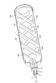
次に、本実施形態の現像剤補給容器について図3〜図7を用いて説明する。ここで図3は現像剤補給容器1の、(a)開口部1a側から見た斜視図、(b)は反対方向から見た斜視図である。図4は現像剤補給容器1内の搬送部がバッフル部材40である場合の断面斜視図である。図5は現像剤補給容器1内の搬送部が螺旋状の突起1cである場合の断面斜視図である。図6は現像剤補給容器の交換動作の説明図である。図7は現像剤補給装置内の誘い込み部と適合部、現像剤補給容器に設けられた誘導部としての被誘い込み部と誤セット防止部としての規制部を示す斜視図である。
[Developer supply container]
Next, the developer supply container of the present embodiment will be described with reference to FIGS. 3A is a perspective view of the developer supply container 1 as viewed from the opening 1a side, and FIG. 3B is a perspective view as viewed from the opposite direction. FIG. 4 is a cross-sectional perspective view in the case where the conveyance unit in the developer supply container 1 is a baffle member 40. FIG. 5 is a cross-sectional perspective view in the case where the conveying portion in the developer supply container 1 is a spiral protrusion 1c. FIG. 6 is an explanatory view of the replacement operation of the developer supply container. FIG. 7 is a perspective view showing a guide part and a conforming part in the developer supply device, a guided part as a guide part provided in the developer supply container, and a restricting part as an erroneous set prevention part .

現像剤補給容器1は略円筒形状に形成され、その一端面のほぼ中央にその容器本体1Aの円筒部より小径の開口部(排出口)1aが突設されている。開口部1aには、開口部1aを閉じる封止部材2が設けてあり、後述の図3に関連した説明にて理解されるように、この封止部材2が現像剤補給容器1の軸方向(矢印a−b方向)にスライド移動することにより、開口部1aの開閉動作を行う構成になっている。   The developer supply container 1 is formed in a substantially cylindrical shape, and an opening (discharge port) 1a having a smaller diameter than the cylindrical part of the container main body 1A protrudes from the center of one end surface of the developer supply container 1. The opening 1a is provided with a sealing member 2 that closes the opening 1a. As will be understood in the description related to FIG. 3 to be described later, this sealing member 2 is in the axial direction of the developer supply container 1. It is configured to open and close the opening 1a by sliding in the direction of arrows ab.

封止部材2の先端部には、係合突起3と、係合突起3の装置本体側の駆動部20(図6参照)との係合を解除する解除突起4とが設けられた円筒部が形成されており、これら係合突起3及び解除突起4を支持している円筒部の領域は弾性変形可能な構成となっている(詳しくは、この弾性変形を補助、促進するために、上記領域の両側に円筒部先端に至るスリットが設けられている)。この係合突起3は、装置本体側の駆動部20と係合して、現像剤補給容器1に回転駆動を伝達する機能を果たす構成になっている。   A cylindrical portion provided with an engagement protrusion 3 and a release protrusion 4 for releasing the engagement of the engagement protrusion 3 with the drive section 20 (see FIG. 6) of the engagement protrusion 3 on the front end portion of the sealing member 2 The region of the cylindrical portion that supports the engagement protrusion 3 and the release protrusion 4 is configured to be elastically deformable (more specifically, in order to assist and promote this elastic deformation, Slits leading to the tip of the cylindrical part are provided on both sides of the area). The engagement protrusion 3 is configured to engage with the drive unit 20 on the apparatus main body side and fulfill the function of transmitting rotational drive to the developer supply container 1.

次に現像剤補給容器1内部の構成について説明する。上述のように、現像剤補給容器1は略円筒形状を有しており、装置本体100内(図2参照)に略水平に配置され、装置本体100から回転駆動を受けて回転する構成になっている。そして、この現像剤補給容器1の内部には上述したように、現像剤の搬送部材としてのバッフル部材40(図4参照)が設けられている。このバッフル部材40は、図4に示すように、現像剤補給容器1の回転に伴って現像剤補給容器1内の現像剤を持ち上げる仕切り壁40bと、仕切り壁40b上に設けられ、仕切り壁40bによって持ち上げられた現像剤を開口部1aへ搬送するための傾斜突起40aとを備えている。すなわち、現像剤補給容器1内の現像剤は現像剤補給容器1の回転に伴って仕切り壁40bによって持ち上げられ、さらに持ち上げられた現像剤は重力により仕切り壁40b上を滑り落ち、その後回転軸線方向に対して傾斜した面をもつ傾斜突起40aにより軸方向に搬送され、最終的に現像剤補給容器1端面に設けた開口部1aから排出される。この構成によれば、簡単な構成にて現像剤の排出性能に優れた現像剤補給容器を提供することができる。   Next, the configuration inside the developer supply container 1 will be described. As described above, the developer supply container 1 has a substantially cylindrical shape, is arranged substantially horizontally in the apparatus main body 100 (see FIG. 2), and is rotated by receiving rotational driving from the apparatus main body 100. ing. Further, as described above, a baffle member 40 (see FIG. 4) as a developer conveying member is provided in the developer supply container 1. As shown in FIG. 4, the baffle member 40 is provided on the partition wall 40b, the partition wall 40b for lifting the developer in the developer supply container 1 as the developer supply container 1 rotates, and the partition wall 40b. And an inclined protrusion 40a for transporting the developer lifted by the nozzle 1a to the opening 1a. That is, the developer in the developer supply container 1 is lifted by the partition wall 40b as the developer supply container 1 rotates, and the lifted developer slides down on the partition wall 40b due to gravity, and then rotates in the direction of the rotation axis. Is conveyed in the axial direction by an inclined protrusion 40a having a surface inclined with respect to the surface, and finally discharged from an opening 1a provided on the end surface of the developer supply container 1. According to this configuration, it is possible to provide a developer supply container having a simple configuration and excellent developer discharge performance.

また図3に示すように、現像剤補給容器1には、現像剤補給容器1の装着方向(矢印a方向)下流側付近の外周面、すなわち開口部1a付近の容器先端部側の外周面に規制部5が設けられている。なお、現像剤補給装置400側には、現像剤補給容器1の現像剤補給装置400への装着可否を判別するために前記現像剤補給容器1に設けられた規制部5が実質的に合致するか否かを規制する適合部としての規制部材400cが設けられている。本実施形態に係る規制部5は、容器本体1Aの円筒部の外径から突出した複数の規制突起(突起部)5aにより構成されており、この複数の規制突起5aの配置や組み合わせを異なる現像剤補給容器ごとに適宜行うことで、該異なる現像剤補給容器の識別子としての規制部5を構成している。現像剤補給容器1側の規制突起5aと現像剤補給装置400(図7参照)側の規制部材400cにより、画像形成装置本体100に画像欠陥等や色間違いのない適切な現像剤を収納した現像剤補給容器のみが、画像形成装置本体100に装着可能となる構成となっている。本構成の詳細については、現像剤補給容器1の交換方法の項にて詳述する。   As shown in FIG. 3, the developer supply container 1 has an outer peripheral surface near the downstream side in the mounting direction of the developer supply container 1 (in the direction of arrow a), that is, an outer peripheral surface near the container front end near the opening 1a. A restriction unit 5 is provided. Note that the regulating portion 5 provided in the developer replenishing container 1 substantially matches the developer replenishing apparatus 400 side in order to determine whether or not the developer replenishing container 1 can be attached to the developer replenishing apparatus 400. A restricting member 400c is provided as a conforming part that restricts whether or not. The restricting portion 5 according to the present embodiment is configured by a plurality of restricting protrusions (protruding portions) 5a protruding from the outer diameter of the cylindrical portion of the container body 1A, and different arrangements and combinations of the restricting protrusions 5a are developed. By appropriately performing for each developer replenishing container, the restriction unit 5 as an identifier of the different developer replenishing container is configured. Development in which an appropriate developer containing no image defect or a color error is stored in the image forming apparatus main body 100 by the restriction protrusion 5a on the developer supply container 1 side and the restriction member 400c on the developer supply device 400 (see FIG. 7) side. Only the agent supply container can be mounted on the image forming apparatus main body 100. Details of this configuration will be described in detail in the section on how to replace the developer supply container 1.

尚、本発明における現像剤補給容器1内部の構成については、現像剤補給容器1が回転することにより容器内部に収容した現像剤を排出口に向けて搬送するものであれば、その形状や構成について限定するものではない。例えば、現像剤補給容器1の内部の現像剤搬送・排出手段の構成については、図4に示すようにバッフル部材40を用いたものの他、図5に示すように一般的によく知られている容器内部に螺旋状突起1cを設けたものであっても構わない。この構成によっても、簡単な構成にて現像剤の排出性能に優れた現像剤補給容器を提供することができる。   As for the configuration inside the developer supply container 1 in the present invention, as long as the developer supply container 1 rotates and conveys the developer accommodated in the container toward the discharge port, the shape and configuration thereof. It is not intended to be limited. For example, the configuration of the developer transport / discharge means inside the developer supply container 1 is generally well known as shown in FIG. 5 in addition to the configuration using the baffle member 40 as shown in FIG. You may provide the spiral protrusion 1c in the inside of a container. Also with this configuration, it is possible to provide a developer supply container having a simple configuration and excellent developer discharge performance.

[現像剤補給容器の交換方法]
次に、上記現像剤補給容器1の交換方法について説明する。画像形成のプロセスに伴い、現像剤補給容器1内の現像剤が略全量消費されると、装置本体100に設けられた現像剤補給容器空検知手段(不図示)によって現像剤補給容器1内の現像剤が無くなったことが検知され、その旨が液晶等の表示手段100b(図2参照)によりユーザーに知らされる。本実施形態において現像剤補給容器1の交換はユーザー自身が行い、その手順は以下の通りである。
[How to replace the developer supply container]
Next, a method for replacing the developer supply container 1 will be described. When almost all of the developer in the developer supply container 1 is consumed during the image forming process, the developer supply container empty detection means (not shown) provided in the apparatus main body 100 detects the developer supply container 1 in the developer supply container 1. It is detected that the developer has run out, and the fact is notified to the user by the display means 100b such as liquid crystal (see FIG. 2). In this embodiment, the user replaces the developer supply container 1 and the procedure is as follows.

まず、閉じられた状態の交換用カバー15をヒンジ18を中心に回動させて図2に示す位置まで開く。この交換用カバー15を開く動作に連動して現像剤補給部開閉手段(不図示)により、図6(c)の状態にある容器本体(円筒部)1Aが図6(a)に示す矢印a方向に移動して、それまで容器本体1Aと離間し、現像剤補給開口部1aを開放する状態にあった封止部材2が現像剤補給開口部1aに圧入嵌合され、現像剤補給開口部1aが閉止され、上記図6(b)に示す状態となる。   First, the replacement cover 15 in the closed state is rotated about the hinge 18 and opened to the position shown in FIG. The container body (cylindrical portion) 1A in the state shown in FIG. 6C is moved by the arrow a shown in FIG. The sealing member 2 that has moved in the direction and separated from the container main body 1A until then and opened the developer supply opening 1a is press-fitted into the developer supply opening 1a, and the developer supply opening 1a 1a is closed, and the state shown in FIG.

次に、ユーザーは、装置本体100に装着されている現像剤のなくなった現像剤補給容器1を図6(a)に示す矢印a方向と逆方向に引き出し、装置本体100から取り外す。この後、ユーザーは新しい現像剤補給容器1を図6(a)に示す矢印aの向きに装置本体100へと挿入した後、交換用カバー15を閉じる。そして、上述のように、この交換用カバー15を閉じる動作に連動して現像剤補給部開閉手段(不図示)により封止部材2が容器本体1Aから離間され、現像剤補給開口部1aが開封される(図6(c))。以上が、現像剤補給容器1の交換手順である。   Next, the user pulls out the developer replenishing container 1 with no developer attached to the apparatus main body 100 in the direction opposite to the direction of the arrow a shown in FIG. Thereafter, the user inserts a new developer supply container 1 into the apparatus main body 100 in the direction of arrow a shown in FIG. 6A, and then closes the replacement cover 15. As described above, the sealing member 2 is separated from the container main body 1A by the developer replenishing portion opening / closing means (not shown) in conjunction with the operation of closing the replacement cover 15, and the developer replenishing opening 1a is opened. (FIG. 6C). The above is the procedure for replacing the developer supply container 1.

[現像剤補給容器の装着可否判定構成]
上述した現像剤補給容器1の交換において、最も避けなければならないのが、異なる種類の現像剤が収納された現像剤補給容器1を誤って画像形成装置本体100にセットしてしまうことである。ここでは、現像剤補給容器1の誤セットを防止するための装着可否判定機構について図を用いて詳細に説明する。
[Configuration for determining whether or not to install developer supply container]
In the replacement of the developer supply container 1 described above, the most important thing to avoid is to erroneously set the developer supply container 1 containing different types of developer in the image forming apparatus main body 100. Here, the mounting availability determination mechanism for preventing the developer replenishment container 1 from being erroneously set will be described in detail with reference to the drawings.

図3に示すように、本実施形態に係る現像剤補給容器1は、容器本体1Aの挿入方向(矢印a方向)先端側(本実施形態においては排出口1a付近の外周面)に、現像剤補給容器本体1Aの円筒部から突出する規制部5としての規制突起5aが設けられている。図7に示すように、現像剤補給装置400に設けられている現像剤補給容器1の挿入口途中には、前記規制部5を規制して現像剤補給容器1の装着可否を判別する適合部である規制部材400cが配置されている。この規制部材400cは、画像形成装置本体100にて使用される現像剤の色や種類に応じて異なる現像剤補給容器1に応じた切欠部400c1(一体成形品にて部分的に凹部を有する場合でも、擬似的に切欠部と呼ぶ。図9(b)参照)を有した状態で配置されている。この規制部材400cは、その形状が、現像剤補給容器1に設けられた規制部5である規制突起5aと実質的に合致するか否かにより、画像形成装置本体100に装着される現像剤補給容器1の装着可否判定を行う構成となっている。   As shown in FIG. 3, the developer supply container 1 according to the present embodiment has a developer on the distal end side (in the present embodiment, the outer peripheral surface in the vicinity of the discharge port 1 a) of the container main body 1 </ b> A. A restricting protrusion 5a is provided as a restricting portion 5 that protrudes from the cylindrical portion of the supply container main body 1A. As shown in FIG. 7, in the middle of the insertion port of the developer supply container 1 provided in the developer supply device 400, a fitting unit that controls the restriction unit 5 to determine whether or not the developer supply container 1 can be attached. A restricting member 400c is arranged. The restricting member 400c has a notch 400c1 corresponding to the developer supply container 1 that differs depending on the color and type of the developer used in the image forming apparatus main body 100 (in the case of a partially formed recess in the integrally molded product). However, it is referred to as a cutout portion in a pseudo manner (see FIG. 9B). The restricting member 400c is supplied with developer supplied to the image forming apparatus main body 100 depending on whether or not the shape of the restricting member 400c substantially matches the restricting protrusion 5a that is the restricting portion 5 provided in the developer supplying container 1. It is configured to determine whether or not the container 1 can be attached.

ここで、現像剤補給容器1に設けられた規制部5と現像剤補給装置400に設けられた規制部材400cの位相が合致していないと、画像形成装置本体100に装着される現像剤補給容器1の正しい装着可否判定が行えないため、その位相を合わせる手段を設けている。この規制部5と規制部材400cの位相を合わせる手段の構成について図8〜図10を用いて詳細に説明する。   Here, if the phases of the regulating portion 5 provided in the developer supply container 1 and the regulating member 400 c provided in the developer supply device 400 do not match, the developer supply container mounted on the image forming apparatus main body 100. Since it is not possible to determine whether or not 1 is correctly attached, means for adjusting the phase is provided. The structure of the means for adjusting the phase of the restricting portion 5 and the restricting member 400c will be described in detail with reference to FIGS.

図8は現像剤補給容器の要部拡大図であり、(a)は被誘い込み突起8aとゲート通過時位置決め突起8bとに分割された状態の被誘い込み部8を示す要部拡大図(規制突起5aを除く)であり、被誘い込み突起8aとゲート通過時位置決め突起8bとに分割された状態の被誘い込み部8と規制突起5aを示す要部拡大図である。図9は現像剤補給装置内の誘い込み部と適合部を示す、(a)斜視図、(b)平面図である。図10は現像剤補給容器装着時の誘い込み部・被誘い込み部の関係を示す模式説明図である。   FIG. 8 is an enlarged view of the main part of the developer supply container. FIG. 8A is an enlarged view of the main part showing the attracted part 8 in a state where it is divided into the attracted protrusion 8a and the positioning protrusion 8b when passing through the gate (regulatory protrusion). 5a), and is an enlarged view of a main part showing the attracted portion 8 and the restricting projection 5a in a state of being divided into the attracted projection 8a and the positioning projection 8b when passing through the gate. FIG. 9A is a perspective view and FIG. 9B is a plan view showing a guide portion and a compatible portion in the developer supply device. FIG. 10 is a schematic explanatory view showing the relationship between the attracting part and the attracted part when the developer supply container is mounted.

現像剤補給容器1には、図8に示すように被誘い込み部8が設けてある。この被誘い込み部8は、後述する現像剤補給装置400側の誘い込み部9に規制を受けるものであり、被誘い込み突起8aとゲート通過時位置決め突起8bを有している。現像剤補給装置400側には、図9に示すように誘い込み部9aが設けてある。この誘い込み部9aは、現像剤補給容器1の回転方向の位相を規定するものであり、前記突起8a,8bを有する被誘い込み部8を規制して、ゲート部9bに向けて誘い込むものである。ゲート部9bは、誘い込み部9aによって形成され、被誘い込み部8の位置決め突起8bを位置決めするためのものである。なお、ここでは、図8に示すように被誘い込み部8の機能上の説明をするために、該被誘い込み部8を被誘い込み突起8aとゲート通過時位置決め突起8bとに分割した状態を図示しているが、図7に示すように両方の突起が一体となった形状の被誘い込み部8であっても構わない。このガイド部としての被誘い込み部8は、図7に示すように、前記現像剤補給容器1の回転軸線方向に対し傾斜した面を備えた突出部を有する構成となっている。   The developer supply container 1 is provided with a guided portion 8 as shown in FIG. The attracting portion 8 is restricted by the attracting portion 9 on the developer replenishing device 400 described later, and has an attracting projection 8a and a positioning projection 8b when passing through the gate. As shown in FIG. 9, a lead-in portion 9a is provided on the developer supply device 400 side. The guide portion 9a defines the phase in the rotation direction of the developer supply container 1, and regulates the guide portion 8 having the protrusions 8a and 8b to guide it toward the gate portion 9b. The gate portion 9 b is formed by the guiding portion 9 a and is used for positioning the positioning protrusion 8 b of the guided portion 8. Here, as shown in FIG. 8, in order to explain the function of the attracting portion 8, the attracting portion 8 is illustrated as being divided into the attracting projection 8 a and the positioning projection 8 b when passing through the gate. However, as shown in FIG. 7, it may be a guided portion 8 having a shape in which both protrusions are integrated. As shown in FIG. 7, the guided portion 8 as the guide portion has a protrusion having a surface inclined with respect to the rotation axis direction of the developer supply container 1.

図8及び図9に示す各部位の詳細な役割については後述するが、上記被誘い込み部8と上記誘い込み部9aにより現像剤補給容器1は回転方向において360°どの位相で現像剤補給装置400に挿入しても、挿入方向(図7に示す矢印a方向)の押し込み量に応じて誘い込み部9aと被誘い込み部8が相対回転し、現像剤補給装置400(規制部材400c)と現像剤補給容器1(規制突起5a)が互いに位相が合わさり、その位相が合わさった後さらに現像剤補給容器1を挿入することで規制部材400cと規制突起5aとが合致したか否かにより現像剤補給容器1の装着可否判定を行うことが可能となる。   Although the detailed role of each part shown in FIGS. 8 and 9 will be described later, the developer replenishing container 1 is rotated 360 degrees in the rotation direction to the developer replenishing device 400 by the attracted part 8 and the attracting part 9a. Even if inserted, the guiding portion 9a and the guided portion 8 rotate relative to each other in accordance with the amount of pressing in the insertion direction (the direction of arrow a shown in FIG. 7), and the developer supply device 400 (regulating member 400c) and the developer supply container 1 (regulation protrusion 5a) are in phase with each other, and after the phases are matched, the developer supply container 1 is further inserted to determine whether the restriction member 400c and the restriction protrusion 5a match each other. It is possible to determine whether or not the device can be attached.

またこれまでの例示では、現像剤補給容器1側に被誘い込み部8を設け、現像剤補給装置400側に誘い込み部9aを設けた構成を例示したが、本発明はこれに限定されるものではない。図11に第1実施形態の変形例(変形例1)を示す。図11に示すように現像剤補給容器1側に誘い込み部9aを設け、現像剤補給装置400側に被誘い込み部8を設けた構成としても良く、この構成によっても同様の効果を発揮する。なお、後述する本実施形態以外の実施の形態に例示する構成においても、この関係は成り立つ。   Further, in the above examples, the configuration in which the attracting portion 8 is provided on the developer supply container 1 side and the attracting portion 9a is provided on the developer supply device 400 side is illustrated, but the present invention is not limited to this. Absent. FIG. 11 shows a modified example (modified example 1) of the first embodiment. As shown in FIG. 11, a configuration may be employed in which a guide portion 9 a is provided on the developer supply container 1 side and a guide portion 8 is provided on the developer supply device 400 side, and this configuration also exhibits the same effect. Note that this relationship also holds in configurations exemplified in embodiments other than the present embodiment described later.

次に図10を用いて、現像剤補給装置の交換時に、前述した位相合わせ手段を構成する誘い込み部9aと被誘い込み部8により、前記規制部材400cと規制突起5aの位相を合わせる動作の詳細について説明する。まず現像剤補給容器1の挿入時について説明する。現像剤補給容器の交換方法でも述べたように現像剤補給容器1を図7に示す矢印aの方向に挿入していくと、図10(a)に示すように規制部材400cと規制突起5aの位相がずれているとき、すなわち誘い込み部9aによって形成されたゲート部9bの領域(以下、ゲート領域という)10dから被誘い込み突起8aの位相が外れているときには、被誘い込み突起8aが誘い込み部9aのテーパー部10cに当接し、誘い込み部9aと被誘い込み部8は相対回転し始める。その後、現像剤補給容器1を更に挿入していき、図10(b)に示すように被誘い込み突起8aがゲート領域10dに侵入すると、今度はゲート通過時位置決め突起8b先端が誘い込み部9aに当接し、誘い込み部9aと被誘い込み部8はさらに相対回転する。そして、図10(c)に示すように誘い込み部9a,9a間のゲート部9b内に被誘い込み部8の位置決め突起8cが位置決められると、規制部材400c・規制突起5aの位相が合致し、前記相対回転が停止し、挿入方向のみの移動となる。以上の動作により位相が合致し、この位相が合致した状態で更に現像剤補給容器1を挿入することで、規制部材400cと規制突起5aが実質的に合致するか否かによる現像剤補給容器の装着可否判定が行なわれる。このように本実施形態によれば、簡単な構成で、操作者が意識して位相合わせを行わなくても現像剤補給容器1の装着可否判定が確実に行われ、また現像剤補給容器1の装着も容易かつ確実に行える。   Next, referring to FIG. 10, when the developer replenishing device is replaced, details of the operation of aligning the phases of the regulating member 400c and the regulating projection 5a by the guiding portion 9a and the guided portion 8 constituting the phase adjusting means described above. explain. First, the insertion of the developer supply container 1 will be described. As described in the method for replacing the developer supply container, when the developer supply container 1 is inserted in the direction of the arrow a shown in FIG. 7, the restriction member 400c and the restriction protrusion 5a are moved as shown in FIG. When the phase is shifted, that is, when the phase of the lug 8a is out of phase with the region 9d of the gate 9b (hereinafter referred to as the gate region) formed by the lug 9a, the lug 8a is The abutting portion 9a abuts on the tapered portion 10c, and the attracted portion 9a and the attracted portion 8 start to rotate relative to each other. Thereafter, the developer supply container 1 is further inserted, and when the attracted protrusion 8a enters the gate region 10d as shown in FIG. 10 (b), the tip of the positioning protrusion 8b at the time of passing through the gate now contacts the attracting part 9a. The guiding part 9a and the guided part 8 are further rotated relative to each other. Then, as shown in FIG. 10 (c), when the positioning projection 8c of the attracted portion 8 is positioned in the gate portion 9b between the attracting portions 9a, 9a, the phases of the regulating member 400c and the regulating projection 5a are matched, Relative rotation stops and only the insertion direction moves. By the above operation, the phases are matched, and the developer supply container 1 is further inserted in a state in which the phases are matched, so that the developer supply container of the developer supply container depends on whether or not the restriction member 400c and the restriction protrusion 5a substantially match. Whether or not it can be attached is determined. As described above, according to the present embodiment, it is possible to reliably determine whether or not the developer supply container 1 is to be mounted with a simple configuration without performing phase alignment with the operator being aware of it. Installation is easy and reliable.

次に現像剤補給容器の脱離時について説明する。本実施形態に係る現像剤補給容器1は、内部に収納した現像剤の搬送・排出のため、画像形成装置本体100からの駆動伝達により回転する。従って装置本体100への装着後の現像剤補給容器1は、特に回転停止位置を規制するなどの手段を設けない限り、現像剤補給容器1の脱離時の規制部材400cと規制突起5aとの位相が不定である。現像剤補給容器1の脱離時においては、規制部材400cと規制部5が実質的に合致するか否かによる装着可否の判定は必要ないが、規制部材400cと規制部5との位相がずれていると干渉して現像剤補給容器1が画像形成装置本体100から引き抜けなくなる可能性がある。このため、現像剤補給容器1の脱離時においても装着時と同様の位相合わせを行う必要がある。そこで、本実施形態に係る誘い込み部9aおよび被誘い込み部8は、画像形成装置本体100に対して現像剤補給容器1を装着するときだけでなく、画像形成装置本体100から現像剤補給容器1を脱離する際においても規制部5と規制部材400cとの位相を規定するよう構成されている。具体的には、本実施形態に係る位相合わせ手段となる誘い込み部9aおよび被誘い込み部8は、図7及び図10に示すように、装着可否判定機構となる規制部材400cと規制部5を介した、挿入方向(図7の矢印a方向)における形状と脱離方向(図7の矢印b方向)における形状とが対称形状をなしている。これにより、回転により現像剤を搬送・排出する現像剤補給容器1の脱離時においても、操作者が意識して位相あわせを行わなくても規制部材400cと規制部5の位相が合致し、現像剤補給容器1を画像形成装置本体100からスムーズに引き抜くことができ、現像剤補給容器1の脱離も容易かつ確実に行える。   Next, the time when the developer supply container is detached will be described. The developer supply container 1 according to the present embodiment is rotated by drive transmission from the image forming apparatus main body 100 in order to transport and discharge the developer stored therein. Therefore, the developer replenishing container 1 after being mounted on the apparatus main body 100 has a restriction member 400c and a restricting protrusion 5a when the developer replenishing container 1 is detached unless a means for restricting the rotation stop position is provided. The phase is indefinite. When the developer replenishing container 1 is detached, it is not necessary to determine whether or not the regulating member 400c and the regulating unit 5 are substantially matched, but the phase between the regulating member 400c and the regulating unit 5 is shifted. The developer supply container 1 may not be pulled out from the image forming apparatus main body 100 due to interference. For this reason, it is necessary to perform phase matching similar to that when the developer supply container 1 is detached. Therefore, the guiding portion 9 a and the attracting portion 8 according to the present embodiment not only attach the developer supply container 1 to the image forming apparatus main body 100 but also remove the developer supply container 1 from the image forming apparatus main body 100. Even when detaching, the phase between the restricting portion 5 and the restricting member 400c is defined. Specifically, as shown in FIG. 7 and FIG. 10, the guiding portion 9 a and the guided portion 8 serving as the phase matching means according to the present embodiment are provided via the regulating member 400 c and the regulating portion 5 serving as a mounting availability determination mechanism. The shape in the insertion direction (arrow a direction in FIG. 7) and the shape in the detachment direction (arrow b direction in FIG. 7) are symmetrical. As a result, even when the developer supply container 1 that transports and discharges the developer by rotation is detached, the phase of the regulating member 400c and the regulating unit 5 are matched without the operator performing the phase alignment. The developer supply container 1 can be smoothly pulled out from the image forming apparatus main body 100, and the developer supply container 1 can be easily and reliably detached.

また、図10に示すように、誘い込み部9aの誘い込み角度α(挿入方向に対するテーパー部10cの角度)は、挿入時の操作力に大きく影響し、誘い込み角度αが小さいほど挿入方向の押し込み量に対する誘い込み部9aと被誘い込み部8の相対回転量が小さくなるため、現像剤補給容器1を挿入しやすい。しかしながら、誘い込み角度αを小さくするほど誘い込み部9aの現像剤補給容器挿入方向の長さLが長くなる。このため、誘い込み部9aの誘い込み角度αと現像剤補給容器挿入方向の長さLは、現像剤補給容器1の操作力と誘い込み部9aの設置スペースのバランスを考えて設計することが好ましい。   Further, as shown in FIG. 10, the guiding angle α of the guiding portion 9a (the angle of the tapered portion 10c with respect to the insertion direction) greatly affects the operating force at the time of insertion, and the smaller the guiding angle α, the more the amount of pushing in the insertion direction. Since the relative rotation amount of the guiding portion 9a and the guided portion 8 is small, the developer supply container 1 can be easily inserted. However, as the guide angle α is decreased, the length L of the guide portion 9a in the developer supply container insertion direction is increased. For this reason, it is preferable to design the guide angle α of the guide portion 9a and the length L in the developer supply container insertion direction in consideration of the balance between the operating force of the developer supply container 1 and the installation space of the guide portion 9a.

現像剤補給装置400側に設けられている誘い込み部9aは、ゲート部9bが1箇所形成できればその機能を果たすが、その場合、挿入時に現像剤補給容器1と現像剤補給装置400との間で最大180°の相対回転となってしまう。また、操作力を低減するために誘い込み角度α(図10(a)参照)を小さくすると、誘い込み部9aの現像剤補給容器挿入方向の長さLもそれなりに必要となる。そこで、本実施形態では、図9に示すように複数箇所のゲート部9bを形成すべく誘い込み部9aを複数箇所設けている。このように構成することで、誘い込み部9aと被誘い込み部8の相対回転量を減らすことができるとともに、操作力を低減するための誘い込み角度αを保ったまま誘い込み部9aの現像剤補給容器挿入方向の長さLを短縮することができる。本実施形態では現像補給容器1と被誘い込み部8が一体であるため、挿入時には現像補給容器自体が回転する。現像補給容器1を挿入していくと規制部材400cと規制部5の位相が合うまでは押し込み量に応じて自動的に回転する。ユーザーの手も同時に回転するため、この回転量があまり大きいと装着動作に違和感を感じてしまうことが考えられる。本実施形態ではゲート部を4箇所に設けているため、挿入時に現像剤補給容器1と現像剤補給装置400との間では最大で45°の相対回転する。操作性の観点から言えば相対回転角度が小さい方がよく、60°以内(ゲート部3箇所以上)が好ましい。なお、この場合、現像剤補給容器1側の被誘い込み部8は機能的には1箇所あればよいが、回転のバランスを考えた際には円周面上に均等間隔で複数箇所配置してあることが好ましい。ただし、現像剤補給装置400側に設ける誘い込み部9aの設置数と現像剤補給容器1側に設ける被誘い込み部8の個数には相関があり、現像剤補給容器1の被誘い込み部8が1箇所であるならば、現像剤補給装置400の誘い込み部9aの個数は適宜選択可能であるが、被誘い込み部8が2箇所以上になる場合には誘い込み部9aの個数はその整数倍でなくてはならない。   The guiding portion 9a provided on the developer supply device 400 side functions as long as one gate portion 9b can be formed. In that case, the insertion portion 9a is inserted between the developer supply container 1 and the developer supply device 400 when inserted. The relative rotation is 180 ° at the maximum. Further, if the guide angle α (see FIG. 10A) is reduced to reduce the operating force, the length L of the guide portion 9a in the developer supply container insertion direction is also required. Therefore, in this embodiment, as shown in FIG. 9, a plurality of guiding portions 9a are provided to form a plurality of gate portions 9b. With this configuration, the amount of relative rotation between the attracting portion 9a and the attracted portion 8 can be reduced, and the developer supply container can be inserted into the attracting portion 9a while maintaining the attracting angle α for reducing the operating force. The length L in the direction can be shortened. In the present embodiment, since the developer supply container 1 and the attracted portion 8 are integrated, the developer supply container itself rotates during insertion. As the developer supply container 1 is inserted, the developer replenishment container 1 automatically rotates according to the amount of push-in until the phase of the regulating member 400c and the regulating unit 5 match. Since the user's hand also rotates at the same time, if the amount of rotation is too large, the user may feel uncomfortable with the wearing operation. In this embodiment, since the gate portions are provided at four places, the relative rotation of 45 ° at the maximum is made between the developer supply container 1 and the developer supply device 400 at the time of insertion. From the viewpoint of operability, it is preferable that the relative rotation angle is small, and it is preferably within 60 ° (three or more gate portions). In this case, the attracting portion 8 on the developer replenishing container 1 side may be functionally provided at one location, but when considering the balance of rotation, a plurality of locations are arranged at equal intervals on the circumferential surface. Preferably there is. However, there is a correlation between the number of attracting portions 9a provided on the developer supply device 400 side and the number of attracted portions 8 provided on the developer supply container 1 side, and there is one attracted portion 8 of the developer supply container 1. If this is the case, the number of attracting portions 9a of the developer replenishing device 400 can be selected as appropriate. However, when the number of attracted portions 8 is two or more, the number of attracting portions 9a must be an integral multiple thereof. Don't be.

ここで、誘い込み部9a・被誘い込み部8に対する規制部材400c・規制部5の関係であるが、基本的に現像剤補給容器1の挿脱着時に互いに干渉しない位置で、且つ誘い込み部9aと被誘い込み部8の位相が一致した際に規制部材400c・規制部5の位相も一致するような位置にあればよい。例えば、誘い込み部9a・被誘い込み部8に対する規制部材400c・規制部5の位置は、それぞれ図8及び図9に示したようにゲート部9b・2ヶ所あるゲート通過時位置決め突起8bの間(一体型の被誘い込み部8の場合はその被誘い込み部8上。図3及び図7参照)でもよいし、第1実施形態の変形例(変形例2)として図12に示すような誘い込み部9a上・被誘い込み部8の間でもよい。   Here, the relationship of the restricting member 400c and the restricting portion 5 with respect to the attracting portion 9a and the attracted portion 8 is basically a position that does not interfere with each other when the developer supply container 1 is inserted and removed, and the attracting portion 9a and the attracted portion 9 are attracted. It suffices if the phase of the restricting member 400c and the restricting portion 5 are matched when the phase of the portion 8 is matched. For example, as shown in FIGS. 8 and 9, the positions of the restricting member 400c and the restricting portion 5 with respect to the guiding portion 9a and the attracted portion 8 are respectively between the gate portion 9b and the two positioning projections 8b when passing through the gate (one In the case of the body-type attracting part 8, it may be on the attracting part 8. Refer to FIGS. 3 and 7), or as a modified example (modified example 2) of the first embodiment on the attracting part 9a as shown in FIG. -It may be between the invited part 8.

また、規制部材400c・規制部5の現像剤補給装置400・現像剤補給容器1それぞれに対する位置に関しては、以下の関係であることが好ましい。すなわち、上述した誘い込み部9a・被誘い込み部8に対する規制部材400c・規制部5の位置関係を守った上で、現像剤補給装置400における規制部材400cの位置は、現像剤補給容器1の挿入方向(図7の矢印a方向)の出来るだけ上流側にあることが好ましく、一方、現像剤補給容器1における規制部5の位置は、現像剤補給容器1の外周面上において現像剤補給容器1の挿入方向(図7の矢印a方向)の出来るだけ下流側にあることが好ましい。これにより、現像剤補給容器1の挿入時に早い段階で装着可否判断を行うことが可能となり、仮にユーザーが間違った現像剤補給容器1を挿入してもその間違いを早期に認識しやすい。   The positions of the regulating member 400c, the regulating unit 5 with respect to the developer supply device 400 and the developer supply container 1 are preferably in the following relationship. In other words, the position of the regulating member 400c in the developer replenishing device 400 is the insertion direction of the developer replenishing container 1 while keeping the positional relationship of the regulating member 400c and the regulating unit 5 with respect to the attraction portion 9a and the attracted portion 8 described above. It is preferable that it is as upstream as possible (in the direction of arrow a in FIG. 7). On the other hand, the position of the regulating portion 5 in the developer supply container 1 is the position of the developer supply container 1 on the outer peripheral surface of the developer supply container 1. It is preferable to be as downstream as possible in the insertion direction (the direction of arrow a in FIG. 7). As a result, it is possible to determine whether or not the developer supply container 1 can be mounted at an early stage when the developer supply container 1 is inserted, and even if the user inserts the wrong developer supply container 1, it is easy to recognize the error at an early stage.

以上のような構成とすることにより、簡単で安価な構成で、現像剤補給容器1の挿入時にユーザーが規制部材400cと規制部5の位相合わせを意識することなく、現像剤補給容器1の装着操作を行うことができる。すなわち、現像剤補給容器1を現像剤補給装置400に押し込んでいくだけで、誘い込み部9a・被誘い込み部8が相対回転し、規制部材400c・規制部5の位相が合い、現像剤補給容器1を現像剤補給装置400に装着する際の装着可否判定を容易に且つ確実に行うことが可能となる。正しい現像剤補給容器1を挿入した場合は簡単な操作でスムーズに装着でき、間違った現像剤補給容器1を挿入した場合にはその間違いを確実に認識することができる。   With the above-described configuration, the developer supply container 1 can be mounted with a simple and inexpensive configuration without the user being aware of the phase alignment between the regulating member 400c and the regulating unit 5 when the developer supply container 1 is inserted. The operation can be performed. In other words, simply by pushing the developer supply container 1 into the developer supply device 400, the guiding portion 9a and the guided portion 8 rotate relative to each other, and the phases of the regulating member 400c and the regulating portion 5 are matched. Can be determined easily and reliably when the toner is mounted on the developer supply device 400. When the correct developer supply container 1 is inserted, it can be smoothly mounted by a simple operation, and when the wrong developer supply container 1 is inserted, the error can be reliably recognized.

更に現像剤補給容器1の脱着の際にも、現像剤補給容器1を現像剤補給装置400から引き抜くだけで、誘い込み部9a・被誘い込み部8が相対回転し、規制部材400c・規制部5の位相が合うので、装着可否判定の必要はないが規制部材400cと規制突起5aの位相合わせを意識することなく、現像剤補給容器1を引き抜くことができる。すなわち、ユーザーは単に現像剤補給容器1を引き抜くのみの操作で、スムーズに現像剤補給容器1を脱着することができ、操作性を大幅に向上することができる。   Further, when the developer replenishing container 1 is detached, simply pulling out the developer replenishing container 1 from the developer replenishing device 400 causes the guiding portion 9a and the attracted portion 8 to rotate relative to each other. Since the phases match, it is not necessary to determine whether or not the mounting is possible, but the developer supply container 1 can be pulled out without being aware of the phase alignment between the regulating member 400c and the regulating projection 5a. That is, the user can smoothly remove the developer supply container 1 by simply pulling out the developer supply container 1, and the operability can be greatly improved.

また、本実施の形態にて例示した現像剤補給装置400の構成によると、現像剤補給装置400における規制部材400cの位置は現像剤補給容器1の挿入方向上流側に、現像剤補給容器1における規制部5の位置は現像剤補給容器1の挿入方向下流側にあるため、現像剤補給容器1の挿入時に早い段階で装着可否判定が行え、早い段階で現像剤補給容器1の装着可否をユーザーに認識させることができる。また、万一違った種類の現像剤補給容器1を装着しようとしても、現像剤補給容器1は現像剤補給装置400に完全には装着されることはなく、現像剤補給容器1の開口部1aを封止している封止部材2が、現像剤補給装置400と係合してしまうことがないことから、誤って封止部材2が開封されてしまったり、画像形成装置本体100からの駆動が現像剤補給容器1に伝達されてしまうことがなく、異なった種類の現像剤が画像形成装置本体100に補給されてしまう不具合を確実に防止することが可能となる。   Further, according to the configuration of the developer replenishing device 400 exemplified in the present embodiment, the position of the regulating member 400 c in the developer replenishing device 400 is upstream of the developer replenishing container 1 in the insertion direction, and in the developer replenishing container 1. Since the position of the restricting portion 5 is on the downstream side in the insertion direction of the developer supply container 1, it is possible to determine whether or not the developer supply container 1 can be attached at an early stage when the developer supply container 1 is inserted. Can be recognized. Even if an attempt is made to mount a different type of developer supply container 1, the developer supply container 1 is not completely mounted on the developer supply device 400, and the opening 1 a of the developer supply container 1 is not provided. Since the sealing member 2 that seals is not engaged with the developer supply device 400, the sealing member 2 is accidentally opened or driven from the image forming apparatus main body 100. Is not transmitted to the developer supply container 1, and it is possible to reliably prevent the problem that different types of developers are supplied to the image forming apparatus main body 100.

〔第2実施形態〕
次に本発明に係る第2実施形態について、図13を用いて詳述する。尚、以下に説明する第2実施形態に係る画像形成装置本体の全体構成及び現像剤補給容器の概略構成は、前述した第1実施形態と同等であるため、ここでは詳しい説明は省略する。また第2実施形態において、前述した第1実施形態と同等の機能を有する部材には同一符号を付している。図13は第2実施形態に係る現像剤補給装置400と現像剤補給容器1を示す斜視図である。
[Second Embodiment]
Next, a second embodiment according to the present invention will be described in detail with reference to FIG. Note that the overall configuration of the image forming apparatus main body and the schematic configuration of the developer supply container according to the second embodiment described below are the same as those of the first embodiment described above, and thus detailed description thereof is omitted here. In the second embodiment, members having the same functions as those in the first embodiment are denoted by the same reference numerals. FIG. 13 is a perspective view showing the developer supply device 400 and the developer supply container 1 according to the second embodiment.

第1実施形態では、現像剤補給装置400側の誘い込み部9a・規制部材400cが現像剤補給装置400に固定されており、また現像剤補給容器1側の被誘い込み部8・規制部5が現像剤補給容器1に固定されている例を示したが、本実施形態においては、誘い込み部9a・規制部材400cもしくは被誘い込み部8・規制部5のどちらか一方が現像剤補給装置400もしくは現像剤補給容器1のいずれか一方に回転自在に支持された構成となっている。図13にその一例を示す。図13(a)では、現像剤補給装置400側の誘い込み部9a・規制部材400cが、回転支持コロ13aにより回転自在に支持されている回転部材410に設けられている。すなわち、現像剤補給装置400側の誘い込み部9a・規制部材400cが回転支持コロ13aにより回転自在に支持された構成となっている。また、図13(b)では、現像剤補給容器1側の被誘い込み部8・規制部5が、現像剤補給容器本体1Aに対して回転自在に支持されている回転部材14に設けられている。すなわち、現像剤補給容器1側の被誘い込み部8・規制部5が現像剤補給容器本体1Aに対して回転自在に支持された構成となっている。   In the first embodiment, the guide portion 9a and the regulating member 400c on the developer supply device 400 side are fixed to the developer supply device 400, and the guided portion 8 and the regulation portion 5 on the developer supply container 1 side are developed. Although the example fixed to the agent replenishing container 1 has been shown, in the present embodiment, one of the guiding portion 9a and the regulating member 400c or the attracted portion 8 and the regulating portion 5 is the developer supplying device 400 or the developer. It is configured to be rotatably supported by either one of the supply containers 1. An example is shown in FIG. In FIG. 13A, the guiding portion 9a and the regulating member 400c on the developer supply device 400 side are provided on a rotating member 410 that is rotatably supported by a rotating support roller 13a. That is, the guide portion 9a and the regulating member 400c on the developer supply device 400 side are rotatably supported by the rotation support roller 13a. In FIG. 13B, the attracting portion 8 and the regulating portion 5 on the developer supply container 1 side are provided on a rotating member 14 that is rotatably supported with respect to the developer supply container main body 1A. . In other words, the guided portion 8 and the regulating portion 5 on the developer supply container 1 side are rotatably supported with respect to the developer supply container main body 1A.

なお、本実施形態では、回転部材410と誘い込み部9a・規制部材400cが一体となって、又は回転部材14と被誘い込み部8・規制部5が一体となって、現像剤補給容器1との嵌め合いのみで回転できるよう構成されているが、本質的には、誘い込み部9a・規制部材400cが、又は被誘い込み部8・規制部5が同時に現像剤補給容器1に対して相対回転できるようになっていればどのような構成であってもよい。同様に、回転支持部に関しては本実施形態ではコロを使用したが、これに限定されるものではなく、基本的には誘い込み部9a・規制部材400c、又は被誘い込み部8・規制部5を回転可能に支持できるものであればどのような構成でもよい。   In the present embodiment, the rotating member 410 and the guiding portion 9a / restricting member 400c are integrated, or the rotating member 14 and the guided portion 8 / restricting portion 5 are integrated, Although it is configured to be able to rotate only by fitting, the guiding portion 9a and the regulating member 400c or the attracting portion 8 and the regulating portion 5 can be relatively rotated relative to the developer supply container 1 at the same time. Any configuration may be used as long as it is. Similarly, although the roller is used in the present embodiment for the rotation support portion, the present invention is not limited to this, and basically the guiding portion 9a and the regulating member 400c, or the guided portion 8 and the regulating portion 5 are rotated. Any configuration that can be supported is possible.

上述した構成とすることにより、現像剤補給容器1を現像剤補給装置400に挿入し、又は現像剤補給容器1を現像剤補給装置400から引き抜いた際に、現像剤補給装置400に回転自在に支持された誘い込み部9a又は現像剤補給容器1に回転自在に支持された被誘い込み部8が位相合わせのために相対回転し、その回転が現像剤補給容器1に伝わることがない。このため、現像剤補給容器1を装着・脱離操作の際に前記誘い込み部9a及び前記被誘い込み部8に倣って回転させる必要がなく、現像剤補給容器1の装着・脱離操作の際の操作力が軽減され、操作性が更に向上する。   With the above-described configuration, when the developer supply container 1 is inserted into the developer supply device 400 or pulled out of the developer supply device 400, the developer supply device 400 can rotate freely. The supported guiding portion 9a or the guided portion 8 rotatably supported by the developer supply container 1 rotates relative to each other for phase adjustment, and the rotation is not transmitted to the developer supply container 1. For this reason, it is not necessary to rotate the developer replenishing container 1 following the guiding portion 9a and the attracted portion 8 when the developer replenishing container 1 is attached / detached. The operating force is reduced and the operability is further improved.

また、図13(a)に示す第2実施形態の変形例(変形例3)として図14を示す。図14は第2実施形態の変形例に係る現像剤補給装置400と現像剤補給容器1を示す斜視図であり、図14(a)は現像剤補給容器1の挿入方向上流側から見た斜視図、図14(b)は現像剤補給容器の挿入方向下流側から見た斜視図である。図14に示す変形例では、図13(a)と同様に、現像剤補給装置400側の誘い込み部9a及び規制部材400cが回転支持コロ13aにより回転自在に支持されている回転部材410に設けられている。このように、現像剤補給装置400側の誘い込み部9a及び規制部材400cが回転支持コロ13aにより回転自在に支持されている場合には、図14に示すように、現像剤補給容器1を挿入する場合のみ位相合わせを行い、現像剤補給容器1の装着後は現像剤補給容器1の回転と共に現像剤補給装置400側の誘い込み部9a及び規制部材400cも回転する構成としてもよい。具体的には、図14に示すように、誘い込み部9aのゲート部9bによって位置決め支持した被誘い込み部8をそのまま挿入方向最下流部まで案内支持するよう、誘い込み部9aのゲート部9bを形成した構成としても良い。   Moreover, FIG. 14 is shown as a modification (modification 3) of 2nd Embodiment shown to Fig.13 (a). FIG. 14 is a perspective view showing the developer supply device 400 and the developer supply container 1 according to a modification of the second embodiment, and FIG. 14A is a perspective view seen from the upstream side in the insertion direction of the developer supply container 1. FIG. 14B is a perspective view of the developer supply container as seen from the downstream side in the insertion direction. In the modification shown in FIG. 14, as in FIG. 13A, the guide portion 9 a and the regulating member 400 c on the developer supply device 400 side are provided on the rotating member 410 that is rotatably supported by the rotating support roller 13 a. ing. As described above, when the guide portion 9a and the regulating member 400c on the developer supply device 400 side are rotatably supported by the rotation support roller 13a, the developer supply container 1 is inserted as shown in FIG. The phase adjustment may be performed only in the case, and after the developer supply container 1 is mounted, the guiding portion 9a and the regulating member 400c on the developer supply device 400 side may rotate as the developer supply container 1 rotates. Specifically, as shown in FIG. 14, the gate portion 9b of the guiding portion 9a is formed so that the guided portion 8 positioned and supported by the gate portion 9b of the guiding portion 9a is guided and supported as it is to the most downstream portion in the insertion direction. It is good also as a structure.

上記構成によれば、ユーザーが現像剤補給容器1を挿入する際に360°どの位相で挿入しても現像剤補給容器1を回転させずに挿脱着できるため、現像剤補給容器の装着・脱離操作の操作性を大きく向上させることができる。   According to the above configuration, when the user inserts the developer supply container 1, the developer supply container 1 can be inserted / removed without rotation regardless of the phase of 360 °. The operability of the separation operation can be greatly improved.

なお、図示していないが、図14に示す誘い込み部9aのゲート部9bの構成は、図13(b)に示す第2実施形態の変形例としても適用可能である。この場合、現像剤補給容器1の装着後、現像剤補給容器本体1Aに回転可能に支持された被誘い込み部8が、現像剤補給装置側の誘い込み部9aのゲート部9bに支持固定された状態で、前記被誘い込み部8に対して現像剤補給容器本体1Aが現像剤補給のために回転することとなるので、前述した効果と同様の効果が得られる。   Although not shown, the configuration of the gate portion 9b of the guiding portion 9a shown in FIG. 14 can also be applied as a modification of the second embodiment shown in FIG. 13 (b). In this case, after the developer supply container 1 is mounted, the guided portion 8 rotatably supported by the developer supply container body 1A is supported and fixed to the gate portion 9b of the guide portion 9a on the developer supply device side. Thus, since the developer supply container main body 1A rotates with respect to the attracted portion 8 for supplying the developer, the same effect as described above can be obtained.

〔第3実施形態〕
次に本発明に係る第3実施形態について、図15を用いて詳述する。尚、以下に説明する第3実施形態に係る画像形成装置本体の全体構成及び現像剤補給容器の概略構成は、前述した第1実施形態と同等であるため、ここでは詳しい説明は省略する。また第3実施形態において、前述した第1実施形態と同等の機能を有する部材には同一符号を付している。図15は第3実施形態に係る現像剤補給装置400と現像剤補給容器1を示す斜視図である。
[Third Embodiment]
Next, a third embodiment according to the present invention will be described in detail with reference to FIG. Note that the overall configuration of the image forming apparatus main body and the schematic configuration of the developer supply container according to the third embodiment described below are the same as those of the first embodiment described above, and thus detailed description thereof is omitted here. In the third embodiment, members having the same functions as those in the first embodiment described above are denoted by the same reference numerals. FIG. 15 is a perspective view showing the developer supply device 400 and the developer supply container 1 according to the third embodiment.

第1実施形態では、現像剤補給装置400側の誘い込み部9a・規制部材400cが現像剤補給装置400に固定されており、また現像剤補給容器1側の被誘い込み部8・規制部5が現像剤補給容器1に固定されている例を示したが、本実施形態においては、誘い込み部9a・規制部材400cおよび被誘い込み部8・規制部5の両方が現像剤補給装置400および現像剤補給容器1に回転自在に支持された構成となっている。図15にその一例を示す。図15に示すように、現像剤補給装置400側の誘い込み部9a・規制部材400cが、回転支持コロ13aにより回転自在に支持されている回転部材410に設けられ、また現像剤補給容器1側の被誘い込み部8・規制部5が、現像剤補給容器本体1Aに対して回転自在に支持されている回転部材14に設けられている。すなわち、現像剤補給装置400側の誘い込み部9a・規制部材400cが回転支持コロ13aにより回転自在に支持され、また現像剤補給容器1側の被誘い込み部8・規制部5が現像剤補給容器本体1Aに対して回転自在に支持された構成となっている。   In the first embodiment, the guide portion 9a and the regulating member 400c on the developer supply device 400 side are fixed to the developer supply device 400, and the guided portion 8 and the regulation portion 5 on the developer supply container 1 side are developed. In the present embodiment, the guide portion 9a and the regulating member 400c and the attracted portion 8 and the regulating portion 5 are both provided with the developer supply device 400 and the developer supply container. 1 is configured to be supported rotatably. An example is shown in FIG. As shown in FIG. 15, the guiding portion 9a and the regulating member 400c on the developer supply device 400 side are provided on the rotating member 410 that is rotatably supported by the rotation support roller 13a, and on the developer supply container 1 side. The guided portion 8 and the regulating portion 5 are provided on a rotating member 14 that is rotatably supported with respect to the developer supply container main body 1A. That is, the guiding portion 9a and the regulating member 400c on the developer supply device 400 side are rotatably supported by the rotation support roller 13a, and the guided portion 8 and the regulating portion 5 on the developer supply container 1 side are the developer supply container main body. It is configured to be rotatably supported with respect to 1A.

なお、本実施形態では、回転部材410と誘い込み部9a・規制部材400cが一体となって、又は回転部材14と被誘い込み部8・規制部5が一体となって、現像剤補給容器1との嵌め合いのみで回転できるよう構成されているが、本質的には、誘い込み部9a・規制部材400cが、又は被誘い込み部8・規制部5が同時に現像剤補給容器1に対して相対回転できるようになっていればどのような構成であってもよい。同様に、回転支持部に関しては本実施形態ではコロを使用したが、これに限定されるものではなく、基本的には誘い込み部9a・規制部材400c、又は被誘い込み部8・規制部5を回転可能に支持できるものであればどのような構成でもよい。   In the present embodiment, the rotating member 410 and the guiding portion 9a / restricting member 400c are integrated, or the rotating member 14 and the guided portion 8 / restricting portion 5 are integrated, Although it is configured to be able to rotate only by fitting, the guiding portion 9a and the regulating member 400c or the attracting portion 8 and the regulating portion 5 can be relatively rotated relative to the developer supply container 1 at the same time. Any configuration may be used as long as it is. Similarly, although the roller is used in the present embodiment for the rotation support portion, the present invention is not limited to this, and basically the guiding portion 9a and the regulating member 400c, or the guided portion 8 and the regulating portion 5 are rotated. Any configuration that can be supported is possible.

このような構成とすることにより、位相合わせの相対回転の際に誘い込み部9a・被誘い込み部8が互いに近づく方向に回転するため、現像剤補給装置400に対する誘い込み部9aの回転量、及び現像剤補給容器1に対する被誘い込み部8の回転量が、前述した第2実施形態の1/2となる。このため、本実施形態によれば、前述した第2実施形態と同様に現像剤補給容器1を装着・脱離操作の際に前記誘い込み部9a及び前記被誘い込み部8に倣って回転させる必要がなく、現像剤補給容器1の装着・脱離操作の際の操作力が第2実施形態に比べて更に軽減され、操作性が更に向上する。   With such a configuration, when the relative rotation of the phase alignment is performed, the attracting portion 9a and the attracted portion 8 rotate in a direction approaching each other. Therefore, the rotation amount of the attracting portion 9a with respect to the developer supply device 400, and the developer The rotation amount of the attracted part 8 with respect to the replenishing container 1 is ½ of the second embodiment described above. Therefore, according to the present embodiment, it is necessary to rotate the developer supply container 1 following the guiding portion 9a and the guided portion 8 during the mounting / detaching operation, as in the second embodiment described above. In addition, the operating force during the mounting / demounting operation of the developer supply container 1 is further reduced compared to the second embodiment, and the operability is further improved.

また、前述した実施形態では、被誘い込み部8や誘い込み部9aの形状として六角形を例示したが、この形状に限定されるものではなく、挿入方向に長い楕円形など、その他の形状であっても良い。また、被誘い込み部8は図3などに例示している一体型だけでなく、図8や図10に例示しているように両方の突起8a,8bが別体で形成されたものであっても良い。   Further, in the above-described embodiment, the hexagonal shape is illustrated as the shape of the attracted portion 8 and the attracting portion 9a. However, the shape is not limited to this shape, and other shapes such as an ellipse that is long in the insertion direction may be used. Also good. In addition, the attracting part 8 is not only the integral type illustrated in FIG. 3 and the like, but also has both protrusions 8a and 8b formed separately as illustrated in FIGS. Also good.

また、前述した実施形態では、画像形成装置に着脱自在な現像剤補給容器が1つである場合を例示したが、現像剤補給容器の使用個数はこれに限定されるものではなく、必要に応じて適宜設定すれば良い。更に前述した実施形態では、モノクロ画像が記録可能な画像形成装置を例示したが、これに限定されるものではなく、カラー画像が記録可能な画像形成装置であってもよく、該画像形成装置に着脱自在な現像剤補給容器および該現像剤補給容器を受け入れる現像剤補給装置に本発明を適用することで同様の効果を得ることができる。   Further, in the above-described embodiment, the case where there is one developer supply container that can be attached to and detached from the image forming apparatus is exemplified, but the number of developer supply containers used is not limited to this and may be changed as necessary. May be set as appropriate. Further, in the above-described embodiment, the image forming apparatus capable of recording a monochrome image has been exemplified. However, the present invention is not limited to this, and an image forming apparatus capable of recording a color image may be used. The same effect can be obtained by applying the present invention to a detachable developer supply container and a developer supply device that receives the developer supply container.

また、前述した実施形態では、画像形成装置として複写機を例示したが、本発明はこれに限定されるものではなく、例えばプリンタ、ファクシミリ装置等の他の画像形成装置や、或いはこれらの機能を組み合わせた複合機等の他の画像形成装置や、記録媒体担持体を使用し、該記録媒体担持体に担持された記録媒体に各色の現像剤像を順次重ねて転写する画像形成装置や、中間転写体を使用し、該中間転写体に各色の現像剤像を順次重ねて転写し、該中間転写体に担持された現像剤像を記録媒体に一括して転写する画像形成装置であっても良く、該画像形成装置に着脱自在な現像剤補給容器および該現像剤補給容器を受け入れる現像剤補給装置に本発明を適用することにより同様の効果を得ることができる。   In the above-described embodiment, the copying machine is exemplified as the image forming apparatus. However, the present invention is not limited to this, and other image forming apparatuses such as a printer and a facsimile apparatus, or their functions are provided. Another image forming apparatus such as a combined machine, an image forming apparatus that uses a recording medium carrier, and sequentially transfers the developer images of each color onto the recording medium carried on the recording medium carrier, or an intermediate An image forming apparatus that uses a transfer body, sequentially transfers the developer images of the respective colors onto the intermediate transfer body, and transfers the developer images carried on the intermediate transfer body to a recording medium all at once. The same effect can be obtained by applying the present invention to a developer supply container detachably attached to the image forming apparatus and a developer supply apparatus that receives the developer supply container.

本発明に係る画像形成装置の一実施形態を示す断面図である。1 is a cross-sectional view illustrating an embodiment of an image forming apparatus according to the present invention. 現像剤補給容器を画像形成装置本体に挿入する動作を示す斜視図である。FIG. 10 is a perspective view showing an operation of inserting the developer supply container into the image forming apparatus main body. 現像剤補給容器の斜視図である。It is a perspective view of a developer supply container. 現像剤補給容器内の搬送部材がバッフル部材である場合の断面斜視図である。It is a cross-sectional perspective view in case a conveyance member in a developer supply container is a baffle member. 現像剤補給容器内の搬送部材が螺旋状の突起である場合の断面斜視図である。It is a cross-sectional perspective view in the case where the conveying member in the developer supply container is a spiral protrusion. 現像剤補給容器の交換動作の説明図である。FIG. 10 is an explanatory diagram of a developer supply container replacement operation. 現像剤補給装置内の誘い込み部と規制部、現像剤補給容器に設けられた被誘い込み部と規制部を示す斜視図である。FIG. 6 is a perspective view showing a guide portion and a restriction portion in the developer supply device, and a guide portion and a restriction portion provided in the developer supply container. 現像剤補給容器に設けられた被誘い込み突起及びゲート通過時位置決め突起と規制部を示す要部拡大図である。FIG. 6 is an enlarged view of a main part showing a protrusion to be guided, a positioning protrusion at the time of passing through a gate, and a restricting portion provided in the developer supply container. 現像剤補給装置内の誘い込み部と規制部を示す、(a)斜視図、(b)平面図である。FIG. 3A is a perspective view and FIG. 2B is a plan view showing a guiding portion and a regulating portion in the developer supply device. 現像剤補給容器装着時の誘い込み部・被誘い込み部の関係を示す模式説明図である。FIG. 6 is a schematic explanatory diagram illustrating a relationship between a guiding part and a guided part when the developer supply container is mounted. 現像剤補給容器に誘い込み部を設け、現像剤補給装置に被誘い込み部を設けた例を示す斜視図である。FIG. 6 is a perspective view illustrating an example in which a guide portion is provided in the developer supply container and a guide portion is provided in the developer supply device. 誘い込み部上に規制部を設け、被誘い込み部の間に規制部を設けた例を示す斜視図である。It is a perspective view which shows the example which provided the control part on the guidance part and provided the control part between the to-be-guided parts. 誘い込み部と規制部もしくは被誘い込み部と規制部のいずれか一方が現像剤補給装置もしくは現像剤補給容器のいずれか一方に回転自在に支持されている例を示す斜視図である。FIG. 10 is a perspective view showing an example in which either one of the guiding part and the restricting part or the attracted part and the restricting part is rotatably supported by either the developer supply device or the developer supply container. 装着時位相合わせ後の現像剤補給容器の回転中に位相がずれない構成を例示した斜視図である。FIG. 10 is a perspective view illustrating a configuration in which the phase does not shift during rotation of the developer supply container after phase adjustment during mounting. 誘い込み部と規制部、被誘い込み部と規制部の両方が現像剤補給装置、現像剤補給容器の両方に回転自在に支持されている例を示す斜視図である。FIG. 5 is a perspective view showing an example in which both a guide part and a restricting part, and both a guided part and a restricting part are rotatably supported by both the developer supply device and the developer supply container.

符号の説明Explanation of symbols

1 …現像剤補給容器
1A …容器本体
1a …開口部(排出口)
1c …螺旋状突起(搬送部材)
2 …封止部材
3 …係合突起
4 …解除突起
5 …規制部
5a …規制突起
8 …被誘い込み部(ガイド部)
8a …被誘い込み突起(突出部)
8b …ゲート通過時位置決め突起(突出部)
9a …誘い込み部
9b …ゲート部
10c …テーパー部
13a …回転支持コロ
20 …駆動部
40 …バッフル部材(搬送部材)
40a …傾斜突起
40b …仕切り壁
100 …画像形成装置本体
104 …感光体ドラム(像担持体)
201 …現像装置
400 …現像剤補給装置
400c …規制部材(適合部)
400c1 …切欠部
DESCRIPTION OF SYMBOLS 1 ... Developer supply container 1A ... Container main body 1a ... Opening part (discharge port)
1c: Spiral protrusion (conveying member)
2 ... Sealing member 3 ... Engagement protrusion 4 ... Release protrusion 5 ... Restriction part 5a ... Restriction protrusion 8 ... Guided part (guide part)
8a ... Induced protrusion (protrusion)
8b ... Positioning protrusion (protruding part) when passing through the gate
9a ... guide part 9b ... gate part 10c ... taper part 13a ... rotation support roller 20 ... drive part 40 ... baffle member (conveyance member)
40a ... inclined projection 40b ... partition wall 100 ... image forming apparatus main body 104 ... photosensitive drum (image carrier)
201... Developing device 400... Developer replenishing device 400 c.
400c1 ... notch

Claims (30)

現像剤補給装置に取り外し可能にセットされる現像剤補給容器において、
前記現像剤補給容器内の現像剤を前記現像剤補給容器の回転に伴い排出口に向けて搬送する搬送部と、
前記現像剤補給容器と一体となって回転するように前記現像剤補給容器の周面に設けられ、前記現像剤補給容器をその回転軸線方向に沿って前記現像剤補給装置内へ挿入した際に前記現像剤補給装置に設けられた適合部の形状に対応するか否かに応じて前記現像剤補給容器を前記現像剤補給装置内にセットするための更なる挿入動作を許容もしくは阻止するための誤セット防止部と、
前記現像剤補給容器を挿入する際の前記誤セット防止部の回転方向位置に依らず前記誤セット防止部が前記適合部との対向位置へと導かれるように前記現像剤補給容器の挿入動作に伴い前記現像剤補給容器を回動させることが可能な誘導部と、
を有することを特徴とする現像剤補給容器。
In a developer supply container that is detachably set in the developer supply device,
A transport unit that transports the developer in the developer supply container toward a discharge port as the developer supply container rotates;
When the developer supply container is provided on the peripheral surface of the developer supply container so as to rotate integrally with the developer supply container, and the developer supply container is inserted into the developer supply device along the rotation axis direction thereof. For allowing or preventing further insertion operation for setting the developer supply container in the developer supply device depending on whether or not the shape of the conforming portion provided in the developer supply device is supported. An erroneous set prevention section;
In the operation of inserting the developer supply container, the erroneous set prevention unit is guided to the position facing the fitting unit regardless of the rotational direction position of the erroneous set prevention unit when the developer supply container is inserted. A guide unit capable of rotating the developer supply container,
A developer supply container characterized by comprising:
前記誘導部は前記現像剤補給容器の回転方向の異なる位置に且つ等間隔となるように複数設けられていることを特徴とする請求項1の現像剤補給容器。The developer supply container according to claim 1, wherein a plurality of the guide portions are provided at different positions in the rotation direction of the developer supply container and at equal intervals. 前記現像剤補給装置には前記誘導部の整数倍となるように前記適合部が複数設けられていることを特徴とする請求項2の現像剤補給容器。3. The developer replenishing container according to claim 2, wherein the developer replenishing device is provided with a plurality of adapting portions so as to be an integral multiple of the guiding portion. 前記現像剤補給容器の挿入動作に伴う前記現像剤補給容器の回動量が60°以内となるように構成されていることを特徴とする請求項1乃至3のいずれかの現像剤補給容器。 The developer supply container according to any one of claims 1 to 3, wherein the developer supply container is configured such that a rotation amount of the developer supply container accompanying the insertion operation of the developer supply container is within 60 °. 前記誘導部は、前記現像剤補給容器と一体となって回転するように前記現像剤補給容器の周面で且つ前記誤セット防止部よりも前記現像剤補給容器の挿入方向下流側に設けられ、前記現像剤補給容器の回転軸線方向に対し傾斜した面を備えた突出部を有することを特徴とする請求項1乃至4のいずれかの現像剤補給容器。 The guide portion is provided on the peripheral surface of the developer supply container and on the downstream side in the insertion direction of the developer supply container with respect to the erroneous set prevention unit so as to rotate integrally with the developer supply container. 5. The developer supply container according to claim 1, further comprising a protrusion having a surface inclined with respect to a rotation axis direction of the developer supply container. 前記現像剤補給装置から前記現像剤補給容器をその回転軸線方向に沿って取り出す際の前記誤セット防止部の回転方向位置に依らず前記誤セット防止部が前記適合部との対向位置へと導かれるように前記現像剤補給容器の取り出し動作に伴い前記現像剤補給容器を回動させることが可能な取り出し用誘導部を有することを特徴とする請求項1乃至5のいずれかの現像剤補給容器。 Regardless of the rotational position of the mis-setting prevention portion when the developer replenishing container is taken out from the developer replenishing device along the rotational axis direction, the mis-setting prevention portion is guided to the position facing the matching portion. 6. The developer supply container according to claim 1, further comprising an extraction guiding portion capable of rotating the developer supply container in accordance with the operation of taking out the developer supply container. . 前記取り出し用誘導部は、前記現像剤補給容器と一体となって回転するように前記現像剤補給容器の周面で且つ前記誤セット防止部よりも前記現像剤補給容器の取り出し方向下流側に設けられ、前記現像剤補給容器の回転軸線方向に対し傾斜した面を備えた突出部を有することを特徴とする請求項6の現像剤補給容器。 The take-out guiding portion is provided on the peripheral surface of the developer supply container and on the downstream side in the take-out direction of the developer supply container with respect to the erroneous set prevention portion so as to rotate integrally with the developer supply container. The developer supply container according to claim 6, further comprising a protrusion having a surface inclined with respect to a rotation axis direction of the developer supply container. 前記誤セット防止部は、前記適合部の形状と対応するように、前記現像剤補給容器の回転方向の異なる位置に設けられた複数の突起を有することを特徴とする請求項1乃至7のいずれかの現像剤補給容器。The said erroneous set prevention part has a some protrusion provided in the position where the rotation direction of the said developer supply container differs corresponding to the shape of the said conforming part. A developer supply container. 適合部を有する現像剤補給装置と、前記現像剤補給装置に取り外し可能にセットされる請求項1乃至8のいずれかの現像剤補給容器と、を有することを特徴とする現像剤補給システム。 9. A developer replenishing system comprising: a developer replenishing device having a conforming portion; and the developer replenishing container according to claim 1 detachably set on the developer replenishing device. 現像剤補給装置に取り外し可能にセットされる現像剤補給容器において、
前記現像剤補給容器内の現像剤を前記現像剤補給容器の回転に伴い排出口に向けて搬送する搬送部と、
前記現像剤補給容器と一体となって回転するように前記現像剤補給容器の周面に設けられ、前記現像剤補給容器をその回転軸線方向に沿って前記現像剤補給装置内へ挿入した際に前記現像剤補給装置に回転可能に設けられた適合部の形状に対応するか否かに応じて前記現像剤補給容器を前記現像剤補給装置内にセットするための更なる挿入動作を許容もしくは阻止するための誤セット防止部と、
前記現像剤補給容器を挿入する際の前記誤セット防止部の回転方向位置に依らず前記適合部が前記誤セット防止部との対向位置へと導かれるように前記現像剤補給容器の挿入動作に伴い前記適合部を回動させることが可能な誘導部と、
を有することを特徴とする現像剤補給容器。
In a developer supply container that is detachably set in the developer supply device,
A transport unit that transports the developer in the developer supply container toward a discharge port as the developer supply container rotates;
Provided on the peripheral surface of the developer supply container so as to rotate integrally with the developer supply container, and when the developer supply container is inserted into the developer supply device along the rotation axis direction thereof Allowing or preventing further insertion operation for setting the developer supply container in the developer supply device according to whether or not the shape of the fitting portion rotatably provided in the developer supply device is supported. An erroneous set prevention unit for
In the operation of inserting the developer replenishment container, the compatible part is guided to the position facing the erroneous set prevention part regardless of the rotational direction position of the erroneous set prevention part when the developer replenishment container is inserted. And a guiding part capable of rotating the conforming part,
A developer supply container characterized by comprising:
前記誘導部は前記現像剤補給容器の回転方向の異なる位置に且つ等間隔となるように複数設けられていることを特徴とする請求項10の現像剤補給容器。The developer supply container according to claim 10, wherein a plurality of the guide portions are provided at equal intervals in different positions in the rotation direction of the developer supply container. 前記誘導部は、前記現像剤補給容器と一体となって回転するように前記現像剤補給容器の周面で且つ前記誤セット防止部よりも前記現像剤補給容器の挿入方向下流側に設けられ、前記回転軸線方向に対し傾斜した面を備えた突出部を有することを特徴とする請求項10又は11の現像剤補給容器。 The guide portion is provided on the peripheral surface of the developer supply container and on the downstream side in the insertion direction of the developer supply container with respect to the erroneous set prevention unit so as to rotate integrally with the developer supply container. 12. The developer supply container according to claim 10, further comprising a protrusion having a surface inclined with respect to the rotation axis direction. 前記現像剤補給装置から前記現像剤補給容器をその回転軸線方向に沿って取り出す際の前記誤セット防止部の回転方向位置に依らず前記適合部が前記誤セット防止部との対向位置へと導かれるように前記現像剤補給容器の取り出し動作に伴い前記適合部を回動させることが可能な取り出し用誘導部を有することを特徴とする請求項10乃至12のいずれかの現像剤補給容器。 Regardless of the rotational position of the mis-setting prevention portion when the developer replenishing container is taken out from the developer replenishing device along the rotational axis direction, the conforming portion is guided to a position facing the erroneous setting prevention portion. 13. The developer supply container according to claim 10, further comprising a take-out guide portion capable of rotating the compatible portion in accordance with the take-out operation of the developer supply container. 前記取り出し用誘導部は、前記現像剤補給容器と一体となって回転するように前記現像剤補給容器の周面で且つ前記誤セット防止部よりも前記現像剤補給容器の取り出し方向下流側に設けられ、前記現像剤補給容器の回転軸線方向に対し傾斜した面を備えた突出部を有することを特徴とする請求項13の現像剤補給容器。 The take-out guiding portion is provided on the peripheral surface of the developer supply container and on the downstream side in the take-out direction of the developer supply container with respect to the erroneous set prevention portion so as to rotate integrally with the developer supply container. The developer supply container according to claim 13, further comprising a protrusion having a surface inclined with respect to a rotation axis direction of the developer supply container. 前記誤セット防止部は、前記適合部の形状と対応するように、前記現像剤補給容器の回転方向の異なる位置に設けられた複数の突起を有することを特徴とする請求項10乃至14のいずれかの現像剤補給容器。15. The erroneous setting preventing portion includes a plurality of protrusions provided at different positions in the rotation direction of the developer supply container so as to correspond to the shape of the conforming portion. A developer supply container. 回転可能な適合部を有する現像剤補給装置と、前記現像剤補給装置に取り外し可能にセットされる請求項10乃至15のいずれかの現像剤補給容器と、を有することを特徴とする現像剤補給システム。 A developer replenishing device comprising: a developer replenishing device having a rotatable adaptable portion; and a developer replenishing container according to any one of claims 10 to 15, which is detachably set in the developer replenishing device. system. 現像剤補給装置に取り外し可能にセットされる現像剤補給容器において、
前記現像剤補給容器内の現像剤を前記現像剤補給容器の回転に伴い排出口に向けて搬送する搬送部と、
前記現像剤補給容器の周りを相対回転可能に設けられ、前記現像剤補給容器をその回転軸線方向に沿って前記現像剤補給装置内へ挿入した際に前記現像剤補給装置に設けられた適合部の形状に対応するか否かに応じて前記現像剤補給容器を前記現像剤補給装置内にセットするための更なる挿入動作を許容もしくは阻止するための誤セット防止部と、
前記現像剤補給容器を挿入する際の前記誤セット防止部の回転方向位置に依らず前記誤セット防止部が前記適合部との対向位置へと導かれるように前記現像剤補給容器の挿入動作に伴い前記誤セット防止部を回動させることが可能な誘導部と、
を有することを特徴とする現像剤補給容器。
In a developer supply container that is detachably set in the developer supply device,
A transport unit that transports the developer in the developer supply container toward a discharge port as the developer supply container rotates;
A fitting portion provided in the developer replenishing apparatus when the developer replenishing container is inserted in the developer replenishing apparatus along the rotation axis direction of the developer replenishing container. An erroneous set prevention unit for allowing or preventing a further insertion operation for setting the developer supply container in the developer supply device according to whether or not the shape corresponds to
In the operation of inserting the developer supply container, the erroneous setting prevention unit is guided to the position facing the fitting unit regardless of the rotational direction position of the erroneous setting prevention unit when the developer supply container is inserted. And a guiding part capable of rotating the erroneous set prevention part,
A developer supply container characterized by comprising:
前記誘導部は前記現像剤補給容器の回転方向の異なる位置に且つ等間隔となるように複数設けられていることを特徴とする請求項17の現像剤補給容器。The developer supply container according to claim 17, wherein a plurality of the guide portions are provided at different positions in the rotation direction of the developer supply container and at equal intervals. 前記誘導部は、前記誤セット防止部とともに前記現像剤補給容器の周りを相対回転可能で且つ前記誤セット防止部よりも前記現像剤補給容器の挿入方向下流側に設けられ、前記回転軸線方向に対し傾斜した面を備えた突出部を有することを特徴とする請求項17又は18の現像剤補給容器。 The guide portion is relatively rotatable around the developer supply container together with the erroneous set prevention portion, and is provided on the downstream side of the erroneous supply prevention portion in the insertion direction of the developer supply container. 19. The developer supply container according to claim 17, further comprising a protrusion having an inclined surface. 前記現像剤補給装置から前記現像剤補給容器をその回転軸線方向に沿って取り出す際の前記誤セット防止部の回転方向位置に依らず前記誤セット防止部が前記適合部との対向位置へと導かれるように前記現像剤補給容器の取り出し動作に伴い前記誤セット防止部を回動させることが可能な取り出し用誘導部を有することを特徴とする請求項17乃至19のいずれかの現像剤補給容器。 Regardless of the rotational position of the mis-setting prevention portion when the developer replenishing container is taken out from the developer replenishing device along the rotational axis direction, the mis-setting prevention portion is guided to the position facing the matching portion. 20. The developer supply container according to claim 17, further comprising a take-out guide portion capable of rotating the erroneous setting prevention portion in accordance with the take-out operation of the developer supply container. . 前記取り出し用誘導部は、前記誤セット防止部とともに前記現像剤補給容器の周りを相対回転可能で且つ前記誤セット防止部よりも前記現像剤補給容器の取り出し方向下流側に設けられ、前記現像剤補給容器の回転軸線方向に対し傾斜した面を備えた突出部を有することを特徴とする請求項20の現像剤補給容器。 The take-out guiding section is relatively rotatable around the developer supply container together with the erroneous set prevention section, and is provided on the downstream side of the developer supply container in the take-out direction of the developer supply container. 21. The developer supply container according to claim 20, further comprising a protrusion having a surface inclined with respect to the rotation axis direction of the supply container. 前記誤セット防止部は、前記適合部の形状と対応するように、前記現像剤補給容器の回転方向の異なる位置に設けられた複数の突起を有することを特徴とする請求項17乃至21のいずれかの現像剤補給容器。The said erroneous set prevention part has a some protrusion provided in the position where the rotation direction of the said developer supply container differs corresponding to the shape of the said conforming part. A developer supply container. 適合部を有する現像剤補給装置と、前記現像剤補給装置に取り外し可能にセットされる請求項17乃至22のいずれかの現像剤補給容器と、を有することを特徴とする現像剤補給システム。 23. A developer replenishing system comprising: a developer replenishing device having a matching portion; and the developer replenishing container according to claim 17 detachably set on the developer replenishing device. 現像剤補給装置に取り外し可能にセットされる現像剤補給容器において、
前記現像剤補給容器内の現像剤を前記現像剤補給容器の回転に伴い排出口に向けて搬送する搬送部と、
前記現像剤補給容器の周りを相対回転可能に設けられ、前記現像剤補給容器をその回転軸線方向に沿って前記現像剤補給装置内へ挿入した際に前記現像剤補給装置に回転可能に設けられた適合部の形状に対応するか否かに応じて前記現像剤補給容器を前記現像剤補給装置内にセットするための更なる挿入動作を許容もしくは阻止するための誤セット防止部と、
前記現像剤補給容器を挿入する際の前記誤セット防止部の回転方向位置に依らず前記誤セット防止部と前記適合部が互いに対向する位置へと導かれるように前記現像剤補給容器の挿入動作に伴い前記誤セット防止部と前記適合部を回動させることが可能な誘導部と、
を有することを特徴とする現像剤補給容器。
In a developer supply container that is detachably set in the developer supply device,
A transport unit that transports the developer in the developer supply container toward a discharge port as the developer supply container rotates;
The developer replenishing container is rotatably provided around the developer replenishing container, and the developer replenishing apparatus is rotatably provided when the developer replenishing container is inserted into the developer replenishing apparatus along the rotation axis direction thereof. An erroneous set prevention unit for allowing or preventing a further insertion operation for setting the developer supply container in the developer supply device according to whether or not the shape corresponds to the shape of the matching part;
Inserting operation of the developer replenishing container so that the erroneous setting preventing part and the conforming part are guided to positions facing each other regardless of the rotational direction position of the erroneous setting preventing part when the developer replenishing container is inserted. And a guiding part capable of rotating the erroneous setting preventing part and the fitting part,
A developer supply container characterized by comprising:
前記誘導部は前記現像剤補給容器の回転方向の異なる位置に且つ等間隔となるように複数設けられていることを特徴とする請求項24の現像剤補給容器。25. The developer supply container according to claim 24, wherein a plurality of guide portions are provided at different positions in the rotation direction of the developer supply container and at equal intervals. 前記誘導部は、前記誤セット防止部とともに前記現像剤補給容器の周りを相対回転可能で且つ前記誤セット防止部よりも前記現像剤補給容器の挿入方向下流側に設けられ、前記回転軸線方向に対し傾斜した面を備えた突出部を有することを特徴とする請求項24又は25の現像剤補給容器。 The guide portion is relatively rotatable around the developer supply container together with the erroneous set prevention portion, and is provided on the downstream side of the erroneous supply prevention portion in the insertion direction of the developer supply container. 26. The developer supply container according to claim 24, wherein the developer supply container has a projecting portion having an inclined surface. 前記現像剤補給装置から前記現像剤補給容器をその回転軸線方向に沿って取り出す際の前記誤セット防止部の回転方向位置に依らず前記誤セット防止部と前記適合部が互いに対向する位置へと導かれるように前記現像剤補給容器の取り出し動作に伴い前記誤セット防止部と前記適合部を回動させることが可能な取り出し用誘導部を有することを特徴とする請求項24乃至26のいずれかの現像剤補給容器。 Regardless of the rotational position of the mis-setting prevention unit when the developer replenishing container is taken out from the developer replenishing device along the rotation axis direction, the mis-setting preventing unit and the matching unit are positioned to face each other. 27. A take-out guiding portion capable of rotating the erroneous setting preventing portion and the fitting portion in accordance with the take-out operation of the developer supply container so as to be guided . Developer supply container. 前記取り出し用誘導部は、前記誤セット防止部とともに前記現像剤補給容器の周りを相対回転可能で且つ前記誤セット防止部よりも前記現像剤補給容器の取り出し方向下流側に設けられ、前記現像剤補給容器の回転軸線方向に対し傾斜した面を備えた突出部を有することを特徴とする請求項27の現像剤補給容器。 The take-out guiding section is relatively rotatable around the developer supply container together with the erroneous set prevention section, and is provided on the downstream side of the developer supply container in the take-out direction of the developer supply container. 28. The developer supply container according to claim 27, further comprising a protrusion having a surface inclined with respect to the rotation axis direction of the supply container. 前記誤セット防止部は、前記適合部の形状と対応するように、前記現像剤補給容器の回転方向の異なる位置に設けられた複数の突起を有することを特徴とする請求項24乃至28のいずれかの現像剤補給容器。29. The any one of claims 24 to 28, wherein the erroneous set prevention portion has a plurality of protrusions provided at different positions in the rotation direction of the developer supply container so as to correspond to the shape of the conforming portion. A developer supply container. 回転可能な適合部を有する現像剤補給装置と、前記現像剤補給装置に取り外し可能にセットされる請求項24乃至29のいずれかの現像剤補給容器と、を有することを特徴とする現像剤補給システム。 30. A developer replenishing device comprising: a developer replenishing device having a rotatable adaptable portion; and a developer replenishing container according to claim 24, wherein the developer replenishing container is detachably set on the developer replenishing device. system.
JP2005048408A 2005-02-24 2005-02-24 Developer supply container and developer supply system Active JP4603905B2 (en)

Priority Applications (8)

Application Number Priority Date Filing Date Title
JP2005048408A JP4603905B2 (en) 2005-02-24 2005-02-24 Developer supply container and developer supply system
US11/718,280 US8000614B2 (en) 2005-02-24 2006-02-23 Developer supply container and developer supply system
PCT/JP2006/303928 WO2006090901A1 (en) 2005-02-24 2006-02-23 Developer supply container and developer supply system
CNB2006800025271A CN100573358C (en) 2005-02-24 2006-02-23 Developer supply case and developer supply system
EP16176078.0A EP3112947B1 (en) 2005-02-24 2006-02-23 Developer supply container and developer supply system
EP16176076.4A EP3112945B1 (en) 2005-02-24 2006-02-23 Developer supply container and developer supply system
EP06715041.7A EP1856580B1 (en) 2005-02-24 2006-02-23 Developer supply container and developer supply system
EP16176077.2A EP3112946B1 (en) 2005-02-24 2006-02-23 Developer supply container and developer supply system

Applications Claiming Priority (1)

Application Number Priority Date Filing Date Title
JP2005048408A JP4603905B2 (en) 2005-02-24 2005-02-24 Developer supply container and developer supply system

Publications (3)

Publication Number Publication Date
JP2006235147A JP2006235147A (en) 2006-09-07
JP2006235147A5 JP2006235147A5 (en) 2008-03-27
JP4603905B2 true JP4603905B2 (en) 2010-12-22

Family

ID=36588906

Family Applications (1)

Application Number Title Priority Date Filing Date
JP2005048408A Active JP4603905B2 (en) 2005-02-24 2005-02-24 Developer supply container and developer supply system

Country Status (5)

Country Link
US (1) US8000614B2 (en)
EP (4) EP3112947B1 (en)
JP (1) JP4603905B2 (en)
CN (1) CN100573358C (en)
WO (1) WO2006090901A1 (en)

Families Citing this family (21)

* Cited by examiner, † Cited by third party
Publication number Priority date Publication date Assignee Title
JP4603905B2 (en) 2005-02-24 2010-12-22 キヤノン株式会社 Developer supply container and developer supply system
JP5740874B2 (en) * 2009-09-15 2015-07-01 株式会社リコー Image forming apparatus and medium storage container
KR101670915B1 (en) 2010-04-15 2016-11-01 삼성전자 주식회사 Image forming apparatus and structure for installing consumption goods thereof
JP5950611B2 (en) 2012-02-17 2016-07-13 キヤノン株式会社 Developer supply container and developer supply system
JP6021699B2 (en) 2013-03-11 2016-11-09 キヤノン株式会社 Developer supply container and developer supply system
JP6137882B2 (en) 2013-03-11 2017-05-31 キヤノン株式会社 Developer supply container
JP6021701B2 (en) 2013-03-19 2016-11-09 キヤノン株式会社 Developer supply container and developer supply system
JP6180140B2 (en) 2013-03-19 2017-08-16 キヤノン株式会社 Developer supply container
JP6128908B2 (en) 2013-03-19 2017-05-17 キヤノン株式会社 Developer supply kit, developer supply device, and image forming apparatus
JP6025631B2 (en) 2013-03-22 2016-11-16 キヤノン株式会社 Developer supply container
JP6048346B2 (en) * 2013-08-29 2016-12-21 コニカミノルタ株式会社 Developer container
JP2016090932A (en) 2014-11-10 2016-05-23 キヤノン株式会社 Developer supply container, developer supply device, and image forming apparatus
JP2016090933A (en) 2014-11-10 2016-05-23 キヤノン株式会社 Developer replenishment container and image forming apparatus
JP6385251B2 (en) 2014-11-10 2018-09-05 キヤノン株式会社 Developer supply container, developer supply device, and image forming apparatus
JP6429597B2 (en) 2014-11-10 2018-11-28 キヤノン株式会社 Developer supply container
JP6380273B2 (en) * 2015-07-23 2018-08-29 京セラドキュメントソリューションズ株式会社 Toner container
JP7005250B2 (en) 2017-09-21 2022-01-21 キヤノン株式会社 Developer replenishment container
JP7000091B2 (en) 2017-09-21 2022-01-19 キヤノン株式会社 Developer replenishment container and developer replenishment system
JP7005249B2 (en) 2017-09-21 2022-01-21 キヤノン株式会社 Developer replenishment container and developer replenishment system
JP7009133B2 (en) * 2017-09-21 2022-01-25 キヤノン株式会社 Developer replenishment container
JP7039226B2 (en) 2017-09-21 2022-03-22 キヤノン株式会社 Developer replenishment container and developer replenishment system

Citations (4)

* Cited by examiner, † Cited by third party
Publication number Priority date Publication date Assignee Title
JPS58113960A (en) * 1981-12-26 1983-07-07 Fujitsu Ltd Cartridge for powder
JPS59126566A (en) * 1983-01-08 1984-07-21 Canon Inc Developer storing container
JPH0164661U (en) * 1987-10-20 1989-04-25
JPH07168430A (en) * 1993-12-15 1995-07-04 Ricoh Co Ltd Toner replenishing device

Family Cites Families (13)

* Cited by examiner, † Cited by third party
Publication number Priority date Publication date Assignee Title
US4740808A (en) * 1983-01-08 1988-04-26 Canon Kabushiki Kaisha Developer container and a developing apparatus usable with the same
JPS62198884A (en) * 1986-02-26 1987-09-02 Ricoh Co Ltd Toner replenishing device
US5819144A (en) * 1996-06-28 1998-10-06 Mita Industrial Co., Ltd. Toner replenishing device of image forming machine
JPH1063077A (en) 1996-08-20 1998-03-06 Konica Corp Developer cartridge, developer supplying device, image forming device, and color image forming device
JP3368205B2 (en) * 1997-06-19 2003-01-20 キヤノン株式会社 Toner supply container and electrophotographic image forming apparatus
JP3697066B2 (en) * 1997-07-31 2005-09-21 キヤノン株式会社 Toner supply container and electrophotographic image forming apparatus
JP3450757B2 (en) * 1998-09-22 2003-09-29 キヤノン株式会社 Toner supply container
JP3847985B2 (en) * 1998-11-04 2006-11-22 キヤノン株式会社 Recycling method of toner supply container
JP4143325B2 (en) * 2002-04-26 2008-09-03 キヤノン株式会社 Toner supply container and drive transmission member
JP4422956B2 (en) 2002-10-16 2010-03-03 キヤノン株式会社 Developer supply mechanism
US7050728B2 (en) * 2003-04-25 2006-05-23 Canon Kabushiki Kaisha Developer supply container detachably mountable to image forming apparatus detecting the amount of developer remaining in the container
JP4652783B2 (en) * 2003-12-10 2011-03-16 キヤノン株式会社 Developer supply container
JP4603905B2 (en) 2005-02-24 2010-12-22 キヤノン株式会社 Developer supply container and developer supply system

Patent Citations (4)

* Cited by examiner, † Cited by third party
Publication number Priority date Publication date Assignee Title
JPS58113960A (en) * 1981-12-26 1983-07-07 Fujitsu Ltd Cartridge for powder
JPS59126566A (en) * 1983-01-08 1984-07-21 Canon Inc Developer storing container
JPH0164661U (en) * 1987-10-20 1989-04-25
JPH07168430A (en) * 1993-12-15 1995-07-04 Ricoh Co Ltd Toner replenishing device

Also Published As

Publication number Publication date
EP3112946B1 (en) 2019-10-02
EP3112947B1 (en) 2019-10-30
EP1856580A1 (en) 2007-11-21
JP2006235147A (en) 2006-09-07
US20090129825A1 (en) 2009-05-21
EP3112945A1 (en) 2017-01-04
WO2006090901A1 (en) 2006-08-31
EP3112946A1 (en) 2017-01-04
EP3112947A1 (en) 2017-01-04
EP1856580B1 (en) 2017-09-06
US8000614B2 (en) 2011-08-16
CN100573358C (en) 2009-12-23
EP3112945B1 (en) 2020-04-08
CN101107576A (en) 2008-01-16

Similar Documents

Publication Publication Date Title
JP4603905B2 (en) Developer supply container and developer supply system
JP4525782B2 (en) Developer container and image forming apparatus
CN101706644B (en) Developer supply container and developer receiving apparatus
JP3541691B2 (en) Image forming apparatus and developer container
JP5067865B2 (en) Developer supply container and image forming apparatus
EP1411395B1 (en) Developer supply system
EP1460487B1 (en) Developer supply container and coupling-driving member therefor
JP2006323082A (en) Developer supply container
CN110007578B (en) Image forming apparatus with a toner supply device
WO2019059417A1 (en) Developer replenishing container and developer replenishing system
JP2004139034A (en) Developer replenishment container
WO2019059414A1 (en) Developer replenishment system, method for attaching developer replenishment container, and developer replenishment unit
EP1357442A2 (en) Toner supply container and unsealing member for unsealing the toner supply container
JP2014191150A (en) Toner conveying mechanism and image forming apparatus
JP2006078627A (en) Developer-capturing container, developer-replenishing system, and image forming apparatus
JP7305105B2 (en) Developer supply device and image forming apparatus
JP6544931B2 (en) Image forming device
JP2011034014A (en) Image forming apparatus
JP2010175804A (en) Developer supply device
JP2006234855A (en) Image forming apparatus
EP0740219A2 (en) Developing unit and toner cartridge
JPH10254237A (en) Image forming device
JP2004325849A (en) Developing device
JP2010224454A (en) Developer supply container
JP2000227715A (en) Image forming device

Legal Events

Date Code Title Description
RD02 Notification of acceptance of power of attorney

Free format text: JAPANESE INTERMEDIATE CODE: A7422

Effective date: 20080116

A521 Written amendment

Free format text: JAPANESE INTERMEDIATE CODE: A523

Effective date: 20080207

A621 Written request for application examination

Free format text: JAPANESE INTERMEDIATE CODE: A621

Effective date: 20080207

A977 Report on retrieval

Free format text: JAPANESE INTERMEDIATE CODE: A971007

Effective date: 20100405

A131 Notification of reasons for refusal

Free format text: JAPANESE INTERMEDIATE CODE: A131

Effective date: 20100511

A521 Written amendment

Free format text: JAPANESE INTERMEDIATE CODE: A523

Effective date: 20100625

TRDD Decision of grant or rejection written
A01 Written decision to grant a patent or to grant a registration (utility model)

Free format text: JAPANESE INTERMEDIATE CODE: A01

Effective date: 20100928

A01 Written decision to grant a patent or to grant a registration (utility model)

Free format text: JAPANESE INTERMEDIATE CODE: A01

A61 First payment of annual fees (during grant procedure)

Free format text: JAPANESE INTERMEDIATE CODE: A61

Effective date: 20101004

FPAY Renewal fee payment (event date is renewal date of database)

Free format text: PAYMENT UNTIL: 20131008

Year of fee payment: 3

R150 Certificate of patent or registration of utility model

Ref document number: 4603905

Country of ref document: JP

Free format text: JAPANESE INTERMEDIATE CODE: R150

Free format text: JAPANESE INTERMEDIATE CODE: R150