EP3112947B1 - Developer supply container and developer supply system - Google Patents
Developer supply container and developer supply system Download PDFInfo
- Publication number
- EP3112947B1 EP3112947B1 EP16176078.0A EP16176078A EP3112947B1 EP 3112947 B1 EP3112947 B1 EP 3112947B1 EP 16176078 A EP16176078 A EP 16176078A EP 3112947 B1 EP3112947 B1 EP 3112947B1
- Authority
- EP
- European Patent Office
- Prior art keywords
- developer supply
- supply container
- developer
- container
- regulation
- Prior art date
- Legal status (The legal status is an assumption and is not a legal conclusion. Google has not performed a legal analysis and makes no representation as to the accuracy of the status listed.)
- Not-in-force
Links
Images


Classifications
-
- G—PHYSICS
- G03—PHOTOGRAPHY; CINEMATOGRAPHY; ANALOGOUS TECHNIQUES USING WAVES OTHER THAN OPTICAL WAVES; ELECTROGRAPHY; HOLOGRAPHY
- G03G—ELECTROGRAPHY; ELECTROPHOTOGRAPHY; MAGNETOGRAPHY
- G03G15/00—Apparatus for electrographic processes using a charge pattern
- G03G15/06—Apparatus for electrographic processes using a charge pattern for developing
- G03G15/08—Apparatus for electrographic processes using a charge pattern for developing using a solid developer, e.g. powder developer
- G03G15/0822—Arrangements for preparing, mixing, supplying or dispensing developer
- G03G15/0865—Arrangements for supplying new developer
- G03G15/0867—Arrangements for supplying new developer cylindrical developer cartridges, e.g. toner bottles for the developer replenishing opening
- G03G15/087—Developer cartridges having a longitudinal rotational axis, around which at least one part is rotated when mounting or using the cartridge
- G03G15/0872—Developer cartridges having a longitudinal rotational axis, around which at least one part is rotated when mounting or using the cartridge the developer cartridges being generally horizontally mounted parallel to its longitudinal rotational axis
-
- G—PHYSICS
- G03—PHOTOGRAPHY; CINEMATOGRAPHY; ANALOGOUS TECHNIQUES USING WAVES OTHER THAN OPTICAL WAVES; ELECTROGRAPHY; HOLOGRAPHY
- G03G—ELECTROGRAPHY; ELECTROPHOTOGRAPHY; MAGNETOGRAPHY
- G03G2215/00—Apparatus for electrophotographic processes
- G03G2215/06—Developing structures, details
- G03G2215/066—Toner cartridge or other attachable and detachable container for supplying developer material to replace the used material
- G03G2215/0685—Toner cartridge or other attachable and detachable container for supplying developer material to replace the used material fulfilling a continuous function within the electrographic apparatus during the use of the supplied developer material, e.g. toner discharge on demand, storing residual toner, not acting as a passive closure for the developer replenishing opening
Description
- The present invention relates to a developer supply container according to the preamble of
claim 1, and a developer supplying system using the developer supply container. - In an image forming apparatus such as an electrophotographic copying machine or a printer, as a developing agent, a fine powdery developer has been conventionally used. Further, in the case where the developer in a main assembly of the image forming apparatus is consumed, the developer is supplied to the image forming apparatus by using a developer supply container.
- As a method of supplying the developer, since the developer is very fine powder as described above, such a method that a developer supply container is mounted in the main assembly of the image forming apparatus so that the developer is not scattered during a developer supply operation and is discharged from an opening little by little has been adopted. The developer supply container which is used in accordance with such a developer supply method has a bottle-like shape which is substantially cylindrical and is mounted and used in the image forming apparatus main assembly. The developer supply container itself is rotated by receiving a driving force from the image forming apparatus main assembly to feed and discharge the developer. Such a developer supply container has been proposed.
- The above-described image forming apparatus main assembly and the developer supply container have been used in common with various kinds of image forming apparatuses in order to reduce costs. However, when the commonality thereof is completely realized, there arises such a problem that a developer supply container containing a developer different in color or kind from a proper developer supply container to be mounted is erroneously mounted in the main assembly of image forming apparatus (hereinafter referred to as "setting (mounting) error").
- For this reason, in recent years, in order to prevent such a setting error that the developer supply container containing a different developer is erroneously mounted in the image forming apparatus main assembly, for example, such a measure that detection of setting error of the developer supply container containing a different kind of developer is performed by a combination of a recess portion provided to the image forming apparatus and a projection portion provided to the developer supply container (
JP H10-063077 A JP H07-168430 A JP 2004-138694 A - However, in the case of employing the combination, an operation for aligning a position of the projection portion of the developer supply container with a position of the recess portion of the image forming apparatus main assembly is required to be performed by an operator. Accordingly, in the conventional constitution, a positional alignment operation becomes required, thus putting a burden on the operator.
-
JP S58-113960 A claim 1 demountably settable in a developer supply apparatus provided with a rotatable adaptation portion. - Further developer supply containers according to the prior art are shown in
JP S62-198884 A US 4 740 808 A andEP 1 357 442 A2 - It is the object of the present invention to further develop a generic developer supply container according to the preamble of
claim 1 such that the developer supply container can be surely and reliably set in a developer supply apparatus. - The object of the present invention is achieved by a developer supply container having the features of
claim 1. - Further advantageous developments of the present invention are defined in the dependent claims. A developer supplying system comprising inter alia a developer supply container according to the present invention is defined in claim 7.
- It is an advantage of the present invention to provide a developer supply container capable of being easily set or mounted in a developer receiving apparatus even in the case where a constitution for determining adaptability of the developer supply container to the developer receiving apparatus is employed.
- It is another advantage of the present invention to provide a developer supply system capable of easily setting or mounting a developer supply container in a developer receiving apparatus even in the case where a constitution for determining adaptability of the developer supply container to the developer receiving apparatus is employed.
- The above and other effects, features and advantages of the present invention will become more apparent upon a consideration of the following description of the preferred embodiments of the present invention taken in conjunction with the accompanying drawings.
-
-
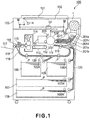
Figure 1 is a sectional view showing an embodiment of an image forming apparatus associated with the present invention. -
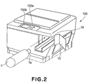
Figure 2 is a perspective view showing an operation for inserting a developer supply container into an image forming apparatus main assembly. -
Figures 3(a) and 3(b) are perspective views each showing a developer supply container. -
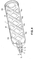
Figure 4 is a sectional perspective view in the case where a feeding member in a developer supply container is a buffle member. -
Figure 5 is a sectional perspective view in the case where a feeding member in a developer supply container is a spiral projection. -
Figures 6(a), 6(b) and 6(c) are explanatory views of a replacement operation of a developer supply container. -
Figure 7 is a perspective view showing a guiding portion and a regulation member provided in a developer receiving apparatus and a lead portion and a regulation portion provided to a developer supply container. -
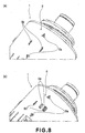
Figures 8(a) and 8(b) are enlarged views each showing a principal portion including a lead projection, a positioning projection, and a regulation portion provided to a developer supply container. -
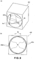
Figures 9(a) and 9(b) are a perspective view and a plan view, respectively, showing a guiding portion and a regulation member provided in a developer receiving apparatus. -
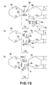
Figures 10(a), 10(b) and 10(c) are schematic explanatory views showing a relationship between a guiding portion and a lead portion during mounting of a developer supply container. -
Figure 11 is a perspective view showing an embodiment in which a lead portion is provided to a developer supply container and a guiding portion is provided in a developer receiving apparatus. -
Figure 12 is a perspective view showing an embodiment in which a regulation member is provided on a guiding portion and a regulation portion is provided between adjacent guiding portions. -
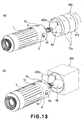
Figures 13(a) and 13(b) are perspective views each showing an embodiment in which either one of a combination of a guiding portion and a regulation member and a combination of a lead portion and a regulation portion is rotatably supported by either one of a developer receiving apparatus or a developer supply container. -
Figures 14(a) and 14(b) are perspective views each illustrating a constitution in which a developer supply container and a developer receiving apparatus are not out of phase with each other during rotation of the developer supply container after phase adjustment during mounting of the developer supply container. -
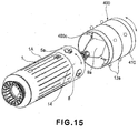
Figure 15 is a perspective view showing an embodiment in which both of a combination of a guiding portion and a regulation member and a combination of a lead portion and a regulation portion are rotatably supported by a developer receiving apparatus and a developer supply container. - Hereinbelow, preferred embodiments of the present invention will be described specifically with reference to the drawings.
- In the following embodiments, dimensions, materials, shapes, and relative arrangements of constitutional parts or members are illustrative and may appropriately modified depending on constitutions or various conditions of apparatuses to which the present invention is applicable, i.e. they can be modified within the scope of the present invention as defined by the appended claims.
- First embodiment of the present invention will be described in detail with reference to the drawings.
-
Figure 1 is a schematic sectional view showing an embodiment of an image forming apparatus to which the present invention is applicable.Figure 2 is a perspective view showing an operation for inserting the developer supply container according to the present invention into the image forming apparatus. - First of all, with reference to
Figures 1 and2 , a general constitution and a general operation of the image forming apparatus as a developer receiving apparatus to which the developer supply container of the present invention is detachably mountable (settable) will be described. - In
Figures 1 and2 , areference numeral 100 represents a main assembly of an electrophotographic copying machine (hereinafter referred to as a "apparatus main assembly"). On the apparatusmain assembly 100, an original 101 is placed on an original supportingglass 102. A light image depending on image information is formed on an electrophotographic photosensitive drum 104 as an image-bearing member
(hereinafter referred to as a "photosensitive drum") by a plurality of mirrors M and lens Ln. A recording medium P such as paper or the like is stacked incassettes - One recording medium P fed by a feeding/separating
apparatuses registration roller 110 through a feeding portion 109. Further, the recording medium P is fed to a transfer portion by theregistration roller 110 while synchronizing timing of rotation of the photosensitive drum 104 with timing of scanning of anoptical portion 103. At the transfer portion, a developer image formed on the photosensitive drum 104 is transferred onto the recording medium P by atransfer charger 111. Then, by aseparation discharger 112, the recording medium P onto which the developer image is transferred is separated from the photosensitive drum 104. - Thereafter, the recording medium P conveyed to a
fixing portion 114 by aconveying portion 113 is subjected to fixation of the developer image thereon under heat and pressure, and is caused to pass through adischarge inversion portion 115 to be discharged (outputted) on adischarge tray 117 by adischarge roller 116 in the case of one-sided copying. In the case of two-sided copying, by controlling aflapper 118 of thedischarge inversion portion 115, the recording medium P is discharged on thedischarge tray 117 through the same path as in the case of the one-sided copying after being conveyed to theregistration roller 110 throughre-feeding paths - Further, in the case of multiple copying, the recording medium P is caused to pass through the
discharge inversion portion 115 to be once partially discharged outside the apparatusmain assembly 100 by thedischarge roller 116. Thereafter, a trailing end of the recording medium P is caused to pass through theflapper 118 and conveyed into the apparatusmain assembly 100 by controlling theflapper 118 and reversely rotating thedischarge roller 116 at a timing at which the recording medium P is still sandwiched between thedischarge rollers 116. As a result, the recording medium is conveyed again into the apparatusmain assembly 100. Thereafter, the recording medium P is conveyed to theregistration roller 110 via there-feeding paths discharge tray 117 through the same paths as in the case of the one-sided copying. - Incidentally, around the photosensitive drum 104 in the apparatus
main assembly 100, a developingapparatus 201, a cleaning apparatus (cleaner) 202, aprimary charger 203, and so on are disposed. - Here, the developing
apparatus 201 develops an electrostatic latent image, with developer, formed on the photosensitive drum 104 by theoptical portion 103 on the basis of the image information of the original 201. Further, adeveloper supply container 1 for supplying developer to the developingapparatus 201 is disposed detachably mountable to the apparatusmain assembly 100 by the user. The present invention is applicable even in the cases where only toner as the developer is supplied from the developer supply container to the image forming apparatus or toner and a carrier as the developer is supplied. In this embodiment, such a constitution that only the toner is supplied from the developer supply container. - The developing
apparatus 201 has adeveloper hopper 201a and a developingdevice 201b. Thedeveloper hopper 201a has a stirringmember 201c for stirring the developer supplied from thedeveloper supply container 1. The developer stirred by the stirringmember 201c is fed to the developingdevice 201b by amagnet roller 201d. The developingdevice 201b includes a developingroller 201f and a feedingmember 201e. The developer fed from thedeveloper hopper 201a by themagnet roller 201 is sent to the developingroller 201f by the feedingmember 201e, thus being supplied to the photosensitive drum 104 by the developingroller 201f. - The
cleaning apparatus 202 is used for removing developing remaining on the photosensitive drum 104. Further, theprimary charger 203 is used for electrically charging the photosensitive drum 104. - The developer supply container will be described with reference to
Figures 3 - 7 . -
Figures 3(a) and 3(b) are perspective views of adeveloper supply container 1 viewed from anopening 1a side (Figure 3(a) ) and an opposite side (Figure 3(b) ).Figure 4 is a perspective sectional view in the case where a feeding member in thedeveloper supply container 1 is abuffle member 40.Figure 5 is a perspective sectional view in the case where the feeding member in thedeveloper supply container 1 is a spiral projection 1c.Figure 6(a), 6(b) and 6(c) are sectional views for illustrating a replacing operation of thedeveloper supply container 1.Figure 7 is a perspective view showing a guiding portion and an adaptation portion in adeveloper receiving apparatus 400 and a lead portion and a regulation portion provided to thedeveloper supply container 1. - The
developer supply container 1 has a substantiallycylindrical container body 1A for containing developer. At an almost center of one end surface of thecontainer body 1A in a longitudinal direction of thedeveloper supply container 1, an opening portion (discharge opening) 1a having a diameter smaller than that of the cylindrical portion is provided in a projected condition. At theopening portion 1a, a sealingmember 2 for closing theopening portion 1a is provided and, as will be understood from explanation with respect toFigure 3 described later, is slidely moved in a rotation axis direction (arrow a - b direction) of thedeveloper supply container 1, whereby an open/close operation of theopening portion 1a is performed. - In this embodiment, the rotation axis direction of the
developer supply container 1 is in parallel to the longitudinal direction of thedeveloper supply container 1 and a mounting/removal direction of thedeveloper supply container 1 with respect to the image forming apparatus. - Incidentally, due to a production error or an assembly error of the developer supply container or the image forming apparatus, parallelism of the rotation axis direction of the developer supply container to the longitudinal direction of the developer supply container or the mounting/removal direction of the developer supply container with respect to the image forming apparatus may be changed by a degree of play. More specifically, the rotational axis direction of the developer supply container may be substantially in parallel to the longitudinal direction of the developer supply container or the mounting/removal direction of the developer supply container with respect to the image forming apparatus.
- The sealing
member 2 has a cylindrical portion, as a coupling portion, is provided with an engagingprojection 3 as a hook portion engageable with a drive portion 20 (Figures 6(a) to 6(c) ) of the apparatus main assembly and arelease projection 4 as a release portion for releasing the engagement of the engagingportion 3 with thedrive portion 20. - An area of the cylindrical portion in which the engaging
portion 3 and therelease portion 4 are supported is constituted to be elastically deformable. More specifically, in order to assist or promote the elastic deformation, at both ends of the area, slits extended to an end of the cylindrical portion are provided. The engagingprojection 3 has a (release prevention) function of engaging the sealingmember 2 with the apparatus main assembly (driving portion) in the rotation axis direction of thedeveloper supply container 1 by being hook-engaged in a hole portion provided in the drivingportion 20 of the apparatus main assembly and a function of receiving a rotational driving force from the apparatus main assembly (driving portion) in combination. - Next, a constitution of the inside of the
developer supply container 1 will be described. As described above, thedeveloper supply container 1 has the substantially cylindrical shape and is configured to receive the rotational driving force from the apparatusmain assembly 100 to be rotated by being horizontally disposed in the apparatus main assembly (as shown inFigure 2 ). Further, inside thedeveloper supply container 1, as described above, the buffle member 40 (Figure 4 ) as the feeding portion of the developer is disposed. Thebuffle member 40 is, as shown inFigure 4 , provided with apartition wall 40b for raising the developer in thedeveloper supply container 1 by the rotation of thedeveloper supply container 1 and aninclined projection 40a, disposed on thepartition wall 40b, for feeding the developer raised by thepartition wall 40b to theopening portion 1a. More specifically, the developer in thedeveloper supply container 1 is raised by thepartition wall 40b by the rotation of thedeveloper supply container 1 and slides down thepartition wall 40b by gravitation. Thereafter, the developer is fed in the rotation axis direction by theinclined projection 40a having a surface inclined with respect to the rotation axis direction and is finally discharged from theopening portion 1a provided at one end surface of thedeveloper supply container 1. According to this constitution, it is possible to satisfy a feeding performance and a stirring performance of the developer at a high level. - Further, as shown in
Figures 3(a) and 3(b) , at an outer peripheral (circumferential) surface of thedeveloper supply container 1 in the neighborhood of a downstream side of the mounting direction (the arrow a direction) of thedeveloper supply container 1, i.e., at an outer peripheral surface of the container end portion in the neighborhood of theopening portion 1a, theregulation portion 5 as an adaptation portion is provided. On the other hand, in thedeveloper receiving apparatus 400, an associatedregulation member 400c as an adaptation member is disposed (Figure 7 ). As described later, theregulation portion 5 and theregulation member 400c are used for determining whether or not thedeveloper supply container 1 is mountable to thedeveloper receiving apparatus 400 on the basis of their mutual adaptation relationship. - The
regulation portion 5 is constituted by a plurality of regulation projections (projection portions) 5a protruded from the outer peripheral surface of the cylindrical portion of thecontainer body 1A. More specifically, by appropriately setting combinations of, e.g., the number and arrangement of theregulation projections 5a for each different type of developer supply containers, theregulation portion 5 functions as an identifier of thedeveloper supply container 1. By the combination of theregulation projections 5a of thedeveloper supply container 1 and theregulation member 400c of thedeveloper receiving apparatus 400, only a developer supply container containing a proper developer which causes no image defect and no color error with respect to the image forming apparatusmain assembly 100 is mountable in the image forming apparatusmain assembly 100. Details of this constitution will be described later. - Incidentally, as a constitution for feeding the developer contained in the
developer supply container 1, other than the constitution using thebuffle 40 shown inFigure 4 , the constitution is not particularly limited in shape and structure so long as it can feed the developer toward the discharge opening (openingportion 1a) by the rotation of thedeveloper supply container 1. For example, as shown inFigure 5 , it is also possible to employ a constitution using aspiral projection 1a provided at an inner peripheral surface of thedeveloper supply container 1. It is possible to feed the developer by the rotation of thedeveloper supply container 1 also based on this constitution. - Next, a replacing method of the above described
developer supply container 1 will be described. During a process of image formation, when the developer in thedeveloper supply container 1 is substantially fully consumed, an empty state of the developer in thedeveloper supply container 1 is detected by developer supply container empty state detection means (not shown) and notification to that effect is provided to a user through the display means 100b (Figure 2 ) such as a liquid crystal display panel or the like. In this embodiment, replacement of thedeveloper supply container 1 is performed by the user himself (herself). The procedure thereof is as follows. - First of all, a
replacement cover 15 in a closed state is rotationally moved around ahinge 18 to be opened to a position shown inFigure 2 . With the opening operation of thereplacement cover 15, the container body (cylindrical portion) 1A in a state shown inFigure 6(c) is moved in a direction of an arrow a shown inFigure 6(a) by an open/close means (not shown). As a result, the sealingmember 2 which has been apart from thecontainer body 1A and is in a state in which the opening portion is opened is pressed and engaged into theopening portion 1a of thedeveloper supply container 1, so that theopening portion 1a is closed and sealed and thedeveloper supply container 1 is placed in a state shown inFigure 6(b) . - Then, the user pulls out the
developer supply container 1, which is mounted in the apparatusmain assembly 100 and in which there is no developer, in a direction opposite from the arrow a direction shown inFigure 6(a) to remove thedeveloper supply container 1 from the apparatusmain assembly 100. Thereafter, the user inserts a newdeveloper supply container 1 in the arrow a direction shown inFigure 6(a) and then closes thereplacement cover 15. Then, as described above, with the closing operation of thereplacement cover 15, the sealingmember 2 is moved apart from thecontainer body 1A by a developer supply portion open/close means (not shown) to unseal theopening portion 1a of the developer supply container 1 (Figure 6(c) ). The replacement procedure of thedeveloper supply container 1 is as described above. - In the above described replacement of the
developer supply container 1, erroneous setting (mounting) of adeveloper supply container 1 containing a different type of developer into an image forming apparatusmain assembly 100 must be avoided. Hereinbelow, a mechanism, for determining whether or not thedeveloper supply container 1 is mountable, which is used for preventing the erroneous setting will be described more specifically with reference to the drawings. - As shown in
Figures 3(a) and 3(b) , thedeveloper supply container 1 of this embodiment, at an end portion (at the outer peripheral surface in the neighborhood of thedischarge opening 1a in this embodiment) in the insertion direction of thecontainer body 1A (in the arrow a direction), the regulation portion 5 (theregulation projections 5a) as the adaptation portion protruded from the cylindrical portion of the developersupply container body 1A is provided. Thisregulation portion 5 is disposed at four positions which are substantially equally spaced on the outer peripheral surface of thecontainer body 1A. - On the other hand, as described above, the
regulation member 400c as the adaptation member for permitting or blocking the mounting of thedeveloper supply container 1, i.e., for determining mechanically whether or not thedeveloper supply container 1 is mountable, on the basis of adaptation relationship with theregulation portion 5 is disposed in the developer receiving apparatus 400 (Figure 7 ). Thisregulation member 400c is also disposed at four positions which are substantially equally spaced on the inner peripheral surface of the developer receiving apparatus 400 (Figure 9(b) ). - The
regulation member 400c is disposed in such a state that it has a cutting portion 400c1, varying depending on adeveloper supply container 1 different in color or type depending on developer used in the image forming apparatusmain assembly 100, (which is virtually referred to as the cutting portion even in the case where thedeveloper receiving apparatus 400 which is integrally molded partially has a recess portion as shown inFigure 9(b) ). In this embodiment, such a constitution that determination as to whether or not thedeveloper supply container 1 is mountable into the image forming apparatusmain assembly 100 is made by judging whether or not a shape of theregulation member 400c is substantially coincident with that of theregulation projections 5a as theregulation portion 5 provided to thedeveloper supply container 1 is employed. - Here, when the
regulation portion 5 provided to thedeveloper supply container 1 and theregulation member 400c provided in thedeveloper receiving apparatus 400 are out of phase (in a direction of rotation of thedeveloper supply container 1 about the rotation axis substantially in parallel to the mounting direction of the developer supply container 1), a proper determination as to whether or not thedeveloper supply container 1 is mountable in the image forming apparatusmain assembly 100 cannot be performed. For this reason, in this embodiment, a phase adjusting means for causing theregulation portion 5 of thedeveloper supply container 1 and theregulation member 400c of thedeveloper receiving apparatus 400 to have the same phase is provided. A constitution of the phase adjusting means for adjusting the phases of theregulation portion 5 and theregulation member 400c so that they are in phase with each other will be described more specifically with reference toFigures 8 to 10 . -
Figure 8(a) is a partially enlarged view of a principal portion of the developer supply container, in which alead portion 8 is divided into' alead projection 8a and apositioning projection 8b is shown.Figure 8(b) is a partially enlarged view of a principal portion of the developer supply container, in which aregulation projection 5a and thelead portion 8 divided into thelead projection 8a and thepositioning projection 8b are shown.Figure 9(a) is a perspective view showing the guiding portion and the adaptation portion in the developer receiving apparatus, andFigure 9(b) is a plan view thereof.Figures 10(a), 10(b) and 10(c) are schematic explanatory views showing a relationship between the guiding portion and the lead portion during mounting of the developer supply container. - As shown in
Figures 8(a) and 8(b) , thelead portion 8 is provided. Thelead portion 8 is regulated by the guidingportion 9a as a guide member of thedeveloper receiving apparatus 400 and includes thelead projection 8a and thepositioning projection 8b. - In the
developer receiving apparatus 400, as shown inFigures 9(a) and 9(b) , the guidingportion 9a as the guide member is provided. The guidingportion 9a is used for rotating the developer supply container by running into the projection to be introduced 8a with the insertion and mounting operation of thedeveloper supply container 1. More specifically, the guidingportion 9a functions as a guide for oppositely disposing theregulation portion 5 and theregulation member 400c to each other (for introducing theregulation portion 5 toward agate portion 9b) by running into thelead projection 8a with the insertion and mounting operation of thedeveloper supply container 1. - Further, the
gate portion 9b is used to position thepositioning projection 8b of thelead portion 8. More specifically, thegate portion 9b and thepositioning projection 8b have a function of maintaining a state in which theregulation portion 5 and theregulation member 400c are located opposite to each other during the inserting and mounting operation (during passing of theregulation portion 5 through theregulation member 400c). - Incidentally, in this embodiment, in order to functionally explain the
lead portion 8, such a state that thelead portion 8 is divided into thelead projection 8a and thepositioning projection 8b is illustrated as shown inFigures 8(a) and 8(b) . However, as shown inFigure 7 , thelead portion 8 may be one having such a shape that both the projections are integrally formed. Thelead portion 8 as the lead portion is, as shown inFigure 7 , a projection portion having an inclined surface with respect to the rotation axis direction of thedeveloper supply container 1. - As described above, in this embodiment, in the rotation direction around the rotation axis line substantially in parallel to the mounting direction of the developer supply container 1 (the arrow a direction shown in
Figure 7 ), it is possible to rotationally move thelead portion 8 toward the guidingportion 9a with the insertion and mounting operation of thedeveloper supply container 1 even when thedeveloper supply container 1 is inserted into thedeveloper receiving apparatus 400 at any phase of 360 degrees. - As a result, the developer receiving apparatus 400 (the
regulation member 400c) and the developer supply container 1 (the regulation portion 5) are in phase with each other. Thereafter, when the insertion and mounting operation of thedeveloper supply container 1 is further continued, a mechanical judgement of adaptability of theregulation member 400c and theregulation portion 5 is made. More specifically, the adaptability of theregulation portion 5 to theregulation member 400c is fulfilled, it is possible to continue the insertion and mounting of thedeveloper supply container 1, so that the mounting operation of thedeveloper supply container 1 is finally completed. On the other hand, in the case where the adaptability of theregulation portion 5 to theregulation member 400c is not fulfilled, theregulation member 400c is an interference member for theregulation portion 5. As a result, a further insertion and mounting operation of thedeveloper supply container 1 is mechanically blocked, so that it is possible to readily recognize that thedeveloper supply container 1 is not a proper developer supply container. - Further, in the above-described embodiment, such a constitution that the
developer supply container 1 is provided with thelead portion 8 and thedeveloper receiving apparatus 400 is provided with the guidingportion 9a is described but the present invention is not limited thereto. It is also possible to adopt a modified embodiment as shown inFigure 11 . More specifically, as shown inFigure 11 , it is also possible to adopt such a constitution that adeveloper supply container 1 is provided with a guidingportion 9a and adeveloper receiving apparatus 400 is provided with alead portion 8. The same effect is achieved by such a constitution. Incidentally, this is true for constitutions in embodiments, described later, other than this embodiment. - Next, with reference to
Figures 10(a), 10(b) and 10(c) , details of an operation of phase alignment (adjustment) between theregulation member 400c and the regulation portion 5 (regulation projections 5a) by the guidingportion 9a and thelead portion 8 which constitute the above described phase adjusting means (guide means) will be described. - First, insertion and mounting of the
developer supply container 1 will be explained. - As also described in the replacement method of the
developer supply container 1, thedeveloper supply container 1 is inserted in the direction of an arrow a indicated inFigure 7 . When theregulation member 400 and theregulation portion 5 are out of phase as shown inFigure 10(a) , i.e., when a phase of theload projection 8a is deviated from anarea 10d of thegate portion 9b formed between adjacent guidingportions 9a (hereinafter, referred to as a "gate area"), the projection to be introduced 8a abuts against a taperedportion 10c as an inclination portion of the guidingportion 9a, so that theregulation portion 5 is rotated together with thedeveloper supply container 1 relative to theregulation member 400c. - Thereafter, when the
developer supply container 1 is further inserted and thelead projection 8a enters thegate area 10d as shown inFigure 10(b) , an end of thepositioning projection 8b abuts against the guidingportion 9a, so that theregulation portion 5 is further rotated relative to theregulation member 400c. - Further, as shown in
Figure 10(c) , when thepositioning projection 8b enters thegate portion 9b located between theadjacent guiding portions 9a, a positional relationship between thedeveloper supply container 1 and thedeveloper receiving apparatus 400 in the rotation direction of thedeveloper supply container 1 is kept so that theregulation portion 5 and theregulation member 400c are out of phase. - Thereafter, the
developer supply container 1 is moved only in the insertion and mounting direction (the arrow a direction ofFigure 7 ) without being substantially rotated relative to thedeveloper receiving apparatus 400. - As described above, the
developer supply container 1 is further inserted in such a state that theregulation portion 5 and theregulation member 400c is in phase with each other, so that determination as to whether or not thedeveloper supply container 1 is mountable is performed by whether or not theregulation member 400c and theregulation portion 5 stand in a corresponding relationship. - As described above, according to this embodiment, by a simple constitution, it is possible to reliably perform the determination as to whether or not the
developer supply container 1 is mountable even when an operator does not perform a phase-adjusting operation consciously. Further, the mounting of thedeveloper supply container 1 can be readily performed with reliability. - Next, a removal (demounting) operation of the
developer supply container 1 from thedeveloper receiving apparatus 400 will be described. - The
developer supply container 1 is, as described above, configured to feed and discharge developer by its own rotation. Further, at the time of completion of the mounting operation of thedeveloper supply container 1, theregulation portion 5 is located downstream from theregulation member 400c in the mounting direction of thedeveloper supply container 1 so as not to be subjected to interference with theregulation member 400c. Further, thedeveloper supply container 1 is rotated by the developer supply operation but at the time of completion of the developer supply operation, a rotation stop position of thedeveloper supply container 1 can be changed to various positions. - Accordingly, at the time of start of the removal (demounting) operation of the
developer supply container 1, there is such a case where theregulation member 400c and theregulation portion 5 are out of phase. In such a case, there is a possibility that thedeveloper supply container 1 cannot be pulled out of the image forming apparatusmain assembly 100 by interference of theregulation member 400c with theregulation portion 5. In this embodiment, in order to solve such a problem, also during the removal operation of thedeveloper supply container 1, theregulation member 400c and theregulation portion 5 are configured to be in phase with each other. - More specifically, the guiding
portion 9a and thelead portion 8 are configured so that theregulation portion 5 is rotated together with the container body relative to theregulation member 400c in order that theregulation portion 5 and theregulation member 400c can be in phase with each other not only during the mounting of thedeveloper supply container 1 in the image forming apparatusmain assembly 100. - More specifically, as shown in
Figures 7 and10 , the guidingportion 9a and thelead portion 8 as the phase alignment means have symmetrical shapes in the insertion direction (arrow a direction shown inFigure 7 ) and the removal direction (arrow b direction shown inFigure 7 ) through theregulation member 400c and theregulation portion 5 which constitute the judging mechanism as to whether or not thedeveloper supply container 1 is mountable. As a result, also during the removal operation of thedeveloper supply container 1, theregulation member 400c and theregulation portion 5 have the same phase without consciously performing the phase adjusting operation by the operator, so that it is possible to smoothly pull thedeveloper supply container 1 out of the image forming apparatusmain assembly 100. - Incidentally, as shown in
Figures 10(a) to 10(c) , a guiding angle α of the guidingportion 9a (an angle of the taperedportion 10c with respect to the insertion direction) affects an operation force during the insertion of thedeveloper supply container 1. More specifically, with a smaller guiding angle α, an amount of rotation of the guidingportion 9a and thelead portion 8 relative to an amount of movement of thedeveloper supply container 1 in the insertion and mounting direction is smaller, so that thedeveloper supply container 1 is liable to be inserted. However, as the guiding angle α is smaller, a length L of the guidingportion 9a (in the developer supply container insertion direction) is longer. For this reason, the guiding angle α and the length L of the guidingportion 9a may preferably be set in view of a balance between the operation force of thedeveloper supply container 1 and a mounting (setting) space of the guidingportion 9a. - A similar function is performed even in the case where only a pair of a
regulation portion 5 and aregulation member 400c are provided and only one guidingportion 9a having a rhombus shape is provided. In this case, however, thedeveloper supply container 1 is rotated relative to thedeveloper receiving apparatus 400 at a rotation angle up to 180 degrees. Further, the length L of the guidingportion 9a in the developer supply container insertion direction is required correspondingly when the guiding angle α (as shown inFigure 10(a) ) is decreased in order to reduce the operation force. - For this reason, in this embodiment, as shown in
Figures 9(a) and 9(b) , a plurality of guidingportions 9a are provided in order to create a plurality ofgate portions 9b. - By such a constitution, an amount of relative rotation between the guiding
portion 9a and thelead portion 8 can be reduced and it is also possible to shorten the length L of the guidingportion 9a in the developer supply container insertion direction while keeping the introduction angle α for decreasing the operation force. - In this embodiment, the
developer supply container 1 and thelead portion 8 are configured to be integrally rotated, so that thedeveloper supply container 1 itself is rotated during the insertion thereof. When thedeveloper supply container 1 is inserted continuously, it is automatically rotated depending on an amount of insertion until theregulation member 400c and theregulation portion 5 are in phase with each other. In this case, a hand of the user (operator) is also rotated together with thedeveloper supply container 1. When the amount of rotation is too large, there is a possibility that the user feels physical disorder in the mounting operation. - In this embodiment, the gate portion is disposed at four positions, so that the
developer supply container 1 and thedeveloper receiving apparatus 400 are configured to be rotated relative to each other at an angle up to 45 degrees during the mounting of thedeveloper supply container 1 in thedeveloper receiving apparatus 400. - Incidentally, from a viewpoint of operability, the
developer supply container 1 may preferably have a relative rotation angle (maximum value) of not more than 60 degrees (corresponding to three or more gate portions) during the mounting operation. In this case, thedeveloper supply container 1 may functionally have one lead portion but may preferably have a plurality of portions to be introduced 8 at equal spacing on the circumferential surface of thedeveloper supply container 1 when a balance of rotation is taken into consideration. However, there is a correlation between the number of guidingportions 9a provided in thedeveloper receiving apparatus 400 and the number of portions to be introduced 8 provided to thedeveloper supply container 1. More specifically, when onelead portion 8 is provided to thedeveloper supply container 1, the number of the guidingportion 9a for thedeveloper receiving apparatus 400 may appropriately be selected. However, in the case of two or morelead portions 8, the number of the guidingportion 9a may preferably be an integral multiple of the number oflead portion 8. - Here, with respect to a positional relationship of the
regulation member 400c with the guidingportion 9a and that of theregulation portion 5 with thelead portion 8, when the guidingportion 9a and thelead portion 8 are in phase with each other, theregulation member 400c and theregulation portion 5 may be in phase with each other. - For example, arrangement positions of the
regulation member 400c and theregulation portion 5 may be at the gate portion as shown inFigures 9(a) and 9(b) and between twopositioning projections 8b as shown inFigure 8(b) , respectively, (or in the case of using an integral-type lead portion 8, theregulation portion 5 is disposed on thelead portion 8 as shown inFigures 3(a), 3(b) and9 ) or may be on the guidingportion 9a and between twolead portions 8, respectively, as shown inFigure 12 as a modified embodiment. - Further, a positional relationship of the
regulation member 400c with thedeveloper receiving apparatus 400 and that of theregulation portion 5 with thedeveloper supply container 1 may preferably be as follows. - On the precondition that the positional relationship of the
regulation member 400c with the guidingportion 9a and the positional relationship of theregulation portion 5 with thelead portion 8 are kept, the position of theregulation member 400c in thedeveloper receiving apparatus 400 may preferably be on an upstream side of thedeveloper receiving apparatus 400 in the insertion and mounting direction of the developer supply container 1 (the arrow a direction shown inFigure 7 ). On the other hand, the position of theregulation portion 5 on thedeveloper supply container 1 may preferably be on a downstream side of thedeveloper supply container 1 in the insertion and mounting direction of the developer supply container 1 (the arrow a direction shown inFigure 7 ). - As a result, it is possible to perform the determination as to whether or not the
developer supply container 1 mountable at an early stage of the mounting operation of thedeveloper supply container 1, so that even when the user erroneously inserts an improperdeveloper supply container 1, the error is liable to be found early. - By employing the constitution as described above, it is possible to perform the phase adjusting operation of the
regulation portion 5 with theregulation member 400c in synchronism with such a simple operation that thedeveloper supply container 1 is inserted and mounted in thedeveloper receiving apparatus 400. - In the case where a proper
developer supply container 1 is inserted, it can be smoothly mounted by a simple operation. On the other hand, in the case where the erroneousdeveloper supply container 1 is inserted, it is possible to recognize the error with reliability. In this case, even when the erroneousdeveloper supply container 1 is intended to be mounted, thedeveloper supply container 1 is not completely mounted in thedeveloper receiving apparatus 1. As a result, the sealingmember 2 which seals theopening portion 1a of thedeveloper supply container 1 is not engaged with thedeveloper receiving apparatus 400. Accordingly, the sealingmember 2 cannot be erroneously operated or a driving force cannot be transmitted from the image forming apparatusmain assembly 100 to thedeveloper supply container 1. In other words, it is possible to reliably obviate such a problem that a different type of developer is supplied into the image forming apparatusmain assembly 100. - Further, also during the removal of the
developer supply container 1, it is possible to perform a phase adjusting operation of theregulation portion 5 with theregulation member 400c in synchronism with such a simple operation that thedeveloper supply container 1 is pull out of thedeveloper receiving apparatus 400. - In other words, only by the operation for simply pulling the
developer supply container 1 out of thedeveloper receiving apparatus 400, the user can smoothly demount the developer supply container, so that it is possible to considerably improve the operability. - Further, according to the constitution of the
developer receiving apparatus 400 used in this embodiment, theregulation member 400c in thedeveloper receiving apparatus 400 is located on the upstream side in the insertion direction of thedeveloper supply container 1 and theregulation portion 5 on thedeveloper supply container 1 is located on the downstream side in the insertion direction of thedeveloper supply container 1, so that it is possible to make the determination whether thedeveloper supply container 1 is mountable or not at an early stage during the insertion of thedeveloper supply container 1. As a result, it is possible to early cause the user to recognize whether thedeveloper supply container 1 is mountable or not. - Second Embodiment of the present invention will be described in detail with reference to
Figure 13 . In this embodiment, a general structure of a main assembly of image forming apparatus and a general constitution of a developer supply container are similar to those in First Embodiment, so that detailed explanation thereof will be omitted. Further, in this embodiment, members or means having the same functions as those in First Embodiment are represented by the same reference numerals or symbols. -
Figures 13(a) and 13(b) are perspective views showing adeveloper receiving apparatus 400 and adeveloper supply container 1 according to Second Embodiment. - In this embodiment, either one of a combination of a guiding
portion 9a and aregulation member 400c and a combination of alead portion 8 and aregulation portion 5 is rotatably supported by either one of thedeveloper receiving apparatus 400 and thedeveloper supply container 1. - In
Figure 13(a) , the guidingportion 9a and theregulation member 400c in thedeveloper receiving apparatus 400 are provided in arotation member 410 rotatably supported byrotation support rollers 13a. In other words, the guidingportion 9a and theregulation member 400c are configured to be rotationally movable along a rotation axis (line) substantially in parallel with a mounting (removal) direction of thedeveloper supply container 1. - In
Figure 13(b) , thelead portion 8 and theregulation portion 5 on thedeveloper supply container 1 are provided on arotation member 14 rotatable relative to acontainer body 1A. In other words, thelead portion 8 and theregulation portion 5 are configured to be rotationally movable along a rotation axis (line) substantially in parallel with the mounting (removal) direction of thedeveloper supply container 1. - Even in the cases of a employing the above described constitutions shown in
Figures 13(a) and 13(b) , it is possible to achieve the same effects as in First Embodiment. - In addition, according to the constitutions (shown in
Figures 13(a) and 13(b) ) of this embodiment, thecontainer body 1A is not rotated during a phase adjusting operation of theregulation portion 5 with theregulation member 400c performed with the mounting (removal) operation of thedeveloper supply container 1, so that a hand of an operator grasping thecontainer body 1A is not rotated. As a result, it is possible to further improve an operability. - In this embodiment, an integral structure of the
rotation member 410 with the guidingportion 9a and theregulation member 400c (Figure 13(a) ) or an integral structure of therotation member 14 with thelead portion 8 and the regulation portion 5 (Figure 13(b) ) is configured to be rotatable only by engagement with thedeveloper supply container 1 but may be configured as any structure so long as the combination of the guidingportion 9a and theregulation member 400c or the combination of thelead portion 8 and theregulation portion 5 can be simultaneously rotated relative to thedeveloper supply container 1 in essence. Further, in the constitution shown inFigure 13(a) , therollers 13a are used as a rotation supporting portion but the present invention is not limited thereto. Basically, it is also possible to use any means (member) so long as it can rotatably support the combination of the guidingportion 9a and theregulation member 400c or the combination of thelead portion 8 and theregulation portion 5. - A modified embodiment of Second Embodiment shown in
Figure 13(a) is shown inFigures 14(a) and 14(b) . -
Figures 14(a) and 14(b) are perspective views showing adeveloper receiving apparatus 400 and adeveloper supply container 1 viewed from an upstream side and a downstream side, respectively, in a mounting direction of thedeveloper supply container 1. - In this modified embodiment shown in
Figures 14(a) and 14(b) , similarly as in the constitution shown inFigure 13(a) , the guidingportion 9a and theregulation member 400c in thedeveloper receiving apparatus 400 are provided in arotation member 410 rotatably supported byrotation support rollers 13a. In this manner, in the case where the guidingportion 9a and theregulation member 400c of thedeveloper receiving apparatus 400 are rotatably supported by therotation support rollers 13a, phase adjustment is only performed in the case where thedeveloper supply container 1 is inserted as shown inFigures 14(a) and 14(b) . More specifically, after thedeveloper supply container 1 is mounted in thedeveloper receiving apparatus 400, the guidingportion 9a and theregulation member 400c of thedeveloper receiving apparatus 400 are integrally rotated by rotation of thedeveloper supply container 1. As shown inFigure 14(a) and 14(b) , agate portion 9b of the guidingportion 9a is formed so that thelead portion 8 which is positionally aligned and supported by thegate portion 9b is guided to a most downstream portion of thedeveloper receiving apparatus 400 in the insertion direction as it is. - According to this modified embodiment, the
developer supply container 1 can be inserted into and removed from thedeveloper receiving apparatus 400 without being rotated even when the user inserts thedeveloper supply container 1 at any phase up to 360 degrees, so that it is possible to remarkably improve an operability of thedeveloper supply container 1 in mounting and demounting operations. - The constitution of the
gate portion 9b of the guidingportion 9a shown inFigures 14(a) and 14(b) is also applicable to the embodiment shown inFigure 13(b) as another modified embodiment (not shown). In this case, after thedeveloper supply container 1 is mounted in thedeveloper receiving apparatus 400, in such a state that thelead portion 8 rotatably supported by thecontainer body 1A of thedeveloper supply container 1 is supported and fixed at thegate portion 9b of the guidingportion 9a in thedeveloper receiving apparatus 400, the developersupply container body 1A is rotated relative to thelead portion 8 in order to supply the developer. For this reason, effects similar to those described above can be achieved. - Third Embodiment of the present invention will be described in detail with reference to
Figure 15 . In this embodiment, a general structure of a main assembly of image forming apparatus and a general constitution of a developer supply container are similar to those in First Embodiment, so that detailed explanation thereof will be omitted. Further, in this embodiment, members or means having the same functions as those in First Embodiment are represented by the same reference numerals or symbols. -
Figure 15 is a perspective view showing adeveloper receiving apparatus 400 and adeveloper supply container 1 according to Third Embodiment. - In this embodiment, both of a combination of a guiding
portion 9a and aregulation member 400c and a combination of alead portion 8 and aregulation portion 5 are rotatably supported by thedeveloper receiving apparatus 400 and thedeveloper supply container 1. - As shown in
Figure 15 , the guidingportion 9a and theregulation member 400c in thedeveloper receiving apparatus 400 are provided in arotation member 410 rotatably supported byrotation support rollers 13a. Further, thelead portion 8 and theregulation portion 5 on thedeveloper supply container 1 are provided on arotation member 14 rotatable relative to acontainer body 1A. In other words, the guidingportion 9a and theregulation member 400c in thedeveloper receiving apparatus 400 are configured to be rotatably around a rotation axis (line) substantially in parallel with a mounting direction of thedeveloper supply container 1. - Similarly, the
lead portion 8 and theregulation portion 5 on thedeveloper supply container 1 are also configured to be rotating around a rotation axis (line) substantially in parallel with the mounting direction of thedeveloper supply container 1. - In this embodiment, an integral structure of the
rotation member 410 with the guidingportion 9a and theregulation member 400c and an integral structure of therotation member 14 with thelead portion 8 and theregulation portion 5 are configured to be rotatable only by engagement with thedeveloper supply container 1 but may be configured as any structure so long as the combination of the guidingportion 9a and theregulation member 400c or the combination of thelead portion 8 and the regulation
portion 5 can be simultaneously rotated relative to thedeveloper supply container 1 in essence. Further, in the constitution shown inFigure 13(a) , therollers 13a are used as a rotation supporting portion but the present invention is not limited thereto. Basically, it is also possible to use any means (member) so long as it can rotatably support the combination of the guidingportion 9a and theregulation member 400c or the combination of thelead portion 8 and theregulation portion 5. - By employing the above described constitution, the guiding
portion 9a and thelead portion 8 are rotated in such a direction that they are moved close to each other during the relative rotation for phase adjustment, so that an amount of rotation of the guidingportion 9a relative to thedeveloper receiving apparatus 400 and an amount of rotation of thelead portion 8 relative to thedeveloper supply container 1 can be decreased to 1/2 of those in Second Embodiment. - Accordingly, an operation force during the mounting/removal operation of the
developer supply container 1 can be further reduced when compared with the case of Second Embodiment, thus further enhancing an operability. - In the above described embodiments, the
developer supply container 1 is inserted and mounted in thedeveloper receiving apparatus 400 by grasping thedeveloper supply container 1 by the operator (user). It is also possible to adopt such a constitution that thedeveloper supply container 1 is automatically moved in the mounting/removal direction by thedeveloper receiving apparatus 400. More specifically, in this case, a sliding table on which thedeveloper supply container 1 is to be placed is automatically moved out of the image forming apparatus in synchronism with an opening operation of the open/close door 15 (Figure 1 ) by the operator. Then, the operator pushes the sliding table on which the developer supply container is placed, the sliding table is automatically retracted into the image forming apparatus. With the retraction operator of the sliding table, i.e., the mounting operation of thedeveloper supply container 1 is mountable or not is made by a combination of theregulation portion 5 and theregulation member 400c. In the case where, the mounting of thedeveloper supply container 1 is blocked, thedeveloper supply container 1 cannot be further inserted, so that a load for driving the sliding table is large. When the increase in load required for driving the sliding table is detected by a load detector provided in the main assembly of image forming apparatus, movement of the sliding table is prohibited and an error notification to that effect is provided to the operator so that the operator can replace the developer supply container with a new one. - Further, in the embodiments described above, the
lead portion 8 and the guidingportion 9a which have hexagonal shapes are used but the shapes of the portions are not limited thereto. For example, these portions may also have other shapes such as an elliptical shape elongated in the insertion direction. Further, thelead portion 8 may be not only of the integral-type as shown inFigures 3(a) and 3(b) but also of a type in which both of theprojections Figures 8 and10 . - In the above described embodiments, a single developer supply container detachably mountable to the image forming apparatus is used but the number of developer supply container may appropriately be changed as desired. Further, the image forming apparatus in the above described embodiments is one capable of recording (forming) a monochromatic image but may also be a color image forming apparatus capable of recording a color image. By using the developer supply container and the developer receiving apparatus according to the present invention in the above described image forming apparatuses, similar effects can be achieved.
- Further, in the above described embodiments, the copying machine is used as the image forming apparatus but the image forming apparatus to which the present invention is applicable is not limited to the copying machine. For example, it is also possible to' other image forming apparatuses including a printer, a facsimile apparatus, a composite machine having functions of these apparatuses, an image forming apparatus for successively transfer respective color developer images onto a recording medium carried on a recording medium carrying member, and an image forming apparatus in which respective color developer images are successively transferred onto an intermediary transfer member and then are simultaneously transferred onto a recording medium. Similar effects can be achieved by applying the present invention to the developer supply container, detachably mountable to the above described image forming apparatuses, and the developer receiving apparatus for receiving the developer supply container.
- As described hereinabove, according to the present invention, it is possible to provide a developer supply container capable of being easily set or mounted in a developer receiving apparatus even in the case where a constitution for determining adaptability of the developer supply container to the developer receiving apparatus is employed. Further, it is also possible to provide a developer supply system capable of easily set or mount a developer supply container in a developer receiving apparatus even in the case where a constitution for determining adaptability of the developer supply container to the developer receiving apparatus.
Claims (7)
- A developer supply container (1) demountably settable in a developer supply apparatus (400) provided with a rotatable adaptation portion (410, 400c, 9a, 9b), said developer supply container (1) comprising:a container body (1A) including an inner space that accommodates a developer and a discharge opening (1a) for permitting discharging of the developer;a feeding portion (40) that feeds the developer in said container body (1A) toward said discharge opening (1a) with rotation of said container body (1A);an erroneous set prevention portion (5, 5a) provided on a peripheral surface of said container body (1A) configured and positioned to permit or prevent, after said developer supply container (1) is partially inserted into the developer supply apparatus (400) along a rotational axis direction of said developer supply container (1), a further inserting operation for setting said developer supply container (1) into the developer supply apparatus (400) depending on the correspondence of said erroneous set prevention portion (5, 5a) to a configuration of the adaptation portion (410, 400c, 9a, 9b); anda leading portion (8, 8a, 8b) configured to rotate the adaptation portion (410, 400c, 9a, 9b) with the inserting operation of said developer supply container (1) to lead the adaptation portion (410, 400c, 9a, 9b) toward said erroneous set prevention portion (5, 5a) irrespective of a rotational position of said erroneous set prevention portion (5, 5a) when said developer supply container (1) is inserted into the developer supply apparatus (400) along an inserting direction (a) of said developer supply container (1), whereinthe leading portion (8, 8a, 8b) has a projection portion having an inclined surface with respect to said rotational axis direction of said developer supply container (1) and is provided on a peripheral surface of said container body (1A) at a position downstream of said erroneous set prevention portion (5, 5a) with respect to the inserting direction (a) of said developer supply container (1).
- A container (1) according to claim 1, further comprising a plurality of said leading portions (8, 8a, 8b) at regular intervals along the rotational axis direction.
- A container (1) according to claim 1 or 2, wherein said leading portion (8, 8a, 8b) is rotatable integrally with said container body (1A).
- A container (1) according to any of claims 1 to 3, further comprising a removal leading portion (8, 8a, 8b) configured to rotate said container body (1A) with the dismounting operation of said developer supply container (1) so that said erroneous set prevention portion (5, 5a) is lead toward the adaptation portion (410, 400c, 9a, 9b), irrespective of the rotational position of said erroneous set prevention portion (5, 5a) at the time when said developer supply container (1) is removed from the developer supply apparatus (400) along the rotational axis direction.
- A container (1) according to claim 4, wherein said removal leading portion (8, 8a, 8b) is rotatable integrally with said container body (1A), and is provided on the peripheral surface of said container body (1A) at a position downstream of said erroneous set prevention portion (5, 5a) with respect to a dismounting direction (b) of said developer supply container (1) and includes a projected portion provided with a surface inclined relative to the rotational axis direction.
- A container (1) according to claim 5, wherein said erroneous set prevention portion (5, 5a) is provided with a plurality of projections disposed at different positions with respect to the rotational axis direction so as to correspond to the configuration of the adaptation portion (410, 400c, 9a, 9b).
- A developer supplying system comprising:a developer supply apparatus (400) including a rotatable adaptation portion (410, 400c, 9a, 9b); andthe developer supply container (1) according to any of claims 1 to 6 demountably settable in said developer supply apparatus (400).
Applications Claiming Priority (3)
| Application Number | Priority Date | Filing Date | Title |
|---|---|---|---|
| JP2005048408A JP4603905B2 (en) | 2005-02-24 | 2005-02-24 | Developer supply container and developer supply system |
| PCT/JP2006/303928 WO2006090901A1 (en) | 2005-02-24 | 2006-02-23 | Developer supply container and developer supply system |
| EP06715041.7A EP1856580B1 (en) | 2005-02-24 | 2006-02-23 | Developer supply container and developer supply system |
Related Parent Applications (2)
| Application Number | Title | Priority Date | Filing Date |
|---|---|---|---|
| EP06715041.7A Division-Into EP1856580B1 (en) | 2005-02-24 | 2006-02-23 | Developer supply container and developer supply system |
| EP06715041.7A Division EP1856580B1 (en) | 2005-02-24 | 2006-02-23 | Developer supply container and developer supply system |
Publications (2)
| Publication Number | Publication Date |
|---|---|
| EP3112947A1 EP3112947A1 (en) | 2017-01-04 |
| EP3112947B1 true EP3112947B1 (en) | 2019-10-30 |
Family
ID=36588906
Family Applications (4)
| Application Number | Title | Priority Date | Filing Date |
|---|---|---|---|
| EP06715041.7A Not-in-force EP1856580B1 (en) | 2005-02-24 | 2006-02-23 | Developer supply container and developer supply system |
| EP16176078.0A Not-in-force EP3112947B1 (en) | 2005-02-24 | 2006-02-23 | Developer supply container and developer supply system |
| EP16176076.4A Expired - Fee Related EP3112945B1 (en) | 2005-02-24 | 2006-02-23 | Developer supply container and developer supply system |
| EP16176077.2A Not-in-force EP3112946B1 (en) | 2005-02-24 | 2006-02-23 | Developer supply container and developer supply system |
Family Applications Before (1)
| Application Number | Title | Priority Date | Filing Date |
|---|---|---|---|
| EP06715041.7A Not-in-force EP1856580B1 (en) | 2005-02-24 | 2006-02-23 | Developer supply container and developer supply system |
Family Applications After (2)
| Application Number | Title | Priority Date | Filing Date |
|---|---|---|---|
| EP16176076.4A Expired - Fee Related EP3112945B1 (en) | 2005-02-24 | 2006-02-23 | Developer supply container and developer supply system |
| EP16176077.2A Not-in-force EP3112946B1 (en) | 2005-02-24 | 2006-02-23 | Developer supply container and developer supply system |
Country Status (5)
| Country | Link |
|---|---|
| US (1) | US8000614B2 (en) |
| EP (4) | EP1856580B1 (en) |
| JP (1) | JP4603905B2 (en) |
| CN (1) | CN100573358C (en) |
| WO (1) | WO2006090901A1 (en) |
Families Citing this family (21)
| Publication number | Priority date | Publication date | Assignee | Title |
|---|---|---|---|---|
| JP4603905B2 (en) | 2005-02-24 | 2010-12-22 | キヤノン株式会社 | Developer supply container and developer supply system |
| JP5740874B2 (en) * | 2009-09-15 | 2015-07-01 | 株式会社リコー | Image forming apparatus and medium storage container |
| KR101670915B1 (en) | 2010-04-15 | 2016-11-01 | 삼성전자 주식회사 | Image forming apparatus and structure for installing consumption goods thereof |
| JP5950611B2 (en) | 2012-02-17 | 2016-07-13 | キヤノン株式会社 | Developer supply container and developer supply system |
| JP6137882B2 (en) | 2013-03-11 | 2017-05-31 | キヤノン株式会社 | Developer supply container |
| JP6021699B2 (en) | 2013-03-11 | 2016-11-09 | キヤノン株式会社 | Developer supply container and developer supply system |
| JP6021701B2 (en) | 2013-03-19 | 2016-11-09 | キヤノン株式会社 | Developer supply container and developer supply system |
| JP6128908B2 (en) | 2013-03-19 | 2017-05-17 | キヤノン株式会社 | Developer supply kit, developer supply device, and image forming apparatus |
| JP6180140B2 (en) | 2013-03-19 | 2017-08-16 | キヤノン株式会社 | Developer supply container |
| JP6025631B2 (en) | 2013-03-22 | 2016-11-16 | キヤノン株式会社 | Developer supply container |
| JP6048346B2 (en) * | 2013-08-29 | 2016-12-21 | コニカミノルタ株式会社 | Developer container |
| JP2016090932A (en) | 2014-11-10 | 2016-05-23 | キヤノン株式会社 | Developer supply container, developer supply device, and image forming apparatus |
| JP2016090933A (en) | 2014-11-10 | 2016-05-23 | キヤノン株式会社 | Developer replenishment container and image forming apparatus |
| JP6385251B2 (en) | 2014-11-10 | 2018-09-05 | キヤノン株式会社 | Developer supply container, developer supply device, and image forming apparatus |
| JP6429597B2 (en) | 2014-11-10 | 2018-11-28 | キヤノン株式会社 | Developer supply container |
| JP6380273B2 (en) * | 2015-07-23 | 2018-08-29 | 京セラドキュメントソリューションズ株式会社 | Toner container |
| JP7005250B2 (en) | 2017-09-21 | 2022-01-21 | キヤノン株式会社 | Developer replenishment container |
| JP7009133B2 (en) | 2017-09-21 | 2022-01-25 | キヤノン株式会社 | Developer replenishment container |
| JP7000091B2 (en) | 2017-09-21 | 2022-01-19 | キヤノン株式会社 | Developer replenishment container and developer replenishment system |
| JP7005249B2 (en) | 2017-09-21 | 2022-01-21 | キヤノン株式会社 | Developer replenishment container and developer replenishment system |
| JP7039226B2 (en) | 2017-09-21 | 2022-03-22 | キヤノン株式会社 | Developer replenishment container and developer replenishment system |
Family Cites Families (17)
| Publication number | Priority date | Publication date | Assignee | Title |
|---|---|---|---|---|
| JPS58113960A (en) * | 1981-12-26 | 1983-07-07 | Fujitsu Ltd | Cartridge for powder |
| US4740808A (en) * | 1983-01-08 | 1988-04-26 | Canon Kabushiki Kaisha | Developer container and a developing apparatus usable with the same |
| JPS59126566A (en) * | 1983-01-08 | 1984-07-21 | Canon Inc | Developer storing container |
| JPS62198884A (en) * | 1986-02-26 | 1987-09-02 | Ricoh Co Ltd | Toner replenishing device |
| JPH0622851Y2 (en) * | 1987-10-20 | 1994-06-15 | 三田工業株式会社 | Toner supply device |
| JP3238998B2 (en) * | 1993-12-15 | 2001-12-17 | 株式会社リコー | Toner supply device and image forming device |
| US5819144A (en) * | 1996-06-28 | 1998-10-06 | Mita Industrial Co., Ltd. | Toner replenishing device of image forming machine |
| JPH1063077A (en) | 1996-08-20 | 1998-03-06 | Konica Corp | Developer cartridge, developer supplying device, image forming device, and color image forming device |
| JP3368205B2 (en) * | 1997-06-19 | 2003-01-20 | キヤノン株式会社 | Toner supply container and electrophotographic image forming apparatus |
| JP3697066B2 (en) * | 1997-07-31 | 2005-09-21 | キヤノン株式会社 | Toner supply container and electrophotographic image forming apparatus |
| JP3450757B2 (en) * | 1998-09-22 | 2003-09-29 | キヤノン株式会社 | Toner supply container |
| JP3847985B2 (en) * | 1998-11-04 | 2006-11-22 | キヤノン株式会社 | Recycling method of toner supply container |
| JP4143325B2 (en) * | 2002-04-26 | 2008-09-03 | キヤノン株式会社 | Toner supply container and drive transmission member |
| JP4422956B2 (en) | 2002-10-16 | 2010-03-03 | キヤノン株式会社 | Developer supply mechanism |
| US7050728B2 (en) * | 2003-04-25 | 2006-05-23 | Canon Kabushiki Kaisha | Developer supply container detachably mountable to image forming apparatus detecting the amount of developer remaining in the container |
| JP4652783B2 (en) * | 2003-12-10 | 2011-03-16 | キヤノン株式会社 | Developer supply container |
| JP4603905B2 (en) | 2005-02-24 | 2010-12-22 | キヤノン株式会社 | Developer supply container and developer supply system |
-
2005
- 2005-02-24 JP JP2005048408A patent/JP4603905B2/en active Active
-
2006
- 2006-02-23 EP EP06715041.7A patent/EP1856580B1/en not_active Not-in-force
- 2006-02-23 EP EP16176078.0A patent/EP3112947B1/en not_active Not-in-force
- 2006-02-23 EP EP16176076.4A patent/EP3112945B1/en not_active Expired - Fee Related
- 2006-02-23 EP EP16176077.2A patent/EP3112946B1/en not_active Not-in-force
- 2006-02-23 US US11/718,280 patent/US8000614B2/en active Active
- 2006-02-23 WO PCT/JP2006/303928 patent/WO2006090901A1/en active Application Filing
- 2006-02-23 CN CNB2006800025271A patent/CN100573358C/en not_active Expired - Fee Related
Non-Patent Citations (1)
| Title |
|---|
| None * |
Also Published As
| Publication number | Publication date |
|---|---|
| EP3112945B1 (en) | 2020-04-08 |
| CN100573358C (en) | 2009-12-23 |
| EP1856580B1 (en) | 2017-09-06 |
| EP3112946A1 (en) | 2017-01-04 |
| EP1856580A1 (en) | 2007-11-21 |
| CN101107576A (en) | 2008-01-16 |
| EP3112947A1 (en) | 2017-01-04 |
| EP3112945A1 (en) | 2017-01-04 |
| JP4603905B2 (en) | 2010-12-22 |
| JP2006235147A (en) | 2006-09-07 |
| WO2006090901A1 (en) | 2006-08-31 |
| EP3112946B1 (en) | 2019-10-02 |
| US8000614B2 (en) | 2011-08-16 |
| US20090129825A1 (en) | 2009-05-21 |
Similar Documents
| Publication | Publication Date | Title |
|---|---|---|
| EP3112947B1 (en) | Developer supply container and developer supply system | |
| EP1103865B1 (en) | Developer supplying cartridge, developer receiving cartridge ,process cartridge and image forming apparatus | |
| JP3541691B2 (en) | Image forming apparatus and developer container | |
| EP1460487B1 (en) | Developer supply container and coupling-driving member therefor | |
| US7242893B2 (en) | Developer supply container | |
| US6947690B2 (en) | Developer supply container | |
| US20040131391A1 (en) | Toner supplying container | |
| US5722020A (en) | Developer container and developer supplying apparatus | |
| US20030081968A1 (en) | Refill toner container, toner supplying apparatus, and driving force transmission mechanism | |
| US7352975B2 (en) | Developer supplying apparatus | |
| EP1357442A2 (en) | Toner supply container and unsealing member for unsealing the toner supply container | |
| JP2003295591A (en) | Developer replenishment apparatus, image forming apparatus and developer replenishment container | |
| JP3774582B2 (en) | Image forming apparatus | |
| JP2003029519A (en) | Sealing member, toner replenishing container and toner replenishing device | |
| JP2003013987A (en) | Power-transmitting mechanism, toner supplying container, and toner supplying unit | |
| JP2003307925A (en) | Developing cartridge | |
| JP3924402B2 (en) | Rotating type developing device and image forming apparatus |
Legal Events
| Date | Code | Title | Description |
|---|---|---|---|
| PUAI | Public reference made under article 153(3) epc to a published international application that has entered the european phase |
Free format text: ORIGINAL CODE: 0009012 |
|
| AC | Divisional application: reference to earlier application |
Ref document number: 1856580 Country of ref document: EP Kind code of ref document: P |
|
| AK | Designated contracting states |
Kind code of ref document: A1 Designated state(s): CH DE GB LI |
|
| 17P | Request for examination filed |
Effective date: 20170704 |
|
| RBV | Designated contracting states (corrected) |
Designated state(s): CH DE GB LI |
|
| 17Q | First examination report despatched |
Effective date: 20180917 |
|
| GRAP | Despatch of communication of intention to grant a patent |
Free format text: ORIGINAL CODE: EPIDOSNIGR1 |
|
| INTG | Intention to grant announced |
Effective date: 20190514 |
|
| RIN1 | Information on inventor provided before grant (corrected) |
Inventor name: MURAKAMI, KATSUYA Inventor name: OKINO, AYATOMO |
|
| GRAS | Grant fee paid |
Free format text: ORIGINAL CODE: EPIDOSNIGR3 |
|
| GRAA | (expected) grant |
Free format text: ORIGINAL CODE: 0009210 |
|
| AC | Divisional application: reference to earlier application |
Ref document number: 1856580 Country of ref document: EP Kind code of ref document: P |
|
| AK | Designated contracting states |
Kind code of ref document: B1 Designated state(s): CH DE GB LI |
|
| REG | Reference to a national code |
Ref country code: GB Ref legal event code: FG4D |
|
| REG | Reference to a national code |
Ref country code: CH Ref legal event code: EP |
|
| REG | Reference to a national code |
Ref country code: DE Ref legal event code: R096 Ref document number: 602006058771 Country of ref document: DE |
|
| REG | Reference to a national code |
Ref country code: DE Ref legal event code: R097 Ref document number: 602006058771 Country of ref document: DE |
|
| PLBE | No opposition filed within time limit |
Free format text: ORIGINAL CODE: 0009261 |
|
| STAA | Information on the status of an ep patent application or granted ep patent |
Free format text: STATUS: NO OPPOSITION FILED WITHIN TIME LIMIT |
|
| REG | Reference to a national code |
Ref country code: CH Ref legal event code: PL |
|
| 26N | No opposition filed |
Effective date: 20200731 |
|
| GBPC | Gb: european patent ceased through non-payment of renewal fee |
Effective date: 20200223 |
|
| PG25 | Lapsed in a contracting state [announced via postgrant information from national office to epo] |
Ref country code: LI Free format text: LAPSE BECAUSE OF NON-PAYMENT OF DUE FEES Effective date: 20200229 Ref country code: CH Free format text: LAPSE BECAUSE OF NON-PAYMENT OF DUE FEES Effective date: 20200229 |
|
| PG25 | Lapsed in a contracting state [announced via postgrant information from national office to epo] |
Ref country code: GB Free format text: LAPSE BECAUSE OF NON-PAYMENT OF DUE FEES Effective date: 20200223 |
|
| PGFP | Annual fee paid to national office [announced via postgrant information from national office to epo] |
Ref country code: DE Payment date: 20210120 Year of fee payment: 16 |
|
| REG | Reference to a national code |
Ref country code: DE Ref legal event code: R119 Ref document number: 602006058771 Country of ref document: DE |
|
| PG25 | Lapsed in a contracting state [announced via postgrant information from national office to epo] |
Ref country code: DE Free format text: LAPSE BECAUSE OF NON-PAYMENT OF DUE FEES Effective date: 20220901 |