JP2006323082A - Developer supply container - Google Patents
Developer supply container Download PDFInfo
- Publication number
- JP2006323082A JP2006323082A JP2005145529A JP2005145529A JP2006323082A JP 2006323082 A JP2006323082 A JP 2006323082A JP 2005145529 A JP2005145529 A JP 2005145529A JP 2005145529 A JP2005145529 A JP 2005145529A JP 2006323082 A JP2006323082 A JP 2006323082A
- Authority
- JP
- Japan
- Prior art keywords
- shutter
- toner
- container
- supply container
- engaging portion
- Prior art date
- Legal status (The legal status is an assumption and is not a legal conclusion. Google has not performed a legal analysis and makes no representation as to the accuracy of the status listed.)
- Pending
Links
Images


Classifications
-
- G—PHYSICS
- G03—PHOTOGRAPHY; CINEMATOGRAPHY; ANALOGOUS TECHNIQUES USING WAVES OTHER THAN OPTICAL WAVES; ELECTROGRAPHY; HOLOGRAPHY
- G03G—ELECTROGRAPHY; ELECTROPHOTOGRAPHY; MAGNETOGRAPHY
- G03G15/00—Apparatus for electrographic processes using a charge pattern
- G03G15/06—Apparatus for electrographic processes using a charge pattern for developing
- G03G15/08—Apparatus for electrographic processes using a charge pattern for developing using a solid developer, e.g. powder developer
- G03G15/0822—Arrangements for preparing, mixing, supplying or dispensing developer
- G03G15/0877—Arrangements for metering and dispensing developer from a developer cartridge into the development unit
- G03G15/0881—Sealing of developer cartridges
- G03G15/0886—Sealing of developer cartridges by mechanical means, e.g. shutter, plug
-
- G—PHYSICS
- G03—PHOTOGRAPHY; CINEMATOGRAPHY; ANALOGOUS TECHNIQUES USING WAVES OTHER THAN OPTICAL WAVES; ELECTROGRAPHY; HOLOGRAPHY
- G03G—ELECTROGRAPHY; ELECTROPHOTOGRAPHY; MAGNETOGRAPHY
- G03G15/00—Apparatus for electrographic processes using a charge pattern
- G03G15/06—Apparatus for electrographic processes using a charge pattern for developing
- G03G15/08—Apparatus for electrographic processes using a charge pattern for developing using a solid developer, e.g. powder developer
- G03G15/0822—Arrangements for preparing, mixing, supplying or dispensing developer
- G03G15/0848—Arrangements for testing or measuring developer properties or quality, e.g. charge, size, flowability
- G03G15/0849—Detection or control means for the developer concentration
- G03G15/0855—Detection or control means for the developer concentration the concentration being measured by optical means
-
- G—PHYSICS
- G03—PHOTOGRAPHY; CINEMATOGRAPHY; ANALOGOUS TECHNIQUES USING WAVES OTHER THAN OPTICAL WAVES; ELECTROGRAPHY; HOLOGRAPHY
- G03G—ELECTROGRAPHY; ELECTROPHOTOGRAPHY; MAGNETOGRAPHY
- G03G15/00—Apparatus for electrographic processes using a charge pattern
- G03G15/06—Apparatus for electrographic processes using a charge pattern for developing
- G03G15/08—Apparatus for electrographic processes using a charge pattern for developing using a solid developer, e.g. powder developer
- G03G15/0822—Arrangements for preparing, mixing, supplying or dispensing developer
- G03G15/0865—Arrangements for supplying new developer
- G03G15/0867—Arrangements for supplying new developer cylindrical developer cartridges, e.g. toner bottles for the developer replenishing opening
- G03G15/087—Developer cartridges having a longitudinal rotational axis, around which at least one part is rotated when mounting or using the cartridge
- G03G15/0872—Developer cartridges having a longitudinal rotational axis, around which at least one part is rotated when mounting or using the cartridge the developer cartridges being generally horizontally mounted parallel to its longitudinal rotational axis
-
- G—PHYSICS
- G03—PHOTOGRAPHY; CINEMATOGRAPHY; ANALOGOUS TECHNIQUES USING WAVES OTHER THAN OPTICAL WAVES; ELECTROGRAPHY; HOLOGRAPHY
- G03G—ELECTROGRAPHY; ELECTROPHOTOGRAPHY; MAGNETOGRAPHY
- G03G2215/00—Apparatus for electrophotographic processes
- G03G2215/06—Developing structures, details
- G03G2215/066—Toner cartridge or other attachable and detachable container for supplying developer material to replace the used material
- G03G2215/0663—Toner cartridge or other attachable and detachable container for supplying developer material to replace the used material having a longitudinal rotational axis, around which at least one part is rotated when mounting or using the cartridge
- G03G2215/0665—Generally horizontally mounting of said toner cartridge parallel to its longitudinal rotational axis
- G03G2215/067—Toner discharging opening covered by arcuate shutter
Abstract
Description
本発明は現像剤受入れ装置へ現像剤を補給する現像剤補給容器に関する。例えば、現像剤受入れ装置としては、電子写真方式を用いて画像を形成する、複写機、ファクシミリ、プリンタ等の画像形成装置を挙げることができる。 The present invention relates to a developer supply container for supplying a developer to a developer receiving apparatus. For example, examples of the developer receiving device include an image forming device such as a copying machine, a facsimile machine, and a printer that forms an image using an electrophotographic system.
従来、電子写真複写機やプリンタ等の画像形成装置には現像剤として微粉末のトナーが使用されている。そして、画像形成装置においてトナーが消費された場合には、トナー補給容器から画像形成装置へトナーを補給することが行われている。 Conventionally, fine powder toner is used as a developer in an image forming apparatus such as an electrophotographic copying machine or a printer. When toner is consumed in the image forming apparatus, the toner is supplied from the toner supply container to the image forming apparatus.
このようなトナー補給容器として、画像形成装置本体内に据え置いて少量ずつトナーを補給する方式が提案、実用されている。 As such a toner replenishing container, there has been proposed and put to practical use a system in which toner is replenished in small amounts by being placed in the image forming apparatus main body.
このような方式のトナー補給容器として、装置本体に装着されたトナー補給容器を回動させることにより、装置本体側のシャッタを開閉するものがある(特許文献1〜3)。
As a toner supply container of this type, there is one that opens and closes a shutter on the apparatus main body side by rotating a toner supply container mounted on the apparatus main body (
詳細には、シャッタを開封するための開突起とシャッタを閉鎖するための閉突起をトナー補給容器の周面に設け、これらがシャッタを挟み込むように保持した状態でトナー補給容器を回動させることによりシャッタを開閉する構成とされている。 Specifically, an opening protrusion for opening the shutter and a closing protrusion for closing the shutter are provided on the peripheral surface of the toner supply container, and the toner supply container is rotated in a state where these are held so as to sandwich the shutter. Thus, the shutter is opened and closed.
そこで、特許文献1〜3の構成に比して、装置本体のシャッタ開閉を行うための構成を簡易化するため、トナー補給容器の周面にシャッタの開封と閉鎖の双方を行うための突起を設けたものがある(特許文献4)。
Therefore, in order to simplify the configuration for opening and closing the shutter of the apparatus main body as compared with the configurations of
詳細には、トナー補給容器の周面の長手方向両端に1つずつ設けた突起を、装置本体側のシャッタに対応して設けられた穴に嵌合させるというものである。この構成では、トナー補給容器が回転運動を行うのに対し、シャッタは上下に直線移動する構成とされている。
しかしながら、特許文献4に開示されている構成の場合、回転移動するトナー補給容器の両端の突起と直線移動する装置本体のシャッタとの位置関係を考慮すると、トナー補給容器を回転させた際に、トナー補給容器の突起をシャッタの穴に確実に嵌め込むように構成するのは設計上困難である。これを無理に嵌め込もうとした場合、シャッタ機構を破損させてしまう恐れがある。また、シャッタを押し上げて確実に閉じ切ると共にトナー補給容器の突起をシャッタの穴から確実に脱離させようとする構成も同様に困難である。 However, in the case of the configuration disclosed in Patent Document 4, in consideration of the positional relationship between the protrusions at both ends of the rotating toner supply container and the shutter of the apparatus body that moves linearly, when the toner supply container is rotated, It is difficult in terms of design to make sure that the protrusion of the toner supply container is securely fitted into the shutter hole. If it is attempted to fit this forcefully, the shutter mechanism may be damaged. Similarly, it is also difficult to push up the shutter to close it securely and to make sure that the protrusion of the toner supply container is detached from the hole of the shutter.
そこで、本発明の目的は、現像剤補給容器の回動を利用したシャッタの開閉を適正に行うことができる現像剤補給容器を提供することである。 SUMMARY OF THE INVENTION Accordingly, an object of the present invention is to provide a developer supply container that can appropriately open and close the shutter using the rotation of the developer supply container.
本発明の他の目的は、現像剤補給容器の回動に伴う、シャッタの再封とシャッタとの係合解除を適正に行うことができる現像剤補給容器を提供することである。 Another object of the present invention is to provide a developer replenishing container capable of appropriately resealing the shutter and releasing the engagement of the shutter with the rotation of the developer replenishing container.
本発明の更なる目的は添付図面を参照しつつ以下の詳細な説明を読むことにより明らかになるであろう。 Further objects of the present invention will become apparent upon reading the following detailed description with reference to the accompanying drawings.
本発明によれば上記目的を達成することができる。本発明は、現像剤を受入れる受入れ口と、前記受入れ口を開閉するシャッタと、を有する現像剤受入れ装置に着脱自在な現像剤補給容器において、
現像剤を収容する容器本体と、
前記容器本体内の現像剤を排出する排出口と、
前記シャッタとスナップロック自在に設けられ、前記容器本体の回動に伴い前記シャッタを開閉移動させるスナップロック部と、を有し、
前記スナップロック部と前記シャッタとのスナップロック解除に要する解除力をF、この解除力に対し垂直な方向への弾性変形力をP、としたとき、
P=kF 0.25≦k≦1
を満足することを特徴とする。
According to the present invention, the above object can be achieved. The present invention provides a developer replenishment container detachably attached to a developer receiving device having a receiving port for receiving a developer and a shutter for opening and closing the receiving port.
A container body for containing a developer;
A discharge port for discharging the developer in the container body;
A snap lock portion provided so as to be snap-lockable with the shutter, and for opening and closing the shutter as the container body rotates.
When the release force required to release the snap lock between the snap lock portion and the shutter is F, and the elastic deformation force in the direction perpendicular to the release force is P,
P = kF 0.25 ≦ k ≦ 1
It is characterized by satisfying.
上記本発明によれば、現像剤補給容器の回動を利用したシャッタの開閉を適正に行うことができる。 According to the present invention, it is possible to appropriately open and close the shutter using the rotation of the developer supply container.
更に、現像剤補給容器の回動に伴う、シャッタの再封とシャッタとの係合解除を適正に行うことができる。 Furthermore, it is possible to appropriately perform the resealing of the shutter and the disengagement of the shutter with the rotation of the developer supply container.
以下、図面を参照して、本発明の好適な実施の形態を例示的に詳しく説明する。ただし、以下の実施形態に記載されている構成部品の寸法、材質、形状、それらの相対配置などは、本発明が適用される装置の構成や各種条件により適宜変更されるべきものであり、特に特定的な記載がない限りは、本発明の範囲をそれらのみに限定する趣旨のものではない。 Hereinafter, exemplary embodiments of the present invention will be described in detail with reference to the drawings. However, the dimensions, materials, shapes, and relative arrangements of the components described in the following embodiments should be appropriately changed according to the configuration of the apparatus to which the present invention is applied and various conditions. As long as there is no specific description, it is not the meaning which limits the scope of the present invention only to them.
<画像形成装置>
まず、最初に、現像剤補給容器としてのトナー補給容器が装着される現像剤受入れ装置としての電子写真画像形成装置の一例である電子写真複写機の構成について図1に基づいて説明する。
<Image forming apparatus>
First, the configuration of an electrophotographic copying machine as an example of an electrophotographic image forming apparatus as a developer receiving apparatus to which a toner supply container as a developer supply container is mounted will be described with reference to FIG.
同図において、100は電子写真複写機本体(以下装置本体という)である。また、101は原稿であり、原稿台ガラス102の上に置かれる。そして、画像情報に応じた光像が光学部103の複数のミラーMとレンズLnにより、電子写真感光体ドラム104上に結像する。105〜108はカセットである,これらカセット105〜108に積載された記録媒体(以下、「用紙」という。)Pのうち、操作部から使用者が入力した情報もしくは原稿101の紙サイズから最適な用紙をカセット105〜108の用紙サイズ情報から選択する。ここで、記録媒体としては、用紙に限定されずに、例えばOHPシート等適宜選択できる。
In the figure,
そして、給送分離装置105A〜108Aにより搬送された1枚の用紙Pを、搬送部109を経由してレジストローラ110まで搬送し、ドラム104の回転と、光学部103のスキャンのタイミングを同期させて搬送する。なお、111、112は転写放電器、分離放電器である。ここで、転写放電器111によって、ドラム104上に形成されたトナー像を用紙Pに転写する。そして、分離放電器112によって、トナー像の転写された用紙Pをドラム104から分離する。
Then, one sheet P conveyed by the feeding / separating
この後、搬送部113により搬送された用紙Pは、定着部114において熱と圧により用紙上のトナー像を定着させた後、片面コピーの場合には、排出反転部115を通過し、排出ローラ116により排出トレイ117へ排出される。また、両面コピーの場合には、排出反転部115のフラッパ118の制御により、再給送搬送部119,120を経由してレジストローラ110まで搬送された後、片面コピーの場合と同様の経路をたどって排出トレイ117へ排出される。
After that, the sheet P conveyed by the
また、多重コピーの場合には、用紙Pは排出反転部115を通り、一度排出ローラ116により一部が装置外へ排出される。そして、この後、用紙Pの終端がフラッパ118を通過し、排出ローラ116にまだ挟持されているタイミングでフラッパ118を制御すると共に排出ローラ116を逆回転させることにより、再度装置内へ搬送される。さらにこの後、再給送搬送部119、120を経由してレジストローラ110まで搬送された後、片面コピーの場合と同様の経路をたどって排出トレイ117へ排出される。
In the case of multiple copying, the paper P passes through the
ところで、上記構成の装置本体100において、ドラム104の回りには現像部201、クリーナ部202、一次帯電器203等が配置されている。ここで、現像部201は、原稿101の情報を光学部103によりドラム104に形成された静電潜像を現像剤としてのトナーを用いて現像するものである。そして、この現像部201ヘトナーを補給するためのトナー補給容器1が装置本体100に使用者によって着脱可能に設けられている。
Meanwhile, in the apparatus
ここで、現像部201は、トナー補給容器1を取り外し可能に装着するトナー受入れ装置7と現像器201aとを有しており、更に現像器201aは、現像ローラ201bと、送り部材201cを有している。トナー補給容器1から補給されたトナーは、送り部材201cにより現像ローラ201bに送られて、この現像ローラ201bにより感光体ドラム104に供給される。
Here, the developing
なお、クリーナ部202は、感光体ドラム104に残留しているトナーを除去するためのものである。また、一次帯電器203は、感光体ドラム104を帯電するためのものである。
The cleaner unit 202 is for removing toner remaining on the
また外装カバーの一部であるトナー補給容器交換用カバー15が設けてあり、使用者がトナー補給容器1を装置本体100に装脱着を行う際は、図1の矢印A方向に交換用カバー15を開けて行う。
Further, a toner replenishing
<トナー補給容器>
次に、トナー補給容器1の構成について、図2(a)〜(c)を用いて説明する。
<Toner supply container>
Next, the configuration of the
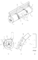
トナー補給容器1のトナーを収納する容器本体1aは中空の略円筒形状であり、容器本体1aの円周上に、長手方向に延びる略長方形状の排出口としての開口部1bが設けられている。更に、容器本体1aの長手方向の一端面にはトナー充填口1cが設けられており、トナー充填後、不図示の封止部材等により封止される。また、トナー補給容器1には、ユーザーがトナー補給容器1の着脱操作時に掴むための把手としてのハンドル2が設けられており、ハンドル2はトナー補給容器1の長手方向の両端に固定されて設けられている。なお、このハンドルの形状は、このような形態に限らず、トナー補給容器の着脱操作時に使用でき、そしてトナー補給容器を回動操作させるにあたり十分な機能を有していれば、どのような形状であっても構わない。
The container main body 1a for storing toner in the
開口部1bは、図2(a)に示すように、トナー補給容器1の外周面に沿った曲率を有した形状の容器シャッタ3により封止されている。この容器シャッタ3は、容器本体1aの長手方向の両端側に設けられたガイド部材1dと係合しており、トナー補給容器1の外周面に沿って周方向にスライド自在に構成されている。
As shown in FIG. 2A, the
そして、トナー補給容器1がトナー受入れ装置7(図3)に挿入・装着された後、トナー補給容器1の回動に伴ってこの容器シャッタ3はトナー受入れ装置7のストッパ部に突き当たることで回動が規制される構成となっている。
Then, after the
容器シャッタ3の回転が規制された状態でトナー補給容器1を更に回動させると、容器シャッタ3から開口部1bが露出し開封が行われる。
When the
一方、トナー補給容器1を交換するにあたって、トナー補給容器1を上述の開封のための回動方向とは逆方向へ回動させると、やはり、この容器シャッタ3の逆側がトナー受入れ装置7のもう1つのストッパ部に突き当たることで回動が規制される構成となっている。
On the other hand, when the
このように容器シャッタ3の回転が規制された状態でトナー補給容器1を更に回動させると、開口部1bが容器シャッタ3にて再度遮蔽される位置へと移動し、再封が行われる。
When the
また、容器本体1aには攪拌搬送部材としての攪拌部材4が内装されている。この攪拌部材4は、後述のカップリング5と同軸的に設けられた回転軸部と、この回転軸部に取り付けられ容器本体1aの内面と摺動自在な攪拌翼部と、から構成されている。この攪拌翼部は、容器内のトナーを攪拌する機能の他に、開口部1bに向けてトナーを搬送する機能をも有している。
In addition, a stirring member 4 as a stirring and transporting member is internally provided in the container body 1a. The stirring member 4 is composed of a rotating shaft portion provided coaxially with a
そして、容器本体1aの長手方向他端面には攪拌部材4と駆動連結関係にあるカップリング5が設けられている。本例では、攪拌部材の回転軸部とカップリングとが樹脂にて一体成型されたものを用いている。
And the
そして、トナー補給容器1が画像形成装置本体にセットされてトナー排出可能な状態となった後、装置本体のカップリング機構とカップリング自在に設けられたカップリング5が回転駆動力を受ける構成とされている。
Then, after the
カップリング5から回転駆動力を伝達された攪拌部材4は、装置本体に実質的に回転不可に固定された状態にあるトナー補給容器1に対して相対回転し、トナー補給容器内のトナーを攪拌しながら開口部1bに向けて搬送・排出する構成になっている。なお、このとき、トナー補給容器を固定状態にするのではなく、トナー補給容器の攪拌部材と共に連れ回る方向への回動を装置本体により少なくとも規制する構成であれば構わない。
The agitating member 4 to which the rotational driving force is transmitted from the
容器本体1aの周面上には、容器本体1aと装置シャッタ8の回転移動を連動させる連動部としての係合部6が設けられている。この係合部6は、トナー補給容器1をトナー受入れ装置7に挿入装着した後のトナー補給容器1のセット操作時に、後述する装置シャッタ8と係合可能な構成となっている。
On the peripheral surface of the container main body 1a, an engaging
係合部6には、図2(c)に示すように、後述するトナー受入れ装置7の補給口7bの開封時に面Dが装置シャッタ8に突き当ることで装置シャッタを押し下げる開封部位としての突起部6aが設けられている。さらに、係合部6には、補給口7bの再封時に面Eが装置シャッタ8を引っ掛けて装置シャッタを引き上げる再封部位としての爪部6bとから構成されている。
As shown in FIG. 2C, the engaging
爪部6bと容器本体1aの外面との間には一定の隙間を設けてあり、爪部6bに矢印B方向(図2(b))から力が加わるとトナー補給容器のほぼ回動中心に向かって弾性変形し、その力を除去すると再び元の状態に復帰するような構成とされている。即ち、樹脂製のスナップフィット(スナップロック)式の係合部を採用している。なお、爪部6bの弾性変形方向は爪部とトナー補給容器の回動中心を結んだ直線の方向に限られるものではなく、例えば前述の爪部と回動中心を結んだ直線に対し多少の交差角をもった方向へ弾性変形する構成であっても構わない。また、装置シャッタ8を引き上げて再封する時のヨーイングを防止して再封の確実性を上げるためには、係合部6は装置シャッタ8の長手方向(装置シャッタ8の回転軸線方向)両端近傍と係合する位置にそれぞれ設けることが好ましく、更に装置シャッタ8の引き上げ時のバランスを考慮すると複数の係合部6はいずれもほぼ同形状であることが好ましい。なお、本実施例では、係合部6を装置シャッタ8の長手方向両端近傍と係合するように2個設け、ほぼ同形状のものとした。
A fixed gap is provided between the
このように係合部にスナップフィット構造部を設けた為、装置シャッタを引き上げて確実に再封することができると共に、装置シャッタの再封後、装置シャッタとの係合を容易に解除することが可能となる。即ち、トナー補給容器の回動を利用した装置シャッタの開閉移動を簡単な構成で行うことが可能となる。 As described above, since the snap fit structure portion is provided in the engaging portion, the device shutter can be pulled up and resealed reliably, and the engagement with the device shutter can be easily released after the device shutter is resealed. Is possible. That is, the opening / closing movement of the apparatus shutter using the rotation of the toner supply container can be performed with a simple configuration.
<トナー受入れ装置>
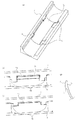
次に、画像形成装置本体側の現像剤受入れ装置としてのトナー受入れ装置7の構成について、図3(a)〜(c)を用いて説明する。
<Toner receiving device>
Next, the configuration of the
トナー受入れ装置7には、トナー補給容器1を取り外し可能に装着する収納部(収納空間)7aと、トナー補給容器1から排出されたトナーを画像形成装置本体内へと受入れる受入れ口としての補給口7bが設けられている。
The
更に、トナー受入れ装置7には、補給口7bを開閉自在に封止する装置シャッタ8が設けられている。装置シャッタ8は、トナー補給容器1及び収納部7aの周面形状に沿った曲率形状を為し、収納部7a下縁に設けられたガイド部材7cと係合している。このような構成とすることで、装置シャッタは円周方向に沿ってスライド移動し、補給口7bを開閉自在に封止できるようになっている。
Further, the
この装置シャッタ8は、トナー補給容器1を収納部7aに装着していない時は、図3(c)に示すように、装置シャッタ8の端部(図3(c)では上側端部)近傍がトナー受入れ装置7に設けられたストッパー7dに突き当たることでそれ以上の移動が制限される。このように、装置シャッタ8により補給口7bを閉鎖することにより、トナー補給容器が装着されていないときに画像形成装置本体側から収納部7a側へトナーが逆流するのを防止している。
When the
また、装置シャッタ8には、図3(d)に示すように、トナー受入れ装置7に挿入・装着されたトナー補給容器1を装着位置(トナー受入れ装置からの取り出しを許容する位置)からトナー補給位置へ回動させるセット操作時に、トナー補給容器1の係合部6と係合する係合部8aが設けられている。本例では、この係合部8aは装置シャッタ8と樹脂にて一体成型されているが、各々を別々に製造しこれらを接着などの方法で一体化させたものを使用しても何ら構わない。
Further, as shown in FIG. 3D, the
この係合部8aには、補給口7bの開封時に係合部6の爪部6bと摺擦することで(図6(a))、爪部6bを容器の回動中心とは反対方向(図6(a)のA方向)に向かって弾性変形させる面Fが設けられている。この弾性変形された爪部6bは更なるトナー補給容器の回動に伴いその弾性変形が解かれ元の位置へ(図6(b)のB方向)復帰し、最終的に係合部6と係合部8aとの係合が完了した状態となる。
The engaging
更に、係合部8aには、補給口7bの再封時に係合部6の面Eに当接して(図6(b))、装置シャッタ8を引き上げるための面Gが設けてある。
Further, the engaging
<トナー補給容器のセット/取り出し操作>
次に、トナー補給容器1及びトナー受入れ装置7を用いたトナー補給容器のセット/取り出し操作について、図4(a)〜(b)、図5(a)〜(f)、図6(a)〜(c)を用いて説明する。なお、図6(a)は図5(a)の際の、図6(b)は図5(a)→(b)の際の、図6(c)は図5(b)の際の、状態の時の係合部6周りを拡大した図である。
<Setting / removing toner supply container>
Next, with reference to FIGS. 4A to 4B, FIGS. 5A to 5F, and FIG. 6A, the
まず、ユーザーがハンドル2を掴んでトナー補給容器1の装着操作が行われる。具体的には、トナー補給容器1はトナー受入れ装置7へ矢印F方向から装着される。その際、トナー補給容器1の開口部1bは上方を向いており容器シャッタ3によって封止された状態にある。即ち、開口部1bは装置シャッタ8によって封止されている補給口7bから離れた位相に位置している(図5(a))。更に、係合部6は装置シャッタ8の係合部8aから離れた位相に位置している(図6(a))
なお、容器シャッタ3は、容器シャッタ3の下縁(開封のための移動方向先端縁)と補給口7bの上縁の位相が略一致(トナー補給容器1及びトナー受入れ装置7の寸法公差や嵌合ガタ等により生じるズレは含む。以下同じ)した状態のとき、ストッパー7dにより円周方向への回転移動が規制される構成となっている。
First, the user grasps the
The
次に、ユーザーがハンドル2を掴んでトナー補給容器1のセット操作が行われる。具体的には、トナー補給容器1は、トナー充填口1c側より回転軸方向から見て反時計回り方向に回動される(図5(b))。
Next, the user grasps the
容器シャッタ3は、トナー補給容器1の回動当初は共に連れ回り、その後、上述のストッパー7dに突き当たり連れ回りが規制されることになる。
The
更にトナー補給容器1の同方向への回動が進むと、係合部6の爪部6bの斜面部が装置シャッタ8の係合部8aの斜面部に乗り上がって、A方向に弾性変形する(図6(b))。
When the
そして、トナー補給容器1の開口部1bの下縁近傍(開封のための開口部1bの回転移動方向先端側近傍)が、容器シャッタ3の下縁(開封のための容器シャッタ3の回転移動方向先端)から露出するのと略同時に、装置シャッタ8の上縁近傍(装置シャッタの回転移動方向後端近傍、即ち、装置シャッタの回転移動方向後端から2mm以内の領域を指す)と略一致した時に、A方向に弾性変形していた係合部6の爪部6bはB方向に弾性復帰する。その結果、トナー補給容器1の係合部6が装置シャッタ8の係合部8aと係合する(図6(c))。
Then, the vicinity of the lower edge of the
なお、上述の説明では、ストッパー7dの厚み(容器の回動方向における長さ)が小さい場合を想定しているが、ストッパー7dが所定以上の厚みを有している場合は、トナー補給容器1の開口部1bの下縁近傍が、容器シャッタ3の下縁から飛び出し更にストッパー7dにより遮蔽された位置から露出するのと略同時に、装置シャッタ8の上縁近傍の位置(位相)と略一致したときに、係合部6が装置シャッタ8の係合部8aと係合するように構成するのが好ましい。なお、このとき後述の装置シャッタの再封時においても同様にストッパー7dの厚みを考慮してタイミングを設定するのが好ましい。
In the above description, it is assumed that the thickness of the
更にトナー補給容器1を同方向へ回転させると、装置シャッタ8は、上縁近傍(装置シャッタの回転移動方向後端近傍、即ち、装置シャッタの回転移動方向後端から2mm以内の領域を指す)が開口部1bの下縁近傍(開口部1bの回転移動方向先端側近傍、即ち、開口部の回転移動方向先端から2mm以内の領域を指す)と略一致した状態を維持したまま、係合部6の突起部6aに押されることによりトナー補給容器1と連動して回転移動し、補給口7bが開封される(図4(b)、図5(c))。
When the
そして、最終的に補給口7bと開口部1bとが連通した時点で、装置シャッタ8はトナー受入れ装置7に設けられたストッパーに突き当たり回転移動が規制され、それと係合しているトナー補給容器もそれ以上の回動が規制される構成となっている。
When the replenishing
このように、補給口7bと開口部1bとが連通した状態のとき、画像形成装置本体側のカップリング機構とカップリングしているトナー補給容器1のカップリング5を介して、この駆動機構からの回転駆動力が攪拌部材4へ伝達されて、トナー補給容器からトナー受入れ装置へトナー補給が行われることになる。
In this way, when the replenishing
トナー補給終了後、補給口7b下縁上にはトナー排出中に蓄積されたトナーが残留している(図5(d))。
After toner replenishment, the toner accumulated during toner discharge remains on the lower edge of the replenishing
この状態において、ユーザーがハンドル2を掴んでトナー充填口1c側より回転軸方向に見て時計回り方向(図5において)にトナー補給容器1を逆方向に回動させる。すると、装置シャッタ8の係合部8aはトナー補給容器1の係合部6に係合した状態を維持されているため、装置シャッタ8は、上縁近傍(再封のための装置シャッタの回転移動方向先端近傍、即ち、装置シャッタの回転移動方向先端から2mm以内の領域を指す)が開口部1bの下縁近傍(再封のための開口部1bの回転移動方向後端近傍、即ち、開口部の回転移動方向後端から2mm以内の領域を指す)と略一致したまま、爪部6bにより引き上げられてトナー補給容器1と連動して共に回転移動する。
In this state, the user grasps the
このとき、装置シャッタ8の上縁近傍(再封のための装置シャッタの回転移動方向先端近傍、即ち、装置シャッタの回転移動方向先端から2mm以内の領域を指す)は開口部1bの下縁近傍(再封のための開口部1bの回転移動方向後端近傍、即ち、開口部の回転移動方向後端から2mm以内の領域を指す)の回転方向における位置が略一致しており、この状態を維持したまま、装置シャッタ8の上縁近傍と開口部1bの下縁近傍は補給口7bと開口部1bとの連通部を通過する。
At this time, the vicinity of the upper edge of the device shutter 8 (near the tip of the device shutter in the rotational movement direction for resealing, that is, the region within 2 mm from the tip of the device shutter in the rotational movement direction) is near the lower edge of the
その際に、前述の補給口7b下縁上に蓄積されたトナーは、トナー補給容器1の再封のための回転移動に伴って、補給口7bを通してトナー受入れ装置7内や、開口部1bを通して容器本体1a内に回収され(図5(e))、このような蓄積トナーによるトナー補給容器1のトナー汚れを可及的に少なくすることができる。
At this time, the toner accumulated on the lower edge of the replenishing
このような構成とすることにより、ユーザーがトナー補給容器1を取り出した際に手を汚すことを抑制することができるためユーザービリティ性の向上を図ることができる。
By adopting such a configuration, it is possible to prevent the user from getting his / her hand dirty when the
更にトナー補給容器1を再封のために回動させると、装置シャッタ8の上縁近傍(再封のための装置シャッタの回転移動方向先端近傍、即ち、装置シャッタの回転移動方向先端から2mm以内の領域を指す)がトナー受入れ装置7のストッパー7dの下面に突き当たりトナー補給容器1との連れ回りが規制される。そして、装置シャッタ8が補給口7bを閉じ切るのと略同時に開口部1bの上縁近傍(再封のための開口部1bの回転移動方向先端近傍、即ち、開口部の回転移動方向先端から2mm以内の領域を指す)が容器シャッタ3に入り込み始めるように、係合部6は容器本体1aと装置シャッタ8の回転移動が連動される。
When the
更にトナー補給容器1を回動させると、装置シャッタ8はストッパー7dに規制されてそれ以上回転しないので、この規制による力によってスナップフィット構成の係合部6の爪部6bは装置シャッタ8の係合部8aから外れる方向(図6(b)のA方向)に弾性変形する。更にトナー補給容器1を回動させると、トナー補給容器1の係合部6の爪部6bは、装置シャッタ8の係合部8aとの係合が解除され図6(c)のB方向へ弾性復帰する。
When the
その後、トナー補給容器1が更に回転し、トナー受入れ装置7によって回転方向への移動が規制されている容器シャッタ3に開口部1bが完全に遮蔽される状態となったとき、トナー補給容器1のガイド部材1dに設けられたストッパー突起(不図示)が容器シャッタ3に突き当たるため、トナー補給容器1のこれ以上の回転移動が規制されて、図5(a)の状態まで戻る。
Thereafter, when the
そして、最後にユーザーがトナー補給容器1をトナー受入れ装置7から引き出すことにより、一連の再封動作並びにトナー補給容器の取り出し操作が完了する。
Finally, when the user pulls out the
なお、本例では、トナー補給容器1のトナー受入れ装置7への装着方向を上方向(図4(a)の矢印F方向)からとしたが、これに限定されるものではなく、例えば特開平7−199623号公報や特開平7−44000号公報のように、装置正面方向より装着する、即ち、トナー補給容器1の長手方向に沿ってトナー補給容器1をトナー受入れ装置7に対し着脱する構成であっても構わない。
In this example, the mounting direction of the
また本実施形態では、トナー受入れ装置7の装着部の側方に設けられた補給口7bに対し開口部1bが略水平方向を向いたとき連通するような構成とされているが、このような構成に限らない。
Further, in this embodiment, the
更に、トナー補給容器1のセット操作時の回転移動方向も、上述の例に限らず、例えば、開口部1bが下向きの状態でトナー補給容器1を装着し、その後、トナー補給容器1を開封のため上述の例とは逆方向へ回転移動させ、再封のためやはり上述の例とは逆方向に回転移動させるような構成であっても構わない。
Further, the rotational movement direction during the setting operation of the
なお、上述したような、「開口部1bの下縁近傍と装置シャッタ8の上縁近傍の回転方向における位置が一致する」状態とは、図5に示すように「開口部1bの下縁と装置シャッタ8の上縁との回転方向のずれ量(L)が回転移動方向に前後5mm以内」の状態を意味している。トナー排出後のトナー汚れレベルの確認を行った結果、ずれ量(L)が前後5mm以内であれば、ずれ量(L)がゼロである場合(上述した図5の構成)と遜色ない程度で問題ないレベルであった。
As described above, “the position in the rotation direction in the vicinity of the lower edge of the
よって、本実施形態によれば、トナー補給容器のトナー受入れ装置へのセット動作時の装置シャッタ/容器シャッタの開閉を確実に且つ容易に行うことができ、そして、トナー補給容器のトナー汚れを極力抑えることができる。 Therefore, according to the present embodiment, the apparatus shutter / container shutter can be opened and closed reliably and easily during the setting operation of the toner supply container to the toner receiving apparatus, and toner contamination of the toner supply container is minimized. Can be suppressed.
<係合部6の構成>
以上のように、トナー補給容器1の係合部6のスナップフィット機能を有する爪部には、トナー補給容器の取り出し操作時(装置シャッタの再封時)に、装置シャッタ8の係合部8aとの係合を維持し装置シャッタ8を引き上げることにより装置シャッタ8の再封を完遂させるための機能が求められている。即ち、係合部6と係合部8aとの係合関係が強固なほど好ましい。
<Configuration of engaging
As described above, the claw portion having the snap fit function of the engaging
一方、係合部6の爪部には、装置シャッタ8が再封された後、係合部8aとの係合解除を完遂させるための機能も求められている。即ち、係合部6と係合部8aとの係合関係は軟弱なほど好ましい。
On the other hand, the claw portion of the engaging
従って、係合部6には、これらの相反する2つの機能が求められている。
Accordingly, the engaging
もちろん、トナー補給容器のセット操作時(シャッタ8の開封時)に係合部6が係合部8aと確実に係合する機能も求められている。
Of course, there is also a demand for a function for the engaging
以上を鑑み、本発明者等が検討を重ねた結果、係合部6が係合部8aとの係合解除に要する解除力、即ち、トナー補給容器の回動方向(図6(b)のC方向)への解除力をF(N)、トナー補給容器の回動方向と垂直な径方向(図6(b)のA方向)への弾性変形力(この弾性変形力は、大きくなると弾性変形し難くなり、小さくなると弾性変形し易くなる指標である)をP(N)としたとき、解除力Fと弾性変形力Pとの間に、以下の関係を満足することが好ましいことが分かった。
In view of the above, as a result of repeated studies by the present inventors, the release force required for the
P=kF(0.25≦k≦1)
この関係を満足すれば、装置シャッタ8を確実に再封することが可能になると共に装置シャッタ8とトナー補給容器1間の係合を確実に解除することが可能となる。
P = kF (0.25 ≦ k ≦ 1)
If this relationship is satisfied, the
また、解除力Fが大き過ぎると係合部6と係合部8a間の係合が外れ難くなると共にトナー補給容器1の回動に要する操作力が上がり、一方、解除力が小さ過ぎると、装置シャッタの再封が完了する前に係合が外れてしまう可能性がある。
On the other hand, if the release force F is too large, the engagement between the
従って、解除力Fは、5≦F≦30を満足するように設定することが好ましい。 Accordingly, the release force F is preferably set so as to satisfy 5 ≦ F ≦ 30.
さらに、弾性変形力Pが大き過ぎると係合部6自体が堅くなるため、係合時の変形の際.破損が発生しやすくなる。一方、弾性変形力Pが小さ過ぎると係合部6自体が柔らかくなるため、係合時の変形が復帰せずに係合不良を起こしてしまう可能性がある。
Furthermore, if the elastic deformation force P is too large, the engaging
従って、弾性変形力Pは、3≦P≦15を満足するように設定することが好ましい。 Therefore, the elastic deformation force P is preferably set so as to satisfy 3 ≦ P ≦ 15.
上述の弾性変形力P(N)は、図2(c)に示すように、係合部3の爪部6b先端部をF方向(トナー補給容器の回動方向と垂直な方向)に、装置シャッタ8と係合する際の変形量:h(mm)の分だけ押して、弾性変形させた時の最大荷重(N)を測定することにより得ることができる。なお、爪部6bの実際の変形方向はF方向とは逆方向だが、本例では測定を簡易にするためF方向、即ち押し方向とした。この弾性変形力の他の測定条件は以下のとおりである。
測定機:圧縮−引張試験機(メーカー:オリエンテック、型番:RTC‐1225A)
ダウンスピード:10(mm/sec.)
また、上述の解除力F(N)は、係合部6の爪部6bと装置シャッタ8の係合部8aとの係合が解除される際(図6(c)→図6(b)→図6(a))の、C方向(トナー補給容器の回動方向)への最大荷重(N)を測定することにより得ることができる。この解除力の測定条件は以下のとおりである。
As shown in FIG. 2C, the elastic deformation force P (N) described above is applied to the front end of the
Measuring machine: Compression-tensile testing machine (Manufacturer: Orientec, Model number: RTC-1225A)
Down speed: 10 (mm / sec.)
Further, the above-described release force F (N) is applied when the engagement between the
測定機:トルクゲージ(メーカー:東日製作所、型番:15BTG)
測定スピード:100(mm/sec.)
具体的には、解除力は、上記トルクゲージをトナー補給容器の長手方向端面に固定し、このトルクゲージによって係合部6の爪部6bと装置シャッタ8の係合部8aとの係合が解除される方向にトナー補給容器を回動させる。そして、爪部6bと係合部8aの係合が解除される際の最大荷重(N)を測定し、それを係合部6の個数(本実施例では2個)で割ることによって、係合部6の1個当たりの解除力を得ることができる。この係合部6の1個当たりの解除力は係合部6の構成の変化に伴い適宜に求めれば良い。
Measuring machine: Torque gauge (Manufacturer: Tohnichi, model number: 15BTG)
Measurement speed: 100 (mm / sec.)
Specifically, the releasing force is fixed to the longitudinal end surface of the toner replenishing container by the torque gauge, and the engagement between the
以上説明したような係合部6の爪部の弾性変形力を得る為に、本例では、爪部の、「曲げ弾性率」と「形状寸法」を適宜に設定している。
In order to obtain the elastic deformation force of the claw portion of the engaging
「曲げ弾性率」としては爪部を構成する樹脂材料にて決まる要素であり、使用する樹脂材料を適宜に設定している。また、「形状寸法」としては、図2(c)、(d)に示すように、爪部6bの幅(容器長手方向の長さ):b、係合部6の爪部6bの長さ:L、爪部6bの厚み:t、が挙げられ、これらを適宜に設定している。
The “flexural modulus” is an element determined by the resin material constituting the claw portion, and the resin material to be used is appropriately set. In addition, as “shape dimension”, as shown in FIGS. 2 (c) and 2 (d), the width of the
これらの因子を、スペースやコスト、成型等、トナー補給容器1を設計する上での状況に応じて最適化することにより、係合部6の弾性変形力を設定することができる。
By optimizing these factors according to the situation in designing the
また、以上説明したような係合部6の爪部の解除力を得る為に、本例では、爪部の、装置シャッタ8の係合部8aとの係合角度:θ(図2(c))と係合部8aとの引掛り量:a(図6(b))を適宜に設定している。
Further, in order to obtain the releasing force of the claw portion of the engaging
これらの因子を、スペースやコスト、成型等、トナー補給容器1を設計する上での状況に応じて最適化することにより、係合部6の解除力を設定することができる。
By optimizing these factors according to the situation in designing the
<検証>
上述した係合部6の弾性変形力と解除力についての検証結果を以下に説明する。以下に示す実施例及び比較例に示す各条件にて係合部6を製作し、以下の(1)〜(3)の項目について評価した。
(1)画像形成装置本体に装着後トナー補給容器1を回転させて、係合部6の爪部6bと装置シャッタ8の係合部8aが係合する際のトナー補給容器1の回動トルク。
(2)補給終了後トナー補給容器1を回転させて、装置シャッタ8により補給口が封止されるまで、係合部6の爪部6bと装置シャッタ8の係合部8aとの係合が外れないかどうかの確認。
(3)装置シャッタ8による補給口封止後トナー補給容器1を回転させて、係合部6の爪部6bと装置シャッタ8の係合部8aとの係合が解除される際のトナー補給容器1の回動トルク。
<Verification>
The verification result about the elastic deformation force and release force of the
(1) Rotating torque of the
(2) After completion of replenishment, the
(3) Toner replenishment when the
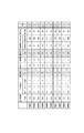
これらの結果をまとめたものを図7にて示す。この図7を参照しつつ、実施例1〜6及び比較例1〜4について順に説明する。なお、トナー補給容器1の回動トルクは、ユーザーの操作力を考慮して、137.3N・cm(14.0kgf・cm)以下に設定することが好ましい。
A summary of these results is shown in FIG. Examples 1 to 6 and Comparative Examples 1 to 4 will be described in order with reference to FIG. The rotational torque of the
<実施例1>
実施例1では、係合部6(容器本体1a)の材質については、材質:LD−PE樹脂、メーカー&グレード:サンテックHD J310、曲げ弾性率:1400Mpa、とした。
<Example 1>
In Example 1, the material of the engaging portion 6 (container body 1a) was made of material: LD-PE resin, manufacturer & grade: Suntech HD J310, and flexural modulus: 1400 Mpa.
そして、係合部6の各寸法は、係合部6の幅:b=5.5mm、爪部6bの長さ:L=16.5mm、爪部6bの肉厚:t=1mm、爪部6bの角度:θ=50°、とした。また、係合部6と装置シャッタ8との引掛り量:a=1.0mmとした。
And each dimension of the
まず、係合部6の爪部6bの弾性変形力:Pを測定するために、トナー補給容器1を下記に示す圧縮−引張試験機にセットして、弾性変形力を測定した結果、P=4.0N(0.4kgf)であった。
First, in order to measure the elastic deformation force: P of the
また、係合部6の爪部6bの解除力:Fを測定するために、トナー補給容器1をトナー受入れ装置7にセットして解除力を測定した結果、F=8.0N(0.8kgf)であった。
Further, in order to measure the release force F of the
従って、P=kFの関係からk=0.5となり、0.25≦k≦1の範囲内であった。 Therefore, from the relationship of P = kF, k = 0.5, which is in the range of 0.25 ≦ k ≦ 1.
次に、上記トナー補給容器1に400gの磁性トナーを充填した状態で、画像形成装置本体に装着しその後回転させて、係合部6と係合部8aとが係合する際、並びに、係合が解除される際のトナー補給容器1の回動トルクを測定した結果、順に33.3N・cm(3.4kgf・cm)、39.2N・cm(4.0kgf・cm)であり、いずれも137.3N・cm(14.0kgf・cm)以下であった。
Next, when the
また、補給終了後、トナー補給容器1を回転させて、装置シャッタ8により補給口が再封されるまで、係合部6と装置シャッタ8との係合が外れる確率を調べる為に、動作確認を100回行った結果、全てにおいて最後まで連動が行われ、外れは発生しなかった。故に不良の発生確率は0%であった。
In addition, after the replenishment, the
<実施例2>
実施例2では、係合部6の材質については、材質:HI−PS樹脂、メーカー&グレード:PSジャパン AGI02、曲げ弾性率:2160Mpa、とした。
<Example 2>
In Example 2, the material of the engaging
そして、係合部6の各寸法は、係合部6の幅:b=5.5mm、爪部6bの長さ:L=16.5mm、爪部6bの肉厚:t=1mm、爪部6bの角度:θ=40°、とした。また、係合部6と装置シャッタ8との引掛り量:a=1.5mmとした。
And each dimension of the
まず、実施例1と同じ方法で、係合部6の爪部6bの弾性変形力:Pと解除力:Fを測定した結果、P=6.0N(0.6kgf)、F=14.0N(0.14kgf)であり、P=kFの関係からk=0.43となり、0.25≦k≦1の範囲内であった。
First, as a result of measuring the elastic deformation force P and the release force F of the
次に、実施例1と同様に、係合部6と装置シャッタ8とが係合する際、並びに係合が解除される際のトナー補給容器1の回動トルクを測定した結果、順に50.0N・cm(5.1kgf・cm)、49.0N・cm(5.0kgf・cm)であり、いずれも137.3N・cm(14.0kgf・cm)以下であった。
Next, as in Example 1, the rotational torque of the
また、補給終了後トナー補給容器1を回転させて、装置シャッタ8により補給口が封止されるまで、係合部6と装置シャッタ8との係合が外れる確率を調べる為に、動作確認を100回行った結果、全てにおいて最後まで連動が行われ、外れは発生しなかった。故に不良の発生確率は0%であった。
In addition, after the replenishment, the
<実施例3>
実施例3では、係合部6の材質については、材質:HI−PS樹脂、メーカー&グレード:PSジャパン NS130、曲げ弾性率:2400Mpa、とした。
<Example 3>
In Example 3, the material of the engaging
そして、係合部6の各寸法は、係合部6の幅:b=5.5mm、爪部6bの長さ:L=16.5mm、爪部6bの肉厚:t=1mm、爪部6bの角度:θ=40°、とした。また、係合部6と装置シャッタ8との引掛り量:a=1.5mmとした。
And each dimension of the
まず、実施例1と同じ方法で、係合部6の爪部6bの弾性変形力:Pと解除力:Fを測定した結果、P=7.0N(0.7kgf)、F=18.0N(1.8kgf)であり、P=kFの関係からk=0.39となり、0.25≦k≦1の範囲内であった。
First, as a result of measuring the elastic deformation force P and the release force F of the
次に、実施例1と同様に、係合部6と装置シャッタ8とが係合する際、並びに係合が解除される際のトナー補給容器1の回動トルクを測定した結果、順に58.8N・cm(6.0kgf・cm)、78.5N・cm(8.0kgf・cm)であり、いずれも137.3N・cm(14.0kgf・cm)以下であった。
Next, as in Example 1, the rotational torque of the
また、補給終了後トナー補給容器1を回転させて、装置シャッタ8により補給口が封止されるまで、係合部6と装置シャッタ8との係合が外れる確率を調べる為に、動作確認を100回行った結果、全てにおいて最後まで連動が行われ、外れは発生しなかった。故に不良の発生確率は0%であった。
In addition, after the replenishment, the
<実施例4>
実施例4では、係合部6の材質については、材質:HI−PS樹脂、メーカー&グレード:PSジャパン NS130、曲げ弾性率:2400Mpa、とした。
<Example 4>
In Example 4, the material of the engaging
そして、係合部6の各寸法は、係合部6の幅:b=6.5mm、爪部6bの長さ:L=16.5mm、爪部6bの肉厚:t=2mm、爪部6bの角度:θ=40°、とした。また、係合部6と装置シャッタ8との引掛り量:a=2mmとした。
The dimensions of the engaging
まず、実施例1と同じ方法で、係合部6の爪部6bの弾性変形力:Pと解除力:Fを測定した結果、P=14.0N(1.4kgf)、F=16.0N(1.6kgf)であり、P=kFの関係からk=0.88となり、0.25≦k≦1の範囲内であった。
First, as a result of measuring the elastic deformation force P and the release force F of the
次に、実施例1と同様に、係合部6と装置シャッタ8とが係合する際、並びに係合が解除される際のトナー補給容器1の回動トルクを測定した結果、順に117.7N・cm(12.0kgf・cm)、98.1N・cm(10.0kgf・cm)であり、いずれも137.3N・cm(14.0kgf・cm)以下であった。
Next, as in the first embodiment, as a result of measuring the rotational torque of the
また、実施例1と同様に、係合部6と装置シャッタ8との係合が外れる確率を調べる為に、動作確認を100回行った結果、全てにおいて最後まで連動が行われ、外れは発生しなかった。故に不良の発生確率は0%であった。
In addition, as in the first embodiment, in order to examine the probability that the
<実施例5>
実施例5では、係合部6の材質については、材質:HI−PS樹脂、メーカー&グレード:PSジャパン NS130、曲げ弾性率:2400Mpa、とした。
<Example 5>
In Example 5, the material of the engaging
そして、係合部6の各寸法は、係合部6の幅:b=6.5mm、爪部6bの長さ:L=16.5mm、爪部6bの肉厚:t=2mm、爪部6bの角度:θ=30°、とした。また、係合部6と装置シャッタ8との引掛り量:a=2mmとした。
The dimensions of the engaging
まず、実施例1と同じ方法で、係合部6の爪部6bの弾性変形力:Pと解除力:Fを測定した結果、P=14.0N(1.4kgf)、F=20.0N(2.0kgf)であり、P=kFの関係からk=0.7となり、0.25≦k≦1の範囲内であった。
First, as a result of measuring the elastic deformation force P and the release force F of the
次に、実施例1と同様に、係合部6と装置シャッタ8とが係合する際、並びに係合が解除される際のトナー補給容器1の回動トルクを測定した結果、順に117.7N・cm(12.0kgf・cm)、137.3N・cm(14.0kgf・cm)であり、いずれも137.3N・cm(14.0kgf・cm)以下であった。
Next, as in the first embodiment, as a result of measuring the rotational torque of the
また、実施例1と同様に、係合部6と装置シャッタ8との係合が外れる確率を調べる為に、動作確認を100回行った結果、全てにおいて最後まで連動が行われ、外れは発生しなかった。故に不良の発生確率は0%であった。
In addition, as in the first embodiment, in order to examine the probability that the
<実施例6>
実施例6では、係合部6の材質については、材質:HI−PS樹脂、メーカー&グレード:テクノポリマー F5451G10、曲げ弾性率:4020Mpa、とした。
<Example 6>
In Example 6, the material of the engaging
そして、係合部6の各寸法は、係合部6の幅:b=6.5mm、爪部6bの長さ:L=16.5mm、爪部6bの肉厚:t=1mm、爪部6bの角度:θ=25°、とした。また、係合部6と装置シャッタ8との引掛り量:a=2mmとした。
The dimensions of the
まず、実施例1と同じ方法で、係合部6の爪部6bの弾性変形力:Pと解除力:Fを測定した結果、P=9.0N(0.9kgf)、F=25.0N(2.5kgf)であり、P=kFの関係からk=0.36となり、0.25≦k≦1の範囲内であった。
First, as a result of measuring the elastic deformation force P and the release force F of the
次に、実施例1と同様に、係合部6と装置シャッタ8とが係合する際、並びに係合が解除される際のトナー補給容器1の回動トルクを測定した結果、順に75.5N・cm(7.7kgf・cm)、117.7N・cm(12.0kgf・cm)であり、いずれも137.3N・cm(14.0kgf・cm)以下であった。
Next, as in Example 1, the rotational torque of the
また、実施例1と同様に、係合部6と装置シャッタ8との係合が外れる確率を調べる為に、動作確認を100回行った結果、全てにおいて最後まで連動が行われ、外れは発生しなかった。故に不良の発生確率は0%であった。
In addition, as in the first embodiment, in order to examine the probability that the
<比較例1>
比較例1では、係合部6の材質については、材質:HI−PS樹脂、メーカー&グレード:テクノポリマー F5451G10、曲げ弾性率:4020Mpa、とした。
<Comparative Example 1>
In the comparative example 1, about the material of the
そして、係合部6の各寸法は、係合部6の幅:b=6.0mm、爪部6bの長さ:L=16.5mm、爪部6bの肉厚:t=1mm、爪部6bの角度:θ=80°、とした。また、係合部6と装置シャッタ8との引掛り量:a=1.0mmとした。
And each dimension of the
まず、実施例1と同じ方法で、係合部6の爪部6bの弾性変形力:Pと解除力:Fを測定した結果、P=10.0N(1.0kgf)、F=4.0N(0.4kgf)であり、P=kFの関係からk=2.5となり、0.25≦k≦1の範囲外であった。
First, as a result of measuring the elastic deformation force P and the release force F of the
次に、実施例1と同様に、係合部6と装置シャッタ8とが係合する際、並びに係合が解除される際のトナー補給容器1の回動トルクを測定した結果、順に84.3N・cm(8.6kgf・cm)、19.6N・cm(2.0kgf・cm)であり、いずれも137.3N・cm(14.0kgf・cm)以下であった。
Next, as in Example 1, the rotational torque of the
また、実施例1と同様に、係合部6と装置シャッタ8との係合が外れる確率を調べる為に、動作確認を100回行った結果、80/100個で外れが発生した。故に不良の発生確率は80%であった。
Further, as in Example 1, the operation was checked 100 times in order to examine the probability that the
<比較例2>
比較例2では、係合部6の材質については、材質:HI−PS樹脂、メーカー&グレード:テクノポリマー F5451G10、曲げ弾性率:4020Mpa、とした。
<Comparative Example 2>
In Comparative Example 2, the material of the engaging
そして、係合部6の各寸法は、係合部6の幅:b=6.5mm、爪部6bの長さ:L=16.5mm、爪部6bの肉厚:t=3mm、爪部6bの角度:θ=70°、とした。また、係合部6と装置シャッタ8との引掛り量:a=1mmとした。
The dimensions of the
まず、実施例1と同じ方法で、係合部6の爪部6bの弾性変形力:Pと解除力:Fを測定した結果、P=17.0N(1.7kgf)、F=8.0N(0.8kgf)であり、P=kFの関係からk=2.12となり、0.25≦k≦1の範囲外であった。
First, as a result of measuring the elastic deformation force P and the release force F of the
次に、実施例1と同様に、係合部6と装置シャッタ8とが係合する際、並びに、係合が解除される際のトナー補給容器1の回動トルクを測定した結果、順に143.2N・cm(14.6kgf・cm)、29.4N・cm(3.0kgf・cm)であり、係合時の回動トルクは137.3N・cm(14.0kgf・cm)を越えていた。
Next, as in the first embodiment, when the engaging
また、実施例1と同様に、係合部6と装置シャッタ8との係合が外れる確率を調べる為に、動作確認を100回行った結果、50/100個で外れが発生した。故に不良の発生確率は50%であった。
Further, as in Example 1, the operation was checked 100 times in order to examine the probability that the
<比較例3>
比較例3では、係合部6の材質については、材質:LD−PE樹脂、メーカー&グレード:サンテックHD J310、曲げ弾性率:1400Mpa、とした。
<Comparative Example 3>
In Comparative Example 3, the material of the engaging
そして、係合部6の各寸法は、係合部6の幅:b=4mm、爪部6bの長さ:L=16.5mm、爪部6bの肉厚:t=1mm、爪部6bの角度:θ=20°、とした。また、係合部6と装置シャッタ8との引掛り量:a=2mmとした。
The dimensions of the engaging
まず、実施例1と同じ方法で、係合部6の爪部6bの弾性変形力:Pと解除力:Fを測定した結果、P=2.0N(0.2kgf)、F=16.0N(1.6kgf)であり、P=kFの関係からk=0.13となり、0.25≦k≦1の範囲外であった。
First, as a result of measuring the elastic deformation force P and the release force F of the
次に、実施例1と同様に、係合部6と装置シャッタ8とが係合する際、並びに係合が解除される際のトナー補給容器1の回動トルクを測定した結果、順に33.3N・cm(3.4kgf・cm)、147.1N・cm(15.0kgf・cm)であり、係合解除時の回動トルクは137.3N・cm(14.0kgf・cm)を越えていた。
Next, as in Example 1, the rotational torque of the
以上のように、係合部6と係合部8aとの係合が外れる不具合が発生しなかったものの、係合部6と係合部8a間の係合操作や係合解除操作に要する操作力が大き過ぎて実用に値しないものであった。
As described above, although there is no problem that the
<比較例4>
比較例4では、係合部6の材質については、材質:HI−PS樹脂、メーカー&グレード:PSジャパン NS130、曲げ弾性率:2400Mpa、とした。
<Comparative example 4>
In the comparative example 4, about the material of the
そして、係合部6の各寸法は、係合部の幅:b=5.5mm、係合部の長さ:L=16.5mm、爪部6bの肉厚:t=1mm、爪部6bの角度:θ=10°、とした。また、係合部6と装置シャッタ8との引掛り量:a=2mmとした。
And each dimension of the
まず、実施例1と同じ方法で、係合部6の爪部6bの弾性変形力:Pと解除力:Fを測定した結果、P=6.0N(0.6kgf)、F=28.0N(2.8kgf)であり、P=kFの関係からk=0.21となり、0.25≦k≦1の範囲外であった。
First, as a result of measuring the elastic deformation force P and the release force F of the
次に、実施例1と同様に、係合部6と装置シャッタ8とが係合する際、並びに係合が解除される際のトナー補給容器1の回動トルクを測定した結果、順に50.0N・cm(5.1kgf・cm)、186.3N・cm(19.0kgf・cm)であり、係合解除時の回動トルクは137.3N・cm(14.0kgf・cm)を越えていた。
Next, as in Example 1, the rotational torque of the
以上のように、係合部6と係合部8aとの係合が外れる不具合が発生しなかったものの、係合部6と係合部8a間の係合操作や係合解除操作に要する操作力が大き過ぎて実用に値しないものであった。
As described above, although there is no problem that the
〔他の実施形態〕
前述した実施形態では、現像剤補給容器の容器本体の形状として、略円筒状のものを例示したが、本発明はこれに限定されるものではなく、現像剤を収納する略筒状の形状であればその他の形状であっても良い。
Other Embodiment
In the above-described embodiment, the shape of the container main body of the developer supply container is exemplified as a substantially cylindrical shape. However, the present invention is not limited to this, and the shape of the developer main body is a substantially cylindrical shape containing the developer. Any other shape may be used.
また、前述した実施形態では、画像形成装置として複写機を例に説明したが、プリンタ、ファクシミリ装置等の画像形成装置や、これらの機能を複数備えた複合機等の画像形成装置でも構わない。 In the above-described embodiment, the copying machine has been described as an example of the image forming apparatus. However, an image forming apparatus such as a printer or a facsimile machine, or an image forming apparatus such as a multifunction machine having a plurality of these functions may be used.
また、前述した実施形態では、単色画像(白黒画像)を形成する画像形成装置を例に説明したが、記録材を担持して搬送する記録材担持体を設けこの記録材担持体に担持された記録材に感光体から各色の現像剤像を順次重ねて転写するカラー画像形成装置や、中間転写体を設けこの中間転写体に感光体から各色の現像剤像を順次重ねて転写し、その後、記録材に一括して転写するカラー画像形成装置であっても構わない。 Further, in the above-described embodiment, the image forming apparatus that forms a single color image (black and white image) has been described as an example. However, a recording material carrier that carries and transports a recording material is provided and is carried on the recording material carrier. A color image forming apparatus that sequentially transfers and transfers developer images of each color from the photosensitive member to the recording material, and an intermediate transfer member is provided, and the developer images of each color are sequentially transferred and transferred from the photosensitive member to the intermediate transfer member. It may be a color image forming apparatus that collectively transfers to a recording material.
以上のような種々の画像形成装置であっても、本発明の現像剤補給容器を適用することが可能である。 The developer supply container of the present invention can also be applied to various image forming apparatuses as described above.
また、本発明の現像剤補給容器は、画像形成装置に着脱自在に設けられた現像剤受入れ装置としてのプロセスカートリッジに対し、現像剤補給容器を着脱自在に構成し、更に、このプロセスカートリッジへ収納されている現像剤を補給する構成であっても良い。 The developer supply container of the present invention is configured such that the developer supply container is detachable with respect to a process cartridge as a developer receiving device provided detachably in the image forming apparatus, and further stored in the process cartridge. It may be configured to replenish the developed developer.
このプロセスカートリッジは現像器201aを少なくとも有する構成とされ、現像器の他に像担持体としての電子写真感光体104を一体に有する構成としても構わない。さらに、この感光体104に作用する帯電器203、クリーナ202のうちの少なくとも1つの画像形成機器を一体に有する構成であっても構わない。
This process cartridge is configured to have at least a developing
以上において本発明を適用可能な実施例について説明したが本発明の権利範囲はこれに限られることは無く、本発明の思想の範囲内において種々の構成を公知の他の構成に変更可能であることは言うまでもない。 Although the embodiments to which the present invention can be applied have been described above, the scope of the present invention is not limited thereto, and various configurations can be changed to other known configurations within the scope of the idea of the present invention. Needless to say.
1 トナー補給容器(現像剤補給容器)
1a 容器本体
1b 開口部(排出口)
1c トナー充填口
1d ガイド部材
2 ハンドル
3 容器シャッタ
4 攪拌部材
5 カップリング
6 係合部(連動部)
6a 突起部(開封部位)
6b 爪部(封止部位)
7 トナー受入れ装置(現像剤受入れ装置)
7a 収納部
7b 補給口(受入れ口)
7c ガイド部材
7d ストッパー
8 装置シャッタ
8a 係合部
1 Toner supply container (Developer supply container)
1c Toner filling port
6a Protrusion (opening part)
6b Claw part (sealing part)
7 Toner receiving device (Developer receiving device)
Claims (2)
現像剤を収容する容器本体と、
前記容器本体内の現像剤を排出する排出口と、
前記シャッタとスナップロック自在に設けられ、前記容器本体の回動に伴い前記シャッタを開閉移動させるスナップロック部と、を有し、
前記スナップロック部と前記シャッタとのスナップロック解除に要する解除力をF、この解除力に対し垂直な方向への弾性変形力をP、としたとき、
P=kF 0.25≦k≦1
を満足することを特徴とする現像剤補給容器。 In a developer supply container detachably attached to a developer receiving device having a receiving port for receiving a developer and a shutter for opening and closing the receiving port,
A container body for containing a developer;
A discharge port for discharging the developer in the container body;
A snap lock portion provided so as to be snap-lockable with the shutter, and for opening and closing the shutter as the container body rotates.
When the release force required to release the snap lock between the snap lock portion and the shutter is F, and the elastic deformation force in the direction perpendicular to the release force is P,
P = kF 0.25 ≦ k ≦ 1
A developer supply container characterized by satisfying
5≦F≦30、3≦P≦15
を満足することを特徴とする請求項1の現像剤補給容器。
About the release force F and the elastic deformation force P,
5 ≦ F ≦ 30, 3 ≦ P ≦ 15
The developer supply container according to claim 1, wherein:
Priority Applications (3)
| Application Number | Priority Date | Filing Date | Title |
|---|---|---|---|
| JP2005145529A JP2006323082A (en) | 2005-05-18 | 2005-05-18 | Developer supply container |
| US11/722,140 US7738818B2 (en) | 2005-05-18 | 2006-05-17 | Developer supply container |
| PCT/JP2006/310279 WO2006123823A1 (en) | 2005-05-18 | 2006-05-17 | Developer supply container |
Applications Claiming Priority (1)
| Application Number | Priority Date | Filing Date | Title |
|---|---|---|---|
| JP2005145529A JP2006323082A (en) | 2005-05-18 | 2005-05-18 | Developer supply container |
Publications (2)
| Publication Number | Publication Date |
|---|---|
| JP2006323082A true JP2006323082A (en) | 2006-11-30 |
| JP2006323082A5 JP2006323082A5 (en) | 2007-02-15 |
Family
ID=37431383
Family Applications (1)
| Application Number | Title | Priority Date | Filing Date |
|---|---|---|---|
| JP2005145529A Pending JP2006323082A (en) | 2005-05-18 | 2005-05-18 | Developer supply container |
Country Status (3)
| Country | Link |
|---|---|
| US (1) | US7738818B2 (en) |
| JP (1) | JP2006323082A (en) |
| WO (1) | WO2006123823A1 (en) |
Cited By (8)
| Publication number | Priority date | Publication date | Assignee | Title |
|---|---|---|---|---|
| JP2008216453A (en) * | 2007-03-01 | 2008-09-18 | Brother Ind Ltd | Toner cartridge and developing device |
| JP2011191447A (en) * | 2010-03-12 | 2011-09-29 | Fuji Xerox Co Ltd | Image forming apparatus and developer container used for the same |
| JP2011242496A (en) * | 2010-05-17 | 2011-12-01 | Oki Data Corp | Developer storing body, image forming unit, and image forming apparatus |
| CN102478774A (en) * | 2010-11-22 | 2012-05-30 | 富士施乐株式会社 | Powder container, powder processing apparatus using the same, and powder container controlling method |
| JP2012103517A (en) * | 2010-11-10 | 2012-05-31 | Fuji Xerox Co Ltd | Storage container for developer and image forming device |
| JP2013213910A (en) * | 2012-04-02 | 2013-10-17 | Konica Minolta Inc | Toner bottle, supply unit, and image forming apparatus |
| JP2016033534A (en) * | 2014-07-30 | 2016-03-10 | 京セラドキュメントソリューションズ株式会社 | Toner container and image forming apparatus |
| JP2021015245A (en) * | 2019-07-16 | 2021-02-12 | 株式会社リコー | Developer storage container, developer supply device, and image forming apparatus |
Families Citing this family (20)
| Publication number | Priority date | Publication date | Assignee | Title |
|---|---|---|---|---|
| JP4621785B2 (en) * | 2008-10-10 | 2011-01-26 | シャープ株式会社 | Developing cartridge and image forming apparatus using the same |
| JP4396867B1 (en) * | 2009-05-15 | 2010-01-13 | 富士ゼロックス株式会社 | Image forming agent storage device and image forming device |
| JP6128908B2 (en) | 2013-03-19 | 2017-05-17 | キヤノン株式会社 | Developer supply kit, developer supply device, and image forming apparatus |
| MX2016016406A (en) | 2014-06-11 | 2017-10-12 | Massachusetts Inst Technology | Residence structures and related methods. |
| US20170266112A1 (en) | 2014-06-11 | 2017-09-21 | Massachusetts Institute Of Technology | Residence structures and related methods |
| JP2016090933A (en) | 2014-11-10 | 2016-05-23 | キヤノン株式会社 | Developer replenishment container and image forming apparatus |
| JP6429597B2 (en) | 2014-11-10 | 2018-11-28 | キヤノン株式会社 | Developer supply container |
| JP6385251B2 (en) | 2014-11-10 | 2018-09-05 | キヤノン株式会社 | Developer supply container, developer supply device, and image forming apparatus |
| US10953208B2 (en) | 2015-05-01 | 2021-03-23 | Massachusetts Institute Of Technology | Triggerable shape memory induction devices |
| EP3364946A4 (en) | 2015-10-23 | 2019-06-26 | Lyndra, Inc. | Gastric residence systems for sustained release of therapeutic agents and methods of use thereof |
| JP6665597B2 (en) * | 2016-03-08 | 2020-03-13 | 富士ゼロックス株式会社 | Developer container and image forming apparatus |
| CN109804318B (en) * | 2016-09-30 | 2021-09-28 | 佳能株式会社 | Toner cartridge and toner supply mechanism |
| RU2712977C1 (en) * | 2016-09-30 | 2020-02-03 | Кэнон Кабусики Кайся | Toner cartridge and toner supply mechanism |
| AU2017336154B2 (en) | 2016-09-30 | 2023-11-09 | Lyndra Therapeutics, Inc. | Gastric residence systems for sustained delivery of adamantane-class drugs |
| JP7005249B2 (en) | 2017-09-21 | 2022-01-21 | キヤノン株式会社 | Developer replenishment container and developer replenishment system |
| JP7009133B2 (en) | 2017-09-21 | 2022-01-25 | キヤノン株式会社 | Developer replenishment container |
| JP7039226B2 (en) | 2017-09-21 | 2022-03-22 | キヤノン株式会社 | Developer replenishment container and developer replenishment system |
| JP7172355B2 (en) * | 2018-09-25 | 2022-11-16 | 富士フイルムビジネスイノベーション株式会社 | Cartridge support unit and image forming apparatus |
| JP7255163B2 (en) * | 2018-12-18 | 2023-04-11 | 富士フイルムビジネスイノベーション株式会社 | Mounting structure of storage container, image forming unit, image forming apparatus |
| CN113168128B (en) * | 2019-05-28 | 2024-03-29 | 惠普发展公司,有限责任合伙企业 | Developing cartridge |
Family Cites Families (16)
| Publication number | Priority date | Publication date | Assignee | Title |
|---|---|---|---|---|
| JPS6386652U (en) * | 1986-11-26 | 1988-06-06 | ||
| JPS6451962U (en) * | 1987-09-25 | 1989-03-30 | ||
| JP3320152B2 (en) | 1993-07-28 | 2002-09-03 | 株式会社リコー | Toner storage container and toner supply device |
| JP3225151B2 (en) * | 1993-12-21 | 2001-11-05 | 株式会社リコー | Developing device |
| JP3387596B2 (en) | 1993-12-28 | 2003-03-17 | キヤノン株式会社 | Toner cartridge and developer receiving device |
| EP0805379B1 (en) | 1996-04-29 | 1998-08-05 | Brother Kogyo Kabushiki Kaisha | Toner cartridge having protrusions engageable with a development case shutter |
| JPH1048938A (en) | 1996-04-29 | 1998-02-20 | Brother Ind Ltd | Toner housing device, toner box, and toner feeding method |
| JP2954889B2 (en) * | 1996-10-16 | 1999-09-27 | 株式会社リコー | Toner cartridge |
| JP3368205B2 (en) | 1997-06-19 | 2003-01-20 | キヤノン株式会社 | Toner supply container and electrophotographic image forming apparatus |
| JP3697066B2 (en) | 1997-07-31 | 2005-09-21 | キヤノン株式会社 | Toner supply container and electrophotographic image forming apparatus |
| JP3450757B2 (en) * | 1998-09-22 | 2003-09-29 | キヤノン株式会社 | Toner supply container |
| JP3847985B2 (en) | 1998-11-04 | 2006-11-22 | キヤノン株式会社 | Recycling method of toner supply container |
| JP4035384B2 (en) | 2002-06-19 | 2008-01-23 | キヤノン株式会社 | Developer supply container |
| JP4652783B2 (en) | 2003-12-10 | 2011-03-16 | キヤノン株式会社 | Developer supply container |
| US7450890B2 (en) * | 2004-11-12 | 2008-11-11 | Canon Kabushiki Kaisha | Developer supply container having a shutter cleaning feature |
| JP4636853B2 (en) * | 2004-11-12 | 2011-02-23 | キヤノン株式会社 | Developer supply container and image forming apparatus |
-
2005
- 2005-05-18 JP JP2005145529A patent/JP2006323082A/en active Pending
-
2006
- 2006-05-17 US US11/722,140 patent/US7738818B2/en not_active Expired - Fee Related
- 2006-05-17 WO PCT/JP2006/310279 patent/WO2006123823A1/en active Application Filing
Cited By (10)
| Publication number | Priority date | Publication date | Assignee | Title |
|---|---|---|---|---|
| JP2008216453A (en) * | 2007-03-01 | 2008-09-18 | Brother Ind Ltd | Toner cartridge and developing device |
| JP2011191447A (en) * | 2010-03-12 | 2011-09-29 | Fuji Xerox Co Ltd | Image forming apparatus and developer container used for the same |
| JP2011242496A (en) * | 2010-05-17 | 2011-12-01 | Oki Data Corp | Developer storing body, image forming unit, and image forming apparatus |
| JP2012103517A (en) * | 2010-11-10 | 2012-05-31 | Fuji Xerox Co Ltd | Storage container for developer and image forming device |
| CN102478774A (en) * | 2010-11-22 | 2012-05-30 | 富士施乐株式会社 | Powder container, powder processing apparatus using the same, and powder container controlling method |
| JP2013213910A (en) * | 2012-04-02 | 2013-10-17 | Konica Minolta Inc | Toner bottle, supply unit, and image forming apparatus |
| US9164421B2 (en) | 2012-04-02 | 2015-10-20 | Konica Minolta, Inc. | Toner bottle, supply unit, and image forming apparatus |
| JP2016033534A (en) * | 2014-07-30 | 2016-03-10 | 京セラドキュメントソリューションズ株式会社 | Toner container and image forming apparatus |
| JP2021015245A (en) * | 2019-07-16 | 2021-02-12 | 株式会社リコー | Developer storage container, developer supply device, and image forming apparatus |
| JP7334515B2 (en) | 2019-07-16 | 2023-08-29 | 株式会社リコー | Developer storage container, developer supply device and image forming apparatus |
Also Published As
| Publication number | Publication date |
|---|---|
| WO2006123823A1 (en) | 2006-11-23 |
| US20090092415A1 (en) | 2009-04-09 |
| US7738818B2 (en) | 2010-06-15 |
Similar Documents
| Publication | Publication Date | Title |
|---|---|---|
| JP2006323082A (en) | Developer supply container | |
| JP4693393B2 (en) | Developer supply device | |
| US7242893B2 (en) | Developer supply container | |
| US6993273B2 (en) | Developer supply container, and coupling-driving member for developer supply container | |
| JP4579655B2 (en) | Toner cartridge and image forming apparatus | |
| TWI427444B (en) | Developer storage container and image forming apparatus | |
| JP5303439B2 (en) | Toner supply device and image forming apparatus | |
| JP4368356B2 (en) | Image forming apparatus and toner container removing method for image forming apparatus | |
| JP4802872B2 (en) | Detachable cartridge and image forming apparatus | |
| JP4347331B2 (en) | Developer supply container | |
| WO2006057426A1 (en) | Developer supply container | |
| JP5392024B2 (en) | Developing device and image forming apparatus | |
| US20060000520A1 (en) | Developer supply container | |
| WO2004027522A1 (en) | Image forming device, powder feeding device, toner storage container, powder storage container, and method of recycling the containers | |
| EP2237112B1 (en) | Developer storing body, image forming unit and image forming apparatus | |
| US9086652B2 (en) | Image forming apparatus | |
| JP2009053551A (en) | Image forming apparatus | |
| JP4478705B2 (en) | Toner transport unit and image forming apparatus | |
| JP2006189675A (en) | Developer supply container | |
| JP5422765B2 (en) | Toner supply device and image forming apparatus | |
| JP2006171199A (en) | Developer supply container | |
| JP2007241043A (en) | Image forming apparatus | |
| JP2007286556A (en) | Container for replenishing developer |
Legal Events
| Date | Code | Title | Description |
|---|---|---|---|
| A521 | Written amendment |
Free format text: JAPANESE INTERMEDIATE CODE: A523 Effective date: 20061221 |
|
| A621 | Written request for application examination |
Free format text: JAPANESE INTERMEDIATE CODE: A621 Effective date: 20061221 |
|
| A131 | Notification of reasons for refusal |
Free format text: JAPANESE INTERMEDIATE CODE: A131 Effective date: 20081216 |
|
| A521 | Written amendment |
Free format text: JAPANESE INTERMEDIATE CODE: A523 Effective date: 20090216 |
|
| A02 | Decision of refusal |
Free format text: JAPANESE INTERMEDIATE CODE: A02 Effective date: 20090310 |