JP4347331B2 - Developer supply container - Google Patents
Developer supply container Download PDFInfo
- Publication number
- JP4347331B2 JP4347331B2 JP2006262851A JP2006262851A JP4347331B2 JP 4347331 B2 JP4347331 B2 JP 4347331B2 JP 2006262851 A JP2006262851 A JP 2006262851A JP 2006262851 A JP2006262851 A JP 2006262851A JP 4347331 B2 JP4347331 B2 JP 4347331B2
- Authority
- JP
- Japan
- Prior art keywords
- toner
- supply container
- developer
- container
- toner supply
- Prior art date
- Legal status (The legal status is an assumption and is not a legal conclusion. Google has not performed a legal analysis and makes no representation as to the accuracy of the status listed.)
- Expired - Fee Related
Links
Images


Classifications
-
- G—PHYSICS
- G03—PHOTOGRAPHY; CINEMATOGRAPHY; ANALOGOUS TECHNIQUES USING WAVES OTHER THAN OPTICAL WAVES; ELECTROGRAPHY; HOLOGRAPHY
- G03G—ELECTROGRAPHY; ELECTROPHOTOGRAPHY; MAGNETOGRAPHY
- G03G15/00—Apparatus for electrographic processes using a charge pattern
- G03G15/06—Apparatus for electrographic processes using a charge pattern for developing
- G03G15/08—Apparatus for electrographic processes using a charge pattern for developing using a solid developer, e.g. powder developer
- G03G15/0822—Arrangements for preparing, mixing, supplying or dispensing developer
- G03G15/0877—Arrangements for metering and dispensing developer from a developer cartridge into the development unit
- G03G15/0881—Sealing of developer cartridges
- G03G15/0886—Sealing of developer cartridges by mechanical means, e.g. shutter, plug
-
- G—PHYSICS
- G03—PHOTOGRAPHY; CINEMATOGRAPHY; ANALOGOUS TECHNIQUES USING WAVES OTHER THAN OPTICAL WAVES; ELECTROGRAPHY; HOLOGRAPHY
- G03G—ELECTROGRAPHY; ELECTROPHOTOGRAPHY; MAGNETOGRAPHY
- G03G15/00—Apparatus for electrographic processes using a charge pattern
- G03G15/06—Apparatus for electrographic processes using a charge pattern for developing
- G03G15/08—Apparatus for electrographic processes using a charge pattern for developing using a solid developer, e.g. powder developer
- G03G15/0822—Arrangements for preparing, mixing, supplying or dispensing developer
- G03G15/0865—Arrangements for supplying new developer
- G03G15/0867—Arrangements for supplying new developer cylindrical developer cartridges, e.g. toner bottles for the developer replenishing opening
- G03G15/087—Developer cartridges having a longitudinal rotational axis, around which at least one part is rotated when mounting or using the cartridge
- G03G15/0872—Developer cartridges having a longitudinal rotational axis, around which at least one part is rotated when mounting or using the cartridge the developer cartridges being generally horizontally mounted parallel to its longitudinal rotational axis
-
- G—PHYSICS
- G03—PHOTOGRAPHY; CINEMATOGRAPHY; ANALOGOUS TECHNIQUES USING WAVES OTHER THAN OPTICAL WAVES; ELECTROGRAPHY; HOLOGRAPHY
- G03G—ELECTROGRAPHY; ELECTROPHOTOGRAPHY; MAGNETOGRAPHY
- G03G15/00—Apparatus for electrographic processes using a charge pattern
- G03G15/06—Apparatus for electrographic processes using a charge pattern for developing
- G03G15/08—Apparatus for electrographic processes using a charge pattern for developing using a solid developer, e.g. powder developer
- G03G15/0822—Arrangements for preparing, mixing, supplying or dispensing developer
- G03G15/0877—Arrangements for metering and dispensing developer from a developer cartridge into the development unit
- G03G15/0881—Sealing of developer cartridges
- G03G15/0882—Sealing of developer cartridges by a peelable sealing film
-
- G—PHYSICS
- G03—PHOTOGRAPHY; CINEMATOGRAPHY; ANALOGOUS TECHNIQUES USING WAVES OTHER THAN OPTICAL WAVES; ELECTROGRAPHY; HOLOGRAPHY
- G03G—ELECTROGRAPHY; ELECTROPHOTOGRAPHY; MAGNETOGRAPHY
- G03G2215/00—Apparatus for electrophotographic processes
- G03G2215/06—Developing structures, details
- G03G2215/066—Toner cartridge or other attachable and detachable container for supplying developer material to replace the used material
- G03G2215/0663—Toner cartridge or other attachable and detachable container for supplying developer material to replace the used material having a longitudinal rotational axis, around which at least one part is rotated when mounting or using the cartridge
- G03G2215/0665—Generally horizontally mounting of said toner cartridge parallel to its longitudinal rotational axis
- G03G2215/067—Toner discharging opening covered by arcuate shutter
-
- G—PHYSICS
- G03—PHOTOGRAPHY; CINEMATOGRAPHY; ANALOGOUS TECHNIQUES USING WAVES OTHER THAN OPTICAL WAVES; ELECTROGRAPHY; HOLOGRAPHY
- G03G—ELECTROGRAPHY; ELECTROPHOTOGRAPHY; MAGNETOGRAPHY
- G03G2215/00—Apparatus for electrophotographic processes
- G03G2215/06—Developing structures, details
- G03G2215/066—Toner cartridge or other attachable and detachable container for supplying developer material to replace the used material
- G03G2215/0687—Toner cartridge or other attachable and detachable container for supplying developer material to replace the used material using a peelable sealing film
Landscapes
- Physics & Mathematics (AREA)
- General Physics & Mathematics (AREA)
- Dry Development In Electrophotography (AREA)
Description
本発明は、現像剤受入れ装置に対し着脱自在な現像剤補給容器に関する。例えば、現像剤受入れ装置としては、電子写真方式や静電記録方式を用いて画像を形成する、複写機、ファクシミリ、プリンタ等の画像形成装置を挙げることができる。 The present invention relates to a developer supply container that is detachable from a developer receiving apparatus. For example, examples of the developer receiving apparatus include an image forming apparatus such as a copying machine, a facsimile, and a printer that forms an image using an electrophotographic system or an electrostatic recording system.
従来より、電子写真複写機やプリンタ等の画像形成装置には現像剤として微粉末のトナーが使用されている。そして、画像形成装置においてトナーが消費された場合には、トナー補給容器から画像形成装置へトナーを補給することが行われている。 Conventionally, fine powder toner is used as a developer in an image forming apparatus such as an electrophotographic copying machine or a printer. When toner is consumed in the image forming apparatus, the toner is supplied from the toner supply container to the image forming apparatus.
このようなトナー補給容器として、画像形成装置本体内に据え置いて少量ずつトナーを補給する方式が提案、実用されている。このようなトナー補給容器では、トナー補給時に画像形成装置内へトナー飛散してしまうのを防止している。 As such a toner replenishing container, there has been proposed and put to practical use a system in which toner is replenished in small amounts by being placed in the image forming apparatus main body. In such a toner supply container, the toner is prevented from scattering into the image forming apparatus when the toner is supplied.
例えば、特許文献1に記載のトナー補給容器では、トナー排出口の周囲に弾性シールを設けることで、トナー補給中にトナー補給容器と画像形成装置との隙間にトナーが侵入するのを防止している。このトナー補給容器にはトナー排出口を開閉するシャッタが設けられている。 For example, in the toner replenishing container described in Patent Document 1, an elastic seal is provided around the toner discharge port to prevent toner from entering the gap between the toner replenishing container and the image forming apparatus during toner replenishment. Yes. The toner supply container is provided with a shutter that opens and closes a toner discharge port.
また、特許文献1に記載のトナー補給容器では、物流時にトナーが漏れ出てしまうのを防止するため、トナー排出口を開閉するシャッタが設けられている。
しかしながら、このような構成の場合、トナー補給容器の物流時におけるトナー漏れを高レベルに防止しようとすると、弾性シールをトナー補給容器とシャッタ間で強く圧縮させることが必要になる。その結果、シャッタと弾性シールとの摺動抵抗が非常に大きくなり、トナー補給容器の開閉に要する負荷が多大なものとなり操作性が悪化する恐れがある。 However, in such a configuration, in order to prevent toner leakage at a high level during the distribution of the toner supply container, it is necessary to strongly compress the elastic seal between the toner supply container and the shutter. As a result, the sliding resistance between the shutter and the elastic seal becomes very large, the load required to open and close the toner replenishing container becomes great, and the operability may be deteriorated.
そこで、本発明では、トナー補給容器と画像形成装置との隙間にトナーが侵入してしまうのを抑制しながらもシャッタ開閉に要する負荷を増大させることなくトナー補給容器の物流時のトナー漏れを抑制することが目的である。 Accordingly, in the present invention, toner leakage during distribution of the toner replenishing container is suppressed without increasing the load required to open and close the shutter while suppressing toner from entering the gap between the toner replenishing container and the image forming apparatus. The purpose is to do.
また、トナー補給容器の物流時のトナー漏れをフィルム部材により抑制しながらも弾性部材を劣化させることなくトナー補給容器と画像形成装置との隙間にトナーが侵入してしまうのを抑制することが他の目的である。 In addition, it is possible to prevent the toner from entering the gap between the toner supply container and the image forming apparatus without deteriorating the elastic member while suppressing toner leakage during distribution of the toner supply container by the film member. Is the purpose.
本発明は、現像剤受入れ装置に着脱自在な現像剤補給容器であって、前記現像剤補給容器の取り出しを許容する装着位置から補給位置への回動を伴うセット動作によりセットされる現像剤補給容器において、
現像剤を収容する収容部と、
前記収容部の周面部に設けられ現像剤を排出する排出口と、
前記排出口を取り囲むように前記排出口の周縁に取り付けられ前記補給位置にある前記収容部と前記現像剤受入れ装置との隙間への現像剤の侵入を防止する弾性部材と、
前記収容部の周面部への溶着部が前記弾性部材を取り囲むように溶着固定され前記排出口からの現像剤漏れを防止するフィルム部材と、
前記フィルム部材の上から前記弾性部材を前記収容部との間で所定量圧縮するように設けられ、前記装着位置にある前記収容部から前記フィルム部材の少なくとも一部が除去されて封止が解かれた後、前記収容部の回動動作に伴い前記排出口を開閉するシャッタと、
を有することを特徴とするものである。
The present invention relates to a developer replenishment container that is detachable from a developer receiving apparatus, and is a developer replenishment set by a set operation that involves rotation from a mounting position that allows removal of the developer replenishment container to a replenishment position In the container,
An accommodating portion for accommodating the developer;
A discharge port for discharging the developer provided in the peripheral surface portion of the housing portion;
An elastic member that is attached to the periphery of the discharge port so as to surround the discharge port, and prevents the developer from entering the gap between the housing portion at the replenishment position and the developer receiving device;
A film member that is welded and fixed so that a welded portion to the peripheral surface portion of the housing portion surrounds the elastic member, and prevents developer leakage from the discharge port;
The elastic member is provided so as to compress a predetermined amount between the film member and the housing portion, and at least a part of the film member is removed from the housing portion at the mounting position to release the sealing. And a shutter that opens and closes the discharge port in accordance with the rotation operation of the housing portion,
It is characterized by having.
本発明によれば、現像剤補給容器と現像剤受入れ装置との隙間に現像剤が侵入してしまうのを防止しながらも、シャッタ開閉に要する負荷を増大させることなく、現像剤補給容器の物流時の現像剤漏れを防止することができる。According to the present invention, the distribution of the developer supply container is prevented without increasing the load required to open and close the shutter while preventing the developer from entering the gap between the developer supply container and the developer receiving device. It is possible to prevent leakage of developer at the time.
また、フィルム部材を除去する際に弾性部材を劣化させてしまうのを防止することができる。Further, it is possible to prevent the elastic member from being deteriorated when the film member is removed.
以下、図面を参照して、本発明の好適な実施の形態を例示的に詳しく説明する。ただし、以下の実施形態に記載されている構成部品の寸法、材質、形状、それらの相対配置などは、本発明が適用される装置の構成や各種条件により適宜変更可能である。つまり、特定的な記載がない限りは、本発明の範囲をそれらのみに限定する趣旨のものではない。 Hereinafter, exemplary embodiments of the present invention will be described in detail with reference to the drawings. However, the dimensions, materials, shapes, and relative arrangements of the components described in the following embodiments can be appropriately changed depending on the configuration of the apparatus to which the present invention is applied and various conditions. That is, as long as there is no specific description, it is not the meaning which limits the scope of the present invention only to them.
<画像形成装置>
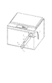
まず、最初に、現像剤補給容器としてのトナー補給容器が装着される現像剤受入れ装置としての電子写真画像形成装置の一例である電子写真複写機の構成について図1に基づいて説明する。
<Image forming apparatus>
First, the configuration of an electrophotographic copying machine as an example of an electrophotographic image forming apparatus as a developer receiving apparatus to which a toner supply container as a developer supply container is mounted will be described with reference to FIG.
同図において、100は電子写真複写機本体(以下装置本体という)である。また、101は原稿であり、原稿台ガラス102の上に置かれる。そして、画像情報に応じた光像が光学部103の複数のミラーMとレンズLnにより、電子写真感光体ドラム104上に結像する。
In the figure,
105〜108は記録媒体(以下、「用紙」という)Pを収容するカセットである。これらカセット105〜108に積載された記録媒体Pのうち、操作部から使用者が入力した情報もしくは原稿101の紙サイズから最適な用紙をカセット105〜108の用紙サイズ情報から選択する。ここで、記録媒体としては、用紙に限定されずに、例えばOHPシート等適宜選択できる。 Reference numerals 105 to 108 denote cassettes for storing recording media (hereinafter referred to as “paper”) P. Among the recording media P loaded in the cassettes 105 to 108, the optimum sheet is selected from the sheet size information of the cassettes 105 to 108 from the information input by the user from the operation unit or the sheet size of the document 101. Here, the recording medium is not limited to paper, and may be selected as appropriate, such as an OHP sheet.
そして、給送分離装置105A〜108Aにより搬送された1枚の用紙Pを、搬送部109を経由してレジストローラ110まで搬送する。その後、レジストローラは、感光ドラム104の回転と、光学部103のスキャンのタイミングを同期させて用紙Pを送出する。
Then, the single sheet P conveyed by the feeding / separating devices 105 </ b> A to 108 </ b> A is conveyed to the
111、112は転写放電器、分離放電器である。転写放電器111は、感光ドラム104上に形成されたトナー像を用紙Pに静電転写するためのものである。そして、分離放電器112は、トナー像が転写された用紙Pをドラム104から分離する際に除電するものである。
この後、搬送部113により搬送された用紙Pは、定着部114において熱と圧により用紙上のトナー像を定着させた後、片面コピーの場合には、排出反転部115を通過し、排出ローラ116により排出トレイ117へ排出される。また、両面コピーの場合には、排出反転部115のフラッパ118の制御により、再給送搬送部119,120を経由してレジストローラ110まで搬送された後、片面コピーの場合と同様の経路をたどって排出トレイ117へ排出される。
After that, the sheet P conveyed by the
また、多重コピーの場合には、用紙Pは排出反転部115を通り、一度排出ローラ116により一部が装置外へ排出される。そして、この後、用紙Pの終端がフラッパ118を通過し、排出ローラ116にまだ挟持されているタイミングでフラッパ118を制御すると共に排出ローラ116を逆回転させることにより、再度装置内へ搬送される。さらにこの後、再給送搬送部119、120を経由してレジストローラ110まで搬送された後、片面コピーの場合と同様の経路をたどって排出トレイ117へ排出される。
In the case of multiple copying, the paper P passes through the
ところで、上記構成の装置本体100において、ドラム104の回りには現像部201、クリーナ部202、一次帯電器203等が配置されている。
Meanwhile, in the apparatus
現像部201は、原稿101の情報を光学部103によりドラム104に形成された静電潜像を現像剤としてのトナーを用いて現像するものである。そして、この現像部201ヘトナーを補給するためのトナー補給容器1が装置本体100に使用者によって着脱可能に設けられている。
The developing
ここで、現像部201は、トナー補給容器1を取り外し可能に装着するトナー受入れ装置7と現像器201aとを有している。現像器201aは、現像ローラ201bと、送り部材201cを有している。トナー補給容器1から補給されたトナーは、送り部材201cにより現像ローラ201bに送られて、この現像ローラ201bにより感光体ドラム104上に形成された静電潜像に供給される。
Here, the developing
なお、クリーナ部202は、感光体ドラム104に残留しているトナーを除去するためのものである。また、一次帯電器203は、感光体ドラム104を帯電するためのものである。
The
また、外装カバーの一部として機能する、トナー補給容器専用の交換用カバー15が設けてあり、使用者がトナー補給容器1の交換を行う際は図1の矢印A方向に交換用カバー15を開けることにより行われる。
Also, a
<トナー補給容器>
次に、現像剤補給容器としてのトナー補給容器1の構成について、図2(a)〜(c)を用いて説明する。
<Toner supply container>
Next, the configuration of the toner supply container 1 as a developer supply container will be described with reference to FIGS.
トナー補給容器1のトナーを収容する収容部としての容器本体1aは中空の略円筒形状を為している。また、容器本体1aの周面上には、容器1の長手方向に沿って延びる略長方形状の排出口としての開口部1bが設けられている。 A container main body 1a as a storage portion for storing toner in the toner supply container 1 has a hollow, substantially cylindrical shape. An opening 1b serving as a substantially rectangular discharge port extending along the longitudinal direction of the container 1 is provided on the peripheral surface of the container body 1a.
トナー補給容器1は、未使用時においては、開口部1bはフィルム部材(フィルムシール)としてのシールフィルム9で密封されている。そして、シールフィルム9は、容器本体に溶着された部分から延出した部分を有しており、この延出した部分は容器本体の長手方向一端側から他端側に向けて折り返されている。トナー補給容器1を後述のトナー受入れ装置7に装着後、ユーザがシールフィルム9の延出部分を掴んで引っ張ることにより、シールフィルム9の開封(引き剥がし)が行われる。その結果、開口部1bが開封される。 When the toner supply container 1 is not used, the opening 1b is sealed with a seal film 9 as a film member (film seal). And the sealing film 9 has a part extended from the part welded to the container main body, and this extended part is return | folded toward the other end side from the longitudinal direction one end side of the container main body. After the toner replenishing container 1 is mounted on a toner receiving device 7 to be described later, the user grasps and pulls the extended portion of the seal film 9, whereby the seal film 9 is opened (stripped). As a result, the opening 1b is opened.
なお、本例では、シールフィルム9を容器本体から引き剥がすことにより開封する構成とされているが、以下のようなシールフィルムでも構わない。 In addition, in this example, it is set as the structure opened by peeling off the sealing film 9 from a container main body, However, The following sealing films may be sufficient.
例えば、シールフィルム9にその長手方向に沿って引き裂きガイド(易引き裂き部)を設け、シールフィルム9をこの引き裂きガイドに沿って引き裂くことにより開封する構成としても構わない。この引き裂きガイドはシールフィルムにレーザー照射を施しその部分のフィルム厚を薄くすることにより形成が可能であるが、他の方法を用いても構わない。 For example, the seal film 9 may be provided with a tear guide (easy tear portion) along the longitudinal direction thereof, and the seal film 9 may be opened by tearing along the tear guide. The tear guide can be formed by irradiating the seal film with laser to reduce the thickness of the film, but other methods may be used.
シールフィルム9は、現像剤補給容器の物流過程においてトナー漏れが発生するのを防止するために設けられている。つまり、シールフィルム9は、現像剤補給容器の物流過程において、ある程度の環境変動(温湿度変動や気圧変動)が生じても、トナー漏れが発生するのを防止するために設けられている。また、シールフィルム9は、現像剤補給容器の物流過程において、現像剤補給容器が振動したり、落下衝撃などによりトナー漏れが発生するのを防止している。 The seal film 9 is provided in order to prevent the occurrence of toner leakage during the distribution process of the developer supply container. That is, the seal film 9 is provided in order to prevent toner leakage even if a certain amount of environmental variation (temperature / humidity variation or atmospheric pressure variation) occurs in the distribution process of the developer supply container. Further, the seal film 9 prevents the developer supply container from vibrating or causing toner leakage due to a drop impact or the like during the distribution process of the developer supply container.
しかしながら、シールフィルム9を容器本体に取り付けていても、現像剤補給容器の物流過程において、環境変動が多大な場合や落下の衝撃が激しいような場合にはトナー漏れが生じてしまうこともある。 However, even if the seal film 9 is attached to the container main body, toner leakage may occur in the course of distribution of the developer replenishing container when the environmental change is great or the impact of dropping is severe.
つまり、本例でのシールフィルムの役割は現像剤補給容器の物流時において想定できる範囲内において、トナー漏れを防止することである。即ち、ここでは、現像剤補給容器の物流時において想定できる範囲内においてトナー漏れを防止することを「トナー漏れを防止する」と言うことにする。 In other words, the role of the seal film in this example is to prevent toner leakage within a range that can be assumed during distribution of the developer supply container. That is, here, preventing toner leakage within a range that can be assumed during distribution of the developer supply container is referred to as “preventing toner leakage”.
なお、シールフィルム9を容器12に取り付ける方法としては、熱板溶着、インパルスシール、超音波溶着、高周波溶着、粘着剤やホットメルト接着剤、両面テープ等による取り付け方法を採用することが可能である。本例では熱板溶着による取り付け方法を採用している。 In addition, as a method of attaching the seal film 9 to the container 12, it is possible to employ an attachment method using hot plate welding, impulse seal, ultrasonic welding, high frequency welding, adhesive, hot melt adhesive, double-sided tape, or the like. . In this example, an attachment method by hot plate welding is adopted.
また、容器本体1aの周面上には、弾性部材(弾性シール)としてのシール部材10が開口部1bを囲むように設けられている。このシール部材10は、トナー補給時に開口部1bからトナー補給容器1とトナー受入れ装置7との隙間にトナーが侵入してしまうのを実質的に防止するために設けられている。つまり、このシール部材10は、容器本体1aと容器シャッタ間にて所定量圧縮されるためトナー補給の橋渡しの役割を果たすことにより上述した隙間へのトナーの侵入を防止している。なお、ここでは、トナーの侵入を完全に防止する場合だけでなく、実用上問題ないレベルであれば僅かにトナーが上記隙間に侵入してしまう場合も含めて「トナーの侵入を防止する」と言うことにする。
A
なお、このシール部材10は、シールフィルム9を剥がした後に作用するものであり、そして、トナー補給容器1とトナー受入れ装置7との隙間を極力埋めるためには開口部1bの周縁に沿って設けるのが好ましい。
The
従って、図2(c)に示すように、シール部材10を容器本体1aに取り付け固定した後、シール部材10の外側にシール部材10を取り囲むようにシールフィルム9を取り付けるのが好ましい。
Therefore, as shown in FIG. 2C, it is preferable that the seal member 9 is attached to the outside of the
そこで、本例では、シールフィルム9の溶着パターン9a(シールフィルム9の容器本体への溶着部)は、シール部材10の周囲を覆うように配置されている。このような構成とすることにより、シールフィルム9を引き剥がす際にシール部材10を傷めてしまうのを防止することができる。その結果、シール部材10によるトナー補給時のシール性が低下してしまうのを防止することができる。また、シールフィルム9はシール部材10の表面を保護する機能も併せ持っており、本例の構成であれば、トナー補給前の時点でシール部材が劣化してしまうのを抑制することができる。
Therefore, in this example, the welding pattern 9a of the seal film 9 (the welded portion of the seal film 9 to the container body) is disposed so as to cover the periphery of the
また、シール部材10の材質としては、トナー受入れ装置7の内壁との摺擦圧を考慮すると低密度なものであることが好ましい。具体的には、低発泡ポリウレタン等の発泡体、羊毛や絹等の動物性繊維や、綿、麻等の植物性繊維、あるいはナイロン、ポリエステル、アクリル等の合成繊維等がベースとなる織布もしくは不織布、等が挙げられる。圧縮性を考慮すると発泡体を用いるのが好ましく、本例では低発泡ポリウレタンを用いている。
Further, the material of the
本例では、トナー補給容器を装置本体から取り出した後、容器本体1a内に残留したトナーが漏れてしまうのを抑制するため容器シャッタ3を設けている。具体的には、図2(a)に示すように、開口部1bを覆うように、シールフィルム9の上からトナー補給容器1の外周面に沿った曲率を有した形状の容器シャッタ3が設けられている。この容器シャッタ3は、容器本体1aの長手方向の両端側に設けられたガイド部材1dと係合しており、トナー補給容器1の外周面に沿って周方向にスライド自在に構成されている。
In this example, the
また、容器本体1aの長手方向の一端面にはトナー充填口1cが設けられており、トナー充填後、このトナー充填口は不図示のキャップ等により封止される。 Further, a toner filling port 1c is provided on one end surface in the longitudinal direction of the container body 1a. After the toner is filled, the toner filling port is sealed with a cap (not shown) or the like.
また、トナー補給容器1には、ユーザがトナー補給容器1の着脱操作時に掴むための把手としてのハンドル2が設けられており、ハンドル2はトナー補給容器1の長手方向の一端に固定されて設けられている。なお、このハンドルの形状は、このような形態に限らず、トナー補給容器の着脱操作時に使用でき、そしてトナー補給容器を回動操作させるにあたり十分な機能を有していれば、どのような形状であっても構わない。 Further, the toner supply container 1 is provided with a handle 2 as a handle for a user to hold when the toner supply container 1 is attached or detached. The handle 2 is fixed to one end in the longitudinal direction of the toner supply container 1. It has been. The shape of the handle is not limited to such a shape, and any shape can be used as long as the handle can be used for attaching / detaching the toner supply container and has a function sufficient for rotating the toner supply container. It does not matter.
また、容器本体1aには搬送部材4が内装されている。この搬送部材4は、後述のカップリング5と同軸的に設けられた回転軸部と、この回転軸部に取り付けられ容器本体1aの内面と摺動自在な攪拌翼部と、から構成されている。この攪拌翼部は、容器内のトナーを開口部1bに向けてトナーを搬送する機能の他に、トナーの攪拌を行う機能も有している。
In addition, a transport member 4 is internally provided in the container body 1a. The conveying member 4 is composed of a rotating shaft portion provided coaxially with a
そして、容器本体1aの長手方向他端面には搬送部材4と駆動連結関係にあるカップリング5が設けられている。本例では、搬送部材の回転軸部とカップリングとが樹脂にて一体成型されたものを用いている。
And the
そして、トナー補給容器1が画像形成装置本体にセットされてトナー排出可能な状態のとき、装置本体のカップリング機構とカップリング自在に設けられたカップリング5が回転駆動力を受ける構成とされている。
When the toner supply container 1 is set in the image forming apparatus main body and the toner can be discharged, the
カップリング5から回転駆動力を伝達された搬送部材4は、装置本体に実質的に回転不可に固定された状態にあるトナー補給容器1に対して相対回転し、トナー補給容器内のトナーを攪拌しながら開口部1bに向けて搬送・排出する構成になっている。
The conveying member 4 to which the rotational driving force is transmitted from the
なお、この時、トナー補給容器を固定状態にするのではなく、トナー補給容器の搬送部材と共に連れ回る方向への回動を装置本体により少なくとも規制する構成であれば構わない。 At this time, the toner replenishing container may not be fixed, but may be configured to restrict at least the rotation of the toner replenishing container in the direction of rotation with the conveying member by the apparatus main body.
<トナー受入れ装置>
次に、画像形成装置本体側の現像剤受入れ装置としてのトナー受入れ装置7の構成について、図3(a)〜(c)を用いて説明する。
<Toner receiving device>
Next, the configuration of the toner receiving device 7 as the developer receiving device on the image forming apparatus main body side will be described with reference to FIGS.
トナー受入れ装置7には、トナー補給容器1を取り外し可能に装着する装着部(収納空間)7aと、トナー補給容器1から排出されたトナーを画像形成装置本体内へと受入れる受入れ口7bが設けられている。
The toner receiving device 7 is provided with a mounting portion (storage space) 7a for detachably mounting the toner supply container 1 and a receiving
更に、トナー受入れ装置7には、受入れ口7bを開閉自在に封止する装置シャッタ8が設けられている。装置シャッタ8は、トナー補給容器1及び装着部7aの周面形状に沿った曲率形状を為し、装着部7a下縁に設けられたガイド部材(不図示)と係合している。このような構成とすることで、装置シャッタは円周方向に沿ってスライド移動し、受入れ口7bを開閉できるようになっている(図3(b)⇒図3(c))。
Further, the toner receiving device 7 is provided with a
この装置シャッタ8は、トナー補給容器1を装着部7aに装着していない時は、図3(b)に示すように、装置シャッタ8の端部(図3(b)では上側端部)近傍がトナー受入れ装置7に設けられたストッパー7cに突き当たることでそれ以上の移動が制限される。このように、装置シャッタ8により受入れ口7bを閉鎖することにより、トナー補給容器が装着されていない時に画像形成装置本体側から装着部7a側へトナーが逆流するのを防止している。
When the toner supply container 1 is not mounted on the mounting portion 7a, the
また、装置シャッタ8には、図3(b)、(c)に示すように、トナー補給容器1の係合部6と係合する係合部8aが設けられている。
Further, as shown in FIGS. 3B and 3C, the
トナー補給容器1の係合部6と装置シャッタの係合部8aの係合は、トナー補給容器1をトナー受入れ装置7に挿入装着した装着位置(トナー補給容器の取り出しを許容する位置)からトナー補給位置へ所定角度回動させるセット操作時に行われる。 The engaging portion 6 of the toner replenishing container 1 and the engaging portion 8a of the apparatus shutter are engaged with each other from the mounting position where the toner replenishing container 1 is inserted and mounted in the toner receiving device 7 (the position where the toner replenishing container can be taken out). This is performed at the time of a setting operation for rotating the supply position by a predetermined angle.
<トナー補給容器のセット/取り出し操作>
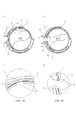
次に、トナー補給容器1のセット/取り出し操作について、図4、図5(a)〜(d)を用いて説明する。なお、図5(b)は図5(a)の、図5(d)は図5(c)の、開口部1b周りを拡大した図である。
<Setting / removing toner supply container>
Next, the setting / removing operation of the toner supply container 1 will be described with reference to FIGS. 4 and 5A to 5D. 5B is an enlarged view of the periphery of the opening 1b in FIG. 5A, and FIG. 5D is a view in FIG. 5C.
まず、ユーザがハンドル2を掴んでトナー補給容器1のトナー受入れ装置への挿入装着操作が行われる。具体的には、トナー補給容器1はトナー受入れ装置7へ矢印A方向から装着される(図4)。 First, the user grasps the handle 2 to perform an operation for inserting and attaching the toner supply container 1 to the toner receiving device. Specifically, the toner supply container 1 is attached to the toner receiving device 7 from the direction of arrow A (FIG. 4).
このとき、上方を向いたトナー補給容器1の開口部1bはシールフィルム9により密閉されており、容器シャッタ3は閉じ位置にある(図5(b))。
At this time, the opening 1b of the toner supply container 1 facing upward is sealed by the sealing film 9, and the
つまり、トナー補給容器1の開口部1bは装置シャッタ8によって封止されている受入れ口7bから回転方向に離れた位置にある。また、トナー補給容器1の係合部6も装置シャッタ8の係合部8aから回転方向に離れた位置にある(図5(a))。
That is, the opening 1b of the toner supply container 1 is located away from the receiving
次に、ユーザがシールフィルム9の延出した部分の端部を矢印C方向(図2(a))へ引っ張ることによりシールフィルムの引き剥がしが行われる。 Next, the user pulls off the seal film 9 by pulling the end of the extended portion of the seal film 9 in the direction of arrow C (FIG. 2A).
その後、ユーザがハンドル2を掴んで、トナー補給容器1をトナー充填口1c側から見て反時計回り方向(図5(a)のX方向)に回動させる。 Thereafter, the user grasps the handle 2 and rotates the toner supply container 1 in the counterclockwise direction (X direction in FIG. 5A) when viewed from the toner filling port 1c side.
なお、容器シャッタ3は、トナー補給容器1を回動させた際に、ストッパー7c、7dにより周方向への回転移動が規制される構成となっている。
The
従って、トナー補給容器1をX方向へ回動させた際、トナー補給容器1の回動当初は容器シャッタ3とトナー補給容器が共に連れ回り、その後、上述のストッパー7cに容器シャッタ3が突き当たり連れ回りが規制されることになる。
Therefore, when the toner replenishing container 1 is rotated in the X direction, the
更にトナー補給容器1の同方向への回動が進むと、トナー補給容器1の係合部6が装置シャッタ8の係合部8aとの係合が行われる。そして、更に回転させると、装置シャッタ8は、係合部6に押されることによりトナー補給容器1と連動して回転移動し、受入れ口7bが開封される(図5(c)、(d))。
When the toner supply container 1 further rotates in the same direction, the engaging portion 6 of the toner supply container 1 is engaged with the engaging portion 8a of the
このように、受入れ口7bと開口部1bとが連通した状態のとき、画像形成装置本体側のカップリング機構からトナー補給容器1のカップリング5が駆動力を受けこれを搬送部材4へ伝達する構成とされている。その結果、トナー補給容器からトナー受入れ装置へトナー補給が行われることになる。その際、シール部材10がトナー補給容器1とトナー受入れ装置7の内壁との隙間を埋めているため、受入れ口7bや開口部1bからこの隙間へトナーが侵入するのを防止することが可能となる。
As described above, when the receiving
トナー補給終了後、ユーザがハンドル2を掴んでトナー充填口1c側から見て時計回り方向(図5(c)のY方向)にトナー補給容器1を回動させる。すると、装置シャッタ8の係合部8aはトナー補給容器1の係合部6との係合状態が維持されているため、装置シャッタ8は係合部6により引き上げられてトナー補給容器1と連動して共に回転移動する。
After completion of toner supply, the user grasps the handle 2 and rotates the toner supply container 1 in the clockwise direction (Y direction in FIG. 5C) as viewed from the toner filling port 1c side. Then, since the engaging portion 8a of the
更にトナー補給容器1を回動させると、装置シャッタ8はストッパー7cに規制されてそれ以上の回転が行われないので、係合部6は装置シャッタ8の係合部8aとの係合が解除される。
When the toner supply container 1 is further rotated, the
更にトナー補給容器1を回動させると、トナー受入れ装置7によって回転方向への移動が規制されている容器シャッタ3に開口部1b及びシール部材10が遮蔽される状態となり、最終的には図5(a)の状態まで戻る。
When the toner replenishing container 1 is further rotated, the opening 1b and the
そして、最後にユーザーがトナー補給容器1をトナー受入れ装置7から引き出すことにより、一連の再封動作並びにトナー補給容器の取り出し操作が完了する。 Finally, when the user pulls out the toner supply container 1 from the toner receiving device 7, a series of resealing operations and a toner supply container take-out operation are completed.
なお、本例では、トナー補給容器1のトナー受入れ装置7への装着方向を装置正面方向からとしたが、これに限定されるものではなく、例えばトナー補給容器1をトナー受入れ装置7に対し上面方向から着脱する構成であっても構わない。 In this example, the mounting direction of the toner replenishing container 1 to the toner receiving device 7 is from the front side of the apparatus. However, the present invention is not limited to this. It may be configured to be detached from the direction.
また本実施形態では、トナー受入れ装置7の装着部の側方に設けられた受入れ口7bに対し開口部1bが略水平方向を向いたとき連通するような構成とされているが、このような構成に限らない。
Further, in the present embodiment, the configuration is such that the opening 1b communicates with the receiving
更に、トナー補給容器1のセット操作時の回転移動方向も上述の例だけに限られない。例えば、開口部1bが下向きの状態でトナー補給容器1を装着し、その後、トナー補給容器1を開封のため上述の例とは逆方向へ回転移動させ、再封のためやはり上述の例とは逆方向に回転移動させるような構成であっても構わない。 Further, the rotational movement direction during the setting operation of the toner supply container 1 is not limited to the above example. For example, the toner replenishing container 1 is mounted with the opening 1b facing downward, and then the toner replenishing container 1 is rotated in the opposite direction to the above-described example for opening, and again for re-sealing the above-described example. It may be configured to rotate and move in the reverse direction.
以上説明した構成では、物流時等において開口部1bからのトナー漏れは発生しなかった。またその後、トナー補給容器1のセット/取り出し操作を1回行った結果、トナー補給容器1やトナー受入れ装置7のトナー汚れは殆ど確認されなかった。更に、同操作を繰り返し20回行っても、トナーによる汚れレベルは悪化しなかった。 In the configuration described above, toner leakage from the opening 1b did not occur during distribution. Thereafter, as a result of performing the setting / removal operation of the toner replenishing container 1 once, the toner replenishing container 1 and the toner receiving device 7 were hardly confirmed to be contaminated with toner. Furthermore, even when the same operation was repeated 20 times, the level of contamination with toner did not deteriorate.
以上のように、本例の構成であれば、物流時とトナー補給時の双方においてトナーによる汚れが生じるのを抑制することができる。従って、トナー補給容器に付着したトナーによりユーザが汚れてしまうのを抑制することができる。 As described above, according to the configuration of this example, it is possible to suppress the occurrence of contamination due to toner both during distribution and during toner supply. Therefore, the user can be prevented from being contaminated by the toner adhering to the toner supply container.
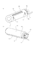
次に図6を用いて本例のトナー補給容器について説明する。なお、本例では、後述するトナー補給容器の一部の構成を除き、上述した実施例1と同様な構成とされている。また、本例では、実施例1にて説明した構成と同様の機能を奏するものには同符号を付すことで詳細な説明を省略する。 Next, the toner supply container of this example will be described with reference to FIG. In this example, the configuration is the same as that of the first embodiment described above except for a part of the configuration of the toner supply container described later. Further, in this example, the same reference numerals are given to components having the same functions as those described in the first embodiment, and detailed description thereof is omitted.
本例では、開口部1bを開閉する構成が実施例1とは異なっている。具体的には、図6(a)に示すように、トナー補給容器は、トナーを収容する収容部としての内筒300と、この内筒300の周りを回転可能に設けられた外筒400(シャッタとも呼ぶ)とにより構成された2重筒状とされている。
In the present example, the configuration for opening and closing the opening 1b is different from that of the first example. Specifically, as shown in FIG. 6A, the toner replenishing container includes an
図6(b)に示すように、この内筒300には実施例1と同様な開口部1bが形成されており、この開口部1bの周囲には実施例1と同様にシール部材10が取り付けられている。さらに、内筒300には、実施例1と同様に、シール部材10を覆うようにシールフィルム9が取り付けられている。
As shown in FIG. 6B, an opening 1b similar to that in the first embodiment is formed in the
また、トナー補給容器がトナー受入れ装置に装着された後、内筒300がトナー受入れ装置に対し回転不可となるように、トナー受入れ装置に設けられた被係合部と係合する係合部302が内筒に設けられている。また、内筒の周面にはガイド突起301が設けられている。
Further, after the toner supply container is mounted on the toner receiving device, the engaging
一方、外筒400には内筒の開口部1bとの連通が可能な連通口401が形成されている。さらに、外筒400の周面には内筒のガイド突起301にガイドされるガイド穴402が形成されており、外筒400が内筒300に対して回転するとき両者が回転軸線方向にずれてしまうことのないように構成されている。
On the other hand, the
このような構成において、トナー補給容器がトナー受入れ装置に装着されると、内筒の係合部302はトナー受入れ装置の被係合部との係合が可能となる。このとき、内筒300の開口部1bと外筒400の連通口401の位置は約90°ずれた状態となっている。また、このとき、シールフィルム9は操作者によって引き剥がされる。
In such a configuration, when the toner supply container is attached to the toner receiving device, the engaging
その後、操作者が、トナー受入れ装置に回転不可に固定された状態の内筒300に対して、外筒400を図示矢印のセット方向へ所定角度(本例では約90°)回転させると、内筒の開口部1bの位置と外筒の連通口401の位置が合致する。つまり、外筒と内筒の2つの開口が連通した状態となり、トナー補給が可能な状態となる。
Thereafter, when the operator rotates the
一方、トナー補給容器を取り出す際は、上述とは逆の手順により行うことができる。つまり、操作者が外筒400をセット方向とは逆方向(本例では約90°)に所定角度回動させ、内筒の開口部1bを閉鎖させる。その結果、操作者がトナー補給容器をトナー受入れ装置から取り出すことが可能な状態となる。
On the other hand, when taking out the toner replenishing container, it can be carried out by a procedure reverse to the above. That is, the operator rotates the
このように、本例では、実施例1での容器シャッタの役割をこの外筒が担っており、また、容器シャッタの開封がトナー収容部である内筒ではなく外筒を回転させることにより行われる。 As described above, in this example, the outer cylinder plays the role of the container shutter in the first embodiment, and the container shutter is opened by rotating the outer cylinder instead of the inner cylinder as the toner accommodating portion. Is called.
このような実施例2の構成であっても、実施例1と同様な効果を得ることができる。 Even with the configuration of the second embodiment, the same effect as that of the first embodiment can be obtained.
なお、本例では、シール部材10を内筒に設けた場合について説明したが、例えば、シール部材10を外筒の内面側に設ける構成としても構わない。この場合、シール部材10は連通口を取り囲むように外筒の内面側に設けられ、上述の例と同様に、内筒と外筒間にトナーが漏れ出てしまうのを防止することができる。また、この場合、外筒により開口部1bを閉鎖している時、つまり、トナー補給容器の物流時において内筒の開口部1bを取り囲むこととなるような外筒の内面の位置にシール部材10を設けても構わない。
In this example, the case where the
なお、前述した実施例1、2では、現像剤補給容器の容器本体の形状として、略円筒状のものを例示したが、本発明はこれに限定されるものではなく、多角形状など現像剤を収納できる形状であればその他の形状であっても良い。 In the first and second embodiments described above, the shape of the container body of the developer supply container is exemplified as a substantially cylindrical shape, but the present invention is not limited to this, and a developer such as a polygonal shape is used. Other shapes may be used as long as they can be stored.
また、前述した実施例1、2では、画像形成装置(現像剤受入れ装置)として複写機を例に説明したが、プリンタ、ファクシミリ装置等の画像形成装置や、これらの機能を複数備えた複合機等の画像形成装置でも構わない。 In the above-described first and second embodiments, a copying machine has been described as an example of an image forming apparatus (developer receiving apparatus). However, an image forming apparatus such as a printer or a facsimile machine, or a multi-function machine having a plurality of these functions. Such an image forming apparatus may be used.
また、前述した実施例1、2では、単色画像(白黒画像)を形成する画像形成装置(現像剤受入れ装置)を例に説明したが、このような画像形成装置だけに限られない。 In the first and second embodiments, the image forming apparatus (developer receiving apparatus) that forms a single color image (black and white image) has been described as an example. However, the present invention is not limited to such an image forming apparatus.
例えば、記録材担持体に担持された記録材に感光体から各色の現像剤像を順次重ねて転写するカラー画像形成装置であっても構わない。また、中間転写体に感光体から各色の現像剤像を順次重ねて転写し、その後、記録材に一括して転写するカラー画像形成装置であっても構わない。 For example, a color image forming apparatus that sequentially superimposes and transfers the developer images of the respective colors from the photoreceptor onto the recording material carried on the recording material carrier may be used. Further, a color image forming apparatus may be used in which the developer images of the respective colors are sequentially superimposed and transferred from the photosensitive member to the intermediate transfer member and then transferred to the recording material in a lump.
以上のような種々の画像形成装置であっても、本発明の現像剤補給容器を適用することが可能である。 The developer supply container of the present invention can also be applied to various image forming apparatuses as described above.
また、本発明の現像剤補給容器は、画像形成装置に着脱自在に設けられた現像剤受入れ装置としてのプロセスカートリッジに対し現像剤を補給する構成であっても構わない。つまり、現像剤補給容器をプロセスカートリッジに対し着脱自在とする構成である。 The developer supply container of the present invention may be configured to supply the developer to a process cartridge as a developer receiving device that is detachably provided in the image forming apparatus. In other words, the developer supply container is detachable from the process cartridge.
なお、このプロセスカートリッジは現像器201aを少なくとも有する構成とされ、現像器の他に像担持体としての電子写真感光体104を一体に有する構成としても構わない。さらに、この感光体104に作用する帯電器203、クリーナ202のうちの少なくとも1つの画像形成機器を一体に有する構成であっても構わない。
This process cartridge is configured to have at least the developing device 201a, and may be configured to integrally include an electrophotographic
以上において本発明を適用可能な実施例について説明したが、本発明の思想の範囲内において種々の構成を公知の他の構成に変更可能であることは言うまでもない。 Although the embodiments to which the present invention can be applied have been described above, it goes without saying that various configurations can be changed to other known configurations within the scope of the idea of the present invention.
次に、比較例について説明する。 Next, a comparative example will be described.
<比較例1>
比較例1では、シールフィルム9を設けない構成とした。その他の構成は、実施例と同じ構成とした。
<Comparative Example 1>
In Comparative Example 1, the seal film 9 was not provided. Other configurations were the same as those in the example.
本構成では物流時等において開口部1bからトナーが漏れてトナー補給容器1を汚してしまったため、その後、トナー補給容器1のセット/取り出し操作を1回行っただけでトナー受入れ装置7も非常に汚れてしまった。 In this configuration, since toner leaks from the opening 1b during distribution and the toner supply container 1 is soiled, the toner receiving device 7 is also very simple after only one set / removal operation of the toner supply container 1 is performed. Dirty.
従って上記結果から、実施例に係るトナー補給容器の構成の効果が確認された。 Therefore, from the above result, the effect of the configuration of the toner supply container according to the example was confirmed.
<比較例2>
比較例2では、シール部材10をトナー受入れ装置7に設けた。その他の構成は、実施例と同じ構成とした。
<Comparative example 2>
In Comparative Example 2, the
本構成にてトナー補給容器1のセット/取り出し操作を1回行った結果、トナー補給容器1やトナー受入れ装置7のトナーの汚れレベルは実施例と殆ど変わらなかった。しかしながら、同操作を繰り返し20回行った結果、シール部材10に蓄積されたトナーがトナー補給容器1に転移したことで、汚れレベルが悪化してしまった。
As a result of performing the setting / removal operation of the toner replenishing container 1 once in this configuration, the level of toner contamination in the toner replenishing container 1 and the toner receiving device 7 is almost the same as in the example. However, the same operation was repeated 20 times, and as a result, the toner accumulated in the
従って上記結果からも、実施例に係るトナー補給容器の構成の効果が確認された。 Therefore, also from the above result, the effect of the configuration of the toner supply container according to the example was confirmed.
1 トナー補給容器(現像剤補給容器)
1a 容器本体
1b 開口部(排出口)
1c トナー充填口
1d ガイド部材
2 ハンドル
3 容器シャッタ
4 搬送部材
5 カップリング
6 係合部
9 シールフィルム
9a シールパターン
10 シール部材
7 トナー受入れ装置(現像剤受入れ装置)
7a 装着部
7b 受入れ口(受入れ口)
7c ストッパー
8 装置シャッタ
8a 係合部
1 Toner supply container (Developer supply container)
1a Container body 1b Opening (discharge port)
1c Toner filling port 1d Guide member 2
Claims (4)
現像剤を収容する収容部と、
前記収容部の周面部に設けられ現像剤を排出する排出口と、
前記排出口を取り囲むように前記排出口の周縁に取り付けられ前記補給位置にある前記収容部と前記現像剤受入れ装置との隙間への現像剤の侵入を防止する弾性部材と、
前記収容部の周面部への溶着部が前記弾性部材を取り囲むように溶着固定され前記排出口からの現像剤漏れを防止するフィルム部材と、
前記フィルム部材の上から前記弾性部材を前記収容部との間で所定量圧縮するように設けられ、前記装着位置にある前記収容部から前記フィルム部材の少なくとも一部が除去されて封止が解かれた後、前記収容部の回動動作に伴い前記排出口を開閉するシャッタと、
を有することを特徴とする現像剤補給容器。 A developer supply container detachably attached to the developer receiving apparatus, wherein the developer supply container is set by a setting operation that involves rotation from a mounting position allowing removal of the developer supply container to a supply position.
An accommodating portion for accommodating the developer;
A discharge port for discharging the developer provided in the peripheral surface portion of the housing portion;
An elastic member that is attached to the periphery of the discharge port so as to surround the discharge port, and prevents the developer from entering the gap between the housing portion at the replenishment position and the developer receiving device;
A film member that is welded and fixed so that a welded portion to the peripheral surface portion of the housing portion surrounds the elastic member, and prevents developer leakage from the discharge port;
The elastic member is provided so as to compress a predetermined amount between the film member and the housing portion, and at least a part of the film member is removed from the housing portion at the mounting position to release the sealing. And a shutter that opens and closes the discharge port in accordance with the rotation operation of the housing portion,
A developer supply container characterized by comprising:
Priority Applications (1)
| Application Number | Priority Date | Filing Date | Title |
|---|---|---|---|
| JP2006262851A JP4347331B2 (en) | 2005-11-08 | 2006-09-27 | Developer supply container |
Applications Claiming Priority (2)
| Application Number | Priority Date | Filing Date | Title |
|---|---|---|---|
| JP2005323691 | 2005-11-08 | ||
| JP2006262851A JP4347331B2 (en) | 2005-11-08 | 2006-09-27 | Developer supply container |
Publications (2)
| Publication Number | Publication Date |
|---|---|
| JP2007156427A JP2007156427A (en) | 2007-06-21 |
| JP4347331B2 true JP4347331B2 (en) | 2009-10-21 |
Family
ID=37625998
Family Applications (1)
| Application Number | Title | Priority Date | Filing Date |
|---|---|---|---|
| JP2006262851A Expired - Fee Related JP4347331B2 (en) | 2005-11-08 | 2006-09-27 | Developer supply container |
Country Status (6)
| Country | Link |
|---|---|
| US (2) | US7937018B2 (en) |
| EP (1) | EP1783563B1 (en) |
| JP (1) | JP4347331B2 (en) |
| KR (2) | KR100882982B1 (en) |
| CN (1) | CN100590541C (en) |
| DE (1) | DE602006016214D1 (en) |
Families Citing this family (17)
| Publication number | Priority date | Publication date | Assignee | Title |
|---|---|---|---|---|
| KR101582433B1 (en) * | 2005-03-04 | 2016-01-11 | 캐논 가부시끼가이샤 | Developer supply container and developer supplying system |
| US8023864B2 (en) * | 2007-04-27 | 2011-09-20 | Brother Kogyo Kabushiki Kaisha | Toner cartridge and developing apparatus |
| AU2011202765B2 (en) * | 2007-05-29 | 2012-05-24 | Fujifilm Business Innovation Corp. | Image forming apparatus and detachable body |
| JP5092544B2 (en) * | 2007-05-29 | 2012-12-05 | 富士ゼロックス株式会社 | Image forming apparatus |
| JP4525782B2 (en) * | 2008-03-24 | 2010-08-18 | 富士ゼロックス株式会社 | Developer container and image forming apparatus |
| JP4553027B2 (en) * | 2008-03-27 | 2010-09-29 | ブラザー工業株式会社 | Developer cartridge, developing device, and image forming apparatus |
| JP5078847B2 (en) * | 2008-11-13 | 2012-11-21 | キヤノン株式会社 | Developer supply container |
| JP5106372B2 (en) * | 2008-12-17 | 2012-12-26 | キヤノン株式会社 | Developer supply container |
| JP4894868B2 (en) | 2009-02-23 | 2012-03-14 | 富士ゼロックス株式会社 | Container, supply device, and image forming apparatus |
| US8380102B2 (en) * | 2010-05-28 | 2013-02-19 | Lexmark International, Inc. | Tubular skiving seal for a rotary toner metering mechanism |
| KR101784850B1 (en) * | 2010-06-11 | 2017-11-06 | 가부시키가이샤 리코 | Information storage system removably installable in image forming apparatus, removable device, and toner container |
| WO2012133726A1 (en) * | 2011-03-31 | 2012-10-04 | Ricoh Company, Ltd. | Powder material container and image forming apparatus provided therewith, and powder material replenishing method |
| JP6083954B2 (en) | 2011-06-06 | 2017-02-22 | キヤノン株式会社 | Developer supply container and developer supply system |
| US8666277B2 (en) * | 2012-05-02 | 2014-03-04 | General Plastic Industrial Co., Ltd. | Developer supply container |
| JP6116253B2 (en) * | 2013-01-11 | 2017-04-19 | キヤノン株式会社 | Developer storage unit, developing device, process cartridge, and image forming apparatus including the same |
| JP2016206523A (en) * | 2015-04-27 | 2016-12-08 | 京セラドキュメントソリューションズ株式会社 | Image forming apparatus having developer containing container, developer containing container mounted on image forming apparatus |
| JP6950655B2 (en) | 2018-09-28 | 2021-10-13 | ブラザー工業株式会社 | Image forming device |
Family Cites Families (21)
| Publication number | Priority date | Publication date | Assignee | Title |
|---|---|---|---|---|
| JPS60147767A (en) | 1984-01-11 | 1985-08-03 | Konishiroku Photo Ind Co Ltd | Case of powdery particle |
| SE459724B (en) | 1987-12-08 | 1989-07-31 | Larson Prod Ab Ove | SETTING AND DEVICE MAKING A LATENT ELECTRIC CHARGING PATTERN |
| JP2541650B2 (en) * | 1989-01-27 | 1996-10-09 | キヤノン株式会社 | Developer supply container |
| JP3308671B2 (en) * | 1993-08-10 | 2002-07-29 | キヤノン株式会社 | Seal member, developer container, and process cartridge |
| JP2987083B2 (en) | 1994-10-21 | 1999-12-06 | 株式会社リコー | Toner cartridge |
| JPH1048938A (en) | 1996-04-29 | 1998-02-20 | Brother Ind Ltd | Toner storage device, toner box, and toner supply method |
| JP3445069B2 (en) * | 1996-07-24 | 2003-09-08 | キヤノン株式会社 | Developing unit, process cartridge, and image forming apparatus |
| JP3883742B2 (en) * | 1999-06-24 | 2007-02-21 | 株式会社リコー | container |
| JP3602008B2 (en) | 1999-07-30 | 2004-12-15 | 株式会社沖データ | Toner cartridge and manufacturing method thereof |
| KR100718442B1 (en) | 2000-07-06 | 2007-05-14 | 한국후지제록스 주식회사 | Toner cartridges for image development |
| ATE453137T1 (en) | 2001-02-19 | 2010-01-15 | Canon Kk | TONER SUPPLY TANK AND TONER SUPPLY SYSTEM |
| US6990301B2 (en) | 2001-02-19 | 2006-01-24 | Canon Kabushiki Kaisha | Sealing member, toner accommodating container and image forming apparatus |
| JP3987324B2 (en) * | 2001-11-16 | 2007-10-10 | 株式会社白崎コーポレーション | Developer container seal |
| JP2003156927A (en) | 2001-11-21 | 2003-05-30 | Canon Inc | Toner supply container and toner stirring blade |
| JP4208521B2 (en) | 2002-08-26 | 2009-01-14 | キヤノン株式会社 | Developer supply container |
| CN2630903Y (en) * | 2003-03-18 | 2004-08-04 | 珠海天威飞马打印耗材有限公司 | Carbon dust box |
| JP2004317995A (en) | 2003-04-21 | 2004-11-11 | Canon Inc | Toner seal member and process cartridge |
| JP4343625B2 (en) | 2003-08-29 | 2009-10-14 | キヤノン株式会社 | Developer supply container |
| JP4693393B2 (en) | 2003-11-19 | 2011-06-01 | キヤノン株式会社 | Developer supply device |
| JP2005274862A (en) | 2004-03-24 | 2005-10-06 | Canon Inc | Developer supply container |
| US7450890B2 (en) | 2004-11-12 | 2008-11-11 | Canon Kabushiki Kaisha | Developer supply container having a shutter cleaning feature |
-
2006
- 2006-09-27 JP JP2006262851A patent/JP4347331B2/en not_active Expired - Fee Related
- 2006-11-01 US US11/555,399 patent/US7937018B2/en not_active Expired - Fee Related
- 2006-11-07 DE DE602006016214T patent/DE602006016214D1/en active Active
- 2006-11-07 KR KR1020060109193A patent/KR100882982B1/en not_active Expired - Fee Related
- 2006-11-07 EP EP06123622A patent/EP1783563B1/en not_active Not-in-force
- 2006-11-08 CN CN200610143966A patent/CN100590541C/en not_active Expired - Fee Related
-
2008
- 2008-11-12 KR KR1020080112425A patent/KR20080103946A/en not_active Withdrawn
-
2011
- 2011-03-21 US US13/052,604 patent/US8718509B2/en not_active Expired - Fee Related
Also Published As
| Publication number | Publication date |
|---|---|
| JP2007156427A (en) | 2007-06-21 |
| KR20080103946A (en) | 2008-11-28 |
| US7937018B2 (en) | 2011-05-03 |
| KR20070049573A (en) | 2007-05-11 |
| US20070104505A1 (en) | 2007-05-10 |
| US8718509B2 (en) | 2014-05-06 |
| EP1783563A1 (en) | 2007-05-09 |
| CN100590541C (en) | 2010-02-17 |
| EP1783563B1 (en) | 2010-08-18 |
| DE602006016214D1 (en) | 2010-09-30 |
| KR100882982B1 (en) | 2009-02-12 |
| CN1963687A (en) | 2007-05-16 |
| US20110200357A1 (en) | 2011-08-18 |
Similar Documents
| Publication | Publication Date | Title |
|---|---|---|
| US8718509B2 (en) | Developer supply container | |
| JP5092544B2 (en) | Image forming apparatus | |
| US7242893B2 (en) | Developer supply container | |
| JP4693393B2 (en) | Developer supply device | |
| KR100767135B1 (en) | Developer supply container | |
| US8155569B2 (en) | Toner cartridge and image forming apparatus | |
| JP2006323082A (en) | Developer supply container | |
| JP4343622B2 (en) | Developer supply container | |
| JP5408402B2 (en) | Image forming apparatus | |
| JP4290155B2 (en) | Developer supply container | |
| US6122458A (en) | Replaceable developer supplying device and replaceable imaging cartridge for an image forming device | |
| JP4769465B2 (en) | Powder container and image forming apparatus | |
| JP2003280347A (en) | Developer supply container and image forming apparatus | |
| JPH0418578A (en) | Toner cartridge | |
| JP5240562B2 (en) | Developing device, process cartridge, and image forming apparatus | |
| RU2349948C2 (en) | Cartridge to feed developer | |
| JP4785368B2 (en) | Developer supply container | |
| US8099013B2 (en) | Image forming apparatus and image forming unit including sealing member |
Legal Events
| Date | Code | Title | Description |
|---|---|---|---|
| A131 | Notification of reasons for refusal |
Free format text: JAPANESE INTERMEDIATE CODE: A131 Effective date: 20090120 |
|
| A521 | Written amendment |
Free format text: JAPANESE INTERMEDIATE CODE: A523 Effective date: 20090323 |
|
| A131 | Notification of reasons for refusal |
Free format text: JAPANESE INTERMEDIATE CODE: A131 Effective date: 20090421 |
|
| A521 | Written amendment |
Free format text: JAPANESE INTERMEDIATE CODE: A523 Effective date: 20090619 |
|
| TRDD | Decision of grant or rejection written | ||
| A01 | Written decision to grant a patent or to grant a registration (utility model) |
Free format text: JAPANESE INTERMEDIATE CODE: A01 Effective date: 20090714 |
|
| A01 | Written decision to grant a patent or to grant a registration (utility model) |
Free format text: JAPANESE INTERMEDIATE CODE: A01 |
|
| A61 | First payment of annual fees (during grant procedure) |
Free format text: JAPANESE INTERMEDIATE CODE: A61 Effective date: 20090715 |
|
| R150 | Certificate of patent or registration of utility model |
Ref document number: 4347331 Country of ref document: JP Free format text: JAPANESE INTERMEDIATE CODE: R150 Free format text: JAPANESE INTERMEDIATE CODE: R150 |
|
| FPAY | Renewal fee payment (event date is renewal date of database) |
Free format text: PAYMENT UNTIL: 20120724 Year of fee payment: 3 |
|
| FPAY | Renewal fee payment (event date is renewal date of database) |
Free format text: PAYMENT UNTIL: 20120724 Year of fee payment: 3 |
|
| FPAY | Renewal fee payment (event date is renewal date of database) |
Free format text: PAYMENT UNTIL: 20130724 Year of fee payment: 4 |
|
| LAPS | Cancellation because of no payment of annual fees |