CN109804318B - Toner cartridge and toner supply mechanism - Google Patents
Toner cartridge and toner supply mechanism Download PDFInfo
- Publication number
- CN109804318B CN109804318B CN201780059131.9A CN201780059131A CN109804318B CN 109804318 B CN109804318 B CN 109804318B CN 201780059131 A CN201780059131 A CN 201780059131A CN 109804318 B CN109804318 B CN 109804318B
- Authority
- CN
- China
- Prior art keywords
- toner cartridge
- opening
- container
- toner
- cartridge according
- Prior art date
- Legal status (The legal status is an assumption and is not a legal conclusion. Google has not performed a legal analysis and makes no representation as to the accuracy of the status listed.)
- Active
Links
Images


Classifications
-
- G—PHYSICS
- G03—PHOTOGRAPHY; CINEMATOGRAPHY; ANALOGOUS TECHNIQUES USING WAVES OTHER THAN OPTICAL WAVES; ELECTROGRAPHY; HOLOGRAPHY
- G03G—ELECTROGRAPHY; ELECTROPHOTOGRAPHY; MAGNETOGRAPHY
- G03G15/00—Apparatus for electrographic processes using a charge pattern
- G03G15/06—Apparatus for electrographic processes using a charge pattern for developing
- G03G15/08—Apparatus for electrographic processes using a charge pattern for developing using a solid developer, e.g. powder developer
- G03G15/0822—Arrangements for preparing, mixing, supplying or dispensing developer
- G03G15/0865—Arrangements for supplying new developer
- G03G15/0867—Arrangements for supplying new developer cylindrical developer cartridges, e.g. toner bottles for the developer replenishing opening
- G03G15/087—Developer cartridges having a longitudinal rotational axis, around which at least one part is rotated when mounting or using the cartridge
- G03G15/0872—Developer cartridges having a longitudinal rotational axis, around which at least one part is rotated when mounting or using the cartridge the developer cartridges being generally horizontally mounted parallel to its longitudinal rotational axis
-
- G—PHYSICS
- G03—PHOTOGRAPHY; CINEMATOGRAPHY; ANALOGOUS TECHNIQUES USING WAVES OTHER THAN OPTICAL WAVES; ELECTROGRAPHY; HOLOGRAPHY
- G03G—ELECTROGRAPHY; ELECTROPHOTOGRAPHY; MAGNETOGRAPHY
- G03G15/00—Apparatus for electrographic processes using a charge pattern
- G03G15/06—Apparatus for electrographic processes using a charge pattern for developing
- G03G15/08—Apparatus for electrographic processes using a charge pattern for developing using a solid developer, e.g. powder developer
- G03G15/0822—Arrangements for preparing, mixing, supplying or dispensing developer
- G03G15/0877—Arrangements for metering and dispensing developer from a developer cartridge into the development unit
- G03G15/0881—Sealing of developer cartridges
- G03G15/0886—Sealing of developer cartridges by mechanical means, e.g. shutter, plug
-
- G—PHYSICS
- G03—PHOTOGRAPHY; CINEMATOGRAPHY; ANALOGOUS TECHNIQUES USING WAVES OTHER THAN OPTICAL WAVES; ELECTROGRAPHY; HOLOGRAPHY
- G03G—ELECTROGRAPHY; ELECTROPHOTOGRAPHY; MAGNETOGRAPHY
- G03G15/00—Apparatus for electrographic processes using a charge pattern
- G03G15/06—Apparatus for electrographic processes using a charge pattern for developing
- G03G15/08—Apparatus for electrographic processes using a charge pattern for developing using a solid developer, e.g. powder developer
- G03G15/0822—Arrangements for preparing, mixing, supplying or dispensing developer
- G03G15/0877—Arrangements for metering and dispensing developer from a developer cartridge into the development unit
-
- G—PHYSICS
- G03—PHOTOGRAPHY; CINEMATOGRAPHY; ANALOGOUS TECHNIQUES USING WAVES OTHER THAN OPTICAL WAVES; ELECTROGRAPHY; HOLOGRAPHY
- G03G—ELECTROGRAPHY; ELECTROPHOTOGRAPHY; MAGNETOGRAPHY
- G03G15/00—Apparatus for electrographic processes using a charge pattern
- G03G15/06—Apparatus for electrographic processes using a charge pattern for developing
- G03G15/08—Apparatus for electrographic processes using a charge pattern for developing using a solid developer, e.g. powder developer
- G03G15/0896—Arrangements or disposition of the complete developer unit or parts thereof not provided for by groups G03G15/08 - G03G15/0894
-
- G—PHYSICS
- G03—PHOTOGRAPHY; CINEMATOGRAPHY; ANALOGOUS TECHNIQUES USING WAVES OTHER THAN OPTICAL WAVES; ELECTROGRAPHY; HOLOGRAPHY
- G03G—ELECTROGRAPHY; ELECTROPHOTOGRAPHY; MAGNETOGRAPHY
- G03G21/00—Arrangements not provided for by groups G03G13/00 - G03G19/00, e.g. cleaning, elimination of residual charge
- G03G21/16—Mechanical means for facilitating the maintenance of the apparatus, e.g. modular arrangements
- G03G21/1604—Arrangement or disposition of the entire apparatus
- G03G21/1623—Means to access the interior of the apparatus
- G03G21/1633—Means to access the interior of the apparatus using doors or covers
-
- G—PHYSICS
- G03—PHOTOGRAPHY; CINEMATOGRAPHY; ANALOGOUS TECHNIQUES USING WAVES OTHER THAN OPTICAL WAVES; ELECTROGRAPHY; HOLOGRAPHY
- G03G—ELECTROGRAPHY; ELECTROPHOTOGRAPHY; MAGNETOGRAPHY
- G03G21/00—Arrangements not provided for by groups G03G13/00 - G03G19/00, e.g. cleaning, elimination of residual charge
- G03G21/16—Mechanical means for facilitating the maintenance of the apparatus, e.g. modular arrangements
- G03G21/1642—Mechanical means for facilitating the maintenance of the apparatus, e.g. modular arrangements for connecting the different parts of the apparatus
- G03G21/1647—Mechanical connection means
-
- G—PHYSICS
- G03—PHOTOGRAPHY; CINEMATOGRAPHY; ANALOGOUS TECHNIQUES USING WAVES OTHER THAN OPTICAL WAVES; ELECTROGRAPHY; HOLOGRAPHY
- G03G—ELECTROGRAPHY; ELECTROPHOTOGRAPHY; MAGNETOGRAPHY
- G03G2215/00—Apparatus for electrophotographic processes
- G03G2215/06—Developing structures, details
- G03G2215/066—Toner cartridge or other attachable and detachable container for supplying developer material to replace the used material
- G03G2215/0663—Toner cartridge or other attachable and detachable container for supplying developer material to replace the used material having a longitudinal rotational axis, around which at least one part is rotated when mounting or using the cartridge
- G03G2215/0665—Generally horizontally mounting of said toner cartridge parallel to its longitudinal rotational axis
- G03G2215/067—Toner discharging opening covered by arcuate shutter
-
- G—PHYSICS
- G03—PHOTOGRAPHY; CINEMATOGRAPHY; ANALOGOUS TECHNIQUES USING WAVES OTHER THAN OPTICAL WAVES; ELECTROGRAPHY; HOLOGRAPHY
- G03G—ELECTROGRAPHY; ELECTROPHOTOGRAPHY; MAGNETOGRAPHY
- G03G2221/00—Processes not provided for by group G03G2215/00, e.g. cleaning or residual charge elimination
- G03G2221/16—Mechanical means for facilitating the maintenance of the apparatus, e.g. modular arrangements and complete machine concepts
- G03G2221/1651—Mechanical means for facilitating the maintenance of the apparatus, e.g. modular arrangements and complete machine concepts for connecting the different parts
- G03G2221/1657—Mechanical means for facilitating the maintenance of the apparatus, e.g. modular arrangements and complete machine concepts for connecting the different parts transmitting mechanical drive power
Abstract
It is an object of the present invention to develop a conventional toner cartridge structure. The toner cartridge includes a container and an opening/closing member. The container includes a housing portion, an ejection opening, and a cartridge-side guide. The opening/closing member includes a closing portion and an engaging portion, and is movable between a closed position and an open position with respect to the container. When the toner cartridge is detached from the receiving apparatus, the engaging portion receives a force for moving the opening/closing member from the opening position toward the closing position by engaging with a receiving apparatus-side guide of the receiving apparatus.
Description
Technical Field
The present invention relates to a toner cartridge and a toner supply mechanism for forming an electrophotographic image.
Background
In an electrophotographic image forming apparatus, a structure is known in which elements such as a photosensitive drum and a developing roller as rotatable members for image formation are integrated into a cartridge, which is mountable to and dismountable from an image forming apparatus main assembly (hereinafter, apparatus main assembly).
In a structure in which the cartridge is detachably mounted in the image forming apparatus, there is also known a structure in which a toner cartridge containing toner (developer) to be consumed at the time of image formation can be replaced separately from the photosensitive drum and the developing roller.
With such a structure, toner (developer) contained in the toner cartridge is supplied into the developing device including the developing roller and the like through the discharge port. In addition, in order to prevent the toner from leaking from the discharge port to the outside, an opening and closing member, such as a shutter for opening and closing the discharge port, is provided.
For example, japanese patent application laid-open No. h07-199623 discloses a structure in which a shutter is opened by rotating a toner cartridge (developer supply container) when the toner cartridge is mounted in the main assembly of the image forming apparatus.
Disclosure of Invention
[ problem to be solved by the invention ]
The object of the present invention is to develop the above-mentioned prior art.
[ means for solving problems ]
A representative structure according to the present application is a toner cartridge detachably mountable to a receiving apparatus including a toner receiving opening and a receiving apparatus side guide, the toner cartridge including a container and an opening/closing member, the container including: an accommodating portion for accommodating toner; a discharge opening for discharging the toner from the accommodating portion toward the receiving opening; and a cartridge-side guide configured to be guided by the reception apparatus-side guide, the opening/closing member including: a closing portion for closing the discharge opening; an engaging portion engageable with a receiving-apparatus-side guide, wherein the opening/closing member is movable relative to the container between a closed position for causing the closing portion to close the discharge opening and an open position for causing the closing portion to open the discharge opening, wherein the engaging portion receives a force for causing the opening/closing member to move from the open position to the closed position by engagement with the receiving-apparatus-side guide when the toner cartridge is detached from the receiving apparatus.
[ Effect of the invention ]
The above conventional techniques can be developed.
Drawings
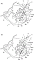
Parts (a) and (b) of fig. 1 are side views of the toner cartridge according to the embodiment.
Fig. 2 is a sectional view schematically showing the structure of an image forming apparatus according to the embodiment.
Fig. 3 is a schematic side sectional view illustrating a state in which the toner cartridge is mounted on the developing unit.
Parts (a) and (b) of fig. 4 are schematic perspective views of the developing unit according to the embodiment.
Parts (a), (b), (c), (d), and (e) of fig. 5 are schematic views of the toner cartridge according to the embodiment.
Parts (a) and (b) of fig. 6 are schematic views of the developing unit and the toner cartridge before mounting (insertion).
Fig. 7 is a schematic view of the developing unit and the toner cartridge during mounting (insertion).
Parts (a), (b), and (c) of fig. 8 are schematic side views showing modified examples of the structure of the insertion guided portion (portion guided at the time of insertion).
Parts (a) and (b) of fig. 9 are schematic side views showing the relationship of forces acting on the toner cartridge.
Parts (a) and (b) of fig. 10 are schematic views showing a state in which the abutting portion and the abutted portion abut against each other.
Parts (a) and (b) of fig. 11 are schematic views when the container frame is rotated so that the toner cartridge is positioned in place.
Parts (a) and (b) of fig. 12 are schematic views when each shutter is moved to the open position and each toner storage portion is communicated.
Parts (a) and (b) of fig. 13 are perspective views showing a modified example of the structure of the operation portion of the toner cartridge.
Fig. 14 is a perspective view of the developing unit and the toner cartridge, which shows a modified example of the structure of the extension member.
Parts (a) and (b) of fig. 15 are side views in the case where the drive transmitting portion engaged with the second drive transmitting portion is provided in the toner cartridge.
Parts (a), (b), and (c) of fig. 16 are side sectional views of the developing unit and the toner cartridge, which show a modified example of the structure of the restricting portion.
Parts (a) and (b) of fig. 17 are perspective views of the developing unit.
Parts (a), (b), and (c) of fig. 18 are sectional views of the developing unit and the toner cartridge.
Fig. 19 is an illustration of the arrangement relationship of the second shutter.
Detailed Description
Hereinafter, an image forming apparatus, a toner image forming portion, and a toner cartridge for forming an electrophotographic image will be described using the drawings. Here, the image forming apparatus is an apparatus for forming an image on a recording material using, for example, an electrophotographic image forming process. For example, it includes an electrophotographic copying machine, an electrophotographic printer (e.g., an LED printer, a laser beam printer, etc.), an electrophotographic facsimile machine, and the like.
Here, in the following example, a monochrome image forming apparatus provided with one toner image forming portion is illustrated. However, the number of toner image forming portions provided in the image forming apparatus is not limited to such an example. For example, the image forming apparatus may have a plurality of toner image forming portions to form a color image.
Similarly, with respect to each configuration disclosed in the embodiments, materials, arrangements, dimensions, other numerical values, and the like are not limited to the described examples unless otherwise described. In addition, "above … …" means upward in the direction of gravity when the image forming apparatus is mounted, unless otherwise specified.
< example 1>
In the present embodiment, a structure that contributes to improvement in usability will be described in detail. More specifically, the present embodiment relates to raising the operational feeling when the user mounts the toner cartridge to the developing unit.
First, the structure of the entire image forming apparatus will be described, and then, the developing unit and the toner cartridge will be described in detail. Here, an operation of mounting the toner cartridge to the developing unit is referred to as a mounting operation, and an operation of dismounting the toner cartridge from the developing unit is referred to as a dismounting operation.
In addition, a position in which the projections, holes, and the like are engaged with each other is referred to as an engaged position, and a position in which the engagement is released is referred to as a non-engaged position (disengaged position).
[ description of electrophotographic image forming apparatus ]
Fig. 2 is a side sectional structure illustration of the structure of the imaging apparatus a according to the present embodiment. The imaging apparatus a shown in fig. 2 receives image information from an external device, such as a personal computer communicably connected with the imaging apparatus. Also, according to the received image information, the image forming apparatus a forms an image (toner image) on a recording material P (e.g., recording sheet, OHP sheet, cloth, etc.) with a developer (toner) by an electrophotographic image forming process.
A toner image forming portion (toner image forming unit) B is detachably provided in the main assembly of the image forming apparatus a. The toner image forming portion (toner image forming unit) B of the present embodiment includes a drum unit C, a developing unit (developing device) D, and a toner cartridge E. The toner cartridge E can be attached to and detached from the developing unit D. That is, the developing unit D has a mounting portion for mounting the toner cartridge E, and is a receiving device (receiving means) for receiving the toner cartridge E.
Here, the toner image forming portion (toner image forming unit) B may be regarded as a unit including a photosensitive drum and a member (process member) acting on the photosensitive drum.
The drum unit C and the developing unit D are integral, and are detachably mountable to the main assembly of the image forming apparatus as one cartridge. The cartridge in which the drum unit C and the developing unit D are integrated is sometimes particularly referred to as a process cartridge. That is, the toner cartridge E is attached to and detached from the developing unit D of the process cartridge. In this case, the entire process cartridge is regarded as the receiving means.
In addition, in the case where the toner cartridge E is mounted on the developing unit D, the process cartridge is mountable to and dismountable from the apparatus main assembly. That is, the drum unit C, the developing unit D, and the toner cartridge E can be mounted to and dismounted from the apparatus main assembly in an integrated state. Therefore, all the toner image forming portions (toner image forming units) B including the drum unit C, the developing unit D, and the toner cartridge E may be referred to as a process cartridge.
Here, the drum unit C, the developing unit D, and the toner cartridge E may be individually formed as respective cartridges. In this case, the drum unit C is referred to as a drum cartridge, and the developing unit D is referred to as a developing cartridge. In addition, in some cases, a photosensitive drum (or a drum unit including a photosensitive drum) is fixed to the main assembly of the apparatus, and only the developing unit (developing cartridge) D and the toner cartridge E are detachable.
In addition, the photosensitive drum or the developing unit may be fixed to the apparatus main assembly, and only the toner cartridge E is detachably mountable to the apparatus main assembly. In this case, the image forming apparatus itself may be regarded as a receiving apparatus for the toner cartridge E.
In addition, the combination of the receiving apparatus and the toner cartridge E may be referred to as a toner supply mechanism (toner supply unit, toner supply device) or the like. In the toner supply mechanism, toner is supplied (replenished) from a toner cartridge E to a developing unit D provided in the receiving apparatus.
Here, in this example, the photosensitive drum as the image bearing member has a structure in which a flange or the like is integrated with a cylinder having a photosensitive layer.
The mounting and dismounting of each cartridge is performed by a user (operator). In addition, the main assembly of the apparatus (the main assembly of the image forming apparatus) means a constituent portion excluding these cartridges (drum unit C, developing unit D, toner cartridge E) from the image forming apparatus a.
The drum unit C is a unit integrally including a photosensitive drum (image bearing member) 16, a charging roller 17, a cleaning blade 19, and the like, and in the present embodiment, it is connected to the developing unit D to constitute a part of the process cartridge. In addition, the developing unit D is a unit integrally including a developing roller (developer carrying member) 24 and the like, and in the present embodiment, it is a part of the process cartridge. The toner cartridge E is a cartridge integrally including a toner container (developer accommodating container, container) 47 for accommodating toner t as a developer.
The photosensitive drum 16 rotates in the direction of arrow a shown in fig. 2. The surface of the rotating photosensitive drum 16 is uniformly charged by a charging roller 17 as a charging means. A laser beam L corresponding to image information is irradiated from a laser scanner (exposure device) 1 onto the photosensitive drum 16, whereby an electrostatic latent image corresponding to the image information is formed on the photosensitive drum 16. And, the toner t carried on the developing roller 24 develops the electrostatic latent image. Thereby, a toner image is formed on the photosensitive drum 16.
Here, referring to fig. 3, the developing process in the toner image forming portion B will be described. The frame 35 of the developing unit D as the receiving device rotatably supports the developing roller 24. The developing roller 24 receives a driving force from a power source (e.g., a motor) (not shown) provided in the apparatus main assembly, and is rotationally driven in a forward direction (the direction of arrow b in the figure) relative to the photosensitive drum 16.
The thickness t of the toner t in the developing chamber 31 is regulated by the developing blade 25 and is carried on the circumferential surface of the developing roller 24. During the regulation of the layer thickness, a toner charge is imparted by triboelectric charging. The charged toner develops the electrostatic latent image on the photosensitive drum 16.
In the developing unit D, the developing chamber 31 communicates with the first toner accommodating portion (developer accommodating portion) 28 through the first opening portion 29. The first toner feeding device 27, which is rotationally driven by a driving source (not shown), supplies the toner t from the first toner containing portion 28 to the developing chamber 31.
In addition, the communication portion 58 is formed by the second opening portion (accommodating body opening, receiving opening) 30 and the third opening portion (container opening, discharge opening) 49. Through this communicating portion 58, the first toner accommodating portion (accommodating member accommodating chamber) 28 is in fluid communication with the second toner accommodating portion (container accommodating chamber) 47t of the toner cartridge E.
The second toner containing portion 47t is a space provided inside the container 47 for containing toner.
The third opening portion 49 is formed in the container frame 47a, and is a discharge opening for discharging the toner from the second toner containing portion 47t to the outside of the container 47 (i.e., into the developing unit D). The toner discharged from the third opening portion 49 is received in the second opening (receiving port) 30 of the developing unit D.
The toner t is supplied from the second toner containing portion 47t into the first toner containing portion 28 through the second toner feeding member 46, which is rotated by the driving force input from the apparatus main assembly through the developing unit D.
Referring back to fig. 2, further description will be made. The recording materials P contained in the feed cassette 2 are separated and fed one by cooperation of the pickup roller 3 and the pressure contact member 5 pressed against the pickup roller 3. And, in synchronization with the toner image formed on the photosensitive drum, the recording material P is fed along the feeding guide 4 to the transfer roller 6 as a transfer device.
Next, the recording material P passes through a transfer nip portion 11 formed by the photosensitive drum 16 and the transfer roller 6, to which a predetermined voltage is applied. At this time, the toner image formed on the photosensitive drum 16 is transferred onto the recording material P. The recording material P on which the toner image has been transferred is fed to a fixing device 8 by a feeding guide 7.
The fixing device 8 includes a driving roller 8a and a fixing roller 8c having a heater 8b incorporated therein. The recording material P receives heat and pressure while passing through a nip portion 8d formed between the fixing roller 8c and the driving roller 8 a. Thereby, the toner image transferred onto the recording material P is fixed thereon. After that, the recording material P on which the toner image has been fixed is fed by the discharge roller pair 9 and discharged to the discharge tray 10.
The cleaning blade 19 elastically contacts the outer peripheral surface of the photosensitive drum 16. Thereby, the toner t (untransferred residual toner) remaining on the photosensitive drum 16, which is not transferred onto the recording material P, is scraped off by the cleaning blade 19. The scraped-off toner t is stored in a removed toner containing portion (waste toner containing portion) 18a of a frame 18 to which a cleaning blade 19 is fixed.
As described above, in the image forming apparatus of the present embodiment, an image is formed on a recording material (recording medium) by using a developer (toner) by an electrophotographic image forming method. As long as the image forming apparatus can form an image on a recording material, and the form thereof is not limited to an electrophotographic copying machine, an electrophotographic printer (laser beam printer, LED printer, etc.), an electrophotographic facsimile machine, an electrophotographic word processor, or the like.
As described above, the toner image forming portion B includes the electrophotographic photosensitive member (photosensitive member) as an image bearing member and the process device acting on the photosensitive member. In the present embodiment, the toner image forming portion may be detachably mountable to the main assembly of the image forming apparatus as one or more cartridges.
The processing device includes a charging device (charging member, charging means), a developing device (developing means, developing unit), a cleaning device (cleaning means, cleaning member), and the like.
The developing device develops the electrostatic latent image on the photosensitive member. In the present embodiment, the developing device (developing unit) can be attached to or detached from the image forming apparatus as a part of the process cartridge.
In addition, a toner cartridge (developer cartridge, toner bottle, developer bottle, toner container, developer container) is a cartridge containing developer (toner) for developing an electrostatic latent image formed on a photosensitive member.
[ Structure of each case (each unit) ]
Next, a detailed structure of each cartridge (each unit) detachably provided in the image forming apparatus will be described.
(details of the vicinity of the toner cartridge receiving portion of the developing unit)
Referring to fig. 4, a detailed structure of the vicinity of the receiving portion of the toner cartridge E of the developing unit D according to the present embodiment will be described. Fig. 4 is a perspective view of the vicinity of a receiving portion (mounting portion) of the toner cartridge E of the developing unit D. Part (a) of fig. 4 shows a state in which the second opening portion 30 is closed (the first shutter 37 is in the closed position). In addition, part (b) of fig. 4 shows a state in which the second opening portion 30 is opened (the first shutter 37 is in the open position). In the present embodiment, the longitudinal direction of the developing unit D is a direction parallel to the rotational axis direction of the developing roller 24 of the developing unit D. Here, in a state in which the toner cartridge E is mounted to the developing unit, the longitudinal direction of the toner cartridge E is substantially parallel to the longitudinal direction of the developing unit D.
In the developing unit D, the toner cartridge E may be mounted to (removable from) a frame (developing frame) 35 at a receiving portion. In the vicinity of the receiving portion, the developing unit D is provided with a second opening (accommodating body opening, receiving port) 30 and a first shutter (accommodating body shutter, receiving apparatus side opening/closing member) 37. In the present embodiment, the second opening portion 30 is provided in the central portion in the longitudinal direction of the developing unit D. However, the position of the second opening portion 30 is not limited to this position as long as it faces a third opening (container opening) 49 which will be described later.
As shown in part (a) of fig. 4, the second opening portion 30 is sealed by a first shutter 37 having a shape with a curvature along the outer circumferential surface of the toner cartridge E.
The first shutter 37 has a hole portion 37a engageable with a projection (container-side engaging portion, opening/closing member moving portion, container-side projection) 45 provided on the toner cartridge E. Two protrusions 45 and two hole portions 37a are provided. The hole portion 37a is provided outside the sealing area in which the first shutter 37 seals the second opening portion 30.
In addition, both end portions in the longitudinal direction of the first shutter 37 are engaged with the first shutter guide portion 34 provided in the frame 35 of the developing unit D. Thereby, the first shutter 37 is slidable (movable) along the first shutter guide portion 34 (in the directions of arrows W1 and W2).
Thereby, the first shutter 37 is movable between a closing position (receiving opening closing position, part (a) of fig. 4) for closing the second opening portion 30 and an opening position (receiving opening position, part (b) of fig. 4) for opening the second opening portion 30.
In addition, as shown in part (b) of fig. 4, a first seal 32 for sealing a space between the first shutter 37 and the second opening portion 30 is mounted to the frame 35 of the developing unit D so as to surround the second opening portion 30.
The developing unit D is provided with insertion guide portions (receiving apparatus-side guides) 35D, 36D for guiding and simultaneously maintaining the posture (mounting posture) of the toner cartridge E when the toner cartridge E is mounted (inserted) at opposite ends of the frame 35 in the longitudinal direction.
In addition, the developing unit D is provided with abutted portions (portions to be abutted) 35a, 36a against which the abutting portions 42a, 43a of the toner cartridge E abut when the toner cartridge E is inserted as will be described below.
Further, the developing unit D is provided with rotation guide portions 35b, 36b for guiding rotation of the toner cartridge E when opening and closing the first shutter 37 and the second shutter (toner cartridge side shutter) 53 at opposite ends of the frame 35 in the longitudinal direction.
The insertion guide portions 35d, 36d are formed linearly and in parallel with each other along the insertion direction f of the toner cartridge E (portion (a) of fig. 4). Here, a direction opposite to the direction in which the toner cartridge E is inserted may be referred to as a removal direction. The removing direction is a direction in which the toner cartridge E is removed from the developing unit D. The downstream side of the insertion direction may be regarded as the upstream side of the removal direction, and the upstream side of the insertion direction may be regarded as the downstream side of the removal direction.
With respect to the opposite end sides in the longitudinal direction of the developing unit D, the side on which the driving unit (e.g., the first drive transmission portion 38) such as a gear is provided is hereinafter referred to as a driving side. The non-driving side of the developing unit is opposite to the driving side in the longitudinal direction.
On the non-driving side of the developing unit D, an abutted portion (portion to be abutted) 35a and a rotation guide portion 35b are provided on the downstream side of the insertion guide portion 35D in the insertion direction f, and on the driving side, an abutted portion (portion to be abutted) 36a and a rotation guide 36b are provided on the downstream side of the insertion guide portion 36D in the insertion direction f.
Further, the developing unit D is provided with a first drive transmission portion 38 at one end portion in the longitudinal direction of the frame 35 for transmitting drive to a second toner feeding unit 46 of the toner cartridge E, which will be described later.
The first drive transmission portion 38 is a gear, and is connected to a driving mechanism of the image forming apparatus main assembly inside the developing unit D. The first drive transmission portion 38 is a torque transmission unit (driving force transmission unit) for transmitting a rotational force for driving the second toner feeding member 46 from the outside of the toner cartridge E.
(detailed description of toner cartridge)
Referring to fig. 5, a detailed structure of the toner cartridge E according to the present embodiment will be described.
Part (a) of fig. 5 is a perspective view of the toner cartridge E as viewed from the second drive transmitting portion (48) side (driving side). In addition, part (b) of fig. 5 is a perspective view of the toner cartridge E when viewed from the side (non-driving side) opposite to the second drive transmission portion (48) side. Part (c) of fig. 5 is a cross-sectional view of the toner cartridge E in which the third opening portion 49 is in a closed state when viewed from the side opposite to the second drive transmission portion (48) side. Part (d) of fig. 5 is a cross-sectional view of the toner cartridge E in a state where the third opening portion 49 is opened when viewed from the side opposite to the second drive transmission portion (48) side. And, part (E) of fig. 5 is a perspective view of the toner cartridge E when the second shutter 53 is in the open position (a state in which the third opening portion 49 is opened). Here, in fig. 5, the toner t is not illustrated.
The toner cartridge E includes a container 47, a second shutter (developer container shutter) 53 movable relative to the container 47, a second toner feeding member 46 provided in the container 47, and a second drive transmission portion (gear) 48 attached to the second toner feeding member 46, and the like.
The container 47 has a substantially cylindrical shape. That is, the frame (container frame) 47a constituting the main assembly portion (main portion) of the container 47 has a substantially cylindrical shape. Here, the longitudinal direction of the toner cartridge E is the longitudinal direction (axial direction) of the cylindrical shape.
At an end portion in the longitudinal direction of the container 47, an insertion guided portion (guided portion, cartridge-side guide portion) 42 is provided which projects outward in the longitudinal direction beyond the side wall 47a2 of the container frame 47 a. Similarly, at the other longitudinal end portion of the container 47, an insertion guided portion (guided portion, cartridge-side guide portion) 43 is provided which projects outwardly in the longitudinal direction beyond the side wall 47a1 of the container frame 47 a.
In addition, the container 47 is provided with an operation portion 44 operated by a user. The operating portion 44 is a U-shaped (U-shaped) projection integrally formed with the frame 47 a. Here, the shape of the operating portion 44 is not limited to the U-shape. In addition, it may be integrally molded with the container frame 47a, or may be made of a member separate from the frame 47a and mounted to the frame 47 a. The operation portion 44 is a grip portion (grip, hold) for a user to grip when inserting or removing the toner cartridge E.
As shown in part (c) of fig. 5, the container frame (cylindrical portion) 47a is hollow, and forms a second toner containing portion 47t in which toner is stored. A second toner feeding member 46 for feeding toner is rotatably provided in the second toner containing portion 47t of the container frame 47 a. A second drive transmission portion 48 for receiving power (rotational force, driving force) for rotationally driving the second toner feeding member 46 is provided at one end portion in the longitudinal direction (rotational axis direction) of the second toner feeding member 46 (part (a) of fig. 5). The second drive transmitting portion 48 is a gear (drive input gear) that receives a driving force (rotational force) from outside the toner cartridge E (i.e., from the developing unit D as a receiving device).
Here, in the present embodiment, the driving force is directly transmitted from the second drive transmission portion 48 to the second toner feeding member 46. However, the driving force may be transmitted from the second driving force transmitting portion 48 to the second toner feeding member 46 through another drive transmitting member (e.g., one or more gears). Such a structure will be described below with reference to fig. 15.
In addition, as shown in part (e) of fig. 5, a third opening portion 49 for discharging the toner t of the second toner containing portion 47t is provided in the outer peripheral surface of the container frame 47 a. In the present embodiment, the third opening portion 49 is provided in the outer peripheral surface of the container frame 47a at the center in the longitudinal direction of the toner cartridge E. However, the position of the third opening portion 49 is not limited to a specific position as long as it is a position facing the second opening portion 30.
As shown in part (c) of fig. 5, a cross-sectional portion (a section along a plane perpendicular to the central axis R of the container frame 47a) of the second shutter 53 has a curved shape (a substantially circular arc shape) along the outer periphery of the container frame 47 a.
The container frame 47a has a curved surface (substantially cylindrical shape, substantially circular arc shape) at least around the third opening portion 49. The second shutter 53 is rotatable (turnable) around the container frame 47a along the curved surface portion (circular arc portion) around the third opening portion 49. Thereby, the second shutter 53 can open and close the third opening portion 49.
The second shutter 53 has a shutter main body portion 53m (main body portion, closing portion) for closing the third opening portion 49. Here, the longitudinal direction of the shutter main body portion 53m is substantially parallel to the longitudinal direction of the toner cartridge E.
In addition, the second shutter 53 is provided with an extended portion 53x extending in the longitudinal direction. At an end portion in the longitudinal direction of the extending portion 53x, a restricting portion 53x1 is provided which protrudes outward in the longitudinal direction beyond the side wall 47a1 of the container frame 47 a. Similarly, at the other longitudinal end portion of the extending portion 53x, there is provided a restricting portion 53x2 that protrudes outward in the longitudinal direction beyond the side wall 47a2 of the container frame 47a (parts (a) and (b) of fig. 5).
In addition, the state in which the second shutter 53 is opened (portion (d) in fig. 5) is changed from the state in which the third opening portion 49 is closed (portion (c) in fig. 5). At this time, the extending portion 53x and the restricting portions 53x1 and 53x2 are disposed away from the operating portion 44.
More specifically, when the second shutter 53 is relatively moved in the arrow n direction with respect to the container frame 47a from the state shown in part (c) of fig. 5, the third opening portion 49 is opened from the closed state (part (d) of fig. 5). At this time, similarly to the second shutter 53, the extending portion 53x provided in the second shutter 53 also moves in the arrow n direction with respect to the container frame 47. That is, when the second shutter 53 is changed from the state in which the third opening portion 49 is closed to the state in which the second shutter is opened, the extension portion 53x is moved away from the operating portion 44.
In addition, when the second shutter 53 is changed from the state in which the third opening portion 49 is opened to the closed state, the extending portion 53x approaches the operating portion 44.
Here, in this example, although the extension portion 53x is formed integrally with the second shutter 53, it may be formed separately. In addition, at least a part of the extended portion 53x may be made of a member (a metal rod or the like) having a higher strength than that of a portion other than the extended portion 53 x.
Also, two protrusions 45 are provided on the cylindrical outer periphery of the container frame 47a so as to be engageable with the hole portions 37a of the first shutter 37. The two protrusions 45 protrude in substantially the same direction. The two projections 45 project toward the downstream side in the insertion direction in which the toner cartridge E is inserted into the developing unit D. In addition, a line connecting the two projections 45 is substantially parallel to the longitudinal direction of the toner cartridge E.
Further, the end portion 53c on the free end portion side of the second shutter 53 is located on the downstream side along the direction (the arrow u direction) in which the second shutter 53 moves relative to the container frame 47a when the third opening portion 49 is closed. The end portion 53c on the free end side of the second shutter 53 is an end portion in the lateral direction of the second shutter 53 (the direction perpendicular to the longitudinal direction of the second shutter 53).
As shown in part (c) of fig. 5, the toner cartridge E is viewed in the longitudinal direction. The state in which the second shutter 53 is closed from the third opening portion 49 (part (b) in fig. 5) is changed to the opened state (part (e) in fig. 5). At this time, the two protrusions 45 are arranged on a side away from the end portion 53c on the free end side of the second shutter 53.
In the longitudinal direction of the container 47, the two protrusions 45 are arranged outside the third opening portion 49. In more detail, when the two projections 45 and the third opening portion 49 are projected onto an imaginary line parallel to the central axis R of the container frame 47a as the rotation axis of the second shutter 53, the entire projection area of the third opening portion 49 falls within a range sandwiched between the projection areas of the two projections.
The opposite end portions 53n in the longitudinal direction of the second shutter 53 (shutter main body portion 53m) are engaged with second shutter guide portions (opening and closing guides) 52 provided on the opposite sides of the container frame 47a in the longitudinal direction of the third opening portion 49. Also, the shutter main body portion 53m of the second shutter 53 is assembled along the second shutter guide portion 52 so as to be slidable in the circumferential direction on the outer peripheral surface of the container frame 47 a. Thereby, the second shutter 53 is movable between an open position (container open position, part (E) of fig. 5) for opening the third opening portion 49 along the outer peripheral surface of the toner cartridge E and a closed position for closing the third opening portion 49 (container closed position, part (b) of fig. 5).
Here, it is preferable that when the second shutter 53 is in the open position, as shown in part (e) of fig. 5, the third opening portion 49 is fully opened from the shutter main body portion 53m (closed portion). However, if the toner t can be discharged from the third opening portion 49 by a required amount when the second shutter 53 is at the open position, a part of the third opening portion 49 may be covered by the shutter main body portion 53m (closed portion). That is, it is sufficient that the shutter main body portion 53m at least partially opens the third opening portion 49 when the second shutter 53 is at the open position, so that the toner t can be supplied from the toner cartridge E to the developing unit D.
In addition, it is preferable that when the second shutter 53 is in the closed position, as shown in part (b) of fig. 5, the third opening portion 49 is completely covered by the shutter main body portion 53 m. However, the third opening portion 49 may be slightly opened as long as the third opening portion 49 is substantially closed by the shutter main body portion 53m and toner leakage from the third opening portion 49 is sufficiently suppressed. That is, it suffices that the shutter main body portion 53m substantially closes the third opening portion 49 when the second shutter 53 is in the closed position.
(modified example of operation part)
Here, with reference to fig. 13, a modified example of the structure of the operation portion 44 will be described.
As shown in part (a) of fig. 13, the shape of the operating portion 44 may be in the form of a protrusion provided at each of the opposite longitudinal ends of the frame 47 a. In addition, as shown in part (b) of fig. 13, the operating portion 44 does not necessarily have to be provided at both longitudinal ends of the frame, but may be a protrusion provided at one longitudinal end. Here, in the present embodiment, the operating portion 44 is formed integrally with the frame 47a, but it may be made of a member different from the frame 47a and mounted to the frame 47 a.
It is preferable that the operating portion 44 is provided on the container frame 47a, which is outwardly beyond the extending portion 53x (the restricting portions 53x1, 53x2) in the longitudinal direction.
[ mounting of toner cartridge to developing unit ]
Next, a process of mounting the toner cartridge E to the developing unit D will be described. In a case where the toner cartridge E has been inserted into the developing unit D, the toner cartridge E rotates so that the second opening portion 30 and the third opening portion 49 are opened and closed.
(toner cartridge insertion developing unit insertion operation)
Referring to fig. 1, 6, and 7, an operation of inserting the toner cartridge E into the developing unit D will be described. Here, for better explanation, fig. 1, part (b) of fig. 6, and fig. 7 are views through the insertion guide portions 35d and 36 d.
Part (a) of fig. 1 is a side view when the toner cartridge E is inserted into the developing unit D as viewed from the non-driving side. Part (b) of fig. 1 is a side view of the toner cartridge E and the developing unit D as viewed from the driving side, and shows a positional relationship of the operating portion 44 and the abutting portion 43a with respect to the mounting direction of the toner cartridge E.
Fig. 6 is a schematic view showing a state of the toner cartridge E and the developing unit D before the toner cartridge E is mounted (inserted), and part (a) of fig. 6 is a perspective view thereof, and part (b) of fig. 6 is a side view thereof.
Fig. 7 is a side view showing a state of the toner cartridge E and the developing unit D during a mounting (inserting) process of the toner cartridge E.
As shown in part (a) of fig. 1, the toner cartridge E includes a rotation guided portion (a portion to be guided for rotation) 42 b. When the first shutter 37 and the second shutter 53 are opened and closed by rotating the toner cartridge E, the rotation is guided by the guide portion 42b to the container frame 47 a. The container 47 can be smoothly rotated by rotating the guided portion 42 b. The rotation guided portion 42b is a rotation guide (toner cartridge side rotation guide) for guiding the rotation of the toner cartridge E. The rotation guided portion 42b has a curved surface shape (substantially circular arc shape) (details will be described later).
In the present embodiment, on the non-driving side, the abutment portion 42a, the rotation guided portion 42b, the regulating portion 42c1, and the regulating portion 42c2 are formed integrally with the insertion guided portion 42. However, they may be provided as separate members as long as they satisfy the respective functions.
As shown in part (b) of fig. 1, the insertion guided portion 43 is provided with an abutting portion 43a that abuts against the abutted portion 36a of the developing unit D when the toner cartridge E is inserted. This structure is such that the insertion guided portion 43 also functions as a rotation guided portion (toner cartridge side rotation guide portion) for guiding the container frame 47a when the abutment portion 43a opens and closes the first shutter 37 and the second shutter 53.
In the present embodiment, on the driving side, the insertion guided portion 43 and the abutting portion 43a may be constituted by separate members. In addition, the rotation-guided portion may be provided as a member separate from the abutment portion 43 a. As described above, based on the consideration of the strength or the like, a portion (non-functional portion, non-contact portion) in which the toner cartridge E and the developing unit D do not abut each other may be appropriately omitted.
In addition, in the present embodiment, at the end portion in the longitudinal direction of the second toner feeding portion 46, the insertion guided portion 43 is provided at the end portion of the second drive transmission portion 48. However, the insertion guided portion 43 may be provided on the container frame 47 a.
Here, referring to part (a) of fig. 1, the arrangement of the operation portion 44 in the container frame 47a will be described. This figure shows the positional relationship of the operating portion 44 and the abutment portion 42a in the insertion direction f.
Here, the insertion direction f will be described. A direction along the plane of the restriction portion 42c is defined as a direction f. More specifically, in the direction along the surface of the restriction portion 42c, the direction in which the abutment portion 42a is located on the downstream side with respect to the insertion guided portion 42 may be regarded as the direction f. That is, the direction in which the toner cartridge E is inserted into the developing unit D is the direction f.
A plane (an imaginary plane passing through the rotation center S of the container frame 47a) parallel to the insertion direction f of the toner cartridge E regulated by the regulating portion 42c1 and the regulating portion 42c2 and passing through the abutting portion 42a and the abutting portion 43a is regarded as a plane m.
The operating portion 44 is provided on the downstream side of the plane m in the opening direction (direction e in part (a) of fig. 1) of the third opening portion 49 (part (d) of fig. 5). Here, the opening direction (the direction of the arrow E) of the third opening portion 49 is a direction (setting direction) in which the toner cartridge E is rotated so as to be set to the developing unit D.
In addition, the arrangement of the restricting portion (engaging portion) 53x1 and the restricting portion (engaging portion) 53x2 provided on the longitudinal end portion of the extending portion 53x with respect to the container frame 47a will be described. As shown in part (a) of fig. 1, the insertion guided portion 42, the restriction portion 53x1, and the restriction portion 53x2 are arranged in a predetermined direction (insertion direction f or removal direction). That is, the insertion guided portion 42, the restriction portion 53x1, and the restriction portion 53x2 are arranged in line in the insertion direction f (or the removal direction). In addition, the restricting portions 53x1 and 53x2 are arranged on the upstream side of the insertion guided portion 42 in the insertion direction f.
In addition, the insertion guided portion 42 is arranged as a single body extending in a predetermined direction (insertion direction f or removal direction). That is, the insertion guided portion 42 extends in the insertion direction f (or the removal direction).
The arrangement of the insertion guided portion 42, the restricting portion 53x1, and the restricting portion 53x2 will be described in more detail below. When the toner cartridge E is viewed in its longitudinal direction, an imaginary line (first imaginary line) extending perpendicular to the insertion direction f of the toner cartridge E is n. When the insertion guided portion 42 and the restricting portion 53x2 are projected on the line n, respectively, the projection region 53y2 of the restricting portion 53x2 falls within the projection region 50 of the insertion guided portion 42. Here, it is not necessary to restrict all of the projection area 53y2 of the portion 53x2 to fall within the projection area 50 of the inserted guided portion 42, but it is only necessary that at least a part of the projection area 53y2 be located within the projection area 50.
Similarly, as shown in part (b) of fig. 1, when the insertion guided portion 43 and the restricting portion 53x1 are projected on the line n, respectively, the projection region 53y1 of the restricting portion 53x1 falls within the projection region 51 of the insertion guided portion 43. It is not necessary to limit all of the projection area 53y1 of the portion 53x1 to be included in the projection area 51 where the guided portion 43 is inserted, and as long as at least a part of the projection area 53y1 is located in the projection area 51.
With this structure, in a state in which the toner cartridge E is mounted to the developing unit D, the regulating portions 53x2 and 53x1 can be engaged with the insertion guide portion 35D and the insertion guide portion 36D, respectively (details will be described later).
Here, if the restricting portions 53x1, 53x2 are provided as described above, it is not necessary to arrange the extending portions 53x in a straight line in the longitudinal direction, and it may have a crank shape or the like (fig. 14).
Next, an operation of inserting the toner cartridge into the developing unit will be described.
As shown in part (a) of fig. 6, before the toner cartridge E is mounted to the developing unit D, the first shutter 37 for the second opening portion 30 (not shown) is in the closed position, and the second shutter 53 for the third opening portion 49 (not shown) is in the closed position. That is, the second opening portion 30 (portion (a) of fig. 4) of the developing unit D and the third opening portion 49 (portion (D) of fig. 5) of the toner cartridge E are closed by the first shutter 37 and the second shutter 53.
On the insertion guided portion 42 of the toner cartridge E, restricted portions (a regulated surface, a posture restricting portion, an insertion direction restricting portion) 42c1 and 42c2 for regulating an insertion posture and a removal posture (an insertion direction, a removal direction) of the toner cartridge E are provided.
The user grips the operating portion 44 and moves the toner cartridge E in the insertion direction f relative to the developing unit D. The user moves the toner cartridge E so that the insertion guided portion 42 of the toner cartridge E and the insertion guide portion 35D of the developing unit D engage with each other, and the insertion guided portion 43 and the insertion guide portion 36D engage with each other. When the insertion guided portions 42, 43 are guided by the insertion guide portions 35D, 36D of the developing unit D, the posture of the toner cartridge E when the toner cartridge E is mounted is stabilized.
Here, as shown in part (b) of fig. 6, in the present embodiment, the insertion guided portions 42, 43 and the insertion guide portions 35d, 36d are configured such that the insertion direction f is inclined with respect to the gravitational direction g.
In other words, the toner cartridge E is inserted while the regulating portion 42c1 on the lower side of the direction of gravity g of the insertion guided portion 42 and the surface 35d1 on the lower side of the direction of gravity g of the insertion guide portion 35d are in contact with each other (portion (a) in fig. 1). Similarly, the toner cartridge E is inserted while the regulating portion 42c2 on the lower side of the direction of gravity g of the insertion guided portion 42 and the surface 35d2 on the lower side of the direction of gravity g of the insertion guide portion 35d are in contact with each other (portion (b) of fig. 1).
Also, as shown in fig. 7, the regulating portion 42c1 on the lower side (the gravitational direction g) of the insertion guided portion 42 is placed on the surface 35d1 of the insertion guided portion 35d so that the position of the insertion guided portion 42 is determined with respect to the rotation guiding portion 35 b. Thereby, the posture of the toner cartridge E with respect to the developing unit D is determined.
When the user further moves the toner cartridge E in the direction f while keeping the toner cartridge posture, as shown in part (a) of fig. 1, the abutting portion 42a of the insertion guided portion 42 provided in the toner cartridge E abuts against the abutted portion 35a provided in the developing unit D. Similarly, as shown in part (b) of fig. 1, an abutting portion 43a provided on the toner cartridge E abuts against an abutted portion 36a provided in the developing unit D. Thereby, the insertion of the toner cartridge E is completed.
In addition, at least a part of the restriction portion 53x2 enters the insertion guide portion 35d in the process of mounting the toner cartridge E to the developing unit. Similarly, at least a part of the restricting portion 53x1 enters the insertion guide portion 36 d.
(modified example of inserting guided portion)
Here, with reference to part (a) of fig. 8, part (b) of fig. 8, and part (c) of fig. 8, a modified example of the structure of the insertion guided portion 42 will be described. Here, for better illustration, the insertion guide portion 35d can be seen.
Parts (a) to (c) of fig. 8 are side views showing various exemplary structures of the insertion guided portion 42, the abutting portion 42a, and the regulating portion 42c of the toner cartridge E, respectively.
In the present embodiment, as shown in fig. 7, the insertion guided portion 42 of the toner cartridge E is constituted by a single protrusion having an oblong shape. However, other shapes and structures as shown in parts (a) to (c) of fig. 8 may be adopted as long as they can perform the same function. However, the shape, number, and arrangement of the protrusions are not limited to the structures shown in the drawings.
That is, as shown in part (a) of fig. 8, a structure in which an oblong projection and a cylindrical projection are combined may be employed. With this structure, the surface 42d of the elongated circular protrusion is in contact with the surface 35d1 of the insertion guide portion 35d, and the surface 42c2 of the cylindrical protrusion is in contact with the surface 35d2 of the insertion guide portion 35 d. Thereby, the posture of the toner cartridge E at the time of insertion is restricted. In addition, the abutting portion 42a of the oblong projection abuts against the abutted portion 35a, thereby completing the insertion of the toner cartridge E.
In addition, as shown in part (b) of fig. 8 and part (c) of fig. 8, the insertion guided portion may be a combination of a plurality of columnar projections. Needless to say, the shape of the protrusions need not be cylindrical, but may be triangular prisms. That is, if the insertion guided portion is arranged along the insertion direction f of the toner cartridge E and the insertion posture of the toner cartridge E can be regulated, the shape may be any shape. Similarly, it does not matter whether the number of inserted guided portions is plural or single.
In the structure of part (b) of fig. 8, the columnar projections 42e and 42f aligned in the insertion direction f contact the surface 35d1 of the insertion guide portion 35 d. In addition, the surface 42c2 of the columnar protrusion 42 is in contact with the surface 35d2 of the insertion guide portion 35 d. Thereby, the posture of the toner cartridge E is regulated. Similarly, the columnar projection 42f provided on the downstream side in the insertion direction f is provided with an abutting portion 42a, and the abutting portion 42a abuts against the abutted portion 35 a. Thereby, the insertion of the toner cartridge E into the developing unit D is completed.
In addition, in the structure of part (c) of fig. 8, the columnar projections 42e and 42f aligned in the insertion direction f contact the surfaces 35d1 of the insertion guide portions 35d, respectively. In addition, the columnar projections 42e and 42f are in contact with the surface 35d2 of the insertion guide portion 35 d. Thereby, the posture of the toner cartridge E is regulated. In addition, the columnar projection 42f provided on the downstream side in the insertion direction f is provided with the abutting portion 42a, and it abuts against the abutted portion 35a, whereby the insertion of the toner cartridge E into the developing unit D is completed.
As described above, in the case where the longitudinal end portion of the toner cartridge E is provided with a plurality of projections, only the portion in contact with the developing unit D needs to be paid attention.
Here, in all the structures of parts (a) to (c) of fig. 8, the insertion guided portion 42 and the restricting portion 53x1 are projected onto the surface n perpendicular to the insertion direction f. At this time, the projection area 53y2 of the restricting portion 53x2 falls within the projection area 50 of the inserted guided portion 42.
(positioning of toner cartridge with respect to developing unit)
With reference to part (a) of fig. 10, part (b) of fig. 10, part (a) of fig. 11, and part (b) of fig. 11, the positioning of the toner cartridge E with respect to the developing unit D will be described.
Part (a) of fig. 10 is a side view of the frame 35 of the developing unit D and the insertion guided portion 42 of the toner cartridge E in a state in which the abutting portion 42a and the abutted portion 35a abut against each other. Part (b) of fig. 10 is a sectional view of the toner cartridge E and the developing unit D in a state in which the abutting portion 42a and the abutted portion 35a abut against each other.
Part (a) of fig. 11 is a side view of the insertion guided portion 42 of the toner cartridge E and the frame 35 of the developing unit D in a state in which the toner cartridge E is positioned with respect to the developing unit D. Part (b) of fig. 11 is a sectional view showing an engagement relationship between the toner cartridge E and the developing unit D which are positioned. More specifically, part (b) of fig. 11 is a sectional view in which the toner cartridge E and the developing unit D are cut at the position of the second shutter 53.
Part (a) of fig. 10 shows a state after the toner cartridge E is inserted into the developing unit D. To open and close the first shutter 37 and the second shutter 53, the container 47 is rotated in the direction of arrow E about the rotational axis S of the toner cartridge E. Then, as shown in part (a) of fig. 11, the abutment portion 42a and the rotation guided portion 42b are engaged with the rotation guide portion 35 b. Thereby, the toner cartridge E is positioned with respect to the developing unit D. At this time, the rotation guided portion 42b is guided by the rotation guide portion 35b provided in the developing unit D. Thereby, the container 47 can be smoothly rotated.
[ opening and closing operation of shutter ]
Hereinafter, the opening/closing operations of the first shutter 37 provided in the developing unit D and the second shutter 53 provided in the toner cartridge E will be described in detail.
In the present embodiment, in the process of mounting the toner cartridge E to the developing unit D, the first shutter 37 of the developing unit D and the second shutter 53 of the toner cartridge E open the second opening portion 30 and the third opening portion 49, respectively (move to the open position). In contrast, in the process in which the toner cartridge E is removed from the developing unit D, the first shutter 37 and the second shutter 53 close the second opening portion 30 and the third opening portion 49, respectively (move to the closed position).
The toner cartridge E is mounted to the developing unit D by a mounting operation including at least a rotation operation. More specifically, the toner cartridge E is linearly inserted into the developing unit D, and then, it is rotated to be mounted to the developing unit D. In conjunction with the rotational movement when the toner cartridge E is mounted, the first shutter 37 and the second shutter 53 move from the closed position to the open position.
Similarly, the toner cartridge E is detached from the developing unit D at least by a detaching operation including a rotating operation. More specifically, the toner cartridge E is rotated relative to the developing unit D, and then, is substantially linearly removed from the developing unit D.
With the rotating operation when the toner cartridge E is detached, the first shutter 37 and the second shutter 53 move from the open position to the closed position.
(opening operation of shutter)
With reference to part (a) of fig. 1, part (b) of fig. 10, part (a) of fig. 11, part (b) of fig. 11, part (a) of fig. 12, and part (b) of fig. 12, the opening operation of the first shutter 37 of the developing unit D and the second shutter 53 of the toner cartridge E will be described. Part (a) of fig. 12 is a side view of the insertion guided portion 42 of the toner cartridge E and the frame 35 of the developing unit D, in which the second opening portion 30 and the third opening portion 49 are opened. Part (b) of fig. 12 is a sectional view of the toner cartridge E and the developing unit D in which the second opening portion 30 and the third opening portion 49 are opened.
In the present embodiment, in a state where the toner cartridge E is positioned with respect to the developing unit D (a mounted state), the relative positions of the second opening portion 30 and the third opening portion 49 may be different. In other words, this structure makes it possible to obtain at least two positions (two states) by rotating the toner cartridge E in a state where the toner cartridge E is mounted to the developing unit D.
At the first position of the toner cartridge E, the second opening portion 30 and the third opening portion 49 do not overlap each other, and are in a non-communicating position where the first toner accommodating portion 28 and the second toner accommodating portion 47t are in a non-communicating state (part (b) of fig. 10). In this state, the first shutter 37 is in the closed position closing the second opening portion 30.
At the second position of the toner cartridge E, the second opening portion 30 and the third opening portion 49 overlap each other, and are in a communication position where the first toner accommodating portion 28 and the second toner accommodating portion 47t are in a communication state (part (b) of fig. 12). In this state, the first shutter 37 is in the open position at which the second opening portion 30 is open.
As shown in part (a) of fig. 1, when the toner cartridge E is inserted into a predetermined position of the developing unit D, the projection 45 of the container frame 47a and the hole portion 37a of the first shutter 37 engage with each other. That is, the insertion posture of the toner cartridge E is restricted so that the insertion guided portion 42 is guided by the insertion guide portion 35d to insert the projection 45 into the hole portion 37 a.
In addition, when the toner cartridge E is inserted into the developing unit D, at least a part of the regulating portion 53x2 provided at one end portion in the longitudinal direction of the extending portion 53x enters the insertion guide portion 35D. In addition, at least a part of the restricting portion 53x1 provided at the other longitudinal end of the extending portion 53x enters the insertion guide portion 36 d. That is, by inserting the toner cartridge E into the developing unit D, the regulating portions 53x2 and 53x1 are engaged with the insertion guide portion 35D and the insertion guide portion 36D, respectively.
From the mounting position shown in part (a) of fig. 1, by the user operating the operating portion 44, the container frame 47a of the toner cartridge E is rotated in the direction of arrow E. Thereby, the engagement state between the insertion guided portion 42 and the frame 35 becomes a state shown in part (a) of fig. 11, and then becomes a state (not shown) in which the second opening portion 30 and the third opening portion 49 shown in part (a) of fig. 12 overlap each other. At this time, the rotational axis S of the toner cartridge E (container frame 47a) is substantially parallel to the longitudinal direction of the toner cartridge E.
Here, part (a) of fig. 1 is a side view as viewed in the longitudinal direction when the toner cartridge E is inserted into a predetermined position of the developing unit D. At this time, when the toner cartridge E continues to rotate in the direction of arrow E about the rotation axis S, the regulating portion 53x2 is in a position of contact with the surface 35d 2. Therefore, when the container frame 47a starts to rotate in the direction of the arrow e as shown in part (a) of fig. 10, the restricting portion 53x2 provided at one end portion in the longitudinal direction of the extending portion 53x abuts on the surface 35d2 of the insertion guide portion 35 d. Thereby, the restriction portion 53x2 receives the reaction force F1 from the surface 35d 2. Therefore, as shown in part (a) of fig. 11, even if the rotation of the container frame 47a advances in the direction of arrow e, the restricting portion 53x2 continues to receive the force F1 from the surface 35d 2. Therefore, the extension portion 53x does not rotate in the direction of the arrow e together with the container frame 47 a.
In other words, the toner cartridge E is inserted into a predetermined position of the developing unit D. At this time, if the restricting portion 53x2 is at the position of its contact surface 35d2 when the toner cartridge E continues to rotate in the direction of arrow E about the rotation axis S, the extending portion 53x does not rotate in the direction of arrow E together with the container frame 47 a.
In addition, part (b) of fig. 1 is a side sectional view viewed from the side opposite to the driving side when the toner cartridge E is inserted into a predetermined position of the developing unit D. At this time, when the toner cartridge E continues to rotate in the direction of arrow E about the rotation axis S, the regulating portion 53x1 is at a position where it contacts the surface 36d 2. Therefore, when the container frame 47a starts to rotate in the direction of the arrow e as shown in part (b) of fig. 10, the restricting portion 53x1 of the extending portion 53x abuts against the surface 36d2 of the insertion guide portion 36 d. Thereby, the restriction portion 53x1 receives the reaction force F2 from the surface 36d 2. Therefore, as shown in part (b) of fig. 11, even if the rotation of the container frame 47a advances in the direction of arrow e, the restricting portion 53x1 continues to receive the force F2 from the surface 36d 2. Therefore, the extension portion 53x does not rotate in the direction of the arrow e together with the container frame 47 a.
With the above-described structure, the insertion guide portions 35d, 36d restrict the extension portion 53x so as not to rotate in the arrow e direction together with the container frame 47 a. This restricts the second shutter 53 from rotating in the direction of the arrow e together with the container frame 47 a. From this state, the container frame 47a is further rotated in the mounting direction (the direction of arrow E) of the toner cartridge E with respect to the developing unit D. Then, the container frame 47a is moved in a direction (opening direction) to open the third opening portion 49 for supplying the toner to the developing unit.
In other words, the second shutter moves relative to the container frame 47a in a direction to open the third opening portion 49. The force F1 received by the restricting portion 53x2 and the force F2 received by the restricting portion 53x2 are forces for moving the second shutter 53 from the closed position to the open position.
In addition, as shown in part (b) of fig. 11, when the container frame 47a is rotated in the direction of arrow e, the surface 45a of the protrusion 45 and the surface 37a1 of the hole portion 37a contact each other, and then the force F5 is applied from the surface 45a to the surface 37a 1. Thereby, the first shutter 37 is pushed in the rotation direction (the direction of the arrow e) of the container frame 47 a. As a result, the first shutter 37 moves in conjunction with the rotation of the container frame 47a, so that the second opening portion 30 is opened. The projection 45 provided on the container frame 47a is a releasing force applying portion (opening position moving portion, opening/closing member moving portion) for applying a force to the first shutter 37 to move the first shutter 37 to the opening position.
Thereafter, as shown in part (a) of fig. 12 and part (b) of fig. 12, the first toner containing portion 28 and the second toner containing portion 47 communicate with each other through the third opening portion 49 and the second opening portion 30. Thereby, the opening operation of the second opening portion 30 and the third opening portion 49 is completed.
At this time, the abutment portion 42a and the rotation guided portion 42b are engaged with the rotation guide portion 35 b. Thereby, with the second opening portion 30 and the third opening portion 49 opened, the relative movement of the toner cartridge E with respect to the developing unit D in the direction of the arrow E is restricted.
In this state, the second drive transmitting portion 48 of the toner cartridge E is connected to the drive transmitting portion 38 of the developing unit D (part (a) of fig. 4). Thereby, the driving force for rotating the second toner feeding member 46 is in a state where it can be transmitted from the developing unit D.
According to the above, the toner t can be conveyed (supplied) from the second toner accommodating portion 47t of the toner cartridge E to the first toner accommodating portion 28 of the developing unit D.
Here, in the present embodiment, the drive transmitting portion 38 of the second drive transmitting portion 48 for transmitting drive to the toner cartridge E is provided on the developing unit D side. However, as shown in fig. 15, the drive transmitting portion 38 that engages with the second drive transmitting portion 48 may be provided on the toner cartridge E side. Here, fig. 15 is a side view of the toner cartridge E as viewed from the driving side in a state where the drive transmission portion 38 is provided to engage with the second drive transmission portion 48. Part (a) of fig. 15 shows a state in which the third opening portion 49 (not shown) is closed by the second shutter 52. In addition, part (b) of fig. 15 shows a state in which the third opening portion 49 (not shown) is opened.
In the modification shown in fig. 15, the toner cartridge E is provided with two gears (38, 48). The drive transmission portion 38 is a drive input gear for receiving a driving force from the developing unit D. The second drive transmission portion 48 is a transmission gear (second gear) that transmits the driving force received by the drive transmission portion 38 toward the second toner feeding member 46. The second driving force transmitting portion 48 is arranged coaxially with the second toner feeding member 46.
The structure is such that when the second shutter 53 moves from the closed position (part (a) in fig. 15) to the open position (part (b) in fig. 15), the restriction portions 53x1 and 53x2 approach the axis of the drive input gear (drive transmission portion 38).
Here, the engagement between the gears is referred to as meshing, and when a belt or the like provided with a protrusion is engaged, it is considered to be meshing.
(switching from toner cartridge insertion operation to shutter release operation)
Next, referring to part (a) of fig. 1, part (a) of fig. 9, and part (b) of fig. 9, a switching operation from an insertion operation of the toner cartridge E to a shutter releasing operation, which is a feature of the present embodiment, will be described. Part (a) of fig. 9 is a side view showing a force relationship acting on the toner cartridge E at the time of completion of insertion into the developing unit D. Further, part (b) of fig. 9 is a side view showing a force relationship acting on the toner cartridge E in another structural example of the abutting portion 42 a.
Here, the insertion guide portion 35d can be seen for convenience.
As shown in part (a) of fig. 9, the toner cartridge E is inserted into the developing unit D by a user's operation, whereby the abutting portion 42a and the abutted portion 35a abut against each other. At this time, the force F1 and the force F2 act on the toner cartridge E. More specifically, a force F1 applied when the user inserts the toner cartridge E acts on the operating portion 44, and by reaction, an equivalent force F2 acts on the abutting portion 42a of the insertion guided portion 42.
Here, a plane (imaginary plane) m is considered, which is parallel to the mounting direction of the toner cartridge E and passes through the rotation axis S of the toner cartridge E (the rotation center of the second shutter member 53). The length of the arm extending from the plane m to the operating portion 44 is r1, and the length of the arm from the rotational axis (rotational center) S to the abutment portion 42a is r 2. At this time, the moment M acting around the rotation axis S of the third opening portion 49 (portion (d) of fig. 5) of the toner cartridge E can be expressed by the following equation.
M=F1×r1+F2×r2
In addition, as shown in part (a) of fig. 9, the rotational direction of the toner cartridge E (container frame 47a) when opening the second opening portion 30 and the third opening portion 49 is the counterclockwise arrow E direction when viewing the toner cartridge E in the rotational axis direction of the container frame 47 a. Here, in the present embodiment, the abutment portion 42a is positioned on the plane m passing through the rotation center S of the container frame 47a and parallel to the insertion direction (guiding direction) f, and therefore, r2 is 0. In addition, when the opening direction (the direction of the arrow e) of the second opening portion 30 and the third opening portion 49 is the positive direction, the operating portion 44 is disposed on the downstream side of the plane m in the rotation direction e.
Thus, F1x r1>0, then M > 0.
Since F1x r1>0, M >0, the force F1 exerted by the user when inserting the toner cartridge E into the developing unit D is converted into a rotational force in the opening direction E of the second opening portion 30 and the third opening portion 49. Therefore, the entire toner cartridge E is rotated in the direction of inserting the toner cartridge E in the direction F by the force F1.
Here, the larger the value of the moment M, the easier the toner cartridge E rotates. In other words, the larger the value of the moment M, the easier it is to more smoothly operate the opening operations of the second opening portion 30 and the third opening portion 49.
Here, as a structure for increasing the moment M, for example, it is conceivable to change the position in which the abutment portion 42a is arranged (as shown in part (b) of fig. 9). More specifically, it is conceivable to arrange the abutment portion 42a at a position distant from the operating portion 44 with respect to a plane m that passes through the rotation center S of the container frame 47a and is parallel to the mounting direction f.
When the force acting on the abutting portion 42a is F3 and the distance from the surface M to the abutting portion 42a is r3, the moment M acting on the rotation center S can be represented by the following equation, as in the structure in part (a) of fig. 9.
M=F1×r1+F3×r3
At this time, F3 × r3 is a moment in the opening direction e of the second opening portion 30 and the third opening portion 49. Therefore, the moment M becomes large, and the container frame 47a is easily rotated in the opening direction e. Here, the above-described positional relationship between the abutment portion 42a and the operating portion 44 can be applied to the relationship between the abutment portion 43a and the operating portion 44, with the same effect as a result.
(closing operation of shutter)
Referring to part (a) of fig. 10, part (b) of fig. 11, and part (b) of fig. 12, the closing operation of the first shutter 37 of the developing unit D and the second shutter 53 of the toner cartridge E will be described. The closing operation of the first shutter 37 and the second shutter 53 is reverse to the above-described opening operation. Here, the closing direction of the first shutter 37 and the second shutter 53 is a direction in which the container frame 47a rotates in the clockwise direction (the direction of the arrow h in part (b) of fig. 12) when viewed in the axial direction from the side opposite to the mounting side of the second drive transmission portion 48.
First, in a state shown in part (b) of fig. 12, the user operates the operation portion 44 to rotate the container frame 47a in the closing direction (the direction of arrow h, the closing direction). Then, as shown in part (b) of fig. 11, the surface 45b of the projection 45 of the container frame 47a abuts against the surface 37a2 of the hole portion 37a of the first shutter 37, and the force F6 is applied from the surface 45b to the surface 37a 2. Thereby, the surface 37a2 of the first shutter 37 receives a force in the arrow h direction from the surface 45b, and rotates in conjunction with the rotating operation of the container 47. And, the first shutter 37 is moved to the closing position where the first shutter 37 closes the second opening portion 30. The surface 45b of the protrusion 45 is a closing force applying portion for moving the first shutter 37 to the closed position by applying a force to the first shutter 37.
In addition, in the state of fig. 12, the user operates the operation portion 44 to rotate the container frame 47a in the closing direction (the direction of arrow h, the closing direction).
Here, when the toner cartridge E continues to rotate in the direction of the arrow h about the rotation axis S, the restricting portion 53x2 is in a position where it contacts the surface 35d1 (part (a) of fig. 12). Similarly, when the toner cartridge E continues to rotate in the direction of arrow h about the rotation axis S, the restriction portion 53x1 is at a position where it contacts the surface 35d 1.
When the container frame 47a starts to rotate in the arrow h direction, the restricting portion 53x2 of the extending portion 53x abuts against the surface 35d1 of the insertion guide portion 35d, as shown in part (a) of fig. 11. Thereby, the restriction portion 53x1 receives the reaction force F3 from the surface 35d 1. Therefore, as shown in part (a) of fig. 10, even if the rotation of the container frame 47a advances in the direction of arrow h, the restriction portion 53x2 continues to receive the reaction force F3 from the surface 35d 1. Therefore, the extension portion 53x does not rotate in the arrow h direction together with the container frame 47 a.
Similarly, when the container frame 47a starts to rotate in the direction of the arrow h, the restricting portion 53x1 of the extending portion 53x abuts against the surface 36d1 of the insertion guide portion 36d, as shown in part (b) of fig. 11. Thus, the restricting portion 53x1 receives the force F4 from the surface 36d1 in the direction of arrow Y. Therefore, as shown in part (b) of fig. 10, even if the rotation of the container frame 47a advances in the direction of arrow h, the restriction portion 53x1 continues to receive the reaction force F4 from the surface 36d 2. Therefore, the extension portion 53x does not rotate in the arrow h direction together with the container frame 47 a.
According to the foregoing, the insertion guide portions 35d, 36d regulate the rotation of the extension portion 53x in the direction of the arrow h together with the container frame 47 a. That is, the insertion guide portion regulates the rotation of the second shutter 53 in the arrow h direction together with the container frame 47 a.
The second shutter 53 and the container frame 47a become movable relative to each other. Accordingly, the second shutter 53 moves to the closed position with respect to the container frame 47a to close the third opening portion 49.
The force F3 received by the limiting portion 53x2 and the force F4 received by the limiting portion 53x1 effectively move the second shutter 53 from the open position to the closed position.
Also, when the container frame 47a is further rotated in the closing direction (the direction of the arrow h), the toner cartridge E is ready to be removed from the developing unit D, as shown in part (a) of fig. 10 and part (b) of fig. 10. At this time, the second opening portion 30 and the third opening portion 49 are closed by the first shutter 37 and the second shutter 53, respectively.
In a state in which the toner cartridge E has been inserted into the mounting position of the developing unit D (part (a) of fig. 9), the operating portion 44 is positioned on the downstream side (in the rotational direction of the container frame 47a) of an imaginary plane m passing through the rotational center and extending in the insertion direction f, as viewed in the rotational axis direction of the container frame 47 a. This structure is such that in this position, the operating portion 44 receives a force to rotate the container frame 47a by the operation of the user. This position is a position in which a moment for rotating the container frame 47a relative to the developing unit D is generated when the operating portion 44 receives a force acting in the insertion direction f.
In other words, in the toner cartridge E according to the present embodiment, the structure is such that the force (arrow R in fig. 9) acting on the operating portion 44 when the container frame 47a is rotated at this position includes the component force (arrow Rf in fig. 9) in the insertion direction f. By the user applying a force to the operation portion 44 in the insertion direction f at the time of insertion, when the toner cartridge E reaches the mounting position, the force in the insertion direction f acts on the operation portion 44. That is, when the toner cartridge E reaches the mounting position, a part of the force required to rotate the container frame 47a has been applied to the operating portion 44. Therefore, by the operation of the user pushing the operating portion 44 in the insertion direction f, even when the container frame 47a rotates as the toner cartridge E is inserted into the mounting position, the force in the insertion direction f continues to act on the operating portion 44.
Thereby, the user grips the operation portion (grip portion) 44 and inserts the toner cartridge E into the mounting position of the developing unit D, and then, in a series of mounting operations for rotating the container frame 47a, force conversion from the insertion operation to the rotation operation is smoothly performed. Therefore, the user can intuitively operate the insertion of the toner cartridge E into the developing unit D and the opening operation of the first shutter 37 and the second shutter 53, thereby remarkably improving the operability.
In addition, in the present embodiment, when the toner cartridge E is at the mounting position, the operating portion (grip portion) 44 is disposed at a position farther from the rotation center (rotation axis) than the abutting portion 42a when the toner cartridge E is viewed in the rotation axis direction of the container frame 47 a. The structure is such that in this state, the operating portion 44 receives a force from the user. Thereby, during the rotation of the container frame 47a, the container frame 47a can be rotated against the sliding resistance between the abutting portion 42a and the abutted portion 35a and the rotation guide portion 35b with a small force. The same applies to the sliding resistance between the abutting portion 43a and the abutted portion 36a and the rotation guide 36 b.
The arrangement of the operation portion 44 in the present embodiment will be described in more detail with reference to fig. 19. Fig. 19 is a diagram for explaining the arrangement of the operation portion, and shows a state in which the toner cartridge E is viewed in the longitudinal direction of the toner cartridge E.
Fig. 19 shows a state in which the second shutter 53 closes the third opening portion 49. In this state, the operating portion 44 is disposed between the front end portion 53c of the second shutter 53 and the extending portion 53 x. More specifically, in the direction of the arrow u, the operating portion 44 is located on the upstream side of the front end portion (end portion on the downstream side in the direction of the arrow b) 53c of the second shutter 53. Also, the operating portion 44 is provided on the downstream side of the extending portion 53x and the restricting portions (engaging portions) 53x1, 53x2 in the direction of the arrow u. When the operating portion 44 is disposed at this position, the extending portion 53x and the restricting portions 53x1, 53x2 do not interfere with the movement of the operating portion when the user opens the second shutter 53 by operating the operating portion 44. That is, when the second shutter 53 is opened, the operating portion 44 moves in the direction of the arrow u, and therefore, the extending portion 53x (the restricting portions 53x1, 53x2) provided on the upstream side of the operating portion 44 in the direction of the arrow u is less likely to affect the movement of the operating portion 44.
Here, the arrow u direction is a direction in which the container 47 and the operating portion 44 move relative to the second shutter 53 when the second shutter 53 opens the toner outlet (the third opening portion 49). At this time, the second shutter 53 moves in the direction of the arrow n opposite to the arrow u with respect to the container 47 and the operating portion 44. The direction of the arrow n is the moving direction of the second shutter 53 (opening direction of the opening and closing member) when releasing the discharge opening.
Here, the direction of the arrow n indicates the direction in which the container 47 and the operating portion 44 move relative to the second shutter 53 (the moving direction of the container 47) when the second shutter 53 closes the discharge opening (the third opening portion 49). At this time, the second shutter 53 moves in the direction of the arrow u with respect to the container 47 and the operating portion 44. That is, the direction of the arrow u is also the moving direction of the shutter 53 when the discharge opening is closed (the closing direction of the opening and closing member).
That is, in the closing direction (the direction of the arrow u) in which the second shutter 53 moves relative to the container 47 to close the third opening portion 49, the operating portion 44 is located upstream of the downstream end portion of the second shutter 53, and on the downstream side of the extending portion 53x (the restricting portions 53x1, 53x 2).
Here, the restriction portions (53x1, 53x2) and the operation portion 44 occupy a region of the angle θ 1 with respect to the center R of the container 47. In the present embodiment, the angle θ 1 is 50 degrees or less. That is, the entire restriction portions (53x1, 53x2) and the entire operation portion 44 are in the region of an angle of 50 degrees with respect to the center of the container 47. It is preferable that at least a part of the restricting portions (53x1, 53x2) and a part of the operating portion 44 are in a region where the angle is 50 degrees. As described above, the toner cartridge E can be kept small in size.
Here, the center R of the container 47 as a reference of the angle θ 1 is the rotation axis of the container 47. That is, the rotation center R of the container 47 is a reference of the angle θ 1 when the second shutter 53 is opened and closed. In addition, the frame of the container 47 has a substantially cylindrical shape. The center R of the cylindrical shape is a reference of the angle θ 1.
(modified example of the regulation section).
Here, as shown in fig. 10, in the present embodiment, the restriction portion 53x1 and the restriction portion 53x2 provided in the extension portion 53x are configured to have a circular cross-sectional shape as viewed from the longitudinal direction. However, the cross-sectional shape thereof is not limited to the circular shape as long as the above-described arrangement condition is satisfied.
Modified examples of the structure of the restriction portion 53x2 will be described with reference to part (a) of fig. 16, part (b) of fig. 16, and part (c) of fig. 16. Part (a) of fig. 16, part (b) of fig. 16, and part (c) of fig. 16 are views viewed from the side opposite to the driving side (in the longitudinal direction) when the toner cartridge E is inserted into a predetermined position of the developing unit D. However, the shape, number and arrangement of the protrusions are not intended to be limited to the illustrated examples. In addition, the shape and the like are not limited to the restriction portion 53x2, and may be used for the restriction portion 53x 1.
That is, in the portion (a) of fig. 16, the cross-sectional shape of the restriction portion 53x2 as viewed in the longitudinal direction may be a square. Each of the insertion guided portion 42 and the restriction portion 53x2 is projected on a line n perpendicular to the insertion direction f. At this time, even with such a structure, the projection area 53y2 of the restricting portion 53x2 falls within the projection area 50 of the inserted guided portion 42.
In addition, when the toner cartridge E continues to rotate about the rotation axis S in the direction of the arrow E, the regulating portion 53x2 is at a position where it contacts the surface 35d 2. More specifically, when the toner cartridge E continues to rotate about the rotation axis S in the direction of the arrow E, the surface 53x2a of the regulating portion 53x2 on the downstream side in the direction of the arrow E is at a position where it contacts the surface 35d 2. Therefore, as the toner cartridge E continues to rotate in the arrow E direction, the surface 53x2a continues to receive the force F1 from the surface 35d 2. Therefore, the extension portion 53x does not rotate in the direction of the arrow e together with the container frame 47a (not shown). In addition, when the toner cartridge E continues to rotate about the rotation axis S in the direction of the arrow h, the regulating portion 53x2 is at a position where it contacts the surface 35d 1. More specifically, when the toner cartridge E continues to rotate about the rotation axis S in the direction of the arrow h, the surface 53x2b of the regulating portion 53x2 on the downstream side in the direction of the arrow h is at a position where it contacts the surface 35d 1. Therefore, as the toner cartridge E continues to rotate in the arrow h direction, the surface 53x2b continues to receive the force F3 from the surface 35d 2. Therefore, the extension portion 53x does not rotate in the direction of the arrow h together with the container frame 47a (not shown).
In addition, as shown in part (b) of fig. 16, the cross-sectional shape at the end of the extended portion 53x may not be circular or square. Here, in the present embodiment, the restriction portion 53x2 is a portion represented by a surface 53x2c, a surface 53x2d, and a surface 53x2 e. At this time, when each of the insertion guided portion 42 and the regulating portion 53x2 is projected onto the line n perpendicular to the insertion direction f, the projection area 53y2 of the regulating portion 53x2 falls within the projection area 50 of the insertion guided portion 42.
In addition, when the toner cartridge E is inserted into a predetermined position of the developing unit D, a part of the regulating portion 53x2 enters the insertion guide 35D. At this time, when the toner cartridge E continues to rotate about the rotation axis S in the direction of the arrow E, the surface 53x2c of the regulating portion 53x2 is in a position where it contacts the surface 35d 2. More specifically, when the toner cartridge E continues to rotate about the rotation axis S in the direction of the arrow E, the surface 53x2c on the downstream side in the direction of the arrow E of the regulating portion 53x2 is at a position where it contacts the surface 35d 2. Therefore, as the toner cartridge E continues to rotate in the arrow E direction, the surface 53x2c continues to receive the force F1 from the surface 35d 2. Therefore, the extension portion 53x does not rotate in the direction of the arrow e together with the container frame 47a (not shown).
In addition, when the toner cartridge E continues to rotate about the rotation axis S in the direction of the arrow h, the regulating portion 53x2 is at a position where it contacts the surface 35d 1. More specifically, when the toner cartridge E continues to rotate about the rotation axis S in the direction of the arrow h, the surface 53x2d of the regulating portion 53x2 on the downstream side in the direction of the arrow h is at a position where it contacts the surface 35d 1. Therefore, as the toner cartridge E continues to rotate in the arrow h direction, the surface 53x2d continues to receive the force F3 from the surface 35d 2. Therefore, the extension portion 53x does not rotate in the direction of the arrow h together with the container frame 47a (not shown).
In addition, as shown in part (c) of fig. 16, the restricting portion 53x2 may be provided by a plurality of members. Here, in the present embodiment, the restriction portion 53x2 is a portion represented by the protrusion 53x2f and the protrusion 53x2 g. When each of the insertion guided portion 42 and the regulating portion 53x2 is projected onto the line n perpendicular to the insertion direction f, the projection area 53y2 of the regulating portion 53x2 falls within the projection area 50 of the insertion guided portion 42.
In addition, when the toner cartridge E is inserted into a predetermined position of the developing unit D, a part of the regulating portion 53x2 enters the insertion guide 35D. At this time, when the toner cartridge E continues to rotate about the rotation axis S in the direction of the arrow E, the projection 53x2f of the regulating portion 53x2 is in a position where it contacts the surface 35d 2. Therefore, when the toner cartridge E continues to rotate in the arrow E direction, the projection 53x2F continues to receive the force F1 from the surface 35d 2. Therefore, the extension portion 53x does not rotate in the direction of the arrow e together with the container frame 47a (not shown).
In addition, when the toner cartridge E continues to rotate about the rotation axis S in the direction of the arrow h, the projection 53x2g of the regulating portion 53x2 is in a position where it contacts the surface 35d 1. Therefore, when the toner cartridge E continues to rotate in the arrow h direction, the projection 53x2g continues to receive the force F3 from the surface 35d 2. Therefore, the extension portion 53x does not rotate in the direction of the arrow h together with the container frame 47a (not shown).
(modified example of developing unit D)
Next, a modified example of the developing unit D will be described with reference to fig. 17 and 18. Fig. 17 is a perspective view showing the periphery of the first shutter 37 of the developing unit D, in which part (a) shows a state in which the first shutter 37 is opened, and part (b) shows a state in which it is closed. Fig. 18 is a sectional view of the toner cartridge E and the developing unit D. Part (a) of fig. 18 shows a process in which the toner cartridge E is inserted into the developing unit D, and part (b) of fig. 18 shows a state in which the insertion of the toner cartridge E is completed. In addition, part (c) of fig. 18 is an enlarged view of a part of part (b) of fig. 18.
In this modified example, a lock arm (receiving apparatus-side lock member) 61 is provided in the developing unit D to prevent accidental opening of the first shutter 37. As shown in fig. 17, two lock arms 61 are provided on the developing unit D, and each lock arm 61 has a claw portion (engaging portion, protruding portion, locking portion) 61a at a free end thereof. In addition, the lock arm 61 can be elastically deformed.
The claw portion 61a of the lock arm 61 is located at the same position as the hole portion 37a of the first shutter 37 in the longitudinal direction of the developing unit D.
Also, in a state in which the first shutter 37 closes the second opening portion 30, the claw portion 61a enters the hole portion 37a to engage with the hole portion 37 a. Thereby, the claw portion 61a locks the movement of the first shutter 37 and prevents the accidental opening of the first shutter 37.
Here, in the process of inserting the toner cartridge E into the developing unit D, as shown in part (b) of fig. 18, the two projections 45 provided on the toner cartridge E are brought into contact with the corresponding claw portions 61 a. When the projection 45 contacts the claw portion 61a, the lock arm 61 is elastically deformed so that the claw portion 61a is retracted from the hole portion 37a to unlock the first shutter 37. That is, the first shutter 37 becomes movable.
When the toner cartridge E is rotated relative to the developing unit D in the state shown in part (b) of fig. 18, as described above, the claw portions 45 are engaged with the hole portions 37a, so that the first shutter 37 can be moved to the open position.
In addition, when the toner cartridge E is detached from the developing unit D, the claw portion 61a enters the hole portion 37a to lock the first shutter 37 in conjunction with the operation of retracting the projection 45 from the hole portion 37a (part (a) of fig. 18).
In the above modified example, the protrusion 45 of the toner cartridge E functions as a release protrusion for releasing the locking of the locking arm 61.
(conclusion)
In the present embodiment, the second shutter 53 is configured to be rotatable about the container 47 (container frame 47 a). Thereby, the second shutter 53 can be opened and closed by an operation (rotating operation) in which the toner cartridge E rotates relative to the developing unit D (receiving apparatus). When the second shutter 53 is opened and closed by the rotating operation of the toner cartridge E, a space (place) required to open and close the second shutter 53 can be reduced as compared with the case where the second shutter 53 is opened and closed by the linear movement of the toner cartridge E.
That is, when the toner cartridge E rotates relative to the developing unit D, although the posture of the toner cartridge E changes, the center (rotational axis S) of the toner cartridge E hardly moves relative to the developing unit D. That is, in the opening and closing operation of the second shutter 53, the area occupied by the toner cartridge E in the developing unit D is hardly changed. As a result, it is not necessary to provide a large space for the developing unit D to open and close the second shutter 53. That is, by employing the toner cartridge E as in the present embodiment, the receiving apparatus (developing unit D) that receives the toner cartridge E and the image forming apparatus provided with the receiving apparatus can be reduced in size.
[ Industrial Applicability ]
According to the present invention, a toner cartridge and a toner supply mechanism for forming an electrophotographic image are provided.
[ symbols ]
16: photosensitive drum (image bearing component)
17: charging roller
19: cleaning scraper
24: developing roller (developer bearing component)
25: developing scraper
27: first toner feeding device
28: first toner containing portion (developer containing portion)
29: first opening
30: second opening (receiving body opening)
31: developing chamber
32: first seal member
34: first baffle guide part
35: frame structure
35 a: abutted part
35 d: insertion guide part
36 a: abutted part
36 d: insertion guide part
37: first baffle plate
37 a: hole part
38: first drive transmission part (second gear)
42: inserting guided portion (guided portion, toner cartridge side guide portion)
42 a: abutment portion
43: inserting guided portion (guided portion, toner cartridge side guide portion)
43 a: abutment portion
44: operation part
45: protrusion (Container side engaging part, opening/closing member moving part, Container side protrusion)
46: second toner feeding member
47: container with a lid
47 a: container frame
47a 1: side wall
47a 2: side wall
47 t: second toner container
48: second drive transmission part
49: third opening (container opening, discharge opening)
53: second baffle
53 c: free end portion
53 m: baffle main body
53 x: extension part
53x 1: limiting surface
53x 2: limiting surface
54: second seal
58: communicating part
a: image forming apparatus
c: drum unit
d: developing unit
e: toner box
f: direction of insertion
t: toner and image forming apparatus
Claims (62)
1. A toner cartridge detachably mountable to a receiving apparatus including a toner receiving opening and a receiving apparatus side guide, comprising:
(1) a container, the container comprising: (1-1) an accommodating portion for accommodating toner, (1-2) a discharge opening for discharging the toner from the accommodating portion toward the toner receiving opening, and (1-3) a cartridge-side guide configured to be guided by the receiving apparatus-side guide; and
(2) an opening/closing member including: (2-1) a closing portion for closing the discharge opening, (2-2) an engaging portion engageable with the reception apparatus-side guide, wherein the opening/closing member is movable relative to the container between a closing position for causing the closing portion to close the discharge opening and an opening position for causing the closing portion to open the discharge opening,
wherein the opening/closing member is rotatable around and along the container, an
Wherein the engaging portion receives a force for moving the opening/closing member from the opening position to the closing position by engaging with the receiving apparatus-side guide when the toner cartridge is detached from the receiving apparatus.
2. The toner cartridge according to claim 1, wherein the toner cartridge is detachable from the receiving device at least by a rotating operation, and wherein the engaging portion receives a force for closing the discharge opening by the rotating operation of the toner cartridge.
3. The toner cartridge according to claim 1, wherein the engaging portion is provided downstream of the cartridge-side guide in a detaching direction in which the toner cartridge is detached from the receiving apparatus.
4. The toner cartridge according to claim 3, wherein the cartridge-side guide extends in the detachment direction.
5. The toner cartridge according to any one of claims 1 to 3, wherein the cartridge side guide and the engaging portion are provided along a detachment direction in which the toner cartridge is detached from the receiving apparatus.
6. The toner cartridge according to any one of claims 1 to 3, wherein at least a part of a projection area of the engagement portion is located between opposite end portions of a projection area of the cartridge-side guide when the cartridge-side guide and the engagement portion are projected onto a first imaginary line extending perpendicular to a removal direction in which the toner cartridge is removed from the receiving apparatus, as viewed from a longitudinal direction of the toner cartridge.
7. The toner cartridge according to any one of claims 1 to 3, wherein the cartridge side guide includes at least one protrusion that protrudes in a longitudinal direction of the container.
8. The toner cartridge according to any one of claims 1 to 3, wherein a free end portion of the engaging portion is provided outside a side wall of the container in a longitudinal direction of the container.
9. The toner cartridge according to any one of claims 1 to 3, wherein the container is provided with an operating portion that is operated when the toner cartridge is detached from the receiving apparatus.
10. The toner cartridge according to claim 9, wherein the operating portion is disposed upstream of a downstream end portion of the closing portion and downstream of the engaging portion in a closing direction in which the opening/closing member is moved to close the discharge opening when the opening/closing member is in a closed position.
11. The toner cartridge according to claim 9, wherein the operation portion has a U-shape.
12. The toner cartridge according to any one of claims 1 to 3, wherein the opening/closing member includes two such engaging portions, and wherein the engaging portions are provided at opposite longitudinal end portions of the opening/closing member, respectively.
13. The toner cartridge according to any one of claims 1 to 3, wherein the opening/closing member is provided with an extending portion that extends over an entire area of the container in a longitudinal direction of the container, and wherein the engaging portion is provided at an end portion of the extending portion.
14. The toner cartridge according to claim 13, wherein the opening/closing member is provided with at least two such engaging portions, and wherein the engaging portions are provided at opposite end portions of the extending portion, respectively.
15. The toner cartridge of claim 13, wherein at least a portion of the extension portion is made of metal.
16. The toner cartridge according to any one of claims 1 to 3, wherein the container is provided with at least two projections arranged in a longitudinal direction of the container, wherein when the opening/closing member closes the discharge opening, a downstream end portion of the closing portion in a moving direction of the opening/closing member that closes the discharge opening approaches the two projections.
17. The toner cartridge according to claim 16, wherein the receiving device includes a receiving device side opening/closing member for opening and closing the toner receiving opening, and a locking portion for locking the receiving device side opening/closing member at a position for covering the toner receiving opening, and wherein the two protrusions are configured to unlock the locking portion.
18. The toner cartridge according to claim 16, wherein when the two projections and the discharge opening are projected onto a second imaginary line extending in a longitudinal direction of the container, at least a part of a projected area of the discharge opening is located between projected areas of the two projections.
19. The toner cartridge according to claim 16, wherein when the two projections and the discharge opening are projected onto a second imaginary line extending in a longitudinal direction of the container, an entire projected area of the discharge opening is located between projected areas of the two projections.
20. The toner cartridge according to any one of claims 1 to 3, wherein the container is provided with a drive input gear for receiving a driving force from the receiving apparatus.
21. The toner cartridge according to claim 20, wherein the container is provided with a feeding member configured to feed the toner from the accommodating portion toward the discharge opening by a driving force received by the drive input gear.
22. The toner cartridge of claim 21, wherein the container is provided with a second gear that engages with the drive input gear to receive the driving force.
23. The toner cartridge of claim 22, wherein the second gear is disposed coaxially with the feed member.
24. The toner cartridge according to claim 20, wherein the engaging portion approaches an axis of a drive input gear as the opening/closing member moves from the closed position toward the open position.
25. The toner cartridge of any of claims 1-3, wherein the container has a substantially cylindrical shape.
26. The toner cartridge according to any one of claims 1 to 3, wherein the discharge opening is provided at an outer peripheral surface of the container, and
wherein the opening/closing member is rotatable around and along the outer circumferential surface of the container.
27. The toner cartridge according to any one of claims 1 to 3, wherein the container guides the opening/closing member by covering an end portion of the closing portion.
28. The toner cartridge according to any one of claims 1 to 3, wherein the engaging portion receives a force for moving the opening/closing member from the closed position toward the open position by engagement with the receiving device-side guide when the toner cartridge is mounted to the receiving device.
29. The toner cartridge according to any one of claims 1 to 3, wherein the engagement portion protrudes in a longitudinal direction of the container.
30. The toner cartridge according to any one of claims 1 to 3, wherein the engagement portion protrudes outward beyond a side wall of the container in a longitudinal direction of the container.
31. The toner cartridge according to any one of claims 1 to 3, wherein the discharge opening is provided on an outer peripheral surface of the container and at a longitudinal center of the toner cartridge.
32. A toner cartridge mountable to a receiving apparatus including a toner receiving opening and a receiving apparatus side guide, comprising:
(1) a container, the container comprising: (1-1) an accommodating portion for accommodating toner, (1-2) a discharge opening for discharging the toner from the accommodating portion toward the toner receiving opening, and (1-3) a cartridge-side guide configured to be guided by the receiving apparatus-side guide; and
(2) an opening/closing member including: (2-1) a closing portion for closing the discharge opening, (2-2) an engaging portion engageable with the reception apparatus-side guide, wherein the opening/closing member is movable between a closing position for causing the closing portion to close the discharge opening and an opening position for causing the closing portion to open the discharge opening,
wherein the opening/closing member is rotatable around and along the container, an
Wherein the engaging portion receives a force for moving the opening/closing member from the closed position to the open position by engagement with the receiving apparatus-side guide when the toner cartridge is mounted to the receiving apparatus.
33. The toner cartridge of claim 32, wherein the toner cartridge is mountable to the receiving device at least by a rotational operation, and wherein the engaging portion receives a force for opening the discharge opening by the rotational operation of the toner cartridge.
34. The toner cartridge of claim 32, wherein the engagement portion is disposed upstream of the cartridge side guide in a mounting direction in which the toner cartridge is mounted to the receiving apparatus.
35. The toner cartridge according to any one of claims 32 to 34, wherein at least a part of a projection area of the engagement portion is located between opposite end portions of a projection area of the cartridge-side guide when the cartridge-side guide and the engagement portion are projected onto a first imaginary line extending perpendicular to a mounting direction in which the toner cartridge is mounted to the receiving apparatus, as viewed from a longitudinal direction of the toner cartridge.
36. The toner cartridge according to any one of claims 32 to 34, wherein the cartridge side guide and the engagement portion are disposed along a mounting direction in which the toner cartridge is mounted to the receiving apparatus.
37. The toner cartridge of claim 36, wherein the cartridge side guide extends in the mounting direction.
38. The toner cartridge of any one of claims 32 to 34, wherein the cartridge side guide includes at least one protrusion that protrudes in a longitudinal direction of the container.
39. The toner cartridge according to any one of claims 32 to 34, wherein a free end of the engaging portion is provided outside a side wall of the container in a longitudinal direction of the container.
40. The toner cartridge according to any one of claims 32-34, wherein the container is provided with an operating portion that is operated when the toner cartridge is mounted to the receiving apparatus.
41. The toner cartridge according to claim 40, wherein the operating portion is disposed upstream of a downstream end portion of the closing portion and downstream of the engaging portion in a closing direction in which the opening/closing member is moved to close the discharge opening when the opening/closing member is in the closed position.
42. The toner cartridge of claim 40, wherein the operating portion has a U-shape.
43. The toner cartridge according to any one of claims 32 to 34, wherein the opening/closing member includes two such engaging portions provided at opposite longitudinal end portions of the opening/closing member, respectively.
44. The toner cartridge according to claim 42, wherein the opening/closing member is provided with an extending portion that extends over an entire area of the container in a longitudinal direction of the container, and wherein the engaging portion is provided at an end portion of the extending portion.
45. The toner cartridge according to claim 44, wherein the opening/closing member is provided with at least two such engaging portions, and wherein the engaging portions are provided at opposite end portions of the extending portion, respectively.
46. The toner cartridge of claim 44, wherein at least a portion of the extension portion is made of metal.
47. The toner cartridge according to any one of claims 32 to 34, wherein the container is provided with at least two projections arranged in a longitudinal direction of the container, wherein when the opening/closing member closes the discharge opening, a downstream end portion of the closing portion in a moving direction of the opening/closing member that closes the discharge opening approaches the two projections.
48. The toner cartridge according to claim 47, wherein the receiving device includes a receiving device-side opening/closing member for opening and closing the toner receiving opening, and a locking portion for locking the opening/closing member at a position for covering the toner receiving opening, and wherein the two projections are configured to unlock the locking portion.
49. The toner cartridge according to claim 47, wherein when the two projections and the discharge opening are projected onto a second imaginary line extending in a longitudinal direction of the container, at least a part of a projected area of the discharge opening is located between projected areas of the two projections.
50. The toner cartridge according to claim 47, wherein when the two projections and the discharge opening are projected onto a second imaginary line extending in a longitudinal direction of the container, an entire projected area of the discharge opening is located between projected areas of the two projections.
51. The toner cartridge according to any one of claims 32 to 34, wherein the container is provided with a drive input gear for receiving a driving force from the receiving apparatus.
52. The toner cartridge according to claim 51, wherein the container is provided with a feeding member configured to feed the toner from the accommodating portion toward the discharge opening by a driving force received by the drive input gear.
53. The toner cartridge of claim 52, wherein the container is provided with a second gear that engages the drive input gear to receive the drive force.
54. The toner cartridge of claim 53, wherein the second gear is disposed coaxially with the feed member.
55. The toner cartridge of claim 51, wherein the engagement portion moves away from an axis of the drive input gear as the opening/closing member moves from the open position toward the closed position.
56. The toner cartridge of any of claims 32-34, wherein the container has a substantially cylindrical shape.
57. The toner cartridge according to any one of claims 32 to 34, wherein the discharge opening is provided at an outer peripheral surface of the container, and
the opening/closing member is rotatable around and along the outer circumferential surface of the container.
58. The toner cartridge according to any one of claims 32 to 34, wherein the container guides the opening/closing member by covering an end portion of the closing portion.
59. The toner cartridge according to any one of claims 32 to 34, wherein the engagement portion protrudes in a longitudinal direction of the container.
60. The toner cartridge of any one of claims 32-34, wherein the engagement portion protrudes outwardly beyond a sidewall of the container in a longitudinal direction of the container.
61. The toner cartridge according to any one of claims 32 to 34, wherein the discharge opening is provided on an outer peripheral surface of the container and at a longitudinal center of the toner cartridge.
62. A toner supply mechanism comprising a receiving apparatus and the toner cartridge of any one of claims 1 to 61.
Priority Applications (1)
| Application Number | Priority Date | Filing Date | Title |
|---|---|---|---|
| CN202111118640.9A CN113759684A (en) | 2016-09-30 | 2017-09-27 | Toner cartridge and toner supply mechanism |
Applications Claiming Priority (3)
| Application Number | Priority Date | Filing Date | Title |
|---|---|---|---|
| JP2016192719 | 2016-09-30 | ||
| JP2016-192719 | 2016-09-30 | ||
| PCT/JP2017/036050 WO2018062571A1 (en) | 2016-09-30 | 2017-09-27 | Toner cartridge and toner supply mechanism |
Related Child Applications (1)
| Application Number | Title | Priority Date | Filing Date |
|---|---|---|---|
| CN202111118640.9A Division CN113759684A (en) | 2016-09-30 | 2017-09-27 | Toner cartridge and toner supply mechanism |
Publications (2)
| Publication Number | Publication Date |
|---|---|
| CN109804318A CN109804318A (en) | 2019-05-24 |
| CN109804318B true CN109804318B (en) | 2021-09-28 |
Family
ID=61760474
Family Applications (2)
| Application Number | Title | Priority Date | Filing Date |
|---|---|---|---|
| CN202111118640.9A Pending CN113759684A (en) | 2016-09-30 | 2017-09-27 | Toner cartridge and toner supply mechanism |
| CN201780059131.9A Active CN109804318B (en) | 2016-09-30 | 2017-09-27 | Toner cartridge and toner supply mechanism |
Family Applications Before (1)
| Application Number | Title | Priority Date | Filing Date |
|---|---|---|---|
| CN202111118640.9A Pending CN113759684A (en) | 2016-09-30 | 2017-09-27 | Toner cartridge and toner supply mechanism |
Country Status (20)
| Country | Link |
|---|---|
| US (3) | US10747144B2 (en) |
| EP (1) | EP3521938A4 (en) |
| JP (1) | JP7016657B2 (en) |
| KR (2) | KR102217074B1 (en) |
| CN (2) | CN113759684A (en) |
| AU (2) | AU2017337463B2 (en) |
| BR (1) | BR112019004676B1 (en) |
| CA (2) | CA3118581C (en) |
| CL (1) | CL2019000723A1 (en) |
| CO (1) | CO2019002489A2 (en) |
| DE (1) | DE112017004984T5 (en) |
| GB (1) | GB2569930A (en) |
| MA (1) | MA46364A (en) |
| MX (1) | MX2019003124A (en) |
| MY (1) | MY197113A (en) |
| PH (1) | PH12019500699A1 (en) |
| RU (2) | RU2752560C2 (en) |
| SG (1) | SG11201901982UA (en) |
| TW (3) | TWI673579B (en) |
| WO (1) | WO2018062571A1 (en) |
Families Citing this family (6)
| Publication number | Priority date | Publication date | Assignee | Title |
|---|---|---|---|---|
| BR112019004673B1 (en) | 2016-09-30 | 2023-12-26 | Canon Kabushiki Kaisha | TONER CARTRIDGE AND TONER SUPPLY MECHANISM |
| JP7172355B2 (en) * | 2018-09-25 | 2022-11-16 | 富士フイルムビジネスイノベーション株式会社 | Cartridge support unit and image forming apparatus |
| JP7190106B2 (en) | 2018-11-27 | 2022-12-15 | 株式会社リコー | POWDER CONTAINER, PROCESS CARTRIDGE, AND IMAGE FORMING APPARATUS |
| CN113168128B (en) * | 2019-05-28 | 2024-03-29 | 惠普发展公司,有限责任合伙企业 | Developing cartridge |
| JP2021117473A (en) * | 2020-01-29 | 2021-08-10 | ブラザー工業株式会社 | Process cartridge and image forming apparatus |
| US11474449B2 (en) | 2020-06-12 | 2022-10-18 | Canon Kabushiki Kaisha | Image forming apparatus having dual operation |
Citations (6)
| Publication number | Priority date | Publication date | Assignee | Title |
|---|---|---|---|---|
| CN1627202A (en) * | 2003-12-10 | 2005-06-15 | 佳能株式会社 | Developer supply container |
| EP1684130A2 (en) * | 2004-11-12 | 2006-07-26 | Canon Kabushiki Kaisha | Developer supply container and image forming apparatus |
| CN101080677A (en) * | 2005-03-04 | 2007-11-28 | 佳能株式会社 | Developer supply container and developer supplying system |
| JP2008224962A (en) * | 2007-03-12 | 2008-09-25 | Brother Ind Ltd | Developer cartridge |
| JP2009175759A (en) * | 2005-03-04 | 2009-08-06 | Canon Inc | Developer supply container and developer supply mechanism |
| JP2016157099A (en) * | 2014-08-01 | 2016-09-01 | キヤノン株式会社 | Toner cartridge, toner supply mechanism, and shutter |
Family Cites Families (61)
| Publication number | Priority date | Publication date | Assignee | Title |
|---|---|---|---|---|
| US5471284A (en) | 1990-01-19 | 1995-11-28 | Canon Kabushiki Kaisha | Image forming apparatus having toner depletion detection feature |
| JPH04110870A (en) | 1990-08-31 | 1992-04-13 | Canon Inc | Color image formation device |
| US5235383A (en) | 1990-08-31 | 1993-08-10 | Canon Kabushiki Kaisha | Process cartridge and image forming apparatus using same |
| US5442421A (en) | 1990-10-01 | 1995-08-15 | Canon Kabushiki Kaisha | Process cartridge and image forming apparatus using the same |
| US5521693A (en) | 1991-05-14 | 1996-05-28 | Canon Kabushiki Kaisha | Image forming apparatus and process cartridge detachably mountable to same |
| US5249026A (en) | 1991-05-17 | 1993-09-28 | Canon Kabushiki Kaisha | Image forming system and process cartridge mountable on same |
| JP3119682B2 (en) | 1991-08-01 | 2000-12-25 | 株式会社リコー | Toner cartridge |
| ES2201068T3 (en) | 1993-02-24 | 2004-03-16 | Canon Kabushiki Kaisha | DISCLOSURE CARTRIDGE THAT HAS A SUPPORT ELEMENT TO SUPPORT THE REVELATE DEVICE AND REVELATE DEVICE WITH A ROTATING CAPACITY. |
| JP3387596B2 (en) | 1993-12-28 | 2003-03-17 | キヤノン株式会社 | Toner cartridge and developer receiving device |
| JP3774488B2 (en) | 1995-04-28 | 2006-05-17 | キヤノン株式会社 | Process cartridge and image forming apparatus |
| US5950049A (en) | 1996-03-05 | 1999-09-07 | Canon Kabushiki Kaisha | Developing cartridge |
| US5940657A (en) | 1996-03-05 | 1999-08-17 | Canon Kabushiki Kaisha | Developing cartridge |
| JP3869903B2 (en) | 1996-03-05 | 2007-01-17 | キヤノン株式会社 | Electrophotographic image forming apparatus |
| JP3311250B2 (en) | 1996-07-31 | 2002-08-05 | キヤノン株式会社 | Process cartridge and image forming apparatus |
| JP3869913B2 (en) | 1996-09-30 | 2007-01-17 | キヤノン株式会社 | Cylindrical member and process cartridge used in electrophotographic image forming apparatus |
| JP3689552B2 (en) | 1997-04-07 | 2005-08-31 | キヤノン株式会社 | Toner frame, process cartridge, and electrophotographic image forming apparatus |
| JP3408166B2 (en) * | 1997-09-30 | 2003-05-19 | キヤノン株式会社 | Toner supply container and electrophotographic image forming apparatus |
| JPH11265135A (en) | 1998-03-16 | 1999-09-28 | Canon Inc | Cleaner, process cartridge, and electrophotographic image forming device |
| US6157792A (en) | 1998-03-31 | 2000-12-05 | Canon Kabushiki Kaisha | Electrophotographic apparatus having plural image forming modes, and a process cartridge applied to such electrophotographic apparatus |
| JP2000075764A (en) | 1998-08-26 | 2000-03-14 | Canon Inc | Process cartridge and image forming device |
| JP2000075733A (en) | 1998-08-31 | 2000-03-14 | Canon Inc | Method for mounting electrophotographic photoreceptor drum, method for replacing the same, and process cartridge |
| JP3554200B2 (en) | 1998-08-31 | 2004-08-18 | キヤノン株式会社 | Process cartridge, image forming apparatus, and cleaning member mounting method |
| JP3893222B2 (en) | 1998-08-31 | 2007-03-14 | キヤノン株式会社 | Shutter pin and developer cartridge |
| US6400916B1 (en) | 1998-11-30 | 2002-06-04 | Canon Kabushiki Kaisha | Process cartridge and electrophotographic apparatus |
| JP2000194248A (en) | 1998-12-28 | 2000-07-14 | Canon Inc | Process cartridge, electrifying unit and developing unit |
| JP3768706B2 (en) | 1998-12-28 | 2006-04-19 | キヤノン株式会社 | Electrophotographic image forming apparatus |
| JP3679645B2 (en) | 1999-03-29 | 2005-08-03 | キヤノン株式会社 | Process cartridge |
| JP4458642B2 (en) | 1999-08-31 | 2010-04-28 | キヤノン株式会社 | Image forming apparatus |
| JP3478797B2 (en) | 1999-12-28 | 2003-12-15 | キヤノン株式会社 | Process cartridge and electrophotographic image forming apparatus |
| JP4250294B2 (en) | 2000-02-16 | 2009-04-08 | キヤノン株式会社 | Color electrophotographic image forming apparatus and process cartridge |
| EP1184741B1 (en) | 2000-09-01 | 2010-07-28 | Canon Kabushiki Kaisha | Cartridge having developer supply opening and image forming apparatus usable therewith |
| JP4672875B2 (en) * | 2001-01-25 | 2011-04-20 | キヤノン株式会社 | Developing device and image forming apparatus |
| KR100476770B1 (en) * | 2002-09-13 | 2005-03-16 | 삼성전자주식회사 | Apparatus for discharging waste toner |
| US8190068B2 (en) | 2005-03-04 | 2012-05-29 | Canon Kabushiki Kaisha | Developer supply container with mounting attitude regulation and drive receiving member rotation suppression features |
| WO2006118185A1 (en) * | 2005-04-27 | 2006-11-09 | Ricoh Company, Limited | Toner container and image forming device |
| JP2006323082A (en) * | 2005-05-18 | 2006-11-30 | Canon Inc | Developer supply container |
| JP5056032B2 (en) * | 2007-01-30 | 2012-10-24 | ブラザー工業株式会社 | Developing device and toner cartridge |
| KR100927141B1 (en) | 2007-03-27 | 2009-11-18 | 삼성전자주식회사 | Rotor support device, developing cartridge and image forming apparatus having same, and developing cartridge assembly method and disassembly method |
| TWI414912B (en) * | 2008-09-09 | 2013-11-11 | Ricoh Co Ltd | Toner container and image forming apparatus |
| JP2011186447A (en) | 2010-02-15 | 2011-09-22 | Canon Inc | Developing device and process cartridge |
| JP5772004B2 (en) | 2010-03-10 | 2015-09-02 | 株式会社リコー | Toner container and image forming apparatus |
| WO2011136129A1 (en) * | 2010-04-27 | 2011-11-03 | 株式会社リコー | Powder receptacle, powder conveyance device and image forming device |
| US8848817B2 (en) | 2010-04-30 | 2014-09-30 | Texas Instruments Incorporated | Transmission modes and signaling for uplink MIMO support or single TB dual-layer transmission in LTE uplink |
| KR101749567B1 (en) * | 2010-10-21 | 2017-06-21 | 에스프린팅솔루션 주식회사 | Image forming apparatus |
| JP5901327B2 (en) | 2012-02-09 | 2016-04-06 | キヤノン株式会社 | Developing device, process cartridge, and image forming apparatus |
| JP5675888B2 (en) | 2012-05-17 | 2015-02-25 | キヤノン株式会社 | Developer storage unit, developing device, process cartridge, image forming apparatus |
| JP6202911B2 (en) | 2012-09-07 | 2017-09-27 | キヤノン株式会社 | Image forming apparatus, process cartridge |
| JP5980064B2 (en) | 2012-09-13 | 2016-08-31 | キヤノン株式会社 | Development device manufacturing method and process cartridge manufacturing method |
| JP6053428B2 (en) | 2012-09-27 | 2016-12-27 | キヤノン株式会社 | Developer container, developer cartridge, process cartridge, and image forming apparatus |
| JP5822816B2 (en) * | 2012-11-20 | 2015-11-24 | 株式会社沖データ | Developer container, developer container holding unit, and image forming apparatus |
| US9377714B2 (en) | 2012-12-14 | 2016-06-28 | Canon Kabushiki Kaisha | Developer accommodating unit with frames for accommodating a developer accommodating member |
| US9690231B2 (en) * | 2013-05-30 | 2017-06-27 | Ricoh Company, Limited | Toner container, developing device, process cartridge, and image forming apparatus that include an operating member to move a shutter for a toner outlet via a linking member |
| JP6376782B2 (en) | 2014-03-10 | 2018-08-22 | キヤノン株式会社 | Cartridge and image forming apparatus |
| RU2668632C2 (en) * | 2014-03-17 | 2018-10-02 | Рикох Компани, Лимитед | Nozzle receiver, powder container, and image forming apparatus |
| JP6655964B2 (en) | 2014-11-28 | 2020-03-04 | キヤノン株式会社 | Cartridge and electrophotographic image forming apparatus |
| US9291989B1 (en) | 2015-02-25 | 2016-03-22 | Lexmark International, Inc. | Replaceable unit for an electrophotographic image forming device having an engagement member for positioning a magnetic sensor |
| CA3071424A1 (en) | 2015-02-27 | 2016-09-01 | Canon Kabushiki Kaisha | Cartridge |
| JP6304116B2 (en) * | 2015-04-27 | 2018-04-04 | 京セラドキュメントソリューションズ株式会社 | Developer replenishing device, developing device including the same, image forming apparatus, developer containing container mounted on developer replenishing device |
| JP2017182006A (en) * | 2016-03-31 | 2017-10-05 | ブラザー工業株式会社 | Toner cartridge |
| BR112019004673B1 (en) | 2016-09-30 | 2023-12-26 | Canon Kabushiki Kaisha | TONER CARTRIDGE AND TONER SUPPLY MECHANISM |
| US10579006B2 (en) | 2017-12-01 | 2020-03-03 | Ricoh Company, Ltd. | Image forming apparatus including circuitry for correcting a relative positional deviation of an image to be printed on a recording medium and image forming method for the same |
-
2017
- 2017-09-27 EP EP17856518.0A patent/EP3521938A4/en active Pending
- 2017-09-27 CN CN202111118640.9A patent/CN113759684A/en active Pending
- 2017-09-27 MY MYPI2019001722A patent/MY197113A/en unknown
- 2017-09-27 RU RU2021100756A patent/RU2752560C2/en active
- 2017-09-27 MX MX2019003124A patent/MX2019003124A/en unknown
- 2017-09-27 GB GB1906069.8A patent/GB2569930A/en not_active Withdrawn
- 2017-09-27 DE DE112017004984.9T patent/DE112017004984T5/en not_active Ceased
- 2017-09-27 WO PCT/JP2017/036050 patent/WO2018062571A1/en unknown
- 2017-09-27 KR KR1020197012319A patent/KR102217074B1/en active IP Right Grant
- 2017-09-27 CA CA3118581A patent/CA3118581C/en active Active
- 2017-09-27 SG SG11201901982UA patent/SG11201901982UA/en unknown
- 2017-09-27 BR BR112019004676-3A patent/BR112019004676B1/en active IP Right Grant
- 2017-09-27 RU RU2019112737A patent/RU2741483C2/en active
- 2017-09-27 AU AU2017337463A patent/AU2017337463B2/en active Active
- 2017-09-27 KR KR1020217004047A patent/KR102316346B1/en active IP Right Grant
- 2017-09-27 CA CA3038787A patent/CA3038787C/en active Active
- 2017-09-27 CN CN201780059131.9A patent/CN109804318B/en active Active
- 2017-09-27 MA MA046364A patent/MA46364A/en unknown
- 2017-09-28 JP JP2017189100A patent/JP7016657B2/en active Active
- 2017-09-29 TW TW106133620A patent/TWI673579B/en active
- 2017-09-29 TW TW108122761A patent/TWI722463B/en active
- 2017-09-29 TW TW110106919A patent/TWI780609B/en active
-
2019
- 2019-03-15 CO CONC2019/0002489A patent/CO2019002489A2/en unknown
- 2019-03-20 CL CL2019000723A patent/CL2019000723A1/en unknown
- 2019-03-27 US US16/366,023 patent/US10747144B2/en active Active
- 2019-03-29 PH PH12019500699A patent/PH12019500699A1/en unknown
-
2020
- 2020-03-12 US US16/816,655 patent/US11506993B2/en active Active
- 2020-06-15 AU AU2020203966A patent/AU2020203966B2/en active Active
-
2021
- 2021-03-25 US US17/211,912 patent/US11366409B2/en active Active
Patent Citations (6)
| Publication number | Priority date | Publication date | Assignee | Title |
|---|---|---|---|---|
| CN1627202A (en) * | 2003-12-10 | 2005-06-15 | 佳能株式会社 | Developer supply container |
| EP1684130A2 (en) * | 2004-11-12 | 2006-07-26 | Canon Kabushiki Kaisha | Developer supply container and image forming apparatus |
| CN101080677A (en) * | 2005-03-04 | 2007-11-28 | 佳能株式会社 | Developer supply container and developer supplying system |
| JP2009175759A (en) * | 2005-03-04 | 2009-08-06 | Canon Inc | Developer supply container and developer supply mechanism |
| JP2008224962A (en) * | 2007-03-12 | 2008-09-25 | Brother Ind Ltd | Developer cartridge |
| JP2016157099A (en) * | 2014-08-01 | 2016-09-01 | キヤノン株式会社 | Toner cartridge, toner supply mechanism, and shutter |
Also Published As
Similar Documents
| Publication | Publication Date | Title |
|---|---|---|
| CN109804318B (en) | Toner cartridge and toner supply mechanism | |
| RU2745009C1 (en) | Toner cartridge and a toner feeder |
Legal Events
| Date | Code | Title | Description |
|---|---|---|---|
| PB01 | Publication | ||
| PB01 | Publication | ||
| SE01 | Entry into force of request for substantive examination | ||
| SE01 | Entry into force of request for substantive examination | ||
| REG | Reference to a national code |
Ref country code: HK Ref legal event code: DE Ref document number: 40002085 Country of ref document: HK |
|
| GR01 | Patent grant | ||
| GR01 | Patent grant |