JP6376782B2 - Cartridge and image forming apparatus - Google Patents
Cartridge and image forming apparatus Download PDFInfo
- Publication number
- JP6376782B2 JP6376782B2 JP2014046204A JP2014046204A JP6376782B2 JP 6376782 B2 JP6376782 B2 JP 6376782B2 JP 2014046204 A JP2014046204 A JP 2014046204A JP 2014046204 A JP2014046204 A JP 2014046204A JP 6376782 B2 JP6376782 B2 JP 6376782B2
- Authority
- JP
- Japan
- Prior art keywords
- photosensitive drum
- developing
- force
- support shaft
- developing roller
- Prior art date
- Legal status (The legal status is an assumption and is not a legal conclusion. Google has not performed a legal analysis and makes no representation as to the accuracy of the status listed.)
- Active
Links
Images


Classifications
-
- G—PHYSICS
- G03—PHOTOGRAPHY; CINEMATOGRAPHY; ANALOGOUS TECHNIQUES USING WAVES OTHER THAN OPTICAL WAVES; ELECTROGRAPHY; HOLOGRAPHY
- G03G—ELECTROGRAPHY; ELECTROPHOTOGRAPHY; MAGNETOGRAPHY
- G03G21/00—Arrangements not provided for by groups G03G13/00 - G03G19/00, e.g. cleaning, elimination of residual charge
- G03G21/16—Mechanical means for facilitating the maintenance of the apparatus, e.g. modular arrangements
- G03G21/1661—Mechanical means for facilitating the maintenance of the apparatus, e.g. modular arrangements means for handling parts of the apparatus in the apparatus
- G03G21/1676—Mechanical means for facilitating the maintenance of the apparatus, e.g. modular arrangements means for handling parts of the apparatus in the apparatus for the developer unit
-
- G—PHYSICS
- G03—PHOTOGRAPHY; CINEMATOGRAPHY; ANALOGOUS TECHNIQUES USING WAVES OTHER THAN OPTICAL WAVES; ELECTROGRAPHY; HOLOGRAPHY
- G03G—ELECTROGRAPHY; ELECTROPHOTOGRAPHY; MAGNETOGRAPHY
- G03G21/00—Arrangements not provided for by groups G03G13/00 - G03G19/00, e.g. cleaning, elimination of residual charge
- G03G21/16—Mechanical means for facilitating the maintenance of the apparatus, e.g. modular arrangements
- G03G21/18—Mechanical means for facilitating the maintenance of the apparatus, e.g. modular arrangements using a processing cartridge, whereby the process cartridge comprises at least two image processing means in a single unit
- G03G21/1803—Arrangements or disposition of the complete process cartridge or parts thereof
- G03G21/1817—Arrangements or disposition of the complete process cartridge or parts thereof having a submodular arrangement
- G03G21/1825—Pivotable subunit connection
Description
本発明は、カートリッジ及び画像形成装置に関するものである。 The present invention relates to a cartridge and an image forming apparatus.
従来、電子写真画像形成プロセスを用いた画像形成装置においては、像担持体としての感光ドラム及び現像剤担持体としての現像ローラを画像形成装置本体に着脱可能としたプロセスカートリッジ方式が採用されている。このプロセスカートリッジ方式によれば、装置のメンテナンスをサービスマンによらずにユーザ自身で行うことができる。そのため、このプロセスカートリッジ方式は画像形成装置に広く用いられている。
ここで、画像が形成される場合、現像ローラは所定圧で感光ドラム方向に付勢された状態になる。そして、現像ローラが感光ドラムに接触して現像する接触現像方式においては、現像ローラの弾性層が感光ドラム表面に所定圧で接触した状態となっている。そのため、プロセスカートリッジが画像形成装置本体に装着された状態で長時間使用されない場合、現像ローラの弾性層が変形してしまうことが懸念される。これによって、現像時に画像の濃度ムラが発生する場合がある。
また、現像ローラが感光ドラムに接していることで、現像ローラから感光ドラムへ不要な現像剤が付着する場合がある。また、感光ドラムと現像ローラとが、現像時以外にも接触して回転する場合、感光ドラムと現像ローラとの摺擦による、感光ドラム、現像ローラ及び現像剤の劣化が促進されることが懸念される。
Conventionally, an image forming apparatus using an electrophotographic image forming process employs a process cartridge system in which a photosensitive drum as an image carrier and a developing roller as a developer carrier are detachable from the main body of the image forming apparatus. . According to this process cartridge system, maintenance of the apparatus can be performed by the user himself / herself without depending on the service person. For this reason, this process cartridge system is widely used in image forming apparatuses.
Here, when an image is formed, the developing roller is biased toward the photosensitive drum with a predetermined pressure. In the contact development method in which the developing roller contacts the photosensitive drum for development, the elastic layer of the developing roller is in contact with the surface of the photosensitive drum at a predetermined pressure. Therefore, there is a concern that the elastic layer of the developing roller may be deformed when the process cartridge is not used for a long time with the process cartridge mounted on the image forming apparatus main body. As a result, image density unevenness may occur during development.
Further, since the developing roller is in contact with the photosensitive drum, unnecessary developer may adhere to the photosensitive drum from the developing roller. In addition, when the photosensitive drum and the developing roller rotate in contact with each other other than during development, there is a concern that deterioration of the photosensitive drum, the developing roller, and the developer due to sliding friction between the photosensitive drum and the developing roller is promoted. Is done.
そのため、画像形成が行われない場合には、プロセスカートリッジに作用して、感光ドラムと現像ローラとを離間させる機構を設けた画像形成装置が提案されている(特許文献1)。この画像形成装置には、感光ドラムの長手方向において、一端側に離間機構(装置本体から現像装置を離間させるための力を付ける部分)が設けられ、他端側に当接機構(現像装置を当接させる為の機構)が設けられている。 For this reason, there has been proposed an image forming apparatus provided with a mechanism that acts on the process cartridge to separate the photosensitive drum and the developing roller when image formation is not performed (Patent Document 1). This image forming apparatus is provided with a separation mechanism (a portion for applying a force for separating the developing device from the apparatus main body) on one end side in the longitudinal direction of the photosensitive drum, and a contact mechanism (developing device on the other end side). A mechanism for contact).
しかしながら、従来の当接機構(例えば加圧バネ)の配置では、現像ローラを感光ドラムから離間させるための力が大きくなる場合があった。
特許文献1では、図12に示すように、加圧バネ203の力が現像ユニットを揺動中心205に対してh方向に力を加える。この力によって現像ユニットが揺動し、現像ローラ202は感光ドラム201に当接する。これに対し、装置本体の機構から力を受け部材204で受けた場合には、加圧バネ203の力に逆らって揺動中心205を中心にh方向とは逆方向の力を加えなければならない。そのための力が大きければ、駆動源であるモータの出力が大きなものを選ぶ必要が生じ、コスト増加や装置本体の大型化を招く可能性があった。
However, with the conventional arrangement of the contact mechanism (for example, a pressure spring), the force for separating the developing roller from the photosensitive drum may be increased.
In
本発明は上記したような事情に鑑みてなされたものであり、感光ドラムと現像ローラとの当接離間機構を有するカートリッジにおいて、感光ドラムと現像ローラとを離間させるときに必要な力を低減することを目的とする。 The present invention has been made in view of the above-described circumstances, and reduces the force required when the photosensitive drum and the developing roller are separated from each other in a cartridge having a contact and separation mechanism between the photosensitive drum and the developing roller. For the purpose.
上記目的を達成するために本発明にあっては、
画像形成装置の装置本体に着脱されるカートリッジにおいて、
感光ドラムに当接して現像を行う現像ローラを有する現像ユニットと、
前記現像ローラの回転軸に平行な方向における前記カートリッジの両端において、前記現像ユニットを支持軸により回転可能に支持する2つの支持機構と、
前記現像ユニットに対し、前記2つの支持機構のうちいずれか一方の支持機構と同じ側に設けられ、前記現像ローラを前記感光ドラムに当接させるための付勢力を前記現像ユニットに加える付勢手段と、
を有し、前記現像ユニットに対し前記付勢力に抗する力が与えられると、前記支持軸を中心に前記現像ユニットが回転することで、前記現像ローラが前記感光ドラムから離間するカートリッジにおいて、
前記一方の支持機構は、前記支持軸に直交する面内で前記支持軸をスライド可能に保持する軸受を有しており、
前記現像ローラの回転軸に直交する面に、カートリッジの各構成部材を投影したときの投影面で、
前記現像ユニットにおいて前記付勢手段の付勢力が作用する作用点が、前記現像ローラの回転中心と前記感光ドラムの回転中心とを結ぶ第1直線と、前記支持軸を通り前記支持軸
のスライド方向に平行な第2直線との間の領域にあり、
前記現像ユニットの自重による前記支持軸回りのモーメントが、前記現像ローラが前記感光ドラムから離間する方向に作用する構成であり、前記付勢手段の付勢力が鉛直上向きの分力を有することを特徴とする。
In the present invention in order to achieve the above Symbol purpose,
In the cartridge attached to and detached from the apparatus main body of the image forming apparatus,
A developing unit having a developing roller for developing in contact with the photosensitive drum;
Two supporting mechanisms for rotatably supporting the developing unit by a supporting shaft at both ends of the cartridge in a direction parallel to the rotating shaft of the developing roller;
A biasing unit that is provided on the same side as one of the two support mechanisms with respect to the developing unit and applies a biasing force to the developing unit to bring the developing roller into contact with the photosensitive drum. When,
In the cartridge in which the developing roller is separated from the photosensitive drum by rotating the developing unit around the support shaft when a force against the urging force is applied to the developing unit.
The one support mechanism has a bearing that slidably holds the support shaft in a plane orthogonal to the support shaft,
A projection surface when each component of the cartridge is projected onto a surface orthogonal to the rotation axis of the developing roller,
In the developing unit, the point of application of the urging force of the urging means is a first straight line connecting the rotation center of the developing roller and the rotation center of the photosensitive drum, and the sliding direction of the support shaft through the support shaft. In a region between a second straight line parallel to
The moment around the support shaft due to the weight of the developing unit acts in a direction in which the developing roller is separated from the photosensitive drum, and the urging force of the urging unit has a vertically upward component force. And
本発明によれば、感光ドラムと現像ローラとの当接離間機構を有するカートリッジにおいて、感光ドラムと現像ローラとを離間させるときに必要な力を低減することが可能となる。 According to the present invention, in a cartridge having a contact / separation mechanism between the photosensitive drum and the developing roller, it is possible to reduce a force required when the photosensitive drum and the developing roller are separated from each other.
以下に図面を参照して、この発明を実施するための形態を例示的に詳しく説明する。ただし、この実施の形態に記載されている構成部品の寸法、材質、形状それらの相対配置などは、発明が適用される装置の構成や各種条件により適宜変更されるべきものであり、この発明の範囲を以下の実施の形態に限定する趣旨のものではない。
本発明は、電子写真方式を用いた画像形成装置(電子写真画像形成装置)、並びに、これに用いられる現像装置及びプロセスカートリッジに関するものである。ここで、電子写真画像形成装置とは、電子写真方式を用いて記録材に画像を形成する装置である。電子写真画像形成装置としては、複写機、プリンタ(レーザビームプリンタ、LEDプリンタなど)、ファクシミリ装置、ワードプロセッサなどが含まれる。プロセスカートリッジ(カートリッジ)とは、像担持体としての電子写真感光体(以下、感光ドラム)と、この感光ドラムに作用するプロセス手段の少なくとも一つを一体的にカートリッジ化したものであ
る。このカートリッジは、電子写真画像形成装置の装置本体に対して着脱可能に構成されている。プロセス手段としては、帯電手段、現像手段、クリーニング手段などが含まれる。現像装置とは、感光ドラム上の潜像を現像するために用いられる装置である。現像装置は、プロセスカートリッジの一部を構成したり、単独で電子写真画像形成装置の本体に対して着脱可能なカートリッジ(現像カートリッジ)を構成したりすることができる。この場合のカートリッジ(現像カートリッジ)としては、後述する、現像装置4と駆動側カバー部材124と非駆動側カバー部材125とで構成されるものであるとよい。現像装置は、感光ドラムに接触又は近接して現像作用を行うものであって、使用開始前の画像形成を行わない時、また保管時等では、現像作用時に対して感光ドラムから離された状態とされるものである。
DETAILED DESCRIPTION Exemplary embodiments for carrying out the present invention will be described in detail below with reference to the drawings. However, the dimensions, materials, shapes, and relative arrangements of the components described in this embodiment should be appropriately changed according to the configuration of the apparatus to which the invention is applied and various conditions. It is not intended to limit the scope to the following embodiments.
The present invention relates to an image forming apparatus (electrophotographic image forming apparatus) using an electrophotographic system, and a developing device and a process cartridge used therefor. Here, the electrophotographic image forming apparatus is an apparatus that forms an image on a recording material using an electrophotographic system. The electrophotographic image forming apparatus includes a copying machine, a printer (laser beam printer, LED printer, etc.), a facsimile machine, a word processor, and the like. The process cartridge (cartridge) is a cartridge in which an electrophotographic photosensitive member (hereinafter referred to as a photosensitive drum) as an image carrier and at least one of process means acting on the photosensitive drum are integrated into a cartridge. This cartridge is configured to be detachable from the main body of the electrophotographic image forming apparatus. Process means include charging means, developing means, cleaning means, and the like. A developing device is a device used to develop a latent image on a photosensitive drum. The developing device can constitute a part of the process cartridge, or can independently constitute a cartridge (developing cartridge) that can be attached to and detached from the main body of the electrophotographic image forming apparatus. The cartridge (developing cartridge) in this case is preferably composed of a developing
[実施例]
(1)画像形成装置の全体構成及び動作
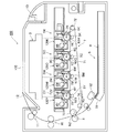
先ず、本実施例の画像形成装置の全体的な構成及び動作について図2を用いて説明する。図2は、本実施例の画像形成装置100の概略断面図である。
本実施例の画像形成装置100は、電子写真プロセスを用いて紙などの記録媒体(以下、記録材)Pにフルカラー画像の形成が可能なレーザビームプリンタである。
本実施例の画像形成装置100は、複数の画像形成部として第1、第2、第3、第4の画像形成部(ステーション)SY、SM、SC、SKを有する。第1、第2、第3、第4の画像形成部SY、SM、SC、SKでは、それぞれイエロー(Y)、マゼンタ(M)、シアン(C)、ブラック(K)の画像が形成される。
[Example]
(1) Overall Configuration and Operation of Image Forming Apparatus First, the overall configuration and operation of the image forming apparatus of this embodiment will be described with reference to FIG. FIG. 2 is a schematic cross-sectional view of the
The
The
本実施例では、第1、第2、第3、第4の画像形成部SY、SM、SC、SKの構成及び動作は、使用する現像剤としてのトナーの色が異なることを除いて実質的に同じである。従って、以下、特に区別を要しない場合は、いずれかの色用に設けられた要素であることを表す符号の添え字Y、M、C、Kは省略して、総括的に説明する。
ここで、本実施例では、画像形成装置100に関して、図2において右側の装置開閉ドア13を設けた側を正面(前面)、正面とは反対側の面を背面(後面)とする。又、画像形成装置100を正面から見て右側を駆動側、左側を非駆動側とする。
In this embodiment, the configuration and operation of the first, second, third, and fourth image forming units SY, SM, SC, and SK are substantially the same except that the color of the toner as the developer to be used is different. Is the same. Therefore, in the following, when there is no particular need to distinguish, subscripts Y, M, C, and K indicating elements provided for any color will be omitted, and the description will be made comprehensively.
In this embodiment, with respect to the
本実施例の画像形成装置100は、プロセスカートリッジ方式を採用しており、プロセスカートリッジ120を画像形成装置100の装置本体110に取り外し可能に装着することによって、記録材Pに画像を形成することができる。
装置本体110内において、第1、第2、第3、第4のプロセスカートリッジ120Y、120M、120C、120Kは、略水平方向に配置されている。第1、第2、第3、第4のプロセスカートリッジ120Y、120M、120C、120Kは、それぞれ同様の電子写真プロセス機構を有しており、収容するトナーの色が各々異なる。
プロセスカートリッジ120には、装置本体110の駆動出力部(図示せず)から回転駆動力が伝達される。又、プロセスカートリッジ120には、装置本体110のバイアス電源(図示せず)から、バイアス電圧(帯電バイアス、現像バイアスなど)が供給される。
The
In the apparatus
A rotational driving force is transmitted to the
図3は、本実施例のプロセスカートリッジ120の概略断面図である。
本実施例のプロセスカートリッジ120は、ドラム型の感光ドラム1と、この感光ドラム1に作用するプロセス手段と、を有する。本実施例では、感光ドラム1は、OPC(有機光導電体)感光体層を有する有機感光ドラムである。そして、本実施例では、プロセスカートリッジ120は、プロセス手段として、帯電手段、現像手段、クリーニング手段を有する。ここで、帯電手段としては、ローラ型の帯電部材である帯電ローラ2が設けられている。また、クリーニング手段としては、クリーニングブレード61が設けられている。また、現像手段としては、現像剤担持体としてローラ型の現像ローラ41を備えた現像
装置4が設けられている。現像装置4は更に、現像剤供給部材としての供給ローラ42、現像剤規制部材としての現像ブレード43などを有する。プロセスカートリッジ120のより具体的な構成については後述する。
FIG. 3 is a schematic cross-sectional view of the
The
第1のプロセスカートリッジ120Yは、現像枠体44内にイエロー(Y)のトナーを収容しており、感光ドラム1の表面にイエロー色のトナー像を形成する。第2のプロセスカートリッジ120Mは、現像枠体44内にマゼンタ(M)のトナーを収容しており、感光ドラム1の表面にマゼンタ色のトナー像を形成する。第3のプロセスカートリッジ120Cは、現像枠体44内にシアン(C)のトナーを収容しており、感光ドラム1の表面にシアン色のトナー像を形成する。第4のプロセスカートリッジ120Kは、現像枠体44内にブラック(K)のトナーを収容しており、感光ドラム1の表面にブラック色のトナー像を形成する。
装置本体110内において、第1、第2、第3、第4のプロセスカートリッジ120Y、120M、120C、120Kの上方には、露光手段としてのレーザスキャナユニット3が設けられている。このレーザスキャナユニット3は、画像情報に対応してレーザ光を出力する。そして、このレーザ光は、プロセスカートリッジ120の露光窓部123を通過して感光ドラム1の表面を走査露光する。
The
In the apparatus
また、装置本体110内において、第1、第2、第3、第4のプロセスカートリッジ120Y、120M、120C、120Kと対向する位置(本実施例では各プロセスカートリッジ120の下方)には、中間転写ユニット7が設けられている。中間転写ユニット7は、中間転写体としての可撓性を有する無端ベルト状の中間転写ベルト71を有する。中間転写ベルト71は、複数の支持ローラとしての駆動ローラ72、ターンローラ73、テンションローラ74に掛け渡されている。プロセスカートリッジ120の感光ドラム1は、中間転写ベルト71に当接するように配置されている。これにより、感光ドラム1と中間転写ベルト71との間に、1次転写部(接触部)N1が形成されている。
Further, in the apparatus
中間転写ベルト71の内周面側には、感光ドラム1に対向して1次転写手段としてのローラ型の転写部材である1次転写ローラ5が設けられている。1次転写ローラ5は、中間転写ベルト71を介して、感光ドラム1に当接するように配置されている。また、2次転写手段としてのローラ型の転写部材である2次転写ローラ8が、中間転写ベルト71を介してターンローラ73に当接するように配置されている。これにより、中間転写ベルト71と2次転写ローラ8との間に、2次転写部(接触部)N2が形成されている。
2次転写部N2よりも記録材Pの搬送方向の上流側(本実施例では中間転写ユニット7の下方)には、給送ユニット9が設けられている。給送ユニット9は、記録材Pを積載して収容した給送トレイ91、給送ローラ92などを有する。2次転写部N2よりも記録材Pの搬送方向の下流側(本実施例では装置本体110内の背面側上方)には、定着手段としての定着ユニット10と、排出ユニット11とが設けられている。装置本体110の上面には、排出トレイ12が設けられている。
A primary transfer roller 5 that is a roller-type transfer member serving as a primary transfer unit is provided on the inner peripheral surface side of the
A feeding unit 9 is provided upstream of the secondary transfer portion N2 in the conveyance direction of the recording material P (in this embodiment, below the intermediate transfer unit 7). The feeding unit 9 includes a feeding
(2)画像形成動作
画像形成動作の一例として、フルカラー画像を形成する動作について図2を用いて説明する。
各プロセスカートリッジ120の感光ドラム1が、図2中矢印R1方向に所定の速度(周速度)で回転駆動される。このとき、中間転写ベルト71も、1次転写部N1における表面の移動方向が感光ドラム1と順方向となるように、図2中矢印R2方向に感光ドラム1の速度(周速度)に対応した速度(周速度)で回転駆動される。
(2) Image Forming Operation As an example of the image forming operation, an operation for forming a full color image will be described with reference to FIG.
The
次に、レーザスキャナユニット3が駆動される。レーザスキャナユニット3の駆動に同期して、各プロセスカートリッジ120において、帯電ローラ2により、感光ドラム1の
表面が所定の極性及び電位に一様に帯電される。そして、レーザスキャナユニット3は、各感光ドラム1の表面を各色の画像信号に応じてレーザ光で走査露光する。これにより、各感光ドラム1の表面に、対応する色の画像信号に応じた潜像(静電像、静電潜像)が形成される。
各感光ドラム1上に形成された潜像は、現像装置4の現像ローラ41によりトナーが供給されることで、トナー像として現像される。ここで、現像ローラ41は、図2中矢印R3方向に所定の速度(周速度)で回転駆動される。
Next, the laser scanner unit 3 is driven. In synchronization with the driving of the laser scanner unit 3, the surface of the
The latent image formed on each
上述のような電子写真画像形成プロセスにより、第1のプロセスカートリッジ120Yの感光ドラム1には、フルカラー画像のイエロー成分に対応するイエロー色のトナー像が形成される。そして、そのトナー像が、1次転写ローラ5Yの作用により、中間転写ベルト71上に1次転写される。同様に第2のプロセスカートリッジ120Mの感光ドラム1には、フルカラー画像のマゼンタ成分に対応するマゼンタ色トナー像が形成される。そして、そのトナー像が、中間転写ベルト71上に既に転写されているイエロー色のトナー像に重畳されて1次転写される。同様に第3のプロセスカートリッジ120Cの感光ドラム1には、フルカラー画像のシアン成分に対応するシアン色トナー像が形成される。そして、そのトナー像が、中間転写ベルト71上に既に転写されているイエロー色、マゼンタ色のトナー像に重畳されて1次転写される。同様に第4のプロセスカートリッジ120Kの感光ドラム1には、フルカラー画像のブラック成分に対応するブラック色トナー像が形成される。そして、そのトナー像が、中間転写ベルト71上に既に転写されているイエロー色、マゼンタ色、シアン色のトナー像に重畳されて1次転写される。
このようにして、中間転写ベルト71上にイエロー色、マゼンタ色、シアン色、ブラック色の4色のトナー像によるフルカラー画像の未定着トナー像が形成される。
By the electrophotographic image forming process as described above, a yellow toner image corresponding to the yellow component of the full color image is formed on the
In this way, an unfixed toner image of a full color image is formed on the
一方、給送ユニット9において所定の制御タイミングで記録材Pが1枚ずつ分離されて給送される。その記録材Pは、所定の制御タイミングで、2次転写ローラ8と中間転写ベルト71との接触部である2次転写部N2に導入される。
これにより、記録材Pが2次転写部N2を搬送されていく過程で、中間転写ベルト71上の、4色分が重畳されたトナー像が、記録材P上に順次に一括して2次転写される。
その後、未定着トナー像を担持した記録材Pは、定着ユニット10へと搬送される。そして、記録材Pは、定着ユニット10によってトナー像が定着された後に、排出トレイ12へ排出される。1次転写工程後に感光ドラム1上に残留したトナー(1次転写残トナー)は、クリーニングユニット6に設けられたクリーニングブレード61によって感光ドラム1上から除去されて回収される。
On the other hand, the recording material P is separated and fed one by one at a predetermined control timing in the feeding unit 9. The recording material P is introduced into a secondary transfer portion N2 that is a contact portion between the secondary transfer roller 8 and the
As a result, in the process in which the recording material P is conveyed through the secondary transfer portion N2, the toner images on which the four colors are superimposed on the
Thereafter, the recording material P carrying the unfixed toner image is conveyed to the fixing
(3)プロセスカートリッジの構成
次に、本実施例のプロセスカートリッジの構成について、図3、4を用いて説明する。
図4は、本実施例のプロセスカートリッジ120の概略斜視図である。
プロセスカートリッジ120は、感光ドラム1の回転軸線方向を長手方向とする横長の形状である。プロセスカートリッジ120は、装置本体110に装着された状態で、長手方向の一方側が駆動側に配置され、他方側が非駆動側に配置される。プロセスカートリッジ120は、クリーニングユニット6と、現像ユニット(現像装置4)と、駆動側カバー部材124と、非駆動側カバー部材125と、を有する。クリーニングユニット6と現像装置4は互いに結合されている。
(3) Configuration of Process Cartridge Next, the configuration of the process cartridge of this embodiment will be described with reference to FIGS.
FIG. 4 is a schematic perspective view of the
The
クリーニングユニット6は、感光ドラム1と、帯電ローラ2と、クリーニングブレード61を有する。感光ドラム1、帯電ローラ2及びクリーニングブレード61は、廃トナー収容部62aを形成する枠体としてのクリーニング容器(クリーニング枠体)62に取り付けられている。
帯電ローラ2は、感光ドラム1の表面に接触し、感光ドラム1の回転に従動して回転す
る。そして、帯電ローラ2は、帯電バイアスの供給を受けて、感光ドラム1の表面を帯電させる。
The
The charging
クリーニングブレード61は、クリーニング容器62に固定されている。クリーニングブレード61は、その先端(短手方向の自由端)の弾性ゴム部が、感光ドラム1の回転方向に対してカウンター方向で感光ドラム1に当接するように配置されている。クリーニングブレード61は、画像形成時には、回転する感光ドラム1上に残留した転写残トナーを掻き取って、感光ドラム1の表面をクリーニングする。クリーニングブレード61は、その先端が、転写残トナーをより確実に掻き取るために感光ドラム1の表面に対して所定の圧力をもって当接するように配置されている。
クリーニングブレード61によって感光ドラム1の表面から掻き取られた転写残トナーは、廃トナーとしてクリーニング容器62の内部に形成された廃トナー収容部62aに収容される。
The
The transfer residual toner scraped off from the surface of the
(4)現像装置の構成
次に、本実施例の現像装置の構成について、図3、5を用いて説明する。
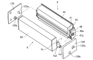
図5は、本実施例の現像装置4の分解斜視図である。
現像装置4は、現像ローラ41の回転軸線方向(回転軸方向)を長手方向とする横長の形状である。現像装置4は、装置本体110内に配置された状態で、長手方向の一方側が駆動側に配置され、他方側が非駆動側に配置される。
(4) Configuration of Developing Device Next, the configuration of the developing device of this embodiment will be described with reference to FIGS.
FIG. 5 is an exploded perspective view of the developing
The developing
現像ローラ41及び供給ローラ42は、トナー収容部44aを形成する現像枠体44に取り付けられている。現像ローラ41の回転軸41aの両端部は、それぞれ現像枠体44の駆動側端部、非駆動側端部に取り付けられた駆動側軸受部材45、非駆動側軸受部材46によって回転自在に支持されている。同様に、供給ローラ42の回転軸42aの両端部は、それぞれ駆動側軸受部材45、非駆動側軸受部材46によって回転自在に支持されている。駆動側軸受部材45、非駆動側軸受部材46は、それぞれ現像枠体44に一体的に固定されている。
本実施例では、現像ローラ41は、ステンレスなどの金属からなる回転軸(芯材、芯金)41aの周りに、適度な導電性を持たせた弾性層41bが形成されて構成されている。弾性層41bは、ゴム材料で形成されている。ゴム材料としては、シリコンゴム、ウレタンゴム、アクリルゴム、天然ゴム、EPDM(エチレンプロピレンジエンゴム)などを用いることができる。弾性層41bの電気抵抗値は、カーボンやカーボン樹脂粒子、金属粒子、イオン導電剤などを分散させることで調整することができる。
The developing
In this embodiment, the developing
現像装置4の駆動側軸受部材45よりも長手方向外側において、現像ローラ41の回転軸41aの駆動側端部には、現像ローラギア41cが取り付けられている。同様に、現像装置4の駆動側軸受部材45よりも長手方向外側において、供給ローラ42の回転軸42aの駆動側端部には、供給ローラギア42bが取り付けられている。そして、これら現像ローラギア41c、供給ローラギア42bは、駆動側軸受部材45により回転自在に支持された駆動伝達部としての現像駆動入力ギア47と噛み合っている。
A developing
現像駆動入力ギア47は、駆動入力カップリング47aを備えている。この駆動入力カップリング47aが、装置本体110側の駆動出力カップリング(図示せず)と係合して、装置本体110の駆動モータ(図示せず)の駆動力が現像駆動入力ギア47に伝達される。これにより、現像ローラギア41c、供給ローラギア42bを介して、現像ローラ41と供給ローラ42に駆動力が伝達され、現像ローラ41と供給ローラ42が所定の速度で回転駆動される。現像ローラ41は、図3中矢印R3方向に回転駆動され、供給ローラ42は、図3中矢印R4方向に回転駆動される。現像ローラ41と供給ローラ42とは接触しており、その接触部における互いの表面の移動方向は逆方向である。
The development
現像ブレード43は、厚み0.1mm程度の弾性を有する金属薄板である。現像ブレード43は、その先端(短手方向の自由端)が、現像ローラ41の回転方向に対してカウンター方向で現像ローラ41に当接するように配置されている。
現像装置4の長手方向の駆動側の端部において、供給ローラ42の回転軸42aの現像枠体44の外側に露出した部分に駆動側供給ローラ軸シール(以下、駆動側シール)50Rが装着されている。また、現像装置4の長手方向の非駆動側の端部において、供給ローラ42の回転軸42aの現像枠体44の外側に露出した部分に、非駆動側供給ローラ軸シール(以下、非駆動側シール)50Lが装着されている。これにより、現像枠体44と回転軸42aとの隙間からのトナー漏れが防止されている。
The developing
A drive-side supply roller shaft seal (hereinafter referred to as drive-side seal) 50 </ b> R is attached to a portion of the
画像形成時には、上述のようにして現像ローラ41と供給ローラ42とが駆動されることで、供給ローラ42と現像ローラ41とが回転しながら摺擦する。これにより、現像枠体44内のトナーが現像ローラ41上に担持される。
現像ブレード43は、現像ローラ41の周面に形成されるトナー層の厚みを規制すると共に、その現像ローラ41に対する当接圧により、現像ローラ41との間で摩擦帯電による電荷をトナーに付与する。
そして、現像ローラ41と感光ドラム1との接触部Aで、現像ローラ41上の電荷を帯びたトナーが、感光ドラム1上の潜像に付着する。これにより、感光ドラム1上の潜像がトナー像として現像される。
At the time of image formation, the developing
The developing
Then, the charged toner on the developing
(5)クリーニングユニットと現像装置の結合方法
次に、本実施例のクリーニングユニット6と現像装置4の結合方法について、図6、7を用いて説明する。
図6、7は、本実施例のクリーニングユニット6と現像装置4との結合方法を説明するための概略斜視図である。図6は、プロセスカートリッジ120の長手方向の駆動側から見たときの概略斜視図であり、図7は、プロセスカートリッジ120の長手方向の非駆動側から見たときの概略斜視図である。
(5) Method for coupling cleaning unit and developing device Next, a method for coupling the
6 and 7 are schematic perspective views for explaining a method of coupling the
感光ドラム1の長手方向における駆動側の端部には、駆動側端部部材1aが取り付けられている。この駆動側端部部材1aには、駆動入力カップリング1a1と軸部1a2とが設けられている。駆動入力カップリング1a1は、装置本体110側の駆動出力カップリング(図示せず)と係合して、装置本体110の駆動モータ(図示せず)の駆動力を受け取る。また、感光ドラム1の長手方向における非駆動側の端部には、非駆動側端部部材1bが取り付けられている。この非駆動側端部部材1bには、軸部1b1が設けられている。
駆動側カバー部材124は、駆動側感光ドラム軸受部124bによって、駆動側端部部材1aの軸部1a2を回転可能に支持する。非駆動側カバー部材125は、非駆動側感光体ドラム軸受部125bによって、非駆動側端部部材1bの軸部1b1を回転可能に支持する。そして、駆動側カバー部材124と非駆動側カバー部材125は、クリーニング容器62に固定される。
A driving
The driving
現像装置4の長手方向の駆動側の端部には、現像枠体44に一体的に固定されたギア保持部材49が設けられている。このギア保持部材49は、現像ローラ41及び供給ローラ42を支持する駆動側軸受部材45と共に、現像枠体44に一体的に固定されている。また、現像装置4の長手方向の非駆動側の端部には、現像ローラ41及び供給ローラ42を支持する非駆動側軸受部材46が、現像枠体44に一体的に固定されている。
A
ギア保持部材49は、上述した、装置本体110から現像装置4への駆動力を受け取る駆動入力カップリング47aを備えた現像駆動入力ギア47を、駆動側軸受部材45と共
に回転可能に支持している(図6)。ギア保持部材49の、現像装置4の長手方向における外側の側面には、円筒状の支持軸(支持機構)49aが設けられている。この支持軸49aが、駆動側カバー部材124の支持穴124aに嵌合することで、ギア保持部材49が駆動側カバー部材124によって回転可能に支持される。
非駆動側軸受部材46の、現像装置4の長手方向における外側の側面には、軸受としての長丸穴(長穴、溝形状)46aが設けられている。この長丸穴46aに、非駆動側カバー部材125の円筒形状の支持軸125aが嵌合することで、非駆動側軸受部材46、すなわち現像装置4が非駆動側カバー部材125によって回転可能かつスライド可能に支持される。この長丸穴46aの長手方向が、現像装置4のスライド可能な方向(スライド方向)になる。ここで、支持軸125aと長丸穴46aは、支持機構に相当する。また、長丸穴46aは、支持軸125aに直交する面内で支持軸125aをスライド可能に保持すると換言できる。
The
On the outer side surface of the non-driving
このように、現像装置4は、駆動側カバー部材124と非駆動側カバー部材125とによって回転(揺動)可能もしくは長丸穴46aでスライド可能に支持されている。現像ローラ41と感光ドラム1との距離は、現像装置4の回転およびスライドによって変えることができる。この現像装置4の回転およびスライドの動きを含めて詳細を後述する。
As described above, the developing
(6)現像装置の加圧および離間の方法
次に、本実施例の現像装置4の加圧について図1、8、9を用いて詳細に説明する。
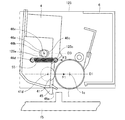
図1は、本実施例の現像装置4が画像形成を行っている姿勢(第1の位置)を示す概略側面図である。図8は、非駆動側から見た現像装置4が感光ドラム1から離間する経過を示す概略側面図である。図9は、非駆動側から見た現像装置4が感光ドラム1から離間した状態(第2の位置)を示す概略側面図である。ここで、図1、8、9では、説明の便宜上、非駆動側カバー部材125を不図示とし、部分的に二点鎖線で示した。また、以下の説明において、方向、角度、長さ等に関して図を用いて説明する場合があるが、このときの図は、現像ローラ41の回転軸に直交する面に、各構成部材を投影したときの投影図(投影面)に相当する。
(6) Method of pressurizing and separating the developing device Next, the pressurizing of the developing
FIG. 1 is a schematic side view showing a posture (first position) in which the developing
本実施例では、図1に示す状態では、長丸穴46aの中心46xは、支持軸125aの中心と略同一の位置に配置されている。そして、長丸穴46aの長手方向(長軸方向)に延びる直線D3は、感光ドラム1の回転中心1cと、現像ローラ41の回転中心41dとを結んだ直線D1と同一の向きとなるように構成されている。つまり、直線D3と直線D1は略平行(平行)となっている。ここで、直線D1は第1直線に相当し、直線D3は、支持軸125aを通り支持軸125aのスライド方向に平行な第2直線に相当する。
長丸穴46aが設けられている非駆動側軸受部材46は、現像装置4と一体的に固定されている。
In the present embodiment, in the state shown in FIG. 1, the
The non-driving
本実施例では、現像装置4を感光ドラム1に向けて付勢する付勢手段として加圧バネ55が設けられている。加圧バネ55は、現像ローラ41を感光ドラム1に当接させるための付勢力を現像装置4に加えていると換言できる。
本実施例では、加圧バネ55として、一端が、非駆動側軸受部材46に設けられたバネ掛け部46dに掛けられ、他端が、非駆動側カバー部材125に設けられたバネ掛け部125cに掛けられた引っ張りバネを適用している。ここで、バネ掛け部46dは、現像装置4において加圧バネ55の付勢力が作用する作用点に相当する。
In this embodiment, a
In the present embodiment, one end of the
そして、加圧バネ55が掛けられた2点を結ぶ直線(バネ掛け部46dの中心とバネ掛け部125cの中心を結んだ直線)D2は、上述の感光ドラム1の回転中心1cと現像ローラ41の回転中心41dとを結んだ直線D1と略平行である。ここで、直線D2は、バネ掛け部46dに作用する加圧バネ55の加圧力の方向に平行な直線に相当する。
そして、本実施例においては、加圧バネ55が、感光ドラム1の回転中心1cと現像ローラ41の回転中心41dとを結んだ直線D1と、長丸穴46aの長手方向に延びる直線D3と、の間の領域に配置されている。加圧バネ55の加圧力(付勢力、バネ力)である力F3は、現像装置4を感光ドラム1の方向へ引きつけるように作用している。本実施例では、加圧バネ55が、直線D1と直線D3との間の領域に配置されている形態について説明するが、これに限るものではなく、この領域に、加圧バネ55の付勢力が作用するバネ掛け部46dが配置されるものであればよい。
このとき、現像装置4の長丸穴46aは、非駆動側カバー部材125の支持軸125aに嵌合しているが、支持軸125aに規制されることなく、現像装置4が非駆動側カバー部材125に対して移動(スライド)可能な状態となっている。
これにより、感光ドラム1と現像ローラ41とが当接する力(当接力)の大きさF1を、加圧バネ55が発生する力F3と略同一にすることができる。
A straight line D2 (a straight line connecting the center of the
In this embodiment, the
At this time, the
Thereby, the magnitude F1 of the force (contact force) between the
次に、図8を用いて現像装置4を感光ドラム1から離間させる動作の過程を説明する。
現像装置4には、感光ドラム1から離間させるための力が、画像形成装置100に設けられた離間作動部材15の離間作動部15aから与えられる。この力を、現像装置4は、駆動側軸受部材45の離間力受け部(受け部)45aで受ける。ここで、現像装置4を感光ドラム1から離間させる力は、現像装置4に対し加圧バネ55の加圧力に抗する力である。
本実施例では、4つのプロセスカートリッジ120を一つの部品で離間させるため、離間作動部材15は、4つ設けられた離間作動部15aが連結部15bにより連結された一体的な構造になっている。
Next, the process of moving the developing
A force for separating the developing
In this embodiment, in order to separate the four
離間作動部材15が、離間力受け部45aと非接触の状態(図1)から矢印D4の方向(図8)へ移動すると、離間作動部15aが駆動側軸受部材45の離間力受け部45aに接触して、作動力F5によって現像装置4を矢印D4の方向へ移動させる。
これと同時に、現像装置4は加圧バネ55から力F3が加えられているため、現像ローラ41と感光ドラム1の接触部Bを支点としてD5方向へ回転する。ただし、現像装置4は、長丸穴46aが支持軸125aにより規制されているため、結果的に長丸穴46aに沿ってスライドし、長丸穴46aの左側端46eに支持軸125aが突き当たるまで移動する。
When the
At the same time, since the force F3 is applied from the
次に、離間作動部材15が、矢印D4の方向へ更に移動することで、離間作動部15aが離間力受け部45aを作動力F5によって更に移動させる。このとき、長丸穴46aはこれ以上D5方向へは移動できない。この為、図9に示すように支持軸125aを回転軸として現像装置4全体がD6方向へ回転する。これにより、現像ローラ41は、感光ドラム1から予め設定されたギャップEだけ離間する。
Next, the
ここで、現像装置4を離間させるために必要な力の大きさについて説明する。
図9の状態において、支持軸125aからバネ掛け部46dまでの距離をr1とする。また図9の状態において、支持軸125aを中心としてバネ掛け部46dを通る半径r1の仮想円の接線t1と直線D2との成す角度をθ1とする。
加圧バネ55が現像装置4をD7方向(半径r1の仮想円の接線方向)に回転させるモーメントM3は下記の式で表わされる。
M3=F3cosθ1×r1
Here, the magnitude of the force necessary for separating the developing
In the state of FIG. 9, the distance from the
The moment M3 by which the
M3 = F3cos θ1 × r1
一方、離間作動部材15が現像装置4を回転させるモーメントM4は、モーメントM3と同じ大きさであり、下記の式で表わされる。ここで、r2は支持軸125aと離間力受け部45aとの距離である。
M4=F5×r2
図9の状態で釣り合っているため、モーメントM3=モーメントM4であり、この状態を維持するために必要な力F5は次の式で表わされる。
On the other hand, the moment M4 that causes the separating
M4 = F5 × r2
Since the state of FIG. 9 is balanced, moment M3 = moment M4, and the force F5 necessary to maintain this state is expressed by the following equation.
![]()
![]()
本実施例では、角度θ1が約60°になる位置にバネ掛け部が配置されている。また、距離r1と距離r2の比率は1:3の配置である。
この配置を上記式に当てはめると、離間作動部材15が現像装置4を離間させるために押す力F5は、次の式で表される。
In this embodiment, the spring hooking portion is disposed at a position where the angle θ1 is about 60 °. The ratio of the distance r1 and the distance r2 is 1: 3.
When this arrangement is applied to the above equation, the force F5 that the separating
![]()
![]()
このように、使用している加圧バネ55の作動力に対して1/6まで小さくすることができる。
ここで、式1からわかるように、角度θ1(θ1<90度)を大きくとった方が力F5を小さくすることができる。また、支持軸125aの中心とバネ掛け部46dの中心を結ぶ直線と、直線D2とのなす角をとった場合には、この角の大きさが90度より小さく設定されるとよく、この角の大きさが小さくなるほど、力F5を小さくすることができる。
また、距離r1よりも距離r2をより長くすることでも、力F5を小さくすることができることがわかる。また、支持軸125aから現像ローラ41の回転中心41dまでの距離よりも距離r2をより長くすることでも、力F5を小さくすることができる。
このようにして、感光ドラム1と現像ローラ41の必要な当接力を与えつつ、現像装置4を感光ドラム1から離間させるための力を小さくすることが可能となる。
Thus, the operating force of the
Here, as can be seen from
It can also be seen that the force F5 can be reduced by making the distance r2 longer than the distance r1. The force F5 can also be reduced by making the distance r2 longer than the distance from the
In this way, it is possible to reduce the force for separating the developing
(変形例)
以下に、変形例について説明する。ここでは、上述した実施例に対して異なる構成部分について述べることとし、上述の実施例と同様の構成部分については、その説明を省略する。
まず、上述した実施例に対して長丸穴46aの向きを変えた形態について、図10を用いて説明する。
図10には、直線D1に対する、長丸穴46aの向きが上述した実施例とは異なる形態を示している。
(Modification)
Hereinafter, modified examples will be described. Here, different components from the above-described embodiment will be described, and the description of the same components as the above-described embodiment will be omitted.
First, the form which changed the direction of the
FIG. 10 shows a form in which the direction of the
図10に示す形態では、直線D1に対し、長丸穴46aの長手方向に延びる直線D8が、水平線(水平方向)Hに対して傾いており、長丸穴46aのうち感光ドラム1に近い側46cが水平線Hに対して鉛直方向下方に角度θ2、傾くように構成されている。ここで、図10において、直線D1と直線D8とのなす角度をθ3とする。また、加圧バネ55は、直線D8と直線D1との間に配置されている。
現像装置4は、現像装置4の重量MDにより長丸穴46aにガイドされて、直線D8に平行な方向に分力F6が生じる。
In the form shown in FIG. 10, the straight line D8 extending in the longitudinal direction of the
The developing
そして、この分力F6は、現像ローラ41と感光ドラム1の当接力F7の一部になる。つまり、直線D8に平行な方向(スライド方向)に作用する現像装置4の自重の分力F6が、現像ローラ41を感光ドラム1に押し当てるように作用する。分力F6の大きさ、お
よび、分力F6から生じる当接力F7の大きさはそれぞれ次の式で表される。
F6=MD×sinθ2
F7=F6×cosθ3=MD×sinθ2×cosθ3
The component force F6 becomes a part of the contact force F7 between the developing
F6 = MD × sin θ2
F7 = F6 × cos θ3 = MD × sin θ2 × cos θ3
このように、長丸穴46aの角度θ2(θ3)を調整することで、現像ローラ41と感光ドラム1の当接力F7を調整することができる。これにより、加圧バネ55の力を小さくしつつ必要な当接力を発生させることができる。さらには、加圧バネ55の力を小さくすることができるので、離間させる時に必要な力も小さくすることができる。
Thus, the contact force F7 between the developing
さらに別の変形例として、上述した実施例に対して加圧バネ55の向きを変えた形態について、図11を用いて説明する。
図11には、直線D1に対する、加圧バネ55の向き、すなわち、加圧バネ55が掛けられた2点を結ぶ直線D11の向きが上述した実施例とは異なる形態を示している。加圧バネ55は、一端が現像装置4のバネ掛け部46dに掛けられ、他端がバネ掛け部46dから水平線Hに対して鉛直方向上方に角度θ5傾いた位置にあるバネ掛け部125cに掛けられている。また、加圧バネ55は、長丸穴46aの長手方向に延びる直線D9と、直線D1との間に配置されている。
As yet another modification, a mode in which the direction of the
FIG. 11 shows a form in which the direction of the pressurizing
この形態では、直線D1と直線D11とがθ4の角度をなすように構成されている。このことから、現像ローラ41と感光ドラム1の当接力F9は、加圧バネ55の加圧力である力F8の分力になり次の式で表わされる。
F9=F8×cosθ4
また、加圧バネ55は鉛直上向きにも分力F10を発生させ、次の式で表わされる。
F10=F8×sinθ5
In this embodiment, the straight line D1 and the straight line D11 are configured to form an angle of θ4. From this, the contact force F9 between the developing
F9 = F8 × cos θ4
The
F10 = F8 × sin θ5
現像装置4の重量が大きいとき、または図11のように現像装置4の重心Gが支持軸125aと離れているとき、現像装置4は支持軸125aを中心に矢印D10方向へ回転する力を受ける。その力(支持軸回りのモーメント)は、重力(現像装置4の自重)によるものであり、現像装置4が感光ドラム1と離れる方向へ作用する。上述の鉛直上向きの分力F10は、現像装置4の重量が大きいときや、支持軸125aと現像装置4の重心が離れているときに、現像装置4の重量を支えるように作用する。
これにより、現像装置4が受ける重力を相殺して、感光ドラム1と現像ローラ41との当接をより確実に行うことができるようになる。
ここで、現像装置4の重量が重いときには、現像装置4を支えている支持軸125aと長丸穴46aとの摩擦力が大きくなる。図11の形態では、分力F10が現像装置4の重さを支えるように作用するため、支持軸125aと長丸穴46aとの摩擦力を小さくして、より効率良く当接力を与えることができる。このことで、分力F10が作用していない場合のように加圧バネ55の力を大きくする必要が無くなる。
When the weight of the developing
Thereby, the gravitational force received by the developing
Here, when the weight of the developing
上述した変形例においては、長丸穴46aの向きと加圧バネ55の向きについて、それぞれ説明したが、これらを組み合わせることもできる。長丸穴46aの向きと加圧バネ55の向きは、直線D1に対して90°未満の角度差であればよい(直交するものでなければよい)。現像装置の設計上の制約に合わせて適宜選択することができる。
In the modified example described above, the direction of the
以上説明したように、本実施例では、現像装置4を支持する支持軸125aがスライド可能に設けられ、加圧バネ55の加圧力が作用するバネ掛け部46dが、直線D1と直線D3との間の領域に配置されている。これにより、現像ローラ41を感光ドラム1に押し当てる力として、加圧バネ55の加圧力を効率的に作用させることが可能となる。一方、現像ローラ41を感光ドラム1から離間させる際には、支持軸125aを回転中心として現像ローラ41を回転させることができるので、離間に必要な力を小さく設定することが
可能となる。したがって、感光ドラム1と現像ローラ41とが当接しているときには十分な当接力を与えつつ、現像ローラ41を感光ドラム1から離間させるための力をより小さくすることが可能となる。
このように、現像装置4を感光ドラム1から離間させる力をより小さくすることができることにより、画像形成装置100の離間駆動部分の小型化および省電力化を実現し、コスト削減につなげることが可能となる。
また、従来の構成では、感光ドラム1と現像ローラ41とが離間状態から当接状態となる場合、現像ローラ41が感光ドラム1に当接する際の衝撃音が大きくなることが懸念されていた。本実施例においては、離間状態から当接状態へ向かう時の力を、従来の構成よりも小さくすることができるので、当接の際の衝撃による振動や音を、より抑えることが可能となる。
また、図1の状態で、直線D1と直線D3とが略平行となるように配置されることで、現像ローラ41が感光ドラム1に対して略平行にスライド可能となる。このことで、感光ドラム1と現像ローラ41との間に所定の大きさ(本実施例ではF3)の力がかかったときに、その大きさの力を(力がロスすることなく)当接力(本実施例ではF1)とすることができる。さらに、直線D1と直線D2とが略平行となることで、感光ドラム1と現像ローラ41とが当接する当接力として必要な力の向きと、加圧バネ55が発生させる力(加圧力)の向きとを略一致させることができる。これにより、より確実に(効率的に)当接力を与えることが可能となる。
As described above, in the present embodiment, the
As described above, since the force for separating the developing
Further, in the conventional configuration, when the
In addition, in the state of FIG. 1, the developing
1…感光ドラム、1c…感光ドラム1の回転中心、4…現像装置、41…現像ローラ、41d…現像ローラ41の回転中心、46a…長丸穴、46d…バネ掛け部、49a…支持軸、55…加圧バネ、120…プロセスカートリッジ、125a…支持軸、D1,D3…直線
DESCRIPTION OF
Claims (11)
感光ドラムに当接して現像を行う現像ローラを有する現像ユニットと、
前記現像ローラの回転軸に平行な方向における前記カートリッジの両端において、前記現像ユニットを支持軸により回転可能に支持する2つの支持機構と、
前記現像ユニットに対し、前記2つの支持機構のうちいずれか一方の支持機構と同じ側に設けられ、前記現像ローラを前記感光ドラムに当接させるための付勢力を前記現像ユニットに加える付勢手段と、
を有し、前記現像ユニットに対し前記付勢力に抗する力が与えられると、前記支持軸を中心に前記現像ユニットが回転することで、前記現像ローラが前記感光ドラムから離間するカートリッジにおいて、
前記一方の支持機構は、前記支持軸に直交する面内で前記支持軸をスライド可能に保持する軸受を有しており、
前記現像ローラの回転軸に直交する面に、カートリッジの各構成部材を投影したときの投影面で、
前記現像ユニットにおいて前記付勢手段の付勢力が作用する作用点が、前記現像ローラの回転中心と前記感光ドラムの回転中心とを結ぶ第1直線と、前記支持軸を通り前記支持軸のスライド方向に平行な第2直線との間の領域にあり、
前記現像ユニットの自重による前記支持軸回りのモーメントが、前記現像ローラが前記感光ドラムから離間する方向に作用する構成であり、前記付勢手段の付勢力が鉛直上向きの分力を有することを特徴とするカートリッジ。 In the cartridge attached to and detached from the apparatus main body of the image forming apparatus,
A developing unit having a developing roller for developing in contact with the photosensitive drum;
Two supporting mechanisms for rotatably supporting the developing unit by a supporting shaft at both ends of the cartridge in a direction parallel to the rotating shaft of the developing roller;
A biasing unit that is provided on the same side as one of the two support mechanisms with respect to the developing unit and applies a biasing force to the developing unit to bring the developing roller into contact with the photosensitive drum. When,
In the cartridge in which the developing roller is separated from the photosensitive drum by rotating the developing unit around the support shaft when a force against the urging force is applied to the developing unit.
The one support mechanism has a bearing that slidably holds the support shaft in a plane orthogonal to the support shaft,
A projection surface when each component of the cartridge is projected onto a surface orthogonal to the rotation axis of the developing roller,
In the developing unit, the point of application of the urging force of the urging means is a first straight line connecting the rotation center of the developing roller and the rotation center of the photosensitive drum, and the sliding direction of the support shaft through the support shaft. In a region between a second straight line parallel to
The moment around the support shaft due to the weight of the developing unit acts in a direction in which the developing roller is separated from the photosensitive drum, and the urging force of the urging unit has a vertically upward component force. Cartridge.
ずれか1項に記載のカートリッジ。 The angle formed by a straight line connecting the support shaft and the action point on the projection plane and a straight line parallel to the direction of the urging force acting on the action point is smaller than 90 degrees. 4. The cartridge according to any one of items 3 .
前記投影面で、前記支持軸から前記受け部までの距離が、前記支持軸から前記作用点までの距離よりも長いことを特徴とする請求項1に記載のカートリッジ。 A receiving portion is provided that receives a force against the biasing force with respect to the developing unit,
In the projection plane A cartridge according to claim 1 distance to the receiving unit from the support shaft, characterized in longer than the distance from the support shaft to the point of action.
前記支持軸は、前記長穴の長手方向にスライド可能であることを特徴とする請求項1乃至7のいずれか1項に記載のカートリッジ。 The bearing is a long hole,
The cartridge according to any one of claims 1 to 7 , wherein the support shaft is slidable in a longitudinal direction of the elongated hole.
Priority Applications (2)
| Application Number | Priority Date | Filing Date | Title |
|---|---|---|---|
| JP2014046204A JP6376782B2 (en) | 2014-03-10 | 2014-03-10 | Cartridge and image forming apparatus |
| US14/634,956 US9213306B2 (en) | 2014-03-10 | 2015-03-02 | Cartridge and image forming apparatus |
Applications Claiming Priority (1)
| Application Number | Priority Date | Filing Date | Title |
|---|---|---|---|
| JP2014046204A JP6376782B2 (en) | 2014-03-10 | 2014-03-10 | Cartridge and image forming apparatus |
Related Child Applications (1)
| Application Number | Title | Priority Date | Filing Date |
|---|---|---|---|
| JP2018096110A Division JP6576507B2 (en) | 2018-05-18 | 2018-05-18 | Cartridge and image forming apparatus |
Publications (3)
| Publication Number | Publication Date |
|---|---|
| JP2015169876A JP2015169876A (en) | 2015-09-28 |
| JP2015169876A5 JP2015169876A5 (en) | 2017-04-13 |
| JP6376782B2 true JP6376782B2 (en) | 2018-08-22 |
Family
ID=54017278
Family Applications (1)
| Application Number | Title | Priority Date | Filing Date |
|---|---|---|---|
| JP2014046204A Active JP6376782B2 (en) | 2014-03-10 | 2014-03-10 | Cartridge and image forming apparatus |
Country Status (2)
| Country | Link |
|---|---|
| US (1) | US9213306B2 (en) |
| JP (1) | JP6376782B2 (en) |
Families Citing this family (20)
| Publication number | Priority date | Publication date | Assignee | Title |
|---|---|---|---|---|
| PT3242164T (en) | 2012-06-15 | 2019-09-27 | Canon Kk | Cartridge, process cartridge and electrophotographic image forming apparatus |
| JP6376841B2 (en) * | 2014-05-23 | 2018-08-22 | キヤノン株式会社 | Cartridge and image forming apparatus |
| JP6131223B2 (en) * | 2014-07-17 | 2017-05-17 | 京セラドキュメントソリューションズ株式会社 | Drive transmission mechanism and image forming apparatus having the same |
| MY189688A (en) | 2014-08-01 | 2022-02-26 | Canon Kk | Toner cartridge and toner supplying mechanism |
| EP3936943B1 (en) | 2014-11-28 | 2024-01-10 | Canon Kabushiki Kaisha | Developing cartridge |
| US10018959B2 (en) | 2016-03-11 | 2018-07-10 | Canon Kabushiki Kaisha | Image forming apparatus |
| JP6950147B2 (en) * | 2016-03-15 | 2021-10-13 | ブラザー工業株式会社 | Process cartridge |
| US10241438B2 (en) * | 2016-03-22 | 2019-03-26 | Canon Kabushiki Kaisha | Developing device having a developing unit that is pivotally supported about the axis of a shaft, and image forming apparatus |
| JP7076945B2 (en) * | 2016-03-22 | 2022-05-30 | キヤノン株式会社 | Developing equipment and image forming equipment |
| CA3118569A1 (en) | 2016-09-30 | 2018-04-05 | Canon Kabushiki Kaisha | Toner cartridge and toner supplying mechanism |
| DE112017004984T5 (en) | 2016-09-30 | 2019-06-27 | Canon Kabushiki Kaisha | Toner cartridge and toner delivery mechanism |
| JP7146410B2 (en) | 2018-02-21 | 2022-10-04 | キヤノン株式会社 | Cartridge and image forming apparatus using the same |
| JP7080678B2 (en) | 2018-03-13 | 2022-06-06 | キヤノン株式会社 | cartridge |
| JP7366599B2 (en) | 2018-06-25 | 2023-10-23 | キヤノン株式会社 | cartridge |
| JP2020101687A (en) * | 2018-12-21 | 2020-07-02 | キヤノン株式会社 | Development device, process cartridge and image formation device |
| JP7218178B2 (en) | 2018-12-28 | 2023-02-06 | キヤノン株式会社 | process cartridge |
| DK3944025T3 (en) * | 2019-03-18 | 2024-03-18 | Canon Kk | Device for electrophotographic imaging and cartridge |
| CN210488238U (en) * | 2019-09-12 | 2020-05-08 | 珠海联合天润打印耗材有限公司 | Processing box |
| WO2022037532A1 (en) * | 2020-08-15 | 2022-02-24 | 珠海鼎龙汇通打印科技有限公司 | Process cartridge |
| CN116339093B (en) | 2020-12-07 | 2024-03-29 | 佳能株式会社 | Toner container and image forming system |
Family Cites Families (31)
| Publication number | Priority date | Publication date | Assignee | Title |
|---|---|---|---|---|
| EP0501497B1 (en) * | 1991-03-01 | 1996-01-03 | Canon Kabushiki Kaisha | Image forming system and process cartridge removably mountable on same |
| JPH0950224A (en) * | 1995-08-04 | 1997-02-18 | Canon Inc | Process cartridge and electrophotographic image forming device |
| JP3126966B1 (en) * | 1999-10-29 | 2001-01-22 | キヤノン株式会社 | Reproduction method of process cartridge |
| US6714746B2 (en) | 2001-01-23 | 2004-03-30 | Canon Kabushiki Kaisha | Image forming apparatus rotationally driving image bearing member and contact electrifying member of process cartridge and process cartridge comprising image bearing member and contact electrifying member |
| JP2002258551A (en) | 2001-02-28 | 2002-09-11 | Canon Inc | Electrophotographic image forming device and process cartridge |
| JP2003307993A (en) | 2002-04-17 | 2003-10-31 | Canon Inc | Electrophotographic photoreceptor drum, process cartridge and electrophotographic image forming apparatus |
| JP2003307931A (en) | 2002-04-17 | 2003-10-31 | Canon Inc | Process cartridge and electrophotographic image forming apparatus |
| JP2003307992A (en) | 2002-04-17 | 2003-10-31 | Canon Inc | Process cartridge and electrophotographic image forming apparatus |
| JP4018517B2 (en) | 2002-11-29 | 2007-12-05 | キヤノン株式会社 | parts |
| JP2004177835A (en) | 2002-11-29 | 2004-06-24 | Canon Inc | Component and component supply method |
| JP2005077743A (en) | 2003-08-29 | 2005-03-24 | Canon Inc | Development frame, process cartridge, and electrophotographic image forming apparatus |
| JP2005148445A (en) | 2003-11-17 | 2005-06-09 | Canon Inc | Developing unit, process cartridge, electrophotographic image forming apparatus, and end part restricting member |
| JP4280770B2 (en) | 2006-01-11 | 2009-06-17 | キヤノン株式会社 | Process cartridge and electrophotographic image forming apparatus |
| JP4948382B2 (en) | 2006-12-22 | 2012-06-06 | キヤノン株式会社 | Coupling member for mounting photosensitive drum |
| JP4498407B2 (en) | 2006-12-22 | 2010-07-07 | キヤノン株式会社 | Process cartridge, electrophotographic image forming apparatus, and electrophotographic photosensitive drum unit |
| JP5311854B2 (en) | 2007-03-23 | 2013-10-09 | キヤノン株式会社 | Electrophotographic image forming apparatus, developing device, and coupling member |
| JP5219626B2 (en) | 2008-05-27 | 2013-06-26 | キヤノン株式会社 | Process cartridge and image forming apparatus |
| JP4701266B2 (en) * | 2008-05-27 | 2011-06-15 | キヤノン株式会社 | Process cartridge and electrophotographic image forming apparatus |
| JP4869289B2 (en) | 2008-05-27 | 2012-02-08 | キヤノン株式会社 | Process cartridge and electrophotographic image forming apparatus |
| JP5328230B2 (en) | 2008-06-10 | 2013-10-30 | キヤノン株式会社 | Cartridge and electrophotographic image forming apparatus using the cartridge |
| JP5288900B2 (en) | 2008-06-20 | 2013-09-11 | キヤノン株式会社 | Process cartridge and electrophotographic image forming apparatus |
| JP5283986B2 (en) | 2008-06-20 | 2013-09-04 | キヤノン株式会社 | Drum unit and electrophotographic image forming apparatus |
| JP2011186447A (en) | 2010-02-15 | 2011-09-22 | Canon Inc | Developing device and process cartridge |
| JP5517732B2 (en) | 2010-05-11 | 2014-06-11 | キヤノン株式会社 | Process cartridge and image forming apparatus |
| KR101615652B1 (en) * | 2011-01-06 | 2016-04-26 | 삼성전자 주식회사 | Process cartridge and image forming device having the same |
| JP5355679B2 (en) | 2011-12-27 | 2013-11-27 | キヤノン株式会社 | Process cartridge and image forming apparatus |
| JP5901327B2 (en) | 2012-02-09 | 2016-04-06 | キヤノン株式会社 | Developing device, process cartridge, and image forming apparatus |
| JP5675888B2 (en) | 2012-05-17 | 2015-02-25 | キヤノン株式会社 | Developer storage unit, developing device, process cartridge, image forming apparatus |
| JP6108728B2 (en) | 2012-08-31 | 2017-04-05 | キヤノン株式会社 | Packaging materials and cartridges |
| JP5669794B2 (en) * | 2012-09-11 | 2015-02-18 | キヤノン株式会社 | Process cartridge and image forming apparatus |
| JP5980064B2 (en) | 2012-09-13 | 2016-08-31 | キヤノン株式会社 | Development device manufacturing method and process cartridge manufacturing method |
-
2014
- 2014-03-10 JP JP2014046204A patent/JP6376782B2/en active Active
-
2015
- 2015-03-02 US US14/634,956 patent/US9213306B2/en active Active
Also Published As
| Publication number | Publication date |
|---|---|
| JP2015169876A (en) | 2015-09-28 |
| US20150253723A1 (en) | 2015-09-10 |
| US9213306B2 (en) | 2015-12-15 |
Similar Documents
| Publication | Publication Date | Title |
|---|---|---|
| JP6376782B2 (en) | Cartridge and image forming apparatus | |
| JP5127567B2 (en) | Process cartridge | |
| US9274499B2 (en) | Cartridge and image forming apparatus | |
| US9632479B2 (en) | Process cartridge and image forming apparatus | |
| JP4730413B2 (en) | Image forming apparatus and process cartridge | |
| JP4487927B2 (en) | Image forming apparatus | |
| JP6094869B2 (en) | Image forming apparatus | |
| JP2007322554A (en) | Photoreceptor unit and image forming apparatus | |
| JP2007171421A (en) | Toner recycling device, process cartridge, and image forming apparatus | |
| JP2007057953A (en) | Image forming apparatus | |
| JP7207921B2 (en) | photoreceptor unit | |
| JP5111238B2 (en) | Process cartridge | |
| US8543034B2 (en) | Electrophotographic color image forming apparatus and cartridge | |
| JP2004279937A (en) | Image forming apparatus | |
| JP6576507B2 (en) | Cartridge and image forming apparatus | |
| JP4761131B2 (en) | Image forming apparatus | |
| JP5241391B2 (en) | Cleaning device | |
| JP2010078687A (en) | Image forming apparatus | |
| JP2016161714A (en) | Developing device, process cartridge, and image forming apparatus | |
| US9164476B2 (en) | Toner cartridge having structure for minimizing deformation when gripped | |
| US10754292B2 (en) | Image forming apparatus | |
| JP4685197B2 (en) | Electrophotographic image forming apparatus and process cartridge | |
| JP2006184429A (en) | Cleaning device, process cartridge, and electronic photographic image forming apparatus | |
| JP5724456B2 (en) | Image forming apparatus | |
| JP2005070186A (en) | Process cartridge and electrophotographic image forming apparatus |
Legal Events
| Date | Code | Title | Description |
|---|---|---|---|
| A521 | Written amendment |
Free format text: JAPANESE INTERMEDIATE CODE: A523 Effective date: 20170307 |
|
| A621 | Written request for application examination |
Free format text: JAPANESE INTERMEDIATE CODE: A621 Effective date: 20170307 |
|
| A977 | Report on retrieval |
Free format text: JAPANESE INTERMEDIATE CODE: A971007 Effective date: 20171117 |
|
| A131 | Notification of reasons for refusal |
Free format text: JAPANESE INTERMEDIATE CODE: A131 Effective date: 20171128 |
|
| A521 | Written amendment |
Free format text: JAPANESE INTERMEDIATE CODE: A523 Effective date: 20180129 |
|
| A02 | Decision of refusal |
Free format text: JAPANESE INTERMEDIATE CODE: A02 Effective date: 20180220 |
|
| A521 | Written amendment |
Free format text: JAPANESE INTERMEDIATE CODE: A523 Effective date: 20180518 |
|
| A911 | Transfer of reconsideration by examiner before appeal (zenchi) |
Free format text: JAPANESE INTERMEDIATE CODE: A911 Effective date: 20180528 |
|
| TRDD | Decision of grant or rejection written | ||
| A01 | Written decision to grant a patent or to grant a registration (utility model) |
Free format text: JAPANESE INTERMEDIATE CODE: A01 Effective date: 20180626 |
|
| A61 | First payment of annual fees (during grant procedure) |
Free format text: JAPANESE INTERMEDIATE CODE: A61 Effective date: 20180724 |
|
| R151 | Written notification of patent or utility model registration |
Ref document number: 6376782 Country of ref document: JP Free format text: JAPANESE INTERMEDIATE CODE: R151 |