JP5328230B2 - Cartridge and electrophotographic image forming apparatus using the cartridge - Google Patents
Cartridge and electrophotographic image forming apparatus using the cartridge Download PDFInfo
- Publication number
- JP5328230B2 JP5328230B2 JP2008151824A JP2008151824A JP5328230B2 JP 5328230 B2 JP5328230 B2 JP 5328230B2 JP 2008151824 A JP2008151824 A JP 2008151824A JP 2008151824 A JP2008151824 A JP 2008151824A JP 5328230 B2 JP5328230 B2 JP 5328230B2
- Authority
- JP
- Japan
- Prior art keywords
- rotational force
- cartridge
- coupling
- main body
- axis
- Prior art date
- Legal status (The legal status is an assumption and is not a legal conclusion. Google has not performed a legal analysis and makes no representation as to the accuracy of the status listed.)
- Active
Links
Images


Classifications
-
- G—PHYSICS
- G03—PHOTOGRAPHY; CINEMATOGRAPHY; ANALOGOUS TECHNIQUES USING WAVES OTHER THAN OPTICAL WAVES; ELECTROGRAPHY; HOLOGRAPHY
- G03G—ELECTROGRAPHY; ELECTROPHOTOGRAPHY; MAGNETOGRAPHY
- G03G15/00—Apparatus for electrographic processes using a charge pattern
- G03G15/06—Apparatus for electrographic processes using a charge pattern for developing
- G03G15/08—Apparatus for electrographic processes using a charge pattern for developing using a solid developer, e.g. powder developer
- G03G15/0896—Arrangements or disposition of the complete developer unit or parts thereof not provided for by groups G03G15/08 - G03G15/0894
-
- G—PHYSICS
- G03—PHOTOGRAPHY; CINEMATOGRAPHY; ANALOGOUS TECHNIQUES USING WAVES OTHER THAN OPTICAL WAVES; ELECTROGRAPHY; HOLOGRAPHY
- G03G—ELECTROGRAPHY; ELECTROPHOTOGRAPHY; MAGNETOGRAPHY
- G03G15/00—Apparatus for electrographic processes using a charge pattern
- G03G15/06—Apparatus for electrographic processes using a charge pattern for developing
- G03G15/08—Apparatus for electrographic processes using a charge pattern for developing using a solid developer, e.g. powder developer
- G03G15/0806—Apparatus for electrographic processes using a charge pattern for developing using a solid developer, e.g. powder developer on a donor element, e.g. belt, roller
- G03G15/0808—Apparatus for electrographic processes using a charge pattern for developing using a solid developer, e.g. powder developer on a donor element, e.g. belt, roller characterised by the developer supplying means, e.g. structure of developer supply roller
-
- G—PHYSICS
- G03—PHOTOGRAPHY; CINEMATOGRAPHY; ANALOGOUS TECHNIQUES USING WAVES OTHER THAN OPTICAL WAVES; ELECTROGRAPHY; HOLOGRAPHY
- G03G—ELECTROGRAPHY; ELECTROPHOTOGRAPHY; MAGNETOGRAPHY
- G03G21/00—Arrangements not provided for by groups G03G13/00 - G03G19/00, e.g. cleaning, elimination of residual charge
- G03G21/16—Mechanical means for facilitating the maintenance of the apparatus, e.g. modular arrangements
- G03G21/18—Mechanical means for facilitating the maintenance of the apparatus, e.g. modular arrangements using a processing cartridge, whereby the process cartridge comprises at least two image processing means in a single unit
- G03G21/1839—Means for handling the process cartridge in the apparatus body
- G03G21/1842—Means for handling the process cartridge in the apparatus body for guiding and mounting the process cartridge, positioning, alignment, locks
- G03G21/1853—Means for handling the process cartridge in the apparatus body for guiding and mounting the process cartridge, positioning, alignment, locks the process cartridge being mounted perpendicular to the axis of the photosensitive member
-
- G—PHYSICS
- G03—PHOTOGRAPHY; CINEMATOGRAPHY; ANALOGOUS TECHNIQUES USING WAVES OTHER THAN OPTICAL WAVES; ELECTROGRAPHY; HOLOGRAPHY
- G03G—ELECTROGRAPHY; ELECTROPHOTOGRAPHY; MAGNETOGRAPHY
- G03G21/00—Arrangements not provided for by groups G03G13/00 - G03G19/00, e.g. cleaning, elimination of residual charge
- G03G21/16—Mechanical means for facilitating the maintenance of the apparatus, e.g. modular arrangements
- G03G21/18—Mechanical means for facilitating the maintenance of the apparatus, e.g. modular arrangements using a processing cartridge, whereby the process cartridge comprises at least two image processing means in a single unit
- G03G21/1839—Means for handling the process cartridge in the apparatus body
- G03G21/1857—Means for handling the process cartridge in the apparatus body for transmitting mechanical drive power to the process cartridge, drive mechanisms, gears, couplings, braking mechanisms
- G03G21/186—Axial couplings
-
- G—PHYSICS
- G03—PHOTOGRAPHY; CINEMATOGRAPHY; ANALOGOUS TECHNIQUES USING WAVES OTHER THAN OPTICAL WAVES; ELECTROGRAPHY; HOLOGRAPHY
- G03G—ELECTROGRAPHY; ELECTROPHOTOGRAPHY; MAGNETOGRAPHY
- G03G2221/00—Processes not provided for by group G03G2215/00, e.g. cleaning or residual charge elimination
- G03G2221/16—Mechanical means for facilitating the maintenance of the apparatus, e.g. modular arrangements and complete machine concepts
- G03G2221/1651—Mechanical means for facilitating the maintenance of the apparatus, e.g. modular arrangements and complete machine concepts for connecting the different parts
- G03G2221/1657—Mechanical means for facilitating the maintenance of the apparatus, e.g. modular arrangements and complete machine concepts for connecting the different parts transmitting mechanical drive power
Abstract
Description
本発明は、カートリッジ、及び、前記カートリッジを用いられる電子写真画像形成装置に関する。 The present invention is a cartridge, and an electrophotographic image forming apparatus is found with the cartridge.
電子写真画像形成装置としては、例えば、電子写真複写機、電子写真プリンター(レーザービームプリンター、LEDプリンター等)等である。 Examples of the electrophotographic image forming apparatus include an electrophotographic copying machine and an electrophotographic printer (laser beam printer, LED printer, etc.).
また、カートリッジとは、現像カートリッジ、及び、プロセスカートリッジを含む。ここで、現像カートリッジとは、電子写真感光体に形成された静電潜像を現像するための現像ローラを有しており、前記電子写真画像形成装置の本体に取り外し可能に装着されるものである。尚、前記電子写真感光体は、前記本体に設けられている場合と、前記現像ローラと一体的にユニット化して(プロセスカートリッジ構成)設けられている場合とがある。また、プロセスカートリッジとは、前記電子写真感光体と前記電子写真感光体に作用するプロセス手段としての、少なくとも現像ローラ(現像手段)とを一体的にカートリッジ化して、前記装置本体に取り外し可能に装着されるものである。ここで、前記電子写真感光体に作用する前記プロセス手段としては、前記現像ローラ(現像手段)に加えて、例えば、帯電手段、クリーニング手段が含まれる。従って、プロセスカートリッジは、例えば、前記電子写真感光体と前記電子写真感光体に作用するプロセス手段としての、少なくとも現像ローラ(現像手段)と帯電手段を一体的にカートリッジ化して、前記本体に取り外し可能に装着されるものである。また、プロセスカートリッジは、例えば、前記電子写真感光体と前記電子写真感光体に作用するプロセス手段としての、少なくとも現像ローラ(現像手段)とクリーニング手段を一体的にカートリッジ化して、前記装置本体に取り外し可能に装着されるものである。また、プロセスカートリッジは、例えば、前記電子写真感光体と前記電子写真感光体に作用するプロセス手段としての、現像ローラ(現像手段)とクリーニング手段及び帯電手段を一体的にカートリッジ化して、前記装置本体に取り外し可能に装着されるものである。 The cartridge includes a developing cartridge and a process cartridge. Here, the developing cartridge has a developing roller for developing the electrostatic latent image formed on the electrophotographic photosensitive member, and is detachably attached to the main body of the electrophotographic image forming apparatus. is there. The electrophotographic photosensitive member may be provided in the main body or may be provided as a unit (process cartridge configuration) integrally with the developing roller. Further, the process cartridge is a cartridge integrally formed with at least the developing roller (developing means) as the process means acting on the electrophotographic photosensitive member and the electrophotographic photosensitive member, and is detachably attached to the apparatus main body. It is what is done. Here, the process means acting on the electrophotographic photosensitive member includes, for example, a charging means and a cleaning means in addition to the developing roller (developing means). Accordingly, the process cartridge can be removed from the main body by integrally forming at least the developing roller (developing means) and the charging means as a cartridge as the process means acting on the electrophotographic photosensitive member and the electrophotographic photosensitive member, for example. It is to be attached to. In addition, the process cartridge, for example, at least a developing roller (developing means) and a cleaning means as a cartridge as the process means acting on the electrophotographic photosensitive member and the electrophotographic photosensitive member are integrally formed into a cartridge and removed from the apparatus main body. It can be installed as possible. Further, the process cartridge includes, for example, a developing roller (developing means), a cleaning means, and a charging means as a cartridge integrally as the electrophotographic photosensitive member and a process means acting on the electrophotographic photosensitive member. Is to be detachably mounted.
ここで、前記現像カートリッジ若しくはプロセスカートリッジは、使用者自身によって装置本体に着脱することができる。したがって、装置のメンテナンスをサービスマンによらずに、使用者自身で行うことができる。これによって、電子写真画像形成装置のメンテナンス操作を向上させている。 Here, the developing cartridge or the process cartridge can be attached to and detached from the apparatus main body by the user himself. Therefore, the maintenance of the apparatus can be performed by the user himself / herself without depending on the service person. This improves the maintenance operation of the electrophotographic image forming apparatus.
従来、電子写真画像形成装置においては、ドラム形状の電子写真感光体(以下、感光体ドラムと称する)に形成された静電潜像を現像装置(現像ローラ)を用いて現像するにあたって、下記の構成が知られている。 2. Description of the Related Art Conventionally, in an electrophotographic image forming apparatus, an electrostatic latent image formed on a drum-shaped electrophotographic photosensitive member (hereinafter referred to as a photosensitive drum) is developed using a developing device (developing roller). The configuration is known.
カートリッジ(現像カートリッジ、若しくは、プロセスカートリッジ)にギアを設ける。そして、カートリッジを画像形成装置の本体に取り付ける。これによって、カートリッジの有するギアを前記本体に設けたギアと噛合させる。そして、前記本体に設けたモータの回転力を本体に設けたギア及びカートリッジ側に設けたギアを介して現像ローラに伝達する。これによって、現像ローラを回転させる(特許文献1)。 A gear is provided on the cartridge (developing cartridge or process cartridge). Then, the cartridge is attached to the main body of the image forming apparatus. Thus, the gear of the cartridge is engaged with the gear provided on the main body. Then, the rotational force of the motor provided on the main body is transmitted to the developing roller via a gear provided on the main body and a gear provided on the cartridge side. As a result, the developing roller is rotated (Patent Document 1).
また、カートリッジ側に、カートリッジ側現像ローラカップリングを設ける。また、装置本体側に本体側現像ローラカップリングを設ける。そして、移動部材(進退機構)を用いて、本体側現像ローラカップリングをその軸線方向に移動させることによって、両カップリングを係合させる。また、移動部材(進退機構)を用いて、本体側現像ローラカップリングをその軸線方向に移動させることによって、両カップリングの係合を解除する。 Further, a cartridge side developing roller coupling is provided on the cartridge side. Further, a main body side developing roller coupling is provided on the main body side of the apparatus. Then, both the couplings are engaged by moving the main body side developing roller coupling in the axial direction using a moving member (advance / retreat mechanism). Further, by using a moving member (advance / retreat mechanism), the main assembly side developing roller coupling is moved in the axial direction thereof, thereby disengaging both couplings.
そして、カートリッジが本体に装着された際に、前記カップリングが係合した状態で前記本体側現像ローラカップリングが回転すると、前記本体側現像ローラカップリングの回転力が現像ローラに伝達される。これによって、前記現像ローラを回転させる(特許文献2)。
しかしながら、前述した従来の構成によれば、現像ローラの軸線と実質直交する方向への移動による、本体に対するカートリッジの着脱に際して、本体側現像ローラカップリングをその軸線方向に移動させなければならない。即ち、前記カートリッジの着脱に際して、本体に設けられた本体カバーの開閉動作によって、前記本体側現像ローラカップリングを水平方向に移動させなければならない。これによって、本体カバーの開放動作によって、前記本体側現像ローラカップリングを前記カートリッジ側現像ローラカップリングから離れる方向へ移動させる。反対に、本体カバーの閉じ動作によって、前記本体側現像ローラカップリングを前記カートリッジ側現像ローラカップリングと係合する方向へ移動させる。 However, according to the conventional configuration described above, when the cartridge is attached to or detached from the main body by moving in the direction substantially perpendicular to the axis of the developing roller, the main body side developing roller coupling must be moved in the axial direction. That is, when the cartridge is attached or detached, the main body side developing roller coupling must be moved in the horizontal direction by opening and closing the main body cover provided on the main body. Accordingly, the main body side developing roller coupling is moved away from the cartridge side developing roller coupling by the opening operation of the main body cover. On the contrary, the main body side developing roller coupling is moved in a direction to engage with the cartridge side developing roller coupling by the closing operation of the main body cover.
したがって、前記従来の構成によれば、本体カバーの開閉動作によって、前記回転体をその回転軸線方向へ移動させる構成(移動部材)を本体に設ける必要がある。 Therefore, according to the conventional configuration, it is necessary to provide the main body with a configuration (moving member) that moves the rotating body in the direction of the rotation axis by opening and closing the main body cover.
また、前述した別の従来の構成によれば、本体に設けた駆動ギアをその軸線方向に進退させなくても、カートリッジを前記軸線と実質的に直交する方向に移動させて、前記本体に着脱できる。しかしながら、この方式では、本体とカートリッジの駆動連結部がギア・ギアの噛合部となる。そのために、現像ローラの回転むらを防止することが難しい。 Further, according to another conventional configuration described above, the cartridge can be moved in the direction substantially perpendicular to the axis line without attaching or detaching the drive gear provided in the body in the direction of the axis line, without being moved forward and backward. it can. However, in this system, the drive connecting portion between the main body and the cartridge becomes the gear / gear meshing portion. For this reason, it is difficult to prevent uneven rotation of the developing roller.
本発明の目的は、上述の従来技術の不都合を解決できる、カートリッジ、及び、前記カートリッジを用いる電子写真画像形成装置を提供するものである。 SUMMARY OF THE INVENTION An object of the present invention is to provide a cartridge and an electrophotographic image forming apparatus using the cartridge, which can solve the above-mentioned disadvantages of the prior art.
本発明の他の目的は、本体カバーの開閉動作によって、現像ローラに回転力を伝達するための本体側カップリング部材を軸線方向へ移動させる機構を備えていない本体に用いられ、現像ローラを滑らかに回転させることができるカートリッジを提供するものである。また、前記カートリッジを用いた電子写真画像形成装置を提供するものである。 Another object of the present invention is used in a main body that does not include a mechanism for moving a main body side coupling member for transmitting a rotational force to the developing roller in the axial direction by opening and closing the main body cover, and smoothes the developing roller. A cartridge that can be rotated is provided. The present invention also provides an electrophotographic image forming apparatus using the cartridge.
本発明の他の目的は、駆動軸を備えた電子写真画像形成装置の本体から、前記駆動軸の軸線と直交する方向に取り外されるカートリッジを提供するものである。また、前記カートリッジを用いた電子写真画像形成装置を提供するものである。 Another object of the present invention is to provide a cartridge that is removed from a main body of an electrophotographic image forming apparatus having a drive shaft in a direction perpendicular to the axis of the drive shaft. The present invention also provides an electrophotographic image forming apparatus using the cartridge.
本発明の他の目的は、本体に設けられた駆動軸の軸線と実質的に直交する方向に取り外されること、及び、現像ローラを滑らかに回転させることができること、を共に実現したカートリッジを提供するものである。また、カートリッジを用いた電子写真画像形成装置を提供するものである。 Another object of the present invention is to provide a cartridge that can be removed in a direction substantially perpendicular to the axis of the drive shaft provided in the main body and that the developing roller can be rotated smoothly. Is. The present invention also provides an electrophotographic image forming apparatus using a cartridge.
本発明の他の目的は、ギアとギアとの噛合によって、本体から回転力を受ける場合と比較して、現像ローラを滑らかに回転することのできるカートリッジを提供するものである。また、前記カートリッジを用いた電子写真画像形成装置を提供するものである。 本発明の他の目的は、感光ドラムに対して位置決めされた現像カートリッジ(プロセスカートリッジの現像器)であっても、確実に現像ローラに回転力を与えることができ、滑らかな回転を実現することができるカートリッジを提供するものである。また、前記カートリッジを用いた電子写真画像形成装置を提供するものである。 Another object of the present invention is to provide a cartridge capable of smoothly rotating a developing roller as compared with a case where a rotational force is received from a main body by meshing between gears. The present invention also provides an electrophotographic image forming apparatus using the cartridge. Another object of the present invention is to provide a rotational force to the developing roller with certainty even when the developing cartridge is positioned with respect to the photosensitive drum (developing device of the process cartridge), and to realize smooth rotation. The present invention provides a cartridge that can be used. The present invention also provides an electrophotographic image forming apparatus using the cartridge.
ここで、感光体と現像ローラとが接触した状態で、感光体に形成された静電潜像を現像する、所謂接触現像方式が知られている。 Here, in a state where the photosensitive member and the developing roller are in contact to develop the electrostatic latent image formed on the photosensitive member, it is known so-called contact developing method.
本発明の他の目的は、感光体に接触した現像ローラが、感光体から離れるために移動したとしても、現像ローラを滑らかに回転させることのできるカートリッジを提供するものである。また、前記カートリッジを用いた電子写真画像形成装置を提供するものである。 Another object of the present invention, a developing roller in contact with the photosensitive member, even when moved to leave photoreceptor or al, is to provide a cartridge which can be smoothly rotating the developing roller. The present invention also provides an electrophotographic image forming apparatus using the cartridge.
ここで、感光体を回転させる回転力と現像ローラを回転させる回転力とを装置本体から別々に受ける構成が知られている。 Here, a configuration is known in which a rotational force for rotating the photosensitive member and a rotational force for rotating the developing roller are separately received from the apparatus main body.
本発明の他の目的は、感光体を回転させる回転力を受ける構成には、カップリングをその軸線方向に進退させる構成を用いることのできるカートリッジを提供するものである。また、前記カートリッジを用いた電子写真画像形成装置を提供するものである。 Another object of the present invention is to provide a cartridge capable of using a configuration in which a coupling is advanced and retracted in the axial direction for receiving a rotational force for rotating a photosensitive member . The present invention also provides an electrophotographic image forming apparatus using the cartridge.
前記課題を解決するための本発明は、
駆動軸と前記駆動軸に設けられた回転力付与部とを有する本体側係合部であって、モータにより回転される本体側係合部を備えた電子写真画像形成装置本体から、前記駆動軸の駆動軸線方向と実質的に直交する取り外し方向に移動して取り外されるカートリッジであって、
潜像を現像するべくローラ軸線を中心に回転可能な現像ローラと、
前記回転力付与部と係合して前記本体側係合部から前記現像ローラを回転させるための回転力を受ける回転力受け部と、前記回転力受け部を介して受けた前記回転力を前記現像ローラへ伝達する回転力伝達部と、を有し、前記本体側係合部から前記回転力を受けることによりカップリング軸線を中心に回転可能なカップリング部材と、
を有し、
前記カップリング軸線の前記回転力受け部側が前記回転力伝達部側よりも前記取り外し方向の上流側に位置するように前記カップリング部材が傾動可能に構成され、この傾動により前記カップリング部材が前記本体側係合部から離脱可能となることを特徴とするものである。
The present invention for solving the above problems is as follows.
A main body side engaging portion having a driving shaft and a rotational force applying portion provided on the driving shaft, wherein the driving shaft includes the main body side engaging portion rotated by a motor. The cartridge is moved and removed in a removal direction substantially perpendicular to the drive axis direction of
A developing roller rotatable about a roller axis to develop a latent image;
A rotational force receiving portion that engages with the rotational force applying portion and receives a rotational force for rotating the developing roller from the main body side engaging portion, and the rotational force received through the rotational force receiving portion A coupling member capable of rotating about a coupling axis by receiving the rotational force from the main body side engaging portion;
Have
The coupling member is configured to be tiltable so that the rotational force receiving portion side of the coupling axis is positioned upstream of the rotational force transmitting portion in the detaching direction. It can be detached from the main body side engaging portion .
前記課題を解決するための他の本発明は、
記録媒体に画像を形成する電子写真画像形成装置において、
駆動軸と前記駆動軸に設けられた回転力付与部とを有する本体側係合部であって、モータにより回転される本体側係合部を備えた電子写真画像形成装置本体と、
前記電子写真画像形成装置本体から、前記駆動軸の駆動軸線方向と実質的に直交する取り外し方向に移動して取り外されるカートリッジであって、
i)潜像を現像するべくローラ軸線を中心に回転可能な現像ローラと、
ii)前記回転力付与部と係合して前記本体側係合部から前記現像ローラを回転させるための回転力を受ける回転力受け部と、前記回転力受け部を介して受けた前記回転力を前記現像ローラへ伝達する回転力伝達部と、を有し、前記本体側係合部から前記回転力を受けることによりカップリング軸線を中心に回転可能なカップリング部材と、
を有するカートリッジと、
を有し、
前記カップリング軸線の前記回転力受け部側が前記回転力伝達部側よりも前記取り外し方向の上流側に位置するように前記カップリング部材が傾動可能に構成され、この傾動により前記カップリング部材が前記本体側係合部から離脱可能となることを特徴とするものである。
Another aspect of the present invention for solving the above problems is as follows:
In an electrophotographic image forming apparatus for forming an image on a recording medium,
An electrophotographic image forming apparatus main body comprising a main body side engaging portion having a driving shaft and a rotational force applying portion provided on the driving shaft, the main body side engaging portion being rotated by a motor;
A cartridge that is removed from the electrophotographic image forming apparatus main body by moving in a removal direction substantially perpendicular to a drive axis direction of the drive shaft;
i) a developing roller rotatable about a roller axis to develop the latent image;
ii) A rotational force receiving portion that engages with the rotational force applying portion and receives a rotational force for rotating the developing roller from the main assembly side engaging portion, and the rotational force received through the rotational force receiving portion A coupling member capable of rotating about a coupling axis by receiving the rotational force from the main body side engaging portion;
A cartridge having
Have
The coupling member is configured to be tiltable so that the rotational force receiving portion side of the coupling axis is positioned upstream of the rotational force transmitting portion in the detaching direction. It can be detached from the main body side engaging portion .
本発明によれば、駆動軸を備えた電子写真画像形成装置の本体から、前記駆動軸の軸線と実質的に直交する方向に取り外し可能なカートリッジを提供することができた。前記カートリッジを用いた電子写真画像形成装置を提供することができた。 According to the present invention, it is possible to provide a cartridge that can be removed from a main body of an electrophotographic image forming apparatus having a drive shaft in a direction substantially perpendicular to the axis of the drive shaft. An electrophotographic image forming apparatus using the cartridge can be provided.
本発明によれば、本体に設けられた駆動軸の軸線と実質的に直交する方向に取り外されること、及び、現像ローラを滑らか回転すること、を共に実現することができた。 According to the present invention, it is possible to realize both the removal in a direction substantially perpendicular to the axis of the drive shaft provided in the main body and the smooth rotation of the developing roller.
本発明によれば、ギアとギアとの噛合によって、本体から回転力を受ける場合と比較して、現像ローラを滑らかに回転させることができた。 According to the present invention, the developing roller can be smoothly rotated by meshing between the gear and the gear as compared with the case of receiving the rotational force from the main body.
本発明によれば、感光体に対して位置決めされたカートリッジであっても、確実に現像ローラに回転力を与えることができ、滑らかな回転を実現することができた。 According to the present invention, even if a cartridge positioned relative to the photosensitive member, it is possible to give a rotational force to ensure the developing roller, it was possible to achieve a smooth rotation.
他の本発明によれば、感光体に接触した現像ローラが、感光体から離れるために移動したとしても、現像ローラを滑らかに回転させることができた。 According to another present invention, a developing roller in contact with the photosensitive member, even when moved to leave photoreceptor or we were able to smoothly rotate a developing roller.
他の本発明によれば、感光体を回転させる回転力を受ける構成には、カップリングをその軸線方向に進退させる構成を用いることができる。 According to another aspect of the present invention, a configuration in which the coupling is advanced and retracted in the axial direction can be used as the configuration for receiving the rotational force for rotating the photosensitive member .
(実施例1)
先ず、本発明を適用可能な現像カートリッジを例に挙げて説明する。
Example 1
First, a developing cartridge to which the present invention can be applied will be described as an example.
ここで、現像カートリッジは、カートリッジの一例である。 Here, the developing cartridge is an example of a cartridge.
(1)現像カートリッジの説明
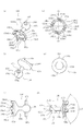
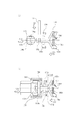
まず、図1乃至図4を用いて、本発明の一実施例を適用した、現像カートリッジB(以下、「カートリッジ」と称す。)について説明する。図1は、カートリッジBの断面図である。図2、図3はカートリッジBの斜視図である。また、図4は電子写真画像形成装置本体A(以下、「装置本体」又は「本体」と称す。)の断面図である。
(1) Description of Developing Cartridge First, a developing cartridge B (hereinafter referred to as “cartridge”) to which an embodiment of the present invention is applied will be described with reference to FIGS. FIG. 1 is a cross-sectional view of the cartridge B. 2 and 3 are perspective views of the cartridge B. FIG. 4 is a cross-sectional view of the electrophotographic image forming apparatus main body A (hereinafter referred to as “apparatus main body” or “main body”).
尚、このカートリッジBは、使用者によって、装置本体Aに、取付け、取り外しが可能である。 The cartridge B can be attached to and detached from the apparatus main body A by the user.
図1乃至図4において、カートリッジBは現像ローラ110を有する。図4に示すように、現像ローラ110は、カートリッジBが装置本体Aに装着された際に、装置本体Aから後述するカップリング機構により回転力を受けて回転する。
1 to 4, the cartridge B has a developing
現像ローラ110は、電子写真感光体ドラム(以下、感光体ドラムと称す)107(図4参照)の現像領域へ現像剤tを供給する。そして、現像ローラ110は、前記現像剤tを用いて、感光体ドラム107に形成された静電潜像を現像する。この現像ローラ110は、マグネットローラ(固定磁石)111を内蔵している。
The developing
現像ローラ110に接触して現像ブレード112が設けられる。ブレード112は、現像ローラ110の周面に付着する現像剤tの量を規定する。また、ブレード112は、現像剤tに摩擦帯電電荷を付与する。
A developing
現像剤収納枠体(現像剤収納部)114内に収納された現像剤tを攪拌部材115、116の回転によって現像室113aへ送り出す。そして、電圧を印加された現像ローラ110を回転させる。これによって、現像ブレード112によって摩擦帯電電荷を付与した現像剤層を現像ローラ110の表面に形成する。そして、その現像剤tを潜像に応じて感光体ドラム107へ転移させる。これによって、現像ローラ110は前記潜像を現像する。
The developer t accommodated in the developer accommodating frame (developer accommodating portion) 114 is sent out to the developing chamber 113a by the rotation of the agitating
尚、感光体ドラム107に形成された現像剤像は、転写ローラ104によって記録媒体102に転写される。ここで、記録媒体102は、画像形成が可能なものであって、例えば、紙、OHPシート等である。
The developer image formed on the
尚、カートリッジBは、現像ユニット119により構成されている。また、ユニット119は、現像枠体113と現像剤収納枠体114によって構成されている。従って、ユニット119は、現像ローラ110、現像ブレード112、現像枠体113、現像室113a、現像剤収納枠体114、及び、攪拌部材115、116を有する。
The cartridge B is constituted by a developing
尚、現像ローラ110は、軸線L1を中心に回転可能である。
The developing
ここで、使用者が、取っ手Tを握って、カートリッジBを装置本体Aに設けられたカートリッジ設置部130aに取り付ける(装着する)。この際に、後述するように、カートリッジBの装着動作に連動して装置本体Aに設けられた駆動軸180(図17参照)とカートリッジBの有するカップリング部材150(後述する)(回転力伝達部品)とが連結する。そして、現像ローラ110等は装置本体Aから回転力を受けて回転する。尚、設置部130aからカートリッジBを取り外す際には、使用者が、取っ手Tを握って、カートリッジBを装置本体Aから取り出す。この際に、カートリッジBの取り出し動作に連動して、駆動軸180からカップリング部材150が離脱する。
Here, the user grasps the handle T and attaches (attaches) the cartridge B to the
尚、カートリッジBの装置本体A(設置部130a)に対する取り付け、及び、取り外しは、カートリッジBを駆動軸180の軸線L3と実質的に直交する方向に移動させて行われる。これらについては、後述する。
The cartridge B is attached to and detached from the apparatus main body A (
(2)電子写真画像形成装置の説明
図4を用いて、カートリッジBを用いる電子写真画像形成装置について説明する。尚、以下、画像形成装置100として、レーザービームプリンターを例に挙げて説明する。
(2) Description of Electrophotographic Image Forming Apparatus An electrophotographic image forming apparatus using the cartridge B will be described with reference to FIG. Hereinafter, a laser beam printer will be described as an example of the
尚、Aは、電子写真画像形成装置100の本体(装置本体)である。また、本体(装置本体)Aとは、画像形成装置100の内、カートリッジBを除いた構成を言う。
A is a main body (apparatus main body) of the electrophotographic
感光体ドラム107の長手方向に沿って帯電ローラ(帯電部材)108が設けられている。帯電ローラ108は本体Aからの電圧印加によって、感光体ドラム107を帯電する。また、帯電ローラ108は、感光体ドラム107に接触して設けられており、感光体ドラム107と従動回転する。
A charging roller (charging member) 108 is provided along the longitudinal direction of the
また、ドラムユニット120は、感光体ドラム107、クリーニングブレード(クリーニング手段)117aを有している。また、ドラムユニット120は、除去現像剤溜め117b、除去現像剤を装置本体Aに設けた除去現像剤箱(不図示)に搬送するための除去現像剤搬送スクリュー117c、及び、帯電ローラ108を有している。尚、これらは、一体的に装置本体Aに位置決めされている。即ち、ユニット120は、感光体ドラム107を中心にして装置本体Aに位置決めされている。例えば、感光体ドラム107と同軸線上に設けられており、かつ、感光体ドラム107の長手方向一端側と他端側とに、ユニット120の枠体から外方へ突出している軸受(不図示)を溝(不図示)に支持させる。前記溝は装置本体Aに設けられている。
The
ここで、除去現像剤は、ブレード117aによって、感光体ドラム107から除去された現像剤である。
Here, the removed developer is a developer removed from the
尚、ユニット120は装置本体Aに対して、固定しても良いし、或いは、着脱可能でも良い。また、ユニット120を、感光体ドラム107を中心にして装置本体Aに位置決めする構成は、公知の構成を適用すれば良い。
The
カートリッジBを装置本体A(設置部130a)に装着する。そして、使用者が、装置本体Aに設けられたカートリッジドア109を閉じる。これによって、ドア109の内側に設けられた付勢バネ192の弾性力により、カートリッジBは感光ドラム107に対して付勢される。それにより、現像ローラ110は感光ドラム107に対して適切な間隔をもって、維持される(図4)。従って、カートリッジBは感光ドラム107に対して位置決めされる。即ち、現像ローラ110は感光ドラム107に対して位置決めされる。具体的には、感光ドラム107は、ドラム軸(不図示)と同軸線上に設けられた軸受107aが本体Aに設けられた位置決め部150に支持された状態で、本体Aに回転可能に位置決めされている(図4、図54)。
The cartridge B is mounted on the apparatus main body A (
尚、ドア109は、カートリッジBを装置本体Aに取り付ける、或いは、装置本体Aから取り出す際に、使用者によって開かれる。
The
画像形成時に、回転する感光体ドラム107の表面を帯電ローラ108によって一様に帯電する。次いで、レーザーダイオード、ポリゴンミラー、レンズ、反射ミラー(いずれも不図示)を有する光学手段101から画像情報に応じたレーザ光を感光体ドラム107へ照射する。これによって、感光体ドラム107に画像情報に応じた静電潜像を形成する。この潜像は、前述した現像ローラ110によって現像される。
At the time of image formation, the surface of the rotating
一方、現像剤像の形成と同期して、カセット103aにセットした記録媒体102を送り出しローラ103b、搬送ローラ対103c、103d、103eによって転写位置へ搬送する。転写位置には、転写ローラ(転写手段)104が配置されている。装置本体Aから転写ローラ104に電圧を印加する。これによって、感光体ドラム107に形成された現像剤像を記録媒体102に転写する。
On the other hand, in synchronization with the formation of the developer image, the
感光体ドラム107の長手方向に沿ってクリーニングブレード117aが配置されている。ブレード117aは、その先端が感光体ドラム107に弾性的に接触している。そして、ブレード117aは、前記現像剤像を記録媒体102に転写後に感光体ドラム107に残留する現像剤tを除去する。ブレード117aによって感光体ドラム107の表面から除去された現像剤tは、現像剤溜め117bに一時的に収納される。そして、現像剤溜め117bの内部に設けられた搬送スクリュー117cにより搬送され、前記除去現像剤箱(不図示)に蓄積される。
A
現像剤像の転写を受けた記録媒体102は、ガイド103fによって定着手段105へ搬送される。定着手段105は、駆動ローラ105c、及び、ヒータ105aを内蔵した定着ローラ105bを備えている。そして、通過する記録媒体102に熱及び圧力を印加して、現像剤像を記録媒体102に定着する。画像を形成された記録媒体102は、その後、ローラ対103g、103hによって搬送され、トレイ106へ排出される。ローラ103b、搬送ローラ対103c、103d、103e、ガイド103f、及び、ローラ対103g、103h等が記録媒体102の搬送手段103である。
The
尚、設置部130aは、カートリッジBが設置される部屋(空間)である。カートリッジBがこの部屋に位置した状態で、カートリッジBの有するカップリング部材150(後述する)が装置本体Aの駆動軸180に連結される。本実施例では、カートリッジBが設置部130aに設置されることを、カートリッジBが装置本体Aに取り付けられると称する。また、カートリッジBが設置部130aから取り外されることを、カートリッジBが装置本体Aから取り外されると称する。
The
(3)現像ローラの構成
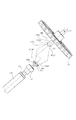
次に、図5を用いて、現像ローラの構成について説明する。図5(a)は、現像ローラ110を現像ローラ110が回転力を受ける側(以下単に「駆動側」と称す)から見た斜視図である。図5(b)は、非駆動側から見た斜視図である。尚、非駆動側とは、現像ローラの軸線方向において、駆動側とは反対側を称す。
(3) Configuration of Developing Roller Next, the configuration of the developing roller will be described with reference to FIG. FIG. 5A is a perspective view of the developing
現像ローラ110は、現像シリンダー110a、駆動側の現像フランジ151、非駆動側の現像フランジ152、マグネットローラ111を有する。
The developing
現像シリンダ−110aは、アルミ等の導電性のシリンダーに塗工層を塗布したものである。これによって、シリンダ−110aは、その周面に現像剤を担持する。そして、担持した現像剤は帯電される。シリンダ−110aの両端部には、現像フランジ151、152が嵌合するために現像シリンダ110aと略同径の開口部110a1、110a2が設けられている。開口部110a1にフランジ151が嵌合する。また、開口部110a2にフランジ152が嵌合する。
The developing cylinder 110a is obtained by applying a coating layer to a conductive cylinder such as aluminum. Thus, the cylinder 110a carries the developer on its peripheral surface. The carried developer is charged. At both ends of the cylinder 110a, openings 110a1 and 110a2 having substantially the same diameter as the developing cylinder 110a are provided in order to fit the developing
フランジ151はアルミ、ステンレス等の金属製である。但し、現像ローラ110を回転するための負荷トルクに応じて、樹脂製にすることも可能である。
The
フランジ151には現像剤攪拌部材115、116(図1参照)等を駆動する現像ギア153(図8(b))を取り付ける嵌合部151c、及び、現像軸受138に支持される勘合部151dが同軸線上に設けられている。そして、後述するマグネットローラ111を支持するための嵌合部を内部に有している。また、フランジ151に嵌合する現像ギア145には、後述するカップリング150(が現像ローラ110の軸線L1に対して、傾動(移動、傾斜)可能に取り付けられている。
The
フランジ152はフランジ151と同様に、アルミ、ステンレス等の金属製である。但し、現像ローラ110の負荷に応じて、樹脂製にすることも可能である。また、シリンダ嵌合部152bと軸受部152aとが略同軸線上に設けられている。更には、マグネットローラ111を現像ローラ110の端部から突出させて軸受部152aに支持する。
Like the
マグネットローラ111は、磁性体または、磁性体粉末を添加した樹脂製である。マグネットローラ111は、軸方向に2〜6極ほど磁極が配置されており、現像ローラ110の表面に現像剤を担持し、搬送している。
The
以上説明したマグネットローラ111を、現像シリンダー110aの内部に取り付ける。その上で、フランジ151の嵌合部151aを開口部110a1に嵌合させる。また、フランジ152の嵌合部152bを開口部110a2に嵌合させる。尚、その固定方法としては、接着、カシメ等で行う。更に、現像ローラ110の駆動側より、間隔規制部材136、現像軸受138、現像ギア(不図示)を挿入する。また、非駆動側より、間隔規制部材137、現像接点156を挿入する。
The
規制部材136、137は現像ローラ110と感光ドラム107の間隔を規制する部材であり、200〜400μ程度の樹脂製の円筒部材で形成されている。規制部材136は現像シリンダー110aの一端部の外周に嵌められる。また、規制部材137は現像シリンダー110aの他端部の外周に嵌められる。これによって、現像ローラ110と感光ドラム107との間隔が200〜400μ程度に維持される。
The regulating
軸受138は、現像枠体113(図1参照)に現像ローラ110を回転自在に支持するための軸受部材である。
The
現像接点156は導電性(主に金属)のコイル状の部材であり、導電性である現像シリンダー110aの内周面または、フランジ152に接する接点部156bを持つ。本実施例では、現像接点156は、フランジ152と接する例を示している。そして、接点部156aを介して、現像カートリッジ外部接点(不図示)により、装置本体と電気的に接続する。従って、カートリッジBが装置本体Aに装着された状態で、装置本体Aに設けられた本体電気接点(不図示)とカートリッジ外部接点とが接触して、本体Aから電圧を受ける。カートリッジ外部接点が受けた電圧は、接点156を介して、現像ローラ110に供給される。
The developing
(5)回転力伝達部品(カップリング部材)の説明
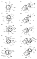
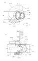
次に、図6を用いて、回転力伝達部品であるカップリング部材の一例について、説明する。図6(a)はカップリング部材を装置本体側から見た斜視図であり、図6(b)はカップリング部材を現像ローラ側から見た斜視図である。また、図6(c)はカップリング軸線L2方向と直交する直交方向から見た図である。また、図6(d)はカップリング部材を装置本体側から見た側面図であり、図6(e)は現像ローラ側から見た図であり、図6(f)は図6(d)をS3で切った断面図である。
(5) Description of rotational force transmission component (coupling member) Next, an example of a coupling member which is a rotational force transmission component will be described with reference to FIG. 6A is a perspective view of the coupling member viewed from the apparatus main body side, and FIG. 6B is a perspective view of the coupling member viewed from the developing roller side. FIG. 6C is a view as seen from an orthogonal direction orthogonal to the coupling axis L2 direction. 6D is a side view of the coupling member as viewed from the apparatus main body side, FIG. 6E is a view as viewed from the developing roller side, and FIG. 6F is a view of FIG. 6D. It is sectional drawing cut by S3.
カップリング部材(以下「カップリング」と称す)150は、カートリッジBを設置部130aに装着(設置)した状態で、装置本体Aの駆動軸180(図17参照)と係合する。また、カップリング150は、カートリッジBを装置本体Aから取り出すことで、駆動軸180から離脱する。この際に、カートリッジBは装置本体Aから、駆動軸180の軸線L3方向と実質的に直交する方向に移動させて、取り外される。また、カートリッジBは装置本体Aに、駆動軸180の軸線L3方向と実質的に直交する方向に移動させて、取り付けられる。そして、カップリング150は、駆動軸180と係合した状態で、駆動軸180を介して、装置本体Aに設けられたモータ186(図14)からの回転力を受ける。また、カップリング150は、その回転力を現像ローラ110に伝達する。これによって、現像ローラ110は回転する。ここで、カップリング150の材質は、ポリアセタール、ポリカーボネート、PPS等の樹脂である。但し、カップリング150の剛性を上げるために、負荷トルクに応じて上記樹脂中にガラス繊維、カーボン繊維等を配合しても良い。前記材料を配合した場合には、カップリング150の剛性を上げることができる。また、前記樹脂中に、金属をインサートして更に剛性を上げても良い。また、カップリング150全体を金属等で製造しても良い。尚、カップリングの材質は、後述する他のカップリングの実施例においても同様である。カップリング150は主に3つの部分を有する(図6(c))。
A coupling member (hereinafter referred to as “coupling”) 150 engages with the drive shaft 180 (see FIG. 17) of the apparatus main body A in a state where the cartridge B is mounted (installed) on the
第一の部分は、駆動軸180と係合し、ピン182から回転力を受けるための回転力受面(回転力受け部)150e(150e1〜150e4)を有する被駆動部150aである。また第二の部分は、現像ギア153と係合して回転力を伝える駆動部150bである。また、第三の部分は、被駆動部150aと駆動部150bの中間である、中間部150cである。現像ギア153は、カップリング150が装置本体Aから受けた回転力を、例えば現像剤供給ローラ(後述する)に伝える。
The first portion is a driven
図6(f)に示すように、被駆動部150aは、軸線L2に対して円錐状に広がった拡開部である駆動軸挿入開口部150mを有する。開口部150mは、図に示すように凹部150z(広がり部)を構成している。凹部150zは、カップリング150の回転軸線L2と同軸線上に位置している。
As shown in FIG. 6 (f), the driven
駆動部150bは、球状の駆動軸受面150iを有する。前記受面150iによって、カップリング150が軸線L1に対して回転力伝達角度位置と係合前角度位置(または、離脱角度位置)間を傾動(移動)できる。これによって、カップリング150は、現像ローラ110の回転位相がどこであっても、駆動軸180の先端部180bに阻止されることなく、駆動軸180と係合する。駆動部150bは、図に示すように凸形状である。
The
そして、被駆動部150a端面の円周上(図6(d)に示す仮想円C1上)には、複数の被駆動伝達突起部150d1〜d4が配置されている。また、各々の突起部150d1、150d2、150d3、150d4の間には、被駆動待機部150k1、150k2、150k3、150k4が設けられている。つまり、隣り合う突起部150d1〜d4の間隔は、この間隔内にピン(回転力付与部)182が位置できるように、ピン182の外径よりも大きく設定されている。この間隔が、待機部150k1〜k4である。更に、図6(d)の方向において、突起部150dの時計周り方向下流側には、カップリング150の回転方向と交差する回転力受面(回転力受け部)150e(150e1〜e4)が設けられている。駆動軸180が回転すると、ピン182が、受面150e1〜e4の何れかに接触する。そして、受面150e1〜e4がピン182の側面に押されて、カップリング150は軸線L2を中心に回転する。
A plurality of driven transmission protrusions 150d1 to d4 are arranged on the circumference of the end face of the driven
また、駆動部150bは、球面である。球面であることによって、カートリッジB内において、現像ローラ110の回転位相がどこであっても、カップリング150が、回転力伝達角度位置と、係合前角度位置(または、離脱角度位置)との間を傾動(移動)できる。図示例では、駆動部150bは、軸線L2を軸線とする球面状の現像軸受け面150iにより構成されている。そして、その中心を通る位置に、ピン(回転力伝達部)155を通す固定穴150gが設けてある。
The
前述したとおり、カップリング150はカップリング150の回転軸線L2と同軸線上に凹部150zを有している。カップリング150が前記回転力伝達角度位置に位置する状態で、凹部150zが駆動軸180の先端にかぶさる。そして、回転力受面150e(150e1〜150e4)が、駆動軸180の先端側において駆動軸180の軸線L3と直交する方向へ突出して設けられている回転力伝達ピン(回転力付与部)182と、カップリング150の回転方向において係合する。尚、回転力受面150eは、回転力受け部である。また、ピン182は、回転力付与部である。これによって、カップリング150は駆動軸180から回転力を受けて回転する。そして、カートリッジBを装置本体Aから取り外す際には、カップリング150が、現像ローラ110の軸線L1と実質的に直交する方向にカートリッジBを移動させる。そして、カートリッジBの前記移動に応じて、凹部150zの一部分(先端位置150A1)が駆動軸180を迂回することを許容するように、カップリング150が前記回転力伝達角度位置から前記離脱角度位置に傾動(移動)する。これによってカップリング150が駆動軸180から離脱することができる。
As described above, the
また、回転力受面(回転力受け部)150e(150e1〜150e4)は、カップリング150の回転軸線L2上に中心Sを有する仮想円C1(図6(d))上に、中心Sを挟んで対向して位置するように複数個配置されている。本実施例では、回転力受面150eは、4箇所に配置されている。
Further, the rotational force receiving surface (rotational force receiving portion) 150e (150e1 to 150e4) sandwiches the center S on a virtual circle C1 (FIG. 6D) having the center S on the rotational axis L2 of the
ここで、回転力受面150eが、中心Sを挟んで対向して配置されていることによって、カップリング150に均等に力が付与される。よって、カップリング150の回転精度を向上させることができる。
Here, since the rotational
また、カップリング150は、前記回転力伝達角度位置に位置する状態では、軸線L2が現像ローラ110の軸線L1と実質的に一致している。そして、カップリング150は、前記離脱角度位置に位置する状態では、装置本体AからカートリッジBを取り外す取り外し方向X6において、その上流側(先端部150A3)が駆動軸180の先端を通過することができるように、軸線L1に対して傾斜している。
Further, in the state where the
(6)現像ギアの説明
次に、図7を用いて、カップリング150を取り付ける現像ギア153の一例について説明する。図7(a)は駆動軸側からみた図であり、図7(b)は図7(a)のS4−S4で切った断面図である。
(6) Description of Development Gear Next, an example of the
図7(a)に示した開口部153g1、153g2は、現像ギア153の回転軸方向に設けられた溝である。また、開口部153g1、g2の間には、空間部153fが構成されている。カップリング150を現像ギア153に取り付ける際、ピン155がこの開口部153g1、153g2に収まる。また、現像軸受け面150iは、空間部153f内に収まる。
The openings 153g1 and 153g2 shown in FIG. 7A are grooves provided in the rotation axis direction of the developing
以上の構成により、カートリッジB内において、現像ローラ110の回転位相がどこであっても(ピン155の停止位置がどこであっても)、カップリング150が回転力伝達角度位置と係合前角度位置(または、離脱角度位置)との間を傾斜可能(移動可能)となる。
With the above configuration, in the cartridge B, regardless of the rotation phase of the developing roller 110 (wherever the stop position of the
また、図7(a)において、開口部153g1、153g2の時計周り方向上流側には、回転力伝達面(回転力被伝達部)153h1、153h2が設けられている。そして、伝達面153h1、153h2に、カップリング150の回転力伝達ピン(回転力伝達部)155の側面が接触する。これによって、カップリング150から現像ローラ110に回転力が伝達される。ここで、伝達面153h1〜153h2は、現像ギア153の回転方向と交差した面である。これによって、伝達面153h1〜153h2は、ピン15155の側面に押される。そして、カップリング150は、軸線L1と軸線L2とが略一直線上になった状態で、軸線L2を中心に回転する。
Further, in FIG. 7A, rotational force transmission surfaces (rotational force transmitted portions) 153h1 and 153h2 are provided on the upstream side in the clockwise direction of the openings 153g1 and 153g2. And the side surface of the rotational force transmission pin (rotational force transmission part) 155 of the
ここで現像ギア153は、被伝達部153h1、153h2を有するから、回転力被伝達部材として機能する。
Here, since the developing
尚、突起部15150dと同様に、回転力伝達面15150h1、15150h2は同一円周上に180°対向して配置されていることが望ましい。 As in the case of the protrusion 15150d, it is desirable that the rotational force transmission surfaces 15150h1 and 15150h2 are arranged to face each other at 180 ° on the same circumference.
(7)カップリングの組付け
図8は、カップリング150を現像ギア153に組み付ける過程を示した断面図である。
(7) Assembly of Coupling FIG. 8 is a cross-sectional view showing a process of assembling the
図8(a)は2部品よりなるカップリング150と、駆動伝達ピン、抜け止め部材156を組付ける状態を表わした図である。図8(b)は更にそれらを現像ギアに組付ける過程を表わした図である。
FIG. 8A is a view showing a state in which the
抜け止め部材156は、現像ギア153に係止する。これにより、カップリング150を、回転力伝達角度位置と係合前角度位置(または離脱角度位置)との間を傾斜可能(移動可能)に取り付ける。そして、カップリング150が軸線L2方向に移動することを規制する。そのため、開口156jは、軸受面150iの直径よりも小さな直径φD15である。即ち、カップリング150の移動が現像ギア153及び抜け止め部材156によって規制される。これによって、カップリング150が現像ローラ(カートリッジ)から外れることはない。
The retaining
図8に示したとおり、カップリング150の駆動部150bが、現像ギア153に設けられた凹部(空間部153f)に係合している。
As shown in FIG. 8, the driving
次に、具体的なカップリングの組付け方法を説明する。 Next, a specific method for assembling the coupling will be described.
図8(a)に示すように、被駆動部150a及び中間部150cは、軸受面150i(駆動部150c)を有する位置決め部材150qに対してX33の方向から挿入される。この時、あらかじめ抜け止め部材156を被駆動部150cと位置決め部材150qの間に置く。この状態でピン155は、位置決め部材150qの有する固定穴150g及び中間部150cの有する固定穴150rを貫通する。これによって、位置決め部材150qを中間部150cに固定する。
As shown in FIG. 8A, the driven
次に、図8(b)に示すように、カップリング150をX33方向に移動させる。これによって、カップリング150を現像ギア153に挿入する。次に、抜け止め部材156を矢印X33方向から挿入する。そして、抜け止め部材156を現像ギア153に固定させる。この取り付け方法により、カップリング150は、位置決め部材150qと現像ギア153の間にガタ(隙間)を残して取り付けることができる。これによって、カップリング150が向きを変える(軸線L2に対して傾斜する、移動する)ことが出来る。
Next, as shown in FIG. 8B, the
尚、カップリングの取り付け方法は、以上述べた取り付け方法に限らない。例えば、カップリングが、現像ギア153に対して軸線方向に対して移動不可能であり、かつ、現像ギア153(現像ローラ110)の軸線に対して傾斜可能に取り付けられれば良い。
The coupling attachment method is not limited to the attachment method described above. For example, the coupling may be attached so as not to move in the axial direction with respect to the developing
そこで、例えば、カップリングを一体的に形成する。そして、現像ギア153に可撓性の係止爪を設け、軸受け面150iを係止する。これにより、抜け止めを行なっても良い。また、この場合であっても、抜け止め部材と併用しても良い。
Therefore, for example, the coupling is integrally formed. Then, a flexible locking claw is provided on the developing
(8)カートリッジ(現像カートリッジ)の組付け
次に、図9、図10を用いて、カートリッジの取り付けについて説明する。図9はカートリッジの駆動側を表わした分解斜視図である。図10(a)は図2のS4−S4で切って、軸線L2を軸線L1と同軸線にした状態の断面図である。図10(b)は図2のS5−S5で切った断面図である。
(8) Assembly of Cartridge (Developing Cartridge) Next, the mounting of the cartridge will be described with reference to FIGS. FIG. 9 is an exploded perspective view showing the drive side of the cartridge. FIG. 10A is a cross-sectional view taken along S4-S4 in FIG. 2 in which the axis L2 is coaxial with the axis L1. FIG. 10B is a cross-sectional view taken along S5-S5 in FIG.
カップリング150を取り付けた現像ギア153を、駆動部150aが露出するように、現像ローラ110の一端側(現像フランジ151)に固定する。
The developing
そして、一体となった現像ローラ110、現像ギア153、カップリング150を、駆動側を軸受部材157、非駆動側を現像支持ピン(不図示)によって支持する。そして、その状態で、一体となった現像ローラ110、現像ギア153、カップリング150を、現像枠体119に回転可能に支持する。これにより、カートリジBとして一体化される(図2、図3に示す状態)。
The integrated developing
この状態で駆動軸180から受けた回転力をカップリング150、現像ギア153を経由して現像ローラ110に伝達する。
In this state, the rotational force received from the
また、この状態で、カップリング150の軸線L2は、現像ローラ110の軸線L1と略同軸線上に位置する状態(図10(a))を取り得るし、軸線L1に対して傾斜した状態(図10(b))も取り得る。
Further, in this state, the axis L2 of the
ここで、図11に示すように、カップリング150は軸線L2が軸線L1に対して、どのような方向にも傾斜できるように現像枠体119に取り付けられている。図11(a1)〜(a5)は駆動軸180の方向からみた図であり、図11(b1)〜(b5)はその斜視図である。ここで、図11(b1)〜(b5)は、現像ギア153の一部を切断して、カップリング150の略全体を図示してある。
Here, as shown in FIG. 11, the
図11(a1)(b1)において、軸線L2は軸線L1に対して同軸線上に位置している。この状態から、カップリング150を上向きに傾斜させたときの状態を、図11(a2)(b2)に示した。この図に示すように、カップリング150が、開口部153gが設けられた方向へ傾斜する際に、ピン155は開口部153gに沿って移動する。その結果、カップリング150は開口部153gと直交する軸線AXを中心に傾斜する。
11 (a1) and 11 (b1), the axis L2 is located on the same axis as the axis L1. The state when the
図11(a3)(b3)では、カップリング150を右向きに傾斜させた状態を示している。この図に示すように、カップリング150が開口部153gと直交する方向へ傾斜する際には、ピン155は開口部153gの中で回転する。尚、ピン155は、ピン155の中心軸線AYを中心にして回転する。
11 (a3) and 11 (b3) show a state in which the
図11(a4)(b4)および図11(a5)(b5)において、カップリング150を下向きに傾けた状態、及び、左向きに傾けた状態を示した。回転軸線AX、AYの説明は重複するので省略する。
11 (a4), (b4) and FIGS. 11 (a5), (b5), the
尚、前記説明した傾斜方向と異なる方向、例えば図11(a1)に示す45°の方向等への傾斜方向は、回転軸線AX、及び、回転軸線AYの方向への回転が組み合わさって傾斜(移動)することができる。 Note that the inclination direction to the direction different from the above-described inclination direction, for example, the direction of 45 ° shown in FIG. 11 (a1), etc. is inclined by the combination of the rotation in the direction of the rotation axis AX and the rotation axis AY ( Move).
このように、本実施例によれば、軸線L1に対して、軸線L2はどのような方向にも傾斜することができる。 Thus, according to the present embodiment, the axis L2 can be inclined in any direction with respect to the axis L1.
尚、本実施例は、開口部151gが、少なくともピン155の突出方向と交差する方向に延びた形状となっている。
In this embodiment, the
また、現像ギア(回転力被伝達部材)153と、カップリング150の間には、図に示すように隙間が設けられている。そこで、前述した通り、カップリング150はあらゆる方向に傾斜可能(移動可能)である。
Further, a gap is provided between the developing gear (rotational force transmitted member) 153 and the
即ち、伝達面(回転力被伝達部)153h(153h1、h2)は、ピン155(回転力伝達部)とは可動状態である。ピン155は、伝達面153hに対して可動である。そして、カップリングの回転方向において、伝達面153hとピン155とは係合する。このように為さしめるために、ピン155と伝達面153hとの間に隙間を有する。これによって、カップリング150は、軸線L1に対して実質的に全方向にわたって傾動可能である。このように、カップリング150は、現像ローラ110の端部に取り付けられている。
That is, the transmission surface (rotational force transmitted portion) 153h (153h1, h2) is movable with the pin 155 (rotational force transmitting portion). The
尚、軸線L2は軸線L1に対してどのような方向にも傾斜可能であると述べた。しかしながら、カップリング150は、必ずしも360°いずれの方向にも所定の角度まで直線的に傾斜可能である必要はない。その場合、例えば、開口部150gを円周方向に広めに設定しておく。このように設定しておけば、軸線L2が軸線L1に対して傾斜する際、直線的に所定の角度傾斜できない場合であっても、カップリング150は軸線L2回りに少し回転できる。これにより、所定の角度まで傾斜することができる。つまり、開口部150gの回転方向のガタの量は、必要に応じ、適宜選択できる。
Note that the axis L2 can be tilted in any direction with respect to the axis L1. However, the
この点については、本明細書に実施例として記載したいずれのカップリングにも適用される。 This applies to any coupling described herein as an example.
このように、カップリング150は、実質的にどの方向にも傾動可能に取り付けられている。そのため、カップリング150は、現像ギア153(現像ローラ110の軸線L1)に対して実質的に全周に渡って旋回可能(移動可能)である。先に説明したように(図10参照)、カップリング150の球面150iが、抜け止め部(凹部の一部)156iに接触している。そのため、カップリング150は球面150iの中心P2を回転中心にして取り付けられている(図10参照)。即ち、現像ギア153(現像ローラ110)の位相に関わらず、カップリング150は、その軸線L2が傾斜可能に取り付けられている。
Thus, the
また、カップリング150が駆動軸180に係合するためには、係合直前において、軸線L2は軸線L1に対して、カートリッジBの装着方向下流側に傾斜している。即ち、図10(b)に示すように、軸線L1に対して、被駆動部150aが装着方向X4下流側となるように、軸線L2を傾斜させる。図12(a)〜(c)では、被駆動部150aの位置が、いずれの場合も、装着方向X4に対して下流側に位置している。
Further, in order for the
これまで説明した構成により、図10に示したとおり、軸線L2が傾斜した状態から、軸線L1と略平行な状態になることも可能である。また、軸線L1と軸線L2の最大傾斜可能角度α4(図10(b))は、被駆動部15150a又は中間部15150cが、現像ギア153又は軸受部材157と接触するまで傾斜可能な角度である。尚、この傾斜角度は、カートリッジBを装置本体Aに着脱する際に、カップリング150が駆動軸180と係合、離脱するのに必要な値に設定すれば良い。
With the configuration described so far, as shown in FIG. 10, the state in which the axis L <b> 2 is inclined can be substantially parallel to the axis L <b> 1. Further, the maximum tiltable angle α4 (FIG. 10B) between the axis L1 and the axis L2 is an angle at which the driven portion 15150a or the intermediate portion 15150c can tilt until it contacts the developing
(9)装置本体の駆動軸及び駆動構成の説明
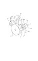
次に、図13、図14を用いて、装置本体Aの現像ローラ駆動構成について説明する。図13は、カートリッジBが挿入されていない状態の装置本体の斜視図で、駆動側の側板を一部切り欠いた斜視図である。図14は現像ローラ駆動構成のみを示した斜視図である。
(9) Description of Drive Shaft and Drive Configuration of Apparatus Main Body Next, the developing roller drive configuration of the apparatus main body A will be described with reference to FIGS. 13 and 14. FIG. 13 is a perspective view of the apparatus main body in a state where the cartridge B is not inserted, and is a perspective view in which a side plate on the driving side is partially cut away. FIG. 14 is a perspective view showing only the developing roller driving configuration.
駆動軸180の先端部180bは半球面である。また円筒形状の主部180aのほぼ中心を貫く、回転力付与部としての回転力伝達ピン182を有している。このピン182によりカップリング150に回転力を伝達する。
The
先端部180bとは長手方向反対側に、軸線L3と略同軸線上に現像駆動ギア181を設けている。ギア181は駆動軸180に対して回転不能に固定されている。そのため、ギア181が回転すると、駆動軸180も回転する。
A developing
また、ギア181はモータ186からピニオンギア(モータピニオン)187、アイドラギア191、感光ドラム駆動ギア190を経て、回転力を受ける。そのため、モータ186が回転すると、駆動軸180も回転する。
The
また、ギア181は、軸受部材(不図示)により、装置本体Aに対して回転自在に支持されている。この時、ギア181は軸線L1方向に対して移動しない。そのため、ギア181と軸受部材(不図示)は近接して配置可能である。
The
また、ギア181は、ギア187からいくつかのギアを介して回転力の伝達を受けると説明した。しかしながら、その限りではない。例えば、装置本体Aに対するモータ186の配置の都合上、適宜選択してよい。またベルト等で回転力を伝達しても良い。
Further, it has been described that the
また、駆動軸180は、その軸線L3方向に対して移動しない。そのため、駆動軸180と、軸受部材183、184との間の隙間は、駆動軸180が回転できる程度の隙間にしてある。従って、ギア181のギア187に対する径方向の位置も正確に位置決めできる。
Further, the
但し、駆動軸180は寸法公差上あり得る範囲で、軸線L3方向にがた(遊び)が発生する場合がある。その場合、そのがた(遊び)を無くすために、駆動軸180もしくは、ギア181を軸線L3方向にバネ等によって弾性的に付勢しても良い。
However, the
(10)本体の装着ガイド構成
図15及び図16に示すように、本実施例の装着手段130は、装置本体Aに設けた本体ガイド130R1、130L1を有する。
(10) Configuration of Main Body Mounting Guide As shown in FIGS. 15 and 16, the mounting means 130 of the present embodiment includes main body guides 130R1 and 130L1 provided in the apparatus main body A.
これらは、装置本体A内に設けられたカートリッジBを装着するためのスペース(カートリッジ装着部130a)に設けられている。装着部130aにカートリッジBを取り付ける取り付け方向(装着方向、挿入方向)と直交する方向の一端側と他端側(左右両側面)にカートリッジ装着手段130が設けられている。一端側と他端側に設けられた装着手段130は互いに対向して設けられている(図15は駆動側側面、図16は非駆動側面を図示)。装着手段130には、カートリッジBを装着するときのガイドとなるガイド部130R1、130L1が設けられている。ガイド部130R1は前記一端側に、ガイド部130L1は前記他端側に、互いに対向して設けてある。カートリッジBを挿入する際に、ガイド部130R1、130L1には、カートリッジ枠体の長手方向の一端と他端から突出する突出部(後述する)をガイドさせる。尚、装置本体AにカートリッジBを装着するには、使用者は、軸109aを中心にして装置本体Aに対して開閉可能なドア109を開く。そして、前記ボスをガイド部130R1、130L1にガイドさせて、カートリッジBを装着部130aに導く、その後、使用者が、ドア109を閉じることによって、装置本体Aに対するカートリッジBの装着が装着完了する。尚、カートリッジBを装置本体Aから取り出す際にも、ドア109を開く。
These are provided in a space (
また、駆動側の溝部130R2は、カートリッジBを装置本体Aに挿入する際、カップリング150と駆動軸180とが係合するまでの、カップリング150の逃げとして機能する。
Further, the drive-side groove 130R2 functions as a relief of the
また、ドア109の内側には、バネ192が設けられており、ドア109を閉じた際には、カートリッジBを弾性的に付勢して、現像ローラ110と感光ドラム107の間隔を維持する。即ち、現像ローラ110が感光ドラム107を付勢する方向へ、カートリッジBを弾性的に付勢する。
Further, a
(11)現像カートリッジの装着ガイド/位置決め構成
図2及び図3に示すように、カートリジBには、現像ローラ110の軸線方向(長手方向)の一端と他端に、カートリッジガイド140R1、140R2、140L2、140L2を配置している。即ち、前記一端にはガイド140R1、140R2、前記他端には、ガイド140L2、140L2を配置している。
(11) Developer Cartridge Installation Guide / Positioning Configuration As shown in FIGS. 2 and 3, the cartridge B includes cartridge guides 140R1, 140R2, and 140L2 at one end and the other end in the axial direction (longitudinal direction) of the developing
本実施例では、ガイド140R1、140R2、140L1、140L2は現像枠体119もしくは現像支持部材157もしくは現像軸受139と一体に成形されている。そして、これらは、外方へ突出して設けられている。
In this embodiment, the guides 140R1, 140R2, 140L1, and 140L2 are formed integrally with the developing
(12)現像カートリッジの装着動作
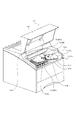
図17を用いて、カートリッジBを本体Aに装着する装着動作について説明する。図17は装着過程を示し、図15のS6−S6で切った断面図である。
(12) Mounting operation of developing cartridge The mounting operation of mounting the cartridge B to the main body A will be described with reference to FIG. FIG. 17 shows the mounting process, and is a cross-sectional view taken along S6-S6 in FIG.
図17(a)に示すように、使用者によって、装置本体Aに設けられたドア109を開く。そして、カートリッジBを装着手段130(装着部130a)に対して取り外し可能に装着する。
As shown in FIG. 17A, the user opens the
カートリッジBを装置本体Aに装着する際は、図17(b)のように、駆動側において、カートリッジガイド140R1、140R2を、本体ガイド130R1に沿わせる。また、非駆動側において、カートリッジガイド140L1、140L2(図3参照)を本体ガイド130L1(図16参照)に沿わせる。これによって、カートリッジBを装着部130aに取り付ける。この時、駆動側に設けられているカップリング150とその周囲を囲う現像支持部材157の円筒部157cは、ガイド130R1の溝部130R2に沿う。しかしながら、円筒部157cは溝部130R2には接触していない。
When the cartridge B is mounted on the apparatus main body A, as shown in FIG. 17B, the cartridge guides 140R1 and 140R2 are placed along the main body guide 130R1 on the driving side. On the non-driving side, the cartridge guides 140L1 and 140L2 (see FIG. 3) are aligned with the main body guide 130L1 (see FIG. 16). As a result, the cartridge B is attached to the mounting
次に、矢印X4方向にカートリッジBを更に挿入していくと、後述するように、カップリング150が駆動軸180と係合する。そして、カートリッジBは装着部130a(所定の位置)に収まる。つまり、図17(c)に示すように、ガイド140R1がガイド130R1に設けられている位置決め部130R1aに接触する。また、ガイド140L1がガイド130L1に設けられている位置決め部130L1a(図16参照)に接触する。このように、カートリッジBは、装着手段130によって、カートリッジ装着部130aに取り外し可能に装着される。カートリッジBは、カートリッジ装着部130aに装着された状態で、カップリング150が駆動軸180と係合する。これによって、カートリッジBは画像形成動作が可能となる。ここで、カートリッジ装着部130aとは、前記装着手段130によって、装置本体Aに装着されたカートリッジBが占める空間のことである。
Next, when the cartridge B is further inserted in the arrow X4 direction, the
前述したとおり、カートリッジBの長手方向一端には、ガイド140R1、140R2が外方へ突出して設けられている(図2)。ガイド140R1とガイド140R2は、カートリッジBの装着方向X4方向に沿って間隔をあけて配置されている。一方、前記長手方向他端には、ガイド140L1、140L2が外方へ突出して設けられている(図3)。ガイド140L1とガイド140L2は、カートリッジBの装着方向X4方向に沿って間隔をあけて配置されている。 As described above, the guides 140R1 and 140R2 are provided at one end in the longitudinal direction of the cartridge B so as to protrude outward (FIG. 2). The guide 140R1 and the guide 140R2 are arranged at an interval along the mounting direction X4 of the cartridge B. On the other hand, guides 140L1 and 140L2 are provided on the other end in the longitudinal direction so as to protrude outward (FIG. 3). The guide 140L1 and the guide 140L2 are arranged at an interval along the mounting direction X4 of the cartridge B.
また、本体Aには、装着部130aの一端側に、ガイド130R1、130R2が、装着方向X4方向に沿って配置されている。そして、ガイド130R1を上方に、ガイド130R2を下方に配置している(図15)。一方、装着部130aの他端側には、ガイド130L1が装着方向X4方向に沿って配置されている(図16)。
Further, in the main body A, guides 130R1 and 130R2 are arranged on one end side of the mounting
そして、カートリッジBを装着部130aに取り付ける際には、ガイド130R1にガイド140R1とガイド140R2をガイドさせて、及び、カートリッジBの底面をガイド130R2にガイドさせて挿入する(図17)。一方、ガイド140L1とガイド140L2は、ガイド130L1にガイドさせて挿入する。
When the cartridge B is attached to the mounting
そして、カップリング150が駆動軸180に係合した状態で、ガイド140R1が位置決め部130R1aに位置決めされる(図17)。また、ガイド140L1が位置決め部130L1a(図16)に位置決めされる。即ち、カップリング150が駆動軸180に係合した状態で、カートリッジBは装着部130aに取り付けられる。
Then, with the
尚、カップリング150が駆動軸180と係合する状態、及び、カップリング150が駆動軸180から離脱する状態については、後述する。
A state where the
また、カートリッジBを装着部130aから取り外す場合には、前記とは反対の工程で行うことができる。
Moreover, when removing the cartridge B from the mounting
上記構成によって、カートリッジBは、駆動軸180の軸線方向と実質的に直交する方向に移動させて装着部130aから取り外すことができる。また、カートリッジBは、駆動軸180の軸線方向と実質的に直交する方向に移動させて、装着部130aに取り付け及び装着部130aから取り外すことができる。
With the above configuration, the cartridge B can be detached from the mounting
尚、カートリッジBが、装着部130aに収まった際には本体Aに設けられた押圧バネ188Rの弾性力により、ガイド140R1(図2も合わせて参照)が加圧を受ける(図15)。また、本体Aに設けられた押圧バネ188Lの弾性力により、ガイド140L1(図3参照)が加圧を受ける(図16)。そして、ドア109を閉じると、ドア109の内側に設けられた付勢バネ192R(非駆動側の付勢バネ192Lは図16参照)の弾性力により、カートリッジBは付勢部114a(図4参照)に加圧を受ける。これにより、現像ローラ110の端部に配置された間隔規制部材136、137(図2参照)が感光ドラム107の端部に接触する。そして、現像ローラ110と感光ドラム107の間隔が維持される。
When the cartridge B is accommodated in the mounting
更に、カバー109を閉じることにより、スイッチ手段(不図示)がONとなる。これにより、装置本体Aから、駆動軸180及びカップリング150を介して、現像ローラ110を回転させるための回転力を受けることが可能となる。
Further, by closing the
このように、カートリッジBは、装着手段130によって、装着部130aに取り外し可能に装着される。即ち、カートリッジBは装置本体A、及び、感光ドラム107に対して位置決めされた状態で、装着部130aに装着される。そして、カートリッジBが装着部130aに装着された状態で、駆動軸180とカップリング150とが係合状態になる。
Thus, the cartridge B is detachably mounted on the mounting
即ち、カップリング150は後述する回転力伝達角度位置となる。
That is, the
カートリッジBは、装着部130aに装着されることによって、画像形成動作が可能となる。
When the cartridge B is mounted on the mounting
尚、カートリッジBの装着形態に関し、上述のように使用者自身でもって、カートリッジBを装着部130aまで進入させても良い。或いは、使用者がカートリッジBを途中位置までは進入させて、最終の装着動作を別の手段で行っても良い。例えば、ドア109を閉める動作を利用して、ドア109の一部を、装着途中位置にあるカートリッジBに作用させる。そして、ドア109の閉じ力でもって、カートリッジBを最終装着位置まで押し込んでも良い。或いは、使用者が途中まではカートリッジBを押し込むけれども、途中からはカートリッジBが自重によって装着部130aに進入しても良い。
Regarding the mounting mode of the cartridge B, as described above, the user himself / herself may cause the cartridge B to enter the mounting
ここでカートリッジBは、図17に示すように、駆動軸180の軸線L3(図18参照)方向と実質的に直交する方向に移動させることで、装置本体Aに取り付けられ、及び、取り外しも行われる。そして、駆動軸180とカップリング150とが係合状態、及び、離脱状態となる。
Here, as shown in FIG. 17, the cartridge B is attached to and removed from the apparatus main body A by moving in a direction substantially perpendicular to the direction of the axis L3 (see FIG. 18) of the
ここで「実質的に直交」の意味について説明する。 Here, the meaning of “substantially orthogonal” will be described.
カートリッジBと装置本体Aの間には、カートリッジBをスムーズに着脱する為に、両者の間には若干の隙間を持たせてある。具体的に言えば、ガイド140R1とガイド130R1との前記長手方向の間、ガイド140R2とガイド130R1との前記間、ガイド140L1とガイド130L1との前記間、及び、ガイド140L2とガイド130L2との前記間に若干の隙間を持たせてある。従ってカートリッジBを装置本体Aに取り付け及び取り外す際に、カートリッジB全体がその隙間の範囲内で若干斜めになることもあり得る。従って、厳密に直交方向からの取り付け及び取り外しではないこともある。しかしそういった場合でも、本発明の作用効果は達成可能である。従ってカートリッジが若干斜めになった場合も含めて、「実質的に直交」と称している。 In order to smoothly attach and detach the cartridge B between the cartridge B and the apparatus main body A, a slight gap is provided between them. Specifically, between the longitudinal direction of the guide 140R1 and the guide 130R1, between the guide 140R2 and the guide 130R1, between the guide 140L1 and the guide 130L1, and between the guide 140L2 and the guide 130L2. Has a slight gap. Therefore, when the cartridge B is attached to and detached from the apparatus main body A, the entire cartridge B may be slightly inclined within the gap. Therefore, it may not be strictly the attachment and detachment from the orthogonal direction. However, even in such a case, the effect of the present invention can be achieved. Therefore, it is referred to as “substantially orthogonal” including the case where the cartridge is slightly inclined.
(13)カップリングと駆動軸との係合動作及び回転力伝達の説明
先に述べたように、カートリッジBは、装着部130a(所定の位置)に位置決めされる直前、もしくは、所定の位置に位置決めされると略同時に、カップリング150は駆動軸180と係合する。即ち、カップリング150が、回転力伝達角度位置に位置する。ここで、前記所定の位置とは、設置部130aである。
(13) Description of the engagement operation between the coupling and the drive shaft and the transmission of the rotational force As described above, the cartridge B is located immediately before being positioned at the mounting
次に、図18,図19、を用いて、カップリング150と駆動軸180との係合動作に関して説明する。図18は、駆動軸と、カートリッジの駆動側の要部を示した斜視図である。図19は装置本体の下方から見た縦断面図である。尚、ここでいう係合とは、軸線L2と軸線L3とが略同軸線となり、回転力の伝達が可能(駆動伝達可能)となっている状態をいう。
Next, the engaging operation between the
図19に示すように、カートリッジBは、駆動軸180の軸線L3と実質的に直交する方向(矢印X4方向)から装置本体Aに装着される。または、装置本体Aから取り外される。カップリング150は、係合前角度位置として、軸線L2(図19(a))が、予め現像ローラ110の軸線L1(図19(a))に対して、装着方向X4に傾斜している(図18(a)、図19(a))。
As shown in FIG. 19, the cartridge B is mounted on the apparatus main body A from a direction substantially perpendicular to the axis L3 of the drive shaft 180 (arrow X4 direction). Alternatively, it is removed from the apparatus main body A. As for the
尚、カップリングを係合前角度位置に傾斜させる構成は、例えば、後述する実施例4又は実施例5の構成を用いれば良い。但し、実施例4、及び、実施例5に限定されずに、適宜の構成を用いることができる。 In addition, what is necessary is just to use the structure of Example 4 or Example 5 mentioned later as the structure which inclines a coupling to the angle position before engagement, for example. However, it is not limited to Example 4 and Example 5, and an appropriate structure can be used.
カップリング150が前述した方向へ傾斜することで、カップリング150は、軸線L1方向において、装着方向X4の下流側の先端位置150A1が、駆動軸先端180b3よりも現像ローラ110の設けられている方向側に位置する。また、装着方向X4の上流側の先端位置150A2は、軸先端180b3よりもピン182の設けられている方向側に位置する(図19(a)、(b))。ここで言う先端位置とは、図6(a)(c)に示す被駆動部150aにおける、軸線L2方向に対して最も駆動軸側であり、かつ、軸線L2よりも最も離れた位置である。つまり、カップリング150の回転位相により、カップリング150の被駆動部150aの一稜線もしくは突起部150dの一稜線のどちらかとなる(図6(a)(c)において、150Aとした)。
Since the
まず、カップリング150の先端位置(カップリング150の一部分)150A1が、軸先端180b3を通過する。そして、カップリング150が、軸先端180b3を通過した後、受面150f、もしくは突起部150dが、駆動軸180の先端部180b、もしくは、ピン182と接触する(図19(b))。尚、受面150f及び突起部150dは、カートリッジ側接触部である。また、駆動軸180は、本体側係合部である。また、ピン182は、本体側係合部及び回転力付与部である。そして、カップリング150、カートリッジBの装着動作に応じて、軸線L2が軸線L1と略直線となるように傾斜していく(図19(c))。そして、カップリング150は、前記係合前角度位置から傾斜し、その軸線L2が軸線L1と略一直線の状態となる回転力伝達角度位置に傾動(移動)する。そして、最終的に装置本体Aに対してカートリッジBの位置が決まる。この際、駆動軸180と現像ローラ110が略同一直線上に位置する。また受面150fが、球面である駆動軸180の先端部180bと対向した状態となる。そして、カップリング150と駆動軸180は係合される(図18(b)、図19(d))。またこの時、ピン155(不図示)は開口150g(図6(b)参照)内に位置する。また、ピン182は、待機部150kに位置する。ここで、カップリング150は、先端部180bにかぶさった状態となる。
First, the tip position (a part of the coupling 150) 150A1 of the
前述したとおり、カップリング150は、カートリッジBが装置本体Aに取り付けられる際には、次の動きをする。即ち、取り付け方向X4から見て、下流側に位置しているカップリング150の一部分(先端位置150A1)が駆動軸180を迂回することを許容するように、カップリング150は、前記係合前角度位置から前記回転力伝達角度位置に傾斜する(移動する)。尚、受面150fは、凹部150zを構成している。また、凹部150zは円錐形状である。尚、取り付け方向X4とは、装置本体AにカートリッジBを取り付ける方向である。
As described above, the
以上説明したように、カップリング150が、軸線L1に対して傾斜可能に取り付けられている。そしてカートリッジBの移動に応じて、本体側係合部(駆動軸180及び/又はピン182)に、カートリッジ側接触部であるカップリング150の一部分(受面150f及び/又は突起部150d)が接触する。これによって、カップリング150の傾動動作が行われる。図19に示すように、カップリング150は、駆動軸180とは、軸線L1方向でオーバラップした状態で装着される。しかし上述のようなカップリングの傾動動作によって、オーバラップした状態のカップリング150と駆動軸180であっても両者は係合可能となる。
As described above, the
さらに、前述したカップリング150の取り付け動作は、駆動軸180とカップリング150の位相に関係なく、行うことができる。図11、20を用いて、この理由を説明する。図20はカップリング150と駆動軸180の各々の位相を表した図である。図20(a)は、カートリッジの装着方向X4の下流側において、ピン182と受面150fとが相対している状態を示した図である。図20(b)は、ピン182と突起部150dとが相対している状態を示した図である。図20(c)は先端部180bと突起部150dとが相対している状態を示した図である。図20(d)では、先端部180bと受面150fとが相対している状態を示した図である。
Further, the above-described attachment operation of the
図11に示すように、カップリング150は現像ローラ110の軸線L1に対して、どのような方向にも傾斜可能に取り付けられている。即ち、カップリング150は旋回可能である。そのため、図20に示すように、カートリッジBの装着方向X4に対して、現像ギア153(現像ローラ)がどのような位相であっても、装着方向X4に傾斜可能である。また、駆動軸180とカップリング150の各々の位相に関係なく、先端位置150A1は、軸線L1方向で軸先端180b3よりも現像ローラ側に位置するようにカップリング150の傾斜角度を設定している。また、先端位置150A2は、軸先端180b3よりもピン182方向側に位置するようにカップリング150の傾斜角度を設定している。このような設定にしておけば、カートリッジBの装着動作に応じて、装着方向X4において、先端位置150A1は、軸先端180b3を通過する。そして、図20(a)に示す場合には、受面150fがピン182と接触する。図20(b)に示す場合には、突起部(係合部)150dがピン(回転力付与部)182と接触する。図20(c)に示す場合には、突起部150dが先端部180bと接触する。図20(d)に示す場合には、受面150fが先端部180bと接触する。更に、カートリッジBを装着する際に発生する、カップリング150と駆動軸180とが接触する接触力により、カップリング150は、軸線L2が軸線L1と略一直線となるように移動する。即ち、カップリング150が駆動軸180と接触を開始した後、軸線L2が軸線L1と略一直線となるまでカートリッジBは移動する。そして、カートリッジBは、軸線L2が軸線L1と略一直線となった状態で、前述したように本体Aに位置決めされる。これによって、カップリング150は、駆動軸180と係合する。即ち、凹部150zが、先端部180bにかぶさる。従って、駆動軸180とカップリング150、または、現像ギア153(現像ローラ)がどのような位相であっても、カップリング150は、駆動軸180(ピン182)と係合することができる。
As shown in FIG. 11, the
また、現像ギア153とカップリング150の間には、図20に示すように隙間が設けられており、上述のように傾斜可能(移動可能)な構成となっている。
Further, a gap is provided between the developing
尚、本実施例においては、カップリング150は、図20の面内において傾動する場合を説明した。しかし、カップリング150は前述の通り旋回も可能であるので、図20の面内以外の方向への傾動を含んでも良い。その場合でも、図20(a)の状態から図20(d)の状態に至ることになる。この点は、以下の実施例についても、特記なき限り該当する。
In the present embodiment, the case where the
次に、図21を用いて、現像ローラ110を回転する際の回転力伝達動作について説明する。駆動源(モータ186)から受けた回転力によって、駆動軸180は、図中X8の方向に、ギア181とともに回転する。そして、駆動軸180と一体のピン182(182a1、182a2)が回転力受け面(回転力受け部)150e1〜150e4のいずれかに接触する。即ち、ピン182a1が回転力受け面150e1〜150e4のいずれか一箇所と接触する。また、ピン182a2が回転力受け面150e1〜150e4のいずれか一箇所と接触する。これによって、駆動軸180の回転力をカップリング150に伝達して、カップリング150を回転させる。さらに、カップリング150が回転することで、カップリング150の有するピン155(回転力伝達部)が現像ギア153に接触する。これによって、駆動軸180の回転力が、カップリング150、ピン155、現像ギア153及び現像フランジ151、を介して現像ローラ110に伝達される。そして、現像ローラ110を回転させる。
Next, a rotational force transmission operation when the developing
また、回転力伝達角度位置において、先端部153bは受面150iと接触する。そして、駆動軸180の先端部(位置決め部)180bは、受面(被位置決め部)150fと接触する。これによって、カップリング150は駆動軸180にかぶさった状態で、駆動軸180に対して位置決めされる(図19d参照)。
In addition, at the rotational force transmission angular position, the tip portion 153b contacts the receiving surface 150i. And the front-end | tip part (positioning part) 180b of the
ここで、本実施例においては、現像ローラ110は間隔維持部材を介して、感光ドラム107に対して位置決めされている。これに対して、駆動軸180は装置本体Aの側板等に位置決めされている。つまり、軸線L3に対して軸線L1は、感光ドラムを介して位置決めされている。そのため、寸法公差が乗りやすい。従って、軸線L3と軸線L1とが同一軸線(軸線L1と軸線L3と一直線)からずれやすくなる。そのような場合、カップリング150が少し傾斜することで、カップリング150は回転力の伝達を行うことができる。このような場合であっても、カップリング150は、現像ギア153(現像ローラ110)、駆動軸180に大きな負荷をかけずに回転することができる。そのため、駆動軸180と現像ローラ110(現像カートリッジ)を組立時(装着時)に精度良く位置決めを調整する等の操作が軽減できる。従って、組立操作性を向上させることができる。
Here, in this embodiment, the developing
これは、本発明の効果として前述した効果に加えて、本発明を適用した実施例の効果の一つである。 This is one of the effects of the embodiment to which the present invention is applied in addition to the effects described above as the effects of the present invention.
また、図14で説明したように、駆動軸180及びギア181の位置は、装置本体Aの所定位置(装着部130a)において、径方向、及び、軸方向に位置決めされる。また、カートリッジBに関しても、上述のように装着部130aに位置決めされる。そして、装着部130aに位置決めされた駆動軸180と、同じく装着部130aに位置決めされたカートリッジBの両者を、カップリング150が連結する。カップリング150は現像ローラ110に対して揺動可能(傾動可能)な構成である。従って、上述のように所定位置に位置決めされた駆動軸180と、同じく所定位置に位置決めされたカートリッジBとの間であっても、カップリング150は円滑に回転力を伝達できる。つまり、駆動軸180と現像ローラ110との間に、多少の軸ずれがあったとしても、カップリング150は円滑に回転力を伝達できる。
Further, as described with reference to FIG. 14, the positions of the
これも、本発明を適用した本実施例の効果の一つである。 This is also one of the effects of the present embodiment to which the present invention is applied.
尚、駆動軸180に、カップリング150が接触する。これによって、カップリング150が係合前角度位置から回転力伝達角度位置に揺動すると述べたが、その限りでは無い。例えば、装置本体の駆動軸以外の場所に本体側係合部としての突き当て部を設けても良い。そして、カートリッジBの装着過程において、先端位置150A1が駆動軸先端180b3を通過した後、カップリング150の一部(カートリッジ側接触部)が前記突き当て部と接触する。これによって、カップリングが揺動方向(傾動方向)の力を受けて、軸線L2が軸線L3と略同軸線となるように揺動(傾動)させることもできる。つまり、カートリッジBの装着動作と連動させて、軸線L1が軸線L3と略同軸線上に位置することできる構成であるならば、どのような手段でも良い。
The
(14)カップリングと駆動軸との離脱動作及びカートリッジを取り出す動作の説明
図22を用いて、カートリッジBを装置本体Aから取り出す際、カップリング150を駆動軸180から離脱させる動作について説明する。図22は装置本体の下方から見た断面図である。
(14) Description of Operation of Separating Coupling from Drive Shaft and Operation of Removing Cartridge The operation of detaching the
図22に示すように、カートリッジBは、装置本体Aから取り外す際に、軸線L3と実質的に直交する方向(矢印X6方向)から取り外される。 As shown in FIG. 22, when removing the cartridge B from the apparatus main body A, the cartridge B is removed from a direction (arrow X6 direction) substantially orthogonal to the axis L3.
現像ギア153(現像ローラ110)の回転が停止した状態では、カップリング150は回転力伝達角度位置として、軸線L2が軸線L1に対して、略同軸線上に位置する(図22(a))。そして、使用者がカートリッジBを装着部130aから取り出すのに応じて、カートリッジBとともに現像ギア153が取り出し方向X6に移動する。そして、カップリング150の取り出し方向X6の上流側の受面150f、もしくは、突起部150dが、少なくとも駆動軸180の先端部180bと接触する(図22(a))。そして、カップリング150は、軸線L2が取り出し方向X6の上流側に傾斜を開始する(図22(b))。こカップリング150が傾斜を開始する方向は、カートリッジBの装着時にカップリング150が傾斜している方向(係合前角度位置)と同じである。カートリッジBを装置本体Aからの取り出す動作により、カップリング150は、取り出し方向X6の上流側先端部150A3が先端部180bに接触しながら移動する。より詳細には、カートリッジBの取り出し方向X6への移動に応じて、カップリング150は、次の動きをする。即ち、カップリング150は、カートリッジ側接触部であるカップリング150の一部分(受面150f及び/又は突起部150d)が、本体側係合部(駆動軸180及び/又はピン182)と接触しながら移動する。そして、軸線L2が離脱角度位置として、先端部150A3が先端180b3に至るまで傾斜する(図22(c))。そして、この状態で、カップリング150は、先端180b3に接触しながら駆動軸180を通過し、駆動軸180から離脱する(図22(d))。その後、図17で説明した装着過程とは反対の過程を辿り、カートリッジBは装置本体Aから取り出される。
In a state where the rotation of the developing gear 153 (developing roller 110) is stopped, the
以上の説明から明らかなように、軸線L1に対する係合前角度位置の角度は、軸線L1に対する離脱角度位置の角度よりも大きい。なぜならば、各部品の寸法公差を考慮して、カップリングの係合時には、係合前角度位置において、先端位置(カップリング150の一部分)150A1が先端部180b3を確実に通過できるようにするからである。即ち、係合前角度位置は、カップリング150と先端部180b3との間に、隙間が空くような角度に設定する必要があるからである(図19(b)参照)。それに対して、カップリング離脱時には、離脱角度位置は、カートリッジBの取り出しに連動して軸線L2が傾斜する。そのため、カップリング150の先端部150A3が、先端部180b3に沿う。つまり、カップリング150は、カートリッジ取り出し方向X6において、カップリング150の上流側と、駆動軸180の先端部180bとはほぼ一致する(図22(c)参照)。従って、係合前角度位置の軸線L1に対する角度は、離脱角度位置の軸線L1に対する角度よりも大きい。
As is clear from the above description, the angle of the pre-engagement angular position with respect to the axis L1 is larger than the angle of the disengagement angular position with respect to the axis L1. This is because, in consideration of the dimensional tolerance of each part, when the coupling is engaged, the tip position (a part of the coupling 150) 150A1 can surely pass the tip portion 180b3 at the pre-engagement angular position. It is. That is, it is necessary to set the pre-engagement angular position so that there is a gap between the
また、カートリッジBを装置本体Aに装着する場合と同様に、カップリング150とピン182との位相は、どのような位相であってもカートリッジBを本体Aから取り出すことができる。
Similarly to the case where the cartridge B is attached to the apparatus main body A, the cartridge B can be taken out from the main body A regardless of the phase of the
前述したとおり、カップリング150は、カートリッジBが装置本体Aに装着されている状態では、取り外し方向X6とは反対方向から見て、カップリング150の一部分(先端位置150A1)は駆動軸180の背後に位置している(図19(d))。そして、装置本体AからカートリッジBを取り外す際には、カップリング150は次の動きをする。即ち、軸線L1と実質的に直交する方向にカートリッジBを移動させるのに応じて、カップリング150の一部分(先端位置150A1)が駆動軸180を迂回することを許容するように、カップリング150は前記回転力伝達角度位置から前記離脱角度位置に移動する(傾斜する)。尚、カップリング150の回転力伝達角度位置とは、カートリッジBが装置本体Aに装着された状態で、カップリング150が駆動軸180から回転力の伝達を受けて、回転することができるカップリング150の軸線L1に対する角度位置である。即ち、回転力伝達角度位置とは、現像ローラ110を回転させるための回転力を現像ローラ110に伝達するための角度位置である。尚、図21には、カップリング150が前記回転力伝達角度位置に位置している状態を示している。
As described above, when the cartridge B is attached to the apparatus main body A, the
また、カップリング150の係合前角度位置とは、カートリッジBを装置本体Aに装着する際、カップリング150が駆動軸180と係合する直前のカップリング150の軸線L1に対する角度位置である。即ち、カートリッジBの取り付け方向において、カップリング150の下流側の先端部150A1が、駆動軸180を通過可能な軸線L1に対する角度位置である。
The pre-engagement angular position of the
また、カップリング150の離脱角度位置とは、カートリッジBを装置本体Aから取り出す場合に、カップリング150が駆動軸180から離脱する時のカップリング150の軸線L1に対する角度位置である。即ち、図22に示すように、カートリッジBの取り外し方向において、カップリング150の先端部150A3が駆動軸180を通過可能な軸線L1に対する角度位置である。
Further, the separation angle position of the
前記係合前角度位置あるいは、前記離脱角度位置において、軸線L2が軸線L1となす角度θ2は、前記回転力伝達角度位置において、軸線L2が軸線L1となす角度θ1よりも大である。尚、角度θ1は0°が好ましい。しかしながら、本実施例によれば、角度θ1は15°程度以内ならば、回転力の円滑な伝達ができる。尚、角度θ2は20〜60°程度が好ましい。 At the pre-engagement angular position or the disengagement angular position, the angle θ2 that the axis L2 makes with the axis L1 is larger than the angle θ1 that the axis L2 makes with the axis L1 at the rotational force transmission angle position. The angle θ1 is preferably 0 °. However, according to the present embodiment, the rotational force can be smoothly transmitted if the angle θ1 is within about 15 °. The angle θ2 is preferably about 20 to 60 °.
以上説明したように、カップリングが、軸線L1に対して傾斜可能に取り付けられている。そして、カートリッジBの取り出し動作に応じて、カップリング150が傾斜する。これによって、軸線L1方向で駆動軸180とオーバラップした状態のカップリング150を、駆動軸180から離脱させることができる。即ち、カートリッジBを、駆動軸180の軸線方向L3と実質的に直交する方向に移動させる。これによって、駆動軸180にかぶさった状態のカップリング150を、駆動軸180から離脱させることができる。
As described above, the coupling is attached to be tiltable with respect to the axis L1. Then, the
尚、前記説明では、カートリッジBが取り出し方向X6に移動するのに連動して、カップリング150の受面150f、もしくは、突起部150dが先端部180bと接触する。これによって、軸線L2が取り出し方向上流側に傾斜(移動)を開始すると説明した。しかしながら、本実施例では、その限りでは無い。例えば、予め、カップリング150に取り出し方向において上流側に付勢力(弾性力)が発生するように、構成しておく。そして、カートリッジBの移動に応じて、カップリング150に対する付勢力によって、軸線L2が取り出し方向において下流側に傾斜(移動)を開始する。そして、先端150A3が先端180b3を通過し、カップリング150が駆動軸180から離脱する。つまり、カップリング150は、カップリング150の取り出し方向の上流側の受面150f、もしくは、突起部150d、と先端部180bとは接触せずに、駆動軸180から離脱することができる。従って、カートリッジBの取り出し動作に連動して、軸線L2を傾斜させることができるならば、どのような構成でも適用できる。
In the above description, the receiving
また、カップリング150が駆動軸180に取り付けられる直前までに、カップリング150の被駆動部を、装着方向下流側に向くように傾斜させる。つまり、あらかじめカップリング150を係合前角度位置の状態にする。
In addition, immediately before the
以上、図22の面内における傾動について説明したが、旋回を含んでも良いことは図19の場合と同じである。 The tilt in the plane of FIG. 22 has been described above, but it is the same as in the case of FIG. 19 that may include turning.
尚、前述したとおり、カップリング150はその軸線L2が現像ローラ110の軸線L1に対して、どのような方向にも傾斜できるように取り付けられている(図11)。
As described above, the
即ち、軸線L2は軸線L1に対してどのような方向にも傾斜可能である。しかしながら、カップリング150は、軸線L2が必ずしも360°いずれの方向にも所定の角度まで、直線的に傾斜可能である必要はない。その場合、例えば、開口部150gを円周方向に広めに設定しておく。このように設定しておけば、軸線L2が軸線L1に対して傾斜する際、直線的に所定の角度傾斜できない場合であっても、カップリング150は軸線L2回りに少し回転できる。これにより、カップリング150は所定の角度まで傾斜することができる。つまり、開口部150gの回転方向のガタの量は、必要に応じ、適宜選択できる。
That is, the axis L2 can be inclined in any direction with respect to the axis L1. However, the
このように、カップリング150は、現像ローラ110の軸線L1に対して実質的にその全周に渡って旋回可能(揺動可能)である。即ち、カップリング150は、現像ローラ110に対して実質的にその全周に渡って傾動可能である。
As described above, the
更に以上の説明から明らかなように、カップリング150は軸線L1に対して実質的にその全周に渡って旋回可能である。
Further, as is clear from the above description, the
ここで、カップリングの旋回とは、カップリングの軸線L2の周りにカップリング自身が回転するのではなくて、傾斜した軸線L2が現像ローラ110の軸線L1の周りに回転することである。但し、遊び或いは積極的に設けた間隙の範囲で、軸線L2の周りにカップリング150自身が回転することを排除しない。
Here, the pivoting of the coupling means that the inclined axis L2 rotates around the axis L1 of the developing
即ち、カップリング150は、駆動部150bの現像ローラ110側一端を軸線L2上に位置させて状態で、被駆動側150aの先端が軸線L2を中心とした円を描くように旋回可能である。
That is, the
また、カップリング150は、現像ローラ110の端部に、軸線L1に対して実質的に全方向にわたって傾斜可能に設けられている。これによって、カップリング150は、係合前角度位置、回転力伝達角度位置、及び、離脱角度位置との間を、円滑に傾動することができる。
Further, the
ここで、実質的に全方向にわたって傾動可能とは、次の範囲を意味する。即ち、使用者が、カートリッジBを装置本体Aに取り付ける際に、回転力付与部を有する駆動軸180がどのような位相で停止していたとしても、カップリング150が回転力伝達角度位置まで傾動することができる範囲である。
Here, being tiltable in substantially all directions means the following range. That is, when the user attaches the cartridge B to the apparatus main body A, the
また、使用者が、カートリッジBを装置本体Aから取り外す際に、駆動軸180がどのような位相で停止していたとしても、カップリング150が前記離脱角度位置まで傾動することができる範囲を意味する。
Further, it means a range in which the
また、カップリング150は、軸線L1に対して実質的に全方向にわたって傾斜可能なように、前記回転力伝達部(例えば、ピン155)と前記回転力伝達部と係合する回転力被伝達部(例えば、回転力伝達面153h1、153h2)との間に隙間を有している。このように、カップリング150は、現像ローラ110の端部に取り付けられている。従って、カップリング150は、軸線L1に対して実質的に全方向にわたって傾斜可能である。前述したとおり、本実施例を適用したカップリングは、その軸線L2が現像ローラ110の軸線L1に対して、どのような方向にも傾斜(移動)できるように取り付けられている)。ここで、傾斜(移動)には、例えば、前述した、傾動する場合、揺動する場合、及び、旋回する場合を含む。
In addition, the
次に、図23〜図24を参照して、カップリングの変形例について説明する。 Next, a modification of the coupling will be described with reference to FIGS.
図23に第1の変形例を示す。本変形例のカップリング1150の駆動部1150bは、被駆動部1150aと同様に拡開形状である。そして、現像ローラと同軸線上に現像軸1153を設けている。
FIG. 23 shows a first modification. The
現像軸1153は円柱部1153aを有しており、材質と負荷、スペースを考慮し、直径5〜15mm程度とした。円柱部1153aを現像フランジ(不図示)の嵌合部eに、圧入、接着、インサート成形等で固定している。これによって、現像軸1153は、装置本体Aからの回転力を、後述するカップリング1150を介して、現像ローラ110に伝達している。そして、その円柱部1153aの一端部には先端部1153bが設けられている。先端部1153bは、カップリング1150の軸線L2が傾斜する際に滑らかに傾斜することができるように球面形状である。また、現像軸1153の先端近傍には、カップリング1150から回転力を受けるために、駆動伝達ピン(回転力伝達部、回転力受け部)1155が現像軸153の軸線L1に対して交差する方向に設けられている。
The developing
ピン1155は、金属製であり、現像軸1153に対して圧入、接着等の方法で固定されている。その位置は回転力が伝達される位置(つまり、現像軸153(現像ローラ110)の軸線L1に対して交差する方向)であれば、どこでも良い。好ましくは、現像軸1153の先端部1153bの球面中心を通る様に配置することが望ましい。
The
カップリング1150の被駆動部1150aについては、これまでの形状と同一であるため説明を省略する。
About the driven part 1150a of the
開口部1150gは回転力伝達面(回転力伝達部))1150iを有する。開口部1150lは、カートリッジBに取り付けられた状態で、現像軸153の設けられた側に向かって広がった、拡開部としての円錐形状である。そして、カップリング1150が回転することによって、回転力伝達面1150iがピン1155を押すことによって、現像ローラ110に回転力が伝達される。
The
これによって、カートリッジB内での現像ローラ110の回転位相がどこであっても、現像軸1153の先端部に阻止されることなく、カップリング1150が軸線L1に対して、回転力伝達角度位置、係合前角度位置、及び、離脱角度位置の間を傾動(移動)できる。図示例では、受け面1150iに、待機開口部1150g(1150g1、1150g2)が設けられている。カップリング1150は、この開口部1150g1、1150g2内にピン1155が位置できるように、現像軸1153に取り付けられる。そして、開口部1150g1、1150g2の大きさは、ピン1155の外径よりも大きくなっている。これによって、カートリッジB内での現像ローラ110の回転位相がどこであっても、ピン1155に阻止されること無く、カップリング1150が回転力伝達角度位置、係合前角度位置(または、離脱角度位置)の間を傾動可能(移動可能)である。
As a result, regardless of the rotational phase of the developing
そして、カップリング1150が回転することによって、回転力伝達面1150iがピン1155を押すことによって、現像ローラ110に回転力が伝達される。
When the
次に、第2の変形例について、図24により説明する。 Next, a second modification will be described with reference to FIG.
これまでの実施例では、カップリングの駆動軸受面、または、現像軸受面が円錐形状である実施例を説明した。しかしながら、本実施例で異なる形状について述べる。 In the embodiments so far, the embodiments have been described in which the drive bearing surface or the developing bearing surface of the coupling has a conical shape. However, different shapes will be described in this embodiment.
図24に示すカップリング12150は、図6に示したカップリング150と同様に、主に3つの部分を有する。即ちカップリング12150は、駆動軸180から回転力を受けるための被駆動部12150a、現像軸153に回転を伝える駆動部12150b、及び、被駆動部12150aと駆動部12150bとを繋ぐ中間部12150cを有する(図24(b))。
The
被駆動部12150a、駆動部12150bはともに、軸線L2に対して駆動軸180の設けられた方向に広がった駆動軸挿入開口部12150m、及び、現像軸153方向に広がった現像軸挿入開口部12150vを有する(図24(b))。尚、開口部12150m及び開口部12150vは、拡開部である。開口部12150m、開口12150vはともに、ラッパ形状の駆動軸受面12150f、現像軸受面12150iにより構成されている。受け面12150f、及び、受面12150iは、凹部12150x、12150zを有している(図24)。回転力伝達時には、凹部12150zが、駆動軸180の先端と対向した状態となる。即ち、凹部12150zが、駆動軸180の先端にかぶさる状態となる。
Both the driven
以上説明したように、カップリングの現像軸受面が拡開形状であれば、カップリングを、現像軸の軸線に対して傾斜可能に取り付けることができる。更に、カップリングの駆動軸受面が拡開形状であれば、カートリッジBの装着動作または、取り出し動作に応じて、駆動軸と干渉せずにカップリングを傾斜させることができる。これによって、本実施例においても、実施例1または第2の実施例と同様の効果を得ることができる。 As described above, if the developing bearing surface of the coupling is an expanded shape, the coupling can be attached so as to be inclined with respect to the axis of the developing shaft. Further, if the drive bearing surface of the coupling is an expanded shape, the coupling can be inclined without interfering with the drive shaft in accordance with the mounting operation or the taking-out operation of the cartridge B. As a result, also in this embodiment, the same effect as that of the first or second embodiment can be obtained.
また開口部12150m、12250mと開口部12150v、12250vの形状は、ラッパ形状、釣鐘形状等を適宜組み合わせても良い。
The shapes of the
次に、図25を用いて、駆動軸の他の実施例について説明する。図25は駆動軸と現像駆動ギアの斜視図である。 Next, another embodiment of the drive shaft will be described with reference to FIG. FIG. 25 is a perspective view of the drive shaft and the development drive gear.
図25に示すように、駆動軸1180の先端を平面1180bにする。これにより、軸の形状が単純となり加工コストを下げることができる。
As shown in FIG. 25, the front end of the
また、図25(b)に示すように、回転力付与部(駆動伝達部)1280(1280c1、1280c2)を駆動軸1280と一体に成形してもよい。駆動軸1280を樹脂成形部品とした場合、回転力付与部を一体に成形することができる。よって、コストダウンを実現できる。尚、1280bは、平面部である。
In addition, as shown in FIG. 25B, the rotational force applying part (drive transmission part) 1280 (1280c1, 1280c2) may be formed integrally with the
次に、軸線L1方向における現像ローラ110の位置決め方法について説明する。尚、ここでは一例として、第1の変形例で述べたような、カップリングの軸線方向において、現像ローラ方向の設けられている側に拡開したカップリング(図24参照)に関して説明する。しかし、勿論、第1の実施例で述べたカップリングについても適用できる。
Next, a method for positioning the developing
カップリング1350にテーパ面(傾斜面)1350e、1350hを設ける。そして、テーパ面1350e、1350hによって、駆動軸181が回転することでスラスト方向に力を発生させる。このスラスト力によって、カップリング1350、及び、現像ローラ110の軸線L1方向の位置決めを行う。図26、図27を用いて説明する。図26はカップリング単体の斜視図及び平面図である。図27は駆動軸、現像軸、カップリングを示した分解斜視図である。
The
図26(b)に示すように、回転力受け面1350e(1350e1〜1350e4)(傾斜面)(回転力受け部)は軸線L2に対して角度α5のテーパ角度がついている。T1方向に駆動軸180が回転すると、ピン182と回転力受け面1350eとが接触する。すると、カップリング1350にはT2方向に分力が加わり、T2方向に移動する。そして、駆動軸受面1350f(図27a)が駆動軸180の先端180bに接触するまで、カップリング1350が軸線L2方向へ移動する。これによって、カップリング1350の軸線L2方向の位置が決まる。また、駆動軸180の先端180bは球面である。受面1350fは円錐面である。そのため、軸線L2に対する直交方向の、駆動軸180に対する被駆動部1350aの位置が決まる。尚、現像ローラ110にカップリング1350が取り付けられている場合には、T2方向に加わる力の大きさによっては、現像ローラ110も軸線方向へ移動する。この場合には、現像ローラ110の装置本体Aに対する長手方向の位置も決まる。尚、現像ローラ110はカートリッジ枠体内に、その長手方向へ遊びを有して取り付けられている。
As shown in FIG. 26B, the rotational
また、図26(c)に示すように、回転力伝達面(回転力伝達部)1350hも軸線L2に対して角度α6のテーパ角度がついた傾斜面である。T1方向にカップリング1350が回転すると、伝達面1350hとピン1155とが接触する。そして、伝達面1350hがピン1155を押す。すると、ピン1155にはT2方向に分力が加わり、T2方向に移動する。そして、現像軸1153の先端1153bがカップリング1350の現像軸受面1350i(図27(b))に接触するまで、現像軸1153が移動する。これによって、現像軸1153(現像ローラ)の軸線L2方向の位置が決まる。また、現像軸受面1350iは円錐面であり、現像軸1153の先端1153bは球面である。そのため、軸線L2に対する直交方向の、現像軸1153に対する駆動部1350bの位置が決まる。
As shown in FIG. 26C, the rotational force transmission surface (rotational force transmission portion) 1350h is also an inclined surface having a taper angle of an angle α6 with respect to the axis L2. When the
尚、テーパ角度α5、α6は、各々カップリング、及び、現像ローラをスラスト方向に移動させる力を発生させる程度に必要である。しかしながら、その力は現像ローラ110の回転トルクにより異なる。但し、他にスラスト方向に位置を決める手段があれば、テーパ角度α5、α6は小さくても構わない。
The taper angles α5 and α6 are necessary to generate a force for moving the coupling and the developing roller in the thrust direction. However, the force varies depending on the rotational torque of the developing
以上説明したように、カップリング1350に軸線L2方向に引き込まれるためのテーパと、軸線L2に直交方向に位置を決めるための円錐面を設ける。これにより、カップリング1350は、軸線L1方向の位置と軸線L1と直交方向の位置を同時に決めることができる。またカップリング1350は、確実に回転力を伝達することができる。またカップリング1350の回転力受け面(回転力受け部)または回転力伝達面(回転力伝達部)に、前述したようなテーパ角度が付いていない場合と比較して、次の効果が得られる。即ち、本実施例では、駆動軸180の有するピン182(回転力付与部)とカップリング1350の回転力受け面1350eとの接触を安定させることができる。また、現像軸1153のピン8(回転力被伝達部)1155とカップリング1350の伝達面(回転力伝達部)1350hとの接触を安定させることができる。
As described above, the
但し、カップリング1350に軸線L2方向に引き込むためのテーパ面(傾斜面)と、軸線L2に直交方向に位置を決めするための円錐面と、が共に無い場合であっても構わない。例えば、軸線L2方向に引き込むためのテーパの代わりに、軸線L2方向に付勢するための部品を追加しても良い。
However, there may be a case where neither the tapered surface (inclined surface) for drawing in the
次に、図28を用いて、カップリングがカートリッジBに対して傾斜する方向を規制する規制手段について、述べる。図28(a)は、カートリッジの駆動側の要部を示した側面図である。図28(b)は、図28(a)のS7−S7で切った断面図である。尚、ここでは一例として、第1の変形例で述べたようなカップリング(図24参照)に関して説明する。尚、第1の変形例で述べたようなカップリングとは、駆動部の形状が、軸線方向において現像ローラの設けられている方向に拡開したものである。しかし、勿論、本実施例は、第1の実施例で述べたカップリングについても適用できる。第1の実施例で述べたカップリングとは、駆動部の形状が球状である。 Next, a regulating means for regulating the direction in which the coupling is inclined with respect to the cartridge B will be described with reference to FIG. FIG. 28A is a side view showing the main part on the drive side of the cartridge. FIG. 28B is a cross-sectional view taken along S7-S7 in FIG. Here, as an example, the coupling (see FIG. 24) described in the first modification will be described. Incidentally, the coupling as described in the first modified example is one in which the shape of the drive unit is expanded in the direction in which the developing roller is provided in the axial direction. However, of course, this embodiment can also be applied to the coupling described in the first embodiment. In the coupling described in the first embodiment, the shape of the drive unit is spherical.
尚、本実施例は、前記規制手段を有することよって、より確実にカップリング1150と駆動軸180とを係合させることができる。
In this embodiment, the
本実施例では、規制手段として、現像支持部材1557に規制部1557h1、1557h2を設けた。この規制手段によって、カップリング1150のカートリッジBに対する揺動方向を規制することができる。規制部1557h1、1557h2は、つば部1150jと接触してカップリング1150の揺動方向を規制する。規制部1557h1、1557h2は、駆動軸180にカップリング1150が係合する直前において、カートリッジBの装着方向X4と平行となるように設ける。また、その間隔D6はカップリング1150の駆動部1150bの外径D7よりも若干大きめにする(図28(d))。これにより、カートリッジBの装着方向X4のみにカップリング1150が傾斜可能となる。また、カップリング1150は現像軸1153に対して、どのような方向にも傾斜可能である。そのため、現像軸1153がどのような位相であっても、カップリング1150は規制方向に傾斜することができる。よって、より確実にカップリング1150の開口1150mに駆動軸180を迎え入れることができる。これによって、カップリング1150は、駆動軸180とより確実に係合可能となる。
In this embodiment, as the restricting means, restricting portions 1557h1 and 1557h2 are provided on the developing
次に、図29を用いて、カップリングの傾斜方向を規制する他の構成について述べる。図29(a)は、装置本体の駆動側の内部を表す斜視図である。図29(b)は、装着方向X4の上流側からみたカートリッジの側面図である。 Next, another configuration for regulating the coupling inclination direction will be described with reference to FIG. FIG. 29A is a perspective view showing the inside of the driving side of the apparatus main body. FIG. 29B is a side view of the cartridge as viewed from the upstream side in the mounting direction X4.
前述した説明では、規制部1557h1、1557h2をカートリッジB内に設けた。本実施例は、装置本体Aの駆動側の装着ガイド1630R1の一部をリブ状の規制部1630R1aとした。これによって、規制部1630R1aをカップリング1150の揺動方向を規制する規制手段とした。そして、使用者がカートリッジBを挿入する際、規制部1630R1aの上面1630R1a−1にカップリング1150の中間部1150cの外周を接触させる。これにより、カップリング1150は上面1630R1a−1によってガイドされる。従って、カップリング1150の傾斜する方向が規制される。また、前述した実施例と同様に、現像軸1153がどのような位相であっても、カップリング1150は規制方向に傾斜することができる。
In the above description, the restriction portions 1557h1 and 1557h2 are provided in the cartridge B. In this embodiment, a part of the drive-side mounting guide 1630R1 of the apparatus main body A is used as a rib-shaped restricting portion 1630R1a. Thus, the restricting portion 1630R1a is used as a restricting means for restricting the swinging direction of the
尚、図29(a)に示す実施例では、規制部1630R1aを、カップリング1150の下側に設けた。しかしながら、図28に示した規制部1557h2と同様に、規制部を上側に追加すると、より確実な規制ができる。
In the embodiment shown in FIG. 29A, the restricting portion 1630R1a is provided on the lower side of the
尚、前述したように、カートリッジB内に規制部を設ける構成と合わせた構成としても良い。この場合には、より確実な規制を行うことができる。 As described above, the configuration may be combined with the configuration in which the restriction portion is provided in the cartridge B. In this case, more reliable regulation can be performed.
また、第1の実施例のカップリング150(図6参照)の軸線と略同軸に軸を設けて、その軸を他のカートリッジ内部の部品により(例えば、軸受部材)規制しても良い。 Further, a shaft may be provided substantially coaxially with the axis of the coupling 150 (see FIG. 6) of the first embodiment, and the shaft may be regulated by other components inside the cartridge (for example, a bearing member).
但し、本実施例において、カップリングの傾斜する方向を規制する手段を設けなくても構わない。例えば、カートリッジBの装着方向の下流側にカップリング1150を傾斜させておく。そして、カップリングの駆動軸受面1150fを大きくする。これによって、駆動軸180とカップリング150を係合することもできる。
However, in this embodiment, there is no need to provide means for regulating the direction in which the coupling is inclined. For example, the
また、これまでの説明では、軸線L1に対するカップリング150の係合前角度位置の角度は、離脱角度位置の角度より大きいとした。しかし、その限りでは無い。
Further, in the description so far, the angle of the pre-engagement angular position of the
図30を用いて説明する。図30はカートリッジBを装置本体Aから取り出す過程を示した縦断面図である。尚、ここでは一例として、第1の変形例で述べたようなカップリングを例に挙げて説明する。しかし、勿論、第1の実施例で述べたカップリングでも適用できる。 This will be described with reference to FIG. FIG. 30 is a longitudinal sectional view showing a process of taking out the cartridge B from the apparatus main body A. Here, as an example, the coupling described in the first modification will be described as an example. However, of course, the coupling described in the first embodiment can also be applied.
カートリッジBを装置本体Aから取り出す過程において、軸線L1に対するカップリング1750の離脱角度位置(図30cの状態)の角度は、次のとおりでも良い。即ち、前記角度は、カップリング1150が駆動軸180と係合する際の軸線L1に対するカップリング1150の係合前角度位置の角度と同等程度でも良い。ここで、カップリング1150が離脱する過程を図30(a)→(b)→(c)→(d)に示して説明する。
In the process of taking out the cartridge B from the apparatus main body A, the angle of the separation angle position of the coupling 1750 with respect to the axis L1 (state in FIG. 30c) may be as follows. That is, the angle may be approximately equal to the angle of the angular position before engagement of the
即ち、カップリング1150の取り出し方向X6において上流側の先端部1150A3が駆動軸180の先端部180b3を通過する時、先端部1150A3と先端部180b3の距離が、係合前角度位置の場合と同程度になるように設定する。このように設定しても、カップリング1150は駆動軸180から離脱することができる。
That is, when the upstream end portion 1150A3 passes the front end portion 180b3 of the
尚、カートリッジBを取り外す際のその他の動作については、これまでの動作と同様である。そのため説明を省略する。 The other operations when removing the cartridge B are the same as the previous operations. Therefore, explanation is omitted.
また、これまでの説明では、カートリジBを装置本体Aに装着する際に、カップリングの装着方向において下流側の先端が駆動軸180の先端よりも、現像軸側にあると説明した。しかしながら、その限りでは無い。
Further, in the description so far, it has been described that when the cartridge B is mounted on the apparatus main body A, the downstream end in the mounting direction of the coupling is closer to the developing shaft than the front end of the
図31を用いて説明する。尚、ここでは一例として、第1の変形例で述べたようなカップリングを例に挙げて説明する。しかし、勿論、第1の実施例で述べたカップリングでも適用できる。 This will be described with reference to FIG. Here, as an example, the coupling described in the first modification will be described as an example. However, of course, the coupling described in the first embodiment can also be applied.
図31は、カートリッジBの装着過程を説明するための縦断面図である。カートリッジBの装着過程は、(a)→(b)→(c)→(d)である。図31に示すように、(a)に示す状態においては、軸線L1方向において、装着方向X4において下流側の先端位置1150A1は、軸先端180b3よりもピン182(回転力付与部)の設けられた側に位置している。(b)に示す状態では、先端位置1150A1は、先端部180bに接触する。この時、先端位置1150A1は先端部180b上に沿って、現像軸1153の設けられた方向に移動する。そして、先端位置1150A1は、先端部180b3を通過する(この位置で、カップリング1150は係合前角度位置をとる)(図31(c))。そして、最終的にカップリング1150と駆動軸180とが係合する(回転力伝達角度位置)(図31(d))。
FIG. 31 is a longitudinal sectional view for explaining the mounting process of the cartridge B. FIG. The mounting process of the cartridge B is (a) → (b) → (c) → (d). As shown in FIG. 31, in the state shown in FIG. 31A, the tip position 1150A1 downstream in the mounting direction X4 in the direction of the axis L1 is provided with a pin 182 (rotational force applying portion) rather than the shaft tip 180b3. Located on the side. In the state shown in (b), the tip position 1150A1 is in contact with the
以上説明したようなカップリングを用いた現像カートリッジにおいては、これまで述べた効果に加えて、以下のような効果がある。 In addition to the effects described so far, the developing cartridge using the coupling as described above has the following effects.
(1)カートリッジと装置本体の駆動連結がギアの場合、ギアの噛みあい力により、カートリッジに外力が働く。その外力が、現像ローラと感光ドラムとが離れる方向に働くような向きになると、画像品質が低下するおそれがあった。従って、現像ローラが感光ドラムに近づく方向にモーメントが働くように、カートリッジの揺動支点もしくは、ギアの位置を設定する必要があった。そのために、設計自由度が狭くなる。従って、装置本体、または、カートリッジを大きくしなければならないおそれがあった。しかし、前述した実施例によれば、駆動入力位置の自由度を高くすることができる。従って、装置本体またはカートリッジを小型化することが可能である。 (1) When the drive connection between the cartridge and the apparatus main body is a gear, an external force acts on the cartridge due to the meshing force of the gear. If the external force is directed so that the developing roller and the photosensitive drum are separated from each other, the image quality may be deteriorated. Therefore, it is necessary to set the cartridge fulcrum or gear position so that the moment acts in the direction in which the developing roller approaches the photosensitive drum. For this reason, the degree of freedom in design is narrowed. Therefore, there is a possibility that the apparatus main body or the cartridge has to be enlarged. However, according to the embodiment described above, the degree of freedom of the drive input position can be increased. Therefore, it is possible to reduce the size of the apparatus main body or the cartridge.
(2)カートリッジと装置本体の駆動連結がギアの場合、カートリッジの装着時、ギアとギアの歯先当たりを防止するために、互いのギアが接線方向よりも近づくように、できるだけギアの配置に配慮する必要があった。そのために、設計自由度が狭くなり、装置本体またはカートリッジをおおきくしなければならないおそれがあった。しかし、前述した実施例によれば、駆動入力位置の自由度を高くすることができる。従って、装置本体またはカートリッジを小型化することが可能である。 (2) When the drive connection between the cartridge and the device body is a gear, when the cartridge is mounted, the gear should be arranged as much as possible so that the gears are closer to each other than the tangential direction in order to prevent the gear and gear teeth from coming into contact with each other. There was a need to consider. For this reason, the degree of freedom in design is reduced, and there is a possibility that the apparatus main body or the cartridge has to be increased. However, according to the embodiment described above, the degree of freedom of the drive input position can be increased. Therefore, it is possible to reduce the size of the apparatus main body or the cartridge.
次に、本実施例に基づく一実施例を示す。 Next, an embodiment based on the present embodiment is shown.
また、カップリング150の被駆動部150aの最大外径をφZ4、突起150d1、150d2、150d3、150d4の各々の内側の端面を通過する仮想円C1の径をφZ5、駆動部150bの最大外径をφZ6とする(図6(d)、(f)を参照)。また、カップリング150の受面150fのなす角をα2とする。また、駆動軸180の軸径をφZ7、ピン182の軸径をφZ8、長さをZ9とする(図19を参照)。また、軸線L1に対する回転力伝達角度位置の角度をβ1、係合前角度位置の角度をβ2、離脱角度位置の角度をβ3とする。この時、例えば、Z4=13mm、Z5=8mm、Z6=10mm、Z7=6mm、Z8=2mm、Z9=14mm、α1=70°、β1=0°、β2=35°、β3=30°と設定した。上記設定で、カップリング150が駆動軸180と係合できることを確認できた。但し、その他の設定でも同様の動作が可能である。また、カップリング150は、現像ローラ110に精度良く回転力を伝達できる。尚、前述した各数値は一例であって、本発明は、前記数値に限定されるものではない。
Further, the maximum outer diameter of the driven
また、本実施例では、ピン(回転力付与部)182は、駆動軸180の先端から5mm以内に配置している。また、突起150dに設けられた回転力受け面(回転力受け部)150eは、カップリング150の先端から4mm以内に配置している。このように、ピン182は、駆動軸180の先端側に配している。また、回転力受け面150eは、カップリング150の先端側に配置している。
In the present embodiment, the pin (rotational force applying portion) 182 is disposed within 5 mm from the tip of the
これによって、カートリッジBを装置本体Aに取り付ける際に、駆動軸180とカップリング150とが円滑に係合することができる。即ち、ピン182と回転力受け面150eとが円滑に係合することができる。
Accordingly, when the cartridge B is attached to the apparatus main body A, the
また、カートリッジBを装置本体Aから取り外す際に、駆動軸180とカップリング150とが円滑に離脱することができる。即ち、ピン182と回転力受け面150eとが円滑に離脱することができる。
Further, when removing the cartridge B from the apparatus main body A, the
尚、前記数値は一例であって、本発明は、前記数値に限定されるものではない。しかしながら、ピン(回転力付与部)182及び回転力受け面150eが、前記数値範囲に配置されていることによって、前述した効果をより発揮する事ができる。
In addition, the said numerical value is an example, Comprising: This invention is not limited to the said numerical value. However, when the pin (rotational force applying portion) 182 and the rotational
以上説明のように、本発明を適用した実施例によれば、カップリング150は、回転力伝達角度位置と係合前角度位置とを取り得る。ここで、前記回転力伝達角度位置とは、現像ローラ110を回転させるための回転力を現像ローラ110に伝達するための角度位置である。また、前記係合前角度位置とは、前記回転力伝達角度位置から前記現像ローラ110の軸線L1と離れる方向へ傾斜した角度位置である。またカップリング150は、前記回転力伝達角度位置から現像ローラ110の軸線L1と離れる方向へ傾斜した離脱角度位置とを取り得る。そして、装置本体Aから、軸線L1と実質的に直交する方向にカートリッジBを取り外すに当たっては、カップリング150が、前記回転力伝達角度位置から前記離脱角度位置に移動する。これによって、カートリッジBを装置本体Aから取り外すことができる。また、軸線L1と実質的に直交する方向にカートリッジBを移動させて、装置本体Aに取り付けるに当たっては、カップリング150が、前記係合前角度位置から前記回転力伝達角度位置に移動する。これによって、カートリッジBを装置本体Aに取付けることができる。以下説明する実施例においても同様である。但し、次に説明する実施例2は、カートリッジBを装置本体Aから取り外す場合のみである。
As described above, according to the embodiment to which the present invention is applied, the
(実施例2)
次に、図32〜図36を用いて、本発明を適用した第2の実施例について説明する。尚、ここでは一例として、第1の変形例で述べたカップリングを例に挙げて説明する。しかし、勿論例えば、第1の実施例で述べたカップリングであっても適用できる。また、カップリングの構成は適宜選択すれば良い。
(Example 2)
Next, a second embodiment to which the present invention is applied will be described with reference to FIGS. Here, as an example, the coupling described in the first modification will be described as an example. However, for example, the coupling described in the first embodiment can also be applied. The coupling configuration may be selected as appropriate.
また、本実施例では、前述した実施例と異なる構成、動作について説明し、同様の構成、機能を有する部材については同一の参照番号を付して先の実施例の説明を援用する。また、同様の部材名を付して説明を援用する。以下説明する他の実施例についても同様である。 Further, in this embodiment, configurations and operations different from those of the above-described embodiments will be described, and members having similar configurations and functions are denoted by the same reference numerals, and description of the previous embodiments is incorporated. Moreover, the same member name is attached and description is used. The same applies to other embodiments described below.
本実施例は、カートリッジBを装置本体Aに取り付ける、及び、取り外す場合のみならず、カートリッジBを装置本体Aから取り外す場合のみであっても、本発明が有効であることを示すものである。 This example shows that the present invention is effective not only when the cartridge B is attached to and detached from the apparatus main body A but also when the cartridge B is removed from the apparatus main body A.
即ち、装置本体Aの制御によって、駆動軸180が停止する場合には、駆動軸180を所定の位相で停止するようにする(ピン182が所定の位置で停止するようにする)。そのうえで、カップリング14150(150)の位相を、停止している駆動軸180の位相に合わせて設定しておく(例えば、待機部14150k(150k)の位置をピン182の停止位置に合うように設定しておく)。このように設定しておけば、カートリッジBを装置本体Aに取り付ける際には、カップリング14150(150)は傾動(揺動,旋回)しなくても、駆動軸180と対向する状態になる。そして、駆動軸180が回転することによって、駆動軸180からの回転力がカップリング14150(150)に伝達される。これによって、カップリング14150(150)は、精度良く回転することができる。
That is, when the
しかしながら、カートリッジBを装置本体Aから、軸線L3方向と実質的に直交する方向に移動させて取り外す場合には、本発明を適用した実施例2が有効である。なぜならば、駆動軸180が所定の位相で停止したとしても、ピン182と回転力受け面14150e1、14150e2(150e)とが係合している。そために、カップリング14150(150)が駆動軸180と離脱するためには、カップリング14150(150)が傾動させなければならないからである。
However, when the cartridge B is removed from the apparatus main body A by moving it in a direction substantially perpendicular to the direction of the axis L3, the second embodiment to which the present invention is applied is effective. This is because even if the
また、前述した実施例1は、カートリッジBを装置本体Aに取り付ける、及び、取り外す場合に、カップリング14150(150)が傾斜(移動)する。従って、前述した、装置本体Aの制御、及び、カートリッジBを装置本体Aに取り付ける際に前もって、カップリング14150(150)の位相を、停止している駆動軸180の位相に合わせて設定する必要がない。
In the first embodiment described above, the coupling 14150 (150) is inclined (moved) when the cartridge B is attached to and removed from the apparatus main body A. Accordingly, it is necessary to set the phase of the coupling 14150 (150) in accordance with the phase of the stopped
以下、図面を用いて説明する。 Hereinafter, it demonstrates using drawing.
図32はカップリングの斜視図及び平面図である。図33はカートリッジの装着動作を表した斜視図である。図34はカートリッジ装着時に装着方向方向から見た平面図である。図35は、カートリッジ(現像ローラ)の駆動が停止した状態を示した斜視図である。図36はカートリッジを取り出す動作を示した縦断面図及び斜視図である。 FIG. 32 is a perspective view and a plan view of the coupling. FIG. 33 is a perspective view showing the mounting operation of the cartridge. FIG. 34 is a plan view seen from the mounting direction when the cartridge is mounted. FIG. 35 is a perspective view showing a state where driving of the cartridge (developing roller) is stopped. FIG. 36 is a longitudinal sectional view and a perspective view showing the operation of taking out the cartridge.
本実施例では、ピン182の停止位置の位相を制御できる制御手段(不図示)を備えた装置本体Aに着脱可能なカートリッジについて述べる。
In this embodiment, a cartridge that can be attached to and detached from the apparatus main body A provided with control means (not shown) that can control the phase of the stop position of the
次に、図32を用いて本実施例に用いられるカップリングについて説明する。 Next, the coupling used in the present embodiment will be described with reference to FIG.
カップリング14150は主に3つの部分より成る。つまり、図32(c)に示すように、駆動軸180から回転力を受けるための被駆動部14150a、現像軸153に回転力を伝える駆動部14150b、及び、被駆動部14150aと駆動部14150bを繋ぐ中間部14150cである。
The
被駆動部14150aは、軸線L2に対して広がった2つの面で構成される駆動軸挿入部14150mを有する。また、駆動部14150bは、軸線L2に対して広がった2つの面で構成される現像軸挿入部14150vを有する。
The driven portion 14150a has a drive
挿入部14150mはテーパ状の駆動軸受面14150f1、14150f2を有する。そして、各々の端面には、突起部14150d1、14150d2が配置されている。突起部14150d1、14150d2は、カップリング14150の軸線L2を中心とする円周上に配置されている。受け面14150f1、14150f2は、図に示すように、両者で凹部14150zを構成している。また、図32(d)に示すように、突起部14150d1、14150d2の時計周りの方向において下流側には、回転力受け面(回転力受け部)14150e(14150e1、14150e2)が設けられている。この受け面14150e1、14150e2に、ピン(回転力付与部)182が接触する。これによって、カップリング14150に回転力が伝達される。尚、隣り合う突起部14150d1〜d2の間隔Wは、ピン182が進入することがきるように、ピン182の外径よりも大きく設定されている。この間隔が待機部14150kである。
The
また、挿入部14150vは2つの面14150i1,14150i2により構成されている。そして、その面14150i1,14150i2に待機開口部14150g1、14150g2が設けられている(図32(a),図32(e)参照)。また、図32(e)において、開口部14150g1、14150g2の時計周り上流側には、回転力伝達面(回転力伝達部)14150h(14150h1、14150h2)(図32(b)(e))が設けられている。そして、前述したように、ピン(回転力被伝達部)155aが回転力伝達面14150h1、14150h2と接触する。これにより、カップリング14150から現像ローラ110に回転力が伝達される。
The insertion portion 14150v is configured by two surfaces 14150i1 and 14150i2. Further, standby openings 14150g1 and 14150g2 are provided on the surfaces 14150i1 and 14150i2 (see FIGS. 32A and 32E). Further, in FIG. 32 (e), on the upstream side of the openings 14150g1 and 14150g2 in the clockwise direction, rotational force transmission surfaces (rotational force transmission portions) 14150h (14150h1 and 14150h2) (FIGS. 32 (b) and (e)) are provided. It has been. As described above, the pin (rotational force transmitted portion) 155a comes into contact with the rotational force transmission surfaces 14150h1 and 14150h2. As a result, the rotational force is transmitted from the
尚、カップリング14150のような形状であっても、カートリッジが装置本体に取り付けられた状態で、カップリングが駆動軸の先端にかぶさる。これによって、後述するような効果が得られる。
Even in the shape of the
そして、カップリング14150は、第1の変形例で説明した構成と同様な構成で、現像軸153に対してどのような方向にも傾斜可能(移動可能)である。
The
次に、図33、図34を用いてカップリングの取り付け動作について述べる。図33(a)は、カップリングが取り付けられる前の状態を示した斜視図である。図33(b)はカップリングが係合した状態を示した斜視図である。図34(a)は装着方向から見た平面図である。図34(b)は装着方向に対して上から見た平面図である。 Next, the mounting operation of the coupling will be described with reference to FIGS. FIG. 33A is a perspective view showing a state before the coupling is attached. FIG. 33B is a perspective view showing a state in which the coupling is engaged. FIG. 34A is a plan view seen from the mounting direction. FIG. 34B is a plan view seen from above with respect to the mounting direction.
前述した制御手段により、ピン(回転力付与部)182の軸線L3は装着方向X4に平行な方向を向いている。また、カートリッジについては、受面14150f1、14150f2が装着方向X4に対して直交する方向に相対するように位相を合わせている(図33(a))。位相を合わせる構成としては、例えば、図に示すように、軸受部材14157に設けた目印14157zに、受面14150f1、14150f2のいずれか一方を合わせる構成で良い。これは、カートリッジを工場から出荷する際に行う。但し、装置本体にカートリッジBを取り付ける前に、使用者が行うようにしても構わない。また、他の位相合わせ手段を用いても良い。そうすることにより、図34(a)に示すように、装着方向に対して、カップリング14150と駆動軸180(ピン182)とは干渉しない位置関係となる。そのため、障害無く、カップリング14150と駆動軸180が係合可能な位置となる(図33(b))。そして、駆動軸180がX8の方向に回転し、ピン182が受け面14150e1、14150e2に接触する。これにより、現像ローラ110に回転力が伝達される。
By the control means described above, the axis L3 of the pin (rotational force applying unit) 182 faces the direction parallel to the mounting direction X4. Further, the phase of the cartridge is adjusted so that the receiving surfaces 14150f1 and 14150f2 face each other in the direction orthogonal to the mounting direction X4 (FIG. 33A). As a configuration for adjusting the phase, for example, as shown in the drawing, either one of the receiving surfaces 14150f1 and 14150f2 may be aligned with the
次に、図35、図36を用いて、カートリッジBを装置本体Aから取り出す動作に連動して、カップリング14150が駆動軸180から離脱する動作について説明する。前記制御手段(不図示)により、駆動軸180に対するピン182の位相を所定の位置で停止する。又、前述したように、カートリッジBの装着のし易さを考慮すると、ピン182は、カートリッジ取り出し方向X6と平行な方向に停止することが望ましい(図35b)。カートリッジBを取り出す時の動作を図36に示している。この状態(図36(a1)(b1))では、カップリング14150は回転力伝達角度位置として、軸線L2が軸線L1に対して、略同軸線上の位置にある。この時、カートリッジBを装着する際と同様に、カップリング14150は現像軸153に対して、どのような方向にも傾斜可能(移動可能)である(図36(a1)、図36(b1))。そのため、カートリッジBの取り出し動作に連動して、軸線L2が軸線L1に対して、取り出し方向とは反対方向に傾斜する。即ち、カートリッジBは、軸線L3と実質的に直交する方向(矢印X6方向)から取り外される。そして、軸線L2は、カップリング14150の先端14150A3が、カートリッジの取り出し過程において、駆動軸180の先端180bを沿う位置まで傾斜する(離脱角度位置)。または、軸線L2は、先端部180b3に対して現像軸153側に位置するまで傾斜する(図36(a2)、図36(b2))。この状態で、カップリング14150は先端部180b3付近を通過する。それにより、カップリング14150は駆動軸180から取り外される。
Next, with reference to FIG. 35 and FIG. 36, an operation of detaching the
尚、カートリッジBが装置本体Aに装着されている状態では、装置本体AからカリッジBを取り外す取り外し方向X6とは反対方向から見て、カップリング14150の一部分(先端14150A3)は駆動軸180の背後に位置している(図36(a1))。そして、装置本体AからカートリッジBを取り外す際には、カートリッジBを現像ローラ110の軸線L1と実質的に直交する方向に移動させるのに応じて、カップリング14150は、次の動きをする。即ち、カップリング150の有する前記一部分(先端14150A3)が駆動軸180を迂回することを許容するように、カップリング150は前記回転力伝達角度位置から前記離脱角度位置に移動する。
When the cartridge B is mounted on the apparatus main body A, a part of the coupling 14150 (the tip 14150A3) is behind the
また、図35(a)に示すように、ピン182の軸線が、カートリッジ取り出し方向X6に対して直交する方向に停止する場合がある。つまり、前記制御手段(不図示)の制御によって、ピン182は通常、図35(b)に示す位置で停止する。しかながら、仮に装置(プリンタ)の電源がOFFとなり、前記制御手段(不図示)が働かなかった場合には、ピン182は、図35(a)に示すような位置に停止する場合も想定される。しかしそのような場合でも、前述したのと同様に、軸線L2は軸線L1に対して傾斜して取り外される。装置が駆動停止状態においては、取り出し方向X6において、ピン182が突起部14150d2よりも、下流側にある。そのため、軸線L2が傾斜することにより、カップリングの突起14150d1の先端14150A3が、ピン182よりも、現像軸153側を通過する。これによって、カップリング14150を駆動軸180から取り外すことができる。
Further, as shown in FIG. 35A, the axis of the
また、駆動軸の位相を制御する手段が無い場合であって、カートリッジBの装着の際には、何らかの方法でカップリング14150を駆動軸180に対して係合させた場合であっても、軸線L2が軸線L1に対して傾斜することで取り出す。これにより、取り出し動作のみでカップリング14150は駆動軸180から取り外すことができる。
Further, even if there is no means for controlling the phase of the drive shaft, and the cartridge 14 is mounted, even if the
前述した通り、本実施例2によれば、カートリッジBを装置本体Aに取り付ける、及び、取り外す場合のみならず、カートリッジBを装置本体Aから取り外す場合のみであっても、本発明を適用した実施例2が有効であることが理解される。 As described above, according to the second embodiment, the present invention is applied not only when the cartridge B is attached to and detached from the apparatus main body A but also when the cartridge B is removed from the apparatus main body A only. It is understood that Example 2 is effective.
前述したとおり、実施例2は次の構成を有する。 As described above, the second embodiment has the following configuration.
カートリッジBは、ピン(回転力付与部)182を有する駆動軸180を備えた装置本体Aから、駆動軸180の軸線L3方向と実質的に直交する方向に移動させて取り外される。そして、カートリッジBは、現像ローラ110とカップリング14150とを有する。
The cartridge B is removed from the apparatus main body A having the
i)現像ローラ110は、その軸線L1を中心に回転可能で、感光体ドラム7に形成された静電潜像を現像する
ii)カップリング14150は、ピン182と係合して、現像ローラ110を回転させるための回転力を受けるものである。そして、カップリング14150は、現像ローラ110を回転させるための回転力を現像ローラ110に伝達するための回転力伝達角度位置と、前記回転力伝達角度位置から傾斜した、カップリング14150が駆動軸180から離脱する離脱角度位置とを取り得る。
i) The developing
そして、カートリッジBを、装置本体Aから、現像ローラ110の軸線L1と実質的に直交する方向にカートリッジBを取り外す際には、カップリング14150は、前記回転力伝達角度位置から前記離脱角度位置に移動する。
When the cartridge B is removed from the apparatus main body A in a direction substantially perpendicular to the axis L1 of the developing
(実施例3)
次に、図37〜図41を参照して、本発明を適用した第3の実施例について説明する。尚、カップリングの構成は実施例2で説明した通りである。
(Example 3)
Next, a third embodiment to which the present invention is applied will be described with reference to FIGS. The coupling configuration is as described in the second embodiment.
図37は装置本体A2のドアを開けた状態を示す断面図である。図38は装置本体A2のドアを開けた状態の装着ガイドを示した斜視図である。図39はカートリッジの駆動側側面を拡大した図である。図40はカートリッジの駆動側から見た斜視図である。図41は装置本体にカートリッジを挿入する直前、及び、所定の位置に装着した後を示した状態の2つの状態を便宜的に一枚の図にあらわした図である。 FIG. 37 is a sectional view showing a state in which the door of the apparatus main body A2 is opened. FIG. 38 is a perspective view showing the mounting guide with the door of the apparatus main body A2 opened. FIG. 39 is an enlarged view of the drive side surface of the cartridge. FIG. 40 is a perspective view seen from the drive side of the cartridge. FIG. 41 is a diagram showing two states in a single drawing for convenience, just before the cartridge is inserted into the apparatus main body and after the cartridge is mounted at a predetermined position.
本実施例では、例えばクラムシェル型画像形成装置のように、カートリッジを鉛直方向下方に装着する場合について説明する。図37に代表的なクラムシェル型画像形成装置を示す。装置本体A2は、下部筐体D2と上部筐体E2とに分割可能である。そして、上部筐体E2には、ドア2109と、ドア2109の内側に露光装置2101を設けている。そのために、上部筐体E2を上方向に開放すると、露光装置2101が退避する。そして、カートリッジ装着部2130aの上方が開放される。従って、使用者は、カートリッジB2を装着部2130aに装着する際、カートリッジB2を鉛直下方向(図中方向X42)に落とし込むだけで良い。従って、カートリッジが大変装着しやすい。また、定着装置105付近のジャム処理を行う際に、装置上部から行うことができる。よってジャム処理を行い易い。ここで、ジャム処理とは、搬送途中で詰まった記録媒体102を取り除く動作である。
In this embodiment, a case will be described in which a cartridge is mounted vertically downward as in a clamshell type image forming apparatus, for example. FIG. 37 shows a typical clamshell type image forming apparatus. The apparatus main body A2 can be divided into a lower casing D2 and an upper casing E2. The upper housing E2 is provided with a
次に、装着部2130aについて述べる。図38に示すように、画像形成装置A2には装着手段2130として、駆動側の装着ガイド2130Rと、非駆動側にガイド2130Rと対向して装着ガイド(不図示)を有している。装着部2130aは、対向する前記ガイドに囲まれた空間である。カートリッジB2が装着部2130aに取り付けられた状態で、カップリング150に、装置本体Aから回転力が伝達される。
Next, the mounting
装着ガイド2130Rは略鉛直方向に溝2130bが設けられている。また、その最下部に、カートリッジB2を所定の位置に決めるための突き当て部2130Raが設けられている。また、駆動軸180が溝部2130bから突出している。これは、カートリッジB2が所定の位置に位置決めされた状態で、装置本体A2からカップリング150に回転力を伝達するためである。また、カートリッジB2を所定の位置に確実に位置決めるために、付勢バネ2188Rが装着ガイド2130Rの下方に設けられている。前述した構成によって、カートリッジB2は、設置部2130aに位置決めされる。
The mounting
次に、図39、図40に示すように、カートリッジB2には、カートリッジ側の装着ガイド2140R1及び2140R2が設けられている。このガイドによって、装着時に、カートリッジB2の姿勢が安定する。そして、装着ガイド2140R1は現像支持部材2157に一体的に形成されている。また、装着ガイド2140R2は装着ガイド2140R1の略鉛直上方に設けられている。そして、ガイド2140R2は、支持部材2157に設けられており、リブ状である。
Next, as shown in FIGS. 39 and 40, the cartridge B2 is provided with cartridge-side mounting guides 2140R1 and 2140R2. This guide stabilizes the posture of the cartridge B2 at the time of mounting. The mounting guide 2140R1 is integrally formed with the
尚、カートリッジB2の有するガイド2140R1、2140R2、及び、装置本体A2に設けられた装着ガイド2130Rが前述したガイド構成である。即ち、図2及び図3を用いて説明したガイドの構成と同様である。また、他端のガイドの構成も同様である。従って、カートリッジB2は装置本体A2(装着部2130a)に、駆動軸180の軸線L3方向と実質的に直交する方向に移動させて取り付けられ、また、装置本体A2(装着部2130a)から取り外される。
The guides 2140R1 and 2140R2 included in the cartridge B2 and the mounting
図41に示すように、カートリッジB2を装着する際には、筐体E2を軸2109aを中心に時計回りに回動する。そして、使用者が、カートリッジB2を筐体D2の上方に持っていく。この時、カップリング150は自重により下方向に傾斜している(図39を合わせて参照)。つまり、カップリング150の被駆動部150aが下方向に向くように、カップリングの軸線L2が軸線L1に対して傾いている(係合前角度位置)。
As shown in FIG. 41, when the cartridge B2 is mounted, the housing E2 is rotated clockwise about the
この状態で使用者は、図41に示すように、カートリッジB2の装着ガイド2140R1、2140R2を装置本体A2の装着ガイド2130Rに合わせて、カートリッジB2を下方向に降ろしていく。この操作だけでカートリッジB2を装置本体A2(装着部2130a)に装着することができる。この装着過程において、実施例1と同様に(図19参照)、カップリング150は駆動軸180と係合することができる(この状態でカップリングは回転力伝達角度位置をとる)。即ち、カートリッジB2を駆動軸180の軸線L3方向と実質的に直交する方向に移動させることで、カップリング150は駆動軸180と係合する。また、カートリッジを取り外す時も、実施例1と同様に、カートリッジを取り外す動作のみで、駆動軸180からカップリング150を離脱することができる(カップリングは回転力伝達角度位置から離脱角度位置に移動する)(図22参照)。即ち、カートリッジB2を駆動軸180の軸線L3方向と実質的に直交する方向に移動させることで、カップリング150は駆動軸180から離脱する。
In this state, as shown in FIG. 41, the user moves the cartridge B2 downward by aligning the mounting guides 2140R1 and 2140R2 of the cartridge B2 with the mounting
以上説明したように、装置本体Aに対してカートリッジを下方向に装着する場合に関して、カップリング150が自重により下方向に傾斜する。そのため、カップリング150は、駆動軸180と確実に係合することができる。
As described above, when the cartridge is mounted downward with respect to the apparatus main body A, the
尚、本実施例ではクラムシェル型の画像形成装置について説明した。しかしながら、その限りでは無い。例えば、カートリッジの装着経路が下方向であれば、本実施例が適用できる。また、装着経路に関しても下方向一直線でなくとも良い。例えば、カートリッジの装着初期は斜め下方で、最後に下方向といった経路でも良い。要するに、所定の位置(装着部2130a)に達する直前の装着経路が鉛直下方向であれば良い。
In this embodiment, the clamshell type image forming apparatus has been described. However, this is not the case. For example, if the cartridge mounting path is downward, the present embodiment can be applied. Further, the mounting route may not be a straight line in the downward direction. For example, the path may be such that the cartridge is initially mounted obliquely downward and finally downward. In short, it suffices if the mounting path immediately before reaching the predetermined position (mounting
(実施例4)
次に、図42〜図45を参照して、本発明を適用した第5の実施例について説明する。尚、カップリングの構成は実施例2で説明した通りである。本実施例では軸線L1に対して、軸線L2を傾斜した状態に維持する手段について述べる。
Example 4
Next, a fifth embodiment to which the present invention is applied will be described with reference to FIGS. The coupling configuration is as described in the second embodiment. In this embodiment, a means for maintaining the axis L2 in an inclined state with respect to the axis L1 will be described.
図42は、現像支持部材にカップリング付勢部材(本実施例特有)を取り付ける状態を表した分解斜視図である。図43は現像支持部材、カップリング、及び現像軸を示した分解斜視図である。図44は、カートリッジの駆動側要部を拡大した斜視図である。図45は駆動軸とカップリングとが係合する過程を示す、縦断面図である。 FIG. 42 is an exploded perspective view showing a state in which the coupling urging member (specific to the present embodiment) is attached to the developing support member. FIG. 43 is an exploded perspective view showing the developing support member, the coupling, and the developing shaft. FIG. 44 is an enlarged perspective view of the main part on the drive side of the cartridge. FIG. 45 is a longitudinal sectional view showing a process in which the drive shaft and the coupling are engaged.
図42に示すように、現像支持部材4157は、支持部材4157が有する抜け止めリブ4157eに保持穴4157jを設けている。保持穴4157jに、カップリング4150の傾斜を維持する維持部材としてのカップリング付勢部材4159a、4159bを取り付けている。付勢部材4159a、4159bは、軸線L2が軸線L1に対して、カートリッジB2の装着方向下流方向に傾斜するように、カップリング4150を付勢する。付勢部材4159a、4159bは圧縮バネ(弾性部材)である。図43に示すように、付勢部材4159a、4159bは、カップリング4150の有するつば部4150jを軸線L1方向に付勢している(図43(a)の矢印X13方向)。付勢部材がつば部4150jと接触する接触位置は、装着方向X4において、現像軸153の中心よりも下流側に設定している。そのため、軸線L2は、軸線L1に対して、付勢部材4159a、4159bによる弾性力によって、被駆動部4150a側がカートリッジの装着方向(X4)下流側に向くように傾斜する(図44参照)。
As shown in FIG. 42, the developing
また、図42で示すように、付勢部材4159a、4159bのカップリング側先端には、当接部材4160a、4160bを設けている。当接部材4160a、4160bは、つば部4150jと接触する。従って、当接部材4160a、4160bの材質は、摺動性の良い材料とした。また、こうした材料を使用することで、後述するように、回転力伝達時に、付勢部材4159a、4159bによる付勢力(弾性力)がカップリング4150の回転に与える影響を少なくした。但し、回転に対する負荷が充分小さく、カップリング4150が良好に回転するのであれば、当接部材4160a、4160bは無くとも良い。
As shown in FIG. 42,
尚、本実施例では付勢部材を2個とした。しかしながら、軸線L2を軸線L1に対して、カートリッジの装着方向X4において下流方向に傾斜させることができるのであれば、付勢部材は何個でも良い。例えば、付勢部材が1個の場合、その付勢位置はカートリッジの装着方向X4の最下流位置であることが望ましい。これによって、カップリング4150を安定して装着方向X4において下流方向に傾斜させることができる。
In this embodiment, two urging members are used. However, any number of urging members may be used as long as the axis L2 can be inclined in the downstream direction in the cartridge mounting direction X4 with respect to the axis L1. For example, when there is one urging member, the urging position is desirably the most downstream position in the cartridge mounting direction X4. Thereby, the
また、付勢部材として、本実施例では圧縮コイルバネとした。しかしながら、付勢部材としては、板バネ、トーションバネ、ゴム、スポンジ等弾性力を発生させるものであれば適宜選択することができる。但し、軸線L2を傾斜させるためにある程度ストロークを必要とする。そのために、コイルバネ等のストロークを得ることのできるものの方が望ましい。 Further, as the urging member, a compression coil spring is used in this embodiment. However, the biasing member can be appropriately selected as long as it generates an elastic force such as a leaf spring, a torsion spring, rubber, or sponge. However, a certain amount of stroke is required to incline the axis L2. Therefore, it is desirable to use a coil spring or the like that can obtain a stroke.
次に、図43を用いて、カップリング4150の取り付け方法について説明する。
Next, a method for attaching the
図43に示すように、ピン155をカップリング4150の待機空間4150gに進入させる。そして、現像支持部材4157の有する空間4157bに、カップリング4150の一部を挿入する。この時、先に説明したように、付勢部材4159a、4159bは当接部材4160a、4160bを介して、つば部4157jの所定の位置を押す。また、支持部材4157はビス等により支持部材4157を現像枠体118に固定する。これにより、付勢部材4159a、4159bがカップリング4150を押圧する力を得ることができる。そして、軸線L2は軸線L1に対して傾斜する(図44の状態)。
As shown in FIG. 43, the
次に、図45を用いて、カップリング4150を駆動軸180と係合させる動作(カートリッジの装着動作の一部)について説明する。図45(a)、(b)(c)は係合直前の状態を示した図であり、図45(d)は係合した状態を示した図であり、
図45(a)に示した状態において、カップリング4150は、その軸線L2が、予め軸線L1に対して、装着方向X4に傾斜している(係合前角度位置)。カップリング4150が傾斜することで、軸線L1方向において、装着方向X4の下流流の側先端位置4150A1は、先端180b3よりも現像ローラ110の設けられている方向側に位置する。また、装着方向X4の上流側の先端位置4150A2は、先端180b3よりもピン182の設けられている方向側に位置する。つまり、先に説明したように、カップリング4150のつば部4150jが、付勢部材4159により押圧されている。そのため、その押圧力により軸線L2は軸線L1に対して傾斜している。
Next, the operation of engaging the
In the state shown in FIG. 45A, the
その後、カートリッジBが装着方向X4に移動することにより、先端面180b、または、ピン(回転力付与部)182の先端(本体側係合部)が、カップリング4150の駆動軸受面4150fまたは突起部(カートリッジ側接触部)4150dに接触する。図45(c)には、ピン182が受面4150fに接触する状態を示した。そして、その接触力(カートリッジの装着力)により、軸線L2が軸線L1と平行な方向に近づいていく。同時に、つば部4150jに設けられたバネ4159の弾性力により押圧されている押圧部4150j1は、バネ4159が圧縮される方向に移動する。そして、最終的には軸線L1と軸線L2は略一直線となる。そして、カップリング4150は、回転力の伝達を行うための待機状態となる(回転力伝達角度位置)(図45d)。
Thereafter, when the cartridge B moves in the mounting direction X4, the
次に、実施例1と同様に、モータ186から、駆動軸180を介して、カップリング4150、ピン155、現像軸4153、現像ローラ110へと回転力が伝達される。回転時、カップリング4150には、付勢部材4159の押圧力が作用する。しかしながら、前述した通り、付勢部材4159の押圧力は、当接部材4160を介して、カップリング4150に作用する。そのため、それほど負荷を掛けずに、カップリング4150を回転することができる。また、モータ186の駆動トルクに余裕があるようであれば、当接部材4160が無くとも良い。この場合には、当接部材4160が無くとも、カップリング4150は回転力を精度良く伝達することができる。
Next, as in the first embodiment, the rotational force is transmitted from the
また、カートリッジBを装置本体Aから取り外す過程においては、取り付ける工程とは反対の工程を辿る(図45d→図45c→図45b→図45a)。つまり、カップリング4150は付勢部材4159により、常に装着方向X4下流側に付勢されている。そのため、カートリッジBの取り外す過程において、装着方向X4上流側では、受面4150fが、ピン182の先端部182Aに接触している(図45dと図45cの中間)。また、装着方向X4下流側では、伝達面4150fと駆動軸180の先端180bとの間には必ず隙間n50ができる。これまでの実施例では、カートリッジの取り出し過程において、カップリングの装着方向X4において下流側の受面4150f、もしくは、突起部4150dが、少なくとも駆動軸180の先端部180bに接触すると説明した(例えば、図19参照)。しかし、本実施例のように、装着方向X4において下流側の受面4150f、もしくは、突起部4150dが、駆動軸180の先端部180bに接触しなくとも、カートリッジBの取り出し動作し応じて、カップリング4150が駆動軸180から離れることができる。そして、カップリング4150が駆動軸180から抜けた後も、付勢部材4159の付勢力により、軸線L2が軸線L1に対して、装着方向X4において下流方向に傾斜する(離脱角度位置)。即ち、本実施例では、軸線L1に対する係合前角度位置の角度と、離脱角度位置の角度は同等である。これは、カップリング4150がバネの弾性力により付勢されているためである。
In the process of removing the cartridge B from the apparatus main body A, the process opposite to the process of attaching is followed (FIG. 45d → FIG. 45c → FIG. 45b → FIG. 45a). That is, the
また、付勢部材4159は、軸線L2を傾斜させる、及び、カップリング4150の傾斜方向を規制するという機能を有している。即ち、付勢部材4159は、カップリング4150の傾斜方向を規制する規制手段としても機能する。
The biasing
以上説明したように、本実施例では、支持部材4157に設けられた付勢部材4159の弾性力でもって、カップリング4150を付勢する。これにより、軸線L1に対して軸線L2を傾斜させる。従って、カップリング4150の傾斜状態が維持される。よって、カップリング4150は駆動軸180に対して確実に係合することができる。
As described above, in this embodiment, the
尚、本実施例で説明した付勢部材4159は、支持部材4157の有するリブ4157eに設けた。しかしながら、その限りではない。例えば、支持部材4157の別の部位でもよいし、カートリッジBに固定されている部材であれば、支持部材以外の部材でも良い。
The urging
また、本実施例では、付勢部材4159の付勢方向は、軸線L1方向とした。しかしながら、前記付勢方向は、軸線L2がカートリッジBの装着方向X4において下流方向に傾斜(移動)すれば、どのような方向でも良い。
In this embodiment, the urging direction of the urging
また、本実施例では、付勢部材4159の付勢位置は、つば部4150jとした。しかしながら、軸線L2がカートリッジの装着方向下流方向に傾斜すれば、カップリングのどの位置でも良い。
In this embodiment, the urging position of the urging
(実施例5)
次に、図46〜図50を参照して、本発明を適用した第9の実施例について説明する。尚、カップリングの構成については前述した通りである。
(Example 5)
Next, a ninth embodiment to which the present invention is applied will be described with reference to FIGS. The coupling configuration is as described above.
本実施例では、軸線L1に対して、軸線L2を傾斜させる別の手段について述べる。 In the present embodiment, another means for inclining the axis L2 with respect to the axis L1 will be described.
図46は、カートリッジの駆動側を拡大した側面図である。図47は、装置本体ガイドの駆動側を示した斜視図である。図48は、カートリッジと本体ガイドの関係示した側面図である。図49は、本体ガイドとカップリングとの関係を示した、装着方向上流側から見た図である。図50は、装着過程を示した側面図である。 FIG. 46 is an enlarged side view of the drive side of the cartridge. FIG. 47 is a perspective view showing the drive side of the apparatus main body guide. FIG. 48 is a side view showing the relationship between the cartridge and the main body guide. FIG. 49 is a diagram showing the relationship between the main body guide and the coupling as viewed from the upstream side in the mounting direction. FIG. 50 is a side view showing the mounting process.
図46(a1)、図46(b1)はカートリッジを、駆動軸側から見た側面図を示し、図46(a2)、図46(b2)はカートリッジを、駆動軸とは反対側から見た側面図である。図46に示すように、カップリング7150は、装着方向X4下流側に傾斜可能な状態で、現像支持部材7157に取り付けられている。また、傾斜方向に関しては、抜け止めリブ7157eによって、装着方向X4下流のみに傾斜可能である。また、カップリング7150は、図46(a1)において、その軸線L2が水平線に対し、角度α60で傾斜している。尚、カップリング7150が角度α60で傾斜している理由は次の通りである。カップリング7150のつば部7150jが、規制手段としての規制部7157h1、7157h2によって規制されている(図46a2参照)。そのため、カップリング7150は装着方向下流側が上側に角度α60傾いた方向に傾斜可能である。
46 (a1) and 46 (b1) are side views of the cartridge as viewed from the drive shaft side, and FIGS. 46 (a2) and 46 (b2) are views of the cartridge from the side opposite to the drive shaft. It is a side view. As shown in FIG. 46, the
次に、図47を用いて、本体ガイド7130Rについて説明する。本体ガイド7130R1は、主に、カップリング7150を介して、カートリッジBをガイドするガイドリブ7130R1aと、カートリッジ位置決め部7130R1e、7130R1fを有する。リブ7130R1aはカートリッジBの装着軌跡上にある。そして、リブ7130R1aは、装着方向X4において、駆動軸180の手前まで延びている。そして、駆動軸180付近におけるリブ7130R1bは、カップリング7150が駆動軸180と係合したときに、干渉しない高さになっている。本体ガイド7130R2は、主に、カートリッジ枠体の一部をガイドして、カートリッジの装着時の姿勢を決めるためのガイド部7130R2aと、カートリッジ位置決め部7130R2cとを有する。
Next, the main body guide 7130R will be described with reference to FIG. The main body guide 7130R1 mainly has guide ribs 7130R1a for guiding the cartridge B through the
次に、カートリッジを装着する際の、本体ガイド7130Rと、カートリッジとの関係について説明する。 Next, the relationship between the main body guide 7130R and the cartridge when the cartridge is mounted will be described.
図48(a)に示すように、カートリッジBは、駆動側において、カップリング7150の中間部(力受け部)7150cが、ガイドリブ(固定部分、当接部)7130R1a上に接触した状態で移動する。この時、支持部材7157の有するカートリッジガイド7157aは、ガイド面7130R1cとはn59だけ離れている。そのため、カップリング7150には、カートリッジBの自重がかかる。また一方、先に説明したように、カップリング7150は、装着方向X4に対して、装着方向の下流側が上側に角度α60傾いた方向に傾斜可能となるように設定している。そのため、カップリング7150は、被駆動部7150aが装着方向X4の下流側(装着方向X4に対して角度α60傾いた方向)に傾斜する(図49参照)。
As shown in FIG. 48A, the cartridge B moves on the drive side in a state where the intermediate portion (force receiving portion) 7150c of the
尚、カップリング7150が前記傾斜する理由は、次の通りである。中間部7150cが、ガイドリブ7130R1aから、カートリッジBの自重の反力を受ける。そして、その反力が、傾斜方向を規制する規制部7157h1、7157h2に作用する。これによって、カップリングは所定の方向に傾斜する。
The reason why the
ここで、中間部7150cがガイドリブ7130R1a上を移動する際に、中間部7150cとガイドリブ7130R1aとの間には、摩擦力が生じる。従って、カップリング7150は、この摩擦力によって、装着方向X4とは反対方向への力を受ける。しかしながら、前記反力によってカップリング7150が装着方向X4の下流側に傾動する力よりも、中間部7150cとガイドリブ7130R1aとの間の摩擦係数によって発生する摩擦力が小さい。そのために、前記摩擦力に打ち勝って、カップリング7150は、装着方向X4下流側に傾動する。
Here, when the
尚、支持部材7157の有する規制部7157p(図46参照)を前記傾斜を規制する規制手段として設けることもできる。これにより、カップリングの傾斜方向の規制を、規制部7157h1、7157h2(図46参照)と規制部7157pとでもって、軸線L2方向で異なる位置で規制する。これにより、カップリング7150が傾斜する方向をより確実に規制できる。また、常に角度α60程度に傾斜させることができる。但し、カップリング7150の傾斜方向の規制は別の手段でも良い。
Note that a restricting
また、ガイドリブ7130R1aは、被駆動部7150aと駆動部7150bと中間部7150cとによって構成される空間7150s内にある。従って、装着過程において、カップリング7150の装置本体A内における長手位置(軸線L2方向における)は規制される(図48参照)。カップリング7150の長手位置が規制されることによって、カップリング7150は、駆動軸180に対してより確実に係合することができる。
Further, the guide rib 7130R1a is in a
次に、カップリング7150が駆動軸180と係合する係合動作について説明する。係合動作は、実施例1とほぼ同様である(図19参照)。ここでは、図50を用いて、カップリングが駆動軸180と係合する過程における、本体ガイド7130R2と支持部材7157及びカップリング7150の関係について、説明する。リブ7130R1aに、中間部7150cが接触している間は、カートリッジガイド7157aは、ガイド面7130R1cから離れている状態である。それによって、カップリング7150は傾斜している(係合前角度位置)(図50(a)、図50(d))。次に、傾斜したカップリング7150の先端7150A1が、軸先端180b3を通過する時点で、中間部7150cはガイドリブ7130R1aと接触しなくなる(図50(b)図50(e))参照)。このとき、カートリッジガイド7157aは、ガイド面7130R1cを通過して、斜面7130R1dを経て、位置決め面7130R1eに接触を始めている状態である(図50(b)、図50(e))。その後は、先端部180bもしくはピン182に、受面7150fもしくは突起部7150dが接触する。そして、カートリッジ装着動作に応じて、軸線L2が軸線L1と略一直線に、かつ、現像軸の中心位置とカップリングの中心位置が同軸線上に近づいてく。そして、最終的には、図50(c)、図50(f)に示すように、軸線L1と軸線L2は略同一直線となる。そして、カップリング7150は回転待機状態となる(回転力伝達角度位置)。
Next, an engaging operation in which the
また、カートリッジBを装置本体Aから取り出す過程においては、ほぼ係合動作と反対の工程を辿る。つまり、カートリッジBが取り出し方向に移動する。これによって、先端部180bが受面7150fを押す。これによって、軸線L2が軸線L1に対して傾き始める。カートリッジの取り出し動作により、取り出し方向X6において上流側の先端部7150A1が先端部180b上を沿って移動し、先端部A1が軸先端180b3に至るまで軸線L2が傾斜する。そして、この状態でカップリング7150が完全に軸先端180b3を通過する(図50(b)参照)。その後は、カップリング7150は、中間部7150cがリブ7130R1a上に接触する。これによって、カップリング7150は、装着方向X4の下流側に傾斜した状態で取り出される。つまり、カップリング7150は、回転力伝達角度位置から離脱角度位置に傾動(揺動)する。
Further, in the process of taking out the cartridge B from the apparatus main body A, a process almost opposite to the engaging operation is followed. That is, the cartridge B moves in the removal direction. As a result, the
以上、説明したように、使用者がカートリッジを本体へ装着する行為によって、カップリングが揺動し、本体駆動軸にカップリングが係合する。また、カップリングの姿勢を維持する手段を格別必要としない。ただし、前述した実施例4に示したように、予めカップリングの姿勢を維持した構成も、本実施例と合わせて実施することができる。 As described above, when the user attaches the cartridge to the main body, the coupling swings and the coupling engages with the main body drive shaft. Further, no special means for maintaining the coupling posture is required. However, as shown in the above-described fourth embodiment, a configuration in which the coupling posture is maintained in advance can be implemented together with the present embodiment.
尚、本実施例では、ガイドリブに自重をかけることによって、カップリングを装着方向X4に傾斜させている。しかしながら、自重のみならず、さらにバネ等の弾性力を利用しても良い。 In this embodiment, the coupling is inclined in the mounting direction X4 by applying its own weight to the guide rib. However, not only its own weight but also an elastic force such as a spring may be used.
前記実施例では、カップリングの中間部が力を受けて、カップリングを傾斜させた。しかしながら、これに限定されるものではない。例えば、本体の当接部から力を受けて、カップリングが傾斜できるのであれば、中間部以外の箇所を当接部に接触させても良い。 In the said Example, the intermediate part of the coupling received force and inclined the coupling. However, the present invention is not limited to this. For example, as long as the coupling can be inclined by receiving a force from the contact portion of the main body, a portion other than the intermediate portion may be brought into contact with the contact portion.
また、本実施例と、実施例2乃至実施例4のいずれかを合わせて実施しても良い。この場合には、より確実にカップリングの駆動軸に対する係合及び離脱を行なうことができる。
Further, this embodiment and any one of
(実施例6)
次に、図51〜図55を用いて実施例6について説明する。これまでの実施例は、感光ドラム107に対して、現像ローラ6110の表面が所定の間隔をあけて保持されている。そして、その状態で、現像ローラ6110が感光ドラム107に形成された潜像の現像を行う。これまでの実施例は、所謂、非接触現像方式を採用したカートリッジについて述べた。本実施例では、感光ドラムに形成された潜像に対して、現像ローラ表面を接触させた状態で現像を行なう、所謂、接触現像方式を採用したカートリッジについて述べる。即ち、本実施例は、接触現像方式を採用したカートリッジに、本発明の一実施例を適用した場合について説明する。
(Example 6)
Next, Example 6 will be described with reference to FIGS. In the embodiments so far, the surface of the developing
図51は本実施例の現像カートリッジの断面図である。図52はカートリッジの現像側を表わした斜視図である。図53は図52において、S24−S24で切った断面図である。図54は、現像カートリッジが現像可能状態にある場合と、現像不可能な状態にある場合を表わした断面図である。図55は図54の状態での駆動の連結を表わした縦断面図である。ここで、現像不可能な状態とは、感光体ドラム107から現像ローラ6110が離間した状態である。
FIG. 51 is a sectional view of the developing cartridge of this embodiment. FIG. 52 is a perspective view showing the developing side of the cartridge. 53 is a cross-sectional view taken along S24-S24 in FIG. FIG. 54 is a cross-sectional view showing a case in which the developing cartridge is in a developable state and a case in which the developing cartridge is not developable. FIG. 55 is a longitudinal sectional view showing the drive connection in the state of FIG. Here, the state where development is impossible is a state where the developing
まず、図51、52を用いて接触現像方式を採用した現像カートリッジB6の構成について述べる。 First, the configuration of the developing cartridge B6 adopting the contact developing method will be described with reference to FIGS.
カートリッジB6は現像ローラ6110を有する。現像ローラ6110は、現像作用時に、装置本体Aから後述するカップリング機構により回転力を受けて回転する。
The cartridge B6 has a developing
現像剤収納枠体(現像剤収納部)6114には現像剤tが収納されている。この現像剤は、攪拌部材6116が回転することによって、現像室6113aに搬送される。搬送された現像剤は、現像室113aにおいてスポンジ状の現像剤供給ローラ6115の回転によって現像ローラ6110表面に供給される。そして、この現像剤は、薄板状の現像ブレード6112と現像ローラ6110との摩擦により電荷を付与され薄層化される。薄層化された現像ローラ6110上の現像剤は、回転により現像位置に搬送される。そして、現像ローラ6110に所定の現像バイアスを印加する。これによって、現像ローラ6110はその表面が、感光体ドラム107の表面に接触した状態で、感光体ドラム107に形成された静電潜像を現像する。即ち、現像ローラ6110によって、静電潜像が現像される。
Developer t is stored in the developer storage frame (developer storage) 6114. This developer is conveyed to the developing
また、前記静電潜像の現像に寄与しなかった現像剤、すなわち、現像ローラ6110の表面に残留した現像剤tは、現像剤供給ローラ6115で剥ぎ取られる。またこれと同時に、供給ローラ6115によって、新しい現像剤tが現像ローラ6110の表面に供給される。これによって現像動作が連続的に行われる。
Further, the developer that has not contributed to the development of the electrostatic latent image, that is, the developer t remaining on the surface of the developing
尚、カートリッジB6は、現像ユニット6119を有する。また、現像ユニット6119は、現像枠体6113と現像剤収納枠体6114とを有する。また、現像ユニット6119は、現像ローラ6110、現像ブレード6112、現像剤供給ローラ6115、現像室6113a、現像剤収納枠体6114、及び、攪拌部材6116を有する。
The cartridge B6 includes a developing
尚、現像ローラ6110は、軸線L1を中心に回転する。
The developing
装置本体Aの構成に関しては、実施例1と略同様であり、説明を省略する。但し、本実施例6に適用される装置本体Aには、前述した装置本体Aの構成に加えて、感光体ドラム107の表面と現像ローラ6110の表面とを接触させる、及び、前記両者を離間させるためのレバー(力付与部材、図54)300が設けられている。尚、レバー300については、後述する。ここで、現像カートリッジBは、実施例1で述べたように、使用者によって、カートリッジガイド6140L1、6140R2等を装置本体Aにガイドすることにより、装着部130a(図3参照)に取り付けられる。尚、カートリッジB6も前述したカートリッジと同様に、駆動軸180の軸線方向と実質的に直交する方向に移動させて装着部に130aに取り付けられる。また、装着部に130aから取り外される。
The configuration of the apparatus main body A is substantially the same as that of the first embodiment, and the description is omitted. However, in the apparatus main body A applied to the sixth embodiment, in addition to the configuration of the apparatus main body A described above, the surface of the
尚、カートリッジB6が前述のように装着部130aに収まった際には、図15、図16に示すような押圧バネ(弾性部材)188Rの弾性力により、カートリッジB6のガイド(突出部)6140R1、が加圧を受ける。また、押圧バネ188Lの弾性力により、カートリッジB6のガイド(ダボ)6140L1(図52参照)が加圧を受ける。これにより、装置本体Aに対して、カートリジB6は、ガイド6140R1、6140L1を中心に回転自在に保持される。即ち、ガイド6140R1は本体ガイド130R1に回転可能に支持され、ガイド6140L1は本体ガイド130L1に回転可能に支持される。そして、ドア109(図3参照)を閉じると、ドア109に設けられた付勢バネ192R(非駆動側の付勢バネ192Lは図16参照)の弾性力により、カートリッジB6は付勢部6114a(図51、52参照)に加圧を受ける。これにより、カトリッジB6は、ガイド6140を中心とした回転モーメントを受ける。そして、カートリッジB6の有する現像ローラ6110の端部に配置されたニップ幅規制部材(間隔規制部材)6136、6137(図52参照)が感光体ドラム107の端部に接触する。そのため、現像ローラ6110と感光ドラム107は一定の接触ニップを保ったまま維持される。即ち、現像ローラ6110は、現像軸6151、ゴム部(弾性部材)6110a(図52、図53)を有する。そして、現像ローラ6110は、ゴム部6110aを撓ませた状態で、感光体ドラム107に接触する。現像ローラ6110は、この状態で、感光体ドラム107に形成された静電潜像を、トナーtを用いて現像する。
When the cartridge B6 is housed in the mounting
次に、図52、図53を用いて、現像ローラ6110の構成、及び、カップリング6150の取り付け構成(支持構成)について説明する。
Next, the configuration of the developing
現像軸6151は鉄等の導電性の細長い軸状であり、その軸方向中央部付近をゴム部6110aで覆われている。また現像軸6151は、現像枠体6113に軸受6152を介して回転可能に支持されている。更に、現像ギア6150bが、現像軸6151に回転不能に位置決めされている。そして、カップリング6150が実施例1で説明した構成と同様な構成により現像ギア6150bに対して、傾斜可能に取り付けられている。つまり、カップリング6150は、軸線L2が現像軸6151の軸線L1に対して、傾動可能に取り付けられている。そして、カップリング6150が装置本体Aから受けた回転力は、駆動伝達ピン(回転力伝達部)6155、現像ギア6153、現像軸6151を介して、現像ローラ6110に伝えられる。これによって、現像ローラ6110は回転する。
The developing
ゴム部6110aは現像軸6151と同軸線上になるように現像軸6151に被覆されている。ゴム部6110aは、周面に現像剤tを担持し、現像軸6151にバイアスを印加される。これによって、ゴム部6110aは、担持している現像剤tによって、前記静電潜像を現像する。
The
規制部材6136、6137は、現像ローラ6110の表面が感光体ドラム107の表面に接触する際に、ニップ幅を一定に規制する部材である。即ち、規制部材6136、6137は、現像ローラ6110の表面のへこみ量を規制するものである。
The regulating
ここで、本実施例のような接触現像方式の場合、常に、現像ローラ6110が感光体ドラムに接触したままの状態が維持されると、現像ローラ6110のゴム部6110aが変形するおそれがある。このため、非現像時には、現像ローラ6110を感光体ドラム107から離間しておくことが好ましい。つまり、図54に示すように、感光体ドラム107に対して現像ローラ6110が接触した状態(図54(a))と、感光体ドラム107から現像ローラ6110が離間した状態(図54(b))とをとることが好ましい。
Here, in the case of the contact development method as in the present embodiment, if the state where the developing
カートリッジB6が、装着部130aに取り付けられた状態では、カートリッジB6は現像剤収納枠体6114の上面(力受け部)6114aが、バネ192R、Lの弾性力によって付勢されている。従って、カートリッジB6はガイド(支点)6140R、Lを中心にして回転している(図54(a)において時計方向X67に回転する)。よって、現像ローラ6110の表面が感光体ドラム107の表面に接触している(図54(a)に図示する状態)。
In the state where the cartridge B6 is attached to the mounting
次いで、本実施例においては、装置本体aに設けたレバー(付勢部材、力付与部材)300が現像離間信号によって回転するモータ(不図示)の力によって回転する(図54(b)において反時計方向(矢示X45方向)に回転する)。そして、レバー300が、カートリッジB6(現像剤収納枠体6114)の底部(力受け部)6114aを付勢する。これによってカートリッジB6は、ガイド6140を中心として、バネ192R、Lの弾性力に抗して回転する(図54(b)において反時計方向X47に回転する)。よって、現像ローラ6110の表面が感光体ドラム107の表面から離れた離間状態となる(図54(b)に図示する状態)。即ち、カートリッジB6は、ガイド(支点)6140R、Lを中心にして回転してX66の方向へ移動する。
Next, in this embodiment, a lever (biasing member, force applying member) 300 provided in the apparatus main body a is rotated by the force of a motor (not shown) that is rotated by a development separation signal (in FIG. 54B, it is counterclockwise). Rotate clockwise (arrow X45 direction)). Then, the
尚、レバー300は、現像接触信号によって反対方向へ回転するモータ(不図示)の力によって待機位置まで回転する(図54(b)において時計方向(矢示X44方向)に回転する)。そして、カートリッジB6は、バネ192R、Lの弾性力によって、現像接触位置へ戻る(図54(a)に図示する状態)。即ち、カートリッジB6は、ガイド(支点)6140R、Lを中心にして回転してX46の方向へ移動する。
The
ここで、レバー300の待機位置とは、レバー300が、カートリッジB6から離れた状態である(図54(a)に図示する位置)。
Here, the standby position of the
さて、本実施例によれば、現像ローラ6110を回転させたままで、カートリッジB6が図54(b)の状態から図54(a)の状態に移動させる、及び、図54(a)の状態から図54(b)の状態に移動させることができる。
Now, according to the present embodiment, the cartridge B6 is moved from the state of FIG. 54B to the state of FIG. 54A while the developing
次に、この動作について説明する。先ず、現像ローラ6110の回転は、図54(b)の状態から図54(a)の状態に移る直前に開始することが好ましい。つまり、現像ローラ6110が回転しながら、感光体ドラム107に接触することが好ましい。このように、現像ローラ6110を回転させながら、感光体ドラム107に接触させることによって、感光体ドラム107及び現像ローラ6110に傷が付くことを防止することができる。これは、現像ローラ6110を感光ドラム107から離間させる場合も同様で、現像ローラ6110が回転しながら離間することが好ましい。
Next, this operation will be described. First, the rotation of the developing
そこで、図55を用いて、本実施例を用いた駆動入力構成の一例を説明する。 An example of the drive input configuration using this embodiment will be described with reference to FIG.
図55(a)の状態が図54(a)の状態に相当する。そして、現像ローラ6110が感光体ドラム107に接触した状態であり、現像ローラ6110が回転可能な状態である。つまり、現像ローラ6110の軸線L1とカップリング6150の軸線L2とが略同一直線状にあり、駆動軸180から回転力をカップリング6150が受けられる状態である。この状態から、現像が終了すると、カートリッジB6はX66の方向に移動する(図54も合わせて参照)。この時、現像軸6153は徐々にX66方向に移動し、カップリング6150の軸線L2は徐々に傾斜する。そして、図55(b)の状態になった時、現像ローラ6150は感光ドラム107から完全に離間する。そして、その後、モータ186の回転が停止する。つまり、図55(b)の状態になってもしばらくはモータ186は回転している。そして、本実施例によれば、カップリング6150は、軸線L2が傾斜した状態でも、回転力の伝達が可能である。したがって、図55(b)に示す状態においても、現像ローラ6110に回転力を伝えることができる。従って、本実施例によれば、現像ローラ6110を回転しながら、感光体ドラム107から離間することができる。
The state of FIG. 55A corresponds to the state of FIG. The developing
また、図55(b)に示す状態から図55(a)に示す状態に移る場合も同様で有る。即ち、図55(b)の状態からモータ186の回転を開始して、現像ローラ6110を回転させることができる。即ち、本実施例によれば、現像ローラ6110を回転しながら、現像ローラ6110を感光体ドラム107に接触させることができる。
The same applies to the case where the state shown in FIG. 55B is changed to the state shown in FIG. That is, the developing
尚、カップリング6150と駆動軸180の係合動作、及び、離脱動作に関しては、実施例1で述べた動作と同様であるため、説明を省略する。
Note that the engagement operation and the disengagement operation between the
実施例6に記載した構成は次の通りである。 The configuration described in Example 6 is as follows.
実施例6に記載した装置本体Aには、前述した装置本体Aの構成に加えて、レバー(付勢部材)300が設けられている。 The apparatus main body A described in the sixth embodiment is provided with a lever (biasing member) 300 in addition to the configuration of the apparatus main body A described above.
実施例6に記載したカートリッジB6は、底部(力受け部)6114aを有する。底部6114aは、カートリッジ6が装置本体Aに装着された状態で、現像ローラ6150を感光体ドラム107から離間するための付勢力をレバー300から受ける。
The cartridge B6 described in Example 6 has a bottom portion (force receiving portion) 6114a. The bottom portion 6114 a receives an urging force from the
そして、カートリッジB6は、現像剤収納枠体6114の上面(力受け部)6114aが、バネ192R、Lの弾性力によって付勢されている。これによって、カートリッジB6は、装置本体Aに回転可能に位置決めされている感光体ドラム107に現像ローラ6110が押圧する。従って、カートリッジB6は、現像ローラ6110が感光体ドラム107に接触している接触状態となる。
In the cartridge B6, the upper surface (force receiving portion) 6114a of the
そしてカートリッジB6は、上面(力受け部)6114aがレバー300によって付勢されると、現像ローラ6110が感光体ドラム107から離れた離間状態となる。
When the upper surface (force receiving portion) 6114a is urged by the
そして、カートリッジB6は、前記接触状態及び前記離間状態のいずれの状態においても、カップリング6150は前記回転力伝達角度位置に位置しており、からの回転力を前記現像ローラに伝達することができる。また、装置本体Aから、軸線L1と実質的に直交する方向にカートリッジB6を取り外す際には、カップリング6150が、前記回転力伝達角度位置から前記離脱角度位置に移動する。これによって、カップリング6150は、駆動軸180から離脱することができる。
In the cartridge B6, in any of the contact state and the separated state, the
このように、カートリッジB6が前記離間状態となって、軸線L3と軸線L1とがずれたとしても、本発明の実施例を適用したカップリング6150によれば、駆動軸180からの回転力を現像ローラ6110に円滑に伝達することができる。
Thus, even if the cartridge B6 is in the separated state and the axis L3 and the axis L1 are displaced, the
尚、軸線L1は、現像ローラ6110の回転軸線である。また、軸線L3は、駆動軸180の回転軸線である。
The axis L1 is the rotation axis of the developing
このように実施例6は、前述した通りの、本発明を適用した実施例の効果を有効に利用するものである。 As described above, the sixth embodiment effectively utilizes the effects of the embodiments to which the present invention is applied as described above.
以上説明したように、駆動入力の位置を揺動中心に配置しなくとも、現像カートリッジが感光体ドラムから離間した状態で、現像ローラに回転力を伝達することが可能である。そのため、駆動入力位置の自由度ができ、カートリッジ、及び、装置本体の小型化を実現できる。 As described above, it is possible to transmit the rotational force to the developing roller in a state where the developing cartridge is separated from the photosensitive drum without arranging the position of the driving input at the center of swinging. Therefore, the degree of freedom of the drive input position can be achieved, and downsizing of the cartridge and the apparatus main body can be realized.
尚、本実施例では、駆動入力位置を現像ローラと同軸線上に配置した。しかしながら、次の実施例で述べるように、駆動入力位置を現像ローラと同軸線上とは異なる位置に配置した場合でも同様な効果を得ることができる。 In this embodiment, the drive input position is arranged on the same line as the developing roller. However, as described in the next embodiment, the same effect can be obtained even when the drive input position is arranged at a position different from the coaxial line with the developing roller.
尚、本実施例では、現像離間におけるカップリングの係合、離脱について述べた。しかしながら、本実施例についても、実施例1で述べたような、カートリッジの装着、取り外しの際のカップリングの係合、離脱にも適用できる。これにより、本実施例では、装置本体に駆動連結、解除機構を格別設けることなく、カートリッジの取り付け/取り外しを行うことができる。また、カートリッジの有する現像ローラの感光体ドラムに対する接触時/離間時の駆動連結、解除を行なうことができる。 In the present embodiment, the engagement and disengagement of the coupling in the development separation are described. However, this embodiment can also be applied to the engagement and disengagement of the coupling at the time of mounting and removing the cartridge as described in the first embodiment. Thus, in this embodiment, the cartridge can be attached / removed without providing a drive connection / release mechanism in the apparatus main body. Further, it is possible to perform drive connection and release at the time of contact / separation of the developing roller of the cartridge with respect to the photosensitive drum.
即ち、本実施例を適用したカートリッジB6によれば、駆動軸180の軸線L3方向と実質的に直交する方向に移動させて、装置本体Aに取り付け及び取り外すことができる。かつ、カートリッジB6によれば、現像離間時にも現像ローラ6110に装置本体Aからの回転力の伝達を円滑に行うことができる。
That is, according to the cartridge B6 to which the present embodiment is applied, the cartridge B6 can be attached to and detached from the apparatus main body A by moving in the direction substantially perpendicular to the direction of the axis L3 of the
ここで、現像離間時とは、互いに表面が接触した状態の感光体ドラム107と現像ローラ6110とが、離れた状態を言う。
Here, at the time of development separation, the
尚、実施例6は、カートリッジとして所謂現像カートリッジを例に挙げて説明したが、本発明はカートリッジとして所謂プロセスカートリッジに適用しても良い。 In the sixth embodiment, a so-called developing cartridge is described as an example of the cartridge. However, the present invention may be applied to a so-called process cartridge as the cartridge.
また、カップリングの構成は、実施例6に用いた構成に限定されることはなく、適宜の構成を適用することができる。 Further, the configuration of the coupling is not limited to the configuration used in the sixth embodiment, and an appropriate configuration can be applied.
また、実施例6は、他の実施例にも適用することができる。 The sixth embodiment can also be applied to other embodiments.
(実施例7)
次に、図56、図57を用いて実施例7について説明する。
(Example 7)
Next, Example 7 is demonstrated using FIG. 56, FIG.
尚、実施例7は実施例6とは、駆動を入力する位置(カップリングの位置)および、カップリングから現像ローラ、現像剤供給ローラへ回転力を伝達する構成が相違する。即ち、カップリング8150は現像ローラ8110の軸線L1上ではなくて、軸線L1とは外れた位置に配置されている。
The seventh embodiment is different from the sixth embodiment in the position for inputting driving (coupling position) and the configuration for transmitting the rotational force from the coupling to the developing roller and the developer supply roller. That is, the
図56は、カートリッジの斜視図である。図57は、カートリッジの駆動部を示した斜視図である。 FIG. 56 is a perspective view of the cartridge. FIG. 57 is a perspective view showing the drive section of the cartridge.
現像ギア8145、及び、現像剤供給ローラギア8146は、各々、現像ローラ8110、現像剤供給ローラ115(図51)の駆動側端部に配置されている。そして、ギア8145、8146は軸(不図示)に固定されている。装置本体Aよりカップリング8150が受けた回転力をカートリッジB8の他の回転部材(現像ローラ8110、現像剤供給ローラ8115、トナー攪拌(不図示)等)にギアを介して伝達する。
The
次に、カップリング8150を取り付けている(支持する)駆動入力ギア8147について説明する。
Next, the
図57に示すように、ギア8147は現像ギア8145、供給ローラギア8146と噛み合う位置で回転可能に取り付けられている。ギア8147は、実施例1で説明した現像ギア151と同様のカップリング収納部8147jを有する。カップリング8150は抜け止め部材8156によってギア8147に傾斜可能に取り付けられている。即ち、カップリング8150は現像ローラ8110の軸線L1上ではなくて、軸線L1とは外れた位置に配置されている。そして、カップリング8150が駆動軸180から受けた回転力は、ギア8147及びギア8145を介して現像ローラ8110に伝達される。また、ギア8147及びギア8146を介して供給ローラ115に伝達される。
As shown in FIG. 57, the
更にカートリッジB8には、支持部材8157が取り付けられている。
Further, a
支持部材8157には穴が設けられており、その内周面8157iがギア8147と嵌合する。尚、カートリッジの取り付け、取り外し動作によるカップリングの係合、駆動、離脱に関する説明は、実施例1と同様のため、説明を省略する。
The
また、カップリング8150が駆動軸に係合する直前に、カップリング8150の軸線L2を係合前角度位置に傾斜させる構成は、実施例2から実施例5のいずれかの構成方法を採用すれば良い。
In addition, the configuration in which the axis line L2 of the
以上説明したように、カップリング8150は現像ローラ8110と同軸線上の端部に配置しなくとも良い。本実施例によれば、画像形成装置本体及びカートリッジの設計自由度を向上させることができる。
As described above, the
(実施例8)
次に、図58〜図62を用いて実施例8について説明する。
(Example 8)
Next, Example 8 will be described with reference to FIGS.
図58は本実施例のプロセスカートリッジの主断面を示し、図59は斜視図を示す。図60は装置本体の主断面を示し、図61は装置本体の装着ガイド(駆動側)及び、駆動連結部を示した斜視図である。図62はプロセスカートリッジを装置本体に装着する過程を示した、装置上方から見た模式図である。尚、前記プロセスカートリッジは、前記カートリッジの一例である。 FIG. 58 shows a main cross section of the process cartridge of the present embodiment, and FIG. 59 shows a perspective view. FIG. 60 shows a main section of the apparatus main body, and FIG. 61 is a perspective view showing a mounting guide (drive side) of the apparatus main body and a drive connecting portion. FIG. 62 is a schematic view showing the process of mounting the process cartridge to the apparatus main body, as viewed from above the apparatus. The process cartridge is an example of the cartridge.
本実施例は、感光体ドラムと現像ローラとを一体的にユニット化して、装置本体に取り外し可能に装着するプロセスカートリッジに本発明を適用した例である。即ち、本実施例は、駆動軸を備えた装置本体Aに対して、前記駆動軸の軸線方向と実質的に直交する方向に移動させて取り付けられる、及び、取り外されるプロセスカートリッジに関するものである。本実施例によれば、プロセスカートリッジ(以下、カートリッジと称する)は、装置本体から回転力を受ける箇所を2箇所有している。 In this embodiment, the present invention is applied to a process cartridge in which a photosensitive drum and a developing roller are integrated into a unit and removably attached to the apparatus main body. In other words, the present embodiment relates to a process cartridge that is attached to and detached from an apparatus main body A having a drive shaft by moving it in a direction substantially perpendicular to the axial direction of the drive shaft. According to this embodiment, the process cartridge (hereinafter referred to as a cartridge) has two locations that receive rotational force from the apparatus main body.
即ち、本実施例を適用したカートリッジは、装置本体から感光体ドラムおよび現像ローラを回転するための回転力を別々に受けている。 That is, the cartridge to which this embodiment is applied receives the rotational force for rotating the photosensitive drum and the developing roller separately from the apparatus main body.
このような構成においても、本発明は適用可能であり、また、下記に述べる効果を得ることができる。感光体ドラム9107に接触して帯電手段(プロセス手段)としての帯電ローラ108が設けられている。
Even in such a configuration, the present invention is applicable, and the effects described below can be obtained. A charging
また、カートリッジB9は、現像手段(プロセス手段)としての現像ローラ9110を有する。現像ローラ9110は、感光体ドラム9107の現像領域へ現像剤tを供給する。そして、現像ローラ9110は、現像剤tを用いて、感光体ドラム9107に形成された静電潜像を現像する。この現像ローラ9110は、マグネットローラ(固定磁石)111を内蔵している。
Further, the cartridge B9 has a developing
現像ローラ9110に接触して現像ブレード9112が設けられている。現像ブレード9112は、現像ローラ9110の周面に付着する現像剤tの量を規定する。
A developing
現像剤収納容器9114内に収納された現像剤tは、攪拌部材9115、9116の回転によって現像室9113aへ送り出される。そして、現像ブレード9112によって電荷を付与した現像剤層を現像ローラ9110の表面に形成する。そして、その現像剤tを潜像に応じて感光体ドラム9107へ転移させる。これによって、前記潜像を現像する。
The developer t stored in the
感光体ドラム9107に接触して、クリーニング手段(プロセス手段)としての弾性クリーニングブレード9117aが配置されている。ブレード9117aは、前記現像剤像を記録媒体9102に転写した後に、感光体ドラム9107に残留する現像剤tを除去する。ブレード9117aによって感光体ドラム9107表面から除去された現像剤tは、除去現像剤溜め9117bに収納される。
In contact with the
尚、カートリッジB9は、互いに揺動可能(回転可能)に結合されている、第1枠体ユニット9119及び第2枠体ユニット9120を有する。
The cartridge B9 includes a
また、第1枠体ユニット(現像器)9119は、カートリッジ枠体の一部である第1枠体9113によって構成されている。そしてユニット9119は、現像ローラ9110、現像ブレード9112、現像室9113a、現像剤収納容器(現像剤収納部)9114、及び、攪拌部材9115、9116を有する。
The first frame unit (developing device) 9119 is constituted by a
また、第2枠体ユニット9120は、カートリッジ枠体の一部である第2枠体9118によって構成されている。そして、ユニット9120は、感光体ドラム9107、クリーニングブレード9117a、除去現像剤溜め(除去現像剤収納部)9117b、及び、帯電ローラ9108を有する。
The
また、第1枠体ユニット(現像器)9119と第2枠体ユニット9120は、ピンPによって回動可能に結合されている。そして、両ユニット9119、9120間に設けられた弾性部材(不図示)によって、感光体ドラム9107に現像ローラ9110が押圧されている。つまり、第1枠体ユニット(現像器)9119は、第2枠体ユニット9120に対して位置を決めている。
Further, the first frame unit (developer) 9119 and the
使用者が、取っ手Tを握って、カートリッジB9を装置本体A9に設けられたカートリッジ装着部9130aに取り付ける(装着する)。この際に、後述するように、カートリッジB9の装着動作に連動して装置本体A9に設けられた駆動軸9180とカートリッジB9の有するカートリッジ側現像ローラカップリング(回転力伝達部品)9150とが結合する。そして、現像ローラ9110等は装置本体A9から回転力を受けて回転する。
The user grasps the handle T and attaches (attaches) the cartridge B9 to the
また、カートリッジB9を装置本体A9に装着完了した後、ドア109を閉じる。すると、ドア109を閉じる動作と連動して、装置本体A9に設けられた本体側ドラムカップリング9190とカートリッジB9の有するカートリッジ側ドラムカップリング(回転力伝達部品)9145とが結合する。そして、感光体ドラム9107は装置本体A9から回転力を受けて回転する。ここで、本体側ドラムカップリング9190は、断面が複数の角部を有する非円形の捩れた穴である。このカップリング9190は、駆動回転体9191の中央に設けられている。駆動回転体9191の周面には、ギア9191a(はす歯ギア)が設けられており、ギア9191aにモータ186からの回転力が伝達される。
Further, after the cartridge B9 is completely attached to the apparatus main body A9, the
また、カートリッジ側ドラムカップリング9145は、断面が複数の角部を有する非円形の捩れた突起である。そして、カップリング9145は、カップリング9190と嵌合して、モータ186からの回転力を受ける。即ち、カップリング9145の有する穴とカップリング9190の有する突起とが嵌合した状態で駆動回転体9191が回転する。これによって、前記突起が前記穴の方向へ引き込み力を受けた状態で、駆動回転体9191の回転力を前記穴と前記突起を介して感光体ドラム9107に伝達する。
The cartridge-
尚、前記突起の形状は、前記穴と嵌合した状態で前記穴から回転力を受けることができれば、その形状は適宜の形状を適用することができる。しかしながら、本実施例においては、前記穴の形状を、断面が略正三角形とし、前記突起の形状を、捩れた略正三角柱とした。これによって、本実施例によれば、前記穴と前記突起の軸線を合わせた状態で(調芯)、また、前記突起が前記穴の方向へ引き込み力を受けた状態で、前記穴からの回転力を前記突起に伝達することができる。よって、正確にかつ滑らかに、感光体ドラム9107を回転することができる。また、前記穴は、感光体ドラム9107の軸部9107aの軸線と同軸線上に設けられている。軸部9107aは、感光体ドラム9107の一端部に設けられており、ユニット9120に回転可能に支持されている。
In addition, if the shape of the said protrusion can receive rotational force from the said hole in the state fitted to the said hole, the shape can apply an appropriate shape. However, in this embodiment, the shape of the hole is a substantially equilateral triangle in cross section, and the shape of the protrusion is a twisted substantially equilateral triangular prism. Thereby, according to the present embodiment, the rotation from the hole in a state where the hole and the axis of the protrusion are aligned (alignment), and the protrusion receives a pulling force in the direction of the hole. A force can be transmitted to the protrusion. Therefore, the
また、本体側ドラムカップリング9190(駆動回転体9191)は、後述するとおり、ドア109の閉じ動作に連動して移動する移動部材(進退機構)9195によって移動する。即ち、カップリング9190は、移動部材9195によって、カップリング9190の回転軸線X70に沿った方向で、かつ、カップリング9145の設けられた方向X93へ移動する。これによって、カップリング9190とカップリング9145とは係合する。そして、カップリング9190の回転力がカップリング9145に伝達される(図62(b))。
Further, the main body side drum coupling 9190 (drive rotating body 9191) is moved by a moving member (advance / retreat mechanism) 9195 that moves in conjunction with the closing operation of the
尚、カップリング9190(駆動回転体9191)は、ドア109の開き動作に連動して移動する移動部材9195によって、前記回転軸線X70に沿った方向で、かつ、ドラムカップリング9145から遠ざかる方向X95へ移動する。これによって、カップリング9190とカップリング9145は、離れる(図62)。
The coupling 9190 (drive rotating body 9191) is moved in the direction along the rotation axis X70 and away from the
即ち、カップリング9190は、後述する移動部材(進退機構)9195によって、カップリング9145に対して、回転軸線X70に沿った方向に進退する(図62(a)(b)(c)で示す矢示X9方向)。尚、移動部材9195の構成の詳細については、公知の構成を適宜用いることができるので、説明を省略する。
That is, the
例えば、カップリング9145とカップリング9190、及び、移動部材9195の構成については、日本特許番号第2875203号公報に説明されている。
For example, the configurations of the
次に、図61に示すように、本実施例の装着手段9130は、装置本体A9に設けた本体ガイド9130R1、9130R2を有する。 Next, as shown in FIG. 61, the mounting means 9130 of this embodiment has body guides 9130R1 and 9130R2 provided in the apparatus body A9.
これらは、装置本体A9内に設けられたカートリッジ装着部9130a(カートリッジ装着スペース)に対向して設けられている(図61は駆動側側面の図であり、非駆動側は対称形状であるため、説明を省略する)。ガイド9130R1、9130R2は、カートリッジB9の取り付け方向に沿って設けられている。
These are provided opposite to the
カートリッジB9を装置本体A9に装着する際には、このガイド9130R1、9130R2に後述するカートリッジガイドをガイドさせて挿入する。尚、装置本体A9にカートリッジB9を装着するには、軸9109aを中心にして装置本体A9に対して開閉可能なカートリジドア109を開いて行う。そして、ドア109を閉じることによって、カートリッジB9の装置本体A9に対する装着を完了する。尚、カートリッジB9を装置本体A9から取り出す際にも、ドア109を開くことにより取り出し動作を行なう。これらの動作は、使用者によって行われる。
When the cartridge B9 is mounted on the apparatus main body A9, the guide 9130R1, 9130R2 guides and inserts a cartridge guide described later. In order to mount the cartridge B9 on the apparatus main body A9, the
次に、図59に示すように、本実施例では、軸受部材9159の有する外側の端部の外周9159aがカートリジガイド9140R1を兼ねている。即ち、軸受部材9159は、外方に突出しており、その周面がガイドの機能を有する。
Next, as shown in FIG. 59, in this embodiment, the
また、第2枠体ユニット120の長手方向一端(駆動側)には、カートリッジガイド140R1の上方にカートリッジガイド9140R2が設けられている。
Further, a cartridge guide 9140R2 is provided above the cartridge guide 140R1 at one end (drive side) in the longitudinal direction of the
そして、カートリッジBを装置本体A9に取り付ける際には、及び、カートリッジBを装置本体A9から取り外す際には、ガイド9140R1はガイド9130R1によってガイドされ、また、ガイド9140R2はガイド9130R2によってガイドされる。 When the cartridge B is attached to the apparatus main body A9 and when the cartridge B is removed from the apparatus main body A9, the guide 9140R1 is guided by the guide 9130R1, and the guide 9140R2 is guided by the guide 9130R2.
尚、装置本体の他端側のガイド構成、及び、カートリッジの他端側のガイド構成も前述した構成と同様であり、説明を省略する。このようにして、カートリッジBは装置本体A9に、駆動軸180の軸線方向L3と実質的に直交する方向に移動させて取り付けられ、また、装置本体A9から取り外される。
The guide configuration on the other end side of the apparatus main body and the guide configuration on the other end side of the cartridge are the same as those described above, and the description thereof is omitted. In this way, the cartridge B is attached to the apparatus main body A9 while being moved in a direction substantially perpendicular to the axial direction L3 of the
このようなカートリッジB9を装置本体A9に装着した時、これまでの実施例と同様に、カップリング9150が装置本体の駆動軸9180に係合する。そして、装置本体A9のモータ186を回転させることで、駆動軸9180が回転する。その回転力がカップリング9150を経由して、現像ローラ9110を回転させる。尚、カートリッジ内の駆動伝達経路は実施例1で述べたような、現像ローラ9110と同軸線上にカップリングを配置しても良いし、又は、現像ローラの軸線から外れた位置にカップリングを配置しても良い。尚、カップリング9150と駆動軸9180の係合動作、及び、離脱動作については、これまでと同様であるため、説明を省略する。
When such a cartridge B9 is attached to the apparatus main body A9, the
尚、カートリッジ側現像ローラカップリング9150の構成は、前述した各カップリングの構成を適宜用いることができる。
In addition, as the configuration of the cartridge side developing
ここで、図62を用いて、これまで説明したプロセスカートリッジB9を装着部9130aに取り付けて、装置本体A9とカートリッジB9との駆動の連結が行われる過程を説明する。
Here, with reference to FIG. 62, a process in which the process cartridge B9 described so far is attached to the mounting
図62(a)は、カートリッジB9を装置本体A9に装着しようとしている。この時、カップリング9150はこれまで説明した通り、装着方向(X92)下流方向に、その軸線L2が傾斜している。また、ドラムカップリング9145と結合する装置本体側のドラムカップリング9190はカートリッジB9の装着経路に対して、邪魔にならないように退避している(退避量は図62(a)に示すX91)。尚、この図では、装置本体A9に設けられた駆動軸9180が、カートリッジB9の装着、取り出し経路内に位置しているように見える。しかしながら、図61から明らかなように、ドラムカップリング9145と現像ローラカップリング9150は、移動経路が断面方向(垂直方向)においてずれている。したがって、駆動軸9180が、カートリッジB9の取り付け、取り外しの邪魔になることはない。
In FIG. 62A, the cartridge B9 is to be mounted on the apparatus main body A9. At this time, as described above, the axis 9 of the
次に、この状態から、使用者がカートリッジB9を装置本体A9内へ挿入していくと、カートリッジB9は装着部9130aに取り付けられる。これまでの説明と同じように、この装着動作でカップリング9150は駆動軸9180と係合する。そして、現像ローラ9110に回転力を伝達可能な状態となる。
Next, when the user inserts the cartridge B9 into the apparatus main body A9 from this state, the cartridge B9 is attached to the mounting
次に、使用者がドア109(図61)を閉じる動作と連動する移動部材9195によって、装置本体A9側のドラムカップリング9190がX93方向に移動する(図62(b))。そして、カップリング9190はカートリッジB9のドラムカップリング9145と噛み合い、回転力の伝達が可能な状態となる。その後、画像形成動作により、モータ186からの回転力が、ドラムカップリング9190に固定されたドラムギア9190に伝達される。及び、前記回転力が、カップリング9150から回転力を受ける駆動軸9150に固定された現像ギア9181に伝達される。これによって、モータ186からの回転力が、ドラムカップリング9190、及び、ドラムギア9190を介して感光体ドラム9107で伝達される。また、モータ186からの回転力が、カップリング9150、受ける駆動軸9150、及び、現像ギア9181を介して現像ローラ9110に伝達される。尚、現像ユニット9114内のカップリング9150から、支持部材9147を経由して、現像ローラ9110に至る回転力の伝達経路の詳細は、これまでと同様であるため、説明を省略する。尚、カートリッジB9を装置本体A9から取り出す際には、使用者がドア109(図61)を開く。ドア109を開く動作と連動する移動部材9195によって、装置本体A9側のドラムカップリング9190がX93方向とは反対方向X95に移動する(図62(c))。これによって、ドラムカップリング914からドラムカップリング9190が離れる。よって、カートリッジB9を装置本体A9から取り出すことができる。
Next, the
前述したとおり、実施例8は、装置本体A9は、前述した装置本体Aの構成に加えて、本体側ドラムカップリング9190とカップリング9190をその軸線方向(回転軸線X70)に移動させる移動部材(進退機構)9195を有する。
As described above, in the eighth embodiment, in addition to the configuration of the apparatus main body A described above, the apparatus main body A9 moves the main body
実施例8によれば、カートリッジ(プロセスカートリッジ)B9は、感光体ドラム107及び現像ローラ9110を一体的に有している。
According to the eighth embodiment, the cartridge (process cartridge) B9 integrally includes the
そして、実施例8によれば、装置本体A9から、現像ローラ9110の軸線L1と実質的に直交する方向にカートリッジB9を取り外す際には、カートリッジ側現像ローラカップリング9150は、次の動きをする。即ち、カップリング9150は、前記回転力伝達角度位置から前記離脱角度位置に移動して駆動軸180から離脱する。そして、移動部材9195によって本体側ドラムカップリング9190がその軸線方向に、かつ、カートリッジ側ドラムカップリング9145から離れる方向へ移動する。これによって、カートリッジ側ドラムカップリング9145は本体側ドラムカップリング9190から離脱する。
According to the eighth embodiment, when the cartridge B9 is removed from the apparatus main body A9 in a direction substantially perpendicular to the axis L1 of the developing
実施例8によれば、感光体ドラム107に装置本体A9から回転力を伝達するカップリング構成、及び、現像ローラ9110に装置本体A9から回転力を伝達するカップリング構成を共に、移動部材を必要とするカップリング構成とする場合と比較して、移動部材を減らすことができる。
According to the eighth embodiment, both the coupling structure for transmitting the rotational force from the apparatus main body A9 to the
従って、実施例8によれば、装置本体を小型化できる。また、装置本体を設計する際に、設計の自由度を増加させることができる。 Therefore, according to the eighth embodiment, the apparatus main body can be downsized. Further, when designing the apparatus main body, the degree of design freedom can be increased.
また、本実施例は、実施例6で述べたような接触現像方式の場合にも適用できる。この場合、カートリッジの着脱のみならず、現像離間時の駆動連結に適用することができる。 This embodiment can also be applied to the contact development method as described in the sixth embodiment. In this case, the present invention can be applied not only to attachment / detachment of the cartridge but also to drive connection at the time of developing separation.
また、本実施例では、感光体ドラムの駆動連結に関して、本実施例のような方式をとっていないが、本実施例のようなカップリングを配置しても良い。 In this embodiment, the driving connection of the photosensitive drums is not the same as in the present embodiment, but a coupling as in this embodiment may be arranged.
以上説明したように、本実施例によれば、少なくとも現像ローラを回転する(現像器に回転力を伝達する)場合に本発明を適用することにより、移動部材(退避機構)を少なくとも一つ減らすことができる。従って、本実施例によれば、装置本体の小型化、及び、設計の自由度を増すことができる。 As described above, according to this embodiment, at least one moving member (retraction mechanism) is reduced by applying the present invention at least when the developing roller is rotated (rotational force is transmitted to the developing device). be able to. Therefore, according to the present embodiment, it is possible to reduce the size of the apparatus main body and increase the degree of design freedom.
尚、実施例8では、感光体ドラムを回転させるために本体から回転力を受けるカートリッジドラムカップリングとして、捩れた突起を例に挙げて説明した。しかしながら、本発明はこれに限定されるものではない。本発明には、カートリッジドラムカップリングに対して本体ドラムカップリングがその回転方向に移動可能(進退可能)なカップリング構成に適宜適用できる。即ち、本体ドラムカップリングがカートリッジドラムカップリングに前記移動方向から接近して両者が係合する、及び、本体ドラムカップリングがカートリッジドラムカップリングから前記移動方向に移動して離れる構成のカップリング構成が適用できる。本発明を適用した実施例には、例えば、所謂ピン駆動のカップリング構成を適用できる。 In the eighth embodiment, a twisted protrusion is described as an example of the cartridge drum coupling that receives a rotational force from the main body in order to rotate the photosensitive drum. However, the present invention is not limited to this. The present invention can be appropriately applied to a coupling configuration in which the main body drum coupling is movable (movable back and forth) in the rotation direction with respect to the cartridge drum coupling. That is, a coupling structure in which the main body drum coupling approaches the cartridge drum coupling from the moving direction and engages both, and the main body drum coupling moves away from the cartridge drum coupling in the moving direction. Is applicable. For example, a so-called pin-driven coupling configuration can be applied to an embodiment to which the present invention is applied.
実施例8によれば、感光体ドラム、及び、現像ローラを回転させる回転力を装置本体から別々に伝達する構成において、カップリングをその回転方向に移動させる(進退させる)移動構成を少なくすることができる。即ち、前記移動構成を、感光体ドラムに回転力を伝達する構成のみとすることができる。 According to the eighth embodiment, in the configuration in which the rotational force for rotating the photosensitive drum and the developing roller is separately transmitted from the apparatus main body, the moving configuration for moving (moving forward and backward) the coupling in the rotation direction is reduced. Can do. That is, the moving configuration can be only a configuration for transmitting a rotational force to the photosensitive drum.
よって、実施例8によれば、感光体ドラム、及び、現像ローラに回転力を伝達する両構成に前記移動構成を必要とする場合と比較して、装置本体の構成を簡略化できる効果を得ることができる。 Therefore, according to the eighth embodiment, an effect of simplifying the configuration of the apparatus main body can be obtained as compared with the case where the moving configuration is required for both the configuration for transmitting the rotational force to the photosensitive drum and the developing roller. be able to.
(実施例9)
次に、図63を用いて実施例9について説明する。
Example 9
Next, Example 9 will be described with reference to FIG.
実施例9は、感光体ドラムを回転させる回転力を装置本体から受けるカップリング、及び、現像ローラを回転させる回転力を装置本体から受けるカップリングに、共に、本発明を適用した実施例を採用したものである。 The ninth embodiment employs an embodiment in which the present invention is applied to both a coupling that receives the rotational force that rotates the photosensitive drum from the apparatus main body and a coupling that receives the rotational force that rotates the developing roller from the apparatus main body. It is a thing.
即ち、本実施例を適用したカートリッジB10と、実施例8で説明したカートリッジB9との相違は、感光体ドラム9107も現像ローラ9110と同様の構成のカップリングで装置本体から回転力を受けるものである。
That is, the difference between the cartridge B10 to which the present embodiment is applied and the cartridge B9 described in the eighth embodiment is that the
実施例9によれば、実施例8で説明した移動部材(進退機構)を用いなくても、プロセスカートリッジB5を、駆動軸180の軸線方向L3と実質的に直交する方向に移動させて装置本体に取り付け、また、装置本体から取り外すことができる。
According to the ninth embodiment, the process cartridge B5 can be moved in a direction substantially perpendicular to the axial direction L3 of the
実施例9を適用したカートリッジB10とカートリッジB9との相違は、カートリッジ側ドラムカップリングの構成、及び、前記カップリングが受けた回転力を感光体ドラムに伝達する構成が相違するのみであって、他の構成は同様である。 The difference between the cartridge B10 and the cartridge B9 to which the ninth embodiment is applied is only in the configuration of the cartridge-side drum coupling and the configuration in which the rotational force received by the coupling is transmitted to the photosensitive drum. Other configurations are the same.
また、装置本体の構成も、本体側ドラムカップリングの構成が相違するのみである。実施例9を適用する装置本体は、本体側ドラムカップリングの構成の代わりに、前述した各実施例で説明した駆動軸が設けられているものであって、説明を省略する。尚、実施例9を適用する装置本体には、駆動軸(第一駆動軸)180及び駆動軸180と同様の構成の駆動軸(第二駆動軸)(不図示)が設けられる。しかしながら、実施例8と同様に、カートリッジ側ドラムカップリング10150とカートリッジ側現像ローラカップリング9150は、移動経路が断面方向(垂直方向)においてずれている。したがって、駆動軸(第一駆動軸)180及び駆動軸180と同様の構成の駆動軸(第二駆動軸)が、カートリッジB10の取り付け、取り外しの邪魔になることはない。
Also, the configuration of the apparatus main body is different only in the configuration of the main body side drum coupling. The apparatus main body to which the ninth embodiment is applied is provided with the drive shaft described in each of the embodiments described above instead of the configuration of the main body side drum coupling, and the description thereof is omitted. The apparatus main body to which the ninth embodiment is applied is provided with a drive shaft (first drive shaft) 180 and a drive shaft (second drive shaft) (not shown) having the same configuration as the
また、カートリッジB10の有する、カートリッジ側ドラムカップリング10150もカートリッジ側現像ローラカップリング9150と同様に、前述した各実施例のカップリング構成と同じである。従って、説明を援用する。
Further, the cartridge
実施例9によれば、カートリッジB5を、駆動軸(第一駆動軸)180及び駆動軸(第二駆動軸)(不図示)の軸線方向L3と実質的に直交する方向に移動させて装置本体に取り付け、また、装置本体から取り外すことができる。 According to the ninth embodiment, the cartridge B5 is moved in a direction substantially perpendicular to the axial direction L3 of the drive shaft (first drive shaft) 180 and the drive shaft (second drive shaft) (not shown), thereby main body of the apparatus. It can be attached to and removed from the device body.
そして、実施例9によれば、カートリッジB10をカートリッジ装着部130aに取り付けると、駆動軸(第一駆動軸)180と現像ローラカップリング9150とが係合して、カップリング9150は駆動軸180から回転力の伝達を受ける。そして、カップリング9150が受けた回転力でもって、現像ローラ9110を回転させる。
According to the ninth embodiment, when the cartridge B10 is attached to the
また、駆動軸(第二駆動軸)とドラムカップリング10150とが係合して、カップリング10150は駆動軸(第二駆動軸)から回転力の伝達を受ける。そして、カップリング10150が受けた回転力でもって、感光体ドラム9107を回転させる。
Further, the drive shaft (second drive shaft) and the
尚、実施例9は、前述各実施例で説明した構成を適宜援用することができる。 In Example 9, the configuration described in each of the above examples can be used as appropriate.
本実施例によれば、実施例8で説明した移動部材(進退機構)を用いなくても、プロセスカートリッジを、駆動軸の軸線方向と実質的に直交する方向に移動させて装置本体に取り付け、また、装置本体から取り外すことができる。 According to the present embodiment, the process cartridge can be attached to the apparatus body by moving the process cartridge in a direction substantially perpendicular to the axial direction of the drive shaft without using the moving member (advance / retreat mechanism) described in the eighth embodiment. Moreover, it can be removed from the apparatus main body.
これによって、装置本体の構成を簡略化できる。 Thereby, the configuration of the apparatus main body can be simplified.
前述した各実施例によれば、装置本体Aは回転力伝達ピン(回転力付与部)182を有する駆動軸(180、1180、9180)を備えている。そして、カートリッジ(B、B2、B6、B8、B9、B10)は、装置本体(A、A2、A9)に対して、駆動軸180の軸線L3方向と実質的に直交する方向に移動させ、取り付け及び取り外される。前記各カートリッジは、現像ローラ(110、6110,8110、9110)及びカップリング(150、1150、4150、6150、7150、8150、9150、10150、12150、14150)を有する。
According to each of the above-described embodiments, the apparatus main body A includes the drive shaft (180, 1180, 9180) having the rotational force transmission pin (rotational force applying unit) 182. Then, the cartridge (B, B2, B6, B8, B9, B10) is moved and attached to the apparatus main body (A, A2, A9) in a direction substantially perpendicular to the direction of the axis L3 of the
i)現像ローラ(110、6110,8110、9110)は、その軸線L1を中心に回転可能で、感光体ドラム(107、9107)に形成された静電潜像を現像する。また、
ii)カップリングは、回転力伝達ピン(回転力付与部)(182、1182、9182)と係合して、前記ピンから前記現像ローラを回転させるための回転力を受けるものである。尚、前記カップリングは、前述したカップリング150、1150、4150、6150、7150、8150、9150、10150、12150、14150である。そして、前記カップリングは、前記現像ローラを回転させるための回転力を前記現像ローラに伝達するための回転力伝達角度位置を取り得る。また、前記カップリングは、前記回転力伝達角度位置から前記現像ローラの軸線L1と離れる方向へ傾斜した係合前角度位置と、前記回転力伝達角度位置から傾斜した、前記カップリングが駆動軸180から離脱する離脱角度位置とを取り得る。そして、前記装置本体に前記現像ローラの軸線L1と実質的に直交する方向にカートリッジ(B、B2、B6、B8、B9、B10)を移動させて取り付ける際には、前記カップリングが、前記係合前角度位置から回転力伝達角度位置に移動する。これによって、前記カップリングが前記駆動軸と対向する。また、前記装置本体から、前記現像ローラの軸線L1と実質的に直交する方向に前記カートリッジを取り外す際には、前記カップリングが、前記回転力伝達角度位置から前記離脱角度位置に移動する。これによって、前記カップリングが、前記駆動軸から離脱する。
i) The developing roller (110, 6110, 8110, 9110) is rotatable about its axis L1, and develops the electrostatic latent image formed on the photosensitive drum (107, 9107). Also,
ii) The coupling engages with a rotational force transmission pin (rotational force applying unit) (182, 1182, 9182) and receives a rotational force for rotating the developing roller from the pin. The couplings are the above-described
また、前記カップリングは、前記カートリッジが前記装置本体に装着されている状態では、取り外し方向X6とは反対方向から見て、前記カップリングの一部分は前記駆動軸の背後に位置している(例えば、図19(d))。尚、前記カップリングの一部分とは、先端位置150A1、1150A1、4150A1、12150A1、14150A3である。また、取り外し方向X6とは、前記カートリッジを前記装置本体から取り外す方向である。そして、装置本体AからカートリッジBを取り外す際には、現像ローラ110の軸線L1と実質的に直交する方向に前記カートリッジを移動させるのに応じて、前記カップリングは次の動きをする。即ち、前記カップリングは、前記カップリングの前記一部分が前記駆動軸を迂回することを許容するように、前記回転力伝達角度位置から前記離脱角度位置に移動する(傾斜する)。
Further, when the cartridge is mounted on the apparatus main body, the coupling is located behind the drive shaft when viewed from the direction opposite to the removal direction X6 (for example, FIG. 19D). The part of the coupling is the tip positions 150A1, 1150A1, 4150A1, 12150A1, and 14150A3. The removal direction X6 is a direction in which the cartridge is removed from the apparatus main body. When the cartridge B is removed from the apparatus main body A, the coupling moves as follows in accordance with the movement of the cartridge in a direction substantially perpendicular to the axis L1 of the developing
また、前記カートリッジを前記装置本体に取り付ける際には、前記カップリングは、次の動きをする。即ち、前記カップリングは、取り付け方向X4から見て、下流側に位置している前記カップリングの前記一部分が前記駆動軸を迂回することを許容するように、前記係合前角度位置から前記回転力伝達角度位置に移動する(傾斜する)。尚、取り付け方向X4とは、前記装置本体に前記カートリッジを取り付ける方向である。 When the cartridge is attached to the apparatus main body, the coupling moves as follows. That is, the coupling rotates from the pre-engagement angular position so as to allow the portion of the coupling located downstream as viewed from the mounting direction X4 to bypass the drive shaft. Move (tilt) to the force transmission angular position. The attachment direction X4 is a direction in which the cartridge is attached to the apparatus main body.
また、前記カップリングは、前記カートリッジが前記装置本体に装着されている状態では、前記装置本体から前記カートリッジを取り外す取り外し方向X6とは反対方向から見て、前記カップリングの前記一部分は前記駆動軸の背後に位置している。そして、前記装置本体から前記カートリッジを取り外す際には、前記カップリングは、次の動きをする。即ち、前記カップリングは、前記現像ローラの軸線L1と実質的に直交する方向に前記カートリッジを移動させるのに応じて、前記カップリングの前記一部分が前記駆動軸を迂回することを許容するように、前記回転力伝達角度位置から前記離脱角度位置に移動する(傾斜する)。 In addition, when the cartridge is mounted on the apparatus main body, the coupling is configured such that the part of the coupling is the drive shaft when viewed from a direction opposite to the removal direction X6 in which the cartridge is removed from the apparatus main body. Located behind. Then, when removing the cartridge from the apparatus main body, the coupling moves as follows. That is, the coupling allows the portion of the coupling to bypass the drive shaft in response to moving the cartridge in a direction substantially perpendicular to the axis L1 of the developing roller. , It moves (tilts) from the rotational force transmission angle position to the separation angle position.
また、前述した実施例には、前記カップリングは前記カップリングの回転軸線L2と同軸線上に凹部(150z、1150z、1350z、4150z、6150z、7150z、9150z、12150z、14150z)を有している。前記カップリングが前記回転力伝達角度位置に位置する状態で、前記凹部が駆動軸180の先端にかぶさる。そして、回転力受面(回転力受け部)が、前記駆動軸の先端側において前記駆動軸の軸線L3と直交する方向へ突出して設けられている回転力伝達ピン(回転力付与部)(182、1182、9182)と、前記カップリングの回転方向において係合する。尚、前記回転力受面は、回転力受面150e、1150e、1350e、4150e、6150e、7150e、9150e、12150e、14150eである。これによって、前記カップリングは前記駆動軸から回転力を受けて回転する。そして、前記カートリッジを前記装置本体から取り外す際には、前記カップリングは次の動きをする。即ち、前記現像ローラの軸線L1と実質的に直交する方向に前記カートリッジを移動させるのに応じて、前記カップリングは、前記凹部の一部分が前記駆動軸を迂回することを許容するように、前記回転力伝達角度位置から前記離脱角度位置に傾動する(移動する)。これによって前記カップリングが前記駆動軸から離脱することができる。尚、前記一部分とは、先端位置150A1、1150A1、4150A1、12150A1、14150A3である。
Further, in the above-described embodiment, the coupling has a concave portion (150z, 1150z, 1350z, 4150z, 6150z, 7150z, 9150z, 12150z, 14150z) on the same axis as the rotation axis L2 of the coupling. The concave portion covers the tip of the
また、前述したとおり、前記カップリングはカップリングの回転軸線L2と同軸線上に前記凹部を有している。前記カップリングが前記回転力伝達角度位置に位置する状態で、前記凹部が前記駆動軸の先端にかぶさる。そして、前記回転力受面(回転力受け部)が、前記駆動軸の先端側において前記駆動軸の軸線L3と直交する方向へ突出して設けられている前記回転力伝達ピンと、前記カップリングの回転方向において係合する。これによって、前記カップリングは前記駆動軸から回転力を受けて回転する。そして、前記カートリッジを前記装置本体から取り外す際には、前記カップリングは次の動きをする。即ち、前記現像ローラの軸線L1と実質的に直交する方向にカートリッジBを移動させるのに応じて、前記凹部の一部分が前記駆動軸を迂回することを許容するように、前記カップリングは、前記回転力伝達角度位置から前記離脱角度位置に傾動する(移動する)。これによって前記カップリングが前記駆動軸から離脱することができる。 Further, as described above, the coupling has the concave portion on the same axis as the rotation axis L2 of the coupling. In a state where the coupling is located at the rotational force transmission angular position, the recess covers the tip of the drive shaft. The rotational force receiving surface (rotational force receiving portion) protrudes in the direction perpendicular to the axis L3 of the drive shaft on the tip side of the drive shaft, and the rotation of the coupling Engage in direction. Accordingly, the coupling receives a rotational force from the drive shaft and rotates. When the cartridge is removed from the apparatus main body, the coupling moves as follows. That is, in order to allow a part of the recess to bypass the drive shaft in response to moving the cartridge B in a direction substantially perpendicular to the axis L1 of the developing roller, the coupling is It tilts (moves) from the rotational force transmission angle position to the separation angle position. Thereby, the coupling can be detached from the drive shaft.
また、前記回転力受面(回転力受け部)は、前記カップリングの回転軸線L2上に中心Sを有する仮想円C1上に(例えば、図6(d))、中心Sを挟んで対向して位置するように複数個配置されている。本実施例では、前記回転力受面は、4箇所に配置されている。これによって、本実施例によれば、前記カップリングは前記装置本体から均等に力を受けることができる。よって、前記カップリングは、円滑に回転することができる。 In addition, the rotational force receiving surface (rotational force receiving portion) is opposed to a virtual circle C1 having a center S on the rotation axis L2 of the coupling (for example, FIG. 6D) with the center S interposed therebetween. A plurality are arranged so as to be positioned. In the present embodiment, the rotational force receiving surfaces are arranged at four locations. Thus, according to the present embodiment, the coupling can receive a force evenly from the apparatus main body. Therefore, the coupling can rotate smoothly.
また、前記カップリングは、前記回転力伝達角度位置に位置する状態では、軸線L2が前記現像ローラの軸線L1と実質的に一致している。そして、前記カップリングは、前記離脱角度位置に位置する状態では、取り外し方向X6において、その上流側が前記駆動軸の先端を通過することができるように、軸線L1に対して傾斜している。尚、前記上流側とは、先端位置150A1、1150A1、4150A1、12150A1、14150A3である。 In the state where the coupling is located at the rotational force transmission angle position, the axis L2 substantially coincides with the axis L1 of the developing roller. The coupling is inclined with respect to the axis L1 so that the upstream side of the coupling can pass through the tip of the drive shaft in the removal direction X6 when the coupling is located at the separation angle position. The upstream side is the tip positions 150A1, 1150A1, 4150A1, 12150A1, and 14150A3.
尚、前述したカートリッジは、感光体ドラムとは別体である現像カートリッジである。或いは、前記カートリッジは、感光体ドラムを一体的に有しているプロセスカートリッジである。本発明は、これらのカートリッジに適用することによって、前述した通りの効果を得ることができる。 The cartridge described above is a developing cartridge that is separate from the photosensitive drum. Alternatively, the cartridge is a process cartridge integrally having a photosensitive drum. By applying the present invention to these cartridges, the effects as described above can be obtained.
(その他の実施例)
前記実施例では、装置本体の駆動軸に対して、斜め下方向や下方向に直交する着脱経路であるカートリッジについて説明した。しかし、本実施例は、その構成に限定されるものではない。前記実施例は、例えば、装置本体の構成上、駆動軸に対して直交する方向から着脱することができるカートリッジに好適に適用することができる。
(Other examples)
In the above-described embodiment, the cartridge that is the attachment / detachment path orthogonal to the downward direction or the downward direction with respect to the drive shaft of the apparatus main body has been described. However, the present embodiment is not limited to the configuration. The above-described embodiment can be preferably applied to, for example, a cartridge that can be attached and detached from a direction orthogonal to the drive shaft due to the configuration of the apparatus main body.
また、前記実施例では、装置本体に対して装着経路は一直線であったが、本実施例は、その構成に限定されるものではない。前記実施例は、例えば、装着経路が直線の組合せ、あるいは曲線経路があっても、好適に適用できる。 Moreover, in the said Example, although the mounting path was a straight line with respect to the apparatus main body, a present Example is not limited to the structure. The above-described embodiment can be preferably applied even when, for example, the mounting route has a combination of straight lines or a curved route.
また、前記実施例の現像カートリッジは単色画像を形成するためのものであった。しかしながら前記実施例は、現像手段を複数設け、複数色の画像(例えば2色画像、3色画像或いはフルカラー等)を形成するカートリッジにも好適に適用することができる。 Further, the developing cartridge of the above embodiment was for forming a monochrome image. However, the above embodiment can also be suitably applied to a cartridge in which a plurality of developing means are provided to form a multi-color image (for example, a two-color image, a three-color image, or a full color).
また、前記実施例のプロセスカートリッジは単色画像を形成するためのものであった。しかしながら前記実施例は、複数の感光ドラムに対して、夫々現像手段、帯電手段を設け、複数色の画像(例えば2色画像、3色画像或いはフルカラー等)を形成するカートリッジにも好適に適用することができる。 The process cartridge of the above embodiment is for forming a single color image. However, the above-described embodiment is also suitably applied to a cartridge that forms a plurality of color images (for example, a two-color image, a three-color image, or a full color) by providing a developing unit and a charging unit for a plurality of photosensitive drums. be able to.
また前述した現像カートリッジとは、少なくとも現像ローラ(現像手段)を備えたものである。 The developing cartridge described above includes at least a developing roller (developing means).
また前述したプロセスカートリッジとは、電子写真感光体と前記電子写真感光体に作用するプロセス手段とを一体的にカートリッジ化して、電子写真画像形成装置の本体に着脱するものである。例えば、電子写真感光体と、前記プロセス手段としての現像手段を少なくとも一体的にカートリッジ化したものである。 The process cartridge described above is a cartridge in which the electrophotographic photosensitive member and the process means acting on the electrophotographic photosensitive member are integrated into a cartridge, which is attached to and detached from the main body of the electrophotographic image forming apparatus. For example, the electrophotographic photosensitive member and the developing means as the process means are at least integrated into a cartridge.
また、このカートリッジ(現像カートリッジ、プロセスカートリッジ)は、使用者自身が装置本体に着脱することができる。そこで、装置本体のメンテナンスを使用者自身で行うことができる。 Further, this cartridge (developing cartridge, process cartridge) can be attached to and detached from the apparatus main body by the user. Therefore, maintenance of the apparatus main body can be performed by the user himself.
以上説明した各実施例によれば、現像ローラに回転力を伝達するための本体側カップリング部材を、その軸線方向へ移動させる機構を備えていない装置本体に対して、駆動軸の軸線と実質的に直交する方向から取り付ける、及び、取り外すことができる。そして、現像ローラを滑らかに回転させることができる。 According to each embodiment described above, the axis of the drive shaft is substantially the same as the axis of the drive shaft with respect to the apparatus main body that does not include a mechanism for moving the main body side coupling member for transmitting the rotational force to the developing roller in the axial direction. Can be attached to and detached from the direction perpendicular to each other. Then, the developing roller can be rotated smoothly.
また、前述した実施例によれば、カートリッジを、駆動軸を備えた電子写真画像形成装置の本体から、前記駆動軸の軸線と実質的に直交する方向に取り外すことができる。 Further, according to the above-described embodiment, the cartridge can be detached from the main body of the electrophotographic image forming apparatus provided with the drive shaft in a direction substantially perpendicular to the axis of the drive shaft.
また、前述した実施例によれば、カートリッジを、駆動軸を備えた電子写真画像形成装置の本体に、前記駆動軸の軸線と実質的に直交する方向に取り付けることができる。 Further, according to the above-described embodiment, the cartridge can be attached to the main body of the electrophotographic image forming apparatus provided with the drive shaft in a direction substantially perpendicular to the axis of the drive shaft.
また、前述した実施例によれば、現像カートリッジを、駆動軸を備えた電子写真画像形成装置の本体に、前記駆動軸の軸線と実質的に直交する方向に取り付け及び取り外すことができる。 Further, according to the above-described embodiment, the developing cartridge can be attached to and detached from the main body of the electrophotographic image forming apparatus provided with the drive shaft in a direction substantially perpendicular to the axis of the drive shaft.
また、前述したカップリングによれば、本体に設けた駆動回転体(駆動ギア)をその軸線方向に進退させなくても、像カートリッジを駆動軸の軸線と実質的に直交する方向に移動させて、装置本体に着脱できる。 Further, according to the above-described coupling, the image cartridge can be moved in a direction substantially perpendicular to the axis of the drive shaft without moving the drive rotator (drive gear) provided in the main body in the direction of the axis. It can be attached to and detached from the device body.
また、前述した実施例によれば、本体とカートリッジの駆動連結部において、ギアとギアとが噛合する場合と比べて、現像ローラを滑らかに回転させることができる。 Further, according to the above-described embodiment, the developing roller can be smoothly rotated in the drive connecting portion between the main body and the cartridge as compared with the case where the gear is engaged with the gear.
また、前述した実施例によれば、カートリッジを、本体に設けられた駆動軸の軸線と実質的に直交する方向に取り外すこと、及び、現像ローラを滑らか回転すること、を共に実現することができた。 Further, according to the above-described embodiment, it is possible to realize both the removal of the cartridge in a direction substantially perpendicular to the axis of the drive shaft provided in the main body and the smooth rotation of the developing roller. It was.
また、前述した実施例によれば、カートリッジを、本体に設けられた駆動軸の軸線と実質的に直交する方向に取り付けること、及び、現像ローラを滑らか回転すること、を共に実現することができた。 Further, according to the above-described embodiment, it is possible to achieve both mounting the cartridge in a direction substantially perpendicular to the axis of the drive shaft provided in the main body and smoothly rotating the developing roller. It was.
また、前述した実施例によれば、カートリッジを、本体に設けられた駆動軸の軸線と実質的に直交する方向から取り付け、及び、取り外すこと、及び、現像ローラを滑らか回転すること、を共に実現することができた。 Further, according to the above-described embodiment, the cartridge can be attached and detached from the direction substantially perpendicular to the axis of the drive shaft provided in the main body, and the developing roller can be smoothly rotated. We were able to.
また、前述した実施例によれば、感光ドラムに対して位置決めされた現像カートリッジ(プロセスカートリッジの現像器)であっても、確実に現像ローラに駆動を与えることができ、滑らかな回転を実現することができた。 Further, according to the above-described embodiment, even the developing cartridge (process cartridge developing device) positioned with respect to the photosensitive drum can reliably drive the developing roller and realize smooth rotation. I was able to.
以上説明した通り、本発明は、カップリング部材の軸線が、現像ローラの軸線に対して、異なった角度位置を取り得る構成である。この構成によって、本発明は、カップリング部材を、本体に設けられた駆動軸の軸線と実質的に直交する方向から、駆動軸と係合させることができる。また、カップリング部材を、前記駆動軸の軸線と実質的に直交する方向から、駆動軸と離脱させることができる。本発明は、現像カートリッジ、現像カートリッジが着脱自在の電子写真画像形成装置、プロセスカートリッジ、及び、プルセスカートリッジが着脱自在の電子写真画像形成装置に適用できる。 As described above, the present invention is configured such that the axis of the coupling member can take different angular positions with respect to the axis of the developing roller. With this configuration, according to the present invention, the coupling member can be engaged with the drive shaft from a direction substantially perpendicular to the axis of the drive shaft provided in the main body. Further, the coupling member can be detached from the drive shaft from a direction substantially perpendicular to the axis of the drive shaft. The present invention can be applied to a developing cartridge, an electrophotographic image forming apparatus in which the developing cartridge is detachable, a process cartridge, and an electrophotographic image forming apparatus in which the process cartridge is detachable.
また、本発明は、電子写真感光体と現像ローラとが接触した状態で、前記電子写真感光体に形成された静電潜像を現像する、所謂接触現像方式適用することができる。 In addition, the present invention can be applied to a so-called contact development method in which an electrostatic latent image formed on the electrophotographic photosensitive member is developed in a state where the electrophotographic photosensitive member and the developing roller are in contact with each other.
また、本発明は、電子写真感光体と現像ローラとが間隔をあけた状態で、前記電子写真感光体に形成された静電潜像を現像する、所謂非接触現像方式にも適用することができる。 The present invention can also be applied to a so-called non-contact development method in which an electrostatic latent image formed on the electrophotographic photosensitive member is developed in a state where the electrophotographic photosensitive member and the developing roller are spaced apart from each other. it can.
また、本発明を適用した前記実施例によれば、前記接触現像方式を適用したカートリッジにおいて、感光体ドラムに接触した現像ローラが、感光体ドラムから離れるために移動したとしても、現像ローラを滑らかに回転させることができた。 Further, according to the embodiment to which the present invention is applied, in the cartridge to which the contact developing method is applied, even if the developing roller in contact with the photosensitive drum moves to move away from the photosensitive drum, the developing roller is smoothed. Could be rotated.
また、本発明を適用した前記実施例によれば、感光体ドラムを回転させる回転力と現像ローラを回転させる回転力とを装置本体から別々に受ける構成に適用することができる。そして、本発明を適用した前記実施例によれば、感光体ドラムを回転させる回転力を受ける構成には、カップリングをその軸線方向に進退させる構成を用いることができる。 Further, according to the embodiment to which the present invention is applied, it can be applied to a configuration in which the rotational force for rotating the photosensitive drum and the rotational force for rotating the developing roller are separately received from the apparatus main body. And according to the said Example to which this invention is applied, the structure which advances / retreats a coupling to the axial direction can be used for the structure which receives the rotational force which rotates a photosensitive drum.
A、A2、A9 電子写真画像形成装置本体
B、B2、B6、B8、B9、B10 プロセスカートリッジ
t 現像剤
L1 現像ローラ軸線
L2 カップリング軸線
L3 駆動軸の軸線
X4 カートリッジ装着方向
X6 カートリッジ取り出し方向
X8 カップリング回転方向
130L1、L2、R1、R2 本体ガイド
140L1、L2、R1、R2 カートリッジガイド
150、1150、4150、6150、7150、8150、9150、10150、12150、14150 カップリング(カップリング部材)(回転力伝達部品)
150e、1150e、1350e、4150e、6150e、7150e、9150e、12150e、14150e 回転力受面(回転力受け部)
150h1、150h2 回転力伝達面(カートリッジ側回転力伝達部)
151 現像フランジ
153 現像軸
155 駆動伝達ピン(回転力被伝達部)
157 現像支持部材
180 駆動軸
181 現像駆動ギア
182、1182、9182 回転力伝達ピン(回転力付与部)(本体側回転力伝達部)
A, A2, A9 Electrophotographic image forming apparatus main body B, B2, B6, B8, B9, B10 Process cartridge t Developer L1 Developing roller axis L2 Coupling axis L3 Drive shaft axis X4 Cartridge mounting direction X6 Cartridge removal direction X8 Cup Ring rotation direction 130L1, L2, R1, R2 Main body guide 140L1, L2, R1,
150e, 1150e, 1350e, 4150e, 6150e, 7150e, 9150e, 12150e, 14150e Rotation force receiving surface (rotation force receiving portion)
150h1, 150h2 rotational force transmission surface (cartridge side rotational force transmission part)
151
157
Claims (152)
潜像を現像するべくローラ軸線を中心に回転可能な現像ローラと、
前記回転力付与部と係合して前記本体側係合部から前記現像ローラを回転させるための回転力を受ける回転力受け部と、前記回転力受け部を介して受けた前記回転力を前記現像ローラへ伝達する回転力伝達部と、を有し、前記本体側係合部から前記回転力を受けることによりカップリング軸線を中心に回転可能なカップリング部材と、
を有し、
前記カップリング軸線の前記回転力受け部側が前記回転力伝達部側よりも前記取り外し方向の上流側に位置するように前記カップリング部材が傾動可能に構成され、この傾動により前記カップリング部材が前記本体側係合部から離脱可能となることを特徴とするカートリッジ。 A main body side engaging portion having a driving shaft and a rotational force applying portion provided on the driving shaft, wherein the driving shaft includes the main body side engaging portion rotated by a motor. The cartridge is moved and removed in a removal direction substantially perpendicular to the drive axis direction of
A developing roller rotatable about a roller axis to develop a latent image;
A rotational force receiving portion that engages with the rotational force applying portion and receives a rotational force for rotating the developing roller from the main body side engaging portion, and the rotational force received through the rotational force receiving portion A coupling member capable of rotating about a coupling axis by receiving the rotational force from the main body side engaging portion;
Have
The coupling member is configured to be tiltable so that the rotational force receiving portion side of the coupling axis is positioned upstream of the rotational force transmitting portion in the detaching direction. A cartridge which can be detached from the main body side engaging portion.
前記カートリッジの前記取り外し方向への更なる移動に伴って、前記カップリング部材が前記本体側係合部から離脱することを特徴とする請求項1に記載のカートリッジ。 As the cartridge moves in the removal direction, the coupling member tilts so that the rotational force receiving portion side of the coupling axis is positioned upstream of the rotational force transmitting portion side in the removal direction. ,
2. The cartridge according to claim 1, wherein the coupling member is detached from the main body side engaging portion with the further movement of the cartridge in the removing direction.
前記カップリング部材は前記回転力被伝達部材に傾動可能に連結されていることを特徴とする請求項1乃至3のいずれか1項に記載のカートリッジ。 A rotational force transmitted member to which the rotational force is transmitted from the rotational force transmission portion of the coupling member;
The cartridge according to any one of claims 1 to 3, wherein the coupling member is tiltably connected to the rotational force receiving member.
前記カップリング部材は、前記カップリング部材が前記本体側係合部から前記回転力を受けている状態で前記半球面に付勢される凹部を有することを特徴とする請求項1乃至9のいずれか1項に記載のカートリッジ。 The drive shaft has a hemispherical surface at its tip,
The said coupling member has a recessed part urged | biased by the said hemispherical surface in the state in which the said coupling member is receiving the said rotational force from the said main body side engaging part. The cartridge according to claim 1.
前記広がり部が前記半球面に付勢されることを特徴とする請求項10に記載のカートリッジ。 The concave portion has a widened portion in which the distance from the coupling axis increases as it goes from the rotational force transmitting portion side to the rotational force receiving portion side of the coupling axis.
The cartridge according to claim 10, wherein the expanding portion is biased to the hemispherical surface.
前記カップリング部材は、前記カートリッジの前記取り外し方向への移動に伴って、その自重により傾動するように構成されたことを特徴とする請求項1乃至11のいずれか1項に記載のカートリッジ。 The removal direction of the cartridge is upward;
The cartridge according to any one of claims 1 to 11, wherein the coupling member is configured to tilt by its own weight as the cartridge moves in the removal direction.
前記装置本体に装着された状態において、前記現像ローラの接離動作に伴い前記カップリング部材が傾動するように構成されたことを特徴とする請求項1乃至16のいずれか1項に記載のカートリッジ。 The developing roller is configured to be able to contact and separate from the photoreceptor on which the latent image is formed,
17. The cartridge according to claim 1, wherein the coupling member is tilted as the developing roller comes in contact with and separates from the apparatus main body. .
潜像を現像するべくローラ軸線を中心に回転可能な現像ローラと、
前記回転力付与部と係合して前記本体側係合部から前記現像ローラを回転させるための回転力を受ける回転力受け部と、前記回転力受け部を介して受けた前記回転力を前記現像ローラへ伝達する回転力伝達部と、を有し、前記本体側係合部から前記回転力を受けることによりカップリング軸線を中心に回転可能であり、前記カップリング軸線が前記ローラ軸線に対して傾斜するように傾動可能なカップリング部材と、
を有し、
前記回転力受け部が前記回転力付与部の前記取り外し方向上流側の背後に位置する際には、前記カップリング部材の傾動に伴って前記回転力受け部が前記回転力付与部の前記取り外し方向上流側の背後から退避することにより、前記カップリング部材が前記本体側係合部から離脱可能に構成されたことを特徴とするカートリッジ。 A main body side engaging portion having a driving shaft and a rotational force applying portion provided on the driving shaft, wherein the driving shaft includes the main body side engaging portion rotated by a motor. The cartridge is moved and removed in a removal direction substantially perpendicular to the drive axis direction of
A developing roller rotatable about a roller axis to develop a latent image;
A rotational force receiving portion that engages with the rotational force applying portion and receives a rotational force for rotating the developing roller from the main body side engaging portion, and the rotational force received through the rotational force receiving portion A rotational force transmitting portion that transmits to the developing roller, and is rotatable about a coupling axis by receiving the rotational force from the main body side engaging portion, and the coupling axis is relative to the roller axis A coupling member that can be tilted to tilt,
Have
When the rotational force receiving portion is located behind the upstream side in the removal direction of the rotational force applying portion, the rotational force receiving portion is removed from the rotational force applying portion in accordance with the tilting of the coupling member. A cartridge, wherein the coupling member is configured to be detachable from the main body side engaging portion by retreating from the rear side on the upstream side.
潜像を現像するべくローラ軸線を中心に回転可能な現像ローラと、
前記回転力付与部と係合して前記本体側係合部から前記現像ローラを回転させるための回転力を受ける回転力受け部と、前記回転力受け部を介して受けた前記回転力を前記現像ローラへ伝達する回転力伝達部と、を有し、前記本体側係合部から前記回転力を受けることによりカップリング軸線を中心に回転可能であり、前記カップリング軸線が前記ローラ軸線に対して傾斜するように傾動可能なカップリング部材であって、前記回転力受け部が前記回転力付与部の前記取り外し方向上流側の背後に位置する際には、前記カップリング部材の傾動に伴って前記回転力受け部が前記回転力付与部の前記取り外し方向上流側の背後から退避することにより、前記本体側係合部から離脱可能なカップリング部材と、
を有することを特徴とするカートリッジ。 A main body side engaging portion having a driving shaft and a rotational force applying portion provided on the driving shaft, wherein the driving shaft includes the main body side engaging portion rotated by a motor. The cartridge is moved and removed in a removal direction substantially perpendicular to the drive axis direction of
A developing roller rotatable about a roller axis to develop a latent image;
A rotational force receiving portion that engages with the rotational force applying portion and receives a rotational force for rotating the developing roller from the main body side engaging portion, and the rotational force received through the rotational force receiving portion A rotational force transmitting portion that transmits to the developing roller, and is rotatable about a coupling axis by receiving the rotational force from the main body side engaging portion, and the coupling axis is relative to the roller axis A coupling member that can be tilted so as to tilt, and when the rotational force receiving portion is located behind the upstream side in the removal direction of the rotational force applying portion, the coupling member is tilted. A coupling member that is detachable from the main body side engaging portion by retracting the rotational force receiving portion from the rear of the rotational force applying portion on the upstream side in the removal direction;
A cartridge characterized by comprising:
前記カップリング部材は前記回転力被伝達部材に傾動可能に連結されていることを特徴とする請求項21乃至23のいずれか1項に記載のカートリッジ。 A rotational force transmitted member to which the rotational force is transmitted from the rotational force transmission portion of the coupling member;
The cartridge according to any one of claims 21 to 23, wherein the coupling member is tiltably coupled to the rotational force receiving member.
前記カップリング部材は、前記カップリング部材が前記本体側係合部から前記回転力を受けている状態で前記半球面に付勢される凹部を有することを特徴とする請求項21乃至29のいずれか1項に記載のカートリッジ。 The drive shaft has a hemispherical surface at its tip,
The said coupling member has a recessed part urged | biased by the said hemispherical surface in the state in which the said coupling member receives the said rotational force from the said main body side engaging part. The cartridge according to claim 1.
前記広がり部が前記半球面に付勢されることを特徴とする請求項30に記載のカートリッジ。 The concave portion has a widened portion in which the distance from the coupling axis increases as it goes from the rotational force transmitting portion side to the rotational force receiving portion side of the coupling axis.
31. The cartridge according to claim 30, wherein the expanding portion is biased toward the hemispherical surface.
前記カップリング部材は、前記カートリッジの前記取り外し方向への移動に伴って、その自重により傾動するように構成されたことを特徴とする請求項21乃至31のいずれか1項に記載のカートリッジ。 The removal direction of the cartridge is upward;
The cartridge according to any one of claims 21 to 31, wherein the coupling member is configured to be tilted by its own weight as the cartridge moves in the removal direction.
前記装置本体に装着された状態において、前記現像ローラの接離動作に伴い前記カップリング部材が傾動するように構成されたことを特徴とする請求項21乃至36のいずれか1項に記載のカートリッジ。 The developing roller is configured to be able to contact and separate from the photoreceptor on which the latent image is formed,
37. The cartridge according to any one of claims 21 to 36, wherein the coupling member is tilted in accordance with the contact / separation operation of the developing roller in a state of being attached to the apparatus main body. .
潜像を現像するべくローラ軸線を中心に回転可能な現像ローラと、
前記回転力付与部と係合して前記本体側係合部から前記現像ローラを回転させるための回転力を受ける回転力受け部と、前記回転力受け部を介して受けた前記回転力を前記現像ローラへ伝達する回転力伝達部と、を有し、前記本体側係合部から前記回転力を受けることによりカップリング軸線を中心に回転可能であり、前記カップリング軸線が前記ローラ軸線に対して傾斜するように傾動可能なカップリング部材と、
を有し、
前記回転力受け部が前記回転力付与部の前記取り外し方向上流側の背後に位置する際には、前記カップリング軸線の前記回転力受け部側が前記回転力伝達部側よりも前記取り外し方向の上流側に位置するように前記カップリング部材が傾動することに伴って前記回転力受け部が前記回転力付与部の前記取り外し方向上流側の背後から退避することにより、前記カップリング部材が前記本体側係合部から離脱可能に構成されたことを特徴とするカートリッジ。 A main body side engaging portion having a driving shaft and a rotational force applying portion provided on the driving shaft, wherein the driving shaft includes the main body side engaging portion rotated by a motor. The cartridge is moved and removed in a removal direction substantially perpendicular to the drive axis direction of
A developing roller rotatable about a roller axis to develop a latent image;
A rotational force receiving portion that engages with the rotational force applying portion and receives a rotational force for rotating the developing roller from the main body side engaging portion, and the rotational force received through the rotational force receiving portion A rotational force transmitting portion that transmits to the developing roller, and is rotatable about a coupling axis by receiving the rotational force from the main body side engaging portion, and the coupling axis is relative to the roller axis A coupling member that can be tilted to tilt,
Have
When the rotational force receiving portion is positioned behind the upstream side in the removal direction of the rotational force applying portion, the rotational force receiving portion side of the coupling axis is upstream in the removal direction from the rotational force transmitting portion side. As the coupling member is tilted so as to be positioned on the side, the rotational force receiving portion retreats from the rear side in the removal direction upstream of the rotational force applying portion, so that the coupling member is on the main body side. A cartridge configured to be detachable from an engaging portion.
前記カップリング部材は前記回転力被伝達部材に傾動可能に連結されていることを特徴とする請求項41又は42に記載のカートリッジ。 A rotational force transmitted member to which the rotational force is transmitted from the rotational force transmission portion of the coupling member;
The cartridge according to claim 41 or 42, wherein the coupling member is connected to the rotational force receiving member so as to be tiltable.
前記カップリング部材は、前記カップリング部材が前記本体側係合部から前記回転力を受けている状態で前記半球面に付勢される凹部を有することを特徴とする請求項41乃至48のいずれか1項に記載のカートリッジ。 The drive shaft has a hemispherical surface at its tip,
The said coupling member has a recessed part urged | biased by the said hemispherical surface in the state in which the said coupling member is receiving the said rotational force from the said main body side engaging part. The cartridge according to claim 1.
前記広がり部が前記半球面に付勢されることを特徴とする請求項49に記載のカートリッジ。 The concave portion has a widened portion in which the distance from the coupling axis increases as it goes from the rotational force transmitting portion side to the rotational force receiving portion side of the coupling axis.
50. The cartridge according to claim 49, wherein the expanding portion is biased toward the hemispherical surface.
前記カップリング部材は、前記カートリッジの前記取り外し方向への移動に伴って、その自重により傾動するように構成されたことを特徴とする請求項41乃至50のいずれか1項に記載のカートリッジ。 The removal direction of the cartridge is upward;
51. The cartridge according to claim 41, wherein the coupling member is configured to be tilted by its own weight as the cartridge moves in the removal direction.
前記装置本体に装着された状態において、前記現像ローラの接離動作に伴い前記カップリング部材が傾動するように構成されたことを特徴とする請求項41乃至55のいずれか1項に記載のカートリッジ。 The developing roller is configured to be able to contact and separate from the photoreceptor on which the latent image is formed,
56. The cartridge according to any one of claims 41 to 55, wherein the coupling member is tilted when the developing roller is brought into contact with and separated from the apparatus main body. .
潜像を現像するべくローラ軸線を中心に回転可能な現像ローラと、
前記現像ローラを回転させるための回転力を伝達するためにカップリング軸線を中心に回転可能なカップリング部材であって、前記カップリング部材の前記カップリング軸線上に中心を有する仮想円上に前記中心を挟んで対向して位置するように複数個配置されており、前記回転力付与部と係合して前記本体側係合部から前記回転力を受ける回転力受け部と、前記回転力受け部を介して受けた前記回転力を前記現像ローラへ伝達する回転力伝達部と、を有し、前記カップリング軸線が前記ローラ軸線に対して傾斜するように傾動可能なカップリング部材と、
前記回転力伝達部から前記回転力が伝達される回転力被伝達部材であって、前記カップリング部材が傾動可能に連結されている回転力被伝達部材と、
を有し、
前記カートリッジの前記取り外し方向への移動に伴って前記カップリング軸線の前記回転力受け部側が前記回転力伝達部側よりも前記取り外し方向において上流側に位置するように前記カップリング部材が傾動可能に構成され、
前記回転力受け部が前記回転力付与部の前記取り外し方向上流側の背後に位置する際には、前記カップリング部材の傾動に伴って前記回転力受け部が前記回転力付与部の前記取り外し方向上流側の背後から退避することにより、前記カップリング部材が前記本体側係合部から離脱可能に構成されたことを特徴とするカートリッジ。 A main body side engaging portion having a driving shaft and a rotational force applying portion provided on the driving shaft, wherein the driving shaft includes the main body side engaging portion rotated by a motor. The cartridge is moved and removed in a removal direction substantially perpendicular to the drive axis direction of
A developing roller rotatable about a roller axis to develop a latent image;
A coupling member rotatable about a coupling axis to transmit a rotational force for rotating the developing roller, wherein the coupling member is on a virtual circle centered on the coupling axis of the coupling member; A plurality of rotational force receiving portions, which are arranged so as to face each other across the center, engage with the rotational force applying portion and receive the rotational force from the main body side engaging portion, and the rotational force receiving portion A rotational force transmitting portion that transmits the rotational force received via the portion to the developing roller, and a coupling member that is tiltable so that the coupling axis is inclined with respect to the roller axis;
A rotational force transmitted member to which the rotational force is transmitted from the rotational force transmitting unit, wherein the coupling member is connected to be tiltable;
Have
As the cartridge moves in the removal direction, the coupling member can tilt so that the rotational force receiving portion side of the coupling axis is positioned upstream in the removal direction from the rotational force transmitting portion side. Configured,
When the rotational force receiving portion is located behind the upstream side in the removal direction of the rotational force applying portion, the rotational force receiving portion is removed from the rotational force applying portion in accordance with the tilting of the coupling member. A cartridge, wherein the coupling member is configured to be detachable from the main body side engaging portion by retreating from the rear side on the upstream side.
前記カップリング部材は、前記カップリング部材が前記本体側係合部から前記回転力を受けている状態で前記半球面に付勢される凹部を有することを特徴とする請求項60乃至65のいずれか1項に記載のカートリッジ。 The drive shaft has a hemispherical surface at its tip,
66. The coupling member according to any one of claims 60 to 65, wherein the coupling member has a recess that is biased to the hemispherical surface in a state where the coupling member receives the rotational force from the main body side engaging portion. The cartridge according to claim 1.
前記広がり部が前記半球面に付勢されることを特徴とする請求項66に記載のカートリッジ。 The concave portion has a widened portion in which the distance from the coupling axis increases as it goes from the rotational force transmitting portion side to the rotational force receiving portion side of the coupling axis.
67. The cartridge according to claim 66, wherein the expanding portion is biased toward the hemispherical surface.
前記カップリング部材は、前記カートリッジの前記取り外し方向への移動に伴って、その自重により傾動するように構成されたことを特徴とする請求項60乃至67のいずれか1項に記載のカートリッジ。 The removal direction of the cartridge is upward;
68. The cartridge according to any one of claims 60 to 67, wherein the coupling member is configured to tilt by its own weight as the cartridge moves in the removal direction.
前記装置本体に装着された状態において、前記現像ローラの接離動作に伴い前記カップリング部材が傾動するように構成されたことを特徴とする請求項60乃至72のいずれか1項に記載のカートリッジ。 The developing roller is configured to be able to contact and separate from the photoreceptor on which the latent image is formed,
The cartridge according to any one of claims 60 to 72, wherein the coupling member is tilted as the developing roller comes in contact with and separates from the apparatus main body. .
駆動軸と前記駆動軸に設けられた回転力付与部とを有する本体側係合部であって、モータにより回転される本体側係合部を備えた電子写真画像形成装置本体と、
前記電子写真画像形成装置本体から、前記駆動軸の駆動軸線方向と実質的に直交する取り外し方向に移動して取り外されるカートリッジであって、
i)潜像を現像するべくローラ軸線を中心に回転可能な現像ローラと、
ii)前記回転力付与部と係合して前記本体側係合部から前記現像ローラを回転させるための回転力を受ける回転力受け部と、前記回転力受け部を介して受けた前記回転力を前記現像ローラへ伝達する回転力伝達部と、を有し、前記本体側係合部から前記回転力を受けることによりカップリング軸線を中心に回転可能なカップリング部材と、
を有するカートリッジと、
を有し、
前記カップリング軸線の前記回転力受け部側が前記回転力伝達部側よりも前記取り外し方向の上流側に位置するように前記カップリング部材が傾動可能に構成され、この傾動により前記カップリング部材が前記本体側係合部から離脱可能となることを特徴とする電子写真画像形成装置。 In an electrophotographic image forming apparatus for forming an image on a recording medium,
An electrophotographic image forming apparatus main body comprising a main body side engaging portion having a driving shaft and a rotational force applying portion provided on the driving shaft, the main body side engaging portion being rotated by a motor;
A cartridge that is removed from the electrophotographic image forming apparatus main body by moving in a removal direction substantially perpendicular to a drive axis direction of the drive shaft;
i) a developing roller rotatable about a roller axis to develop the latent image;
ii) A rotational force receiving portion that engages with the rotational force applying portion and receives a rotational force for rotating the developing roller from the main assembly side engaging portion, and the rotational force received through the rotational force receiving portion A coupling member capable of rotating about a coupling axis by receiving the rotational force from the main body side engaging portion;
A cartridge having
Have
The coupling member is configured to be tiltable so that the rotational force receiving portion side of the coupling axis is positioned upstream of the rotational force transmitting portion in the detaching direction. An electrophotographic image forming apparatus, wherein the electrophotographic image forming apparatus can be detached from the main body side engaging portion.
前記カートリッジの前記取り外し方向への更なる移動に伴って、前記カップリング部材が前記本体側係合部から離脱することを特徴とする請求項77に記載の電子写真画像形成装置。 As the cartridge moves in the removal direction, the coupling member tilts so that the rotational force receiving portion side of the coupling axis is positioned upstream of the rotational force transmitting portion side in the removal direction. ,
78. The electrophotographic image forming apparatus according to claim 77, wherein the coupling member is detached from the main body side engaging portion as the cartridge further moves in the removing direction.
前記カップリング部材は前記回転力被伝達部材に傾動可能に連結されていることを特徴とする請求項77乃至79のいずれか1項に記載の電子写真画像形成装置。 The cartridge has a rotational force transmitted member to which the rotational force is transmitted from the rotational force transmission portion of the coupling member,
80. The electrophotographic image forming apparatus according to any one of claims 77 to 79, wherein the coupling member is tiltably coupled to the rotational force receiving member.
前記回転力が前記回転力被伝達部材から前記他の回転力被伝達部材を介して前記現像ローラへ伝達されることを特徴とする請求項80または83に記載の電子写真画像形成装置。 The cartridge has another rotational force receiving member provided at the end of the developing roller,
84. The electrophotographic image forming apparatus according to claim 80, wherein the rotational force is transmitted from the rotational force transmitted member to the developing roller via the other rotational force transmitted member.
前記カップリング部材は、前記カップリング部材が前記本体側係合部から前記回転力を受けている状態で前記半球面に付勢される凹部を有することを特徴とする請求項77乃至85のいずれか1項に記載の電子写真画像形成装置。 The drive shaft has a hemispherical surface at its tip,
86. The coupling member according to claim 77, wherein the coupling member has a recess that is biased toward the hemispherical surface in a state where the coupling member receives the rotational force from the main body side engaging portion. The electrophotographic image forming apparatus according to claim 1.
前記広がり部が前記半球面に付勢されることを特徴とする請求項86に記載の電子写真画像形成装置。 The concave portion has a widened portion in which the distance from the coupling axis increases as it goes from the rotational force transmitting portion side to the rotational force receiving portion side of the coupling axis.
90. The electrophotographic image forming apparatus according to claim 86, wherein the expanding portion is biased toward the hemispherical surface.
前記カップリング部材は、前記カートリッジの前記取り外し方向への移動に伴って、その自重により傾動するように構成されたことを特徴とする請求項77乃至87のいずれか1項に記載の電子写真画像形成装置。 The removal direction of the cartridge is upward;
The electrophotographic image according to any one of claims 77 to 87, wherein the coupling member is configured to tilt by its own weight as the cartridge moves in the removal direction. Forming equipment.
前記装置本体に装着された状態において、前記現像ローラの接離動作に伴い前記カップリング部材が傾動するように構成されたことを特徴とする請求項77乃至92のいずれか1項に記載の電子写真画像形成装置。 The developing roller is configured to be able to contact and separate from the photoreceptor on which the latent image is formed,
The electronic device according to any one of claims 77 to 92, wherein the coupling member is tilted in accordance with a contact / separation operation of the developing roller in a state of being attached to the apparatus main body. Photo image forming apparatus.
駆動軸と前記駆動軸に設けられた回転力付与部とを有する本体側係合部であって、モータにより回転される本体側係合部を備えた電子写真画像形成装置本体と、
前記電子写真画像形成装置本体から、前記駆動軸の駆動軸線方向と実質的に直交する取り外し方向に移動して取り外されるカートリッジであって、
i)潜像を現像するべくローラ軸線を中心に回転可能な現像ローラと、
ii)前記回転力付与部と係合して前記本体側係合部から前記現像ローラを回転させるための回転力を受ける回転力受け部と、前記回転力受け部を介して受けた前記回転力を前記現像ローラへ伝達する回転力伝達部と、を有し、前記本体側係合部から前記回転力を受けることによりカップリング軸線を中心に回転可能であり、前記カップリング軸線が前記ローラ軸線に対して傾斜するように傾動可能なカップリング部材と、を有するカートリッジと、
を有し、
前記回転力受け部が前記回転力付与部の前記取り外し方向上流側の背後に位置する際には、前記カップリング部材の傾動に伴って前記回転力受け部が前記回転力付与部の前記取り外し方向上流側の背後から退避することにより、前記カップリング部材が前記本体側係合部から離脱可能に構成されたことを特徴とする電子写真画像形成装置。 In an electrophotographic image forming apparatus for forming an image on a recording medium,
An electrophotographic image forming apparatus main body comprising a main body side engaging portion having a driving shaft and a rotational force applying portion provided on the driving shaft, the main body side engaging portion being rotated by a motor;
A cartridge that is removed from the electrophotographic image forming apparatus main body by moving in a removal direction substantially perpendicular to a drive axis direction of the drive shaft;
i) a developing roller rotatable about a roller axis to develop the latent image;
ii) A rotational force receiving portion that engages with the rotational force applying portion and receives a rotational force for rotating the developing roller from the main assembly side engaging portion, and the rotational force received through the rotational force receiving portion A rotational force transmitting portion that transmits the rotational force to the developing roller, and is rotatable about a coupling axis by receiving the rotational force from the main body side engaging portion, and the coupling axis is the roller axis A cartridge having a coupling member that is tiltable to tilt with respect to
Have
When the rotational force receiving portion is located behind the upstream side in the removal direction of the rotational force applying portion, the rotational force receiving portion is removed from the rotational force applying portion in accordance with the tilting of the coupling member. An electrophotographic image forming apparatus, wherein the coupling member is configured to be detachable from the main body side engaging portion by retracting from an upstream side rear side.
駆動軸と前記駆動軸に設けられた回転力付与部とを有する本体側係合部であって、モータにより回転される本体側係合部を備えた電子写真画像形成装置本体と、
前記電子写真画像形成装置本体から、前記駆動軸の駆動軸線方向と実質的に直交する取り外し方向に移動して取り外されるカートリッジであって、
i)潜像を現像するべくローラ軸線を中心に回転可能な現像ローラと、
ii)前記回転力付与部と係合して前記本体側係合部から前記現像ローラを回転させるための回転力を受ける回転力受け部と、前記回転力受け部を介して受けた前記回転力を前記現像ローラへ伝達する回転力伝達部と、を有し、前記本体側係合部から前記回転力を受けることによりカップリング軸線を中心に回転可能であり、前記カップリング軸線が前記ローラ軸線に対して傾斜するように傾動可能なカップリング部材であって、前記回転力受け部が前記回転力付与部の前記取り外し方向上流側の背後に位置する際には、前記カップリング部材の傾動に伴って前記回転力受け部が前記回転力付与部の前記取り外し方向上流側の背後から退避することにより、前記本体側係合部から離脱可能なカップリング部材と、
を有するカートリッジと、
を有することを特徴とする電子写真画像形成装置。 In an electrophotographic image forming apparatus for forming an image on a recording medium,
An electrophotographic image forming apparatus main body comprising a main body side engaging portion having a driving shaft and a rotational force applying portion provided on the driving shaft, the main body side engaging portion being rotated by a motor;
A cartridge that is removed from the electrophotographic image forming apparatus main body by moving in a removal direction substantially perpendicular to a drive axis direction of the drive shaft;
i) a developing roller rotatable about a roller axis to develop the latent image;
ii) A rotational force receiving portion that engages with the rotational force applying portion and receives a rotational force for rotating the developing roller from the main assembly side engaging portion, and the rotational force received through the rotational force receiving portion A rotational force transmitting portion that transmits the rotational force to the developing roller, and is rotatable about a coupling axis by receiving the rotational force from the main body side engaging portion, and the coupling axis is the roller axis A coupling member that can be tilted so as to be inclined with respect to the rotational force receiving portion when the rotational force receiving portion is positioned behind the upstream side in the removal direction of the rotational force applying portion. Along with the withdrawal of the rotational force receiving part from the upstream side of the rotational direction of the rotational force applying part, a coupling member that can be detached from the main body side engaging part,
A cartridge having
An electrophotographic image forming apparatus comprising:
前記カップリング部材は前記回転力被伝達部材に傾動可能に連結されていることを特徴とする請求項97乃至99のいずれか1項に記載の電子写真画像形成装置。 The cartridge has a rotational force transmitted member to which the rotational force is transmitted from the rotational force transmission portion of the coupling member,
99. The electrophotographic image forming apparatus according to claim 97, wherein the coupling member is tiltably coupled to the rotational force receiving member.
前記カップリング部材は、前記カップリング部材が前記本体側係合部から前記回転力を受けている状態で前記半球面に付勢される凹部を有することを特徴とする請求項97乃至105のいずれか1項に記載の電子写真画像形成装置。 The drive shaft has a hemispherical surface at its tip,
106. The coupling member according to any one of claims 97 to 105, wherein the coupling member has a recess that is biased to the hemispherical surface in a state where the coupling member receives the rotational force from the main body side engaging portion. The electrophotographic image forming apparatus according to claim 1.
前記広がり部が前記半球面に付勢されることを特徴とする請求項106に記載の電子写真画像形成装置。 The concave portion has a widened portion in which the distance from the coupling axis increases as it goes from the rotational force transmitting portion side to the rotational force receiving portion side of the coupling axis.
107. The electrophotographic image forming apparatus according to claim 106, wherein the expanding portion is biased toward the hemispherical surface.
前記カップリング部材は、前記カートリッジの前記取り外し方向への移動に伴って、その自重により傾動するように構成されたことを特徴とする請求項97乃至107のいずれか1項に記載の電子写真画像形成装置。 The removal direction of the cartridge is upward;
108. The electrophotographic image according to any one of claims 97 to 107, wherein the coupling member is configured to tilt by its own weight as the cartridge moves in the removal direction. Forming equipment.
前記装置本体に装着された状態において、前記現像ローラの接離動作に伴い前記カップリング部材が傾動するように構成されたことを特徴とする請求項97乃至112のいずれか1項に記載の電子写真画像形成装置。 The developing roller is configured to be able to contact and separate from the photoreceptor on which the latent image is formed,
The electronic device according to any one of claims 97 to 112, wherein the coupling member is tilted with the developing roller being brought into and out of contact with the apparatus main body. Photo image forming apparatus.
駆動軸と前記駆動軸に設けられた回転力付与部とを有する本体側係合部であって、モータにより回転される本体側係合部を備えた電子写真画像形成装置本体と、
前記電子写真画像形成装置本体から、前記駆動軸の駆動軸線方向と実質的に直交する取り外し方向に移動して取り外されるカートリッジであって、
i)潜像を現像するべくローラ軸線を中心に回転可能な現像ローラと、
ii)前記本体側係合部の前記回転力付与部と係合して前記現像ローラを回転させるための回転力を受ける回転力受け部と、前記回転力受け部を介して受けた前記回転力を前記現像ローラへ伝達する回転力伝達部と、を有し、前記本体側係合部から前記回転力を受けることによりカップリング軸線を中心に回転可能であり、前記カップリング軸線が前記ローラ軸線に対して傾斜するように傾動可能なカップリング部材と、
を有するカートリッジと、
を有し、
前記回転力受け部が前記回転力付与部の前記取り外し方向上流側の背後に位置する際には、前記カップリング軸線の前記回転力受け部側が前記回転力伝達部側よりも前記取り外し方向の上流側に位置するように前記カップリング部材が傾動することに伴って前記回転力受け部が前記回転力付与部の前記取り外し方向上流側の背後から退避することにより、前記カップリング部材が前記本体側係合部から離脱可能に構成されたことを特徴とする電子写真画像形成装置。 In an electrophotographic image forming apparatus for forming an image on a recording medium,
An electrophotographic image forming apparatus main body comprising a main body side engaging portion having a driving shaft and a rotational force applying portion provided on the driving shaft, the main body side engaging portion being rotated by a motor;
A cartridge that is removed from the electrophotographic image forming apparatus main body by moving in a removal direction substantially perpendicular to a drive axis direction of the drive shaft;
i) a developing roller rotatable about a roller axis to develop the latent image;
ii) A rotational force receiving portion that receives the rotational force for rotating the developing roller by engaging with the rotational force applying portion of the main body side engaging portion, and the rotational force received via the rotational force receiving portion A rotational force transmitting portion that transmits the rotational force to the developing roller, and is rotatable about a coupling axis by receiving the rotational force from the main body side engaging portion, and the coupling axis is the roller axis A coupling member that can be tilted so as to tilt with respect to
A cartridge having
Have
When the rotational force receiving portion is positioned behind the upstream side in the removal direction of the rotational force applying portion, the rotational force receiving portion side of the coupling axis is upstream in the removal direction from the rotational force transmitting portion side. As the coupling member is tilted so as to be positioned on the side, the rotational force receiving portion retreats from the rear side in the removal direction upstream of the rotational force applying portion, so that the coupling member is on the main body side. An electrophotographic image forming apparatus configured to be detachable from an engaging portion.
前記カップリング部材は前記回転力被伝達部材に傾動可能に連結されていることを特徴とする請求項117又は118に記載の電子写真画像形成装置。 The cartridge has a rotational force transmitted member to which the rotational force is transmitted from the rotational force transmission portion of the coupling member,
119. The electrophotographic image forming apparatus according to claim 117 or 118, wherein the coupling member is tiltably coupled to the rotational force receiving member.
前記カップリング部材は、前記カップリング部材が前記本体側係合部から前記回転力を受けている状態で前記半球面に付勢される凹部を有することを特徴とする請求項117乃至124のいずれか1項に記載の電子写真画像形成装置。 The drive shaft has a hemispherical surface at its tip,
The said coupling member has a recessed part urged | biased by the said hemispherical surface in the state in which the said coupling member is receiving the said rotational force from the said main body side engaging part. The electrophotographic image forming apparatus according to claim 1.
前記広がり部が前記半球面に付勢されることを特徴とする請求項125に記載の電子写真画像形成装置。 The concave portion has a widened portion in which the distance from the coupling axis increases as it goes from the rotational force transmitting portion side to the rotational force receiving portion side of the coupling axis.
126. The electrophotographic image forming apparatus according to claim 125, wherein the expanding portion is biased toward the hemispherical surface.
前記カップリング部材は、前記カートリッジの前記取り外し方向への移動に伴って、その自重により傾動するように構成されたことを特徴とする請求項117乃至126のいずれか1項に記載の電子写真画像形成装置。 The removal direction of the cartridge is upward;
127. The electrophotographic image according to any one of claims 117 to 126, wherein the coupling member is configured to tilt by its own weight as the cartridge moves in the removal direction. Forming equipment.
前記装置本体に装着された状態において、前記現像ローラの接離動作に伴い前記カップリング部材が傾動するように構成されたことを特徴とする請求項117乃至131のいずれか1項に記載の電子写真画像形成装置。 The developing roller is configured to be able to contact and separate from the photoreceptor on which the latent image is formed,
The electronic device according to any one of claims 117 to 131, wherein the coupling member is tilted in accordance with the contact / separation operation of the developing roller in a state of being mounted on the apparatus main body. Photo image forming apparatus.
駆動軸と前記駆動軸に設けられた回転力付与部とを有する本体側係合部であって、モータにより回転される本体側係合部を備えた電子写真画像形成装置本体と、
前記電子写真画像形成装置本体から、前記駆動軸の駆動軸線方向と実質的に直交する取り外し方向に移動して取り外されるカートリッジであって、
i)潜像を現像するべくローラ軸線を中心に回転可能な現像ローラと、
iii)前記現像ローラを回転させるための回転力を伝達するためにカップリング軸線を中心に回転可能なカップリング部材であって、前記カップリング部材の前記カップリング軸線上に中心を有する仮想円上に前記中心を挟んで対向して位置するように複数個配置されており、前記回転力付与部と係合して前記本体側係合部から前記回転力を受ける回転力受け部と、前記回転力受け部を介して受けた前記回転力を前記現像ローラへ伝達する回転力伝達部と、を有し、前記カップリング軸線が前記ローラ軸線に対して傾斜するように傾動可能なカップリング部材と、
iii)前記回転力伝達部から前記回転力が伝達される回転力被伝達部材であって、前記カップリング部材が傾動可能に連結されている回転力被伝達部材と、
を有するカートリッジと、
を有し、
前記カートリッジの前記取り外し方向への移動に伴って前記カップリング軸線の前記回転力受け部側が前記回転力伝達部側よりも前記取り外し方向において上流側に位置するように前記カップリング部材が傾動可能に構成され、
前記回転力受け部が前記回転力付与部の前記取り外し方向上流側の背後に位置する際には、前記カップリング部材の傾動に伴って前記回転力受け部が前記回転力付与部の前記取り外し方向上流側の背後から退避することにより、前記カップリング部材が前記本体側係合部から離脱可能に構成されたことを特徴とする電子写真画像形成装置。 In an electrophotographic image forming apparatus for forming an image on a recording medium,
An electrophotographic image forming apparatus main body comprising a main body side engaging portion having a driving shaft and a rotational force applying portion provided on the driving shaft, the main body side engaging portion being rotated by a motor;
A cartridge that is removed from the electrophotographic image forming apparatus main body by moving in a removal direction substantially perpendicular to a drive axis direction of the drive shaft;
i) a developing roller rotatable about a roller axis to develop the latent image;
iii) a coupling member that is rotatable about a coupling axis to transmit a rotational force for rotating the developing roller, the virtual member having a center on the coupling axis of the coupling member And a rotational force receiving portion that is disposed so as to be opposed to each other across the center and that receives the rotational force from the main body side engaging portion by engaging with the rotational force applying portion, and the rotational A rotational force transmitting portion that transmits the rotational force received via the force receiving portion to the developing roller, and a coupling member that is tiltable so that the coupling axis is inclined with respect to the roller axis. ,
iii) a rotational force transmitted member to which the rotational force is transmitted from the rotational force transmitting portion, wherein the coupling member is connected to be tiltable;
A cartridge having
Have
As the cartridge moves in the removal direction, the coupling member can tilt so that the rotational force receiving portion side of the coupling axis is positioned upstream in the removal direction from the rotational force transmitting portion side. Configured,
When the rotational force receiving portion is located behind the upstream side in the removal direction of the rotational force applying portion, the rotational force receiving portion is removed from the rotational force applying portion in accordance with the tilting of the coupling member. An electrophotographic image forming apparatus, wherein the coupling member is configured to be detachable from the main body side engaging portion by retracting from an upstream side rear side.
前記カップリング部材は、前記カップリング部材が前記本体側係合部から前記回転力を受けている状態で前記半球面に付勢される凹部を有することを特徴とする請求項136乃至141のいずれか1項に記載の電子写真画像形成装置。 The drive shaft has a hemispherical surface at its tip,
144. The coupling member according to any one of claims 136 to 141, wherein the coupling member has a recess that is biased toward the hemispherical surface in a state where the coupling member receives the rotational force from the main body side engaging portion. The electrophotographic image forming apparatus according to claim 1.
前記広がり部が前記半球面に付勢されることを特徴とする請求項142に記載の電子写真画像形成装置。 The concave portion has a widened portion in which the distance from the coupling axis increases as it goes from the rotational force transmitting portion side to the rotational force receiving portion side of the coupling axis.
143. The electrophotographic image forming apparatus according to claim 142, wherein the expanding portion is biased toward the hemispherical surface.
前記カップリング部材は、前記カートリッジの前記取り外し方向への移動に伴って、その自重により傾動するように構成されたことを特徴とする請求項136乃至143のいずれか1項に記載の電子写真画像形成装置。 The removal direction of the cartridge is upward;
144. The electrophotographic image according to any one of claims 136 to 143, wherein the coupling member is configured to tilt by its own weight as the cartridge moves in the removal direction. Forming equipment.
前記装置本体に装着された状態において、前記現像ローラの接離動作に伴い前記カップリング部材が傾動するように構成されたことを特徴とする請求項136乃至148のいずれか1項に記載の電子写真画像形成装置。 The developing roller is configured to be able to contact and separate from the photoreceptor on which the latent image is formed,
149. The electron according to any one of claims 136 to 148, wherein the coupling member is tilted in accordance with the contact and separation operation of the developing roller in a state of being mounted on the apparatus main body. Photo image forming apparatus.
Priority Applications (82)
| Application Number | Priority Date | Filing Date | Title |
|---|---|---|---|
| JP2008151824A JP5328230B2 (en) | 2008-06-10 | 2008-06-10 | Cartridge and electrophotographic image forming apparatus using the cartridge |
| CN201410282708.0A CN104166327B (en) | 2008-06-10 | 2009-06-09 | Box and the electrophotographic image forming for using the box |
| MX2014004892A MX358043B (en) | 2008-06-10 | 2009-06-09 | Cartri dge, and electrophotographic image forming apparatus which uses cartridge. |
| PL09762562T PL2288966T3 (en) | 2008-06-10 | 2009-06-09 | Cartridge, and electrophotographic image forming apparatus which uses cartridge |
| KR1020207019467A KR20200085924A (en) | 2008-06-10 | 2009-06-09 | Cartridge |
| ES09762562T ES2828095T3 (en) | 2008-06-10 | 2009-06-09 | Electrophotographic photosensitive drumless monochrome cartridge and electrophotographic imaging apparatus using the cartridge |
| KR1020107029731A KR101492309B1 (en) | 2008-06-10 | 2009-06-09 | Cartridge, and electrophotographic image forming apparatus which uses cartridge |
| KR1020227001493A KR102459128B1 (en) | 2008-06-10 | 2009-06-09 | Cartridge |
| KR1020147022589A KR101543980B1 (en) | 2008-06-10 | 2009-06-09 | Process cartridge |
| CA3111684A CA3111684A1 (en) | 2008-06-10 | 2009-06-09 | Cartridge, and electrophotographic image forming apparatus which uses cartridge |
| CA2946487A CA2946487C (en) | 2008-06-10 | 2009-06-09 | Cartridge, and electrophotographic image forming apparatus which uses cartridge |
| EP20154789.0A EP3680725A1 (en) | 2008-06-10 | 2009-06-09 | Cartridge, and electrophotographic image forming apparatus which uses cartridge |
| KR1020147022584A KR101543977B1 (en) | 2008-06-10 | 2009-06-09 | Process cartridge |
| KR1020147022591A KR101544338B1 (en) | 2008-06-10 | 2009-06-09 | Process cartridge |
| EP09762562.8A EP2288966B1 (en) | 2008-06-10 | 2009-06-09 | Cartridge, and electrophotographic image forming apparatus which uses cartridge |
| AU2009258530A AU2009258530A1 (en) | 2008-06-10 | 2009-06-09 | Cartri dge, and electrophotographic image forming apparatus which uses cartridge |
| CA3031949A CA3031949C (en) | 2008-06-10 | 2009-06-09 | Cartridge, and electrophotographic image forming apparatus which uses cartridge |
| MYPI2010005824A MY172764A (en) | 2008-06-10 | 2009-06-09 | Cartridge, and electrophotographic image forming apparatus which uses cartridge |
| CN201410282711.2A CN104166328B (en) | 2008-06-10 | 2009-06-09 | Box and the electrophotographic image forming for using the box |
| CN200980121411.3A CN102057333B (en) | 2008-06-10 | 2009-06-09 | Cartridge, and electrophotographic image forming apparatus which uses cartridge |
| CA3031965A CA3031965C (en) | 2008-06-10 | 2009-06-09 | Cartridge, and electrophotographic image forming apparatus which uses cartridge |
| KR1020157012775A KR102017547B1 (en) | 2008-06-10 | 2009-06-09 | Process cartridge |
| US12/990,126 US20110038649A1 (en) | 2008-06-10 | 2009-06-09 | Cartridge, and electrophotographic image forming apparatus which uses cartridge |
| CA3031968A CA3031968C (en) | 2008-06-10 | 2009-06-09 | Cartridge, and electrophotographic image forming apparatus which uses cartridge |
| BRPI0914886A BRPI0914886B1 (en) | 2008-06-10 | 2009-06-09 | cartridge and electrophotographic image-forming apparatus |
| KR1020147022585A KR101543978B1 (en) | 2008-06-10 | 2009-06-09 | Process cartridge |
| KR1020207000521A KR102132834B1 (en) | 2008-06-10 | 2009-06-09 | Cartridge |
| RU2010154421/28A RU2539761C2 (en) | 2008-06-10 | 2009-06-09 | Cartridge and electrophotographic image forming apparatus using said cartridge |
| SG2013041488A SG191624A1 (en) | 2008-06-10 | 2009-06-09 | Cartridge, and electrophotographic image forming apparatus which uses cartridge |
| CA2725120A CA2725120C (en) | 2008-06-10 | 2009-06-09 | Cartridge, and electrophotographic image forming apparatus which uses cartridge |
| CN201410282719.9A CN104166329B (en) | 2008-06-10 | 2009-06-09 | Box and the electrophotographic image forming for using the box |
| DE112009005579.6T DE112009005579B4 (en) | 2008-06-10 | 2009-06-09 | Cartridge and electrophotographic image forming device comprising this cartridge |
| CA2946499A CA2946499C (en) | 2008-06-10 | 2009-06-09 | Cartridge, and electrophotographic image forming apparatus which uses cartridge |
| DE112009005570.2T DE112009005570B3 (en) | 2008-06-10 | 2009-06-09 | Cartridge and electrophotographic image forming device with this cartridge |
| EP20154786.6A EP3680722A1 (en) | 2008-06-10 | 2009-06-09 | Cartridge, and electrophotographic image forming apparatus which uses cartridge |
| CA3031957A CA3031957C (en) | 2008-06-10 | 2009-06-09 | Cartridge, and electrophotographic image forming apparatus which uses cartridge |
| CA3031974A CA3031974C (en) | 2008-06-10 | 2009-06-09 | Cartridge, and electrophotographic image forming apparatus which uses cartridge |
| CA3097422A CA3097422A1 (en) | 2008-06-10 | 2009-06-09 | Cartridge, and electrophotographic image forming apparatus which uses cartridge |
| CN201410281539.9A CN104166325B (en) | 2008-06-10 | 2009-06-09 | Box and the electrophotographic image forming for using the box |
| EP20154788.2A EP3680724A1 (en) | 2008-06-10 | 2009-06-09 | Cartridge, and electrophotographic image forming apparatus which uses cartridge |
| KR1020197025216A KR102066381B1 (en) | 2008-06-10 | 2009-06-09 | Cartridge |
| KR1020227036731A KR102631035B1 (en) | 2008-06-10 | 2009-06-09 | Cartridge |
| MX2010012873A MX2010012873A (en) | 2008-06-10 | 2009-06-09 | Cartri dge, and electrophotographic image forming apparatus which uses cartridge. |
| KR1020147022582A KR101547435B1 (en) | 2008-06-10 | 2009-06-09 | Cartridge, and electrophotographic image forming apparatus which uses cartridge |
| EP20154787.4A EP3680723A1 (en) | 2008-06-10 | 2009-06-09 | Cartridge, and electrophotographic image forming apparatus which uses cartridge |
| CN201410281825.5A CN104166326B (en) | 2008-06-10 | 2009-06-09 | Box and the electrophotographic image forming for using the box |
| KR1020147022583A KR101497291B1 (en) | 2008-06-10 | 2009-06-09 | Cartridge, and electrophotographic image forming apparatus which uses cartridge |
| CN201410281437.7A CN104007641B (en) | 2008-06-10 | 2009-06-09 | Box and the electrophotographic image forming using the box |
| KR1020217003540A KR102353175B1 (en) | 2008-06-10 | 2009-06-09 | Cartridge |
| CN201410281836.3A CN104155865B (en) | 2008-06-10 | 2009-06-09 | Box and the electrophotographic image forming for using the box |
| KR1020157006806A KR101544344B1 (en) | 2008-06-10 | 2009-06-09 | Process cartridge |
| DE112009001406.2T DE112009001406B4 (en) | 2008-06-10 | 2009-06-09 | Cartridge and electrophotographic image forming apparatus with this cartridge |
| KR1020147022588A KR101543979B1 (en) | 2008-06-10 | 2009-06-09 | Process cartridge |
| PCT/JP2009/060822 WO2009151132A1 (en) | 2008-06-10 | 2009-06-09 | Cartri dge, and electrophotographic image forming apparatus which uses cartridge |
| TW105118986A TWI603169B (en) | 2008-06-10 | 2009-06-10 | Cartridge, and electrophotographic image forming apparatus which uses cartridge |
| TW109114921A TWI751544B (en) | 2008-06-10 | 2009-06-10 | Process cartridge for electrophotographic image forming apparatus |
| TW110146609A TWI811887B (en) | 2008-06-10 | 2009-06-10 | Process cartridge for electrophotographic image forming apparatus |
| TW107144749A TWI696048B (en) | 2008-06-10 | 2009-06-10 | Process cartridge for electrophotographic image forming apparatus |
| TW106125760A TWI650622B (en) | 2008-06-10 | 2009-06-10 | Cartridge, and electrophotographic image forming apparatus which uses cartridge |
| TW098119431A TWI410760B (en) | 2008-06-10 | 2009-06-10 | Cartridge, and electrophotographic image forming apparatus which uses cartridge |
| TW102126892A TWI550371B (en) | 2008-06-10 | 2009-06-10 | Cartridge, and electrophotographic image forming apparatus which uses cartridge |
| HK14111210.5A HK1198213A1 (en) | 2008-06-10 | 2011-06-22 | Cartridge, and electrophotographic image forming apparatus which uses cartridge |
| HK11106414.2A HK1152997A1 (en) | 2008-06-10 | 2011-06-22 | Cartridge, and electrophotographic image forming apparatus which uses cartridge |
| US13/866,338 US9684261B2 (en) | 2008-06-10 | 2013-04-19 | Cartridge, and electrophotographic image forming apparatus which uses cartridge |
| RU2014147192/28A RU2589393C2 (en) | 2008-06-10 | 2014-11-24 | Cartridge and electrophotographic image forming device using cartridge |
| HK15100410.5A HK1199944A1 (en) | 2008-06-10 | 2015-01-14 | Cartridge, and electrophotographic image forming apparatus which uses cartridge |
| HK15100412.3A HK1200038A1 (en) | 2008-06-10 | 2015-01-14 | Cartridge, and electrophotographic image forming apparatus which uses cartridge |
| HK15100407.0A HK1199941A1 (en) | 2008-06-10 | 2015-01-14 | Cartridge, and electrophotographic image forming apparatus which uses cartridge |
| HK15100411.4A HK1199945A1 (en) | 2008-06-10 | 2015-01-14 | Cartridge, and electrophotographic image forming apparatus which uses cartridge |
| HK15100409.8A HK1199943A1 (en) | 2008-06-10 | 2015-01-14 | Cartridge, and electrophotographic image forming apparatus which uses cartridge |
| HK15100408.9A HK1199942A1 (en) | 2008-06-10 | 2015-01-14 | Cartridge, and electrophotographic image forming apparatus which uses cartridge |
| RU2016121623A RU2642131C2 (en) | 2008-06-10 | 2016-06-01 | Cartridge and device of electrophotographic image formation in which cartridge is used |
| US15/595,218 US10168665B2 (en) | 2008-06-10 | 2017-05-15 | Cartridge, and electrophotographic image forming apparatus which uses cartridge |
| RU2018100723A RU2677701C1 (en) | 2008-06-10 | 2018-01-11 | Cartridge and electrophotographic image forming device using cartridge |
| US16/189,147 US11067949B2 (en) | 2008-06-10 | 2018-11-13 | Cartridge and electrophotographic image forming apparatus which uses cartridge |
| RU2018145768A RU2697897C1 (en) | 2008-06-10 | 2018-12-24 | Cartridge and electrophotographic image forming device, in which cartridge is used |
| RU2019125526A RU2720944C1 (en) | 2008-06-10 | 2019-08-13 | Cartridge and electrophotographic image forming device, in which cartridge is used |
| US16/774,216 US11061369B2 (en) | 2008-06-10 | 2020-01-28 | Cartridge and electrophotographic image forming apparatus which uses cartridge |
| RU2020114773A RU2738431C1 (en) | 2008-06-10 | 2020-04-27 | Cartridge and electrophotographic image forming device, in which cartridge is used |
| RU2020140027A RU2751461C1 (en) | 2008-06-10 | 2020-12-07 | Cartridge and electrophotographic image forming device in which the cartridge is used |
| US17/341,524 US11500327B2 (en) | 2008-06-10 | 2021-06-08 | Cartridge and electrophotographic image forming apparatus which uses cartridge |
| RU2021119736A RU2767289C1 (en) | 2008-06-10 | 2021-07-06 | Cartridge and electrophotographic imaging device in which the cartridge is used |
Applications Claiming Priority (1)
| Application Number | Priority Date | Filing Date | Title |
|---|---|---|---|
| JP2008151824A JP5328230B2 (en) | 2008-06-10 | 2008-06-10 | Cartridge and electrophotographic image forming apparatus using the cartridge |
Related Child Applications (1)
| Application Number | Title | Priority Date | Filing Date |
|---|---|---|---|
| JP2013154326A Division JP5889254B2 (en) | 2013-07-25 | 2013-07-25 | Cartridge and electrophotographic image forming apparatus using the cartridge |
Publications (3)
| Publication Number | Publication Date |
|---|---|
| JP2009300516A JP2009300516A (en) | 2009-12-24 |
| JP2009300516A5 JP2009300516A5 (en) | 2011-07-28 |
| JP5328230B2 true JP5328230B2 (en) | 2013-10-30 |
Family
ID=40941905
Family Applications (1)
| Application Number | Title | Priority Date | Filing Date |
|---|---|---|---|
| JP2008151824A Active JP5328230B2 (en) | 2008-06-10 | 2008-06-10 | Cartridge and electrophotographic image forming apparatus using the cartridge |
Country Status (18)
| Country | Link |
|---|---|
| US (6) | US20110038649A1 (en) |
| EP (5) | EP3680724A1 (en) |
| JP (1) | JP5328230B2 (en) |
| KR (16) | KR101543980B1 (en) |
| CN (8) | CN104007641B (en) |
| AU (1) | AU2009258530A1 (en) |
| BR (1) | BRPI0914886B1 (en) |
| CA (10) | CA3031974C (en) |
| DE (3) | DE112009005579B4 (en) |
| ES (1) | ES2828095T3 (en) |
| HK (8) | HK1198213A1 (en) |
| MX (2) | MX2010012873A (en) |
| MY (1) | MY172764A (en) |
| PL (1) | PL2288966T3 (en) |
| RU (9) | RU2539761C2 (en) |
| SG (1) | SG191624A1 (en) |
| TW (7) | TWI811887B (en) |
| WO (1) | WO2009151132A1 (en) |
Families Citing this family (82)
| Publication number | Priority date | Publication date | Assignee | Title |
|---|---|---|---|---|
| JP4948382B2 (en) | 2006-12-22 | 2012-06-06 | キヤノン株式会社 | Coupling member for mounting photosensitive drum |
| JP4498407B2 (en) | 2006-12-22 | 2010-07-07 | キヤノン株式会社 | Process cartridge, electrophotographic image forming apparatus, and electrophotographic photosensitive drum unit |
| JP5311854B2 (en) | 2007-03-23 | 2013-10-09 | キヤノン株式会社 | Electrophotographic image forming apparatus, developing device, and coupling member |
| JP5328230B2 (en) * | 2008-06-10 | 2013-10-30 | キヤノン株式会社 | Cartridge and electrophotographic image forming apparatus using the cartridge |
| JP4558083B2 (en) * | 2008-06-20 | 2010-10-06 | キヤノン株式会社 | Cartridge, method for assembling the cartridge, and method for disassembling the cartridge |
| JP5495671B2 (en) * | 2008-08-27 | 2014-05-21 | キヤノン株式会社 | Developing cartridge and coupling member |
| EP2333620A1 (en) | 2008-09-01 | 2011-06-15 | Canon Kabushiki Kaisha | Developing cartridge, process cartridge, and electrophotographic image forming apparatus |
| JP5428846B2 (en) * | 2009-12-24 | 2014-02-26 | ブラザー工業株式会社 | cartridge |
| JP5683281B2 (en) | 2010-02-02 | 2015-03-11 | キヤノン株式会社 | Drum unit |
| JP5027897B2 (en) * | 2010-03-17 | 2012-09-19 | 京セラドキュメントソリューションズ株式会社 | Photosensitive drum support structure and image forming apparatus having the same |
| JP4919124B2 (en) | 2010-03-31 | 2012-04-18 | ブラザー工業株式会社 | cartridge |
| JP5115607B2 (en) | 2010-08-31 | 2013-01-09 | ブラザー工業株式会社 | Caps and cartridges |
| JP5542741B2 (en) * | 2010-11-30 | 2014-07-09 | 京セラドキュメントソリューションズ株式会社 | Toner supply device and toner storage container |
| JP5884436B2 (en) | 2011-11-24 | 2016-03-15 | ブラザー工業株式会社 | cartridge |
| TWI748546B (en) * | 2011-12-06 | 2021-12-01 | 日商佳能股份有限公司 | Rotational force transmission unit |
| JP5355679B2 (en) | 2011-12-27 | 2013-11-27 | キヤノン株式会社 | Process cartridge and image forming apparatus |
| JP5901327B2 (en) * | 2012-02-09 | 2016-04-06 | キヤノン株式会社 | Developing device, process cartridge, and image forming apparatus |
| CN110412851B (en) * | 2012-06-15 | 2022-08-05 | 佳能株式会社 | Processing box |
| JP6108728B2 (en) | 2012-08-31 | 2017-04-05 | キヤノン株式会社 | Packaging materials and cartridges |
| US9182733B2 (en) | 2013-02-07 | 2015-11-10 | Canon Kabushiki Kaisha | Developer supply cartridge, process cartridge and image forming apparatus |
| JP2014191025A (en) | 2013-03-26 | 2014-10-06 | Mitsubishi Chemicals Corp | Bearing member, end part member, photosensitive drum unit, and process cartridge |
| JP6102573B2 (en) | 2013-06-28 | 2017-03-29 | ブラザー工業株式会社 | cartridge |
| JP6127779B2 (en) | 2013-06-28 | 2017-05-17 | ブラザー工業株式会社 | cartridge |
| JP6415198B2 (en) | 2013-09-12 | 2018-10-31 | キヤノン株式会社 | cartridge |
| JP6060866B2 (en) * | 2013-09-20 | 2017-01-18 | ブラザー工業株式会社 | Image forming apparatus |
| WO2016011925A1 (en) * | 2014-07-25 | 2016-01-28 | 珠海艾派克科技股份有限公司 | Rotational force drive component, processing box and image formation device |
| JP6064867B2 (en) | 2013-10-31 | 2017-01-25 | ブラザー工業株式会社 | cartridge |
| US9448529B2 (en) | 2013-11-18 | 2016-09-20 | Brother Kogyo Kabushiki Kaisha | Developing cartridge |
| JP6131841B2 (en) * | 2013-11-18 | 2017-05-24 | ブラザー工業株式会社 | Developer cartridge |
| JP6376749B2 (en) | 2013-12-06 | 2018-08-22 | キヤノン株式会社 | Process cartridge and electrophotographic image forming apparatus |
| JP6136938B2 (en) | 2014-01-06 | 2017-05-31 | ブラザー工業株式会社 | Developer cartridge |
| JP6233586B2 (en) * | 2014-02-25 | 2017-11-22 | 株式会社リコー | Image forming apparatus |
| JP6376782B2 (en) | 2014-03-10 | 2018-08-22 | キヤノン株式会社 | Cartridge and image forming apparatus |
| JP6135583B2 (en) | 2014-03-31 | 2017-05-31 | ブラザー工業株式会社 | cartridge |
| JP6137027B2 (en) | 2014-03-31 | 2017-05-31 | ブラザー工業株式会社 | cartridge |
| JP6079688B2 (en) | 2014-03-31 | 2017-02-15 | ブラザー工業株式会社 | cartridge |
| JP6079687B2 (en) | 2014-03-31 | 2017-02-15 | ブラザー工業株式会社 | cartridge |
| JP6137028B2 (en) | 2014-03-31 | 2017-05-31 | ブラザー工業株式会社 | cartridge |
| JP6221905B2 (en) | 2014-03-31 | 2017-11-01 | ブラザー工業株式会社 | cartridge |
| JP6137029B2 (en) | 2014-03-31 | 2017-05-31 | ブラザー工業株式会社 | cartridge |
| JP6287603B2 (en) * | 2014-06-06 | 2018-03-07 | 三菱ケミカル株式会社 | Bearing member, end member, photosensitive drum unit, developing roller unit, process cartridge, and bearing member manufacturing method |
| JP2016014850A (en) | 2014-06-09 | 2016-01-28 | 三菱化学株式会社 | Shaft member, end member, photoreceptor drum unit, developing roller unit, and process cartridge |
| JP6265080B2 (en) * | 2014-07-10 | 2018-01-24 | 三菱ケミカル株式会社 | End member, photosensitive drum unit, developing roller unit, and process cartridge |
| TWI747534B (en) * | 2014-11-28 | 2021-11-21 | 日商佳能股份有限公司 | Cartridge and electrophotographic image forming apparatus |
| JP6643052B2 (en) | 2014-11-28 | 2020-02-12 | キヤノン株式会社 | Image forming device |
| JP6671997B2 (en) | 2015-02-05 | 2020-03-25 | キヤノン株式会社 | Cartridge, photoreceptor unit, electrophotographic image forming apparatus |
| JP6432374B2 (en) * | 2015-02-06 | 2018-12-05 | 富士ゼロックス株式会社 | Image forming unit and image forming apparatus |
| KR102271625B1 (en) | 2015-02-27 | 2021-06-30 | 캐논 가부시끼가이샤 | Cartridge |
| JP6512864B2 (en) | 2015-02-27 | 2019-05-15 | キヤノン株式会社 | Cartridge, process cartridge, image forming apparatus |
| EP4258060A3 (en) * | 2015-02-27 | 2024-03-20 | Canon Kabushiki Kaisha | Drum unit, cartridge and coupling member |
| JP6873604B2 (en) | 2015-06-05 | 2021-05-19 | キヤノン株式会社 | Process cartridge and electrophotographic image forming apparatus |
| CN106325023B (en) * | 2015-06-19 | 2023-09-08 | 江西镭博钛电子科技有限公司 | Developing box |
| US10410779B2 (en) | 2015-10-09 | 2019-09-10 | Lexmark International, Inc. | Methods of making physical unclonable functions having magnetic and non-magnetic particles |
| US9929864B2 (en) | 2015-10-09 | 2018-03-27 | Lexmark International, Inc. | Rotating magnetic measurements of physical unclonable functions |
| US20170100862A1 (en) | 2015-10-09 | 2017-04-13 | Lexmark International, Inc. | Injection-Molded Physical Unclonable Function |
| US9917699B2 (en) | 2015-10-09 | 2018-03-13 | Lexmark International, Inc. | Physical unclonable function imaged through two faces |
| CN105573092B (en) * | 2015-12-18 | 2022-03-01 | 珠海天威飞马打印耗材有限公司 | Processing box |
| CN105511246B (en) * | 2016-01-21 | 2022-12-09 | 珠海天威飞马打印耗材有限公司 | Processing box |
| KR102172796B1 (en) * | 2016-06-14 | 2020-11-02 | 캐논 가부시끼가이샤 | Process cartridge and electrophotographic image forming apparatus |
| JP6914620B2 (en) | 2016-06-29 | 2021-08-04 | キヤノン株式会社 | Image forming device |
| US9665748B1 (en) * | 2016-08-03 | 2017-05-30 | Lexmark International, Inc. | Magnetic helical physical unclonable function measured adjacent to flight |
| GB2567779B (en) | 2016-08-26 | 2021-08-18 | Canon Kk | Cartridge and image forming apparatus |
| KR102289296B1 (en) * | 2016-08-26 | 2021-08-11 | 캐논 가부시끼가이샤 | Drum unit, cartridge, electrophotographic image forming apparatus, and coupling member |
| US10102466B2 (en) | 2016-12-09 | 2018-10-16 | Lexmark International, Inc. | Magnetic keys having a plurality of magnet layers with holes |
| US11150592B2 (en) * | 2017-01-24 | 2021-10-19 | Canon Kabushiki Kaisha | Drive transmission device and image forming apparatus |
| JP6957205B2 (en) | 2017-05-31 | 2021-11-02 | キヤノン株式会社 | Cartridge and image forming equipment |
| KR102223456B1 (en) | 2017-06-15 | 2021-03-04 | 캐논 가부시끼가이샤 | Cartridge and electrophotographic image forming apparatus |
| US20190139909A1 (en) | 2017-11-09 | 2019-05-09 | Lexmark International, Inc. | Physical Unclonable Functions in Integrated Circuit Chip Packaging for Security |
| JP7058992B2 (en) * | 2017-12-13 | 2022-04-25 | キヤノン株式会社 | Image forming equipment and cartridge |
| CN116224734A (en) | 2017-12-13 | 2023-06-06 | 佳能株式会社 | Cartridge and image forming apparatus |
| JP7080678B2 (en) | 2018-03-13 | 2022-06-06 | キヤノン株式会社 | cartridge |
| TWM562227U (en) * | 2018-03-13 | 2018-06-21 | General Plastic Industrial Co Ltd | Toner cartridge side cover |
| JP7179475B2 (en) | 2018-03-29 | 2022-11-29 | キヤノン株式会社 | Detachable unit set and electrophotographic image forming apparatus |
| JP7366599B2 (en) | 2018-06-25 | 2023-10-23 | キヤノン株式会社 | cartridge |
| CN108594615A (en) * | 2018-07-11 | 2018-09-28 | 珠海天威飞马打印耗材有限公司 | Protective cover, handle box and its installation method |
| JP6639583B2 (en) * | 2018-07-24 | 2020-02-05 | キヤノン株式会社 | Process cartridge and electrophotographic image forming apparatus |
| KR102390147B1 (en) * | 2018-08-30 | 2022-04-25 | 휴렛-팩커드 디벨롭먼트 컴퍼니, 엘.피. | Toner refill cartridge connected to main body through interface between development cartridge and main body |
| CN109669333A (en) * | 2018-12-02 | 2019-04-23 | 中山市迪迈打印科技有限公司 | Self-resetting Delevoping cartridge |
| JP7286389B2 (en) * | 2019-04-15 | 2023-06-05 | キヤノン株式会社 | Wireless communication device, wireless communication system and communication method |
| MX2021015203A (en) * | 2019-06-12 | 2022-01-18 | Canon Kk | Drum unit, drive transmission unit, cartridge, and electronic photo image forming device. |
| KR20210034435A (en) * | 2019-09-20 | 2021-03-30 | 휴렛-팩커드 디벨롭먼트 컴퍼니, 엘.피. | Toner cartridge movable to detachment direction by reverse rotation of coupler |
| JP2023531640A (en) | 2021-02-09 | 2023-07-25 | エルジー エナジー ソリューション リミテッド | Battery modules, battery packs containing same and automobiles |
Family Cites Families (64)
| Publication number | Priority date | Publication date | Assignee | Title |
|---|---|---|---|---|
| US4065941A (en) * | 1975-05-16 | 1978-01-03 | Koto Sangyo Kabushiki Kaisha | Universal joint |
| US4835565A (en) * | 1986-06-11 | 1989-05-30 | Ricoh Company, Ltd. | Image developing device for electrophotography |
| JPH0266582A (en) * | 1988-08-31 | 1990-03-06 | Mita Ind Co Ltd | Multiple color developing device for image forming device |
| JPH08184977A (en) * | 1994-10-31 | 1996-07-16 | Canon Inc | Production of cylindrical body and apparatus for producing the same as well as cylindrical body, developing sleeve, photosensitive drum and developing device |
| JPH08220938A (en) | 1995-02-20 | 1996-08-30 | Matsushita Electric Ind Co Ltd | Electrophotographic device |
| JP2875203B2 (en) * | 1995-03-27 | 1999-03-31 | キヤノン株式会社 | Electrophotographic image forming apparatus, process cartridge, driving force transmitting component, and electrophotographic photosensitive drum |
| JP3251152B2 (en) * | 1995-07-26 | 2002-01-28 | キヤノン株式会社 | Developing device and process cartridge |
| JP3530644B2 (en) * | 1995-07-31 | 2004-05-24 | キヤノン株式会社 | Developing frame, process cartridge, and electrophotographic image forming apparatus |
| JP3359194B2 (en) | 1995-07-31 | 2002-12-24 | キヤノン株式会社 | Developing holder, process cartridge, and electrophotographic image forming apparatus |
| EP0797125B1 (en) * | 1996-03-21 | 2002-11-06 | Canon Kabushiki Kaisha | Process cartridge and electrophotographic image forming apparatus |
| US6240266B1 (en) * | 1996-03-21 | 2001-05-29 | Canon Kabushiki Kaisha | Process cartridge and drum mount for photosensitive drum |
| JP3382465B2 (en) * | 1996-07-04 | 2003-03-04 | キヤノン株式会社 | Process cartridge and electrophotographic image forming apparatus |
| JP3689504B2 (en) * | 1996-09-26 | 2005-08-31 | キヤノン株式会社 | Electrophotographic image forming apparatus |
| JP3969805B2 (en) | 1996-09-26 | 2007-09-05 | キヤノン株式会社 | Electrophotographic image forming apparatus |
| JP3943669B2 (en) * | 1997-09-25 | 2007-07-11 | キヤノン株式会社 | Electrophotographic image forming apparatus and process cartridge |
| JP3799125B2 (en) * | 1997-03-28 | 2006-07-19 | キヤノン株式会社 | Electrophotographic image forming apparatus |
| JP3789040B2 (en) * | 1997-03-28 | 2006-06-21 | キヤノン株式会社 | Electrophotographic image forming apparatus |
| JP3782544B2 (en) * | 1997-03-28 | 2006-06-07 | キヤノン株式会社 | Electrophotographic image forming apparatus |
| KR100235175B1 (en) | 1997-05-31 | 1999-12-15 | 김창균 | Pressure pump and internal engine |
| JPH11282250A (en) | 1998-03-30 | 1999-10-15 | Canon Inc | Developing device and process cartridge |
| JPH11282251A (en) * | 1998-03-30 | 1999-10-15 | Canon Inc | Developing device and process cartridge |
| US6228476B1 (en) * | 1998-10-30 | 2001-05-08 | Johns Manville International, Inc. | Coated foam insulation and method of making the same |
| JP2000214654A (en) * | 1999-01-20 | 2000-08-04 | Matsushita Electric Ind Co Ltd | Color image forming device |
| US6438374B1 (en) * | 1999-05-26 | 2002-08-20 | Lucent Technologies Inc. | Dynamic multi-step overload control for message processing in wireless communication service network |
| JP3507372B2 (en) * | 1999-09-03 | 2004-03-15 | キヤノン株式会社 | Developing device, process cartridge, and electrophotographic image forming device |
| US6385420B1 (en) * | 1999-10-06 | 2002-05-07 | Canon Kabushiki Kaisha | Charging apparatus for contacting and separating charging member by use of moving force of body to be charged |
| JP2001175149A (en) | 1999-12-15 | 2001-06-29 | Ricoh Co Ltd | Electrophotographic image forming device |
| JP2001201996A (en) * | 2000-01-18 | 2001-07-27 | Canon Inc | Image forming device and process cartridge |
| JP2002062735A (en) * | 2000-06-09 | 2002-02-28 | Canon Inc | Developing device |
| JP4514170B2 (en) * | 2000-07-11 | 2010-07-28 | キヤノン株式会社 | Coupling device and image forming apparatus having the same |
| JP4046933B2 (en) * | 2000-08-02 | 2008-02-13 | キヤノン株式会社 | Drive transmission device and image forming apparatus having the same |
| JP4672885B2 (en) * | 2001-03-01 | 2011-04-20 | キヤノン株式会社 | Developing device and process cartridge |
| JP4310069B2 (en) * | 2001-04-27 | 2009-08-05 | キヤノン株式会社 | Developing device having magnetic seal |
| JP3657530B2 (en) * | 2001-05-15 | 2005-06-08 | シャープ株式会社 | Image forming apparatus |
| US6517439B1 (en) * | 2001-09-19 | 2003-02-11 | Maytag Corporation | U-joint construction |
| JP4125007B2 (en) | 2002-01-11 | 2008-07-23 | キヤノン株式会社 | Process cartridge and electrophotographic image forming apparatus |
| US6947677B2 (en) * | 2002-02-26 | 2005-09-20 | Canon Kabushiki Kaisha | Image forming apparatus with developing apparatus and method thereof |
| JP2004045603A (en) * | 2002-07-10 | 2004-02-12 | Konica Minolta Holdings Inc | Image forming apparatus |
| US7035573B2 (en) * | 2002-09-24 | 2006-04-25 | Canon Kabushiki Kaisha | Developing apparatus having developer carrying screw with a plurality of inclination angles |
| JP4047135B2 (en) * | 2002-10-31 | 2008-02-13 | キヤノン株式会社 | Reproduction method of toner supply container |
| KR100814425B1 (en) * | 2003-02-20 | 2008-03-18 | 삼성전자주식회사 | Process cartridge and image forming machine |
| US7190921B2 (en) | 2003-07-31 | 2007-03-13 | Brother Kogyo Kabushiki Kaisha | Developing cartridge, photosensitive member cartridge, process unit, and image forming apparatus |
| JP3873940B2 (en) | 2003-07-31 | 2007-01-31 | セイコーエプソン株式会社 | Double-sided liquid crystal display |
| JP3958272B2 (en) * | 2003-09-25 | 2007-08-15 | キヤノン株式会社 | Process cartridge and electrophotographic image forming apparatus |
| JP3789122B2 (en) | 2003-11-28 | 2006-06-21 | キヤノン株式会社 | Process cartridge remanufacturing method |
| JP4387934B2 (en) * | 2003-12-09 | 2009-12-24 | キヤノン株式会社 | Process cartridge and electrophotographic image forming apparatus |
| JP2006058459A (en) | 2004-08-18 | 2006-03-02 | Canon Inc | Separating member, process cartridge and electrophotographic image forming apparatus |
| JP3962734B2 (en) | 2004-08-31 | 2007-08-22 | キヤノン株式会社 | Mounting mechanism for detachably mounting the process cartridge to the main body of the electrophotographic image forming apparatus |
| JP3950882B2 (en) | 2004-10-06 | 2007-08-01 | キヤノン株式会社 | Electrophotographic image forming apparatus |
| JP4040636B2 (en) * | 2005-03-24 | 2008-01-30 | キヤノン株式会社 | Process cartridge and electrophotographic image forming apparatus |
| JP2007052185A (en) * | 2005-08-17 | 2007-03-01 | Ntn Corp | Image forming apparatus |
| JP4720352B2 (en) * | 2005-08-08 | 2011-07-13 | ブラザー工業株式会社 | Image forming apparatus and image forming unit |
| JP2007147881A (en) * | 2005-11-25 | 2007-06-14 | Brother Ind Ltd | Developing cartridge and image forming apparatus |
| JP4280770B2 (en) * | 2006-01-11 | 2009-06-17 | キヤノン株式会社 | Process cartridge and electrophotographic image forming apparatus |
| JP4709133B2 (en) | 2006-01-11 | 2011-06-22 | キヤノン株式会社 | Electrophotographic image forming apparatus |
| JP5043337B2 (en) | 2006-01-12 | 2012-10-10 | キヤノン株式会社 | Image forming apparatus |
| JP4378374B2 (en) * | 2006-03-10 | 2009-12-02 | キヤノン株式会社 | Process cartridge, developer supply cartridge, and electrophotographic image forming apparatus |
| JP4948382B2 (en) * | 2006-12-22 | 2012-06-06 | キヤノン株式会社 | Coupling member for mounting photosensitive drum |
| JP4498407B2 (en) | 2006-12-22 | 2010-07-07 | キヤノン株式会社 | Process cartridge, electrophotographic image forming apparatus, and electrophotographic photosensitive drum unit |
| JP5311854B2 (en) | 2007-03-23 | 2013-10-09 | キヤノン株式会社 | Electrophotographic image forming apparatus, developing device, and coupling member |
| US7664436B2 (en) * | 2007-05-15 | 2010-02-16 | Canon Kabushiki Kaisha | Color electrophotographic image forming apparatus |
| JP5328230B2 (en) * | 2008-06-10 | 2013-10-30 | キヤノン株式会社 | Cartridge and electrophotographic image forming apparatus using the cartridge |
| TWI799888B (en) * | 2016-03-04 | 2023-04-21 | 日商佳能股份有限公司 | Cartridge and image forming apparatus |
| CN105809070A (en) | 2016-03-14 | 2016-07-27 | 贵州大学 | USB flash disk fingerprint authentication encryption method |
-
2008
- 2008-06-10 JP JP2008151824A patent/JP5328230B2/en active Active
-
2009
- 2009-06-09 CN CN201410281437.7A patent/CN104007641B/en active Active
- 2009-06-09 KR KR1020147022589A patent/KR101543980B1/en active IP Right Grant
- 2009-06-09 CN CN200980121411.3A patent/CN102057333B/en active Active
- 2009-06-09 BR BRPI0914886A patent/BRPI0914886B1/en active IP Right Grant
- 2009-06-09 MX MX2010012873A patent/MX2010012873A/en active IP Right Grant
- 2009-06-09 KR KR1020147022584A patent/KR101543977B1/en active IP Right Grant
- 2009-06-09 RU RU2010154421/28A patent/RU2539761C2/en active
- 2009-06-09 KR KR1020147022588A patent/KR101543979B1/en active IP Right Grant
- 2009-06-09 EP EP20154788.2A patent/EP3680724A1/en not_active Withdrawn
- 2009-06-09 CA CA3031974A patent/CA3031974C/en active Active
- 2009-06-09 DE DE112009005579.6T patent/DE112009005579B4/en active Active
- 2009-06-09 AU AU2009258530A patent/AU2009258530A1/en not_active Abandoned
- 2009-06-09 WO PCT/JP2009/060822 patent/WO2009151132A1/en active Application Filing
- 2009-06-09 MX MX2014004892A patent/MX358043B/en unknown
- 2009-06-09 CA CA3111684A patent/CA3111684A1/en active Pending
- 2009-06-09 CA CA3031965A patent/CA3031965C/en active Active
- 2009-06-09 CN CN201410281539.9A patent/CN104166325B/en active Active
- 2009-06-09 CA CA3097422A patent/CA3097422A1/en active Pending
- 2009-06-09 KR KR1020107029731A patent/KR101492309B1/en active IP Right Grant
- 2009-06-09 CN CN201410281825.5A patent/CN104166326B/en active Active
- 2009-06-09 CN CN201410281836.3A patent/CN104155865B/en active Active
- 2009-06-09 EP EP20154789.0A patent/EP3680725A1/en not_active Withdrawn
- 2009-06-09 KR KR1020207000521A patent/KR102132834B1/en active IP Right Grant
- 2009-06-09 KR KR1020207019467A patent/KR20200085924A/en not_active IP Right Cessation
- 2009-06-09 KR KR1020147022583A patent/KR101497291B1/en active IP Right Grant
- 2009-06-09 CA CA3031957A patent/CA3031957C/en active Active
- 2009-06-09 MY MYPI2010005824A patent/MY172764A/en unknown
- 2009-06-09 CN CN201410282708.0A patent/CN104166327B/en active Active
- 2009-06-09 KR KR1020227001493A patent/KR102459128B1/en active IP Right Grant
- 2009-06-09 CA CA3031949A patent/CA3031949C/en active Active
- 2009-06-09 CN CN201410282719.9A patent/CN104166329B/en active Active
- 2009-06-09 CA CA2946499A patent/CA2946499C/en active Active
- 2009-06-09 CA CA3031968A patent/CA3031968C/en active Active
- 2009-06-09 KR KR1020227036731A patent/KR102631035B1/en active IP Right Grant
- 2009-06-09 SG SG2013041488A patent/SG191624A1/en unknown
- 2009-06-09 CA CA2725120A patent/CA2725120C/en active Active
- 2009-06-09 KR KR1020217003540A patent/KR102353175B1/en active IP Right Grant
- 2009-06-09 CN CN201410282711.2A patent/CN104166328B/en active Active
- 2009-06-09 KR KR1020147022582A patent/KR101547435B1/en active IP Right Grant
- 2009-06-09 KR KR1020157012775A patent/KR102017547B1/en active IP Right Grant
- 2009-06-09 EP EP20154786.6A patent/EP3680722A1/en not_active Withdrawn
- 2009-06-09 KR KR1020147022591A patent/KR101544338B1/en active IP Right Grant
- 2009-06-09 EP EP09762562.8A patent/EP2288966B1/en active Active
- 2009-06-09 DE DE112009001406.2T patent/DE112009001406B4/en active Active
- 2009-06-09 US US12/990,126 patent/US20110038649A1/en not_active Abandoned
- 2009-06-09 EP EP20154787.4A patent/EP3680723A1/en not_active Withdrawn
- 2009-06-09 DE DE112009005570.2T patent/DE112009005570B3/en active Active
- 2009-06-09 KR KR1020147022585A patent/KR101543978B1/en active IP Right Grant
- 2009-06-09 PL PL09762562T patent/PL2288966T3/en unknown
- 2009-06-09 KR KR1020157006806A patent/KR101544344B1/en active IP Right Grant
- 2009-06-09 ES ES09762562T patent/ES2828095T3/en active Active
- 2009-06-09 CA CA2946487A patent/CA2946487C/en active Active
- 2009-06-09 KR KR1020197025216A patent/KR102066381B1/en active IP Right Grant
- 2009-06-10 TW TW110146609A patent/TWI811887B/en active
- 2009-06-10 TW TW098119431A patent/TWI410760B/en active
- 2009-06-10 TW TW105118986A patent/TWI603169B/en active
- 2009-06-10 TW TW102126892A patent/TWI550371B/en active
- 2009-06-10 TW TW107144749A patent/TWI696048B/en active
- 2009-06-10 TW TW106125760A patent/TWI650622B/en active
- 2009-06-10 TW TW109114921A patent/TWI751544B/en active
-
2011
- 2011-06-22 HK HK14111210.5A patent/HK1198213A1/en unknown
- 2011-06-22 HK HK11106414.2A patent/HK1152997A1/en unknown
-
2013
- 2013-04-19 US US13/866,338 patent/US9684261B2/en active Active
-
2014
- 2014-11-24 RU RU2014147192/28A patent/RU2589393C2/en active
-
2015
- 2015-01-14 HK HK15100408.9A patent/HK1199942A1/en unknown
- 2015-01-14 HK HK15100411.4A patent/HK1199945A1/en unknown
- 2015-01-14 HK HK15100410.5A patent/HK1199944A1/en unknown
- 2015-01-14 HK HK15100409.8A patent/HK1199943A1/en unknown
- 2015-01-14 HK HK15100412.3A patent/HK1200038A1/en unknown
- 2015-01-14 HK HK15100407.0A patent/HK1199941A1/en unknown
-
2016
- 2016-06-01 RU RU2016121623A patent/RU2642131C2/en active
-
2017
- 2017-05-15 US US15/595,218 patent/US10168665B2/en active Active
-
2018
- 2018-01-11 RU RU2018100723A patent/RU2677701C1/en active
- 2018-11-13 US US16/189,147 patent/US11067949B2/en active Active
- 2018-12-24 RU RU2018145768A patent/RU2697897C1/en active
-
2019
- 2019-08-13 RU RU2019125526A patent/RU2720944C1/en active
-
2020
- 2020-01-28 US US16/774,216 patent/US11061369B2/en active Active
- 2020-04-27 RU RU2020114773A patent/RU2738431C1/en active
- 2020-12-07 RU RU2020140027A patent/RU2751461C1/en active
-
2021
- 2021-06-08 US US17/341,524 patent/US11500327B2/en active Active
- 2021-07-06 RU RU2021119736A patent/RU2767289C1/en active
Also Published As
Similar Documents
| Publication | Publication Date | Title |
|---|---|---|
| JP5328230B2 (en) | Cartridge and electrophotographic image forming apparatus using the cartridge | |
| JP5889254B2 (en) | Cartridge and electrophotographic image forming apparatus using the cartridge | |
| AU2021229186B2 (en) | Cartridge, and electrophotographic image forming apparatus which uses cartridge | |
| JP2014206770A (en) | Cartridge, and electrophotographic image forming apparatus using the cartridge | |
| JP6494725B2 (en) | Cartridge and electrophotographic image forming apparatus using the cartridge | |
| JP6246311B2 (en) | Cartridge and electrophotographic image forming apparatus using the cartridge | |
| JP6074532B2 (en) | Cartridge and electrophotographic image forming apparatus using the cartridge | |
| JP6667697B2 (en) | Cartridge and electrophotographic image forming apparatus using the cartridge | |
| AU2024200278A1 (en) | Cartridge, and electrophotographic image forming apparatus which uses cartridge |
Legal Events
| Date | Code | Title | Description |
|---|---|---|---|
| RD04 | Notification of resignation of power of attorney |
Free format text: JAPANESE INTERMEDIATE CODE: A7424 Effective date: 20100201 |
|
| RD01 | Notification of change of attorney |
Free format text: JAPANESE INTERMEDIATE CODE: A7421 Effective date: 20100630 |
|
| A521 | Request for written amendment filed |
Free format text: JAPANESE INTERMEDIATE CODE: A523 Effective date: 20110609 |
|
| A621 | Written request for application examination |
Free format text: JAPANESE INTERMEDIATE CODE: A621 Effective date: 20110609 |
|
| TRDD | Decision of grant or rejection written | ||
| A01 | Written decision to grant a patent or to grant a registration (utility model) |
Free format text: JAPANESE INTERMEDIATE CODE: A01 Effective date: 20130625 |
|
| A61 | First payment of annual fees (during grant procedure) |
Free format text: JAPANESE INTERMEDIATE CODE: A61 Effective date: 20130723 |
|
| R151 | Written notification of patent or utility model registration |
Ref document number: 5328230 Country of ref document: JP Free format text: JAPANESE INTERMEDIATE CODE: R151 |
|
| S802 | Written request for registration of partial abandonment of right |
Free format text: JAPANESE INTERMEDIATE CODE: R311802 |
|
| R350 | Written notification of registration of transfer |
Free format text: JAPANESE INTERMEDIATE CODE: R350 |