JP4558083B2 - Cartridge, method for assembling the cartridge, and method for disassembling the cartridge - Google Patents
Cartridge, method for assembling the cartridge, and method for disassembling the cartridge Download PDFInfo
- Publication number
- JP4558083B2 JP4558083B2 JP2009116176A JP2009116176A JP4558083B2 JP 4558083 B2 JP4558083 B2 JP 4558083B2 JP 2009116176 A JP2009116176 A JP 2009116176A JP 2009116176 A JP2009116176 A JP 2009116176A JP 4558083 B2 JP4558083 B2 JP 4558083B2
- Authority
- JP
- Japan
- Prior art keywords
- cartridge
- cartridge frame
- side cover
- developing roller
- coupling
- Prior art date
- Legal status (The legal status is an assumption and is not a legal conclusion. Google has not performed a legal analysis and makes no representation as to the accuracy of the status listed.)
- Active
Links
Images


Classifications
-
- G—PHYSICS
- G03—PHOTOGRAPHY; CINEMATOGRAPHY; ANALOGOUS TECHNIQUES USING WAVES OTHER THAN OPTICAL WAVES; ELECTROGRAPHY; HOLOGRAPHY
- G03G—ELECTROGRAPHY; ELECTROPHOTOGRAPHY; MAGNETOGRAPHY
- G03G21/00—Arrangements not provided for by groups G03G13/00 - G03G19/00, e.g. cleaning, elimination of residual charge
- G03G21/16—Mechanical means for facilitating the maintenance of the apparatus, e.g. modular arrangements
- G03G21/1642—Mechanical means for facilitating the maintenance of the apparatus, e.g. modular arrangements for connecting the different parts of the apparatus
- G03G21/1647—Mechanical connection means
-
- G—PHYSICS
- G03—PHOTOGRAPHY; CINEMATOGRAPHY; ANALOGOUS TECHNIQUES USING WAVES OTHER THAN OPTICAL WAVES; ELECTROGRAPHY; HOLOGRAPHY
- G03G—ELECTROGRAPHY; ELECTROPHOTOGRAPHY; MAGNETOGRAPHY
- G03G15/00—Apparatus for electrographic processes using a charge pattern
- G03G15/06—Apparatus for electrographic processes using a charge pattern for developing
- G03G15/08—Apparatus for electrographic processes using a charge pattern for developing using a solid developer, e.g. powder developer
- G03G15/0806—Apparatus for electrographic processes using a charge pattern for developing using a solid developer, e.g. powder developer on a donor element, e.g. belt, roller
-
- G—PHYSICS
- G03—PHOTOGRAPHY; CINEMATOGRAPHY; ANALOGOUS TECHNIQUES USING WAVES OTHER THAN OPTICAL WAVES; ELECTROGRAPHY; HOLOGRAPHY
- G03G—ELECTROGRAPHY; ELECTROPHOTOGRAPHY; MAGNETOGRAPHY
- G03G21/00—Arrangements not provided for by groups G03G13/00 - G03G19/00, e.g. cleaning, elimination of residual charge
- G03G21/16—Mechanical means for facilitating the maintenance of the apparatus, e.g. modular arrangements
- G03G21/18—Mechanical means for facilitating the maintenance of the apparatus, e.g. modular arrangements using a processing cartridge, whereby the process cartridge comprises at least two image processing means in a single unit
- G03G21/1803—Arrangements or disposition of the complete process cartridge or parts thereof
- G03G21/1814—Details of parts of process cartridge, e.g. for charging, transfer, cleaning, developing
-
- G—PHYSICS
- G03—PHOTOGRAPHY; CINEMATOGRAPHY; ANALOGOUS TECHNIQUES USING WAVES OTHER THAN OPTICAL WAVES; ELECTROGRAPHY; HOLOGRAPHY
- G03G—ELECTROGRAPHY; ELECTROPHOTOGRAPHY; MAGNETOGRAPHY
- G03G21/00—Arrangements not provided for by groups G03G13/00 - G03G19/00, e.g. cleaning, elimination of residual charge
- G03G21/16—Mechanical means for facilitating the maintenance of the apparatus, e.g. modular arrangements
- G03G21/18—Mechanical means for facilitating the maintenance of the apparatus, e.g. modular arrangements using a processing cartridge, whereby the process cartridge comprises at least two image processing means in a single unit
- G03G21/1839—Means for handling the process cartridge in the apparatus body
- G03G21/1857—Means for handling the process cartridge in the apparatus body for transmitting mechanical drive power to the process cartridge, drive mechanisms, gears, couplings, braking mechanisms
- G03G21/186—Axial couplings
Abstract
Description
本発明は、電子写真画像形成装置に用いられるカートリッジ、前記カートリッジの組立て方法、及び、前記カートリッジの分解方法に関する。 The present invention relates to a cartridge used in an electrophotographic image forming apparatus, a method for assembling the cartridge, and a method for disassembling the cartridge.
ここで、電子写真画像形成装置とは、電子写真画像形成プロセスを用いて、記録媒体に画像を形成するものである。そして、電子写真画像形成装置の例としては、例えば、電子写真複写機、電子写真プリンタ(例えばレーザビームプリンタ、LEDプリンタ等)、フアクシミリ装置及びワードプロセッサ等が含まれる。 Here, the electrophotographic image forming apparatus forms an image on a recording medium using an electrophotographic image forming process. Examples of the electrophotographic image forming apparatus include an electrophotographic copying machine, an electrophotographic printer (for example, a laser beam printer, an LED printer, etc.), a facsimile apparatus, a word processor, and the like.
また、カートリッジとは、例えば、現像カートリッジ或いはプロセスカートリッジである。前記カートリッジは、電子写真画像形成装置の本体に取り外し可能に装着された状態で、記録媒体に画像を形成する画像形成プロセスに寄与するものである。ここで、前記現像カートリッジとは、現像ローラを有し、前記現像ローラによって、前記電子写真感光体ドラムに形成された静電潜像を現像するのに用いられる現像剤(トナー)を収納している。そして、前記現像カートリッジは、前記本体に取り外し可能に装着されるものである。また、前記プロセスカートリッジとは、プロセス手段としての前記現像ローラに加えて、電子写真感光体ドラムを一体的にカートリッジ化して、前記本体に取り外し可能に装着されるものである。 The cartridge is, for example, a developing cartridge or a process cartridge. The cartridge contributes to an image forming process for forming an image on a recording medium in a state in which the cartridge is detachably attached to the main body of the electrophotographic image forming apparatus. Here, the developing cartridge has a developing roller, and stores the developer (toner) used for developing the electrostatic latent image formed on the electrophotographic photosensitive drum by the developing roller. Yes. The developing cartridge is detachably attached to the main body. The process cartridge is a cartridge in which an electrophotographic photosensitive drum is integrally formed in addition to the developing roller as process means, and is detachably mounted on the main body.
ここで前記カートリッジは、使用者自身によって前記本体に対する着脱を行うことができる。そのため、前記電子写真画像形成装置のメンテナンスを容易に行うことができる。 Here, the cartridge can be attached to and detached from the main body by the user himself. Therefore, maintenance of the electrophotographic image forming apparatus can be easily performed.
また、前記カップリング部材とは、前記カートリッジが前記本体に取り外し可能に装着された際に、前記本体から回転力を受けるものである。 The coupling member receives a rotational force from the main body when the cartridge is detachably mounted on the main body.
また、前記記録媒体とは、電子写真画像形成装置によって画像が形成されるものであって、例えば、紙、OHPシート等が含まれる。 The recording medium is an image on which an image is formed by an electrophotographic image forming apparatus, and includes, for example, paper, an OHP sheet, and the like.
また、本体とは、前記電子写真画像形成装置の構成から前記カートリッジの構成を除いた構成である。 The main body is a configuration obtained by removing the configuration of the cartridge from the configuration of the electrophotographic image forming apparatus.
従来、電子写真方式によって多色画像を形成するカラー電子写真画像形成装置が知られている。この画像形成装置は、帯電装置によって一様に帯電されたドラム形状の電子写真感光体(以下感光体ドラム、又は、ドラムと称す)に選択的な露光を行い潜像を形成する。そして、互いに色の異なる現像剤を収容した複数のカートリッジをロータリに装着する。前記ロータリの回転によって、前記感光体ドラムに対して所定色の現像剤を収容したカートリッジを対向させて前記潜像を現像する。そして、この現像画像を記録媒体に転写する。これらの現像画像の転写動作を各色について行う。これによって、カラー画像を記録媒体に形成する。 Conventionally, a color electrophotographic image forming apparatus for forming a multicolor image by an electrophotographic method is known. This image forming apparatus selectively exposes a drum-shaped electrophotographic photosensitive member (hereinafter referred to as a photosensitive drum or a drum) uniformly charged by a charging device to form a latent image. Then, a plurality of cartridges containing developers of different colors are mounted on the rotary. The latent image is developed by rotating the rotary so that a cartridge containing a developer of a predetermined color is opposed to the photosensitive drum. Then, this developed image is transferred to a recording medium. These developed image transfer operations are performed for each color. Thereby, a color image is formed on the recording medium.
ここで、従来、現像カートリッジにおいて、サイドカバーをネジを用いて枠体に係止する構成が知られている。また、ネジを外すことによって、前記サイドカバーを前記枠体から取り外す方法が知られている(特許文献1)。 Here, conventionally, in a developing cartridge, a configuration in which a side cover is locked to a frame body using a screw is known. Moreover, the method of removing the said side cover from the said frame by removing a screw is known (patent document 1).
従来、カートリッジにおいて、サイドカバーをカートリッジ枠体に取り付けるに当たって、取り付け操作性を向上させたカートリッジを提供することが望まれている。 2. Description of the Related Art Conventionally, it has been desired to provide a cartridge with improved mounting operability when attaching a side cover to a cartridge frame.
本発明の目的は、カートリッジにおいて、サイドカバー及び軸受部材をカートリッジ枠体に取り付けるに当たって、取り付け操作性を向上させたカートリッジを提供するものである。 An object of the present invention is to provide a cartridge having improved operability in attaching a side cover and a bearing member to the cartridge frame in the cartridge.
本発明の他の目的は、カートリッジにおいて、サイドカバー及び軸受部材をカートリッジ枠体から取り外すに当たって、取り外し操作性を向上させたカートリッジを提供するものである。 Another object of the present invention is to provide a cartridge having improved detachability when removing the side cover and the bearing member from the cartridge frame.
本発明の他の目的は、カートリッジにおいて、サイドカバー及び軸受部材をカートリッジ枠体に取り付けるに当たって、取り付け操作性を向上させたカートリッジの組立て方法を提供するものである。 Another object of the present invention is to provide a method of assembling a cartridge with improved mounting operability in attaching a side cover and a bearing member to the cartridge frame in the cartridge.
本発明の他の目的は、カートリッジにおいて、サイドカバー及び軸受部材をカートリッジ枠体から取り外すに当たって、取り外し操作性を向上させたカートリッジの分解方法を提供するものである。 Another object of the present invention is to provide a method for disassembling a cartridge with improved detachability when removing a side cover and a bearing member from the cartridge frame.
上記目的を達成するための本発明に係る代表的な構成は、電子写真画像形成装置の本体に取り外し可能に装着されるカートリッジにおいて、現像剤を収容する現像剤収容部と、前記現像剤収容部に収容されている現像剤を用いて、電子写真感光体ドラムに形成された静電潜像を現像するための現像ローラと、前記現像ローラの長手方向に沿って設けられているカートリッジ枠体と、前記カートリッジ枠体の長手方向一端側に設けられ、且つ、前記現像ローラの長手方向一端側に設けられた現像ローラ軸部を支持する軸受部材と、前記カートリッジが前記本体に装着された状態で、前記本体から前記現像ローラを回転するための回転力を受ける回転力受け部材と、前記カートリッジ枠体の前記長手方向において、前記軸受部材の外側に設けられたサイドカバーと、前記軸受部材を前記カートリッジ枠体に取り付けるために、前記軸受部材を前記カートリッジ枠体に締結している第1の締結部材であって、前記カートリッジ枠体の前記長手方向において前記サイドカバーの外側から締結することができる第1の締結部材と、前記サイドカバーを前記カートリッジ枠体に取り付けるために、前記サイドカバーを前記カートリッジ枠体に締結している第2の締結部材と、を有し、更に、前記サイドカバーには弾性部材と、且つ、前記弾性部材の弾性力によって傾斜する前記回転力受け部材としてのカップリング部材の傾斜を規制する傾斜規制部が設けられており、前記第2の締結部材によって前記サイドカバーを前記カートリッジ枠体に取り付ける際に、前記カップリング部材は前記サイドカバーと一体で前記カートリッジ枠体に取り付けられたことを特徴とする。 In order to achieve the above object, a typical configuration according to the present invention includes a developer accommodating portion that accommodates a developer in a cartridge that is detachably mounted on a main body of an electrophotographic image forming apparatus, and the developer accommodating portion. A developing roller for developing an electrostatic latent image formed on the electrophotographic photosensitive drum using the developer contained in the cartridge, and a cartridge frame provided along the longitudinal direction of the developing roller; A bearing member that is provided on one end side in the longitudinal direction of the cartridge frame and supports a developing roller shaft provided on one end side in the longitudinal direction of the developing roller; and the cartridge is mounted on the main body. A rotational force receiving member that receives a rotational force for rotating the developing roller from the main body, and provided outside the bearing member in the longitudinal direction of the cartridge frame. In order to attach the side cover and the bearing member to the cartridge frame, a first fastening member that fastens the bearing member to the cartridge frame, the side in the longitudinal direction of the cartridge frame A first fastening member that can be fastened from the outside of the cover; and a second fastening member that fastens the side cover to the cartridge frame in order to attach the side cover to the cartridge frame. And the side cover includes an elastic member, and an inclination restricting portion for restricting an inclination of the coupling member as the rotational force receiving member that is inclined by the elastic force of the elastic member, When the side cover is attached to the cartridge frame by the second fastening member, the coupling member is the side Characterized in that the bar integrally mounted to said cartridge frame.
本発明の効果は、カートリッジにおいて、サイドカバー及び軸受部材をカートリッジ枠体に取り付けるに当たって、取り付け操作性を向上させることができた。 The effect of the present invention is that the mounting operability can be improved in mounting the side cover and the bearing member on the cartridge frame in the cartridge.
本発明の他の効果は、カートリッジにおいて、サイドカバー及び軸受部材をカートリッジ枠体から取り外すに当たって、取り外し操作性を向上させることができた。 Another effect of the present invention is that, in removing the side cover and the bearing member from the cartridge frame in the cartridge, the removal operability can be improved.
本発明の他の効果は、カートリッジにおいて、サイドカバー及び軸受部材をカートリッジ枠体に取り付けるに当たって、取り付け操作性を向上させたカートリッジの組立て方法を提供することができた。 Another effect of the present invention is to provide a method for assembling a cartridge with improved mounting operability when attaching the side cover and the bearing member to the cartridge frame in the cartridge.
本発明の他の効果は、カートリッジにおいて、サイドカバー及び軸受部材をカートリッジ枠体から取り外すに当たって、取り外し操作性を向上させたカートリッジの分解方法を提供することができた。 Another advantage of the present invention is that a cartridge disassembling method with improved detachability can be provided in removing the side cover and the bearing member from the cartridge frame in the cartridge.
〔第1実施形態〕
カートリッジの説明
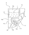
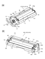
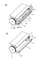
まず、図1乃至図4を用いて、第1実施形態に係る現像装置としての現像カートリッジB(以下、「カートリッジ」と称す)について説明する。図1は、カートリッジBの断面図である。図2はカートリッジBの斜視図である。図3はカートリッジBを現像ローラ軸線方向において、駆動側から見た側面図、および非駆動側から見た側面図である。また、図4はカラー電子写真画像形成装置100aの本体Aの断面図である。
[First Embodiment]
Description of Cartridge First, a developing cartridge B (hereinafter referred to as “cartridge”) as a developing device according to the first embodiment will be described with reference to FIGS. 1 to 4. FIG. 1 is a cross-sectional view of the cartridge B. FIG. 2 is a perspective view of the cartridge B. FIG. FIG. 3 is a side view of the cartridge B viewed from the driving side and a side view viewed from the non-driving side in the direction of the developing roller axis. FIG. 4 is a sectional view of the main body A of the color electrophotographic image forming apparatus 100a.
尚、このカートリッジBは、ユーザによって、本体Aに設けられたロータリC(本体A)に対して、取り付け、取り外しが可能である。 The cartridge B can be attached to and detached from the rotary C (main body A) provided in the main body A by the user.
図1乃至図3において、カートリッジBは現像ローラ110を有する。現像ローラ110は、現像作用時に、本体Aから後述するカップリング機構により回転力を受けて回転する。
1 to 3, the cartridge B has a developing
カートリッジBが有する現像剤収容部114には所定色の現像剤tが収納されている。現像剤は、現像室113aにおいてスポンジ状の現像剤供給ローラ115の回転によって現像ローラ110表面に供給される。そして、現像剤tは、現像ローラ110に供給される現像剤の厚みを規制する現像ブレード112と現像ローラ110との摩擦により電荷を付与され薄層化される。薄層化された現像ローラ110上の現像剤は、回転により現像位置に搬送される。そして、現像ローラ110に所定の現像バイアスを印加することにより、電子写真感光体ドラム(以下、感光体ドラム、又は、ドラムと称す)107に形成された静電潜像を現像する。即ち、現像ローラ110によって、静電潜像が現像される。
A
また、前記潜像の現像に寄与しなかった現像剤、すなわち、現像ローラ110の表面に残留した現像剤は、現像剤供給ローラ115で剥ぎ取られる。またこれと同時に、供給ローラ115によって、新しい現像剤が現像ローラ110表面に供給される。これによって現像動作が連続的に行われる。ここで、現像ローラ110は、現像剤収容部114aに収容されている現像剤tを用いて、感光体ドラム107に形成された静電潜像を現像する。また、供給ローラ115は、現像ローラ110に現像剤tを供給する。
Further, the developer that has not contributed to the development of the latent image, that is, the developer remaining on the surface of the developing
尚、カートリッジBは、現像ユニット119を有する。現像ユニット119は、現像枠体113を有する。また、現像ユニット119は、現像ローラ110、現像ブレード112、供給ローラ115、現像室113a、及び、現像剤収容部114を有する。尚、現像ローラ110は軸線L1(図10(a))を中心に回転可能である。
The cartridge B has a developing
また、現像ローラ110及び、供給ローラ115は、軸部110a及び、軸部115aが、軸受部材(第1の軸受部材)138に回転可能に支持されている。また、軸部110b及び、軸部115bが、その反対側に位置する軸受部材(第2の軸受部材)139に回転可能に支持されている。軸受部材138を現像枠体113に対してネジ200b、200cにより締結している。また、軸受部材139を現像枠体113に対して第4のネジ(第4の締結部)200d、第5のネジ(第5の締結部)200e)により締結している。これにより、現像ローラ110及び、供給ローラ115は、軸受部材138、139を介して、現像枠体(カートリッジ枠体)113に回転可能に支持されている。尚、枠体113は、現像ローラ110の長手方向に沿って設けられている。軸受部材138は枠体113の長手方向において駆動側(カップリング150の設けられている側)に設けられている。軸受部材139は枠体113の長手方向において非駆動側(カップリング150の設けられていない側)に設けられている。軸受部材(第1の軸受部材)138は、枠体113の長手方向一端側に設けられている。そして、軸受部材138は、現像ローラ110の長手方向一端側に設けられた一端側軸部(現像ローラ軸部)110aを支持する、且つ、供給ローラ115の長手方向一端側に設けられた一端側軸部(現像剤供給ローラ軸部)115aを支持する。また、軸受部材(第2の軸受部材)139は、枠体113の長手方向他端側に設けられている。そして、現像ローラ110の長手方向他端側に設けられた他端側軸部(現像ローラ軸部)110bを支持する、且つ、供給ローラ115の長手方向他端側に設けられた他端側軸部(現像剤供給ローラ軸部)115bを支持する。
In addition, the developing
ここで、カートリッジBは、ユーザによって、現像ロータリCに設けられたカートリッジ収容部130Aに取り外し可能に取り付けられる。ロータリCは、本体Aに設けられている。この際に、後述するように、カートリッジBがロータリCにより所定の位置(感光体ドラム対向部)に位置決めされる動作に連動して、本体Aに設けられた駆動軸180とカートリッジBの有するカップリング部材(回転駆動力伝達部品)150とが結合する。そして、現像ローラ110、供給ローラ115は本体Aから回転力を受けて回転する。
Here, the cartridge B is detachably attached to the
電子写真画像形成装置の説明
図4を用いて、カートリッジBを用いるカラー電子写真画像形成装置100について説明する。尚、以下、画像形成装置100として、カラーレーザービームプリンタを例に挙げて説明する。
Description of Electrophotographic Image Forming Apparatus A color electrophotographic
図4に示すように、色の異なる現像剤(トナー)を収納した複数のカートリッジB(B1、B2、B3、B4)をロータリC(収容部130A、図4)に取り付ける。尚、カートリッジBのロータリCに対する取り付け、取り外しはユーザによって行われる。そして、ロータリCを回転することにより、所定色の現像剤を収納したカートリッジBを感光体ドラム107に対向させる。そして、感光体ドラム107に形成された静電潜像を現像する。現像された現像像を転写ベルト122aに転写する。さらに、これらの動作を各色について行う。これにより、カラー画像を得る。以下に詳細に説明する。ここで記録媒体Sは、画像を形成することができるものであって、例えば紙、OHPシート等である。
As shown in FIG. 4, a plurality of cartridges B (B1, B2, B3, B4) containing developers (toners) of different colors are attached to the rotary C (
図4に示すように、光学手段120から画像情報に基づいたレーザ光をドラム107に照射する。これによって、ドラム107に静電潜像を形成する。そして、この潜像は現像剤tを用いて、現像ローラ110によって現像される。ドラム107に形成された現像剤像は、中間転写ベルト(中間転写体)122aに転写される。
As shown in FIG. 4, the
次に、転写ベルト122a上に転写された現像剤像が、二次転写ローラ(第2の転写手段)122cによって記録媒体Sに転写される。そして、現像剤像が転写された記録媒体Sを、加圧ローラ123aと加熱ローラ123bを有する定着手段123に搬送する。そして、記録媒体Sに転写された現像剤像を定着手段123によって、記録媒体Sに定着する。定着後、記録媒体Sをトレイ124へ排出する。
Next, the developer image transferred onto the
さらに、画像形成工程について説明する。 Further, the image forming process will be described.
転写ベルト122aの回転と同期して、ドラム107を反時計回り(図4)に回転させる。そして、ドラム107表面を帯電ローラ108によって均一に帯電する。そして、露光手段120によって、画像情報に応じて、例えばイエロー画像の光照射を行う。そして、ドラム107にイエロー色の静電潜像を形成する。即ち、ドラム107に画像情報に応じた静電潜像を形成する。
In synchronization with the rotation of the
前記潜像の形成と同時にロータリCを回転させる。これによって、イエローカートリッジB1を現像位置に移動させる。そして、現像ローラ110に所定のバイアス電圧を印加する。これによって、潜像にイエロー現像剤を付着させる。そして、潜像がイエロー現像剤によって現像される。その後、転写ベルト122aの押えローラ(一次転写ローラ)122bに現像剤と逆極性のバイアス電圧を印加する。これによって、感光体ドラム107上のイエローの現像剤像を転写ベルト122aに一次転写する。尚、感光体ドラム107に残留した現像剤は、クリーニングブレード117aによって除去される。除去された現像剤は、現像剤ボックス107dに回収される。
The rotary C is rotated simultaneously with the formation of the latent image. As a result, the yellow cartridge B1 is moved to the developing position. Then, a predetermined bias voltage is applied to the developing
上述のようにイエロー現像剤像の一次転写が終了すると、ロータリCが回転する。そして、次のカートリッジB2が移動して、ドラム107に対向した位置に位置決めされる。以上の工程を、マゼンタカートリッジB2、シアンカートリッジB3、ブラックカートリッジB4の各カートリッジについて行う。このように、マゼンダ、シアン、そしてブラックの各色について繰り返すことによって、転写ベルト122a上に4色の現像剤像を重ね合わせる。
As described above, when the primary transfer of the yellow developer image is completed, the rotary C rotates. Then, the next cartridge B2 moves and is positioned at a position facing the
尚、カートリッジB1は、イエロー色の現像剤を収納しているものであり、イエロー色現像剤像を形成する。カートリッジB2は、マゼンタ色の現像剤を収納しているものであり、マゼンタ色現像剤像を形成する。カートリッジB3は、シアン色の現像剤を収納しているものであり、シアン色現像剤像を形成する。カートリッジB4は、ブラック色の現像剤を収納しているものであり、ブラック色現像剤像を形成する。各カートリッジBの構成は同じである。 The cartridge B1 contains a yellow developer and forms a yellow developer image. The cartridge B2 contains a magenta developer and forms a magenta developer image. The cartridge B3 contains a cyan developer and forms a cyan developer image. The cartridge B4 contains a black developer and forms a black developer image. Each cartridge B has the same configuration.
そして、転写ベルト122a上に4色の現像剤像が形成された後、転写ローラ122cが転写ベルト122aに圧接される(図4)。更に転写ローラ122cの圧接と同期して、レジストローラ対121e近傍の所定の位置で待機していた記録媒体Sが、転写ベルト122aと転写ローラ122cのニップ部に送り出される。そして、同時に記録媒体Sが搬送手段121としての給送ローラ121b、レジストローラ対121eによってカセット121aから搬送される。
Then, after four color developer images are formed on the
また、転写ローラ122cには、現像剤と逆極性のバイアス電圧が印加されている。これによって、転写ベルト122a上の現像剤像が、搬送されてきた記録媒体Sに一括して二次転写される。尚、帯電ローラ122dは、ベルト122aに付着した現像剤を除去する。
A bias voltage having a polarity opposite to that of the developer is applied to the
現像剤像が転写された記録媒体Sは定着手段123に搬送される。そして現像剤像の定着が行われる。そして、定着が行われた記録媒体Sは、排出ローラ対121gによって、排出トレイ124に排出される。これによって、記録媒体Sに画像形成を完了する。
The recording medium S to which the developer image is transferred is conveyed to the fixing
尚、ロータリCにはカートリッジ収容部130Aが複数箇所に設けられている。カートリッジBがこの部屋に取り付けられた状態で、ロータリCが一方向へ回転する。これによって、カートリッジBのカップリング部材150(後述する)が、本体Aに設けられた駆動軸(本体駆動軸)180に連結(係合)し及び駆動軸180から離脱する。ここで、収容部130Aに収納されたカートリッジBの現像ローラ110は、ロータリCの一方向への移動に応じて、駆動軸180の軸線L3方向と実質的に直交する方向に移動する。即ち、ロータリCの回転によって、現像ローラ110は軸線L1が軸線L3と実質的に直交する方向に移動する。
The rotary C is provided with a plurality of cartridge
回転力伝達機構の説明
現像ギア(回転力伝達部材)145は、現像ローラ110の軸部(回転軸)110aに設けられている。また、供給ローラギア(回転力伝達部材)146は、供給ローラ115の軸部(回転軸)115aに設けられている。そして、本体Aよりカップリング(回転力受け部材)150が受けた回転力をカートリッジBの他の有する回転部材(現像ローラ110、供給ローラ115等)にギア145、146を介して伝達する。カップリング150は、カートリッジBが本体Aに装着された状態で、本体Aから現像ローラ110を回転するための回転力を受ける。また、供給ローラ115を回転するための回転力を受ける。ギア145は、枠体113の長手方向一端側であって前記長手方向において軸受部材138の外側に設けられており、カップリング150が本体Aから受けた回転力を現像ローラ110に伝達する。尚、回転力伝達部材としては、ギアに限定されずに、例えば歯付きベルト等であっても良い。但し、ギアはコンパクト、取り付け易い利点がある。
Description of Rotational Force Transmission Mechanism The developing gear (rotational force transmission member) 145 is provided on the shaft portion (rotary shaft) 110a of the developing
次に、カップリング150を取り付けている(支持している)円筒部材(図5、図7、図8、図9)147について説明する。
Next, the cylindrical member (FIGS. 5, 7, 8, and 9) 147 to which the
図5に示すように、円筒部材147は現像ギア145とギア部(第1のギア)147a、供給ローラギア146とギア部(第2のギア)147bが噛み合う位置で回転可能に取り付けられている。円筒部材147は、内部にカップリング収納部147jを有し(図7(b)参照)、カップリング150の駆動部150bを収納している。
As shown in FIG. 5, the
カップリング150は円筒部材147の抜け止め部147k1、147k2、147k3、及び、147k4によって、円筒部材147に対し図7(c)矢印X34方向への移動を規制され、また、円筒部材147に傾斜可能(図8参照)に取り付けられている。
The movement of the
更にサイドカバー(サイド部材)157を現像ローラ110の軸線L1方向(長手方向)から取り付ける(図2(a)、図3参照)。この時、サイドカバー157及び軸受部材138を貫通させて、第3のネジ(第3の締結部材)200bを現像枠体113に取り付ける。これにより、サイドカバー157及び軸受部材138を共締めして、現像枠体113に取り付ける。また、ネジ200bをサイドカバー157及び軸受部材138を貫通させて、現像枠体113に設けられたネジ座面114d(図10)にネジ留めする。これによって、軸受部材138を介して、サイドカバー157を直接現像枠体113に固定することができる。尚、サイドカバー157は、枠体113の長手方向(現像ローラ110の長手方向)において、軸受部材138の外側に設けられている。そして、サイドカバー157はギア145、146(回転力伝達部材)及びギア部(ギア、回転力伝達部材)147a、147bを覆っている。即ち、サイドカバー157は、枠体113の長手方向一端側であって且つ軸受部材138との間でもって、カップリング150が本体Aから受けた回転力を現像ローラ110に伝達するためのギア145を覆っている。従って、ギア145は、軸受部材138とサイドカバー157との間に位置しているから、組立て易い。これによって、ギア145、146及びギア部147a、147bが他の部材と接触するのを防止している。また、これらが、不用意にユーザに触れることを防止できる。尚、サイドカバー157は、必ずしも、前記ギアを完全に覆っていなくても良い。例えば、櫛歯状に前記ギアを覆っていても良いし、前記ギアの一部分を覆っていても良い。このような場合であっても、本実施形態に含まれる。円筒部材147は、内側にカップリング150の駆動部150b(一端側)を可動状態で取り付けられている。円筒部材147は、円筒部材147の内側に設けられた、カップリング150が本体Aから受けた回転力を受ける回転力受け面(円筒側力受け部)147(147h1、147h2)を前記内側に有する。また、円筒部材147は、円筒部材147の外側周面に設けられている、回転力受け面147が受けた回転力を現像ローラ110に伝達するためのギア(第1のギア)147aを有する。また、カートリッジBは、軸部110aに設けられた、ギア145(回転力伝達部材、第2のギア)を有する。従って、カートリッジBが本体Aに装着された状態で、本体Aに設けられた駆動軸180からの回転力が、カップリング150、円筒部材147、ギア147a、及び、ギア145を介して現像ローラ110に伝達される。そして、現像ローラ110を回転させる。本実施形態によれば、カップリング150を取り付けている円筒部材147自体にギア147a、147bを設けている。従って、カップリング150を介して円筒部材147が受けた回転力を、効率良く現像ローラ110、及び、供給ローラ115に伝達することができる。また、回転力伝達構成をコンパクトにすることができる。
Further, a side cover (side member) 157 is attached from the direction of the axis L1 (longitudinal direction) of the developing roller 110 (see FIGS. 2A and 3). At this time, the third screw (third fastening member) 200 b is attached to the developing
また、サイドカバー157には穴157jが設けられており、その内周面157mが円筒部材147と嵌合する(図5、図7(e)、図8、図13参照)。
Further, the
(5)回転駆動力伝達部品(カップリング、カップリング部材)の説明
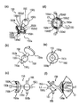
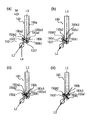
次に、図6を用いて、本実施形態の主要な構成要素である回転駆動力伝達部品であるカップリング(カップリング部材、回転力受け部材)の一例について説明する。図6(a)はカップリングを装置本体側から見た斜視図であり、図6(b)はカップリングを現像ローラ側から見た斜視図である。また、図6(c)はカップリング回転軸線L2方向に直交方向から見た図である。また、図6(d)はカップリングを装置本体側から見た側面図であり、図6(e)は現像ローラ側から見た図である。また、図6(f)は図6(d)をS3で切った断面図である。
(5) Description of Rotational Driving Force Transmission Parts (Coupling, Coupling Member) Next, referring to FIG. 6, a coupling (coupling member) that is a rotational driving force transmission component that is a main component of the present embodiment. An example of the rotational force receiving member) will be described. FIG. 6A is a perspective view of the coupling as viewed from the apparatus main body side, and FIG. 6B is a perspective view of the coupling as viewed from the developing roller side. FIG. 6C is a diagram viewed from the direction orthogonal to the direction of the coupling rotation axis L2. 6D is a side view of the coupling as viewed from the apparatus main body side, and FIG. 6E is a view as viewed from the developing roller side. Moreover, FIG.6 (f) is sectional drawing which cut FIG.6 (d) by S3.
カートリッジBを収容部130Aに取り外し可能に取り付ける。これは、ユーザによって行われる。そして、制御信号によってロータリCを回転駆動させる。そして、カートリッジBが所定位置(感光体ドラム107と対向する位置、現像位置)に達した位置で、ロータリCを停止させる。これによって、カップリング150は、本体Aに設けられた駆動軸180と係合する。
The cartridge B is removably attached to the
更に、ロータリCを一方向へ回転することによって、カートリッジBを前記所定位置(現像位置)から移動させる。即ち、所定位置から退避させる。これによって、カップリング150は、駆動軸180から離脱する。
Further, the cartridge B is moved from the predetermined position (development position) by rotating the rotary C in one direction. That is, it is retracted from a predetermined position. As a result, the
カップリング150は、駆動軸180と係合した状態で、本体Aに設けられたモータ(不図示)から回転力を受ける。そして、その回転力を現像ローラ110に伝達する。これによって、現像ローラ110が本体Aから受けた回転力で回転する。この回転力の伝達は、カップリング150、回転力受け面(円筒側力受け部、回転力被伝達部)147(147h1、147h2)、ギア部147a、ギア145を介して行われる。尚、回転力受け面147には、ピン(回転力伝達部)155を介して回転力が伝達される。また、供給ローラ115には、ギア部147b、ギア146を介して、回転力が伝達される。
The
前述した通り、駆動軸180はピン182(回転力付与部)(図19(a)参照)を有しており、モータ(不図示)により回転される。
As described above, the
尚、カップリング150の材質は、樹脂(例えば、ポリアセタール)が望ましい。
The material of the
カップリング150は、図6(c)に示すように、主に3つの部分を有する。第1の部分は、駆動軸180(後述する)と係合し、この駆動軸180に設けられた回転力付与部(本体側回転力伝達部)である回転力伝達ピン182から回転力を受けるための被駆動部150aである。また第2の部分は、ピン155が円筒部材147と係合して、回転力を伝える駆動部150bである。また、第3の部分は、被駆動部150aと駆動部150bとをつなぐ中間部150cである。
The
図6(f)に示すように、被駆動部150aは、回転軸線L2に対して広がった駆動軸挿入開口部150mを有する。また、駆動部150bは、球状の駆動軸受面(球形状部)150i、駆動力伝達部(突出部)155、およびカップリング規制部150jを有する。尚、伝達部155は、カップリング150が本体Aから受けた回転力を、円筒部材147に伝達するためのものであり、円筒部材147の半径方向に突出している。ここで、規制部150jは、軸線L2と略同軸線上にあり、後述する規制収納部160b(図10(b))と係合する。これにより、規制部150jはカップリングの軸線L2を規制する。
As shown in FIG. 6F, the driven
開口部150mは、駆動軸180側に向かって拡開した円錐形状の駆動軸受け面150fにより形成されている。受け面150fは、図6(f)に示すように凹部150zを構成している。尚、凹部150zは、軸線L2方向において、円筒部材147とは反対側に開口部150m(開口)を有する。
The
これにより、現像ローラ110のカートリッジB内での回転位相に関わらず、カップリング150が駆動軸180の軸線L3に対して係合前角度位置(図19(a))、回転力伝達角度位置(図19(d))、及び、離脱角度位置(図22(c)(d))間を移動できる。即ち、カップリング150は、駆動軸180の先端部182aに阻止されることなく、前記各位置を移動(傾動、旋回)することができる。
As a result, regardless of the rotation phase of the developing
そして、凹部150zの端面であって、軸線L2を中心とする円周上には、2個の突起(突出部)(係合部)150d(150d1、150d2)が等間隔に配置されている。また、各々の突起150dの間には、進入部150k(150k1、150k2)が設けられている。ここで、突起150d1、150d2の間隔は、この間隔内に、駆動軸180に設けられたピン182が位置できるように、ピン182の外径よりも大きく設定されている。尚、ピン182が回転力伝達部である。この突起の間が、進入部150k1、150k2である。
Two protrusions (protruding portions) (engaging portions) 150d (150d1, 150d2) are arranged at equal intervals on the end surface of the
カップリング150に駆動軸180から回転力が伝達される際には、進入部150k1、150k2にピン182が位置する。更に、図6(d)において、各突起150dの時計回りの方向において、上流側には、回転力受面(回転力受け部)150e(150e1、150e2)が設けられている。受面150eは、カップリング150の回転方向と交差して設けられている。即ち、突起150d1には受け面150e1、及び、突起150d2には受け面150e2が設けられている。駆動軸180が回転している状態では、ピン182a1、182a2が、受け面150eのいずれかに接触する。これによって、ピン182a1、182a2が接触している受け面150eがピン182に押される。これによって、カップリング150は、軸線L2を中心にして回転する。
When the rotational force is transmitted from the
尚、受け面150fは、図6(f)に示すように、先端角度α2の円錐となっている。これにより、カップリング150と駆動軸180とが係合する。そして、カップリング150が回転力伝達角度位置にある場合、駆動軸の先端180b(図19(a)参照)が受け面150fに当接する。そして、円錐の軸、即ちカップリング150の軸線L2と、駆動軸180の軸線L3(図21参照)とが略同軸線上となる。即ち、カップリング150と駆動軸180とが調芯され、カップリング150に伝達される回転トルクが安定する。
The receiving
本実施形態において、α2は60°〜150°である。α2の角度によって、開口部150mの非円錐部150n(図6(a)、図6(d))は、広い場合(図7(b)参照)や、存在しない場合がある。また、受け面150fは円錐としたが、円筒形状でも良いし、釣鐘形状、ラッパ状形状でも良い。
In the present embodiment, α2 is 60 ° to 150 °. Depending on the angle α2, the
また、受け面150eは軸線L2上に中心Oを有する仮想円上(同一円周上)C1に配置されていることが望ましい(図6(d))。これにより、回転力伝達半径が一定となり、伝達されるトルクが安定する。また、突起150dは、カップリング150の受ける力の釣り合いにより、カップリング150の位置ができるだけ安定する方が好ましい。そのため本実施形態では、各受け面150eを180°対向した位置に配置している。
The receiving
即ち、本実施形態では、受け面150e1と受け面150e2を対向させて対で構成している。なぜなら、180°でもって対向した位置に配置することにより、カップリング150の受ける力は偶力となる。そのため、カップリング150は偶力を与えるだけで回転運動を続けることができる。そこで、回転軸線L2の位置を規定しなくとも、カップリング150は回転することができるからである。
That is, in this embodiment, the receiving surface 150e1 and the receiving surface 150e2 are opposed to each other. This is because the force received by the
即ち、突起150dは、凹部150zの先端側に設けられている。そして、突起(突出部)150dは、カップリング150が回転する回転方向と交差する交差方向に突出して、及び、前記回転方向に沿って間隔をあけて2個設けられている。即ち、突起150dを2個配置することにより、後述する回転した状態の駆動軸と係合する際、より確実な係合が可能となる。
That is, the
そして、受け面150eは、カートリッジBがロータリCに取り付けられた状態で、ピン182と係合する。そして、回転する駆動軸180から回転力を受けるピン182によって押される。これによって、受け面150eは、駆動軸180からの回転力を受ける。また、受け面150eは、軸線L2から等距離に、及び、軸線L2を挟んで対になって位置するように、各突起150dにおいて、前記交差方向に設けられた面に設けられている。
The receiving
また、進入部(窪み)150kが、前記回転方向に沿って、及び、軸線L2方向に窪んで設けられている。この、進入部150kは、突起150dと突起150dとの間に設けられている。尚、駆動軸180が回転を停止している場合に、カートリッジBがロータリCに取り付けられた状態で、カップリングが駆動軸180と係合すると、ピン182が進入部150kに進入する。そして、回転する駆動軸180のピン182によって、受け面150eが押される。あるいは、カップリングが駆動軸180と係合する際に、駆動軸180が既に回転している場合には、ピン182が進入部150kに進入して、ピン182が受け面150eを押す。これによって、カップリング150が回転する。
Moreover, the entrance part (dent) 150k is provided so as to be recessed along the rotation direction and in the direction of the axis L2. The
尚、受け面150eは、受け面150fの内側に配置されていても良い。或いは、受け面150eは、軸線L2方向において、受け面150fから外方へ突出した箇所に配置されていても良い。受け面150eが、受け面150fの内側に配置されている場合には、進入部150kも受け面150fの内側に配置される。
The receiving
即ち、進入部150kは、受け面150fの円弧部の内側で、且つ、突起150d間に位置する窪みである。また、受け面150eが、前記外方へ突出した箇所に配置されている場合には、進入部150kは、突起150d間に位置する窪みである。
That is, the
尚、ここで、窪みとは、軸線L2方向において、貫通している穴であっても、或いは、底部を有している場合であっても含まれる。即ち、窪みとは、突起150d間に位置している空間領域であれば良い。そして、カートリッジBがロータリCに取り付けられた状態で、前記領域に、ピン182が進入できればよい。
Here, the dent is included even if it is a hole that penetrates in the direction of the axis L2 or has a bottom. That is, the depression may be a spatial region located between the
駆動部150bは、円筒部材147のカートリッジB内での回転位相がどこであっても、円筒部材147の軸線L4(図9参照)に対して、回転力伝達角度位置と、係合前角度位置(または、離脱角度位置)の間を移動できるように球面である。図示例では、駆動部150bは、軸線L2を軸線とする球状の抜け止め部150iを有する。そして、駆動部150b(球部)の中心を通る位置に伝達部を設けている。さらに、軸線L2を軸線とする円柱状のカップリング規制部150jが、駆動部150bの、中間部150cと対向する位置に設けてある。尚、規制部150jは、後述する規制収納部160b(図10(b))と係合することにより、軸線L2を規制する。
The
この実施形態では、カップリング150は一体であるが、被駆動部150a、中間部150cと駆動部150bとに分割され、結合することによって一体化することも可能である。また、駆動伝達部155を鉄製の平行ピンとして、別体とすることも可能である。その他、様々な分割が可能であるが、カップリングとして一体的に動作可能であれば、どのように分割しても良い。
In this embodiment, the
次に、図7を用いて、カップリング150を取り付ける(支持する)円筒部材147について説明する。
Next, the
図7(a)に示した開口部147g1、147g2は円筒部材147の回転軸方向に設けられた溝になっている。カップリング150を取り付ける際、回転力伝達部(回転力伝達部)155がこの開口部147g1、147g2に進入する。
The openings 147g1 and 147g2 shown in FIG. 7A are grooves provided in the rotation axis direction of the
また、図7(a)において、開口部147g1、147g2の時計回り方向上流側には、回転力受け面(円筒側力受け部、回転力被伝達部)147h(147h1、147h2)が設けられている。そして、伝達面147hに、カップリング150の伝達部155の側面が接触する。これにより、現像ローラ110に回転力が伝達される。
In FIG. 7A, a rotational force receiving surface (cylindrical side force receiving portion, rotational force receiving portion) 147h (147h1, 147h2) is provided on the upstream side in the clockwise direction of the openings 147g1, 147g2. Yes. And the side surface of the
図7(b)に示したように、円筒部材147にはカップリング150の駆動部150bを収納するカップリング収納部147jが設けられている。
As shown in FIG. 7B, the
また、収納したカップリング150の駆動部150bが、円筒部材147から抜ける(脱落する)事を防止するための、抜け止め部147k(147k1〜147k4)が設けられている。円筒部材147は受け面147h、抜け止め部147k等が樹脂製であって、一体成形されている。
In addition, a retaining
図7(b)、図7(c)は、カップリング150を円筒部材147に取り付けるカップリング取り付け工程を示す断面図である。
FIG. 7B and FIG. 7C are cross-sectional views showing a coupling attachment process for attaching the
まず、カップリング150をX33方向に移動させ、駆動部150bを収納部147jに挿入する。挿入前において、抜け止め部150iの直径φZ6は、抜け止め部147kの内側稜線147m(147m1〜147m4)によって構成される円の直径φD15(図7(a))よりも大きい。即ち、Z6>D15の関係にある。
First, the
駆動部150bの挿入に従い、抜け止め部(第1の規制部)147k(147k1〜147k4)が、弾性変形により一時的に円筒部材147の半径方向外側に設けた空間147lに退避する(図7cの状態)。そして、駆動部150bが収納部147jに挿入可能となる。即ち、一時的にD15=Z6の関係となる。駆動部150bの収納部147jへの挿入が完了すると、弾性変形していた抜け止め部147k(147k1〜147k4)は、元の状態に戻る。即ち、Z6>D15の関係となる。
In accordance with the insertion of the
これにより、カップリング150と円筒部材147とが一体となった駆動ユニットU1となる(図7dの状態)。
As a result, the drive unit U1 in which the
次に、図7eに示すように、サイドカバー157を矢印X33方向から挿入する。これにより、サイドカバー157に一体的に形成された抜け止め部(第2の規制部)157aが円筒部材147の内面との空間(隙間)147l内に進入する。即ち、抜け止め部157aが空間(隙間)147l内に挿入した状態で、サイドカバー157は軸受部材138を挟んで枠体113に取り付けられる。これにより、図7(f)に示すように、抜け止め部147k(147k1〜147k4)が、円筒部材147の半径方向外側へ弾性変形するのが防止される。従って、カップリング150が円筒部材147から抜ける(脱落する)のを防ぐことができる。本実施形態によれば、サイドカバー157を枠体113に取り付ける際に、抜け止め部157aを空間(隙間)147l内に進入させている。従って、カートリッジBの組立て操作性が向上する。即ち、サイドカバー157を枠体113に取り付ける操作性を向上させることができる。尚、本実施形態によれば、サイドカバー157を枠体113に取り付ける方法として、次の二つの方法がある。第1の方法は、枠体113に軸受部材138を取り付けた後に、サイドカバー157を枠体113に取り付ける方法である(図13(b))。また、第2の方法は、軸受部材138とサイドカバー157を一体にして、枠体113に取り付ける方法である(図20(b))。いずれの方法においても、本実施形態は、前述したカートリッジBの組立て操作性を向上させることができる。
Next, as shown in FIG. 7e, the
尚、抜け止め部147kは、サイドカバー157とは別部材であるカップリング抜け止め部材として、サイドカバー157と別体とすることもできる。
The retaining
このように、カップリング150は、円筒部材147内において、回転力伝達角度位置、係合前角度位置、及び、離脱角度位置の間を移動(傾動、旋回)可能に取り付けられている。
As described above, the
以上説明したように、前述した実施形態は、カートリッジBが本体Aに装着された状態で、現像ローラ110を回転するための回転力を本体Aから受けるためのカップリング(カップリング部材)150を有する。また、内側にカップリング150の一端側(駆動部150b)を可動状態で取り付けられている円筒部材147を有する。また、円筒部材147の内側には、カップリング150が本体Aから受けた回転力を受けるための円筒側力受け部(回転力受け部)147h(147h1、h2)が設けられている。円筒部材147の外側周面には、力受け部147hが受けた回転力を現像ローラ110に伝達するためのギア(第1のギア)147aが設けられている。
As described above, in the above-described embodiment, the coupling (coupling member) 150 for receiving the rotational force for rotating the developing
また、円筒部材147には、円筒部材147に取り付けられたカップリング150の一端側である駆動部150bが、円筒部材147の軸線方向に外れるのを規制する抜け止め部(第1の規制部)147kが設けられている。尚、円筒部材147の軸線方向とは、回転力伝達角度位置に位置するカップリング150の軸線L2と同じ方向である。ここで、抜け止め部147kは、円筒部材147の半径方向に撓み可能に設けられている。また、抜け止め部147kは、円筒部材147の内側に設けられている。尚、円筒部材147の内側とは、円筒部材147の軸線方向端部よりも内側である。
Further, the
また、カップリング150の一端側(駆動部150b)を円筒部材147の内側に、抜け止め部147kを撓ませつつ取り付けた状態で、抜け止め部147k(147k1〜147k4)が撓むのを規制する抜け止め部(第2の規制部)157aが設けられている。抜け止め部157aは、サイドカバー157の内側に設けられている。尚、サイドカバー157の内側とは、サイドカバー157を枠体113に取り付けた状態で、内側即ち枠体113側である。抜け止め部(第1の規制部)147kは、樹脂製であって、樹脂の弾性力でもって、円筒部材147の半径方向(ラジアル方向)に撓み可能である。
In addition, in a state where one end side of the coupling 150 (the driving
また、抜け止め部(第1の規制部)147kは、円筒部材147の円周方向に沿って、かつ、前記円周方向において間隔をあけて複数箇所に配置されている。また、抜け止め部147kは、前記半径方向に撓み可能である。また、抜け止め部147kは、円筒部材147の内面と空間(隙間)147l(147l1、147l2)(図7(c)(e)(f))を有して配置されている。そして、抜け止め部(第2の規制部)157aは少なくとも一つの空間147lに侵入して、抜け止め部147kが前記半径方向において円筒部材147の外方に撓むのを規制する(図7(f))。また、円筒部材147、回転力受け面(円筒側力受け部)147h、及び、抜け止め部147kは樹脂製であって、一体成形されている。ここで、カップリング150の駆動部150b(一端側)は球形状部である。
Further, the retaining portion (first restricting portion) 147k is disposed at a plurality of locations along the circumferential direction of the
また、抜け止め部147kは、カップリング150が円筒部材147から外れるのを規制するために、突出部Sを有している。突出部Sは、前記球形状部が円筒部材147から外れるのを規制するために、前記半径方向において円筒部材147の前記内側方向に突出している。そして、突出部Sでもって前記球形状部が円筒部材147の軸線方向に外れるのを規制している(図7(c)、図8)。また、前述したサイドカバー157は、軸受部材138と結合されている状態で、カップリング159の一端側を取り付けた円筒部材147を回転可能に覆っている。
Further, the retaining
更に、サイドカバー157が抜け止め部157aを有している(図7(e)(f))。そして、抜け止め部157aは、円筒部材147の内面と抜け止め部147kとの、少なくとも一つの空間147lに進入している。そして、抜け止め部147kが撓むのを規制している(図7(f))。前述した実施形態によれば、駆動部150bを円筒部材147内に取り付ける際には、抜け止め部147kが前記半径方向外側に撓む。これによって、駆動部150bが円筒部材147内に進入するのを許容する。これによって、駆動部150bを円筒部材147内に円滑に取り付けることができる。また、サイドカバー157を枠体113に取り付けさえすれば、抜け止め部157aが空間147lに進入する。従って、抜け止め部147kが撓むのを規制することができる。また、反対に、駆動部150bを円筒部材147から取り外す際にも、抜け止め部147kが前記半径方向外側に撓む。これによって、駆動部150bを円筒部材147から円滑に取り外すことができる。
Further, the
また、カップリング150を枠体113に取り付けるカップリングの取り付け方法は、カップリング部材の取り付け工程とサイドカバーの取り付け工程を有する。前記カップリング部材の取り付け工程は、樹脂製の抜け止め部(第1の規制部)147kを前記半径方向の外側に撓ませながらカップリング150の一端側を円筒部材147の内側に可動状態で取り付ける。そして、サイドカバー157を枠体113に取り付けるサイドカバーの取り付け工程は次の工程を有する。円筒部材147を、軸受部材138と、サイドカバー157との間に介在させる。そして、サイドカバー157の開口157jからカップリング150の他端側を突出させた状態で、且つ、サイドカバー157が有する抜け止め部(第2の規制部)157aを、少なくとも一つの空間(隙間)147lに進入させる。これによって、抜け止め部(第1の規制部)147kが撓むのを規制するようにサイドカバー157を枠体113に取り付ける。
The coupling attachment method for attaching the
ここで、抜け止め部147kとは、円筒部材147の円周方向に沿って、間隔をあけて複数箇所に配置されており、半径方向に撓み可能である。また、前記カップリング部材の取り付け工程によって、円筒部材147は、カップリング150の前記一端側を前記内側に取り付けられている。また、軸受部材138は、枠体113の長手方向一端に取り付けられている、現像ローラ110の長手方向一端側に設けられた軸部110aを支持している。また、空間(隙間)147lとは、円筒部材147の内面と抜け止め部147kとの、少なくとも一つの空間(隙間)147lである。
Here, the retaining
また、カップリング150を枠体113から取り外すカップリング部材の取り外し方法は、サイドカバーの取り外し工程とカップリング部材の取り外し工程とを有する。前記サイドカバーの取り外し工程は、枠体113に取り付けられているサイドカバー157を枠体113から取り外す工程である。この際に、サイドカバー157は、カップリング150が取り付けられている円筒部材147を、軸受部材138との間に、介在させて枠体113に取り付けられている。そしてサイドカバー157は、開口157jからカップリング150の他端側を突出させた状態で、枠体113に取り付けられている。且つ、サイドカバー157は、サイドカバー157が有する抜け止め部157aを円筒部材147の内面と抜け止め部147との、少なくとも一つの空間147lに進入させて抜け止め部147kが撓むのを規制するように枠体113に取り付けられている。また、前記カップリング部材の取り外し工程は、円筒部材147からカップリング150を取り外す工程である。そして、前記カップリング部材の取り外し工程は、前記サイドカバーの取り外し工程によって、サイドカバー157を枠体113から取り外した後に行われる。そして、前記カップリング部材の取り外し工程は、円筒部材147からカップリング150を取り外すに当たって、抜け止め部147kを円筒部材147の半径方向において外側に撓ませながら行われる。
The method for removing the coupling member for removing the
また、サイドカバー157の取り付け工程において、サイドカバー157を枠体113に取り付けるに当たって、サイドカバー157が有するバネ159の弾性力によってカップリング150を傾斜規制部157nに突き当てた状態で行われる。そして、サイドカバー157をカップリング150と一体に枠体113に取り付ける。また、サイドカバー157の取り外し工程においても、同様の状態で行われる。この工程では、サイドカバー157とカップリング150とを一体で枠体113に取り付けることが出来るので、取り付け操作性を向上させることができる。また、取り外し操作性を向上させることができる。
Further, in the step of attaching the
前述した実施形態によれば、カップリング150を取り付けるに当たって、取り付け操作性を向上させることができた。また、前述した実施形態によれば、カートリッジBからカップリング150を取り外すに当たって、取り外し操作性を向上させることができた。また、前述した実施形態によれば、カートリッジBに取り付けられているカップリング150を交換するに当たって、交換操作性を向上させることができた。また、前述した実施形態によれば、カートリッジBに取り付けられているカップリング150を交換するに当たって、交換操作性を向上させた、カップリング150の交換方法を提供することができた。
According to the above-described embodiment, the attachment operability can be improved when attaching the
これにより、軸線L2方向の一方向に移動させるだけの簡単な工程で、カップリング150を円筒部材147に取り付けることができる。このように、カップリング150をカートリッジBに取り付けた状態では、画像形成時に、カップリング150が円筒部材147から外れることがない。よって、画像不良が発生することを防止することができる。
Thereby, the
次に、図9を用いて、カップリング150の、円筒部材147に対する移動範囲に関して説明する。
Next, the movement range of the
図9は、円筒部材147とカップリング150の結合状態を表した図である。図9(a1)〜(a5)は駆動軸180の方向から見た図であり、図9(b1)〜(b5)はその斜視図である。
FIG. 9 is a view showing a coupled state of the
ここで、図9に示すように、カップリング150は、その軸線L2が軸線L4に対して、どのような方向にも傾斜できるように円筒部材147に取り付けられている。
Here, as shown in FIG. 9, the
図9(a1)(b1)において、軸線L2は軸線L4と同軸線上にある。図9(a2)(b2)には、この状態から、カップリング150を上向きに傾斜させたときの状態を示している。カップリング150が、開口部151gが設けられた方向へ傾斜しているとき、伝達ピン155は開口部151gに沿って移動する(図9(a2)(b2))。その結果、カップリング150は、開口部151gと直交する軸線AXを中心に傾斜する。
9A1 and 9B1, the axis L2 is on the same axis as the axis L4. FIGS. 9A2 and 9B2 show a state where the
図9(a3)(b3)においては、カップリング150を右向きに傾斜させた状態を示している。このようにカップリングが、開口部151gの直行方向へ傾斜しているとき、ピン155は開口部151gの中で回転する。回転する際の軸線L2は、伝達ピン155の中心軸線AYである。
9A3 and 9B3 show a state in which the
カップリング150を下向きに傾けた状態及び左向きに傾けた状態を、図9(a4)(b4)及び図9(a5)(b5)に示した。カップリング150は、各々回転軸線AX、AYを中心に傾斜する。
The state where the
ここで説明した傾斜方向と異なる方向、及び中間位置では、軸線AX回りの回転と、AY回りの回転とが合わさって傾斜する。尚、前記傾斜方向と異なる方向とは、例えば図9(a2)と(a3)、(a3)と(a4)、(a4)と(a5)、(a5)と(a2)である。このように、軸線L4に対して、軸線L2はどのような方向にも傾斜することができる。 In a direction different from the inclination direction described here, and in an intermediate position, the rotation around the axis AX and the rotation around the AY are combined and inclined. The directions different from the inclination direction are, for example, FIGS. 9 (a2) and (a3), (a3) and (a4), (a4) and (a5), (a5) and (a2). Thus, the axis L2 can be inclined in any direction with respect to the axis L4.
尚、軸線L2は、軸線L4に対してどのような方向にも傾斜可能であると説明した。しかしながら、軸線L2は軸線L4に対して、必ずしも360°いずれの方向にも所定の角度まで傾斜可能である必要はない。その場合、例えば、開口部147gを円周方向に広めに設定しておけばよい。このように設定しておけば、軸線L2が軸線L4に対して傾斜する際、直線的に所定の角度傾斜できない場合であっても、カップリング150が軸線L2まわりに少し回転する。これにより、軸線L2は軸線L4に対して、所定の角度まで傾斜することができる。つまり、開口部147gの回転方向のガタは、必要に応じて適宜選択できる。
It has been described that the axis L2 can be inclined in any direction with respect to the axis L4. However, the axis L2 is not necessarily tiltable to a predetermined angle in any direction of 360 ° with respect to the axis L4. In that case, for example, the
先に説明したように(図7参照)、球面150iが抜け止め面147lに接触している。そのため、カップリング150は球面150iの球中心P2を回動中心にして取り付けられている。つまり、円筒部材147の位相に関わらず、軸線L2は傾斜可能に取り付けられている。
As described above (see FIG. 7), the
次に、係合直前において、軸線L2は軸線L4に対して、回転方向X4において下流側へ傾斜する規制方法について述べる。 Next, a regulation method in which the axis L2 is inclined downstream in the rotation direction X4 with respect to the axis L4 immediately before the engagement will be described.
図10(a)及び図11を用いて、カップリング150の角度位置規制部(以下、「規制部」と称す)160について説明する。図10(a)は、規制部(傾斜規制部)160を本体側から見た斜視図である。図10(b)は、規制部160を本体側から見た側面図である。図11(a)は、カップリング150が駆動伝達角度位置(後述)にある場合の、カップリング150と規制部160との位置関係を示す斜視図である。図11(b)は、カップリング150が後述する係合前角度位置にある場合の、カップリング150と規制部160との位置関係を示す斜視図である。また、図11(c)、図11(d)は、それぞれ図11(a)、図11(b)の状態における、円筒部材147と抜け止め部材156の状態を示したものである。
The angular position restricting portion (hereinafter referred to as “restricting portion”) 160 of the
規制部160は、軸受部160aと、規制収納部160bを有する(図10)。更に、規制収納部160bは、位置決め部160b1と、フリー部160b2とを有する。尚、規制部160は、軸受部材138と一体となっている。規制部160は、軸受部材138の外側に設けられている。軸受部材138の外側とは、軸受部材138が枠体113に取り付けられた状態で外側、即ち、枠体113とは反対側である。軸受部材138の外側には、ギア145、146、及び、カップリング150が設けられている。
The
軸受部160aは、円筒部材147の内周面147i(図7(b)参照)を、回転可能に支持する。更に、収納部160bに、カップリング150のカップリング規制部150jが収納される。この状態において、カップリング150は、規制部150jが収納部160bの壁と干渉しない範囲で、自由に移動可能となる。
The bearing
カップリング150は、後述するねじりコイルバネ(カップリング側弾性部材)159の弾性力によって押されて、係合前角度位置をとる。その時、規制部150jが位置決め部160b1に当接し、カップリング150は、駆動軸180との係合に最適な係合前角度位置に位置決めされる。即ち、位置決め部160b1は、カップリング150が係合前角度位置にあるときのみ、位置決めとして作用する。
The
カップリング150が係合前角度位置以外の位置にある場合には、カップリング150は、規制部150jがフリー部160b2の内壁と干渉しない範囲で、自由に移動可能である。尚、カップリング150が係合前角度位置以外の位置にある場合とは、カップリング150が、係合前角度位置と回転力伝達角度位置との間、回転力伝達角度位置、回転力伝達角度位置と離脱角度位置との間、離脱角度位置にある場合である。
When the
また、カップリング150が係合前角度位置以外の位置から係合前角度位置にバネ159の弾性力によって移動する場合、規制部150jはフリー部160b2の壁にガイドされる。そして、規制部150jは、位置決め部160b1に導かれる。そして、カップリング150は係合前角度位置に至る。
Further, when the
次に、図12(a)、図12(b)を用いて、バネ159について説明する。バネ159は、カップリング150を係合前角度位置に移動させるための付勢力を発生する。図12(a)は、サイドカバー157にバネ159を取り付けた状態を表した斜視図、図12(b)は、カートリッジBの斜視図である。
Next, the
図12(a)に示すように、サイドカバー157の外側面157iに、バネ支持部157e1、バネ回転止め157e2を設けている。また、支持部157e1に、バネ159のコイル部159bを取り付けている。バネ回転止め157e2に、バネ159の回転止めアーム159cが当接している。そして、図12(b)に示すように、バネ159の接触部159aが、カップリング150の中間部150cに接触している。この状態で、バネ159がねじれて弾性力を発生させる。この弾性力によって、中間部150cを付勢している。これにより、カップリング150は軸線L2を軸線L4に対して傾斜させている(図12(b)に示す状態、係合前角度位置)。尚、バネ159の中間部150cへの接触位置は、回転方向X4において、駆動部159bの中心よりも上流側に設定している。そのため、軸線L2は、軸線L4に対して、被駆動部150a側が回転方向X4において下流側に向くように傾斜する。
As shown in FIG. 12A, a spring support portion 157
尚、本実施形態では弾性部材として、ねじりコイルバネを用いたが、この限りではない。例えば、板ばね、ゴム、スポンジ等、弾性力を発生させるものであれば良い。但し、軸線L2を傾斜させるためには、ある程度ストロークを必要とする。そのために、ストロークを得られるものが望ましい。 In this embodiment, the torsion coil spring is used as the elastic member, but this is not restrictive. For example, any material that generates an elastic force, such as a leaf spring, rubber, or sponge, may be used. However, a certain amount of stroke is required to incline the axis L2. Therefore, what can obtain a stroke is desirable.
(カップリング150のカートリッジ枠体113への取り付け)
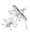
次に、図13を用いて、カップリング150を、現像枠体(カートリッジ枠体)113に取り付ける取り付け方法について説明する。図13(a)は、円筒部材147にバネ159を取り付ける前の、カートリッジBの斜視図である。図13(b)は、サイドカバー157及びバネ159を取り付ける前の、カートリッジBの斜視図である。図13(c)は、バネ159をサイドカバー157に取り付ける前の、カートリッジBの斜視図である。図13(d)は、バネ159の取り付けが完了したカートリッジBの斜視図である。
(Attaching the
Next, a method for attaching the
枠体113には、軸受部材138、現像ローラ110、及び、供給ローラ115が取り付けてある。この時、第1のネジ(第1の締結部材)200cによって、軸受部材138は現像枠体113に対して固定されている。更に、一端側軸部110aには、円筒部材147に設けられたギア147aから、現像ローラ110に回転力を伝達するための、現像ローラギア145が取り付けている。また、一端側軸部115aには、円筒部材147に設けられたギア147bから、供給ローラ110に回転力を伝達するための、供給ローラギア146が取り付けてある。尚、一端側軸部110aは、現像ローラ110の長手方向において一端側に設けられており、軸受部材138に回転可能に支持されている。一端側軸部115aは、供給ローラ115の長手方向において一端側に設けられており、軸受部材138に回転可能に支持されている。110bは、現像ローラ110の長手方向において他端側に設けられており、軸受部材139に回転可能に支持されている。115bは、供給ローラ115の長手方向において他端側に設けられており、軸受部材139に回転可能に支持されている。これによって、現像ローラ110及び供給ローラ115は、軸受部材138、139を介して枠体113に支持されている。
A bearing
まず、駆動ユニット(カップリング150を取り付けた円筒部材147)を、規制部160に取り付ける(図13(b))。このとき、カップリング規制部150jが規制溝部160bに収まるように取り付ける(図11(b)参照)。この状態で、現像ローラギア147aはギア145と噛み合い、供給ローラギア147bは、供給ローラギア146と噛み合う。これによって、円筒部材147からローラ110、115に回転力が伝達可能である。尚、カップリング150は、カップリング規制部150jが規制部160内の規制収納部160bの壁と干渉しない範囲で、自由に移動できる。
First, the drive unit (
次に、円筒部材147を軸受部材138とサイドカバー157との間に介在させて、サイドカバー157を枠体113に取り付ける(図13(c))。取り付ける際には、カップリング150が、サイドカバー157の開口部157jを通過し、軸受138とサイドカバー157とが接触する。ネジ200bは、サイドカバー157の貫通穴157f、及び、軸受部材138の貫通穴138fを通過して、現像枠体113に設けられたネジ締め部113dに取り付けられる(図23(a))。これによって、ネジ200bにより、サイドカバー157、及び、軸受部材138は現像枠体113に対して共締めされる。また、ネジ200aは、サイドカバー157の貫通穴157gを通過して、現像枠体113のネジ締め部113gに取り付けられる(図23(a))。これによって、ネジ200aにより、サイドカバー157は、枠体113に固定される。また、ネジ200cは、軸受部材138の貫通穴138gを通過して、枠体113のネジ締め部113gに取り付けられる(図23(a))。これによって、ネジ200cにより、軸受部材138は、枠体113に固定される。また、ギア支持部160aで円筒部材147を回転自在に支持する。更に、抜け止め部157aにより円筒部材147からカップリング150が外れるのを防ぐ。
Next, the
最後に、バネ159を、サイドカバー157のバネ支持部157e1に取り付ける(図13(d))。このとき、バネ159の接触部159aの付勢方向下流側に、カップリング150の中間部150cが当接するように取り付ける。この状態で、カップリング150は、バネ159の弾性力によって付勢されてロータリCの回転方向X4の下流側に向いて傾斜する。更に、規制部150jが規制溝部160bのV溝部160b1に当接している。即ち、カップリング150は、係合前角度位置に固定されている。
Finally, the
ここで、サイドカバー157にはバネ159と、バネ159の弾性力によって傾斜するカップリング150の傾斜を規制する傾斜規制部157n(図8)が設けられている。そして、ネジ(第2のネジ)200a及びネジ(第3のネジ)200bによってサイドカバー157を枠体113に取り付ける。この際に、カップリング150はサイドカバー157と一体で枠体113に取り付けることができる(図20(b))。これは、カップリング150がバネ159の弾性力によって規制部157nに押圧されている。そして、この状態で、カップリング150は、サイドカバー157に支持されているからである。従って、枠体113にカップリング150を取り付ける取り付け作業性を向上させることができた。また、本実施形態によれば、カップリング150、サイドカバー157、及び、軸受部材138を一体で枠体113に取り付けることができる(図20(b))。従って、カップリング150、サイドカバー157及ぶ軸受部材138を枠体113に取り付ける取り付け作業性を向上させることができた。しかしながら、この構成に限定されることはなく、両者を別々に枠体113に取り付けても良い。
Here, the
尚、取り付け方法に関して、サイドカバー157に円筒部材147を取り付けた後、サイドカバー157を枠体113に取り付けるなど、取り付けの順番は適宜変更できる。
In addition, regarding the attachment method, after attaching the
(7)カラー電子写真画像形成装置本体Aに対するカートリッジBの着脱方法
次に、図14(a)乃至図15を用いて、本体Aに対するカートリッジBの着脱操作について説明する。
(7) Method for Attaching / Removing Cartridge B to / from Color Electrophotographic Image Forming Apparatus Main Body A Next, the attaching / detaching operation of the cartridge B to / from the main body A will be described using FIGS.
図14(a)は、ロータリCを現像位置より一定角度位相をずらした、カートリッジ着脱及び待機位置を示した断面図である。ロータリCは、現像動作中以外は位相をずらした待機位置を取り、さらにカートリッジB(B1〜B4)の着脱作業も上記位置で行う。本実施形態では、現像位置から45°上流の位置を待機位置としている。 FIG. 14A is a cross-sectional view showing the cartridge attachment / detachment and standby positions in which the rotary C is shifted by a certain angle phase from the development position. The rotary C takes a standby position in which the phase is shifted except during the developing operation, and the cartridge B (B1 to B4) is also attached and detached at the above position. In the present embodiment, a position 45 ° upstream from the development position is set as a standby position.
カートリッジB(B1〜B4)を着脱する際には、先ず、ユーザが着脱カバー13を開く。これによって、ユーザがカートリッジB(B1〜B4)にアクセス可能となる。図14(a)は、4つのカートリッジBのうち、カートリッジB1が着脱位置にあり、カバー13が開かれた状態を示した断面図である。カバー13はインターロックSW(不図示)と連動し、カバー13を開放することで、インターロックSWがOFFとなる。これによって、本体Aへの駆動が解除される。同時に、カバー13を開放することによって、バネ(不図示)の弾性力によって、図中の矢印方向に付勢されたカートリッジ係合解除部材19が矢印方向に回転する。そして、解除部材19がカートリッジ係止部材(不図示)を押圧する。そして、係止部材(不図示)をカートリッジBの被係止部であるガイド部60bと係合しない位置まで移動させる。これにより、着脱位置にあるカートリッジB1のみ、ロータリCとの係合が解除される。そして、ユーザがカートリッジB1の着脱を行うことが可能となる。
When attaching or detaching the cartridge B (B1 to B4), first, the user opens the attachment /
ユーザがカバー13を閉めると、図14(a)に示したように、カバー13に設けられた突起部13aが解除部材19を反時計回りに回転させる。これによって、解除部材19は現像器係止部材(不図示)と接触しない位置に保持される。よって、インターロックSWがONの時は、必ずカートリッジB(B1〜B4)全てがロックされた状態にある。そのため、カートリッジB(B1〜B4)のロックが掛からないまま本体Aの駆動が掛かるというトラブルを確実に防ぐことができる。
When the user closes the
次に、カートリッジを画像形成装置に装着するときの説明をする。 Next, a description will be given of when the cartridge is mounted on the image forming apparatus.
図14(b)に示すように、ユーザが把手54を把持したときに、カートリッジBは、カートリッジ独自の重心によって、姿勢が概ね決まる。この姿勢は、カートリッジBが本体Aの上部に位置する開口部30を通過するときに必要な姿勢にほぼ近い姿勢である。
As shown in FIG. 14B, when the user holds the
カートリッジBの装着軌跡は、本体ガイド17に沿って移動し、最終的にロータリCに装着される。このとき、図15(a)に示すように、カートリッジBの両端部に固定された軸受部材138、139の被ガイド部60a、61aが本体ガイド17の規制リブ17a、17b上にガイドされて移動する。そして、図15(a)に示すように、カートリッジBが、ガイド17からロータリC内に移動するときは、カートリッジVの両端に設けられたガイド部60b、61bの先端が、ロータリCのガイド溝C2(図15(b))に係合する。その状態で、ユーザが装着方向に力を加えることで、カートリッジBをロータリC内に移動させ、正規位置である現像ローラの位置決め部(収容部130A)まで到達可能となる。本実施形態における位置決め部とは、両側に設けられた60a、61aの外周である。
The mounting locus of the cartridge B moves along the
尚、カートリッジBを本体Aから取り外す際には、前述した装着する際とは逆の動作を行う。 When the cartridge B is removed from the main body A, the operation opposite to that described above is performed.
図16乃至図20を用いて、カップリングの係合動作、回転力伝達動作、離脱動作に関して説明する。図16は駆動軸180、カップリング150、円筒部材147を示した縦断面図である。図17は駆動軸180、カップリング150、円筒部材147の位相違いを示した縦断面図である。図18は駆動軸180、カップリング150、円筒部材147を示した斜視図である。図19は駆動軸180、カップリング150、円筒部材147を示した縦断面図である。図22は、駆動ユニットの側断面図、(b)(c)は駆動ユニットの分解過程を表わした斜視図である。
The coupling engagement operation, rotational force transmission operation, and disengagement operation will be described with reference to FIGS. FIG. 16 is a longitudinal sectional view showing the
ロータリCの回転によって、カートリッジBが現像位置に至る過程において、カップリング150は、係合前角度位置に位置している。即ち、カップリング150は軸線L2が、あらかじめ円筒部材147の軸線L4に対して、被駆動部150aがロータリCの回転方向X4下流側に位置するように、バネ159の弾性力(付勢力)により傾斜している。尚、本実施形態において、軸線L2は、現像ローラ110と供給ローラ115との間に位置する。かつ、ロータリCと同心で、駆動部150bの中心を通る円の接線に対して、軸線L2が、ロータリCの回転方向X4(図4)下流側で、ロータリCの半径方向外側を向いている。
In the process where the cartridge B reaches the developing position by the rotation of the rotary C, the
カップリング150が傾斜することで、ロータリCの回転方向X4の下流側先端位置150A1は、軸線L4方向において駆動軸180の先端180b3よりも円筒部材147方向側に位置する。また、方向X4において上流側先端位置150A2は、軸線L4方向において先端180b3よりもピン182方向側に位置する(図16(a)、(b))。ここで言う先端位置とは、図6(a)(c)に示すカップリング150の被駆動部150aにおける、軸線L2方向に対して最も駆動軸側であり、かつ、軸線L2より最も離れた位置である。つまり、カップリング150の回転位相により、被駆動部150aの一稜線もしくは非駆動突起150dの一稜線のどちらかとなる(図6(a)(c)において、150Aとした)。
As the
まず、ロータリCの回転方向X4において、下流側先端位置150A1が、先端180b3を通過する。そして、カップリング150は、先端180b3を通過した後、受面150fもしくは突起部150dが、先端180b3もしくはピン182と接触する。
First, in the rotational direction X4 of the rotary C, the downstream end position 150A1 passes through the end 180b3. Then, after the
そして、ロータリCの回転に応じて、軸線L2が軸線L4と平行になるように傾斜していく(図16(c))。ここで、図16(c)の状態でロータリCは一時停止する。このとき、カップリング150は係合前角度位置と駆動伝達角度位置との中間の位置にある。そして、カップリング150は、2箇所の突起150dとピン182とが接触すれば、回転力を伝達できる角度位置となっている。ロータリCが停止している間に、駆動軸180は回転する。そして、進入部150kに位置するピン182は、突起150dとの隙間に進入する。カップリング150と駆動軸180との回転位相差によっては、この一時停止中に、駆動軸180からカップリング150への回転力の伝達が開始される。そして、少なくとも次に述べるロータリCが停止する位置(図16(d))までには、駆動軸180からカップリング150への回転力の伝達が開始される。
And according to rotation of the rotary C, it inclines so that the axis line L2 may become parallel to the axis line L4 (FIG.16 (c)). Here, the rotary C is temporarily stopped in the state of FIG. At this time, the
そして、最終的に、本体Aに対してカートリッジBの位置が決まる。即ち、ロータリCが停止する。この際、駆動軸180の軸線L3と円筒部材147の軸線とが略同一直線上に位置する。即ち、カップリング150は、その先端位置150A1が駆動軸180を迂回することを許容するように、前記係合前角度位置から前記回転力伝達角度位置に移動する(傾動する、揺動する、旋回する)。そして、カップリング150は回転力伝達角度位置として、軸線L2とが軸線L4とが略同一軸線上となるように、前記係合前角度位置から傾斜する(揺動する、旋回する))。そして、カップリング150と駆動軸180は係合する(図16(d))。即ち、凹部150zが先端部180bにかぶさる。これによって、駆動軸180からカップリング150に安定した回転力が伝達される。またこの時、ピン155は開口147gに、ピン182は進入部150kに位置する。
Finally, the position of the cartridge B with respect to the main body A is determined. That is, the rotary C stops. At this time, the axis L3 of the
尚、本実施形態では、カップリング150が駆動軸180と係合を開始する状態では、駆動軸180はすでに回転している。そのため、カップリング150は直ちに回転を始める。
In this embodiment, in a state where the
以上で説明したように、本実施形態によれば、カップリング150が、軸線L4に対して傾斜可能に取り付けられている。従って、ロータリCの回転に応じて、カップリング150は駆動軸180と干渉せずにカップリング150自身が傾斜することによって、駆動軸180に対して係合する(連結する)ことができる。
As described above, according to the present embodiment, the
さらに、本実施形態では、先に説明したように、駆動軸180が常に回転している。つまり、係合動作時に、駆動軸180の位相が常に変化しており、駆動軸180とカップリング150の位相は様々な関係をとる。このような場合、上述したカップリング150の係合動作は、駆動軸180とカップリング150との位相に関係なく可能である。これについて、図17を用いて説明する。図17はカップリングと駆動軸の夫々の位相を表した図である。図17(a)は、ロータリCの回転方向X4において上流側で、ピン182と受面150fとが相対している。図17(b)はピン182と突起150dとが相対している。図17(c)は先端部180bと突起150dとが相対している。図17(d)は先端部180bと受面150fとが相対している。
Furthermore, in this embodiment, as described above, the
図9に示したように、カップリング150は円筒部材147に対して、どのような方向にも傾斜可能(旋回可能、移動可能)に取り付けられている。そのため、図17に示すように、カップリング150は、回転方向X4に対して、円筒部材147がどのような位相であっても、装着方向X4に傾斜可能である。また、駆動軸180とカップリング150の夫々の位相に関係なく、ロータリCの回転方向において下流側先端位置150A1は、駆動軸180の先端180b3よりも、ロータリCの回転方向X4において下流側に位置している。また、回転方向X4において上流側先端位置150A2は、先端180b3よりもピン182方向側に位置するように、カップリング150の傾斜角度を設定している。
As shown in FIG. 9, the
このような設定にしておけば、ロータリCの回転動作に応じて、回転方向X4において下流側先端位置150A1は、先端180b3を通過する。そして、図17(a)の場合は、受面150fがピン182に接触する。図17(b)の場合は、突起150dがピン182に接触する。図17(c)の場合は、突起150dが先端部180bに接触する。図17(d)の場合は、受面150fが先端部180bに接触する。更に、ロータリCが回転する際に発生する接触力(付勢力)により、軸線L2が軸線L4と平行な位置に近づき、両者は係合(連結)する。従って、駆動軸180とカップリング150、または、カップリング150と円筒部材147がどのような位相であっても、両者は係合することができる。
With this setting, the downstream tip position 150A1 passes through the tip 180b3 in the rotation direction X4 in accordance with the rotational operation of the rotary C. In the case of FIG. 17A, the receiving
次に、図18を用いて、現像ローラ110を回転する際の回転力伝達動作について説明する。モータ(不図示)から受けた回転力によって駆動軸180は、図中X8の方向に、ギア(はす歯ギア)181とともに回転する。そして、駆動軸180と一体のピン182が受け面150e1、150e2に接触して、カップリング150を回転させる。さらに、カップリング150が回転することで、円筒部材147を介在して、現像ローラ110の軸部110bに取り付けてある現像ギア145に回転力が伝達され、現像ローラ110を回転させる。
Next, the rotational force transmission operation when the developing
また仮に、軸線L3と軸線L4とが同軸線上から多少ずれていたとしても、カップリング150が少し傾斜することで、現像ローラ110、及び、駆動軸180に大きな負荷をかけずにカップリングは回転することができる。
Even if the axis L3 and the axis L4 are slightly deviated from the coaxial line, the
次に、図19を用いて、ロータリCが一方向に回転することにより、カートリッジBが所定の位置(現像位置)から移動するのに応じて、カップリング150が駆動軸180から離脱する動作について説明する。
Next, with reference to FIG. 19, as the rotary C rotates in one direction, the
まず、カートリッジBが所定の位置から移動する際の、各々のピン182の位置について説明する。画像形成が終了すると、これまでの説明から明らかなように、ピン182は、進入部150k1、150k2の2箇所に位置している。そして、ピン155は開口150g1、150g2に位置している。
First, the position of each
次に、カートリッジBが画像形成動作を終了し、次のカートリッジBに切り替わる動作に連動して、駆動軸180に対するカップリング150の係合が解除される動作について説明する。
Next, the operation of releasing the engagement of the
画像形成動作が終了した状態では、カップリング150は回転力伝達角度位置として、軸線L2が軸線L4に対して、略同軸線上に位置している(図19(a))。そして、カートリッジBとともに円筒部材147が回転方向X4に移動する。そして、回転方向X4において上流側の受面150fもしくは、突起150dが駆動軸180の先端部180bに、もしくは、ピン182に接触する。そして、軸線L2が回転方向X4の上流側に傾斜を開始する(図19(b))。この傾斜する方向は、カップリング150が駆動軸180に係合する際に、カップリング150が傾斜している方向とは、円筒部材147に対して反対方向である。このロータリCの回転動作により、回転方向X4において上流側先端部150A2が先端部180bに接触しながら移動する。そして、軸線L2が離脱角度位置として、上流側先端部150A2が先端180b3に至るまで傾斜する(図19(c))。そして、この状態でカップリング150は、軸先端180b3に接触しながら、先端180b3を通過する(図19(d))。即ち、回転方向X4において、駆動軸180の上流側に位置しているカップリング150の一部分(上流側先端位置150A2)が駆動軸180を迂回することを許容するように、カップリング150は前記回転力伝達角度位置から前記離脱角度位置に移動する。このように、カートリッジBがロータリCの回転に応じて移動する。
In the state where the image forming operation has been completed, the
更に、ロータリCが1回転するまでに、カップリング150は、先に説明したバネ159の付勢力により、軸線L2が回転方向X4において下流側に傾斜する。つまり、カップリング150は離脱角度位置から係合前角度位置に移動する。それにより、ロータリCが1回転した後、カップリング150が駆動軸180に再び係合可能な状態となる。
Further, until the rotary C makes one rotation, the axis L2 of the
尚、カップリング150の回転力伝達角度位置とは、カートリッジBが所定位置(感光ドラム107と対向した位置)に位置し、かつ、カップリング150が駆動軸180からの回転力を受けて回転することができる、カップリング150の軸線L4に対する角度位置である。また、カップリング150の係合前角度位置とは、ロータリCの回転に応じて、カートリッジBが前記所定位置へ移動する過程において、カップリング150が駆動軸180に係合する直前のカップリング150の軸線L4に対する角度位置である。また、カップリング150の離脱角度位置とは、ロータリCの回転に応じて、カートリッジBが前記所定位置から移動する過程において、カップリング150が駆動軸180から離脱するときの、カップリング150の軸線L4に対する角度位置である。軸線L4は、円筒部材147の回転軸線であり、また、ギア147a、147bの回転軸線である。尚、軸線L4は、軸線L1と略平行である。
The rotational force transmission angle position of the
尚、カップリングとは、ある軸から他の軸へ回転力(駆動力)を伝達するのに用いる部材であって、軸継手とも呼ばれる。尚、本実施形態に用いられるカップリング部材の構成は、カップリング150の構成に限定されることは無く、適宜の構成を適用することができる。
The coupling is a member used to transmit a rotational force (driving force) from one shaft to another shaft, and is also called a shaft coupling. The configuration of the coupling member used in this embodiment is not limited to the configuration of the
尚、円筒部材147に設けられた抜け止め部147kの撓みを防止するために設けられたサイドカバー157の抜け止め部157aは、図20(a)に示すように、同一円周上の全域に配されていなくとも良い。例えば、一部がかけていても良い。抜け止め部157aに対して、抜け止め部147kは回転可能である。そのため、抜け止め部147kの位相に関わらず、少なくとも向かい合う一対の抜け止め部(例えば、147k1と147k3)の撓みを防止する位相に抜け止め部157aが必ず配置されていれば良い。
In addition, the retaining
現像ローラ110の取り外し方法
次に本実施の形態で用いられた現像ローラ110の取り外し方法について図20を用いて述べる。これらの図はカートリッジの分解過程を表わした斜視図である。
Next, a method for removing the developing
先の説明で、カートリッジBの長手方向一端側において、ネジ200bはサイドカバー157、軸受部材138を枠体113に共締めにて締結している。ネジ200aはサイドカバー157を枠体113に締結している。ネジ200cは軸受部材138を枠体113に締結している。ここで、図3(a)、図23に示すように、サイドカバー157には、ネジ200cと同軸線上に貫通穴157hを設けている。そして、穴157hの外径φZ30をネジ200cの外径よりも大きく設定している。即ち、ネジ200cは、サイドカバー157を取り外さなくとも解除することができる。即ち、穴157hからドライバー(工具)を進入させて、ネジ200cの締結を解除することができる。これにより、カートリッジBの状態において、ネジ200a、200b、200cを同時に(一連の動作で)、且つ、同じ方向から外す事ができる。そうすることにより、一体部U2(図20(b))(サイドカバー157、軸受部材138、駆動ユニットU1、ギア145、ギア146)をY3方向に、同時に取り外すことができる。
In the above description, the
更にカートリッジBの長手方向他端側において、ネジ200f、200eを取り外すことにより、枠体113から軸受部材139をY4方向に取り外すことができる。
Furthermore, the bearing
前述した、カートリッジBの分解方法は次のとおりである。即ち、枠体113からサイドカバー157及び軸受部材138、139を取り外す方法は次の工程を有する。
The method for disassembling the cartridge B described above is as follows. That is, the method of removing the
サイドカバー157を枠体113から取り外すために、ネジ(第2のネジ)200aを解除する工程を有する。また、軸受部材138を枠体113から取り外すために、枠体113の前記長手方向においてサイドカバー157の外側からサイドカバー157に設けられた穴157hを介して、ネジ(第1のネジ)200cを解除する工程を有する。また、サイドカバー157及び軸受部材138を113枠体から取り外すために、ネジ(第3のネジ)200bを解除する工程を有する。また、軸受部材139を枠体113から取り外すために、ネジ(第4のネジ)200dを解除する工程を有する。また、軸受部材139を枠体113から取り外すために、ネジ(第5のネジ)200fを解除する工程を有する。
In order to remove the
これによって、軸受部材138、軸受部材139、及び、サイドカバー157を枠体113から取り外すことができる。この方法によれば、枠体113から軸受部材138、及び、サイドカバー157を効率的に取り外すことができる。なぜならば、ネジ200a、b、cを一連の操作で取り外すことができるからである。また、取り外し工程の手順は、前述した順番に限定されるものではない。しかしながら、前述した手順で行えば、枠体113から軸受部材138、及び、サイドカバー157を効率的に取り外すことができる。なぜならば、サイドカバー157及び軸受部材138を113枠体に共締めしているネジ200bを最後に取り外すからである。これによって、枠体113から、サイドカバー157及び軸受部材138を同時に取り外すことができるからである。
Accordingly, the bearing
前述した工程によって、現像ローラ110及び供給ローラ115を枠体から取り外すことができる。そして、この方法によれば、現像ローラ110(供給ローラ115)を枠体113から短時間で取り外すことができる。即ち、現像ローラ110(供給ローラ115)を枠体113から取り外す取り外し操作性を向上させることができた。また、新品のカートリッジBを製造する場合には、前述した手順と反対の手順で、現像ローラ110(供給ローラ115)を枠体113に短時間で取り付けることができる。即ち、現像ローラ110(供給ローラ115)を枠体113に取り付ける操作性を向上させることができた。また、現像ローラ110(供給ローラ115)を再使用する場合には、同様の効果を得ることができる。但し、本実施形態は、現像ローラ110(供給ローラ115)を再使用する場合に限定されず、新品のカートリッジBを製造する場合に、前述したに効果を発揮する。
Through the process described above, the developing
尚、本実施形態では、枠体113に対する軸受部材138及びサイドカバー157の締結部材として、ネジを用いた。しかしながら、その限りでは無い。例えば、締結部材として、ネジの代りにリベット等を用いても良い。
In the present embodiment, screws are used as fastening members for the bearing
現像ローラ110を再使用する場合には、これらの工程により、取り外した現像ローラ110を、検査、清掃等の工程に回す。そして、検査の結果不具合が無ければ、現像ローラ110は再使用できる。尚、現像ローラ110を再使用する場合には、現像ローラ110を、取り外したカートリッジB(枠体113)そのものに再取り付けしても良い。或いは、取り外したカートリッジB(枠体113)とは別のカートリッジB(枠体113)に取り付けても良い。尚、枠体113(現像剤収容部114)を再使用する場合には、現像剤収容部114に現像剤を再充填する。現像剤の再充填を行う場合には、枠体113(現像剤収容部114)をクリーニングした後に行う。尚、現像ローラ110を再使用する場合であっても、枠体113(現像剤収容部114)は、新品を用いても良い。また、供給ローラ115を再使用する場合も、前述した現像ローラの場合と同じである。尚、現像ローラ110、供給ローラ115を再使用する予定が無ければ、取り外し動作は不要である。
When the developing
また、新品のカートリッジBを製造する場合には、前述した工程と反対の手順で、枠体113に現像ローラ110、供給ローラ115を取り付ければ良い。また、カートリッジBのリフィルを行う場合には、前述した通りの手順でカートリッジBを一旦分解する。そして、部品(現像ローラ110、供給ローラ115、枠体113等)を検査して、再使用に不都合が無ければ、これらの部品を再使用する。部品を再使用する場合には、その部品を、取り外したカートリッジB(枠体113)とは別のカートリッジB(枠体113)に取り付けても良い。或いは、部品を取り外したカートリッジBそのものに再取り付けしても良い。
Further, when a new cartridge B is manufactured, the developing
また、枠体113から取り外した一体部U2の中から、ギアユニットU1を取り出し、特に消耗が激しい使用後のカップリング150のみを新品のカップリングと交換することもできる。つまり、図22に示すように、円筒部材147に対してカップリング150をY2の方向に移動させることで、円筒部材147の抜け止め部147kが撓む。これにより、カップリング150を円筒部材147から簡単に取り外すことができる(図21)。これにより、簡単な工程で消耗の激しいカップリング150のみを交換し、他の再生可能な部品と合わせて、再組立てすることも可能である。
It is also possible to take out the gear unit U1 from the integrated part U2 removed from the
尚、本実施形態では、現像カートリッジについて述べたがその限りでは無い。例えば、、感光ドラム及び、感光ドラムに作用する他のプロセス部材が一体的に構成されている所謂プロセスカートリッジに対しても適用できる。 In the present embodiment, the developing cartridge has been described, but the present invention is not limited thereto. For example, the present invention can be applied to a so-called process cartridge in which a photosensitive drum and other process members acting on the photosensitive drum are integrally formed.
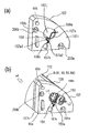
図23は、ネジによって、サイドカバー157、軸受部材138を枠体113に締結している状態を示す側面図である。図23(a)は、前述した実施形態を示す側面図である。前述した通り、ネジ200aはサイドカバー157と枠体113とを締結している。ネジ200bは、サイドカバー157と軸受部材138とを枠体113に共締め(締結)している。ネジ200cは軸受部材138を枠体113に締結している。尚、ネジ200cは、穴157hから侵入する例えばドライバー(工具)(不図示)によって、サイドカバー157の外側から、締結、解除が可能である。前述した通り、次のように、サイドカバー157と軸受部材138とを枠体113に取り付けている(締結している)。
FIG. 23 is a side view showing a state in which the
まず、ネジ(第1のネジ、第1の締結部材)200cによって、軸受部材138を枠体113に取り付けている。ネジ200cは、枠体113の前記長手方向において、サイドカバー157の外側から枠体113に締結することができる。また、締結の解除をすることができる。これは、ネジ200cを締結(解除)するドライバーを、サイドカバー157に設けた穴157hから侵入させることができるからである。即ち、ネジ200cは、サイドカバー157に設けられた穴157hから進入して、軸受部材138に設けられた貫通穴138gを通過して、枠体113に設けられた締結部1113hに締結される。また、ネジ200cは、穴157hから進入する例えばドライバー(工具)によって締結又は解除することができる。この構成によって、後述するとおりの効果を得ることができる。
First, the bearing
また、ネジ(第2のネジ、第2の締結部材)200aによって、サイドカバー157を枠体113に直接締結している。また、ネジ(第3のネジ、第3の締結部材)200bによって、サイドカバー157を軸受部材138と共に枠体113に締結している。即ち、共締めしている。前述した構成によって、後述するとおりの効果を得ることができる。尚、本実施形態では、枠体113の前記長手方向において、サイドカバー157の外側から軸受部材を138を枠体113に締結することができるように、サイドカバー157に穴157hを設けた。しかしながらこれに限定されるものではない。例えば、サイドカバー157に穴を設ける代わりに、サイドカバー157を切り欠いても良い。但し、サイドカバー157に穴を設ける構成は、サイドカバー157を切り欠く構成と比較して、サイドカバー157の強度を維持することできる。また、サイドカバー157がギア145、146を覆う面積を大きくすることができる。また、サイドカバー157が軸受部材138を覆う面積を大きくすることができる。
Further, the
前述した通り、カートリッジBの組立て方法は次のとおりである。即ち、枠体113にサイドカバー157及び軸受部材138を取り付ける方法は次のとおりである。先ず、ネジ(第1のネジ)200cによって、枠体113の前記長手方向において、サイドカバー157の外側から、軸受部材138を枠体113に直接締結する。そして、ネジ(第2のネジ)200aによって、サイドカバー157を枠体113に直接締結する。そして、ネジ(第3のネジ)200bによって、サイドカバー157を軸受部材138と共に枠体113に締結する(図13(b)、図23(a))。この方法によれば、サイドカバー157及び軸受部材138を重ねて枠体113に沿わせた状態で、ネジ200a、b、cを一連の動作で締結することができる。従って、組立て作業性を向上させることができた。
As described above, the assembly method of the cartridge B is as follows. That is, the method for attaching the
また、ネジ200bによって、サイドカバー157を軸受部材138と共に枠体113に共締めする。これによっても、組立て作業性を向上させることができた。尚、ネジ200b、又は/及び200cによって、先ず、軸受部材138を枠体113に締結することが好ましいが、ネジ200aによる締結とネジ200bによる締結は、どちらが先であっても構わない。また、軸受部材139を枠体113に取り付けるに当たっては、ネジ(第4のネジ)200dによって、軸受部材139を枠体113に直接締結する。また、ネジ200e(第5のネジ)によって、軸受部材139を枠体113に直接締結する(図20(b)(c))。
Further, the
図23(b)(c)は、本発明を適用した他の実施形態である。図23(b)は、ネジ200a、200cに加えて、ネジ200g、200fを用いた例である。ネジ200gは、軸受部材138を枠体113に締結している。ネジ200gは穴157nに侵入するドライバー(工具)(不図示)によって、サイドカバー157の外部から締結、解除が可能である。また、ネジ200fは、サイドカバー157を枠体113に締結している。即ち、ネジ200gはネジ200cと同様の構成、ネジ200fはネジ200aと同様の構成である。この実施形態では、サイドカバー157と軸受部材138とを共締めしてはいない。
FIGS. 23B and 23C show another embodiment to which the present invention is applied. FIG. 23B shows an example in which screws 200 g and 200 f are used in addition to the
図23(c)は、ネジ200b、200c、200gに加えて、ネジ200iを用いた例である。ネジ200iはサイドカバー157、軸受部材138、を枠体113に共締めしている。即ち、この実施形態では、ネジ200b、200iを用いて、2箇所でもって共締めしている。
FIG. 23C illustrates an example in which the
即ち、本実施形態は、枠体113の長手方向において、外側にサイドカバー157、その内側に軸受部材138を配置して、両者を枠体113に締結するものである。そして、本実施形態によれば、軸受部材138を枠体113に締結する構成として、枠体113の長手方向においてサイドカバー157の外側から締結が可能な構成を用いている。即ち、前述した実施形態のネジ200cと穴157h、及び、ネジ200gと穴157nの構成を用いている。
That is, in the present embodiment, in the longitudinal direction of the
これによって、本実施形態よれば、外側にサイドカバー157、その内側に軸受部材138を配置して、両者を枠体113に締結するに当たって、サイドカバー157の外側からネジ留めすることができる。しかも、本実施形態によれば、一連の操作によって両者157、138を枠体113にネジ留めすることができ、組立て操作性を向上させることができた。即ち、枠体113に軸受部材138をネジ留めした後に、サイドカバー157を枠体113に対向させて、サイドカバー157を枠体113にネジ留めしなくても良い。
Thus, according to the present embodiment, the
本実施形態よれば、両者138、157を一度に枠体113に対向させてネジ留めすることができる。従って、両者138、157を別々に枠体113に対向させて、ネジ留めする手間を省くことができる。また、両者138、157を枠体113から取り外す場合には、サイドカバー157の外側から、両者138、157を枠体113に締結しているネジを取り外すことができる。このネジの取り外しを一連の動作で行うことができる。
According to the present embodiment, both 138 and 157 can be screwed against the
従って、枠体113からの両者138、157を取り外す取り外し操作性を向上させることができた。また、両者157、138を枠体113に共締めすることによって、取り付け作業性を向上させることができた。また、分解する場合には、取り外し作業性を向上させることができた。
Therefore, the detachability for removing both 138 and 157 from the
尚、前述した各実施形態の、カップリング部材の取り付け方法、及び、カートリッジの組立て方法は、自動組立て機(所謂ロボット)を用いても、或いは、工具を用いて手作業でも適用できる。また、カップリング部材の取り外し方法、及び、カートリッジの分解方法は、主として、工具を用いて手作業で行うことができる。但し、自動組立て機を適宜用いても良い。 The coupling member mounting method and the cartridge assembling method of each of the embodiments described above can be applied using an automatic assembling machine (so-called robot) or manually using a tool. Further, the method for removing the coupling member and the method for disassembling the cartridge can be mainly performed manually using a tool. However, you may use an automatic assembly machine suitably.
前述した実施形態によれば、カートリッジBにカップリング150を取り付けるに当たって、取り付け操作性を向上させることができた。また、カートリッジBからカップリング150を取り外すに当たって、取り外し操作性を向上させることができた。また、カートリッジBにカップリング150を取り付けるに当たって、取り付け操作性を向上させた、カップリング150の取り付け方法を提供することができた。また、カートリッジBに取り付けられているカップリング150を取り外すに当たって、取り外し操作性を向上させた、カップリング150の取り外し方法を提供することができた。
According to the above-described embodiment, when attaching the
回転力受け部材として、カップリング150の代りにギアを用いる実施形態の説明
尚、前述した実施形態では、図2(a)等に示すように、本体Aから回転力を受ける回転力受け部材として、カップリング150について説明した。しかしながら、本実施形態は、この限りではない。つまり、図24に示すように、本体Aから回転力を受ける部材として、駆動力入力ギア(回転力受け部材)205を用いても良い。本体Aからの回転力をギア205が受け、ギア205と噛み合っているギア206、及び、現像ギア145を介して、現像ローラ110に回転力を伝達しても良い。
2. Description of Embodiment Using Gear instead of Coupling 150 as a Torque Receiving Member In the above-described embodiment, as shown in FIG. The
尚、図24(a)に示すように、ギア205及びギア206はその軸線方向一端部を軸受部材207、他端部をサイドカバー208により回転可能に支持されているがその限りでは無い。また、図7(f)に示すように、円筒部材147はその軸線方向一端部を軸受部材138、他端部をサイドカバー157により回転自在に支持されているがその限りでは無い。
As shown in FIG. 24A, the
一例を図24(b)に示す。この実施形態では、ギア209及びギア210はその軸線方向一端部のみを軸受部材211で支持し、他端側はサイドカバー212で脱落するのを防止する構成である。このような構成でも良い。
An example is shown in FIG. In this embodiment, the
前述した実施形態によれば、カートリッジBにおいて、サイドカバー157及び軸受部材138を枠体113に取り付けるに当たって、取り付け操作性を向上させることができた。また、カートリッジBにおいて、サイドカバー157及び軸受部材138を枠体113から取り外すに当たって、取り外し操作性を向上させることができた。また、カートリッジBにおいて、サイドカバー157及び軸受部材138を枠体113に取り付けるに当たって、取り付け操作性を向上させたカートリッジの組立て方法を提供することができた。また、カートリッジBにおいて、サイドカバー157及び軸受部材138を枠体113から取り外すに当たって、取り外し操作性を向上させたカートリッジの分解方法を提供することができた。
According to the embodiment described above, when the
A 電子写真画像形成装置本体、B カートリッジ(現像装置)、 C ロータリ(移動部材)、t 現像剤、100 電子写真画像形成装置、110 現像ローラ、113 カートリッジ枠体、115 現像剤供給ローラ、138 軸受部材(第1の軸受部材)、139 軸受部材(第2の軸受部材)、145 現像ギア(回転力伝達部材)、146 供給ローラギア、147 ギア、150 カップリング、157 サイドカバー、159 弾性部材(ねじりコイルバネ)、200 ネジ、200aネジ(第2のネジ、第2の締結部材)、200b ネジ(第3のネジ、第3の締結部材)、200c ネジ(第1のネジ、第1の締結部材)、200d ネジ(第4のネジ、第4の締結部材)、200e ネジ(第5のネジ、第5の締結部材)、157 サイドカバー A electrophotographic image forming apparatus main body, B cartridge (developing apparatus), C rotary (moving member), t developer, 100 electrophotographic image forming apparatus, 110 developing roller, 113 cartridge frame, 115 developer supplying roller, 138 bearing Member (first bearing member), 139 bearing member (second bearing member), 145 developing gear (rotational force transmission member), 146 supply roller gear, 147 gear, 150 coupling, 157 side cover, 159 elastic member (torsion) Coil spring), 200 screw, 200a screw (second screw, second fastening member), 200b screw (third screw, third fastening member), 200c screw (first screw, first fastening member) , 200d screw (fourth screw, fourth fastening member), 200e screw (fifth screw, fifth fastening member), 157 Compartment cover
Claims (9)
現像剤を収容する現像剤収容部と、
前記現像剤収容部に収容されている現像剤を用いて、電子写真感光体ドラムに形成された静電潜像を現像するための現像ローラと、
前記現像ローラの長手方向に沿って設けられているカートリッジ枠体と、
前記カートリッジ枠体の長手方向一端側に設けられ、且つ、前記現像ローラの長手方向一端側に設けられた現像ローラ軸部を支持する軸受部材と、
前記カートリッジが前記本体に装着された状態で、前記本体から前記現像ローラを回転するための回転力を受ける回転力受け部材と、
前記カートリッジ枠体の前記長手方向において、前記軸受部材の外側に設けられたサイドカバーと、
前記軸受部材を前記カートリッジ枠体に取り付けるために、前記軸受部材を前記カートリッジ枠体に締結している第1の締結部材であって、前記カートリッジ枠体の前記長手方向において前記サイドカバーの外側から締結することができる第1の締結部材と、
前記サイドカバーを前記カートリッジ枠体に取り付けるために、前記サイドカバーを前記カートリッジ枠体に締結している第2の締結部材と、
を有し、
更に、前記サイドカバーには弾性部材と、且つ、前記弾性部材の弾性力によって傾斜する前記回転力受け部材としてのカップリング部材の傾斜を規制する傾斜規制部が設けられており、前記第2の締結部材によって前記サイドカバーを前記カートリッジ枠体に取り付ける際に、前記カップリング部材は前記サイドカバーと一体で前記カートリッジ枠体に取り付けられたことを特徴とするカートリッジ。 In the cartridge that is detachably mounted on the main body of the electrophotographic image forming apparatus,
A developer accommodating portion for accommodating the developer;
A developing roller for developing an electrostatic latent image formed on the electrophotographic photosensitive drum using the developer contained in the developer containing unit;
A cartridge frame provided along the longitudinal direction of the developing roller;
A bearing member provided on one end side in the longitudinal direction of the cartridge frame and supporting a developing roller shaft portion provided on one end side in the longitudinal direction of the developing roller;
A rotational force receiving member that receives rotational force for rotating the developing roller from the main body in a state where the cartridge is mounted on the main body;
A side cover provided outside the bearing member in the longitudinal direction of the cartridge frame;
A first fastening member that fastens the bearing member to the cartridge frame for attaching the bearing member to the cartridge frame, from the outside of the side cover in the longitudinal direction of the cartridge frame. A first fastening member that can be fastened;
A second fastening member for fastening the side cover to the cartridge frame in order to attach the side cover to the cartridge frame;
Have
Further, the side cover is provided with an elastic member, and an inclination restricting portion for restricting an inclination of the coupling member as the rotational force receiving member that is inclined by the elastic force of the elastic member. The cartridge, wherein the coupling member is attached to the cartridge frame integrally with the side cover when the side cover is attached to the cartridge frame by a fastening member .
現像剤を収容する現像剤収容部と、
前記現像剤収容部に収容されている現像剤を用いて、電子写真感光体ドラムに形成された静電潜像を現像するための現像ローラと、
前記現像ローラに前記現像剤を供給する現像剤供給ローラと、
前記カートリッジが前記本体に装着された状態で、前記現像ローラを回転するための回転力を前記本体から受けるためのカップリング部材と、
前記現像ローラの長手方向に沿って設けられているカートリッジ枠体と、
前記カートリッジ枠体の長手方向一端側に設けられた、前記現像ローラの長手方向一端側に設けられた現像ローラ軸部を支持する、且つ、前記現像剤供給ローラの長手方向一端側に設けられた現像剤供給ローラ軸部を支持する第1の軸受部材と、
前記カートリッジ枠体の長手方向他端側に設けられた、前記現像ローラの長手方向他端側に設けられた現像ローラ軸部を支持する、且つ、前記現像剤供給ローラの長手方向他端側に設けられた現像剤供給ローラ軸部を支持する第2の軸受部材と、
前記カートリッジ枠体の前記長手方向一端側であって前記第1の軸受部材との間でもって、前記カップリング部材が前記本体から受けた回転力を前記現像ローラに伝達するためのギアを覆っているサイドカバーと、
前記第1の軸受部材を前記カートリッジ枠体に取り付けるために、前記第1の軸受部材を前記カートリッジ枠体に締結している第1のネジであって、前記カートリッジ枠体の前記長手方向において前記サイドカバーの外側から前記サイドカバーに設けられた穴を介して締結している第1のネジと、
前記サイドカバーを前記カートリッジ枠体に取り付けるために、前記サイドカバーを前記カートリッジ枠体に締結している第2のネジと、
前記サイドカバーを前記カートリッジ枠体に取り付けるために、前記サイドカバーを前記第1の軸受部材と共に前記カートリッジ枠体に締結している第3のネジと、
前記第2の軸受部材を前記カートリッジ枠体に取り付けるために、前記第2の軸受部材を前記カートリッジ枠体に締結している第4のネジと、
前記第2の軸受部材を前記カートリッジ枠体に取り付けるために、前記第2の軸受部材を前記カートリッジ枠体に締結している第5のネジと、
を有し、
更に、前記サイドカバーには弾性部材と、且つ、前記弾性部材の弾性力によって傾斜する前記カップリング部材の傾斜を規制する傾斜規制部が設けられており、前記第2のネジ及び前記第3のネジによって前記サイドカバーを前記カートリッジ枠体に取り付ける際に、前記カップリング部材は前記サイドカバーと一体で前記カートリッジ枠体に取り付けられたことを特徴とするカートリッジ。 In the cartridge that is detachably mounted on the main body of the electrophotographic image forming apparatus,
A developer accommodating portion for accommodating the developer;
A developing roller for developing an electrostatic latent image formed on the electrophotographic photosensitive drum using the developer contained in the developer containing unit;
A developer supply roller for supplying the developer to the development roller;
A coupling member for receiving a rotational force for rotating the developing roller from the main body in a state where the cartridge is mounted on the main body;
A cartridge frame provided along the longitudinal direction of the developing roller;
Provided on one end side in the longitudinal direction of the cartridge frame body, supports a developing roller shaft provided on one end side in the longitudinal direction of the developing roller, and provided on one end side in the longitudinal direction of the developer supply roller. A first bearing member that supports the developer supply roller shaft;
Supports a developing roller shaft provided on the other end in the longitudinal direction of the developing roller, provided on the other end in the longitudinal direction of the cartridge frame, and on the other end in the longitudinal direction of the developer supply roller. A second bearing member that supports the developer supply roller shaft provided;
Covering a gear for transmitting the rotational force received by the coupling member from the main body to the developing roller between one end of the cartridge frame in the longitudinal direction and the first bearing member. The side cover
In order to attach the first bearing member to the cartridge frame, a first screw that fastens the first bearing member to the cartridge frame, the longitudinal direction of the cartridge frame being A first screw fastened from the outside of the side cover through a hole provided in the side cover;
A second screw that fastens the side cover to the cartridge frame to attach the side cover to the cartridge frame;
A third screw fastening the side cover to the cartridge frame together with the first bearing member to attach the side cover to the cartridge frame;
A fourth screw that fastens the second bearing member to the cartridge frame to attach the second bearing member to the cartridge frame;
A fifth screw that fastens the second bearing member to the cartridge frame to attach the second bearing member to the cartridge frame;
Have
Further, the side cover is provided with an elastic member, and an inclination restricting portion for restricting an inclination of the coupling member that is inclined by an elastic force of the elastic member, and the second screw and the third screw are provided. The cartridge, wherein the coupling member is attached to the cartridge frame integrally with the side cover when the side cover is attached to the cartridge frame by a screw .
前記現像剤収容部に収容されている現像剤を用いて、電子写真感光体ドラムに形成された静電潜像を現像するための現像ローラと、
カートリッジが電子写真画像形成装置の本体に装着された状態で、前記現像ローラを回転するための回転力を前記本体から受けるためのカップリング部材と、
前記現像ローラの長手方向に沿って設けられているカートリッジ枠体と、
前記カートリッジ枠体の長手方向一端側に設けられ、且つ、前記現像ローラの長手方向一端側に設けられた現像ローラ軸部を支持する軸受部材と、
前記カートリッジ枠体の前記長手方向一端側であって前記軸受部材との間に、前記カップリング部材が前記本体から受けた回転力を前記現像ローラに伝達するためのギアを覆っているサイドカバーと、を有して、前記本体に取り外し可能に装着される前記カートリッジの組立て方法であって、
前記軸受部材を前記カートリッジ枠体に取り付けるために、第1のネジによって、前記カートリッジ枠体の前記長手方向において前記サイドカバーの外側から、前記軸受部材を前記カートリッジ枠体に締結し、
前記サイドカバーを前記カートリッジ枠体に取り付けるために、第2のネジによって、前記サイドカバーを前記カートリッジ枠体に締結し、
前記サイドカバーを前記カートリッジ枠体に取り付けるために、第3のネジによって、前記サイドカバーを前記軸受部材と共に前記カートリッジ枠体に締結し、
前記サイドカバーには弾性部材と、且つ、前記弾性部材の弾性力によって傾斜する前記カップリング部材の傾斜を規制する傾斜規制部が設けられており、前記第2のネジ及び前記第3のネジによって前記サイドカバーを前記カートリッジ枠体に取り付ける際に、前記カップリング部材は前記サイドカバーと一体で前記カートリッジ枠体に取り付けることを特徴とするカートリッジの組立て方法。 A developer accommodating portion for accommodating the developer;
A developing roller for developing an electrostatic latent image formed on the electrophotographic photosensitive drum using the developer contained in the developer containing unit;
A coupling member for receiving a rotational force for rotating the developing roller from the main body in a state where the cartridge is mounted on the main body of the electrophotographic image forming apparatus;
A cartridge frame provided along the longitudinal direction of the developing roller;
A bearing member provided on one end side in the longitudinal direction of the cartridge frame and supporting a developing roller shaft provided on one end side in the longitudinal direction of the developing roller;
A side cover covering a gear for transmitting the rotational force received by the coupling member from the main body to the developing roller between the one end in the longitudinal direction of the cartridge frame and the bearing member; And an assembly method of the cartridge which is removably mounted on the main body,
In order to attach the bearing member to the cartridge frame, the bearing member is fastened to the cartridge frame from the outside of the side cover in the longitudinal direction of the cartridge frame by a first screw.
In order to attach the side cover to the cartridge frame, the side cover is fastened to the cartridge frame by a second screw,
In order to attach the side cover to the cartridge frame, the side cover is fastened to the cartridge frame together with the bearing member by a third screw.
The side cover is provided with an elastic member, and an inclination restricting portion for restricting the inclination of the coupling member that is inclined by the elastic force of the elastic member, and the second cover and the third screw A method of assembling a cartridge , wherein when the side cover is attached to the cartridge frame, the coupling member is attached to the cartridge frame integrally with the side cover .
前記現像剤収容部に収容されている現像剤を用いて、電子写真感光体ドラムに形成された静電潜像を現像するための現像ローラと、
前記現像ローラに前記現像剤を供給する現像剤供給ローラと、
カートリッジが電子写真画像形成装置の本体に装着された状態で、前記現像ローラを回転するための回転力を前記本体から受けるためのカップリング部材と、
前記現像ローラの長手方向に沿って設けられているカートリッジ枠体と、
前記カートリッジ枠体の長手方向一端側に設けられた、前記現像ローラの長手方向一端側に設けられた現像ローラ軸部を支持する、且つ、前記現像剤供給ローラの長手方向一端側に設けられた現像剤供給ローラ軸部を支持する第1の軸受部材と、
前記カートリッジ枠体の長手方向他端側に設けられた、前記現像ローラの長手方向他端側に設けられた現像ローラ軸部を支持する、且つ、前記現像剤供給ローラの長手方向他端側に設けられた現像剤供給ローラ軸部を支持する第2の軸受部材と、
前記カートリッジ枠体の前記長手方向一端側であって前記第1の軸受部材との間に、前記カップリング部材をカップリング部材が前記本体から受けた回転力を前記現像ローラに伝達するためのギアを覆っているサイドカバーと、を有して、前記本体に取り外し可能に装着される前記カートリッジの組立て方法であって、
前記第1の軸受部材を前記カートリッジ枠体に取り付けるために、第1のネジによって、前記カートリッジ枠体の前記長手方向においてサイドカバーの外側から前記サイドカバーに設けられた穴を介して、前記第1の軸受部材を前記カートリッジ枠体に締結し、
前記サイドカバーを前記カートリッジ枠体に取り付けるために、第2のネジによって、前記サイドカバーを前記カートリッジ枠体に締結し、
前記サイドカバーを前記カートリッジ枠体に取り付けるために、第3のネジによって、前記サイドカバーを前記第1の軸受部材と共に前記カートリッジ枠体に締結し、
前記サイドカバーには弾性部材と、且つ、前記弾性部材の弾性力によって傾斜する前記カップリング部材の傾斜を規制する傾斜規制部が設けられており、前記第2のネジ及び前記第3のネジによって前記サイドカバーを前記カートリッジ枠体に取り付ける際に、前記カップリング部材は前記サイドカバーと一体で前記カートリッジ枠体に取り付け、
前記第2の軸受部材を前記カートリッジ枠体に取り付けるために、第4のネジによって、前記第2の軸受部材を前記カートリッジ枠体に締結し、
前記第2の軸受部材を前記カートリッジ枠体に取り付けるために、第5のネジによって、前記第2の軸受部材を前記カートリッジ枠体に締結することを特徴とするカートリッジの組立て方法。 A developer accommodating portion for accommodating the developer;
A developing roller for developing an electrostatic latent image formed on the electrophotographic photosensitive drum using the developer contained in the developer containing unit;
A developer supply roller for supplying the developer to the development roller;
A coupling member for receiving a rotational force for rotating the developing roller from the main body in a state where the cartridge is mounted on the main body of the electrophotographic image forming apparatus;
A cartridge frame provided along the longitudinal direction of the developing roller;
Provided on one end side in the longitudinal direction of the cartridge frame body, supports a developing roller shaft provided on one end side in the longitudinal direction of the developing roller, and provided on one end side in the longitudinal direction of the developer supply roller. A first bearing member that supports the developer supply roller shaft;
Supports a developing roller shaft provided on the other end in the longitudinal direction of the developing roller, provided on the other end in the longitudinal direction of the cartridge frame, and on the other end in the longitudinal direction of the developer supply roller. A second bearing member that supports the developer supply roller shaft provided;
A gear for transmitting the rotational force received by the coupling member from the main body to the developing roller between the first bearing member and the one end of the cartridge frame in the longitudinal direction. And a side cover covering the cartridge, wherein the cartridge is removably attached to the main body.
In order to attach the first bearing member to the cartridge frame, the first screw is used to pass through the hole provided in the side cover from the outside of the side cover in the longitudinal direction of the cartridge frame. 1 bearing member is fastened to the cartridge frame,
In order to attach the side cover to the cartridge frame, the side cover is fastened to the cartridge frame by a second screw,
In order to attach the side cover to the cartridge frame, the side cover is fastened to the cartridge frame together with the first bearing member by a third screw;
The side cover is provided with an elastic member, and an inclination restricting portion for restricting the inclination of the coupling member that is inclined by the elastic force of the elastic member, and the second cover and the third screw When attaching the side cover to the cartridge frame, the coupling member is attached to the cartridge frame integrally with the side cover,
In order to attach the second bearing member to the cartridge frame, the second bearing member is fastened to the cartridge frame by a fourth screw;
A method for assembling a cartridge, wherein the second bearing member is fastened to the cartridge frame with a fifth screw in order to attach the second bearing member to the cartridge frame.
前記現像剤収容部に収容されている現像剤を用いて、電子写真感光体ドラムに形成された静電潜像を現像するための現像ローラと、
カートリッジが電子写真画像形成装置の本体に装着された状態で、前記現像ローラを回転するための回転力を前記本体から受けるためのカップリング部材と、
前記現像ローラの長手方向に沿って設けられているカートリッジ枠体と、
前記カートリッジ枠体の長手方向一端側に設けられ、且つ、前記現像ローラの長手方向一端側に設けられた現像ローラ軸部を支持する軸受部材と、
前記カートリッジ枠体の前記長手方向一端側であって前記軸受部材との間に前記カップリング部材が前記本体から受けた回転力を前記現像ローラに伝達するためのギアを覆っているサイドカバーと、を有して、前記本体に取り外し可能に装着される前記カートリッジの分解方法であって、
前記サイドカバーを前記カートリッジ枠体から取り外すために、第2のネジを解除する工程と、
前記軸受部材を前記カートリッジ枠体から取り外すために、前記カートリッジ枠体の前記長手方向において前記サイドカバーの外側から、第1のネジを解除する工程と、 前記サイドカバー及び前記軸受部材を前記カートリッジ枠体から取り外すために、第3のネジを解除する工程と、
を有して、
前記サイドカバーには弾性部材と、且つ、前記弾性部材の弾性力によって傾斜する前記カップリングの傾斜を規制する傾斜規制部が設けられており、前記第2のネジ及び前記第3のネジを解除することによって前記サイドカバーを前記カートリッジ枠体から取り外す際に、前記カップリング部材は前記サイドカバーと一体で前記カートリッジ枠体から取り外し、
前記サイドカバー及び前記軸受部材を前記カートリッジ枠体から取り外すことを特徴とするカートリッジの分解方法。 A developer accommodating portion for accommodating the developer;
A developing roller for developing an electrostatic latent image formed on the electrophotographic photosensitive drum using the developer contained in the developer containing unit;
A coupling member for receiving a rotational force for rotating the developing roller from the main body in a state where the cartridge is mounted on the main body of the electrophotographic image forming apparatus;
A cartridge frame provided along the longitudinal direction of the developing roller;
A bearing member provided on one end side in the longitudinal direction of the cartridge frame and supporting a developing roller shaft provided on one end side in the longitudinal direction of the developing roller;
A side cover covering a gear for transmitting the rotational force received by the coupling member from the main body to the developing roller between the bearing member and the one end side in the longitudinal direction of the cartridge frame; A method for disassembling the cartridge, which is detachably mounted on the main body,
Releasing the second screw to remove the side cover from the cartridge frame;
Releasing the first screw from the outside of the side cover in the longitudinal direction of the cartridge frame in order to remove the bearing member from the cartridge frame; and removing the side cover and the bearing member from the cartridge frame Releasing the third screw for removal from the body;
Having
The side cover is provided with an elastic member and an inclination restricting portion for restricting the inclination of the coupling inclined by the elastic force of the elastic member, and the second screw and the third screw are released. When removing the side cover from the cartridge frame, the coupling member is removed from the cartridge frame integrally with the side cover,
A method for disassembling a cartridge, wherein the side cover and the bearing member are removed from the cartridge frame.
前記現像剤収容部に収容されている現像剤を用いて、電子写真感光体ドラムに形成された静電潜像を現像するための現像ローラと、
前記現像ローラに前記現像剤を供給する現像剤供給ローラと、
カートリッジが電子写真画像形成装置の本体に装着された状態で、前記現像ローラを回転するための回転力を前記本体から受けるためのカップリング部材と、
前記現像ローラの長手方向に沿って設けられているカートリッジ枠体と、
前記カートリッジ枠体の長手方向一端側に設けられた、前記現像ローラの長手方向一端側に設けられた現像ローラ軸部を支持する、且つ、前記現像剤供給ローラの長手方向一端側に設けられた現像剤供給ローラ軸部を支持する第1の軸受部材と、
前記カートリッジ枠体の長手方向他端側に設けられた、前記現像ローラの長手方向他端側に設けられた現像ローラ軸部を支持する、且つ、前記現像剤供給ローラの長手方向他端側に設けられた現像剤供給ローラ軸部を支持する第2の軸受部材と、
前記カートリッジ枠体の長手方向一端側に設けられ、且つ、前記現像ローラの長手方向一端側に設けられた現像ローラ軸部を支持する第1の軸受部材と、
前記カートリッジ枠体の前記長手方向一端側であって前記第1の軸受部材との間に前記カップリング部材が前記本体から受けた回転力を前記現像ローラに伝達するためのギアを覆っているサイドカバーと、を有して、前記本体に取り外し可能に装着される前記カートリッジの分解方法であって、
前記サイドカバーを前記カートリッジ枠体から取り外すために、第2のネジを解除する工程と、
前記第1の軸受部材を前記カートリッジ枠体から取り外すために、前記カートリッジ枠体の前記長手方向において前記サイドカバーの外側から前記サイドカバーに設けられた穴を介して、第1のネジを解除する工程と、
前記サイドカバー及び前記第1の軸受部材を前記カートリッジ枠体から取り外すために、第3のネジを解除する工程と、
前記第2の軸受部材を前記カートリッジ枠体から取り外すために、第4のネジを解除する工程と、
前記第2の軸受部材を前記カートリッジ枠体から取り外すために、第5のネジを解除する工程と、
を有して、
前記サイドカバーには弾性部材と、且つ、前記弾性部材の弾性力によって傾斜する前記カップリングの傾斜を規制する傾斜規制部が設けられており、前記第2のネジ及び前記第3のネジによって前記サイドカバーを前記カートリッジ枠体から取り外す際に、前記カップリング部材は前記サイドカバーと一体で前記カートリッジ枠体から取り外し、
前記第1の軸受部材、前記第2の軸受部材、及び、前記サイドカバーを前記カートリッジ枠体から取り外すことを特徴とするカートリッジの分解方法。 A developer accommodating portion for accommodating the developer;
A developing roller for developing an electrostatic latent image formed on the electrophotographic photosensitive drum using the developer contained in the developer containing unit;
A developer supply roller for supplying the developer to the development roller;
A coupling member for receiving a rotational force for rotating the developing roller from the main body in a state where the cartridge is mounted on the main body of the electrophotographic image forming apparatus;
A cartridge frame provided along the longitudinal direction of the developing roller;
Provided on one end side in the longitudinal direction of the cartridge frame body, supports a developing roller shaft provided on one end side in the longitudinal direction of the developing roller, and provided on one end side in the longitudinal direction of the developer supply roller. A first bearing member that supports the developer supply roller shaft;
Supports a developing roller shaft provided on the other end in the longitudinal direction of the developing roller, provided on the other end in the longitudinal direction of the cartridge frame, and on the other end in the longitudinal direction of the developer supply roller. A second bearing member that supports the developer supply roller shaft provided;
A first bearing member provided on one end side in the longitudinal direction of the cartridge frame and supporting a developing roller shaft provided on one end side in the longitudinal direction of the developing roller;
The side which is the one end side of the said cartridge frame body in the longitudinal direction, and covers the gear for transmitting the rotational force which the said coupling member received from the said main body to the said developing roller between the said 1st bearing members A method of disassembling the cartridge, which has a cover and is detachably attached to the main body,
Releasing the second screw to remove the side cover from the cartridge frame;
In order to remove the first bearing member from the cartridge frame, the first screw is released from the outside of the side cover in the longitudinal direction of the cartridge frame through a hole provided in the side cover. Process,
Releasing a third screw to remove the side cover and the first bearing member from the cartridge frame;
Releasing a fourth screw to remove the second bearing member from the cartridge frame;
Releasing a fifth screw to remove the second bearing member from the cartridge frame;
Having
The side cover is provided with an elastic member, and an inclination restricting portion for restricting the inclination of the coupling inclined by the elastic force of the elastic member, and the second screw and the third screw When removing the side cover from the cartridge frame, the coupling member is removed from the cartridge frame integrally with the side cover,
A method for disassembling a cartridge, comprising: removing the first bearing member, the second bearing member, and the side cover from the cartridge frame.
Priority Applications (3)
| Application Number | Priority Date | Filing Date | Title |
|---|---|---|---|
| JP2009116176A JP4558083B2 (en) | 2008-06-20 | 2009-05-13 | Cartridge, method for assembling the cartridge, and method for disassembling the cartridge |
| US12/486,175 US8233821B2 (en) | 2008-06-20 | 2009-06-17 | Cartridge, assembling method for cartridge, and disassembling method for cartridge |
| US13/363,788 US8391748B2 (en) | 2008-06-20 | 2012-02-01 | Cartridge, assembling method for cartridge, and disassembling method for cartridge |
Applications Claiming Priority (2)
| Application Number | Priority Date | Filing Date | Title |
|---|---|---|---|
| JP2008161117 | 2008-06-20 | ||
| JP2009116176A JP4558083B2 (en) | 2008-06-20 | 2009-05-13 | Cartridge, method for assembling the cartridge, and method for disassembling the cartridge |
Publications (3)
| Publication Number | Publication Date |
|---|---|
| JP2010026501A JP2010026501A (en) | 2010-02-04 |
| JP2010026501A5 JP2010026501A5 (en) | 2010-04-15 |
| JP4558083B2 true JP4558083B2 (en) | 2010-10-06 |
Family
ID=41431432
Family Applications (9)
| Application Number | Title | Priority Date | Filing Date |
|---|---|---|---|
| JP2009116176A Active JP4558083B2 (en) | 2008-06-20 | 2009-05-13 | Cartridge, method for assembling the cartridge, and method for disassembling the cartridge |
| JP2009116175A Active JP5306050B2 (en) | 2008-06-20 | 2009-05-13 | Cartridge, coupling member attaching method, and coupling member removing method |
| JP2013134661A Active JP5490293B2 (en) | 2008-06-20 | 2013-06-27 | Cartridge, coupling member attaching method, and coupling member removing method |
| JP2014035116A Active JP5815058B2 (en) | 2008-06-20 | 2014-02-26 | Developer cartridge |
| JP2015186528A Active JP5980395B2 (en) | 2008-06-20 | 2015-09-24 | Rotational force transmission member |
| JP2016132193A Active JP6173535B2 (en) | 2008-06-20 | 2016-07-04 | cartridge |
| JP2017118421A Active JP6312906B2 (en) | 2008-06-20 | 2017-06-16 | Rotational force transmission unit |
| JP2018054741A Active JP6466009B2 (en) | 2008-06-20 | 2018-03-22 | Rotational force transmission member and rotational force transmission unit |
| JP2019002838A Active JP6682669B2 (en) | 2008-06-20 | 2019-01-10 | cartridge |
Family Applications After (8)
| Application Number | Title | Priority Date | Filing Date |
|---|---|---|---|
| JP2009116175A Active JP5306050B2 (en) | 2008-06-20 | 2009-05-13 | Cartridge, coupling member attaching method, and coupling member removing method |
| JP2013134661A Active JP5490293B2 (en) | 2008-06-20 | 2013-06-27 | Cartridge, coupling member attaching method, and coupling member removing method |
| JP2014035116A Active JP5815058B2 (en) | 2008-06-20 | 2014-02-26 | Developer cartridge |
| JP2015186528A Active JP5980395B2 (en) | 2008-06-20 | 2015-09-24 | Rotational force transmission member |
| JP2016132193A Active JP6173535B2 (en) | 2008-06-20 | 2016-07-04 | cartridge |
| JP2017118421A Active JP6312906B2 (en) | 2008-06-20 | 2017-06-16 | Rotational force transmission unit |
| JP2018054741A Active JP6466009B2 (en) | 2008-06-20 | 2018-03-22 | Rotational force transmission member and rotational force transmission unit |
| JP2019002838A Active JP6682669B2 (en) | 2008-06-20 | 2019-01-10 | cartridge |
Country Status (3)
| Country | Link |
|---|---|
| US (10) | US8233821B2 (en) |
| JP (9) | JP4558083B2 (en) |
| CN (4) | CN101609298B (en) |
Families Citing this family (58)
| Publication number | Priority date | Publication date | Assignee | Title |
|---|---|---|---|---|
| AU2016238959B2 (en) * | 2006-12-22 | 2017-07-13 | Canon Kabushiki Kaisha | Process cartridge, electrophotographic image forming apparatus, and electrophotographic photosensitive drum unit |
| JP4498407B2 (en) * | 2006-12-22 | 2010-07-07 | キヤノン株式会社 | Process cartridge, electrophotographic image forming apparatus, and electrophotographic photosensitive drum unit |
| JP5311854B2 (en) * | 2007-03-23 | 2013-10-09 | キヤノン株式会社 | Electrophotographic image forming apparatus, developing device, and coupling member |
| JP4558083B2 (en) * | 2008-06-20 | 2010-10-06 | キヤノン株式会社 | Cartridge, method for assembling the cartridge, and method for disassembling the cartridge |
| JP5127584B2 (en) | 2008-06-20 | 2013-01-23 | キヤノン株式会社 | Drum unit and electrophotographic image forming apparatus |
| JP5495671B2 (en) * | 2008-08-27 | 2014-05-21 | キヤノン株式会社 | Developing cartridge and coupling member |
| EP2333620A1 (en) | 2008-09-01 | 2011-06-15 | Canon Kabushiki Kaisha | Developing cartridge, process cartridge, and electrophotographic image forming apparatus |
| JP5554963B2 (en) * | 2009-10-30 | 2014-07-23 | キヤノン株式会社 | Developing cartridge and process cartridge |
| JP5751779B2 (en) * | 2009-10-30 | 2015-07-22 | キヤノン株式会社 | Developing device, developing cartridge, process cartridge, and image forming apparatus |
| JP5430349B2 (en) * | 2009-10-30 | 2014-02-26 | キヤノン株式会社 | Developer cartridge |
| CN101846955A (en) * | 2010-01-28 | 2010-09-29 | 珠海赛纳科技有限公司 | Process cartridge |
| RU2547171C2 (en) * | 2010-01-28 | 2015-04-10 | Жухаи Сеине Течнологы Лимитед | Processing cartridge |
| JP4911228B2 (en) * | 2010-01-29 | 2012-04-04 | ブラザー工業株式会社 | Cartridge and image forming apparatus |
| TWI599859B (en) | 2010-06-11 | 2017-09-21 | 理光股份有限公司 | Shutter,toner container, and image forming apparatus |
| JP4843112B1 (en) * | 2010-06-11 | 2011-12-21 | 株式会社リコー | Detachable device, developer container, and image forming apparatus |
| JP5542741B2 (en) * | 2010-11-30 | 2014-07-09 | 京セラドキュメントソリューションズ株式会社 | Toner supply device and toner storage container |
| US8892004B2 (en) | 2011-03-29 | 2014-11-18 | Static Control Components, Inc. | Drive gear for extended drive shaft |
| US8644733B2 (en) | 2011-03-29 | 2014-02-04 | Static Control Components, Inc. | Cartridge drive shaft gear |
| JP5392302B2 (en) * | 2011-06-10 | 2014-01-22 | ブラザー工業株式会社 | Developer cartridge |
| JP2013029733A (en) * | 2011-07-29 | 2013-02-07 | Canon Inc | Cover member and cartridge |
| JP5884343B2 (en) | 2011-08-31 | 2016-03-15 | ブラザー工業株式会社 | Process cartridge and developer cartridge |
| JP5928887B2 (en) * | 2012-05-30 | 2016-06-01 | 富士ゼロックス株式会社 | Structure and image forming apparatus |
| JP5943716B2 (en) | 2012-06-04 | 2016-07-05 | キヤノン株式会社 | Developer cartridge |
| CN102880025A (en) * | 2012-10-24 | 2013-01-16 | 富美科技集团有限公司 | Photosensitive drum driving assembly |
| JP2014115472A (en) | 2012-12-10 | 2014-06-26 | Canon Inc | Cartridge and manufacturing method for cartridge |
| US10025266B2 (en) | 2012-12-14 | 2018-07-17 | Canon Kabushiki Kaisha | Process cartridge including a coupling member and a sheet that contacts the coupling member |
| JP6184311B2 (en) * | 2012-12-14 | 2017-08-23 | キヤノン株式会社 | Process cartridge and image forming apparatus |
| US9696684B2 (en) | 2012-12-14 | 2017-07-04 | Canon Kabushiki Kaisha | Process cartridge and image forming apparatus |
| JP6242201B2 (en) * | 2012-12-14 | 2017-12-06 | キヤノン株式会社 | Process cartridge and image forming apparatus |
| US20140165761A1 (en) * | 2012-12-17 | 2014-06-19 | Mitsubishi Kagaku Imaging Corporation | Drive transmission part for image forming apparatus |
| US9182733B2 (en) | 2013-02-07 | 2015-11-10 | Canon Kabushiki Kaisha | Developer supply cartridge, process cartridge and image forming apparatus |
| JP6415198B2 (en) | 2013-09-12 | 2018-10-31 | キヤノン株式会社 | cartridge |
| CN106125533B (en) * | 2013-09-29 | 2020-03-24 | 纳思达股份有限公司 | Axis deviation adjusting mechanism, rotary force driving assembly and processing box |
| JP6111992B2 (en) | 2013-11-18 | 2017-04-12 | ブラザー工業株式会社 | Developer cartridge |
| CN104765257B (en) * | 2014-01-06 | 2019-11-26 | 兄弟工业株式会社 | Delevoping cartridge with driving force receiving member |
| CN103885306B (en) * | 2014-03-10 | 2017-01-11 | 珠海天威飞马打印耗材有限公司 | Driving assembly, roller and processing box |
| CN105093871B (en) * | 2014-05-06 | 2017-12-29 | 纳思达股份有限公司 | A kind of power reception unit and handle box |
| KR101610191B1 (en) | 2014-05-07 | 2016-04-07 | 삼성전자주식회사 | imaging cartridge and electrophotographic image forming apparatus using the same |
| JP6376841B2 (en) * | 2014-05-23 | 2018-08-22 | キヤノン株式会社 | Cartridge and image forming apparatus |
| US9329517B2 (en) | 2014-09-30 | 2016-05-03 | Clover Technologies Group, Llc | Drive receiving member for an imaging cartridge |
| TWI747534B (en) * | 2014-11-28 | 2021-11-21 | 日商佳能股份有限公司 | Cartridge and electrophotographic image forming apparatus |
| KR102271625B1 (en) | 2015-02-27 | 2021-06-30 | 캐논 가부시끼가이샤 | Cartridge |
| JP6562655B2 (en) | 2015-02-27 | 2019-08-21 | キヤノン株式会社 | Cartridge and image forming apparatus |
| JP6512864B2 (en) | 2015-02-27 | 2019-05-15 | キヤノン株式会社 | Cartridge, process cartridge, image forming apparatus |
| EP4258060A3 (en) | 2015-02-27 | 2024-03-20 | Canon Kabushiki Kaisha | Drum unit, cartridge and coupling member |
| JP6808311B2 (en) * | 2015-10-14 | 2021-01-06 | キヤノン株式会社 | Electrophotographic photosensitive drum unit, cartridge, and flange member |
| JP6800660B2 (en) * | 2015-10-14 | 2020-12-16 | キヤノン株式会社 | cartridge |
| CN106610575B (en) * | 2015-10-26 | 2020-02-21 | 中山诚威科技有限公司 | Power coupling device and processing box |
| JP6601731B2 (en) * | 2016-01-12 | 2019-11-06 | 株式会社リコー | Drive transmission device and image forming apparatus |
| CN205787615U (en) * | 2016-02-26 | 2016-12-07 | 中山诚威科技有限公司 | A kind of handle box |
| JP6658132B2 (en) | 2016-03-11 | 2020-03-04 | ブラザー工業株式会社 | Developing cartridge and image forming apparatus |
| JP6508120B2 (en) * | 2016-05-09 | 2019-05-08 | 京セラドキュメントソリューションズ株式会社 | Toner container, toner supply device, and image forming apparatus |
| GB2567779B (en) | 2016-08-26 | 2021-08-18 | Canon Kk | Cartridge and image forming apparatus |
| US9588478B1 (en) | 2016-09-30 | 2017-03-07 | Roy Fan | Drive coupling and transmitting assembly for photosensitive drum and toner cartridges |
| CN107203113A (en) * | 2017-04-17 | 2017-09-26 | 上福全球科技股份有限公司 | Powder box and its transmission component |
| JP6957205B2 (en) | 2017-05-31 | 2021-11-02 | キヤノン株式会社 | Cartridge and image forming equipment |
| CN108957997B (en) * | 2018-07-27 | 2024-04-05 | 珠海天威飞马打印耗材有限公司 | Process cartridge |
| KR20210024807A (en) | 2019-08-26 | 2021-03-08 | 휴렛-팩커드 디벨롭먼트 컴퍼니, 엘.피. | Replaceable cartridge with driven coupler |
Citations (2)
| Publication number | Priority date | Publication date | Assignee | Title |
|---|---|---|---|---|
| JP2001125472A (en) * | 1999-10-29 | 2001-05-11 | Canon Inc | Method for reproducing process cartridge |
| JP2005164756A (en) * | 2003-11-28 | 2005-06-23 | Canon Inc | Process cartridge reproduction method |
Family Cites Families (297)
| Publication number | Priority date | Publication date | Assignee | Title |
|---|---|---|---|---|
| US899913A (en) | 1907-12-13 | 1908-09-29 | Hugh Robertson Shaw | Power-transmission universal joint. |
| US2300514A (en) | 1940-02-21 | 1942-11-03 | Westinghouse Electric & Mfg Co | Dial attaching device |
| US2292676A (en) | 1941-08-21 | 1942-08-11 | Leon F Thiry | Rubber ball and socket joint |
| US3406534A (en) | 1966-10-10 | 1968-10-22 | Chapper John | Universal coupling |
| US3490841A (en) | 1968-01-15 | 1970-01-20 | Ibm | Photoconductor drum locator |
| US3818380A (en) | 1969-03-28 | 1974-06-18 | R Tyre | Single component controlled rc bridge |
| US3815386A (en) | 1971-02-02 | 1974-06-11 | Kamyr Ab | Device for bleaching of cellulosic pulp |
| US3922883A (en) | 1974-10-03 | 1975-12-02 | Motorola Inc | Anti-backlash universal coupling |
| US4106611A (en) | 1974-12-28 | 1978-08-15 | Ricoh Company, Ltd. | Serial printing apparatus |
| US4167321A (en) | 1976-09-14 | 1979-09-11 | Olympus Optical Co., Ltd. | Photosensitive drum for electrographic apparatus |
| DE7903031U1 (en) | 1979-02-05 | 1979-07-12 | Basf Ag, 6700 Ludwigshafen | PRESSURE DEVICE FOR FLEXIBLE RECORDING CARRIERS, IN PARTICULAR SUCH IN CASES |
| US4433767A (en) | 1979-07-16 | 1984-02-28 | Thor Charles C | Power transmission mechanism |
| JPS5744224U (en) * | 1980-08-28 | 1982-03-11 | ||
| JPS57153844A (en) | 1981-03-05 | 1982-09-22 | Sato Co Ltd | Device for printing and pasting label |
| US4457738A (en) | 1982-04-19 | 1984-07-03 | Xerox Corporation | Anti-backlash double universal flexible coupling |
| JPS59116951U (en) | 1983-01-25 | 1984-08-07 | 京セラミタ株式会社 | Copy machine power transmission device |
| GB2141520B (en) | 1983-06-08 | 1986-08-28 | Xerox Corp | Drive shaft connector |
| JPS59228281A (en) | 1983-06-10 | 1984-12-21 | Fuji Xerox Co Ltd | Photosensitive body driving device of electrophotographic copying machine |
| US4451117A (en) | 1983-11-04 | 1984-05-29 | Goode Robert C | Digital watch magnifying element |
| JPS60249729A (en) | 1984-05-23 | 1985-12-10 | Fuji Xerox Co Ltd | Uncouplable two-freedom joint |
| US4833502A (en) | 1985-07-11 | 1989-05-23 | Canon Kabushiki Kaisha | Image forming apparatus having an image bearing member reciprocally movable in the direction of the rotational axis thereof |
| FR2587509B1 (en) | 1985-09-17 | 1991-01-04 | Canon Kk | IMAGE SUPPORT ELEMENT AND MECHANISM FOR ESTABLISHING AN ELECTRICAL CONNECTION BETWEEN THIS ELEMENT AND AN IMAGE FORMING APPARATUS |
| DE3631494A1 (en) | 1985-09-17 | 1987-03-26 | Canon Kk | IMAGE CARRIER ELEMENT WITH RELATED DRIVE MECHANISM |
| US4835565A (en) | 1986-06-11 | 1989-05-30 | Ricoh Company, Ltd. | Image developing device for electrophotography |
| JPS634252A (en) * | 1986-06-24 | 1988-01-09 | Canon Inc | Process cartridge and image forming device using same |
| JPS63115630U (en) * | 1987-01-23 | 1988-07-26 | ||
| US4873549A (en) | 1987-03-03 | 1989-10-10 | Mita Industrial Co., Ltd. | Device for detecting the life of an image forming process unit, opening of a seal of the unit and attachment of the unit to an image forming apparatus |
| JPH0271278A (en) | 1988-09-06 | 1990-03-09 | Ricoh Co Ltd | Image forming device |
| US4915493A (en) | 1989-01-04 | 1990-04-10 | Magna International Inc. | Automotive rear view mirror assembly |
| FR2645607B1 (en) | 1989-04-07 | 1991-08-16 | Nacam | QUICK DRIVE AND DRIVE SHAFT COUPLING DEVICE AND ITS APPLICATION, PARTICULARLY TO AN AUTOMOTIVE STEERING |
| JPH02304459A (en) | 1989-05-19 | 1990-12-18 | Hitachi Ltd | Drum driving device for electrophotographic printer |
| US5094651A (en) | 1989-06-28 | 1992-03-10 | Cornay Paul J | Universal joint having hemispherical cup-shaped yoke and exterior, lubricating ring |
| US5290203A (en) | 1989-07-25 | 1994-03-01 | Gkn Automotive, Inc. | Constant velocity universal joint having high stress resistance |
| JPH03125166A (en) | 1989-10-11 | 1991-05-28 | Ricoh Co Ltd | Developing device |
| US5128715A (en) | 1990-03-19 | 1992-07-07 | Fuji Xerox Co., Ltd. | Print cartidge and image forming apparatus employing the same |
| JPH03125166U (en) | 1990-03-30 | 1991-12-18 | ||
| JPH04119363A (en) | 1990-09-10 | 1992-04-20 | Konica Corp | Image forming device |
| JPH04240870A (en) | 1991-01-25 | 1992-08-28 | Canon Inc | Drive transmission device for color image forming device |
| US5210574A (en) | 1991-03-08 | 1993-05-11 | Mita Industrial Co., Ltd. | Photosensitive drum body-mounting mechanism including a drive coupling member with a coupling protrusion adapted to bite into the inner surface of the mechanism's photosensitive drum |
| JPH04119363U (en) | 1991-04-05 | 1992-10-26 | 株式会社ゼクセル | radial piston pump |
| KR940009803B1 (en) | 1991-08-08 | 1994-10-17 | 구인회 | Roller cam device |
| JP2549684Y2 (en) | 1991-08-28 | 1997-09-30 | 三洋電機株式会社 | Rotation transmission mechanism of electrophotographic device |
| JPH0527765U (en) * | 1991-09-13 | 1993-04-09 | 株式会社リコー | Development unit driving device for image forming apparatus |
| US5177854A (en) | 1991-10-03 | 1993-01-12 | Xerox Corp | Distortion-free method of mounting an end piece on a thin-walled hollow tube |
| JPH0530857U (en) | 1991-10-04 | 1993-04-23 | 富士通株式会社 | Photosensitive drum connection structure |
| JP3058213B2 (en) | 1991-12-26 | 2000-07-04 | エヌティエヌ株式会社 | Constant velocity universal joint |
| US5331373A (en) * | 1992-03-13 | 1994-07-19 | Canon Kabushiki Kaisha | Image forming apparatus, process cartridge mountable within it and method for attaching photosensitive drum to process cartridge |
| EP0586033B1 (en) | 1992-06-30 | 1998-03-25 | Canon Kabushiki Kaisha | Photosensitive drum, process cartridge and image forming apparatus |
| JP3352155B2 (en) | 1992-06-30 | 2002-12-03 | キヤノン株式会社 | Process cartridge and image forming apparatus |
| JP2999636B2 (en) | 1992-09-21 | 2000-01-17 | キヤノン株式会社 | Image forming device |
| JP3253186B2 (en) | 1992-09-24 | 2002-02-04 | キヤノン株式会社 | Method of joining engagement member to cylinder, cylinder member and process cartridge |
| DE69321944T2 (en) * | 1993-05-20 | 1999-04-29 | Canon Kk | A process cartridge |
| JP3517263B2 (en) | 1994-02-03 | 2004-04-12 | Ntn株式会社 | Hydrostatic gas bearing spindle |
| JPH07217665A (en) | 1994-02-04 | 1995-08-15 | Sutanree Works Japan:Kk | Universal coupling and universal tool including universal coupling |
| JP3869868B2 (en) | 1994-04-27 | 2007-01-17 | キヤノン株式会社 | Process cartridge and image forming apparatus |
| JP3337859B2 (en) | 1994-04-26 | 2002-10-28 | キヤノン株式会社 | Process cartridge and image forming apparatus |
| US5583618A (en) | 1994-05-31 | 1996-12-10 | Matsushita Electric Industrial Co., Ltd. | Process cartridge and image generating apparatus |
| US5647802A (en) | 1994-06-02 | 1997-07-15 | Torvec, Inc. | Variable-angle gears |
| US5562357A (en) | 1994-08-10 | 1996-10-08 | Larry C. Y. Lee | Snap-fit ball joint |
| JP3146261B2 (en) | 1994-09-26 | 2001-03-12 | リツペルトーユニポール ゲゼルシヤフト ミツト ベシユレンクテル ハフツング | Tools for mechanical surface treatment |
| CA2160649C (en) * | 1994-10-17 | 1999-11-23 | Yoshiya Nomura | Toner container, toner container assembling method, process cartridge, and electrophotographic image forming apparatus |
| JP3839932B2 (en) | 1996-09-26 | 2006-11-01 | キヤノン株式会社 | Process cartridge, electrophotographic image forming apparatus, electrophotographic photosensitive drum and coupling |
| JPH08292704A (en) | 1995-04-21 | 1996-11-05 | Canon Inc | Process cartridge and electrophotographic image forming device |
| JP3315560B2 (en) | 1995-06-13 | 2002-08-19 | キヤノン株式会社 | Process cartridge, electrophotographic image forming apparatus, and method of mounting electrophotographic photosensitive drum |
| JP3323696B2 (en) | 1995-06-13 | 2002-09-09 | キヤノン株式会社 | Ground member, electrophotographic photosensitive drum, process cartridge, and electrophotographic image forming apparatus |
| JP3372719B2 (en) | 1995-07-11 | 2003-02-04 | キヤノン株式会社 | Process cartridge and image forming apparatus |
| JP3530644B2 (en) | 1995-07-31 | 2004-05-24 | キヤノン株式会社 | Developing frame, process cartridge, and electrophotographic image forming apparatus |
| JPH0962079A (en) | 1995-08-25 | 1997-03-07 | Canon Inc | Refilling method for process cartridge with toner and process cartridge |
| JP3402872B2 (en) * | 1995-08-25 | 2003-05-06 | キヤノン株式会社 | Process cartridge regeneration method and process cartridge |
| JP3656667B2 (en) | 1995-12-08 | 2005-06-08 | セイコーエプソン株式会社 | Electrophotographic image carrier and image forming apparatus using the same |
| JPH09177807A (en) | 1995-12-21 | 1997-07-11 | Ricoh Co Ltd | Joint mechanism for two shafts |
| JP3505020B2 (en) | 1995-12-26 | 2004-03-08 | Ntn株式会社 | Fixed type constant velocity universal joint |
| JP3372418B2 (en) | 1996-02-21 | 2003-02-04 | 株式会社リコー | Image forming device |
| US5809380A (en) | 1996-03-14 | 1998-09-15 | Matsushita Electric Industrial Co., Ltd. | Color image forming apparatus with plural color units |
| US5983055A (en) | 1996-03-19 | 1999-11-09 | Sharp Kabushiki Kaisha | Photosensitive element for electrophotography |
| US6226478B1 (en) | 1996-03-21 | 2001-05-01 | Canon Kabushiki Kaisha | Process cartridge having drive mount for photosensitive drum |
| US6240266B1 (en) | 1996-03-21 | 2001-05-29 | Canon Kabushiki Kaisha | Process cartridge and drum mount for photosensitive drum |
| US5749028A (en) | 1996-06-26 | 1998-05-05 | Xerox Corporation | Multi-size photoreceptor flange bearing |
| JP3332818B2 (en) * | 1996-08-29 | 2002-10-07 | キヤノン株式会社 | Process cartridge, electrophotographic image forming apparatus, and connection terminal connection method |
| JP3363751B2 (en) * | 1996-08-29 | 2003-01-08 | キヤノン株式会社 | Process cartridge and electrophotographic image forming apparatus |
| JP3323754B2 (en) | 1996-08-30 | 2002-09-09 | キヤノン株式会社 | Process cartridge and electrophotographic image forming apparatus |
| JP3342362B2 (en) | 1996-09-20 | 2002-11-05 | キヤノン株式会社 | Process cartridge and electrophotographic image forming apparatus |
| JP3745047B2 (en) | 1996-09-26 | 2006-02-15 | キヤノン株式会社 | Electrophotographic image forming apparatus and process cartridge |
| JP3492109B2 (en) | 1996-09-26 | 2004-02-03 | キヤノン株式会社 | Process cartridge and electrophotographic image forming apparatus |
| JP3869913B2 (en) | 1996-09-30 | 2007-01-17 | キヤノン株式会社 | Cylindrical member and process cartridge used in electrophotographic image forming apparatus |
| JP3352370B2 (en) | 1996-11-14 | 2002-12-03 | キヤノン株式会社 | Process cartridge and electrophotographic image forming apparatus |
| US5848334A (en) | 1996-11-18 | 1998-12-08 | Xerox Corporation | Drive coupling with plural intimate planar contact |
| JPH10222041A (en) | 1996-12-03 | 1998-08-21 | Canon Inc | Process cartridge and electrophotographic image forming device |
| JP3363727B2 (en) * | 1996-12-12 | 2003-01-08 | キヤノン株式会社 | Process cartridge, electrophotographic image forming apparatus, process cartridge assembling method, and waste toner container assembling method |
| JP3745111B2 (en) * | 1997-03-18 | 2006-02-15 | キヤノン株式会社 | Coupling member, process cartridge, and process cartridge assembly method |
| JP3789040B2 (en) | 1997-03-28 | 2006-06-21 | キヤノン株式会社 | Electrophotographic image forming apparatus |
| JPH10331845A (en) | 1997-05-29 | 1998-12-15 | Minolta Co Ltd | Supporting mechanism of cylinder rotary body |
| JP3609919B2 (en) | 1997-06-19 | 2005-01-12 | 京セラミタ株式会社 | Shaft coupling for image forming apparatus |
| JPH1173010A (en) | 1997-07-03 | 1999-03-16 | Canon Inc | Developing cartridge and electronic photographic image forming device |
| JP3728104B2 (en) | 1997-07-03 | 2005-12-21 | キヤノン株式会社 | Developing cartridge side cover and developing cartridge |
| JP3332813B2 (en) * | 1997-08-01 | 2002-10-07 | キヤノン株式会社 | Process cartridge and electrophotographic image forming apparatus |
| US6058280A (en) | 1997-11-14 | 2000-05-02 | Xerox Corporation | Molded quick change photoreceptor support |
| JPH11249494A (en) * | 1998-03-03 | 1999-09-17 | Canon Inc | Drum flange, cylindrical member, process cartridge and electrophotographic image forming device |
| JPH11249495A (en) * | 1998-03-03 | 1999-09-17 | Canon Inc | Grounding member, cylindrical member, process cartridge and electrophotographic image forming device |
| JPH11282326A (en) | 1998-03-26 | 1999-10-15 | Canon Inc | Process cartridge, and electrophotographic image forming device |
| US5845175A (en) | 1998-03-27 | 1998-12-01 | Xerox Corporation | Rigid interference gear mount for enhanced motion quality |
| US6152826A (en) | 1998-04-29 | 2000-11-28 | Hand Tool Design Corporation | Impact universal joint |
| JPH11325097A (en) | 1998-05-15 | 1999-11-26 | Koyo Seiko Co Ltd | Coupling structure of shaft and yoke |
| JP3439342B2 (en) | 1998-06-03 | 2003-08-25 | 京セラミタ株式会社 | Image forming device |
| US6615006B2 (en) | 1998-06-30 | 2003-09-02 | Steven Bruce Michlin | Electrical contact device for a developer roller |
| JP2000075732A (en) | 1998-08-28 | 2000-03-14 | Matsushita Electric Ind Co Ltd | Image forming unit and image forming device |
| JP3673658B2 (en) * | 1998-10-28 | 2005-07-20 | キヤノン株式会社 | Process cartridge and electrophotographic image forming apparatus |
| JP2000131945A (en) | 1998-10-26 | 2000-05-12 | Canon Inc | Developing device and process cartridge |
| JP3697090B2 (en) * | 1998-10-26 | 2005-09-21 | キヤノン株式会社 | Electrophotographic image forming apparatus |
| JP3684092B2 (en) * | 1998-10-26 | 2005-08-17 | キヤノン株式会社 | Electrophotographic image forming apparatus |
| JP2000170783A (en) | 1998-12-03 | 2000-06-20 | Canon Inc | Torque transmitting mechanism, sheet feeding device, and image forming device |
| JP3796364B2 (en) * | 1999-01-27 | 2006-07-12 | キヤノン株式会社 | Electrophotographic image forming apparatus |
| US6330410B1 (en) | 1999-02-26 | 2001-12-11 | Brother Kogyo Kabushiki Kaisha | Photosensitive member cartridge |
| JP4219469B2 (en) | 1999-03-04 | 2009-02-04 | Ntn株式会社 | Constant velocity universal joint |
| JP3679645B2 (en) | 1999-03-29 | 2005-08-03 | キヤノン株式会社 | Process cartridge |
| JP2000280348A (en) | 1999-04-02 | 2000-10-10 | Canon Inc | Cylindrical member, electrophotographic photoreceptor drum and process cartridge |
| US6336012B1 (en) | 1999-04-30 | 2002-01-01 | Canon Kabushiki Kaisha | Developing device, process cartridge and electric energy supply part to developing roller |
| JP3748506B2 (en) * | 1999-05-20 | 2006-02-22 | キヤノン株式会社 | Process cartridge and process cartridge assembly method |
| JP3320398B2 (en) * | 1999-05-20 | 2002-09-03 | キヤノン株式会社 | Process cartridge and electrophotographic image forming apparatus |
| JP3320399B2 (en) * | 1999-05-20 | 2002-09-03 | キヤノン株式会社 | Process cartridge, method of assembling process cartridge, and electrophotographic image forming apparatus |
| US6118962A (en) | 1999-05-26 | 2000-09-12 | Xerox Corporation | Automatic camming of a developer module |
| SE9902207L (en) | 1999-06-11 | 2000-12-12 | Sca Hygiene Prod Ab | Use of moisture-tight packaging for absorbent articles containing moisture-sensitive additives |
| JP2001083753A (en) | 1999-09-14 | 2001-03-30 | Fuji Xerox Co Ltd | Image forming device |
| JP3679665B2 (en) | 1999-11-19 | 2005-08-03 | キヤノン株式会社 | Gap assurance member, developing device, charging device, and process cartridge |
| JP3478797B2 (en) | 1999-12-28 | 2003-12-15 | キヤノン株式会社 | Process cartridge and electrophotographic image forming apparatus |
| JP2001194954A (en) | 2000-01-11 | 2001-07-19 | Fuji Xerox Co Ltd | Method of fixing packing member incorporated into electrophotographic photoreceptor, and electrophotographic photoreceptor, and process cartridge for electrophotography |
| US6549736B2 (en) * | 2000-01-19 | 2003-04-15 | Canon Kabushiki Kaisha | Process cartridge, engaging member therefor and method for mounting developing roller and magnet |
| US6487278B1 (en) | 2000-02-29 | 2002-11-26 | Ameritech Corporation | Method and system for interfacing systems unified messaging with legacy systems located behind corporate firewalls |
| JP3188439B1 (en) | 2000-03-07 | 2001-07-16 | キヤノン株式会社 | Reproduction method of process cartridge |
| EP1162515B1 (en) * | 2000-06-09 | 2011-04-27 | Canon Kabushiki Kaisha | Developing apparatus, process cartridge and flexible seal |
| JP3283501B2 (en) | 2000-06-28 | 2002-05-20 | キヤノン株式会社 | Process cartridge remanufacturing method |
| JP3716716B2 (en) | 2000-07-10 | 2005-11-16 | 富士ゼロックス株式会社 | Rotating body driving device and image forming apparatus using the same |
| JP4046933B2 (en) | 2000-08-02 | 2008-02-13 | キヤノン株式会社 | Drive transmission device and image forming apparatus having the same |
| US6549738B2 (en) | 2000-08-30 | 2003-04-15 | Oki Data Corporation | Image forming cartridge and image forming apparatus having a photoreceptor drum that rotates at a constant velocity and is stably grounded |
| JP2002182446A (en) | 2000-10-04 | 2002-06-26 | Canon Inc | Driving force transmission component, electrophotograhic photoreceptor drum, process cartridge and electrophotographic image forming device |
| US6829455B2 (en) * | 2000-10-20 | 2004-12-07 | Canon Kabushiki Kaisha | Driving force transmission mechanism, image forming apparatus equipped with such a mechanism, and process unit of such an apparatus |
| KR100402391B1 (en) | 2000-10-26 | 2003-10-22 | 삼성전자주식회사 | Memory card system |
| JP3432218B2 (en) | 2000-10-31 | 2003-08-04 | キヤノン株式会社 | Process cartridge, load generating member, and electrophotographic image forming apparatus |
| US6490426B1 (en) | 2000-11-03 | 2002-12-03 | Xerox Corporation | Modular imaging member flange assembly |
| JP3667243B2 (en) | 2000-12-01 | 2005-07-06 | キヤノン株式会社 | Process cartridge, process cartridge mounting mechanism, and electrophotographic image forming apparatus |
| JP2002244382A (en) * | 2000-12-13 | 2002-08-30 | Canon Inc | Processing cartridge, electric contact point member and electrophotographic image forming device |
| JP3658315B2 (en) * | 2000-12-19 | 2005-06-08 | キヤノン株式会社 | Process cartridge and electrophotographic image forming apparatus |
| JP4677093B2 (en) * | 2000-12-25 | 2011-04-27 | キヤノン株式会社 | Process cartridge |
| TW500949B (en) | 2000-12-26 | 2002-09-01 | Quanta Display Inc | Device and flow for in-line operation of liquid crystal display |
| US6654580B2 (en) | 2000-12-27 | 2003-11-25 | Matsushita Electric Industrial Co., Ltd. | Image forming apparatus |
| US6397029B1 (en) | 2001-01-11 | 2002-05-28 | Lexmark International, Inc | Coupler for an image-forming apparatus |
| JP3985453B2 (en) | 2001-01-12 | 2007-10-03 | 松下電工株式会社 | Power converter |
| JP3542583B2 (en) | 2001-02-02 | 2004-07-14 | キヤノン株式会社 | Process cartridge, electrophotographic photosensitive drum, electrophotographic image forming apparatus, and color electrophotographic image forming apparatus |
| US6699550B2 (en) | 2001-04-12 | 2004-03-02 | Bridgestone Corporation | Base-body for photosensitive drum and photosensitive drum with the use of the same |
| JP3840063B2 (en) * | 2001-04-27 | 2006-11-01 | キヤノン株式会社 | Process cartridge |
| JP3542569B2 (en) * | 2001-04-27 | 2004-07-14 | キヤノン株式会社 | Process cartridge remanufacturing method |
| JP3564080B2 (en) * | 2001-04-27 | 2004-09-08 | キヤノン株式会社 | Process cartridge remanufacturing method |
| JP4447191B2 (en) | 2001-09-12 | 2010-04-07 | 株式会社リコー | Bearing structure of drive mechanism, image reading apparatus, and image forming apparatus |
| JP2003162203A (en) * | 2001-09-13 | 2003-06-06 | Canon Inc | Unit, developing cartridge, process cartridge, toner cartridge, and electrophotographic image forming device |
| KR100381598B1 (en) | 2001-09-18 | 2003-04-26 | 삼성전자주식회사 | coupling apparatus and process cartridge and electrophotographic printer having the same |
| US6896440B2 (en) | 2001-09-24 | 2005-05-24 | Cardinal Ig Company | Connector for joining multiple pane window spacers |
| JP2003139221A (en) * | 2001-11-06 | 2003-05-14 | Funai Electric Co Ltd | Gear mounting structure |
| KR100423475B1 (en) | 2001-11-27 | 2004-03-18 | 삼성전자주식회사 | coupling apparatus |
| US6572480B1 (en) | 2001-12-05 | 2003-06-03 | Visteon Global Technologies, Inc. | Polygon universal joint |
| JP3793457B2 (en) | 2001-12-27 | 2006-07-05 | 京セラミタ株式会社 | Drive mechanism for image forming apparatus |
| US6795671B2 (en) | 2002-01-15 | 2004-09-21 | Canon Kabushiki Kaisha | Image forming apparatus featuring switchable, contact and spaced, clutch-operated developing units |
| JP2003215917A (en) | 2002-01-24 | 2003-07-30 | Canon Inc | Developing device, process cartridge and image forming apparatus |
| JP3595798B2 (en) | 2002-01-31 | 2004-12-02 | キヤノン株式会社 | Process cartridge and electrophotographic image forming apparatus |
| JP2003247535A (en) | 2002-02-26 | 2003-09-05 | Bridgestone Corp | Cylindrical supporting body |
| US7139604B1 (en) * | 2002-03-28 | 2006-11-21 | Pacesetter, Inc. | Cardiac stimulation system and method for discriminating sinus from non-sinus events |
| JP3997817B2 (en) | 2002-04-02 | 2007-10-24 | ブラザー工業株式会社 | Developing device and image forming apparatus |
| JP2003307992A (en) | 2002-04-17 | 2003-10-31 | Canon Inc | Process cartridge and electrophotographic image forming apparatus |
| JP2004045603A (en) | 2002-07-10 | 2004-02-12 | Konica Minolta Holdings Inc | Image forming apparatus |
| JP2004101690A (en) * | 2002-09-06 | 2004-04-02 | Canon Inc | Development device, process cartridge, and electrophotographic image forming apparatus |
| KR100953602B1 (en) | 2002-09-13 | 2010-04-21 | 폴리몰드 아게 | Injection device used for blow molding hollow plastic bodies |
| JP3913153B2 (en) | 2002-09-30 | 2007-05-09 | キヤノン株式会社 | Power supply contact member, process cartridge, and image forming apparatus |
| JP3944045B2 (en) * | 2002-09-30 | 2007-07-11 | キヤノン株式会社 | Developer supply container and electrophotographic image forming apparatus |
| JP4314006B2 (en) | 2002-09-30 | 2009-08-12 | キヤノン株式会社 | Image forming apparatus |
| JP2004144240A (en) | 2002-10-25 | 2004-05-20 | Ntn Corp | Tripod type constant velocity universal joint |
| JP2004151563A (en) * | 2002-10-31 | 2004-05-27 | Canon Inc | Recycling method for process cartridge |
| JP3970161B2 (en) | 2002-11-08 | 2007-09-05 | キヤノン株式会社 | Process cartridge remanufacturing method |
| AU2003298612A1 (en) | 2002-11-19 | 2004-06-15 | William D. Himes | Developer cartridge including rim |
| JP4018517B2 (en) | 2002-11-29 | 2007-12-05 | キヤノン株式会社 | parts |
| JP2004177835A (en) | 2002-11-29 | 2004-06-24 | Canon Inc | Component and component supply method |
| US6869366B2 (en) | 2002-12-19 | 2005-03-22 | Easco Hand Tools Inc. | Universal joint |
| JP2004198822A (en) | 2002-12-19 | 2004-07-15 | Fuji Xerox Co Ltd | Driving force transmitting device and image forming apparatus |
| CN1205459C (en) | 2002-12-26 | 2005-06-08 | 上海华辰科技发展有限公司 | Culvert type flow meter |
| GB2397136A (en) | 2003-01-10 | 2004-07-14 | Gcc Man Ltd | A toner cartridge |
| JP2004246058A (en) | 2003-02-13 | 2004-09-02 | Fuji Xerox Co Ltd | Image forming apparatus |
| JP4228196B2 (en) | 2003-02-21 | 2009-02-25 | Nok株式会社 | Anti-vibration rubber for image forming drum and method of assembling the same |
| US7121205B2 (en) | 2003-03-14 | 2006-10-17 | Ricoh Company, Limited | Device for and method of coupling shafts, image formation apparatus, process cartridge, and belt unit |
| CN101369111B (en) | 2003-05-22 | 2011-08-17 | 三菱化学株式会社 | Photoconductor drum, its assembling method and device, and imaging device using the same |
| JP4126254B2 (en) | 2003-06-30 | 2008-07-30 | 株式会社リコー | Image forming apparatus |
| JP3970217B2 (en) | 2003-08-29 | 2007-09-05 | キヤノン株式会社 | Electrophotographic image forming apparatus |
| JP4227488B2 (en) | 2003-08-29 | 2009-02-18 | キヤノン株式会社 | Drive transmission device and image forming apparatus |
| JP4681833B2 (en) | 2003-09-19 | 2011-05-11 | 株式会社リコー | Image forming apparatus |
| JP2005148445A (en) | 2003-11-17 | 2005-06-09 | Canon Inc | Developing unit, process cartridge, electrophotographic image forming apparatus, and end part restricting member |
| JP2005156654A (en) | 2003-11-21 | 2005-06-16 | Canon Inc | Charging device, process cartridge, and image forming apparatus |
| US7020410B2 (en) | 2003-11-21 | 2006-03-28 | Mitsubishi Chemical America, Inc. | Grounding plate assembly for a drum in an image forming apparatus |
| JP3782807B2 (en) | 2003-11-28 | 2006-06-07 | キヤノン株式会社 | Process cartridge and method for attaching electrophotographic photosensitive drum |
| JP4049736B2 (en) | 2003-11-28 | 2008-02-20 | 京セラミタ株式会社 | Image forming apparatus |
| JP4652783B2 (en) | 2003-12-10 | 2011-03-16 | キヤノン株式会社 | Developer supply container |
| JP4110143B2 (en) | 2004-01-30 | 2008-07-02 | キヤノン株式会社 | Electrophotographic image forming apparatus, unit detachable from electrophotographic image forming apparatus, and process cartridge |
| US7228090B2 (en) | 2004-02-26 | 2007-06-05 | Konica Minolta Business Technologies, Inc. | Image forming apparatus with a removable process unit capable of securing rotation transmission accuracy without stressing a holding portion despite shaft misalignment |
| JP2005241946A (en) * | 2004-02-26 | 2005-09-08 | Konica Minolta Business Technologies Inc | Image forming apparatus and driving transmitting joint |
| JP3885062B2 (en) | 2004-03-30 | 2007-02-21 | キヤノン株式会社 | Electrophotographic photosensitive drum, process cartridge, and electrophotographic image forming apparatus |
| US7164875B2 (en) * | 2004-03-30 | 2007-01-16 | Canon Kabushiki Kaisha | Electrophotographic image forming apparatus having a plurality of mounting portions for detachably mounting a plurality process cartridges |
| JP3970274B2 (en) | 2004-03-31 | 2007-09-05 | キヤノン株式会社 | Process cartridge and electrophotographic image forming apparatus |
| JP4656558B2 (en) | 2004-04-09 | 2011-03-23 | 株式会社三共 | Member service provision system |
| JP2005299788A (en) | 2004-04-12 | 2005-10-27 | Kyocera Mita Corp | Shaft joint and image forming device |
| JP4101248B2 (en) * | 2004-04-16 | 2008-06-18 | キヤノン株式会社 | Process cartridge remanufacturing method |
| US7158749B2 (en) * | 2004-04-26 | 2007-01-02 | Canon Kabushiki Kaisha | Cleaning device, process cartridge, cleaning member and electrophotographic image forming apparatus |
| JP4110128B2 (en) * | 2004-04-26 | 2008-07-02 | キヤノン株式会社 | Process cartridge, electrophotographic image forming apparatus and bearing member |
| JP2005316192A (en) * | 2004-04-28 | 2005-11-10 | Canon Inc | Electrophotographic image forming apparatus |
| JP3840232B2 (en) * | 2004-05-06 | 2006-11-01 | キヤノン株式会社 | Process cartridge |
| JP3885074B2 (en) | 2004-05-11 | 2007-02-21 | キヤノン株式会社 | Electrophotographic photosensitive drum, process cartridge, and electrophotographic image forming apparatus |
| JP4604550B2 (en) | 2004-05-24 | 2011-01-05 | ブラザー工業株式会社 | Image forming apparatus and process cartridge |
| EP1610188B1 (en) | 2004-06-22 | 2012-03-07 | Brother Kogyo Kabushiki Kaisha | Image-forming device |
| EP1762752A4 (en) | 2004-06-22 | 2011-08-03 | Nobuyoshi Sugitani | Gear mechanism, planetary gear device, rotating bearing device, and magical planetary gear speed reducer |
| US7366443B2 (en) | 2004-06-22 | 2008-04-29 | Ntn Corporation | Constant-velocity joint and image-forming device |
| US7343123B2 (en) | 2004-06-28 | 2008-03-11 | Samsung Electronics Co., Ltd. | Image forming apparatus having reduced image errors from image bearing bodies and method of manufacturing same |
| US20060008289A1 (en) * | 2004-07-06 | 2006-01-12 | Canon Kabushiki Kaisha | Electrophotographic image forming apparatus and process cartridge |
| EP1774411A2 (en) | 2004-07-26 | 2007-04-18 | GCC IP Pty Limited | Driving force member |
| JP2006039364A (en) | 2004-07-29 | 2006-02-09 | Canon Inc | Drum driving force transmitting device, process cartridge, and electrophotographic image forming apparatus |
| JP3970279B2 (en) | 2004-07-30 | 2007-09-05 | キヤノン株式会社 | Process cartridge and electrophotographic image forming apparatus |
| US7457570B2 (en) | 2004-08-06 | 2008-11-25 | Ricoh Company, Ltd. | Image forming apparatus including a magnetic brush developing system using a two-component developer comprising toner and carrier |
| KR100605165B1 (en) | 2004-08-13 | 2006-07-28 | 삼성전자주식회사 | Image forming apparatus |
| JP3826148B2 (en) | 2004-08-26 | 2006-09-27 | キヤノン株式会社 | Process cartridge and electrophotographic image forming apparatus |
| JP4431467B2 (en) * | 2004-09-03 | 2010-03-17 | 株式会社リコー | Image forming apparatus. |
| JP4617122B2 (en) | 2004-09-08 | 2011-01-19 | キヤノン株式会社 | Developer transport member, developing device, and process cartridge |
| JP4711755B2 (en) | 2004-09-13 | 2011-06-29 | Ntn株式会社 | Image forming apparatus |
| JP2006084935A (en) | 2004-09-17 | 2006-03-30 | Ricoh Co Ltd | Shaft-coupling device, transmission device having the coupling device, and image forming apparatus having the transmission device |
| JP4621094B2 (en) | 2004-09-20 | 2011-01-26 | オセ−テクノロジーズ・ベー・ヴエー | Image alignment device |
| US7877043B2 (en) * | 2004-09-22 | 2011-01-25 | Ntn Corporation | Constant-velocity joint and image-forming device |
| JP4584089B2 (en) * | 2004-09-22 | 2010-11-17 | Ntn株式会社 | Constant velocity joint |
| US7289752B2 (en) | 2004-09-24 | 2007-10-30 | Ntn Corporation | Tripod type constant-velocity joint and image-forming device |
| JP4886182B2 (en) | 2004-09-27 | 2012-02-29 | キヤノン株式会社 | Cartridge, process cartridge, and electrophotographic image forming apparatus |
| JP3950882B2 (en) * | 2004-10-06 | 2007-08-01 | キヤノン株式会社 | Electrophotographic image forming apparatus |
| JP3950883B2 (en) | 2004-10-06 | 2007-08-01 | キヤノン株式会社 | Electrophotographic image forming apparatus |
| JP4710476B2 (en) | 2004-10-28 | 2011-06-29 | ブラザー工業株式会社 | Image forming apparatus |
| JP2006133436A (en) | 2004-11-05 | 2006-05-25 | Oki Data Corp | Image forming apparatus |
| JP4799851B2 (en) | 2004-11-15 | 2011-10-26 | 株式会社リコー | Image forming apparatus |
| JP2006163298A (en) * | 2004-12-10 | 2006-06-22 | Canon Inc | Color image forming apparatus |
| JP4711669B2 (en) | 2004-12-10 | 2011-06-29 | Ntn株式会社 | Image forming apparatus |
| JP5049486B2 (en) | 2004-12-13 | 2012-10-17 | キヤノン株式会社 | Image forming apparatus and image carrier unit applied thereto |
| JP4239100B2 (en) | 2005-01-31 | 2009-03-18 | ブラザー工業株式会社 | Developing cartridge and image forming apparatus |
| JP2006208916A (en) | 2005-01-31 | 2006-08-10 | Ricoh Co Ltd | Image forming apparatus |
| JP2006284622A (en) | 2005-03-31 | 2006-10-19 | Konica Minolta Business Technologies Inc | Image forming apparatus |
| JP4794892B2 (en) * | 2005-04-11 | 2011-10-19 | キヤノン株式会社 | Process cartridge and electrophotographic image forming apparatus |
| JP4603441B2 (en) | 2005-07-29 | 2010-12-22 | Ntn株式会社 | Constant velocity joint |
| CN1851282B (en) | 2005-04-21 | 2012-06-27 | Ntn株式会社 | Constant-velocity joint and image forming device |
| KR100608067B1 (en) | 2005-04-22 | 2006-08-02 | 삼성전자주식회사 | Photoreceptors, developing cartridge using the same, and image forming apparatus using the same |
| JP4227626B2 (en) | 2005-05-09 | 2009-02-18 | キヤノン株式会社 | Developer container, cartridge, and developer container manufacturing method |
| JP4681946B2 (en) | 2005-05-27 | 2011-05-11 | キヤノン株式会社 | Process cartridge, developing cartridge, and electrophotographic image forming apparatus |
| KR100636239B1 (en) | 2005-06-02 | 2006-10-19 | 삼성전자주식회사 | Electrophotographic color image forming apparatus |
| US8010011B2 (en) | 2005-07-05 | 2011-08-30 | Katun Corporation | Removably mountable frame for an image processsing apparatus, a removably mountable adaptor for an image processing apparatus and cartridges for use with a removably frame and removably mountable adaptor |
| JP2007051692A (en) | 2005-08-18 | 2007-03-01 | Mitsuya Kenkyusho:Kk | Universal joint |
| US7236722B2 (en) | 2005-08-25 | 2007-06-26 | Lexmark International, Inc. | Helically splined drive member for an image forming device |
| JP2007069868A (en) | 2005-09-09 | 2007-03-22 | Nissan Motor Co Ltd | Shaft joint structure for steering device and steering device |
| JP4536628B2 (en) | 2005-09-16 | 2010-09-01 | 株式会社リコー | Image forming apparatus, process cartridge, and image forming method |
| JP2007121774A (en) | 2005-09-27 | 2007-05-17 | Ricoh Co Ltd | Rotation body drive device and image forming apparatus |
| JP2007147881A (en) | 2005-11-25 | 2007-06-14 | Brother Ind Ltd | Developing cartridge and image forming apparatus |
| JP4487927B2 (en) | 2005-12-26 | 2010-06-23 | ブラザー工業株式会社 | Image forming apparatus |
| JP4386034B2 (en) | 2005-12-27 | 2009-12-16 | ブラザー工業株式会社 | Image forming apparatus |
| JP4240326B2 (en) | 2005-12-27 | 2009-03-18 | ブラザー工業株式会社 | Image forming apparatus and developing cartridge |
| JP4796396B2 (en) | 2006-01-27 | 2011-10-19 | 京セラミタ株式会社 | Image forming apparatus |
| JP4758247B2 (en) | 2006-02-20 | 2011-08-24 | 株式会社東芝 | Drive transmission mechanism and image forming apparatus having the same |
| JP2007241186A (en) | 2006-03-13 | 2007-09-20 | Canon Inc | Method of recycling developing cartridge |
| JP4600331B2 (en) | 2006-03-29 | 2010-12-15 | ブラザー工業株式会社 | Image forming apparatus |
| KR100788037B1 (en) | 2006-04-05 | 2007-12-24 | 주식회사 파캔오피씨 | Photosensitive drum for printer cartridge and method for mounting the same |
| JP4364214B2 (en) | 2006-05-13 | 2009-11-11 | 村田機械株式会社 | Drive transmission mechanism and image forming apparatus using the same |
| US7942426B2 (en) | 2006-07-12 | 2011-05-17 | Black & Decker Inc. | Pivotal/rigid accessories for power and hand tools |
| KR101248870B1 (en) | 2006-08-25 | 2013-03-28 | 삼성전자주식회사 | Toner suppling device, developing apparatus and image forming apparatus having the toner suppling devide |
| US20080102966A1 (en) | 2006-10-27 | 2008-05-01 | Torvec, Inc. | Spherical Universal Coupling |
| US7537410B2 (en) | 2006-10-31 | 2009-05-26 | Xerox Corporation | Coupling apparatus |
| JP4948382B2 (en) * | 2006-12-22 | 2012-06-06 | キヤノン株式会社 | Coupling member for mounting photosensitive drum |
| JP4498407B2 (en) * | 2006-12-22 | 2010-07-07 | キヤノン株式会社 | Process cartridge, electrophotographic image forming apparatus, and electrophotographic photosensitive drum unit |
| JP4095649B1 (en) | 2006-12-28 | 2008-06-04 | キヤノン株式会社 | Electrophotographic image forming apparatus, process cartridge, and moving member |
| JP5311854B2 (en) * | 2007-03-23 | 2013-10-09 | キヤノン株式会社 | Electrophotographic image forming apparatus, developing device, and coupling member |
| US7630667B2 (en) | 2007-05-07 | 2009-12-08 | General Plastic Industrial Co., Ltd. | Supporting apparatus for a photosensitive drum |
| US8229320B2 (en) * | 2007-05-15 | 2012-07-24 | Canon Kabushiki Kaisha | Electrophotographic image forming apparatus, cartridge, and cartridge holding member with lock and lock releasing members for releasably locking cartridge to the cartridge holding member |
| US7711287B2 (en) * | 2007-05-15 | 2010-05-04 | Canon Kabushiki Kaisha | Cartridge and electrophotographic image forming apparatus |
| JP4604063B2 (en) * | 2007-06-11 | 2010-12-22 | キヤノン株式会社 | Image forming apparatus |
| US8223831B2 (en) | 2007-06-22 | 2012-07-17 | Samsung Electronics Co., Ltd. | System and method for periodic pattern detection for motion compensated interpolation |
| JP5039481B2 (en) * | 2007-08-31 | 2012-10-03 | 株式会社リコー | CONNECTION DEVICE, CONNECTION METHOD, AND IMAGE FORMING DEVICE |
| JP5135031B2 (en) | 2007-10-05 | 2013-01-30 | 株式会社リコー | Connecting device and image forming apparatus |
| KR20090044054A (en) | 2007-10-31 | 2009-05-07 | 삼성전자주식회사 | Photoreceptor, image forming apparatus having the same and assembling method of photoreceptor |
| JP5328230B2 (en) | 2008-06-10 | 2013-10-30 | キヤノン株式会社 | Cartridge and electrophotographic image forming apparatus using the cartridge |
| JP4558083B2 (en) * | 2008-06-20 | 2010-10-06 | キヤノン株式会社 | Cartridge, method for assembling the cartridge, and method for disassembling the cartridge |
| JP5159507B2 (en) * | 2008-06-20 | 2013-03-06 | キヤノン株式会社 | Method of removing coupling member, method of attaching coupling member, and electrophotographic photosensitive drum unit |
| JP5288900B2 (en) * | 2008-06-20 | 2013-09-11 | キヤノン株式会社 | Process cartridge and electrophotographic image forming apparatus |
| JP5127584B2 (en) * | 2008-06-20 | 2013-01-23 | キヤノン株式会社 | Drum unit and electrophotographic image forming apparatus |
| JP5283986B2 (en) * | 2008-06-20 | 2013-09-04 | キヤノン株式会社 | Drum unit and electrophotographic image forming apparatus |
| JP5371627B2 (en) * | 2008-08-27 | 2013-12-18 | キヤノン株式会社 | Developing device, developing cartridge, and electrophotographic image forming apparatus |
| JP5523015B2 (en) * | 2008-08-28 | 2014-06-18 | キヤノン株式会社 | Image forming apparatus |
| US8270877B2 (en) * | 2009-04-28 | 2012-09-18 | Brother Kogyo Kabushiki Kaisha | Image forming apparatus |
| JP5471015B2 (en) * | 2009-04-28 | 2014-04-16 | ブラザー工業株式会社 | Image forming apparatus |
| JP5029664B2 (en) | 2009-09-09 | 2012-09-19 | ブラザー工業株式会社 | Image forming apparatus and cartridge |
| JP5523061B2 (en) * | 2009-10-30 | 2014-06-18 | キヤノン株式会社 | Electrophotographic image forming apparatus |
| JP5683281B2 (en) * | 2010-02-02 | 2015-03-11 | キヤノン株式会社 | Drum unit |
| US8630546B2 (en) * | 2010-11-01 | 2014-01-14 | Calix, Inc. | Network interface device synchronization |
| US8862215B2 (en) * | 2013-01-16 | 2014-10-14 | Polar Electro Oy | Reconfigurable sensor devices monitoring physical exercise |
-
2009
- 2009-05-13 JP JP2009116176A patent/JP4558083B2/en active Active
- 2009-05-13 JP JP2009116175A patent/JP5306050B2/en active Active
- 2009-06-17 US US12/486,175 patent/US8233821B2/en active Active
- 2009-06-17 US US12/486,199 patent/US8433219B2/en active Active
- 2009-06-19 CN CN2009101503045A patent/CN101609298B/en active Active
- 2009-06-19 CN CN2011102744436A patent/CN102323731A/en active Pending
- 2009-06-19 CN CN201110267924.4A patent/CN102323730B/en active Active
- 2009-06-19 CN CN2009101503079A patent/CN101609299B/en active Active
-
2012
- 2012-02-01 US US13/363,788 patent/US8391748B2/en active Active
- 2012-12-03 US US13/692,225 patent/US8494411B2/en active Active
-
2013
- 2013-06-21 US US13/923,523 patent/US9477201B2/en active Active
- 2013-06-27 JP JP2013134661A patent/JP5490293B2/en active Active
-
2014
- 2014-02-26 JP JP2014035116A patent/JP5815058B2/en active Active
-
2015
- 2015-09-24 JP JP2015186528A patent/JP5980395B2/en active Active
-
2016
- 2016-05-04 US US15/146,025 patent/US9594343B2/en active Active
- 2016-07-04 JP JP2016132193A patent/JP6173535B2/en active Active
-
2017
- 2017-01-30 US US15/419,262 patent/US10095179B2/en active Active
- 2017-06-16 JP JP2017118421A patent/JP6312906B2/en active Active
-
2018
- 2018-03-22 JP JP2018054741A patent/JP6466009B2/en active Active
- 2018-09-18 US US16/134,392 patent/US10545450B2/en active Active
-
2019
- 2019-01-10 JP JP2019002838A patent/JP6682669B2/en active Active
-
2020
- 2020-01-06 US US16/734,663 patent/US10901360B2/en active Active
- 2020-12-10 US US17/117,540 patent/US11209772B2/en active Active
Patent Citations (2)
| Publication number | Priority date | Publication date | Assignee | Title |
|---|---|---|---|---|
| JP2001125472A (en) * | 1999-10-29 | 2001-05-11 | Canon Inc | Method for reproducing process cartridge |
| JP2005164756A (en) * | 2003-11-28 | 2005-06-23 | Canon Inc | Process cartridge reproduction method |
Also Published As
Similar Documents
| Publication | Publication Date | Title |
|---|---|---|
| JP6466009B2 (en) | Rotational force transmission member and rotational force transmission unit | |
| JP5328230B2 (en) | Cartridge and electrophotographic image forming apparatus using the cartridge | |
| JP5889254B2 (en) | Cartridge and electrophotographic image forming apparatus using the cartridge | |
| JP2014206770A (en) | Cartridge, and electrophotographic image forming apparatus using the cartridge | |
| JP6494725B2 (en) | Cartridge and electrophotographic image forming apparatus using the cartridge | |
| JP6074532B2 (en) | Cartridge and electrophotographic image forming apparatus using the cartridge | |
| JP2017083872A (en) | Cartridge and electrophotographic image forming apparatus using the cartridge |
Legal Events
| Date | Code | Title | Description |
|---|---|---|---|
| A521 | Request for written amendment filed |
Free format text: JAPANESE INTERMEDIATE CODE: A523 Effective date: 20100225 |
|
| A621 | Written request for application examination |
Free format text: JAPANESE INTERMEDIATE CODE: A621 Effective date: 20100225 |
|
| A871 | Explanation of circumstances concerning accelerated examination |
Free format text: JAPANESE INTERMEDIATE CODE: A871 Effective date: 20100225 |
|
| A131 | Notification of reasons for refusal |
Free format text: JAPANESE INTERMEDIATE CODE: A131 Effective date: 20100330 |
|
| A521 | Request for written amendment filed |
Free format text: JAPANESE INTERMEDIATE CODE: A523 Effective date: 20100528 |
|
| TRDD | Decision of grant or rejection written | ||
| A975 | Report on accelerated examination |
Free format text: JAPANESE INTERMEDIATE CODE: A971005 Effective date: 20100614 |
|
| A01 | Written decision to grant a patent or to grant a registration (utility model) |
Free format text: JAPANESE INTERMEDIATE CODE: A01 Effective date: 20100622 |
|
| A01 | Written decision to grant a patent or to grant a registration (utility model) |
Free format text: JAPANESE INTERMEDIATE CODE: A01 |
|
| A61 | First payment of annual fees (during grant procedure) |
Free format text: JAPANESE INTERMEDIATE CODE: A61 Effective date: 20100720 |
|
| R150 | Certificate of patent or registration of utility model |
Free format text: JAPANESE INTERMEDIATE CODE: R150 Ref document number: 4558083 Country of ref document: JP Free format text: JAPANESE INTERMEDIATE CODE: R150 |
|
| FPAY | Renewal fee payment (event date is renewal date of database) |
Free format text: PAYMENT UNTIL: 20130730 Year of fee payment: 3 |