JP4227626B2 - Developer container, cartridge, and developer container manufacturing method - Google Patents
Developer container, cartridge, and developer container manufacturing method Download PDFInfo
- Publication number
- JP4227626B2 JP4227626B2 JP2006113697A JP2006113697A JP4227626B2 JP 4227626 B2 JP4227626 B2 JP 4227626B2 JP 2006113697 A JP2006113697 A JP 2006113697A JP 2006113697 A JP2006113697 A JP 2006113697A JP 4227626 B2 JP4227626 B2 JP 4227626B2
- Authority
- JP
- Japan
- Prior art keywords
- rotating body
- frame
- developer container
- developer
- end seal
- Prior art date
- Legal status (The legal status is an assumption and is not a legal conclusion. Google has not performed a legal analysis and makes no representation as to the accuracy of the status listed.)
- Expired - Fee Related
Links
Images


Classifications
-
- G—PHYSICS
- G03—PHOTOGRAPHY; CINEMATOGRAPHY; ANALOGOUS TECHNIQUES USING WAVES OTHER THAN OPTICAL WAVES; ELECTROGRAPHY; HOLOGRAPHY
- G03G—ELECTROGRAPHY; ELECTROPHOTOGRAPHY; MAGNETOGRAPHY
- G03G15/00—Apparatus for electrographic processes using a charge pattern
- G03G15/06—Apparatus for electrographic processes using a charge pattern for developing
- G03G15/08—Apparatus for electrographic processes using a charge pattern for developing using a solid developer, e.g. powder developer
- G03G15/0896—Arrangements or disposition of the complete developer unit or parts thereof not provided for by groups G03G15/08 - G03G15/0894
- G03G15/0898—Arrangements or disposition of the complete developer unit or parts thereof not provided for by groups G03G15/08 - G03G15/0894 for preventing toner scattering during operation, e.g. seals
-
- G—PHYSICS
- G03—PHOTOGRAPHY; CINEMATOGRAPHY; ANALOGOUS TECHNIQUES USING WAVES OTHER THAN OPTICAL WAVES; ELECTROGRAPHY; HOLOGRAPHY
- G03G—ELECTROGRAPHY; ELECTROPHOTOGRAPHY; MAGNETOGRAPHY
- G03G15/00—Apparatus for electrographic processes using a charge pattern
- G03G15/06—Apparatus for electrographic processes using a charge pattern for developing
- G03G15/08—Apparatus for electrographic processes using a charge pattern for developing using a solid developer, e.g. powder developer
- G03G15/0822—Arrangements for preparing, mixing, supplying or dispensing developer
- G03G15/0865—Arrangements for supplying new developer
- G03G15/0875—Arrangements for supplying new developer cartridges having a box like shape
-
- G—PHYSICS
- G03—PHOTOGRAPHY; CINEMATOGRAPHY; ANALOGOUS TECHNIQUES USING WAVES OTHER THAN OPTICAL WAVES; ELECTROGRAPHY; HOLOGRAPHY
- G03G—ELECTROGRAPHY; ELECTROPHOTOGRAPHY; MAGNETOGRAPHY
- G03G2215/00—Apparatus for electrophotographic processes
- G03G2215/06—Developing structures, details
- G03G2215/066—Toner cartridge or other attachable and detachable container for supplying developer material to replace the used material
- G03G2215/0685—Toner cartridge or other attachable and detachable container for supplying developer material to replace the used material fulfilling a continuous function within the electrographic apparatus during the use of the supplied developer material, e.g. toner discharge on demand, storing residual toner, not acting as a passive closure for the developer replenishing opening
Description
本発明は、現像剤容器、カートリッジ及び現像剤容器の製造方法に関するものである。
The present invention is a developer container, a method for manufacturing a mosquito Tori' di及 beauty developer container.
電子写真プロセスを用いたプリンタ等の画像形成装置は、像担持体としての感光体ドラムを一様に帯電させ、該感光体ドラムへの選択的な露光によって潜像を形成する。そして、画像形成装置は、該潜像を現像剤であるトナーで顕在化し、該トナー像を記録媒体に転写する。更に、画像形成装置は、転写されたトナー像に熱や圧力を加える。これにより、該トナー像が記録媒体に定着させられる。これにより画像記録が行なわれる。 An image forming apparatus such as a printer using an electrophotographic process uniformly charges a photosensitive drum as an image carrier, and forms a latent image by selective exposure to the photosensitive drum. The image forming apparatus exposes the latent image with toner as a developer, and transfers the toner image to a recording medium. Further, the image forming apparatus applies heat or pressure to the transferred toner image. Thereby, the toner image is fixed on the recording medium. As a result, image recording is performed.
このような装置はトナー補給や各種プロセス手段のメンテナンスを伴う。そこで、このトナー補給作業やメンテナンスを容易にする手段として、プロセスカートリッジが実用化されている。ここで、プロセスカートリッジとは、前記感光体ドラム,及び、前記プロセス手段としての、帯電手段,現像手段,クリーニング部材等の内の少なくとも一つを枠体内にまとめてカートリッジ化したものである。 Such an apparatus involves toner replenishment and maintenance of various process means. Therefore, a process cartridge has been put into practical use as a means for facilitating the toner replenishment work and maintenance. Here, the process cartridge is a cartridge in which at least one of the photosensitive drum and the charging means, the developing means, the cleaning member, and the like as the process means is collected in a frame.
このようなプロセスカートリッジのクリーニング装置は、感光体ドラム、感光体ドラムを帯電させるための帯電ローラ(帯電手段)、感光体ドラム上に残った現像剤を感光体ドラムから掻きとるためのクリーニング部材、これらを支持するクリーニング枠体を有する。 Such a process cartridge cleaning device includes a photosensitive drum, a charging roller (charging means) for charging the photosensitive drum, a cleaning member for scraping off the developer remaining on the photosensitive drum from the photosensitive drum, It has a cleaning frame that supports them.
前記クリーニング装置は、クリーニング枠体内に収容したトナーが枠体外に漏れることを防止する。そのために、クリーニング部材の端部に端部シール部材(シール部材)及びシート部材が配設されている。また、端部シール部材の形状誤差や組み立て時の貼り付け誤差によって生じる端部シール部材とクリーニング枠体の壁面との隙間を塞ぐために、充填シール剤(充填剤)が注入されている(特許文献1参照)。 The cleaning device prevents the toner stored in the cleaning frame from leaking out of the frame. For this purpose, an end seal member (seal member) and a sheet member are disposed at the end of the cleaning member. In addition, a filling sealant (filler) is injected to close a gap between the end seal member and the wall surface of the cleaning frame caused by a shape error of the end seal member or a pasting error during assembly (Patent Literature). 1).
このような構成をとることにより、トナーが枠体内から枠体の壁面と端部シール部材との隙間を通って枠体外へ漏れることを防止している。
しかしながら、上記のような従来技術の場合には、端部シール部材とクリーニング枠体の隙間を塞ぐための充填シール剤は、その充填量が少ない場合には、隙間を塞ぐことはできない。 However, in the case of the prior art as described above, the filling sealant for closing the gap between the end seal member and the cleaning frame cannot close the gap when the filling amount is small.
逆に充填量が多い場合には、充填シール剤がシート部材を持ち上げることにより、シート部材と端部シール部材と充填シール剤との間に隙間を生じてしまう。 On the other hand, when the filling amount is large, the filling sealant lifts the sheet member, thereby creating a gap between the sheet member, the end seal member, and the filling sealant.
現像剤を収容する枠体において、この様な隙間が生じると、そこから現像剤が漏れ出すおそれがある。 If such a gap is generated in the frame that houses the developer, the developer may leak out.
これらの問題を防ぐため、従来は組み立て工程において充填シール剤の充填量を厳しく管理している。 In order to prevent these problems, the filling amount of the filling sealant is conventionally strictly controlled in the assembly process.
本発明は上記したような事情に鑑みてなされたものであり、充填剤の充填量を厳しく管理することなく、現像剤が漏れるのを規制することを目的とする。
また、本発明の目的は、充填剤のはみ出しを抑制することにある。
The present invention has been made in view of the circumstances as described above, and an object thereof is to regulate the leakage of the developer without strictly managing the filling amount of the filler.
Another object of the present invention is to suppress the protrusion of the filler.
上記目的を達成するために本発明にあっては、
現像剤を収納する枠体と、
前記枠体に取り付けられ、その周面に現像剤を担持して回転する回転体と、
前記枠体と前記回転体の間からの現像剤の漏れを規制するために前記枠体に取り付けられ、前記回転体の長手方向の端部において前記枠体と前記回転体の周面との間に位置する端部シール部材と、
前記枠体と前記回転体の間からの現像剤の漏れを規制するために前記枠体に取り付けられ、前記回転体の長手方向に亘って前記枠体と前記回転体の周面との間に位置し、前記回転体の長手方向の端部において前記端部シール部材と前記回転体の周面との間に進入しているシート部材と、
を有する現像剤容器において、
前記枠体は前記回転体の長手方向の端部において前記枠体を貫通している貫通孔を有し
、前記貫通孔の一端開口は前記シート部材を介して前記回転体に対向しており、前記貫通孔の他端開口は前記回転体に対向しておらず、
前記枠体と前記端部シール部材と前記シート部材との間からの現像剤の漏れを規制するために、前記他端開口から前記一端開口に向かって前記貫通孔に注入されることにより、前記枠体と前記端部シール部材と前記シート部材との間に充填された充填剤を有することを特徴とする。
また、カートリッジにおいて、上記記載の現像剤容器を有し、画像形成装置本体に着脱可能に設けられたことを特徴とする。
In order to achieve the above object, the present invention provides:
A frame body you storing the current image agent,
A rotating body attached to the frame body and carrying a developer on its peripheral surface to rotate;
Attached to the frame body to restrict leakage of developer from between the frame body and the rotating body, and between the frame body and the peripheral surface of the rotating body at the longitudinal end portion of the rotating body. An end seal member located at
It is attached to the frame body in order to regulate the leakage of the developer from between the frame body and the rotating body, and between the frame body and the peripheral surface of the rotating body over the longitudinal direction of the rotating body. A sheet member that is located between the end seal member and the peripheral surface of the rotating body at an end in the longitudinal direction of the rotating body ;
In a developer container having
The frame body has a through hole penetrating the frame body at an end portion in a longitudinal direction of the rotating body.
The one end opening of the through hole is opposed to the rotating body through the sheet member, and the other end opening of the through hole is not opposed to the rotating body,
In order to regulate the leakage of the developer from between the frame body, the end seal member and the sheet member, by being injected into the through hole from the other end opening toward the one end opening, It characterized by having a filler filled between the end seal member and the frame member and the seat member.
The cartridge includes the developer container described above and is detachably provided on the main body of the image forming apparatus.
また、画像形成装置に用いられる現像剤容器の製造方法において、
ア)現像剤を担持して回転する回転体が取り付けられるための枠体であって、その一端開口が前記枠体に前記回転体が取り付けられた状態において前記回転体に対向しており、その他端開口が前記枠体に前記回転体が取り付けられた状態において前記回転体に対向しない貫通孔を有し、現像剤を収納するための枠体を準備する枠体準備工程と、
イ)端部シール部材を前記枠体に取り付ける端部シール部材取り付け工程と、
ウ)シート部材に前記一端開口と前記端部シール部材の一部を覆わせて、前記シート部材を前記枠体に取り付けるシート部材取り付け工程と、
エ)前記端部シール部材取り付け工程及び前記シート部材取り付け工程の後に、前記他端開口から前記一端開口に向かって前記貫通孔に充填剤を注入して、前記充填剤を前記端部シール部材と前記シート部材と前記枠体との間に充填する充填工程と、
を有することを特徴とする。
In the method for producing a developer container used in the image forming apparatus,
A ) A frame on which a rotating body that carries a developer and rotates is attached, and one end opening of the frame faces the rotating body in a state where the rotating body is attached to the frame. A frame body preparation step for preparing a frame body for storing developer, having an end opening having a through- hole that does not face the rotating body in a state where the rotating body is attached to the frame body ;
A ) an end seal member attaching step for attaching the end seal member to the frame;
C ) a sheet member attaching step of covering the sheet member with a part of the one end opening and the end seal member, and attaching the sheet member to the frame;
D ) After the end seal member attaching step and the sheet member attaching step , a filler is injected into the through hole from the other end opening toward the one end opening, and the filler is used as the end seal member. and as charge Hamako filling between said frame and said sheet member,
It is characterized by having.
本発明によれば、充填剤の充填量を厳しく管理することなく、現像剤が漏れるのを規制することができる。また、充填剤のはみ出しを抑制することが可能となる。 According to the present invention, it is possible to regulate the leakage of the developer without strictly managing the filling amount of the filler. Further, it is possible to suppress the protrusion of the filler.
以下に図面を参照して、この発明を実施するための最良の形態を例示的に詳しく説明する。ただし、この実施の形態に記載されている構成部品の寸法、材質、形状それらの相対配置などは、発明が適用される装置の構成や各種条件により適宜変更されるべきものであり
、この発明の範囲を以下の実施の形態に限定する趣旨のものではない。
The best mode for carrying out the present invention will be exemplarily described in detail below with reference to the drawings. However, the dimensions, materials, shapes, and relative arrangements of the components described in this embodiment should be appropriately changed according to the configuration of the apparatus to which the invention is applied and various conditions. It is not intended to limit the scope to the following embodiments.
本発明は、現像剤容器、カートリッジ及び現像剤容器の製造方法に関するものである。 The present invention is a developer container, the present invention relates to cartridges及beauty manufacturing method of the current image container.
ここで、例えば、画像形成装置の例として電子写真画像形成装置が挙げられる。電子写真画像形成装置とは、電子写真画像形成方式を用いて記録媒体(記録用紙、OHPシート等)に画像を形成するものである。そして、電子写真画像形成装置の例としては、例えば、電子写真複写機、電子写真プリンタ(例えば、レーザービームプリンタ、LEDプリンタ等)、ファクシミリ装置及びワードプロセッサ等が含まれる。 Here, for example, an electrophotographic image forming apparatus can be cited as an example of the image forming apparatus. The electrophotographic image forming apparatus forms an image on a recording medium (recording paper, OHP sheet, etc.) using an electrophotographic image forming system. Examples of the electrophotographic image forming apparatus include an electrophotographic copying machine, an electrophotographic printer (for example, a laser beam printer, an LED printer, etc.), a facsimile apparatus, a word processor, and the like.
また、現像剤容器とは、回転体としての像担持体又は現像ローラを有し、画像形成装置に用いられるものをいう。また、プロセスカートリッジとは、少なくともプロセス手段としてのクリーニング部材と、像担持体とを一体的にカートリッジ化して画像形成装置本体に着脱可能とするものをいう。尚、プロセス手段としてクリーニング部材に加えて、更に少なくともプロセス手段としての、帯電手段または現像手段のいずれか一方を有していても良い。以下、説明する実施例は、像担持体としての電子写真感光体ドラムに加えてクリーニング部材、帯電手段、現像手段を一体に有している。 The developer container refers to a developer container having an image carrier or developing roller as a rotating body and used in an image forming apparatus. The process cartridge refers to a cartridge in which at least a cleaning member serving as a process unit and an image carrier are integrated into a cartridge that can be attached to and detached from the main body of the image forming apparatus. In addition to the cleaning member, the process means may further include at least one of a charging means and a developing means as the process means. In the following embodiments, in addition to the electrophotographic photosensitive drum as an image carrier, a cleaning member, a charging unit, and a developing unit are integrally provided.
[多色画像形成装置の全体構成]
以下に、本発明の実施の形態に係る画像形成装置の全体構成について、図1を参照して概要説明する。図1は、多色画像形成装置の一態様であるフルカラーレーザービームプリンタ(以下、画像形成装置本体という)100の全体構成を示す縦断面図である。
[Overall configuration of multicolor image forming apparatus]
The overall configuration of the image forming apparatus according to the embodiment of the present invention will be outlined below with reference to FIG. FIG. 1 is a longitudinal sectional view showing an overall configuration of a full-color laser beam printer (hereinafter referred to as an image forming apparatus main body) 100 which is an aspect of a multicolor image forming apparatus.
図1に示す画像形成装置本体100は、像担持体として垂直方向に並設された4個の電子写真感光体ドラム(以下、感光体ドラムという)1(1a,1b,1c,1d)を備えている。
The image forming apparatus
感光体ドラム1は、駆動手段(不図示)によって、同図中、反時計回りに回転駆動される。感光体ドラム1の周囲には、その回転方向に従って順に、帯電手段2(2a,2b,2c,2d)、スキャナユニット3(3a,3b,3c,3d)、現像装置4(4a,4b,4c,4d)、クリーニング装置6(6a,6b,6c,6d)、静電転写装置5が配置されている。ここで、帯電手段2は、感光体ドラム1表面を均一に帯電する。また、スキャナユニット3は、画像情報に基づいてレーザービームを照射し感光体ドラム1に静電潜像を形成する。また、現像装置4は、静電潜像に現像剤(以下、トナーと称す)を付着させてトナー像として現像する。また、静電転写装置5は、感光体ドラム1上のトナー像を記録媒体Sに転写する。また、クリーニング装置6は、転写後の感光体ドラム1表面に残った転写残トナーを除去する。
The photosensitive drum 1 is driven to rotate counterclockwise in the drawing by a driving means (not shown). Around the photosensitive drum 1, the charging means 2 (2a, 2b, 2c, 2d), the scanner unit 3 (3a, 3b, 3c, 3d), and the developing device 4 (4a, 4b, 4c) are sequentially arranged according to the rotation direction. 4d), a cleaning device 6 (6a, 6b, 6c, 6d) and an
ここで、感光体ドラム1,帯電手段2,現像装置4及びクリーニング装置6は一体的にカートリッジ化されプロセスカートリッジ7を構成している。
Here, the photosensitive drum 1, the charging
以下、回転体としての感光体ドラム1から順に詳述する。 Hereinafter, the photosensitive drum 1 as a rotating body will be described in detail in order.
感光体ドラム1は、例えばアルミシリンダの外周面に感光層を設けて構成したものである。感光体ドラム1は、その両端部を支持部材によって回転自在に支持されており、一方の端部に駆動モータ(不図示)からの駆動力が伝達される。これにより、感光体ドラム1は反時計周りに回転駆動される。 The photosensitive drum 1 is configured by providing a photosensitive layer on the outer peripheral surface of an aluminum cylinder, for example. Both ends of the photosensitive drum 1 are rotatably supported by a support member, and a driving force from a driving motor (not shown) is transmitted to one end. As a result, the photosensitive drum 1 is driven to rotate counterclockwise.
帯電手段2としては、接触帯電方式のものを使用することができる。帯電手段は、ローラ
状に形成された導電性ローラである。このローラを感光体ドラム1表面に当接させるとともに、このローラに帯電バイアス電圧を印加することにより、感光体ドラム1表面を一様に帯電させるものである。本実施の形態においては、反転現像系を用いるもので、感光体ドラム1表面はマイナス極性に帯電されている。
As the charging means 2, a contact charging type can be used. The charging means is a conductive roller formed in a roller shape. The roller is brought into contact with the surface of the photosensitive drum 1 and the surface of the photosensitive drum 1 is uniformly charged by applying a charging bias voltage to the roller. In this embodiment, a reversal development system is used, and the surface of the photosensitive drum 1 is charged with a negative polarity.
スキャナユニット3は、レーザーダイオード(不図示)によって画像信号に対応する画像光が、スキャナモーター(不図示)によって高速回転されるポリゴンミラー9(9a,9b,9c,9d)に照射される。ポリゴンミラー9に反射した画像光は、結像レンズ10(10a,10b,10c,10d)を介して帯電済みの感光体ドラム1表面を選択的に露光して静電潜像を形成するように構成している。 The scanner unit 3 emits image light corresponding to an image signal to a polygon mirror 9 (9a, 9b, 9c, 9d) rotated at high speed by a scanner motor (not shown) by a laser diode (not shown). The image light reflected by the polygon mirror 9 selectively exposes the surface of the charged photosensitive drum 1 through the imaging lens 10 (10a, 10b, 10c, 10d) to form an electrostatic latent image. It is composed.
現像装置4はそれぞれイエロー、マゼンタ、シアン、ブラックの各色トナーを夫々収納した現像剤容器46を有する。そして、現像剤容器46内に設けられたトナーを送り機構42によってトナー供給ローラ43へトナーが送り込まれる。また、トナー供給ローラ43は、図示時計方向に回転する。そして、トナー供給ローラ43は、現像ローラ40へのトナーの供給、感光体ドラム1への現像を行った後のトナーの現像ローラ40からのはぎ取りを行う。
The developing device 4 includes
回転体としての現像ローラ40へ供給されたトナーは、現像ローラ40外周に圧接された現像ブレード44によって図示時計方向に回転する現像ローラ40の外周に塗布され、且つ電荷を付与される。
The toner supplied to the developing
そして静電潜像が形成された感光体ドラム1と対向した現像ローラ40に現像バイアスが印加される。これにより、静電潜像が現像される。
A developing bias is applied to the developing
静電転写装置5には、すべての感光体ドラム1a,1b,1c,1dに対向し、接するように循環移動する静電転写ベルト(静電搬送ベルト)11が配設される。転写ベルト11には樹脂フィルムや、ゴム基層上に樹脂層が設けられた多層フィルム状部材が用いられている。この転写ベルト11は、駆動ローラ13、従動ローラ14a,14b、テンションローラ15に張架されている。そして、転写ベルト11は、図中左側の外周面に記録媒体Sを静電吸着して上記感光体ドラム1に記録媒体Sを接触させるべく循環移動する。これにより、記録媒体Sは転写ベルト11により転写位置まで搬送され、感光体ドラム1上のトナー像を転写される。
The
この転写ベルト11の内側に当接し、4個の感光体ドラム1a,1b,1c,1dに対向した位置に転写ローラ12(12a,12b,12c,12d)が並設される。これら転写ローラ12には、転写時にプラス極性のバイアスが印加されて、プラス極性の電荷が転写ベルト11を介して記録媒体Sに印加される。このとき生じた電界により、感光体ドラム1に接触中の記録媒体Sに、感光体ドラム1上のマイナス極性のトナー像が転写される。
The transfer roller 12 (12a, 12b, 12c, 12d) is arranged in parallel at a position in contact with the inside of the
給送部16は、画像形成部に記録媒体Sを給送搬送するものであり、複数枚の記録媒体Sが給送カセット17に収納されている。画像形成時には給送ローラ18(半月ローラ)、レジストローラ19が画像形成動作に応じて駆動回転し、給送カセット17内の記録媒体Sを1枚毎分離給送する。それとともに、給送された記録媒体Sの先端はレジストローラ19に突き当たり一旦停止し、ループを形成する。その後、記録媒体Sは、転写ベルト11の回転と画像書出し位置の同期をとって、レジストローラ19によって転写ベルト11へと給送されていく。
The
定着部20は、記録媒体Sに転写された複数色のトナー画像を定着する。定着部20は、
回転する加熱ローラ21aと、これに圧接して記録媒体Sに熱及び圧力を与える加圧ローラ21bとを有する。
The fixing
A
すなわち、感光体ドラム1上のトナー像を転写した記録媒体Sは定着部20を通過する際に加圧ローラ21bで搬送される。それとともに、加熱ローラ21aによって熱及び圧力を与えられる。これによって複数色のトナー像が記録媒体S表面に定着される。
That is, the recording medium S to which the toner image on the photosensitive drum 1 is transferred is conveyed by the
画像形成の動作としては、プロセスカートリッジ7a,7b,7c,7dが、印字タイミングに合わせて順次駆動され、その駆動に応じて感光体ドラム1a,1b,1c,1dが、反時計回り方向に回転駆動される。そして、各々のプロセスカートリッジ7に対応するスキャナユニット3が順次駆動される。この駆動により、帯電ローラ2は感光体ドラム1の周面に一様な電荷を付与する。そして、スキャナユニット3は、その感光体ドラム1周面に画像信号に応じて露光を行う。これによって感光体ドラム1周面上に静電潜像が形成される。現像装置4内の現像ローラ40は、静電潜像の低電位部にトナーを転移させて感光体ドラム1周面上にトナー像を形成(現像)する。
As an image forming operation, the
その一方、最上流の感光体ドラム1周面上トナー像の先端が、転写ベルト11との対向点に回転搬送されてくる。このタイミングで、その対向点に記録媒体Sの印字開始位置が一致するように、レジローラ19が回転を開始して記録媒体Sを転写ベルト11へ給送する。
On the other hand, the leading edge of the toner image on the circumferential surface of the most upstream photosensitive drum is rotated and conveyed to a point facing the
記録媒体Sは静電吸着ローラ22と転写ベルト11とによって挟み込まれるようにして転写ベルト11の外周に接触する。そして、転写ベルト11と吸着ローラ22との間に電圧が印加される。これにより、誘電体である記録媒体Sと転写ベルト11の誘電体層に電荷を誘起する。これにより、記録媒体が転写ベルト11の外周に静電吸着される。これにより、記録媒体Sは転写ベルト11に安定して吸着され、最下流の転写部まで搬送される。
The recording medium S comes into contact with the outer periphery of the
このように搬送されながら記録媒体Sは、各感光体ドラム1と転写ローラ12との間に形成される電界によって、各感光体ドラム1のトナー像を順次転写される。 While being conveyed in this manner, the toner image on each photoconductive drum 1 is sequentially transferred to the recording medium S by an electric field formed between each photoconductive drum 1 and the transfer roller 12.
4色のトナー像を転写された記録媒体Sは、ベルト駆動ローラ13の曲率により転写ベルト11から曲率分離され、定着部20に搬入される。記録媒体Sは、定着部20で上記トナー像を熱定着される。その後、記録媒体Sは、排出ローラ23によって、排出部24から画像面を下にした状態で本体外に排出される。
The recording medium S to which the four color toner images are transferred is separated from the
[プロセスカートリッジの構成]
次に、本発明の一実施の形態に係るプロセスカートリッジについて図2及び図3により詳細に説明する。図2及び図3はトナーを収納したプロセスカートリッジ7の主断面および斜視図を示している。なお、イエロー、マゼンダ、シアン、ブラックの各プロセスカートリッジ7a,7b,7c,7dは同一構成である。
[Process cartridge configuration]
Next, a process cartridge according to an embodiment of the present invention will be described in detail with reference to FIGS. 2 and 3 show a main cross section and a perspective view of the
プロセスカートリッジ7は、クリーナーユニット50と現像ユニット(現像装置)4とに分かれている。そして、クリーナーユニット50は、感光体ドラム1と帯電手段2とクリーニング手段(クリーニング装置6)とを備えている。また、現像ユニット4は、感光体ドラム1上の静電潜像を現像する現像手段としての現像ローラ40を有する。
The
現像剤容器としてのクリーナーユニット50は、少なくともトナーを収納する枠体(以下、クリーニング枠体という)51を有する。そして、感光体ドラム1が軸受部材31(31a,31b)を介してクリーニング枠体51に回動自在に取り付けられている。
The
感光体ドラム1の周上には、一次帯電手段2、クリーニング部材としてのクリーニングブレード60、可撓性シート部材80が設けられている。そして、一次帯電手段2は、感光体ドラム1の外周面に設けられた感光層を一様に帯電する。また、クリーニングブレード60は、転写後に感光体ドラム1上に残った現像剤(残留トナー)を除去する。
A
さらに、クリーニングブレード60によって感光体ドラム1表面から除去された残留トナー(廃トナー)は、クリーニング枠体51の後方に設けられた廃トナー室55に納められる。
Further, residual toner (waste toner) removed from the surface of the photosensitive drum 1 by the
また、感光体ドラム1上の残留トナーは、可撓性シート部材80の感光体ドラム1と当接している箇所(ドラム当接部)を通ってクリーニングブレード60の位置まで到達する。そして、クリーニングブレード60によってドラム上から除去されたトナーは、クリーニング枠体51外に漏れないように可撓性シート部材80の当接条件を設定している。
Further, the residual toner on the photosensitive drum 1 reaches the position of the
現像ユニット4は、現像剤容器46を有する。現像剤容器46は、トナーを収納する現像枠体45a,45bと、回転体としての現像ローラ40と、を有する。また、現像枠体45a,45bには、感光体ドラム1と微少間隙を保持して図2に示す矢印Y方向に回転する現像ローラ40が設けられている。
The developing unit 4 has a
現像枠体45a,45bは結合され(超音波溶着等により結合)、現像剤容器46となる。
The developing
現像ローラ40は軸受部材を介して回転自在に現像剤容器46に支持される。また、現像ローラ40の周上には、現像ローラ40と接触して図2に示す矢印Z方向に回転するトナー供給ローラ43と現像ブレード44がそれぞれ配置されている。さらに現像剤容器46内には収容されたトナーを撹拌するとともにトナー供給ローラ43に搬送するためのトナー搬送機構42が設けられている。
The developing
そして、現像ユニット4は、現像剤容器46の両端に設けた結合穴47,48とクリーニング枠体51の両端に設けた支持穴を合わせる。そして、クリーニング枠体51の両端からピン49が差し込まれる。これによって、現像ユニット4全体がクリーナーユニット50に対して揺動自在に支持された吊り構造となっている。
In the developing unit 4, the coupling holes 47 and 48 provided at both ends of the
また、支持穴を中心に現像ローラ40が感光体ドラム1に接触するように加圧ばねによって現像ユニット4が常に付勢されている。現像時には、現像剤容器41内に収納されたトナーがトナー攪拌機構42によってトナー供給ローラ43へ搬送される。図2に示す矢印Y方向に回転するトナー供給ローラ43が、そのトナーを図2に示す矢印Z方向に回転する現像ローラ40との摺擦によって現像ローラ40に供給し、現像ローラ40上に担持させる。
Further, the developing unit 4 is always urged by the pressure spring so that the developing
現像ローラ40上に担持されたトナーは、現像ローラ40の回転に伴って現像ブレード44に至り、現像ブレード44がトナーを規制して所定のトナー薄層を形成し、所望の帯電電荷量を付与する。現像ローラ40上で薄層化されたトナーは、現像ローラ40の回転につれて、感光体ドラム1と現像ローラ40とが接近した現像部に搬送される。そして、前記トナーは、現像部において、図示しない電源から現像ローラ40に印加した現像バイアスにより、感光体ドラム1の表面に形成されている静電潜像に付着して、潜像を現像化する。潜像の現像化に寄与せずに現像ローラ40の表面に残留したトナーは、現像ローラ40の回転にともなって現像器内に戻され、トナー供給ローラ43との摺擦部で現像ローラ40から剥離、回収される。回収されたトナーは、トナー攪拌機構42により残りのトナーと撹拌混合される。
The toner carried on the developing
[画像形成装置本体に対するプロセスカートリッジの着脱方法]
次に、画像形成装置本体100に対するプロセスカートリッジ7の着脱方法について、図4を用いて説明する。図4に示すように、画像形成装置本体100には前扉101が設けられていて、回動可能に設けられている。また、前扉101の奥には、転写装置5が回動可能に設けられている。これら前扉101、転写装置5が開いた状態で、プロセスカートリッジ7は、画像形成装置本体100に対して着脱可能となる。プロセスカートリッジ7の両端部の感光体ドラム支持部近傍には把手部材90が設けられていて、カートリッジ着脱時には本体前扉側に突出している。
[Method of attaching / detaching process cartridge to / from image forming apparatus main body]
Next, a method for attaching / detaching the
プロセスカートリッジ7は、画像形成装置本体100内に設けられているガイドレール部(不図示)と、プロセスカートリッジ7に設けられた挿入ガイド部(不図示)とが係合することにより、画像形成装置本体100に対し着脱可能となる。
In the
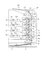
次に、本発明の実施例について図2、図5〜図14を用いて説明する。図5はクリーニング部材のクリーニング枠体51への組み付けを示す概略斜視図である。また、図6はクリーナーユニット50を示す概略斜視図である。また、図7は充填シール剤120の注入口を示す概略斜視図である。また、図8はクリーニング枠体51と端部シール82を示す概略斜視図である。また、図9はクリーニング枠体51と端部シール82を示す概略正面図である。また、図10は他の実施例のクリーニング枠体51と端部シール82を示す概略正面図、更に、図11はクリーニング枠体51と端部シール82と充填シール剤120を示す概略正面図である。これら図8〜11は、図6に示すB部に相当する。また、図12はクリーニング枠体51と端部シール82と充填シール剤120を示す概略断面図である。また、図13は注入形態(バックアップ部材130)を示す概略断面図である。また、図14は他の実施例の注入形態(バックアップ部材130)を示す概略断面図である。これら図12〜14は、図2に示すA部に相当する。
Next, an embodiment of the present invention will be described with reference to FIGS. 2 and 5 to 14. FIG. 5 is a schematic perspective view showing assembly of the cleaning member to the
まずは、クリーナーユニット50の主要構成について、説明する。
First, the main configuration of the
図6に示すように、クリーナーユニット50は、クリーニング枠体51、クリーニングブレード60、シール部材としての端部シール82、可撓性のシート部材(以下、すくいシートという)80を有する。ここで、端部シール82は、感光体ドラム1の長手方向端部に設けられており、クリーニング枠体51からのトナー漏れを規制する。また、すくいシート80は、クリーニングブレード60によって、感光体ドラム1から除去した現像剤をクリーニング枠体51内へ導く(ガイドする)。
As shown in FIG. 6, the
次に、クリーナーユニットの組み付け順序について説明する。 Next, the assembly order of the cleaner units will be described.
図5に示すように、まず、クリーニングブレード60が有する支持板金61は、クリーナーユニット50のケーシングであるクリーニング枠体51にタップタイトねじ65で固定される。支持板金61を固定するための固定部は、クリーニング枠体51の両端に位置する座面52,53である。その際、ねじ65は、支持板金61に設けられた穴部61q,61rを挿通して、座面52,53に設けられたねじ下穴部52c,53cにねじ込まれる。また、クリーニングブレード60を組み付ける前に、クリーニング枠体51の両端には、弾性ブレード部材62とクリーニング枠体51の隙間を塞ぐための弾性発泡シール部材(不図示)が貼り付けられている。
As shown in FIG. 5, first, the support sheet metal 61 included in the
図5に示すように、クリーニングブレード60のX方向(枠体長手方向)の位置は、座面52に設けられている長手位置決めボス52bと、支持板金61の長丸穴61cとが嵌合
することで決まる。さらに、クリーニングブレード60のY方向(枠体短手方向)の位置は、座面52,53に設けられている角ボス52a,53aと、支持板金61の切り欠き部61a,61bとが嵌合して決まる。Z方向(高さ方向)の位置は、座面52,53の高さによって決定する。これらによって、感光体ドラム1に対するクリーニングブレード60の当接条件が決定する。
As shown in FIG. 5, the position of the
クリーニングブレード60を組み付け後、シール部材としての端部シール82をクリーニング枠体51に貼り付ける。
After the
ここで、端部シール82は、弾性ブレード部材62のエッジ62aに、端部シール82の隅部82fが当接するように配設され(図8,9参照)る。そして、端部シール82と一体化された両面テープ(不図示)により、端部シール82はクリーニング枠体51に接着される(クリーニングブレード両端ともに同様)。
Here, the
端部シール82を貼り付け後、シート部材としてのすくいシート80を貼り付ける。
After attaching the
まず、クリーニング枠体51の配設部(配設面)としてのシート座面54に、両面テープ81を貼り付ける。その後、すくいシート80は、両面テープ81の上に貼り付けられる(図12参照)。これによって、すくいシート80は隙間dを覆う。本実施例での両面テープ81は幅1.5〜2.5mmとしている。尚、本実施例においては、クリーニング枠体51に、端部シール82及びすくいシート80、クリーニングブレード60が取り付けられているが、クリーニング枠体51は一体でなくても良い。即ち、端部シール82が取り付けられる枠体と、すくいシート80が取り付けられる枠体と、クリーニングブレード60が取り付けられる枠体は、別枠体であっても良い。本実施例においては、一体で有る場合と別枠体で有る場合とを総称してクリーニング枠体51と称す。
First, the double-
そして、接着及びシール機能を有する充填剤(充填材)としての充填シール剤120が、端部シール82、クリーニング枠体51、すくいシート80に隙間無く接するように、注入される(図12参照)。これによって、端部シール82の形状誤差や貼り付け誤差によって生じる、クリーニング枠体51におけるシート座面54の壁54aと端部シール82の隙間dを塞ぐことができる。本実施例における充填シール剤120は、熱可塑性エラストマーを採用しているが、速乾性のシリコーン接着シール剤や、紫外線硬化型ボンドでも構わない。
Then, a filling
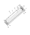
次に、充填シール剤の注入位置について、説明する。 Next, the filling sealant injection position will be described.
図8,図9に示すように、端部シール82は、壁面82a,82b,82cから構成される凹部821を有している。そして、充填シール剤120は、図11に示すように、凹部821と、シート座面54の所定面としての壁54aと、の間の隙間dに注入される。ここで、隙間dは、すくいシート80によって覆われている。言い換えると、凹部821と壁54aとすくいシート80とによって囲まれた領域は、充填剤を収納するための充填剤収納領域である。尚、感光体ドラム1がクリーニング枠体51に取り付けられた際には、すくいシート80を基準として、隙間dは、感光体ドラム1の逆側に位置する。また、所定面としての壁54aは、配設部(配設面)としてのシート座面54に略直交するように設けられている。
As shown in FIGS. 8 and 9, the
本実施例では、シート座面54の幅が3mm程度しかない。そのため、両面テープ81の貼り付け誤差等を考慮すると、シート座面幅を長手全域で確保することが望まれる。よって、シート座面54に設けられた凹面54bを極力小さくし、凹面54b以外の壁54a(ストレート部)と、端部シール82の凹部821との間で間隙)を構成している。
In this embodiment, the width of the
そして、本実施例では、凹部821の位置を、すくいシート80の先端80aと、壁54aとの間(すくいシート80の一部とクリーニング枠体51との間に挟まれる部分)にしている。これにより、充填シール剤120の粘着力(接着力)を利用することができ、剥離強度を大きくすることができる。これによって、端部シール82の反発力によるすくいシート80の剥がれを防止することができる。即ち、本実施例の構成を採用して、剥離強度を大きくすることにより、シート座面54に貼り付ける両面テープ81の幅を小さくすることができる。
In this embodiment, the
なお、シート座面54に凹面54bを設けることなく、図10に示すように、シート座面54の壁54aを、長手全域において、全くのストレートにしてもよい。
Instead of providing the
さらに、本実施例では、凹部821の両端に、端部シール82の壁面82dとシート座面54の壁54aによって生じる隙間aを設けている。また、端部シール82の壁面82a,82eとシート座面54の凹部54bとの間に各々隙間b,cを設けている。これらの隙間a,b,cは、充填シール剤のバッファーである(図11参照)。これにより、充填シール剤120の充填量の規格を緩和し、組立性を向上させることができる。また、クリーニング枠体51と端部シール82との隙間の発生、すくいシート80からの充填シール剤120のはみ出しを防止することができる。
また、クリーニング枠体51に設けられた連通孔57の空間もバッファーとしての機能を果たす。また、図7に示すように連通孔57の両端にリブ57a,57bを設ける。これにより、リブ57a,57bで囲まれた溜め部としての領域Rをバッファーとすることができる。
Further, in the present embodiment, a gap a generated by the
The space of the
本実施例では、充填口である連通孔57は長丸穴形状をしているが、形状を限定する必要はない。尚、連通孔57は隙間dと連通している。また、連通孔57は、隙間dを基準としてすくいシート80とは逆側に位置するように、設けられている。
In this embodiment, the
次に、充填シール剤の注入方法について説明する。 Next, a method for injecting the filling sealant will be described.
充填シール剤120は、画像形成装置本体100に装着されたときの上方に位置する側から連通孔57から注入される。図13に示すように、プロセスカートリッジ7において、感光体ドラム1が装着される場合と略同じ位置に、感光体ドラム1と略同一径を有するバックアップ部材130を、両端の端部シール82の位置に配設する。そして、端部シール82を圧縮させた状態にして、シート座面54に対して略垂直(鉛直)方向における上方から充填シール剤120を注入する。即ち、すくいシート80を隙間dの下方に位置させた状態で、充填シール剤120が連通孔57に注入される。
The filling
このとき、端部シール82は、2.5〜4.5mmの厚みが1.5〜2.5mmに圧縮される。
At this time, the
なお、バックアップ部材130の形状は、円形状である必要はない。即ち、図14に示すように、角部を有する形状で、角部を端部シール82の凹部821と、すくいシート80の先端80aの間に当接させる構成でも良い。しかし、バックアップ部材130を円形状にすることにより、すくいシート80や端部シール82に対する負荷を軽減することができる。
そして、感光体ドラム1を、両端の端部シール82に接触させて、クリーニング枠体51に取り付ける。この際、すくいシート80の一部は端部シール82と感光体ドラム1の
間に位置している(図9、図13参照)。
尚、本実施例においては、バックアップ部材130を使用して、充填シール剤120の感
光体ドラム1への付着防止を保障している。しかし、感光体ドラム1自体をバックアップのために使ってもよい。この場合、バックアップ部材130を使用する必要がなくなり、クリーナーユニット50の製造工程を少なくすることができる。
Note that the shape of the
Then, the photosensitive drum 1 is attached to the
In this embodiment, the
本実施例によれば、連通孔57から充填される充填シール剤120は、端部シール82の凹部821と、凹部821に対向するクリーニング枠体51の壁54aとの隙間に充填される。そのため、充填シール剤120の流動経路を規制することができる。従って、充填シール剤120が端部シール82やすくいシート80の外側へはみ出したりすることを防止することができる。
According to the present embodiment, the filling
さらに、バックアップ部材130を当接させることや、凹部821と壁54aとの隙間以外の隙間、連通孔57の高さ、連通孔57の注入側付近のバッファー等により、充填量が多い場合でも、凹部821と壁54aとの隙間にしっかりと充填される。このとき、充填シール剤120が、すくいシート80を持ち上げることは無く、クリーニング枠体51と端部シール82の隙間を確実に塞ぐことができる。
Furthermore, even when the back-up
このように、充填シール剤120の充填量を厳しく管理することなく、クリーニング枠体51と端部シール82の隙間を確実に塞ぐことができる。また、充填シール剤120が端部シール82やすくいシート80の外側へはみ出したりすることを防止することが可能となる。
As described above, the gap between the cleaning
また、前述した実施例では、凹部821の位置を、すくいシート80先端と、凹部821に対向するクリーニング枠体51の面(壁54a)との間にしている。これにより、充填シール剤120の粘着力を利用している。即ち、本実施例によれば、端部シール82の反発力に耐えることができ、すくいシート80の剥離強度を確保することができる。これによって、すくいシート80をクリーニング枠体51に貼り付ける両面テープの幅を小さくすることができる。
尚、本発明は、クリーニングユニットに限られず現像ユニットに適用しても良い。
In the embodiment described above, the position of the
The present invention is not limited to the cleaning unit, and may be applied to a developing unit.
1(1a,1b,1c,1d) 感光体ドラム
2(2a,2b,2c,2d) 帯電手段(帯電ローラ)
3(3a,3b,3c,3d) スキャナユニット
4(4a,4b,4c,4d) 現像装置(現像ユニット)
5 静電転写手段
6(6a,6b,6c,6d) クリーニング装置
7(7a,7b,7c,7d) プロセスカートリッジ
9 ポリゴンミラー
10 結像レンズ
11 静電転写ベルト
12 転写ローラ
13 駆動ローラ
14a,14b 従動ローラ
15 テンションローラ
16 給送部
17 給送カセット
18 給送ローラ
19 レジストローラ
20 定着部
21a 加熱ローラ
21b 加圧ローラ
22 静電吸着ローラ
23 排出ローラ
24 排出部
30 軸受部材
40(40a,40b,40c,40d) 現像ローラ
42 トナー送り機構
43 トナー供給ローラ
44 現像ブレード
45a,45b 現像枠体
46 現像剤容器
47,48 結合穴
49 ピン
50 クリーナーユニット
51 クリーニング枠体
52,53 座面
52a,53a 角ボス
52b 長手位置決めボス
52c,53c ねじ下穴
54 シート座面
54a 壁面
54b 凹部
55 廃トナー容器
57 連通孔
57a,57b リブ
60 クリーニングブレード
61 支持板金
61a,61b 切り欠き部
61c 長丸穴
61q,61r 穴部
62 弾性ブレード部材
62a エッジ部
65 ねじ
80 可撓性シート部材(すくいシート)
80a 先端
81 両面テープ
82 端部シール
82a,82b,82c,82d,82e 壁面
82f 隅部
821 凹部
90 カートリッジ把手
100 画像形成装置本体
101 前扉
120 充填シール剤
130 バックアップ部材
a,b,c,d 隙間
R バッファー
S 記録媒体
1 (1a, 1b, 1c, 1d) Photosensitive drum 2 (2a, 2b, 2c, 2d) Charging means (charging roller)
3 (3a, 3b, 3c, 3d) Scanner unit 4 (4a, 4b, 4c, 4d) Developing device (developing unit)
5 Electrostatic transfer means 6 (6a, 6b, 6c, 6d) Cleaning device 7 (7a, 7b, 7c, 7d) Process cartridge 9 Polygon mirror 10
Claims (21)
前記枠体に取り付けられ、その周面に現像剤を担持して回転する回転体と、
前記枠体と前記回転体の間からの現像剤の漏れを規制するために前記枠体に取り付けられ、前記回転体の長手方向の端部において前記枠体と前記回転体の周面との間に位置する端部シール部材と、
前記枠体と前記回転体の間からの現像剤の漏れを規制するために前記枠体に取り付けられ、前記回転体の長手方向に亘って前記枠体と前記回転体の周面との間に位置し、前記回転体の長手方向の端部において前記端部シール部材と前記回転体の周面との間に進入しているシート部材と、
を有する現像剤容器において、
前記枠体は前記回転体の長手方向の端部において前記枠体を貫通している貫通孔を有し、前記貫通孔の一端開口は前記シート部材を介して前記回転体に対向しており、前記貫通孔の他端開口は前記回転体に対向しておらず、
前記枠体と前記端部シール部材と前記シート部材との間からの現像剤の漏れを規制するために、前記他端開口から前記一端開口に向かって前記貫通孔に注入されることにより、前記枠体と前記端部シール部材と前記シート部材との間に充填された充填剤を有することを特徴とする現像剤容器。 A frame body you storing the current image agent,
A rotating body attached to the frame body and carrying a developer on its peripheral surface to rotate;
Attached to the frame body to restrict leakage of developer from between the frame body and the rotating body, and between the frame body and the peripheral surface of the rotating body at the longitudinal end portion of the rotating body. An end seal member located at
It is attached to the frame body in order to regulate the leakage of the developer from between the frame body and the rotating body, and between the frame body and the peripheral surface of the rotating body over the longitudinal direction of the rotating body. A sheet member that is located between the end seal member and the peripheral surface of the rotating body at an end in the longitudinal direction of the rotating body ;
In a developer container having
The frame body has a through hole penetrating the frame body at an end portion in a longitudinal direction of the rotating body, and one end opening of the through hole faces the rotating body via the sheet member, The other end opening of the through hole does not face the rotating body,
In order to regulate the leakage of the developer from between the frame body, the end seal member and the sheet member, by being injected into the through hole from the other end opening toward the one end opening, developer container, characterized in that it comprises a filler filled between the end seal member and the frame member and the seat member.
を特徴とする請求項1乃至4のいずれか1項に記載の現像剤容器。The developer container according to claim 1, wherein:
ア)現像剤を担持して回転する回転体が取り付けられるための枠体であって、その一端開口が前記枠体に前記回転体が取り付けられた状態において前記回転体に対向しており、その他端開口が前記枠体に前記回転体が取り付けられた状態において前記回転体に対向しない貫通孔を有し、現像剤を収納するための枠体を準備する枠体準備工程と、
イ)端部シール部材を前記枠体に取り付ける端部シール部材取り付け工程と、
ウ)シート部材に前記一端開口と前記端部シール部材の一部を覆わせて、前記シート部材を前記枠体に取り付けるシート部材取り付け工程と、
エ)前記端部シール部材取り付け工程及び前記シート部材取り付け工程の後に、前記他端開口から前記一端開口に向かって前記貫通孔に充填剤を注入して、前記充填剤を前記端部シール部材と前記シート部材と前記枠体との間に充填する充填工程と、
を有することを特徴とする現像剤容器の製造方法。 In a method for producing a developer container used in an image forming apparatus,
A ) A frame on which a rotating body that carries a developer and rotates is attached, and one end opening of the frame faces the rotating body in a state where the rotating body is attached to the frame. A frame body preparation step for preparing a frame body for storing developer, having an end opening having a through- hole that does not face the rotating body in a state where the rotating body is attached to the frame body ;
A ) an end seal member attaching step for attaching the end seal member to the frame;
C ) a sheet member attaching step of covering the sheet member with a part of the one end opening and the end seal member, and attaching the sheet member to the frame;
D ) After the end seal member attaching step and the sheet member attaching step , a filler is injected into the through hole from the other end opening toward the one end opening, and the filler is used as the end seal member. and as charge Hamako filling between said frame and said sheet member,
A process for producing a developer container, comprising:
で前記充填剤を前記貫通孔に注入することを特徴とする請求項16に記載の現像剤容器の製造方法。 In the filling step, the sheet member is pressed toward the one end opening provided
The method for manufacturing a developer container according to claim 16 , wherein the filler is injected into the through hole .
Priority Applications (4)
| Application Number | Priority Date | Filing Date | Title |
|---|---|---|---|
| JP2006113697A JP4227626B2 (en) | 2005-05-09 | 2006-04-17 | Developer container, cartridge, and developer container manufacturing method |
| US11/415,169 US7483646B2 (en) | 2005-05-09 | 2006-05-02 | Developer container, process cartridge, image forming apparatus and manufacturing method for developer container |
| CN2006100801626A CN1862412B (en) | 2005-05-09 | 2006-05-09 | Developer container, process cartridge, image forming apparatus and manufacturing method for developer container |
| US12/332,527 US7630665B2 (en) | 2005-05-09 | 2008-12-11 | Developer container, process cartridge, image forming apparatus and manufacturing method for developer container |
Applications Claiming Priority (2)
| Application Number | Priority Date | Filing Date | Title |
|---|---|---|---|
| JP2005136318 | 2005-05-09 | ||
| JP2006113697A JP4227626B2 (en) | 2005-05-09 | 2006-04-17 | Developer container, cartridge, and developer container manufacturing method |
Publications (3)
| Publication Number | Publication Date |
|---|---|
| JP2006343722A JP2006343722A (en) | 2006-12-21 |
| JP2006343722A5 JP2006343722A5 (en) | 2008-12-04 |
| JP4227626B2 true JP4227626B2 (en) | 2009-02-18 |
Family
ID=37394149
Family Applications (1)
| Application Number | Title | Priority Date | Filing Date |
|---|---|---|---|
| JP2006113697A Expired - Fee Related JP4227626B2 (en) | 2005-05-09 | 2006-04-17 | Developer container, cartridge, and developer container manufacturing method |
Country Status (3)
| Country | Link |
|---|---|
| US (2) | US7483646B2 (en) |
| JP (1) | JP4227626B2 (en) |
| CN (1) | CN1862412B (en) |
Families Citing this family (33)
| Publication number | Priority date | Publication date | Assignee | Title |
|---|---|---|---|---|
| JP4681946B2 (en) * | 2005-05-27 | 2011-05-11 | キヤノン株式会社 | Process cartridge, developing cartridge, and electrophotographic image forming apparatus |
| JP2007093831A (en) * | 2005-09-28 | 2007-04-12 | Brother Ind Ltd | Image forming apparatus, image formation process unit and developing unit |
| JP2008089808A (en) * | 2006-09-29 | 2008-04-17 | Oki Data Corp | Developing device and image forming apparatus |
| US8229320B2 (en) | 2007-05-15 | 2012-07-24 | Canon Kabushiki Kaisha | Electrophotographic image forming apparatus, cartridge, and cartridge holding member with lock and lock releasing members for releasably locking cartridge to the cartridge holding member |
| JP4948489B2 (en) | 2007-08-10 | 2012-06-06 | キヤノン株式会社 | Image forming apparatus |
| US20090095985A1 (en) | 2007-10-10 | 2009-04-16 | Samsung Electronics Co., Ltd. | Multi-layer electrode, cross point memory array and method of manufacturing the same |
| JP5371287B2 (en) | 2008-05-27 | 2013-12-18 | キヤノン株式会社 | Developing device, process cartridge, and electrophotographic image forming apparatus |
| JP4558083B2 (en) | 2008-06-20 | 2010-10-06 | キヤノン株式会社 | Cartridge, method for assembling the cartridge, and method for disassembling the cartridge |
| JP4591558B2 (en) * | 2008-06-20 | 2010-12-01 | 富士ゼロックス株式会社 | Liquid material coating method and developer removing apparatus |
| JP5151774B2 (en) * | 2008-07-29 | 2013-02-27 | 株式会社リコー | Cleaning device, process unit, and image forming apparatus |
| WO2010024471A1 (en) * | 2008-09-01 | 2010-03-04 | キヤノン株式会社 | Developing cartridge, process cartridge, and electrophotographic image forming apparatus |
| JP5419584B2 (en) | 2008-09-01 | 2014-02-19 | キヤノン株式会社 | Cartridge and electrophotographic image forming apparatus |
| JP5335329B2 (en) * | 2008-09-01 | 2013-11-06 | キヤノン株式会社 | Image forming apparatus |
| JP5424749B2 (en) * | 2008-09-01 | 2014-02-26 | キヤノン株式会社 | cartridge |
| US8029284B2 (en) * | 2008-09-29 | 2011-10-04 | Maxillent Ltd. | Implants, tools, and methods for sinus lift and lateral ridge augmentation |
| US8301056B2 (en) * | 2008-10-10 | 2012-10-30 | Brother Kogyo Kabushiki Kaisha | Developing device |
| JP4666047B2 (en) * | 2008-10-10 | 2011-04-06 | ブラザー工業株式会社 | Development device |
| US20100191101A1 (en) * | 2009-01-23 | 2010-07-29 | Yoav Lichtenstein | Catheter with isolation between ultrasound transducer and position sensor |
| JP5430349B2 (en) * | 2009-10-30 | 2014-02-26 | キヤノン株式会社 | Developer cartridge |
| JP5554963B2 (en) * | 2009-10-30 | 2014-07-23 | キヤノン株式会社 | Developing cartridge and process cartridge |
| JP2011203369A (en) * | 2010-03-24 | 2011-10-13 | Brother Industries Ltd | Developing device |
| CN102103354B (en) * | 2011-02-25 | 2012-09-05 | 珠海天威飞马打印耗材有限公司 | Processing box |
| JP5709193B2 (en) | 2012-04-30 | 2015-04-30 | 進 庄司 | Electrophotographic image forming apparatus having end seal material |
| JP6004799B2 (en) | 2012-07-10 | 2016-10-12 | キヤノン株式会社 | Developer container and image forming apparatus |
| JP2014048473A (en) * | 2012-08-31 | 2014-03-17 | Canon Inc | Developing apparatus |
| JP5980064B2 (en) | 2012-09-13 | 2016-08-31 | キヤノン株式会社 | Development device manufacturing method and process cartridge manufacturing method |
| US9182733B2 (en) | 2013-02-07 | 2015-11-10 | Canon Kabushiki Kaisha | Developer supply cartridge, process cartridge and image forming apparatus |
| TWI781537B (en) | 2015-02-27 | 2022-10-21 | 日商佳能股份有限公司 | Cartridge |
| JP6512864B2 (en) | 2015-02-27 | 2019-05-15 | キヤノン株式会社 | Cartridge, process cartridge, image forming apparatus |
| WO2018037574A1 (en) | 2016-08-26 | 2018-03-01 | キヤノン株式会社 | Cartridge and image forming device |
| KR102079823B1 (en) | 2017-01-19 | 2020-02-20 | 휴렛-팩커드 디벨롭먼트 컴퍼니, 엘.피. | development cartridge and electrophotographic image forming apparatus adapting the same |
| JP6957205B2 (en) | 2017-05-31 | 2021-11-02 | キヤノン株式会社 | Cartridge and image forming equipment |
| JP7211042B2 (en) * | 2018-11-30 | 2023-01-24 | 株式会社リコー | Developer storage container, developing device and image forming apparatus |
Family Cites Families (22)
| Publication number | Priority date | Publication date | Assignee | Title |
|---|---|---|---|---|
| JP3471950B2 (en) * | 1995-02-02 | 2003-12-02 | キヤノン株式会社 | Process cartridge and image forming apparatus |
| JP3441980B2 (en) * | 1998-08-31 | 2003-09-02 | キヤノン株式会社 | Developing device |
| JP3679665B2 (en) | 1999-11-19 | 2005-08-03 | キヤノン株式会社 | Gap assurance member, developing device, charging device, and process cartridge |
| JP3478797B2 (en) | 1999-12-28 | 2003-12-15 | キヤノン株式会社 | Process cartridge and electrophotographic image forming apparatus |
| US6829455B2 (en) * | 2000-10-20 | 2004-12-07 | Canon Kabushiki Kaisha | Driving force transmission mechanism, image forming apparatus equipped with such a mechanism, and process unit of such an apparatus |
| US6654575B2 (en) * | 2000-11-28 | 2003-11-25 | Canon Kabushiki Kaisha | Developer container having sealing member |
| US6658223B2 (en) * | 2001-11-29 | 2003-12-02 | Kyocera Mita Corporation | Toner seal for a cleaning device |
| JP2003215917A (en) | 2002-01-24 | 2003-07-30 | Canon Inc | Developing device, process cartridge and image forming apparatus |
| JP4072362B2 (en) | 2002-03-14 | 2008-04-09 | キヤノン株式会社 | Developing device, process cartridge, and image forming apparatus |
| JP4109915B2 (en) | 2002-07-01 | 2008-07-02 | キヤノン株式会社 | Cleaning device, process cartridge, and image forming apparatus |
| JP2004101690A (en) * | 2002-09-06 | 2004-04-02 | Canon Inc | Development device, process cartridge, and electrophotographic image forming apparatus |
| JP3944045B2 (en) * | 2002-09-30 | 2007-07-11 | キヤノン株式会社 | Developer supply container and electrophotographic image forming apparatus |
| JP3913153B2 (en) | 2002-09-30 | 2007-05-09 | キヤノン株式会社 | Power supply contact member, process cartridge, and image forming apparatus |
| JP2004151563A (en) | 2002-10-31 | 2004-05-27 | Canon Inc | Recycling method for process cartridge |
| JP2005043539A (en) | 2003-07-25 | 2005-02-17 | Canon Inc | Cleaning apparatus and processing cartridge |
| JP4652783B2 (en) * | 2003-12-10 | 2011-03-16 | キヤノン株式会社 | Developer supply container |
| JP3885062B2 (en) * | 2004-03-30 | 2007-02-21 | キヤノン株式会社 | Electrophotographic photosensitive drum, process cartridge, and electrophotographic image forming apparatus |
| US7158749B2 (en) * | 2004-04-26 | 2007-01-02 | Canon Kabushiki Kaisha | Cleaning device, process cartridge, cleaning member and electrophotographic image forming apparatus |
| JP3840232B2 (en) * | 2004-05-06 | 2006-11-01 | キヤノン株式会社 | Process cartridge |
| JP3826148B2 (en) * | 2004-08-26 | 2006-09-27 | キヤノン株式会社 | Process cartridge and electrophotographic image forming apparatus |
| JP4886182B2 (en) * | 2004-09-27 | 2012-02-29 | キヤノン株式会社 | Cartridge, process cartridge, and electrophotographic image forming apparatus |
| JP4681946B2 (en) * | 2005-05-27 | 2011-05-11 | キヤノン株式会社 | Process cartridge, developing cartridge, and electrophotographic image forming apparatus |
-
2006
- 2006-04-17 JP JP2006113697A patent/JP4227626B2/en not_active Expired - Fee Related
- 2006-05-02 US US11/415,169 patent/US7483646B2/en active Active
- 2006-05-09 CN CN2006100801626A patent/CN1862412B/en active Active
-
2008
- 2008-12-11 US US12/332,527 patent/US7630665B2/en not_active Expired - Fee Related
Also Published As
| Publication number | Publication date |
|---|---|
| JP2006343722A (en) | 2006-12-21 |
| US7630665B2 (en) | 2009-12-08 |
| US7483646B2 (en) | 2009-01-27 |
| CN1862412B (en) | 2012-02-08 |
| US20090092411A1 (en) | 2009-04-09 |
| US20060251445A1 (en) | 2006-11-09 |
| CN1862412A (en) | 2006-11-15 |
Similar Documents
| Publication | Publication Date | Title |
|---|---|---|
| JP4227626B2 (en) | Developer container, cartridge, and developer container manufacturing method | |
| JP4011930B2 (en) | Developer container, developing device, process cartridge, and image forming apparatus | |
| JP5063792B2 (en) | Developing device, process cartridge, developing device, and process cartridge remanufacturing method | |
| JP5980064B2 (en) | Development device manufacturing method and process cartridge manufacturing method | |
| US7428393B2 (en) | Developing device, process cartridge, device unit, and image forming apparatus having a sealing member | |
| JP2006251145A (en) | Cleaning device, developing device, process cartridge and electrophotographic image forming apparatus | |
| JP4764766B2 (en) | Developing device, process cartridge, and image forming apparatus | |
| US10928751B2 (en) | Remanufacturing method for developing apparatus and cartridge | |
| JP5250932B2 (en) | Powder container, toner container, image forming apparatus | |
| JP6137786B2 (en) | Developing device, process cartridge, image forming apparatus | |
| JP5312626B2 (en) | Frame unit, developing device and process cartridge | |
| JP2007025345A (en) | Developing device, process cartridge and image forming apparatus | |
| JP2006343562A (en) | Developing device, process cartridge and electrophotographic image forming apparatus | |
| US20200073288A1 (en) | Remanufacturing method | |
| JP2003214540A (en) | Seal structure, developing device having seal structure, process cartridge and electrophotographic image forming apparatus | |
| JP5370922B2 (en) | Developing device, process unit, image forming apparatus, and assembling method of developing device | |
| JPH096111A (en) | Developer cartridge, developing device, process cartridge and image forming device | |
| JP4109915B2 (en) | Cleaning device, process cartridge, and image forming apparatus | |
| US20230418216A1 (en) | Image forming apparatus | |
| JP7075035B2 (en) | Toner container and image forming device | |
| US20200272073A1 (en) | Developing device and remanufacturing method of developing device | |
| JP6406980B2 (en) | Developing device and process cartridge | |
| JP2022139159A (en) | Toner cartridge and image forming apparatus | |
| JP2004101671A (en) | Developing apparatus, electrophotographic image forming apparatus, and bushing member | |
| JP2000075657A (en) | Developing device, developing cartridge, and image forming device |
Legal Events
| Date | Code | Title | Description |
|---|---|---|---|
| A521 | Request for written amendment filed |
Free format text: JAPANESE INTERMEDIATE CODE: A523 Effective date: 20081022 |
|
| A621 | Written request for application examination |
Free format text: JAPANESE INTERMEDIATE CODE: A621 Effective date: 20081022 |
|
| A871 | Explanation of circumstances concerning accelerated examination |
Free format text: JAPANESE INTERMEDIATE CODE: A871 Effective date: 20081022 |
|
| TRDD | Decision of grant or rejection written | ||
| A975 | Report on accelerated examination |
Free format text: JAPANESE INTERMEDIATE CODE: A971005 Effective date: 20081104 |
|
| A01 | Written decision to grant a patent or to grant a registration (utility model) |
Free format text: JAPANESE INTERMEDIATE CODE: A01 Effective date: 20081111 |
|
| A01 | Written decision to grant a patent or to grant a registration (utility model) |
Free format text: JAPANESE INTERMEDIATE CODE: A01 |
|
| A61 | First payment of annual fees (during grant procedure) |
Free format text: JAPANESE INTERMEDIATE CODE: A61 Effective date: 20081128 |
|
| FPAY | Renewal fee payment (event date is renewal date of database) |
Free format text: PAYMENT UNTIL: 20111205 Year of fee payment: 3 |
|
| R150 | Certificate of patent or registration of utility model |
Ref document number: 4227626 Country of ref document: JP Free format text: JAPANESE INTERMEDIATE CODE: R150 Free format text: JAPANESE INTERMEDIATE CODE: R150 |
|
| FPAY | Renewal fee payment (event date is renewal date of database) |
Free format text: PAYMENT UNTIL: 20121205 Year of fee payment: 4 |
|
| FPAY | Renewal fee payment (event date is renewal date of database) |
Free format text: PAYMENT UNTIL: 20131205 Year of fee payment: 5 |
|
| LAPS | Cancellation because of no payment of annual fees |