JP4886182B2 - Cartridge, process cartridge, and electrophotographic image forming apparatus - Google Patents
Cartridge, process cartridge, and electrophotographic image forming apparatus Download PDFInfo
- Publication number
- JP4886182B2 JP4886182B2 JP2004279247A JP2004279247A JP4886182B2 JP 4886182 B2 JP4886182 B2 JP 4886182B2 JP 2004279247 A JP2004279247 A JP 2004279247A JP 2004279247 A JP2004279247 A JP 2004279247A JP 4886182 B2 JP4886182 B2 JP 4886182B2
- Authority
- JP
- Japan
- Prior art keywords
- cartridge
- main body
- electrical contact
- guide
- guided
- Prior art date
- Legal status (The legal status is an assumption and is not a legal conclusion. Google has not performed a legal analysis and makes no representation as to the accuracy of the status listed.)
- Expired - Fee Related
Links
- 238000000034 method Methods 0.000 title claims description 38
- 230000008569 process Effects 0.000 title claims description 37
- 230000008878 coupling Effects 0.000 claims description 14
- 238000010168 coupling process Methods 0.000 claims description 14
- 238000005859 coupling reaction Methods 0.000 claims description 14
- 238000011144 upstream manufacturing Methods 0.000 claims description 7
- 108091008695 photoreceptors Proteins 0.000 claims 1
- 238000012546 transfer Methods 0.000 description 26
- 238000004140 cleaning Methods 0.000 description 15
- 230000002093 peripheral effect Effects 0.000 description 5
- 230000001105 regulatory effect Effects 0.000 description 5
- 239000011347 resin Substances 0.000 description 3
- 229920005989 resin Polymers 0.000 description 3
- 230000015572 biosynthetic process Effects 0.000 description 2
- 238000010438 heat treatment Methods 0.000 description 2
- 230000007723 transport mechanism Effects 0.000 description 2
- 241001272720 Medialuna californiensis Species 0.000 description 1
- 229910052782 aluminium Inorganic materials 0.000 description 1
- XAGFODPZIPBFFR-UHFFFAOYSA-N aluminium Chemical compound [Al] XAGFODPZIPBFFR-UHFFFAOYSA-N 0.000 description 1
- 238000005452 bending Methods 0.000 description 1
- 239000003086 colorant Substances 0.000 description 1
- 238000013461 design Methods 0.000 description 1
- 238000011161 development Methods 0.000 description 1
- 238000010586 diagram Methods 0.000 description 1
- 230000000694 effects Effects 0.000 description 1
- 230000005684 electric field Effects 0.000 description 1
- 238000003384 imaging method Methods 0.000 description 1
- 238000003780 insertion Methods 0.000 description 1
- 230000037431 insertion Effects 0.000 description 1
- 239000000463 material Substances 0.000 description 1
- 230000007246 mechanism Effects 0.000 description 1
- 229910052751 metal Inorganic materials 0.000 description 1
- 239000002184 metal Substances 0.000 description 1
- 238000001179 sorption measurement Methods 0.000 description 1
- 230000000087 stabilizing effect Effects 0.000 description 1
- 230000032258 transport Effects 0.000 description 1
- 238000003466 welding Methods 0.000 description 1
Images


Classifications
-
- G—PHYSICS
- G03—PHOTOGRAPHY; CINEMATOGRAPHY; ANALOGOUS TECHNIQUES USING WAVES OTHER THAN OPTICAL WAVES; ELECTROGRAPHY; HOLOGRAPHY
- G03G—ELECTROGRAPHY; ELECTROPHOTOGRAPHY; MAGNETOGRAPHY
- G03G21/00—Arrangements not provided for by groups G03G13/00 - G03G19/00, e.g. cleaning, elimination of residual charge
- G03G21/16—Mechanical means for facilitating the maintenance of the apparatus, e.g. modular arrangements
- G03G21/18—Mechanical means for facilitating the maintenance of the apparatus, e.g. modular arrangements using a processing cartridge, whereby the process cartridge comprises at least two image processing means in a single unit
- G03G21/1839—Means for handling the process cartridge in the apparatus body
- G03G21/1867—Means for handling the process cartridge in the apparatus body for electrically connecting the process cartridge to the apparatus, electrical connectors, power supply
- G03G21/1871—Means for handling the process cartridge in the apparatus body for electrically connecting the process cartridge to the apparatus, electrical connectors, power supply associated with a positioning function
-
- G—PHYSICS
- G03—PHOTOGRAPHY; CINEMATOGRAPHY; ANALOGOUS TECHNIQUES USING WAVES OTHER THAN OPTICAL WAVES; ELECTROGRAPHY; HOLOGRAPHY
- G03G—ELECTROGRAPHY; ELECTROPHOTOGRAPHY; MAGNETOGRAPHY
- G03G2215/00—Apparatus for electrophotographic processes
- G03G2215/01—Apparatus for electrophotographic processes for producing multicoloured copies
- G03G2215/0103—Plural electrographic recording members
- G03G2215/0119—Linear arrangement adjacent plural transfer points
-
- G—PHYSICS
- G03—PHOTOGRAPHY; CINEMATOGRAPHY; ANALOGOUS TECHNIQUES USING WAVES OTHER THAN OPTICAL WAVES; ELECTROGRAPHY; HOLOGRAPHY
- G03G—ELECTROGRAPHY; ELECTROPHOTOGRAPHY; MAGNETOGRAPHY
- G03G2221/00—Processes not provided for by group G03G2215/00, e.g. cleaning or residual charge elimination
- G03G2221/16—Mechanical means for facilitating the maintenance of the apparatus, e.g. modular arrangements and complete machine concepts
- G03G2221/1651—Mechanical means for facilitating the maintenance of the apparatus, e.g. modular arrangements and complete machine concepts for connecting the different parts
- G03G2221/166—Electrical connectors
-
- G—PHYSICS
- G03—PHOTOGRAPHY; CINEMATOGRAPHY; ANALOGOUS TECHNIQUES USING WAVES OTHER THAN OPTICAL WAVES; ELECTROGRAPHY; HOLOGRAPHY
- G03G—ELECTROGRAPHY; ELECTROPHOTOGRAPHY; MAGNETOGRAPHY
- G03G2221/00—Processes not provided for by group G03G2215/00, e.g. cleaning or residual charge elimination
- G03G2221/16—Mechanical means for facilitating the maintenance of the apparatus, e.g. modular arrangements and complete machine concepts
- G03G2221/18—Cartridge systems
- G03G2221/183—Process cartridge
- G03G2221/1884—Projections on process cartridge for guiding mounting thereof in main machine
Landscapes
- Engineering & Computer Science (AREA)
- Computer Vision & Pattern Recognition (AREA)
- Physics & Mathematics (AREA)
- General Physics & Mathematics (AREA)
- Electrophotography Configuration And Component (AREA)
Description
本発明は、カートリッジ、プロセスカートリッジ、及び、電子写真画像形成装置に関するものである。 The present invention relates to a cartridge, a process cartridge, and an electrophotographic image forming apparatus.
ここで、電子写真画像形成装置(以下、画像形成装置と称す)とは、電子写真画像形成方式を用いて記録媒体(例えば、紙、OHPシート等)に画像を形成するものである。そして、前記画像形成装置の例としては、例えば、電子写真複写機、電子写真プリンタ(例えば、レーザービームプリンタ、LEDプリンタ等)、ファクシミリ装置及びワードプロセッサ等が含まれる。 Here, an electrophotographic image forming apparatus (hereinafter referred to as an image forming apparatus) forms an image on a recording medium (for example, paper, an OHP sheet) using an electrophotographic image forming system. Examples of the image forming apparatus include an electrophotographic copying machine, an electrophotographic printer (for example, a laser beam printer, an LED printer, etc.), a facsimile machine, a word processor, and the like.
従来、電子写真画像形成分野においては、例えば、電子写真感光体に作用するプロセス手段をカートリッジ枠体にて一体にまとめてカートリッジ化したカートリッジが知られている。そして、このカートリッジを画像形成装置の装置本体に着脱可能とするカートリッジ方式が採用されている。ここで前記プロセス手段としては、現像手段の他に、例えば、帯電手段、クリーニング手段等がある。従って、カートリッジとしては、現像手段を有する現像カートリッジ、帯電手段を有する帯電カートリッジ、クリーニング手段を有するクリーニングカートリッジ等がある。 Conventionally, in the electrophotographic image forming field, for example, a cartridge is known in which process means acting on an electrophotographic photosensitive member are integrated into a cartridge frame. A cartridge system is employed in which the cartridge is detachable from the main body of the image forming apparatus. Here, the process means includes, for example, a charging means and a cleaning means in addition to the developing means. Accordingly, the cartridge includes a developing cartridge having a developing unit, a charging cartridge having a charging unit, and a cleaning cartridge having a cleaning unit.
また、電子写真感光体及び前記プロセス手段を一体的にカートリッジ化して、このプロセスカートリッジを前記装置本体に着脱可能とするプロセスカートリッジ方式も採用されている。 Also, a process cartridge system is adopted in which the electrophotographic photosensitive member and the process means are integrated into a cartridge so that the process cartridge can be attached to and detached from the apparatus main body.
このようなカートリッジ方式によれば、装置のメンテナンスをサービスマンによらずにユーザー自身で行うことができる。そのため、装置の操作性を格段に向上させることができる。従って、このカートリッジ方式は、画像形成装置において広く用いられている。 According to such a cartridge system, the apparatus can be maintained by the user himself / herself without depending on the service person. As a result, the operability of the apparatus can be significantly improved. Therefore, this cartridge system is widely used in image forming apparatuses.
ところで、前記プロセス手段には、装置本体からの給電を必要とするものがある。従って、装置本体から前記プロセス手段へ給電するためにカートリッジにカートリッジ電気接点が設けられている。更に、カートリッジを装置本体に装着する際にカートリッジをガイドするためのガイド部材に、カートリッジ電気接点を設けた例がある(特許文献1参照)。尚、このような構成によっても、カートリッジ電気接点と装置本体に設けられた本体電気接点との電気的な接続は良好に行われる。
上記従来例では、装置本体に設けられた本体電気接点に対して、カートリッジに設けられたカートリッジ電気接点のための領域を比較的広く取っている。これは、カートリッジを装置本体に装着した際、両電気接点を確実に接触させるためである。 In the above-described conventional example, the area for the cartridge electrical contact provided in the cartridge is relatively wide with respect to the body electrical contact provided in the apparatus main body. This is to ensure that both electrical contacts are brought into contact when the cartridge is mounted on the apparatus main body.
そこで、本発明の目的は、カートリッジ電気接点と本体電気接点との電気的接続の信頼性を向上させたカートリッジ、プロセスカートリッジ、電子写真画像形成装置を提供することにある。 SUMMARY OF THE INVENTION An object of the present invention is to provide a cartridge, a process cartridge, and an electrophotographic image forming apparatus in which the reliability of electrical connection between a cartridge electrical contact and a main body electrical contact is improved.
また、本発明の他の目的は、電子写真画像形成装置本体にカートリッジを装着する際に、カートリッジ電気接点と本体電気接点とを電気的に確実に接続させることを実現したカートリッジ、プロセスカートリッジ、電子写真画像形成装置を提供することにある。 Another object of the present invention is to provide a cartridge, a process cartridge, and an electronic device that realizes an electrical connection between the cartridge electrical contact and the body electrical contact when the cartridge is mounted on the electrophotographic image forming apparatus body. A photographic image forming apparatus is provided.
また、本発明の他の目的は、カートリッジ電気接点のカートリッジ枠体からの露出領域を減少させることのできるカートリッジ、プロセスカートリッジ、電子写真画像形成装置を提供することにある。 Another object of the present invention is to provide a cartridge, a process cartridge, and an electrophotographic image forming apparatus capable of reducing the exposed area of the cartridge electrical contacts from the cartridge frame.
また、本発明の他の目的は、カートリッジを電子写真画像形成装置本体に装着する際にカートリッジが装着方向と直交する方向にぶれたとしても、第一被ガイド部と第二被ガイド部との間にカートリッジ電気接点をガイドするためのガイド部を設けることにより、前記装置本体にカートリッジを装着する際に、前記装置本体に設けられた本体電気接点を前記カートリッジに設けられたカートリッジ電気接点へ確実に導くことにある。 Another object of the present invention is that even when the cartridge is mounted on the electrophotographic image forming apparatus main body, even if the cartridge is shaken in a direction orthogonal to the mounting direction, the first guided portion and the second guided portion By providing a guide portion for guiding the cartridge electrical contact therebetween, when the cartridge is mounted on the apparatus main body, the main body electric contact provided on the apparatus main body is securely connected to the cartridge electric contact provided on the cartridge. There is to lead to.
上記目的を達成するため、本出願に係る第1の発明は電子写真画像形成装置本体に設けられた装着部に取り外し可能に装着されるカートリッジにおいて、
前記装置本体から、電子写真感光体に作用するプロセス手段に給電するために、前記カートリッジを前記装着部に装着した際に、前記装置本体に設けられた本体電気接点と電気的に接続するカートリッジ電気接点と、
前記カートリッジを前記装着部へ装着する際に、前記カートリッジを前記装着部へガイドするように、前記装置本体に設けられた本体ガイドにガイドされる第一被ガイド部、及び、第二被ガイド部と、
前記カートリッジを前記装着部へ装着する際に、前記本体電気接点と前記カートリッジ電気接点とが電気的に接続するように、前記本体電気接点を前記カートリッジ電気接点へガイドするガイド部と、
を有し、
前記ガイド部は、前記第一被ガイド部と前記第二被ガイド部との間に設けられ、前記カートリッジを前記装着部へ装着する方向において、前記カートリッジ電気接点は前記ガイド部に対して上流側に配置されていることを特徴とする。
In order to achieve the above object, a first invention according to the present application is a cartridge that is detachably mounted to a mounting portion provided in an electrophotographic image forming apparatus main body.
In order to supply power to the process means acting on the electrophotographic photosensitive member from the apparatus main body, when the cartridge is mounted on the mounting portion, the cartridge electric that is electrically connected to the main body electrical contact provided on the apparatus main body. Contacts,
A first guided portion and a second guided portion guided by a body guide provided in the apparatus main body so that the cartridge is guided to the mounting portion when the cartridge is mounted to the mounting portion. When,
A guide portion that guides the main body electrical contact to the cartridge electrical contact so that the main body electrical contact and the cartridge electrical contact are electrically connected when the cartridge is mounted to the mounting portion;
Have
The guide portion is provided between the first guided portion and the second guided portion, and the cartridge electrical contact is upstream of the guide portion in a direction in which the cartridge is attached to the attachment portion. It is characterized by being arranged in.
以上説明したように、本発明によれば、前記装置本体に前記カートリッジを装着する際に、前記装置本体に設けられた本体電気接点と前記カートリッジに設けられたカートリッジ電気接点との電気的接続の信頼性を向上させることができる。 As described above, according to the present invention, when the cartridge is mounted on the apparatus main body, the electrical connection between the main body electrical contact provided on the apparatus main body and the cartridge electrical contact provided on the cartridge is performed. Reliability can be improved.
(実施例1)
以下に、本発明の一実施例に係るフルカラー画像形成装置について図面に基づいて説明する。
Example 1
A full-color image forming apparatus according to an embodiment of the present invention will be described below with reference to the drawings.
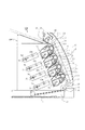
[フルカラー画像形成装置の全体構成]
まず、図1を参照して、フルカラー画像形成装置の全体構成について説明する。尚、図1はフルカラー画像形成装置の一態様であるフルカラー電子写真画像形成装置100の全体構成を示す断面図である。
[Entire configuration of full-color image forming apparatus]
First, the overall configuration of the full-color image forming apparatus will be described with reference to FIG. FIG. 1 is a cross-sectional view showing the overall configuration of a full-color electrophotographic
フルカラー電子写真画像形成装置100は、垂直方向に並設された4個の電子写真感光体としての感光体ドラム1(1a,1b,1c,1d)を備えている。感光体ドラム1は、駆動手段(不図示)によって、反時計回り(図2参照)に回転駆動される。感光体ドラム1の周囲について、その回転方向に従って順に述べる。まず、感光体ドラム1表面を均一に帯電する帯電手段としての帯電ローラ2(2a、2b、2c、2d)が設けられている。次に、画像情報に基づいてレーザービームを照射し感光体ドラム1に静電潜像を形成するスキャナユニット3(3a、3b、3c、3d)が設けられている。そして、前記静電潜像を現像する現像部材としての現像ローラ40を有する現像ユニット4(4a、4b、4c、4d)が設けられている。続いて、感光体ドラム1の周面に形成された現像剤像を記録媒体Sに転写させる転写装置5が設けられている。更に、転写後の感光体ドラム1表面に残った残留現像剤を除去するクリーニング手段としてのクリーニング装置6(6a、6b、6c、6d)が設けられている。
The full-color electrophotographic
ここで、感光体ドラム1と帯電ローラ2、現像ユニット4、クリーニング装置6は一体的にカートリッジ化されプロセスカートリッジ7(7a、7b、7c、7d)を構成している。
Here, the photosensitive drum 1, the charging roller 2, the developing
転写装置5には、循環移動する転写ベルト11が設けられている。この転写ベルト11は、すべての感光体ドラム1に対向して、かつ、接触している。また、4個の感光体ドラム1に対向した位置に転写ローラ12(12a,12b,12c,12d)が並設される。各転写ローラ12は、転写ベルト11の内側に当接している。
The
給送部16は、画像形成部(カートリッジ7)に記録媒体Sを搬送する。この給送部16はカセット17を有する。そして、このカセット17に記録媒体Sが収納されている。画像形成時には給送ローラ18(半月ローラ)、レジストローラ19が画像形成動作に応じて駆動回転して、カセット17内の記録媒体Sを1枚毎に分離給送する。
The feeding unit 16 conveys the recording medium S to the image forming unit (cartridge 7). The feeding unit 16 has a
定着部20は、記録媒体Sに転写された複数色の現像剤画像を定着させるものである。この定着部20は、回転する加熱ローラ21aと、これに圧接して記録媒体Sに熱及び圧力を与える加圧ローラ21bとを有する。
The
画像形成の動作を以下に説明する。まず、各感光体ドラム1が、回転駆動する(反時計方向)。そして、各々のカートリッジ7に対応するスキャナユニット3が順次駆動する。更に、帯電ローラ2は感光体ドラム1の周面に一様な電荷を付与する。そして、スキャナユニット3は、その感光体ドラム1に画像信号に応じて露光を行う。こうして、感光体ドラム1に静電潜像が形成される。現像ユニット4内の現像ローラ40は、静電潜像の低電位部に現像剤を転移させる。そして、感光体ドラム1に現像剤像が形成(現像)される。一方、給送部16においては、感光体ドラム1に形成された現像剤像と、記録媒体Sの画像形成開始位置が一致するように、記録媒体Sがレジローラ19によって転写ベルト11へ給送される。
The image forming operation will be described below. First, each photosensitive drum 1 is rotationally driven (counterclockwise). The scanner units 3 corresponding to the cartridges 7 are sequentially driven. Further, the charging roller 2 applies a uniform charge to the peripheral surface of the photosensitive drum 1. The scanner unit 3 exposes the photosensitive drum 1 according to the image signal. Thus, an electrostatic latent image is formed on the photosensitive drum 1. The developing
そして、記録媒体Sは、吸着ローラ22と転写ベルト11とによって挟み込まれるようにして転写ベルト11の外周に圧接する。それとともに、転写ベルト11と吸着ローラ22との間に電圧が印加される。これにより、誘電体である記録媒体Sと転写ベルト11の誘電体層とに電荷が誘起される。こうして、記録媒体Sが転写ベルト11の外周に静電吸着される。これにより、記録媒体Sは転写ベルト11によって最下流の転写部まで搬送される。
The recording medium S is pressed against the outer periphery of the transfer belt 11 so as to be sandwiched between the
このように搬送されながら、記録媒体Sは、各感光体ドラム1と転写ローラ12との間に形成される電界によって、各感光体ドラム1の現像剤像を順次転写される。 While being transported in this way, the developer image on each photosensitive drum 1 is sequentially transferred onto the recording medium S by an electric field formed between each photosensitive drum 1 and the transfer roller 12.
4色の現像剤像を転写された記録媒体Sは、ベルト駆動ローラ13の曲率により転写ベルト11から曲率分離される。その後、記録媒体Sは定着部20に搬入される。そして、この記録媒体Sは、定着部20で上記現像剤像を熱定着される。その後、この記録媒体Sは、排出ローラ23によって、排出部24から装置本体100Aの外部に排出される。
The recording medium S onto which the four color developer images have been transferred is separated from the transfer belt 11 by the curvature of the
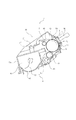
[プロセスカートリッジの構成]
次に、図2及び図3を用いて本発明の一実施例であるプロセスカートリッジ7について説明する。図2は現像剤を収納したカートリッジ7の断面図を示している。また、図3(a)、(b)はカートリッジ7の斜視図を示している。なお、イエロー、マゼンダ、シアン、ブラックの各カートリッジ7は同一構成である。
[Process cartridge configuration]
Next, a process cartridge 7 according to an embodiment of the present invention will be described with reference to FIGS. FIG. 2 shows a sectional view of the cartridge 7 containing the developer. 3A and 3B are perspective views of the cartridge 7. FIG. The yellow, magenta, cyan, and black cartridges 7 have the same configuration.
カートリッジ7は、感光体ドラム1と、クリーナユニット50、及び、現像ユニット4を有する。クリーナユニット50は帯電ローラ2およびクリーニング手段としてのクリーニングブレード60を有する。
The cartridge 7 includes a photosensitive drum 1, a
感光体ドラム1は、例えばアルミシリンダの外周面に感光層を設けて構成したものである。感光体ドラム1は、軸受31(31a、31b)を介して、第一枠体51(カートリッジ枠体)に回動可能に取り付けられている。感光体ドラム1の一端側に、駆動モータ(不図示)からの駆動力が伝達される。これにより、感光体ドラム1は回転駆動される(反時計方向)。感光体ドラム1の周面上には、感光体ドラム1の周面を一様に帯電させるための帯電手段としての帯電ローラ2、転写後に感光体ドラム1上に残った現像剤(残留現像剤)を除去するためのクリーニングブレード60、及び、可撓性シート部材80が設けられている。 The photosensitive drum 1 is configured by providing a photosensitive layer on the outer peripheral surface of an aluminum cylinder, for example. The photosensitive drum 1 is rotatably attached to a first frame 51 (cartridge frame) via bearings 31 (31a, 31b). A driving force from a driving motor (not shown) is transmitted to one end side of the photosensitive drum 1. Thereby, the photosensitive drum 1 is rotationally driven (counterclockwise). On the peripheral surface of the photosensitive drum 1, a charging roller 2 as a charging unit for uniformly charging the peripheral surface of the photosensitive drum 1, and a developer (residual developer) remaining on the photosensitive drum 1 after transfer. ) And a flexible sheet member 80 are provided.
本実施例の帯電ローラ2は、接触帯電方式である。帯電ローラ2は、ローラ状の導電性ローラであり、感光体ドラム1表面に当接している。そして、この帯電ローラ2に装置本体100Aから帯電バイアス電圧が印加される。これにより、感光体ドラム1の表面が一様に帯電される。また、感光体ドラム1表面に残留した残留現像剤は、前記シート部材80のドラム当接部を通ってクリーニングブレード60の位置まで到達する。そして、この残留現像剤はクリーニングブレード60によって感光体ドラム1表面から除去される。そして、除去された残留現像剤(除去現像剤)は、第一枠体51後方に設けられた除去現像剤収納室55に収納される。ここで、クリーニングブレード60によって感光体ドラム1上から除去された残留現像剤が第一枠体51外に漏れないように、感光体ドラム1に対して前記シート部材80が当接されている。
The charging roller 2 of this embodiment is a contact charging system. The charging roller 2 is a roller-like conductive roller and is in contact with the surface of the photosensitive drum 1. A charging bias voltage is applied to the charging roller 2 from the apparatus
現像ユニット4は、現像ローラ40と現像枠体45a、45bを有する。ここで、現像ローラ40は、感光体ドラム1と微少間隙を保持して回転する(時計方向)。また、現像枠体45a、45bは、イエロー、マゼンタ、シアン、ブラックの各色の現像剤を収納する。現像枠体45a、45bは互いに結合されて(超音波溶着等により結合)、第二枠体(カートリッジ枠体)45となる。現像ローラ40は軸受(不図示)を介して回転可能に第二枠体45に支持されている。また現像ローラ40と接触して回転する(時計方向)現像剤供給ローラ43と現像ブレード44がそれぞれ配置されている。さらに第二枠体45内には現像剤搬送機構42が設けられている。この現像剤搬送機構42は、第二枠体45内に収納された現像剤を撹拌するとともに現像剤供給ローラ43に現像剤を搬送する。
The developing
図4は図3(b)のe−e断面を表した図である。以下、現像ユニット4の支持構成を説明する。第二枠体45の長手方向一端側と他端側に結合穴47が設けられている。また、クリーナユニット50の長手方向一端側と他端側に支持穴52,53が設けられている。そして、この結合穴47と支持穴52,53を合わせ、支持穴52から結合部材としての結合ピン56(57)を差し込む。これによって、現像ユニット4とクリーナユニット50は回動可能に結合される。即ち、現像ユニット4とクリーナユニット50は吊り構造となっている。また、ピン56、57を中心に加圧ばね54の弾性力によって、現像ユニット4がクリーナユニット50に対して常に付勢されている。これにより、現像ローラ40が感光体ドラム1に対して弾性的に付勢されている。
FIG. 4 is a diagram showing the ee cross section of FIG. Hereinafter, the support structure of the developing
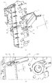
[画像形成装置本体に対するプロセスカートリッジの着脱及び帯電電気接点の接続]
次に、図5を用いて、装置本体100Aに対してカートリッジ7を取り外し可能に装着する方法について説明する。図5に示すように、装置本体100Aには前扉101が設けられている。この前扉101は、装置本体100Aに対して回動可能に設けられている。また、前扉101の内側には転写装置5が取付けられている。即ち、前扉101と転写装置5は、装置本体100Aに対して回動可能に設けられている。これら前扉101、転写装置5が開いた状態で、カートリッジ7は、装置本体100Aに対して着脱可能となる。また、カートリッジ7の両端部には把手部材97が設けられている。カートリッジ7を装着する際には、ユーザはその把手部材97を持ち、カートリッジ7を本体ガイド部材102、103の間に挿入する。ここで、本体ガイド部材102は、装置本体100Aに設けられた装着部Bの一端側に設けられている。また、本体ガイド部材103は、装置本体100Aに設けられた装着部Bの他端側に設けられている。そして、各本体ガイド部材102、103には、このカートリッジ7を装着部Bへガイドする本体ガイド104、105が設けられている。即ち、装置本体100Aの一端側にガイド104、他端側にガイド105が配置されている。本体ガイド104、105は4個のカートリッジ7毎に配置されている。
[Removal of process cartridge and connection of charging electrical contact to image forming apparatus main body]
Next, a method for detachably mounting the cartridge 7 on the apparatus
図6(a)、(b)は感光体ドラム1の長手方向における一端側について拡大した図である。前記一端側には、クリーナユニット50からカートリッジボス90及びカートリッジガイド92が突出して設けられている(図3(b)参照)。前記長手方向の他端側には、クリーナユニット50からカートリッジボス91及びカートリッジガイド93が突出して設けられている(図3(a)参照)。このガイド92、93は、カートリッジ7を装置本体100Aへ装着する際に、溝形状の前記本体ガイド105によって前記長手方向(Z方向)及び前記短手方向(Y方向)の移動方向を規制される。即ち、ガイド92の上面(第一被ガイド)92d、下面(第二被ガイド)92e、側面92fは、本体ガイド105の上側内面(溝の上側内面)105d、下側内面(溝の下側内面)105e、側面(溝の底面)105fによって、移動方向を規制される。即ち、上面92dは上側内面105d、下面92eは下側内面105e、及び、側面92fは側面105fによって移動方向を規制される。これによってカートリッジ7は装着部Bへガイドされる。尚、ガイド93も同様であるため、開示を省略する。また、ボス90、91は、カートリッジ7を装置本体100Aへ装着する際に、本体ガイド104によって移動方向を規制される。尚、ボス90、91は外径20mm程度の樹脂製であり、感光体ドラム1の同軸線上に配置されている。ガイド92、93は幅7mm程度、高さ7mm程度でカートリッジ7の装着方向(X方向)と略平行に設けられている。尚、ボス90、91、及び、ガイド92、93は共に、軸受31a、31bと一体的に構成されている。そして、ガイド92、93はユニット50から外方へ突出している。また、カートリッジ7の装着方向(X方向)において、ガイド92、93の下流側近傍には、前記支持穴52、53が設けられている。そして、支持穴52、53に嵌入されたピン56、57の端面は、ガイド92、93の端面とほぼ同じ高さである。また、ピン56、57のうち一端側のピン56は金属製であり、φ3mm程度の導電性の円柱形状である。また、ピン57は樹脂製である。
6A and 6B are enlarged views of one end side in the longitudinal direction of the photosensitive drum 1. A
次に、図10を用いて装置本体100Aからカートリッジ7の内部に設けられた帯電ローラ2に至るまでの電気経路について説明する。まず、帯電接点板94がクリーナユニット50の一端側の内側に設けられている。そして、前記ピン56は、この接点板94に設けられた穴94aに圧入されている。即ち、前記ピン56と前記接点板94は電気的に接続されている。更に、この接点板94は、コイルバネ状の加圧バネ95と接触(電気的に接続)している。そして、前記バネ95は、帯電ローラ2の長手方向一端側の軸を回転可能に支持する導電樹脂製の帯電ローラ軸受96と接触(電気的に接続)している。このような構成において、カートリッジ7が装着部Bに装着された際に、本体電気接点としての電気接点バネ106がピン56と接触する。そして、前記バネ106を介して装置本体100Aから電圧が給電される。その結果、ピン56を通じて帯電ローラ2に帯電バイアスが供給される。即ち、前記ピン56は前記装置本体100Aから帯電ローラ2に給電するためのカートリッジ電気接点部材として機能する。また、この装置本体100Aに設けられたバネ106は、本体電気接点として機能する。ここで、ピン56はカートリッジ電気接点としてのピン電気接点56aを有する。また、前記バネ106は本体電気接点としての弾性を有するバネ電気接点106aを有する。そして、前記接点56aは第一枠体51の外側へ露出している。また、前記接点106aは装置本体100Aに設けられており、装着部B内に露出している。そして、カートリッジ7が装着部Bに装着された際に、接点56aは接点106aと電気的に接続する。即ち、接点106aの有する弾性力によって両者は弾性的に接触する。ここで、カートリッジ電気接点(接点56a)は、カートリッジ電気接点部材(ピン56)の内、本体電気接点と接触する部分である。又、本体電気接点(接点106a)は、本体電気接点部材(バネ106)の一部である。
Next, an electrical path from the apparatus
更に、図3(b)、図6(a)、(b)に示すように、カートリッジ7を装着する装着方向(X方向)において、ガイド92の下流側の端部から前記ピン56に至る凹部(切り欠き部)52aが、所定の幅で設けられている。即ち、前記装着方向と直交する短手方向(Y方向)において、ガイド92の内側に凹部52aが設けられている。言い換えると、ガイド92の短手方向中央部には、ピン56(支持穴52)から前記装着方向(X方向)下流側に向かって凹部52aが設けられている。その結果、ピン56の一部が第一枠体51の外部に露出している。そして、ピン56の露出している一部分に前記接点56aが設けられている。本実施例において、凹部52aの幅bは約2.95mmであり、ピン56の外径c(=約3.0mm)よりもやや狭くなっている。これにより、カートリッジ7を装置本体100Aに装着する際に、前記凹部52aの上側内面92bと下側内面92cとによって、前記短手方向(Y方向)に移動を規制して、前記接点106aを確実に前記接点56aに当接するようにガイドすることができる。そのため、前記両電気接点の電気的接続に関する信頼性を向上できる。尚、本実施例によれば、カートリッジ7の長手方向の移動は本体ガイド104、105によって規制されている。従って、装着時において、カートリッジ7はその長手方向へぶれることが抑制されている。よって、接点106aは、前記短手方向の移動を規制されてガイドされれば、確実にピン電気接点56aにまで導かれる。更に、凹部52aの前記装着方向(X方向)下流側は開放している。この凹部52aは第一ガイド部としての上側内面92b及び第二ガイド部としての下側内面92cを有する。ここで、上側内面92bと下側内面92cは互いに対向している。また、上側内面92bと下側内面92cは、カートリッジ7の装着方向(X方向)と略平行方向に設けられている。そして、接点56aは、前記短手方向(Y方向)において、上側内面92bと下側内面92cとの間に設けられている。また、接点56aは、装着方向Xにおいて、上側内面92b及び下側内面92cの上流側に設けられている。尚、「接点56aが上側内面92bと下側内面92cとの間に設けられている」とは、前記装着方向Xにおいては、接点56aが上側内面92b及び下側内面92cと必ずしもオーバーラップしなければならないという意味ではない。即ち、上側内面92b又は下側内面92cによって接点106aが接点56aにまで導かれることが可能な配置関係であれば良い。そして、ピン56は凹部52aと対抗する部分が第一枠体51から露出している。そして、このピン56の露出している領域の一部に、前記接点56aが設けられている。即ち、凹部52aの上側内面92bと下側内面92cとでもって、接点106aの移動方向を規制する。そして、接点106aをピン56aの露出領域部分に導く。従って、本体電気接点と接触させるために、ピン56の接点領域としての接点56aを大きくしなくとも、接点56aと接点106aとを確実に接触させることが可能となる。
Further, as shown in FIGS. 3B, 6A, and 6B, a recess extending from the downstream end of the
次に、図7を用いて一端側の本体ガイド部材102について説明する。本体ガイド部材102は樹脂性である。そして、装着された4つのカートリッジ7を全て側面から覆うように一体的に構成されている。更に本体ガイド部材102には、本体ガイド104、105が設けられている。ここで、カートリッジ7を装置部Bに装着する際に、本体ガイド104はカートリッジ7のボス90と係合する。更に、本体ガイド105はカートリッジ7のガイド92と係合する。更に詳しく述べると、カートリッジ7を装置部Bに装着する際には、本体ガイド105はガイド92の外側をガイドする。即ち、ガイド92の上面92d及び下面92eが、本体ガイド105にガイドされる。これにより、カートリッジ7は装着部B(装置本体100Aの内部)へガイドされる。ここで、上側内面92bと下側内面92cは、前記短手方向(Y方向)において、上面92dと下面92eとの間に設けられている。即ち、本体ガイド105の上側内面105dにガイドされる上面92dと本体ガイド105の下側内面105eにガイドされる下面92eとの間に、バネ106をガイドするための上側内面92bと下側内面92cが設けられている。従って、カートリッジ7を装置本体100Aに挿入する過程において、カートリッジ7の中で一番ぶれが小さい場所でバネ106をガイドすることができる。そのため、接点106aを接点56aへ精度良く安定してガイドすることができる。更に、ぶれが小さい箇所で接点をとるため、接点106a及び接点56aを大きくする必要がなくなる。これにより、カートリッジ7及び装置本体100Aを小型化することができる。
Next, the main
また、本体ガイド105は、前記装着方向(X方向)に沿って溝状に構成されている。そして、本体ガイド105の側面105fには、前記装着方向と平行に長穴105aが構成されている。その長穴105aから接点106aがカートリッジ7の装着部Bとしての内部(図5参照)側に露出している。バネ106は線径φ1mm程度のねじりコイルバネである。バネ106はコイルばねの一部が折り曲げられており、この折り曲げられた部分に接点106aが設けられている。ねじりコイルバネの回転軸は、前記短手方向(Y方向)と略平行な方向である。本実施例においては、バネ106の接点106aが、ガイド92に沿って(即ち、カートリッジ7の装着方向に沿って)移動可能である。従って、装置本体100Aに設けられた電気接点構成のみならず、カートリッジ7に設けられた電気接点構成に関して省スペース化できる。更に、移動可能でない電気接点構成や前記短手方向に移動可能な電気接点構成と比べて、材料の選択や構成等、設計の自由度が高まる。更に、バネ106の接点106aはピン56の軸線方向(感光体ドラム1の長手方向(Z方向))にピン56を加圧している。
The
次に、図9に基づいて、カートリッジ7の装着に伴って装置本体100Aの電気接点とカートリッジ7の電気接点が電気的に接続する過程を説明する。図9は一端側の本体ガイド102部材の裏側から一部を切り欠き、ガイド92の周辺がわかるようにしている。
Next, a process of electrically connecting the electrical contact of the apparatus
まず、ユーザがカートリッジ7を装置本体100A内に挿入する。その際、図9(a)の状態のようにガイド92の外側が本体ガイド105にガイドされている。ここで、本体ガイド105の幅m(図7(b)参照)はガイド92の幅l(図6(b)参照)よりも0.5mm程度広く設定されている。これにより、ユーザはカートリッジ7の姿勢を安定させて、且つ、カートリッジ7を挿入する際の挿入力が強くなりすぎずに、カートリッジ7をスムーズに装着できる。さらに、図9(b)の状態に進むと、バネ106がガイド92の内側の凹部52aに入り込む。即ち、接点106aが凹部52aによってガイドされている。このように、バネ106を凹部52aによって規制するため、板バネ等のように接点をとるための接点領域を広く取ることなく、接点106aを確実にピン電気接点56aに導くことができる。更に、装着が進んで完了すると、バネ106は撓みピン56の角部付近(接点56a)に接触する(図8の状態)。この時の接触圧は50〜100gf程度である。また、バネ106は棒状であり、ピン56についても棒状であるため接触位置で滑り易い。しかし、前述したように、第一ガイド部92b及び第二ガイド部92c間の幅bはピン56の外径cより小さくしている(図6(b)参照)。そのため、常に接点106aは接点56aに接触し、カートリッジ7に安定した給電を行う事ができる。
First, the user inserts the cartridge 7 into the apparatus
以上のような構成を採用することにより、カートリッジ7の装着の際、確実に装置本体100Aの接点106aがガイドされ、カートリッジ7の接点56aから脱落する事が無くなる。更に、脱落することによる接点の変形等の不具合も無くなる。また、装着が完了した後も接点106aが接点56aに確実に当接することができる。従って、カートリッジ7の接点の領域を非常に小さくすることができる。即ち、本実施例によれば、カートリッジ電気接点と本体電気接点とを確実に当接させるために、カートリッジ及び装置本体の公差を見積もった上でカートリッジ7の電気接点を大きくする必要が無い。更に、カートリッジ7の小型化を達成し、装置本体100Aも小さくできる。まとめると、本実施例によれば、装置本体100Aからカートリッジ7への給電の安定性を損なう事無く、カートリッジ7の小型化を達成できる。
By adopting the above-described configuration, when the cartridge 7 is mounted, the
また、本実施例で説明したような縦型インライン方式のカラー画像形成装置であって、カートリッジ7の側面(感光体ドラム1の長手方向の端面)から給電している場合は、カートリッジ7の側面において、カートリッジ電気接点に必要な範囲が狭くすることができる。その結果、隣合うカートリッジ7の感光体ドラム1間の距離を短縮することができ、装置本体100Aの高さを低く抑えることができる。
Further, in the vertical in-line type color image forming apparatus described in the present embodiment, when power is supplied from the side surface of the cartridge 7 (end surface in the longitudinal direction of the photosensitive drum 1), the side surface of the cartridge 7 is used. The range required for the cartridge electrical contacts can be narrowed. As a result, the distance between the photosensitive drums 1 of the adjacent cartridges 7 can be shortened, and the height of the apparatus
また、これまで述べてきた実施例では、クリーニングユニット50と現像ユニット4を結するピン56がカートリッジ7の電気接点を兼ねる構成について述べてきた。しかし、接点部材がユニット同士を結合させる機能を有さなくともカートリッジ7の小型化を達成できる。但し、本実施例を用いることにより、従来よりも比較的小径であるピン56をカートリッジ電気接点部材として兼ねることができる。従って、従来必要であった接点のスペースを省略することができ、カートリッジ7をより小さくすることができる。
In the embodiments described so far, the configuration in which the
また、本実施例では帯電ローラ2のための接点部材について述べたが、その他のプロセス手段、例えば現像手段、クリーニング手段等への給電についても同様に本発明を適用できる。 In the present embodiment, the contact member for the charging roller 2 has been described. However, the present invention can be similarly applied to power supply to other process means such as a developing means and a cleaning means.
また、本実施例ではピン56は丸棒としているが、他の形状、例えば角柱等でも本発明を適用できる。
In this embodiment, the
尚、本実施例においてはドラム状の電子写真感光体について説明したが、ベルト状の電子写真感光体にも本発明を適用できる。但し、電子写真感光体ドラムの方が省スペースであるため、カートリッジの小型化に適している。 In this embodiment, the drum-shaped electrophotographic photosensitive member has been described. However, the present invention can also be applied to a belt-shaped electrophotographic photosensitive member. However, since the electrophotographic photosensitive drum saves space, it is suitable for reducing the size of the cartridge.
(実施例2)
次に図11に基づいて第2の実施例を説明する。第1の実施例と共通する箇所については説明を省略する。図11はプロセスカートリッジと装置本体の接点のみ表した斜視図である。
(Example 2)
Next, a second embodiment will be described with reference to FIG. A description of portions common to the first embodiment is omitted. FIG. 11 is a perspective view showing only the contact between the process cartridge and the apparatus main body.
本実施例では、結合ピン201はカートリッジガイド201aと一体的に成形されている。また、ピン201はカートリッジガイド203と略一直線に連なっており、カートリッジ7の装置本体100Aへの装着は略直線状のリブとなるピン201とガイド203で行う。
In this embodiment, the connecting
更に、ピン201のピン電気接点201a、接点ガイド201bともに金属性である。そのため、接点ガイド201bの間隔dを更に小さくしても、接点ガイド201c、201dに本体接点202が当接しても給電可能である。そのため、よりカートリッジ7を小型化できる。
Further, both the pin
また、更にピン201の幅fをガイド203の幅gより小さくして、装置本体100Aへのカートリッジ7の装着はガイド203のみで行うことも可能であり、実施例1と同等の効果が得られる。
Further, the width f of the
1(1a、1b、1c、1d) 感光体ドラム
2(2a、2b、2c、2d) 帯電ローラ
3(3a、3b、3c、3d) スキャナユニット
4(4a、4b、4c、4d) 現像ユニット
5 転写装置
6(6a、6b、6c、6d) クリーニング装置
7(7a、7b、7c、7d) プロセスカートリッジ
9 ポリゴンミラー
10 結像レンズ
11 転写ベルト
12 転写ローラ
13 駆動ローラ
14a、14b 従動ローラ
15 テンションローラ
16 給送部
17 カセット
18 給送ローラ
19 レジストローラ
20 定着部
21a 加熱ローラ
21b 加圧ローラ
22 吸着ローラ
23 排出ローラ
24 排出部
31 軸受
40(40a、40b、40c、40d) 現像ローラ
41 現像剤室
42 現像剤送り機構
43 現像剤供給ローラ
44 現像ブレード
45 第二枠体
47 結合穴
50 クリーナユニット
51 第一枠体
52、53 結合穴
54 加圧バネ
55 除去現像剤収納室
56、57 結合ピン
60 クリーニングブレード
80 可撓性シート部材
90、91 カートリッジボス
92、93 カートリッジガイド
94 帯電接点板
95 帯電ローラ加圧バネ
96 帯電ローラ軸受
100 電子写真画像形成装置
100A 電子写真画像形成装置本体
101 前扉
102、103 本体ガイド部材
104、105 本体ガイド
106 電気接点バネ
201 結合ピン(第2の実施例)
202 本体接点(第2の実施例)
203 カートリッジガイド(第2の実施例)
1 (1a, 1b, 1c, 1d) Photosensitive drum 2 (2a, 2b, 2c, 2d) Charging roller 3 (3a, 3b, 3c, 3d) Scanner unit 4 (4a, 4b, 4c, 4d) Development unit 5 Transfer device 6 (6a, 6b, 6c, 6d) Cleaning device 7 (7a, 7b, 7c, 7d) Process cartridge 9 Polygon mirror 10 Imaging lens 11 Transfer belt 12 Transfer roller 13 Drive roller 14a, 14b Drive roller 15 Tension roller DESCRIPTION OF SYMBOLS 16 Feeding part 17 Cassette 18 Feeding roller 19 Registration roller 20 Fixing part 21a Heating roller 21b Pressure roller 22 Adsorption roller 23 Ejection roller 24 Ejection part 31 Bearing 40 (40a, 40b, 40c, 40d) Developer roller 41 Developer chamber 42 Developer feed mechanism 43 Developer supply roller 44 Blade 45 Second frame 47 Bonding hole 50 Cleaner unit 51 First frame 52, 53 Bonding hole 54 Pressure spring 55 Removed developer storage chamber 56, 57 Bonding pin 60 Cleaning blade 80 Flexible sheet member 90, 91 Cartridge Boss 92, 93 Cartridge guide 94 Charging contact plate 95 Charging roller pressure spring 96 Charging roller bearing 100 Electrophotographic image forming apparatus 100A Electrophotographic image forming apparatus main body 101 Front door 102, 103 Main body guide member 104, 105 Main body guide 106 Electric contact Spring 201 coupling pin (second embodiment)
202 Main body contact (second embodiment)
203 Cartridge guide (second embodiment)
Claims (15)
前記装置本体から、電子写真感光体に作用するプロセス手段に給電するために、前記カートリッジを前記装着部に装着した際に、前記装置本体に設けられた本体電気接点と電気的に接続するカートリッジ電気接点と、
前記カートリッジを前記装着部へ装着する際に、前記カートリッジを前記装着部へガイドするように、前記装置本体に設けられた本体ガイドにガイドされる第一被ガイド部、及び、第二被ガイド部と、
前記カートリッジを前記装着部へ装着する際に、前記本体電気接点と前記カートリッジ電気接点とが電気的に接続するように、前記本体電気接点を前記カートリッジ電気接点へガイドするガイド部と、
を有し、
前記ガイド部は、前記第一被ガイド部と前記第二被ガイド部との間に設けられ、前記カートリッジを前記装着部へ装着する方向において、前記カートリッジ電気接点は前記ガイド部に対して上流側に配置されていることを特徴とするカートリッジ。 In the cartridge that is detachably mounted on the mounting portion provided in the electrophotographic image forming apparatus main body,
In order to supply power to the process means acting on the electrophotographic photosensitive member from the apparatus main body, when the cartridge is mounted on the mounting portion, the cartridge electric that is electrically connected to the main body electrical contact provided on the apparatus main body. Contacts,
A first guided portion and a second guided portion guided by a body guide provided in the apparatus main body so that the cartridge is guided to the mounting portion when the cartridge is mounted to the mounting portion. When,
A guide portion that guides the main body electrical contact to the cartridge electrical contact so that the main body electrical contact and the cartridge electrical contact are electrically connected when the cartridge is mounted to the mounting portion;
Have
The guide portion is provided between the first guided portion and the second guided portion, and the cartridge electrical contact is upstream of the guide portion in a direction in which the cartridge is attached to the attachment portion. A cartridge characterized by being arranged in
電子写真感光体と、
前記電子写真感光体を回転可能に支持する第一枠体と、
前記電子写真感光体に形成された静電潜像を現像する現像ローラと、
前記現像ローラを回転可能に結合する第二枠体と、
前記第一枠体と前記第二枠体とを回転可能に結合するための導電性結合ピンであって、前記装置本体から前記現像ローラに給電するために、前記カートリッジを前記装着部に装着した際に、前記装置本体に設けられた本体電気接点と電気的に接続する導電性結合ピンと、
前記カートリッジを前記装着部に装着する際に、前記カートリッジを前記装着部へガイドするように、前記装置本体に設けられた本体ガイドにガイドされる第一被ガイド部、及び、第二被ガイド部と、
前記カートリッジを前記装着部へ装着する際に、前記本体電気接点と前記結合ピンとが電気的に接続するように、前記本体電気接点を前記結合ピンへガイドするガイド部とを有し、
前記ガイド部は、前記第一被ガイド部と前記第二被ガイド部との間に設けられ、前記カートリッジを前記装着部へ装着する方向において、前記導電性結合ピンは前記ガイド部に対して上流側に配置されていることを特徴とするカートリッジ。 In the cartridge that is detachably mounted on the mounting portion provided in the electrophotographic image forming apparatus main body,
An electrophotographic photoreceptor;
A first frame for rotatably supporting the electrophotographic photosensitive member;
A developing roller for developing the electrostatic latent image formed on the electrophotographic photosensitive member;
A second frame that rotatably couples the developing roller;
A conductive coupling pin for rotatably coupling the first frame and the second frame, wherein the cartridge is mounted on the mounting portion in order to supply power to the developing roller from the apparatus main body. A conductive coupling pin electrically connected to a main body electrical contact provided in the apparatus main body,
A first guided portion and a second guided portion that are guided by a body guide provided in the apparatus main body so that the cartridge is guided to the mounting portion when the cartridge is mounted to the mounting portion. When,
A guide portion for guiding the body electrical contact to the coupling pin so that the body electrical contact and the coupling pin are electrically connected when the cartridge is mounted to the mounting portion ;
The guide portion is provided between the first guided portion and the second guided portion, and the conductive coupling pin is upstream of the guide portion in a direction in which the cartridge is attached to the attachment portion. The cartridge is arranged on the side.
(i)装着部と、
(ii)前記カートリッジを前記装着部に装着した際に、前記カートリッジに設けられたカートリッジ電気接点と電気的に接続する本体電気接点と、
(iii)前記カートリッジを前記装着部へ装着する際に、前記カートリッジを前記装着部へガイドするための本体ガイドと、
(iv)前記装着部に取り外し可能に装着されたカートリッジであって、電子写真感光体に作用するプロセス手段と、前記装置本体から前記プロセス手段に給電するために、前記カートリッジを前記装着部に装着した際に、前記電子写真画像形成装置の装置本体に設けられた本体電気接点と電気的に接続するカートリッジ電気接点と、前記カートリッジを前記装着部へ装着する際に、前記カートリッジを前記装着部へガイドするように、前記本体ガイドにガイドされる第一被ガイド部、及び、第二被ガイド部と、前記カートリッジを前記装着部へ装着する際に、前記本体電気接点と前記カートリッジ電気接点とが電気的に接続するように、前記本体電気接点を前記カートリッジ電気接点へガイドするガイド部と、を有し、前記ガイド部は、前記第一被ガイド部と前記第二被ガイド部との間に設けられ、前記カートリッジを前記装着部へ装着する方向において、前記カートリッジ電気接点は前記ガイド部に対して上流側に配置されているカートリッジと、
を有することを特徴とする電子写真画像形成装置。 In an electrophotographic image forming apparatus that forms an image on a recording medium using a cartridge,
(I) a mounting part;
(Ii) a main body electrical contact that is electrically connected to a cartridge electrical contact provided on the cartridge when the cartridge is mounted on the mounting portion;
(Iii) a body guide for guiding the cartridge to the mounting portion when mounting the cartridge to the mounting portion;
(Iv) A cartridge detachably mounted on the mounting portion, the process means acting on the electrophotographic photosensitive member, and the cartridge is mounted on the mounting portion to supply power to the process means from the apparatus main body. The cartridge electrical contact electrically connected to the main body electrical contact provided in the apparatus main body of the electrophotographic image forming apparatus, and the cartridge to the mounting portion when the cartridge is mounted to the mounting portion. When the cartridge is mounted on the mounting portion, the main body electrical contact and the cartridge electrical contact are connected to each other so as to guide the first guided portion and the second guided portion guided by the main body guide. A guide part for guiding the main body electrical contact to the cartridge electrical contact so as to be electrically connected, A cartridge provided between the first guided portion and the second guided portion, wherein the cartridge electrical contact is disposed upstream of the guide portion in the direction of mounting the cartridge to the mounting portion. When,
An electrophotographic image forming apparatus comprising:
前記装置本体から、電子写真感光体に作用するプロセス手段に給電するために、前記カートリッジを前記装着部に装着した際に、前記装置本体に設けられた本体電気接点と電気的に接続するカートリッジ電気接点と、
前記カートリッジを前記装着部へ装着する際に、前記カートリッジを前記装着部へガイドするように、前記装置本体に設けられた本体ガイドにガイドされる第一被ガイド部、及び、第二被ガイド部と、
前記カートリッジを前記装着部へ装着する際に、前記本体電気接点と前記カートリッジ電気接点とが電気的に接続するように、前記本体電気接点を前記カートリッジ電気接点へガイドする第一ガイド部、及び、第二ガイド部と、
を有し、
前記第一ガイド部及び第二ガイド部は、前記第一被ガイド部と前記第二被ガイド部との間に設けられ、前記カートリッジ電気接点は、前記第一ガイド部と前記第二ガイド部との間に設けられていることを特徴とするカートリッジ。 In the cartridge that is detachably mounted on the mounting portion provided in the electrophotographic image forming apparatus main body,
In order to supply power to the process means acting on the electrophotographic photosensitive member from the apparatus main body, when the cartridge is mounted on the mounting portion, the cartridge electric that is electrically connected to the main body electrical contact provided on the apparatus main body. Contacts,
A first guided portion and a second guided portion guided by a body guide provided in the apparatus main body so that the cartridge is guided to the mounting portion when the cartridge is mounted to the mounting portion. When,
A first guide portion for guiding the main body electrical contact to the cartridge electrical contact so that the main body electrical contact and the cartridge electrical contact are electrically connected when the cartridge is mounted to the mounting portion; and A second guide part;
Have
The first guide portion and the second guide portion are provided between the first guided portion and the second guided portion, and the cartridge electrical contact includes the first guide portion and the second guide portion. A cartridge provided between the two.
Priority Applications (2)
| Application Number | Priority Date | Filing Date | Title |
|---|---|---|---|
| JP2004279247A JP4886182B2 (en) | 2004-09-27 | 2004-09-27 | Cartridge, process cartridge, and electrophotographic image forming apparatus |
| US10/960,055 US7248810B2 (en) | 2004-09-27 | 2004-10-08 | Cartridge, process cartridge, and electrophotographic image forming apparatus |
Applications Claiming Priority (1)
| Application Number | Priority Date | Filing Date | Title |
|---|---|---|---|
| JP2004279247A JP4886182B2 (en) | 2004-09-27 | 2004-09-27 | Cartridge, process cartridge, and electrophotographic image forming apparatus |
Publications (3)
| Publication Number | Publication Date |
|---|---|
| JP2006091652A JP2006091652A (en) | 2006-04-06 |
| JP2006091652A5 JP2006091652A5 (en) | 2007-11-15 |
| JP4886182B2 true JP4886182B2 (en) | 2012-02-29 |
Family
ID=36099255
Family Applications (1)
| Application Number | Title | Priority Date | Filing Date |
|---|---|---|---|
| JP2004279247A Expired - Fee Related JP4886182B2 (en) | 2004-09-27 | 2004-09-27 | Cartridge, process cartridge, and electrophotographic image forming apparatus |
Country Status (2)
| Country | Link |
|---|---|
| US (1) | US7248810B2 (en) |
| JP (1) | JP4886182B2 (en) |
Families Citing this family (62)
| Publication number | Priority date | Publication date | Assignee | Title |
|---|---|---|---|---|
| JP4794892B2 (en) * | 2005-04-11 | 2011-10-19 | キヤノン株式会社 | Process cartridge and electrophotographic image forming apparatus |
| JP4227626B2 (en) * | 2005-05-09 | 2009-02-18 | キヤノン株式会社 | Developer container, cartridge, and developer container manufacturing method |
| JP4332806B2 (en) | 2005-12-27 | 2009-09-16 | ブラザー工業株式会社 | Developing unit and image forming apparatus |
| US20070154232A1 (en) * | 2006-01-04 | 2007-07-05 | Lexmark International, Inc. | Contacting removable printer cartridges |
| US20080005148A1 (en) * | 2006-06-30 | 2008-01-03 | Rearden Commerce, Inc. | Automated knowledge base of feed tags |
| US7865513B2 (en) * | 2006-06-30 | 2011-01-04 | Rearden Commerce, Inc. | Derivation of relationships between data sets using structured tags or schemas |
| JP4498407B2 (en) | 2006-12-22 | 2010-07-07 | キヤノン株式会社 | Process cartridge, electrophotographic image forming apparatus, and electrophotographic photosensitive drum unit |
| JP4948382B2 (en) | 2006-12-22 | 2012-06-06 | キヤノン株式会社 | Coupling member for mounting photosensitive drum |
| JP5084257B2 (en) * | 2006-12-28 | 2012-11-28 | キヤノン株式会社 | Process cartridge and image forming apparatus using the same |
| JP5311854B2 (en) | 2007-03-23 | 2013-10-09 | キヤノン株式会社 | Electrophotographic image forming apparatus, developing device, and coupling member |
| US7711287B2 (en) | 2007-05-15 | 2010-05-04 | Canon Kabushiki Kaisha | Cartridge and electrophotographic image forming apparatus |
| US8229320B2 (en) | 2007-05-15 | 2012-07-24 | Canon Kabushiki Kaisha | Electrophotographic image forming apparatus, cartridge, and cartridge holding member with lock and lock releasing members for releasably locking cartridge to the cartridge holding member |
| JP4458377B2 (en) | 2007-06-29 | 2010-04-28 | キヤノン株式会社 | Process cartridge and electrophotographic image forming apparatus |
| JP2009162908A (en) | 2007-12-28 | 2009-07-23 | Brother Ind Ltd | Process cartridge, image forming apparatus, and developing cartridge |
| US7555237B1 (en) * | 2008-02-27 | 2009-06-30 | Aetas Technology Incorporated | Positioning mechanism for positioning a developing apparatus and related developing apparatus |
| JP5306050B2 (en) | 2008-06-20 | 2013-10-02 | キヤノン株式会社 | Cartridge, coupling member attaching method, and coupling member removing method |
| JP5127584B2 (en) | 2008-06-20 | 2013-01-23 | キヤノン株式会社 | Drum unit and electrophotographic image forming apparatus |
| JP5424749B2 (en) * | 2008-09-01 | 2014-02-26 | キヤノン株式会社 | cartridge |
| JP5335329B2 (en) * | 2008-09-01 | 2013-11-06 | キヤノン株式会社 | Image forming apparatus |
| JP5419584B2 (en) * | 2008-09-01 | 2014-02-19 | キヤノン株式会社 | Cartridge and electrophotographic image forming apparatus |
| JP4663801B2 (en) * | 2008-09-01 | 2011-04-06 | キヤノン株式会社 | Process cartridge and image forming apparatus |
| JP5147607B2 (en) * | 2008-09-01 | 2013-02-20 | キヤノン株式会社 | Image forming apparatus |
| EP2333620A1 (en) | 2008-09-01 | 2011-06-15 | Canon Kabushiki Kaisha | Developing cartridge, process cartridge, and electrophotographic image forming apparatus |
| US8029284B2 (en) * | 2008-09-29 | 2011-10-04 | Maxillent Ltd. | Implants, tools, and methods for sinus lift and lateral ridge augmentation |
| JP5554963B2 (en) * | 2009-10-30 | 2014-07-23 | キヤノン株式会社 | Developing cartridge and process cartridge |
| JP5751779B2 (en) * | 2009-10-30 | 2015-07-22 | キヤノン株式会社 | Developing device, developing cartridge, process cartridge, and image forming apparatus |
| JP5430349B2 (en) * | 2009-10-30 | 2014-02-26 | キヤノン株式会社 | Developer cartridge |
| US9104135B2 (en) | 2011-12-30 | 2015-08-11 | Lexmark International, Inc. | Toner cartridge having positional control features |
| US8948650B2 (en) | 2011-12-30 | 2015-02-03 | Lexmark International, Inc. | Toner cartridge having a shutter lock mechanism |
| US9031451B2 (en) | 2011-12-30 | 2015-05-12 | Lexmark International, Inc. | Toner cartridge having a shutter lock mechanism |
| US8867970B2 (en) | 2011-12-30 | 2014-10-21 | Lexmark International, Inc. | Toner cartridges having positional control features |
| US8867966B2 (en) * | 2011-12-30 | 2014-10-21 | Lexmark International, Inc. | Toner cartridge for use in an image forming device |
| US8938179B2 (en) | 2012-06-25 | 2015-01-20 | Lexmark International, Inc. | Toner cartridge for an image forming device having a retainer assembly having positioning features for processing circuitry |
| US8879953B2 (en) | 2012-06-25 | 2014-11-04 | Lexmark International, Inc. | Retainer assembly having positioning features for processing circuitry used within an image forming device supply item |
| JP6128780B2 (en) | 2012-09-05 | 2017-05-17 | キヤノン株式会社 | Developing device and cartridge |
| US9182733B2 (en) | 2013-02-07 | 2015-11-10 | Canon Kabushiki Kaisha | Developer supply cartridge, process cartridge and image forming apparatus |
| US8879964B1 (en) | 2013-05-16 | 2014-11-04 | Lexmark International, Inc. | Toner cartridge having an angled exit port surface |
| JP2014237472A (en) | 2013-06-07 | 2014-12-18 | キヤノン株式会社 | Packing member and cartridge packed in the same |
| US9261851B2 (en) | 2013-11-20 | 2016-02-16 | Lexmark International, Inc. | Positional control features of a replaceable unit for an electrophotographic image forming device |
| US9367019B2 (en) * | 2014-06-30 | 2016-06-14 | Kyocera Document Solutions Inc. | Electric wire member and image forming apparatus including the same |
| US9477177B2 (en) | 2014-09-02 | 2016-10-25 | Lexmark International, Inc. | Toner cartridge having a shutter lock mechanism |
| CA3071296A1 (en) | 2015-02-27 | 2016-09-01 | Canon Kabushiki Kaisha | Cartridge |
| JP6512864B2 (en) | 2015-02-27 | 2019-05-15 | キヤノン株式会社 | Cartridge, process cartridge, image forming apparatus |
| US9360797B1 (en) | 2015-08-13 | 2016-06-07 | Lexmark International, Inc. | Toner cartridge having a movable projection for providing installation feedback to an image forming device |
| US9477178B1 (en) | 2015-08-13 | 2016-10-25 | Lexmark International, Inc. | System for determining the open or closed state of a toner cartridge shutter |
| US9551974B1 (en) | 2015-09-15 | 2017-01-24 | Lexmark International, Inc. | Positioning features for electrical connectors of replaceable units of an image forming device |
| US9360834B1 (en) | 2015-09-15 | 2016-06-07 | Lexmark International, Inc. | Replaceable unit for an electrophotographic image forming device having positioning features for electrical contacts |
| US9563169B1 (en) | 2015-12-14 | 2017-02-07 | Lexmark International, Inc. | Replaceable unit for an electrophotographic image forming device having a retractable electrical connector |
| KR101756845B1 (en) | 2015-12-28 | 2017-07-11 | 에스프린팅솔루션 주식회사 | Proicess cartridge and electrophotographic image forming apparatus using the same |
| US9983541B2 (en) | 2016-01-18 | 2018-05-29 | Lexmark International, Inc. | Positioning features for electrical contacts of a replaceable unit of an electrophotographic image forming device |
| SG11201901179RA (en) | 2016-08-26 | 2019-03-28 | Canon Kk | Cartridge and image forming apparatus |
| JP6855284B2 (en) | 2017-03-03 | 2021-04-07 | キヤノン株式会社 | Cartridge and image forming device |
| US10073410B1 (en) | 2017-05-11 | 2018-09-11 | Lexmark International, Inc. | Imaging unit having positioning features for electrical contacts for use in an electrophotographic image forming device |
| US9989917B1 (en) * | 2017-05-17 | 2018-06-05 | Lexmark International, Inc. | Toner cartridge with positional control features |
| JP6957205B2 (en) | 2017-05-31 | 2021-11-02 | キヤノン株式会社 | Cartridge and image forming equipment |
| SG11202108005QA (en) | 2019-03-18 | 2021-10-28 | Canon Kk | Electrophotographic image forming apparatus and cartridge |
| US10698363B1 (en) | 2019-04-12 | 2020-06-30 | Lexmark International, Inc. | Electrical connection for an imaging unit of an electrophotographic image forming device |
| US10649399B1 (en) | 2019-04-12 | 2020-05-12 | Lexmark Internatioanl, Inc. | Replaceable unit for an electrophotographic image forming device having a magnetic sensor |
| US10761476B1 (en) | 2019-04-12 | 2020-09-01 | Lexmark International, Inc. | Replaceable unit for an electrophotographic image forming device having a movable electrical connector |
| US10649389B1 (en) | 2019-04-12 | 2020-05-12 | Lexmark International, Inc. | Electrical connectors of a replaceable unit of an electrophotographic image forming device |
| JP7604148B2 (en) | 2020-09-17 | 2024-12-23 | キヤノン株式会社 | cartridge |
| JP2024168080A (en) * | 2023-05-23 | 2024-12-05 | キヤノン株式会社 | Image forming device |
Family Cites Families (47)
| Publication number | Priority date | Publication date | Assignee | Title |
|---|---|---|---|---|
| US191981A (en) * | 1877-06-12 | Improvement in casting grooved pulleys | ||
| US159787A (en) * | 1875-02-16 | Improvement in car-pushers | ||
| US5331373A (en) * | 1992-03-13 | 1994-07-19 | Canon Kabushiki Kaisha | Image forming apparatus, process cartridge mountable within it and method for attaching photosensitive drum to process cartridge |
| JP3352155B2 (en) * | 1992-06-30 | 2002-12-03 | キヤノン株式会社 | Process cartridge and image forming apparatus |
| JP3869868B2 (en) * | 1994-04-27 | 2007-01-17 | キヤノン株式会社 | Process cartridge and image forming apparatus |
| JP3337859B2 (en) * | 1994-04-26 | 2002-10-28 | キヤノン株式会社 | Process cartridge and image forming apparatus |
| AU3426895A (en) * | 1994-10-17 | 1996-05-02 | Canon Kabushiki Kaisha | Toner container, toner container assembling method, process cartridge, and electrophotographic image forming apparatus |
| JP3315560B2 (en) * | 1995-06-13 | 2002-08-19 | キヤノン株式会社 | Process cartridge, electrophotographic image forming apparatus, and method of mounting electrophotographic photosensitive drum |
| JP3372719B2 (en) | 1995-07-11 | 2003-02-04 | キヤノン株式会社 | Process cartridge and image forming apparatus |
| JP3530644B2 (en) * | 1995-07-31 | 2004-05-24 | キヤノン株式会社 | Developing frame, process cartridge, and electrophotographic image forming apparatus |
| JP3402872B2 (en) * | 1995-08-25 | 2003-05-06 | キヤノン株式会社 | Process cartridge regeneration method and process cartridge |
| JPH0962079A (en) * | 1995-08-25 | 1997-03-07 | Canon Inc | Refilling method for process cartridge with toner and process cartridge |
| JP3332818B2 (en) * | 1996-08-29 | 2002-10-07 | キヤノン株式会社 | Process cartridge, electrophotographic image forming apparatus, and connection terminal connection method |
| JP3363751B2 (en) * | 1996-08-29 | 2003-01-08 | キヤノン株式会社 | Process cartridge and electrophotographic image forming apparatus |
| JP3342362B2 (en) * | 1996-09-20 | 2002-11-05 | キヤノン株式会社 | Process cartridge and electrophotographic image forming apparatus |
| JPH10222041A (en) * | 1996-12-03 | 1998-08-21 | Canon Inc | Process cartridge and electrophotographic image forming device |
| JP3363727B2 (en) * | 1996-12-12 | 2003-01-08 | キヤノン株式会社 | Process cartridge, electrophotographic image forming apparatus, process cartridge assembling method, and waste toner container assembling method |
| JPH10228224A (en) * | 1997-02-14 | 1998-08-25 | Canon Inc | Process cartridge and electrophotographic image forming device |
| JP3745111B2 (en) * | 1997-03-18 | 2006-02-15 | キヤノン株式会社 | Coupling member, process cartridge, and process cartridge assembly method |
| JP3332813B2 (en) * | 1997-08-01 | 2002-10-07 | キヤノン株式会社 | Process cartridge and electrophotographic image forming apparatus |
| JP2000004371A (en) | 1998-06-16 | 2000-01-07 | Canon Inc | Color copying machine and color adjusting method therefor |
| US6542633B1 (en) * | 1997-10-31 | 2003-04-01 | Canon Kabushiki Kaisha | Image forming system with capability for color correction |
| JP3420486B2 (en) * | 1997-11-07 | 2003-06-23 | キヤノン株式会社 | Process cartridge and electrophotographic image forming apparatus |
| JPH11249494A (en) * | 1998-03-03 | 1999-09-17 | Canon Inc | Drum flange, cylindrical member, process cartridge and electrophotographic image forming device |
| JPH11249495A (en) * | 1998-03-03 | 1999-09-17 | Canon Inc | Grounding member, cylindrical member, process cartridge and electrophotographic image forming device |
| JP3673658B2 (en) * | 1998-10-28 | 2005-07-20 | キヤノン株式会社 | Process cartridge and electrophotographic image forming apparatus |
| JP3684092B2 (en) * | 1998-10-26 | 2005-08-17 | キヤノン株式会社 | Electrophotographic image forming apparatus |
| JP3697090B2 (en) * | 1998-10-26 | 2005-09-21 | キヤノン株式会社 | Electrophotographic image forming apparatus |
| JP3320399B2 (en) * | 1999-05-20 | 2002-09-03 | キヤノン株式会社 | Process cartridge, method of assembling process cartridge, and electrophotographic image forming apparatus |
| JP3293818B2 (en) * | 1999-05-20 | 2002-06-17 | キヤノン株式会社 | Process cartridge and electrophotographic image forming apparatus |
| JP3320398B2 (en) * | 1999-05-20 | 2002-09-03 | キヤノン株式会社 | Process cartridge and electrophotographic image forming apparatus |
| JP3478797B2 (en) * | 1999-12-28 | 2003-12-15 | キヤノン株式会社 | Process cartridge and electrophotographic image forming apparatus |
| US6549736B2 (en) * | 2000-01-19 | 2003-04-15 | Canon Kabushiki Kaisha | Process cartridge, engaging member therefor and method for mounting developing roller and magnet |
| DE60144502D1 (en) * | 2000-06-09 | 2011-06-09 | Canon Kk | Developer, work unit and flexible seal |
| US6829455B2 (en) * | 2000-10-20 | 2004-12-07 | Canon Kabushiki Kaisha | Driving force transmission mechanism, image forming apparatus equipped with such a mechanism, and process unit of such an apparatus |
| JP3432218B2 (en) * | 2000-10-31 | 2003-08-04 | キヤノン株式会社 | Process cartridge, load generating member, and electrophotographic image forming apparatus |
| JP2002244382A (en) * | 2000-12-13 | 2002-08-30 | Canon Inc | Processing cartridge, electric contact point member and electrophotographic image forming device |
| JP3542569B2 (en) | 2001-04-27 | 2004-07-14 | キヤノン株式会社 | Process cartridge remanufacturing method |
| JP3840063B2 (en) | 2001-04-27 | 2006-11-01 | キヤノン株式会社 | Process cartridge |
| JP3564080B2 (en) * | 2001-04-27 | 2004-09-08 | キヤノン株式会社 | Process cartridge remanufacturing method |
| JP3848124B2 (en) * | 2001-10-18 | 2006-11-22 | キヤノン株式会社 | Process cartridge and electrophotographic image forming apparatus |
| JP3595798B2 (en) * | 2002-01-31 | 2004-12-02 | キヤノン株式会社 | Process cartridge and electrophotographic image forming apparatus |
| JP3684209B2 (en) * | 2002-05-31 | 2005-08-17 | キヤノン株式会社 | Cartridge and electrophotographic image forming apparatus |
| JP3797295B2 (en) * | 2002-08-09 | 2006-07-12 | ブラザー工業株式会社 | Detachable member, developing device, process device, and image forming apparatus |
| JP3862682B2 (en) * | 2003-08-29 | 2006-12-27 | キヤノン株式会社 | Electrophotographic image forming apparatus and process cartridge |
| JP3625470B1 (en) * | 2003-09-30 | 2005-03-02 | キヤノン株式会社 | Process cartridge and electrophotographic image forming apparatus |
| JP4095589B2 (en) * | 2004-02-27 | 2008-06-04 | キヤノン株式会社 | Electrophotographic image forming apparatus and process cartridge |
-
2004
- 2004-09-27 JP JP2004279247A patent/JP4886182B2/en not_active Expired - Fee Related
- 2004-10-08 US US10/960,055 patent/US7248810B2/en active Active
Also Published As
| Publication number | Publication date |
|---|---|
| JP2006091652A (en) | 2006-04-06 |
| US7248810B2 (en) | 2007-07-24 |
| US20060067725A1 (en) | 2006-03-30 |
Similar Documents
| Publication | Publication Date | Title |
|---|---|---|
| JP4886182B2 (en) | Cartridge, process cartridge, and electrophotographic image forming apparatus | |
| US20230025758A1 (en) | Developing cartridge | |
| US7953339B2 (en) | Image forming device and cartridge being electrically connected by terminals | |
| JP4794892B2 (en) | Process cartridge and electrophotographic image forming apparatus | |
| JP6950147B2 (en) | Process cartridge | |
| JP3684195B2 (en) | Process cartridge and electrophotographic image forming apparatus | |
| JP2004086182A (en) | Process cartridge and electrophotographic image forming apparatus | |
| JP6821450B2 (en) | Develop equipment, process cartridges, and image forming equipment | |
| JP2003195726A (en) | Image forming apparatus and process cartridge | |
| JP5831048B2 (en) | Image forming apparatus | |
| JP2010085797A (en) | Cartridge, electronic device, and image forming apparatus incorporating same | |
| JP2008242142A (en) | Cartridge and image forming apparatus | |
| KR100693232B1 (en) | Electrophotographic imaging apparatus, cartridges and process cartridges | |
| JP4665927B2 (en) | Cartridge and image forming apparatus | |
| JP4921609B2 (en) | Cartridge and image forming apparatus | |
| US20110158686A1 (en) | Developing cartridge | |
| JP2007047491A (en) | Electrode plate attaching method and process cartridge | |
| JP4483805B2 (en) | Developing cartridge and image forming apparatus | |
| JP4915425B2 (en) | Image forming apparatus | |
| JP4847600B2 (en) | Cartridge and image forming apparatus | |
| JP4736568B2 (en) | Image forming apparatus, process cartridge, and developing cartridge | |
| JP2018155777A (en) | Image forming apparatus and developing unit | |
| JP2005099231A (en) | Processing cartridge and electrophotographic image forming apparatus | |
| JP5196058B2 (en) | Developer cartridge | |
| JP3958314B2 (en) | Cleaning device, process cartridge, and electrophotographic image forming apparatus |
Legal Events
| Date | Code | Title | Description |
|---|---|---|---|
| A621 | Written request for application examination |
Free format text: JAPANESE INTERMEDIATE CODE: A621 Effective date: 20070927 |
|
| A521 | Request for written amendment filed |
Free format text: JAPANESE INTERMEDIATE CODE: A523 Effective date: 20071002 |
|
| RD04 | Notification of resignation of power of attorney |
Free format text: JAPANESE INTERMEDIATE CODE: A7424 Effective date: 20100201 |
|
| A131 | Notification of reasons for refusal |
Free format text: JAPANESE INTERMEDIATE CODE: A131 Effective date: 20100406 |
|
| A521 | Request for written amendment filed |
Free format text: JAPANESE INTERMEDIATE CODE: A523 Effective date: 20100604 |
|
| RD01 | Notification of change of attorney |
Free format text: JAPANESE INTERMEDIATE CODE: A7421 Effective date: 20100630 |
|
| A131 | Notification of reasons for refusal |
Free format text: JAPANESE INTERMEDIATE CODE: A131 Effective date: 20110125 |
|
| A131 | Notification of reasons for refusal |
Free format text: JAPANESE INTERMEDIATE CODE: A131 Effective date: 20110913 |
|
| A521 | Request for written amendment filed |
Free format text: JAPANESE INTERMEDIATE CODE: A523 Effective date: 20111111 |
|
| TRDD | Decision of grant or rejection written | ||
| A01 | Written decision to grant a patent or to grant a registration (utility model) |
Free format text: JAPANESE INTERMEDIATE CODE: A01 Effective date: 20111206 |
|
| A01 | Written decision to grant a patent or to grant a registration (utility model) |
Free format text: JAPANESE INTERMEDIATE CODE: A01 |
|
| A61 | First payment of annual fees (during grant procedure) |
Free format text: JAPANESE INTERMEDIATE CODE: A61 Effective date: 20111209 |
|
| FPAY | Renewal fee payment (event date is renewal date of database) |
Free format text: PAYMENT UNTIL: 20141216 Year of fee payment: 3 |
|
| R151 | Written notification of patent or utility model registration |
Ref document number: 4886182 Country of ref document: JP Free format text: JAPANESE INTERMEDIATE CODE: R151 |
|
| FPAY | Renewal fee payment (event date is renewal date of database) |
Free format text: PAYMENT UNTIL: 20141216 Year of fee payment: 3 |
|
| LAPS | Cancellation because of no payment of annual fees |