JP3697090B2 - Electrophotographic image forming apparatus - Google Patents
Electrophotographic image forming apparatus Download PDFInfo
- Publication number
- JP3697090B2 JP3697090B2 JP32130298A JP32130298A JP3697090B2 JP 3697090 B2 JP3697090 B2 JP 3697090B2 JP 32130298 A JP32130298 A JP 32130298A JP 32130298 A JP32130298 A JP 32130298A JP 3697090 B2 JP3697090 B2 JP 3697090B2
- Authority
- JP
- Japan
- Prior art keywords
- cartridge
- process cartridge
- photosensitive drum
- drum
- main body
- Prior art date
- Legal status (The legal status is an assumption and is not a legal conclusion. Google has not performed a legal analysis and makes no representation as to the accuracy of the status listed.)
- Expired - Fee Related
Links
- 238000000034 method Methods 0.000 claims description 113
- 230000008878 coupling Effects 0.000 claims description 67
- 238000010168 coupling process Methods 0.000 claims description 67
- 238000005859 coupling reaction Methods 0.000 claims description 67
- 230000005540 biological transmission Effects 0.000 claims description 30
- 238000003825 pressing Methods 0.000 claims description 8
- 238000012546 transfer Methods 0.000 description 43
- 238000004140 cleaning Methods 0.000 description 36
- 230000015572 biosynthetic process Effects 0.000 description 8
- 210000000078 claw Anatomy 0.000 description 7
- 238000011161 development Methods 0.000 description 7
- 230000002093 peripheral effect Effects 0.000 description 5
- 229910052782 aluminium Inorganic materials 0.000 description 4
- XAGFODPZIPBFFR-UHFFFAOYSA-N aluminium Chemical compound [Al] XAGFODPZIPBFFR-UHFFFAOYSA-N 0.000 description 4
- 230000007547 defect Effects 0.000 description 4
- WFKWXMTUELFFGS-UHFFFAOYSA-N tungsten Chemical compound [W] WFKWXMTUELFFGS-UHFFFAOYSA-N 0.000 description 3
- 241000135309 Processus Species 0.000 description 2
- XLOMVQKBTHCTTD-UHFFFAOYSA-N Zinc monoxide Chemical compound [Zn]=O XLOMVQKBTHCTTD-UHFFFAOYSA-N 0.000 description 2
- 238000010586 diagram Methods 0.000 description 2
- 238000003384 imaging method Methods 0.000 description 2
- 229910052751 metal Inorganic materials 0.000 description 2
- 239000002184 metal Substances 0.000 description 2
- 108091008695 photoreceptors Proteins 0.000 description 2
- 229910000838 Al alloy Inorganic materials 0.000 description 1
- BUGBHKTXTAQXES-UHFFFAOYSA-N Selenium Chemical compound [Se] BUGBHKTXTAQXES-UHFFFAOYSA-N 0.000 description 1
- GWEVSGVZZGPLCZ-UHFFFAOYSA-N Titan oxide Chemical compound O=[Ti]=O GWEVSGVZZGPLCZ-UHFFFAOYSA-N 0.000 description 1
- 229910021417 amorphous silicon Inorganic materials 0.000 description 1
- 239000011248 coating agent Substances 0.000 description 1
- 238000000576 coating method Methods 0.000 description 1
- 239000003086 colorant Substances 0.000 description 1
- 230000000694 effects Effects 0.000 description 1
- 239000004744 fabric Substances 0.000 description 1
- 239000003365 glass fiber Substances 0.000 description 1
- 238000003780 insertion Methods 0.000 description 1
- 230000037431 insertion Effects 0.000 description 1
- 150000002500 ions Chemical class 0.000 description 1
- 238000012423 maintenance Methods 0.000 description 1
- 239000000463 material Substances 0.000 description 1
- 230000013011 mating Effects 0.000 description 1
- 238000010297 mechanical methods and process Methods 0.000 description 1
- 230000001105 regulatory effect Effects 0.000 description 1
- 239000002990 reinforced plastic Substances 0.000 description 1
- 239000011347 resin Substances 0.000 description 1
- 229920005989 resin Polymers 0.000 description 1
- 239000011669 selenium Substances 0.000 description 1
- 229910052711 selenium Inorganic materials 0.000 description 1
- 238000000926 separation method Methods 0.000 description 1
- OGIDPMRJRNCKJF-UHFFFAOYSA-N titanium oxide Inorganic materials [Ti]=O OGIDPMRJRNCKJF-UHFFFAOYSA-N 0.000 description 1
- 239000011787 zinc oxide Substances 0.000 description 1
Images


Classifications
-
- G—PHYSICS
- G03—PHOTOGRAPHY; CINEMATOGRAPHY; ANALOGOUS TECHNIQUES USING WAVES OTHER THAN OPTICAL WAVES; ELECTROGRAPHY; HOLOGRAPHY
- G03G—ELECTROGRAPHY; ELECTROPHOTOGRAPHY; MAGNETOGRAPHY
- G03G15/00—Apparatus for electrographic processes using a charge pattern
- G03G15/06—Apparatus for electrographic processes using a charge pattern for developing
- G03G15/08—Apparatus for electrographic processes using a charge pattern for developing using a solid developer, e.g. powder developer
-
- G—PHYSICS
- G03—PHOTOGRAPHY; CINEMATOGRAPHY; ANALOGOUS TECHNIQUES USING WAVES OTHER THAN OPTICAL WAVES; ELECTROGRAPHY; HOLOGRAPHY
- G03G—ELECTROGRAPHY; ELECTROPHOTOGRAPHY; MAGNETOGRAPHY
- G03G21/00—Arrangements not provided for by groups G03G13/00 - G03G19/00, e.g. cleaning, elimination of residual charge
- G03G21/16—Mechanical means for facilitating the maintenance of the apparatus, e.g. modular arrangements
- G03G21/18—Mechanical means for facilitating the maintenance of the apparatus, e.g. modular arrangements using a processing cartridge, whereby the process cartridge comprises at least two image processing means in a single unit
- G03G21/1839—Means for handling the process cartridge in the apparatus body
- G03G21/1857—Means for handling the process cartridge in the apparatus body for transmitting mechanical drive power to the process cartridge, drive mechanisms, gears, couplings, braking mechanisms
- G03G21/186—Axial couplings
-
- G—PHYSICS
- G03—PHOTOGRAPHY; CINEMATOGRAPHY; ANALOGOUS TECHNIQUES USING WAVES OTHER THAN OPTICAL WAVES; ELECTROGRAPHY; HOLOGRAPHY
- G03G—ELECTROGRAPHY; ELECTROPHOTOGRAPHY; MAGNETOGRAPHY
- G03G15/00—Apparatus for electrographic processes using a charge pattern
- G03G15/75—Details relating to xerographic drum, band or plate, e.g. replacing, testing
- G03G15/757—Drive mechanisms for photosensitive medium, e.g. gears
-
- G—PHYSICS
- G03—PHOTOGRAPHY; CINEMATOGRAPHY; ANALOGOUS TECHNIQUES USING WAVES OTHER THAN OPTICAL WAVES; ELECTROGRAPHY; HOLOGRAPHY
- G03G—ELECTROGRAPHY; ELECTROPHOTOGRAPHY; MAGNETOGRAPHY
- G03G2221/00—Processes not provided for by group G03G2215/00, e.g. cleaning or residual charge elimination
- G03G2221/16—Mechanical means for facilitating the maintenance of the apparatus, e.g. modular arrangements and complete machine concepts
- G03G2221/1651—Mechanical means for facilitating the maintenance of the apparatus, e.g. modular arrangements and complete machine concepts for connecting the different parts
- G03G2221/1657—Mechanical means for facilitating the maintenance of the apparatus, e.g. modular arrangements and complete machine concepts for connecting the different parts transmitting mechanical drive power
Landscapes
- Physics & Mathematics (AREA)
- General Physics & Mathematics (AREA)
- Engineering & Computer Science (AREA)
- Computer Vision & Pattern Recognition (AREA)
- Electrophotography Configuration And Component (AREA)
Description
【0001】
【発明の属する技術分野】
本発明は、電子写真画像形成装置に関するものである。
【0002】
ここで、電子写真画像形成装置とは、電子写真画像形成プロセスを用いて記録媒体に画像を形成するものである。そして、電子写真画像形成装置の例としては、例えば電子写真複写機、電子写真プリンタ(例えばレーザービームプリンタ、LEDプリンタ等)、ファクシミリ装置およびワードプロッサ等が含まれる。
【0003】
また、プロセスカートリッジとは、帯電手段またはクリーニング手段と電子写真感光体とを一体的にカートリッジ化し、このカートリッジを画像形成装置本体に対して着脱可能とするものである。及び帯電手段、クリーニング手段の少なくとも1つと電子写真感光体とを一体的にカートリッジ化して画像形成装置本体に着脱可能とするものをいう。
【0004】
【従来の技術】
従来、電子写真画像形成プロセスを用いた電子写真画像形成装置においては、電子写真感光体及び前記電子写真感光体に作用するプロセス手段を一体的にカートリッジ化して、このカートリッジを画像形成装置本体に着脱可能とするカートリッジ方式が採用されている。このプロセスカートリッジ方式によれば、装置のメンテナンスをサービスマンによらずにユーザー自身で行うことができるので、格段に操作性を向上させることができた。そこでこのプロセスカートリッジ方式は、電子写真画像形成装置において広く用いられている。
【0005】
【発明が解決しようとする課題】
このようなプロセスカートリッジでは、画像形成装置による画像形成時に、電子写真感光体が振れないようにする必要がある。そのため、電子写真感光体をフレームに支持させて、該フレームを画像形成装置本体に保持させることにより、画像形成装置本体に対する電子写真感光体の位置を決めている。
【0007】
本発明は上記従来技術を更に発展させたものであり、その主要な目的は、画像形成時の電子写真感光体の振れを抑制できて、該電子写真感光体を精度良く保持することのできるプロセスカートリッジを着脱可能な電子写真画像形成装置を提供することにある。
【0008】
【課題を解決するための手段】
上記目的を達成するための本発明に係る電子写真画像形成装置の代表的な構成は、
プロセスカートリッジを着脱可能で、記録媒体に画像を形成するための電子写真画像形成装置であって、
前記プロセスカートリッジは、電子写真感光体ドラムと、前記電子写真感光体ドラムに作用するプロセス手段と、前記電子写真感光体ドラムに設けられた、前記電子写真感光体ドラムを支持するためのドラム支持軸と、前記ドラム支持軸を回転可能に支持する枠体と、前記電子写真感光体ドラムの軸線方向において前記枠体の一端側で、前記電子写真感光体ドラムと同一軸線上に設けられた第1カートリッジ位置決め部と、前記電子写真感光体ドラムの軸線方向において前記枠体の他端側で、前記電子写真感光体ドラムと同一軸線上に設けられた第2カートリッジ位置決め部と、
前記ドラム支持軸に設けられた、前記電子写真感光体ドラムに前記電子写真画像形成装置の装置本体から駆動力を伝達するための被駆動伝達部材であって、前記ドラム支持軸と同心の位置決め穴と、前記駆動力が伝達される駆動伝達用穴と、を有する、被駆動伝達部材と、前記プロセスカートリッジが前記カートリッジ位置決め部を中心に回転するのを規制する突出部と、を有する、
前記電子写真画像形成装置において、
(i) 前記プロセスカートリッジが前記電子写真画像形成装置の装置本体に装着された際に、前記第1カートリッジ位置決め部及び前記第2カートリッジ位置決め部と係合して前記プロセスカートリッジの位置決めをおこなう、前記一端側と前記他端側に設けられた第1の位置決め部と、
(ii) 前記装置本体に装着された装着位置と、前記装着位置から引き出された引き出し位置との間を移動可能な、前記プロセスカートリッジを取り外し可能に装着するための可動体であって、前記プロセスカートリッジを前記可動体に装着する際に、前記カートリッジ位置決め部をガイドするガイド面と、前記ガイド面の先端に設けられた仮受け部であって、前記装着位置以外の位置において、前記プロセスカートリッジを前記可動体に仮位置決めするために、前記カートリッジ位置決め部と係合する仮受け部と、前記突出部と係合して前記プロセスカートリッジが前記カートリッジ位置決め部を中心に回転するのを規制する回転規制部と、前記可動体の前部下端に設けられた第2の位置決め部であって、前記装着位置において、前記第1カートリッジ位置決め部及び前記第2カートリッジ位置決め部を前記第1の位置決め部に当接させて位置決めするために、前記カートリッジ位置決め部と当接する第2の位置決め部と、を有する可動体と、
(iii) 前記可動体に設けられた押圧部材であって、前記装着位置において前記第2の位置決め部によって前記第1カートリッジ位置決め部及び前記第2カートリッジ位置決め部を前記第1の位置決め部に加圧する方向に前記可動体を加圧する押圧部材と、
(iv) 前記他端側に設けられた前記第 1 の位置決め部に回転可能に支持された本体駆動伝達部材であって、前記本体駆動伝達部材の回転中心に設けられた、前記位置決め穴と嵌合して前記被駆動伝達部材の位置決めをおこなうカップリング軸と、前記駆動伝達用穴係合して前記被駆動伝達部材に前記駆動力を伝達する駆動伝達用突起と、を有する本体駆動伝達部材と、
(v) 前記記録媒体を搬送するための搬送手段と、
を有することを特徴とする。
【0009】
上記の本発明に係る電子写真画像形成装置によれば、電子写真画像形成装置の装置本体に電子写真感光体ドラムを精度良く保持させることができ、さらに、画像形成時の電子写真感光体ドラムの振れを抑制することができる。
【0010】
【発明の実施の形態】
〔発明の実施の形態の説明〕
以下、本発明の実施の形態を図面に従って詳細に説明する。
【0011】
以下の説明において、プロセスカートリッジBの短手方向とは、プロセスカートリッジBを電子写真画像形成装置本体A1へ着脱する方向であり、記録媒体Sの搬送方向と一致している。またプロセスカートリッジBの長手方向とは、プロセスカートリッジBを電子写真画像形成装置本体A1へ着脱する方向と交差する方向(略直交する方向)であり、記録媒体Sの表面と平行であり、且つ、記録媒体Sの搬送方向と交差(略直交)する方向である。又、プロセスカートリッジBに関し左右とは記録媒体Sの搬送方向に従って記録媒体を上から見て右又は左である。
【0012】
(電子写真画像形成装置の全体構成)
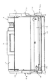
図1は本発明に係る電子写真画像形成装置(以下、画像形成装置という)全体の概略構成を示す縦断面図である。
【0013】
まず、図1を参照して、画像形成装置Aの全体についての概略を説明する。なお、同図に示す画像形成装置Aは4色フルカラーのレーザービームプリンタである。
【0014】
同図に示す画像形成装置Aは、ドラム形状の電子写真感光体(以下「感光体ドラム」という)1を備えている。感光体ドラム1は、後述する駆動手段によって、同図中、反時計回りに回転駆動される。感光体ドラム1の周囲には、その回転方向に従って順に、帯電装置(帯電手段)2、露光装置3、現像装置4、転写装置5、及び、クリーニング装置(クリーニング手段)6等が配設されている。帯電装置2は、感光体ドラム1表面を均一に帯電するものである。露光装置3は、画像情報に基づいてレーザービームを照射し感光体ドラム1上の静電潜像を形成するものである。現像装置4は、感光体ドラム1上に形成された静電潜像にトナー(現像剤)を付着させて該潜像をトナー像として現像するものである。転写装置5は、感光体ドラム1上のトナー像が1次転写されるものである。クリーニング装置6は、1次転写後の感光体ドラム1表面に残った転写残トナーを除去するものである。
【0015】
ここで感光体ドラム1と帯電装置2とトナーを除去するクリーニング装置6は一体的にカートリッジ化されてプロセスカートリッジBを構成している。そして、このプロセスカートリッジBは、画像形成装置Aの電子写真画像形成装置本体A1(以下、装置本体という)に着脱可能となっている。
【0016】
その他に、記録紙、OHPシート、布などの記録媒体Sを転写装置5に向けて給送するとともに、記録媒体Sを搬送する給搬送装置(搬送手段)7を備えている。また、転写装置5による記録媒体Sへの2次転写後のトナー像を該記録媒体Sに定着させる定着装置8も備えている。
【0017】
次に、上記レーザービームプリンタの各部の構成を説明する。
【0018】
(感光体ドラム)
感光体ドラム1は、直径47mmのアルミニウムシリンダー1c(図17(a)参照)の外周面に、有機光導電体層(OPC感光体)を塗布して構成したものである。感光体ドラム1は、その両端部がプロセスカートリッジBの後述する枠体(フレーム)100に回転自在に支持されている(図3参照)。そして、一方の端部に装置本体A1内の駆動モータ(不図示)から駆動力が伝達されることにより、矢印方向に回転駆動される。
【0019】
(帯電装置)
帯電装置2としては、例えば、特開昭63−149669号公報に示すようないわゆる接触帯電方式のものを使用することができる。帯電部材は、ローラ状に形成された導電性ローラ(Cローラ)である。そして、このローラを感光体ドラム1表面に当接させるとともに、このローラに電源(不図示)によって帯電バイアス電圧を印加することにより、感光体ドラム1表面を一様に帯電させるものである。
【0020】
(露光装置)
露光装置3は、ポリゴンミラー3aを有し、このポリゴンミラー3aには、レーザーダイオード(不図示)によって画像信号に対応する画像光が照射される。ポリゴンミラー3aはスキャナーモータ(不図示)によって高速で回転され、反射した画像光を結像レンズ3b、反射ミラー3c等を介して、帯電済の感光体ドラム1表面を選択的に露光して静電潜像を形成するように構成している。
【0021】
(現像装置)
現像装置4は、装置本体A1の有する軸4dを中心に割出回転可能な回転体4Aと、これに搭載された4個の現像器、すなわち、イエロー、マゼンタ、シアン、ブラックの各色のトナーをそれぞれ収納した現像器4Y,4M,4C,4Bkを備えている。感光体ドラム1上の静電潜像の現像時には、その静電潜像に付着すべき色の所定の現像器が現像位置に配置される。すなわち、所定の現像器が回転体4Aの割出回転によって感光体ドラム1に対向した現像位置に止まり、さらにその現像器の現像スリーブ4bが感光体ドラム1に対して微少間隙(300μm程度)をもって対向するように位置決めされる。こうして現像スリーブ4bが位置決めされた後、感光体ドラム1上の静電潜像を現像する。この現像は、次のようにして行う。現像する色に対応する現像器の容器内のトナーを送り機構(不図示)によって塗布ローラ4aへ送り込む。そして、回転する塗布ローラ4a及びトナー規制ブレード4cによって、回転する現像スリーブ4bの外周にトナーを薄層塗布し、かつトナーへ電荷を付与(摩擦帯電)する。この現像スリーブ4bと、静電潜像が形成された感光体ドラム1との間に現像バイアスを印加することにより、静電潜像にトナー像を付着させてトナー像として現像するものである。また、各現像器4Y,4M,4C,4Bkの現像スリーブ4bには、各現像器が現像位置に配置されたときに、装置本体A1に設けられた図示しない各色現像用高圧電源と接続されるようになっており、各色の現像毎に選択的に電圧が印加される。なお、各現像器4Y,4M,4C,4Bkは、回転体4Aに対して個別に、また回転体4Aは装置本体A1に対してそれぞれ着脱可能に構成されている。
【0022】
(転写装置)
転写装置5は、感光体ドラム1から順次に1次転写されて重ねられた複数のトナー像を、一括して記録媒体Sに2次転写するものである。転写装置5は、矢印R5方向に走行する中間転写ベルト5aを備えている。本実施の形態の中間転写ベルト5aは、周長約440mmのベルトであり、駆動ローラ5b、2次転写対向ローラ5c、従動ローラ5dの3本のローラにより掛け渡されている。また、従動ローラ5dに近接して押えローラ5jを備えている。押えローラ5jは、中間転写ベルト5aを感光体ドラム1に押圧する位置と中間転写ベルト5aが感光体ドラム1から離れる位置をとるように後退する。中間転写ベルト5aは駆動ローラ5bの回転によって矢印R5方向に走行する。さらに、中間転写ベルト5aの外側の所定位置には、中間転写ベルト5aの表面に接離可能なクリーニングユニット5eが設けてある。このクリーニングユニット5eは、記録媒体Sにトナー像を一括して2次転写した後に残った中間転写ベルト5a上の転写残トナーを除去するものである。すなわち、このクリーニングユニット5eは帯電ローラ5fを中間転写ベルト5aに当接させてトナーに転写時と逆の電荷を与える。逆の電荷を付与されたトナーは、感光体ドラム1に静電的に付着され、その後、感光体ドラム1用の後述のクリーニング装置6によって回収されるものである。なお、中間転写ベルト5aのクリーニング方法としては、上述の静電クリーニングに限らず、ブレードやファーブラシなどの機械的な方法や、これらを併用したもの等でもよい。
【0023】
(クリーニング装置)
クリーニング装置6は、現像装置4によって感光体ドラム1上のトナーが中間転写ベルト5aに1次転写された後に、1次転写されないで感光体ドラム1表面に残ったいわゆる転写残トナーをクリーニングブレード6a(図3参照)によって除去するものである。このクリーニングブレード6aによって感光体ドラム1表面から除去された除去トナーは、感光体ドラム1の寿命に見合って十分に収納しうる容積のクリーニング容器11内に蓄えられ、プロセスカートリッジBの交換時に取り除かれる。クリーニング容器11は、図3に示すように、除去トナー搬送容器17を複数内蔵しており、これらの除去トナー搬送容器17にはそれぞれ回転自在の除去トナー搬送部材25が設けられている。そして、感光体ドラム1側の除去トナー搬送容器17に蓄えられた除去トナーを除去トナー搬送部材25の回転によって次段の除去トナー搬送容器17に順次搬送するようになっている。なお、除去トナー搬送部材25は後述の除去トナー搬送カップリング20に連結されて回転駆動される。
【0024】
(給搬送装置)
給搬送装置7は、画像形成部へ記録媒体Sを給送するものであり、複数枚の記録媒体Sが収納されて、装置本体A1の下部に装填される給紙カセット7aを備えている。画像形成時にはピックアップ部材7e、搬送ローラ7bが画像形成動作に応じて駆動回転し、給紙カセット7a内の記録媒体Sを1枚ずつ分離給送する。そして、その記録媒体Sをガイド板7cによってガイドし、レジストローラ7dを通り中間転写ベルト5aへと給送するものである。
【0025】
(定着装置)
定着装置8は、記録媒体Sに2次転写された複数のトナー画像を定着させるものであり、図1に示すように、駆動回転する駆動ローラ8aと、これに圧接して記録媒体Sに熱及び圧力を印加する定着ローラ8bとからなる。すなわち、中間転写ベルト5a上のトナーを一括転写させる2次転写ローラ5nを通過した記録媒体Sは定着装置8を通過する際に駆動ローラ8aで搬送されるとともに、定着ローラ8bによって熱及び圧力を印加される。これにより複数色のトナー像が記録媒体S表面に定着される。さらに、この記録媒体Sは図示矢印方向に移動するベルト9aと該ベルト9aに巻掛けられて駆動される排出ローラ9bとからなる排紙装置9により装置本体A1上部の排紙トレイ10上に排出される。
【0026】
(プロセスカートリッジの装置本体への着脱)
次に、プロセスカートリッジの着脱について、図2、図13及び図14を用いて説明する。
【0027】
装置本体A1へのプロセスカートリッジBの装着は、図2に示すように、プロセスカートリッジBを装置本体A1内部へ導くための可動体50によりなされる。可動体50は装置本体A1の中で記録媒体Sの搬送方向と略平行に移動可能に構成されている。そして装置本体A1より引き出された可動体50に対しプロセスカートリッジBは取り外し可能に装着される。
【0028】
詳しくは、プロセスカートリッジBを可動体50に装着する際に、図13及び図14に示すように、可動体50に設けられている第一ガイド面50aに対してプロセスカートリッジBのドラムカップリング19(反対側はサイドカバー14の円筒部14b)が導かれる。これと同時に、可動体50に設けられている第2ガイド面50bに対してプロセスカートリッジBの回転決めダボ11a(反対側は回転決めダボ11b)が導かれる。そして、プロセスカートリッジBの後述するドラムカップリング19(反対側は円筒部14b)と軸方向に並列する円筒形状位置決めボス13a(反対側は円筒形状位置決めボス14a)が第1ガイド面50aの先端に設けられた仮受け部50fに入る(図2参照)。そして、プロセスカートリッジBは該仮受け部50fを中心に時計回りに揺動する。これによりプロセスカートリッジBの回転決めダボ11a(反対側は回転決めダボ11b)は可動体50の第2ガイド面50bの底部に設けられている回転決め部50eに突き当たる。そしてこのダボ11a(11b)が可動体50に設けられているCRG加圧部材(カートリッジ加圧部材)54により加圧されることにより、プロセスカートリッジBの可動体50への装着が完了する。
【0029】
この時、図12に示すプロセスカートリッジBのROM用コネクタ23は可動体50に配置されている不図示のコネクタと連結される。また、ドラムシャッタ18は可動体50に設けられているカム受け部50gにより途中まで開かれる。
【0030】
こうしてプロセスカートリッジBを可動体50に装着した後に、さらに可動体50を装置本体A1側に移動する(図2参照)。可動体50が移動することによってプロセスカートリッジBの円筒形状位置決めボス13a(反対側は円筒形状位置決めボス14a)は装置本体A1内のカートリッジ受け部材(位置決め部材)(以下、CRG受け部材という)55に嵌合する。この時、可動体50の背面に配置されている押圧部51の引っ掛け部51bが装置本体A1の側面に掛かり、該押圧部51の背板51aに対して可動体50が加圧される。これにより、可動体50の前部下端に設けられている突き当て部50dがプロセスカートリッジBの円筒形状位置決めダボ13a(反対側は円筒形状位置決めボス14a)をCRG受け部材55に対して加圧位置決めする。その結果、プロセスカートリッジBの装着位置が装置本体A1に対して決まり、図1に示すように画像形成が可能な状態となる。
【0031】
この時、図2に示す装置本体A1の有するドラム駆動カップリング52、除去トナー搬送駆動カップリング53がプロセスカートリッジBのギアーカバー13に向けて移動する。ドラム駆動カップリング(駆動伝達部材)52はプロセスカートリッジBのドラムカップリング(被駆動伝達部材)19に連結する。そして、除去トナー搬送駆動カップリング53は可動体50に設けられた切り欠き部50cを通って除去トナー搬送カップリング20に連結する。これによりプロセスカートリッジBのドラムカップリング19及び除去トナー搬送カップリング20が駆動可能な状態となる。
【0032】
また、プロセスカートリッジBのレーザシャッタ開閉リブ11cが図1及び図2に示す露光装置3のレーザシャッタ3dを開く。また、プロセスカートリッジBの反駆動側の円筒部14bの中央に設けられた図5に示すドラムアース接点21と、プロセスカートリッジBの帯電装置カバー15に設けられた図6に示す一次バイアス接点22が装置本体A1の不図示の高圧接点と電気的に接続される。また、ドラムシャッタ18が装置本体A1の不図示のシャッタ開閉リブにより完全に開かれる。
【0033】
(画像形成動作)
次に、本実施の形態による画像形成装置Aの画像形成動作について、図1を用いて説明する。
【0034】
中間転写ベルト5aの回転と同期して感光体ドラム1を図1の矢印方向(反時計回り)に回転させ、この感光体ドラム1表面を帯電装置2によって均一に帯電するとともに、露光装置3によってイエロー画像の光照射を行い、感光体ドラム1上にイエローの静電潜像を形成する。この静電潜像形成と同時に現像装置4を駆動してイエローの現像器4Yを現像位置に配置し、感光体ドラム1上の静電潜像にイエロートナーが付着するように感光体ドラム1の帯電極性と同極性でほぼ同電位の電圧を印加して静電潜像にイエローのトナーを付着させて現像する。1次転写ローラ(従動ローラ)5dにトナーと逆極性の電圧を印加して感光体ドラム1上のイエローのトナー像を中間転写ベルト5a上に1次転写する。
【0035】
上述のようにしてイエロートナー像の1次転写が終了すると、次の現像器が回転移動し、感光体ドラム1に対向する現像位置に位置決めされ、イエローの場合と同様にしてマゼンタ、シアン、そしてブラックの各色について、静電潜像の形成、現像、1次転写を順次に行い、中間転写ベルト5a上に4色のトナー像を重ね合わせる。これらトナー像を、給搬送装置7から供給された記録媒体Sに一括して2次転写する。
【0036】
そして2次転写後の記録媒体Sを定着装置8に搬送して、ここで、トナー像の定着を行う。その後、その記録媒体Sを図示矢印方向に移動するベルト9aと該ベルト9aに巻き掛けられて駆動される排出ローラ9bとによって排紙トレイ10上に排出して画像形成を終了するものである。
【0037】
(プロセスカートリッジの枠体構成)
次に、プロセスカートリッジの枠体構成について、図3〜12を用いて説明する。
【0038】
プロセスカートリッジBは、図3に示すように、感光体ドラム1の周りに帯電装置(Cローラ)2とクリーニング装置6とを配設している。そしてこれらを枠体100でもって一体化して装置本体A1の有する前述した可動体(装着手段)50に着脱可能に構成してある。プロセスカートリッジBの枠体100は、クリーニング容器11と、該クリーニング容器11の後端部に超音波により接合される後部容器12と、を備える。さらにクリーニング容器11は、感光体ドラム1及び帯電装置2の長手方向の両端部に延出されたドラム支持部11eと、クリーニング装置6のクリーニングブレード6aを支持するクリーニングブレード支持部11dと、帯電装置2を支持するローラ支持部11fと、を有する。また後部容器12は、プロセスカートリッジBを装置本体A1に着脱する際に操作者が掴むための把手16を有する。そして、図4〜図12に示すように、プロセスカートリッジBの長手方向の駆動側には、クリーニング容器11と後部容器12にわたりギアーカバー(一方のサイドカバー)13が固定されている。また、プロセスカートリッジBの長手方向の反駆動側には、クリーニング容器11と後部容器12にわたり他方のサイドカバー14が固定されている。このギアーカバー13とサイドカバー14には、プロセスカートリッジBを装置本体A1に装着する際のガイドとなる円筒形状位置決めボス(位置決め部)13a,14a及び回転決めダボ11a,11bが設けられている。そして、クリーニング容器11の上部には帯電装置2の長手方向及びその両端部を覆う帯電装置カバー15が取り付けられている。
【0039】
さらに、クリーニング容器11の下部には、感光体ドラム1を装置本体A1の外部へ取り出した場合に感光体ドラム1を外光及び人がふれることから等から保護するため、ドラムシャッター18を回動自在に備える。
【0040】
(プロセスカートリッジの支持手段の詳細構成)
次に、図16を用いてプロセスカートリッジBの中心(感光体ドラム中心)を支持する構成について詳細に述べる。
【0041】
先に述べたように、プロセスカートリッジBの装置本体A1 への装着が完了した後、プロセスカートリッジBの中心はギアーカバー13、サイドカバー14夫々に一体成形された円筒形の円筒形状位置決めボス13a,14aで位置決めされる。これらの円筒形状位置決めボス13a,14aは感光体ドラム1と同軸上に配設されている。
【0042】
駆動側の円筒形状位置決めボス13aは図17(a)に示すドラム支持軸1a1に取り付けられるドラムカップリング19と感光体ドラム1の軸方向に近接して設けられる(図16(b)参照)。すなわち、円筒形状位置決めボス13aはドラムカップリング19と感光体ドラム1の軸線方向に並列している。円筒形状位置決めボス13aの直径D1はドラムカップリング19の直径D2よりもわずかに大きい。この円筒形状位置決めボス13aの長手方向の外側端面13a6の位置は、ギアーカバー13の外側板部131の長手方向の位置と同じか、あるいはそれより内側になっている。一方、ドラムカップリング19の長手方向の外側端面19aの位置は、該外側板部131より外側になる。円筒形状位置決めボス13aの外径D1とドラムカップリング19の外径D2の関係は、D1>D2であり、D1=28mm程度、D2=27.6mm程度である。
【0043】
反駆動側の円筒形状位置決めボス14aは長手方向の外側に円筒形状位置決めボス13aと同心円でわずかに外径の小さい円筒部14bを有する(図16(a)参照)。この円筒形状位置決めボス14aの長手方向の外側端面14a6の位置は、サイドカバー14の外側板部141の長手方向の位置と同じか、あるいはそれより内側になっている。円筒部14bの長手方向の外側端面14b1の位置は、該外側板部141より外側になる。円筒形位置決めボス14aの外径D3と円筒部14bの外径D4はD1=D3、D2=D4という関係にある。
【0044】
図15に示すように、この円筒形状位置決めボス14a(反対側は円筒形状位置決めボス13a)は、プロセスカートリッジBが装置本体A1に装着された状態でCRG受け部材55により支持されている。CRG受け部材55は装置本体A1の不図示のフレーム側板に配置されている。このCRG受け部材55は略半円形状であり、装置本体A1へのプロセスカートリッジBの挿入方向(装置本体A1への可動体50の移動方向)に対して半円内側が対向している。
【0045】
円筒形状位置決めボス14a(13a)は可動体50に設けられた突き当て部50dと対向する位置に第1の受け部14a5(13a5)を有する。この受け部14a5(13a5)には突き当て部50dが約2.0kgf程度の荷重F3で突き当たっている。
【0046】
さらにこの荷重F3の作用をCRG受け部55で受ける位置を限定するために、円筒形状位置決めボス14a(13a)の円周上に第2の受け部14a3(13a3)と、第3の受け部14a4(13a4)と、を設けている。これらの受け部14a3(13a3),14a4(13a4)は円筒形状位置決めボス14a(13a)の円周上において荷重F3を均等に振り分けた位置に配置されている。すなわち、感光体ドラム1の軸線中心Oに直交する荷重F3の作用線l(エル)3に対して第3の受け部14a4(13a4)及び第2の受け部14a3(13a3)がなす角度θ1,θ2が等しくなる(θ1=θ2)位置に配置されている。そして第2の受け部14a3(13a3)と第3の受け部14a4(13a4)はそれぞれCRG受け部材55の内周面55aに当接している。
【0047】
なお、第3の受け部14a4(13a4)は第1の受け部14a5(13a5)を構成する第1の突起14a7(13a7)に設けられている。また、第2の受け部14a3(13a3)は第2の突起14a1(13a1)に設けられている。そして、第1の突起14a7(13a7)と第2の突起14a1(13a1)との間はCRG受け部材55と非接触の凹部14a2(13a2)に形成されている。
【0048】
従って、プロセスカートリッジBは円筒形状位置決めボス13a,14aの円周方向において可動体50の突き当て部50dに当接する第1の受け部14a5(13a5)、装置本体A1のCRG受け部材55に当接する第2の受け部14a3(13a3)及び第3の受け部14a4(13a4)の3点で位置決めされる。これにより、プロセスカートリッジBの円筒形状位置決めボス13a,14aのガタを無くすることができる。
【0049】
また、本実施の形態に係るカラー画像形成装置Aにおいては、4色の現像器4Y,4M,4C,4Bkが回転体4A内で感光体ドラム1に次々と接触するため、現像のたびに感光体ドラム1に荷重(外力)F2が発生する。また、転写装置5の中間転写ベルト5a等は画像形成しない時は感光体ドラム1から離間しているが、感光体ドラム1のトナー像が転写される時には該感光体ドラム1に当接する。この時にも、感光体ドラム1に荷重(外力)F1が発生する。そこで、荷重F1を受けるために、荷重F1の作用線(力線)l(エル)1と対向する第2の受け部14a4(13a4)を円筒形状位置決めボス14a(13a)の円周方向において第1の受け部14a5(13a5)側に延長させている。また、荷重F2は、該荷重F2の作用線(力線)l(エル)2と対向する第1の受け部14a5(13a5)で受けている。
【0050】
従って、円筒形状位置決めボス14a(13a)は、各受け部14a5(13a5),14a4(13a4),14a3(13a3)を下記の角度範囲で精度よく形成すればよい。即ち、第1の受け部14a5(13a5)の角度範囲θ5を5°程度とし、第2の受け部14a4(13a4)の角度範囲θ3を10°程度とし、第3の受け部14a3(13a3)の角度範囲θ4を40°程度とする。そして、これらの各受け部14a5(13a5),14a4(13a4),14a3(13a3)以外の範囲には、CRG受け部材55の内周面55aと非接触となるように0.5mm程度の段差を有する凹部14a2(13a2)を設けている。
【0051】
このように本実施の形態に係るプロセスカートリッジBでは、円筒形状位置決めボス13a,14aが3つの受け部14a5(13a5),14a4(13a4),14a3(13a3)で可動体50及びCRG受け部材55によって支持される。このため、プロセスカートリッジBの感光体ドラム1への現像器4Y,4M,4C,4Bkの切り替えによる衝撃、あるいは転写装置5の中間転写ベルト5aの当接、離間による衝撃によって感光体ドラム1の位置が動くようなことがない。従って、画像形成時に感光体ドラム1の位置がずれ、4色のトナー像が中間転写ベルト5a上で同一の位置に転写されない、いわゆる「色ずれ」という画像不良の発生を防ぐことができる。よって、カラー画像形成装置Aにおいても、画像不良のない画像を出力できる。
【0052】
また、可動体50及びCRG受け部材55が受ける3つの受け部14a5(13a5),14a4(13a4),14a3(13a3)は突起14a7(13a7),突起14a1(13a1)により形成されている。このため、円筒形状位置決めボス13a,14aの強度が向上し、装置本体A1内でのプロセスカートリッジBの支持構造の剛性アップも期待できる。
【0053】
なお、本実施の形態では、円筒形状位置決めボス13a,14aの円周上の3ヶ所に受け部を設けたが、該円筒形状位置決めボス13a,14aの円周上に3ヶ所以上受け部を設けることもできる。
【0054】
(ドラムカップリングの詳細構成)
更に、図17及び図18を用いて、ドラムカップリング19の詳細な構成について説明する。
【0055】
感光体ドラム1はクリーニング容器11のドラム支持部11eに回転自在に支持されている。感光体ドラム1はアルミシリンダー1cの駆動側でドラムフランジ1aが嵌入し、接着、かしめ等の結合方法で固定されている。ドラムフランジ1aの中心にはドラム支持軸1a1の最大径部分1a11が圧入固定またはインサート成形されている。ドラム支持軸1a1は、クリーニング容器11のドラム支持部11dおよびギアーカバー13の円筒形状位置決めボス13aに嵌合している。そして、ドラム支持軸1a1は、ドラム支持部11dおよびギアーカバー13に感光体ドラム1の軸線方向へ脱出しないように固定支持された玉軸受111に嵌入し、この玉軸受111によって回転自在に支持されている。
【0056】
ドラム支持軸1a1の軸先端にはドラムカップリング19が嵌合している。このドラムカップリング19は装置本体A1のドラム駆動カップリング52から回転力を受ける部材である。図17(a)に示すように、このドラム支持軸1a1のDカット部1a3とドラムカップリング19のDカップ穴19cは圧入嵌合されている。そして、ドラム支持軸1a1に設けた円弧部1a12の周方向の溝1a2へドラムカップリング19のDカット穴19cの一部である爪部19dがくい込んでいる。これによりドラムカップリング19がドラム支持軸1a1から抜けないような構成となっている。
【0057】
ドラムカップリング19の装置本体A1側と相対する面19eには、図17(a)及び図18(b)に示すように、感光体ドラム1と同心でドラム駆動カップリング軸80に嵌合する円状の嵌合穴(穴部)19aが形成されている。更に、前記面19eには、該嵌合穴19aを中心にして、円弧形状の駆動伝達用の駆動連結穴(穴部)19bが放射状に6箇所配置されている。そして、前記面19eの各駆動連結穴19b間においてドラム駆動カップリング52から回転力を受ける面19b1はすべて嵌合穴19aの中心に向かっている。
【0058】
装置本体A1のドラム駆動カップリング52は、感光体ドラム1と同心のカップリング軸80にガイド部材81が該カップリング軸80の軸方向に固定されて回転自在に保持されている。このガイド部材81は、前述したCRG受け部材55の内周面55aを不図示の機構手段によって往復運動を行って、プロセスカートリッジBの駆動連結(図17(b)の状態)、解除(図17(a)の状態)を行う。カップリング軸80の先端付近には、ドラム駆動カップリング52が回転方向、軸方向とも固定されている。このドラム駆動カップリング52のドラムカップリング19側と相対する面52cには、図17(a)及び図18(a)に示すように、感光体ドラム1の軸線中心Oを中心に回転力伝達用の駆動連結爪(突起)52bが放射状に6ヶ所配置されている。そして、各駆動連結爪52bにおいてドラムカップリング19の面19b1に駆動を伝達する面19b1は感光体ドラム1の軸線中心0に向かっている。また、カップリング軸80の先端部(突起部)80aはドラム駆動カップリング52の面52cから飛び出ており、その先端面80a1は駆動連結爪52bの先端面52b1とほぼ同一高さである。この先端部80aはプロセスカートリッジBのドラムカップリング19の嵌合穴19aに嵌合する。
【0059】
装置本体A1のドラム駆動カップリング52は、プロセスカートリッジBが装置本体A1に挿入されて、前述の円筒形状位置決めボス14a(13a)がCRG受け部材55に嵌合(図17(a)の状態)した後、感光体ドラム1の軸線方向に移動する。そして、カップリング軸80の先端部80aがプロセスカートリッジBのドラムカップリング19の嵌合穴19aに嵌入すると同時に、駆動連結爪52bが駆動連結穴19bに噛合う。
【0060】
この時、ドラム駆動カップリング52はCRG受け部材55の内周面55aにより固定されているため、安定した回転を得ることができる。また、カップリング軸80の先端部80aはドラムカップリング19の嵌合穴19aに嵌合している。このため、ドラムカップリング19は回転中心が定まって歳差運動しなくなり、感光体ドラム1の振れを防止する。そして、ドラム駆動カップリング52の駆動連結爪52bがドラムカップリング19の嵌合穴19aに噛合って、ドラムカップリング19へのドラム駆動カップリング52の回転力の伝達が可能となる。
【0061】
このように本実施の形態に係るプロセスカートリッジBでは、ドラムカップリング19の回転中心がドラム駆動カップリング52の面52aより突出するカップリング軸80の先端部80aによって位置決めされる。このため、ドラムカップリング19は歳差運動しなくなり、ドラム駆動カップリング52の回転力の伝達ばかりでなく、安定した角速度伝達を行うことができる。これにより画像形成時の感光体ドラム1の振れを防止できる。
【0062】
従って、感光体ドラム1が振れることによっても生じる前述の「色ずれ」という画像不良の発生を防ぐことができ、カラー画像形成装置Aにおいても、画像不良のない画像を出力できる。
【0063】
また、ドラムカップリング19、ドラム駆動カップリング52ともに、ヤング率の高い材質、例えばアルミ等の金属、ガラス繊維が混入された樹脂(強化プラスチック)などを用いることができる。これによって、角速度伝達時のドラムカップリング19及びドラム駆動カップリング52のねじれによる角速度の遅れを少なくすることができ、より安定した角速度伝達が達成できる。
【0064】
【実施例】
実施の形態に併記した。
【0065】
(他の実施の形態)
前述した実施の形態で示したプロセスカートリッジBはカラー画像形成装置に適用した場合を例示したが、本発明のプロセスカートリッジは単色画像、2色画像、あるいは3色画像を形成する画像形成装置に用いられるプロセスカートリッジにも好適に適用することができる。
【0066】
また、電子写真感光体としては、感光体ドラムに限定されることなく、例えば次のものが含まれる。先ず感光体としては光導電体が用いられ、光導電体としては例えばアモルファスシリコン、アモルファスセレン、酸化亜鉛、酸化チタン及び有機光導電体(OPC)等が含まれる。また前記感光体を搭載する形状としては、例えばドラム状またはベルト状のものが用いられており、例えばドラムタイプの感光体にあっては、アルミ合金等のシリンダ上に光導電体を蒸着あるいは塗工等を行ったものである。
【0067】
また帯電装置の構成も、前述した実施の形態では所謂接触帯電方法を用いたが、他の構成として従来から用いられているタングステンワイヤーの三方周囲にアルミ等の金属シールドを施し、前記タングステンワイヤーに高電圧を印加することによって生じた正または負のイオンを感光体ドラムの表面に移動させ、該ドラムの表面を一様に帯電する構成を用いても良いことは当然である。
【0068】
なお、前記帯電装置としては前記ローラ型以外にも、ブレード(帯電ブレード)、バッド型、ブロック型、ロッド型、ワイヤ型等のものであっても良い。
【0069】
また、感光体ドラム1に残存するトナーのクリーニング方法としても、ブレード、ファーブラシ、磁気ブラシなど用いてクリーニング手段を構成しても良い。
【0070】
また、前述したプロセスカートリッジとは、例えば電子写真感光体と、少なくともプロセス手段の1つを備えたものである。従って、そのプロセスカートリッジの態様としては、前述した実施形態のもの以外にも、例えば電子写真感光体と帯電手段とを一体的にカートリッジ化し、装置本体に着脱可能とするもの。電子写真感光体とクリーニング手段とを一体的にカートリッジ化し、装置本体に着脱可能とするもの等がある。
【0071】
即ち、前述したプロセスカートリッジとは、少なくとも帯電手段とクリーニング手段の何れか1つと電子写真感光体とを一体的にカートリッジ化し、このカートリッジを画像形成装置本体に対して着脱可能とするものである。そして、このプロセスカートリッジは、使用者自身が装置本体に着脱することができる。そこで、装置本体のメンテナンスを使用者自身で行うことができる。
【0072】
更に、前述した実施の形態では、電子写真画像形成装置としてレーザービームプリンタを例示したが、本発明はこれに限定する必要はなく、例えば、電子写真複写機、ファクシミリ装置、或いはワードプロセッサ等の電子写真画像形成装置に使用することも当然可能である。
【0073】
【発明の効果】
以上説明したように、本発明に係る電子写真画像形成装置によれば、電子写真画像形成装置の装置本体に電子写真感光体ドラムを精度良く保持させることができ、さらに、画像形成時の電子写真感光体ドラムの振れを抑制することができる。
【図面の簡単な説明】
【図1】本実施形態に係る電子写真画像形成装置の縦断面図である。
【図2】電子写真画像形成装置本体に対してプロセスカートリッジを着脱するときの説明図である。
【図3】プロセスカートリッジの縦断面図である。
【図4】プロセスカートリッジの右側面図である。
【図5】プロセスカートリッジの左側面図である。
【図6】プロセスカートリッジの平面図である。
【図7】プロセスカートリッジの底面図である。
【図8】プロセスカートリッジ正面図である。
【図9】プロセスカートリッジの背面図である。
【図10】プロセスカートリッジの前右上方から見る外観斜視図である。
【図11】プロセスカートリッジの後右上方から見る外観斜視図である。
【図12】プロセスカートリッジを上下を逆にして左後から見る斜視図である。
【図13】プロセスカートリッジを電子写真画像形成装置本体に装着するための可動体の斜視図である。
【図14】プロセスカートリッジを電子写真画像形成装置本体に装着したときの説明図である。
【図15】プロセスカートリッジの円筒形状位置決めボス付近を拡大した縦断面図である。
【図16】プロセスカートリッジの円筒形状位置決めボス付近の斜視図である。
【図17】電子写真画像形成装置本体とプロセスカートリッジのドラム駆動連結部付近の横断面図である。
【図18】(a)は電子写真画像形成装置のドラム駆動カップリングの斜視図である。(b)はプロセスカートリッジのドラムカップリングの斜視図である。
【符号の説明】
1 電子写真感光体
2 帯電装置(帯電手段)
6 クリーニング装置(クリーニング手段)
7 給搬送装置(搬送手段)
13a,14a 円筒形状位置決めボス(位置決め部)
19 ドラムカップリング(被駆動伝達部材)
19a 嵌合穴(電子写真感光体と同心の穴部)
19b 駆動連結穴(駆動伝達用の穴部)
50 可動体(装着手段)
52 ドラム駆動カップリング(駆動伝達部材)
52b 駆動連結爪(突起)
55 CRG受け部材(位置決め部材)
80a 先端部(突起部)
100 枠体(フレーム)
A1 電子写真画像形成装置本体
B プロセスカートリッジ[0001]
BACKGROUND OF THE INVENTION
The present invention relates to electronic image forming apparatus.
[0002]
Here, the electrophotographic image forming apparatus forms an image on a recording medium using an electrophotographic image forming process. Examples of the electrophotographic image forming apparatus include an electrophotographic copying machine, an electrophotographic printer (for example, a laser beam printer, an LED printer, etc.), a facsimile apparatus, a word processor, and the like.
[0003]
The process cartridge is a cartridge in which a charging unit or a cleaning unit and an electrophotographic photosensitive member are integrally formed, and the cartridge can be attached to and detached from the image forming apparatus main body. In addition, this means that at least one of the charging unit and the cleaning unit and the electrophotographic photosensitive member are integrally formed into a cartridge that can be attached to and detached from the image forming apparatus main body.
[0004]
[Prior art]
Conventionally, in an electrophotographic image forming apparatus using an electrophotographic image forming process, the electrophotographic photosensitive member and the process means acting on the electrophotographic photosensitive member are integrally formed into a cartridge, and the cartridge is attached to and detached from the image forming apparatus main body. The cartridge system that enables it is adopted. According to this process cartridge system, the apparatus can be maintained by the user himself / herself without depending on the service person, so that the operability can be remarkably improved. Therefore, this process cartridge system is widely used in electrophotographic image forming apparatuses.
[0005]
[Problems to be solved by the invention]
In such a process cartridge, it is necessary to prevent the electrophotographic photosensitive member from shaking when an image is formed by the image forming apparatus. Therefore, the position of the electrophotographic photosensitive member relative to the image forming apparatus main body is determined by supporting the electrophotographic photosensitive member on the frame and holding the frame on the main body of the image forming apparatus.
[0007]
The present invention is a further development of the above-described prior art, and the main object of the present invention is a process capable of suppressing the shake of the electrophotographic photosensitive member during image formation and holding the electrophotographic photosensitive member with high accuracy. An object of the present invention is to provide an electrophotographic image forming apparatus in which a cartridge can be attached and detached.
[0008]
[Means for Solving the Problems]
A typical configuration of the electrophotographic image forming apparatus according to the present invention for achieving the above object is as follows:
An electrophotographic image forming apparatus for detachably attaching a process cartridge to form an image on a recording medium,
The process cartridge includes an electrophotographic photosensitive drum, process means acting on the electrophotographic photosensitive drum, and a drum support shaft provided on the electrophotographic photosensitive drum for supporting the electrophotographic photosensitive drum. A frame body rotatably supporting the drum support shaft, and a first body provided on the same axis as the electrophotographic photosensitive drum on one end side of the frame body in the axial direction of the electrophotographic photosensitive drum. A cartridge positioning portion, and a second cartridge positioning portion provided on the same axis as the electrophotographic photosensitive drum on the other end side of the frame in the axial direction of the electrophotographic photosensitive drum,
A driven transmission member provided on the drum support shaft for transmitting a driving force from the main body of the electrophotographic image forming apparatus to the electrophotographic photosensitive drum, the positioning hole being concentric with the drum support shaft A driven transmission member having a drive transmission hole through which the driving force is transmitted, and a protrusion that restricts the process cartridge from rotating around the cartridge positioning unit.
In the electrophotographic image forming apparatus,
(i) positioning the process cartridge by engaging with the first cartridge positioning unit and the second cartridge positioning unit when the process cartridge is mounted on the main body of the electrophotographic image forming apparatus; A first positioning portion provided on one end side and the other end side;
(ii) A movable body for detachably mounting the process cartridge, which is movable between a mounting position mounted on the apparatus main body and a pulling position pulled out from the mounting position. A guide surface for guiding the cartridge positioning portion and a temporary receiving portion provided at a tip of the guide surface when the cartridge is mounted on the movable body, wherein the process cartridge is mounted at a position other than the mounting position; In order to temporarily position the movable body, a temporary receiving portion that engages with the cartridge positioning portion, and a rotation restriction that engages with the protruding portion and restricts the process cartridge from rotating about the cartridge positioning portion. And a second positioning portion provided at a lower end of the front portion of the movable body, wherein the first cart A movable body having a ridge positioning part and a second positioning part in contact with the cartridge positioning part to position the second cartridge positioning part in contact with the first positioning part;
(iii) A pressing member provided on the movable body, wherein the first cartridge positioning unit and the second cartridge positioning unit are pressed against the first positioning unit by the second positioning unit at the mounting position. A pressing member that pressurizes the movable body in a direction;
(iv) A main body drive transmission member rotatably supported by the first positioning portion provided on the other end side, and fitted with the positioning hole provided at the rotation center of the main body drive transmission member A main body drive transmission member having a coupling shaft for positioning the driven transmission member, and a drive transmission projection for engaging the drive transmission hole and transmitting the driving force to the driven transmission member When,
(v) transport means for transporting the recording medium;
It is characterized by having.
[0009]
According to the above-described electrophotographic image forming apparatus of the present invention, the electrophotographic photosensitive drum can be accurately held in the main body of the electrophotographic image forming apparatus. The shake can be suppressed.
[0010]
DETAILED DESCRIPTION OF THE INVENTION
[Description of Embodiments of the Invention]
Hereinafter, embodiments of the present invention will be described in detail with reference to the drawings.
[0011]
In the following description, the short direction of the process cartridge B is a direction in which the process cartridge B is attached to and detached from the electrophotographic image forming apparatus main body A1, and coincides with the conveyance direction of the recording medium S. Further, the longitudinal direction of the process cartridge B is a direction (substantially orthogonal direction) that intersects with the direction in which the process cartridge B is attached to and detached from the electrophotographic image forming apparatus main body A1, is parallel to the surface of the recording medium S, and This is a direction that intersects (substantially orthogonal) the conveyance direction of the recording medium S. Further, left and right with respect to the process cartridge B are right or left when the recording medium is viewed from above according to the conveyance direction of the recording medium S.
[0012]
(Overall configuration of electrophotographic image forming apparatus)
FIG. 1 is a longitudinal sectional view showing a schematic configuration of an entire electrophotographic image forming apparatus (hereinafter referred to as an image forming apparatus) according to the present invention.
[0013]
First, an outline of the entire image forming apparatus A will be described with reference to FIG. The image forming apparatus A shown in the figure is a four-color full-color laser beam printer.
[0014]
The image forming apparatus A shown in FIG. 1 includes a drum-shaped electrophotographic photosensitive member (hereinafter referred to as “photosensitive drum”) 1. The
[0015]
Here, the
[0016]
In addition, a recording medium S such as recording paper, an OHP sheet, and cloth is fed toward the transfer device 5, and a feeding / conveying device (conveying means) 7 that conveys the recording medium S is provided. Further, a fixing device 8 for fixing the toner image after the secondary transfer onto the recording medium S by the transfer device 5 to the recording medium S is also provided.
[0017]
Next, the configuration of each part of the laser beam printer will be described.
[0018]
(Photosensitive drum)
The
[0019]
(Charging device)
As the
[0020]
(Exposure equipment)
The
[0021]
(Developer)
The developing
[0022]
(Transfer device)
The transfer device 5 performs a secondary transfer of a plurality of toner images that are sequentially primary-transferred and superposed sequentially from the
[0023]
(Cleaning device)
The
[0024]
(Feeding and conveying device)
The feeding / conveying
[0025]
(Fixing device)
The fixing device 8 fixes a plurality of toner images secondarily transferred to the recording medium S. As shown in FIG. 1, a driving roller 8a that rotates and drives the recording medium S in contact with the driving roller 8a. And a fixing roller 8b for applying pressure. That is, the recording medium S that has passed through the secondary transfer roller 5n that collectively transfers the toner on the intermediate transfer belt 5a is conveyed by the driving roller 8a when passing through the fixing device 8, and heat and pressure are applied by the fixing roller 8b. Applied. As a result, the toner images of a plurality of colors are fixed on the surface of the recording medium S. Further, this recording medium S is discharged onto a
[0026]
(Removal of the process cartridge to the main body)
Next, attachment / detachment of the process cartridge will be described with reference to FIGS.
[0027]
As shown in FIG. 2, the process cartridge B is attached to the apparatus main body A1 by a
[0028]
Specifically, when the process cartridge B is mounted on the
[0029]
At this time, the
[0030]
After the process cartridge B is thus mounted on the
[0031]
At this time, the
[0032]
The laser shutter opening /
[0033]
(Image forming operation)
Next, an image forming operation of the image forming apparatus A according to the present embodiment will be described with reference to FIG.
[0034]
The
[0035]
When the primary transfer of the yellow toner image is completed as described above, the next developing device rotates and is positioned at the developing position facing the
[0036]
Then, the recording medium S after the secondary transfer is conveyed to the fixing device 8 where the toner image is fixed. Thereafter, the recording medium S is discharged onto the
[0037]
(Process cartridge frame structure)
Next, the frame structure of the process cartridge will be described with reference to FIGS.
[0038]
As shown in FIG. 3, the process cartridge B is provided with a charging device (C roller) 2 and a
[0039]
Further, a
[0040]
(Detailed configuration of process cartridge support means)
Next, a configuration for supporting the center of the process cartridge B (photosensitive drum center) will be described in detail with reference to FIG.
[0041]
As described above, after the process cartridge B is completely attached to the apparatus main body A1, the center of the process cartridge B is the cylindrical
[0042]
The drive-side
[0043]
The counter-drive side
[0044]
As shown in FIG. 15, the
[0045]
The
[0046]
Further, in order to limit the position where the action of the load F3 is received by the
[0047]
In addition, the 3rd receiving part 14a4 (13a4) is provided in the 1st protrusion 14a7 (13a7) which comprises the 1st receiving part 14a5 (13a5). The second receiving portion 14a3 (13a3) is provided on the second protrusion 14a1 (13a1). And between the 1st processus | protrusion 14a7 (13a7) and the 2nd processus | protrusion 14a1 (13a1), it forms in the
[0048]
Accordingly, the process cartridge B contacts the first receiving portion 14a5 (13a5) that contacts the butting
[0049]
In the color image forming apparatus A according to the present embodiment, the four
[0050]
Therefore, the
[0051]
Thus, in the process cartridge B according to the present embodiment, the
[0052]
The three receiving portions 14a5 (13a5), 14a4 (13a4), and 14a3 (13a3) received by the
[0053]
In this embodiment, the receiving portions are provided at three locations on the circumference of the
[0054]
(Detailed configuration of drum coupling)
Further, a detailed configuration of the
[0055]
The
[0056]
A
[0057]
As shown in FIGS. 17A and 18B, a
[0058]
In the
[0059]
In the
[0060]
At this time, since the
[0061]
As described above, in the process cartridge B according to the present embodiment, the rotation center of the
[0062]
Therefore, it is possible to prevent the occurrence of the above-mentioned “color misregistration” image defect caused by the shaking of the
[0063]
Further, both the
[0064]
【Example】
This is also shown in the embodiment.
[0065]
(Other embodiments)
Although the process cartridge B shown in the above-described embodiment is applied to a color image forming apparatus, the process cartridge of the present invention is used for an image forming apparatus that forms a single color image, a two color image, or a three color image. The present invention can also be suitably applied to a process cartridge.
[0066]
Further, the electrophotographic photosensitive member is not limited to the photosensitive drum, and includes, for example, the following. First, a photoconductor is used as the photoreceptor, and examples of the photoconductor include amorphous silicon, amorphous selenium, zinc oxide, titanium oxide, and organic photoconductor (OPC). As the shape for mounting the photoconductor, for example, a drum-shaped or belt-shaped one is used. For example, in the case of a drum-type photoconductor, a photoconductor is deposited or coated on a cylinder made of aluminum alloy or the like. It is the one that has been crafted.
[0067]
In addition, the so-called contact charging method is used in the above-described embodiment for the configuration of the charging device. However, as another configuration, a metal shield such as aluminum is provided around the three sides of a tungsten wire that has been conventionally used, and the tungsten wire is applied to the tungsten wire. Of course, it is possible to use a configuration in which positive or negative ions generated by applying a high voltage are moved to the surface of the photosensitive drum and the surface of the drum is uniformly charged.
[0068]
In addition to the roller type, the charging device may be a blade (charging blade), a pad type, a block type, a rod type, a wire type, or the like.
[0069]
Further, as a method for cleaning the toner remaining on the
[0070]
The above-described process cartridge includes, for example, an electrophotographic photosensitive member and at least one process means. Therefore, as an aspect of the process cartridge, in addition to the embodiment described above, for example, an electrophotographic photosensitive member and a charging unit are integrated into a cartridge so that the cartridge can be attached to and detached from the apparatus main body. In some cases, the electrophotographic photosensitive member and the cleaning unit are integrally formed into a cartridge so that the electrophotographic photosensitive member can be attached to and detached from the apparatus main body.
[0071]
That is, the process cartridge described above is a cartridge in which at least one of the charging unit and the cleaning unit and the electrophotographic photosensitive member are integrally formed, and the cartridge can be attached to and detached from the image forming apparatus main body. The process cartridge can be attached to and detached from the apparatus main body by the user. Therefore, maintenance of the apparatus main body can be performed by the user himself.
[0072]
Further, in the above-described embodiment, the laser beam printer is exemplified as the electrophotographic image forming apparatus. However, the present invention is not limited to this. For example, an electrophotographic apparatus such as an electrophotographic copying machine, a facsimile machine, or a word processor. Of course, it can also be used in an image forming apparatus.
[0073]
【The invention's effect】
As described above, according to the engagement Ru electronic imaging apparatus of the present invention, the electrophotographic photosensitive drum can be accurately held to the apparatus main body of an electrophotographic image forming apparatus, further, at the time of image formation runout can suppress Wins Rukoto the electrophotographic photosensitive drum.
[Brief description of the drawings]
FIG. 1 is a longitudinal sectional view of an electrophotographic image forming apparatus according to an embodiment.
FIG. 2 is an explanatory diagram when a process cartridge is attached to and detached from an electrophotographic image forming apparatus main body.
FIG. 3 is a longitudinal sectional view of a process cartridge.
FIG. 4 is a right side view of the process cartridge.
FIG. 5 is a left side view of the process cartridge.
FIG. 6 is a plan view of a process cartridge.
FIG. 7 is a bottom view of the process cartridge.
FIG. 8 is a front view of a process cartridge.
FIG. 9 is a rear view of the process cartridge.
FIG. 10 is an external perspective view of the process cartridge as viewed from the upper front right.
FIG. 11 is an external perspective view of the process cartridge as viewed from the upper right rear side.
FIG. 12 is a perspective view of the process cartridge as viewed from the left rear side upside down.
FIG. 13 is a perspective view of a movable body for mounting the process cartridge to the electrophotographic image forming apparatus main body.
FIG. 14 is an explanatory diagram when the process cartridge is mounted on the electrophotographic image forming apparatus main body.
FIG. 15 is an enlarged longitudinal sectional view of the vicinity of a cylindrical positioning boss of a process cartridge.
FIG. 16 is a perspective view of the vicinity of a cylindrical positioning boss of a process cartridge.
FIG. 17 is a cross-sectional view of the electrophotographic image forming apparatus main body and the vicinity of the drum drive coupling portion of the process cartridge.
FIG. 18A is a perspective view of a drum drive coupling of the electrophotographic image forming apparatus. (B) is a perspective view of a drum coupling of a process cartridge.
[Explanation of symbols]
1
6 Cleaning device (cleaning means)
7 Feeding and conveying device (conveying means)
13a, 14a Cylindrical positioning boss (positioning part)
19 Drum coupling (driven transmission member)
19a Fitting hole (hole concentric with electrophotographic photosensitive member)
19b Drive connecting hole (drive transmission hole)
50 Movable body (mounting means)
52 Drum drive coupling (drive transmission member)
52b Drive coupling claw (protrusion)
55 CRG receiving member (positioning member)
80a Tip (projection)
100 frame
A1 Electrophotographic image forming apparatus main body B Process cartridge
Claims (1)
前記プロセスカートリッジは、電子写真感光体ドラムと、前記電子写真感光体ドラムに作用するプロセス手段と、前記電子写真感光体ドラムに設けられた、前記電子写真感光体ドラムを支持するためのドラム支持軸と、前記ドラム支持軸を回転可能に支持する枠体と、前記電子写真感光体ドラムの軸線方向において前記枠体の一端側で、前記電子写真感光体ドラムと同一軸線上に設けられた第1カートリッジ位置決め部と、前記電子写真感光体ドラムの軸線方向において前記枠体の他端側で、前記電子写真感光体ドラムと同一軸線上に設けられた第2カートリッジ位置決め部と、The process cartridge includes an electrophotographic photosensitive drum, process means acting on the electrophotographic photosensitive drum, and a drum support shaft provided on the electrophotographic photosensitive drum for supporting the electrophotographic photosensitive drum. A frame body rotatably supporting the drum support shaft, and a first body provided on the same axis as the electrophotographic photosensitive drum on one end side of the frame body in the axial direction of the electrophotographic photosensitive drum. A cartridge positioning portion, and a second cartridge positioning portion provided on the same axis as the electrophotographic photosensitive drum on the other end side of the frame in the axial direction of the electrophotographic photosensitive drum,
前記ドラム支持軸に設けられた、前記電子写真感光体ドラムに前記電子写真画像形成装置の装置本体から駆動力を伝達するための被駆動伝達部材であって、前記ドラム支持軸と同心の位置決め穴と、前記駆動力が伝達される駆動伝達用穴と、を有する、被駆動伝達部材と、前記プロセスカートリッジが前記カートリッジ位置決め部を中心に回転するのを規制する突出部と、を有する、A driven transmission member provided on the drum support shaft for transmitting a driving force from the main body of the electrophotographic image forming apparatus to the electrophotographic photosensitive drum, the positioning hole being concentric with the drum support shaft A driven transmission member having a drive transmission hole through which the driving force is transmitted, and a protrusion that restricts the process cartridge from rotating around the cartridge positioning unit.
前記電子写真画像形成装置において、In the electrophotographic image forming apparatus,
(i)(i) 前記プロセスカートリッジが前記電子写真画像形成装置の装置本体に装着された際に、前記第1カートリッジ位置決め部及び前記第2カートリッジ位置決め部と係合して前記プロセスカートリッジの位置決めをおこなう、前記一端側と前記他端側に設けられた第1の位置決め部と、The one end side that engages with the first cartridge positioning unit and the second cartridge positioning unit to position the process cartridge when the process cartridge is mounted on the main body of the electrophotographic image forming apparatus; A first positioning portion provided on the other end side;
(ii)(ii) 前記装置本体に装着された装着位置と、前記装着位置から引き出された引き出し位置との間を移動可能な、前記プロセスカートリッジを取り外し可能に装着するための可動体であって、前記プロセスカートリッジを前記可動体に装着する際に、前記カートリッジ位置決め部をガイドするガイド面と、前記ガイド面の先端に設けられた仮受け部であって、前記装着位置以外の位置において、前記プロセスカートリッジを前記可動体に仮位置決めするために、前記カートリッジ位置決め部と係合する仮受け部と、前記突出部と係合して前記プロセスカートリッジが前記カートリッジ位置決め部を中心に回転するのを規制する回転規制部と、前記可動体の前部下端に設けられた第2の位置決め部であって、前記装着位置において、前記第1カートリッジ位置決め部及び前記第2カートリッジ位置決め部を前記第1の位置決め部に当接させて位置決めするために、前記カートリッジ位置決め部と当接する第2の位置決め部と、を有する可動体と、A movable body for detachably mounting the process cartridge, which is movable between a mounting position mounted on the apparatus main body and a drawing position pulled out from the mounting position, the process cartridge being A guide surface for guiding the cartridge positioning portion when mounted on the movable body, and a temporary receiving portion provided at a tip of the guide surface, wherein the process cartridge is placed at a position other than the mounting position. A temporary receiving portion that engages with the cartridge positioning portion, a rotation restricting portion that engages with the protrusion and restricts the process cartridge from rotating about the cartridge positioning portion, A second positioning portion provided at a front lower end of the movable body, wherein the first cartridge is located at the mounting position; Di positioning portion and said second cartridge positioning portion for positioning is brought into contact with the first positioning portion, and a movable body having a second positioning portion in contact with the cartridge positioning portion equivalent,
(iii)(iii) 前記可動体に設けられた押圧部材であって、前記装着位置において前記第2の位置決め部によって前記第1カートリッジ位置決め部及び前記第2カートリッジ位置決め部を前記第1の位置決め部に加圧する方向に前記可動体を加圧する押圧部材と、A pressing member provided on the movable body, wherein the first cartridge positioning unit and the second cartridge positioning unit are pressed against the first positioning unit by the second positioning unit at the mounting position. A pressing member that pressurizes the movable body;
(iv)(iv) 前記他端側に設けられた前記第The first provided on the other end side 11 の位置決め部に回転可能に支持された本体駆動伝達部材であって、前記本体駆動伝達部材の回転中心に設けられた、前記位置決め穴と嵌合して前記被駆動伝達部材の位置決めをおこなうカップリング軸と、前記駆動伝達用穴係合して前記被駆動伝達部材に前記駆動力を伝達する駆動伝達用突起と、を有する本体駆動伝達部材と、A main body drive transmission member rotatably supported by the positioning portion of the main body drive transmission member, the coupling being provided in the rotation center of the main body drive transmission member and engaging with the positioning hole to position the driven transmission member A main body drive transmission member having a shaft and a drive transmission projection for engaging the drive transmission hole and transmitting the driving force to the driven transmission member;
(v)(v) 前記記録媒体を搬送するための搬送手段と、Conveying means for conveying the recording medium;
を有することを特徴とする電子写真画像形成装置。An electrophotographic image forming apparatus comprising:
Priority Applications (5)
| Application Number | Priority Date | Filing Date | Title |
|---|---|---|---|
| JP32130298A JP3697090B2 (en) | 1998-10-26 | 1998-10-26 | Electrophotographic image forming apparatus |
| EP99308415A EP0997798A3 (en) | 1998-10-26 | 1999-10-25 | Process cartridge and electrophotographic image forming apparatus |
| KR1019990046518A KR100331190B1 (en) | 1998-10-26 | 1999-10-26 | Electrophotographic image forming apparatus and process cartridge detachably mountable thereto comprising a positioning portion for engagement with a positioning member of a main assembly of the image forming apparatus |
| CN99123359A CN1254109A (en) | 1998-10-26 | 1999-10-26 | Cartridge processing and electrographic imaging equipment |
| US09/427,087 US6317572B1 (en) | 1998-10-26 | 1999-10-26 | Electrophotographic image forming apparatus and process cartridge detachably mountable thereto comprising a positioning portion for engagement with a positioning member of a main assembly of the image forming apparatus |
Applications Claiming Priority (1)
| Application Number | Priority Date | Filing Date | Title |
|---|---|---|---|
| JP32130298A JP3697090B2 (en) | 1998-10-26 | 1998-10-26 | Electrophotographic image forming apparatus |
Publications (3)
| Publication Number | Publication Date |
|---|---|
| JP2000132056A JP2000132056A (en) | 2000-05-12 |
| JP2000132056A5 JP2000132056A5 (en) | 2004-11-04 |
| JP3697090B2 true JP3697090B2 (en) | 2005-09-21 |
Family
ID=18131067
Family Applications (1)
| Application Number | Title | Priority Date | Filing Date |
|---|---|---|---|
| JP32130298A Expired - Fee Related JP3697090B2 (en) | 1998-10-26 | 1998-10-26 | Electrophotographic image forming apparatus |
Country Status (5)
| Country | Link |
|---|---|
| US (1) | US6317572B1 (en) |
| EP (1) | EP0997798A3 (en) |
| JP (1) | JP3697090B2 (en) |
| KR (1) | KR100331190B1 (en) |
| CN (1) | CN1254109A (en) |
Families Citing this family (33)
| Publication number | Priority date | Publication date | Assignee | Title |
|---|---|---|---|---|
| JP4046933B2 (en) * | 2000-08-02 | 2008-02-13 | キヤノン株式会社 | Drive transmission device and image forming apparatus having the same |
| JP3658315B2 (en) | 2000-12-19 | 2005-06-08 | キヤノン株式会社 | Process cartridge and electrophotographic image forming apparatus |
| JP4677093B2 (en) | 2000-12-25 | 2011-04-27 | キヤノン株式会社 | Process cartridge |
| JP3840063B2 (en) | 2001-04-27 | 2006-11-01 | キヤノン株式会社 | Process cartridge |
| JP3564080B2 (en) | 2001-04-27 | 2004-09-08 | キヤノン株式会社 | Process cartridge remanufacturing method |
| JP3542569B2 (en) | 2001-04-27 | 2004-07-14 | キヤノン株式会社 | Process cartridge remanufacturing method |
| KR100392628B1 (en) * | 2001-11-26 | 2003-07-25 | 삼성전자주식회사 | coupling apparatus |
| KR100393074B1 (en) * | 2002-01-10 | 2003-07-31 | Samsung Electronics Co Ltd | Method for forming image in electrophotographic printing machine |
| JP2005004178A (en) * | 2003-05-20 | 2005-01-06 | Canon Inc | Process cartridge, electrophotographic image-forming apparatus and method for assembling process cartridge |
| JP4040010B2 (en) * | 2003-10-08 | 2008-01-30 | 株式会社リコー | Electrophotographic toner and image forming process |
| JP4474168B2 (en) * | 2004-01-15 | 2010-06-02 | キヤノン株式会社 | Image forming apparatus |
| JP4110128B2 (en) * | 2004-04-26 | 2008-07-02 | キヤノン株式会社 | Process cartridge, electrophotographic image forming apparatus and bearing member |
| JP2005316192A (en) * | 2004-04-28 | 2005-11-10 | Canon Inc | Electrophotographic image forming apparatus |
| JP4886182B2 (en) * | 2004-09-27 | 2012-02-29 | キヤノン株式会社 | Cartridge, process cartridge, and electrophotographic image forming apparatus |
| JP3950883B2 (en) * | 2004-10-06 | 2007-08-01 | キヤノン株式会社 | Electrophotographic image forming apparatus |
| JP3950882B2 (en) * | 2004-10-06 | 2007-08-01 | キヤノン株式会社 | Electrophotographic image forming apparatus |
| JP4498407B2 (en) | 2006-12-22 | 2010-07-07 | キヤノン株式会社 | Process cartridge, electrophotographic image forming apparatus, and electrophotographic photosensitive drum unit |
| JP4948382B2 (en) | 2006-12-22 | 2012-06-06 | キヤノン株式会社 | Coupling member for mounting photosensitive drum |
| JP5311854B2 (en) * | 2007-03-23 | 2013-10-09 | キヤノン株式会社 | Electrophotographic image forming apparatus, developing device, and coupling member |
| US7711287B2 (en) | 2007-05-15 | 2010-05-04 | Canon Kabushiki Kaisha | Cartridge and electrophotographic image forming apparatus |
| US7742717B2 (en) * | 2007-09-11 | 2010-06-22 | Samsung Electronics Co., Ltd. | Developing device, memory unit thereof, and image forming apparatus |
| JP4558083B2 (en) | 2008-06-20 | 2010-10-06 | キヤノン株式会社 | Cartridge, method for assembling the cartridge, and method for disassembling the cartridge |
| JP5127584B2 (en) * | 2008-06-20 | 2013-01-23 | キヤノン株式会社 | Drum unit and electrophotographic image forming apparatus |
| EP2333620A1 (en) | 2008-09-01 | 2011-06-15 | Canon Kabushiki Kaisha | Developing cartridge, process cartridge, and electrophotographic image forming apparatus |
| JP4663801B2 (en) * | 2008-09-01 | 2011-04-06 | キヤノン株式会社 | Process cartridge and image forming apparatus |
| JP5335329B2 (en) * | 2008-09-01 | 2013-11-06 | キヤノン株式会社 | Image forming apparatus |
| JP5147607B2 (en) * | 2008-09-01 | 2013-02-20 | キヤノン株式会社 | Image forming apparatus |
| US8029284B2 (en) * | 2008-09-29 | 2011-10-04 | Maxillent Ltd. | Implants, tools, and methods for sinus lift and lateral ridge augmentation |
| JP5751779B2 (en) * | 2009-10-30 | 2015-07-22 | キヤノン株式会社 | Developing device, developing cartridge, process cartridge, and image forming apparatus |
| JP6098088B2 (en) * | 2012-09-21 | 2017-03-22 | ブラザー工業株式会社 | Passive member, cartridge, and image forming apparatus |
| JP2015141331A (en) * | 2014-01-29 | 2015-08-03 | 株式会社沖データ | image forming apparatus |
| JP6541340B2 (en) * | 2014-12-03 | 2019-07-10 | キヤノン株式会社 | Image forming device |
| CA3135761C (en) | 2015-02-27 | 2024-03-05 | Canon Kabushiki Kaisha | Drum unit, cartridge and coupling member |
Family Cites Families (39)
| Publication number | Priority date | Publication date | Assignee | Title |
|---|---|---|---|---|
| JPS60149669A (en) | 1984-01-17 | 1985-08-07 | Sumitomo Electric Ind Ltd | Ultraviolet-curing magnetic paint composition |
| DE3631495A1 (en) * | 1985-09-17 | 1987-03-26 | Canon Kk | IMAGE SUPPORT ELEMENT USED WITH AN IMAGE GENERATION DEVICE |
| GB2180795B (en) * | 1985-09-17 | 1990-08-29 | Canon Kk | Image bearing member and driving mechanism therefor |
| US4851960A (en) | 1986-12-15 | 1989-07-25 | Canon Kabushiki Kaisha | Charging device |
| JPS63149669A (en) | 1986-12-15 | 1988-06-22 | Canon Inc | Contact electric charging method |
| GB2239303B (en) * | 1989-12-22 | 1994-01-12 | Xerox Corp | Drive coupling |
| US5128715A (en) * | 1990-03-19 | 1992-07-07 | Fuji Xerox Co., Ltd. | Print cartidge and image forming apparatus employing the same |
| JPH04218067A (en) * | 1990-03-19 | 1992-08-07 | Fuji Xerox Co Ltd | Print cartridge and image forming device provided with the same |
| JPH0424656A (en) * | 1990-05-18 | 1992-01-28 | Fuji Xerox Co Ltd | Driving device for photosensitive drum |
| US5331373A (en) | 1992-03-13 | 1994-07-19 | Canon Kabushiki Kaisha | Image forming apparatus, process cartridge mountable within it and method for attaching photosensitive drum to process cartridge |
| JP3352155B2 (en) | 1992-06-30 | 2002-12-03 | キヤノン株式会社 | Process cartridge and image forming apparatus |
| JP3192484B2 (en) * | 1992-06-30 | 2001-07-30 | キヤノン株式会社 | Process cartridge and image forming apparatus to which this process cartridge can be attached and detached |
| JPH0635320A (en) * | 1992-07-14 | 1994-02-10 | Ricoh Co Ltd | Developing device |
| DE69308966T2 (en) | 1992-09-04 | 1997-08-07 | Canon Kk | Electrophotographic work unit and image forming device with such a work unit |
| JP3285413B2 (en) | 1993-04-28 | 2002-05-27 | キヤノン株式会社 | Photosensitive drum, process cartridge, and image forming apparatus |
| US5463446A (en) | 1993-05-20 | 1995-10-31 | Canon Kabushiki Kaisha | Rotary member a process cartridge and an assembling method for rolling members |
| JP3869868B2 (en) | 1994-04-27 | 2007-01-17 | キヤノン株式会社 | Process cartridge and image forming apparatus |
| JPH0815940A (en) | 1994-04-28 | 1996-01-19 | Canon Inc | Developing frame, process cartridge and image forming device |
| JP2877729B2 (en) | 1994-04-28 | 1999-03-31 | キヤノン株式会社 | Shutter member, process cartridge, and image forming apparatus |
| JP2877728B2 (en) | 1994-04-28 | 1999-03-31 | キヤノン株式会社 | Process cartridge and image forming apparatus |
| JP3052733B2 (en) * | 1994-06-15 | 2000-06-19 | セイコーエプソン株式会社 | Cartridge and image forming apparatus |
| AU3426895A (en) | 1994-10-17 | 1996-05-02 | Canon Kabushiki Kaisha | Toner container, toner container assembling method, process cartridge, and electrophotographic image forming apparatus |
| JP3599411B2 (en) * | 1995-03-27 | 2004-12-08 | キヤノン株式会社 | Process cartridge |
| JP3372719B2 (en) | 1995-07-11 | 2003-02-04 | キヤノン株式会社 | Process cartridge and image forming apparatus |
| US5768658A (en) | 1995-07-21 | 1998-06-16 | Canon Kabushiki Kaisha | Electrode member, developing apparatus, process cartridge and image forming apparatus |
| US5893006A (en) | 1995-07-31 | 1999-04-06 | Canon Kabushiki Kaisha | Process cartridge detectably mountable to image forming apparatus and image forming apparatus using same |
| JP3402860B2 (en) | 1995-07-31 | 2003-05-06 | キヤノン株式会社 | Process cartridge and electrophotographic image forming apparatus |
| JPH0962079A (en) | 1995-08-25 | 1997-03-07 | Canon Inc | Refilling method for process cartridge with toner and process cartridge |
| JPH0990853A (en) * | 1995-09-22 | 1997-04-04 | Canon Inc | Process cartridge and image forming device |
| JP3768632B2 (en) | 1996-02-27 | 2006-04-19 | キヤノン株式会社 | Process cartridge and electrophotographic image forming apparatus |
| JP3332818B2 (en) | 1996-08-29 | 2002-10-07 | キヤノン株式会社 | Process cartridge, electrophotographic image forming apparatus, and connection terminal connection method |
| JPH1069204A (en) * | 1996-08-29 | 1998-03-10 | Canon Inc | Process cartridge and electrophotographic image forming device |
| JP3363751B2 (en) | 1996-08-29 | 2003-01-08 | キヤノン株式会社 | Process cartridge and electrophotographic image forming apparatus |
| JP3323754B2 (en) * | 1996-08-30 | 2002-09-09 | キヤノン株式会社 | Process cartridge and electrophotographic image forming apparatus |
| JP3416485B2 (en) * | 1996-09-30 | 2003-06-16 | キヤノン株式会社 | Developing cartridge and electrophotographic image forming apparatus |
| JPH10222041A (en) | 1996-12-03 | 1998-08-21 | Canon Inc | Process cartridge and electrophotographic image forming device |
| JP3363727B2 (en) | 1996-12-12 | 2003-01-08 | キヤノン株式会社 | Process cartridge, electrophotographic image forming apparatus, process cartridge assembling method, and waste toner container assembling method |
| JP3799125B2 (en) * | 1997-03-28 | 2006-07-19 | キヤノン株式会社 | Electrophotographic image forming apparatus |
| JP3332813B2 (en) | 1997-08-01 | 2002-10-07 | キヤノン株式会社 | Process cartridge and electrophotographic image forming apparatus |
-
1998
- 1998-10-26 JP JP32130298A patent/JP3697090B2/en not_active Expired - Fee Related
-
1999
- 1999-10-25 EP EP99308415A patent/EP0997798A3/en not_active Withdrawn
- 1999-10-26 CN CN99123359A patent/CN1254109A/en active Pending
- 1999-10-26 KR KR1019990046518A patent/KR100331190B1/en not_active IP Right Cessation
- 1999-10-26 US US09/427,087 patent/US6317572B1/en not_active Expired - Lifetime
Also Published As
| Publication number | Publication date |
|---|---|
| EP0997798A3 (en) | 2001-07-18 |
| KR20000029301A (en) | 2000-05-25 |
| EP0997798A2 (en) | 2000-05-03 |
| KR100331190B1 (en) | 2002-04-06 |
| US6317572B1 (en) | 2001-11-13 |
| CN1254109A (en) | 2000-05-24 |
| JP2000132056A (en) | 2000-05-12 |
Similar Documents
| Publication | Publication Date | Title |
|---|---|---|
| JP3697090B2 (en) | Electrophotographic image forming apparatus | |
| JP3684092B2 (en) | Electrophotographic image forming apparatus | |
| JP2004125893A (en) | Developer cartridge, attachment method of one end side cover, attaching method of the other end side cover and electrophotographic image forming apparatus | |
| JP2004125870A (en) | Reproduction method for process cartridge | |
| JP2006106419A (en) | Process cartridge and electrophotographic image forming apparatus | |
| US6181897B1 (en) | Developing apparatus | |
| JP4617197B2 (en) | Electrophotographic photosensitive drum, process cartridge, electrophotographic image forming apparatus, and method of assembling flange of electrophotographic photosensitive drum | |
| JP2000315006A (en) | Developing device, process cartridge, electrophotographic image forming device, and power feed component | |
| JP2003280489A (en) | Image forming apparatus | |
| JP3517475B2 (en) | Image forming device | |
| JPH1130944A (en) | Process cartridge unit and attaching/detaching structure thereof | |
| JP2001194977A (en) | Process cartridge and image forming device | |
| JP2002214869A (en) | Image forming device | |
| JP3768700B2 (en) | Cleaning device and process cartridge | |
| JP3340545B2 (en) | Image forming device | |
| JP4783036B2 (en) | Positioning mechanism for photoreceptor and developing roller and image forming apparatus provided with the same | |
| JPH06250488A (en) | Color image forming device | |
| JP2000132027A (en) | Process cartridge and electrophotographic image forming device | |
| JP3936825B2 (en) | Image forming apparatus | |
| JP2000132028A (en) | Cleaning device, process cartridge and electrophotographic image forming device | |
| JP7363460B2 (en) | Drive transmission structure, developer container and image forming device | |
| JP2000132029A (en) | Process cartrdige and electrophotographic image forming device | |
| JP2000132057A (en) | Process cartridge and electrophotographic image forming device | |
| JP2000112240A (en) | Developing cartridge, image forming device and driven- side driving force transmission member | |
| JP2000132052A (en) | Process cartridge and electrophotographic image forming device |
Legal Events
| Date | Code | Title | Description |
|---|---|---|---|
| A977 | Report on retrieval |
Free format text: JAPANESE INTERMEDIATE CODE: A971007 Effective date: 20050126 |
|
| A131 | Notification of reasons for refusal |
Free format text: JAPANESE INTERMEDIATE CODE: A131 Effective date: 20050215 |
|
| A521 | Request for written amendment filed |
Free format text: JAPANESE INTERMEDIATE CODE: A523 Effective date: 20050414 |
|
| TRDD | Decision of grant or rejection written | ||
| A01 | Written decision to grant a patent or to grant a registration (utility model) |
Free format text: JAPANESE INTERMEDIATE CODE: A01 Effective date: 20050614 |
|
| A61 | First payment of annual fees (during grant procedure) |
Free format text: JAPANESE INTERMEDIATE CODE: A61 Effective date: 20050701 |
|
| R150 | Certificate of patent or registration of utility model |
Free format text: JAPANESE INTERMEDIATE CODE: R150 |
|
| FPAY | Renewal fee payment (event date is renewal date of database) |
Free format text: PAYMENT UNTIL: 20080708 Year of fee payment: 3 |
|
| FPAY | Renewal fee payment (event date is renewal date of database) |
Free format text: PAYMENT UNTIL: 20090708 Year of fee payment: 4 |
|
| FPAY | Renewal fee payment (event date is renewal date of database) |
Free format text: PAYMENT UNTIL: 20090708 Year of fee payment: 4 |
|
| FPAY | Renewal fee payment (event date is renewal date of database) |
Free format text: PAYMENT UNTIL: 20100708 Year of fee payment: 5 |
|
| FPAY | Renewal fee payment (event date is renewal date of database) |
Free format text: PAYMENT UNTIL: 20100708 Year of fee payment: 5 |
|
| FPAY | Renewal fee payment (event date is renewal date of database) |
Free format text: PAYMENT UNTIL: 20110708 Year of fee payment: 6 |
|
| FPAY | Renewal fee payment (event date is renewal date of database) |
Free format text: PAYMENT UNTIL: 20120708 Year of fee payment: 7 |
|
| LAPS | Cancellation because of no payment of annual fees |