JP3869868B2 - Process cartridge and image forming apparatus - Google Patents
Process cartridge and image forming apparatus Download PDFInfo
- Publication number
- JP3869868B2 JP3869868B2 JP09364395A JP9364395A JP3869868B2 JP 3869868 B2 JP3869868 B2 JP 3869868B2 JP 09364395 A JP09364395 A JP 09364395A JP 9364395 A JP9364395 A JP 9364395A JP 3869868 B2 JP3869868 B2 JP 3869868B2
- Authority
- JP
- Japan
- Prior art keywords
- main body
- contact
- process cartridge
- apparatus main
- photosensitive drum
- Prior art date
- Legal status (The legal status is an assumption and is not a legal conclusion. Google has not performed a legal analysis and makes no representation as to the accuracy of the status listed.)
- Expired - Fee Related
Links
Images


Classifications
-
- G—PHYSICS
- G03—PHOTOGRAPHY; CINEMATOGRAPHY; ANALOGOUS TECHNIQUES USING WAVES OTHER THAN OPTICAL WAVES; ELECTROGRAPHY; HOLOGRAPHY
- G03G—ELECTROGRAPHY; ELECTROPHOTOGRAPHY; MAGNETOGRAPHY
- G03G21/00—Arrangements not provided for by groups G03G13/00 - G03G19/00, e.g. cleaning, elimination of residual charge
- G03G21/16—Mechanical means for facilitating the maintenance of the apparatus, e.g. modular arrangements
- G03G21/18—Mechanical means for facilitating the maintenance of the apparatus, e.g. modular arrangements using a processing cartridge, whereby the process cartridge comprises at least two image processing means in a single unit
- G03G21/1803—Arrangements or disposition of the complete process cartridge or parts thereof
- G03G21/1817—Arrangements or disposition of the complete process cartridge or parts thereof having a submodular arrangement
- G03G21/1825—Pivotable subunit connection
-
- G—PHYSICS
- G03—PHOTOGRAPHY; CINEMATOGRAPHY; ANALOGOUS TECHNIQUES USING WAVES OTHER THAN OPTICAL WAVES; ELECTROGRAPHY; HOLOGRAPHY
- G03G—ELECTROGRAPHY; ELECTROPHOTOGRAPHY; MAGNETOGRAPHY
- G03G21/00—Arrangements not provided for by groups G03G13/00 - G03G19/00, e.g. cleaning, elimination of residual charge
- G03G21/16—Mechanical means for facilitating the maintenance of the apparatus, e.g. modular arrangements
- G03G21/1642—Mechanical means for facilitating the maintenance of the apparatus, e.g. modular arrangements for connecting the different parts of the apparatus
- G03G21/1647—Mechanical connection means
-
- G—PHYSICS
- G03—PHOTOGRAPHY; CINEMATOGRAPHY; ANALOGOUS TECHNIQUES USING WAVES OTHER THAN OPTICAL WAVES; ELECTROGRAPHY; HOLOGRAPHY
- G03G—ELECTROGRAPHY; ELECTROPHOTOGRAPHY; MAGNETOGRAPHY
- G03G21/00—Arrangements not provided for by groups G03G13/00 - G03G19/00, e.g. cleaning, elimination of residual charge
- G03G21/16—Mechanical means for facilitating the maintenance of the apparatus, e.g. modular arrangements
- G03G21/1642—Mechanical means for facilitating the maintenance of the apparatus, e.g. modular arrangements for connecting the different parts of the apparatus
- G03G21/1652—Electrical connection means
-
- G—PHYSICS
- G03—PHOTOGRAPHY; CINEMATOGRAPHY; ANALOGOUS TECHNIQUES USING WAVES OTHER THAN OPTICAL WAVES; ELECTROGRAPHY; HOLOGRAPHY
- G03G—ELECTROGRAPHY; ELECTROPHOTOGRAPHY; MAGNETOGRAPHY
- G03G21/00—Arrangements not provided for by groups G03G13/00 - G03G19/00, e.g. cleaning, elimination of residual charge
- G03G21/16—Mechanical means for facilitating the maintenance of the apparatus, e.g. modular arrangements
- G03G21/18—Mechanical means for facilitating the maintenance of the apparatus, e.g. modular arrangements using a processing cartridge, whereby the process cartridge comprises at least two image processing means in a single unit
- G03G21/1839—Means for handling the process cartridge in the apparatus body
- G03G21/1842—Means for handling the process cartridge in the apparatus body for guiding and mounting the process cartridge, positioning, alignment, locks
- G03G21/1853—Means for handling the process cartridge in the apparatus body for guiding and mounting the process cartridge, positioning, alignment, locks the process cartridge being mounted perpendicular to the axis of the photosensitive member
-
- G—PHYSICS
- G03—PHOTOGRAPHY; CINEMATOGRAPHY; ANALOGOUS TECHNIQUES USING WAVES OTHER THAN OPTICAL WAVES; ELECTROGRAPHY; HOLOGRAPHY
- G03G—ELECTROGRAPHY; ELECTROPHOTOGRAPHY; MAGNETOGRAPHY
- G03G21/00—Arrangements not provided for by groups G03G13/00 - G03G19/00, e.g. cleaning, elimination of residual charge
- G03G21/16—Mechanical means for facilitating the maintenance of the apparatus, e.g. modular arrangements
- G03G21/18—Mechanical means for facilitating the maintenance of the apparatus, e.g. modular arrangements using a processing cartridge, whereby the process cartridge comprises at least two image processing means in a single unit
- G03G21/1839—Means for handling the process cartridge in the apparatus body
- G03G21/1867—Means for handling the process cartridge in the apparatus body for electrically connecting the process cartridge to the apparatus, electrical connectors, power supply
-
- G—PHYSICS
- G03—PHOTOGRAPHY; CINEMATOGRAPHY; ANALOGOUS TECHNIQUES USING WAVES OTHER THAN OPTICAL WAVES; ELECTROGRAPHY; HOLOGRAPHY
- G03G—ELECTROGRAPHY; ELECTROPHOTOGRAPHY; MAGNETOGRAPHY
- G03G21/00—Arrangements not provided for by groups G03G13/00 - G03G19/00, e.g. cleaning, elimination of residual charge
- G03G21/16—Mechanical means for facilitating the maintenance of the apparatus, e.g. modular arrangements
- G03G21/18—Mechanical means for facilitating the maintenance of the apparatus, e.g. modular arrangements using a processing cartridge, whereby the process cartridge comprises at least two image processing means in a single unit
- G03G21/1875—Mechanical means for facilitating the maintenance of the apparatus, e.g. modular arrangements using a processing cartridge, whereby the process cartridge comprises at least two image processing means in a single unit provided with identifying means or means for storing process- or use parameters, e.g. lifetime of the cartridge
-
- G—PHYSICS
- G03—PHOTOGRAPHY; CINEMATOGRAPHY; ANALOGOUS TECHNIQUES USING WAVES OTHER THAN OPTICAL WAVES; ELECTROGRAPHY; HOLOGRAPHY
- G03G—ELECTROGRAPHY; ELECTROPHOTOGRAPHY; MAGNETOGRAPHY
- G03G2215/00—Apparatus for electrophotographic processes
- G03G2215/02—Arrangements for laying down a uniform charge
- G03G2215/021—Arrangements for laying down a uniform charge by contact, friction or induction
-
- G—PHYSICS
- G03—PHOTOGRAPHY; CINEMATOGRAPHY; ANALOGOUS TECHNIQUES USING WAVES OTHER THAN OPTICAL WAVES; ELECTROGRAPHY; HOLOGRAPHY
- G03G—ELECTROGRAPHY; ELECTROPHOTOGRAPHY; MAGNETOGRAPHY
- G03G2221/00—Processes not provided for by group G03G2215/00, e.g. cleaning or residual charge elimination
- G03G2221/16—Mechanical means for facilitating the maintenance of the apparatus, e.g. modular arrangements and complete machine concepts
- G03G2221/1651—Mechanical means for facilitating the maintenance of the apparatus, e.g. modular arrangements and complete machine concepts for connecting the different parts
- G03G2221/1657—Mechanical means for facilitating the maintenance of the apparatus, e.g. modular arrangements and complete machine concepts for connecting the different parts transmitting mechanical drive power
-
- G—PHYSICS
- G03—PHOTOGRAPHY; CINEMATOGRAPHY; ANALOGOUS TECHNIQUES USING WAVES OTHER THAN OPTICAL WAVES; ELECTROGRAPHY; HOLOGRAPHY
- G03G—ELECTROGRAPHY; ELECTROPHOTOGRAPHY; MAGNETOGRAPHY
- G03G2221/00—Processes not provided for by group G03G2215/00, e.g. cleaning or residual charge elimination
- G03G2221/16—Mechanical means for facilitating the maintenance of the apparatus, e.g. modular arrangements and complete machine concepts
- G03G2221/1651—Mechanical means for facilitating the maintenance of the apparatus, e.g. modular arrangements and complete machine concepts for connecting the different parts
- G03G2221/166—Electrical connectors
-
- G—PHYSICS
- G03—PHOTOGRAPHY; CINEMATOGRAPHY; ANALOGOUS TECHNIQUES USING WAVES OTHER THAN OPTICAL WAVES; ELECTROGRAPHY; HOLOGRAPHY
- G03G—ELECTROGRAPHY; ELECTROPHOTOGRAPHY; MAGNETOGRAPHY
- G03G2221/00—Processes not provided for by group G03G2215/00, e.g. cleaning or residual charge elimination
- G03G2221/16—Mechanical means for facilitating the maintenance of the apparatus, e.g. modular arrangements and complete machine concepts
- G03G2221/18—Cartridge systems
- G03G2221/183—Process cartridge
- G03G2221/1846—Process cartridge using a handle for carrying or pulling out of the main machine
-
- G—PHYSICS
- G03—PHOTOGRAPHY; CINEMATOGRAPHY; ANALOGOUS TECHNIQUES USING WAVES OTHER THAN OPTICAL WAVES; ELECTROGRAPHY; HOLOGRAPHY
- G03G—ELECTROGRAPHY; ELECTROPHOTOGRAPHY; MAGNETOGRAPHY
- G03G2221/00—Processes not provided for by group G03G2215/00, e.g. cleaning or residual charge elimination
- G03G2221/16—Mechanical means for facilitating the maintenance of the apparatus, e.g. modular arrangements and complete machine concepts
- G03G2221/18—Cartridge systems
- G03G2221/183—Process cartridge
- G03G2221/1884—Projections on process cartridge for guiding mounting thereof in main machine
-
- G—PHYSICS
- G03—PHOTOGRAPHY; CINEMATOGRAPHY; ANALOGOUS TECHNIQUES USING WAVES OTHER THAN OPTICAL WAVES; ELECTROGRAPHY; HOLOGRAPHY
- G03G—ELECTROGRAPHY; ELECTROPHOTOGRAPHY; MAGNETOGRAPHY
- G03G2221/00—Processes not provided for by group G03G2215/00, e.g. cleaning or residual charge elimination
- G03G2221/16—Mechanical means for facilitating the maintenance of the apparatus, e.g. modular arrangements and complete machine concepts
- G03G2221/18—Cartridge systems
- G03G2221/183—Process cartridge
- G03G2221/1892—Presence detection
Landscapes
- Physics & Mathematics (AREA)
- General Physics & Mathematics (AREA)
- Engineering & Computer Science (AREA)
- Computer Vision & Pattern Recognition (AREA)
- Electrophotography Configuration And Component (AREA)
- Dry Development In Electrophotography (AREA)
Description
【0001】
【産業上の利用分野】
本発明は、プロセスカートリッジ及び前記プロセスカートリッジを着脱可能な画像形成装置に関する。
【0002】
ここで画像形成装置としては、例えば電子写真複写機、電子写真プリンター(例えば、LEDプリンター、レーザービームプリンター等)、電子写真ファクシミリ装置、及び、電子写真ワードプロセッサー等が含まれる。
【0003】
またプロセスカートリッジとしては、帯電手段、現像手段及びクリーニング手段と電子写真感光体とを一体的にカートリッジ化し、このカートリッジを画像形成装置本体に対して着脱可能とするものである。
【0004】
【従来の技術】
従来、電子写真画像形成プロセスを用いた画像形成装置においては、電子写真感光体及び前記電子写真感光体に作用するプロセス手段を一体的にカートリッジ化して、このカートリッジを画像形成装置本体に着脱可能とするプロセスカートリッジ方式が採用されている。このプロセスカートリッジ方式によれば、装置のメンテナンスをサービスマンによらずにユーザー自身で行うことができるので、格段に操作性を向上させることができた。そこでこのプロセスカートリッジ方式は、画像形成装置において広く用いられている。
【0005】
一方、このプロセスカートリッジ方式において、プロセスカートリッジを画像形成装置本体に着脱するにあたって、その操作性を容易にすることが望まれている。
【0006】
またさらに、プロセスカートリッジを画像形成装置本体に装着した際に、プロセスカートリッジと画像形成装置本体との電気的接続をより一層確実に、また、より一層精度良く行うことが望まれている。
【0007】
これらを実現したものとして、例えば特開平02−163761号公開公報(1990年6月25日公開)に記載されている技術が知られている。この公報に記載されている技術は、プロセスカートリッジのフレームの側面に、帯電器と接続している接点、帯電グリッドと接続しているグリッド接点、感光ドラムと接続しているドラムアース板、現像器と接続しているバイアス接点、及び、アンテナと接続しているアンテナ接点を設けている。
【0008】
これらの技術は、プロセスカートリッジの電気的接続に関して、非常に有効なものである。
【0009】
【発明が解決しようとする課題】
本発明は、前述技術をさらに発展させたものである。
【0010】
本発明の目的は、プロセスカートリッジを画像形成装置本体に装着した際に、プロセスカートリッジと画像形成装置本体との電気的接続をより一層確実に、また、より一層精度良く行うことのできるプロセスカートリッジ、及び、画像形成装置を提供することにある。
【0011】
本発明の他の目的は、本体との電気的接続を確実に行うことによって、画像形成品質を向上させることのできるプロセスカートリッジ、及び、画像形成装置を提供することにある。
【0012】
本発明の他の目的は、プロセスカートリッジの装着操作性を向上させるとともに、プロセスカートリッジと装置本体との電気的接続をより一層精度良く行うことのできるプロセスカートリッジ、及び、画像形成装置を提供することにある。
【0013】
【課題を解決するための手段】
前記課題を解決するための本発明に係る代表的な構成は、
電子写真画像形成装置本体に着脱可能なプロセスカートリッジにおいて、
第一枠体に設けられた電子写真感光体ドラムと、
前記電子写真感光体ドラムを前記第一枠体に支持するドラム軸と、
前記第一枠体に設けられた、前記電子写真感光体ドラムに帯電を行うための帯電ローラと、
前記第一枠体と回動可能に結合している第二枠体に設けられたトナーを用いて、前記電子写真感光体ドラムに形成された静電潜像を現像するための現像ローラと、
前記電子写真感光体ドラムの軸線方向において一端側に設けられた前記第一枠体の側面部において露出した状態で設けられた、前記プロセスカートリッジが前記装置本体に装着された際に、前記装置本体に設けられた本体アース接点と接続して、前記装置本体との間で前記電子写真感光体ドラムのアースを取るためのアース接点であって、前記ドラム軸の先端に位置するアース接点と、前記一端側に設けられた前記第一枠体の側面部において露出した状態で設けられた、前記プロセスカートリッジが前記装置本体に装着された際に、前記装置本体に設けられた本体帯電バイアス接点と接続して、前記装置本体から前記帯電ローラに印加する帯電バイアスを受けるための帯電バイアス接点と、
前記一端側に設けられた前記第二枠体の側面部において露出した状態で設けられた、前記プロセスカートリッジが前記装置本体に装着された際に、前記装置本体に設けられた本体現像バイアス接点と接続して、前記装置本体から前記現像ローラに印加する現像バイアスを受けるための現像バイアス接点と、
前記一端側に設けられた前記第二枠体の側面部において露出した状態で設けられた、前記プロセスカートリッジが前記装置本体に装着された際に、前記装置本体に設けられた本体被検出接点と接続して、前記プロセスカートリッジが前記装置本体に装着されたことを前記装置本体に伝達するための被検出接点と、
前記一端側に設けられた、プロセスカートリッジが前記電子写真画像形成装置本体に装着された際に、前記電子写真感光体ドラムを回転させるための駆動力を前記電子写真画像形成装置本体から受けるためのはす歯ギアと、
前記軸線方向において他端側に設けられた、前記プロセスカートリッジが前記装置本体に装着された際に、前記装置本体に設けられた転写ローラを回転させるための駆動力を前記転写ローラへ伝達するための平歯ギアと、
前記プロセスカートリッジは、前記電子写真感光体ドラムの軸線方向と交差する方向から前記装置本体に装着されるものであって、前記プロセスカートリッジが前記装置本体に装着された際に、前記帯電ローラは前記電子写真感光体ドラムの上側に配置されており、そして、前記帯電バイアス接点は前記アース接点よりも上方に配置されており、そして、前記装着方向において、前記現像ローラは前記電子写真感光体ドラムの上流側に配置されており、そして、前記装着方向において、下流側に前記アース接点、その上流側に現像バイアス接点、更にその上流側に被検出接点が配置されており、前記装置本体に設けられているばねの弾性力によって、前記アース接点が前記本体アース接点と接続するように、現像バイアス接点が前記本体現像バイアス接点と接続するように、前記帯電バイアス接点が前記本体帯電バイアス接点と接続するように、及び、前記被検出接点が前記本体被検出接点と接続するように、前記他端側から前記一端側に向って、弾性的に付勢されることを特徴とするプロセスカートリッジである。
【0014】
またさらに、前記目的を達成するための別の本発明に係る代表的な構成は、プロセスカートリッジを着脱可能であって、記録媒体に画像を形成するための画像形成装置において、
(a)本体アース接点と、
(b)本体現像バイアス接点と、
(c)本体帯電バイアス接点と、
(d)本体被検出接点と、
(e)第一枠体に設けられた、電子写真感光体ドラムと、
前記電子写真感光体ドラムを前記第一枠体に支持するドラム軸と、
前記第一枠体に設けられた、前記電子写真感光体ドラムに帯電を行うための帯電ローラと、
前記第一枠体と回動可能に結合している第二枠体に設けられた、トナーを用いて、前記電子写真感光体ドラムに形成された静電潜像を現像するための現像ローラと、
前記電子写真感光体ドラムの軸線方向において一端側に設けられた前記第一枠体の側面部において露出した状態で設けられた、前記プロセスカートリッジが前記装置本体に装着された際に、前記本体アース接点と接続して、前記装置本体との間で前記電子写真感光体ドラムのアースを取るためのアース接点であって、前記ドラム軸の先端に位置するアース接点と、
前記一端側に設けられた前記第一枠体の側面部において露出した状態で設けられた、前記プロセスカートリッジが前記装置本体に装着された際に、前記本体帯電バイアス接点と接続して、前記装置本体から前記帯電ローラに印加する帯電バイアスを受けるための帯電バイアス接点と、
前記一端側に設けられた前記第二枠体の側面部において露出した状態で設けられた、前記プロセスカートリッジが前記装置本体に装着された際に、前記本体現像バイアス接点と接続して、前記装置本体から前記現像ローラに印加する現像バイアスを受けるための現像バイアス接点と、
前記一端側に設けられた前記第二枠体の側面部において露出した状態で
設けられた、前記プロセスカートリッジが前記装置本体に装着された際に、前記本体被検出接点と接続して、前記プロセスカートリッジが前記装置本体に装着されたことを前記装置本体に伝達するための被検出接点と、
前記一端側に設けられた、プロセスカートリッジが前記電子写真画像形成装置本体に装着された際に、前記電子写真感光体ドラムを回転させるための駆動力を前記電子写真画像形成装置本体から受けるためのはす歯ギアと、
前記軸線方向において他端側に設けられた、前記プロセスカートリッジが前記装置本体に装着された際に、前記装置本体に設けられた転写ローラを回転させるための駆動力を前記転写ローラへ伝達するための平歯ギアと、
前記プロセスカートリッジは、前記電子写真感光体ドラムの軸線方向と交差する方向から前記装置本体に装着されるものであって、前記プロセスカートリッジが前記装置本体に装着された際に、前記帯電ローラは前記電子写真感光体ドラムの上側に配置されており、そして、前記帯電バイアス接点は前記アース接点よりも上方に配置されており、そして、前記装着方向において、前記現像ローラは前記電子写真感光体ドラムの上流側に配置されており、そして、前記装着方向において、下流側に前記アース接点、その上流側に現像バイアス接点、更にその上流側に被検出接点が配置されているプロセスカートリッジを取り外し可能に装着するための装着手段と、
前記プロセスカートリッジを、前記アース接点が前記本体アース接点と接続するように、前記現像バイアス接点が前記本体現像バイアス接点と接続するように、及び、前記被検出接点が前記本体被検出接点と接続するように、前記他端側から前記一端側に向って、弾性的に付勢するばねと、
を有することを特徴とする画像形成装置である。
【0015】
【作用】
前記構成にあっては、プロセスカートリッジの同一側面側に各電気接点が設けてあるので、電気接点の取付け位置の精度を向上させることができる。
【0016】
【実施例】
次に本発明の好適な実施例について説明する。図1は本発明の一実施例を適用した電子写真画像形成装置の構成説明図、図2はその外観斜視図である。また図3〜図8は本発明の一実施例を適用したプロセスカートリッジに関する図面である。図3はプロセスカートリッジの側断面図、図4はその外観の概略を図示した外観斜視図、図5はその右側面図、図6はその左側面図、図7はそれを上方から見た斜視図、図8はそれを下方から見た斜視図である。
【0017】
(電子写真画像形成装置A及びプロセスカートリッジB)
まず、図1及び図2を用いて、本発明の一実施例を適用する電子写真画像形成装置Aについて説明する。また図3にプロセスカートリッジBの側断面図を示す。
【0018】
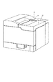
この電子写真画像形成装置Aは、図1に示すように、電子写真画像形成プロセスによって記録媒体に画像を形成するものである。そしてドラム形状の電子写真感光体(以下、感光体ドラムと称す)にトナー像を形成する。そして前記トナー像の形成と同期して、カセット3aにセットした記録媒体2をピックアップローラ3b、搬送ローラ対3c、3d及びレジストローラ対3e等からなる搬送手段3で反転搬送する。次いで、プロセスカートリッジBの有する前記感光体ドラムに形成したトナー像を転写手段としての転写ローラ4に電圧を印加することによって記録媒体2に転写する。その後トナー像の転写を受けた記録媒体2をガイド3fで定着手段5へと搬送する。この定着手段5は駆動ローラ5c及びヒータ5aを内蔵する定着ローラ5bを有する。そして通過する記録媒体2に熱及び圧力を印加して転写されたトナー像を定着する。そしてこの記録媒体2を排出ローラ対3g、3h、3iで搬送し、反転経路3jを通して排出トレイ6へと排出する。この排出トレイ6は装置本体Aの上面に設けられている。尚、揺動可能なフラッパ3kを動作させ、排出ローラ対3mによって反転経路3jを介することなる、記録媒体2を排出することもできる。
【0019】
一方、前記プロセスカートリッジBは、図3乃至図8に示すように、像担持体としての感光層7e(図26)を有する感光体ドラム7を回転し、その表面を帯電手段である帯電ローラ8への電圧印加によって一様に帯電する。次いで光学系1からの画像情報に応じたレーザービーム光を露光開口部9を介して感光体ドラムへ照射して潜像を形成する。そしてこの潜像をトナーを用いて現像手段9によって現像する。すなわち、帯電ローラ8は感光体ドラム7に接触して設けられており、感光体ドラム7に帯電を行う。なおこの帯電ローラ8は、感光体ドラム7に従動回転する。また、現像手段9は、感光体ドラム7の現像領域へトナーを供給して、感光体ドラム7に形成された潜像を現像する。なお光学系1は、レーザーダイオード1a、ポリゴンミラー1b、レンズ1c、反射ミラー1dを有している。
【0020】
ここで、前記現像手段9は、トナー容器11a内のトナーをトナー送り部材9bの回転によって、現像ローラ9cへ送り出す。そして、固定磁石を内蔵した現像ローラ9cを回転させると共に、現像ブレード9dによって摩擦帯電電荷を付与したトナー層を現像ローラ9bの表面に形成し、そのトナーを感光体ドラム7の現像領域へ供給する。そして、そのトナーを前記潜像に応じて感光体ドラム7へ転移させることによってトナー像を形成して可視像化する。ここで現像ブレード9dは、現像ローラ9bの周面のトナー量を規定するものである。またこの現像ローラ9cの近傍には、現像室内のトナーを循環させる撹拌部材9eを回動可能に取付けている。
【0021】
そして転写ローラ4に前記トナー像と逆極性の電圧を印加して、感光体ドラム7に形成されたトナー像を記録媒体2に転写した後に、クリーニング手段10によって感光体ドラム7上の残留トナーを除去する。ここでクリーニング手段10は、弾性クリーニングブレード10aによって感光体ドラム7に残留したトナーを掻き落として廃トナー溜め10bへ集める。
【0022】
尚、プロセスカートリッジBは、トナーを収納するトナー容器11aを有するトナー枠体11と現像ローラ9c等の現像手段を保持する現像枠体12とを結合する。そしてこれに感光体ドラム7及びクリーニングブレード10a等を保持するクリーニング枠体13を結合して構成している。そしてこのプロセスカートリッジBを装置本体Aに着脱可能に装着するものである。
【0023】
このプロセスカートリッジBには画像情報に応じた光を感光体ドラム7へ照射するための露光開口部9及び感光体ドラム7を記録媒体2に対向するための転写開口部15が設けてある。
【0024】
次に本実施例に係るプロセスカートリッジBのハウジングの構成について説明する。
【0025】
本実施例プロセスカートリッジBは、トナー枠体11と現像枠体12とを結合し、これにクリーニング枠体13を回動可能に結合して構成したハウジング内に前記感光体ドラム7、帯電ローラ8、現像手段9及びクリーニング手段10等を収納してカートリッジ化したものである。そして、このプロセスカートリッジBを装置本体14に設けたカートリッジ装着手段に対して取り外し可能に装着する。
【0026】
(プロセスカートリッジBのハウジングの構成)
本実施例に係るプロセスカートリッジBは、前述したようにトナー容器11と現像枠体12及びクリーニング枠体13を結合してハウジングを構成しているが、次にその構成について説明する。
【0027】
図3及び図9に示すように、トナー枠体11にはトナー収納容器9aを形成し、また、トナー送り部材9bを取り付けている。また現像枠体12には現像ローラ9c及び現像ブレード9dを取り付け、更に前記現像ローラ9cの近傍には現像室内のトナーを循環させる攪拌部材9eを回動可能に取り付けている。そして前記トナー容器11と現像枠体12を溶着(本実施例では超音波溶着)して一体的な第二枠体としての現像ユニットD(図9(b)参照)を構成している。
【0028】
また、クリーニング枠体13には感光体ドラム7、帯電ローラ8及びクリーニング手段11の各部材を取り付けている。更にプロセスカートリッジBを装置本体Aから取り外したときに感光体ドラム7を覆い、これを保護するドラムシャッタ部材18を取り付けて第一枠体としてのクリーニングユニットC(図9(a)参照)を構成している。
【0029】
そして、上記現像ユニットDと上記クリーニングユニットCを結合部材22で結合することによってプロセスカートリッジBを構成する。即ち、図9に示すように、現像枠体12の長手方向両側に形成したアーム部19の先端には回動軸20が設けてあり(図9(b)参照)、一方、クリーニング枠体13の長手方向両側2箇所には前記回動軸20を位置決め係止するための凹部21が設けてある(図9(a)参照)。この凹部21に前記回動軸20を挿入し、結合部材22をクリーニング枠体13に取り付けることにより、現像ユニットDとクリーニングユニットCは回動軸20を中心に回動可能に結合される。そして現像ユニットDの自重によって現像ローラ9cが感光体ドラム7へ押し付けられる。このとき結合部材22に取りつけた圧縮バネ22aによって現像枠体12を下方へ付勢することにより、現像ローラ9cを感光体ドラム7へ確実に押し付ける。従って、現像ローラ9cの長手方向両端にスペーサリング9fを取り付けることにより、このリング9fが感光体ドラム7に押し付けられ、感光体ドラム7と現像ローラ9cとが一定間隔(約300μm程度)をもって対向する。したがって、現像ユニットDとクリーニングユニットCは軸20を中心にして互いに回動可能である。
【0030】
なお前述結合部材22による現像ユニットDとクリーニングユニットCとの結合については、WO92/18910号公開(1992年10月29日公開)に記載されている。
【0031】
(プロセスカートリッジBのガイド手段の構成)
次に、カートリッジBを装置本体に着脱する際のガイド手段について説明する。なおこのガイド手段については、図4〜図9に図示している。なお、図5はカートリッジBを装着本体Aに装着する方向(矢示X)に見た場合(現像ユニットD側から見た場合)の右側の側面図である。図6はその左側の側面図である。
【0032】
さて、上記カートリッジ枠体であるハウジング100の両外側面には、図に示すように、プロセスカートリッジBを装置本体14に着脱するときのガイドとなるガイド手段が設けられている。該ガイド手段は、第一ガイド部材としてのダボ13aと、第二ガイド部材としての長手ガイド12aと、第三ガイド部材としての短手ガイド13bと、により構成されている。
【0033】
前記ダボ13aは、感光体ドラム7を支持しているドラム軸7aを回転不能に支持するための円筒状部材であって、クリーニング枠体13の側面に配設されている。また前記長手ガイド12aは、現像枠体12とクリーニング枠体13の連続する側面にまたがるように現像枠体12の側面に配設されている。更に前記短手ガイド13bはクリーニング枠体13の側面において前記ダボ13aより上方の位置に配設されている。
【0034】
前記長手ガイド12aは、カートリッジ挿入方向(矢示X方向)に延設されており、その傾きはプロセスカートリッジの挿入角度と略同一角度となるように設定されている。このカートリッジ挿入方向に延設された長手ガイド12aの延長上に前記ダボ13aが配設されている。また前記短手ガイド13bは前記長手ガイド12aと略平行な方向に配設されている。尚、上記ダボ13a、第二ガイド部材12a、第三ガイド部材13b、bは図10に示す側面とは反対側の側面にも同一形状、同一位置で配設されている。また、この3つのガイドはクリーニング枠体13、現像枠体12の同一平面から略同じ高さで突出形成されている。
【0035】
以下詳細に説明する。
【0036】
第一ガイド部材としてのダボ13aは、クリーニングユニットCの一側端(右側端13c)C1及び他側端(左側端13d)C2に設けられている。ここで一側端C1とはカートリッジBを現像ユニットD側から見た場合(カートリッジBを装着方向に見た場合)感光体ドラム7の軸線方向に対して右側端に設けられたクリーニング枠体13の一部分13cである。また他側端C2とは、感光体ドラム7の軸線方向に対して左側端に設けられたクリーニング枠体13の一部分13dである。そしてこのダボ13aは、感光体ドラム7の軸線方向と同軸に、クリーニング枠体13の側端13c・13dから外方へ突出して設けられている円筒状部材である。そしてこの円筒状部材13aの部分で、金属製のドラム軸7aを支持している。そこで、円筒状部材13aはドラム軸7aを囲むように設けられている。よって、ドラム軸7aが円筒部材13aを介して、後述する本体のガイド部材16aによってガイドされ、溝16a5によって位置決めされる。
【0037】
また第二ガイド部材としての長手ガイド12aは、現像ユニットDの一側端(右側端12c)D1及び他側端(左側端12d)D2に設けられている。ここで一側端D1とは、感光体ドラム7の軸線方向に対して右側端に設けられた現像枠体12の一部分12cである。また他側端D2とは、感光体ドラム7の軸線方向に対して左側端に設けられた現像枠体12の一部分12dである。そしてこの長手ガイド12aは、前記円筒部材13aとは離れた位置であって、カートリッジの装着方向(矢示X方向)に対して前記円筒部材13aの上流側に設けられている。さらに詳細には、円筒部材13aの外周面から装着方向に対して上流側へ伸ばした上下の仮想線l1・l2(図5)で狭まれた領域l内に、前記長手ガイド12aは配置されている。そしてこの長手ガイド12aは、装着方向の先端12a1がクリーニング枠体13に僅かに(約1mm〜3mm程度)またがっている。
【0038】
さらに第三ガイド部材としての短手ガイド13bは、クリーニングユニットCの側端13c・13dに設けられている。そしてこの短手ガイド13bは、前記円筒部材13aの上方に設けられている。より詳細には、プロセスカートリッジを装着方向に対して見た場合に、前記短手ガイド13bは前記円筒部材13aの略真上に配置されている。すなわち、円筒部材13aの外周面と接するように、カートリッジ装着方向(矢示X方向)と略直交させて引いた直線l3・l4で狭まれた領域l5内に前記短手ガイド13bは配置されている。また、この短手ガイド13bは、前記長手ガイド12aとほぼ平行に設けられている。
【0039】
ここで前記ガイド部材のサイズの一例を示す。
【0040】
第一ガイド部材13aは外径が約10.0mm(許容範囲7.5mm〜10.0mm)、第二ガイド部材12aは長さが約36.0mm(許容範囲15.0mm〜41.0mm)、幅が約8.0mm(許容範囲1.5mm〜10.0mm)、また、短手ガイド13bは長さが約10.0mm(許容範囲3.0mm〜17.0mm)幅が約4.0mm(許容範囲1.5mm〜7.0mm)である。またさらに、第一ガイド部材13aの外周面と第二ガイド部材12aの装置方向先端12a1との間隔は約9.0mm、第一ガイド部材13aの外周面と第三ガイド部材13bの下方端13b1との間隔は約7.5mm(許容範囲5.5mm〜9.5mm)である。
【0041】
次に、クリーニングユニットCの上面13dに設けられた規制当接部13e及び解除当接部13fについて説明する。ここで上面とは、プロセスカートリッジBを装置本体Aに装着した際に、上方に位置する面である。
【0042】
本実施例では、クリーニングユニットCの上面13iであって、カートリッジ装着方向に対して直交する方向の一側端13c及び他側端13dに各々規制当接部13e及び解除当接部13fを設けている。この規制当接部13eは、プロセスカートリッジBを装置本体Aに装着した際に、プロセスカートリッジBの位置を規定するものである。すなわち、プロセスカートリッジBを装置本体Aに装着した際に、装置本体Aに設けられた固定部材25(図10〜図17)に前記当接部13eが当接して、プロセスカートリッジBは位置が規定される。また、解除当接部13fは、プロセスカートリッジBを装置本体から取り出す際に、機能するものである。すなわちプロセスカートリッジBを装置本体Aから取り出す際に、前記規定部材25と当接して、モーメントの作用によってカートリッジBをスムーズに取り出すようにしたものである。プロセスカートリッジBの着脱工程については、図10〜図17を用いて後述する。
【0043】
より詳細には、本実施例においては、クリーニングユニットCの上面13iであって、カートリッジ装着方向に対して直交する方向の両側端に凹部13gが設けられている。この凹部13gには、装着方向(矢示X方向)先端から上方へ傾斜する第1の斜面13g1、この斜面13g1の上方端13g2から下降する第2の斜面13g3及びこの斜面13g3の下方端13g4からさらに下降する第4の斜面13g5が設けられている。そしてこの斜面13g5の下方端13g6には、壁(斜面)13g7が設けられている。ここで前記第2の斜面13g3が規制当接部13eに相当し、また、前記壁13g8が前記解除当接部13fに相当する。
【0044】
ここで各々のサイズの一例を示す。
【0045】
まず規制当接部13eは、装置本体Aに装着されたカートリッジBの水平線l(図5)に対して傾斜角度0°、長さは約6.0mm(許容範囲4.5mm〜8.0mm)です。また、解除当接部13fは、前記水平線lに対して傾斜角度θ1約45°、長さは約10.0、mm(許容範囲8.5mm〜15.0mm)である。
【0046】
(カートリッジの着脱工程)
さて次に、プロセスカートリッジBを装置本体Aに対して着脱する工程について、図10〜図19を用いて説明する。
【0047】
上述の如くして構成したプロセスカートリッジBを装置本体Aに設けたカートリッジ装着手段に対して着脱可能とする。
【0048】
操作者が開閉部材15を開くと、図18及び図19に示すように、カートリッジ装着スペースSが設けてあり、装置本体Aの左右内側面にカートリッジ装着ガイド部材16が取り付けてある。この左右ガイド部材16にはそれぞれ上述プロセスカートリッジBのガイドを案内するための2筋の第一のガイド部16a、及び第2のガイド部16bが対向して設けてある。このガイド部16a、16bに沿ってプロセスカートリッジBを挿入し、開閉部材15を閉じることによってプロセスカートリッジBの画像形成装置Aへの装着が完了する。尚、プロセスカートリッジBは、図10〜図17に示すように、感光体ドラム7aの軸線と交差する方向から装置本体に着脱される。より詳細には、前記軸線とほぼ直交する方向から着脱される。そして、クリーニングユニットCを前方にして現像ユニットDを後方にして装着される。また、前記着脱に際しては、プロセスカートリッジBを持ち易いように、該カートリッジBには把手部材17としての凹部(図3参照)が設けてある。更に前記プロセスカートリッジBには着脱動作に連動して開閉するドラムシャッタ18(図3参照)が設けてあり、画像形成装置Aから取り出した時には前記シャッタ18が閉じて感光体ドラム7の転写領域を保護するようになっている。なおこのシャッタ18はアーム18aに支持されている。この開閉部材15は支点15a(図1)を中心にして開閉する。
【0049】
前記第一のガイド部16aは、ガイド部材16の下方に設けられたものであり、プロセスカートリッジBに設けられた長手ガイド12a及び円筒状部材13aをガイドする。この第一のガイド部16aには、カートリッジBの装着方向(矢示X方向)に対して、上流側から下流側に向って、主ガイド部16a1、段差16a2、逃げ部16a3、副ガイド部16a4、及び位置決め溝16a5が設けられている。前記主ガイド部16a1は、長手ガイド12a及び円筒状部材13aをガイドするものである。また、副ガイド部16a4は円筒状部材13aを位置決め溝16a5へガイドするものである。さらに、前記位置決め溝16a5は円筒状部材13aを嵌合させて、カートリッジBの位置を規定するものである。またさらに、第二のガイド部16bは、ガイド部材16の上方に設けられたものであり、短手ガイド13bをガイドする。この第二のガイド部16bには、カートリッジBの装着方向に対して、上流側から下流側に向って上昇斜面16b1及び、その下流側に逃げ16b2が設けられている。
【0050】
また装置本体Aのカートリッジ装着スペースSには、ステー27に固定された固設部材(回転規制部材)25が左右両側端に設けられている。この固設部材25は、前記規制当接部13eと当接して、カートリッジBが時計方向へ回転するのを規制する。そこで、円筒状部材13aが溝16a5に嵌合すること、及び、規制当接部13eが固設部材25に当節することによって、カートリッジBは所定の装着位置に正しく装着される。なお、この固設部材25は、後述する通り、カートリッジBを取り出す際には解除当接部13fと当接し、カートリッジをスムーズに取り出せるようにする。
【0051】
さらにカートリッジ装着スペースSには、加圧部材26が左右両側端に設けられている。この加圧部材26は、支点26bを中心にして回動可能で、コイルバネ26aの弾性力によって時計方向へ付勢されている。この加圧部材26は、カートリッジBの上面を弾性的に押圧することによって、装置の振動等によってカートリッジBが振動することを防止する。
【0052】
続いて、カートリッジ着脱時における、装置本体側の装着ガイド部材16とカートリッジ側のガイド12a・13a・13bとの関係について図面を参照して説明する。図10〜図15はプロセスカートリッジが挿入され始めてから所定位置に装着されるまでの状態を表す模式図である。図10及び図15にのみプロセスカートリッジ全体の側面を示し、装置本体側の装着ガイド部材は仮想線で示している。また図11〜図14のカートリッジ挿入途中を表す図では、プロセスカートリッジBについてガイドのみを実線で示し、その他は二点鎖線で示している。
【0053】
先ず、図10に示すように装置本体AにプロセスカートリッジBが挿入されると、ガイド部16a上をプロセスカートリッジBの円筒部材13aと長手ガイド12aが摺動案内される。この時、短手ガイド13bはガイド部16aに案内されてはおらず、所定の間隔l(本実施例では、約2.0〜4.0mm程度)離れている。
【0054】
この時、カートリッジBの装着の邪魔にならないように、前記加圧部材26はカートリッジ上面に設けられた斜面13iに沿って上方へ回動する。そして加圧部材26は、カートリッジBがさらに奥へ挿入されるのにつれて、カートリッジ上面を摺動し、カートリッジBが浮き上がるのを防止する。この後、加圧部材26はカートリッジBが装着されている間ずうっと、カートリッジ上面を押圧し続ける。
【0055】
続いて、プロセスカートリッジBが図11に示す状態になると、円筒部材13aが第一の装着ガイド部16aに形成された段差16a2を通過して、逃げ16a3にさしかかる。このガイド部16aの逃げ16a3はプロセスカートリッジBが所定の位置にきた時(図15参照)に長手ガイド12aを逃がすためのものであり、その深さm(本実施例では、約4.0〜8.0mm程度)は先に述べた間隔lよりも大きくなるように設定されている(1<m)。なお、図10及び図11に示す通り、短手ガイド13bは第二のガイド部16b(16b1)に接していない。
【0056】
従って、プロセスカートリッジBが図12に示す状態まで進むと、該カートリッジBの円筒部材13aが逃げ16a3の下縁に達する前に前記短手ガイド13bがガイド部16bに接する。即ち、長手ガイド12aと短手ガイド13bがプロセスカートリッジBの挿入ガイドとなり、これによってプロセスカートリッジBの段差等による衝撃が和らげられる。
【0057】
更にプロセスカートリッジBが図13に示す状態まで進むと、今度は先に述べた第一のガイド部16aの逃げ16a3にプロセスカートリッジBの長手ガイド12aがさしかかる。そうすると、今度はプロセスカートリッジBの円筒部材13aが副ガイド部16a4に沿うようになる。この時、プロセスカートリッジBは円筒部材13aと短手ガイド13bが、各々第一のガイド部16a及び第二のガイド部16bにガイドされる(図14参照)。
【0058】
そして、カートリッジBが図14に示す状態まで進むと、今度は短手ガイド13bが第二のガイド部16bの逃げ16b2にさしかかる。この短手ガイド13bが逃げるため短い間だけ、円筒部材13aのみが副ガイド部16a4に沿うようになる。そして、最後にプロセスカートリッジBが反時計方向へ僅かに回転して、円筒部材13aが第一のガイド部16aの溝16a5に入り込む(図15参照)。これとほぼ同時に、クリーニング枠体13に形成された規制当接部13eが装置本体Aに固設された前記固設部材25の回転規制部25a(図15参照)に当接する。これによって、プロセスカートリッジBの全体の位置が決まる。これにより、プロセスカートリッジBの中心(円筒部材13a)が一点で決まり、他のガイド(長手ガイド12a、短手ガイド13b)は装置本体Aのガイド部材16のどこにも接することはない。したがって、カートリッジBは精度良く位置決めされる。
【0059】
尚、前記規制当接部13eと回転規制部25aの位置関係は、プロセスカートリッジBの駆動に対して、その駆動により生じるモーメントを受ける向きに設けられている。更に規制当接部13e及び回転規制25aと円筒部材13aの中心との距離は、前記長手ガイド12a及び短手ガイド13bと円筒部材13aの中心との距離よりも長くなるように設定されている。このため、駆動時のプロセスカートリッジBの姿勢がより安定する。
【0060】
そして、図15に示す状態において、感光体ドラム7の軸線方向一側端に設けられたはす歯ギア7bが、装置本体に設けられた駆動はす歯ギア28と噛合する。そして感光体ドラム7はギア28・7bを介して、装置本体Aから駆動力を伝達される。ここで、ギア28からギア7bに駆動力を伝達する際に、カートリッジBは時計方向へ回転しようとする力を受ける。このカートリッジBの動きを前記当接部13eで規制する。
【0061】
また加圧部材26がプロセスカートリッジBを上からから下方へ付勢している。そのため、例えば、円筒部材13aが本体Aの溝16a5に嵌合しなかった場合であっても、回転規制部25aと当接部13eの接触部分を支点としてモーメントが作用して、円筒部材13aは溝16a5に嵌合する。
【0062】
次に、図16及び図17を用いて、プロセスカートリッジBを装置本体Aから取り出す場合について説明する。なお、矢示Y方向がプロセスカートリッジBを取り出す方向である。
【0063】
さて、プロセスカートリッジBを取り出す場合には、図16に示す通り、操作者がカートリッジBの把手部分17(現像枠体12に設けられた凹部)を持って、前記把手部分17を上方へ持ち上げる(矢示a方向)。するとプロセスカートリッジBは、円筒部材13aを中心にして反時計方向へ回転する。次いで、プロセスカートリッジBの規制当接部13fが装置本体に設けられた固設部材25の解除当接部25bに突き当たる。操作者がさらにプロセスカートリッジBを持ち上げると、図17に示すように、今度は規制当接部13fと解除当接部25bの当接ポイントDを支点としてプロセスカートリッジBが回転する。そこでてこの作用によって円筒部材13aが持ち上がり、溝16a5から抜け出る。このとき、ドラムギア7bと駆動ギア28の噛合が解除される。この状態でプロセスカートリッジBを真っ直ぐ引き出す。すると、図14→図13→図12→図11→図10に示す手順で、プロセスカートリッジBは装置本体Aから取り出すことができる。
【0064】
以上説明したように、本発明の実施例によれば、第二ガイド部材としての長手ガイドが現像ユニットDとクリーニングユニットCの連続する側面にまたがるようにカートリッジ挿入方向に延設されているため、着脱時におけるプロセスカートリッジのふらつきがなくなり、安定した挿入が行え、その操作性が向上する。
【0065】
また、プロセスカートリッジを装置本体に着脱するときのガイドとなるガイド手段を、上記3つのガイド(円筒部材13a、長手ガイド12a、短手ガイド13b)で構成し、その着脱時に少なくとも2つのガイドによってプロセスカートリッジBをガイドする構成とした。これにより、装置本体側の装着ガイド部材に段差等があっても、プロセスカートリッジが受ける衝撃が和らげられる。
【0066】
また、プロセスカートリッジの位置決めを、駆動により生じるカートリッジのモーメントを受ける向き設置された回転止め部25aと上記円筒部材13aとで行うようにし、且つ、それ以外のガイド(長手ガイド12a、短手ガイド13b)は装置本体のガイド部材とは非接触となる構成とした。これにより、駆動時(画像形成時)のプロセスカートリッジBの姿勢がより安定する。
【0067】
なお、前述した実施例のプロセスカートリッジBでは、カートリッジ着脱用のガイドとして3箇所のガイド部材からなるガイド手段を例示した。しかしながら、本発明はこれに限定する必要はなく、例えば少なくとも第一ガイド部材としての円筒部材と第二ガイド部材としての長手ガイドとからなるガイド手段、或いは、上述した3箇所以外のガイド部材を更に設けて構成したガイド手段としても良い。これによってもカートリッジの着脱時の状態が安定し、その操作性が向上する。
【0068】
次に、図20及び図21を用いて、プロセスカートリッジBの他の着脱工程について説明する。なお前述実施例と同様の機能を果たす部材については、同一符号を付して説明を採用する。
【0069】
プロセスカートリッジBには感光体ドラム7の回転軸7aの延長線上にカートリッジ枠体の両側面から突出するように位置決め部である軸40(図20は一方側のみ図示)が設けてある。そして、左右ガイド部材16にはプロセスカートリッジBの前記位置決め軸40の挿入をガイドするために斜め下方へ向うガイド溝16iが対向して設けてある。更に前記ガイド溝16iの最奥部には前記位置決め軸40を落とし込み、位置決めするための位置決め凹部16kが設けてある。
【0070】
上記ガイド溝16iに枠体両側面から突出した位置決め軸40を沿わせ、且つ位置決め凹部16kに落ち込むまでプロセスカートリッジBを挿入することにより、カートリッジBの挿入位置が位置決めされる。
【0071】
図20及び図21に示すように、本実施例においても、プロセスカートリッジBに形成する規制当接部13e及び解除当接部13fを共にカートリッジ枠体上部に設けた。また、これらが当接する画像形成装置Aに設ける回転規制部25a及び解除当接部25bを一部材で構成した。
【0072】
即ち、プロセスカートリッジBの枠体上面に凹部13gを設け、この凹部13gの2面を規制当接部13eと解除当接部13fとしている。また画像形成装置本体Aには装着されたプロセスカートリッジBの上方位置に位置して、前記凹部13gに入り込むように固設部材25を設けている。そしてその固設部材25の2面を回転規制部25a及び解除当接部25bとしている。
【0073】
このように構成すると、プロセスカートリッジBを装置本体Aに装着したときは、図20に示すように、規制当接部13eが回転規制部25aに当接する。またプロセスカートリッジBを取り出すときは、図21に示すように、操作者が把手部分17を把んでカートリッジBを上方へ持ち上げると、解除当接部13fが解除当接部15bに当接して、今度は該当接部分Dを支点として回転する。そこで円筒部材13aは溝16a5から抜け出る。また、ドラムギア7bは駆動ギア28との噛合が解除される。
【0074】
また固設部材25は記録媒体の搬送経路に存在しないために、搬送される記録媒体との干渉を考慮する必要がなく、そのための部品配置の制約がない。
【0075】
すなわち本実施例によれば、装置本体AからプロセスカートリッジBを取り出す取り出し方法において、(a)プロセスカートリッジを前記円筒部材13aを回転中心として上方へ回転させて、前記解除当接部13fを解除当接部25bに当接させる工程と、次いで、プロセスカートリッジBを前記当接部13fと当接部25bが当接する部分を回転中心として上方へ回転させる工程と、次いで、プロセスカートリッジBを装置本体Aの外方へ引き出す工程と、を有する。
【0076】
更に、回転規制部25a及び解除当接部25bを一部材で一体的に構成したために、精度保証域を狭く限定出来てコストダウンを図ることが出来る。また、位置精度を向上させることが出来る。
【0077】
尚、本実施例では固設部材25を装着したプロセスカートリッジBの上方に位置するように配置した例を示したが、この固設部材25は装着したプロセスカートリッジBの側方に配置するようにしても良い。
【0078】
さらに、図22及び図23を用いて、プロセスカートリッジBの他の着脱工程について説明する。
【0079】
図22に示すように、プロセスカートリッジBの枠体上面であって、画像形成装置の挿入方向先端部には、後述する回転規制部41に当接する規制当接部42が形成されている。また、枠体下面には後述する解除突当部43に当接する解除当接部44が形成されている。
【0080】
そして装置本体Aには、図22に示すように、プロセスカートリッジBをガイド溝16iに沿って挿入し、位置決め軸40が位置決め凹部16kに落ち込んだ状態において、前記規制当接部42の上方位置に回転規制部材41が設けてある。また、解除当接部44の下方位置に解除突当部43が設けてある。
【0081】
前記プロセスカートリッジBには感光体ドラム7の回転軸7aにドラムギア7bが設けてある。そして、カートリッジBの位置決め軸40を位置決め凹部16kに落とし込むと前記ドラムギア7bが装置本体Aに設けた駆動ギア28とを噛合する。これによって感光体ドラム7は、駆動力の伝達を受ける。このとき、図22に示すように、前記ギア7b・28の噛み合い力Fにより、プロセスカートリッジBには位置決め軸40を中心として時計回り方向の回転モーメントが作用する。この回転モーメント力により、プロセスカートリッジBの規制当接部42が回転規制部41に当接し、プロセスカートリッジBがその姿勢を維持する。
【0082】
一方、前記プロセスカートリッジBを取り出す場合には、図23に示すように、操作者がカートリッジBの把手部分17を持ち、該部分を上方へ持ち上げる。すると、プロセスカートリッジBは位置決め軸40を中心にして反時計回り方向に回転し、解除当接部44が解除突当部43に突き当たる。操作者が更にプロセスカートリッジBを持ち上げると、今度は、当接部44と当接部43の当接ポイントDを支点としてプロセスカートリッジBが回転する。そこで、梃子の作用によって、位置決め軸40が持ち上がり、位置決め凹部16kから抜け出る。このときドラムギア7bと駆動ギア28との噛合状態が解除される。この状態でプロセスカートリッジBをガイド溝16iに沿って引き出すことにより、装置本体Aから取り出すことが出来る。
【0083】
このように、プロセスカートリッジBに当接部42・44を形成し、また画像形成装置本体Aに回転規制部41及び解除当接部43を設けることにより、プロセスカートリッジBの装着姿勢の維持及び取り出し時のギア噛合の解除を容易に行う子とが出来る。
【0084】
またさらに、図24及び図25を用いて、プロセスカートリッジBの他の着脱工程について説明する。
【0085】
図24及び図25に示す実施例が図22及び図23に示した実施例と異なる点は、プロセスカートリッジBに形成する解除当接部44をカートリッジ枠体の側面に設けてある。そしてこの当接部44が当接する画像形成装置本体Aに設けた解除当接部43を装置本体内側面に設けてある点である。
【0086】
即ち、カートリッジ枠体の両側面に凹部45を形成し、その一面(凹部45の上面)を解除当接部44としている。また解除当接部43はカートリッジ装着スペースSを形成する両内側面の所定位置に対向して内側へ突出した突起部で構成している。
【0087】
このようにすると、前述実施例と同様の効果が得られるばかりでなく、部品配置の制約が少なくなる利点がある。即ち、プロセスカートリッジBを画像形成装置本体Aから取り出すときは、図25に示すように、当接部44が当接部43に当接してカートリッジBの回転支点となる。そしてこの当接部44及び突当部43は記録媒体の搬送面にないために、搬送される記録媒体との干渉を考慮する必要がない。そこで、そのための部品の配置の制約がなくなる。
【0088】
なお、図9(a)・(b)に示す通り、感光体ドラム7の軸線方向他端側には、平歯ギア7nが設けられている。この平歯ギア7nは、プロセスカートリッジBが装置本体Aに装着された際に、装置本体Aに設けられたギア(図示せず)と噛合して、転写ローラ4を回転させる駆動力をカートリッジBから伝達する。
【0089】
また9hは現像ローラ9cの軸線方向一端に設けられたはす歯ギアで、前記はす歯ギア7bと噛合して、現像ローラ9cを回転させる駆動力を前記はす歯ギア7bから伝達される。
【0090】
(電気接点の構成)
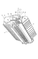
次に、前記プロセスカートリッジBを画像形成装置本体Aに装着したときに、両者を電気的に接続するための接点構造について図5、図8、図9、及び図19を用いて説明する。
【0091】
プロセスカートリッジBには、図に示すように、複数の電気接点が設けてある。即ち、▲1▼感光体ドラム7を装置本体Aとの間でアースするために、該ドラム7と電気的に接続した導電性アース接点119、▲2▼帯電ローラ8へ装置本体Aから帯電バイアスを印加するために、帯電ローラ軸8aと電気的に接続した導電性帯電バイアス接点120、▲3▼現像ローラ9bに装置本体Aから現像バイアスを印加するために、現像ローラ9bと電気的に接続した導電性現像バイアス接点21、▲4▼トナー残量を検出するために、アンテナ線117と電気的に接続した導電性トナー検出接点122、の4個の接点がカートリッジ枠体側面(右側面)から露出するように設けてある。そして前記4個の接点119〜122は、全てカートリッジ枠体の一方側側面に、各接点間が電気的にリークしない距離を隔てて設けられている。なお前記トナー検出接点122は、プロセスカートリッジBが装置本体Aに装着されたことを装置本体Aに検出させるための、カートリッジ有無接点を兼ねる。
【0092】
前記アース接点119は、感光体ドラム7の芯決め軸7aを導電性の材質にするか、或いは、樹脂に導電材をインサート成形して電気接点としている。本実施例では、軸7aを鉄等の金属製としている。また他の接点20、121、122は厚さが約0.1mm〜0.3mm程度の導電性の金属材をプロセスカートリッジ内部から張り巡らせている。そして、帯電接点120はクリーニングユニットCの駆動側側面(一側端C1)から露出し、現像接点121及びトナー検出接点122は現像ユニットDの駆動側側面(一側端D1)から露出するように設けられている。
【0093】
さらに詳細に説明する。
【0094】
前述した通り、本実施例においては、感光体ドラム7の軸線方向一側端にはす歯ギア7bを設けている。このはす歯ギア7bは、装置本体Aに設けられた駆動はす歯ギア28と噛合して、ドラム7を回転させる。なおこのはす歯ギア7bは、回転する際にスラスト力(図26に示す矢示dの方向)を生じて、長手方向に遊びを有してクリーニング枠体13に設けられているドラム7をはす歯ギア7bが設けられている側へ付勢する。そして、はす歯ギア7bの側端7b1がクリーニング枠体13の一側端13bの内面13b1に突き当たる。これによって、ドラム7はカートリッジBの内部において、軸線方向の位置が規定される。そして前記アース接点119及び帯電バイアス接点120は、前記クリーニング枠体13の一側端13bに露出して設けられている。そしてアース接点119は、前記ドラム軸7aの先端であって、前記円筒部材13aの先端よりも僅かに外方へ突出している(約0.8mm突出している)。このドラム軸7aは、感光層7eを被覆されているドラム筒7d(本実施例ではアルミニウム製)を貫通するもので、両側端を前記円筒部材13aによって、クリーニング枠体13の両側端13c・13dに支持されている。そして、ドラム筒7dの内面7d1と前記軸7aの外周面7a1とに接触するアース板7fによって前記ドラム筒7dと前記軸7aは電気的に接続されている。
【0095】
また、前記帯電バイアス接点120は、垂直方向において、前記長手ガイド部12aのほぼ真上であって、前記帯電ローラ8を支持している枠体13部分の近傍に設けられている(図5)。そして前記帯電バイアス接点120は、前記帯電ローラ軸8aと接触している導電性部材120aを介して前記帯電ローラ8と電気的に接続している。
【0096】
次に、現像バイアス接点121及びトナー検出接点122について説明する。これら両接点121・122は、クリーニング枠体13の一側端13bと同じ側に設けられている現像ユニットDの一側端D1に設けられている。そして前記現像バイアス接点121は、前記長手ガイド12aの真下であって、前記現像ローラ9cに内蔵されたマグネット9dを支持している枠体12c部分の近傍に設けられている(図5)。そして前記現像バイアス接点121は、前記現像ローラ9cの側端と接触している導電性部材121aを介して前記現像ローラ9cと電気的に接続している(図9(b))。また、トナー検出接点122は、カートリッジ装着方向(矢示A方向)に対して前記長手ガイド12aの上流側に設けられている。そして、前記現像ローラ9cのトナー容器11a側に、前記現像ローラ9cの長手方向に沿って設けられたアンテナ棒9eと接触している導電性部材9fを介して前記アンテナ棒9eと電気的に接続している。前述した通り、前記アンテナ棒9eは、現像ローラ9cと一定距離を隔てた位置に設けられている。そして、このアンテナ棒9eと現像ローラ9cとの間の静電容量は両者間に存在するトナー量によって変化する。そこで、この静電容量の変化を電位差変化として、装置本体Aの検出回路(図示せず)によって検出することにより、トナー量残量を検出するものである。
【0097】
ここで前記トナー残量とは、現像ローラ9cとアンテナ棒9eの間に存在するトナー量が、所定の静電容量を生ずるトナー量である。これによって、トナー11a内のトナー残量が、所定の量となったことを検出できる。そこで、装置本体Aに設けた前記検出回路によって、前記トナー検出接点122を介して静電容量が第一の所定の値になったことを検出し、トナー容器11a内のトナー残量が所定の量となったことを判別する。装置本体Aは、静電容量が前記第一の所定の値となったことを検出すると、プロセスカートリッジの交換報知を行う(例えば、ランプの点滅、ブザーによる音の発生)。また、前記検出回路は、前記静電容量が前記第一の所定の値よりも小さい第二の所定の値を検出することによって、カートリッジBが装置本体に装着されたことを検出する。また、前記検出回路は、カートリッジBが装着されたことを検出しなければ、装置本体を駆動させない。
【0098】
なおカートリッジ未装着の報知を行っても良い(例えば、ランプの点滅等)。
【0099】
次に、前記カートリッジBに設けた接点と、装置本体に設けた接点部材との接続について説明する。
【0100】
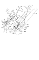
さて、画像形成装置Aのカートリッジ装着スペースSの一方側の内側面には、図19に示すように、前記プロセスカートリッジBを装着したときに、前記各接点119〜122に接続し得る4個の接点部材(アース接点119と接触するアース接点部材123、帯電バイアス接点120と接触する帯電接点部材124、現像バイアス接点121と接触する現像接点部材125、トナー検出接点122と接触するトナー検出接点部材126)が設けてある。
【0101】
図19(a)・(b)に示す通り、アース接点部材123は前記溝16a5に対応して設けられている。また、現像接点部材125、及びトナー検出接点部材126は第一のガイド部16aの下方に設けられている。また、第二のガイド部16bの上方に設けられている。
【0102】
ここで、各接点とガイドとの位置関係について説明する。
【0103】
まず垂直方向において、最下位に現像バイアス接121、その上方にほぼ同じ高さにトナー検出接点122、長手ガイド12a及び円筒部材13a(アース接点119)、さらにその上方に短手ガイド13b、最上位に帯電バイアス接点120が配置されている。また、カートリッジ装着方向(矢示X方向)において、再上流にトナー検出接点122、その下流に長手ガイド12a、次いでその下流に帯電バイアス接点120、及び現像バイアス接点、そこで電極のはい回を短縮できる。さらにその下流に短手ガイド13b、円筒部材13a(アース接点119)が配置されている。このように配置することによって、帯電バイアス接点120は帯電ローラ8に近付ける、現像バイアス接点121は現像ローラ9cに近付ける、トナー検出接点122はアンテナ枠9eに近付ける、また、アース接点119は感光体ドラム7に近付けることができる。
【0104】
ここで、各接点のサイズは次の通りである。まず、帯電バイアス接点120は、たて及び横ともに約10.0mm(許容範囲8.0mm〜12mm)、現像バイアス接点121は、たて約9.0mm(許容範囲6.0mm〜12.0mm)、横約8.0mm(許容範囲5.0mm〜11.0mm)、トナー検出接点122はたて約8.0mm(許容範囲6.0mm〜10.0mm)、横約9.0mm(許容範囲7.0mm〜11.0mm)、及び、アース接点119は円型でその外径は約7.0mmである。なお前述帯電バイアス接点120、現像バイアス接点121、及びトナー検出接点122は矩形である。
【0105】
前記アース接点部材23は導電性板ばね部材でカートリッジ側のアース接点119が取り付けられている感光体ドラム7の円筒部材13a(ドラム軸7aが位置決めされる溝16a5に取り付けられており(図19・26参照)、これが装置本体シャーシを介してアースされている。また他の接点部材124、125、126は、圧縮バネ129によってホルダ127から突出して取り付けられている。これを帯電接点部材124を例にとって説明する。図26に示すように、帯電接点部材124をホルダカバー127内に脱落不能且つ突出可能に取る付ける。そして、このホルダカバー127を装置本体側面に取り付けた電気基板128に固定し、各接点部材と配線パターンとを導電性の圧縮バネ129によって電気的に接続している。
【0106】
次に、図27を参照して、プロセスカートリッジBを画像形成装置Aに装着する際に、カートリッジ側の各接点が画像形成装置側の各接点部材に接する状態を、帯電接点19を例にとって説明する。尚、、図26は画像形成装置Aに装着したときのプロセスカートリッジBの状態説明図である。矢印HはプロセスカートリッジBを画像形成装置Aに装着する際のカートリッジに対する装置本体側の帯電接点部材24の相対的な経路を示す。なお、図27は図5の矢印Oで切った断面を示す。
【0107】
プロセスカートリッジBを画像形成装置Aに挿入して、ガイド部16a・16bによってガイドして装着する際に、所定の装着位置へ至る前にあっては帯電接点部材124は、図27の(a)で示す状態にある。このとき、帯電接点部材124は未だクリーニング枠体13の平面30に接触していない。更にカートリッジBの挿入が進むと、帯電接点部材124は図10の(b)の位置に達する。ここで、クリーニング枠体13の側面13cに形成した斜面31(図5)に接触する。この斜面31に沿って接点部材124が押圧されることで圧縮バネ129が徐々に撓み、接点部材124はスムーズに帯電接点120が露出している平面32に達する。そして、カートリッジBが所定の装着位置まで挿入されると、接点部材124は図10の(c)の位置に達して、帯電接点120と接触する。他の2つの接点部材125、126も同様にして接点121、122と接触する。
【0108】
このように本実施例においては、前述ガイド部材16によってカートリッジBをガイドして、所定の装着位置に装着すると、前記各接点は各接点部材と確実に接続する。
【0109】
またアース接点部材123は、プロセスカートリッジBを所定位置へ装着すると、板バネ状のアース接点部材123が円筒部材13aから突出しているアース接点119と接触する(図26参照)。ここでカートリッジBが装置本体Aに接着されると、アース接点119とアース接点部材123が電気的に接続して、感光体ドラム7がアースされる。また帯電バイアス接点120と帯電接点部材124が電気的に接続して、帯電ローラ8に高電圧(AC電圧とDC電圧の重畳)が印加される。また現像バイアス接点121と現像接点部材125が電気的に接続して、現像ローラ9cに高電圧が印加される。またさらに、トナー検出接点122とトナー検出接点部材126が電気的に接続して、静電容量に応じた情報が本体Aに伝達される。
【0110】
次に画像形成装置Aを駆動して感光体ドラム7を回転させた場合について説明する。プロセスカートリッジBは画像形成装置Aに装着するときに、挿入を容易にするために、感光体ドラム7の軸線方向に対して約2mm〜3mm程度のスラストガタをもたせている。このため、帯電接点部材124等の突出量を前記ガタ以上にする必要がある。そこで、本実施例ではプロセスカートリッジBを装着したときに、該カートリッジBを装置本体の一方側(接点部材123〜126が設けられている側)に付勢するように板ばね45を設けている。この板ばね45は、前記各接点部材が設けられているのとは反対側の第一の装着ガイド16aの上方に設けられている。
【0111】
また本実施例のように、プロセスカートリッジBの各接点119〜122をはす歯ギア7bが設けられている側(駆動側側面)に設けると、はす歯ギア7bによる本体側との駆動の接続と、接点119〜122による本体側との電気的接続をカートリッジBの同じ側で行うことができる。そこで前記同じ側をカートリッジの基準とすれば、寸法の積み上げ誤差が少なくなり、各接点の取付け位置とはす歯ギアの取付け位置の精度を高めることができる。またさらに、前述実施例のように、はす歯ギアのねじれ方向をはす歯ギアの設けられている側へスラスト力が発生するように定めれば、感光体ドラムの軸線方向の位置決めを各接点の設けられた側で行うことができる。そこでこの場合には、前述効果に加えて、感光体ドラムと接点との位置精度も向上させることができる。またさらに前述実施例のように、各接点19〜22を設けた側と逆方向にドラムシャッタ18を開閉させるためのレバー18bを設けるようにすれば、プロセスカートリッジBを画像形成装置Aに挿入するときに、各接点19〜22の摺擦抵抗と、ドラムシャッタ18を開閉させるための抵抗とがカートリッジBの長手方向両側に分散される。そのため、挿入抵抗が長手方向で均一化してカートリッジBをスムーズに挿入することが出来るようになる。
【0112】
またさらに前述実施例のように、プロセスカートリッジBの各接点をカートリッジ枠体の一方側側面に全て配置したうえで、板ばねによってプロセスカートリッジBを弾性的に付勢させれば、各電気接点が本体側の接点部材と電気的に安定して接続される。
【0113】
なお図28は、各接点を前記レバー18bが設けられている側に設けた例である。このように構成しても、充分な効果を得ることができる。
【0114】
また、前述した実施例で示したプロセスカートリッジBは単色画像を形成する場合を例示したが、本発明に係るプロセスカートリッジは現像手段を複数設け、複数色の画像(例えば2色画像、3色画像あるいはフルカラー等)を形成するカートリッジにも好適に適用することができる。
【0115】
また、電子写真感光体としては、前記感光体ドラム7に限定されることなく、例えば次のものが含まれる。先ず感光体としては光導電体が用いられ、光導電体としては例えばアモルファスシリコン、アモルファスセレン、酸化亜鉛、、酸化チタン及び有機光導電体(OPC)等が含まれる。また前記感光体を搭載する形状としては、例えばドラム状又はベルト状のものが用いられており、例えばドラムタイプの感光体にあっては、アルミ合金等のシリンダ上に光導電体を蒸着或いは塗工等を行ったものである。
【0116】
また現像方法としても、公知の2成分磁気ブラシ現像法、カスケード現像法、タッチダウン現像法、クラウド現像法等の種々の現像法を用いることが可能である。
【0117】
また帯電手段の構成も、前述した第一実施例では所謂接触帯電方法を用いたが、他の構成として従来から用いられているタングステンワイヤーの三方周囲にアルミ等の金属シールドを施し、前記タングステンワイヤーに高電圧を印加することによって生じた正又は負のイオンを感光体ドラムの表面に移動させ、該ドラムの表面を一様に帯電する構成を用いても良いことは当然である。
【0118】
尚、前記帯電手段としては前記ローラ型以外にも、ブレード(帯電ブレード)、パッド型、ブロック型、ロッド型、ワイヤ型等のものでも良い。
【0119】
また感光体ドラムに残存するトナーのクリーニング方法としても、ブレード、ファーブラシ、磁気ブラシ等を用いてクリーニング手段を構成しても良い。
【0120】
前述したように、プロセスカートリッジに設ける複数の電気接点を全てカートリッジ枠体の一方側側面に配置したために、弾性手段によって該カートリッジを電気接点が設けてある側面側に付勢して位置決めすることにより、画像形成装置との電気的接続を安定して行うことが出来る。
【0121】
あるいは電子写真感光体にはす歯ギアによって駆動力を伝達し、該ギアの回転によって感光体が付勢される側に前記はす歯ギア及び電気接点を設けることにより、画像形成装置に対する電気的接続、及び、駆動の接続をより確実に行うことが可能となる。
【0122】
あるいは、前述実施例の通り各接点を配置することにより、各接点のカートリッジ内での電極のはい回しを短縮することができる。
【0123】
あるいは、前記電気接点と接続される装置本体側の電気基板を装置側面に縦置き配置することが可能となるために、装置の小型化を図ることが出来るものである。
【0124】
【発明の効果】
以上説明した通り、本発明によれば、プロセスカートリッジを画像形成装置本体に装着した際に、プロセスカートリッジと画像形成装置本体との電気的接続をより一層正確に、また、より一層精度良く行うことのできるものである。
【図面の簡単な説明】
【図1】本発明の一実施例を適用した電子写真画像形成装置の側面図である。
【図2】図1に示した装置の外観斜視図である。
【図3】本発明の一実施例を適用したプロセスカートリッジの側断面図である。
【図4】図1に示したプロセスカートリッジの模式的外観斜視図である。
【図5】図1に示したプロセスカートリッジの右側面図である。
【図6】図1に示したプロセスカートリッジの左側面図である。
【図7】図1に示したプロセスカートリッジの外観斜視図である。
【図8】図1に示したプロセスカートリッジを下方から見た外観斜視図である。
【図9】(a)図1に示したプロセスカートリッジのクリーナユニットの外観斜視図である。
(b)図1に示したプロセスカートリッジの現像ユニットの外観斜視図である。
【図10】図1に示したプロセスカートリッジの装置本体に対する着脱工程を示した側面図である。
【図11】図1に示したプロセスカートリッジの装置本体に対する着脱工程を示した側面図である。
【図12】図1に示したプロセスカートリッジの装置本体に対する着脱工程を示した側面図である。
【図13】図1に示したプロセスカートリッジの装置本体に対する着脱工程を示した側面図である。
【図14】図1に示したプロセスカートリッジの装置本体に対する着脱工程を示した側面図である。
【図15】図1に示したプロセスカートリッジの装置本体に対する着脱工程を示した側面図である。
【図16】図1に示したプロセスカートリッジの装置本体に対する着脱工程を示した側面図である。
【図17】図1に示したプロセスカートリッジの装置本体に対する着脱工程を示した側面図である。
【図18】装置本体内部の斜視図である。
【図19】(a)装置本体内部の斜視図である。
(b)装置本体内部の側面図である。
【図20】本発明の一実施例を適用したプロセスカートリッジの側面図である。
【図21】本発明の一実施例を適用したプロセスカートリッジの側面図である。
【図22】本発明の一実施例を適用したプロセスカートリッジの側面図である。
【図23】本発明の一実施例を適用したプロセスカートリッジの側面図である。
【図24】本発明の一実施例を適用したプロセスカートリッジの側面図である。
【図25】本発明の一実施例を適用したプロセスカートリッジの側面図である。
【図26】接点と接点部材が接続した状態を示す図である。
【図27】接点と接点部材が接続した状態を示す図である。
【図28】本発明の一実施例を適用したプロセスカートリッジの側面図である。
【符号の説明】
A 画像形成装置
B プロセスカートリッジ
1 光学手段
1a ポリゴンミラー
1b レンズ
1c 反射ミラー
2 記録媒体
3 搬送手段
3a カセット
3b ピックアップローラ
3c、3d 搬送ローラ対
3e レジストローラ対
3f ガイド部材
3g、3h、3i 排出ローラ対
3j 反転搬送経路
3k フラッパ
3m 排出ローラ対
4 転写ローラ
5 定着手段
5a ヒータ
5b 定着ローラ
5c 駆動ローラ
6 排出部
7 感光体ドラム
7a ドラム軸
7b はす歯ギア
8 帯電ローラ
9 現像手段
9b トナー送り部材
9c 現像ローラ
9d 現像ブレード
10 クリーニング手段
10a クリーニングブレード
10b 廃トナー溜め
11 トナー枠体
12 現像枠体
12a 第二ガイド部材(長手ガイド)
13 クリーニング枠体
13a 第一ガイド部材(ダボ)
13b 第三ガイド部材(短手ガイド)
13e 規制当接部
13f 解除当接部
15 開閉部材
16 ガイド部材
16a5 位置決め凹部
17 把手凹部
25a 回転規制部
25b 解除当接部
28 駆動ギア
A 装置本体
B プロセスカートリッジ
C クリーニングユニット
D 現像ユニット
119 アース接点
120 帯電バイアス接点
121 現像バイアス接点
122 トナー検出接点
123 アース接点部材
124 帯電接点部材
125 現像接点部材
126 トナー検出接点部材
128 電気基板
129 圧縮バネ[0001]
[Industrial application fields]
The present invention relates to a process cartridge and an image forming apparatus to which the process cartridge can be attached and detached.
[0002]
Here, examples of the image forming apparatus include an electrophotographic copying machine, an electrophotographic printer (for example, an LED printer, a laser beam printer, etc.), an electrophotographic facsimile apparatus, an electrophotographic word processor, and the like.
[0003]
Further, as the process cartridge, the charging unit, the developing unit, the cleaning unit, and the electrophotographic photosensitive member are integrally formed into a cartridge, and the cartridge can be attached to and detached from the image forming apparatus main body.
[0004]
[Prior art]
Conventionally, in an image forming apparatus using an electrophotographic image forming process, the electrophotographic photosensitive member and the process means acting on the electrophotographic photosensitive member are integrally formed into a cartridge, and the cartridge can be attached to and detached from the image forming apparatus main body. The process cartridge method is adopted. According to this process cartridge system, the apparatus can be maintained by the user himself / herself without depending on the service person, so that the operability can be remarkably improved. Therefore, this process cartridge system is widely used in image forming apparatuses.
[0005]
On the other hand, in this process cartridge system, it is desired to facilitate the operability when the process cartridge is attached to and detached from the image forming apparatus main body.
[0006]
Furthermore, when the process cartridge is mounted on the main body of the image forming apparatus, it is desired to make electrical connection between the process cartridge and the main body of the image forming apparatus more reliably and with higher accuracy.
[0007]
For example, a technique described in Japanese Laid-Open Patent Publication No. 02-163761 (published on June 25, 1990) is known as a technique for realizing these. The technology described in this publication includes a contact point connected to a charger, a grid contact point connected to a charging grid, a drum earth plate connected to a photosensitive drum, and a developing unit on a side surface of a process cartridge frame. And an antenna contact connected to the antenna.
[0008]
These techniques are very effective with respect to the electrical connection of the process cartridge.
[0009]
[Problems to be solved by the invention]
The present invention is a further development of the aforementioned technology.
[0010]
An object of the present invention is to provide a process cartridge capable of performing electrical connection between the process cartridge and the image forming apparatus main body more reliably and with higher accuracy when the process cartridge is mounted on the main body of the image forming apparatus. Another object is to provide an image forming apparatus.
[0011]
Another object of the present invention is to provide a process cartridge and an image forming apparatus capable of improving image forming quality by reliably performing electrical connection with a main body.
[0012]
Another object of the present invention is to provide a process cartridge and an image forming apparatus that can improve the mounting operability of the process cartridge and can perform electrical connection between the process cartridge and the apparatus main body with higher accuracy. It is in.
[0013]
[Means for Solving the Problems]
A typical configuration according to the present invention for solving the above problems is as follows.
In a process cartridge that can be attached to and detached from the electrophotographic image forming apparatus main body,
An electrophotographic photosensitive drum provided on the first frame;
A drum shaft for supporting the electrophotographic photosensitive drum on the first frame;
A charging roller provided on the first frame for charging the electrophotographic photosensitive drum;
A developing roller for developing an electrostatic latent image formed on the electrophotographic photosensitive drum using toner provided on a second frame that is rotatably coupled to the first frame;
When the process cartridge, which is provided in an exposed state at a side surface portion of the first frame provided on one end side in the axial direction of the electrophotographic photosensitive drum, is mounted on the apparatus main body, the apparatus main body An earth contact for grounding the electrophotographic photosensitive drum with respect to the apparatus body, the earth contact located at the tip of the drum shaft; and Connected to a main body charging bias contact provided on the apparatus main body when the process cartridge provided on the side face of the first frame provided on one end side is mounted on the apparatus main body. A charging bias contact for receiving a charging bias applied from the apparatus main body to the charging roller;
A main body developing bias contact provided on the main body of the apparatus when the process cartridge is mounted on the main body of the apparatus provided exposed in a side surface of the second frame provided on the one end side; A developing bias contact for receiving a developing bias applied to the developing roller from the apparatus main body;
A main body detected contact provided on the apparatus main body when the process cartridge is mounted on the apparatus main body, and is exposed in a side surface portion of the second frame provided on the one end side; A detected contact for transmitting to the apparatus main body that the process cartridge is mounted on the apparatus main body,
When the process cartridge provided on the one end side is mounted on the electrophotographic image forming apparatus main body, the driving force for rotating the electrophotographic photosensitive drum is received from the electrophotographic image forming apparatus main body. Helical gear,
When the process cartridge provided on the other end side in the axial direction is mounted on the apparatus main body, a driving force for rotating the transfer roller provided on the apparatus main body is transmitted to the transfer roller. Spur tooth gear
The process cartridge is mounted on the apparatus main body from a direction intersecting the axial direction of the electrophotographic photosensitive drum, and when the process cartridge is mounted on the apparatus main body, the charging roller is The electrophotographic photosensitive drum is disposed above the charging bias contact, and the charging bias contact is disposed above the ground contact. In the mounting direction, the developing roller is disposed on the electrophotographic photosensitive drum. In the mounting direction, the ground contact is disposed downstream, the development bias contact is disposed upstream, and the detected contact is disposed upstream of the ground contact, and is provided in the apparatus main body. The development bias contact is connected to the main body development so that the ground contact is connected to the main body ground contact by the elastic force of the spring. From the other end side to the one end side, so that the charging bias contact is connected to the main body charging bias contact, and the detected contact is connected to the main body detected contact, so as to connect to the bias contact. In the process cartridge, the process cartridge is elastically biased.
[0014]
Still further, another exemplary configuration according to the present invention for achieving the above object is an image forming apparatus in which a process cartridge is detachable and an image is formed on a recording medium.
(A) a main body ground contact;
(B) a main body developing bias contact;
(C) a main body charging bias contact;
(D) a main body detected contact;
(E) an electrophotographic photosensitive drum provided on the first frame;
A drum shaft for supporting the electrophotographic photosensitive drum on the first frame;
A charging roller provided on the first frame for charging the electrophotographic photosensitive drum;
A developing roller for developing an electrostatic latent image formed on the electrophotographic photosensitive drum using toner, provided on a second frame rotatably coupled to the first frame; ,
When the process cartridge provided in an exposed state at a side surface portion of the first frame provided on one end side in the axial direction of the electrophotographic photosensitive drum is mounted on the apparatus main body, the main body grounding An earth contact for connecting the contact and grounding the electrophotographic photosensitive drum between the apparatus main body and an earth contact located at a tip of the drum shaft;
When the process cartridge provided in an exposed state on the side surface of the first frame provided on the one end side is attached to the apparatus main body, the apparatus is connected to the main body charging bias contact, and the apparatus A charging bias contact for receiving a charging bias applied from the main body to the charging roller;
When the process cartridge provided in the exposed state at the side surface of the second frame provided on the one end side is attached to the apparatus main body, the apparatus is connected to the main body developing bias contact, and the apparatus A developing bias contact for receiving a developing bias applied from the main body to the developing roller;
In an exposed state at a side surface portion of the second frame body provided on the one end side
When the process cartridge is installed in the apparatus main body, the process cartridge is connected to the main body detected contact to transmit to the apparatus main body that the process cartridge is installed in the apparatus main body. A detection contact;
When the process cartridge provided on the one end side is mounted on the electrophotographic image forming apparatus main body, the driving force for rotating the electrophotographic photosensitive drum is received from the electrophotographic image forming apparatus main body. Helical gear,
When the process cartridge provided on the other end side in the axial direction is mounted on the apparatus main body, a driving force for rotating the transfer roller provided on the apparatus main body is transmitted to the transfer roller. Spur tooth gear
The process cartridge is mounted on the apparatus main body from a direction intersecting the axial direction of the electrophotographic photosensitive drum, and when the process cartridge is mounted on the apparatus main body, the charging roller is The electrophotographic photosensitive drum is disposed above the charging bias contact, and the charging bias contact is disposed above the ground contact. In the mounting direction, the developing roller is disposed on the electrophotographic photosensitive drum. A process cartridge that is disposed upstream and in which the grounding contact is disposed downstream, the development bias contact upstream, and the detected contact disposed upstream is detachably mounted in the mounting direction. Mounting means for
The process cartridge is connected such that the ground contact is connected to the main body ground contact, the development bias contact is connected to the main body development bias contact, and the detected contact is connected to the main body detected contact. A spring that elastically biases from the other end side to the one end side,
An image forming apparatus comprising:
[0015]
[Action]
In the above configuration, since each electrical contact is provided on the same side surface of the process cartridge, the accuracy of the mounting position of the electrical contact can be improved.
[0016]
【Example】
Next, preferred embodiments of the present invention will be described. FIG. 1 is a structural explanatory view of an electrophotographic image forming apparatus to which an embodiment of the present invention is applied, and FIG. 2 is an external perspective view thereof. 3 to 8 are drawings relating to a process cartridge to which an embodiment of the present invention is applied. 3 is a side sectional view of the process cartridge, FIG. 4 is an external perspective view illustrating an outline of the external appearance thereof, FIG. 5 is a right side view thereof, FIG. 6 is a left side view thereof, and FIG. FIG. 8 and FIG. 8 are perspective views as seen from below.
[0017]
(Electrophotographic image forming apparatus A and process cartridge B)
First, an electrophotographic image forming apparatus A to which one embodiment of the present invention is applied will be described with reference to FIGS. FIG. 3 is a side sectional view of the process cartridge B.
[0018]
This electrophotographic image forming apparatus A forms an image on a recording medium by an electrophotographic image forming process as shown in FIG. Then, a toner image is formed on a drum-shaped electrophotographic photosensitive member (hereinafter referred to as a photosensitive drum). In synchronism with the formation of the toner image, the recording medium 2 set in the cassette 3a is reversely conveyed by the conveying means 3 including the
[0019]
On the other hand, as shown in FIGS. 3 to 8, the process cartridge B rotates a
[0020]
Here, the developing
[0021]
Then, a voltage having a polarity opposite to that of the toner image is applied to the transfer roller 4 to transfer the toner image formed on the
[0022]
The process cartridge B couples a
[0023]
The process cartridge B is provided with an
[0024]
Next, the structure of the housing of the process cartridge B according to the present embodiment will be described.
[0025]
In the process cartridge B of this embodiment, the
[0026]
(Configuration of housing of process cartridge B)
In the process cartridge B according to the present embodiment, the
[0027]
As shown in FIGS. 3 and 9, a
[0028]
Further, the
[0029]
The developing unit D and the cleaning unit C are coupled by a
[0030]
The coupling between the developing unit D and the cleaning unit C by the
[0031]
(Configuration of guide means of process cartridge B)
Next, guide means for attaching / detaching the cartridge B to / from the apparatus main body will be described. This guide means is shown in FIGS. 5 is a right side view of the cartridge B when viewed in the direction (arrow X) in which the cartridge B is mounted on the mounting body A (when viewed from the developing unit D side). FIG. 6 is a left side view thereof.
[0032]
As shown in the drawing, guide means are provided on both outer side surfaces of the
[0033]
The
[0034]
The
[0035]
This will be described in detail below.
[0036]
The
[0037]
The
[0038]
Further, a
[0039]
Here, an example of the size of the guide member is shown.
[0040]
The
[0041]
Next, the
[0042]
In the present embodiment, a
[0043]
More specifically, in the present embodiment, recesses 13g are provided on the upper surface 13i of the cleaning unit C on both side ends in a direction orthogonal to the cartridge mounting direction. The
[0044]
Here, an example of each size is shown.
[0045]
First, the
[0046]
(Cartridge attachment / detachment process)
Next, the process of attaching / detaching the process cartridge B to / from the apparatus main body A will be described with reference to FIGS.
[0047]
The process cartridge B configured as described above is detachable from the cartridge mounting means provided in the apparatus main body A.
[0048]
When the operator opens the opening / closing
[0049]
The
[0050]
In the cartridge mounting space S of the apparatus main body A, fixed members (rotation restricting members) 25 fixed to the
[0051]
Further, in the cartridge mounting space S,
[0052]
Next, the relationship between the mounting
[0053]
First, as shown in FIG. 10, when the process cartridge B is inserted into the apparatus main body A, the
[0054]
At this time, the
[0055]
Subsequently, when the process cartridge B is in the state shown in FIG. 11, the
[0056]
Therefore, when the process cartridge B advances to the state shown in FIG. 12, the
[0057]
When the process cartridge B further advances to the state shown in FIG. 13, the
[0058]
Then, when the cartridge B advances to the state shown in FIG. 14, the
[0059]
The positional relationship between the restricting
[0060]
In the state shown in FIG. 15, the
[0061]
The
[0062]
Next, a case where the process cartridge B is taken out from the apparatus main body A will be described with reference to FIGS. 16 and 17. The arrow Y direction is the direction in which the process cartridge B is taken out.
[0063]
When the process cartridge B is taken out, as shown in FIG. 16, the operator holds the
[0064]
As described above, according to the embodiment of the present invention, the longitudinal guide as the second guide member extends in the cartridge insertion direction so as to straddle the continuous side surface of the developing unit D and the cleaning unit C. The wobbling of the process cartridge when removing and attaching is eliminated, stable insertion can be performed, and the operability is improved.
[0065]
Further, the guide means serving as a guide for attaching / detaching the process cartridge to / from the apparatus main body is constituted by the above three guides (
[0066]
Further, the positioning of the process cartridge is performed by the
[0067]
In the process cartridge B of the above-described embodiment, the guide means including three guide members is illustrated as the cartridge attachment / detachment guide. However, the present invention does not have to be limited to this. For example, guide means including at least a cylindrical member as a first guide member and a longitudinal guide as a second guide member, or guide members other than the above-described three locations are further provided. It is good also as a guide means provided and constituted. This also stabilizes the state when the cartridge is attached and detached, and improves its operability.
[0068]
Next, another attaching / detaching process of the process cartridge B will be described with reference to FIGS. In addition, about the member which fulfill | performs the function similar to the said Example, the same code | symbol is attached | subjected and description is employ | adopted.
[0069]
The process cartridge B is provided with a
[0070]
The insertion position of the cartridge B is positioned by inserting the process cartridge B into the guide groove 16i along the
[0071]
As shown in FIGS. 20 and 21, also in the present embodiment, the
[0072]
That is, the
[0073]
With this configuration, when the process cartridge B is mounted on the apparatus main body A, as shown in FIG. 20, the restricting
[0074]
Further, since the fixed
[0075]
That is, according to the present embodiment, in the method of taking out the process cartridge B from the apparatus main body A, (a) the process cartridge is rotated upward with the
[0076]
Furthermore, since the
[0077]
In this embodiment, an example is shown in which the fixing
[0078]
Further, another attaching / detaching process of the process cartridge B will be described with reference to FIGS.
[0079]
As shown in FIG. 22, on the upper surface of the frame of the process cartridge B, a restricting
[0080]
Then, in the apparatus main body A, as shown in FIG. 22, the process cartridge B is inserted along the guide groove 16i so that the
[0081]
In the process cartridge B, a
[0082]
On the other hand, when taking out the process cartridge B, as shown in FIG. 23, the operator holds the
[0083]
As described above, the
[0084]
Furthermore, another attaching / detaching process of the process cartridge B will be described with reference to FIGS.
[0085]
The embodiment shown in FIGS. 24 and 25 differs from the embodiment shown in FIGS. 22 and 23 in that a
[0086]
That is, the
[0087]
In this way, not only the same effects as in the previous embodiment can be obtained, but also there is an advantage that restrictions on component arrangement are reduced. That is, when the process cartridge B is taken out from the image forming apparatus main body A, the
[0088]
As shown in FIGS. 9A and 9B, a spur gear 7n is provided on the other end side of the
[0089]
[0090]
(Configuration of electrical contacts)
Next, a contact structure for electrically connecting the process cartridge B to the image forming apparatus main body A will be described with reference to FIGS. 5, 8, 9, and 19. FIG.
[0091]
As shown in the drawing, the process cartridge B is provided with a plurality of electrical contacts. (1) In order to ground the
[0092]
The
[0093]
Further details will be described.
[0094]
As described above, in this embodiment, the
[0095]
Further, the charging
[0096]
Next, the
[0097]
Here, the toner remaining amount is a toner amount in which a toner amount existing between the developing
[0098]
In addition, notification that the cartridge is not installed may be performed (for example, blinking of a lamp or the like).
[0099]
Next, the connection between the contact provided on the cartridge B and the contact member provided on the apparatus main body will be described.
[0100]
Now, on the inner side surface of one side of the cartridge mounting space S of the image forming apparatus A, as shown in FIG. 19, when the process cartridge B is mounted, four
[0101]
As shown in FIGS. 19A and 19B, the
[0102]
Here, the positional relationship between each contact and the guide will be described.
[0103]
First, in the vertical direction, the developing
[0104]
Here, the size of each contact is as follows. First, the charging
[0105]
The
[0106]
Next, referring to FIG. 27, the state where each contact on the cartridge side contacts each contact member on the image forming apparatus side when the process cartridge B is mounted on the image forming apparatus A will be described by taking the charging
[0107]
When the process cartridge B is inserted into the image forming apparatus A and guided and mounted by the
[0108]
As described above, in this embodiment, when the cartridge B is guided by the
[0109]
Further, when the process cartridge B is mounted at a predetermined position, the
[0110]
Next, a case where the image forming apparatus A is driven and the
[0111]
Further, as in this embodiment, if the contact points 119 to 122 of the process cartridge B are provided on the side where the
[0112]
Further, as in the above-described embodiment, when all the contact points of the process cartridge B are arranged on one side surface of the cartridge frame and the process cartridge B is elastically biased by the leaf spring, Electrically and stably connected to the contact member on the main body side.
[0113]
FIG. 28 shows an example in which each contact is provided on the side where the
[0114]
Further, the process cartridge B shown in the above-described embodiment is exemplified as a case where a single color image is formed. However, the process cartridge according to the present invention is provided with a plurality of developing means, and a plurality of color images (for example, two color images, three color images). Alternatively, it can be suitably applied to a cartridge that forms a full color or the like.
[0115]
Further, the electrophotographic photosensitive member is not limited to the
[0116]
As the developing method, various developing methods such as a known two-component magnetic brush developing method, cascade developing method, touch-down developing method, and cloud developing method can be used.
[0117]
In addition, the charging means is configured by using the so-called contact charging method in the first embodiment described above. However, as another configuration, a metal shield such as aluminum is provided around three sides of a tungsten wire conventionally used, and the tungsten wire Naturally, it is possible to use a configuration in which positive or negative ions generated by applying a high voltage to the surface of the photosensitive drum are moved to the surface of the photosensitive drum, and the surface of the drum is uniformly charged.
[0118]
In addition to the roller type, the charging means may be a blade (charging blade), pad type, block type, rod type, wire type, or the like.
[0119]
Further, as a method for cleaning the toner remaining on the photosensitive drum, the cleaning unit may be configured using a blade, a fur brush, a magnetic brush, or the like.
[0120]
As described above, since the plurality of electrical contacts provided on the process cartridge are all arranged on one side surface of the cartridge frame, the cartridge is biased and positioned by the elastic means toward the side surface where the electrical contacts are provided. The electrical connection with the image forming apparatus can be performed stably.
[0121]
Alternatively, the driving force is transmitted to the electrophotographic photosensitive member by a helical gear, and the helical gear and the electrical contact are provided on the side to which the photosensitive member is urged by the rotation of the gear, thereby providing an electrical connection to the image forming apparatus. Connection and drive connection can be more reliably performed.
[0122]
Alternatively, by disposing each contact as in the above-described embodiment, it is possible to shorten the turning of the electrode in the cartridge of each contact.
[0123]
Alternatively, since the electric substrate on the apparatus main body side connected to the electric contact can be arranged vertically on the side of the apparatus, the apparatus can be reduced in size.
[0124]
【The invention's effect】
As described above, according to the present invention, when the process cartridge is mounted on the image forming apparatus main body, the electrical connection between the process cartridge and the image forming apparatus main body can be performed more accurately and more accurately. It can be done.
[Brief description of the drawings]
FIG. 1 is a side view of an electrophotographic image forming apparatus to which an embodiment of the present invention is applied.
FIG. 2 is an external perspective view of the apparatus shown in FIG.
FIG. 3 is a side sectional view of a process cartridge to which an embodiment of the present invention is applied.
4 is a schematic external perspective view of the process cartridge shown in FIG. 1. FIG.
5 is a right side view of the process cartridge shown in FIG. 1. FIG.
6 is a left side view of the process cartridge shown in FIG. 1. FIG.
7 is an external perspective view of the process cartridge shown in FIG. 1. FIG.
FIG. 8 is an external perspective view of the process cartridge shown in FIG. 1 as viewed from below.
9A is an external perspective view of a cleaner unit of the process cartridge shown in FIG. 1. FIG.
FIG. 2B is an external perspective view of the developing unit of the process cartridge shown in FIG.
10 is a side view showing a process of attaching / detaching the process cartridge shown in FIG. 1 to / from the apparatus main body.
11 is a side view showing a process of attaching / detaching the process cartridge shown in FIG. 1 to / from the apparatus main body.
12 is a side view showing a process of attaching / detaching the process cartridge shown in FIG. 1 to / from the apparatus main body.
13 is a side view showing a process of attaching / detaching the process cartridge shown in FIG. 1 to / from the apparatus main body.
14 is a side view showing a process of attaching / detaching the process cartridge shown in FIG. 1 to / from the apparatus main body.
15 is a side view showing a process of attaching / detaching the process cartridge shown in FIG. 1 to / from the apparatus main body.
16 is a side view showing a process of attaching / detaching the process cartridge shown in FIG. 1 to / from the apparatus main body.
17 is a side view showing a process of attaching / detaching the process cartridge shown in FIG. 1 to / from the apparatus main body.
FIG. 18 is a perspective view of the inside of the apparatus main body.
FIG. 19A is a perspective view of the inside of the apparatus main body.
(B) It is a side view inside an apparatus main body.
FIG. 20 is a side view of a process cartridge to which an embodiment of the present invention is applied.
FIG. 21 is a side view of a process cartridge to which an embodiment of the present invention is applied.
FIG. 22 is a side view of a process cartridge to which an embodiment of the present invention is applied.
FIG. 23 is a side view of a process cartridge to which an embodiment of the present invention is applied.
FIG. 24 is a side view of a process cartridge to which an embodiment of the present invention is applied.
FIG. 25 is a side view of a process cartridge to which an embodiment of the present invention is applied.
FIG. 26 is a diagram showing a state in which a contact and a contact member are connected.
FIG. 27 is a diagram showing a state in which a contact and a contact member are connected.
FIG. 28 is a side view of a process cartridge to which an embodiment of the present invention is applied.
[Explanation of symbols]
A Image forming apparatus
B Process cartridge
1 Optical means
1a Polygon mirror
1b lens
1c Reflective mirror
2 recording media
3 Transport means
3a cassette
3b Pickup roller
3c, 3d Carrying roller pair
3e Registration roller pair
3f Guide member
3g, 3h, 3i discharge roller pair
3j Reverse transfer path
3k flapper
3m discharge roller pair
4 Transfer roller
5 Fixing means
5a heater
5b Fixing roller
5c Drive roller
6 discharge part
7 Photosensitive drum
7a Drum shaft
7b helical gear
8 Charging roller
9 Development means
9b Toner feeding member
9c Development roller
9d Development blade
10 Cleaning means
10a Cleaning blade
10b Waste toner reservoir
11 Toner frame
12 Development frame
12a Second guide member (longitudinal guide)
13 Cleaning frame
13a First guide member (Dowel)
13b Third guide member (short guide)
13e Restricting contact part
13f Release contact part
15 Opening / closing member
16 Guide member
16a5 positioning recess
17 Handle recess
25a Rotation restriction part
25b Release contact part
28 Drive gear
A Device body
B Process cartridge
C Cleaning unit
D Development unit
119 Earth contact
120 Charging bias contact
121 Development bias contact
122 Toner detection contact
123 Earth contact member
124 Charging contact member
125 Development contact member
126 Toner detection contact member
128 Electric board
129 compression spring
Claims (2)
第一枠体に設けられた電子写真感光体ドラムと、
前記電子写真感光体ドラムを前記第一枠体に支持するドラム軸と、
前記第一枠体に設けられた、前記電子写真感光体ドラムに帯電を行うための帯電ローラと、
前記第一枠体と回動可能に結合している第二枠体に設けられた、トナーを用いて、前記電子写真感光体ドラムに形成された静電潜像を現像するための現像ローラと、
前記電子写真感光体ドラムの軸線方向において一端側に設けられた前記第一枠体の側面部において露出した状態で設けられた、前記プロセスカートリッジが前記装置本体に装着された際に、前記装置本体に設けられた本体アース接点と接続して、前記装置本体との間で前記電子写真感光体ドラムのアースを取るためのアース接点であって、前記ドラム軸の先端に位置するアース接点と、
前記一端側に設けられた前記第一枠体の側面部において露出した状態で設けられた、前記プロセスカートリッジが前記装置本体に装着された際に、前記装置本体に設けられた本体帯電バイアス接点と接続して、前記装置本体から前記帯電ローラに印加する帯電バイアスを受けるための帯電バイアス接点と、
前記一端側に設けられた前記第二枠体の側面部において露出した状態で設けられた、前記プロセスカートリッジが前記装置本体に装着された際に、前記装置本体に設けられた本体現像バイアス接点と接続して、前記装置本体から前記現像ローラに印加する現像バイアスを受けるための現像バイアス接点と、
前記一端側に設けられた前記第二枠体の側面部において露出した状態で設けられた、前記プロセスカートリッジが前記装置本体に装着された際に、前記装置本体に設けられた本体被検出接点と接続して、前記プロセスカートリッジが前記装置本体に装着されたことを前記装置本体に伝達するための被検出接点と、
前記一端側に設けられた、プロセスカートリッジが前記電子写真画像形成装置本体に装着された際に、前記電子写真感光体ドラムを回転させるための駆動力を前記電子写真画像形成装置本体から受けるためのはす歯ギアと、
前記軸線方向において他端側に設けられた、前記プロセスカートリッジが前記装置本体に装着された際に、前記装置本体に設けられた転写ローラを回転させるための駆動力を前記転写ローラへ伝達するための平歯ギアと、
前記プロセスカートリッジは、前記電子写真感光体ドラムの軸線方向と交差する方向から前記装置本体に装着されるものであって、前記プロセスカートリッジが前記装置本体に装着された際に、前記帯電ローラは前記電子写真感光体ドラムの上側に配置されており、そして、前記帯電バイアス接点は前記アース接点よりも上方に配置されており、そして、前記装着方向において、前記現像ローラは前記電子写真感光体ドラムの上流側に配置されており、そして、前記装着方向において、下流側に前記アース接点、その上流側に現像バイアス接点、更にその上流側に被検出接点が配置されており、前記装置本体に設けられているばねの弾性力によって、前記アース接点が前記本体アース接点と接続するように、前記現像バイアス接点が前記本体現像バイアス接点と接続するように、前記帯電バイアス接点が本体帯電バイアス接点と接続するように、及び、前記被検出接点が本体被検出接点と接続するように、前記他端側から前記一端側に向って、弾性的に付勢されることを特徴とするプロセスカートリッジ。In a process cartridge that can be attached to and detached from the electrophotographic image forming apparatus main body,
An electrophotographic photosensitive drum provided on the first frame;
A drum shaft for supporting the electrophotographic photosensitive drum on the first frame;
A charging roller provided on the first frame for charging the electrophotographic photosensitive drum;
A developing roller for developing an electrostatic latent image formed on the electrophotographic photosensitive drum using toner, provided on a second frame rotatably coupled to the first frame; ,
When the process cartridge, which is provided in an exposed state at a side surface portion of the first frame provided on one end side in the axial direction of the electrophotographic photosensitive drum, is mounted on the apparatus main body , the apparatus main body a grounding contact provided was connected to the body earth contact, a ground contact for taking ground said electrophotographic photosensitive drum between said apparatus main body, located at the top of the drum axis,
A main body charging bias contact provided on the main body of the apparatus when the process cartridge is mounted on the main body of the apparatus provided in an exposed state on a side surface of the first frame provided on the one end side ; connect, a charging bias contact for receiving a charging bias to be applied to the charging roller from the main assembly of the apparatus,
A main body developing bias contact provided on the main body of the apparatus when the process cartridge is mounted on the main body of the apparatus provided exposed in a side surface of the second frame provided on the one end side ; connect a developing bias contact for receiving a developing bias applied to the developing roller from the main assembly of the apparatus,
A main body detected contact provided on the apparatus main body when the process cartridge is mounted on the apparatus main body, and is exposed in a side surface portion of the second frame provided on the one end side ; connect, and the detection contact for transmitting to the main assembly of the apparatus said process cartridge is mounted to the apparatus main body,
When the process cartridge provided on the one end side is mounted on the electrophotographic image forming apparatus main body, the driving force for rotating the electrophotographic photosensitive drum is received from the electrophotographic image forming apparatus main body. Helical gear ,
When the process cartridge provided on the other end side in the axial direction is mounted on the apparatus main body, a driving force for rotating the transfer roller provided on the apparatus main body is transmitted to the transfer roller. Spur tooth gear
The process cartridge is mounted on the apparatus main body from a direction intersecting the axial direction of the electrophotographic photosensitive drum, and when the process cartridge is mounted on the apparatus main body, the charging roller is are disposed above the electrophotographic photosensitive drum, and said charging bias contact is disposed above said grounding contact, and, in the mounting direction, the developing roller of the electrophotographic photosensitive drum is arranged on the upstream side, and, in the mounting direction, the ground contact on the downstream side, the developing bias contact at its upstream side, is further to be detected contacts disposed on the upstream side, it is provided in the apparatus main body by the elastic force of which spring, so that the ground contact is connected to the body grounding contact, said developing bias contact is the body From the other end side to the one end side, so that the charging bias contact is connected to the main body charging bias contact, and the detected contact is connected to the main body detected contact, so as to connect to the image bias contact. A process cartridge which is elastically biased toward the surface.
(a)本体アース接点と、
(b)本体現像バイアス接点と、
(c)本体帯電バイアス接点と、
(d)本体被検出接点と、
(e)第一枠体に設けられた、電子写真感光体ドラムと、
前記電子写真感光体ドラムを前記第一枠体に支持するドラム軸と、
前記第一枠体に設けられた前記電子写真感光体ドラムに帯電を行うための帯電ローラと、
前記第一枠体と回動可能に結合している第二枠体に設けられた、トナーを用いて、前記電子写真感光体ドラムに形成された静電潜像を現像するための現像ローラと、
前記電子写真感光体ドラムの軸線方向において一端側に設けられた前記第一枠体の側面部において露出した状態で設けられた、前記プロセスカートリッジが前記装置本体に装着された際に、前記本体アース接点と接続して、前記装置本体との間で前記電子写真感光体ドラムのアースを取るためのアース接点であって、前記ドラム軸の先端に位置するアース接点と、
前記一端側に設けられた前記第一枠体の側面部において露出した状態で設けられた、前記プロセスカートリッジが前記装置本体に装着された際に、前記本体帯電バイアス接点と接続して、前記装置本体から前記帯電ローラに印加する帯電バイアスを受けるための帯電バイアス接点と、
前記一端側に設けられた前記第二枠体の側面部において露出した状態で設けられた、前記プロセスカートリッジが前記装置本体に装着された際に、前記本体現像バイアス接点と接続して、前記装置本体から前記現像ローラに印加する現像バイアスを受けるための現像バイアス接点と、
前記一端側に設けられた前記第二枠体の側面部において露出した状態で設けられた、前記プロセスカートリッジが前記装置本体に装着された際に、前記本体被検出接点と接続して、前記プロセスカートリッジが前記装置本体に装着されたことを前記装置本体に伝達するための被検出接点と、
前記一端側に設けられた、プロセスカートリッジが前記電子写真画像形成装置本体に装着された際に、前記電子写真感光体ドラムを回転させるための駆動力を前記電子写真画像形成装置本体から受けるためのはす歯ギアと、
前記軸線方向において他端側に設けられた、前記プロセスカートリッジが前記装置本体に装着された際に、前記装置本体に設けられた転写ローラを回転させるための駆動力を前記転写ローラへ伝達するための平歯ギアと、
前記プロセスカートリッジは、前記電子写真感光体ドラムの軸線方向と交差する方向から前記装置本体に装着されるものであって、前記プロセスカートリッジが前記装置本体に装着された際に、前記帯電ローラは前記電子写真感光体ドラムの上側に配置されており、そして、前記帯電バイアス接点は前記アース接点よりも上方に配置されており、そして、前記装着方向において、前記現像ローラは前記電子写真感光体ドラムの上流側に配置されており、そして、前記装着方向において、下流側に前記アース接点、その上流側に現像バイアス接点、更にその上流側に被検出接点が配置されているプロセスカートリッジを取り外し可能に装着するための装着手段と、
前記プロセスカートリッジを、前記アース接点が前記本体アース接点と接続するように、前記現像バイアス接点が前記本体現像バイアス接点と接続するように、前記帯電バイアス接点が前記本体帯電バイアス接点と接続するように、及び、前記被検出接点が前記本体被検出接点と接続するように、前記他端側から前記一端側に向って弾性的に付勢するばねと、
を有することを特徴とする画像形成装置。In an image forming apparatus for detaching a process cartridge and forming an image on a recording medium,
(A) a main body ground contact;
(B) a main body developing bias contact;
(C) a main body charging bias contact;
(D) a main body detected contact;
(E) an electrophotographic photosensitive drum provided on the first frame;
A drum shaft for supporting the electrophotographic photosensitive drum on the first frame;
A charging roller for charging the electrophotographic photosensitive drum provided in the first frame;
A developing roller for developing an electrostatic latent image formed on the electrophotographic photosensitive drum using toner, provided on a second frame rotatably coupled to the first frame; ,
When the process cartridge provided in an exposed state at a side surface portion of the first frame provided on one end side in the axial direction of the electrophotographic photosensitive drum is mounted on the apparatus main body, the main body grounding An earth contact for connecting the contact and grounding the electrophotographic photosensitive drum between the apparatus main body and an earth contact located at a tip of the drum shaft;
When the process cartridge provided in an exposed state on the side surface of the first frame provided on the one end side is attached to the apparatus main body, the apparatus is connected to the main body charging bias contact, and the apparatus A charging bias contact for receiving a charging bias applied from the main body to the charging roller;
When the process cartridge provided in the exposed state at the side surface of the second frame provided on the one end side is attached to the apparatus main body, the apparatus is connected to the main body developing bias contact, and the apparatus A developing bias contact for receiving a developing bias applied from the main body to the developing roller ;
When the process cartridge provided in an exposed state on the side surface of the second frame provided on the one end side is attached to the apparatus main body, it is connected to the main body detected contact, and the process A detected contact for transmitting to the apparatus body that the cartridge is mounted on the apparatus body;
When the process cartridge provided on the one end side is mounted on the electrophotographic image forming apparatus main body, the driving force for rotating the electrophotographic photosensitive drum is received from the electrophotographic image forming apparatus main body. Helical gear ,
When the process cartridge provided on the other end side in the axial direction is mounted on the apparatus main body, a driving force for rotating the transfer roller provided on the apparatus main body is transmitted to the transfer roller. Spur tooth gear
The process cartridge is mounted on the apparatus main body from a direction intersecting the axial direction of the electrophotographic photosensitive drum, and when the process cartridge is mounted on the apparatus main body, the charging roller is are disposed above the electrophotographic photosensitive drum, and said charging bias contact is disposed above said grounding contact, and, in the mounting direction, the developing roller of the electrophotographic photosensitive drum It is arranged on the upstream side, and, in the mounting direction, the ground contact on the downstream side, the developing bias contact at its upstream side, further detachably mounted process cartridge to be detected contacts are arranged on the upstream side Mounting means for
The charging bias contact is connected to the main body charging bias contact so that the development cartridge contacts the main body developing bias contact so that the earth contact is connected to the main body earth contact. And a spring that elastically biases from the other end side toward the one end side so that the detected contact is connected to the main body detected contact ;
An image forming apparatus comprising:
Priority Applications (10)
| Application Number | Priority Date | Filing Date | Title |
|---|---|---|---|
| JP09364395A JP3869868B2 (en) | 1994-04-27 | 1995-04-19 | Process cartridge and image forming apparatus |
| AU17629/95A AU681494B2 (en) | 1994-04-27 | 1995-04-24 | Process cartridge and image forming apparatus |
| KR1019950009925A KR0166647B1 (en) | 1994-04-27 | 1995-04-26 | Process cartridge and image forming apparatus |
| EP95302816A EP0679964B1 (en) | 1994-04-27 | 1995-04-26 | Process cartridge and image forming apparatus |
| CN95104234A CN1064145C (en) | 1994-04-27 | 1995-04-26 | Process cartridge and image forming apparatus |
| DE69518570T DE69518570T2 (en) | 1994-04-27 | 1995-04-26 | Process cartridge and imaging device |
| US08/968,727 US5873012A (en) | 1994-04-19 | 1997-11-12 | Image forming apparatus having process cartridge with specific arrangement of electrical contacts |
| AU46767/97A AU714505B2 (en) | 1994-04-27 | 1997-11-28 | Process cartridge and image forming apparatus |
| US09/122,381 US6128452A (en) | 1994-04-27 | 1998-07-27 | Process cartridge and image forming apparatus having particular arrangement of electrical contacts |
| HK98112958A HK1012044A1 (en) | 1994-04-27 | 1998-12-08 | Process cartridge and image forming apparatus |
Applications Claiming Priority (3)
| Application Number | Priority Date | Filing Date | Title |
|---|---|---|---|
| JP8978894 | 1994-04-27 | ||
| JP6-89788 | 1994-04-27 | ||
| JP09364395A JP3869868B2 (en) | 1994-04-27 | 1995-04-19 | Process cartridge and image forming apparatus |
Publications (2)
| Publication Number | Publication Date |
|---|---|
| JPH0816072A JPH0816072A (en) | 1996-01-19 |
| JP3869868B2 true JP3869868B2 (en) | 2007-01-17 |
Family
ID=26431199
Family Applications (1)
| Application Number | Title | Priority Date | Filing Date |
|---|---|---|---|
| JP09364395A Expired - Fee Related JP3869868B2 (en) | 1994-04-19 | 1995-04-19 | Process cartridge and image forming apparatus |
Country Status (8)
| Country | Link |
|---|---|
| US (2) | US5873012A (en) |
| EP (1) | EP0679964B1 (en) |
| JP (1) | JP3869868B2 (en) |
| KR (1) | KR0166647B1 (en) |
| CN (1) | CN1064145C (en) |
| AU (1) | AU681494B2 (en) |
| DE (1) | DE69518570T2 (en) |
| HK (1) | HK1012044A1 (en) |
Families Citing this family (77)
| Publication number | Priority date | Publication date | Assignee | Title |
|---|---|---|---|---|
| JP3869868B2 (en) * | 1994-04-27 | 2007-01-17 | キヤノン株式会社 | Process cartridge and image forming apparatus |
| JP3359194B2 (en) * | 1995-07-31 | 2002-12-24 | キヤノン株式会社 | Developing holder, process cartridge, and electrophotographic image forming apparatus |
| JP3530644B2 (en) | 1995-07-31 | 2004-05-24 | キヤノン株式会社 | Developing frame, process cartridge, and electrophotographic image forming apparatus |
| JP3382465B2 (en) * | 1996-07-04 | 2003-03-04 | キヤノン株式会社 | Process cartridge and electrophotographic image forming apparatus |
| JP3372772B2 (en) * | 1996-07-22 | 2003-02-04 | キヤノン株式会社 | Process cartridge and electrophotographic image forming apparatus |
| JP3416486B2 (en) * | 1996-09-30 | 2003-06-16 | キヤノン株式会社 | Developing cartridge and electrophotographic image forming apparatus |
| JPH10228223A (en) * | 1997-02-14 | 1998-08-25 | Canon Inc | Process cartridge and electrophotographic image forming device |
| JP3332813B2 (en) * | 1997-08-01 | 2002-10-07 | キヤノン株式会社 | Process cartridge and electrophotographic image forming apparatus |
| AU750160B2 (en) * | 1997-09-01 | 2002-07-11 | Canon Kabushiki Kaisha | Process cartridge and electrophotographic image forming apparatus |
| JPH1192040A (en) * | 1997-09-22 | 1999-04-06 | Toshiba Corp | Image forming device |
| US6041196A (en) * | 1997-10-27 | 2000-03-21 | Canon Kabushiki Kaisha | Developer detecting apparatus for detecting the position of an upper surface of developer contained in a container and process cartridge comprising such apparatus |
| JP3290619B2 (en) * | 1997-11-20 | 2002-06-10 | キヤノン株式会社 | Process cartridge and electrophotographic image forming apparatus |
| JPH11161131A (en) * | 1997-11-29 | 1999-06-18 | Canon Inc | Processing cartridge and electrophotographic image forming device |
| JPH11249495A (en) * | 1998-03-03 | 1999-09-17 | Canon Inc | Grounding member, cylindrical member, process cartridge and electrophotographic image forming device |
| JPH11249494A (en) | 1998-03-03 | 1999-09-17 | Canon Inc | Drum flange, cylindrical member, process cartridge and electrophotographic image forming device |
| JP3530752B2 (en) * | 1998-10-09 | 2004-05-24 | キヤノン株式会社 | Electrophotographic image forming apparatus, process cartridge, developing device, developer supply container, and measuring component |
| JP3673658B2 (en) | 1998-10-28 | 2005-07-20 | キヤノン株式会社 | Process cartridge and electrophotographic image forming apparatus |
| JP3697090B2 (en) | 1998-10-26 | 2005-09-21 | キヤノン株式会社 | Electrophotographic image forming apparatus |
| JP3684092B2 (en) | 1998-10-26 | 2005-08-17 | キヤノン株式会社 | Electrophotographic image forming apparatus |
| JP2000206774A (en) | 1998-11-13 | 2000-07-28 | Canon Inc | Remaining-toner quantitative detector, remaining-toner quantitative detecting method, profess cartridge, and electrophotographic image forming device |
| JP3320398B2 (en) | 1999-05-20 | 2002-09-03 | キヤノン株式会社 | Process cartridge and electrophotographic image forming apparatus |
| JP3748506B2 (en) | 1999-05-20 | 2006-02-22 | キヤノン株式会社 | Process cartridge and process cartridge assembly method |
| JP3320399B2 (en) | 1999-05-20 | 2002-09-03 | キヤノン株式会社 | Process cartridge, method of assembling process cartridge, and electrophotographic image forming apparatus |
| JP2001066871A (en) * | 1999-08-30 | 2001-03-16 | Canon Inc | Developing device, process cartridge and electrophotographic image forming device |
| US6549736B2 (en) | 2000-01-19 | 2003-04-15 | Canon Kabushiki Kaisha | Process cartridge, engaging member therefor and method for mounting developing roller and magnet |
| CN1237416C (en) | 2000-06-09 | 2006-01-18 | 佳能株式会社 | Developing device, processing box, connecting method and flexible seating element between developing frame and developer frame |
| JP3658289B2 (en) * | 2000-07-28 | 2005-06-08 | キヤノン株式会社 | Process cartridge and electrophotographic image forming system |
| JP3432208B2 (en) * | 2000-11-17 | 2003-08-04 | キヤノン株式会社 | Process cartridge, electrophotographic image forming apparatus, and cartridge mounting method |
| JP3658315B2 (en) | 2000-12-19 | 2005-06-08 | キヤノン株式会社 | Process cartridge and electrophotographic image forming apparatus |
| JP4677093B2 (en) | 2000-12-25 | 2011-04-27 | キヤノン株式会社 | Process cartridge |
| US6636791B2 (en) * | 2001-01-05 | 2003-10-21 | Calsonic Kansei Corporation | Collision record apparatus, collision state estimation method, and record medium |
| JP3697168B2 (en) | 2001-03-09 | 2005-09-21 | キヤノン株式会社 | Process cartridge and electrophotographic image forming apparatus |
| JP3542569B2 (en) | 2001-04-27 | 2004-07-14 | キヤノン株式会社 | Process cartridge remanufacturing method |
| JP3840063B2 (en) | 2001-04-27 | 2006-11-01 | キヤノン株式会社 | Process cartridge |
| JP3564080B2 (en) | 2001-04-27 | 2004-09-08 | キヤノン株式会社 | Process cartridge remanufacturing method |
| JP2003208074A (en) * | 2002-01-11 | 2003-07-25 | Canon Inc | Process cartridge and electrophotographic image forming device |
| JP4125007B2 (en) * | 2002-01-11 | 2008-07-23 | キヤノン株式会社 | Process cartridge and electrophotographic image forming apparatus |
| JP3595798B2 (en) * | 2002-01-31 | 2004-12-02 | キヤノン株式会社 | Process cartridge and electrophotographic image forming apparatus |
| JP3809402B2 (en) * | 2002-05-17 | 2006-08-16 | キヤノン株式会社 | Process cartridge and electrophotographic image forming apparatus |
| JP3684209B2 (en) * | 2002-05-31 | 2005-08-17 | キヤノン株式会社 | Cartridge and electrophotographic image forming apparatus |
| JP3797295B2 (en) * | 2002-08-09 | 2006-07-12 | ブラザー工業株式会社 | Detachable member, developing device, process device, and image forming apparatus |
| US6801733B2 (en) * | 2003-01-21 | 2004-10-05 | Static Control Components, Inc. | Printer cartridge and method of making or refurbishing |
| JP2005114976A (en) * | 2003-10-07 | 2005-04-28 | Brother Ind Ltd | Image forming apparatus |
| JP4110143B2 (en) * | 2004-01-30 | 2008-07-02 | キヤノン株式会社 | Electrophotographic image forming apparatus, unit detachable from electrophotographic image forming apparatus, and process cartridge |
| JP2005316192A (en) * | 2004-04-28 | 2005-11-10 | Canon Inc | Electrophotographic image forming apparatus |
| JP4569171B2 (en) * | 2004-05-26 | 2010-10-27 | 富士ゼロックス株式会社 | Image forming apparatus |
| JP4617122B2 (en) * | 2004-09-08 | 2011-01-19 | キヤノン株式会社 | Developer transport member, developing device, and process cartridge |
| JP4886182B2 (en) * | 2004-09-27 | 2012-02-29 | キヤノン株式会社 | Cartridge, process cartridge, and electrophotographic image forming apparatus |
| JP3950883B2 (en) * | 2004-10-06 | 2007-08-01 | キヤノン株式会社 | Electrophotographic image forming apparatus |
| JP3950882B2 (en) * | 2004-10-06 | 2007-08-01 | キヤノン株式会社 | Electrophotographic image forming apparatus |
| JP4794892B2 (en) * | 2005-04-11 | 2011-10-19 | キヤノン株式会社 | Process cartridge and electrophotographic image forming apparatus |
| JP2007114718A (en) | 2005-09-26 | 2007-05-10 | Brother Ind Ltd | Image forming apparatus, process cartridge, and developing cartridge |
| JP4948382B2 (en) | 2006-12-22 | 2012-06-06 | キヤノン株式会社 | Coupling member for mounting photosensitive drum |
| JP4498407B2 (en) | 2006-12-22 | 2010-07-07 | キヤノン株式会社 | Process cartridge, electrophotographic image forming apparatus, and electrophotographic photosensitive drum unit |
| JP5311854B2 (en) | 2007-03-23 | 2013-10-09 | キヤノン株式会社 | Electrophotographic image forming apparatus, developing device, and coupling member |
| US7711287B2 (en) | 2007-05-15 | 2010-05-04 | Canon Kabushiki Kaisha | Cartridge and electrophotographic image forming apparatus |
| JP4630932B2 (en) * | 2008-05-27 | 2011-02-09 | キヤノン株式会社 | Process cartridge and image forming apparatus |
| JP5127584B2 (en) | 2008-06-20 | 2013-01-23 | キヤノン株式会社 | Drum unit and electrophotographic image forming apparatus |
| JP4558083B2 (en) | 2008-06-20 | 2010-10-06 | キヤノン株式会社 | Cartridge, method for assembling the cartridge, and method for disassembling the cartridge |
| EP2333620A1 (en) | 2008-09-01 | 2011-06-15 | Canon Kabushiki Kaisha | Developing cartridge, process cartridge, and electrophotographic image forming apparatus |
| JP4663801B2 (en) * | 2008-09-01 | 2011-04-06 | キヤノン株式会社 | Process cartridge and image forming apparatus |
| JP5147607B2 (en) * | 2008-09-01 | 2013-02-20 | キヤノン株式会社 | Image forming apparatus |
| US8029284B2 (en) * | 2008-09-29 | 2011-10-04 | Maxillent Ltd. | Implants, tools, and methods for sinus lift and lateral ridge augmentation |
| KR101600866B1 (en) * | 2008-12-19 | 2016-03-08 | 삼성전자 주식회사 | Image forming apparatus |
| JP5751779B2 (en) * | 2009-10-30 | 2015-07-22 | キヤノン株式会社 | Developing device, developing cartridge, process cartridge, and image forming apparatus |
| JP5263322B2 (en) * | 2011-03-10 | 2013-08-14 | ブラザー工業株式会社 | Image forming apparatus |
| JP5806999B2 (en) | 2012-10-22 | 2015-11-10 | 株式会社東芝 | Image forming apparatus |
| JP2015125278A (en) * | 2013-12-26 | 2015-07-06 | 株式会社リコー | Image forming apparatus |
| JP6494436B2 (en) * | 2015-06-05 | 2019-04-03 | キヤノン株式会社 | Image reading apparatus and image forming apparatus |
| CA166450S (en) * | 2015-07-22 | 2016-09-02 | Canon Kk | Process cartridge for image forming apparatus |
| JP6566806B2 (en) * | 2015-09-16 | 2019-08-28 | キヤノン株式会社 | Cartridge and bearing member |
| JP6602126B2 (en) * | 2015-09-16 | 2019-11-06 | キヤノン株式会社 | Cartridge and member used for cartridge |
| JP6589630B2 (en) * | 2015-12-25 | 2019-10-16 | ブラザー工業株式会社 | Developer cartridge |
| JP6759835B2 (en) * | 2016-08-10 | 2020-09-23 | ブラザー工業株式会社 | Development cartridge |
| JP7094163B2 (en) * | 2018-06-25 | 2022-07-01 | シャープ株式会社 | Process cartridge and image forming apparatus equipped with it |
| US10725422B2 (en) * | 2018-10-25 | 2020-07-28 | Lexmark International, Inc. | Toner cartridge electrical contacts |
| US10884353B2 (en) | 2019-05-07 | 2021-01-05 | Lexmark International, Inc. | Toner cartridge electrical contacts |
Family Cites Families (23)
| Publication number | Priority date | Publication date | Assignee | Title |
|---|---|---|---|---|
| US4591258A (en) * | 1981-12-22 | 1986-05-27 | Canon Kabushiki Kaisha | Safety means for process kit |
| DE3850678T2 (en) * | 1987-01-09 | 1994-11-24 | Canon Kk | Work unit and multi-color imaging device equipped with it. |
| US4873549A (en) * | 1987-03-03 | 1989-10-10 | Mita Industrial Co., Ltd. | Device for detecting the life of an image forming process unit, opening of a seal of the unit and attachment of the unit to an image forming apparatus |
| DE3854559T2 (en) * | 1987-03-31 | 1996-03-21 | Canon Kk | Imaging device. |
| DE68908915T2 (en) * | 1988-03-02 | 1994-01-20 | Canon Kk | Imaging device with removable process cassette. |
| US5142322A (en) * | 1988-04-05 | 1992-08-25 | Surti Tyrone N | Electrophotographic copier process kit having support brackets for providing disassembly of internal process components |
| US5177529A (en) * | 1988-11-25 | 1993-01-05 | Xerox Corporation | Machine with removable unit having two element electrical connection |
| JP2909970B2 (en) * | 1988-12-19 | 1999-06-23 | キヤノン株式会社 | Process cartridge and electrophotographic image forming apparatus |
| US5404198A (en) * | 1989-12-15 | 1995-04-04 | Canon Kabushiki Kaisha | Process cartridge and image forming apparatus |
| JP3118810B2 (en) * | 1990-05-11 | 2000-12-18 | 旭化成工業株式会社 | Separation membrane module |
| DE69130380T2 (en) * | 1990-07-13 | 1999-05-12 | Canon K.K., Tokio/Tokyo | Work unit and imaging device with such a unit |
| US5126789A (en) * | 1990-07-26 | 1992-06-30 | Konica Corporatoin | Image forming apparatus |
| US5210573A (en) * | 1990-07-26 | 1993-05-11 | Konica Corporation | Image forming apparatus |
| SG43303A1 (en) * | 1991-04-10 | 1997-10-17 | Canon Kk | Process cartridge recording apparatus and method for assembling process cartridge |
| US5331373A (en) * | 1992-03-13 | 1994-07-19 | Canon Kabushiki Kaisha | Image forming apparatus, process cartridge mountable within it and method for attaching photosensitive drum to process cartridge |
| JPH05333668A (en) * | 1992-05-29 | 1993-12-17 | Canon Inc | Contact electrostatic charging device and process cartridge |
| JP3352155B2 (en) * | 1992-06-30 | 2002-12-03 | キヤノン株式会社 | Process cartridge and image forming apparatus |
| JP3320102B2 (en) * | 1992-06-30 | 2002-09-03 | キヤノン株式会社 | Process cartridge and image forming apparatus |
| KR0134171B1 (en) * | 1992-09-04 | 1998-04-22 | 미타라이 하지메 | Process cartridge, method for assembling process cartridge |
| JP3259985B2 (en) * | 1992-09-04 | 2002-02-25 | キヤノン株式会社 | Process cartridge and image forming apparatus |
| JP3285414B2 (en) * | 1993-04-28 | 2002-05-27 | キヤノン株式会社 | Process cartridge and image forming apparatus |
| DE69321944T2 (en) * | 1993-05-20 | 1999-04-29 | Canon K.K., Tokio/Tokyo | A process cartridge |
| JP3869868B2 (en) * | 1994-04-27 | 2007-01-17 | キヤノン株式会社 | Process cartridge and image forming apparatus |
-
1995
- 1995-04-19 JP JP09364395A patent/JP3869868B2/en not_active Expired - Fee Related
- 1995-04-24 AU AU17629/95A patent/AU681494B2/en not_active Ceased
- 1995-04-26 KR KR1019950009925A patent/KR0166647B1/en not_active IP Right Cessation
- 1995-04-26 DE DE69518570T patent/DE69518570T2/en not_active Expired - Lifetime
- 1995-04-26 EP EP95302816A patent/EP0679964B1/en not_active Expired - Lifetime
- 1995-04-26 CN CN95104234A patent/CN1064145C/en not_active Expired - Fee Related
-
1997
- 1997-11-12 US US08/968,727 patent/US5873012A/en not_active Expired - Lifetime
-
1998
- 1998-07-27 US US09/122,381 patent/US6128452A/en not_active Expired - Lifetime
- 1998-12-08 HK HK98112958A patent/HK1012044A1/en not_active IP Right Cessation
Also Published As
| Publication number | Publication date |
|---|---|
| EP0679964A2 (en) | 1995-11-02 |
| US5873012A (en) | 1999-02-16 |
| JPH0816072A (en) | 1996-01-19 |
| DE69518570D1 (en) | 2000-10-05 |
| EP0679964A3 (en) | 1996-06-05 |
| EP0679964B1 (en) | 2000-08-30 |
| DE69518570T2 (en) | 2001-04-26 |
| CN1125332A (en) | 1996-06-26 |
| CN1064145C (en) | 2001-04-04 |
| KR0166647B1 (en) | 1999-03-20 |
| AU1762995A (en) | 1995-11-23 |
| HK1012044A1 (en) | 1999-07-23 |
| AU681494B2 (en) | 1997-08-28 |
| US6128452A (en) | 2000-10-03 |
Similar Documents
| Publication | Publication Date | Title |
|---|---|---|
| JP3869868B2 (en) | Process cartridge and image forming apparatus | |
| JP3337859B2 (en) | Process cartridge and image forming apparatus | |
| US5943529A (en) | Process cartridge and electrophotographic image forming apparatus | |
| JP3359194B2 (en) | Developing holder, process cartridge, and electrophotographic image forming apparatus | |
| US6895199B2 (en) | Process cartridge including a protruding member engaging a regulating guide of an electrophotographic image forming apparatus to which the process cartridge is attachable and from which the cartridge is detachable and such an electrophotographic image forming apparatus | |
| JP3268162B2 (en) | Process cartridge and image forming apparatus | |
| JP2004125893A (en) | Developer cartridge, attachment method of one end side cover, attaching method of the other end side cover and electrophotographic image forming apparatus | |
| JP2000089567A (en) | Shutter member, processing cartridge and image forming device | |
| JP3542509B2 (en) | Magnetic seal member, developing device, process cartridge, and electrophotographic image forming device | |
| JP3295581B2 (en) | Process cartridge and electrophotographic image forming apparatus | |
| JP3848124B2 (en) | Process cartridge and electrophotographic image forming apparatus | |
| CA2147713C (en) | Process cartridge and image forming apparatus | |
| JP2004144844A (en) | Developer storing container, developing device, removed developer storing container, cleaning device, processing cartridge and electrophotographic image forming apparatus | |
| AU738042B2 (en) | Process cartridge and image forming apparatus | |
| JP3352289B2 (en) | Process cartridge and image forming apparatus | |
| AU714505B2 (en) | Process cartridge and image forming apparatus | |
| JPH11184353A (en) | Process cartridge and electrophotographic image forming device | |
| JP3246581B2 (en) | Image forming device | |
| JPH08339149A (en) | Process cartridge and electrophotographic image forming device | |
| JP3486488B2 (en) | Process cartridge and electrophotographic image forming apparatus | |
| JPH0943926A (en) | Toner frame, process cartridge, and electrophotography image forming device | |
| JPH08305243A (en) | Process cartridge and image forming device | |
| JPH0943924A (en) | Cleaning frame body, process cartridge, and electrophotography image forming device | |
| JP4604715B2 (en) | Developing device and image forming apparatus | |
| JP2004279681A (en) | Process cartridge, image forming apparatus, developing unit, cleaner unit, drive transmission component and gear |
Legal Events
| Date | Code | Title | Description |
|---|---|---|---|
| A02 | Decision of refusal |
Free format text: JAPANESE INTERMEDIATE CODE: A02 Effective date: 20020604 |
|
| A521 | Request for written amendment filed |
Free format text: JAPANESE INTERMEDIATE CODE: A523 Effective date: 20050606 |
|
| A61 | First payment of annual fees (during grant procedure) |
Free format text: JAPANESE INTERMEDIATE CODE: A61 Effective date: 20061016 |
|
| R150 | Certificate of patent or registration of utility model |
Free format text: JAPANESE INTERMEDIATE CODE: R150 |
|
| FPAY | Renewal fee payment (event date is renewal date of database) |
Free format text: PAYMENT UNTIL: 20091020 Year of fee payment: 3 |
|
| FPAY | Renewal fee payment (event date is renewal date of database) |
Free format text: PAYMENT UNTIL: 20101020 Year of fee payment: 4 |
|
| FPAY | Renewal fee payment (event date is renewal date of database) |
Free format text: PAYMENT UNTIL: 20101020 Year of fee payment: 4 |
|
| FPAY | Renewal fee payment (event date is renewal date of database) |
Free format text: PAYMENT UNTIL: 20111020 Year of fee payment: 5 |
|
| FPAY | Renewal fee payment (event date is renewal date of database) |
Free format text: PAYMENT UNTIL: 20111020 Year of fee payment: 5 |
|
| FPAY | Renewal fee payment (event date is renewal date of database) |
Free format text: PAYMENT UNTIL: 20121020 Year of fee payment: 6 |
|
| FPAY | Renewal fee payment (event date is renewal date of database) |
Free format text: PAYMENT UNTIL: 20131020 Year of fee payment: 7 |
|
| LAPS | Cancellation because of no payment of annual fees |