JP3809402B2 - Process cartridge and electrophotographic image forming apparatus - Google Patents
Process cartridge and electrophotographic image forming apparatus Download PDFInfo
- Publication number
- JP3809402B2 JP3809402B2 JP2002204342A JP2002204342A JP3809402B2 JP 3809402 B2 JP3809402 B2 JP 3809402B2 JP 2002204342 A JP2002204342 A JP 2002204342A JP 2002204342 A JP2002204342 A JP 2002204342A JP 3809402 B2 JP3809402 B2 JP 3809402B2
- Authority
- JP
- Japan
- Prior art keywords
- cartridge
- main body
- process cartridge
- electrical contact
- contact
- Prior art date
- Legal status (The legal status is an assumption and is not a legal conclusion. Google has not performed a legal analysis and makes no representation as to the accuracy of the status listed.)
- Expired - Fee Related
Links
Images


Classifications
-
- G—PHYSICS
- G03—PHOTOGRAPHY; CINEMATOGRAPHY; ANALOGOUS TECHNIQUES USING WAVES OTHER THAN OPTICAL WAVES; ELECTROGRAPHY; HOLOGRAPHY
- G03G—ELECTROGRAPHY; ELECTROPHOTOGRAPHY; MAGNETOGRAPHY
- G03G21/00—Arrangements not provided for by groups G03G13/00 - G03G19/00, e.g. cleaning, elimination of residual charge
- G03G21/16—Mechanical means for facilitating the maintenance of the apparatus, e.g. modular arrangements
- G03G21/18—Mechanical means for facilitating the maintenance of the apparatus, e.g. modular arrangements using a processing cartridge, whereby the process cartridge comprises at least two image processing means in a single unit
- G03G21/1839—Means for handling the process cartridge in the apparatus body
- G03G21/1842—Means for handling the process cartridge in the apparatus body for guiding and mounting the process cartridge, positioning, alignment, locks
- G03G21/1853—Means for handling the process cartridge in the apparatus body for guiding and mounting the process cartridge, positioning, alignment, locks the process cartridge being mounted perpendicular to the axis of the photosensitive member
-
- G—PHYSICS
- G03—PHOTOGRAPHY; CINEMATOGRAPHY; ANALOGOUS TECHNIQUES USING WAVES OTHER THAN OPTICAL WAVES; ELECTROGRAPHY; HOLOGRAPHY
- G03G—ELECTROGRAPHY; ELECTROPHOTOGRAPHY; MAGNETOGRAPHY
- G03G21/00—Arrangements not provided for by groups G03G13/00 - G03G19/00, e.g. cleaning, elimination of residual charge
- G03G21/16—Mechanical means for facilitating the maintenance of the apparatus, e.g. modular arrangements
- G03G21/18—Mechanical means for facilitating the maintenance of the apparatus, e.g. modular arrangements using a processing cartridge, whereby the process cartridge comprises at least two image processing means in a single unit
- G03G21/1875—Mechanical means for facilitating the maintenance of the apparatus, e.g. modular arrangements using a processing cartridge, whereby the process cartridge comprises at least two image processing means in a single unit provided with identifying means or means for storing process- or use parameters, e.g. lifetime of the cartridge
- G03G21/1878—Electronically readable memory
- G03G21/1882—Electronically readable memory details of the communication with memory, e.g. wireless communication, protocols
- G03G21/1885—Electronically readable memory details of the communication with memory, e.g. wireless communication, protocols position of the memory; memory housings; electrodes
-
- G—PHYSICS
- G03—PHOTOGRAPHY; CINEMATOGRAPHY; ANALOGOUS TECHNIQUES USING WAVES OTHER THAN OPTICAL WAVES; ELECTROGRAPHY; HOLOGRAPHY
- G03G—ELECTROGRAPHY; ELECTROPHOTOGRAPHY; MAGNETOGRAPHY
- G03G2221/00—Processes not provided for by group G03G2215/00, e.g. cleaning or residual charge elimination
- G03G2221/16—Mechanical means for facilitating the maintenance of the apparatus, e.g. modular arrangements and complete machine concepts
- G03G2221/1651—Mechanical means for facilitating the maintenance of the apparatus, e.g. modular arrangements and complete machine concepts for connecting the different parts
- G03G2221/166—Electrical connectors
-
- G—PHYSICS
- G03—PHOTOGRAPHY; CINEMATOGRAPHY; ANALOGOUS TECHNIQUES USING WAVES OTHER THAN OPTICAL WAVES; ELECTROGRAPHY; HOLOGRAPHY
- G03G—ELECTROGRAPHY; ELECTROPHOTOGRAPHY; MAGNETOGRAPHY
- G03G2221/00—Processes not provided for by group G03G2215/00, e.g. cleaning or residual charge elimination
- G03G2221/16—Mechanical means for facilitating the maintenance of the apparatus, e.g. modular arrangements and complete machine concepts
- G03G2221/18—Cartridge systems
- G03G2221/1823—Cartridges having electronically readable memory
Landscapes
- Engineering & Computer Science (AREA)
- Computer Vision & Pattern Recognition (AREA)
- Physics & Mathematics (AREA)
- General Physics & Mathematics (AREA)
- Computer Networks & Wireless Communication (AREA)
- Electrophotography Configuration And Component (AREA)
Description
【0001】
【発明の属する技術分野】
本発明は、電子写真画像形成装置本体に着脱可能なプロセスカートリッジ、及び、電子写真画像形成装置に関するものである。ここで、電子写真画像形成装置とは電子写真画像形成プロセスを用いて記録媒体に画像を形成するものである。そして、電子写真画像形成装置の例としては、例えば電子写真複写機、電子写真プリンタ(例えば、レーザービームプリンタ、LEDプリンタ等)、ファクシミリ装置及びワードプロセッサ等が含まれる。
【0002】
また、プロセスカートリッジとは、プロセス手段としての帯電手段、現像手段、またはクリーニング手段と電子写真感光体とを一体的にカートリッジ化し、このカートリッジを電子写真画像形成装置本体に対して着脱可能とするものである。さらに、プロセス手段としての帯電手段、現像手段、クリーニング手段の少なくとも1つと電子写真感光体とを一体的にカートリッジ化して電子写真画像形成装置本体に着脱可能とするもの、及び、少なくともプロセス手段としての現像手段と電子写真感光体とを一体的にカートリッジ化して電子写真画像形成装置本体に着脱可能とするものをいう。
【0003】
【従来の技術】
従来、電子写真画像形成プロセスを用いた電子写真画像形成装置においては、電子写真感光体及び前記電子写真感光体に作用するプロセス手段を一体的にカートリッジ化して、このカートリッジを画像形成装置本体に着脱可能とするプロセスカートリッジ方式が採用されている。このプロセスカートリッジ方式によれば、装置のメンテナンスをサービスマンによらずにユーザー自身で行なうことができるので、格段に操作性を向上させることができた。そこでこのプロセスカートリッジ方式は電子写真画像形成装置において広く用いられている。
【0004】
また、近年種々のサービス情報やプロセス情報を記憶するメモリ(記憶素子)をカートリッジに搭載した製品が実現されている。電子写真画像形成装置はこのカートリッジのメモリ情報を活用することにより、画質やカートリッジのメンテナンスをより一層向上させている。そして、電子写真画像形成装置本体に設けられたコネクタとの間で電気的接続を行なうことにより、カートリッジのメモリと電気通信を行なっているものがある。
【0005】
【発明が解決しようとする課題】
しかしながら、従来の接触式のコネクタを用いる場合には、確実な電気的接続を実現するために、電子写真画像形成装置本体側の通信機構やカートリッジ側のメモリの接点部が複雑になるおそれがあった。
【0006】
本発明は従来の技術の有する未解決の課題に鑑みてなされたものである。
【0007】
本発明の目的はプロセスカートリッジのカートリッジ電気接点部と、電子写真画像形成装置の本体電気接点とが、簡単な構成で電気的接続可能なプロセスカートリッジ、及び、電子写真画像形成装置を提供することである。
【0008】
本発明の他の目的は、プロセスカートリッジを電子写真画像形成装置本体に装着する際に、前記装置本体に設けられた本体電気接点と、カートリッジ電気接点部とが安定して確実に接触することができるプロセスカートリッジ、及び、電子写真画像形成装置を提供することにある。
【0009】
また、本発明の他の目的は、プロセスカートリッジを電子写真画像形成装置本体に装着する際に、前記装置本体に設けられた本体電気接点が、プロセスカートリッジの枠体、及び、前記カートリッジ電気接点以外の基体と当接することなく、前記カートリッジ電気接点と接触することのできるプロセスカートリッジ、及び、電子写真画像形成装置を提供することである。
【0010】
また、本発明の他の目的は、小型化、省スペースを実現したプロセスカートリッジ、及び、電子写真画像形成装置を提供することにある。
【0011】
また、本発明の他の目的は、プロセスカートリッジを電子写真画像形成装置本体の装置位置に装着された際は、前記装置本体に設けられた本体電気接点とカートリッジ電気接点部とが安定して確実に接触することができるプロセスカートリッジ、及び、電子写真画像形成装置を提供することである。
【0012】
また、本発明の他の目的は、プロセスカートリッジが電子写真画像形成装置本体に装着された際に、前記装置本体に設けられた本体電気接点とカートリッジ電気接点部との接触する位置の精度が良いプロセスカートリッジ、及び、電子写真画像形成装置を提供することにある。
【0013】
また、本発明の他の目的は、プロセスカートリッジを電子写真画像形成装置本体に装着する際に、前記装置本体に設けられた本体電気接点と、基体のカートリッジ電気接点部とが、衝撃なくスムーズに接触することのできるプロセスカートリッジ、及び、電子写真画像形成装置を提供することにある。
【0018】
【課題を解決するための手段】
上記目的を達成するための本発明の代表的な構成は、
本体電気接点を有する移動可能に設けられたコネクタホルダーと、本体押圧手段と、固設部材と、を有する電子写真画像形成装置本体に着脱可能なプロセスカートリッジにおいて、
電子写真感光体ドラムと、
前記電子写真感光体ドラムに作用するプロセス手段と、
枠体と、
情報を記憶する記憶素子と、
前記記憶素子と電気的に接続するカートリッジ電気接点部であって、前記プロセスカートリッジを前記装置本体に装着した際に、前記本体電気接点と電気的に接続するカートリッジ電気接点部と、
前記枠体に設けられた被押圧部であって、前記プロセスカートリッジを前記装置本体に装着した際に、前記本体押圧手段によって、前記本体電気接点と前記カートリッジ電気接点部とが電気的に接続する方向に押圧される被押圧部と、
前記枠体に設けられた溝部であって、前記プロセスカートリッジを前記装置本体に装着する途中において、前記コネクタホルダーと係合して、前記コネクタホルダーの前記プロセスカートリッジに対する長手方向の位置決めをおこなう先端部と、前記プロセスカートリッジを前記装置本体に装着した際に、前記固設部材に設けられた本体回転規制部と当接して、前記プロセスカートリッジが回転するのを規制するのを規制する、溝部の底部に設けられた回転規制当接部と、を有する溝部と、
前記枠体に設けられた、前記プロセスカートリッジを前記装置本体に装着する途中において、前記コネクタホルダーに設けられたガイドリブが当接して摺動するカートリッジ当接部であって、前記本体電気接点が前記カートリッジ電気接点部及び前記枠体と接触しない状態から、前記本体電気接点が前記カートリッジ電気接点部に接触するように前記ガイドリブをガイドする傾斜面を有するカートリッジ当接部と、
を有することを特徴とするプロセスカートリッジである。
【0019】
また、上記目的を達成するための他の代表的な構成は、
プロセスカートリッジを着脱可能であって、記録媒体に画像を形成する電子写真画像形成装置において、
(i)本体電気接点を有する移動可能に設けられたコネクタホルダーと、
(ii)本体押圧手段と、
(iii)固設部材と、
(iv)電子写真感光体ドラムと、前記電子写真感光体ドラムに作用するプロセス手段と、枠体と、情報を記憶する記憶素子と、前記記憶素子と電気的に接続するカートリッジ電気接点部であって、前記プロセスカートリッジを前記電子写真画像形成装置の装置本体に装着した際に、前記本体電気接点と電気的に接続するカートリッジ電気接点部と、前記枠体に設けられた被押圧部であって、前記プロセスカートリッジを前記装置本体に装着した際に、前記本体押圧手段によって、前記本体電気接点と前記カートリッジ電気接点部とが電気的に接続する方向に押圧される被押圧部と、前記枠体に設けられた溝部であって、前記プロセスカートリッジを前記装置本体に装着する途中において、前記コネクタホルダーと係合して、前記コネクタホルダーの前記プロセスカートリッジに対する長手方向の位置決めをおこなう先端部と、前記プロセスカートリッジを前記装置本体に装着した際に、前記固設部材に設けられた本体回転規制部と当接して、前記プロセスカートリッジが回転するのを規制するのを規制する、溝部の底部に設けられた回転規制当接部と、を有する溝部と、を有するプロセスカートリッジを取り外し可能に装着する装着手段と、
(v)前記記録媒体を搬送するための搬送手段と、
を有することを特徴とする電子写真画像形成装置である。
【0022】
(作用)
プロセスカートリッジのカートリッジ電気接点と、電子写真画像形成装置本体に設けられた本体電気接点との電気的接続が簡単な構成で可能になる。
【0023】
また、プロセスカートリッジを電子写真画像形成装置本体に装着した際に、電子写真画像形成装置本体に設けられた本体電気接点と、カートリッジ電気接点部とを安定して確実に接触させることができる。
【0024】
また、プロセスカートリッジを電子写真画像形成装置本体に装着した際に、前記装置本体に設けられた本体電気接点が、プロセスカートリッジの枠体、及び、前記カートリッジ電気接点以外の基体に当接することなく、前記カートリッジ電気接点と接触することができる。
【0025】
また、プロセスカートリッジ、及び、電子写真画像形成装置本体の小型化、省スペースを実現することが可能になる。
【0026】
また、プロセスカートリッジを電子写真画像形成装置本体に装着した際に、電子写真画像形成装置本体に設けられた本体電気接点と、基体のカートリッジ電気接点部とを安定して確実に接触させることができる。
【0027】
また、プロセスカートリッジを電子写真画像形成装置本体に装着した際に、電子写真画像形成装置本体に設けられた本体電気接点と、プロセスカートリッジに設けられたカートリッジ電気接点部との接触の位置精度を向上させることができる。
【0028】
さらに、プロセスカートリッジを電子写真画像形成装置本体に装着する際に、前記装置本体に設けられた本体電気接点と、カートリッジ電気接点部とが、衝撃なくスムーズに接触することができる。
【0029】
【発明の実施の形態】
本発明の実施の形態を図面に基づいて説明する。
【0030】
(第1の実施の形態)
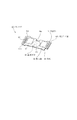
図1は第1の実施の形態による電子写真画像形成装置を示すものである。この装置は、レーザーダイオード、ポリゴンミラー、レンズ、反射ミラーを備えた光学手段1と、光学手段1から得られる画像情報に応じたレーザー光を照射する。これによってプロセスカートリッジ2の電子写真感光体である感光体ドラム11に画像情報に応じた潜像が形成される。この潜像は、現像手段によって現像され、可視像、すなわち、トナー像とされる。
【0031】
(画像形成装置の全体構成)
画像形成のためのプロセス手段の1つである現像手段は、感光体ドラム11にトナーを送り出す現像剤担持体である現像ローラ21と、現像ローラ21の表面に付着する現像剤の量を規制するための規制部材である現像ブレード22とからなる。また、現像ローラ21、及び、現像ブレード22とそれらを保持する現像枠体23と、現像剤を収容したトナー収納部24aを有するトナー収容容器24を結合して、現像装置である現像ユニット20を形成している。
【0032】
現像枠体23は現像室23aを有し、現像室23aに隣接するトナー収納部24a内のトナーはトナー送り部材25の回転によって、現像室23aの現像ローラ21へと送り出される。現像枠体23は、現像ローラ21の近傍に回動自在なトナー撹拌部材26を備えており、トナー収納部24aから送り出された現像室23a内のトナーを循環させる。また、トナーは磁性を有しており、現像ローラ21は固定磁石を内蔵しているため、現像ローラ21上にはトナーが付着する。
【0033】
そして現像ローラ21を回転することによってトナーは搬送され、現像ブレード22にて摩擦帯電電荷が付与される。そして、所定厚のトナー層が現像ローラ21上に形成され、感光体ドラム11の現像領域へと搬送される。この現像領域へと供給されたトナーは、前記感光体ドラム11上の前記潜像へと転移され、感光体ドラム11上にトナー像を形成する。なお、現像ローラ21は、画像形成装置本体に設けられている現像バイアス回路に接続されている。そして、通常交流電圧に直流電圧が重畳された現像バイアス電圧が印加される。
【0034】
一方、給送システム3は、上記トナー像の形成と同期して給紙カセット3aにセットした記録媒体Pをピックアップローラ3b、搬送ローラ対3c、3d、3eで転写位置へと搬送する。転写位置には、転写手段としての転写ローラ4が配置されており、電圧を印加することによって、感光体ドラム11上のトナー像を記録媒体Pに転写する。
【0035】
トナー像の転写を受けた記録媒体Pは、搬送ガイド3fで定着手段5へと搬送する。定着手段5は、駆動ローラ5c、及びヒータ5aを内蔵した定着ローラ5bを備え、通過する記録媒体Pに熱、及び圧力を印加して転写されたトナー像を記録媒体P上に定着する。
【0036】
記録媒体Pは、排出ローラ対3g、3hで搬送し、反転経路3jを経由して排出トレイ6へと排出される。この排出トレイ6は、画像形成装置本体の上面に設けられている。なお、揺動可能なフラッパ3kを動作させ、反転経路3jを介することなく記録媒体Pを排出することもできる。このように、上記ピックアップローラ3b、搬送ローラ対3c、3d、3e、搬送ガイド3f、排出ローラ対3g、3hによって搬送手段を構成している。
【0037】
転写ローラ4によってトナー像を記録媒体Pに転写した後の感光体ドラム11は、クリーニング手段12によって感光体ドラム11上に残留したトナーを除去した後、次の画像形成プロセスに供される。クリーニング手段12は感光体ドラム11に当接して設けられたクリーニングブレード12aによって感光体ドラム11上の残留トナーを掻き落として廃トナー溜め12bへと集める。
【0038】
(プロセスカートリッジの構成)
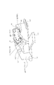
カートリッジ2は、図2に示すように、現像ローラ21を支持する現像枠体23にトナー収容容器24を溶着して、一体として現像ユニット20(現像装置)を形成している。トナー収容容器24は、トナーを収容するトナー収納部24aと、該トナー収納部24aのトナーを現像室23aに供給するためのトナー供給開口24bを形成し、そのトナー収納部24a内にトナー送り部材25を回動可能に支持している。なお、トナー供給開口24bは、カートリッジ2が使用される時までは、現像剤シール(不図示)によって封止されている。そして、カートリッジ2の最初の使用時にユーザーによって現像材シールが引き抜かれることによってトナーが供給可能となる。現像枠体23は、現像ローラ21及び現像ブレード22を支持している。
【0039】
また、クリーニングブレード12a、感光体ドラム11及び帯電ローラ7を枠体であるドラム枠体13で支持してクリーニングユニット10を形成している。
【0040】
そして、カートリッジ2は前記現像ユニット20及びクリーニングユニット10を結合して一体化することによってカートリッジ化されている。
【0041】
図3に示すように、感光体ドラム11の両端には、ギアフランジが取り付けられ、一方のギアフランジはドラム軸受14に回転可能に支持され、他方のギアフランジは、図4に示すようにドラム軸15で回転可能に支持される。そして、ドラム軸受14とドラム軸15はドラム枠体13に取り付けられ、クリーニングユニット10を構成している。
【0042】
(クリーニングユニットと現像ユニットの結合)
次に、クリーニングユニット10と現像ユニット20を結合する構成を説明する。図3及び図4に示すように、クリーニングユニット10と現像ユニット20は、両側のサイドカバー30、40によって結合される。一方のサイドカバー30は基準穴31をドラム軸受14の円筒部14aと嵌合させることによってクリーニングユニット10と位置決めされ、ビス51によって固定される。そしてサイドカバー30の基準ボスと現像ユニット20の基準穴を猷合させることによって現像ユニット20が位置決めされ、上記と同様にビス52によって固定される。
【0043】
他方のサイドカバー40は、基準穴41と感光体ドラム11のドラム軸15の円筒部15aが嵌合することによってクリーニングユニット10と位置決めされ、ビス53で固定される。また、現像ユニット20も反対側と同様にビス54によって固定される。
【0044】
(プロセスカートリッジの装着ガイド手段の構成)
次に、カートリッジ2を本体100に着脱する際の装着ガイド手段を図15、及び、図16に基いて説明する。図15は、カートリッジ2を本体100に装着する装着方向(矢印Xの方向)に見た場合の現像ユニット20の右側に位置する本体100の一部を示す斜視図である。また、図16は、同じく現像ユニット20の左側に位置する本体100の一部を示す斜視図である。
【0045】
クリーニングユニット10の両外側面においては、図3、図4に示すドラム軸受14の円筒部14a外径とドラム軸15の円筒部15a外径により、カートリッジ2を本体100に着脱するときのカートリッジ側のガイド部材が構成される。
【0046】
図3ないし図6に示すように、プロセスカートリッジ本体(ユニット本体)であるクリーニングユニット10を構成するドラム枠体13の上面、すなわち、カートリッジ2を本体100に装着した際の、上方に位置する面には、プロセスカートリッジ装着方向に対して直交する長手方向の端部にそれぞれ回転規制当接部である規制当接部16a、17aが設けられている。両規制当接部16a、17aは、前記装着方向に延在する装着案内部(溝部)である溝16、17の末端の底部に配設されている。そして、カートリッジ2を本体100に装着した際に、カートリッジ2の回動位置を規定するものである。
【0047】
すなわち、カートリッジ2を本体100に装着した際に、図15及び図16に示すように、画像形成装置の本体100に設けられた本体回転規制部材である固設部材101、102の先端に前記規制当接部16a、17aがそれぞれ当接する。
【0048】
そして、カートリッジ2はドラム軸受14の円筒部14a、ドラム軸15の円筒部15aを中心とする回動位置が規定される。
【0049】
次に本体100に設けられたガイド壁について述べる。図1に示す本体100の開閉部材100aを支点を中心に反時計回りに回動すると、本体100の上部が開放される。図15及び図16は、この状態のカートリッジ2の左右両端における本体100への装着ガイド手段を示す部分斜視図である。すなわち、開閉部材100aを開けた開口部から本体100の両側の内壁を、前述のように、カートリッジ2の着脱方向(X方向)から見た右側が図15、左側が図16である。
【0050】
本体100の右側の内壁には、図15に示すようにガイド部材(装着手段)121が配設され、左側の内壁には図16に示すガイド部材122(装着手段)が形成されている。
【0051】
ガイド部材121、122には、それぞれカートリッジ2の挿入方向(装着方向)である矢印Xの方向から見て前下りになるように斜設したガイド部121a、122aを備えている。また、ガイド部材121、122には、このガイド部121a、122aにそれぞれつながっている。そして、カートリッジ2のドラム軸受14の位置決め部材である円筒部14a、及び、ドラム軸15の位置決め部材である円筒部15aが、丁度嵌入する半円形の装置位置である位置決め溝121b、122bを備えている。この位置決め溝121b、122bは周壁が円筒形をしている。そして、この位置決め溝121b、122bの中心が、カートリッジ2を本体100に装着したときのカートリッジ2のドラム軸受14の円筒部14a、ドラム軸15の円筒部15aの中心とそれぞれ一致し、感光体ドラム11の軸線である中心線とも一致する。
【0052】
ガイド部材121、122の幅は、カートリッジ2の着脱方向から見てドラム軸受14の円筒部14a、ドラム軸15の円筒部15aが遊嵌する幅を有する。そして、カートリッジ2が本体100へ装着された状態においては、カートリッジ2のドラム軸受14の円筒部14a、ドラム軸15の円筒部15aがそれぞれ本体100のガイド部材121、122の位置決め溝121b、122bに嵌合する。そしてさらに、カートリッジ2のドラム枠体13の両側の規制当接部16a、17aが本体100の固設部材101、102の先端に当接するようになっている。
【0053】
(レーザーシャッターの構成)
図17に示すように、本体100へカートリッジ2が装着されていない状態で、光学手段1からレーザー光が漏れないように、レーザー光路を遮断するための露光光遮蔽部材であるシャッター130が設けられる。
【0054】
シャッター130は、支軸等(不図示)によって、画像形成装置の本体100にシャッター支店131のまわりに回動可能に設けられている。シャッター130を回動させるためのシャッターリンク132は、軸受等(不図示)により本体100に回動可能に設けられている。さらに、このリンク132は、図19に示すように、矢印Xで示すカートリッジ2の装着方向(図中手前から奥へ向かう方向)と交差するY方向において、カートリッジ2が装着された際に、ドラム枠体13の規制当接部16aが当接する固設部材101と、本体100の右側側壁との間に配置されている。さらに、カートリッジ2の装着方向においては、リンク132の当接部132aは固設部材101の奥側に配置されている。
【0055】
次に、シャッター130とリンク132の動作について説明する。
【0056】
本体100にカートリッジ2が装着されていない際には、シャッター130はバネ等(不図示)によってシャッター支点131を中心にして、図17において、時計回り方向に付勢されている。そして、シャッター部130aが光学手段1に当接した位置で、レーザー光路を遮光している。そして、本体100にカートリッジ2が装着される工程で、ドラム枠体13の溝16の壁部材であるリブ18が駆動部材としてリンク132の当接部132aと当接する(図4及び図18参照)。このように、カートリッジ2のドラム枠体13のリブ18と当接部132aとが当接すると、リンク132は支軸132bを中心にして、図17において時計回りに回転する。
【0057】
このとき、リンク132のボス132cがシャッター130の当接部130bと当接して押される。これによって、シャッター130はシャッター支点131を中心にして反時計回りに回転し、シャッター部130aをレーザー光路から退避させる。
【0058】
その結果、カートリッジ2が本体100の所定位置に装着された際には、レーザー光路はシャッター130のシャッター部130aによって遮ぎられることはなく、レーザー光を確実に感光体ドラム11に照射することができる。
【0059】
(メモリタグの構成)
図3ないし図6に示すように、カートリッジ2のドラム枠体13の表面には基体であるメモリタグ60が取り付けられている。メモリタグ60は図7及び図8に示すように、記憶素子61とカートリッジ電気接点部である62と後述するコネクタ140の突き当て部141が当接する当接部63を基板(プリント基板)64上に配置した札状部材である(図13参照)。ここで接点部62は、導電材料からなり、記憶素子61と電気的に接続されている。
【0060】
記憶素子61は中央に配置され、樹脂によるコーティング層65(保護部)で保護されている。また、接点部62は記憶素子61を保護するコーティング層65と同一面で、かつ記憶素子61の両側に並設されている。さらに、接点部62の近傍には、図13に示すコネクタ140の突き当て部141が当接する当接部63が並んで設けられている。
【0061】
図13及び図14に示すように、コネクタ140には弾性変形することで接触圧を生じる金属製の電気接点142、(本体電気接点)が設けられている。そして、突き当て部141がメモリタグ60の基体当接部である当接部63と当接することで、電気接点142のたわみ量が一定となり、メモリタグ60の接点部62に対する接触圧を所望の接点圧とし、導通を安定させることができる。
【0062】
さらに、メモリタグ60の当接部63は接点部62と同一高さの平面とすることで、メモリタグ60内での当接部63と接点部62との高さ方向の寸法精度を高めている。これによって、コネクタ140の電気接点142の接点圧のより一層の安定が図れる。
【0063】
また、メモリタグ60の記憶素子61を保護するコーティング層65(保護部)の両側に接点部62を設け、当接部63を両接点部62の延長線上で、かつ、接点部62に隣接するように平面的に配置した。
【0064】
このような当接部63を設けることによって、図13、図14に示すコネクタホルダ150の回転軸151からのコネクタ140の突き当て部141までの距離L1と電気接点142までの距離L2の長さがほぼ等しくできるので、突き当て部141の高さの寸法バラツキの影響を受けにくく、電気接点142の接触圧を安定させることができる。
【0065】
また、メモリタグ60の当接部63が接点部62に並設され、コネクタ140の突き当て部141と電気接点142との距離がほぼ等しいため、圧バランスが均等になり、接点部62の接触圧不足等による導通不良を防止することができる。
【0066】
次にメモリタグ60の取付構成について説明する。
【0067】
図7及び図8に示すように、メモリタグ60の一側縁には、長手方向で接点部62の間に凹形状の溝部60aが設けられている。そして、カートリッジ2には、メモリタグ60の長手方向に直交する接点位置決め部であるリブ71が形成され、メモリタグ60の凹形状の切り欠き部である溝部60aをリブ71に嵌合させることで長手方向位置決めを行なっている。また、短手方向は、カートリッジ2の位置決め部72a、72bヘメモリタグ60の突き当て部60bを突き当てて、幅寸法60b1による位置決めを行なう。
【0068】
さらに、図9及び図10に示すように、短手方向は、カートリッジ2の位置決め部72ヘメモリタグ60の突き当て部60bを突き当てることで位置決めを行なっても良い。突き当てによる位置決めを行なうことで、カートリッジ2のメモリタグ60の取付部の成形金型の抜き方向が、メモリタグ60の接点部62を含む表面と平行でなくても、短手方向の位置決めが行なえる。
【0069】
以上の位置決めを行なうことで、カートリッジ2のメモリタグ60の取付部の成形金型の抜き方向が、メモリタグ60の接点部62を含む表面と平行でなくても、長手方向及び短手方向の位置決めが行なえる。そのため、金型構成がメモリタグ60の長手方向位置決め、及び、短手方向位置決めを左右することなく、複数の製品で使用することができ、マスメリットによるコストダウンが図れる。
【0070】
また、位置決め形状を穴(丸穴、角穴)で行なうと、メモリタグが大型になる。しかし、上記のように凹形状の切り欠き部にすることで、メモリタグの大型化を抑えることができる。
【0071】
さらに、位置決め形状を穴(丸穴、角穴)で行なうと、位置決め穴と位置決めボスの嵌合時に、こじりの可能性がある。特に本実施の形状では、0.6mm程度の薄板の基板を用いているので、こじりの可能性は大きい。しかし、上記のように凹形状にすれば、こじりの可能性もなく、組立性がさらに良くなる。
【0072】
次に、本体100側に配設されたコネクタ構成を説明する。
【0073】
図13に示すように、コネクタ140には弾性変形することで接触圧を生じる金属製の本体電気接点である電気接点142を、メモリタグ60の接点部62の1個に対して、1つないしは2つ配置してある。また、この電気接点142の脇にはメモリタグ60の当接部63に当接する突き当て部141が長手方向両端付近に設けてある。電気接点142のメモリタグ60との接触部の反対側にはリード線が繁げられて本体100の制御部(不図示)と接続されている。
【0074】
コネクタホルダ150は、回転軸151と、コネクタ取付部152と、コネクタ140の長手位置決めを行なうための長手位置決めレバー153と、当接回転レバー154からなる。
【0075】
コネクタ140はコネクタホルダ150にスナップフィット、ネジ等によって固定されている(不図示)。また、コネクタホルダ150は前述のように、回転軸151上で回動し、また、図12に示すように、回転軸151は軸受151aで長手方向(矢印C方向)にスライド可能に本体100に保持されている。
【0076】
次に、カートリッジ2を本体100に装着する動作に従って、コネクタ140とメモリタグ60との通電接続を説明する。
【0077】
カートリッジ2の右側の規制当接部16aは、本体100のレーザー光遮蔽部材(露光光遮蔽部材)であるシャッター130を開閉するリブ18を壁部材とする装着案内部である溝16内に設けられている。また、左側の規制当接部17aは、外側が開放された装着案内部である溝17内に設けられている。図12に示すように、カートリッジ2を本体100に矢印Xで示す方向に挿入すると、挿入途中で、本体100側の固設部材101を、カートリッジ2の溝16のカートリッジ装着案内部(壁面)16b、16cが挟み込み(図5及び図6参照)、カートリッジ2の装着方向と交差する方向のガイドを行なう。さらにカートリッジ2を挿入していくと、長手方向(前記交差する方向)に移動可能に配置された本体電気接点支持部材であるコネクタホルダ150の、本体支持部材位置決め部である長手位置決めレバー153も、前記溝16の先端部の16b、16c間に入る。そして、コネクタ140のカートリッジ2に対する長手方向位置決めが行なわれる。
【0078】
すなわち、前記装着案内部である溝16の壁面16b、16cはカートリッジ2の装着方向と交差する方向のガイドを行なうためのカートリッジ装着案内部である。また壁面16b、16cは、カートリッジ2に対して電気接点142を有するコネクタ140の長手方向位置決めを行なうためのカートリッジ支持部材位置決め部でもある。
【0079】
さらに、溝16の底部16aは、本体回転規制部である固設部材101と当接して、カートリッジ2の回転を規制する回転規制当接部である。よって、カートリッジ2の小型化が可能となる。また、本体回転規制部である固設部材101は、カートリッジ2の装着方向と交差する方向のガイドを行なう本体カートリッジ装着案内部でもあるので、装置本体の小型化も可能になる。さらに、カートリッジ2が挿入されると、カートリッジ2の挿入方向先端部がコネクタホルダ150の当接回転レバー154と当接し、コネクタ140はコネクタホルダ150の回転軸151を中心にメモリタグ60側に回転する(図11において時計回り)。
【0080】
そして、カートリッジ2のドラム軸受14の円筒部14a、ドラム軸15の円筒部15aが本体100の位置決め溝121b、122bに到達する(図15及び図16参照)
カートリッジ2はドラム軸受14の円筒部14a、ドラム軸15の円筒部15aの中心を結ぶ中心線に対し、クリーニングユニット10側と現像ユニット20側では、この中心線を水平に保つと現像ユニット20側がクリーニングユニット10側よりも大きな一次モーメントを生ずるような重量配分になっている。そのため、カートリッジ2はドラム軸受14の円筒部14a、ドラム軸15の円筒部15aを結ぶ線上で時計回りに回動し、固設部材101、102の先端にカートリッジ2の規制当接部16a、17aが当接し、カートリッジ2の挿入動作が完了する。また、それと同時に、コネクタ140はメモリタグ60に当接する。
【0081】
前述のように、カートリッジ2のメモリタグ60近傍に溝16を配置し、本体100のコネクタ140を取り付けたコネクタホルダ150を溝16のカートリッジ支持部材位置決め部である16b、16cによって位置決めすることにより、メモリタグ60の接点部62とコネクタ140とは精度良く当接・維持させることができる。これによって、メモリタグ60の接点ズレを防ぎ、また、コネクタユニットの小型化が図れる。
【0082】
さらに、前記溝16は本体100にカートリッジ2を装着するときの装着方向と交差する方向のカートリッジ装着案内部を兼ねているので、コネクタユニットの長手方向の移動可能幅を小さくすることができ、コネクタユニットの移動可能幅を含む本体100側のスペースを小さくできる。また、前述の構成によって、レバー153を溝16にスムーズに挿入することができる。
【0083】
また、本体100のシャッター130を開閉するためのリブ18を前記溝16を形成する一端の壁部材とすることで、スペースをより一層有効に活用できる。
【0084】
さらに、前述のように、前記溝16はカートリッジ2の装着時の装着方向と交差する方向のカートリッジ装着案内部も兼ねているので、本体100側のシャッター130の開閉機構との位置精度が向上し、本体100のレーザーシャッター設置部の小型化にも貢献できる。
【0085】
(第2の実施の形態)
本実施の形態では、前述の第1の実施の形態と異なる項目のみを説明し、他の第1の実施の形態と同様の構成については説明を省略する。
【0086】
次に、本体100側に配設されたコネクタ構成を説明する。
【0087】
図20及び図21に示すように、コネクタ140には弾性変形することで、接触圧を生じる金属製の本体電気接点である電気接点142を、メモリタグ60の接点部62の1個に対して、1つないしは2つ配置してある。また、この電気接点142の脇にはメモリタグ60の当接部63(図7及び図9参照)に当接する突き当て部141が長手方向両端付近に設けてある。電気接点142のメモリタグ60との接触部の反対側にはリード線が繋げられて本体100の制御部(不図示)と接続されている。
【0088】
コネクタホルダ150は回転軸151とコネクタ取り付け部152と本体支持部材位置決め部である長手位置決めレバー153からなる。
【0089】
コネクタ140はコネクタホルダ150にスナップフィット、ネジ等によって固定されている(不図示)。また、コネクタホルダ150は前述のように、回転軸151上で回動し、また、回転軸151は軸受151aで長手方向(矢印C方向カートリッジ2の装着方向と交差する方向)にスライド可能に本体100に保持されている。そして、バネ155によってコネクタホルダ150は矢印Y方向に付勢されている。
【0090】
次に、カートリッジ2を本体100に装着する動作に従って、コネクタ140とメモリタグ60との接続を説明する。
【0091】
また、第1の実施の形態と同様にカートリッジ2の右側の規制当接部16a(不図示)は、本体100のレーザー光遮蔽部材(露光光遮蔽部材)であるシャッター130を開閉するリブ18を壁部材とする装着案内部である溝16内に設けられている。また、左側の規制当接部17aは、外側が開放された装着案内部である溝17内に設けられている(不図示)。図21、図25及び図26に示すように、カートリッジ2を本体100に矢印Xで示す方向に挿入すると、挿入途中で、本体100側の固設部材101を、溝16のカートリッジ装着案内部16b、16c(不図示)が挟み込み、カートリッジ2の装着方向と交差する方向のガイドを行なう。さらにカートリッジ2を挿入していくと、長手方向に移動可能に配置されたコネクタホルダ150の本体支持部位置決め部である長手位置決めレバー153も前記溝16の先端部の16b、16c間に入り、コネクタ140のカートリッジ2に対する長手方向位置決めが行なわれる。
【0092】
すなわち、前記装着案内部である溝16の壁面16b、16cは、カートリッジ2の装着方向と交差する方向のガイドを行なうためのカートリッジ装着案内部である。また壁面16b、16cは、カートリッジ2に対して電気接点142を有するコネクタ140の長手方向位置決めを行なうための、カートリッジ支持部材位置決め部でもある。さらに、溝16の底部16aは、本体回転規制部である固設部材101と当接して、カートリッジ2の回転を規制する回転規制当接部である。よって、カートリッジ2の小型化が可能となる。また、本体回転規制部である固設部材101は、カートリッジ2の装着方向と交差する方向のガイドを行なう本体カートリッジ装着案内部でもあるので装置本体の小型化も可能になる。
【0093】
また、図21に示すように、カートリッジ2のドラム枠体13には、メモリタグ60取り付け部の長手両側端部付近にカートリッジ当接部であるコネクタホルダガイド19が設けられている。そして、コネクタホルダ150は、前述の通り、バネ155によって矢印Y方向に付勢されている。そこで、図22に示すように、カートリッジ2が、さらに、挿入されると、コネクタホルダガイド19にコネクタホルダ150に設けられた本体当接部であるガイドリブ156が当接・摺動する。このとき、コネクタ140の電気接点142及び当接部63は、メモリタグ60、及び、メモリタグ60を保持している枠体であるドラム枠体13との接触はない。
【0094】
コネクタホルダガイド19は、前述の構成が得られるような高さh1に設定されている。また、図37、図38に示すように、カートリッジ装着方向と交差する方向において、メモリタグ60と並んで設けられたコネクタホルダガイド19のカートリッジ装着方向上流側には、傾斜面19aが設けられている。そして、傾斜面19aのカートリッジ装着方向上流側の端部19bが、図37に示すように、カートリッジ装着方向における接点部62の長さL3の間に位置する構成になっている。前術の構成によって、ガイドリブ156が傾斜面19aに沿って下降する。そして、本体100の所定の装着位置に装着される直前に、電気接点142がメモリタグ60の接点部62に当接するようにコネクタホルダ150がガイドされる。前述の構成により電気接点142と接点部62とが接触するときに電気接点142に衝撃が加わることなく、スムーズに接触することができる。そして、図23及び図24に示すように、突き当て部141がメモリタグ60の当接部63と当接して、ガイドリブ156は枠体表面である凹部13aと対応する位置にきて、枠体13とは離間する(図24は、コネクタ140がメモリタグ40と当接した状態(図23)時の、コネクタホルダガイド19とガイドリブ156の位置関係を示す断面図である)。
【0095】
また、メモリタグ60は、カートリッジ枠体13の上面側から突出した設置部13bに設けられる。そして、前記設置部13bの高さは、プロセスカートリッジが前記装置位置に装着された際に、図24にも示すようにガイドリブ156とカートリッジ枠体の表面13aとの間に隙間が生じる高さに設定されている。
【0096】
そして、カートリッジ2の位置決め部材であるドラム軸受14の円筒部14a、及び、ドラム軸15の円筒部15aが本体100の位置決め溝121b、122bに到達する(図25及び図26参照)。
【0097】
カートリッジ2はドラム軸受14の円筒部14a、ドラム軸15の円筒部15aの中心を結ぶ中心線回りのクリーニングユニット10側と現像ユニット20側の一次モーメントの関係は、現像ユニット20側がクリーニングユニット10側よりも大きな一次モーメントを生ずるような重量配分になっている。そのため、カートリッジ2はドラム軸受14の円筒部14a、ドラム軸15の円筒部15aを結ぶ線上で時計回りに回動し、固設部材101、102の先端にカートリッジ2の規制当接部16a、17aが当接し、カートリッジ2の挿入動作が完了する。
【0098】
上述の構成によって、本体100に装着中のカートリッジ2の姿勢のばらつきによって、本体100のコネクタ140の電気接点142が、メモリタグ60以外(例えば、メモリタグ60のカートリッジ2挿入方向先端側に設けられたリブ13b等)に接触することを防止して、電気接点142と安定して確実に接触して、信頼性のある導通が確保できる。
【0099】
また、電気接点142のたわみ量が一定となり、メモリタグ60の接点部62に対する接触圧を所望の接点圧とし、導通を安定させることができる。
【0100】
また、第1の実施の形態と同様に、前述のように、カートリッジ2のメモリタグ60近傍に溝16を配置し、本体100のコネクタ140を取り付けたコネクタホルダ150を溝16のカートリッジ支持部材位置決め部である16b、16cによって位置決めすることにより、メモリタグ60の接点部62とコネクタ140とは精度良く当接・維持させることができる。これによって、メモリタグ60の接点ズレを防ぎ、また、コネクタユニットの小型化が図れる。
【0101】
さらに、前記溝16は本体100にカートリッジ2を装着するときの装着方向と交差する方向のカートリッジ装着案内部を兼ねているので、コネクタユニットの長手方向の移動可能幅を小さくすることができ、コネクタユニットの移動可能幅を含む本体100側のスペースを小さくできる。また、前述の構成によって、レバー153を溝16にスムーズに挿入することができる。
【0102】
また、本体100のシャッター130を開閉するためのリブ18を前記溝16を形成する一端の側壁とすることで、スペースをより一層有効に活用できる。さらに、前述のように、前記溝16はカートリッジ2の装着時の装着方向と交差する方向のカートリッジ装着案内部も兼ねているので、本体100側のシャッター130の開閉機構との位置精度が向上し、本体100のレーザーシャッター設置部の小型化にも貢献できる。
【0103】
(第3の実施の形態)
本実施例では、前述の第1、2の実施例と異なる項目のみを説明し、他の第1、2の実施例と同様の構成については説明を省略する。
【0104】
次に、本体100側に配設されたコネクタ構成を説明する。
【0105】
図27に示すように、コネクタ140には弾性変形することで接触圧を生じる金属製の電気接点142をメモリタグ60の接点部62の1個に対して、1つないしは2つ配置してある。また、この電気接点142の脇にはメモリタグ60の当接部63(図7及び図9参照)に当接する突き当て部141が長手方向両端付近に設けてある。電気接点142のメモリタグ60との接触部の反対側にはリード線が繋げられて本体100の制御部(不図示)と接続されている。
【0106】
コネクタホルダ150は、回転軸151と、コネクタ取付部152と、本体支持部材位置決め部である長手位置決めレバー153とからなる。
【0107】
コネクタ140はコネクタホルダ150にスナップフィット、ネジ等によって固定されている(不図示)。また、図27に示すように、コネクタホルダ150は前述のように、回転軸151上で回動し、また、回転軸151は軸受151aで長手方向(矢印C方向、カートリッジの装着方向と交差する方向)にスライド可能に本体100に保持されている。そして、バネ155によってコネクタホルダ150は矢印Y方向に付勢されている。
【0108】
次に、カートリッジ2を本体100に装着する動作に従って、コネクタ140とメモリタグ60との接続を説明する。
【0109】
また、実施例1、2と同様にカートリッジ2の右側の規制当接部16aは、本体100のレーザー光遮蔽部材(露光光遮蔽部材)であるシャッター130を開閉するリブ18を壁部材とする装着案内部である溝16内に設けられている(不図示)。また、左側の規制当接部17aは、外側が開放された装着案内部である溝17a内に設けられている(不図示)。図28及び図32及び図33に示すように、カートリッジ2を本体100に矢印Xで示す方向に挿入すると、挿入途中で、本体100側の固設部材101を、図5、6に示す溝16のカートリッジ装着案内部である16b、16cが挟み込み、カートリッジ2の装着方向と交差する方向のガイドを行なう。さらにカートリッジ2を挿入していくと、長手方向に移動可能に配置されたコネクタホルダ150の本体支持部材位置決め部である長手位置決めレバー153も前記溝16の先端部の16b、16cに入り、コネクタ140のカートリッジ2に対する長手方向位置決めが行なわれる。
【0110】
すなわち、前記装着案内部である溝16の壁面16b、16cは、カートリッジの装着方向と交差する方向のガイドを行なうためのカートリッジ装着案内部である。また、壁面16b、16cは、カートリッジ2に対して電気接点142を有するコネクタ140の長手方向位置決めを行なうための、カートリッジ支持部材位置決め部でもある。さらに、溝16の底部16aは、本体回転規制部である固設部材101と当接して、カートリッジ2の回転を規制する回転規制当接部である。よって、カートリッジ2の小型化が可能となる。また、本体回転規制部である固設部材101は、カートリッジ2の装着方向と交差する方向のガイドを行なう本体カートリッジ装着案内部でもあるので、装置本体の小型化も可能になる。
【0111】
また、図28に示すように、カートリッジ2には、メモリタグ60取り付け部の長手両側端部付近に、カートリッジ2の本体100への挿入方向に平行なリブ状のコネクタホルダガイド19が複数本設けられている。そして、コネクタホルダ150は、前述の通り、バネ155によって矢印Y方向に付勢されている。そこで、図29に示すように、カートリッジ2が、更に挿入されると、コネクタホルダガイド19の19c部分に、コネクタホルダ150に設けられた本体当接部であるガイドリブ156が当接したのち摺動する(場合によっては、ガイドリブ15が最初にコネクタホルダガイド19の19d部分に当接したのち、19c部分へ摺動する)。このとき、コネクタ140の電気接点142、及び、当接部63(図7参照)は、メモリタグ60、及び、メモリタグ60を保持している枠体13に接触しない。コネクタホルダガイド19は、前述の構成が得られるような高さh1に設定されている。また、図37、図38に示すように、カートリッジ装着方向と交差する方向において、メモリタグ60と並んで設けられたコネクタホルダガイド19のカートリッジ装着方向上流側には、傾斜面19aが設けられている。そして、傾斜面19aのカートリッジ装着方向上流側の端部19bが、図37に示すように、カートリッジ装着方向における接点部62の長さL3の間に位置する構成になっている。前述の構成によって、ガイドリブ156が傾斜面19aに沿って下降する。そして、本体100の所定の装着位置に装着される直前に、電気接点142がメモリタグ60の接点部62に当接するようにコネクタホルダ150がガイドされる。前述の構成によって、電気接点142と接点部62とが、接触する時に電気接点142に衝撃が加わることなく、スムーズに接触することができる。そして、図30及び図31に示すように、突き当て部141がメモリタグ60の当接部63(図7参照)と当接して、ガイドリブ156は枠体の表面である13aと対応する位置にきて、枠体13とは離間する。(図31は、コネクタ140がメモリタグ40と当接した状態(図30)の、コネクタホルダガイド19とガイドリブ156の位置関係を示す断面図である。)また、メモリタグ60は、カートリッジ枠体13の上面側から突出した設置部13bに設けられる。そして、前記設置部13bの高さは、プロセスカートリッジが前記装置位置に装着された際に、図24にも示すようにガイドリブ156と凹部13aとの間に隙間が生じる高さに設定されている。
【0112】
また、図27、29、30、31に示すように、カートリッジ2の装着方向前方下部に押圧部材160が配置されている。
【0113】
この押圧部材160は、本体100フレーム部材(不図示)に支点161で回動可能に支持されており、引張りバネ162で、矢印Z方向に付勢されている。なお、押圧部材160はカートリッジの下面に設けられた被押圧部13aに当接するまでは、ストッパー163に当接した位置にある。
【0114】
また、図34に示す通り、本実施形のカートリッジの被押圧部13aの長手配置は、メモリタグ60とカートリッジの規制当接部16aの間で、通紙領域の外側である。
【0115】
この押圧部材160によって、上述のカートリッジ2が、本体100の所定の位置に装着される動作と、ほぼ同時に、押圧部材160がカートリッジ2の被押圧部13aに当接する。
【0116】
そして、カートリッジ2のドラム軸受14の円筒部14a(図6参照)、ドラム軸15の円筒部15a(図5参照)が本体100の位置決め溝121b、122bに到達する(図32及び図33参照)。
【0117】
また、ドラム軸受14の円筒部14aと、ドラム軸15の円筒部15aの中心を結ぶ中心線(以下、ドラム軸線と呼ぶ)まわりにおいて、クリーニングユニット10側と現像ユニット20側の一次モーメントの関係は、現像ユニット20側が下方向に回転するモーメントが、クリーニングユニット10側が下方向に回転するモーメントの方よりも、大きなモーメントを生ずるような重量配分になっている。
【0118】
また、ドラム軸線まわりには、メモリタグ60においてコネクタの矢印Y方向の力によるモーメントが発生する。しかし、押圧部材160によって、カートリッジ2の被押圧部13aが矢印Z方向に押される為、前記コネクタ140によるモーメントと反対方向のモーメントが発生する。なお、後述のカートリッジ2の規制当接部16a、17aが固設部材101、102の先端に確実に当接するためには、カートリッジ2のドラム軸線まわりのモーメントの関係は、コネクタ140によるモーメント≦押圧部材160によるモーメントであることが望ましい。
【0119】
そして、図35に示すように、カートリッジ2はドラム軸線上(図35では感光体ドラム11中心)で時計回りに回動し、図36に示す固設部材101、102の先端にカートリッジ2の規制当接部16a、17a(不図示)が当接し、カートリッジ2の挿入動作が完了する。
【0120】
また、感光体ドラム11が本体100の駆動手段(不図示)から回転駆動を受けた際に、感光体ドラム11は時計回りに回動するため、カートリッジ2も時計回りに回転することになる。よって、本体100から回転駆動を受けた際も、常に、規制当接部16a、17aが本体100の固設部材101、102の先端にカートリッジ2の規制当接部16a、17a(不図示)が当接した状態になっている。
【0121】
なお、上記構成において、カートリッジの被押圧部13aを下面側(通紙面側)に配置しているが、カートリッジの被押圧部13a及び本体押圧部160の断面配置は、カートリッジ2のドラム軸線に対し、矢印Y方向の力に抗するモーメントが得られる位置であれば良い。
【0122】
また、長手方向の配置においても、望ましくはコネクタ140と同位置であるが、その近傍であれば、同様の効果が得られる。
【0123】
上述の構成によって、カートリッジ2の規制当接部16a、17aが固設部材101、102の先端に確実に当接する為、カートリッジ2の本体との位置決めが正確に行なえる。
【0124】
また、カートリッジ2とコネクタ140の位置決めも正確に行なえるため、電気接点142のたわみ量が一定となり、メモリタグ60の接点部62に対する接触圧を所望の接点圧とし、導通を安定させることができる。
【0125】
また、上述のように、カートリッジ2はドラム軸線まわりのクリーニングユニット10側と現像ユニット20側の一次モーメントの関係は、現像ユニット20側がクリーニングユニット10側よりも大きなモーメントを生ずるような重量配分になっている。しかし、カートリッジの現像ユニット20内のトナーが大量に消費され、かつ、クリーニングユニット10内に廃トナーが溜ってきた場合に、現像ユニット20側が下方向(時計回り方向)に回転するモーメントが小さくなり、クリーニングユニット10側が下方向(反時計回り方向)に回転するモーメントが大きくなる。
【0126】
さらに、本体100からカートリッジ2に駆動伝達(回転駆動)を受けていない場合は、本体100の固設部材101、102の先端にカートリッジ2の規制当接部16a、17a(不図示)が当接する方向の力も働かない。
【0127】
従って、押圧部材160でカートリッジ2の被押圧部13aを押圧することで、本体100の固設部材101、102の先端にカートリッジ2の規制当接部16a、17aを当接させて、カートリッジ2の円筒部14a、15aを中心に時計回りの回転方向の位置決めをすることができる。よって、カートリッジ2の現像ユニット20内のトナーが大量に消費された場合、また、本体100からカートリッジ2に駆動伝達(回転駆動)を受けていない場合に、コネクタ140による矢印Y方向のモーメントによる、規制当接部16a、17aが固設部材101、102の先端の離間、あるいは、メモリタグ60の接点部62に対するコネクタ140の接点圧不足の発生を防止することができる。
【0128】
すなわち、カートリッジ2のトナーの消費量に関係なく、さらに、カートリッジ2が本体100から駆動伝達されていない場合でも、電気接点42と接点部62との電気的接続の信頼性を向上させることができる。
【0129】
これは、特に、カートリッジ2のトナー重量の変化量が大きい、大容量カートリッジ、さらに、メモリタグ60と本体100の制御部(不図示)との通信の迅速化に有効である。
【0130】
【発明の効果】
よって、以上説明したように、本発明は以下に記載するような効果を奏する。
【0131】
プロセスカートリッジのカートリッジ電気接点と、電子写真画像形成装置本体に設けられた本体電気接点との電気的接続が簡単な構成で可能になる。
【0132】
また、プロセスカートリッジを電子写真画像形成装置本体に装着した際に、電子写真画像形成装置本体に設けられた本体電気接点と、カートリッジ電気接点部とを安定して確実に接触させることができる。
【0133】
また、プロセスカートリッジを電子写真画像形成装置本体に装着した際に、前記装置本体に設けられた本体電気接点が、プロセスカートリッジの枠体、及び、前記カートリッジ電気接点以外の基体に当接することなく、前記カートリッジ電気接点と接触することができる。
【0134】
また、プロセスカートリッジ、及び、電子写真画像形成装置本体の小型化、省スペースを実現することが可能になる。
【0135】
また、プロセスカートリッジを電子写真画像形成装置本体に装着した際に、電子写真画像形成装置本体に設けられた本体電気接点と、基体のカートリッジ電気接点部とを安定して確実に接触させることができる。
【0136】
また、プロセスカートリッジを電子写真画像形成装置本体に装着した際に、電子写真画像形成装置本体に設けられた本体電気接点と、プロセスカートリッジに設けられたカートリッジ電気接点部との接触の位置精度を向上させることができる。
【0137】
さらに、プロセスカートリッジを電子写真画像形成装置本体に装着する際に、前記装置本体に設けられた本体電気接点と、カートリッジ電気接点部とが、衝撃なくスムーズに接触することができる。
【図面の簡単な説明】
【図1】第1の実施の形態による電子写真画像形成装置を示す縦断面図である。
【図2】図1のプロセスカートリッジを示す断面図である。
【図3】図2のプロセスカートリッジを分解して示す分解斜視図である。
【図4】図2のプロセスカートリッジを分解して別方向からみた分解斜視図である。
【図5】図2のプロセスカートリッジを左側からみた斜視図である。
【図6】図2のプロセスカートリッジを右側からみた斜視図である。
【図7】メモリタグを示す斜視図である。
【図8】メモリタグをプロセスカートリッジに取り付けた状態を示す斜視図である。
【図9】メモリタグを示す斜視図である。
【図10】メモリタグをプロセスカートリッジに取り付けた状態を示す斜視図である。
【図11】メモリタグとコネクタの配置を示す側面図である。
【図12】メモリタグとコネクタの配置を示す拡大斜視図である。
【図13】コネクタを示す斜視図である。
【図14】コネクタを示す側面図である。
【図15】画像形成装置本体の右側の装着ガイド手段を示す斜視図である。
【図16】画像形成装置本体の左側の装着ガイド手段を示す斜視図である。
【図17】レーザーシャッターを説明する図である。
【図18】レーザーシャッターの駆動部を説明する図である。
【図19】レーザーシャッターの配置を説明する図である。
【図20】第2の実施の形態によるコネクタを示す斜視図である。
【図21】第2の実施の形態によるメモリタグとコネクタの配置を示す拡大斜視図である。
【図22】コネクタホルダガイドとガイドリブが当接した状態を示す縦断面図である。
【図23】コネクタとメモリタグが当接した状態を示す縦断面図である。
【図24】図23のときの、コネクタホルダガイドとガイドリブを示す縦断面図である。
【図25】画像形成装置本体の右側の装着ガイド手段を示す斜視図である。
【図26】画像形成装置本体の左側の装着ガイド手段を示す斜視図である。
【図27】コネクタを示す斜視図である。
【図28】メモリタグとコネクタの配置を示す拡大斜視図である。
【図29】コネクタホルダガイドとガイドリブが当接した状態示す縦断面図である。
【図30】コネクタとメモリタグが当接した状態を示す縦断面図である。
【図31】図23の時の、コネクタホルダガイドとガイドリブを示す縦断面図である。
【図32】画像形成装置本体の右側の装着ガイド手段を示す斜視図である。
【図33】画像形成装置本体の左側の装着ガイド手段を示す斜視図である。
【図34】プロセスカートリッジを底面からみた斜視図である。
【図35】プロセスカートリッジの縦断面図である。
【図36】プロセスカートリッジが画像形成装置へ装着完了した斜視図である。
【図37】プロセスカートリッジのコネクタホルダガイドとメモリタグとの位置関係を示す上面図である。
【図38】プロセスカートリッジのコネクタホルダガイドとメモリタグとの位置関係を示す縦断面図である。
【符号の説明】
1 光学手段
2 プロセスカートリッジ(カートリッジ)
3 給送システム
10 クリーニングユニット
11 感光体ドラム
12 クリーニング手段
13 ドラム枠体
13a 凹部
14 ドラム軸受
14a、15a 円筒部
15 ドラム軸
16、17 溝
16a、17a 規制当接部
18、13b、71 リブ
19 コネクタホルダガイド
20 現像ユニット
21 現像ローラ
24 トナー収容容器
30、40 サイドカバー
60 メモリタグ
60b1 位置決め部
61 記憶素子
62 接点部
63 当接部
64 基板
72、72a、72b 位置決め部
100 本体
101、102 固設部材
121、122 ガイド部材
130 シャッター
132 リンク
140 コネクタ
141 電気接点
142 突き当て部
150 コネクタホルダ
151 回転軸
153 長手位置決めレバー
154 当接回転レバー
155 バネ
156 ガイドリブ[0001]
BACKGROUND OF THE INVENTION
The present invention relates to a process cartridge that can be attached to and detached from an electrophotographic image forming apparatus main body, and an electrophotographic image forming apparatus. Here, the electrophotographic image forming apparatus forms an image on a recording medium using an electrophotographic image forming process. Examples of the electrophotographic image forming apparatus include an electrophotographic copying machine, an electrophotographic printer (for example, a laser beam printer, an LED printer, etc.), a facsimile machine, a word processor, and the like.
[0002]
Further, the process cartridge is a cartridge in which a charging unit, a developing unit, or a cleaning unit as a process unit and an electrophotographic photosensitive member are integrally formed, and the cartridge can be attached to and detached from the main body of the electrophotographic image forming apparatus. It is. Further, at least one of charging means, developing means, and cleaning means as process means and an electrophotographic photosensitive member are integrated into a cartridge so as to be detachable from the main body of the electrophotographic image forming apparatus, and at least as process means This means that the developing means and the electrophotographic photosensitive member are integrally formed into a cartridge that can be attached to and detached from the electrophotographic image forming apparatus main body.
[0003]
[Prior art]
Conventionally, in an electrophotographic image forming apparatus using an electrophotographic image forming process, the electrophotographic photosensitive member and the process means acting on the electrophotographic photosensitive member are integrally formed into a cartridge, and the cartridge is attached to and detached from the image forming apparatus main body. A process cartridge system that enables this is adopted. According to this process cartridge system, the maintenance of the apparatus can be performed by the user himself / herself without depending on the service person, so that the operability can be remarkably improved. Therefore, this process cartridge system is widely used in electrophotographic image forming apparatuses.
[0004]
In recent years, products in which a memory (storage element) that stores various service information and process information is mounted on a cartridge have been realized. The electrophotographic image forming apparatus further improves image quality and cartridge maintenance by utilizing the memory information of the cartridge. Some of them are in electrical communication with the memory of the cartridge by making an electrical connection with a connector provided in the main body of the electrophotographic image forming apparatus.
[0005]
[Problems to be solved by the invention]
However, when a conventional contact-type connector is used, there is a possibility that the communication mechanism on the electrophotographic image forming apparatus main body side and the contact portion of the memory on the cartridge side may be complicated in order to achieve reliable electrical connection. It was.
[0006]
The present invention has been made in view of the unsolved problems of the prior art.
[0007]
An object of the present invention is to provide a process cartridge and an electrophotographic image forming apparatus in which a cartridge electrical contact portion of a process cartridge and a main body electrical contact of the electrophotographic image forming apparatus can be electrically connected with a simple configuration. is there.
[0008]
Another object of the present invention is that when the process cartridge is mounted on the electrophotographic image forming apparatus main body, the main body electrical contact provided on the main body of the apparatus and the cartridge electric contact portion are in stable and reliable contact. An object of the present invention is to provide a process cartridge and an electrophotographic image forming apparatus.
[0009]
Another object of the present invention is that when the process cartridge is mounted on the electrophotographic image forming apparatus main body, the main body electrical contact provided on the apparatus main body is other than the frame of the process cartridge and the cartridge electric contact. It is an object of the present invention to provide a process cartridge and an electrophotographic image forming apparatus that can come into contact with the cartridge electrical contact without contacting the substrate.
[0010]
Another object of the present invention is to provide a process cartridge and an electrophotographic image forming apparatus that achieve a reduction in size and space.
[0011]
Another object of the present invention is that when the process cartridge is mounted at the apparatus position of the electrophotographic image forming apparatus main body, the main body electrical contact and the cartridge electric contact portion provided in the apparatus main body are stable and reliable. The present invention provides a process cartridge and an electrophotographic image forming apparatus that can come into contact with each other.
[0012]
Another object of the present invention is that when the process cartridge is mounted on the electrophotographic image forming apparatus main body, the accuracy of the position where the main body electrical contact provided in the apparatus main body and the cartridge electric contact portion come into contact with each other is good. A process cartridge and an electrophotographic image forming apparatus are provided.
[0013]
Another object of the present invention is that when the process cartridge is mounted on the electrophotographic image forming apparatus main body, the main body electrical contact provided on the main body of the apparatus and the cartridge electrical contact portion of the base body smoothly and without impact. It is an object of the present invention to provide a process cartridge and an electrophotographic image forming apparatus that can come into contact with each other.
[0018]
[Means for Solving the Problems]
A typical configuration of the present invention for achieving the above object is as follows.
In a process cartridge detachably attached to an electrophotographic image forming apparatus main body having a movable connector holder having a main body electrical contact, a main body pressing means, and a fixed member,
An electrophotographic photosensitive drum;
Process means acting on the electrophotographic photosensitive drum;
A frame,
A storage element for storing information;
A cartridge electrical contact portion electrically connected to the storage element, the cartridge electrical contact portion electrically connected to the body electrical contact when the process cartridge is mounted on the apparatus body;
A pressed portion provided in the frame body, and when the process cartridge is mounted on the apparatus main body, the main body electric contact and the cartridge electric contact portion are electrically connected by the main body pressing means. A pressed part pressed in the direction;
A groove portion provided in the frame body, which engages with the connector holder and positions the connector holder in the longitudinal direction with respect to the process cartridge during the mounting of the process cartridge to the apparatus main body. And a bottom portion of a groove that restricts the rotation of the process cartridge from contacting the main body rotation restricting portion provided on the fixed member when the process cartridge is mounted on the apparatus main body. A rotation restricting contact portion provided in the groove portion,
A cartridge abutting portion provided on the frame body, in which the guide rib provided on the connector holder abuts and slides in the middle of mounting the process cartridge on the apparatus main body, wherein the main body electrical contact is the A cartridge contact portion having an inclined surface for guiding the guide rib so that the main body electrical contact comes into contact with the cartridge electrical contact portion from a state where the cartridge electrical contact portion and the frame body do not come into contact;
It is a process cartridge characterized by having.
[0019]
In addition, other typical configurations for achieving the above object are as follows:
In an electrophotographic image forming apparatus in which a process cartridge is detachable and forms an image on a recording medium.
(I) a movably provided connector holder having a body electrical contact;
(Ii) a body pressing means;
(Iii) a fixed member;
(Iv) an electrophotographic photosensitive drum, process means acting on the electrophotographic photosensitive drum, a frame, a storage element for storing information, and a cartridge electrical contact portion electrically connected to the storage element. A cartridge electrical contact portion that is electrically connected to the main body electrical contact when the process cartridge is mounted on the main body of the electrophotographic image forming apparatus, and a pressed portion provided on the frame. The pressed portion that is pressed in the direction in which the main body electrical contact and the cartridge electrical contact portion are electrically connected by the main body pressing means when the process cartridge is mounted on the apparatus main body, and the frame body In the middle of mounting the process cartridge to the apparatus main body, and engages with the connector holder. A front end portion for positioning the slider in the longitudinal direction with respect to the process cartridge; and when the process cartridge is mounted on the apparatus main body, the process cartridge comes into contact with a main body rotation restricting portion provided on the fixed member. A mounting means for detachably mounting a process cartridge having a groove portion having a rotation restriction abutting portion provided at a bottom portion of the groove portion for restricting rotation.
(V) conveying means for conveying the recording medium;
An electrophotographic image forming apparatus comprising:
[0022]
(Function)
The electrical connection between the cartridge electrical contact of the process cartridge and the main body electrical contact provided in the main body of the electrophotographic image forming apparatus can be made with a simple configuration.
[0023]
Further, when the process cartridge is mounted on the electrophotographic image forming apparatus main body, the main body electrical contact provided in the electrophotographic image forming apparatus main body and the cartridge electrical contact portion can be stably and reliably brought into contact with each other.
[0024]
Further, when the process cartridge is mounted on the electrophotographic image forming apparatus main body, the main body electrical contact provided in the apparatus main body does not come into contact with the base body other than the frame body of the process cartridge and the cartridge electric contact, The cartridge electrical contact can be contacted.
[0025]
In addition, the process cartridge and the electrophotographic image forming apparatus main body can be reduced in size and saved in space.
[0026]
Further, when the process cartridge is mounted on the electrophotographic image forming apparatus main body, the main body electrical contact provided on the electrophotographic image forming apparatus main body and the cartridge electrical contact portion of the substrate can be stably and reliably brought into contact with each other. .
[0027]
In addition, when the process cartridge is mounted on the electrophotographic image forming apparatus main body, the positional accuracy of the contact between the main body electric contact provided on the electrophotographic image forming apparatus main body and the cartridge electric contact portion provided on the process cartridge is improved. Can be made.
[0028]
Further, when the process cartridge is mounted on the electrophotographic image forming apparatus main body, the main body electrical contact provided in the apparatus main body and the cartridge electrical contact portion can smoothly contact without impact.
[0029]
DETAILED DESCRIPTION OF THE INVENTION
Embodiments of the present invention will be described with reference to the drawings.
[0030]
(First embodiment)
FIG. 1 shows an electrophotographic image forming apparatus according to a first embodiment. This apparatus irradiates an
[0031]
(Overall configuration of image forming apparatus)
The developing means, which is one of the process means for image formation, regulates the amount of developer that adheres to the surface of the developing
[0032]
The developing
[0033]
Then, the toner is transported by rotating the developing
[0034]
On the other hand, the feeding system 3 conveys the recording medium P set in the sheet feeding cassette 3a to the transfer position by the pickup roller 3b and the pair of conveying
[0035]
The recording medium P that has received the transfer of the toner image is conveyed to the fixing unit 5 by the conveyance guide 3f. The fixing unit 5 includes a driving roller 5c and a fixing roller 5b incorporating a heater 5a, and fixes the transferred toner image on the recording medium P by applying heat and pressure to the passing recording medium P.
[0036]
The recording medium P is conveyed by the discharge roller pairs 3g and 3h, and discharged to the discharge tray 6 via the reverse path 3j. The discharge tray 6 is provided on the upper surface of the image forming apparatus main body. It is also possible to operate the
[0037]
After the toner image is transferred to the recording medium P by the
[0038]
(Process cartridge configuration)
As shown in FIG. 2, the
[0039]
Further, the
[0040]
The
[0041]
As shown in FIG. 3, gear flanges are attached to both ends of the photosensitive drum 11, one gear flange is rotatably supported by the drum bearing 14, and the other gear flange is a drum as shown in FIG. The
[0042]
(Combination of cleaning unit and development unit)
Next, a configuration in which the
[0043]
The other side cover 40 is positioned with the
[0044]
(Configuration of process cartridge mounting guide means)
Next, the mounting guide means when the
[0045]
On both outer surfaces of the
[0046]
As shown in FIGS. 3 to 6, the upper surface of the
[0047]
That is, when the
[0048]
In the
[0049]
Next, the guide wall provided in the
[0050]
As shown in FIG. 15, a guide member (mounting means) 121 is disposed on the right inner wall of the
[0051]
The guide members 121 and 122 are respectively provided with
[0052]
The widths of the guide members 121 and 122 are such that the
[0053]
(Laser shutter configuration)
As shown in FIG. 17, a
[0054]
The
[0055]
Next, operations of the
[0056]
When the
[0057]
At this time, the boss 132c of the
[0058]
As a result, when the
[0059]
(Configuration of memory tag)
As shown in FIGS. 3 to 6, a
[0060]
The
[0061]
As shown in FIGS. 13 and 14, the
[0062]
Further, the
[0063]
Further,
[0064]
By providing such a
[0065]
In addition, since the
[0066]
Next, the mounting structure of the
[0067]
As shown in FIGS. 7 and 8, a
[0068]
Further, as shown in FIGS. 9 and 10, in the short direction, positioning may be performed by abutting the abutting
[0069]
By performing the above positioning, even if the removal direction of the molding die of the attachment portion of the
[0070]
If the positioning shape is a hole (round hole, square hole), the memory tag becomes large. However, an increase in the size of the memory tag can be suppressed by using the concave notch as described above.
[0071]
Furthermore, if the positioning shape is a hole (round hole, square hole), there is a possibility of twisting when the positioning hole and the positioning boss are fitted. In particular, the shape of this embodiment uses a thin substrate of about 0.6 mm, so that the possibility of twisting is large. However, if the concave shape is used as described above, there is no possibility of twisting, and the assemblability is further improved.
[0072]
Next, the connector configuration disposed on the
[0073]
As shown in FIG. 13, one or more
[0074]
The
[0075]
The
[0076]
Next, the energization connection between the
[0077]
The restriction contact portion 16a on the right side of the
[0078]
That is, the wall surfaces 16b and 16c of the
[0079]
Further, the bottom portion 16 a of the
[0080]
The
In the
[0081]
As described above, the
[0082]
Further, since the
[0083]
Further, by using the
[0084]
Further, as described above, since the
[0085]
(Second Embodiment)
In the present embodiment, only items different from those of the first embodiment described above will be described, and description of the same configurations as those of the other first embodiment will be omitted.
[0086]
Next, the connector configuration disposed on the
[0087]
As shown in FIGS. 20 and 21, an
[0088]
The
[0089]
The
[0090]
Next, the connection between the
[0091]
Similarly to the first embodiment, the right-side regulating contact portion 16a (not shown) of the
[0092]
That is, the wall surfaces 16b and 16c of the
[0093]
Further, as shown in FIG. 21, the
[0094]
The
[0095]
Further, the
[0096]
Then, the
[0097]
In the
[0098]
With the above-described configuration, the
[0099]
Further, the amount of deflection of the
[0100]
Similarly to the first embodiment, as described above, the
[0101]
Further, since the
[0102]
Further, by using the
[0103]
(Third embodiment)
In the present embodiment, only items different from the first and second embodiments will be described, and the description of the same configuration as the other first and second embodiments will be omitted.
[0104]
Next, the connector configuration disposed on the
[0105]
As shown in FIG. 27, the
[0106]
The
[0107]
The
[0108]
Next, the connection between the
[0109]
Similarly to the first and second embodiments, the right-side regulating contact portion 16a of the
[0110]
That is, the wall surfaces 16b and 16c of the
[0111]
As shown in FIG. 28, the
[0112]
In addition, as shown in FIGS. 27, 29, 30, and 31, a pressing
[0113]
The pressing
[0114]
Further, as shown in FIG. 34, the longitudinal arrangement of the pressed
[0115]
By this pressing
[0116]
The
[0117]
The relationship between the primary moments on the
[0118]
Further, a moment is generated around the drum axis due to the force in the arrow Y direction of the connector in the
[0119]
Then, as shown in FIG. 35, the
[0120]
Further, when the photosensitive drum 11 is rotationally driven from a driving means (not shown) of the
[0121]
In the above configuration, the pressed
[0122]
The longitudinal arrangement is desirably the same as that of the
[0123]
With the above-described configuration, the
[0124]
Further, since the
[0125]
As described above, the relationship between the primary moments of the
[0126]
Further, when the drive transmission (rotation drive) is not received from the
[0127]
Therefore, by pressing the pressed
[0128]
That is, regardless of the amount of toner consumed by the
[0129]
This is particularly effective for speeding up communication between the large-capacity cartridge in which the toner weight change amount of the
[0130]
【The invention's effect】
Therefore, as described above, the present invention has the following effects.
[0131]
The electrical connection between the cartridge electrical contact of the process cartridge and the main body electrical contact provided in the main body of the electrophotographic image forming apparatus can be made with a simple configuration.
[0132]
Further, when the process cartridge is mounted on the electrophotographic image forming apparatus main body, the main body electrical contact provided in the electrophotographic image forming apparatus main body and the cartridge electrical contact portion can be stably and reliably brought into contact with each other.
[0133]
Further, when the process cartridge is mounted on the electrophotographic image forming apparatus main body, the main body electrical contact provided in the apparatus main body does not come into contact with the base body other than the frame body of the process cartridge and the cartridge electric contact, The cartridge electrical contact can be contacted.
[0134]
In addition, the process cartridge and the electrophotographic image forming apparatus main body can be reduced in size and saved in space.
[0135]
Further, when the process cartridge is mounted on the electrophotographic image forming apparatus main body, the main body electrical contact provided on the electrophotographic image forming apparatus main body and the cartridge electrical contact portion of the substrate can be stably and reliably brought into contact with each other. .
[0136]
In addition, when the process cartridge is mounted on the electrophotographic image forming apparatus main body, the positional accuracy of the contact between the main body electric contact provided on the electrophotographic image forming apparatus main body and the cartridge electric contact portion provided on the process cartridge is improved. Can be made.
[0137]
Further, when the process cartridge is mounted on the electrophotographic image forming apparatus main body, the main body electrical contact provided in the apparatus main body and the cartridge electrical contact portion can smoothly contact without impact.
[Brief description of the drawings]
FIG. 1 is a longitudinal sectional view showing an electrophotographic image forming apparatus according to a first embodiment.
2 is a cross-sectional view showing the process cartridge of FIG. 1. FIG.
FIG. 3 is an exploded perspective view showing the process cartridge of FIG. 2 in an exploded manner.
4 is an exploded perspective view of the process cartridge of FIG. 2 as seen from another direction.
5 is a perspective view of the process cartridge of FIG. 2 as viewed from the left side. FIG.
6 is a perspective view of the process cartridge of FIG. 2 as viewed from the right side.
FIG. 7 is a perspective view showing a memory tag.
FIG. 8 is a perspective view showing a state in which a memory tag is attached to a process cartridge.
FIG. 9 is a perspective view showing a memory tag.
FIG. 10 is a perspective view showing a state in which a memory tag is attached to a process cartridge.
FIG. 11 is a side view showing the arrangement of memory tags and connectors.
FIG. 12 is an enlarged perspective view showing the arrangement of memory tags and connectors.
FIG. 13 is a perspective view showing a connector.
FIG. 14 is a side view showing the connector.
FIG. 15 is a perspective view showing a mounting guide means on the right side of the image forming apparatus main body.
FIG. 16 is a perspective view showing a mounting guide means on the left side of the image forming apparatus main body.
FIG. 17 is a diagram illustrating a laser shutter.
FIG. 18 is a diagram illustrating a laser shutter driving unit.
FIG. 19 is a diagram illustrating the arrangement of laser shutters.
FIG. 20 is a perspective view showing a connector according to a second embodiment.
FIG. 21 is an enlarged perspective view showing the arrangement of memory tags and connectors according to the second embodiment.
FIG. 22 is a longitudinal sectional view showing a state in which the connector holder guide and the guide rib are in contact with each other.
FIG. 23 is a longitudinal sectional view showing a state where the connector and the memory tag are in contact with each other.
24 is a longitudinal sectional view showing a connector holder guide and a guide rib at the time of FIG. 23. FIG.
FIG. 25 is a perspective view showing a mounting guide means on the right side of the image forming apparatus main body.
FIG. 26 is a perspective view showing a mounting guide means on the left side of the image forming apparatus main body.
FIG. 27 is a perspective view showing a connector.
FIG. 28 is an enlarged perspective view showing the arrangement of the memory tag and the connector.
FIG. 29 is a longitudinal sectional view showing a state in which the connector holder guide and the guide rib are in contact with each other.
30 is a longitudinal sectional view showing a state where the connector and the memory tag are in contact with each other. FIG.
31 is a longitudinal sectional view showing a connector holder guide and a guide rib at the time of FIG. 23. FIG.
FIG. 32 is a perspective view showing a mounting guide means on the right side of the image forming apparatus main body.
FIG. 33 is a perspective view showing a mounting guide means on the left side of the image forming apparatus main body.
FIG. 34 is a perspective view of the process cartridge as viewed from the bottom.
FIG. 35 is a longitudinal sectional view of a process cartridge.
FIG. 36 is a perspective view in which the process cartridge is completely mounted on the image forming apparatus.
FIG. 37 is a top view showing the positional relationship between the connector holder guide of the process cartridge and the memory tag.
FIG. 38 is a longitudinal sectional view showing a positional relationship between a connector holder guide of the process cartridge and a memory tag.
[Explanation of symbols]
1 Optical means
2 Process cartridge (cartridge)
3 Feeding system
10 Cleaning unit
11 Photosensitive drum
12 Cleaning means
13 Drum frame
13a recess
14 Drum bearing
14a, 15a Cylindrical part
15 drum shaft
16, 17 groove
16a, 17a Restricting contact part
18, 13b, 71 ribs
19 Connector holder guide
20 Development unit
21 Developing roller
24 Toner container
30, 40 Side cover
60 memory tags
60b1 positioning part
61 Memory element
62 Contact part
63 Contact part
64 substrates
72, 72a, 72b Positioning part
100 body
101, 102 Fixed member
121, 122 guide member
130 Shutter
132 links
140 connector
141 Electrical contact
142 Butting part
150 Connector holder
151 Rotation axis
153 Longitudinal positioning lever
154 Contact rotation lever
155 Spring
156 Guide rib
Claims (4)
電子写真感光体ドラムと、
前記電子写真感光体ドラムに作用するプロセス手段と、
枠体と、
情報を記憶する記憶素子と、
前記記憶素子と電気的に接続するカートリッジ電気接点部であって、前記プロセスカートリッジを前記装置本体に装着した際に、前記本体電気接点と電気的に接続するカートリッジ電気接点部と、
前記枠体に設けられた被押圧部であって、前記プロセスカートリッジを前記装置本体に装着した際に、前記本体押圧手段によって、前記本体電気接点と前記カートリッジ電気接点部とが電気的に接続する方向に押圧される被押圧部と、
前記枠体に設けられた溝部であって、前記プロセスカートリッジを前記装置本体に装着する途中において、前記コネクタホルダーと係合して、前記コネクタホルダーの前記プロセスカートリッジに対する長手方向の位置決めをおこなう先端部と、前記プロセスカートリッジを前記装置本体に装着した際に、前記固設部材に設けられた本体回転規制部と当接して、前記プロセスカートリッジが回転するのを規制するのを規制する、溝部の底部に設けられた回転規制当接部と、を有する溝部と、
前記枠体に設けられた、前記プロセスカートリッジを前記装置本体に装着する途中において、前記コネクタホルダーに設けられたガイドリブが当接して摺動するカートリッジ当接部であって、前記本体電気接点が前記カートリッジ電気接点部及び前記枠体と接触しない状態から、前記本体電気接点が前記カートリッジ電気接点部に接触するように前記ガイドリブをガイドする傾斜面を有するカートリッジ当接部と、
を有することを特徴とするプロセスカートリッジ。In a process cartridge detachably attached to an electrophotographic image forming apparatus main body having a movable connector holder having a main body electrical contact, a main body pressing means, and a fixed member,
An electrophotographic photosensitive drum;
Process means acting on the electrophotographic photosensitive drum;
A frame,
A storage element for storing information;
A cartridge electrical contact portion electrically connected to the storage element, the cartridge electrical contact portion electrically connected to the body electrical contact when the process cartridge is mounted on the apparatus body;
A pressed portion provided in the frame body, and when the process cartridge is mounted on the apparatus main body, the main body electric contact and the cartridge electric contact portion are electrically connected by the main body pressing means. A pressed part pressed in the direction;
A groove portion provided in the frame body, which engages with the connector holder and positions the connector holder in the longitudinal direction with respect to the process cartridge during the mounting of the process cartridge to the apparatus main body. And a bottom portion of a groove that restricts the rotation of the process cartridge from contacting the main body rotation restricting portion provided on the fixed member when the process cartridge is mounted on the apparatus main body. A rotation restricting contact portion provided in the groove portion,
A cartridge abutting portion provided on the frame body, in which the guide rib provided on the connector holder abuts and slides in the middle of mounting the process cartridge on the apparatus main body, wherein the main body electrical contact is the A cartridge contact portion having an inclined surface for guiding the guide rib so that the main body electrical contact comes into contact with the cartridge electrical contact portion from a state where the cartridge electrical contact portion and the frame body do not come into contact;
A process cartridge comprising:
前記プロセスカートリッジを前記装置本体に装着した状態において、前記基体は前記枠体の上面側に設けられ、前記被押圧部は前記枠体の下面側に設けられていることを特徴とする請求項1または2に記載のプロセスカートリッジ。Furthermore, the process cartridge has a base body having the storage element and the cartridge electrical contact portion,
2. The state in which the base is provided on the upper surface side of the frame body and the pressed portion is provided on the lower surface side of the frame body when the process cartridge is mounted on the apparatus main body. Or the process cartridge of 2.
(i)本体電気接点を有する移動可能に設けられたコネクタホルダーと、
(ii)本体押圧手段と、
(iii)固設部材と、
(iv)電子写真感光体ドラムと、前記電子写真感光体ドラムに作用するプロセス手段と、枠体と、情報を記憶する記憶素子と、前記記憶素子と電気的に接続するカートリッジ電気接点部であって、前記プロセスカートリッジを前記電子写真画像形成装置の装置本体に装着した際に、前記本体電気接点と電気的に接続するカートリッジ電気接点部と、前記枠体に設けられた被押圧部であって、前記プロセスカートリッジを前記装置本体に装着した際に、前記本体押圧手段によって、前記本体電気接点と前記カートリッジ電気接点部とが電気的に接続する方向に押圧される被押圧部と、前記枠体に設けられた溝部であって、前記プロセスカートリッジを前記装置本体に装着する途中において、前記コネクタホルダーと係合して、前記コネクタホルダーの前記プロセスカートリッジに対する長手方向の位置決めをおこなう先端部と、前記プロセスカートリッジを前記装置本体に装着した際に、前記固設部材に設けられた本体回転規制部と当接して、前記プロセスカートリッジが回転するのを規制するのを規制する、溝部の底部に設けられた回転規制当接部と、を有する溝部と、を有するプロセスカートリッジを取り外し可能に装着する装着手段と、
(v)前記記録媒体を搬送するための搬送手段と、
を有することを特徴とする電子写真画像形成装置。In an electrophotographic image forming apparatus in which a process cartridge is detachable and forms an image on a recording medium.
(I) a movably provided connector holder having a body electrical contact;
(Ii) a body pressing means;
(Iii) a fixed member;
(Iv) an electrophotographic photosensitive drum, process means acting on the electrophotographic photosensitive drum, a frame, a storage element for storing information, and a cartridge electrical contact portion electrically connected to the storage element. A cartridge electrical contact portion that is electrically connected to the main body electrical contact when the process cartridge is mounted on the main body of the electrophotographic image forming apparatus, and a pressed portion provided on the frame. The pressed portion that is pressed in the direction in which the main body electrical contact and the cartridge electrical contact portion are electrically connected by the main body pressing means when the process cartridge is mounted on the apparatus main body, and the frame body In the middle of mounting the process cartridge to the apparatus main body, and engages with the connector holder. A front end portion for positioning the slider in the longitudinal direction with respect to the process cartridge; and when the process cartridge is mounted on the apparatus main body, the process cartridge comes into contact with a main body rotation restricting portion provided on the fixed member. A mounting means for detachably mounting a process cartridge having a groove portion having a rotation restriction abutting portion provided at a bottom portion of the groove portion for restricting rotation.
(V) conveying means for conveying the recording medium;
An electrophotographic image forming apparatus comprising:
Priority Applications (6)
| Application Number | Priority Date | Filing Date | Title |
|---|---|---|---|
| JP2002204342A JP3809402B2 (en) | 2002-05-17 | 2002-07-12 | Process cartridge and electrophotographic image forming apparatus |
| US10/207,081 US6898392B2 (en) | 2002-05-17 | 2002-07-30 | Process cartridge and electrophotographic image forming apparatus |
| EP11172311.0A EP2392974B1 (en) | 2002-05-17 | 2002-07-31 | Process cartridge and electrophotographic image forming apparatus |
| EP02255353.1A EP1363169B1 (en) | 2002-05-17 | 2002-07-31 | Process cartridge and electrophotographic image forming apparatus |
| KR10-2002-0047292A KR100429748B1 (en) | 2002-05-17 | 2002-08-10 | Process cartridge and electrophotographic image forming apparatus |
| CNB02130324XA CN1260943C (en) | 2002-05-17 | 2002-08-16 | Treating box and electronic photographing imaging apparatus |
Applications Claiming Priority (2)
| Application Number | Priority Date | Filing Date | Title |
|---|---|---|---|
| JP2002142267 | 2002-05-17 | ||
| JP2002204342A JP3809402B2 (en) | 2002-05-17 | 2002-07-12 | Process cartridge and electrophotographic image forming apparatus |
Publications (3)
| Publication Number | Publication Date |
|---|---|
| JP2004045857A JP2004045857A (en) | 2004-02-12 |
| JP2004045857A5 JP2004045857A5 (en) | 2005-04-14 |
| JP3809402B2 true JP3809402B2 (en) | 2006-08-16 |
Family
ID=29272402
Family Applications (1)
| Application Number | Title | Priority Date | Filing Date |
|---|---|---|---|
| JP2002204342A Expired - Fee Related JP3809402B2 (en) | 2002-05-17 | 2002-07-12 | Process cartridge and electrophotographic image forming apparatus |
Country Status (5)
| Country | Link |
|---|---|
| US (1) | US6898392B2 (en) |
| EP (2) | EP2392974B1 (en) |
| JP (1) | JP3809402B2 (en) |
| KR (1) | KR100429748B1 (en) |
| CN (1) | CN1260943C (en) |
Cited By (1)
| Publication number | Priority date | Publication date | Assignee | Title |
|---|---|---|---|---|
| US9996052B2 (en) | 2016-02-10 | 2018-06-12 | Canon Kabushiki Kaisha | Cartridge capable of being inserted in an apparatus main body of an image forming apparatus |
Families Citing this family (56)
| Publication number | Priority date | Publication date | Assignee | Title |
|---|---|---|---|---|
| JP3809402B2 (en) | 2002-05-17 | 2006-08-16 | キヤノン株式会社 | Process cartridge and electrophotographic image forming apparatus |
| JP4110143B2 (en) * | 2004-01-30 | 2008-07-02 | キヤノン株式会社 | Electrophotographic image forming apparatus, unit detachable from electrophotographic image forming apparatus, and process cartridge |
| JP2005242255A (en) * | 2004-02-27 | 2005-09-08 | Canon Inc | Process cartridge, developing cartridge, and grip member component |
| JP3970274B2 (en) * | 2004-03-31 | 2007-09-05 | キヤノン株式会社 | Process cartridge and electrophotographic image forming apparatus |
| JP3970279B2 (en) * | 2004-07-30 | 2007-09-05 | キヤノン株式会社 | Process cartridge and electrophotographic image forming apparatus |
| JP4110144B2 (en) * | 2004-09-17 | 2008-07-02 | キヤノン株式会社 | Electrophotographic image forming apparatus |
| CN100442170C (en) * | 2004-09-17 | 2008-12-10 | 佳能株式会社 | Process cartridge and image forming apparatus |
| JP4794892B2 (en) * | 2005-04-11 | 2011-10-19 | キヤノン株式会社 | Process cartridge and electrophotographic image forming apparatus |
| JP4732125B2 (en) * | 2005-10-28 | 2011-07-27 | キヤノン株式会社 | Image forming apparatus |
| US20070264040A1 (en) * | 2006-05-09 | 2007-11-15 | Cartridge Corporation Of America, Inc. | Multiple Contact Printer Chip |
| JP4667444B2 (en) | 2006-12-13 | 2011-04-13 | キヤノン株式会社 | Electrophotographic image forming apparatus |
| JP5084257B2 (en) | 2006-12-28 | 2012-11-28 | キヤノン株式会社 | Process cartridge and image forming apparatus using the same |
| JP5049615B2 (en) * | 2007-03-09 | 2012-10-17 | キヤノン株式会社 | Electrophotographic image forming apparatus |
| JP4985030B2 (en) * | 2007-03-29 | 2012-07-25 | ブラザー工業株式会社 | Image forming apparatus |
| JP5043493B2 (en) * | 2007-04-09 | 2012-10-10 | キヤノン株式会社 | Image forming apparatus |
| JP5344566B2 (en) * | 2008-02-05 | 2013-11-20 | キヤノン株式会社 | Image forming apparatus and cartridge |
| JP4840399B2 (en) * | 2008-04-25 | 2011-12-21 | ブラザー工業株式会社 | Image forming apparatus |
| KR101080425B1 (en) | 2009-07-20 | 2011-11-04 | 삼성전자주식회사 | Developing device and image forming apparatus using the same |
| JP5447938B2 (en) * | 2009-09-01 | 2014-03-19 | 株式会社リコー | Image forming apparatus |
| JP2011069933A (en) * | 2009-09-25 | 2011-04-07 | Fuji Xerox Co Ltd | Image forming apparatus and process cartridge |
| WO2011127304A2 (en) | 2010-04-07 | 2011-10-13 | Zafgen Corporation | Methods of treating an overweight subject |
| JP2012003243A (en) | 2010-05-19 | 2012-01-05 | Canon Inc | Process cartridge and electrophotographic image forming device |
| US8873992B2 (en) * | 2011-11-07 | 2014-10-28 | Canon Kabushiki Kaisha | Process cartridge and electrophotographic image forming apparatus |
| US8867966B2 (en) * | 2011-12-30 | 2014-10-21 | Lexmark International, Inc. | Toner cartridge for use in an image forming device |
| KR20130084090A (en) * | 2012-01-16 | 2013-07-24 | 삼성전자주식회사 | Image forming apparatus |
| JP6213706B2 (en) | 2012-08-17 | 2017-10-18 | 株式会社リコー | Developer container and image forming apparatus |
| JP6140962B2 (en) | 2012-09-27 | 2017-06-07 | キヤノン株式会社 | Cartridge, process cartridge, and image forming apparatus |
| JP6053428B2 (en) | 2012-09-27 | 2016-12-27 | キヤノン株式会社 | Developer container, developer cartridge, process cartridge, and image forming apparatus |
| JP6245932B2 (en) | 2012-11-06 | 2017-12-13 | キヤノン株式会社 | Cartridge, developing cartridge, process cartridge, and image forming apparatus |
| JP6370039B2 (en) | 2013-01-31 | 2018-08-08 | キヤノン株式会社 | Storage container, developing device, process cartridge, and image forming apparatus |
| JP5820403B2 (en) * | 2013-01-31 | 2015-11-24 | 株式会社沖データ | Exchange unit, image forming apparatus, and mounting discrimination member mounting method |
| JP6289172B2 (en) | 2013-05-23 | 2018-03-07 | キヤノン株式会社 | Developer container, developer cartridge, process cartridge, and image forming apparatus |
| JP6112974B2 (en) | 2013-05-31 | 2017-04-12 | キヤノン株式会社 | Developer container, developer cartridge, process cartridge, and image forming apparatus |
| JP6173069B2 (en) | 2013-06-27 | 2017-08-02 | キヤノン株式会社 | Developer container, developer cartridge, process cartridge, and image forming apparatus |
| JP6100110B2 (en) | 2013-07-03 | 2017-03-22 | キヤノン株式会社 | Cartridge, image forming apparatus, apparatus main body of image forming apparatus, and cartridge mounting system |
| JP6398362B2 (en) * | 2013-10-24 | 2018-10-03 | 株式会社リコー | Communication connector and image forming apparatus |
| US9195165B2 (en) * | 2014-01-06 | 2015-11-24 | Brother Kogyo Kabushiki Kaisha | Developing cartridge and process cartridge |
| KR20150106729A (en) * | 2014-03-12 | 2015-09-22 | 삼성전자주식회사 | Cartridge and electrophotographic image forming apparatus using the same |
| CN104090471B (en) * | 2014-07-21 | 2017-09-12 | 珠海天威飞马打印耗材有限公司 | Laser printer |
| JP6348379B2 (en) * | 2014-08-28 | 2018-06-27 | 株式会社沖データ | Image forming apparatus and detachable unit |
| JP6566627B2 (en) * | 2014-11-19 | 2019-08-28 | キヤノン株式会社 | Cartridge and image forming apparatus using the same |
| ES2971313T3 (en) * | 2014-11-28 | 2024-06-04 | Canon Kk | Development cartridge |
| GB2588064B (en) | 2014-11-28 | 2021-06-30 | Canon Kk | Cartridge, member constituting cartridge, and image forming apparatus |
| JP2016151727A (en) * | 2015-02-19 | 2016-08-22 | 富士ゼロックス株式会社 | Electronic component attachment structure, removable attachment unit, and image forming apparatus |
| JP6786785B2 (en) * | 2015-10-09 | 2020-11-18 | 富士ゼロックス株式会社 | Image forming device and attachment / detachment unit |
| CN205750283U (en) * | 2015-12-31 | 2016-11-30 | 珠海奔图电子有限公司 | Image forming apparatus powder box, Delevoping cartridge and image forming apparatus |
| US10203658B2 (en) | 2016-03-25 | 2019-02-12 | Brother Kogyo Kabushiki Kaisha | Image forming apparatus having electrical contact |
| BR112018074598B1 (en) | 2016-06-14 | 2024-01-16 | Canon Kabushiki Kaisha | PROCESS CARTRIDGE AND ELECTROPHOTOGRAPHIC IMAGE FORMING APPARATUS |
| JP6855284B2 (en) | 2017-03-03 | 2021-04-07 | キヤノン株式会社 | Cartridge and image forming device |
| CN116184783A (en) | 2017-12-13 | 2023-05-30 | 佳能株式会社 | Cartridge and image forming apparatus |
| JP7058992B2 (en) | 2017-12-13 | 2022-04-25 | キヤノン株式会社 | Image forming equipment and cartridge |
| US10627780B2 (en) | 2018-01-23 | 2020-04-21 | Canon Kabushiki Kaisha | Cartridge and image forming apparatus |
| EP3985443A4 (en) | 2019-06-12 | 2023-07-19 | Canon Kabushiki Kaisha | Drum unit, drive transmission unit, cartridge, and electronic photo image forming device |
| JP2021039173A (en) * | 2019-08-30 | 2021-03-11 | ブラザー工業株式会社 | Drum cartridge |
| JP7472442B2 (en) | 2019-08-30 | 2024-04-23 | ブラザー工業株式会社 | Drum cartridge and image forming apparatus |
| JP7338331B2 (en) * | 2019-08-30 | 2023-09-05 | ブラザー工業株式会社 | Drum cartridge and image forming device |
Family Cites Families (39)
| Publication number | Priority date | Publication date | Assignee | Title |
|---|---|---|---|---|
| US5095335A (en) | 1989-09-19 | 1992-03-10 | Canon Kabushiki Kaisha | Copier with retractable charging unit to prevent damage to drum when removing process cartridge |
| FR2664713B1 (en) | 1990-07-13 | 1994-07-29 | Canon Kk | PROCESSING CARTRIDGE AND IMAGE FORMING APPARATUS USING THE SAME. |
| JP3278198B2 (en) * | 1991-06-28 | 2002-04-30 | キヤノン株式会社 | Process cartridge and image forming apparatus to which the process cartridge can be attached and detached |
| KR0134171B1 (en) | 1992-09-04 | 1998-04-22 | 미타라이 하지메 | Process cartridge, method for assembling process cartridge |
| JP3259985B2 (en) | 1992-09-04 | 2002-02-25 | キヤノン株式会社 | Process cartridge and image forming apparatus |
| EP0770932B1 (en) | 1992-09-04 | 1999-08-25 | Canon Kabushiki Kaisha | Process cartridge and image forming apparatus |
| JPH06273987A (en) | 1993-03-23 | 1994-09-30 | Canon Inc | Process cartridge and image forming device |
| JP3869868B2 (en) * | 1994-04-27 | 2007-01-17 | キヤノン株式会社 | Process cartridge and image forming apparatus |
| JP3839932B2 (en) | 1996-09-26 | 2006-11-01 | キヤノン株式会社 | Process cartridge, electrophotographic image forming apparatus, electrophotographic photosensitive drum and coupling |
| JP3154642B2 (en) | 1995-04-28 | 2001-04-09 | キヤノン株式会社 | Process cartridge, method for coupling toner developing frame and cleaning frame, and image forming apparatus |
| US5768660A (en) | 1995-08-02 | 1998-06-16 | Canon Kabushiki Kaisha | Charging device and process cartridge |
| JP3359245B2 (en) * | 1995-10-25 | 2002-12-24 | キヤノン株式会社 | Process cartridge and electrophotographic image forming apparatus |
| JPH09213407A (en) | 1996-01-31 | 1997-08-15 | Canon Inc | Connector, unit, process cartridge and electrophotographic image forming device |
| JP3382465B2 (en) | 1996-07-04 | 2003-03-04 | キヤノン株式会社 | Process cartridge and electrophotographic image forming apparatus |
| JP3311249B2 (en) * | 1996-07-26 | 2002-08-05 | キヤノン株式会社 | Process cartridge and image forming apparatus |
| JP3311250B2 (en) * | 1996-07-31 | 2002-08-05 | キヤノン株式会社 | Process cartridge and image forming apparatus |
| JP3332818B2 (en) * | 1996-08-29 | 2002-10-07 | キヤノン株式会社 | Process cartridge, electrophotographic image forming apparatus, and connection terminal connection method |
| JPH10153938A (en) | 1996-09-26 | 1998-06-09 | Canon Inc | Electrophotographic image forming device and process cartridge |
| JP3969805B2 (en) | 1996-09-26 | 2007-09-05 | キヤノン株式会社 | Electrophotographic image forming apparatus |
| US6175706B1 (en) | 1996-09-26 | 2001-01-16 | Canon Kabushiki Kaisha | Process cartridge, electrophotographic image forming apparatus driving force transmission part and electrophotographic photosensitive drum |
| JPH11242371A (en) * | 1997-10-31 | 1999-09-07 | Canon Inc | Connector, unit, process cartridge and electrophotographic image forming device |
| JP3420486B2 (en) | 1997-11-07 | 2003-06-23 | キヤノン株式会社 | Process cartridge and electrophotographic image forming apparatus |
| US6404995B1 (en) * | 1998-04-10 | 2002-06-11 | Canon Kabushiki Kaisha | Image forming apparatus including a unit detachably attachable to the main assembly having a memory and an antenna electrically connected to the memory |
| JPH11348375A (en) * | 1998-04-10 | 1999-12-21 | Canon Inc | Imaging apparatus and unit to be mounted removably thereon |
| US6137966A (en) * | 1998-04-16 | 2000-10-24 | Canon Kabushiki Kaisha | Image forming apparatus |
| JP3530751B2 (en) | 1998-10-09 | 2004-05-24 | キヤノン株式会社 | Process cartridge and electrophotographic image forming apparatus |
| JP3943772B2 (en) | 1999-08-06 | 2007-07-11 | キヤノン株式会社 | Developing device, process cartridge, and electrophotographic image forming apparatus |
| JP2001051490A (en) | 1999-08-06 | 2001-02-23 | Canon Inc | Developing device, process cartridge and electrophotographic image forming device |
| JP2001092335A (en) | 1999-09-17 | 2001-04-06 | Canon Inc | Process cartridge, electrophotographic image forming device and developer quantity detection member |
| US6697578B2 (en) | 2000-08-25 | 2004-02-24 | Canon Kabushiki Kaisha | Memory member, unit, process cartridge and electrophotographic image forming apparatus |
| JP3492302B2 (en) | 2000-08-25 | 2004-02-03 | キヤノン株式会社 | Memory member, unit, process cartridge, and electrophotographic image forming apparatus |
| JP3492301B2 (en) | 2000-08-25 | 2004-02-03 | キヤノン株式会社 | Unit, process cartridge, and electrophotographic image forming apparatus |
| JP2002072824A (en) | 2000-08-25 | 2002-03-12 | Canon Inc | Unit, process cartridge, and electrophotographic image forming device |
| JP3461330B2 (en) | 2000-08-25 | 2003-10-27 | キヤノン株式会社 | Electrophotographic image forming system, electrophotographic image forming apparatus, process cartridge, and memory member |
| JP4551544B2 (en) | 2000-08-25 | 2010-09-29 | キヤノン株式会社 | Electrophotographic image forming apparatus |
| JP3461331B2 (en) | 2000-08-25 | 2003-10-27 | キヤノン株式会社 | Memory member, unit, process cartridge, and electrophotographic image forming apparatus |
| EP1326144B1 (en) * | 2001-12-28 | 2008-09-03 | Canon Kabushiki Kaisha | Process cartridge and electrophotographic image forming apparatus |
| JP3809402B2 (en) | 2002-05-17 | 2006-08-16 | キヤノン株式会社 | Process cartridge and electrophotographic image forming apparatus |
| US8451298B2 (en) | 2008-02-13 | 2013-05-28 | Qualcomm Mems Technologies, Inc. | Multi-level stochastic dithering with noise mitigation via sequential template averaging |
-
2002
- 2002-07-12 JP JP2002204342A patent/JP3809402B2/en not_active Expired - Fee Related
- 2002-07-30 US US10/207,081 patent/US6898392B2/en not_active Expired - Lifetime
- 2002-07-31 EP EP11172311.0A patent/EP2392974B1/en not_active Expired - Lifetime
- 2002-07-31 EP EP02255353.1A patent/EP1363169B1/en not_active Expired - Lifetime
- 2002-08-10 KR KR10-2002-0047292A patent/KR100429748B1/en not_active IP Right Cessation
- 2002-08-16 CN CNB02130324XA patent/CN1260943C/en not_active Expired - Fee Related
Cited By (1)
| Publication number | Priority date | Publication date | Assignee | Title |
|---|---|---|---|---|
| US9996052B2 (en) | 2016-02-10 | 2018-06-12 | Canon Kabushiki Kaisha | Cartridge capable of being inserted in an apparatus main body of an image forming apparatus |
Also Published As
| Publication number | Publication date |
|---|---|
| KR20030089394A (en) | 2003-11-21 |
| CN1459974A (en) | 2003-12-03 |
| US6898392B2 (en) | 2005-05-24 |
| EP1363169B1 (en) | 2014-11-12 |
| US20030215257A1 (en) | 2003-11-20 |
| CN1260943C (en) | 2006-06-21 |
| EP1363169A3 (en) | 2007-12-12 |
| EP2392974B1 (en) | 2016-01-06 |
| EP2392974A1 (en) | 2011-12-07 |
| JP2004045857A (en) | 2004-02-12 |
| EP1363169A2 (en) | 2003-11-19 |
| KR100429748B1 (en) | 2004-05-03 |
Similar Documents
| Publication | Publication Date | Title |
|---|---|---|
| JP3809402B2 (en) | Process cartridge and electrophotographic image forming apparatus | |
| US7194220B2 (en) | Process cartridge having cartridge electrical contact connected to a cartridge memory element and connectable to a main assembly electrical contact and image forming apparatus to which such cartridge is mountable | |
| JP3809375B2 (en) | Image forming apparatus | |
| JP4194298B2 (en) | Information storage medium, unit, process cartridge, developing cartridge, and electrophotographic image forming apparatus | |
| EP0770936B1 (en) | Process cartridge and electrophotographic image forming apparatus | |
| US6993264B2 (en) | Process cartridge and electrophotographic image forming apparatus | |
| US7826779B2 (en) | Developer cartridge | |
| US7620347B2 (en) | Developing device and image forming apparatus having a gear holder | |
| US9304483B2 (en) | Cartridge, image forming apparatus and main assembly of image forming apparatus | |
| KR100725886B1 (en) | Eletrophotographic image forming apparatus, process cartridge and discharge preventing mechanism | |
| EP1696282B1 (en) | Image forming apparatus, toner cartridge and development cartridge | |
| US7826768B2 (en) | Cartridge and image forming device | |
| JPH10228224A (en) | Process cartridge and electrophotographic image forming device | |
| KR100693232B1 (en) | Electrophotographic image forming apparatus, cartridge and process cartridge | |
| US7228086B2 (en) | Electrophotographic image forming apparatus having process cartridge with electrical contacts | |
| JP2009031376A (en) | Electrophotographic image forming apparatus | |
| JP3907540B2 (en) | Process cartridge and image forming apparatus | |
| CN115993764A (en) | Box unit | |
| JP2007047402A (en) | Energizing part contacting method | |
| JP3542509B2 (en) | Magnetic seal member, developing device, process cartridge, and electrophotographic image forming device |
Legal Events
| Date | Code | Title | Description |
|---|---|---|---|
| A521 | Request for written amendment filed |
Free format text: JAPANESE INTERMEDIATE CODE: A523 Effective date: 20040607 |
|
| A621 | Written request for application examination |
Free format text: JAPANESE INTERMEDIATE CODE: A621 Effective date: 20040607 |
|
| A977 | Report on retrieval |
Free format text: JAPANESE INTERMEDIATE CODE: A971007 Effective date: 20051109 |
|
| A131 | Notification of reasons for refusal |
Free format text: JAPANESE INTERMEDIATE CODE: A131 Effective date: 20051115 |
|
| A521 | Request for written amendment filed |
Free format text: JAPANESE INTERMEDIATE CODE: A523 Effective date: 20060116 |
|
| A131 | Notification of reasons for refusal |
Free format text: JAPANESE INTERMEDIATE CODE: A131 Effective date: 20060214 |
|
| A521 | Request for written amendment filed |
Free format text: JAPANESE INTERMEDIATE CODE: A523 Effective date: 20060417 |
|
| TRDD | Decision of grant or rejection written | ||
| A01 | Written decision to grant a patent or to grant a registration (utility model) |
Free format text: JAPANESE INTERMEDIATE CODE: A01 Effective date: 20060516 |
|
| A61 | First payment of annual fees (during grant procedure) |
Free format text: JAPANESE INTERMEDIATE CODE: A61 Effective date: 20060522 |
|
| R150 | Certificate of patent or registration of utility model |
Ref document number: 3809402 Country of ref document: JP Free format text: JAPANESE INTERMEDIATE CODE: R150 Free format text: JAPANESE INTERMEDIATE CODE: R150 |
|
| FPAY | Renewal fee payment (event date is renewal date of database) |
Free format text: PAYMENT UNTIL: 20100526 Year of fee payment: 4 |
|
| FPAY | Renewal fee payment (event date is renewal date of database) |
Free format text: PAYMENT UNTIL: 20100526 Year of fee payment: 4 |
|
| FPAY | Renewal fee payment (event date is renewal date of database) |
Free format text: PAYMENT UNTIL: 20110526 Year of fee payment: 5 |
|
| FPAY | Renewal fee payment (event date is renewal date of database) |
Free format text: PAYMENT UNTIL: 20120526 Year of fee payment: 6 |
|
| FPAY | Renewal fee payment (event date is renewal date of database) |
Free format text: PAYMENT UNTIL: 20120526 Year of fee payment: 6 |
|
| FPAY | Renewal fee payment (event date is renewal date of database) |
Free format text: PAYMENT UNTIL: 20130526 Year of fee payment: 7 |
|
| FPAY | Renewal fee payment (event date is renewal date of database) |
Free format text: PAYMENT UNTIL: 20140526 Year of fee payment: 8 |
|
| LAPS | Cancellation because of no payment of annual fees |