JP5820403B2 - Exchange unit, image forming apparatus, and mounting discrimination member mounting method - Google Patents
Exchange unit, image forming apparatus, and mounting discrimination member mounting method Download PDFInfo
- Publication number
- JP5820403B2 JP5820403B2 JP2013016758A JP2013016758A JP5820403B2 JP 5820403 B2 JP5820403 B2 JP 5820403B2 JP 2013016758 A JP2013016758 A JP 2013016758A JP 2013016758 A JP2013016758 A JP 2013016758A JP 5820403 B2 JP5820403 B2 JP 5820403B2
- Authority
- JP
- Japan
- Prior art keywords
- main body
- edge
- attachment
- toner cartridge
- movement restricting
- Prior art date
- Legal status (The legal status is an assumption and is not a legal conclusion. Google has not performed a legal analysis and makes no representation as to the accuracy of the status listed.)
- Active
Links
- 238000000034 method Methods 0.000 title claims description 23
- 238000003780 insertion Methods 0.000 claims description 119
- 230000037431 insertion Effects 0.000 claims description 119
- 230000001105 regulatory effect Effects 0.000 claims description 3
- 241000287462 Phalacrocorax carbo Species 0.000 claims 1
- 239000000758 substrate Substances 0.000 description 106
- 238000010586 diagram Methods 0.000 description 34
- 238000012546 transfer Methods 0.000 description 17
- 238000004140 cleaning Methods 0.000 description 6
- 230000000694 effects Effects 0.000 description 6
- 230000002093 peripheral effect Effects 0.000 description 6
- 239000003086 colorant Substances 0.000 description 4
- 238000004891 communication Methods 0.000 description 3
- 239000000463 material Substances 0.000 description 3
- 238000003756 stirring Methods 0.000 description 3
- 230000005540 biological transmission Effects 0.000 description 2
- 238000011161 development Methods 0.000 description 2
- PCHJSUWPFVWCPO-UHFFFAOYSA-N gold Chemical compound [Au] PCHJSUWPFVWCPO-UHFFFAOYSA-N 0.000 description 2
- 239000010931 gold Substances 0.000 description 2
- 229910052737 gold Inorganic materials 0.000 description 2
- 108091008695 photoreceptors Proteins 0.000 description 2
- 238000007747 plating Methods 0.000 description 2
- 238000007639 printing Methods 0.000 description 2
- 238000007790 scraping Methods 0.000 description 2
- 125000002066 L-histidyl group Chemical group [H]N1C([H])=NC(C([H])([H])[C@](C(=O)[*])([H])N([H])[H])=C1[H] 0.000 description 1
- 239000000969 carrier Substances 0.000 description 1
- 230000002452 interceptive effect Effects 0.000 description 1
- 239000004973 liquid crystal related substance Substances 0.000 description 1
- 238000012986 modification Methods 0.000 description 1
- 230000004048 modification Effects 0.000 description 1
- 238000003825 pressing Methods 0.000 description 1
- 238000011084 recovery Methods 0.000 description 1
- 230000000630 rising effect Effects 0.000 description 1
- 238000000926 separation method Methods 0.000 description 1
- 238000004381 surface treatment Methods 0.000 description 1
- 238000011144 upstream manufacturing Methods 0.000 description 1
- 239000002699 waste material Substances 0.000 description 1
Images


Classifications
-
- G—PHYSICS
- G03—PHOTOGRAPHY; CINEMATOGRAPHY; ANALOGOUS TECHNIQUES USING WAVES OTHER THAN OPTICAL WAVES; ELECTROGRAPHY; HOLOGRAPHY
- G03G—ELECTROGRAPHY; ELECTROPHOTOGRAPHY; MAGNETOGRAPHY
- G03G15/00—Apparatus for electrographic processes using a charge pattern
- G03G15/55—Self-diagnostics; Malfunction or lifetime display
-
- G—PHYSICS
- G03—PHOTOGRAPHY; CINEMATOGRAPHY; ANALOGOUS TECHNIQUES USING WAVES OTHER THAN OPTICAL WAVES; ELECTROGRAPHY; HOLOGRAPHY
- G03G—ELECTROGRAPHY; ELECTROPHOTOGRAPHY; MAGNETOGRAPHY
- G03G15/00—Apparatus for electrographic processes using a charge pattern
- G03G15/06—Apparatus for electrographic processes using a charge pattern for developing
- G03G15/08—Apparatus for electrographic processes using a charge pattern for developing using a solid developer, e.g. powder developer
- G03G15/0822—Arrangements for preparing, mixing, supplying or dispensing developer
- G03G15/0863—Arrangements for preparing, mixing, supplying or dispensing developer provided with identifying means or means for storing process- or use parameters, e.g. an electronic memory
-
- G—PHYSICS
- G03—PHOTOGRAPHY; CINEMATOGRAPHY; ANALOGOUS TECHNIQUES USING WAVES OTHER THAN OPTICAL WAVES; ELECTROGRAPHY; HOLOGRAPHY
- G03G—ELECTROGRAPHY; ELECTROPHOTOGRAPHY; MAGNETOGRAPHY
- G03G21/00—Arrangements not provided for by groups G03G13/00 - G03G19/00, e.g. cleaning, elimination of residual charge
- G03G21/16—Mechanical means for facilitating the maintenance of the apparatus, e.g. modular arrangements
- G03G21/1642—Mechanical means for facilitating the maintenance of the apparatus, e.g. modular arrangements for connecting the different parts of the apparatus
- G03G21/1652—Electrical connection means
-
- G—PHYSICS
- G03—PHOTOGRAPHY; CINEMATOGRAPHY; ANALOGOUS TECHNIQUES USING WAVES OTHER THAN OPTICAL WAVES; ELECTROGRAPHY; HOLOGRAPHY
- G03G—ELECTROGRAPHY; ELECTROPHOTOGRAPHY; MAGNETOGRAPHY
- G03G21/00—Arrangements not provided for by groups G03G13/00 - G03G19/00, e.g. cleaning, elimination of residual charge
- G03G21/16—Mechanical means for facilitating the maintenance of the apparatus, e.g. modular arrangements
- G03G21/18—Mechanical means for facilitating the maintenance of the apparatus, e.g. modular arrangements using a processing cartridge, whereby the process cartridge comprises at least two image processing means in a single unit
- G03G21/1839—Means for handling the process cartridge in the apparatus body
- G03G21/1867—Means for handling the process cartridge in the apparatus body for electrically connecting the process cartridge to the apparatus, electrical connectors, power supply
- G03G21/1871—Means for handling the process cartridge in the apparatus body for electrically connecting the process cartridge to the apparatus, electrical connectors, power supply associated with a positioning function
-
- G—PHYSICS
- G03—PHOTOGRAPHY; CINEMATOGRAPHY; ANALOGOUS TECHNIQUES USING WAVES OTHER THAN OPTICAL WAVES; ELECTROGRAPHY; HOLOGRAPHY
- G03G—ELECTROGRAPHY; ELECTROPHOTOGRAPHY; MAGNETOGRAPHY
- G03G21/00—Arrangements not provided for by groups G03G13/00 - G03G19/00, e.g. cleaning, elimination of residual charge
- G03G21/16—Mechanical means for facilitating the maintenance of the apparatus, e.g. modular arrangements
- G03G21/18—Mechanical means for facilitating the maintenance of the apparatus, e.g. modular arrangements using a processing cartridge, whereby the process cartridge comprises at least two image processing means in a single unit
- G03G21/1875—Mechanical means for facilitating the maintenance of the apparatus, e.g. modular arrangements using a processing cartridge, whereby the process cartridge comprises at least two image processing means in a single unit provided with identifying means or means for storing process- or use parameters, e.g. lifetime of the cartridge
- G03G21/1878—Electronically readable memory
- G03G21/1882—Electronically readable memory details of the communication with memory, e.g. wireless communication, protocols
- G03G21/1885—Electronically readable memory details of the communication with memory, e.g. wireless communication, protocols position of the memory; memory housings; electrodes
-
- H—ELECTRICITY
- H05—ELECTRIC TECHNIQUES NOT OTHERWISE PROVIDED FOR
- H05K—PRINTED CIRCUITS; CASINGS OR CONSTRUCTIONAL DETAILS OF ELECTRIC APPARATUS; MANUFACTURE OF ASSEMBLAGES OF ELECTRICAL COMPONENTS
- H05K13/00—Apparatus or processes specially adapted for manufacturing or adjusting assemblages of electric components
-
- Y—GENERAL TAGGING OF NEW TECHNOLOGICAL DEVELOPMENTS; GENERAL TAGGING OF CROSS-SECTIONAL TECHNOLOGIES SPANNING OVER SEVERAL SECTIONS OF THE IPC; TECHNICAL SUBJECTS COVERED BY FORMER USPC CROSS-REFERENCE ART COLLECTIONS [XRACs] AND DIGESTS
- Y10—TECHNICAL SUBJECTS COVERED BY FORMER USPC
- Y10T—TECHNICAL SUBJECTS COVERED BY FORMER US CLASSIFICATION
- Y10T29/00—Metal working
- Y10T29/49—Method of mechanical manufacture
- Y10T29/49002—Electrical device making
- Y10T29/49117—Conductor or circuit manufacturing
Landscapes
- Physics & Mathematics (AREA)
- General Physics & Mathematics (AREA)
- Engineering & Computer Science (AREA)
- Computer Vision & Pattern Recognition (AREA)
- Computer Networks & Wireless Communication (AREA)
- Manufacturing & Machinery (AREA)
- Microelectronics & Electronic Packaging (AREA)
- Electrophotography Configuration And Component (AREA)
- Dry Development In Electrophotography (AREA)
Description
本発明は、交換ユニット、画像形成装置及び取付判別部材搭載方法に関するものである。 The present invention relates to an exchange unit, an image forming apparatus, and an attachment determination member mounting method.
従来、プリンタ、複写機、ファクシミリ、複合機等の画像形成装置、例えば、電子写真式のカラーのプリンタにおいては、ブラック、イエロー、マゼンタ及びシアンの各色の画像形成ユニットが、プリンタの本体、すなわち、装置本体に対して着脱自在に配設され、前記各画像形成ユニットにおいて、帯電ローラによって一様に帯電させられた感光体ドラムの表面がLEDヘッドによって露光されて静電潜像が形成され、現像ローラによって静電潜像が現像されてトナー像が形成される。 Conventionally, in an image forming apparatus such as a printer, a copier, a facsimile machine, a multifunction machine, for example, an electrophotographic color printer, an image forming unit of each color of black, yellow, magenta and cyan is a main body of the printer, that is, In each of the image forming units, the surface of the photosensitive drum uniformly charged by the charging roller is exposed by the LED head to form an electrostatic latent image and developed. The electrostatic latent image is developed by the roller to form a toner image.
続いて、各感光体ドラム上のトナー像が転写ローラによって用紙に順次重ねて転写されてカラーのトナー像が形成され、定着器において、前記カラーのトナー像が用紙に定着させられてカラーの画像が形成される。 Subsequently, the toner images on the respective photosensitive drums are sequentially transferred onto a sheet by a transfer roller to form a color toner image. In the fixing unit, the color toner image is fixed on the sheet and a color image is formed. Is formed.
ところで、前記構成のプリンタにおいては、各画像形成ユニットが交換ユニットとして配設され、例えば、感光体ドラム、帯電ローラ、現像ローラ等が寿命になったり、画像形成ユニットのトナータンク内のトナーがなくなったりすると、画像形成ユニットが新品と交換されるようになっている。 By the way, in the printer having the above-described configuration, each image forming unit is disposed as an exchange unit, and for example, the photosensitive drum, the charging roller, the developing roller, etc. are used up or the toner in the toner tank of the image forming unit is exhausted. In such a case, the image forming unit is replaced with a new one.
また、各画像形成ユニットにおいて、トナーカートリッジを画像形成ユニットの本体、すなわち、画像形成ユニット本体に対して着脱することができるようにされたプリンタにおいては、トナーカートリッジが交換ユニットとして配設され、トナーカートリッジ内のトナーがなくなると、トナーカートリッジが新品と交換される。 Further, in each image forming unit, in the printer in which the toner cartridge can be attached to and detached from the main body of the image forming unit, that is, the image forming unit main body, the toner cartridge is provided as an exchange unit, and the toner When the toner in the cartridge runs out, the toner cartridge is replaced with a new one.
前記プリンタにおいては、画像形成ユニット、トナーカートリッジ等の交換ユニットが交換されると、交換ユニットが適正に取り付けられたかどうかを判断したり、交換ユニットの種別、情報等を取得したりするために、取付判定部材が交換ユニットに搭載されるようになっている。 In the printer, when a replacement unit such as an image forming unit or a toner cartridge is replaced, in order to determine whether the replacement unit is properly attached or to obtain the type, information, etc. of the replacement unit, An attachment determination member is mounted on the replacement unit.
前記取付判定部材は、例えば、メモリが実装された基板から成り、該基板は、交換ユニットの本体、すなわち、交換ユニット本体に形成されたポケット部に挿入することによって交換ユニットに搭載される(例えば、特許文献1参照。)。 The attachment determination member includes, for example, a board on which a memory is mounted, and the board is mounted on the replacement unit by being inserted into a main body of the replacement unit, that is, a pocket portion formed in the replacement unit main body (for example, , See Patent Document 1).
しかしながら、前記従来のプリンタにおいては、基板がポケット部から抜けないように、ポケット部にリブが形成され、該リブを変形させながら基板をポケット部に挿入するようになっているので、基板を交換ユニットに搭載するための作業が煩わしい。 However, in the conventional printer, a rib is formed in the pocket portion so that the substrate does not come out of the pocket portion, and the substrate is inserted into the pocket portion while the rib is deformed. The work for mounting on the unit is troublesome.
本発明は、前記従来のプリンタの問題点を解決して、取付判別部材を交換ユニットに搭載するための作業を簡素化することができる交換ユニット、画像形成装置及び取付判別部材搭載方法を提供することを目的とする。 The present invention provides a replacement unit, an image forming apparatus, and a mounting determination member mounting method capable of solving the problems of the conventional printer and simplifying the work for mounting the mounting determination member on the replacement unit. For the purpose.
そのために、本発明の交換ユニットにおいては、第1の縁部、該第1の縁部と対向する第2の縁部、及び他の縁部を備えた取付判別部材と、該取付判別部材の第1の縁部と当接するように形成された第1の位置決め部及び前記取付判別部材の第2の縁部と当接するように形成された第2の位置決め部を備え、第1、第2の位置決め部間に形成された領域に前記取付判別部材を滑り込ませることによって、取付判別部材の第1、第2の縁部において、前記第1、第2の位置決め部間の方向である第1の方向で前記取付判別部材の位置決めを行う交換ユニット本体と、該交換ユニット本体に対して着脱自在に配設された移動規制部材とを有する。
そして、該移動規制部材が前記交換ユニット本体に取り付けられた状態で、交換ユニット本体に形成された移動規制部及び移動規制部材に形成された移動規制部によって、取付判別部材の他の縁部において、前記領域に取付判別部材を滑り込ませる方向である第2の方向、及び前記第1、第2の方向に対して直角の方向であり、かつ、前記取付判別部材を交換ユニット本体に装着する方向である第3の方向での、前記取付判別部材の移動が規制される。
For this purpose, in the replacement unit of the present invention, a first edge, a second edge opposite to the first edge, and an attachment determination member having another edge, and the attachment determination member A first positioning portion formed so as to be in contact with the first edge portion and a second positioning portion formed so as to be in contact with the second edge portion of the attachment determining member; By sliding the attachment discriminating member into a region formed between the positioning portions, the first and second edge portions of the attachment discriminating member are in the direction between the first and second positioning portions. A replacement unit main body for positioning the attachment determination member in the direction of the direction, and a movement restricting member detachably attached to the replacement unit main body.
Then, with the movement restricting member attached to the replacement unit main body, the movement restricting portion formed on the replacement unit main body and the movement restricting portion formed on the movement restricting member at the other edge of the attachment determining member. A direction in which the attachment determination member is slid into the region, and a direction perpendicular to the first and second directions, and a direction in which the attachment determination member is attached to the replacement unit main body. The movement of the attachment determining member in the third direction is restricted.
本発明によれば、交換ユニットにおいては、第1の縁部、該第1の縁部と対向する第2の縁部、及び他の縁部を備えた取付判別部材と、該取付判別部材の第1の縁部と当接するように形成された第1の位置決め部及び前記取付判別部材の第2の縁部と当接するように形成された第2の位置決め部を備え、第1、第2の位置決め部間に形成された領域に前記取付判別部材を滑り込ませることによって、取付判別部材の第1、第2の縁部において、前記第1、第2の位置決め部間の方向である第1の方向で前記取付判別部材の位置決めを行う交換ユニット本体と、該交換ユニット本体に対して着脱自在に配設された移動規制部材とを有する。
そして、該移動規制部材が前記交換ユニット本体に取り付けられた状態で、交換ユニット本体に形成された移動規制部及び移動規制部材に形成された移動規制部によって、取付判別部材の他の縁部において、前記領域に取付判別部材を滑り込ませる方向である第2の方向、及び前記第1、第2の方向に対して直角の方向であり、かつ、前記取付判別部材を交換ユニット本体に装着する方向である第3の方向での、前記取付判別部材の移動が規制される。
According to the present invention, in the replacement unit, the first edge portion, the second edge portion facing the first edge portion, and another attachment determination member provided with the other edge portion, and the attachment determination member A first positioning portion formed so as to be in contact with the first edge portion and a second positioning portion formed so as to be in contact with the second edge portion of the attachment determining member; By sliding the attachment discriminating member into a region formed between the positioning portions, the first and second edge portions of the attachment discriminating member are in the direction between the first and second positioning portions. A replacement unit main body for positioning the attachment determination member in the direction of the direction, and a movement restricting member detachably attached to the replacement unit main body.
Then, with the movement restricting member attached to the replacement unit main body, the movement restricting portion formed on the replacement unit main body and the movement restricting portion formed on the movement restricting member at the other edge of the attachment determining member. A direction in which the attachment determination member is slid into the region, and a direction perpendicular to the first and second directions, and a direction in which the attachment determination member is attached to the replacement unit main body. The movement of the attachment determining member in the third direction is restricted.
この場合、取付判別部材の第1の縁部を第1の位置決め部に当接させ、取付判別部材の第2の縁部を第2の位置決め部に当接させることによって、第1の方向で前記取付判別部材の位置決めを行うことができ、移動規制部材を交換ユニット本体に取り付けた状態で、交換ユニット本体の移動規制部及び移動規制部材の移動規制部によって、第2、第3の方向での取付判別部材の移動を規制することができる。 In this case, the first edge of the attachment determination member is brought into contact with the first positioning portion, and the second edge of the attachment determination member is brought into contact with the second positioning portion in the first direction. The attachment determining member can be positioned. With the movement restricting member attached to the exchange unit main body, the movement restricting portion of the exchange unit main body and the movement restricting portion of the movement restricting member in the second and third directions. The movement of the attachment determining member can be restricted.
したがって、取付判別部材を交換ユニットに搭載するための作業を簡素化することができる。 Therefore, it is possible to simplify the work for mounting the attachment determination member on the replacement unit.
以下、本発明の実施の形態について図面を参照しながら詳細に説明する。この場合、画像形成装置としてのカラーのプリンタについて説明する。 Hereinafter, embodiments of the present invention will be described in detail with reference to the drawings. In this case, a color printer as an image forming apparatus will be described.
図2は本発明の第1の実施の形態におけるプリンタの概略図である。 FIG. 2 is a schematic view of the printer according to the first embodiment of the present invention.
図に示されるように、プリンタ10の下部に媒体収容部としての用紙カセット11が配設され、該用紙カセット11内に媒体としての図示されない用紙が収容される。前記用紙カセット11の前端に隣接させて、用紙を1枚ずつ分離させて給紙するための給紙機構が配設される。該給紙機構は、ホッピングローラ12及び分離ローラ13を備え、給紙機構によって給紙された用紙は、上方に配設された第1の搬送ローラ14に送られた後、更に第2の搬送ローラ15に送られ、第2の搬送ローラ15によって斜行が矯正された後、用紙の搬送方向における上流側から順に配設されたブラック、イエロー、マゼンタ及びシアンの各色の画像を形成する画像形成部としての画像形成ユニット16Bk、16Y、16M、16Cに送られる。なお、該各画像形成ユニット16Bk、16Y、16M、16Cは、第1の交換ユニットとして、プリンタ10の本体、すなわち、装置本体に対して着脱自在に配設される。
As shown in the drawing, a
前記各画像形成ユニット16Bk、16Y、16M、16Cは、像担持体としての感光体ドラム31Bk、31Y、31M、31Cを備え、露光装置としてのLEDヘッド22Bk、22Y、22M、22Cが、各画像形成ユニット16Bk、16Y、16M、16Cに隣接させて、かつ、各感光体ドラム31Bk、31Y、31M、31Cと対向させて配設され、各感光体ドラム31Bk、31Y、31M、31Cの表面を露光して潜像としての静電潜像を形成する。 Each of the image forming units 16Bk, 16Y, 16M, and 16C includes photosensitive drums 31Bk, 31Y, 31M, and 31C as image carriers, and the LED heads 22Bk, 22Y, 22M, and 22C as exposure devices are configured to form the images. Adjacent to the units 16Bk, 16Y, 16M, and 16C and facing the photosensitive drums 31Bk, 31Y, 31M, and 31C, the surfaces of the photosensitive drums 31Bk, 31Y, 31M, and 31C are exposed. Thus, an electrostatic latent image is formed as a latent image.
また、前記各画像形成ユニット16Bk、16Y、16M、16Cに沿って、転写ユニットu1が配設される。該転写ユニットu1は、第1のローラとしての駆動ローラr1、第2のローラとしての従動ローラr2、前記駆動ローラr1と従動ローラr2とによって走行自在に張設された搬送部材としての転写ベルト17、及び該転写ベルト17を挟んで配設された転写部材としての転写ローラ21Bk、21Y、21M、21Cを備える。該転写ローラ21Bk、21Y、21M、21Cは、前記感光体ドラム31Bk、31Y、31M、31Cと対向させて配設され、図示されない転写用の電源によって所定の電圧が印加される。
A transfer unit u1 is disposed along each of the image forming units 16Bk, 16Y, 16M, and 16C. The transfer unit u1 includes a driving roller r1 serving as a first roller, a driven roller r2 serving as a second roller, and a
各画像形成ユニット16Bk、16Y、16M、16Cに送られた用紙は、前記転写ベルト17が走行させられるのに伴って、画像形成ユニット16Bk、16Y、16M、16Cと転写ローラ21Bk、21Y、21M、21Cとの間を搬送され、該各転写ローラ21Bk、21Y、21M、21Cは、各感光体ドラム31Bk、31Y、31M、31C上に形成された各色の現像剤像としてのトナー像を順次重ねて用紙に転写し、カラーのトナー像を形成する。
The sheets sent to the image forming units 16Bk, 16Y, 16M, and 16C are transferred to the image forming units 16Bk, 16Y, 16M, and 16C and the transfer rollers 21Bk, 21Y, 21M, and the like as the
続いて、用紙は、定着装置としての定着器18に送られ、該定着器18においてカラーのトナー像が定着させられ、カラーの画像が形成される。そして、定着器18から排出された用紙は、第3の搬送ローラ19によって搬送された後、排出ローラ20によって装置本体外に排出され、媒体積載部としてのスタッカ38に積載される。
Subsequently, the sheet is sent to a fixing
なお、25は、転写ベルト17上に付着した現像剤としてのトナーを掻き取るための第1のクリーニング部材としてのクリーニングブレードであり、該クリーニングブレード25によって掻き取られたトナーは、現像剤回収容器としての廃トナーボックス26に回収される。
次に、前記画像形成ユニット16Bk、16Y、16M、16Cについて説明する。なお、各画像形成ユニット16Bk、16Y、16M、16Cの構造は同じであるので、ブラックの画像形成ユニット16Bkについて説明する。 Next, the image forming units 16Bk, 16Y, 16M, and 16C will be described. Since the image forming units 16Bk, 16Y, 16M, and 16C have the same structure, the black image forming unit 16Bk will be described.
図3は本発明の第1の実施の形態における画像形成ユニットの概略図である。 FIG. 3 is a schematic view of the image forming unit according to the first embodiment of the present invention.
図において、16Bkは画像形成ユニット、17は矢印方向に走行させられる転写ベルト、21Bkは転写ローラ、22BkはLEDヘッド、31Bkは感光体ドラム、Pは用紙である。 In the figure, 16Bk is an image forming unit, 17 is a transfer belt that runs in the direction of the arrow, 21Bk is a transfer roller, 22Bk is an LED head, 31Bk is a photosensitive drum, and P is paper.
前記画像形成ユニット16Bkにおいて、画像形成ユニット16Bkの本体、すなわち、画像形成ユニット本体37の上方に現像剤収容装置としてのトナーカートリッジ41が配設され、トナーカートリッジ41に収容されたブラックのトナーが、現像剤搬送路としてのトナー搬送路27を介して前記画像形成ユニット本体37に供給される。なお、トナーカートリッジ41は、第2の交換ユニットとして、画像形成ユニット本体37に対して着脱自在に配設される。
In the image forming unit 16Bk, a
前記感光体ドラム31Bkは、表面に電荷を蓄えることができ、露光によって表面の電荷が除去される感光体から成り、所定の回転速度で回転させられる。そして、感光体ドラム31Bkの周囲には、帯電装置としての帯電ローラ32、現像剤担持体としての現像ローラ33、現像剤供給部材としてのトナー供給ローラ34、現像剤層規制部材としての現像ブレード35、第2のクリーニング部材としてのクリーニングブレード36等が配設される。
The photoreceptor drum 31Bk is made of a photoreceptor that can store charges on the surface and from which the charges on the surface are removed by exposure, and is rotated at a predetermined rotation speed. Around the photosensitive drum 31Bk, a charging
前記帯電ローラ32は、感光体ドラム31Bkに所定の圧力で当接させて感光体ドラム31Bkと逆方向に回転自在に配設され、図示されない帯電用の電源によって所定の電圧が印加され、前記感光体ドラム31Bkの表面を一様に帯電させる。また、前記現像ローラ33は、感光体ドラム31Bkに所定の圧力で当接させて感光体ドラム31Bkと逆方向に回転自在に配設され、図示されない現像用の電源によって所定の電圧が印加され、感光体ドラム31Bk上の静電潜像にトナーを付着させてトナー像を形成する。そして、前記トナー供給ローラ34は、現像ローラ33に所定の圧力で当接させて現像ローラ33と同方向に回転自在に配設され、図示されない現像剤供給用の電源によって所定の電圧が印加され、前記トナーカートリッジ41から供給されたトナーを現像ローラ33に供給する。また、前記現像ブレード35は、現像ローラ33上に供給されたトナーの層、すなわち、トナー層を一定の厚さに規制してトナーを薄層化する。そして、クリーニングブレード36は、トナー像が用紙Pに転写された後に感光体ドラム31Bkに残留したトナーを掻き取ることによって除去する。
The charging
この場合、現像ローラ33によって一成分現像方式による現像が行われ、そのために、前記トナーとして、非磁性一成分現像剤のトナーが使用される。
In this case, development by the one-component development method is performed by the developing
前記画像形成ユニット16Bkにおいて、感光体ドラム31Bkの表面が、帯電ローラ32によって一様に帯電させられ、LEDヘッド22Bkによってブラックの画像データに基づいて露光されてブラックの静電潜像が形成される。また、トナーカートリッジ41からトナー搬送路27を介して画像形成ユニット本体37に供給されたトナーは、トナー供給ローラ34によって現像ローラ33に供給され、前記トナーが前記静電潜像に付着させられてブラックのトナー像が形成される。
In the image forming unit 16Bk, the surface of the photosensitive drum 31Bk is uniformly charged by the charging
ところで、前記トナーカートリッジ41は、装置本体に対して着脱することによって画像形成ユニット本体37に対して着脱することができるようになっている。
Incidentally, the
次に、トナーカートリッジ41を装置本体に対して着脱する方法について説明する。
Next, a method for attaching / detaching the
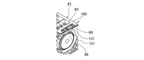
図4は本発明の第1の実施の形態におけるプリンタの斜視図である。 FIG. 4 is a perspective view of the printer according to the first embodiment of the present invention.
図において、10はプリンタ、Csは筐体、29は該筐体Csの前壁に筐体Csに対して揺動自在に、かつ、開閉自在に配設された筐体開閉部としてのフロントカバー、38は前記筐体Csの頂部に形成されたスタッカ、41はトナーカートリッジである。
In the figure,
前記筐体Cs内には、画像形成ユニット16Bk、16Y、16M、16C(図2)の各画像形成ユニット本体37が配設され、装置本体における各画像形成ユニット本体37の上方に、トナーカートリッジ41を装置本体に対して着脱するための、断面が三角形の形状を有する空洞の嵌入部Spが形成される。前記フロントカバー29を開き、トナーカートリッジ41を、嵌入部Spから取り出したり、嵌入部Spに挿入したり、すなわち、嵌入部Spに対して挿脱することができる。
Each image forming unit
また、各嵌入部Spの底部には、嵌入部Spに挿入されたトナーカートリッジ41を保持する交換ユニット保持部材としてのトナーカートリッジ保持ユニット61が配設される。該トナーカートリッジ保持ユニット61は、所定の固定要素、例えば、ねじ等によって装置本体に取り付けられる。したがって、トナーカートリッジ41を、トナーカートリッジ保持ユニット61上を摺動させながら、嵌入部Spから取り出したり、嵌入部Spに挿入したりすることができる。
Further, a toner
なお、以下の説明において、トナーカートリッジ41の長手方向であり、また、装置本体に対してトナーカートリッジ41を着脱する方向、すなわち、挿脱方向である嵌入部Spの奥行方向を第1の方向としてのY方向とし、トナーカートリッジ41の幅方向である、画像形成ユニット16Bk、16Y、16M、16Cと転写ローラ21Bk、21Y、21M、21Cとの間を搬送される用紙Pの搬送方向を、前記Y方向に対して直角の方向である第2の方向としてのX方向とし、トナーカートリッジ41の高さ方向であるプリンタ10の高さ方向を、前記Y方向及びX方向に対して直角の方向である第3の方向としてのZ方向とする。
In the following description, the first direction is the longitudinal direction of the
次に、トナーカートリッジ41及びトナーカートリッジ保持ユニット61から成る交換ユニット組立体について説明する。
Next, an exchange unit assembly including the
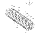
図5は本発明の第1の実施の形態におけるトナーカートリッジの透視図、図6は本発明の第1の実施の形態におけるトナーカートリッジの第1の斜視図、図7は本発明の第1の実施の形態におけるトナーカートリッジの第2の斜視図、図8は本発明の第1の実施の形態におけるトナーカートリッジ保持ユニットの第1の斜視図、図9は本発明の第1の実施の形態におけるトナーカートリッジ保持ユニットの第2の斜視図、図10は本発明の第1の実施の形態における交換ユニット組立体の第1の斜視図、図11は本発明の第1の実施の形態における交換ユニット組立体の第2の斜視図である。 5 is a perspective view of the toner cartridge in the first embodiment of the present invention, FIG. 6 is a first perspective view of the toner cartridge in the first embodiment of the present invention, and FIG. 7 is the first perspective view of the present invention. FIG. 8 is a first perspective view of a toner cartridge holding unit according to the first embodiment of the present invention, and FIG. 9 is a first perspective view of the toner cartridge according to the first embodiment of the present invention. FIG. 10 is a first perspective view of the replacement unit assembly according to the first embodiment of the present invention, and FIG. 11 is a replacement unit according to the first embodiment of the present invention. It is a 2nd perspective view of an assembly.
まず、トナーカートリッジ41について説明する。
First, the
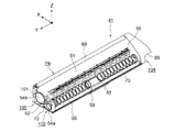
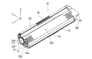
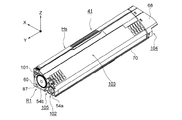
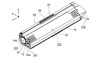
図5〜7に示されるように、トナーカートリッジ41は、Y方向に延在させて形成され、断面がほぼ三角形の形状を有する筒状体から成るハウジングHsを備える。該ハウジングHsは、Z方向に立ち上げて形成された第1の壁部としての側壁部101、前記トナーカートリッジ保持ユニット61と対向するように形成された第2の壁部としての底壁部102、前記側壁部101と底壁部102とを結ぶ第3の壁部としての傾斜壁部103、前記トナーカートリッジ41が嵌入部Sp内に配設された状態で、嵌入部Spの手前側に位置させられる第4の壁部としての後壁部104、及び前記トナーカートリッジ41が嵌入部Sp内に配設された状態で、嵌入部Spの奥側に位置させられる第5の壁部としての前壁部105を備える。
As shown in FIGS. 5 to 7, the
前記ハウジングHs内にトナーを収容する現像材収容部としてのトナー収容部51が形成され、該トナー収容部51内には、Y方向に延在させて、現像剤搬送部材としてのスパイラル56、及び攪拌部材55が配設され、スパイラル56が回転させられるのに伴ってトナー収容部51内のトナーが現像剤供給部としてのトナー供給口59に向けて搬送され、攪拌部材55が回転させられるのに伴ってトナー収容部51内のトナーが攪拌される。
A
前記底壁部102には、Y方向における中央部に、トナー収容部51内のトナーをトナー搬送路27(図3)に供給するための前記トナー供給口59が形成され、該トナー供給口59を開閉するために、開閉部材としてのシャッタ53が、Y方向に移動自在に、かつ、底壁部102に対して摺動自在に配設される。
The
また、前記底壁部102におけるトナー供給口59より後壁部104側には、トナー供給口59と隣接させて、第1の開閉動作規制要素としての第1のラッチ71が形成される。該第1のラッチ71は、可撓性材料から成り、前記シャッタ53における後壁部104側の端部に形成された第1の係合部107と係合させられて、シャッタ53によるトナー供給口59の開閉動作を規制し、第1の係合部107との係合が解除されて、シャッタ53によるトナー供給口59の開閉動作の規制を解除する。
A
なお、前記シャッタ53における後壁部104側の端部には、前記第1の係合部107と隣接させて、かつ、第1の係合部107より後壁部104側に第2の係合部108が形成される。該第2の係合部108は、トナーカートリッジ41を嵌入部Spから取り出す際に、後述される第2の開閉動作規制要素としての第2のラッチと係合させられ、これに伴って、シャッタ53は前壁部105側に移動させられ、トナー供給口59を閉じる。
It should be noted that a second engagement is provided at an end of the
さらに、前記底壁部102の両縁には、トナーカートリッジ41をトナーカートリッジ保持ユニット61に対して摺動させるための摺動部としての外周リブ70がY方向に沿って形成される。
Further, on both edges of the
ところで、前記トナーカートリッジ41には、トナーカートリッジ41が画像形成ユニット本体37に対して適正に取り付けられたかどうかを判断したり、トナーカートリッジ41の種別、情報等を取得したりすることができるように取付判別部材としての判別用基板60が搭載されるようになっている。そのために、トナーカートリッジ41の本体、すなわち、交換ユニット本体としての後述されるトナーカートリッジ本体41a(図1)の前記底壁部102における側壁部101及び前壁部105の近傍に、取付判別部材搭載部R1が形成され、該取付判別部材搭載部R1に判別用基板60、及び移動規制部材としての固定部材87が配設される。
By the way, it is possible to determine whether or not the
前記判別用基板60は、後述される記憶素子としてのメモリ152(図20)が実装された基板から成り、接続端子としての第1、第2のコンタクト部60a、60bを備える。本実施の形態において、前記メモリ152として不揮発性メモリが使用され、メモリ152には、トナーカートリッジ41が画像形成ユニット本体37に対して適正に取り付けられたかどうかを判断したり、トナーカートリッジ41の種別、情報等を取得したりするための判別情報が記録される。なお、トナーカートリッジ41の情報としては、トナー収容部51に収容されるトナーの量、色、特性等の消耗品情報を記録することができる。
The
また、前記取付判別部材搭載部R1と隣接させて、各色のトナーカートリッジ41が、対応する画像形成ユニット本体37とは異なる画像形成ユニット本体37に誤って取り付けられるのを防止するために、第1の取付規制部としての挿入規制部85が形成される。該挿入規制部85は、複数箇所、本実施の形態においては、4箇所に設定された規制部位のうちの所定の二つの規制部位において、突出させて形成された規制要素としての突起85a、85bを備える。
In addition, in order to prevent the
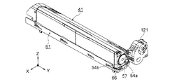
また、傾斜壁部103の最も上端部には、トナーカートリッジ41を操作者が持つための把持部としての持ち手69がY方向に沿って形成され、後壁部104には、嵌入部Spからトナーカートリッジ41を取り出すときに操作者が指を掛けるための取手としての引手68が形成される。
In addition, a
そして、前記前壁部105には、後述される回転入力部としての駆動入力ギヤ57(図16)と噛合し、該駆動入力ギヤ57の回転を受けて回転させられる第1の回転伝達部としてのギヤ54a、及び該ギヤ54aの回転を受けて回転させられる第2の回転伝達部としてのギヤ54bが配設され、前記ギヤ54aに前記スパイラル56の一端が、ギヤ54bに前記攪拌部材55の一端が取り付けられる。
The
また、前記前壁部105には、トナーカートリッジ41側の第1の位置決め部材としての位置決めポスト52が突出させて形成され、該位置決めポスト52は、トナーカートリッジ41を嵌入部Spに挿入したときに、前記駆動入力ギヤ57の端面S1(図16)における軸心部に形成された装置本体側の第1の位置決め部材としての位置決め穴h11(図16)と係合して、装置本体に対してトナーカートリッジ41の位置決め(駆動入力ギヤ57と位置決めポスト52との心合せ)を行う。さらに、前記前壁部105の下端には、トナーカートリッジ41側の第2の位置決め部材としての、かつ、回転規制部としての溝部72が底壁部102にかけて形成され、該溝部72は、トナーカートリッジ保持ユニット61に形成された装置本体側の第2の位置決め部材としての位置決め突起64と係合して、装置本体に対してトナーカートリッジ41の位置決めを行うとともに、前記駆動入力ギヤ57の回転がギヤ54aに伝達されるのに伴って、トナーカートリッジ41が回転させられるのを防止する。
Further, a
次に、前記トナーカートリッジ保持ユニット61について説明する。
Next, the toner
図8及び9に示されるように、トナーカートリッジ保持ユニット61は、前記トナーカートリッジ41を載置するための板状のトレー62、及び該トレー62の両縁から上方に向けて帯状に立ち上げて形成され、トナーカートリッジ41を嵌入部Spに対して挿脱する際に、トナーカートリッジ41を案内する案内部としてのガイド111、112を備え、該ガイド111、112の長手方向(Y方向)における複数箇所、本実施の形態においては、4箇所に、案内摺動部63が内側に向けて所定量だけ突出させて形成される。前記トナーカートリッジ41を案内する際に、前記外周リブ70が案内摺動部63と摺動させられる。
As shown in FIGS. 8 and 9, the toner
前記トレー62には、トナーカートリッジ41を嵌入部Spに対して挿脱したり、シャッタ53がトナー供給口59を開閉したりする際に、前記シャッタ53とトレー62とが干渉することがないように、帯状の凹部AR1が形成され、トナーカートリッジ41を嵌入部Spに対して挿脱する際に、前記突起85a、85bとトレー62とが干渉することがないように、帯状の凹部AR2が前記凹部AR1と隣接させて形成される。該凹部AR1はシャッタ53の厚さよりわずかに深く、前記凹部AR2は突起85a、85bの高さよりわずかに深く形成される。
The
また、前記凹部AR1の長手方向(Y方向)における中央部に、トナー供給口59と共に、トナー収容部51内のトナーをトナー搬送路27(図3)に供給するための現像剤導入部としてのトナー導入口115が形成され、該トナー導入口115より手前側(嵌入部Spの入口側)にトナー導入口115と隣接させて、移動規制要素としてのシャッタ移動規制部76が上方に向けて突出させて形成される。該シャッタ移動規制部76は、トナーカートリッジ41を嵌入部Spに挿入するときに、シャッタ53がトナー導入口115に到達するのに伴ってシャッタ53と当接し、シャッタ53が奥側(嵌入部Spの終端部側)に移動するのを阻止し、トナー供給口59を開く。
Further, in the central portion in the longitudinal direction (Y direction) of the concave portion AR1, together with the
そして、前記シャッタ移動規制部76より手前側(嵌入部Spの始端部側)には、第2のラッチ78が配設される。該第2のラッチ78は、可撓性材料から成り、前記シャッタ53によるトナー供給口59の開閉動作を規制し、トナーカートリッジ41を嵌入部Spから取り出すのに伴って、シャッタ53が後壁部104側に移動するのを規制し、トナー供給口59を閉じる。
A
さらに、第2のラッチ78と隣接させて、規制解除要素としてのラッチ解除ポスト75が配設され、トナーカートリッジ41を嵌入部Spに挿入する際に、トナーカートリッジ41の移動に伴って前記第1のラッチ71を押して撓ませ、シャッタ53によるトナー供給口59の開閉動作の規制を解除し、シャッタ53が底壁部102対して移動するのを可能にする。
Further, a
また、前記凹部AR1、AR2の境界部分の奥側の端部に前記位置決め突起64が上方に向けて突出させて形成される。該位置決め突起64は、トナーカートリッジ41を嵌入部Spに挿入したときに、前記溝部72と係合することによって、装置本体に対してトナーカートリッジ41の位置決めを行うとともに、前記駆動入力ギヤ57の回転がギヤ54aに伝達されるのに伴って、トナーカートリッジ41が回転させられるのを防止する。
Further, the
さらに、前記凹部AR2の奥側の端部における、前記取付判別部材搭載部R1と対応する箇所に接点66が形成される。該接点66は、可撓性材料から成り、三角形の形状を有する接続端子としての第1、第2のコンタクト部66a、66bを備え、該第1、第2のコンタクト部66a、66bは、トナーカートリッジ41が嵌入部Spに挿入されたときに判別用基板60に押し付けられ、所定の接触圧力で判別用基板60の第1、第2のコンタクト部60a、60bと当接させられ、前記判別用基板60と接触させられる。なお、前記第1、第2のコンタクト部66a、66bの表面には表面処理、本実施の形態においては、金メッキが施され、第1、第2のコンタクト部66a、66bと第1、第2のコンタクト部60a、60bとの導電性が高くされる。
Furthermore, a
また、前記凹部AR2の長手方向(Y方向)における中央部の近傍には、前記挿入規制部85と共に、各色のトナーカートリッジ41が、対応する画像形成ユニット本体37とは異なる画像形成ユニット本体37に誤って取り付けられるのを防止するために、第2の取付規制部としての挿入規制部86が形成される。該挿入規制部86は、4箇所に設定された規制部位のうちの所定の二つの規制部位において、突出させて形成された規制要素としての突起86a、86bを備える。例えば、本実施の形態においては、前記挿入規制部85において突起85a、85bが形成された規制部位と、前記挿入規制部86において突起86a、86bが形成された規制部位とが異なる位置に設定されるので、トナーカートリッジ41を嵌入部Spに挿入する際に、前記挿入規制部85は、挿入規制部86と干渉することなく、挿入規制部86を通過する。
In addition, in the vicinity of the central portion in the longitudinal direction (Y direction) of the
そして、トナーカートリッジ41が嵌入部Spに挿入されると、図10及び11に示されるように、トナーカートリッジ41がトナーカートリッジ保持ユニット61上に置かれ、溝部72と位置決め突起64とが係合させられて、装置本体に対してトナーカートリッジ41の位置決めが行われるとともに、前記駆動入力ギヤ57の回転がギヤ54aに伝達されるのに伴って、トナーカートリッジ41が回転させられるのを防止する。
When the
また、接点66が判別用基板60と接触させられることによって、装置本体に配設された図示されない制御部と判別用基板60との間の通信が可能になる。したがって、制御部は、前記メモリ152に記録された判別情報を読み出し、判別情報に基づいて、トナーカートリッジ41が画像形成ユニット本体37に対して適正に取り付けられたかどうかを判断したり、トナーカートリッジ41の種別、情報等を取得したりする。
Further, when the
さらに、前記位置決めポスト52と前記駆動入力ギヤ57の端面S1に形成された位置決め穴h11とが係合して、装置本体に対してトナーカートリッジ41の位置決めが行われる。
Further, the
次に、トナーカートリッジ41を嵌入部Spに挿入するときの、前記駆動入力ギヤ57とギヤ54aとの噛合方法について説明する。
Next, a method for meshing the
図12は本発明の第1の実施の形態におけるトナーカートリッジが嵌入部に挿入されるときの交換ユニット組立体の状態を示す第1の図、図13は本発明の第1の実施の形態におけるトナーカートリッジが嵌入部に挿入されるときの交換ユニット組立体の状態を示す第2の図、図14は本発明の第1の実施の形態におけるトナーカートリッジが嵌入部に挿入されるときのトナーカートリッジの状態を示す第1の図、図15は本発明の第1の実施の形態におけるトナーカートリッジが嵌入部に挿入されるときのトナーカートリッジの状態を示す第2の図、図16は本発明の第1の実施の形態における駆動入力ギヤとトナーカートリッジに配設されたギヤとの噛合方法を説明するための図である。 FIG. 12 is a first diagram showing a state of the replacement unit assembly when the toner cartridge is inserted into the insertion portion according to the first embodiment of the present invention, and FIG. 13 is a diagram according to the first embodiment of the present invention. FIG. 14 shows a state of the replacement unit assembly when the toner cartridge is inserted into the insertion portion, and FIG. 14 shows the toner cartridge when the toner cartridge is inserted into the insertion portion according to the first embodiment of the present invention. FIG. 15 is a second diagram illustrating the state of the toner cartridge when the toner cartridge is inserted into the insertion portion according to the first embodiment of the present invention. FIG. 16 is a diagram illustrating the state of the present invention. FIG. 5 is a diagram for explaining a meshing method between a drive input gear and a gear disposed in a toner cartridge in the first embodiment.
図において、41はトナーカートリッジ、52は位置決めポスト、54a、54bはギヤ、57は駆動入力ギヤ、61はトナーカートリッジ保持ユニット、121は各嵌入部Spの終端部に配設され、スパイラル56及び攪拌部材55を回転させるための駆動装置、122は箱状体から成る外筐としてのモータケースである。前記駆動入力ギヤ57は、モータケース122のトナーカートリッジ41と対向する面に形成された貫通穴h1から突出させて配設され、前記ギヤ54aと噛合させられる。
In the figure, 41 is a toner cartridge, 52 is a positioning post, 54a and 54b are gears, 57 is a drive input gear, 61 is a toner cartridge holding unit, 121 is disposed at the end of each insertion portion Sp, spiral 56 and stirring A
前記モータケース122内には、トナーの搬送用・攪拌用の駆動部としての図示されないカートリッジモータ、モータケース122に対して進退自在に、かつ、回転自在に配設され、前記カートリッジモータの出力軸に取り付けられた図示されない出力ギヤと噛合させられる中間ギヤ123、及び該中間ギヤ123とモータケース122の背面に形成された突部125との間に配設され、前記駆動入力ギヤ57を所定の付勢力でトナーカートリッジ41側に向けて付勢する付勢部材としてのスプリング58が配設される。前記中間ギヤ123は有底の筒状体から成るボス部124を備え、該ボス部124の端面に前記駆動入力ギヤ57が取り付けられる。
In the
トナーカートリッジ41を嵌入部Spに挿入するに当たり、図12及び14に示されるように矢印方向に移動させると、位置決めポスト52と駆動入力ギヤ57の端面S1に形成された位置決め穴h11とが係合させられ、装置本体に対するトナーカートリッジ41の位置決めが行われる。そして、トナーカートリッジ41を更に移動させると、図16(b)に示されるように、駆動入力ギヤ57の端面S1とギヤ54aの端面S2とが当接し、駆動入力ギヤ57とギヤ54aとが噛合しないことがあるが、その場合、スプリング58の付勢力に抗して駆動入力ギヤ57及び中間ギヤ123が後退(図16(b)において左方へ移動)させられる。
When the
このようにして、トナーカートリッジ41が嵌入部Spに挿入され、装置本体に対して位置決めが行われた後、例えば、前記カートリッジモータが駆動された場合等において、駆動入力ギヤ57が回転させられ、駆動入力ギヤ57及びギヤ54aの各歯の位置が一致すると、駆動入力ギヤ57はスプリング58の付勢力で押され、図16(a)に示されるように、駆動入力ギヤ57とギヤ54aとが噛合する。これにより、図13及び15に示されるように、トナーカートリッジ41に駆動入力ギヤ57を組み付けることができる。したがって、カートリッジモータを駆動すると、中間ギヤ123が回転させられるのに伴って、駆動入力ギヤ57が回転させられ、カートリッジモータの回転が、ギヤ54aに伝達され、更にギヤ54bに伝達される。
Thus, after the
次に、取付判別部材搭載部R1について説明する。 Next, the attachment determination member mounting portion R1 will be described.
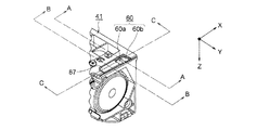
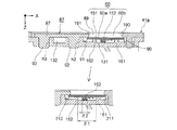
図1は本発明の第1の実施の形態における判別用基板の取付状態を示すトナーカートリッジの分解斜視図、図17は本発明の第1の実施の形態における固定部材の第1の斜視図、図18は本発明の第1の実施の形態における固定部材の第2の斜視図、図19は本発明の第1の実施の形態におけるトナーカートリッジの要部を示す図、図20は図19のA−A断面図、図21は図19のB−B断面図、図22は図19のC−C断面図である。 FIG. 1 is an exploded perspective view of a toner cartridge showing a mounting state of a discrimination substrate in the first embodiment of the present invention. FIG. 17 is a first perspective view of a fixing member in the first embodiment of the present invention. 18 is a second perspective view of the fixing member according to the first embodiment of the present invention, FIG. 19 is a view showing a main part of the toner cartridge according to the first embodiment of the present invention, and FIG. AA sectional view, FIG. 21 is a BB sectional view of FIG. 19, and FIG. 22 is a CC sectional view of FIG.
図において、41はトナーカートリッジ、102は底壁部、85は挿入規制部、85a、85bは突起、104は後壁部、105は前壁部であり、該前壁部105に位置決めポスト52、ギヤ54a、54b等が配設される。
In the figure, 41 is a toner cartridge, 102 is a bottom wall portion, 85 is an insertion restricting portion, 85a and 85b are projections, 104 is a rear wall portion, and 105 is a front wall portion.
また、R1は取付判別部材搭載部であり、該取付判別部材搭載部R1において、前壁部105に隣接させて矩形の形状を有する判別部材収容部としての凹部131が形成され、該凹部131に判別用基板60が収容される。
Further, R1 is an attachment determination member mounting portion. In the attachment determination member mounting portion R1, a
該判別用基板60は、基板本体151、該基板本体151の一方の面、本実施の形態においては、基板本体151の下面に取り付けられた記憶素子としてのメモリ152、及び前記基板本体151の他方の面、本実施の形態においては、基板本体151の上面に形成された第1、第2のコンタクト部60a、60bを備えるとともに、前記前壁部105側に第1の縁部L1を、該第1の縁部L1と対向する側に第2の縁部L2を、側壁部101側に第3の縁部L3を、該第3の縁部と対向する側に第4の縁部L4を置いて、トナーカートリッジ本体41aに対して着脱自在に配設される。
The
そして、前記第4の縁部L4側に、凹部131に隣接させて、矩形の形状を有する移動規制部材収容部としての凹部132が形成され、該凹部132に固定部材87が収容される。該固定部材87は、トナーカートリッジ本体41aに取り付けられることによって、判別用基板60をトナーカートリッジ本体41aに固定するとともに、凹部131における判別用基板60の移動を規制する。
A
なお、前記取付判別部材搭載部R1は、トナーカートリッジ41を前記嵌入部Sp(図4)に挿入したとき、嵌入部Spの最も奥側の位置に置かれるので、該最も奥側の位置において判別用基板60の第1、第2のコンタクト部60a、60bと接点66(図8)の第1、第2のコンタクト部66a、66bとがそれぞれ当接させられる。
Note that, when the
そして、前記凹部131における内周縁に、第1、第2の位置決め部88、89及び第1、第2の移動規制部90、190が形成される。
The first and
前記第1、第2の位置決め部88、89は、前記凹部131の底面から上方に向けて立ち上げて形成されて、判別用基板60の第1、第2の縁部L1、L2と当接させられ、凹部131の幅方向(Y方向)において前記判別用基板60を挟持する。
The first and
また、前記第1の移動規制部90は、凹部131における内周縁から下方に向けて突出させて形成された一対の突起から成り、判別用基板60の第3の縁部L3と当接させられ、前記第2の移動規制部190は、凹部131における内周縁から固定部材87側に向けて突出させて形成された突縁から成り、前記第3の縁部L3の上面を覆う。そして、前記凹部131の底面には、凹部対向要素としての一対のリブ161、162が、判別用基板60の下面と対向させて、上方に向けて突出させて、かつ、凹部131の幅方向に延在させて形成される。
The first
なお、前記第1、第2の位置決め部88、89は、前記凹部131の長手方向(X方向)に延在させて形成され、前記第1の位置決め部88の上端は、第2の位置決め部89の上端より低くされ、第1の位置決め部88によって低壁部が形成される。また、前記第1の移動規制部90は、凹部131の幅方向における両端に形成され、前記第2の移動規制部190は、凹部131の幅方向に延在させて形成される。
The first and
そして、前記固定部材87は、矩形の形状を有する平板部97、及び該平板部97から下方に向けて突出させて形成された第1、第2の係止部としての、かつ、円柱状の突起部としての一対のポスト92を備え、該各ポスト92を、前記凹部131に隣接させて形成された第1、第2の被係止部としての穴h2、h3に圧入することによってトナーカートリッジ本体41aに取り付けられる。なお、前記ポスト92は、平板部97の長手方向(X方向)における両端の近傍に形成される。
The fixing
前記平板部97における側壁部101側の縁部に、前記判別用基板60の第4の縁部L4と当接させて、かつ、下方に向けて突出させて、一対の突起から成る第1の移動規制部91が形成され、前記第4の縁部L4と当接させて、かつ、側壁部101側に向けて突出させて、突縁から成る第2の移動規制部191が形成される。なお、前記第1の移動規制部91は、固定部材87の幅方向(Y方向)における両端に形成され、前記第2の移動規制部191は、固定部材87の幅方向に延在させて形成される。
A first edge formed of a pair of protrusions is brought into contact with the edge of the
なお、凹部131の長手方向の長さ、すなわち、対向壁211、212間の距離をm1とし、凹部131の長手方向における第1の移動規制部90、91間の距離をm2とし、判別用基板60の第3、第4の縁部L3、L4間の距離をm3としたとき、距離m1〜m3は、
m1>m2>m3
にされる。本実施の形態において、距離m1、m2の差は2〔mm〕に、距離m2、m3の差は0.5〔mm〕にされる。また、凹部131の長手方向におけるリブ161、162間の距離をδ1とし、メモリ152の幅をδ2としたとき、距離δ1及び幅δ2は、
δ1>δ2
にされる。
The length of the
m1>m2> m3
To be. In the present embodiment, the difference between the distances m1 and m2 is 2 [mm], and the difference between the distances m2 and m3 is 0.5 [mm]. When the distance between the
δ1> δ2
To be.
前記第1、第2の位置決め部88、89は、第1、第2の縁部L1、L2と当接して凹部131の幅方向における判別用基板60の位置決めを行う。また、第1の移動規制部90、91は、第3、第4の縁部L3、L4と当接して凹部131の長手方向における判別用基板60の位置決めを行うとともに、凹部131の長手方向における判別用基板60の移動を規制する。そして、第2の移動規制部190、191は、第3、第4の縁部L3、L4と当接して凹部131の深さ方向(Z方向)における判別用基板60の移動を規制する。さらに、前記リブ161、162は、前記基板本体151の下面と当接して凹部131の深さ方向における判別用基板60の位置決めを行う。
The first and
ところで、トナーカートリッジ本体41aの高さ方向における所定の基準位置、本実施の形態においては、凹部131の底面から第1の位置決め部88の上端までの距離H1が凹部131の底面から判別用基板60の上面までの距離H2より短いと、接点66が判別用基板60のエッジで擦られてしまう。そこで、距離H1、H2は、
H2<H1
にされる。なお、第1の位置決め部88の上端には、トナーカートリッジ41をトナーカートリッジ保持ユニット61に対して移動させたときに、接点66が第1の位置決め部88を円滑に通過することができるように面取り98が形成される。
By the way, a predetermined reference position in the height direction of the toner cartridge
H2 <H1
To be. Note that, at the upper end of the
また、距離H1と、凹部131の底面から底壁部102の上面までの距離H3とが等しいと、トナーカートリッジ41を移動させる際に接点66と第1の位置決め部88との当接量が多くなり、接点66の表面が摩耗してしまう。そこで、距離H1、H3は、
H1<H3
にされる。さらに、凹部131の底面から第2の位置決め部89の上端までの距離H4、及び凹部131の底面から第2の移動規制部190の上端までの距離H5が、距離H3より短いと、判別用基板60の位置決め及び移動の規制を確実に行うことができない。そこで、距離H3〜H5は、
H3=H4=H5
にされる。
If the distance H1 is equal to the distance H3 from the bottom surface of the
H1 <H3
To be. Further, when the distance H4 from the bottom surface of the
H3 = H4 = H5
To be.
また、凹部131の底壁から固定部材87の上面までの距離H6が距離H3より長いと、トナーカートリッジ41をトナーカートリッジ保持ユニット61に対して移動させることができない。そこで、距離H3、H6は、
H6≦H3
にされる。したがって、距離H1〜H6は、
H2<H1<H3<H6≦H3=H4=H5
にされる。
If the distance H6 from the bottom wall of the
H6 ≦ H3
To be. Therefore, the distances H1 to H6 are
H2 <H1 <H3 <H6 ≦ H3 = H4 = H5
To be.
次に、前記判別用基板60をトナーカートリッジ41に搭載する方法、すなわち、搭載方法について説明する。
Next, a method for mounting the
図23は本発明の第1の実施の形態における判別用基板の搭載方法を示す第1の斜視図、図24は本発明の第1の実施の形態における判別用基板の搭載方法を示す第2の斜視図、図25は本発明の第1の実施の形態における判別用基板の搭載方法を示す第3の斜視図、図26は本発明の第1の実施の形態における判別用基板の搭載方法を示す第4の斜視図である。 FIG. 23 is a first perspective view showing a method for mounting a discrimination substrate according to the first embodiment of the present invention, and FIG. 24 is a second perspective view showing a method for mounting a discrimination substrate according to the first embodiment of the present invention. FIG. 25 is a third perspective view showing a method for mounting the discrimination substrate in the first embodiment of the present invention, and FIG. 26 is a method for mounting the discrimination substrate in the first embodiment of the present invention. It is a 4th perspective view which shows this.
まず、図23に示されるように、判別用基板60を底壁部102における取付判別部材搭載部R1に矢印方向に載置し、図24に示されるように、判別用基板60を、凹部131における第1、第2の位置決め部88、89及び第1、第2の移動規制部90、190によって包囲された領域に滑り込ませる。このとき、判別用基板60は前記リブ161、162と接触させられる。
First, as shown in FIG. 23, the
この場合、前記第1、第2の位置決め部88、89は、判別用基板60の移動を凹部131の幅方向(Y方向)においてだけ規制し、凹部131の長手方向(X方向)においては規制しない。したがって、凹部131の長手方向において判別用基板60を自由に移動させることができ、判別用基板60を前記領域に円滑に滑り込ませることができる。
In this case, the first and
続いて、判別用基板60を第1の移動規制部90と当接するまで側壁部101側に移動させると、判別用基板60の第3の縁部L3が第2の移動規制部190の下に滑り込む。
Subsequently, when the
次に、図25及び26に示されるように、固定部材87のポスト92を穴h2、h3に圧入することによって、固定部材87をトナーカートリッジ本体41aに取り付ける。これにより、固定部材87は、凹部132の長手方向及び高さ方向(Z方向)において位置決めされる。そして、前記固定部材87は、第1、第2の移動規制部91、191を備えているので、凹部131の長手方向及び深さ方向における判別用基板60の移動が規制される。
Next, as shown in FIGS. 25 and 26, the fixing
次に、前記トナーカートリッジ41を嵌入部Spに挿入するときの挿入規制部材85、86の状態について説明する。
Next, the state of the
図27は本発明の第1の実施の形態における挿入規制部材の状態を示す第1の図、図28は本発明の第1の実施の形態における挿入規制部材の状態を示す第2の図、図29は本発明の第1の実施の形態における挿入規制部材の状態を示す第3の図、図30は本発明の第1の実施の形態における挿入規制部材の状態を示す第4の図、図31は本発明の第1の実施の形態における挿入規制部材の状態を示す第5の図である。 FIG. 27 is a first view showing the state of the insertion restricting member in the first embodiment of the present invention, FIG. 28 is a second view showing the state of the insertion restricting member in the first embodiment of the present invention, 29 is a third view showing the state of the insertion restricting member in the first embodiment of the present invention, FIG. 30 is a fourth view showing the state of the insertion restricting member in the first embodiment of the present invention, FIG. 31 is a fifth view showing the state of the insertion restricting member in the first embodiment of the invention.
図において、41はトナーカートリッジ、61はトナーカートリッジ保持ユニット、27はトナーカートリッジ保持ユニット61に形成されたトナー搬送路、59はトナーカートリッジ41に形成されたトナー供給口、85はトナーカートリッジ41に形成された挿入規制部材、86はトナーカートリッジ保持ユニット61に形成された挿入規制部材である。
In the figure, 41 is a toner cartridge, 61 is a toner cartridge holding unit, 27 is a toner conveyance path formed in the toner
まず、トナーカートリッジ41をトナーカートリッジ保持ユニット61のトレー62上に載置し、嵌入部Spへの挿入を開始する。
First, the
ところで、トナーカートリッジ41と画像形成ユニット本体37(図3)とが対応する場合、トナーカートリッジ41及びトナーカートリッジ保持ユニット61には、前述されたように前記挿入規制部材85、86がそれぞれ配設され、挿入規制部材85に突起85a、85bが、挿入規制部材86に突起86a、86bが形成される。
When the
この場合、トナーカートリッジ41を嵌入部Spに挿入するために前進させると、図27〜29に示されるように、前記挿入規制部85は、挿入規制部86と干渉することなく、挿入規制部86を通過する。
In this case, when the
したがって、前記トナーカートリッジ41に収容されたトナーの色と、画像形成ユニット本体37で使用されるトナーの色とが一致することが分かる。
Therefore, it can be seen that the color of the toner contained in the
これに対して、図30及び31に示されるように、挿入規制部85が突起85a、85bを備え、前記挿入規制部材86が突起86c、86bを備える場合に、トナーカートリッジ41を嵌入部Spに挿入するために前進させると、突起85aと突起86cとが当接させられ、前記挿入規制部85は、挿入規制部86と干渉し、挿入規制部86を通過することができない。
On the other hand, as shown in FIGS. 30 and 31, when the
したがって、前記トナーカートリッジ41に収容されたトナーの色と、画像形成ユニット本体37で使用されるトナーの色とが一致しないことが分かる。
Therefore, it can be seen that the color of the toner stored in the
このようにして、各色のトナーカートリッジ41が、対応する画像形成ユニット本体37とは異なる画像形成ユニット本体37に誤って取り付けられるのを防止することができる。
In this way, it is possible to prevent each
次に、前記トナーカートリッジ41を嵌入部Spに挿脱する方法について説明する。なお、前述されたように、シャッタ53の後壁部104側の端部には、第1、第2の係合部107、108が形成されるので、図32〜35によって第1の係合部107側における交換ユニット組立体の状態を、図36〜39によって第2の係合部108側における交換ユニット組立体の状態を説明する。
Next, a method for inserting / removing the
図32は本発明の第1の実施の形態における第1の係合部側の交換ユニット組立体の状態を示す第1の図、図33は本発明の第1の実施の形態における第1の係合部側の交換ユニット組立体の状態を示す第2の図、図34は本発明の第1の実施の形態における第1の係合部側の交換ユニット組立体の状態を示す第3の図、図35は本発明の第1の実施の形態における第1の係合部側の交換ユニット組立体の状態を示す第4の図、図36は本発明の第1の実施の形態における第2の係合部側の交換ユニット組立体の状態を示す第1の図、図37は本発明の第1の実施の形態における第2の係合部側の交換ユニット組立体の状態を示す第2の図、図38は本発明の第1の実施の形態における第2の係合部側の交換ユニット組立体の状態を示す第3の図、図39は本発明の第1の実施の形態における第2の係合部側の交換ユニット組立体の状態を示す第4の図である。 FIG. 32 is a first view showing the state of the replacement unit assembly on the first engagement portion side in the first embodiment of the present invention, and FIG. 33 is the first diagram in the first embodiment of the present invention. FIG. 34 shows a state of the exchange unit assembly on the engagement portion side, and FIG. 34 shows a third state of the exchange unit assembly on the first engagement portion side in the first embodiment of the present invention. FIG. 35 is a fourth view showing a state of the replacement unit assembly on the first engagement portion side in the first embodiment of the present invention, and FIG. 36 is a diagram of the first embodiment of the present invention. FIG. 37 shows a state of the replacement unit assembly on the second engagement portion side, and FIG. 37 shows a state of the replacement unit assembly on the second engagement portion side in the first embodiment of the present invention. FIG. 2 and FIG. 38 are third views showing the state of the replacement unit assembly on the second engagement portion side in the first embodiment of the present invention. FIG, 39 is a fourth diagram showing the first second state of the replacement unit assembly of the engagement side in the embodiment of the present invention.
図において、27はトナー搬送路、41はトナーカートリッジ、53はシャッタ、59はトナー供給口、115はトナー導入口、61はトナーカートリッジ保持ユニット、68は引手、71はトナーカートリッジ41の底壁部102に取り付けられた第1のラッチ、75はトナーカートリッジ保持ユニット61に形成されたラッチ解除ポスト、77はトナーカートリッジ41の底壁部102に形成され、シャッタ53をトナー供給口59が閉じられた位置で止めるストッパ、78はトナーカートリッジ保持ユニット61に形成された第2のラッチである。
In the figure, 27 is a toner conveyance path, 41 is a toner cartridge, 53 is a shutter, 59 is a toner supply port, 115 is a toner introduction port, 61 is a toner cartridge holding unit, 68 is a handle, and 71 is a bottom wall portion of the
まず、フロントカバー29(図4)を開き、トナーカートリッジ41をトナーカートリッジ保持ユニット61のトレー62上に載置し、挿入を開始する。このとき、図32に示されるように、第1のラッチ71の先端に形成された凸部171とシャッタ53の第1の係合部107に形成された凹部172とが係合させられ、トナーカートリッジ41の前進に伴ってシャッタ53が前進させられる。また、図32及び36に示されるように、シャッタ53における前壁部105側の端部に形成された当接部109とストッパ77とが当接させられるのに伴って、第2のラッチ78がシャッタ53によって下方に向けて押されて撓む。
First, the front cover 29 (FIG. 4) is opened, the
次に、挿入規制部85が挿入規制部86を通過すると、図33に示されるように、第1のラッチ71がラッチ解除ポスト75によって上方に向けて撓み、凸部171と凹部172との係合が解除される。
Next, when the
続いて、図34に示されるように、凸部171と凹部172との係合が解除されると、シャッタ53は底壁部102に対して移動可能になり、シャッタ53によるトナー供給口59の開閉動作の規制が解除され、該トナー供給口59を開くことができるようになる。また、前記当接部109が、トナーカートリッジ保持ユニット61に形成されたシャッタ移動規制部76と当接させられる。このとき、図38に示されるように、第2のラッチ78の山部78aがシャッタ53の下面から外れ、第2のラッチ78は上方に移動させられる。
Subsequently, as shown in FIG. 34, when the engagement between the
次に、図35に示されるように、トナーカートリッジ41が更に前進させられると、当接部109がシャッタ移動規制部76と当接させられているので、シャッタ53は停止させられ、トナー供給口59が開かれる。そして、トナー供給口59とトナー搬送路27とが重なると、トナーカートリッジ41は停止させられる。このとき、トナーカートリッジ41の前端がトナーカートリッジ保持ユニット61の前端に到達し、図39に示されるように、山部78aと第2の係合部108とが係合させられるのに伴って、溝部72と位置決め突起64とが係合させられ、取付判別部材搭載部R1に形成された第1の位置決め部88が接点66を乗り越え、判別用基板60と接点66とが接触させられる。このようにして、トナーカートリッジ41を嵌入部Spに挿入することができる。
Next, as shown in FIG. 35, when the
続いて、前記フロントカバー29を閉じると、前記制御部は、制御部と判別用基板60との間の通信が可能になったかどうかを判断し、通信が可能になった場合、トナーカートリッジ41が嵌入部Spに正確に挿入されたと判断し、通常の印刷動作を開始する。また、通信が可能にならなかった場合、制御部は、トナーカートリッジ41が嵌入部Spに正確に挿入されていないと判断し、通常の印刷動作を開始することなく、図示されない表示部、例えば、液晶ディスプレイ(LCD)に、トナーカートリッジ41が嵌入部Spに正確に挿入されていないことを表すメッセージを表示し、操作者に通知する。
Subsequently, when the
次に、トナーカートリッジ41の前端がトナーカートリッジ保持ユニット61の前端に到達したときの接点66の状態について説明する。
Next, the state of the
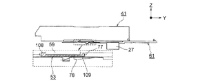
図40は本発明の第1の実施の形態におけるトナーカートリッジがトナーカートリッジ保持ユニットの前端に到達したときの接点の状態を示す第1の図、図41は本発明の第1の実施の形態におけるトナーカートリッジがトナーカートリッジ保持ユニットの前端に到達したときの接点の状態を示す第2の図、図42は本発明の第1の実施の形態におけるトナーカートリッジがトナーカートリッジ保持ユニットの前端に到達したときの接点の状態を示す第3の図、図43は本発明の第1の実施の形態におけるトナーカートリッジがトナーカートリッジ保持ユニットの前端に到達したときの接点の状態を示す第4の図、図44は本発明の第1の実施の形態におけるトナーカートリッジがトナーカートリッジ保持ユニットの前端に到達したときの接点の状態を示す第5の図である。 FIG. 40 is a first diagram showing a contact state when the toner cartridge reaches the front end of the toner cartridge holding unit according to the first embodiment of the present invention, and FIG. 41 is a diagram according to the first embodiment of the present invention. FIG. 42 shows a contact state when the toner cartridge reaches the front end of the toner cartridge holding unit, and FIG. 42 shows a state where the toner cartridge reaches the front end of the toner cartridge holding unit according to the first embodiment of the present invention. FIG. 43 shows a state of the contact of the toner cartridge. FIG. 43 shows a state of the contact when the toner cartridge reaches the front end of the toner cartridge holding unit according to the first embodiment of the present invention. Is the contact when the toner cartridge in the first embodiment of the present invention reaches the front end of the toner cartridge holding unit. It is a fifth diagram illustrating a state.
図40〜42に示されるように、トナーカートリッジ41がトナーカートリッジ保持ユニット61の前端に到達すると、接点66は変形しながら、第1の位置決め部88とトナーカートリッジ保持ユニット61の本体との間の隙間を通過して凹部131内に進入し、凹部131内において判別用基板60と接触する。
As shown in FIGS. 40 to 42, when the
ところで、前述されたように、トナーカートリッジ41を嵌入部Spに挿入するに当たり、図16(b)に示されるように、駆動入力ギヤ57の端面S1とギヤ54aの端面S2とが当接し、駆動入力ギヤ57とギヤ54aとが噛合しないことがある。その場合、スプリング58の付勢力に抗して駆動入力ギヤ57及び中間ギヤ123が後退させられるが、このとき、スプリング58の付勢力によってトナーカートリッジ41が0.5〜1〔mm〕程度手前に位置させられる。この場合、判別用基板60がトナーカートリッジ41の底壁部102に取り付けられるので、図43及び44に示されるように、接点66に対して判別用基板60の位置が変動しても、判別用基板60と接点66とを安定させて接触させることができ、しかも、判別用基板60と接点66との接触圧力が変化することはない。また、判別用基板60はトナーカートリッジ41自体の重みで常に接点66に押し付けられた状態に置かれるので、判別用基板60と接点66とを安定させて接触させることができる。
Incidentally, as described above, when the
本実施の形態においては、前述されたように、凹部131の底面から第1の位置決め部88の上端までの距離H1(図20)が、凹部131の底面から第2の位置決め部89の上端までの距離H2より短いので、第1の位置決め部88とトナーカートリッジ保持ユニット61の本体との間の隙間を通過する際に接点66が第1の位置決め部88から受ける力を小さくすることができる。しかも、第1の位置決め部88の上端に面取り98が形成されているので、接点66を容易に変形させて、第1の位置決め部88とトナーカートリッジ保持ユニット61の本体との間の隙間を通過させることができる。
In the present embodiment, as described above, the distance H1 (FIG. 20) from the bottom surface of the
また、判別用基板60が、トナーカートリッジ41の前壁部105に隣接させて配設され、嵌入部Spの最も奥側で接点66と接触させられるので、接点66がトナーカートリッジ41の底壁部102と接触する量を少なくすることができる。したがって、接点66に施された金メッキの摩耗量を小さくすることができる。
Further, since the
次に、トナーカートリッジ41を嵌入部Spから取り出す方法について説明する。
Next, a method for taking out the
まず、図35に示されるように、当接部109がシャッタ移動規制部76と当接させられ、トナー供給口59が開かれ、図39に示されるように、山部78aと第2の係合部108とが係合させられ、判別用基板60と接点66とが接触させられた状態で、トナーカートリッジ41の引手68に手をかけ、トナーカートリッジ41を後退させると、ストッパ77が当接部109に当接させられて、トナー供給口59はシャッタ53によって閉じられる。
First, as shown in FIG. 35, the
さらに、トナーカートリッジ41を後退させると、トナーカートリッジ41を引く力によって第2のラッチ78が撓み、第2の係合部108と山部78aとの係合が解除される。このようにして、トナーカートリッジ41を嵌入部Spから取り出すことができる。
Further, when the
なお、トナーカートリッジ41を後退させるときに、第1のラッチ71が後退させられ、ラッチ解除ポスト75と当接すると、第1のラッチ71は、ラッチ解除ポスト75に押されて撓み、ラッチ解除ポスト75を乗り越え、第1のラッチ71の先端に形成された凸部171と、シャッタ53の第1の係合部107に形成された凹部172とが係合させられる。
When the
このように、本実施の形態においては、判別用基板60の第1の縁部L1(図1)を第1の位置決め部88に当接させ、判別用基板60の第2の縁部L2を第2の位置決め部89に当接させることによって、凹部131の幅方向(Y方向)において前記判別用基板60の位置決めを行ことができ、前記判別用基板60の第4の縁部L4を第1の移動規制部91、191に当接させて、固定部材87を交換ユニット本体41aに取り付けることによって、前記凹部131の長手方向(X方向)及び深さ方向(Z方向)において判別用基板60の移動を規制することができる。
Thus, in the present embodiment, the first edge portion L1 (FIG. 1) of the
したがって、判別用基板60をトナーカートリッジ41に搭載するための作業を簡素化することができるだけでなく、判別用基板60を容易に、かつ、安定させてトナーカートリッジ本体41aに取り付けることができる。
Accordingly, not only can the work for mounting the
また、前記凹部131内に、トナーカートリッジ41の嵌入部Spに対する挿脱方向と同じ方向に延在させてリブ161、162が形成されるので、トナーカートリッジ41の嵌入部Spに対する挿脱に伴って判別用基板60に外力が加わるのを防止することができる。したがって、判別用基板60の耐久性を高くすることができる。
In addition, since the
さらに、固定部材87をトナーカートリッジ本体41aに取り付けることによって固定部材87が凹部132の長手方向及び高さ方向において位置決めされるので、トナーカートリッジ41を嵌入部Spに対して挿脱する際に固定部材87に外力が加わることはほとんどない。したがって、固定部材87のポスト92を穴h2、h3に圧入することによって、固定部材87をトナーカートリッジ本体41aに十分に安定させて取り付けることができる。仮に、トナーカートリッジ41を嵌入部Spに対して挿脱する際に、固定部材87に外力が加わっても、外力は、固定部材87に対して幅方向に加わることになり、高さ方向に加わることはない。したがって、ポスト92が穴h2、h3から抜けることはなく、固定部材87がトナーカートリッジ本体41aから外れることはない。
Furthermore, the fixing
また、判別用基板60を凹部131に取り付ける方向と、固定部材87のポスト92を穴h2、h3に圧入する方向とが同じであるので、判別用基板60及び固定部材87をトナーカートリッジ本体41aに取り付けるための作業を簡素化することができる。
Further, since the direction in which the
次に、本発明の第2の実施の形態について説明する。なお、第1の実施の形態と同じ構造を有するものについては、同じ符号を付与し、同じ構造を有することによる発明の効果については同実施の形態の効果を援用する。 Next, a second embodiment of the present invention will be described. In addition, about the thing which has the same structure as 1st Embodiment, the same code | symbol is provided and the effect of the same embodiment is used about the effect of the invention by having the same structure.
図45は本発明の第2の実施の形態におけるトナーカートリッジ保持ユニットの配設状態を示す図である。 FIG. 45 is a diagram showing an arrangement state of the toner cartridge holding unit in the second embodiment of the present invention.
この場合、交換ユニット保持部材としてのトナーカートリッジ保持ユニット61は、画像形成ユニット本体37の上に現像剤搬送路としてのトナー搬送路27(図3)を介することなく直接取り付けられる。したがって、第2の交換ユニットとしてのトナーカートリッジ41(図5)の現像剤収容部としてのトナー収容部51内の現像剤としてのトナーは、現像剤供給口としてのトナー供給口59から現像剤導入部としてのトナー導入口115を通り、画像形成ユニット本体37内に供給される。
In this case, the toner
次に、本発明の第3の実施の形態について説明する。なお、第1、2の実施の形態と同じ構造を有するものについては、同じ符号を付与し、同じ構造を有することによる発明の効果については前記各実施の形態の効果を援用する。 Next, a third embodiment of the present invention will be described. In addition, about the thing which has the same structure as 1st, 2nd embodiment, the same code | symbol is provided and the effect of each said embodiment is used about the effect of the invention by having the same structure.
図46は本発明の第3の実施の形態におけるトナーカートリッジの斜視図、図47は本発明の第3の実施の形態におけるトナーカートリッジがトナーカートリッジ保持ユニットの前端に到達したときの接点の状態を示す第1の図、図48は本発明の第3の実施の形態におけるトナーカートリッジがトナーカートリッジ保持ユニットの前端に到達したときの接点の状態を示す第2の図、図49は本発明の第3の実施の形態におけるトナーカートリッジがトナーカートリッジ保持ユニットの前端に到達したときの接点の状態を示す第3の図である。 FIG. 46 is a perspective view of the toner cartridge according to the third embodiment of the present invention, and FIG. 47 shows the contact state when the toner cartridge reaches the front end of the toner cartridge holding unit according to the third embodiment of the present invention. 48 is a second diagram showing the contact state when the toner cartridge reaches the front end of the toner cartridge holding unit according to the third embodiment of the present invention. FIG. 49 is a diagram illustrating the present invention. FIG. 14 is a third diagram illustrating a contact state when the toner cartridge according to the third embodiment reaches the front end of the toner cartridge holding unit.
図において、41は第2の交換ユニットとしてのトナーカートリッジ、61は交換ユニット保持部材としてのトナーカートリッジ保持ユニット、101は第1の壁部としての側壁部、102は第2の壁部としての底壁部、103は第3の壁部としての傾斜壁部、104は第4の壁部としての後壁部、105は第5の壁部としての前壁部である。
In the figure, 41 is a toner cartridge as a second replacement unit, 61 is a toner cartridge holding unit as a replacement unit holding member, 101 is a side wall as a first wall, and 102 is a bottom as a second wall. The
この場合、交換ユニット本体としてのトナーカートリッジ本体41a(図1)の前壁部105における側壁部101及び底壁部102の近傍に取付判別部材搭載部R1が形成され、該取付判別部材搭載部R1に、取付判別部材としての判別用基板60及び移動規制部材としての固定部材87が配設される。
In this case, an attachment determination member mounting portion R1 is formed in the vicinity of the
また、トナーカートリッジ保持ユニット61の先端が、上方に向けて立ち上げられて当接部61aが形成され、該当接部61aに接点66が形成される。
Further, the tip of the toner
ところで、前述されたように、トナーカートリッジ41を嵌入部Sp(図4)に挿入するに当たり、図16(b)に示されるように、回転入力部としての駆動入力ギヤ57の端面S1と第1の回転伝達部としてのギヤ54aの端面S2とが当接し、駆動入力ギヤ57とギヤ54aとが噛合しないことがある。このとき、付勢部材としてのスプリング58の付勢力によってトナーカートリッジ41が0.5〜1〔mm〕程度手前に位置させられる。この場合、取付判別部材としての判別用基板60がトナーカートリッジ41の前壁部105に取り付けられるので、図47〜49に示されるように、接点66に対して判別用基板60の位置が変動する。
By the way, as described above, when the
そこで、本実施の形態においては、判別用基板60と接点66とを安定させて接触させることができるように、接点66の寸法が設定される。
Therefore, in the present embodiment, the dimension of the
次に、本発明の第4の実施の形態について説明する。なお、第1〜3の実施の形態と同じ構造を有するものについては、同じ符号を付与し、同じ構造を有することによる発明の効果については前記各実施の形態の効果を援用する。 Next, a fourth embodiment of the present invention will be described. In addition, about the thing which has the same structure as 1st-3rd embodiment, the same code | symbol is provided and the effect of each said embodiment is used about the effect of the invention by having the same structure.
図50は本発明の第4の実施の形態におけるトナーカートリッジの第1の斜視図、図51は本発明の第4の実施の形態におけるトナーカートリッジの第2の斜視図、図52は本発明の第4の実施の形態におけるトナーカートリッジ保持ユニットの第1の斜視図、図53は本発明の第4の実施の形態におけるトナーカートリッジ保持ユニットの第2の斜視図である。 FIG. 50 is a first perspective view of a toner cartridge according to the fourth embodiment of the present invention, FIG. 51 is a second perspective view of the toner cartridge according to the fourth embodiment of the present invention, and FIG. FIG. 53 is a first perspective view of a toner cartridge holding unit according to the fourth embodiment, and FIG. 53 is a second perspective view of the toner cartridge holding unit according to the fourth embodiment of the present invention.
図において、41は第2の交換ユニットとしてのトナーカートリッジ、41aは交換ユニット本体としてのトナーカートリッジ本体、61は交換ユニット保持部材としてのトナーカートリッジ保持ユニット、101は第1の壁部としての側壁部、102は第2の壁部としての底壁部、103は第3の壁部としての傾斜壁部、104は第4の壁部としての後壁部、105は第5の壁部としての前壁部である。 In the figure, 41 is a toner cartridge as a second replacement unit, 41a is a toner cartridge body as a replacement unit body, 61 is a toner cartridge holding unit as a replacement unit holding member, and 101 is a side wall portion as a first wall portion. , 102 is a bottom wall portion as a second wall portion, 103 is an inclined wall portion as a third wall portion, 104 is a rear wall portion as a fourth wall portion, and 105 is a front wall portion as a fifth wall portion. It is a wall.
この場合、トナーカートリッジ本体41aの底壁部102における側壁部101及び前壁部105の近傍に取付判別部材搭載部R1が形成され、該取付判別部材搭載部R1に取付判別部材としての判別用基板60及び移動規制部材としての固定部材287が配設される。
In this case, the attachment discriminating member mounting portion R1 is formed in the vicinity of the
そして、各色のトナーカートリッジ41が、対応する画像形成ユニット本体37とは異なる画像形成ユニット本体37に誤って取り付けられるのを防止するために、前記固定部材287に第1の取付規制部としての挿入規制部285が突出させて形成され、前記凹部AR2の長手方向(Y方向)における中央部の近傍に、第2の取付規制部としての挿入規制部286が突出させて形成される。
In order to prevent the
前記固定部材287は、トナーカートリッジ41の幅方向(X方向)において移動させることによって、挿入規制部285を複数箇所、本実施の形態においては、4箇所に設定された規制部位のうちの、所定の画像形成ユニット本体37と対応する一つの規制部位に置くことができるようになっている。また、前記挿入規制部286は、凹部AR2の幅方向(X方向)において複数箇所、本実施の形態においては、4箇所に設定された規制部位のうちの、所定の画像形成ユニット本体37と対応する一つの規制部位に置くことができるようになっている。そして、前記挿入規制部286には、凹部AR2の長手方向に延在させて、前記挿入規制部285を通過させるための所定の幅の溝291が形成される。なお、前記挿入規制部285の厚さは、前記挿入規制部286の溝291を通過することができるように設定される。
The fixing
したがって、前記挿入規制部285、286を同じ画像形成ユニット本体37に対応する規制部位に置くと、トナーカートリッジ41を嵌入部Spに挿入するときに、前記挿入規制部285は、挿入規制部286と干渉することなく溝291を通過する。
Therefore, when the
次に、取付判別部材搭載部R1について説明する。 Next, the attachment determination member mounting portion R1 will be described.
図54は本発明の第4の実施の形態における判別用基板の取付状態を示すトナーカートリッジの分解斜視図、図55は本発明の第4の実施の形態における固定部材の第1の斜視図、図56は本発明の第4の実施の形態における固定部材の第2の斜視図、図57は本発明の第4の実施の形態におけるトナーカートリッジの要部を示す図、図58は図57のD−D断面図、図59は図57のE−E断面図、図60は図57のF−F断面図である。 FIG. 54 is an exploded perspective view of the toner cartridge showing the attachment state of the discrimination substrate according to the fourth embodiment of the present invention. FIG. 55 is a first perspective view of the fixing member according to the fourth embodiment of the present invention. 56 is a second perspective view of the fixing member according to the fourth embodiment of the present invention, FIG. 57 is a diagram showing the main part of the toner cartridge according to the fourth embodiment of the present invention, and FIG. 59 is a sectional view taken along line DD, FIG. 59 is a sectional view taken along line EE in FIG. 57, and FIG. 60 is a sectional view taken along line FF in FIG.
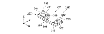
図において、60は判別用基板、R1は取付判別部材搭載部、231は取付判別部材搭載部R1において前壁部105に隣接させて形成され、矩形の形状を有する判別部材収容部としての、かつ、移動規制部材収容部としての凹部であり、該凹部231に判別用基板60及び固定部材287が収容される。
In the figure, 60 is a discrimination substrate, R1 is an attachment discrimination member mounting portion, 231 is formed adjacent to the
前記判別用基板60は、基板本体151、該基板本体151の一方の面、本実施の形態においては、基板本体151の下面に取り付けられた記憶素子としてのメモリ152、及び前記基板本体151の他方の面、本実施の形態においては、基板本体151の上面に形成された接続端子としての第1、第2のコンタクト部60a、60bを備えるとともに、前記前壁部105側に第1の縁部L1を、該縁部L1と対向する側に第2の縁部L2を、側壁部101側に第3の縁部L3を、該第3の縁部L3と対向する側に第4の縁部L4を置いて、トナーカートリッジ本体41aに対して着脱自在に配設される。
The
前記固定部材287をトナーカートリッジ本体41aに取り付けることによって、判別用基板60をトナーカートリッジ本体41aに固定するとともに、凹部231における判別用基板60の移動を規制する。
By attaching the fixing
そして、前記凹部231における内周縁に、第1、第2の位置決め部288、289が形成される。該第1、第2の位置決め部288、289は、前記凹部231の底面から上方に向けて立ち上げて形成されて、判別用基板60の第1、第2の縁部L1、L2と当接させられ、凹部231の幅方向(Y方向)において前記判別用基板60を挟持する。また、前記凹部231の底面に、凹部対向要素としての一対のリブ261、262が、前記基板本体151の下面と対向させて、上方に向けて突出させて、かつ、凹部231の長手方向(X方向)に延在させて形成される。
Then, first and
なお、前記第1、第2の位置決め部288、289は、前記凹部231の長手方向に延在させて形成され、図58に示されるように、前記第1の位置決め部288の上端は、第2の位置決め部289の上端より低くされ、第1の位置決め部288によって低壁部が形成される。
The first and
そして、図55に示されるように、前記固定部材287は、「コ」字状の形状を有し、第1、第2の腕部301、302及び第1、第2の腕部301、302を連結する連結部303から成る平板部297を備え、前記第1の腕部301において、前記挿入規制部285が内側縁部から上方に向けて突出させて形成される。
As shown in FIG. 55, the fixing
前記固定部材287の長手方向(X方向)における両端の近傍に、前記第1、第2の腕部301、302の外側縁部から下方に向けて突出させて第1、第2の係止部としての、かつ、円柱状の突起部としての第1、第2のポスト292、293が形成される。また、図60に示されるように、前記凹部231には、前記第1のポスト292と係止させるための第1の被係止部としての複数の、本実施の形態においては、4個の穴h21が形成されるとともに、前記第2のポスト293と係止させるための第2の被係止部としての1個の長穴h22が、凹部231の長手方向に延在させて形成される。そして、前記固定部材287は、各穴h21のうちの一つの穴h21に前記第1のポスト292を、長穴h22に前記第2のポスト293をそれぞれ圧入することによって、トナーカートリッジ41が凹部231の長手方向に移動自在に取り付けられる。
First and second engaging portions are projected downward from the outer edge portions of the first and
なお、本実施の形態においては、前記凹部231に長穴h22が形成されるようになっているが、該長穴h22に代えて第2のポスト293を圧入するための4個の穴を形成することができる。また、本実施の形態においては、各穴h21及び長穴h22によって、凹部231の長手方向における5箇所で第1、第2のポスト292、293による圧入が行われるようになっているが、3箇所以上で圧入を行うことができる。
In the present embodiment, the elongated hole h22 is formed in the
そして、前記固定部材287において、前記第1、第2の腕部301、302の内側縁部に、第1の移動規制部311、312及び第2の移動規制部315、316が形成される。
In the fixing
前記第1の移動規制部311、312は、前記第1、第2の腕部301、302の内側縁部から下方(Z方向)に向けて突出させて形成された突起から成り、判別用基板60の第3、第4の縁部L3、L4と当接させられ、前記第2の移動規制部315、316は、内側縁部から内側に向けて突出させて形成された突縁から成り、第3、第4の縁部L3、L4の上面を覆う。なお、前記第1の移動規制部311、312は固定部材287の幅方向(Y方向)における中央に形成され、前記第2の移動規制部315、316は固定部材287の幅方向に延在させて形成される。
The first
前記第1、第2の位置決め部288、289は、第1、第2の縁部L1、L2と当接して凹部231の幅方向における判別用基板60の位置決めを行う。また、第1の移動規制部311、312は、第3、第4の縁部L3、L4と当接して凹部231の長手方向における判別用基板60の移動を規制する。そして、第2の移動規制部315、316は、第3、第4の縁部L3、L4と当接して凹部231の深さ方向(Z方向)における判別用基板60の移動を規制する。さらに、前記リブ261、262は、前記基板本体151の下面と当接して凹部131の深さ方向における判別用基板60の位置決めを行う。
The first and
次に、前記判別用基板60をトナーカートリッジ41に搭載する搭載方法について説明する。
Next, a mounting method for mounting the
まず、判別用基板60を底壁部102における取付判別部材搭載部R1に載置し、判別用基板60を、凹部231における第1、第2の位置決め部288、289及び第1、第2の移動規制部315、316によって包囲された領域に滑り込ませる。このとき、判別用基板60は前記リブ261、262と接触させられる。この場合、第1、第2の位置決め部288、289は、凹部231の幅方向において判別用基板60の移動を規制する。
First, the
続いて、前記第1のポスト292を穴h21のうちの一つの穴h21に、第2のポスト293を長穴h22に圧入することによって、固定部材287をトナーカートリッジ本体41aに取り付ける。これにより、固定部材287は、凹部231の長手方向及び深さ方向において位置決めが行われ、凹部231の長手方向及び深さ方向における判別用基板60の移動が規制される。
Subsequently, the fixing
次に、固定部材287の各色のトナーカートリッジ41への取付状態について説明する。
Next, the attachment state of the fixing
図61は本発明の第4の実施の形態における固定部材の取付状態を示す第1の図、図62は本発明の第4の実施の形態における固定部材の取付状態を示す第2の図、図63は本発明の第4の実施の形態における固定部材の取付状態を示す第3の図、図64は本発明の第4の実施の形態における固定部材の取付状態を示す第4の図である。 FIG. 61 is a first diagram showing the mounting state of the fixing member in the fourth embodiment of the present invention, FIG. 62 is a second diagram showing the mounting state of the fixing member in the fourth embodiment of the present invention, FIG. 63 is a third view showing the mounting state of the fixing member in the fourth embodiment of the present invention, and FIG. 64 is a fourth view showing the mounting state of the fixing member in the fourth embodiment of the present invention. is there.
この場合、固定部材287をトナーカートリッジ41に取り付ける位置は各色ごとに異ならせて設定される。すなわち、固定部材287は、例えば、ブラックのトナーカートリッジ41の場合、図61に示される位置に、イエローのトナーカートリッジ41の場合、図62に示される位置に、マゼンタのトナーカートリッジ41の場合、図63に示される位置に、シアンのトナーカートリッジ41の場合、図64に示される位置に取り付けられる。したがって、挿入規制部285を、各色のトナーカートリッジ41ごとに異なる規制部位に置くことができる。
In this case, the position where the fixing
このように、本実施の形態においては、固定部材287に挿入規制部285が形成されるので、トナーカートリッジ41のコストを低くすることができる。
Thus, in this embodiment, since the
前記各実施の形態においては、プリンタについて説明しているが、本発明を複写機、ファクシミリ、複合機等に適用することができる。 In each of the above embodiments, a printer has been described. However, the present invention can be applied to a copying machine, a facsimile machine, a multifunction machine, and the like.
また、前記各実施の形態においては、取付判別部材として、判別用基板60が配設されるようになっているが、取付判別部材としてヒューズを配設することができる。その場合、装置本体にトナーカートリッジ、画像形成ユニット等の交換ユニットがセットされると、前記ヒューズに所定の電流が供給されてヒューズが溶断されるようになっている。したがって、制御部によってヒューズが溶断されているかどうか、すなわち、ヒューズの状態を判断し、交換ユニットが装置本体に対して適正に取り付けられたかどうかを判断したり、交換ユニットの種別、情報等を取得したりすることができる。
In each of the above embodiments, the
なお、本発明は前記各実施の形態に限定されるものではなく、本発明の趣旨に基づいて種々変形させることが可能であり、それらを本発明の範囲から排除するものではない。 The present invention is not limited to the above embodiments, and various modifications can be made based on the gist of the present invention, and they are not excluded from the scope of the present invention.
16Bk、16Y、16M、16C 画像形成ユニット
41 トナーカートリッジ
41a トナーカートリッジ本体
60 判別用基板
87、287 固定部材
88、288 第1の位置決め部
89、289 第2の位置決め部
91、311、312 第1の移動規制部
191、315、316 第2の移動規制部
L1 第1の縁部
L2 第2の縁部
16Bk, 16Y, 16M, 16C
Claims (23)
(b)該取付判別部材の第1の縁部と当接するように形成された第1の位置決め部及び前記取付判別部材の第2の縁部と当接するように形成された第2の位置決め部を備え、第1、第2の位置決め部間に形成された領域に前記取付判別部材を滑り込ませることによって、取付判別部材の第1、第2の縁部において、前記第1、第2の位置決め部間の方向である第1の方向で前記取付判別部材の位置決めを行う交換ユニット本体と、
(c)該交換ユニット本体に対して着脱自在に配設された移動規制部材とを有するとともに、
(d)該移動規制部材が前記交換ユニット本体に取り付けられた状態で、交換ユニット本体に形成された移動規制部及び前記移動規制部材に形成された移動規制部によって、取付判別部材の他の縁部において、前記領域に取付判別部材を滑り込ませる方向である第2の方向、及び前記第1、第2の方向に対して直角の方向であり、かつ、前記取付判別部材を交換ユニット本体に装着する方向である第3の方向での、前記取付判別部材の移動が規制されることを特徴とする交換ユニット。 (A) an attachment discriminating member provided with a first edge, a second edge facing the first edge, and another edge;
(B) a first positioning portion formed so as to be in contact with a first edge portion of the attachment determination member and a second position formed so as to be in contact with a second edge portion of the attachment determination member. The first and second edge portions of the attachment determination member are provided with a positioning portion, and the first and second edges of the attachment determination member are slid into an area formed between the first and second positioning portions. first and row cormorant exchange unit body positioning the mounting discrimination member in a direction which is the direction between the positioning portion,
(C) a movement restricting member that is detachably disposed on the replacement unit main body ;
(D) In a state where the movement restricting member is attached to the replacement unit main body, the movement restricting portion formed on the exchange unit main body and the movement restricting portion formed on the movement restricting member cause another edge of the attachment determining member. In the second direction, which is a direction in which the attachment determination member is slid into the region, and a direction perpendicular to the first and second directions, and the attachment determination member is mounted on the replacement unit main body. The replacement unit is characterized in that movement of the attachment discriminating member in a third direction, which is a direction to perform, is restricted .
(b)該取付判別部材の第1の縁部と当接するように形成された第1の位置決め部及び前記取付判別部材の第2の縁部と当接するように形成された第2の位置決め部を備え、第1、第2の位置決め部間に形成された領域に前記取付判別部材を滑り込ませることによって、取付判別部材の第1、第2の縁部において、前記第1、第2の位置決め部間の方向である第1の方向で前記取付判別部材の位置決めを行う交換ユニット本体と、
(c)該交換ユニット本体に対して着脱自在に配設され、交換ユニット本体に取り付けられた状態で、取付判別部材の他の縁部において、前記領域に取付判別部材を滑り込ませる方向である第2の方向、及び前記第1、第2の方向に対して直角の方向であり、かつ、前記取付判別部材を交換ユニット本体に装着する方向である第3の方向での、前記取付判別部材の移動を規制する移動規制部を備える移動規制部材とを有することを特徴とする交換ユニット。 (A) an attachment discriminating member provided with a first edge, a second edge facing the first edge, and another edge;
(B) a first positioning portion formed so as to be in contact with the first edge portion of the attachment determination member and a second positioning portion formed so as to be in contact with the second edge portion of the attachment determination member. And the first and second positioning portions at the first and second edge portions of the attachment determination member by sliding the attachment determination member into a region formed between the first and second positioning portions. An exchange unit main body for positioning the attachment determining member in a first direction which is a direction between the parts;
(C) A direction in which the attachment determination member is slid into the region at the other edge of the attachment determination member in a state of being detachably disposed on the replacement unit main body and attached to the replacement unit main body. 2 and the third direction which is a direction perpendicular to the first and second directions and which is a direction in which the attachment determination member is mounted on the replacement unit main body. An exchange unit comprising: a movement restricting member including a movement restricting portion for restricting movement.
(b)前記移動規制部材は、前記取付判別部材の第3の縁部と対向する第4の縁部と当接するように形成された第1の移動規制部を備え、
(c)前記各第1の移動規制部間の距離は、前記取付判別部材の第3、第4の縁部間の距離より長くされる請求項1に記載の交換ユニット。 (A) The replacement unit main body includes a first movement restricting portion formed so as to come into contact with a third edge of the attachment determining member,
(B) the movement restricting member is provided with a third fourth edge you face the edge and the first movement restricting portion formed so as to abut the mounting discrimination member,
(C) The exchange unit according to claim 1, wherein a distance between each of the first movement restricting portions is longer than a distance between the third and fourth edge portions of the attachment determining member.
(b)前記第1の方向に対して直角の方向である第2の方向における前記凹部の対向壁間の距離は、前記各第1の移動規制部間の距離より長くされる請求項3に記載の交換ユニット。 (A) The exchange unit main body includes a recess for accommodating the attachment determination member,
(B) the distance of the opposing walls of the recess in a second direction which is a direction perpendicular to the first direction, to claim 3, wherein the greater than the distance between the first movement restricting portion The listed replacement unit.
(b)該凹部に、前記取付判別部材の下面と当接させて凹部対向要素が形成される請求項1又は2に記載の交換ユニット。 (A) The exchange unit main body includes a recess for accommodating the attachment determination member,
(B) The replacement unit according to claim 1 or 2 , wherein a concave portion-facing element is formed in the concave portion in contact with the lower surface of the attachment determining member.
(b)前記移動規制部材は、交換ユニットが誤って取り付けられるのを防止するための取付規制部を備え、前記凹部の長手方向に移動自在に配設される請求項1〜19のいずれか1項に記載の交換ユニット。 (A) The exchange unit main body includes a recess for accommodating the attachment determination member,
(B) the movement restricting member is provided with a mounting regulating portion for preventing the mounted incorrectly exchange unit, claim 1-19 which is movably arranged in the longitudinal direction of the recess 1 Replacement unit as described in the section.
(a)前記交換ユニット本体において、第1の位置決め部と第2の位置決め部との間に形成された領域に前記取付判別部材を滑り込ませることによって、取付判別部材の第1、第2の縁部において、前記第1、第2の位置決め部間の方向である第1の方向で前記取付判別部材の位置決めを行い、
(b)前記移動規制部材を前記交換ユニット本体に取り付けることによって、交換ユニット本体に形成された移動規制部及び前記移動規制部材に形成された移動規制部により、取付判別部材の他の縁部において、前記領域に取付判別部材を滑り込ませる方向である第2の方向、及び前記第1、第2の方向に対して直角の方向であり、かつ、前記取付判別部材を交換ユニット本体に装着する方向である第3の方向での、前記取付判別部材の移動を規制することを特徴とする取付判別部材搭載方法。 An attachment determination member having a first edge, a second edge opposite to the first edge, and another edge, and formed so as to contact the first edge of the attachment determination member An exchange unit main body having a second positioning portion formed so as to abut on the first positioning portion and the second edge of the attachment determining member, and detachably attached to the exchange unit main body. In the replacement unit having the movement restriction member provided, in the mounting determination member mounting method of mounting the mounting determination member on the replacement unit main body,
(A) In the replacement unit main body, the first and second edges of the attachment determination member are slid by sliding the attachment determination member into a region formed between the first positioning portion and the second positioning portion. In the portion, the attachment determining member is positioned in a first direction which is a direction between the first and second positioning portions ,
By the (b) the movement restricting member be attached to the replacement unit body, the movement restricting portion formed on the movement restricting portion and the movement restricting member is formed with an exchange unit main body, in other edge portion of the mounting discrimination member A direction in which the attachment determination member is slid into the region, and a direction perpendicular to the first and second directions, and a direction in which the attachment determination member is attached to the replacement unit main body. A mounting discriminating member mounting method , wherein movement of the mounting discriminating member in the third direction is restricted.
Priority Applications (4)
| Application Number | Priority Date | Filing Date | Title |
|---|---|---|---|
| JP2013016758A JP5820403B2 (en) | 2013-01-31 | 2013-01-31 | Exchange unit, image forming apparatus, and mounting discrimination member mounting method |
| EP14152684.8A EP2762982B1 (en) | 2013-01-31 | 2014-01-27 | Replaceable unit, image forming apparatus that incorporates the replaceable unit and method for attaching a part to the replaceable unit |
| CN201410039176.8A CN103969995B (en) | 2013-01-31 | 2014-01-27 | Replaceable unit and image forming apparatus incorporating the same |
| US14/166,811 US9134674B2 (en) | 2013-01-31 | 2014-01-28 | Replaceable unit, image forming apparatus that incorporates the replaceable unit and method for attaching a part to the replaceable unit |
Applications Claiming Priority (1)
| Application Number | Priority Date | Filing Date | Title |
|---|---|---|---|
| JP2013016758A JP5820403B2 (en) | 2013-01-31 | 2013-01-31 | Exchange unit, image forming apparatus, and mounting discrimination member mounting method |
Publications (3)
| Publication Number | Publication Date |
|---|---|
| JP2014149341A JP2014149341A (en) | 2014-08-21 |
| JP2014149341A5 JP2014149341A5 (en) | 2014-10-02 |
| JP5820403B2 true JP5820403B2 (en) | 2015-11-24 |
Family
ID=50068795
Family Applications (1)
| Application Number | Title | Priority Date | Filing Date |
|---|---|---|---|
| JP2013016758A Active JP5820403B2 (en) | 2013-01-31 | 2013-01-31 | Exchange unit, image forming apparatus, and mounting discrimination member mounting method |
Country Status (4)
| Country | Link |
|---|---|
| US (1) | US9134674B2 (en) |
| EP (1) | EP2762982B1 (en) |
| JP (1) | JP5820403B2 (en) |
| CN (1) | CN103969995B (en) |
Families Citing this family (15)
| Publication number | Priority date | Publication date | Assignee | Title |
|---|---|---|---|---|
| JP6338460B2 (en) * | 2013-08-20 | 2018-06-06 | キヤノン株式会社 | Cartridge and image forming apparatus |
| JP6348379B2 (en) * | 2014-08-28 | 2018-06-27 | 株式会社沖データ | Image forming apparatus and detachable unit |
| US9285758B1 (en) | 2014-12-19 | 2016-03-15 | Lexmark International, Inc. | Positional control features between replaceable units of an electrophotographic image forming device |
| US9291992B1 (en) * | 2014-12-19 | 2016-03-22 | Lexmark International, Inc. | Positional control features for an imaging unit in an electrophotographic image forming device |
| JP6552212B2 (en) * | 2015-02-16 | 2019-07-31 | キヤノン株式会社 | Cartridge, image forming apparatus, and method of manufacturing cartridge |
| JP6598468B2 (en) * | 2015-02-16 | 2019-10-30 | キヤノン株式会社 | Cartridge, image forming apparatus, and cartridge manufacturing method |
| JP2016151727A (en) * | 2015-02-19 | 2016-08-22 | 富士ゼロックス株式会社 | Electronic component attachment structure, removable attachment unit, and image forming apparatus |
| JP6582713B2 (en) * | 2015-08-17 | 2019-10-02 | 富士ゼロックス株式会社 | Conveying apparatus and image forming apparatus |
| JP6589630B2 (en) | 2015-12-25 | 2019-10-16 | ブラザー工業株式会社 | Developer cartridge |
| JP6685756B2 (en) * | 2016-02-17 | 2020-04-22 | キヤノン株式会社 | Image forming apparatus, control method thereof, and program |
| JP6520833B2 (en) * | 2016-06-08 | 2019-05-29 | 京セラドキュメントソリューションズ株式会社 | Toner container, image forming apparatus |
| JP2018077448A (en) * | 2016-09-26 | 2018-05-17 | 株式会社沖データ | Toner storage container, image forming unit, and image forming apparatus |
| JP6764816B2 (en) | 2017-03-24 | 2020-10-07 | 株式会社沖データ | Development unit, image forming unit and image forming device |
| JP7362247B2 (en) * | 2018-12-12 | 2023-10-17 | キヤノン株式会社 | Image forming device |
| JP2020197625A (en) * | 2019-06-03 | 2020-12-10 | キヤノン株式会社 | Image forming apparatus |
Family Cites Families (23)
| Publication number | Priority date | Publication date | Assignee | Title |
|---|---|---|---|---|
| JPS6161595U (en) * | 1984-09-27 | 1986-04-25 | ||
| JPS6313496U (en) * | 1986-07-10 | 1988-01-28 | ||
| DE3701310A1 (en) * | 1987-01-17 | 1988-07-28 | Bodenseewerk Geraetetech | Contact-making device for making contact with surface-mounted integrated circuits |
| JPH11176516A (en) * | 1997-12-10 | 1999-07-02 | Olympus Optical Co Ltd | Member mounting device |
| FR2805635B1 (en) * | 2000-02-24 | 2003-12-12 | Mitsubishi Electric France | CARD READER AND MOBILE EQUIPMENT COMPRISING SAME |
| US6697578B2 (en) * | 2000-08-25 | 2004-02-24 | Canon Kabushiki Kaisha | Memory member, unit, process cartridge and electrophotographic image forming apparatus |
| JP2003051688A (en) * | 2001-08-08 | 2003-02-21 | Shindengen Electric Mfg Co Ltd | Electronic circuit device |
| JP3809402B2 (en) * | 2002-05-17 | 2006-08-16 | キヤノン株式会社 | Process cartridge and electrophotographic image forming apparatus |
| JP4194298B2 (en) * | 2002-05-17 | 2008-12-10 | キヤノン株式会社 | Information storage medium, unit, process cartridge, developing cartridge, and electrophotographic image forming apparatus |
| JP4535710B2 (en) * | 2003-10-31 | 2010-09-01 | 京セラ株式会社 | Card fixing device and portable terminal using the same |
| US7136608B2 (en) * | 2003-12-19 | 2006-11-14 | Steven Miller | Removable toner cartridge universal adapter |
| EP1821160A4 (en) * | 2004-12-09 | 2013-01-16 | Seiko Epson Corp | Development apparatus, image forming apparatus, image forming system, cartridge, development unit and photoreceptor unit |
| JP2006284818A (en) * | 2005-03-31 | 2006-10-19 | Seiko Epson Corp | Development unit, image forming apparatus, image forming system, and photoreceptor unit |
| US7424245B2 (en) * | 2005-10-19 | 2008-09-09 | Static Control Components, Inc. | Systems and methods for remanufacturing imaging components |
| JP2007199505A (en) * | 2006-01-27 | 2007-08-09 | Toshiba Corp | Developer supply device |
| JP4681489B2 (en) | 2006-03-31 | 2011-05-11 | 株式会社沖データ | Toner cartridge, developing device, and image forming apparatus |
| US7515837B2 (en) * | 2007-01-17 | 2009-04-07 | Static Control Components, Inc. | System and methods for universal imaging components |
| US20080253799A1 (en) * | 2007-04-10 | 2008-10-16 | Static Control Components, Inc. | Method for converting a non-chipped imaging cartridge to a multi-use chipped imaging cartridge |
| CN201494096U (en) * | 2009-08-28 | 2010-06-02 | 珠海天威飞马打印耗材有限公司 | Chip fixing structure |
| JP5433388B2 (en) * | 2009-12-03 | 2014-03-05 | シャープ株式会社 | Connector, toner cartridge including the connector, and image forming apparatus |
| KR101515184B1 (en) * | 2010-06-11 | 2015-04-24 | 가부시키가이샤 리코 | Information storage device, removable device, developer container, and image forming apparatus |
| JP4921609B2 (en) * | 2011-09-16 | 2012-04-25 | キヤノン株式会社 | Cartridge and image forming apparatus |
| JP6140963B2 (en) * | 2012-09-27 | 2017-06-07 | キヤノン株式会社 | Cartridge and image forming apparatus |
-
2013
- 2013-01-31 JP JP2013016758A patent/JP5820403B2/en active Active
-
2014
- 2014-01-27 CN CN201410039176.8A patent/CN103969995B/en active Active
- 2014-01-27 EP EP14152684.8A patent/EP2762982B1/en active Active
- 2014-01-28 US US14/166,811 patent/US9134674B2/en active Active
Also Published As
| Publication number | Publication date |
|---|---|
| CN103969995B (en) | 2019-12-27 |
| EP2762982A1 (en) | 2014-08-06 |
| JP2014149341A (en) | 2014-08-21 |
| US9134674B2 (en) | 2015-09-15 |
| EP2762982B1 (en) | 2017-03-01 |
| US20140212151A1 (en) | 2014-07-31 |
| CN103969995A (en) | 2014-08-06 |
Similar Documents
| Publication | Publication Date | Title |
|---|---|---|
| JP5820403B2 (en) | Exchange unit, image forming apparatus, and mounting discrimination member mounting method | |
| JP4806265B2 (en) | Exchange unit and image forming apparatus | |
| JP5811452B2 (en) | Image forming apparatus | |
| JP5741808B2 (en) | Developer amount detection device and image forming apparatus | |
| JP5195803B2 (en) | Image forming apparatus | |
| JP4655133B2 (en) | Image forming apparatus | |
| US8369736B2 (en) | Developing device and image forming apparatus | |
| JP5822816B2 (en) | Developer container, developer container holding unit, and image forming apparatus | |
| US8913927B2 (en) | Developer cartridge, developing device and image forming apparatus | |
| JP2009162908A (en) | Process cartridge, image forming apparatus, and developing cartridge | |
| JP6598468B2 (en) | Cartridge, image forming apparatus, and cartridge manufacturing method | |
| JP6494295B2 (en) | Image forming apparatus and cartridge | |
| JP2010078847A (en) | Image forming apparatus and developing device | |
| CN110837216A (en) | Powder storage container, developer replenishing device, and image forming apparatus | |
| JP5999491B2 (en) | Image forming apparatus | |
| JP2014145793A (en) | Toner supply device | |
| JP2012226007A (en) | Image forming device | |
| JP2016161619A (en) | Side member, cartridge and image formation apparatus | |
| JP5855595B2 (en) | Image forming apparatus | |
| JP5309256B2 (en) | Image forming apparatus and toner container | |
| JP2007148058A (en) | Image forming apparatus | |
| JP5811902B2 (en) | Image forming apparatus | |
| JP5352724B2 (en) | Toner container | |
| JP5819339B2 (en) | Image forming apparatus | |
| JP2014231207A (en) | Image formation apparatus |
Legal Events
| Date | Code | Title | Description |
|---|---|---|---|
| A521 | Request for written amendment filed |
Free format text: JAPANESE INTERMEDIATE CODE: A523 Effective date: 20140818 |
|
| A621 | Written request for application examination |
Free format text: JAPANESE INTERMEDIATE CODE: A621 Effective date: 20140818 |
|
| A977 | Report on retrieval |
Free format text: JAPANESE INTERMEDIATE CODE: A971007 Effective date: 20150128 |
|
| A131 | Notification of reasons for refusal |
Free format text: JAPANESE INTERMEDIATE CODE: A131 Effective date: 20150203 |
|
| A521 | Request for written amendment filed |
Free format text: JAPANESE INTERMEDIATE CODE: A523 Effective date: 20150403 |
|
| TRDD | Decision of grant or rejection written | ||
| A01 | Written decision to grant a patent or to grant a registration (utility model) |
Free format text: JAPANESE INTERMEDIATE CODE: A01 Effective date: 20150908 |
|
| A61 | First payment of annual fees (during grant procedure) |
Free format text: JAPANESE INTERMEDIATE CODE: A61 Effective date: 20151002 |
|
| R150 | Certificate of patent or registration of utility model |
Ref document number: 5820403 Country of ref document: JP Free format text: JAPANESE INTERMEDIATE CODE: R150 |
|
| S111 | Request for change of ownership or part of ownership |
Free format text: JAPANESE INTERMEDIATE CODE: R313111 |
|
| R350 | Written notification of registration of transfer |
Free format text: JAPANESE INTERMEDIATE CODE: R350 |