JP5430349B2 - Developer cartridge - Google Patents
Developer cartridge Download PDFInfo
- Publication number
- JP5430349B2 JP5430349B2 JP2009249749A JP2009249749A JP5430349B2 JP 5430349 B2 JP5430349 B2 JP 5430349B2 JP 2009249749 A JP2009249749 A JP 2009249749A JP 2009249749 A JP2009249749 A JP 2009249749A JP 5430349 B2 JP5430349 B2 JP 5430349B2
- Authority
- JP
- Japan
- Prior art keywords
- developing cartridge
- support member
- developing
- handle portion
- developer
- Prior art date
- Legal status (The legal status is an assumption and is not a legal conclusion. Google has not performed a legal analysis and makes no representation as to the accuracy of the status listed.)
- Active
Links
- 230000001105 regulatory effect Effects 0.000 claims description 9
- 239000007769 metal material Substances 0.000 claims description 3
- 210000003813 thumb Anatomy 0.000 description 14
- 210000003811 finger Anatomy 0.000 description 13
- 238000000034 method Methods 0.000 description 6
- 238000003466 welding Methods 0.000 description 4
- 238000005452 bending Methods 0.000 description 3
- 230000005540 biological transmission Effects 0.000 description 3
- 238000004140 cleaning Methods 0.000 description 3
- 238000003860 storage Methods 0.000 description 3
- XEEYBQQBJWHFJM-UHFFFAOYSA-N Iron Chemical compound [Fe] XEEYBQQBJWHFJM-UHFFFAOYSA-N 0.000 description 2
- 239000000853 adhesive Substances 0.000 description 2
- 230000001070 adhesive effect Effects 0.000 description 2
- 230000015572 biosynthetic process Effects 0.000 description 2
- 230000005484 gravity Effects 0.000 description 2
- 238000012423 maintenance Methods 0.000 description 2
- 239000002184 metal Substances 0.000 description 2
- 229910052751 metal Inorganic materials 0.000 description 2
- 230000002093 peripheral effect Effects 0.000 description 2
- 238000011144 upstream manufacturing Methods 0.000 description 2
- JOYRKODLDBILNP-UHFFFAOYSA-N Ethyl urethane Chemical compound CCOC(N)=O JOYRKODLDBILNP-UHFFFAOYSA-N 0.000 description 1
- 230000001154 acute effect Effects 0.000 description 1
- 210000000078 claw Anatomy 0.000 description 1
- 230000000694 effects Effects 0.000 description 1
- 230000001771 impaired effect Effects 0.000 description 1
- 238000009434 installation Methods 0.000 description 1
- 229910052742 iron Inorganic materials 0.000 description 1
- 238000005304 joining Methods 0.000 description 1
- -1 polyethylene terephthalate Polymers 0.000 description 1
- 229920000139 polyethylene terephthalate Polymers 0.000 description 1
- 239000005020 polyethylene terephthalate Substances 0.000 description 1
- 239000002904 solvent Substances 0.000 description 1
Images


Classifications
-
- G—PHYSICS
- G03—PHOTOGRAPHY; CINEMATOGRAPHY; ANALOGOUS TECHNIQUES USING WAVES OTHER THAN OPTICAL WAVES; ELECTROGRAPHY; HOLOGRAPHY
- G03G—ELECTROGRAPHY; ELECTROPHOTOGRAPHY; MAGNETOGRAPHY
- G03G15/00—Apparatus for electrographic processes using a charge pattern
- G03G15/06—Apparatus for electrographic processes using a charge pattern for developing
- G03G15/08—Apparatus for electrographic processes using a charge pattern for developing using a solid developer, e.g. powder developer
- G03G15/0896—Arrangements or disposition of the complete developer unit or parts thereof not provided for by groups G03G15/08 - G03G15/0894
-
- G—PHYSICS
- G03—PHOTOGRAPHY; CINEMATOGRAPHY; ANALOGOUS TECHNIQUES USING WAVES OTHER THAN OPTICAL WAVES; ELECTROGRAPHY; HOLOGRAPHY
- G03G—ELECTROGRAPHY; ELECTROPHOTOGRAPHY; MAGNETOGRAPHY
- G03G15/00—Apparatus for electrographic processes using a charge pattern
- G03G15/06—Apparatus for electrographic processes using a charge pattern for developing
- G03G15/08—Apparatus for electrographic processes using a charge pattern for developing using a solid developer, e.g. powder developer
- G03G15/0822—Arrangements for preparing, mixing, supplying or dispensing developer
- G03G15/0877—Arrangements for metering and dispensing developer from a developer cartridge into the development unit
- G03G15/0881—Sealing of developer cartridges
- G03G15/0882—Sealing of developer cartridges by a peelable sealing film
-
- G—PHYSICS
- G03—PHOTOGRAPHY; CINEMATOGRAPHY; ANALOGOUS TECHNIQUES USING WAVES OTHER THAN OPTICAL WAVES; ELECTROGRAPHY; HOLOGRAPHY
- G03G—ELECTROGRAPHY; ELECTROPHOTOGRAPHY; MAGNETOGRAPHY
- G03G2215/00—Apparatus for electrophotographic processes
- G03G2215/01—Apparatus for electrophotographic processes for producing multicoloured copies
- G03G2215/0167—Apparatus for electrophotographic processes for producing multicoloured copies single electrographic recording member
- G03G2215/0174—Apparatus for electrophotographic processes for producing multicoloured copies single electrographic recording member plural rotations of recording member to produce multicoloured copy
- G03G2215/0177—Rotating set of developing units
Landscapes
- Physics & Mathematics (AREA)
- General Physics & Mathematics (AREA)
- Dry Development In Electrophotography (AREA)
- Electrophotography Configuration And Component (AREA)
Description
本発明は、電子画像形成装置に取り外し可能に装着される現像カートリッジに関する。 The present invention relates to a developing cartridge that is detachably attached to an electronic image forming apparatus.
ここで、電子写真画像形成装置とは、電子写真画像形成プロセスを用いて記録媒体に画像を形成するものである。例えば、電子写真複写機、電子写真プリンタ(LEDプリンタ、レーザービームプリンタなど)、電子写真ファクシミリ装置、及び、電子写真ワードプロセッサーなどが含まれる。 Here, the electrophotographic image forming apparatus forms an image on a recording medium using an electrophotographic image forming process. For example, an electrophotographic copying machine, an electrophotographic printer (such as an LED printer or a laser beam printer), an electrophotographic facsimile apparatus, and an electrophotographic word processor are included.
現像カートリッジとは、前記電子写真感光体に作用するプロセス手段として、少なくとも現像手段を一体的にカートリッジ化して、電子写真画像形成装置の本体に着脱するものである。 The developing cartridge is a process unit that acts on the electrophotographic photosensitive member, and at least the developing unit is integrated into a cartridge and is attached to and detached from the main body of the electrophotographic image forming apparatus.
また、現像カートリッジは使用者自身によって装置本体に対する着脱を行うことができる。したがって、装置のメンテナンスをサービスマンによらずに、使用者で行うことができる。これによって、画像形成装置のメンテナンス操作を向上させている。 The developer cartridge can be attached to and detached from the apparatus main body by the user himself. Therefore, maintenance of the apparatus can be performed by the user without depending on the service person. This improves the maintenance operation of the image forming apparatus.
近年、電子写真画像形成装置の一層の小型化が必要とされている。ここで、本体を小型化する手段の一つとして、複数の現像カートリッジを搭載可能なロータリを備えた、所謂、ロータリ式のカラー電子写真画像形成装置が提案されている(特許文献1)。 In recent years, further miniaturization of electrophotographic image forming apparatuses has been required. Here, as one of means for reducing the size of the main body, a so-called rotary type color electrophotographic image forming apparatus including a rotary capable of mounting a plurality of developing cartridges has been proposed (Patent Document 1).
また、回転可能なロータリに4色の現像カートリッジを着脱可能に収納しているカラー画像形成装置において、現像カートリッジの着脱は、現像カートリッジの把手部を持ち、装置本体上面のカバーを開き、上方より行うような構成が知られている(特許文献2)。 Further, in a color image forming apparatus in which four color developer cartridges are detachably housed in a rotatable rotary, the developer cartridge is attached / detached by holding the handle of the developer cartridge, opening the cover on the upper surface of the apparatus main body, and The structure to perform is known (patent document 2).
最近の電子写真画像形成装置には、高速、高画質であると同時に、更なる小型化が求められている。そのためには、電子写真画像形成装置内で大きな空間を占めるカートリッジの小型化が必要となる。 Recent electrophotographic image forming apparatuses are required to be further miniaturized as well as high speed and high image quality. For this purpose, it is necessary to reduce the size of the cartridge that occupies a large space in the electrophotographic image forming apparatus.
現像カートリッジを小型化するには、構成部品の小型化、部品点数の削減、各部品の効率的な配置が要求される。そして、部品同士が近接して配置されるため、例えば、現像カートリッジの着脱動作時にユーザが把手部を把持した時、指が他の部品に触れ、ユーザビリティ性を悪化させる原因となる場合がある。 In order to reduce the size of the developing cartridge, it is necessary to reduce the size of the component parts, reduce the number of parts, and efficiently arrange each part. Since the components are arranged close to each other, for example, when the user grips the handle during the mounting / demounting operation of the developing cartridge, the finger may touch other components, which may cause the usability to deteriorate.
本発明は上記点に鑑みてなされたものであり、その目的は、現像カートリッジの小型化を図るとともに、ユーザビリティ性を損なわない現像カートリッジを提供するものである。 The present invention has been made in view of the above points, and an object of the present invention is to provide a developing cartridge that does not impair usability while reducing the size of the developing cartridge.
上記目的を達成するための本発明に係る代表的な構成は、記録媒体に画像を形成する電子写真画像形成装置に着脱可能な現像カートリッジであって、枠体と、現像剤を担持する現像剤担持体と、現像剤担持体の表面に担持された現像剤の層厚を規制するための規制部材と、前記規制部材の一端を支持した状態で、前記枠体に取り付けられる支持部材と、前記支持部材における前記規制部材を支持する一端部とは反対側の他端部に対して隙間を有して設けられた、前記現像カートリッジを把持するための把手部と、前記支持部材の前記他端部から前記把手部に向かって延びるように前記支持部材に設けられ、前記把手部を把持する動作に伴って撓むことで前記支持部材の前記他端部を覆うシート部材と、を有することを特徴とする。 In order to achieve the above object, a typical configuration according to the present invention is a developing cartridge that is detachable from an electrophotographic image forming apparatus for forming an image on a recording medium, and includes a frame and a developer carrying the developer. and bearing member, a regulating member for regulating the layer thickness of the developer carried on the surface of the developer carrying member, while supporting one end of the regulating member, a supporting member attached to the frame body, wherein A grip portion for holding the developing cartridge, which is provided with a gap with respect to the other end portion of the support member opposite to the one end portion supporting the regulating member, and the other end of the support member A sheet member that is provided on the support member so as to extend from the portion toward the handle portion and covers the other end portion of the support member by bending in accordance with an operation of gripping the handle portion. Features.
本発明にあっては、小型化した現像カートリッジの把手部をユーザが把持したときに、支持部材の端部をシート部材が覆うようになるため、ユーザの指が支持部材の端部に触れることがなく、ユーザビリティ性を低下させることがない。 In the present invention, when the user grips the handle portion of the downsized developer cartridge, the sheet member covers the end of the support member, so that the user's finger touches the end of the support member. There is no loss of usability.
次に本発明を実施するための一形態として、複数の現像カートリッジを搭載可能なロータリを備えた、所謂、ロータリ方式のカラー電子写真画像形成装置の実施形態について図面を参照して説明する。 Next, as a mode for carrying out the present invention, an embodiment of a so-called rotary type color electrophotographic image forming apparatus provided with a rotary capable of mounting a plurality of developing cartridges will be described with reference to the drawings.
〔第1実施形態〕
<カラー電子写真画像形成装置の全体構成>
まず、現像カートリッジを装着して画像形成するカラー電子写真画像形成装置の構成及びその画像形成動作について説明する。
[First Embodiment]
<Overall configuration of color electrophotographic image forming apparatus>
First, the configuration of a color electrophotographic image forming apparatus that mounts a developing cartridge and forms an image and its image forming operation will be described.
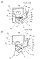
本発明の実施形態に係るカラー電子写真画像形成装置(以下、「画像形成装置」という)は、4色フルカラーのレーザービームプリンタである。図1(a)は、イエロー現像カートリッジ5aが現像動作中の概略構成を示す断面図である。図1(b)は、ブラック現像カートリッジ5dが現像動作中の概略構成を示す断面図である。
A color electrophotographic image forming apparatus (hereinafter referred to as “image forming apparatus”) according to an embodiment of the present invention is a four-color full-color laser beam printer. FIG. 1A is a cross-sectional view showing a schematic configuration during the developing operation of the yellow developing
図1(a)に示すように、画像形成装置100は、感光体ドラム2aを有する。感光体ドラム2aの周囲には、感光体ドラム2aを一様に帯電するための帯電手段2b(本実施形態では帯電ローラを採用している)と、感光体ドラム2a上にレーザー光を照射して潜像を形成するための露光手段15を有する。
As shown in FIG. 1A, the
また、画像形成装置100は、感光体ドラム2a上に形成された潜像を対応する色のトナーで現像して顕像化する複数の現像カートリッジ5(5a〜5d)を有する。複数の現像カートリッジ5とは、イエロー現像カートリッジ5a、マゼンタ現像カートリッジ5b、シアン現像カートリッジ5c、ブラック現像カートリッジ5dを指す。また、感光体ドラム2a上の残留トナーを除去するクリーニング手段2cが配置されている。
Further, the
本実施形態では、感光体ドラム2aと帯電手段2bとクリーニング手段2cが一体に構成され、かつ、画像形成装置100に対して着脱可能なドラムカートリッジ2を採用している。
In the present exemplary embodiment, a
ロータリ1は、回転軸1aを中心に回転可能に構成され、イエロー現像カートリッジ5a、マゼンタ現像カートリッジ5b、シアン現像カートリッジ5c、ブラック現像カートリッジ5dを同姿勢に保持している。ロータリ1が各現像カートリッジ5a〜5dを保持する構成は全て同様である。
The
現像カートリッジ5はロータリ1に装着されると、現像カートリッジ5に設けられた被係止部61c(61ca〜61cd)が、ロータリ1に設けられた現像カートリッジ係止部材19(19a〜19d)と係合する。係止部材19はバネ(不図示)により現像カートリッジ5と係合する方向(矢印D方向)に付勢されている。これにより、ロータリ1からの脱落が抑制されている。
When the developing
ここで、ロータリ1は、現像カートリッジ5を保持した状態で、本体フレームに対して取り付けられている。本実施形態では、現像カートリッジ5は、ロータリ1に対してロータリ1の径方向に着脱可能としている。
Here, the
画像形成に際しては、感光体ドラム2aを、中間転写ベルト3の回転方向である図1矢印C方向と同期させて、図1において反時計回り方向の矢印A方向に回転させる。そして、この感光体ドラム2aの表面を帯電手段2bによって均一に帯電するとともに、露光手段15によってイエロー画像の光照射を行い、感光体ドラム2a上にイエローの静電潜像を形成する。
When forming an image, the
この静電潜像の形成と同時に、ロータリ1は、ロータリ回転軸1aを中心にして、画像形成装置100に設けられた駆動伝達機構により図1において時計回り方向の矢印B方向に回転する。これによって、ロータリ1は回転して、イエローの現像カートリッジ5aを、感光体ドラム2aと対向する現像位置に配置する(図1(a))。
Simultaneously with the formation of the electrostatic latent image, the
そして、感光体ドラム2aに形成された潜像にイエロー現像剤が付着するように、感光体ドラム2aの帯電極性と同極性の電圧を現像ローラ51aに印加する。これによって、感光体ドラム2aに形成された潜像にイエロー現像剤を付着させて現像する。即ち、感光体ドラム2aにイエロー現像剤像が形成される。
Then, a voltage having the same polarity as the charging polarity of the
その後、中間転写ベルト3内側に配置された一次転写ローラ4にトナーと逆極性の電圧を印加して、感光体ドラム2a上のイエローのトナー像を中間転写ベルト3上に一次転写する。
Thereafter, a voltage having a polarity opposite to that of the toner is applied to the primary transfer roller 4 disposed inside the
上述のようにして、イエロートナー像の一次転写が終了すると、ロータリ1が、画像形成装置100の駆動伝達機構から駆動を受け、図1矢印B方向へ回転移動する。すると、マゼンタ現像カートリッジ5b、シアン現像カートリッジ5c、ブラック現像カートリッジ5dが順次、感光体ドラム2aに対向する現像位置に位置決めされる。イエローの場合と同様にして、マゼンダ、シアン、そしてブラックの各色について、静電潜像の形成、現像、一次転写が順次行われ、中間転写ベルト3上に4色のトナー像を重ね合わせる。
As described above, when the primary transfer of the yellow toner image is completed, the
この間、二次転写ローラ6は、図1(a)に示すように、中間転写ベルト3とは非接触状態にある。また、この時、中間転写ベルト3のクリーニングユニット10も中間転写ベルト3とは非接触状態に位置する。
During this time, the
一方、トナー像が記録媒体であるシートSは、画像形成装置100下部に設けられた給送カセット7に積載収納されており、給送ローラ8によって給送カセット7から一枚ずつ分離給送され、レジストローラ対9に給送する。レジストローラ対9は、給送されたシートSを中間転写ベルト3と二次転写ローラ6の間に送り出す。ここで、二次転写ローラ6が、図1(b)に示すように、中間転写ベルト3に圧接された状態になる。
On the other hand, the sheet S in which the toner image is a recording medium is stacked and stored in a feeding
更に、二次転写ローラ6には、トナーと逆極性の電圧が印加されており、前述の中間転写ベルト3上に重ね合わせた4色のトナー像は一括して、搬送されてきたシートSの表面に二次転写されていく。
Further, a voltage having a polarity opposite to that of the toner is applied to the
トナー像が転写されたシートSは、定着器11に送られる。定着器11においては、上記シートSが熱圧され、そのトナー像がシートS上に定着される。これにより、シートS上には画像が形成されることになり、このシートSは、定着器11から装置外部の上カバー12の排出部へ排出される。
The sheet S on which the toner image is transferred is sent to the fixing
<現像カートリッジの構成>
次に現像カートリッジ5について説明する。現像カートリッジは、イエロー現像カートリッジ5a、マゼンタ現像カートリッジ5b、シアン現像カートリッジ5c、ブラック現像カートリッジ5dの構成は全て同様である。よって、本実施形態での各現像カートリッジ5a〜5dの構成の説明は、現像カートリッジ5として行う。現像カートリッジ5について図2及び図3を用いて説明する。
<Configuration of developer cartridge>
Next, the developing
図2(a)は、本実施形態における現像カートリッジ5のトナーシール引き前の断面図である。図2(b)は、本実施形態における現像カートリッジ5のトナーシール引き後の断面図である。図3は、本実施形態における現像カートリッジ5の把手部54付近の拡大概略断面図である。
FIG. 2A is a cross-sectional view of the developing
現像カートリッジ5の現像枠体55は、トナー収容室56と現像ローラ51やトナー供給ローラ52を有する現像室57に分離され、両者はトナー供給開口58により上下に分けられている。
The developing
現像カートリッジ5がユーザの手元に届くまでの未使用状態においては、図2(a)に示すように、トナー供給開口58には、トナー収容室56と現像室57を分離するための、フィルム状のトナーシール70が固定されている。固定方法は熱溶着などの方法による。使用前に、トナーシール70を取り除くことで、トナー収容室56内のトナー80は、感光体ドラムと対向する現像位置において、図2(b)に示すように、現像室57に自由落下する。
In the unused state until the developing
現像室57内のトナーは、トナー供給ローラ52に供給される。さらに、トナー供給ローラ52は、図2において時計回り方向の矢印E方向に回転することで、現像剤担持体である現像ローラ51にトナーを供給する。現像ローラ51は、弾性ゴムローラで構成され、矢印F方向に回転する。現像ローラ51表面のトナーは、現像ブレード53によって一定の厚みに規制され、現像位置で、感光体ドラム2aに対して現像される。
The toner in the developing
現像ブレード53は、現像ローラ51の表面に担持された現像剤の層厚を規制する規制部材となるものであり、現像ローラ51の軸線方向において周面に当接している。そして、現像ブレード53は、図2に示すように、短手方向(現像ローラ51の軸線方向と直交する方向)の一端側において支持部材62により支持されている。つまりは、図3に示すように、現像ブレード53の面53aが支持部材62の面62aに固定されている。支持方法として、本実施形態ではYAG溶接を採用しているが、強固に固定できれば接合方法は問わない。また、支持部材62は、剛性を確保するために、本実施形態では金属材料、具体的には鉄、SUS等の、1.2mm程度の厚さの板金とし、面62aに対して現像ブレード53と反対方向に垂直に曲げられた面62bを有している。すなわち、支持部材62は、L字型に曲がった曲げ部を有している。
The developing
支持部材62は、図2(a)に示すように,現像ブレード53が、現像ローラ51に対してある一定の当接圧を持って現像ローラ51に当接し、その長手方向が現像ローラ51の軸線に対して平行になるように現像枠体55に固定される。
As shown in FIG. 2A, the
現像動作後に、現像ローラ51の表面に残されたトナーは、トナー供給ローラ52によって除去される。その後、再びトナー供給ローラ52によって、現像ローラ51にトナーが供給される。
After the developing operation, the toner remaining on the surface of the developing
また、現像位置では、安定的に現像ローラ51を感光体ドラム2aに当接させるため、ロータリ1ごと感光体ドラム2a方向に付勢させている。これによって、現像カートリッジ5の現像ローラ51(図1(a)にあっては、イエロー現像カートリッジ5aの現像ローラ51a)が感光体ドラム2aに所定の加圧力で当接する状態となる。
Further, at the development position, the
このとき、現像カートリッジ5を保持しているロータリ1は、ロータリ駆動軸20(図1参照)を中心として揺動可能であり、加圧手段(不図示)によって、感光体ドラム2aの方向にロータリごと加圧され、現像ローラ51aが感光体ドラム2aに当接する。
At this time, the
(現像カートリッジの把手部)
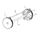
ここで、現像カートリッジ5の把手部54の構成について、図2乃至図5を用いて説明する。なお、図4は本実施形態における現像カートリッジ5の概略斜視図である。図5は現像カートリッジ5における把手部の分解斜視図である。
(Developer cartridge handle)
Here, the configuration of the
把手部54は、現像カートリッジ5を把持するためのものであり、現像カートリッジ5の長手方向(図4矢印R方向)で、ほぼ中央に位置する。そして、図3に示すように、面54c,54dを有するリブ54fが現像ブレード53の支持部材62の端面62cと対向するように設けられている。つまり、端面62cを形成している稜線62b1,62b2が把手部54の面54dと対向している。さらにリブ54fの先端にはリブ中心線Lから面54c方向に突出した凸部54a、面54d方向に突出した凸部54bを有している。凸部54a,54bは、各々面54c,54dに対して1〜10mm程度突出しており、ユーザが把持したときの指の引っ掛かりとなる。
The
また、面54c,54dは、ユーザが実際に把持する部分で、現像カートリッジの5の長手に沿って幅は50〜150mm程度である。
Further, the
また、図2(b)で見た時、面54cの上方の空間M、面54dの下方の空間Nはユーザが指を入れるスペースとなる。本実施形態では、空間Mに人差し指、中指、薬指を、空間Nに親指を入れて、斜面部54c,54dを挟み込むことで把持することを最適としている。
Further, when viewed in FIG. 2B, the space M above the
把手部54は、別部品として現像枠体55に固定されている。図2、図5に示すように、現像枠体55の凹部55bに対して、把手部54の接合面54eが固定されている。本実施形態では、超音波溶着で固定しているが、超音波溶着に限定する必要はなく、接着剤、溶剤、両面テープ等でも構わない。
The
また、前記把手部54は、図3に示すように、L字型に曲がった支持部材62の曲げ部側端部、すなわち支持部材62の短手方向であって前記現像ブレード53を支持している端部と反対の他端側に対して隙間Hを有して設けられている。このように、隙間Hを設けることで、空間Nを広く確保している。
Further, as shown in FIG. 3, the
(現像カートリッジの着脱)
次に、画像形成装置100に対する現像カートリッジ5の着脱操作について、図6及び図7を用いて説明する。なお、イエロー現像カートリッジ5a、マゼンタ現像カートリッジ5b、シアン現像カートリッジ5c、ブラック現像カートリッジ5dの着脱動作は全て同じである。ここでは、イエロー現像カートリッジ5aを着脱する場合を例に説明する。
(Removal of developer cartridge)
Next, the attaching / detaching operation of the developing
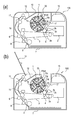
図6(a)は、現像カートリッジの待機状態を示した画像形成装置本体の断面図である。図6(b)は、イエロー現像カートリッジ5aを着脱するときの着脱位置を示した画像形成装置本体の断面図である。図7は、イエロー現像カートリッジ5aを着脱する際の断面図である。
FIG. 6A is a cross-sectional view of the image forming apparatus main body showing a standby state of the developing cartridge. FIG. 6B is a cross-sectional view of the main body of the image forming apparatus showing the attachment / detachment position when attaching / detaching the yellow developing
ロータリ1は、待機状態では、感光体ドラム2aに対して現像ローラ51aが離れる位相まで、ロータリ回転軸1aを中心に回転させた位置で待機している。本実施形態では、図6(a)に示すように、ブラック現像カートリッジ5dが、現像位置からロータリ回転方向Bに対して、約45°上流の位置を待機状態としている。待機状態への移動は、現像動作終了後に、駆動伝達機構によって、自動的に行われる。
In the standby state, the
そして、イエロー現像カートリッジ5aを画像形成装置100から取り出すためには、図6(b)に示すように、着脱カバー13を開くことでユーザがイエロー現像カートリッジ5aを着脱することが可能になる。
In order to take out the yellow developing
つまり、前述した空間Mに人差し指、中指、薬指を、空間Nに親指を入れて、把手部54を把持することができ、イエロー現像カートリッジ5aを取り出すことができる。
That is, the index finger, middle finger, and ring finger can be put in the space M and the thumb can be put in the space N, and the
その他の、マゼンタ現像カートリッジ5b、シアン現像カートリッジ5c、ブラック現像カートリッジ5dも同様に、現像位置からロータリ回転方向Bに対して、45°上流の位置で着脱可能となる。
Similarly, the
図7に示すように、ユーザが把手部54を把持した時、イエロー現像カートリッジ5aの姿勢は、画像形成装置100内の着脱位置におけるイエロー現像カートリッジ5aの姿勢(図7破線)と略同一となる。このため、ユーザが現像カートリッジ5を画像形成装置100へ着脱する操作が容易となっている。これは、着脱位置において、イエロー現像カートリッジ5aの重心位置Gに対して、把手部54が、ほぼ鉛直上方向に位置するためである。本実施形態における重心位置Gは、現像ローラ51a、トナー供給ローラ52a、現像ブレードの支持部材62の近傍に位置している。
As shown in FIG. 7, when the user holds the
ここで、現像カートリッジ5の装着軌跡を、図7及び図8を用いて説明する。図8は、現像カートリッジを保持するロータリの概略斜視図である。
Here, the mounting locus of the developing
図7に示すように、現像カートリッジ5a′は、本体ガイド17に沿って矢印U方向に移動し、ロータリ1に対して装着、取り出しされる。現像カートリッジ5a′は、現像カートリッジ5aの現像ローラ51a軸線方向両端部に固定されたサイド部材60,61に配置されたガイド部材60b,61b(図4参照)が、ロータリ1のガイド部1cにより、所定の位置に案内される。また、図8に示すように、現像カートリッジを位置決めするための位置決め部1dを有している。
As shown in FIG. 7, the developing
前記位置決め部1dに対して、図4及び図5に示す現像カートリッジ5の現像ローラ軸線方向の両端部に固定されたサイド部材60,61の軸部60a,61aの外周部が、突き当たることで位置決めされ装着が完了する。本実施形態では、軸部60a,61aは現像ローラ51に対して同軸上に位置しているが、特に限定する必要はない。
Positioning is performed when the outer peripheral portions of the
(可撓性のシート部材)
本実施形態の現像カートリッジ5には、把手部54と対向した支持部材62の端部から把手部54に向かって突出した可撓性を有するシート部材(以下、「可撓性部材」という)59が設けられている。これにより、ユーザが把手部54を把持する際に、前記可撓性部材が前記端部を覆うことでユーザの指が支持部材62の端部に接触しないようにしている。
(Flexible sheet member)
In the developing
次に前記可撓性部材59について、図2(b)、図3及び図9を用いて説明する。なお、図9(a)は、現像カートリッジ5を把持した状態を示す概略断面図である。図9(b)は、現像カートリッジ5を把持した状態の把手部54付近の拡大概略断面図である。
Next, the
本実施形態の可撓性部材59はシート状のポリエチレンテレフタレート、ウレタン等から成り、厚さは75μm程度、現像ローラ51の軸線方向における長さは把手部54と同等である。
The
また、図3に示すように、可撓性部材59は、その端面59aが現像ブレード53の支持部材62の面62cから把手部54の面54dと対向するように突出している。そして、その突出部59cの長さhは、支持部材62の厚さT以上、かつ、把手部54と支持部材端部との隙間H以下となるように設定されている。ここで、突出部59cは、支持部材62の端部稜線62b1から可撓性部材59の端面59aまでのことを言う。
As shown in FIG. 3, the
前記突出部59cの長さが支持部材62の厚さT以上あれば、可撓性部材59が湾曲したときに支持部材62の端面62cは覆われ、ユーザの指が支持部材62に触れることはない。なお、突出部59cの長さは支持部材の厚さTより短くても稜線62b1と把手部54の面54dの間に介在できる長さであればよい。
If the length of the
また、可撓性部材59の固定方法は、支持部材62の面62bに対して両面テープで固定されている。本実施形態は、両面テープで固定しているが、両面テープに限定する必要はなく、接着剤等でも構わない。
The
そして、図9に示すように、ユーザが把手部54を把持した際に、空間Nに親指が侵入すると、親指が可撓性部材59の突出部59cに当接することにより、可撓性部材59の端面59aが端面59a′まで撓む。それにより、突出部59cが支持部材62の端面62cを構成する端部稜線62b1,62b2と把手部54の面54dの間に介在するようになる。
As shown in FIG. 9, when the user grips the
これにより、先に説明したように、ユーザが把手部54を把持しようとして空間Nに親指が侵入した際に、親指の爪が金属材料である支持部材62の端部稜線62b1,62b2に触れ不快な思いをしなくてすむ。また、突出部59cが撓むために空間Nの領域が減少することなく、把持性を損なうこともない。
As a result, as described above, when the user tries to grasp the
また、上述では、突出部59cの長さを、支持部材62の厚さTよりも長くし、突出部59cが支持部材62の端部稜線62b1,62b2と把手部54の面54dの間に介在するとした。しかし、少なくとも一つの稜線と把手部54の面54dの間に介在できる長さであっても十分な効果がある。ここで、少なくとも一つの稜線とは、把手部54の先端側にある稜線(図9(b)中で62b1)のことである。
In the above description, the length of the protruding
〔他の実施形態〕
第1実施形態では、可撓性部材59の突出部59cの長さは、支持部材62の厚さTよりも長いとしたが、その限りではない。
[Other Embodiments]
In the first embodiment, the length of the
支持部材の構成として、図10(a)に示すように、支持部材162の厚さTを構成する面が複数有する場合にも適用できる。この時、把手部54の面54dに対向する支持部材162の稜線は、162b1,162b2である。そして、空間Nに親指が侵入すると、親指が可撓性部材59の突出部59cに当接することにより、可撓性部材59の端面159aが端面159a′まで撓む。従って、突出部159cの長さは、支持部材162の稜線162b1,162b2と把手部54の面54dの間に介在できる長さであれば良い。
As shown in FIG. 10A, the structure of the support member can also be applied to a case where there are a plurality of surfaces constituting the thickness T of the
また、第1実施形態では、現像ブレード53を支持する支持部材62を部品コストが低いとして板金で構成した。しかし、支持部材62は、図10(b)に示すように、スペースの最適化を図るため角材262で構成しても良い。この場合、把手部54の面54dに対向する支持部材262の稜線は、262b1,262b2である。そして、空間Nに親指が侵入すると、親指が可撓性部材59の突出部59cに当接することにより、可撓性部材59の端面259aが端面259a′まで撓む。従って、突出部259cの長さは、稜線262b1,262b2と把手部54の面54dの間に介在できる長さであれば良い。
In the first embodiment, the
また、図11(a)、(b)に示すような支持部材が把手部の面54dに対して直交していない場合でも適用できる。この場合、把手部54の面54dに対向する支持部材362,462の稜線は、各々362b2,462b1である。そして、空間Nに親指が侵入すると、親指が可撓性部材59の突出部59cに当接することにより、可撓性部材59の各々の端面359a,459aが端面359a′、459a′まで撓む。
Further, the present invention can be applied even when the support member as shown in FIGS. 11A and 11B is not orthogonal to the
従って、図11(a)に示すように、支持部材362の端面362cが把手部54のリブ54fの先端方向を向いている場合、すなわちL字型の曲げ角が鈍角となっている場合の突出部359cの長さは、稜線362b2と把手部54の面54dの間に介在できる長さであれば良い。
Therefore, as shown in FIG. 11A, the protrusion when the end surface 362c of the
また、図11(b)に示すように、支持部材462の端面462cが把手部54のリブ54fの根元方向を向いている場合、すなわちL字型の曲げ角が鋭角となっている場合の突出部459cの長さは、稜線462b1と把手部54の面54dの間に介在できる長さであれば良い。
Further, as shown in FIG. 11B, the protrusion when the
さらに、第1実施形態では把手部54のリブ54fは面で形成されるとしたが、図12に示すように、曲面154c,154dで形成しても良い。この場合、把手部154の曲面154dに対向する支持部材562の稜線は562b1,562b2である。そして、空間Nに親指が侵入すると、親指が可撓性部材59の突出部59cに当接することにより、可撓性部材59の端面559aが端面559a′まで撓む。従って、突出部559cの長さは、稜線562b1,562b2と把手部154の曲面154dの間に介在できる長さであれば良い。
Furthermore, in the first embodiment, the
以上説明したように、本実施形態の現像カートリッジによると、可撓性部材を現像ブレードの支持部材に配置し、突出部の長さを、現像カートリッジの把手部を把持した際に、突出部が変形し、把手部と少なくとも一つの支持部材の稜線の間に介在するようにした。これにより、支持部材の端部稜線にユーザの指が触れることを回避することができる。従って、把手部と支持部材を近接して配置することができ、現像カートリッジの小型化とユーザビリティ性の両立を図ることができる。 As described above, according to the developing cartridge of this embodiment, when the flexible member is arranged on the supporting member of the developing blade and the length of the protruding portion is grasped by the grip portion of the developing cartridge, the protruding portion It was deformed so as to be interposed between the grip portion and the ridge line of at least one support member. Thereby, it can avoid that a user's finger | toe touches the edge part ridgeline of a supporting member. Therefore, the grip portion and the support member can be disposed close to each other, and both the downsizing of the developing cartridge and the usability can be achieved.
尚、前述した実施の形態では、ロータリ式の電子画像形成装置に用いられるカラー現像カートリッジの場合を示したが、これに限定する必要はなく、インライン式である場合の現像カートリッジやモノクロ現像カートリッジにも適用できる。 In the above-described embodiment, the case of the color developing cartridge used in the rotary type electronic image forming apparatus is shown. However, the present invention is not limited to this, and the developing cartridge or the monochrome developing cartridge in the case of the inline type is used. Is also applicable.
5 …現像カートリッジ
51 …現像ローラ
52 …トナー供給ローラ
53 …現像ブレード
54 …把手部
59 …可撓性部材
59c …突出部
100 …画像形成装置
DESCRIPTION OF
Claims (5)
枠体と、
現像剤を担持する現像剤担持体と、
現像剤担持体の表面に担持された現像剤の層厚を規制するための規制部材と、
前記規制部材の一端を支持した状態で、前記枠体に取り付けられる支持部材と、
前記支持部材における前記規制部材を支持する一端部とは反対側の他端部に対して隙間を有して設けられた、前記現像カートリッジを把持するための把手部と、
前記支持部材の前記他端部から前記把手部に向かって延びるように前記支持部材に設けられ、前記把手部を把持する動作に伴って撓むことで前記支持部材の前記他端部を覆うシート部材と、
を有することを特徴とする現像カートリッジ。 A developing cartridge detachable from an electrophotographic image forming apparatus for forming an image on a recording medium,
A frame,
A developer carrying member carrying the developer;
A regulating member for regulating the layer thickness of the developer carried on the surface of the developer carrying body;
In a state where one end of the restriction member is supported, a support member attached to the frame body ,
A grip portion for gripping the developing cartridge, provided with a gap with respect to the other end portion of the support member opposite to the one end portion that supports the regulating member ;
A sheet that is provided on the support member so as to extend from the other end portion of the support member toward the handle portion and covers the other end portion of the support member by being bent in accordance with an operation of gripping the handle portion. Members,
A developing cartridge comprising:
Priority Applications (3)
| Application Number | Priority Date | Filing Date | Title |
|---|---|---|---|
| JP2009249749A JP5430349B2 (en) | 2009-10-30 | 2009-10-30 | Developer cartridge |
| US12/906,529 US8422914B2 (en) | 2009-10-30 | 2010-10-18 | Developing cartridge |
| CN201010519899.XA CN102053527B (en) | 2009-10-30 | 2010-10-26 | Developing cartridge |
Applications Claiming Priority (1)
| Application Number | Priority Date | Filing Date | Title |
|---|---|---|---|
| JP2009249749A JP5430349B2 (en) | 2009-10-30 | 2009-10-30 | Developer cartridge |
Publications (3)
| Publication Number | Publication Date |
|---|---|
| JP2011095520A JP2011095520A (en) | 2011-05-12 |
| JP2011095520A5 JP2011095520A5 (en) | 2012-12-13 |
| JP5430349B2 true JP5430349B2 (en) | 2014-02-26 |
Family
ID=43925579
Family Applications (1)
| Application Number | Title | Priority Date | Filing Date |
|---|---|---|---|
| JP2009249749A Active JP5430349B2 (en) | 2009-10-30 | 2009-10-30 | Developer cartridge |
Country Status (3)
| Country | Link |
|---|---|
| US (1) | US8422914B2 (en) |
| JP (1) | JP5430349B2 (en) |
| CN (1) | CN102053527B (en) |
Families Citing this family (17)
| Publication number | Priority date | Publication date | Assignee | Title |
|---|---|---|---|---|
| CN102138108B (en) | 2008-09-01 | 2014-01-08 | 佳能株式会社 | Developing cartridge, process cartridge, and electrophotographic image forming apparatus |
| JP5901327B2 (en) | 2012-02-09 | 2016-04-06 | キヤノン株式会社 | Developing device, process cartridge, and image forming apparatus |
| JP6108728B2 (en) | 2012-08-31 | 2017-04-05 | キヤノン株式会社 | Packaging materials and cartridges |
| JP6218493B2 (en) | 2012-09-06 | 2017-10-25 | キヤノン株式会社 | Unit, unit manufacturing method, image forming apparatus, and image forming apparatus manufacturing method |
| JP5980064B2 (en) | 2012-09-13 | 2016-08-31 | キヤノン株式会社 | Development device manufacturing method and process cartridge manufacturing method |
| JP6053428B2 (en) | 2012-09-27 | 2016-12-27 | キヤノン株式会社 | Developer container, developer cartridge, process cartridge, and image forming apparatus |
| US9182733B2 (en) | 2013-02-07 | 2015-11-10 | Canon Kabushiki Kaisha | Developer supply cartridge, process cartridge and image forming apparatus |
| JP6274892B2 (en) | 2014-02-04 | 2018-02-07 | キヤノン株式会社 | Developer container, cartridge, image forming apparatus |
| JP6406928B2 (en) | 2014-08-29 | 2018-10-17 | キヤノン株式会社 | Developer container, developer storage unit, process cartridge, and image forming apparatus |
| TWI641927B (en) | 2015-02-27 | 2018-11-21 | 佳能股份有限公司 | Cartridge |
| JP6512864B2 (en) | 2015-02-27 | 2019-05-15 | キヤノン株式会社 | Cartridge, process cartridge, image forming apparatus |
| WO2018037574A1 (en) | 2016-08-26 | 2018-03-01 | キヤノン株式会社 | Cartridge and image forming device |
| JP6957205B2 (en) | 2017-05-31 | 2021-11-02 | キヤノン株式会社 | Cartridge and image forming equipment |
| JP7080678B2 (en) | 2018-03-13 | 2022-06-06 | キヤノン株式会社 | cartridge |
| JP7366599B2 (en) | 2018-06-25 | 2023-10-23 | キヤノン株式会社 | cartridge |
| JP2022050266A (en) | 2020-09-17 | 2022-03-30 | キヤノン株式会社 | Cartridge and image forming apparatus |
| JP2023043462A (en) | 2021-09-16 | 2023-03-29 | キヤノン株式会社 | Cartridge protection assembly |
Family Cites Families (45)
| Publication number | Priority date | Publication date | Assignee | Title |
|---|---|---|---|---|
| US4839691A (en) * | 1986-03-31 | 1989-06-13 | Kabushiki Kaisha Toshiba | Image forming apparatus |
| JP3528483B2 (en) * | 1996-12-27 | 2004-05-17 | 京セラミタ株式会社 | Handle structure |
| US6397016B1 (en) * | 1999-06-28 | 2002-05-28 | Matsushita Electric Industrial Co., Ltd. | Image forming apparatus having a plurality of image forming units and translucent toner detection window |
| JP2001075458A (en) * | 1999-06-30 | 2001-03-23 | Matsushita Electric Ind Co Ltd | Image forming unit and image forming device using the same |
| JP3679665B2 (en) | 1999-11-19 | 2005-08-03 | キヤノン株式会社 | Gap assurance member, developing device, charging device, and process cartridge |
| JP3478797B2 (en) | 1999-12-28 | 2003-12-15 | キヤノン株式会社 | Process cartridge and electrophotographic image forming apparatus |
| JP4422864B2 (en) * | 2000-06-06 | 2010-02-24 | キヤノン株式会社 | Image forming apparatus |
| JP3203242B2 (en) * | 2000-08-14 | 2001-08-27 | 松下電器産業株式会社 | Color image recording device |
| US6829455B2 (en) | 2000-10-20 | 2004-12-07 | Canon Kabushiki Kaisha | Driving force transmission mechanism, image forming apparatus equipped with such a mechanism, and process unit of such an apparatus |
| JP3432218B2 (en) | 2000-10-31 | 2003-08-04 | キヤノン株式会社 | Process cartridge, load generating member, and electrophotographic image forming apparatus |
| JP2002244382A (en) | 2000-12-13 | 2002-08-30 | Canon Inc | Processing cartridge, electric contact point member and electrophotographic image forming device |
| JP2002278416A (en) * | 2001-03-19 | 2002-09-27 | Canon Inc | Shutter member and process cartridge |
| JP2003162203A (en) | 2001-09-13 | 2003-06-06 | Canon Inc | Unit, developing cartridge, process cartridge, toner cartridge, and electrophotographic image forming device |
| JP2003215917A (en) | 2002-01-24 | 2003-07-30 | Canon Inc | Developing device, process cartridge and image forming apparatus |
| JP4072362B2 (en) | 2002-03-14 | 2008-04-09 | キヤノン株式会社 | Developing device, process cartridge, and image forming apparatus |
| JP2004101690A (en) | 2002-09-06 | 2004-04-02 | Canon Inc | Development device, process cartridge, and electrophotographic image forming apparatus |
| JP3944045B2 (en) | 2002-09-30 | 2007-07-11 | キヤノン株式会社 | Developer supply container and electrophotographic image forming apparatus |
| JP3913153B2 (en) | 2002-09-30 | 2007-05-09 | キヤノン株式会社 | Power supply contact member, process cartridge, and image forming apparatus |
| JP4314006B2 (en) | 2002-09-30 | 2009-08-12 | キヤノン株式会社 | Image forming apparatus |
| JP2004126118A (en) * | 2002-10-01 | 2004-04-22 | Canon Chemicals Inc | Elastic blade and its manufacturing method |
| JP2004151563A (en) | 2002-10-31 | 2004-05-27 | Canon Inc | Recycling method for process cartridge |
| US6785499B1 (en) * | 2003-02-24 | 2004-08-31 | Kabushiki Kaisha Toshiba | Developing device and image forming apparatus |
| US7164875B2 (en) | 2004-03-30 | 2007-01-16 | Canon Kabushiki Kaisha | Electrophotographic image forming apparatus having a plurality of mounting portions for detachably mounting a plurality process cartridges |
| JP3885062B2 (en) | 2004-03-30 | 2007-02-21 | キヤノン株式会社 | Electrophotographic photosensitive drum, process cartridge, and electrophotographic image forming apparatus |
| US7158749B2 (en) | 2004-04-26 | 2007-01-02 | Canon Kabushiki Kaisha | Cleaning device, process cartridge, cleaning member and electrophotographic image forming apparatus |
| JP4110128B2 (en) | 2004-04-26 | 2008-07-02 | キヤノン株式会社 | Process cartridge, electrophotographic image forming apparatus and bearing member |
| JP3840232B2 (en) | 2004-05-06 | 2006-11-01 | キヤノン株式会社 | Process cartridge |
| JP3885074B2 (en) | 2004-05-11 | 2007-02-21 | キヤノン株式会社 | Electrophotographic photosensitive drum, process cartridge, and electrophotographic image forming apparatus |
| JP3826148B2 (en) | 2004-08-26 | 2006-09-27 | キヤノン株式会社 | Process cartridge and electrophotographic image forming apparatus |
| JP4886182B2 (en) | 2004-09-27 | 2012-02-29 | キヤノン株式会社 | Cartridge, process cartridge, and electrophotographic image forming apparatus |
| JP4794892B2 (en) | 2005-04-11 | 2011-10-19 | キヤノン株式会社 | Process cartridge and electrophotographic image forming apparatus |
| JP4227626B2 (en) | 2005-05-09 | 2009-02-18 | キヤノン株式会社 | Developer container, cartridge, and developer container manufacturing method |
| JP4681946B2 (en) | 2005-05-27 | 2011-05-11 | キヤノン株式会社 | Process cartridge, developing cartridge, and electrophotographic image forming apparatus |
| JP4500742B2 (en) * | 2005-07-20 | 2010-07-14 | 株式会社リコー | Electric wire protection device and electronic device |
| JP4714119B2 (en) * | 2006-09-28 | 2011-06-29 | 富士ゼロックス株式会社 | Developer cartridge and image forming apparatus |
| JP4498407B2 (en) | 2006-12-22 | 2010-07-07 | キヤノン株式会社 | Process cartridge, electrophotographic image forming apparatus, and electrophotographic photosensitive drum unit |
| JP4948382B2 (en) | 2006-12-22 | 2012-06-06 | キヤノン株式会社 | Coupling member for mounting photosensitive drum |
| US8229320B2 (en) | 2007-05-15 | 2012-07-24 | Canon Kabushiki Kaisha | Electrophotographic image forming apparatus, cartridge, and cartridge holding member with lock and lock releasing members for releasably locking cartridge to the cartridge holding member |
| JP5058863B2 (en) * | 2008-03-31 | 2012-10-24 | 京セラドキュメントソリューションズ株式会社 | Image forming apparatus |
| JP5306050B2 (en) | 2008-06-20 | 2013-10-02 | キヤノン株式会社 | Cartridge, coupling member attaching method, and coupling member removing method |
| JP5371627B2 (en) | 2008-08-27 | 2013-12-18 | キヤノン株式会社 | Developing device, developing cartridge, and electrophotographic image forming apparatus |
| JP5147607B2 (en) | 2008-09-01 | 2013-02-20 | キヤノン株式会社 | Image forming apparatus |
| JP5424749B2 (en) | 2008-09-01 | 2014-02-26 | キヤノン株式会社 | cartridge |
| JP5419584B2 (en) | 2008-09-01 | 2014-02-19 | キヤノン株式会社 | Cartridge and electrophotographic image forming apparatus |
| JP5335329B2 (en) | 2008-09-01 | 2013-11-06 | キヤノン株式会社 | Image forming apparatus |
-
2009
- 2009-10-30 JP JP2009249749A patent/JP5430349B2/en active Active
-
2010
- 2010-10-18 US US12/906,529 patent/US8422914B2/en active Active
- 2010-10-26 CN CN201010519899.XA patent/CN102053527B/en active Active
Also Published As
| Publication number | Publication date |
|---|---|
| US8422914B2 (en) | 2013-04-16 |
| CN102053527B (en) | 2013-04-03 |
| JP2011095520A (en) | 2011-05-12 |
| US20110103832A1 (en) | 2011-05-05 |
| CN102053527A (en) | 2011-05-11 |
Similar Documents
| Publication | Publication Date | Title |
|---|---|---|
| JP5430349B2 (en) | Developer cartridge | |
| JP5419584B2 (en) | Cartridge and electrophotographic image forming apparatus | |
| US10353339B2 (en) | Cartridge with restriction member for restricting relative movement of toner cartridge and process cartridge | |
| JP5792989B2 (en) | Process cartridge, developing device, and image forming apparatus | |
| US20100054799A1 (en) | Covering member and cartridge | |
| US20050025522A1 (en) | Process cartridge and holding member | |
| JP4663801B2 (en) | Process cartridge and image forming apparatus | |
| JP5554963B2 (en) | Developing cartridge and process cartridge | |
| JP5751779B2 (en) | Developing device, developing cartridge, process cartridge, and image forming apparatus | |
| JP2005321438A (en) | Process cartridge and electrophotographic image forming apparatus | |
| JP4882516B2 (en) | Process unit and developer cartridge | |
| JP5330906B2 (en) | Image forming apparatus | |
| US7106991B2 (en) | Process cartridge smoothly and stably attached to and detached from an image forming apparatus, and an image forming apparatus including the process cartridge | |
| JP4948585B2 (en) | Image forming apparatus | |
| JP2013214118A (en) | Image forming apparatus | |
| JP5610740B2 (en) | Developer cartridge | |
| JP5339822B2 (en) | Developing cartridge and electrophotographic image forming apparatus | |
| JP2020106621A (en) | Image forming apparatus | |
| JP4783036B2 (en) | Positioning mechanism for photoreceptor and developing roller and image forming apparatus provided with the same | |
| JP6378586B2 (en) | Mechanical parts, toner cartridge, and image forming apparatus | |
| JP2006058757A (en) | Process cartridge | |
| JP2006011480A (en) | Image forming apparatus | |
| JP4850879B2 (en) | Developing cartridge and process cartridge | |
| JP5627213B2 (en) | Developing cartridge and electrophotographic image forming apparatus | |
| JPH11305613A (en) | Electrophotographic image forming device |
Legal Events
| Date | Code | Title | Description |
|---|---|---|---|
| A521 | Request for written amendment filed |
Free format text: JAPANESE INTERMEDIATE CODE: A523 Effective date: 20121026 |
|
| A621 | Written request for application examination |
Free format text: JAPANESE INTERMEDIATE CODE: A621 Effective date: 20121026 |
|
| A977 | Report on retrieval |
Free format text: JAPANESE INTERMEDIATE CODE: A971007 Effective date: 20131022 |
|
| TRDD | Decision of grant or rejection written | ||
| A01 | Written decision to grant a patent or to grant a registration (utility model) |
Free format text: JAPANESE INTERMEDIATE CODE: A01 Effective date: 20131105 |
|
| A61 | First payment of annual fees (during grant procedure) |
Free format text: JAPANESE INTERMEDIATE CODE: A61 Effective date: 20131203 |
|
| R151 | Written notification of patent or utility model registration |
Ref document number: 5430349 Country of ref document: JP Free format text: JAPANESE INTERMEDIATE CODE: R151 |