JP6137786B2 - Developing device, process cartridge, image forming apparatus - Google Patents
Developing device, process cartridge, image forming apparatus Download PDFInfo
- Publication number
- JP6137786B2 JP6137786B2 JP2012127135A JP2012127135A JP6137786B2 JP 6137786 B2 JP6137786 B2 JP 6137786B2 JP 2012127135 A JP2012127135 A JP 2012127135A JP 2012127135 A JP2012127135 A JP 2012127135A JP 6137786 B2 JP6137786 B2 JP 6137786B2
- Authority
- JP
- Japan
- Prior art keywords
- hole
- supply roller
- developing
- roller
- sealing member
- Prior art date
- Legal status (The legal status is an assumption and is not a legal conclusion. Google has not performed a legal analysis and makes no representation as to the accuracy of the status listed.)
- Active
Links
Images


Classifications
-
- G—PHYSICS
- G03—PHOTOGRAPHY; CINEMATOGRAPHY; ANALOGOUS TECHNIQUES USING WAVES OTHER THAN OPTICAL WAVES; ELECTROGRAPHY; HOLOGRAPHY
- G03G—ELECTROGRAPHY; ELECTROPHOTOGRAPHY; MAGNETOGRAPHY
- G03G15/00—Apparatus for electrographic processes using a charge pattern
- G03G15/06—Apparatus for electrographic processes using a charge pattern for developing
- G03G15/08—Apparatus for electrographic processes using a charge pattern for developing using a solid developer, e.g. powder developer
- G03G15/0822—Arrangements for preparing, mixing, supplying or dispensing developer
- G03G15/0877—Arrangements for metering and dispensing developer from a developer cartridge into the development unit
- G03G15/0881—Sealing of developer cartridges
-
- G—PHYSICS
- G03—PHOTOGRAPHY; CINEMATOGRAPHY; ANALOGOUS TECHNIQUES USING WAVES OTHER THAN OPTICAL WAVES; ELECTROGRAPHY; HOLOGRAPHY
- G03G—ELECTROGRAPHY; ELECTROPHOTOGRAPHY; MAGNETOGRAPHY
- G03G15/00—Apparatus for electrographic processes using a charge pattern
- G03G15/06—Apparatus for electrographic processes using a charge pattern for developing
- G03G15/08—Apparatus for electrographic processes using a charge pattern for developing using a solid developer, e.g. powder developer
- G03G15/0806—Apparatus for electrographic processes using a charge pattern for developing using a solid developer, e.g. powder developer on a donor element, e.g. belt, roller
- G03G15/0817—Apparatus for electrographic processes using a charge pattern for developing using a solid developer, e.g. powder developer on a donor element, e.g. belt, roller characterised by the lateral sealing at both sides of the donor member with respect to the developer carrying direction
-
- G—PHYSICS
- G03—PHOTOGRAPHY; CINEMATOGRAPHY; ANALOGOUS TECHNIQUES USING WAVES OTHER THAN OPTICAL WAVES; ELECTROGRAPHY; HOLOGRAPHY
- G03G—ELECTROGRAPHY; ELECTROPHOTOGRAPHY; MAGNETOGRAPHY
- G03G15/00—Apparatus for electrographic processes using a charge pattern
- G03G15/06—Apparatus for electrographic processes using a charge pattern for developing
- G03G15/08—Apparatus for electrographic processes using a charge pattern for developing using a solid developer, e.g. powder developer
- G03G15/0896—Arrangements or disposition of the complete developer unit or parts thereof not provided for by groups G03G15/08 - G03G15/0894
- G03G15/0898—Arrangements or disposition of the complete developer unit or parts thereof not provided for by groups G03G15/08 - G03G15/0894 for preventing toner scattering during operation, e.g. seals
-
- G—PHYSICS
- G03—PHOTOGRAPHY; CINEMATOGRAPHY; ANALOGOUS TECHNIQUES USING WAVES OTHER THAN OPTICAL WAVES; ELECTROGRAPHY; HOLOGRAPHY
- G03G—ELECTROGRAPHY; ELECTROPHOTOGRAPHY; MAGNETOGRAPHY
- G03G2215/00—Apparatus for electrophotographic processes
- G03G2215/01—Apparatus for electrophotographic processes for producing multicoloured copies
- G03G2215/0103—Plural electrographic recording members
- G03G2215/0119—Linear arrangement adjacent plural transfer points
- G03G2215/0122—Linear arrangement adjacent plural transfer points primary transfer to an intermediate transfer belt
- G03G2215/0125—Linear arrangement adjacent plural transfer points primary transfer to an intermediate transfer belt the linear arrangement being horizontal or slanted
- G03G2215/0132—Linear arrangement adjacent plural transfer points primary transfer to an intermediate transfer belt the linear arrangement being horizontal or slanted vertical medium transport path at the secondary transfer
Description
本発明は、電子写真画像形成装置に関するものである。ここで、電子写真画像形成装置とは、電子写真画像形成方式を用いて記録媒体に画像を形成するものである。そして、電子写真画像形成装置の例としては、例えば、電子写真複写機、電子写真プリンタ(例えば、レーザービームプリンタ、LEDプリンタ等)、ファクシミリ装置等が含まれる。
また、プロセスカートリッジとは、電子写真感光体ドラムおよびそれに作用するプロセス手段を一体的にカートリッジ化し、画像形成装置本体に着脱可能にしたものである。そして、プロセス手段の例としては、電子写真感光体ドラムに作用する帯電手段、現像手段、およびクリーニング手段等が挙げられる。
The present invention relates to an electrophotographic image forming apparatus. Here, the electrophotographic image forming apparatus forms an image on a recording medium using an electrophotographic image forming system. Examples of the electrophotographic image forming apparatus include an electrophotographic copying machine, an electrophotographic printer (for example, a laser beam printer, an LED printer, etc.), a facsimile machine, and the like.
The process cartridge is a cartridge in which the electrophotographic photosensitive drum and process means acting on the electrophotographic photosensitive drum are integrated into a cartridge so that the process cartridge can be attached to and detached from the main body of the image forming apparatus. Examples of the process means include a charging means, a developing means, and a cleaning means that act on the electrophotographic photosensitive drum.
プロセスカートリッジを構成している現像手段としての現像装置は、主として現像剤を収容する枠体、枠体の開口部に配置された現像ローラ、現像ローラにトナーを供給する供給ローラ、現像ローラ上の現像剤(以下トナー)の厚さを規制する現像剤規制部材を有する。
このような構成の現像装置において、枠体の開口部からのトナー流出防止のために、現像ローラの長手方向両端部と枠体との間に端部シール部材(封止部材)が一般的に設けられている。端部シール部材は、枠体の支持部に取り付けられて支持され、現像ローラの長手方向両端部の表面に当接してトナーシールを行っている。
特許文献1においては、供給ローラを枠体に組み付ける方法として、供給ローラを供給ローラの軸線方向へ移動して組み付ける方法が開示されている。特許文献1においては、枠体の側面に貫通穴を形成し、貫通穴から供給ローラを軸線方向に挿入することにより供給ローラを枠体に組み付けている。
A developing device as a developing means constituting a process cartridge includes a frame that mainly contains a developer, a developing roller disposed in an opening of the frame, a supply roller that supplies toner to the developing roller, and a developing roller. A developer regulating member that regulates the thickness of the developer (hereinafter referred to as toner) is provided.
In the developing device having such a configuration, an end seal member (sealing member) is generally provided between both ends in the longitudinal direction of the developing roller and the frame body in order to prevent toner from flowing out from the opening of the frame body. Is provided. The end seal member is attached to and supported by the support portion of the frame body, and abuts against the surface of both ends in the longitudinal direction of the developing roller to perform toner sealing.
In
上述の従来技術のように現像剤を収容する枠体に供給ローラを挿入するための貫通穴を有する構成において、現像ローラ端部と枠体の間に封止部材を設ける場合に、封止部材と封止部材の支持部とが現像ローラと貫通穴との間に位置すると、現像ローラからの圧力を封止部材を介して支持部が受けて、支持部が変形する恐れがあった。支持部が変形すると、封止部材による封止性能が低下してしまう。 When the sealing member is provided between the end portion of the developing roller and the frame body in the configuration having a through hole for inserting the supply roller in the frame body containing the developer as in the above-described prior art, the sealing member If the support portion of the sealing member is positioned between the developing roller and the through hole, the support portion may receive the pressure from the developing roller through the sealing member, and the support portion may be deformed. When the support portion is deformed, the sealing performance by the sealing member is deteriorated.
そこで本発明の目的は、封止部材を支持する支持部の変形を抑制する現像装置を提供することである。 Accordingly, an object of the present invention is to provide a developing device that suppresses deformation of a support portion that supports a sealing member.
上記目的を達成するために、本出願に係る現像装置は、現像剤を用いて静電潜像を現像するための現像ローラと、前記現像ローラに現像剤を供給する供給ローラと、現像剤を収容すると共に、前記現像ローラおよび前記供給ローラが取り付けられる枠体であって、前記現像ローラの軸線方向の一端側に、現像剤が前記枠体から外部へ漏れないように前記枠体と前記現像ローラの間に配置される第1封止部材を支持する支持面を備える支持部と、前記支持部に形成される貫通穴とが設けられた枠体と、前記貫通穴に配置され該貫通穴を封止する第2封止部材と、を有する現像装置であって、前記貫通穴は、前記支持部において、前記供給ローラが挿入される挿入位置に設けられる第1穴部であって、前記供給ローラの軸線方向と直交する方向において、前記供給ローラの断面よりも大きい断面を有し、前記供給ローラの軸線方向に沿って挿入される前記供給ローラの通過を許容する第1穴部と、前記支持部において、前記挿入位置と異なる位置に設けられ、前記第1穴部と連通している第2穴部であって、前記現像ローラと対峙する位置に前記供給ローラが移動可能なように構成される第2穴部と、を有し、前記支持部は、前記支持面とは表裏関係にあり且つ前記第1穴部の内周面の一部を構成する背面を有し、前記支持部の前記支持面には、前記第1封止部材が接して配置され、前記支持部の前記背面には、前記第2封止部材が接して配置されていることを特徴とする。
また、本出願に係る他の現像装置は、現像剤を用いて静電潜像を現像するための現像ローラと、前記現像ローラに現像剤を供給する供給ローラと、現像剤を収容すると共に、前記現像ローラおよび前記供給ローラが取り付けられる枠体であって、前記現像ローラの軸線方向の一端側に、現像剤が前記枠体から外部へ漏れないように前記枠体と前記現像ローラの間に配置される第1封止部材を支持する支持面を備える支持部と、前記支持部に形成される貫通穴とが設けられた枠体と、を有する現像装置であって、前記貫通穴は、前記支持部において、前記供給ローラが挿入される挿入位置に設けられる第1穴部であって、前記供給ローラの軸線方向と直交する方向において、前記供給ローラの断面よりも大きい断面を有し、前記供給ローラの軸線方向に沿って挿入される前記供給ローラの通過を許容する第1穴部と、前記支持部において、前記挿入位置と異なる位置に設けられ、前記第1穴部と連通している第2穴部であって、前記現像ローラと対峙する位置に前記供給ローラが移動可能なように構成される第2穴部と、を有し、前記支持部は、前記支持面とは表裏関係にあり且つ前記第2穴部の内周面の一部を構成する背面を有し、前記支持部の前記支持面には、前記第1封止部材が接して配置され、前記支持部の前記背面には、供給ローラの軸部が接して配置されていることを特徴とする。
In order to achieve the above object, a developing device according to the present application includes a developing roller for developing an electrostatic latent image using a developer, a supply roller that supplies the developer to the developing roller, and a developer. A frame body that is housed and to which the developing roller and the supply roller are attached, and the frame body and the developing member are disposed on one end side in the axial direction of the developing roller so that the developer does not leak from the frame body to the outside. A support portion having a support surface for supporting the first sealing member disposed between the rollers, a frame body provided with a through hole formed in the support portion, and the through hole disposed in the through hole. A developing device having a second sealing member that seals, wherein the through hole is a first hole portion provided at an insertion position in the support portion where the supply roller is inserted, In a direction perpendicular to the axial direction of the supply roller A first hole having a cross section larger than a cross section of the supply roller and allowing the supply roller to be inserted along an axial direction of the supply roller; and A second hole provided at a different position and communicating with the first hole, the second hole configured to allow the supply roller to move to a position facing the developing roller; And the support portion has a back surface that is in a front-back relationship with the support surface and forms a part of the inner peripheral surface of the first hole, and the support surface of the support portion includes the back surface The first sealing member is disposed in contact, and the second sealing member is disposed in contact with the back surface of the support portion.
Another developing device according to the present application contains a developing roller for developing an electrostatic latent image using a developer, a supply roller for supplying the developer to the developing roller, and a developer. A frame body to which the developing roller and the supply roller are attached, wherein one end side in the axial direction of the developing roller is disposed between the frame body and the developing roller so that the developer does not leak from the frame body to the outside. A developing device having a support portion including a support surface that supports the first sealing member disposed, and a frame body provided with a through hole formed in the support portion, wherein the through hole is In the support portion, a first hole provided at an insertion position where the supply roller is inserted, and having a cross section larger than a cross section of the supply roller in a direction orthogonal to the axial direction of the supply roller, Shaft of the supply roller A first hole portion that allows the supply roller to be inserted along a direction, and a second hole portion that is provided at a position different from the insertion position in the support portion and communicates with the first hole portion. A second hole configured to allow the supply roller to move to a position facing the developing roller, and the support portion is in a front-back relationship with the support surface and It has a back surface that constitutes a part of the inner peripheral surface of the second hole, the first sealing member is disposed in contact with the support surface of the support portion, and on the back surface of the support portion, The shaft portion of the supply roller is disposed in contact with the supply roller.
本発明によれば、現像剤を収容する枠体に供給ローラを挿入するための貫通穴を有し、現像ローラ端部と枠体の間に封止部材を設ける構成において、封止部材を支持する支持部の変形を抑制することができる。 According to the present invention, the sealing member is supported in the configuration in which the through hole for inserting the supply roller is inserted into the frame body that stores the developer, and the sealing member is provided between the end portion of the developing roller and the frame body. It is possible to suppress deformation of the supporting portion.
(実施例)
本発明に係るプロセスカートリッジ及びカラー電子写真画像形成装置の実施形態について説明する。図1は本実施形態に係るカラー電子写真画像形成装置の全体構成図である。
(Example)
Embodiments of a process cartridge and a color electrophotographic image forming apparatus according to the present invention will be described. FIG. 1 is an overall configuration diagram of a color electrophotographic image forming apparatus according to the present embodiment.
(画像形成装置の全体構成)
画像形成装置の全体構成について、図1を用いて説明する。図1に示す画像形成装置100は、4個のプロセスカートリッジの装着部(不図示)を有する。図1において、Y,M,C,Bkはそれぞれフルカラー画像の色分解成分色に対応するイエロー、マゼンタ、シアン、ブラックの各色の現像剤(以下トナー)による画像を形成する第1〜第4の4つの作像ステーションである。前記Y,M,C,Bkは、装置本体100内に水平方向に対して傾斜して併設されている。
(Overall configuration of image forming apparatus)
The overall configuration of the image forming apparatus will be described with reference to FIG. The
各作像ステーションY,M,C,Bkには、それぞれ像担持体としての電子写真感光体ドラム1(1a,1b,1c,1d)の周囲に感光体ドラム1の表面を一様に帯電させる帯電ローラ2(2a,2b,2c,2d)、感光体ドラム1に形成した潜像をトナーによって現像して可視像化する現像ローラ25(25a,25b,25c,25d)、感光体ドラム1に形成した現像剤像を記録媒体に転写した後に、感光体ドラム1に残留したトナーを除去するクリーニング部材6(6a,6b,6c,6d)等の電子写真プロセス手段が配置されている。尚、後述する通り、前記感光体ドラム1、帯電ローラ2、現像ローラ25、及び、クリーニング部材6は、一体的にプロセスカートリッジ7(7a,7b,7c,7d)に設けられており、プロセスカートリッジ7は装置本体100に対して着脱可能となっている。
In each of the image forming stations Y, M, C, and Bk, the surface of the
また、画像形成装置本体におけるプロセスカートリッジ下側には画像情報に基づいて感光体ドラム1に選択的な露光を行い、感光体ドラム1に潜像を形成するためのスキャナユニット3が設けられている。
A scanner unit 3 for selectively exposing the
装置本体の下部には記録媒体Sを収納したカセット17が装着されている。そして、記録媒体Sが前記各感光体ドラム1の位置を通過して装置本体上方へ搬送されるように記録媒体搬送手段が設けられている。すなわち、カセット17内の記録媒体Sを1枚ずつ分離給送する給送ローラ54、給送された記録媒体Sを搬送する搬送ローラ対76、感光体ドラム1に形成される潜像と記録媒体Sとの同期を取るためのレジストローラ対55が設けられている。また、プロセスカートリッジ7(7a、7b、7c、7d)の上方には各感光体ドラム1(1a、1b、1c、1d)上に形成したトナー画像を転写させるための中間転写手段としての中間転写ユニット5が設けられている。中間転写ユニット5には駆動ローラ56、従動ローラ57、各色の感光体ドラムに対向する位置に1次転写ローラ58(58a、58b、58c、58d)、2次転写ローラ70に対向する位置に対向ローラ59を有し、各ローラの周りに転写ベルト9が掛け渡されている。そして、前記転写ベルト9はすべての感光体ドラム1に対向し、且つ接するように循環移動し、1次転写ローラ58(58a、58b、58c、58d)に電圧を印加することにより、感光体ドラム1から転写ベルト9上に一次転写を行う。そして、転写ベルト9内に配置された対向ローラ59と2次転写ローラ70への電圧印加により、転写ベルト9のトナーを記録媒体Sに転写する。
A
画像形成に際しては、各感光体ドラム1を回転させ、帯電ローラ2によって一様に帯電させた感光体ドラム1にスキャナユニット3から選択的な露光を行う。これによって、感光体ドラム1に静電潜像を形成する。その潜像を現像ローラ25によって現像する。これによって、各感光体ドラム1に各色現像剤像を形成する。この画像形成と同期して、レジストローラ対55が、記録媒体Sを対向ローラ59と2次転写ローラ70とが転写ベルト9を介在させて当接している2次転写位置に搬送する。そして、2次転写ローラ70へ転写バイアス電圧を印加することで、転写ベルト上の各色現像剤像を記録媒体Sに2次転写する。これによって、記録媒体Sにカラー画像を形成する。前記のようにしてカラー画像が形成された記録媒体Sは、定着部74によって加熱、加圧されて現像剤像が定着される。その後、記録媒体Sは、排出ローラ72によって排出部75に排出される。尚、定着部74は、装置本体上部に配置されている。
When forming an image, each
(プロセスカートリッジ)
次に、本発明を実施したプロセスカートリッジについて説明する。図3は現像剤(以後、トナーと言う)を収納したプロセスカートリッジ7の主断面である。尚、イエロー色のトナーを収納したカートリッジ7a、マゼンタ色のトナーを収納したカートリッジ7b、シアン色のトナーを収納したカートリッジ7c、ブラック色のトナーを収納したカートリッジ7dは同一構成である。
(Process cartridge)
Next, a process cartridge embodying the present invention will be described. FIG. 3 is a main cross section of the process cartridge 7 containing a developer (hereinafter referred to as toner). The cartridge 7a containing yellow toner, the cartridge 7b containing magenta toner, the cartridge 7c containing cyan toner, and the
プロセスカートリッジ7(7a,7b,7c,7d)は、感光体ドラム1(1a,1b,1c,1d)、帯電ローラ2(2a,2b,2c,2d)、クリーニング部材6(6a,6b,6c,6d)を備えたクリーニングユニット26(26a,26b,26c,26d)と、現像ローラを有する現像装置としての現像ユニット4(4a,4b,4c,4d)とから構成されている。 The process cartridge 7 (7a, 7b, 7c, 7d) includes a photosensitive drum 1 (1a, 1b, 1c, 1d), a charging roller 2 (2a, 2b, 2c, 2d), and a cleaning member 6 (6a, 6b, 6c). , 6d), and a developing unit 4 (4a, 4b, 4c, 4d) as a developing device having a developing roller, and a cleaning unit 26 (26a, 26b, 26c, 26d).
前記クリーニングユニット26のクリーニング枠体27には、感光体ドラム1がドラム前軸受10、ドラム奥軸受11(図4参照)を介して回転自在に取り付けられている。感光体ドラム1の周上には、前述した通り帯電ローラ2、クリーニング部材6が配置されている。
The
さらに、クリーニング部材6によって感光体ドラム1表面から除去された残留トナーは除去トナー室27aに落下する。そしてクリーニングユニット26に本体駆動モータ(不図示)の駆動力を伝達することにより、感光体ドラム1を画像形成動作に応じて回転駆動させる。帯電ローラ2は、帯電ローラ軸受28を介し、クリーニング枠体27に回転可能に取り付けられており、帯電ローラ加圧部材46により感光体ドラム1に向かって加圧され、感光体ドラム1に従動回転する。
Further, the residual toner removed from the surface of the
現像ユニット4は、主な構成として、現像枠体31と、現像ローラ25と、トナー供給ローラ34と、現像ブレード35と、トナー搬送部材36と、を有する。現像枠体31は現像剤を収容する。現像ローラ25は、図5に示すように、現像枠体の両側にそれぞれ取り付けられた現像前軸受12、現像奥軸受13を介して回転自在に現像枠体31に支持されており、現像枠体31の開口部31sに配置されている。現像ローラ25は、周面にトナーを担持し、感光体ドラム1と接触して配置され、現像ローラ軸線q(図5参照)を中心に図3矢印B方向に回転し、感光体ドラム1に形成された静電潜像を現像して現像剤像を形成する。トナー供給ローラ34は、発泡層としてのウレタンフォーム層を表面に有し、回転軸部材として供給ローラ軸34hを有する。トナー供給ローラ34は、現像ローラ25に接触して図3矢印C方向に回転し、現像ローラ25にトナーを供給する。現像ブレード35は、トナー供給ローラ34と現像ローラ25上のトナー層を規制する。トナー搬送部材36は、現像枠体31のトナー収容部31aに設けられ、収容されたトナーを撹拌するとともに前記トナー供給ローラ34へトナーを搬送する。
The developing
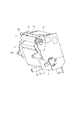
図4はプロセスカートリッジの外観斜視図である。クリーニングユニット26に対し現像ユニット4が回転自在に取り付けられている。現像ユニット4は、現像前軸受12、現像奥軸受13の吊り穴12a、13a(図15参照)に、クリーニング枠体27に圧入される前支持ピン14、奥支持ピン15が係合されることで、クリーニング枠体27に対し回転自在に支持されている(図3、図4参照)。またクリーニング枠体27には感光体ドラム1を回転自在に支持するドラム前軸受10、ドラム奥軸受11が設けられている。そしてドラム奥軸受11には電子写真感光体ドラムに画像形成装置本体の駆動力を伝達するために感光体ドラム1に結合されたドラムカップリング16を支持している。
FIG. 4 is an external perspective view of the process cartridge. The developing
また、図5に示す現像ユニット4は、プロセスカートリッジ7の画像形成時においては、現像枠体31に設けられた加圧バネ38と、現像前軸受12に設けられた引張りバネ39によりクリーニングユニット26に付勢される構成となっている。このバネにより現像前軸受12、現像奥軸受13の穴12a、13aが回動中心となり、現像ローラ25が感光体ドラム1に接触するための加圧力となる。
Further, the developing
尚、感光体ドラム1と現像ローラ25が接触して現像を行う接触現像方式においては、感光体ドラム1は剛体とし、現像ローラ25は弾性体を有するローラとすることが好ましい。この弾性体としては、ソリッドゴム単層やトナーへの帯電付与性を考慮してソリッドゴム層上に樹脂コーティングを施したもの等が用いられる。
In the contact development method in which development is performed with the
次に、プロセスカートリッジの画像形成に関する一連の動作を説明する(図1、図3参照)。画像情報が画像形成装置に送られると、不図示の本体駆動モーターが回転を開始し、感光体ドラム1に駆動を伝達する。そして帯電ローラ2に画像形成装置本体から帯電バイアス電圧が印加され、感光体ドラム1の表面を一様に帯電させる。そして画像情報に応じ、スキャナユニット3から露光が行われ潜像画像が感光体ドラム1上に形成される。
Next, a series of operations relating to image formation of the process cartridge will be described (see FIGS. 1 and 3). When the image information is sent to the image forming apparatus, a main body drive motor (not shown) starts rotating and transmits the drive to the
そして現像枠体31内のトナーは、現像剤搬送機構36によってトナー供給ローラ34へ送り込まれる。そしてトナー供給ローラ34が、現像ローラ25の外周にトナーを供給する。供給されたトナーは現像ブレード35により現像ローラ25の外周に摩擦帯電される。そして現像ローラ25に装置本体から現像バイアス電圧を印加する。これにより、電子写真感光体ドラム1に形成された静電潜像を現像する。尚、現像ローラ25は感光体ドラム1と対向して配置されている。そして、現像ローラ25は、感光体ドラム1に接触して、感光体ドラム1に形成された静電潜像を現像する構成となっている。
The toner in the developing
(本発明に係る現像ユニット構成)
本発明に係る現像ユニット構成の説明を行う。
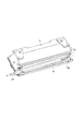
図6、図11に示すように、現像枠体31は一端側面に貫通穴31fを有しており、貫通穴31fは、供給ローラ34を現像枠体31の外側から供給ローラ軸線p方向に挿入可能に形成されている。また、図15に示すように貫通穴31fは、供給ローラ34を挿入するための挿入穴31fa(挿入部)と供給ローラ軸34hをガイドする第1のガイド穴31fb(ガイド部)とを有している。挿入穴31faは供給ローラ最大外径より大きく形成し(すなわち、供給ローラ軸線pに垂直な貫通穴の断面が、供給ローラ軸線pに垂直な供給ローラの断面より大きい)、供給ローラ34を挿入し易くしている。これにより、供給ローラ34を挿入穴31faに挿入する際に、供給ローラ34と挿入穴31faの内縁との摺擦を抑制することができる。したがって、供給ローラの損傷を抑制することができる。供給ローラ34を現像枠体31に挿入していく過程において、供給ローラ軸34gは、現像枠体31の長手他端側に設けた第2のガイド穴31gに挿入される(図7参照)。
(Developing unit configuration according to the present invention)
The configuration of the developing unit according to the present invention will be described.
As shown in FIGS. 6 and 11, the developing
現像枠体31の一端に設けた挿入穴31faと第1のガイド穴31fbは供給ローラが移動できるように連結している。供給ローラ軸方向に挿入した後は、図8と図9に示すように、供給ローラ軸34hを挿入穴位置(図8参照)から第1のガイド穴位置(図9のR方向)へ移動させて保持する。
An insertion hole 31fa provided at one end of the developing
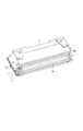
その後、図10〜図12に示すように貫通穴31fを封止するための第2封止部材としてのブッシュ部材81を組み付けることにより、供給ローラ軸34hは、現像枠体31に設けた第1のガイド穴31fbとブッシュ部材81に設けた第3のガイド穴81aとにガイドされ保持される(図11参照)。
After that, as shown in FIGS. 10 to 12, the
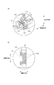
ここで本発明では、ブッシュ部材81にはポリスチレンが用いられている。ブッシュ部材81が現像枠体31に設けた挿入穴31faと嵌合することにより、現像枠体31の挿入穴31fa周辺の剛性を増す役割を有している(図2(a)参照)。端部シール部材83は、現像枠体31が有する支持部31kに貼り付けられて支持されている。この端部シール部材83に当接するように現像ローラ25が組み付けられる。端部シール部材は、現像ローラ25の周面における現像ローラ25の軸線方向の端部と枠体の支持部31kとの隙間を封止する第1封止部材として機能している。
Here, in the present invention, the
図13、図14に示すように軸受部材(12、13)により現像ローラ25と現像枠体31の位置決めが行われる。ここで、端部シール部材83と支持部31kとは、現像ローラ25と貫通穴31fの間に位置し、端部シール部材83は現像ローラ25と支持部31kとにより圧縮保持される。よって、現像ローラ25が端部シール部材83と当接することにより発生する力P1が現像枠体31の支持部31kに掛かる(図15参照)。本発明では力P1により支持部31kが変形する(貫通穴31fが変形する)ことを防止するため、図2(a)に示すように、ブッシュ部材81を現像枠体31の挿入穴31faに嵌合させている。図2(b)は、図2(a)において更に端部シール部材83を支持部31kに貼り付けた状態での、ブッシュ部材嵌合部の断面図(挿入穴31fの中心を通り供給ローラの軸線pに平行な鉛直面での断面図)である。図2(b)に示すように、ブッシュ部材81が支持部31kの裏面(貫通穴31fの内縁の一部)を支持するように挿入穴31faに嵌合する。そして、端部シール部材83とブッシュ部材81とは、現像ローラの軸線q方向に垂直な同一平面上に位置するように設けられている。この構成により、上記力P1の影響で支持部31kが変形することを抑制することができる。
As shown in FIGS. 13 and 14, the developing
なお、本実施例では、ブッシュ部材81は、図2(b)に示すように、現像ローラの軸線q方向において貫通穴の一端から他端に渡って設けられており、支持部31kの裏面を支持している。この構成により、現像枠体31の支持部31kの変形をより効果的に抑制することができる。
In this embodiment, as shown in FIG. 2B, the
また、本実施例では、ブッシュ部材にポリスチレンを用いている。貫通穴31fを封止するとともに支持部31kの変形を抑制するために、ブッシュ部材の材料としては、ポリカーボネート、ポリプロピレン、ABS樹脂等の熱可塑性プラスティック製のものを用いることが望ましい。特に、支持部31kの変形を抑制する上では20MPa以上の引張強さ(JIS K7113)を有する材料を用いることが望ましい。
In this embodiment, polystyrene is used for the bush member. In order to seal the through
また、本実施例では、供給ローラの回転軸34g、34hの引張強さ(JIS g0202)はブッシュ部材81の引張強さよりも大きく、供給ローラの回転軸34hは、図2(a)に示すように支持部31kの裏面に対向する位置に配置されている。これにより、支持部31kが力P1を受けた時に、ブッシュ部材81だけでなく供給ローラの回転軸34hも支持部31kの変形を抑制することに寄与できるため、より効果的に支持部31kの変形を抑制することができる。
Further, in this embodiment, the tensile strength (JIS g0202) of the
なお、本実施例において現像ローラの軸線qは供給ローラの軸線pと平行であり、「供給ローラの軸線方向」は「現像ローラの軸線方向」と同一の方向を表している。また、本実施例において、供給ローラの回転軸34g、34hは便宜的に異なる符号を用いているが、同じ部材を表している。
In this embodiment, the axis q of the developing roller is parallel to the axis p of the supply roller, and the “axis direction of the supply roller” represents the same direction as the “axis direction of the developing roller”. In the present embodiment, the
S 記録媒体
1(1a〜1d) 感光体ドラム
4(4a〜44d) 現像ユニット
6(6a〜6d) クリーニング部材
7(7a〜7d) プロセスカートリッジ
13c トナー収納部
25(25a〜25d) 現像ローラ
25g ゴムローラ部
25j 現像ローラ軸
25k 現像ローラ回転中心
26(26a〜26d) クリーニングユニット(第一の枠体)
27 クリーニング枠体
30 トナー容器
31 現像枠体
31f 貫通穴
31fa 挿入穴
31fb 第1のガイド穴
31g 第2のガイド穴
31k 支持部
34 トナー供給ローラ
34g 供給ローラ軸
34h 供給ローラ軸
35 現像ブレード
36 トナー搬送部材
81 ブッシュ部材
82 ブッシュシール部材
83 端部シール部材
100 画像形成装置
S Recording medium 1 (1a to 1d) Photosensitive drum 4 (4a to 44d) Developing unit 6 (6a to 6d) Cleaning member 7 (7a to 7d) Process cartridge 13c Toner storage unit 25 (25a to 25d) Developing
27 Cleaning frame body 30
Claims (14)
前記現像ローラに現像剤を供給する供給ローラと、
現像剤を収容すると共に、前記現像ローラおよび前記供給ローラが取り付けられる枠体であって、前記現像ローラの軸線方向の一端側に、現像剤が前記枠体から外部へ漏れないように前記枠体と前記現像ローラの間に配置される第1封止部材を支持する支持面を備える支持部と、前記支持部に形成される貫通穴とが設けられた枠体と、
前記貫通穴に配置され該貫通穴を封止する第2封止部材と、を有する現像装置であって、
前記貫通穴は、
前記支持部において、前記供給ローラが挿入される挿入位置に設けられる第1穴部であって、前記供給ローラの軸線方向と直交する方向において、前記供給ローラの断面よりも大きい断面を有し、前記供給ローラの軸線方向に沿って挿入される前記供給ローラの通過を許容する第1穴部と、
前記支持部において、前記挿入位置と異なる位置に設けられ、前記第1穴部と連通している第2穴部であって、前記現像ローラと対峙する位置に前記供給ローラが移動可能なように構成される第2穴部と、を有し、
前記支持部は、前記支持面とは表裏関係にあり且つ前記第1穴部の内周面の一部を構成する背面を有し、
前記支持部の前記支持面には、前記第1封止部材が接して配置され、
前記支持部の前記背面には、前記第2封止部材が接して配置されていることを特徴とする現像装置。 A developing roller for developing the electrostatic latent image using a developer;
A supply roller for supplying a developer to the developing roller;
A frame body that contains the developer and to which the developing roller and the supply roller are attached, and the frame body on one end side in the axial direction of the developing roller so that the developer does not leak from the frame body to the outside. And a frame provided with a support portion provided with a support surface for supporting the first sealing member disposed between the developing roller, and a through hole formed in the support portion,
A second sealing member disposed in the through hole and sealing the through hole,
The through hole is
In the support portion, a first hole provided at an insertion position where the supply roller is inserted, and having a cross section larger than a cross section of the supply roller in a direction orthogonal to the axial direction of the supply roller, A first hole allowing passage of the supply roller inserted along the axial direction of the supply roller;
In the support portion, a second hole portion provided at a position different from the insertion position and communicating with the first hole portion so that the supply roller can move to a position facing the developing roller. A second hole configured,
The support portion has a back surface that is in a front-back relationship with the support surface and forms a part of the inner peripheral surface of the first hole portion,
The first sealing member is disposed in contact with the support surface of the support portion,
The developing device, wherein the second sealing member is disposed in contact with the back surface of the support portion.
前記第2封止部材には、前記供給ローラの前記軸部が挿入可能な挿入穴が設けられていることを特徴とする請求項1に記載の現像装置。 The supply roller has a foam layer and a shaft portion that supports the foam layer,
The developing device according to claim 1, wherein the second sealing member is provided with an insertion hole into which the shaft portion of the supply roller can be inserted.
前記供給ローラの前記軸部は前記第2封止部材を貫通するように前記挿入穴に挿入されていることを特徴とする請求項2に記載の現像装置。 The insertion hole penetrates the second sealing member;
The developing device according to claim 2 , wherein the shaft portion of the supply roller is inserted into the insertion hole so as to penetrate the second sealing member.
前記現像ローラに現像剤を供給する供給ローラと、
現像剤を収容すると共に、前記現像ローラおよび前記供給ローラが取り付けられる枠体であって、前記現像ローラの軸線方向の一端側に、現像剤が前記枠体から外部へ漏れないように前記枠体と前記現像ローラの間に配置される第1封止部材を支持する支持面を備える支持部と、前記支持部に形成される貫通穴とが設けられた枠体と、
前記貫通穴に配置され該貫通穴を封止する第2封止部材と、を有する現像装置であって、
前記貫通穴は、
前記支持部において、前記供給ローラが挿入される挿入位置に設けられる第1穴部であって、前記供給ローラの軸線方向と直交する方向において、前記供給ローラの断面よりも大きい断面を有し、前記供給ローラの軸線方向に沿って挿入される前記供給ローラの通過を許容する第1穴部と、
前記支持部において、前記挿入位置と異なる位置に設けられ、前記第1穴部と連通している第2穴部であって、前記現像ローラと対峙する位置に前記供給ローラが移動可能なように構成される第2穴部と、を有し、
前記支持部は、前記支持面とは表裏関係にあり且つ前記第2穴部の内周面の一部を構成する背面を有し、
前記支持部の前記支持面には、前記第1封止部材が接して配置され、
前記支持部の前記背面には、供給ローラの軸部が接して配置されていることを特徴とする現像装置。 A developing roller for developing the electrostatic latent image using a developer;
A supply roller for supplying a developer to the developing roller;
A frame body that contains the developer and to which the developing roller and the supply roller are attached, and the frame body on one end side in the axial direction of the developing roller so that the developer does not leak from the frame body to the outside. And a frame provided with a support portion provided with a support surface for supporting the first sealing member disposed between the developing roller, and a through hole formed in the support portion,
A second sealing member disposed in the through hole and sealing the through hole,
The through hole is
In the support portion, a first hole provided at an insertion position where the supply roller is inserted, and having a cross section larger than a cross section of the supply roller in a direction orthogonal to the axial direction of the supply roller, A first hole allowing passage of the supply roller inserted along the axial direction of the supply roller;
In the support portion, a second hole portion provided at a position different from the insertion position and communicating with the first hole portion so that the supply roller can move to a position facing the developing roller. A second hole configured,
The support portion has a back surface which is in a front-back relationship with the support surface and forms a part of the inner peripheral surface of the second hole portion,
The first sealing member is disposed in contact with the support surface of the support portion,
A developing device, wherein a shaft portion of a supply roller is disposed in contact with the back surface of the support portion.
前記第2封止部材が前記背面に接して配置されていることを特徴とする請求項4に記載の現像装置。 The back surface constitutes a part of the inner peripheral surface of the first hole portion,
The developing device according to claim 4 , wherein the second sealing member is disposed in contact with the back surface.
請求項1〜12のいずれか1項に記載の現像装置と、
像担持体と、
記録媒体を搬送する搬送手段と、
を有することを特徴とする画像形成装置。 An image forming apparatus for forming an image on a recording medium,
The developing device according to any one of claims 1 to 12 ,
An image carrier;
Conveying means for conveying the recording medium;
An image forming apparatus comprising:
Priority Applications (2)
| Application Number | Priority Date | Filing Date | Title |
|---|---|---|---|
| JP2012127135A JP6137786B2 (en) | 2012-06-04 | 2012-06-04 | Developing device, process cartridge, image forming apparatus |
| US13/906,816 US9239544B2 (en) | 2012-06-04 | 2013-05-31 | Development apparatus, process cartridge, and image forming apparatus |
Applications Claiming Priority (1)
| Application Number | Priority Date | Filing Date | Title |
|---|---|---|---|
| JP2012127135A JP6137786B2 (en) | 2012-06-04 | 2012-06-04 | Developing device, process cartridge, image forming apparatus |
Publications (3)
| Publication Number | Publication Date |
|---|---|
| JP2013250514A JP2013250514A (en) | 2013-12-12 |
| JP2013250514A5 JP2013250514A5 (en) | 2015-07-09 |
| JP6137786B2 true JP6137786B2 (en) | 2017-05-31 |
Family
ID=49670409
Family Applications (1)
| Application Number | Title | Priority Date | Filing Date |
|---|---|---|---|
| JP2012127135A Active JP6137786B2 (en) | 2012-06-04 | 2012-06-04 | Developing device, process cartridge, image forming apparatus |
Country Status (2)
| Country | Link |
|---|---|
| US (1) | US9239544B2 (en) |
| JP (1) | JP6137786B2 (en) |
Families Citing this family (5)
| Publication number | Priority date | Publication date | Assignee | Title |
|---|---|---|---|---|
| JP6584138B2 (en) * | 2014-06-17 | 2019-10-02 | キヤノン株式会社 | Developing cartridge, process cartridge, and image forming apparatus |
| JP6525683B2 (en) * | 2015-03-31 | 2019-06-05 | キヤノン株式会社 | Developing device, process cartridge and image forming apparatus |
| US10936586B2 (en) | 2017-11-29 | 2021-03-02 | Wipro Limited | Method and system for providing domain-specific response to a user query |
| US11126138B2 (en) * | 2019-08-28 | 2021-09-21 | Lexmark International, Inc. | Bushing assembly for an electrophotographic image forming device |
| JP2023032854A (en) * | 2021-08-27 | 2023-03-09 | キヤノン株式会社 | Developing unit |
Family Cites Families (4)
| Publication number | Priority date | Publication date | Assignee | Title |
|---|---|---|---|---|
| JP2002202660A (en) * | 2000-12-28 | 2002-07-19 | Canon Inc | Developing device, process cartridge and electrophotographic image forming device |
| JP4600055B2 (en) * | 2005-01-27 | 2010-12-15 | セイコーエプソン株式会社 | Developing device, image forming apparatus, image forming system, and method for assembling developer supply roller |
| JP2011203369A (en) * | 2010-03-24 | 2011-10-13 | Brother Industries Ltd | Developing device |
| JP5903805B2 (en) | 2011-08-31 | 2016-04-13 | ブラザー工業株式会社 | Developing apparatus and manufacturing method thereof |
-
2012
- 2012-06-04 JP JP2012127135A patent/JP6137786B2/en active Active
-
2013
- 2013-05-31 US US13/906,816 patent/US9239544B2/en active Active
Also Published As
| Publication number | Publication date |
|---|---|
| US20130322921A1 (en) | 2013-12-05 |
| JP2013250514A (en) | 2013-12-12 |
| US9239544B2 (en) | 2016-01-19 |
Similar Documents
| Publication | Publication Date | Title |
|---|---|---|
| JP4684732B2 (en) | Electrophotographic image forming apparatus and process cartridge | |
| JP4869289B2 (en) | Process cartridge and electrophotographic image forming apparatus | |
| JP4912505B2 (en) | Process cartridge | |
| EP3211482A1 (en) | Developing cartridge and image forming apparatus | |
| US20160018784A1 (en) | Process cartridge and image forming apparatus | |
| JP6137786B2 (en) | Developing device, process cartridge, image forming apparatus | |
| JP6039247B2 (en) | Developing device, process cartridge, image forming apparatus | |
| US10139774B2 (en) | Developing device and image forming apparatus | |
| JP7076945B2 (en) | Developing equipment and image forming equipment | |
| US20170277071A1 (en) | Developing device and image forming apparatus | |
| JP2011215434A (en) | Developer container, developing device, and image forming apparatus | |
| JP7406891B2 (en) | Process cartridges, developing devices and image forming devices | |
| JP2006343562A (en) | Developing device, process cartridge and electrophotographic image forming apparatus | |
| JP4685197B2 (en) | Electrophotographic image forming apparatus and process cartridge | |
| JP5866885B2 (en) | Photosensitive unit and image forming apparatus | |
| JP2022016058A (en) | Image carrier unit and image forming apparatus including the same | |
| JP2017156744A (en) | Developing cartridge and image forming apparatus | |
| JP6639632B2 (en) | Image forming device | |
| US10488785B2 (en) | Developing unit, process cartridge, and image forming apparatus including process cartridge | |
| US10670986B2 (en) | Developing apparatus and image forming apparatus | |
| JP5704857B2 (en) | Image forming system and electrophotographic image forming apparatus | |
| JP2014071422A (en) | Developer storage unit, developing unit, and process cartridge | |
| JP2013029869A (en) | Image forming apparatus | |
| JP2005070186A (en) | Process cartridge and electrophotographic image forming apparatus | |
| JP2005338752A (en) | Cleaning unit, process cartridge, cleaning material, electrophotographic image forming device |
Legal Events
| Date | Code | Title | Description |
|---|---|---|---|
| A521 | Request for written amendment filed |
Free format text: JAPANESE INTERMEDIATE CODE: A523 Effective date: 20150525 |
|
| A621 | Written request for application examination |
Free format text: JAPANESE INTERMEDIATE CODE: A621 Effective date: 20150525 |
|
| A977 | Report on retrieval |
Free format text: JAPANESE INTERMEDIATE CODE: A971007 Effective date: 20160325 |
|
| A131 | Notification of reasons for refusal |
Free format text: JAPANESE INTERMEDIATE CODE: A131 Effective date: 20160405 |
|
| A521 | Request for written amendment filed |
Free format text: JAPANESE INTERMEDIATE CODE: A523 Effective date: 20160603 |
|
| A131 | Notification of reasons for refusal |
Free format text: JAPANESE INTERMEDIATE CODE: A131 Effective date: 20161122 |
|
| A521 | Request for written amendment filed |
Free format text: JAPANESE INTERMEDIATE CODE: A523 Effective date: 20170120 |
|
| TRDD | Decision of grant or rejection written | ||
| A01 | Written decision to grant a patent or to grant a registration (utility model) |
Free format text: JAPANESE INTERMEDIATE CODE: A01 Effective date: 20170328 |
|
| A61 | First payment of annual fees (during grant procedure) |
Free format text: JAPANESE INTERMEDIATE CODE: A61 Effective date: 20170425 |
|
| R151 | Written notification of patent or utility model registration |
Ref document number: 6137786 Country of ref document: JP Free format text: JAPANESE INTERMEDIATE CODE: R151 |