JP4684732B2 - Electrophotographic image forming apparatus and process cartridge - Google Patents
Electrophotographic image forming apparatus and process cartridge Download PDFInfo
- Publication number
- JP4684732B2 JP4684732B2 JP2005129494A JP2005129494A JP4684732B2 JP 4684732 B2 JP4684732 B2 JP 4684732B2 JP 2005129494 A JP2005129494 A JP 2005129494A JP 2005129494 A JP2005129494 A JP 2005129494A JP 4684732 B2 JP4684732 B2 JP 4684732B2
- Authority
- JP
- Japan
- Prior art keywords
- hole
- photosensitive drum
- frame
- process cartridge
- developing roller
- Prior art date
- Legal status (The legal status is an assumption and is not a legal conclusion. Google has not performed a legal analysis and makes no representation as to the accuracy of the status listed.)
- Expired - Fee Related
Links
Images


Classifications
-
- G—PHYSICS
- G03—PHOTOGRAPHY; CINEMATOGRAPHY; ANALOGOUS TECHNIQUES USING WAVES OTHER THAN OPTICAL WAVES; ELECTROGRAPHY; HOLOGRAPHY
- G03G—ELECTROGRAPHY; ELECTROPHOTOGRAPHY; MAGNETOGRAPHY
- G03G21/00—Arrangements not provided for by groups G03G13/00 - G03G19/00, e.g. cleaning, elimination of residual charge
- G03G21/16—Mechanical means for facilitating the maintenance of the apparatus, e.g. modular arrangements
- G03G21/18—Mechanical means for facilitating the maintenance of the apparatus, e.g. modular arrangements using a processing cartridge, whereby the process cartridge comprises at least two image processing means in a single unit
- G03G21/1803—Arrangements or disposition of the complete process cartridge or parts thereof
- G03G21/181—Manufacturing or assembling, recycling, reuse, transportation, packaging or storage
-
- G—PHYSICS
- G03—PHOTOGRAPHY; CINEMATOGRAPHY; ANALOGOUS TECHNIQUES USING WAVES OTHER THAN OPTICAL WAVES; ELECTROGRAPHY; HOLOGRAPHY
- G03G—ELECTROGRAPHY; ELECTROPHOTOGRAPHY; MAGNETOGRAPHY
- G03G21/00—Arrangements not provided for by groups G03G13/00 - G03G19/00, e.g. cleaning, elimination of residual charge
- G03G21/16—Mechanical means for facilitating the maintenance of the apparatus, e.g. modular arrangements
- G03G21/18—Mechanical means for facilitating the maintenance of the apparatus, e.g. modular arrangements using a processing cartridge, whereby the process cartridge comprises at least two image processing means in a single unit
- G03G21/1803—Arrangements or disposition of the complete process cartridge or parts thereof
- G03G21/1817—Arrangements or disposition of the complete process cartridge or parts thereof having a submodular arrangement
- G03G21/1825—Pivotable subunit connection
-
- G—PHYSICS
- G03—PHOTOGRAPHY; CINEMATOGRAPHY; ANALOGOUS TECHNIQUES USING WAVES OTHER THAN OPTICAL WAVES; ELECTROGRAPHY; HOLOGRAPHY
- G03G—ELECTROGRAPHY; ELECTROPHOTOGRAPHY; MAGNETOGRAPHY
- G03G2221/00—Processes not provided for by group G03G2215/00, e.g. cleaning or residual charge elimination
- G03G2221/16—Mechanical means for facilitating the maintenance of the apparatus, e.g. modular arrangements and complete machine concepts
- G03G2221/18—Cartridge systems
- G03G2221/183—Process cartridge
- G03G2221/1853—Process cartridge having a submodular arrangement
- G03G2221/1861—Rotational subunit connection
Landscapes
- Engineering & Computer Science (AREA)
- Computer Vision & Pattern Recognition (AREA)
- Physics & Mathematics (AREA)
- General Physics & Mathematics (AREA)
- Life Sciences & Earth Sciences (AREA)
- Manufacturing & Machinery (AREA)
- Sustainable Development (AREA)
- Electrophotography Configuration And Component (AREA)
Description
本発明は電子写真画像形成装置、及び、電子写真画像形成装置に着脱可能なプロセスカートリッジに関するものである。 The present invention relates to an electrophotographic image forming apparatus and a process cartridge that can be attached to and detached from the electrophotographic image forming apparatus.
ここで、電子写真画像形成装置とは、電子写真画像形成方式を用いて記録媒体に画像を記録するものであり、例えば、電子写真複写機、電子写真プリンタ(例えばレーザービームプリンタ、LEDプリンタ等)、ファクシミリ装置及びワードプロセッサ等が含まれる。 Here, the electrophotographic image forming apparatus is for recording an image on a recording medium using an electrophotographic image forming method. For example, an electrophotographic copying machine, an electrophotographic printer (for example, a laser beam printer, an LED printer, etc.) A facsimile machine and a word processor.
また、プロセスカートリッジとは、帯電手段、現像手段またはクリーニング手段の少なくとも何れか一つと電子写真像担持体とを一体的にカートリッジ化し、このカートリッジを画像形成装置本体に対して着脱可能とするものである。 The process cartridge is a cartridge in which at least one of charging means, developing means, and cleaning means and an electrophotographic image carrier are integrally formed, and the cartridge can be attached to and detached from the image forming apparatus main body. is there.
複写機、レーザプリンタ、ファクシミリなどの電子写真画像形成装置は、帯電装置によって一様に帯電された像担持体である電子写真感光体ドラムに選択的な露光を行って静電潜像を形成する。そして、この静電潜像を現像装置によってトナーを付着させてトナー像として現像し、その後、このトナー像を紙などの記録剤に転写して画像を形成する。そして、トナー像の転写後の像担持体は、表面に残留したトナーをクリーニング装置で除去されて、次の画像形成装置に供される。 An electrophotographic image forming apparatus such as a copying machine, a laser printer, or a facsimile forms an electrostatic latent image by selectively exposing an electrophotographic photosensitive drum, which is an image carrier uniformly charged by a charging device. . The electrostatic latent image is developed as a toner image by attaching toner to the developing device, and then the toner image is transferred to a recording agent such as paper to form an image. Then, the toner remaining on the surface of the image carrier after the transfer of the toner image is removed by a cleaning device and used for the next image forming apparatus.
近年では、像担持体、帯電装置、現像装置、クリーニング装置などをカートリッジ容器に一体的に組み込んでプロセスカートリッジとしてカートリッジ化したものが知られている。このプロセスカートリッジは、画像形成装置本体に対して着脱自在な構成されている。よって、これをユーザが画像形成装置本体に装着することによって、トナーの供給や像担持体の交換をユーザ自身で簡単に行うことができ、メンテナンスの容易化を図っている。 In recent years, an image carrier, a charging device, a developing device, a cleaning device, and the like are integrally incorporated in a cartridge container to form a cartridge as a process cartridge. The process cartridge is configured to be detachable from the image forming apparatus main body. Therefore, when the user mounts this on the main body of the image forming apparatus, the user can easily supply the toner and replace the image carrier, thereby facilitating maintenance.
さらに近年では、多色画像を形成する画像形成装置も考案されており、この多色の画像形成装置に用いられるプロセスカートリッジも実用化されている。 Further, in recent years, an image forming apparatus for forming a multicolor image has been devised, and a process cartridge used for the multicolor image forming apparatus has been put into practical use.
ここで、上述のプロセスカートリッジにおける現像手段としては、一般的に現像剤担持体を像担持体に対して接触状態で現像を行う接触現像方式、および現像剤担持体を像担持体に対して所定の間隙を設けた状態で現像を行う非接触現像方式の2つの構成が知られている。 Here, as the developing means in the above-described process cartridge, a contact development method in which development is generally performed in a state where the developer carrier is in contact with the image carrier, and the developer carrier is predetermined with respect to the image carrier. There are two known non-contact development methods in which development is performed in a state where a gap is provided.
しかしながら、上述の接触方式の現像手段は、像担持体に対して長期間接触されたままの状態で放置しておくと、現像手段のうちの像担持体と接触する部分が変形して、画像に影響を及ぼす場合があった。また、像担持体表面においても、プロセスカートリッジ運搬時の振動等により像担持体と現像手段とが摺擦して、現像メモリとして履歴が残り、画像に影響を及ぼす場合があった。 However, if the above-mentioned contact-type developing means is left in contact with the image carrier for a long time, the portion of the developing means that contacts the image carrier is deformed, and the image There was a case to affect. In addition, even on the surface of the image carrier, the image carrier and the developing unit rub against each other due to vibration or the like when the process cartridge is transported, and a history remains as a development memory, which may affect the image.
上記問題を回避する手段として、従来からも出荷時などの未使用時あるいは、長期使用停止時に像担持体と現像手段を離間させる機構を設けた構成の画像形成装置およびプロセスカートリッジ(例えば特許文献1)が提案されている。従来の離間部材は、プロセスカートリッジの枠体を現像付勢部材に抗して掴みこむことで現像手段を像担持体から離間させる構成である。
本発明は、従来技術をさらに発展させたものである。即ち、安定して現像ローラ、または、帯電ローラを電子写真感光体ドラムから離間することができるプロセスカートリッジ及び画像形成装置を提供することを目的とするものである。 The present invention is a further development of the prior art. That is, an object of the present invention is to provide a process cartridge and an image forming apparatus that can stably separate a developing roller or a charging roller from an electrophotographic photosensitive drum.
上記目的を達成するための代表的な構成は、電子写真画像形成装置本体に着脱可能なプロセスカートリッジにおいて、感光体ドラムと、前記感光体ドラムと接触して、前記感光体ドラムに形成された静電潜像を現像する現像ローラと、
前記感光体ドラムを回転自在に支持する第1の枠体と、前記現像ローラを回転自在に支持する第2の枠体であって、前記第1の枠体と回転自在に結合する第2の枠体と、前記第1の枠体または前記第2の枠体のいずれか一方の枠体に設けられた、第1の穴および第2の穴と、前記第1の枠体または前記第2の枠体の他方の枠体に設けられ、前記プロセスカートリッジの長手方向において、前記第1の穴と前記第2の穴の間に位置する第3の穴と、前記第1の穴、前記第3の穴、前記第2の穴に順に挿入し、前記第1の枠体および前記第2の枠体と係合する離間部材であって、挿入方向の先端側に斜面を有し、前記離間部材が前記第3の穴へ挿入される際に、前記斜面が前記第3の穴と当接して前記他方の枠体を移動させることで、前記現像ローラと前記感光体ドラムとが接触した状態から、前記現像ローラと前記感光体ドラムとが離間した状態にする前記離間部材と、を有することを特徴とするプロセスカートリッジである。
A typical configuration for achieving the above object is a process cartridge that can be attached to and detached from an electrophotographic image forming apparatus main body, and a photosensitive drum that is in contact with the photosensitive drum and formed on the photosensitive drum. A developing roller for developing the electrostatic latent image;
A first frame that rotatably supports the photosensitive drum, and a second frame that rotatably supports the developing roller, wherein the second frame is rotatably coupled to the first frame. A frame , a first hole and a second hole provided in one of the first frame and the second frame, and the first frame or the second frame. A third hole located between the first hole and the second hole in the longitudinal direction of the process cartridge, the first hole, and the first hole. 3 is a separation member that is inserted into the third hole and the second hole in order and engages with the first frame body and the second frame body, and has a slope on the distal end side in the insertion direction, and the separation When the member is inserted into the third hole, the inclined surface comes into contact with the third hole and moves the other frame, thereby causing the developing roller to move. From a state where the La and the photosensitive drum in contact, a process cartridge and having a said spacer member to a state where the developing roller and the photosensitive drum are separated from each other.
本発明によれば、現像ローラと感光体ドラムを離間させるための離間部材を、第1の枠体と第2の枠体によって確実に支持することができるので、現像ローラを感光体ドラムとの離間を安定して確実におこなうことができる。 According to the present invention, the spacing member for spacing the developing roller and the photosensitive light drum, it is possible to reliably supported by the first frame and the second frame member, a developing roller-sensitive light drum Can be stably and reliably separated from each other.
(画像形成装置全体について)
以下に図面を参照して、本発明を適用できる実施例を説明する。ただし、この実施例に記載されている構成部品の寸法、材質、形状、その相対配置などは、特に特定的な記載がない限りは、この発明の範囲をそれらのみに限定する趣旨のものではない。また、以下の説明で一度説明した部材についての材質、形状などは、特に改めて記載しない限り初めの説明と同様のものである。
(About the entire image forming apparatus)
Embodiments to which the present invention can be applied will be described below with reference to the drawings. However, the dimensions, materials, shapes, relative arrangements, and the like of the components described in this embodiment are not intended to limit the scope of the present invention only to those unless otherwise specified. . Further, the materials, shapes, etc. of the members once described in the following description are the same as those in the first description unless otherwise described.
[画像形成装置の全体の説明]
まず、図1を参照して電子写真画像形成装置100(以下、画像形成装置100という。)の全体構成について、画像形成動作とともに説明する。尚、図1は本実施の形態であるプロセスカートリッジ1(以下、カートリッジ1という)を画像形成装置100に装着した状態を示す概略図である。
[Overall Description of Image Forming Apparatus]
First, an overall configuration of an electrophotographic image forming apparatus 100 (hereinafter referred to as an image forming apparatus 100) will be described together with an image forming operation with reference to FIG. FIG. 1 is a schematic view showing a state in which a process cartridge 1 (hereinafter referred to as cartridge 1) according to the present embodiment is mounted on an
図1に示すように、本実施形態における画像形成装置100は、鉛直方向に並設した4個のカートリッジ1(1a,1b,1c,1d)を装着するための装着部(不図示)を有する。そして、下から順にイエロー、マゼンタ、シアン、ブラックの各色トナー像を形成するカートリッジ1が画像形成装置100に装着している。なお、各カートリッジ1は形成されるトナー像の色が異なるが構成は同一である。
As shown in FIG. 1, the
各カートリッジ1は、光学手段103(103a,103b,103c,103d)から画像情報に基づいたレーザー光像が照射される。そして、ドラム形状の電子写真感光体である感光体ドラム21(21a,21b,21c,21d)に静電潜像が形成される。そして、現像ローラ11等によって、この静電潜像をトナー像に現像する。このトナー像形成と同期して記録紙、OHPシート等の記録媒体Sがカセット17から分離給送ローラ118、搬送ローラ119及び、搬送ベルト111等からなる搬送手段で搬送される。
Each cartridge 1 is irradiated with a laser beam image based on image information from the optical means 103 (103a, 103b, 103c, 103d). Then, an electrostatic latent image is formed on the photosensitive drum 21 (21a, 21b, 21c, 21d) which is a drum-shaped electrophotographic photosensitive member. Then, the electrostatic latent image is developed into a toner image by the developing
前記搬送ベルト111は全ての感光体ドラム21に対向し、接するように循環移動するフィルム状部材であり、駆動ローラ113、従動ローラ114a,114b、テンションローラ115の4本のローラに掛け渡されて図1の矢印方向に回転する。記録媒体Sは前記搬送ベルト111により転写位置まで搬送される。そして、前記感光体ドラム1に形成されたトナー像が転写手段としての転写ローラ112(112a,112b,112c,112d)にバイアス印加することにより記録媒体Sに転写され、その記録媒体Sが定着手段120へと搬送される。この定着手段120は駆動ローラ121a及びヒータを内蔵する定着ローラ121bを有し、定着手段120を搬送されるSが熱及び圧力を印加されてトナー像が定着される。そして、この記録媒体Sが排出ローラ対123によって排出部124へと排出されるように構成されている。
The conveyance belt 111 is a film-like member that circulates and moves so as to face and contact all the
[プロセスカートリッジ]
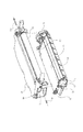
次に本発明を適用できるプロセスカートリッジ1の構成について、図2を用いて説明する。カートリッジ1は感光体ドラム21と帯電ローラ23およびクリーニングブレード24を備えた第1の枠体であるドラムユニット20、および、感光体ドラム21上の静電潜像を現像する現像手段を有する第2の枠体である現像ユニット10に分かれている。
[Process cartridge]
Next, the configuration of the process cartridge 1 to which the present invention can be applied will be described with reference to FIG. The cartridge 1 has a
[ドラムユニット]
ドラムユニット20の構成について、図2を用いて説明する。ドラムユニット20には感光体ドラム21が回転自在に取り付けられている。感光体ドラム21は、アルミシリンダの外周面に有機光導電体層を塗布して構成されている。感光体ドラム21周上には、感光体ドラム21の表面を一様に帯電させるための一次帯電部材である帯電ローラ23、および感光体ドラム21上に残った現像剤(トナー)を除去するためのクリーニングブレード24(以下、ブレード24という。)が配置されている。そして、さらにブレード24によって感光体ドラム21表面から除去された残留トナーは、トナー送り機構25によって廃トナー室26に順次送られる。そして、駆動モーター(不図示)の駆動力を伝達することにより、感光体ドラム21が画像形成動作に応じて矢印A方向(反時計回り)に回転する。
[Drum unit]
The configuration of the
[現像ユニット]
現像ユニット10の構成について、図2を用いて説明する。現像ユニット10は、感光体ドラム21と接触して矢印B方向に回転する現像ローラ11、トナーが収容されたトナー容器13と現像部である現像容器14とから構成される。現像ローラ11の周面上には、現像ローラ11と接触して矢印C方向に回転するトナー供給ローラ12と、現像ブレード15がそれぞれ配置されている。さらにトナー容器13内にはトナーを攪拌するとともにトナー供給ローラ12に搬送するためのトナー攪拌機構16が設けられている。
[Development unit]
The configuration of the developing
[現像ユニットの支持]
現像ユニットの支持方法について、図2,3,4を用いて説明する。
[Support for development unit]
A method for supporting the developing unit will be described with reference to FIGS.
現像ユニット10は、現像ユニット10の長手方向において一端側と他端側に支持穴71を有する。そして、ドラムユニット20も、ドラムユニット20の長手方向において一端側と他端側に支持穴72を有する。そして、回転中心としての結合ピン73を支持穴71と支持穴72に貫通させることによって、現像ユニット10全体がドラムユニット20に対して揺動自在に支持されることになる。そして、支持穴71、72を中心に現像ローラ11が感光体ドラム21に接触するように、付勢手段である加圧バネ74によって現像ユニット10が常に付勢されている。
The developing
[現像方法]
現像時において、トナー容器13に収容されたトナーをトナー攪拌機構16によってトナー供給ローラ12へ搬送する。そして、図2に示すようにトナー供給ローラ12が、現像ローラ11との摺擦よることによって、トナーを現像ローラ11に供給し、担持させる。そして、現像ローラ11上に担持されたトナーは、現像ローラ11の回転にともない現像ブレード15のところに移動する。そして、現像ブレード15によってトナーを規制して所望の帯電電荷量を付与するとともに、所定のトナー層厚に形成する。
[Development method]
During development, the toner contained in the
そして、規制されたトナーは、現像ローラ11の回転にともともなって、現像ローラ11と感光体ドラム21との接触部(現像部)へ搬送される。そして、現像部において電源(不図示)から現像ローラ11に直流現像バイアスが印加される。そして、現像部において感光体ドラム21の表面に形成された静電潜像に付着して、前記静電潜像を現像する。現像に寄与しなかったトナーは、現像ローラ11の回転によって搬送され、現像ローラ11とトナー供給ローラ12との摺擦により現像容器14内に回収される。回収されたトナーは、トナー攪拌機構16により残りのトナーと攪拌混合される。感光体ドラム21と現像ローラ11が接触して現像を行う接触現像方式においては、感光体ドラム21は剛体とし、現像ローラ11は弾性体を有するローラとすることが好ましい。
The regulated toner is conveyed to a contact portion (developing portion) between the developing
図5に示すように、樹脂材料からなる離間部材83の挿入方向先端には斜面83aが設けられている。そして、図5(a)に示すように、離間部材83を矢印D方向(カートリッジ1の長手方向)からドラムユニット20に設けられた支持穴80に挿入する。尚、ここで支持穴80は、結合ピン73を通る鉛直線に対して感光体ドラム21とは反対側に設けられている。即ち、まず、離間部材83は、前記長手方向の一端側においてドラムユニット20に設けられた第1の支持穴80を通過する。そして次に、図5(b)に示すように、現像ユニット10に設けられた第3の支持穴82に、斜面83aが係合する。そして離間部材83をさらに矢印D方向に挿入させていくと、斜面83aに沿って現像ユニット10が矢印E方向に持ち上がる。そして、図5(c)に示すように、離間部材83の外形(係合部)83bと第2の支持穴82の上部とが係合する位置まで現像ユニット10が持ち上がる。即ち、斜面83aは、支持穴82を係合部83bまで案内する役目をする。そして、離間部材83は最終的には、長手方向において、支持穴80よりも内側で、ドラムユニット20に設けられた支持穴81に支持される。即ち、離間部材83は、第1の支持穴80と第2の支持穴81において両持ちで支持される。そして、長手方向において、その間に位置する現像ユニット10に設けられた第3の支持穴82を加圧バネ74の付勢力に抗して移動させた状態で維持する。すなわち、この状態で、図4(b)に示すように現像ローラ11が感光体ドラム21から離間した状態になる。この時の現像ユニットの位置を離間位置とする。また、離間部材83を取り外すことで、第3の支持穴部は加圧バネ74の付勢力により移動し、現像ローラ11と感光体ドラム21は接触した状態になる。この時の現像ユニットの位置を接触位置とする。
As shown in FIG. 5, a
尚、前述した図4、図5の構成は、カートリッジ1の長手方向において他端側にも設けられている。 4 and 5 described above are also provided on the other end side in the longitudinal direction of the cartridge 1.
前述の構成は、即ち、離間部材83の長手方向において、離間部材83を第1の支持穴80と第2の支持穴81とにおいて両持ち支持する。そして、前記長手方向において第1の支持穴80と第2の支持穴81との間で、現像ユニット10と係合する構成にすることで、離間部材83が変形することを抑えることができる。したがって、感光体ドラム21と現像ローラ11を、確実に経時的にも安定して離間することができる。
In the above-described configuration, that is, in the longitudinal direction of the
なお、上述の説明では、第1および第2の支持穴80,81をドラムユニット20に、第3の支持穴82を現像ユニット10に設けた。しかし、図12に示すように第1および第2の支持穴80,81を現像ユニット10に、第3の支持穴82をドラムユニット20に設ける構成でもよい。
In the above description, the first and second support holes 80 and 81 are provided in the
図12(a)に示すように、離間部材83を矢印D方向(カートリッジ1の長手方向)から現像ユニット10に挿入する。即ち、まず、離間部材83は、前記長手方向の一端側においてドラムユニット20に設けられた第1の支持穴80を通過する。そして次に、図12(b)に示すように、現像ユニット10に設けられた第3の支持穴82に、斜面83aが係合する。尚、斜面83aは、図5に示す実施例とは上下方向で反対になっている。即ち、斜面83bが下方向に向く位置で、離間部材83を挿入することになる。そして、さらに、離間部材83を現像ユニット10に矢印D方向に挿入させていくと、斜面83aに沿ってドラムユニット20が矢印E方向に下がる。そして、図12(c)に示すように、離間部材83の外径部と第2の支持穴82の下部とが係合する位置までドラムユニット20が下がる。そして、離間部材83は最終的には、長手方向において、支持穴80よりも内側で、ドラムユニット20に設けられた支持穴81に支持される。即ち、離間部材83は、第1の支持穴80と第2の支持穴81において両持ちで支持される。そして、長手方向において、その間に位置する現像ユニット10に設けられた第3の支持穴82を加圧バネ74の付勢力に抗して移動させた状態で維持する。すなわち、この状態で、図4(b)に示すように現像ローラ11が感光体ドラム21から離間した状態になる。この時の現像ユニットの位置を離間位置とする。また、離間部材83を取り外すことで、第3の支持穴部は加圧バネ74の付勢力により移動し、図4(a)に示すように現像ローラ11と感光体ドラム21は接触した状態になる。この時の現像ユニットの位置を接触位置とする。
As shown in FIG. 12A, the separating
尚、前述した図12に示す構成は、カートリッジ1の長手方向において他端側にも設けられている。 The above-described configuration shown in FIG. 12 is also provided on the other end side in the longitudinal direction of the cartridge 1.
即ち、前述した図4、図5で示した構成における効果と同様の効果が得られる。 That is, the same effects as those in the configuration shown in FIGS. 4 and 5 described above can be obtained.
[把手部]
次に、離間部材83に設けられた把手部86の構成について図11を用いて説明する。離間部材83には、ユーザが離間部材83を引き抜く際に、力を加えやすいよう把手部86を設けている。図11(a)のように把手部86は、カートリッジ1(ここではドラムユニット20)の長手方向に沿って、屈曲部87において曲げることができる。そして、離間部材83を装着したままのカートリッジ1が画像形成装置100に装着することができる。そのため、カートリッジ1を画像形成装置100に装着したまま、現像ローラ11と感光体ドラム21を離間させることができる。そして、ユーザが離間部材83を引き抜く際には図11(b)のように屈曲部87で把手部86を引き抜き方向に曲げることができる。
[Grip part]
Next, the structure of the
本発明に係る第2の実施例について図6〜9、図13、14を用いて説明する。 A second embodiment according to the present invention will be described with reference to FIGS.
尚、本実施例は、離間部材83によって、現像ローラ11と感光体ドラム21の離間と同時に、感光体ドラム21と帯電ローラ23も離間する構成である。
In the present embodiment, the
[帯電部材]
帯電ローラ23は接触帯電方式を用いたものであり、感光体ドラム21表面に当接させるともに、帯電ローラ23に電圧印加することで、感光体ドラム21の表面を一様に帯電させるものである。芯金23aの周りに導電性のゴム部材23bを形成して構成されている。そして、帯電軸受け23cを介して加圧ばね(付勢手段)23dによって感光体ドラム21に押し付けられている。帯電ローラ23は帯電軸受け23cに回転自在に支持されている。さらに、帯電軸受け23cはガイド部22に支持される。ここで帯電部材軸受け131とガイド部133との間は摺動可能となっている。そして、帯電ローラ23は回転自在であるとともに、図6矢印の方向(感光体ドラム21に対して当接離間方向)に移動可能となっている。
[Charging member]
The charging
[離間部材]
支持部材90は軸受け部90aと連結部90bと作用穴部90cから形成されており、軸受け部90aは帯電部材芯金23aが摺動可能に支持することができる。軸受け部90aは感光体ドラム21と接触しないようになっており、感光体ドラム21の表面を傷つけることがない。離間部材84を支持部材90の作用穴部90cに挿入することで、支持部材90を移動させて、帯電ローラ23を感光体ドラム21から離間させる。離間部材84は、実施例1と同様に、ドラムユニット20に設けられた第1の支持穴80から挿入されることになる。
[Separation member]
The
[現像ローラ、帯電ローラ離間]
次に、図7〜図9、図13、図14を用いて、現像ローラ、帯電ローラを移動させる構成について説明する。
[Separation of developing roller and charging roller]
Next, a configuration for moving the developing roller and the charging roller will be described with reference to FIGS. 7 to 9, 13, and 14.
図9に示すように、本実施例の離間部材83も樹脂材料からなっている。そして、離間部材83は、第1の斜面83aと、第2の斜面83bと、第1の係合部83c、第2の係合部83d、を有する。第1の斜面83aは、離間部材83がカートリッジ1に挿入する際に、第3の支持穴82と係合して、現像ユニット10を離間位置まで案内するために設けられている。また、第2の斜面83bは、離間部材83がカートリッジ1に挿入する際に、支持部材90の作用穴部90cと係合して、帯電ローラ23が感光体ドラム21と離間する位置まで案内するために設けられている。また、83eは、離間部材83がカートリッジ1に挿入する際に、操作者が把持する把持部である。
As shown in FIG. 9, the spacing
次に、現像ローラ11、帯電ローラ23の離間動作について説明する。
Next, the separation operation of the developing
まず、図13(a)に示すように、離間部材83を矢印D方向(カートリッジ1の長手方向)から挿入する。即ち、まず、離間部材83は、前記長手方向の一端側においてドラムユニット20に設けられた第1の支持穴80を通過する。そして次に、図13(b)に示すように、現像ユニット10に設けられた第3の支持穴82に、斜面83aが係合する。そして離間部材83をさらに矢印D方向に挿入させていくと、斜面83aに沿って現像ユニット10が矢印E方向に持ち上がる。そして、図13(c)に示すように、第1の係合部83cと第2の支持穴82の上部とが係合する位置まで現像ユニット10が持ち上がる。即ち、現像ユニット10が離間位置まで移動する。そして、次に、図13(d)に示すように、離間部材83と作用穴部90cとが係合を開始する。即ち、第2の斜面83bが、作用穴部90cに係合することによって、離間部材83をさらに矢印D方向に挿入させていく。すると、斜面83bに沿って連結部90bが矢印F方向に移動する。ここで、矢印E方向は、矢印F方向と交差する方向で、本実施例では略直交する方向になっている。そして、更に離間部材83が矢印D方向に移動すると、作用穴部90cが第2の係合部83dとが係合する位置まで移動する。この状態で、帯電ローラ23が感光体ドラム21から離間することになる。この時の連結部90bの位置を離間位置(第2の離間位置)とする。そして、帯電ローラ23が感光体ドラム21と接触しているときの連結部90bの位置を接触位置(第2の接触位置)とする。離間部材83は最終的には、長手方向において、支持穴80よりも内側で、ドラムユニット20に設けられた支持穴81に支持される。そして、図13(e)に示す状態で、現像ローラ11と感光体ドラム21の離間と同時に、感光体ドラム21と帯電ローラ23も離間した状態で維持する。即ち、感光体ドラム21に対して離間する方向が異なる現像ローラ11、帯電ローラ23を、離間部材83でもって同時に離間させることができる。
First, as shown in FIG. 13A, the
即ち、離間部材83の長手方向において、離間部材83を第1の支持穴80と第2の支持穴81とにおいて、図13(e)に示すように、e方向、f方向ともに両持ち支持する。そして、前記長手方向において第1の支持穴80と第2の支持穴81との間で、現像ユニット10及び連結部90bと係合する構成にすることで、離間部材83が変形することを抑えることができる。したがって、感光体ドラム21と現像ローラ11、感光体ドラム21と帯電ローラ23を、確実に経時的にも安定して離間することができる。
That is, in the longitudinal direction of the spacing
また、長手方向他端側についても同様の構成で帯電ローラ23は離間され帯電部材にかかる圧力が解除される。このように帯電ローラ23に直接作用させるのではなく帯電部材を支持している支持部材を介して帯電部材に作用する機構のため、精度や剛性が必要とされる帯電部材周りの枠体に挿入用穴を空ける等特別な設計が必要なくなる。
Further, the charging
また、離間部材83は、プロセスカートリッジ1に着脱可能な構成になっておりので、長期間画像形成を行なわないような場合は、プロセスカートリッジ1に離間部材83を取り付けることで、再度、現像ローラ11、帯電ローラ23を感光体ドラムから離間させることができる。
Further, since the
尚、前述した図6〜9、図13、14に示す構成は、カートリッジ1の長手方向において他端側にも設けられている。 6 to 9, 13, and 14 described above are also provided on the other end side in the longitudinal direction of the cartridge 1.
次に、本発明に係る第3の実施例について図2,10を用いて説明する。 Next, a third embodiment according to the present invention will be described with reference to FIGS.
[トナーシール]
トナー容器13と現像容器14は出荷時等、使用開始前はトナーの漏れを起こさないように、開口部17をシール部材であるトナーシール85で塞いでいる。カートリッジ1を使用する際は、トナーシール85を開封することで開口部17が開放され、トナー容器13内のトナーは現像容器14へ搬送部材16によって移動することができる。
[Toner seal]
The
本実施例の構成は実施例2とほぼ同じだが、図10に示すように、離間部材83にさらに、トナーシール85の端部を離間部材83のトナーシール貼付面83aに貼り付ける。このような構成とすることで、ユーザがトナーシール85を開封する際に、現像ローラ11と感光体ドラム21の離間、及び、帯電ローラ23と感光体ドラム21の離間を同時におこなうことができる。したがって、離間部材83の抜き忘れを簡単な構成で防止できる。
Although the configuration of the present embodiment is almost the same as that of the second embodiment, as shown in FIG. 10, the end portion of the
なお、本願発明は上記実施例に限定されるものではない。実施例以外の形態や構成要件の配置等も可能であるが、本発明の効果のある範囲にとどまる。 In addition, this invention is not limited to the said Example. Forms other than the embodiments and arrangement of the constituent elements are possible, but the scope of the present invention is limited.
1 プロセスカートリッジ
10 現像ユニット
11 現像手段
12 トナー供給ローラ
13 トナー容器
14 現像容器
15 現像ブレード
16 トナー攪拌機構
17 開口部
20 ドラムユニット
21 像担持体
22 ガイド部
23 帯電部材(帯電手段)
23a 芯金
23b ゴム層
23c 軸受け
23d ばね
24 クリーニングブレード
25 トナー送り機構
26 廃トナー室
41 スキャナ部
42 給送部
43 転写部
44 定着器
45 排出部
46 給紙カセット
70,71 軸受け部
72 支持穴
73a,b ピン
74a,b 現像付勢手段
80 第1の支持穴
81 第2の支持穴
82 第3の支持穴
83 離間部材
83a トナーシール貼付面
83b 離間部材先端斜面
84 帯電移動部
84a 帯電移動部先端斜面
85 トナーシール
86 把手部
87 屈曲部
90 帯電支持部材
90a 軸受け部
90b 連結部
90c 作用穴部
90d 帯電移動部
P 転写材
DESCRIPTION OF SYMBOLS 1
Claims (8)
感光体ドラムと、
前記感光体ドラムと接触して、前記感光体ドラムに形成された静電潜像を現像する現像ローラと、
前記感光体ドラムを回転自在に支持する第1の枠体と、
前記現像ローラを回転自在に支持する第2の枠体であって、前記第1の枠体と回転自在に結合する第2の枠体と、
前記第1の枠体または前記第2の枠体のいずれか一方の枠体に設けられた、第1の穴および第2の穴と、
前記第1の枠体または前記第2の枠体の他方の枠体に設けられ、前記プロセスカートリッジの長手方向において、前記第1の穴と前記第2の穴の間に位置する第3の穴と、
前記第1の穴、前記第3の穴、前記第2の穴に順に挿入し、前記第1の枠体および前記第2の枠体と係合する離間部材であって、挿入方向の先端側に斜面を有し、前記離間部材が前記第3の穴へ挿入される際に、前記斜面が前記第3の穴と当接して前記他方の枠体を移動させることで、前記現像ローラと前記感光体ドラムとが接触した状態から、前記現像ローラと前記感光体ドラムとが離間した状態にする前記離間部材と、
を有することを特徴とするプロセスカートリッジ。 In a process cartridge that can be attached to and detached from the electrophotographic image forming apparatus main body,
A photosensitive drum;
A developing roller that contacts the photosensitive drum and develops an electrostatic latent image formed on the photosensitive drum;
A first frame that rotatably supports the photosensitive drum;
A second frame for rotatably supporting the developing roller, and a second frame body rotatably coupled to said first frame,
A first hole and a second hole provided in either one of the first frame and the second frame;
A third hole provided between the first hole and the second hole in the longitudinal direction of the process cartridge, provided in the other frame of the first frame or the second frame. When,
A separation member that is inserted into the first hole, the third hole, and the second hole in order and engages with the first frame body and the second frame body, the distal end side in the insertion direction When the spacing member is inserted into the third hole, the inclined surface abuts on the third hole and moves the other frame so that the developing roller and the The separation member that brings the developing roller and the photosensitive drum away from the state in which the photosensitive drum is in contact with each other;
Process cartridge and having a.
前記感光体ドラムに形成された静電潜像を現像するための現像剤を収容するトナー容器であって、前記現像ローラに前記現像剤を供給するための開口を有するトナー容器と、
前記開口を取り外し可能に塞ぐシール部材であって、前記シール部材の長手方向において一端側は前記離間部材と連結しているシール部材と、
を有する請求項1乃至3のいずれかに記載のプロセスカートリッジ。 Further, the process cartridge includes:
A toner container containing a developer for developing the electrostatic latent image formed on the photosensitive drum, the toner container having an opening for supplying the developer to the developing roller;
A seal member that removably closes the opening, wherein one end side in the longitudinal direction of the seal member is connected to the spacing member;
The process cartridge according to any one of claims 1 to 3 having a.
前記感光体ドラムと接触して、前記感光体ドラムを帯電する帯電ローラと、
前記帯電ローラを回転自在に支持する、前記帯電ローラが前記感光体ドラムと接触する接触位置と、前記帯電ローラが前記感光体ドラムから離間する離間位置と、をとり得る支持部材であって、前記離間位置において、前記離間部材と係合する第4の穴を有する支持部材と、
を有する請求項1乃至4のいずれかに記載のプロセスカートリッジ。 Furthermore, the process cartridge includes:
A charging roller that contacts the photosensitive drum and charges the photosensitive drum;
Rotatably supports the charging roller, wherein the contact touch position charging roller you contact with the photosensitive drum, wherein the inter charging roller away you apart from the photosensitive drum position, a support member which may take the there, before KiHanare between positions, a support member having a fourth hole of the engaging said spacer member,
The process cartridge according to any one of claims 1 to 4 having a.
(a)装着部と、
(b)前記装着部に取り外し可能に装着されたプロセスカートリッジであって、
感光体ドラムと、
前記感光体ドラムと接触して、前記感光体ドラムに形成された静電潜像を現像する現像ローラと、
前記感光体ドラムを回転自在に支持する第1の枠体と、
前記現像ローラを回転自在に支持する第2の枠体であって、前記第1の枠体と回転自在に結合する第2の枠体と、前記第1の枠体または前記第2の枠体のいずれか一方の枠体に設けられた、第1の穴および第2の穴と、前記第1の枠体または前記第2の枠体の他方の枠体に設けられ、前記プロセスカートリッジの長手方向において、前記第1の穴と前記第2の穴の間に位置する第3の穴と、
前記第1の穴、前記第3の穴、前記第2の穴に順に挿入し、前記第1の枠体および前記第2の枠体と係合する離間部材であって、挿入方向の先端側に斜面を有し、前記離間部材が前記第3の穴へ挿入される際に、前記斜面が前記第3の穴と当接して前記他方の枠体を移動させることで、前記現像ローラと前記感光体ドラムとが接触した状態から、前記現像ローラと前記感光体ドラムとが離間した状態にする前記離間部材と、を有するプロセスカートリッジと、
(c)前記記録媒体を搬送する搬送手段と、
を有することを特徴とする電子写真画像形成装置。 In an electrophotographic image forming apparatus for forming an image on a recording medium,
(A) a mounting part;
(B) a process cartridge detachably mounted on the mounting portion,
A photosensitive drum;
A developing roller that contacts the photosensitive drum and develops an electrostatic latent image formed on the photosensitive drum;
A first frame that rotatably supports the photosensitive drum;
A second frame body rotatably supporting the developing roller, the second frame body rotatably coupled to the first frame body, and the first frame body or the second frame body; The first hole and the second hole provided in any one of the frames, and the other of the first frame and the second frame, and the length of the process cartridge A third hole located between the first hole and the second hole in a direction;
A separation member that is inserted into the first hole, the third hole, and the second hole in order and engages with the first frame body and the second frame body, the distal end side in the insertion direction When the spacing member is inserted into the third hole, the inclined surface abuts on the third hole and moves the other frame so that the developing roller and the The separation member that brings the developing roller and the photosensitive drum into a separated state from a state in which the photosensitive drum is in contact with the photosensitive drum ;
(C) conveying means for conveying the recording medium;
An electrophotographic image forming apparatus comprising:
Priority Applications (2)
| Application Number | Priority Date | Filing Date | Title |
|---|---|---|---|
| JP2005129494A JP4684732B2 (en) | 2005-04-27 | 2005-04-27 | Electrophotographic image forming apparatus and process cartridge |
| US11/137,577 US7272339B2 (en) | 2005-04-27 | 2005-05-26 | Process cartridge including first and second frames and separating member moving the second frame to a separated position and image forming apparatus detachably mounting the cartridge |
Applications Claiming Priority (1)
| Application Number | Priority Date | Filing Date | Title |
|---|---|---|---|
| JP2005129494A JP4684732B2 (en) | 2005-04-27 | 2005-04-27 | Electrophotographic image forming apparatus and process cartridge |
Related Child Applications (1)
| Application Number | Title | Priority Date | Filing Date |
|---|---|---|---|
| JP2010244362A Division JP4685197B2 (en) | 2010-10-29 | 2010-10-29 | Electrophotographic image forming apparatus and process cartridge |
Publications (3)
| Publication Number | Publication Date |
|---|---|
| JP2006308755A JP2006308755A (en) | 2006-11-09 |
| JP2006308755A5 JP2006308755A5 (en) | 2008-06-19 |
| JP4684732B2 true JP4684732B2 (en) | 2011-05-18 |
Family
ID=37234555
Family Applications (1)
| Application Number | Title | Priority Date | Filing Date |
|---|---|---|---|
| JP2005129494A Expired - Fee Related JP4684732B2 (en) | 2005-04-27 | 2005-04-27 | Electrophotographic image forming apparatus and process cartridge |
Country Status (2)
| Country | Link |
|---|---|
| US (1) | US7272339B2 (en) |
| JP (1) | JP4684732B2 (en) |
Families Citing this family (33)
| Publication number | Priority date | Publication date | Assignee | Title |
|---|---|---|---|---|
| KR100532120B1 (en) * | 2004-02-03 | 2005-11-29 | 삼성전자주식회사 | A detachable developer capable of maintaining NIP |
| KR100633070B1 (en) | 2004-12-14 | 2006-10-11 | 삼성전자주식회사 | Developing apparatus |
| JP4865341B2 (en) * | 2005-02-04 | 2012-02-01 | キヤノン株式会社 | Process cartridge and electrophotographic image forming apparatus |
| JP4280753B2 (en) * | 2005-04-27 | 2009-06-17 | キヤノン株式会社 | Electrophotographic image forming apparatus and process cartridge |
| JP4661507B2 (en) * | 2005-09-30 | 2011-03-30 | ブラザー工業株式会社 | Image forming apparatus |
| JP4280770B2 (en) * | 2006-01-11 | 2009-06-17 | キヤノン株式会社 | Process cartridge and electrophotographic image forming apparatus |
| JP4882516B2 (en) * | 2006-05-30 | 2012-02-22 | ブラザー工業株式会社 | Process unit and developer cartridge |
| JP4464435B2 (en) | 2006-12-11 | 2010-05-19 | キヤノン株式会社 | Process cartridge and electrophotographic image forming apparatus |
| JP4280772B2 (en) | 2006-12-28 | 2009-06-17 | キヤノン株式会社 | Process cartridge and electrophotographic image forming apparatus |
| JP5084257B2 (en) * | 2006-12-28 | 2012-11-28 | キヤノン株式会社 | Process cartridge and image forming apparatus using the same |
| US7856192B2 (en) * | 2006-12-28 | 2010-12-21 | Canon Kabushiki Kaisha | Process cartridge and electrophotographic image forming apparatus |
| JP5219462B2 (en) * | 2007-01-31 | 2013-06-26 | キヤノン株式会社 | Developing device, process cartridge, and electrophotographic image forming apparatus |
| JP5094186B2 (en) * | 2007-04-10 | 2012-12-12 | キヤノン株式会社 | Process cartridge and electrophotographic image forming apparatus |
| JP5094189B2 (en) * | 2007-04-13 | 2012-12-12 | キヤノン株式会社 | Process cartridge |
| US7693464B2 (en) * | 2007-04-20 | 2010-04-06 | Lexmark International, Inc. | Stabilizer for a toner cartridge and related method |
| JP4458377B2 (en) | 2007-06-29 | 2010-04-28 | キヤノン株式会社 | Process cartridge and electrophotographic image forming apparatus |
| JP4458378B2 (en) | 2007-06-29 | 2010-04-28 | キヤノン株式会社 | Process cartridge and electrophotographic image forming apparatus |
| JP5219626B2 (en) * | 2008-05-27 | 2013-06-26 | キヤノン株式会社 | Process cartridge and image forming apparatus |
| JP5344538B2 (en) * | 2008-05-27 | 2013-11-20 | キヤノン株式会社 | Process cartridge assembling method, process cartridge disassembling method, process cartridge remanufacturing method, and process cartridge |
| JP5241448B2 (en) * | 2008-11-27 | 2013-07-17 | キヤノン株式会社 | Process cartridge and image forming apparatus |
| JP4692626B2 (en) * | 2008-12-26 | 2011-06-01 | ブラザー工業株式会社 | Image forming apparatus and developing cartridge |
| JP2011186447A (en) * | 2010-02-15 | 2011-09-22 | Canon Inc | Developing device and process cartridge |
| JP5062277B2 (en) * | 2010-03-19 | 2012-10-31 | ブラザー工業株式会社 | Image forming apparatus |
| JP5062276B2 (en) | 2010-03-19 | 2012-10-31 | ブラザー工業株式会社 | Image forming apparatus |
| JP5014455B2 (en) * | 2010-04-12 | 2012-08-29 | シャープ株式会社 | Transfer device and image forming apparatus |
| JP5106656B2 (en) | 2010-06-22 | 2012-12-26 | キヤノン株式会社 | Process cartridge and image forming apparatus |
| JP5362086B1 (en) * | 2012-09-11 | 2013-12-11 | キヤノン株式会社 | Process cartridge and image forming apparatus |
| JP6208001B2 (en) * | 2013-12-24 | 2017-10-04 | シャープ株式会社 | Process unit, image forming apparatus including the same, and charger separation method |
| US10241438B2 (en) * | 2016-03-22 | 2019-03-26 | Canon Kabushiki Kaisha | Developing device having a developing unit that is pivotally supported about the axis of a shaft, and image forming apparatus |
| JP6615242B2 (en) | 2018-01-23 | 2019-12-04 | キヤノン株式会社 | Separation holding member, cartridge unit, and package |
| EP3704548A1 (en) * | 2018-05-18 | 2020-09-09 | Hewlett-Packard Development Company, L.P. | Roller and coupler transitions |
| JP2020101687A (en) * | 2018-12-21 | 2020-07-02 | キヤノン株式会社 | Development device, process cartridge and image formation device |
| CN221804500U (en) * | 2022-09-22 | 2024-10-01 | 江西亿铂电子科技有限公司 | Processing box |
Citations (9)
| Publication number | Priority date | Publication date | Assignee | Title |
|---|---|---|---|---|
| JPH0239169A (en) * | 1988-07-29 | 1990-02-08 | Canon Inc | Contact electrifying device |
| JPH05323694A (en) * | 1992-05-20 | 1993-12-07 | Canon Inc | Process cartridge and image forming device |
| JPH07104637A (en) * | 1993-10-01 | 1995-04-21 | Casio Electron Mfg Co Ltd | Image forming device and its transportation method |
| JP2001194866A (en) * | 2000-01-11 | 2001-07-19 | Canon Inc | Pressure means of electrifying roller and image forming device equipped therewith |
| JP2001201914A (en) * | 2000-01-18 | 2001-07-27 | Canon Inc | Processing cartridge and image forming device |
| JP2002006722A (en) * | 2000-06-27 | 2002-01-11 | Canon Inc | Process cartridge, separating member, and electrophotographic image forming device |
| JP2003241621A (en) * | 2002-02-22 | 2003-08-29 | Canon Inc | Process cartridge, and separation keeping member for the same |
| JP2005055579A (en) * | 2003-08-01 | 2005-03-03 | Canon Inc | Spacing retaining member and process cartridge |
| JP2006189914A (en) * | 2006-04-11 | 2006-07-20 | Canon Inc | Process cartridge |
Family Cites Families (35)
| Publication number | Priority date | Publication date | Assignee | Title |
|---|---|---|---|---|
| JPH05188667A (en) * | 1992-01-07 | 1993-07-30 | Canon Inc | Process cartridge and recorder |
| JP3337859B2 (en) | 1994-04-26 | 2002-10-28 | キヤノン株式会社 | Process cartridge and image forming apparatus |
| CA2160649C (en) | 1994-10-17 | 1999-11-23 | Yoshiya Nomura | Toner container, toner container assembling method, process cartridge, and electrophotographic image forming apparatus |
| US5943528A (en) | 1995-04-28 | 1999-08-24 | Canon Kabushiki Kaisha | Toner accommodating container with a gripping cover feature usable with a process cartridge, a process cartridge using the same, and an apparatus using the process cartridge |
| JP3323696B2 (en) | 1995-06-13 | 2002-09-09 | キヤノン株式会社 | Ground member, electrophotographic photosensitive drum, process cartridge, and electrophotographic image forming apparatus |
| JPH0962079A (en) | 1995-08-25 | 1997-03-07 | Canon Inc | Refilling method for process cartridge with toner and process cartridge |
| JP3402872B2 (en) | 1995-08-25 | 2003-05-06 | キヤノン株式会社 | Process cartridge regeneration method and process cartridge |
| JP3869903B2 (en) | 1996-03-05 | 2007-01-17 | キヤノン株式会社 | Electrophotographic image forming apparatus |
| JP3869901B2 (en) | 1996-03-05 | 2007-01-17 | キヤノン株式会社 | Developing cartridge and electrophotographic image forming apparatus |
| JP3869902B2 (en) | 1996-03-05 | 2007-01-17 | キヤノン株式会社 | Developing cartridge and electrophotographic image forming apparatus |
| JPH1069199A (en) | 1996-08-29 | 1998-03-10 | Canon Inc | Cleaner, process cartridge, electrophotographic image forming device, and cleaning frame |
| JP3372829B2 (en) * | 1997-06-23 | 2003-02-04 | キヤノン株式会社 | Process cartridge |
| JP3658202B2 (en) | 1998-08-31 | 2005-06-08 | キヤノン株式会社 | Developing cartridge assembly method |
| JP3893222B2 (en) | 1998-08-31 | 2007-03-14 | キヤノン株式会社 | Shutter pin and developer cartridge |
| JP3338024B2 (en) | 1999-09-27 | 2002-10-28 | キヤノン株式会社 | Handle, process cartridge, handle mounting method, and electrophotographic image forming apparatus |
| JP3338023B2 (en) | 1999-09-27 | 2002-10-28 | キヤノン株式会社 | Process cartridge, handle mounting method, and electrophotographic image forming apparatus |
| JP3413173B2 (en) | 2000-01-05 | 2003-06-03 | キヤノン株式会社 | Process cartridge and electrophotographic image forming apparatus |
| JP3720707B2 (en) | 2000-01-19 | 2005-11-30 | キヤノン株式会社 | Process cartridge and electrophotographic image forming apparatus |
| US6233421B1 (en) * | 2000-02-04 | 2001-05-15 | Jui-Chi Wang | Developer replenishing container |
| US6483234B1 (en) * | 2000-08-30 | 2002-11-19 | Koninklijke Philips Electronics N.V. | Single-component arctic bright calcium halophosphate phosphor |
| JP3652246B2 (en) | 2000-12-21 | 2005-05-25 | キヤノン株式会社 | Process cartridge and image forming apparatus |
| JP3542583B2 (en) | 2001-02-02 | 2004-07-14 | キヤノン株式会社 | Process cartridge, electrophotographic photosensitive drum, electrophotographic image forming apparatus, and color electrophotographic image forming apparatus |
| JP3566697B2 (en) | 2001-02-09 | 2004-09-15 | キヤノン株式会社 | Process cartridge, electrophotographic image forming apparatus, and separation mechanism |
| JP2003208074A (en) | 2002-01-11 | 2003-07-25 | Canon Inc | Process cartridge and electrophotographic image forming device |
| JP4011930B2 (en) | 2002-02-20 | 2007-11-21 | キヤノン株式会社 | Developer container, developing device, process cartridge, and image forming apparatus |
| JP4164293B2 (en) | 2002-06-03 | 2008-10-15 | キヤノン株式会社 | Developing device, process cartridge, and image forming apparatus |
| JP4174380B2 (en) | 2002-07-04 | 2008-10-29 | キヤノン株式会社 | Electrophotographic photosensitive drum and process cartridge |
| US7088939B2 (en) | 2003-07-25 | 2006-08-08 | Canon Kabushiki Kaisha | Process cartridge and electrophotographic image forming apparatus |
| US7072603B2 (en) | 2003-08-01 | 2006-07-04 | Canon Kabushiki Kaisha | Process cartridge and holding member |
| JP3673793B2 (en) | 2003-08-29 | 2005-07-20 | キヤノン株式会社 | Process cartridge, process cartridge mounting mechanism, and electrophotographic image forming apparatus |
| JP2005134844A (en) | 2003-10-31 | 2005-05-26 | Canon Inc | Seal member, developing device, process cartridge, and image forming apparatus |
| JP3782807B2 (en) | 2003-11-28 | 2006-06-07 | キヤノン株式会社 | Process cartridge and method for attaching electrophotographic photosensitive drum |
| JP4086766B2 (en) | 2003-11-28 | 2008-05-14 | キヤノン株式会社 | Process cartridge and process cartridge assembling method |
| JP3789122B2 (en) | 2003-11-28 | 2006-06-21 | キヤノン株式会社 | Process cartridge remanufacturing method |
| JP4865341B2 (en) | 2005-02-04 | 2012-02-01 | キヤノン株式会社 | Process cartridge and electrophotographic image forming apparatus |
-
2005
- 2005-04-27 JP JP2005129494A patent/JP4684732B2/en not_active Expired - Fee Related
- 2005-05-26 US US11/137,577 patent/US7272339B2/en active Active
Patent Citations (9)
| Publication number | Priority date | Publication date | Assignee | Title |
|---|---|---|---|---|
| JPH0239169A (en) * | 1988-07-29 | 1990-02-08 | Canon Inc | Contact electrifying device |
| JPH05323694A (en) * | 1992-05-20 | 1993-12-07 | Canon Inc | Process cartridge and image forming device |
| JPH07104637A (en) * | 1993-10-01 | 1995-04-21 | Casio Electron Mfg Co Ltd | Image forming device and its transportation method |
| JP2001194866A (en) * | 2000-01-11 | 2001-07-19 | Canon Inc | Pressure means of electrifying roller and image forming device equipped therewith |
| JP2001201914A (en) * | 2000-01-18 | 2001-07-27 | Canon Inc | Processing cartridge and image forming device |
| JP2002006722A (en) * | 2000-06-27 | 2002-01-11 | Canon Inc | Process cartridge, separating member, and electrophotographic image forming device |
| JP2003241621A (en) * | 2002-02-22 | 2003-08-29 | Canon Inc | Process cartridge, and separation keeping member for the same |
| JP2005055579A (en) * | 2003-08-01 | 2005-03-03 | Canon Inc | Spacing retaining member and process cartridge |
| JP2006189914A (en) * | 2006-04-11 | 2006-07-20 | Canon Inc | Process cartridge |
Also Published As
| Publication number | Publication date |
|---|---|
| US7272339B2 (en) | 2007-09-18 |
| JP2006308755A (en) | 2006-11-09 |
| US20060245784A1 (en) | 2006-11-02 |
Similar Documents
| Publication | Publication Date | Title |
|---|---|---|
| JP4684732B2 (en) | Electrophotographic image forming apparatus and process cartridge | |
| JP5127567B2 (en) | Process cartridge | |
| US8165493B2 (en) | Process cartridge and electrophotographic image forming apparatus | |
| JP4134985B2 (en) | Image forming apparatus and cartridge | |
| JP4148530B2 (en) | Process cartridge and electrophotographic image forming apparatus | |
| US8494409B2 (en) | Process cartridge and image forming apparatus | |
| JP5111238B2 (en) | Process cartridge | |
| JP2007033807A (en) | Image forming apparatus | |
| US10139774B2 (en) | Developing device and image forming apparatus | |
| JP2006251145A (en) | Cleaning device, developing device, process cartridge and electrophotographic image forming apparatus | |
| JP2008209910A (en) | Electrophotographic image forming apparatus and process cartridge | |
| JP6137786B2 (en) | Developing device, process cartridge, image forming apparatus | |
| JP3997250B2 (en) | Process cartridge | |
| JP6039247B2 (en) | Developing device, process cartridge, image forming apparatus | |
| JP5533085B2 (en) | Image forming apparatus | |
| JP4685197B2 (en) | Electrophotographic image forming apparatus and process cartridge | |
| JP2003241618A (en) | Image forming device | |
| JP5908434B2 (en) | Image forming apparatus | |
| JP3997196B2 (en) | Process cartridge and developing separation member | |
| JP7483541B2 (en) | Cartridge and image forming apparatus | |
| JP2006145604A (en) | Development cartridge, process cartridge, and electrophotographic image forming apparatus | |
| JP5326427B2 (en) | Image forming apparatus | |
| JP2005091792A (en) | Process cartridge and image forming apparatus | |
| JP2005157063A5 (en) | ||
| JP2005070186A (en) | Process cartridge and electrophotographic image forming apparatus |
Legal Events
| Date | Code | Title | Description |
|---|---|---|---|
| A521 | Request for written amendment filed |
Free format text: JAPANESE INTERMEDIATE CODE: A523 Effective date: 20080423 |
|
| A621 | Written request for application examination |
Free format text: JAPANESE INTERMEDIATE CODE: A621 Effective date: 20080423 |
|
| RD04 | Notification of resignation of power of attorney |
Free format text: JAPANESE INTERMEDIATE CODE: A7424 Effective date: 20100201 |
|
| RD01 | Notification of change of attorney |
Free format text: JAPANESE INTERMEDIATE CODE: A7421 Effective date: 20100630 |
|
| A131 | Notification of reasons for refusal |
Free format text: JAPANESE INTERMEDIATE CODE: A131 Effective date: 20100907 |
|
| A521 | Request for written amendment filed |
Free format text: JAPANESE INTERMEDIATE CODE: A523 Effective date: 20101029 |
|
| TRDD | Decision of grant or rejection written | ||
| A01 | Written decision to grant a patent or to grant a registration (utility model) |
Free format text: JAPANESE INTERMEDIATE CODE: A01 Effective date: 20110208 |
|
| A01 | Written decision to grant a patent or to grant a registration (utility model) |
Free format text: JAPANESE INTERMEDIATE CODE: A01 |
|
| A61 | First payment of annual fees (during grant procedure) |
Free format text: JAPANESE INTERMEDIATE CODE: A61 Effective date: 20110209 |
|
| FPAY | Renewal fee payment (event date is renewal date of database) |
Free format text: PAYMENT UNTIL: 20140218 Year of fee payment: 3 |
|
| R150 | Certificate of patent or registration of utility model |
Ref document number: 4684732 Country of ref document: JP Free format text: JAPANESE INTERMEDIATE CODE: R150 Free format text: JAPANESE INTERMEDIATE CODE: R150 |
|
| LAPS | Cancellation because of no payment of annual fees |