JP4086766B2 - Process cartridge and process cartridge assembling method - Google Patents
Process cartridge and process cartridge assembling method Download PDFInfo
- Publication number
- JP4086766B2 JP4086766B2 JP2003400799A JP2003400799A JP4086766B2 JP 4086766 B2 JP4086766 B2 JP 4086766B2 JP 2003400799 A JP2003400799 A JP 2003400799A JP 2003400799 A JP2003400799 A JP 2003400799A JP 4086766 B2 JP4086766 B2 JP 4086766B2
- Authority
- JP
- Japan
- Prior art keywords
- gear
- developing
- roller
- process cartridge
- driving force
- Prior art date
- Legal status (The legal status is an assumption and is not a legal conclusion. Google has not performed a legal analysis and makes no representation as to the accuracy of the status listed.)
- Expired - Fee Related
Links
Images


Classifications
-
- G—PHYSICS
- G03—PHOTOGRAPHY; CINEMATOGRAPHY; ANALOGOUS TECHNIQUES USING WAVES OTHER THAN OPTICAL WAVES; ELECTROGRAPHY; HOLOGRAPHY
- G03G—ELECTROGRAPHY; ELECTROPHOTOGRAPHY; MAGNETOGRAPHY
- G03G21/00—Arrangements not provided for by groups G03G13/00 - G03G19/00, e.g. cleaning, elimination of residual charge
- G03G21/16—Mechanical means for facilitating the maintenance of the apparatus, e.g. modular arrangements
- G03G21/18—Mechanical means for facilitating the maintenance of the apparatus, e.g. modular arrangements using a processing cartridge, whereby the process cartridge comprises at least two image processing means in a single unit
- G03G21/1803—Arrangements or disposition of the complete process cartridge or parts thereof
- G03G21/181—Manufacturing or assembling, recycling, reuse, transportation, packaging or storage
-
- G—PHYSICS
- G03—PHOTOGRAPHY; CINEMATOGRAPHY; ANALOGOUS TECHNIQUES USING WAVES OTHER THAN OPTICAL WAVES; ELECTROGRAPHY; HOLOGRAPHY
- G03G—ELECTROGRAPHY; ELECTROPHOTOGRAPHY; MAGNETOGRAPHY
- G03G21/00—Arrangements not provided for by groups G03G13/00 - G03G19/00, e.g. cleaning, elimination of residual charge
- G03G21/16—Mechanical means for facilitating the maintenance of the apparatus, e.g. modular arrangements
- G03G21/18—Mechanical means for facilitating the maintenance of the apparatus, e.g. modular arrangements using a processing cartridge, whereby the process cartridge comprises at least two image processing means in a single unit
- G03G21/1803—Arrangements or disposition of the complete process cartridge or parts thereof
- G03G21/1814—Details of parts of process cartridge, e.g. for charging, transfer, cleaning, developing
-
- G—PHYSICS
- G03—PHOTOGRAPHY; CINEMATOGRAPHY; ANALOGOUS TECHNIQUES USING WAVES OTHER THAN OPTICAL WAVES; ELECTROGRAPHY; HOLOGRAPHY
- G03G—ELECTROGRAPHY; ELECTROPHOTOGRAPHY; MAGNETOGRAPHY
- G03G21/00—Arrangements not provided for by groups G03G13/00 - G03G19/00, e.g. cleaning, elimination of residual charge
- G03G21/16—Mechanical means for facilitating the maintenance of the apparatus, e.g. modular arrangements
- G03G21/18—Mechanical means for facilitating the maintenance of the apparatus, e.g. modular arrangements using a processing cartridge, whereby the process cartridge comprises at least two image processing means in a single unit
- G03G21/1803—Arrangements or disposition of the complete process cartridge or parts thereof
- G03G21/1817—Arrangements or disposition of the complete process cartridge or parts thereof having a submodular arrangement
- G03G21/1821—Arrangements or disposition of the complete process cartridge or parts thereof having a submodular arrangement means for connecting the different parts of the process cartridge, e.g. attachment, positioning of parts with each other, pressure/distance regulation
-
- G—PHYSICS
- G03—PHOTOGRAPHY; CINEMATOGRAPHY; ANALOGOUS TECHNIQUES USING WAVES OTHER THAN OPTICAL WAVES; ELECTROGRAPHY; HOLOGRAPHY
- G03G—ELECTROGRAPHY; ELECTROPHOTOGRAPHY; MAGNETOGRAPHY
- G03G21/00—Arrangements not provided for by groups G03G13/00 - G03G19/00, e.g. cleaning, elimination of residual charge
- G03G21/16—Mechanical means for facilitating the maintenance of the apparatus, e.g. modular arrangements
- G03G21/18—Mechanical means for facilitating the maintenance of the apparatus, e.g. modular arrangements using a processing cartridge, whereby the process cartridge comprises at least two image processing means in a single unit
- G03G21/1839—Means for handling the process cartridge in the apparatus body
- G03G21/1857—Means for handling the process cartridge in the apparatus body for transmitting mechanical drive power to the process cartridge, drive mechanisms, gears, couplings, braking mechanisms
-
- G—PHYSICS
- G03—PHOTOGRAPHY; CINEMATOGRAPHY; ANALOGOUS TECHNIQUES USING WAVES OTHER THAN OPTICAL WAVES; ELECTROGRAPHY; HOLOGRAPHY
- G03G—ELECTROGRAPHY; ELECTROPHOTOGRAPHY; MAGNETOGRAPHY
- G03G21/00—Arrangements not provided for by groups G03G13/00 - G03G19/00, e.g. cleaning, elimination of residual charge
- G03G21/16—Mechanical means for facilitating the maintenance of the apparatus, e.g. modular arrangements
- G03G21/18—Mechanical means for facilitating the maintenance of the apparatus, e.g. modular arrangements using a processing cartridge, whereby the process cartridge comprises at least two image processing means in a single unit
- G03G21/1839—Means for handling the process cartridge in the apparatus body
- G03G21/1867—Means for handling the process cartridge in the apparatus body for electrically connecting the process cartridge to the apparatus, electrical connectors, power supply
Landscapes
- Engineering & Computer Science (AREA)
- Computer Vision & Pattern Recognition (AREA)
- Physics & Mathematics (AREA)
- General Physics & Mathematics (AREA)
- Life Sciences & Earth Sciences (AREA)
- Manufacturing & Machinery (AREA)
- Sustainable Development (AREA)
- Electrophotography Configuration And Component (AREA)
- Dry Development In Electrophotography (AREA)
Description
本発明は、電子写真画像形成装置本体に着脱可能なプロセスカートリッジ及びプロセスカートリッジ組立方法に関する。 The present invention relates to a process cartridge that can be attached to and detached from an electrophotographic image forming apparatus main body and a process cartridge assembling method.
ここで、電子写真画像形成装置は、電子写真画像形成プロセスを用いて記録媒体に画像を形成するもので、例えば、電子写真複写機、電子写真プリンター(例えばレーザービームプリンター、LEDプリンター等)、電子写真ファクシミリなどが含まれる。 Here, the electrophotographic image forming apparatus forms an image on a recording medium using an electrophotographic image forming process. For example, an electrophotographic copying machine, an electrophotographic printer (for example, a laser beam printer, an LED printer, etc.), an electronic Includes photo facsimiles.
また、プロセスカートリッジとは、少なくともプロセス手段としての現像手段と、電子写真感光体ドラムとを一体的にカートリッジ化して、このカートリッジを電子写真画像形成装置本体に着脱可能とするものである。 Further, the process cartridge is a cartridge in which at least developing means as process means and an electrophotographic photosensitive drum are integrally formed so that the cartridge can be attached to and detached from the main body of the electrophotographic image forming apparatus.
従来、電子写真画像形成プロセスを用いた電子写真画像形成装置においては、電子写真感光体及び前記電子写真感光体に作用するプロセス手段を一体的にカートリッジ化し、このカートリッジを電子写真画像形成装置本体に着脱可能とするプロセスカートリッジ方式が採用されている。このプロセスカートリッジ方式によれば、装置のメンテナンスをサービスマンによらずユーザー自身で行うことができる。そのため、格段に操作性を向上させることができた。このプロセスカートリッジ方式は、電子写真画像形成装置において広く用いられている。 Conventionally, in an electrophotographic image forming apparatus using an electrophotographic image forming process, an electrophotographic photosensitive member and process means acting on the electrophotographic photosensitive member are integrally formed into a cartridge, and this cartridge is used as a main body of the electrophotographic image forming apparatus. A process cartridge system that is detachable is adopted. According to this process cartridge system, maintenance of the apparatus can be performed by the user himself / herself without depending on the service person. Therefore, the operability can be remarkably improved. This process cartridge system is widely used in electrophotographic image forming apparatuses.
このようなプロセスカートリッジにおいては、枠体の長手方向両端からプロセス手段を支持するための軸受部材、画像形成装置本体からの駆動力を受けてプロセスカートリッジを駆動する駆動伝達手段のギア類、及び枠体のサイドカバー部材を組み付ける構成、方法が知られている(特許文献1参照)。
従来は現像枠体に設けられた駆動伝達手段であるギアを支持するためのギア軸をサイドカバー部材に設けられたギア軸穴と嵌合させて組み付けていた。これによって、良好な駆動力の伝達を受けていた。 Conventionally, a gear shaft for supporting a gear, which is a drive transmission means provided in the developing frame, is assembled by being fitted to a gear shaft hole provided in the side cover member. As a result, a good driving force was transmitted.
しかしながら、プロセスカートリッジの更なる小型化に伴い、ギア軸が他のギアに覆われてしまい、サイドカバー部材でギア軸を支持することが困難な場合が生じてきた。 However, with further miniaturization of the process cartridge, the gear shaft is covered with another gear, and it has become difficult to support the gear shaft with the side cover member.
また、複数のギアを取り付けた後、サイドカバー部材を取り付けるまでの間にギアが欠落してしまう。そのため、組立作業時のカートリッジの姿勢の制限、組立工程の自由度が制限される懸念があった。 Further, the gears are lost after the plurality of gears are attached and before the side cover member is attached. For this reason, there is a concern that the posture of the cartridge at the time of assembling work is limited and the degree of freedom in the assembling process is limited.
そこで、本発明は従来の技術をさらに発展させたものである。 Therefore, the present invention is a further development of the conventional technology.
即ち、本発明の目的は、プロセスカートリッジの小型化を図った場合でも、プロセスカートリッジを駆動させるための駆動力伝達手段であるギアをギア軸に確実に支持して良好な駆動力の伝達を行なうことのできるプロセスカートリッジ及びプロセスカートリッジの組立方法を提供することである。 That is, the object of the present invention is to reliably support the gear, which is a driving force transmission means for driving the process cartridge, on the gear shaft even when the process cartridge is miniaturized, and to transmit a good driving force. The present invention provides a process cartridge and a method for assembling the process cartridge.
本発明の他の目的は、カートリッジ枠体にギア及びサイドカバー部材を取り付ける際に、不用意にギアが欠落することがなく組立性を向上させることのできるプロセスカートリッジ及びプロセスカートリッジの組立方法を提供することである。 Another object of the present invention is to provide a process cartridge and a process cartridge assembling method capable of improving the assembling property without inadvertently missing the gear when the gear and the side cover member are attached to the cartridge frame. It is to be.
また、本発明の他の目的は、プロセスカートリッジの組立の際に、プロセスカートリッジの姿勢に影響を与えることなく組み立てることができるプロセスカートリッジ及びプロセスカートリッジの組立方法を提供することである。 Another object of the present invention is to provide a process cartridge and a process cartridge assembling method that can be assembled without affecting the posture of the process cartridge when the process cartridge is assembled.
また、本発明の他の目的は、プロセスカートリッジの組立性を向上させることができるプロセスカートリッジ及びプロセスカートリッジの組立方法を提供することである。 Another object of the present invention is to provide a process cartridge and a process cartridge assembling method capable of improving the process cartridge assembling ability.
また、本発明の他の目的は、規制部材によって駆動力伝達ギアの軸間距離を正確に保つことができるプロセスカートリッジ及びプロセスカートリッジの組立方法を提供することである。 Another object of the present invention is to provide a process cartridge and a process cartridge assembling method in which the distance between the axes of the driving force transmission gear can be accurately maintained by the restricting member.
上記目的は本発明に係るプロセスカートリッジ及びプロセスカートリッジ組立方法にて達成される。要約すれば、第1の本発明によれば、電子写真画像形成装置本体に着脱可能なプロセスカートリッジにおいて、
電子写真感光体ドラムと、
現像剤を収納する現像剤収納部と、
前記現像剤収納部に収納されている現像剤を用いて、前記電子写真感光体ドラムに形成された静電潜像を現像するための現像ローラと、
前記現像ローラに前記現像剤を供給するための現像剤供給ローラと、
前記現像ローラと前記現像剤供給ローラとを支持して、前記現像剤収納部を有する現像枠体と、
前記現像枠体の長手方向一端側に設けられた第一のギアであって、前記プロセスカートリッジが前記画像形成装置本体に装着された際に、前記画像形成装置本体に設けられた本体ギアと係合して駆動力の伝達を受ける駆動力受けギア部を有する第一のギアと、
前記現像枠体の長手方向において、前記駆動力受けギア部よりも内側に設けられた第二のギアであって、前記第一のギアが受けた駆動力を前記現像剤供給ローラへ伝達するための第二のギアと、
前記現像枠体の長手方向において、前記第一のギアと第二のギアとの間に設けられた、前記第二のギアを支持する規制部材であって、前記現像枠体の長手方向一端側に設けられた係止部に係止された規制部材と、
を有することを特徴とするプロセスカートリッジが提供される。
The above object is achieved by the process cartridge and the process cartridge assembling method according to the present invention. In summary, according to the first aspect of the present invention, in a process cartridge that is detachable from an electrophotographic image forming apparatus main body,
An electrophotographic photosensitive drum ;
A developer storage section for storing the developer;
A developing roller for developing an electrostatic latent image formed on the electrophotographic photosensitive drum using the developer stored in the developer storage section;
A developer supply roller for supplying the developer to the developing roller;
A developing frame that supports the developing roller and the developer supply roller and has the developer accommodating portion ;
A first gear provided on one end side in the longitudinal direction of the developing frame, and a main gear provided on the image forming apparatus main body when the process cartridge is mounted on the image forming apparatus main body; A first gear having a driving force receiving gear portion that receives the driving force in combination,
A second gear provided on the inner side of the driving force receiving gear portion in the longitudinal direction of the developing frame for transmitting the driving force received by the first gear to the developer supply roller; With the second gear of the
In the longitudinal direction of the developing frame, wherein a first gear provided between the second gear, a regulating member for supporting said second gear, one longitudinal end of said developing frame and it locked the regulating member locking portion provided in,
A process cartridge is provided.
第1の本発明の一実施態様によれば、更に前記プロセスカートリッジは、前記現像枠体の長手方向において、前記規制部材よりも外側に取り付けられたカバー部材であって、前記規制部材を間に挟んで前記現像枠体に取り付けられたカバー部材を有する。 According to an embodiment of the first aspect of the present invention, the process cartridge is a cover member attached to the outside of the restriction member in the longitudinal direction of the developing frame, and the restriction member is interposed between the cover members. A cover member attached to the developing device frame with a sandwich.
他の実施態様によれば、前記カバー部材は、前記長手方向において前記第一のギアの一端側を支持する。 According to another embodiment, the cover member supports one end side of the first gear in the longitudinal direction .
他の実施態様によれば、前記長手方向において、前記駆動力受けギア部は、前記第二のギアの回転中心と重なる領域を有する。 According to another embodiment, in the longitudinal direction, the driving force receiving gear portion has a region overlapping the rotation center of the second gear .
他の実施態様によれば、更に前記プロセスカートリッジは、前記現像枠体の長手方向において、前記駆動力受けギア部よりも内側に設けられた第三のギアであって、前記駆動力を前記現像剤供給ローラへ伝達するための第三のギアを有し、前記規制部材は、前記長手方向において前記第三のギアの少なくとも一部と重なり、前記第三のギアを支持する第三ギア支持軸の一端側を支持する。 According to another embodiment, the process cartridge is a third gear provided inside the driving force receiving gear portion in the longitudinal direction of the developing device frame, and the driving force is applied to the developing cartridge. A third gear support shaft for transmitting to the agent supply roller, wherein the regulating member overlaps at least a part of the third gear in the longitudinal direction and supports the third gear. Supports one end side .
他の実施態様によれば、前記現像枠体は、前記長手方向一端側に軸受け部材を有し、前記第一のギアと前記第二のギアと前記規制部材とは、前記軸受け部材に設けられている。 According to another embodiment, the developing device frame has a bearing member at one end in the longitudinal direction, and the first gear, the second gear, and the regulating member are provided on the bearing member. It is .
第2の本発明によれば、電子写真感光体ドラムと、現像剤を収納する現像剤収納部と、前記現像剤収納部に収納されている現像剤を用いて、前記電子写真感光体ドラムに形成された静電潜像を現像するための現像ローラと、前記現像ローラに前記現像剤を供給するための現像剤供給ローラと、前記現像ローラと前記現像剤供給ローラとを支持し、前記現像剤収納部を有する現像枠体と、を有する、前記電子写真画像形成装置本体に着脱可能なプロセスカートリッジの組立方法において、
(i)前記現像ローラと、前記現像剤供給ローラとを、前記現像枠体に取り付けるローラ取り付け工程と、
(ii)第二のギアを前記現像枠体に取り付ける第二ギア取り付け工程と、
ここで、前記第二のギアは、前記画像形成装置本体に設けられた本体ギアと係合する第一のギアが受けた駆動力を前記現像剤供給ローラへ伝達するものである、
(iii)前記第二ギア取り付け工程の後に、規制部材によって前記第二のギアを支持するために、前記規制部材を前記現像枠体に取り付ける規制部材取り付け工程であって、前記現像枠体の長手方向一端側に設けられた係止部に前記規制部材を係止させる規制部材取り付け工程と、
ここで、前記規制部材は、前記現像枠体の長手方向において前記第一のギアと第二のギアとの間に設けられて、前記第二のギアを支持するものである、
(iv)前記規制部材取り付け工程の後に、前記第一のギアを前記現像枠体に取り付ける第一ギア取り付け工程と、
を有することを特徴とするプロセスカートリッジの組立方法が提供される。
According to the second aspect of the present invention, the electrophotographic photosensitive drum is formed by using the electrophotographic photosensitive drum, the developer accommodating portion for accommodating the developer, and the developer accommodated in the developer accommodating portion. A developing roller for developing the formed electrostatic latent image; a developer supplying roller for supplying the developer to the developing roller; and the developing roller and the developer supplying roller. In a method for assembling a process cartridge detachably attached to the electrophotographic image forming apparatus main body, the developing frame having an agent storage portion ,
(I) a roller attaching step for attaching the developing roller and the developer supply roller to the developing frame;
(Ii) a second gear attachment step of attaching a second gear to the developing device frame;
Here, the second gear transmits the driving force received by the first gear engaged with a main body gear provided in the image forming apparatus main body to the developer supply roller.
(Iii) a regulating member attaching step for attaching the restricting member to the developing device frame so as to support the second gear by the restricting member after the second gear attaching step; A regulating member attaching step for latching the regulating member to a latching portion provided on one end side in the direction ;
Here, the regulating member is provided between the first gear and the second gear in the longitudinal direction of the developing device frame, and supports the second gear.
(Iv) a first gear attaching step for attaching the first gear to the developing frame after the regulating member attaching step;
A process cartridge assembling method is provided.
第2の本発明の一実施態様によれば、更に、前記第一ギア取り付け工程の後に、前記現像枠体の長手方向において、前記規制部材を間に挟んで、前記カバー部材を前記現像枠体に取り付けるカバー部材取り付け工程を有する。 According to an embodiment of the second aspect of the present invention, further, after the first gear attaching step, the cover member is placed on the developing device frame in the longitudinal direction of the developing device frame with the regulating member interposed therebetween. A cover member attaching step for attaching to the cover .
他の実施態様によれば、更に、前記第二ギア取り付け工程の後に、前記第二のギアと係合して前記駆動力を前記現像剤供給ローラへ伝達するための第三のギアを前記現像枠体に取り付ける第三ギア取り付け工程を有する。 According to another embodiment, a third gear for engaging the second gear and transmitting the driving force to the developer supply roller after the second gear mounting step is further provided. A third gear attaching step for attaching to the frame;
他の実施態様によれば、前記ローラ取り付け工程は、前記現像枠体が前記長手方向一端側に有する軸受け部材に、前記現像ローラと、前記現像剤供給ローラとを取り付ける工程であり、前記第二ギア取り付け工程は、前記軸受け部材に前記第二のギアを取り付ける工程であり、記規制部材取り付け工程は、前記軸受け部材に前記規制部材を取り付ける工程であり、前記第一ギア取り付け工程は、前記軸受け部材に前記第一のギアを取り付ける工程である。 According to another embodiment, the roller attaching step is a step of attaching the developing roller and the developer supply roller to a bearing member that the developing device frame has on one end side in the longitudinal direction. The gear attachment step is a step of attaching the second gear to the bearing member, the restriction member attachment step is a step of attaching the restriction member to the bearing member, and the first gear attachment step is the bearing. It is a step of attaching the first gear to a member .
本発明によれば、プロセスカートリッジの小型化を図った場合でも、プロセスカートリッジを駆動させるための駆動伝達手段であるギアをギア軸に確実に支持することができる。また、本発明によれば、組立性を向上させることができる。 According to the present invention, even when the process cartridge is downsized, the gear, which is a drive transmission means for driving the process cartridge, can be reliably supported on the gear shaft. Further, according to the present invention, the assemblability can be improved.
以下、本発明に係るプロセスカートリッジ及びプロセスカートリッジ組立方法を図面に則して説明する。 Hereinafter, a process cartridge and a process cartridge assembling method according to the present invention will be described with reference to the drawings.
実施例1
[画像形成装置の全体の説明]
先ず、図1を参照して、本発明のプロセスカートリッジが着脱可能に装着される画像形成装置の一例であるカラー画像形成装置の全体構成について概略説明する。本実施例にて、カラー画像形成装置は、カラーレーザープリンターとされる。
Example 1
[Overall Description of Image Forming Apparatus]
First, an overall configuration of a color image forming apparatus as an example of an image forming apparatus to which a process cartridge of the present invention is detachably mounted will be described with reference to FIG. In this embodiment, the color image forming apparatus is a color laser printer.
カラーレーザープリンターAは、図1に示すように、本実施例では4つの、即ち、イエローY、マゼンタM、シアンC、ブラックKの画像形成部PY、PM、PC、PKを構成するプロセスカートリッジ20(20Y、20M、20C、20K)と、各画像形成部PY、PM、PC、PKで形成された可視像(トナー像)が多重転写されて形成されるカラー画像を保持する中間転写体ユニット40とを有する。4色のプロセスカートリッジ20はプリンター本体Bに対して個別に着脱可能に構成されている。
As shown in FIG. 1, the color laser printer A has four
図2をも参照するとより良く理解されるように、各プロセスカートリッジ20(20Y、20M、20C、20K)は、一定速度で回転する像担持体としての電子写真感光体(以下、「感光体ドラム」という。)21(21Y、21M、21C、21K)、帯電手段22(22Y、22M、22C、22K)、現像手段25(25Y、25M、25C、25K)、及びクリーニング手段24(24Y、24M、24C、24K)、を備え、トナー像を形成する。なお、露光手段50は、装置本体Bに設けられている。又、中間転写体ユニット40は、保持したカラー画像を、転写位置へと搬送し、給送部1から給送された転写材Pに更に転写する。
As will be better understood with reference also to FIG. 2, each process cartridge 20 (20Y, 20M, 20C, 20K) is an electrophotographic photosensitive member (hereinafter referred to as “photosensitive drum” ) as an image carrier that rotates at a constant speed. ) 21 (21Y, 21M, 21C, 21K), charging means 22 (22Y, 22M, 22C, 22K), developing means 25 (25Y, 25M, 25C, 25K), and cleaning means 24 (24Y, 24M, 24C, 24K), and a toner image is formed. The exposure means 50 is provided in the apparatus main body B. The intermediate
カラー画像を転写された転写材Pは、定着部60へ搬送してカラー画像を転写材Pに定着し、排出ローラ群71、72、73、74によって装置上面の排出トレイ70上へ排出される。
The transfer material P onto which the color image has been transferred is conveyed to the fixing
次に、上記画像形成装置の各部の構成について順次詳細に説明する。 Next, the configuration of each part of the image forming apparatus will be sequentially described in detail.
[プロセスカートリッジ]
先ず、プロセスカートリッジ20(20Y、20M、20C、20K)についてその構成を概略説明する。各プロセスカートリッジ20(20Y、20M、20C、20K)は、同様の構成とされる。
[Process cartridge]
First, the configuration of the process cartridge 20 (20Y, 20M, 20C, 20K) will be schematically described. Each process cartridge 20 (20Y, 20M, 20C, 20K) has the same configuration.
図2に、プロセスカートリッジ20の断面を示す。プロセスカートリッジ20は、画像形成を行いながら、耐久によって減少する現像剤(トナー)と、耐久によって劣化していく感光体ドラム21、帯電手段としての帯電ローラ22、現像手段25を構成する現像ローラ25a等のプロセスパーツを一体的に交換部品として備えている。感光体ドラム21、帯電手段22及び現像手段25については後で詳述する。
FIG. 2 shows a cross section of the
従って、トナーがなくなると同時に交換を行い、新しいプロセスパーツに交換する。これによって、常に高画質を提供できる。 Therefore, the toner is replaced as soon as the toner runs out, and is replaced with a new process part. As a result, high image quality can always be provided.
本実施例のインラインフルカラー画像形成装置においては、イエローY、マゼンタM、シアンC、ブラックKの4色のプロセスカートリッジ20(20Y、20M、20C、20K)を各々独立で4個使用している。各色独立のカートリッジにすることで出力する画像によって寿命の異なるプロセスカートリッジを効率良く使用することができる。 In the inline full-color image forming apparatus of this embodiment, four process cartridges 20 (20Y, 20M, 20C, and 20K) of four colors of yellow Y, magenta M, cyan C, and black K are used independently. By making the cartridges independent for each color, it is possible to efficiently use process cartridges having different lifetimes depending on the output images.
次に、図3及び図4をも参照して、本発明のプロセスカートリッジ20(20Y、20M、20C、20K)について説明する。図3はプロセスカートリッジ20の概略斜視図であり、図4はプロセスカートリッジ20の分解斜視図である。なお、イエローY、マゼンタM、シアンC、ブラックKの各カートリッジ20Y、20M、20C、20Kは同一構成である。
Next, the process cartridge 20 (20Y, 20M, 20C, 20K) of the present invention will be described with reference to FIGS. FIG. 3 is a schematic perspective view of the
プロセスカートリッジ20は、電子写真感光体ドラム21、帯電手段22及びクリーニング手段24を備えた感光体ドラムユニット20Aと、感光体ドラム21上の静電潜像を現像する現像手段25を有する現像ユニット20Bとに分かれている。
The
感光体ドラムユニット20Aは、感光体ドラム21が軸受(図示せず)を介してドラム枠体26に回転自在に取り付けられている。感光体ドラム21の周りには、感光体ドラム21の表面を一様に帯電させるための一次帯電手段である帯電ローラ22、及び、感光体ドラム21上に残った現像剤(トナー)を除去するためのクリーニングブレード24aが配置される。クリーニングブレード24aによって感光体ドラム21表面から除去された残留トナーは、トナー送り機構24bによってドラム枠体26の後方に設けられた廃トナー室24cに順次送られる。
In the
また、感光体ドラム21は、駆動モータ(図示せず)により画像形成動作に応じて、図2にて矢印a方向へと反時計回りに回転される。
Further, the
現像ユニット20Bは、現像枠体を構成する現像容器27を有する。現像容器27は、感光体ドラム21と接触して矢印b方向に回転する現像ローラ25aを備えた現像室27aと、現像剤(トナー)が収容された現像剤収納部、即ち、トナー容器27bとを有する。
The developing
現像ローラ25aは、軸受部材75、76(図4)を介して回転自在に現像容器27に支持されている。また、現像ローラ25aの周上には、現像ローラ25aと接触して矢印c方向に回転する現像剤(トナー)供給ローラ25bと現像ブレード23がそれぞれ配置されている。
The developing
さらに、トナー容器27b内には収容トナーを攪拌すると共にトナー供給ローラ25bにトナーを搬送するためのトナー搬送部材28が設けられている。
Further, in the
現像ユニット20Bは、現像ユニット20Bの両端に取り付けられた軸受部材75、76にそれぞれ設けられた支持穴77を中心に固定ピン29によって現像ユニット20B全体が感光体ドラムユニット20Aに対して揺動自在に支持された吊り構造とされる。また、現像ユニット20Bは、プロセスカートリッジ単体(装置本体に装着しない)状態においては、支持穴77及び固定ピン29を中心とする回転モーメントにより現像ローラ25aが感光体ドラム21に接触するように、加圧バネ24dによって常に付勢されている。
In the developing
[電子写真感光体ドラム]
各感光体ドラム21Y、21M、21C、21Kは、アルミシリンダーの外側に有機光導電体層を塗布して構成される。また、感光体ドラム21は、感光体ドラムユニット20Aに、即ち、ドラム枠体26に組み込まれており、現像ユニット20Bと共にプロセスカートリッジ20を一体的に構成する。
[Electrophotographic photosensitive drum]
Each of the
各プロセスカートリッジ20(20Y、20M、20C、20K)は、プリンター本体100に対して着脱自在に支持されており、感光体ドラム21(21Y、21M、21C、21K)の寿命に合わせて容易にユニット交換可能とされている。 Each process cartridge 20 (20Y, 20M, 20C, 20K) is detachably supported with respect to the printer main body 100, and can easily be united according to the life of the photosensitive drum 21 (21Y, 21M, 21C, 21K). It can be exchanged.
本発明に係る感光体ドラム21の取り付け方法などについては、後で説明する。
A method for attaching the
[帯電手段]
帯電手段22(22Y、22M、22C、22K)は、接触帯電方式を用いたものであり、ローラ状に形成された導電性の帯電ローラ22を感光体ドラム21表面に当接させるとともに、帯電ローラ22に電圧印加することにより、感光体ドラム21の表面を一様に帯電させる。
[Charging means]
The charging means 22 (22Y, 22M, 22C, 22K) uses a contact charging system, and a
[露光手段]
上記感光体ドラム21への露光は、図1に示すように、露光手段50を形成するスキャナー部にて行われる。
[Exposure means]
As shown in FIG. 1, the exposure to the
本実施例では、露光手段50は、4つの画像形成部PY、PM、PC、PKに対して、ポリゴンミラー52(52YM、52CK)が2つの一体型のスキャナーを構成している。画像信号がレーザーダイオードに与えられると、このレーザーダイオードは画像信号に対応する画像光51(51Y、51M、51C、51K)をポリゴンミラー52(52YM、52CK)へ照射する。このポリゴンミラー52は高速回転し、ポリゴンミラー52で反射した画像光51が反射ミラー54(54Y、54M、54C、54K)にて転向され、さらに結像レンズ53(53Y、53M、53C、53K)を介して、一定速度で回転する感光体ドラム21(21Y、21M、21C、21K)の表面を選択的に露光する。その結果、感光体ドラム21上に静電潜像が形成される。
In the present embodiment, the exposure means 50 forms two integrated scanners with polygon mirrors 52 (52YM, 52CK) for the four image forming portions PY, PM, PC, PK. When the image signal is given to the laser diode, the laser diode irradiates the polygon mirror 52 (52YM, 52CK) with the image light 51 (51Y, 51M, 51C, 51K) corresponding to the image signal. The polygon mirror 52 rotates at a high speed, and the
[現像手段]
現像手段25(25Y、25M、25C、25K)は、上述のように、トナー容器27b内に、上記感光体ドラム21上の静電潜像を可視像化するためのイエローY、マゼンタM、シアンC、ブラックKの色現像剤(トナー)を収納している。
[Development means]
As described above, the developing means 25 (25Y, 25M, 25C, and 25K) includes yellow Y, magenta M, and magenta M for visualizing the electrostatic latent image on the
現像時、収容されたトナーがトナー搬送部材28によってトナー供給ローラ25bへ搬送されると、矢印c方向に回転するトナー供給ローラ25bが、そのトナーを矢印b方向に回転する現像ローラ25aとの摺擦によって現像ローラ25aに供給し、現像ローラ25a上に担持させる。
During development, when the stored toner is conveyed to the
現像ローラ25a上に担持されたトナーは、現像ローラ25aの回転に伴い現像ブレード23のところに至り、現像ブレード23がトナーを規制して所望の帯電電荷量を付与すると共に、所定のトナー薄層に形成する。規制されたトナーは、現像ローラ25aの回転につれて、感光体ドラム21と現像ローラ25aとが接触した現像部に搬送される。現像部においては、図示しない電源から現像ローラ25aに印加した直流現像バイアスにより、トナーが現像ローラ25aから感光ドラム21へと移動し、感光体ドラム21上の潜像を可視像(トナー像)とする。
The toner carried on the developing
現像ローラ25aの表面に残留したトナーは、トナー供給ローラ25bにより剥離回収される。回収されたトナーは、トナー搬送部材28により残りのトナーと攪拌混合される。
The toner remaining on the surface of the developing
本発明のように感光体ドラム21と現像ローラ25aが接触して現像を行う接触現像方式においては、感光体ドラム21は剛体とし、現像ローラ25aは弾性体を有するローラとすることが好ましい。この弾性体としては、ソリッドゴム単層やトナーへの帯電付与性を考慮してソリッドゴム層上に樹脂コーティングを施したもの等が用いられる。
In the contact development system in which development is performed by contacting the
[中間転写体ユニット]
中間転写体ユニット40を構成する中間転写体40aは、カラー画像形成動作時には各現像手段25により可視化された感光体ドラム21上のトナー画像を多重転写するために感光体ドラム21の外周速度と同期して、図1にて時計回りに矢印方向に回転する。
[Intermediate transfer unit]
The
感光体ドラム21上に形成されたトナー画像は、感光体ドラム21に中間転写体40aを挟んで対向位置に配置され、電圧を印加された1次転写ローラ42(42Y、42M、42C、42K)との接点である一次転写部T1(T1Y、T1M、T1C、T1K)で中間転写体40a上に多重転写される。
The toner image formed on the
多重転写を受けた中間転写体40aは、2次転写ローラ5と接する二次転写部T2において2次転写ローラ5によって転写材Pを挟み込み搬送する。2次転写ローラ5には電圧が印加される。これによって、転写材2には中間転写体40a上の各色トナー像が同時多重転写される。
The
本実施例にて、中間転写体40aは、周長約620mmのシームレス樹脂ベルトで形成されていて、駆動ローラ41、2次転写対向ローラ43、テンションローラ44の3軸で張架されている。また、テンションローラ44の両端をばねで荷重し、中間転写ベルトとされる中間転写体40aの周長が本体内の温湿度や経時変化により変化しても、張架テンション変化量を吸収できる構成とされる。
In this embodiment, the
中間転写体40aの内側の片側縁部全周には、ゴムで形成されたガイドリブ(不図示)が接着剤により貼り付けられている。そして、テンションローラ44の片側端部には勾配を持ち、樹脂で形成したフランジ(不図示)が配置されていて、ガイドリブ(不図示)とフランジ(不図示)で中間転写体40aの走行方向と直交する方向の動き(寄り)を規制している。
A guide rib (not shown) made of rubber is attached to the entire circumference of one side edge portion inside the
中間転写体40aは、本体に駆動ローラ41を支点として支持されており、駆動ローラ41に駆動モータ(図示せず)の駆動力を伝達することにより、上述したように、中間転写体40aを画像形成動作に応じて、図1にて、時計回りに回転させる。
The
[給紙部]
給紙部は、画像形成部へ転写材Pを給送するものであり、複数枚の転写材Pを収納したカセット1、給紙ローラ2、レジストローラ対3などから構成される。
[Paper Feeder]
The paper feed unit feeds the transfer material P to the image forming unit, and includes a cassette 1 that stores a plurality of transfer materials P, a
画像形成時には、給紙ローラ2が画像形成動作に応じて駆動回転し、カセット1内の転写材Pは、一枚ずつ分離給送され、レジストローラ対3に至る。画像形成動作中にレジストローラ対3は、転写材Pを静止待機させる非回転の動作と転写材Pを中間転写体40aに向けて搬送する回転の動作とを所定のシーケンスで行い、次工程である転写工程時の画像と転写材Pとの位置合わせを行う。
At the time of image formation, the
[転写部]
二次転写部T2は、上述のように、2次転写ローラ5を備えている。
[Transfer section]
The secondary transfer unit T2 includes the secondary transfer roller 5 as described above.
2次転写ローラ5は、揺動可能とされる。また、転写ローラ5は、金属軸を中抵抗発泡弾性体で巻回することにより形成されている。転写ローラ5は、図1にて略上下方向に移動可能で且つ駆動されている。 The secondary transfer roller 5 can swing. The transfer roller 5 is formed by winding a metal shaft with a medium resistance foamed elastic body. The transfer roller 5 is movable and driven substantially vertically in FIG.
転写ローラ5は、転写材Pにカラー画像を転写するタイミングに合わせてカム部材(図示せず)により上方の位置へと、即ち、転写材Pを介して中間転写体40aに所定の圧で押し付けられる。この時同時に、転写ローラ5には転写バイアス電圧が印加され、中間転写体40a上のトナー画像は、転写材Pに転写される。
The transfer roller 5 is pressed to an upper position by a cam member (not shown) at the timing of transferring a color image to the transfer material P, that is, pressed against the
ここで、中間転写体40aと転写ローラ5とはそれぞれ駆動されているため、両者に挟まれた状態の転写材Pは、転写工程が行われると同時に、図示左方向に所定の速度で送出され、次工程である定着部60へと搬送される。
Here, since the
[定着部]
定着部60は、転写材P上に形成したトナー画像を定着させるものであり、転写材Pに熱を加えるためのセラミックヒータ63を内蔵しているフィルムガイドユニット61と、転写材Pをフィルムガイドユニット61に圧接させるための加圧ローラ62とを有する。
[Fixing part]
The fixing
即ち、トナー像を保持した転写材Pは、フィルムガイドユニット61と加圧ローラ62とにより搬送されると共に、熱及び圧力を加えられることによりトナーが転写材Pに定着される。
That is, the transfer material P holding the toner image is conveyed by the
[画像形成動作]
次に、上記のように構成された装置によって画像形成を行う場合の動作について説明する。
[Image forming operation]
Next, an operation when image formation is performed by the apparatus configured as described above will be described.
先ず、図1に示す給紙ローラ2を回転して給紙カセット1内の転写材Pを一枚分離し、レジストローラ対3へと搬送する。
First, the
一方、感光体ドラム21と中間転写体40aとが各々所定の外周速度V(プロセス速度)で図示矢印方向へ回転する。
On the other hand, the
帯電手段22によって表面を均一に帯電された感光体ドラム21は、レーザーにて像露光51を受け、静電潜像が形成される。
The
1:イエロー画像の形成
スキャナー部50によりイエロー画像のレーザー51Yの照射を行い、感光体ドラム21Y上にイエロー潜像を形成する。この潜像形成と同時にイエロー現像手段25Yを駆動し、感光体ドラム21Y上の潜像にイエロートナーが付着するように現像ローラ25aに感光体ドラム21Yの帯電極性と同極性で略同電位の電圧を印加してイエロー現像を行う。
1: Formation of Yellow Image The scanner unit 50 irradiates a yellow image with a
同時に、現像部の下流の1次転写ローラ42Y当接位置で感光体ドラム21Y上のイエロートナー像を中間転写体40aの外周に一次転写する。この時、中間転写体40aには上記イエロートナーと逆特性の電圧を印加して一次転写を行う。
At the same time, the yellow toner image on the
2:マゼンタ画像の形成
次いで、中間転写体40aの外周のイエロー画像の先端に一致するように、スキャナー部50によりマゼンタ画像のレーザー51Mの照射がスタートされ、イエローと同様にして感光体ドラム21M上の潜像にマゼンタトナー像が現像され、感光体ドラム21M上のマゼンタトナー像を1次転写ローラ42M当接位置で中間転写体40a上にイエロートナー像に重ねて転写する。
2: Formation of Magenta Image Next, the scanner unit 50 starts the irradiation of the
3:シアン画像の形成
次いで、中間転写体40aの外周のイエロー及びマゼンタ画像の先端に一致するように、スキャナー部50によりシアン画像のレーザー51Cの照射がスタートされ、マゼンタと同様にして感光体ドラム21C上の潜像にシアントナー像が現像され、感光体ドラム21C上のシアントナー像を1次転写ローラ42C当接位置で中間転写体40a上にイエロー、マゼンタの各トナー像に重ねて転写する。
3: Cyan Image Formation Next, irradiation of the cyan image laser 51C is started by the scanner unit 50 so as to coincide with the front end of the yellow and magenta image on the outer periphery of the
4:ブラック画像の形成
次いで、中間転写体40aの外周のイエロー/マゼンタ/シアン画像の先端に一致するように、スキャナー部50によりブラック画像のレーザー51Kの照射がスタートされ、シアンと同様にして感光体ドラム21K上の潜像にブラックトナー像が現像され、感光体ドラム21K上のブラックトナー像を1次転写ローラ42K当接位置で中間転写体40a上に更に重ねて転写する。
4: Formation of Black Image Next, irradiation of the laser 51K of the black image is started by the scanner unit 50 so as to coincide with the leading edge of the yellow / magenta / cyan image on the outer periphery of the
以上、イエロー、マゼンタ、シアン、ブラックの順で潜像形成及び現像を行い、更には、中間転写体40aへのトナー転写をそれぞれの1次転写ローラ42(42Y、42M、42C、42K)当接位置で行い、中間転写体40aの表面にイエロー、マゼンタ、シアン、ブラックの4種のトナーから成るフルカラーの画像を形成する。
As described above, latent images are formed and developed in the order of yellow, magenta, cyan, and black, and toner transfer to the
ブラックトナーの中間転写体40aへの転写が終了する前に、即ち4色目のブラックトナーの一次転写を終えてフルカラー画像を形成した中間転写体40aの画像先端が二次転写部T2へ到達する前に、先述のレジストローラ対3で待機させておいた転写材Pをタイミングを合わせて搬送スタートさせる。
Before the transfer of the black toner to the
上記4色の中間転写体40a上への各色の画像形成時には下方に待機し中間転写体40aとは非接触状態であった転写ローラ5を同時に上方へとカム(図示せず)で移動させ、転写材Pを中間転写体40aの二次転写部T2で圧接すると同時に転写ローラ5にトナーと逆特性のバイアスを印加する。これにより、中間転写体40a上の4色のフルカラー画像を転写材Pに転写する。二次転写部T2を経た転写材Pは、中間転写体40aから剥離され定着部60へ搬送され、トナー定着を行った後に排出ローラ対71、72、73、74を介して本体上部の排出トレイ70上へ画像面を下向きにして排出される。これによって、画像形成動作を終了する。
During image formation of each color on the four-color
[現像ユニット構成]
次に、図5〜図10を参照して、プロセスカートリッジ20の有する現像ユニット20Bの構成について説明する。
[Development unit configuration]
Next, the configuration of the developing
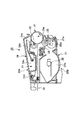
図5は、現像ユニット20Bの一端側における概略側面図であり、図6は、現像ユニット20Bの一端側の概略断面図である。図7は、現像ユニット20Bの全体構成を表す概略斜視図である。また、図8〜図10は、現像ユニット20Bの一端側の分解斜視図である。
FIG. 5 is a schematic side view on one end side of the developing
現像ユニット20Bの現像枠体は、本実施例によれば、上述のように、トナーを収容するトナー容器27bと、現像室27bとを形成する現像容器27からなる主現像枠体と、現像容器27の両端に配置され現像ローラ25a及びトナー供給ローラ25bを支持する端部軸受部材75、76にて構成されている。
According to the present embodiment, the developing frame of the developing
また、図8及び図9を参照するとより良く理解されるように、現像容器27、即ち、主現像枠体の一端側には、一端サイドカバー部材82、一端軸受部材76及び規制部材83、更には、装置本体から駆動力を受けて現像ローラ25a、トナー供給ローラ25b及びトナー搬送部材28を駆動するためのギア列が配置されている。即ち、装置本体から駆動力を受ける駆動力受けギア84、現像ローラ25aの一端に係合している現像ローラギア85、トナー供給ローラ25bの一端に係合しているトナー供給ローラギア86、第一駆動力伝達ギア87、第二駆動力伝達ギア88、トナー搬送部材28の一端に係合しているトナー搬送部材ギア89などが配置されている。
As will be better understood with reference to FIGS. 8 and 9, the developing
駆動力受けギア84は、第一駆動力受けギア部84aと第二駆動力受けギア部84bからなり、第一駆動力伝達ギア87は、第一伝達ギア部87aと第二伝達ギア部87bからなる。
The driving
一端軸受部材76は、現像ローラ25aの一端側軸25a1及びトナー供給ローラ25bの一端側軸25b1を回転可能に嵌合支持する嵌合穴76a、76b(図10)を有する。また、一端軸受部材76は、駆動力受けギア84、第一駆動力伝達ギア87及び第二駆動力伝達ギア88をそれぞれ回転可能に嵌合支持するギア軸76c、76d及び76eを有し、更に、規制部材83と係合する位置決め突起76h、76iを有している。
The one-
トナー搬送部材ギア89は、主現像枠体27に回転支持されているトナー搬送部材軸90に係合されている。
The toner conveying
次に、図5及び図6を参照して、駆動伝達構成について説明する。 Next, the drive transmission configuration will be described with reference to FIGS.
現像ユニット20Aは、駆動力受けギア84が装置本体から駆動力を受けて現像ローラ25a及びトナー供給ローラ25b、並びに、トナー搬送部材28へと駆動力を伝達する。
In the developing
現像ローラ25aへは、駆動力受けギア84の第一駆動力受けギア部84aと現像ローラギア85が噛合って駆動伝達される。
The first driving force receiving
トナー供給ローラ72へは、駆動力受けギア84の第二駆動力受けギア部84bが第一駆動力伝達ギア87の第二伝達ギア部87bと噛合い、第一駆動力伝達ギア87の第二伝達ギア部87bが第二駆動力伝達ギア88と噛合い、更に第二駆動力伝達ギア88がトナー供給ローラギア86と噛合って駆動伝達される。
To the
トナー搬送部材28へは、駆動力受けギア84の第二駆動力受けギア部84bが第一駆動力伝達ギア87の第二伝達ギア部87bと噛合い、第一駆動力伝達ギア87の第一伝達ギア部87aがトナー搬送部材ギア89と噛合って駆動伝達される。
The second driving force receiving
次に、規制部材83について説明する。
Next, the regulating
規制部材83は、現像ユニット20Bの一端側において、トナー供給ローラ25bに駆動伝達するための第一駆動力伝達ギア87、第二駆動力伝達ギア88及びトナー供給ローラギア86よりも外側に配置されている。規制部材83は、本実施例では、鋼板のような金属板で作製した板金とした。勿論、これに限定されるものではなく、樹脂、FRP(強化繊維樹脂)などを使用して作製しても良い。
The restricting
規制部材83は、一端軸受部材76の位置決め突起76h、76iと係合する位置決め穴83a、83b、第一駆動力伝達ギア87及び第二駆動力伝達ギア88を嵌合支持するギア軸76d、76eの軸先端部76d1、76e1と係合する係合穴83c、83d、更に、一端軸受部材76に弾性的に設けられている係止部である爪部76kを係止する係止穴83eを有している。
The restricting
規制部材83は、一端軸受部材76の位置決め突起76h、76iと、規制部材83の位置決め穴83a、83bが係合して位置決めがされ、そして、規制部材83の係合穴83c、83dが軸先端部76d1、76e1と係合する。
The restricting
第一駆動力伝達ギア87を支持するギア軸76dは、駆動力受けギア84に覆われて一端サイドカバー部材82で軸支持することはできないが、規制部材83と係合して駆動時にギア軸76dが軸倒れしないように支持されている。また、第二駆動力伝達ギア88を支持するギア軸76eは、他のギアで覆われていないので、本実施例では規制部材83及び一端サイドカバー部材82で軸支持しているが、どちらか一方のみで軸支持するのでもよい。
The
また、一端軸受部材76の爪部76kが係止穴83eに係止されて、規制部材83が一端軸受部材76から外れにくい状態となっている。
Further, the
規制部材83は、一端軸受部材76と一端サイドカバー部材82の間に挟まれ、規制部材83の一部(位置決め穴周囲)が一端サイドカバー部材82接触し、一端軸受部材76に押さえられて支持される。
The restricting
[現像ユニット組立方法]
次に、上述した図7〜図10、更には、図11、図12を参照して、本発明の特徴部をなす、現像枠体27に端部軸受部材75、76、駆動伝達手段であるギア類、サイドカバー部材81、82を取り付ける構成、及び、組立方法について説明する。
[Development unit assembly method]
Next, referring to FIGS. 7 to 10 described above, and FIGS. 11 and 12, the
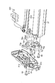
図11及び図12は、現像ユニット20Bの他端軸受部材75及びサイドカバー部材81の構成を説明するための分解された状態を示す概略斜視図である。
FIG. 11 and FIG. 12 are schematic perspective views showing a disassembled state for explaining the configuration of the other
現像枠体を構成している現像容器27の一端には、一端位置決め係合穴71a、71b、及び、ネジ穴71c、71dが設けられている。また、一端軸受部材76には、現像容器27の一端位置決め係合穴71a、71bと係合する位置決め突起76m、76n(図10)が設けられている。
One end of the developing
先ず、現像枠体27に一端軸受部材76を取り付ける方法を説明する。
First, a method of attaching the one
一端軸受部材76の嵌合穴76a、76bに現像ローラ25a及びトナー供給ローラ25bの一端側軸25a1、25b1を貫通させる。これによって、現像ローラ25a及びトナー供給ローラ25bの一端側軸25a1、25b1は一端軸受部材76の嵌合穴76a、76bに回転可能に支持される。
The developing
次に、一端軸受部材76の位置決め突起76m、76nを現像容器27の一端位置決め係合穴71a、71bに係合させる。位置決め突起76m、76nが位置決め係合穴71a、71bに係合し、現像容器27に一端軸受部材76が位置決めされる。その後、ネジ93、94によって一端軸受部材76を現像容器27にネジ留めする。ネジ93、94は、一端軸受部材76のネジ貫通穴76p、76qを貫通して現像容器27のネジ穴71c、71dにそれぞれ係止される。これによって、一端軸受部材76は現像容器27に係止される。
Next, the positioning
次に、トナー供給ローラギア86、第一駆動力伝達ギア87、第二駆動力伝達ギア88、及び、規制部材83の取り付け方法について説明する。
Next, a method for attaching the toner
先ず、トナー供給ローラギア86を、トナー供給ローラ25bの一端側軸25b1に係合させる。
First, the toner
第一駆動力伝達ギア87は、一端軸受部材76のギア軸76dに回転可能に嵌合支持される。ここで、第一駆動力伝達ギア87の第一伝達ギア部87aがトナー搬送部材ギア79と噛合う。第二駆動力伝達ギア88は、一端軸受部材76のギア軸76eに回転可能に嵌合支持される。ここで、第二駆動力伝達ギア88は、第一駆動力伝達ギア87の第二伝達ギア部87b及びトナー供給ローラギア86と噛合う。
The first driving
規制部材83は、上述したように、一端軸受部材76の位置決め突起76h、76iと、規制部材83の位置決め穴83a、83bが係合して位置決めがされる。また、係合穴83c、83dが軸先端部76d1、76e1と係合する。これにより、ギア軸が軸倒れしないよう支持している。そして、ギア88とギア87との中心間距離が確実に保たれる。
As described above, the
ここで、第一駆動力伝達ギア87、第二駆動力伝達ギア88、トナー供給ローラギア86の少なくとも一部が規制部材83によって覆われる。また、一端軸受部材76の爪部76kは、係止穴83eに対して撓みながら嵌入される。これによって、規制部材83が一端軸受部材76に係止されて外れにくい状態となり、第一駆動力伝達ギア87、第二駆動力伝達ギア88、トナー供給ローラギア86は、一端軸受部材76から欠落することはない。
Here, at least a part of the first driving
次に、現像ローラギア85、駆動力受けギア84、一端サイドカバー部材部材82の取り付け方法について説明する。
Next, a method of attaching the developing
現像ローラギア85は、現像ローラ25aの一端側軸25a1に係合させる。駆動力受けギア84は、一端軸受部材76のギア軸76cに回転可能に嵌合支持される。
The developing
ここで、現像ローラギア85と駆動力受けギア84の第一受けギア部84aが噛合い、駆動力受けギア84の第二受けギア部84bは、第一駆動力伝達ギア87の第二伝達ギア部87bと噛合う。
Here, the developing
次に、一端サイドカバー部材82の位置決め穴82a、82bを一端軸受部材76の位置決め突起76h、76iに係合し、一端サイドカバー部材82が一端軸受部材76に位置決めされたのち、ネジ95、96によって一端サイドカバー部材82を一端軸受部材76にネジ留めする。ネジ95、96は、一端サイドカバー部材82のネジ貫通穴82c、82dを貫通して一端軸受部材76のネジ穴76r、76sにそれぞれ係止される。これによって、一端サイドカバー部材82は、一端軸受部材76に係止される。
Next, the
次に、特に、図7、図11及び図12を参照して、現像枠体27に他端軸受部材75及び他端サイドカバー部材81を取り付ける方法を説明する。
Next, a method for attaching the other
先ず、他端軸受部材75の嵌合穴75a、75bに現像ローラ25a及びトナー供給ローラ25bの他端側軸25a2、25b2を貫通させる。これによって、現像ローラ25a及びトナー供給ローラ25bの他端側軸25a2、25b2は、他端軸受部材75の嵌合穴75a、75bに回転可能に支持される。
First, the other end side shafts 25a2 and 25b2 of the developing
次に、他端軸受部材75の位置決め突起75m、75nを現像容器27の他端位置決め係合穴71e、71fに係合させる。
Next, the positioning
位置決め突起75m、75nが係合穴71e、71fに係合し、現像容器27に他端軸受部材75が位置決めされたのち、ネジ97、98によって他端軸受部材75を現像容器27にネジ留めする。ネジ97、98は、他端軸受部材75のネジ貫通穴75p、75qを貫通して現像容器27のネジ穴71g、71hにそれぞれ係止される。これによって、他端軸受部材75は現像容器71に係止される。
After the
次に、他端サイドカバー部材81の取り付け方法について説明する。
Next, a method for attaching the other end
他端サイドカバー部材81の位置決め穴81a、81bは、他端軸受部材75の位置決め突起75h、75iに係合し、他端サイドカバー部材81が他端軸受部材75に位置決めされたのち、ネジ99によって他端サイドカバー部材81を現像枠体27にネジ留めする。ネジ99は、他端サイドカバー部材81のネジ貫通穴81pを貫通して現像枠体27のネジ穴に係止される。これによって、他端サイドカバー部材81が係止される。
The positioning holes 81 a and 81 b of the other end
以上説明した本発明のプロセスカートリッジの組立方法は、要するに、次の工程を有している。
(a)電子写真感光体ドラム21に形成された静電潜像を現像するための現像ローラ25aの一端25a1と、現像ローラ25aに現像剤を供給するための現像剤供給ローラ25bの一端25b1を一端軸受部材76に支持して、一端軸受部材76を主現像枠体27の長手方向一端に取り付ける、及び、現像ローラ25aの他端25a2と、現像剤供給ローラ25bの他端25b2を他端軸受部材75に支持して、他端軸受部材75を主現像枠体27の長手方向他端に取り付けるローラ取り付け工程と、
(b)主現像枠体27の長手方向一端に取り付けられた一端軸受部材76に、装置本体から受けた駆動力を現像剤供給ローラ25bへ伝達するための第一駆動力伝達ギア87、第二駆動力伝達ギア88、及び、現像剤供給ローラギア86を取り付ける駆動力伝達ギア取り付け工程と、
(c)第一駆動力伝達ギア87、第二駆動力伝達ギア88、及び、現像剤供給ローラギア86が取り付けられた一端軸受部材76に、第一駆動力伝達ギア87、第二駆動力伝達ギア88、及び、現像剤供給ローラギア86の少なくとも一部と重なるように、主現像枠体27の長手方向において、第一駆動力伝達ギア87、第二駆動力伝達ギア88、及び、現像剤供給ローラギア86の外側に規制部材83を取り付ける規制部材取り付け工程と、を有する。ここで、規制部材83が有するギア軸穴83c、83dが第一駆動力伝達ギア87のギア軸76d(軸先端部76d1)と第二駆動力伝達ギア88のギア軸76e(軸先端部76e1)と嵌合して、また、規制部材83が有する位置決め穴83a、83bが一端軸受部材76に設けられた位置決め突起76h、76iと嵌合することによって、規制部材83は一端軸受部材76に取り付けられる。更に、
(d)規制部材83を間に挟んで、一部が規制部材83と接触して規制部材83を一端軸受部材76に押さえるように一端カバー部材82を一端軸受部材76に取り付ける一端カバー部材取り付け工程、を有する。ここで、一端カバー部材82は一端軸受部材76に設けられた位置決め突起76h、76iと嵌合して一端軸受部材76に対する取り付け位置が決められる。
In short, the process cartridge assembling method of the present invention described above has the following steps.
(A) One end 25a1 of the developing
(B) a first driving
(C) The first driving
(D) One end cover member attaching step for attaching the one
また、前記規制部材取り付け工程において、規制部材83は、規制部材83が有する係止穴83eに、一端軸受け部材76に設けられた係止部76kが弾性的に係止することができる。
Further, in the restricting member attaching step, the restricting
更に、ローラ取り付け工程に先立って、現像枠体27の長手方向一端に、現像剤収納部27b内に収納されている現像剤を搬送するトナー搬送部材28に装置本体から受けた駆動力を伝達するためのトナー搬送部材ギア89を取り付けるトナー搬送部材ギア取り付け工程を有することができる。
Further, prior to the roller mounting step, the driving force received from the apparatus main body is transmitted to one end in the longitudinal direction of the developing
更に、規制部材取り付け工程の後に、プロセスカートリッジ20が装置本体に装着された際に装置本体から駆動力を受ける駆動力受けギア84を一端軸受部材76に設けられたギア軸76cに取り付ける駆動力受けギア取り付け工程と、駆動力受けギア84が装置本体から受けた駆動力を現像ローラ25aに伝達するための現像ローラギア85を現像ローラ25aの一端25a1に取り付ける現像ローラギア取り付け工程と、を有し、一端軸受部材76に駆動力受けギア84及び現像ローラギア85を取り付けた後に、一端軸受部材76に一端カバー部材82を取り付けることができる。
Further, after the restricting member attaching step, the driving
尚、工程の順番は適宜選択することができる。 In addition, the order of processes can be selected as appropriate.
以上説明したように、本発明を適用した前述の実施例によれば、以下のような効果が得られる。 As described above, according to the above-described embodiment to which the present invention is applied, the following effects can be obtained.
規制部材によって第一駆動力伝達ギアのギア軸を支持する。そして、前記規制部材を一端軸受部材と一端サイドカバー部材の間に挟む。そして、一端サイドカバー部材の一部を規制部材の一部に接触させて一端軸受部材へ押し付けて前記規制部材を前記一端軸受部材に係止させる。この構成、方法によって、プロセスカートリッジを駆動させるための駆動伝達手段であるギアをギア軸に確実に支持させることができる。よって、良好な駆動力の伝達を行うことができる。また、プロセスカートリッジの小型化を図ることができる。 The gear shaft of the first driving force transmission gear is supported by the restriction member. The regulating member is sandwiched between the one end bearing member and the one end side cover member. Then, a part of the one end side cover member is brought into contact with a part of the regulating member and pressed against the one end bearing member to lock the regulating member to the one end bearing member. With this configuration and method, it is possible to reliably support the gear, which is a drive transmission means for driving the process cartridge, on the gear shaft. Therefore, good driving force can be transmitted. In addition, the process cartridge can be reduced in size.
また、規制部材が第一駆動力伝達ギア、第二駆動力伝達ギア、現像剤供給ローラギアの少なくとも一部を覆い、前記規制部材を前記一端軸受部材に取り付けることによって、ギアが不用意に欠落することを防止できる。従って、組立性を向上させることができる。即ち、組立時のカートリッジの姿勢および組立工程の自由度がひろがり、組立性の向上を図ることができる。 Further, the restriction member covers at least a part of the first driving force transmission gear, the second driving force transmission gear, and the developer supply roller gear, and the gear is inadvertently lost by attaching the restriction member to the one end bearing member. Can be prevented. Therefore, assemblability can be improved. That is, the posture of the cartridge at the time of assembly and the degree of freedom of the assembly process are expanded, and the assemblability can be improved.
本発明の上記プロセスカートリッジの組立方法は、プロセスカートリッジ製品の製造に際して実施することができるが、使用済みのプロセスカートリッジの再使用に際して、或いは、検査、部品取り替えに際しての、分解後の再組立時にも適用することができ、同様の作用効果を達成し得る。 The process cartridge assembling method of the present invention can be carried out when manufacturing a process cartridge product, but also when reusing a used process cartridge or when reassembling after disassembling when inspecting or replacing parts. It can be applied and similar effects can be achieved.
20 プロセスカートリッジ
20A 感光体ドラムユニット
20B 現像ユニット
21 感光体ドラム(像担時体)
25a 現像ローラ
25b トナー供給ローラ(現像剤供給ローラ)
26 ドラム枠体
27 現像枠体(現像容器)
27a 現像室
27b トナー容器(現像剤収納部)
28 トナー搬送部材
29 ピン
40 中間転写体ユニット
40a 中間転写体
75 他端軸受部材
75a、75b 嵌合穴
75f、75g 係合穴
75h、75i 位置決め突起
76 一端軸受部材
76a、76b 嵌合穴
76c、76d、76e ギア軸
76d1、76e1 軸先端部
76h、76i 位置決め突起
76k 爪部(係止部)
76m、76n 位置決め突起
76p、76q ネジ貫通穴
76r、76s ネジ穴
77 支持穴
78 感光体ドラム駆動伝達部
79 現像駆動伝達部
81 他端サイドカバー部材
81a、81b 位置決め穴
81c、81d ネジ貫通穴
82 一端サイドカバー部材
82a、82b 位置決め穴
82c、82d ネジ貫通穴
83 規制部材
83a、83b 位置決め穴
83c、83d 係合穴
83e 係止穴
84 駆動力受けギア
84a 第一駆動力受けギア部
84b 第二駆動力受けギア部
85 現像ローラギア
86 トナー供給ローラギア
87 第一駆動力伝達ギア
87a 第一伝達ギア部
87b 第二伝達ギア部
88 第二駆動力伝達ギア
89 トナー搬送部材ギア
90 トナー搬送部材軸
20
26
28
76m,
Claims (10)
電子写真感光体ドラムと、
現像剤を収納する現像剤収納部と、
前記現像剤収納部に収納されている現像剤を用いて、前記電子写真感光体ドラムに形成された静電潜像を現像するための現像ローラと、
前記現像ローラに前記現像剤を供給するための現像剤供給ローラと、
前記現像ローラと前記現像剤供給ローラとを支持して、前記現像剤収納部を有する現像枠体と、
前記現像枠体の長手方向一端側に設けられた第一のギアであって、前記プロセスカートリッジが前記画像形成装置本体に装着された際に、前記画像形成装置本体に設けられた本体ギアと係合して駆動力の伝達を受ける駆動力受けギア部を有する第一のギアと、
前記現像枠体の長手方向において、前記駆動力受けギア部よりも内側に設けられた第二のギアであって、前記第一のギアが受けた駆動力を前記現像剤供給ローラへ伝達するための第二のギアと、
前記現像枠体の長手方向において、前記第一のギアと第二のギアとの間に設けられた、前記第二のギアを支持する規制部材であって、前記現像枠体の長手方向一端側に設けられた係止部に係止された規制部材と、
を有することを特徴とするプロセスカートリッジ。 In a process cartridge that can be attached to and detached from the electrophotographic image forming apparatus main body,
An electrophotographic photosensitive drum ;
A developer storage section for storing the developer;
A developing roller for developing the electrostatic latent image formed on the electrophotographic photosensitive drum using the developer stored in the developer storage section;
A developer supply roller for supplying the developer to the developing roller;
A developing frame that supports the developing roller and the developer supply roller and has the developer accommodating portion ;
A first gear provided on one end side in the longitudinal direction of the developing frame, and a main gear provided on the image forming apparatus main body when the process cartridge is mounted on the image forming apparatus main body. A first gear having a driving force receiving gear portion that receives the driving force in combination,
A second gear provided on the inner side of the driving force receiving gear portion in the longitudinal direction of the developing frame for transmitting the driving force received by the first gear to the developer supply roller; With the second gear of the
In the longitudinal direction of the developing frame, wherein a first gear provided between the second gear, a regulating member for supporting said second gear, one longitudinal end of said developing frame and it locked the regulating member locking portion provided in,
A process cartridge comprising:
前記現像枠体の長手方向において、前記規制部材よりも外側に取り付けられたカバー部材であって、前記規制部材を間に挟んで前記現像枠体に取り付けられたカバー部材を有することを特徴とする請求項1に記載のプロセスカートリッジ。 Further, the process cartridge is
A cover member attached to the outside of the restriction member in the longitudinal direction of the development frame body, the cover member being attached to the development frame body with the restriction member interposed therebetween. The process cartridge according to claim 1.
前記現像枠体の長手方向において、前記駆動力受けギア部よりも内側に設けられた第三のギアであって、前記駆動力を前記現像剤供給ローラへ伝達するための第三のギアを有し、
前記規制部材は、前記長手方向において前記第三のギアの少なくとも一部と重なり、前記第三のギアを支持する第三ギア支持軸の一端側を支持することを特徴とする請求項1に記載のプロセスカートリッジ。 Further, the process cartridge is
A third gear provided on the inner side of the driving force receiving gear portion in the longitudinal direction of the developing device frame and having a third gear for transmitting the driving force to the developer supply roller; And
The regulating member, according to claim 1, characterized in that the in the longitudinal direction overlaps with at least a portion of said third gear, supports one end side of the third gear support shaft for supporting the third gear Process cartridge.
前記第一のギアと前記第二のギアと前記規制部材とは、前記軸受け部材に設けられていることを特徴とする請求項1に記載のプロセスカートリッジ。 The developing frame has a bearing member on one end side in the longitudinal direction,
The process cartridge according to claim 1 , wherein the first gear, the second gear, and the restricting member are provided on the bearing member .
(i)前記現像ローラと、前記現像剤供給ローラとを、前記現像枠体に取り付けるローラ取り付け工程と、
(ii)第二のギアを前記現像枠体に取り付ける第二ギア取り付け工程と、
ここで、前記第二のギアは、前記画像形成装置本体に設けられた本体ギアと係合する第一のギアが受けた駆動力を前記現像剤供給ローラへ伝達するものである、
(iii)前記第二ギア取り付け工程の後に、規制部材によって前記第二のギアを支持するために、前記規制部材を前記現像枠体に取り付ける規制部材取り付け工程であって、前記現像枠体の長手方向一端側に設けられた係止部に前記規制部材を係止させる規制部材取り付け工程と、
ここで、前記規制部材は、前記現像枠体の長手方向において前記第一のギアと第二のギアとの間に設けられて、前記第二のギアを支持するものである、
(iv)前記規制部材取り付け工程の後に、前記第一のギアを前記現像枠体に取り付ける第一ギア取り付け工程と、
を有することを特徴とするプロセスカートリッジの組立方法。 The electrostatic latent image formed on the electrophotographic photosensitive drum is developed using an electrophotographic photosensitive drum, a developer accommodating portion that accommodates the developer, and a developer that is accommodated in the developer accommodating portion. A developing roller, a developer supplying roller for supplying the developer to the developing roller, a developing frame that supports the developing roller and the developer supplying roller, and has the developer accommodating portion. In a method for assembling a process cartridge that can be attached to and detached from the electrophotographic image forming apparatus main body,
(I) a roller attaching step for attaching the developing roller and the developer supply roller to the developing frame;
(Ii) a second gear attachment step of attaching a second gear to the developing device frame;
Here, the second gear transmits the driving force received by the first gear engaged with a main body gear provided in the image forming apparatus main body to the developer supply roller.
(Iii) a regulating member attaching step for attaching the restricting member to the developing device frame so as to support the second gear by the restricting member after the second gear attaching step; A regulating member attaching step for latching the regulating member to a latching portion provided on one end side in the direction ;
Here, the regulating member is provided between the first gear and the second gear in the longitudinal direction of the developing device frame, and supports the second gear.
(Iv) a first gear attaching step for attaching the first gear to the developing frame after the regulating member attaching step;
A process cartridge assembling method characterized by comprising:
前記第二ギア取り付け工程は、前記軸受け部材に前記第二のギアを取り付ける工程であり、
前記規制部材取り付け工程は、前記軸受け部材に前記規制部材を取り付ける工程であり、
前記第一ギア取り付け工程は、前記軸受け部材に前記第一のギアを取り付ける工程であることを特徴とする請求項7に記載のプロセスカートリッジの組立方法。 The roller attachment step is a step of attaching the development roller and the developer supply roller to a bearing member that the development frame body has on one end side in the longitudinal direction.
The second gear attachment step is a step of attaching the second gear to the bearing member,
The restricting member attaching step is a step of attaching the restricting member to the bearing member,
8. The process cartridge assembling method according to claim 7 , wherein the first gear attaching step is a step of attaching the first gear to the bearing member .
Priority Applications (5)
| Application Number | Priority Date | Filing Date | Title |
|---|---|---|---|
| JP2003400799A JP4086766B2 (en) | 2003-11-28 | 2003-11-28 | Process cartridge and process cartridge assembling method |
| US10/878,616 US7027756B2 (en) | 2003-11-28 | 2004-06-29 | Process cartridge and assemblying method therefor |
| CNB2004100626172A CN100367132C (en) | 2003-11-28 | 2004-06-30 | Process cartridge and assemblying method therefor |
| EP04015345A EP1580622B1 (en) | 2003-11-28 | 2004-06-30 | Process cartridge and assemblying method therefor |
| KR1020040049854A KR100644307B1 (en) | 2003-11-28 | 2004-06-30 | Process cartridge and assemblying method therefor |
Applications Claiming Priority (1)
| Application Number | Priority Date | Filing Date | Title |
|---|---|---|---|
| JP2003400799A JP4086766B2 (en) | 2003-11-28 | 2003-11-28 | Process cartridge and process cartridge assembling method |
Publications (3)
| Publication Number | Publication Date |
|---|---|
| JP2005164751A JP2005164751A (en) | 2005-06-23 |
| JP2005164751A5 JP2005164751A5 (en) | 2006-07-20 |
| JP4086766B2 true JP4086766B2 (en) | 2008-05-14 |
Family
ID=34616673
Family Applications (1)
| Application Number | Title | Priority Date | Filing Date |
|---|---|---|---|
| JP2003400799A Expired - Fee Related JP4086766B2 (en) | 2003-11-28 | 2003-11-28 | Process cartridge and process cartridge assembling method |
Country Status (5)
| Country | Link |
|---|---|
| US (1) | US7027756B2 (en) |
| EP (1) | EP1580622B1 (en) |
| JP (1) | JP4086766B2 (en) |
| KR (1) | KR100644307B1 (en) |
| CN (1) | CN100367132C (en) |
Families Citing this family (39)
| Publication number | Priority date | Publication date | Assignee | Title |
|---|---|---|---|---|
| JP3997817B2 (en) * | 2002-04-02 | 2007-10-24 | ブラザー工業株式会社 | Developing device and image forming apparatus |
| US7330681B2 (en) * | 2004-08-30 | 2008-02-12 | Seiko Epson Corporation | Developing device, image forming apparatus, and image forming system |
| US7664434B2 (en) * | 2004-12-28 | 2010-02-16 | Canon Kabushiki Kaisha | Charging member, process cartridge and electrophotographic apparatus |
| JP4239100B2 (en) * | 2005-01-31 | 2009-03-18 | ブラザー工業株式会社 | Developing cartridge and image forming apparatus |
| JP4684732B2 (en) * | 2005-04-27 | 2011-05-18 | キヤノン株式会社 | Electrophotographic image forming apparatus and process cartridge |
| JP4280753B2 (en) * | 2005-04-27 | 2009-06-17 | キヤノン株式会社 | Electrophotographic image forming apparatus and process cartridge |
| KR20070095491A (en) * | 2005-09-22 | 2007-10-01 | 삼성전자주식회사 | An developing unit and image forming apparatus having the same |
| JP4667444B2 (en) | 2006-12-13 | 2011-04-13 | キヤノン株式会社 | Electrophotographic image forming apparatus |
| JP4280772B2 (en) * | 2006-12-28 | 2009-06-17 | キヤノン株式会社 | Process cartridge and electrophotographic image forming apparatus |
| JP5084257B2 (en) * | 2006-12-28 | 2012-11-28 | キヤノン株式会社 | Process cartridge and image forming apparatus using the same |
| US7856192B2 (en) * | 2006-12-28 | 2010-12-21 | Canon Kabushiki Kaisha | Process cartridge and electrophotographic image forming apparatus |
| JP5094186B2 (en) * | 2007-04-10 | 2012-12-12 | キヤノン株式会社 | Process cartridge and electrophotographic image forming apparatus |
| JP4968957B2 (en) | 2008-03-31 | 2012-07-04 | キヤノン株式会社 | Frame body unit, developing device and process cartridge, and frame body unit, developing device and process cartridge manufacturing method |
| JP5344538B2 (en) | 2008-05-27 | 2013-11-20 | キヤノン株式会社 | Process cartridge assembling method, process cartridge disassembling method, process cartridge remanufacturing method, and process cartridge |
| JP4562206B2 (en) * | 2008-09-29 | 2010-10-13 | キヤノン株式会社 | Electrophotographic image forming apparatus |
| JP2011186447A (en) * | 2010-02-15 | 2011-09-22 | Canon Inc | Developing device and process cartridge |
| JP5517732B2 (en) | 2010-05-11 | 2014-06-11 | キヤノン株式会社 | Process cartridge and image forming apparatus |
| JP5539038B2 (en) | 2010-06-02 | 2014-07-02 | キヤノン株式会社 | Electrophotographic image forming apparatus |
| JP5106656B2 (en) | 2010-06-22 | 2012-12-26 | キヤノン株式会社 | Process cartridge and image forming apparatus |
| JP4846062B1 (en) | 2010-08-20 | 2011-12-28 | キヤノン株式会社 | Cartridge and image forming apparatus |
| JP5392302B2 (en) * | 2011-06-10 | 2014-01-22 | ブラザー工業株式会社 | Developer cartridge |
| JP5348211B2 (en) | 2011-08-31 | 2013-11-20 | ブラザー工業株式会社 | Developer cartridge |
| JP5413427B2 (en) | 2011-08-31 | 2014-02-12 | ブラザー工業株式会社 | Image forming apparatus |
| JP5348209B2 (en) | 2011-08-31 | 2013-11-20 | ブラザー工業株式会社 | cartridge |
| JP5182402B2 (en) | 2011-08-31 | 2013-04-17 | ブラザー工業株式会社 | cartridge |
| JP5413428B2 (en) | 2011-08-31 | 2014-02-12 | ブラザー工業株式会社 | cartridge |
| WO2013069807A1 (en) | 2011-11-09 | 2013-05-16 | Canon Kabushiki Kaisha | Cartridge and unit, seal member and blade member |
| JP2013122489A (en) | 2011-11-09 | 2013-06-20 | Canon Inc | Cartridge and unit |
| EP3745215A1 (en) * | 2012-06-15 | 2020-12-02 | Canon Kabushiki Kaisha | Cartridge, process cartridge and electrophotographic image forming apparatus |
| JP6057651B2 (en) | 2012-10-01 | 2017-01-11 | キヤノン株式会社 | Process cartridge and process cartridge manufacturing method |
| CN105334711B (en) * | 2014-07-25 | 2019-06-11 | 纳思达股份有限公司 | A kind of handle box and image forming apparatus |
| CA3135768C (en) | 2015-02-27 | 2024-03-05 | Canon Kabushiki Kaisha | Drum unit, cartridge and coupling member |
| JP6693302B2 (en) * | 2016-06-30 | 2020-05-13 | ブラザー工業株式会社 | Developer cartridge |
| JP7058992B2 (en) | 2017-12-13 | 2022-04-25 | キヤノン株式会社 | Image forming equipment and cartridge |
| JP6665243B2 (en) * | 2017-12-15 | 2020-03-13 | 株式会社スギノマシン | Nozzle inspection method and apparatus |
| JP2019174625A (en) * | 2018-03-28 | 2019-10-10 | ブラザー工業株式会社 | Developing cartridge |
| JP7057191B2 (en) * | 2018-03-30 | 2022-04-19 | キヤノン株式会社 | Manufacturing method of image-carrying unit and manufacturing method of cartridge |
| JP7059072B2 (en) | 2018-03-30 | 2022-04-25 | キヤノン株式会社 | Manufacturing method of image-carrying unit and manufacturing method of cartridge |
| CN109272574B (en) * | 2018-09-10 | 2020-04-10 | 武汉大学 | Construction method and calibration method of linear array rotary scanning camera imaging model based on projection transformation |
Family Cites Families (18)
| Publication number | Priority date | Publication date | Assignee | Title |
|---|---|---|---|---|
| US5966566A (en) | 1993-03-24 | 1999-10-12 | Canon Kabushiki Kaisha | Recycle method for process cartridge and image forming apparatus |
| JPH06314001A (en) * | 1993-04-28 | 1994-11-08 | Canon Inc | Gear unit and image forming device |
| JP2875203B2 (en) * | 1995-03-27 | 1999-03-31 | キヤノン株式会社 | Electrophotographic image forming apparatus, process cartridge, driving force transmitting component, and electrophotographic photosensitive drum |
| JP3382474B2 (en) | 1996-09-30 | 2003-03-04 | キヤノン株式会社 | Process cartridge, electrophotographic image forming apparatus, and method of incorporating cleaning roller |
| JP3466888B2 (en) * | 1997-10-01 | 2003-11-17 | キヤノン株式会社 | Process cartridge and electrophotographic image forming apparatus |
| JP2000194248A (en) | 1998-12-28 | 2000-07-14 | Canon Inc | Process cartridge, electrifying unit and developing unit |
| JP3679645B2 (en) | 1999-03-29 | 2005-08-03 | キヤノン株式会社 | Process cartridge |
| JP3513447B2 (en) * | 1999-10-29 | 2004-03-31 | キヤノン株式会社 | Process cartridge |
| JP3413173B2 (en) | 2000-01-05 | 2003-06-03 | キヤノン株式会社 | Process cartridge and electrophotographic image forming apparatus |
| JP3720707B2 (en) | 2000-01-19 | 2005-11-30 | キヤノン株式会社 | Process cartridge and electrophotographic image forming apparatus |
| JP4250294B2 (en) | 2000-02-16 | 2009-04-08 | キヤノン株式会社 | Color electrophotographic image forming apparatus and process cartridge |
| JP4677093B2 (en) * | 2000-12-25 | 2011-04-27 | キヤノン株式会社 | Process cartridge |
| JP3832815B2 (en) | 2001-01-16 | 2006-10-11 | 株式会社リコー | Drive transmission device and image forming apparatus including the same |
| JP3566697B2 (en) | 2001-02-09 | 2004-09-15 | キヤノン株式会社 | Process cartridge, electrophotographic image forming apparatus, and separation mechanism |
| JP4672893B2 (en) | 2001-03-30 | 2011-04-20 | キヤノン株式会社 | Developer supply container and image forming apparatus |
| JP3890227B2 (en) | 2001-12-21 | 2007-03-07 | キヤノン株式会社 | Process means moving mechanism, charging device, process cartridge, and electrophotographic image forming apparatus |
| JP4011930B2 (en) | 2002-02-20 | 2007-11-21 | キヤノン株式会社 | Developer container, developing device, process cartridge, and image forming apparatus |
| JP3720802B2 (en) * | 2002-11-06 | 2005-11-30 | キヤノン株式会社 | Process cartridge remanufacturing method |
-
2003
- 2003-11-28 JP JP2003400799A patent/JP4086766B2/en not_active Expired - Fee Related
-
2004
- 2004-06-29 US US10/878,616 patent/US7027756B2/en not_active Expired - Lifetime
- 2004-06-30 KR KR1020040049854A patent/KR100644307B1/en active IP Right Grant
- 2004-06-30 EP EP04015345A patent/EP1580622B1/en not_active Expired - Lifetime
- 2004-06-30 CN CNB2004100626172A patent/CN100367132C/en not_active Expired - Fee Related
Also Published As
| Publication number | Publication date |
|---|---|
| US20050117935A1 (en) | 2005-06-02 |
| EP1580622A3 (en) | 2005-10-05 |
| US7027756B2 (en) | 2006-04-11 |
| CN1621971A (en) | 2005-06-01 |
| EP1580622A2 (en) | 2005-09-28 |
| EP1580622B1 (en) | 2012-02-22 |
| CN100367132C (en) | 2008-02-06 |
| KR20050052322A (en) | 2005-06-02 |
| JP2005164751A (en) | 2005-06-23 |
| KR100644307B1 (en) | 2006-11-15 |
Similar Documents
| Publication | Publication Date | Title |
|---|---|---|
| JP4086766B2 (en) | Process cartridge and process cartridge assembling method | |
| JP3789122B2 (en) | Process cartridge remanufacturing method | |
| JP3782807B2 (en) | Process cartridge and method for attaching electrophotographic photosensitive drum | |
| JP4444997B2 (en) | Process cartridge and electrophotographic image forming apparatus | |
| JP4164293B2 (en) | Developing device, process cartridge, and image forming apparatus | |
| JP3950882B2 (en) | Electrophotographic image forming apparatus | |
| JP2002304106A (en) | Process cartridge, electrophotographic photoreceptor drum, electrophotographic imaging device and color electrophotographic imaging device | |
| JP2006106419A (en) | Process cartridge and electrophotographic image forming apparatus | |
| JP2002189401A (en) | Process cartridge and electrophotographic image forming device | |
| JP2003084559A (en) | Developing device, process cartridge and image forming device | |
| JP2002196585A (en) | Process cartridge and electrophotographic image forming device | |
| JP4739446B2 (en) | Process cartridge | |
| JP2005181983A (en) | Image forming apparatus and developing-agent amount detecting method, cartridge, and storage medium | |
| JPH04258967A (en) | Image forming device | |
| JPH10221919A (en) | Image forming device | |
| JP2006145604A (en) | Development cartridge, process cartridge, and electrophotographic image forming apparatus | |
| JP2007047295A (en) | Developer and developing device and image forming apparatus using them | |
| JPH03100664A (en) | Color image forming device | |
| JP2001154438A (en) | Image forming device | |
| JP2004333929A (en) | Image forming apparatus | |
| JP2007025346A (en) | Process cartridge | |
| JP2007025348A (en) | Developing device, and process cartridge | |
| JP2005156655A (en) | Process cartridge and image forming apparatus | |
| JP2005031488A (en) | Bearing member and process cartridge | |
| JPH11311888A (en) | Image forming device |
Legal Events
| Date | Code | Title | Description |
|---|---|---|---|
| A521 | Written amendment |
Free format text: JAPANESE INTERMEDIATE CODE: A523 Effective date: 20060602 |
|
| A621 | Written request for application examination |
Free format text: JAPANESE INTERMEDIATE CODE: A621 Effective date: 20060602 |
|
| A977 | Report on retrieval |
Free format text: JAPANESE INTERMEDIATE CODE: A971007 Effective date: 20070706 |
|
| TRDD | Decision of grant or rejection written | ||
| A01 | Written decision to grant a patent or to grant a registration (utility model) |
Free format text: JAPANESE INTERMEDIATE CODE: A01 Effective date: 20080212 |
|
| A61 | First payment of annual fees (during grant procedure) |
Free format text: JAPANESE INTERMEDIATE CODE: A61 Effective date: 20080219 |
|
| FPAY | Renewal fee payment (event date is renewal date of database) |
Free format text: PAYMENT UNTIL: 20110228 Year of fee payment: 3 |
|
| R150 | Certificate of patent or registration of utility model |
Ref document number: 4086766 Country of ref document: JP Free format text: JAPANESE INTERMEDIATE CODE: R150 Free format text: JAPANESE INTERMEDIATE CODE: R150 |
|
| FPAY | Renewal fee payment (event date is renewal date of database) |
Free format text: PAYMENT UNTIL: 20120229 Year of fee payment: 4 |
|
| FPAY | Renewal fee payment (event date is renewal date of database) |
Free format text: PAYMENT UNTIL: 20130228 Year of fee payment: 5 |
|
| FPAY | Renewal fee payment (event date is renewal date of database) |
Free format text: PAYMENT UNTIL: 20140228 Year of fee payment: 6 |
|
| LAPS | Cancellation because of no payment of annual fees |