JP4250294B2 - Color electrophotographic image forming apparatus and process cartridge - Google Patents
Color electrophotographic image forming apparatus and process cartridge Download PDFInfo
- Publication number
- JP4250294B2 JP4250294B2 JP2000037826A JP2000037826A JP4250294B2 JP 4250294 B2 JP4250294 B2 JP 4250294B2 JP 2000037826 A JP2000037826 A JP 2000037826A JP 2000037826 A JP2000037826 A JP 2000037826A JP 4250294 B2 JP4250294 B2 JP 4250294B2
- Authority
- JP
- Japan
- Prior art keywords
- process cartridge
- groove
- guide member
- image forming
- guided portion
- Prior art date
- Legal status (The legal status is an assumption and is not a legal conclusion. Google has not performed a legal analysis and makes no representation as to the accuracy of the status listed.)
- Expired - Fee Related
Links
Images


Classifications
-
- G—PHYSICS
- G03—PHOTOGRAPHY; CINEMATOGRAPHY; ANALOGOUS TECHNIQUES USING WAVES OTHER THAN OPTICAL WAVES; ELECTROGRAPHY; HOLOGRAPHY
- G03G—ELECTROGRAPHY; ELECTROPHOTOGRAPHY; MAGNETOGRAPHY
- G03G21/00—Arrangements not provided for by groups G03G13/00 - G03G19/00, e.g. cleaning, elimination of residual charge
- G03G21/16—Mechanical means for facilitating the maintenance of the apparatus, e.g. modular arrangements
- G03G21/18—Mechanical means for facilitating the maintenance of the apparatus, e.g. modular arrangements using a processing cartridge, whereby the process cartridge comprises at least two image processing means in a single unit
- G03G21/1839—Means for handling the process cartridge in the apparatus body
- G03G21/1842—Means for handling the process cartridge in the apparatus body for guiding and mounting the process cartridge, positioning, alignment, locks
- G03G21/185—Means for handling the process cartridge in the apparatus body for guiding and mounting the process cartridge, positioning, alignment, locks the process cartridge being mounted parallel to the axis of the photosensitive member
-
- G—PHYSICS
- G03—PHOTOGRAPHY; CINEMATOGRAPHY; ANALOGOUS TECHNIQUES USING WAVES OTHER THAN OPTICAL WAVES; ELECTROGRAPHY; HOLOGRAPHY
- G03G—ELECTROGRAPHY; ELECTROPHOTOGRAPHY; MAGNETOGRAPHY
- G03G2221/00—Processes not provided for by group G03G2215/00, e.g. cleaning or residual charge elimination
- G03G2221/16—Mechanical means for facilitating the maintenance of the apparatus, e.g. modular arrangements and complete machine concepts
- G03G2221/18—Cartridge systems
- G03G2221/183—Process cartridge
- G03G2221/1884—Projections on process cartridge for guiding mounting thereof in main machine
Description
【0001】
【発明の属する技術分野】
本発明はカラー(多色)電子写真画像形成装置(以下、単に電子写真画像形成装置、又は画像形成装置という)、及びこの本体に着脱可能なプロセスカートリッジに関する。
【0002】
ここで、電子写真画像形成装置とは、電子写真画像形成方式を用いて記録媒体に画像を形成する物である。そして、電子写真画像形成装置の例としては、例えば電子写真複写機、電子写真プリンタ(例えばレーザービームプリンタ、LEDプリンタ等)ファクシミリ装置及びワードプロセッサ等が含まれる。
【0003】
また、プロセスカートリッジとは、帯電手段、現像手段またはクリーニング手段と電子写真感光体ドラムとを一体的にカートリッジ化し、このカートリッジを画像形成装置本体に対して着脱可能とする物である。及び帯電手段、現像手段、クリーニング手段の少なくとも1つと電子写真感光体ドラムとを一体的にカートリッジ化して画像形成装置本体に着脱可能とするものである。更に、少くとも帯電手段と電子写真感光体ドラムとを一体的にカートリッジ化して装置本体に着脱可能とするものをいう。
【0004】
【従来の技術】
従来、電子写真画像プロセスを用いた画像形成装置においては、電子写真感光体及び前記電子写真感光体に作用するプロセス手段を一体的にカートリッジ化して、このカートリッジを画像形成装置本体に着脱可能とするプロセスカートリッジ方式が採用されている。このプロセスカートリッジ方式によれば、装置のメンテナンスをサービスマンによらずにユーザー自身で行うことができるので、格段に操作性を向上させることができた。そこでこのプロセスカートリッジ方式は、画像形成装置において広く用いられている。
【0005】
このようなプロセスカートリッジは現像ローラ、現像ブレードを組み込んだ現像フレームと、現像剤であるトナーを収納したトナーフレームとを一体のユニットとした現像ユニットと、感光体ドラムを支持すると共にクリーニングブレード等を組み込んだクリーニングフレームを回動可能に結合した形式のものが賞用されている。
【0006】
なお、いわゆるクリーナレスのプロセスカートリッジにおいては、帯電フレームで帯電ローラと感光体ドラムを一体のユニットした帯電フレームと現像ユニットを回動可能に結合する。
【0007】
【発明が解決しようとする課題】
上記プロセスカートリッジを画像形成装置本体に装着するために、画像形成装置本体にはプロセスカートリッジ挿入方向両サイドに、これを支持するガイドレールを形成し、またプロセスカートリッジには前記ガイドレールに対応する位置にガイドリブを形成することによって、着脱を容易にすることが一般的である。
【0008】
また異なる色のプロセスカートリッジを複数個用いて、これらを並列に画像形成装置に着脱可能に具備することによって、多色画像を得る多色画像形成装置においても、上述したようなガイドレール及びガイドリブを形成することにより、プロセスカートリッジの着脱を容易にすることが一般的である。
【0009】
このような形態をとった場合、両サイドのガイドレールが同一の高さであるとプロセスカートリッジを前後逆に挿入することができてしまう。
【0010】
さらに上記多色画像形成装置においては隣り合うプロセスカートリッジのガイドリブ及びこれを支持するガイドレールの干渉を避けるために、各プロセスカートリッジの間隔を広げることが必要となり、装置の小型化が難しい。
【0011】
本発明は電子写真画像形成装置に対しプロセスカートリッジを装着する際の誤装着を防止すると共に、さらに多色画像形成装置においては本体の小型化が可能な形態のプロセスカートリッジ及び電子写真画像形成装置を提供することを目的とする。
【0012】
【課題を解決するための手段】
主要な本発明は請求項と対応する番号を付して示せば以下のとおりである。
【0013】
本出願に係る第1の発明は、複数個のプロセスカートリッジを水平方向に並べて個々に取り外し可能に装着して、記録媒体にカラー画像を形成するカラー電子写真画像形成装置において、
a.互いに反対方向に向かって開口している第1の溝と第2の溝であって、上下方向に重なって配置されている第1の溝と第2の溝を有する第1のガイド部材と、
b.互いに反対方向に向かって開口している第1の溝と第2の溝であって、上下方向に重なって配置されている第1の溝と第2の溝を有する第2のガイド部材と、
c.互いに反対方向に向かって開口している第1の溝と第2の溝であって、上下方向に重なって配置されている第1の溝と第2の溝を有する第3のガイド部材と、
d.電子写真感光体ドラムと、
前記電子写真感光体ドラムに作用するプロセス手段と、
前記プロセスカートリッジを前記電子写真画像形成装置の装置本体に装着する装着方向に沿って、前記装着方向と交叉する方向の一端側に配置されている第1の被ガイド部と、前記装着方向に沿って、前記装着方向と交叉する方向の他端側に配置されている第2の被ガイド部であって、前記装置本体に装着された状態で、前記第1の被ガイド部とは異なった高さに配置されている第2の被ガイド部と、
を有する前記複数個のプロセスカートリッジと、
を有し、
前記複数個のプロセスカートリッジの内1つのプロセスカートリッジを前記装置本体に装着するにあたって、前記1つのプロセスカートリッジの有する前記第1の被ガイド部を前記第2のガイド部材の有する前記第1の溝に沿ってガイドし、前記1つのプロセスカートリッジの有する前記第2の被ガイド部を前記第1のガイド部材の有する前記第2の溝に沿ってガイドし、及び、前記複数個のプロセスカートリッジの内他の1つのプロセスカートリッジを前記装置本体に装着するにあたって、前記他の1つのプロセスカートリッジの有する前記第1の被ガイド部を前記第3のガイド部材の有する前記第1の溝に沿ってガイドし、前記他の1つのプロセスカートリッジの有する前記第2の被ガイド部を前記第2のガイド部材の有する前記第2の溝に沿ってガイドするように構成したことを特徴とするカラー電子写真画像形成装置である。
【0016】
本出願に係る第2の発明は、電子写真感光体ドラムと、前記電子写真感光体ドラムに作用するプロセス手段と、装置本体に装着する装着方向に沿って、一端側に配置されている第1の被ガイド部と、前記装着方向に沿って、他端側に配置されている第2の被ガイド部であって、前記装置本体に装着された状態で、前記第1の被ガイド部とは異なった高さに配置されている第2の被ガイド部と、を有する複数個のプロセスカートリッジを水平方向に並べて個々に取り外し可能に装着して、記録媒体にカラー画像を形成するカラー電子写真画像形成装置であって、
互いに反対方向に向かって開口している第1の溝と第2の溝であって、上下方向に重なって配置されている第1の溝と第2の溝を有する第1のガイド部材と、
互いに反対方向に向かって開口している第1の溝と第2の溝であって、上下方向に重なって配置されている第1の溝と第2の溝を有する第2のガイド部材と、
互いに反対方向に向かって開口している第1の溝と第2の溝であって、上下方向に重なって配置されている第1の溝と第2の溝を有する第3のガイド部材と、
を有し、
前記第1の被ガイド部を、前記第3のガイド部材の有する前記第1の溝に沿ってガイドし、前記第2の被ガイド部を、前記第2のガイド部材の有する前記第2の溝に沿ってガイドすることで、前記複数個のプロセスカートリッジの内の1つのプロセスカートリッジが装着されたカラー電子写真画像形成装置の前記装置本体に取り外し可能に装着される前記複数個のプロセスカートリッジの内の別の1つのプロセスカートリッジであって、
前記装置本体に装着するにあたって、前記別の1つのプロセスカートリッジの有する前記第1の被ガイド部を前記第2のガイド部材の有する前記第1の溝に沿ってガイドし、前記別の1つのプロセスカートリッジの有する前記第2の被ガイド部を前記第1のガイド部材の有する前記第2の溝に沿ってガイドするように構成したことを特徴とするプロセスカートリッジ。
【0017】
【発明の実施の形態】
以下本発明の実施の形態を図面に従って説明する。
【0018】
以下の説明で長手方向とは記録媒体の搬送方向に交叉する方向で記録媒体に平行な方向をいう。また左右とは記録媒体の搬送方向を上から見ての左右である。また、プロセスカートリッジの上とはプロセスカートリッジの装着状態における上をいう。
【0019】
図1は本発明の適用される画像形成装置を表わす図面である。この画像形成装置は、像担持体である感光体ドラム上にトナー像を形成する画像形成部31Y,31M,31C,31BKと、そのトナー像を一担転写する中間転写ベルト4a及びそのベルト4a上のトナー像を記録媒体2に転写する転写手段である二次転写ローラ40、記録媒体2を中間転写ベルト4aと二次転写ローラ40間へ送り出す給紙手段及び転写手段へ記録媒体2を搬送する給送手段、定着手段、排紙手段を具備する。
【0020】
以下画像形成について説明する。
【0021】
図1に示すように画像形成装置には複数枚の記録媒体(例えば、記録紙、OHPシート、布等)2を積載収納する給紙カセット3aが着脱自在に装着されている。ピックアップローラ3bにより給紙カセット3aから給送された記録媒体2はリタードローラ対3cにより一枚ずつに分離され、搬送ローラ3d,3fによってレジストローラ対3gに搬送される。
【0022】
記録媒体2が搬送された時には、レジストローラ対3gは回転を停止しており、これのニップに突き当てられることにより記録媒体2は斜行を矯正される。
【0023】
像担持体を含むプロセスカートリッジBY,BM,BC,BBには4ドラムフルカラー方式の場合、図のごとくイエロー、マゼンタ、シアン、ブラックの4つが並列配置されている。各々のプロセスカートリッジBY,BM,BC,BBに対し、それぞれ光学走査系が1Y,1M,1C,1BKが設けられ、画像信号により各色ごとの感光体ドラム上にトナー像が形成された後、転写ローラ4Y,4M,4C,4BKにより図示矢印方向に走行する中間転写ベルト4a上に各色トナーが重ねて転写される。
【0024】
この後、記録媒体2は所定のタイミングで、2次転写ローラ40に送り出され、中間転写ベルト4a上のトナー像が記録媒体2上へ転写され、定着器5で定着された後、排出ローラ対3h,3iにより排出され、装置本体14上のトレー6に積載される。
【0025】
上記画像形成部31Y,31M,31C,31BKは光学走査系1Y,1M,1C,1BKを除いて夫々がプロセスカートリッジBY,BM,BC,BBを構成している。プロセスカートリッジの構成は同様であるのでプロセスカートリッジBYについてのべる。
【0026】
図2に示すようにプロセスカートリッジBYは感光体ドラム7の周囲に帯電手段、露光部、現像手段、転写開口を配設したものである。この実施の形態では磁性キャリア粉を有する二成分現像剤を用いている。そこで本発明の実施の形態に用いられる感光体ドラム7としては、通常用いられている有機感光体等を用いることができるが、望ましくは、有機感光体上にその抵抗が102〜1014Ω・cmの材質を有する表面層を持つものや、アモルファスシリコン感光体などを用いると、電荷注入帯電を実現でき、オゾン発生の防止、ならびに消費電力の低減に効果がある。また、帯電性についても向上させることが可能となる。
【0027】
そこで本実の形態においてはアルミニウム製のドラム基体上に負帯電の有機感光体を設けた感光体ドラム7を用いた。
【0028】
帯電手段は、磁性キャリアを用いた磁気ブラシ帯電器8である。
【0029】
この帯電器8は回転自在に支持された中空円筒形の帯電ローラ8a内に固定のマグネット8bを配してある。転写後、感光体ドラム7上に残留したトナーは図示矢印方向に回転する帯電器8に取り込まれる。
【0030】
現像手段は本実施の形態では2成分現像剤を接触状態にして現像する方法(2成分非接触現像)を採用した。
【0031】
図2には本実施の形態において用いた2成分磁気ブラシ現像用の現像手段10が示されている。現像スリーブ10dは中空円筒形であって回転自在に支持されている。現像スリーブ10d内には固定のマグネット10cが配設されている。現像スリーブ10dは感光体ドラム7と同方向に回転し、周面は感光体ドラム7の周面の移動方向に対して反対方向に移動する。感光体ドラム7と現像スリーブ10dは非接触で0.2〜1.0mm程度の隙間があけられていて、現像剤が感光体ドラム7に対して接触する状態で現像できるように設定されている。
【0032】
キャリアを混合されてトナーは両端を除く長手方向の隔壁10fで仕切られたケーシング内の撹拌スクリュー10g,10hで供給される。不図示のトナー供給容器から供給されたトナーは撹拌スクリュー10gの一端側へ落下して長手方向の一方向へ送られ乍ら撹拌され他端側の隔壁10fのない部分をとおり、撹拌スクリュー10hで一端側に移動して、ついで、一端側の隔壁10fのない部分をとおり撹拌スクリュー10gで送られ乍ら撹拌され、循環する。
【0033】
ここで感光体ドラム7に形成された静電潜像を、現像装置10を用いて2成分磁気ブラシ法により顕像化する現像工程と現像剤の循環系について以下説明する。
【0034】
まず、現像スリーブ10dの回転に伴いマグネット10cの極で汲み上げられた現像剤は、搬送される過程において、現像スリーブ10dに対して垂直に配置された規制ブレード10eによって規制され、現像スリーブ10d上に薄層形成される。ここで薄層形成された現像剤が、現像主極に搬送されてくると磁気力によって穂立ちが形成される。この穂状に形成された現像剤によって感光体ドラム7の静電潜像を現像し、その後反発磁界によって現像スリーブ10d上の現像剤は、現像容器10a内に戻される。
【0035】
現像スリーブ10dには図示しない電源から直流電圧及び交流電圧が印加される。一般に二成分現像法においては交流電圧を印加すると現像効率が増し、画像は高品位になるが、逆にかぶりが発生しやすくなるということも生じる。このため、通常、現像スリーブ10dに印加する直流電圧と感光体ドラム7の表面電位間に電位差を設けることによって、現像時に非画像領域にトナーが付くのを防止する。
【0036】
このトナー像は、ついで中間転写装置4により中間転写体である中間転写ベルト4aに転写される。中間転写装置4は無端状のベルト4aを駆動ローラ4b、従動ローラ4c、及び二次転写対向ローラ4dに巻掛け、図1中矢印方向に回動される。さらに転写ベルト4a内には転写ローラ4Y,4M,4C,4BKを備え、各転写ローラは、ベルト4aの内側から感光体ドラム7(7Y,7M,7C,BK)方向に加圧力を発生しつつ、高圧電源より給電されることで、ベルト4aの裏側からトナーと逆極性の帯電を行なうことにより感光体ドラム7上のトナー像を順次中間転写ベルト4aの上面に転写する。
【0037】
中間転写ベルト4aとしてはポリイミド樹脂からなるものを用いることができる。ベルト4aの材質としてはポリイミド樹脂に限定されるものではなく、誘電体例えばポリカーボネイト樹脂や、ポリエチレンテレフタレート樹脂、ポリフッ化ビニリデン樹脂、ポリエチレンナフタレート樹脂、ポリエーテルエーテルケトン樹脂、ポリエーテルサルフォン樹脂、ポリウレタン樹脂などのプラスチックや、フッ素系、シリコン系のゴムを好適に用いることができる。
【0038】
トナー像転写後の感光体ドラム7の面には転写残トナーが残留している。この転写残トナーをそのまま帯電器を通過させると、残画像部分のみ帯電電位が低下したり、次の画像上で前画像部分が薄くなったり濃く現われたりする現象(以下ゴーストと称する)が発生してしまう。感光体ドラム7と接触した帯電磁気ブラシ下を転写残トナーが通過しても、ほとんどの場合前画像の形状をとどめたままである。そこで、感光体ドラム7の回転に伴い、帯電領域に到達した転写残トナーを磁気ブラシ帯電器8に取り込み前画像の履歴を消してしまうことが必要になる。このとき、交流電圧を磁気ブラシ帯電器8に印加すると感光体ドラム一帯電器間の電界による振動効果によって、帯電器へのトナーの取り込みが容易に行なわれる。ここで、感光体ドラム7上の転写残トナーは転写時の剥離放電等により、極性が正のものと負のものが混在していることが多いが、磁気ブラシ帯電器8への取り込み易さを考えると転写残トナーは正帯電されていることが望ましい。本実施の形態では、中間転写装置4と磁気ブラシ帯電器8との間の感光体ドラム7に導電性ブラシ11を当接させ、帯電バイアスと逆極性のバイアスを印加する。正極性の転写残トナーは磁気ブラシ帯電器8を通過し、負極性の転写残トナーは一時的に導電性ブラシ11に捕獲され、除電された後に再び感光体ドラム7上に送り出される。これにより転写残トナーは磁気ブラシ方向へより取り込まれやすくなる。
【0039】
(プロセスカートリッジのフレームの構成)
このプロセスカートリッジB(BY,BM,BC,BB)は電子写真感光体ドラム7と現像手段10とを現像フレーム12でもって一体的に構成した現像ユニットDに、帯電ローラ8a、規制ブレード8c、帯電ブラシ11等を帯電フレーム13でもって一体的の帯電ユニットCとしてユニット毎組み付ける。更に、長手方向両端より前部カバー16、後部カバー17(図4参照)でもって現像ユニットDと帯電ユニットCの位置決めと結合を行なうものである。
【0040】
図3から図7はプロセスカートリッジB(BY,BM,BC,BB)の投影図である。ここで図3は正面図、図4は右側面図、図5は左側面図、図6は平面図、図7は背面図である。
【0041】
図2に示すように帯電ユニットCは帯電ローラ8a、規制ブレード8c、導電性ブラシ11を帯電フレーム13により一体的に構成してある。図2に示すように帯電フレーム13はプロセスカートリッジBの外装の一部を構成している。
【0042】
帯電ユニットCは図2に示す揺動中心SCを中心に揺動可能に現像フレーム12に支持されている。このため図9に示すように帯電フレーム13の長手方向の奥側である一端に固定したギアユニット24のギアケース26には前記揺動中心SC上に円筒形軸部26aが設けられると共に長手方向の他端の端部カバー23には揺動中心SC上に円筒形の穴23aが設けられている。
【0043】
図2に示すように現像フレーム12の上部では側板12g上部のガイド部12aの内側、端板部12h,12i(図9、図10参照)に周縁を当接して天板29が固定されている。
【0044】
図2に示すように現像フレーム12にはばね座12pが長手方向の2箇所に設けられている。このばね座12pに保持された圧縮コイルばね30が、現像フレーム12と帯電フレーム13間に縮設されている。このばね30のばね力で帯電ユニットCは揺動中心SCを中心にして図2において時計回りに付勢されている。
【0045】
図9に示すように帯電ローラ8aの端部を縮径して回転中心回りに設けたジャーナル部8a2には回転自在にスペーサコロ8nが嵌入している。スペーサコロ8nは上記圧縮コイルばね30のばね力で感光体ドラム7の画像領域外に圧接している。このような構成により感光体ドラム7と帯電ローラ8a間には隙間が設けられていて、帯電ローラ8aと感光体ドラム7の対向部を通過しようとする転写残トナーを帯電ローラ8aの周面の移動方向を感光体ドラム7の周面の移動方向と反対にして帯電バイアスを加えて転写残トナーを捕捉するようになっている。
【0046】
上記において、揺動中心SCと帯電ローラ8aの中心を結ぶ線と、帯電ローラ8aと感光体ドラム7の中心を結ぶ線はほぼ直角である。
【0047】
図2に示すように現像スリーブ10dは現像フレーム12に対してSLv加圧中心を中心にして揺動可能に取り付けられている。図10に示すように現像スリーブ10dの両側の縮径されたジャーナル部10d1には現像スリーブ10dよりも現像隙間だけ大きい半径を有するスペーサコロ10jが嵌合している。スペーサコロ10jの外側にはジャーナル10d1を嵌合した揺動アーム32が設けてある。
【0048】
図11は揺動アーム32の側面付近を示す現像スリーブ10dに対して直角な断面図である。現像フレーム12の両端板部12h,12iに対して長手方向に圧入された支持軸33に揺動アーム32の根本が揺動可能に支持されている。揺動アーム32の前記支持軸33からみてほぼ真上には軸受穴32aが設けられ、その上方にはストッパ部32bが設けられている。支持軸33の中心である加圧中心SLvと軸受穴32aの中心を結ぶ線に対してほぼ直角な線上にばね座32cが設けられている。
【0049】
揺動アーム32の軸受穴32aには現像スリーブ10dの両端のジャーナル部10d1が回転自在に支持されている。ばね座32cと現像フレーム12の端板部12h,12iに設けたばね座12nとの間には圧縮コイルばね35が縮設してある。これによって、現像スリーブ10dは感光体ドラム7に向かって加圧中心SLvを中心に回動して加圧されたスペーサコロ10jは感光体ドラム7の画像領域外の端部に圧接して、現像スリーブ10dと感光体ドラム7との間に所定の隙間(0.2〜1.0mm)が保たれる。
【0050】
上記ストッパ部32bは組立分解時に現像スリーブカバー36に当ることによって揺動アーム32が図11において外方へ回り込むのを防止している。従って組立状態のプロセスカートリッジBにおいては、ストッパ32bと現像スリーブカバー36とは当接していない。なお現像スリーブカバー36は長手方向で両側の揺動アーム32間に延在しており、現像フレーム12にねじ止めされている。
【0051】
(プロセスカートリッジの画像形成装置本体への着脱構成)
プロセスカートリッジBの上部の着脱方向から見て左右には図2に示すようにフランジ状のガイド部12a,29bが外方へ向って突設されており、このガイド部12a,29bは図8に示す装置本体14に形成されたガイドレール201a,201bに丁度係合し長手方向に画像形成装置本体14に着脱される。このガイド部12a,29bは角形であり、夫々現像フレーム12、帯電フレーム13の剛性を増すのに寄与する。隣接するプロセスカートリッジB間のガイドレール201a,201bは一体成形のガイド部材201に構成されている。ここで、ガイド部12aは現像フレーム12に一体成形されている。ガイド部29bは帯電フレーム13に一体成形されている。
【0052】
ここでガイド部12aと隣り合うプロセスカートリッジBのガイド部29bは、左右方向で互いに重なり合わない位置に形成されており、本実施の形態ではガイド部12aの下に隣り合うカートリッジのガイド部29bが入り込むようにしている。
【0053】
このように構成してあるのでプロセスカートリッジBの前後を逆にしてガイドレール201a,201bに挿入しようとしても、ガイドレール201aとガイド部29b及びガイドレール201bとガイド部12aは高さが異なるのでプロセスカートリッジBはガイドレール201a,201bに装着できないので使用者は誤装着に直ちに気がつく。
【0054】
図8に示すように1つのガイド部材201に設けられたガイドレール201a,201bはガイド部材201の両側で互いに反対方向に開口する角形の溝型であって共通のウエブ201cを有する。そして第1のガイドレール201aと第2のガイドレール201bは1つのガイド部材201において上下方向で重なっている。即ち、隣り合うプロセスカートリッジBの間のガイドレール201a,201bは上下方向で重なっている。このため隣接するプロセスカートリッジBを互いに接近できる。このようにガイド部材201がZ型鋼の形状の上下にフランジ201d,201eを有し更に上方へ突出部201fが構成されているのでガイド部材201の高さが高く且つ、3個所の左右方向に幅のあるウエブ201c,フランジ201d,201eを設けてあるので、上下左右方向に断面係数が大きく、強度が大きい。逆に、荷重を定めると小さくもできるので図8に示すように隣接するプロセスカートリッジBを接近できる。
【0055】
各ガイド部材201は同一高さに配設され且つ中間転写ベルト4aの走行方向と直交し水平方向に配設されている。即ち、各ガイド部材201は中間転写ベルト4aの表面に平行している。
【0056】
上記においてガイド部材201はプラスチック又は板金材料もしくはこれらを複合した複合部材で作られる。
【0057】
上記プロセスカートリッジBが装置本体14に装着された際に装置本体14に設けた不図示の高圧電源に通じる装置本体側の各接点に夫々接続される接点が設けてある。
【0058】
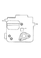
図3に示すようにプロセスカートリッジBの装着方向から見て手前側には感光体ドラム7に通じるドラムアース接点101が設けられている。また図7に示すようにプロセスカートリッジBの装着方向から見て奥側には導電性ブラシ11に通じる導電性ブラシ接点102、帯電ローラ8aに通じる帯電バイアス接点103、現像スリーブ10dに通じる現像バイアス接点104が設けられている。これら接点102,103,104は装置本体14にプロセスカートリッジBが装着された際、装置本体側の高圧電源に通ずる接点に接触する。なお、導電性ブラシ接点102、帯電バイアス接点103、現像バイアス接点104を設けた側と同じプロセスカートリッジBの装着方向から見て奥側にはI.C付コネクタ105が設けられており、プロセスカートリッジBを装置本体14へ装着された際に装置本体側の不図示のコネクタと結合され、装置本体側の制御装置は、装着されたプロセスカートリッジBの使用履歴をI.Cコネクタ105に書き込み、或は読み出して制御に用いる。
【0059】
プロセスカートリッジBの装着方向から見て奥側の端面には長手方向の軸を中心に回転する軸継手となった3つの駆動力受け部が設けてある。プロセスカートリッジBが装置本体14へ装着されると、3つの駆動力受け部は装置本体14の駆動部材と連結される。
【0060】
図7に示すように、プロセスカートリッジBの奥側の端面には夫々端面から退いた位置にドラムカップリング凸部37d、帯電部カップリング38、現像部カップリング39が外部にのぞんで設けてある。
【0061】
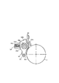
(感光体ドラムの支持及び駆動手段)
ドラムカップリング凸部37dは感光体ドラム7の一端に固定されたドラムフランジ37の先端に形成されている。図12は感光体ドラム7の支持方法及び駆動方法を示す。感光体ドラム7は中空円筒形のアルミ筒の外周に感光層を設けたドラム筒7aの一方端に駆動側ドラムフランジ37が嵌入固定され、他方端には非駆動側ドラムフランジ41が嵌入固定されている。これらのドラムフランジ37,41の中心に嵌入するドラム軸42の一端は現像フレーム12の端板部12iに設けたドラム貫通穴12bを挿通している。ドラム軸42の直径をわたる穴に圧入されたピン43は非駆動側ドラムフランジ41の中心穴から半径方向に向かって設けた溝41aに丁度嵌合している。ドラム軸42とドラム筒7aを電気的に導通させるための導電性ばね44が非駆動側ドラムフランジ41の内側端面に固定されている。この固定方法はドラムフランジ41に設けたダボ41bに導電性ばね44を嵌め込み、該ダボ41bを溶融固化することによっている。導電性ばね44の一端はドラム筒7a内周に弾力で圧接し、他端はドラム軸42に弾力で圧接している。
【0062】
現像フレーム12の端板部12iに取り付けたドラムアース接点101の一端がドラム軸42に弾力で接している。このドラムアース接点101は現像フレーム12に配設され他端はプロセスカートリッジBの外部の面に出て外部接点となっている。
【0063】
組立てのために、端板部12iのドラム貫通穴12bから半径方向に設けた溝12cはピン43が軸方向へ通りぬけることができる。
【0064】
駆動側ドラムフランジ37はドラム筒7aに嵌合する取付部37a、ドラム筒7a端に接するつば37b、つば37bから縮径したジャーナル部37c、ジャーナル部37cの端面中心部から軸方向へ凸部となったカップリング凸部37dの順で軸方向にこれらが配列してある。駆動側ドラムフランジ37はプラスチック一体成形品である。
【0065】
ジャーナル部37cは現像フレーム12の端板部12hの穴12dに嵌入する後部カバー17に一体に設けた軸支部17aにカラー56を介して回転自在に嵌合している。
【0066】
カップリング状の凸部37dは図13に示すように、ドラム軸42を中心とするねじれた正三角柱である。この三角柱の外接円径はジャーナル部37cよりも直径が小さい。
【0067】
装置本体14に設けた駆動装置は固設されたモータ45と、モータ45のモータ軸に固定したピニオン46と、ピニオン46及び大ギア48と噛合い回転自在に支持された中間ギア47と、大ギア48と、大ギア48に固定されると共に端部に芯決め部57を剛結した大ギア軸49と、大ギア軸49を支軸する軸受51と、カップリング凹軸52とを有する。
【0068】
軸受51は大ギア軸49を軸方向に移動しないように支持している。カップリング凹部52aはねじれた正三角柱となる穴を有し、カップリング凸部37dと軸方向に係脱される。カップリング凸部37dとカップリング凹部52aは嵌合時に、カップリング凸部37dのねじれた正三角柱の稜線がカップリング凹部52aのねじれた三角柱の面に接触することにより、カップリング凸部37dとカップリング凹部52aは調心されて回転中心が一致する。芯決め部57及びカップリング凹軸52は微小移動可能な周方向ガタが設けられ互に相対回転しないように結合されている。上記において、カップリング凹軸52はプロセスカートリッジB側へ最も移動した位置で位置を定められると共に、ばね力に抗して後退可能に支持されている(詳細な説明は省略する)。
【0069】
ドラム軸42の反駆動側の支持部分はドラム軸42が反駆動部側へ移動しない構成となっている。図に示すようにドラム軸42には軸用止め輪53が嵌入している。現像フレーム12の端板部12iに固定された前部カバー16に固定された軸受ケース54に収納された軸受55はドラム軸42に嵌入すると共に軸用止め輪53と軸受ケース54を軸方向の反対側で内外輪端面と接することによりドラム軸42の反駆動側への移動が止められている。一方感光体ドラム7はドラムフランジ37がジャーナル部37cに嵌入するカラー56を介して駆動側への移動を制限されている。上記構成で感光体ドラム7が軸方向に制限的に移動を許されるよう軸支部17aと軸受55間の距離は軸用止め輪53とカラー56の夫々軸支部17a、軸受55と対向する面間の距離よりも大きくしてある。
【0070】
このように駆動装置を構成してあるため、プロセスカートリッジBを画像形成装置本体14へ装着するとカートリッジフレーム(現像フレーム12、前部カバー16、後部カバー17)は装置本体14に対して長手方向の位置が定まる。そして、ドラム軸42の先端部分42aが芯決め部57の中心穴57aに嵌入すると共にカップリング凸部37dがカップリング凹部52aに嵌合する。そしてモータ45が回転すると、ピニオン46、中間ギア47、大ギア48が回転して大ギア軸49から芯決め部57を介してカップリング凹軸52が回転する。この回転によってカップリング凸部37dとカップリング凹部52aは互いにねじれた三角柱がねじ込み勝手となり、ドラムフランジ37とカップリング凹軸52は引き付け合うので、カップリング凸部37d先端がカップリング凹部52aの底面に接する。そこで位置決めされているカップリング凹軸52に対して、感光体ドラム7の軸方向位置が一定に定まる。
【0071】
そして、上記においてプロセスカートリッジBが装置本体14へ装着されてもカップリング凸部37dとカップリング凹部52aが嵌合しない場合には、カップリング凸部37dの端面がカップリング凹軸52の凹部52aの口部の縁を押してカップリング凹軸52をプロセスカートリッジBの方へ付勢している不図示のばね力に抗して後退させている。したがって、プロセスカートリッジBを装着後、前回転時にカップリング凸部37dと凹部52aの位相が合った時点で瞬時に嵌合する。なお、上述においてカップリング凸部37dの端面とカップリング凹部52aの底を当接しないで、ドラムフランジ37のつば37bをカラー56を介して後部カバー17の軸支部17aに向けてカップリングの引込み力で寄せるようにしてもよい。
【0072】
以上の実施の形態をまとめると共に補足すると次のとおりである。
【0073】
第1は、感光体ドラム1周囲に少なくとも1つ以上のプロセス手段を配設しこれらを一体的なカートリッジとし、これを着脱可能とした画像形成装置及びこれに用いられるプロセスカートリッジBにおいて、
前記画像形成装置本体14には、プロセスカートリッジ挿入方向両サイドに第1のガイドレール201a及び第2のガイドレール201bを具備し、
前記プロセスカートリッジBには前記ガイドレール201a,201bに対応する位置に第1のガイドリブ状のガイド部12a及び第2のガイドリブ状のガイド部29bが形成されており、
さらにこれらガイドレール201a,201b及びガイド部12a,29bの対を、異なる高さに形成した画像形成装置及びこれに用いられるプロセスカートリッジである。これによりプロセスカートリッジを前後逆に挿入しようとしてもこれを阻止することが可能となる。
【0074】
第2は、画像形成装置本体14に複数のプロセスカートリッジBY,BM,BC,BBを並列に着脱可能とした多色画像形成装置本体14及びこれに用いられるプロセスカートリッジにおいて、
前記画像形成装置本体14には、任意のプロセスカートリッジ挿入方向両サイドに第1のガイドレール201a,及び第2のガイドレール201bを具備し、前記任意のプロセスカートリッジBには前記ガイドレール201a,201bに対応する位置に第1のガイド部12a及び第2のガイド部29bが形成されており、
前記第1のガイドレール201a及びガイド部12aの対が前記第2のガイドレール201b及びガイド部29bの対と互いに重なり合わない高さに形成されている多色画像形成装置及びこれに用いられるプロセスカートリッジである。これにより、多色画像形成装置において前記第1に記載した効果を満足するだけでなく、隣り合うカートリッジのガイド部を上面から見たときに重なり合う関係に配置することが可能となる。
【0075】
実施の形態は多色画像形成装置に適用したが、これによってプロセスカートリッジ間を接近できるため装置本体を小さくできる。またプロセスカートリッジの前後を間違えることがない。また本発明は単色の画像形成装置に適用してプロセスカートリッジの前後を間違える誤装着を防止できる。
【0076】
実施の形態は中間転写体を有する多色電子写真画像形成装置についてのべたが、中間転写体を備えずプロセスカートリッジを並列して搬送手段で搬送される記録媒体に順次転写像を重ね合わせるようにした多色電子写真画像形成装置に対しても本発明は有効である。
【0077】
【発明の効果】
本発明によれば、プロセスカートリッジを装着する際に、プロセスカートリッジの前後を間違えるという誤装着を未然に防止することができる。また更に、本発明によれば、「第1のガイド部材」「第2のガイド部材」及び「第3のガイド部材」を有したうえで、隣接するプロセスカートリッジを接近させて装着することができるので、カラー電子写真画像形成装置を小型化することができる。
【0078】
さらに多色画像形成装置においては、隣り合うプロセスカートリッジのガイドレールを互いに重なり合わない高さにしたので、装置の小型化が可能となる。
【図面の簡単な説明】
【図1】電子写真画像形成装置の縦断面図である。
【図2】プロセスカートリッジの縦断面図である。
【図3】プロセスカートリッジの正面図である。
【図4】プロセスカートリッジの右側面図である。
【図5】プロセスカートリッジの左側面図である。
【図6】プロセスカートリッジの平面図である。
【図7】プロセスカートリッジの背面図である。
【図8】プロセスカートリッジを装置本体に装着した図である。
【図9】帯電ユニットの正面図である。
【図10】現像ユニットの側面図である。
【図11】現像スリーブの支持部を示す正面図である。
【図12】電子写真感光体ドラムの支持と駆動装置を示す縦断面図である。
【図13】駆動側ドラムフランジの斜視図である。
【符号の説明】
B(BY,BM,BC,BB)…プロセスカートリッジ
C…帯電ユニット
D…現像ユニット
SC…揺動中心
SLv…加圧中心
1Y,1M,1C,1BK…走査光学系
2…記録媒体
3a…給紙カセット 3b…ピックアップローラ 3c…リタードローラ対 3d,3f…搬送ローラ 3g…レジストローラ対 3h,3i…排出ローラ対
4…中間転写装置 4a…中間転写ベルト 4b…駆動ローラ 4c…従動ローラ 4d…二次転写対向ローラ 4Y,4M,4C,4BK…転写ローラ
5…定着器
6…トレー
7…感光体ドラム 7a…ドラム筒
8…磁気ブラン帯電器 8a…帯電ローラ 8a2…ジャーナル部 8b…マグネット 8c…規制ブレード 8n…スペーサコロ
10…現像手段 10a…現像容器 10c…マグネット 10d…現像スリーブ 10d1…ジャーナル部 10e…規制ブレード 10f…隔壁 10g,10h…撹拌スクリュー 10j…スペーサコロ
11…導電性ブラン
12…現像フレーム 12a…ガイド部 12b…ドラム貫通穴 12c…溝12d…穴 12g…側板 12h,12i…端板部 12p…ばね座 12n…ばね座
13…帯電フレーム
14…装置本体
16…前部カバー
17…後部カバー 17a…軸支部
23…端部カバー 23a…穴
24…ギアユニット
26…ギアケース 26a…円筒軸部
29…天板 29b…ガイド部
30…圧縮コイルばね
31…画像形成部 31Y,31M,31C,31BK…画像形成部
32…揺動アーム 32a…軸受穴 32b…ストッパ部 32c…ばね座
33…支持軸
35…圧縮コイルばね
36…現像スリーブカバー
37…ドラムフランジ 37a…取付部 37b…つば 37c…ジャーナル部 37d…カップリング凸部
38…帯電部カップリング
39…現像部カップリング
40…二次転写ローラ
41…非駆動側フランジ 41a…溝 41b…ダボ
42…ドラム軸 42a…先端部分
43…ピン
44…導電性ばね
45…モータ
46…ピニオン
47…中間ギア
48…大ギア
49…大ギア軸
51…軸受
52…カップリング凹軸 52a…カップリング凹部
53…軸用止め輪
54…軸受ケース
55…軸受
56…カラー
57…芯決め部
101…ドラムアース接点
102…導電性ブラシ接点
103…帯電バイアス接点
104…現像バイアス接点
105…I.C付コネクタ
201…ガイド部材
201a,201b…ガイドレール
201c…ウエブ
201d,201e…フランジ
201f…突出部[0001]
BACKGROUND OF THE INVENTION
The present inventionColor (multicolor)Electrophotographic image forming device (Hereinafter, simply referred to as an electrophotographic image forming apparatus or an image forming apparatus)And a process cartridge detachable from the main body.
[0002]
Here, the electrophotographic image forming apparatus is an object that forms an image on a recording medium using an electrophotographic image forming system. Examples of the electrophotographic image forming apparatus include an electrophotographic copying machine, an electrophotographic printer (for example, a laser beam printer, an LED printer, etc.), a facsimile machine, a word processor, and the like.
[0003]
The process cartridge is a cartridge in which a charging unit, a developing unit or a cleaning unit and an electrophotographic photosensitive drum are integrally formed, and the cartridge can be attached to and detached from the image forming apparatus main body. In addition, at least one of the charging unit, the developing unit, and the cleaning unit and the electrophotographic photosensitive drum are integrally formed into a cartridge that can be attached to and detached from the main body of the image forming apparatus. Further, it means that at least the charging means and the electrophotographic photosensitive drum are integrated into a cartridge so that it can be attached to and detached from the apparatus main body.
[0004]
[Prior art]
2. Description of the Related Art Conventionally, in an image forming apparatus using an electrophotographic image process, an electrophotographic photosensitive member and process means acting on the electrophotographic photosensitive member are integrally formed into a cartridge so that the cartridge can be attached to and detached from the image forming apparatus main body. A process cartridge system is adopted. According to this process cartridge system, the apparatus can be maintained by the user himself / herself without depending on the service person, so that the operability can be remarkably improved. Therefore, this process cartridge system is widely used in image forming apparatuses.
[0005]
Such a process cartridge includes a developing unit in which a developing frame incorporating a developing roller and a developing blade and a toner frame containing toner as a developer are integrated, a photosensitive drum, and a cleaning blade. An award-winning type in which the built-in cleaning frame is rotatably coupled is used.
[0006]
In a so-called cleanerless process cartridge, a charging frame in which a charging roller and a photosensitive drum are integrated as a unit is rotatably coupled to a developing frame.
[0007]
[Problems to be solved by the invention]
In order to mount the process cartridge on the image forming apparatus main body, guide rails for supporting the process cartridge are formed on both sides of the image forming apparatus main body in the process cartridge insertion direction, and the process cartridge has a position corresponding to the guide rail. Generally, it is easy to attach and detach by forming guide ribs.
[0008]
Further, in the multicolor image forming apparatus for obtaining a multicolor image by using a plurality of process cartridges of different colors and detachably mounting them in parallel to the image forming apparatus, the guide rail and the guide rib as described above are provided. In general, the process cartridge can be easily attached and detached.
[0009]
When taking such a form, if the guide rails on both sides have the same height, the process cartridge can be inserted backwards and forwards.
[0010]
Further, in the multicolor image forming apparatus, it is necessary to widen the interval between the process cartridges in order to avoid interference between the guide ribs of the adjacent process cartridges and the guide rails supporting the process cartridges, and it is difficult to reduce the size of the apparatus.
[0011]
According to the present invention, there is provided a process cartridge and an electrophotographic image forming apparatus in which a main body can be miniaturized in a multicolor image forming apparatus while preventing erroneous mounting when the process cartridge is mounted on the electrophotographic image forming apparatus. The purpose is to provide.
[0012]
[Means for Solving the Problems]
The main present invention will be described below with numbers corresponding to the claims.
[0013]
According to a first aspect of the present application, a plurality of process cartridges are arranged in a horizontal direction.IndividuallyIn a color electrophotographic image forming apparatus that is detachably mounted and forms a color image on a recording medium,
a. A first guide member having a first groove and a second groove, which are first and second grooves that are open in opposite directions, and are disposed so as to overlap in the vertical direction;
b. A second guide member having a first groove and a second groove which are open in the opposite directions and are arranged in the vertical direction;
c. A third guide member having a first groove and a second groove that are open in the opposite directions and are arranged in the vertical direction;
d. An electrophotographic photosensitive drum;
Process means acting on the electrophotographic photosensitive drum;
A first guided portion disposed on one end side in a direction crossing the mounting direction along the mounting direction in which the process cartridge is mounted on the apparatus main body of the electrophotographic image forming apparatus, and along the mounting direction A second guided portion disposed on the other end side in the direction crossing the mounting direction,In a state of being mounted on the apparatus main body,A second guided portion disposed at a different height from the first guided portion;
HaveAboveA plurality of process cartridges;
Have
When mounting one process cartridge of the plurality of process cartridges to the apparatus main body, the first guided portion of the one process cartridge is inserted into the first groove of the second guide member. And guiding the second guided portion of the one process cartridge along the second groove of the first guide member, and the other of the plurality of process cartridges. When mounting the one process cartridge to the apparatus main body, the first guided portion of the other process cartridge is guided along the first groove of the third guide member, The second guided member of the second guide member has the second guided portion of the other one process cartridge. Is a color electrophotographic image forming apparatus characterized by being configured to guide along.
[0016]
According to a second aspect of the present application, there is provided a first electrophotographic photosensitive drum, process means acting on the electrophotographic photosensitive drum, and a first arrangement disposed on one end side along a mounting direction of mounting on the apparatus main body. And a second guided portion disposed on the other end side along the mounting direction, and the first guided portion in a state of being mounted on the apparatus main body. A color electrophotographic image for forming a color image on a recording medium by mounting a plurality of process cartridges having second guided portions arranged at different heights in a horizontal direction so as to be individually removable. A forming device,
A first guide member having a first groove and a second groove, which are first and second grooves that are open in opposite directions, and are disposed so as to overlap in the vertical direction;
A second guide member having a first groove and a second groove which are open in the opposite directions and are arranged in the vertical direction;
A third guide member having a first groove and a second groove that are open in the opposite directions and are arranged in the vertical direction;
HaveAnd
The first guided portion is guided along the first groove of the third guide member, and the second guided portion of the second guide member is guided by the second groove. Of the plurality of process cartridges detachably mounted on the apparatus main body of the color electrophotographic image forming apparatus to which one process cartridge of the plurality of process cartridges is mounted. Another process cartridge of
In mounting on the device body,Another oneGuiding the first guided portion of the process cartridge along the first groove of the second guide member;Another oneA process cartridge configured to guide the second guided portion of the process cartridge along the second groove of the first guide member.
[0017]
DETAILED DESCRIPTION OF THE INVENTION
Embodiments of the present invention will be described below with reference to the drawings.
[0018]
In the following description, the longitudinal direction refers to a direction that intersects the recording medium conveyance direction and is parallel to the recording medium. The left and right are the left and right when the recording medium is transported from above. Further, the top of the process cartridge means the top of the process cartridge in the mounted state.
[0019]
FIG. 1 shows an image forming apparatus to which the present invention is applied. This image forming apparatus includes
[0020]
Image formation will be described below.
[0021]
As shown in FIG. 1, a
[0022]
When the
[0023]
In the case of the four-drum full-color system, the process cartridges BY, BM, BC, and BB including the image carrier are arranged in parallel as shown in the drawing, yellow, magenta, cyan, and black. For each of the process cartridges BY, BM, BC, and BB,
[0024]
Thereafter, the
[0025]
The
[0026]
As shown in FIG. 2, the process cartridge BY is provided with a charging unit, an exposure unit, a developing unit, and a transfer opening around the
[0027]
Therefore, in this embodiment, the
[0028]
The charging means is a
[0029]
The
[0030]
In the present embodiment, the developing means employs a method of developing with a two-component developer in contact (two-component non-contact development).
[0031]
FIG. 2 shows the developing means 10 for developing the two-component magnetic brush used in the present embodiment. The developing
[0032]
The toner mixed with the carrier is supplied by stirring
[0033]
Here, the developing process for developing the electrostatic latent image formed on the
[0034]
First, the developer pumped up by the pole of the
[0035]
A DC voltage and an AC voltage are applied to the developing
[0036]
This toner image is then transferred by an
[0037]
As the
[0038]
Transfer residual toner remains on the surface of the
[0039]
(Process cartridge frame configuration)
The process cartridge B (BY, BM, BC, BB) includes a developing unit D in which the electrophotographic
[0040]
3 to 7 are projection views of the process cartridge B (BY, BM, BC, BB). 3 is a front view, FIG. 4 is a right side view, FIG. 5 is a left side view, FIG. 6 is a plan view, and FIG. 7 is a rear view.
[0041]
As shown in FIG. 2, in the charging unit C, a charging
[0042]
The charging unit C is supported by the developing
[0043]
As shown in FIG. 2, at the upper part of the developing
[0044]
As shown in FIG. 2, the developing
[0045]
As shown in FIG. 9, a
[0046]
In the above, the line connecting the swing center SC and the center of the charging
[0047]
As shown in FIG. 2, the developing
[0048]
FIG. 11 is a cross-sectional view perpendicular to the developing
[0049]
Journal portions 10d1 at both ends of the developing
[0050]
The
[0051]
(Configuration for attaching / detaching process cartridge to / from image forming apparatus main body)
As shown in FIG. 2, flange-shaped
[0052]
Here, the
[0053]
Since it is configured in this manner, even if the process cartridge B is inserted in the
[0054]
As shown in FIG. 8, the
[0055]
Each
[0056]
In the above, the
[0057]
When the process cartridge B is mounted on the apparatus
[0058]
As shown in FIG. 3, a
[0059]
Three driving force receiving portions that are shaft couplings that rotate about a longitudinal axis are provided on the end face on the back side when viewed from the mounting direction of the process cartridge B. When the process cartridge B is mounted on the apparatus
[0060]
As shown in FIG. 7, a drum coupling
[0061]
(Supporting and driving means for photosensitive drum)
The
[0062]
One end of the
[0063]
For assembly, the
[0064]
The drive-
[0065]
The journal portion 37 c is rotatably fitted via a
[0066]
As shown in FIG. 13, the coupling-shaped
[0067]
The drive unit provided in the apparatus
[0068]
The
[0069]
The support portion on the counter drive side of the
[0070]
Since the drive device is configured as described above, when the process cartridge B is mounted on the image forming apparatus
[0071]
If the coupling
[0072]
The above embodiment is summarized and supplemented as follows.
[0073]
First, in an image forming apparatus and a process cartridge B used for the image forming apparatus in which at least one process means is disposed around the photosensitive drum 1 and these are integrated into an integral cartridge.
The image forming apparatus
In the process cartridge B, a first guide rib-shaped
Further, an image forming apparatus in which pairs of the
[0074]
Secondly, in the multi-color image forming apparatus
The image forming apparatus
A multicolor image forming apparatus in which the pair of the
[0075]
Although the embodiment is applied to a multicolor image forming apparatus, the process cartridges can be approached by this, so that the apparatus main body can be made small. Also, there is no mistake in the front and rear of the process cartridge. In addition, the present invention can be applied to a single color image forming apparatus to prevent erroneous mounting of the process cartridge in the wrong direction.
[0076]
In the embodiment, the multicolor electrophotographic image forming apparatus having the intermediate transfer member is described. However, the transfer image is sequentially superimposed on the recording medium which is not provided with the intermediate transfer member and is conveyed by the conveying means in parallel with the process cartridge. The present invention is also effective for the multicolor electrophotographic image forming apparatus.
[0077]
【The invention's effect】
According to the present invention, when the process cartridge is mounted, it is possible to prevent an erroneous mounting such that the front and rear of the process cartridge are mistaken. Furthermore, according to the present invention, it is possible to mount the adjacent process cartridges close to each other while having the “first guide member”, “second guide member”, and “third guide member”. Therefore, the color electrophotographic image forming apparatus can be reduced in size.
[0078]
Further, in the multicolor image forming apparatus, the guide rails of the adjacent process cartridges are set so as not to overlap each other, so that the apparatus can be miniaturized.
[Brief description of the drawings]
FIG. 1 is a longitudinal sectional view of an electrophotographic image forming apparatus.
FIG. 2 is a longitudinal sectional view of a process cartridge.
FIG. 3 is a front view of a process cartridge.
FIG. 4 is a right side view of the process cartridge.
FIG. 5 is a left side view of the process cartridge.
FIG. 6 is a plan view of a process cartridge.
FIG. 7 is a rear view of the process cartridge.
FIG. 8 is a diagram in which a process cartridge is mounted on the apparatus main body.
FIG. 9 is a front view of the charging unit.
FIG. 10 is a side view of the developing unit.
FIG. 11 is a front view showing a support portion of the developing sleeve.
FIG. 12 is a longitudinal sectional view showing a support and driving device for an electrophotographic photosensitive drum.
FIG. 13 is a perspective view of a drive side drum flange.
[Explanation of symbols]
B (BY, BM, BC, BB) ... Process cartridge
C ... Charging unit
D ... Developing unit
SC ... Oscillation center
SLv ... Pressure center
1Y, 1M, 1C, 1BK ... Scanning optical system
2. Recording medium
3a:
4 ...
5 ... Fixer
6 ... Tray
7 ...
8 ...
DESCRIPTION OF
11 ... Conductive bran
DESCRIPTION OF
13 ... Charging frame
14 ... Main unit
16 ... Front cover
17 ...
23 ...
24 ... Gear unit
26 ...
29 ...
30 ... Compression coil spring
31 ...
32 ...
33 ... Support shaft
35 ... Compression coil spring
36 ... Developing sleeve cover
37 ...
38 ... Charging part coupling
39. Development unit coupling
40. Secondary transfer roller
41 ...
42 ... drum
43 ... pin
44 ... Conductive spring
45 ... Motor
46 ... pinion
47 ... Intermediate gear
48 ... Large gear
49 ... Large gear shaft
51 ... Bearing
52 ... Coupling
53 ... Retaining ring for shaft
54 ... Bearing case
55 ... Bearing
56 ... Color
57 ... Centering part
101 ... Drum ground contact
102 ... Conductive brush contact
103: Charging bias contact
104: Development bias contact
105 ... I. Connector with C
201 ... Guide member
201a, 201b ... guide rail
201c ... Web
201d, 201e ... flange
201f ... protrusion
Claims (2)
a.互いに反対方向に向かって開口している第1の溝と第2の溝であって、上下方向に重なって配置されている第1の溝と第2の溝を有する第1のガイド部材と、
b.互いに反対方向に向かって開口している第1の溝と第2の溝であって、上下方向に重なって配置されている第1の溝と第2の溝を有する第2のガイド部材と、
c.互いに反対方向に向かって開口している第1の溝と第2の溝であって、上下方向に重なって配置されている第1の溝と第2の溝を有する第3のガイド部材と、
d.電子写真感光体ドラムと、
前記電子写真感光体ドラムに作用するプロセス手段と、
前記プロセスカートリッジを前記電子写真画像形成装置の装置本体に装着する装着方向に沿って、前記装着方向と交叉する方向の一端側に配置されている第1の被ガイド部と、前記装着方向に沿って、前記装着方向と交叉する方向の他端側に配置されている第2の被ガイド部であって、前記装置本体に装着された状態で、前記第1の被ガイド部とは異なった高さに配置されている第2の被ガイド部と、
を有する前記複数個のプロセスカートリッジと、
を有し、
前記複数個のプロセスカートリッジの内1つのプロセスカートリッジを前記装置本体に装着するにあたって、前記1つのプロセスカートリッジの有する前記第1の被ガイド部を前記第2のガイド部材の有する前記第1の溝に沿ってガイドし、前記1つのプロセスカートリッジの有する前記第2の被ガイド部を前記第1のガイド部材の有する前記第2の溝に沿ってガイドし、及び、前記複数個のプロセスカートリッジの内他の1つのプロセスカートリッジを前記装置本体に装着するにあたって、前記他の1つのプロセスカートリッジの有する前記第1の被ガイド部を前記第3のガイド部材の有する前記第1の溝に沿ってガイドし、前記他の1つのプロセスカートリッジの有する前記第2の被ガイド部を前記第2のガイド部材の有する前記第2の溝に沿ってガイドするように構成したことを特徴とするカラー電子写真画像形成装置。In a color electrophotographic image forming apparatus for forming a color image on a recording medium by mounting a plurality of process cartridges in a horizontal direction and detachably mounting them,
a. A first guide member having a first groove and a second groove, which are first and second grooves that are open in opposite directions, and are disposed so as to overlap in the vertical direction;
b. A second guide member having a first groove and a second groove which are open in the opposite directions and are arranged in the vertical direction;
c. A third guide member having a first groove and a second groove that are open in the opposite directions and are arranged in the vertical direction;
d. An electrophotographic photosensitive drum;
Process means acting on the electrophotographic photosensitive drum;
A first guided portion disposed on one end side in a direction crossing the mounting direction along the mounting direction in which the process cartridge is mounted on the apparatus main body of the electrophotographic image forming apparatus, and along the mounting direction A second guided portion disposed on the other end side in a direction crossing the mounting direction, wherein the second guided portion has a height different from that of the first guided portion when mounted on the apparatus main body. A second guided portion disposed on the side;
A plurality of process cartridges having:
Have
When mounting one process cartridge of the plurality of process cartridges to the apparatus main body, the first guided portion of the one process cartridge is formed in the first groove of the second guide member. And guiding the second guided portion of the one process cartridge along the second groove of the first guide member, and the other of the plurality of process cartridges. When mounting the one process cartridge to the apparatus main body, the first guided portion of the other process cartridge is guided along the first groove of the third guide member, The second guided member has the second guided portion of the other one process cartridge. Color electrophotographic image forming apparatus characterized by being configured to guide along.
互いに反対方向に向かって開口している第1の溝と第2の溝であって、上下方向に重なって配置されている第1の溝と第2の溝を有する第1のガイド部材と、
互いに反対方向に向かって開口している第1の溝と第2の溝であって、上下方向に重なって配置されている第1の溝と第2の溝を有する第2のガイド部材と、
互いに反対方向に向かって開口している第1の溝と第2の溝であって、上下方向に重なって配置されている第1の溝と第2の溝を有する第3のガイド部材と、
を有し、
前記第1の被ガイド部を、前記第3のガイド部材の有する前記第1の溝に沿ってガイドし、前記第2の被ガイド部を、前記第2のガイド部材の有する前記第2の溝に沿ってガイドすることで、前記複数個のプロセスカートリッジの内の1つのプロセスカートリッジが装着されたカラー電子写真画像形成装置の前記装置本体に取り外し可能に装着される前記複数個のプロセスカートリッジの内の別の1つのプロセスカートリッジであって、
前記装置本体に装着するにあたって、前記別の1つのプロセスカートリッジの有する前記第1の被ガイド部を前記第2のガイド部材の有する前記第1の溝に沿ってガイドし、前記別の1つのプロセスカートリッジの有する前記第2の被ガイド部を前記第1のガイド部材の有する前記第2の溝に沿ってガイドするように構成したことを特徴とするプロセスカートリッジ。 An electrophotographic photosensitive drum; process means acting on the electrophotographic photosensitive drum; a first guided portion disposed on one end side along a mounting direction of mounting on the apparatus main body; and And a second guided portion disposed on the other end side, the second guided portion being disposed at a height different from that of the first guided portion when mounted on the apparatus main body. A color electrophotographic image forming apparatus for forming a color image on a recording medium by horizontally detaching and mounting a plurality of process cartridges having two guided portions ;
A first guide member having a first groove and a second groove, which are first and second grooves that are open in opposite directions, and are disposed so as to overlap in the vertical direction;
A second guide member having a first groove and a second groove which are open in the opposite directions and are arranged in the vertical direction;
A third guide member having a first groove and a second groove that are open in the opposite directions and are arranged in the vertical direction;
I have a,
The first guided portion is guided along the first groove of the third guide member, and the second guided portion of the second guide member is guided by the second groove. Of the plurality of process cartridges detachably mounted on the apparatus main body of the color electrophotographic image forming apparatus to which one process cartridge of the plurality of process cartridges is mounted. Another process cartridge of
When mounting to the apparatus main body, the first guided portion of the other one process cartridge is guided along the first groove of the second guide member, and the other one process is performed. A process cartridge configured to guide the second guided portion of the cartridge along the second groove of the first guide member.
Priority Applications (3)
| Application Number | Priority Date | Filing Date | Title |
|---|---|---|---|
| JP2000037826A JP4250294B2 (en) | 2000-02-16 | 2000-02-16 | Color electrophotographic image forming apparatus and process cartridge |
| US09/782,280 US6463233B2 (en) | 2000-02-16 | 2001-02-14 | Process cartridge having first and second cartridge guiding portions and an electrophotographic image forming apparatus to which the process cartridge is attached |
| EP01301388A EP1126332B1 (en) | 2000-02-16 | 2001-02-16 | Process cartridge and image forming apparatus |
Applications Claiming Priority (1)
| Application Number | Priority Date | Filing Date | Title |
|---|---|---|---|
| JP2000037826A JP4250294B2 (en) | 2000-02-16 | 2000-02-16 | Color electrophotographic image forming apparatus and process cartridge |
Publications (3)
| Publication Number | Publication Date |
|---|---|
| JP2001228781A JP2001228781A (en) | 2001-08-24 |
| JP2001228781A5 JP2001228781A5 (en) | 2006-01-05 |
| JP4250294B2 true JP4250294B2 (en) | 2009-04-08 |
Family
ID=18561658
Family Applications (1)
| Application Number | Title | Priority Date | Filing Date |
|---|---|---|---|
| JP2000037826A Expired - Fee Related JP4250294B2 (en) | 2000-02-16 | 2000-02-16 | Color electrophotographic image forming apparatus and process cartridge |
Country Status (3)
| Country | Link |
|---|---|
| US (1) | US6463233B2 (en) |
| EP (1) | EP1126332B1 (en) |
| JP (1) | JP4250294B2 (en) |
Families Citing this family (56)
| Publication number | Priority date | Publication date | Assignee | Title |
|---|---|---|---|---|
| JP2003162203A (en) * | 2001-09-13 | 2003-06-06 | Canon Inc | Unit, developing cartridge, process cartridge, toner cartridge, and electrophotographic image forming device |
| JP2003084534A (en) * | 2001-09-13 | 2003-03-19 | Canon Inc | Developing cartridge, process cartridge, toner cartridge, and electrophotographic image forming apparatus |
| JP3890227B2 (en) * | 2001-12-21 | 2007-03-07 | キヤノン株式会社 | Process means moving mechanism, charging device, process cartridge, and electrophotographic image forming apparatus |
| JP2003215917A (en) | 2002-01-24 | 2003-07-30 | Canon Inc | Developing device, process cartridge and image forming apparatus |
| JP4072362B2 (en) | 2002-03-14 | 2008-04-09 | キヤノン株式会社 | Developing device, process cartridge, and image forming apparatus |
| US6978100B2 (en) * | 2002-09-30 | 2005-12-20 | Canon Kabushiki Kaisha | Process cartridge, developing cartridge and developing roller |
| US6980755B2 (en) * | 2002-09-30 | 2005-12-27 | Canon Kabushiki Kaisha | Recycling method for developer supplying unit including the step of driving a feeding member in a direction to feed developer from a developer supply port to a developer accommodating portion |
| JP4314006B2 (en) * | 2002-09-30 | 2009-08-12 | キヤノン株式会社 | Image forming apparatus |
| JP3809412B2 (en) * | 2002-09-30 | 2006-08-16 | キヤノン株式会社 | Developing cartridge and electrophotographic image forming apparatus |
| JP3913153B2 (en) * | 2002-09-30 | 2007-05-09 | キヤノン株式会社 | Power supply contact member, process cartridge, and image forming apparatus |
| JP3720802B2 (en) | 2002-11-06 | 2005-11-30 | キヤノン株式会社 | Process cartridge remanufacturing method |
| JP3747195B2 (en) * | 2002-11-20 | 2006-02-22 | キヤノン株式会社 | Process cartridge and electrophotographic image forming apparatus |
| US6801733B2 (en) * | 2003-01-21 | 2004-10-05 | Static Control Components, Inc. | Printer cartridge and method of making or refurbishing |
| EP1452931A1 (en) * | 2003-02-28 | 2004-09-01 | Ricoh Company, Ltd. | Image forming apparatus using installable process cartridge |
| JP3970217B2 (en) * | 2003-08-29 | 2007-09-05 | キヤノン株式会社 | Electrophotographic image forming apparatus |
| JP4378221B2 (en) * | 2003-10-08 | 2009-12-02 | キヤノン株式会社 | Process cartridge and electrophotographic image forming apparatus |
| JP3673795B2 (en) * | 2003-10-24 | 2005-07-20 | キヤノン株式会社 | Developing device, process cartridge, and image forming apparatus |
| JP3782807B2 (en) * | 2003-11-28 | 2006-06-07 | キヤノン株式会社 | Process cartridge and method for attaching electrophotographic photosensitive drum |
| JP4086766B2 (en) * | 2003-11-28 | 2008-05-14 | キヤノン株式会社 | Process cartridge and process cartridge assembling method |
| JP3885062B2 (en) * | 2004-03-30 | 2007-02-21 | キヤノン株式会社 | Electrophotographic photosensitive drum, process cartridge, and electrophotographic image forming apparatus |
| US7158749B2 (en) * | 2004-04-26 | 2007-01-02 | Canon Kabushiki Kaisha | Cleaning device, process cartridge, cleaning member and electrophotographic image forming apparatus |
| JP3885074B2 (en) * | 2004-05-11 | 2007-02-21 | キヤノン株式会社 | Electrophotographic photosensitive drum, process cartridge, and electrophotographic image forming apparatus |
| JP4498076B2 (en) * | 2004-09-07 | 2010-07-07 | キヤノン株式会社 | Image forming apparatus |
| JP3950882B2 (en) * | 2004-10-06 | 2007-08-01 | キヤノン株式会社 | Electrophotographic image forming apparatus |
| JP3950883B2 (en) * | 2004-10-06 | 2007-08-01 | キヤノン株式会社 | Electrophotographic image forming apparatus |
| JP4664656B2 (en) * | 2004-11-30 | 2011-04-06 | 京セラミタ株式会社 | Image forming apparatus |
| JP4280770B2 (en) | 2006-01-11 | 2009-06-17 | キヤノン株式会社 | Process cartridge and electrophotographic image forming apparatus |
| JP4667444B2 (en) | 2006-12-13 | 2011-04-13 | キヤノン株式会社 | Electrophotographic image forming apparatus |
| JP4095649B1 (en) | 2006-12-28 | 2008-06-04 | キヤノン株式会社 | Electrophotographic image forming apparatus, process cartridge, and moving member |
| JP4458377B2 (en) | 2007-06-29 | 2010-04-28 | キヤノン株式会社 | Process cartridge and electrophotographic image forming apparatus |
| JP4458378B2 (en) | 2007-06-29 | 2010-04-28 | キヤノン株式会社 | Process cartridge and electrophotographic image forming apparatus |
| JP4645646B2 (en) * | 2007-12-28 | 2011-03-09 | ブラザー工業株式会社 | Image forming apparatus |
| JP4968957B2 (en) | 2008-03-31 | 2012-07-04 | キヤノン株式会社 | Frame body unit, developing device and process cartridge, and frame body unit, developing device and process cartridge manufacturing method |
| JP4569978B1 (en) * | 2009-03-23 | 2010-10-27 | キヤノン株式会社 | Color electrophotographic image forming apparatus |
| JP4905567B2 (en) * | 2010-02-23 | 2012-03-28 | ブラザー工業株式会社 | Developing cartridge and image forming apparatus |
| JP5106656B2 (en) | 2010-06-22 | 2012-12-26 | キヤノン株式会社 | Process cartridge and image forming apparatus |
| JP4846062B1 (en) | 2010-08-20 | 2011-12-28 | キヤノン株式会社 | Cartridge and image forming apparatus |
| CN107678261B (en) | 2011-11-09 | 2020-10-23 | 佳能株式会社 | Cartridge and image forming apparatus |
| JP2013122489A (en) | 2011-11-09 | 2013-06-20 | Canon Inc | Cartridge and unit |
| US8867966B2 (en) * | 2011-12-30 | 2014-10-21 | Lexmark International, Inc. | Toner cartridge for use in an image forming device |
| US8867970B2 (en) | 2011-12-30 | 2014-10-21 | Lexmark International, Inc. | Toner cartridges having positional control features |
| JP6071248B2 (en) * | 2012-05-22 | 2017-02-01 | キヤノン株式会社 | Electrophotographic image forming apparatus |
| US8879953B2 (en) | 2012-06-25 | 2014-11-04 | Lexmark International, Inc. | Retainer assembly having positioning features for processing circuitry used within an image forming device supply item |
| JP5496282B2 (en) * | 2012-08-01 | 2014-05-21 | シャープ株式会社 | Unit assembly and image forming apparatus |
| JP5496281B2 (en) * | 2012-08-01 | 2014-05-21 | シャープ株式会社 | Unit assembly and image forming apparatus |
| JP5496283B2 (en) * | 2012-08-01 | 2014-05-21 | シャープ株式会社 | Unit assembly and image forming apparatus |
| JP6057651B2 (en) | 2012-10-01 | 2017-01-11 | キヤノン株式会社 | Process cartridge and process cartridge manufacturing method |
| USD736309S1 (en) * | 2013-07-25 | 2015-08-11 | Samsung Electronics Co., Ltd. | Toner cartridge for copy machine |
| USD736851S1 (en) * | 2013-07-25 | 2015-08-18 | Samsung Electronics Co., Ltd. | Toner cartridge for copy machine |
| JP6544982B2 (en) * | 2014-05-29 | 2019-07-17 | キヤノン株式会社 | Image forming device |
| BR112019004673B1 (en) | 2016-09-30 | 2023-12-26 | Canon Kabushiki Kaisha | TONER CARTRIDGE AND TONER SUPPLY MECHANISM |
| WO2018062571A1 (en) | 2016-09-30 | 2018-04-05 | キヤノン株式会社 | Toner cartridge and toner supply mechanism |
| US9989917B1 (en) * | 2017-05-17 | 2018-06-05 | Lexmark International, Inc. | Toner cartridge with positional control features |
| USD936137S1 (en) * | 2019-04-17 | 2021-11-16 | Lexmark International, Inc. | Toner cartridge |
| USD941389S1 (en) * | 2019-04-17 | 2022-01-18 | Lexmark International, Inc. | Toner cartridge |
| USD934340S1 (en) * | 2020-01-21 | 2021-10-26 | Lexmark International, Inc. | Toner cartridge |
Family Cites Families (44)
| Publication number | Priority date | Publication date | Assignee | Title |
|---|---|---|---|---|
| JP2754627B2 (en) * | 1988-12-09 | 1998-05-20 | 富士ゼロックス株式会社 | Developing machine mounting device |
| US5471284A (en) | 1990-01-19 | 1995-11-28 | Canon Kabushiki Kaisha | Image forming apparatus having toner depletion detection feature |
| US5235383A (en) | 1990-08-31 | 1993-08-10 | Canon Kabushiki Kaisha | Process cartridge and image forming apparatus using same |
| US5442421A (en) | 1990-10-01 | 1995-08-15 | Canon Kabushiki Kaisha | Process cartridge and image forming apparatus using the same |
| US5521693A (en) | 1991-05-14 | 1996-05-28 | Canon Kabushiki Kaisha | Image forming apparatus and process cartridge detachably mountable to same |
| US5249026A (en) | 1991-05-17 | 1993-09-28 | Canon Kabushiki Kaisha | Image forming system and process cartridge mountable on same |
| JP3278198B2 (en) | 1991-06-28 | 2002-04-30 | キヤノン株式会社 | Process cartridge and image forming apparatus to which the process cartridge can be attached and detached |
| JP3005114B2 (en) | 1991-07-19 | 2000-01-31 | キヤノン株式会社 | Cleaning device, process cartridge provided with the cleaning device, and image forming apparatus |
| US5585895A (en) | 1991-12-19 | 1996-12-17 | Canon Kabushiki Kaisha | Developing device and process cartridge with it |
| US5283616A (en) | 1991-12-19 | 1994-02-01 | Canon Kabushiki Kaisha | Developing device having bearing for supporting a developing roller |
| US5331373A (en) | 1992-03-13 | 1994-07-19 | Canon Kabushiki Kaisha | Image forming apparatus, process cartridge mountable within it and method for attaching photosensitive drum to process cartridge |
| JP3352155B2 (en) | 1992-06-30 | 2002-12-03 | キヤノン株式会社 | Process cartridge and image forming apparatus |
| EP0586044B1 (en) | 1992-09-04 | 1997-03-26 | Canon Kabushiki Kaisha | Process cartridge, method for assembling process cartridge and image forming apparatus |
| JP3259985B2 (en) | 1992-09-04 | 2002-02-25 | キヤノン株式会社 | Process cartridge and image forming apparatus |
| MX9303563A (en) | 1992-09-04 | 1994-03-31 | Canon Kk | PROCESS CARTRIDGE, METHOD FOR ASSEMBLING A PROCESS CARTRIDGE AND IMAGE FORMING DEVICE. |
| ES2201068T3 (en) | 1993-02-24 | 2004-03-16 | Canon Kabushiki Kaisha | DISCLOSURE CARTRIDGE THAT HAS A SUPPORT ELEMENT TO SUPPORT THE REVELATE DEVICE AND REVELATE DEVICE WITH A ROTATING CAPACITY. |
| US5966566A (en) | 1993-03-24 | 1999-10-12 | Canon Kabushiki Kaisha | Recycle method for process cartridge and image forming apparatus |
| JP3337859B2 (en) | 1994-04-26 | 2002-10-28 | キヤノン株式会社 | Process cartridge and image forming apparatus |
| JP2877728B2 (en) * | 1994-04-28 | 1999-03-31 | キヤノン株式会社 | Process cartridge and image forming apparatus |
| JP3235342B2 (en) * | 1994-05-16 | 2001-12-04 | 富士ゼロックス株式会社 | Multicolor image forming device |
| JP3267465B2 (en) | 1994-06-24 | 2002-03-18 | キヤノン株式会社 | Process cartridge and image forming apparatus |
| JP3471950B2 (en) | 1995-02-02 | 2003-12-02 | キヤノン株式会社 | Process cartridge and image forming apparatus |
| CN1093946C (en) | 1995-07-21 | 2002-11-06 | 佳能株式会社 | Electrod assembly, developing device, processing card box and imaging equipment |
| JP3359245B2 (en) | 1995-10-25 | 2002-12-24 | キヤノン株式会社 | Process cartridge and electrophotographic image forming apparatus |
| JPH09213407A (en) | 1996-01-31 | 1997-08-15 | Canon Inc | Connector, unit, process cartridge and electrophotographic image forming device |
| JP3372747B2 (en) | 1996-02-09 | 2003-02-04 | キヤノン株式会社 | Developing device |
| US5940657A (en) | 1996-03-05 | 1999-08-17 | Canon Kabushiki Kaisha | Developing cartridge |
| US6072969A (en) | 1996-03-05 | 2000-06-06 | Canon Kabushiki Kaisha | Developing cartridge |
| JP3337915B2 (en) | 1996-07-04 | 2002-10-28 | キヤノン株式会社 | Process cartridge, method of assembling process cartridge, and image forming apparatus |
| JP3397590B2 (en) | 1996-07-04 | 2003-04-14 | キヤノン株式会社 | Process cartridge assembling method, process cartridge, and electrophotographic image forming apparatus |
| JP3311250B2 (en) | 1996-07-31 | 2002-08-05 | キヤノン株式会社 | Process cartridge and image forming apparatus |
| JP3969805B2 (en) | 1996-09-26 | 2007-09-05 | キヤノン株式会社 | Electrophotographic image forming apparatus |
| JP3969804B2 (en) | 1996-09-26 | 2007-09-05 | キヤノン株式会社 | Electrophotographic image forming apparatus |
| JPH10153938A (en) | 1996-09-26 | 1998-06-09 | Canon Inc | Electrophotographic image forming device and process cartridge |
| JP3382474B2 (en) | 1996-09-30 | 2003-03-04 | キヤノン株式会社 | Process cartridge, electrophotographic image forming apparatus, and method of incorporating cleaning roller |
| JP3352370B2 (en) | 1996-11-14 | 2002-12-03 | キヤノン株式会社 | Process cartridge and electrophotographic image forming apparatus |
| JP3327801B2 (en) | 1996-12-25 | 2002-09-24 | キヤノン株式会社 | Process cartridge, process cartridge assembling method, toner container assembling method, and electrophotographic image forming apparatus |
| JPH10222043A (en) | 1997-02-03 | 1998-08-21 | Canon Inc | Process cartridge and electrophotographic image forming device |
| JPH1184883A (en) * | 1997-09-05 | 1999-03-30 | Ricoh Co Ltd | Image forming device |
| JP3472108B2 (en) | 1997-10-01 | 2003-12-02 | キヤノン株式会社 | Process cartridge and electrophotographic image forming apparatus |
| JP3466888B2 (en) | 1997-10-01 | 2003-11-17 | キヤノン株式会社 | Process cartridge and electrophotographic image forming apparatus |
| JP3437424B2 (en) | 1997-10-27 | 2003-08-18 | キヤノン株式会社 | Developing device, process cartridge, and electrophotographic image forming device |
| US6157792A (en) | 1998-03-31 | 2000-12-05 | Canon Kabushiki Kaisha | Electrophotographic apparatus having plural image forming modes, and a process cartridge applied to such electrophotographic apparatus |
| JP3554200B2 (en) | 1998-08-31 | 2004-08-18 | キヤノン株式会社 | Process cartridge, image forming apparatus, and cleaning member mounting method |
-
2000
- 2000-02-16 JP JP2000037826A patent/JP4250294B2/en not_active Expired - Fee Related
-
2001
- 2001-02-14 US US09/782,280 patent/US6463233B2/en not_active Expired - Lifetime
- 2001-02-16 EP EP01301388A patent/EP1126332B1/en not_active Expired - Lifetime
Also Published As
| Publication number | Publication date |
|---|---|
| EP1126332B1 (en) | 2011-05-25 |
| EP1126332A2 (en) | 2001-08-22 |
| EP1126332A3 (en) | 2005-08-03 |
| US20010028811A1 (en) | 2001-10-11 |
| US6463233B2 (en) | 2002-10-08 |
| JP2001228781A (en) | 2001-08-24 |
Similar Documents
| Publication | Publication Date | Title |
|---|---|---|
| JP4250294B2 (en) | Color electrophotographic image forming apparatus and process cartridge | |
| JP3768706B2 (en) | Electrophotographic image forming apparatus | |
| JP3679645B2 (en) | Process cartridge | |
| JP3478797B2 (en) | Process cartridge and electrophotographic image forming apparatus | |
| JP3679665B2 (en) | Gap assurance member, developing device, charging device, and process cartridge | |
| JP2000194248A (en) | Process cartridge, electrifying unit and developing unit | |
| US6587660B2 (en) | Developing apparatus | |
| EP1081560B1 (en) | Developing device, process cartridge and electrophotographic image forming apparatus | |
| US20090180801A1 (en) | Electrophotographic photoreceptor, photoreceptor supporting device, imaging device and process cartridge | |
| JP2001066871A (en) | Developing device, process cartridge and electrophotographic image forming device | |
| US6522845B2 (en) | Image forming apparatus and image forming unit detachably attachable thereto | |
| JP2003005475A (en) | Driving transmitting coupling, electrophotographic photoreceptor drum, process cartridge and electrophotographic image forming device | |
| JP2003186303A (en) | Gap-assuring member, developing device using the gap- assuring member, charging device and process cartridge detachable from image-forming apparatus | |
| JP2000275933A (en) | Process cartridge and electrophotographic image forming device | |
| JP2001350320A (en) | Electrifying unit attaching method, electrifying unit exchanging method, process cartridge and electrophotographic image forming device | |
| JP2000275967A (en) | Process cartridge and electrophotographic image forming device | |
| JP2002341728A (en) | Process cartridge and image forming device | |
| JP2002182541A (en) | Protection member, process cartridge, and image forming apparatus | |
| JP2001092334A (en) | Process cartridge and electrophotographic image forming device equipped with the same | |
| JP2000276030A (en) | Process cartridge and electrophotographic image forming device | |
| JP2002072647A (en) | Developing means, process cartridge and electrophotographic image forming device | |
| JP2000276032A (en) | Process cartridge and electrophotographic image forming device | |
| JP2001222157A (en) | Shutter member and developer replenishing container, developing cartridge and process cartridge, and developer replenishing container and electrophotographic image forming device | |
| JP2002099146A (en) | Magnetic body seal member, developing device and electrifier using the same, and process cartridge and image forming device using them | |
| JP2002066296A (en) | Insert molding rotary member, developer stirring member of image forming apparatus, image forming apparatus and process cartridge |
Legal Events
| Date | Code | Title | Description |
|---|---|---|---|
| A521 | Request for written amendment filed |
Free format text: JAPANESE INTERMEDIATE CODE: A523 Effective date: 20051115 |
|
| A621 | Written request for application examination |
Free format text: JAPANESE INTERMEDIATE CODE: A621 Effective date: 20051115 |
|
| RD01 | Notification of change of attorney |
Free format text: JAPANESE INTERMEDIATE CODE: A7421 Effective date: 20060106 |
|
| A977 | Report on retrieval |
Free format text: JAPANESE INTERMEDIATE CODE: A971007 Effective date: 20080611 |
|
| A131 | Notification of reasons for refusal |
Free format text: JAPANESE INTERMEDIATE CODE: A131 Effective date: 20080624 |
|
| A521 | Request for written amendment filed |
Free format text: JAPANESE INTERMEDIATE CODE: A523 Effective date: 20080808 |
|
| A131 | Notification of reasons for refusal |
Free format text: JAPANESE INTERMEDIATE CODE: A131 Effective date: 20081118 |
|
| A521 | Request for written amendment filed |
Free format text: JAPANESE INTERMEDIATE CODE: A523 Effective date: 20081128 |
|
| TRDD | Decision of grant or rejection written | ||
| A01 | Written decision to grant a patent or to grant a registration (utility model) |
Free format text: JAPANESE INTERMEDIATE CODE: A01 Effective date: 20090106 |
|
| A01 | Written decision to grant a patent or to grant a registration (utility model) |
Free format text: JAPANESE INTERMEDIATE CODE: A01 |
|
| A61 | First payment of annual fees (during grant procedure) |
Free format text: JAPANESE INTERMEDIATE CODE: A61 Effective date: 20090119 |
|
| FPAY | Renewal fee payment (event date is renewal date of database) |
Free format text: PAYMENT UNTIL: 20120123 Year of fee payment: 3 |
|
| R150 | Certificate of patent or registration of utility model |
Free format text: JAPANESE INTERMEDIATE CODE: R150 |
|
| FPAY | Renewal fee payment (event date is renewal date of database) |
Free format text: PAYMENT UNTIL: 20130123 Year of fee payment: 4 |
|
| FPAY | Renewal fee payment (event date is renewal date of database) |
Free format text: PAYMENT UNTIL: 20140123 Year of fee payment: 5 |
|
| LAPS | Cancellation because of no payment of annual fees |