EP1452931A1 - Image forming apparatus using installable process cartridge - Google Patents
Image forming apparatus using installable process cartridge Download PDFInfo
- Publication number
- EP1452931A1 EP1452931A1 EP04003511A EP04003511A EP1452931A1 EP 1452931 A1 EP1452931 A1 EP 1452931A1 EP 04003511 A EP04003511 A EP 04003511A EP 04003511 A EP04003511 A EP 04003511A EP 1452931 A1 EP1452931 A1 EP 1452931A1
- Authority
- EP
- European Patent Office
- Prior art keywords
- process cartridge
- image forming
- image
- forming apparatus
- guide portion
- Prior art date
- Legal status (The legal status is an assumption and is not a legal conclusion. Google has not performed a legal analysis and makes no representation as to the accuracy of the status listed.)
- Withdrawn
Links
Images


Classifications
-
- G—PHYSICS
- G03—PHOTOGRAPHY; CINEMATOGRAPHY; ANALOGOUS TECHNIQUES USING WAVES OTHER THAN OPTICAL WAVES; ELECTROGRAPHY; HOLOGRAPHY
- G03G—ELECTROGRAPHY; ELECTROPHOTOGRAPHY; MAGNETOGRAPHY
- G03G15/00—Apparatus for electrographic processes using a charge pattern
- G03G15/01—Apparatus for electrographic processes using a charge pattern for producing multicoloured copies
Definitions
- the present invention relates to a method and apparatus for image forming, and more particularly to a mechanism in the method and apparatus for positioning a process cartridge which houses a combination of image forming devices.
- An image forming apparatus such as a copier, a printer, or a facsimile, visualizes an electrostatic latent image formed on a latent image carrier, i.e., a photoconductor, with a developer, and transfers the image visualized onto a sheet or the like, thereby obtaining a recorded output.
- a latent image carrier i.e., a photoconductor
- the image forming apparatus may adopt, besides a configuration using single photoconductor for one color, a configuration including a plurality of photoconductors to form a plurality of corresponding colored images.
- the image forming apparatus with a plurality of photoconductors is used for forming a multi-colored image such as a full-colored image.
- one applicable method is sequentially superimposing each of the colored images formed on the photoconductors with developer having a complemental color of a separated color onto a sheet being conveyed.
- Another method is transferring a plurality of images from each of the photoconductors one by one onto a common position of an intermediate transferor and then transferring an image superimposed thereon onto a sheet at one time.
- tandem architecture As a configuration of using a plurality of photoconductors, what is called tandem architecture is generally known.
- photoconductors for each color are parallely arranged in an extending direction of a belt which works as an intermediate transferor receiving images superimposed from photoconductors thereon, as described in Japanese Patent Laid-Open Application Publication No. 10-39718, for instance.
- Japanese Patent Laid-Open Application Publication No.10-39718 proposes, for instance, a configuration capable of forming a multi-colored image like the tandem architecture in which a cartridge for image forming is installed into an image forming apparatus.
- the process cartridge accommodates a combination of a photoconductor and image forming devices carrying out an image forming process thereon.
- Each image forming device installed in the process cartridge needs to have an alignment specified in order to prevent an image generated from being defective.
- a configuration has been provided capable of independently positioning a developing device and a cleaning device used in the process cartridge in relation to the photoconductor.
- a photoconductor in a process cartridge needs to have relational position specified to other photoconductor, that is, needs to maintain registration, when the process cartridge is installed. This configuration is necessary in order to prevent color displacement caused by transfer displacement among one-color images.
- a configuration is provided of specifying a relative position of each image forming device to the photoconductor installed in the process cartridge. Likewise, the process cartridge needs to have any solutions for positioning itself in relation to other process cartridges.
- Another object of the present invention is to provide a novel method of providing a process cartridge in an image forming apparatus which includes a guiding portion for guiding the process cartridge.
- the present invention provides a novel process cartridge including a photoconductive element and a housing.
- the housing houses the photoconductive element and includes a guide portion guiding the process cartridge.
- the guide portion of the process cartridge may face an inner wall of the image forming apparatus or another process cartridge adjoining thereto.
- the guide portion may guide another process cartridge adjoining.
- the guide portion may slidably engage with a portion of the process cartridge adjoining.
- the guide portion may vary in shape in accordance with a location in the image forming apparatus.
- the guide portion may have either one of configurations of being separately formed from the housing and being integrated with the housing.
- the present invention also provides a novel image forming apparatus including an image transfer mechanism and a process cartridge detachably mounted.
- the process cartridge includes a photoconductive element and a housing.
- the housing houses the photoconductive element and includes a guide portion guiding the process cartridge.
- the present invention also provides a novel image forming apparatus including an image transfer mechanism and a plurality of process cartridges detachably mounted and arranged in line in parallel.
- Each one of the plurality of the process cartridges forms an image for a single separated color, and includes a photoconductive element and a housing.
- the housing houses the photoconductive element and includes a guide portion guiding the process cartridge.
- This patent specification further describes a novel method of providing a process cartridge detachably mounted in an image forming apparatus.
- the novel method includes the steps of providing a photoconductive element and storing the photoconductive element.
- the providing step provides the photoconductive element.
- the storing step stores the photoconductive element in a housing including a guide portion guiding the process cartridge.
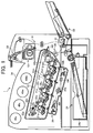
- the image forming apparatus 1 includes a fusing device 10, a transfer device 20, a transfer belt 20a, a driving roller 20e, a secondary bias transferor 20f, image forming mechanisms 21y, 21c, 21m, and 21bk, and bias transferors 22y, 22c, 22m, and 22bk.
- the image forming apparatus 1 shown in FIG. 1 further includes a manual feeding tray 23, a paper feeding device 24, a paper feeding cassette 24a, photoconductive drums 25y, 25c, 25m, and 25bk, a writing device 29, a polygon motor 29a, and f ⁇ lenses 29f.
- the image forming apparatus 1 shown in FIG. 1 also includes registration rollers 30, a reverse circulating path 30, feeding rollers 31, a conveying-path switcher 32, a paper output tray 34, and toner supply tanks 40y, 40c, 40m, and 40bk.
- the image forming apparatus 1 further includes a developing device 26bk, a charging device 27bk, and a charging device 28bk in the image forming mechanism 21bk.
- the image forming apparatus 1 in FIG. 2 also includes a process cartridge 50, an opening 51, an introducing mouth 52, a top wall 53, a bottom wall 54, guiding members 60 and 70 attached to the process cartridges 50, and guiding members 80 and 90.
- FIGs. 1 and 2 also show a writing laser beam Lbk and arrows indicating rotating directions of the photoconductive drums 25.
- the image forming mechanisms 21y, 21c, 21m, and 21bk form images of yellow, cyan, magenta, and black color, respectively, according to an original image.
- the transferor 22 faces the image forming mechanisms 21y through 21bk.
- the manual feeding tray 23 and the paper feeding cassette 24a feed a recording sheet into a transfer area in which the image forming mechanisms 21y through 21bk and the transferor 22 are opposed each other.
- the paper feeding cassette 24a is placed in the paper feeding unit 24.
- the registration rollers 30 feed the recording paper sent from the manual feeding tray 23 or the paper feeding cassette 24a in synchronize with operations of the image forming mechanisms 21y through 21bk.
- the fusing device 10 carries out a fusing operation on the recording sheet having an image transferred from the transfer device 20.
- the fusing device 10 adopting a heat roller fusing method fixes the image onto the recording sheet through a process of melting softening and penetrating by using a heating roller and a platen roller.
- the heating roller and the platen roller may be placed side by side of a conveying path of the recording sheet.
- the transfer device 20 includes the transfer belt 20a which winds on a plurality of rollers and works as a transfer member.
- the transfer device 20 also includes the bias transferors 22y, 22c, 22m, and 22bk facing corresponding drums 25y, 25c, 25m, and 25bk in the image forming mechanisms 21y, 21c, 21m, and 21bk, respectively.
- the bias transferors 22y, 22c, 22m, and 22bk apply transfer bias having reversed polarity of toner to sequentially superimpose toner images formed with the image forming mechanisms onto the transfer belt 20a.
- the image transfer device 20 further includes the secondary bias transferor 20f on a conveying path of the recording sheet.
- the secondary bias transferor 20f transfers toner images superimposed on the transfer belt 20a onto the recording sheet at a time.
- the transfer device 20 stretches with a slope, thereby occupying less space horizontally.
- the image forming apparatus 1 in FIG. 1 is an example of a color printer adopting a tandem method capable of forming a full-colored image.
- the present invention also considers a copier, a facsimile, a duplicator, or the like as an image forming apparatus as well.
- the image forming apparatus 1 is able to process specific paper having higher heat capacity such as 90K paper including OHP sheet, cards, or postcards, cardboard having basis weight of 100g/m 2 or more, or envelopes.
- 90K paper including OHP sheet, cards, or postcards, cardboard having basis weight of 100g/m 2 or more, or envelopes.
- the image forming mechanisms 21y, 21c, 21m, and 21bk in FIG. 1 carry out development of yellow, cyan, magenta, and black images, respectively.
- the image forming mechanism 21bk will be described as a representative example of the image forming mechanisms.
- the photoconductive drum 25bk in the image forming mechanism 21bk works as an electrostatic latent image carrier.
- the charging device 27bk, the developing device 26bk, and the cleaning device 28bk are sequentially arranged.
- a latent image according to image information corresponding to a separate color is formed with the writing laser beam Lbk emitted from the writing device 29.
- a belt-like shaped member may be adopted instead of a drum-shaped member.
- an image is formed according to the following processes and conditions.
- the following example describes the image forming mechanism 21bk using black toner as a representative image forming mechanism. It is to be noted, however, that image forming mechanisms of other colors are configured in the similar manner.
- the photoconductive drum 25bk is driven to rotate by a main motor (not shown), and discharged with alternating current (AC) bias having no direct current (DC) component applied to the charging device 27bk.
- the photoconductive drum 25bk thus have its surface potential set to standard potential of approximately -50V.
- the charging device 27bk applies DC bias with AC bias superimposed to the photoconductive drum 25bk.
- the photoconductive drum 25bk is evenly charged to have potential equivalent of DC component, approximately -500V to approximately -700V, as the surface potential.
- a preferable value of the surface potential is determined by a process controlling unit.
- a writing process starts.
- An image is written with the writing device 29 according to digital image information from a controller (not shown) in order to form a latent image. That is, in the writing device 29, a laser light source emits a laser beam based on a signal for laser diode binarized in each color according to the digital image information.
- the laser beam passes through cylinder lens (not shown), the polygon motor 29a, the f ⁇ lenses 29f, the first, second, and third mirrors, and the WTL lens (not shown).
- the photoconductive drum for carrying an image of each color, the photoconductive drum 25bk in this case, is irradiated with the laser beam.
- Each area on the surface of the photoconductive drum 25bk irradiated becomes to have surface potential of approximately -50V, thereby forming a latent image according to the image information.
- the latent image formed on the photoconductive drum 25bk is visualized with the developing device 26bk using complemental color toner of a separated color.
- a developing process applies approximately -300V to approximately -500V of DC with AC bias superimposed to a developing sleeve in order to develop toner (Q/M: -20 to -30µC/g) on image areas having lower potential caused by the irradiation of the laser beam, thereby forming a toner image.
- a toner image of each color visualized in the developing process is transferred onto the recording sheet being fed with a predetermined timing from the registration rollers 30.
- the recording sheet is applied attaching bias from rollers before reaching the transfer belt 22a.
- the recording sheet thus attaches to the transfer belt 22a due to electrostatic.
- Each of the bias transferors 22y, 22c, 22m, and 22bk installed in the transfer device 20 and facing the respective photoconductive drum applies a bias having reversed polarity of toner onto the transfer belt 20a. This action causes the photoconductive drums to electrostatically transfer toner images onto the transfer belt 20a. The toner images superimposed on the transfer belt 20a are transferred at a time onto the recording sheet with the secondary bias transferor 20f.
- the recording sheet with each color image transferred is self stripped from the transfer belt 22a with the driving roller 22b of a transfer belt unit, and conveyed to the fusing device 10.
- the toner image is fixed onto the recording sheet as it passes through a fusing nip including a fusing belt and pressing rollers.
- the recording sheet is ejected onto the paper output tray 34.
- the image forming apparatus 1 shown in FIG. 1 is capable of a double-sided image forming on the recording sheet which is ejected after a fusing process, as well as a single-sided image forming.
- the recording sheet after the fusing process is conveyed to the reversal circulating path 31.
- the recording sheet is fed to the registration rollers 30 from the feeding rollers 32 at the end of the reversal circulating path 31.
- the feeding rollers 32 also feed a sheet set on the manual feeding tray 23.
- the conveying path of the recording sheet is switched according to a type of image firming between single-sided or double-sided image forming with the conveying path switcher 33 installed at a rearward of the fusing device 10.
- FIG. 2 illustrates an exemplary configuration of the process cartridge 50 formed with a housing molded from resinous material.
- the image forming mechanism 21bk for a black colored image is provided, on its housing, with the opening 51 on a side facing the transfer belt 20a for exposing a part of the photoconductive drum 25bk, and the writing light introducing mouth 52 on the other side facing the writing device 9.
- the process cartridge 50 is attached or detached along with a line equivalent to a longitudinal direction, or an axis of the photoconductive drum 25bk.
- the attaching/detaching line is perpendicular to a sheet surface of the FIG. 2 from which the process cartridge 50 can be withdrawn for maintenance or checkup.
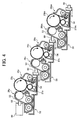
- FIG. 3 and FIG. 4 on an outer wall of the process cartridge 50, the top wall 53 of the developing device 26bk facing adjoining process cartridge is provided with the guiding member 60 while the bottom wall 54 of the cleaning device 28bk is provided with guiding member 70.
- the process cartridge 50 for magenta color is omitted in FIG. 4.
- the guiding member 80 is placed inside the housing contacting the guiding member 60 attached to the process cartridge 50 on the left side to guide the process cartridge 50 being attached or detached.
- the guiding member 90 is placed inside the housing contacting the guiding member 60 attached to the process cartridge 50 on the right side to guide the process cartridge 50 being attached or detached.
- Each of the guiding members 60 and 70 is arranged to face the adjoining process cartridge.
- the guiding member 60 is formed to protrude as a male member, while the guiding member 70 is formed to recess as a female member engaging the guiding member 60.
- Each of the guiding members 60 and 70 is provided with enough length to hold travel of attachment/detachment of the process cartridge 50 along with the perpendicular line to the sheet surface of the drawings.
- the guiding members 60 and 70 are configured to protrude and recess, respectively, they are able to fit each other, as shown in FIG. 4.
- the guiding member 60 invaginates its tip into the guiding member 70. In this configuration, space between the process cartridges becomes less in comparison with a case of using guiding members without engagement.
- Each of the guiding members 60 and 70 in a state of engagement pushes against a wall of the adjoining process cartridge 50.
- This configuration defines amount of space between process cartridges 50, thereby enabling positioning of the process cartridges 50 to each other.
- the guiding members 60 and 70 may be formed separately from the housing of the process cartridge 50 and attached thereto afterward, or formed together with the housing of the process cartridge 50.
- the guiding members 60 and 70 may be joined or fastened to the housing of the process cartridge 50.
- the process cartridge 50 moving inward in the image forming apparatus 1 is able to use the guiding members 60 and 70 of the adjoining process cartridges. Moreover, when loaded in the image forming apparatus 1, the process cartridge 50 is able to keep the positioning due to a function of the guiding members 60 and 70 determining the amount of space between the process cartridges.
- the guiding members 60 and 70 enable movement of the process cartridge 50 by bearing its weight.
- Each of the guiding members 60 and 70 is separately placed from the other, side by side of a vertical centerline of the process cartridge 50. According to this configuration, the process cartridge 50 just receives gravity at horizontal relative positions, and is capable of sliding without receiving any couple of force.
- each of the guiding members 60 and 70 of the process cartridge 50 has an appropriate sized tip at a horizontal end to fit an opponent so that the process cartridge 50 slides smoothly without receiving any additional external force onto a horizontal line.
- the above configuration eliminates necessity of the image forming apparatus 1 to have a member for guiding the process cartridge 50 in motion or positioning the process cartridge 50. This saves space occupied with the process cartridge 50, enabling a downsizing of the image forming apparatus 1.
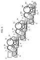
- FIG. 5 includes guiding members 61, 62, 63, 71, 72, and 73 instead of the guiding members 60 and 70 in FIGs. 2 through 4. Guiding members 81 and 91 of the image forming apparatus are also shown in FIG. 5 as substitutes of guiding members 80 and 90. Other reference numbers in FIG. 5 are identical with the reference numbers in the above embodiment. A tip shape of each of the guiding members 61, 62, and 63 respectively fitting to corresponding guiding member 71, 72, and 73 varies in each process cartridge 50.
- the process cartridge 50 in the left includes the guiding member 61 having a protruding slanting tip which fits the guiding member 81, and the guiding member 71 having a recessing arcing tip.
- the process cartridge 50 in the middle includes the guiding member 62 having a protruding arcing tip which fits the recessing arcing tip of the guiding member 71, and the guiding member 72 having a recessing rectangular tip.
- the process cartridge 50 in the right includes the guiding member 63 having a protruding rectangular tip which fits the recessing rectangular tip of the guiding member 72, and the guiding member 73 having a recessing rectangular tip which fits the guiding member 91.
- the above configuration prevents misplacing of the process cartridge 50 in the image forming apparatus 20 housing a plurality of process cartridges to form separate color images.
- the process cartridge 50 can be loaded into a position at which each of the guiding members 61, 62, and 63 and 71, 72, and 73 matches its opponent. This consequently determines a loading position of the process cartridge 50 to be placed with consideration of transferring order.
- the guiding members 61, 62, and 63 and 71, 72, and 73 thus allow the loading position to be identified of the process cartridge 50 to be installed in the image forming apparatus 1.
- an image forming apparatus 100 that includes an image forming mechanism 101a, a transfer medium 101b, an optical writing system 101c, a sheet feeding mechanism 101d, a toner feeding mechanism 101e, and a guiding mechanism 101f.
- the image forming mechanism 101a generally includes four process cartridges 140y, 140c, 140m, and 140bk which are explained with reference to FIG. 7.
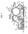
- FIG. 7 illustrates an enlarged sectional view of the process cartridge 140y, focusing on operations of the process cartridge 140y.
- the process cartridges 140y, 140c, 140m, and 140bk have identical structures with toners of different colors.
- the process cartridge 140y includes an image carrying member 102y and various image forming components including a charging roller 107y, a developing unit 109y, and a cleaning unit 113y.
- the developing unit 109y includes a developing roller 111y, a developing blade 131y, and toner conveying screws 132y and 133y.
- the parts of the developing unit 109y are encased in a developing case 110y that contains a dry-type developer D.
- the cleaning unit 113y includes a cleaning blade 135y and a collected-toner conveying screw 136y.
- the parts of the cleaning unit 113y are encased in a cleaning case 134y.
- the developing case 110y and the cleaning case 134y are integrally mounted to form a unit case 141y.
- the unit case 141y has a light passing window 144y at the bottom thereof.
- the transfer medium 101b includes an intermediate transfer belt 103.
- the intermediate transfer belt 103 is supported by a plurality of supporting rollers 104, 105, and 106, and is held in contact with primary transfer rollers 112y, 112c, 112m, and 112bk which correspond to the image carrying members 102y, 102c, 102m, and 102bk, respectively.
- the optical writing system 101c includes an optical writing device.
- the sheet feeding mechanism 101d includes a sheet feeding cassette 114, a sheet feeding roller 115, a sheet feeding unit 116, a registration roller pair 117, a secondary transfer roller 118, a fusing unit 119, a sheet discharging roller pair 120, a sheet discharging part 122, and a belt cleaning unit 124.
- the toner feeding mechanism 101e includes toner bottles 137y, 137c, 137m, and 137bk.
- the guiding mechanism 101f includes a guide 142 having guide portions 142y, 142c, 142m, and 142bk which are explained with reference to FIG. 8.
- the guide portions 142y, 142c, 142m, and 142bk have supporting surfaces 143y, 143c, 143m, and 143bk, and guide protrusions 146y, 146c, 146m, and 146bk, respectively.
- the image forming apparatus 100 of the present invention also includes an opening 145a (shown in FIG. 10) on a front side panel thereof.
- the intermediate transfer belt 103 is arranged above the image forming mechanism 101a at a predetermined angle relative to the horizontal plane with one end of the intermediate transfer belt 103 close to the supporting roller 105 higher than the other end thereof.
- the predetermined angle is preferably in a range from approximately 10 degrees to approximately 20 degrees, and is preferably approximately 15 degrees.
- the image forming apparatus 100 produces a full-color image through the following operations.
- the optical writing system 101c emits laser beams to the image forming mechanism 101a supported by the guiding mechanism 101f.
- the image forming mechanism 101a produces different color images with toners which are conveyed by the toner feeding mechanism 101e, and transfers the images one after another onto the transfer medium 101b to form a superimposed full-color image.
- the transfer medium 101b then transfers the superimposed full-color image onto a recording medium fed by the sheet feeding mechanism 101d.
- the full-color image transferred onto the recording medium 101b is fixed and then discharged onto the top of the image forming apparatus 100.
- the image carrying member 102y has a drum-shaped photoconductive element and forms an electrostatic latent image for a single color toner image on its surface.
- the image forming components are arranged around the image carrying member 102y and form the single color toner image based on the electrostatic latent image formed on the image carrying member 102y.
- the image carrying member 102y rotates clockwise.
- the charging roller 107y is applied with a charged voltage and then charges the image carrying member 102y to a predetermined polarity to form an electrostatic latent image on the image carrying member 102y.
- the optical writing system 101c emits and irradiates the image carrying member 102y with a laser beam Ly.
- the developing unit 109y visualizes the electrostatic latent image as a yellow toner image.
- the developing roller 111y is rotatably supported by the developing case 110y and is closely placed opposite to the image carrying member 102y through an open space formed on the developing case 110y.
- the developing blade 131y regulates an amount of the dry-type developer D on the developing roller 111y.
- the toner conveying screws 132y and 133y are oppositely provided to the developing roller 111y.
- the dry-type developer D in the developing case 110y is agitated by the toner conveying screws 132y and 133y, carried onto a surface of the developing roller 111y, and then conveyed by the developing roller 111y rotating in a direction B, as indicated in FIG. 7.
- the developing blade 131y regulates the dry-type developer D accumulated on the surface of the developing roller 111y to a fixed level.
- the dry-type developer D of the regulated amount adhering on the developing roller 111y is conveyed to a developing area formed between the developing roller 111y and the image carrying member 102y.
- toner contained in the dry-type developer D is electrostatically transferred onto an electrostatic latent image formed on the surface of the image carrying member 102y such that the electrostatic latent image becomes visualized as a toner image.
- the dry-type developer D may be a one-component developer or a two-component developer.
- the present invention preferably uses the two-component developer including toner and carriers.
- the intermediate transfer belt 103 that serves as the transfer medium 101b forms an endless belt extended with pressure among the plurality of supporting rollers 104, 105, and 106, and rotates in a direction A.
- the intermediate transfer belt 103 is arranged with an angle to a horizontal plane in an obliquely downward direction from left (LEFT) to right (RIGHT) of the image forming apparatus 100 in FIG. 6.
- the intermediate transfer belt 103 is held in contact between the primary transfer roller 112y arranged at a position opposite to the image carrying member 102y such that the toner image formed on the surface of the image carrying member 102y is transferred onto the intermediate transfer belt 103 to superimpose different color toner images to obtain a recorded image.
- the primary transfer roller 112y receives a transfer voltage and primarily transfers a yellow toner image onto the surface of the intermediate transfer belt 103 by an action of the transfer voltage.
- the cleaning unit 113y scrapes the surface of the image carrying member 102y to remove residual toner adhering to the surface of the image carrying member 102y.
- the cleaning unit 113y is encased by the cleaning case 134y that has an opening relative to the image carrying member 102y.
- the cleaning blade 135y has a base edge fixedly supported by the cleaning case 134y and a leading edge pressed onto the surface of the image carrying member 102y to scrape the residual toner adhering to the surface of the image carrying member 102y.
- the collected-toner conveying screw 136y conveys removed toner to a toner collecting bottle (not shown).
- the charging roller 107y is applied a voltage generated by a current that includes a direct current and a superimposed alternating current.
- the charging roller 107y simultaneously discharges and charges the surface of the image carrying member 102y with the voltage applied. Namely, the image carrying member 102y is prepared for a next image forming operation. Thus, a yellow toner image is formed on the image carrying member 102y and is transferred onto the intermediate transfer belt 103.
- a cyan toner image, a magenta toner image and a black toner image are formed on the surfaces of the image carrying members 102c, 102m, and 102bk, respectively.
- Those color toner images are sequentially superimposed on the surface of the intermediate transfer belt 103 on which the yellow toner image is already formed, such that a primary superimposed toner image is formed on the intermediate transfer belt 103.
- residual toner on the image carrying members 102c, 102m, and 102bk is also removed by the cleaning units 113c, 113m, and 113bk, respectively.
- the image forming components have the same numbers as those corresponding to and arranged around the image carrying member 102y, with respective characters "c", "m” and "bk” according to their respective colors.
- the sheet feeding mechanism 101d is arranged at the lower part of the image forming apparatus 100.
- the sheet feeding cassette 114 accommodates a plurality of recording media such as transfer sheets that include a recording medium P.
- the sheet feeding roller 115 is provided at the top of the sheet feeding unit 116 and feeds recording media. When the sheet feeding roller 115 is rotated, the recording medium P, placed on the top of a sheet stack of recording media in the sheet feeding cassette 114, is fed in a direction C as indicated in FIG. 6.
- the recording medium P, fed from the sheet feeding cassette 114 is conveyed to the registration roller pair 117.
- the registration roller pair 117 stops and feeds the recording medium P in synchronization with a movement of the superimposed toner image towards a transfer area formed between the intermediate transfer belt 103 and the secondary transfer roller 118.
- the secondary transfer roller 118 is applied with an adequate predetermined transfer voltage such that a primary superimposed toner image, formed on the surface of the intermediate transfer belt 103, is transferred onto the recording medium P to form a secondary superimposed toner image.
- the recording medium P that has the secondary superimposed toner image thereon is conveyed further upward and passes between a pair of fusing rollers of the fusing unit 119.
- the fusing unit 119 fixes the secondary superimposed toner image to the recording medium P by applying heat and pressure.
- the recording medium P passes the fusing unit 119, the recording medium P is discharged face-down by the sheet discharging roller pair 120 to the sheet discharging part 122 provided at the upper portion of the image forming apparatus 100.
- the belt cleaning unit 124 scrapes the surface of the intermediate belt 103 and removes residual toner adhering onto the surface of the intermediate transfer belt 103.
- the toner bottles 137y, 137c, 137m, and 137bk of the toner feeding mechanism 101e are provided at the upper portion of the image forming apparatus 100 and contain yellow, cyan, magenta, and black toners, respectively. Yellow, cyan, magenta, and black toners are conveyed from the toner bottles 137y, 137c, 137m, and 137bk, respectively, through respective conveying paths (not shown) to supply the developing units 109y, 109c, 109m, and 109bk, respectively.
- a process cartridge (140y, 140c, 140m, and 140bk) is formed by an image carrying member (102y, 102c, 102m, and 102bk) and at least a part of the image forming mechanism 101a.
- the image carrying member (102y, 102c, 102m, and 102bk) has a surface on which an electrostatic latent image for a corresponding color out of predetermined colors is formed.
- the image forming mechanism 101a is integrally mounted with the image carrying member (102y, 102c, 102m, and 102bk).
- the image forming mechanism 101a is configured to form a toner image in a corresponding color based on the electrostatic latent image formed on the image carrying member (102y, 102c, 102m, and 102bk).
- the image forming apparatus 100 includes a plurality of process cartridges (140y, 140c, 140m, and 140bk) configured to transfer yellow, cyan, magenta, and black toner images, respectively, formed on the image carrying members 102y, 102c, 102m, and 102bk, respectively, into a full-color toner image onto the intermediate transfer belt 103. More specifically, in the process cartridge 140y, the developing case 110y, and the cleaning case 134y are integrally formed as a unit case 141y, as shown in FIG. 7.
- the image carrying member 102y is rotatably supported by the unit case 141y.
- the image carrying member 102y, developing unit 109y, cleaning unit 113y, and charging roller 107y are integrally mounted to form process cartridge 140y.
- the process cartridge does not necessarily include an entire portion of the image forming mechanism.
- the process cartridge may include the image carrying member and at least one of the charging unit, the developing unit and the cleaning unit.
- the image carrying members 102y, 102c, 102m, and 102bk are in contact with a bottom surface of the intermediate transfer belt 103 between the supporting rollers 105 and 106, and are arranged such that the supporting roller 105 is disposed higher than the supporting roller 106. As shown in FIG. 6, the process cartridges 140y, 140c, 140m, and 140bk may be removed in an axial direction of the image carrying members 102y, 102c, 102m, and 102bk, respectively.
- FIG. 8 illustrates a sectional view of the guide 142 including the guide portions 142y, 142c, 142m, and 142bk arranged in a stepped manner, according to an embodiment of the present invention.
- the guide 142 includes the guide portions 142y, 142c, 142m, and 142bk, and is fixed to the image forming apparatus 100.
- the supporting surfaces 143y, 143c, 143m, and 143bk are mounted substantially horizontal and have respective bottom and side surfaces for supporting the process cartridges 140y, 140c, 140m, and 140bk.
- the supporting surfaces 143y, 143c, 143m, and 143bk guide the process cartridges 140y, 140c, 140m, and 140bk when the process cartridges 140y, 140c, 140m, and 140bk are inserted into or removed from the image forming apparatus 100.
- the supporting surfaces 143y, 143c, 143m, and 143bk guide the process cartridges 140y, 140c, 140m, and 140bk, respectively, and are arranged at positions having different heights in a stepped manner according to heights of positions of the process cartridges 140y, 140c, 140m, and 140bk.
- the guide portions 142y, 142c, 142m, and 142bk of the guide 142 support the process cartridges 140y, 140c, 140m, and 140bk, and have a predetermined angle to the horizontal plane and are arranged parallel to the intermediate transfer belt 103.
- the guide portions 142y, 142c, 142m, and 142bk and the unit cases 141y, 141c, 141m, and 141bk of the process cartridges 140y, 140c, 140m, and 140bk include the light passing windows 144y, 144c, 144m, and 144bk, respectively, for passing a laser beam L emitted by the optical writing system 101c to the image carrying members 102y, 102c, 102m, and 102bk, respectively.
- the developing case 110y includes a convex portion 149y in the vicinity of the toner conveying screw 133y such that the process cartridge 140y is guided along a vertical side of the guide portion 142y.
- the other developing cases 110c, 110m, and 110bk are arranged in a similar manner. Accordingly, the vertical side of the guide portion 142y is also used as a guide member for the process cartridge 140y.
- the image forming apparatus 100 includes an internal front panel 145 (see FIG. 10) disposed over an internal front side of the image forming apparatus 100 (the surface side of the figure).
- the internal front side panel 145 covers the internal portions of the image forming apparatus 100 including the process cartridges 140y, 140c, 140m, and 140bk, the intermediate transfer belt 103, and the optical writing system 101c.
- the internal front panel 145 has an opening 145a formed as indicated by the chain double-dashed lines shown in FIG. 6.
- the process cartridges 140y, 140c, 140m, and 140bk are removable through the opening 145a.
- the image forming apparatus 100 includes a cover plate 171 which is hingedly mounted to the internal front panel 145 to cover the opening 145a.
- the cover plate 171 may be opened and closed, and has a shape for determining precision positions of the process cartridges 140y, 140c, 140m, and 140bk. For instance, holes may be used for determining precision positions of the process cartridges 140y, 140c, 140m, and 140bk.
- an engaging mechanism (not shown) completely fixes positions of the image carrying members of the process cartridges to perform the image forming operation.
- FIG. 10 illustrates a perspective view of the image forming apparatus 100 and shows a relationship between the opening 145a and the cover plate 171.
- a user may pull the process cartridge 140y in a direction towards the user to detach it from the supporting surface 143y.
- the user may place and push the process cartridge 140y on the supporting surface 143y in a reverse direction to attach it. Namely, the user may remove and insert the process cartridge while keeping it horizontal. Therefore, there is no need to engage the slide rail provided on the process cartridge with the guide rail provided on the image forming apparatus.
- the user may instantly recognize the position of the supporting surface 143y and understand that the supporting surface 143y may be used to guide the process cartridge 140y when the process cartridge 140y is inserted or removed.
- This process may also be applied to the other process cartridges 140c, 140m, and 140bk.
- the image forming apparatus 100 includes a regulating member configured to regulate a path of the process cartridge.
- the regulating member prevents the process cartridge from undesirable movements in a direction perpendicular to the path of the process cartridge along the plane of the supporting surface of the guide during attachment and detachment.
- the process cartridge does not cause interference and damage to another process cartridge placed next to it.
- the guide portion 142y includes the regulating member that has a guide protrusion 146y protruding upward from the supporting surface 143y of the guide portion 142y and extending toward a removing direction of the process cartridge 140y.
- the guide protrusion 146y may be slidably engaged in a groove 148y formed on the unit case 141y of the process cartridge 140y to prevent the process cartridge 140y from undesirable movements in a direction perpendicular to the path of the process cartridge 140y during attachment and detachment.
- the process cartridge 140y may include the guide protrusion 146y and the supporting surface 143y may include the groove 148y.
- the guide portions 142y, 142c, 142m, and 142bk may include the guiding protrusions 146y, 146c, 146m, and 146bk, and may have different shapes and mounting locations to properly engage respective grooves included in the process cartridges 140y, 140c, 140m, and 140bk.
- FIG. 9 illustrates the unit case 141y of the process cartridge 140y that has a guide groove 147y thereon.
- the unit case 141y of the process cartridge 140y includes the guide groove 147y which may be engaged with the guide protrusion 146y included in the guide portion 144y close to the vertical side of the guide portion 144y, as shown in FIG. 8. Improper insertion of the process cartridges may be prevented by varying the form or the locations of the guide protrusions and the guide grooves.
- the guide portions 142y, 142c, 142m, and 142bk may include the guide grooves 147y, 147c, 147m, and 147bk and the process cartridges 140y, 140c, 140m, and 140bk may include the guide protrusions 146y, 146c, 146m, and 146bk such that the process cartridges 140y, 140c, 140m, and 140bk are prevented from being misaligned.
- an improper insertion of process cartridge may also be prevented.
- An erroneous supply of improper color toner to a developing unit may also be prevented. As a result, the quality deterioration of the image due to color toner mixture is avoided.
- the image forming apparatus 100 includes an elevating member (not shown) which allows the guide portions 142y, 142c, 142m, and 142bk to move vertically.
- the elevating member descends the guide portions 142y, 142c, 142m, and 142bk supporting the process cartridges 140y, 140c, 140m, and 140bk such that the image carrying members 102y, 102c, 102m, and 102bk separate from the intermediate transfer belt 103.
- the separation avoids rubbing and damaging the surfaces of the image carrying members 102y, 102c, 102m, and 102bk, and the surface of the intermediate transfer belt 103.
- the guide portions 142y, 142c, 142m, and 142bk may be configured to elevate collectively or individually. If the guide portions 142y, 142c, 142m, and 142bk are individually movable, a user can selectively descend the guide portions 142y, 142c, 142m, and 142bk to attach or detach a desired process cartridge.
- the intermediate transfer belt 103 may be eliminated with the images directly transferred onto a recording paper sheet.
- the image forming apparatus 100 includes toner bottles 137y, 137c, 137m, and 137bk which are separately mounted to the process cartridges 140y, 140c, 140m, and 140bk, respectively.
- the toner bottles 137y, 137c, 137m, and 137bk of different colors are provided above the intermediate transfer belt 103 and correspond to the process cartridges 140y, 140c, 140m, and 140bk, respectively, such that each color toner is conveyed to a corresponding one of the process cartridges 140y, 140c, 140m, and 140bk.
- the toner bottles 137y, 137c, 137m, and 137bk may be replaced separately from the process cartridges 140y, 140c, 140m, and 140bk when a toner needs to be replenished. Also, the process cartridges 140y, 140c, 140m, and 140bk may be replaced separately from the toner bottles 137y, 137c, 137m, and 137bk when a component needs to be replaced.
- this structure allows separate exchanges of toner and process cartridges, thereby reducing the maintenance cost for the user. Therefore, the number of opening and closing operations of the cover plate 171 may be reduced and the number of replacements of the process cartridges may also be reduced. Thereby, toner scattering in an area such as a shutter area may be prevented and operator-maintainability is improved.
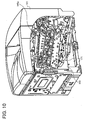
- FIG. 11 shows an image forming apparatus 200 that includes guide portions 220y, 220c, 220m, and 220bk and process cartridges 240y, 240c, 240m, and 240bk.
- the image forming apparatus 200 is similar to the image forming apparatus 100 of FIG. 6.
- the guide portions 220y, 220c, 220m, and 220bk of the image forming apparatus 200 include supporting surfaces 223y, 223c, 223m, and 223bk, and regulating members 225y, 225c, 225m, and 225bk.
- the supporting surfaces 223y, 223c, 223m, and 223bk include light passing windows 226y, 226c, 226m, and 226bk, and pushup members 228y, 228c, 228m, and 228bk.
- the regulating members 225y, 225c, 225m, and 225bk include guide openings 227y, 227c, 227m, and 227bk.
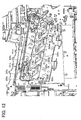
- FIG. 13 illustrates a positioning hole 229y of the regulating member 225y.
- each of the supporting surfaces 143y, 143c, 143m, and 143bk of a corresponding one of the guide portions 142y, 142c, 142m, and 142bk is arranged approximately horizontal in the image forming apparatus 100
- each of the supporting surfaces 223y, 223c, 223m, and 223bk of a corresponding one of the guide portions 220y, 220c, 220m, and 220bk is arranged to be inclined relative to a horizontal plane in the image forming apparatus 200.
- the process cartridges 240y, 240c, 240m, and 240bk of the image forming apparatus 200, shown in FIG. 11, are similar to the process cartridges 140y, 140c, 140m, and 140bk, respectively, of the image forming apparatus 100, shown in FIG. 6, with the exception of the guide portion 220y, for example, a convex portion 242y, a positioning latch 243y, a lever 250y, and a cam 251y, as shown in FIG. 16.
- This structure allows a sliding movement of each of the process cartridges 240y, 240c, 240m, and 240bk in a stable manner. More specifically, the process cartridge 240y slidably moves on the guide portion 220y while pressing down both the supporting surface 223y and the regulating member 225y by its own weight, thereby avoiding undesirable movements of the process cartridge 240y in a direction parallel to the supporting surface 223y.
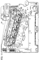
- FIG. 12 shows the inside of the image forming apparatus 200 when the process cartridges 240y, 240c, 240m, and 240bk are removed.
- Each of the guide portions 220y, 220c, 220m, and 220bk has an L-shaped form.
- the supporting surfaces 223y, 223c, 223m, and 223bk support the bottom surfaces of the process cartridges 240y, 240c, 240m, and 240bk, respectively.
- the light passing windows 226y, 226c, 226m, and 226bk are included in the supporting surfaces 223y, 223c, 223m and 223bk, respectively.
- Each of the light passing windows 226y, 226c, 226m, and 226bk passes a laser beam emitted by an optical writing system which is positioned under the guide portions 220y, 220c, 220m, and 220bk.
- the supporting surfaces 223y, 223c, 223m, and 223bk include pushup members 228y, 228c, 228m, and 228bk, respectively.
- the pushup members 228y, 228c, 228m, and 228bk guide the process cartridges 240y, 240c, 240m, and 240bk, respectively, such that the process cartridges 240y, 240c, 240m, and 240bk are pushed up to positions contacting the intermediate transfer belt.
- the regulating members 225y, 225c, 225m, and 225bk are arranged approximately perpendicular to the supporting surfaces 223y, 223c, 223m, and 223bk, respectively.
- the regulating members 225y, 225c, 225m, and 225bk regulate movement of the process cartridges 240y, 240c, 240m, and 240bk, respectively, to precision positions.
- the regulating members 225y, 225c, 225m, and 225bk include guide openings 227y, 227c, 227m, and 227bk and positioning holes 229y, 229c, 229m, and 229bk, respectively.
- Each of the guide openings 227y, 227c, 227m, and 227bk guides a corresponding one of the process cartridges 240y, 240c, 240m, and 240bk.
- Each of the positioning holes 229y, 229c, 229m, and 229bk is positioned at one edge side of the regulating member close to the cover plate 171, and determines a preliminary operable position of a corresponding one of the process cartridges 240y, 240c, 240m, and 240bk, respectively.
- the guide portion 220y and the process cartridge 240y are primarily shown.
- the guide portions 220y, 220c, 220m, and 220bk have identical structures.
- the process cartridges 240y, 240c, 240m, and 240bk also have identical structures with toners different in colors from each other.
- FIG. 13 shows an enlarged view of the guide portion 220y.
- the process cartridge 240y presses by its own weight the supporting surface 223y such that undesirable movements in a direction different from the sliding direction are eliminated.
- the convex portion 242y shown in FIG. 16, is included at a leading portion of the process cartridge 240y and is configured to be engaged with the guide opening 227y formed on the regulating member 225y of the guide portion 220y. This regulates movements of the process cartridge 240y towards the intermediate transfer belt such that the process cartridge 240y may maintain a distance from the intermediate transfer belt. This prevents damage to a photoconductive drum of the process cartridge 240y and the intermediate transfer belt.
- the convex portion 242y of the process cartridge 240y moves off the guide opening 227y. Then, as the process cartridge 240y is inserted, the process cartridge 240y is lifted in a vertical direction by and onto the pushup member 228y of the supporting surface 223y. As a result, the photoconductive drum of the process cartridge 240y contacts the intermediate transfer belt.
- the process cartridge 240y is preferably separated from the intermediate transfer belt when the process cartridge 240y is installed.
- the process cartridge 240y needs to be set to a predetermined preliminary position and held in contact with the intermediate transfer belt to perform the image forming operation.
- the process cartridge 240y is inserted into the image forming apparatus 200, it is guided by the guide opening 227y of the regulating member 225y and the pushup member 228y of the supporting surface 223y.
- the positioning latch 243y of the process cartridge 240y is detented into the positioning hole 229y of the guide portion 220y such that the positioning latch 243y and the positioning hole 229y are engaged to determine the preliminary position of the process cartridge 240y.
- the process cartridge 240y located at the preliminary position is fixed to a precision position by closing the cover plate 171.
- FIGs. 9 and 12 show installation and removal of the process cartridge 240y.
- the image forming apparatus 200 has the positioning hole 229y and the positioning latch 243y.
- the positioning latch 243y of the process cartridge 240y fits in the positioning hole 229y of the guide portion 220y by the weight of the process cartridge 240y.
- the process cartridge 240y is set to the preliminary position and a locking pressure is applied such that the process cartridge 240y is locked.
- the process cartridge 240y is then fixed to the precision position by the cover plate 171 as previously described.
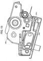
- the lever 250y of the process cartridge 240y is used.
- the process cartridge 240y has the lever 250y which is arranged at a position close to the positioning latch 243y.
- the lever 250y is pulled out, and the cam 251y provided at a hinge portion of the lever 250y contacts the regulating member 225y of the guide portion 220y and pushes up the process cartridge 240y.
- the positioning latch 243y of the process cartridge 240y is disengaged from the positioning hole 229y of the guide portion 220y. The process cartridge 240y is then easily removed by pulling the lever 250y.
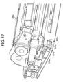
- FIG. 16 is a perspective view of the process cartridge 240y and FIG. 17 is an enlarged view of a part of the process cartridge 240y.
- a bottom side of the process cartridge 240y is formed approximately flat so that the process cartridge 240y is smoothly inserted along the guide portion 220y.
- the convex portion 242y of the process cartridge 240y is arranged at a lower part of the process cartridge 240y to face the regulating member 225y and to be close to the pushup member 228y when the process cartridge 240y is in an operational position.
- a process cartridge having a structure of the present invention may easily and smoothly be installed and removed along a guide member eliminating undesirable movements by its own weight.
- the image forming apparatus 200 of the present invention includes toner bottles (not shown in FIG. 11) which are separately mounted to the process cartridges 240y, 240c, 240m, and 240bk.
- the toner bottles may be replaced separately from the process cartridges 240y, 240c, 240m, and 240bk when toner needs to be replenished.
- the process cartridges 240y, 240c, 240m, and 240bk may be replaced separately from the toner bottles when a component needs to be replaced.
Abstract
A method and apparatus (1) of image forming include a process
cartridge (50) detachably mounted therein. The process cartridge (50) includes
a photoconductive element (25y,25c,25m,25bk) and a housing (53,54)
storing the photoconductive element and including a guide portion (60,70)
guiding the process cartridge. The guide portion (60,70) faces an inner
wall of the image forming apparatus (1) or another process cartridge
(50) adjoining thereto. The guide portion guides the process cartridge
adjoining and is slidably engages with a portion of said process
cartridge adjoining. The guide portion varies in shape according to a
position in the image forming apparatus. The guide portion
is separately formed from or integrated with the housing. A
method and apparatus (1) of an image forming includes an image
transfer mechanism (22) and a plurality of process cartridges (50)
arranged in line in parallel. Each of the process cartridges (50)
includes photoconductive elements (25) and a housing (53,54), and forms an
image for a single separated color.
Description
- The present invention relates to a method and apparatus for image forming, and more particularly to a mechanism in the method and apparatus for positioning a process cartridge which houses a combination of image forming devices.
- An image forming apparatus, such as a copier, a printer, or a facsimile, visualizes an electrostatic latent image formed on a latent image carrier, i.e., a photoconductor, with a developer, and transfers the image visualized onto a sheet or the like, thereby obtaining a recorded output.
- As a configuration for an image forming apparatus, the image forming apparatus may adopt, besides a configuration using single photoconductor for one color, a configuration including a plurality of photoconductors to form a plurality of corresponding colored images. The image forming apparatus with a plurality of photoconductors is used for forming a multi-colored image such as a full-colored image.
- In order to obtain a full-colored image, for example, one applicable method is sequentially superimposing each of the colored images formed on the photoconductors with developer having a complemental color of a separated color onto a sheet being conveyed. Another method is transferring a plurality of images from each of the photoconductors one by one onto a common position of an intermediate transferor and then transferring an image superimposed thereon onto a sheet at one time.
- As a configuration of using a plurality of photoconductors, what is called tandem architecture is generally known. In the tandem architecture, photoconductors for each color are parallely arranged in an extending direction of a belt which works as an intermediate transferor receiving images superimposed from photoconductors thereon, as described in Japanese Patent Laid-Open Application Publication No. 10-39718, for instance.
- Japanese Patent Laid-Open Application Publication No.10-39718 proposes, for instance, a configuration capable of forming a multi-colored image like the tandem architecture in which a cartridge for image forming is installed into an image forming apparatus. The process cartridge accommodates a combination of a photoconductor and image forming devices carrying out an image forming process thereon.
- Each image forming device installed in the process cartridge needs to have an alignment specified in order to prevent an image generated from being defective. To meet this necessity, a configuration has been provided capable of independently positioning a developing device and a cleaning device used in the process cartridge in relation to the photoconductor.
- In an image forming apparatus of forming a multi-colored image with a plurality of process cartridges, a photoconductor in a process cartridge needs to have relational position specified to other photoconductor, that is, needs to maintain registration, when the process cartridge is installed. This configuration is necessary in order to prevent color displacement caused by transfer displacement among one-color images.
- To install the process cartridges into the image forming apparatus, there has used a member installed in the apparatus such as a guiding rail or a drawer capable of sliding as holding the cartridges. A growing demand for a downsized image forming apparatus in these years requires more compact configuration saving in space between process cartridges which has been occupied with the guiding rail or the drawer.
- A configuration is provided of specifying a relative position of each image forming device to the photoconductor installed in the process cartridge. Likewise, the process cartridge needs to have any solutions for positioning itself in relation to other process cartridges.
- In view of the foregoing, it is an object of the present invention to provide a novel process cartridge used in an image forming apparatus which includes a guiding portion for guiding the process cartridge.
- Another object of the present invention is to provide a novel method of providing a process cartridge in an image forming apparatus which includes a guiding portion for guiding the process cartridge.
- To achieve these and other objects, in one example, the present invention provides a novel process cartridge including a photoconductive element and a housing. The housing houses the photoconductive element and includes a guide portion guiding the process cartridge.
- The guide portion of the process cartridge may face an inner wall of the image forming apparatus or another process cartridge adjoining thereto.
- The guide portion may guide another process cartridge adjoining.
- The guide portion may slidably engage with a portion of the process cartridge adjoining.
- The guide portion may vary in shape in accordance with a location in the image forming apparatus.
- The guide portion may have either one of configurations of being separately formed from the housing and being integrated with the housing.
- The present invention also provides a novel image forming apparatus including an image transfer mechanism and a process cartridge detachably mounted. The process cartridge includes a photoconductive element and a housing. The housing houses the photoconductive element and includes a guide portion guiding the process cartridge.
- The present invention also provides a novel image forming apparatus including an image transfer mechanism and a plurality of process cartridges detachably mounted and arranged in line in parallel. Each one of the plurality of the process cartridges forms an image for a single separated color, and includes a photoconductive element and a housing. The housing houses the photoconductive element and includes a guide portion guiding the process cartridge.
- This patent specification further describes a novel method of providing a process cartridge detachably mounted in an image forming apparatus.
- In one example, the novel method includes the steps of providing a photoconductive element and storing the photoconductive element. The providing step provides the photoconductive element. The storing step stores the photoconductive element in a housing including a guide portion guiding the process cartridge.
- A more complete appreciation of the disclosure and many of the attendant advantages thereof will be readily obtained as the same becomes better understood by reference to the following detailed description when considered in connection with the accompanying drawings, wherein:
- FIG. 1 is a schematic diagram showing an exemplary configuration of an image forming apparatus adopting process cartridges according to an embodiment of the present invention;
- FIG. 2 is a schematic diagram showing an enlarged view of one of the process cartridges equipped in the image forming apparatus in FIG. 1;
- FIG. 3 is a schematic diagram illustrating a structure of guiding mechanism with a plurality of the process cartridge shown in FIG. 2;
- FIG. 4 is a schematic diagram showing an enlarged view of a part of the structure shown in FIG. 3;
- FIG. 5 is a schematic diagram showing another exemplary structure of guiding members in process cartridges installed in the image forming apparatus shown in FIG. 1;
- FIG. 6 illustrates a vertical sectional view of a full-color image forming apparatus according to another embodiment of the present invention;
- FIG. 7 illustrates an enlarged sectional view of an image carrying member and an image forming mechanism arranged around the image carrying member;
- FIG. 8 illustrates a sectional view of a guide having guide portions arranged in a stepped manner;
- FIG. 9 illustrates a process cartridge provided with a guide groove engaged with the guide protrusion;
- FIG. 10 illustrates a perspective view of the image forming apparatus of FIG. 11 with a cover plate opened, the cover plate being provided to a front side of the image forming apparatus;
- FIG. 11 illustrates a vertical sectional view of an image forming apparatus according to another embodiment of the present invention;
- FIG. 12 illustrates a perspective view in part of the image forming apparatus of FIG. 16 showing an inside of the image forming apparatus with the process cartridges removed;
- FIG. 13 illustrates an enlarged view of a guide portion of the image forming apparatus of FIG. 16;
- FIG. 14 illustrates a perspective view in part of a process cartridge with a lever positioned at a release position at which the process cartridge is released from the guide portion;
- FIG. 15 illustrates a side view of the process cartridge with the lever at a locking position at which the process cartridge is locked to the guide portion;
- FIG. 16 illustrates a perspective view of the process cartridge from a rear side; and
- FIG. 17 illustrates an enlarged view in part of the process cartridge from the rear side.
-
- In describing preferred embodiments illustrated in the drawings, specific terminology is employed for the sake of clarity. However, the disclosure of this patent specification is not intended to be limited to the specific terminology so selected and it is to be understood that each specific element includes all technical equivalents that operate in a similar manner. Referring now to the drawings, wherein like reference numerals designate identical or corresponding parts throughout the several views, particularly to FIGs. 1 and 2, an image forming apparatus 1 according to an exemplary embodiment of the present invention is described. In FIG. 1, the image forming apparatus 1 includes a
fusing device 10, a transfer device 20, a transfer belt 20a, a driving roller 20e, asecondary bias transferor 20f,image forming mechanisms bias transferors manual feeding tray 23, apaper feeding device 24, apaper feeding cassette 24a,photoconductive drums writing device 29, apolygon motor 29a, and flenses 29f. The image forming apparatus 1 shown in FIG. 1 also includesregistration rollers 30, areverse circulating path 30, feedingrollers 31, a conveying-path switcher 32, apaper output tray 34, andtoner supply tanks - As shown in FIG. 2, the image forming apparatus 1 further includes a developing device 26bk, a charging device 27bk, and a charging device 28bk in the image forming mechanism 21bk. The image forming apparatus 1 in FIG. 2 also includes a
process cartridge 50, anopening 51, an introducingmouth 52, atop wall 53, abottom wall 54, guidingmembers process cartridges 50, and guidingmembers - FIGs. 1 and 2 also show a writing laser beam Lbk and arrows indicating rotating directions of the photoconductive drums 25.
- The
image forming mechanisms image forming mechanisms 21y through 21bk. Themanual feeding tray 23 and thepaper feeding cassette 24a feed a recording sheet into a transfer area in which theimage forming mechanisms 21y through 21bk and the transferor 22 are opposed each other. Thepaper feeding cassette 24a is placed in thepaper feeding unit 24. Theregistration rollers 30 feed the recording paper sent from themanual feeding tray 23 or thepaper feeding cassette 24a in synchronize with operations of theimage forming mechanisms 21y through 21bk. The fusingdevice 10 carries out a fusing operation on the recording sheet having an image transferred from the transfer device 20. - The fusing
device 10 adopting a heat roller fusing method fixes the image onto the recording sheet through a process of melting softening and penetrating by using a heating roller and a platen roller. The heating roller and the platen roller may be placed side by side of a conveying path of the recording sheet. - The transfer device 20 includes the transfer belt 20a which winds on a plurality of rollers and works as a transfer member. The transfer device 20 also includes the
bias transferors drums image forming mechanisms bias transferors - The image transfer device 20 further includes the
secondary bias transferor 20f on a conveying path of the recording sheet. Thesecondary bias transferor 20f transfers toner images superimposed on the transfer belt 20a onto the recording sheet at a time. - In the image forming apparatus 1 shown in FIG. 1, the transfer device 20 stretches with a slope, thereby occupying less space horizontally.
- The image forming apparatus 1 in FIG. 1 is an example of a color printer adopting a tandem method capable of forming a full-colored image. At the same time, the present invention also considers a copier, a facsimile, a duplicator, or the like as an image forming apparatus as well.
- In addition to normal paper generally used for copying, the image forming apparatus 1 is able to process specific paper having higher heat capacity such as 90K paper including OHP sheet, cards, or postcards, cardboard having basis weight of 100g/m2 or more, or envelopes.
- The
image forming mechanisms - The photoconductive drum 25bk in the image forming mechanism 21bk works as an electrostatic latent image carrier. Along with the rotating direction indicated with arrows in FIGs. and 2 of the photoconductive drum 25bk, the charging device 27bk, the developing device 26bk, and the cleaning device 28bk are sequentially arranged. At a location between the charging device 27bk and the developing device 26bk on the photoconductive drum 25bk, a latent image according to image information corresponding to a separate color is formed with the writing laser beam Lbk emitted from the
writing device 29. As an electrostatic latent image carrier, a belt-like shaped member may be adopted instead of a drum-shaped member. These devices for image forming arranged around the photoconductive drum 25bk are combined into theprocess cartridge 50 which is configured to have a unit structure and a housing, as shown in FIG. 2. - In the image forming apparatus 1 of the above configuration, an image is formed according to the following processes and conditions. The following example describes the image forming mechanism 21bk using black toner as a representative image forming mechanism. It is to be noted, however, that image forming mechanisms of other colors are configured in the similar manner.
- In an image forming process, the photoconductive drum 25bk is driven to rotate by a main motor (not shown), and discharged with alternating current (AC) bias having no direct current (DC) component applied to the charging device 27bk. The photoconductive drum 25bk thus have its surface potential set to standard potential of approximately -50V.
- The charging device 27bk applies DC bias with AC bias superimposed to the photoconductive drum 25bk. The photoconductive drum 25bk is evenly charged to have potential equivalent of DC component, approximately -500V to approximately -700V, as the surface potential. A preferable value of the surface potential is determined by a process controlling unit.
- Upon completion of uniform charging of the photoconductive drum 25bk, a writing process starts. An image is written with the
writing device 29 according to digital image information from a controller (not shown) in order to form a latent image. That is, in thewriting device 29, a laser light source emits a laser beam based on a signal for laser diode binarized in each color according to the digital image information. The laser beam passes through cylinder lens (not shown), thepolygon motor 29a, the flenses 29f, the first, second, and third mirrors, and the WTL lens (not shown). The photoconductive drum for carrying an image of each color, the photoconductive drum 25bk, in this case, is irradiated with the laser beam. Each area on the surface of the photoconductive drum 25bk irradiated becomes to have surface potential of approximately -50V, thereby forming a latent image according to the image information. - The latent image formed on the photoconductive drum 25bk is visualized with the developing device 26bk using complemental color toner of a separated color. A developing process applies approximately -300V to approximately -500V of DC with AC bias superimposed to a developing sleeve in order to develop toner (Q/M: -20 to -30µC/g) on image areas having lower potential caused by the irradiation of the laser beam, thereby forming a toner image.
- A toner image of each color visualized in the developing process is transferred onto the recording sheet being fed with a predetermined timing from the
registration rollers 30. The recording sheet is applied attaching bias from rollers before reaching thetransfer belt 22a. The recording sheet thus attaches to thetransfer belt 22a due to electrostatic. - Each of the
bias transferors secondary bias transferor 20f. - The recording sheet with each color image transferred is self stripped from the
transfer belt 22a with the driving roller 22b of a transfer belt unit, and conveyed to thefusing device 10. The toner image is fixed onto the recording sheet as it passes through a fusing nip including a fusing belt and pressing rollers. The recording sheet is ejected onto thepaper output tray 34. - The image forming apparatus 1 shown in FIG. 1 is capable of a double-sided image forming on the recording sheet which is ejected after a fusing process, as well as a single-sided image forming. In the double-sided image forming, the recording sheet after the fusing process is conveyed to the
reversal circulating path 31. The recording sheet is fed to theregistration rollers 30 from the feedingrollers 32 at the end of thereversal circulating path 31. The feedingrollers 32 also feed a sheet set on themanual feeding tray 23. The conveying path of the recording sheet is switched according to a type of image firming between single-sided or double-sided image forming with the conveyingpath switcher 33 installed at a rearward of thefusing device 10. - It is to be understood that each property described above such as charging potential is not limited to attributes in the above description, but may vary according to a color or density, naturally.
- FIG. 2 illustrates an exemplary configuration of the
process cartridge 50 formed with a housing molded from resinous material. The image forming mechanism 21bk for a black colored image is provided, on its housing, with theopening 51 on a side facing the transfer belt 20a for exposing a part of the photoconductive drum 25bk, and the writinglight introducing mouth 52 on the other side facing the writing device 9. - The
process cartridge 50 is attached or detached along with a line equivalent to a longitudinal direction, or an axis of the photoconductive drum 25bk. In the present embodiment, the attaching/detaching line is perpendicular to a sheet surface of the FIG. 2 from which theprocess cartridge 50 can be withdrawn for maintenance or checkup. - With referring to FIGs. 3 and 4, further details of the image forming apparatus 1 will now be described. In FIG. 3 and FIG. 4, on an outer wall of the
process cartridge 50, thetop wall 53 of the developing device 26bk facing adjoining process cartridge is provided with the guidingmember 60 while thebottom wall 54 of the cleaning device 28bk is provided with guidingmember 70. Theprocess cartridge 50 for magenta color is omitted in FIG. 4. - As shown in FIG. 3, the guiding
member 80 is placed inside the housing contacting the guidingmember 60 attached to theprocess cartridge 50 on the left side to guide theprocess cartridge 50 being attached or detached. Similarly, the guidingmember 90 is placed inside the housing contacting the guidingmember 60 attached to theprocess cartridge 50 on the right side to guide theprocess cartridge 50 being attached or detached. - Each of the guiding
members member 60 is formed to protrude as a male member, while the guidingmember 70 is formed to recess as a female member engaging the guidingmember 60. Each of the guidingmembers process cartridge 50 along with the perpendicular line to the sheet surface of the drawings. - Since the guiding
members members member 60 invaginates its tip into the guidingmember 70. In this configuration, space between the process cartridges becomes less in comparison with a case of using guiding members without engagement. - Each of the guiding
members process cartridge 50. This configuration defines amount of space betweenprocess cartridges 50, thereby enabling positioning of theprocess cartridges 50 to each other. - The guiding
members process cartridge 50 and attached thereto afterward, or formed together with the housing of theprocess cartridge 50. - In the former case, the guiding
members process cartridge 50. - According to the above configuration, the
process cartridge 50 moving inward in the image forming apparatus 1 is able to use the guidingmembers process cartridge 50 is able to keep the positioning due to a function of the guidingmembers members process cartridge 50 by bearing its weight. Each of the guidingmembers process cartridge 50. According to this configuration, theprocess cartridge 50 just receives gravity at horizontal relative positions, and is capable of sliding without receiving any couple of force. As a matter of course, each of the guidingmembers process cartridge 50 has an appropriate sized tip at a horizontal end to fit an opponent so that theprocess cartridge 50 slides smoothly without receiving any additional external force onto a horizontal line. The above configuration eliminates necessity of the image forming apparatus 1 to have a member for guiding theprocess cartridge 50 in motion or positioning theprocess cartridge 50. This saves space occupied with theprocess cartridge 50, enabling a downsizing of the image forming apparatus 1. - With referring to FIG. 5, another embodiment of the image forming apparatus 1 according to the present invention will now be described. FIG. 5 includes guiding
members members members members members member process cartridge 50. - In the exemplary embodiment shown in FIG. 5, the
process cartridge 50 in the left includes the guidingmember 61 having a protruding slanting tip which fits the guidingmember 81, and the guidingmember 71 having a recessing arcing tip. Theprocess cartridge 50 in the middle includes the guidingmember 62 having a protruding arcing tip which fits the recessing arcing tip of the guidingmember 71, and the guidingmember 72 having a recessing rectangular tip. Theprocess cartridge 50 in the right includes the guidingmember 63 having a protruding rectangular tip which fits the recessing rectangular tip of the guidingmember 72, and the guidingmember 73 having a recessing rectangular tip which fits the guidingmember 91. - The above configuration prevents misplacing of the
process cartridge 50 in the image forming apparatus 20 housing a plurality of process cartridges to form separate color images. Into a position at which each of the guidingmembers process cartridge 50 can be loaded. This consequently determines a loading position of theprocess cartridge 50 to be placed with consideration of transferring order. The guidingmembers process cartridge 50 to be installed in the image forming apparatus 1. - Referring to FIG. 6, another embodiment of the present invention will now be described. In FIG. 6, an image forming apparatus 100 is shown that includes an
image forming mechanism 101a, atransfer medium 101b, anoptical writing system 101c, asheet feeding mechanism 101d, atoner feeding mechanism 101e, and aguiding mechanism 101f. - The
image forming mechanism 101a generally includes fourprocess cartridges process cartridge 140y, focusing on operations of theprocess cartridge 140y. Theprocess cartridges process cartridge 140y includes animage carrying member 102y and various image forming components including a chargingroller 107y, a developingunit 109y, and acleaning unit 113y. The developingunit 109y includes a developingroller 111y, a developingblade 131y, andtoner conveying screws unit 109y are encased in a developingcase 110y that contains a dry-type developer D. Thecleaning unit 113y includes acleaning blade 135y and a collected-toner conveying screw 136y. The parts of thecleaning unit 113y are encased in acleaning case 134y. According to the image forming apparatus 100 of the present invention, the developingcase 110y and thecleaning case 134y are integrally mounted to form aunit case 141y. Theunit case 141y has alight passing window 144y at the bottom thereof. - The
transfer medium 101b includes anintermediate transfer belt 103. Theintermediate transfer belt 103 is supported by a plurality of supportingrollers primary transfer rollers image carrying members - The
optical writing system 101c includes an optical writing device. - The
sheet feeding mechanism 101d includes asheet feeding cassette 114, asheet feeding roller 115, asheet feeding unit 116, aregistration roller pair 117, asecondary transfer roller 118, afusing unit 119, a sheet dischargingroller pair 120, asheet discharging part 122, and abelt cleaning unit 124. - The
toner feeding mechanism 101e includestoner bottles - The
guiding mechanism 101f includes a guide 142 havingguide portions guide portions surfaces protrusions - The image forming apparatus 100 of the present invention also includes an
opening 145a (shown in FIG. 10) on a front side panel thereof. - The
intermediate transfer belt 103 is arranged above theimage forming mechanism 101a at a predetermined angle relative to the horizontal plane with one end of theintermediate transfer belt 103 close to the supportingroller 105 higher than the other end thereof. The predetermined angle is preferably in a range from approximately 10 degrees to approximately 20 degrees, and is preferably approximately 15 degrees. - The image forming apparatus 100 produces a full-color image through the following operations. The
optical writing system 101c emits laser beams to theimage forming mechanism 101a supported by theguiding mechanism 101f. Theimage forming mechanism 101a produces different color images with toners which are conveyed by thetoner feeding mechanism 101e, and transfers the images one after another onto thetransfer medium 101b to form a superimposed full-color image. Thetransfer medium 101b then transfers the superimposed full-color image onto a recording medium fed by thesheet feeding mechanism 101d. The full-color image transferred onto therecording medium 101b is fixed and then discharged onto the top of the image forming apparatus 100. - Referring to FIG. 7, operations of the
image forming mechanism 101a are explained. As previously described, theprocess cartridges process cartridge 140y. - The
image carrying member 102y has a drum-shaped photoconductive element and forms an electrostatic latent image for a single color toner image on its surface. The image forming components are arranged around theimage carrying member 102y and form the single color toner image based on the electrostatic latent image formed on theimage carrying member 102y. - The
image carrying member 102y rotates clockwise. The chargingroller 107y is applied with a charged voltage and then charges theimage carrying member 102y to a predetermined polarity to form an electrostatic latent image on theimage carrying member 102y. Theoptical writing system 101c emits and irradiates theimage carrying member 102y with a laser beam Ly. - The developing
unit 109y visualizes the electrostatic latent image as a yellow toner image. The developingroller 111y is rotatably supported by the developingcase 110y and is closely placed opposite to theimage carrying member 102y through an open space formed on the developingcase 110y.
The developingblade 131y regulates an amount of the dry-type developer D on the developingroller 111y. Thetoner conveying screws roller 111y. The dry-type developer D in the developingcase 110y is agitated by thetoner conveying screws roller 111y, and then conveyed by the developingroller 111y rotating in a direction B, as indicated in FIG. 7. The developingblade 131y regulates the dry-type developer D accumulated on the surface of the developingroller 111y to a fixed level. The dry-type developer D of the regulated amount adhering on the developingroller 111y is conveyed to a developing area formed between the developingroller 111y and theimage carrying member 102y. In the developing area, toner contained in the dry-type developer D is electrostatically transferred onto an electrostatic latent image formed on the surface of theimage carrying member 102y such that the electrostatic latent image becomes visualized as a toner image. The dry-type developer D may be a one-component developer or a two-component developer. The present invention preferably uses the two-component developer including toner and carriers. - As shown in FIG. 6, the
intermediate transfer belt 103 that serves as the transfer medium 101b forms an endless belt extended with pressure among the plurality of supportingrollers
Theintermediate transfer belt 103 is arranged with an angle to a horizontal plane in an obliquely downward direction from left (LEFT) to right (RIGHT) of the image forming apparatus 100 in FIG. 6. Theintermediate transfer belt 103 is held in contact between theprimary transfer roller 112y arranged at a position opposite to theimage carrying member 102y such that the toner image formed on the surface of theimage carrying member 102y is transferred onto theintermediate transfer belt 103 to superimpose different color toner images to obtain a recorded image. Theprimary transfer roller 112y receives a transfer voltage and primarily transfers a yellow toner image onto the surface of theintermediate transfer belt 103 by an action of the transfer voltage. - As shown in FIG. 7, after the yellow toner image is transferred onto the
intermediate transfer belt 103, thecleaning unit 113y scrapes the surface of theimage carrying member 102y to remove residual toner adhering to the surface of theimage carrying member 102y. - The
cleaning unit 113y is encased by thecleaning case 134y that has an opening relative to theimage carrying member 102y. Thecleaning blade 135y has a base edge fixedly supported by thecleaning case 134y and a leading edge pressed onto the surface of theimage carrying member 102y to scrape the residual toner adhering to the surface of theimage carrying member 102y. The collected-toner conveying screw 136y conveys removed toner to a toner collecting bottle (not shown). - The charging
roller 107y is applied a voltage generated by a current that includes a direct current and a superimposed alternating current. The chargingroller 107y simultaneously discharges and charges the surface of theimage carrying member 102y with the voltage applied. Namely, theimage carrying member 102y is prepared for a next image forming operation. Thus, a yellow toner image is formed on theimage carrying member 102y and is transferred onto theintermediate transfer belt 103. - Through operations similar to those as described above, a cyan toner image, a magenta toner image and a black toner image are formed on the surfaces of the
image carrying members 102c, 102m, and 102bk, respectively. Those color toner images are sequentially superimposed on the surface of theintermediate transfer belt 103 on which the yellow toner image is already formed, such that a primary superimposed toner image is formed on theintermediate transfer belt 103. After the toner images in the different colors are transferred, residual toner on theimage carrying members 102c, 102m, and 102bk is also removed by the cleaning units 113c, 113m, and 113bk, respectively. As shown in FIG. 6, the image forming components have the same numbers as those corresponding to and arranged around theimage carrying member 102y, with respective characters "c", "m" and "bk" according to their respective colors. - As shown in FIG. 6, the
sheet feeding mechanism 101d is arranged at the lower part of the image forming apparatus 100. Thesheet feeding cassette 114 accommodates a plurality of recording media such as transfer sheets that include a recording medium P. Thesheet feeding roller 115 is provided at the top of thesheet feeding unit 116 and feeds recording media. When thesheet feeding roller 115 is rotated, the recording medium P, placed on the top of a sheet stack of recording media in thesheet feeding cassette 114, is fed in a direction C as indicated in FIG. 6. The recording medium P, fed from thesheet feeding cassette 114, is conveyed to theregistration roller pair 117. Theregistration roller pair 117 stops and feeds the recording medium P in synchronization with a movement of the superimposed toner image towards a transfer area formed between theintermediate transfer belt 103 and thesecondary transfer roller 118. Thesecondary transfer roller 118 is applied with an adequate predetermined transfer voltage such that a primary superimposed toner image, formed on the surface of theintermediate transfer belt 103, is transferred onto the recording medium P to form a secondary superimposed toner image. - The recording medium P that has the secondary superimposed toner image thereon is conveyed further upward and passes between a pair of fusing rollers of the
fusing unit 119. Thefusing unit 119 fixes the secondary superimposed toner image to the recording medium P by applying heat and pressure. After the recording medium P passes thefusing unit 119, the recording medium P is discharged face-down by the sheet dischargingroller pair 120 to thesheet discharging part 122 provided at the upper portion of the image forming apparatus 100. Thebelt cleaning unit 124 scrapes the surface of theintermediate belt 103 and removes residual toner adhering onto the surface of theintermediate transfer belt 103. - As shown in FIG. 6, the
toner bottles toner feeding mechanism 101e are provided at the upper portion of the image forming apparatus 100 and contain yellow, cyan, magenta, and black toners, respectively. Yellow, cyan, magenta, and black toners are conveyed from thetoner bottles units 109y, 109c, 109m, and 109bk, respectively. - As previously described, a process cartridge (140y, 140c, 140m, and 140bk) is formed by an image carrying member (102y, 102c, 102m, and 102bk) and at least a part of the
image forming mechanism 101a. The image carrying member (102y, 102c, 102m, and 102bk) has a surface on which an electrostatic latent image for a corresponding color out of predetermined colors is formed. Theimage forming mechanism 101a is integrally mounted with the image carrying member (102y, 102c, 102m, and 102bk). Theimage forming mechanism 101a is configured to form a toner image in a corresponding color based on the electrostatic latent image formed on the image carrying member (102y, 102c, 102m, and 102bk). The image forming apparatus 100 includes a plurality of process cartridges (140y, 140c, 140m, and 140bk) configured to transfer yellow, cyan, magenta, and black toner images, respectively, formed on theimage carrying members intermediate transfer belt 103. More specifically, in theprocess cartridge 140y, the developingcase 110y, and thecleaning case 134y are integrally formed as aunit case 141y, as shown in FIG. 7. Theimage carrying member 102y is rotatably supported by theunit case 141y.
Theimage carrying member 102y, developingunit 109y, cleaningunit 113y, and chargingroller 107y are integrally mounted to formprocess cartridge 140y. As previously described, the process cartridge does not necessarily include an entire portion of the image forming mechanism. The process cartridge may include the image carrying member and at least one of the charging unit, the developing unit and the cleaning unit. - The
image carrying members intermediate transfer belt 103 between the supportingrollers roller 105 is disposed higher than the supportingroller 106. As shown in FIG. 6, theprocess cartridges image carrying members - FIG. 8 illustrates a sectional view of the guide 142 including the
guide portions guide portions surfaces process cartridges surfaces process cartridges process cartridges surfaces process cartridges process cartridges guide portions process cartridges intermediate transfer belt 103. Theguide portions unit cases 141y, 141c, 141m, and 141bk of theprocess cartridges light passing windows optical writing system 101c to theimage carrying members - Further, as shown in FIG. 7, the developing
case 110y includes aconvex portion 149y in the vicinity of thetoner conveying screw 133y such that theprocess cartridge 140y is guided along a vertical side of theguide portion 142y. The other developing cases 110c, 110m, and 110bk are arranged in a similar manner. Accordingly, the vertical side of theguide portion 142y is also used as a guide member for theprocess cartridge 140y. - The image forming apparatus 100 includes an internal front panel 145 (see FIG. 10) disposed over an internal front side of the image forming apparatus 100 (the surface side of the figure). The internal
front side panel 145 covers the internal portions of the image forming apparatus 100 including theprocess cartridges intermediate transfer belt 103, and theoptical writing system 101c. The internalfront panel 145 has anopening 145a formed as indicated by the chain double-dashed lines shown in FIG. 6. Theprocess cartridges opening 145a. Further, the image forming apparatus 100 includes acover plate 171 which is hingedly mounted to the internalfront panel 145 to cover theopening 145a. Thecover plate 171 may be opened and closed, and has a shape for determining precision positions of theprocess cartridges process cartridges cover plate 171 is set to a closed position, an engaging mechanism (not shown) completely fixes positions of the image carrying members of the process cartridges to perform the image forming operation. FIG. 10 illustrates a perspective view of the image forming apparatus 100 and shows a relationship between theopening 145a and thecover plate 171. - According to this configuration, when the
process cartridge 140y is checked, repaired, or replaced, a user may pull theprocess cartridge 140y in a direction towards the user to detach it from the supportingsurface 143y. The user may place and push theprocess cartridge 140y on the supportingsurface 143y in a reverse direction to attach it. Namely, the user may remove and insert the process cartridge while keeping it horizontal. Therefore, there is no need to engage the slide rail provided on the process cartridge with the guide rail provided on the image forming apparatus. Further, by opening thecover plate 171 of the image forming apparatus 100, the user may instantly recognize the position of the supportingsurface 143y and understand that the supportingsurface 143y may be used to guide theprocess cartridge 140y when theprocess cartridge 140y is inserted or removed. Thus, even an inexperienced user may easily attach and detach theprocess cartridge 140y while keeping it horizontal. This process may also be applied to theother process cartridges - Further, the image forming apparatus 100 includes a regulating member configured to regulate a path of the process cartridge. The regulating member prevents the process cartridge from undesirable movements in a direction perpendicular to the path of the process cartridge along the plane of the supporting surface of the guide during attachment and detachment. Thus, the process cartridge does not cause interference and damage to another process cartridge placed next to it. As shown in FIG. 7, the
guide portion 142y includes the regulating member that has aguide protrusion 146y protruding upward from the supportingsurface 143y of theguide portion 142y and extending toward a removing direction of theprocess cartridge 140y. Theguide protrusion 146y may be slidably engaged in agroove 148y formed on theunit case 141y of theprocess cartridge 140y to prevent theprocess cartridge 140y from undesirable movements in a direction perpendicular to the path of theprocess cartridge 140y during attachment and detachment. Alternatively, theprocess cartridge 140y may include theguide protrusion 146y and the supportingsurface 143y may include thegroove 148y. The processes described above relating to the yellow toner as indicated by the character "y" may also be applied to parts and units related to the cyan, magenta, and black toners as indicated by the characters "c", "m" and "bk". - In FIG. 8, the
guide portions protrusions process cartridges - FIG. 9 illustrates the
unit case 141y of theprocess cartridge 140y that has aguide groove 147y thereon. Theunit case 141y of theprocess cartridge 140y includes theguide groove 147y which may be engaged with theguide protrusion 146y included in theguide portion 144y close to the vertical side of theguide portion 144y, as shown in FIG. 8. Improper insertion of the process cartridges may be prevented by varying the form or the locations of the guide protrusions and the guide grooves. Alternatively, theguide portions guide grooves 147y, 147c, 147m, and 147bk and theprocess cartridges guide protrusions process cartridges - Further, the image forming apparatus 100 includes an elevating member (not shown) which allows the
guide portions process cartridges guide portions process cartridges image carrying members intermediate transfer belt 103. The separation avoids rubbing and damaging the surfaces of theimage carrying members intermediate transfer belt 103. Theguide portions guide portions guide portions - Alternatively, the
intermediate transfer belt 103 may be eliminated with the images directly transferred onto a recording paper sheet. - As shown in FIG. 6, the image forming apparatus 100 includes
toner bottles process cartridges toner bottles intermediate transfer belt 103 and correspond to theprocess cartridges process cartridges toner bottles process cartridges process cartridges toner bottles cover plate 171 may be reduced and the number of replacements of the process cartridges may also be reduced. Thereby, toner scattering in an area such as a shutter area may be prevented and operator-maintainability is improved. - Next, an
image forming apparatus 200 according to another embodiment of the present invention will be described with reference to FIGs. 6 through 12. FIG. 11 shows animage forming apparatus 200 that includesguide portions process cartridges image forming apparatus 200 is similar to the image forming apparatus 100 of FIG. 6. - In the discussion following, suffix characters "y", "c", "m" and "bk" are attached to reference numbers of components and represent respective colors. Based on this suffix system, the following explanation primarily focuses on the yellow color mechanism section. The remaining color mechanism sections have similar structures.
- As shown in FIG. 12, the
guide portions image forming apparatus 200 include supportingsurfaces members surfaces windows pushup members members guide openings positioning hole 229y of the regulatingmember 225y. - Further, while each of the supporting
surfaces guide portions surfaces guide portions image forming apparatus 200. - The
process cartridges image forming apparatus 200, shown in FIG. 11, are similar to theprocess cartridges guide portion 220y, for example, aconvex portion 242y, apositioning latch 243y, alever 250y, and acam 251y, as shown in FIG. 16. - This structure allows a sliding movement of each of the
process cartridges process cartridge 240y slidably moves on theguide portion 220y while pressing down both the supportingsurface 223y and the regulatingmember 225y by its own weight, thereby avoiding undesirable movements of theprocess cartridge 240y in a direction parallel to the supportingsurface 223y. - Detailed structures of the
guide portions process cartridges guide portions process cartridges - FIG. 12 shows the inside of the
image forming apparatus 200 when theprocess cartridges guide portions surfaces process cartridges light passing windows surfaces light passing windows guide portions surfaces pushup members
Thepushup members process cartridges process cartridges members surfaces members process cartridges members guide openings positioning holes 229y, 229c, 229m, and 229bk, respectively. Each of theguide openings process cartridges positioning holes 229y, 229c, 229m, and 229bk is positioned at one edge side of the regulating member close to thecover plate 171, and determines a preliminary operable position of a corresponding one of theprocess cartridges - Referring to FIGs. 8 through 12, the
guide portion 220y and theprocess cartridge 240y are primarily shown. Theguide portions process cartridges - FIG. 13 shows an enlarged view of the
guide portion 220y. When theprocess cartridge 240y is slid on the angled supportingsurface 223y, theprocess cartridge 240y presses by its own weight the supportingsurface 223y such that undesirable movements in a direction different from the sliding direction are eliminated. Theconvex portion 242y, shown in FIG. 16, is included at a leading portion of theprocess cartridge 240y and is configured to be engaged with theguide opening 227y formed on the regulatingmember 225y of theguide portion 220y. This regulates movements of theprocess cartridge 240y towards the intermediate transfer belt such that theprocess cartridge 240y may maintain a distance from the intermediate transfer belt. This prevents damage to a photoconductive drum of theprocess cartridge 240y and the intermediate transfer belt. When theprocess cartridge 240y is inserted into the image forming apparatus 200 a certain distance corresponding to a predetermined length of theguide portion 220y, theconvex portion 242y of theprocess cartridge 240y moves off theguide opening 227y. Then, as theprocess cartridge 240y is inserted, theprocess cartridge 240y is lifted in a vertical direction by and onto thepushup member 228y of the supportingsurface 223y. As a result, the photoconductive drum of theprocess cartridge 240y contacts the intermediate transfer belt. - To avoid damage to the intermediate transfer belt, the
process cartridge 240y is preferably separated from the intermediate transfer belt when theprocess cartridge 240y is installed. However, theprocess cartridge 240y needs to be set to a predetermined preliminary position and held in contact with the intermediate transfer belt to perform the image forming operation. As previously described, when theprocess cartridge 240y is inserted into theimage forming apparatus 200, it is guided by the guide opening 227y of the regulatingmember 225y and thepushup member 228y of the supportingsurface 223y. At the preliminary position, thepositioning latch 243y of theprocess cartridge 240y is detented into thepositioning hole 229y of theguide portion 220y such that thepositioning latch 243y and thepositioning hole 229y are engaged to determine the preliminary position of theprocess cartridge 240y. Theprocess cartridge 240y located at the preliminary position is fixed to a precision position by closing thecover plate 171. - FIGs. 9 and 12 show installation and removal of the
process cartridge 240y. In this embodiment of the present invention, theimage forming apparatus 200 has thepositioning hole 229y and thepositioning latch 243y. When theprocess cartridge 240y is inserted, thepositioning latch 243y of theprocess cartridge 240y fits in thepositioning hole 229y of theguide portion 220y by the weight of theprocess cartridge 240y. Thus, theprocess cartridge 240y is set to the preliminary position and a locking pressure is applied such that theprocess cartridge 240y is locked. Theprocess cartridge 240y is then fixed to the precision position by thecover plate 171 as previously described. To release theprocess cartridge 240y located at the precision position, thelever 250y of theprocess cartridge 240y is used. - As previously described, the
process cartridge 240y has thelever 250y which is arranged at a position close to thepositioning latch 243y. Thelever 250y is pulled out, and thecam 251y provided at a hinge portion of thelever 250y contacts the regulatingmember 225y of theguide portion 220y and pushes up theprocess cartridge 240y. Thepositioning latch 243y of theprocess cartridge 240y is disengaged from thepositioning hole 229y of theguide portion 220y. Theprocess cartridge 240y is then easily removed by pulling thelever 250y. - FIG. 16 is a perspective view of the
process cartridge 240y and FIG. 17 is an enlarged view of a part of theprocess cartridge 240y. A bottom side of theprocess cartridge 240y is formed approximately flat so that theprocess cartridge 240y is smoothly inserted along theguide portion 220y. Theconvex portion 242y of theprocess cartridge 240y is arranged at a lower part of theprocess cartridge 240y to face the regulatingmember 225y and to be close to thepushup member 228y when theprocess cartridge 240y is in an operational position. - A process cartridge having a structure of the present invention may easily and smoothly be installed and removed along a guide member eliminating undesirable movements by its own weight.
- Similar to the image forming apparatus 100, the
image forming apparatus 200 of the present invention includes toner bottles (not shown in FIG. 11) which are separately mounted to theprocess cartridges process cartridges process cartridges - Numerous additional modifications and variations are possible in light of the above teachings. It is therefore to be understood that within the scope of the appended claims, the disclosure of this patent specification may be practiced otherwise than as specifically described herein.
- This patent specification is based on Japanese patent application, No.JPAP2003-054072 filed on February 28, 2003 in the Japanese Patent Office, the entire contents of which are incorporated by reference herein.
Claims (12)
- A process cartridge detachably mountable in an image forming apparatus, comprising:an image carrying means, in particular a photoconductive element; anda housing configured to house said image carrying means, in particular said photoconductive element and including a guide portion guiding the process cartridge.
- The process cartridge according to Claim 1, wherein said guide portion faces one of an inner wall of the image forming apparatus and another process cartridge adjoining thereto.
- The process cartridge according to Claim 1 or 2 or the method according to claim 9 or 10, wherein said guide portion is configured to guide said another process cartridge adjoining.
- The process cartridge according to one of Claims 1 to 3 or the method according to claim 9, or 10 or 3, wherein said guide portion is configured to slidably engage with a portion of said process cartridge adjoining.
- The process cartridge according to one of Claims 1 to 4 or the method according to claim 9, 10, 3, or 4, wherein said guide portion varies in shape in accordance with a location in the image forming apparatus.
- The process cartridge according to one of Claims 1 to 5 or the method of one of claims 9, 10, or 3, 4, or 5, wherein said guide portion has either one of configurations of being separately formed from said housing and being integrated with said housing.
- An image forming apparatus, comprising:an image transfer mechanism; andat least one of the process cartridge of one of claims 1 to 6 detachably mounted.
- The image forming apparatus of claim 7, comprising:a plurality of the process cartridges detachably mounted and arranged in line in parallel, and each one of the plurality of process cartridges forming an image for a single separated color.
- A method of providing a process cartridge detachably mounted in an image forming apparatus, comprising the steps of:providing a photoconductive element; andstoring said photoconductive element in a housing including a guide portion guiding the process cartridge.
- The method according to Claim 9, wherein the storing step arranges said guide portion to face one of an inner wall of the image forming apparatus and another process cartridge adjoining thereto.
- A method of making an image forming apparatus, comprising the steps of:providing an image transfer mechanism; andproviding at least one of the process cartridge detachably mounted therein in accordance with the method claimed in one of claims 9, 10, 3 to 6.
- The method of claim 11, comprising the steps of:providing a plurality of process cartridges arranged in line in parallel and detachably mounted therein, and each one of said plurality of process cartridges forms an image for a single separated color.
Applications Claiming Priority (2)
| Application Number | Priority Date | Filing Date | Title |
|---|---|---|---|
| JP2003054072 | 2003-02-28 | ||
| JP2003054072 | 2003-02-28 |
Publications (1)
| Publication Number | Publication Date |
|---|---|
| EP1452931A1 true EP1452931A1 (en) | 2004-09-01 |
Family
ID=32767859
Family Applications (1)
| Application Number | Title | Priority Date | Filing Date |
|---|---|---|---|
| EP04003511A Withdrawn EP1452931A1 (en) | 2003-02-28 | 2004-02-17 | Image forming apparatus using installable process cartridge |
Country Status (3)
| Country | Link |
|---|---|
| US (1) | US7136610B2 (en) |
| EP (1) | EP1452931A1 (en) |
| CN (1) | CN1525264A (en) |
Families Citing this family (40)
| Publication number | Priority date | Publication date | Assignee | Title |
|---|---|---|---|---|
| US6631247B1 (en) | 1999-09-29 | 2003-10-07 | Ricoh Co., Ltd. | Method and system for remote diagnostic, control and information collection based on various communication modes for sending messages to a resource manager |
| JP3710129B2 (en) * | 2002-09-04 | 2005-10-26 | 株式会社リコー | Image forming apparatus and transfer unit |
| JP2004139031A (en) | 2002-09-24 | 2004-05-13 | Ricoh Co Ltd | Image forming apparatus, replenishment toner storage container, and process cartridge |
| CN100407065C (en) * | 2002-12-20 | 2008-07-30 | 株式会社理光 | Imager |
| JP4383898B2 (en) * | 2003-02-28 | 2009-12-16 | 株式会社リコー | Developer container, developer supply device, and image forming apparatus |
| EP1452931A1 (en) | 2003-02-28 | 2004-09-01 | Ricoh Company, Ltd. | Image forming apparatus using installable process cartridge |
| KR100547128B1 (en) * | 2003-07-04 | 2006-01-26 | 삼성전자주식회사 | Electrophotographic printer |
| JP4587269B2 (en) * | 2003-10-27 | 2010-11-24 | 株式会社リコー | Process cartridge replacement method, device unit replacement method |
| JP4341957B2 (en) * | 2003-12-25 | 2009-10-14 | 株式会社リコー | Image forming apparatus |
| JP2005221825A (en) * | 2004-02-06 | 2005-08-18 | Ricoh Co Ltd | Toner bottle, its production method, toner container, toner cartridge, and image forming apparatus |
| JP4656561B2 (en) * | 2004-03-05 | 2011-03-23 | 株式会社リコー | Toner container, toner supply device, developing device, process cartridge, and image forming apparatus |
| JP2005300626A (en) * | 2004-04-07 | 2005-10-27 | Ricoh Co Ltd | Cleaning device and image forming apparatus |
| JP2005315913A (en) * | 2004-04-26 | 2005-11-10 | Ricoh Co Ltd | Image forming apparatus |
| JP4675122B2 (en) * | 2004-05-10 | 2011-04-20 | 株式会社リコー | Toner transport device, process cartridge, and image forming apparatus |
| JP4616591B2 (en) * | 2004-07-20 | 2011-01-19 | 株式会社リコー | Image forming apparatus |
| US7720416B2 (en) | 2004-08-16 | 2010-05-18 | Ricoh Company, Ltd. | Method and toner bottle for image forming apparatus capable of effectively supplying toner to image forming apparatus |
| JP4519589B2 (en) * | 2004-09-17 | 2010-08-04 | 株式会社リコー | Image forming apparatus |
| US7447469B2 (en) * | 2004-10-18 | 2008-11-04 | Ricoh Company, Ltd. | Image forming device and mounting member for mounting a toner container thereon |
| US20060117771A1 (en) * | 2004-11-10 | 2006-06-08 | Akira Fujimori | Image forming apparatus and air intake and exhaust system |
| JP4755867B2 (en) | 2004-11-26 | 2011-08-24 | 株式会社リコー | Developing device, process cartridge including the same, and image forming apparatus |
| BRPI0509579A (en) * | 2004-12-10 | 2007-09-25 | Ricoh Kk | imaging device, application device, transfer device, process cartridge, and toner |
| JP2006251301A (en) | 2005-03-10 | 2006-09-21 | Ricoh Co Ltd | Developing device, process cartridge and image forming apparatus using the same, and toner |
| JP4764743B2 (en) * | 2005-12-20 | 2011-09-07 | 株式会社リコー | Developing device, image forming apparatus |
| JP4820689B2 (en) | 2006-05-15 | 2011-11-24 | 株式会社リコー | Developing device, process cartridge, and image forming apparatus |
| JP2008046240A (en) * | 2006-08-11 | 2008-02-28 | Ricoh Co Ltd | Developing device, process cartridge and image forming apparatus |
| JP2008070570A (en) | 2006-09-13 | 2008-03-27 | Ricoh Co Ltd | Developing device and image forming apparatus |
| JP2008102489A (en) * | 2006-09-19 | 2008-05-01 | Ricoh Co Ltd | Developer conveying device, developing device, process unit, and image forming apparatus |
| JP2009047714A (en) * | 2006-09-19 | 2009-03-05 | Ricoh Co Ltd | Developer carrying device, developing device, process unit, and image forming apparatus |
| JP2008102492A (en) * | 2006-09-19 | 2008-05-01 | Ricoh Co Ltd | Developer transferring device, developing device, process unit and image forming apparatus |
| JP5152628B2 (en) * | 2007-01-26 | 2013-02-27 | 株式会社リコー | Developing device, image forming apparatus |
| JP2008249835A (en) | 2007-03-29 | 2008-10-16 | Ricoh Co Ltd | Developing device and image forming apparatus |
| JP2008256901A (en) * | 2007-04-04 | 2008-10-23 | Ricoh Co Ltd | Developing device, process cartridge, and image forming apparatus |
| US20090016777A1 (en) * | 2007-07-13 | 2009-01-15 | Satoru Miyamoto | Developer container filled with developer for image forming apparatus, and method for producing developer container filled with developer |
| US8036575B2 (en) * | 2007-10-19 | 2011-10-11 | Ricoh Company, Limited | Development device, image forming apparatus, and process cartridge having compact structure for discharging developer |
| JP5187114B2 (en) * | 2008-02-25 | 2013-04-24 | 株式会社リコー | Developing device, process cartridge, and image forming apparatus |
| JP5299686B2 (en) * | 2008-08-08 | 2013-09-25 | 株式会社リコー | Process cartridge and image forming apparatus |
| US8380104B2 (en) | 2009-03-19 | 2013-02-19 | Fuji Xerox Co., Ltd. | Replacement unit and image forming device |
| EP2273318A3 (en) * | 2009-07-08 | 2016-08-31 | Ricoh Company, Ltd. | Development device and image forming apparatus |
| JP2011107649A (en) * | 2009-11-20 | 2011-06-02 | Fuji Xerox Co Ltd | Image forming apparatus |
| JP6465067B2 (en) * | 2016-04-27 | 2019-02-06 | 京セラドキュメントソリューションズ株式会社 | Image forming apparatus |
Citations (7)
| Publication number | Priority date | Publication date | Assignee | Title |
|---|---|---|---|---|
| US5198841A (en) * | 1989-12-08 | 1993-03-30 | Minolta Camera Kabushiki Kaisha | Electric printer |
| US5258809A (en) * | 1990-02-26 | 1993-11-02 | Siemens Nixdorf Informationssysteme Aktiengesellschaft | Electrophotographic printer of modular design |
| EP0895137A1 (en) * | 1997-07-31 | 1999-02-03 | Samsung Electronics Co., Ltd. | Toner supplying device for imaging system |
| EP1126332A2 (en) * | 2000-02-16 | 2001-08-22 | Canon Kabushiki Kaisha | Process cartridge and image forming apparatus |
| US20010028810A1 (en) * | 2000-04-07 | 2001-10-11 | Naoki Yamaguchi | Color image forming apparatus |
| JP2002132011A (en) * | 2000-10-30 | 2002-05-09 | Canon Inc | Process cartridge, electrophotographic image forming device and photoreceptor protective member |
| US20020146257A1 (en) * | 1998-05-07 | 2002-10-10 | Yasushi Nakazato | Image forming apparatus |
Family Cites Families (56)
| Publication number | Priority date | Publication date | Assignee | Title |
|---|---|---|---|---|
| DE3329714A1 (en) * | 1982-08-17 | 1984-02-23 | Canon K.K., Tokyo | WORK UNIT AND MULTICOLOR IMAGE DEVICE THEREFORE |
| JP2741879B2 (en) | 1988-12-20 | 1998-04-22 | 株式会社リコー | Cleaning equipment for electrophotographic equipment |
| DE4021242C2 (en) | 1989-07-04 | 1996-10-17 | Ricoh Kk | Electrophotographic printing or copying machine with interchangeable process unit |
| US5109254A (en) | 1989-08-25 | 1992-04-28 | Ricoh Company, Ltd. | Developing apparatus |
| US5416568A (en) | 1991-07-09 | 1995-05-16 | Ricoh Company, Ltd. | Developing unit for an image forming apparatus |
| US5663788A (en) | 1992-04-02 | 1997-09-02 | Ricoh Company, Ltd. | Efficiently removable developing toner in an electrostatic image forming apparatus |
| JP3313190B2 (en) | 1992-09-28 | 2002-08-12 | 株式会社リコー | Image forming device |
| US5532795A (en) | 1993-12-28 | 1996-07-02 | Ricoh Company, Ltd. | Method of and system for cleaning roller members |
| JP3280809B2 (en) | 1994-03-14 | 2002-05-13 | 株式会社リコー | Image forming device |
| JP3336808B2 (en) | 1994-04-11 | 2002-10-21 | 株式会社リコー | Rotary developing device |
| JP3372697B2 (en) | 1994-04-20 | 2003-02-04 | 株式会社リコー | Moving body positioning method and image forming apparatus in image forming apparatus |
| JP3392256B2 (en) | 1994-04-22 | 2003-03-31 | 株式会社リコー | Image forming device |
| JPH07325480A (en) | 1994-06-01 | 1995-12-12 | Ricoh Co Ltd | Image forming device |
| JP3305159B2 (en) | 1994-06-02 | 2002-07-22 | 株式会社リコー | Developing device |
| JPH07333978A (en) | 1994-06-05 | 1995-12-22 | Ricoh Co Ltd | Rotary type developing device |
| JP3384914B2 (en) | 1994-10-04 | 2003-03-10 | 株式会社リコー | Developing device |
| JP3413314B2 (en) | 1994-10-21 | 2003-06-03 | 株式会社リコー | Image forming device |
| JPH08160781A (en) | 1994-12-12 | 1996-06-21 | Ricoh Co Ltd | Image forming device |
| JP3347251B2 (en) | 1994-12-31 | 2002-11-20 | 株式会社リコー | Developing device |
| US5915155A (en) | 1995-01-12 | 1999-06-22 | Ricoh Company, Ltd. | Toner replenishing and developer replacing device for a developing unit of an image forming apparatus |
| EP1338929A3 (en) | 1995-04-20 | 2004-12-01 | Ricoh Company, Ltd. | Developing device using a toner and carrier mixture |
| US5678125A (en) | 1995-05-17 | 1997-10-14 | Ricoh Company, Ltd. | Image forming apparatus |
| JP3451468B2 (en) | 1995-10-03 | 2003-09-29 | 株式会社リコー | Toner supply device |
| US5771429A (en) | 1995-10-31 | 1998-06-23 | Ricoh Company, Ltd. | Developing device capable of automatic toner content control |
| KR100197477B1 (en) | 1995-11-14 | 1999-06-15 | 이토가 미찌야 | Developing device for an image forming apparatus having developer distribution features |
| JP3860870B2 (en) | 1995-12-21 | 2006-12-20 | 株式会社リコー | Development device |
| JP3454491B2 (en) | 1996-02-29 | 2003-10-06 | 株式会社リコー | Picture forming method, toner and image forming apparatus |
| JP3449159B2 (en) * | 1996-04-03 | 2003-09-22 | 株式会社リコー | Image forming device |
| JPH1069155A (en) | 1996-05-29 | 1998-03-10 | Ricoh Co Ltd | Image forming device |
| JPH1073976A (en) | 1996-07-03 | 1998-03-17 | Ricoh Co Ltd | Image forming device |
| JP3372772B2 (en) | 1996-07-22 | 2003-02-04 | キヤノン株式会社 | Process cartridge and electrophotographic image forming apparatus |
| JP3537116B2 (en) | 1996-11-01 | 2004-06-14 | 株式会社リコー | Image forming device |
| FR2756387B1 (en) | 1996-11-22 | 2001-11-30 | Ricoh Kk | IMAGE FORMING APPARATUS, PARTICULARLY FOR COPIER AND PRINTER |
| JP3396141B2 (en) | 1996-12-16 | 2003-04-14 | 株式会社リコー | Image forming device |
| KR100283816B1 (en) | 1997-01-17 | 2001-03-02 | 이토가 미찌야 | Image carrier, method for manufacturing same, and image forming apparatus using same |
| KR100370539B1 (en) | 1997-04-03 | 2005-01-15 | 가부시키가이샤 리코 | Image forming apparatus and method for obtaining appropriate toner density |
| KR100310126B1 (en) | 1997-06-06 | 2002-02-19 | 이토가 미찌야 | Pc drum integrated revolving type developing unit |
| JPH1184791A (en) | 1997-09-08 | 1999-03-30 | Ricoh Co Ltd | Image forming device |
| JP3541691B2 (en) | 1997-10-03 | 2004-07-14 | 株式会社リコー | Image forming apparatus and developer container |
| JPH11316479A (en) | 1997-12-09 | 1999-11-16 | Ricoh Co Ltd | Image forming device |
| JPH11338212A (en) | 1998-03-25 | 1999-12-10 | Ricoh Co Ltd | Image forming device |
| JP3753862B2 (en) | 1998-03-26 | 2006-03-08 | 株式会社リコー | Image forming apparatus |
| JP3677408B2 (en) | 1998-04-20 | 2005-08-03 | 株式会社リコー | Image forming apparatus |
| JP3577228B2 (en) | 1998-10-16 | 2004-10-13 | 株式会社リコー | Image forming apparatus and image forming unit used therein |
| CN1122196C (en) | 1998-12-07 | 2003-09-24 | 株式会社理光 | Developing device and image forming device |
| CN1133101C (en) | 1999-02-08 | 2003-12-31 | 株式会社理光 | Developing device |
| JP3588029B2 (en) | 1999-04-09 | 2004-11-10 | 株式会社リコー | Electrophotographic image forming apparatus and process cartridge used therein |
| JP3959222B2 (en) | 1999-05-06 | 2007-08-15 | 株式会社リコー | Developing device and image forming apparatus |
| JP4070387B2 (en) | 1999-06-21 | 2008-04-02 | 株式会社リコー | Developing device and image forming apparatus |
| JP2001194867A (en) | 2000-01-13 | 2001-07-19 | Ricoh Co Ltd | Image forming device and its electrostatic charging roller |
| JP4102011B2 (en) | 2000-09-19 | 2008-06-18 | 株式会社リコー | Transfer roller device |
| US6597881B2 (en) | 2000-10-16 | 2003-07-22 | Ricoh Company, Ltd. | Image forming apparatus |
| JP2002221805A (en) | 2000-11-21 | 2002-08-09 | Ricoh Co Ltd | Reusable photoreceptor, image forming device using the same, and method for diagnosing service life of recyclable photoreceptor |
| JP3787082B2 (en) | 2000-11-30 | 2006-06-21 | 株式会社リコー | Classification device and image forming apparatus |
| JP3872365B2 (en) | 2002-03-19 | 2007-01-24 | 株式会社リコー | Image forming apparatus |
| EP1452931A1 (en) | 2003-02-28 | 2004-09-01 | Ricoh Company, Ltd. | Image forming apparatus using installable process cartridge |
-
2004
- 2004-02-17 EP EP04003511A patent/EP1452931A1/en not_active Withdrawn
- 2004-02-25 CN CNA2004100066166A patent/CN1525264A/en active Pending
- 2004-03-01 US US10/788,488 patent/US7136610B2/en not_active Expired - Lifetime
Patent Citations (7)
| Publication number | Priority date | Publication date | Assignee | Title |
|---|---|---|---|---|
| US5198841A (en) * | 1989-12-08 | 1993-03-30 | Minolta Camera Kabushiki Kaisha | Electric printer |
| US5258809A (en) * | 1990-02-26 | 1993-11-02 | Siemens Nixdorf Informationssysteme Aktiengesellschaft | Electrophotographic printer of modular design |
| EP0895137A1 (en) * | 1997-07-31 | 1999-02-03 | Samsung Electronics Co., Ltd. | Toner supplying device for imaging system |
| US20020146257A1 (en) * | 1998-05-07 | 2002-10-10 | Yasushi Nakazato | Image forming apparatus |
| EP1126332A2 (en) * | 2000-02-16 | 2001-08-22 | Canon Kabushiki Kaisha | Process cartridge and image forming apparatus |
| US20010028810A1 (en) * | 2000-04-07 | 2001-10-11 | Naoki Yamaguchi | Color image forming apparatus |
| JP2002132011A (en) * | 2000-10-30 | 2002-05-09 | Canon Inc | Process cartridge, electrophotographic image forming device and photoreceptor protective member |
Non-Patent Citations (1)
| Title |
|---|
| PATENT ABSTRACTS OF JAPAN vol. 2002, no. 09 4 September 2002 (2002-09-04) * |
Also Published As
| Publication number | Publication date |
|---|---|
| US20040170447A1 (en) | 2004-09-02 |
| CN1525264A (en) | 2004-09-01 |
| US7136610B2 (en) | 2006-11-14 |
Similar Documents
| Publication | Publication Date | Title |
|---|---|---|
| EP1452931A1 (en) | Image forming apparatus using installable process cartridge | |
| US7024133B2 (en) | Image forming apparatus using a user installable process cartridge, a method of arranging the process cartridge, and the process cartridge itself | |
| US9002230B2 (en) | Electrophotographic color image forming apparatus with movable cartridge carrying member and associated electrical contacts | |
| EP1406130B1 (en) | Image forming apparatus and process cartridge removably mounted thereto | |
| US8290395B2 (en) | Electrophotographic image forming apparatus | |
| US8768208B2 (en) | Image forming apparatus with cartridge supporting member and preventing members for ensuring mounting of cartridges in associated mounting portions | |
| JP5159176B2 (en) | Image forming apparatus | |
| US8358954B2 (en) | Image forming apparatus with openable and movable members | |
| JP2007322554A (en) | Photoreceptor unit and image forming apparatus | |
| KR20130129847A (en) | Image forming apparatus | |
| US8948676B2 (en) | Image forming apparatus | |
| US8798497B2 (en) | Image forming apparatus | |
| US10474063B2 (en) | Image forming apparatus having movable shutter member | |
| US10705454B2 (en) | Toner supply device with movable toner bottle | |
| JP2004212986A (en) | Image forming apparatus and process cartridge | |
| US7912405B2 (en) | Image forming apparatus having a plurality of image forming units | |
| JP4653401B2 (en) | Process cartridge and image forming apparatus | |
| US8380104B2 (en) | Replacement unit and image forming device | |
| JP2004170727A (en) | Image forming apparatus |
Legal Events
| Date | Code | Title | Description |
|---|---|---|---|
| PUAI | Public reference made under article 153(3) epc to a published international application that has entered the european phase |
Free format text: ORIGINAL CODE: 0009012 |
|
| AK | Designated contracting states |
Kind code of ref document: A1 Designated state(s): AT BE BG CH CY CZ DE DK EE ES FI FR GB GR HU IE IT LI LU MC NL PT RO SE SI SK TR |
|
| AX | Request for extension of the european patent |
Extension state: AL LT LV MK |
|
| 17P | Request for examination filed |
Effective date: 20050127 |
|
| AKX | Designation fees paid |
Designated state(s): DE ES FR GB IT NL |
|
| 17Q | First examination report despatched |
Effective date: 20060619 |
|
| STAA | Information on the status of an ep patent application or granted ep patent |
Free format text: STATUS: THE APPLICATION HAS BEEN WITHDRAWN |
|
| 18W | Application withdrawn |
Effective date: 20090525 |