JP3710129B2 - Image forming apparatus and transfer unit - Google Patents
Image forming apparatus and transfer unit Download PDFInfo
- Publication number
- JP3710129B2 JP3710129B2 JP2002258681A JP2002258681A JP3710129B2 JP 3710129 B2 JP3710129 B2 JP 3710129B2 JP 2002258681 A JP2002258681 A JP 2002258681A JP 2002258681 A JP2002258681 A JP 2002258681A JP 3710129 B2 JP3710129 B2 JP 3710129B2
- Authority
- JP
- Japan
- Prior art keywords
- image forming
- unit
- main body
- photoconductor
- recording medium
- Prior art date
- Legal status (The legal status is an assumption and is not a legal conclusion. Google has not performed a legal analysis and makes no representation as to the accuracy of the status listed.)
- Expired - Lifetime
Links
Images


Classifications
-
- G—PHYSICS
- G03—PHOTOGRAPHY; CINEMATOGRAPHY; ANALOGOUS TECHNIQUES USING WAVES OTHER THAN OPTICAL WAVES; ELECTROGRAPHY; HOLOGRAPHY
- G03G—ELECTROGRAPHY; ELECTROPHOTOGRAPHY; MAGNETOGRAPHY
- G03G21/00—Arrangements not provided for by groups G03G13/00 - G03G19/00, e.g. cleaning, elimination of residual charge
- G03G21/16—Mechanical means for facilitating the maintenance of the apparatus, e.g. modular arrangements
- G03G21/18—Mechanical means for facilitating the maintenance of the apparatus, e.g. modular arrangements using a processing cartridge, whereby the process cartridge comprises at least two image processing means in a single unit
- G03G21/1839—Means for handling the process cartridge in the apparatus body
- G03G21/1842—Means for handling the process cartridge in the apparatus body for guiding and mounting the process cartridge, positioning, alignment, locks
- G03G21/185—Means for handling the process cartridge in the apparatus body for guiding and mounting the process cartridge, positioning, alignment, locks the process cartridge being mounted parallel to the axis of the photosensitive member
-
- G—PHYSICS
- G03—PHOTOGRAPHY; CINEMATOGRAPHY; ANALOGOUS TECHNIQUES USING WAVES OTHER THAN OPTICAL WAVES; ELECTROGRAPHY; HOLOGRAPHY
- G03G—ELECTROGRAPHY; ELECTROPHOTOGRAPHY; MAGNETOGRAPHY
- G03G15/00—Apparatus for electrographic processes using a charge pattern
- G03G15/75—Details relating to xerographic drum, band or plate, e.g. replacing, testing
- G03G15/751—Details relating to xerographic drum, band or plate, e.g. replacing, testing relating to drum
-
- G—PHYSICS
- G03—PHOTOGRAPHY; CINEMATOGRAPHY; ANALOGOUS TECHNIQUES USING WAVES OTHER THAN OPTICAL WAVES; ELECTROGRAPHY; HOLOGRAPHY
- G03G—ELECTROGRAPHY; ELECTROPHOTOGRAPHY; MAGNETOGRAPHY
- G03G21/00—Arrangements not provided for by groups G03G13/00 - G03G19/00, e.g. cleaning, elimination of residual charge
- G03G21/16—Mechanical means for facilitating the maintenance of the apparatus, e.g. modular arrangements
- G03G21/18—Mechanical means for facilitating the maintenance of the apparatus, e.g. modular arrangements using a processing cartridge, whereby the process cartridge comprises at least two image processing means in a single unit
- G03G21/1803—Arrangements or disposition of the complete process cartridge or parts thereof
- G03G21/1814—Details of parts of process cartridge, e.g. for charging, transfer, cleaning, developing
-
- G—PHYSICS
- G03—PHOTOGRAPHY; CINEMATOGRAPHY; ANALOGOUS TECHNIQUES USING WAVES OTHER THAN OPTICAL WAVES; ELECTROGRAPHY; HOLOGRAPHY
- G03G—ELECTROGRAPHY; ELECTROPHOTOGRAPHY; MAGNETOGRAPHY
- G03G21/00—Arrangements not provided for by groups G03G13/00 - G03G19/00, e.g. cleaning, elimination of residual charge
- G03G21/16—Mechanical means for facilitating the maintenance of the apparatus, e.g. modular arrangements
- G03G21/18—Mechanical means for facilitating the maintenance of the apparatus, e.g. modular arrangements using a processing cartridge, whereby the process cartridge comprises at least two image processing means in a single unit
- G03G21/1839—Means for handling the process cartridge in the apparatus body
- G03G21/1842—Means for handling the process cartridge in the apparatus body for guiding and mounting the process cartridge, positioning, alignment, locks
- G03G21/1853—Means for handling the process cartridge in the apparatus body for guiding and mounting the process cartridge, positioning, alignment, locks the process cartridge being mounted perpendicular to the axis of the photosensitive member
-
- G—PHYSICS
- G03—PHOTOGRAPHY; CINEMATOGRAPHY; ANALOGOUS TECHNIQUES USING WAVES OTHER THAN OPTICAL WAVES; ELECTROGRAPHY; HOLOGRAPHY
- G03G—ELECTROGRAPHY; ELECTROPHOTOGRAPHY; MAGNETOGRAPHY
- G03G2215/00—Apparatus for electrophotographic processes
- G03G2215/01—Apparatus for electrophotographic processes for producing multicoloured copies
- G03G2215/0103—Plural electrographic recording members
- G03G2215/0119—Linear arrangement adjacent plural transfer points
- G03G2215/0122—Linear arrangement adjacent plural transfer points primary transfer to an intermediate transfer belt
- G03G2215/0125—Linear arrangement adjacent plural transfer points primary transfer to an intermediate transfer belt the linear arrangement being horizontal or slanted
- G03G2215/0132—Linear arrangement adjacent plural transfer points primary transfer to an intermediate transfer belt the linear arrangement being horizontal or slanted vertical medium transport path at the secondary transfer
-
- G—PHYSICS
- G03—PHOTOGRAPHY; CINEMATOGRAPHY; ANALOGOUS TECHNIQUES USING WAVES OTHER THAN OPTICAL WAVES; ELECTROGRAPHY; HOLOGRAPHY
- G03G—ELECTROGRAPHY; ELECTROPHOTOGRAPHY; MAGNETOGRAPHY
- G03G2215/00—Apparatus for electrophotographic processes
- G03G2215/01—Apparatus for electrophotographic processes for producing multicoloured copies
- G03G2215/0103—Plural electrographic recording members
- G03G2215/0119—Linear arrangement adjacent plural transfer points
- G03G2215/0138—Linear arrangement adjacent plural transfer points primary transfer to a recording medium carried by a transport belt
- G03G2215/0141—Linear arrangement adjacent plural transfer points primary transfer to a recording medium carried by a transport belt the linear arrangement being horizontal
-
- G—PHYSICS
- G03—PHOTOGRAPHY; CINEMATOGRAPHY; ANALOGOUS TECHNIQUES USING WAVES OTHER THAN OPTICAL WAVES; ELECTROGRAPHY; HOLOGRAPHY
- G03G—ELECTROGRAPHY; ELECTROPHOTOGRAPHY; MAGNETOGRAPHY
- G03G2221/00—Processes not provided for by group G03G2215/00, e.g. cleaning or residual charge elimination
- G03G2221/16—Mechanical means for facilitating the maintenance of the apparatus, e.g. modular arrangements and complete machine concepts
- G03G2221/1606—Mechanical means for facilitating the maintenance of the apparatus, e.g. modular arrangements and complete machine concepts for the photosensitive element
- G03G2221/1609—Mechanical means for facilitating the maintenance of the apparatus, e.g. modular arrangements and complete machine concepts for the photosensitive element protective arrangements for preventing damage
-
- G—PHYSICS
- G03—PHOTOGRAPHY; CINEMATOGRAPHY; ANALOGOUS TECHNIQUES USING WAVES OTHER THAN OPTICAL WAVES; ELECTROGRAPHY; HOLOGRAPHY
- G03G—ELECTROGRAPHY; ELECTROPHOTOGRAPHY; MAGNETOGRAPHY
- G03G2221/00—Processes not provided for by group G03G2215/00, e.g. cleaning or residual charge elimination
- G03G2221/16—Mechanical means for facilitating the maintenance of the apparatus, e.g. modular arrangements and complete machine concepts
- G03G2221/1642—Mechanical means for facilitating the maintenance of the apparatus, e.g. modular arrangements and complete machine concepts for the transfer unit
-
- G—PHYSICS
- G03—PHOTOGRAPHY; CINEMATOGRAPHY; ANALOGOUS TECHNIQUES USING WAVES OTHER THAN OPTICAL WAVES; ELECTROGRAPHY; HOLOGRAPHY
- G03G—ELECTROGRAPHY; ELECTROPHOTOGRAPHY; MAGNETOGRAPHY
- G03G2221/00—Processes not provided for by group G03G2215/00, e.g. cleaning or residual charge elimination
- G03G2221/16—Mechanical means for facilitating the maintenance of the apparatus, e.g. modular arrangements and complete machine concepts
- G03G2221/18—Cartridge systems
- G03G2221/183—Process cartridge
Landscapes
- Physics & Mathematics (AREA)
- General Physics & Mathematics (AREA)
- Engineering & Computer Science (AREA)
- Computer Vision & Pattern Recognition (AREA)
- Electrostatic Charge, Transfer And Separation In Electrography (AREA)
- Electrophotography Configuration And Component (AREA)
- Color Electrophotography (AREA)
Description
【0001】
【発明の属する技術分野】
本発明は、電子写真方式の画像形成装置及び転写ユニットに関する。
【0002】
【従来の技術】
電子写真方式を採用した複写機、プリンタ等の画像形成装置は、外周面にトナー像が形成される感光体、及び、感光体の周囲に配置されて感光体の外周面へのトナー像の形成に関わりをもつ作像手段としての帯電器、現像器、クリーニング器、及び、感光体の外周面に形成されたトナー像を記録媒体に転写するための転写ローラや中間転写ベルト等の各部材を有している。
【0003】
これらの各部材は、その材質や使用形態により個々に目安となる耐用期間が定められており、その耐用期間に応じて交換する構成とされている。また、ゴミの付着や傷付き等により、耐用期間の経過前であっても交換する必要が生じる場合がある。
【0004】
各部材を交換するための構成に関して、各部材を個々に交換する構成とすることも可能であるが、その場合には、交換作業の頻度が増えて手間がかかり、或る部材の交換作業時に隣接して位置する他の部材を傷付けることがある。そこで、感光体、帯電器、現像器、クリーニング器等をユニット化したプロセスカートリッジを構成し、これらの各部材を一括して交換する構成とした画像形成装置が普及している。
【0005】
しかし近年では、各部材のなかで最も高価な部材である感光体について長寿命化を図り、この感光体を他の部材とは別個に交換できるようにした画像形成装置が提案され、及び、実用化されている。
【0006】
このように感光体を他の部材とは別個に交換可能な構成とした場合、感光体の外周面に傷が付いたことが原因となって記録媒体上に形成される画像品質が低下した場合には、感光体のみを交換することになる。
【0007】
【特許文献1】
特開2002−108049
【特許文献2】
特開2000−227688
【0008】
【発明が解決しようとする課題】
しかし、感光体の外周面に傷が付いた場合において、その傷の原因は、感光体の外周面に押圧される転写用部材、例えば、中間転写ベルト、記録媒体搬送ベルト、転写ローラ等にある場合が多い。このため、傷が付いた感光体を交換しても、その傷の原因となっている転写用部材を交換しないと、交換した感光体が短時間で再び傷付き、画像品質が再び低下するという事態が発生しやすい。
【0009】
例えば、中間転写ベルトを有するカラー画像形成装置において、中間転写ベルトの外周面に紙粉や残留トナーを含んだ異物が固着した場合、その異物が感光体の外周面に押圧されることにより感光体の外周面に点状の傷を付け、その異物が感光体への押圧を繰り返すことによりその点状の傷が次第にスジ状になる。感光体の外周面にスジ状の傷が付いた場合には、感光体上ではそのスジ状の傷の部分にトナーが多量に付着するようになり、記録媒体上ではそのスジ状の傷に対応する部分が黒スジとなって現れる。
【0010】
また、中間転写ベルトを回転駆動させるローラと中間転写ベルトの内周面との間に異物が入り込んだ場合には、その異物の影響により中間転写ベルトの外周面側に凸部が生じ、その凸部が感光体の外周面に押圧されることにより感光体の外周面に点状の傷が付き、その凸部が感光体の外周面への押圧を繰り返すことによりその点状の傷が次第にスジ状になる。
【0011】
中間転写ベルトを用いずに記録媒体搬送ベルトにより記録媒体を搬送するタイプのカラー画像形成装置においては、画像形成時には記録媒体搬送ベルトと感光体との間に記録媒体が介装されるために記録媒体搬送ベルトが感光体の外周面に直接押圧されることは少ない。しかし、前後して搬送される記録媒体の間の部分では、記録媒体搬送ベルトが感光体の外周面に押圧される。このため、記録媒体搬送ベルトの外周面に異物が固着した場合や、記録媒体搬送ベルトと回転駆動用のローラとの間に異物が入り込んで記録媒体搬送ベルトの外周面側に向けた凸部が生じた場合には、中間転写ベルトの場合と同じように感光体の外周面にスジ状の傷が付くことになる。
【0012】
中間転写ベルトや記録媒体搬送ベルトを用いず、感光体の外周面に押圧される転写ローラを備えた単色用の画像形成装置においても、転写ローラの外周面に異物が固着した場合には、その異物が原因となる傷が感光体の外周面に付く。
【0013】
本発明の目的は、感光体の外周面の傷付きが原因となって画像品質が低下した場合に、感光体とその感光体の外周面の傷付きの原因となっている可能性の高い転写用部材とを一体に交換し、交換作業の手間を軽減するとともに感光体の外周面に同じような傷が付くことの繰り返しを防止することである。
【0014】
本発明の別の目的は、画像品質の低下の原因が転写用部材にはなく感光体のみにある場合、例えば、感光体の外周面に帯電生成物などが付着した膜が生じた場合には、その感光体のみを単独で交換できるようにすることである。
【0015】
【課題を解決するための手段】
上記両目的は、本発明によれば、外周面にトナー像が形成される複数の感光体を有し、前記複数の感光体上に形成されたトナー像を記録媒体上に転写する画像形成装置において、前記複数の感光体と、前記複数の感光体上のトナー像を記録媒体上に転写する転写用部材とを一体的に保持し、且つ前記感光体と前記転写用部材とを一体的に保持した状態で本体ケースに対して着脱交換可能に取り付けられている転写ユニットと、少なくとも前記複数の感光体上のそれぞれに現像を行う複数の作像手段を備える作像ユニットと、前記感光体と前記転写用部材とを一体的に保持した状態で本体ケースから取り外すことが可能な本体ケース外まで、前記転写ユニットを本体ケースに対して引き出しスライドさせる機構と、前記転写ユニットを前記本体ケースから引き出して取り外した状態で、前記複数の感光体を交換可能に保持する機構と、を備えることによって、達成される。
【0016】
ここで、感光体の外周面の傷付きにより記録媒体上に形成される画像の品質が低下した場合には、その感光体外周面の傷付きの原因は、転写用部材に固着した異物や、転写用部材の内周面とこの転写用部材を駆動させるローラとの間に異物が入り込んだために転写用部材の外周面側に生じた凸部などである場合が多い。
【0017】
したがって、外周面に傷が付いた複数の感光体とその感光体の傷付きの原因となっている可能性の高い転写用部材とを一体的に保持している転写ユニットを一体に交換することができ、画像品質の低下の原因となっている部品の交換作業に要する手間を軽減できるとともに、同じような画像品質の低下の発生を繰り返すことなく画像品質の回復を確実に図ることができる。転写ユニットの交換は、転写ユニットをスライドさせて本体ケース外に引き出すことにより行うことができる。また、現像器を備える作像ユニットを転写ユニットと別個のユニットとすることにより、現像器又は現像器を備える作像ユニットを転写ユニットとは別個に交換することができる。さらに、転写用部材に問題はなく感光体が耐用期間に達した場合には感光体のみを交換することができ、この交換は、転写ユニットを本体ケース外に引き出した状態で行うことができる。
【0018】
請求項2記載の発明は、請求項1記載の画像形成装置において、前記転写用部材は中間転写ベルトであることを特徴とする。
【0019】
したがって、複数の感光体と中間転写ベルトとを一体的に保持する転写ユニットを備えた画像形成装置において、感光体の外周面の傷付きにより記録媒体上に形成される画像の品質が低下した場合には、外周面に傷が付いた複数の感光体とその傷付きの原因となっている可能性が高い中間転写ベルトとを一体に交換することができ、画像品質の低下の原因となっている部品の交換作業に要する手間を軽減できるとともに、同じような画像品質の低下の発生を繰り返すことなく画像品質の回復を確実に図ることができる。
【0020】
請求項3記載の発明は、請求項2記載の画像形成装置において、前記中間転写ベルトが上側に配置され、その下側に前記感光体が配置されていることを特徴とする。
【0021】
したがって、複数の感光体と中間転写ベルトとを備えた転写ユニットをメンテナンス等のために本体ケースから取外した場合において、感光体が中間転写ベルトにより遮光されるので、露光による感光体の劣化が抑制される。
【0022】
請求項4記載の発明は、請求項1記載の画像形成装置において、前記転写用部材は記録媒体搬送ベルトであることを特徴とする。
【0023】
したがって、複数の感光体と記録媒体搬送ベルトとを一体的に保持する転写ユニットを備えた画像形成装置において、感光体の外周面の傷付きにより記録媒体上に形成される画像の品質が低下した場合には、外周面に傷が付いた複数の感光体とその傷付きの原因となっている可能性が高い記録媒体搬送ベルトとを一体に交換することができ、画像品質の低下の原因となっている部品の交換作業に要する手間を軽減できるとともに、同じような画像品質の低下の発生を繰り返すことなく画像品質の回復を確実に図ることができる。
【0024】
請求項5記載の発明は、請求項4記載の画像形成装置において、前記記録媒体搬送ベルトが上側に配置され、その下側に前記感光体が配置されていることを特徴とする。
【0025】
したがって、複数の感光体と記録媒体搬送ベルトとを備えた転写ユニットをメンテナンス等のために本体ケースから取外した場合において、感光体が記録媒体搬送ベルトにより遮光されるので、露光による感光体の劣化が抑制される。
【0030】
請求項6記載の発明は、請求項1ないし5のいずれか一記載の画像形成装置において、前記作像ユニットが前記転写ユニットとは別個に前記本体ケースに対して着脱自在に取付けられていることを特徴とする。
【0031】
ここで、感光体の周囲に配置された転写用部材以外の作像手段としては、帯電器、現像器、クリーニング器等が挙げられる。また、クリーニングレス方式の画像形成装置では、クリーニング器を有しないものもある。これらの各作像手段は、感光体や転写用部材に比べて耐用期間を短く定められていることが多く、交換頻度が感光体や転写用部材に比べて高い。
【0032】
したがって、これらの作像手段を一体化した作像ユニットを本体ケースに対して一体に着脱することにより、複数の作像手段を一体に交換することができ、作像手段の交換作業の手間が軽減される。また、転写ユニットを本体ケースから取外すことなく、作像ユニットを本体ケースから取外すことができる。
【0033】
請求項7記載の発明は、請求項1ないし6のいずれか一記載の画像形成装置において、前記作像手段の一つとして帯電器が設けられ、この帯電器は前記感光体に対して非接触方式であることを特徴とする。
【0034】
したがって、帯電器に異物が固着しても、その異物が感光体に押圧されて感光体の外周面を傷付けるということが発生しない。このため、感光体外周面に傷が付いた場合に、その傷付きの原因が帯電器にあるということはなく、感光体の外周面に傷が付いたために転写ユニットを交換する場合、帯電器を同時に交換する必要はない。
【0035】
請求項8記載の発明は、請求項1ないし6のいずれか一記載の画像形成装置において、前記作像手段の一つとして現像器が設けられ、この現像器は前記感光体に対して非接触方式であることを特徴とする。
【0036】
したがって、現像器に異物が固着しても、その異物が感光体に押圧されて感光体の外周面を傷付けるということが発生しない。このため、感光体外周面に傷が付いた場合に、その傷付きの原因が現像器にあるということはなく、感光体の外周面に傷が付いたために転写ユニットを交換する場合、現像器を同時に交換する必要はない。
【0037】
請求項9記載の発明は、請求項1ないし6のいずれか一記載の画像形成装置において、前記作像手段の一つとしてクリーニング器が設けられ、このクリーニング器はブラシ接触方式であることを特徴とする。
【0038】
したがって、クリーニング器に異物が固着しても、その異物が感光体に押圧されて感光体の外周面を傷付けるということが発生しない。このため、感光体外周面に傷が付いた場合に、その傷付きの原因がクリーニング器にあるということはなく、感光体の外周面に傷が付いたために転写ユニットを交換する場合、クリーニング器を同時に交換する必要はない。
【0039】
請求項10記載の発明は、請求項1ないし6のいずれか一記載の画像形成装置において、前記作像ユニットの上側に前記転写ユニットが設置されていることを特徴とする。
【0040】
したがって、本体ケースからの転写ユニットの取外しを、本体ケースから現像ユニットを取外すことなく行える。また、作像ユニットと転写ユニットとを本体ケース内に取付ける構造を簡単化することができる。
【0041】
請求項10記載の発明は、請求項1ないし6のいずれか一記載の画像形成装置において、前記作像手段の一つとしてクリーニング器が設けられ、前記作像ユニットにおける前記クリーニング器の開口部が上向きに開口していることを特徴とする。
【0042】
ここで、「クリーニング器の開口部が上向きに開口する」とは、水平面に対する開口部の開口面の傾斜角度が90°より小さいことを意味する。
【0043】
したがって、クリーニング器の開口部が開口された状態で作像ケースを本体ケースから取り出した場合でも、その開口部から廃トナーがこぼれ落ちるということが防止される。
【0044】
請求項12記載の発明の転写ユニットは、複数の感光体と前記複数の感光体上のトナー像を記録媒体上に転写する転写用部材とを一体的に保持し、これら感光体と転写用部材とを一体的に保持した状態で本体ケースに対して着脱交換可能に取り付けられ、前記本体ケースから引き出し取り外した状態で前記複数の感光体を交換可能に保持する機構を備えるようになっている。
【0045】
したがって、感光体に傷が付いて画像品質が低下した場合には、その感光板と傷付きの原因となっている可能性の高い部材である転写用部材とを一体に交換することができ、これらの感光体と転写用部材との交換に要する手間を軽減でき、感光体のみを交換して転写用部材を交換しなかったために発生する同じような感光体の傷付きの繰り返しを効率よく阻止することができる。
【0046】
【発明の実施の形態】
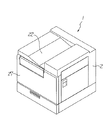
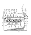
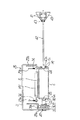
本発明の第1の実施の形態を図1ないし図9に基づいて説明する。図1は画像形成装置であるカラープリンタの外観の概略を示す斜視図、図2はその内部構造の概略を示す正面図である。
【0047】
このカラープリンタ1の本体ケース2内の略中央部には、4つの作像部3(3Y、3C、3M、3B)と、露光装置4と、転写用部材である中間転写ベルト5とが配置されている。各作像部3はそれぞれ異なる色の画像(トナー像)を形成する部分であり、これらの作像部3及びその作像部3の構成部品等に関する明細書及び図面の記載において、Y、C、M、Bの添え字は、各々イエロー、シアン、マゼンタ、ブラックの色を示している。
【0048】
4つの作像部3Y、3C、3M、3Bは、使用するトナーの色が異なるために形成される画像の色が異なるものであり、基本的な構造は同じである。
【0049】
各作像部3は、矢印方向へ回転駆動される感光体6(6Y、6C、6M、5B)、感光体6の周囲に配置された作像手段の一つである帯電器7(7Y、7C、7M、7B)、作像手段の一つである現像器8(8Y、8C、8M、8B)、作像手段の一つであるクリーニング器9(9Y、9C、9M、9B)等により構成されている。
【0050】
露光装置4は、レーザー光を出射し、そのレーザー光により画像データに応じた静電潜像を感光体6の外周面に書き込む。
【0051】
感光体6は、直径が30〜100mm程度のアルミニウム製円筒と、その外周面に設けられた光導電性物質である有機半導体の層とにより形成されている。露光装置4から出射されたレーザー光が感光体6の外周面に照射されることにより、感光体6の外周面には画像データに応じた静電潜像が書き込まれる。なお、露光装置4から出射されたレーザー光を各感光体6の外周面に照射させるための照射用スリット10が、各作像部3における帯電器7と現像器8との間に設けられている。
【0052】
帯電器7は、感光体6の外周面を一様に帯電するもので、感光体6に対して非接触方式のものが採用されている。
【0053】
現像器8は、感光体6へのトナーの供給を行い、供給されたトナーが感光体6の外周面に書き込まれた静電潜像に付着することにより感光体6上の静電潜像がトナー像として顕像化させるもので、感光体6に対して非接触方式のものが採用されている。
【0054】
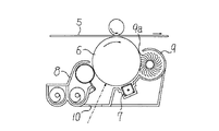
クリーニング器9は、感光体6の外周面に付着している残留トナーをクリーニングするもので、感光体6の外周面にブラシを接触させるブラシ接触方式のものが採用されている。さらに、このクリーニング器9は、その開口部9a(図9参照)が上向きに開口するように、即ち、開口部9aの水平面に対する傾斜角度が90°より小さくなるように位置付けられている。
【0055】
中間転写ベルト5は、厚みが50〜600μmの樹脂フィルム又はゴムを基体として形成されたループ状のベルトで、感光体6上に形成されたトナー像が転写可能となる抵抗値を有している。この中間転写ベルト5は、ローラ11、12、13により支持されて矢印方向へ回転駆動される。中間転写ベルト5の内周面側(ループの内側)には、各感光体6上のトナー像を中間転写ベルト5上に転写させるための4個の転写ローラ14が配置されている。中間転写ベルト5の外周面側(ループの外側)には、中間転写ベルト5の外周面に付着した残留トナーや紙粉等をクリーニングするクリーニング器15が配置されている。
【0056】
本体ケース2内における4個の作像部3及び露光装置4の下方には、記録媒体(用紙)Sが積層保持される給紙カセット16が配置されている。給紙カセット16内に積層保持されている記録媒体Sは、最上位のものから順に分離給紙される。
【0057】
本体ケース2内には、給紙カセット16内から分離給紙された記録媒体Sが搬送される搬送経路17が形成されている。この搬送経路17上には、レジストローラ18、中間転写ローラ19、定着器20、排紙ローラ21等が配置されている。
【0058】
レジストローラ18は、所定のタイミングで間欠的に回転駆動されるローラである。このレジストローラ18が間欠的に回転駆動されることにより、レジストローラ18の位置まで搬送されて停止していた記録媒体Sが、中間転写ベルト5と中間転写ローラ19とにより挟まれる転写位置へ送り込まれ、この転写位置において中間転写ベルト5上のトナー像が記録媒体Sに転写される。
【0059】
定着器20は、記録媒体S上に転写されたトナー像を熱と圧力とを加えて記録媒体Sに定着させる部分である。定着器20内を通過する過程においてトナー像が定着された記録媒体Sは、排紙ローラ21により本体ケース2の上面部に形成されている排紙トレイ部22上に排紙される。
【0060】
本体ケース2内における4個の作像部3及び中間転写ベルト5の上方には、作像部3に補給されるトナーを収納したトナー容器23(23Y、23C、23M、23B)が着脱自在に装着されるトナー容器装着部24が設けられている。トナー容器装着部24に装着された各トナー容器23Y、23C、23M、23B内のトナーは、それぞれのトナーの色と同じ色の画像を形成する各作像部3Y、3C、3M、3Bへ向けてトナー搬送機構(図示せず)により搬送される。
【0061】
上述した中間転写ベルト5、感光体6、帯電器7、現像器8、クリーニング器9等のうち、4個の感光体6と中間転写ベルト5とは一体的に保持されて転写ユニット25が構成されている。また、各作像部3ごとの帯電器7と現像器8とクリーニング器9とは一体的に保持されて作像ユニット26が構成されている。各作像部3ごとの4個の作像ユニット26は一つの作像ユニットトレイ26a(図4、図6参照)上に載置され、この作像ユニットトレイ26aに対して作像ユニット26が着脱自在に取付けられている。
【0062】
図4は、本体ケース2の正面側に設けられている正面カバー27を開放した状態を示している。正面カバー27を開放することにより、転写ユニット25、4個の作像ユニット26が載置された作像ユニットトレイ26a、トナー容器装着部24が露出され、転写ユニット25、作像ユニット26、トナー容器23の交換作業が可能となる。なお、転写ユニット25と作像ユニット26との間には、作像ユニット26を載置した作像ユニットトレイ26aを上下方向に移動させることにより転写ユニット25と作像ユニット26とを接離させる接離機構(図示せず)が設けられている。この接離機構は、正面カバー27を開放する動作に伴って作像ユニットトレイ26aを下方に移動させ、正面カバー27を閉止する動作に伴って作像ユニットトレイ26aを上昇させるように構成されている。なお、このような正面カバー27の開閉動作に連動する接離機構に代えて、レバー操作されるカムにより作像ユニットトレイ26aを昇降させる接離機構を設けてもよい。
【0063】
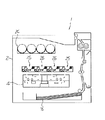
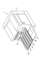
図5は、転写ユニット25を本体ケース2外に引き出した状態を示し、図6は、作像ユニット26を本体ケース2外に引き出した状態を示している。図3は、転写ユニット25を本体ケース2外に引き出したときのカラープリンタの内部構造の概略を示す正面図である。
【0064】
なお、本実施の形態では、転写ユニット25と作像ユニット26とを別個に本体ケース2外に引き出す構造を例に挙げて示したが、これらの転写ユニット25と作像ユニット26とを一体に引き出し可能とし、引き出した後に転写ユニット25を作像ユニット26から分離させて交換し、また、転写ユニット25を作像ユニット26から分離した後に作像ユニット26を交換するように構成してもよい。このような構成の変形例によれば、転写ユニット25と作像ユニット26との間に接離機構を設ける必要がなくなり、作像ユニット26の上部に所定間隔を隔てて転写ユニット25を載置する構造とすればよく、本体ケース2内に作像ユニット26と転写ユニット25とを取付ける構造を簡単化することができる。
【0065】
転写ユニット25は、図7及び図8に示すように、前後一対の中間転写ベルト保持側板28a、28b、前後一対のカラー画像用の転写ローラ14Y、14C、14Mを保持する転写ローラ保持側板29a、29b、これらの中間転写ベルト保持側板28a、28bと転写ローラ保持側板29a、29bとを連結するステー(図示せず)等から構成される枠体を有している。中間転写ベルト保持側板28a、28b間には、ローラ11、12、13と黒用の転写ローラ14Bとが保持されている。転写ユニット25の一部として設けられている両側のステー(図示せず)には、転写ユニット25を本体ケース2に着脱する際にスライドさせるスライドレール30が固定されている(図5参照)。中間転写ベルト保持側板28a、28bの上部側外周部には樹脂製のカバー31が固定され、このカバー31の正面部と上面部とには転写ユニット25を本体ケース2に着脱する際に把持できる取っ手32、33が設けられている。転写ローラ14の軸部には、転写ローラ14を感光体6側へ付勢するスプリング34が設けられている。
【0066】
黒用の転写ローラ14Bは、中間転写ベルト5を感光体6の外周面へ押圧する位置に配置されている。カラー用の転写ローラ14Y、14C、14Mは、転写ローラ保持側板29a、29bと共に、中間転写ベルト5を感光体6の外周面から離反させる位置(図7参照)と、中間転写ベルト5を感光体6の外周面に押圧する位置とへ切替自在に設けられている。
【0067】
転写ユニット25における感光体6の保持構造について詳しく説明する。前側の中間転写ベルト保持側板28aには感光体前ホルダ35が固定され、この感光体前ホルダ35には球軸受36の外輪が圧入されている。球軸受36の内輪にはスプリングホルダ37が圧入され、スプリングホルダ37には加圧スプリング38の一端が挿入固定されている。後側の中間転写ベルト保持側板28bには感光体後ホルダ39が固定されている。感光体6の後側フランジ部6bは、感光体後ホルダ39に十分なクリアランスをもった状態で差し込まれている。感光体6の前側フランジ部6aは、加圧スプリング38の他端に差し込まれている。これにより、個々の感光体6は、感光体前ホルダ35と感光体後ホルダ39との間で加圧スプリング38の加圧力によって保持され、及び、個々の感光体6は転写ユニット25に対して着脱自在に保持されている。
【0068】
本体ケース2内の内部側板(図示せず)には、4個の本体側感光体軸ホルダ40が固定されている。この本体側感光体軸ホルダ40には、2個の球軸受41を介して感光体軸42が保持され、感光体軸42には駆動用カップリング43が圧入されている。感光体軸42は、後側(球軸受41や駆動用カップリング43が圧入されている部分)がφ12mm、前側がφ10mmに形成され、水平方向に延出されている。
【0069】
中間転写ベルト5と4個の感光体6とを保持した転写ユニット25を、本体ケース2内に取付ける構造を図7及び図8を参照して詳しく説明する。転写ユニット25を本体ケース2内へ向けてスライドさせることにより、感光体軸42の先端部を感光体6の後側フランジ部6bから前側フランジ部6aに向けて挿入させる。感光体軸42のφ12mmの部分が後側フランジ部6bに形成されている穴径がφ12mmの穴44に嵌合する位置まで転写ユニット25をスライドさせることにより、感光体6の後側が本体ケース2に対して位置決めされ、駆動用カップリング43が後側フランジ部6bに形成されている噛合部43aと噛合い、駆動部(図示せず)から感光体6への駆動力伝達が可能となる。さらに、感光体後ホルダ39の一部が球軸受41の外輪部に嵌合されることにより、転写ユニット25の全体が本体ケース2に対して位置決めされる。
【0070】
感光体軸42の前側は、前側フランジ部6aに形成されている穴45(φ10mm)と、スプリングホルダ37に形成されている穴46(φ11mm)と、中間転写ベルト保持側板28aに取付けられている軸受47の内輪(φ10mm)とに挿入される。
【0071】
作像ユニットトレイ26aには、図6に示すように、その両側に位置してこの作像ユニットトレイ26aを本体ケース2に着脱する際にスライドさせるスライドレール48が固定され、正面部には作像ユニットトレイ26aを本体ケース2に着脱する際に把持できる取っ手49が設けられている。
【0072】
このような構成において、カラー画像のプリント時には、各作像部3の感光体6の外周面にそれぞれ異なった色のトナー像が形成され、各感光体6の外周面に中間転写ベルト5が押圧されることにより感光体6上のトナー像が中間転写ベルト5上に重ね転写され、中間転写ベルト5上にカラーのトナー像が形成される。
中間転写ベルト5上に形成されたカラーのトナー像は、給紙カセット16内から分離給紙された記録媒体Sが中間転写ベルト5と中間転写ローラ19とによる挟持位置を通過する過程でその記録媒体Sに転写される。記録媒体S上に転写されたカラーのトナー像はその記録媒体Sが定着器20内を通過する過程で定着され、カラーのトナー像が定着された記録媒体Sが排紙トレイ部22に排紙される。
【0073】
このようなカラープリンタ1において、様々な原因により記録媒体S上に形成される画像の品質が低下する場合があり、そのような画像品質低下の原因の一つとして、感光体6の外周面に傷が付いた場合がある。そして、このような感光体6の外周面に傷が付いた場合、その傷付きの原因は中間転写ベルト5にある場合が多い。
【0074】
例えば、中間転写ベルト5の外周面に紙粉や残留トナーを含んだ異物が固着した場合、その異物が感光体6の外周面に押圧されたときに感光体6の外周面に点状の傷が付く。そして、画像形成時においては中間転写ベルト5と感光体6との接触位置が常に同じになるということはほとんどなく、画像形成のたびに中間転写ベルト5上の異物が感光体6の外周面の異なる位置に押圧を繰り返すことになり、感光体6の外周面の傷は次第にスジ状の傷に成長する。感光体6の外周面にスジ状の傷が付いた場合には、感光体6の外周面上ではその傷の部分に多量のトナーが付着するようになり、記録媒体S上ではそのスジ状の傷に対応する部分が黒スジとなって現れる。
【0075】
また、中間転写ベルト5を回転駆動させるローラ11、12、13と中間転写ベルト5の内周面との間に異物が入り込んだ場合には、その異物の影響により中間転写ベルト5の外周面側に凸部が生じ、その凸部が感光体6の外周面に押圧されることにより感光体6の外周面に点状の傷が付く。そして、画像形成時においては中間転写ベルト5と感光体6との接触位置が常に同じになるということはほとんどなく、画像形成のたびに中間転写ベルト5上の凸部が感光体6の外周面の異なる位置に押圧を繰り返すことになり、感光体6の外周面の傷は次第にスジ状の傷に成長し、記録媒体S上ではそのスジ状の傷に対応する部分が黒スジとなって現れる。
【0076】
このような場合において、感光体6のみを交換したのでは、交換した感光体6に短期間のうちに再び同じような傷が付き、形成される画像の品質が低下する。
そこで、このような場合には、傷付きが生じている全ての感光体6とその原因となっている中間転写ベルト5とをともに交換しなければならず、転写ユニット25を全体として交換する。
【0077】
転写ユニット25の交換に際しては、図4に示すように正面カバー27を開放する。正面カバー27の開放動作に伴い、接離機構により作像ユニットトレイ26aが下方に下がり、作像ユニット26が転写ユニット25から離反する。
【0078】
そこで、転写ユニット25の正面部に設けられている取っ手32を把持し、図5に示すように転写ユニット25を正面側へスライドさせ、所定位置までスライドさせた後に取っ手32、33を把持して転写ユニット25を本体ケース2から取外す。この取外し時には、図7に示すように、4つの感光体6がそれぞれ感光体軸42から抜き取られる。
【0079】
このようして転写ユニット25を本体ケース2から取外した後、用意してある新しい転写ユニット25を取外し時とは逆の手順で本体ケース2内に取付け(図8参照)、正面カバー27を閉止する。
【0080】
したがって、感光体6の外周面の傷付きにより記録媒体S上に形成される画像品質が低下した場合には、傷が付いた感光体6とその傷付きの原因となっている可能性が高い中間転写ベルト5とを一体に交換することができ、感光体6と中間転写ベルト5とを個別に交換する場合に比べて、交換作業の手間を大幅に軽減することができる。また、この交換作業を、感光体6の表面を傷付けたり感光体6を露光させたりすることなく行える。交換作業時において感光体6の露光を防止できるという点については、この転写ユニット25の構成が、上側に中間転写ベルト5が配置されてその下側に感光体6が配置されているので、中間転写ベルト5が感光体6に対する遮光機能を十分に発揮することができる。
【0081】
一方、記録媒体S上に形成された画像品質の低下の原因が、中間転写ベルト5に付着した異物や中間転写ベルト5に形成された凸部が感光体6の外周面を傷付けたからではなく、個々の感光体6にある場合がある。例えば、感光体6の外周面に帯電性生物の膜が付着した場合等である。このような場合には、図7に示すように転写ユニット25を本体ケース2外へ取外した後、画像品質低下の原因のある感光体6のみを交換することができる。この感光体6の交換は、感光体前ホルダ35と感光体後ホルダ39との間に加圧スプリング38の加圧力により保持されている感光体6を、加圧スプリング38の加圧力に抗して加圧スプリング38側へ移動させることにより後側フランジ部6bを感光体後ホルダ39が抜き取り、ついで、前側フランジ部6aを加圧スプリング38の端部から外すことにより行える。新しい感光体6の取付けはその逆の手順で行えばよく、感光体6と加圧スプリング38とを感光体前ホルダ35にセットした後、加圧スプリング38を圧縮した状態で後側を感光体後ホルダ39へ差し込み、前側は感光体前ホルダ35を中間転写ベルト保持側板28aの取付用の穴35aに差し込むことにより、感光体前ホルダ35は加圧スプリング38の力で穴35aを前側へスライドしてその穴35aから抜け止めされる。
【0082】
したがって、画像品質の低下の原因が或る特定の感光体6にある場合には、その感光体6のみを交換することができ、画像品質の低下の原因がない他の感光体6や中間転写ベルト5については引き続き使用することができるため、不要なコスト高を招くということが生じない。このような或る特定の感光体6を交換するために転写ユニット25を本体ケース2外に取り出している時間が長くなる場合でも、上側に中間転写ベルト5が配置されてその下側に感光体6が配置された構成であるので、中間転写ベルト5が感光体6に対する遮光機能を十分に発揮することができ、交換しない感光体6が露光により劣化することを抑制できる。
【0083】
また、このカラープリンタ1では、図4に示すように正面カバー27を開放して作像ユニットトレイ26aを下方へ下げた後、図6に示すようにこの作像ユニットトレイ26aを正面側へ引き出すことができる。そして、各作像部3ごとの帯電器7と現像器8とクリーニング器9とが一体的に保持された作像ユニット26を作像ユニットトレイ26a上から取外すことにより、各作像ユニット26を新しいものに交換することができる。
【0084】
帯電器7や現像器8及びクリーニング器9等は、感光体6や中間転写ベルト5に比べて耐用期間を短く定められていることが多く、交換頻度も感光体6や中間転写ベルト5に比べて高い。このため、これらの帯電器7や現像器8及びクリーニング器9等を作像ユニット26として一体化して一度に交換できる構成とし、しかも、感光体6や中間転写ベルト5を本体ケース2から取外すことなく交換できるので、帯電器7や現像器8及びクリーニング器9等の交換作業を手間をかけず容易に行える。
【0085】
また、各作像ユニット26において、クリーニング器9の開口部9aが上向きに開口するように位置付けられているので、作像ユニット26をクリーニング器9の開口部9aが開口された状態で本体ケース2から取り出した場合でも、その開口部9aから廃トナーがこぼれ落ちるということが防止される。
【0086】
なお、本実施の形態では、感光体6としてドラム状の感光体を例に挙げて説明したが、ベルト状の感光体を用いてもよい。
【0087】
つぎに、本発明の第2の実施の形態を図10に基づいて説明する。なお、図1ないし図9において説明した部分と同じ部分は同じ符号で示し、説明も省略する(以下の実施の形態でも同じ)。
【0088】
画像形成装置であるカラープリンタ50には、本体ケース2の上部に支軸51を支点として回動自在に上部構造体52が設けられ、本体ケース2の側部に支軸53を支点として回動自在に側部構造体54が設けられている。上部構造体52には、トナー容器23(23Y、23C、23M、23B)が着脱自在に装着されるトナー容器装着部24が設けられている。側部構造体54には、定着器20が設けられている。
【0089】
上部構造体52の下面部には、転写ユニット55が矢印方向へスライド自在に取付けられている。この転写ユニット55の基本的構造は第1の実施の形態で説明した転写ユニット25と同じであり、枠体56に保持された中間転写ベルト5と4個の感光体6とを備えている。枠体56の両側には、この転写ユニット55を矢印方向へスライドさせて上部構造体52に着脱する際に把持する取っ手57が設けられている。それぞれの感光体6は枠体56に対して個々に着脱自在に取付けられている。
【0090】
本体ケース2内には、閉止位置に回動された上部構造体52に取付けられている転写ユニット55の各感光体6に対向する位置に配置された4個の作像ユニット26が着脱可能に配置されている。
【0091】
このような構成において、外周面に傷が付いた感光体6とその傷付きの原因となっている可能性が高い中間転写ベルト5とを交換する場合には、上部構造体52を図示する開放位置へ回動させ、転写ユニット55を矢印方向へ引き出すことにより上部構造体52から取外す。転写ユニット55を取外した後、用意してある新しい転写ユニット55を上部構造体52に取付け、その後上部構造体52を閉止する。
【0092】
一方、記録媒体S上に形成された画像の品質低下の原因が、個々の感光体6にある場合には、画像品質低下の原因のある感光体6のみを交換し、他の感光体6や中間転写ベルト5を引き続き使用することができる。
【0093】
作像ユニット26を交換する場合には、図示する上方回動位置へ上部構造体52を回動させることにより作像ユニット26を露出させ、露出された個々の作像ユニット26を必要に応じて新しいものに交換することができる。
【0094】
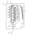
つぎに、本発明の第3の実施の形態を図11及び図12に基づいて説明する。
画像形成装置である本実施の形態のカラープリンタ60は、4個の作像部3を有するタンデム方式を採用しているという基本的構成は第1の実施の形態のカラープリンタ1と同じであるが、中間転写ベルトを使用しない点がカラープリンタ1の構成と異なる。
【0095】
このカラープリンタ60には、感光体6の外周面に押圧される転写用部材としての記録媒体搬送ベルト61が設けられており、記録媒体搬送ベルト61はローラ11、12、13に支持されて矢印方向へ駆動され、記録媒体Sを静電吸着して搬送する。記録媒体搬送ベルト61の内周面側(ループの内側)には、各感光体6上のトナー像を静電吸着して搬送している記録媒体S上に転写させるための4個の転写ローラ14が配置されている。記録媒体搬送ベルト61の外周面側(ループの外側)には、記録媒体搬送ベルト61の外周面に付着したトナーや紙粉等をクリーニングするクリーニング器15が配置されている。
【0096】
記録媒体搬送ベルト61と4個の感光体6とは、図7及び図8に示したような前後の保持側板28a、28b、29a、29bやステー等により構成される枠体に一体的に保持され、転写ユニット62が構成されている。この転写ユニット62において、上側に記録媒体搬送ベルト61が配置され、その下側に感光体6が配置されている。また、個々の感光体6は転写ユニット62に対して着脱自在に保持されている。
【0097】
転写ユニット62は本体ケース2に対して着脱自在に取付けられており、図11は転写ユニット62が取付けられている状態のカラープリンタ60の内部構造の概略を示し、図12は転写ユニット62が取外されている状態のカラープリンタ60の内部構造の概略を示している。
【0098】
このような構成において、カラー画像のプリント時には、各作像部3の感光体6の外周面にそれぞれ異なった色のトナー像が形成され、各色のトナー像は、給紙カセット16内から分離給紙された後に記録媒体搬送ベルト61により静電吸着されて搬送される記録媒体Sが感光体6の外周面に押圧されることによりその記録媒体S上に順次転写され、記録媒体S上にカラー画像が形成される。記録媒体Sに形成されたカラー画像は、その記録媒体Sが定着器20内を通過する過程で定着され、カラー画像が定着された記録媒体Sが排紙トレイ63上に排紙される。
【0099】
このようなカラープリンタ60において、様々な原因により記録媒体S上に形成される画像の品質が低下する場合があり、そのような画像品質低下の原因の一つとして、感光体6の外周面に傷が付いた場合がある。そして、このような感光体6の外周面に傷が付いた場合、その傷付きの原因は記録媒体搬送ベルト61にある場合が多い。
【0100】
例えば、記録媒体搬送ベルト61の外周面に紙粉や残留トナーを含んだ異物が固着した場合、画像形成時には記録媒体搬送ベルト61と感光体6との間に記録媒体Sが介装されるために記録媒体搬送ベルト61が感光体6の外周面に直接押圧されることは少ない。しかし、搬送される記録媒体S間の部分では記録媒体搬送ベルト61が感光体6の外周面に押圧される。このため、記録媒体搬送ベルト61の外周面に異物が固着した場合には、第1の実施の形態で説明した中間転写ベルト5の場合と同じように、その異物が感光体6の外周面に押圧されることにより経時的に感光体6の外周面にスジ状の傷が付くことになる。そして、感光体6の外周面にスジ状の傷が付いた場合には、感光体6の外周面上ではその傷の部分に多量のトナーが付着するようになり、記録媒体S上ではそのスジ状の傷に対応する部分が黒スジとなって現れる。
【0101】
また、記録媒体搬送ベルト61を回転駆動させるローラ11、12、13と記録媒体搬送ベルト61の内周面との間に異物が入り込んだ場合には、その異物の影響により記録媒体搬送ベルト61の外周面側に凸部が生じ、その凸部が感光体の6の外周面に押圧されることにより経時的に感光体6の外周面にスジ状の傷が付くことになり、記録媒体S上ではそのスジ状の傷に対応する部分が黒スジとなって現れる。
【0102】
このような場合に、感光体6のみを交換したのでは、交換した感光体6に短期間のうちに再び同じような傷が付く。そこで、このような場合には、傷付きが生じている全ての感光体6とその傷付きの原因となっている記録媒体搬送ベルト61とをともに交換しなければならず、転写ユニット62を全体として交換する。
【0103】
転写ユニット62の交換の手順は第1の実施の形態で説明した手順と同じであり、正面カバー27(図4参照)を開放し、開放後に転写ユニット62を正面側へ引き出す。
【0104】
したがって、感光体6の外周面の傷付きにより記録媒体S上に形成される画像品質が低下した場合には、傷が付いた感光体6とその傷付きの原因となっている可能性が高い記録媒体搬送ベルト61とを一体に交換することができ、感光体6と記録媒体搬送ベルト61とを個別に交換する場合に比べて、交換作業の手間を大幅に軽減することができる。また、この交換作業を、感光体6の表面を傷付けたり感光体6を露光させたりすることなく行える。
【0105】
一方、記録媒体S上に形成された画像品質の低下の原因が、記録媒体搬送ベルト61に付着した異物や記録媒体搬送ベルト61に形成された凸部が感光体6の外周面を傷付けたからではなく、個々の感光体6にある場合がある。例えば、感光体6の外周面に帯電性生物の膜が付着した場合等である。このような場合には、第1の実施の形態での説明と同じように、転写ユニット62を本体ケース2外へ取外した後、画像品質低下の原因のある感光体6のみを交換し、画像品質低下の原因がない他の感光体6や記録媒体搬送ベルト61を引き続き使用することができる。
【0106】
なお、本実施の形態では、第1の実施の形態と同じように、転写ユニット62と作像ユニット26とを別個に本体ケース2外に引き出す場合を例に挙げて示したが、これらの転写ユニット62と作像ユニット26とを一体に引き出し可能とし、引き出した後に転写ユニット62を作像ユニット26から分離させて交換し、また、転写ユニット62を作像ユニット26から分離した後に作像ユニット26を交換する構成としてもよい。このような構成の変形例によれば、転写ユニット62と作像ユニット26との間に接離機構を設ける必要がなくなり、作像ユニット26の上部に所定間隔を隔てて転写ユニット62を載置する構造とすればよく、本体ケース2内に作像ユニット26と転写ユニット62とを取付ける構造を簡単化することができる。
【0119】
【発明の効果】
請求項1記載の画像形成装置によれば、複数の感光体の外周面の傷付きにより記録媒体上に形成される画像の品質が低下した場合には、外周面に傷が付いた複数の感光体とその感光体の傷付きの原因となっている可能性の高い転写用部材とを一体的に保持している転写ユニットを一体に交換することができ、画像品質の低下の原因となっている部品の交換作業に要する手間を軽減できるとともに、同じような画像品質の低下の発生を繰り返すことなく画像品質の回復を確実に図ることができる。また、現像器は感光体や転写用部材に比べて耐用期間を短く定められていることが多く、交換頻度が感光体や転写用部材に比べて高いので、現像器を備える作像ユニットを転写ユニットと別個のユニットとすることにより、現像器又は現像器を備える作像ユニットを転写ユニットとは別個に交換することができる。さらに、転写用部材に問題はなく感光体が耐用期間に達した場合には感光体のみを交換することができ、この交換を、転写ユニットを本体ケース外に引き出した状態で行うことができる。
【0120】
請求項2記載の発明によれば、請求項1記載の画像形成装置において、転写用部材は中間転写ベルトであるので、感光体の外周面の傷付きにより記録媒体上に形成される画像の品質が低下した場合には、転写ユニットを交換することにより、外周面に傷が付いた複数の感光体とその傷付きの原因となっている可能性が高い中間転写ベルトとを一体に交換することができ、画像品質の低下の原因となっている部品の交換作業に要する手間を軽減できるとともに、同じような画像品質の低下の発生を繰り返すことなく画像品質の回復を確実に図ることができる。
【0121】
請求項3記載の発明によれば、請求項2記載の画像形成装置において、前記中間転写ベルトが上側に配置され、その下側に前記感光体が配置されているので、複数の感光体と中間転写ベルトとを備えた転写ユニットをメンテナンス等のために本体ケースから取外した場合において、感光体が中間転写ベルトにより遮光されるので、露光による感光体の劣化を抑制できる。
【0122】
請求項4記載の発明によれば、請求項1記載の画像形成装置において、転写用部材は記録媒体搬送ベルトであるので、感光体の外周面の傷付きにより記録媒体上に形成される画像の品質が低下した場合には、転写ユニットを交換することにより、外周面に傷が付いた複数の感光体とその傷付きの原因となっている可能性が高い記録媒体搬送ベルトとを一体に交換することができ、画像品質の低下の原因となっている部品の交換作業に要する手間を軽減できるとともに、同じような画像品質の低下の発生を繰り返すことなく画像品質の回復を確実に図ることができる。
【0123】
請求項5記載の発明によれば、請求項4記載の画像形成装置において、前記記録媒体搬送ベルトが上側に配置され、その下側に前記感光体が配置されているので、複数の感光体と記録媒体搬送ベルトとを備えた転写ユニットをメンテナンス等のために本体ケースから取外した場合において、感光体が記録媒体搬送ベルトにより遮光されるので、露光による感光体の劣化を抑制できる。
【0126】
請求項6記載の発明によれば、請求項1ないし5のいずれか一記載の画像形成装置において、前記作像ユニットが前記転写ユニットとは別個に前記本体ケースに対して着脱自在に取付けられているので、作像手段を一体化した作像ユニットを本体ケースに対して一体に着脱することにより、複数の作像手段を一体に交換することができ、作像手段の交換作業の手間を軽減することができ、また、転写ユニットを本体ケースから取外すことなく作像ユニットを本体ケースから取外すことができる。
【0127】
請求項7記載の発明によれば、請求項1ないし6のいずれか一記載の画像形成装置において、前記作像手段の一つとして帯電器が設けられ、この帯電器は前記感光体に対して非接触方式であるので、帯電器に異物が固着しても、その異物が感光体に押圧されて感光体の外周面を傷付けるということが発生せず、帯電器については転写ユニットの交換タイミングと異なるタイミングで交換することができる。
【0128】
請求項8記載の発明によれば、請求項1ないし6のいずれか一記載の画像形成装置において、前記作像手段の一つとして現像器が設けられ、この現像器は前記感光体に対して非接触方式であるので、現像器に異物が固着しても、その異物が感光体に押圧されて感光体の外周面を傷付けるということが発生せず、感光体については転写ユニットの交換タイミングと異なるタイミングで交換することができる。
【0129】
請求項9記載の発明によれば、請求項1ないし6のいずれか一記載の画像形成装置において、前記作像手段の一つとしてクリーニング器が設けられ、このクリーニング器はブラシ接触方式であるので、クリーニング器に異物が固着しても、その異物が感光体に押圧されて感光体の外周面を傷付けるということが発生せず、クリーニング器については転写ユニットの交換タイミングと異なるタイミングで交換することができる。
【0130】
請求項10記載の発明によれば、請求項1ないし6のいずれか一記載の画像形成装置において、前記作像ユニットの上側に前記転写ユニットが設置されているので、本体ケースからの転写ユニットの取外しを、本体ケースから現像ユニットを取外すことなく行うことができ、また、作像ユニットと転写ユニットとを本体ケース内に取付ける構造を簡単化することができる。
【0131】
請求項11記載の発明によれば、請求項1ないし6のいずれか一記載の画像形成装置において、前記作像手段の一つとしてクリーニング器が設けられ、前記作像ユニットにおける前記クリーニング器の開口部が上向きに開口しているので、クリーニング器の開口部が開口された状態で作像ケースを本体ケースから取り出した場合でも、その開口部から廃トナーがこぼれ落ちるということを防止できる。
【0132】
請求項12記載の発明の転写ユニットは、複数の感光体と前記複数の感光体上のトナー像を記録媒体上に転写する転写用部材とを一体的に保持し、これら感光体と転写用部材とを一体的に保持した状態で本体ケースに対して着脱交換可能に取り付けられ、前記本体ケースから引き出し取り外した状態で前記複数の感光体を着脱可能に保持する機構を備えるので、感光体に傷が付いて画像品質が低下した場合には、その感光板と傷付きの原因となっている可能性の高い部材である転写用部材とを一体に交換することができ、これらの感光体と転写用部材との交換に要する手間を軽減でき、感光体のみを交換して転写用部材を交換しなかったために発生する同じような感光体の傷付きの繰り返しを効率よく阻止することができる。
【図面の簡単な説明】
【図1】本発明の第1の実施の形態のカラープリンタの外観の概略を示す斜視図である。
【図2】その内部構造の概略を示す正面図である。
【図3】転写ユニットを本体ケース外に取外した状態の内部構造の概略を示す正面図である。
【図4】正面カバーを開放した状態の外観の概略を示す斜視図である。
【図5】転写ユニットを引き出した状態の外観の概略を示す斜視図である。
【図6】現像ユニットを現像ユニットトレイと共に引き出した状態の外観の概略を示す斜視図である。
【図7】転写ユニットを本体ケース外に取外した状態の概略を示す縦断側面図である。
【図8】転写ユニットを本体ケース内に取付けた状態の概略を示す縦断側面図である。
【図9】現像ユニットの概略構造を示す縦断正面図である。
【図10】本発明の第2の実施の形態のカラープリンタの外観の概略を示す正面図である。
【図11】本発明の第3の実施の形態のカラープリンタの内部構造の概略を示す正面図である。
【図12】転写ユニットを本体ケース外に取外した状態の内部構造の概略を示す正面図である。
【符号の説明】
2 本体ケース
5 転写用部材、中間転写部材
6 感光体
7 作像手段、帯電器
8 作像手段、現像器
9 作像手段、クリーニング器
9a 開口部
25 転写ユニット
26 作像ユニット
61 転写用部材、記録媒体搬送ベルト
62 転写ユニット
S 記録媒体[0001]
BACKGROUND OF THE INVENTION
The present invention relates to an electrophotographic image forming apparatus and a transfer unit.
[0002]
[Prior art]
2. Description of the Related Art Image forming apparatuses such as copying machines and printers that employ an electrophotographic method have a photoreceptor on which the toner image is formed on the outer circumferential surface, and the toner image is formed on the outer circumferential surface of the photoreceptor disposed around the photoreceptor. Each member such as a transfer roller and an intermediate transfer belt for transferring a toner image formed on the outer peripheral surface of the photosensitive member to a recording medium as a charging device, a developing device, a cleaning device as an image forming means concerned. Have.
[0003]
Each of these members has a lifetime determined as a standard depending on the material and usage, and is replaced according to the lifetime. Moreover, it may be necessary to replace even before the end of the useful life due to dust adhesion or scratches.
[0004]
Regarding the configuration for replacing each member, it is possible to replace each member individually, but in that case, the frequency of the replacement work increases and it takes time and effort. Other members located adjacent to each other may be damaged. In view of this, an image forming apparatus in which a process cartridge in which a photosensitive member, a charging device, a developing device, a cleaning device, and the like are unitized is configured and these members are replaced at once has been widely used.
[0005]
However, in recent years, an image forming apparatus has been proposed that can extend the life of the photosensitive member, which is the most expensive member, and can be replaced separately from other members. It has become.
[0006]
When the photoconductor is configured to be exchangeable separately from other members in this way, the image quality formed on the recording medium is deteriorated due to the outer peripheral surface of the photoconductor being scratched. In this case, only the photoconductor is replaced.
[0007]
[Patent Document 1]
JP 2002-108049 A
[Patent Document 2]
JP2000-227688
[0008]
[Problems to be solved by the invention]
However, when the outer peripheral surface of the photosensitive member is scratched, the cause of the scratch is a transfer member that is pressed against the outer peripheral surface of the photosensitive member, such as an intermediate transfer belt, a recording medium conveyance belt, or a transfer roller. There are many cases. For this reason, even if the damaged photosensitive member is replaced, if the transfer member causing the scratch is not replaced, the replaced photosensitive member is damaged again in a short time, and the image quality is lowered again. Things are likely to happen.
[0009]
For example, in a color image forming apparatus having an intermediate transfer belt, when a foreign matter containing paper dust or residual toner adheres to the outer peripheral surface of the intermediate transfer belt, the foreign matter is pressed against the outer peripheral surface of the photosensitive member. The spot-like scratches gradually become streaks by making spot-like scratches on the outer peripheral surface and repeatedly pressing the foreign matter against the photoconductor. When streaky scratches are found on the outer peripheral surface of the photoconductor, a large amount of toner adheres to the streaky scratches on the photoconductor, and the streaky scratches are supported on the recording medium. Appear as black streaks.
[0010]
In addition, when foreign matter enters between the roller that rotates the intermediate transfer belt and the inner peripheral surface of the intermediate transfer belt, a convex portion is generated on the outer peripheral surface side of the intermediate transfer belt due to the influence of the foreign matter. As the portion is pressed against the outer peripheral surface of the photoconductor, dot-like scratches are formed on the outer peripheral surface of the photoconductor, and when the convex portion repeatedly presses against the outer peripheral surface of the photoconductor, the dot-like scratches gradually become streaks. It becomes a shape.
[0011]
In a color image forming apparatus in which a recording medium is conveyed by a recording medium conveyance belt without using an intermediate transfer belt, recording is performed because the recording medium is interposed between the recording medium conveyance belt and the photosensitive member during image formation. The medium conveying belt is hardly pressed directly against the outer peripheral surface of the photosensitive member. However, the recording medium transport belt is pressed against the outer peripheral surface of the photosensitive member at a portion between the recording media transported back and forth. For this reason, when a foreign object adheres to the outer peripheral surface of the recording medium transport belt, or a foreign object enters between the recording medium transport belt and the rotation driving roller, there is a convex portion toward the outer peripheral surface of the recording medium transport belt. If this occurs, streak-like scratches will be made on the outer peripheral surface of the photoreceptor as in the case of the intermediate transfer belt.
[0012]
Even in a single-color image forming apparatus having a transfer roller that is pressed against the outer peripheral surface of the photoconductor without using an intermediate transfer belt or a recording medium conveying belt, if foreign matter adheres to the outer peripheral surface of the transfer roller, Scratches caused by foreign matter are attached to the outer peripheral surface of the photoreceptor.
[0013]
It is an object of the present invention to provide a transfer that is highly likely to cause damage to the photoreceptor and the outer peripheral surface of the photoreceptor when image quality is deteriorated due to damage to the outer periphery of the photoreceptor. It is to replace the working member as one body, reduce the labor of the replacement work, and prevent the outer peripheral surface of the photoreceptor from being repeatedly damaged.
[0014]
Another object of the present invention is that when the cause of the image quality deterioration is not in the transfer member but only in the photosensitive member, for example, in the case where a film with a charged product or the like is formed on the outer peripheral surface of the photosensitive member. In other words, it is possible to replace only the photoconductor alone.
[0015]
[Means for Solving the Problems]
According to the present invention, the above-mentioned two objects are an image forming apparatus having a plurality of photoconductors having toner images formed on the outer peripheral surface thereof, and transferring the toner images formed on the plurality of photoconductors onto a recording medium. The plurality of photoconductors and a transfer member for transferring toner images on the plurality of photoconductors onto a recording medium are integrally held, and the photoconductor and the transfer member are integrated with each other. Hold it against the caseDetachable and replaceableA transfer unit attached to the image forming unit, and an image forming unit including at least a plurality of image forming means for performing development on each of the plurality of photoconductors;Pull the transfer unit out of the main body case until it can be removed from the main body case with the photosensitive member and the transfer member held together.A sliding mechanism and the transfer unit from the main body case.Pulled out and removedAnd a mechanism for holding the plurality of photoconductors in a replaceable manner.
[0016]
Here, when the quality of the image formed on the recording medium is deteriorated due to scratches on the outer peripheral surface of the photosensitive member, the cause of the scratches on the outer peripheral surface of the photosensitive member is a foreign matter fixed to the transfer member, In many cases, it is a convex portion or the like generated on the outer peripheral surface side of the transfer member because foreign matter has entered between the inner peripheral surface of the transfer member and a roller for driving the transfer member.
[0017]
ThereforeOutsideA transfer unit that integrally holds a plurality of photoconductors with scratches on the peripheral surface and a transfer member that is likely to cause damage to the photoconductor can be replaced as a single unit. In addition, it is possible to reduce the time and effort required to replace the parts that cause the degradation of the image quality, and it is possible to reliably restore the image quality without repeating the occurrence of the similar degradation of the image quality. To replace the transfer unit, slide the transfer unit and pull it out of the case.It can be carried out.MaCurrentBy making the image forming unit including the imager a unit separate from the transfer unit, the developing unit or the image forming unit including the developer can be replaced separately from the transfer unit. Further, there is no problem with the transfer member, and when the photoconductor reaches the end of its useful life, only the photoconductor can be replaced, and this replacement can be performed with the transfer unit pulled out of the main body case.
[0018]
According to a second aspect of the present invention, in the image forming apparatus according to the first aspect, the transfer memberIsIntermediate transfer beltIsIt is characterized by that.
[0019]
Therefore, a plurality of photoconductors and intermediate transfer beltA transfer unit that holds the unit togetherIn the image forming apparatus provided, when the quality of the image formed on the recording medium is deteriorated due to scratches on the outer peripheral surface of the photoconductor, the plurality of photoconductors having the outer peripheral surface scratched and causes of the scratches It is possible to replace the intermediate transfer belt that is likely to become a single unit, reducing the work required to replace the parts that are causing the image quality to be reduced, and reducing the image quality as well. The image quality can be reliably recovered without repeating the occurrence of the above.
[0020]
According to a third aspect of the present invention, in the image forming apparatus according to the second aspect, the intermediate transfer belt is disposed on the upper side, and the photoconductor is disposed on the lower side.
[0021]
Therefore, when a transfer unit including a plurality of photoconductors and an intermediate transfer belt is removed from the main body case for maintenance or the like, the photoconductor is shielded from light by the intermediate transfer belt, so that deterioration of the photoconductor due to exposure is suppressed. Is done.
[0022]
According to a fourth aspect of the present invention, in the image forming apparatus according to the first aspect, the transfer memberIsRecording medium transport beltIsIt is characterized by that.
[0023]
Therefore, a plurality of photoreceptors and a recording medium conveyance beltA transfer unit that holds the unit togetherIn the image forming apparatus provided, when the quality of the image formed on the recording medium is deteriorated due to scratches on the outer peripheral surface of the photoconductor, the plurality of photoconductors having the outer peripheral surface scratched and causes of the scratches It is possible to replace the recording medium transport belt that has a high possibility of becoming a single unit, reducing the time and effort required to replace the parts that cause the degradation of the image quality, and providing similar image quality. The image quality can be reliably restored without repeating the occurrence of the deterioration.
[0024]
According to a fifth aspect of the present invention, in the image forming apparatus according to the fourth aspect, the recording medium conveyance belt is disposed on the upper side, and the photoconductor is disposed on the lower side.
[0025]
Therefore, when a transfer unit including a plurality of photoconductors and a recording medium conveyance belt is removed from the main body case for maintenance or the like, the photoconductor is shielded by the recording medium conveyance belt, so that the photoconductor deteriorates due to exposure. Is suppressed.
[0030]
Claim6The invention described in claim 1 to claim 15In the image forming apparatus according to any one of the above,SaidThe image forming unit is detachably attached to the main body case separately from the transfer unit.
[0031]
Here, examples of the image forming means other than the transfer member disposed around the photosensitive member include a charging device, a developing device, and a cleaning device. In addition, some cleaningless image forming apparatuses do not have a cleaning device. Each of these image forming means often has a shorter service life than the photoconductor and transfer member, and the replacement frequency is higher than that of the photoconductor and transfer member.
[0032]
Therefore, a plurality of image forming means can be exchanged integrally by attaching and detaching the image forming unit in which these image forming means are integrated to the main body case. It is reduced. Further, the image forming unit can be detached from the main body case without removing the transfer unit from the main body case.
[0033]
Claim7The described invention is claimed.Any one of 1 to 6In the image forming apparatus described above, a charger is provided as one of the image forming units, and the charger is of a non-contact type with respect to the photoconductor.
[0034]
Therefore, even if a foreign substance adheres to the charger, it does not occur that the foreign substance is pressed against the photoconductor and damages the outer peripheral surface of the photoconductor. For this reason, when the outer peripheral surface of the photoconductor is damaged, the charger is not the cause of the damage. When the transfer unit is replaced because the outer peripheral surface of the photoconductor is damaged, the charger Need not be replaced at the same time.
[0035]
Claim8The described invention is claimed.Any one of 1 to 6In the image forming apparatus described above, a developing unit is provided as one of the image forming units, and the developing unit is a non-contact type with respect to the photosensitive member.
[0036]
Therefore, even if a foreign object adheres to the developing device, the foreign object is not pressed against the photoconductor and does not damage the outer peripheral surface of the photoconductor. For this reason, when the outer peripheral surface of the photoconductor is scratched, the cause of the scratch is not in the developing unit. When the transfer unit is replaced because the outer peripheral surface of the photoconductor is damaged, the developing device Need not be replaced at the same time.
[0037]
Claim9The described invention is claimed.Any one of 1 to 6In the image forming apparatus described above, a cleaning device is provided as one of the image forming units, and the cleaning device is of a brush contact type.
[0038]
Therefore, even if a foreign substance adheres to the cleaning device, it does not occur that the foreign substance is pressed against the photoconductor and damages the outer peripheral surface of the photoconductor. For this reason, when the outer peripheral surface of the photoconductor is damaged, the cause of the damage is not in the cleaning device. When the transfer unit is replaced because the outer peripheral surface of the photoconductor is damaged, the cleaning device Need not be replaced at the same time.
[0039]
Claim10The described invention is claimed.Any one of 1 to 6The image forming apparatus described above is characterized in that the transfer unit is installed above the image forming unit.
[0040]
Therefore, the transfer unit can be detached from the main body case without removing the developing unit from the main body case. Further, the structure for mounting the image forming unit and the transfer unit in the main body case can be simplified.
[0041]
Claim10The described invention is claimed.Any one of 1 to 6In the image forming apparatus described above, a cleaning device is provided as one of the image forming units, and an opening of the cleaning device in the image forming unit is opened upward.
[0042]
Here, “the opening of the cleaning device opens upward” means that the inclination angle of the opening surface of the opening with respect to the horizontal plane is smaller than 90 °.
[0043]
Therefore, even when the image forming case is taken out from the main body case with the opening of the cleaning device opened, waste toner is prevented from spilling from the opening.
[0044]
A transfer unit according to a twelfth aspect of the present invention integrally holds a plurality of photoconductors and a transfer member that transfers toner images on the plurality of photoconductors onto a recording medium, and the photoconductor and the transfer member. Against the main body caseDetachable and replaceableAttached to the main body caseWith drawer removedAnd a mechanism for holding the plurality of photoconductors in a replaceable manner.
[0045]
Therefore, when the image quality deteriorates due to scratches on the photoreceptor, the photosensitive plate and the transfer member, which is a member that is likely to cause scratches, can be replaced together. The effort required to replace these photoconductors and transfer members can be reduced, and it is possible to efficiently prevent repeated damage to similar photoconductors that occur because only the photoconductor is replaced and the transfer member is not replaced. can do.
[0046]
DETAILED DESCRIPTION OF THE INVENTION
A first embodiment of the present invention will be described with reference to FIGS. FIG. 1 is a perspective view showing an outline of an appearance of a color printer as an image forming apparatus, and FIG. 2 is a front view showing an outline of the internal structure.
[0047]
Four image forming units 3 (3Y, 3C, 3M, and 3B), an
[0048]
The four image forming units 3Y, 3C, 3M, and 3B have different colors of images formed because the colors of the toners used are different, and the basic structure is the same.
[0049]
Each image forming unit 3 includes a photoreceptor 6 (6Y, 6C, 6M, 5B) that is rotationally driven in the direction of an arrow, and a charger 7 (7Y, 7) that is one of the image forming means disposed around the
[0050]
The
[0051]
The
[0052]
The
[0053]
The developing device 8 supplies toner to the
[0054]
The cleaning device 9 cleans residual toner adhering to the outer peripheral surface of the
[0055]
The
[0056]
Below the four image forming units 3 and the
[0057]
In the main body case 2, a
[0058]
The registration roller 18 is a roller that is rotationally driven intermittently at a predetermined timing. By intermittently driving the registration roller 18, the recording medium S that has been transported to the position of the registration roller 18 and stopped is sent to a transfer position sandwiched between the
[0059]
The fixing
[0060]
Above the four image forming units 3 and the
[0061]
Of the above-described
[0062]
FIG. 4 shows a state in which the
[0063]
FIG. 5 shows a state where the
[0064]
In this embodiment, the
[0065]
As shown in FIGS. 7 and 8, the
[0066]
The black transfer roller 14 </ b> B is disposed at a position where the
[0067]
The holding structure of the
[0068]
Four main body side
[0069]
A structure for mounting the
[0070]
The front side of the
[0071]
As shown in FIG. 6, the image forming
[0072]
In such a configuration, when printing a color image, toner images of different colors are formed on the outer peripheral surface of the
The color toner image formed on the
[0073]
In such a color printer 1, the quality of an image formed on the recording medium S may be deteriorated due to various causes. One of the causes of such a decrease in image quality is the outer peripheral surface of the
[0074]
For example, when a foreign matter containing paper dust or residual toner adheres to the outer peripheral surface of the
[0075]
Further, when foreign matter enters between the
[0076]
In such a case, if only the
Therefore, in such a case, all the
[0077]
When replacing the
[0078]
Therefore, the handle 32 provided at the front portion of the
[0079]
After the
[0080]
Therefore, when the image quality formed on the recording medium S is deteriorated due to scratches on the outer peripheral surface of the
[0081]
On the other hand, the cause of the deterioration of the image quality formed on the recording medium S is not because the foreign matter adhering to the
[0082]
Therefore, when a
[0083]
Further, in this color printer 1, after opening the
[0084]
The charging
[0085]
Further, in each
[0086]
In the present embodiment, a drum-shaped photoconductor has been described as an example of the
[0087]
Next, a second embodiment of the present invention will be described with reference to FIG. The same portions as those described in FIGS. 1 to 9 are denoted by the same reference numerals, and description thereof is omitted (the same applies to the following embodiments).
[0088]
In the
[0089]
A
[0090]
In the main body case 2, four
[0091]
In such a configuration, when replacing the
[0092]
On the other hand, when the cause of the deterioration in the quality of the image formed on the recording medium S is in the
[0093]
When the
[0094]
Next, a third embodiment of the present invention will be described with reference to FIGS.
The
[0095]
The
[0096]
The recording medium transport belt 61 and the four
[0097]
The transfer unit 62 is detachably attached to the main body case 2. FIG. 11 shows an outline of the internal structure of the
[0098]
In such a configuration, when printing a color image, toner images of different colors are formed on the outer peripheral surface of the
[0099]
In such a
[0100]
For example, when a foreign matter including paper dust or residual toner adheres to the outer peripheral surface of the recording medium conveyance belt 61, the recording medium S is interposed between the recording medium conveyance belt 61 and the
[0101]
In addition, when foreign matter enters between the
[0102]
In such a case, if only the
[0103]
The procedure for replacing the transfer unit 62 is the same as that described in the first embodiment. The front cover 27 (see FIG. 4) is opened, and the transfer unit 62 is pulled out to the front side after opening.
[0104]
Therefore, when the image quality formed on the recording medium S is deteriorated due to scratches on the outer peripheral surface of the
[0105]
On the other hand, the cause of the deterioration of the image quality formed on the recording medium S is that the foreign matter adhering to the recording medium conveyance belt 61 or the convex part formed on the recording medium conveyance belt 61 scratches the outer peripheral surface of the
[0106]
In the present embodiment, as in the first embodiment, the case where the transfer unit 62 and the
[0119]
【The invention's effect】
According to the image forming apparatus of claim 1,pluralWhen the quality of the image formed on the recording medium is deteriorated due to scratches on the outer peripheral surface of the photoreceptor, the outer peripheral surface is scratched.pluralIntegrated photoconductor and transfer member that is likely to cause damage to the photoconductorHolding the transfer unitThey can be replaced as a whole, reducing the time and effort required to replace the parts that are causing the degradation of image quality, and ensuring the recovery of image quality without repeating the same degradation of image quality. You can plan.In addition, the developing device is often set to have a shorter service life than the photoconductor and transfer member, and the replacement frequency is higher than that of the photoconductor and transfer member, so the image forming unit including the developer is transferred. By using a unit separate from the unit, the developing unit or the image forming unit including the developing unit can be replaced separately from the transfer unit. Further, there is no problem with the transfer member, and when the photosensitive member reaches the end of its useful life, only the photosensitive member can be replaced, and this replacement can be performed with the transfer unit pulled out of the main body case.
[0120]
According to the invention of claim 2, in the image forming apparatus of claim 1,Since the transfer member is an intermediate transfer belt,When the quality of the image formed on the recording medium is deteriorated due to scratches on the outer peripheral surface of the photoconductor, by replacing the transfer unit, a plurality of photoconductors whose outer peripheral surfaces are damaged and the scratches It is possible to replace the intermediate transfer belt, which is likely to be the cause, as a single unit, reducing the work required to replace the parts that are causing the image quality to be reduced, and providing similar image quality. The image quality can be reliably restored without repeating the occurrence of the deterioration.
[0121]
According to a third aspect of the present invention, in the image forming apparatus according to the second aspect, the intermediate transfer belt is disposed on the upper side, and the photosensitive member is disposed on the lower side thereof. When the transfer unit including the transfer belt is removed from the main body case for maintenance or the like, the photosensitive member is shielded from light by the intermediate transfer belt, so that deterioration of the photosensitive member due to exposure can be suppressed.
[0122]
According to the invention of
[0123]
According to a fifth aspect of the present invention, in the image forming apparatus according to the fourth aspect, the recording medium conveyance belt is disposed on the upper side, and the photosensitive member is disposed on the lower side thereof. When the transfer unit including the recording medium conveyance belt is removed from the main body case for maintenance or the like, the photosensitive member is shielded from light by the recording medium conveyance belt, so that deterioration of the photosensitive member due to exposure can be suppressed.
[0126]
Claim6According to the described invention, claims 1 to5In the image forming apparatus according to any one of the above,SaidSince the image forming unit is detachably attached to the main body case separately from the transfer unit., ProductBy attaching and detaching the image forming unit that integrates the image means to the main body case, multiple image forming means can be replaced as a whole, and the labor for replacing the image forming means can be reduced. In addition, the image forming unit can be detached from the main body case without removing the transfer unit from the main body case.
[0127]
Claim7According to the described invention, the claimsAny one of 1 to 6In the image forming apparatus described above, a charger is provided as one of the image forming units, and the charger is a non-contact type with respect to the photosensitive member. Is not pressed by the photosensitive member and damages the outer peripheral surface of the photosensitive member, and the charger can be replaced at a timing different from the replacement timing of the transfer unit.
[0128]
Claim8According to the described invention, the claimsAny one of 1 to 6In the image forming apparatus described above, a developing device is provided as one of the image forming units, and the developing device is a non-contact type with respect to the photosensitive member. Is not pressed by the photosensitive member and damages the outer peripheral surface of the photosensitive member, and the photosensitive member can be replaced at a timing different from the replacement timing of the transfer unit.
[0129]
Claim9According to the described invention, the claimsAny one of 1 to 6In the image forming apparatus described above, a cleaning device is provided as one of the image forming units, and since this cleaning device is a brush contact system, even if the foreign matter adheres to the cleaning device, the foreign matter is pressed against the photoconductor. As a result, the outer peripheral surface of the photosensitive member is not damaged, and the cleaning device can be replaced at a timing different from the replacement timing of the transfer unit.
[0130]
Claim10According to the described invention, the claimsAny one of 1 to 6In the image forming apparatus described above, since the transfer unit is installed above the image forming unit, the transfer unit can be removed from the main body case without removing the developing unit from the main body case. A structure for attaching the image forming unit and the transfer unit in the main body case can be simplified.
[0131]
Claim11According to the described invention, the claimsAny one of 1 to 6In the image forming apparatus described above, a cleaning device is provided as one of the image forming units, and the opening of the cleaning device in the image forming unit is opened upward, so the opening of the cleaning device is opened. Even when the image forming case is taken out from the main body case in this state, it is possible to prevent waste toner from spilling from the opening.
[0132]
A transfer unit according to a twelfth aspect of the present invention integrally holds a plurality of photoconductors and a transfer member that transfers toner images on the plurality of photoconductors onto a recording medium, and the photoconductor and the transfer member. Against the main body caseDetachable and replaceableAttached to the main body caseWith drawer removedIn this case, a mechanism that detachably holds the plurality of photoconductors is provided, so that when the photoconductor is scratched and image quality is deteriorated, the photoconductor plate and a member that is highly likely to cause scratches. This is because the transfer member can be replaced as a unit, reducing the effort required to replace these photoconductors and transfer members, and only the photoconductor is replaced and the transfer member is not replaced. Thus, it is possible to efficiently prevent the same photoreceptor from being repeatedly damaged.
[Brief description of the drawings]
FIG. 1 is a perspective view illustrating an outline of an appearance of a color printer according to a first embodiment of the present invention.
FIG. 2 is a front view showing the outline of the internal structure.
FIG. 3 is a front view showing an outline of an internal structure in a state where a transfer unit is detached from a main body case.
FIG. 4 is a perspective view showing an outline of an appearance in a state where a front cover is opened.
FIG. 5 is a perspective view showing an outline of an appearance in a state where a transfer unit is pulled out.
FIG. 6 is a perspective view showing an outline of an appearance in a state where the developing unit is pulled out together with the developing unit tray.
FIG. 7 is a longitudinal side view schematically showing a state in which the transfer unit is removed from the main body case.
FIG. 8 is a longitudinal side view schematically showing a state in which the transfer unit is mounted in the main body case.
FIG. 9 is a longitudinal front view showing a schematic structure of a developing unit.
FIG. 10 is a front view illustrating an outline of an appearance of a color printer according to a second embodiment of the present invention.
FIG. 11 is a front view showing an outline of an internal structure of a color printer according to a third embodiment of the present invention.
FIG. 12 is a front view showing an outline of the internal structure in a state in which the transfer unit is removed from the main body case.
[Explanation of symbols]
2 Body case
5 Transfer members, intermediate transfer members
6 Photoconductor
7 Image forming means, charger
8 Image forming means, developing device
9 Image forming means, cleaning device
9a opening
25 Transfer unit
26 Image creation unit
61 Transfer member, recording medium conveyance belt
62 Transfer unitG
S recoding media
Claims (12)
前記複数の感光体と、前記複数の感光体上のトナー像を記録媒体上に転写する転写用部材とを一体的に保持し、且つ前記感光体と前記転写用部材とを一体的に保持した状態で本体ケースに対して着脱交換可能に取り付けられている転写ユニットと、
少なくとも前記複数の感光体上のそれぞれに現像を行う複数の作像手段を備える作像ユニットと、
前記感光体と前記転写用部材とを一体的に保持した状態で本体ケースから取り外すことが可能な本体ケース外まで、前記転写ユニットを本体ケースに対して引き出しスライドさせる機構と、
前記転写ユニットを前記本体ケースから引き出して取り外した状態で、前記複数の感光体を交換可能に保持する機構と、
を備えることを特徴とする画像形成装置。In an image forming apparatus having a plurality of photosensitive members on which toner images are formed on an outer peripheral surface and transferring the toner images formed on the plurality of photosensitive members onto a recording medium,
The plurality of photoconductors and a transfer member that transfers toner images on the plurality of photoconductors onto a recording medium are integrally held, and the photoconductor and the transfer member are held integrally. A transfer unit that is detachably attached to the main body case in a state;
An image forming unit comprising at least a plurality of image forming means for performing development on each of the plurality of photoconductors;
A mechanism for pulling and sliding the transfer unit with respect to the main body case until the outer surface of the main body case can be removed from the main body case in a state where the photosensitive member and the transfer member are integrally held ;
A mechanism for holding the plurality of photoconductors in a replaceable state in a state where the transfer unit is pulled out from the main body case and removed ;
An image forming apparatus comprising:
Priority Applications (7)
| Application Number | Priority Date | Filing Date | Title |
|---|---|---|---|
| JP2002258681A JP3710129B2 (en) | 2002-09-04 | 2002-09-04 | Image forming apparatus and transfer unit |
| EP10177914A EP2315080B1 (en) | 2002-09-04 | 2003-09-02 | Image forming apparatus and image transferring unit for use in the same |
| EP03019562A EP1429199B1 (en) | 2002-09-04 | 2003-09-02 | Image forming apparatus and image transferring unit for use in the same |
| DE60336108T DE60336108D1 (en) | 2002-09-04 | 2003-09-02 | Image forming apparatus and the image transfer unit therein |
| US10/653,097 US6996354B2 (en) | 2002-09-04 | 2003-09-03 | Image forming apparatus and image transferring unit for use in the same |
| US11/213,868 US7127195B2 (en) | 2002-09-04 | 2005-08-30 | Image forming apparatus and image transferring unit for use in the same |
| US11/545,496 US7298991B2 (en) | 2002-09-04 | 2006-10-11 | Image forming apparatus and image transferring unit for use in the same |
Applications Claiming Priority (1)
| Application Number | Priority Date | Filing Date | Title |
|---|---|---|---|
| JP2002258681A JP3710129B2 (en) | 2002-09-04 | 2002-09-04 | Image forming apparatus and transfer unit |
Related Child Applications (4)
| Application Number | Title | Priority Date | Filing Date |
|---|---|---|---|
| JP2004308134A Division JP3837425B2 (en) | 2004-10-22 | 2004-10-22 | Image forming apparatus and transfer unit |
| JP2005053852A Division JP3840487B2 (en) | 2005-02-28 | 2005-02-28 | Image forming apparatus |
| JP2005053853A Division JP4174481B2 (en) | 2005-02-28 | 2005-02-28 | Image forming apparatus and transfer unit |
| JP2005196146A Division JP3840490B2 (en) | 2005-07-05 | 2005-07-05 | Image forming apparatus and transfer unit |
Publications (2)
| Publication Number | Publication Date |
|---|---|
| JP2004094151A JP2004094151A (en) | 2004-03-25 |
| JP3710129B2 true JP3710129B2 (en) | 2005-10-26 |
Family
ID=32063238
Family Applications (1)
| Application Number | Title | Priority Date | Filing Date |
|---|---|---|---|
| JP2002258681A Expired - Lifetime JP3710129B2 (en) | 2002-09-04 | 2002-09-04 | Image forming apparatus and transfer unit |
Country Status (4)
| Country | Link |
|---|---|
| US (3) | US6996354B2 (en) |
| EP (2) | EP2315080B1 (en) |
| JP (1) | JP3710129B2 (en) |
| DE (1) | DE60336108D1 (en) |
Families Citing this family (63)
| Publication number | Priority date | Publication date | Assignee | Title |
|---|---|---|---|---|
| JP3710129B2 (en) | 2002-09-04 | 2005-10-26 | 株式会社リコー | Image forming apparatus and transfer unit |
| JP4647232B2 (en) | 2003-06-24 | 2011-03-09 | 株式会社リコー | Process cartridge and image forming apparatus |
| JP2005024665A (en) | 2003-06-30 | 2005-01-27 | Ricoh Co Ltd | Powder conveying apparatus, image forming apparatus, toner container, and process cartridge |
| KR100547130B1 (en) * | 2003-07-04 | 2006-01-26 | 삼성전자주식회사 | Electrophotographic printing press |
| US7158730B2 (en) * | 2003-08-07 | 2007-01-02 | Ricoh Company, Ltd. | Image forming apparatus, process cartridge, developing unit, and image forming method |
| US7421239B2 (en) * | 2003-08-26 | 2008-09-02 | Ricoh Company, Ltd. | Cleaning apparatus for removing toner adhered onto endless belt |
| JP4681833B2 (en) * | 2003-09-19 | 2011-05-11 | 株式会社リコー | Image forming apparatus |
| JP2005099289A (en) * | 2003-09-24 | 2005-04-14 | Fuji Xerox Co Ltd | Printer device |
| JP3782807B2 (en) * | 2003-11-28 | 2006-06-07 | キヤノン株式会社 | Process cartridge and method for attaching electrophotographic photosensitive drum |
| JP2005189664A (en) * | 2003-12-26 | 2005-07-14 | Ricoh Co Ltd | Transfer belt unit and image forming apparatus |
| JP4579567B2 (en) | 2004-03-31 | 2010-11-10 | キヤノン株式会社 | Image forming apparatus |
| US7539453B2 (en) * | 2004-04-16 | 2009-05-26 | Ricoh Company, Ltd. | Printer capable of reserving sheet wrapping width |
| US7302209B2 (en) * | 2004-06-30 | 2007-11-27 | Canon Kabushiki Kaisha | Image forming apparatus facilitating removal of recording material from opening/closing portion |
| JP4616591B2 (en) * | 2004-07-20 | 2011-01-19 | 株式会社リコー | Image forming apparatus |
| JP4519589B2 (en) * | 2004-09-17 | 2010-08-04 | 株式会社リコー | Image forming apparatus |
| JP4585821B2 (en) * | 2004-09-17 | 2010-11-24 | 株式会社リコー | Image forming apparatus |
| JP4644531B2 (en) * | 2004-09-17 | 2011-03-02 | 株式会社リコー | Image forming apparatus |
| KR100618325B1 (en) * | 2004-10-11 | 2006-08-31 | 삼성전자주식회사 | Color Image Forming Device |
| JP4763998B2 (en) * | 2004-11-11 | 2011-08-31 | キヤノン株式会社 | Image forming apparatus |
| JP4781087B2 (en) * | 2004-11-12 | 2011-09-28 | キヤノン株式会社 | Image forming apparatus |
| US7379687B2 (en) * | 2004-11-12 | 2008-05-27 | Canon Kabushiki Kaisha | Image forming apparatus with first and second opening and closing units |
| US7400842B2 (en) * | 2004-11-15 | 2008-07-15 | Ricoh Company, Ltd. | Heat exhaustion apparatus and image forming apparatus using same |
| EP1674948B1 (en) | 2004-12-27 | 2018-08-01 | Brother Kogyo Kabushiki Kaisha | Image forming apparatus |
| JP2006235314A (en) * | 2005-02-25 | 2006-09-07 | Ricoh Co Ltd | Image forming apparatus |
| JP4615340B2 (en) * | 2005-03-17 | 2011-01-19 | 株式会社リコー | Belt unit and image forming apparatus in which the belt unit is inserted and removed |
| US7130563B2 (en) * | 2005-03-18 | 2006-10-31 | Kabushiki Kaisha Toshiba | Apparatus for producing images |
| JP4760373B2 (en) * | 2005-08-12 | 2011-08-31 | ブラザー工業株式会社 | Image forming apparatus and tandem photoreceptor unit |
| JP4331709B2 (en) * | 2005-08-25 | 2009-09-16 | シャープ株式会社 | Image recording device |
| JP4667180B2 (en) * | 2005-09-09 | 2011-04-06 | キヤノン株式会社 | Image forming apparatus |
| JP4280770B2 (en) | 2006-01-11 | 2009-06-17 | キヤノン株式会社 | Process cartridge and electrophotographic image forming apparatus |
| JP4810305B2 (en) * | 2006-05-15 | 2011-11-09 | キヤノン株式会社 | Image forming apparatus |
| US7689142B2 (en) * | 2006-08-28 | 2010-03-30 | Ricoh Company, Ltd. | Image forming apparatus, and processing unit and latent image writing device mounted therein |
| US7929881B2 (en) * | 2006-12-11 | 2011-04-19 | Canon Kabushiki Kaisha | Process cartridge and electrophotographic image forming apparatus |
| JP4095649B1 (en) | 2006-12-28 | 2008-06-04 | キヤノン株式会社 | Electrophotographic image forming apparatus, process cartridge, and moving member |
| JP5012087B2 (en) * | 2007-03-01 | 2012-08-29 | ブラザー工業株式会社 | Developing device and image forming apparatus |
| JP4324621B2 (en) * | 2007-04-17 | 2009-09-02 | シャープ株式会社 | Intermediate transfer unit attaching / detaching mechanism and intermediate transfer unit attaching / detaching method |
| JP4863946B2 (en) * | 2007-07-19 | 2012-01-25 | 株式会社リコー | Exchange unit, image forming apparatus, and method for attaching replacement unit of image forming apparatus |
| JP2009069256A (en) * | 2007-09-11 | 2009-04-02 | Ricoh Co Ltd | Fixing liquid constant temperature holding device and image forming apparatus |
| JP4591516B2 (en) | 2008-01-29 | 2010-12-01 | ブラザー工業株式会社 | Image forming apparatus |
| KR101524065B1 (en) * | 2008-04-30 | 2015-06-01 | 삼성전자주식회사 | Image forming apparatus |
| JP4623148B2 (en) | 2008-06-24 | 2011-02-02 | ブラザー工業株式会社 | Image forming apparatus |
| JP2010122465A (en) * | 2008-11-19 | 2010-06-03 | Canon Inc | Image forming apparatus |
| JP4645745B2 (en) * | 2009-01-30 | 2011-03-09 | ブラザー工業株式会社 | Image forming apparatus |
| JP2010195549A (en) * | 2009-02-26 | 2010-09-09 | Ricoh Co Ltd | Image forming device |
| JP4562208B1 (en) * | 2009-03-23 | 2010-10-13 | キヤノン株式会社 | Color electrophotographic image forming apparatus |
| JP4605821B2 (en) * | 2009-03-23 | 2011-01-05 | キヤノン株式会社 | Electrophotographic image forming apparatus |
| JP2012008926A (en) * | 2010-06-28 | 2012-01-12 | Oki Electric Ind Co Ltd | Automatic transaction device |
| JP5636845B2 (en) * | 2010-09-24 | 2014-12-10 | 富士ゼロックス株式会社 | Image forming apparatus |
| KR20120048327A (en) * | 2010-11-05 | 2012-05-15 | 삼성전자주식회사 | Image forming apparatus |
| JP5665490B2 (en) * | 2010-11-10 | 2015-02-04 | キヤノン株式会社 | Image forming apparatus |
| JP5682247B2 (en) * | 2010-11-10 | 2015-03-11 | 富士ゼロックス株式会社 | Detachable unit and image forming apparatus |
| US20120237257A1 (en) * | 2011-03-18 | 2012-09-20 | Konica Minolta Business Technologies, Inc. | Color image forming apparatus |
| JP5899844B2 (en) | 2011-11-14 | 2016-04-06 | ブラザー工業株式会社 | Image forming apparatus |
| JP5910079B2 (en) * | 2011-12-28 | 2016-04-27 | ブラザー工業株式会社 | Image forming apparatus |
| JP2014010201A (en) | 2012-06-28 | 2014-01-20 | Brother Ind Ltd | Image forming apparatus |
| JP6520116B2 (en) * | 2014-12-26 | 2019-05-29 | 株式会社リコー | Image forming device |
| JP6406210B2 (en) * | 2015-10-29 | 2018-10-17 | 京セラドキュメントソリューションズ株式会社 | Image forming apparatus |
| JP6465067B2 (en) * | 2016-04-27 | 2019-02-06 | 京セラドキュメントソリューションズ株式会社 | Image forming apparatus |
| JP6680261B2 (en) * | 2017-05-16 | 2020-04-15 | 京セラドキュメントソリューションズ株式会社 | Unit and image forming apparatus including the same |
| JP7056063B2 (en) * | 2017-10-05 | 2022-04-19 | 京セラドキュメントソリューションズ株式会社 | Intermediate transfer unit and image forming device |
| JP7183647B2 (en) | 2018-09-13 | 2022-12-06 | ブラザー工業株式会社 | image forming device |
| JP2025139120A (en) * | 2024-03-12 | 2025-09-26 | キヤノン株式会社 | Image forming apparatus |
| JP2025139717A (en) * | 2024-03-13 | 2025-09-29 | キヤノン株式会社 | Image forming device |
Family Cites Families (49)
| Publication number | Priority date | Publication date | Assignee | Title |
|---|---|---|---|---|
| US4974020A (en) * | 1986-09-30 | 1990-11-27 | Mita Industrial Co. | Removable developing units for a copying machine and display for indicating the useful life of the machine |
| US4866482A (en) * | 1986-10-24 | 1989-09-12 | Ricoh Company, Ltd. | Image forming device for electrostatic recording apparatus having a slidable replacement holding case |
| US4926219A (en) * | 1987-09-30 | 1990-05-15 | Ricoh Company, Ltd. | Improved paper handling mechanism in conjunction with image forming apparatus such as laser printers |
| JPH0384837A (en) | 1989-08-25 | 1991-04-10 | Furukawa Electric Co Ltd:The | Plane cathode-ray tube display device |
| JPH03200980A (en) * | 1989-10-02 | 1991-09-02 | Ricoh Co Ltd | Devices with multiple replacement parts |
| JPH03200160A (en) | 1989-12-28 | 1991-09-02 | Ricoh Co Ltd | Belt magazine |
| JPH03266857A (en) | 1990-03-16 | 1991-11-27 | Konica Corp | Color image forming device |
| JPH04114174A (en) | 1990-09-05 | 1992-04-15 | Ricoh Co Ltd | Copying device with belt magazine |
| EP0530491B1 (en) * | 1991-08-02 | 1997-05-07 | Minolta Co., Ltd. | Electrophotographic image forming apparatus with detachable imaging cartridge |
| JPH0545951A (en) | 1991-08-16 | 1993-02-26 | Minolta Camera Co Ltd | Image forming cartridge |
| JPH0635264A (en) | 1992-07-14 | 1994-02-10 | Minolta Camera Co Ltd | Image forming method and its device |
| US5612771A (en) * | 1993-09-07 | 1997-03-18 | Matsushita Electric Industrial Co., Ltd. | Multi-color electrophotographic printer having multiple image forming units for creating multiple toner images in registry |
| JP3280809B2 (en) | 1994-03-14 | 2002-05-13 | 株式会社リコー | Image forming device |
| US5574538A (en) | 1994-09-26 | 1996-11-12 | Ricoh Company, Ltd. | Method and apparatus for removing image forming substance from image holding member forming processing situation mark |
| JP3364632B2 (en) | 1994-11-08 | 2003-01-08 | 株式会社リコー | Toner supply device |
| JPH08137181A (en) * | 1994-11-11 | 1996-05-31 | Minolta Co Ltd | Image forming device |
| JPH08160781A (en) | 1994-12-12 | 1996-06-21 | Ricoh Co Ltd | Image forming device |
| JP3379867B2 (en) | 1995-01-20 | 2003-02-24 | 株式会社リコー | Image forming device |
| US5887228A (en) * | 1995-10-16 | 1999-03-23 | Ricoh Company, Ltd. | Color image forming apparatus including process cartridge |
| JPH09114179A (en) * | 1995-10-16 | 1997-05-02 | Ricoh Co Ltd | Color image forming equipment |
| JPH09179474A (en) | 1995-12-26 | 1997-07-11 | Ricoh Co Ltd | Electrophotographic equipment |
| US5918087A (en) | 1996-07-19 | 1999-06-29 | Ricoh Company, Ltd. | Image forming apparatus |
| FR2756387B1 (en) | 1996-11-22 | 2001-11-30 | Ricoh Kk | IMAGE FORMING APPARATUS, PARTICULARLY FOR COPIER AND PRINTER |
| US6141519A (en) * | 1996-12-05 | 2000-10-31 | Brother Kogyo Kabushiki Kaisha | Image-forming apparatus having at least one of additives in the non-magnetic single-component toner exhibiting electrical conductivity |
| JP3396141B2 (en) | 1996-12-16 | 2003-04-14 | 株式会社リコー | Image forming device |
| KR100310126B1 (en) | 1997-06-06 | 2002-02-19 | 이토가 미찌야 | Pc drum integrated revolving type developing unit |
| JPH1172998A (en) | 1997-06-30 | 1999-03-16 | Ricoh Co Ltd | Image forming device |
| JP3541691B2 (en) | 1997-10-03 | 2004-07-14 | 株式会社リコー | Image forming apparatus and developer container |
| JPH11316479A (en) | 1997-12-09 | 1999-11-16 | Ricoh Co Ltd | Image forming device |
| JP3677408B2 (en) | 1998-04-20 | 2005-08-03 | 株式会社リコー | Image forming apparatus |
| JP3542731B2 (en) * | 1998-11-27 | 2004-07-14 | シャープ株式会社 | Image forming device |
| JP2000227688A (en) * | 1999-02-05 | 2000-08-15 | Ricoh Co Ltd | Process unit and image forming apparatus having the process unit |
| JP4185210B2 (en) | 1999-03-31 | 2008-11-26 | コニカミノルタビジネステクノロジーズ株式会社 | Image forming apparatus |
| JP3372939B2 (en) * | 1999-11-30 | 2003-02-04 | キヤノン株式会社 | Image forming device |
| US6493528B2 (en) * | 2000-03-03 | 2002-12-10 | Canon Kabushiki Kaisha | Image forming unit and image forming apparatus |
| JP4070939B2 (en) * | 2000-06-13 | 2008-04-02 | コニカミノルタビジネステクノロジーズ株式会社 | Image forming apparatus |
| US6484003B2 (en) | 2000-06-21 | 2002-11-19 | Konica Corporation | Color image forming apparatus with rack having detachable units |
| JP4102011B2 (en) | 2000-09-19 | 2008-06-18 | 株式会社リコー | Transfer roller device |
| JP4745506B2 (en) | 2001-01-30 | 2011-08-10 | キヤノン株式会社 | Image forming unit and image forming apparatus |
| US6611672B2 (en) | 2000-09-26 | 2003-08-26 | Ricoh Company, Ltd. | Image forming apparatus, monocolor image forming apparatus, toner recycling apparatus and intermediate transfer member |
| JP2002108049A (en) | 2000-09-27 | 2002-04-10 | Konica Corp | Color image forming device |
| JP2002108050A (en) | 2000-10-02 | 2002-04-10 | Konica Corp | Color image forming device |
| US6522845B2 (en) * | 2000-10-12 | 2003-02-18 | Canon Kabushiki Kaisha | Image forming apparatus and image forming unit detachably attachable thereto |
| JP3442047B2 (en) * | 2000-11-17 | 2003-09-02 | キヤノン株式会社 | Process cartridge and electrophotographic image forming apparatus |
| JP2002221805A (en) | 2000-11-21 | 2002-08-09 | Ricoh Co Ltd | Recycled photoreceptor, image forming apparatus using recycled photoreceptor, and method for diagnosing life of recycled photoreceptor |
| JP2002182539A (en) | 2000-12-14 | 2002-06-26 | Fuji Xerox Co Ltd | Color image forming device |
| US6775494B2 (en) * | 2001-02-28 | 2004-08-10 | Canon Kabushiki Kaisha | Process cartridge, image forming apparatus and intermediate transfer belt |
| JP3710129B2 (en) | 2002-09-04 | 2005-10-26 | 株式会社リコー | Image forming apparatus and transfer unit |
| EP1452931A1 (en) | 2003-02-28 | 2004-09-01 | Ricoh Company, Ltd. | Image forming apparatus using installable process cartridge |
-
2002
- 2002-09-04 JP JP2002258681A patent/JP3710129B2/en not_active Expired - Lifetime
-
2003
- 2003-09-02 EP EP10177914A patent/EP2315080B1/en not_active Expired - Lifetime
- 2003-09-02 DE DE60336108T patent/DE60336108D1/en not_active Expired - Lifetime
- 2003-09-02 EP EP03019562A patent/EP1429199B1/en not_active Expired - Lifetime
- 2003-09-03 US US10/653,097 patent/US6996354B2/en not_active Expired - Lifetime
-
2005
- 2005-08-30 US US11/213,868 patent/US7127195B2/en not_active Expired - Lifetime
-
2006
- 2006-10-11 US US11/545,496 patent/US7298991B2/en not_active Expired - Fee Related
Also Published As
| Publication number | Publication date |
|---|---|
| EP1429199A2 (en) | 2004-06-16 |
| EP2315080B1 (en) | 2012-02-08 |
| US7127195B2 (en) | 2006-10-24 |
| US20070036584A1 (en) | 2007-02-15 |
| US6996354B2 (en) | 2006-02-07 |
| DE60336108D1 (en) | 2011-04-07 |
| US20050281584A1 (en) | 2005-12-22 |
| EP2315080A1 (en) | 2011-04-27 |
| EP1429199A3 (en) | 2004-06-23 |
| US7298991B2 (en) | 2007-11-20 |
| EP1429199B1 (en) | 2011-02-23 |
| US20040101328A1 (en) | 2004-05-27 |
| JP2004094151A (en) | 2004-03-25 |
Similar Documents
| Publication | Publication Date | Title |
|---|---|---|
| JP3710129B2 (en) | Image forming apparatus and transfer unit | |
| JP5100468B2 (en) | Image forming apparatus | |
| US7515848B2 (en) | Image forming apparatus in which an image forming unit is mounted and dismounted by rotating an intermediary transfer member | |
| US6968142B2 (en) | Process cartridge and image forming apparatus | |
| JP2004271804A (en) | Image forming device | |
| JP2004109886A (en) | Image forming device | |
| JP2006350379A (en) | Image forming apparatus and transfer unit | |
| JP3840487B2 (en) | Image forming apparatus | |
| JP4174481B2 (en) | Image forming apparatus and transfer unit | |
| JP3837425B2 (en) | Image forming apparatus and transfer unit | |
| JP3840490B2 (en) | Image forming apparatus and transfer unit | |
| JP2004145060A (en) | Color image forming equipment | |
| JPH04181953A (en) | Image forming device | |
| JP6942011B2 (en) | Charged roller bearing holding mechanism | |
| JP2009093099A (en) | Image forming apparatus and unit replacement method | |
| JP3592522B2 (en) | Image forming device | |
| JP2006317982A (en) | Unit having photoconductor and image forming apparatus | |
| JP6112394B2 (en) | Image forming apparatus and process cartridge used therefor | |
| JP4054568B2 (en) | Image forming apparatus | |
| JPH09114322A (en) | Electrophotographic equipment | |
| JP6717133B2 (en) | Cleaning device and image forming device | |
| JP2004157448A (en) | Color image forming equipment | |
| JP2008096519A (en) | Image forming apparatus and process cartridge | |
| JP2015206881A (en) | Belt conveyance device and image forming apparatus | |
| KR20080054160A (en) | Tandem Image Forming Device |
Legal Events
| Date | Code | Title | Description |
|---|---|---|---|
| A621 | Written request for application examination |
Free format text: JAPANESE INTERMEDIATE CODE: A621 Effective date: 20040224 |
|
| A871 | Explanation of circumstances concerning accelerated examination |
Free format text: JAPANESE INTERMEDIATE CODE: A871 Effective date: 20040728 |
|
| A975 | Report on accelerated examination |
Free format text: JAPANESE INTERMEDIATE CODE: A971005 Effective date: 20040806 |
|
| A131 | Notification of reasons for refusal |
Free format text: JAPANESE INTERMEDIATE CODE: A131 Effective date: 20040825 |
|
| A521 | Request for written amendment filed |
Free format text: JAPANESE INTERMEDIATE CODE: A523 Effective date: 20041022 |
|
| A131 | Notification of reasons for refusal |
Free format text: JAPANESE INTERMEDIATE CODE: A131 Effective date: 20041228 |
|
| A521 | Request for written amendment filed |
Free format text: JAPANESE INTERMEDIATE CODE: A523 Effective date: 20050228 |
|
| RD01 | Notification of change of attorney |
Free format text: JAPANESE INTERMEDIATE CODE: A7421 Effective date: 20050228 |
|
| A521 | Request for written amendment filed |
Free format text: JAPANESE INTERMEDIATE CODE: A523 Effective date: 20050318 |
|
| RD02 | Notification of acceptance of power of attorney |
Free format text: JAPANESE INTERMEDIATE CODE: A7422 Effective date: 20050318 |
|
| A072 | Dismissal of procedure [no reply to invitation to correct request for examination] |
Free format text: JAPANESE INTERMEDIATE CODE: A073 Effective date: 20050419 |
|
| A131 | Notification of reasons for refusal |
Free format text: JAPANESE INTERMEDIATE CODE: A131 Effective date: 20050510 |
|
| A521 | Request for written amendment filed |
Free format text: JAPANESE INTERMEDIATE CODE: A523 Effective date: 20050705 |
|
| TRDD | Decision of grant or rejection written | ||
| A01 | Written decision to grant a patent or to grant a registration (utility model) |
Free format text: JAPANESE INTERMEDIATE CODE: A01 Effective date: 20050726 |
|
| A61 | First payment of annual fees (during grant procedure) |
Free format text: JAPANESE INTERMEDIATE CODE: A61 Effective date: 20050808 |
|
| R151 | Written notification of patent or utility model registration |
Ref document number: 3710129 Country of ref document: JP Free format text: JAPANESE INTERMEDIATE CODE: R151 |
|
| RD05 | Notification of revocation of power of attorney |
Free format text: JAPANESE INTERMEDIATE CODE: A7425 Effective date: 20060925 |
|
| A072 | Dismissal of procedure [no reply to invitation to correct request for examination] |
Free format text: JAPANESE INTERMEDIATE CODE: A072 Effective date: 20070116 |
|
| FPAY | Renewal fee payment (event date is renewal date of database) |
Free format text: PAYMENT UNTIL: 20080819 Year of fee payment: 3 |
|
| FPAY | Renewal fee payment (event date is renewal date of database) |
Free format text: PAYMENT UNTIL: 20090819 Year of fee payment: 4 |
|
| FPAY | Renewal fee payment (event date is renewal date of database) |
Free format text: PAYMENT UNTIL: 20090819 Year of fee payment: 4 |
|
| FPAY | Renewal fee payment (event date is renewal date of database) |
Free format text: PAYMENT UNTIL: 20100819 Year of fee payment: 5 |
|
| FPAY | Renewal fee payment (event date is renewal date of database) |
Free format text: PAYMENT UNTIL: 20100819 Year of fee payment: 5 |
|
| FPAY | Renewal fee payment (event date is renewal date of database) |
Free format text: PAYMENT UNTIL: 20110819 Year of fee payment: 6 |
|
| FPAY | Renewal fee payment (event date is renewal date of database) |
Free format text: PAYMENT UNTIL: 20110819 Year of fee payment: 6 |
|
| FPAY | Renewal fee payment (event date is renewal date of database) |
Free format text: PAYMENT UNTIL: 20120819 Year of fee payment: 7 |
|
| FPAY | Renewal fee payment (event date is renewal date of database) |
Free format text: PAYMENT UNTIL: 20120819 Year of fee payment: 7 |
|
| FPAY | Renewal fee payment (event date is renewal date of database) |
Free format text: PAYMENT UNTIL: 20130819 Year of fee payment: 8 |
|
| EXPY | Cancellation because of completion of term |