JP2008249835A - Developing device and image forming apparatus - Google Patents
Developing device and image forming apparatus Download PDFInfo
- Publication number
- JP2008249835A JP2008249835A JP2007088406A JP2007088406A JP2008249835A JP 2008249835 A JP2008249835 A JP 2008249835A JP 2007088406 A JP2007088406 A JP 2007088406A JP 2007088406 A JP2007088406 A JP 2007088406A JP 2008249835 A JP2008249835 A JP 2008249835A
- Authority
- JP
- Japan
- Prior art keywords
- developer
- screw
- conveying
- developing device
- transport
- Prior art date
- Legal status (The legal status is an assumption and is not a legal conclusion. Google has not performed a legal analysis and makes no representation as to the accuracy of the status listed.)
- Pending
Links
Images


Classifications
-
- G—PHYSICS
- G03—PHOTOGRAPHY; CINEMATOGRAPHY; ANALOGOUS TECHNIQUES USING WAVES OTHER THAN OPTICAL WAVES; ELECTROGRAPHY; HOLOGRAPHY
- G03G—ELECTROGRAPHY; ELECTROPHOTOGRAPHY; MAGNETOGRAPHY
- G03G15/00—Apparatus for electrographic processes using a charge pattern
- G03G15/06—Apparatus for electrographic processes using a charge pattern for developing
- G03G15/08—Apparatus for electrographic processes using a charge pattern for developing using a solid developer, e.g. powder developer
- G03G15/0822—Arrangements for preparing, mixing, supplying or dispensing developer
- G03G15/0887—Arrangements for conveying and conditioning developer in the developing unit, e.g. agitating, removing impurities or humidity
- G03G15/0891—Arrangements for conveying and conditioning developer in the developing unit, e.g. agitating, removing impurities or humidity for conveying or circulating developer, e.g. augers
- G03G15/0893—Arrangements for conveying and conditioning developer in the developing unit, e.g. agitating, removing impurities or humidity for conveying or circulating developer, e.g. augers in a closed loop within the sump of the developing device
-
- G—PHYSICS
- G03—PHOTOGRAPHY; CINEMATOGRAPHY; ANALOGOUS TECHNIQUES USING WAVES OTHER THAN OPTICAL WAVES; ELECTROGRAPHY; HOLOGRAPHY
- G03G—ELECTROGRAPHY; ELECTROPHOTOGRAPHY; MAGNETOGRAPHY
- G03G2215/00—Apparatus for electrophotographic processes
- G03G2215/08—Details of powder developing device not concerning the development directly
- G03G2215/0802—Arrangements for agitating or circulating developer material
- G03G2215/0836—Way of functioning of agitator means
- G03G2215/0838—Circulation of developer in a closed loop within the sump of the developing device
Landscapes
- Physics & Mathematics (AREA)
- General Physics & Mathematics (AREA)
- Dry Development In Electrophotography (AREA)
Abstract
Description
本発明は、複写機、ファクシミリ、プリンタ等の画像形成装置に係り、詳しくは、2成分現像剤を使用する現像装置並びにその現像装置を備えた画像形成装置に関するものである。 The present invention relates to an image forming apparatus such as a copying machine, a facsimile machine, and a printer, and more particularly to a developing device that uses a two-component developer and an image forming device including the developing device.
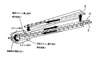
従来、トナーと磁性キャリアからなる2成分現像剤を用いる現像装置として、図9に示す構造のものが知られている。図9に示す現像装置104は、現像剤担持体である現像ローラ115に現像剤を供給する現像剤供給搬送路402と現像剤を攪拌する現像剤攪拌搬送路112とを分けて設けており、2つの搬送路で現像剤を逆方向に搬送することにより現像剤を循環させている。また、図9に示す現像装置104では、現像剤供給搬送路402を、現像ローラ115に供給され現像領域を通過しトナーを消費した現像剤を回収する現像剤回収搬送路として兼用している。
ところが、このように現像剤供給搬送路と現像剤回収搬送路とを1つの搬送路で兼用すると、現像ローラに供給する適切なトナー濃度に調整された現像剤にトナーが消費された現像剤が混入することになるので、現像ローラに供給される現像剤のトナー濃度が低下し、現像時の画像濃度が低下してしまうといった不具合が生じる。
Conventionally, as a developing device using a two-component developer composed of toner and a magnetic carrier, one having a structure shown in FIG. 9 is known. The developing
However, when the developer supply conveyance path and the developer recovery conveyance path are used as one conveyance path in this way, the developer in which the toner is consumed by the developer adjusted to an appropriate toner concentration supplied to the developing roller is obtained. As a result, the toner density of the developer supplied to the developing roller is lowered, resulting in a problem that the image density during development is lowered.
このような不具合は、特許文献1に記載された現像装置のように現像剤供給搬送路と現像剤回収搬送路とを異なる現像剤搬送路として設けることで解消することができる。特許文献1に記載の現像装置の概略構成図を図10に示す。図10に示す現像装置204は、現像剤供給搬送路209と現像剤回収搬送路207とを分けて設けている。さらに、現像剤供給搬送路209の現像剤搬送方向最下流側まで搬送された現像剤と現像剤回収搬送路207の現像剤搬送方向最下流側まで搬送された回収現像剤とを攪拌しながら現像剤供給搬送路209とは逆方向に現像剤を搬送する現像剤攪拌搬送路210を備えている。このような現像装置204では、感光体201上の潜像の現像に用いた後の現像剤は現像剤回収搬送路7に送られるため、現像剤供給搬送路209に現像済みの現像剤が混入することがない。これにより、現像剤供給搬送路9内の現像剤のトナー濃度が変化することなく、現像ローラ5に供給される現像剤のトナー濃度も一定となる。さらに、回収現像剤をすぐに現像剤供給搬送路9に供給するのではなく、現像剤攪拌搬送路10で攪拌した後で現像剤供給搬送路9に現像剤を供給するため、十分に攪拌された状態の現像剤を現像剤供給搬送路9に供給することができる。これにより、図9に示した現像装置104で生じる不具合であった現像時の画像濃度の不均一や画像濃度の低下を防止することができる。
Such a problem can be solved by providing the developer supply transport path and the developer recovery transport path as different developer transport paths as in the developing device described in
しかしながら、特許文献1に記載の現像装置のような構成では、画像面積率の小さい潜像を現像すると現像剤回収搬送路で回収される現像剤の量が多くなり、現像剤回収搬送路下流側から現像剤攪拌搬送路上流側に移送される回収現像剤の量が多くなる。そのため、連続して画像面積率の小さい潜像の現像を行うと現像剤攪拌搬送路上流側に存在する現像剤の量が次第に多くなる。このように現像剤攪拌搬送路上流側に存在する現像剤の量が多くなると、現像剤回収搬送路下流側から現像剤攪拌搬送路上流側に移送される回収現像剤の流れが悪くなり、現像剤回収搬送路の現像剤搬送方向下流側で回収現像剤が滞留してしまう。そして、この滞留によって現像剤回収搬送路の現像剤搬送方向下流側で回収現像剤の嵩が高くなり過ぎると、回収現像剤が現像ローラに再付着する、いわゆる連れ回り現象が生じてしまう。このような連れ回り現象が生じると、現像済みのトナー濃度の低下した現像剤が現像ローラに付着することになるので、この部分だけ画像濃度が薄くなったり白帯が発生したりして画像品質が劣化するといった問題が生じる。
However, in the configuration such as the developing device described in
本発明は、以上の問題に鑑みなされたものであり、その目的とするところは、現像ローラに回収済みの現像剤が再付着することで画像品質が劣化してしまうのを抑制できる現像装置、及び、その現像装置を備えた画像形成装置を提供することである。 The present invention has been made in view of the above problems, and the object of the present invention is to provide a developing device capable of suppressing deterioration of image quality caused by reattaching the collected developer to the developing roller, And providing an image forming apparatus including the developing device.
上記目的を達成するために、請求項1の発明は、磁性キャリアとトナーとからなる2成分現像剤を表面上に担持して回転し、潜像担持体と対向する箇所で該潜像担持体の表面の潜像にトナーを供給して現像する現像剤担持体と、該現像剤担持体の軸線方向に沿って現像剤を搬送し、該現像剤担持体に現像剤を供給する現像剤供給搬送スクリュを備えた現像剤供給搬送路と、該潜像担持体と対向する箇所を通過後の該現像剤担持体上から回収された該現像剤を該現像剤担持体の軸線方向に沿って、且つ、該現像剤供給搬送スクリュと同方向に搬送する現像剤回収搬送スクリュを備えた現像剤回収搬送路と、現像に用いられずに該現像剤供給搬送路の現像剤搬送方向最下流側まで搬送された余剰現像剤と、該現像剤担持体から回収され該現像剤回収搬送路の現像剤搬送方向最下流側まで搬送された回収現像剤との供給を受け、該現像剤担持体の軸線方向に沿って、且つ、該余剰現像剤と該回収現像剤とを攪拌しながら該現像剤供給搬送スクリュとは逆方向に搬送する現像剤攪拌搬送スクリュを備え、該現像剤を該現像剤供給搬送路に供給する現像剤攪拌搬送路とを有し、該現像剤攪拌搬送路と該現像剤回収搬送路とは略同じ高さで並列に設けられ、該現像剤供給搬送路は他の2つの該現像剤搬送路の上方に位置するように設けられた現像装置において、該現像剤攪拌スクリュの現像剤搬送方向上流側の現像剤搬送量が該現像剤回収スクリュの現像剤搬送方向下流側の現像剤搬送量に対し同等以上となるように構成したことを特徴とするものである。
また、請求項2の発明は、請求項1の現像装置において、該現像剤攪拌搬送スクリュの回転数が少なくとも該現像剤回収搬送スクリュの回転数よりも高いことを特徴とするものである。
また、請求項3の発明は、請求項2の現像装置において、上記現像剤回収搬送スクリュの回転数が上記現像剤供給搬送スクリュの回転数よりも高いことを特徴とするものである。
また、請求項4の発明は、請求項1、2または3の現像装置において、少なくとも上記現像剤攪拌搬送スクリュの現像剤搬送方向上流側の外径が、上記現像剤回収搬送スクリュの外径よりも大きいことを特徴とするものである。
また、請求項5の発明は、請求項1、2または3の現像装置のおいて、上記現像剤攪拌搬送スクリュの現像剤搬送方向上流側の外径及び上記現像剤回収搬送スクリュの現像剤搬送方向下流側の外径が、少なくとも現像剤回収搬送スクリュにおける現像剤搬送方向下流側以外の部分の外径よりも大きいことを特徴とするものである。
また、請求項6の発明は、請求項1、2、3、4または5の現像装置において、少なくとも現像剤攪拌搬送スクリュの現像剤搬送方向上流側のスクリュピッチが、上記現像剤回収搬送スクリュのスクリュピッチよりも大きいことを特徴とするものである。
また、請求項7の発明は、請求項1、2、3、4または5の現像装置において、上記現像剤攪拌搬送スクリュの現像剤搬送方向上流側のスクリュピッチ及び上記現像剤回収搬送スクリュの現像剤搬送方向下流側のスクリュピッチが、少なくとも該現像剤回収搬送スクリュにおける現像剤搬送方向下流側以外の部分のスクリュピッチよりも大きいことを特徴とするものである。
また、請求項8の発明は、請求項1、2、3、4または5の現像装置において、少なくとも上記現像剤攪拌搬送スクリュの現像剤搬送方向上流側のスクリュ条数が、上記現像剤回収搬送スクリュの現像剤搬送方向下流側のスクリュ条数よりも多いことを特徴とするものである。
また、請求項9の発明は、請求項1、2、3、4または5の現像装置において、上記現像剤攪拌搬送スクリュの現像剤搬送方向上流側のスクリュ条数及び上記現像剤回収搬送スクリュの現像剤搬送方向下流側のスクリュ条数が、少なくとも該現像剤回収搬送スクリュにおける現像剤搬送方向下流側以外の部分のスクリュ条数よりも多いことを特徴とするものである。
また、請求項10の発明は、潜像を担持する潜像担持体と、該潜像担持体上の潜像を現像剤で現像する現像手段とを備えた画像形成装置において、該現像手段として、請求項1、2、3、4、5、6、7、8または9の現像装置を用いることを特徴とするものである。
In order to achieve the above-mentioned object, the invention according to
According to a second aspect of the present invention, in the developing device of the first aspect, the rotational speed of the developer stirring and conveying screw is at least higher than the rotational speed of the developer collecting and conveying screw.
According to a third aspect of the present invention, in the developing device of the second aspect, the number of rotations of the developer collecting and conveying screw is higher than the number of rotations of the developer supplying and conveying screw.
According to a fourth aspect of the present invention, in the developing device according to the first, second, or third aspect, at least an outer diameter of the developer agitating and conveying screw upstream in the developer conveying direction is greater than an outer diameter of the developer collecting and conveying screw. Is also large.
Further, the invention of
The invention of
The invention according to
The invention of
The invention according to
According to a tenth aspect of the present invention, there is provided an image forming apparatus comprising: a latent image carrier that carries a latent image; and a developing unit that develops the latent image on the latent image carrier with a developer. The developing device of
本発明においては、回収現像剤が現像剤回収搬送路の現像剤搬送方向下流側から向きを大きく変えて現像剤攪拌搬送路の現像剤搬送方向上流側に移送される。よって、現像剤攪拌スクリュの現像剤搬送方向上流側の現像剤搬送量を現像剤回収スクリュの現像剤搬送方向下流側の現像剤搬送量に対し同等以上とすることで、現像剤回収搬送路から現像剤攪拌搬送路へ移送される現像剤移送量よりも現像剤攪拌搬送路の現像剤搬送方向上流側の現像剤搬送量を多くすることができる。これにより、現像剤攪拌搬送路の現像剤搬送方向上流側に存在する現像剤の量が少なくなるので、現像剤回収搬送路の現像剤搬送方向下流側から現像剤攪拌搬送路の現像剤搬送方向上流側への回収現像剤の受け渡しがスムーズに行なわれる。つまり、現像剤回収搬送路の現像剤搬送方向下流側に存在する回収現像剤の嵩が現像剤担持体に上記回収現像剤が再付着する高さとならないように、現像剤回収搬送路下流側から現像剤攪拌搬送路上流側へ回収現像剤をスムーズに移送することができる。よって、現像剤回収搬送路の現像剤搬送方向下流側にある上記回収現像剤の嵩が上記高さにならないので、回収現像剤が現像剤回収搬送路から現像剤担持体に再付着するのを抑制することができる。したがって、現像剤担持体は現像剤供給搬送路から供給される現像剤のみを用いて潜像担持体上の潜像を現像することができる。 In the present invention, the recovered developer is largely changed in direction from the developer transport direction downstream side of the developer recovery transport path and transferred to the developer transport direction upstream side of the developer stirring transport path. Therefore, by setting the developer conveyance amount upstream of the developer agitating screw in the developer conveyance direction to be equal to or greater than the developer conveyance amount downstream of the developer collection screw in the developer conveyance direction, The developer transport amount on the upstream side in the developer transport direction of the developer stirring transport path can be made larger than the developer transport amount transported to the developer stirring transport path. As a result, the amount of the developer existing on the upstream side in the developer conveyance direction of the developer agitation conveyance path is reduced, so that the developer conveyance direction in the developer agitation conveyance path from the downstream side in the developer conveyance direction of the developer recovery conveyance path. The collected developer is smoothly transferred to the upstream side. In other words, from the downstream side of the developer recovery transport path, the volume of the recovered developer existing on the downstream side of the developer recovery transport path in the developer transport direction does not become the height at which the recovered developer is reattached to the developer carrier. The recovered developer can be smoothly transferred to the upstream side of the developer stirring and conveying path. Therefore, the volume of the collected developer on the downstream side of the developer collecting conveyance path in the developer conveying direction does not become the above height, so that the collected developer is reattached to the developer carrier from the developer collecting conveying path. Can be suppressed. Therefore, the developer carrier can develop the latent image on the latent image carrier using only the developer supplied from the developer supply / conveyance path.
以上、本発明によれば、現像剤担持体に回収済みの現像剤が再付着することで画像品質が劣化してしまうのを抑制できるという優れた効果がある。 As described above, according to the present invention, there is an excellent effect that image quality can be prevented from being deteriorated due to re-deposition of the collected developer on the developer carrying member.
以下、本発明を適用した画像形成装置として、複数の感光体が並行配設されたタンデム型のカラーレーザー複写機(以下、単に「複写機」という)の一実施形態について説明する。
図2は、本実施形態に係る複写機の概略構成図である。この複写機はプリンタ部100、これを載せる給紙装置200、プリンタ部100の上に固定されたスキャナ300などを備えている。また、このスキャナ300の上に固定された原稿自動搬送装置400なども備えている。
Hereinafter, as an image forming apparatus to which the present invention is applied, an embodiment of a tandem type color laser copying machine (hereinafter simply referred to as “copying machine”) in which a plurality of photoconductors are arranged in parallel will be described.
FIG. 2 is a schematic configuration diagram of the copying machine according to the present embodiment. The copier includes a
プリンタ部100は、イエロー(Y)、マゼンダ(M)、シアン(C)、黒(K)の各色の画像を形成するための4組のプロセスカートリッジ18Y,M,C,Kからなる画像形成ユニット20を備えている。各符号の数字の後に付されたY,M,C,Kは、イエロー、シアン、マゼンダ、ブラック用の部材であることを示している(以下同様)。プロセスカートリッジ18Y,M,C,Kの他には、光書込ユニット21、中間転写ユニット17、二次転写装置22、レジストローラ対49、ベルト定着方式の定着装置25などが配設されている。
The
光書込ユニット21は、図示しない光源、ポリゴンミラー、f−θレンズ、反射ミラーなどを有し、画像データに基づいて後述の感光体の表面にレーザ光を照射する。
プロセスカートリッジ18Y,M,C,Kは、ドラム状の感光体1、帯電器、現像装置4、ドラムクリーニング装置、除電器などを有している。
The
The process cartridges 18Y, 18M, 18C, and 18K include a drum-shaped
以下、イエロー用のプロセスカートリッジ18について説明する。
帯電手段たる帯電器によって、感光体1Yの表面は一様帯電される。帯電処理が施された感光体1Yの表面には、光書込ユニット21によって変調及び偏向されたレーザ光が照射される。すると、照射部(露光部)の電位が減衰する。この減衰により、感光体1Y表面にY用の静電潜像が形成される。形成されたY用の静電潜像は現像手段たる現像装置4Yによって現像されてYトナー像となる。
Y用の感光体1Y上に形成されたYトナー像は、後述の中間転写ベルト110に一次転写される。一次転写後の感光体1Yの表面は、ドラムクリーニング装置によって転写残トナーがクリーニングされる。
Y用のプロセスカートリッジ18Yにおいて、ドラムクリーニング装置によってクリーニングされた感光体1Yは、除電器によって除電される。そして、帯電器によって一様帯電せしめられて、初期状態に戻る。以上のような一連のプロセスは、他のプロセスカートリッジ18M,C,Kについても同様である。
Hereinafter, the yellow process cartridge 18 will be described.
The surface of the photoreceptor 1Y is uniformly charged by a charger as charging means. The surface of the
The Y toner image formed on the Y photoconductor 1Y is primarily transferred to an
In the Y process cartridge 18Y, the photoconductor 1Y cleaned by the drum cleaning device is discharged by the charge eliminator. Then, it is uniformly charged by the charger and returns to the initial state. The series of processes as described above is the same for the other process cartridges 18M, 18C, and 18K.
次に、中間転写ユニット17について説明する。
中間転写ユニット17は、中間転写ベルト110やベルトクリーニング装置90などを有している。また、張架ローラ14、駆動ローラ15、二次転写バックアップローラ16、4つの一次転写バイアスローラ62Y,M,C,Kなども有している。
中間転写ベルト110は、張架ローラ14を含む複数のローラによってテンション張架されている。そして、図示しないベルト駆動モータによって駆動される駆動ローラ15の回転によって図中時計回りに無端移動せしめられる。
4つの一次転写バイアスローラ62Y,M,C,Kは、それぞれ中間転写ベルト110の内周面側に接触するように配設され、図示しない電源から一次転写バイアスの印加を受ける。また、中間転写ベルト110をその内周面側から感光体1Y,M,C,Kに向けて押圧してそれぞれ一次転写ニップを形成する。各一次転写ニップには、一次転写バイアスの影響により、感光体1と一次転写バイアスローラ62との間に一次転写電界が形成される。
Y用の感光体1Y上に形成された上述のYトナー像は、この一次転写電界やニップ圧の影響によって中間転写ベルト110上に一次転写される。このYトナー像の上には、M,C,K用の感光体1M,C,K上に形成されたM,C,Kトナー像が順次重ね合わせて一次転写される。この重ね合わせの一次転写により、中間転写ベルト110上には多重トナー像たる4色重ね合わせトナー像(以下、4色トナー像という)が形成される。
中間転写ベルト110上に重ね合わせ転写された4色トナー像は、後述の二次転写ニップで図示しない記録体たる転写紙に二次転写される。二次転写ニップ通過後の中間転写ベルト110の表面に残留する転写残トナーは、図中左側の駆動ローラ15との間にベルトを挟み込むベルトクリーニング装置90によってクリーニングされる。
Next, the intermediate transfer unit 17 will be described.
The intermediate transfer unit 17 includes an
The
The four primary transfer bias rollers 62Y, 62M, 62C, and 62K are disposed so as to be in contact with the inner peripheral surface side of the
The above-described Y toner image formed on the Y photoconductor 1Y is primarily transferred onto the
The four-color toner image superimposed and transferred onto the
次に、二次転写装置22について説明する。
中間転写ユニット17の図中下方には、2本の張架ローラ23によって紙搬送ベルト24を張架している二次転写装置22が配設されている。紙搬送ベルト24は、少なくとも何れか一方の張架ローラ23の回転駆動に伴って、図中反時計回りに無端移動せしめられる。2本の張架ローラ23のうち、図中右側に配設された一方の張架ローラ23は、中間転写ユニット17の二次転写バックアップローラ16との間に、中間転写ベルト110及び紙搬送ベルト24を挟み込んでいる。この挟み込みにより、中間転写ユニット17の中間転写ベルト110と、二次転写装置22の紙搬送ベルト24とが接触する二次転写ニップが形成されている。そして、この一方の張架ローラ23には、トナーと逆極性の二次転写バイアスが図示しない電源によって印加される。この二次転写バイアスの印加により、二次転写ニップには中間転写ユニット17の中間転写ベルト110上の4色トナー像をベルト側からこの一方の張架ローラ23側に向けて静電移動させる二次転写電界が形成される。後述のレジストローラ対49によって中間転写ベルト110上の4色トナー像に同期するように二次転写ニップに送り込まれた転写紙には、この二次転写電界やニップ圧の影響を受けた4色トナー像が二次転写せしめられる。なお、このように一方の張架ローラ23に二次転写バイアスを印加する二次転写方式に代えて、転写紙を非接触でチャージさせるチャージャを設けてもよい。
Next, the
Below the intermediate transfer unit 17 in the figure, a
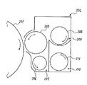
複写機本体の下部に設けられた給紙装置200には、内部に複数の転写紙を紙束の状態で複数枚重ねて収容可能な給紙カセット44が、鉛直方向に複数重なるように配設されている。それぞれの給紙カセット44は、紙束の一番上の転写紙に給紙ローラ42を押し当てている。そして、給紙ローラ42を回転させることにより、一番上の転写紙を給紙路46に向けて送り出される。
In the
給紙カセット44から送り出された転写紙を受け入れる給紙路46は、複数の搬送ローラ対47と、その路内の末端付近に設けられたレジストローラ対49とを有している。そして、転写紙をレジストローラ対49に向けて搬送する。レジストローラ対49に向けて搬送された転写紙は、レジストローラ対49のローラ間に挟まれる。一方、中間転写ユニット17において、中間転写ベルト110上に形成された4色トナー像は、ベルトの無端移動に伴って二次転写ニップに進入する。レジストローラ対49は、ローラ間に挟み込んだ転写紙を二次転写ニップにて4色トナー像に密着させ得るタイミングで送り出す。これにより、二次転写ニップでは、中間転写ベルト110上の4色トナー像が転写紙に密着する。そして、転写紙上に二次転写されて、白色の転写紙上でフルカラー画像となる。このようにしてフルカラー画像が形成された転写紙は、紙搬送ベルト24の無端移動に伴って二次転写ニップを出た後、紙搬送ベルト24上から定着装置25に送られる。
The paper feed path 46 that receives the transfer paper fed from the
定着装置25は、定着ベルト26を2本のローラによって張架しながら無端移動せしめるベルトユニットと、このベルトユニットの一方のローラに向けて押圧される加圧ローラ27とを備えている。これら定着ベルト26と加圧ローラ27とは互いに当接して定着ニップを形成しており、紙搬送ベルト24から受け取った転写紙をここに挟み込む。ベルトユニットにおいける2本のローラのうち、加圧ローラ27から押圧される方のローラは、内部に図示しない熱源を有しており、これの発熱によって定着ベルト26を加圧する。加圧された定着ベルト26は、定着ニップに挟み込まれた転写紙を加熱する。この加熱やニップ圧の影響により、フルカラー画像が転写紙に定着せしめられる。
The fixing
定着装置25内で定着処理が施された転写紙は、プリンタ筐体の図中左側板の外側に設けたスタック部57上にスタックされるか、もう一方の面にもトナー像を形成するために上述の二次転写ニップに戻されるかする。
The transfer paper subjected to the fixing process in the fixing
図示しない原稿のコピーがとられる際には、例えばシート原稿の束が原稿自動搬送装置400の原稿台30上セットされる。但し、その原稿が本状に閉じられている片綴じ原稿である場合には、コンタクトガラス32上にセットされる。このセットに先立ち、複写機本体に対して原稿自動搬送装置400が開かれ、スキャナ300のコンタクトガラス32が露出される。この後、閉じられた原稿自動搬送装置400によって片綴じ原稿が押さえられる。
When a document (not shown) is copied, for example, a bundle of sheet documents is set on the document table 30 of the automatic document feeder 400. However, when the original is a single-sided original that is closed in a main form, it is set on the
このようにして原稿がセットされた後、図示しないコピースタートスイッチが押下されると、スキャナ300による原稿読取動作がスタートする。但し、原稿自動搬送装置400にシート原稿がセットされた場合には、この原稿読取動作に先立って、原稿自動搬送装置400がシート原稿をコンタクトガラス32まで自動移動させる。原稿読取動作では、まず、第1走行体33と第2走行体34とがともに走行を開始し、第1走行体33に設けられた光源から光が発射される。そして、原稿面からの反射光が第2走行体34内に設けられたミラーによって反射せしめられ、結像レンズ35を通過した後、読取センサ36に入射される。読取センサ36は、入射光に基づいて画像情報を構築する。
When a copy start switch (not shown) is pressed after the document is set in this way, the document reading operation by the
このような原稿読取動作と並行して、各プロセスカートリッジ18Y,M,C,K内の各機器や、中間転写ユニット17、二次転写装置22、定着装置25がそれぞれ駆動を開始する。そして、読取センサ36によって構築された画像情報に基づいて、光書込ユニット21が駆動制御されて、各感光体1Y,M,C,K上に、Y,M,C,Kトナー像が形成される。これらトナー像は、中間転写ベルト110上に重ね合わせ転写された4色トナー像となる。
In parallel with such a document reading operation, each device in each of the process cartridges 18Y, 18M, 18C, 18K, the intermediate transfer unit 17, the
また、原稿読取動作の開始とほぼ同時に、給紙装置200内では給紙動作が開始される。この給紙動作では、給紙ローラ42の1つが選択回転せしめられ、ペーパーバンク43内に多段に収容される給紙カセット44の1つから転写紙が送り出される。送り出された転写紙は、分離ローラ45で1枚ずつ分離されて反転給紙路46に進入した後、搬送ローラ対47によって二次転写ニップに向けて搬送される。このような給紙カセット44からの給紙に代えて、手差しトレイ51からの給紙が行われる場合もある。この場合、手差し給紙ローラ50が選択回転せしめられて手差しトレイ51上の転写紙を送り出した後、分離ローラ52が転写紙を1枚ずつ分離してプリンタ部100の手差し給紙路53に給紙する。
Further, almost simultaneously with the start of the document reading operation, the paper feeding operation is started in the
本複写機は、2色以上のトナーからなる他色画像を形成する場合には、中間転写ベルト110をその上部張架面がほぼ水平になる姿勢で張架して、上部張架面に全ての感光体1Y,M,C,Kを接触させる。これに対し、Kトナーのみからなるモノクロ画像を形成する場合には、図示しない機構により、中間転写ベルト110を図中左下に傾けるような姿勢にして、その上部張架面をY,M,C用の感光体1Y,M,Cから離間させる。そして、4つの感光体1Y,M,C,Kのうち、K用の感光体1Kだけを図中反時計回りに回転させて、Kトナー像だけを作像する。この際、Y,M,Cについては、感光体1だけでなく、現像器も駆動を停止させて、感光体や現像剤の不要な消耗を防止する。
In the case of forming another color image composed of two or more colors of toner, the copying machine stretches the
本複写機は、複写機内の下記機器の制御を司るCPU等から構成される図示しない制御部と、液晶ディスプレイや各種キーボタン等などから構成される図示しない操作表示部とを備えている。操作者は、この操作表示部に対するキー入力操作により、制御部に対して命令を送ることで、転写紙の片面だけに画像を形成するモードである片面プリントモードについて、3つのモードの中から1つを選択することができる。この3つの片面プリントモードとは、ダイレクト排出モードと、反転排出モードと、反転デカール排出モードとからなる。 The copying machine includes a control unit (not shown) configured by a CPU or the like that controls the following devices in the copying machine, and an operation display unit (not shown) configured by a liquid crystal display, various key buttons, and the like. The operator sends a command to the control unit by a key input operation on the operation display unit, so that one of the three modes is selected from the three-sided print mode, which is a mode for forming an image only on one side of the transfer paper. You can choose one. The three single-sided printing modes include a direct discharge mode, a reverse discharge mode, and a reverse decal discharge mode.
図3は、4つプロセスカートリッジ18Y,M,C,Kのうちの1つが備える現像装置4及び感光体1を示す拡大構成図である。4つのプロセスカートリッジ18Y,M,C,Kは、それぞれ扱うトナーの色が異なる点の他がほぼ同様の構成になっているので、同図では「4」に付すY,M,C,Kという添字を省略している。
図3に示すように感光体1は図中矢印G方向に回転しながら、その表面を不図示の帯電装置により帯電される。帯電された感光体1の表面は不図示の露光装置より照射されたレーザ光により静電潜像を形成された潜像に現像装置4からトナーを供給され、トナー像を形成する。
FIG. 3 is an enlarged configuration diagram illustrating the developing
As shown in FIG. 3, the surface of the
現像装置4は、図中矢印I方向に表面移動しながら感光体1の表面の潜像にトナーを供給し、現像する現像剤担持体としての現像ローラ5を有している。なお、現像ローラ5の表面はV溝あるいはブラスト処理されておりφ25[mm]のAl(アルミニウム)素管からなり、現像ドクタ12及び感光体1とのギャップは0.4[mm]程度となっている。
また、現像ローラ5に現像剤を供給しながら図3の奥方向に現像剤を搬送する供給搬送部材としての供給スクリュ8を有している。供給スクリュ8は、回転軸とこの回転軸に設けられた羽部とを備え、回転することにより軸方向に現像剤を搬送する現像剤搬送スクリュである。
現像ローラ5の供給スクリュ8との対向部から表面移動方向下流側には、現像ローラ5に供給された現像剤を現像に適した厚さに規制する現像剤規制部材としてのステンレスからなる現像ドクタ12を備えている。そして、現像ドクタ12によって薄層化された現像剤を感光体1との対抗部である現像領域まで搬送し現像を行う。
The developing
Further, a
A developing doctor made of stainless steel as a developer regulating member for regulating the developer supplied to the developing
現像領域から表面移動方向下流側には、現像領域を通過した現像済みの現像剤を回収し、回収した回収現像剤を供給スクリュ8と同方向に搬送する回収搬送部材としての回収スクリュ6を備えている。供給スクリュ8を備えた供給搬送路9は現像ローラ5の横方向に、回収スクリュ6を備えた回収搬送路としての回収搬送路7は現像ローラ5の下方に並設されている。
On the downstream side in the surface movement direction from the development area, a
現像装置4は、供給搬送路9の下方で回収搬送路7に並列して、攪拌搬送路10を設けている。攪拌搬送路10は、現像剤を攪拌しながら供給スクリュ8とは逆方向である図中手前側に搬送する攪拌搬送部材としての攪拌スクリュ11を備えている。
供給搬送路9と攪拌搬送路10とは仕切り部材としての第一仕切り壁133によって仕切られている。第一仕切り壁133の供給搬送路9と攪拌搬送路10とを仕切る箇所は図中手前側と奥側との両端は開口部となっており、供給搬送路9と攪拌搬送路10とが連通している。
なお、供給搬送路9と回収搬送路7とも第一仕切り壁133によって仕切られているが、第一仕切り壁133の供給搬送路9と回収搬送路7とを仕切る箇所には開口部を設けていない。
また、攪拌搬送路10と回収搬送路7との2つの搬送路は仕切り部材としての第二仕切り壁134によって仕切られている。第二仕切り壁134は、図中手前側が開口部となっており、攪拌搬送路10と回収搬送路7とが連通している。
また、現像装置4では、現像剤を収容する現像剤収容部を供給搬送路9、回収搬送路7及び攪拌搬送路10によって構成する。
The developing
The
The
Further, the two conveyance paths of the stirring
Further, in the developing
現像後の現像剤は回収搬送路7にて回収を行い、図3中の断面手前側に搬送され、非画像領域部に設けられた第一仕切り壁133の開口部で、攪拌搬送路10へ現像剤が移送される。なお、攪拌搬送路10における現像剤搬送方向上流側の第一仕切り壁133の開口部の付近で攪拌搬送路10の上側に設けられたトナー補給口から攪拌搬送路10にトナーが補給される。
The developer after the development is collected in the
次に、3つの現像剤搬送路内での現像剤の循環について説明する。
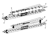
図4は現像剤搬送路内の現像剤の流れを説明する現像装置4の斜視断面図である。図中の各矢印は現像剤の移動方向を、図中の直方体は各スクリュ上での現像剤の分布を示している。また、図5は、現像装置4内の現像剤の流れの模式図であり、図4と同様、図中の各矢印は現像剤の移動方向を示している。
Next, the circulation of the developer in the three developer conveyance paths will be described.
FIG. 4 is a perspective sectional view of the developing
攪拌搬送路10から現像剤の供給を受けた供給搬送路9では、現像ローラ5に現像剤を供給しながら、供給スクリュ8の現像剤搬送方向下流側に現像剤を搬送する。そして、現像ローラ5に供給され現像に用いられず供給搬送路9の現像剤搬送方向下流端まで搬送された余剰現像剤は第一仕切り壁133の余剰開口部より攪拌搬送路10に供給される(図5中矢印E)。
現像ローラ5から回収搬送路7に送られ、回収スクリュ6によって回収搬送路7の現像剤搬送方向下流端まで搬送された回収現像剤は第二仕切り壁134の回収開口部より攪拌搬送路10に供給される(図5中矢印F)。
そして、攪拌搬送路10は、供給された余剰現像剤と回収現像剤とを攪拌し、攪拌スクリュ11の現像剤搬送方向下流側であり、供給スクリュ8の現像剤搬送方向上流側に搬送し、第一仕切り壁133の供給開口部より供給搬送路9に供給される(図5中矢印D)。
攪拌搬送路10では攪拌スクリュ11によって、回収現像剤、余剰現像剤及びトナー補給口から必要に応じて補給されるプレミックストナーを、回収搬送路7及び供給搬送路9の現像剤と逆方向に攪拌搬送する。そして、現像剤搬送方向下流側で連通している供給搬送路9の現像剤搬送方向上流側に攪拌された現像剤を移送する。なお、攪拌搬送路10の下方には、不図示のトナー濃度センサが設けられ、センサ出力により詳細は後述するトナー補給装置を作動し、トナー収納部からトナー補給を行う。
In the
The collected developer sent from the developing
The agitating and conveying
In the
図3に示す現像装置4では、供給搬送路9と回収搬送路7とを備え、現像剤の供給と回収とを異なる現像剤搬送路で行うので、現像済みの現像剤が供給搬送路9に混入することがない。よって、供給搬送路9の現像剤搬送方向下流側ほど現像ローラ5に供給される現像剤のトナー濃度が低下することを防止することができる。また、回収搬送路7と攪拌搬送路10とを備え、現像剤の回収と攪拌とを異なる現像剤搬送路で行うので、現像済みの現像剤が攪拌の途中に落ちることがない。よって、十分に攪拌がなされた現像剤が供給搬送路9に供給されるため、供給搬送路9に供給されるの現像剤が攪拌不足となることを防止することができる。このように、供給搬送路9内の現像剤のトナー濃度が低下することを防止し、供給搬送路9内の現像剤が攪拌不足となることを防止することができるので現像時の画像濃度を一定にすることができる。
In the developing
次に、本発明の特徴部について図1、図6、図7及び図8を用いて説明する。なお、特に記載のない場合は、現像剤搬送部材である供給スクリュ8、回収スクリュ6及び攪拌スクリュ11のスクリュの外径はφ22[mm]、スクリュピッチは25[mm]及びスクリュ条数は1条であり、各スクリュの回転数は約700[rpm]である。当然ながら、これらの諸条件に限定されるものではない。
Next, the characteristic part of this invention is demonstrated using FIG.1, FIG.6, FIG.7 and FIG. Unless otherwise specified, the outer diameter of the
[構成例1]
本構成例においては、供給スクリュ8と回収スクリュ6の回転数を約700[rpm]、攪拌スクリュ11の回転数を約730〜780[rpm]とする。これにより、攪拌スクリュ11の現像剤搬送量が他のスクリュよりも多くなるため、現像剤は攪拌搬送路10の現像剤搬送方向下流側に多く滞留し、攪拌搬送路10の現像剤搬送方向上流側にある現像剤の量が少なくなる。よって、回収搬送路7の現像剤搬送方向最下流側から攪拌搬送路10の現像剤搬送方向最上流側への現像剤の受け渡しが、回収搬送路7の現像剤搬送方向下流側の現像剤の嵩が高くなり過ぎないないような供給量でスムーズに行なわれ、回収搬送路7の現像剤搬送方向下流に滞留する現像剤が減る。したがって、図1に示すように、回収スクリュ6の現像剤搬送方向下流側における現像剤の嵩が低くなり、現像ローラ5に回収現像剤が再付着する、いわゆる連れ回り現象の発生を抑制することができる。
[Configuration example 1]
In this configuration example, the rotation speed of the
[変形例1]
構成例1の構成に加え、さらに、回収スクリュ6の回転数を攪拌スクリュ11と略同一回転数程度にしても良い。これにより、回収スクリュ6の現像剤搬送量が増加するため、回収搬送路7から攪拌搬送路10に移送される回収現像剤の現像剤移送量が多くなるが、現像装置4のような構成では攪拌搬送路10の現像剤搬送方向上流側の現像剤搬送量が上記現像剤移送量よりも多くなる状態は維持されるので、回収搬送路7の現像剤搬送方向最下流側から攪拌搬送路10の現像剤搬送方向最上流側への現像剤の受け渡しはスムーズに行われ、上記連れ回り現象が発生するのを抑制することができる。
[Modification 1]
In addition to the configuration of the configuration example 1, the number of rotations of the
[構成例2]
本構成例においては、攪拌スクリュ11の現像剤搬送方向上流側のスクリュ径をφ24、上記現像剤搬送方向上流側以外のスクリュ径をφ22とする。これにより、攪拌スクリュ11の現像剤搬送方向上流側での現像剤搬送量が他のスクリュよりも多くなるため、現像剤は攪拌搬送路10の現像剤搬送方向下流側に多く滞留し攪拌搬送路10の現像剤搬送方向上流側にある現像剤の量が少なくなる。よって、回収搬送路7の現像剤搬送方向最下流側から攪拌搬送路10の現像剤搬送方向最上流側への現像剤の受け渡しが、回収搬送路7の現像剤搬送方向下流側の現像剤の嵩が高くなり過ぎないないような供給量でスムーズに行なわれ、回収搬送路7の現像剤搬送方向最下流に滞留する現像剤が減る。したがって、回収搬送路7の現像剤搬送方向下流側での現像剤の嵩は低くなり、上記連れ回り現象の発生を抑制することができる。
[Configuration example 2]
In this configuration example, the screw diameter on the upstream side in the developer conveyance direction of the stirring
[変形例2]
構成例2の構成に加え、さらに、図6に示すように回収スクリュ6の現像剤搬送方向下流側のスクリュ径をφ24、上記下流側以外のスクリュ径をφ22にしても良い。これにより、回収スクリュ6の現像剤搬送方向下流側での現像剤搬送量が増加するため、回収搬送路7から攪拌搬送路10に移送される回収現像剤の現像剤移送量が多くなるが、現像装置4のような構成では攪拌搬送路10の現像剤搬送方向上流側の現像剤搬送量が上記現像剤移送量よりも多くなる状態は維持されるので、回収搬送路7の現像剤搬送方向最下流側から攪拌搬送路10の現像剤搬送方向最上流側への現像剤の受け渡しはスムーズに行われ、上記連れ回り現象は発生しにくくなる。
[Modification 2]
In addition to the configuration of the configuration example 2, as shown in FIG. 6, the screw diameter on the downstream side in the developer conveying direction of the
[構成例3]
本構成例においては、攪拌スクリュ11の現像剤搬送方向上流側のスクリュのピッチを30、上記現像剤搬送方向上流側以外のスクリュのピッチを25とする。これにより、攪拌スクリュ11の現像剤搬送方向上流側での現像剤搬送量が他のスクリュよりも多くなるため、現像剤は攪拌搬送路10の現像剤搬送方向下流側に多く滞留し、攪拌搬送路10の現像剤搬送方向上流側にある現像剤の量が少なくなる。よって、回収搬送路7の現像剤搬送方向最下流側から攪拌搬送路10の現像剤搬送方向最上流側への現像剤の受け渡しが、回収搬送路7の現像剤搬送方向下流側の現像剤の嵩が高くなり過ぎないないような供給量でスムーズに行なわれ、回収搬送路7の現像剤搬送方向下流側に滞留する現像剤が減る。したがって、回収搬送路7の現像剤搬送方向下流での現像剤の嵩は低くなり、上記連れ回り現象の発生を抑制することができる。
[Configuration example 3]
In this configuration example, the pitch of the screw on the upstream side in the developer transport direction of the stirring
[変形例3]
構成例3の構成に加え、さらに、図7に示すように回収スクリュ6の現像剤搬送方向下流側のスクリュのピッチを30、上記現像剤搬送方向上流側以外のスクリュのピッチを25にしても良い。これにより、回収スクリュ6の現像剤搬送方向下流側での現像剤搬送量が増加するため、回収搬送路7から攪拌搬送路10に移送される回収現像剤の現像剤移送量が多くなるが、現像装置4のような構成では攪拌搬送路10の現像剤搬送方向上流側の現像剤搬送量が上記現像剤移送量よりも多くなる状態は維持されるので、回収搬送路7の現像剤搬送方向最下流側から攪拌搬送路10の現像剤搬送方向最上流側への現像剤の受け渡しはスムーズに行われ、上記連れ回り現象は発生しにくくなる。
[Modification 3]
In addition to the configuration of the configuration example 3, as shown in FIG. 7, the screw pitch of the
[構成例4]
本構成例においては、攪拌スクリュ11の現像剤搬送方向上流側のスクリュ条数を2条、上記現像剤搬送方向上流側以外のスクリュ条数を1条とする。これにより、攪拌スクリュ11の現像剤搬送方向上流側の現像剤搬送量が他のスクリュよりも多くなるため、現像剤は攪拌搬送路10の現像剤搬送方向下流側に多く滞留し、攪拌搬送路10の現像剤搬送方向上流側にある現像剤の量が少なくなる。よって、回収搬送路7の搬送方向最下流側から攪拌搬送路10の現像剤搬送方向最上流側への現像剤の受け渡しが、回収搬送路7の現像剤搬送方向下流側の現像剤の嵩が高くなり過ぎないないような供給量でスムーズに行なわれ、回収搬送路7の現像剤搬送方向下流側に滞留する現像剤が減る。したがって、回収搬送路7の現像剤搬送方向下流側での現像剤の嵩は低くなり、上記連れ回り現象の発生を抑制することができる。
[Configuration Example 4]
In this configuration example, the number of screws on the upstream side of the developer conveying direction of the stirring
[変形例4]
構成例4の構成に加え、さらに、図8に示すように回収スクリュ6の現像剤搬送方向下流側のスクリュ条数を2条、上記現像剤搬送方向上流側以外のスクリュ条数を1条にしても良い。これにより、回収スクリュ6の現像剤搬送方向下流側での現像剤搬送量が増加するため、回収搬送路7から攪拌搬送路10に移送される回収現像剤の現像剤移送量が多くなるが、現像装置4のような構成では攪拌搬送路10の現像剤搬送方向上流側の現像剤搬送量が上記現像剤移送量よりも多くなる状態は維持されるので、回収搬送路7の現像剤搬送方向最下流側から攪拌搬送路10の現像剤搬送方向最上流側への現像剤の受け渡しはスムーズに行われ、上記連れ回り現象は発生しにくくなる。
[Modification 4]
In addition to the configuration of Configuration Example 4, as shown in FIG. 8, the number of screws on the downstream side in the developer conveyance direction of the
以上、本実施形態によれば、磁性キャリアとトナーとからなる2成分現像剤を表面上に担持して回転し、潜像担持体である感光体1と対向する箇所で感光体1の表面の潜像にトナーを供給して現像する現像剤担持体である現像ローラ5と、現像ローラ5の軸線方向に沿って現像剤を搬送し、現像ローラ5に現像剤を供給する現像剤供給搬送スクリュである供給スクリュ8を備えた現像剤供給搬送路である供給搬送路9と、感光体1と対向する箇所を通過後の現像ローラ5上から回収された現像剤を現像ローラ5の軸線方向に沿って、且つ、供給スクリュ8と同方向に搬送する現像剤回収搬送スクリュである回収スクリュ6を備えた現像剤回収搬送路である回収搬送路7と、現像に用いられずに供給搬送路9の現像剤搬送方向の最下流側まで搬送された余剰現像剤と、現像ローラ5から回収され回収搬送路7の現像剤搬送方向の最下流側まで搬送された回収現像剤との供給を受け、現像ローラ5の軸線方向に沿って、且つ該余剰現像剤と回収現像剤とを攪拌しながら供給スクリュ8とは逆方向に搬送する現像剤攪拌搬送スクリュである攪拌スクリュ11を備え、現像剤を供給搬送路9に供給する現像剤攪拌搬送路である攪拌搬送路10とを有し、攪拌搬送路10と回収搬送路7とは略同じ高さで並列に設けられ、供給搬送路9は他の2つの現像剤搬送路の上方に位置するように設けられた現像装置4において、攪拌スクリュ11の現像剤搬送方向上流側の現像剤搬送量が回収スクリュ6の現像剤搬送方向下流側の現像剤搬送量に対し同等以上となるように構成している。これにより、回収搬送路7から攪拌搬送路10へ移送される現像剤移送量よりも攪拌搬送路10の現像剤搬送方向上流側の現像剤搬送量を多くすることができる。したがって、攪拌搬送路10の現像剤搬送方向上流側に存在する現像剤の量が少なくなるので、回収搬送路7の現像剤搬送方向下流側から攪拌搬送路10の現像剤搬送方向上流側への現像剤の受け渡しがスムーズに行なわれる。よって、回収搬送路7の現像剤搬送方向下流側にある現像剤の嵩が現像ローラ5に回収現像剤が再付着する高さよりも高くならないようにすることができるので、回収搬送路7の現像剤搬送方向下流側の現像剤が現像ローラ5に再付着するのを抑制することができる。したがって、現像ローラ5は供給搬送路9から供給される現像剤のみを用いて感光体1上の潜像を現像することができ、現像ローラ5に回収済みの現像剤が再付着することなく、適切なトナー濃度の現像剤のみで潜像を現像することができるので、画像品質を良好に保つことができる。
また、本実施形態によれば、攪拌スクリュ11の回転数が少なくとも回収スクリュ6の回転数よりも高くすることで、回収搬送路7の現像剤搬送方向最下流側から攪拌搬送路10の現像剤搬送方向最上流側に供給される現像剤の量よりも攪拌スクリュ11の現像剤搬送量が多くなり、攪拌搬送路10の現像剤搬送方向上流側の現像剤の量を少なくすることができる。これにより、回収搬送路7の現像剤搬送方向最下流側から攪拌搬送路10の現像剤搬送方向最上流側への現像剤の受け渡しがスムーズに行なわれ、回収搬送路7の現像剤搬送方向下流側に滞留する現像剤が減る。したがって、回収スクリュ6の現像剤搬送方向下流側での現像剤の嵩が上記高さよりも低くなり、連れ回り現象の発生が防止できる。
また、本実施形態によれば、回収スクリュ6の回転数が供給スクリュ8の回転数よりも高く、つまり、攪拌スクリュ7の回転数だけではなく回収スクリュ6の回転数も高くすることで、例えば回収スクリュ6の回転数を攪拌スクリュ11と略同一回転数程度に増速すると、回収スクリュ6の現像剤搬送量も増加するため、回収搬送路7から攪拌搬送路10に移送される回収現像剤の現像剤移送量が多くなるが、現像装置4のような構成では攪拌搬送路10の現像剤搬送方向上流側の現像剤搬送量が上記現像剤移送量よりも多くなる状態は維持されるので、回収搬送路7の現像剤搬送方向最下流側から攪拌搬送路10の現像剤搬送方向最上流側への現像剤の受け渡しはスムーズに行われ、連れ回り現象の発生を抑制することができる。
また、本実施形態によれば、少なくとも攪拌スクリュ11の現像剤搬送方向上流側の外径を回収スクリュ6の外径よりも大きくすることで、回収搬送路7の現像剤搬送方向最下流側から攪拌搬送路10の現像剤搬送方向最上流側に供給される現像剤の量よりも攪拌スクリュ11の現像剤搬送量が多くなり、攪拌搬送路10の現像剤搬送方向上流側の現像剤の量を少なくすることができる。これにより、回収搬送路7の現像剤搬送方向最下流側から攪拌搬送路10の現像剤搬送方向最上流側への現像剤の受け渡しがスムーズに行なわれ、回収搬送路7の現像剤搬送方向下流側に滞留する現像剤が減る。したがって、回収スクリュ6の現像剤搬送方向下流側での現像剤の嵩が上記高さよりも低くなり、上記連れ回り現象の発生が防止できる。
また、本実施形態によれば、攪拌スクリュ11の現像剤搬送方向上流側の外径及び回収スクリュ6の現像剤搬送方向下流側の外径が、少なくとも回収スクリュ6における上記現像剤搬送方向下流側以外の部分の外径よりも大きいことで、攪拌スクリュ11の現像剤搬送方向上流側だけではなく回収スクリュ6の現像剤搬送方向下流側での現像剤搬送量も増加するため、回収搬送路7から攪拌搬送路10に移送される回収現像剤の現像剤移送量が多くなるが、現像装置4のような構成では攪拌搬送路10の現像剤搬送方向上流側の現像剤搬送量が上記現像剤移送量よりも多くなる状態は維持されるので、回収搬送路7の現像剤搬送方向最下流側から攪拌搬送路10の現像剤搬送方向最上流側への現像剤の受け渡しはスムーズに行われ、連れ回り現象の発生を抑制することができる。
また、本実施形態によれば、少なくとも攪拌スクリュ11の現像剤搬送方向上流側のスクリュピッチが、回収スクリュ6のスクリュピッチよりも大きいことで、回収搬送路7の現像剤搬送方向最下流側から攪拌搬送路10の現像剤搬送方向最上流側に供給される現像剤の量よりも攪拌スクリュ11の現像剤搬送量が多くなり、攪拌搬送路10の現像剤搬送方向上流側の現像剤の量を少なくすることができる。これにより、回収搬送路7の現像剤搬送方向最下流側から攪拌搬送路10の現像剤搬送方向最上流側への現像剤の受け渡しがスムーズに行なわれ、回収搬送路7の現像剤搬送方向下流側に滞留する現像剤が減る。したがって、回収スクリュ6の現像剤搬送方向下流側での現像剤の嵩が上記高さよりも低くなり、上記連れ回り現象の発生が防止できる。
また、本実施形態によれば、攪拌スクリュ11の現像剤搬送方向上流側のスクリュピッチ及び回収スクリュ6の現像剤搬送方向下流側のスクリュピッチが、少なくとも回収スクリュ6における上記現像剤搬送方向下流側以外の部分のスクリュピッチよりも大きいことで、攪拌スクリュ11の現像剤搬送方向上流側だけではなく回収スクリュ6の現像剤搬送方向下流側での現像剤搬送量も増加するため、回収搬送路7から攪拌搬送路10に移送される回収現像剤の現像剤移送量が多くなるが、現像装置4のような構成では攪拌搬送路10の現像剤搬送方向上流側の現像剤搬送量が上記現像剤移送量よりも多くなる状態は維持されるので、回収搬送路7の現像剤搬送方向最下流側から攪拌搬送路10の現像剤搬送方向最上流側への現像剤の受け渡しはスムーズに行われ、連れ回り現象の発生を抑制することができる。
また、本実施形態によれば、少なくとも攪拌スクリュ11の現像剤搬送方向上流側のスクリュ条数が、回収スクリュ6のスクリュ条数よりも多いことで、回収搬送路7の現像剤搬送方向最下流側から攪拌搬送路10の現像剤搬送方向最上流側に供給される現像剤の量よりも攪拌スクリュ11の現像剤搬送量が多くなり、攪拌搬送路10の現像剤搬送方向上流側の現像剤の量を少なくすることができる。これにより、回収搬送路7の現像剤搬送方向最下流側から攪拌搬送路10の現像剤搬送方向最上流側への現像剤の受け渡しがスムーズに行なわれ、回収搬送路7の現像剤搬送方向下流側に滞留する現像剤が減る。したがって、回収スクリュ6の現像剤搬送方向下流側での現像剤の嵩が上記高さよりも低くなり、上記連れ回り現象の発生が防止できる。
また、本実施形態によれば、攪拌スクリュ11の現像剤搬送方向上流側のスクリュ条数及び回収スクリュ6の現像剤搬送方向下流側のスクリュ条数が、少なくとも回収スクリュ6における上記現像剤搬送方向下流側以外の部分のスクリュ条数よりも多いことで、攪拌スクリュ11の現像剤搬送方向上流側だけではなく回収スクリュ6の現像剤搬送方向下流側での現像剤搬送量も増加するため、回収搬送路7から攪拌搬送路10に移送される回収現像剤の現像剤移送量が多くなるが、現像装置4のような構成では攪拌搬送路10の現像剤搬送方向上流側の現像剤搬送量が上記現像剤移送量よりも多くなる状態は維持されるので、回収搬送路7の現像剤搬送方向最下流側から攪拌搬送路10の現像剤搬送方向最上流側への現像剤の受け渡しはスムーズに行われ、連れ回り現象の発生を抑制することができる。
また、本実施形態によれば、感光体1と、感光体1上の潜像を現像剤で現像する現像手段とを備えた画像形成装置である複写機において、上記現像手段として、本発明の現像装置を用いることにより、現像ローラ5に回収搬送路7に回収された回収済みの現像剤が現像ローラ5に再付着しないので、高品質な画像を形成することができる。
As described above, according to the present embodiment, the two-component developer composed of the magnetic carrier and the toner is carried on the surface and rotated, and the surface of the
In addition, according to the present embodiment, the developer in the stirring and conveying
Moreover, according to this embodiment, the rotation speed of the
Further, according to the present embodiment, at least the outer diameter of the agitating
Further, according to the present embodiment, the outer diameter of the stirring
Further, according to the present embodiment, at least the screw pitch on the upstream side in the developer transport direction of the stirring
Further, according to the present embodiment, the screw pitch on the upstream side in the developer transport direction of the stirring
Further, according to the present embodiment, at least the number of screws on the upstream side in the developer conveying direction of the stirring
Further, according to this embodiment, the number of screws on the upstream side in the developer conveying direction of the stirring
Further, according to the present embodiment, in a copying machine that is an image forming apparatus including the
尚、本実施形態においては、現像ローラ5に回収搬送路7で回収済みの現像剤が再付着する連れ回り現象を抑制する現像装置4の構成として、各構成例及び各変形例における特徴的な構成(スクリュの回転数、スクリュの外径、スクリュピッチ及びスクリュ条数)を個別に有したものを示したが、これらに限られるものではない。各構成例及び各変形例における特徴的な構成を組み合わせることで相乗効果により、上記連れ回り現象が生じるのをさらに抑制することが可能となる。また、攪拌スクリュ11の現像剤搬送方向上流側の現像剤搬送量が回収スクリュ6の現像剤搬送方向下流側の現像剤搬送量に対し同等以上であれば良いが、攪拌スクリュ11の上記現像剤搬送量が回収スクリュ6の上記現像剤搬送量よりも多いほうが攪拌搬送路10の現像剤搬送方向上流側に存在する現像剤の量をより少なくすることができるので、画像面積率の小さい潜像の現像を行い回収搬送路7で回収する現像剤の量が多い場合などでは、回収搬送路7の現像剤搬送方向下流側から攪拌搬送路10の現像剤搬送方向上流側への現像剤の受け渡しをよりスムーズに行うことができる。
In this embodiment, the configuration of the developing
1 感光体
4 現像装置
5 現像ローラ
6 回収スクリュ
7 回収搬送路
8 供給スクリュ
9 供給搬送路
10 攪拌搬送路
11 攪拌スクリュ
12 現像ドクタ
14 張架ローラ
15 駆動ローラ
16 二次転写バックアップローラ
17 中間転写ユニット
18 プロセスカートリッジ
20 画像形成ユニット
21 光書込ユニット
22 二次転写装置
23 張架ローラ
24 紙搬送ベルト
25 定着装置
26 定着ベルト
27 加圧ローラ
30 原稿台
32 コンタクトガラス
33 第1走行体
34 第2走行体
35 結像レンズ
36 読取センサ
42 給紙ローラ
44 給紙カセット
46 給紙路
47 搬送ローラ対
49 レジストローラ対
57 スタック部
62 一次転写バイアスローラ
90 ベルトクリーニング装置
100 プリンタ部
104 現像装置
110 中間転写ベルト
111 攪拌スクリュ
112 現像剤攪拌搬送路
115 現像ローラ
133 第一仕切り壁
134 第二仕切り壁
200 給紙装置
201 感光体
204 現像装置
205 現像ローラ
206 回収スクリュ
207 現像剤回収搬送路
208 供給スクリュ
209 現像剤供給搬送路
210 現像剤攪拌搬送路
211 攪拌スクリュ
300 スキャナ
400 原稿自動搬送装置
401 供給スクリュ
402 現像剤供給搬送路
DESCRIPTION OF
Claims (10)
該現像剤担持体の軸線方向に沿って現像剤を搬送し、該現像剤担持体に現像剤を供給する現像剤供給搬送スクリュを備えた現像剤供給搬送路と、
該潜像担持体と対向する箇所を通過後の該現像剤担持体上から回収された該現像剤を該現像剤担持体の軸線方向に沿って、且つ、該現像剤供給搬送スクリュと同方向に搬送する現像剤回収搬送スクリュを備えた現像剤回収搬送路と、
現像に用いられずに該現像剤供給搬送路の現像剤搬送方向最下流側まで搬送された余剰現像剤と、該現像剤担持体から回収され該現像剤回収搬送路の現像剤搬送方向最下流側まで搬送された回収現像剤との供給を受け、該現像剤担持体の軸線方向に沿って、且つ、該余剰現像剤と該回収現像剤とを攪拌しながら該現像剤供給搬送スクリュとは逆方向に搬送する現像剤攪拌搬送スクリュを備え、該現像剤を該現像剤供給搬送路に供給する現像剤攪拌搬送路とを有し、
該現像剤攪拌搬送路と該現像剤回収搬送路とは略同じ高さで並列に設けられ、該現像剤供給搬送路は他の2つの該現像剤搬送路の上方に位置するように設けられた現像装置において、
該現像剤攪拌スクリュの現像剤搬送方向上流側の現像剤搬送量が該現像剤回収スクリュの現像剤搬送方向下流側の現像剤搬送量に対し同等以上となるように構成したことを特徴とする現像装置。 A two-component developer comprising a magnetic carrier and a toner is carried on the surface and rotated, and the developer is developed by supplying toner to the latent image on the surface of the latent image carrier at a location facing the latent image carrier. A carrier;
A developer supply transport path including a developer supply transport screw that transports the developer along the axial direction of the developer support and supplies the developer to the developer support;
The developer recovered from the developer carrier after passing through the portion facing the latent image carrier is along the axial direction of the developer carrier and in the same direction as the developer supply / conveying screw. A developer recovery transport path having a developer recovery transport screw to be transported to
The excess developer that has not been used for development and has been transported to the most downstream side in the developer transport direction of the developer supply transport path, and the most downstream in the developer transport direction of the developer recovery transport path that has been recovered from the developer carrier What is the developer supply / conveying screw along the axial direction of the developer carrier and stirring the surplus developer and the collected developer while being supplied with the collected developer conveyed to the side? A developer agitating and conveying screw for conveying the developer in the reverse direction, and a developer agitating and conveying path for supplying the developer to the developer supply and conveying path;
The developer agitation transport path and the developer recovery transport path are provided in parallel at substantially the same height, and the developer supply transport path is provided above the other two developer transport paths. In the developing device
The developer conveying amount on the upstream side in the developer conveying direction of the developer agitating screw is configured to be equal to or greater than the developer conveying amount on the downstream side in the developer conveying direction of the developer recovery screw. Development device.
上記現像剤回収搬送スクリュの回転数が上記現像剤供給搬送スクリュの回転数よりも高いことを特徴とする現像装置。 The developing device according to claim 2.
The developing device, wherein the rotation speed of the developer collecting and conveying screw is higher than the rotation speed of the developer supplying and conveying screw.
少なくとも上記現像剤攪拌搬送スクリュの現像剤搬送方向上流側の外径が、上記現像剤回収搬送スクリュの外径よりも大きいことを特徴とする現像装置。 The developing device according to claim 1, 2 or 3,
A developing device characterized in that at least the outer diameter of the developer agitating and conveying screw upstream in the developer conveying direction is larger than the outer diameter of the developer collecting and conveying screw.
上記現像剤攪拌搬送スクリュの現像剤搬送方向上流側の外径及び上記現像剤回収搬送スクリュの現像剤搬送方向下流側の外径が、少なくとも現像剤回収搬送スクリュにおける現像剤搬送方向下流側以外の部分の外径よりも大きいことを特徴とする現像装置。 In the developing device of claim 1, 2, or 3,
The outer diameter of the developer agitating and conveying screw upstream in the developer conveying direction and the outer diameter of the developer collecting and conveying screw downstream in the developer conveying direction are at least other than the downstream side in the developer conveying direction of the developer collecting and conveying screw. A developing device characterized by being larger than the outer diameter of the portion.
少なくとも現像剤攪拌搬送スクリュの現像剤搬送方向上流側のスクリュピッチが、上記現像剤回収搬送スクリュのスクリュピッチよりも大きいことを特徴とする現像装置。 The developing device according to claim 1, 2, 3, 4 or 5.
A developing device characterized in that at least a screw pitch on the upstream side in the developer transport direction of the developer agitation transport screw is larger than a screw pitch of the developer recovery transport screw.
上記現像剤攪拌搬送スクリュの現像剤搬送方向上流側のスクリュピッチ及び上記現像剤回収搬送スクリュの現像剤搬送方向下流側のスクリュピッチが、少なくとも該現像剤回収搬送スクリュにおける現像剤搬送方向下流側以外の部分のスクリュピッチよりも大きいことを特徴とする現像装置。 The developing device according to claim 1, 2, 3, 4 or 5.
The screw pitch on the upstream side in the developer conveying direction of the developer agitating and conveying screw and the screw pitch on the downstream side in the developer conveying direction of the developer collecting and conveying screw are at least other than the downstream side in the developer conveying direction in the developer collecting and conveying screw. A developing device characterized in that it is larger than the screw pitch of the portion.
少なくとも上記現像剤攪拌搬送スクリュの現像剤搬送方向上流側のスクリュ条数が、上記現像剤回収搬送スクリュの現像剤搬送方向下流側のスクリュ条数よりも多いことを特徴とする現像装置。 The developing device according to claim 1, 2, 3, 4 or 5.
The developing device according to claim 1, wherein at least the number of screws on the upstream side in the developer conveying direction of the developer stirring and conveying screw is greater than the number of screws on the downstream side in the developer conveying direction of the developer collecting and conveying screw.
上記現像剤攪拌搬送スクリュの現像剤搬送方向上流側のスクリュ条数及び上記現像剤回収搬送スクリュの現像剤搬送方向下流側のスクリュ条数が、少なくとも該現像剤回収搬送スクリュにおける現像剤搬送方向下流側以外の部分のスクリュ条数よりも多いことを特徴とする現像装置。 The developing device according to claim 1, 2, 3, 4 or 5.
The number of screws on the upstream side in the developer conveying direction of the developer stirring and conveying screw and the number of screws on the downstream side in the developer conveying direction of the developer collecting and conveying screw are at least downstream in the developer conveying direction in the developer collecting and conveying screw. A developing device characterized in that it is larger than the number of screw strips in portions other than the side.
該潜像担持体上の潜像を現像剤で現像する現像手段とを備えた画像形成装置において、
該現像手段として、請求項1、2、3、4、5、6、7、8または9の現像装置を用いることを特徴とする画像形成装置。 A latent image carrier for carrying a latent image;
An image forming apparatus comprising: a developing unit that develops the latent image on the latent image carrier with a developer;
An image forming apparatus using the developing device according to claim 1, 2, 3, 4, 5, 6, 7, 8, or 9 as the developing means.
Priority Applications (2)
| Application Number | Priority Date | Filing Date | Title |
|---|---|---|---|
| JP2007088406A JP2008249835A (en) | 2007-03-29 | 2007-03-29 | Developing device and image forming apparatus |
| US12/042,848 US8010020B2 (en) | 2007-03-29 | 2008-03-05 | Developing device and image forming apparatus equipped with the same |
Applications Claiming Priority (1)
| Application Number | Priority Date | Filing Date | Title |
|---|---|---|---|
| JP2007088406A JP2008249835A (en) | 2007-03-29 | 2007-03-29 | Developing device and image forming apparatus |
Publications (2)
| Publication Number | Publication Date |
|---|---|
| JP2008249835A true JP2008249835A (en) | 2008-10-16 |
| JP2008249835A5 JP2008249835A5 (en) | 2011-12-15 |
Family
ID=39794619
Family Applications (1)
| Application Number | Title | Priority Date | Filing Date |
|---|---|---|---|
| JP2007088406A Pending JP2008249835A (en) | 2007-03-29 | 2007-03-29 | Developing device and image forming apparatus |
Country Status (2)
| Country | Link |
|---|---|
| US (1) | US8010020B2 (en) |
| JP (1) | JP2008249835A (en) |
Families Citing this family (11)
| Publication number | Priority date | Publication date | Assignee | Title |
|---|---|---|---|---|
| US8036575B2 (en) * | 2007-10-19 | 2011-10-11 | Ricoh Company, Limited | Development device, image forming apparatus, and process cartridge having compact structure for discharging developer |
| JP5392593B2 (en) * | 2007-10-23 | 2014-01-22 | 株式会社リコー | Image forming apparatus |
| US20090129837A1 (en) * | 2007-11-15 | 2009-05-21 | Kabushiki Kaisha Toshiba | Developing device using recycled toner |
| JP2009258445A (en) * | 2008-04-17 | 2009-11-05 | Ricoh Co Ltd | Developer supply device and image forming apparatus |
| US8744318B2 (en) * | 2010-03-15 | 2014-06-03 | Kyocera Document Solutions, Inc. | Developing device and image forming apparatus including the same |
| JP5156778B2 (en) * | 2010-03-15 | 2013-03-06 | 京セラドキュメントソリューションズ株式会社 | Developing device and image forming apparatus including the same |
| EP2378374B1 (en) | 2010-04-01 | 2019-09-25 | Ricoh Company, Ltd. | Powder container, powder supply assembly, and image forming apparatus |
| JP5534431B2 (en) | 2010-06-14 | 2014-07-02 | 株式会社リコー | Powder container and image forming apparatus |
| JP5769067B2 (en) | 2010-08-27 | 2015-08-26 | 株式会社リコー | Developing device and image forming apparatus having the same |
| US8923726B2 (en) | 2011-04-21 | 2014-12-30 | Ricoh Company, Ltd. | Image forming apparatus incorporating developing device with first and second seals |
| JP2012230203A (en) | 2011-04-25 | 2012-11-22 | Ricoh Co Ltd | Development device and image forming apparatus |
Citations (5)
| Publication number | Priority date | Publication date | Assignee | Title |
|---|---|---|---|---|
| JPH03282488A (en) * | 1990-03-30 | 1991-12-12 | Canon Inc | Developing device |
| JPH1124404A (en) * | 1997-07-08 | 1999-01-29 | Minolta Co Ltd | Developing device |
| JPH11167260A (en) * | 1997-12-03 | 1999-06-22 | Toshiba Corp | Developing device |
| JP2003263025A (en) * | 2002-03-07 | 2003-09-19 | Konica Corp | Developing device and image forming apparatus |
| JP2006251440A (en) * | 2005-03-11 | 2006-09-21 | Ricoh Co Ltd | Developing device, process cartridge, and image forming apparatus |
Family Cites Families (60)
| Publication number | Priority date | Publication date | Assignee | Title |
|---|---|---|---|---|
| US5368972A (en) | 1992-02-15 | 1994-11-29 | Ricoh Company, Ltd. | Method of preparing composite particles comprising adhering wax particles to the surface of resin particles |
| JPH07152235A (en) * | 1993-11-30 | 1995-06-16 | Fujitsu Ltd | Developer stirring device, developing device using the same and image forming device |
| US5987280A (en) * | 1994-03-18 | 1999-11-16 | Fujitsu Limited | Developing device for electrostatic latent image |
| JP3384914B2 (en) | 1994-10-04 | 2003-03-10 | 株式会社リコー | Developing device |
| JP3347251B2 (en) | 1994-12-31 | 2002-11-20 | 株式会社リコー | Developing device |
| US5915155A (en) | 1995-01-12 | 1999-06-22 | Ricoh Company, Ltd. | Toner replenishing and developer replacing device for a developing unit of an image forming apparatus |
| EP1338929A3 (en) | 1995-04-20 | 2004-12-01 | Ricoh Company, Ltd. | Developing device using a toner and carrier mixture |
| US5771429A (en) | 1995-10-31 | 1998-06-23 | Ricoh Company, Ltd. | Developing device capable of automatic toner content control |
| KR100197477B1 (en) | 1995-11-14 | 1999-06-15 | 이토가 미찌야 | Developing device for an image forming apparatus having developer distribution features |
| JPH09146355A (en) | 1995-11-20 | 1997-06-06 | Ricoh Co Ltd | Developing device for image forming device |
| JP3860870B2 (en) | 1995-12-21 | 2006-12-20 | 株式会社リコー | Development device |
| JPH10177301A (en) | 1996-10-16 | 1998-06-30 | Ricoh Co Ltd | Developing device |
| US5963766A (en) * | 1997-06-09 | 1999-10-05 | Minolta Co., Ltd. | Developing device |
| JP3640370B2 (en) | 1997-06-16 | 2005-04-20 | 株式会社リコー | Toner for electrostatic image development |
| JPH1184791A (en) | 1997-09-08 | 1999-03-30 | Ricoh Co Ltd | Image forming device |
| CN1133101C (en) | 1999-02-08 | 2003-12-31 | 株式会社理光 | Developing device |
| JP3959222B2 (en) | 1999-05-06 | 2007-08-15 | 株式会社リコー | Developing device and image forming apparatus |
| JP4070387B2 (en) | 1999-06-21 | 2008-04-02 | 株式会社リコー | Developing device and image forming apparatus |
| JP2003302823A (en) | 2002-04-12 | 2003-10-24 | Ricoh Co Ltd | Image forming apparatus |
| JP3741691B2 (en) | 2002-04-12 | 2006-02-01 | 株式会社リコー | Image forming apparatus |
| US7133629B2 (en) | 2002-04-12 | 2006-11-07 | Ricoh Company, Ltd. | Image forming method and apparatus including as easy-to-handle large capacity toner container |
| JP3974463B2 (en) | 2002-07-03 | 2007-09-12 | 株式会社リコー | Toner and two-component developer using the same |
| US7212767B2 (en) | 2002-08-09 | 2007-05-01 | Ricoh Company, Ltd. | Image forming apparatus and process cartridge removably mounted thereto |
| JP2004077587A (en) * | 2002-08-12 | 2004-03-11 | Konica Minolta Holdings Inc | Developing device and image forming apparatus |
| JP2004109631A (en) | 2002-09-19 | 2004-04-08 | Ricoh Co Ltd | Image forming apparatus and processing cartridge |
| JP2004139031A (en) | 2002-09-24 | 2004-05-13 | Ricoh Co Ltd | Image forming apparatus, replenishment toner storage container, and process cartridge |
| EP1431837B1 (en) | 2002-12-20 | 2014-12-03 | Ricoh Company, Ltd. | A colour image forming apparatus with installable process cartridges |
| US7076192B2 (en) | 2002-12-27 | 2006-07-11 | Ricoh Company, Ltd. | Powder conveying device and image forming apparatus using the same |
| JP2004226524A (en) | 2003-01-21 | 2004-08-12 | Ricoh Co Ltd | Toner conveyance device, toner supply device, and image forming apparatus |
| EP1452931A1 (en) | 2003-02-28 | 2004-09-01 | Ricoh Company, Ltd. | Image forming apparatus using installable process cartridge |
| JP4383898B2 (en) | 2003-02-28 | 2009-12-16 | 株式会社リコー | Developer container, developer supply device, and image forming apparatus |
| CN100349073C (en) | 2003-03-05 | 2007-11-14 | 株式会社理光 | Image forming device and processing cartridge |
| JP2004361749A (en) | 2003-06-05 | 2004-12-24 | Ricoh Co Ltd | Image forming apparatus and image formation unit of image forming apparatus |
| JP2005024665A (en) | 2003-06-30 | 2005-01-27 | Ricoh Co Ltd | Powder transport device, image forming apparatus, toner storage part, and process cartridge |
| JP2005189799A (en) | 2003-12-05 | 2005-07-14 | Ricoh Co Ltd | Image forming apparatus, image forming method, and process cartridge |
| JP2005195938A (en) | 2004-01-08 | 2005-07-21 | Ricoh Co Ltd | Image forming apparatus and process cartridge |
| EP1589384B1 (en) | 2004-04-23 | 2020-01-08 | Ricoh Company, Ltd. | Developer container |
| JP2005326524A (en) | 2004-05-13 | 2005-11-24 | Ricoh Co Ltd | Fixing device and image forming apparatus |
| JP4558383B2 (en) | 2004-06-14 | 2010-10-06 | 株式会社リコー | Image forming apparatus and process cartridge |
| JP4456957B2 (en) | 2004-08-06 | 2010-04-28 | 株式会社リコー | Toner cartridge and image forming apparatus |
| US7315715B2 (en) | 2004-09-08 | 2008-01-01 | Ricoh Co. Ltd. | Apparatus, method, and program for image forming |
| US7447469B2 (en) | 2004-10-18 | 2008-11-04 | Ricoh Company, Ltd. | Image forming device and mounting member for mounting a toner container thereon |
| US7184691B2 (en) | 2004-11-09 | 2007-02-27 | Ricoh Company, Ltd. | Toner container, toner supply device and image forming apparatus |
| JP2006243255A (en) | 2005-03-02 | 2006-09-14 | Canon Inc | Developing device |
| JP2006251594A (en) | 2005-03-14 | 2006-09-21 | Ricoh Co Ltd | Developing device, process cartridge and image forming apparatus |
| US7369796B2 (en) * | 2005-07-14 | 2008-05-06 | Kabushiki Kaisha Toshiba | Developer apparatus, image forming apparatus and toner supplying method |
| DE602006020532D1 (en) | 2005-11-09 | 2011-04-21 | Ricoh Co Ltd | Filling container for two-component developer and filling method |
| JP2007155841A (en) | 2005-11-30 | 2007-06-21 | Ricoh Co Ltd | Powder container, toner supply device and image forming apparatus |
| JP4764743B2 (en) | 2005-12-20 | 2011-09-07 | 株式会社リコー | Developing device, image forming apparatus |
| JP4953634B2 (en) * | 2006-01-05 | 2012-06-13 | 株式会社リコー | Developing device and image forming apparatus |
| JP4820689B2 (en) * | 2006-05-15 | 2011-11-24 | 株式会社リコー | Developing device, process cartridge, and image forming apparatus |
| JP4815272B2 (en) * | 2006-05-29 | 2011-11-16 | 株式会社リコー | Developing device and image forming apparatus |
| JP4988251B2 (en) | 2006-06-02 | 2012-08-01 | 株式会社リコー | Developing device and image forming apparatus |
| JP2008015020A (en) * | 2006-07-03 | 2008-01-24 | Ricoh Co Ltd | Developing device, process cartridge, and image forming apparatus |
| JP4913492B2 (en) * | 2006-07-18 | 2012-04-11 | 株式会社リコー | Developing device, image forming apparatus, toner and carrier |
| JP2008046240A (en) * | 2006-08-11 | 2008-02-28 | Ricoh Co Ltd | Developing device, process cartridge and image forming apparatus |
| JP4859702B2 (en) * | 2007-02-22 | 2012-01-25 | 株式会社リコー | Developing device, image forming apparatus |
| JP5039416B2 (en) * | 2007-04-03 | 2012-10-03 | 株式会社リコー | Developing device and image forming apparatus |
| JP5298752B2 (en) * | 2007-10-18 | 2013-09-25 | コニカミノルタ株式会社 | Image forming method and image forming apparatus |
| US8036575B2 (en) * | 2007-10-19 | 2011-10-11 | Ricoh Company, Limited | Development device, image forming apparatus, and process cartridge having compact structure for discharging developer |
-
2007
- 2007-03-29 JP JP2007088406A patent/JP2008249835A/en active Pending
-
2008
- 2008-03-05 US US12/042,848 patent/US8010020B2/en not_active Expired - Fee Related
Patent Citations (5)
| Publication number | Priority date | Publication date | Assignee | Title |
|---|---|---|---|---|
| JPH03282488A (en) * | 1990-03-30 | 1991-12-12 | Canon Inc | Developing device |
| JPH1124404A (en) * | 1997-07-08 | 1999-01-29 | Minolta Co Ltd | Developing device |
| JPH11167260A (en) * | 1997-12-03 | 1999-06-22 | Toshiba Corp | Developing device |
| JP2003263025A (en) * | 2002-03-07 | 2003-09-19 | Konica Corp | Developing device and image forming apparatus |
| JP2006251440A (en) * | 2005-03-11 | 2006-09-21 | Ricoh Co Ltd | Developing device, process cartridge, and image forming apparatus |
Also Published As
| Publication number | Publication date |
|---|---|
| US20080240792A1 (en) | 2008-10-02 |
| US8010020B2 (en) | 2011-08-30 |
Similar Documents
| Publication | Publication Date | Title |
|---|---|---|
| JP4820689B2 (en) | Developing device, process cartridge, and image forming apparatus | |
| JP4764743B2 (en) | Developing device, image forming apparatus | |
| JP4672509B2 (en) | Developing device and image forming apparatus | |
| JP2008249835A (en) | Developing device and image forming apparatus | |
| JP5039352B2 (en) | Developing device, process cartridge, and image forming apparatus | |
| JP5644127B2 (en) | Image forming apparatus and developing device used therefor | |
| JP2008046240A (en) | Developing device, process cartridge and image forming apparatus | |
| JP6440016B2 (en) | Developing device, process cartridge, and image forming apparatus | |
| JP5277587B2 (en) | Image forming apparatus | |
| JP2012230203A (en) | Development device and image forming apparatus | |
| JP5240557B2 (en) | Developing device, image forming apparatus, and process cartridge | |
| JP2009058597A (en) | Development device and image forming apparatus | |
| JP5811437B2 (en) | Developing device and image forming apparatus using the same | |
| JP5158473B2 (en) | Developing device and image forming apparatus | |
| JP2009063710A (en) | Developing unit and image forming device | |
| JP5033534B2 (en) | Developing device and image forming apparatus | |
| JP5037254B2 (en) | Developing device, image forming apparatus | |
| JP5380942B2 (en) | Developing device and image forming apparatus | |
| JP2008268238A (en) | Developing device, process cartridge, and image forming apparatus | |
| JP2010217328A (en) | Developing device, image-forming device, and process cartridge | |
| JP4971054B2 (en) | Developing device, process cartridge, and image forming apparatus | |
| JP2010102125A (en) | Developing device and image forming apparatus | |
| JP2011145600A (en) | Image forming apparatus | |
| JP2014235265A (en) | Image forming apparatus and control method of the same | |
| JP2020170206A (en) | Developing device and image forming apparatus |
Legal Events
| Date | Code | Title | Description |
|---|---|---|---|
| A621 | Written request for application examination |
Free format text: JAPANESE INTERMEDIATE CODE: A621 Effective date: 20091216 |
|
| A521 | Written amendment |
Free format text: JAPANESE INTERMEDIATE CODE: A523 Effective date: 20111031 |
|
| A977 | Report on retrieval |
Free format text: JAPANESE INTERMEDIATE CODE: A971007 Effective date: 20111111 |
|
| A131 | Notification of reasons for refusal |
Free format text: JAPANESE INTERMEDIATE CODE: A131 Effective date: 20111118 |
|
| A521 | Written amendment |
Free format text: JAPANESE INTERMEDIATE CODE: A523 Effective date: 20120116 |
|
| A02 | Decision of refusal |
Free format text: JAPANESE INTERMEDIATE CODE: A02 Effective date: 20120525 |