JP3997196B2 - Process cartridge and developing separation member - Google Patents
Process cartridge and developing separation member Download PDFInfo
- Publication number
- JP3997196B2 JP3997196B2 JP2003397201A JP2003397201A JP3997196B2 JP 3997196 B2 JP3997196 B2 JP 3997196B2 JP 2003397201 A JP2003397201 A JP 2003397201A JP 2003397201 A JP2003397201 A JP 2003397201A JP 3997196 B2 JP3997196 B2 JP 3997196B2
- Authority
- JP
- Japan
- Prior art keywords
- process cartridge
- developing
- image
- image carrier
- charging
- Prior art date
- Legal status (The legal status is an assumption and is not a legal conclusion. Google has not performed a legal analysis and makes no representation as to the accuracy of the status listed.)
- Expired - Fee Related
Links
Images


Description
本発明は、プロセスカートリッジ、及びこのプロセスカートリッジに着脱可能な現像離間部材に関する。 The present invention relates to a process cartridge and a developing separation member that can be attached to and detached from the process cartridge .
ここで,電子写真画像形成装置とは、電子写真画像形成方式を用いて記録媒体に画像を形成するものであり、例えば電子写真複写機、電子写真プリンタ(例えばレーザービームプリンタ、LEDプリンタ等)、ファクシミリ装置及びワードプロセッサ等が含まれる。 Here, the electrophotographic image forming apparatus is an apparatus that forms an image on a recording medium using an electrophotographic image forming system, such as an electrophotographic copying machine, an electrophotographic printer (for example, a laser beam printer, an LED printer, etc.), A facsimile machine and a word processor are included.
また、プロセスカートリッジとは、帯電手段、現像手段またはクリーニング手段の少なくとも何れか一つと電子写真感光体ドラムとを一体的にカートリッジ化し、このカートリッジを画像形成装置本体に対して着脱可能とする物である。 The process cartridge is a cartridge in which at least one of charging means, developing means and cleaning means and an electrophotographic photosensitive drum are integrally formed, and the cartridge can be attached to and detached from the image forming apparatus main body. is there.
複写機、レーザプリンタ、ファクシミリなどの画像形成装置は、帯電装置によって一様に帯電された感光体ドラム(像担持体)に選択的な露光を行って静電潜像を形成し、この静電潜像を現像装置によってトナーを付着させてトナー像として現像し、その後、このトナー像を紙などの記録剤に転写して画像を形成する。そして、トナー像の転写後の像担持体は、表面に残留したトナーをクリーニング装置で除去されて、次の画像形成装置に供される。 Image forming apparatuses such as copiers, laser printers, and facsimile machines selectively expose a photosensitive drum (image carrier) uniformly charged by a charging device to form an electrostatic latent image. The latent image is developed as a toner image by attaching toner with a developing device, and then the toner image is transferred to a recording agent such as paper to form an image. Then, the toner remaining on the surface of the image carrier after the transfer of the toner image is removed by a cleaning device and used for the next image forming apparatus.
近年では、感光像担持体、帯電装置、現像装置、クリーニング装置などをカートリッジ容器に一体的に組み込んでプロセスカートリッジとしてカートリッジ化したものが知られている。このプロセスカートリッジは、画像形成装置本体に対して着脱自在に構成されているので、これをユーザが画像形成装置本体に装着することによって、トナーの供給や感光ドラムの交換をユーザ自信で簡単に行うことができ、メンテナンスの容易化を図っている。 In recent years, a photosensitive cartridge having a photosensitive image carrier, a charging device, a developing device, a cleaning device, and the like integrated into a cartridge container as a process cartridge is known. The process cartridge is configured to be detachable from the main body of the image forming apparatus. When the user mounts the process cartridge on the main body of the image forming apparatus, the user can easily supply toner and replace the photosensitive drum with confidence. It is possible to make maintenance easier.
さらに近年では、イエロー、マゼンタ、シアン、ブラックのそれぞれ独立した現像器を、感光ドラムに対して選択的に配設して現像動作を行う、または感光ドラムに対して固定的に配設しそれぞれの現像器を選択的に駆動することにより、多色画像を形成する画像形成装置も考案されており、この多色の画像形成装置に用いられるプロセスカートリッジも実用化されるようになってきている。 Further, in recent years, independent developing devices for yellow, magenta, cyan, and black are selectively disposed on the photosensitive drum to perform a developing operation, or are fixedly disposed on the photosensitive drum and are respectively disposed. An image forming apparatus for forming a multicolor image by selectively driving a developing device has been devised, and a process cartridge used for the multicolor image forming apparatus has been put into practical use.
ここで、上述のプロセスカートリッジにおける帯電装置としては、コロナ放電などを用いた非接触方式と、帯電ローラ等を用いた接触方式が一般的であるが、近年ではオゾン発生の防止などを目的に後者の接触方式が一般的に用いられるようになってきている。 Here, as the charging device in the above-described process cartridge, a non-contact method using corona discharge and a contact method using a charging roller are generally used, but in recent years, the latter is used for the purpose of preventing ozone generation. The contact method is generally used.
しかしながら、上述の接触方式の帯電装置は、感光体ドラムに対して長期間接触されたままの状態で放置しておくと、帯電部材(例えば帯電ローラ)のうちの感光体ドラムと接触する部分が永久変形を起こし帯電能力に変化をきたし、濃度ムラ等の画像不良を生じる場合があった。また感光体ドラム表面においても、プロセスカートリッジ運搬時の振動等により感光体ドラムと帯電部材とが摺擦し、帯電メモリとして履歴が残り、濃度ムラ等の画像不良を生じる場合があった。よって、画像形成を行わない時は、帯電部材と感光ドラムの接触圧を軽減した方がよい。同様な理由で、画像形成を行うときに接触する現像剤担持体と感光ドラムも、画像形成を行なわない時は接触をしていない方がよい。 However, if the above-described contact-type charging device is left in contact with the photosensitive drum for a long period of time, a portion of the charging member (for example, a charging roller) that contacts the photosensitive drum will be removed. It may cause permanent deformation and change in charging ability, resulting in image defects such as density unevenness. Also on the surface of the photosensitive drum, the photosensitive drum and the charging member rub against each other due to vibrations when the process cartridge is transported, and a history remains as a charging memory, which may cause image defects such as density unevenness. Therefore, when image formation is not performed, it is better to reduce the contact pressure between the charging member and the photosensitive drum. For the same reason, it is preferable that the developer carrying member and the photosensitive drum that are in contact with each other when the image is formed are not in contact with each other when the image is not formed.
ここで、上記問題の解決手段としては、従来から感光体ドラム表面と帯電部材との間であって特に画像が書き込まれる領域(画像形成領域)の外側の領域(非画像形成領域)にスペーサ部材を挟み込み、未使用状態(特に搬送時)に両者を離間させた状態に保持しておく方法(例えば特許文献1参照)やソレノイドを用いて加圧離間を行う方法(例えば特許文献2参照)等が開示されている。さらにトナーシールの一端をこのスペーサ部材と連結することで、トナーシールの開封とスペーサの取り外しを一括で行ないユーザの作業を減らし、より負担をかけない構成が(例えば特許文献3)が開示されている。しかしながら、感光体ドラムと帯電部材の間にスペーサー部材を挟み込む方法では、非画像形成領域といえども感光ドラムと帯電部材とスペーサー部材が摺擦され表面状態が変化し両者の接触性が変化してしまう。また、ソレノイドを用いて離間を行なう場合、複雑な回路をあらたに設ける必要がある。また、トナーシールの開封とスペーサの取り外しを同時に行なうには強い力が必要であった。 Here, as a means for solving the above problem, a spacer member is conventionally provided in an area (non-image forming area) between the surface of the photosensitive drum and the charging member and outside the area (image forming area) where an image is written. A method of holding the two in an unused state (especially during transport) (see, for example, Patent Document 1), a method of performing pressure separation using a solenoid (see, for example, Patent Document 2), etc. Is disclosed. Further, by connecting one end of the toner seal to this spacer member, a configuration is disclosed in which the toner seal is unsealed and the spacer is removed at one time to reduce the user's work and less burden is imposed (for example, Patent Document 3). Yes. However, in the method in which the spacer member is sandwiched between the photosensitive drum and the charging member, even in the non-image forming region, the photosensitive drum, the charging member, and the spacer member are rubbed to change the surface state, and the contact between them changes. End up. In addition, when separating using a solenoid, it is necessary to newly provide a complicated circuit. Also, a strong force is required to simultaneously open the toner seal and remove the spacer.
また、帯電部材と感光ドラムだけでなく、現像剤担持体と感光ドラムを離間させようとした時は部品点数が多くなりコストが高くなる、ユーザビリティーが悪くなるという問題があった。
本発明は上述した手法を改良し、簡単な構成で、ユーザの負担を増やさず、帯電手段を像担持体から当接離間方向に移動させること等ができるプロセスカートリッジ及び画像形成装置を提供することを目的とするものである。 The present invention provides a process cartridge and an image forming apparatus in which the above-described method is improved and the charging means can be moved in the contact and separation direction from the image carrier without increasing the burden on the user with a simple configuration. It is intended.
本願発明は上記課題を解決するためのものであり、The present invention is for solving the above problems,
像担持体と、An image carrier;
前記像担持体に接触して前記像担持体を帯電する帯電手段とを有し、Charging means for charging the image carrier in contact with the image carrier;
画像形成装置本体に着脱可能なプロセスカートリッジにおいて、In a process cartridge detachable from the image forming apparatus main body,
前記像担持体を回転可能に保持し前記帯電手段を前記像担持体に対し当接離間方向に移動可能に保持する第1の枠体と、A first frame for holding the image carrier rotatably and holding the charging means movably in a contact and separation direction with respect to the image carrier;
前記像担持体の表面に形成された静電潜像を現像するための現像剤を担持する現像剤担持体と、A developer carrying member carrying a developer for developing an electrostatic latent image formed on the surface of the image carrying member;
第1の枠体に対して移動可能であって前記現像剤担持体を設けた第2の枠体と、A second frame that is movable with respect to the first frame and provided with the developer carrier;
前記現像剤担持体と前記像担持体を当接させるために前記第1の枠体と前記第2の枠体を付勢する付勢部材とを有し、A biasing member that biases the first frame and the second frame to bring the developer carrier and the image carrier into contact with each other;
現像離間部材を前記プロセスカートリッジに装着している時は、前記現像離間部材は前記付勢部材の付勢力に抗して前記第1の枠体と第2の枠体を移動させて前記現像剤担持体と前記像担持体を離間状態にさせ、且つ前記帯電手段と前記像担持体とを離間状態又は前記現像離間部材が前記プロセスカートリッジに装着されている時の前記帯電手段と前記像担持体との当接圧よりも弱くなる状態に保持し、When the developing separation member is mounted on the process cartridge, the developing separation member moves the first frame and the second frame against the urging force of the urging member to move the developer. The charging unit and the image carrier when the carrier and the image carrier are separated from each other and the charging unit and the image carrier are separated from each other or when the developing separation member is mounted on the process cartridge. And keep it weaker than the contact pressure with
前記現像離間部材が前記プロセスカートリッジから取り外された時は、前記現像剤担持体と前記像担持体とは当接し、且つ前記帯電部材と前記像担持体は当接することを特徴とするプロセスカートリッジである。When the developing separation member is removed from the process cartridge, the developer carrier and the image carrier are in contact with each other, and the charging member and the image carrier are in contact with each other. is there.
本発明の効果として、現像剤担持体を離間する部材で帯電部材の位置決めをできることから、複数の部材を使うことなく各々の当接離間状態を設定することができる。 As an effect of the present invention , since the charging member can be positioned by a member that separates the developer carrier, each contact / separation state can be set without using a plurality of members.
以下に実施例を説明する。 Examples will be described below.
[画像形成装置の全体の説明]
まずカラー画像形成装置の全体構成について、図1を参照して概略説明する。
[Overall Description of Image Forming Apparatus]
First, the overall configuration of the color image forming apparatus will be schematically described with reference to FIG.
図1はカラー画像形成装置の一形態であるレーザープリンタの全体構成説明図である。 FIG. 1 is an explanatory diagram of the overall configuration of a laser printer which is an embodiment of a color image forming apparatus.
カラーレーザープリンタは図1に示すように、Y(イエロー),M(マゼンタ),C(シアン),Bk(ブラック)(以下数字の添え字は各色を表す)各色毎に一定速度で回転する像担持体(感光体ドラム)21を有するプロセスカートリッジ2Y,2M,2C,2Bkをもつ画像形成部と画像形成部で現像され多重転写されたカラー画像を保持し給送部から給送された転写材Pに更に転写する中間転写体35、カラー画像を転写された転写材Pに定着する定着部50、転写材Pを装置上面の排出トレイ56上に排出する排出ローラ群53.54.55よりなる。尚上記4色のプロセスカートリッジ2はプリンタ本体に対して個別に着脱可能に構成されている。ここで、プロセスカートリッジとは、帯電手段、現像手段またはクリーニング手段の少なくとも何れか一つと電子写真感光体ドラムとを一体的にカートリッジ化し、このカートリッジを画像形成装置本体に対して着脱可能とする物である。
As shown in FIG. 1, the color laser printer has an image that rotates at a constant speed for each color, Y (yellow), M (magenta), C (cyan), Bk (black) (the subscripts of the numbers represent the colors below). An image forming unit having
次に上記画像形成装置の各部の構成について順次詳細に説明する。 Next, the configuration of each part of the image forming apparatus will be sequentially described in detail.
[像担持体]
像担持体である感光体ドラム21(21Y,21M,21C,21Bk)はアルミシリンダの外周面に有機光導電体層を塗布して構成し、感光体ドラム21の感光体ドラム枠体24に回転自在に支持されている。また図示後方の一方端に図示しない駆動モーターの駆動力を伝達することにより、感光体ドラム21を画像形成動作に応じて図示反時計回りに回転させるようにしている。
[Image carrier]
The photosensitive drum 21 (21Y, 21M, 21C, 21Bk), which is an image carrier, is configured by applying an organic photoconductive layer to the outer peripheral surface of an aluminum cylinder, and rotates to the
[帯電手段]
帯電手段は接触帯電方式を用いたものであり、ローラ状に形成された導電性の帯電ローラ23を感光体ドラム21表面に当接させるとともに、帯電ローラに電圧印加することにより、感光体ドラム21の表面を一様に帯電させるものである。
[Charging means]
The charging means uses a contact charging system, and a
[露光手段]
上記像担持体21への露光はスキャナー部1(1Y,1M,1C,1Bk)から行われる。画像信号がレーザーダイオードに与えられると、このレーザーダイオードは画像信号に対応する画像光10をポリゴンミラー11(11Y,11M,11C,11Bk)へ照射する。このポリゴンミラー11はスキャナーモーター12によって高速回転し、ポリゴンミラー11で反射した画像光10が結像レンズ13を介して一定速度で回転する像担持体21の表面を選択的に露光しその結果像担持体21上に静電潜像を形成する。
[Exposure means]
The
[現像手段]
上記静電潜像を可視像化するために、イエロー、マゼンタ、シアン、ブラックの各色現像を可能とする4個の現像器から構成される。4色の各現像器は感光体ドラム21に対向し現像ローラ22が感光体ドラム21に対し回転しながら接触する位置に配置され、感光体ドラム21に各色トナーによる可視像を形成する。
[Development means]
In order to make the electrostatic latent image visible, it is composed of four developing units capable of developing colors of yellow, magenta, cyan, and black. Each of the four color developing devices is disposed at a position facing the
[中間転写体]
中間転写体35はカラー画像形成動作時には各現像器2により可視化された感光体ドラム21上のトナー画像を多重転写するため感光体ドラム21の外周速度と同期して図示時計回りに回転する。感光体ドラム21上に形成されたトナー画像は感光体ドラム21に中間転写体35を挟んで対向位置に配置され、電圧を印加された一次転写ローラ34(34Y,34M,34C,34Bk)との接点である一次転写部T1(T1Y,T1M,T1C,T1Bk)で中間転写体35上に多重転写される。多重転写を受けた中間転写体35は二次転写部T2において電圧を印加された2次転写ローラ51によって転写材Pを挟み込み搬送することにより転写材2に中間転写体35上の各色トナー像を同時多重転写する。
[Intermediate transfer member]
The
本実施例に係わる中間転写体(中間転写ベルト)35は周長約620mmのシームレス樹脂ベルトで形成されていて、駆動ローラ31、2次転写対向ローラ32、テンションローラ33の3軸で張架され、テンションローラ33の両端をばねで荷重し、中間転写ベルト35の周長が本体内の温湿度や経時変化により変化しても、変化量を吸収できる構成になっている。
The intermediate transfer member (intermediate transfer belt) 35 according to this embodiment is formed of a seamless resin belt having a circumferential length of about 620 mm, and is stretched around three axes of a
中間転写体35の内側の片側縁部全周には、ゴムで形成されたガイドリブ(不図示)が接着剤により貼り付けられている。そして、テンションローラ33の片側端部には勾配を持ち、樹脂で形成したフランジ(不図示)が配置されていて、ガイドリブ(不図示)とフランジ(不図示)で中間転写体35の走行方向と直行する方向の動き(以下「寄り」という)を規制している。
A guide rib (not shown) made of rubber is affixed to the entire circumference of one side edge portion inside the
中間転写体35は本体に駆動ローラ31を支点とし支持され、駆動ローラ31の図示後方の一方端に図示しない駆動モーターの駆動力を伝達することにより、中間転写体31を画像形成動作に応じて図示時計回りに回転させるようにしている。
The
[給紙部]
給紙部は画像形成部へ転写材Pを給送するものであり、複数枚の転写材Pを収納したカセット7と給紙ローラ41、分離パッド42、給紙ガイド43、レジストローラ対44から主に構成される。画像形成時には給紙ローラ41が画像形成動作に応じて駆動回転し、カセット4内の転写材Pを一枚ずつ分離給送すると共に、給紙ガイド43によってガイドし、搬送ローラを経由してレジストローラ44に至る。画像形成動作中にレジストローラ44は、転写材Pを静止待機させる非回転の動作と転写材Pを中間転写体35に向けて搬送する回転の動作とを所定のシーケンスで行い、次工程である転写工程時の画像と転写材Pとの位置合わせを行う。
[Paper Feeder]
The sheet feeding unit feeds the transfer material P to the image forming unit. From the cassette 7 storing a plurality of transfer materials P, the
[2次転写部]
2次転写部は揺動可能な2次転写ローラ51からなる。2次転写ローラ51は金属軸を中抵抗発泡弾性体で巻いてあり、図示略上下方向に移動可能で且つ駆動を有す。転写材Pにカラー画像を転写するタイミングに合わせて2次転写ローラ51は図示しないカム部材により上方の位置、即ち転写材Pを介して中間転写体35に所定の圧で押しつけられる。この時同時に2次転写ローラ51にはバイアスが印加され中間転写体35上のトナー画像は転写材Pに転写される。ここで中間転写体35と2次転写ローラ51とは夫々駆動されているため、両者に挟まれた状態の転写材Pは転写工程が行われると同時に、図示左方向に所定の速度で搬送され、搬送ベルト52により次工程である定着器50にむけて搬送される。
[Secondary transfer section]
The secondary transfer unit is composed of a swingable
[定着部]
定着部50は上記現像手段により形成されたトナー画像を中間転写体35を介して転写材P上に形成したトナー画像を定着させるものであり、転写材Pに熱を加えるためのセラミックヒータ63を内蔵しているフィルムガイドユニット61と転写材Pをフィルムガイドユニット61に圧接させるための加圧ローラ62とから成る。即ちトナー像を保持した転写材Pはフィルムガイドユニット61と加圧ローラ62とにより搬送されると共に熱及び圧力を加えられることによりトナーが転写材Pに定着される。
[Fixing part]
The fixing
[画像形成動作]
次に上記のように構成された装置によって画像形成を行う場合の動作について説明する。
[Image forming operation]
Next, an operation when image formation is performed by the apparatus configured as described above will be described.
先ず図1に示す給紙ローラ41を回転して給紙カセット7内の転写材Pを一枚分離し、レジストローラ44へと搬送する。
First, the
一方感光体ドラム21と中間転写体35とが各々所定の外周速度V(以下プロセス速度と呼ぶ)で図示矢印方向へ回転する。
On the other hand, the
帯電ローラ23によって表面を均一に帯電された感光体ドラム21はレーザー10露光を受け画像形成を行う。
The
各色の画像形成動作は同様なので、ここではイエロー画像について述べる。 Since the image forming operation for each color is the same, a yellow image will be described here.
イエロー画像の形成
スキャナー部1Yによりイエロー画像のレーザー10Y照射を行い、感光体ドラム21Y上にイエロー潜像を形成する。この潜像形成と同時にイエロー現像器22Yを駆動し感光体ドラム21Y上の潜像にイエロートナーが付着するように感光体ドラム21Yの帯電極性と同極性で略同電位の電圧を印加してイエロー現像を行う。同時に現像位置の下流の第一転写位置T1Yで感光体ドラム21Y上のイエロートナー像を中間転写体35の外周に一次転写する。この時中間転写体35には上記イエロートナーと逆特性の電圧を印加して一次転写を行う。
Yellow Image Formation A yellow image is formed on the photosensitive drum 21Y by irradiating the laser image 10Y of the yellow image with the scanner unit 1Y. Simultaneously with the formation of the latent image, the yellow developing unit 22Y is driven to apply a voltage having the same polarity as the charging polarity of the photosensitive drum 21Y so that yellow toner adheres to the latent image on the photosensitive drum 21Y. Develop. At the same time, the yellow toner image on the photosensitive drum 21Y is primarily transferred onto the outer periphery of the
上述と同様にマゼンタ、シアン、ブラック画像を形成し、イエロー、マゼンタ、シアン、ブラックの順で潜像形成及び現像及び中間転写体35へのトナー転写をそれぞれの1次転写位置T1Y,T1M,T1C,T1Kで行い、中間転写体35の表面にイエロー、マゼンタ、シアン、ブラックの4種のトナーから成るフルカラーの画像を形成することになる。
In the same manner as described above, magenta, cyan, and black images are formed, and latent image formation, development, and toner transfer to the
ブラックトナーの中間転写体35への転写が終了する前に、即ち4色目のブラックトナーの一次転写を終えてフルカラー画像を形成した中間転写体35の画像先端が第二転写部T2へ到達する前に、先述のレジストローラ44で待機させておいた転写材Pをタイミングを合わせて搬送スタートさせる。上記4色の中間転写体35上への各色の画像形成時には下方に待機し中間転写体35とは非接触状態であった2次転写ローラ51を同時に上方へカム(図示せず)で移動させ転写材Pを中間転写体35の第二転写部T2で圧接すると同時に2次転写ローラ51にトナーと逆特性のバイアスを印加することで、中間転写体35上のフルカラー画像を転写材Pに一気に4色同時に転写する。第二転写部T2を経た転写材Pは中間転写体35から剥離され定着部50へ搬送されトナー定着を行った後に排出ローラ対53、54、55を介して本体上部の排出トレイ56上へ画像面を下向きにして排出され、画像形成動作を終了する。
Before the transfer of the black toner to the
図4は、画像形成装置の開閉カバー開口時の様子を表す概略断面図である。 FIG. 4 is a schematic cross-sectional view illustrating a state when the opening / closing cover of the image forming apparatus is opened.
本体の開閉カバー14はカラー画像形成装置Aの正面下方側に回転中心を有している。開閉カバー14側に前述の中間転写体35は設けられているため、開閉カバー14を開くことでプロセスカートリッジ2Y、2M、2C、2Bkへのアクセスが可能となる。
The main body opening /
101はプロセスカートリッジ2Y、2M、2C、2Bkを一体で保持するCRG保持板である。このCRG保持板101のピボット点は、装置上方に設けられ、後述のリンク機構により開閉カバー14と連結されている。これにより、開閉カバー14が開くことでCRG保持板101および、プロセスカートリッジ2Y、2M、2C、2Bkは所定の角度をもって保持されるようにピボット点を中心に回転移動する。本実施例では、このときの角度は約45度である。
Reference numeral 101 denotes a CRG holding plate that integrally holds the
この状態なら図中矢印方向にプロセスカートリッジ装着、着脱する場合に遮るものが無く操作がやりやすくなる。 In this state, there is no obstruction when the process cartridge is attached and detached in the direction of the arrow in the figure, and the operation becomes easy.
さらに詳しく説明していく。 I will explain in more detail.
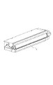
図2は、前記CRG保持板に保持された状態のプロセスカートリッジ周りを表した概略斜視図である。説明の都合上、プロセスカートリッジ2Bk、2Cは不図示としている。 FIG. 2 is a schematic perspective view showing the periphery of the process cartridge held by the CRG holding plate. For convenience of explanation, the process cartridges 2Bk and 2C are not shown.
101aは各プロセスカートリッジ2Y、2M、2C、2Bkを保持するCRG保持右側板、101bは各プロセスカートリッジ2Y、2M、2C、2Bkを保持するCRG保持左側板である。本実施例では、低コストを実現するために保持部材を別体とし、CRG保持右側板101a、CRG保持左側板101bとしたが、保持部材としては、一体でも構わないし、別部材にて連結しても構わない。
101a is a CRG holding right side plate for holding each
今回、保持部材は、別体となるCRG保持右側板101aとCRG保持左側板101bとしたが、後述のリンク部材による連結により、側板間の位相もほぼ同じとすることで、一体構成と同様の保持部材となっている。
This time, the holding member is the CRG holding
CRG保持右側板101a、CRG保持左側板101bにはともに、プロセスカートリッジ挿入時にプロセスカートリッジの下方を支持し、挿入をスムーズに行うためのガイドリブ101a−a、101b−aが設けられている。また、プロセスカートリッジをまとめて一体とする際の回転中心となるピボット部101a−b、101b−bがそれぞれ設けられている。また、プロセスカートリッジ2Y、2M、2C、2Bkの駆動側のカップリング部および、非駆動側の位置決め軸受け部を逃げるための開口部101a−c、101b−cがそれぞれ設けられている。また、後述のリンク機構との連結部であるボスがそれぞれ2箇所設けられている。
Both the CRG holding
次に、CRG保持板101のリンク機構との連結、及び実際の動きについて説明する。 Next, the connection of the CRG holding plate 101 with the link mechanism and the actual movement will be described.
図3、図4、図5は、CRG保持右側板101a、CRG保持左側板101bと連結するリンク機構の詳細を表した装置内部の概略斜視図である。図3は画像形成時の位置でのリンク機構の状態を表し、図4は開閉カバー14が開ききった状態でのリンク機構の状態を表す。
3, 4, and 5 are schematic perspective views of the inside of the apparatus showing details of a link mechanism that is connected to the CRG holding
図5は、図3の状態のリンク機構部分を拡大した詳細斜視図である。 FIG. 5 is an enlarged detailed perspective view of the link mechanism portion in the state of FIG.
図3と図5を用いて開閉カバー14が閉じた状態について説明する。開閉カバー14と連結したリンク部材群、ドア連結板105、中間ロッド104、回転ロッド103、CRG保持板連結ロッド102により、CRG保持板101は押し込まれ、保持バネ109により保持された状態となっている。そのときそれぞれのプロセスカートリッジ2は、本体中央側板106に設けられた位置決め穴106aのプリンタ本体の後方と下方の2つの端面にプロセスカートリッジ2の軸受を押し当てるように不図示のバネにより付勢している。このようにしてプロセスカートリッジの位置決めはCRG保持板101とは、別に本体側で行うようにすることで、CRG保持板101は、プロセスカートリッジ2に対しては、あくまでもラフガイドとしての機能でよいので、プロセスカートリッジ2装着においても操作者はラフな動作で構わない。そのため、操作者はプロセスカートリッジ2の装着がきちんと行われたかどうかを確認しながら装着する必要がなくなり、操作性が向上することになる。
A state in which the opening /
最後に、図4を用いて開閉カバー14が完全に開いた状態について説明する。開閉カバー14に連結されているリンク部材群、ドア連結板105、中間ロッド104、回転ロッド103、CRG保持板連結ロッド102によりCRG保持板101は、図4に示すような画像形成時の位置に比べて約45度角度を有する位置まで移動する。このような位置までプロセスカートリッジ2が移動することで、プロセスカートリッジ2へのアクセスも良くなり、装着、脱着もやりやすくなる。
Finally, a state where the opening /
次に本発明のプロセスカートリッジ2について、図6、7、8、13を用いて詳細に説明する。
Next, the
図6はプロセスカートリッジ2の概略断面図、図7、8は概略斜視図を示している。なお、イエロー、マゼンタ、シアン、ブラックの各カートリッジは同一構成である。
FIG. 6 is a schematic sectional view of the
プロセスカートリッジ2は感光体ドラム21と帯電ローラ23およびクリーニング手段を備えた第1の枠体である感光体ドラムユニット2a、および感光体ドラム21上の静電潜像を現像する現像手段を有する第2の枠体である現像ユニット2bに分かれている。
The
感光体ドラムユニット2aは感光体ドラム21が軸受を介してクリーニング枠体に回転自在に取り付けられている。感光体ドラム21周上には、感光体ドラム21の表面を一様に帯電させるための一次帯電ローラである帯電ローラ22、および感光体ドラム21上に残った現像剤(トナー)を除去するためのクリーニングブレード28が配置され、さらにクリーニングブレード28によって感光体ドラム21表面から除去された残留トナーは、トナー送り機構29によってクリーニング枠体24後方に設けられた廃トナー室30に順次送られる。そして、図示後方の一方端に図示しない駆動モーターの駆動力を伝達することにより、感光体ドラム21を画像形成動作に応じて図示反時計回りに回転駆動させるようにしている。
In the photosensitive drum unit 2a, the
現像ユニット2bは、感光体ドラム21と接触して矢印Y方向に回転する現像剤担持体である現像ローラ22、および現像剤収容部であるトナーが収容されたトナー容器70と現像部である現像容器71とから構成される。現像ローラ22は軸受部材を介して回転自在に現像容器71に支持され、また現像ローラ22の周上には、現像ローラ22と接触して矢印Z方向に回転するトナー供給ローラ72と現像ブレード73がそれぞれ配置されている。さらにトナー容器70内には収容トナーを攪拌するとともにトナー供給ローラ72に搬送するためのトナー攪拌機構74が設けられている。トナー容器70と現像容器71は出荷時等、使用開始前はトナーの漏れを起こさないように、開口部71aをシール部材であるトナーシールで閉鎖している。使用開始時にトナーシールを開封することでトナー容器70と現像容器72は連通し、トナー容器内のトナーは現像容器へ移動する。
The developing unit 2b includes a developing
そして現像ユニット2bは、現像ユニット2bの両端に取り付けられた軸受部材75,76にそれぞれ設けられた支持穴77を中心にピン77aによって現像ユニット2b全体が感光体ドラムユニット2aに対して揺動自在に支持された吊り構造となっており、画像形成を行なう時即ち画像形成時は、支持穴77を中心に回転モーメントにより現像ローラ22が感光体ドラム21に接触するよう、付勢部材である加圧バネ124a,124bによって現像ユニット2bが常に付勢されている。輸送時や長期放置時等、画像形成を行なわない非画像形成時においては、図13に示すように、現像離間部材である離間部材123を装着することにより、加圧バネ124a,124bに抗して、離間部材天面が感光体ドラムユニット天面3aを、離間部材底面123cが現像ユニット底面3bをそれぞれ掴み、現像ローラ22と感光体ドラム21を非接触状態にすることで、長期当接による現像ローラの変形を防止する。離間部材123を取り外すことにより、現像ローラ22と感光ドラム21との離間状態を解除し接触状態にすることができる。現像ローラ22と感光ドラムを離間させる場合はこのように別の枠体でそれぞれを支持し、各々の枠体を接触させた方が回転精度・位置決め精度がよく、また現像剤をトナー容器も大きく構成できる。
The developing unit 2b is configured such that the entire developing unit 2b is swingable with respect to the photosensitive drum unit 2a by
現像時、トナー攪拌機構74によって収容されたトナーがトナー供給ローラ72へ搬送されると、矢印Y方向に回転するトナー供給ローラ72が、そのトナーを矢印Z方向に回転する現像ローラ22との摺擦によって現像ローラ22に供給し、現像ローラ22上に担持させる。現像ローラ22上に担持されたトナーは、現像ローラ22の回転にともない現像ブレード73のところに至り、現像ブレード73がトナーを規制して所望の帯電電荷量を付与するとともに、所定のトナー薄層に形成する。規制されたトナーは、現像ローラ22の回転につれて、感光体ドラム21と現像ローラ22とが接触した現像位置に搬送され、現像位置において図示しない電源から現像ローラ22に印加した直流現像バイアスにより、感光体ドラム21の表面に残留したトナーは、現像ローラ22から剥離、回収される。回収されたトナーは、トナー攪拌機構74により残りのトナーと攪拌混合される。
At the time of development, when the toner accommodated by the
本発明のように感光体ドラム21と現像ローラ22が接触して現像を行う接触現像方式においては、感光体ドラム21は剛体とし、現像ローラ22は弾性体を有するローラとすることが好ましい。この弾性体としては、ソリッドゴム単層やトナーへの帯電付与性を考慮してソリッドゴム層上に樹脂コーティングを施したもの等が用いられる。
In the contact development method in which the development is performed with the
次に、本発明に係る構成について図9〜図12を用いて詳細に説明する。 Next, the configuration according to the present invention will be described in detail with reference to FIGS.
(帯電ローラ)
図9を用いて帯電ローラ23と、帯電ローラの支持構成について説明する。帯電ローラは芯金23bの周りに導電性のゴム部材23aを形成して構成されており、軸受け131を介して加圧ばね(付勢部材)132によって感光体ドラム21に押し付けられている。帯電ローラ23は帯電ローラ軸受け131に回転自在に支持され、さらに、帯電ローラ軸受け131はガイド部133に支持される。ここで帯電ローラ軸受け131とガイド部133との間は摺動可能となっており、帯電ローラ23は回転自在であるとともに、図中矢印の方向(感光体ドラム21に対して当接離間方向)に移動可能となっている。
(Charging roller)
The charging
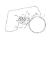
(帯電移動部材)
図10、図11を用いて帯電移動部材である離間部材123、支持部材121、帯電移動部123d及び帯電移動部の一部で支持部材121に作用する作用部123d−1について説明する。支持部材121は軸受け部121aと連結部121bと作用穴部121cから形成されており、軸受け部121aは帯電ローラ芯金23aが摺動可能となっている。121aは感光ドラム21と接触しないように設計されており、こうすることで感光ドラム21の表面を傷つけることがない。帯電移動部123dは支持部材121の作用穴部121cに作用部123d−1を挿入することで支持部材を介して帯電ローラ23を感光ドラム21に対して当接離間方向に移動させる。挿入位置は感光体ドラム枠体24に図示しない挿入用穴を設けることで規制している。
(Charging moving member)
With reference to FIGS. 10 and 11, the
(帯電ローラ離間)
帯電ローラ離間は、帯電ローラは現像ローラと異なり位置決め精度等に厳しくないため、同じ枠体で離間機構を設けた方が複雑な構成とならなくて良い。図11、図12を用いて帯電ローラを移動させる構成について説明する。帯電ローラ23が感光体ドラム21に当接している状態で、離間部材123をプロセスカートリッジに装着することで帯電移動部123−dを、カートリッジ枠体に設けられた図示しない挿入用穴から挿入すると、作用部123d−1が作用穴部121cに入り、さらに挿入すると作用部123d−1の先端は傾斜が着いているため、作用穴部121cが移動する。作用穴部121cの移動を、連結部121bを介して軸受け部121aに伝達することにより、帯電ローラ23を感光ドラムと離間する方向に移動させる。支持部材121の移動方向は、帯電ローラ軸受け131のガイド部133の方向や感光体ドラム中心と帯電ローラ中心を結ぶ架空線と略同一方向であるのが好ましい。図示されていない長手方向逆側についても同様の構成で帯電ローラ23は離間され帯電ローラにかかる圧力が解除される。このように帯電ローラ23に直接作用させるのではなく帯電ローラを支持している支持部材を介して帯電ローラに作用する機構のため、精度や剛性が必要とされる帯電ローラ周りの枠体に挿入用穴を空ける等特別な設計が必要なくなる。また、帯電移動部材を先端に傾斜がついた棒上部材にし、支持部材を穴にすることで帯電移動部材を出し入れするだけで帯電ローラの当接離間を調整することができ複雑な機構を特別に設ける必要がない。また、一度帯電ローラの離間状態を解除したあとも手動で当接離間を繰り返し行なえるため、帯電ローラの離間を解除しプロセスカートリッジを使用し始めた後、長期間画像形成を行なわないような時はプロセスカートリッジに離間部材を作用させることで再度帯電ローラを離間させることができる。また、帯電移動部材を帯電ローラ23の当接離間方向に対して略垂直に移動させることにより、帯電ローラ23の当接離間を行なう構成としたことで、帯電移動部材の短手方向の延長上に新たな機構を設けることなく簡単な構成となる。なお、本実施例では、帯電移動部123dにより、帯電ローラ23と感光ドラム21を完全に離間させているが、帯電ローラと感光ドラム間の圧力を解除するために帯電ローラ21を離間方向へ少しだけ移動させる構成としてもよい。つまり、画像形成を行なわない非画像形成時、離間部材123をプロセスカートリッジ2に装着させ、帯電ローラと感光ドラムの間の圧力が解除された状態にしておき、画像形成を行なう時、即ち現像を行なう時は、離間部材123をプロセスカートリッジから取り外し帯電ローラが機能を発揮できる当接状態に移動させられるように、帯電移動部材によって当接離間方向の相対位置を決定する構成であれば、帯電ローラと感光ドラムが完全に離間するかどうかは関係ない。
(Charging roller separation)
Since the charging roller is not strict in positioning accuracy and the like unlike the developing roller, the charging roller is not required to have a complicated configuration if the separation mechanism is provided with the same frame. A configuration for moving the charging roller will be described with reference to FIGS. 11 and 12. When the charging
本実施例では離間部材123が、現像離間部材と帯電移動部材を兼用するようになっている。すなわち離間部材123は現像離間作用部123b、123cを有しこれらにより現像ローラ22と感光体ドラム21を離間させている。また、帯電移動部123dにより帯電ローラを移動させることができる構造となっている。よって、離間部材123を取り外し現像ローラの離間状態を解除すると、同時に帯電ローラを画像形成可能な当接状態に当接させることができる。このように、ユーザーが帯電ローラ23の離間状態、現像ローラの離間状態を解除する場合、離間部材123を取り去るという一度の動作で目的を達することができる。
In this embodiment the
(離間部材とトナーシールが連結)
本実施例の構成は実施例1とほぼ同じだが、図12に示すように、離間部材123にさらに、トナーシール82の端部をこの離間部材123のトナーシール貼付面123aに貼り付ける構成となっている。このような構成とすることで、ユーザーがトナーシールを開封する際に帯電ローラ23の離間状態、現像ローラの離間状態が解除されるため、帯電移動部材の抜き忘れが生じる可能性がなくなる。またこれを実現するための構成も非常に簡単なものとすることができる。
(Separation member and toner seal are connected)
The configuration of the present embodiment is almost the same as that of the first embodiment. However, as shown in FIG. 12, the end of the toner seal 82 is further affixed to the toner
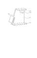
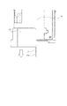
(トナーシールが余長を持っている)
本実施例の構成は実施例2のように、離間部材にトナーシールが連結されているものである。図14にカートリッジ枠体2に離間部材123が取り付けられた状態、図15にカートリッジ枠体2から離間部材123が所定の位置まで引き抜かれ、現像ローラと帯電ローラが感光ドラムに接触した状態を示す。トナーシール125は、カートリッジ枠体2に離間部材123が取り付けられた状態で余長部分(たわみ部分)125aを持つ。余長部分125aの長さは、離間部材123がカートリッジ枠体2から引き抜かれ現像離間、帯電離間が解除された後に余長部分がなくなるように設定されている。即ち、離間部材の取り外しに際して、離間部材123が所定の位置まで移動した場合現像離間・帯電離間が解除されその時はトナーシールの開封はされなく、次にその所定の位置からさらに離間部材を移動させることでトナーシールの開封が起こると言う2段階のステップを踏む。こうすることで、離間解除の際に必要な引き抜き力F1とトナーシール引き抜きの際に必要な引き抜き力F2が同時に作用しないように構成されている訳である。
(Toner seal has extra length)
As in the second embodiment, the configuration of the present embodiment is such that a toner seal is connected to a spacing member. FIG. 14 shows a state in which the
本実施例は離間部材123が帯電移動部材及び現像離間部材を兼ねている構成で説明をしているが、帯電移動部材のみ(現像ローラの離間構成を持たない構成)、または、現像離間部材のみ(帯電ローラの移動構成を持たない構成)にトナーシールを余長をもって貼り付けた構成にしても、離間解除に必要な引き抜き力F1とトナーシール引き抜きの際に必要な引き抜き力F2が同時に作用しないとうい効果が得られる。よって比較的軽い力で離間部材の引き抜きとトナーシールの引き抜きが達成される。
In the present embodiment, the
上述した、実施例では離間部材123がプロセスカートリッジから取れる構成となっているが、かならずしも取れる必要はない。離間部材をプロセスカートリッジの一部として構成した場合、離間部材を移動させ現像離間、帯電離間等を解除した後、当該現像離間部材はプロセスカートリッジと結合したままなので、ユーザーが現像離間部材を取り去った後、それを捨てるという工程が必要なくなる。
In the above-described embodiment, the
なお、本願発明は上記実施例に限定されるものではない。実施例以外の形態や構成要件の配置等も可能であるが、本発明の効果のある範囲にとどまる。 In addition, this invention is not limited to the said Example. Forms other than the embodiments and arrangement of the constituent elements are possible, but the scope of the present invention is limited.
2 プロセスカートリッジ
2a 感光体ドラムユニット
2b 現像ユニット
3a 感光体ドラムユニット天面
3b 現像ユニット底面
11 ポリゴンミラー
12 スキャナーモータ
14 開閉カバー
21 感光体ドラム
22 現像ローラ
23 帯電ローラ
23a 帯電ローラゴム部
23b 帯電ローラ芯金
24 感光体ドラム枠体
25 現像器
27 軸受け
28 クリーニングブレード
29 トナー送り機構
30 廃トナー室
35 中間転写体(中間転写ベルト)
50 定着部
53、54、55 排出ローラ
56 排出トレイ
70 トナー容器
71 現像容器
71a 開口部
72 トナー供給ローラ
73 現像ブレード
74 トナー攪拌機構
75,76 軸受部材
77 支持穴
77a ピン
101 CRG保持板
101a CRG保持右側板
101a−a、101b−a ガイドリブ
101a−c、101b−c 開口部
102 CRG保持板連結ロッド
101b CRG保持左側板
103 回転ロッド
104 中間ロッド
105 ドア連結板
121 支持部材
121a 軸受け部
121b 連結部
121c 作用穴部
123 離間部材
123a トナーシール貼付面
123b 離間部材天面
123c 離間部材底面
2 process cartridge 2a photosensitive drum unit 2b developing unit 3a photosensitive drum unit
50 Fixing
Claims (7)
前記像担持体に接触して前記像担持体を帯電する帯電手段と、
前記像担持体を回転可能に保持し前記帯電手段を前記像担持体に対し当接離間方向に移動可能に保持する第1の枠体と、
前記像担持体の表面に形成された静電潜像を現像するための現像剤を担持する現像剤担持体と、
第1の枠体に対して移動可能であって前記現像剤担持体を設けた第2の枠体と、前記現像剤担持体と前記像担持体を当接させるために前記第1の枠体と前記第2の枠体を付勢する付勢部材とを有する、画像形成装置本体に着脱可能なプロセスカートリッジにおいて、
現像離間部材を前記プロセスカートリッジに装着している時は、前記現像離間部材は前記付勢部材の付勢力に抗して前記第1の枠体と第2の枠体を移動させて前記現像剤担持体と前記像担持体を離間状態にさせ、且つ前記帯電手段と前記像担持体とを離間状態又は前記現像離間部材が前記プロセスカートリッジに装着されている時の前記帯電手段と前記像担持体との当接圧よりも弱くなる状態に保持し、
前記現像離間部材が前記プロセスカートリッジから取り外された時は、前記現像剤担持体と前記像担持体とは当接し、且つ前記帯電部材と前記像担持体は当接することを特徴とするプロセスカートリッジ。 An image carrier;
Charging means for charging the image carrier in contact with the image carrier;
A first frame for holding the image carrier rotatably and holding the charging means movably in a contact and separation direction with respect to the image carrier;
A developer carrying member carrying a developer for developing an electrostatic latent image formed on the surface of the image carrying member;
A second frame which is movable with respect to the first frame and provided with the developer carrier; and the first frame for bringing the developer carrier and the image carrier into contact with each other. And a process cartridge that is attachable to and detachable from the image forming apparatus main body, and a biasing member that biases the second frame.
When the developing separation member is mounted on the process cartridge, the developing separation member moves the first frame and the second frame against the urging force of the urging member to move the developer. The charging unit and the image carrier when the carrier and the image carrier are separated from each other and the charging unit and the image carrier are separated from each other or when the developing separation member is mounted on the process cartridge. And keep it weaker than the contact pressure with
A process cartridge according to claim 1, wherein when the developing separation member is removed from the process cartridge, the developer carrier and the image carrier are in contact with each other, and the charging member and the image carrier are in contact with each other.
前記開口部を閉鎖するシール部材が前記現像離間部材に連結されており、
前記現像離間部材をプロセスカートリッジに装着された状態から所定の位置に移動させることにより前記現像剤担持体と前記像担持体を当接状態にさせた時に、前記シール部材は前記開口部を閉鎖したままであり、
前記現像離間部材を所定の位置からさらに移動させることで前記シール部材を開封させることを特徴とする請求項1乃至6のいずれかに記載のプロセスカートリッジ。 The second frame body develops the image carrier with a developer container for containing a developer for developing the electrostatic latent image formed on the surface of the image carrier, and the developer. A developing portion, and an opening communicating the developer containing portion and the developing portion,
A seal member that closes the opening is connected to the development spacing member;
The seal member closes the opening when the developer carrying member and the image carrying member are brought into contact with each other by moving the developing separation member from a state where it is attached to the process cartridge to a predetermined position. Remain
7. The process cartridge according to claim 1, wherein the seal member is opened by further moving the developing separation member from a predetermined position.
Priority Applications (2)
| Application Number | Priority Date | Filing Date | Title |
|---|---|---|---|
| JP2003397201A JP3997196B2 (en) | 2003-11-27 | 2003-11-27 | Process cartridge and developing separation member |
| US10/902,250 US7072603B2 (en) | 2003-08-01 | 2004-07-30 | Process cartridge and holding member |
Applications Claiming Priority (1)
| Application Number | Priority Date | Filing Date | Title |
|---|---|---|---|
| JP2003397201A JP3997196B2 (en) | 2003-11-27 | 2003-11-27 | Process cartridge and developing separation member |
Related Child Applications (1)
| Application Number | Title | Priority Date | Filing Date |
|---|---|---|---|
| JP2006108791A Division JP3997250B2 (en) | 2006-04-11 | 2006-04-11 | Process cartridge |
Publications (3)
| Publication Number | Publication Date |
|---|---|
| JP2005157063A JP2005157063A (en) | 2005-06-16 |
| JP2005157063A5 JP2005157063A5 (en) | 2006-06-01 |
| JP3997196B2 true JP3997196B2 (en) | 2007-10-24 |
Family
ID=34722416
Family Applications (1)
| Application Number | Title | Priority Date | Filing Date |
|---|---|---|---|
| JP2003397201A Expired - Fee Related JP3997196B2 (en) | 2003-08-01 | 2003-11-27 | Process cartridge and developing separation member |
Country Status (1)
| Country | Link |
|---|---|
| JP (1) | JP3997196B2 (en) |
Families Citing this family (3)
| Publication number | Priority date | Publication date | Assignee | Title |
|---|---|---|---|---|
| JP2007148117A (en) * | 2005-11-29 | 2007-06-14 | Canon Inc | Electrophotographic image forming apparatus |
| JP5087904B2 (en) * | 2006-11-02 | 2012-12-05 | 富士ゼロックス株式会社 | Charging roller, electrophotographic process cartridge, and image forming apparatus |
| JP5152556B2 (en) * | 2007-06-18 | 2013-02-27 | 富士ゼロックス株式会社 | Image forming apparatus |
-
2003
- 2003-11-27 JP JP2003397201A patent/JP3997196B2/en not_active Expired - Fee Related
Also Published As
| Publication number | Publication date |
|---|---|
| JP2005157063A (en) | 2005-06-16 |
Similar Documents
| Publication | Publication Date | Title |
|---|---|---|
| US6968142B2 (en) | Process cartridge and image forming apparatus | |
| US7072603B2 (en) | Process cartridge and holding member | |
| JP4684732B2 (en) | Electrophotographic image forming apparatus and process cartridge | |
| JP3970217B2 (en) | Electrophotographic image forming apparatus | |
| JP4134985B2 (en) | Image forming apparatus and cartridge | |
| JP3630957B2 (en) | Development device | |
| US20060210304A1 (en) | Electrophotographic image forming apparatus, and process cartridge | |
| US6181897B1 (en) | Developing apparatus | |
| JP3997250B2 (en) | Process cartridge | |
| JP2005043537A (en) | Process cartridge and image forming apparatus using the same | |
| JP2001255741A (en) | Partition member, sealing parts, developing device and process cartridge | |
| JP3997196B2 (en) | Process cartridge and developing separation member | |
| JP2005043538A (en) | Processing cartridge and image forming apparatus | |
| JP2003241618A (en) | Image forming device | |
| JP2001194977A (en) | Process cartridge and image forming device | |
| JP3997247B2 (en) | Electrophotographic image forming apparatus | |
| JP2005157063A5 (en) | ||
| JP2005043798A (en) | Image forming apparatus and processing cartridge used in it | |
| JP2001201915A (en) | Process cartridge and image forming device | |
| JP2005043539A (en) | Cleaning apparatus and processing cartridge | |
| JP2003195721A (en) | Process cartridge and image forming apparatus | |
| JP4685197B2 (en) | Electrophotographic image forming apparatus and process cartridge | |
| JP2005043536A (en) | Image forming apparatus and processing cartridge used in it | |
| JP4378393B2 (en) | Process cartridge | |
| JP4109915B2 (en) | Cleaning device, process cartridge, and image forming apparatus |
Legal Events
| Date | Code | Title | Description |
|---|---|---|---|
| A521 | Written amendment |
Free format text: JAPANESE INTERMEDIATE CODE: A523 Effective date: 20060411 |
|
| A621 | Written request for application examination |
Free format text: JAPANESE INTERMEDIATE CODE: A621 Effective date: 20060411 |
|
| A131 | Notification of reasons for refusal |
Free format text: JAPANESE INTERMEDIATE CODE: A131 Effective date: 20070227 |
|
| A521 | Written amendment |
Free format text: JAPANESE INTERMEDIATE CODE: A523 Effective date: 20070424 |
|
| TRDD | Decision of grant or rejection written | ||
| A01 | Written decision to grant a patent or to grant a registration (utility model) |
Free format text: JAPANESE INTERMEDIATE CODE: A01 Effective date: 20070724 |
|
| A61 | First payment of annual fees (during grant procedure) |
Free format text: JAPANESE INTERMEDIATE CODE: A61 Effective date: 20070806 |
|
| FPAY | Renewal fee payment (event date is renewal date of database) |
Free format text: PAYMENT UNTIL: 20100810 Year of fee payment: 3 |
|
| R150 | Certificate of patent or registration of utility model |
Ref document number: 3997196 Country of ref document: JP Free format text: JAPANESE INTERMEDIATE CODE: R150 Free format text: JAPANESE INTERMEDIATE CODE: R150 |
|
| FPAY | Renewal fee payment (event date is renewal date of database) |
Free format text: PAYMENT UNTIL: 20100810 Year of fee payment: 3 |
|
| FPAY | Renewal fee payment (event date is renewal date of database) |
Free format text: PAYMENT UNTIL: 20110810 Year of fee payment: 4 |
|
| FPAY | Renewal fee payment (event date is renewal date of database) |
Free format text: PAYMENT UNTIL: 20120810 Year of fee payment: 5 |
|
| FPAY | Renewal fee payment (event date is renewal date of database) |
Free format text: PAYMENT UNTIL: 20120810 Year of fee payment: 5 |
|
| FPAY | Renewal fee payment (event date is renewal date of database) |
Free format text: PAYMENT UNTIL: 20130810 Year of fee payment: 6 |
|
| LAPS | Cancellation because of no payment of annual fees |