JP3673793B2 - Process cartridge, process cartridge mounting mechanism, and electrophotographic image forming apparatus - Google Patents
Process cartridge, process cartridge mounting mechanism, and electrophotographic image forming apparatus Download PDFInfo
- Publication number
- JP3673793B2 JP3673793B2 JP2003209842A JP2003209842A JP3673793B2 JP 3673793 B2 JP3673793 B2 JP 3673793B2 JP 2003209842 A JP2003209842 A JP 2003209842A JP 2003209842 A JP2003209842 A JP 2003209842A JP 3673793 B2 JP3673793 B2 JP 3673793B2
- Authority
- JP
- Japan
- Prior art keywords
- cartridge
- image forming
- photosensitive drum
- forming apparatus
- main body
- Prior art date
- Legal status (The legal status is an assumption and is not a legal conclusion. Google has not performed a legal analysis and makes no representation as to the accuracy of the status listed.)
- Expired - Fee Related
Links
Images


Classifications
-
- G—PHYSICS
- G03—PHOTOGRAPHY; CINEMATOGRAPHY; ANALOGOUS TECHNIQUES USING WAVES OTHER THAN OPTICAL WAVES; ELECTROGRAPHY; HOLOGRAPHY
- G03G—ELECTROGRAPHY; ELECTROPHOTOGRAPHY; MAGNETOGRAPHY
- G03G21/00—Arrangements not provided for by groups G03G13/00 - G03G19/00, e.g. cleaning, elimination of residual charge
- G03G21/16—Mechanical means for facilitating the maintenance of the apparatus, e.g. modular arrangements
- G03G21/18—Mechanical means for facilitating the maintenance of the apparatus, e.g. modular arrangements using a processing cartridge, whereby the process cartridge comprises at least two image processing means in a single unit
- G03G21/1839—Means for handling the process cartridge in the apparatus body
-
- G—PHYSICS
- G03—PHOTOGRAPHY; CINEMATOGRAPHY; ANALOGOUS TECHNIQUES USING WAVES OTHER THAN OPTICAL WAVES; ELECTROGRAPHY; HOLOGRAPHY
- G03G—ELECTROGRAPHY; ELECTROPHOTOGRAPHY; MAGNETOGRAPHY
- G03G21/00—Arrangements not provided for by groups G03G13/00 - G03G19/00, e.g. cleaning, elimination of residual charge
- G03G21/16—Mechanical means for facilitating the maintenance of the apparatus, e.g. modular arrangements
- G03G21/18—Mechanical means for facilitating the maintenance of the apparatus, e.g. modular arrangements using a processing cartridge, whereby the process cartridge comprises at least two image processing means in a single unit
-
- G—PHYSICS
- G03—PHOTOGRAPHY; CINEMATOGRAPHY; ANALOGOUS TECHNIQUES USING WAVES OTHER THAN OPTICAL WAVES; ELECTROGRAPHY; HOLOGRAPHY
- G03G—ELECTROGRAPHY; ELECTROPHOTOGRAPHY; MAGNETOGRAPHY
- G03G2221/00—Processes not provided for by group G03G2215/00, e.g. cleaning or residual charge elimination
- G03G2221/16—Mechanical means for facilitating the maintenance of the apparatus, e.g. modular arrangements and complete machine concepts
- G03G2221/18—Cartridge systems
- G03G2221/183—Process cartridge
- G03G2221/1853—Process cartridge having a submodular arrangement
- G03G2221/1861—Rotational subunit connection
-
- G—PHYSICS
- G03—PHOTOGRAPHY; CINEMATOGRAPHY; ANALOGOUS TECHNIQUES USING WAVES OTHER THAN OPTICAL WAVES; ELECTROGRAPHY; HOLOGRAPHY
- G03G—ELECTROGRAPHY; ELECTROPHOTOGRAPHY; MAGNETOGRAPHY
- G03G2221/00—Processes not provided for by group G03G2215/00, e.g. cleaning or residual charge elimination
- G03G2221/16—Mechanical means for facilitating the maintenance of the apparatus, e.g. modular arrangements and complete machine concepts
- G03G2221/18—Cartridge systems
- G03G2221/183—Process cartridge
- G03G2221/1884—Projections on process cartridge for guiding mounting thereof in main machine
Description
【0001】
【発明の属する技術分野】
本発明は、プロセスカートリッジ、プロセスカートリッジの装着機構、及び、電子写真画像形成装置に関するものである。
【0002】
ここで、電子写真画像形成装置とは、電子写真画像形成方式を用いて記録媒体(例えば、記録紙、OHPシート、布等)に画像を形成するものである。電子写真画像形成装置の例としては、例えば、電子写真複写機、電子写真プリンタ(例えば、レーザプリンタ、LEDプリンタ等)、ファクシミリ装置、ワードプロセッサ及びこれらの複合機(マルチファンクションプリンター等)が含まれる。
【0003】
また、プロセスカートリッジとは、プロセス手段としての帯電手段、現像手段又はクリーニング手段と電子写真感光体ドラムとを一体的にカートリッジ化し、このカートリッジを画像形成装置本体に対して着脱可能とするものである。或いは、プロセス手段としての帯電手段、現像手段、クリーニング手段の少なくとも1つと電子写真感光体ドラムとを一体的にカートリッジ化して画像形成装置本体に着脱可能とするものである。更には、少なくともプロセス手段としての現像手段と電子写真感光体ドラムとを一体的にカートリッジ化して電子写真画像形成装置本体に着脱可能とするものをいう。
【0004】
【従来の技術】
従来、電子写真画像形成装置においては、電子写真感光体ドラム(以下、「感光体ドラム」と称す)及び前記感光体ドラムに作用するプロセス手段を一体的にカートリッジ化して、このカートリッジを画像形成装置本体に着脱可能とするプロセスカートリッジ方式が採用されている。このプロセスカートリッジ方式によれば、装置のメンテナンスをサービスマンによらず操作者自身で行うことができるので、格段に操作性を向上させることができる。そのため、このプロセスカートリッジ方式は、電子写真画像形成装置において広く用いられている。
【0005】
従来、カートリッジ方式の画像形成装置においては、装置本体に対して開閉する開閉カバーの開閉動作に連動して、プロセスカートリッジを画像形成位置(装着位置)と装置本体の手前位置(載置位置)とに移動させることが知られている(例えば、特許文献1参照)。
【0006】
特許文献1に記載された構成によれば、装置本体の手前側でもってカートリッジを移動ガイドに載置(装着)する。そして、カバーを閉じることによって、カバーの移動に連動して移動ガイドがカートリッジを装着位置へ搬送する。
【0007】
従って、カートリッジを装置本体へ装着する際に、操作者が装置本体の奥までカートリッジを押し込む必要がない。
【0008】
よって、カートリッジの装置本体に対する装着操作性を格段に向上させることができた。
【0009】
【特許文献1】
特開2002−278418号公報
【0010】
【発明が解決しようとする課題】
本発明は、前記従来技術をさらに発展させたものである。
【0011】
本発明の目的は、プロセスカートリッジを電子写真画像形成装置本体に装着する際の装着操作性を向上させたプロセスカートリッジ、プロセスカートリッジの装着機構、及び、電子写真画像形成装置を提供することにある。
【0012】
また、本発明の他の目的は、プロセスカートリッジを載置する載置位置から装着位置までプロセスカートリッジを確実に移動することができるプロセスカートリッジ、プロセスカートリッジの装着機構、及び、電子写真画像形成装置を提供することにある。
【0013】
また、本発明の他の目的は、プロセスカートリッジが載置位置から装着位置まで移動する際に、引っ張り力を受けるプロセスカートリッジ、プロセスカートリッジの装着機構、及び、電子写真画像形成装置を提供することにある。
【0014】
また、本発明の他の目的は、載置位置から装着位置へ向かう方向へ引っ張り力を受けるプロセスカートリッジ、プロセスカートリッジの装着機構、及び、電子写真画像形成装置を提供することにある。
【0015】
【課題を解決するための手段】
上記目的を達成するための主たる本発明に係るプロセスカートリッジにあっては、
電子写真画像形成装置本体に設けられた移動ガイドに載置され、前記移動ガイドの移動に連動して載置位置から装着位置まで移動可能なプロセスカートリッジであって、
電子写真感光体ドラムと、
前記電子写真感光体ドラムに作用するプロセス手段と、
前記電子写真感光体ドラム及び前記プロセス手段を支持するカートリッジフレームと、
前記載置位置において前記移動ガイドに載置される第一の被載置部であって、前記感光体ドラムの長手方向の一端側に設けられた第一の被載置部と、
前記載置位置において前記移動ガイドに載置される第二の被載置部であって、前記感光体ドラムの長手方向の他端側に設けられた第二の被載置部と、
前記装着位置において前記画像形成装置本体に対して位置決めされる第一の位置決め部であって、前記感光体ドラムの長手方向の一端側に前記カートリッジフレームから外方へ突出して設けられた第一の位置決め部と、
前記装着位置において前記画像形成装置本体に対して位置決めされる第二の位置決め部であって、前記感光体ドラムの長手方向の他端側に前記カートリッジフレームから外方へ突出して設けられた第二の位置決め部と、
前記画像形成装置本体に設けられており、前記移動ガイドの移動に連動して移動する係止部に係合して前記係止部が移動することによって、前記載置位置から前記装着位置へ向かう方向へ前記係止部から引っ張り力を受ける係合部と、
を有することを特徴とする。
【0016】
また、主たる本発明に係る電子写真画像形成装置にあっては、
プロセスカートリッジを着脱可能であって、記録媒体に画像を形成するための電子写真画像形成装置において、
(i)移動ガイドと、
(ii)係止部と、
(iii)電子写真感光体ドラムと、
前記電子写真感光体ドラムに作用するプロセス手段と、
前記電子写真感光体ドラム及び前記プロセス手段を支持するカートリッジフレームと、
前記移動ガイドに載置される第一の被載置部であって、前記感光体ドラムの長手方向の一端側に設けられた第一の被載置部と、
前記移動ガイドに載置される第二の被載置部であって、前記感光体ドラムの長手方向の他端側に設けられた第二の被載置部と、
前記画像形成装置本体に対して位置決めされる第一の位置決め部であって、前記感光体ドラムの長手方向の一端側に前記カートリッジフレームから外方へ突出して設けられた第一の位置決め部と、
前記画像形成装置本体に対して位置決めされる第二の位置決め部であって、前記感光体
ドラムの長手方向の他端側に前記カートリッジフレームから外方へ突出して設けられた第二の位置決め部と、
前記移動ガイドの移動に連動して移動する前記係止部に係合して、前記係止部が移動することによって、前記第一の被載置部及び前記第二の被載置部に載置される載置位置から前記第一の位置決め部及び前記第二の位置決め部に位置決めされる装着位置へ向かう方向へ前記係止部から引っ張り力を受ける係合部と、
を有するプロセスカートリッジを前記画像形成装置本体に位置決めする位置決め部材と、
(iv)前記プロセスカートリッジの有する前記電子写真感光体ドラムに形成された現像剤像を前記記録媒体に転写する転写手段と、
(v)前記記録媒体を搬送する搬送手段と、
を有することを特徴とする。
【0017】
また、主たる本発明に係るプロセスカートリッジの装着機構にあっては、
電子写真画像形成装置本体にプロセスカートリッジを装着するためのプロセスカートリッジの装着機構において、
前記画像形成装置本体が、
移動ガイドと、係止部と、を有し、
前記プロセスカートリッジが、
電子写真感光体ドラムと、
前記電子写真感光体ドラムに作用するプロセス手段と、
前記電子写真感光体ドラム及び前記プロセス手段を支持するカートリッジフレームと、
前記移動ガイドに載置される第一の被載置部であって、前記感光体ドラムの長手方向の一端側に設けられた第一の被載置部と、
前記移動ガイドに載置される第二の被載置部であって、前記感光体ドラムの長手方向の他端側に設けられた第二の被載置部と、
前記画像形成装置本体に対して位置決めされる第一の位置決め部であって、前記感光体ドラムの長手方向の一端側に前記カートリッジフレームから外方へ突出して設けられた第一の位置決め部と、
前記画像形成装置本体に対して位置決めされる第二の位置決め部であって、前記感光体ドラムの長手方向の他端側に前記カートリッジフレームから外方へ突出して設けられた第二の位置決め部と、
前記移動ガイドの移動に連動して移動する前記係止部に係合して、前記係止部が移動することによって、前記第一の被載置部及び前記第二の被載置部に載置される載置位置から前記第一の位置決め部及び前記第二の位置決め部に位置決めされる装着位置へ向かう方向へ前記係止部から引っ張り力を受ける係合部と、を有し、
前記画像形成装置本体に前記プロセスカートリッジを装着することを特徴とする。
【0018】
【発明の実施の形態】
以下に図面を参照して、この発明の好適な実施の形態を例示的に説明する。ただし、この実施の形態に記載されている構成部品の寸法、材質、形状、その相対配置などは、特に特定的な記載がない限りは、この発明の範囲をそれらのみに限定する趣旨のものではない。また、以下の説明で一度説明した部材についての材質、形状などは、特に改めて記載しない限り初めの説明と同様のものである。
【0019】
また、以下の説明において、プロセスカートリッジの長手方向とは、プロセスカートリッジを装置本体に対して着脱する方向と交差する方向(略直交する方向)である。また、プロセスカートリッジの上面とは、プロセスカートリッジを装置本体へ装着した状態で上方に位置する面であり、下面とは下方に位置する面である。
【0020】
(第1の実施の形態)
【0021】
図1〜図12を参照して、第1の実施の形態に係るプロセスカートリッジ及びカラー電子写真画像形成装置について説明する。
【0022】
[カラー電子写真画像形成装置の全体の説明]
まずカラー画像形成装置の全体構成について、図2を用いて概略説明する。図2は、本実施の形態に係る電子写真プロセスを用いた画像形成装置の一形態であるカラーレーザープリンタの断面図である。
【0023】
図2に示すように、カラーレーザープリンタA(以下「プリンタ」と称す)は、4個のプロセスカートリッジ20(20Y、20M、20C、20Bk)と、中間転写体40と、を有する4連ドラム方式(インライン)のプリンタである。
【0024】
そして、4個のプロセスカートリッジ20(20Y、20M、20C、20Bk)を垂直方向に並べて装着する。カートリッジ20Yは、イエロー色の現像剤を収納し、イエロー色の現像剤像を形成する。カートリッジ20Mは、マゼンタ色の現像剤を収納し、マゼンタ色の現像剤像を形成する。カートリッジ20Cは、シアン色の現像剤を収納し、シアン色の現像剤像を形成する。カートリッジ20Bkは、ブラック色の現像剤を収納し、ブラック色の現像剤像を形成する。そして、中間転写体40は、各プロセスカートリッジ20で形成された現像剤像を重ねて転写され、その現像剤像(カラー画像)を記録媒体Pに転写する。
【0025】
カラー画像を転写された記録媒体Pは、定着器60へ搬送され、カラー画像が記録媒体Pに定着される。その後、排出ローラ群71、72、73が、カラー画像が定着された記録媒体Pを装置上面の排出トレイ70上へ排出する。
【0026】
なお、上記4色のカートリッジ20は装置本体(プリンタ)A本体に対して個別に着脱可能に構成されている。
【0027】
次に上記画像形成装置の各部の構成について図2、図3を参照して順次説明する。図3は、本実施の形態に係るカートリッジの概略断面図である。なお、各色の構成が同一の場合は、イエロー現像剤を有するカートリッジ20Yについてのみ説明し、その他プロセスカートリッジについては説明を省略する。
【0028】
[感光体ドラム]
本実施の形態に係る感光体ドラム21は、アルミシリンダーの外側に有機光導電体層を塗布されている。そして、カートリッジフレーム26に回転自在に支持されている。また、感光体ドラム21は、後方(図2)のカートリッジ20の一方端に駆動モーター(不図示)の駆動力を伝達する。これにより、ドラム21は、画像形成動作に応じて図示反時計方向(図3)に回転する。
【0029】
[帯電手段]
帯電手段22(22Y)は、電圧を印加することができる帯電ローラ22aを有している。そして、帯電ローラ22aにより感光体ドラム21の表面を一様に帯電させる。
【0030】
[露光手段]
感光体ドラム21への露光は、スキャナー部50により行われる。本実施の形態では、スキャナー部50は、1個のポリゴンミラー52で2つのカートリッジ20に画像光を導くことが可能なポリゴンミラー52(52YM、52CBk)を2つ備えている。これにより、合計4つのカートリッジ20に画像光を導く。画像信号がレーザーダイオード(不図示)に与えられると、このレーザーダイオードは画像信号に対応する画像光51(51Y)をポリゴンミラー52へ照射する。画像光51は、高速で回転するポリゴンミラー52(52YM)で反射される。そして、更に、反射レンズ54(54Y)により反射される。その後、結像レンズ53(53Y)を介して一定速度で回転する感光体ドラム21の表面に導かれる。感光体ドラム21に到達した画像光51は、感光体ドラム21の表面を選択的に露光し静電潜像を形成する。
【0031】
[現像手段]
現像手段は、現像ローラ23(23Y)を有する。そして、現像ローラ23によって、上記静電潜像を現像する。そのために、現像ローラ23は、感光体ドラム21に対向し、かつ、感光体ドラム21に対し感光体ドラム回転方向の順方向に回転しながら接触している。現像ローラ23は、感光体ドラム21上に現像剤による可視像を形成する。
【0032】
[中間転写体]
中間転写体40は、カラー画像形成動作時に各現像ローラ23により現像された感光体ドラム21上の現像剤画像を多重転写される。そのため、感光体ドラム21の外周速度と同期して時計方向(図2)に回転する。
【0033】
感光体ドラム21上に形成された現像剤画像は、電圧を印加された一次転写ローラ42(42Y、42M、42C、42Bk)により転写体40に多重転写される。前記転写ローラ42は、転写体40を挟んで感光体ドラム21と対向する位置に配置されている。
【0034】
多重転写を受けた転写体40は、電圧を印加された二次転写ローラ5との間に記録媒体Pを挟み込む。そして、両者によって記録媒体Pを搬送する。これにより、記録媒体Pに転写体40上のカラー現像剤像を一括転写する。
【0035】
本実施の形態に係る中間転写体(中間転写ベルト)40は、周長約620mmのシームレス樹脂ベルトで構成されている。そして、この転写体40は、駆動ローラ41、二次転写対向ローラ43、テンションローラ44の3軸で張架されている。そして、ローラ44の両端をばねで荷重している。これによって、転写体40の周長が装置本体内の温湿度や経時変化により変化しても、張架テンション変化量を吸収できる。
【0036】
また、転写体40は、装置(プリンタ)本体Aに駆動ローラ41を支点とし支持されている。そして、駆動ローラ41の後方(図2)の一方端に駆動モータ(不図示)の駆動力が伝達される。これにより、転写体40は、画像形成動作に応じて時計方向(図2)回りに回転する。
【0037】
[給送部]
給送部は、装着されているカートリッジ20へ記録媒体Pを給送するものであり、複数枚の記録媒体Pを収納したカセット1、ローラ2、レジストローラ対3等を有する。
【0038】
画像形成時にはローラ2が画像形成動作に応じて駆動回転する。これによって、カセット1内の記録媒体Pを一枚ずつ給送する。そして、送り出された記録媒体Pは、レジストローラ対3に至る。レジストローラ対3は、記録媒体Pを静止待機させる非回転の動作と、記録媒体Pを転写体40に向けて搬送する回転の動作とを所定のシーケンスで行う。これによって、ローラ対3は、転写工程時の画像と記録媒体Pとの位置合わせを行う。
【0039】
[転写部]
転写部は揺動可能な二次転写ローラ5を有する。転写ローラ5は略上下方向(図2)に移動可能で且つ回転駆動する。転写ローラ5は、記録媒体Pにカラー画像を転写するタイミングに合わせてカム部材(不図示)により記録媒体Pを介して転写体40に所定の圧で押し付けられる。この時転写ローラ5にはバイアスが印加される。これによって、転写体40上の現像剤像は記録媒体Pに転写される。ここで、転写体40と転写ローラ5とは夫々駆動されている。そのため、両者に挟まれた状態の記録媒体Pは、転写工程が行われた後に、左方向(図2)に搬送され、定着器60に到達する。
【0040】
[定着部]
定着部においては、記録媒体P上に形成したカラー現像剤像を定着器60により記録媒体Pに定着させる。定着器60は、記録媒体Pに熱を加えるためのセラミックヒータ63を内蔵しているフィルムガイドユニット61と、記録媒体Pをフィルムガイドユニット61に圧接させるための加圧ローラ62とを有する。これにより記録媒体Pは、熱及び圧力を加えられる。これによりカラー現像剤像が記録媒体Pに定着される。
【0041】
[画像形成動作]
次に上記のように構成された装置によって画像形成を行う場合の動作について説明する。
【0042】
まず図2に示す給送ローラ2(図2)を回転する。そして、カセット1内の記録媒体Pをレジストローラ対3へ搬送する。
【0043】
一方、感光体ドラム21と転写体40とが各々所定の外周速度V(以下プロセス速度と呼ぶ)で図示矢印方向(図2)へ回転する。
【0044】
帯電ローラ22aによって表面を帯電された感光体ドラム21は、レーザー光(画像光)51による露光を受けて、静電潜像を形成される。
【0045】
1:イエロー画像の形成
スキャナー部50によりイエロー画像のレーザー光51Yで、感光体ドラム21Yを照射しイエロー画像に対応する潜像を形成する。この潜像形成と同時にイエロー現像ローラ23Yを回転する。そして、感光体ドラム21Y上の潜像にイエロー現像剤が付着するように感光体ドラム21Yの帯電極性と同極性の電圧を印加してイエロー現像剤の現像を行う。現像されたイエロー現像剤像は、転写ローラ42Yが中間転写体40を介して当接する位置で、転写体40の外周に一次転写される。
【0046】
2:マゼンタ画像の形成
次いで転写体40に形成されたイエロー画像の先端と一致するように、スキャナー部50によりマゼンタ画像のレーザー光で、感光体ドラム21Mを照射する。これによって、感光体ドラム21Mにマゼンタ画像に対応する静電潜像を形成する。この潜像形成と同時にマゼンタ現像ローラを回転する。そして、前述と同様にマゼンタ現像剤の現像を行う。現像されたマゼンタ現像剤像は、転写体40の外周にイエローの現像剤像に重ねて一次転写される。
【0047】
3:シアン画像の形成
次いで転写体40の外周のイエロー及びマゼンタ画像の先端と一致するように、前述したマゼンタ画像の形成と同様の動作を行う。
【0048】
4:ブラック画像の形成
次いで中間転写体40の外周のイエロー、マゼンタ及びシアン画像の先端と一致するように、前述したマゼンタ画像の形成と同様の動作を行う。
【0049】
尚、21C、21Bkは感光体ドラム、42C、42Bkは一次転写ローラである。
【0050】
以上述べたように、イエロー、マゼンタ、シアン、ブラックの順で潜像の形成、現像、及び、転写体40への現像剤の転写を行う。そして、転写体40の表面にイエロー、マゼンタ、シアン、ブラックの4種の現像剤から成るフルカラーの画像を形成することになる。
【0051】
尚、ブラック現像剤の転写体40への転写が終了する前に、先述のレジストローラ対3で待機させておいた記録媒体Pを搬送させる。
【0052】
転写体40への前記4色の画像形成時には、下方に待機し転写体40とは非接触状態であった転写ローラ5を同時に上方へカム(不図示)によって移動させる。そして、転写ローラ5によって、記録媒体Pを転写体40の第二転写部で圧接する。また、転写ローラ5に現像剤と逆特性のバイアスを印加する。これによって、転写体40上のフルカラー画像を記録媒体Pに4色同時に転写する。
【0053】
その後、記録媒体Pは、転写体40から剥離され定着部へ搬送される。そして、現像剤像の定着が行われる。その後、記録媒体Pは、排出ローラ対71、72、73、74を介して本体上部の排出トレイ70上へ排出される。これによって、画像形成動作を終了する。
【0054】
次に本発明に係るプロセスカートリッジ、プロセスカートリッジの装着機構、及び、電子写真画像形成装置の一実施形態について詳細に述べる。
【0055】
[プロセスカートリッジ]
図3にカートリッジ20の断面を示す。カートリッジ20は現像剤と感光体ドラム21、及び、プロセス手段としての帯電ローラ22a、現像ローラ23等を一体的に構成している。そして現像剤がなくなると操作者が交換を行う。これによって、常に高画質を提供できる。本実施の形態に係るインラインフルカラー画像形成装置においては、イエロー、マゼンタ、シアン、ブラックの4色のプロセスカートリッジ20(20Y、20M、20C、20Bk)を各々独立で4個使用している。各色独立のカートリッジにすることで出力する画像によって寿命の異なるカートリッジを効率良く使用することができる。
【0056】
本実施の形態では、カートリッジフレーム26としてのドラムフレーム26aに感光体ドラム21とクリーニングブレード24、帯電ローラ22aを設けている。また、カートリッジフレーム26としての現像フレーム27に、現像剤を収納する現像剤収納部、現像剤を撹拌するための撹拌部材29、現像ローラ23、現像剤を現像ローラ23に供給するための現像剤供給スポンジローラ28、現像ローラ23上の現像剤量を規制するための現像ブレード25を設けている。
【0057】
即ち、本実施の形態では、カートリッジフレーム26は、ドラムフレーム26a、及び、現像フレーム27を有している。
【0058】
[プロセスカートリッジ装着方法]
図4は、本実施の形態に係る画像形成装置の開閉カバー開放状態を表す断面図である。
【0059】
図4に示すように、装置本体Aに設けられた開閉カバー10は、画像形成装置の正面下方側に回転中心11を有している。そして、カバー10に転写体40が設けられているため、カバー10を開くことで中間転写体ユニットがカバー10と一体的に回転する。これによって、操作者がカートリッジ20(20Y、20M、20C、20Bk)へアクセスすることが可能となる。
【0060】
尚、カバー10は、カートリッジ20を装置本体Aに対して着脱する際に、開閉するものである。
【0061】
装置本体Aに設けられた移動ガイド30、32は、カートリッジ20(20Y、20M、20C、20Bk)を一体で保持する。移動ガイド30、32の回転中心36は、装置上方に設けられ、リンク機構によりカバー10と連結されている。即ち、移動ガイド30、32は、カバー10の移動と連動する。これにより、カバー10が開くことで移動ガイド30、32はピボット点を中心に回転移動する。そして、カートリッジ20(20Y、20M、20C、20Bk)は、ガイド30、32によって所定の角度をもって保持されて、載置位置200(図4)から装着位置300(図2)へ移動する。本実施の形態では、このときの回転角度は約35度である。
【0062】
尚、カートリッジ20を装置本体Aへ装着する装着方向と交差する交差方向の一端側にガイド30、他端側にガイド32が配置されている。そして、ガイド30は、カートリッジ20の長手方向一端側を保持し、ガイド32は、カートリッジ20の他端側を保持する。また、ガイド30、32は、カバー10の開閉動作に連動して移動する。
【0063】
ガイド30、32には、カートリッジ20を載置するカートリッジ載置部34、35が設けられている。移動ガイド30、32が装着位置300(図2)の場合には、載置部34、35は水平面から約10度傾いている。また、移動ガイド30、32がカートリッジ20をガイド30、32に載置(装着)する載置位置200(図4)を装着する位置にくると、載置部34、35は水平面から約45度傾いている。
【0064】
尚、カートリッジ20を装置本体Aから取り出す際には、載置位置200(図4)はカートリッジ20をガイド30、32から取り出す取り出し位置となる。
【0065】
図4に示す状態で、カートリッジ20を載置部34、35に平行に載置する。又は、カートリッジ20をガイド30、32から取り出す。そのため、操作者は、水平面から約45°の角度でプロセスカートリッジ20をカートリッジ載置部34、35に載置することができる。又は、載置部34、35から引き抜くことができる。
【0066】
従って、載置、引き抜き方向に遮るものがなく、操作者は操作が行い易い。また、ガイド34、35にカートリッジ20を載置(装着)する際には、載置部34、35上にカートリッジ20を挿入(載置)すると、ガイド30、32が45°傾いているため、カートリッジ20は自然に載置部34、35(ガイド30、32)を滑るように移動する。
【0067】
そして、カートリッジ20は、載置部34、35の奥(壁面30a)に突き当たって停止する。そのため、操作者は自然な操作で確実にカートリッジ20を移動ガイド30、32に装着することができる。
【0068】
尚、載置部34は、移動ガイド30に設けられており、載置部35は、移動ガイド32に設けられている(図4)。従って、載置部34には、カートリッジ20の一端側が載置(装着)され、載置部35には、カートリッジ20の他端側が載置(装着)される。
【0069】
カートリッジ被載置部について、図7、及び、図8を用いて説明する。カートリッジ被載置部は、移動ガイド30、32に接触し、支持される部分である。
【0070】
まず、第一の被載置部26a、30b(図7)は、カートリッジ20の駆動側(カップリング87の設けられている側)に設けられている。
【0071】
また、フレーム26としてのドラムフレーム26bの下面に設けられている。そして、第一移動ガイド30(図1)に設けられた載置部34上に支持される。
【0072】
また、第二の被載置部26b、26c、27a、27b(図8)は、カートリッジ20の非駆動側(カップリング87の設けられていない側)に設けられている。また、フレーム26に設けられている。
【0073】
そして、第二移動ガイド32(図1)に設けられた載置部35上に支持される。
【0074】
次に、カートリッジ20の被載置部を載置部に載置する状態について説明する。
【0075】
まず、第一の被載置部26a、30bを載置部34上に載置する状態について、図7を用いて説明する。
【0076】
図7に示すように、カートリッジ20の一端を第一移動ガイド30を上を滑るように押し込む(矢印X方向)。そして、載置部34上に第一の被載置部26a、30bが支持される。ここで、第一の被載置部26aは、ドラムフレーム26bの下面である。
【0077】
また、第一の被載置部30bは、回転止めであって、カートリッジ20が装置本体から駆動力を受ける際に、カートリッジ20が回転しようとするのを規制する。
【0078】
次に、第二の被載置部26b、26c、27a、27bを載置部35上に載置する状態について、図8を用いて説明する。
【0079】
図8に示すように、カートリッジ20の他端を第二移動ガイド32上を滑るように押し込む(矢印X方向)。すると、まず、第二の被載置部フレーム26としての現像フレーム27の下面27a、27bが載置部35Y上を滑りながら移動する。
【0080】
その後、第二の被載置部26b、26c、27a、27bが、第二移動ガイド32のガイドリブ39(載置部35)上に乗り上げる。これによって、第二の被載置部26b、26c、27a、27bがガイドリブ39(載置部35)上に載置される。
【0081】
ここで、第二の被載置部27a、27bは、フレーム26としての現像フレーム27の下面である。また、第二の被載置部26b、26cは、ドラムフレーム26bの上方に配置した突起下面である。
【0082】
尚、第一の被載置部、及び第二の被載置部は、前述した実施の形態に限定されることはない。移動ガイドに載置される形態であれば、適宜用いることができる。
【0083】
[プロセスカートリッジのプリンタ本体への固定方法]
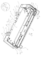
図1は、カバー10の開口時(図4)に、本実施の形態に係るカートリッジが装置本体の移動ガイドに載置された状態を示す概略斜視図である。図5は、本実施の形態に係る画像形成装置の開閉カバー開放状態を表す概略断面図である。図6は、本実施の形態に係るカートリッジの上面図である。
【0084】
尚、カバー10は、装置本体Aに対してカートリッジを着脱する際に、開閉するものである。
【0085】
尚、本実施の形態では、低コストを実現するために移動ガイド30と移動ガイド32とを別体とした。しかしながら、移動ガイドとしては、一体でも構わないし、別部材にて連結しても構わない。
【0086】
また、本実施の形態に係る移動ガイド30、32は、後述のリンク部材による連結により、側板間の位相もほぼ同じとする。これによって、一体構成と同様の移動ガイドとなっている。
【0087】
右移動ガイド30、左移動ガイド32にはともに、カートリッジ挿入時にカートリッジの下方を支持し、挿入をスムーズに行うためのカートリッジ載置部34、35が設けられている。
【0088】
また、図6で示す通りフレーム26には、カートリッジ20を装置本体Aに位置決めするための位置決め部85、86が設けられている。この位置決め部85、86は、感光体ドラム21の長手方向の両端にフレーム26から外方へ突出して設けられている。
【0089】
また、この位置決め部85、86は、感光体ドラム21を貫通しているドラム軸21dの一端21aと他端21bをフレーム26に回転可能に位置決めする。そのため、軸受85a、86aでドラム軸21dの一端21aと他端21bをフレーム26に支持している。位置決め部85、86は装置本体Aに対して、直接軸受85a,86aでもって位置決めされる。
【0090】
尚、右位置決め部85の外側のドラム軸21dの一端21aには本体駆動手段から感光体ドラム21へ駆動力を伝達するカップリング87を設けている。
【0091】
即ち、本実施の形態では、位置決め部85、86は、感光体ドラム21の軸線と同軸線上に配置されている。そして、位置決め部85は、ドラム21の一端側、位置決め部86は、ドラム21の他端側に配置されている。また、この位置決め部85、86は、ドラム軸21を支持する軸受け85a、86aの外面である。
【0092】
図4、図5に示すように本体右側板100には、プロセスカートリッジ位置決め部材101(101Y、101M、101C、101Bk)が配置されている。本体左側板110にも同様のカートリッジ位置決め部材(不図示)が配置されている。本体左右側板100、110のカートリッジ位置決め部材101は、本体側板100、110に調整して組み付け固定されている。これによって、各カートリッジ20Y、20M、20C、20Bkは、各カートリッジ20が有するドラム軸21dの平行度を高精度に維持することができる。
【0093】
カートリッジ20の両端に突出して設けられた位置決め部85、86を係止するカートリッジ位置決め部材101は、本体側板面上又は、装置内側に突出して設けられている。
【0094】
位置決め部材101は、水平方向101a、鉛直方向101bに2箇所の突き当て面を有している(図12)。その2箇所の突き当て面101a、101bに、フレーム26から突出した右位置決め部85、左位置決め部86の軸受85a、86aが直接当接する。このように各色のフレーム26を直接本体側板100、110で支持することにより、各カートリッジの感光体ドラム21が精度良く装置本体Aに位置決めされる。
【0095】
即ち、4本の感光体ドラム21の平行度を向上させることができた。
【0096】
図1、図6で示すように、フレーム26の装着方向先端側には、フレーム26の略外形線91よりも突出した位置に、外部から引っ張り力を受ける係合部81、82が設けられている。尚、外形線91は、カートリッジフレーム26の外側を意味するので、図6に示すように直線的である必要はない。
【0097】
本実施の形態では、右係合部81はフレーム26の先端突出部83の右方から感光体ドラム21と略平行に外側に伸びている。先端突出部83は外観上、及び、補強の目的で長手中央方向に延長している。しかしながら、破線で示される領域のみに設置しても良い。左係合部82も同様にカートリッジフレーム26の先端突出部84の左方から感光体ドラム21と略平行に外側に伸びている。
【0098】
また、装置本体Aには、係止部としての抜け止めスライダ31、33が設けられている。このスライダ31、33は、移動ガイド30、32に対してスライド可能に取り付けられている。そして、カートリッジ20に設けられた係合部81、82と係合する引っ張り力作用部37、38を有する。
【0099】
尚、作用部37は、係合部81と係合し、作用部38は、係合部82と係合する。
【0100】
また、スライダ31、33は、カバー10の閉動作に連動して矢印(図1)のようにカートリッジ20の上部から下方へ移動する。
【0101】
そして、作用部37、38が係合部81、82と係合する。尚、カバー10の開閉ガイドに連動してスライダ31、33は上方へ移動する。そして、作用部37、38が係合部81、82と離れる。即ち、係合状態が解除される。尚、係合部81、82は、外形線91よりも突出して配置されている。そのため、係合部81、82とスライダ31、33の係合がフレーム26に邪魔されることはない。
【0102】
作用部37、38は、カートリッジ20を載置部34、35に載置する位置がばらついた場合でも、作用部37、38が係合部81、82と確実に係合するように、よりカートリッジ20側に張り出した第一係止部37a,38aを有する。また、更に、作用部37、38、係合部81、82と係合し、
カートリッジ20を載置位置200から装着位置300まで移動ガイド30、32とともに移動するように引っ張り力をカートリッジ20に与える第二係止部37b、38bと、第一係止部37a、38aと第二係止部37b、38bとの段差を滑らかにつなぐガイド部37c、38cと、を有する。
【0103】
スライダ31、33が、カバー10の閉動作に連動して下がり始めると、初めに、第一係止部37a、38aがカートリッジ20の背面部20aと係合部81、82との隙間に入り込む。これによって、その後の装着動作時による装置本体Aに設けられた駆動部や突起部からの抵抗力によって、カートリッジ20が移動ガイド30、32から離れるのを防止する。
【0104】
ここで、第一係止部37a、38aは、第二係止部37b、38bよりも移動ガイド30、32に近い位置に設けられている。これは、カートリッジ20が移動ガイド30、32の正規の位置に対して多少のばらつきをもって載置されている場合であっても、作用部37、38の先端である第一係止部37a、38aが上方から下方へ移動する際に、係合部81、82とぶつからず、カートリッジ20の背面部20aと係合部81、82との隙間にスムーズに入り込むようにするためである。
【0105】
第一係止部37a、38aが、カートリッジ20の背面部20aと係合部81、82との隙間に入り込んだ状態から、更に抜け止めスライダ31、33が下方へスライドすると、係合部81、82にガイド部37c、38cが当接する。そして、カートリッジ20を載置部34、35に押し付ける力と、カートリッジ20を右移動ガイド30及び左移動ガイド32の背面部30a、32aの方向へ引っ張る力、即ち、カートリッジ20を装着方向へ引っ張る力が発生する。
【0106】
尚、ガイド部37c、38cは、第一係止部37a、38aと第二係止部37b、38bとの段差を滑らかにつなぐ形状であればより好適である。本実施の形態では、係合部81、82からの距離が第二係止部37b、38bに近づくにつれ小さくなるようにしている。
【0107】
次に、カートリッジ20の装着時の位置決めについて詳述する。図7は、本実施の形態に係るカートリッジを移動ガイドに装着した状態の一部を示す右側面図である。図8は、本実施の形態に係るカートリッジを移動ガイドに装着した状態の一部を示す左側面図である。
【0108】
図7、図8は、カートリッジ20(20Y、20M)が装置本体Aに装着された状態を示す側面図である。図7、図8の斜線ハッチング断面はともに、カートリッジ20が係合する載置部34と作用部37を模式的に示している。
【0109】
尚、載置部35、作用部38は他端側なので図示していない。
【0110】
図7に示すように、のカートリッジフレーム26がカートリッジ側面全体を構成している。
【0111】
図7、図8に示す通り、高さ方向でフレーム26に一定量の隙間を有して、載置部34が略直線状に配置されている。従って、操作者がカートリッジ20を装着する際に、カートリッジ20は、載置部34を滑るように移動ガイド30に収納される。カートリッジフレーム26の先端が移動ガイド30の壁面30aに突き当たって停止する。
【0112】
載置部34(34Y、34M)上の装着方向の下流側には約1mm程度の段差が設けられており、カートリッジ20は、ガイド30に装着されると限られた面(規制部)30bで接触する。この面は装置本体Aにフレーム26が位置決めされた際のカートリッジ20が回転しようとするのを規制する回転止めとして使用されている。
【0113】
即ち、カートリッジ20が装置本体Aから駆動力を受ける際に、カートリッジ20は、位置決め部85、86を中心にして回転しようとする。その際に、フレーム26が規制部30bに当接する。これによって、カートリッジ20の回転を規制し、カートリッジ20の位置が決まる。
【0114】
右側面側は装置本体Aとカートリッジ20の駆動連結を行っている。即ち、ドラム21には、ドラム軸線と同軸線上に設けられたカップリング87を介して装置本体Aから駆動力が駆動伝達される。又、現像ローラ23は、現像フレーム27の揺動中心に配置した現像入力ギア92(図中一点破線表示)により駆動入力が行われる。ギア92は矢印の時計方向(図7)に駆動される。そのため、カートリッジ20は、カートリッジ右位置決め部85と前述の規制部としてのカートリッジ回転止め面30bで両持ち支持される。従って、カートリッジ20は、駆動力伝達を装置本体Aから受ける際に、姿勢を安定的にできる。即ち、画像形成を行う際に、カートリッジ20の装置本体Aに対する位置決めが精度よく行われる。
【0115】
尚、右移動ガイド30にはスライダ31が移動可能に取り付いてある。
【0116】
図8は、プロセスカートリッジの左側面図とカートリッジ20に係合する本体左移動ガイド32の模式図である。前述のカートリッジの右側面図との相違点のみ説明する。
【0117】
カートリッジ20のフレーム26は、右側面と異なり上半分はドラムフレーム26a、下半分はドラムフレーム26aに揺動可能に結合した現像フレーム27で構成されている。そのため、カートリッジ20を装着する際、現像フレーム27の底面が左移動ガイド32の載置部35上を滑るように装着される。
【0118】
ガイド32の斜面を滑る途中でフレーム26上部の装着先端側に設けたリブが左移動ガイド32上のガイドリブ39(39Y、39M)に滑らかに載り上げていく。装置本体A内にカートリッジ20が位置決めされると、ドラム軸線と同軸線上に設けられた位置決め部85、86と右側面図にある載置部34(34Y、34M)の回転止め(30b)と接触している規制部20bの3点でカートリッジ20が固定される。従って、カートリッジ20が装置本体Aに位置決めされる際に、左側面図の載置部35とカートリッジ20は接触しなくなる。
【0119】
カートリッジ20が有する回り止め面20bは、カートリッジ20の装着方向下流側であって、カートリッジ20の一端側(カップリング85の設けられた装置本体Aから駆動力を受ける側)に配置されている。また、カートリッジ20の下面に設けられている。
【0120】
尚、図1、図4、図5、図7、図8、及び、図12において、矢印X方向がカートリッジ装着方向である。また、その反対方向がカートリッジ20の装置本体Aからの取り出し方向である。
【0121】
尚、左側面図にも右側面図と同様にスライダ33が移動可能に取り付けられている。
【0122】
[移動ガイド]
次に、移動ガイド30、32のリンク機構との連結、及び、実際の動きについて説明する。
【0123】
図4は、プロセスカートリッジ右移動ガイド30と連結するリンク機構を図示した装置内部の概略断面図である。
【0124】
15は、移動ガイド30と連結するリンク部材である移動ガイド連結ロッドである。連結ロッド15は、連結部と反対側の端部は装置本体A後方に略L字に延びた形状となっている。この端部に、カバー10が開く際のタイムラグを有するための回転ロッド14が連結している。このロッド14に中間ロッド13が連結されている。又、その反対側の端部が、カバー10と一体となったドア連結レバー12と連結している。
【0125】
カバー10を開く際のタイムラグを利用して、転写ベルト40を回転するための駆動ローラ41へ駆動力の伝達を行うカップリングの連結解除、及び、4つのドラム21へ駆動力の伝達を行うカップリングの連結解除を行う。
【0126】
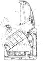
次に、図9、図10、図11を用いて、移動ガイド30が移動する際のカートリッジに作用する機構、及び、作用する力について説明する。図9は、本実施の形態に係る画像形成装置本体Aにカートリッジ20を載置する様子を示す模式図である。図10は、本実施の形態に係る移動ガイドが回転中の状態を示す模式図である。図11は、本実施の形態に係るカートリッジを画像形成装置本体Aに自動装着した状態を示す模式図である。
【0127】
図は本体の断面を用い、カートリッジ20は左側面図を用いている。また、移動ガイド32は左側の移動ガイドを示しており、図7、図8と同様にカートリッジ20に作用する部分を示している。また、本体側面110と本体側面110に取り付けられている部品は、カートリッジ20に作用する部品のみを示している。図9は本体移動ガイド32が約35度傾いている状態を示している。又、前述のよう、移動ガイド32に対して載置部35が約10度傾いている。従って、カートリッジ装着時の載置部35の水平面からの傾きは約45度になる。
【0128】
図示のマゼンダカートリッジ20Mのように、矢印方向から装着すると、左右の移動ガイド30、32の載置部35、34にカートリッジフレーム26の座面が載置される。そして、カートリッジ20は、載置部35、34を滑るように装着される。このとき移動ガイド32にスライド可能に取り付けられたスライダ33は、バネ(不図示)の弾性力によって装置本体A上方へ付勢されている。そのため、スライダ33は装置本体Aの天板105に当接している。
【0129】
また、作用部38は、カートリッジ20が本体移動ガイド32に滑り込んで装着される際に、干渉しない範囲まで上方に退避している。
【0130】
そして、図10に示すように、カバー10を閉める動作に連動して、移動ガイド32が回転角35度から約5度以下まで回転する。そして、スライダ33が移動ガイド32に対して相対的に下方に移動する。このとき、スライダ33の引っ張り力作用部38がカートリッジ20の左係合部82に係合する。
【0131】
作用部38は、スライダ33の可動範囲の全域にわたり、カートリッジ20の左係合部82に係合するだけの長さを有する。また、カートリッジ20も本体移動ガイド32の回転に伴って、回転移動する。そして、本体側板に設けられたカートリッジ位置決め部材101に接近する。このとき、カートリッジ20の回転を妨げる抵抗力が以下の3種類発生する。
【0132】
3種類の抵抗力とは、第1に、カートリッジ20をカートリッジ位置決め部材101に押し付けるためのカートリッジ押さえ部材103への動作力、第2に、ドラムシャッタ89を開くために本体側板に配置したシャッタ開閉部材102にドラムシャッタ棒90が当接し回転する際の当接反力、第3に、本体側板に配置したプロセスカートリッジ突き当て部材のテーパー面から突き当て面に乗り上げるときの乗り上げ反力である。
【0133】
この3種類の作用力について更に詳しく述べる。図12は、カートリッジ20を本体のプロセスカートリッジ位置決め部材101へ押し付けるカートリッジ押さえ部材103の動作を表す模式図である。
【0134】
図12(a)に示すように、カートリッジ押さえ部材103(103Y、103M、103C、103Bk)は、装置本体Aとしての本体側板110(図9)に回転可能に取り付けられている。そして、図に示す引っ張りバネ108で引っ張り力が掛かっている。図に示す通り、回転中心107の位置を配置することで、押さえ部材103の回転開始からバネ動作長が伸び始める。そして、バネ108は、その後更に回転すると釣合い点を境に動作長が縮む。これによって押さえ部材103は、バネ108の弾性力によって左位置決め部86が本体位置決め部材101に突き当てるようにカートリッジ20を付勢する。バネ108による押し付け力は、約500gf(4.9N)〜1kgf(9.8N)程度である。
【0135】
尚、押さえ部材103を回転動作させるのはカートリッジ20自体で行う。左移動ガイド32の回転に従い左位置決め部86が押さえ部材103に接近し当接すると(図12(b)参照)、引っ張りバネ108が伸びている間はカートリッジ20に抵抗が発生する。
【0136】
その後、図12(c)に示すように釣合い点を超えると、押さえ部材103は、バネ108の弾性力によって、左位置決め部86を位置決め部材101へ付勢し始める。
【0137】
その後、図12(d)に示すように、水平面101aと鉛直面101bに位置決め部86が突き当たり、カートリッジ20が位置決めされる。
【0138】
尚、実際には、位置決め部86の一部である軸受86aが、水平面101aと鉛直面101bに突き当てる。尚、軸受86aは、感光体ドラム21のドラム軸21dを支持している。
【0139】
次に、ドラムシャッタ89について説明する。
【0140】
カートリッジ20を構成する感光体ドラム21は感光層を有し、感光層が光に反応して画像形成を行っている。そのため、光に対し敏感である。従って、カートリッジ20の出荷時や画像形成装置本体から外に取り出したときに、感光体ドラム21の周面が露出しないように光を遮光するためのドラムシャッタ89(図7)を設けている。
【0141】
本実施の形態では厚みが薄い可撓性の遮光シートを用いている。そして、ドラムシャッタの一方をフレーム26に接着し取り付けている。他方をドラムシャッタ棒に巻きつけるように回動可能に固定している。シャッタ棒は自然とドラムシャッタ89を閉じるように図7に示すように右側面にシャッタ戻しバネ93を配設している。
【0142】
図9に示すように操作者がカートリッジ20をガイド32に装填する際はドラムシャッタ89は閉じている。そして、図10に示すようにガイド32が回転し、カートリッジ20が装置本体に設けられている位置決め部材101に接近すると、本体左側板110に配置しているシャッタ開閉部材102にドラムシャッタ棒90が当接する。これによって、シャッタ棒90がカートリッジ20に対して回転する。それにより、可撓性のドラムシャッタ89が矢印方向(図10)に上方へ折り曲がりながら移動する。
【0143】
そして、図11に示すようにカートリッジ20が所定の位置で位置決めされるとシャッタ棒90により、シャッタ89がカートリッジ20の上方に折り曲げられて退避する。そのとき、可撓性のカートリッジ把手88もドラムシャッタ89に押し曲げられる。そのため、シャッタ開閉部材102により、シャッタ棒90を介して、カートリッジ20には移動ガイド32から抜け出る方向に力を受ける。抵抗力は、前述のシャッタ戻しバネ93のバネ力とカートリッジ把手88の押し曲げ力、シャッタ89の押し曲げ力の合計でおよそ1N(100gf)から3N(300gf)の力となる。
【0144】
次に、本体側板上に配置したカートリッジ突き当て部材のテーパー面から突き当て面に乗り上げるときの乗り上げ抵抗力について説明する。
【0145】
上記乗り上げ反力は、移動ガイド32上に仮置きされたカートリッジ20が装置本体A内で正規の位置へ位置決めされる際に発生する。この乗り上げ反力はカートリッジ20の自重と乗り上げ段差の量によって決定される。カートリッジ20の自重がおよそ1kgのため、テーパー面を45°とすると自重が反力になって掛かってくる。この場合も、カートリッジ20がガイド32から抜け落ちる方向に抵抗力が掛かることになる。
【0146】
以上のように、プロセスカートリッジ20を自動装着する際に、移動ガイド30、32の回転に伴って前述した様々な抵抗力がカートリッジ20に作用する。
【0147】
本実施の形態では、移動ガイド30、32に対して移動す可能な抜け止め31、33を設けている。そして、開閉カバー10の動作に連動して、移動ガイド30、32の移動開始後、最初にカートリッジ20の係合部81、82に引っ張り力作用部材37、38が係合する。続いて、プロセスカートリッジ押さえ部材103の抵抗力が作用し、更にシャッタ89を開閉するための抵抗力が作用する。最後に突き当て面のテーパー乗り上げ抵抗力が作用する。
【0148】
しかし、カートリッジ20は抜け止め力作用部材37、38の引っ張り力により前述の抵抗力に抗しながら、ガイド30、32と一体的に位置決め部材101の突き当て面101a、101bに案内される。カートリッジ20が突き当て面101a、101bに当接すると、作用部材37、38と係合部81、82は係合が解除される。
【0149】
前述の押え部材103は、回転するまで抵抗力として作用する。しかしながら、図12(c)に示す位置まで回転すると、押え部材103が、位置決め部86を押し始める。押え部材103の力により、位置決め部86は位置決め水平面101aをすべり、垂直面101bへ突き当たる。カートリッジ20の位置決め部86が水平面101aを滑る際に、引っ張り力作用部37、38と係合部81、82は係合が解除される。
【0150】
その後、本体のカバー10が閉じ、カートリッジ20は、装置本体の装着位置へ正しく自動装着される。
【0151】
このように、カートリッジ20は、装置本体Aの装着位置300へ、作用部材37、38の引っ張り力を受けながら移動する。従って、カートリッジ20は、前述した抵抗力を受けても、その抵抗力に抗して確実に装着位置300に装着できる。
【0152】
ここで、装着位置300とは、カートリッジ20を装置本体に位置決めした位置である。カートリッジ20は、装置本体から駆動力の伝達を受けている場合と、駆動力の伝達を受けていない場合とでは、位置決め位置が若干異なるが、本明細書では、この両方の場合を包含した装着位置とする。
【0153】
(第2の実施の形態)
図4、図13乃至図18を参照して、第2の実施の形態に係るプロセスカートリッジ及び画像形成装置について説明する。なお、第1の実施の形態と同様の構成については説明を省略し、本実施の形態に係る特徴的な構成について詳述する。
【0154】
図15は、本実施の形態に係る押圧部材の配置を示す一部断面図である。図16、図17、図18は、本実施の形態に係る押圧部材の概略断面図である。
【0155】
図15に示すように、カートリッジ20にかかる付勢力は本体側板100、110に設けられた第1の押圧部材94(94a、94b、94c、94d)と開閉カバー10と一体となった中間転写体40に設けられた第2の押圧部材95(95a、95b、95c、95d)である。カートリッジ20は、図16に示したように、第1の押圧部材94により、第1の押圧方向(水平から約45度下方向)に押圧され、第2の押圧部材95により、第2の押圧方向(水平から約15度下方向)に押圧されている。そして、本体側板100、110に設けられた位置決め部材101の後方面101cと下方面101dの2つの端面にカートリッジ20の軸受部材でもある位置決め部材85、86を押し当てるように加圧バネ(不図示)の弾性力により付勢される。このようにして、カートリッジ20は、装置本体Aに位置決めされる。
【0156】
本実施の形態では、カートリッジ20の位置決めは、移動ガイド30、32とは別に、装置本体Aで行うようにしている。
【0157】
図13は、本実施の形態に係るカートリッジ20の外観を示す斜視図である。図13に示すように、カートリッジ20の被押圧部は、フレーム26の両端部に設けられた第1の被押圧部96(96a、96b)と第2の被押圧部97(97a、97b)である。そして、プリンタAに設けられた前記第1の押圧部材94及び第2の押圧部材95により、それぞれ付勢力を受けている。また、被押圧部は、カートリッジフレーム26を構成するクリーニングフレームに限らず、クリーニングフレームに結合可能な部品や現像フレーム27に設けた軸受部材である位置決め部85、86などであっても良い。
【0158】
ここで、カバー10を完全に閉めた時に、カバー10と一体になった転写体40に取り付けられた第2の押圧部材95により、カートリッジ20が位置決め方向に付勢力を受ける。この場合、位置決め部85、86が第1の押圧部材94を乗り越える際、カートリッジ挿入方向とは反対の抵抗力を受ける。
本実施の形態に係る押圧方法によれば、2つの押圧部材により段階的の押圧している。そのため、カートリッジ20を装着する際に、押圧部材から受ける抵抗力が小さく、スムーズにカートリッジ20を装置本体Aに装着することができる。
[画像形成装置に装着したプロセスカートリッジにかかる力]
【0159】
図8に示すように、カートリッジ20を装置本体Aに装着して、カバー10を閉じる。すると、フレーム26は前述したように、第1の押圧部材94により本体水平から45度下方向にFaの力、第2の押圧部材95により本体水平方向から約15度下方向にFbの力を受ける。その他、感光体ドラム21の長手方向が一次転写ローラ42により中間転写体40を介して、カートリッジ20が位置決めされる方向に、本体略水平方向の力Fc(不図示)を受けている。よって、カートリッジ20はFa、Fb、Fcの付勢力を受け、位置決め部材101に位置決めされている。
【0160】
更に、画像形成動作時に駆動力をかけた場合、装置本体に設けられた駆動出力ギア(不図示)とカートリッジ20に設けられた駆動入力ギア(不図示)の位置とそれぞれのギアの噛み合い圧力角により、カートリッジ20が装着方向の反対側にFdの付勢力を受ける。
【0161】
ここで、装置本体Aに対して、水平方向の力をFa1、Fb1、Fc1、Fd1、鉛直方向の力をFa2、Fb2、Fc2、Fd2とする。よって、カートリッジ20を確実に位置決めするためには、Fa1+Fb1+Fc1>Fd1(本体水平方向)の関係を満たしていれば良い。鉛直方向に関しては、Fa2、Fb2、Fc2、Fd2は全て同方向で鉛直下向きに付勢力が働くため、Fa2+Fb2+Fc2+Fd2>0が必ず成り立つので問題ない。
【0162】
また、前述した実施の形態をまとめると以下の通りである。
【0163】
電子写真画像形成装置(プリンタ)本体Aに設けられ、前記装置本体A西対して移動可能な移動ガイド30、32に載置され、前記移動ガイド30、32の移動に連動して載置位置200から装着位置300まで移動可能なプロセスカートリッジ20であって、
電子写真感光体ドラム21と、
該電子写真感光体ドラムに作用するプロセス手段(例えば、帯電ローラ22a、現像ローラ23、クリーニングブレード24)と、
前記電子写真感光体ドラム21及び前記プロセス手段を支持するカートリッジフレーム26と、
前記移動ガイド30に載置される第一の被載置部26a、30bであって、前記感光体ドラム21の長手方向の一端側に設けられた第一の被載置部26a、30bと、
前記移動ガイド32に載置される第二の被載置部26b、26c、27a、27bであって、前記感光体ドラム21の長手方向の他端側に設けられた第二の被載置部26b、26c、27a、27bと、
前記画像形成装置本体Aに対して位置決めされる第一の位置決め部であって、前記感光体ドラムの長手方向の一端側に前記カートリッジフレーム26から外方へ突出するよう設けられた第一の位置決め部85と、
前記画像形成装置本体に対して位置決めされる第二の位置決め部であって、前記感光体ドラムの長手方向の他端側に前記カートリッジフレーム26から外方へ突出するよう設けられた第二の位置決め部86と、
前記移動ガイド30、32の移動に連動して移動する係止部(スライダ31、33)に係合し、前記載置位置200から前記装着位置300へ向かう方向へ引っ張り力を受ける係合部81、82と、
を有する。
【0164】
この構成によれば、カートリッジ20が載置位置200から装着位置300まで移動する際に受ける抵抗力により、カートリッジ20が移動ガイド30、32に対して大きくずれることがない。よって、装着位置300まで確実にかつ簡便にカートリッジ20を移動することができる。
【0165】
尚、載置位置とは、カートリッジ20を移動ガイド30、32に載置する位置である。この載置位置200は、開閉カバー10が設けられている側である。よって、操作者が、移動ガイド30、32にカートリッジ20を載置する操作を行い易い。又、カートリッジ20を取り出す際は取り出し易い。
【0166】
また、前記係合部81、82は、前記フレーム26の装着方向(X方向)の先端側に配置されている。
【0167】
この構成によれば、フレーム26から装着方向先端側の外側に係合部81、82が突出している。そこで、カートリッジ20の移動ガイド30、32への仮固定を画像形成装置本体A側に設けられた係止部(スライダ31、33)により確実に行うことができる。更に、カートリッジ20が移動ガイド30、32に確実に仮固定される。そこで、カートリッジ20を画像形成を行う装着位置300まで確実に移動することができる。
【0168】
また、前記係合部81、82は、前記フレーム26から前記装着方向(X方向)へ突出して配置され、前記感光体ドラム21の長手方向の中央部から両側に一箇所ずつ配置されている。
【0169】
即ち、前記中央部から異端側に保持部81が配置され、他端側に係合部82が配置されている。
【0170】
この構成によれば、前記係合部81、82は、前記感光体ドラム21の長手方向一端側と他端側とに一箇所ずつ、前記フレーム26から前記装着方向(X方向)へ突出して配置されている。そのため、長手方向の位置が異なる2箇所を装置本体A側に設けられた係止部(スライダ31、33)で移動ガイド30、32に仮固定できる。従って、短手方向に装着するカートリッジ20の装着性を向上することができる。
【0171】
ここで、短手方向とは、前記感光体ドラムの長手方向と交差する方向である。
【0172】
また、前記係合部81、82は、前記フレーム26から前記装着方向(X方向)へ向かって前記感光体ドラム21の長手方向に対して略垂直に突出した第一突出部83、84と、該第一突出部から前記感光体ドラム21の長手方向に対して略平行に突出した第二突出部81、82と、を有する。
【0173】
この構成によれば、前記係合部81、82を長手に略平行に突出した鍵穴形状にすることで、係合部81、82の形状を強固な形状にできる。そのため、係合部81、82の強度を確保できる。従って、カートリッジ20の画像形成装置本体Aへの自動装着の確実性を向上させることができる。
【0174】
また、前記第一の位置決め部85及び/又は前記第二の位置決め部86は、前記画像形成装置本体Aに設けられた第一の押圧方向に押圧する第一の押圧部材94と、前記第一の押圧方向とは異なる第二の押圧方向に押圧する第二の押圧部材95とにより前記画像形成装置本体Aに設けられた位置決め部材101に付勢される。
【0175】
この構成によれば、異なる方向から位置決め部が付勢される。そのため、より確実に位置決めがなされるとともに、1つの部材から受ける押圧力を少なくすることができる。従って、載置位置から装着位置までカートリッジが移動する際に受ける、例えば摩擦力による抵抗力を少なくすることができる。よって、カートリッジの画像形成装置本体Aへの自動装着の確実性を向上させることができる。
【0176】
また、前記第一の位置決め部85及び/又は前記第二の位置決め部86は、前記画像形成装置本体Aに設けられた本体フレーム(本体側板100、110)に設けられ、第一の押圧方向に押圧する第一の押圧部材94と、前記画像形成装置本体Aに設けられた転写ユニット(中間転写体40)に設けられ、前記第一の押圧方向とは異なる第二の押圧方向に押圧する第二の押圧部材95とにより前記画像形成装置に設けられた位置決め部材101に付勢される。
【0177】
また、前記係止部(スライダ31、33)は、前記移動ガイド30、32の移動に連動して前記移動ガイド30、32に対してスライド可能に取り付けられている。
【0178】
この構成によれば、カートリッジ20を移動ガイド30、32に載置する際には、係止部(スライド31、33)がスライドすることによって、係止部(スライド31、33)が係合部81、82と干渉しないように退避させることができる。そのため、カートリッジ20を装着方向(X方向)により近い位置に載置することができる。よって、自動装着の確実性を向上することができる。
【0179】
また、前記移動ガイド30、32は、前記画像形成装置本体Aに設けられた開閉部材(開閉カバー10)の開閉動作に連動して前記画像形成装置本体Aに対して揺動可能に取り付けられている。
【0180】
この構成によれば、プロセスカートリッジ20を装置本体Aに自動装着する際に、画像形成装置本体Aに設けられた位置決め部101、101a、101bにカートリッジ20を引き込みながら移動することができる。そこで、カートリッジ20の画像形成装置本体Aへの自動装着の際の位置決めを確実に行うことができる。
【0181】
また、前記係止部(スライダ31、33)は、前記係合部81、82との距離が異なるような段差(ガイド部37c、38c)を有する。そして、前記カートリッジ20の有する係合部81、82に係合する開始時には引っ張り力が働かずに係合する。そして、前記係止部は(スライダ31、33)、移動ガイド30、32の揺動に伴って、係合部81、82に徐々に引っ張り力が作用する。
【0182】
この構成によれば、前記係止部(スライダ31、33)が段差を有し、係合部81、82に係合する開始時には、カートリッジ20に引っ張り力が働かずに係合する。そして、移動ガイド30、32の回転に伴って徐々にカートリッジ20に引っ張り力が作用する。従って、カートリッジ20を移動ガイド30、32に載置する際に、カートリッジ20の位置が移動ガイド30、32の奥まで突き当たらない。よって、カートリッジ20が正規の載置位置から万一手前に浮いていたとしても、開閉部材(開閉カバー10)の動作と共に移動ガイド30、32が移動を開始する。そして、前記係止部(スライダ31、33)がスライドしながらカートリッジ20の係合部81、82に確実に入り込む。そして、その後、カートリッジ20を装着する方向へ引っ張る引っ張り力が発生する。これによって、カートリッジ20の自動装着の動作の確実性を向上することができる。
【0183】
【発明の効果】
以上説明してきたように、本発明によれば、電子写真画像形成装置本体に対するプロセスカートリッジの装着操作性を向上させることができた。
【図面の簡単な説明】
【図1】本実施の形態に係るプロセスカートリッジが画像形成装置本体の移動ガイドに保持された状態を示す概略斜視図である。
【図2】本実施の形態に係る電子写真プロセスを利用した画像形成装置の一形態であるカラーレーザープリンタの概略断面図である。
【図3】本実施の形態に係るプロセスカートリッジの概略断面図である。
【図4】本実施の形態に係る画像形成装置の開閉カバー開放状態を表す概略断面図である。
【図5】本実施の形態に係る画像形成装置の開閉カバー開放状態を表す概略断面図である。
【図6】本実施の形態に係るプロセスカートリッジの上面図である。
【図7】本実施の形態に係るプロセスカートリッジを移動ガイドに装着した状態の一部を示す右側面図である。
【図8】本実施の形態に係るプロセスカートリッジを移動ガイドに装着した状態の一部を示す左側面図である。
【図9】本実施の形態に係る画像形成装置にプロセスカートリッジを装着する様子を示す模式図である。
【図10】本実施の形態に係る移動ガイドが回転中の状態を示す模式図である。
【図11】本実施の形態に係るプロセスカートリッジを画像形成装置に自動装着した状態を示す模式図である。
【図12】本実施の形態に係る押さえ部材の動作を表す模式図である。
【図13】第2の実施の形態に係るプロセスカートリッジの外観を示す斜視図である。
【図14】第2の実施の形態に係る押圧部材の配置を示す一部断面図である。
【図15】第2の実施の形態に係る押圧部材の配置を示す一部断面図である。
【図16】第2の実施の形態に係るプロセスカートリッジの位置決め状態を示す一部断面図である。
【図17】第2の実施の形態に係る押圧部材の概略断面図である。
【図18】第2の実施の形態に係る押圧部材の概略断面図である。
【符号の説明】
1 カセット
2 給送ローラ
3 レジストローラ対
5 二次転写ローラ
10 開閉カバー
11 回転中心
12 ドア連結レバー
13 中間ロッド
14 回転ロッド
15 移動ガイド連結ロッド
20 プロセスカートリッジ
20a 背面部
20b 規制部(規制面) 21 感光体ドラム
21d ドラム軸
22 帯電手段
22a 帯電ローラ
23 現像ローラ
24 クリーニングブレード
25 現像ブレード
26 カートリッジフレーム
26a ドラムフレーム(カートリッジフレーム)
27 現像フレーム(カートリッジフレーム)
28 トナー供給スポンジローラ
29 トナー撹拌部材
30 第一移動ガイド
30a 壁面
30b 回転止め
31 右スライダ
32 第二移動ガイド
33 左スライダ
34、35 載置部
36 回転中心
37,38 引っ張り力作用部材
39 ガイドリブ
40 中間転写体(中間転写ベルト)
41 駆動ローラ
42 一次転写ローラ
43 二次転写対向ローラ
44 テンションローラ
50 スキャナー部
51 画像光
52 ポリゴンミラー
53 結像レンズ
54 反射レンズ
60 定着器
61 フィルムガイドユニット
62 加圧ローラ
63 セラミックヒータ
70 排出トレイ
71 排出ローラ群
81 右係合部
82 左係合部
83 先端突出部
84 先端突出部
85、86 位置決め部
85a、86a 軸受
87 カップリング
89 ドラムシャッタ
91 略外形線
92 現像容器入力ギア
93 シャッタ戻しバネ
94、95 押圧部材
96,97 被押圧部
100 本体右側板
101 位置決め部材
101a 位置決め部
101b 位置決め部
102 シャッタ開閉部材
103 押さえ部材
105 本体天板
107 回転中心
108 引っ張りバネ
110 本体左側板(装置本体)
200 載置位置
300 装着位置
A 装置本体(プリンタ本体)
P 記録媒体[0001]
BACKGROUND OF THE INVENTION
The present invention relates to a process cartridge, a process cartridge mounting mechanism, and an electrophotographic image forming apparatus.
[0002]
Here, the electrophotographic image forming apparatus forms an image on a recording medium (for example, recording paper, OHP sheet, cloth, etc.) using an electrophotographic image forming system. Examples of the electrophotographic image forming apparatus include an electrophotographic copying machine, an electrophotographic printer (for example, a laser printer, an LED printer, etc.), a facsimile apparatus, a word processor, and a complex machine (multifunction printer, etc.) thereof.
[0003]
Further, the process cartridge is a cartridge in which a charging unit, a developing unit or a cleaning unit as a process unit and an electrophotographic photosensitive drum are integrally formed, and the cartridge can be attached to and detached from the image forming apparatus main body. . Alternatively, at least one of charging means, developing means, and cleaning means as process means and the electrophotographic photosensitive drum are integrally formed into a cartridge that can be attached to and detached from the main body of the image forming apparatus. Further, it means that at least the developing means as the process means and the electrophotographic photosensitive drum are integrally formed into a cartridge so as to be detachable from the main body of the electrophotographic image forming apparatus.
[0004]
[Prior art]
2. Description of the Related Art Conventionally, in an electrophotographic image forming apparatus, an electrophotographic photosensitive drum (hereinafter referred to as “photosensitive drum”) and process means acting on the photosensitive drum are integrally formed into a cartridge, and this cartridge is used as an image forming apparatus. A process cartridge system that is detachable from the main body is employed. According to this process cartridge system, the maintenance of the apparatus can be performed by the operator himself without depending on the service person, so that the operability can be remarkably improved. For this reason, this process cartridge system is widely used in electrophotographic image forming apparatuses.
[0005]
2. Description of the Related Art Conventionally, in a cartridge type image forming apparatus, a process cartridge is moved to an image forming position (mounting position) and a front position (mounting position) of the apparatus body in conjunction with an opening / closing operation of an opening / closing cover that opens and closes to the apparatus body. (For example, refer to Patent Document 1).
[0006]
According to the configuration described in
[0007]
Therefore, it is not necessary for the operator to push the cartridge all the way into the apparatus main body when mounting the cartridge on the apparatus main body.
[0008]
Therefore, the mounting operability with respect to the apparatus main body of the cartridge can be remarkably improved.
[0009]
[Patent Document 1]
JP 2002-278418 A
[0010]
[Problems to be solved by the invention]
The present invention is a further development of the prior art.
[0011]
An object of the present invention is to provide a process cartridge, a process cartridge mounting mechanism, and an electrophotographic image forming apparatus, which have improved mounting operability when the process cartridge is mounted on an electrophotographic image forming apparatus main body.
[0012]
Another object of the present invention is to provide a process cartridge, a process cartridge mounting mechanism, and an electrophotographic image forming apparatus capable of reliably moving the process cartridge from a mounting position for mounting the process cartridge to a mounting position. It is to provide.
[0013]
Another object of the present invention is to provide a process cartridge that receives a pulling force when the process cartridge moves from the mounting position to the mounting position, a process cartridge mounting mechanism, and an electrophotographic image forming apparatus. is there.
[0014]
Another object of the present invention is to provide a process cartridge, a process cartridge mounting mechanism, and an electrophotographic image forming apparatus that receive a pulling force in a direction from the mounting position toward the mounting position.
[0015]
[Means for Solving the Problems]
In the process cartridge according to the main present invention for achieving the above object,
A process cartridge mounted on a moving guide provided in the electrophotographic image forming apparatus main body and movable from a mounting position to a mounting position in conjunction with the movement of the moving guide,
An electrophotographic photosensitive drum;
Process means acting on the electrophotographic photosensitive drum;
A cartridge frame that supports the electrophotographic photosensitive drum and the process means;
A first placement portion placed on the moving guide at the placement position, the first placement portion provided on one end side in the longitudinal direction of the photosensitive drum;
A second placement portion placed on the moving guide at the placement position, the second placement portion provided on the other end side in the longitudinal direction of the photosensitive drum;
A first positioning portion that is positioned with respect to the image forming apparatus main body at the mounting position and protrudes outward from the cartridge frame toward one end side in a longitudinal direction of the photosensitive drum; do it A first positioning portion provided;
A second positioning portion that is positioned with respect to the image forming apparatus main body at the mounting position and projects outward from the cartridge frame toward the other end in the longitudinal direction of the photosensitive drum; do it A second positioning portion provided;
Provided in the image forming apparatus main body, Locking portion that moves in conjunction with movement of the moving guide When the locking portion moves by engaging with In the direction from the mounting position to the mounting position From the locking part An engaging portion that receives a pulling force;
It is characterized by having.
[0016]
In the electrophotographic image forming apparatus according to the main present invention,
In an electrophotographic image forming apparatus for detaching a process cartridge and forming an image on a recording medium,
(I) a movement guide;
(Ii) a locking portion;
(Iii) an electrophotographic photosensitive drum;
Process means acting on the electrophotographic photosensitive drum;
A cartridge frame that supports the electrophotographic photosensitive drum and the process means;
Previous A first placement portion placed on the movement guide, the first placement portion provided on one end side in the longitudinal direction of the photosensitive drum;
Previous A second placement portion placed on the moving guide, the second placement portion provided on the other end side in the longitudinal direction of the photosensitive drum,
Previous A first positioning portion positioned with respect to the main body of the image forming apparatus, and projecting outward from the cartridge frame to one end side in a longitudinal direction of the photosensitive drum; do it A first positioning portion provided;
Previous A second positioning unit positioned with respect to the image forming apparatus main body, wherein the photoconductor
Projects outward from the cartridge frame to the other end in the longitudinal direction of the drum do it A second positioning portion provided;
Engage with the locking portion that moves in conjunction with the movement of the moving guide. By moving the locking portion, Said Placed on the first placement portion and the second placement portion From the mounting position Positioned by the first positioning part and the second positioning part Toward the mounting position From the locking part An engaging portion that receives a pulling force;
Process cartridge with A positioning member for positioning the image forming apparatus main body; ,
(Iv) transfer means for transferring a developer image formed on the electrophotographic photosensitive drum of the process cartridge to the recording medium;
(V) conveying means for conveying the recording medium;
It is characterized by having.
[0017]
In the process cartridge mounting mechanism according to the main present invention,
In the process cartridge mounting mechanism for mounting the process cartridge to the electrophotographic image forming apparatus main body,
The image forming apparatus main body is
A moving guide and a locking portion;
The process cartridge is
An electrophotographic photosensitive drum;
Process means acting on the electrophotographic photosensitive drum;
A cartridge frame that supports the electrophotographic photosensitive drum and the process means;
Previous A first placement portion placed on the moving guide, the first placement portion provided on one end side in the longitudinal direction of the photosensitive drum;
Previous A second placement portion placed on the moving guide, the second placement portion provided on the other end side in the longitudinal direction of the photosensitive drum,
Previous A first positioning portion positioned with respect to the main body of the image forming apparatus, and projecting outward from the cartridge frame toward one end side in a longitudinal direction of the photosensitive drum; do it A first positioning portion provided;
Previous A second positioning portion positioned with respect to the main body of the image forming apparatus, and projecting outward from the cartridge frame toward the other end in the longitudinal direction of the photosensitive drum; do it A second positioning portion provided;
Engage with the locking portion that moves in conjunction with the movement of the moving guide. The , By moving the locking portion, Said Placed on the first placement portion and the second placement portion From the mounting position Positioned by the first positioning part and the second positioning part Toward the mounting position From the locking part An engaging portion for receiving a pulling force,
The process cartridge is mounted on the main body of the image forming apparatus.
[0018]
DETAILED DESCRIPTION OF THE INVENTION
Preferred embodiments of the present invention will be illustratively described below with reference to the drawings. However, the dimensions, materials, shapes, relative arrangements, and the like of the components described in this embodiment are not intended to limit the scope of the present invention only to those unless otherwise specified. Absent. Further, the materials, shapes, etc. of the members once described in the following description are the same as those in the first description unless otherwise described.
[0019]
In the following description, the longitudinal direction of the process cartridge is a direction (substantially orthogonal) that intersects the direction in which the process cartridge is attached to and detached from the apparatus main body. Further, the upper surface of the process cartridge is a surface located above in a state where the process cartridge is mounted on the apparatus main body, and the lower surface is a surface located below.
[0020]
(First embodiment)
[0021]
A process cartridge and a color electrophotographic image forming apparatus according to a first embodiment will be described with reference to FIGS.
[0022]
[Overall Description of Color Electrophotographic Image Forming Apparatus]
First, the overall configuration of the color image forming apparatus will be schematically described with reference to FIG. FIG. 2 is a cross-sectional view of a color laser printer which is an embodiment of an image forming apparatus using the electrophotographic process according to the present embodiment.
[0023]
As shown in FIG. 2, the color laser printer A (hereinafter referred to as “printer”) is a four-drum system having four process cartridges 20 (20Y, 20M, 20C, 20Bk) and an
[0024]
Then, four process cartridges 20 (20Y, 20M, 20C, 20Bk) are mounted side by side in the vertical direction. The
[0025]
The recording medium P to which the color image has been transferred is conveyed to the fixing device 60 and the color image is fixed to the recording medium P. Thereafter, the
[0026]
The four-
[0027]
Next, the configuration of each part of the image forming apparatus will be sequentially described with reference to FIGS. FIG. 3 is a schematic cross-sectional view of the cartridge according to the present embodiment. If the configuration of each color is the same, only the
[0028]
[Photosensitive drum]
In the
[0029]
[Charging means]
The charging means 22 (22Y) has a charging roller 22a to which a voltage can be applied. Then, the surface of the
[0030]
[Exposure means]
The exposure to the
[0031]
[Development means]
The developing means has a developing roller 23 (23Y). Then, the electrostatic latent image is developed by the developing
[0032]
[Intermediate transfer member]
In the
[0033]
The developer image formed on the
[0034]
The
[0035]
The intermediate transfer member (intermediate transfer belt) 40 according to the present embodiment is constituted by a seamless resin belt having a circumferential length of about 620 mm. The
[0036]
The
[0037]
[Feeding department]
The feeding unit feeds the recording medium P to the mounted
[0038]
During image formation, the
[0039]
[Transfer section]
The transfer unit has a swingable
[0040]
[Fixing part]
In the fixing unit, the color developer image formed on the recording medium P is fixed on the recording medium P by the fixing device 60. The fixing device 60 includes a
[0041]
[Image forming operation]
Next, an operation when image formation is performed by the apparatus configured as described above will be described.
[0042]
First, the feeding roller 2 (FIG. 2) shown in FIG. 2 is rotated. Then, the recording medium P in the
[0043]
On the other hand, the
[0044]
The
[0045]
1: Yellow image formation
The
[0046]
2: Formation of magenta image
Next, the
[0047]
3: Cyan image formation
Next, the same operation as the magenta image formation described above is performed so as to coincide with the yellow of the outer periphery of the
[0048]
4: Formation of a black image
Next, the same operation as the magenta image formation described above is performed so as to coincide with the leading edges of the yellow, magenta and cyan images on the outer periphery of the
[0049]
[0050]
As described above, the latent image is formed, developed, and the developer is transferred to the
[0051]
Incidentally, before the transfer of the black developer to the
[0052]
When the four color images are formed on the
[0053]
Thereafter, the recording medium P is peeled off from the
[0054]
Next, an embodiment of a process cartridge, a process cartridge mounting mechanism, and an electrophotographic image forming apparatus according to the present invention will be described in detail.
[0055]
[Process cartridge]
FIG. 3 shows a cross section of the
[0056]
In the present embodiment, a
[0057]
In other words, in the present embodiment, the
[0058]
[Process cartridge mounting method]
FIG. 4 is a cross-sectional view illustrating an open / close cover open state of the image forming apparatus according to the present embodiment.
[0059]
As shown in FIG. 4, the opening /
[0060]
The
[0061]
The movement guides 30 and 32 provided in the apparatus main body A integrally hold the cartridge 20 (20Y, 20M, 20C, and 20Bk). A
[0062]
A
[0063]
The
[0064]
When the
[0065]
In the state shown in FIG. 4, the
[0066]
Therefore, there is nothing to block in the mounting and pulling direction, and the operator can easily operate. Further, when the
[0067]
Then, the
[0068]
In addition, the mounting
[0069]
The cartridge placement portion will be described with reference to FIGS. The cartridge placement portion is a portion that contacts and is supported by the movement guides 30 and 32.
[0070]
First, the
[0071]
Further, it is provided on the lower surface of a
[0072]
Further, the
[0073]
And it is supported on the mounting
[0074]
Next, a state where the placement portion of the
[0075]
First, a state where the
[0076]
As shown in FIG. 7, one end of the
[0077]
The
[0078]
Next, a state where the
[0079]
As shown in FIG. 8, the other end of the
[0080]
Thereafter, the
[0081]
Here, the
[0082]
The first placement portion and the second placement portion are not limited to the above-described embodiment. Any form can be used as long as it is placed on the moving guide.
[0083]
[How to fix the process cartridge to the printer]
FIG. 1 is a schematic perspective view showing a state in which the cartridge according to the present embodiment is placed on the moving guide of the apparatus main body when the
[0084]
The
[0085]
In the present embodiment, the
[0086]
In addition, the movement guides 30 and 32 according to the present embodiment have substantially the same phase between the side plates due to connection by a link member described later. Thus, the movement guide is the same as that of the integrated configuration.
[0087]
Both the
[0088]
As shown in FIG. 6, the
[0089]
The
[0090]
A
[0091]
That is, in the present embodiment, the
[0092]
As shown in FIGS. 4 and 5, a process cartridge positioning member 101 (101 </ b> Y, 101 </ b> M, 101 </ b> C, 101 </ b> Bk) is disposed on the main body
[0093]
The
[0094]
The positioning
[0095]
That is, the parallelism of the four
[0096]
As shown in FIGS. 1 and 6,
[0097]
In the present embodiment, the
[0098]
Further, the apparatus main body A is provided with retaining
[0099]
The
[0100]
In addition, the
[0101]
Then, the
[0102]
The
[0103]
When the
[0104]
Here, the
[0105]
When the
[0106]
The
[0107]
Next, positioning when the
[0108]
7 and 8 are side views showing a state in which the cartridge 20 (20Y, 20M) is mounted on the apparatus main body A. FIG. Both the hatched cross sections in FIGS. 7 and 8 schematically show the mounting
[0109]
The
[0110]
As shown in FIG. 7, the
[0111]
As shown in FIGS. 7 and 8, the mounting
[0112]
On the downstream side in the mounting direction on the mounting portion 34 (34Y, 34M), a step of about 1 mm is provided. When the
[0113]
That is, when the
[0114]
On the right side, the drive connection between the apparatus main body A and the
[0115]
A
[0116]
FIG. 8 is a left side view of the process cartridge and a schematic view of the main body left moving
[0117]
Unlike the right side surface, the
[0118]
In the middle of sliding on the slope of the
[0119]
The
[0120]
1, 4, 5, 7, 8, and 12, the arrow X direction is the cartridge mounting direction. The opposite direction is the direction in which the
[0121]
Note that the
[0122]
[Mobile Guide]
Next, the connection of the movement guides 30 and 32 with the link mechanism and the actual movement will be described.
[0123]
FIG. 4 is a schematic cross-sectional view of the inside of the apparatus illustrating the link mechanism connected to the process cartridge right moving
[0124]
[0125]
Using the time lag when opening the
[0126]
Next, a mechanism that acts on the cartridge and a force that acts when the
[0127]
The figure uses a cross section of the main body, and the
[0128]
When mounted from the direction of the arrow as in the illustrated
[0129]
Further, the
[0130]
Then, as shown in FIG. 10, in conjunction with the operation of closing the
[0131]
The
[0132]
The three types of resistance force are firstly an operating force to the
[0133]
These three types of acting force will be described in more detail. FIG. 12 is a schematic diagram showing the operation of the
[0134]
As shown in FIG. 12A, the cartridge pressing member 103 (103Y, 103M, 103C, 103Bk) is rotatably attached to a main body side plate 110 (FIG. 9) as the apparatus main body A. A tensile force is applied by a
[0135]
The pressing
[0136]
Thereafter, when the balance point is exceeded as shown in FIG. 12C, the pressing
[0137]
Thereafter, as shown in FIG. 12 (d), the positioning
[0138]
In practice, the
[0139]
Next, the
[0140]
The
[0141]
In this embodiment, a flexible light shielding sheet having a small thickness is used. Then, one of the drum shutters is attached and attached to the
[0142]
As shown in FIG. 9, when the operator loads the
[0143]
Then, as shown in FIG. 11, when the
[0144]
Next, the climbing resistance force when climbing from the taper surface of the cartridge abutting member disposed on the main body side plate to the abutting surface will be described.
[0145]
The climbing reaction force is generated when the
[0146]
As described above, when the
[0147]
In the present embodiment, retaining
[0148]
However, the
[0149]
The above-described
[0150]
Thereafter, the
[0151]
Thus, the
[0152]
Here, the mounting
[0153]
(Second Embodiment)
A process cartridge and an image forming apparatus according to the second embodiment will be described with reference to FIGS. 4 and 13 to 18. Note that a description of the same configuration as that of the first embodiment will be omitted, and a characteristic configuration according to the present embodiment will be described in detail.
[0154]
FIG. 15 is a partial cross-sectional view showing the arrangement of the pressing members according to the present embodiment. 16, FIG. 17, and FIG. 18 are schematic cross-sectional views of the pressing member according to the present embodiment.
[0155]
As shown in FIG. 15, the urging force applied to the
[0156]
In the present embodiment, the positioning of the
[0157]
FIG. 13 is a perspective view showing the appearance of the
[0158]
Here, when the
According to the pressing method according to the present embodiment, stepwise pressing is performed by two pressing members. Therefore, when the
[Force applied to the process cartridge mounted on the image forming apparatus]
[0159]
As shown in FIG. 8, the
[0160]
Further, when a driving force is applied during the image forming operation, the positions of the drive output gear (not shown) provided in the apparatus main body and the drive input gear (not shown) provided in the
[0161]
Here, for the apparatus main body A, the horizontal force is Fa1, Fb1, Fc1, and Fd1, and the vertical force is Fa2, Fb2, Fc2, and Fd2. Therefore, in order to position the
[0162]
The above-described embodiment is summarized as follows.
[0163]
An electrophotographic image forming apparatus (printer) main body A is mounted on
An electrophotographic
Process means (for example, charging roller 22a, developing
A
A first positioning portion positioned with respect to the image forming apparatus main body A, the first positioning portion provided on one end side in the longitudinal direction of the photosensitive drum so as to protrude outward from the
A second positioning portion positioned with respect to the main body of the image forming apparatus, the second positioning portion provided on the other end side in the longitudinal direction of the photosensitive drum so as to protrude outward from the
An
Have
[0164]
According to this configuration, the
[0165]
The placement position is a position where the
[0166]
The engaging
[0167]
According to this configuration, the engaging
[0168]
Further, the engaging
[0169]
That is, the holding
[0170]
According to this configuration, the engaging
[0171]
Here, the short side direction is a direction crossing the longitudinal direction of the photosensitive drum.
[0172]
The engaging
[0173]
According to this configuration, the
[0174]
The
[0175]
According to this configuration, the positioning portion is urged from different directions. Therefore, positioning can be performed more reliably and the pressing force received from one member can be reduced. Accordingly, it is possible to reduce a resistance force caused by, for example, a frictional force received when the cartridge moves from the mounting position to the mounting position. Therefore, the reliability of automatic mounting of the cartridge to the image forming apparatus main body A can be improved.
[0176]
Further, the
[0177]
The locking portions (
[0178]
According to this configuration, when the
[0179]
The movement guides 30 and 32 are swingably attached to the image forming apparatus main body A in conjunction with an opening / closing operation of an opening / closing member (opening / closing cover 10) provided in the image forming apparatus main body A. Yes.
[0180]
According to this configuration, when the
[0181]
The locking portions (
[0182]
According to this configuration, the locking portion (
[0183]
【The invention's effect】
As described above, according to the present invention, the mounting operability of the process cartridge with respect to the main body of the electrophotographic image forming apparatus can be improved.
[Brief description of the drawings]
FIG. 1 is a schematic perspective view illustrating a state in which a process cartridge according to an exemplary embodiment is held by a moving guide of an image forming apparatus main body.
FIG. 2 is a schematic cross-sectional view of a color laser printer which is an embodiment of an image forming apparatus using an electrophotographic process according to the present embodiment.
FIG. 3 is a schematic cross-sectional view of a process cartridge according to the present embodiment.
FIG. 4 is a schematic cross-sectional view illustrating an open / close cover open state of the image forming apparatus according to the exemplary embodiment.
FIG. 5 is a schematic cross-sectional view illustrating an open / close cover open state of the image forming apparatus according to the exemplary embodiment.
FIG. 6 is a top view of the process cartridge according to the present embodiment.
FIG. 7 is a right side view illustrating a part of a state where the process cartridge according to the present embodiment is mounted on a moving guide.
FIG. 8 is a left side view showing a part of the state where the process cartridge according to the present embodiment is mounted on a moving guide.
FIG. 9 is a schematic diagram illustrating a state in which a process cartridge is attached to the image forming apparatus according to the exemplary embodiment.
FIG. 10 is a schematic diagram showing a state where the movement guide according to the present embodiment is rotating.
FIG. 11 is a schematic diagram illustrating a state in which the process cartridge according to the present embodiment is automatically mounted in the image forming apparatus.
FIG. 12 is a schematic diagram showing the operation of the pressing member according to the present embodiment.
FIG. 13 is a perspective view showing an appearance of a process cartridge according to a second embodiment.
FIG. 14 is a partial cross-sectional view showing the arrangement of pressing members according to the second embodiment.
FIG. 15 is a partial cross-sectional view showing an arrangement of pressing members according to a second embodiment.
FIG. 16 is a partial cross-sectional view showing a positioning state of the process cartridge according to the second embodiment.
FIG. 17 is a schematic cross-sectional view of a pressing member according to a second embodiment.
FIG. 18 is a schematic cross-sectional view of a pressing member according to a second embodiment.
[Explanation of symbols]
1 cassette
2 Feeding roller
3 Registration roller pair
5 Secondary transfer roller
10 Open / close cover
11 Center of rotation
12 Door connecting lever
13 Intermediate rod
14 Rotating rod
15 Moving guide connecting rod
20 Process cartridge
20a rear part
20b Regulation part (regulation surface) 21 Photosensitive drum
21d drum shaft
22 Charging means
22a Charging roller
23 Development roller
24 Cleaning blade
25 Development blade
26 Cartridge frame
26a Drum frame (cartridge frame)
27 Development frame (cartridge frame)
28 Toner supply sponge roller
29 Toner stirring member
30 First movement guide
30a wall surface
30b Anti-rotation
31 Right slider
32 Second movement guide
33 Left slider
34, 35 Placement section
36 center of rotation
37, 38 tensile force acting member
39 Guide rib
40 Intermediate transfer member (intermediate transfer belt)
41 Drive roller
42 Primary transfer roller
43 Secondary transfer counter roller
44 Tension roller
50 Scanner section
51 Image light
52 Polygon mirror
53 Imaging lens
54 Reflective lens
60 Fixing device
61 Film guide unit
62 Pressure roller
63 Ceramic heater
70 discharge tray
71 discharge roller group
81 Right engagement part
82 Left engagement part
83 Tip protrusion
84 Tip protrusion
85, 86 Positioning part
85a, 86a Bearing
87 coupling
89 Drum shutter
91 Outline
92 Developer container input gear
93 Shutter return spring
94, 95 Pressing member
96,97 Pressed part
100 Body right side plate
101 Positioning member
101a Positioning part
101b Positioning part
102 Shutter opening / closing member
103 Holding member
105 Main body top plate
107 center of rotation
108 tension spring
110 Left side plate of the main unit (device main unit)
200 Placement position
300 wearing position
A Device body (printer body)
P Recording medium
Claims (16)
電子写真感光体ドラムと、
前記電子写真感光体ドラムに作用するプロセス手段と、
前記電子写真感光体ドラム及び前記プロセス手段を支持するカートリッジフレームと、
前記載置位置において前記移動ガイドに載置される第一の被載置部であって、前記感光体ドラムの長手方向の一端側に設けられた第一の被載置部と、
前記載置位置において前記移動ガイドに載置される第二の被載置部であって、前記感光体ドラムの長手方向の他端側に設けられた第二の被載置部と、
前記装着位置において前記画像形成装置本体に対して位置決めされる第一の位置決め部であって、前記感光体ドラムの長手方向の一端側に前記カートリッジフレームから外方へ突出して設けられた第一の位置決め部と、
前記装着位置において前記画像形成装置本体に対して位置決めされる第二の位置決め部であって、前記感光体ドラムの長手方向の他端側に前記カートリッジフレームから外方へ突出して設けられた第二の位置決め部と、
前記画像形成装置本体に設けられており、前記移動ガイドの移動に連動して移動する係止部に係合して前記係止部が移動することによって、前記載置位置から前記装着位置へ向かう方向へ前記係止部から引っ張り力を受ける係合部と、
を有することを特徴とするプロセスカートリッジ。A process cartridge mounted on a moving guide provided in the electrophotographic image forming apparatus main body and movable from a mounting position to a mounting position in conjunction with the movement of the moving guide,
An electrophotographic photosensitive drum;
Process means acting on the electrophotographic photosensitive drum;
A cartridge frame that supports the electrophotographic photosensitive drum and the process means;
A first placement portion placed on the moving guide at the placement position, the first placement portion provided on one end side in the longitudinal direction of the photosensitive drum;
A second placement portion placed on the moving guide at the placement position, the second placement portion provided on the other end side in the longitudinal direction of the photosensitive drum;
A first positioning portion positioned with respect to the image forming apparatus main body at the mounting position, the first positioning portion being provided to project outward from the cartridge frame on one end side in the longitudinal direction of the photosensitive drum; Positioning part of
A second positioning portion positioned with respect to the image forming apparatus main body at the mounting position, the second positioning portion being provided to project outward from the cartridge frame on the other end side in the longitudinal direction of the photosensitive drum; Two positioning parts;
It is provided in the image forming apparatus main body and engages with a locking portion that moves in conjunction with the movement of the moving guide, and the locking portion moves to move from the mounting position to the mounting position. An engaging portion that receives a pulling force from the locking portion in the direction;
A process cartridge comprising:
(i)移動ガイドと、
(ii)係止部と、
(iii)電子写真感光体ドラムと、
前記電子写真感光体ドラムに作用するプロセス手段と、
前記電子写真感光体ドラム及び前記プロセス手段を支持するカートリッジフレームと、
前記移動ガイドに載置される第一の被載置部であって、前記感光体ドラムの長手方向の一端側に設けられた第一の被載置部と、
前記移動ガイドに載置される第二の被載置部であって、前記感光体ドラムの長手方向の他端側に設けられた第二の被載置部と、
前記画像形成装置本体に対して位置決めされる第一の位置決め部であって、前記感光体ドラムの長手方向の一端側に前記カートリッジフレームから外方へ突出して設けられた第一の位置決め部と、
前記画像形成装置本体に対して位置決めされる第二の位置決め部であって、前記感光体ドラムの長手方向の他端側に前記カートリッジフレームから外方へ突出して設けられた第二の位置決め部と、
前記移動ガイドの移動に連動して移動する前記係止部に係合して、前記係止部が移動することによって、前記第一の被載置部及び前記第二の被載置部に載置される載置位置から前記第一の位置決め部及び前記第二の位置決め部に位置決めされる装着位置へ向かう方向へ前記係止部から引っ張り力を受ける係合部と、
を有するプロセスカートリッジを前記画像形成装置本体に位置決めする位置決め部材と、
(iv)前記プロセスカートリッジの有する前記電子写真感光体ドラムに形成された現像剤像を前記記録媒体に転写する転写手段と、
(v)前記記録媒体を搬送する搬送手段と、
を有することを特徴とする電子写真画像形成装置。In an electrophotographic image forming apparatus for detaching a process cartridge and forming an image on a recording medium,
(I) a movement guide;
(Ii) a locking portion;
(Iii) an electrophotographic photosensitive drum;
Process means acting on the electrophotographic photosensitive drum;
A cartridge frame that supports the electrophotographic photosensitive drum and the process means;
A first of the mounting portion to be mounted before Symbol moving guide, a first of the mounting portion provided on one longitudinal end of said photosensitive drum,
A second of the mounting portion to be mounted before Symbol moving guide, and a second of the mounting portion provided on the other longitudinal end side of said photosensitive drum,
A first positioning portion to be positioned relative to prior Symbol image forming apparatus main body, said first positioning part from said cartridge frame in the longitudinal direction of the one end side of the photosensitive drum is provided to protrude outward When,
A second positioning portion to be positioned relative to prior Symbol image forming apparatus main body, the second positioning which protrudes outwardly from said cartridge frame in the longitudinal direction of the other end of the photosensitive drum And
Engage with the engaging portion that moves in conjunction with the movement of the moving guide, and the engaging portion moves, so that it is mounted on the first placement portion and the second placement portion. An engagement portion that receives a pulling force from the locking portion in a direction from the placement position to the mounting position that is positioned by the first positioning portion and the second positioning portion ;
A positioning member for positioning the process cartridge on the image forming apparatus main body ,
(Iv) transfer means for transferring a developer image formed on the electrophotographic photosensitive drum of the process cartridge to the recording medium;
(V) conveying means for conveying the recording medium;
An electrophotographic image forming apparatus comprising:
前記画像形成装置本体が、
移動ガイドと、係止部と、を有し、
前記プロセスカートリッジが、
電子写真感光体ドラムと、
前記電子写真感光体ドラムに作用するプロセス手段と、
前記電子写真感光体ドラム及び前記プロセス手段を支持するカートリッジフレームと、
前記移動ガイドに載置される第一の被載置部であって、前記感光体ドラムの長手方向の一端側に設けられた第一の被載置部と、
前記移動ガイドに載置される第二の被載置部であって、前記感光体ドラムの長手方向の他端側に設けられた第二の被載置部と、
前記画像形成装置本体に対して位置決めされる第一の位置決め部であって、前記感光体ドラムの長手方向の一端側に前記カートリッジフレームから外方へ突出して設けられた第一の位置決め部と、
前記画像形成装置本体に対して位置決めされる第二の位置決め部であって、前記感光体ドラムの長手方向の他端側に前記カートリッジフレームから外方へ突出して設けられた第二の位置決め部と、
前記移動ガイドの移動に連動して移動する前記係止部に係合して、前記係止部が移動することによって、前記第一の被載置部及び前記第二の被載置部に載置される載置位置から前記第一の位置決め部及び前記第二の位置決め部に位置決めされる装着位置へ向かう方向へ前記係止部から引っ張り力を受ける係合部と、を有し、
前記画像形成装置本体に前記プロセスカートリッジを装着することを特徴とするプロセスカートリッジの装着機構。In the process cartridge mounting mechanism for mounting the process cartridge to the electrophotographic image forming apparatus main body,
The image forming apparatus main body is
A moving guide and a locking portion;
The process cartridge is
An electrophotographic photosensitive drum;
Process means acting on the electrophotographic photosensitive drum;
A cartridge frame that supports the electrophotographic photosensitive drum and the process means;
A first of the mounting portion to be mounted before Symbol moving guide, a first of the mounting portion provided on one longitudinal end of said photosensitive drum,
A second of the mounting portion to be mounted before Symbol moving guide, and a second of the mounting portion provided on the other longitudinal end side of said photosensitive drum,
A first positioning portion to be positioned relative to prior Symbol image forming apparatus main body, said first positioning part from said cartridge frame in the longitudinal direction of the one end side of the photosensitive drum is provided to protrude outward When,
A second positioning portion to be positioned relative to prior Symbol image forming apparatus main body, the second positioning which protrudes outwardly from said cartridge frame in the longitudinal direction of the other end of the photosensitive drum And
The engaging engages with the locking portion that moves in conjunction with movement of the moving guide, by the locking portion is moved, placing the first of the mounting portion and the second of the mounting portion An engaging portion that receives a pulling force from the locking portion in a direction from the placed position to the mounting position that is positioned by the first positioning portion and the second positioning portion ;
A process cartridge mounting mechanism, wherein the process cartridge is mounted on the image forming apparatus main body.
Priority Applications (7)
| Application Number | Priority Date | Filing Date | Title |
|---|---|---|---|
| JP2003209842A JP3673793B2 (en) | 2003-08-29 | 2003-08-29 | Process cartridge, process cartridge mounting mechanism, and electrophotographic image forming apparatus |
| EP03029890A EP1536295A3 (en) | 2003-08-29 | 2003-12-29 | Process cartridge, mounting mechanism therefor and electrophotographic image forming apparatus |
| US10/746,035 US6980758B2 (en) | 2003-08-29 | 2003-12-29 | Process cartridge, mounting mechanism therefor and electrophotographic image forming apparatus |
| CNB2003101238019A CN100442169C (en) | 2003-08-29 | 2003-12-30 | Process cartridge, mounting mechanism therefor and electrophotographic image forming apparatus |
| KR1020030099523A KR100631455B1 (en) | 2003-08-29 | 2003-12-30 | Process cartridge, mounting mechanism therefor and electrophotographic image forming apparatus |
| RU2004126181/28A RU2289835C2 (en) | 2003-08-29 | 2004-08-27 | Technological cartridge, mechanism for mounting cartridge and image forming electric-photographic device |
| US11/190,022 US7340197B2 (en) | 2003-08-29 | 2005-07-27 | Process cartridge, mounting mechanism therefor and electrophotographic image forming apparatus |
Applications Claiming Priority (1)
| Application Number | Priority Date | Filing Date | Title |
|---|---|---|---|
| JP2003209842A JP3673793B2 (en) | 2003-08-29 | 2003-08-29 | Process cartridge, process cartridge mounting mechanism, and electrophotographic image forming apparatus |
Publications (2)
| Publication Number | Publication Date |
|---|---|
| JP2005077441A JP2005077441A (en) | 2005-03-24 |
| JP3673793B2 true JP3673793B2 (en) | 2005-07-20 |
Family
ID=34209043
Family Applications (1)
| Application Number | Title | Priority Date | Filing Date |
|---|---|---|---|
| JP2003209842A Expired - Fee Related JP3673793B2 (en) | 2003-08-29 | 2003-08-29 | Process cartridge, process cartridge mounting mechanism, and electrophotographic image forming apparatus |
Country Status (6)
| Country | Link |
|---|---|
| US (2) | US6980758B2 (en) |
| EP (1) | EP1536295A3 (en) |
| JP (1) | JP3673793B2 (en) |
| KR (1) | KR100631455B1 (en) |
| CN (1) | CN100442169C (en) |
| RU (1) | RU2289835C2 (en) |
Families Citing this family (71)
| Publication number | Priority date | Publication date | Assignee | Title |
|---|---|---|---|---|
| JP4087285B2 (en) * | 2003-02-13 | 2008-05-21 | シャープ株式会社 | Opening / closing mechanism and image forming apparatus |
| JP3970217B2 (en) * | 2003-08-29 | 2007-09-05 | キヤノン株式会社 | Electrophotographic image forming apparatus |
| JP4378221B2 (en) * | 2003-10-08 | 2009-12-02 | キヤノン株式会社 | Process cartridge and electrophotographic image forming apparatus |
| JP4292991B2 (en) * | 2003-12-26 | 2009-07-08 | ブラザー工業株式会社 | Image forming apparatus |
| JP4378299B2 (en) * | 2004-02-20 | 2009-12-02 | キヤノン株式会社 | Process cartridge and electrophotographic image forming apparatus |
| JP4717455B2 (en) * | 2004-02-27 | 2011-07-06 | キヤノン株式会社 | Image forming apparatus |
| JP2005292332A (en) * | 2004-03-31 | 2005-10-20 | Murata Mach Ltd | Image forming apparatus |
| KR100601681B1 (en) * | 2004-05-29 | 2006-07-14 | 삼성전자주식회사 | Electrophotographic image forming apparatus |
| US7778567B2 (en) | 2004-09-29 | 2010-08-17 | Brother Kogyo Kabushiki Kaisha | Image forming apparatus and image forming unit |
| KR100644662B1 (en) * | 2004-12-13 | 2006-11-10 | 삼성전자주식회사 | Electrophotographic image forming apparatus |
| JP4865341B2 (en) * | 2005-02-04 | 2012-02-01 | キヤノン株式会社 | Process cartridge and electrophotographic image forming apparatus |
| JP4247688B2 (en) * | 2005-03-30 | 2009-04-02 | ブラザー工業株式会社 | Image forming apparatus |
| JP4684732B2 (en) * | 2005-04-27 | 2011-05-18 | キヤノン株式会社 | Electrophotographic image forming apparatus and process cartridge |
| JP4280753B2 (en) * | 2005-04-27 | 2009-06-17 | キヤノン株式会社 | Electrophotographic image forming apparatus and process cartridge |
| JP4329041B2 (en) | 2005-12-27 | 2009-09-09 | ブラザー工業株式会社 | Tandem type photoreceptor unit and image forming apparatus |
| JP4280770B2 (en) * | 2006-01-11 | 2009-06-17 | キヤノン株式会社 | Process cartridge and electrophotographic image forming apparatus |
| JP4148530B2 (en) | 2006-12-08 | 2008-09-10 | キヤノン株式会社 | Process cartridge and electrophotographic image forming apparatus |
| JP4444999B2 (en) * | 2006-12-11 | 2010-03-31 | キヤノン株式会社 | Developing device, process cartridge, and electrophotographic image forming apparatus |
| JP4498407B2 (en) | 2006-12-22 | 2010-07-07 | キヤノン株式会社 | Process cartridge, electrophotographic image forming apparatus, and electrophotographic photosensitive drum unit |
| JP4280772B2 (en) | 2006-12-28 | 2009-06-17 | キヤノン株式会社 | Process cartridge and electrophotographic image forming apparatus |
| JP5084257B2 (en) * | 2006-12-28 | 2012-11-28 | キヤノン株式会社 | Process cartridge and image forming apparatus using the same |
| US7856192B2 (en) * | 2006-12-28 | 2010-12-21 | Canon Kabushiki Kaisha | Process cartridge and electrophotographic image forming apparatus |
| JP4095649B1 (en) | 2006-12-28 | 2008-06-04 | キヤノン株式会社 | Electrophotographic image forming apparatus, process cartridge, and moving member |
| JP5219462B2 (en) * | 2007-01-31 | 2013-06-26 | キヤノン株式会社 | Developing device, process cartridge, and electrophotographic image forming apparatus |
| JP5311854B2 (en) | 2007-03-23 | 2013-10-09 | キヤノン株式会社 | Electrophotographic image forming apparatus, developing device, and coupling member |
| KR100906340B1 (en) * | 2007-03-27 | 2009-07-06 | 삼성전자주식회사 | Cleaning apparatus and image forming apparatus having the same |
| JP5094186B2 (en) * | 2007-04-10 | 2012-12-12 | キヤノン株式会社 | Process cartridge and electrophotographic image forming apparatus |
| JP4458377B2 (en) | 2007-06-29 | 2010-04-28 | キヤノン株式会社 | Process cartridge and electrophotographic image forming apparatus |
| JP4458378B2 (en) | 2007-06-29 | 2010-04-28 | キヤノン株式会社 | Process cartridge and electrophotographic image forming apparatus |
| JP5159225B2 (en) * | 2007-09-21 | 2013-03-06 | キヤノン株式会社 | Image forming apparatus |
| KR100892110B1 (en) * | 2008-02-22 | 2009-04-08 | 삼성전자주식회사 | Developing cartridge, image forming apparatus having the same, and printing method for an image forming apparatus |
| KR100933290B1 (en) * | 2008-02-22 | 2009-12-22 | 삼성전자주식회사 | A memory unit, a developer cartridge, a developing apparatus and an image forming apparatus including the same |
| KR100915397B1 (en) * | 2008-02-22 | 2009-09-03 | 삼성전자주식회사 | Cover member, developing cartridge and developing unit for image forming apparatus |
| KR100915396B1 (en) * | 2008-02-22 | 2009-09-03 | 삼성전자주식회사 | Toner cartridge, a devloping unit and image forming apparatus having the same |
| KR100899350B1 (en) * | 2008-02-22 | 2009-05-27 | 삼성전자주식회사 | Developing apparatus, image forming apparatus having the same, and toner suppling method for a developing apparatus |
| KR100912900B1 (en) * | 2008-02-22 | 2009-08-20 | 삼성전자주식회사 | Developer cartrage, developing device and image forming apparatus having the same |
| KR101012398B1 (en) * | 2008-03-03 | 2011-02-11 | 삼성전자주식회사 | Module for using O/S and image forming device for using it |
| JP5219626B2 (en) * | 2008-05-27 | 2013-06-26 | キヤノン株式会社 | Process cartridge and image forming apparatus |
| JP4701266B2 (en) * | 2008-05-27 | 2011-06-15 | キヤノン株式会社 | Process cartridge and electrophotographic image forming apparatus |
| JP5127584B2 (en) * | 2008-06-20 | 2013-01-23 | キヤノン株式会社 | Drum unit and electrophotographic image forming apparatus |
| JP5288900B2 (en) * | 2008-06-20 | 2013-09-11 | キヤノン株式会社 | Process cartridge and electrophotographic image forming apparatus |
| JP5159507B2 (en) | 2008-06-20 | 2013-03-06 | キヤノン株式会社 | Method of removing coupling member, method of attaching coupling member, and electrophotographic photosensitive drum unit |
| JP5371627B2 (en) * | 2008-08-27 | 2013-12-18 | キヤノン株式会社 | Developing device, developing cartridge, and electrophotographic image forming apparatus |
| JP4941523B2 (en) | 2008-08-28 | 2012-05-30 | ブラザー工業株式会社 | Image forming apparatus and process cartridge |
| JP4546569B1 (en) * | 2009-03-02 | 2010-09-15 | キヤノン株式会社 | Color electrophotographic image forming apparatus |
| KR101636550B1 (en) | 2009-09-28 | 2016-07-06 | 삼성전자 주식회사 | Image forming apparatus |
| JP5284341B2 (en) * | 2010-01-14 | 2013-09-11 | キヤノン株式会社 | Image forming apparatus |
| JP2011186447A (en) * | 2010-02-15 | 2011-09-22 | Canon Inc | Developing device and process cartridge |
| JP5106656B2 (en) | 2010-06-22 | 2012-12-26 | キヤノン株式会社 | Process cartridge and image forming apparatus |
| JP5318082B2 (en) * | 2010-12-17 | 2013-10-16 | キヤノン株式会社 | Image forming apparatus |
| US9164425B2 (en) | 2013-10-09 | 2015-10-20 | Lexmark International, Inc. | Toner cartridge having loading and latching features |
| JP5875328B2 (en) * | 2011-11-01 | 2016-03-02 | キヤノン株式会社 | Image forming apparatus and cartridge |
| JP6004717B2 (en) | 2012-04-16 | 2016-10-12 | キヤノン株式会社 | Developer storage unit, developer cartridge, developer cartridge, and process cartridge |
| RS59433B1 (en) | 2012-06-15 | 2019-11-29 | Canon Kk | Cartridge, process cartridge and electrophotographic image forming apparatus |
| US10025266B2 (en) | 2012-12-14 | 2018-07-17 | Canon Kabushiki Kaisha | Process cartridge including a coupling member and a sheet that contacts the coupling member |
| US9696684B2 (en) | 2012-12-14 | 2017-07-04 | Canon Kabushiki Kaisha | Process cartridge and image forming apparatus |
| JP6184311B2 (en) | 2012-12-14 | 2017-08-23 | キヤノン株式会社 | Process cartridge and image forming apparatus |
| JP2014119534A (en) | 2012-12-14 | 2014-06-30 | Canon Inc | Process cartridge and image forming apparatus |
| JP6242201B2 (en) | 2012-12-14 | 2017-12-06 | キヤノン株式会社 | Process cartridge and image forming apparatus |
| US8761639B1 (en) * | 2013-11-20 | 2014-06-24 | Lexmark International, Inc. | Replaceable unit for an electrophotographic image forming device having a latching mechanism |
| US9261851B2 (en) | 2013-11-20 | 2016-02-16 | Lexmark International, Inc. | Positional control features of a replaceable unit for an electrophotographic image forming device |
| JP6415199B2 (en) * | 2014-09-10 | 2018-10-31 | キヤノン株式会社 | Process cartridge |
| JP2016066016A (en) | 2014-09-25 | 2016-04-28 | キヤノン株式会社 | Image forming apparatus |
| JP6566627B2 (en) | 2014-11-19 | 2019-08-28 | キヤノン株式会社 | Cartridge and image forming apparatus using the same |
| CA3034218A1 (en) | 2016-08-26 | 2018-03-01 | Canon Kabushiki Kaisha | Drum unit, cartridge, electrophotographic image forming apparatus, and coupling member |
| JP6946628B2 (en) | 2016-09-30 | 2021-10-06 | ブラザー工業株式会社 | Image forming device |
| KR20210024807A (en) | 2019-08-26 | 2021-03-08 | 휴렛-팩커드 디벨롭먼트 컴퍼니, 엘.피. | Replaceable cartridge with driven coupler |
| RU2754933C1 (en) * | 2020-12-29 | 2021-09-08 | Кэнон Кабусики Кайся | Drum unit, cartridge, device for generating electrophotographic images and coupling element |
| EP4338012A1 (en) * | 2021-07-09 | 2024-03-20 | Hewlett-Packard Development Company, L.P. | Toner transfer modulators |
| JP2023181768A (en) * | 2022-06-13 | 2023-12-25 | 株式会社リコー | Image formation device |
| CN115253433B (en) * | 2022-08-08 | 2023-06-06 | 广州全一泵业有限公司 | Water purifying device of water supply equipment |
Family Cites Families (13)
| Publication number | Priority date | Publication date | Assignee | Title |
|---|---|---|---|---|
| JPH02159790A (en) | 1988-12-14 | 1990-06-19 | Niles Parts Co Ltd | Manufacture of circuit board |
| JPH0490561A (en) * | 1990-08-03 | 1992-03-24 | Canon Inc | Attaching and detaching method for process cartridge |
| JP3530625B2 (en) * | 1995-04-26 | 2004-05-24 | キヤノン株式会社 | Image forming device |
| JP3787487B2 (en) * | 1999-10-08 | 2006-06-21 | キヤノン株式会社 | Process cartridge mounting mechanism, electrophotographic image forming apparatus, and process cartridge |
| JP2001249601A (en) * | 2000-03-03 | 2001-09-14 | Canon Inc | Image forming device |
| JP2002156888A (en) * | 2000-11-17 | 2002-05-31 | Canon Inc | Process cartridge and electrophotographic image forming device |
| JP3432208B2 (en) * | 2000-11-17 | 2003-08-04 | キヤノン株式会社 | Process cartridge, electrophotographic image forming apparatus, and cartridge mounting method |
| JP3667243B2 (en) * | 2000-12-01 | 2005-07-06 | キヤノン株式会社 | Process cartridge, process cartridge mounting mechanism, and electrophotographic image forming apparatus |
| JP3625431B2 (en) | 2001-03-16 | 2005-03-02 | キヤノン株式会社 | Process cartridge attaching / detaching mechanism, process cartridge, and electrophotographic image forming apparatus |
| JP3631155B2 (en) | 2001-03-16 | 2005-03-23 | キヤノン株式会社 | Process cartridge attachment / detachment mechanism |
| JP3673755B2 (en) * | 2001-12-28 | 2005-07-20 | キヤノン株式会社 | Process cartridge and electrophotographic image forming apparatus |
| JP2003208074A (en) * | 2002-01-11 | 2003-07-25 | Canon Inc | Process cartridge and electrophotographic image forming device |
| JP3962734B2 (en) * | 2004-08-31 | 2007-08-22 | キヤノン株式会社 | Mounting mechanism for detachably mounting the process cartridge to the main body of the electrophotographic image forming apparatus |
-
2003
- 2003-08-29 JP JP2003209842A patent/JP3673793B2/en not_active Expired - Fee Related
- 2003-12-29 EP EP03029890A patent/EP1536295A3/en not_active Withdrawn
- 2003-12-29 US US10/746,035 patent/US6980758B2/en not_active Expired - Lifetime
- 2003-12-30 CN CNB2003101238019A patent/CN100442169C/en not_active Expired - Fee Related
- 2003-12-30 KR KR1020030099523A patent/KR100631455B1/en active IP Right Grant
-
2004
- 2004-08-27 RU RU2004126181/28A patent/RU2289835C2/en not_active IP Right Cessation
-
2005
- 2005-07-27 US US11/190,022 patent/US7340197B2/en not_active Expired - Fee Related
Also Published As
| Publication number | Publication date |
|---|---|
| EP1536295A3 (en) | 2005-06-08 |
| US20050260011A1 (en) | 2005-11-24 |
| KR20050022858A (en) | 2005-03-08 |
| US20050047821A1 (en) | 2005-03-03 |
| US6980758B2 (en) | 2005-12-27 |
| CN1591207A (en) | 2005-03-09 |
| CN100442169C (en) | 2008-12-10 |
| RU2004126181A (en) | 2006-02-27 |
| RU2289835C2 (en) | 2006-12-20 |
| JP2005077441A (en) | 2005-03-24 |
| EP1536295A2 (en) | 2005-06-01 |
| KR100631455B1 (en) | 2006-10-09 |
| US7340197B2 (en) | 2008-03-04 |
Similar Documents
| Publication | Publication Date | Title |
|---|---|---|
| JP3673793B2 (en) | Process cartridge, process cartridge mounting mechanism, and electrophotographic image forming apparatus | |
| US11579563B2 (en) | Process cartridge and image forming apparatus | |
| JP3970217B2 (en) | Electrophotographic image forming apparatus | |
| US9507318B2 (en) | Process cartridge and electrophotographic image forming apparatus | |
| US7860433B2 (en) | Process cartridge and electrophotographic image forming apparatus | |
| KR101259274B1 (en) | Process cartridge, electrophotographic image forming apparatus and developing roller | |
| US7466939B2 (en) | Electrophotographic image forming apparatus to which a plurality of process cartridges are detachably mountable by using a moving guide and an opening and closing member | |
| US20020031368A1 (en) | Developing cartridge, process cartridge and electrophotographic image forming apparatus | |
| JP3997247B2 (en) | Electrophotographic image forming apparatus | |
| JP4378393B2 (en) | Process cartridge | |
| JP2001066972A (en) | Image forming device | |
| JP2021075365A (en) | Sheet feeding device and image forming device |
Legal Events
| Date | Code | Title | Description |
|---|---|---|---|
| A521 | Request for written amendment filed |
Free format text: JAPANESE INTERMEDIATE CODE: A523 Effective date: 20050114 |
|
| TRDD | Decision of grant or rejection written | ||
| A01 | Written decision to grant a patent or to grant a registration (utility model) |
Free format text: JAPANESE INTERMEDIATE CODE: A01 Effective date: 20050405 |
|
| A61 | First payment of annual fees (during grant procedure) |
Free format text: JAPANESE INTERMEDIATE CODE: A61 Effective date: 20050425 |
|
| R150 | Certificate of patent or registration of utility model |
Ref document number: 3673793 Country of ref document: JP Free format text: JAPANESE INTERMEDIATE CODE: R150 Free format text: JAPANESE INTERMEDIATE CODE: R150 |
|
| FPAY | Renewal fee payment (event date is renewal date of database) |
Free format text: PAYMENT UNTIL: 20090428 Year of fee payment: 4 |
|
| FPAY | Renewal fee payment (event date is renewal date of database) |
Free format text: PAYMENT UNTIL: 20090428 Year of fee payment: 4 |
|
| FPAY | Renewal fee payment (event date is renewal date of database) |
Free format text: PAYMENT UNTIL: 20100428 Year of fee payment: 5 |
|
| FPAY | Renewal fee payment (event date is renewal date of database) |
Free format text: PAYMENT UNTIL: 20110428 Year of fee payment: 6 |
|
| FPAY | Renewal fee payment (event date is renewal date of database) |
Free format text: PAYMENT UNTIL: 20120428 Year of fee payment: 7 |
|
| FPAY | Renewal fee payment (event date is renewal date of database) |
Free format text: PAYMENT UNTIL: 20130428 Year of fee payment: 8 |
|
| FPAY | Renewal fee payment (event date is renewal date of database) |
Free format text: PAYMENT UNTIL: 20130428 Year of fee payment: 8 |
|
| FPAY | Renewal fee payment (event date is renewal date of database) |
Free format text: PAYMENT UNTIL: 20140428 Year of fee payment: 9 |
|
| LAPS | Cancellation because of no payment of annual fees |