JP6184311B2 - Process cartridge and image forming apparatus - Google Patents

Process cartridge and image forming apparatus Download PDF

Info

Publication number
JP6184311B2
JP6184311B2 JP2013256653A JP2013256653A JP6184311B2 JP 6184311 B2 JP6184311 B2 JP 6184311B2 JP 2013256653 A JP2013256653 A JP 2013256653A JP 2013256653 A JP2013256653 A JP 2013256653A JP 6184311 B2 JP6184311 B2 JP 6184311B2
Authority
JP
Japan
Prior art keywords
process cartridge
photosensitive drum
roller
main body
driving force
Prior art date
Legal status (The legal status is an assumption and is not a legal conclusion. Google has not performed a legal analysis and makes no representation as to the accuracy of the status listed.)
Active
Application number
JP2013256653A
Other languages
Japanese (ja)
Other versions
JP2014134788A5 (en
JP2014134788A (en
Inventor
前嶋 英樹
英樹 前嶋
真人 田邉
真人 田邉
計介 野村
計介 野村
宏樹 清水
宏樹 清水
Current Assignee (The listed assignees may be inaccurate. Google has not performed a legal analysis and makes no representation or warranty as to the accuracy of the list.)
Canon Inc
Original Assignee
Canon Inc
Priority date (The priority date is an assumption and is not a legal conclusion. Google has not performed a legal analysis and makes no representation as to the accuracy of the date listed.)
Filing date
Publication date
Application filed by Canon Inc filed Critical Canon Inc
Priority to JP2013256653A priority Critical patent/JP6184311B2/en
Publication of JP2014134788A publication Critical patent/JP2014134788A/en
Publication of JP2014134788A5 publication Critical patent/JP2014134788A5/ja
Application granted granted Critical
Publication of JP6184311B2 publication Critical patent/JP6184311B2/en
Active legal-status Critical Current
Anticipated expiration legal-status Critical

Links

Images

Classifications

    • GPHYSICS
    • G03PHOTOGRAPHY; CINEMATOGRAPHY; ANALOGOUS TECHNIQUES USING WAVES OTHER THAN OPTICAL WAVES; ELECTROGRAPHY; HOLOGRAPHY
    • G03GELECTROGRAPHY; ELECTROPHOTOGRAPHY; MAGNETOGRAPHY
    • G03G21/00Arrangements not provided for by groups G03G13/00 - G03G19/00, e.g. cleaning, elimination of residual charge
    • G03G21/16Mechanical means for facilitating the maintenance of the apparatus, e.g. modular arrangements
    • G03G21/18Mechanical means for facilitating the maintenance of the apparatus, e.g. modular arrangements using a processing cartridge, whereby the process cartridge comprises at least two image processing means in a single unit
    • G03G21/1839Means for handling the process cartridge in the apparatus body
    • G03G21/1842Means for handling the process cartridge in the apparatus body for guiding and mounting the process cartridge, positioning, alignment, locks
    • GPHYSICS
    • G03PHOTOGRAPHY; CINEMATOGRAPHY; ANALOGOUS TECHNIQUES USING WAVES OTHER THAN OPTICAL WAVES; ELECTROGRAPHY; HOLOGRAPHY
    • G03GELECTROGRAPHY; ELECTROPHOTOGRAPHY; MAGNETOGRAPHY
    • G03G15/00Apparatus for electrographic processes using a charge pattern
    • G03G15/06Apparatus for electrographic processes using a charge pattern for developing
    • G03G15/08Apparatus for electrographic processes using a charge pattern for developing using a solid developer, e.g. powder developer
    • GPHYSICS
    • G03PHOTOGRAPHY; CINEMATOGRAPHY; ANALOGOUS TECHNIQUES USING WAVES OTHER THAN OPTICAL WAVES; ELECTROGRAPHY; HOLOGRAPHY
    • G03GELECTROGRAPHY; ELECTROPHOTOGRAPHY; MAGNETOGRAPHY
    • G03G21/00Arrangements not provided for by groups G03G13/00 - G03G19/00, e.g. cleaning, elimination of residual charge
    • G03G21/16Mechanical means for facilitating the maintenance of the apparatus, e.g. modular arrangements
    • G03G21/18Mechanical means for facilitating the maintenance of the apparatus, e.g. modular arrangements using a processing cartridge, whereby the process cartridge comprises at least two image processing means in a single unit
    • G03G21/1839Means for handling the process cartridge in the apparatus body
    • G03G21/1857Means for handling the process cartridge in the apparatus body for transmitting mechanical drive power to the process cartridge, drive mechanisms, gears, couplings, braking mechanisms
    • G03G21/1864Means for handling the process cartridge in the apparatus body for transmitting mechanical drive power to the process cartridge, drive mechanisms, gears, couplings, braking mechanisms associated with a positioning function
    • GPHYSICS
    • G03PHOTOGRAPHY; CINEMATOGRAPHY; ANALOGOUS TECHNIQUES USING WAVES OTHER THAN OPTICAL WAVES; ELECTROGRAPHY; HOLOGRAPHY
    • G03GELECTROGRAPHY; ELECTROPHOTOGRAPHY; MAGNETOGRAPHY
    • G03G21/00Arrangements not provided for by groups G03G13/00 - G03G19/00, e.g. cleaning, elimination of residual charge
    • G03G21/16Mechanical means for facilitating the maintenance of the apparatus, e.g. modular arrangements
    • G03G21/18Mechanical means for facilitating the maintenance of the apparatus, e.g. modular arrangements using a processing cartridge, whereby the process cartridge comprises at least two image processing means in a single unit
    • G03G21/1803Arrangements or disposition of the complete process cartridge or parts thereof
    • G03G21/1817Arrangements or disposition of the complete process cartridge or parts thereof having a submodular arrangement
    • G03G21/1821Arrangements or disposition of the complete process cartridge or parts thereof having a submodular arrangement means for connecting the different parts of the process cartridge, e.g. attachment, positioning of parts with each other, pressure/distance regulation
    • GPHYSICS
    • G03PHOTOGRAPHY; CINEMATOGRAPHY; ANALOGOUS TECHNIQUES USING WAVES OTHER THAN OPTICAL WAVES; ELECTROGRAPHY; HOLOGRAPHY
    • G03GELECTROGRAPHY; ELECTROPHOTOGRAPHY; MAGNETOGRAPHY
    • G03G21/00Arrangements not provided for by groups G03G13/00 - G03G19/00, e.g. cleaning, elimination of residual charge
    • G03G21/16Mechanical means for facilitating the maintenance of the apparatus, e.g. modular arrangements
    • G03G21/18Mechanical means for facilitating the maintenance of the apparatus, e.g. modular arrangements using a processing cartridge, whereby the process cartridge comprises at least two image processing means in a single unit
    • G03G21/1803Arrangements or disposition of the complete process cartridge or parts thereof
    • G03G21/1817Arrangements or disposition of the complete process cartridge or parts thereof having a submodular arrangement
    • G03G21/1825Pivotable subunit connection
    • GPHYSICS
    • G03PHOTOGRAPHY; CINEMATOGRAPHY; ANALOGOUS TECHNIQUES USING WAVES OTHER THAN OPTICAL WAVES; ELECTROGRAPHY; HOLOGRAPHY
    • G03GELECTROGRAPHY; ELECTROPHOTOGRAPHY; MAGNETOGRAPHY
    • G03G21/00Arrangements not provided for by groups G03G13/00 - G03G19/00, e.g. cleaning, elimination of residual charge
    • G03G21/16Mechanical means for facilitating the maintenance of the apparatus, e.g. modular arrangements
    • G03G21/18Mechanical means for facilitating the maintenance of the apparatus, e.g. modular arrangements using a processing cartridge, whereby the process cartridge comprises at least two image processing means in a single unit
    • G03G21/1839Means for handling the process cartridge in the apparatus body
    • G03G21/1857Means for handling the process cartridge in the apparatus body for transmitting mechanical drive power to the process cartridge, drive mechanisms, gears, couplings, braking mechanisms
    • G03G21/186Axial couplings

Description

本発明は、画像形成装置に着脱可能なプロセスカートリッジ及びこれらを有する画像形成装置に関する。画像形成装置とは、画像形成プロセスを用いて記録材に画像を形成するものである。画像形成装置の例としてはプリンタ、複写機、ファクシミリ装置、ワードプロセッサ、およびこれらの複合機などが含まれる。   The present invention relates to a process cartridge that can be attached to and detached from an image forming apparatus, and an image forming apparatus having these. An image forming apparatus forms an image on a recording material using an image forming process. Examples of the image forming apparatus include a printer, a copier, a facsimile machine, a word processor, and a complex machine of these.

従来、電子写真画像形成プロセスを用いた電子写真画像形成装置においては、感光体ドラムおよび感光体ドラムに作用するプロセスパーツを一体的にカートリッジ化する。そして、このカートリッジを画像形成装置の装置本体に着脱可能とするプロセスカートリッジ方式が採用されている。   2. Description of the Related Art Conventionally, in an electrophotographic image forming apparatus using an electrophotographic image forming process, a photosensitive drum and process parts acting on the photosensitive drum are integrally formed into a cartridge. A process cartridge system is employed in which the cartridge is detachable from the main body of the image forming apparatus.

このプロセスカートリッジ方式によれば、画像形成装置のメンテナンスをユーザ自身で行うことができる。その結果、格段に操作性を向上させることができ、プロセスカートリッジ方式は、画像形成装置において広く用いられている。   According to this process cartridge system, maintenance of the image forming apparatus can be performed by the user himself / herself. As a result, the operability can be remarkably improved, and the process cartridge system is widely used in image forming apparatuses.

特許文献1には、複数のプロセスカートリッジを一列に並べたカラー電子写真画像形成装置が記載されている。ここで、プロセスカートリッジは、感光体ドラムを有するドラムユニットと、現像ローラを有する現像ユニットとが揺動中心によって回転可能に結合している。そして、感光体ドラムには感光体ドラムの軸線方向の一端側にドラムカップリングが設けられている。そして、プロセスカートリッジが装置本体に装着された際に、ドラムカップリングが装置本体に設けられた本体カップリングと係合して第一の駆動力が伝達される。   Patent Document 1 describes a color electrophotographic image forming apparatus in which a plurality of process cartridges are arranged in a line. Here, in the process cartridge, a drum unit having a photosensitive drum and a developing unit having a developing roller are rotatably coupled by a swing center. The photosensitive drum is provided with a drum coupling on one end side in the axial direction of the photosensitive drum. When the process cartridge is mounted on the apparatus main body, the drum coupling engages with the main body coupling provided on the apparatus main body, and the first driving force is transmitted.

また、現像ローラには現像ローラの軸線方向の一端側に軸継手部材であるオルダムカップリングが設けられている。オルダムカップリングは本体駆動伝達部材と係合し、現像ローラの軸線と交差する方向に移動可能に設けられた駆動側係合部と、現像ローラに固定された従動側係合部と、前記従動側係合部と前記従動側係合部との間に設けられた中間係合部で構成されている。そして、プロセスカートリッジが装置本体に装着された際に、駆動側係合部が装置本体に設けられた本体現像カップリングと係合して第二の駆動力が伝達される。すなわち装置本体からプロセスカートリッジへの駆動伝達を独立した二か所で行っている。   The developing roller is provided with an Oldham coupling which is a shaft coupling member on one end side in the axial direction of the developing roller. The Oldham coupling engages with the main body drive transmission member, and is provided with a driving side engaging portion that is movable in a direction crossing the axis of the developing roller, a driven side engaging portion fixed to the developing roller, and the driven It is comprised by the intermediate | middle engaging part provided between the side engaging part and the said driven side engaging part. When the process cartridge is mounted on the apparatus main body, the driving side engaging portion engages with the main body developing coupling provided on the apparatus main body, so that the second driving force is transmitted. That is, drive transmission from the apparatus main body to the process cartridge is performed at two independent positions.

特許第4464435号Patent No. 4464435

上記のようなプロセスカートリッジにおいては、感光体ドラムの軸線上と現像ローラの軸線上に独立した駆動伝達を行っている。このように感光体ドラムのカップリングと現像ローラのカップリングとが隣り合う関係にある場合には、感光体ドラムの駆動伝達部材と現像ローラの駆動伝達部材との間隔が狭くなる。その結果、装置本体或いはプロセスカートリッジの構成の自由度が狭まる。   In the process cartridge as described above, independent drive transmission is performed on the axis of the photosensitive drum and the axis of the developing roller. As described above, when the coupling of the photosensitive drum and the coupling of the developing roller are adjacent to each other, the interval between the driving transmission member of the photosensitive drum and the driving transmission member of the developing roller becomes narrow. As a result, the degree of freedom of configuration of the apparatus main body or the process cartridge is narrowed.

そこで、本発明は、感光体ドラムへの駆動入力と現像ローラへの駆動入力との間隔を広げることを目的とする。   Accordingly, an object of the present invention is to widen the interval between the drive input to the photosensitive drum and the drive input to the developing roller.

上記目的を達成するための本発明に係る代表的な構成は、感光体ドラムと、前記感光体ドラムに形成された静電潜像を現像する回転可能な現像ローラと、前記現像ローラに駆動力を伝達するための回転ローラであって、その軸線が現像ローラの軸線に対してずれた位置にあるように配置され回転ローラと、前記回転ローラに配置されたカップリング部材と、前記カップリング部材に設けられ、前記回転ローラの軸線に対して交差する方向に移動可能であり、前記現像ローラに伝達するための駆動力を受ける駆動力受け部と、前記回転ローラの軸線に対して交差する方向に駆動力受け部を付勢するための付勢部材と、前記回転ローラに対して前記回転ローラの軸線に対して交差する方向に前記駆動力受け部と共に移動できるように前記駆動力受け部を回転可能に支持する支持部と、前記付勢部材によって付勢される前記支持部を受けるための突き当て部と、を有し、前記突き当て部は前記回転ローラの軸線に垂直な平面上において、前記感光体ドラムの外周よりも外側に位置することを特徴とする。 To achieve the above object, a typical configuration according to the present invention includes a photosensitive drum, a rotatable developing roller that develops an electrostatic latent image formed on the photosensitive drum, and a driving force applied to the developing roller. a rotating roller for transmitting a rotary roller whose axis is arranged to be in a position shifted relative to the axis of the developing roller, and a coupling member disposed on the rotary row La, the cup A driving force receiving portion that is provided on the ring member and is movable in a direction intersecting with the axis of the rotating roller and receiving a driving force for transmission to the developing roller; and intersecting with the axis of the rotating roller the driving force for movement and the biasing member for urging the driving force receiving portion in a direction, the direction crossing the axis of the rotating roller with said driving force receiving portion with respect to the rotating roller to Has a support portion for rotatably supporting the only part, and a abutting portion for receiving the supporting part which is biased by the biasing member, the abutting portion is perpendicular to the axis of the rotating roller It is located outside the outer periphery of the photosensitive drum on a plane.

本発明にあっては、感光体ドラムへの駆動入力と現像ローラへの駆動入力との間隔を広げることが可能となる。   In the present invention, the interval between the drive input to the photosensitive drum and the drive input to the developing roller can be increased.

本発明の実施形態における、現像ユニットが当接状態かつ駆動側係合部と本体現像カップリングが係合時の軸継手部材の動作を説明する側面図と断面図である。FIG. 6 is a side view and a cross-sectional view for explaining the operation of the shaft coupling member when the developing unit is in contact with the driving side engaging portion and the main body developing coupling in the embodiment of the present invention. 本発明の実施形態における、画像形成装置の主断面図である。1 is a main cross-sectional view of an image forming apparatus in an embodiment of the present invention. 本発明の実施形態における、プロセスカートリッジの主断面図である。It is a main sectional view of a process cartridge in an embodiment of the present invention. 本発明の実施形態における、プロセスカートリッジの全体斜視図である。1 is an overall perspective view of a process cartridge in an embodiment of the present invention. 本発明の実施形態における、現像ユニットの全体斜視図である。1 is an overall perspective view of a developing unit in an embodiment of the present invention. 本発明の実施形態における、画像形成装置にプロセスカートリッジを装着する構成図である。FIG. 2 is a configuration diagram of mounting a process cartridge on an image forming apparatus according to an embodiment of the present invention. 本発明の実施の形態における、プロセスカートリッジを画像形成装置本体に装着する動作を説明する模式図である。FIG. 6 is a schematic diagram for explaining an operation of mounting the process cartridge on the main body of the image forming apparatus in the embodiment of the present invention. 本発明の実施形態における、プロセスカートリッジが画像形成装置本体に位置決めされた状態を示す斜視図である。FIG. 3 is a perspective view showing a state in which the process cartridge is positioned on the image forming apparatus main body in the embodiment of the present invention. 本発明の実施形態における、現像ユニットの離間動作を説明する断面図である。FIG. 6 is a cross-sectional view illustrating a separation operation of the developing unit in the embodiment of the present invention. 本発明の実施形態における、現像ユニットの当接動作を説明する断面図である。FIG. 10 is a cross-sectional view illustrating the contact operation of the developing unit in the embodiment of the present invention. 本発明の実施形態における、プロセスカートリッジを画像形成装置本体に装着する前の斜視図である。FIG. 3 is a perspective view of the embodiment of the present invention before the process cartridge is mounted on the image forming apparatus main body. 本発明の実施形態における、プロセスカートリッジを画像形成装置本体に装着する斜視図である。FIG. 3 is a perspective view of mounting the process cartridge on the image forming apparatus main body in the embodiment of the present invention. 本発明の実施形態における、プロセスカートリッジを画像形成装置本体に装着する動作を装置本体前側から見た模式図である。FIG. 5 is a schematic view of the operation of mounting the process cartridge on the image forming apparatus main body as viewed from the front side of the apparatus main body in the embodiment of the present invention. 本発明の実施形態における、プロセスカートリッジを画像形成装置本体に装着する動作を装置本体側面側から見た模式図である。FIG. 6 is a schematic view of the operation of mounting the process cartridge on the image forming apparatus main body as viewed from the side of the apparatus main body in the embodiment of the present invention. 本発明の実施形態における、現像剤供給ローラ及び現像ローラの支持構成を説明する斜視図である。FIG. 5 is a perspective view illustrating a developer supply roller and a support configuration of the development roller in the embodiment of the present invention. 本発明の実施形態における、軸継手部材の分解説明図である。It is a decomposition explanatory view of a shaft coupling member in an embodiment of the present invention. 本発明の実施形態における、軸継手部材の断面説明図である。It is a section explanatory view of a shaft coupling member in an embodiment of the present invention. 本発明の実施形態における、現像ユニット状態の軸継手部材と画像形成装置本体の第一の本体駆動部材、第二の本体駆動部材を説明する斜視図である。FIG. 5 is a perspective view illustrating a shaft coupling member in a developing unit state, a first main body driving member, and a second main body driving member of the image forming apparatus main body in the embodiment of the present invention. 本発明の実施形態における、現像ユニットが離間状態かつ駆動側係合部と本体現像カップリングが非係合時の軸継手部材の動作を説明する側面図と断面図である。FIG. 10 is a side view and a cross-sectional view for explaining the operation of the shaft coupling member when the developing unit is in the separated state and the driving side engaging portion and the main body developing coupling are not engaged in the embodiment of the present invention. 本発明の実施形態における、現像ユニットが離間状態かつ駆動側係合部と本体現像カップリングが係合時の軸継手部材の動作を説明する側面図と断面図である。FIG. 8 is a side view and a cross-sectional view for explaining the operation of the shaft coupling member when the developing unit is in the separated state and the driving side engaging portion and the main body developing coupling are engaged in the embodiment of the present invention. 従来例における現像ユニットが当接状態かつ駆動側係合部と本体現像カップリングが係合時の軸継手部材の動作を説明する側面図と断面図である。FIG. 10 is a side view and a sectional view for explaining the operation of the shaft coupling member when the developing unit is in contact with the driving side engaging portion and the main body developing coupling in the conventional example. 本発明の他の実施形態における、突き当て部が感光体ドラムの外周面より外側かつ現像剤供給ローラの外周面より外側に設けられた場合の駆動入力部の位置関係を説明する側面図と断面図である。The side view and cross section explaining the positional relationship of the drive input unit when the abutting part is provided outside the outer peripheral surface of the photosensitive drum and outside the outer peripheral surface of the developer supply roller in another embodiment of the present invention. FIG. 本発明の他の実施形態における、突き当て部が感光体ドラムの外周面より外側かつ現像剤供給ローラの外周面より内側に設けられた場合の駆動入力部の位置関係を説明する側面図と断面図である。The side view and cross section explaining the positional relationship of the drive input unit when the abutting part is provided outside the outer peripheral surface of the photosensitive drum and inside the outer peripheral surface of the developer supply roller in another embodiment of the present invention. FIG.

〔第1実施形態〕
以下に本発明の第1実施形態にかかる電子写真画像形成装置及びこれに用いるプロセスカートリッジについて説明する。
[First Embodiment]
Hereinafter, an electrophotographic image forming apparatus according to a first embodiment of the present invention and a process cartridge used therefor will be described.

(画像形成装置の全体構成)
まず電子写真画像形成装置(以下「画像形成装置」という)100の全体構成について、図2を用いて説明する。図2に示すように、着脱可能な4個のプロセスカートリッジ70(70Y,70M,70C,70K)が装着されている。また、本実施形態では、プロセスカートリッジ70の画像形成装置100への装着方向上流側の面は前側面側、装着方向下流側の面は奥側面側と定義される。図2において、プロセスカートリッジ70は、装置本体100A内に水平方向に対して傾斜して併設されている。
(Overall configuration of image forming apparatus)
First, the overall configuration of an electrophotographic image forming apparatus (hereinafter referred to as “image forming apparatus”) 100 will be described with reference to FIG. As shown in FIG. 2, four detachable process cartridges 70 (70Y, 70M, 70C, 70K) are mounted. Further, in the present embodiment, the surface on the upstream side in the mounting direction of the process cartridge 70 to the image forming apparatus 100 is defined as the front side surface, and the surface on the downstream side in the mounting direction is defined as the back side surface. In FIG. 2, the process cartridge 70 is provided in the apparatus main body 100A so as to be inclined with respect to the horizontal direction.

各プロセスカートリッジ70には、電子写真感光体ドラム(以下「感光体ドラム」という)1(1a,1b,1c,1d)と、感光体ドラム1の周囲に帯電ローラ2(2a,2b,2c,2d)と、現像ローラ25(25a,25b,25c,25d)と、クリーニング部材6(6a,6b,6c,6d)等のプロセス手段が一体的に配置されている。   Each process cartridge 70 includes an electrophotographic photosensitive drum (hereinafter referred to as “photosensitive drum”) 1 (1a, 1b, 1c, 1d) and a charging roller 2 (2a, 2b, 2c, 2d), the developing roller 25 (25a, 25b, 25c, 25d), and process means such as the cleaning member 6 (6a, 6b, 6c, 6d) are integrally disposed.

帯電ローラ2は、感光体ドラム1の表面を一様に帯電するものであり、現像ローラ25は、感光体ドラム1に形成した潜像をトナーによって現像して可視像化するものである。そして、クリーニング部材6は、感光体ドラム1に形成したトナー像を記録材に転写した後に、感光体ドラム1に残留したトナーを除去するものである。   The charging roller 2 uniformly charges the surface of the photosensitive drum 1, and the developing roller 25 develops the latent image formed on the photosensitive drum 1 with toner to make a visible image. The cleaning member 6 removes the toner remaining on the photosensitive drum 1 after the toner image formed on the photosensitive drum 1 is transferred to a recording material.

また、プロセスカートリッジ70の下方には画像情報に基づいて感光体ドラム1に選択的な露光を行い、感光体ドラム1に潜像を形成するためのスキャナユニット3が設けられている。   A scanner unit 3 for selectively exposing the photosensitive drum 1 based on image information and forming a latent image on the photosensitive drum 1 is provided below the process cartridge 70.

装置本体100Aの下部には記録材Sを収納したカセット99が装着されている。そして、記録材Sが二次転写ローラ69、定着部74を通過して装置本体100Aの上方へ搬送されるように記録材搬送部が設けられている。すなわち、カセット99内の記録材Sを1枚ずつ分離給送する給送ローラ54、給送された記録材Sを搬送する搬送ローラ対76、感光体ドラム1に形成される潜像と記録材Sとの同期を取るためのレジストローラ対55が設けられている。   A cassette 99 containing a recording material S is mounted at the lower part of the apparatus main body 100A. A recording material conveyance unit is provided so that the recording material S passes through the secondary transfer roller 69 and the fixing unit 74 and is conveyed above the apparatus main body 100A. That is, the feeding roller 54 that separates and feeds the recording material S in the cassette 99 one by one, the transport roller pair 76 that transports the fed recording material S, the latent image formed on the photosensitive drum 1 and the recording material. A registration roller pair 55 for synchronizing with S is provided.

また、プロセスカートリッジ70(70Y,70M,70C,70K)の上方には各感光体ドラム1(1a、1b、1c、1d)上に形成したトナー画像を転写させるための中間転写手段としての中間転写ユニット5が設けられている。中間転写ユニット5には駆動ローラ56、従動ローラ57、各色の感光体ドラム1に対向する位置に一次転写ローラ58(58a、58b、58c、58d)、二次転写ローラ69に対向する位置に対向ローラ59を有し、転写ベルト9が掛け渡されている。   Further, intermediate transfer as intermediate transfer means for transferring the toner images formed on the respective photosensitive drums 1 (1a, 1b, 1c, 1d) above the process cartridges 70 (70Y, 70M, 70C, 70K). A unit 5 is provided. The intermediate transfer unit 5 has a driving roller 56, a driven roller 57, a primary transfer roller 58 (58a, 58b, 58c, 58d) at a position facing the photosensitive drum 1 of each color, and a position facing the secondary transfer roller 69. A transfer belt 9 is stretched over a roller 59.

そして、転写ベルト9はすべての感光体ドラム1に対向し、且つ接するように循環移動する。そして、一次転写ローラ58(58a、58b、58c、58d)に電圧が印加されることにより、感光体ドラム1から転写ベルト9上にトナー像が一次転写される。そして、転写ベルト9内に配置された対向ローラ59と二次転写ローラ69への電圧印加により、転写ベルト9のトナーが記録材Sに転写される。   The transfer belt 9 circulates and moves so as to face and be in contact with all the photosensitive drums 1. Then, a voltage is applied to the primary transfer roller 58 (58a, 58b, 58c, 58d), whereby the toner image is primarily transferred from the photosensitive drum 1 onto the transfer belt 9. The toner on the transfer belt 9 is transferred to the recording material S by applying a voltage to the opposing roller 59 and the secondary transfer roller 69 disposed in the transfer belt 9.

画像形成に際しては、各感光体ドラム1が回転し、帯電ローラ2により一様に帯電された感光体ドラム1にスキャナユニット3が選択的に露光する。これによって、感光体ドラム1に静電潜像が形成される。その潜像を現像ローラ25が現像する。これによって、各感光体ドラム1に各色トナー像が形成される。この画像形成と同期して、レジストローラ対55が、記録材Sを対向ローラ59と二次転写ローラ69とが転写ベルト9を介在させて当接している二次転写位置に搬送する。   During image formation, each photosensitive drum 1 rotates, and the scanner unit 3 selectively exposes the photosensitive drum 1 uniformly charged by the charging roller 2. As a result, an electrostatic latent image is formed on the photosensitive drum 1. The developing roller 25 develops the latent image. As a result, each color toner image is formed on each photosensitive drum 1. In synchronization with this image formation, the registration roller pair 55 conveys the recording material S to the secondary transfer position where the opposing roller 59 and the secondary transfer roller 69 are in contact with each other with the transfer belt 9 interposed therebetween.

そして、二次転写ローラ69へ転写バイアス電圧が印加されることで、転写ベルト上の各色トナー像は記録材Sに二次転写される。これによって、記録材Sにカラー画像が形成される。カラー画像が形成された記録材Sは、定着部74によって加熱、加圧されてトナー像が定着される。その後、記録材Sは、排出ローラ72によって排出部75に排出される。尚、定着部74は、装置本体100Aの上部に配置されている。   Then, a transfer bias voltage is applied to the secondary transfer roller 69 so that each color toner image on the transfer belt is secondarily transferred to the recording material S. As a result, a color image is formed on the recording material S. The recording material S on which the color image is formed is heated and pressurized by the fixing unit 74 to fix the toner image. Thereafter, the recording material S is discharged to the discharge unit 75 by the discharge roller 72. The fixing unit 74 is disposed on the upper part of the apparatus main body 100A.

(プロセスカートリッジ)
次に本実施形態に係るプロセスカートリッジ70について、図3乃至図5を用いて説明する。図3はトナーを収納したプロセスカートリッジ70の主断面である。尚、イエロー色のトナーを収納したカートリッジ7Y、マゼンタ色のトナーを収納したカートリッジ7M、シアン色のトナーを収納したカートリッジ7C、ブラック色のトナーを収納したカートリッジ7Kのカートリッジの構成は同一構成である。
(Process cartridge)
Next, the process cartridge 70 according to the present embodiment will be described with reference to FIGS. FIG. 3 is a main cross section of a process cartridge 70 containing toner. The cartridge 7Y containing yellow toner, the cartridge 7M containing magenta toner, the cartridge 7C containing cyan toner, and the cartridge 7K containing black toner have the same configuration. .

プロセスカートリッジ70は、第一のユニットであるドラムユニット26(26a,26b,26c,26d)と、第二のユニットである現像ユニット4(4a,4b,4c,4d)とを有する。ドラムユニット26は、少なくとも感光体ドラム1を有するものである。本実施形態では、ドラムユニット26は感光ドラム1と、帯電ローラ2、及びクリーニング部材6を備えている。そして、現像ユニット4は、少なくとも現像ローラ25と現像ローラ25に駆動力を伝達する後述する回転部材とを備えている。   The process cartridge 70 includes a drum unit 26 (26a, 26b, 26c, 26d) as a first unit and a developing unit 4 (4a, 4b, 4c, 4d) as a second unit. The drum unit 26 has at least the photosensitive drum 1. In the present embodiment, the drum unit 26 includes the photosensitive drum 1, the charging roller 2, and the cleaning member 6. The developing unit 4 includes at least a developing roller 25 and a rotating member described later that transmits a driving force to the developing roller 25.

ドラムユニット26の枠体27には、感光体ドラム1がドラム前軸受10、ドラム奥軸受11を介して回転自在に取り付けられている。感光体ドラム1の軸線方向一端側には第一のドラムカップリング部材としてのドラムカップリング16とフランジが設けられている。   The photosensitive drum 1 is rotatably attached to the frame body 27 of the drum unit 26 via the drum front bearing 10 and the drum back bearing 11. A drum coupling 16 as a first drum coupling member and a flange are provided on one end side in the axial direction of the photosensitive drum 1.

感光体ドラム1の周囲には、前述した通り帯電ローラ2、クリーニング部材6が配置されている。クリーニング部材6はゴムブレードで形成された弾性部材とクリーニング支持部材8から構成されている。ゴムブレードの先端部は感光体ドラム1の回転方向に対してカウンター方向に当接させて配設してある。そして、クリーニング部材6によって感光体ドラム1表面から除去された残留トナーは除去トナー室27aに落下する。   As described above, the charging roller 2 and the cleaning member 6 are disposed around the photosensitive drum 1. The cleaning member 6 includes an elastic member formed of a rubber blade and a cleaning support member 8. The tip of the rubber blade is disposed in contact with the rotation direction of the photosensitive drum 1 in the counter direction. The residual toner removed from the surface of the photosensitive drum 1 by the cleaning member 6 falls into the removed toner chamber 27a.

そして、感光体ドラム1に駆動源である本体駆動モータ(不図示)の駆動力が伝達されることにより、感光体ドラム1を画像形成動作に応じて回転駆動させる。帯電ローラ2は、帯電ローラ軸受28を介し、ドラムユニット26に回転可能に取り付けられている。また、帯電ローラ2は、帯電ローラ加圧部材46により感光体ドラム1に向かって加圧され、感光体ドラム1に従動回転する。   Then, the driving force of a main body driving motor (not shown) as a driving source is transmitted to the photosensitive drum 1 to rotate the photosensitive drum 1 according to the image forming operation. The charging roller 2 is rotatably attached to the drum unit 26 via a charging roller bearing 28. Further, the charging roller 2 is pressurized toward the photosensitive drum 1 by the charging roller pressing member 46 and is driven to rotate by the photosensitive drum 1.

現像ユニット4は、感光体ドラム1と接触して矢印B方向に回転する現像ローラ25と、現像ローラ25を支持する現像枠体31の構成を有する。また、現像ユニット4は、現像ローラ25が配置されている現像室31bと、現像室31bの下方に配置されトナーを収納するためのトナー収納室31cとで構成されており、それぞれの室は隔壁31dによって仕切られている。また、隔壁31dには、トナー収納室31cから現像室31bへトナーを搬送する際にトナーが通過するトナー開口31eが設けられている。現像ローラ25は、現像枠体31の両側にそれぞれ取り付けられた現像前軸受12、現像奥軸受13を介して、回転自在に現像枠体31に支持されている。   The developing unit 4 includes a developing roller 25 that contacts the photosensitive drum 1 and rotates in the direction of arrow B, and a developing frame 31 that supports the developing roller 25. The developing unit 4 includes a developing chamber 31b in which the developing roller 25 is disposed and a toner storage chamber 31c that is disposed below the developing chamber 31b and stores toner. Each chamber has a partition wall. It is partitioned by 31d. The partition wall 31d is provided with a toner opening 31e through which the toner passes when the toner is transported from the toner storage chamber 31c to the developing chamber 31b. The developing roller 25 is rotatably supported by the developing frame 31 via a pre-development bearing 12 and a developing back bearing 13 that are respectively attached to both sides of the developing frame 31.

また、現像ローラ25の周囲には、現像ローラ25に接触して回転する回転部材としての現像剤供給ローラ34と、現像ローラ25上のトナー層を規制するための現像ブレード35が配置されている。さらに、現像枠体31のトナー収納室31cには、収納されたトナーを撹拌するとともに、前記トナー開口31eを介して現像室31bへトナーを搬送するためのトナー搬送部材36が設けられている。   Around the developing roller 25, a developer supply roller 34 as a rotating member that rotates in contact with the developing roller 25 and a developing blade 35 for regulating the toner layer on the developing roller 25 are disposed. . Further, the toner storage chamber 31c of the developing frame 31 is provided with a toner transport member 36 for stirring the stored toner and transporting the toner to the development chamber 31b through the toner opening 31e.

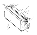
図4はプロセスカートリッジ70の全体斜視図である。また図5は現像ユニット4の全体斜視図である。ドラムユニット26に対して現像ユニット4が回転自在に取り付けられている。現像前軸受12、現像奥軸受13の吊り穴12a・13aに、ドラムユニットの枠体27に圧入された前支持ピン14、奥支持ピン15が係合する。それによって、現像ユニット4は、枠体27に対し、支持ピン14・15を回転軸として回転自在に支持されている。   FIG. 4 is an overall perspective view of the process cartridge 70. FIG. 5 is an overall perspective view of the developing unit 4. The developing unit 4 is rotatably attached to the drum unit 26. The front support pin 14 and the back support pin 15 that are press-fitted into the frame body 27 of the drum unit are engaged with the suspension holes 12 a and 13 a of the pre-development bearing 12 and the development back bearing 13. As a result, the developing unit 4 is supported by the frame 27 so as to be rotatable about the support pins 14 and 15 as rotation axes.

また、枠体27には感光体ドラム1を回転自在に支持するドラム前軸受10、ドラム奥軸受11が設けられている。ドラム奥軸受11は、感光体ドラム1に結合されたドラムカップリング16を支持している。また、ドラム前軸受10はフランジを支持している。ここで、ドラムカップリング16は、感光体ドラム1に装置本体100Aからの駆動回転力を伝達するためのドラムカップリング部材である。   The frame 27 is provided with a drum front bearing 10 and a drum back bearing 11 that rotatably support the photosensitive drum 1. The drum back bearing 11 supports a drum coupling 16 coupled to the photosensitive drum 1. The drum front bearing 10 supports a flange. Here, the drum coupling 16 is a drum coupling member for transmitting a driving rotational force from the apparatus main body 100 </ b> A to the photosensitive drum 1.

現像枠体31には、現像ローラ25を回転自在に支持する現像前軸受12、現像奥軸受13が設けられている。また、現像ユニット4は、プロセスカートリッジ70の画像形成時においては、現像枠体31の両端に設けられた加圧バネ32により、ドラムユニット26に付勢される構成となっている。この加圧バネ32により、現像前軸受12、現像奥軸受13の吊り穴12a・13aが回動中心となり、現像ローラ25が感光体ドラム1に当接するための加圧力となる。   The development frame body 31 is provided with a pre-development bearing 12 and a development back bearing 13 that rotatably support the development roller 25. Further, the developing unit 4 is configured to be urged to the drum unit 26 by the pressure springs 32 provided at both ends of the developing frame 31 when the process cartridge 70 forms an image. By the pressurizing spring 32, the suspension holes 12 a and 13 a of the pre-development bearing 12 and the development back bearing 13 become the rotation center, and a pressure is applied so that the developing roller 25 comes into contact with the photosensitive drum 1.

(プロセスカートリッジの画像形成装置本体への挿入・装着構成)
図6において、上記プロセスカートリッジ70を画像形成装置100に挿入する構成について説明する。なお、本実施形態では、プロセスカートリッジ70を画像形成装置開口部101(101a,101b,101c,101d)へ挿入する構成は、感光体ドラム1の軸線方向と平行な方向(図中矢印Fの方向)で、手前側から奥側に向かって挿入する構成となっている。
(Insertion and mounting configuration of the process cartridge to the image forming apparatus body)
With reference to FIG. 6, a configuration for inserting the process cartridge 70 into the image forming apparatus 100 will be described. In this embodiment, the configuration in which the process cartridge 70 is inserted into the image forming apparatus opening 101 (101a, 101b, 101c, 101d) is a direction parallel to the axial direction of the photosensitive drum 1 (the direction of arrow F in the figure). ), It is configured to be inserted from the near side toward the far side.

画像形成装置100において画像形成装置100の底面200に対する鉛直方向の上方側には、第1の本体ガイド部である本体装着上ガイド部103(103a,103b,103c,103d)(図6参照)が設けられている。また、画像形成装置100において鉛直方向の下方側には、第2の本体ガイド部である本体装着下ガイド部102(102a,102b,102c,102d)(図6参照)が設けられている。この本体装着上ガイド部103と本体装着下ガイド部102は、それぞれプロセスカートリッジ70の挿入方向Fに沿って伸びたガイド形状となっている。   In the image forming apparatus 100, on the upper side in the vertical direction with respect to the bottom surface 200 of the image forming apparatus 100, there is a main body mounting upper guide portion 103 (103a, 103b, 103c, 103d) (see FIG. 6) which is a first main body guide portion. Is provided. Further, on the lower side in the vertical direction in the image forming apparatus 100, a main body mounting lower guide portion 102 (102a, 102b, 102c, 102d) (see FIG. 6), which is a second main body guide portion, is provided. Each of the main body mounting upper guide portion 103 and the main body mounting lower guide portion 102 has a guide shape extending along the insertion direction F of the process cartridge 70.

前記本体装着下ガイド部102の装着方向手前側にプロセスカートリッジ70を載せて、挿入方向Fの向きにプロセスカートリッジ70を本体装着上ガイド部103と本体装着下ガイド部102とに沿って移動させて画像形成装置100への挿入を行う。   The process cartridge 70 is placed on the front side of the main body mounting lower guide portion 102 in the mounting direction, and the process cartridge 70 is moved along the main body mounting upper guide portion 103 and the main body mounting lower guide portion 102 in the insertion direction F. Insertion into the image forming apparatus 100 is performed.

次に上記プロセスカートリッジ70を装置本体100Aに装着する動作について説明する。図7(a)はプロセスカートリッジ70の装置本体100A内への装着前の状態を説明する図である。   Next, an operation of mounting the process cartridge 70 on the apparatus main body 100A will be described. FIG. 7A is a view for explaining a state before the process cartridge 70 is mounted in the apparatus main body 100A.

図7(b)はプロセスカートリッジ70の装置本体100A内への装着途中の状態を説明する図である。装置本体100Aに設けられた本体装着下ガイド部102には、プロセスカートリッジ70を装置本体に対して、加圧・位置決めする本体加圧部材104と本体加圧バネ105が設けられている。プロセスカートリッジ70が装置本体100Aに装着される際には、枠体27のガイド部27bが前記本体加圧部材104に乗り上がり、プロセスカートリッジ70は画像形成装置100の鉛直方向において上方に移動する。そして、枠体27のガイド部27bは、本体装着下ガイド部102のガイド面から離れた状態となる。   FIG. 7B is a diagram for explaining a state in the process of mounting the process cartridge 70 in the apparatus main body 100A. The main body mounting lower guide portion 102 provided in the apparatus main body 100A is provided with a main body pressing member 104 and a main body pressing spring 105 for pressing and positioning the process cartridge 70 with respect to the apparatus main body. When the process cartridge 70 is mounted on the apparatus main body 100A, the guide portion 27b of the frame 27 rides on the main body pressing member 104, and the process cartridge 70 moves upward in the vertical direction of the image forming apparatus 100. And the guide part 27b of the frame 27 will be in the state which left | separated from the guide surface of the main body mounting | wearing lower guide part 102. FIG.

図7(c)はプロセスカートリッジ70が装置本体100Aの奥側板98へ突き当たるまで装着された状態を説明する図である。枠体27のガイド部27bが本体加圧部材104に乗った状態で、さらにプロセスカートリッジ70の装着を続けると、ドラムユニット26に設けられた突き当て部が、装置本体100Aの奥側板98に当接する。   FIG. 7C is a diagram illustrating a state where the process cartridge 70 is mounted until it abuts against the back plate 98 of the apparatus main body 100A. When the mounting of the process cartridge 70 is continued while the guide portion 27b of the frame 27 is on the main body pressing member 104, the abutting portion provided in the drum unit 26 comes into contact with the back plate 98 of the apparatus main body 100A. .

図7(d)、図8はプロセスカートリッジ70が装置本体100Aに位置決めされた状態を説明する図である。図7(c)の状態で、装置本体100Aの前ドア96を閉めることと連動して、本体加圧部材104と本体加圧バネ105を備えた本体装着下ガイド部102が画像形成装置100の鉛直方向において上方に移動する。それに伴い、ドラム奥軸受11の上部に設けられたカートリッジ位置決め部11aが奥側板98の本体位置決め部である突き当て部98aに当接する。   FIGS. 7D and 8 are views for explaining a state in which the process cartridge 70 is positioned on the apparatus main body 100A. In the state of FIG. 7C, in conjunction with closing the front door 96 of the apparatus main body 100 </ b> A, the main body mounting lower guide portion 102 including the main body pressurizing member 104 and the main body pressurizing spring 105 is connected to the image forming apparatus 100. Move upward in the vertical direction. Along with this, the cartridge positioning portion 11 a provided at the upper portion of the drum back bearing 11 abuts against the abutting portion 98 a that is the main body positioning portion of the back side plate 98.

そして、ドラム前軸受10の上部に設けられたカートリッジ位置決め部10aが前側板97の本体位置決め部である突き当て部97aに当接することで、プロセスカートリッジ70の装置本体100Aに対する位置が決まる。この状態でも、枠体27のガイド部27bは、本体装着下ガイド部102のガイド面から離れており、プロセスカートリッジ70は本体加圧部材104から受ける本体加圧バネ105のバネ力で加圧された状態である。   The position of the process cartridge 70 relative to the apparatus main body 100A is determined by the cartridge positioning portion 10a provided on the upper portion of the drum front bearing 10 coming into contact with the abutting portion 97a which is the main body positioning portion of the front plate 97. Even in this state, the guide portion 27 b of the frame body 27 is separated from the guide surface of the main body mounting lower guide portion 102, and the process cartridge 70 is pressurized by the spring force of the main body pressure spring 105 received from the main body pressure member 104. It is in the state.

さらに、枠体27には、プロセスカートリッジ70の回転止めとなるボス27cが側面に設けられており、前記ボス27cが奥側板98に設けられた回転止め穴部98bに嵌合する。そして、プロセスカートリッジ70が装置本体100A内で回転することを防止する。   Further, the frame body 27 is provided with a boss 27 c for preventing rotation of the process cartridge 70 on the side surface, and the boss 27 c is fitted into a rotation stop hole 98 b provided on the back side plate 98. Then, the process cartridge 70 is prevented from rotating in the apparatus main body 100A.

(プロセスカートリッジにおける感光体ドラムと現像ローラの離間機構)
本実施形態に係るプロセスカートリッジ70は感光体ドラム1と現像ローラ25を当接、離間可能である。ここで、感光体ドラム1と現像ローラ25の当接離間機構について図9、図10を用いて説明する。
(Separation mechanism between photosensitive drum and developing roller in process cartridge)
The process cartridge 70 according to the present embodiment can contact and separate the photosensitive drum 1 and the developing roller 25. Here, the contact / separation mechanism between the photosensitive drum 1 and the developing roller 25 will be described with reference to FIGS.

図9において、装置本体にはプロセスカートリッジ70の長手方向の所定位置に離間部材94が配置されている。現像枠体31の離間力受け部31aが矢印N方向に移動する離間部材94から力を受けることで、プロセスカートリッジ70の現像ユニット4は現像ローラ25を感光体ドラム1から離間させる離間位置に移動される。   In FIG. 9, a separation member 94 is disposed at a predetermined position in the longitudinal direction of the process cartridge 70 in the apparatus main body. The developing unit 4 of the process cartridge 70 moves to a separating position for separating the developing roller 25 from the photosensitive drum 1 when the separating force receiving portion 31a of the developing frame 31 receives a force from the separating member 94 that moves in the direction of arrow N. Is done.

また、図10に示すように、離間部材94が矢印Pの方向に移動し、離間力受け部31aから離れると、両端の加圧バネ32(図5参照)の付勢力により現像ユニット4が現像前軸受12、現像奥軸受13の穴12a・13aを中心にして、矢印T方向に回動する。そして、現像ユニット4が接触位置に移動し、現像ローラ25と感光体ドラム1は接触する。この当接離間機構によって、画像形成時には現像ユニット4は当接位置に移動し、画像形成を行わないときは、に図9の離間位置に移動して、保持される。それによって、現像ローラ25の変形による画像品質への影響を抑える効果を得ている。   As shown in FIG. 10, when the separating member 94 moves in the direction of the arrow P and moves away from the separating force receiving portion 31a, the developing unit 4 develops by the urging force of the pressure springs 32 (see FIG. 5) at both ends. It rotates in the direction of arrow T around the holes 12a and 13a of the front bearing 12 and the developing rear bearing 13. Then, the developing unit 4 moves to the contact position, and the developing roller 25 and the photosensitive drum 1 come into contact with each other. By this contact / separation mechanism, the developing unit 4 is moved to the contact position during image formation, and is moved to the separation position shown in FIG. 9 and held when image formation is not performed. Thereby, the effect of suppressing the influence on the image quality due to the deformation of the developing roller 25 is obtained.

(プロセスカートリッジを装着する際の離間機構)
次にプロセスカートリッジ70を装置本体100Aに装着する際の、前記当接離間機構について図11、図12を用いて説明する。
(Separation mechanism when mounting the process cartridge)
Next, the contact / separation mechanism when the process cartridge 70 is attached to the apparatus main body 100A will be described with reference to FIGS.

プロセスカートリッジ70を装置本体100Aに装着する際には、現像ユニット4は接触位置にあり、感光体ドラム1と現像ローラ25が接触した状態になっている。また、プロセスカートリッジ70の装置本体100Aへの装着完了時及び画像形成装置100の画像形成動作終了時には、現像ユニット4は離間位置にあり、感光体ドラム1と現像ローラ25は離間した状態になっている。   When the process cartridge 70 is mounted on the apparatus main body 100A, the developing unit 4 is in the contact position, and the photosensitive drum 1 and the developing roller 25 are in contact with each other. Further, when the mounting of the process cartridge 70 to the apparatus main body 100A is completed and when the image forming operation of the image forming apparatus 100 is completed, the developing unit 4 is in the separated position, and the photosensitive drum 1 and the developing roller 25 are separated. Yes.

よって、プロセスカートリッジ70を装置本体100Aに装着する際に、プロセスカートリッジ70を接触位置から離間位置に移動させる必要があり、その構成を図11乃至図14を用いて説明する。図11に示すように、装置本体100Aにはプロセスカートリッジ70を装着するための画像形成装置開口部101が設けられている。さらに図11、図12に示すように、装置本体100Aには、プロセスカートリッジ70の現像ユニット4に設けられた離間力受け部31aと当接する離間ガイド部93が設けられている。   Therefore, when the process cartridge 70 is mounted on the apparatus main body 100A, it is necessary to move the process cartridge 70 from the contact position to the separation position, and the configuration will be described with reference to FIGS. As shown in FIG. 11, the image forming apparatus opening 101 for mounting the process cartridge 70 is provided in the apparatus main body 100A. Further, as shown in FIGS. 11 and 12, the apparatus main body 100 </ b> A is provided with a separation guide portion 93 that contacts the separation force receiving portion 31 a provided in the developing unit 4 of the process cartridge 70.

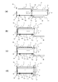
図13(a)、図14(a)に示すように、プロセスカートリッジ70を装置本体100Aに進入する前は、現像ユニット4は接触位置にあり、感光体ドラム1と現像ローラ25が当接している。そして、図13(b)、図14(b)に示すように、プロセスカートリッジ70を装置本体100Aに装着すると、まず枠体に一体に設けられたガイド部27bが、装置本体100Aに設けられた本体装着下ガイド部102に装着される。そして、現像枠体31に設けられた離間力受け部31aが離間ガイド部93の斜めに傾いた斜面である面取り部93aに当接する。   As shown in FIGS. 13A and 14A, before the process cartridge 70 enters the apparatus main body 100A, the developing unit 4 is in the contact position, and the photosensitive drum 1 and the developing roller 25 are in contact with each other. Yes. Then, as shown in FIGS. 13B and 14B, when the process cartridge 70 is mounted on the apparatus main body 100A, first, a guide portion 27b provided integrally with the frame is provided on the apparatus main body 100A. It is attached to the main body attachment lower guide portion 102. Then, the separation force receiving portion 31 a provided on the developing device frame 31 abuts on a chamfered portion 93 a that is an inclined slope of the separation guide portion 93.

更にプロセスカートリッジ70を進入させると、図13(c)、図14(c)に示すように離間力受け部31aが前記面取り部93aに沿って移動して現像ユニット4が奥支持ピン15を回転中心として矢印J方向に回転する。すると現像ユニット4が矢印Kの離間位置に移動し、現像ローラ25が感光体ドラム1と離間する。そしてプロセスカートリッジ70が装置本体100Aに位置決めされた際には、図13(d)、図14(d)に示すように離間力受け部31aは離間ガイド部93の装着方向下流側に配置された離間部材94に当接した状態になる。その際に、現像ユニット4は離間位置にあり、現像ローラ25は感光体ドラム1と離間した状態を保ったままプロセスカートリッジ70を装置本体100Aに装着できる。   When the process cartridge 70 is further advanced, the separation force receiving portion 31a moves along the chamfered portion 93a and the developing unit 4 rotates the back support pin 15 as shown in FIGS. 13 (c) and 14 (c). It rotates in the direction of arrow J as the center. Then, the developing unit 4 moves to the separation position indicated by the arrow K, and the developing roller 25 is separated from the photosensitive drum 1. When the process cartridge 70 is positioned on the apparatus main body 100A, as shown in FIGS. 13D and 14D, the separation force receiving portion 31a is disposed on the downstream side in the mounting direction of the separation guide portion 93. It will be in the state contact | abutted to the separation member 94. At this time, the developing unit 4 is in the separated position, and the developing cartridge 25 can be mounted on the apparatus main body 100A while maintaining the separated state from the photosensitive drum 1.

(プロセスカートリッジにおける感光ドラム駆動機構、現像剤供給ローラ支持、現像カップリング部の構成)
次に本実施形態に係る現像ユニット4におけるカップリング部の構成、回転部材である現像剤供給ローラ34及び現像剤供給ローラ34の支持構成について図15乃至図18を用いて説明する。
(Configuration of photosensitive drum drive mechanism, developer supply roller support, development coupling unit in process cartridge)
Next, the configuration of the coupling unit in the developing unit 4 according to the present embodiment, the developer supply roller 34 that is a rotating member, and the support configuration of the developer supply roller 34 will be described with reference to FIGS. 15 to 18.

図15は現像ローラ25及び現像剤供給ローラ34の支持部の長手方向一端側(奥側)を示した図である。図15において、現像ローラ25の現像ローラ軸25jと現像剤供給ローラ34の現像剤供給ローラ軸34jは、現像奥軸受13の内周に回転可能に嵌合している。ここでは、現像ローラ25及び現像剤供給ローラ34の長手方向一端側の支持構成について説明したが、長手方向他端側についても同様に軸受部材に軸受部が一体に設けられ、現像ローラ軸25j及び現像剤供給ローラ軸34jの他端側を回転可能に嵌合している。また、カップリング部には軸継手部材であるオルダムカップリング20が用いられている。本実施形態では、現像剤供給ローラ34と現像ローラ25はそれぞれ現像ユニットに支持されている構成である。そのため、現像剤供給ローラ34と現像ローラ25は、感光体ドラム1と現像ローラ25との当接離間状態に関わらず、常時当接している。   FIG. 15 is a view showing one end side (back side) in the longitudinal direction of the support portion of the developing roller 25 and the developer supply roller 34. In FIG. 15, the developing roller shaft 25 j of the developing roller 25 and the developer supplying roller shaft 34 j of the developer supplying roller 34 are rotatably fitted to the inner periphery of the developing back bearing 13. Here, the support structure on the one end side in the longitudinal direction of the developing roller 25 and the developer supply roller 34 has been described, but the bearing portion is similarly provided integrally with the bearing member on the other end side in the longitudinal direction, and the developing roller shaft 25j and The other end side of the developer supply roller shaft 34j is rotatably fitted. An Oldham coupling 20 that is a shaft coupling member is used for the coupling portion. In the present embodiment, the developer supply roller 34 and the developing roller 25 are each supported by a developing unit. Therefore, the developer supply roller 34 and the developing roller 25 are always in contact regardless of the contact and separation state of the photosensitive drum 1 and the developing roller 25.

次に図16を用いて、オルダムカップリング20の構成について説明する。ここではオルダムカップリング20の構成を説明するために現像奥軸受13は不図示にしてある。図16に示すように、オルダムカップリング20は、被駆動部としての従動側係合部21と、中間部としての中間係合部22と、駆動力受け部としての駆動側係合部23とで構成されている。   Next, the configuration of the Oldham coupling 20 will be described with reference to FIG. Here, in order to explain the configuration of the Oldham coupling 20, the developing rear bearing 13 is not shown. As shown in FIG. 16, the Oldham coupling 20 includes a driven side engaging portion 21 as a driven portion, an intermediate engaging portion 22 as an intermediate portion, and a driving side engaging portion 23 as a driving force receiving portion. It consists of

従動側係合部21は、現像剤供給ローラ34の軸34jの軸線方向一端側に固定して取り付けられている。固定の方法としては、スプリングピンや平行ピンにより結合する方法や、図16に示したように、現像剤供給ローラ軸34jの端面にカット部34kを設け、従動側係合部21側の穴も同様の形状にして嵌合させる方法がある。   The driven side engaging portion 21 is fixedly attached to one end side in the axial direction of the shaft 34j of the developer supply roller 34. As a fixing method, a coupling method using a spring pin or a parallel pin, or a cut portion 34k is provided on the end surface of the developer supply roller shaft 34j as shown in FIG. There is a method of fitting the same shape.

駆動側係合部23は、本体の駆動源の駆動力を受入れる部分である。そして、駆動側係合部23の軸部23dは保持部41の穴41dに回転可能に保持されている。この保持部は、現像ローラの軸方向に対して直行する方向に移動可能である。また駆動側係合部23には、後述する装置本体100Aの第二の本体駆動伝達部材である本体現像カップリング91(図18参照)と係合する3個の突起23c1,23c2,23c3が一体に形成されている。   The driving side engaging portion 23 is a portion that receives the driving force of the driving source of the main body. The shaft portion 23 d of the driving side engaging portion 23 is rotatably held in the hole 41 d of the holding portion 41. This holding portion is movable in a direction perpendicular to the axial direction of the developing roller. The drive-side engagement portion 23 is integrally provided with three protrusions 23c1, 23c2, and 23c3 that engage with a main body developing coupling 91 (see FIG. 18) that is a second main body drive transmission member of the apparatus main body 100A described later. Is formed.

このオルダムカップリング20は、本体に設けられた駆動力を与える駆動部材である本体現像カップリング91の軸線と現像剤供給ローラ34の軸線とのズレを許容して装置本体100Aから駆動回転力(第二の駆動回転力)を現像剤供給ローラ34に伝達する。そして、オルダムカップリング20は、現像ユニット4が前記接触位置及び前記離間位置に位置する状態で、現像剤供給ローラ34に装置本体100Aから駆動回転力(第二の駆動回転力)を伝達可能である。   This Oldham coupling 20 allows a deviation between the axis of the main body developing coupling 91 which is a driving member for providing a driving force provided in the main body and the axis of the developer supply roller 34, so that the driving rotational force ( (Second driving torque) is transmitted to the developer supply roller 34. The Oldham coupling 20 can transmit a driving rotational force (second driving rotational force) from the apparatus main body 100A to the developer supply roller 34 in a state where the developing unit 4 is located at the contact position and the separation position. is there.

図17において、オルダムカップリング20の構成について断面図を用いてさらに詳しく説明する。図17(a)は図16中の矢印H方向に対して水平に切った断面図、図17(b)は図16中の矢印I方向に対して水平に切った断面図である。図17(a)において、従動側係合部21にはリブ21aが一体に設けられている。中間係合部22には溝22aが設けられており、前記リブ21aと溝22aは図16の矢印H方向に移動可能に係合している。図17(b)において、駆動側係合部23にはリブ23bが一体に設けられている。中間係合部22には溝22bが設けられており、前記リブ23bと溝22bは図16の矢印I方向に移動可能に係合している。本実施形態では、H方向とI方向とは略直交する関係になっている。   In FIG. 17, the configuration of the Oldham coupling 20 will be described in more detail with reference to cross-sectional views. 17A is a cross-sectional view cut horizontally with respect to the direction of arrow H in FIG. 16, and FIG. 17B is a cross-sectional view cut horizontally with respect to the direction of arrow I in FIG. In FIG. 17A, the driven side engaging portion 21 is integrally provided with a rib 21a. The intermediate engagement portion 22 is provided with a groove 22a, and the rib 21a and the groove 22a are engaged so as to be movable in the direction of arrow H in FIG. In FIG. 17B, the drive side engaging portion 23 is integrally provided with a rib 23b. The intermediate engaging portion 22 is provided with a groove 22b, and the rib 23b and the groove 22b are engaged so as to be movable in the direction of arrow I in FIG. In the present embodiment, the H direction and the I direction are substantially orthogonal to each other.

中間係合部22は従動側係合部21と駆動側係合部23と係合し、駆動側係合部23に入力された駆動力を従動側係合部21に伝達する中間部となるものであり、それぞれの係合部21,23と係合を維持したまま現像剤供給ローラ34の軸線方向と交差する方向へ移動可能となっている。   The intermediate engaging portion 22 is engaged with the driven side engaging portion 21 and the driving side engaging portion 23, and becomes an intermediate portion that transmits the driving force input to the driving side engaging portion 23 to the driven side engaging portion 21. It is possible to move in the direction intersecting the axial direction of the developer supply roller 34 while maintaining the engagement with the engaging portions 21 and 23.

図18はプロセスカートリッジ70に設けられたカップリングと装置本体100Aに設けられたカップリングの構成を示す図である。前述したように現像ユニット4に設けられたオルダムカップリング20の駆動側係合部23の端面には軸線方向に突出する3個の突起23c1,23c2,23c3が形成されている。また、本体現像カップリング91との軸線(回転中心)を合わせるための芯決めボス23aが、駆動側係合部23の端面から軸線方向に突出している。   FIG. 18 is a view showing the configuration of the coupling provided in the process cartridge 70 and the coupling provided in the apparatus main body 100A. As described above, the three projections 23c1, 23c2, and 23c3 projecting in the axial direction are formed on the end face of the driving side engaging portion 23 of the Oldham coupling 20 provided in the developing unit 4. A centering boss 23 a for aligning the axis (rotation center) with the main body developing coupling 91 protrudes from the end surface of the drive side engaging portion 23 in the axial direction.

保持部41のガイド部41bは現像ユニット4に図示しないビス等により固定されたサイドカバー43の溝43aに現像剤供給ローラ34の軸線方向に対し、交差する方向に移動可能にガイドされる。すなわち、駆動側係合部23は現像剤供給ローラの軸線方向と交差する方向に移動可能となっている。   The guide portion 41 b of the holding portion 41 is guided by a groove 43 a of the side cover 43 fixed to the developing unit 4 with screws (not shown) so as to be movable in a direction intersecting the axial direction of the developer supply roller 34. That is, the driving side engaging portion 23 is movable in a direction crossing the axial direction of the developer supply roller.

感光体ドラム1の軸線方向の一端側には、ドラムカップリング部である三角柱のドラムカップリング16が設けられている。本実施形態では、ドラムカップリング16は感光ドラムのフランジと一体に形成されている。図18において、感光体ドラム1に装置本体100Aの駆動を伝達するためのドラム駆動部材(第一の本体駆動伝達部材)である本体ドラムカップリング90には断面が略三角形の穴90aが設けられている。現像剤供給ローラ34に装置本体100Aから駆動力(第二の駆動回転力)を与えるための駆動部材である本体現像カップリング91には3個の穴91a1,91a2,91a3が設けられている。   On one end side of the photosensitive drum 1 in the axial direction, a triangular prism drum coupling 16 as a drum coupling portion is provided. In this embodiment, the drum coupling 16 is formed integrally with the flange of the photosensitive drum. In FIG. 18, a main body drum coupling 90 which is a drum driving member (first main body driving transmission member) for transmitting the driving of the apparatus main body 100A to the photosensitive drum 1 is provided with a hole 90a having a substantially triangular cross section. ing. Three holes 91a1, 91a2 and 91a3 are provided in the main body developing coupling 91 which is a driving member for applying a driving force (second driving rotational force) from the apparatus main body 100A to the developer supply roller 34.

本体ドラムカップリング90は圧縮バネなどのドラム押圧部材106により、プロセスカートリッジ70の方向に付勢されている。そして、本体ドラムカップリング90は感光体ドラム1の軸線方向に移動可能である。また、プロセスカートリッジ70が装置本体100Aに装着された時にドラムカップリング16と本体ドラムカップリング90の穴90aの位相がずれて当接した場合に本体ドラムカップリング90がドラムカップリング16に押されて後退する。そして、本体ドラムカップリング90が回転することによって、ドラムカップリング16と穴90aとは係合し、感光体ドラム1に駆動回転力が伝達される。   The main body drum coupling 90 is urged toward the process cartridge 70 by a drum pressing member 106 such as a compression spring. The main body drum coupling 90 is movable in the axial direction of the photosensitive drum 1. When the process cartridge 70 is mounted on the apparatus main body 100A, the main body drum coupling 90 is pushed by the drum coupling 16 when the drum coupling 16 and the hole 90a of the main body drum coupling 90 are out of phase with each other. And retreat. Then, when the main body drum coupling 90 rotates, the drum coupling 16 and the hole 90a are engaged with each other, and the driving rotational force is transmitted to the photosensitive drum 1.

また、本体現像カップリング91は、感光体ドラム1の軸線方向と平行な方向に向かって圧縮バネなどの現像押圧部材107によりプロセスカートリッジ70の方向に付勢されている。しかし、本体現像カップリング91は、軸線方向と交差する方向にガタはなく、装置本体100Aに設けられている。即ち、本体現像カップリング91は、駆動伝達のために回転する他に、前記軸線方向にのみ移動可能である。   The main body development coupling 91 is urged in the direction of the process cartridge 70 by a development pressing member 107 such as a compression spring in a direction parallel to the axial direction of the photosensitive drum 1. However, the main body developing coupling 91 is provided in the apparatus main body 100A without play in the direction intersecting the axial direction. That is, the main body developing coupling 91 can move only in the axial direction in addition to rotating for driving transmission.

プロセスカートリッジ70を装置本体100Aに進入させて、駆動側係合部23と本体現像カップリング91とが係合する際に、突起23c1〜23c3と穴91a1〜91a3と位相が合わない場合がある。この場合は、突起23c1〜23c3の先端が穴91a1〜91a3以外の所に当接して、本体現像カップリング91が、現像押圧部材107の付勢力に抗して軸線方向に後退する。しかし、本体現像カップリング91が回転し、突起23c1〜23c3と穴91a1〜91a3と位相が合うと、本体現像カップリング91は現像押圧部材107の付勢力で前進する。   When the process cartridge 70 is moved into the apparatus main body 100A and the driving side engaging portion 23 and the main body developing coupling 91 are engaged, the projections 23c1 to 23c3 and the holes 91a1 to 91a3 may not be in phase. In this case, the tips of the projections 23c1 to 23c3 come into contact with places other than the holes 91a1 to 91a3, and the main body development coupling 91 moves backward in the axial direction against the urging force of the development pressing member 107. However, when the main body development coupling 91 rotates and the projections 23c1 to 23c3 and the holes 91a1 to 91a3 are in phase, the main body development coupling 91 advances by the biasing force of the development pressing member 107.

そして、突起23c1〜23c3と穴91a1〜91a3係合し、係合部位置決め部である芯決めボス23aと伝達部材位置決め部である芯決め穴91bも嵌合し、駆動側係合部23と本体現像カップリング91の軸線(回転中心)が一致する。そして、本体現像カップリング91が回転することによって、突起23c1〜23c3と穴91a1〜91a3とはそれぞれ係合し、現像剤供給ローラ34に駆動回転力が伝達される。   Then, the projections 23c1 to 23c3 are engaged with the holes 91a1 to 91a3, the centering boss 23a that is the engaging part positioning part and the centering hole 91b that is the transmission member positioning part are also fitted, and the driving side engaging part 23 and the main body The axis (rotation center) of the development coupling 91 coincides. When the main body developing coupling 91 rotates, the projections 23c1 to 23c3 and the holes 91a1 to 91a3 are engaged with each other, and the driving torque is transmitted to the developer supply roller 34.

次に、現像ローラ25の回転について説明する。現像剤供給ローラ34には、長手方向(現像剤供給ローラの軸方向、現像ローラの軸方向)において一端側には駆動側係合部23が設けられ、他端側に第一ギアが設けられている。なお、本実施形態では、現像剤供給ローラの軸方向と現像ローラの軸方向とは実質的に平行の関係にある。一方、現像ローラ25には、第一ギアとかみ合う第二ギアが設けられている。この構成により、現像剤供給ローラ34と長手方向の他端側においてギアにより駆動連結された現像ローラ25に回転力が伝達される。   Next, rotation of the developing roller 25 will be described. The developer supply roller 34 is provided with a driving side engaging portion 23 on one end side in the longitudinal direction (axial direction of the developer supply roller, axial direction of the developing roller) and a first gear on the other end side. ing. In this embodiment, the axial direction of the developer supply roller and the axial direction of the developing roller are substantially parallel to each other. On the other hand, the developing roller 25 is provided with a second gear that meshes with the first gear. With this configuration, the rotational force is transmitted to the developing roller 25 that is drivingly connected to the developer supply roller 34 by a gear on the other end side in the longitudinal direction.

ここで、本体ドラムカップリング90及び本体現像カップリング91に対する駆動伝達は装置本体100A内に設けられたモータにより行われる。これにより、感光体ドラム1と現像剤供給ローラ34は互いに独立して画像形成装置本体から駆動力を受ける。なお、モータは各色のプロセスカートリッジ70につき各1台のモータを用いる構成や、モータ1台で何色かのプロセスカートリッジに駆動を伝達する構成がある。   Here, drive transmission to the main body drum coupling 90 and the main body development coupling 91 is performed by a motor provided in the apparatus main body 100A. Accordingly, the photosensitive drum 1 and the developer supply roller 34 receive driving force from the image forming apparatus main body independently of each other. The motor has a configuration in which one motor is used for each color process cartridge 70 and a configuration in which driving is transmitted to a process cartridge of several colors by one motor.

(プロセスカートリッジにおける当接離間動作時のオルダムカップリングの動作)
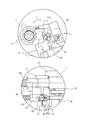
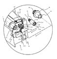
次に本実施形態に係るプロセスカートリッジ70における現像ローラと感光ドラムの当接離間動作時のオルダムカップリング20の動作に関して図1、図19、図20を用いて説明する。
(Operation of Oldham coupling during contact and separation of process cartridge)
Next, the operation of the Oldham coupling 20 when the developing roller and the photosensitive drum are brought into contact with and separated from each other in the process cartridge 70 according to the present embodiment will be described with reference to FIGS. 1, 19, and 20.

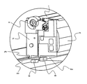
図19は現像ユニット4が離間位置に位置する状態を示す側面図と長手方向の断面図である。現像ユニットが離間ガイド部93によって、離間位置に位置する状態においては、図19に示すように、現像ローラ25と感光体ドラム1は離間した状態となっている。   FIG. 19 is a side view and a longitudinal sectional view showing a state in which the developing unit 4 is located at the separation position. In a state where the developing unit is positioned at the separation position by the separation guide portion 93, the developing roller 25 and the photosensitive drum 1 are separated from each other as shown in FIG.

しかし、サイドカバー43内に設けられた捩じりコイルバネで構成した付勢部材である付勢バネ42の腕部42aが保持部41の係止部41cに当接する。それによって、駆動側係合部23は、感光体ドラム1の軸線方向に対して交差する方向Q(感光体ドラムに向かう方向)に付勢される。そして、保持部41の当接部41aはドラム奥軸受11に設けられた突き当て部(ストッパ)である軸受当接部11aに当接し、係合されることになる。   However, the arm portion 42 a of the urging spring 42, which is an urging member constituted by a torsion coil spring provided in the side cover 43, comes into contact with the locking portion 41 c of the holding portion 41. As a result, the driving side engaging portion 23 is biased in a direction Q (a direction toward the photosensitive drum) intersecting the axial direction of the photosensitive drum 1. Then, the abutting portion 41 a of the holding portion 41 abuts on and is engaged with a bearing abutting portion 11 a which is an abutting portion (stopper) provided on the drum back bearing 11.

ここでドラム奥軸受11の軸受当接部11aはV字形状をしている。そして、軸受当接部11aは、感光体ドラム1の軸線方向においては感光体ドラム1の軸線と平行な2面で形成されている。そして、この軸受当接部11aに保持部41が当接することで感光体ドラム1の軸線と平行に保持部41を保持できる。また、ドラム奥軸受11にはカートリッジ位置決め部11aが一体で設けられている。したがって、保持部41で回転自在に支持される駆動側係合部23は、カートリッジ位置決め部11aが位置決めされる装置本体100Aの奥側板98に対して精度良く位置決めされる。したがって、駆動側係合部23は、装置本体100Aに設けられた本体現像カップリング91の軸線91jに対しても精度良く位置決めできる。   Here, the bearing contact portion 11a of the drum back bearing 11 has a V shape. The bearing contact portion 11 a is formed by two surfaces parallel to the axis of the photosensitive drum 1 in the axial direction of the photosensitive drum 1. The holding portion 41 can be held in parallel with the axis of the photosensitive drum 1 by the holding portion 41 coming into contact with the bearing contact portion 11a. The drum back bearing 11 is integrally provided with a cartridge positioning portion 11a. Therefore, the driving side engaging portion 23 rotatably supported by the holding portion 41 is accurately positioned with respect to the back side plate 98 of the apparatus main body 100A where the cartridge positioning portion 11a is positioned. Therefore, the driving side engaging portion 23 can be accurately positioned with respect to the axis 91j of the main body developing coupling 91 provided in the apparatus main body 100A.

尚、本実施形態では保持部41を感光体ドラム1の方向に付勢するものとして、付勢バネ42を用いた。しかし、保持部41に一体的に弾性変形可能な弾性部を設けることによって軸受当接部11aに当接させても良い。   In this embodiment, the urging spring 42 is used to urge the holding portion 41 toward the photosensitive drum 1. However, the holding portion 41 may be brought into contact with the bearing contact portion 11a by providing an elastic portion that can be elastically deformed integrally.

次に、本体現像カップリング91に駆動側係合部23が係合して回転した際は、駆動側係合部23が本体現像カップリング91によって位置決めされる。このとき、保持部41の当接部41aがドラム奥軸受11、即ち軸受当接部11aから離間する構成になっている。   Next, when the driving side engaging portion 23 is engaged with the main body developing coupling 91 and rotated, the driving side engaging portion 23 is positioned by the main body developing coupling 91. At this time, the contact portion 41a of the holding portion 41 is configured to be separated from the drum back bearing 11, that is, the bearing contact portion 11a.

そのため、プロセスカートリッジ70が装置本体100Aに進入する際は、駆動側係合部23の軸線23jは本体現像カップリング91の軸線91jに対して感光体ドラム1側に一定距離だけズレた状態で係合を始めることになる。この状態から更にプロセスカートリッジ70が進入すると、芯決めボス23aの先端外周に設けられたテーパー状の面取り部と、これに対応して穴91bに設けられた面取り部とが接触しながら係合することで、軸芯のずれを補正しながら係合する構成になっている。   Therefore, when the process cartridge 70 enters the apparatus main body 100A, the axis 23j of the drive side engaging portion 23 is engaged with the axis 91j of the main body developing coupling 91 being shifted from the photosensitive drum 1 by a certain distance. It will start the match. When the process cartridge 70 further enters from this state, the tapered chamfered portion provided on the outer periphery of the tip of the centering boss 23a and the chamfered portion provided in the hole 91b correspondingly engage with each other. Thus, it is configured to engage while correcting the deviation of the axis.

そして、本体現像カップリング91が回転し、駆動側係合部23の突起23c1〜23c3(図18参照)と本体現像カップリング91の穴91a1〜91a3(図18参照)の位相が合った時に、芯決めボス23aと穴91bが嵌合する。それによって、駆動側係合部23の軸線23jと本体現像カップリング91の軸線91jが一致することになる。そして、駆動側係合部23は本体現像カップリング91で位置決めされるため、保持部41はドラム奥軸受11、即ち軸受当接部11aから離間する。   When the main body development coupling 91 rotates and the phases of the projections 23c1 to 23c3 (see FIG. 18) of the driving side engaging portion 23 and the holes 91a1 to 91a3 (see FIG. 18) of the main body development coupling 91 match, The centering boss 23a and the hole 91b are fitted. As a result, the axis line 23j of the driving side engaging portion 23 and the axis line 91j of the main body developing coupling 91 coincide with each other. Since the driving side engaging portion 23 is positioned by the main body developing coupling 91, the holding portion 41 is separated from the drum back bearing 11, that is, the bearing contact portion 11a.

さらに、図1は現像ユニット4が当接位置に位置する状態を示す側面図と長手方向の断面図である。装置本体100Aの離間部材94(図10参照)が動作することでプロセスカートリッジ70の現像ユニット4が枠体27の現像奥軸受13を支持している奥支持ピン15を中心に矢印T方向に回動する。そして、現像ユニット4が接触位置に移動し、感光体ドラム1と現像ローラ25が当接する。ここで現像ユニット4が当接位置に移動しても、駆動側係合部23と本体現像カップリング91は係合したままである。   Further, FIG. 1 is a side view and a longitudinal sectional view showing a state in which the developing unit 4 is located at the contact position. When the separation member 94 (see FIG. 10) of the apparatus main body 100A operates, the developing unit 4 of the process cartridge 70 rotates in the direction of arrow T around the back support pin 15 that supports the development back bearing 13 of the frame 27. Move. Then, the developing unit 4 moves to the contact position, and the photosensitive drum 1 and the developing roller 25 come into contact with each other. Here, even if the developing unit 4 moves to the contact position, the driving side engaging portion 23 and the main body developing coupling 91 remain engaged.

また、図1と図20に示すように、現像ユニット4が離間位置と当接位置のどちらの位置の状態においても、中間係合部22は駆動側係合部23と従動側係合部21とに係合している。したがって、中間係合部22は現像ユニット4が離間位置と接触位置との間を移動する際にも、駆動側係合部23及び従動側係合部21との係合を維持しながら移動することを可能にしている。   As shown in FIGS. 1 and 20, the intermediate engagement portion 22 has a drive-side engagement portion 23 and a driven-side engagement portion 21 regardless of whether the development unit 4 is in the separated position or the contact position. And is engaged. Therefore, the intermediate engaging portion 22 moves while maintaining the engagement with the driving side engaging portion 23 and the driven side engaging portion 21 even when the developing unit 4 moves between the separation position and the contact position. Making it possible.

(プロセスカートリッジにおける軸受当接部と感光体ドラムの位置関係)
次に本実施形態に係るプロセスカートリッジ70における軸受当接部11aと感光体ドラム1の位置関係に関して図19、図21を用いて説明する。
(Positional relationship between bearing contact part and photosensitive drum in process cartridge)
Next, the positional relationship between the bearing contact portion 11a and the photosensitive drum 1 in the process cartridge 70 according to the present embodiment will be described with reference to FIGS.

図19は本実施形態における、現像ローラ25と感光体ドラム1とが離間した状態の側面図と断面図である。   FIG. 19 is a side view and a cross-sectional view showing a state where the developing roller 25 and the photosensitive drum 1 are separated from each other in this embodiment.

ここで、本実施形態における特徴部分である軸受当接部11aについて説明する。   Here, the bearing contact part 11a which is a characteristic part in the present embodiment will be described.

軸受当接部11aは、保持部41が突き当たるドラム奥軸受11に設けられた当接部である。駆動側係合23が本体現像カップリング91と係合しているときには、駆動側係合部23の位置は本体現像カップリング部により決められる。しかし、現像ローラと感光体ドラムとが離間した状態でプロセスカートリッジ70を本体に挿入する際に、駆動側係合部の位置によっては本体現像カップリングと係合しにくくなる。本実施形態では、本体現像カップリングの位置は本体により決められているため、プロセスカートリッジの本体挿入時の駆動側係合部と本体現像カップリングとが係合しやすくするためには、駆動側係合部の位置を決めておく必要がある。そのため、本実施形態では、駆動側係合部と本体現像カップリングとが係合していない場合に、付勢部材であるバネ42により保持部41を軸受当接部11aに付勢する構成とする。その構成により、保持部41は軸受当接部11aに位置決めされる結果、駆動側係合部と本体現像カップリングとが係合していない場合であっても駆動側係合部の位置が決められる。   The bearing contact portion 11a is a contact portion provided on the drum back bearing 11 against which the holding portion 41 abuts. When the drive side engagement 23 is engaged with the main body development coupling 91, the position of the drive side engagement portion 23 is determined by the main body development coupling portion. However, when the process cartridge 70 is inserted into the main body in a state where the developing roller and the photosensitive drum are separated from each other, it is difficult to engage with the main body developing coupling depending on the position of the driving side engaging portion. In this embodiment, since the position of the main body developing coupling is determined by the main body, the driving side engaging portion and the main body developing coupling when the main body of the process cartridge is inserted are easily engaged with the driving side. It is necessary to determine the position of the engaging portion. Therefore, in the present embodiment, when the driving side engaging portion and the main body developing coupling are not engaged, the holding portion 41 is biased to the bearing contact portion 11a by the spring 42 that is a biasing member. To do. As a result of the positioning of the holding portion 41 by the bearing contact portion 11a, the position of the driving side engaging portion is determined even when the driving side engaging portion and the main body development coupling are not engaged. It is done.

図19に示すように、軸受当接部11aの形状は、保持部41と少なくとも2点以上で当接するような形状とする必要がある。そこで、本実施形態では、V字形状としている。本実施形態では、図19で当接ポイント(当接部)は411、412である。そして、本実施形態では、全ての当接ポイントが、前記感光体ドラムの回転軸線90jに垂直な平面上において感光体ドラム1の外周面より外側になるように配置されている。更に、感光体ドラム1の回転中心1aと本体からカップリングを介して駆動を受ける駆動部材である現像剤供給ローラ34の回転中心34aとを結ぶ直線L1の方向において、感光体ドラム1の外周面よりも駆動部材(駆動ローラ)側(現像剤供給ローラ側)に配置される必要がある。本実施形態では、感光体ドラム1の回転中心1aと本体からカップリングを介して駆動を受ける駆動部材である現像剤供給ローラ34の回転中心34aとを結ぶ直線L1の方向において、最も感光体ドラムにある当接ポイントが感光体ドラム1の外周面と回転中心34aとの間に配置する構成とした。このような構成により、プロセスカートリッジを小型化しても感光体ドラムに駆動力を伝達する装置本体側の駆動伝達部の軸線と、第二のユニットに駆動回転力を伝達する装置本体側の駆動伝達部の軸線との距離を大きくとることが可能となる。また、本実施形態では、保持部41が突き当たる軸受当接部11aの当接ポイント411、412は、感光体ドラム1の外周面より外側かつ現像ローラ25の外周面より内側に設けた。本実施形態では、全ての当接ポイントが現像ローラ25の外周面より内側にある構成であったが、少なくとも1の当接ポイントが外周面よりも内側にある構成にすれば、プロセスカートリッジが大型化しすぎることを低減できる。また、少なくとも全ての当接ポイントは感光ドラムの中心と現像剤供給ローラの中心間にある必要がある。   As shown in FIG. 19, the shape of the bearing contact portion 11a needs to be in contact with the holding portion 41 at at least two points. Therefore, in this embodiment, it is V-shaped. In the present embodiment, the contact points (contact portions) are 411 and 412 in FIG. In this embodiment, all the contact points are arranged outside the outer peripheral surface of the photosensitive drum 1 on a plane perpendicular to the rotation axis 90j of the photosensitive drum. Further, the outer peripheral surface of the photosensitive drum 1 in the direction of a straight line L1 that connects the rotational center 1a of the photosensitive drum 1 and the rotational center 34a of the developer supply roller 34 that is a driving member that is driven from the main body via a coupling. It is necessary to dispose it closer to the drive member (drive roller) side (developer supply roller side). In the present embodiment, in the direction of a straight line L1 that connects the rotation center 1a of the photosensitive drum 1 and the rotation center 34a of the developer supply roller 34 that is a drive member that receives driving from the main body via a coupling, the photosensitive drum is the most. The contact point is located between the outer peripheral surface of the photosensitive drum 1 and the rotation center 34a. With such a configuration, even if the process cartridge is downsized, the axis of the drive transmission unit on the apparatus main body side that transmits the driving force to the photosensitive drum and the drive transmission on the apparatus main body side that transmits the driving rotational force to the second unit. It is possible to increase the distance from the axis of the part. In the present embodiment, the contact points 411 and 412 of the bearing contact portion 11 a against which the holding portion 41 abuts are provided outside the outer peripheral surface of the photosensitive drum 1 and inside the outer peripheral surface of the developing roller 25. In this embodiment, all the contact points are on the inner side of the outer peripheral surface of the developing roller 25. However, if at least one contact point is on the inner side of the outer peripheral surface, the process cartridge is large. It is possible to reduce excessive conversion. Further, at least all the contact points must be between the center of the photosensitive drum and the center of the developer supply roller.

次に、本体ドラムカップリング90の軸線90jと本体現像カップリング91の軸線91jとの距離をLaとする。   Next, let La be the distance between the axis 90j of the main body drum coupling 90 and the axis 91j of the main body developing coupling 91.

比較例として、保持部41が突き当たる軸受当接部11aは、感光体ドラム1の外周面より内側に設けられている構成を図21に示す。この図では、軸受当接部11aが感光体ドラム1の外周面よりも内側にあるため、全ての軸受当接部11aと保持部との当接ポイントが感光体ドラム1の外周面よりも内側になる。この時の、本体ドラムカップリング90の軸線90jと本体現像カップリング91の軸線91jとの距離をLbとする。   As a comparative example, FIG. 21 shows a configuration in which the bearing contact portion 11 a against which the holding portion 41 abuts is provided on the inner side of the outer peripheral surface of the photosensitive drum 1. In this figure, since the bearing contact portion 11a is inside the outer peripheral surface of the photosensitive drum 1, the contact points of all the bearing contact portions 11a and the holding portions are inside the outer peripheral surface of the photosensitive drum 1. become. At this time, the distance between the axis 90j of the main body drum coupling 90 and the axis 91j of the main body developing coupling 91 is Lb.

このように、保持部41が突き当たる軸受当接部11aを、感光体ドラム1の外周面より外側に設けることで、本体ドラムカップリング90の軸線90jと本体現像カップリング91の軸線91jとの距離をLaをより大きく(La>Lb)することが可能となる。   Thus, by providing the bearing abutting portion 11 a against which the holding portion 41 abuts outside the outer peripheral surface of the photosensitive drum 1, the distance between the axis 90 j of the main body drum coupling 90 and the axis 91 j of the main body developing coupling 91. It is possible to make La larger (La> Lb).

よって、本体ドラムカップリング90と本体現像カップリング91のクリアランスをより確保することが可能となり、装置本体100Aの設計配置の自由度を向上させることが可能となる。また、プロセスカートリッジ70においても、感光体ドラム1及び現像ローラ25を小径化させ、プロセスカートリッジ70の更なる小型化も可能となる。   Therefore, the clearance between the main body drum coupling 90 and the main body development coupling 91 can be further ensured, and the degree of freedom in design and arrangement of the apparatus main body 100A can be improved. Also in the process cartridge 70, the photosensitive drum 1 and the developing roller 25 can be reduced in diameter, and the process cartridge 70 can be further reduced in size.

図19においては、保持部41が突き当たる軸受当接部11aは、感光体ドラム1の外周面より外側かつ現像ローラ25の外周面より内側に設けた例を示した。ここで、図22に示すように、保持部41が突き当たる軸受当接部11aが感光体ドラム1の外周面より外側であって、現像剤供給ローラ34の外周面より外側でも同様の効果を得ることが可能である。また、図23に示すように、保持部41が突き当たる軸受当接部11aが感光体ドラム1の外周面より外側であって、現像ローラ25の外周面より外側かつ現像剤供給ローラ34の外周面より内側でも同様の効果を得ることが可能である。   FIG. 19 shows an example in which the bearing contact portion 11 a against which the holding portion 41 abuts is provided outside the outer peripheral surface of the photosensitive drum 1 and inside the outer peripheral surface of the developing roller 25. Here, as shown in FIG. 22, the same effect is obtained even when the bearing contact portion 11 a against which the holding portion 41 abuts is outside the outer peripheral surface of the photosensitive drum 1 and outside the outer peripheral surface of the developer supply roller 34. It is possible. Further, as shown in FIG. 23, the bearing contact portion 11 a against which the holding portion 41 abuts is outside the outer peripheral surface of the photosensitive drum 1, outside the outer peripheral surface of the developing roller 25, and the outer peripheral surface of the developer supply roller 34. A similar effect can be obtained even on the inner side.

しかし、図22に示すように、保持部41が突き当たる軸受当接部11aを感光体ドラム1の外周面より外側であって、感光ドラムの中心と現像剤供給ローラの中心間から外れた位置であって現像剤供給ローラ34の外周面より外側に設けた場合、装置本体100Aから入力される第二の駆動回転力をギア110a,110b等を介して、現像剤供給ローラ34等に伝達する必要があり、部品点数の増加に繋がる。   However, as shown in FIG. 22, the bearing abutting portion 11 a against which the holding portion 41 abuts is outside the outer peripheral surface of the photosensitive drum 1 and at a position deviated from between the center of the photosensitive drum and the center of the developer supply roller. In the case where it is provided outside the outer peripheral surface of the developer supply roller 34, it is necessary to transmit the second driving rotational force input from the apparatus main body 100A to the developer supply roller 34, etc. via the gears 110a, 110b, etc. There will be an increase in the number of parts.

また、図23に示すように、保持部41が突き当たる軸受当接部11aを感光体ドラム1の外周面より外側であって、現像ローラ25の外周面より外側かつ現像剤供給ローラ34の外周面より内側に設けた場合、部品点数の増加を防ぐために現像剤供給ローラ軸上にオルダムカップリング20を設けると、駆動側係合部23が小さくなり強度低下に繋がる。よって、保持部41が突き当たる軸受当接部11aは感光体ドラム1の外周面より外側かつ感光ドラムの中心と現像剤供給ローラ(回転部材)の中心との間であって、さらに、現像剤供給ローラの外周面よりも外側であることが望ましい。   Further, as shown in FIG. 23, the bearing contact portion 11 a against which the holding portion 41 abuts is outside the outer peripheral surface of the photosensitive drum 1, outside the outer peripheral surface of the developing roller 25, and the outer peripheral surface of the developer supply roller 34. When the Oldham coupling 20 is provided on the developer supply roller shaft in order to prevent an increase in the number of parts when it is provided on the inner side, the drive-side engagement portion 23 becomes smaller, leading to a decrease in strength. Therefore, the bearing contact portion 11a against which the holding portion 41 abuts is outside the outer peripheral surface of the photosensitive drum 1 and between the center of the photosensitive drum and the center of the developer supply roller (rotating member), and further, the developer supply It is desirable to be outside the outer peripheral surface of the roller.

これにより、駆動ギアの増加による部品点数増加や、駆動係合部の強度低下を回避しつつ、本体ドラムカップリング90の軸線90jと本体現像カップリング91の軸線91jとの距離を大きくすることが可能となる。   Accordingly, the distance between the axis 90j of the main body drum coupling 90 and the axis 91j of the main body developing coupling 91 can be increased while avoiding an increase in the number of parts due to an increase in the drive gear and a decrease in strength of the drive engagement portion. It becomes possible.

以上本発明の実施形態について説明したが、本発明は上記実施形態に何ら限定されるものではなく、本発明の技術思想内であらゆる変形が可能である。   Although the embodiments of the present invention have been described above, the present invention is not limited to the above-described embodiments, and various modifications can be made within the technical idea of the present invention.

1 …感光体ドラム
11 …ドラム奥軸受
11a …軸受当接部
16 …ドラムカップリング
20 …オルダムカップリング
23 …駆動側係合部
25 …現像ローラ
41 …保持部
70 …プロセスカートリッジ
97a …突き当て部
98a …突き当て部
DESCRIPTION OF SYMBOLS 1 ... Photosensitive drum 11 ... Drum back bearing 11a ... Bearing contact part 16 ... Drum coupling 20 ... Oldham coupling 23 ... Drive side engaging part 25 ... Developing roller 41 ... Holding part 70 ... Process cartridge 97a ... Butting part 98a ... Abutting part

Claims (26)

感光体ドラムと、
前記感光体ドラムに形成された静電潜像を現像する回転可能な現像ローラと、
前記現像ローラに駆動力を伝達するための回転ローラであって、その軸線が現像ローラの軸線に対してずれた位置にあるように配置され回転ローラと、
前記回転ローラに配置されたカップリング部材と、
前記カップリング部材に設けられ、前記回転ローラの軸線に対して交差する方向に移動可能であり、前記現像ローラに伝達するための駆動力を受ける駆動力受け部と、
前記回転ローラの軸線に対して交差する方向に駆動力受け部を付勢するための付勢部材と、
前記回転ローラに対して前記回転ローラの軸線に対して交差する方向に前記駆動力受け部と共に移動できるように前記駆動力受け部を回転可能に支持する支持部と、
前記付勢部材によって付勢される前記支持部を受けるための突き当て部と、
を有し、
前記突き当て部は前記回転ローラの軸線に垂直な平面上において、前記感光体ドラムの外周よりも外側に位置することを特徴とするプロセスカートリッジ。
A photosensitive drum;
A rotatable developing roller for developing an electrostatic latent image formed on the photosensitive drum;
A rotating roller for transmitting the driving force to the developing roller, and a rotary roller whose axis is arranged to be in a position shifted relative to the axis of the developing roller,
A coupling member disposed on the rotary row La,
A driving force receiving portion that is provided on the coupling member, is movable in a direction intersecting with the axis of the rotating roller, and receives a driving force for transmission to the developing roller;
An urging member for urging the driving force receiving portion in a direction intersecting the axis of the rotating roller;
A support portion that rotatably supports the driving force receiving portion so as to be able to move with the driving force receiving portion in a direction intersecting the axis of the rotating roller with respect to the rotating roller;
An abutment portion for receiving the support portion biased by the biasing member;
Have
The process cartridge according to claim 1, wherein the abutting portion is positioned outside the outer periphery of the photosensitive drum on a plane perpendicular to the axis of the rotating roller.
前記現像ローラにトナーを供給するために前記回転ローラは前記現像ローラと接触することを特徴とする請求項1記載のプロセスカートリッジ。   The process cartridge according to claim 1, wherein the rotating roller is in contact with the developing roller for supplying toner to the developing roller. 前記現像ローラは、前記回転ローラと接触した状態で前記感光ドラムに対して当接離間が可能であることを特徴とする請求項2記載のプロセスカートリッジ。 The developing roller, the process cartridge according to claim 2, wherein the relative said photosensitive drum in contact with the rotating roller is capable of contact and separation. 前記突き当て部は、前記平面上において前記感光ドラムと前記回転ローラとの間に配置されることを特徴とする請求項1から請求項3のいずれかに記載のプロセスカートリッジ。 The abutment portion, the process cartridge according to any one of claims 1 to 3, wherein the arrangement is the fact between the rotary roller and the photosensitive drum on the plane. 前記カップリング部材は、前記回転ローラの端部に設けられる従動部と、前記駆動力受け部と係合している状態で前記従動部に対して対回転ローラの軸線に対して交差する方向に移動可能であるように前記従動部と係合する中間部と、を有し、前記中間部に対して前記駆動力受け部の動く方向は前記従動部に対して前記中間部の動く方向と異なることを特徴とする請求項1から請求項4のいずれかに記載のプロセスカートリッジ。   The coupling member is in a direction intersecting the axis of the counter-rotating roller with respect to the driven portion while being engaged with the driven portion provided at the end of the rotating roller and the driving force receiving portion. An intermediate portion engaged with the driven portion so as to be movable, and a moving direction of the driving force receiving portion with respect to the intermediate portion is different from a moving direction of the intermediate portion with respect to the driven portion. The process cartridge according to any one of claims 1 to 4, wherein the process cartridge is characterized in that: 前記付勢部材は弾性変形可能であることを特徴とする請求項1から請求項5のいずれかに記載のプロセスカートリッジ。   6. The process cartridge according to claim 1, wherein the biasing member is elastically deformable. 前記付勢部材はスプリングであることを特徴とする請求項1から請求項5のいずれかに記載のプロセスカートリッジ。   6. The process cartridge according to claim 1, wherein the biasing member is a spring. 前記カップリング部材はオルダムカップリングであることを特徴とする請求項1から請求項7のいずれかに記載のプロセスカートリッジ。   The process cartridge according to claim 1, wherein the coupling member is an Oldham coupling. 前記カップリング部材は、前記回転ローラの軸の端部に配置されることを特徴とする請求項1から請求項8のいずれかに記載のプロセスカートリッジ。The process cartridge according to claim 1, wherein the coupling member is disposed at an end portion of a shaft of the rotating roller. 感光体ドラムと、
前記感光体ドラムに形成された静電潜像を現像する回転可能な現像ローラと、
前記現像ローラに駆動力を伝達するための回転ローラであって、その軸線が前記現像ローラの軸線に対してずれた位置にあるように配置された回転ローラと、
前記回転ローラに配置されたカップリング部材と、
前記カップリング部材に設けられ、前記回転ローラの軸に対して交差する方向に移動可能であり、前記現像ローラに伝達する駆動力を受ける駆動力受け部と、
前記回転ローラの軸に対して交差する方向に前記駆動力受け部を付勢するための付勢部材と、
前記回転ローラに対して前記回転ローラの軸線に対して交差する方向に前記駆動力受け部と共に移動できるように前記駆動力受け部を回転可能に支持する支持部と、
前記付勢部材によって付勢される前記支持部を受けるための突き当て部と、
を有し、
前記突き当て部と前記支持部との接触点が前記回転ローラの軸線に垂直な平面上において前記感光体ドラムの外周面よりも外側に位置するように、前記突き当て部が配置されていることを特徴とするプロセスカートリッジ。
A photosensitive drum;
A rotatable developing roller for developing an electrostatic latent image formed on the photosensitive drum;
A rotating roller for transmitting a driving force to the developing roller, the rotating roller being arranged such that its axis is shifted from the axis of the developing roller ;
A coupling member disposed on the rotary row La,
A driving force receiving portion that is provided on the coupling member, is movable in a direction intersecting with the axis of the rotating roller, and receives a driving force transmitted to the developing roller;
An urging member for urging the driving force receiving portion in a direction intersecting the axis of the rotating roller;
A support portion that rotatably supports the driving force receiving portion so as to be able to move with the driving force receiving portion in a direction intersecting the axis of the rotating roller with respect to the rotating roller;
An abutment portion for receiving the support portion biased by the biasing member;
Have
The abutting portion is disposed such that a contact point between the abutting portion and the support portion is positioned outside the outer peripheral surface of the photosensitive drum on a plane perpendicular to the axis of the rotating roller. Process cartridge characterized by.
前記現像ローラにトナーを供給するために前記回転ローラは前記現像ローラと接触することを特徴とする請求項10記載のプロセスカートリッジ。 The process cartridge according to claim 10 , wherein the rotating roller is in contact with the developing roller to supply toner to the developing roller. 前記現像ローラは、現像剤供給ローラと接触した状態で、前記感光体ドラムに対して当接離間が可能であることを特徴とする請求項11記載のプロセスカートリッジ。   12. The process cartridge according to claim 11, wherein the developing roller can be brought into contact with and separated from the photosensitive drum while being in contact with the developer supply roller. 前記接触点は、前記平面上において前記感光体ドラムと前記回転ローラとの間に配置されることを特徴とする請求項10から請求項11のいずれかに記載のプロセスカートリッジ。 The process cartridge according to claim 10 , wherein the contact point is disposed between the photosensitive drum and the rotation roller on the plane. 前記接触点は複数あり、少なくとも一の接触点は前記平面上において現像ローラの外周よりも内側に位置することを特徴とする請求項13記載のプロセスカートリッジ。 The process cartridge according to claim 13, wherein there are a plurality of the contact points, and at least one contact point is located inside the outer periphery of the developing roller on the plane. 前記接触点は、前記平面上において回転ローラの外周よりも外側に配置されることを特徴とする請求項13記載のプロセスカートリッジ。 The process cartridge according to claim 13 , wherein the contact point is disposed outside the outer periphery of the rotating roller on the plane. 前記カップリング部材は、前記回転ローラの端部に設けられる従動部と、前記駆動力受け部と係合している状態で前記従動部に対して前記回転ローラの軸線に対して交差する方向に移動可能であるように前記従動部と係合する中間部と、を有し、前記中間部に対して前記駆動力受け部の動く方向は前記従動部に対して前記中間部の動く方向と異なることを特徴とする請求項10から請求項15のいずれかに記載のプロセスカートリッジ。 The coupling member is in a direction intersecting the axis of the rotating roller with respect to the driven portion while being engaged with the driven force receiving portion and a driven portion provided at an end of the rotating roller. An intermediate portion engaged with the driven portion so as to be movable, and a moving direction of the driving force receiving portion with respect to the intermediate portion is different from a moving direction of the intermediate portion with respect to the driven portion. The process cartridge according to claim 10 , wherein the process cartridge is characterized in that: 前記付勢部材は弾性変形可能であることを特徴とする請求項10から請求項16のいずれかに記載のプロセスカートリッジ。 The process cartridge according to claim 10, wherein the biasing member is elastically deformable. 前記付勢部材はスプリングであることを特徴とする請求項10から請求項16のいずれかに記載のプロセスカートリッジ。 The process cartridge according to claim 10, wherein the biasing member is a spring. 前記カップリング部材はオルダムカップリングであることを特徴とする請求項10から請求項18のいずれかに記載のプロセスカートリッジ。 The process cartridge according to any one of claims 10 to 18 , wherein the coupling member is an Oldham coupling. 前記カップリング部材は、前記回転ローラの軸の端部に配置されることを特徴とする請求項10から請求項19のいずれかに記載のプロセスカートリッジ。   The process cartridge according to any one of claims 10 to 19, wherein the coupling member is disposed at an end portion of a shaft of the rotating roller. 請求項1から請求項9のいずれかに記載のプロセスカートリッジと、  A process cartridge according to any one of claims 1 to 9,
前記駆動力受け部に駆動力を与えるための駆動部材を有し、前記プロセスカートリッジを着脱することが可能な画像形成装置本体と、  An image forming apparatus main body having a driving member for applying a driving force to the driving force receiving portion and capable of attaching and detaching the process cartridge;
を有する画像形成装置。  An image forming apparatus.
前記画像形成装置本体は、前記感光体ドラムに対する前記現像ローラの当接状態と離間状態とを切り替える当接離間機構を有することを特徴とする請求項21に記載の画像形成装置。The image forming apparatus according to claim 21, wherein the image forming apparatus main body includes a contact / separation mechanism that switches between a contact state and a separation state of the developing roller with respect to the photosensitive drum. 前記画像形成装置本体は前記感光体ドラムに駆動力を与えるドラム駆動部材を有し、前記感光体ドラムは前記ドラム駆動部材と係合し、前記感光体ドラムを回転するための駆動力を受けるドラムカップリン部材を有することを特徴とする請求項21または請求項22に記載の画像形成装置。 The image forming apparatus main body has a drum driving member that applies a driving force to the photosensitive drum, and the photosensitive drum is engaged with the drum driving member and receives a driving force for rotating the photosensitive drum. The image forming apparatus according to claim 21 , further comprising a coupling member. 請求項10から請求項20のいずれかに記載のプロセスカートリッジと、  A process cartridge according to any one of claims 10 to 20,
前記駆動力受け部に駆動力を与えるための駆動部材を有し、前記プロセスカートリッジを着脱することが可能な画像形成装置本体と、  An image forming apparatus main body having a driving member for applying a driving force to the driving force receiving portion and capable of attaching and detaching the process cartridge;
を有する画像形成装置。  An image forming apparatus.
前記画像形成装置本体は、前記感光体ドラムに対する前記現像ローラの当接状態と離間状態とを切り替える当接離間機構を有することを特徴とする請求項24に記載の画像形成装置。25. The image forming apparatus according to claim 24, wherein the image forming apparatus main body includes a contact / separation mechanism that switches between a contact state and a separation state of the developing roller with respect to the photosensitive drum. 前記画像形成装置本体は前記感光体ドラムに駆動力を与えるドラム駆動部材を有し、前記感光体ドラムは前記ドラム駆動部材と係合し、前記感光体ドラムを回転するための駆動力を受けるドラムカップリン部材を有することを特徴とする請求項24または請求項25に記載の画像形成装置。 The image forming apparatus main body has a drum driving member that applies a driving force to the photosensitive drum, and the photosensitive drum is engaged with the drum driving member and receives a driving force for rotating the photosensitive drum. The image forming apparatus according to claim 24 , further comprising a coupling member.
JP2013256653A 2012-12-14 2013-12-12 Process cartridge and image forming apparatus Active JP6184311B2 (en)

Priority Applications (1)

Application Number Priority Date Filing Date Title
JP2013256653A JP6184311B2 (en) 2012-12-14 2013-12-12 Process cartridge and image forming apparatus

Applications Claiming Priority (3)

Application Number Priority Date Filing Date Title
JP2012273205 2012-12-14
JP2013256653A JP6184311B2 (en) 2012-12-14 2013-12-12 Process cartridge and image forming apparatus

Related Child Applications (1)

Application Number Title Priority Date Filing Date
JP2017135865A Division JP6366791B2 (en) 2012-12-14 2017-07-12 Process cartridge and image forming apparatus

Publications (3)

Publication Number Publication Date
JP2014134788A JP2014134788A (en) 2014-07-24
JP2014134788A5 JP2014134788A5 (en) 2017-01-12
JP6184311B2 true JP6184311B2 (en) 2017-08-23

Family

ID=50934484

Family Applications (2)

Application Number Title Priority Date Filing Date
JP2013256653A Active JP6184311B2 (en) 2012-12-14 2013-12-12 Process cartridge and image forming apparatus
JP2017135865A Active JP6366791B2 (en) 2012-12-14 2017-07-12 Process cartridge and image forming apparatus

Family Applications After (1)

Application Number Title Priority Date Filing Date
JP2017135865A Active JP6366791B2 (en) 2012-12-14 2017-07-12 Process cartridge and image forming apparatus

Country Status (13)

Country Link
US (1) US9880517B2 (en)
EP (3) EP2933690B1 (en)
JP (2) JP6184311B2 (en)
CN (4) CN111308875B (en)
CA (2) CA2894395C (en)
ES (2) ES2807031T3 (en)
HK (1) HK1209852A1 (en)
HU (1) HUE039523T2 (en)
PL (1) PL2933690T3 (en)
PT (2) PT3407141T (en)
RS (2) RS57639B1 (en)
RU (6) RU2015128302A (en)
WO (1) WO2014092207A1 (en)

Cited By (2)

* Cited by examiner, † Cited by third party
Publication number Priority date Publication date Assignee Title
JP2017211660A (en) * 2012-12-14 2017-11-30 キヤノン株式会社 Process cartridge and image forming apparatus
US10025266B2 (en) 2012-12-14 2018-07-17 Canon Kabushiki Kaisha Process cartridge including a coupling member and a sheet that contacts the coupling member

Families Citing this family (33)

* Cited by examiner, † Cited by third party
Publication number Priority date Publication date Assignee Title
JP2010128338A (en) * 2008-11-28 2010-06-10 Brother Ind Ltd Process cartridge and image forming apparatus
US9696684B2 (en) 2012-12-14 2017-07-04 Canon Kabushiki Kaisha Process cartridge and image forming apparatus
WO2016011925A1 (en) * 2014-07-25 2016-01-28 珠海艾派克科技股份有限公司 Rotational force drive component, processing box and image formation device
JP6494304B2 (en) * 2015-01-26 2019-04-03 キヤノン株式会社 Gear unit, developing device and manufacturing method thereof
JP6486148B2 (en) 2015-02-27 2019-03-20 キヤノン株式会社 Image forming apparatus and cartridge
US9996052B2 (en) * 2016-02-10 2018-06-12 Canon Kabushiki Kaisha Cartridge capable of being inserted in an apparatus main body of an image forming apparatus
JP6942482B2 (en) * 2016-02-29 2021-09-29 キヤノン株式会社 Development cartridge and image forming equipment
JP6465906B2 (en) * 2016-02-29 2019-02-06 キヤノン株式会社 Developing device, process cartridge, and image forming apparatus
US10156825B2 (en) 2016-02-29 2018-12-18 Canon Kabushiki Kaisha Developing apparatus with independently rotatable members supporting a developing frame body, process cartridge, and image forming apparatus
US10067461B2 (en) 2016-02-29 2018-09-04 Canon Kabushiki Kaisha Developing cartridge with a restricted portion that contacts a restricting portion of an image forming apparatus
US20170248869A1 (en) * 2016-02-29 2017-08-31 Canon Kabushiki Kaisha Developing cartridge and image forming apparatus
KR102131649B1 (en) * 2016-02-29 2020-08-05 캐논 가부시끼가이샤 Developing apparatus and image forming apparatus
JP6746330B2 (en) 2016-03-11 2020-08-26 キヤノン株式会社 Developing cartridge and image forming apparatus
US10241438B2 (en) * 2016-03-22 2019-03-26 Canon Kabushiki Kaisha Developing device having a developing unit that is pivotally supported about the axis of a shaft, and image forming apparatus
EP3239782B1 (en) * 2016-04-27 2019-08-21 Canon Kabushiki Kaisha Developing device and image forming apparatus
JP6797571B2 (en) * 2016-06-14 2020-12-09 キヤノン株式会社 Frame, cartridge, image forming device and manufacturing method of frame
JP6914620B2 (en) * 2016-06-29 2021-08-04 キヤノン株式会社 Image forming device
AU2016420865B2 (en) 2016-08-26 2020-07-02 Canon Kabushiki Kaisha Drum unit, cartridge, electrophotographic image forming apparatus and coupling member
JP7282483B2 (en) * 2017-01-24 2023-05-29 キヤノン株式会社 Drive transmission device and image forming device
US11150592B2 (en) * 2017-01-24 2021-10-19 Canon Kabushiki Kaisha Drive transmission device and image forming apparatus
US10571857B2 (en) * 2017-04-17 2020-02-25 Canon Kabushiki Kaisha Rotatable member, process cartridge and image forming apparatus
JP7066356B2 (en) 2017-08-30 2022-05-13 キヤノン株式会社 Developer
JP6921699B2 (en) * 2017-09-29 2021-08-18 キヤノン株式会社 Developing equipment and image forming equipment
CN108227448B (en) * 2018-01-26 2023-08-25 珠海天威飞马打印耗材有限公司 Process cartridge, mounting method and dismounting method thereof, and electrophotographic image forming apparatus
CN110119078A (en) * 2018-02-04 2019-08-13 江西润宏模具有限公司 A kind of handle box
CN108181794A (en) * 2018-02-09 2018-06-19 珠海天威飞马打印耗材有限公司 A kind of handle box
JP7226616B2 (en) * 2018-03-30 2023-02-21 ブラザー工業株式会社 developer cartridge
JP7047541B2 (en) * 2018-03-30 2022-04-05 ブラザー工業株式会社 Develop cartridge
JP7267781B2 (en) 2019-03-05 2023-05-02 キヤノン株式会社 Cartridge remanufacturing method and cartridge
CN109765773B (en) * 2019-03-09 2024-01-09 珠海联合天润打印耗材有限公司 Process cartridge
BR112021023671A2 (en) * 2019-06-12 2022-01-04 Canon Kk Cartridge, accessory and mounting kit
JP2023057884A (en) * 2021-10-12 2023-04-24 キヤノン株式会社 process cartridge
JP2023081064A (en) 2021-11-30 2023-06-09 キヤノン株式会社 Image forming apparatus and process cartridge

Family Cites Families (36)

* Cited by examiner, † Cited by third party
Publication number Priority date Publication date Assignee Title
JP2811568B2 (en) * 1987-12-14 1998-10-15 株式会社リコー Developing device
JPH027663U (en) * 1988-06-30 1990-01-18
JP3339274B2 (en) 1995-10-23 2002-10-28 松下電器産業株式会社 Image forming device
JP2002162828A (en) * 2000-09-18 2002-06-07 Oki Data Corp Developing device
JP2002189401A (en) * 2000-12-22 2002-07-05 Canon Inc Process cartridge and electrophotographic image forming device
JP3634807B2 (en) 2002-02-20 2005-03-30 キヤノン株式会社 Process cartridge and image forming apparatus
JP3658372B2 (en) 2002-02-22 2005-06-08 キヤノン株式会社 Process cartridge and separation holding member for process cartridge
JP2003295596A (en) * 2002-04-02 2003-10-15 Canon Inc Developer detection method, developing device, process cartridge and image forming apparatus
US7088939B2 (en) 2003-07-25 2006-08-08 Canon Kabushiki Kaisha Process cartridge and electrophotographic image forming apparatus
US7072603B2 (en) 2003-08-01 2006-07-04 Canon Kabushiki Kaisha Process cartridge and holding member
JP3673793B2 (en) 2003-08-29 2005-07-20 キヤノン株式会社 Process cartridge, process cartridge mounting mechanism, and electrophotographic image forming apparatus
JP3970217B2 (en) 2003-08-29 2007-09-05 キヤノン株式会社 Electrophotographic image forming apparatus
JP3673795B2 (en) 2003-10-24 2005-07-20 キヤノン株式会社 Developing device, process cartridge, and image forming apparatus
JP3782807B2 (en) 2003-11-28 2006-06-07 キヤノン株式会社 Process cartridge and method for attaching electrophotographic photosensitive drum
JP3789122B2 (en) 2003-11-28 2006-06-21 キヤノン株式会社 Process cartridge remanufacturing method
KR100605165B1 (en) * 2004-08-13 2006-07-28 삼성전자주식회사 Image forming apparatus
US8060003B2 (en) 2006-10-20 2011-11-15 Canon Kabushiki Kaisha Image forming apparatus wherein a setting unit sets an interval of image formation according to a size of a recording medium
JP4444999B2 (en) * 2006-12-11 2010-03-31 キヤノン株式会社 Developing device, process cartridge, and electrophotographic image forming apparatus
JP4464435B2 (en) * 2006-12-11 2010-05-19 キヤノン株式会社 Process cartridge and electrophotographic image forming apparatus
JP4444997B2 (en) * 2006-12-11 2010-03-31 キヤノン株式会社 Process cartridge and electrophotographic image forming apparatus
JP4651131B2 (en) 2006-12-11 2011-03-16 キヤノン株式会社 Process cartridge
JP5084257B2 (en) 2006-12-28 2012-11-28 キヤノン株式会社 Process cartridge and image forming apparatus using the same
JP4095649B1 (en) 2006-12-28 2008-06-04 キヤノン株式会社 Electrophotographic image forming apparatus, process cartridge, and moving member
JP5094186B2 (en) 2007-04-10 2012-12-12 キヤノン株式会社 Process cartridge and electrophotographic image forming apparatus
JP4458378B2 (en) 2007-06-29 2010-04-28 キヤノン株式会社 Process cartridge and electrophotographic image forming apparatus
JP4574719B2 (en) * 2008-05-27 2010-11-04 キヤノン株式会社 Developing device, process cartridge, and electrophotographic image forming apparatus
JP4701266B2 (en) * 2008-05-27 2011-06-15 キヤノン株式会社 Process cartridge and electrophotographic image forming apparatus
JP4558083B2 (en) * 2008-06-20 2010-10-06 キヤノン株式会社 Cartridge, method for assembling the cartridge, and method for disassembling the cartridge
JP5355131B2 (en) * 2009-02-16 2013-11-27 キヤノン株式会社 Cartridge and electrophotographic image forming apparatus
CN102656524B (en) * 2009-12-18 2015-04-29 佳能株式会社 Image forming device and process cartridge
JP5106656B2 (en) 2010-06-22 2012-12-26 キヤノン株式会社 Process cartridge and image forming apparatus
JP2013174652A (en) 2012-02-23 2013-09-05 Canon Inc Cartridge
JP5943685B2 (en) * 2012-04-13 2016-07-05 キヤノン株式会社 Developing unit, process cartridge, and electrophotographic image forming apparatus
JP6004717B2 (en) 2012-04-16 2016-10-12 キヤノン株式会社 Developer storage unit, developer cartridge, developer cartridge, and process cartridge
JP6184311B2 (en) 2012-12-14 2017-08-23 キヤノン株式会社 Process cartridge and image forming apparatus
JP2014119534A (en) 2012-12-14 2014-06-30 Canon Inc Process cartridge and image forming apparatus

Cited By (6)

* Cited by examiner, † Cited by third party
Publication number Priority date Publication date Assignee Title
JP2017211660A (en) * 2012-12-14 2017-11-30 キヤノン株式会社 Process cartridge and image forming apparatus
US10025266B2 (en) 2012-12-14 2018-07-17 Canon Kabushiki Kaisha Process cartridge including a coupling member and a sheet that contacts the coupling member
US10698361B2 (en) 2012-12-14 2020-06-30 Canon Kabushiki Kaisha Process cartridge having a coupling member and a coupling member supporting portion
US10712707B2 (en) 2012-12-14 2020-07-14 Canon Kabushiki Kaisha Process cartridge having a positioning portion capable of positioning a driving force receiving portion of a coupling member
US11073787B2 (en) 2012-12-14 2021-07-27 Canon Kabushiki Kaisha Process cartridge with a coupling member having a movable force receiving portion
US11392079B2 (en) 2012-12-14 2022-07-19 Canon Kabushiki Kaisha Process cartridge and image forming apparatus

Also Published As

Publication number Publication date
US20150277370A1 (en) 2015-10-01
EP3553605B1 (en) 2023-10-18
CA2986530C (en) 2020-07-07
EP3553605A1 (en) 2019-10-16
RU2713070C1 (en) 2020-02-03
RS57639B1 (en) 2018-11-30
US9880517B2 (en) 2018-01-30
JP2014134788A (en) 2014-07-24
RU2743629C1 (en) 2021-02-20
EP2933690B1 (en) 2018-06-20
PL2933690T3 (en) 2018-11-30
CN104919377B (en) 2020-03-31
RU2015128302A (en) 2017-01-23
ES2807031T3 (en) 2021-02-19
WO2014092207A1 (en) 2014-06-19
HUE039523T2 (en) 2019-01-28
CA2894395C (en) 2018-11-27
CA2894395A1 (en) 2014-06-19
CA2986530A1 (en) 2014-06-19
PT3407141T (en) 2020-07-03
JP2017211660A (en) 2017-11-30
RS60803B1 (en) 2020-10-30
CN111505922A (en) 2020-08-07
RU2727273C1 (en) 2020-07-21
CN111505923B (en) 2023-02-28
ES2677722T3 (en) 2018-08-06
CN111308875A (en) 2020-06-19
CN111308875B (en) 2022-12-09
EP2933690A4 (en) 2016-08-10
BR112015013904A2 (en) 2017-07-11
CN111505922B (en) 2023-03-28
CN104919377A (en) 2015-09-16
EP2933690A1 (en) 2015-10-21
JP6366791B2 (en) 2018-08-01
RU2690228C1 (en) 2019-05-31
PT2933690T (en) 2018-10-18
RU2658537C1 (en) 2018-06-21
CN111505923A (en) 2020-08-07
EP3407141B1 (en) 2020-06-24
EP3407141A1 (en) 2018-11-28
HK1209852A1 (en) 2016-04-08

Similar Documents

Publication Publication Date Title
JP6366791B2 (en) Process cartridge and image forming apparatus
JP4464435B2 (en) Process cartridge and electrophotographic image forming apparatus
JP4444997B2 (en) Process cartridge and electrophotographic image forming apparatus
JP4732547B2 (en) Process cartridge and electrophotographic image forming apparatus
US11073787B2 (en) Process cartridge with a coupling member having a movable force receiving portion
JP2014119534A (en) Process cartridge and image forming apparatus
JP5021087B2 (en) Process cartridge

Legal Events

Date Code Title Description
A521 Request for written amendment filed

Free format text: JAPANESE INTERMEDIATE CODE: A523

Effective date: 20161129

A621 Written request for application examination

Free format text: JAPANESE INTERMEDIATE CODE: A621

Effective date: 20161129

TRDD Decision of grant or rejection written
A01 Written decision to grant a patent or to grant a registration (utility model)

Free format text: JAPANESE INTERMEDIATE CODE: A01

Effective date: 20170627

A61 First payment of annual fees (during grant procedure)

Free format text: JAPANESE INTERMEDIATE CODE: A61

Effective date: 20170725

R151 Written notification of patent or utility model registration

Ref document number: 6184311

Country of ref document: JP

Free format text: JAPANESE INTERMEDIATE CODE: R151