JP4240326B2 - Image forming apparatus and developing cartridge - Google Patents
Image forming apparatus and developing cartridge Download PDFInfo
- Publication number
- JP4240326B2 JP4240326B2 JP2006122215A JP2006122215A JP4240326B2 JP 4240326 B2 JP4240326 B2 JP 4240326B2 JP 2006122215 A JP2006122215 A JP 2006122215A JP 2006122215 A JP2006122215 A JP 2006122215A JP 4240326 B2 JP4240326 B2 JP 4240326B2
- Authority
- JP
- Japan
- Prior art keywords
- developing cartridge
- cartridge
- unit
- developing
- drum
- Prior art date
- Legal status (The legal status is an assumption and is not a legal conclusion. Google has not performed a legal analysis and makes no representation as to the accuracy of the status listed.)
- Active
Links
- 230000002093 peripheral effect Effects 0.000 claims description 33
- 230000015572 biosynthetic process Effects 0.000 claims description 15
- 230000008878 coupling Effects 0.000 abstract description 175
- 238000010168 coupling process Methods 0.000 abstract description 175
- 238000005859 coupling reaction Methods 0.000 abstract description 175
- 238000003780 insertion Methods 0.000 description 54
- 230000037431 insertion Effects 0.000 description 54
- 238000004140 cleaning Methods 0.000 description 40
- 238000003825 pressing Methods 0.000 description 26
- 238000001514 detection method Methods 0.000 description 22
- 238000003860 storage Methods 0.000 description 21
- 238000012546 transfer Methods 0.000 description 21
- 230000004048 modification Effects 0.000 description 20
- 238000012986 modification Methods 0.000 description 20
- 229920001971 elastomer Polymers 0.000 description 18
- 238000000926 separation method Methods 0.000 description 15
- 230000007246 mechanism Effects 0.000 description 14
- 230000005540 biological transmission Effects 0.000 description 13
- 238000000034 method Methods 0.000 description 10
- 239000011347 resin Substances 0.000 description 10
- 229920005989 resin Polymers 0.000 description 10
- 241000048567 Pogonias cromis Species 0.000 description 9
- 238000013459 approach Methods 0.000 description 9
- 238000011161 development Methods 0.000 description 9
- 229910052751 metal Inorganic materials 0.000 description 9
- 239000002184 metal Substances 0.000 description 9
- 239000000758 substrate Substances 0.000 description 8
- 238000010438 heat treatment Methods 0.000 description 7
- 230000008569 process Effects 0.000 description 7
- 239000003086 colorant Substances 0.000 description 6
- 239000000463 material Substances 0.000 description 6
- 241000961004 Nibea albiflora Species 0.000 description 5
- 238000004891 communication Methods 0.000 description 5
- 239000000178 monomer Substances 0.000 description 5
- PPBRXRYQALVLMV-UHFFFAOYSA-N Styrene Chemical group C=CC1=CC=CC=C1 PPBRXRYQALVLMV-UHFFFAOYSA-N 0.000 description 4
- 239000000428 dust Substances 0.000 description 4
- 230000003287 optical effect Effects 0.000 description 4
- 239000000843 powder Substances 0.000 description 4
- 230000001105 regulatory effect Effects 0.000 description 4
- 229920006311 Urethane elastomer Polymers 0.000 description 3
- NIXOWILDQLNWCW-UHFFFAOYSA-N acrylic acid group Chemical group C(C=C)(=O)O NIXOWILDQLNWCW-UHFFFAOYSA-N 0.000 description 3
- 230000000052 comparative effect Effects 0.000 description 3
- 238000005192 partition Methods 0.000 description 3
- 230000000149 penetrating effect Effects 0.000 description 3
- 238000007790 scraping Methods 0.000 description 3
- 238000004804 winding Methods 0.000 description 3
- OKTJSMMVPCPJKN-UHFFFAOYSA-N Carbon Chemical compound [C] OKTJSMMVPCPJKN-UHFFFAOYSA-N 0.000 description 2
- VYPSYNLAJGMNEJ-UHFFFAOYSA-N Silicium dioxide Chemical compound O=[Si]=O VYPSYNLAJGMNEJ-UHFFFAOYSA-N 0.000 description 2
- 239000000654 additive Substances 0.000 description 2
- 125000000217 alkyl group Chemical group 0.000 description 2
- 229910052799 carbon Inorganic materials 0.000 description 2
- 239000003795 chemical substances by application Substances 0.000 description 2
- 238000007334 copolymerization reaction Methods 0.000 description 2
- 229910052736 halogen Inorganic materials 0.000 description 2
- 150000002367 halogens Chemical class 0.000 description 2
- 239000002245 particle Substances 0.000 description 2
- 229920000515 polycarbonate Polymers 0.000 description 2
- 239000004417 polycarbonate Substances 0.000 description 2
- 229920001721 polyimide Polymers 0.000 description 2
- 230000004044 response Effects 0.000 description 2
- 229920002379 silicone rubber Polymers 0.000 description 2
- 239000004945 silicone rubber Substances 0.000 description 2
- 125000006850 spacer group Chemical group 0.000 description 2
- 238000011144 upstream manufacturing Methods 0.000 description 2
- SMZOUWXMTYCWNB-UHFFFAOYSA-N 2-(2-methoxy-5-methylphenyl)ethanamine Chemical compound COC1=CC=C(C)C=C1CCN SMZOUWXMTYCWNB-UHFFFAOYSA-N 0.000 description 1
- NIXOWILDQLNWCW-UHFFFAOYSA-M Acrylate Chemical compound [O-]C(=O)C=C NIXOWILDQLNWCW-UHFFFAOYSA-M 0.000 description 1
- 229920002943 EPDM rubber Polymers 0.000 description 1
- CERQOIWHTDAKMF-UHFFFAOYSA-M Methacrylate Chemical compound CC(=C)C([O-])=O CERQOIWHTDAKMF-UHFFFAOYSA-M 0.000 description 1
- 239000004642 Polyimide Substances 0.000 description 1
- GWEVSGVZZGPLCZ-UHFFFAOYSA-N Titan oxide Chemical compound O=[Ti]=O GWEVSGVZZGPLCZ-UHFFFAOYSA-N 0.000 description 1
- 230000009471 action Effects 0.000 description 1
- 230000000996 additive effect Effects 0.000 description 1
- 150000003863 ammonium salts Chemical class 0.000 description 1
- 238000005452 bending Methods 0.000 description 1
- 239000011230 binding agent Substances 0.000 description 1
- 239000000969 carrier Substances 0.000 description 1
- 229910000420 cerium oxide Inorganic materials 0.000 description 1
- 230000000994 depressogenic effect Effects 0.000 description 1
- 238000013461 design Methods 0.000 description 1
- 238000010586 diagram Methods 0.000 description 1
- 238000006073 displacement reaction Methods 0.000 description 1
- 230000000694 effects Effects 0.000 description 1
- 239000000835 fiber Substances 0.000 description 1
- 239000010419 fine particle Substances 0.000 description 1
- -1 for example Substances 0.000 description 1
- 125000000524 functional group Chemical group 0.000 description 1
- 238000009434 installation Methods 0.000 description 1
- 239000000395 magnesium oxide Substances 0.000 description 1
- CPLXHLVBOLITMK-UHFFFAOYSA-N magnesium oxide Inorganic materials [Mg]=O CPLXHLVBOLITMK-UHFFFAOYSA-N 0.000 description 1
- AXZKOIWUVFPNLO-UHFFFAOYSA-N magnesium;oxygen(2-) Chemical compound [O-2].[Mg+2] AXZKOIWUVFPNLO-UHFFFAOYSA-N 0.000 description 1
- 229910044991 metal oxide Inorganic materials 0.000 description 1
- 150000004706 metal oxides Chemical class 0.000 description 1
- TWNQGVIAIRXVLR-UHFFFAOYSA-N oxo(oxoalumanyloxy)alumane Chemical compound O=[Al]O[Al]=O TWNQGVIAIRXVLR-UHFFFAOYSA-N 0.000 description 1
- BMMGVYCKOGBVEV-UHFFFAOYSA-N oxo(oxoceriooxy)cerium Chemical compound [Ce]=O.O=[Ce]=O BMMGVYCKOGBVEV-UHFFFAOYSA-N 0.000 description 1
- 239000009719 polyimide resin Substances 0.000 description 1
- 238000006116 polymerization reaction Methods 0.000 description 1
- 230000009467 reduction Effects 0.000 description 1
- 150000003839 salts Chemical class 0.000 description 1
- 239000000377 silicon dioxide Substances 0.000 description 1
- 238000005549 size reduction Methods 0.000 description 1
- 238000003756 stirring Methods 0.000 description 1
- VEALVRVVWBQVSL-UHFFFAOYSA-N strontium titanate Chemical compound [Sr+2].[O-][Ti]([O-])=O VEALVRVVWBQVSL-UHFFFAOYSA-N 0.000 description 1
- 239000000126 substance Substances 0.000 description 1
- 238000010557 suspension polymerization reaction Methods 0.000 description 1
- 230000001360 synchronised effect Effects 0.000 description 1
- 229920002803 thermoplastic polyurethane Polymers 0.000 description 1
- OGIDPMRJRNCKJF-UHFFFAOYSA-N titanium oxide Inorganic materials [Ti]=O OGIDPMRJRNCKJF-UHFFFAOYSA-N 0.000 description 1
Images


Classifications
-
- G—PHYSICS
- G03—PHOTOGRAPHY; CINEMATOGRAPHY; ANALOGOUS TECHNIQUES USING WAVES OTHER THAN OPTICAL WAVES; ELECTROGRAPHY; HOLOGRAPHY
- G03G—ELECTROGRAPHY; ELECTROPHOTOGRAPHY; MAGNETOGRAPHY
- G03G21/00—Arrangements not provided for by groups G03G13/00 - G03G19/00, e.g. cleaning, elimination of residual charge
- G03G21/16—Mechanical means for facilitating the maintenance of the apparatus, e.g. modular arrangements
- G03G21/18—Mechanical means for facilitating the maintenance of the apparatus, e.g. modular arrangements using a processing cartridge, whereby the process cartridge comprises at least two image processing means in a single unit
- G03G21/1839—Means for handling the process cartridge in the apparatus body
- G03G21/1867—Means for handling the process cartridge in the apparatus body for electrically connecting the process cartridge to the apparatus, electrical connectors, power supply
- G03G21/1871—Means for handling the process cartridge in the apparatus body for electrically connecting the process cartridge to the apparatus, electrical connectors, power supply associated with a positioning function
-
- G—PHYSICS
- G03—PHOTOGRAPHY; CINEMATOGRAPHY; ANALOGOUS TECHNIQUES USING WAVES OTHER THAN OPTICAL WAVES; ELECTROGRAPHY; HOLOGRAPHY
- G03G—ELECTROGRAPHY; ELECTROPHOTOGRAPHY; MAGNETOGRAPHY
- G03G15/00—Apparatus for electrographic processes using a charge pattern
- G03G15/06—Apparatus for electrographic processes using a charge pattern for developing
- G03G15/08—Apparatus for electrographic processes using a charge pattern for developing using a solid developer, e.g. powder developer
- G03G15/0822—Arrangements for preparing, mixing, supplying or dispensing developer
- G03G15/0865—Arrangements for supplying new developer
- G03G15/0867—Arrangements for supplying new developer cylindrical developer cartridges, e.g. toner bottles for the developer replenishing opening
- G03G15/0868—Toner cartridges fulfilling a continuous function within the electrographic apparatus during the use of the supplied developer material, e.g. toner discharge on demand, storing residual toner, acting as an active closure for the developer replenishing opening
-
- G—PHYSICS
- G03—PHOTOGRAPHY; CINEMATOGRAPHY; ANALOGOUS TECHNIQUES USING WAVES OTHER THAN OPTICAL WAVES; ELECTROGRAPHY; HOLOGRAPHY
- G03G—ELECTROGRAPHY; ELECTROPHOTOGRAPHY; MAGNETOGRAPHY
- G03G15/00—Apparatus for electrographic processes using a charge pattern
- G03G15/06—Apparatus for electrographic processes using a charge pattern for developing
- G03G15/08—Apparatus for electrographic processes using a charge pattern for developing using a solid developer, e.g. powder developer
- G03G15/0822—Arrangements for preparing, mixing, supplying or dispensing developer
- G03G15/0865—Arrangements for supplying new developer
- G03G15/0875—Arrangements for supplying new developer cartridges having a box like shape
-
- G—PHYSICS
- G03—PHOTOGRAPHY; CINEMATOGRAPHY; ANALOGOUS TECHNIQUES USING WAVES OTHER THAN OPTICAL WAVES; ELECTROGRAPHY; HOLOGRAPHY
- G03G—ELECTROGRAPHY; ELECTROPHOTOGRAPHY; MAGNETOGRAPHY
- G03G15/00—Apparatus for electrographic processes using a charge pattern
- G03G15/06—Apparatus for electrographic processes using a charge pattern for developing
- G03G15/08—Apparatus for electrographic processes using a charge pattern for developing using a solid developer, e.g. powder developer
- G03G15/0896—Arrangements or disposition of the complete developer unit or parts thereof not provided for by groups G03G15/08 - G03G15/0894
-
- G—PHYSICS
- G03—PHOTOGRAPHY; CINEMATOGRAPHY; ANALOGOUS TECHNIQUES USING WAVES OTHER THAN OPTICAL WAVES; ELECTROGRAPHY; HOLOGRAPHY
- G03G—ELECTROGRAPHY; ELECTROPHOTOGRAPHY; MAGNETOGRAPHY
- G03G21/00—Arrangements not provided for by groups G03G13/00 - G03G19/00, e.g. cleaning, elimination of residual charge
- G03G21/16—Mechanical means for facilitating the maintenance of the apparatus, e.g. modular arrangements
- G03G21/1604—Arrangement or disposition of the entire apparatus
- G03G21/1623—Means to access the interior of the apparatus
-
- G—PHYSICS
- G03—PHOTOGRAPHY; CINEMATOGRAPHY; ANALOGOUS TECHNIQUES USING WAVES OTHER THAN OPTICAL WAVES; ELECTROGRAPHY; HOLOGRAPHY
- G03G—ELECTROGRAPHY; ELECTROPHOTOGRAPHY; MAGNETOGRAPHY
- G03G21/00—Arrangements not provided for by groups G03G13/00 - G03G19/00, e.g. cleaning, elimination of residual charge
- G03G21/16—Mechanical means for facilitating the maintenance of the apparatus, e.g. modular arrangements
- G03G21/18—Mechanical means for facilitating the maintenance of the apparatus, e.g. modular arrangements using a processing cartridge, whereby the process cartridge comprises at least two image processing means in a single unit
- G03G21/1839—Means for handling the process cartridge in the apparatus body
- G03G21/1857—Means for handling the process cartridge in the apparatus body for transmitting mechanical drive power to the process cartridge, drive mechanisms, gears, couplings, braking mechanisms
- G03G21/1864—Means for handling the process cartridge in the apparatus body for transmitting mechanical drive power to the process cartridge, drive mechanisms, gears, couplings, braking mechanisms associated with a positioning function
-
- G—PHYSICS
- G03—PHOTOGRAPHY; CINEMATOGRAPHY; ANALOGOUS TECHNIQUES USING WAVES OTHER THAN OPTICAL WAVES; ELECTROGRAPHY; HOLOGRAPHY
- G03G—ELECTROGRAPHY; ELECTROPHOTOGRAPHY; MAGNETOGRAPHY
- G03G2221/00—Processes not provided for by group G03G2215/00, e.g. cleaning or residual charge elimination
- G03G2221/16—Mechanical means for facilitating the maintenance of the apparatus, e.g. modular arrangements and complete machine concepts
- G03G2221/163—Mechanical means for facilitating the maintenance of the apparatus, e.g. modular arrangements and complete machine concepts for the developer unit
-
- G—PHYSICS
- G03—PHOTOGRAPHY; CINEMATOGRAPHY; ANALOGOUS TECHNIQUES USING WAVES OTHER THAN OPTICAL WAVES; ELECTROGRAPHY; HOLOGRAPHY
- G03G—ELECTROGRAPHY; ELECTROPHOTOGRAPHY; MAGNETOGRAPHY
- G03G2221/00—Processes not provided for by group G03G2215/00, e.g. cleaning or residual charge elimination
- G03G2221/16—Mechanical means for facilitating the maintenance of the apparatus, e.g. modular arrangements and complete machine concepts
- G03G2221/1651—Mechanical means for facilitating the maintenance of the apparatus, e.g. modular arrangements and complete machine concepts for connecting the different parts
- G03G2221/1654—Locks and means for positioning or alignment
-
- G—PHYSICS
- G03—PHOTOGRAPHY; CINEMATOGRAPHY; ANALOGOUS TECHNIQUES USING WAVES OTHER THAN OPTICAL WAVES; ELECTROGRAPHY; HOLOGRAPHY
- G03G—ELECTROGRAPHY; ELECTROPHOTOGRAPHY; MAGNETOGRAPHY
- G03G2221/00—Processes not provided for by group G03G2215/00, e.g. cleaning or residual charge elimination
- G03G2221/16—Mechanical means for facilitating the maintenance of the apparatus, e.g. modular arrangements and complete machine concepts
- G03G2221/1651—Mechanical means for facilitating the maintenance of the apparatus, e.g. modular arrangements and complete machine concepts for connecting the different parts
- G03G2221/1657—Mechanical means for facilitating the maintenance of the apparatus, e.g. modular arrangements and complete machine concepts for connecting the different parts transmitting mechanical drive power
-
- G—PHYSICS
- G03—PHOTOGRAPHY; CINEMATOGRAPHY; ANALOGOUS TECHNIQUES USING WAVES OTHER THAN OPTICAL WAVES; ELECTROGRAPHY; HOLOGRAPHY
- G03G—ELECTROGRAPHY; ELECTROPHOTOGRAPHY; MAGNETOGRAPHY
- G03G2221/00—Processes not provided for by group G03G2215/00, e.g. cleaning or residual charge elimination
- G03G2221/16—Mechanical means for facilitating the maintenance of the apparatus, e.g. modular arrangements and complete machine concepts
- G03G2221/1678—Frame structures
- G03G2221/1684—Frame structures using extractable subframes, e.g. on rails or hinges
Abstract
Description
本発明は、レーザプリンタなどの画像形成装置、およびその画像形成装置に装備される現像カートリッジに関する。 The present invention relates to an image forming apparatus such as a laser printer, and a developing cartridge equipped in the image forming apparatus.
レーザプリンタなどの画像形成装置において、たとえば、感光体カートリッジの感光ドラムの表面にトナーを供給するための現像カートリッジが着脱自在に複数並んで配置されるカラー画像形成装置が知られている(たとえば、特許文献1参照。)。
特許文献1に記載のカラー画像形成装置において、現像カートリッジは、その中にトナーを蓄え、また、そのトナーを担持する現像ローラを備えており、トナーは、現像ローラの表面上に担持され、現像ローラの回転に伴って、感光ドラムの表面に接触するときに、感光ドラムの表面に形成されている静電潜像に供給される。これにより、感光ドラムの表面上の静電潜像が現像剤像に現像され、その後、その現像剤像が用紙に転写されることによって、用紙への画像の形成が達成される。
In an image forming apparatus such as a laser printer, for example, a color image forming apparatus in which a plurality of developing cartridges for supplying toner to a surface of a photosensitive drum of a photosensitive cartridge are detachably arranged is known (for example, (See Patent Document 1).
In the color image forming apparatus described in
また、感光体カートリッジは、カラー画像形成装置に対して着脱自在であり、カラー画像形成装置から引き出すことにより離脱される。そして、この感光体カートリッジの、カラー画像形成装置に対する装着状態において、感光ドラムに備えられた歯車は、カラー画像形成装置本体に備えられた駆動歯車に対して直接噛合している。
そして、現像カートリッジは、その両側面に設けられているガイド突起が感光体カートリッジのフレームに形成されているガイド溝に案内されることにより、感光体カートリッジに装着される。この装着状態において、感光体カートリッジのフレームに備えられた電極により、現像ローラに対して、トナーを担持させるための現像バイアスが印加される。また、現像ローラに備えられた現像ローラ歯車は、感光ドラムの歯車と噛み合い、カラー画像形成装置本体に備えられた駆動歯車に直接噛合している感光ドラムの歯車の回転に同期して、上述したように、現像ローラが回転する。
The developing cartridge is mounted on the photosensitive cartridge by guiding guide protrusions provided on both side surfaces thereof to guide grooves formed in the frame of the photosensitive cartridge. In this mounted state, a developing bias for carrying toner is applied to the developing roller by the electrode provided on the frame of the photosensitive cartridge. Further, the developing roller gear provided in the developing roller meshes with the gear of the photosensitive drum and is synchronized with the rotation of the gear of the photosensitive drum that is directly meshed with the driving gear provided in the color image forming apparatus main body. Thus, the developing roller rotates.
特許文献1に記載のカラー画像形成装置において、上述した各歯車が、その外周面に形成された歯部(歯先から歯底までの部分、以下同じ。)にて噛合するので、各歯車の径方向、たとえば、上下方向または前後方向におけるカラー画像形成装置の寸法について、小型化へ向けた設計の自由度が低減されるという不具合がある。
そのため、各歯車同士をその径方向と直交する方向(各歯車の回転軸方向)で連結するカップリング等の連結機構を介することにより、一方の歯車から対応する他方の歯車へ駆動力を伝達することが望ましい。しかし、その場合には、各歯車の回転軸方向、すなわち、上述した上下方向または前後方向に対応する左右方向におけるカラー画像形成装置の寸法について、小型化に向けた設計の自由度が低減される懸念が生じる。
In the color image forming apparatus described in
Therefore, a driving force is transmitted from one gear to the corresponding other gear through a coupling mechanism such as a coupling that connects the gears in a direction orthogonal to the radial direction (rotational axis direction of each gear). It is desirable. However, in that case, the degree of freedom in design for size reduction is reduced with respect to the dimension of the color image forming apparatus in the rotation axis direction of each gear, that is, the horizontal direction corresponding to the vertical direction or the front-rear direction described above. Concerns arise.
また、ガイド突起は、現像カートリッジを感光体カートリッジに対して着脱するときにのみ機能するので、カラー画像形成装置の小型化に伴う部品点数の削減に対して障害となるおそれがあり、上述したガイド溝に案内される機能以外の付加機能を備えていることが望ましい。
そこで、本発明の目的は、駆動力を確実に現像カートリッジに供給することができる小型で機能的な画像形成装置、およびその画像形成装置に対して着脱自在に装着される現像カートリッジを提供することにある。
Further, since the guide protrusion functions only when the developing cartridge is attached to and detached from the photosensitive cartridge, there is a possibility that the guide protrusion may become an obstacle to the reduction in the number of parts accompanying the downsizing of the color image forming apparatus. It is desirable to provide an additional function other than the function guided by the groove.
SUMMARY OF THE INVENTION Accordingly, an object of the present invention is to provide a small and functional image forming apparatus that can reliably supply driving force to a developing cartridge, and a developing cartridge that is detachably attached to the image forming apparatus. It is in.
上記目的を達成するため、請求項1に記載の発明は、画像形成装置であって、画像形成装置本体と、像担持体と、前記像担持体を現像するための現像剤を担持する現像剤担持体と前記現像剤担持体に駆動力を伝達するために突出する駆動入力部とを備える現像カートリッジと、前記駆動入力部に連結して前記現像剤担持体に前記駆動力を伝達するために回転し、回転軸方向に進退自在である駆動回転体と、前記駆動入力部を案内することで、前記現像カートリッジを前記像担持体に向けて案内するための案内部と、前記像担持体を備え、前記画像形成装置本体に対して前記駆動回転体の回転軸方向と直交する方向に沿って着脱自在な感光体カートリッジとを備え、前記現像カートリッジは、前記感光体カートリッジに対して前記案内部に沿って着脱自在であり、前記案内部は、前記感光体カートリッジに備えられ、前記感光体カートリッジに対する前記現像カートリッジの着脱方向と直交する方向において前記駆動入力部と対向し、前記感光体カートリッジに対する前記現像カートリッジの着脱時に前記駆動入力部を案内する駆動入力部案内溝が形成された案内壁を備えていることを特徴としている。
In order to achieve the above object, an invention according to
このような構成によると、現像カートリッジの駆動入力部が駆動回転体に連結されることによって、駆動力を現像カートリッジの現像剤担持体に対して確実に伝達することができる。
さらに、駆動入力部が案内部によって案内されることにより、現像カートリッジは像担持体に向けて案内される。
According to such a configuration, the driving input of the developing cartridge is connected to the driving rotating body, whereby the driving force can be reliably transmitted to the developer carrying body of the developing cartridge.
Furthermore, the developing cartridge is guided toward the image carrier by the drive input unit being guided by the guide unit.
そのため、駆動入力部に対して、本来の機能、すなわち駆動回転体から駆動力が伝達される機能とは別に、案内部によって案内される機能を付加することができる。よって、案内部によって案内される部材を新たに設ける必要をなくすことができる。
その結果、画像形成装置の機能性の向上および画像形成装置の小型化を達成することができる。
Therefore, a function guided by the guide unit can be added to the drive input unit in addition to the original function, that is, the function of transmitting the driving force from the drive rotating body. Therefore, it is not necessary to newly provide a member guided by the guide portion.
As a result, it is possible to improve the functionality of the image forming apparatus and reduce the size of the image forming apparatus.
また、このような構成によると、駆動回転体の、回転軸方向への進退に応じて、駆動回転体と駆動入力部との連結および連結の解除を自在に行うことができる。
そのため、駆動回転体と駆動入力部との連結および連結の解除を、現像カートリッジの像担持体に向けての案内、および現像カートリッジの像担持体から離間する方向に向けての案内に連動させることで、画像形成装置の使い勝手を向上することができる。
Further, according to the configuration of this, the drive rotor in accordance with the forward and backward in the rotation axis direction, the connection and release of the connection between the drive rotor and the driving input portion can be carried out freely.
Therefore, the connection and release of the connection between the drive rotator and the drive input unit are interlocked with the guide of the developing cartridge toward the image carrier and the guide of the developer cartridge toward the direction away from the image carrier. Thus, usability of the image forming apparatus can be improved.
その結果、画像形成装置の機能性を向上することができる。
また、このような構成によると、像担持体を備える感光体カートリッジにより、像担持体の交換が容易となる。
また、この感光体カートリッジは、画像形成装置本体に対して駆動回転体の回転軸方向と直交する方向に沿って着脱自在であるので、画像形成装置本体に装着された状態で、駆動回転体を回転軸方向に進退させることにより、駆動回転体の、像担持体に向けて案内された現像カートリッジの駆動入力部に対する連結および連結の解除を自在に行うことができる。これにより、駆動回転体と駆動入力部との連結および連結の解除を、現像カートリッジの像担持体に向けての案内、および現像カートリッジの像担持体から離間する方向に向けての案内に連動させることで、画像形成装置の使い勝手を向上することができる。
As a result, the functionality of the image forming apparatus can be improved.
Further, according to the configuration as this, a photosensitive member cartridge including an image bearing member, thereby facilitating the replacement of the image carrier.
The photosensitive cartridge is detachable with respect to the image forming apparatus main body along a direction orthogonal to the rotation axis direction of the drive rotating body, so that the drive rotating body is attached to the image forming apparatus main body. By advancing and retreating in the direction of the rotation axis, the drive rotator can be freely connected to and released from the drive input portion of the developing cartridge guided toward the image carrier. Thereby, the connection and release of the connection between the drive rotator and the drive input unit are interlocked with the guide of the developing cartridge toward the image carrier and the guide of the developer cartridge toward the direction away from the image carrier. As a result, the usability of the image forming apparatus can be improved.
その結果、画像形成装置の機能性を向上することができる。
また、このような構成によると、現像カートリッジは、感光体カートリッジに対して、感光体カートリッジに備えられた案内部に沿って着脱自在であるので、現像カートリッジを容易に交換することができる。
その結果、画像形成装置の機能性を向上することができる。
As a result, the functionality of the image forming apparatus can be improved.
Further, according to the configuration of this, the developing cartridge, the photosensitive member cartridge, so is removable along the guide portion provided in the photosensitive member cartridge can be easily replaced developing cartridge.
As a result, the functionality of the image forming apparatus can be improved.
また、請求項2に記載の発明は、請求項1に記載の発明において、前記現像カートリッジには、前記画像形成装置本体側に備えられた給電部に当接されて電力が供給されるために突出する被給電部が備えられていることを特徴としている。
このような構成によると、現像カートリッジの被給電部が画像形成装置本体側の給電部に当接されることにより、電力を現像カートリッジに確実に供給することができる。
According to a second aspect of the present invention, in the first aspect of the present invention, the developer cartridge is brought into contact with a power supply portion provided on the image forming apparatus main body side so that electric power is supplied. It is characterized in that a power-feeding portion that protrudes is provided.
According to such a configuration, power can be reliably supplied to the developing cartridge by bringing the power-supplied portion of the developing cartridge into contact with the power feeding portion on the image forming apparatus main body side.
また、請求項3に記載の発明は、請求項2に記載の発明において、前記給電部は、前記感光体カートリッジに備えられていることを特徴としている。
このような構成によると、給電部が、感光体カートリッジに備えられることにより、現像カートリッジの給電部に対して近づくことができるので、感光体カートリッジに対する現像カートリッジの装着時には、給電部に確実に当接され、電力を現像カートリッジに対して確実に供給することができる。また、現像カートリッジ側の被給電部を小さくすることができる。
According to a third aspect of the present invention, in the second aspect of the present invention, the power feeding unit is provided in the photosensitive member cartridge.
According to such a configuration, since the power supply unit is provided in the photoconductor cartridge, the power supply unit of the developing cartridge can be approached. Therefore, when the development cartridge is attached to the photoconductor cartridge, the power supply unit is reliably applied. The electric power can be reliably supplied to the developing cartridge. In addition, the power-supplied part on the developing cartridge side can be reduced.
また、請求項4に記載の発明は、請求項2または3に記載の発明において、前記案内部は、前記感光体カートリッジに対する前記現像カートリッジの着脱時に前記駆動入力部を案内する駆動入力部案内溝および前記被給電部を案内する被給電部案内溝が形成され、前記感光体カートリッジに対する前記現像カートリッジの着脱方向と直交する方向において互いに対向する1対の案内壁を備え、前記駆動入力部案内溝と前記被給電部案内溝との溝幅が異なることを特徴としている。 According to a fourth aspect of the present invention, in the invention according to the second or third aspect , the guide portion guides the drive input portion when the developing cartridge is attached to or detached from the photosensitive cartridge. And a pair of guide walls that are opposed to each other in a direction orthogonal to a direction in which the developing cartridge is attached to and detached from the photosensitive cartridge. And the power-supplied part guide groove have different groove widths.
このような構成によると、駆動入力部案内溝と被給電部案内溝との溝幅が異なる。
そのため、駆動入力部の、駆動入力部案内溝によって案内される部分における寸法、および被給電部の、被給電部案内溝によって案内される部分における寸法を、駆動入力部案内溝と被給電部案内溝との溝幅に対応させて異ならせれば、駆動入力部を被給電部案内溝に対向させ、かつ被給電部を駆動入力部案内溝に対向させると、駆動入力部案内溝または被給電部案内溝の狭く設定された溝幅に対して、対向する駆動入力部または被給電部の上述した寸法が大きいので、現像カートリッジを感光体カートリッジに装着することができない。よって、感光体カートリッジへの現像カートリッジの誤装着を防止することができる。
According to such a configuration, the groove widths of the drive input portion guide groove and the power supplied portion guide groove are different.
Therefore, the dimensions of the drive input portion guided by the drive input portion guide groove and the dimensions of the power supplied portion guided by the power supplied portion guide groove are determined by the drive input portion guide groove and the power supplied portion guide. If the drive input part is made to face the power-supplied part guide groove and the power-fed part is made to face the drive input part guide groove, the drive input part guide groove or the power-fed part The developing cartridge cannot be mounted on the photosensitive cartridge because the above-mentioned dimensions of the opposing drive input unit or power-supplied unit are larger than the narrow groove width of the guide groove. Therefore, it is possible to prevent erroneous mounting of the developing cartridge to the photosensitive member cartridge.
その結果、感光体カートリッジに対して現像カートリッジを正確に装着することができる。
また、請求項5に記載の発明は、請求項4に記載の発明において、前記駆動入力部および前記被給電部は、前記感光体カートリッジに対する前記現像カートリッジの着脱方向と直交する方向において前記現像カートリッジから外方へ突出し、前記駆動入力部案内溝の溝幅は、前記駆動入力部の突出方向と直交する方向における最大寸法より大きく、前記被給電部案内溝の溝幅は、前記被給電部の突出方向と直交する方向における最大寸法より大きく、かつ、前記駆動入力部の突出方向と直交する方向における最大寸法は、前記被給電部案内溝の溝幅よりも大きいことを特徴としている。
As a result, the developing cartridge can be accurately attached to the photosensitive member cartridge.
According to a fifth aspect of the present invention, in the fourth aspect of the present invention, the drive input unit and the power-supplied unit are configured so that the developing cartridge is in a direction orthogonal to a direction in which the developing cartridge is attached to or detached from the photosensitive cartridge. The groove width of the drive input portion guide groove is larger than the maximum dimension in the direction orthogonal to the protrusion direction of the drive input portion, and the groove width of the power supplied portion guide groove is equal to that of the power supplied portion. The maximum dimension in the direction perpendicular to the projecting direction and the direction perpendicular to the projecting direction of the drive input section is larger than the groove width of the power-supplied section guide groove.
このような構成によると、駆動入力部案内溝の溝幅は、駆動入力部の突出方向と直交する方向における最大寸法より大きいので、駆動入力部は、駆動入力部案内溝に円滑に案内される。
また、被給電部案内溝の溝幅は、被給電部の突出方向と直交する方向における最大寸法より大きいので、被給電部は、被給電部案内溝に円滑に案内される。
According to such a configuration, since the groove width of the drive input portion guide groove is larger than the maximum dimension in the direction orthogonal to the projecting direction of the drive input portion, the drive input portion is smoothly guided to the drive input portion guide groove. .
Further, since the groove width of the power-supplied part guide groove is larger than the maximum dimension in the direction orthogonal to the protruding direction of the power-supplied part, the power-supplied part is smoothly guided to the power-supplied part guide groove.
そして、駆動入力部の突出方向と直交する方向における最大寸法は、被給電部案内溝の溝幅よりも大きいので、駆動入力部を被給電部案内溝に対向させ、かつ被給電部を駆動入力部案内溝に対向させると、駆動入力部は被給電部案内溝に案内されないので、現像カートリッジを感光体カートリッジに装着することができない。よって、感光体カートリッジへの現像カートリッジの誤装着を防止することができる。 Since the maximum dimension in the direction orthogonal to the protruding direction of the drive input unit is larger than the groove width of the power-supplied part guide groove, the drive input part is made to face the power-supplied part guide groove and the power-supplied part is driven to input. If it is opposed to the part guide groove, the drive input part is not guided by the power-supplied part guide groove, so that the developing cartridge cannot be mounted on the photosensitive cartridge. Therefore, it is possible to prevent erroneous mounting of the developing cartridge to the photosensitive member cartridge.
その結果、感光体カートリッジに対して現像カートリッジを正確に装着することができる。
また、請求項6に記載の発明は、請求項2ないし5のいずれかに記載の発明において、前記駆動入力部と前記被給電部とは、前記感光体カートリッジに対する前記現像カートリッジの着脱方向と直交する方向において互いに対向するように前記現像カートリッジに備えられていることを特徴としている。
As a result, the developing cartridge can be accurately attached to the photosensitive member cartridge.
According to a sixth aspect of the present invention, in the invention according to any one of the second to fifth aspects, the drive input portion and the power-supplied portion are orthogonal to a direction in which the developing cartridge is attached to or detached from the photosensitive cartridge. The developing cartridges are provided so as to face each other in the direction in which they are to be carried out.
このような構成によると、現像カートリッジにおいて、駆動入力部と被給電部とは、感光体カートリッジに対する現像カートリッジの着脱方向と直交する方向において互いに対向している。
そのため、感光体カートリッジに現像カートリッジが装着された状態において、駆動入力部に駆動回転体からの駆動力が伝達されることにより、駆動入力部を中心とするねじれ力が発生しても、被給電部に、そのようなねじれ力が大きく作用することを防止することができる。
According to such a configuration, in the developing cartridge, the drive input unit and the power-supplied unit are opposed to each other in a direction orthogonal to the direction in which the developing cartridge is attached to and detached from the photosensitive cartridge.
Therefore, even when a torsional force is generated around the drive input unit by transmitting the drive force from the drive rotator to the drive input unit in a state where the developing cartridge is mounted on the photosensitive cartridge, the power input It is possible to prevent such a twisting force from acting on the part.
その結果、被給電部の位置ずれを防止することができ、給電部は被給電部に安定して電力を供給することができる。
また、駆動入力部および被給電部の両方が、感光体カートリッジに対する現像カートリッジの着脱時に案内部によって案内される場合には、現像カートリッジを、感光体カートリッジに対して姿勢を崩すことなく安定して着脱することができる。
As a result, it is possible to prevent positional deviation of the power-supplied unit, and the power supply unit can stably supply power to the power-supplied unit.
In addition, when both the drive input unit and the power-supplied unit are guided by the guide unit when the developing cartridge is attached to or detached from the photosensitive cartridge, the developing cartridge can be stably held without breaking the posture with respect to the photosensitive cartridge. Detachable.
その結果、感光体カートリッジに対して現像カートリッジを着脱自在に一層確実に装着することができる。
また、請求項7に記載の発明は、請求項2ないし6のいずれかに記載の発明において、前記駆動入力部は、突出方向と直交する方向における最大寸法が前記被給電部よりも大きいことを特徴としている。
As a result, the developing cartridge can be more detachably attached to the photosensitive cartridge.
The invention according to claim 7 is the invention according to any one of
このような構成によると、駆動回転体に連結されて駆動力が伝達される駆動入力部は、突出方向と直交する方向における最大寸法が、被給電部よりも大きいので、被給電部よりも高い剛性を確保することができる。
その結果、駆動回転体からの駆動力を駆動入力部に対して安定して伝達することができる。
According to such a configuration, the drive input unit connected to the drive rotator to transmit the driving force has a maximum dimension in the direction orthogonal to the protruding direction is larger than the power-supplied unit, and thus is higher than the power-supplied unit. Rigidity can be ensured.
As a result, the driving force from the driving rotating body can be stably transmitted to the driving input unit.
また、請求項8に記載の発明は、請求項2ないし7のいずれかに記載の発明において、前記駆動入力部は、回転しながら前記現像担持体に駆動力を伝達する従動回転体と、前記従動回転体の外周面を覆うカバー部とを備えていることを特徴としている。
このような構成によると、カバー部により従動回転体の外周面が覆われるので、従動回転体は、案内部に案内されるときにおいて案内部に直接接触することを避けることができ、その接触に伴って損傷を受けるおそれを低減させることができる。
The invention according to an eighth aspect is the invention according to any one of the second to seventh aspects, wherein the drive input section transmits a driving force to the developing carrier while rotating; And a cover portion covering the outer peripheral surface of the driven rotor.
According to such a configuration, since the outer peripheral surface of the driven rotator is covered by the cover portion, the driven rotator can avoid directly contacting the guide portion when guided by the guide portion. Accordingly, the risk of being damaged can be reduced.
その結果、感光体カートリッジに対して現像カートリッジを着脱自在に一層確実に装着することができる。
また、請求項9に記載の発明は、請求項2ないし8のいずれかに記載の発明において、前記現像カートリッジは、前記現像剤担持体の駆動時に前記感光体カートリッジに対して位置決めする位置決め部を、前記現像カートリッジの装着方向下流側に備えていることを特徴としている。
As a result, the developing cartridge can be more detachably attached to the photosensitive cartridge.
According to a ninth aspect of the present invention, in the invention according to any one of the second to eighth aspects, the developing cartridge has a positioning portion for positioning with respect to the photosensitive member cartridge when the developer carrying member is driven. The developing cartridge is provided downstream in the mounting direction of the developing cartridge.
このような構成によると、現像カートリッジの装着方向下流側に備えられた位置決め部により、現像カートリッジを感光体カートリッジに対して精度良く装着することができる。また、位置決め部が下流側にあるので、現像剤担持体を像担持体に確実に安定して接触させることができる。
そのため、現像カートリッジが装着された感光体カートリッジが画像形成装置本体に装着されると、駆動回転体を、現像カートリッジの駆動入力部に確実に連結することができ、駆動力を現像カートリッジの現像剤担持体に対して確実に伝達することができる。また、請求項2に従属させる場合には、給電部は、現像カートリッジの被給電部に確実に当接でき、電力を現像カートリッジに対して確実に供給することができる。
According to such a configuration, the developing cartridge can be mounted on the photosensitive cartridge with high accuracy by the positioning portion provided on the downstream side in the mounting direction of the developing cartridge. Further, since the positioning portion is on the downstream side, the developer carrier can be reliably brought into contact with the image carrier.
For this reason, when the photosensitive cartridge having the developing cartridge mounted thereon is mounted in the image forming apparatus main body, the driving rotating body can be reliably connected to the driving input portion of the developing cartridge, and the driving force is applied to the developer of the developing cartridge. Transmission to the carrier can be ensured. According to the second aspect of the present invention, the power supply unit can reliably contact the power-supplied unit of the developing cartridge and can reliably supply power to the developing cartridge.
また、請求項10に記載の発明は、請求項9に記載の発明において、前記駆動入力部は、前記感光体カートリッジに対する前記現像カートリッジの着脱方向と直交する方向において、前記位置決め部よりも外方へ突出することを特徴としている。
このような構成によると、現像カートリッジに備えられる駆動入力部は、感光体カートリッジに対する現像カートリッジの着脱方向と直交する方向において位置決め部よりも外方に突出している。
Further, an invention according to
According to such a configuration, the drive input portion provided in the developing cartridge protrudes outward from the positioning portion in a direction orthogonal to the attaching / detaching direction of the developing cartridge with respect to the photosensitive cartridge.
そのため、現像カートリッジの駆動入力部は、駆動回転体に対して近づくことができるので、現像カートリッジが装着された感光体カートリッジが画像形成装置本体に装着されると、駆動回転体を駆動入力部に確実に連結することができ、駆動力を現像カートリッジの現像剤担持体に対して確実に伝達することができる。
また、駆動回転体が回転軸方向に進退可能であるので、現像カートリッジの駆動入力部が駆動回転体に近づくことにより、駆動回転体の、回転軸方向への移動量を少なくすることができる。
Therefore, the drive input unit of the developing cartridge can approach the drive rotator. Therefore, when the photosensitive cartridge with the developer cartridge mounted is mounted on the image forming apparatus main body, the drive rotator is used as the drive input unit. As a result, the driving force can be reliably transmitted to the developer carrying member of the developing cartridge.
Further, since the drive rotator can advance and retreat in the direction of the rotation axis, the amount of movement of the drive rotator in the direction of the rotation axis can be reduced when the drive input unit of the developing cartridge approaches the drive rotator.
そのため、駆動回転体の回転軸方向、すなわち画像形成装置本体に対する感光体カートリッジの着脱方向と直交する方向における画像形成装置の寸法を小さくすることができ、画像形成装置の小型化を達成することができる。特に、画像形成装置本体に対する感光体カートリッジの着脱方向を、画像形成装置の前後方向または上下方向とすれば、左右方向における寸法を小さくすることができる。 Therefore, the size of the image forming apparatus can be reduced in the direction of the rotation axis of the drive rotator, that is, in the direction orthogonal to the direction in which the photosensitive cartridge is attached to and detached from the image forming apparatus main body. it can. In particular, if the direction in which the photosensitive cartridge is attached to and detached from the image forming apparatus main body is the front-rear direction or the vertical direction of the image forming apparatus, the dimensions in the left-right direction can be reduced.
また、請求項11に記載の発明は、請求項9または10に記載の発明において、前記被給電部は、前記感光体カートリッジに対する前記現像カートリッジの着脱方向と直交する方向において、前記位置決め部よりも外方へ突出することを特徴としている。
このような構成によると、給電部は、現像カートリッジの被給電部に対して近づくことができるので、現像カートリッジが装着された感光体カートリッジが画像形成装置本体に装着されると、被給電部は給電部に確実に当接され、電力を現像カートリッジに対して確実に供給することができる。
The invention of
According to such a configuration, the power feeding unit can approach the power supplied unit of the developing cartridge. Therefore, when the photosensitive cartridge with the developing cartridge is mounted on the image forming apparatus main body, the power supplied unit is The power supply unit is reliably brought into contact with the power supply unit, so that power can be reliably supplied to the developing cartridge.
また、請求項12に記載の発明は、請求項9ないし11のいずれかに記載の発明において、前記位置決め部は、前記現像剤担持体の軸の、前記感光体カートリッジに対する前記現像カートリッジの着脱方向と直交する方向における両端部を覆うことを特徴としている。
このような構成によると、位置決め部が、現像剤担持体の軸の、感光体カートリッジに対する現像カートリッジの着脱方向と直交する方向における両端部を覆う。
Further, an invention according to
According to such a configuration, the positioning portion covers both ends of the shaft of the developer carrying member in the direction orthogonal to the attaching / detaching direction of the developing cartridge relative to the photosensitive cartridge.
そのため、位置決め部が、感光体カートリッジへの現像カートリッジの装着時に感光体カートリッジに対して現像カートリッジの位置決めをすると、位置決め部によって軸の両端部が覆われる現像剤担持体を精度良く位置決めすることができる。また、現像剤担持体の軸の損傷等を低減できる。さらに、現像剤担持体の軸の長さを短くすることもできる。
その結果、感光体カートリッジに対して現像カートリッジを一層正確に装着することができる。
Therefore, when the positioning unit positions the developing cartridge with respect to the photosensitive cartridge when the developing cartridge is attached to the photosensitive cartridge, the positioning unit can accurately position the developer carrier covering both ends of the shaft. it can. Further, damage to the shaft of the developer carrying member can be reduced. Furthermore, the length of the shaft of the developer carrier can be shortened.
As a result, the developing cartridge can be more accurately mounted on the photosensitive member cartridge.
また、請求項13に記載の発明は、請求項9ないし12のいずれかに記載の発明において、前記位置決め部には、前記感光体カートリッジに対する前記現像カートリッジの着脱方向と直交する方向における端部の側端面を面取りして、前記感光体カートリッジに対する前記現像カートリッジの着脱方向の移動を案内する傾斜面が形成されていることを特徴としている。
The invention according to
このような構成によると、位置決め部に形成されている傾斜面により、感光体カートリッジに対して現像カートリッジを着脱させるときには、位置決め部の、感光体カートリッジに対する現像カートリッジの着脱方向と直交する方向における端部と感光体カートリッジとの接触により生じる摩擦力を低減することができる。
そのため、現像カートリッジは、感光体カートリッジに対して着脱方向へ円滑に移動することができる。
According to such a configuration, when the developing cartridge is attached to or detached from the photosensitive cartridge due to the inclined surface formed in the positioning portion, the end of the positioning portion in the direction orthogonal to the attaching and detaching direction of the developing cartridge with respect to the photosensitive cartridge. The frictional force generated by the contact between the part and the photosensitive cartridge can be reduced.
Therefore, the developing cartridge can smoothly move in the attaching / detaching direction with respect to the photosensitive member cartridge.
その結果、感光体カートリッジに対して現像カートリッジを着脱自在に確実に装着することができる。
また、請求項14に記載の発明は、請求項9ないし13のいずれかに記載の発明において、前記駆動入力部および/または前記被給電部が前記位置決め部を兼ねることを特徴としている。
As a result, the developing cartridge can be securely attached to the photosensitive member cartridge in a detachable manner.
The invention as claimed in
このような構成によると、駆動入力部および/または被給電部に対して、それぞれの本来の機能、すなわち駆動入力部における、駆動回転体から駆動力が伝達される機能、給電部における、給電部から電力が供給される機能とは別に、感光体カートリッジに対して現像カートリッジを位置決めする機能を付加することができる。
その結果、現像カートリッジおよび現像カートリッジを備える画像形成装置の機能性を向上することができる。
According to such a configuration, the drive input unit and / or the power-supplied unit have their original functions, i.e., the function in which the driving force is transmitted from the drive rotating body in the drive input unit, and the power supply unit in the power supply unit. In addition to the function of supplying electric power from the printer, a function of positioning the developing cartridge relative to the photosensitive cartridge can be added.
As a result, the functionality of the developing cartridge and the image forming apparatus including the developing cartridge can be improved.
また、請求項15に記載の発明は、請求項1ないし14のいずれかに記載の発明において、前記現像カートリッジおよび前記像担持体を複数備えていることを特徴としている。
このような構成によると、現像カートリッジおよび像担持体を複数備えることにより、複数色での画像形成が可能となる。
その結果、画像形成装置の機能性の向上を達成することができる。
The invention of
According to such a configuration, by providing a plurality of developing cartridges and image carriers, it is possible to form an image with a plurality of colors.
As a result, it is possible to improve the functionality of the image forming apparatus.
また、請求項16に記載の発明は、請求項15に記載の発明において、複数の前記現像カートリッジおよび前記像担持体が、一体的に前記画像形成装置本体に対して着脱自在であることを特徴としている。
このような構成によると、画像形成装置本体に対する複数の現像カートリッジおよび像担持体の着脱を一度に行うことができる。
The invention described in
According to such a configuration, the plurality of developing cartridges and the image carrier can be attached to and detached from the image forming apparatus main body at a time.
その結果、画像形成装置の機能性の向上を達成することができる。
また、請求項17に記載の発明は、像担持体を備える像担持体ユニットを介して画像形成装置本体に対して着脱自在な現像カートリッジであって、現像剤を担持する現像剤担持体と、前記像担持体ユニットに対する前記現像カートリッジの着脱方向と直交する方向において突出し、前記像担持体ユニットに対する前記現像カートリッジの着脱方向と直交する方向において、前記像担持体ユニットに備えられた案内部の案内壁に形成された駆動入力部案内溝と対向し、前記像担持体ユニットに対する前記現像カートリッジの着脱時に前記駆動入力部案内溝によって案内され、前記現像カートリッジの外部からの駆動力を受け、前記駆動力により前記現像剤担持体を回転させる駆動入力部とを備えることを特徴としている。
As a result, it is possible to improve the functionality of the image forming apparatus.
The invention according to claim 17 is a developer cartridge that is detachable from the image forming apparatus main body via an image carrier unit including an image carrier, and a developer carrier that carries a developer; A guide of a guide provided in the image carrier unit protrudes in a direction orthogonal to the attaching / detaching direction of the developing cartridge relative to the image carrier unit, and in a direction orthogonal to the attaching / detaching direction of the developing cartridge relative to the image carrier unit. faces the driving input portion guiding groove formed in the wall, said guided by the driving input portion guiding groove said when the developing cartridge detachable with respect to the image carrier unit, receives the driving force from the outside of the developing cartridge, the drive And a drive input unit that rotates the developer carrier by force.
このような構成によると、現像カートリッジの駆動入力部が駆動回転体に連結されることによって、外部からの駆動力を現像カートリッジに対して確実に伝達することができる。
さらに、駆動入力部が案内部によって案内されることにより、現像カートリッジは像担持体ユニットに着脱される。
According to such a configuration, the driving input unit of the developing cartridge is connected to the driving rotating body, so that driving force from the outside can be reliably transmitted to the developing cartridge.
Further, the developing cartridge is attached to and detached from the image carrier unit by guiding the drive input unit by the guide unit.
そのため、駆動入力部に対して、本来の機能、すなわち外部から駆動力が伝達される機能とは別に、案内部によって案内される機能を付加することができる。よって、案内部によって案内される部材を新たに設ける必要をなくすことができる。
その結果、画像形成装置の機能性の向上および画像形成装置の小型化を達成することができる。
Therefore, a function guided by the guide unit can be added to the drive input unit in addition to the original function, that is, the function of transmitting the driving force from the outside. Therefore, it is not necessary to newly provide a member guided by the guide portion.
As a result, it is possible to improve the functionality of the image forming apparatus and reduce the size of the image forming apparatus.
また、請求項18に記載の発明は、請求項17に記載の発明において、前記現像カートリッジには、前記画像形成装置本体側に備えられた給電部に当接されて電力が供給される被給電部が備えられていることを特徴としている。
このような構成によると、現像カートリッジの被給電部が画像形成装置本体側の給電部に当接されることにより、電力を現像カートリッジに確実に供給することができる。
According to an eighteenth aspect of the present invention, in the invention according to the seventeenth aspect , the developing cartridge is in contact with a power supply portion provided on the image forming apparatus main body side to be supplied with power. It is characterized by having a part.
According to such a configuration, power can be reliably supplied to the developing cartridge by bringing the power-supplied portion of the developing cartridge into contact with the power feeding portion on the image forming apparatus main body side.
また、請求項19に記載の発明は、請求項18に記載の発明において、前記駆動入力部と前記被給電部とは、前記像担持体ユニットに対する前記現像カートリッジの着脱方向と直交する方向において互いに対向するように前記現像カートリッジに備えられていることを特徴としている。
このような構成によると、現像カートリッジにおいて、駆動入力部と被給電部とは、像担持体ユニットに対する現像カートリッジの着脱方向と直交する方向において互いに対向している。
According to a nineteenth aspect of the invention, in the eighteenth aspect of the invention, the drive input portion and the power-supplied portion are mutually in a direction orthogonal to a direction in which the developing cartridge is attached to and detached from the image carrier unit. The developing cartridge is provided so as to face each other.
According to such a configuration, in the developing cartridge, the drive input unit and the power-supplied unit are opposed to each other in a direction orthogonal to the direction in which the developing cartridge is attached to and detached from the image carrier unit.
そのため、像担持体ユニットに現像カートリッジが装着された状態において、駆動入力部に駆動回転体からの駆動力が伝達されることにより、駆動入力部を中心とするねじれ力が発生しても、被給電部に、そのようなねじれ力が大きく作用することを防止することができる。
その結果、被給電部の位置ずれを防止することができ、給電部は被給電部に安定して電力を供給することができる。
Therefore, even when a torsional force centered on the drive input unit is generated by transmitting the drive force from the drive rotator to the drive input unit in a state in which the developing cartridge is mounted on the image carrier unit, It is possible to prevent such a twisting force from acting on the power feeding unit.
As a result, it is possible to prevent positional deviation of the power-supplied unit, and the power supply unit can stably supply power to the power-supplied unit.
また、駆動入力部および被給電部の両方が、像担持体ユニットに対する現像カートリッジの着脱時に案内部によって案内される場合には、現像カートリッジを、像担持体ユニットに対して姿勢を崩すことなく安定して着脱することができる。
その結果、像担持体ユニットに対して現像カートリッジを着脱自在に一層確実に装着することができる。
In addition, when both the drive input unit and the power-supplied unit are guided by the guide unit when the developing cartridge is attached to or detached from the image carrier unit, the developer cartridge is stable without breaking the posture with respect to the image carrier unit. And can be removed.
As a result, the developing cartridge can be more detachably attached to the image carrier unit.
また、請求項20に記載の発明は、請求項18または19に記載の発明において、前記駆動入力部は、突出方向と直交する方向における最大寸法が前記被給電部よりも大きいことを特徴としている。
このような構成によると、駆動回転体に連結されて駆動力が伝達される駆動入力部は、突出方向と直交する方向における最大寸法が、被給電部よりも大きいので、被給電部よりも高い剛性を確保することができる。
The invention described in
According to such a configuration, the drive input unit connected to the drive rotator to transmit the driving force has a maximum dimension in the direction orthogonal to the protruding direction is larger than the power-supplied unit, and thus is higher than the power-supplied unit. Rigidity can be ensured.
その結果、駆動力を駆動入力部に対して安定して伝達することができる。
また、請求項21に記載の発明は、請求項18ないし20のいずれかに記載の発明において、前記駆動入力部は、回転しながら前記現像担持体に駆動力を伝達する従動回転体と、前記従動回転体の外周面を覆うカバー部とを備えていることを特徴としている。
このような構成によると、カバー部により従動回転体の外周面が覆われるので、従動回転体は、案内部に案内されるときにおいて案内部に直接接触することを避けることができ、その接触に伴って損傷を受けるおそれを低減させることができる。
As a result, the driving force can be stably transmitted to the drive input unit.
Further, an invention according to
According to such a configuration, since the outer peripheral surface of the driven rotator is covered by the cover portion, the driven rotator can avoid directly contacting the guide portion when guided by the guide portion. Accordingly, the risk of being damaged can be reduced.
その結果、像担持体ユニットに対して現像カートリッジを着脱自在に一層確実に装着することができる。
また、請求項22に記載の発明は、請求項18ないし21のいずれかに記載の発明において、前記現像カートリッジは、前記現像剤担持体の駆動時に前記像担持体ユニットに対して位置決めする位置決め部を、前記現像カートリッジの装着方向下流側に備えていることを特徴としている。
As a result, the developing cartridge can be more detachably attached to the image carrier unit.
The invention according to
このような構成によると、現像カートリッジの装着方向下流側に備えられた位置決め部により、現像カートリッジを像担持体ユニットに対して精度良く装着することができる。
そのため、現像カートリッジが装着された像担持体ユニットが画像形成装置本体に装着されると、駆動回転体を、現像カートリッジの駆動入力部に確実に連結することができ、駆動力を現像カートリッジに対して確実に伝達することができる。また、請求項18に従属させる場合には、給電部は、現像カートリッジの被給電部に確実に当接でき、電力を現像カートリッジに対して確実に供給することができる。
According to such a configuration, the developing cartridge can be mounted on the image carrier unit with high accuracy by the positioning portion provided on the downstream side in the mounting direction of the developing cartridge.
Therefore, when the image carrier unit to which the developing cartridge is attached is attached to the main body of the image forming apparatus, the driving rotating body can be reliably connected to the driving input portion of the developing cartridge, and the driving force is applied to the developing cartridge. Can be transmitted reliably. According to the eighteenth aspect of the present invention, the power supply unit can reliably contact the power-supplied unit of the developing cartridge and can reliably supply power to the developing cartridge.
また、請求項23に記載の発明は、請求項22に記載の発明において、前記駆動入力部は、前記像担持体ユニットに対する前記現像カートリッジの着脱方向と直交する方向において前記位置決め部よりも外方へ突出していることを特徴としている。
このような構成によると、現像カートリッジに備えられる駆動入力部は、像担持体ユニットに対する現像カートリッジの着脱方向と直交する方向において位置決め部よりも外方に突出している。
Further, the invention according to
According to such a configuration, the drive input unit provided in the developing cartridge protrudes outward from the positioning unit in a direction orthogonal to the attaching / detaching direction of the developing cartridge with respect to the image carrier unit.
そのため、現像カートリッジの駆動入力部は、駆動回転体に対して近づくことができるので、現像カートリッジが装着された像担持体ユニットが画像形成装置本体に装着されると、駆動回転体を駆動入力部に確実に連結することができ、駆動力を現像カートリッジの現像剤担持体に対して確実に伝達することができる。
また、駆動回転体が回転軸方向に進退可能であるので、現像カートリッジの駆動入力部が駆動回転体に近づくことにより、駆動回転体の、回転軸方向への移動量を少なくすることができる。
Therefore, the drive input unit of the developing cartridge can approach the drive rotator. Therefore, when the image carrier unit with the developer cartridge mounted is mounted on the image forming apparatus main body, the drive rotator is connected to the drive input unit. The driving force can be reliably transmitted to the developer carrying member of the developing cartridge.
Further, since the drive rotator can advance and retreat in the direction of the rotation axis, the amount of movement of the drive rotator in the direction of the rotation axis can be reduced when the drive input unit of the developing cartridge approaches the drive rotator.
そのため、駆動回転体の回転軸方向、すなわち画像形成装置本体に対する像担持体ユニットの着脱方向と直交する方向における画像形成装置の寸法を小さくすることができ、画像形成装置の小型化を達成することができる。特に、画像形成装置本体に対する像担持体ユニットの着脱方向を、画像形成装置の前後方向または上下方向とすれば、左右方向における寸法を小さくすることができる。 Therefore, it is possible to reduce the size of the image forming apparatus in the rotation axis direction of the driving rotating body, that is, the direction orthogonal to the attaching / detaching direction of the image carrier unit with respect to the image forming apparatus main body, thereby achieving downsizing of the image forming apparatus. Can do. In particular, if the direction in which the image carrier unit is attached to and detached from the image forming apparatus main body is the front-rear direction or the vertical direction of the image forming apparatus, the dimensions in the left-right direction can be reduced.
また、請求項24に記載の発明は、請求項22または23に記載の発明において、前記被給電部は、前記像担持体ユニットに対する前記現像カートリッジの着脱方向と直交する方向において前記位置決め部よりも外方へ突出していることを特徴としている。
このような構成によると、給電部は、現像カートリッジの被給電部に対して近づくことができるので、現像カートリッジが装着された像担持体ユニットが画像形成装置本体に装着されると、被給電部は給電部に確実に当接され、電力を現像カートリッジに対して確実に供給することができる。
According to a twenty- fourth aspect of the present invention, in the invention according to the twenty- second or twenty- third aspect , the power-supplied portion is positioned in a direction orthogonal to a direction in which the developing cartridge is attached to or detached from the image carrier unit. It is characterized by protruding outward from the part.
According to such a configuration, the power supply unit can approach the power supplied unit of the developing cartridge. Therefore, when the image carrier unit with the developing cartridge is mounted on the image forming apparatus main body, the power supplied unit Is reliably brought into contact with the power feeding section, and can reliably supply power to the developing cartridge.
また、請求項25に記載の発明は、請求項22ないし24のいずれかに記載の発明において、前記位置決め部は、前記現像剤担持体の軸の、前記像担持体ユニットに対する前記現像カートリッジの着脱方向と直交する方向における両端部を覆うことを特徴としている。
このような構成によると、位置決め部が、現像剤担持体の軸の、像担持体ユニットに対する現像カートリッジの着脱方向と直交する方向における両端部を覆う。
The invention according to
According to such a configuration, the positioning portion covers both ends of the axis of the developer carrying member in the direction orthogonal to the attaching / detaching direction of the developing cartridge with respect to the image carrying unit.
そのため、位置決め部が、像担持体ユニットへの現像カートリッジの装着時に像担持体ユニットに対して現像カートリッジの位置決めをすると、位置決め部によって軸の両端部が覆われる現像剤担持体を精度良く位置決めすることができる。
その結果、像担持体ユニットに対して現像カートリッジを一層正確に装着することができる。
Therefore, when the positioning unit positions the developing cartridge with respect to the image carrier unit when the developing cartridge is mounted on the image carrier unit, the positioning unit accurately positions the developer carrier that covers both ends of the shaft. be able to.
As a result, the developing cartridge can be more accurately mounted on the image carrier unit.
また、請求項26に記載の発明は、請求項22ないし25のいずれかに記載の発明において、前記位置決め部には、前記像担持体ユニットに対する前記現像カートリッジの着脱方向と直交する方向における端部の側端面を面取りして、前記像担持体ユニットに対する前記現像カートリッジの着脱方向の移動を案内する傾斜面が形成されていることを特徴としている。
The direction the invention according to
このような構成によると、位置決め部に形成されている傾斜面により、像担持体ユニットに対して現像カートリッジを着脱させるときには、位置決め部の、像担持体ユニットに対する現像カートリッジの着脱方向と直交する方向における端部と像担持体ユニットとの接触により生じる摩擦力を低減することができる。
そのため、現像カートリッジは、像担持体ユニットに対して着脱方向へ円滑に移動することができる。
According to such a configuration, when the developing cartridge is attached to or detached from the image carrier unit due to the inclined surface formed in the positioning part, the direction of the positioning part perpendicular to the attaching or detaching direction of the developer cartridge relative to the image carrier unit. The frictional force generated by the contact between the end of the image carrier unit and the image carrier unit can be reduced.
Therefore, the developing cartridge can smoothly move in the attaching / detaching direction with respect to the image carrier unit.
その結果、像担持体ユニットに対して現像カートリッジを着脱自在に確実に装着することができる。
また、請求項27に記載の発明は、請求項22ないし26のいずれかに記載の発明において、前記駆動入力部および/または前記被給電部が前記位置決め部を兼ねることを特徴としている。
As a result, the developing cartridge can be securely attached to the image carrier unit in a detachable manner.
According to a twenty-seventh aspect , in the invention according to any one of the twenty- second to twenty- sixth aspects, the drive input unit and / or the power-supplied unit also serves as the positioning unit.
このような構成によると、駆動入力部および/または被給電部に対して、それぞれの本来の機能、すなわち駆動入力部における、駆動回転体から駆動力が伝達される機能、給電部における、給電部から電力が供給される機能とは別に、像担持体ユニットに対して現像カートリッジを位置決めする機能を付加することができる。
その結果、現像カートリッジおよび現像カートリッジを備える画像形成装置の機能性を向上することができる。
According to such a configuration, the drive input unit and / or the power-supplied unit have their original functions, i.e., the function in which the driving force is transmitted from the drive rotating body in the drive input unit, and the power supply unit in the power supply unit. In addition to the function of supplying power from, a function of positioning the developing cartridge with respect to the image carrier unit can be added.
As a result, the functionality of the developing cartridge and the image forming apparatus including the developing cartridge can be improved.
また、請求項28に記載の発明は、請求項17ないし27のいずれかに記載の発明において、前記像担持体ユニットとともに複数備えられ、複数の前記像担持体ユニットと一体的に前記画像形成装置本体に対して着脱自在であることを特徴としている。
このような構成によると、画像形成装置本体に対する複数の現像カートリッジおよび感光体カートリッジの着脱を一度に行うことができる。
A twenty-eighth aspect of the invention is the invention according to any of the seventeenth to twenty-seventh aspects, wherein a plurality of the image carrier units are provided together with the image carrier unit, and the image forming apparatus is integrated with the plurality of the image carrier units. It is characterized by being detachable from the main body.
According to such a configuration, it is possible to attach and detach a plurality of developing cartridges and photoconductor cartridges to / from the image forming apparatus main body at a time.
その結果、画像形成装置の機能性の向上を達成することができる。 As a result, it is possible to improve the functionality of the image forming apparatus.
請求項1に記載の発明によれば、駆動力を現像カートリッジの現像剤担持体に対して確実に伝達することができる。また、画像形成装置の機能性の向上および画像形成装置の小型化を達成することができる。また、画像形成装置の機能性を向上することができる。
請求項2に記載の発明によれば、電力を現像カートリッジに確実に供給することができる。
According to the first aspect of the present invention, the driving force can be reliably transmitted to the developer carrier of the developing cartridge. Further, it is possible to improve the functionality of the image forming apparatus and reduce the size of the image forming apparatus. In addition, the functionality of the image forming apparatus can be improved .
According to the second aspect of the present invention, power can be reliably supplied to the developing cartridge.
請求項3に記載の発明によれば、電力を現像カートリッジに対して確実に供給することができる。また、現像カートリッジ側の被給電部を小さくすることができる。
請求項4に記載の発明によれば、感光体カートリッジに対して現像カートリッジを正確に装着することができる。
請求項5に記載の発明によれば、感光体カートリッジに対して現像カートリッジを正確に装着することができる。
According to the invention described in claim 3 , it is possible to reliably supply power to the developing cartridge. In addition, the power-supplied part on the developing cartridge side can be reduced.
According to the fourth aspect of the present invention, the developing cartridge can be accurately mounted on the photosensitive member cartridge.
According to the fifth aspect of the present invention, the developing cartridge can be accurately mounted on the photosensitive member cartridge.
請求項6に記載の発明によれば、給電部は被給電部に安定して電力を供給することができる。また、感光体カートリッジに対して現像カートリッジを着脱自在に一層確実に装着することができる。
請求項7に記載の発明によれば、駆動回転体からの駆動力を駆動入力部に対して安定して伝達することができる。
According to the sixth aspect of the present invention, the power supply unit can stably supply power to the power-supplied unit. Further, the developing cartridge can be detachably attached to the photosensitive cartridge more securely.
According to the seventh aspect of the present invention, the driving force from the driving rotating body can be stably transmitted to the driving input unit.
請求項8に記載の発明によれば、感光体カートリッジに対して現像カートリッジを着脱自在に一層確実に装着することができる。
請求項9に記載の発明によれば、駆動力を現像カートリッジの現像剤担持体に対して確実に伝達することができる。また、電力を現像カートリッジに対して確実に供給することができる。
According to the eighth aspect of the present invention, the developing cartridge can be detachably attached to the photosensitive member cartridge more securely.
According to the ninth aspect of the present invention, the driving force can be reliably transmitted to the developer carrier of the developing cartridge. In addition, power can be reliably supplied to the developing cartridge.
請求項10に記載の発明によれば、駆動力を現像カートリッジの現像剤担持体に対して確実に伝達することができる。また、画像形成装置の小型化を達成することができる。
請求項11に記載の発明によれば、電力を現像カートリッジに対して確実に供給することができる。
請求項12に記載の発明によれば、感光体カートリッジに対して現像カートリッジを一層正確に装着することができる。また、現像剤担持体の軸の損傷等を低減できる。さらに、現像剤担持体の軸の長さを短くすることもできる。
According to the invention of
According to the invention of
According to the invention of
請求項13に記載の発明によれば、感光体カートリッジに対して現像カートリッジを着脱自在に確実に装着することができる。
請求項14に記載の発明によれば、現像カートリッジおよび現像カートリッジを備える画像形成装置の機能性を向上することができる。
請求項15に記載の発明によれば、画像形成装置の機能性の向上を達成することができる。
According to the invention described in
According to the invention described in
According to the invention described in
請求項16に記載の発明によれば、画像形成装置の機能性の向上を達成することができる。
請求項17に記載の発明によれば、駆動力を現像カートリッジに対して確実に伝達することができる。また、画像形成装置の機能性の向上および画像形成装置の小型化を達成することができる。
According to the invention described in
According to the seventeenth aspect of the present invention, the driving force can be reliably transmitted to the developing cartridge. Further, it is possible to improve the functionality of the image forming apparatus and reduce the size of the image forming apparatus.
請求項18に記載の発明によれば、電力を現像カートリッジに確実に供給することができる。
請求項19に記載の発明によれば、給電部は被給電部に安定して電力を供給することができる。また、像担持体ユニットに対して現像カートリッジを着脱自在に一層確実に装着することができる。
According to the eighteenth aspect , electric power can be reliably supplied to the developing cartridge.
According to the nineteenth aspect of the present invention, the power feeding unit can stably supply power to the power-supplied unit. Further, the developing cartridge can be detachably attached to the image carrier unit more securely.
請求項20に記載の発明によれば、駆動力を駆動入力部に対して安定して伝達することができる。
請求項21に記載の発明によれば、像担持体ユニットに対して現像カートリッジを着脱自在に一層確実に装着することができる。
請求項22に記載の発明によれば、駆動力を現像カートリッジに対して確実に伝達することができる。また、電力を現像カートリッジに対して確実に供給することができる。
According to the invention of
According to the invention described in
According to the invention of
請求項23に記載の発明によれば、駆動力を現像カートリッジの現像剤担持体に対して確実に伝達することができる。また、画像形成装置の小型化を達成することができる。
請求項24に記載の発明によれば、電力を現像カートリッジに対して確実に供給することができる。
請求項25に記載の発明によれば、像担持体ユニットに対して現像カートリッジを一層正確に装着することができる。
According to the invention of
According to the invention of
According to the invention described in
請求項26に記載の発明によれば、像担持体ユニットに対して現像カートリッジを着脱自在に確実に装着することができる。
請求項27に記載の発明によれば、現像カートリッジおよび現像カートリッジを備える画像形成装置の機能性を向上することができる。
請求項28に記載の発明によれば、画像形成装置の機能性の向上を達成することができる。
According to the invention described in
According to the twenty-seventh aspect , the functionality of the developing cartridge and the image forming apparatus including the developing cartridge can be improved.
According to the twenty-eighth aspect of the present invention, the functionality of the image forming apparatus can be improved.
1.カラーレーザプリンタの全体構成
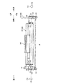
図1は、本発明の画像形成装置としてのカラーレーザプリンタの一実施形態を示す要部側断面図、図2は、図1に示すカラーレーザプリンタの、現像カートリッジが装着されたドラムサブユニットの要部側断面図、図3は、図2に示す現像カートリッジの要部側断面図である。
1. 1 is a cross-sectional side view of a main part of an embodiment of a color laser printer as an image forming apparatus according to the present invention, and FIG. 2 is a mounting view of a developing cartridge of the color laser printer shown in FIG. FIG. 3 is a cross-sectional side view of the main part of the developing cartridge shown in FIG. 2.
図1において、このカラーレーザプリンタ1は、後述する複数のドラムサブユニット23が水平方向において並列的に配置される、横置きタイプのタンデム型カラーレーザプリンタであって、画像形成装置本体としての本体ケーシング2内に、記録媒体としての用紙3を給紙するための給紙部4と、給紙された用紙3に画像を形成するための画像形成部5と、画像が形成された用紙3を排紙するための排紙部6とを備えている。
In FIG. 1, the
なお、以下の説明において、図1の紙面右側(本体ケーシング2におけるドラム着脱口162が形成されている側)を前側とし、図1の紙面左側を後側とする。また、図1の紙厚方向手前側を、左側とし、図1の紙厚方向手奥側を、右側とする。
また、以下に示す方向は、特に言及がない限り、後述するドラムユニット21および現像カートリッジ22が本体ケーシング2に装着されている状態での方向である。
(1)給紙部
給紙部4は、本体ケーシング2内の底部において、本体ケーシング2の後述するトレイ収容部171に対して、前側から前後方向にスライド自在に着脱され、用紙3を収容する給紙トレイ7と、その給紙トレイ7の前端部上方に設けられ、互いに対向配置される分離ローラ8および分離パッド9と、分離ローラ8の後側に設けられる給紙ローラ10とを備えている。
In the following description, the right side of FIG. 1 (the side where the drum attachment / detachment opening 162 in the
Further, the directions shown below are directions in a state where a
(1) Paper Feed Unit The paper feed unit 4 accommodates the paper 3 at the bottom in the
また、給紙部4において、用紙3の給紙側搬送経路11は、その上流側端部が、下方において分離ローラ8に隣接し、その下流側端部が、上方において後述する搬送ベルト53に隣接しており、用紙3が前側に向かって給紙され、反転後、後側に向かって排紙される、側面視略U字形状に形成されている。
給紙側搬送経路11の途中には、分離ローラ8の前側上方に設けられ、互いに対向配置される紙粉取りローラ12およびピンチローラ13と、それらの上方に設けられる1対のレジストローラ14とが設けられている。
Further, in the paper feed unit 4, the paper feed side conveyance path 11 of the paper 3 has an upstream end adjacent to the separation roller 8 at the lower side and a downstream end at the upper side to a
A paper dust removing roller 12 and a pinch roller 13 which are provided on the upper front side of the separation roller 8 and are arranged to face each other, and a pair of
給紙トレイ7の内部には、用紙3が積層状に載置される用紙押圧板15が設けられている。この用紙押圧板15は、後端部において揺動自在に支持されることによって、前端部が下方に配置され、給紙トレイ7の底板に沿う載置位置と、前端部が上方に配置され、傾斜する給紙位置との間で移動自在とされている。
また、給紙トレイ7の前端部下方には、用紙押圧板15の前端部を上方に持ち上げるレバー16が設けられている。このレバー16は、用紙押圧板15の前端部下方において、上下方向に揺動自在に支持されている。
Inside the paper feed tray 7 is provided a
A
そして、レバー16の揺動により、用紙押圧板15の前端部が、レバー16によって持ち上げられ、用紙押圧板15が給紙位置に位置される。
用紙押圧板15が給紙位置に位置されると、用紙押圧板15上の最上位の用紙3は、給紙ローラ10に押圧され、給紙ローラ10の回転によって、分離ローラ8と分離パッド9との間に向けて給紙される。
As the
When the
なお、給紙トレイ7を本体ケーシング2から離脱させると、用紙押圧板15が載置位置に位置される。用紙押圧板15が載置位置に位置されると、用紙押圧板15上に用紙3を積層状に載置することができる。
給紙された用紙3は、分離ローラ8の回転によって、分離ローラ8と分離パッド9との間に挟まれ、1枚ごとに捌かれて搬送される。搬送された用紙3は、紙粉取りローラ12とピンチローラ13との間を通過し、紙粉が除去された後、給紙側搬送経路11に沿ってレジストローラ14に向けて搬送される。
When the paper feed tray 7 is detached from the
The fed paper 3 is sandwiched between the separation roller 8 and the separation pad 9 by the rotation of the separation roller 8, and is fed and conveyed one by one. The transported paper 3 passes between the paper dust removing roller 12 and the pinch roller 13, and after the paper dust is removed, it is transported toward the
レジストローラ14は、用紙3を、レジスト後に、搬送ベルト53に搬送する。
(2)画像形成部
画像形成部5は、スキャナ部17、プロセス部18、転写部19および定着部20を備えている。
(2−1)スキャナ部
スキャナ部17は、本体ケーシング2の上部に1つ設けられており、図示しないが、レーザ発光部、ポリゴンミラー、複数のレンズおよび反射鏡を備えている。スキャナ部17では、レーザ発光部から発光される各色に対応する画像データに基づくレーザビームを、ポリゴンミラーで走査して、複数のレンズおよび反射鏡を通過または反射させた後、各感光ドラム24に対応して、各色に対応して、それぞれ出射している。
(2−2)プロセス部
プロセス部18は、スキャナ部17の下方であって、給紙部4の上方に配置されており、後で詳述するが、1つのドラムユニット21と、各色に対応して、4つの現像カートリッジ22とを備えている。
(2−2−1)ドラムユニット
ドラムユニット21は、後で詳述するが、本体ケーシング2の後述するドラム収容部161に対して、前側から前後方向に着脱自在に装着される。このドラムユニット21は、各色に対応して、感光体カートリッジおよび像担持体ユニットとしての4つのドラムサブユニット23を備えている。すなわち、ドラムサブユニット23は、イエロードラムサブユニット23Y、マゼンタドラムサブユニット23M、シアンドラムサブユニット23Cおよびブラックドラムサブユニット23Kの4つからなる。
The
(2) Image Forming Unit The image forming unit 5 includes a scanner unit 17, a
(2-1) Scanner Unit One scanner unit 17 is provided on the upper portion of the
(2-2) Process Unit The
(2-2-1) Drum Unit As will be described in detail later, the
各ドラムサブユニット23は、互いに前後方向に間隔を隔てて並列的に配置されており、より具体的には、前側から後側に向かって、イエロードラムサブユニット23Y、マゼンタドラムサブユニット23M、シアンドラムサブユニット23Cおよびブラックドラムサブユニット23Kが、順次配置されている。
各ドラムサブユニット23は、後述するように、左サイドフレーム70および右サイドフレーム71と、センターフレーム72とを備えている(図4参照)。
The drum subunits 23 are arranged in parallel at intervals in the front-rear direction, and more specifically, from the front side to the rear side, the
As will be described later, each
各ドラムサブユニット23は、図2に示すように、像担持体としての感光ドラム24、スコロトロン型帯電器25およびクリーニングブラシ68を保持している。
感光ドラム24は、幅方向(前後方向および上下方向に直交する左右方向、以下同じ。)に沿って配置され、円筒形状をなし、最表層がポリカーボネートからなる正帯電性の感光層により形成されるドラム本体26と、このドラム本体26の軸線方向に沿って配置されるドラム軸27とを備えている。
As shown in FIG. 2, each
The
ドラム軸27は、軸方向両端部が、後で詳述するが、右サイドフレーム71およびセンターフレーム72の左サイドプレート95(図4参照)に挿通され、後述する側板121(図7参照)によって位置決めされている。
ドラム本体26の軸方向両端部には、回動支持部材30(図9参照)が相対回転不能に嵌入されており、その回動支持部材30が、ドラム軸27の周りにおいて、相対回転可能に支持されている。これによって、ドラム本体26がドラム軸27に対して回転自在に支持される。画像形成時において、感光ドラム24には、本体ケーシング2内に設けられる図示しないモータからの駆動力が伝達され、感光ドラム24が回転される。
As will be described in detail later, both ends of the
A rotation support member 30 (see FIG. 9) is fitted to both ends of the
スコロトロン型帯電器25は、感光ドラム24の斜め上側後方に、感光ドラム24と間隔を隔てて対向配置され、後述するセンターフレーム72に保持されている。このスコロトロン型帯電器25は、感光ドラム24と間隔を隔てて対向配置された放電ワイヤ28と、放電ワイヤ28と感光ドラム24との間に設けられるグリッド29とを備えている。
放電ワイヤ28には、後述するワイヤ電極80(図5参照)が接続されており、グリッド29には、後述するグリッド電極81(図5参照)が接続されている。
The
A wire electrode 80 (see FIG. 5) to be described later is connected to the
スコロトロン型帯電器25では、画像形成時において、本体ケーシング2内に設けられる図示しない高圧基板からワイヤ電極80を介して放電ワイヤ28に高電圧を印加して、放電ワイヤ28をコロナ放電させるとともに、本体ケーシング2内に設けられる図示しない高圧基板からグリッド電極81を介してグリッド29を印加して、感光ドラム24に供給される電荷量を制御しつつ、感光ドラム24の表面を一様に正極性に帯電させる。
In the
クリーニングブラシ68は、感光ドラム24の後方において、感光ドラム24と対向して接触するように配置され、後述するセンターフレーム72に保持されている。クリーニングブラシ68には、画像形成時において、本体ケーシング2内に設けられる図示しない高圧基板から後述するクリーニング電極83(図5参照)を介してクリーニングバイアスが印加される。
(2−2−2)現像カートリッジ
現像カートリッジ22は、図1に示すように、各色に対応するドラムサブユニット23に対応して、それぞれ着脱自在に設けられている。すなわち、現像カートリッジ22は、イエロードラムサブユニット23Yに着脱自在に装着されるイエロー現像カートリッジ22Y、マゼンタドラムサブユニット23Mに着脱自在に装着されるマゼンタ現像カートリッジ22M、シアンドラムサブユニット23Cに着脱自在に装着されるシアン現像カートリッジ22C、および、ブラックドラムサブユニット23Kに着脱自在に装着されるブラック現像カートリッジ22Kの4つからなる。
The cleaning
(2-2-2) Developing Cartridge As shown in FIG. 1, the developing
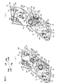
各現像カートリッジ22は、図3に示すように、現像フレーム31と、その現像フレーム31内に設けられる、アジテータ32、供給ローラ33、現像剤担持体としての現像ローラ34および層厚規制ブレード35とを備えている。
現像フレーム31は、下端部に開口部36が開口されるボックス形状に形成されており(図11参照)、上下方向途中に形成される隔壁39によって、トナー収容室37と現像室38とに区画されている。また、隔壁39には、トナー収容室37と現像室38とを連通する連通口40が形成されている。
As shown in FIG. 3, each developing
The developing
トナー収容室37には、各色に対応するトナーが収容されている。より具体的には、各現像カートリッジ22に対応して、イエロー現像カートリッジ22Yにはイエロー、マゼンタ現像カートリッジ22Mにはマゼンタ、シアン現像カートリッジ22Cにはシアン、ブラック現像カートリッジ22Kにはブラックのトナーが、それぞれ収容されている。
各色に対応するトナーは、正帯電性の非磁性1成分の重合トナーが用いられる。重合トナーは、略球形であり、スチレンなどのスチレン系単量体や、アクリル酸、アルキル(C1〜C4)アクリレート、アルキル(C1〜C4)メタアクリレートなどのアクリル系単量体を、懸濁重合などの公知の重合方法によって共重合させることにより得られる、結着樹脂を主成分とし、これに、各色に対応する着色剤や、荷電制御剤、ワックスなどが配合されることによりトナー母粒子が形成され、さらに、流動性の向上を図るべく外添剤が添加されてなる。
The
As the toner corresponding to each color, a positively charged non-magnetic one-component polymerized toner is used. The polymerized toner has a substantially spherical shape and is a suspension polymerization of a styrene monomer such as styrene or an acrylic monomer such as acrylic acid, alkyl (C1 to C4) acrylate, or alkyl (C1 to C4) methacrylate. Obtained by copolymerization by a known polymerization method such as a binder resin as a main component, and by adding a colorant corresponding to each color, a charge control agent, a wax and the like, toner base particles are obtained. In addition, an external additive is added to improve the fluidity.
着色剤としては、上記した、イエロー、マゼンタ、シアンおよびブラックの各着色剤が、各色に対応して配合されている。また、荷電制御剤としては、たとえば、アンモニウム塩などのイオン性官能基を有するイオン性単量体と、スチレン系単量体やアクリル系単量体などのイオン性単量体と共重合可能な単量体との共重合によって得られる荷電制御樹脂が配合されている。また、外添剤としては、たとえば、シリカ、酸化アルミニウム、酸化チタン、チタン酸ストロンチウム、酸化セリウム、酸化マグネシウムなどの金属酸化物の粉末や、炭化物の粉末、金属塩の粉末などの無機粉末が配合されている。 As the colorant, the above-mentioned colorants of yellow, magenta, cyan and black are blended corresponding to each color. Moreover, as a charge control agent, for example, an ionic monomer having an ionic functional group such as an ammonium salt and an ionic monomer such as a styrene monomer or an acrylic monomer can be copolymerized. A charge control resin obtained by copolymerization with a monomer is blended. As external additives, for example, powders of metal oxides such as silica, aluminum oxide, titanium oxide, strontium titanate, cerium oxide and magnesium oxide, inorganic powders such as carbide powders and metal salt powders are blended. Has been.
また、トナー収容室37には、トナー収容室37内に収容されているトナーの残量を検出するための窓142が設けられている。窓142は、現像フレーム31の両側壁141に埋設され、トナー収容室37を挟んで対向配置されている(図17参照)。
アジテータ32は、トナー収容室37内に設けられている。アジテータ32は、現像フレーム31の両側壁141に回転自在に支持される回転軸41と、その回転軸41の軸方向にわたって設けられ、回転軸から径方向外方に延びる攪拌部材42とを備えている。画像形成時において、回転軸41には、本体ケーシング2内に設けられる図示しないモータからの駆動力が、従動回転体としてのカップリング受動ギヤ144(図12参照)を介して伝達され、攪拌部材42がトナー収容室37内を周回移動する。
The
The
供給ローラ33は、現像室38内において、連通口40の下方に設けられている。この供給ローラ33は、現像フレーム31の両側壁141に回転自在に支持される金属製の供給ローラ軸43と、その供給ローラ軸43の周りを被覆する導電性のスポンジからなるスポンジローラ44とを備えている。画像形成時において、供給ローラ軸43には、本体ケーシング2内に設けられる図示しないモータからの駆動力が、カップリング受動ギヤ144(図12参照)を介して伝達され、供給ローラ33が回転される。
The
現像ローラ34は、現像室38内において、供給ローラ33に対して斜め後側下方に設けられている。この現像ローラ34は、現像フレーム31の両側壁141に回転自在に支持される金属製の現像ローラ軸45と、その現像ローラ軸45の周りを被覆する導電性のゴムからなるゴムローラ46とを備えている。
より具体的には、ゴムローラ46は、カーボン微粒子などを含む導電性のウレタンゴム、シリコーンゴムまたはEPDMゴムなどからなるゴムローラ層と、そのゴムローラ層の表面に被覆され、ウレタンゴム、ウレタン樹脂、ポリイミド樹脂のような耐磨耗性に優れた樹脂などを主成分とするコート層との2層構造からなる。また、現像ローラ軸45には、現像カートリッジ22がドラムサブユニット23に装着された状態において、後述する現像ローラ電極82の給電部としての給電コイル155(図5参照)が接続されている。
The developing
More specifically, the
また、現像ローラ34は、供給ローラ33に対して、ゴムローラ46とスポンジローラ44とが互いに圧接するように、配置されている。また、現像ローラ34は、現像室38の開口部36から下方に向けて露出するように、配置されている(図11参照)。
現像ローラ34では、画像形成時において、現像ローラ軸45には、本体ケーシング2内に設けられる図示しないモータからの駆動力が、カップリング受動ギヤ144(図12参照)を介して伝達され、現像ローラ34が回転される。また、本体ケーシング2内に設けられる図示しない高圧基板から現像ローラ電極82および給電コイル155を介して現像バイアスが印加される。
The developing
In the developing
層厚規制ブレード35は、現像室38内において、現像ローラ34に上方から圧接するように設けられている。層厚規制ブレード35は、金属製の板ばね部材からなるブレード48と、ブレード48の遊端部に設けられる絶縁性または導電性のシリコーンゴムまたはウレタンゴムからなる断面半円形状の押圧部49とを備えている。
ブレード48の基端部が、固定部材47によって隔壁39に固定されており、ブレード48の弾性力により、ブレード48の遊端部に設けられる押圧部49が、現像ローラ34のゴムローラ46に対して上方から圧接される。
(2−2−3)プロセス部での現像動作
そして、図3に示すように、各現像カートリッジ22では、トナー収容室37に収容されている各色に対応するトナーが、自重によって連通口40に移動し、アジテータ32によって攪拌されながら、連通口40から現像室38へ放出される。
The layer
The base end portion of the
(2-2-3) Developing Operation in Process Unit As shown in FIG. 3, in each developing
連通口40から現像室38へ放出されたトナーは、供給ローラ33に供給される。供給ローラ33に供給されたトナーは、供給ローラ33の回転により、現像ローラ34に供給され、このとき、供給ローラ33と、現像バイアスが印加されている現像ローラ34との間で正極性に摩擦帯電される。
現像ローラ34に供給されたトナーは、現像ローラ34の回転に伴って、層厚規制ブレード35の押圧部49と、現像ローラ34のゴムローラ46との間に進入して、一定厚さの薄層としてゴムローラ46の表面に担持される。
The toner discharged from the communication port 40 to the developing
The toner supplied to the developing
一方、図2に示すように、各現像カートリッジ22に対応するドラムサブユニット23では、スコロトロン型帯電器25が、コロナ放電を発生させて、感光ドラム24の表面を一様に正帯電させる。
感光ドラム24の表面は、感光ドラム24の回転に伴って、スコロトロン型帯電器25により一様に正帯電された後、スキャナ部17からのレーザビームの高速走査により露光され、用紙3に形成すべき画像に対応した静電潜像が形成される。
On the other hand, as shown in FIG. 2, in the
The surface of the
さらに感光ドラム24が回転すると、次いで、現像ローラ34の表面に担持されかつ正帯電されているトナーが、現像ローラ34の回転により、感光ドラム24に対向して接触するときに、感光ドラム24の表面に形成されている静電潜像、すなわち、一様に正帯電されている感光ドラム24の表面のうち、レーザビームによって露光され電位が下がっている露光部分に供給される。これにより、感光ドラム24の静電潜像は、トナーにより可視像化され、感光ドラム24の表面には、各色に対応して、反転現像によるトナー像が担持される。
When the
なお、転写後に感光ドラム24上に残存する転写残トナーは、現像ローラ34に回収される。また、転写後に感光ドラム24上に付着する用紙3からの紙粉は、クリーニングブラシ68によって回収される。
(2−3)転写部
転写部19は、図1に示すように、本体ケーシング2内において、給紙部4の上方であって、プロセス部18の下方において、前後方向に沿って配置されている。この転写部19は、駆動ローラ51、従動ローラ52、搬送ベルト53、転写ローラ54およびクリーニング部55を備えている。
The transfer residual toner remaining on the
(2-3) Transfer Unit As shown in FIG. 1, the
駆動ローラ51および従動ローラ52は、前後方向に間隔を隔てて対向配置されており、駆動ローラ51は、ブラックドラムサブユニット23Kよりも後方に配置され、従動ローラ52は、イエロードラムサブユニット23Yよりも前方に配置されている。
搬送ベルト53は、エンドレスベルトからなり、カーボンなどの導電性粒子を分散した導電性のポリカーボネートやポリイミドなどの樹脂フィルムから形成されている。この搬送ベルト53は、駆動ローラ51と従動ローラ52との間に巻回されている。
The driving roller 51 and the driven
The
画像形成時において、駆動ローラ51には、本体ケーシング2内に設けられる図示しないモータからの駆動力が伝達され、駆動ローラ51が回転される。すると、搬送ベルト53が、駆動ローラ51および従動ローラ52の間を、各ドラムサブユニット23の感光ドラム24と対向して接触する転写位置において、感光ドラム24と同方向に回転するように周回移動されるとともに、従動ローラ52が従動される。
During image formation, a driving force from a motor (not shown) provided in the
転写ローラ54は、駆動ローラ51および従動ローラ52の間に巻回されている搬送ベルト53内において、各感光ドラム24と、搬送ベルト53を挟んで対向するように、それぞれ設けられている。各転写ローラ54は、金属製のローラ軸に、導電性のゴムからなるゴムローラが被覆されている。また、各転写ローラ54は、搬送ベルト53と対向して接触する転写位置において、搬送ベルト53の周回移動方向と同方向に回転するように設けられており、画像形成時には、本体ケーシング2内に設けられる図示しない高圧基板からの転写バイアスが印加される。
The
クリーニング部55は、駆動ローラ51および従動ローラ52の間に巻回されている搬送ベルト53の下方に配置され、1次クリーニングローラ56、2次クリーニングローラ57、掻取ブレード58およびトナー貯留部59を備えている。
1次クリーニングローラ56は、感光ドラム24および転写ローラ54が接触する上側の搬送ベルト53と反対側の、下側の搬送ベルト53と接触するように配置され、その接触位置において、搬送ベルト53の周回移動方向と同方向に回転するように設けられている。1次クリーニングローラ56には、画像形成時に、本体ケーシング2内に設けられる図示しない高圧基板からの1次クリーニングバイアスが印加される。
The
The
2次クリーニングローラ57は、1次クリーニングローラ56に対して下方から接触するように配置され、その接触位置において、1次クリーニングローラ56の回転方向と同方向に回転するように設けられている。2次クリーニングローラ57には、画像形成時に、本体ケーシング2内に設けられる図示しない高圧基板からの2次クリーニングバイアスが印加される。
The secondary cleaning roller 57 is disposed so as to come into contact with the
掻取ブレード58は、2次クリーニングローラ57に対して下方から接触するように設けられている。
トナー貯留部59は、1次クリーニングローラ56および2次クリーニングローラ57の下方において、2次クリーニングローラ57から落下するトナーを貯留できるように設けられている。
The
The
そして、給紙部4から給紙された用紙3は、駆動ローラ51の駆動および従動ローラ52の従動により周回移動される搬送ベルト53によって、前側から後側に向かって、各ドラムサブユニット23に対応する転写位置を、順次通過するように搬送され、その搬送中に、各ドラムサブユニット23の感光ドラム24に担持されている各色のトナー像が、順次転写され、これにより、用紙3にカラー像が形成される。
Then, the sheet 3 fed from the sheet feeding unit 4 is transferred to each
すなわち、たとえば、イエロードラムサブユニット23Yの感光ドラム24の表面に担持されたイエローのトナー像が、用紙3に転写されると、次いで、マゼンタドラムサブユニット23Mの感光ドラム24の表面に担持されたマゼンタのトナー像が、既にイエローのトナー像が転写されている用紙3に重ねて転写され、以下同様の動作によって、シアンドラムサブユニット23Cの感光ドラム24の表面に担持されたシアンのトナー像、ブラックドラムサブユニット23Kの感光ドラム24の表面に担持されたブラックのトナー像が重ねて転写され、これによって、用紙3にカラー像が形成される。
That is, for example, when a yellow toner image carried on the surface of the
一方、上記の転写動作において、搬送ベルト53の表面に付着したトナーは、クリーニング部55において、まず、搬送ベルト53の表面から、1次クリーニングバイアスにより1次クリーニングローラ56に転写され、さらに、2次クリーニングバイアスにより2次クリーニングローラ57に転写される。その後、2次クリーニングローラ57に転写されたトナーは、掻取ブレード58によって、掻き取られ、2次クリーニングローラ57から落下して、トナー貯留部59に貯留される。
(2−4)定着部
定着部20は、本体ケーシング2におけるブラックドラムサブユニット23Kよりも後側であって、感光ドラム24と搬送ベルト53とが接触する転写位置と、前後方向において対向するように配置されている。この定着部20は、加熱ローラ61および加圧ローラ62を備えている。
On the other hand, in the above transfer operation, the toner adhering to the surface of the
(2-4) Fixing Unit The fixing
加熱ローラ61は、その表面に離型層が形成される金属素管からなり、その軸方向に沿ってハロゲンランプが内装されている。加熱ローラ61は、ハロゲンランプにより、その表面が定着温度に加熱される。
加圧ローラ62は、加熱ローラ61の下方において、加熱ローラ61と対向配置されている。この加圧ローラ62は、加熱ローラ61を下方から押圧する。
The
The
そして、用紙3上に転写されたカラー像は、次いで、定着部20に搬送され、用紙3が加熱ローラ61と加圧ローラ62との間を通過する間に、熱定着される。
(3)排紙部
排紙部6において、用紙3の排紙側搬送経路63は、その上流側端部が、下方において定着部20に隣接し、その下流側端部が、上方において排紙トレイ64に隣接しており、用紙3が後側に向かって給紙され、反転後、前側に向かって排紙される、側面視略U字形状に形成されている。
排紙側搬送経路63の途中には、互いに対向する搬送ローラ65およびピンチローラ66が設けられている。また、排紙側搬送経路63の下流側端部には、1対の排紙ローラ67が設けられている。
The color image transferred onto the paper 3 is then conveyed to the fixing
(3) Paper Discharge Unit In the paper discharge unit 6, the paper discharge
A
また、排紙部6には、排紙トレイ64が設けられている。排紙トレイ64は、本体ケーシング2の上壁を、前側から後側に向かって次第に窪むように形成して、排紙される用紙3を積層状に載置できるように、形成されている。
定着部20から搬送される用紙は、排紙側搬送経路63に沿って、搬送ローラ65およびピンチローラ66により搬送され、排紙ローラ67によって、排紙トレイ64上に排紙される。
2.ドラムユニット
図4は、ドラムサブユニットの分解斜視図、図5は、フロントビーム、4つのドラムサブユニットおよびリヤビームを並列に配設した状態を示す右側斜視図、図6は、フロントビーム、4つのドラムサブユニットおよびリヤビームを並列に配設して、1対の側板を組み付ける状態を示す左側斜視図である。
The paper discharge unit 6 is provided with a
The sheet conveyed from the fixing
2. Drum Unit FIG. 4 is an exploded perspective view of the drum subunit, FIG. 5 is a right perspective view showing a state in which the front beam, the four drum subunits and the rear beam are arranged in parallel, and FIG. 6 is the front beam and the four drums. It is a left perspective view showing a state where a subunit and a rear beam are arranged in parallel and a pair of side plates are assembled.
図7は、ドラムユニット(現像カートリッジ装着状態)の右側斜視図、図8は、ドラムユニット(現像カートリッジ装着状態)の左側斜視図、図9は、ドラムユニットに1つの現像カートリッジを装着する状態を示す左側斜視図、図10は、ドラムユニットに1つの現像カートリッジを装着する状態を、図9よりも上方から見た左側斜視図である。
図11は、現像カートリッジの背面図、図12は、現像カートリッジの左側斜視図であり、現像カートリッジの後側面を示したもの、図13は、現像カートリッジの右側斜視図であり、現像カートリッジの前側面を示したもの、図14は、1つの現像カートリッジが離脱状態にあるドラムユニットの平面図、図15は、図14に示すドラムユニットの右側面図であって、側板が取り外され、前側2つのドラムサブユニットの右ガイド溝が説明のために露出された態様を示したもの、図16は、図14に示すドラムユニットの左側面図であって、側板が取り外された態様を示したもの、図17は、図14のA−A線断面図である。
7 is a right side perspective view of the drum unit (developing cartridge mounted state), FIG. 8 is a left side perspective view of the drum unit (developing cartridge mounted state), and FIG. 9 is a left side perspective view illustrating a state where one developing cartridge is mounted on the drum unit. FIG. 10 and FIG. 10 are left perspective views of the state in which one developing cartridge is mounted on the drum unit, as viewed from above FIG.
FIG. 11 is a rear view of the developing cartridge, FIG. 12 is a left perspective view of the developing cartridge, showing the rear side of the developing cartridge, and FIG. 13 is a right perspective view of the developing cartridge, in front of the developing cartridge. FIG. 14 is a plan view of the drum unit in a state where one developing cartridge is detached, and FIG. 15 is a right side view of the drum unit shown in FIG. 14 with the side plate removed and the two front drums. FIG. 16 is a left side view of the drum unit shown in FIG. 14 and shows a state in which the side plate is removed, FIG. FIG. 15 is a cross-sectional view taken along line AA in FIG. 14.
図22は、フロントビーム、4つのドラムサブユニットおよびリヤビームを並列に配設した状態を示す右側斜視図、図23は、フロントビーム、4つのドラムサブユニットおよびリヤビームを並列に配設して、1対の側板を組み付ける状態を示す左側斜視図である。
次に、これら図4〜図17ならびに図22および図23を参照して、ドラムユニットについて詳述する。
22 is a right perspective view showing a state in which the front beam, the four drum subunits, and the rear beam are arranged in parallel. FIG. 23 is a diagram in which the front beam, the four drum subunits, and the rear beam are arranged in parallel. It is a left side perspective view showing the state where a pair of side plates is assembled.
Next, the drum unit will be described in detail with reference to FIGS. 4 to 17 and FIGS. 22 and 23.
ドラムユニット21は、図6に示すように、各色に対応する4つのドラムサブユニット23と、前後方向に沿って並列に配設される4つのドラムサブユニット23の前後方向両側に配置されるフロントビーム96およびリヤビーム111と、フロントビーム96、4つのドラムサブユニット23およびリヤビーム111を、幅方向の両方から挟む1対の側板121とを備えている。
As shown in FIG. 6, the
ドラムユニット21は、これら4つのドラムサブユニット23、フロントビーム96、リヤビーム111および1対の側板121が、一体的に、本体ケーシング2のドラム収容部162(図1参照)に対してスライド自在に着脱される。
(1)ドラムサブユニット
ドラムサブユニット23は、図4に示すように、幅方向において間隔を隔てて対向配置される左サイドフレーム70および右サイドフレーム71と、左サイドフレーム70と右サイドフレーム71との間に架設されるセンターフレーム72とを備えている。
(1−1)サイドフレーム
左サイドフレーム70および右サイドフレーム71は、樹脂材料から成形されている。左サイドフレーム70は、上方から下方に向かって先細になる側面視略三角形に形成されており、右サイドフレーム71は、前側上方から後側下方に向かって傾斜する側面視略平行四辺形に形成されている。
In the
(1) Drum Subunit As shown in FIG. 4, the
(1-1) Side Frame The
右サイドフレーム71には、その内壁面において、被給電部案内溝としての右ガイド溝73が形成されている。
右ガイド溝73は、右サイドフレーム71の内壁面において、右サイドフレーム71の内壁面から幅方向外側に向かって断面コ字状に窪むように、かつ右サイドフレーム71の後側上端縁から、右サイドフレーム71の前側下端近傍まで、略上下方向に沿って形成されている。右ガイド溝73の上端部は、上方に向かって開放され、幅広に形成されている。右ガイド溝73は、上述した幅広に形成されている上端部の下側から下端部手前までは一定の溝幅A(図示実線矢印参照)に保たれ、下端部手前で下側斜め後方に向かって屈曲し、その下端部である最深部154は、現像カートリッジ22がドラムサブユニット23に装着された状態で、現像ローラ34が感光ドラム24に接触する位置における現像ローラ軸45の位置に、対応して配置されている。なお、最深部154の溝幅B(図示破線矢印参照)は、上述した溝幅Aよりも小さい。この右ガイド溝73には、現像カートリッジ22の位置決め部としてのカラー部材50および被給電部としての給電部材182の円筒部184(図11参照)が、スライド自在に受け入れられる。
The
The
そして、右ガイド溝73の、上述した屈曲位置における前側の溝壁には、切欠201が形成されており、この切欠201を介して、右ガイド溝73は、右サイドフレーム71の右側面に開放されている。
また、右サイドフレーム71には、右ガイド溝73よりも前方の上側に、ボス75が形成されている。ボス75は、左サイドフレーム70の、右サイドフレーム71のボス75に幅方向において対向する位置にも形成されている。このボス75は、右サイドフレーム71および左サイドフレーム70の外壁面から幅方向外方へ突出する筒状に形成され、現像カートリッジ22がドラムサブユニット23に装着された状態で、現像カートリッジ22の窓142(図13参照)が、幅方向において対向するように配置されている。
A
Further, a
また、図5に示すように、右サイドフレーム71の右側面における下端部の前端には、支持軸部156が形成されている。支持軸部156は、円筒状に形成され、右サイドフレーム71の右側面から幅方向外側(右側)に向かって突出している。
また、図4に示すように、右サイドフレーム71には、その下端部に、感光ドラム24を支持するためのドラム支持部76が形成されている。ドラム支持部76は、右サイドフレーム71の内壁面から幅方向外側に向かって筒状に窪み、次に述べるセンターフレーム72の軸挿通筒部90を受ける受け部77を備えている。また、受け部77の中心には、右サイドフレーム71の厚さ方向を貫通する軸挿通孔78が形成されている。
As shown in FIG. 5, a
Further, as shown in FIG. 4, the
また、右サイドフレーム71には、その後端部に、右サイドフレーム71をセンターフレーム72に組み付けるためのねじ92を挿通するねじ挿通孔79が、厚さ方向を貫通するように2つ形成されている。一方のねじ挿通孔79は、右サイドフレーム71の後端部の下端に形成され、他方のねじ挿通孔79は、右サイドフレーム71の後端部の上下方向途中に形成されている。
The
また、左サイドフレーム70および右サイドフレーム71には、ボス75の上方に、前後方向に沿って延びる凸条84がそれぞれ形成されている。この凸条84は、左サイドフレーム70および右サイドフレーム71の外壁面から幅方向外方に突出し、前後方向に沿って細長い筋状に形成されている。
また、左サイドフレーム70は、上述したように、側面視略三角形状であり、その前側面には、略上下方向に延びる前側垂直壁60が形成されている。前側垂直壁60の下端部には前側凹部69が形成されている。この前側凹部69は、前側垂直壁60と連続するように、前側垂直壁60が前側にくぼむ側面視略円弧形状に形成されている。なお、前側垂直壁60の上端と左サイドフレーム70の上側面の後端部とは、斜め前側上方に延びる傾斜面によって連結されている。
Further, on the
Further, as described above, the
また、左サイドフレーム70の下端部には、左サイドフレーム70を側板121に組み付けるための、後述するねじ136を螺着させるねじ螺着部85が設けられている。このねじ螺着部85は、左サイドフレーム70の外壁面から幅方向外方に突出する筒状に形成されている。
また、左サイドフレーム70の前側面における凸条84の前端部の下側には、左サイドフレーム70の前側面から前方に突出する位置決め突起200が形成されている。
Further, a
In addition, a
左サイドフレーム70の、ボス75と前側垂直壁60との間には、図23(図4に現れない)に示すように、上下方向に沿って延びる側面視細長矩形状の側壁開口部213が形成されている。この側壁開口部213の上側端部には、側壁開口部213の前側縁部と後側縁部と間に、円筒形状のレバー支持軸214が架設されている。
このレバー支持軸214には、レバー206が幅方向に、揺動自在に支持されている。
As shown in FIG. 23 (not shown in FIG. 4), a side wall opening 213 having an elongated rectangular shape in side view extending in the vertical direction is formed between the
A
レバー206は、レバー支持軸214に挿通されるレバー揺動軸207を挟んで2つの端部を持つ縦断面視略逆L字形状に形成されており、一端が側壁開口部213より右側へ突出しており、他端が側壁開口部213より左側へ突出している。
また、右サイドフレーム71には、図5に示すように、ワイヤ電極80、グリッド電極81、現像ローラ電極82およびクリーニング電極83が、右サイドフレーム71の厚さ方向を貫通するように支持され、外壁面から幅方向外側に向かって突出するように設けられている。
The
Further, as shown in FIG. 5, the
ワイヤ電極80は、右サイドフレーム71の前後方向および上下方向のほぼ中央であって、軸挿通孔78に対して上方に配置されている。
グリッド電極81は、右サイドフレーム71の後端部の上下方向途中であって、軸挿通孔78に対して斜め後側上方に配置されている。
現像ローラ電極82は、右サイドフレーム71の前端部の上下方向途中であって、軸挿通孔78に対して斜め前側上方に配置されている。また、現像ローラ電極82には、給電コイル155が接続されている。
The
The
The developing
給電コイル155は、図22に示すように、金属線材などの導電性線材からなるワイヤを1巻き以上巻回した巻回部157および巻回部157から接線方向に互いに隔間するように突出した一方腕部158および他方腕部159を備えている。
そして、この給電コイル155は、巻回部157が右サイドフレーム71の支持軸部156に挿通され、一方腕部158が右サイドフレーム71の前端縁に沿って斜め前側上方に向かって配設され、その遊端部が現像ローラ電極82に接続されている。また、他方腕部159は、一方腕部158よりも前側にて斜め前側上方に向かって延設され、その上下方向における略中央位置において、支持軸部156の上方に設けられた縦断面視鉤形状のフック160に係止されている。そして、他方腕部159は、フック160に係止されている部分から後方へ屈折し、フック160に係止されている部分から遊端部までは、側面視略弓形状に形成されている。他方腕部159において、上述した側面視略弓形状を形成する凸部176は、給電コイル155の右サイドフレーム71に対する装着(組付)状態において、側面視で右ガイド溝73の切欠201から右ガイド溝73内に突出している。
As shown in FIG. 22, the
In the
クリーニング電極83は、図5に示すように、右サイドフレーム71の後端部の上下方向途中であって、グリッド電極81の上方であって、軸挿通孔78に対して斜め後側上方に配置されている。
また、右サイドフレーム71の外壁面には、ワイヤ電極80を囲んで、半円弧状に幅方向外側へ突出する嵌合周壁94が形成されている。
(1−2)センターフレーム
センターフレーム72は、図4に示すように、左サイドフレーム70および右サイドフレーム71とは独立して、樹脂材料から成形されている。このセンターフレーム72は、幅方向に延びるセンタープレート86と、センタープレート86の幅方向両端部に設けられる右サイドプレート87および左サイドプレート95とを一体的に備えている。なお、この左サイドプレート95と上述した左サイドフレーム70および右サイドフレーム71とが、1対の案内壁として機能する。
As shown in FIG. 5, the cleaning
A fitting
(1-2) Center Frame As shown in FIG. 4, the
センタープレート86は、平面視略細長板状をなし、上下方向途中には、幅方向に沿って、スコロトロン型帯電器25を保持するための帯電器保持部88が設けられている。
帯電器保持部88には、幅方向にわたって放電ワイヤ28が張設されるとともに、そのワイヤ28の下方にグリッド29が保持されている(図2参照)。また、この帯電器保持部88には、放電ワイヤ28を挟持するワイヤクリーナ89が、幅方向においてスライド自在に保持されている。
The
A
また、センタープレート86には、帯電器保持部88の下方に、クリーニングブラシ68を保持するためのブラシ保持部93が設けられている。
ブラシ保持部93には、幅方向にわたってクリーニングブラシ68が保持されている(図2参照)。
また、センタープレート86の上端部の幅方向両端部には、位置決めローラ218が備えられている。位置決めローラ218は、センタープレート86の上端部の幅方向両端部において幅方向に沿って設けられたローラ支持軸219に回転自在に支持されている(図10参照)。
The
The
In addition,
右サイドプレート87および左サイドプレート95は、センタープレート86の幅方向両端部において、センタープレート86から屈曲して前方に向かって延びるように形成されている。右サイドプレート87および左サイドプレート95は、側面視において、上方が幅狭となる略三角形状に形成されており、その前端部には、ドラム軸27を挿通する軸挿通筒部90が設けられている。
The
右サイドプレート87の上端部および後端部には、センターフレーム72に右サイドフレーム71に組み付けるためのねじ92を螺着させるねじ螺着部91が設けられている。このねじ螺着部91は、右サイドプレート87の外壁面から幅方向外方に突出する筒状に形成されている。
左サイドプレート95は、右サイドプレート87よりも大形であり、前後方向に延びる底辺壁137と、その底辺壁137の前端部から略鉛直上方に延びる後側垂直壁138と、底辺壁137の後端部および後側垂直壁138の上端部をつなぐ傾斜壁139とを備える略直角三角形状に形成されている。なお、後側垂直壁138の上端と傾斜壁139の上端とは、斜め後側上方へ延びる傾斜面で連結されている。
At the upper end portion and the rear end portion of the
The
後側垂直壁138の略中央位置には、後側凹部152が形成されている。この後側凹部152は、後側垂直壁138と連続するように、後側垂直壁138が後側にくぼむ側面視略円弧形状に形成されている。
後側垂直壁138には、後側凹部152の下端部から連続して下側斜め後方に向かって凹む溝状の最深部153が形成されている。最深部153の溝幅は、上述した溝幅Bと等しい。また、最深部153は、現像カートリッジ22がドラムサブユニット23に装着された状態で、現像ローラ34が感光ドラム24に接触する位置における現像ローラ軸45の位置に、対応して配置されている。
A
The rear
傾斜壁139の上端部から、傾斜壁139の上下方向における寸法の略3分の1下方の位置には、位置決め凹部202が凹設されている。
左サイドプレート95には、図示しないが、上記した感光ドラム24を支持するためのドラム支持部76が形成されており、その中心には、左サイドプレート95の厚さ方向を貫通する軸挿通孔78が形成されている。
A
Although not shown, the
また、左サイドプレート95の軸挿通筒部90の上方には、各側板121をドラムサブユニット23に組み付けるためのねじ136(図23参照)を螺着させるねじ螺着部85が設けられている。このねじ螺着部85は、左サイドプレート95の外壁面から幅方向外方に突出する筒状に形成されている。また、左サイドプレート95には、その上側に前後方向に沿って延びる上記した凸条84が形成されている。
(1−3)ドラムサブユニットの組立
図4に示すように、センターフレーム72の幅方向右側に、右サイドフレーム71を配置する。そして、センターフレーム72の軸挿通筒部90を、右サイドフレーム71のドラム支持部76において、幅方向において軸挿通孔78と重なるように、受け部77に受け入れさせるとともに、センターフレーム72のねじ螺着部91を、右サイドフレーム71のねじ挿通孔79に幅方向において重なるように配置し、その後、ねじ92を、各ねじ挿通孔79に挿通した後、各ねじ螺着部91に螺着する。これによって、センターフレーム72の右側に、右サイドフレーム71が組み付けられる。
Further, a
(1-3) Assembly of Drum Subunit As shown in FIG. 4, the
また、センターフレーム72の幅方向右側に右サイドフレーム71が組み付けられると、センターフレーム72の放電ワイヤ28およびグリッド29には、図5に示すように、右側の右サイドフレーム71に設けられるワイヤ電極80およびグリッド電極81が、それぞれ接続される。また、クリーニングブラシ68には、クリーニング電極83が接続される。
When the
図4に示すように、右サイドフレーム71がセンターフレーム72の幅方向右側に組み付けられるのに対し、左サイドフレーム70は、センターフレーム72および右サイドフレーム71に組み付けられず、後述する側板121に組み付けられる。そして、左サイドフレーム70が組み付けられた側板121に、右サイドフレーム71が組み付けられたセンターフレーム72を組み付けると、ドラムサブユニット23が完成する。なお、これらの組み付けについては、後に詳説する。
As shown in FIG. 4, the
ドラムサブユニット23が完成すると、図6に示すように、センターフレーム72の左サイドプレート95の後側垂直壁138と左サイドフレーム70の前側垂直壁60が前後方向に対向する。このとき、後側垂直壁138と前側垂直壁60との間には一定の対向距離C(図示実線矢印参照)が設けられており、この後側垂直壁138と前側垂直壁60との間の隙間が、駆動入力部案内溝としての左ガイド溝189とされる。なお、上述した右ガイド溝73および左サイド溝189ならびに右ガイド溝73が形成される右サイドフレーム71および左ガイド溝189が形成される左サイドフレーム70およびセンターフレーム72は、案内部として機能する。
When the
また、この対向距離C(以降、左ガイド溝189の溝幅Cと呼ぶ。)は、上述した右サイド溝73の溝幅A(図4参照)よりも大きく設定されている。そして、左サイドプレート95の後側凹部152と左サイドフレーム70の前側凹部69とが前後方向に対向して、それぞれの側面視略円弧部分が合わさることにより、側面視円形状のカップリング内側挿通部74が形成される。
The facing distance C (hereinafter referred to as the groove width C of the left guide groove 189) is set larger than the groove width A (see FIG. 4) of the
また、このドラムサブユニット23には、図9に示すように、感光ドラム24が保持される。すなわち、まず、回動支持部材30が相対回転不能に嵌入されるドラム本体26を、スコロトロン型帯電器25と間隔を隔てて並行するように、右サイドプレート87と左サイドプレート95との間に配置する。次いで、図4に示すように、このドラム本体26の軸線に沿って、センターフレーム72の各軸挿通筒部90および右サイドフレーム71の各軸挿通孔78に、ドラム軸27を挿通して、相対回転不能に固定する。そして、このドラム軸27によって、ドラム本体26を相対回転不能に支持する回動支持部材30を、相対回転可能に支持することにより、感光ドラム24が、ドラムサブユニット23に保持される。
(2)フロントビーム
フロントビーム96は、図5に示すように、前後方向に沿って並列に配設される4つのドラムサブユニット23の前側に配置され、1対の側板121間に架設される(図6参照)。
The
(2) Front Beam As shown in FIG. 5, the
このフロントビーム96は、幅方向に対向配置される1対のフロント側壁97と、1対のフロント側壁97の間に架設されるフロント前壁98およびフロント後壁99とを備え、樹脂材料から一体的に成形されている。
各フロント側壁97は、側面視略平行四辺形板状のフロント側壁基部100と、フロント側壁基部100の下端から、下方に延びるフロント側壁脚部101とを備えている。フロント側壁基部100の外壁面には、側板121を組み付けるための後述するねじ136が螺着されるフロントねじ螺着部103が設けられている。
The
Each
また、各フロント側壁97のフロントねじ螺着部103の前方には、軸受け穴203が、フロントビーム96を幅方向に貫通するように形成されている。この軸受け穴203には、位置決め軸204が、その両端部が各フロント側壁97よりも幅方向外側に突出するように挿通されている。
フロント側壁97では、フロント側壁基部100からフロント側壁脚部101に連続する後端面が、前側上方から後側下方に向かって傾斜する前側傾斜面102として形成されている。前側傾斜面102の左端部における上端部には、位置決め凹部215が凹設されている(図6参照)。
Further, a
In the
フロント前壁98は、幅方向に沿って延びる正面視略矩形細長板状をなし、1対のフロント側壁97間において、上下方向に沿って配置されている。
このフロント前壁98には、幅方向中央において、手前側把持部104が設けられている。この手前側把持部104は、幅方向において間隔を隔てて対向配置される1対の把持側板105と、把持側板105間に架設される把持中央板106とを備えている。
The front
The front
手前側把持部104は、各把時側板105の基端部(把持中央板106に接続されていない方の端部)が、位置決め軸204に回動自在に支持されることにより、ほぼ直立した状態の収納位置(破線表示)と、略水平方向に沿うように傾斜した状態の操作位置(実線表示)とに揺動される。
また、手前側把持部104は、その幅方向の中央が、フロントビーム96の幅方向中央と一致するように配置されている。
The front
Further, the
フロント後壁99は、図10に示すように、幅方向に延びる背面視細長矩形板状をなし、フロント前壁98の後方に配置されている。このフロント後壁99は、各フロント側壁97の前側傾斜面102に沿って、前側上方から後側下方に向かって傾斜するように、各フロント側壁97間に架設されている。
フロント後壁99は、その両端部における上下方向略中央位置に、上述した位置決めローラ218および位置決め突起219がそれぞれ備えられている。各位置決め突起219は、フロント後壁99内にほぼ埋没するように配置され、各位置決めローラ218は、その外周面の一部がフロント後壁99から側面視において突出するように配置されている。
(3)リヤビーム
リヤビーム111は、前後方向に沿って並列に配設される4つのドラムサブユニット23の後側に配置され、1対の側板121間に架設される。
As shown in FIG. 10, the front
The front
(3) Rear Beam The
このリヤビーム111は、図5に示すように、幅方向に対向配置される1対のリヤ側壁112と、1対のリヤ側壁112の間に架設されるリヤ架設壁113とを備え、樹脂材料から一体的に成形されている。
リヤ側壁112は、下方に向かって幅狭となる側面視略三角形板状をなし、その外壁面には、側板121を組み付けるためのねじ136が螺着されるリヤねじ螺着部114が、上端部と略中央部とに2つ設けられている。また、リヤ側壁112の、略中央部に設けられたリヤねじ螺着部114の下側には、リヤ側壁脚部107が形成されている。また、リヤ側壁112には、その略中央部に設けられたリヤねじ螺着部114とリヤ側壁脚部107の上端部との間において、前方に窪んだリヤ側壁切欠き部108が形成されている。
また、リヤ側壁112の前端面が、前側上方から後側下方に向かって傾斜する後側傾斜面115として形成されている。
As shown in FIG. 5, the
The
Further, the front end surface of the
リヤ架設壁113は、幅方向に沿って延びる正面視略矩形細長板状をなし、1対のリヤ側壁112間において、上下方向に沿って配置されている。
このリヤ架設壁113には、幅方向中央において、奥側把持部116が設けられている。この奥側把持部116は、図10に示すように、リヤ架設壁113の上端部が下方に向かって背面視略凹状に窪む把持凹部117と、把持凹部117を幅方向に跨ぐように、リヤ架設壁113の上端部に連結される背面視略コ字状のリヤ取手118とを備えている。
The
The
この奥側把持部116は、その幅方向の中央が、リヤビーム111の幅方向中央と一致するように配置されている。
(4)側板
側板121は、図6に示すように、フロントビーム96、4つのドラムサブユニット23およびリヤビーム111を、幅方向の両方から挟むことができるように1対として設けられている。
The
(4) Side Plate As shown in FIG. 6, the
各側板121は、ドラムサブユニット23を形成する樹脂材料の線膨張係数よりも、線膨張係数の低い材料、たとえば、金属または繊維強化樹脂から形成されており、好ましくは、金属から形成されている。
各側板121は、図23に示すように、前後方向に延びる側面視略細長矩形板状をなし、後述するドラムユニット21の組み立てにおいて、前後方向に沿って並列に配設されるフロントビーム96、4つのドラムサブユニット23およびリヤビーム111に対して、前端部がフロントビーム96に対向し、後端部がリヤビーム111に対向するように形成されている。また、上端部がドラムサブユニット23のセンターフレーム72の左サイドプレート95、左サイドフレーム70および右サイドフレーム71の凸条84に対向し、下端部がドラムサブユニット23のセンターフレーム72の左サイドプレート95、左サイドフレーム70および右サイドフレーム71の下端部に対向するように形成されている。
Each
As shown in FIG. 23, each
また、各側板121の上端部は、断面L字形状となるように、幅方向外側に屈曲され、前後方向にわたって幅方向外側に延びる鍔部122が形成されている。また、各側板121の後端部には、2つのコロ177が回転自在に備えられている。この2つのコロ177は、前後方向において、スペーサー178を介して互いに距離を隔てて配置されている。また、前側のコロ177は、鍔部122に対して上下方向に間隔を隔てて鍔部122の下方に配置されており、後側のコロ177は、鍔部122の後端部に対して間隔を隔てて配置されている。
Further, the upper end portion of each
また、各側板121の、後端縁の下端部には、切欠き部179が形成されている。この切欠き部179は、各側板121の後端縁と連続し、かつ前側にくぼむ側面視U字形状に形成されている。
また、各側板121には、上端部において、各側板121がドラムサブユニット23に組み付けられた状態で、各ドラムサブユニット23のボス75を受け入れる4つの光透過孔123が形成されている。
Further, a
Each
各光透過孔123は、側板121の上端部において、前後方向に沿って互いに間隔を隔てて4つ形成されている。この光透過孔123は、各現像カートリッジ22が各ドラムサブユニット23に装着された状態で、現像カートリッジ22の各窓142(図12参照)と、ドラムサブユニット23の各ボス75(図4参照)とが、幅方向に対向する位置において、厚さ方向を貫通する丸孔として形成されている。
Four light transmission holes 123 are formed at the upper end portion of the
また、各側板121には、下端部において、各ドラムサブユニット23の各ドラム軸27の軸方向端部を挿通する軸孔124が形成されている。
また、各側板121には、各軸孔124の斜め後側上方および斜め前側上方に1対の図示しない係止孔が形成されており、それらの係止孔に針金ばね127が係止されている。詳しくは、針金ばね127は、下方に向かって凹む側面視略V字状の針金からなり、その上側両端部が幅方向外側に屈曲されており、上述した係止孔に係止されている。そして、針金ばね127は、その前側部分が、左側面視において、後側下方から前側上方に傾斜して軸孔124の3時位置と6時位置とを繋ぐように、軸孔124から露出されている。
Each
Further, each
また、各側板121には、前端部において、各側板121がフロントビーム96に組み付けられた状態で、フロント側壁基部100のフロントねじ螺着部103に対向し、ねじ136を挿通するための前側ねじ挿通孔128が形成されている。また、各側板121の、前側ねじ挿通孔128の斜め前側上方には、軸露出孔216が形成されている。
また、各側板121には、後端部において、各側板121がリヤビーム111に組み付けられた状態で、リヤ側壁112のリヤねじ螺着部114に対向し、ねじ136を挿通するための後側ねじ挿通孔129が2つずつ形成されている。これらの後側ねじ挿通孔129のうち、一方の後側ネジ挿通孔129は、スペーサー178の前後方向略中央位置に形成されている。
Further, each
Further, each
また、左側の側板121には、各側板121がドラムサブユニット23に組み付けられ、さらに、現像カートリッジ22がドラムサブユニット23に装着された状態で、各現像カートリッジ22のカップリング受動ギヤ144が幅方向において対向するカップリング外側挿通孔130が、それぞれ形成されている。
各カップリング外側挿通孔130は、側板121の上下方向中央において、前後方向に沿って互いに間隔を隔てて4つ形成されている。このカップリング外側挿通孔130は、側板121がドラムサブユニット23に組み付けられ、さらに、現像カートリッジ22がドラムサブユニット23に装着された状態で、ドラムサブユニット23の左側面に形成されたカップリング内側挿通部74と幅方向において対向する位置において、厚さ方向を貫通する丸穴として形成されている。
In addition, each
Four coupling outer insertion holes 130 are formed at the center in the vertical direction of the
また、左側の側板121には、各光通過孔123の後側において、左側の側板121がドラムサブユニット23に組み付けられた状態で、各ドラムサブユニット23のレバー206の、上述した側壁開口部213より左側へ突出している他端を受け入れる4つのレバー通過孔208が形成されている。
各レバー通過孔208は、左側の側板121の上端部において、前後方向に沿って互いに間隔を隔てて4つ形成されている。このレバー通過孔208は、各現像カートリッジ22が各ドラムサブユニット23に装着された状態で、現像カートリッジ22の後述する検出ギヤ205と、ドラムサブユニット23の側壁開口部213とが、幅方向に対向する位置において、厚さ方向を対向する側面視凸状に形成されている。
The
Four lever passage holes 208 are formed at the upper end portion of the
また、各側板121には、各側板121がドラムサブユニット23に組み付けられた状態で、ドラムサブユニット23のねじ螺着部85に対向し、ねじ136を挿通するための中間ねじ挿通孔132が、それぞれ形成されている。
中間ねじ挿通孔132は、各カップリング外側挿通孔130の前後位置に1つずつ配置され、各側板121に対して8つずつ形成されている。
Each
The intermediate screw insertion holes 132 are arranged one by one at the front and rear positions of each coupling
また、右側の側板121には、図7に示すように、各側板121がドラムサブユニット23に組み付けられた状態で、各右サイドフレーム71に設けられるワイヤ電極80およびグリッド電極81を、右側の側板121に対して幅方向外側へ露出させるための中央開口部133が形成されている。
各中央開口部133は、前後方向に沿って互いに間隔を隔てて4つ形成されている。この中央開口部133は、ワイヤ電極80を含む嵌合周壁94(図5参照)を嵌合させ、かつ、グリッド電極81を挿通させることができる大きな開口部として形成されている。
Further, as shown in FIG. 7, the
Four
また、右側の側板121には、各中央開口部133の前方に、各側板121がドラムサブユニット23に組み付けられた状態で、現像ローラ電極82を、右側の側板121に対して幅方向外側へ露出させるための前側開口部134が形成されている。各前側開口部134は、各側板121がドラムサブユニット23に組み付けられた状態で、現像ローラ電極82と幅方向において対向し、各中央開口部133に対応して、4つ形成されている。
In addition, on the
また、右側の側板121には、各中央開口部133の後方に、各側板121がドラムサブユニット23に組み付けられた状態で、クリーニング電極83を、右側の側板121に対して幅方向外側へ露出させるための後側開口部135が形成されている。各後開口部135は、各側板121がドラムサブユニット23に組み付けられた状態で、クリーニング電極83と幅方向において対向し、各中央開口部133に対応して、4つ形成されている。
(5)ドラムユニットの組立
まず、4つのドラムサブユニット23を前後方向において隣接して配設する。4つのドラムサブユニット23を前後方向において隣接して配設するには、図6に示すように、互いに隣接するドラムサブユニット23において、前側のドラムサブユニット23のセンターフレーム72の左サイドプレート95の位置決め凹部202に後側のドラムサブユニット23の左サイドフレーム70の位置決め突起200を嵌め込み、かつ前側のドラムサブユニット23の右サイドフレーム71の後端面に、後側のドラムサブユニット23の右サイドフレーム71の前端面を当接させる。これによって、各ドラムサブユニット23が、前側上方から後側下方に向かって傾斜する状態で、前後方向に沿って隣接配置される。
Further, the cleaning
(5) Assembly of drum unit First, the four
そして、最前端位置のドラムサブユニット23に、フロントビーム96を隣接して配設するとともに、最後端位置のドラムサブユニット23にリヤビーム111を隣接して配設する。最前端位置のドラムサブユニット23に、フロントビーム96を隣接して配設するには、フロントビーム96の前側傾斜面102に、最前端位置のドラムサブユニット23の左サイドフレーム70および右サイドフレーム71の前端面を当接させる。このとき、前側傾斜面102に形成された位置決め凹部215に、最前端位置のドラムサブユニット23の左サイドフレーム70の位置決め突起200が嵌め込まれる。また、最後端位置のドラムサブユニット23にリヤビーム111を隣接して配設するには、リヤビーム111の後側傾斜面115に、最後端位置のドラムサブユニット23の左サイドサイドプレート95および右サイドフレーム71の後端面を当接させる。
A
そして、図23に示すように、前後方向に沿って配設された、フロントビーム96、4つのドラムサブユニット23およびリヤビーム111の幅方向両側に、各側板121を配置して、ねじ136を介して、フロントビーム96、4つのドラムサブユニット23およびリヤビーム111に、各側板121を組み付ける。
左側の側板121を、フロントビーム96、4つのドラムサブユニット23およびリヤビーム111の幅方向左側に組み付けるには、左側の側板121の前側ねじ挿通孔128を、フロントビーム96の左側のフロントねじ螺着部103と幅方向において対向配置し、左側の側板121の後側ねじ挿通孔129を、リヤビーム111の左側のリヤねじ螺着部114と幅方向において対向配置し、左側の側板121の中間ねじ挿通孔132を、各ドラムサブユニット23の左側のねじ螺着部85と幅方向において対向配置する。
Then, as shown in FIG. 23, the
In order to assemble the
次いで、左側の側板121の内壁面を、各ドラムサブユニット23の左サイドフレーム71の凸条84およびセンターフレーム72の凸条84に当接させて、左側の側板121の各軸孔124に、ドラム軸27の軸方向左側端部を挿通するとともに、左側の側板121の各光透過孔123に、各ドラムサブユニット23の左側の右サイドフレーム71のボス75を、ボス75が幅方向外方へ露出するように嵌合させる。左側の側板121の各光透過孔123に、各ドラムサブユニット23の左側の右サイドフレーム71のボス75を嵌合させることにより、各ドラムサブユニット23の左側の側板121に対するドラム軸27を中心とする回動が規制される。
Next, the inner wall surface of the
そして、ねじ136を、前側ねじ挿通孔128に挿通し、フロントねじ螺着部103に螺着させ、後側ねじ挿通孔129に挿通し、リヤねじ螺着部114に螺着させ、各中間ねじ挿通孔132に挿通し、各ねじ螺着部85に螺着させる。これによって、図8および図9に示すように、左側の側板121が、フロントビーム96、4つのドラムサブユニット23およびリヤビーム111の左側に組み付けられる。
Then, the
右側の側板121を、フロントビーム96、4つのドラムサブユニット23およびリヤビーム111の幅方向右側に組み付けるには、図7に示すように、右側の側板121の前側ねじ挿通孔128を、フロントビーム96の右側のフロントねじ螺着部103(図5参照)と幅方向において対向配置し、右側の側板121の後側ねじ挿通孔129を、リヤビーム111の右側のリヤねじ螺着部114(図5参照)と幅方向において対向配置する。
To assemble the
次いで、右側の側板121の内壁面を、各ドラムサブユニット23の右サイドフレーム71の凸条84に当接させて、右側の側板121の各軸孔124に、ドラム軸27の軸方向右側端部を挿通するとともに、右側の側板121の各光透過孔123に、各ドラムサブユニット23の右側の右サイドフレーム71のボス75を、ボス75が幅方向外方へ露出するように嵌合させる。また、右側の側板121の中央開口部133に、各ドラムサブユニット23の嵌合周壁94を嵌合させる。右側の側板121の各光透過孔123に、各ドラムサブユニット23の右側の右サイドフレーム71のボス75を嵌合させることにより、各ドラムサブユニット23の右側の側板121に対するドラム軸27を中心とする回動が規制される。
Next, the inner wall surface of the
そして、ねじ136を、前側ねじ挿通孔128に挿通し、フロントねじ螺着部103に螺着させ、後側ねじ挿通孔129に挿通し、リヤねじ螺着部114に螺着させる。これによって、右側の側板121が、フロントビーム96、4つのドラムサブユニット23およびリヤビーム111の右側に組み付けられる。
このようにして組み立てられたドラムユニット21では、各ドラムサブユニット23においてセンターフレーム72の左サイドプレート95と右サイドフレーム71との間に支持されるドラム軸27は、その軸方向両端部が、図7および図8に示すように、各側板121の軸孔124に挿通される。
Then, the
In the
ドラム軸27の軸方向端部は、軸孔124に挿通された状態において、上述した針金ばね127によって、軸孔124の孔中心に対する、針金ばね127の軸孔124での上述した露出部分の反対側の方向、すなわち斜め上側後方へ付勢される。これによって、ドラム軸27は、その軸方向両端部が、針金ばね127によって押圧されて、軸孔124の周縁に当接する。これによって、ドラム軸27の軸方向両端部は、1対の側板121間において位置決めされる。
When the axial end of the
また、フロントビーム96の位置決め軸204は、その軸方向両端部が、各側板121の軸露出孔216に挿通され、各側板121から幅方向外側に露出される。
また、各リヤ側壁112のリヤ側壁切欠き部108の後端縁は、図8に示すように、各側板121の切欠き部179の後端縁に対して、側面視において露出されない。
また、このようにして組み立てられたドラムユニット21では、左側の側板121に形成された各カップリング外側挿通孔130が、各ドラムサブユニット23の左側面のカップリング内側挿通部74と幅方向において対向する。
In addition, both axial ends of the
Further, as shown in FIG. 8, the rear end edge of the rear side
In the
また、このドラムユニット21の左側の側板121の下半分には、各ドラムサブユニット23に対応して、左キャップ180(図示ハッチング領域)がそれぞれ備えられている。各左キャップ180は、絶縁性のゴムまたはスポンジなどからなる側面視凸形状のシート状に形成されており、ドラム軸27および軸孔124ならびにカップリング外側挿通孔130およびねじ136を露出させつつ、上述した針金ばね127を係止するための図示しない係止孔を塞いで、この係止孔からの異物の進入を防止している。
The left half of the
また、このようにして組み立てられたドラムユニット21では、図7に示すように、右側の側板121に形成された各中央開口部133から、グリッド電極81およびワイヤ電極80が幅方向外側へ露出されるとともに、各前側開口部134から、現像ローラ電極82が幅方向外側へ露出され、後側開口部135から、クリーニング電極83が幅方向外側へ露出される。
Further, in the
また、このドラムユニット21の右側の側板121の下半分には、各ドラムサブユニット23に対応して、右キャップ181(図示ハッチング領域)がそれぞれ備えられている。各右キャップ181は、絶縁性のゴムまたはスポンジなどからなる側面視台形状のシート状に形成されており、ドラム軸27、現像ローラ電極82、ワイヤ電極80、グリッド電極81およびクリーニング電極83をそれぞれ露出させつつ、中央開口部133、前側開口部134および後側開口部135をそれぞれ塞いで、異物の進入を防止している。
Further, right caps 181 (shown hatched areas) are provided in the lower half of the
また、左キャップ180および右キャップ181は、上述したように、絶縁性を有しているので、上記の各電極に供給された電力が側板121を介して漏電することを防止している。
以上に示した手順にてドラムサブユニット23およびドラムユニット21が組み立てられるが、上述したように、左サイドフレーム70は、他の部品(右サイドフレーム71およびセンターフレーム72)に組み付けることができない。そのため、予め左サイドフレーム70が組み付けられた側板121に、右サイドフレーム71が組み付けられたセンターフレーム72が組み付けることでドラムサブユニット23を完成させることもできる。
Further, as described above, the
The
詳しくは、図23に示すように、各左サイドフレーム70を、左側の側板121に対して幅方向内側に配置して、左側の側板121の内壁面に各左サイドフレーム70の凸条84に当接させて、左側の側板121の各光透過孔123に、各左サイドフレーム70のボス75を、ボス75が幅方向外方へ露出するように嵌合させる。
そして、左側の側板121において、各カップリング外側挿通孔130の前側に位置する中央ねじ挿通孔132に、各左サイドフレーム70のねじ螺着部85を対向させて、ねじ132を、中央ねじ挿通孔132に挿通し、ねじ螺着部85に螺着させる。これによって、左側の側板121に各左サイドフレーム70が組み付けられる。その後、上述した手順によって右サイドフレーム70が組み付けられた各センターフレーム72に、各左サイドフレーム70が組み付けられた左側の側板121、フロントビーム96、リヤビーム111および右側の側板121が組み付けられる。
Specifically, as shown in FIG. 23, the left side frames 70 are arranged on the inner side in the width direction with respect to the
Then, in the
これに対して、上述したように、複数のドラムサブユニット23を配設すると、図6に示すように、位置決め凹部202に位置決め突起200を嵌め込むことで、前側のドラムサブユニット23の左サイドプレート95に後側のドラムサブユニット23の左サイドフレーム70を組み付けることができる。そして複数のドラムサブユニット23の配設が完了してから側板121を組み付けることができるので、ドラムユニットの組立が比較的容易となる。
3.現像カートリッジ
次に、図11ないし図13を参照して、現像カートリッジについて詳述する。
(1)現像カートリッジ
上記したように、現像カートリッジ22では、図11に示すように、現像フレーム31の下端の開口部36から、現像ローラ34が下方に向けて露出するように配置されている。また、現像ローラ34の現像ローラ軸45は、現像フレーム31の両側壁141に回転自在に支持されており、現像フレーム31の両側壁141から、軸方向両端部が幅方向両側へ突出するように設けられている。また、現像ローラ軸45の軸方向両端部には、カラー部材50が被覆されている。カラー部材50は、一定の外径D(図示実線矢印参照)の中空円筒状に形成されている。この外径Dは、最深部153および154の溝幅B(図4参照)に対して、等しいか僅かに小さい。また、現像ローラ軸45の左端部に備えられたカラー50の幅方向左側端面と外周面との間には、それらを繋ぐように面取りされた傾斜面としてのカラー傾斜面185が形成されている。
On the other hand, as described above, when a plurality of
3. Developing Cartridge Next, the developing cartridge will be described in detail with reference to FIGS.
(1) Developer Cartridge As described above, in the
また、現像カートリッジ22の右側の側壁141には、導電性の給電部材182が備えられている。この給電部材182は、軸受部183と、軸受部183の上端部から幅方向外側(右側)へ突出する円筒部184とを一体的に備えている。円筒部184は、一定の外径E(図示破線参照)の中空円筒状に形成されており、幅方向外側(右側)に突出している。なお、円筒部184の幅方向外側(右側)端面は、左右方向において、幅方向右側のカラー部材50の幅方向外側(右側)端面よりも右側の位置にある。また、上記の外径Eは、上述したカラー50の外径Dならびに最深部153および154の溝幅B(図4参照)よりも大きく、右ガイド溝73の溝幅A(図4参照)に対して、ほぼ等しいか僅かに小さい。なお、給電部材182は、円筒部184に対してその軸方向(左右方向)へ挿通したねじにより、現像フレーム31に螺設される(図15参照)。
Further, a conductive
軸受部183は、図13に示すように、側面視略矩形状の薄板状に形成されており、その下端部には、図11に示すように、肉厚方向に貫通する軸受孔188が形成されている。軸受部183の下端部は、左右方向において、右側の側壁141とカラー部材50との間に配置されている。そして、現像ローラ軸45は、軸受部183の軸受孔188に挿通されており、両側壁141と同様に、軸受部183によっても回転自在に支持されている。
As shown in FIG. 13, the bearing
また、図12に示すように、現像フレーム31の両側壁141の上端部の後端部には、離間突起212が形成されている。離間突起212は、両側壁141から幅方向外側へ突出する中空円筒体に形成されている。
また、図13に示すように、現像フレーム31の前側壁の左右方向両端部の、窓142に近接する位置には、位置決め突起217が形成されている。
Further, as shown in FIG. 12, a
As shown in FIG. 13, positioning
位置決め突起217は、側面視台形状に形成されており、現像フレーム31の前側壁から離間するように凸設されている。
また、現像フレーム31の両側壁141には、トナーの残量を検出するための窓142が埋設されている。この窓142は、トナー収容室37内のトナーの残量を、後述する発光素子174および受光素子175からなる光センサ173(図17参照)によって光学的に検知させるための検知光を、幅方向に沿って通過させる。
The
In addition,
また、現像カートリッジ22には、図12に示すように、左側の側壁141に、ギヤカバー143によって被覆されるギヤ機構部(図示せず)が設けられている。このギヤ機構部は、ギヤカバー143から幅方向外側(左側)に突出するカップリング受動ギヤ144と、このカップリング受動ギヤ144に噛合するギヤトレイン(図示せず)とを備えている。
Further, as shown in FIG. 12, the developing
カップリング受動ギヤ144は、円筒形状であり、左端部には、左端面から右側へ向けて凹設された側面視略8の字形状のカップリング挿通孔187が形成されており、右端部の外周面には図示しない歯部が形成されている。カップリング受動ギヤ144の外径は、円筒部184の外径E(図11参照)よりも大きい。
カップリング受動ギヤ144は、図11に示すように、上述した給電部材182の円筒部184と幅方向において対向している。詳しくは、カップリング受動ギヤ144は、その中心軸が円筒部184の中心軸と前後上下方向において一致する。
The coupling
As shown in FIG. 11, the coupling
また、カップリング受動ギヤ144は、円筒部184よりも大径であり、かつカラー部材50よりも幅方向外側に突出している。また、カップリング受動ギヤ144は、その左端面が、現像カートリッジ22がドラムサブユニット23に装着されたときに、左ガイド溝189の幅方向外側(左側)端縁に対して、僅かに内側(右側)に位置するように突出している。
Further, the coupling
ギヤカバー143の、カップリング受動ギヤ144に対応する位置には、カバー部としての円筒カバー186が設けられている。なお、この円筒カバー186と上述したカップリング受動ギヤ144とが駆動入力部として機能する。円筒カバー186は、外径F(図示一点鎖線矢印参照)の中空円筒体であり、ギヤカバー143の左側表面から左側に向かって突出している。なお、円筒カバー186の外径Fは、カップリング受動ギヤ144の外径よりも僅かに大きい。すなわち、この外径Fは、円筒部184の外径Eよりも大きい。また、円筒カバー186の外径Fは、右ガイド溝73の溝幅Aよりも大きく、左ガイド溝189の溝幅C(図6参照)に対しては、ほぼ等しいか僅かに小さい。そして、図12に示すように、円筒カバー186は、カップリング受動ギヤ143の外周面を覆い、かつその左端面が、カップリング受動ギヤ144の左端面と面一であり、左側へ向けて開放されている。
A
カップリング受動ギヤ144には、後述するように、本体ケーシング2内に設けられる駆動回転体としてのカップリング入力軸145(図18参照)に相対回転不能に結合される。このカップリング入力軸145には、本体ケーシング2内に設けられるモータ(図示せず)からの駆動力が伝達されている。
ギヤトレイン(図示せず)は、アジテータ32の回転軸41と噛合するアジテータ駆動ギヤ、供給ローラ33の供給ローラ軸43と噛合する供給ローラ駆動ギヤ、現像ローラ34の現像ローラ軸45と噛合する現像ローラ駆動ギヤ、検出ギヤ205などを備えており、これらが中間ギヤなどを介してカップリング受動ギヤ144に噛合している。
As will be described later, the coupling
A gear train (not shown) includes an agitator drive gear that meshes with the
検出ギヤ205は、カップリング受動ギヤ144の斜め前側上方において、左側の側壁141から幅方向外側(左側)へ突出する検出ギヤ支持軸(図示せず)に回転自在に支持されている。
この検出ギヤ205は、欠け歯ギヤとして形成されており、その右端部には、図示しない歯部および欠け歯部が設けられており、その左側面には、検出ギヤ205の周縁にそって配置され、左側へ突出する被検知突起(図示せず)が設けられている。
The
The
この被検知突起(図示せず)は、現像カートリッジ22に関する情報、すなわち現像カートリッジ22が新品か旧品かという情報、または現像カートリッジ22の印刷可能枚数に関する情報に対応するように設けられている。
現像カートリッジ22が装着されたドラムユニット21が本体ケーシング2に装着されると、本体ケーシング2のモータ(図示せず)の駆動力が、カップリング入力軸145およびカップリング受動ギヤ144を介して検出ギヤ205の上述した歯部に伝達され、検出ギヤ205が回転する。
This detected protrusion (not shown) is provided so as to correspond to information on the developing
When the
そして、検出ギヤ205の回転に応じて、上述した検出ギヤ205の被検出突起(図示せず)は、ドラムサブユニット23に備えられている、上述したレバー206の一端に当接する(図23参照)。これによってレバー206はレバー揺動軸207を中心に揺動し、上述したレバー206の他端が、側板121のレバー通過孔208から左側へ突出し(図8参照)、本体ケーシング2に備えられた検出センサ(図示せず)に検出される。そして、検出センサ(図示せず)の検出結果、たとえばレバー206の検出回数や1回の検出に要した時間などで、本体ケーシング2に備えられた図示しないCPUが上述した現像カートリッジ22の情報を判断する。
Then, in response to the rotation of the
また、現像フレーム31には、現像カートリッジ把持部146が設けられている。この現像カートリッジ把持部146は、左右方向に長手の薄板状に形成されており、現像フレーム31の上壁147に備えられている。
また、現像カートリッジ把持部146は、その後端部に図示しない回転軸が左右方向に沿って挿通されており、この回転軸(図示せず)を介して、現像フレーム31の上壁147の後端部で揺動自在に支持されている。
Further, the developing
Further, the developing
また、現像カートッジ把持部146は、その左右方向中央に側面視略矩形状の把持長孔209が形成されている。
また、図13に示すように、現像カートリッジ把持部146の前端部の左右方向両端部と、これらに対向する上壁147の前端部の左右方向両端部とは、たとえば、コイルばねや板ばねやスポンジなどの弾性部材210で連結されており、現像カートッジ把持部146の前端部は、常には、上壁147の前端部から離間する方向に付勢されている。
Further, the developing
Further, as shown in FIG. 13, both the left and right end portions of the front end portion of the developing
また、現像カートリッジ把持部146の前端部の幅方向両端部には、幅方向外側へ突出する押圧突起211が形成されている。
(2)現像カートリッジのドラムユニットへの装着
各色に対応する現像カートリッジ22を、ドラムユニット21の各色に対応するドラムサブユニット23へ装着するには、まず、図9に示すように、ドラムユニット21の上方から、現像カートリッジ22を、その現像カートリッジ22に対応するドラムサブユニット23へ装着する。
In addition, pressing
(2) Mounting of developing cartridge to drum unit In order to mount the developing
より具体的には、図15に示すように、現像カートリッジ22の現像ローラ軸45の軸方向右端部のカラー部材50ならびに給電部材182の円筒部184を、対応するドラムサブユニット23の右サイドフレーム71に形成される右ガイド溝73に挿入する。これと同時に、図16に示すように、現像ローラ軸45の軸方向左端部のカラー部材50ならびにカップリング受動ギヤ144およびカップリング受動ギヤ144の外周面を覆う円筒カバー186を、対応するドラムサブユニット23の左サイドフレーム70とセンターフレーム72の左サイドプレート95との間に形成される左ガイド溝189に挿入する。そして、右ガイド溝73に沿って円筒部184がスライドするように、かつ左ガイド溝189に沿ってカップリング受動ギヤ144を被覆する円筒カバー186がスライドするように、現像カートリッジ22をドラムサブユニット23に対して下方へ押し込む。なお、現像カートリッジ22のドラムサブユニット23に対する着脱方向は、上記のように上下方向となる。
More specifically, as shown in FIG. 15, the
そして、図15および図16に示すように、現像ローラ軸45の軸方向両端部のカラー部材50が、右ガイド溝73の最深部154および左サイド溝189の最深部153に当接すると、現像カートリッジ22が、対応するドラムサブユニット23へ装着される。
このとき、軸方向右側のカラー部材50は、最深部154の、溝幅を形成する互いに対向する溝壁に対して当接し(図15参照)、軸方向左側のカラー部材50は、最深部153の、溝幅を形成する互いに対向する溝壁に対して当接する(図16参照)。また、各現像カートリッジ22の位置決め突起217は、ドラムサブユニット23の位置決めローラ218(図9参照)およびフロントビーム96の位置決めローラ218(図10参照)に当接する。また、現像カートリッジ22の現像ローラ34のゴムローラ46は、図2に示すように、感光ドラム24の表面に当接する。
As shown in FIGS. 15 and 16, when the
At this time, the
カラー部材50の最深部153および最深部154に対する当接と、位置決め突起217の位置決めローラ218に対する当接と、現像ローラ34の感光ドラム24に対する当接とにより、現像カートリッジ22は、ドラムサブユニット23への装着時に、ドラムサブユニット23に対して位置決めされる。
詳しくは、カラー部材50は、図16に示すように、最深部153および最深部154(図15参照)の、溝幅を形成する互いに対向する溝壁に対して当接する。そのため、現像カートリッジ22は、ドラムサブユニット23に対して、最深部153および最深部154の各溝壁の対向する方向、すなわち、斜め上側後方と斜め下側前方とを繋ぐ方向に位置決めされる。
The developing
Specifically, as shown in FIG. 16, the
また、位置決め突起217が位置決めローラ218に対して当接することにより、現像カートリッジ22は、ドラムサブユニット23に対して、位置決め突起217の位置決めローラ218に対する当接する方向、すなわち、斜め上側後方と斜め下側前方とを繋ぐ方向に位置決めされる。
また、現像ローラ34が感光ドラム24に対して当接することにより、現像カートリッジ22は、現像ローラ34の感光ドラム24に対する当接する方向、すなわち、斜め下側後方と斜め上側前方とを繋ぐ方向に位置決めされる。
Further, when the
Further, when the developing
以上の結果、現像カートリッジ22は、ドラムサブユニット23に対して上下前後方向に位置決めされる。
また、現像カートリッジ22が、対応するドラムサブユニット23へ装着されると、図15に示すように、現像ローラ軸45の給電部材182の円筒部184が、右サイドフレーム71に設けられている現像ローラ電極82に接続された給電コイル155の凸部176に当接される。
As a result, the developing
Further, when the developing
また、現像カートリッジ22が、対応するドラムサブユニット23へ装着されると、図17に示すように、現像フレーム31の左側の側壁141に埋設される左側の窓142が、左サイドフレーム70に形成されるボス75、および、左側の側板121に形成される光透過孔123と、検知光が通過できるように、幅方向において対向する。また、現像フレーム31の右側の側壁141に埋設される右側の窓142が、右サイドフレーム71に形成されるボス75、および、右側の側板121に形成される光透過孔123と、検知光が通過できるように、幅方向において対向する。
When the developing
また、現像フレーム31の左側の側壁141に設けられるギヤカバー143から突出するカップリング受動ギヤ144が、図8に示すように、左サイドフレーム70に形成されるカップリング内側挿通部74、および、左側の側板121に形成されるカップリング外側挿通孔130と、本体ケーシング2に備えられたカップリング入力軸145(図18参照)が進退自在に通過できるように、幅方向において対向する。
Further, as shown in FIG. 8, a coupling
そして、すべての現像カートリッジ22がドラムサブユニット23へ装着されると、フロントビーム96の手前側把持部104と、各現像カートリッジ22の現像カートリッジ把持部146と、リヤビーム111の奥側把持部116とが、図14に示すように、前後方向に沿って重なるように配置される。
また、すべての現像カートリッジ22がドラムサブユニット23へ装着された状態において、各現像カートリッジ22は、把持長孔209に指を入れて、現像カートリッジ把持部146を掴んで、上方に持ち上げれば、上方へ引き出すことができる。
When all the developing
Further, in a state where all the developing
そして、このように、すべての現像カートリッジ22をドラムサブユニット23へ装着した後、図1に示すように、ドラムユニット21を、本体ケーシング2のドラム収容部161へ装着すれば、上記した画像形成動作により、用紙3にカラー画像を形成することができる。
4.本体ケーシング
図18は、カップリング受動ギヤがカップリング入力軸に連結される様子を説明するための、図1に示すレーザプリンタの内部を上方から見た概要図である。図19は、図18におけるカップリング入力軸とアームとの当接状態を説明するための、カップリング入力軸およびアーム周辺の左側斜視図である。
Then, after all the developing
4). Main Body Casing FIG. 18 is a schematic view of the inside of the laser printer shown in FIG. 1 as viewed from above for explaining how the coupling passive gear is connected to the coupling input shaft. FIG. 19 is a left perspective view of the periphery of the coupling input shaft and the arm for explaining a contact state between the coupling input shaft and the arm in FIG.
本体ケーシング2は、前側が開放される側面視略矩形状のボックス形状をなし、その内部には、ドラムユニット21を収容するドラム収容部161が形成されている。また、本体ケーシング2の前壁には、ドラム収容部161に連通するドラム着脱口162が形成されている。
また、本体ケーシング2の前壁には、ドラム着脱口162を開閉するためのフロントカバー163が設けられている。このフロントカバー163は、本体ケーシング2のドラム着脱口162の下端部に設けられるヒンジ(図示せず)を介して回動自在に支持されており、本体ケーシング2に対して開閉自在に設けられている。これによって、フロントカバー163を、ヒンジを支点として閉じると、フロントカバー163によってドラム着脱口162が閉鎖され、逆に、フロントカバー163を、ヒンジを支点として開くと、ドラム着脱口162が開放され、このドラム着脱口162を介して、ドラムユニット21をドラム収容部161に対して前方から着脱させることができる。
The
A
また、ドラム収容部161には、図示しないローラと、図示しないレールとが設けられている。このレール(図示せず)は、本体ケーシング2の幅方向に対向する両側壁165の内壁面において、前後方向に沿って延び、互いに幅方向に対向するようにそれぞれ設けられている。また、ローラ(図示せず)は、各レール(図示せず)の前端部の上方において、各レールに対して僅かに間隔を隔てるように、回転自在に両側壁165の内壁面に備えられている。
The
そのため、側板121の鍔部122が、ローラ(図示せず)に案内され、かつ、コロ177が、レール(図示せず)上を案内されることにより、ドラムユニット21がドラム収容部161に対して前後方向へ円滑に着脱される。
また、ドラム収容部161の後端部には、両側壁165の内壁面の間に架設される図示しない位置決めバーが備えられおり、ドラム収容部161の前端部における上述したローラ(図示せず)に近接した位置には、図示しない位置決め機構が備えられている。この位置決め機構(図示せず)は、フロントカバー163の開閉に応じて、ドラム収容部161内に収容されたドラムユニット21に対して、後方(ドラムユニット21の装着方向)への押圧または前方(ドラムユニット21の離脱方向)への押圧を選択的に付与する。
For this reason, the
Further, a positioning bar (not shown) provided between the inner wall surfaces of the both
詳しくは、ドラムユニット21をドラム収容部161に収容し、フロントカバー163を閉じると、位置決め機構(図示せず)により、ドラムユニット21の位置決め軸204(図7参照)が後方へ押される。また、これにより、上述した各側板121の切欠き部179(図7参照)が、ドラム収容部161の位置決めバー(図示せず)に当接され、ドラムユニット21は、位置決め機構(図示せず)と位置決めバー(図示せず)とによって、ドラム収容部161内で位置決めされる。
Specifically, when the
一方、フロントカバー163を開くと、位置決め機構(図示せず)により、ドラムユニット21の位置決め軸204(図7参照)が前方へ押圧される。また、切欠き部179は、位置決めバー(図示せず)から離間するので、ドラムユニット21のドラム収容部161内での位置決めが解除され、ドラムユニット21は、ドラム収容部161から離脱可能となる。
On the other hand, when the
なお、上述した操作位置にある手前側把持部104を把持することにより、ドラムユニット21は、ドラム収容部161に対して着脱される。また、手前側把持部104が収納位置に回動すると、フロントカバー163を閉じることができる。なお、フロントカバー163の開閉に、手前側把持部104の回動を連動させてもよい。
また、この本体ケーシング2は、ドラム収容部161の下方に、給紙トレイ7を収容するトレイ収容部171が形成されている。また、本体ケーシング2の前壁には、トレイ収容部171に連通するトレイ着脱口172が形成されている。
Note that the
In the
トレイ収容部171には、上記した給紙トレイ7が、前後方向に沿ってスライド自在に装着されており、給紙トレイ7は、トレイ収容部171に対する装着状態から、前方に引き出せば、トレイ収容部171から離脱させることができる。
また、左側の側壁165は、図18に示すように、幅方向外側(左側)表面を形成する外側壁192と幅方向内側(右側)表面を形成する内側壁193とを備えている。
The above-described paper feed tray 7 is slidably mounted along the front-rear direction in the
Further, as shown in FIG. 18, the
幅方向における、外側壁192と内側壁193との間には、現像カートリッジ22の左側に備えられたカップリング受動ギヤ144に対して幅方向へ進退自在に連結されるカップリング入力軸145と、そのカップリング入力軸145を幅方向(左右方向)へ進退させるためのアーム194とが設けられている。
アーム194は、前後方向に沿って延びるアーム部195と、そのアーム部195の後端部に設けられるカム部196とを一体的に備えている。
A
The
カム部196には、図19に示すように、カップリング入力軸145が挿通される前後方向に延びる長孔197が形成されており、その長孔197の後端部の周りには、幅方向に厚く形成される退避部198が設けられている。また、長孔197の前端部の周りには、幅方向に薄く形成される進出部199が設けられている。
そして、このアーム194は、その後端部の長孔197にカップリング入力軸145が挿通された状態で、内側壁193に沿って前後方向に移動可能に支持されている。また、このアーム194は、フロントカバー163の開閉に連動して、前後方向に移動するように設けられている。
As shown in FIG. 19, a
The
カップリング入力軸145は、図18(b)および(d)に示すように、本体ケーシング2に装着されたドラムユニット21のカップリング受動ギヤ144のカップリング挿通孔187に、幅方向において対向配置されている。このカップリング入力軸145には、本体ケーシング2内に設けられるモータ(図示せず)からの回転駆動力が入力されている。また、このカップリング入力軸145は、付勢ばね(図示せず)によって、常には、幅方向内側(右側)、つまり、カップリング挿通孔187に向かって付勢されている。
As shown in FIGS. 18B and 18D, the
そして、ドラムユニット21の本体ケーシング2に対する着脱時において、フロントカバー7を開くと、アーム194は、そのフロントカバー163の開放に連動して、前方に移動し、図19(b)に示すように、カップリング入力軸145に退避部198が係合する。すると、カップリング入力軸145は、図18(b)および(d)に示すように、付勢ばね(図示せず)の付勢力に抗して、カップリング受動ギヤ144のカップリング挿通孔187から、カップリング入力軸145の回転軸方向(幅方向、すなわち左右方向)における左側(幅方向外側)へ、退避する。
When the front cover 7 is opened when the
また、ドラムユニット21の本体ケーシング2に対する装着後において、フロントカバー7を閉めると、アーム194は、そのフロントカバー163の閉鎖に連動して、後方に移動し、図19(a)に示すように、カップリング入力軸145に進出部199が係合する。すると、カップリング入力軸145は、図18(a)および(c)に示すように、付勢ばねの付勢力によって、カップリング受動ギヤ144のカップリング挿通孔187内に向けて、右側(幅方向内側)へ進出して、相対回転不能に連結される。
When the front cover 7 is closed after the
これによって、各現像カートリッジ22では、図示しないモータからの駆動力が、カップリング入力軸145からカップリング受動ギヤ144へと伝達され、図示しないギヤトレインを介して、アジテータ32、供給ローラ33、現像ローラ34および検出ギヤ205が回転駆動される。
また、図7に示すように、右側の側板121に形成された各中央開口部133から露出するワイヤ電極80およびグリッド電極81、また、各前側開口部134から露出する現像ローラ電極82、さらには、後側開口部135から露出するクリーニング電極83には、本体ケーシング2内に設けられる図示しない高圧基板に接続されている各端子が、それぞれ接続される。
As a result, in each
Further, as shown in FIG. 7, the
また、本体ケーシング2のドラム収容部161の上部には、図示しない押圧離間機構が備えられており、この押圧離間機構(図示せず)によりこのカラーレーザプリンタ1では4つのドラムサブユニット23を用いたカラー画像と、ブラックドラムサブユニット23Kだけを用いたモノクロ画像とをユーザの目的に合わせて選択的に形成することができる。
In addition, a pressing / separating mechanism (not shown) is provided on the upper portion of the
詳しくは、ドラム収容部161内にドラムユニット21が収容されて、フロントカバー163が閉じられ、カップリング入力軸145がカップリング受動ギヤ144に連結された状態において、図示しない操作パネルを操作し、画像形成をカラーで行うかモノクロで行うかを選択する。
この選択に応じて、カラー画像形成を行う場合には、押圧離間機構(図示せず)により、ドラムユニット21に装着された4つの現像カートリッジ22の押圧突起211に対して、下方への押圧が付与される。このとき、押圧突起211が備えられた各現像カートリッジ把持部146は、弾性部材210の付勢力に抗して、その前端部は、現像フレーム31の上壁147の前端部へ向けて移動する。この移動に伴い、弾性部材210の付勢力は、現像フレーム31の上壁147の前端部に対して、現像カートリッジ把持部146の前端部から離間する方向(下方)へ作用する。これにより、4つの現像カートリッジ22の現像フレーム31は、下方へ移動し、各現像フレーム31に支持されている現像ローラ34のゴムローラ46は、図2に示すように、感光ドラム24の表面に圧接され、各現像ローラ34からのトナーは各感光ドラム24へ供給され、カラー画像の形成が可能となる。
Specifically, in a state where the
In response to this selection, when color image formation is performed, downward pressing is applied to the
一方、モノクロ画像形成を行う場合には、押圧離間機構(図示せず)により、図7に示すように、ドラムユニット21に装着された4つの現像カートリッジ22のうち、ブラック現像カートリッジ22Kの押圧突起211に対してのみ、下方への押圧が付与される。これに対し、ブラック現像カートリッジ22K以外の現像カートリッジ22には、押圧離間機構(図示せず)により、それぞれの離間突起212に対して上方への押圧が付与される。これにより、ブラック現像カートリッジ22Kは下方へ移動し、ブラック現像カートリッジ22Kの現像ローラ34のゴムローラ46は、ブラックドラムサブユニット23Kの感光ドラム24の表面に圧接され、ブラック現像カートリッジ22K以外の現像カートリッジ22は上方に移動し、各現像カートリッジ22の現像ローラ34のゴムローラ46は、各感光ドラム24から離間する。そのため、ブラックドラムサブユニット23Kの感光ドラム24に対してのみ、ブラック現像カートリッジ22Kの現像ローラ34からのトナーが供給され、モノクロ画像の形成が可能となる。
On the other hand, when monochrome image formation is performed, a
また、画像形成途中において用紙詰まりが生じた場合、この押圧離間機構(図示せず)は、全ての現像カートリッジ22の離間突起212に対して上方への押圧を付与する。これにより、全ての現像カートリッジ22の現像ローラ34のゴムローラ46は、各感光ドラム24から離間し、詰まった用紙3の除去が容易となる。
また、本体ケーシング2には、図17に示すように、各現像カートリッジ22に対応して、トナー収容室37内のトナーの残量を検知するための光センサ173が、それぞれ設けられている。
Further, when a paper jam occurs in the middle of image formation, the pressing / separating mechanism (not shown) applies upward pressing to the
Further, as shown in FIG. 17, the
各光センサ173は、発光素子174および受光素子175を備え、これら発光素子174および受光素子175は、ドラムユニット21を挟んで対向配置(発光素子174が右側、受光素子175が左側)されている。
発光素子174および受光素子175は、対応する現像カートリッジ22がドラムユニット21に装着され、かつ、ドラムユニット21がドラム収容部171に装着されている状態において、1対の光透過孔123の幅方向外側において、これら1対の光透過孔123と幅方向において対向するように配置されている。
Each
The
これによって、発光素子174から出射される検知光は、右側の光透過孔123に嵌合されているボス75内を通過した後、右側の窓142を介してトナー収容室37に入射され、トナー収容室37内を通過した後、左側の窓142を介して出射され、左側の光透過孔123に嵌合されているボス75内を通過した後、受光素子175にて検知される。
この光センサ173では、検知光の検知の頻度に対応して、トナー収容室37内のトナーの残量を判別するようにしており、トナー収容室37内のトナーの残量がわずかになると、図示しない操作パネルなどにトナーエンプティの警告を表示する。
5.作用効果
このカラーレーザプリンタ1では、現像カートリッジ22にカップリング受動ギヤ144および給電部材182が備えられている。そして、ドラムサブユニット23には、右ガイド溝73を形成する右サイドフレーム71と左ガイド溝189を形成するセンターフレーム72および左サイドフレーム70とが備えられている。
As a result, the detection light emitted from the
The
5. Action and Effect In this
そして、カップリング受動ギヤ144がカップリング入力軸145に連結されることによって、図示しないモータからの駆動力が、図示しないギヤトレインを介して、現像ローラ34に確実に供給される。
また、給電部材182の円筒部184がドラムサブユニット23に備えられた給電コイル155に当接されることによって、現像ローラ34に電力(現像バイアス)が供給される。なお、給電コイル155がドラムサブユニット23以外に備えられている場合に比べると、円筒部184は、給電コイル155に近づくことができるので、現像ローラ34に電力を確実に供給することができ、また、円筒部184を小さくすることができる。
The coupling
Further, when the
さらに、カップリング受動ギヤ144が左ガイド溝189にスライドするように案内され、かつ給電部材182の円筒部184が右ガイド溝73にスライドするように案内されることにより、現像カートリッジ22はドラムサブユニット23に対して着脱される。
そのため、現像カートリッジ22の交換が容易となり、また、カップリング受動ギヤ144に対して、本来の機能、すなわちカップリング入力軸145から駆動力が伝達される機能とは別に、ドラムサブユニット23への現像カートリッジ22の装着時に左ガイド溝189によって案内される機能を付加することができる。また、円筒部184に対しても、本来の機能、すなわち給電コイル155から電力が供給される機能とは別に、ドラムサブユニット23への現像カートリッジ22の装着時に右ガイド溝73によって案内される機能を付加することができる。
Further, the coupling
As a result, the developing
よって、左ガイド溝189および右ガイド溝73によって案内される部材を新たに設ける必要をなくすことができる。
その結果、現像カートリッジ22およびカラーレーザプリンタ1の機能性の向上およびカラーレーザプリンタ1の小型化を達成することができる。
また、感光ドラム24を備えるドラムサブユニット23は、複数配列され、それぞれに現像カートリッジ22が装着されて一体となったドラムユニット21として、本体ケーシング2のドラム収容部161に対して、カップリング入力軸145の回転軸方向、すなわち幅方向(左右方向)と直交する前後方向に沿って着脱自在である。
Therefore, it is possible to eliminate the need to newly provide a member guided by the
As a result, it is possible to improve the functionality of the developing
In addition, a plurality of
そのため、複数の現像カートリッジ22およびドラムサブユニット23により、複数色での画像形成が可能となる。また、感光ドラム24の交換などに伴う複数の現像カートリッジ22およびドラムサブユニット23の着脱を一度に行うことができ、その操作は容易となる。
また、カップリング入力軸145は、その回転軸方向(左右方向)へ進退自在である。
Therefore, the plurality of developing
In addition, the
そのため、カップリング入力軸145は、アーム194の進出部199に係合されると、カップリング受動ギヤ144のカップリング挿通孔187内に向けて右側へ進出して、相対回転不能に連結される。また、カップリング入力軸145は、アーム194の退避部198に係合されると、カップリング挿通孔187内から左側へ退避し、カップリング受動ギヤ144との連結が解除される。
Therefore, when the
そして、カップリング受動ギヤ144とカップリング入力軸145との連結および連結の解除は、ドラムユニット21の、本体ケーシング2のドラム収容部161に対する着脱時におけるフロントカバー163の開閉に連動しているので、カラーレーザプリンタ1の使い勝手を向上することができる。
その結果、カラーレーザプリンタ1の機能性を向上することができる。
Since the coupling
As a result, the functionality of the
また、カップリング受動ギヤ144は、その外周面が円筒カバー186によって覆われているので、カップリング受動ギヤ144は、左ガイド溝189に案内されるときにおいて左ガイド溝189に直接接触することを避けることができ、その接触に伴って損傷を受けるおそれを低減させることができる。
その結果、ドラムサブユニット23に対して現像カートリッジ22を着脱自在に確実に装着することができる。
Further, since the outer peripheral surface of the coupling
As a result, the developing
また、現像カートリッジ22には、現像カートリッジ22のドラムサブユニット23に対する装着方向下流側、すなわち現像フレーム31の下端の開口部36から、現像ローラ34が下方に向けて露出するように配置されており、その現像ローラ34の現像ローラ軸45の軸方向両端部には、カラー部材50が被覆されている。
カラー部材50が、左ガイド溝189の最深部153および右ガイド溝73の最深部154に当接することで、現像カートリッジ22は、ドラムサブユニット23への装着時に、ドラムサブユニット23に対して位置決めされるので、現像カートリッジ22はドラムサブユニット23に対して精度良く装着することができる。また、このカラー部材50が上述した装着方向下流側の現像ローラ軸45に対して隣接配置されているので、現像ローラ34を感光ドラム24に確実に安定して接触させることができる。
Further, the developing
When the
そのため、現像カートリッジ22が装着されたドラムサブユニット23が本体ケーシング2に装着されると、カップリング入力軸145は、カップリング受動ギヤ144に確実に連結することができ、駆動力を現像ローラ34に対して確実に伝達することができる。また、給電コイル155は、給電部材182の円筒部184に確実に当接でき、電力を現像ローラ34に対して確実に供給することができる。
Therefore, when the
そして、カラー部材50が、ドラムサブユニット23への現像カートリッジ22の装着時に、ドラムサブユニット23に対して現像カートリッジ22の位置決めをすると、カラー部材50によって現像ローラ軸45の両端部が覆われる現像ローラ34を精度良く位置決めすることができる。
その結果、ドラムサブユニット23に対して現像カートリッジ22を正確に装着することができる。また、カラー部材50に両端部が覆われることにより、現像ローラ軸45の損傷等を低減できる。さらに、現像ローラ軸45の長さを短くすることもできる。
When the
As a result, the developing
また、現像ローラ軸45の左端部に備えられたカラー50の幅方向左側端面と外周面との間には、それらを繋ぐように面取りされた傾斜面としてのカラー傾斜面185が形成されている。
そのため、現像カートリッジ22がドラムサブユニット23に対して着脱されるときに、そのカラー部材50の左側端部とドラムサブユニット23の左ガイド溝189との接触により生じる摩擦力を低減することができる。
A color inclined
Therefore, when the developing
そのため、現像カートリッジ22は、ドラムサブユニット23に対して着脱方向へ円滑に移動することができ、ドラムサブユニット23に対して現像カートリッジ22を着脱自在に確実に装着することができる。
また、カップリング受動ギヤ144は、幅方向(左右方向)、すなわちドラムサブユニット23に対する現像カートリッジ22の着脱方向(上下方向)と直交する方向においてカラー部材50よりも外側(左側)に突出している。また、円筒カバー186は、カップリング受動ギヤ144の左端面と面一である。
Therefore, the developing
Further, the coupling
そのため、カップリング受動ギヤ144およびカップリング受動ギヤ144の外周面を覆う円筒カバー186は、カップリング入力軸145に対して近づくことができるので、現像カートリッジ22が装着されたドラムサブユニット23が本体ケーシング2に装着されると、カップリング受動ギヤ144はカップリング入力軸145に確実に連結することができ、駆動力を現像ローラ34に対して確実に伝達することができる。
Therefore, the coupling
また、カップリング受動ギヤ144は、その左端面が、図18(c)および(d)に示すように、現像カートリッジ22がドラムサブユニット23に装着されたときに、左ガイド溝189の幅方向外側(左側)端縁に対して、僅かに内側(右側)に位置するように突出している。そのため、カップリング受動ギヤ144の左端面が、図18(a)および(b)に示すような、左ガイド溝189の幅方向内側(右側)端縁よりも内側(右側)に位置する比較例と比べると、カップリング入力軸145の、カップリング受動ギヤ144に連結するための回転軸方向(左右方向)への移動量を少なくすることができる。
Further, the coupling
そのため、本実施例におけるカップリング入力軸145の移動量をX(図18(d)の図示矢印参照)とし、比較例におけるカップリング入力軸145の移動量をY(図18(b)の図示矢印参照)とすると、カップリング入力軸145の回転軸方向(幅方向)における本体ケーシング2の寸法を、移動量Yと移動量Xとの差に相当する量Z(図18(b)および(c)の図示矢印参照)だけ小さくすることができ、カラーレーザプリンタ1の小型化を達成することができる。
For this reason, the amount of movement of the
また、給電部材182の円筒部184は、幅方向外側(右側)に突出しており、円筒部184の幅方向外側(右側)端面は、左右方向において、幅方向右側のカラー部材50の幅方向外側(右側)端面よりも右側の位置にある。
そのため、円筒部184は、給電コイル155に近づくことができ、現像ローラ34に電力を確実に供給することができる。
In addition, the
Therefore, the
また、カップリング受動ギヤ144は、円筒部184よりも大径であるので、円筒部184よりも高い剛性を確保することができる。
その結果、カップリング入力軸145からの駆動力をカップリング受動ギヤ144に対して安定して伝達することができる。
また、カップリング受動ギヤ144は、円筒部184と幅方向において対向している。詳しくは、カップリング受動ギヤ144は、その中心軸が円筒部184の中心軸と前後上下方向において一致する。
In addition, since the coupling
As a result, the driving force from the
Further, the coupling
そのため、ドラムサブユニット23に現像カートリッジ22が装着された状態において、カップリング受動ギヤ144にカップリング入力軸145からの駆動力が伝達されることにより、カップリング受動ギヤ144を中心とするねじれ力が発生しても、円筒部184および円筒部184を備える給電部材182に、そのようなねじれ力が大きく作用することを防止することができる。
Therefore, when the developing
その結果、給電部材182の位置ずれを防止することができ、給電コイル155は、円筒部184に当接して、現像ローラ34に安定して電力を供給することができる。
また、円筒カバー186に外周面が覆われたカップリング受動ギヤ144および給電部材182の円筒部184の両方が、上述したように、ドラムサブユニット23に対する現像カートリッジ22の着脱時に、右ガイド溝73および左ガイド溝189によってそれぞれ案内されるので、現像カートリッジ22を、ドラムサブユニット23に対して姿勢を崩すことなく安定して着脱することができる。
As a result, it is possible to prevent displacement of the
Further, as described above, both the coupling
その結果、ドラムサブユニット23に対して現像カートリッジ22を着脱自在に確実に装着することができる。
また、左ガイド溝189の溝幅Cは右ガイド溝73の溝幅Aより大きく、右ガイド溝73に案内される円筒部184の外径Eは、右ガイド溝73の溝幅Aに対して、ほぼ等しいか僅かに小さい。そして、左ガイド溝189に案内されるカップリング受動ギヤ144の外周面を覆う円筒カバー186の外径Fは、右ガイド溝73の溝幅Aよりも大きく、左ガイド溝189の溝幅Cに対しては、ほぼ等しいか僅かに小さい。
As a result, the developing
The groove width C of the
このような構成によると、カップリング受動ギヤ144および円筒カバー186は、左ガイド溝189に円滑に案内され、円筒部184は、右ガイド溝73に円滑に案内される。
そして、カップリング受動ギヤ144および円筒カバー186を右ガイド溝73に対向させ、かつ円筒部184を左ガイド溝189に対向させると、カップリング受動ギヤ144および円筒カバー186は右ガイド溝73に案内されないので、現像カートリッジ22をドラムサブユニット23に装着することができない。よって、ドラムサブユニット23への現像カートリッジ22の誤装着を防止することができる。
According to such a configuration, the coupling
When the coupling
その結果、ドラムサブユニット23に対して現像カートリッジ22を正確に装着することができる。
6.変形例
(1)変形例1
図20は、変形例1を適用したドラムサブユニットおよび現像カートリッジの左側面図であって、現像カートリッジがドラムサブユニットに着脱される態様を示したもの、図21は、変形例1を適用したドラムサブユニットおよび現像カートリッジの右側面図であって、説明のために右ガイド溝が露出されており、現像カートリッジがドラムサブユニットに着脱される態様を示したものである。
As a result, the developing
6). Modification (1)
20 is a left side view of the drum subunit and the developing cartridge to which the first modification is applied, and shows a mode in which the developing cartridge is attached to and detached from the drum subunit, and FIG. 21 is a first modification to which the first modification is applied. FIG. 4 is a right side view of the drum subunit and the developing cartridge, in which a right guide groove is exposed for explanation, and a mode in which the developing cartridge is attached to and detached from the drum subunit is shown.
なお、図20および図21において、上記に説明した部材と同様の部材には同一の符号を付してその説明を省略する。
上記した実施例では、図15および図16に示すように、カラー部材50が最深部153および最深部154に対して当接し、かつ位置決め突起217が位置決めローラ218に対して当接し、現像ローラ34が感光ドラム24に対して当接することにより、現像カートリッジ22は、ドラムサブユニット23への装着時に、ドラムサブユニット23に対して位置決めされる。
20 and 21, the same members as those described above are denoted by the same reference numerals, and the description thereof is omitted.
In the embodiment described above, as shown in FIGS. 15 and 16, the
このような実施例において、変形例として、カラー部材50の代わりに、カップリング受動ギヤ144の外周面を覆う円筒カバー186および給電部材182の円筒部184が、位置決めの役割を担ってもよい。その場合、カラー部材50の外径は、上述した外径D(図11参照)より小さくてもよい。
その場合、図20に示すように、左ガイド溝189において、前側凹部69の下端部を後側垂直壁138に向かって突出させる。この突出量は、前側凹部69の下端部と後側凹部152の上端部との間の間隔が円筒カバー186の外径Fよりも小さくなるように、かつ、後側凹部152の上端部が前側凹部69の下端部に対して斜め上側後方に位置するように設定する。
In such an embodiment, as a modification, instead of the
In that case, as shown in FIG. 20, the lower end portion of the front
また、図21に示すように、右ガイド溝73の後側溝壁の、現像カートリッジ22がドラムサブユニット23に装着されたときに円筒部184が対向する位置に、右ガイド溝73の後側溝壁から連続して後側へ窪む位置決め凹部220を設ける。
このようなドラムサブユニット23において、図21(a)に示すように、現像カートリッジ22の現像ローラ軸45の軸方向右端部のカラー部材50および給電部材182の円筒部184を右ガイド溝73に挿入する。これと同時に、図20(b)に示すように、現像ローラ軸45の軸方向左端部のカラー部材50ならびにカップリング受動ギヤ144およびカップリング受動ギヤ144の外周面を覆う円筒カバー186を左ガイド溝189に挿入する。そして、右ガイド溝73に沿って円筒部184がスライドするように、かつ左ガイド溝189に沿ってカップリング受動ギヤ144を被覆する円筒カバー186がスライドするように、現像カートリッジ22をドラムサブユニット23に対して下方へ押し込む。
Further, as shown in FIG. 21, the rear groove wall of the
In such a
すると、図21(b)に示すように、給電部材182の円筒部184が、給電コイル155の凸部176に斜め下側前方から当接される。これにより、円筒部184は、給電コイル155から位置決め凹部220へ向けて斜め上側後方に押圧を受け、円筒部184は位置決め凹部220の上端部に係止される。
そして、図20(a)に示すように、後側凹部152の上端部と前側凹部69の下端部との間の間隔は、上述したように、円筒カバー186の外径Fより小さいので、円筒カバー186に外周面が覆われたカップリング受動ギヤ144は、後側凹部152の上端部および前側凹部69の下端部に係止される。このとき、円筒カバー186に外周面が覆われたカップリング受動ギヤ144は、後側凹部152の上端部および前側凹部69の下端部から、斜め上側後方と斜め下側前方とを繋ぐ方向に押圧力を受ける。
Then, as shown in FIG. 21B, the
As shown in FIG. 20A, the distance between the upper end portion of the rear
このとき、カラー部材50は最深部153および最深部154に位置するが、最深部153および最深部154に当接しない。
以上により、円筒部184が給電コイル155に当接されて、位置決め凹部220の上端部に係止されること、ならびに、円筒カバー186に外周面が覆われたカップリング受動ギヤ144が後側凹部152の上端部および前側凹部69の下端部に係止されることにより、現像カートリッジ22は、ドラムサブユニット23に対して、斜め上側後方と斜め下側前方とを繋ぐ方向に位置決めされる。なお、この位置決め方向は、カラー部材50を位置決めに用いたときの位置決め方向と一致する。
At this time, the
As described above, the
そのため、円筒部184および円筒カバー186に外周面が覆われたカップリング受動ギヤ144は、カラー部材50に代わって、現像カートリッジ22の、ドラムサブユニット23に対する位置決めの役割を担うことができる。
よって、カップリング受動ギヤ144および給電部材182の円筒部184に対して、それぞれの本来の機能、すなわちカップリング受動ギヤ144における、カップリング入力軸145から駆動力が伝達される機能、円筒部184における、給電コイル155に当接されて電力が供給される機能とは別に、ドラムサブユニット23に対して現像カートリッジ22を位置決めする機能を付加することができる。
Therefore, the coupling
Therefore, the original function of the coupling
その結果、現像カートリッジ22およびカラーレーザプリンタ1の機能性を向上することができる。
(2)変形例2
図24は、変形例2を適用した現像カートリッジの左側斜視図であり、現像カートリッジの後側面を示したものである。なお、図24において、上記に説明した部材と同様の部材には同一の符号を付してその説明を省略する。
As a result, the functionality of the developing
(2)
FIG. 24 is a left perspective view of the developing cartridge to which the second modification is applied, and shows the rear side surface of the developing cartridge. In FIG. 24, the same members as those described above are denoted by the same reference numerals, and the description thereof is omitted.
図24に示すように、この現像カートリッジ22では、カップリング受動ギヤ144は、その外周面が外部に露出されていてもよい。詳しくは、円筒カバー186が、その左側端縁がカラー部材50の右側端縁と左右方向で一致するように形成されている。
つまり、カップリング受動ギヤ144の、円筒カバー186の左側端縁よりも左側の部分は、その外周面が円筒カバー186に覆われていない。これにより、現像カートリッジ22をドラムサブユニット23に対して着脱するとき、左ガイド溝189では、円筒カバー186ではなく、カップリング受動ギヤ144の外周面がスライドされる。
(3)変形例3
図25は、変形例3を適用した現像カートリッジの左側斜視図であり、現像カートリッジの後側面を示したものである。なお、図25において、上記に説明した部材と同様の部材には同一の符号を付してその説明を省略する。
As shown in FIG. 24, in this developing
That is, the outer peripheral surface of the portion of the coupling
(3) Modification 3
FIG. 25 is a left perspective view of the developing cartridge to which the third modification is applied, and shows the rear side surface of the developing cartridge. In FIG. 25, the same members as those described above are denoted by the same reference numerals, and the description thereof is omitted.
図25に示すように、この現像カートリッジ22では、カップリング受動ギヤ144の外周面が、円筒カバー186の内周面に対して径方向に隙間を隔てるように、円筒カバー186に覆われていてもよい。
また、カップリング受動ギヤ144には、カップリング挿通孔187の代わりに、カップリング受動ギヤ144の回転軸を挟んで互いに対向する1対のカップリング連結突起119がカップリング受動ギヤ144の左側面から左側へ突出するように形成されていてもよい。
As shown in FIG. 25, in this developing
Further, the coupling
カップリング連結突起119は、その左側端縁が、円筒カバー186の左側端縁と左右方向において一致するようにそれぞれ形成されている。なお、カップリング受動ギヤ144に連結するカップリング入力軸145は、その右端面(カップリング受動ギヤ144と左右方向に対向する面)に、右端面から左側へ向けて凹設された側面視略8の字形状の挿通孔(図示せず)が形成されている。そのため、各カップリング連結突起119が上述したカップリング入力軸145の挿通孔(図示せず)に嵌め込まれることにより、カップリング入力軸145がカップリング受動ギヤ144に連結する。
(4)変形例4
図26、27および28は、変形例4を適用した現像カートリッジの左側斜視図であり、現像カートリッジの後側面を示したものである。なお、図26、27および28において、上記に説明した部材と同様の部材には同一の符号を付してその説明を省略する。
The coupling connection protrusion 119 is formed so that the left edge thereof coincides with the left edge of the
(4) Modification 4
26, 27 and 28 are left side perspective views of the developing cartridge to which the modified example 4 is applied, and show the rear side surface of the developing cartridge. 26, 27, and 28, members similar to those described above are denoted by the same reference numerals and description thereof is omitted.
図26に示すように、この現像カートリッジ22では、カップリング受動ギヤ144は、その外周面が全て円筒カバー186に覆われていなくてもよい。詳しくは、カップリング受動ギヤ144の外周面における、現像カートリッジ22をドラムサブユニット23に対して着脱するときに左ガイド溝189でスライドされる部分のみが円筒カバー186に覆われる構成であってもよい。
As shown in FIG. 26, in this developing
つまり、円筒カバー186は、円筒体ではなく、側面視円弧状に形成されて前後方向にカップリング受動ギヤ144を挟む1対の突起として形成されており、現像カートリッジ22をドラムサブユニット23に対して着脱するときに左ガイド溝189に対してスライドされる。そのため、円筒カバー186は、カップリング受動ギヤ144の代わりに左ガイド溝189に対してスライドされるために必要最低限とされる大きさであればよく、その機能を果たすことができるのであれば、図27に示すように、円筒カバー186の周長が、例えば、図26で示した円筒カバー186の周長の約半分であってもよい。さらには、図28に示すように、円筒カバー186の周長が、例えば、図27で示した円筒カバー186の周長の約半分であってもよい。
(5)変形例5
上記各実施形態におけるドラムユニット21では、各色に対応した現像カートリッジ22が、各色に対応した各ドラムサブユニット23に着脱自在に装着されるように、ドラムサブユニット23とは別体として設けられているが、現像カートリッジ22とドラムサブユニット23とを一体的に形成してもよい。その場合には、ドラムユニット21の交換により、各色に対応するトナー、現像ローラ34および感光ドラム24を一度に交換することが可能となる。
(6)変形例6
上記各実施形態においては、各感光ドラム24から、直接、用紙3に転写するタンデム型のカラーレーザプリンタ1を例示したが、本発明はこれに限定されるものではなく、たとえば、各色毎のトナー像を、各感光体から一旦中間転写体に転写し、その後、用紙に一括転写する中間転写タイプのカラーレーザプリンタとして構成することもでき、さらには、モノクロのレーザプリンタとして構成することもできる。モノクロのレーザプリンタにおいては、1つのドラムサブユニット23に1つの現像カートリッジ22が装着された画像形成ユニットとしてのプロセスユニットを備えていてもよい。
That is, the
(5) Modification 5
In the
(6) Modification 6
In each of the above embodiments, the tandem type
1 カラーレーザプリンタ
2 本体ケーシング
22 現像カートリッジ
23 ドラムサブユニット
24 感光ドラム
34 現像ローラ
50 カラー部材
70 左サイドフレーム
71 右サイドフレーム
72 センターフレーム
73 右ガイド溝
95 左サイドプレート
144 カップリング受動ギヤ
145 カップリング入力軸
155 給電コイル
182 給電部材
185 カラー傾斜面
186 円筒カバー
189 左ガイド溝
DESCRIPTION OF
Claims (28)
像担持体と、
前記像担持体を現像するための現像剤を担持する現像剤担持体と前記現像剤担持体に駆動力を伝達するために突出する駆動入力部とを備える現像カートリッジと、
前記駆動入力部に連結して前記現像剤担持体に前記駆動力を伝達するために回転し、回転軸方向に進退自在である駆動回転体と、
前記駆動入力部を案内することで、前記現像カートリッジを前記像担持体に向けて案内するための案内部と、
前記像担持体を備え、前記画像形成装置本体に対して前記駆動回転体の回転軸方向と直交する方向に沿って着脱自在な感光体カートリッジと
を備え、
前記現像カートリッジは、前記感光体カートリッジに対して前記案内部に沿って着脱自在であり、
前記案内部は、
前記感光体カートリッジに備えられ、
前記感光体カートリッジに対する前記現像カートリッジの着脱方向と直交する方向において前記駆動入力部と対向し、前記感光体カートリッジに対する前記現像カートリッジの着脱時に前記駆動入力部を案内する駆動入力部案内溝が形成された案内壁を備えていることを特徴とする画像形成装置。 An image forming apparatus main body;
An image carrier;
A developer cartridge comprising a developer carrier for carrying a developer for developing the image carrier, and a drive input unit protruding to transmit a driving force to the developer carrier;
A drive rotator that is coupled to the drive input unit and rotates to transmit the driving force to the developer carrier , and is movable forward and backward in the direction of the rotation axis ;
A guide unit for guiding the developer cartridge toward the image carrier by guiding the drive input unit ;
With the image bearing member, comprising a <br/> a detachable photosensitive cartridge along a direction perpendicular to the rotation axis direction of the drive rotor relative to the image forming apparatus main body,
The developer cartridge is detachable along the guide portion with respect to the photosensitive cartridge,
The guide part is
Provided in the photosensitive cartridge,
A drive input portion guide groove is formed which faces the drive input portion in a direction orthogonal to the mounting direction of the developing cartridge relative to the photosensitive cartridge and guides the driving input portion when the developing cartridge is attached to or detached from the photosensitive cartridge. An image forming apparatus comprising a guide wall .
前記感光体カートリッジに対する前記現像カートリッジの着脱時に前記駆動入力部を案内する駆動入力部案内溝および前記被給電部を案内する被給電部案内溝が形成され、前記感光体カートリッジに対する前記現像カートリッジの着脱方向と直交する方向において互いに対向する1対の案内壁を備え、
前記駆動入力部案内溝と前記被給電部案内溝との溝幅が異なることを特徴とする、請求項2または3に記載の画像形成装置。 The guide part is
A drive input portion guide groove for guiding the drive input portion and a power supplied portion guide groove for guiding the power supplied portion when the developer cartridge is attached to and detached from the photosensitive cartridge are formed, and the developer cartridge is attached to and detached from the photosensitive cartridge. A pair of guide walls facing each other in a direction perpendicular to the direction,
Wherein the groove width of the driving input portion guiding groove and the power-supplied portion guide grooves are different, the image forming apparatus according to claim 2 or 3.
前記駆動入力部案内溝の溝幅は、前記駆動入力部の突出方向と直交する方向における最大寸法より大きく、
前記被給電部案内溝の溝幅は、前記被給電部の突出方向と直交する方向における最大寸法より大きく、
かつ、前記駆動入力部の突出方向と直交する方向における最大寸法は、前記被給電部案内溝の溝幅よりも大きいことを特徴とする、請求項4に記載の画像形成装置。 The drive input unit and the power-supplied unit protrude outward from the developing cartridge in a direction orthogonal to a direction in which the developing cartridge is attached to and detached from the photosensitive cartridge.
The groove width of the drive input portion guide groove is larger than the maximum dimension in the direction orthogonal to the protruding direction of the drive input portion,
The groove width of the power-supplied part guide groove is larger than the maximum dimension in the direction orthogonal to the protruding direction of the power-supplied part,
5. The image forming apparatus according to claim 4 , wherein a maximum dimension in a direction orthogonal to a protruding direction of the drive input unit is larger than a groove width of the power-supplied part guide groove.
現像剤を担持する現像剤担持体と、
前記像担持体ユニットに対する前記現像カートリッジの着脱方向と直交する方向において突出し、前記像担持体ユニットに対する前記現像カートリッジの着脱方向と直交する方向において、前記像担持体ユニットに備えられた案内部の案内壁に形成された駆動入力部案内溝と対向し、前記像担持体ユニットに対する前記現像カートリッジの着脱時に前記駆動入力部案内溝によって案内され、前記現像カートリッジの外部からの駆動力を受け、前記駆動力により前記現像剤担持体を回転させる駆動入力部と
を備えることを特徴とする、現像カートリッジ。 A developing cartridge that is detachable from an image forming apparatus main body through an image carrier unit including an image carrier,
A developer carrying member carrying the developer;
A guide of a guide provided in the image carrier unit protrudes in a direction orthogonal to the attaching / detaching direction of the developing cartridge relative to the image carrier unit, and in a direction orthogonal to the attaching / detaching direction of the developing cartridge relative to the image carrier unit. faces the driving input portion guiding groove formed in the wall, said guided by the driving input portion guiding groove said when the developing cartridge detachable with respect to the image carrier unit, receives the driving force from the outside of the developing cartridge, the drive A developing cartridge, comprising: a drive input unit that rotates the developer carrying member by force.
Priority Applications (6)
| Application Number | Priority Date | Filing Date | Title |
|---|---|---|---|
| JP2006122215A JP4240326B2 (en) | 2005-12-27 | 2006-04-26 | Image forming apparatus and developing cartridge |
| US11/614,359 US7756443B2 (en) | 2005-12-27 | 2006-12-21 | Image forming apparatus and developing cartridge having driving input and guide |
| EP06026636A EP1804137B1 (en) | 2005-12-27 | 2006-12-21 | Image forming device and developing cartridge |
| AT06026636T ATE548680T1 (en) | 2005-12-27 | 2006-12-21 | IMAGE PRODUCING APPARATUS AND DEVELOPER CARTRIDGE |
| ES06026636T ES2383699T3 (en) | 2005-12-27 | 2006-12-21 | Imaging device and developer cartridge |
| CN2006101725386A CN1991623B (en) | 2005-12-27 | 2006-12-27 | Image forming apparatus and developing cartridge |
Applications Claiming Priority (2)
| Application Number | Priority Date | Filing Date | Title |
|---|---|---|---|
| JP2005376119 | 2005-12-27 | ||
| JP2006122215A JP4240326B2 (en) | 2005-12-27 | 2006-04-26 | Image forming apparatus and developing cartridge |
Related Child Applications (1)
| Application Number | Title | Priority Date | Filing Date |
|---|---|---|---|
| JP2008172272A Division JP4423573B2 (en) | 2005-12-27 | 2008-07-01 | Image forming apparatus and developing cartridge |
Publications (2)
| Publication Number | Publication Date |
|---|---|
| JP2007199649A JP2007199649A (en) | 2007-08-09 |
| JP4240326B2 true JP4240326B2 (en) | 2009-03-18 |
Family
ID=37895904
Family Applications (1)
| Application Number | Title | Priority Date | Filing Date |
|---|---|---|---|
| JP2006122215A Active JP4240326B2 (en) | 2005-12-27 | 2006-04-26 | Image forming apparatus and developing cartridge |
Country Status (5)
| Country | Link |
|---|---|
| US (1) | US7756443B2 (en) |
| EP (1) | EP1804137B1 (en) |
| JP (1) | JP4240326B2 (en) |
| AT (1) | ATE548680T1 (en) |
| ES (1) | ES2383699T3 (en) |
Families Citing this family (25)
| Publication number | Priority date | Publication date | Assignee | Title |
|---|---|---|---|---|
| JP4877495B2 (en) * | 2006-07-19 | 2012-02-15 | ブラザー工業株式会社 | Image forming apparatus, image forming cartridge support member, and image forming unit |
| JP4498407B2 (en) | 2006-12-22 | 2010-07-07 | キヤノン株式会社 | Process cartridge, electrophotographic image forming apparatus, and electrophotographic photosensitive drum unit |
| JP4948382B2 (en) | 2006-12-22 | 2012-06-06 | キヤノン株式会社 | Coupling member for mounting photosensitive drum |
| JP5311854B2 (en) | 2007-03-23 | 2013-10-09 | キヤノン株式会社 | Electrophotographic image forming apparatus, developing device, and coupling member |
| US9261821B2 (en) | 2007-10-30 | 2016-02-16 | Canon Kabushiki Kaisha | Image forming apparatus |
| JP4683045B2 (en) | 2007-12-28 | 2011-05-11 | ブラザー工業株式会社 | Image forming apparatus |
| JP4821787B2 (en) * | 2008-02-29 | 2011-11-24 | ブラザー工業株式会社 | Tandem type photoreceptor unit and image forming apparatus |
| JP4539736B2 (en) * | 2008-02-29 | 2010-09-08 | ブラザー工業株式会社 | Tandem type photoreceptor unit and image forming apparatus |
| JP4561846B2 (en) * | 2008-02-29 | 2010-10-13 | ブラザー工業株式会社 | Image forming apparatus |
| JP4558083B2 (en) | 2008-06-20 | 2010-10-06 | キヤノン株式会社 | Cartridge, method for assembling the cartridge, and method for disassembling the cartridge |
| JP4689750B2 (en) * | 2008-09-29 | 2011-05-25 | キヤノン株式会社 | Electrophotographic image forming apparatus |
| JP4565667B2 (en) * | 2008-09-29 | 2010-10-20 | キヤノン株式会社 | Color electrophotographic image forming apparatus |
| JP4549426B2 (en) | 2008-09-29 | 2010-09-22 | キヤノン株式会社 | Electrophotographic image forming apparatus |
| EP2202588B1 (en) * | 2008-12-23 | 2011-03-16 | Sagemcom Documents Sas | Printing unit |
| JP2011154317A (en) | 2010-01-28 | 2011-08-11 | Brother Industries Ltd | Image-forming device |
| JP5071492B2 (en) | 2010-02-26 | 2012-11-14 | ブラザー工業株式会社 | Image forming apparatus |
| JP5136582B2 (en) * | 2010-03-24 | 2013-02-06 | ブラザー工業株式会社 | Developer cartridge |
| JP5035398B2 (en) | 2010-07-29 | 2012-09-26 | ブラザー工業株式会社 | Image forming apparatus |
| JP5630297B2 (en) * | 2011-01-31 | 2014-11-26 | ブラザー工業株式会社 | Photoconductor unit |
| US8798496B2 (en) | 2011-01-31 | 2014-08-05 | Brother Kogyo Kabushiki Kaisha | Electro-photographic type image forming device and photosensitive unit provided in the same |
| JP5196061B2 (en) * | 2012-07-18 | 2013-05-15 | ブラザー工業株式会社 | cartridge |
| JP6034257B2 (en) * | 2013-07-11 | 2016-11-30 | 株式会社沖データ | Image forming unit and image forming apparatus |
| USD795340S1 (en) * | 2015-10-15 | 2017-08-22 | Brother Industries, Ltd. | Toner cartridge |
| JP1550182S (en) * | 2015-10-15 | 2016-05-30 | ||
| JP7215051B2 (en) | 2018-09-28 | 2023-01-31 | ブラザー工業株式会社 | developer cartridge |
Family Cites Families (17)
| Publication number | Priority date | Publication date | Assignee | Title |
|---|---|---|---|---|
| EP0285139B1 (en) * | 1987-03-31 | 1995-10-11 | Canon Kabushiki Kaisha | An image forming apparatus |
| JP3466831B2 (en) | 1996-08-29 | 2003-11-17 | キヤノン株式会社 | Process cartridge and electrophotographic image forming apparatus |
| JP3363717B2 (en) | 1996-09-26 | 2003-01-08 | キヤノン株式会社 | Process cartridge and electrophotographic image forming apparatus |
| JP4046933B2 (en) * | 2000-08-02 | 2008-02-13 | キヤノン株式会社 | Drive transmission device and image forming apparatus having the same |
| JP3631156B2 (en) * | 2001-03-16 | 2005-03-23 | キヤノン株式会社 | Electrophotographic image forming apparatus |
| US6708011B2 (en) * | 2001-07-05 | 2004-03-16 | Seiko Epson Corporation | System for forming color images |
| CN100451857C (en) | 2001-09-13 | 2009-01-14 | 兄弟工业株式会社 | Imaging device and treating unit thereof |
| JP2003084645A (en) | 2001-09-13 | 2003-03-19 | Brother Ind Ltd | Image forming apparatus and photoreceptor unit |
| US6751428B2 (en) * | 2001-09-13 | 2004-06-15 | Brother Kogyo Kabushiki Kaisha | Image forming device and detachably loaded process unit |
| EP1347344A3 (en) * | 2002-03-20 | 2007-10-24 | Seiko Epson Corporation | Image carrier cartridge and image forming apparatus |
| JP2005258344A (en) * | 2004-03-15 | 2005-09-22 | Brother Ind Ltd | Developing cartridge, image carrier cartridge, process cartridge and image forming apparatus |
| JP2005326788A (en) * | 2004-05-17 | 2005-11-24 | Brother Ind Ltd | Image forming apparatus and process cartridge |
| JP4280697B2 (en) * | 2004-09-28 | 2009-06-17 | キヤノン株式会社 | Image forming apparatus |
| JP4292479B2 (en) * | 2004-10-19 | 2009-07-08 | ブラザー工業株式会社 | Image forming apparatus |
| JP4630634B2 (en) * | 2004-11-05 | 2011-02-09 | キヤノン株式会社 | Image forming apparatus |
| EP1842105A1 (en) | 2005-01-25 | 2007-10-10 | GCC IP Pty Limited | Resiliently biased developing cartridge |
| JP2006208838A (en) * | 2005-01-28 | 2006-08-10 | Brother Ind Ltd | Process cartridge, development cartridge and image forming apparatus |
-
2006
- 2006-04-26 JP JP2006122215A patent/JP4240326B2/en active Active
- 2006-12-21 AT AT06026636T patent/ATE548680T1/en active
- 2006-12-21 ES ES06026636T patent/ES2383699T3/en active Active
- 2006-12-21 US US11/614,359 patent/US7756443B2/en active Active
- 2006-12-21 EP EP06026636A patent/EP1804137B1/en active Active
Also Published As
| Publication number | Publication date |
|---|---|
| ATE548680T1 (en) | 2012-03-15 |
| US7756443B2 (en) | 2010-07-13 |
| EP1804137B1 (en) | 2012-03-07 |
| US20070147881A1 (en) | 2007-06-28 |
| EP1804137A2 (en) | 2007-07-04 |
| JP2007199649A (en) | 2007-08-09 |
| EP1804137A3 (en) | 2009-04-22 |
| ES2383699T3 (en) | 2012-06-25 |
Similar Documents
| Publication | Publication Date | Title |
|---|---|---|
| JP4240326B2 (en) | Image forming apparatus and developing cartridge | |
| JP4802796B2 (en) | Developing cartridge, image carrier unit, and image forming apparatus | |
| JP4345018B2 (en) | Image forming apparatus and tandem process unit | |
| JP4581948B2 (en) | Image forming apparatus | |
| JP4882517B2 (en) | Process unit and image forming apparatus | |
| JP4661507B2 (en) | Image forming apparatus | |
| JP4586726B2 (en) | Image forming apparatus | |
| JP4742863B2 (en) | Tandem type photoreceptor unit and image forming apparatus | |
| JP4760373B2 (en) | Image forming apparatus and tandem photoreceptor unit | |
| JP4389174B2 (en) | Image forming apparatus | |
| JP4329041B2 (en) | Tandem type photoreceptor unit and image forming apparatus | |
| JP4332806B2 (en) | Developing unit and image forming apparatus | |
| JP4622830B2 (en) | Developing cartridge, process unit, and image forming apparatus | |
| JP4582253B2 (en) | Developing cartridge and image forming apparatus | |
| JP4332807B2 (en) | Developing cartridge and image forming apparatus | |
| JP2009210631A (en) | Image forming device | |
| JP4742562B2 (en) | Image forming apparatus | |
| JP2007148286A (en) | Developing cartridge, image carrier holding unit, process unit and image forming apparatus | |
| JP4423573B2 (en) | Image forming apparatus and developing cartridge | |
| JP4292479B2 (en) | Image forming apparatus | |
| JP4882516B2 (en) | Process unit and developer cartridge | |
| JP2008276273A (en) | Process cartridge, developing cartridge, and image forming apparatus | |
| JP4059110B2 (en) | Image forming apparatus | |
| JP4513916B2 (en) | Photosensitive cartridge, developing cartridge, and process cartridge | |
| JP2007047413A (en) | Image forming apparatus |
Legal Events
| Date | Code | Title | Description |
|---|---|---|---|
| A977 | Report on retrieval |
Free format text: JAPANESE INTERMEDIATE CODE: A971007 Effective date: 20080509 |
|
| A131 | Notification of reasons for refusal |
Free format text: JAPANESE INTERMEDIATE CODE: A131 Effective date: 20080513 |
|
| A521 | Request for written amendment filed |
Free format text: JAPANESE INTERMEDIATE CODE: A523 Effective date: 20080701 |
|
| TRDD | Decision of grant or rejection written | ||
| A01 | Written decision to grant a patent or to grant a registration (utility model) |
Free format text: JAPANESE INTERMEDIATE CODE: A01 Effective date: 20081204 |
|
| A01 | Written decision to grant a patent or to grant a registration (utility model) |
Free format text: JAPANESE INTERMEDIATE CODE: A01 |
|
| A61 | First payment of annual fees (during grant procedure) |
Free format text: JAPANESE INTERMEDIATE CODE: A61 Effective date: 20081217 |
|
| FPAY | Renewal fee payment (event date is renewal date of database) |
Free format text: PAYMENT UNTIL: 20120109 Year of fee payment: 3 |
|
| R150 | Certificate of patent or registration of utility model |
Ref document number: 4240326 Country of ref document: JP Free format text: JAPANESE INTERMEDIATE CODE: R150 Free format text: JAPANESE INTERMEDIATE CODE: R150 |
|
| FPAY | Renewal fee payment (event date is renewal date of database) |
Free format text: PAYMENT UNTIL: 20120109 Year of fee payment: 3 |
|
| FPAY | Renewal fee payment (event date is renewal date of database) |
Free format text: PAYMENT UNTIL: 20130109 Year of fee payment: 4 |
|
| FPAY | Renewal fee payment (event date is renewal date of database) |
Free format text: PAYMENT UNTIL: 20140109 Year of fee payment: 5 |