JP3796364B2 - Electrophotographic image forming apparatus - Google Patents
Electrophotographic image forming apparatus Download PDFInfo
- Publication number
- JP3796364B2 JP3796364B2 JP01833999A JP1833999A JP3796364B2 JP 3796364 B2 JP3796364 B2 JP 3796364B2 JP 01833999 A JP01833999 A JP 01833999A JP 1833999 A JP1833999 A JP 1833999A JP 3796364 B2 JP3796364 B2 JP 3796364B2
- Authority
- JP
- Japan
- Prior art keywords
- shaft
- coupling
- photosensitive drum
- drum
- coupling shaft
- Prior art date
- Legal status (The legal status is an assumption and is not a legal conclusion. Google has not performed a legal analysis and makes no representation as to the accuracy of the status listed.)
- Expired - Fee Related
Links
Images


Description
【0001】
【発明の属する技術分野】
本発明は、プロセスカートリッジを着脱可能な電子写真画像形成装置に関するものである。
【0002】
ここで、電子写真画像形成装置とは、電子写真画像形成方式を用いて記録媒体に画像を形成するものである。そして、電子写真画像形成装置の例としては、例えば、電子写真複写機、電子写真プリンタ(例えばレーザープリンタ、LEDプリンタ等)、ファクシミリ装置及びワードプロセッサ等が含まれる。
【0003】
また、プロセスカートリッジとは、帯電手段、現像手段またはクリーニング手段と電子写真感光体ドラムとを一体的にカートリッジ化し、このカートリッジを電子写真画像形成装置本体に対して着脱可能とするものである。及び帯電手段、現像手段、クリーニング手段の少なくとも1つと電子写真感光体ドラムとを一体的にカートリッジ化して電子写真画像形成装置本体に着脱可能とするものである。更に、少なくとも現像手段と電子写真感光体ドラムとを一体的にカートリッジ化して電子写真画像形成装置本体に着脱可能とするものをいう。
【0004】
【従来の技術】
電子写真画像形成方式を用いた電子写真画像形成装置は、帯電手段によって一様に帯電させた電子写真感光体ドラムに画像情報に応じた選択的な露光を行って静電潜像を形成する。そして、その潜像を現像手段によってトナーを用いて現像してトナー像を形成する。その後、前記電子写真感光体ドラムに形成したトナー像を転写手段によって記録媒体に転写して画像形成を行う。
【0005】
従来、電子写真画像形成プロセスを用いた電子写真画像形成装置においては、電子写真感光体ドラム及び前記電子写真感光体ドラムに作用するプロセス手段を一体的にカートリッジ化して、このカートリッジを画像形成装置本体に着脱可能とするプロセスカートリッジ方式が採用されている。このプロセスカートリッジ方式によれば、装置のメンテナンスをサービスマンによらずにユーザー自身で行うことができるので、格段に操作性を向上させることができた。そこでこのプロセスカートリッジ方式は、画像形成装置において広く用いられている。
【0006】
このようなプロセスカートリッジにあっては、少なくとも電子写真感光体ドラムを駆動するため、プロセスカートリッジを画像形成装置本体に装着した際に、画像形成装置本体側の駆動源につらなる動力伝達部材と電子写真感光体ドラムとが連結される。
【0007】
ここで、電子写真感光体ドラムを回転駆動させるために、種々の方法が考えられてきた。その1つの方法は特開昭62−65049号公報に記載されている通り、画像形成装置本体に設けられたギアの側面に固設されたピンを、感光体ドラムに設けられたギアの側面に設けられた凹部に嵌合させて、感光体ドラムを回転させる方法である。
【0008】
他の1つの方法は特開昭63−4252号公報に記載されている通り、画像形成装置本体に設けられたはす歯ギアと嵌合させて感光体ドラムを回転させる方法もある。
【0009】
【発明が解決しようとする課題】
上述の従来の技術で説明した公報に記載された技術は、いずれも感光体ドラムに回転力を伝達する構成として非常に有効なものである。本発明は前述した従来技術を更に発展させたものである。
【0010】
本発明の目的は、プロセスカートリッジの電子写真感光体ドラムと、前記電子写真感光体ドラムを駆動するための駆動ギアとの結合及び解除をカップリング軸を用いて確実に行うことのできる電子写真画像形成装置を提供することにある。
【0011】
【課題を解決するための手段】
上記目的を達成するための本発明の代表的な構成は、
プロセスカートリッジを着脱可能で、記録媒体に画像を形成するための電子写真画像形成装置において、
a.電子写真感光体ドラムと、前記電子写真感光体ドラムに作用するプロセス手段と、前記電子写真感光体ドラムの長手方向の一端に設けられたねじれた多角柱の突起と、を有するプロセスカートリッジを取り外し可能に装着するためのカートリッジ装着手段と、
b.駆動源に連結されて、中心に断面が多角形のねじれた穴と丸穴を同軸上に有し、回転自在で軸方向に移動しないように支持された駆動ギアと、
c.前記駆動ギアのねじれた穴の軸方向に摺動するねじれた多角柱を一端に有し、他端に前記電子写真感光体ドラムの突起と係脱する、ねじれ角およびねじれ方向が前記電子写真感光体ドラムのねじれた多角柱と同一で、断面が多角形のねじれた穴を有し、前記ねじれた多角柱の中心に設けられた丸穴を中心に回転自在で軸方向に移動自在に支持されたカップリング軸と、
d.前記駆動ギアの丸穴と前記カップリング軸の丸穴に嵌合する軸を同軸上に有する固定軸と、
e.前記カップリング軸のねじれた穴が前記電子写真感光体ドラムの長手方向の一端に設けられた多角柱の突起と離脱した位置と、前記カップリング軸のねじれた穴が前記電子写真感光体ドラムの長手方向の一端に設けられたねじれた多角柱の突起と係合する位置と、をとるように設けられたカップリング軸の軸方向移動手段と、
f.前記記録媒体を搬送するための搬送手段と、
を有し、
被駆動側カップリングについて、前記カップリング軸の断面が多角形のねじれた穴の内接円直径φD1と、前記電子写真感光体ドラムの長手方向の一端に設けられたねじれた多角柱の突起の内接円直径φD2との差(φD1−φD2)として表される被駆動側カップリングのガタ量、
および、
駆動側カップリングについて、
前記駆動ギアの断面が多角形のねじれた穴の内接円直径φD3と、前記カップリング軸のねじれた多角柱の内接円直径φD4との差(φD3−φD4)として表される駆動側カップリングのガタ量の関係が
(φD3−φD4)≦(φD1−φD2)
である、ことを特徴とする電子写真画像形成装置である。
【0012】
(作用)
上記電子写真画像形成装置にあっては、駆動ギアの断面が多角形のねじれた穴の内接円直径φD3と、カップリング軸のねじれた多角柱の内接円直径φD4との内接円直径差(φD3−φD4)として表される駆動側カップリングのガタ量を、カップリング軸の断面が多角形のねじれた穴の内接円直径φD1と、前記電子写真感光体ドラムの長手方向の一端に設けられたねじれた多角柱の突起の内接円直径φD2との内接円直径差(φD1−φD2)として表される被駆動側カップリングのガタ量に対して、小さく或いは等しくしている。
【0013】
それ故、駆動側カップリング軸のねじれた穴が電子写真感光体ドラムの長手方向の一端に設けられたねじれた多角柱の突起と係合するカップリング結合時において、駆動側カップリングについては、駆動ギアの断面が多角形のねじれた穴と、カップリング軸のねじれた多角柱との内接円直径差(φD3−φD4)として表される駆動側カップリングのガタ量を出来るだけ小さくとれるため、カップリング軸は電子写真感光体ドラム側へのスライドと同時に回転を始めるように作用する。
【0014】
また、前記カップリング結合時において、被駆動側カップリングについては、カップリング軸の断面が多角形のねじれた穴と、電子写真感光体ドラムの長手方向の一端に設けられたねじれた多角柱の突起との内接円直径差(φD1−φD2)として表される被駆動側カップリングのガタ量を出来るだけ大きくとれるため、カップリング軸の断面が多角形のねじれた穴は、電子写真感光体ドラムの長手方向の一端に設けられたねじれた多角柱の突起に結合しやすくなって、カップリング軸が電子写真感光体ドラム側にスライドするように作用する。
【0015】
よって、カップリング軸の断面が多角形のねじれた穴は、電子写真感光体ドラムの長手方向の一端に設けられたねじれた多角柱の突起を容易に結合できる。
【0016】
また、カップリング軸のねじれた穴が電子写真感光体ドラムの長手方向の一端に設けられた多角柱の突起と離脱するカップリング解除時において、駆動側カップリングについては、駆動ギアの断面が多角形のねじれた穴と、カップリング軸のねじれた多角柱との内接円直径差(φD3−φD4)として表される駆動側カップリングのガタ量を出来るだけ小さくとれるため、カップリング軸は駆動ギア側へのスライドと同時に回転を始めるように作用する。
【0017】
よって、カップリング軸の断面が多角形のねじれた穴は、電子写真感光体ドラムの長手方向の一端に設けられたねじれた多角柱の突起から容易に解除できる。
【0018】
【発明の実施の形態】
次に本発明に係る実施の形態を図面を参照して説明する。
【0019】
以下の説明において長手方向とは記録媒体の搬送方向に直角で記録媒体の表面に沿う方向であり、感光体ドラムの軸線方向と一致している。
【0020】
まず、本実施の形態に係るプロセスカートリッジBおよびこれを取り外し可能に装着可能な電子写真画像形成装置Aについて、図1から図13を参照して具体的に説明する。ここでは説明の順序として、まず、図1から図6を参照してプロセスカートリッジBおよびこれを装着して用いる電子写真画像形成装置Aの全体構成を説明し、次に図7から図13を参照してプロセスカートリッジBと画像形成装置本体13との駆動力伝達機構である軸継手の構成について説明する。
【0021】
{全体構成}
図1はプロセスカートリッジBを取り外し可能に装着した電子写真画像形成装置Aであるレーザービームプリンタの断面説明図である。
【0022】
本実施の形態に係る電子写真画像形成装置(レーザービームプリンタ)Aは、図1に示すように、光学系1から画像情報に基づいたレーザー光をドラム形状の電子写真感光体ドラム(以下「感光体ドラム」という)7に照射して前記感光体ドラム7に静電潜像を形成し、この潜像を現像剤であるトナーを用いて現像してトナー像を形成する。そして、トナー像の形成と同期して、記録紙、OHPシートなどの記録媒体2をカセット3aからピックアップローラ3bおよび搬送ローラ対3d等からなる搬送手段3で搬送し、かつ前記感光体ドラム7に形成したトナー像を転写手段としての転写ローラ4に電圧印加することによって記録媒体2に転写する。そして、トナー像を転写した記録媒体2をガイド板3fでガイドして定着手段5へと搬送する。定着手段5は駆動ローラ5aおよびヒータ5bを内蔵する定着回転体5cからなり、通過する記録媒体2に熱および圧力を印加して転写トナー像を記録媒体2に定着する。そして記録媒体2を排出ローラ対3gで搬送し、反転搬送経路3iを通して排出部6へと排出する。
【0023】
尚、本実施の形態に係る電子写真画像形成装置Aは図示しない手差しトレイおよびローラによって手差し給紙も可能である。
【0024】
{プロセスカートリッジの構成}
一方、前記プロセスカートリッジBは、電子写真感光体ドラムと、少なくとも1つのプロセス手段を備えたものである。ここでプロセス手段としては、例えば電子写真感光体ドラムを帯電させる帯電手段、電子写真感光体ドラムに形成された潜像を現像する現像手段、電子写真感光体ドラムの表面に残留するトナーをクリーニングするためのクリーニング手段等がある。
【0025】
本実施の形態のプロセスカートリッジBは、図2に示すように、感光体ドラム7、帯電ローラ8、露光開口9、現像手段10及びクリーニング手段11を有するものである。そして、このプロセスカートリッジBは、電子写真画像形成装置Aの画像形成装置本体(以下「装置本体」という)13から後述する本体軸継手装置によって感光体ドラム7が回転される。そして、その表面を帯電手段である帯電ローラ8への電圧印加によって一様に帯電し、前記光学系1からの情報光(レーザー光)を露光開口9を介して感光体ドラム7に露光して静電潜像を形成し、現像手段10によって現像する。
【0026】
前記現像手段10は、トナー収納部10a内のトナーをトナー送り部材10bで送り出す。そして固定磁石10cを内蔵した現像ローラ10dを回転させると共に、現像ブレード10eによって摩擦帯電電荷を付与したトナー層を現像ローラ10dの表面に形成する。そしてそのトナーを前記潜像に応じて感光体ドラム7へ転移させることによってトナー像を形成して可視像化するものである。そして装置本体13に設けられた転写ローラ4に前記トナー像と逆極性の電圧を印加してトナー像を記録媒体2に転写する。転写後の感光体ドラム7は、クリーニング手段11によって残留トナーが除去される。即ち、クリーニングブレード11aによって感光体ドラム7の表面上の残留トナーが掻き落とされる。前記クリーニングブレード11aにより掻き落とされたトナーは、スクイシート11bによって除去トナー溜め11cへ集められる。
【0027】
尚、前記帯電ローラ8は感光体ドラム7に当接しており、感光体ドラム7に従動回転する。また、クリーニングブレード11aは感光体ドラム7に当接している。
【0028】
{プロセスカートリッジのハウジング構成}
前記プロセスカートリッジBは、トナーを収納するトナー収納部10aを有するトナーフレーム12aと、現像ローラ10d等の現像手段10を保持する現像フレーム12bとを溶着(本実施の形態では超音波溶着)して現像ユニット12Uを構成する。そして、この現像ユニット12Uと、感光体ドラム7、帯電ローラ8、及びクリーニング手段11等を支持するクリーニングフレーム12cとを互いに丸軸状の結合部材12dによって揺動可能に結合すると共に、図示しない圧縮コイルばねにより前記結合部材12dを中心に互いに付勢して、感光体ドラム7と現像ローラ10d両端の大径部とを圧接している。
【0029】
そして、このプロセスカートリッジBは装置本体13に設けた後述のカートリッジ装着手段に対し使用者によって感光体ドラム7の長手方向(軸線方向)に交差する方向から取り外し可能に装着される(図5、図6参照)。尚、クリーニングフレーム12cの長手方向の外側面には、図4に示すように、感光体ドラム7のドラム軸36a(図7参照)を支持する軸受12c2の近傍に装着ガイド12c4が設けられている。前記軸受12c2及び装着ガイド12c4はクリーニングフレーム12cに一体に突出形成されている。さらに、図3に示すように、クリーニングフレーム12cに取り付けられた軸受34には装着ガイド12c5が一体成形されている。そして、これらの装着ガイド12c4,12c5はプロセスカートリッジBを装置本体13に装着する際に、図5、図6に示すガイド部35a,35cにガイドされる。
【0030】
{カートリッジ装着手段の構成}
前記カートリッジ装着手段として、図5、図6に示すように、装置本体13内に設けられたカートリッジ装着スペースSの左右両側面にカートリッジ装着ガイド部材35が対向して取り付けてある(図5は一方側面、図6は他方側面を示す)。そして、この左右のガイド部材35には、プロセスカートリッジBを装置本体13に装着するときのガイドとなるガイド部35a,35cが対向して設けてある。このガイド部35a,35cのうち、プロセスカートリッジBの挿入方向から見て左側のガイド部35aには前記プロセスカートリッジBの軸受12c2及び装着ガイド12c4をガイドさせ、プロセスカートリッジBの挿入方向から見て右側のガイド部35cには前記プロセスカートリッジBの軸受34に一体に突出形成した円筒形のボス34a(図7参照)及び装着ガイド12c5をガイドさせて、装置本体13内にプロセスカートリッジBを挿入する。そして円筒形のボス34aをガイド部35cの奥側の終端部に設けたU溝35dで支持し、軸受12c2をガイド部35aの奥側の終端部に設けたU溝35bに嵌合させる。尚、前記装置本体13にプロセスカートリッジBを装着するには、図1に示す軸14aを中心にして装置本体13に対して開閉可能な開閉カバー14を矢印O方向に開いて行う。そして、開閉カバー14を矢印P方向に閉じることによってプロセスカートリッジBの装置本体13への装着が完了する。なお、プロセスカートリッジBを装置本体13から取り外す際にも、開閉カバー14を開く。
【0031】
前記プロセスカートリッジBを装置本体13に装着すると、後述するように、前記開閉カバー14の閉じ動作に連動してカートリッジ側軸継手部材と装置本体側軸継手部材とが結合し、感光体ドラム7等は装置本体13から駆動を受けて回転可能となる。
【0032】
{軸継手およびその駆動構成}
次に装置本体13からプロセスカートリッジBへ駆動力を伝達する駆動伝達機構である軸継手の構成について説明する。
【0033】
図7、図8、図11に示すように、プロセスカートリッジBに取り付けられた感光体ドラム7の長手方向の一方の端部にはプロセスカートリッジB側の軸継手部材が設けてある。この軸継手部材は感光体ドラム7の一方の端部に固定したドラムフランジ37にカップリング凸軸15(円柱形状)を設けたものであり、前記カップリング凸軸15の先端面に突起としてのドラム軸凸部16が形成してある。尚、このドラム軸凸部16の端面16aはカップリング凸軸15の端面15aと平行である。また、このカップリング凸軸15は感光体ドラム7の回転軸として機能する。本実施の形態では、上記ドラムフランジ37とカップリング凸軸15およびドラム軸凸部16は一体に設けてある。
【0034】
図7に示すように前記カップリング凸軸15及びドラム軸凸部16は、ドラムフランジ37が感光体ドラム7の一端部に取り付けられた際に、感光体ドラム7の軸心と同軸上に位置するようにドラムフランジ37に設けられている。尚、37bは嵌合部であって、ドラムフランジ37を感光体ドラム7に取り付ける際に、ドラムシリンダ7aの内面に嵌合する部分である。このドラムフランジ37は感光体ドラム7に“かしめ”或いは“接着”等によって取り付けられる。また、ドラムシリンダ7aの周囲には、感光層7bが被覆されている(図7参照)。
【0035】
また、この感光体ドラム7の他端側には、ドラムフランジ36が固定されている。そして、このドラムフランジ36には、ドラム軸36aと平歯ギア36bとが一体的に成型されている(図7参照)。
【0036】
尚、プロセスカートリッジBを装置本体13に装着すると、前記軸受12c2が装置本体13のU溝35b(図5参照)に嵌合して位置決めされ、且つ、ドラムフランジ36と一体的に成型した平歯ギア36bが転写ローラ4に駆動力を伝達するギア(図示せず)と噛合する。
【0037】
また、感光体ドラム7を中心として、クリーニングフレーム12c側よりも現像ユニット12U側が重いため、図3に示すように、クリーニングフレーム12c上に設けたつき当て部12c1が装置本体13に固設したつき当て部13aに当接し、更に開閉カバー14の裏面に設けた圧縮コイルばね14bにより、現像ユニット12Uの上面を押圧する。
【0038】
また、前記ドラムフランジ37,36の材質としては、ポリアセタール(polyacetal)、ポリカーボネイト(polycarbonate)、ポリアミド(polyamide)、及び、ポリブチレンテレフタレート(polybutyleneterephthalate)等の樹脂材料を用いている。但し、他の材質を適宜選択して用いても構わない。
【0039】
また、プロセスカートリッジBのカップリング凸軸15のドラム軸凸部16の回りには、カップリング凸軸15と同芯円の円筒形のボス34aがクリーニングフレーム12cに設けられている(図3、図7参照)。このボス34aによって、プロセスカートリッジBを着脱する際等にドラム軸凸部16は保護され、外力による傷や変形等から守られている。そこで、ドラム軸凸部16が損傷することによるカップリング駆動時のガタツキや振動を防止することができる。
【0040】
また、前記ボス34aの形状は、本実施の形態に示す円形に限定されることはなく、前記ガイド部35cにガイドされること、また、前記U溝35dに支持されることができればよく、例えば完全な円筒形でなく欠円形の円弧形状であっても構わない。また、本実施の形態では、カップリング凸軸15を回転可能に支持するための軸受34と円筒形のボス34aとを一体成型してクリーニングフレーム12cにねじ止め(図示せず)しているが(図3、図7参照)、軸受34とボス34aは別体であっても構わない。
【0041】
また、本実施の形態では、クリーニングフレーム12cに設けられた軸受12c2に前記ドラム軸36aが嵌合し(図4、図7参照)、前記クリーニングフレーム12cに取り付けられた軸受34の内面に前記カップリング凸軸15が嵌合して(図3、図7参照)、前記感光体ドラム7はプロセスカートリッジBのクリーニングフレーム12に取り付けられている。そこで、感光体ドラム7は、カップリング凸軸15、ドラム軸36aを中心として回転する。尚、本実施の形態では、感光体ドラム7は図7に示すように、クリーニングフレーム12cに軸線方向に移動可能に取り付けられている。これは、取り付け公差を考慮したためである。しかしながら、これに限定されるものではなく、感光体ドラム7はクリーニングフレーム12cに対して軸線方向に移動しないように取り付けてもよい。
【0042】
即ち、ドラムフランジ37の端面37c(はす歯ギア37aの端面)を軸受34の端面34bに摺動自在に接せしめる共にドラムフランジ36の端面36c(平歯ギア36bの端面)をクリーニングフレーム12cの内面12c6に摺動自在に接するように配設してもよい。
【0043】
(ドラム軸凸部(突起)の構成)
前記ドラム軸凸部16の形状は図8に示すように、感光体ドラム7の回転方向(矢印Q方向)にねじれた多角柱、詳しくは軸方向に向かって略正三角柱で軸方向に次第に回転方向の位相が異なるようにねじれた形状であって、略正三角柱の稜線は面取りされている。
【0044】
(カップリング軸の構成)
前記ドラム軸凸部16と嵌合するカップリング軸凹部17はカップリング軸18の一端に設けられている。カップリング軸凹部17は感光体ドラム7の回転方向Qにおいて断面が多角形で前記ドラム軸凸部16の軸方向に次第に回転方向の位相が異なるようにねじれた穴である。このカップリング軸凸部16のねじれ角およびねじれ方向は後述するねじれた多角柱としてのカップリング軸凸部20のそれと同一となっている。また、前記カップリング軸18は、カップリング軸フランジ19を挟んだもう一端側にねじれた多角柱としてのカップリング軸凸部20を前記カップリング軸凹部17と同軸上に有する。このカップリング軸凸部20は同じく感光体ドラム7の回転方向Qにおいて軸方向に従って回転方向の位相が異なるように同ピッチでねじられた多角柱、詳しくは略正三角柱で略正三角柱の角部は面取りされている形状となっている。
【0045】
(ドラム駆動ギアの構成)
前記カップリング軸凸部20と嵌合するギア側カップリング凹部21はドラム駆動ギア22に設けられている。ギア側カップリング凹部21はドラム駆動ギア22の回転方向(矢印R方向)において断面が多角形で前記カップリング軸凸部20の軸方向に次第に回転方向の位相が異なるようにねじれた穴である。そして、このギア側カップリング凹部21は装置本体13側の回転体として配設されるドラム駆動ギア22の中心に設けられている。
【0046】
尚、前記ギア側カップリング凹部21は、断面が略正三角柱である前述のカップリング軸凸部20が丁度嵌合するような、断面が略正三角形の穴である。
【0047】
(駆動側カップリング及び被駆動側カップリングの説明)
図9に示すように、駆動側カップリングについて、前記ドラム駆動ギア22のギア側カップリング凹部21の断面形状である略正三角形穴の内接円直径をφD3、前記カップリング軸18のカップリング軸凸部20の断面形状である略正三角柱の内接円直径をφD4とすると、駆動側カップリングのガタは(φD3−φD4)で表すことができる。
【0048】
また、図10に示すように、被駆動側カップリングについて、前記カップリング凸軸15のドラム軸凸部16の断面形状である略正三角柱の内接円直径をφD2、前記カップリング軸18のカップリング軸凹部17の断面形状である略正三角形穴の内接円直径をφD1とすると、被駆動側カップリングのガタは(φD1−φD2)で表すことができる。
【0049】
そして、前記各カップリング部の断面形状で表されるガタ量は以下のような関係式とする。
【0050】
(φD3−φD4)≦(φD1−φD2)…(1)
このような構成の軸継手装置は、装置本体13に設けられた駆動モータ(不図示)からの駆動力がギア列(不図示)により前記ドラム駆動ギア22に伝達され、ドラム駆動ギア22はその駆動力を前記プロセスカートリッジBに伝達する。より詳しくは、駆動力はドラム駆動ギア22から、ドラム駆動ギア22の中央部にあるギア側カップリング凹部21と前記カップリング軸凸部20との軸継手によりカップリング軸18へ伝達される。そして、カップリング軸凸部20とカップリング軸フランジ19を挟んで一体化されているカップリング軸凹部17は、ドラム軸凸部16と嵌合することによって駆動力をプロセスカートリッジBへと伝達する。このようにして、ドラム駆動ギア22とプロセスカートリッジB内のドラム軸凸部16は一体的に回転する。
【0051】
そこで、本実施の形態の構成においては、プロセスカートリッジBが装置本体13に装着されて、ドラム駆動ギア22とカップリング軸18とドラム軸凸部16が各々嵌合され回転する際、略正三角柱のドラム軸凸部16の各稜線とカップリング軸凹部17の内面及びカップリング軸凸部20の各稜線とギア側カップリング凹部21の内面とが等しく当接するため互いに軸心が合致する。更に、そのねじれ形状によって各凹部17,21が各凸部16,20を引き寄せる方向に力が作用して、前記ドラム軸凸部16の端面16aがカップリング軸凹部17の底と当接する。そこで、ドラム軸凸部16と一体の感光体ドラム7は装置本体13内で軸方向の位置及びラジアル方向の位置が安定して決まる。
【0052】
尚、本実施の形態において、感光体ドラム7の側からみて、感光体ドラム7の回転方向Q(図8参照)に対して、前記ドラム軸凸部16のねじれ方向はこのドラム軸凸部16の根本から先端に向かって反対方向、また、カップリング軸凹部17のねじれ方向はこのカップリング軸凹部17の入り口から内側に向かって反対方向である。同様に、感光体ドラム7の側から見て、感光体ドラム7の回転方向Qに対して、前記カップリング軸凸部20のねじれ方向はこのカップリング軸凸部20の根本から先端に向かって反対方向、またギア側カップリング凹部21のねじれ方向はこのギア側カップリング凹部21の入り口から内側に向かって反対方向である。
【0053】
装置本体13には、前記カップリング軸18を感光体ドラム7の長手方向に相対的に移動させるための軸方向移動手段としてのカムレバー28を有する本体軸継手装置が設けてある。この本体軸継手装置は、プロセスカートリッジBを装置本体13に装着したときの感光体ドラム7の回転軸線と一致する位置にカップリング軸18のカップリング軸凹部17が配設してある(図6参照)。またカップリング軸18は図13に示すように、駆動モータ(図示せず)の駆動力を感光体ドラム7へと伝えるドラム駆動ギア22と更にカップリング結合されている。
【0054】
{軸継手の係脱装置の構成}
次に、開閉カバー14の閉鎖動作に連動してギア側カップリング凹部21に対するカップリング軸凸部20の移動およびカップリング軸凹部17とドラム軸凸部16を嵌合させる本体軸継手装置としての係脱装置の構成について、図11から図13を参照して説明する。
【0055】
図11から図13に係脱装置のドラム駆動ギア22とカップリング軸18と段付カシメ軸25と圧縮コイルばね26とカムレバー28の位置関係を示す。図11は係脱装置の分解斜視図、図12および図13はプロセスカートリッジBの感光体ドラム7と装置本体13の本体フレーム23と係脱装置の各構成部材の位置関係を示す断面図である。
【0056】
図11乃至図13に示すように、プロセスカートリッジBおよび駆動系ユニットの位置決め部を形成する装置本体13の本体フレーム23には係脱装置のカップリング軸受27が嵌合固定されている。
【0057】
前記駆動系ユニットを構成する駆動ギア列の不図示のギア軸が加締め固定、支持される枠体材として設けられた駆動板金24には、大小2つの径を同軸上に持つ段付カシメ軸(固定軸)25の大径軸部25a側の一端が加締められている。この段付カシメ軸25は、大径軸部25aがドラム駆動ギア22内部の中心に形成された大径丸穴22aと嵌合しており、更に、小径軸部25bがカップリング軸18の中心を貫通し、且つ、カップリング軸凹部17の底まで貫通する丸穴18aと嵌合している。カップリング軸18とドラム駆動ギア22のX−Y方向(軸直角方向)位置決めは、段付カシメ軸25の大径軸部25aから小径軸部25bの長手方向の長い範囲で嵌合位置決めされている。この固定軸である段付カシメ軸25の大径軸部25aには、カップリング軸18が入り込む凹部25dが設けられている。大径軸部25aは中空円筒形であって小径軸部25bとは板状ハブ25eによって結合されている。これによって、小径軸部25bは大径軸部25aの内側に入り込み、カップリング軸18と小径軸部25bとの嵌合長さを大とされるのに寄与している。そして、前記カップリング軸18を感光体ドラム7側に付勢する圧縮コイルばね26は図11に示すように、段付カシメ軸25に対して駆動板金24を間にして反対側に配置されている。
【0058】
圧縮コイルばね26は駆動板金24にねじ止め固定されたばね受け部材40に一方の端部が当接し、他端は駆動板金24と段付カシメ軸25を貫通して設けられた貫通穴41を通じてカップリング軸18のねじれた多角柱のカップリング軸凸部20の端面、即ちカップリング軸18の後端面18fを摺動部材であるワッシャ42を介して押圧している押圧部材43の端面に当接して縮設するように構成される。
【0059】
このワッシャ42は、例えば焼入鋼板であって、摺動面となるカップリング軸18側の面と押圧部材43側の面とは表面粗度を良好とするように例えば鏡面仕上されている。このワッシャ42は摺動面となる上記両面を夫々単一平面とすると、カップリング軸18の後端面18f(カップリング軸凸部20の先端面)及び押圧部材43の後述するスライドバー43bの先端の何れに対しても摺動可能である。また、スライドバー43bの先端が嵌合する凹部をワッシャ42表面に設けると、ワッシャ42は押圧部材43に対して非回転であり、カップリング軸18とは摺動する。また、カップリング軸18の後端面18fにダボを設けて、このダボの嵌入する凹部をワッシャ42表面に設けると、ワッシャ42はカップリング軸18に対して非回転であって、押圧部材43のスライドバー43bの先端と摺動する。
【0060】
図11に示すように押圧部材43は、圧縮コイルばね26の一端の座巻部が接する正三角形のばね座43aと、このばね座43aの正三角形の頂点近くから延出されたスライドバー43bとを有する。スライドバー43bは駆動板金24の穴41及び段付カシメ軸25の大径軸部25aに設けられた軸方向に貫通する穴25a1に移動自在に嵌合している。そしてスライドバー43bの先端はワッシャ42の表面に当接している。
【0061】
なお、圧縮コイルばね26を保持するため、圧縮コイルばね26の内径に挿入される不図示の円筒軸が押圧部材43またはばね受け部材40に一体または固定して設けられている。
【0062】
そして、前記カップリング軸18の内部に形成された丸穴18aと同軸上にあるカップリング軸18のドラム側丸軸18eは、カップリング軸受27のラジアル軸受部27bと嵌合される。
【0063】
更に、前記カップリング軸受27のラジアル軸受部27bと同軸上にある前記カップリング軸受27の軸部27f(図12、図13参照)は本体フレーム23の位置決め基準穴23aに嵌合されて取り付けられている。
【0064】
前記駆動板金24に加締められた段付カシメ軸25には、カップリング軸18が回転自在に、かつスラスト方向に摺動自在に嵌合している。詳しくは、駆動板金24側に断面が略正三角形でねじれた柱状で形成された駆動側カップリング軸凸部20を位置させ、感光体ドラム7側には断面が略正三角形でねじれた三角柱の突起である前記ドラム軸凸部16と嵌合し結合するカップリング軸凹部17を位置させた状態に、前記カップリング軸18が前記段付カシメ軸25の小径軸部25bに回転自在に、かつスラスト方向に摺動自在に嵌合している。こうして段付カシメ軸25の小径軸部25bに取り付けられたカップリング軸18は、前記後端面18fが段付カシメ軸25の大径軸部25a側で押圧部材43とばね受け部材40との間に挿入縮設された圧縮コイルばね26により押圧部材43及びワッシャ42を介して感光体ドラム7側に押圧付勢されている。
【0065】
前述した駆動系ユニットの駆動モータ(図示せず)からの駆動回転力を前記カップリング軸18を介して前記感光体ドラム7に伝達するはす歯ギアであるドラム駆動ギア22は、カップリング軸受27の端面である後述のスラスト軸受部27dに摺動可能に接している。前記ドラム駆動ギア22は、既に述べたように、中央にギア側カップリング凹部21を有し、このギア側カップリング凹部21には前記カップリング軸18の断面が略正三角形でねじれた柱状に形成された駆動側カップリング軸凸部20がねじれながら摺動してスライドするようになっている。
【0066】
前記カップリング軸受27は、前記本体フレーム23に固定支持されるフランジ部27aを有する。このフランジ部27aの中心にはラジアル軸受部27bが配設されている。このラジアル軸受部27bには前記カップリング軸18のカップリング軸凹部17を中心に有するドラム側丸軸18eが前記感光体ドラム7の長手方向に相対的に移動可能に、かつ回転自在に嵌合している。従って、このラジアル軸受部27bは前記カップリング軸18が本体フレーム23を貫通してドラム軸凸部16と嵌合するときの案内をする。また、前記カップリング軸受27は、フランジ部27aから少なくとも上下部が開放されるようにドラム駆動ギア22側にカップリング軸18の軸方向に延びる横架材27cを設け、この横架材27cの先端に前記ドラム駆動ギア22のスラスト面を支持するスラスト軸受部27d(図11参照)を一体で有する。横架材27c間の開口部27e(図11参照)には上方からカムレバー28が挿入されている。
【0067】
カムレバー28は前記カップリング軸受27の開口部27eを上下方向に貫通している。前記カムレバー28は、その中央に上下方向に延びる丸長穴部28bを有し、この丸長穴部28bには前記カップリング軸18のドラム側丸軸18eが貫通している。前記丸長穴部28bの幅方向の両サイドにはカム部28Aが設けられている。カム部28Aは、丸長穴部28bの両サイドの上と下に設けられた上下方向の垂直な面の低部28cおよび頂部28dと、前記低部28cと頂部28dにつづくカム形状のスロープ28aとからなっている。そして、このカムレバー28は前記圧縮コイルばね26によって感光体ドラム7側に付勢される前記カップリング軸18のカップリング軸フランジ19のドラム側丸軸18eにつづく側面が前記スロープ28a、低部28c、頂部28dと接するようになっている。また、カムレバー28は前記スロープ28aを設けた側と反対側が上下の全長にわたり垂直面28eとなってカップリング軸受27のフランジ部27aに摺動可能に接している(図12参照)。また、カムレバー28には、前記低部28cからカップリング軸18のカップリング軸フランジ19の厚さよりわずかに大きな距離だけ離れた位置にスペーサ部39が設けられている。このスペーサ部39はカムレバー28が下降することによってカップリング軸フランジ19とカップリング軸受27dとの間に入り込むようになっている。
【0068】
本実施の形態に示すカムレバー28は、装置本体13に固設した上下方向の図示しない案内部材に案内されるようになっており、上端に設けたピン28fと装置本体13に軸14aで枢着した開閉カバー14に一端が枢着された不図示のリンクの他端が結合されている。ただし、カムレバー28をカップリング軸受27の横架材27c間で上下動自在に案内してもよい。
【0069】
{軸継手の係脱動作の説明}
先ず、着脱可能なプロセスカートリッジBが装置本体13からの駆動回転力をカップリング結合で伝達される電子写真画像形成装置Aにおいて、プロセスカートリッジBを挿入する前の軸継手が解除された状態を図12で説明する。
【0070】
ドラム駆動ギア22は駆動モータ(不図示)からのギア列(不図示)で連結され、更にドラム駆動ギア22からは記録媒体2の給送、搬送系のギア列(不図示)にも連結されている。
【0071】
カムレバー28は装置本体13のプロセスカートリッジBのカートリッジ装着部を開閉する開閉カバー14の開閉と連動して上下動作する。
【0072】
第一に、プロセスカートリッジBを装置本体13に装着するときには、装置本体13の開閉カバー14が開放された状態であり、カップリング軸受27のフランジ部27aとカップリング軸18のカップリング軸フランジ19の間にあるカムレバー28は図12に示すように上昇位置にある。そして、カムレバー28は、その上昇位置でカム部28Aのカム形状高さの高い頂部28dによってカップリング軸フランジ19を圧縮コイルばね26を圧縮する方向に押している。
【0073】
そのため、装置本体13内側のプロセスカートリッジBが位置決めされる位置において、カップリング軸18は本体フレーム23よりも駆動側に引っ込んだ状態にあり、プロセスカートリッジB装着の邪魔にはならない。
【0074】
第二に、図12に示すように、プロセスカートリッジBが装置本体13に装着され、プロセスカートリッジBのカップリング凸軸15が本体フレーム23に固定したカップリング軸受27との位置決め位置に収まると開閉カバー14は閉じることができるようになる。
【0075】
カップリング軸受27のフランジ部27aとカップリング軸18のカップリング軸フランジ19の間にあるカムレバー28は、開閉カバー14が閉じると図13に示すように連動して押し下げられ、カム部28Aの頂部28dとその背部の垂直面28eがカップリング軸フランジ19とカップリング軸受27のフランジ部27aを摺動し乍ら下降する。そして、カムレバー28のスロープ28aがカップリング軸フランジ19と接するようになると、圧縮コイルばね26のばね力によりカップリング軸18は感光体ドラム7側へ移動する。このとき、カップリング軸18は、カムレバー28のカム部28Aのカム形状の高低差を連結するスロープ28aを摺動しながらカム形状高さの低い低部28cまでカップリング軸フランジ19が前進する。
【0076】
そのため、カップリング軸18の駆動側のカップリング軸凹部17は装置本体13内側に装着されているプロセスカートリッジBのドラム軸凸部16に押し付けられる状態となる。
【0077】
この時、ドラム駆動ギア22は負荷の掛かった各ローラ軸を駆動するための多数のギア列(不図示)と噛み合っているために回転しない。ここで、本実施の形態では、前記ギア側カップリング凹部21の断面形状である略正三角形穴の内接円直径φD3と前記カップリング軸凸部20の断面形状である略正三角形柱の内接円直径φD4の関係は、前述した式(1)に示したように、その内接円直径差(φD3−φD4)を、前記ドラム軸凸部16の断面形状である略正三角柱の内接円直径φD2と前記カップリング軸凹部17の断面形状である略正三角形穴の内接円直径φD1との内接円直径差(φD1−φD2)に対して、小さく、或いは等しくなるように設定している。
【0078】
このため、ドラム駆動ギア22の断面が多角形のねじれたギア側カップリング凹部21穴と、カップリング軸18のねじれたカップリング軸凸部20との内接円直径差(φD3−φD4)として表される駆動側カップリングのガタ量を出来るだけ小さくとることができる。これにより、前記内接円直径差(φD3−φD4)が極めて小さくなって前記ギア側カップリング凹部21と前記カップリング軸凸部20のガタ量をほとんど無くすることが可能となる。これによりカップリング軸18は、ドラム駆動ギア22の略正三角形のねじれた形状のギア側カップリング凹部21に沿って段付カシメ軸25の小径軸部25b上を回転しながら感光体ドラム7側にスライドしていく。その結果、カップリング軸凹部17とドラム軸凸部16は結合する。
【0079】
前記カップリング軸凹部17とドラム軸凸部16が結合するとき、図10に示すようにカップリング軸凹部17の内接円直径φD1はドラム軸凸部16の内接円直径φD2よりも大きい方が結合が容易である。すなわち、前述した式(1)に示したように、前記カップリング軸凹部17の断面形状である略正三角形穴の内接円直径φD1と、前記ドラム軸凸部16の断面形状である略正三角形柱の内接円直径φD2との内接円直径差である(φD1−φD2)は前記カップリング軸凹部17とドラム軸凸部16が噛合う範囲で出来るだけ大きい方がカップリングが容易である。なお、図10においてαはドラム軸凸部16とカップリング軸凹部17のバックラッシ角度である。
【0080】
本実施の形態では、前記カップリング軸凹部17の断面形状である略正三角形穴の内接円直径φD1と前記ドラム軸凸部16の断面形状である略正三角形柱の内接円直径φD2の関係は、前述した式(1)に示したように、その内接円直径差(φD1−φD2)を、前記ギア側カップリング凹部21の断面形状である略正三角形穴の内接円直径φD3と前記カップリング軸凸部20の断面形状である略正三角形柱の内接円直径φD4との内接円直径差(φD3−φD4)に対して、大きく、或いは等しくなるように設定している。
【0081】
このため、前記カップリング軸18の断面が多角形のねじれたカップリング軸凹部17と、前記感光体ドラムの長手方向の一端に設けられたねじれた多角柱のドラム軸凸部16との内接円直径差(φD1−φD2)として表される被駆動側カップリングのガタ量を出来るだけ大きくとることができる。これにより、前記カップリング軸凹部17とドラム軸凸部16が結合するとき、前記カップリング軸18の断面が多角形のねじれたカップリング軸凹部17は、感光体ドラム7の長手方向の一端に設けられたねじれた多角柱のドラム軸凸部16に結合しやすくなって、前記カップリング軸18が感光体ドラム7側にスライドするようになる。従って、前記カップリング軸18の断面が多角形のねじれたカップリング軸凹部17は、前記感光体ドラム7の長手方向の一端に設けられたねじれた多角柱のドラム軸凸部16を容易に結合できる。
【0082】
更にカムレバー28が押し下げられると、カムレバー28のカム部28Aの低部28cからカップリング軸18のカップリング軸フランジ19の厚さよりわずかに大きな距離だけ離れてカムレバー28に設けられたスペーサ部39は図13に示すように、カップリング軸フランジ19とカップリング軸受27dとの間に入る。これによって、前記ドラム軸凸部16とカップリング軸凹部17のねじれ角によるスラスト反力、または駆動回転による反力がカップリング軸18に結合を外す方向に働いたとしても、スペーサ部39があることによりカップリング軸18はスラスト方向には動けず軸継手の結合は外れない。
【0083】
本実施の形態で示す軸継手は既に述べたように、ねじれた略正三角柱の軸と穴の組み合わせであるため、カップリング軸18のカップリング軸凹部17がドラム軸凸部16を回転によって軸方向に引き込む。この状態でプロセスカートリッジBと装置本体13の駆動伝達系における軸継手は結合され、プロセスカートリッジBの感光体ドラム7の駆動伝達が可能となる。
【0084】
第三に、プロセスカートリッジBの交換やジャム(紙づまりをいう)処理等でプロセスカートリッジBを装置本体13から取り出すときの作用を説明する。
【0085】
プロセスカートリッジBを装置本体13から取り出すためには軸継手の結合を解除しなければならない。
【0086】
カップリング軸18に形成されたカップリング軸凹部17がドラム軸凸部16を駆動回転によって軸方向に引き込む方向にねじられている。このため、軸継手の結合は前記カップリング軸18を駆動回転方向とは逆方向に回転させなければ前記カップリング軸凹部17にねじ込んだ前記ドラム軸凸部16が解除されない。
【0087】
本実施の形態ではプロセスカートリッジBを抜き取るときにカートリッジ装着部用の開閉カバー14を開くと、前記開閉カバー14に連動してカムレバー28が引き上げられる。このため、カップリング軸18のカップリング軸フランジ19の軸方向を軸継手の結合が外れないように規制していたスペーサ部39もカップリング軸受27外へ引き上げられるので、カップリング軸18は段付カシメ軸25の小径軸部25b上をスラスト方向に動けるようになる。
【0088】
更にカムレバー28が引き上げられると、共にカム部28Aのカム形状のスロープ28aが引き上げられる。カム形状のスロープ28aが引き上げられることにより、カム形状のスロープ28aが低部28cから頂部28dまでのリフトを持つので、カップリング軸18のカップリング軸フランジ19がスロープ28aの引き上げによって圧縮コイルばね26のばね力に抗してドラム駆動ギア22側に押される。これにより、前記カップリング軸18は圧縮コイルばね26を圧縮する方向であるドラム駆動ギア22側に引き戻される。このとき、ドラム駆動ギア22は段付カシメ軸25の大径軸部25aに軸方向に不動に支持されており、且つ負荷の掛かった多数のギア列(不図示)と噛合い、容易には回転しない。
【0089】
そのため、前記カップリング軸18の前記カップリング軸凸部20は駆動回転時に当接していた前記ギア側カップリング凹部21のねじれた略正三角形穴壁面とは反対の面に当接して(図9参照)、このねじれた略正三角形穴壁面に沿って駆動方向とは逆方向に回転しながら、駆動板金24方向にスライドして前記ドラム駆動ギア22の中心にねじれ込んでいく。
【0090】
このとき、前記カップリング軸凸部20において駆動回転時に当接していた前記ギア側カップリング凹部21のねじれた略正三角形穴壁面とは反対の面に当接するまでの移動量は出来るだけ小さい方が良い。つまり、前記ギア側カップリング凹部21の略正三角形穴と前記カップリング軸凸部20の略正三角形柱とのガタ量は出来るだけ小さい方がカップリング解除に有効である。なお、図9においてβはカップリング軸凸部20とギア側カップリング凹部21のバックラッシ角度である。
【0091】
本実施の形態では、前記ギア側カップリング凹部21の断面形状である略正三角形穴の内接円直径φD3と前記カップリング軸凸部20の断面形状である略正三角形柱の内接円直径φD4の関係は、前述した式(1)に示したように、その内接円直径差(φD3−φD4)を、前記ドラム軸凸部16の断面形状である略正三角柱の内接円直径φD2と前記カップリング軸凹部17の断面形状である略正三角形穴の内接円直径φD1との内接円直径差(φD1−φD2)に対して、小さく、或いは等しくなるように設定している。
【0092】
このため、ドラム駆動ギア22の断面が多角形のねじれたギア側カップリング凹部21穴と、カップリング軸18のねじれたカップリング軸凸部20との内接円直径差(φD3−φD4)として表される駆動側カップリングのガタ量を出来るだけ小さくとることができる。これにより、前記内接円直径差(φD3−φD4)が極めて小さくなって前記ギア側カップリング凹部21と前記カップリング軸凸部20のガタ量をほとんど無くすることが可能となる。
【0093】
そのため、カム形状のスロープ28aが引き上げられることにより、カップリング軸フランジ19が段付カシメ軸25の小径軸部25b上でスラスト方向にスライドすると、前記カップリング軸凸部20は駆動回転時に当接していた前記ギア側カップリング凹部穴21のねじれた壁面から反対の面に素早く当接する。このため、段付カシメ軸25の小径軸部25b上でのカップリング軸フランジ19のスラスト方向へのスライドと同時にカップリング軸18は駆動方向とは逆方向に回転する。
【0094】
このように、前記カップリング軸18は駆動回転方向とは逆回転方向にねじれ込んでドラム駆動ギア22側へ引っ込んでいくため、前記ドラム軸凸部16と前記カップリング軸凹部17との軸継手の結合は前記開閉カバー14を開放するだけの作業で解除され、前記カップリング軸18のドラム側丸軸18eも前記本体フレーム23よりも駆動側に引っ込んだ位置に退避するのでプロセスカートリッジBは長手方向に直交する方向の動作以外の動作を必要とせずに装置本体13から取り出すことができる。
【0095】
また、本実施の形態によれば、被駆動側カップリングであるドラム軸凸部16とカップリング軸凹部17の接触部におけるねじれ角度と、駆動側カップリングであるカップリング軸凸部20とギア側カップリング凹部穴21との接触部におけるねじれ角が等しい場合、
駆動側カップリングについて、前記ギア側カップリング凹部21の断面形状である略正三角形穴の内接円直径をφD3、前記カップリング軸凸部20の断面形状である略正三角柱の内接円直径をφD4として、駆動側カップリングのガタを(φD3−φD4)で表し、
被駆動側カップリングについて、前記ドラム軸凸部16の断面形状である略正三角柱の内接円直径をφD2、前記カップリング軸凹部17の断面形状である略正三角形穴の内接円直径をφD1として、被駆動側カップリングのガタを(φD1−φD2)で表し、
各カップリング部の断面形状で表されるガタ量を以下のような関係式
(φD3−φD4)≦(φD1−φD2)…(1)
とすると、
軸継手を構成する前記ドラム軸凸部16と前記カップリング軸凹部17との結合を解除する際に、ドラム駆動ギア22につらなるギア列の抵抗が大で、且つ感光体ドラム7の回転抵抗およびはす歯ギア37aにつらなるギア列の抵抗が大きくても、ドラム駆動ギア22および感光体ドラム7が不動のまま、カップリング軸18を感光体ドラム7側から駆動板金24側へ移動できるので、開閉カバー14に加わる開く際の負荷が小さい。
【0096】
従って、ドラム軸凸部16とカップリング軸凹部17、およびカップリング軸凸部20とギア側カップリング凹部21における各ねじれた面のねじれ角を大きくとれる(ねじれが強い)。このねじれ角を大きくとれるということは、画像形成時に感光体ドラム7を軸線方向でドラム駆動ギア22側へ強く引きつけることになり、感光体ドラム7の軸線方向の位置を正確なものとする効果が大きい。更にドラム駆動ギア22が軸方向に移動しないので、装置本体13内の軸継手装置の占める空間が小さく、装置本体13の小型化に寄与する。
【0097】
以上説明したように、本実施の形態に示す電子写真画像形成装置Aは、プロセスカートリッジBの感光体ドラム7と、この感光体ドラム7を駆動するためのドラム駆動ギア22との結合及び解除をカップリング軸18を用いて確実に行うことができる。
【0098】
また、プロセスカートリッジBの感光体ドラム7への回転伝達速度の安定化が図れる。
【0099】
また、プロセスカートリッジBの感光体ドラム7に駆動力の伝達を行う際に、カップリング軸18を感光体ドラム7側またはドラム駆動ギア22側へ運転時に推力を発生させて付勢することができるので、プロセスカートリッジの装置本体に対する位置決め精度を向上させ、その結果、画像品質を向上させることができる。
【0100】
また、プロセスカートリッジBの感光体ドラム7を駆動する駆動時には、カップリング軸18を感光体ドラム7のドラム軸凸部16側に移動させることによって確実な連結状態を実現し、更にカップリング軸18とドラム軸凸部16との結合を解除する際には、駆動側カップリング(カップリング軸凸部20とギア側カップリング凹部21)、および被駆動側カップリング(ドラム軸凸部16とカップリング軸凹部17)に回転力を加えないようにカップリング軸18の移動を可能とする本体軸継手装置を備えているので、カップリング軸18の移動を開閉カバーの開閉動作と連動して行うことが可能となり、電子写真画像形成装置Aの操作性の向上を図ることができる。
【0101】
また、カップリング軸18と、このカップリング軸18を駆動するドラム駆動ギア22は、段付カシメ軸25により同軸上に配置されているので、カップリング軸18とドラム駆動ギア22との回転中心位置精度、及びプロセスカートリッジBの感光体ドラム7に対するカップリング軸18の回転中心位置精度を向上させ、その結果、画像品質を向上させることができる。
【0102】
{他の実施の形態}
前述した実施の形態で示した電子写真画像形成装置は単色画像を形成する場合を例示したが、本発明はこれに限定する必要はなく、現像手段を複数設け、複数色の画像(2色画像、3色画像あるいはフルカラー等)を形成する電子写真画像形成装置にも好適に適用することができる。
【0103】
また、プロセスカートリッジの電子写真感光体ドラムとしては、前記感光体ドラムに限定されることなく、例えば次のものが含まれる。先ず感光体ドラムとしては光導電体が用いられ、光導電体としては例えばアモルファスシリコン、アモルファスセレン、酸化亜鉛、酸化チタン及び有機光導電体(OPC)等が含まれる。また前記感光体を搭載する形状としては、例えばドラム形状またはベルト状のものが用いられており、例えばドラムタイプの感光体にあっては、アルミ合金等のシリンダ上に光導電体を蒸着或いは塗工等を行ったものである。
【0104】
また、現像方法としても、公知の2成分磁気ブラシ現像法、カスケード現像法、タッチダウン現像法、クラウド現像法等の種々の現像法を用いることが可能である。
【0105】
また、帯電手段の構成も、前述した実施の形態では所謂接触帯電方法を用いたが、他の構成として従来から知られているタングステンワイヤーの三方周囲にアルミ等の金属シールドを施し、前記タングステンワイヤーに高電圧を印加することによって生じた正または負のイオンを感光体ドラムの表面に移動させ、該ドラム表面を一様に帯電する構成を用いてもよいことは当然である。
【0106】
なお、前記帯電手段としては前記ローラ型以外にも、ブレード(帯電ブレード)、バッド型、ブロック型、ロッド型、ワイヤ型等のものでも良い。
【0107】
また、感光体ドラムに残像するトナーのクリーニング方法としても、ブレード、ファーブラシ、磁気ブラシ等を用いてクリーニング手段を構成しても良い。
【0108】
また、前述したプロセスカートリッジとは、例えば電子写真感光体と、少なくともプロセス手段の1つを備えたものである。従って、そのプロセスカートリッジの態様としては、前述した実施形態のもの以外にも、例えば電子写真感光体と帯電手段とを一体的にカートリッジ化し、装置本体に着脱可能にするもの。電子写真感光体と現像手段とを一体的にカートリッジ化し、装置本体に着脱可能にするもの。電子写真感光体とクリーニング手段とを一体的にカートリッジ化し、装置本体に着脱可能にするもの。更には電子写真感光体と、前記プロセス手段の2つ以上のものを組み合わせて一体的にカートリッジ化し、装置本体に着脱可能にするもの等がある。
【0109】
即ち、前述したプロセスカートリッジとは、帯電手段、現像手段又はクリーニング手段と電子写真感光体とを一体的にカートリッジ化し、このカートリッジを画像形成装置本体に対して着脱可能とするものである。及び帯電手段、現像手段、クリーニング手段の少なくとも一つと電子写真感光体とを一体的にカートリッジ化して画像形成装置本体に着脱可能とするものである。更に少なくとも現像手段と電子写真感光体とを一体的にカートリッジ化して装置本体に着脱可能とするものをいう。そして、このプロセスカートリッジは、使用者自身が装置本体に着脱することができる。そこで、装置本体のメンテナンスを使用者自身で行うことができる。
【0110】
更に、前述した実施の形態では、電子写真画像形成装置としてレーザービームプリンタを例示したが、本発明はこれに限定する必要はなく、例えば、電子写真複写機、フャクシミリ装置、或いはワードプロセッサ等の電子写真画像形成装置に使用することも当然可能である。
【0111】
【発明の効果】
以上説明したように、本発明に係る電子写真画像形成装置は、プロセスカートリッジの電子写真感光体ドラムと、前記電子写真感光体ドラムを駆動するための駆動ギアとの結合及び解除をカップリング軸を用いて確実に行うことができる。
【図面の簡単な説明】
【図1】 実施の形態に係る電子写真画像形成装置の縦断面図である。
【図2】 プロセスカートリッジの縦断面である。
【図3】 プロセスカートリッジを装着方向に向かって見た右上からの斜視図である。
【図4】 プロセスカートリッジを装着方向に向かって見た左上からの斜視図である。
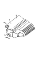
【図5】 画像形成装置本体のカートリッジ装着部の左側の斜視図である。
【図6】 画像形成装置本体のカートリッジ装着部の右側の斜視図である。
【図7】 プロセスカートリッジの感光体ドラムの縦断面図である。
【図8】 軸継手の分解斜視図である。
【図9】 ドラム駆動ギアのギア側カップリング凹部とカップリング軸のカップリング軸凸部との結合態様を示す説明図である。
【図10】 感光体ドラムのドラム軸凸部とカップリング軸のカップリング軸凹部との結合態様を示す説明図である。
【図11】 本体軸継手装置の分解斜視図である。
【図12】 感光体ドラムとカップリング軸の結合解除状態を示す説明図である。
【図13】 感光体ドラムとカップリング軸の結合状態を示す説明図である。
【符号の説明】
2 記録媒体
3 搬送手段
7 電子写真感光体ドラム
8 帯電ローラ(帯電手段)
10 現像手段
11 クリーニング手段
16a ドラム軸凸部(突起)
17 カップリング軸凹部(ねじれた穴)
18 カップリング軸
20 カップリング軸凸部(ねじれた多角柱)
21 ギア側カップリング凹部(ねじれた穴)
22 ドラム駆動ギア
22a 大径丸穴
25 段付カシメ軸(固定軸)
28 カムレバー(軸方向移動手段)
35 カートリッジ装着手段
A 電子写真画像形成装置
B プロセスカートリッジ[0001]
BACKGROUND OF THE INVENTION
The present invention relates to an electrophotographic image forming apparatus to which a process cartridge can be attached and detached.
[0002]
Here, the electrophotographic image forming apparatus forms an image on a recording medium using an electrophotographic image forming system. Examples of the electrophotographic image forming apparatus include an electrophotographic copying machine, an electrophotographic printer (for example, a laser printer, an LED printer, etc.), a facsimile machine, a word processor, and the like.
[0003]
The process cartridge is a cartridge in which a charging unit, a developing unit or a cleaning unit and an electrophotographic photosensitive drum are integrally formed, and the cartridge can be attached to and detached from the main body of the electrophotographic image forming apparatus. In addition, at least one of the charging unit, the developing unit, and the cleaning unit and the electrophotographic photosensitive drum are integrally formed into a cartridge so as to be detachable from the main body of the electrophotographic image forming apparatus. Further, it means that at least the developing means and the electrophotographic photosensitive drum are integrated into a cartridge so that it can be attached to and detached from the electrophotographic image forming apparatus main body.
[0004]
[Prior art]
An electrophotographic image forming apparatus using an electrophotographic image forming system forms an electrostatic latent image by performing selective exposure according to image information on an electrophotographic photosensitive drum uniformly charged by a charging unit. Then, the latent image is developed with toner by a developing unit to form a toner image. Thereafter, the toner image formed on the electrophotographic photosensitive drum is transferred to a recording medium by a transfer unit to form an image.
[0005]
2. Description of the Related Art Conventionally, in an electrophotographic image forming apparatus using an electrophotographic image forming process, an electrophotographic photosensitive drum and process means acting on the electrophotographic photosensitive drum are integrally formed into a cartridge, and this cartridge is the main body of the image forming apparatus. A process cartridge system that can be attached and detached is employed. According to this process cartridge system, the apparatus can be maintained by the user himself / herself without depending on the service person, so that the operability can be remarkably improved. Therefore, this process cartridge system is widely used in image forming apparatuses.
[0006]
In such a process cartridge, in order to drive at least the electrophotographic photosensitive drum, when the process cartridge is mounted on the image forming apparatus body, a power transmission member and an electrophotographic member serving as a drive source on the image forming apparatus body side are provided. The photosensitive drum is connected.
[0007]
Here, various methods have been considered for rotationally driving the electrophotographic photosensitive drum. One method is described in Japanese Patent Laid-Open No. 62-65049, in which a pin fixed to a side surface of a gear provided in the main body of the image forming apparatus is attached to a side surface of the gear provided to the photosensitive drum. In this method, the photosensitive drum is rotated by being fitted into the provided recess.
[0008]
As another method, as described in JP-A-63-4252, there is a method in which the photosensitive drum is rotated by fitting with a helical gear provided in the main body of the image forming apparatus.
[0009]
[Problems to be solved by the invention]
Any of the techniques described in the above-described conventional techniques is very effective as a configuration for transmitting a rotational force to the photosensitive drum. The present invention is a further development of the above-described prior art.
[0010]
An object of the present invention is to provide an electrophotographic image in which coupling and release of an electrophotographic photosensitive drum of a process cartridge and a driving gear for driving the electrophotographic photosensitive drum can be reliably performed using a coupling shaft. It is to provide a forming apparatus.
[0011]
[Means for Solving the Problems]
A typical configuration of the present invention for achieving the above object is as follows.
In an electrophotographic image forming apparatus for detaching a process cartridge and forming an image on a recording medium,
a. A process cartridge having an electrophotographic photosensitive drum, process means acting on the electrophotographic photosensitive drum, and a twisted polygonal column protrusion provided at one end in the longitudinal direction of the electrophotographic photosensitive drum is removable. Cartridge mounting means for mounting on
b. Drive source Concatenated A drive gear that has a twisted hole and a round hole with a polygonal cross section at the center, and is supported so as to be rotatable and not move in the axial direction;
c. Sliding in the axial direction of the twisted hole of the drive gear. Move A twisted angle and a twist direction that engages and disengages the protrusion of the electrophotographic photosensitive drum at the other end. Electrophotographic photosensitive drum A cup having the same shape as a twisted polygonal column, having a twisted hole with a polygonal cross section, and being rotatably supported around the round hole provided at the center of the twisted polygonal column and movable in the axial direction. A ring axis;
d. A fixed shaft coaxially having a shaft that fits into the round hole of the drive gear and the round hole of the coupling shaft;
e. The position where the twisted hole of the coupling shaft is separated from the projection of the polygonal column provided at one end in the longitudinal direction of the electrophotographic photosensitive drum, and the twisted hole of the coupling shaft is formed on the electrophotographic photosensitive drum. An axially moving means of the coupling shaft provided to take a position to engage with the projection of the twisted polygonal column provided at one end in the longitudinal direction;
f. Conveying means for conveying the recording medium;
Have
For the driven side coupling, the inscribed circle diameter φD1 of the twisted hole having a polygonal cross section of the coupling shaft and the twisted polygonal column protrusion provided at one end in the longitudinal direction of the electrophotographic photosensitive drum Play amount of driven side coupling expressed as difference (φD1−φD2) from inscribed circle diameter φD2;
and,
About drive side coupling
A drive side cup in which the cross section of the drive gear is expressed as a difference (φD3−φD4) between the inscribed circle diameter φD3 of the polygonal twisted hole and the inscribed circle diameter φD4 of the twisted polygonal column of the coupling shaft Ring backlash relationship
(ΦD3-φD4) ≦ (φD1-φD2)
This is an electrophotographic image forming apparatus characterized by that.
[0012]
(Function)
In the electrophotographic image forming apparatus, the inscribed circle diameter of the inscribed circle diameter φD3 of the twisted hole having a polygonal cross section of the drive gear and the inscribed circle diameter φD4 of the twisted polygonal column of the coupling shaft. The backlash amount of the driving side coupling expressed as the difference (φD3−φD4) is determined by the inscribed circle diameter φD1 of the twisted hole having a polygonal section of the coupling shaft and one end in the longitudinal direction of the electrophotographic photosensitive drum. Is smaller or equal to the backlash amount of the driven side coupling expressed as the inscribed circle diameter difference (φD1−φD2) with the inscribed circle diameter φD2 of the twisted polygonal column protrusion provided in .
[0013]
Therefore, at the time of coupling coupling in which the twisted hole of the drive side coupling shaft engages with the projection of the twisted polygonal column provided at one end in the longitudinal direction of the electrophotographic photosensitive drum, Since the drive gear cross section has a polygonal twisted hole and the inscribed circle diameter difference (φD3-φD4) between the twisted polygonal column of the coupling shaft, the backlash of the drive side coupling can be made as small as possible. The coupling shaft acts to start rotating simultaneously with the slide toward the electrophotographic photosensitive drum side.
[0014]
Further, at the time of coupling, the driven side coupling has a polygonal twisted hole in the cross section of the coupling shaft and a twisted polygonal column provided at one end in the longitudinal direction of the electrophotographic photosensitive drum. Since the backlash of the driven side coupling expressed as the inscribed circle diameter difference (φD1-φD2) from the protrusion can be made as large as possible, the twisted hole having a polygonal cross section of the coupling shaft is formed on the electrophotographic photosensitive member. It becomes easy to couple to the projection of the twisted polygonal column provided at one end in the longitudinal direction of the drum so that the coupling shaft slides toward the electrophotographic photosensitive drum side.
[0015]
Therefore, the twisted hole having a polygonal cross section of the coupling shaft can easily couple the twisted polygonal column protrusion provided at one end in the longitudinal direction of the electrophotographic photosensitive drum.
[0016]
Further, when the coupling is released in which the twisted hole of the coupling shaft separates from the projection of the polygonal column provided at one end in the longitudinal direction of the electrophotographic photosensitive drum, the drive gear has a large cross section of the drive gear. Since the backlash of the drive side coupling expressed as the inscribed circle diameter difference (φD3-φD4) between the square twisted hole and the twisted polygonal column of the coupling shaft can be made as small as possible, the coupling shaft is driven Acts to start rotating simultaneously with sliding toward the gear side.
[0017]
Therefore, the twisted hole having a polygonal cross section of the coupling shaft can be easily released from the projection of the twisted polygonal column provided at one end in the longitudinal direction of the electrophotographic photosensitive drum.
[0018]
DETAILED DESCRIPTION OF THE INVENTION
Next, embodiments according to the present invention will be described with reference to the drawings.
[0019]
In the following description, the longitudinal direction is a direction perpendicular to the conveyance direction of the recording medium and along the surface of the recording medium, and coincides with the axial direction of the photosensitive drum.
[0020]
First, the process cartridge B according to the present embodiment and the electrophotographic image forming apparatus A to which the process cartridge B can be detachably mounted will be specifically described with reference to FIGS. 1 to 13. Here, as an order of description, first, the overall configuration of the process cartridge B and the electrophotographic image forming apparatus A that is used by mounting the process cartridge B will be described with reference to FIGS. 1 to 6, and then with reference to FIGS. Next, the structure of the shaft coupling that is the driving force transmission mechanism between the process cartridge B and the image forming apparatus
[0021]
{overall structure}
FIG. 1 is a cross-sectional explanatory view of a laser beam printer which is an electrophotographic image forming apparatus A to which a process cartridge B is detachably mounted.
[0022]
As shown in FIG. 1, an electrophotographic image forming apparatus (laser beam printer) A according to the present embodiment applies a laser beam based on image information from an optical system 1 to a drum-shaped electrophotographic photosensitive drum (hereinafter “photosensitive”). The electrostatic latent image is formed on the
[0023]
The electrophotographic image forming apparatus A according to the present embodiment can also be manually fed by a manual tray and a roller (not shown).
[0024]
{Process cartridge configuration}
On the other hand, the process cartridge B includes an electrophotographic photosensitive drum and at least one process means. Here, as the process means, for example, a charging means for charging the electrophotographic photosensitive drum, a developing means for developing a latent image formed on the electrophotographic photosensitive drum, and a toner remaining on the surface of the electrophotographic photosensitive drum are cleaned. There are cleaning means and the like.
[0025]
As shown in FIG. 2, the process cartridge B of the present embodiment includes a
[0026]
The developing means 10 feeds the toner in the
[0027]
The charging
[0028]
{Process cartridge housing configuration}
In the process cartridge B, a
[0029]
The process cartridge B is detachably mounted by a user from a direction intersecting the longitudinal direction (axial direction) of the
[0030]
{Configuration of cartridge mounting means}
As the cartridge mounting means, as shown in FIGS. 5 and 6, cartridge mounting
[0031]
When the process cartridge B is mounted on the apparatus
[0032]
{Shaft coupling and drive structure}
Next, the configuration of the shaft coupling which is a drive transmission mechanism that transmits the driving force from the apparatus
[0033]
As shown in FIGS. 7, 8, and 11, a shaft coupling member on the process cartridge B side is provided at one end in the longitudinal direction of the
[0034]
As shown in FIG. 7, the coupling
[0035]
A
[0036]
When the process cartridge B is mounted on the apparatus
[0037]
Further, since the developing unit 12U side is heavier than the
[0038]
The drum flanges 37 and 36 are made of a resin material such as polyacetal, polycarbonate, polyamide, and polybutylene terephthalate. However, other materials may be appropriately selected and used.
[0039]
A
[0040]
In addition, the shape of the
[0041]
In the present embodiment, the
[0042]
That is, the
[0043]
(Configuration of drum shaft protrusion (projection))
As shown in FIG. 8, the shape of the drum shaft
[0044]
(Composition of coupling shaft)
A coupling shaft
[0045]
(Drum drive gear configuration)
A gear-
[0046]
The gear-
[0047]
(Description of driving side coupling and driven side coupling)
As shown in FIG. 9, for the drive side coupling, the inscribed circle diameter of a substantially equilateral triangular hole which is the cross-sectional shape of the gear
[0048]
In addition, as shown in FIG. G The inscribed circle diameter of the substantially regular triangular prism that is the cross-sectional shape of the drum shaft
[0049]
The backlash amount represented by the cross-sectional shape of each of the coupling portions is represented by the following relational expression.
[0050]
(ΦD3-φD4) ≦ (φD1-φD2) (1)
In the shaft coupling device having such a configuration, a driving force from a driving motor (not shown) provided in the
[0051]
Therefore, in the configuration of the present embodiment, when the process cartridge B is mounted on the apparatus
[0052]
In this embodiment, when viewed from the
[0053]
The apparatus
[0054]
{Configuration of shaft coupling engaging / disengaging device}
Next, in conjunction with the closing operation of the opening /
[0055]
11 to 13 show the positional relationship among the
[0056]
As shown in FIGS. 11 to 13, a
[0057]
A stepped caulking shaft having two large and small diameters coaxially is provided on a
[0058]
One end of the
[0059]
The
[0060]
As shown in FIG. 11, the pressing
[0061]
In order to hold the
[0062]
The drum-
[0063]
Further, the shaft portion 27f (see FIGS. 12 and 13) of the
[0064]
The
[0065]
A
[0066]
The
[0067]
The
[0068]
The
[0069]
{Description of engagement / disengagement of shaft coupling}
First, in the electrophotographic image forming apparatus A in which the detachable process cartridge B transmits the driving rotational force from the apparatus
[0070]
The
[0071]
The
[0072]
First, when the process cartridge B is mounted on the apparatus
[0073]
Therefore, at the position where the process cartridge B inside the apparatus
[0074]
Second, as shown in FIG. 12, when the process cartridge B is mounted on the apparatus
[0075]
When the opening /
[0076]
Therefore, the coupling shaft
[0077]
At this time, the
[0078]
For this reason, the inscribed circle diameter difference (φD3-φD4) between the gear
[0079]
When the coupling shaft
[0080]
In the present embodiment, the inscribed circle diameter φD1 of the substantially equilateral triangular hole which is the sectional shape of the coupling shaft
[0081]
For this reason, the coupling shaft
[0082]
When the
[0083]
Since the shaft coupling shown in the present embodiment is a combination of a twisted substantially equilateral triangular prism shaft and a hole as described above, the coupling shaft
[0084]
Third, the operation when the process cartridge B is taken out from the apparatus
[0085]
In order to remove the process cartridge B from the apparatus
[0086]
A coupling shaft
[0087]
In the present embodiment, when the opening /
[0088]
When the
[0089]
Therefore, the coupling shaft
[0090]
At this time, the amount of movement of the coupling shaft
[0091]
In the present embodiment, the inscribed circle diameter φD3 of the substantially equilateral triangular hole that is the cross-sectional shape of the gear
[0092]
For this reason, the inscribed circle diameter difference (φD3-φD4) between the gear
[0093]
Therefore, when the
[0094]
Thus, the
[0095]
Further, according to the present embodiment, the twist angle at the contact portion between the drum shaft
For the drive side coupling, the inscribed circle diameter of the substantially equilateral triangular hole that is the cross-sectional shape of the gear
For the driven side coupling, the inscribed circle diameter of the substantially equilateral triangular prism that is the cross-sectional shape of the drum shaft
The amount of play expressed by the cross-sectional shape of each coupling part is expressed by the following relational expression:
(ΦD3-φD4) ≦ (φD1-φD2) (1)
Then,
When the coupling between the drum shaft
[0096]
Therefore, the twist angle of each twisted surface in the drum shaft
[0097]
As described above, the electrophotographic image forming apparatus A shown in the present embodiment couples and releases the
[0098]
Further, the rotation transmission speed of the process cartridge B to the
[0099]
Further, when the driving force is transmitted to the
[0100]
Further, when driving the
[0101]
Further, since the
[0102]
{Other embodiments}
The electrophotographic image forming apparatus shown in the above-described embodiment has exemplified the case of forming a single color image. However, the present invention is not limited to this, and a plurality of developing means are provided to provide a plurality of color images (two-color images). The present invention can also be suitably applied to an electrophotographic image forming apparatus that forms a three-color image or a full color).
[0103]
Further, the electrophotographic photosensitive drum of the process cartridge is not limited to the photosensitive drum, and includes, for example, the following. First, a photoconductor is used as the photosensitive drum, and examples of the photoconductor include amorphous silicon, amorphous selenium, zinc oxide, titanium oxide, and an organic photoconductor (OPC). As the shape for mounting the photoconductor, for example, a drum shape or a belt shape is used. For example, in the case of a drum type photoconductor, a photoconductor is deposited or coated on a cylinder made of aluminum alloy or the like. It is the one that has been crafted.
[0104]
As the developing method, various developing methods such as a known two-component magnetic brush developing method, cascade developing method, touch-down developing method, and cloud developing method can be used.
[0105]
Further, the so-called contact charging method is used in the above-described embodiment for the structure of the charging means. However, as another structure, a metal shield such as aluminum is provided around three sides of a tungsten wire which has been conventionally known, and the tungsten wire Naturally, it is possible to use a configuration in which positive or negative ions generated by applying a high voltage are moved to the surface of the photosensitive drum and the drum surface is uniformly charged.
[0106]
In addition to the roller type, the charging unit may be a blade (charging blade), a pad type, a block type, a rod type, a wire type, or the like.
[0107]
Further, as a method for cleaning the toner remaining on the photosensitive drum, the cleaning unit may be configured using a blade, a fur brush, a magnetic brush, or the like.
[0108]
The above-described process cartridge includes, for example, an electrophotographic photosensitive member and at least one process means. Therefore, as an aspect of the process cartridge, in addition to the above-described embodiment, for example, an electrophotographic photosensitive member and a charging unit are integrated into a cartridge so that it can be attached to and detached from the apparatus main body. An electrophotographic photosensitive member and developing means are integrated into a cartridge so that it can be attached to and detached from the apparatus main body. An electrophotographic photosensitive member and a cleaning means are integrated into a cartridge so that it can be attached to and detached from the apparatus main body. Further, there is a combination of an electrophotographic photosensitive member and two or more of the above process means, which are integrated into a cartridge so that it can be attached to and detached from the apparatus main body.
[0109]
That is, the process cartridge described above is a cartridge in which a charging unit, a developing unit or a cleaning unit and an electrophotographic photosensitive member are integrally formed, and this cartridge can be attached to and detached from the image forming apparatus main body. In addition, at least one of the charging unit, the developing unit, and the cleaning unit and the electrophotographic photosensitive member are integrally formed into a cartridge that can be attached to and detached from the image forming apparatus main body. Further, it means that at least the developing means and the electrophotographic photosensitive member are integrated into a cartridge so that it can be attached to and detached from the apparatus main body. The process cartridge can be attached to and detached from the apparatus main body by the user. Therefore, maintenance of the apparatus main body can be performed by the user himself.
[0110]
Further, in the above-described embodiment, the laser beam printer is exemplified as the electrophotographic image forming apparatus. However, the present invention is not limited to this. For example, an electrophotographic apparatus such as an electrophotographic copying machine, a facsimile machine, or a word processor. Of course, it can also be used in an image forming apparatus.
[0111]
【The invention's effect】
As described above, the electrophotographic image forming apparatus according to the present invention uses a coupling shaft to couple and release the electrophotographic photosensitive drum of the process cartridge and the driving gear for driving the electrophotographic photosensitive drum. Can be used reliably.
[Brief description of the drawings]
FIG. 1 is a longitudinal sectional view of an electrophotographic image forming apparatus according to an embodiment.
FIG. 2 is a longitudinal section of a process cartridge.
FIG. 3 is a perspective view from the upper right of the process cartridge as viewed in the mounting direction.
FIG. 4 is a perspective view from the upper left of the process cartridge as viewed in the mounting direction.
FIG. 5 is a left perspective view of a cartridge mounting portion of the image forming apparatus main body.
FIG. 6 is a perspective view on the right side of the cartridge mounting portion of the image forming apparatus main body.
FIG. 7 is a longitudinal sectional view of a photosensitive drum of a process cartridge.
FIG. 8 is an exploded perspective view of the shaft coupling.
FIG. 9 is an explanatory view showing a coupling mode of a gear side coupling concave portion of the drum driving gear and a coupling shaft convex portion of the coupling shaft.
FIG. 10 is an explanatory diagram showing a coupling mode between a drum shaft convex portion of a photosensitive drum and a coupling shaft concave portion of a coupling shaft.
FIG. 11 is an exploded perspective view of the main body shaft coupling device.
FIG. 12 is an explanatory diagram illustrating a state where the coupling between the photosensitive drum and the coupling shaft is released.
FIG. 13 is an explanatory diagram showing a coupling state of the photosensitive drum and the coupling shaft.
[Explanation of symbols]
2 recording media
3 Transport means
7 Electrophotographic photosensitive drum
8 Charging roller (charging means)
10 Development means
11 Cleaning means
16a Drum shaft protrusion (protrusion)
17 Coupling shaft recess (twisted hole)
18 Coupling shaft
20 Coupling shaft convex part (twisted polygonal column)
21 Gear side coupling recess (twisted hole)
22 Drum drive gear
22a Large diameter round hole
25 Stepped caulking shaft (fixed shaft)
28 Cam lever (Axial movement means)
35 Cartridge mounting means
A Electrophotographic image forming apparatus
B Process cartridge
Claims (2)
a.電子写真感光体ドラムと、
前記電子写真感光体ドラムに作用するプロセス手段と、
前記電子写真感光体ドラムの長手方向の一端に設けられたねじれた多角柱の突起と、
を有するプロセスカートリッジを取り外し可能に装着するためのカートリッジ装着手段と、
b.駆動源に連結されて、中心に断面が多角形のねじれた穴と丸穴を同軸上に有し、回転自在で軸方向に移動しないように支持された駆動ギアと、
c.前記駆動ギアのねじれた穴の軸方向に摺動するねじれた多角柱を一端に有し、他端に前記電子写真感光体ドラムの突起と係脱する、ねじれ角およびねじれ方向が前記電子写真感光体ドラムのねじれた多角柱と同一で、断面が多角形のねじれた穴を有し、前記ねじれた多角柱の中心に設けられた丸穴を中心に回転自在で軸方向に移動自在に支持されたカップリング軸と、
d.前記駆動ギアの丸穴と前記カップリング軸の丸穴に嵌合する軸を同軸上に有する固定軸と、
e.前記カップリング軸のねじれた穴が前記電子写真感光体ドラムの長手方向の一端に設けられた多角柱の突起と離脱した位置と、前記カップリング軸のねじれた穴が前記電子写真感光体ドラムの長手方向の一端に設けられたねじれた多角柱の突起と係合する位置と、をとるように設けられたカップリング軸の軸方向移動手段と、
f.前記記録媒体を搬送するための搬送手段と、
を有し、
被駆動側カップリングについて、
前記カップリング軸の断面が多角形のねじれた穴の内接円直径φD1と、前記電子写真感光体ドラムの長手方向の一端に設けられたねじれた多角柱の突起の内接円直径φD2との差(φD1−φD2)として表される被駆動側カップリングのガタ量、
および、
駆動側カップリングについて、
前記駆動ギアの断面が多角形のねじれた穴の内接円直径φD3と、前記カップリング軸のねじれた多角柱の内接円直径φD4との差(φD3−φD4)として表される駆動側カップリングのガタ量の関係が
(φD3−φD4)≦(φD1−φD2)
である、ことを特徴とする電子写真画像形成装置。In an electrophotographic image forming apparatus for detaching a process cartridge and forming an image on a recording medium,
a. An electrophotographic photosensitive drum;
Process means acting on the electrophotographic photosensitive drum;
Twisted polygonal column protrusions provided at one end in the longitudinal direction of the electrophotographic photosensitive drum,
Cartridge mounting means for detachably mounting a process cartridge having
b. A drive gear connected to the drive source, having a twisted hole and a round hole having a polygonal cross section at the center, and being supported so as to be rotatable and not move in the axial direction;
c. Has a sliding to Runejire was polygonal on one end in the axial direction of the twisted hole of said drive gear, said protrusions disengageably of the electrophotographic photosensitive drum at the other end, the twist angle and twist direction the electrophotographic Same as the twisted polygonal column of the photoconductor drum , having a twisted hole with a polygonal cross section, and is supported rotatably around the round hole provided in the center of the twisted polygonal column and movable in the axial direction Coupled coupling shaft,
d. A fixed shaft coaxially having a shaft that fits into the round hole of the drive gear and the round hole of the coupling shaft;
e. The position where the twisted hole of the coupling shaft is separated from the projection of the polygonal column provided at one end in the longitudinal direction of the electrophotographic photosensitive drum, and the twisted hole of the coupling shaft is formed on the electrophotographic photosensitive drum. An axially moving means of the coupling shaft provided to take a position to engage with the projection of the twisted polygonal column provided at one end in the longitudinal direction;
f. Conveying means for conveying the recording medium;
Have
About driven side coupling
The inscribed circle diameter φD1 of the twisted hole having a polygonal cross section of the coupling shaft and the inscribed circle diameter φD2 of the twisted polygonal column protrusion provided at one end in the longitudinal direction of the electrophotographic photosensitive drum Play amount of driven side coupling expressed as difference (φD1-φD2),
and,
About drive side coupling
A drive side cup in which the cross section of the drive gear is expressed as a difference (φD3−φD4) between the inscribed circle diameter φD3 of the polygonal twisted hole and the inscribed circle diameter φD4 of the twisted polygonal column of the coupling shaft Ring backlash relationship
(ΦD3-φD4) ≦ (φD1-φD2)
An electrophotographic image forming apparatus characterized by that.
Priority Applications (1)
| Application Number | Priority Date | Filing Date | Title |
|---|---|---|---|
| JP01833999A JP3796364B2 (en) | 1999-01-27 | 1999-01-27 | Electrophotographic image forming apparatus |
Applications Claiming Priority (1)
| Application Number | Priority Date | Filing Date | Title |
|---|---|---|---|
| JP01833999A JP3796364B2 (en) | 1999-01-27 | 1999-01-27 | Electrophotographic image forming apparatus |
Publications (3)
| Publication Number | Publication Date |
|---|---|
| JP2000214646A JP2000214646A (en) | 2000-08-04 |
| JP2000214646A5 JP2000214646A5 (en) | 2005-02-24 |
| JP3796364B2 true JP3796364B2 (en) | 2006-07-12 |
Family
ID=11968905
Family Applications (1)
| Application Number | Title | Priority Date | Filing Date |
|---|---|---|---|
| JP01833999A Expired - Fee Related JP3796364B2 (en) | 1999-01-27 | 1999-01-27 | Electrophotographic image forming apparatus |
Country Status (1)
| Country | Link |
|---|---|
| JP (1) | JP3796364B2 (en) |
Families Citing this family (11)
| Publication number | Priority date | Publication date | Assignee | Title |
|---|---|---|---|---|
| JP3097041B2 (en) * | 1993-08-13 | 2000-10-10 | 株式会社小松製作所 | Return flow sharing circuit for pressure oil supply device |
| US7228090B2 (en) | 2004-02-26 | 2007-06-05 | Konica Minolta Business Technologies, Inc. | Image forming apparatus with a removable process unit capable of securing rotation transmission accuracy without stressing a holding portion despite shaft misalignment |
| US7043180B2 (en) * | 2004-03-26 | 2006-05-09 | Lexmark International, Inc. | Gear and shaft arrangement for an image forming device |
| JP5306050B2 (en) * | 2008-06-20 | 2013-10-02 | キヤノン株式会社 | Cartridge, coupling member attaching method, and coupling member removing method |
| CN102087494B (en) * | 2011-01-14 | 2012-12-26 | 珠海天威飞马打印耗材有限公司 | Photosensitive drum drive assembly, photosensitive drum and processing cartridge |
| CN102866608B (en) * | 2011-07-05 | 2015-11-25 | 珠海艾派克科技股份有限公司 | A kind of photosensitive drum driving head and image processing system driving mechanism |
| JP6065399B2 (en) | 2012-03-28 | 2017-01-25 | ブラザー工業株式会社 | Image forming apparatus |
| JP6207254B2 (en) * | 2013-06-25 | 2017-10-04 | キヤノン株式会社 | Rotation transmission device and image forming apparatus |
| JP2016014850A (en) * | 2014-06-09 | 2016-01-28 | 三菱化学株式会社 | Shaft member, end member, photoreceptor drum unit, developing roller unit, and process cartridge |
| JP2017521727A (en) * | 2014-07-25 | 2017-08-03 | 珠海艾派克科技股▲ふん▼有限公司 | Rotational force drive unit, process cartridge, and image forming apparatus |
| JP6921636B2 (en) | 2016-06-14 | 2021-08-18 | キヤノン株式会社 | Process cartridge and electrophotographic image forming apparatus |
-
1999
- 1999-01-27 JP JP01833999A patent/JP3796364B2/en not_active Expired - Fee Related
Also Published As
| Publication number | Publication date |
|---|---|
| JP2000214646A (en) | 2000-08-04 |
Similar Documents
| Publication | Publication Date | Title |
|---|---|---|
| RU2690046C1 (en) | Process cartridge and electrophotographic image forming device | |
| JP3689504B2 (en) | Electrophotographic image forming apparatus | |
| JP3745049B2 (en) | Process cartridge and electrophotographic image forming apparatus | |
| JP3969805B2 (en) | Electrophotographic image forming apparatus | |
| US6349188B1 (en) | Process cartridge, electrophotographic image forming apparatus, driving force transmission part and electrophotographic photosensitive drum | |
| US6175706B1 (en) | Process cartridge, electrophotographic image forming apparatus driving force transmission part and electrophotographic photosensitive drum | |
| US6501926B1 (en) | Process cartridge and electrophotographic image forming apparatus | |
| US6501927B1 (en) | Process cartridge and photosensitive drum driving mount | |
| JP3667243B2 (en) | Process cartridge, process cartridge mounting mechanism, and electrophotographic image forming apparatus | |
| US20090317132A1 (en) | Process cartridge, electrophotographic image forming apparatus and electrographic photosensitive drum unit | |
| JP3787487B2 (en) | Process cartridge mounting mechanism, electrophotographic image forming apparatus, and process cartridge | |
| JPH10240103A (en) | Process cartridge, electrophotographic image forming device, electrophotographic photoreceptor drum and coupling | |
| JP3796364B2 (en) | Electrophotographic image forming apparatus | |
| JP3780059B2 (en) | Electrophotographic image forming apparatus | |
| JP3782541B2 (en) | Process cartridge and electrophotographic image forming apparatus | |
| JP3754813B2 (en) | Electrophotographic image forming apparatus | |
| JP2000338842A (en) | Electrophotographic image forming device | |
| JP3943669B2 (en) | Electrophotographic image forming apparatus and process cartridge | |
| JP3748484B2 (en) | Electrophotographic image forming apparatus | |
| JP3768998B2 (en) | Process cartridge and electrophotographic image forming apparatus | |
| JPH10104996A (en) | Electronic photography photosensitive body drum, process cartridge and electronic photography image forming device | |
| JPH11109836A (en) | Electrophotographic image forming device and process cartridge | |
| JP2005208683A (en) | Process cartridge, electrophotographic image forming apparatus, electronic photoreceptor drum, and coupling | |
| JP4208933B2 (en) | Process cartridge | |
| JP2006220738A (en) | Electrophotographic image forming apparatus |
Legal Events
| Date | Code | Title | Description |
|---|---|---|---|
| A521 | Written amendment |
Free format text: JAPANESE INTERMEDIATE CODE: A523 Effective date: 20040319 |
|
| A621 | Written request for application examination |
Free format text: JAPANESE INTERMEDIATE CODE: A621 Effective date: 20040319 |
|
| A977 | Report on retrieval |
Free format text: JAPANESE INTERMEDIATE CODE: A971007 Effective date: 20051212 |
|
| A131 | Notification of reasons for refusal |
Free format text: JAPANESE INTERMEDIATE CODE: A131 Effective date: 20051220 |
|
| A521 | Written amendment |
Free format text: JAPANESE INTERMEDIATE CODE: A523 Effective date: 20060123 |
|
| TRDD | Decision of grant or rejection written | ||
| A01 | Written decision to grant a patent or to grant a registration (utility model) |
Free format text: JAPANESE INTERMEDIATE CODE: A01 Effective date: 20060411 |
|
| A61 | First payment of annual fees (during grant procedure) |
Free format text: JAPANESE INTERMEDIATE CODE: A61 Effective date: 20060417 |
|
| R150 | Certificate of patent or registration of utility model |
Free format text: JAPANESE INTERMEDIATE CODE: R150 |
|
| FPAY | Renewal fee payment (event date is renewal date of database) |
Free format text: PAYMENT UNTIL: 20090421 Year of fee payment: 3 |
|
| FPAY | Renewal fee payment (event date is renewal date of database) |
Free format text: PAYMENT UNTIL: 20100421 Year of fee payment: 4 |
|
| FPAY | Renewal fee payment (event date is renewal date of database) |
Free format text: PAYMENT UNTIL: 20110421 Year of fee payment: 5 |
|
| FPAY | Renewal fee payment (event date is renewal date of database) |
Free format text: PAYMENT UNTIL: 20120421 Year of fee payment: 6 |
|
| FPAY | Renewal fee payment (event date is renewal date of database) |
Free format text: PAYMENT UNTIL: 20130421 Year of fee payment: 7 |
|
| LAPS | Cancellation because of no payment of annual fees |